Comparison of design rules for glued-in rods and design rule proposal for implementation in European...
14
CIB-W18/46-7-10 INTERNATIONAL COUNCIL FOR RESEARCH AND INNOVATION IN BUILDING AND CONSTRUCTION WORKING COMMISSION W18 - TIMBER STRUCTURES COMPARISON OF DESIGN RULES FOR GLUED-IN RODS AND DESIGN RULE PROPOSAL FOR IMPLEMENTATION IN EUROPEAN STANDARDS M Stepinac V Rajcic University of Zagreb, Faculty of Civil Engineering CROATIA F Hunger J-W van de Kuilen Technische Universität München, Holzforschung München GERMANY R Tomasi University of Trento ITALY E Serrano Linnaeus University SWEDEN MEETING FORTY SIX VANCOUVER CANADA AUGUST 2013
Transcript of Comparison of design rules for glued-in rods and design rule proposal for implementation in European...

CIB-W18/46-7-10
INTERNATIONAL COUNCIL FOR RESEARCH AND INNOVATION
IN BUILDING AND CONSTRUCTION
WORKING COMMISSION W18 - TIMBER STRUCTURES
COMPARISON OF DESIGN RULES FOR GLUED-IN RODS AND
DESIGN RULE PROPOSAL FOR IMPLEMENTATION IN
EUROPEAN STANDARDS
M Stepinac
V Rajcic
University of Zagreb, Faculty of Civil Engineering
CROATIA
F Hunger
J-W van de Kuilen
Technische Universität München, Holzforschung München
GERMANY
R Tomasi
University of Trento
ITALY
E Serrano
Linnaeus University
SWEDEN
MEETING FORTY SIX
VANCOUVER
CANADA
AUGUST 2013

1
Comparison of design rules for glued-in rods and design rule proposal for implementation in
European standards
Stepinac, Mislav University of Zagreb, Faculty of Civil Engineering, Croatia
Hunger, Frank Technische Universität München, Holzforschung München, Germany
Tomasi, Roberto University of Trento, Italy
Serrano, Erik Linnaeus University, Sweden
Rajcic, Vlatka University of Zagreb, Faculty of Civil Engineering, Croatia
van de Kuilen, Jan-Willem Technische Universität München, Holzforschung München, Germany
1 Introduction Glued-in rods are often considered as “new, innovative and highly efficient” way to connect timber elements. However, they have been used for at least 30 years. Glued-in rods represent a versatile joint system with advantages such as high load transition, appropriate behaviour in case of fire, easy application combined with a high level of prefabrication for fast installation. In addition, the aesthetic appearance of the finished joint also plays an important role.
Despite many national and international research projects and many practical applications of glued-in rods in timber structures, there is still no universal standard covering the design thereof. Therefore, a project group within WG1 of COST Action FP1004 (dealing with enhancing mechanical properties of timber, engineered wood products and timber structures) focuses on this topic with the aim to prepare the way for the implementation of design rules for glued-in rods into European standards by defining common design procedure or technical guideline. The idea is to focus all research knowledge and experiences (GIROD, Licons, etc.) to point out key issues regarding glued-in rods that need to be resolved.
Different design methods are in use in a number of countries but there are some apparent contradictions between these models and the influence of parameters that they predict. This has been evaluated in various studies. A general-purpose European design procedure which is convenient and user-friendly would be helpful. Due to past disagreements, the design rules considering glued-in rods included in a previous version of the Eurocode 5 (EC5) [1] cannot be found in the current valid version. At recent CEN meetings, within TC 250 work programme for the next five years, glued-in rods have been highlighted as an important work item because they are widely used all over the world. Consequently, design rules are considered necessary in Eurocode 5. The benefits of this work item were stated as a harmonisation of the current state of the art. The output of design rules as a new clause in existing EN1995 [1] was suggested.

2
This paper gives an overview and presents known design models, technical approvals and regulations, national standards and guidance papers, comparing the different approaches. Although there are many proposals for calculation and design of glued-in rods, it is necessary to individuate a unique design method and guidance about safe design of glued-in rods.
In addition to the comparison of design rules an online survey on the usage, requirements for a design rule and scientific research was developed and sent to scientists, timber industrialists and structural designers all over Europe.
2 Methods
2.1 General
One outcome of the discussion within the COST Action FP 1004 was to gather relevant information from published articles and known design rules and try to find out what needs must be further researched and what hinders the introduction in EC5. After reviewing literature, information was compiled and a systematic procedure was established. A table was compiled that contained the parameters that were investigated and the test setup used, besides general and additional information provided in the article. Parameters are grouped as shown in Figure 1. This figure is only a methodical presentation of the full table which will be available online [4]. This table can assist in the development of further research because it is easy to identify where the lack of knowledge and research is.
Figure 1: Overview of compiled information
Several studies were carried out to comprehend the influence of boundary conditions, loading modes and test setups. Different test setups have been used to obtain the capacity of a single glued in rod. The most common setups are pull-pull tests (see e.g. Bainbridge et al. (2000) [10]) where rods are glued-in on both sides of the specimen and pulled out axially (often in the longitudinal direction of the timber member). Others include pull-compression tests (Rajčić et al. 2006 [19]) which are carried out in a similar method to that outlined in EN 1382(1999) [3]. Tests carried out on the specimens in pull-compression setup do not correspond to the practical application (Tlustochowicz et al. 2011 [25]) but the test procedure is common and convenient for obtaining the capacity of a glued-in rod. By selecting the test setup and the anchorage length, different failure modes can be provoked or even excluded (Steiger et al. 2007 [24]). Typical failure modes are rod failure (preferably by yielding), shear failure in the adhesive or rupture of the timber around the bond and failure of the host timber member by splitting or tensile failure as shown in Figure 2.

3
Figure 2: Failure modes for glued-in rods: (a) shear failure along the rod, (b) tensile failure, (c) group tear out, (d) splitting failure, (e) yielding of the rod (Tlustochowicz et al. 2011 [25])
A wide range in the tested timber quality can be noted because most of the tests are preformed to gain knowledge for a specific application (Kangas et al. 2001 [17]). The most typical timber quality was C24 or better. Glulam (Tomasi et al. 2009 [36]) or laminated veneer lumber made of softwood (Harvey et al. 2000 [15]) have also been used. This confirms the aspect to use glued-in rods for special and challenging applications. Steiger et al. (2004) [58] studied the interrelation of timber density and the pull-out strength. The study showed that the pull-out strength strongly depends on the timber density around the anchorage zone especially for glued-in rods parallel to the grain. Tests with hardwood are not so common and are rarely conducted (Otero et al. 2008 [18], Rajčić et al. 2006 [20]) but in practice glued-in rods are often used for retrofitting historical buildings of which the main structure is made of hardwood. Broughton et al. (2001a) [12] studied the influence of the moisture content at the time of bonding on the pull-out strength on hardwood. The generic types of adhesive most frequently studied were polyurethanes and epoxies. The experimental pull-out behaviour has been tested for different types of adhesives by Broughton et al. (2001b) [13] but nowadays technical approvals for both of the above mentioned adhesive types are available for use with softwoods. The fatigue performance of bonded-in rods was studied by Bainbridge et al. (2000) [10] for different types of adhesives but all in all the long-term behaviour is rarely considered because of the lack of standardized approval procedures and because the tests are time-consuming and expensive. This is a serious drawback since only standardized tests can deliver comparable test results that can be considered in the evaluation of the long-term behaviour in the design rules. Other parameters, subject of studies by Steiger et al. (2004) [58], concern the geometry of the tested samples including anchorage length, rod diameter and the slenderness ratio (the quotient of the anchorage length and the drill-hole diameter). While there is a negative relationship between anchorage length and the shear strength in the anchorage zone the shear strength increases with larger drill-hole and rod diameters. This causes a negative relationship between the shear strength and the slenderness ratio whilst the total pull-out force increases at higher slenderness values (Rossignon et al. 2008 [22]). This topic is important as it can dictate the failure mode. Feligioni et al. (2003) [14] found a good correlation between the pull-out strength of glued-in rods and the volume of the adhesive, which depended up on the anchorage length and the glue line thickness. It was concluded that the glue line thickness is an important parameter because it allows optimization of the stress transfer from timber to rod. Blass et al. (1999) [11] studied the influence of spacings between multiple rods and the edge distances at axially glued in rods. It was shown that the load-carrying capacity decreased if the edge distance was less than 2.5 times the rod diameter. The results of a study by Broughton et al. (2001a) [12] also confirmed this, demonstrating how multiple rods spaced too closely do not act individually but pull-out as one.

4
2.2 Introduction to the questionnaire
The main objective of the online survey was to gather overall knowledge and interest in glued-in rods. The questionnaire was divided into three parts: use of glued-in rods in practice, regulations and standards, and the extent of scientific research on the subject.
In the first part of the questionnaire the idea was to obtain information on the popularity of glued-in rods in practice, the usage of glued in rods instead of other similar applications and the main advantages and disadvantages of these applications. The second part of the survey was focused on standards and norms, in particular on the familiarity with regulations, standards and guidelines. Of special interest was to get knowledge about which standards are most widely used and why, as well as disadvantages of the standards and the parts that need improvement. The research part of the survey was aimed at gathering technical information about research methods, test conditions and common materials used in laboratory tests. All in all a total of 32 questions were asked in an online survey which can be found online [4].
2.3 Results of the questionnaire
The questionnaire was filled out by 56 respondents (from 15 European countries), including; scientists, timber industry representatives and designers (Figure 3). Of the total number of respondents only 2 knew very little about glued-in rods, 11 had only read articles, and 43 people indicated they were very familiar with the subject matter, whether as designers, researchers or people from the timber industry, filled out the survey.
Figure 3: Left: Affiliation of respondents. Right: Distribution and number of respondents by country.
Glued-in rods were often recognized as systems which provided stiff joints, high load capacity, good fire resistance and which were aesthetically desirable at the same time. Yet given the large number of people indicating their familiarity with the matter, glued in rods were very seldom used in practice. Only 9% of respondents are using glued in rods frequently in practice, whilst 68% had never used them or used them in practice only a few times. The main reason for this was reported to be because of the lack of standards and regulations and consequently lack of adequate information about the design, quality control and installation methods. In new structures, e.g. timber bridges, residential houses, long-span buildings, glued-in rods are applied where they are desirable because they allow the execution of joints without external steel parts, and they can transfer significant moments from beams to columns. The embedded rods are protected against fire hazards, are more resistant to environmental conditions and they are easy to prefabricate. When talking about historic structures, they were very often applied in beams, trusses, joints and less in columns, timber plates and for anchoring in concrete. Glued-in rods are also often used as systems for replacing decayed parts and strengthening of critical parts in structures, where they allow the easy connection of the replacement material to the remaining timber structure on site. The connections in a traditionally jointed timber frame are one of the weakest spots and often suffer from decay in older structures. Glued in rods were reported to be very effective in

5
attaching new sections to replace decayed timber. In some cases beams were undersized for structural changes of use or even for their original use. So it is possible to use glued-in steel rods or plates, the latter either set vertically in a slot cut in a beam or glued to the bottom side of a beam if it will be covered. This was a very effective way, causing minimal intrusion, to increase strength and stiffness of a beam. Figure 4 and show where and when are glued-in rods used when designing new and historical structures.
Figure 4: Left: Reasons for designing new structures. Right: Use of glued-in rods in retrofitting historical buildings.
Despite many advantages there were situations when glued-in rods were not desirable and caused lack of trust. One of the main reasons is uncertainty related to production and quality control. Qualified personnel is the prerequisite for good application because more expertise is needed compared to driving screws. The need for good workmanship in the preparation and cleaning of the rod and sealing holes in existing elements that, for example, allow the adhesive to leak out of the hole or the slot for the rod or the plate can be critical. It is also difficult to inspect and to assess glued-in rods once installed. The joints cannot be disassembled for repairing and if they are of poor workmanship this could lead to progressive failure in multiple rod connections because of the brittleness of the adhesive and/or the whole connection system. Applications performed directly on the building site (in-situ) require a system to connect them, but this can be expensive and may reduce the effectiveness of the connection due to very variable conditions such as temperature, skill of the personnel or dust. It was also difficult to certify that the joint is safe and functional. So, in conclusion, despite of the many advantages of glued-in rods they are not often used because there is little information about quality control, and a lack of standards and information about design (durability, detailing, stiffness, etc.).
When it comes to preferable materials for glued-in rods, the epoxy adhesive (EPX) with an maximum glueline thickness up to 2mm, threaded steel or Fibre-reinforced plastic bars (FRP), glulam or softwood were the ones mostly used. One of the reasons for using EPX (95% respondents are using EPX) with thickness up to 2mm was because EPX is one of the most mature structural adhesives for these types of applications and a thickness up to 2 mm is defined in the relevant technical approvals. If glued-in rods are compared to self tapping screws, the use of glued-in rods were, according to the answers from the respondents, preferable when using large diameter rods, whilst self tapping screws were preferred in the case of non-qualified personnel or for in-situ applications. Glued-in rods were thought to be a more complex and expensive system and extended quality control is necessary.
The second part of the questionnaire was oriented on present codes, standards and guidelines. Rules for design were characterized as unreliable and unsatisfying. As seen from Figure 5, almost 60% of respondents were not confident whilst 89% were not satisfied with present
6
standards and regulations. It can be concluded that there is a general dissatisfaction with the present design rules and procedures.
Figure 5: Confidence and satisfaction about present norms and design rules
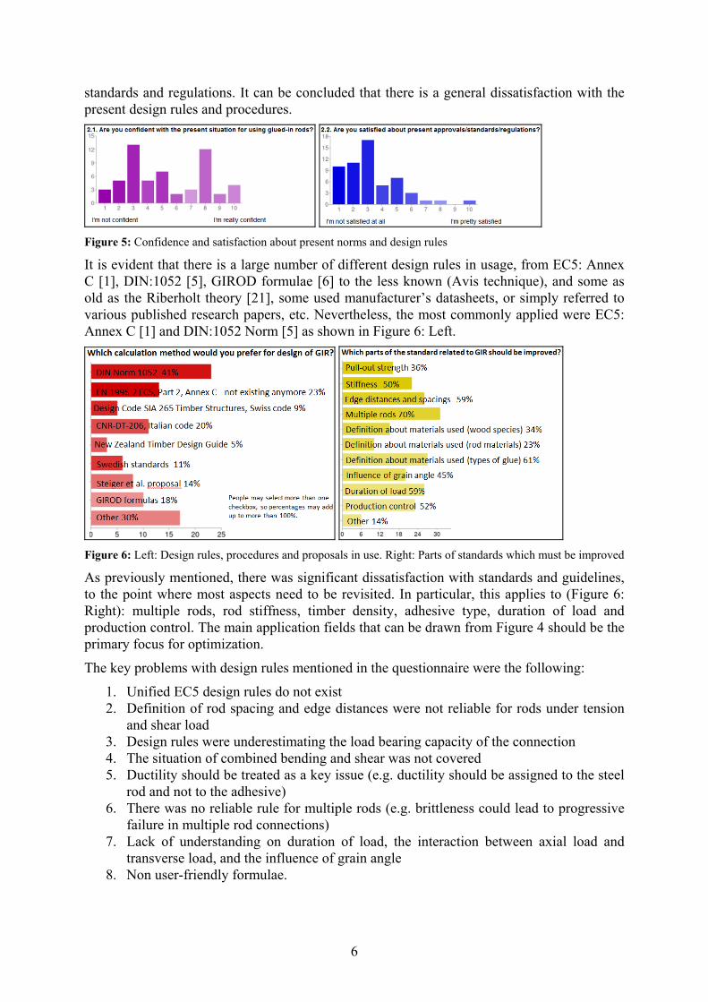
It is evident that there is a large number of different design rules in usage, from EC5: Annex C [1], DIN:1052 [5], GIROD formulae [6] to the less known (Avis technique), and some as old as the Riberholt theory [21], some used manufacturer’s datasheets, or simply referred to various published research papers, etc. Nevertheless, the most commonly applied were EC5: Annex C [1] and DIN:1052 Norm [5] as shown in Figure 6: Left.
Figure 6: Left: Design rules, procedures and proposals in use. Right: Parts of standards which must be improved
As previously mentioned, there was significant dissatisfaction with standards and guidelines, to the point where most aspects need to be revisited. In particular, this applies to (Figure 6: Right): multiple rods, rod stiffness, timber density, adhesive type, duration of load and production control. The main application fields that can be drawn from Figure 4 should be the primary focus for optimization.
The key problems with design rules mentioned in the questionnaire were the following:
1. Unified EC5 design rules do not exist 2. Definition of rod spacing and edge distances were not reliable for rods under tension
and shear load 3. Design rules were underestimating the load bearing capacity of the connection 4. The situation of combined bending and shear was not covered 5. Ductility should be treated as a key issue (e.g. ductility should be assigned to the steel
rod and not to the adhesive) 6. There was no reliable rule for multiple rods (e.g. brittleness could lead to progressive
failure in multiple rod connections) 7. Lack of understanding on duration of load, the interaction between axial load and
transverse load, and the influence of grain angle 8. Non user-friendly formulae.

7
In the third section of the questionnaire, information about investigation methods, past laboratory tests and materials used in laboratory tests was collected. The most common loading configurations for testing were pull-pull and pull-compression methods (Figure 7: Left). However, it was generally regarded that tests conducted on specimens in a pull-compression setup did not correspond to the practical application of glued-in rods, and pull-out strengths were influenced by local excessive compression stresses in the area of the load transfer (Tlustochowicz et al. 2011 [25]), even though this method is often used. Results for load-bearing capacity vary significantly when the different methods are applied, thus the need for a standardized test method, which is easy to use, was identified.
Figure 7: Left: Most common test methods. Middle: Distribution of performed tests. Right: Lack of information and proposals for further laboratory examinations
The results clearly show the lack of experimental investigation and the necessity to investigate problems such as duration of load, fatigue, and dynamic climatic tests. Many new experimental studies must be conducted in order to achieve load bearing capacities of such systems (Figure 7: Right) but for this standardized test-setups are necessary.
Other results from the online survey will be available online [4].
3 Introducing and comparing the design approaches Over the past twenty five years, despite many national research projects, European projects, European Actions and constant practical application of glued-in rods there is still no universal standard for the design thereof. The main problems are due to the many different approaches available in the literature for defining the behaviour of the adhesive connections. The question is what kind of approach (strength analyses, linear elastic fracture mechanics, non-linear fracture mechanics) is the best and which parameters (anchorage length, diameter of rod, load-to-grain angle, density of timber, moisture content...) must be considered in the final design rules.
An early design proposal was published in 1988 by Riberholt [21], who proposed an equation for the calculation of axially loaded pull-out strength for a single glued-in rod.
In the 1990’s a considerable amount of experimental work was done and different design methods were presented. Certain design methods were introduced into national design standards and in 1997 a proposal was implemented in a pre-version of the Eurocode 5: Part 2 [1]. When, in 1998, the European GIROD project started, the idea was to present a design method for glued-in rods. The project was divided into several tasks and working groups. It included studies on how the moisture content, duration of load, fatigue, effect of distances between the rods and edge distances, properties of the adhesives and other parameters affect the axial strength of the connection. A number of laboratory tests were conducted and
8
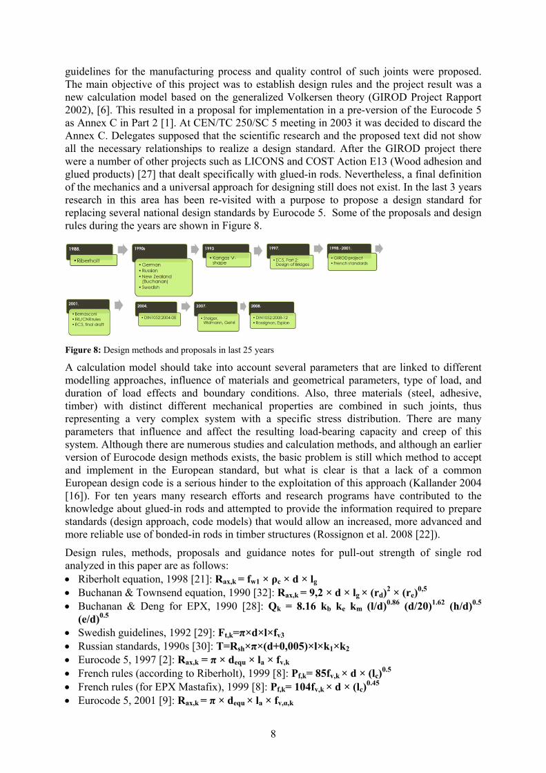
guidelines for the manufacturing process and quality control of such joints were proposed. The main objective of this project was to establish design rules and the project result was a new calculation model based on the generalized Volkersen theory (GIROD Project Rapport 2002), [6]. This resulted in a proposal for implementation in a pre-version of the Eurocode 5 as Annex C in Part 2 [1]. At CEN/TC 250/SC 5 meeting in 2003 it was decided to discard the Annex C. Delegates supposed that the scientific research and the proposed text did not show all the necessary relationships to realize a design standard. After the GIROD project there were a number of other projects such as LICONS and COST Action E13 (Wood adhesion and glued products) [27] that dealt specifically with glued-in rods. Nevertheless, a final definition of the mechanics and a universal approach for designing still does not exist. In the last 3 years research in this area has been re-visited with a purpose to propose a design standard for replacing several national design standards by Eurocode 5. Some of the proposals and design rules during the years are shown in Figure 8.
Figure 8: Design methods and proposals in last 25 years
A calculation model should take into account several parameters that are linked to different modelling approaches, influence of materials and geometrical parameters, type of load, and duration of load effects and boundary conditions. Also, three materials (steel, adhesive, timber) with distinct different mechanical properties are combined in such joints, thus representing a very complex system with a specific stress distribution. There are many parameters that influence and affect the resulting load-bearing capacity and creep of this system. Although there are numerous studies and calculation methods, and although an earlier version of Eurocode design methods exists, the basic problem is still which method to accept and implement in the European standard, but what is clear is that a lack of a common European design code is a serious hinder to the exploitation of this approach (Kallander 2004 [16]). For ten years many research efforts and research programs have contributed to the knowledge about glued-in rods and attempted to provide the information required to prepare standards (design approach, code models) that would allow an increased, more advanced and more reliable use of bonded-in rods in timber structures (Rossignon et al. 2008 [22]).
Design rules, methods, proposals and guidance notes for pull-out strength of single rod analyzed in this paper are as follows: Riberholt equation, 1998 [21]: Rax,k = fw1 × ρc × d × lg
Buchanan & Townsend equation, 1990 [32]: Rax,k = 9,2 × d × lg × (rd)2 × (re)0,5
Buchanan & Deng for EPX, 1990 [28]: Qk = 8.16 kb ke km (l/d)0.86 (d/20)1.62 (h/d)0.5 (e/d)0.5
Swedish guidelines, 1992 [29]: Ft,k=π×d×l×fv3 Russian standards, 1990s [30]: T=Rsh×π×(d+0,005)×l×k1×k2 Eurocode 5, 1997 [2]: Rax,k = π × dequ × la × fv,k French rules (according to Riberholt), 1999 [8]: Pf,k= 85fv,k × d × (lc)
0.5 French rules (for EPX Mastafix), 1999 [8]: Pf,k= 104fv,k × d × (lc)
0.45 Eurocode 5, 2001 [9]: Rax,k = π × dequ × la × fv,α,k

9
Feligioni proposal, 2002 [14]: Rax,k = π × lg × (fv,k× dequ + k ×(d+e)×e) Eurocode 5, 2003[1]: Rax,k = π × dequ × la × fax,k × (tanω)/ω GIROD equation, 2003 [6]: Pf = τf × π × d × l × (tanω/ω) Steiger, Widmann, Gehri proposal, 2007 [24]: Fax,mean=fv,0,mean×π×dh×l New Zealand Design Guide, 2007 [31]: Qk = 6.73 kb ke km (l/d)0.86 (d/20)1.62 (h/d)0.5
(e/d)0.5 Rossignon, Espion proposal, 2008 [22]: Fax,mean = π × dh x la × fv,0,mean DIN standard, 2010 [34], CNR DT 206/2007 [35]: Rax,d = π × d × lad × fk1,d Yeboah, 2013 [26]: Pu,mean,k = π × dh × lb × fv,mean
where: Rax,k/Qk/ Ft,k/ T/ Pf,k/ Pf = characteristic axial resistance [N], [kN] Fax,mean/ Pu,mean,k = mean axial resistance [N], [kN] l, lg/lad/la/lb/lc = glued-in length/effective anchorage length [mm] d = nominal diameter of rod [mm] dh/h = diameter of drilled hole [mm] dequ = equivalent diameter [mm] e = edge distance [mm] kb/km/ke/k1/k2 = bar type factor/moisture factor/epoxy factor/coeff. due to irregular stress
distribution/reduction factor taking into account irregular force distribution among multiple rods ω = stiffness ratio of the joint τf = local bondline shear strength [N/mm2] fv3/ fv,k/Rsh/ fax,k/ fk1,k = strength parameter/ch. shear strength of the wood/ design shear strength of
wood across the grain/ch. shear strength of the wood at the angle between the rod and grain direction/ ch. value of bond line strength [N/mm2]
fv,0,mean/ fv,mean = nominal shear strength of single axially loaded rod parallel to the grain [N/mm2] It can be concluded from past studies that pull-out capacity depends primarily on the interfacial layer and shear strength parameter which is influenced by mechanical and geometrical properties of three different materials. In general a simplified calculation model for axial loading could be summarized as:
Rax,k = π × d × l × fv,k
where: Rax,k = characteristic pull-out capacity, l = anchorage length, d = diameter, fv,k = shear strength parameter.
However, the mechanics of glued-in rods are complex, so an accepted simplification of the equation might result in uneconomic connection designs. If we take a closer look at the simplified equation there are numerous unanswered questions such as which diameter (diameter of rod, diameter of hole or equivalent diameter) and anchorage length (length of bonded rod or equivalent anchorage length) to use, which parameters must be included in the shear strength parameter (timber density, MC content of timber, MOE of timber, rod and adhesive, rod surface, rod material, type of adhesive, slenderness ratio, geometrical factors, etc.). If we take a look at present standards and proposals (Figure 9: Left) it can be easily concluded that existing calculation models differ significantly.
From the consensus of expert discussions, and verified by the results of the questionnaire it can be concluded that most common design rules like EC5, the former DIN [5], and SIA [7] are on the “safe side” while equations proposed in various scientific papers deliver much

10
higher values for the calculated pull-out capacity. Often designers are not satisfied about the
Figure 9: Left: Comparison of pull-out capacity [kN] between different design rules (EPX, l=200mm, ρ=370kg/m3, d=20mm, e=2mm). Blue lines represent characteristic values and red lines represent mean values. Right: Influence of glue-line thickness on capacity of rod
current state of the design standards because they were underestimating the possibility of a high load bearing capacity. On the other hand, some engineers were not confident with equations from scientific papers because effects like duration of load or influence of weather conditions were not taken into account. Figure 10 shows the characteristic pull-out capacity calculated on basis of different design rules whereby the diameter of rod and the anchorage length were varied. Problems occur when defining these two parameters in the equation. The diameter “d” is sometimes the diameter of rod (Riberholt [21], DIN [5]), the diameter of the drilled hole (Steiger et al. 2007 [24], Yeboah et al. 2013 [26]) or an equivalent diameter (EC5 [1], Feligioni et al. 2003 [14]). A similar problem applies for the definition of anchorage length.
Figure 10: Comparison of pull-out strength [kN] between different design rules when varying diameter of the rod (EPX, l=200mm, ρ=370kg/m3, e=2mm) and anchorage length (EPX, d=12mm, e=2mm d=20mm).
The glue-line thickness is considered only in some formulas. Some standards propose a maximum value of 2mm [5, 7, 8] but do not provide answers for glue-line thickness which may be less than this value. Differences and the influence on the calculated load capacity are shown in Figure 9: Right.
The former EC5 [1] equation, which was based on the GIROD project findings, includes a number of influencing parameters including fracture mechanics parameters, which was often characterized as non-user-friendly for engineers in practice. Also, the influence of wood density, which possibly cannot be neglected, is not included in the equation. For example, some studies (Riberholt 1988 [21], Feligioni et al. 2003 [14]) define wood density as one of the main parameters and its influence on load bearing capacity is shown in Figure 11.

11
Figure 11: Comparison of pull-out capacity [kN] between different design rules when varying the timber density (EPX, l=200mm, e=2mm, d=20mm)
Edge distances are also a crucial factor for load bearing capacity because too small an edge distance may cause splitting of wood (Serrano 2001 [23]). However, there are some differences in the proposals; more than 2d (Riberholt 1988 [21]), more than 2.3d (Steiger et al. 2007 [24]) but values for edge distances more than 2.5d are present in most design equations.
4 Conclusion Connections using glued-in rods have gained popularity as they provide solutions both for newly built structures and for strengthening existing structures. The aim of this paper was to analyse the present situation about the usage, the state of art in laboratory experiments and existing design methods or approaches. An online survey was employed to acquire an appreciation of the expert and user issues. The total number of 56 respondents appears sufficient to comprehend the present situation regarding glued-in rods, especially since 95% of the respondents confirmed they had a lot of experience with such applications. The performance of connections with glued-in rods is governed by very complex mechanisms and depends on a large number of geometrical, material and configuration parameters as well as their interaction. Previous standardization proposals, guidelines and other similar documents were compared and it can be concluded that there are unacceptable and possibly also unexplainable deviations and differences in the calculated values of the pull-out strength of single glued-in rods. However, despite a huge number of different design rules and approaches the basic principle is always similar. The calculation of the pull-out strength of single glued-in rod depends on several parameters, albeit with slight variations. These are the anchorage length, diameter of rod and a parameter that characterizes the shear strength of the rod/adhesive/timber interface. The problem is to define the shear strength parameter that should include the timber and the adhesive properties. There are still many outstanding questions regarding the load-carrying capacity of such applications. In addition to this, the issue is also the disagreement among the experts on the definition calculation equation. The implementation of a design rule in Eurocode 5 can only be achieved if some technical guideline is made before the implementation itself. Such a technical guideline must cover all applications and has to include all of the important parameters described in this paper, which will influence the load-carrying capacity. It is crucial that information is provided about production methods, production control, restrictions of use and recommendations of materials which can be used. There are many scientific papers published, experimental investigations performed and a number of experts involved in this topic already and there is probably no need for another comprehensive European project such as e.g. GIROD, unless some specific items are addressed such as complex load situations, duration of load, cyclic climatic conditions and fatigue. Having said this, there is indeed still some lack of experimental data

12
and knowledge on general joint behaviour. The way forward towards a generally accepted design approach for glued-in rods should be a better cooperation among the scientists, designers and producers. COST Actions in which experts have the opportunity to cooperate and also host researchers are a good way to solve some of the problems. For now “The sad story about bonded-in bolts” (Larsen 2011 [33]) is still reality but lately a significant effort have been made to turn it into, if not a happy saga, at least a less sad story. COST Actions FP1004 and FP1101, among others, are dealing with glued-in rods and hopefully, by the end of the Actions, technical guidelines will be accessible to designers, industry and scientists.
Acknowledgement The work described here was conducted in Holzforschung München (Germany) as a part of COST Action FP1004 ''Enhance mechanical properties of timber, engineered wood products and timber structures''. I would like to thank the representatives of COST office for their Short Term Scientific Mission grant, which contributed to a successful progress of this research. Also, I would like to thank the COST representatives from BIROD Core group (van de Kuilen, J-W, Serrano E., Broughton J., Widmann R., Harte A., Tomasi R., Hunger F.) for their professional assistance and representatives from both COST FP1004 and FP1101 Actions for a huge support.
REFERENCES
[1] European Committee for Standardization CEN (2003) prEN 1995-2 Eurocode 5-design of timber structures, Part 2: Bridges. Final Project Team draft (Stage 34). Document CEN/TC 250/SC 5: N 198. CEN, Brussels [2] European Committee for Standardization CEN (1997) Eurocode 5-design of timber structures, Part 2: Bridges ENV 1995-2:1997. CEN, Brussels [3] EN 1382-1999 Timber structures - Test methods - Withdrawal capacity of timber fasteners [4] Online survey: https://docs.google.com/spreadsheet/viewform?formkey=dFBlSnpURldQMXc2NXZiQ2VWdm4yVlE6MQ#gid=0, results: https://sites.google.com/site/bondedinrods/ [5] Deutsches Institut für Normung e.V. DIN (2008) Norm 1052:2008-12 Entwurf, Berechnung und Bemessung von Holzbauwerken. DIN, Berlin [6] GIROD - Glued in Rods for Timber Structures, SP Rapport 2002:26, Building Technology, Borås 2002 [7] Swiss Society of Engineers and Architects SIA (2003), Design Code SIA 265 Timber Structures. SIA, Zurich [8] Faye C, Le Magorou L, Morlier P, Surleau J (2004) French data concerning glued-in rods. Paper 37-7-10. In: Proceedings of 37th conference of CIB-W18, Edinburgh, Scotland [9] European Committee for Standardization CEN (2001) Eurocode 5-design of timber structures, Part 2: Bridges ENV 1995-2:2001. CEN, Brussels [10] Bainbridge RJ, Mettem CJ, Harvey K, Ansell MP (2000) Fatigue performance of bonded-in rods in glulam, using three adhesive types. Paper 33-7-12. In: Proceedings of 33rd conference of CIB-W18, Delft, The Netherlands [11] Blass HJ, Laskewitz B (1999) Effect of spacing and edge distance on the axial strength of glued-in rods. Paper 32-7-12. In: Proceedings of 32nd conference of CIB-W18, Graz, Austria [12] Broughton JG, Hutchinson AR (2001a) Pull-out behaviour of steel rods bonded into timber. Mater Struct J 34(2): 100–109 [13] Broughton JG, Hutchinson AR (2001b) Adhesive systems for structural connections in timber. Int J Adhes Adhes 21(3):177–186 [14] Feligioni L, Lavisci P, Duchanois G, De Ciechi M, Spinelli P (2003) Influence of glue rheology and joints thickness on the strength of bonded-in rods. Holz als Roh un Werkstoff 61, P281-287 [15] Harvey K, Ansell MP (2000) Improved timber connections using bonded-in GFRP rods. Proceedings of the 6th WCTE, Whistler Resort, Canada [16] Kallander B (2004) Glued in rods in load bearing timber structures—status regarding European standards for test procedures. Paper 37-7-9. In: Proceedings of 37th conference of CIB-W18, Edinburgh, Scotland [17] Kangas J, Kevarinmaki A (2001) Quality control of connections based on V-shaped glued-in steel rods. Paper 34-7-4. In: Proceedings of 34th conference of CIB-W18, Venice, Italy in timber engineering, Lahti, Finland [18] Otero Chans D, Cimadevila JE, Gutierrez EM (2008) Glued joints in hardwood timber. Int J Adhes Adhes 28(8):457–463 [19] Rajčić V, Bjelanović A, Rak M (2006) Comparison of the pull-out strength of steel bars glued in glulam elements obtained experimentaly and numerically. Proceedings of the CIBW18 [20] Rajčić V, Bjelanović A, Rak M (2004) Experimental tests of the glued bolt using threaded steel bars, Proceeding of the WCTE 2004, Lahti page 317-320[21] Riberholt H (1988) Glued bolts in glulam—proposals for CIB code. Paper 21-7-2. In: Proceedings of the 21st conference of CIB-W18, Parksville, Canada [22] Rossignon A, Espion B (2008) Experimental assessment of the pull-out strength of single rods bonded in glulam parallel to the grain. Holz als Roh- und Werkstoff 66(6): 419–432

13
[23] Serrano E (2001) Glued-in rods for timber structures—a 3D model and finite element parameter studies. Int J Adhes Adhes 21(2):115–127 [24] Steiger R, Gehri E, Widmann R (2007) Pull-out strength of axially loaded steel rods bonded in glulam parallel to the grain. Mater Struct J 40(1):69–78 [25] Tlustochowicz G, Serrano E, Steiger R (2011) State-of.the-art review on timber connections with glued-in steel rods. Material and Structures 44:997-1020 [26] Yeboah D, Taylor S, McPolin D, Gilfillan J (2013) Pull-out behaviour of axially loaded Basalt Fibre Reinforced Polymer (BFRP) rods bonded parallel to the grain of glulam elements. Construction and Building Materials, Volume 38, Pages 962–969 [27] COST Action E13 Wood Adhesion and Glued Products, Working Group 2: Glued Wood Products (2002) State of the Art – Report. Editors: Carl-Johan Johansson, Tony Pizzi, Marc Van Leemput [28] Buchanon AH, Deng XJ (1996) Strength of steel rods in glulam timber. In: Proceedings of international wood engineering conference, New Orleans, LA, USA [29] Carling O (1992) Dimensionering av trakonstruktioner. AB Svensk Byggtjanst och Tratek, Stockholm, Sweden [30] Turkovsky SB (1989) Designing of wood glued structures joint on glued-in bars. Paper 22-7-13. In: Proceedings of the 22nd conference of CIB-W18, Berlin, German Democratic Republic [31] New Zealand Design Guide (2007), Timber Industry Federation, NZW14085 SC [32] Townsend PK (1990) Steel Dowels Epoxy Bonded in Glue Laminated Timber. Res. Report 90-11, Christchurch [33] Larsen HJ (2011) The sad story of glued-in bolts in Eurocode 5. Essay 4.3, CIB-W18, A review of meeting 1-43 [34] DIN EN1995-1-1/NA:2010-12 (GERMAN NATIONAL ANNEX TO EC5) [35] CNR-DT 206/2007, Istruzioni per la Protegattazione, l’Esecuzione ed il Controllo delle Strutture di Legno [36] Tomasi R, Parisi MA, Piazza M (2009) Ductile design of glued-laminated timber beams. Practical Periodical and structural design and construction, ASCE, p:113-122