Technical Information - Axial Piston Motors - HMC Hydraulics
Upload
khangminh22Category
view
5download
0
Karlstads universitet 651 88 Karlstad Tfn 054-700 10 00 Fax 054-700 14 60
[email protected] www.kau.se
Faculty of Technology and Science
Department of Mechanical and Materials Engineering
Zhenkun Yang
Alternatives to hard chromium
plating on piston rods
Degree Project of 30 credit points
Master of Science in Engineering, Mechanical Engineering
Date/Term: Spring 2011
Supervisor: Pavel Krakhmalev
Examiner: Jens Bergström

Abstract
As a main part of hydraulic cylinder, the piston rod is used in tough surrounding and
corrosive condition; consequently a high quality protecting layer is essential.
Currently EHC, electroplating hard chromium (hard chrome) is a widespread method
for piston rod due to powerful performance and low cost. Unfortunately the plating
process contains hexavalent chromium (Cr6+) which is toxic and carcinogenic; perhaps
it will be prohibited in the nearing future. Therefore it is crucial to seeking alternatives
to hard chrome for piston rod manufacturer.
Through extensive searching for alternatives to hard chrome, the competitors like
HVOF, electroplating tungsten plating and stainless steel linear were studied in the
present work. Since microhardness and corrosion resistance are top priorities, after
comparison perhaps Cr3C2-NiCr20% HVOF is the most promising technique.
Distinct pretreatments Cr3C2-NiCr coatings were compared with hard chrome in
pendulum impact test, hardness test and acetic acid salt spray (AASS) test. The results
indicate that hard chrome show higher toughness more than 40% compare with HVOF,
the microhardness of HVOF is higher than hard chrome, mean value 1784 Vs. 1244
HV and both coatings have excellent bonding strength. After 40 hours in AASS test,
the hard chrome was rated No. 10, however the HVOF just No. 6.

Contents
1. Introduction……………………………………………………………….... 1
1.1 Hydraulic cylinders and work conditions…………………………....... 1
1.2 Criterion of piston rod coatings……………………………………....... 1
1.3 Hard chrome coating……………………………………………………. 3
1.4 Alternatives to hard chrome……………………………………………. 6
1.4.1 HVOF and coating material C3Cr2-NiCr………………………… 7
1.4.2 Other competitors………………………………………………….. 15
1.5 Aims of study……………………………………………………………...... 20
2. Test method……………………………………………………………......... 21
2.1 Methods to investigate mechanical properties of coatings……………. 21
2.2 Coating impact test use a pendulum machine…………………………. 22
2.3 Expansion for stainless liner……………………………………………. 24
3. Experimental procedure…………………………………………………… 25
3.1 Coating impact test……………………………………………………… 25
3.2 Microhardness test………………………………………………………. 28
3.3 Corrosion test……………………………………………………………. 32
4. Results……………………………………………………………………..... 30
4.1 HVOF and hard chrome coatings……………………………………… 30
4.1.1 Various energy degree of indentations……………………………. 30
4.1.2 Coating cross sections of indentations……………………………. 30
4.1.3 Crack patterns…………………………………………………....... 32
4.1.4 Hardness test……………………………………………………...... 34
4.1.5 Corrosion resistance……………………………………………….. 34
4.2 Stainlessliner…………………………………………………………….. 35
5. Discussion………………………………………………………………........ 38
5.1 HVOF compare to hard chrome coatings………………………............ 38
5.1.1 Coating characterization………………………………………...... 38
5.1.2 Hardness profile…………………………………………………… 39
5.1.3 Results of pendulum impact test………………………………….. 41
5.1.4 Corrosion resistance in AASS…………………………………....... 48
5.2 Stainless linear………………………………………………………....... 49
6. Conclusions…………………………………………………………………. 50
Acknowledgement……………………………………………………………… 51
References………………………………………………………………………. 52
1
1. Introduction
Hard chrome coatings are widely used for the manufacture of the piston rods in
hydraulic cylinders at present due to excellent characteristics. However, the plating
process is toxic and carcinogenic; it probably will be prohibited in the near future.
Therefore, to keep an advantageous position among competitors, it is essential for
piston rod manufacturers to find out alternatives to the hard chrome.
1.1 Hydraulic cylinders and work conditions
Hydraulic cylinder is a mechanical component that uses liquid under pressure to apply
a linear force. Typically, a hydraulic cylinder consists of pressurized liquid, cylinder
barrel, piston and piston rod. Piston rod is a main part of hydraulic cylinder, piston
rod is stiffly connected to the piston, which moves forth and back in cylinder barrel
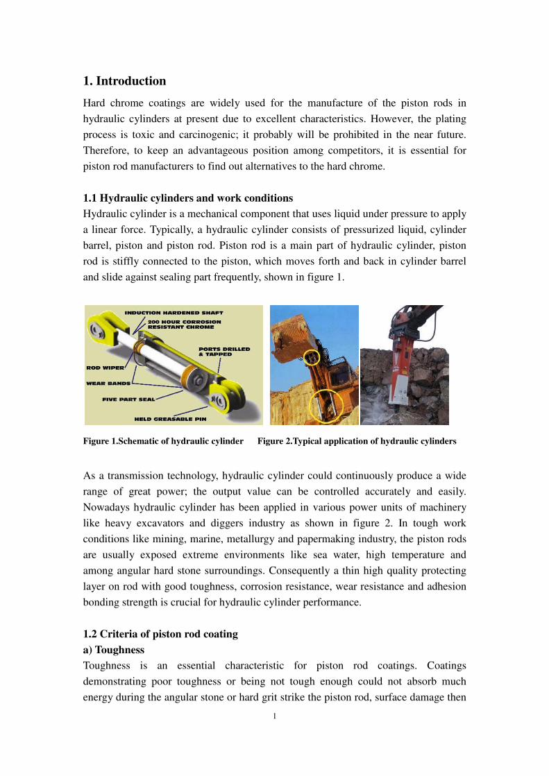
and slide against sealing part frequently, shown in figure 1.
Figure 1.Schematic of hydraulic cylinder Figure 2.Typical application of hydraulic cylinders
As a transmission technology, hydraulic cylinder could continuously produce a wide
range of great power; the output value can be controlled accurately and easily.
Nowadays hydraulic cylinder has been applied in various power units of machinery
like heavy excavators and diggers industry as shown in figure 2. In tough work
conditions like mining, marine, metallurgy and papermaking industry, the piston rods
are usually exposed extreme environments like sea water, high temperature and
among angular hard stone surroundings. Consequently a thin high quality protecting
layer on rod with good toughness, corrosion resistance, wear resistance and adhesion
bonding strength is crucial for hydraulic cylinder performance.
1.2 Criteria of piston rod coating
a) Toughness
Toughness is an essential characteristic for piston rod coatings. Coatings
demonstrating poor toughness or being not tough enough could not absorb much
energy during the angular stone or hard grit strike the piston rod, surface damage then

2
happens easily, the hydraulic cylinder will in turn fail to work immediately due to
coating delamination or flaking.
Impact test is a dynamic test in which a selected specimen is usually struck and
broken by a swing pendulum. The most common tests of this type are Charpy V-notch
test and Izod test which are described in ASTM E23. The principle difference
between two tests is the manner of the specimen is fixed. A typical pendulum
machine is shown in figure 3.
Figure 3.impact test and pendulum machine Figure 4.a salt spray cabinet and rod sample
b) Corrosion resistance
Due to poor working environment, the corrosion resistance is very important for
hydraulic cylinder piston rod coating. Salt spray test is a conventional standardized
test method used to check corrosion resistance of hydraulic cylinder piston rod
coating; it is an accelerated corrosion resistance test and the appearance of corrosion
products is evaluated after a period of time.
The apparatus for testing as shown in figure 4 consist of a closed testing chamber,
where a salted solution, mainly a solution of sodium chloride, is sprayed by means of
a nozzle. This produces a corrosive environment in the chamber and thus, parts in it
are attacked under this severe corroding atmosphere.
Table 1.Protection rating vs. area of defect from ASTM B 537-70
Area of defect (%) 0 0-0.1 0.1-0.25 0.25-0.5 0.5-1.0
Rating 10 9 8 7 6
Area of defect (%) 1.0-2.5 2.5-5 5-10 10-25 25-50
Rating 5 4 3 2 1

3
Tests performed with a solution of NaCl are known as NSS (neutral salt spray).
Results are generally evaluated as testing hours in NSS without appearance of
corrosion products. Other solutions are ASS (acetic acid test) and CASS (acetic acid
with copper chloride test). Chamber construction, testing procedure and testing
parameters are standardized under national and international standards, such as
ASTM B117, DIN 50021, and ISO 9227. After test duration, sample could be rated
according to rusted surface area using reference standard as shown in table 1. [1]
c) Wear resistance
As a power transmission unit, piston rod needs to move forth and back frequently, at
the same time wear happens during coating surface slide against the cylinder sealing.
Hence wear resistance is also an important requirement for piston rod lifetime.
Surface hardness is the key parameter for wear resistance. Besides toughness,
corrosion resistance and wear resistance, according to various industry standards and
customers’ requirements, other criterion of piston rod coatings are listed in the table2.
Table 2.Typical values for piston rod coating
Characteristics Typical values of piston rod coatings
Hardness > 900 HV 0.1, > 789 HV 0.5
Corrosion resistance AASS 40 hours rating number 10
NSS 96 hours rating number 10
Surface roughness R a 0.2; R max 1.6
Adhesion > 10,000 psi (ASTM C633), no flaking after test
Crack tightness < 800/cm
Surface finish Defects are not permitted, must be glossy
1.3 Hard chrome coating
At present time, the most common process has been used for piston rod coating is
hard chromium plating, also referred simply as hard chrome or engineered chrome.
Hard chrome has been used for piston rod coating since 1940, involves the reduction
of metallic ions at the surface of the substrate, which is made the cathode in an
electrolytic cell.

4
Figure 5.Schematic of hard chromium plating process [3]
The traditional solution used for industrial hard chrome plating is made up of about
250 g/l of CrO3 and about 2.5 g/l of SO4-. In solution, the chrome exists as chromic
acid, known as hexavalent chromium. A high current is used, in part to stabilize a thin
layer of chromium (+2) at the surface of the plated work [2]. Hard chrome process for
piston rod includes degreasing, masking, and cleaning prior to plating. Following the
plating step, the piston rods are removed from the bath, masking is released from the
rods, the piston rods are baked for brittle relief, finishing such as grinding, lapping,
and polishing is completed. The process is illustrated schematically in figure 5. [3]
a) Hard chrome coating properties
Compare to conventional coating methods, hard chrome coating is powerful,
inexpensive, well understood and easily performed. Typically the thickness of hard
chrome coating is about 10~500µm, and the microstructure is extremely fine,
containing a very small amount of oxide incursions and microcracks.
Figure 6.SEM micrographs of hard chrome coating cross-sections:
A. small vertical microcracks B. excellent interface with grit blasted substrate [4]

5
From previous study, the coatings are characterized by numerous small vertical
microcracks as shown in figure 6A; All of the hard chrome coatings possess an
excellent interface with substrate almost complete free from defects as shown in
figure 6B [4].
b) Why replace hard chrome
Chrome plating has been used as a fundamental coating in a wide range of industries:
aerospace, heavy equipment, automotive, papermaking, and others. Unfortunately,
hard chrome plating is toxic and carcinogenic. The accepted emission level for
hexavalent chromium Cr6+ varies greatly in different parts of the world and become to
hard chrome coatings more and more restricted.
“In the USA, the Occupational Safety and Health Administration adopted a
permissible exposure limit of five micrograms of Cr6+ per cubic meter of air (5µg/m3)
as an 8-hour time weighted average. Many other countries still have a limit of
50µg/m3, including Japan, Germany, France the United Kingdom and South Africa.
Sweden has a limit of 20µg/m3 and the most restrictive limit among EU member
states is Denmark, with the same limit as the USA of 5µg/m3.” [5]
There are two main factors limit the application of hard chrome: the first and vital
reason is in the manufacture stage, the hard chrome plating bath contains Cr6+, which
induce adverse health and environmental effects. “Chromic acid means lots of
hexavalent chrome and the process is quite inefficient, with most of the current going
to hydrolyze the water, producing copious amounts of hydrogen and oxygen bubbles.
When they raise to the surface these bubbles burst, throwing a fine mist of hexavalent
chrome into the air [5].” Cr6+ mist air emissions must be trapped in scrubbers,
contaminated waste water must be treated before release to public treatment plants or
water courses and solid wastes must be disposed of as hazardous waste. The heavy
metal effluents lead to high disposal cost.
Another disadvantage is attributable to the long life cycles of hard chromium plated
rod surfaces. When used with a hydraulic rod sealing system shown in figure 7 (A),
the rod surface will either become smoother or be prone to minute scratching [6]. In
the dynamic seal tests, standard hard chrome plated rods from different sources were
used. These rods differed from each other in terms of thickness of the hard chrome
plating as well as surface roughness and structure, such as grinding pattern. Figure 7
(B) shows the surface values of typical hard chrome plated rods generally available on
the market or produced by customers. Consequently, the sealing part could be
scratched by the hard chrome surface and the hydraulic cylinder will be completely
failure. The search for alternative coatings is also being driven for reduction of seal

6
wear and longer life of hydraulic cylinders.
Fig 7.A) Schematic sealing system B) Hard chrome rod with ground and honed pattern [6]
Additionally, there are more demands on the hydraulic cylinders, including: improve
the corrosion resistance, reduce fatigue loss and lower overall cost.
1.4 Alternatives to hard chrome
When replacing hard chrome coating, in fact often the total system (substrate +
coating + manufacturing method) is designed for the purpose of using the coating that
must be replaced. Therefore one must ask a number of questions to ensure that the
replacement makes good engineering and economic sense: what are the hard chrome
coating functions and what properties does the replacement really need? Does the new
coating requires a change in substrate material or component design? For example, a
new PVD coating may requires a more temperature tolerant substrate to be effective.
What is the true cost of the process, old and new? Including development, source
materials, coating, and finishing, not just the coating part of it. [7]
Through extensive searching for surface treatment methods, there are a large number
of potential process substitutions for hard chrome including thermal spray, electro and
electroless plate, laser and weld coating, vacuum coating, heat treatment coating as
shown in table 3.
Among the various alternatives to hard chrome, actually some coating methods have
been used for hydraulic cylinder piston rods successfully by piston rods manufacturer:
HVOF (high velocity oxygen fuel), electroless tungsten nick alloy plating and plasma
spraying. Additionally, as a replacement for hard chrome, stainless liner is a novel
promising technique needs to be learned further.

7
Table 3.Alternatives to hard chrome that maybe applicable to hydraulic cylinders
Hard chrome alternatives
Thermal spray HVOF(high velocity oxygen fuel),
plasma flame and arc spray, cold(dynamic spray)
Electro and
electroless plate
Electro deposition(Ni-W-SiC, Ni-W-B, Fe-Ni-W )
Electroless Nickel plating
Laser and weld
Coating
Laser cladding, weld cladding, seam welding
Impact welding (explosive bonding, electro spark
deposition)
Heat treatment
Coating
Nitriding, carburizing, Metallurgical rolling bonding,
Stainless liner
Vacuum coating Physical vapor deposition (PVD)
Chemical vapor deposition (CVD)
1.4.1 HVOF and coating material Cr3C2-NiCr
Due to outstanding characteristics, HVOF coating has been widely used in aerospace,
automotive, power generation, transportation, petro chemical metal process, paper
industry and heavy equipments.
a) Thermal spraying coatings and HVOF spraying process
Thermal spraying is one of classic fusion process for surface coating. The coating
material is melted at a certain distance from the substrate, and projected it towards in
fine molten droplet. They are fed in powder or wire form, heated to a molten or semi
molten state and accelerated towards substrates in the form of micrometer-size
particles as shown in figure 8. [8]
Fig 8.Schematic sprayed particle and compressive stress within the surface of the substrate [8]
8
Various types of substrate materials could be used for thermal spraying and substrate
temperatures remain typically below 200 oC. Cleaning and grit blasting are important
for substrate preparation. This provides a more chemically and physically active
surface needed for good bonding. The surface area is increased, which will in turn
increase the coating bond strength. The rough surface profile will promote mechanical
bonding.
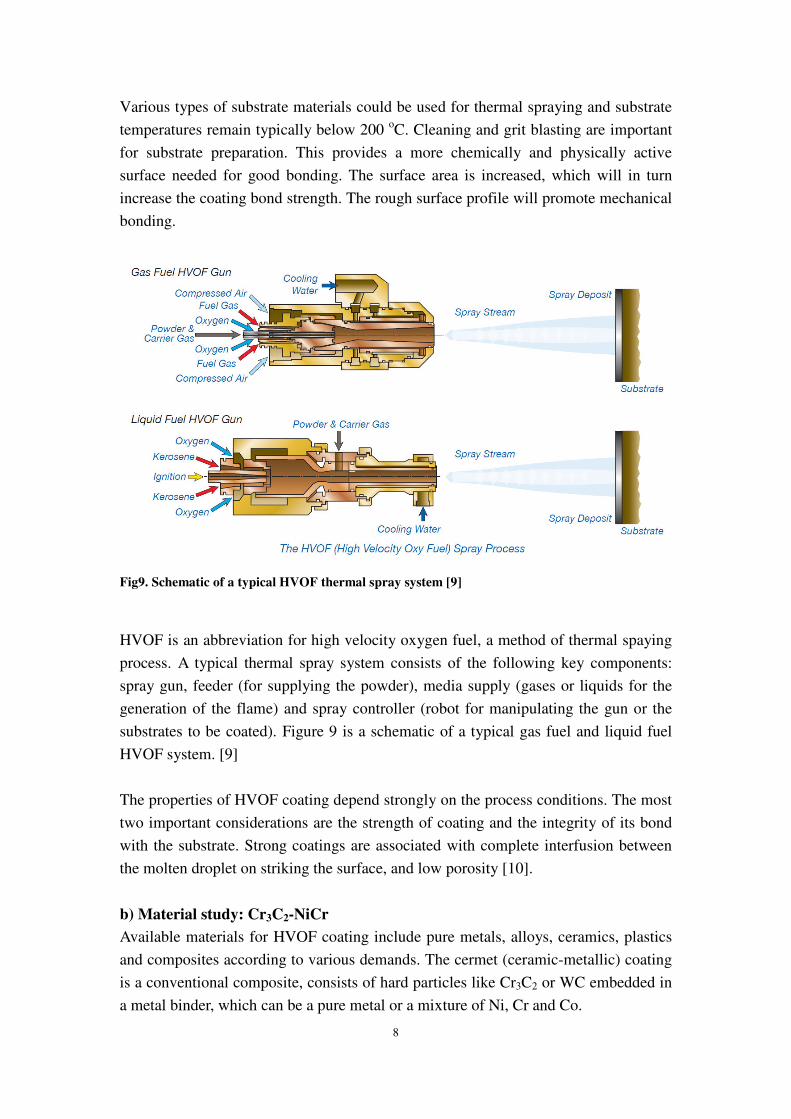
Fig9. Schematic of a typical HVOF thermal spray system [9]
HVOF is an abbreviation for high velocity oxygen fuel, a method of thermal spaying
process. A typical thermal spray system consists of the following key components:
spray gun, feeder (for supplying the powder), media supply (gases or liquids for the
generation of the flame) and spray controller (robot for manipulating the gun or the
substrates to be coated). Figure 9 is a schematic of a typical gas fuel and liquid fuel
HVOF system. [9]
The properties of HVOF coating depend strongly on the process conditions. The most
two important considerations are the strength of coating and the integrity of its bond
with the substrate. Strong coatings are associated with complete interfusion between
the molten droplet on striking the surface, and low porosity [10].
b) Material study: Cr3C2-NiCr
Available materials for HVOF coating include pure metals, alloys, ceramics, plastics
and composites according to various demands. The cermet (ceramic-metallic) coating
is a conventional composite, consists of hard particles like Cr3C2 or WC embedded in
a metal binder, which can be a pure metal or a mixture of Ni, Cr and Co.

9
Table4. Wear and corrosion resistance as priority
A) HVOF coating materials sorted by wear resistance
Product Composition
Diamalloy 2003/4/5/6
Sulzer Metco5812/5810 WC-12~17%Co alloy
WOKA 360/365/370
Sulzer Metco5843/7,5803 WC-Co-Cr alloy
WOKA 710/720/730
Diamalloy 3004/5/7
Sulzer Metco 5255
Cr3C2-20/20/25%Ni Cr
Cr3C2-25/20/7%Ni Cr
Cr3C2-50%Ni Cr
AMDRY 4532/4535 Ni-Cr alloy
B) HVOF coating materials sorted by corrosion resistance
Product Composition
Diamalloy 3001/3002NS
AMDRY 4532/4535
Co-Mo alloy
Ni-Cr alloy
WOKA 360/365/370
Sulzer Metco5843/7,5803 WC-Co-Cr alloy
WOKA 710/720/730
Diamalloy 3004/5/7
Sulzer Metco5812/5810
Cr3C2-20/20/25%Ni Cr
Cr3C2-25/20/7%Ni Cr
WC-12~17%Co alloy
Carbides based cermets coatings are widely used against wear and corrosion in gas
and oil industries. Their wear resistance is three to five times that of electroplated
chromium, and their manufacturing costs are low. It was pointed out that the wear
behavior of coatings depends on the microstructure and the volume fraction of
carbides being preserved during the deposition process [11]. Several studies and
reviews have already appeared focusing on materials for thermal spraying of wear
resistant coatings. Carbides, oxides and cermets have received the majority of interest;
in particular, nickel–chromium based coatings containing chromium carbide particle
dispersions (hard phase), due to their excellent oxidation resistance and are candidates

10
for continuous service in the range of 550–8158C, with a maximum of 9008C for
discontinuous service. [12]
Table 4 shows some HVOF coating materials have been used successfully in surface
applications: A) wear resistance and B) corrosion resistance as priority. In order to
achieve satisfactory properties, cermet Cr3C2-NiCr coating could be a preferable
alternative to hard chrome.
The SEM image of sintered Woka 720 and morphology of Cr3C2-NiCr powders was
shown in figure 10. Cr3C2-NiCr powder used in HVOF method, generally sinter
crushed, the weight proportion of NiCr is from 7~50% according to the variation of
requirements. The powder was in angular shape with angular carbide particles from
10 to 55µm aggregated densely in Ni-Cr alloy matrix. [13]
Fig 10.Woka 720 agglomerated sintered powder, morphology of Cr3C2-NiCr powder [13]
The powder was commercially available and hardness could reach 1200 Hv,
information about conventional used Cr3C2-NiCr powders were shown in table 5.
Table5. Information about Cr3C2-NiCr powder (provide by Sulzer Metco)
Provider Composition
(Wt %)
Nominal grain size
Distribution (µm)
Carbide size
(µm)
WOKA 720,
Sulzer-Metco
75Cr3C2–
25(80Ni20Cr) −55/+10 5-10
Diamalloy 3007,
Sulzer-Metco
80Cr3C2–
20(80Ni20Cr) −45/+5 5-10
In the HVOF spraying process, melted and semi-melted particles (the particles are a
mixture of Cr3C2 in a NiCr matrix) were observed for in the cermet coating. The cross

11
section structure of the Cr3C2-NiCr coating which consists of: (A) Nanocrystalline
NiCr matrix; (B) carbides; (C) low Cr2O3 content; (D) pores; (E) small cracks as show
in figure 11. The main phenomena, which occur during spraying, are the thermal
decomposition of the chromium carbide and the carbide reactions with the metallic
binder. In the Cr3C2–NiCr coating, besides Cr3C2 particles retained from the starting
powder, the carbides, Cr7C3 and Cr23C6, were also presented. Among three carbides
present in the Cr3C2–NiCr coating, Cr3C2 retained from the starting powders plays the
most important role in determining wear performance of the coating. [14]
Fig 11.The consist of HVOF Cr3C2-NiCr microstructure, SEM cross section image [14]
c) HVOF Cr3C2-NiCr coating characteristics
Cr3C2-NiCr coating deposited by HVOF process has been studied by various
researchers and the wear performance is compared with hard chrome coating. In
general, there is no direct correlation between hardness, coefficient of friction and
wear resistance, however high hardness, low coefficient of friction often are taken as
an indicator of good abrasive wear resistance.
Figure 12 shows microhardness values (HV 0.3) of hard chrome and hard chrome
alternatives like Cr3C2-NiCr coating that have been investigated and published:
Hard chrome: 800~1000.
Cr3C2-NiCr50%: 900, Cr3C2-NiCr20%: 1100, Cr3C2-NiCr25% 750~ 1300. [15]

12
Fig12. Microhardness values as alternatives to hard chrome (published in the literature) [15]
Table6. The conditions of dry abrasive wear test [16]
Normal load (N) 45
Wheel (rpm) 201
Total sliding distance (m) 8657
Total duration of the test (min) 60
Wheel surface speed (m s-1) 2.4
Abrasive material Silica
Particle size range (µm) 150-300
Feed rate (kg/h) 19.32
In abrasive wear test, the coated samples were tested using dry abrasive rubber wheel.
The coated sample was mounted in the sample holder and was pressed against the rim
of the rubber wheel as shown in figure 13 [16]. The dry silica sand fell freely between
the wheel and the coated surface. The test conditions followed are given in table 6.

13
Fig13. Schematic diagram of abrasive test rig and slurry abrasive wear testing [16]
The results of carbide-based thermally sprayed coatings comparing to the hard
chrome plating have been shown in figure 14. The wear test on the hard chrome
plating had to be discontinued after 20 min as the plating got completely peeled off
the substrate at the test region under identical test conditions, indicating the poor
adhesion of the plating to the substrate. HVOF Cr3C2-NiCr coatings have much better
abrasive wear resistance compared to the hard chrome plating. [17]
Fig14. The loss volume of thermal sprayed coatings vs. hard chrome plating in abrasive test [17]
In slurry abrasive testing, the material surface was exposed to hard particles moving
along and forced against it; hard particles are mixed in a liquid, so slurry could be

14
pumped in the test as shown in figure of 14. Miller Number is an index of the relative
abrasion of slurries. The wear damage on the standard wear block is worse as the
Miller Number gets higher. The SAR (slurry abrasion response) Number is an index
of relative abrasion response of materials as tested in any particular slurry of interest.
The SAR Number is a generalized form of the Miller Number. [18]
Experience has shown that slurries with a Miller or SAR Number of 50 or lower can
be pumped with minor abrasive damage to the system. It was clearly demonstrated in
figure 15 [19]; the SAR number of HVOF coatings like WC-Co and Cr3C2-NiCr are
below 50, show better performance than hard chrome coating (approximately 100) in
slurry abrasive testing.
Fig15. The SAR number of different coatings and bulk materials as a function of hardness [19]
Hard chrome and various thermal spray coatings on different substrates have been
investigated in salt spray fog testing, the results are shown in figure 16 [20]. On mild
steel substrate, hard chrome coating presents excellent corrosion resistance.
Comparing to the other alternatives, HVOF WC-Co-Cr and Cr3C2-NiCr coatings
indicate relatively good corrosion protection.

15
Fig16. Percentages area of coupons corroded after exposed to salt fog for 30 days [20]
Therefore, coatings produced using HVOF have advantages comparing to other hard
chrome alternatives that include: optimum hardness and toughness, excellent wear
resistance and good corrosion resistance. After preliminary discussion, taking into
account of the manufacturer and customer’s opinions, HVOF and cermet powder
Cr3C2-NiCr are probably the most promising material among the competitors.
1.4.2 Other competitors
Plenty of investigations have been done for replacement of hard chrome; actually
some alternatives have been approved for producing piston rod coatings on hydraulic
cylinder.
a) Nickel based electroplating and electroless plating coatings
Nickel based coatings are applied by electroplating or electroless plating techniques.
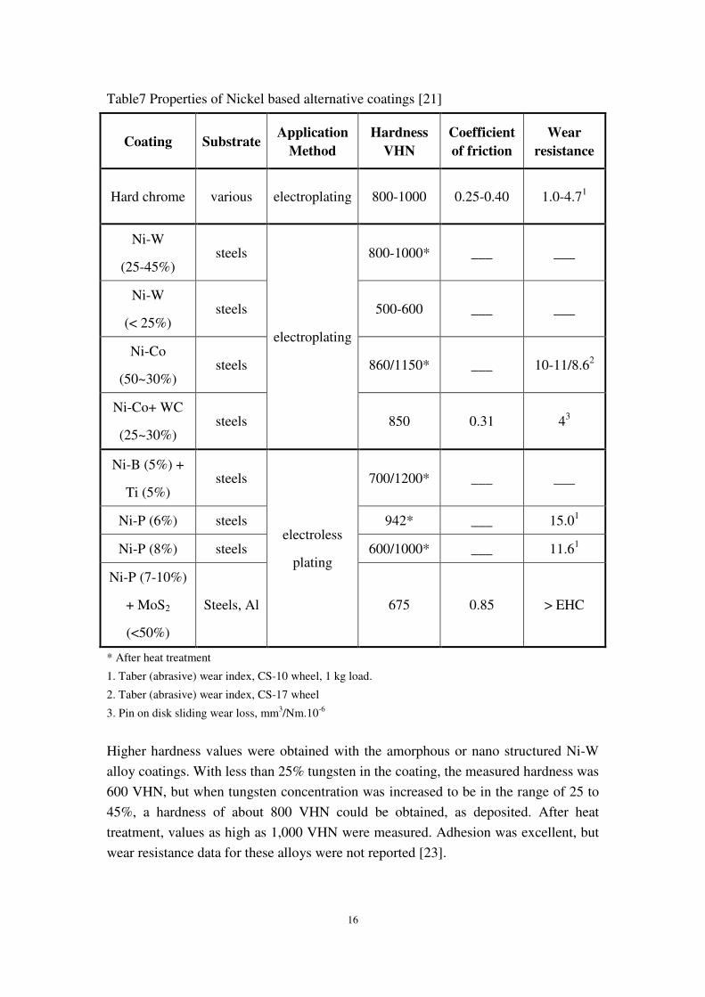
Examples of these alloys, mixtures and composites coatings are listed in table 7, with
proved hardness, coefficient of friction and wear properties. Hard chrome also is
given for comparison [21].
Electroplating is a plating process that uses electrical current to reduce cations of a
desired material from a solution and coat a conductive object with a thin layer of
metal as shown in figure 17. Electroplated nickel itself is not a very hard material,
with a VHN of about 230. However, coatings with a nanocrystalline structure have
exhibited higher microhardness values. To obtain higher hardness values, alloying
also has been investigated, especially with tungsten additions.
16
Table7 Properties of Nickel based alternative coatings [21]
Coating Substrate Application
Method
Hardness
VHN
Coefficient
of friction
Wear
resistance
Hard chrome various electroplating 800-1000 0.25-0.40 1.0-4.71
Ni-W
(25-45%) steels
electroplating
800-1000* ___ ___
Ni-W
(< 25%) steels 500-600 ___ ___
Ni-Co
(50~30%) steels 860/1150* ___ 10-11/8.62
Ni-Co+ WC
(25~30%) steels 850 0.31 43
Ni-B (5%) +
Ti (5%) steels
electroless
plating
700/1200* ___ ___
Ni-P (6%) steels 942* ___ 15.01
Ni-P (8%) steels 600/1000* ___ 11.61
Ni-P (7-10%)
+ MoS2
(<50%)
Steels, Al 675 0.85 > EHC
* After heat treatment
1. Taber (abrasive) wear index, CS-10 wheel, 1 kg load.
2. Taber (abrasive) wear index, CS-17 wheel
3. Pin on disk sliding wear loss, mm3/Nm.10-6
Higher hardness values were obtained with the amorphous or nano structured Ni-W
alloy coatings. With less than 25% tungsten in the coating, the measured hardness was
600 VHN, but when tungsten concentration was increased to be in the range of 25 to
45%, a hardness of about 800 VHN could be obtained, as deposited. After heat
treatment, values as high as 1,000 VHN were measured. Adhesion was excellent, but
wear resistance data for these alloys were not reported [23].

Fig 17.Sketch of electroplating
The addition of nanometer
electroplated matrix has been successful
according to the data listed in Table
the coefficient of friction and sliding w
baseline EHC [24]. For electroless plating, s
in Table 7 for the most common Ni
cobalt or tungsten. The as
range of 500 to 800 VHN. When heat treated,
harder (900 and1200 VHN) because of a precipitation hardening
hardness depends on the composition,
incorporated (i.e., B or P), and the type of heat treatment.
The Nanofilm has produced hydraulic piston rods with
The coating processes for different coating materials are similar in that they are
electrolytic and deposit a coating of nickel and tungsten with minor percentages of
boron or silicon carbide to enhance the coating properties. The nickel
alloy electroplating processes are available as alternatives to hard chrome.
Coating materials include:
Nickel-tungsten-boron (Ni
Nickel-tungsten-silicon carbide (Ni
Iron-nickel-tungsten (Fe-Ni 30%
Ni-W-B electroplating deposits an amorphous alloy
silver-white appearance. The coating
high ductility, a low coefficient of friction, and plates very uniformly.
heat treatment is required to
harder than chrome plating.
17
Sketch of electroplating and electroplating piston rods [22]
The addition of nanometer-size particles, such as tungsten carbides, to a nickel
electroplated matrix has been successful for improving hardness and wear resistance
to the data listed in Table 7. As deposited, the hardness is 850 VHN, and
of friction and sliding wear resistance compare very favorably with the
For electroless plating, some published quantitative data are given
the most common Ni-P and Ni-B alloys, and others with metals such as
cobalt or tungsten. The as deposited hardness of these coatings typically falls
range of 500 to 800 VHN. When heat treated, most of the coatings listed become
harder (900 and1200 VHN) because of a precipitation hardening mechanism. The
hardness depends on the composition, concentration of the reducing agent element
incorporated (i.e., B or P), and the type of heat treatment.
produced hydraulic piston rods with nickel based alloy coatings.
The coating processes for different coating materials are similar in that they are
electrolytic and deposit a coating of nickel and tungsten with minor percentages of
boron or silicon carbide to enhance the coating properties. The nickel-
alloy electroplating processes are available as alternatives to hard chrome.
ting materials include:
Ni-W 46% -B 7.5%)
silicon carbide (Ni-W 39.5% -SiC 1%)
Ni 30%-W 30%)
B electroplating deposits an amorphous alloy. The coating
appearance. The coating has favorable chemical and abrasion
high ductility, a low coefficient of friction, and plates very uniformly.
required to increase the hardness to a level comparable or slightly
chrome plating.
to a nickel-cobalt
for improving hardness and wear resistance
As deposited, the hardness is 850 VHN, and
very favorably with the
published quantitative data are given
with metals such as
ardness of these coatings typically falls in the
most of the coatings listed become
mechanism. The
of the reducing agent element
ickel based alloy coatings.
The coating processes for different coating materials are similar in that they are
electrolytic and deposit a coating of nickel and tungsten with minor percentages of
-tungsten based
alloy electroplating processes are available as alternatives to hard chrome. [22]
The coating has a bright,
favorable chemical and abrasion resistance,
high ductility, a low coefficient of friction, and plates very uniformly. A post-plating
the hardness to a level comparable or slightly

18
Ni-W-SiC composite plating is similar to Ni-W-B, except that it uses silicon carbide
particles interspersed in the matrix to relieve internal stress and improve coating
hardness. The appearance of the coating is similar to that of Ni-W-B, and heat
treatment (- 500' F for 46 hours) raises the hardness significantly to a level that is as
hard as or slightly harder than chromium.
Electroplating processes are very compatible with the facilities and equipment used
for chrome plating: the tanks can be converted with a liner, stainless anodes,
additional circulation and filtration and automatic chemical controllers. Electroplating
process uses less energy than chrome plating. Coatings are more uniform than chrome
plating, piston rods exhibit good performance like wear and corrosion resistance
based on customers’ feedback. The major disadvantages associated with these
tungsten plating processes are (1) their lack of maturity, (2) potential increased costs
over chrome, and (3) their reliance on nickel. [25]
b) Plasma spraying coatings
Hunger, a German company, has developed a coating technology Ceraplate as shown
in figure 18, which used in aggressive environment for piston rods. As an alternative
to the hard chrome, the ceramic coating improves surface protection significantly
against chemical attack and mechanical wear.
Technical facts of Ceraplate coatings: sprayed Ni/Cr base inter layer and Cr2CO3/TiO2
top layer. Layer thickness: interlayer approximate 150 µm, top layer approximate 200
µm. Hardness of top layer 950 HV to 1050 HV. Surface super finished to Ra = 0.15
µm. For piston rods up to a diameter of 1500 mm and a length of 20 m, the coating
passed corrosion test (DIN EN ISO 9227, 1500 hours) and was proved good in
practical application. [26]
Fig 18.Sketch of Ceraplate coating 2000 for hydraulic piston rods (Hunger Corporation) [26]

19
c) Stainless steel tube cladding
Additionally, using a stainless steel tube clad on the piston rod substrate is a novel
method, which needs to be studied further. A tube could be used as a protective
covering liner that protects the piston rod surface. When heat up the tube and cold
down piston rod, diameter of tube increase and rod volume contract, if space is
adequate, the rod could be put into the tube. After return to room temperature, the rod
would be hold tightly by the tube. The liner maybe could replace hard chrome
coatings and right choice of liner material is vital.
Since hardness and corrosion resistance are essential criteria, martensitic stainless
steel is the most promising material for piston rods’ liner. The hardness and chemical
composition of martensitic stainless steel are listed in the table 8. The corrosion
resistance of these stainless steels is excellent in sea water, weak acids and weak
alkalis, acceptable in strong acids.
Table 8.Stainless steel designations and chemical composition (hardness > 500 HV)
Designation (Martensitic) Vickers Hardness
AISI 418 (temper at 260 C) 475-585
AISI 420 (temper at 204 C) 540-590
AISI 440A (temper at 316 C) 500-600
AISI 440B (temper at 316 C) 560-660
AISI 440C (temper at 316 C) 590-690
Semi-Austenitic 17-7 PH (TH 1050) 350-500
Martensitic custom 455 (H 950) 460-500
Martensitic custom 465 (H 950) 459-517
Designation Cr C Mo Mn Si Others
AISI 440A 16-18 0.6-0.75 0.75 <1 <1 <0.04P,< 0.03S
AISI 440B 16-18 0.75-0.95 0.75 <1 <1 <0.04P,< 0.03S
AISI 440C 16-18 0.95-1.2 0.75 <1 <1 <0.04P,< 0.03S
AISI 420 12-14 >0.15 - <1 <1 <0.03P,< 0.03S
Martensitic
custom 465 11-12.5 0.02 0.75-1.2 0.25 0.25
10.8-11.2 Ni,
1.5-1.8 Ti

20
1.5 Aims of the study
The purpose of this investigation is to study the criteria for piston rods of hydraulic
cylinders and alternatives hard chrome coating. After extensive searching for possible
competitive alternatives to hard chrome, find out the most promising replacement of
hard chrome on piston rods, regarding microhardness and corrosion resistance as top
priorities:
(1) Evaluate present alternatives and determine which one is the most promising.
(2) Alternative versus hard chrome as the reference:
Microstructure characterization study
Impact test (appropriate method)
Hardness test
Corrosion test
(3) Seek for appropriate method cladding stainless linear on piston rods
Calculation stainless liner with distinct parameters

21
2. Test method
2.1 Methods to investigate mechanical properties of coatings
Coatings are increasingly being used in commercial production and in industrial series
processes, for wear and corrosion protection to achieve specific surface properties.
The test methods closely related to practical applications can be classified according
to the stress mechanisms acting on the surface, the typical test methods are listed in
table 9 [27]:
Table 9.Typical coating properties test methods
Coating properties Test methods
Corrosion
Ageing test, current-density-potential measurement
pin on disk test with corrosive intermediate layer
Taber abraser with corrosive intermediate layer
Adhesion Scotch tape test, pin on disk test
Thermal reaction annealing in defined atmosphere, thermal shock test,
heat wave measuring method
Abrasion Taber abraser,
pin on disk test with abrasive intermediate layer
Erosion Sand blasting, slurry jet blasting
Cavitation Sonotrode
Fatigue adhesion and
crack propagation
impact test: ball indenter impact test, scratch test and
Rockwell-C test
Coating fatigue strength and crack propagation could investigate by a ball indenter
impact tester, as shown in figure 19 A). During the impact test an oscillating indenter
system, a coil-spindle, with a cemented carbides ball, at its front tip, penetrates
successively into the coated specimen at an adjustable peak force, which remains
constant during the test. Through a parameter variation of the impact test, concerning
the applied load and the number of impacts, a diagram of the impact force peak value
vs. the number of impacts leading to a coating failure can be elaborated. [28]

22
(A) Ball indenter impact tester (B) Pendulum grooving scratch tester
Figure 19.Coating properties investigating tester
A single pass pendulum grooving has been used for investigating tribological
behavior of coatings successfully, such as wear resistance, dynamic hardness,
toughness and bonding strength. The device is developed from a common pendulum
impact machine, as shown schematically in figure 19 B). The swinging pendulum is
equipped with a sintered hard metal stylus at the lower end of hammer and the device
has attached a precise specimen holder with an operating system for adjustable
incursion depth of stylus in micrometer level. The stylus is finished to form an apex of
90° with a tip radius of 50m.A biaxial force sensor is constructed in the specimen
holder for measurement of normal (Fn) and tangential (Ft) forces. The variation of Fn
and Ft with time during scratching is recorded by a digital storage oscilloscope
attached with an X–Y recorder. [29]
2.2 Coating impact test: use a pendulum machine
Toughness is another significant required property for piston rod coatings; it provides
information on the resistance of material to sudden fracture, measures the toughness
or energy absorption capability of materials.

23
Figure 20.Schematic of impact test theory: use a pendulum machine
A pendulum impact test is a dynamic test in which a selected specimen is usually
struck and broken by a swing pendulum. A pendulum machine used in a typical
impact test is shown in figure 20. The hammer is raised to a certain height, before the
hammer is released, the potential energy will be E p, after being released, the potential
energy will decrease and the kinetic energy will increase. At the time of impact, the
kinetic energy of the pendulum E k equal to potential energy E p: E k = E p.
If: hammer mass = m, initial height = a, final height = b
a = R (1 – cosα), b = R (1 - cosβ)
So: Initial energy: mga = W a = E i
Energy after rupture: m g b = W b = E r
Energy absorbed during impact: m g (a - b) = W (a - b) = E abs
In the present impact test, the notched specimen will be replaced by cylindrical piston
rod, the pendulum should stop at the lowest position; consequently the value of b is
equal to zero.
So: Energy absorbed by coating and substrate
E abs = m g a = m g R (1 – cosα)

2.3 Expansion theory for stainless liner
The thermal expansion of pipes and bars could be expressed in a simplified way:
∆L = L * α * ∆T
∆L ---- Length change in millimeter
expansion coefficient, ∆T
Figure 21.Image and schematic
For stainless steel tube as show in figure 21
expansion in radius could calculate:
∆ R = R * α * ∆T ∆ r = r *
R ---- Radius of stainless steel pipe
24
Expansion theory for stainless liner
The thermal expansion of pipes and bars could be expressed in a simplified way:
Length change in millimeter, L ---- Length in millimeter
∆T ---- T max – T min (temperature difference)
chematic of stainless steel tube for piston rod liner
steel tube as show in figure 21 and piston rod substrate, the thermal
expansion in radius could calculate:
r = r * α * ∆T (2π∆R = 2πR * α * ∆T; 2π∆r = 2
Radius of stainless steel pipe, r---- Radius of carbon steel rod
The thermal expansion of pipes and bars could be expressed in a simplified way:
Length in millimeter, α ---- Linear
and piston rod substrate, the thermal
r = 2πr * α * ∆T)

25
3. Experimental procedure
3.1 Coating impact test
a) Coating impact test use a pendulum machine
HVOF coating as a promising alternative to hard chrome, various investigation and
test have been operated, while knowledge on impact test is still limited because there
lacks an efficient and practical method to evaluate. The conventional impact test
machine is designed to study material toughness: a small piece of notched specimen
will be cut off by the sharp hammer blade.
Figure 22.Pictures of modified hammer and blade: a hard steel ball has been used
This coating impact test aims to find out the critical energies of distinct samples,
therefore the hammer of pendulum machine must be modified. Otherwise thin piston
rod coating will be destroyed by sharp blade.
A new hammer was made for the cylindrical specimen. A 10 mm diameter and 5 mm
deep hole was drilled on a steel bar. Then a 1 mm diameter hard steel ball SS45 is
placed into the hole, after that the ball was covered by a steel sheet with 8 mm
diameter round space preserved, finally the bar was fixed on the new hammer by
screw as show in figure 22. Therefore the contact type was switched to spherical
against cylindrical area.
26
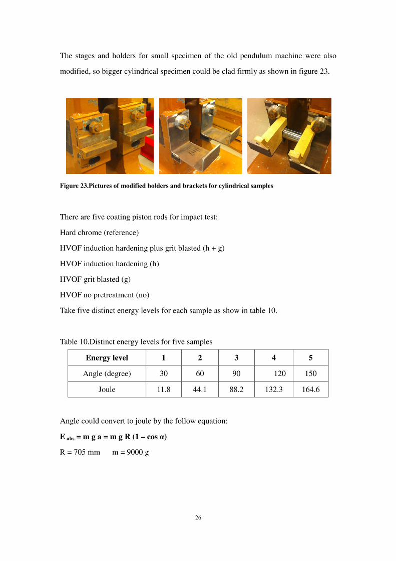
The stages and holders for small specimen of the old pendulum machine were also
modified, so bigger cylindrical specimen could be clad firmly as shown in figure 23.
Figure 23.Pictures of modified holders and brackets for cylindrical samples
There are five coating piston rods for impact test:
Hard chrome (reference)
HVOF induction hardening plus grit blasted (h + g)
HVOF induction hardening (h)
HVOF grit blasted (g)
HVOF no pretreatment (no)
Take five distinct energy levels for each sample as show in table 10.
Table 10.Distinct energy levels for five samples
Energy level 1 2 3 4 5
Angle (degree) 30 60 90 120 150
Joule 11.8 44.1 88.2 132.3 164.6
Angle could convert to joule by the follow equation:
E abs = m g a = m g R (1 – cos α)
R = 705 mm m = 9000 g

For each energy level, we plan to test 5 times and every piston rod should have 25
indentations. Once surface damage happened, the lower level of energy will be
regarded as the critical energy for the coating as shown in figure
Figure 24.Schematic and photo of critical energy level for piston rod coating
b) Stereo microscope and indentation
The size of indentations was measured by stereo microscope, the resolution is 1
The length along longitudinal and transverse direction was measured, acco
contact type, it was spherical ball strike against
indentations refer to the mean value of longitudinal distance.
So the depth of each indentation could be calculated follow the equation:
Depth d = R – (R2 – L
R ---- Radius of the steel ball
L ---- Longitudinal indentation length
The original data and indentation depth mean value were recorded, radial cracks (text
in blue) and delamination area (text in red) also be measured. Original data recorde
from each indentation (mm
b) Optical microscope and SEM
As shown in figure 26, the microstructure of coatings cross section was studied using
an optical microscope; morphology
27
For each energy level, we plan to test 5 times and every piston rod should have 25
nce surface damage happened, the lower level of energy will be
regarded as the critical energy for the coating as shown in figure 24.
c and photo of critical energy level for piston rod coating
b) Stereo microscope and indentation
The size of indentations was measured by stereo microscope, the resolution is 1
The length along longitudinal and transverse direction was measured, acco
contact type, it was spherical ball strike against cylindrical rod; the diameters of
s refer to the mean value of longitudinal distance.
So the depth of each indentation could be calculated follow the equation:
L2/ 4)
1/2
of the steel ball
ongitudinal indentation length
The original data and indentation depth mean value were recorded, radial cracks (text
in blue) and delamination area (text in red) also be measured. Original data recorde
m) was listed in appendix 1.
Optical microscope and SEM
As shown in figure 26, the microstructure of coatings cross section was studied using
morphology of coatings surface and indentations were studied
For each energy level, we plan to test 5 times and every piston rod should have 25
nce surface damage happened, the lower level of energy will be
The size of indentations was measured by stereo microscope, the resolution is 1 µm.
The length along longitudinal and transverse direction was measured, according to
rod; the diameters of
So the depth of each indentation could be calculated follow the equation:
The original data and indentation depth mean value were recorded, radial cracks (text
in blue) and delamination area (text in red) also be measured. Original data recorded
As shown in figure 26, the microstructure of coatings cross section was studied using
of coatings surface and indentations were studied

28
by SEM (scanning electron microscope). The specimens were prepared in a normal
way. The first step of preparation is cutting. The critical energy indentations were
picked to investigate. The rods were cut off along the transverse directions.
Figure 25.Taking critical energy indentations and cutting off along transverse direction
After cutting the piston rods and washing the samples, the cross section of indentation
was plastified as shown in figure 25. Final step is grinding and polishing. The
specimens were ground by Pinno using 25N 4 minutes with water, and then were
polished as described below:
Alleqvo-20N 5min –blue lubricant-9µm; Dur-20N-6min- red lubricant -3µm ;
Plusr-20N-6min- green lubricant -3µm. After each step specimen should be washed to
avoid any contamination from the previous steps.
Figure 26.Photos of specimen preparation: cutting and plastify
3.2 Micro hardness test
Two specimens, hard chrome and HVOF (h + g), were selected to do a hardness test
by the Microhardness tester. According to coating thickness, hard chrome 10 points
and HVOF 20 points, the span is 10 µm. The test follows the straight line as shown in

29
figure 19. The test load is 25 gram.
3.3 Corrosion test
The corrosion test was handled by SP technical research institute laboratory, salt spray
test according to ISO 9227 AASS test.
Three hard chrome piston rods Ø100 x 150 mm as the references numbered 1, 2, and
3. Six HVOF piston rods Ø100 x 150 mm marked 850, 851, 852, 853, 854, and 855.
The items were cleaned by acetone before the corrosion resistance test. Then they
were placed on plastic rackets at an angle between 15o ~20o to vertical. The samples
were exposed to acetic acid salt spray for 72 hours. The PH value of used NaCl salt
solution is about 3.1~ 3.3.

30
4. Results
4.1 HVOF and hard chrome coatings
4.1.1 Various energy degree indentations
The diameter along longitudinal and transverse directions of hard chrome and HVOF
coating indentations and surface damage could be observed by stereo microscope, as
shown in figure 27. According to original data, the indentation depth mean values
were calculated. The indentation depth, radial cracks texted in blue and delamination
area texted in red are listed in table 11.
(A) 30/90/150 indentations of Hard chrome coating
(b) Indentation and surface damage of various HVOF coatings
Figure 27.Indentation photos of hard chrome and HVOF coatings studied by stereo microscope
4.1.2 Coatings cross section of indentations
a) Hard chrome versus HVOF (h + g)
Hard chrome (150 energy degree) and HVOF hardening plus grit blasted (90 energy
degree) coatings were investigated by optical microscope, as show in figure 28.
Coating thickness was measured by optical microscope: hard chrome is 35.64 µm,
and the HVOF coating is 119.31 µm.

31
Table 11.Original data recorded from each indentation (mm).
Depth - Energy
Crack/delamination 30 60 90 120 150
Hard chrome 0.12 0.28 0.42 0.6 0.7
HVOF
hardening +grit blasted 0.13
0.33
0.45
0.51
0.9
0.63
11.43mm2
HVOF
Hardening 0.14
0.32
0.54
0.49
8.41mm2
HVOF
Grit blasted
0.19
0.3
0.44
5.26mm2
HVOF
No pretreatment 0.12
0.32
0.64
0.59
10.6mm2
(A) Hard chrome: corner and bottom (B) HVOF (h+ g): corner and bottom
Figure 28.OM cross section images of hard chrome and HVOF samples

b) Pretreatment for HVOF coatings
Various HVOF coatings, hardening plus grit blasted (90 energy degree) hardening (60
energy degree) and no pretreatment sample (60 energy degree) samples were
investigated by optical microscope, as shown
(A) HVOF (h+ g): 90 degree (B) HVOF (h): 60 degree
(C) HVOF (h): 60 degree (D) HVOF (no pretreatment): 60 degree
Figure 29.OM cross section images of HVOF samples
4.1.3 Crack patterns
Hard chrome (150 energy degree) and HVOF hardening plus grit blasted (90 degree
energy) samples were selected for the investigation of surface
the impact indentation patterns are shown in
32
Pretreatment for HVOF coatings
Various HVOF coatings, hardening plus grit blasted (90 energy degree) hardening (60
energy degree) and no pretreatment sample (60 energy degree) samples were
by optical microscope, as shown in figure 29.
HVOF (h+ g): 90 degree (B) HVOF (h): 60 degree
HVOF (h): 60 degree (D) HVOF (no pretreatment): 60 degree
.OM cross section images of HVOF samples
Hard chrome (150 energy degree) and HVOF hardening plus grit blasted (90 degree
energy) samples were selected for the investigation of surface morphology
the impact indentation patterns are shown in figure 30 A and B.
Various HVOF coatings, hardening plus grit blasted (90 energy degree) hardening (60
energy degree) and no pretreatment sample (60 energy degree) samples were
HVOF (h): 60 degree (D) HVOF (no pretreatment): 60 degree
Hard chrome (150 energy degree) and HVOF hardening plus grit blasted (90 degree
morphology by SEM,

33
A) Hard chrome 150 degree
B) HVOF hardening plus grit blasted 90 degree
Figure 30.SEM coating surface images

34
4.1.4 Hardness test
The microhardness test results of hard chrome and HVOF (hardening plus grit blasted)
coatings were listed in table 12.
Table 12.Hardness test results of hard chrome and HVOF (h + g) samples.
Test No. 1 2 3 4 5 6 7 8 9 10
Hv 0.025 1589 1392 1223 1118 873 769 808 789 845 794
A) Hard chrome
Test No. 1 2 3 4 5 6 7 8 9 10
Hv 0.025 1731 1978 1969 2452 1973 2282 1727 1355 1213 2276
Test No. 11 12 13 14 15 16 17 18 19 20
Hv 0.025 3145 1527 2119 1215 754 721 665 640 614 638
B) HVOF (h + g)
4.1.5 Corrosion resistance
(A) Hard chrome: ref. 1, 2 and 3 (B) HVOF: 851, 852 and 853
Figure 31.Pictures of items after 40 hours of exposure to acetic acid spray
As shown in figure 31, the samples were photographed after 40 hours of exposure to
acetic acid spray. Table 11 indicates protection rating of the corrosion test items.
Visual examination was carried out after rinsing and drying the samples. After 40
hours AASS test, hard chrome protect rating was No. 10; the protect rating of all
HVOF coatings were No. 6 as shown in table 13.

35
Table 13.Corrosion test results of hard chrome and HVOF coating samples.
The objects Protect rating
after 24 hours
Protect rating
after 40 hours
Protect rating
after 70 hours
Ref. 1 10 10 10
Ref. 2 10 10 10
Ref. 3 10 10 10
850 7 6 5
851 7 6 5
852 7 6 3*
853 7 6 5
854 7 6 5
855 7 6 5
* No. 852 show flaking off of coating
4.2 Stainless liner
According to the comparison of various designation of stainless steel in section 1.4.2,
Martensitic stainless steel is the most competitive material for the piston rod liner.
From equation ∆R = R * α * ∆T and thermal expansion coefficient in table 14:
Three stainless pipes with different inner diameters
D= 50; 90; 150mm so R = 25; 45; 75mm
Assumption: heat up 500 o C from room temperature
α=9.9*10-6 ∆T=500
R = 25; 45; 75mm
∆R= 0.125; 0.225; 0.375 mm

36
Three carbon steel rods with different diameters:
d= 50; 90; 150mm so r = 25; 45; 75mm
Assumption: cold down to 200 o C from room temperature by liquid nitrogen
α=12*10-6 ∆T=200
r = 25; 45; 75mm
∆ r = 0.06; 0.108; 0.18 mm
Table 14.Thermal expansion coefficient for materials
Material Linear thermal expansion coefficient
α (10-6 m/m o C)
Carbon steel 10~13
Stainless steel (Martensitic) 9.9
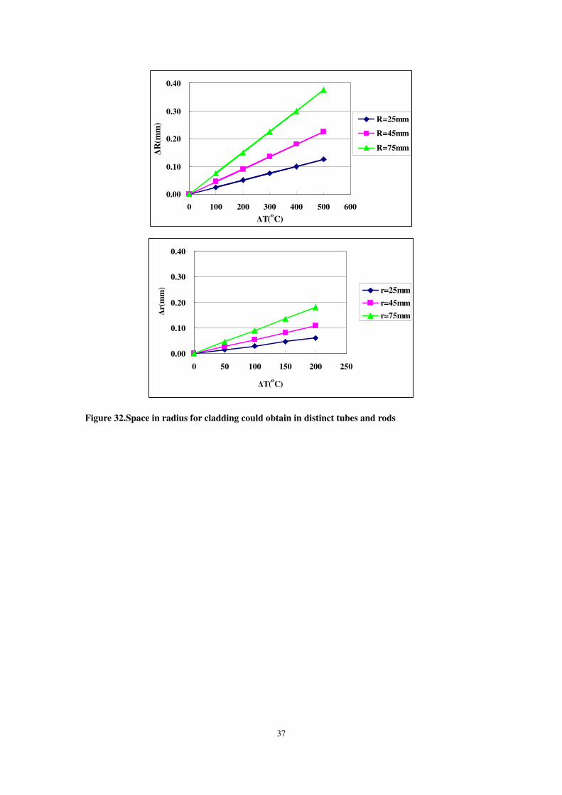
So for distinct diameter liners and substrates, heating the martensitic stainless steel
tubes up to 500 , while cooling piston rod down to minus 200 by liquid nitrogen,
space in radius ∆L for cladding could obtain as shown in figure 32:
∆L= ∆R +∆ r
=0.185; 0.333; 0.555 mm
(R = 25; 45; 75mm, r = 25; 45; 75)
37
Figure 32.Space in radius for cladding could obtain in distinct tubes and rods
0.00
0.10
0.20
0.30
0.40
0 100 200 300 400 500 600
∆T(oC)
∆R
(mm
) R=25mm
R=45mm
R=75mm
0.00
0.10
0.20
0.30
0.40
0 50 100 150 200 250
∆T(oC)
∆r(
mm
) r=25mm
r=45mm
r=75mm

38
5. Discussion
5.1 HVOF coatings compare to hard chrome
5.1.1 Coating characterization
Coating cross sections were investigated by optical microscope as show in figure 33.
Typically, coating thickness of thermal spraying is much thicker than electroplating
(hard chrome 150 degree 35.64 µm, and HVOF hardened plus grit blasted 90 degree
119.31 µm), both of them show excellent bonding strength with the substrates.
(A) Hard chrome (B) HVOF hardened plus grit blasted
Figure 33.OM cross section images of hard chrome and HVOF samples (mag. 500)
In previous study [4], small vertical microcracks were observed in hard chrome
coatings, as shown in figure 6A and 33A; the reason for this particular cracked
morphology has not been completely understood so far; it is believed that they are
caused by relaxation of residual tensile stresses formed in the coating during the
deposition. The typical HVOF Cr3C2-NiCr coating has lamellar structure parallel to
substrate surface with fine carbides dispersed, presents the splats formed during the
spray process as shown in figure 33B and 34A.
Furthermore from previous study, it was found that the size, shape and content of
carbide particles within the as-sprayed coatings changed with spray parameters.
Within the coating deposited at comparatively lower flows of propane and oxygen, as
shown in Figure 34B, large carbide particles in an angular shape similar to that in the

39
starting powder were present with an inhomogeneous distribution. On the other hand,
the coating deposited at higher flows of both propane and oxygen and a long spray
distance contained less carbide particles figure 34A [30].
A) Long distance, higher propane oxygen flows. B) Lower propane oxygen flows.
Fig34. Microstructure of HVOF sprayed Cr3C2–NiCr coatings [29]
A comparatively finer carbide size and higher volume fraction in even dispersed
condition may lead to a better bonding of carbide particles to the matrix phase. The
fine Cr3C2–NiCr coatings present a “bimodal structure” formed by CrC particles with
a size greater than 1 µm together with sub-micron carbides in a Ni–Cr matrix. The
decrease of the size of the feedstock powder involves the reduction of the superficial
coating roughness [31]. The fine Cr3C2–NiCr coatings demonstrate superior
performance to hard chrome with regard to mechanical and tribological properties.
For future successful applications of Cr3C2–NiCr HVOF coatings as alternative to
hard chromium, many factors like wear resistance, friction coefficient, costs and
environmental issues have to be considered collectively [32].
5.1.2 Hardness profile
The results of microhardness test were listed in table 11. The coating microhardness,
texted in blue color was in accordance with the finding results in section 1.4.1 c):
Hard chrome: 800~1000 Hv.
Cr3C2-NiCr25%: 750~ 1300 Hv.

40
Figure 35.HV hardness diagram: hard chrome vs. HVOF (h + g)
Both of the two coatings show good microhardness, as shown in figure 35; they all
could meet the customers’ hardness requirement in table 1. HVOF coating presents
higher hardness than hard chrome, several hardness value were reach 2000 Hv,
perhaps due to the carbides hard particles like Cr3C2, Cr7C3 and Cr23C6.
Figure 36.Substrate temperature of various surface treatments. [9]
The substrates of two samples were treated by identical hardening mechanisms:
induction hardening. However in the interfacial areas approximate 50 µm to the
substrates, the hardness of hard chrome is a little bit higher than HVOF; it was
0
500
1000
1500
2000
2500
3000
3500
0 0.05 0.1 0.15 0.2 0.25
Distance (mm)
HV
har
dnes
s
Hard Cr
HVOF(h+g)

41
probably affected during thermal spraying, the substrate temperature was elevated
above 600 oC by high temperature and kinetic energy particles. Perhaps
recrystallization annealing happened at this temperature for medium carbon steel. In
this process deformed grains are replaced by a new set of undeformed grains that
nucleate and grow until the original grains have been entirely consumed. Since
recrystallization is usually accompanied by a reduction in the strength and hardness of
a material and a simultaneous increase in the ductility, the hardness of HVOF
substrate decreased. On the other hand, for plating process, the substrate temperature
could maintain below 200 oC, as shown in figure 36. [9]
5.1.3 Results of pendulum impact test
Toughness of coating can be expressed as ability to absorb impact energy without
delamination or cracking. Impact test is a toughness measure method, all the coating
energy level showed in this work is generally for comparison, and most of energy was
absorbed by substrate. It was found that coating toughness using different test
methods were approximately the same. [33]
Figure 37.Critical energy diagram: indentation depth versus distinct energy level
The indentations of hard chrome and HVOF coatings formed in distinct energy level
0
0.1
0.2
0.3
0.4
0.5
0.6
0.7
0.8
30 60 90 120 150
Degree (o)
Depth
(m
m) Cr
HVOF/hg
HVOF/h
HVOF/g
HVOF

42
were listed in table 10. During the impact test, once the delamination or damage
happened, the test was terminated, and the former energy level was regarded as the
critical energy degree for this coating, as shown in table texted in blue. From the
indentation depth versus distinct energy diagram as shown in figure 37, the critical
energy level of hard chrome and HVOF coatings could be easily found out, the bar
filled with oblique line. Hard chrome can pass highest energy level 150 degree, no
radial cracks and surface damage was obtained.
a) Coating characters and impact results
Du to different process of formation, coating microstructure and bonding mechanisms,
in ordinary engineering applications HVOF coatings are much thicker than hard
chrome. In this present, the thickness of HVOF is 3.3 times against hard chrome, as
show in figure 33. Coating thickness, hardness, ductility and toughness are related,
but the ductility is the key parameter for coating toughness. Even HVOF is thicker
and harder than hard chrome coating, the ductile hard chrome coating shows excellent
toughness, as show in figure 28(A) no radial cracks or delamination was found from
30 to 150 angle degree. Most of HVOF coatings show good quality at low angle
degree as shown in figure 28(B), with increasing impact energy, flaking off and the
radial cracks happened, and the crack direction was not perpendicular to the substrate.
A) Cracks and crack length c B) Crack propagation path
Figure 38.The indentation cracks in HVOF Cr3C2–NiCr20 coatings [17]
43
Figure 38 A) shows the typical indentations on the transverse section with cracks for
Cr3C2– NiCr20 coatings. In the thermal sprayed coatings, the cracks parallel to the
coating substrate interface are more easily formed in comparison to the perpendicular
direction. This has been attributed to the characteristics of the thermal sprayed
coatings have discussed in section 1.4.1 a). Further, examination of the crack features
show that the crack propagates along a region between the carbide particles and the
binder phase in Cr3C2–NiCr20 coatings as shown in figure 38 B). [17]
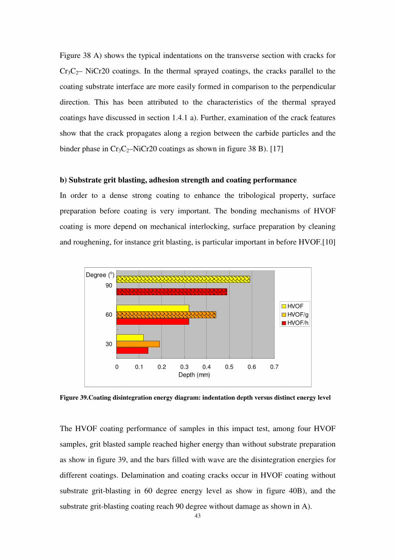
b) Substrate grit blasting, adhesion strength and coating performance
In order to a dense strong coating to enhance the tribological property, surface
preparation before coating is very important. The bonding mechanisms of HVOF
coating is more depend on mechanical interlocking, surface preparation by cleaning
and roughening, for instance grit blasting, is particular important in before HVOF.[10]
Figure 39.Coating disintegration energy diagram: indentation depth versus distinct energy level
The HVOF coating performance of samples in this impact test, among four HVOF
samples, grit blasted sample reached higher energy than without substrate preparation
as show in figure 39, and the bars filled with wave are the disintegration energies for
different coatings. Delamination and coating cracks occur in HVOF coating without
substrate grit-blasting in 60 degree energy level as show in figure 40B), and the
substrate grit-blasting coating reach 90 degree without damage as shown in A).
0 0.1 0.2 0.3 0.4 0.5 0.6 0.7
30
60
90
Degree (o)
Depth (mm)
HVOF
HVOF/g
HVOF/h
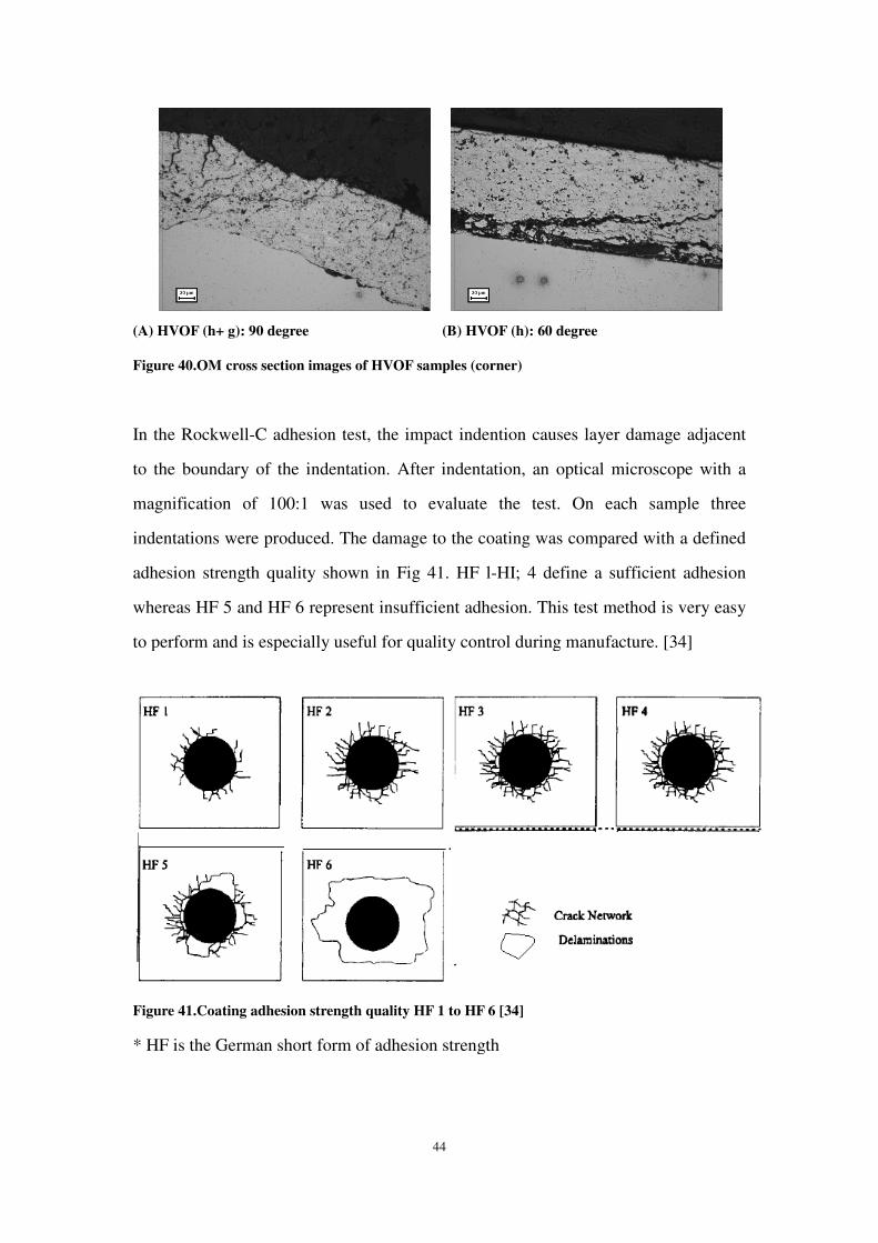
(A) HVOF (h+ g): 90 degree (B) HVOF (h): 60 degree
Figure 40.OM cross section images of HVOF samples (corner)
In the Rockwell-C adhesion test, t
to the boundary of the indentation. After indentation, an optical microscope with a
magnification of 100:1
indentations were produced. The damage to the coating was
adhesion strength quality shown in
whereas HF 5 and HF 6 represent insufficient adhesion.
to perform and is especially useful for quality control
Figure 41.Coating adhesion strength quality HF 1 to HF 6
* HF is the German short form of adhesion strength
44
g): 90 degree (B) HVOF (h): 60 degree
.OM cross section images of HVOF samples (corner)
C adhesion test, the impact indention causes layer damage
to the boundary of the indentation. After indentation, an optical microscope with a
magnification of 100:1 was used to evaluate the test. On each sample three
indentations were produced. The damage to the coating was compared with a defined
gth quality shown in Fig 41. HF l-HI; 4 define a sufficient adhesion
5 and HF 6 represent insufficient adhesion. This test method is very
to perform and is especially useful for quality control during manufacture
adhesion strength quality HF 1 to HF 6 [34]
short form of adhesion strength
damage adjacent
to the boundary of the indentation. After indentation, an optical microscope with a
was used to evaluate the test. On each sample three
compared with a defined
HI; 4 define a sufficient adhesion
This test method is very easy
during manufacture. [34]

45
Figure 42 indicates that during 90 degree energy impact test, substrate hardening and
grit blasting samples present good bonding strength HF2-HF3 A); On the contrary,
substrate without grit blasting shows poor adhesion HF 6 as shown in B).
(A) HVOF (h+ g): 90 degree (B) HVOF (h): 90degree
Figure 42.Stereo microscope: impact indentations images of HVOF coatings
c) Substrate hardness and coating performance
The physical properties, such as hardness, of the substrate may have evident influence
on the properties and performance of the hard coatings.
Practically, hard coatings need to be deposited on different kinds of substrate
materials in different application areas. For instance, despite the excellent CVD
coating properties, the poor quality of the substrate would prevent industrial
applications where the coating-substrate compound has to withstand high load as
shown in figure 43A). After induction hardening, microstructural gradients are
generated in substrate. As a result, hard layers are obtained, which is an excellent load
support of coating, while the core of the substrate remains tough as shown in figure
43B). Nevertheless, induction hardening have many more advantages due to
generation of compressive residual stresses in substrate and only very low distortions
resulting from the surface treatment [35].
From the former study the influence of substrate hardness on the properties of the
hard coatings was investigated. It was found that the substrate hardness has little

46
influence on the crystalline structure, nano-hardness, and tribological properties
(friction coefficient and wear rate). However, it showed a significant effect of the
toughness and adhesion of the hard coatings. And adhesion between coating and
substrate increases linearly with the increasing of substrate hardness. It can be
concluded that hard coatings need to be supported by hard substrates. [36]
Figure 43.A) AISI substrate plus TiN coating B) AISI substrate after induction hardening
In this thesis, in accord with literature, substrate induction hardening samples show
much better performance: hard chrome 150, HVOF (h + g) 120 and HVOF (g) 60
degree, as shown in figure 42.
d) Crack patterns and failure modes
Hard chrome and HVOF coatings with distinct characteristics, during the pendulum
impact test, show different mechanisms in crack propagation and damage.
Cracking and delaminating mechanisms of various coatings by distinct indentation
have been studied as shown in figure 44. The patterns and development of crack is a
function of coating thickness t and normal load W. A partial delamination of coating
can be generated only by the indentation of a hard pin if the indentation load or depth
is large enough. For ductile coating, when load increasing, ring cracks more than three
are generated around the indentation mark, and partial delamination takes place
between the neighboring rings as show in figure 44 A): 1. Elastic contact, without
cracks; 2. Maximum tensile stress exceeds the critical value of coating, the ring cracks

47
propagated downward to form a shape of cone, the ring cracks concentrated around
the indentation; 3. Partial delamination takes place between neighboring rings. For
brittle coating as shown in figure 44 B): 1.The radial cracks generated in the contact
area since partial plastic deformation; 2. Maximum tensile stress exceeds the critical
value of coating, the lateral cracks propagated downward to form a shape of cone;
radial cracks, lateral cracks, and partial delamination take place; 3. Large area general
delamination happened around indentation mark. [37]
A) Indentation by a SiC ball of radius 1.5mm B) Indentation by a diamond pin of 0.2mm tip
Figure44. Indentation mark and crack pattern: Al2O3 coating on WC-Co substrate [37]
The hard chrome coating indentation marks and crack patterns in 150 degree impact
test were similar with the indentation of Al2O3 coating on WC-Co substrate by a SiC
ball in region two, as shown in figure 30 A): ring cracks appeared around the contact
area and no partial spall was observed. The metallurgical characteristics of HVOF
Cr3C2– NiCr20 coatings influence the crack propagation path. The HVOF (h + g)
coating indentation marks and crack patterns in 90 degree impact test were similar
with the indentation of Al2O3 coating on WC-Co substrate by a diamond pin, between
region two and region three as shown in figure 30 B): radial and lateral cracks
appeared around the contact area, small parts of delamination was observed. In the
higher energy level 120 degree, the indentation patterns developed from region 2 to 3,
and the flaking was observed.

48
From literature it was found that the ductile coatings, such as TiN layers, presented
with relatively small delaminations whereas the high microhardness coatings like CrN
and Cr2N layers, showed brittle behavior with large delaminations and relatively early
coating failure [34].
Two main failure modes can be found during the impact test: adhesive (interfacial)
and cohesive. Adhesive failure is associated with bonding strength of coating, and
cohesive failure is associated with toughness [38]. Figure 27 shows that adhesive
failure had happened in HVOF various coatings; with energy level increasing,
cohesive failure mode probably could be found in hard chrome coatings, due to
excellent coating toughness.
5.1.4 Corrosion resistance in AASS
Table 13 indicates after 40 hours AASS test, the protect rating of hard chrome items
were No. 10, no corrode area was found by visual examination. However the HVOF
is No. 6, were not qualified.
As shown in figure 31, the samples were photographed after 40 hours of exposure to
acetic acid spray. Perhaps the brown rust in the figure 31B) was obtained from the
substrate corrosion, due to the porosity of HVOF coating is much higher compare to
that of hard chrome as mentioned in section 1.4.1. In figure 16, the corrosion
resistances of various HVOF coatings have been listed, the Cr3C2-NiCr coatings on
mild steel substrate indicate relatively good corrosion protection in AASS test.
Published corrosion data exist for a wide range of coating materials deposited by
different techniques; for instance HVOF and hard chrome coatings. However not all
corrosion resistance data can be compared directly because of variations in substrate
material and surface preparation, the deposition parameters, coating thickness, coating
porosity and surface finish, sometimes the use of bond coatings and intermediate
layers, and sometimes the use of post treatments [38]. All of these reasons could

49
affect the testing results. Finally, the salt fog test providing results in a short time
period, however cannot be related to in service use in most cases: for hydraulic
cylinders, most of time the coatings of piston rods were immersed in hydraulic oil.
5.2 Stainless liner
For hardness and corrosion resistance requirements, perhaps martensitic stainless tube
could be a competitive alternative to hard chrome. According to thermal expansion
theory, if heating up the tube (R = 25/45/75mm) to 500о
C and cooling down the
substrate piston rod (r = 25/ 45/ 75mm) to -200о
C, space in radius 0.185/0.333/0.555
mm could be acquired.
However, perhaps martensitic stainless liner for hydraulic piston rod is not a practical
method. Due to high hardness and brittle behaviour, almost no commercial martensitic
thin pipes or tubes in reality; moreover, for custom martensitic stainless steel have
low carbon content, which makes it highly prone to occur micro-cracking during heat
up the tube to 500о
C. [40]

50
6. Conclusions
Cr3C2-NiCr20% HVOF as a promising alternative to hard chrome has been studied:
1. Pendulum impact test showed that substrate pretreatments, induction hardening and
grit blasting are very crucial for HVOF coatings; coherently HVOF (h + g) presents
the highest critical energy level among HVOF samples. Hard chrome and HVOF
coatings present distinct cracks propagation and delamination mechanisms. Hard
chrome shows higher toughness more than 40% and adhesion strength compare
with HVOF; cracking and delaminating take place more easily in HVOF coatings
due to brittleness.
2. Hardness test demanstrated that HVOF coating indicates higher hardness than
hard chrome, which is a key parameter for wear resistance (mean value: 1784 Vs.
1244 Hv); however the hardness of HVOF substrate is a little bit lower than hard
chrome, perhaps it was affected by thermal spray process.
3. Corrosion resistance showed that HVOF rating number 6 and hard chrome rating
10 after 40 hours in AASS test: the substrates of HVOF coating were corrode since
the coating porosity.
While as hard chrome alternatives on hydraulic piston rods, besides HVOF there are
several viable processes have been investigated.

51
Acknowledgement
I appreciate that all the kind help from my supervisor Pavel Krakhmalev, without his
guidance and supervise the thesis could not be accomplished. In additional, I wish to
thank the financial support from Fricweld and the efforts from Mats Blåder. Thanks
Professor Jens Bergström, Jörgen Persson and Göran Karlsson, Anna Persson and
Christer Burman for all the kind help during the project discussion, experiment
preparation and laboratory works. In the end, I would like to thank my family for
endless love and support, especially my dearest daughter Lu.

52
Reference:
[1] Standard Practice for Rating of Electroplated Panels Subjected to Atmospheric
Exposure. <http://www.astm.org/Standards/B537.htm>. Accessed 20 March 2010.
American Society for Test and Material
[2] Plating. <http://en.wikipedia.org/wiki/Plating>. Accessed 20 March 2010.
Wikipedia
[3] Wear and Corrosion alternatives- Chrome plating.
<http://www.hazmat-alternatives.com/Alt_tech-Chrome.php>. Accessed 1 April
2010. A service of Rowan technology group
[4] Bolelli G, Giovanardi R, Lusvarghi L, Manfredini T. Corrosion resistance of
HVOF-sprayed coatings for hard chrome replacement. Corrosion Science, 48(11),
2006, 3375-3397.
[5] Flitney B. Alternatives to hard chrome for hydraulic actuators: why replace hard
chrome. Sealing Technology, October 2007, 8-12.
[6] Papatheodorou T. Influence of hard chrome plated rod surface treatments on
sealing behavior of hydraulic rod seals. Sealing Technology, April 2005, 5-10.
[7] Legg K.O, Graham M, Chang P, Rastagar F, Gonzales A, Sartwell B. The
replacement of electroplating. Surface and Coatings Technology, 81(1), 1996,
99-105.
[8] Thermal spraying coatings: Nature of thermal spraying coatings.
<http://www.newagestudwelding.com/thermal-spray-process.php>. Accessed 1
April 2010. Fastening system, INC
[9] Product and service: Material.
<http://www.sulzermetco.com/en/desktopdefault.aspx>. Accessed 15 April 2010.
Sulzer Metco company
[10] Hutchings I.M. Tribology: Friction and Wear of Engineering Materials. Edward
Arnold, London, 1992, 213-215 & 232-233.
[11] Sahraoui T, Fenineche N-E, Montavon G, Coddet C. Structure and wear
behaviour of HVOF sprayed Cr3C2–NiCr and WC–Co coatings. Materials and

53
Design, 24(5), 2003, 309-313.
[12] Staia M.H, Valente T, Bartuli C, Lewis D.B, Constable C.P. Part I:
characterization of Cr3C2-25% NiCr reactive plasma sprayed coatings produced at
different pressures. Surface and Coatings Technology, 146-147, 2001, 553-562.
[13] Toma D, Brandl W, Marginean G. Wear and corrosion behaviors of thermally
sprayed cermet coatings. Surface and Coatings Technology, 138(2-3), 2001,
149-158.
[14] Guilemany J.M, Espallargas N, Suegama P.H, Benedetti A.V. Comparative study
of Cr3C2–NiCr coatings obtained by HVOF and hard chromium coatings.
Corrosion Science, 48(10), 2006, 2998-3013.
[15] Siegmann St, Brandt O, Margadant N. Tribological requirements of thermal
sprayed coatings for wear resistant applications. 1st International Thermal
Spraying Conference – Thermal spray: surface engineering via applied research,
Canada, 2000, 1135-1140.
[16] Shipway P.H, Wirojanupatump S. The role of lubrication and corrosion in
abrasion of materials in aqueous environments. Tribology International, 35(10),
2002, 661-667.
[17] Murthy J.K.N, Venkataraman B. Abrasive wear behaviour of WC–CoCr and
Cr3C2–20(NiCr) deposited by HVOF and detonation spray processes. Surface &
Coatings Technology, 200(8), 2006, 2642-2652.
[18] Standard Test Method for Determination of Slurry Abrasivity (Miller Number)
and Slurry Abrasion response of Materials (SAR Number)
<http://www.astm.org/Standards/G75.htm>. Accessed 20 March 2010. American
Society for Test and Material
[19] Millerand J.E, Schmidt F.E, eds. Slurry Erosion: Uses, Applications and Test
Methods, ASTM Spec. Tech. Publ., 1987, 169-172.
[20] Koon A P, Hee T B, Taylor M, Weston M, Yip J. Hard Chrome Replacement by
HVOF Sprayed Coatings. SIM Tech Technical Report, PT/99/002/ST.
[21] Brooman E. Wear behavior of environmentally acceptable alternatives to
chromium coatings: Nickel-based candidates. Metal finishing, 102(9), 2004,

54
75-82.
[22] Hunan Nanofilm company. Properties of tungsten plating coatings.
<http://www.hnnfe.com>. Accessed 15 June 2010. [Chinese]
[23] Hovestad A, Bosch A.J, Berger P.A, Zuidwijk Th. Electroplating of amorphous
iron-group metal-tungsten alloys as alternative to chromium plating. 3rd
International Conference on Hard and Decorative chrome plating, France, April
2001.
[24] Zhang Z.T. Electrochemically deposited Nanocomposites made from Nano
particles. Surface and Coatings Technology, 2002, 12-14.
[25] Meyers B.R, Lynn S.C, Jang E. Case study: alternatives to the use of chromium in
plating and conversion coating at mcclellan air force base, California. Tribology
International, 60, 1998, 112-115.
[26] Ceraplate coating. <http://hunger-hydraulik.de/index.php/ceraplate-coating.html>.
Accessed 20 March 2010. Hunger Hydraulic company Germany
[27] Loffler F. Methods to investigate mechanical properties of coatings. Thin Solid
Films, 339(1-2), 1999, 181-186.
[28] Bouzakis K.D, Siganos A, Leyendecker T, Erkens G. Thin hard coatings fracture
propagation during the impact test. Thin Solid Films, 460(1-2), 2004, 181-189.
[29] Duan D.L, Li S, Zhang R.L, Hu W.Y, Li S.Z. Evaluation of adhesion between
coating and substrate by a single pendulum impact scratch test. Thin Solid Films,
515(4), 2006, 2244-2250.
[30] Ji G.C, Li C.J, Wang Y.Y, Li W.Y. Microstructural characterization and abrasive
wear performance of HVOF sprayed Cr3C2–NiCr coating. Surface & Coatings
Technology, 200(24), 2006, 6749-6757.
[31] Picas J.A, Forn A, Igartua A, Mendoza G. Mechanical and tribological properties
of high velocity oxy-fuel thermal sprayed nanocrystalline CrC–NiCr coatings.
Surface and Coatings Technology, 174 -175, 2003, 1095-1100.
[32] [32] Picas J A, Forna A, Matthuaus G. HVOF coatings as an alternative to hard
chrome for pistons and valves. Wear, 261, 2006, 477-484.
[33] Ding X.Z, Zeng X.T, Liu Y.C, Wei J, Holiday P. Influence of Substrate Hardness

55
on the Properties of PVD Hard Coatings. Synthesis and Reactivity in Inorganic,
Metal-Organic, and Nano-Metal Chemistry,
http://www.informaworld.com/smpp/title~db=all~content=t713597303~tab=issueslist~branc
hes=38 - v3838(2), 2008, 156-161.
[34] Heinke W, Leyland A, Matthews A, Berg G, Friedrich C, Broszeit E. Evaluation
of PVD nitride coatings, using impact, scratch and Rockwell-C adhesion tests.
Thin Solid Films, 270(1-2), 1995, 431-438.
[35] Pantleon K, Kessler O, Hoffann F, Mayr P. Induction surface hardening of hard
coated steels. Surface and Coatings Technology, 120-121, 1999, 495-501.
[36] Zhang C, Hu T, Zhang N. Influence of substrate hardness on coating-substrate
adhesion. Advanced Material Research, 177, 2011, 148-150.
[37] Friedrich K , Schlarb AK. , Cracking and delaminating of coatings by indentation,
Handbook: Tribology of Polymeric Nano Composites, 272.
[38] Zhu X.D, Dou H.L, Ban Z.G, Liu Y.X, He J.W. Repeated impact test for
characterization of hard coatings. Surface and Coatings Technology, 201(9-11),
2007, 5493-5497.
[39] Brooman E.W. Corrosion performance of environmentally acceptable alternatives
to Cadmium and Chromium coatings: Chromium-Part II. Metal Finishing, 98(8),
August 2000, 39-45.
[40] Nebhnani M.C, Bhakta U.C, Gowrisankar I, Biswas D. Failure of a martensitic
stainless steel pipe weld in a fossil fuel power plant. Engineering Failure Analysis,
9(3), 2002, 277-286.
Copyright © 2022 FDOKUMEN