GPX 80 Gas Piston Pump - Titan Tool
28
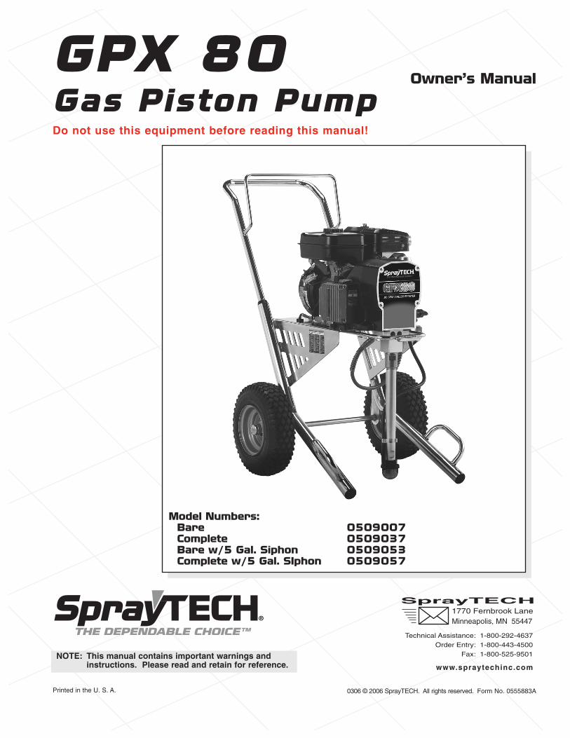
0306 © 2006 SprayTECH. All rights reserved. Form No. 0555883A Printed in the U. S. A. GPX 80 Gas Piston Pump Do not use this equipment before reading this manual! SprayTECH 1770 Fernbrook Lane Minneapolis, MN 55447 Technical Assistance: 1-800-292-4637 Order Entry: 1-800-443-4500 Fax: 1-800-525-9501 www.spraytechinc.com Owner’s Manual NOTE: This manual contains important warnings and instructions. Please read and retain for reference. Model Numbers: Bare 0509007 Complete 0509037 Bare w/5 Gal. Siphon 0509053 Complete w/5 Gal. SIphon 0509057
-
Upload
khangminh22 -
Category
Documents
-
view
0 -
download
0
Transcript of GPX 80 Gas Piston Pump - Titan Tool
0306 © 2006 SprayTECH. All rights reserved. Form No. 0555883APrinted in the U. S. A.
GPX 80Gas Piston PumpDo not use this equipment before reading this manual!
SprayTECH1770 Fernbrook LaneMinneapolis, MN 55447
Technical Assistance: 1-800-292-4637Order Entry: 1-800-443-4500
Fax: 1-800-525-9501
www.spraytechinc.com
Owner’s Manual
NOTE: This manual contains important warnings andinstructions. Please read and retain for reference.
Model Numbers:Bare 0509007Complete 0509037Bare w/5 Gal. Siphon 0509053Complete w/5 Gal. SIphon 0509057
Table of ContentsSafety Precautions .................................................................2
Français ..............................................................................18Español ...............................................................................20
Specifications .........................................................................3General Description ...............................................................4Operation ................................................................................4
Setup ....................................................................................4Preparing to Paint .................................................................4Painting.................................................................................5Pressure Relief Procedure ...................................................6
Spraying ..................................................................................6Spraying Technique ..............................................................6Practice.................................................................................6
Cleanup ...................................................................................7Maintenance............................................................................7
General Repair and Service Notes.......................................7Maintaining the Engine .........................................................8Replacing the Filter...............................................................8Replacing the PRIME/SPRAY Valve.....................................8Replacing the Potentiometer ................................................9Replacing the Sprayer ON/OFF Switch................................9Replacing the Gears and/or Slider Assembly.....................10Replacing the Electronic Pressure Control (EPC) Board ...11Replacing the Transducer ...................................................11Servicing the Clutch Assembly ...........................................12Servicing the Fluid Section .................................................14
Troubleshooting ...................................................................16Parts Listings........................................................................22
Main Assembly....................................................................22Drive Assembly ...................................................................23Fluid Section Assembly ......................................................24Cart Assembly.....................................................................25Filter Assembly ...................................................................25PRIME/SPRAY Assembly ...................................................265 Gallon Siphon Set (optional) ...........................................26Electrical Schematic ...........................................................27Labels .................................................................................27Accessories ........................................................................27
Limited Warranty ..................................................................28
Safety PrecautionsThis manual contains information that must be read andunderstood before using the equipment. When you come toan area that has one of the following symbols, pay particularattention and make certain to heed the safeguard.
This symbol indicates a potential hazard that may causeserious injury or loss of life. Important safety informationwill follow.
This symbol indicates a potential hazard to you or to theequipment. Important information that tells how toprevent damage to the equipment or how to avoid causesof minor injuries will follow.
IMPORTANT SAFETY INSTRUCTIONSA. SAVE THESE INSTRUCTIONS – To reduce the risks of
fire or explosion, electrical shock, and the injury topersons, read and understand all instructionsincluded in this manual. Be familiar with the controlsand the proper usage of the equipment.
WARNING
NOTE: Notes give important information that shouldbe given special attention.
CAUTION
WARNING
2 © SprayTECH. All rights reserved.
B. WARNING – To reduce the risk of fire or explosion:1. Do not spray flammable or combustible materials near
an open flame, pilot lights or sources of ignition such ashot objects, cigarettes, motors, electrical equipment andelectrical appliances. Avoid creating sparks fromconnecting and disconnecting power cords.
2. For units intended for use with only water-basedmaterials — Do not spray or clean with flammableliquids. For use with water-based liquids only.
3. For units intended for use with only water-based ormineral spirit-type materials with a minimum flash pointof 21ºC (69.8ºF) — Do not spray or clean with liquidshaving a flash point of less than 21ºC (69.8ºF). Flashpoint is the temperature at which a fluid can produceenough vapor to ignite.
4. Paint or solvent flowing through the equipment is ableto result in static electricity. Static electricity creates arisk of fire or explosion in the presence of paint orsolvent fumes. All parts of the spray system, includingthe pump, hose assembly, spray gun and objects in andaround the spray area shall be properly grounded toprotect against static discharge and sparks. Use onlyconductive or grounded high-pressure airless paintsprayer hoses specified by the manufacturer.
5. Verify that all containers and collection systems aregrounded to prevent static discharge.
6. For electric units — connect to a grounded outlet anduse grounded extension cords. Do not use a 3 to 2adapter.
7. Do not use a paint or solvent containing halogenatedhydrocarbons. Such as chlorine, bleach mildewcide,methylene chloride and trichloroethane. They are notcompatible with aluminum. Contact the coatingsupplier about compatibility of material with aluminum.
8. Keep spray area well ventilated. Keep a good supply offresh air moving through the area to keep the air withinthe spray area free from accumulation of flammablevapors. Keep pump assembly in well ventilated area.Do not spray pump assembly.
9. Do not smoke in the spray area.10. Do not operate light switches, engines, or similar spark
producing products in the spray area.11. Keep area clean and free of paint or solvent
containers, rags, and other flammable materials.12. Know the contents of the paint and solvents being
sprayed. Read all Material Safety Data Sheets (MSDS)and container labels provided with the paints andsolvents. Follow the paint and solvent manufacture’ssafety instructions.
13. Place pump at least 25 feet (7.62 meters) from thespray object in a well ventilated area (add more hose ifnecessary). Flammable vapors are often heavier thanair. Floor area must be extremely well ventilated. Thepump contains arcing parts that emit sparks and canignite vapors.
14. Plastic can cause static sparks. Never hang plastic toenclose spray area. Do not use plastic drop clothswhen spraying flammable material.
15. Fire extinguisher equipment shall be present and working.
C. WARNING – To reduce the risk of skin injection:
1. Do not aim the gun at, or spray any person or animal.2. Keep hands and other body parts away from the
discharge. For example, do not try to stop leaks withany part of the body.
HAZARD:Injection injury – A high pressure fluid stream producedby this equipment can pierce the skin and underlyingtissues, leading to a serious injury and possibleamputation. See a physician immediately. DO NOTTREAT AN INJECTION AS A SIMPLE CUT.
WARNING
3. Always use the nozzle tip guard. Do not spray withoutthe nozzle tip guard in place.
4. Only use a nozzle tip specified by the manufacturer.5. Use caution when cleaning and changing nozzle tips.
In the case where the nozzle tip clogs while spraying,ALWAYS lock gun trigger, shut pump off, and releaseall pressure before servicing, cleaning tip or guard, orchanging tip. Pressure will not be released by turningoff the motor. The PRIME/SPRAY valve handle mustbe turned to PRIME to relieve the pressure. Refer toPRESSURE RELIEF PROCEDURE described in thepump manual.
6. Do not leave the unit energized or under pressure whileunattended. When the unit is not in use, turn off the unitand relieve the pressure in accordance with themanufacturer’s instructions.
7. High-pressure spray is able to inject toxins into thebody and cause serious bodily injury. In the event thatinjection occurs, seek medical attention immediately.
8. Check hoses and parts for signs of damage, a leak caninject material into the skin. Inspect hose before eachuse. Replace any damaged hoses or parts.
9. This system is capable of producing 3300 PSI / 22.8MPa. Only use replacement parts or accessories thatare specified by the manufacturer and that are rated aminimum of 3300 PSI. This includes spray tips, nozzleguards, guns, extensions, fittings, and hose.
10. Always engage the trigger lock when not spraying.Verify the trigger lock is functioning properly.
11. Verify that all connections are secure before operatingthe unit.
12. Know how to stop the unit and bleed pressure quickly.Be thoroughly familiar with the controls. Pressure willnot be released by turning off the motor. ThePRIME/SPRAY valve handle must be turned to PRIMEto relieve the pressure. Refer to PRESSURE RELIEFPROCEDURE described in the pump manual.
13. Always remove the spray tip before flushing or cleaningthe system.
D. WARNING – To reduce the risk of injury:1. Always wear appropriate gloves, eye protection,
clothing and a respirator or mask when painting.Hazardous vapors – Paints, solvents, insecticides, andother materials can be harmful if inhaled or come incontact with body. Vapors can cause severe nausea,fainting or poisoning.
2. Do not operate or spray near children. Keep childrenaway from equipment at all times.
3. Do not overreach or stand on an unstable support.Keep effective footing and balance at all times.
4. Stay alert and watch what you are doing.5. Do not operate the unit when fatigued or under the
influence of drugs or alcohol.6. Do not kink or over-bend the hose. Airless hose can
develop leaks from wear, kinking and abuse. A leakcan inject material into the skin.
7. Do not expose the hose to temperatures or pressures inexcess of those specified by manufacturer.
8. Do not use the hose as a strength member to pull or liftthe equipment.
9. Use lowest possible pressure to flush equipment.10. Follow all appropriate local, state and national codes
governing ventilation, fire prevention and operation.11. The United States Government Safety Standards have
been adopted under the Occupational Safety andHealth Act (OSHA). These standards, particularly part1910 of the General Standards and part 1926 of theConstruction Standards should be consulted.
WARNING
12. Before each use, check all hoses for cuts, leaks,abrasion or bulging of cover. Check for damage ormovement of couplings. Immediately replace hose ifany of those conditions exist. Never repair a paint hose.Replace with a conductive high-pressure hose.
13. Do not spray outdoors on windy days.14. Always unplug cord from outlet before working on
equipment.
Do not lift by cart handle when loading or unloading.
Gasoline Engine Safety
The engine exhaust from this unit contains chemicalsknown to the State of California to cause cancer, birthdefects, or other reproductive harm.
1. Gas engines are designed to give safe and dependableservice if operated according to instructions. Read andunderstand the engine Owner's Manual before operatingthe engine. Failure to do so could result in personal injuryor equipment damage.
2. To prevent fire hazards and to provide adequateventilation, keep the engine at least 1 meter (3 feet) awayfrom buildings and other equipment during operation. Donot place flammable objects close to the engine.
3. Children and pets must be kept away from the area ofoperation due to a possibility of burns from hot enginecomponents or injury from any equipment the engine maybe used to operate.
4. Know how to stop the engine quickly, and understand theoperation of all controls. Never permit anyone to operatethe engine without proper instructions.
5. Gasoline is extremely flammable and is explosive undercertain conditions.
6. Refuel in a well-ventilated area with the engine stopped.Do not smoke or allow flames or sparks in the refuelingarea or where gasoline is stored.
7. Do not overfill the fuel tank. After refueling, make sure thetank cap is closed properly and securely.
8. Be careful not to spill fuel when refueling. Fuel vapor orspilled fuel may ignite. If any fuel is spilled, make sure thearea is dry before starting the engine.
9. Never run the engine in an enclosed or confined area.Exhaust contains poisonous carbon monoxide gas;exposure may cause loss of consciousness and may leadto death.
10. The muffler becomes very hot during operation andremains hot for a while after stopping the engine. Becareful not to touch the muffler while it is hot. To avoidsevere burns or fire hazards, let the engine cool beforetransporting it or storing it indoors.
11. Never ship/transport unit with gasoline in the tank.
SpecificationsGallons per minute (GPM) ...............0.80 (3.0 LPM)Maximum tip size .............................one gun = 0.026”
two guns = 0.019”Maximum pressure ..........................3300 PSI (22.8 MPa)Power...............................................4.5 HP gas engineWeight ..............................................128 lbs. (58.1 kg)Maximum hose length......................300’ (91.4 m)
WARNING
CAUTION
© SprayTECH. All rights reserved. 3
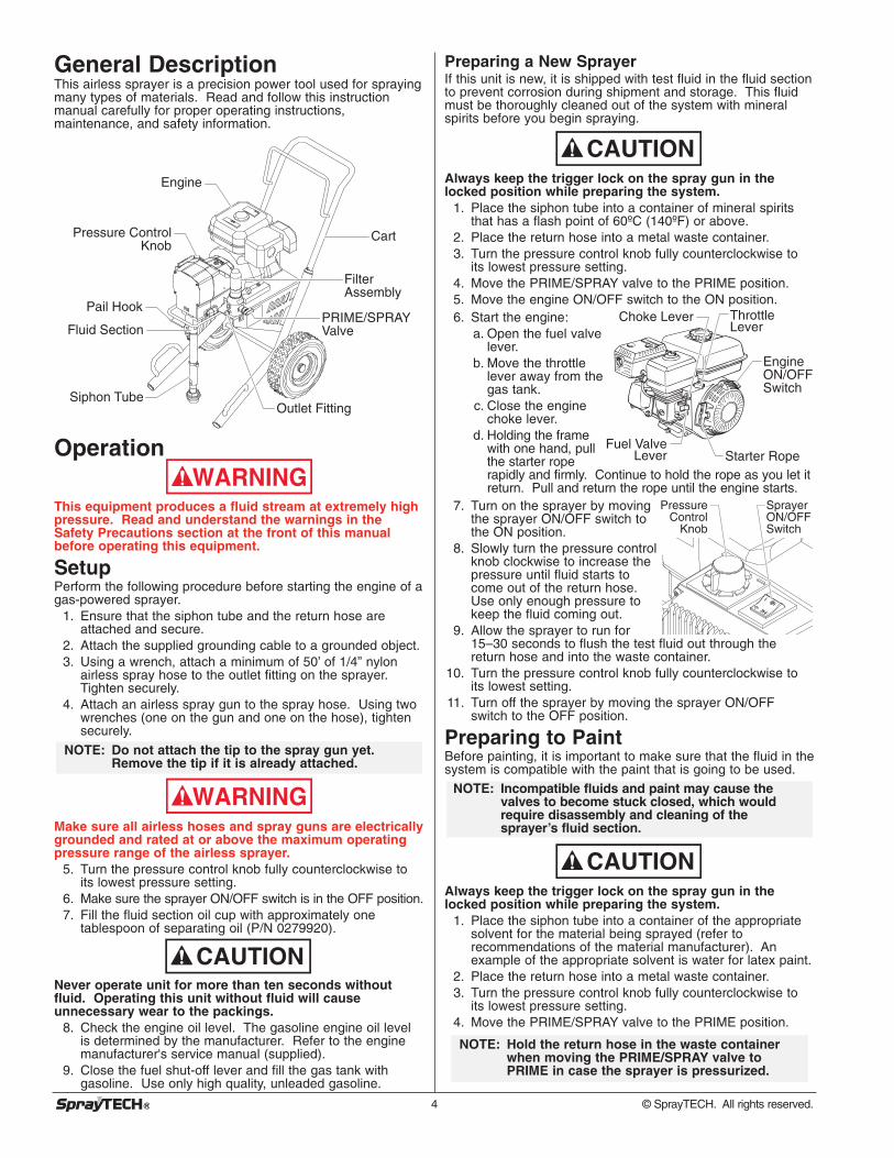
General DescriptionThis airless sprayer is a precision power tool used for sprayingmany types of materials. Read and follow this instructionmanual carefully for proper operating instructions,maintenance, and safety information.
Operation
This equipment produces a fluid stream at extremely highpressure. Read and understand the warnings in theSafety Precautions section at the front of this manualbefore operating this equipment.
SetupPerform the following procedure before starting the engine of agas-powered sprayer.
1. Ensure that the siphon tube and the return hose areattached and secure.
2. Attach the supplied grounding cable to a grounded object.3. Using a wrench, attach a minimum of 50’ of 1/4” nylon
airless spray hose to the outlet fitting on the sprayer.Tighten securely.
4. Attach an airless spray gun to the spray hose. Using twowrenches (one on the gun and one on the hose), tightensecurely.
Make sure all airless hoses and spray guns are electricallygrounded and rated at or above the maximum operatingpressure range of the airless sprayer.
5. Turn the pressure control knob fully counterclockwise toits lowest pressure setting.
6. Make sure the sprayer ON/OFF switch is in the OFF position.7. Fill the fluid section oil cup with approximately one
tablespoon of separating oil (P/N 0279920).
Never operate unit for more than ten seconds withoutfluid. Operating this unit without fluid will causeunnecessary wear to the packings.
8. Check the engine oil level. The gasoline engine oil levelis determined by the manufacturer. Refer to the enginemanufacturer's service manual (supplied).
9. Close the fuel shut-off lever and fill the gas tank withgasoline. Use only high quality, unleaded gasoline.
CAUTION
WARNING
NOTE: Do not attach the tip to the spray gun yet.Remove the tip if it is already attached.
WARNING
Engine
Pressure Control Knob
Pail Hook
Fluid Section
Siphon Tube
Cart
Filter Assembly
PRIME/SPRAY Valve
Outlet Fitting
4 © SprayTECH. All rights reserved.
Preparing a New SprayerIf this unit is new, it is shipped with test fluid in the fluid sectionto prevent corrosion during shipment and storage. This fluidmust be thoroughly cleaned out of the system with mineralspirits before you begin spraying.
Always keep the trigger lock on the spray gun in thelocked position while preparing the system.
1. Place the siphon tube into a container of mineral spiritsthat has a flash point of 60ºC (140ºF) or above.
2. Place the return hose into a metal waste container.3. Turn the pressure control knob fully counterclockwise to
its lowest pressure setting.4. Move the PRIME/SPRAY valve to the PRIME position.5. Move the engine ON/OFF switch to the ON position.6. Start the engine:
a. Open the fuel valvelever.
b. Move the throttlelever away from thegas tank.
c. Close the enginechoke lever.
d. Holding the framewith one hand, pullthe starter roperapidly and firmly. Continue to hold the rope as you let itreturn. Pull and return the rope until the engine starts.
7. Turn on the sprayer by movingthe sprayer ON/OFF switch tothe ON position.
8. Slowly turn the pressure controlknob clockwise to increase thepressure until fluid starts tocome out of the return hose.Use only enough pressure tokeep the fluid coming out.
9. Allow the sprayer to run for15–30 seconds to flush the test fluid out through thereturn hose and into the waste container.
10. Turn the pressure control knob fully counterclockwise toits lowest setting.
11. Turn off the sprayer by moving the sprayer ON/OFFswitch to the OFF position.
Preparing to PaintBefore painting, it is important to make sure that the fluid in thesystem is compatible with the paint that is going to be used.
Always keep the trigger lock on the spray gun in thelocked position while preparing the system.
1. Place the siphon tube into a container of the appropriatesolvent for the material being sprayed (refer torecommendations of the material manufacturer). Anexample of the appropriate solvent is water for latex paint.
2. Place the return hose into a metal waste container.3. Turn the pressure control knob fully counterclockwise to
its lowest pressure setting.4. Move the PRIME/SPRAY valve to the PRIME position.
NOTE: Hold the return hose in the waste containerwhen moving the PRIME/SPRAY valve toPRIME in case the sprayer is pressurized.
CAUTION
NOTE: Incompatible fluids and paint may cause thevalves to become stuck closed, which wouldrequire disassembly and cleaning of thesprayer’s fluid section.
Pressure Control
Knob
Sprayer ON/OFF Switch
Fuel Valve Lever
Choke Lever
Engine ON/OFFSwitch
ThrottleLever
Starter Rope
CAUTION

5. Move the engine ON/OFF switch to the ON position.6. Start the engine:
a. Open the fuel valve lever.b. Move the throttle lever away from the gas tank.c. Close the engine choke lever.d. Holding the frame with one hand, pull the starter rope
rapidly and firmly. Continue to hold the rope as you letit return. Pull and return the rope until the enginestarts.
7. Turn on the sprayer by moving the sprayer ON/OFFswitch to the ON position.
8. Slowly turn the pressure control knob clockwise toincrease the pressure until fluid starts to come out of thereturn hose. Use only enough pressure to keep the fluidcoming out.
9. Allow the sprayer to run for 15–30 seconds to flush the oldsolvent out through the return hose and into the metalwaste container.
10. Turn the pressure control knob fully counterclockwise toits lowest setting.
11. Turn off the sprayer by moving the sprayer ON/OFFswitch to the OFF position.
12. Move the PRIME/SPRAY valve to the SPRAY position.13. Turn on the sprayer.14. Turn the pressure control knob slowly clockwise to
increase pressure.15. Unlock the gun by turning the gun trigger lock to the
unlocked position.
Ground the gun by holding it against theedge of the metal container whileflushing. Failure to do so may lead to astatic electric discharge, which maycause a fire.16. Trigger the gun into the metal waste
container until the old solvent is goneand fresh solvent is coming out of the gun.
17. Lock the gun by turning the gun trigger lock to the lockedposition.
18. Set down the gun and increase the pressure by turningthe pressure control knob slowly clockwise to its highestsetting.
19. Check the entire system for leaks. If leaks occur, turn thesprayer off and follow the “Pressure Relief Procedure” inthis manual before tightening any fittings or hoses.
20. Follow the “Pressure Relief Procedure” in this manualbefore changing from solvent to paint.
Be sure to follow the pressure relief procedure whenshutting the unit down for any purpose, includingservicing or adjusting any part of the spray system,changing or cleaning spray tips, or preparing for cleanup.
Painting1. Place the siphon tube into a container of paint.2. Place the return hose into a metal waste container.3. Turn the pressure control knob fully counterclockwise to
its lowest pressure setting.4. Move the PRIME/SPRAY valve to the PRIME position.5. Move the engine ON/OFF switch to the ON position.6. Start the engine:
a. Open the fuel valve lever.b. Move the throttle lever away from the gas tank.
WARNING
WARNING
NOTE: Make sure that the spray gun does not have atip or tip guard installed.
c. Close the enginechoke lever.
d. Holding the framewith one hand, pullthe starter roperapidly and firmly.Continue to holdthe rope as you letit return. Pull andreturn the rope untilthe engine starts.
7. Turn on the sprayerby moving the sprayer ON/OFF switch to the ON position.
8. Slowly turn the pressure controlknob clockwise to increase thepressure until fluid starts tocome out of the return hose.Use only enough pressure tokeep the fluid coming out.
9. Allow the sprayer to run untilpaint is coming through thereturn hose into the metalwaste container.
10. Turn the pressure control knob fully counterclockwise toits lowest setting.
11. Turn off the sprayer by moving the sprayer ON/OFFswitch to the OFF position.
12. Remove the return hose from the waste container and placeit in its operating position above the container of paint.
13. Move the PRIME/SPRAY valve to the SPRAY position.14. Turn on the sprayer.15. Turn the pressure control knob slowly clockwise to
increase pressure.16. Unlock the gun by turning the gun trigger lock to the
unlocked position.
Ground the gun by holding it against theedge of the metal container whileflushing. Failure to do so may lead to astatic electric discharge, which maycause a fire.17. Trigger the gun into the metal waste
container until all air and solvent is flushed from the sprayhose and paint is flowing freely from the gun.
18. Lock the gun by turning the gun trigger lock to the lockedposition.
19. Turn the pressure control knob fully counterclockwise toits lowest setting.
20. Turn off the sprayer.21. Attach tip guard and tip to the gun as instructed by the tip
guard or tip manuals.
POSSIBLE INJECTION HAZARD. Do not spray without thetip guard in place. Never trigger the gun unless the tip is ineither the spray or the unclog position. Always engage thegun trigger lock before removing, replacing or cleaning tip.22. Turn on the sprayer.23. Increase the pressure by turning the pressure control
knob slowly clockwise and test the spray pattern on apiece of cardboard. Adjust the pressure control knob untilthe spray from the gun is completely atomized. Try tokeep the pressure control knob at the lowest setting thatmaintains good atomization.
NOTE: Turning the pressure up higher than needed toatomize the paint will cause premature tip wearand additional overspray.
WARNING
WARNING
Pressure Control
Knob
Sprayer ON/OFF Switch
Fuel Valve Lever
Choke Lever
Engine ON/OFFSwitch
ThrottleLever
Starter Rope
© SprayTECH. All rights reserved. 5
Pressure Relief Procedure
Be sure to follow the pressure relief procedure whenshutting the unit down for any purpose, includingservicing or adjusting any part of the spray system,changing or cleaning spray tips, or preparing for cleanup.
1. Lock the gun by turning the gun trigger lock to the lockedposition.
2. Turn off the sprayer by moving the sprayer ON/OFFswitch to the OFF position.
3. Turn off the engine by moving the engine ON/OFF switchto the OFF position.
4. Turn the pressure control knob counterclockwise to itslowest setting.
5. Unlock the gun by turning the gun trigger lock to theunlocked position.
4. Hold the metal part of the gun firmly tothe side of a metal container to groundthe gun and avoid a build up of staticelectricity.
5. Trigger the gun to remove any pressurethat may still be in the hose.
6. Lock the gun by turning the gun trigger lock to the lockedposition.
7. Move the PRIME/SPRAY valve to the PRIME position.
Spraying
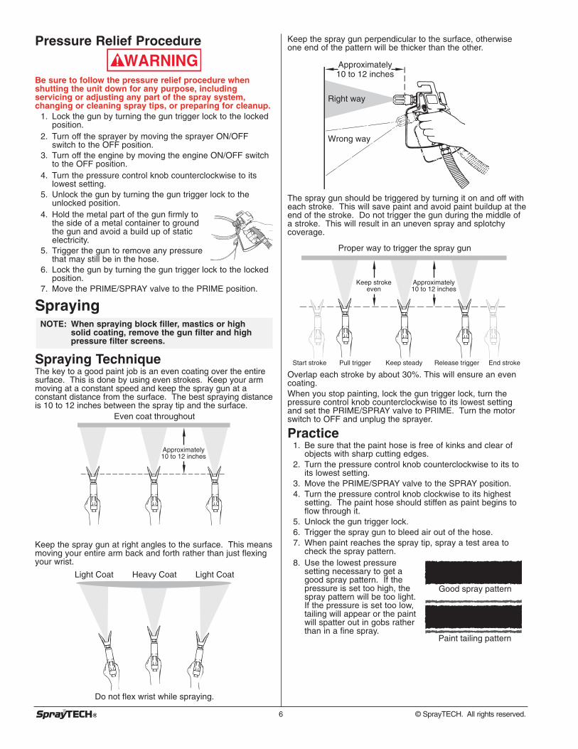
Spraying TechniqueThe key to a good paint job is an even coating over the entiresurface. This is done by using even strokes. Keep your armmoving at a constant speed and keep the spray gun at aconstant distance from the surface. The best spraying distanceis 10 to 12 inches between the spray tip and the surface.
Keep the spray gun at right angles to the surface. This meansmoving your entire arm back and forth rather than just flexingyour wrist.
Heavy Coat
Do not flex wrist while spraying.
Light Coat Light Coat
K k h d d
Even coat throughout
Approximately10 to 12 inches
NOTE: When spraying block filler, mastics or highsolid coating, remove the gun filter and highpressure filter screens.
WARNING
6 © SprayTECH. All rights reserved.
Keep the spray gun perpendicular to the surface, otherwiseone end of the pattern will be thicker than the other.
The spray gun should be triggered by turning it on and off witheach stroke. This will save paint and avoid paint buildup at theend of the stroke. Do not trigger the gun during the middle ofa stroke. This will result in an uneven spray and splotchycoverage.
Overlap each stroke by about 30%. This will ensure an evencoating.When you stop painting, lock the gun trigger lock, turn thepressure control knob counterclockwise to its lowest settingand set the PRIME/SPRAY valve to PRIME. Turn the motorswitch to OFF and unplug the sprayer.
Practice1. Be sure that the paint hose is free of kinks and clear of
objects with sharp cutting edges.2. Turn the pressure control knob counterclockwise to its to
its lowest setting.3. Move the PRIME/SPRAY valve to the SPRAY position.4. Turn the pressure control knob clockwise to its highest
setting. The paint hose should stiffen as paint begins toflow through it.
5. Unlock the gun trigger lock.6. Trigger the spray gun to bleed air out of the hose.7. When paint reaches the spray tip, spray a test area to
check the spray pattern.8. Use the lowest pressure
setting necessary to get agood spray pattern. If thepressure is set too high, thespray pattern will be too light.If the pressure is set too low,tailing will appear or the paintwill spatter out in gobs ratherthan in a fine spray.
Good spray pattern
Paint tailing pattern
Proper way to trigger the spray gun
Approximately10 to 12 inches
Keep strokeeven
Start stroke End strokePull trigger Release triggerKeep steady
Approximately10 to 12 inches
Right way
Wrong way
Cleanup
Special cleanup instructions for use with flammablesolvents:
• Always flush spray gun preferably outside and at least onehose length from spray pump.
• If collecting flushed solvents in a one gallon metalcontainer, place it into an empty five gallon container, thenflush solvents.
• Area must be free of flammable vapors.• Follow all cleanup instructions.
The sprayer, hose, and gun should be cleaned thoroughlyafter daily use. Failure to do so permits material to buildup, seriously affecting the performance of the unit.
Always spray at minimum pressure with the gun nozzle tipremoved when using mineral spirits or any other solventto clean the sprayer, hose, or gun. Static electricitybuildup may result in a fire or explosion in the presence offlammable vapors.
1. Follow the “Pressure Relief Procedure” found in theOperation section of this manual.
2. Remove the gun tip and tip guard and clean with a brushusing the appropriate solvent.
3. Place the siphon tube into a container of the appropriatesolvent (refer to recommendations of the materialmanufacturer). An example of the appropriate solvent iswater for latex paint.
4. Place the return hose into a metal waste container.5. Move the PRIME/SPRAY valve to its PRIME position.
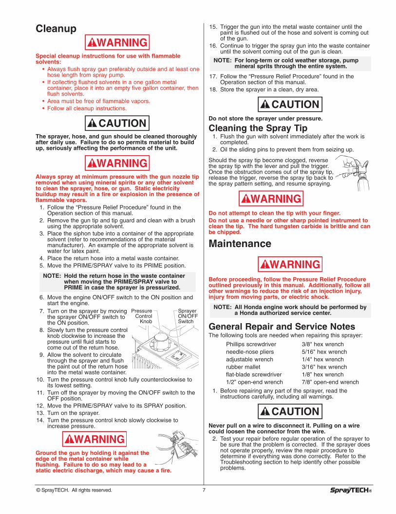
6. Move the engine ON/OFF switch to the ON position andstart the engine.
7. Turn on the sprayer by movingthe sprayer ON/OFF switch tothe ON position.
8. Slowly turn the pressure controlknob clockwise to increase thepressure until fluid starts tocome out of the return hose.
9. Allow the solvent to circulatethrough the sprayer and flushthe paint out of the return hoseinto the metal waste container.
10. Turn the pressure control knob fully counterclockwise toits lowest setting.
11. Turn off the sprayer by moving the ON/OFF switch to theOFF position.
12. Move the PRIME/SPRAY valve to its SPRAY position.13. Turn on the sprayer.14. Turn the pressure control knob slowly clockwise to
increase pressure.
Ground the gun by holding it against theedge of the metal container whileflushing. Failure to do so may lead to astatic electric discharge, which may cause a fire.
WARNING
Pressure Control
Knob
Sprayer ON/OFF Switch
NOTE: Hold the return hose in the waste containerwhen moving the PRIME/SPRAY valve toPRIME in case the sprayer is pressurized.
WARNING
CAUTION
WARNING
© SprayTECH. All rights reserved. 7
15. Trigger the gun into the metal waste container until thepaint is flushed out of the hose and solvent is coming outof the gun.
16. Continue to trigger the spray gun into the waste containeruntil the solvent coming out of the gun is clean.
17. Follow the “Pressure Relief Procedure” found in theOperation section of this manual.
18. Store the sprayer in a clean, dry area.
Do not store the sprayer under pressure.
Cleaning the Spray Tip1. Flush the gun with solvent immediately after the work is
completed. 2. Oil the sliding pins to prevent them from seizing up.
Should the spray tip become clogged, reversethe spray tip with the lever and pull the trigger.Once the obstruction comes out of the spray tip,release the trigger, reverse the spray tip back tothe spray pattern setting, and resume spraying.
Do not attempt to clean the tip with your finger. Do not use a needle or other sharp pointed instrument toclean the tip. The hard tungsten carbide is brittle and canbe chipped.
Maintenance
Before proceeding, follow the Pressure Relief Procedureoutlined previously in this manual. Additionally, follow allother warnings to reduce the risk of an injection injury,injury from moving parts, or electric shock.
General Repair and Service NotesThe following tools are needed when repairing this sprayer:
Phillips screwdriver 3/8" hex wrenchneedle-nose pliers 5/16" hex wrenchadjustable wrench 1/4" hex wrenchrubber mallet 3/16" hex wrenchflat-blade screwdriver 1/8” hex wrench1/2” open-end wrench 7/8” open-end wrench
1. Before repairing any part of the sprayer, read theinstructions carefully, including all warnings.
Never pull on a wire to disconnect it. Pulling on a wirecould loosen the connector from the wire.
2. Test your repair before regular operation of the sprayer tobe sure that the problem is corrected. If the sprayer doesnot operate properly, review the repair procedure todetermine if everything was done correctly. Refer to theTroubleshooting section to help identify other possibleproblems.
CAUTION
NOTE: All Honda engine work should be performed bya Honda authorized service center.
WARNING
WARNING
CAUTION
NOTE: For long-term or cold weather storage, pumpmineral sprits through the entire system.
3. Make certain that the service area is well ventilated incase solvents are used during cleaning. Always wearprotective eyewear while servicing. Additional protectiveequipment may be required depending on the type ofcleaning solvent. Always contact the supplier of solventsfor recommendations.
4. If you have any further questions concerning yourSprayTECH airless sprayer, call SprayTECH:
Technical Service...................................1-800-292-4637Fax ................................................1-800-525-9501
Maintaining the Engine
When transporting a sprayer with a gas engine, make surethe fuel is shut off.
Important Facts Concerning this SprayerThis gas-powered sprayer contains a clutch that engageswhen the sprayer is pumping. The sprayer’s pressure controlsystem engages and disengages the clutch to controlpressure. To prevent unnecessary wear to the clutch, it isadvisable to adjust the engine speed and pressure setting tolimit the amount of times the clutch engages and disengages.To reduce clutch wear, refer to the following examples.
Example:Operating one gun with a .019 tip — reduce the engine speedby adjusting the throttle to a low or medium setting andincrease pressure only until the heavy ends of the spraypattern have been eliminated.
Example:Operating one gun with .023 tip — increase engine speed to ahigher setting and increase pressure until the heavy ends ofthe spray pattern have been eliminated.
Example:Spraying light-bodied materials at low pressure — to reducesurging at the gun and to decrease clutch wear, reduce theengine speed to idle and reduce pressure until the desiredspray pattern is achieved.
Routine Engine MaintenanceDaily
• Check and fill the gas tank.• After the first 20 hours of operation, drain the oil and refill
with clean oil. Check the engine oil level and fill asnecessary.
Weekly• Remove the cover of the air filter and clean the element.
Replace the element if necessary. If operating in anunusually dusty environment, check the filter daily andreplace if necessary. (Replacement elements can bepurchased from your local SprayTECH dealer.)
• After each 50 hours of operation: Change the engine oil.
Spark Plug• Use only a (NKG) BP6ES plug.• Gap the plug 0.025” – 0.030” (0.7 – 0.8 mm).• Make sure to use a spark plug wrench when installing and
removing the plug.
NOTE: For detailed engine specifications andmaintenance, refer to the separate enginemanual supplied with this sprayer.
WARNING
8 © SprayTECH. All rights reserved.
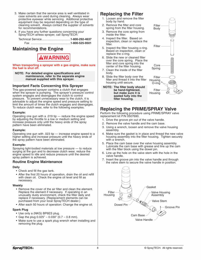
Replacing the Filter 1. Loosen and remove the filter
body by hand.2. Remove the filter and core
spring from the filter housing.3. Remove the core spring from
inside the filter.4. Inspect the filter. Based on
inspection, clean or replace thefilter.
5. Inspect the filter housing o-ring.Based on inspection, clean orreplace the o-ring.
6. Slide the new or cleaned filterover the core spring. Place thefilter and core spring into thecenter of the filter housing.
7. Clean the inside of the filterbody.
8. Slide the filter body over thefilter and thread it into the filterhousing until secure.
Replacing the PRIME/SPRAY ValvePerform the following procedure using PRIME/SPRAY valvereplacement kit P/N 0507690.
1. Drive the groove pin out of the valve handle.2. Remove the valve handle and the cam base.3. Using a wrench, loosen and remove the valve housing
assembly.4. Make sure the gasket is in place and thread the new valve
housing assembly into the filter housing. Tighten securelywith a wrench.
5. Place the cam base over the valve housing assembly.Lubricate the cam base with grease and line up the camwith the filter block using the dowel pin.
6. Line up the hole on the valve stem with the hole in thevalve handle.
7. Insert the groove pin into the valve handle and throughthe valve stem to secure the valve handle in position.
Dowel Pin
Cam Base
Valve Stem
Filter Housing
Valve Housing Assembly
Gasket
Valve Handle
Groove Pin
NOTE: The filter body shouldbe hand-tightened,but make sure it isseated fully into thefilter housing.
Filter Body
CoreSpring
Filter
Filter Housing
O-ring
Filter Housing

Replacing the Potentiometer
Electrostatic discharge (ESD) potential could causedamage to electronic pressure control. Use SprayTECHESD wrist strap P/N 0507958 or equivalent when workingon electronic pressure control.
1. Perform the Pressure Relief Procedure.2. Pry off the pressure control knob cap to expose the knob
tension nut.3. Turn the pressure control knob fully counterclockwise to
the minimum pressure setting.4. Using a 5/16” socket, loosen the tension nut in the center
of the knob. Remove the knob.5. Using a Phillips screwdriver, remove the four screws that
secure the electronic pressure control (EPC) assembly tothe EPC housing. Carefully remove the EPC assemblyfrom the housing. Gently move the assembly away fromthe sprayer and allow the assembly to hang from thehousing.
6. Hold the potentiometer inside the EPC housing whileusing a 1/2” thin wall socket to remove the seal nut thatsecures the potentiometer to the mounting plate. Removethe potentiometer from the EPC housing.
7. Carefully remove the potentiometer wires from theirconnection point on the EPC board.
8. Insert the stem of the new potentiometer through the holein the mounting plate from inside the EPC housing.Position the protruding tab on the potentiometer face intothe hole on the underside of the mounting plate (the wireswill face the open side of the EPC housing).
9. Thread the seal nut onto the threaded portion of the stemand tighten using a 1/2” thin wall socket.
Do not over-tighten the seal nut.10. Turn the potentiometer stem fully counterclockwise.11. Place the pressure control knob on the potentiometer
stem with the indicator tab resting at the “minimumpressure” tab on the mounting plate.
12. Tighten the knob tension nut using a 5/16” socket.
Do not over-tighten the knob tension nut. Over-tighteningwill damage the potentiometer.13. Connect the potentiometer wires to the EPC board. The
protruding tab on the EPC board connector will mate withthe slot on the potentiometer wires connector. Theconnector on the end of the potentiometer wires and theconnector on the EPC board will mate only one way. Donot force the connectors together.
14. Carefully place the EPC assembly over the EPC housingtaking care not to pinch any wires.
15. Install the four screws that secure the EPC assembly tothe EPC housing. Tighten securely.
CAUTION
CAUTION
EPC Housing
Pressure Control KnobSeal Nut
Cap
EPCBoard
EPCAssembly
EPCAssembly
Screw
Potentiometer
WARNING
Replacing the Sprayer ON/OFF Switch
Electrostatic discharge (ESD) potential could causedamage to electronic pressure control. Use SprayTECHESD wrist strap P/N 0507958 or equivalent when workingon electronic pressure control.
1. Perform the Pressure Relief Procedure.2. Using a Phillips screwdriver, remove the four screws that
secure the electronic pressure control (EPC) assembly tothe EPC housing. Carefully remove the EPC assemblyfrom the housing. Gently move the assembly away fromthe sprayer and allow the assembly to hang from thehousing.
3. Locate the bottom of the sprayer ON/OFF switch insidethe EPC housing.
4. Disconnect the switch wires from the sprayer ON/OFFswitch. Remember the locations of each of the two wires(label the wires, if necessary).
5. Depress the mounting tabs on each corner of the sprayerON/OFF switch inside the EPC housing and remove theswitch through the top of the housing.
6. Snap the new sprayer ON/OFF switch into the switch holein the EPC housing.
7. Connect the two switch wires to the new sprayer ON/OFFswitch. Make sure the wires are connected to thecorresponding terminals from which they were removed(refer to the labels created earlier in this procedure or theelectrical schematic in the Parts List section of thismanual).
8. Carefully place the EPC assembly over the EPC housingtaking care not to pinch any wires.
9. Install the four screws that secure the EPC assembly tothe EPC housing. Tighten securely.
Sprayer ON/OFF Switch
EPCBoard
EPCAssembly
EPCAssembly
Screw
WARNING
© SprayTECH. All rights reserved. 9
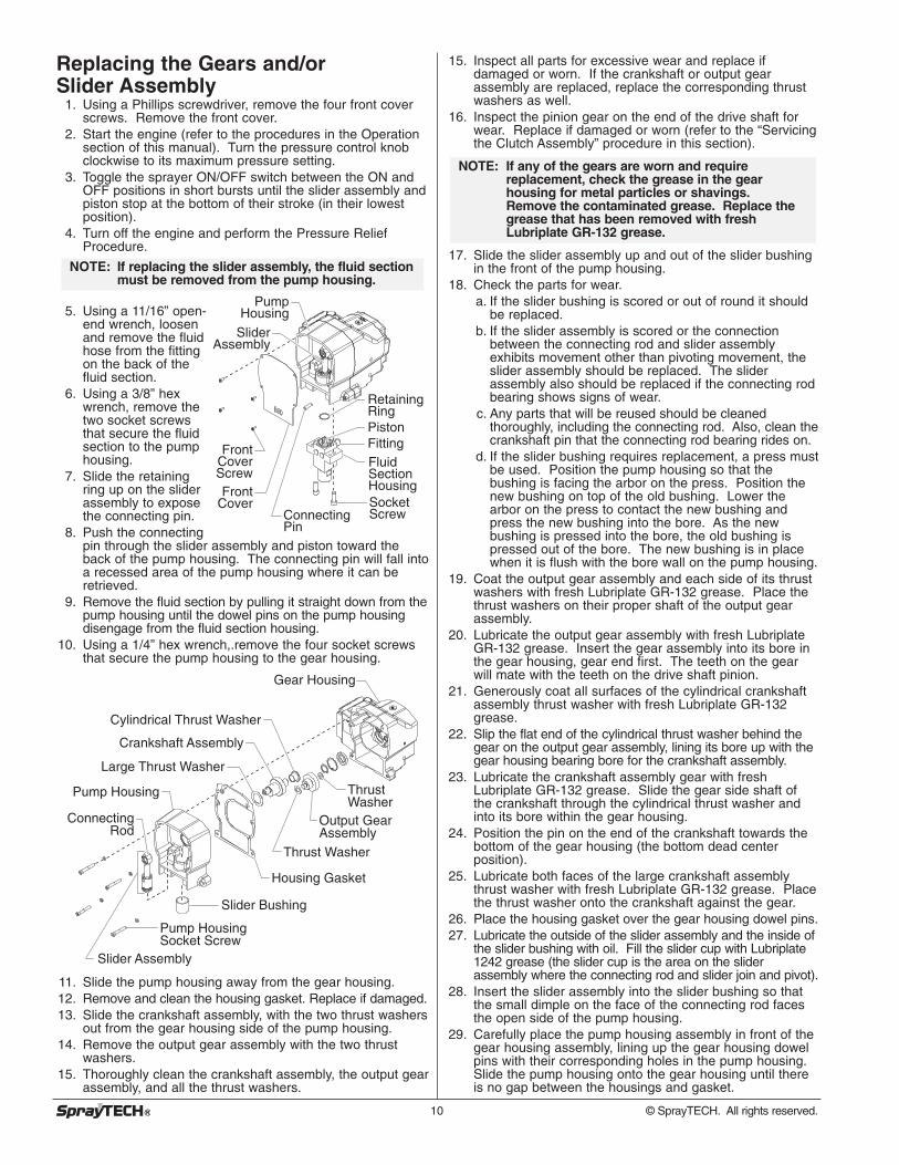
Replacing the Gears and/or Slider Assembly
1. Using a Phillips screwdriver, remove the four front coverscrews. Remove the front cover.
2. Start the engine (refer to the procedures in the Operationsection of this manual). Turn the pressure control knobclockwise to its maximum pressure setting.
3. Toggle the sprayer ON/OFF switch between the ON andOFF positions in short bursts until the slider assembly andpiston stop at the bottom of their stroke (in their lowestposition).
4. Turn off the engine and perform the Pressure ReliefProcedure.
5. Using a 11/16” open-end wrench, loosenand remove the fluidhose from the fittingon the back of thefluid section.
6. Using a 3/8” hexwrench, remove thetwo socket screwsthat secure the fluidsection to the pumphousing.
7. Slide the retainingring up on the sliderassembly to exposethe connecting pin.
8. Push the connectingpin through the slider assembly and piston toward theback of the pump housing. The connecting pin will fall intoa recessed area of the pump housing where it can beretrieved.
9. Remove the fluid section by pulling it straight down from thepump housing until the dowel pins on the pump housingdisengage from the fluid section housing.
10. Using a 1/4” hex wrench,.remove the four socket screwsthat secure the pump housing to the gear housing.
11. Slide the pump housing away from the gear housing.12. Remove and clean the housing gasket. Replace if damaged.13. Slide the crankshaft assembly, with the two thrust washers
out from the gear housing side of the pump housing.14. Remove the output gear assembly with the two thrust
washers.15. Thoroughly clean the crankshaft assembly, the output gear
assembly, and all the thrust washers.
Connecting Rod
Slider Bushing
Slider Assembly
Gear Housing
Pump Housing
Output Gear Assembly
Thrust Washer
Thrust Washer
Housing Gasket
Large Thrust Washer
Crankshaft Assembly
Cylindrical Thrust Washer
Pump Housing Socket Screw
FittingPiston
Retaining Ring
Pump Housing
Slider Assembly
Front Cover Screw
Fluid SectionHousingSocket Screw
Front Cover
Connecting Pin
NOTE: If replacing the slider assembly, the fluid sectionmust be removed from the pump housing.
10 © SprayTECH. All rights reserved.
15. Inspect all parts for excessive wear and replace ifdamaged or worn. If the crankshaft or output gearassembly are replaced, replace the corresponding thrustwashers as well.
16. Inspect the pinion gear on the end of the drive shaft forwear. Replace if damaged or worn (refer to the “Servicingthe Clutch Assembly” procedure in this section).
17. Slide the slider assembly up and out of the slider bushingin the front of the pump housing.
18. Check the parts for wear.a. If the slider bushing is scored or out of round it should
be replaced.b. If the slider assembly is scored or the connection
between the connecting rod and slider assemblyexhibits movement other than pivoting movement, theslider assembly should be replaced. The sliderassembly also should be replaced if the connecting rodbearing shows signs of wear.
c. Any parts that will be reused should be cleanedthoroughly, including the connecting rod. Also, clean thecrankshaft pin that the connecting rod bearing rides on.
d. If the slider bushing requires replacement, a press mustbe used. Position the pump housing so that thebushing is facing the arbor on the press. Position thenew bushing on top of the old bushing. Lower thearbor on the press to contact the new bushing andpress the new bushing into the bore. As the newbushing is pressed into the bore, the old bushing ispressed out of the bore. The new bushing is in placewhen it is flush with the bore wall on the pump housing.
19. Coat the output gear assembly and each side of its thrustwashers with fresh Lubriplate GR-132 grease. Place thethrust washers on their proper shaft of the output gearassembly.
20. Lubricate the output gear assembly with fresh LubriplateGR-132 grease. Insert the gear assembly into its bore inthe gear housing, gear end first. The teeth on the gearwill mate with the teeth on the drive shaft pinion.
21. Generously coat all surfaces of the cylindrical crankshaftassembly thrust washer with fresh Lubriplate GR-132grease.
22. Slip the flat end of the cylindrical thrust washer behind thegear on the output gear assembly, lining its bore up with thegear housing bearing bore for the crankshaft assembly.
23. Lubricate the crankshaft assembly gear with freshLubriplate GR-132 grease. Slide the gear side shaft ofthe crankshaft through the cylindrical thrust washer andinto its bore within the gear housing.
24. Position the pin on the end of the crankshaft towards thebottom of the gear housing (the bottom dead centerposition).
25. Lubricate both faces of the large crankshaft assemblythrust washer with fresh Lubriplate GR-132 grease. Placethe thrust washer onto the crankshaft against the gear.
26. Place the housing gasket over the gear housing dowel pins.27. Lubricate the outside of the slider assembly and the inside of
the slider bushing with oil. Fill the slider cup with Lubriplate1242 grease (the slider cup is the area on the sliderassembly where the connecting rod and slider join and pivot).
28. Insert the slider assembly into the slider bushing so thatthe small dimple on the face of the connecting rod facesthe open side of the pump housing.
29. Carefully place the pump housing assembly in front of thegear housing assembly, lining up the gear housing dowelpins with their corresponding holes in the pump housing.Slide the pump housing onto the gear housing until thereis no gap between the housings and gasket.
NOTE: If any of the gears are worn and requirereplacement, check the grease in the gearhousing for metal particles or shavings.Remove the contaminated grease. Replace thegrease that has been removed with freshLubriplate GR-132 grease.
Do not force the pump housing and gear housing together.30. Locate the four socket screws and lock washers that secure
the pump housing to the gear housing. The longer screws(2.25”) are fastened into the top internal holes. The shorterscrews (2”) are fastened into the bottom external bosses.
31. Using a 1/4” hex wrench, snug and tighten the socketscrews in a crossing pattern. Torque to 200–230 in./lbs.
32. If the fluid section was removed, reinstall by pushing thefluid section up toward the pump housing until the dowelpins in the pump housing engage the holes in the fluidsection housing. When the connecting pin hole on thepiston rod lines up with the hole in the slider assembly,insert the connecting pin.
33. Slide the retaining ring down over the connecting pin.34. Insert the two socket screws that secure the fluid section
to the pump housing and alternately snug, tighten, andtorque the screws to 400-440 in./lbs.
35. Position the front cover over the pump housing. Securethe front cover using the four front cover screws.
36. Using a 11/16” open-end wrench, attach the fluid hose tothe fitting on the back of the fluid section. Tighten securely.
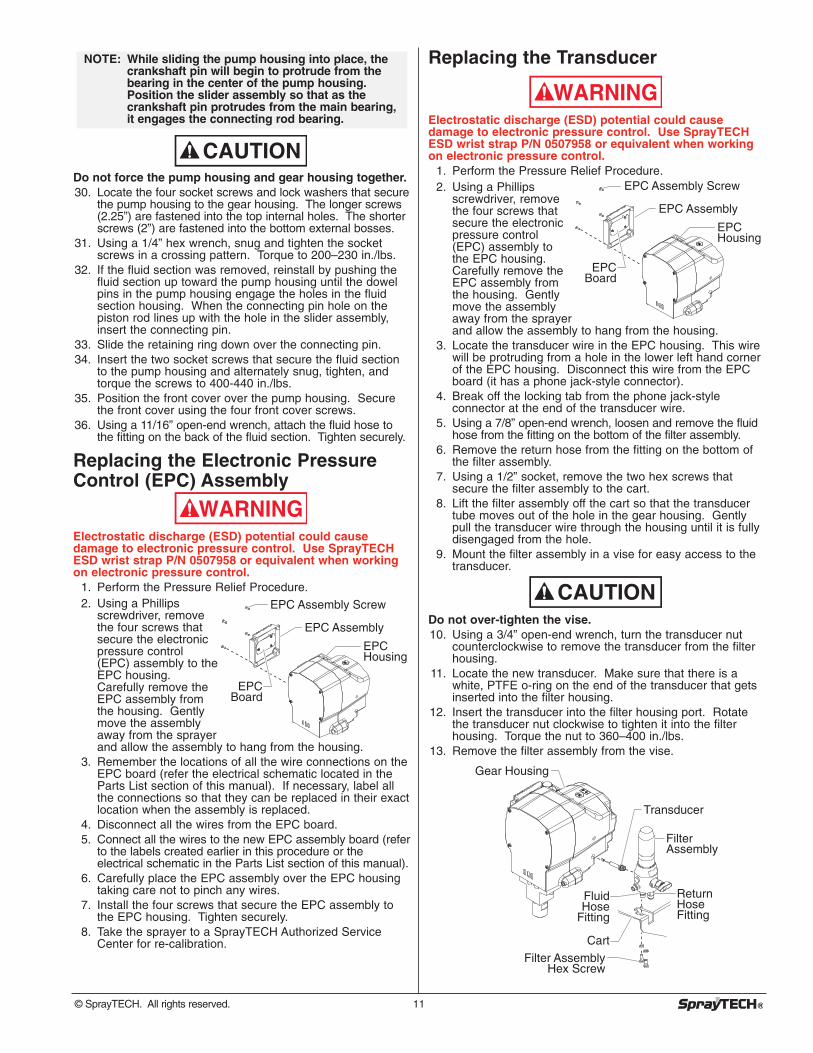
Replacing the Electronic PressureControl (EPC) Assembly
Electrostatic discharge (ESD) potential could causedamage to electronic pressure control. Use SprayTECHESD wrist strap P/N 0507958 or equivalent when workingon electronic pressure control.
1. Perform the Pressure Relief Procedure.2. Using a Phillips
screwdriver, removethe four screws thatsecure the electronicpressure control(EPC) assembly to theEPC housing.Carefully remove theEPC assembly fromthe housing. Gentlymove the assemblyaway from the sprayerand allow the assembly to hang from the housing.
3. Remember the locations of all the wire connections on theEPC board (refer the electrical schematic located in theParts List section of this manual). If necessary, label allthe connections so that they can be replaced in their exactlocation when the assembly is replaced.
4. Disconnect all the wires from the EPC board.5. Connect all the wires to the new EPC assembly board (refer
to the labels created earlier in this procedure or theelectrical schematic in the Parts List section of this manual).
6. Carefully place the EPC assembly over the EPC housingtaking care not to pinch any wires.
7. Install the four screws that secure the EPC assembly tothe EPC housing. Tighten securely.
8. Take the sprayer to a SprayTECH Authorized ServiceCenter for re-calibration.
EPC Housing
EPC Assembly Screw
EPC Assembly
EPCBoard
WARNING
CAUTION
NOTE: While sliding the pump housing into place, thecrankshaft pin will begin to protrude from thebearing in the center of the pump housing.Position the slider assembly so that as thecrankshaft pin protrudes from the main bearing,it engages the connecting rod bearing.
Replacing the Transducer
Electrostatic discharge (ESD) potential could causedamage to electronic pressure control. Use SprayTECHESD wrist strap P/N 0507958 or equivalent when workingon electronic pressure control.
1. Perform the Pressure Relief Procedure.2. Using a Phillips
screwdriver, removethe four screws thatsecure the electronicpressure control(EPC) assembly tothe EPC housing.Carefully remove theEPC assembly fromthe housing. Gentlymove the assemblyaway from the sprayerand allow the assembly to hang from the housing.
3. Locate the transducer wire in the EPC housing. This wirewill be protruding from a hole in the lower left hand cornerof the EPC housing. Disconnect this wire from the EPCboard (it has a phone jack-style connector).
4. Break off the locking tab from the phone jack-styleconnector at the end of the transducer wire.
5. Using a 7/8” open-end wrench, loosen and remove the fluidhose from the fitting on the bottom of the filter assembly.
6. Remove the return hose from the fitting on the bottom ofthe filter assembly.
7. Using a 1/2” socket, remove the two hex screws thatsecure the filter assembly to the cart.
8. Lift the filter assembly off the cart so that the transducertube moves out of the hole in the gear housing. Gentlypull the transducer wire through the housing until it is fullydisengaged from the hole.
9. Mount the filter assembly in a vise for easy access to thetransducer.
Do not over-tighten the vise.10. Using a 3/4” open-end wrench, turn the transducer nut
counterclockwise to remove the transducer from the filterhousing.
11. Locate the new transducer. Make sure that there is awhite, PTFE o-ring on the end of the transducer that getsinserted into the filter housing.
12. Insert the transducer into the filter housing port. Rotatethe transducer nut clockwise to tighten it into the filterhousing. Torque the nut to 360–400 in./lbs.
13. Remove the filter assembly from the vise.
Transducer
Filter Assembly Hex Screw
Gear Housing
Return Hose Fitting
FilterAssembly
Fluid Hose
Fitting
Cart
CAUTION
EPC Housing
EPC Assembly Screw
EPC Assembly
EPCBoard
WARNING
© SprayTECH. All rights reserved. 11

14. Insert the phone jack-style connector on the newtransducer wire into the hole in the gear housing fromwhich the old transducer wire was removed. Push thewire and connector until the connector is visible in theEPC housing.
15. Gently pull the wire into the EPC housing while movingthe filter assembly to its mounting point on the cart. Guidethe end of the transducer tube into the hole in the gearhousing.
16. Mount the filter assembly to the cart using the two hexscrews and lock washers. Torque the screws to 100–130in./lbs.
17. Using a 7/8” open-end wrench, attach the fluid hose to thefitting on the bottom of the filter assembly. Tighten securely.
18. Push the return hose firmly into the fitting on the bottom ofthe filter assembly. Pull on the hose to make sure it hasengaged within the fitting.
19. Plug the phone jack-style connector on the transducerwire into the socket on the EPC board from which the oldconnector was removed.
20. Carefully place the EPC assembly over the EPC housingtaking care not to pinch any wires.
21. Install the four screws that secure the EPC assembly tothe EPC housing. Tighten securely.
22. Take the sprayer to a SprayTECH Authorized ServiceCenter for re-calibration.
23. After re-calibration, pressurize the system and check forleaks.
Servicing the Clutch Assembly
Removing/Replacing the Clutch ArmatureAssembly
1. Perform the Pressure Relief Procedure.2. Using a 11/16” open-end wrench, loosen and remove the
fluid hose from the fitting on the back of the fluid section.3. Hold the transducer tube with a pliers to prevent it from
rotating and turn the transducer nut counterclockwiseusing a 3/4” open-end wrench. When the nut disengagesthe filter housing, carefully remove the transducer from thefilter housing.
4. Locate the wire that exits the rear of the electronicpressure control (EPC) housing and connects to the wireharness on the engine. Disconnect this wire from itsconnector at the engine wire harness.
5. Using a 1/2” wrench, remove the four hex screws and lockwashers that secure the clutch housing to the gear housing.
6. Using a 9/16” socket, remove the two hex screws thatsecure the gear housing to the cart.
NOTE: When replacing the clutch armature, the clutchrotor must be replaced also. This will allow foreven wear and maximum life on clutch parts.
Transducer
Filter Assembly Hex Screw
Gear Housing
Return Hose Fitting
FilterAssembly
Fluid Hose
Fitting
Cart
12 © SprayTECH. All rights reserved.
7. Slide the pump and gear housings away from the engineto disengage them from the clutch housing.
8. Locate the clutch armature assembly on the end of theengine shaft. Note the two set screws as well as theunused, threaded hole in the taper lock bushing at thecenter of the clutch hub.
9. Using an 1/8” hex wrench, remove the two set screwsfrom the taper lock bushing
10. Thread one of the set screws into the unused, threaded holeon the taper lock bushing. As the screw tightens, the bushingwill loosen. Once the bushing has loosened enough, slide theclutch armature assembly off the engine shaft.
11. To replace the clutch armature assembly , line up thethree holes in the taper lock bushing with the three holesin the clutch armature and insert the bushing into thecenter of the clutch armature.
12. Line up the key on the taper lock bushing with the keywayon the engine shaft and slide the assembly onto the shaftwith the holes facing out.
13. Apply blue Loctite to the two set screws and insert thescrews into the taper lock bushing. Tighten the set screwsonly two turns at this time.
15. Using the clutch set-uptool (P/N 0509926),position the clutcharmature on the engineshaft. Hold the toolacross the face of theclutch housing so thatthe center, recessedportion of the toolstraddles the clutcharmature assembly. Pullthe clutch armatureassembly towards thetool until the face of the armature is against the tool.
15. While holding the clutch armature assembly against thetool, use an 1/8” hex wrench and alternately tighten theset screws into the taper lock bushing. Torque to 65–75in/lbs.
16. Make sure the friction surface of the clutch armature isclean and free from oil or grease.
Removing the Clutch Rotor, Clutch Field, andDrive Shaft Assembly
1. Follow steps 1–7 in “Removing/Replacing the ClutchArmature Assembly.”
2. Locate the clutch rotor assembly, which will be protruding outfrom the gear housing. Note the locations of the three socketscrews and the two empty, threaded holes on the clutch rotor.
3. Using a 3/16” hex wrench, remove the three socketscrews and lock washers that secure the clutch rotor tothe drive shaft assembly.
4. Thread two of the socket screws into the empty, threadedholes and tighten alternately. This will push the clutchrotor away from the drive shaft assembly and pinion.
Clutch Housing
Engine
Set Screw
Set-Up Tool
TaperLock Bushing
Taper Lock Bushing
Gear Housing
Clutch Armature
Pump Housing
Lock Washer
Clutch Housing
Clutch Housing Hex Screw
Set Screw
Engine Shaft
Gear Housing Hex Screw
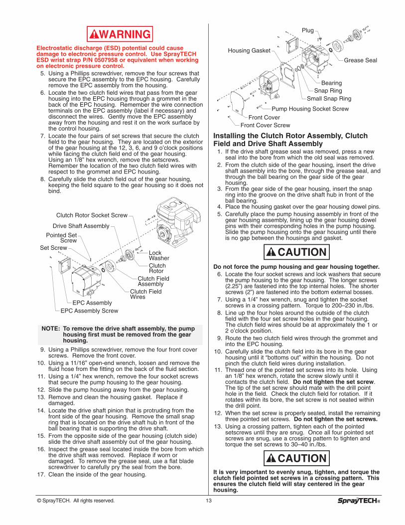
Electrostatic discharge (ESD) potential could causedamage to electronic pressure control. Use SprayTECHESD wrist strap P/N 0507958 or equivalent when workingon electronic pressure control.
5. Using a Phillips screwdriver, remove the four screws thatsecure the EPC assembly to the EPC housing. Carefullyremove the EPC assembly from the housing.
6. Locate the two clutch field wires that pass from the gearhousing into the EPC housing through a grommet in theback of the EPC housing. Remember the wire connectionterminals on the EPC assembly (label if necessary) anddisconnect the wires. Gently move the EPC assemblyaway from the housing and rest it on the work surface bythe control housing.
7. Locate the four pairs of set screws that secure the clutchfield to the gear housing. They are located on the exteriorof the gear housing at the 12, 3, 6, and 9 o’clock positionswhile facing the clutch field end of the gear housing.Using an 1/8” hex wrench, remove the setscrews.Remember the location of the two clutch field wires withrespect to the grommet and EPC housing.
8. Carefully slide the clutch field out of the gear housing,keeping the field square to the gear housing so it does notbind.
9. Using a Phillips screwdriver, remove the four front coverscrews. Remove the front cover.
10. Using a 11/16” open-end wrench, loosen and remove thefluid hose from the fitting on the back of the fluid section.
11. Using a 1/4” hex wrench, remove the four socket screwsthat secure the pump housing to the gear housing.
12. Slide the pump housing away from the gear housing.13. Remove and clean the housing gasket. Replace if
damaged.14. Locate the drive shaft pinion that is protruding from the
front side of the gear housing. Remove the small snapring that is located on the drive shaft hub in front of theball bearing that is supporting the drive shaft.
15. From the opposite side of the gear housing (clutch side)slide the drive shaft assembly out of the gear housing.
16. Inspect the grease seal located inside the bore from whichthe drive shaft was removed. Replace if worn ordamaged. To remove the grease seal, use a flat bladescrewdriver to carefully pry the seal from the bore.
17. Clean the inside of the gear housing.
NOTE: To remove the drive shaft assembly, the pumphousing first must be removed from the gearhousing.
Clutch Rotor Socket Screw
Drive Shaft Assembly
Pointed Set Screw
Set Screw
Clutch Field Assembly
Lock WasherClutch Rotor
Clutch Field Wires
EPC AssemblyEPC Assembly Screw
WARNING
Installing the Clutch Rotor Assembly, ClutchField and Drive Shaft Assembly
1. If the drive shaft grease seal was removed, press a newseal into the bore from which the old seal was removed.
2. From the clutch side of the gear housing, insert the driveshaft assembly into the bore, through the grease seal, andthrough the ball bearing on the gear side of the gearhousing.
3. From the gear side of the gear housing, insert the snapring into the groove on the drive shaft hub in front of theball bearing.
4. Place the housing gasket over the gear housing dowel pins.5. Carefully place the pump housing assembly in front of the
gear housing assembly, lining up the gear housing dowelpins with their corresponding holes in the pump housing.Slide the pump housing onto the gear housing until thereis no gap between the housings and gasket.
Do not force the pump housing and gear housing together.6. Locate the four socket screws and lock washers that secure
the pump housing to the gear housing. The longer screws(2.25”) are fastened into the top internal holes. The shorterscrews (2”) are fastened into the bottom external bosses.
7. Using a 1/4” hex wrench, snug and tighten the socketscrews in a crossing pattern. Torque to 200–230 in./lbs.
8. Line up the four holes around the outside of the clutchfield with the four set screw holes in the gear housing.The clutch field wires should be at approximately the 1 or2 o’clock position.
9. Route the two clutch field wires through the grommet andinto the EPC housing.
10. Carefully slide the clutch field into its bore in the gearhousing until it “bottoms out” within the housing. Do notpinch the clutch field wires during installation.
11. Thread one of the pointed set screws into its hole. Usingan 1/8” hex wrench, rotate the screw slowly until itcontacts the clutch field. Do not tighten the set screw.The tip of the set screw should mate with the drill pointhole in the field. Check the clutch field for rotation. If itrotates within its bore, the set screw is not seated withinthe drill point.
12. When the set screw is properly seated, install the remainingthree pointed set screws. Do not tighten the set screws.
13. Using a crossing pattern, tighten each of the pointedsetscrews until they are snug. Once all four pointed setscrews are snug, use a crossing pattern to tighten andtorque the set screws to 30–40 in./lbs.
It is very important to evenly snug, tighten, and torque theclutch field pointed set screws in a crossing pattern. Thisensures the clutch field will stay centered in the gearhousing.
CAUTION
CAUTION
Grease Seal
BearingSnap Ring
Small Snap Ring
Front Cover
Pump Housing Socket Screw
Front Cover Screw
Plug
Housing Gasket
© SprayTECH. All rights reserved. 13

14. Install the remaining four set screws over the four pointedset screws. Using an 1/8” hex wrench, tighten each of theset screws in a crossing pattern until they are snug. Onceall four set screws are snug, use a crossing pattern totighten and torque the set screws to 60–70 in./lbs.
15. Line up the three screw holes and dowel pin hole on theclutch rotor with the screw holes and dowel pin on the driveshaft assembly hub. Place the clutch rotor onto the hub.
16. Using a 3/16” hex wrench, thread the three socket screwsand lock washers through the clutch rotor and into thedrive shaft assembly hub. Evenly snug, tighten, andtorque the socket screws to 75–85 in/lbs.
17. Make sure the friction surface of the clutch rotor is cleanand free from oil or grease.
Electrostatic discharge (ESD) potential could causedamage to electronic pressure control. Use SprayTECHESD wrist strap P/N 0507958 or equivalent when workingon electronic pressure control.18. Locate the two clutch field wires in the EPC housing.
Gently pull the wires fully into the EPC housing so thatthere is no slack in the gear housing. Connect the wiresto their proper terminals on the EPC board (refer to thelabels created earlier in this procedure or the electricalschematic in the Parts List section of this manual).
19. Carefully place the EPC assembly over the EPC housingtaking care not to pinch any wires.
20. Install the four screws that secure the EPC assembly tothe EPC housing. Tighten securely.
Mating the Gear Housing and the ClutchHousing
1. Place the gear housing assembly onto the cart in front ofthe clutch housing. Line up the dowel pins in the gearhousing with their corresponding holes in the clutchhousing. Slide the gear housing assembly onto the clutchhousing until there is no gap between the housings.
2. Thread the four hex screws and lock washers through theclutch housing and into the gear housing.
3. Using a 1/2” wrench, snug and tighten the hex screws in acrossing pattern. Torque to 140–155 in./lbs.
4. Using a 9/16” socket, thread the two hex screws that securethe gear housing to the cart through the underside of thecart and into the gear housing. Torque to 100–120 in./lbs.
5. Connect the wire from the EPC housing to its matingconnector on the engine wire harness.
6. Make sure that there is a white PTFE o-ring on the end ofthe transducer that gets inserted into the filter housing.Insert the transducer into the filter housing port.
7. Hold the transducer tube with a pliers to prevent it fromrotating, and turn the transducer nut clockwise with a 3/4”open-end wrench to tighten it into the filter housing.Torque the nut to 360–400 in./lbs.
Checking the Clutch Gap1. Remove the plastic plug from the top of the clutch
housing. Look through the port to locate the clutcharmature and the clutch rotor.
2. Check the gap between the clutch armature and the clutchrotor using a .016” feeler gauge and a .035” feeler gauge.a. Insert each feeler gauge through the port and into the
gap between the clutch armature and the clutch rotor.The .016” feeler gauge should fit in the gap. The .035”feeler gauge should not fit in the gap.
b. Pull the engine pull cord several times to rotate theclutch armature, checking the gap with each feelergauge between each pull.
c. If the .016” gauge does not fit or the .035” gauge does fitat any checkpoint, the gap must be readjusted. This isdone by relocating the clutch hub and armature assemblyon the engine shaft. Refer to the “Removing/Replacingthe Clutch Armature Assembly” procedure.
WARNING
14 © SprayTECH. All rights reserved.
Servicing the Fluid SectionUse the following procedures to service the valves and repackthe fluid section.
1. Using a Phillips screwdriver, remove the four front coverscrews. Remove the front cover.
2. Start the engine (refer to the procedures in the Operationsection of this manual). Turn the pressure control knobclockwise to its maximum pressure setting.
3. Toggle the sprayer ON/OFF switch between the ON andOFF positions in short bursts until the slider assembly andpiston rod stop at the bottom of their stroke (in their lowestposition).
4. Turn off the engine and perform the Pressure ReliefProcedure.
Before proceeding, follow the Pressure Relief Procedureoutlined previously in this manual. Additionally, follow allother warnings to reduce the risk of an injection injury,injury from moving parts or electric shock.
Servicing the ValvesThe design of the fluid sectionallows access to the inlet valveand seat as well as the outletvalve and seat withoutcompletely disassembling thefluid section. It is possible thatthe valves may not seat properlybecause of debris stuck in theinlet valve seat or outlet valveseat. Use the followinginstructions to clean the valvesand reverse or replace the seats.
1. Using a wrench, loosen andremove the inlet valvehousing from the fluidsection housing.
2. Clean out any debris in the inlet valve housing andexamine the valve housing and seat. If the inlet valveseat is damaged, reverse the seat to the unused side orreplace the seat.
3. Using a 3/8" hex wrench, loosen and remove the outletvalve retainer from the piston rod.
4. Clean out any debris andexamine the outlet valve retainerand seat. If the outlet valve seatis damaged, reverse to theunused side or replace the seat.
5. Remove, clean, and inspect the outlet cage, crushwasher, and outlet valve ball. Replace if they are worn ordamaged.
6. Reassemble the valves by reversing the steps above.
NOTE: If the outlet valve seat is reversed or replaced,the outlet valve ball must be replaced.
NOTE: Always service theoutlet valve with thepiston rod attached tothe pump. This willprevent the piston rodfrom rotating duringdisassembly of theoutlet valve.
Piston Rod
Outlet Cage
Crush Washer
Outlet Valve Seat
Outlet ValveRetainer
Outlet Valve Ball
NOTE: If the inlet valve seat is reversed or replaced,the inlet valve ball must be replaced.
NOTE: Keep the sprayer inthe upright positionfor this procedure.
Fluid Section Housing
Inlet Valve SealInlet Valve SeatPTFE O-RingInlet ValveHousing
Piston BushingInlet Cage
Inlet Valve Ball
WARNING

Repacking the Fluid Section
1. Remove the inlet valveand outlet valveassemblies using thesteps in the “Servicingthe Valves” procedureabove.
2. Using a 11/16” open-endwrench, loosen andremove the fluid hosefrom the fitting on theback of the fluid section.
3. Using a 3/8” hex wrench,remove the two socketscrews that secure thefluid section to the pumphousing.
4. Slide the retaining ringup on the sliderassembly to expose theconnecting pin.
5. Push the connecting pinthrough the sliderassembly and pistontoward the back of thepump housing. Theconnecting pin will fallinto a recessed area ofthe pump housing whereit can be retrieved.
6. Remove the fluid sectionby pulling it straight downfrom the pump housinguntil the dowel pins on thepump housing disengageform the fluid sectionhousing.
7. Slide the piston rod outthrough the bottom of the fluid section housing.
8. Using a wrench, loosen and remove the retainer nut andpiston guide from the fluid section housing.
9. Remove the upper and lower packings from the fluidsection housing.
10. Clean the fluid section housing thoroughly 11. Locate the new upper and lower packing assemblies. .
Remove the piston insertion tool from the upper packingand the seal sizing tool from the lower packing.
12 Pack the areas between thepacking lips with grease(included in repacking kit).Lubricate the o-rings on theexterior of the packings withgrease.
13. Insert the upper packingassembly into the top of thefluid section housing with the raised lip facing down intothe housing.
Install upper packing with raised lip facing down.
Raised Lip
NOTE: Be careful not to scratch, score, or otherwisedamage the inside of the fluid section housingduring removal of the packing assemblies.
Slider Assembly
Retainer Nut
Retaining Ring
Connecting Pin
Piston Guide
Fluid SectionHousing
UpperPacking
Lower Packing
Socket Screw
Piston Rod
Fitting
NOTE: The factory-installed packings are red in color.The replacement packings in the packingreplacement kit are white.
14. Insert the lower packingassembly into the bottom of thefluid section housing with thelarge beveled edge facingtoward the housing (bevelededge will be facing up whenthe housing is upright).
15 Inspect the piston rod for wearand replace if necessary.
16 Reassemble the outlet valve assembly into the piston rodusing the new o-ring, outlet valve seal, and outlet valve ballthat came with the repacking kit. Apply blue Loctie to thethreads of the outlet valve retainer. Torque the outlet valveretainer to 300–350 in./lbs.
Never use a wrench on the piston rod itself. This couldcause damage to the piston and cause leakage.17. Insert the new piston guide into the retainer nut. Thread
the retainer nut into the fluid section housing until it ishand tight.
18. Slide the piston guide tool (included in the repacking kit)over the top of the piston rod.
19. Insert the piston rod into the bottom of the fluid sectionhousing, through the lower packing, through the upperpacking, and out through the retainer nut. Using a rubbermallet, tap the bottom of the piston rod lightly until thepiston rod is in position in the fluid section housing.
20. Using a wrench, tighten the retainer nut. Torque to 550-600 in./lbs.
21. Position the fluid section underneath the pump housing bylining up the pump housing dowel pins with theirrespective holes in the top of the fluid section housing.Push the fluid section up towards the pump housing,engaging the dowel pins, until the fluid section housingrests against the pump housing. When the connecting pinhole on the piston rod lines up with the hole in the sliderassembly, insert the connecting pin.
22. Insert the two socket screws that secure the fluid sectionto the pump housing and alternately snug, tighten, andtorque the screws to 400-440 in./lbs.
23. Reassemble the inlet valve using the new inlet valve seal,o-ring, and inlet valve ball. Thread the inlet valveassembly into the fluid section housing and torque to 350-400 in./lbs.
24. Position the front cover over the pump housing. Securethe front cover using the four front cover screws.
25. Using a 11/16” open-end wrench, attach the fluid hose tothe fitting on the back of the fluid section. Tightensecurely.
26. Turn on the sprayer by following the procedure in the“Operation” section of this manual and check for leaks.
NOTE: Repacking kit P/N 0509909 is available. Forbest results use all parts supplied in this kit.
NOTE: Make sure the raised lip on the bottom of thelower packing assembly is fully outside thepacking around the piston rod after insertionof the piston rod.
NOTE: Coat the piston guide tool and the piston rodwith grease before inserting them into the fluidsection housing.
CAUTION
Install lower packing so large beveled edge will
be facing up when the fluid section housing is upright.
Large Beveled Edge
© SprayTECH. All rights reserved. 15
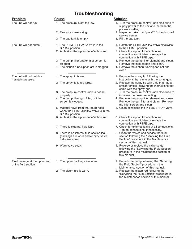
Troubleshooting
16 © SprayTECH. All rights reserved.
Solution1. Turn the pressure control knob clockwise to
supply power to the unit and increase thepressure setting.
2. Inspect or take to a SprayTECH authorizedservice center.
3. Fill the gas tank.
1. Rotate the PRIME/SPRAY valve clockwiseto the PRIME position.
2. Check the siphon tube/siphon setconnection and tighten or re-tape theconnection with PTFE tape.
3. Remove the pump filter element and clean.Remove the inlet screen and clean.
4. Remove the siphon tube/siphon set andclean.
1. Replace the spray tip following theinstructions that came with the spray gun.
2. Replace the spray tip with a tip that has asmaller orifice following the instructions thatcame with the spray gun.
3. Turn the pressure control knob clockwise toincrease the pressure setting.
4. Remove the pump filter element and clean.Remove the gun filter and clean. Removethe inlet screen and clean.
5. Clean or replace the PRIME/SPRAY valve.
6. Check the siphon tube/siphon setconnection and tighten or re-tape theconnection with PTFE tape.
7. Check for external leaks at all connections.Tighten connections, if necessary.
8. Clean the valves and service the fluidsection following the “Servicing the FluidSection” procedure in the Maintenancesection of this manual.
9. Reverse or replace the valve seatsfollowing the “Servicing the Fluid Section”procedure in the Maintenance section ofthis manual.
1. Repack the pump following the “Servicingthe Fluid Section” procedure in theMaintenance section of this manual.
2. Replace the piston rod following the“Servicing the Fluid Section” procedure inthe Maintenance section of this manual.
Cause1. The pressure is set too low.
2. Faulty or loose wiring.
3. The gas tank is empty.
1. The PRIME/SPRAY valve is in theSPRAY position.
2. Air leak in the siphon tube/siphon set.
3. The pump filter and/or inlet screen isclogged.
4. The siphon tube/siphon set is clogged.
1. The spray tip is worn.
2. The spray tip is too large.
3. The pressure control knob is not setproperly.
4. The pump filter, gun filter, or inletscreen is clogged.
5. Material flows from the return hosewhen the PRIME/SPRAY valve is in theSPRAY position.
6. Air leak in the siphon tube/siphon set.
7. There is external fluid leak.
8. There is an internal fluid section leak(packings are worn and/or dirty, valveballs are worn).
9. Worn valve seats
1. The upper packings are worn.
2. The piston rod is worn.
TroubleshootingProblemThe unit will not run.
The unit will not prime.
The unit will not build ormaintain pressure.
Fluid leakage at the upper endof the fluid section.
© SprayTECH. All rights reserved. 17
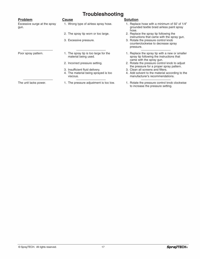
TroubleshootingProblemExcessive surge at the spraygun.
Poor spray pattern.
The unit lacks power.
Cause1. Wrong type of airless spray hose.
2. The spray tip worn or too large.
3. Excessive pressure.
1. The spray tip is too large for thematerial being used.
2. Incorrect pressure setting.
3. Insufficient fluid delivery.4. The material being sprayed is too
viscous.
1. The pressure adjustment is too low.
Solution1. Replace hose with a minimum of 50’ of 1/4”
grounded textile braid airless paint sprayhose.
2. Replace the spray tip following theinstructions that came with the spray gun.
3. Rotate the pressure control knobcounterclockwise to decrease spraypressure.
1. Replace the spray tip with a new or smallerspray tip following the instructions thatcame with the spray gun.
2. Rotate the pressure control knob to adjustthe pressure for a proper spray pattern.
3. Clean all screens and filters.4. Add solvent to the material according to the
manufacturer's recommendations.
1. Rotate the pressure control knob clockwiseto increase the pressure setting.

18 © SprayTECH. Tous droits réservés.
Consignes de sécuritéLe présent manuel comprend des renseignements devant êtrelus attentivement avant toute utilisation de l'appareil. Lorsquel'un des symboles suivants apparaît, il est recommandé d'êtreparticulièrement attentif et de tenir compte des mesures desécurité indiquées.
Ce symbole indique un danger potentiel pouvant causer desblessures graves ou même mortelles. Des renseignementsimportants sur la sécurité sont également indiqués.
Ce symbole indique un danger potentiel pouvant causer desblessures corporelles ou des dommages à l'équipement. Desrenseignements importants sur la façon de prévenir toutdommage à l'équipement ou toute blessure corporelle mineuresont également indiqués.
CONSIGNES DE SÉCURITÉ IMPORTANTESA. CONSERVEZ CES CONSIGNES – Pour réduire les
risques d’incendie ou d’explosion, d’électrocution etde blessures, lisez et assurez-vous de biencomprendre toutes les consignes contenues dans cemanuel. Familiarisez-vous avec les commandes etl’usage correct de l’équipement.
B. AVERTISSEMENT – Pour réduire le risque d’incendieou d’explosion :1. Ne pulvérisez pas de matières inflammables ou
combustibles près d’une flamme nue, de voyantslumineux ou de sources d’ignition telles que des objetschauds, cigarettes, moteurs, matériel et appareilsélectriques. Évitez de produire des étincelles enconnectant et en déconnectant les cordons électriques.
2. Pour les appareils destinés à n’utiliser que des produitsà l’eau – Ne pulvérisez pas et ne les nettoyez pas avecdes liquides inflammables. Exclusivement pour usageavec liquides à base d’eau.
3. Pour les appareils destinés à un usage exclusif avec desproduits à l’eau ou des produits minéraux de type alcoolavec un point d’éclair minimum de 21 ºC (70 ºF) – Nepulvérisez pas et ne les nettoyez pas avec des liquidesayant un point d’éclair inférieur à 21 ºC (70 ºF). Le pointd’éclair est la température à laquelle un fluide peutproduire suffisamment de vapeur pour s’enflammer.
4. L’écoulement de peinture ou de solvant dansl’équipement peut produire de l’électricité statique.L’électricité statique crée un risque d’incendie oud’explosion en présence de fumées de peinture ou desolvant. Toutes les pièces du système du pulvérisateur,y compris la pompe, l’ensemble du tuyau, le pistolet depulvérisation et les objets dans et autour de la zone depulvérisation doivent être correctement reliés à la terrepour protéger contre les décharges d’électricité statiqueet les étincelles. N’utilisez que des tuyaux conducteursou reliés à la terre pour pulvérisateurs de peinture sousvide à haute pression, spécifiés par le fabricant.
5. Vérifiez que tous les conteneurs ou systèmes destockage sont reliés à la terre pour éviter les déchargesd’électricité statique.
6. Connectez à une prise électrique avec prise de terre etutilisez des rallonges électriques reliées à la terre.N’utilisez pas d’adaptateur 3 à 2.
AVERTISSEMENT
NOTA : Les remarques donnent des renseignementsimportants requérant une attention particulière.
ATTENTION
AVERTISSEMENT
7. N’utilisez pas de peinture ou de solvant contenant duhalon, par exemple, le chlore, les agents antimoisissure àl’eau de Javel, le chlorure de méthylène et letrichloroéthane. Ils ne sont pas compatibles avecl’aluminium. Contactez le fournisseur de revêtements pourconnaître la compatibilité du matériau avec l’aluminium.
8. La zone de pulvérisation doit toujours être bien aérée.Une bonne quantité d’air frais doit constammenttraverser la zone de pulvérisation pour éviter lesaccumulations de vapeurs inflammables. Le systèmede pompage doit être placé dans une zone bien aérée.Ne pulvérisez pas le système de pompage.
9. Ne fumez pas dans la zone de pulvérisation.10. N’actionnez pas d’interrupteurs électriques, de moteurs
ou autres dispositifs produisant des étincelles dans lazone de pulvérisation.
11. Maintenez la propreté de la zone et veillez à ce qu’ellene contienne pas de conteneurs de peinture ou desolvant, de chiffons et autres matières inflammables.
12. Sachez ce que contiennent la peinture et les solvantspulvérisés. Lisez les fiches de sécurité du matériel(MSDS) et les étiquettes apposées sur les conteneursde peintures et de solvants. Respectez les consignesde sécurité du fabricant de peinture et de solvant.
13. Placez la pompe à une distance minimum de 7,62 mètres(25 pieds) de l’objet à pulvériser, dans une zone bienaérée (ajoutez de la longueur de tuyau si besoin est). Lesvapeurs inflammables sont souvent plus lourdes que l’air.La zone près du sol doit être très bien aérée. La pompecontient des pièces qui produisent des arcs et émettentdes étincelles pouvant enflammer les vapeurs.
14. Le plastique peut causer des étincelles d’électricitéstatique. N’accrochez aucun plastique dans une zonede pulvérisation fermée. N’utilisez pas de toiles deprotection en plastique quand vous pulvérisez unematière inflammable.
15. Ayez un extincteur en bon état de fonctionnement àportée de main.
C. AVERTISSEMENT – Pour réduire le risque depénétration dans la peau :
1. Ne dirigez pas le pistolet sur et ne pulvérisez pas lespersonnes ou les animaux.
2. N’approchez pas les mains ni d’autres parties du corpsde la sortie du produit. Par exemple, ne tentez pasd’arrêter une fuite avec une partie du corps.
3. Utilisez toujours le protège-embout de la buse. Nepulvérisez pas sans que le protège-embout de la busene soit installé.
4. Utilisez exclusivement un embout de buse spécifié parle fabricant.
5. Prenez garde quand vous nettoyez ou que vous changezles embouts de buse. Si l’embout se bouche pendant quevous pulvérisez, verrouillez TOUJOURS la détente dupistolet, arrêtez la pompe et libérez toute la pressionavant de réparer ou de nettoyer l’embout ou le protecteurou avant de changer d’embout. La pression n’est paslibérée par l’arrêt du moteur. La poignée du robinet-valvePRIME/SPRAY (AMORÇAGE/ PULVÉRISATION) doitêtre placée sur PRIME pour libérer la pression. Consultezla PROCÉDURE DE LIBÉRATION DE PRESSIONdécrite dans le manuel de la pompe.
DANGER :Blessure par injection – Le jet de fluide à haute pressionproduit par cet équipement peut transpercer la peau etles tissus sous-jacents, ce qui produit de gravesblessures et peut entraîner une amputation. Consultezimmédiatement un médecin. NE TRAITEZ PAS UNEINJECTION COMME UNE SIMPLE COUPURE.
AVERTISSEMENT
Français
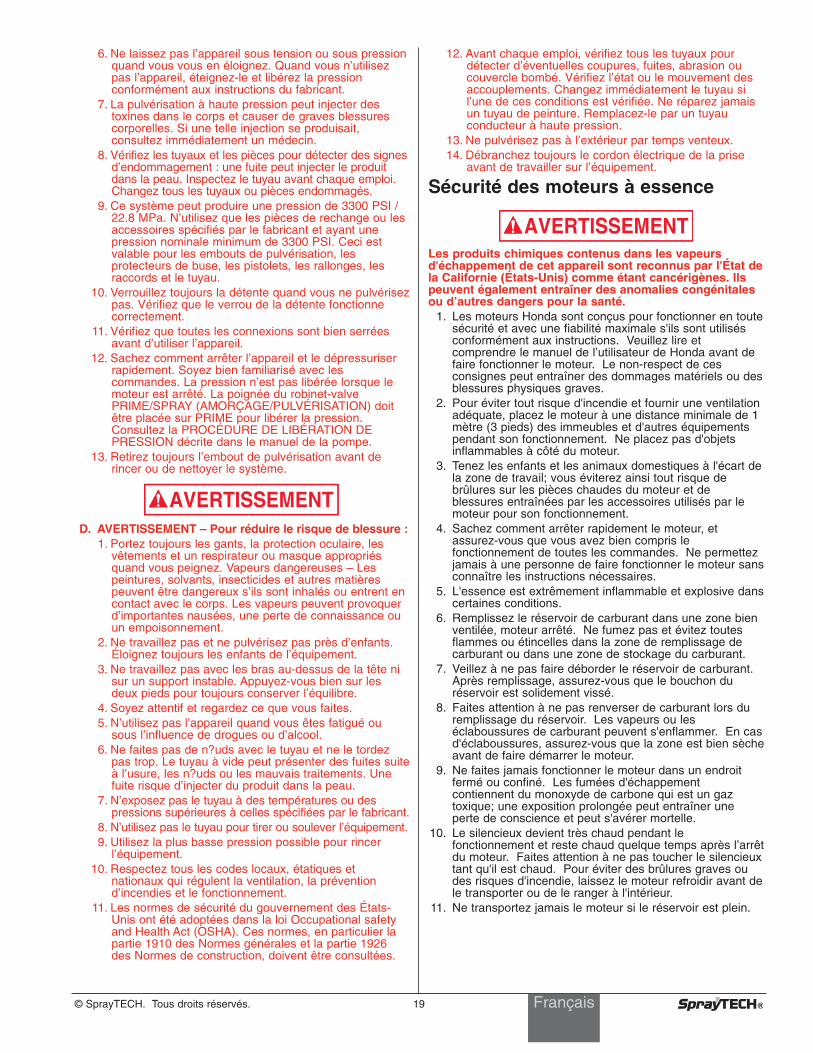
© SprayTECH. Tous droits réservés. 19
6. Ne laissez pas l’appareil sous tension ou sous pressionquand vous vous en éloignez. Quand vous n’utilisezpas l’appareil, éteignez-le et libérez la pressionconformément aux instructions du fabricant.
7. La pulvérisation à haute pression peut injecter destoxines dans le corps et causer de graves blessurescorporelles. Si une telle injection se produisait,consultez immédiatement un médecin.
8. Vérifiez les tuyaux et les pièces pour détecter des signesd’endommagement : une fuite peut injecter le produitdans la peau. Inspectez le tuyau avant chaque emploi.Changez tous les tuyaux ou pièces endommagés.
9. Ce système peut produire une pression de 3300 PSI /22.8 MPa. N’utilisez que les pièces de rechange ou lesaccessoires spécifiés par le fabricant et ayant unepression nominale minimum de 3300 PSI. Ceci estvalable pour les embouts de pulvérisation, lesprotecteurs de buse, les pistolets, les rallonges, lesraccords et le tuyau.
10. Verrouillez toujours la détente quand vous ne pulvérisezpas. Vérifiez que le verrou de la détente fonctionnecorrectement.
11. Vérifiez que toutes les connexions sont bien serréesavant d’utiliser l’appareil.
12. Sachez comment arrêter l’appareil et le dépressuriserrapidement. Soyez bien familiarisé avec lescommandes. La pression n’est pas libérée lorsque lemoteur est arrêté. La poignée du robinet-valvePRIME/SPRAY (AMORÇAGE/PULVÉRISATION) doitêtre placée sur PRIME pour libérer la pression.Consultez la PROCÉDURE DE LIBÉRATION DEPRESSION décrite dans le manuel de la pompe.
13. Retirez toujours l’embout de pulvérisation avant derincer ou de nettoyer le système.
D. AVERTISSEMENT – Pour réduire le risque de blessure :1. Portez toujours les gants, la protection oculaire, les
vêtements et un respirateur ou masque appropriésquand vous peignez. Vapeurs dangereuses – Lespeintures, solvants, insecticides et autres matièrespeuvent être dangereux s’ils sont inhalés ou entrent encontact avec le corps. Les vapeurs peuvent provoquerd’importantes nausées, une perte de connaissance ouun empoisonnement.
2. Ne travaillez pas et ne pulvérisez pas près d’enfants.Éloignez toujours les enfants de l’équipement.
3. Ne travaillez pas avec les bras au-dessus de la tête nisur un support instable. Appuyez-vous bien sur lesdeux pieds pour toujours conserver l’équilibre.
4. Soyez attentif et regardez ce que vous faites.5. N’utilisez pas l’appareil quand vous êtes fatigué ou
sous l’influence de drogues ou d’alcool.6. Ne faites pas de n?uds avec le tuyau et ne le tordez
pas trop. Le tuyau à vide peut présenter des fuites suiteà l’usure, les n?uds ou les mauvais traitements. Unefuite risque d’injecter du produit dans la peau.
7. N’exposez pas le tuyau à des températures ou despressions supérieures à celles spécifiées par le fabricant.
8. N’utilisez pas le tuyau pour tirer ou soulever l’équipement.9. Utilisez la plus basse pression possible pour rincer
l’équipement.10. Respectez tous les codes locaux, étatiques et
nationaux qui régulent la ventilation, la préventiond’incendies et le fonctionnement.
11. Les normes de sécurité du gouvernement des États-Unis ont été adoptées dans la loi Occupational safetyand Health Act (OSHA). Ces normes, en particulier lapartie 1910 des Normes générales et la partie 1926des Normes de construction, doivent être consultées.
AVERTISSEMENT
12. Avant chaque emploi, vérifiez tous les tuyaux pourdétecter d’éventuelles coupures, fuites, abrasion oucouvercle bombé. Vérifiez l’état ou le mouvement desaccouplements. Changez immédiatement le tuyau sil’une de ces conditions est vérifiée. Ne réparez jamaisun tuyau de peinture. Remplacez-le par un tuyauconducteur à haute pression.
13. Ne pulvérisez pas à l’extérieur par temps venteux.14. Débranchez toujours le cordon électrique de la prise
avant de travailler sur l’équipement.
Sécurité des moteurs à essence
Les produits chimiques contenus dans les vapeursd'échappement de cet appareil sont reconnus par l'État dela Californie (États-Unis) comme étant cancérigènes. Ilspeuvent également entraîner des anomalies congénitalesou d’autres dangers pour la santé.
1. Les moteurs Honda sont conçus pour fonctionner en toutesécurité et avec une fiabilité maximale s'ils sont utilisésconformément aux instructions. Veuillez lire etcomprendre le manuel de l’utilisateur de Honda avant defaire fonctionner le moteur. Le non-respect de cesconsignes peut entraîner des dommages matériels ou desblessures physiques graves.
2. Pour éviter tout risque d'incendie et fournir une ventilationadéquate, placez le moteur à une distance minimale de 1mètre (3 pieds) des immeubles et d'autres équipementspendant son fonctionnement. Ne placez pas d'objetsinflammables à côté du moteur.
3. Tenez les enfants et les animaux domestiques à l'écart dela zone de travail; vous éviterez ainsi tout risque debrûlures sur les pièces chaudes du moteur et deblessures entraînées par les accessoires utilisés par lemoteur pour son fonctionnement.
4. Sachez comment arrêter rapidement le moteur, etassurez-vous que vous avez bien compris lefonctionnement de toutes les commandes. Ne permettezjamais à une personne de faire fonctionner le moteur sansconnaître les instructions nécessaires.
5. L'essence est extrêmement inflammable et explosive danscertaines conditions.
6. Remplissez le réservoir de carburant dans une zone bienventilée, moteur arrêté. Ne fumez pas et évitez toutesflammes ou étincelles dans la zone de remplissage decarburant ou dans une zone de stockage du carburant.
7. Veillez à ne pas faire déborder le réservoir de carburant.Après remplissage, assurez-vous que le bouchon duréservoir est solidement vissé.
8. Faites attention à ne pas renverser de carburant lors duremplissage du réservoir. Les vapeurs ou leséclaboussures de carburant peuvent s'enflammer. En casd'éclaboussures, assurez-vous que la zone est bien sècheavant de faire démarrer le moteur.
9. Ne faites jamais fonctionner le moteur dans un endroitfermé ou confiné. Les fumées d'échappementcontiennent du monoxyde de carbone qui est un gaztoxique; une exposition prolongée peut entraîner uneperte de conscience et peut s'avérer mortelle.
10. Le silencieux devient très chaud pendant lefonctionnement et reste chaud quelque temps après l’arrêtdu moteur. Faites attention à ne pas toucher le silencieuxtant qu'il est chaud. Pour éviter des brûlures graves oudes risques d'incendie, laissez le moteur refroidir avant dele transporter ou de le ranger à l'intérieur.
11. Ne transportez jamais le moteur si le réservoir est plein.
AVERTISSEMENT
Français

20 © SprayTECH. Todos los derechos reservados.
Precauciones de seguridadEste manual contiene información que debe leer y comprenderantes de usar el equipo. Cuando se encuentre con uno de lossiguientes símbolos, asegúrese de observar sus indicacionesde seguridad.
Este símbolo indica la existencia de un peligro potencial quepuede causar lesiones graves o la muerte. Después delmismo se incluye información de seguridad importante.
Este símbolo indica la existencia de un peligro potencial parausted o el equipo. Después del mismo se incluye informaciónimportante que indica la forma de evitar daños al equipo o laforma de prevenir lesiones menores.
INSTRUCCIONES DE SEGURIDAD IMPORTANTESA. GUARDE ESTAS INSTRUCCIONES – Para reducir el
riesgo de incendio o explosión, descarga eléctrica ydaños a las personas, lea y comprenda todas lasinstrucciones incluidas en este manual. Familiarícesecon los controles y con el uso adecuado del equipo.
B. ADVERTENCIA – Para reducir el riesgo de incendio oexplosión:1. No pulverice materiales inflamables ni combustibles
cerca de llamas desnudas, pilotos o fuentes de ignicióncomo objetos calientes, cigarrillos, motores, equiposeléctricos o electrodomésticos. Evite producir chispasal conectar y desconectar los cables de alimentación.
2. Para unidades que se vayan a utilizar con materialesacuosos — No pulverice ni limpie con líquidosinflamables. Para su uso con líquidos acuosossolamente.
3. Para unidades que se vayan a utilizar solamente conmateriales acuosos o de tipo de alcohol mineral con unpunto de inflamación mínimo de 21 ºC (69,8 ºF) — Nopulverice ni limpie con líquidos que tengan un punto deinflamación por debajo de 21 ºC (69,8 ºF). El punto deinflamación es la temperatura a la que un fluido puedeproducir vapor suficiente como para incendiarse.
4. La pintura o disolvente que pase por el equipo puedeproducir electricidad estática. La electricidad estáticasupone un riesgo de incendio o explosión en presenciade emanaciones de pintura o disolvente. Todas laspiezas del sistema pulverizador, incluyendo la bomba,el conjunto de mangueras, la pistola pulverizadora y losobjetos dentro y alrededor de la zona de pulverizaciónse conectarán a tierra para protegerlos frente adescargas estáticas y chispas. Utilice solamentemangueras para pulverizadores de pintura airless (sinaire) de alta presión conductoras o con toma a tierraespecificadas por el fabricante.
5. Compruebe que todos los recipientes y sistemas derecogida están conectados a tierra para evitardescargas eléctricas.
6. Conecte a una salida con toma a tierra y utilice cablesalargadores puestos a tierra. No utilice un adaptador de3 a 2.
7. No utilice pintura o disolvente que contengahidrocarburos halogenados, como cloro, fungicidablanqueador, cloruro de metileno y tricloroetano. Noson compatibles con el aluminio. Póngase en contactocon el proveedor del material para conocer sucompatibilidad con el aluminio.
ADVERTENCIA
NOTA: los avisos contienen información importante,présteles especial atención.
PRECAUCION
ADVERTENCIA
8. Mantenga la zona de pulverización bien ventilada.Asegúrese de que circula aire fresco por la zona paraevitar que se acumulen vapores inflamables en el airede la zona de pulverización. Ponga el conjunto de labomba en una zona bien ventilada. No pulverice elconjunto de la bomba.
9. No fume en la zona de pulverización.10. No encienda interruptores de luces, motores ni
productos similares que puedan producir chispas en lazona de pulverización.
11. Mantenga la zona limpia y despejada de botes de pinturay disolventes, trapos y otros materiales inflamables.
12. Infórmese del contenido de la pintura y de losdisolventes que pulverice. Lea las hojas de datos sobreseguridad de los materiales (MSDS) y las etiquetas enlos botes de pintura y disolvente. Siga las instruccionesde seguridad del fabricante de la pintura y del disolvente.
13. Coloque la bomba al menos a 7,62 metros (25 pies) delobjeto que se va a pulverizar en una zona bienventilada (añada más manguera si fuera necesario).Los vapores inflamables suelen ser más pesados queel aire. La zona del suelo debe estar muy bienventilada. La bomba contiene piezas que forman arcosque producen chispas y pueden inflamar los vapores.
14. El plástico puede producir chispas estáticas. Nuncautilice plástico para cercar la zona de pulverización. Noutilice cortinas de plástico mientras pulveriza materialinflamable.
15. Deberá contar con equipos extintores de incendios quefuncionen correctamente.
C. ADVERTENCIA – Para reducir el riesgo de daños en lapiel:
1. No apunte con la pistola ni pulverice sobre ningunapersona ni animal.
2. Mantenga las manos y el resto del cuerpo lejos de ladescarga. Por ejemplo, no trate de detener fugas conninguna parte de su cuerpo.
3. Utilice siempre el protector de la boquilla. No pulvericesin el protector en su sitio.
4. Utilice solamente la boquilla especificada por elfabricante.
5. Tenga cuidado al limpiar y cambiar las boquillas. Si laboquilla se atasca durante la pulverización, ponga SIEMPRE el seguro del gatillo de la pistola,apague la bomba y libere toda la presión antes dereparar, limpiar el protector o la boquilla o cambiar laboquilla. La presión no se libera apagando el motor.Para liberar la presión hay que poner la manija de laválvula PRIME/SPRAY (cebar/pulverizar) en PRIME.Consulte el Procedimiento para liberar presión que sedescribe en el manual de la bomba.
6. No deje el aparato con corriente ni con presión cuandonadie esté pendiente de ella. Cuando no utilice elaparato, apáguelo y libere la presión siguiendo lasinstrucciones del fabricante.
7. La pulverización a alta presión puede inyectar toxinas enel cuerpo y producir daños graves en el mismo. En casode que esto ocurra, visite a un médico inmediatamente.
8. Compruebe las mangueras y las piezas en busca dedaños; una fuga puede inyectar material en la piel.Inspeccione la manguera antes de cada uso. Sustituyalas mangueras o las piezas dañadas.
PELIGRO:Lesión causada por inyección. La corriente de líquido aalta presión que produce este equipo puede perforar lapiel y tejidos subcutáneos, pudiendo provocar graveslesiones y posibles amputaciones. Visite a un médicoinmediatamente. NO TRATE UNA LESIÓN CAUSADAPOR INYECCIÓN COMO UN SIMPLE CORTE.
ADVERTENCIA
Español
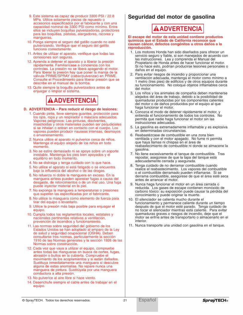
© SprayTECH. Todos los derechos reservados. 21
9. Este sistema es capaz de producir 3300 PSI / 22.8MPa. Utilice solamente piezas de repuesto oaccesorios especificados por el fabricante y con unacapacidad nominal de 3300 PSI como mínimo. Entreellos se incluyen boquillas pulverizadoras, protectorespara las boquillas, pistolas, alargadores, racores ymangueras.
10. Ponga siempre el seguro del gatillo cuando no estépulverizando. Verifique que el seguro del gatillofunciona correctamente.
11. Antes de utilizar el aparato, verifique que todas lasconexiones son seguras.
12. Aprenda a detener el aparato y a liberar la presiónrápidamente. Familiarícese a conciencia con loscontroles. La presión no se libera apagando el motor.Para liberar la presión hay que poner la manija de laválvula PRIME/SPRAY (cebar/pulverizar) en PRIME.Consulte el Procedimiento para liberar presión que sedescribe en el manual de la bomba.
13. Quite siempre la boquilla pulverizadora antes deenjuagar o limpiar el sistema.
D. ADVERTENCIA – Para reducir el riesgo de lesiones:1. Cuando pinte, lleve siempre guantes, protección para
los ojos, ropa y un respirador o máscara adecuados.Vapores peligrosos: Las pinturas, disolventes,insecticidas y otros materiales pueden ser perjudicialessi se inhalan o entran en contacto con el cuerpo. Losvapores pueden producir nauseas intensas, desmayoso envenenamiento.
2. Nunca utilice el aparato ni pulverice cerca de niños.Mantenga el equipo alejado de los niños en todomomento.
3. No se estire demasiado ni se apoye sobre un soporteinestable. Mantenga los pies bien apoyados y elequilibrio en todo momento.
4. No se distraiga y tenga cuidado con lo que hace.5. No utilice el aparato si está fatigado o se encuentra
bajo la influencia del alcohol o de las drogas.6. No retuerza ni doble la manguera en exceso. En la
manguera airless pueden aparecer fugas a causa deldesgaste, de retorcimientos o de un mal uso. Una fugapuede inyectar material en la piel.
7. No exponga la manguera a temperaturas o presionesque superen las especificadas por el fabricante.
8. No utilice la manguera como elemento de fuerza paratirar del equipo o levantarlo.
9. Utilice la presión más baja posible para enjuagar elequipo.
10. Cumpla todos los reglamentos locales, estatales ynacionales pertinentes relativos a ventilación,prevención de incendios y funcionamiento.
11. Las normas sobre seguridad del gobierno de losEstados Unidos se han adoptado al amparo de la Leyde salud y seguridad ocupacional (OSHA). Debenconsultarse tres normas, particularmente la sección1910 de las Normas generales y la sección 1926 de lasNormas sobre construcción.
12. Cada vez que vaya a utilizar el equipo, compruebeantes todas las mangueras en busca de cortes, fugas,abrasión o bultos en la cubierta. Compruebe elmovimiento de los acoplamientos y si están dañados.Sustituya inmediatamente una manguera si descubrealguna de estas anomalías. No repare nunca unamanguera de pintura. Sustitúyala por una mangueraconductora a alta presión.
13. No pulverice al aire libre si hace viento.14. Desenchufe siempre el cable antes de trabajar en el
equipo.
ADVERTENCIA
Seguridad del motor de gasolina
El escape del motor de esta unidad contiene productosquímicos que el Estado de California reconoce quecausan cáncer, defectos congénitos u otros daños a lareproducción.
1. Los motores Honda han sido diseñados para ofrecer unservicio seguro y fiable, si son manejados de acuerdo conlas instrucciones. Lea y comprenda el Manual delPropietario de Honda antes de hacer funcionar el motor.Si no hace esto, podrían producirse lesiones personales odaños en el equipo.
2. Para evitar riesgos de incendio y proporcionar unaventilación adecuada, mantenga el motor como mínimo a1 metro (tres pies) de edificios y de otros equipos durantesu funcionamiento. No coloque objetos inflamables cercadel motor.
3. Los niños y los animales de compañía deben mantenersealejados del área de trabajo, debido a la posibilidad dequemaduras producidas por los componentes calientesdel motor o de daños producidos por el equipo al quehaga funcionar el motor.
4. Conozca el modo de detener rápidamente el motor, yentienda el funcionamiento de todos los controles. Nopermita que nadie haga funcionar el motor sin lasinstrucciones adecuadas.
5. La gasolina es extremadamente inflamable y es explosivaen determinadas circunstancias.
6. Reabastézcase de combustible en una zona bienventilada y con el motor apagado. No fume ni permitaque haya llamas ni chispas en el área dereabastecimiento de combustible ni donde se almacene lagasolina.
7. No llene excesivamente el tanque de combustible. Trasrepostar, asegúrese de que la tapa del tanque estáadecuadamente cerrada y asegurada.
8. Tenga cuidado de no derramar combustible cuandorealice el reabastecimiento. Los vapores del combustibleo el combustible derramado pueden inflamarse. Si sederrama combustible, asegúrese de que el área esté secaantes de arrancar el motor.
9. Nunca haga funcionar el motor en un área cerrada oreducida. Los gases de escape contienen monóxido decarbono tóxico: su exposición puede causar la pérdida delconocimiento y puede originar la muerte.
10. El silenciador se calienta mucho durante elfuncionamiento y permanece caliente durante un tiempodespués de que el motor esté parado. Tenga cuidado deno tocar el silenciador mientras está caliente. Para evitarquemaduras graves o riesgos de incendio, deje que elmotor se enfríe antes de transportarlo o almacenarlo en elinterior.
11. Nunca transporte una unidad con gasolina en el tanque.
ADVERTENCIA
Español
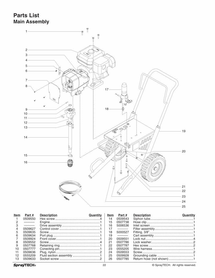
22 © SprayTECH. All rights reserved.
Parts List Main Assembly
8
1110
9
12
13
16
14
15
7
3
4
5
6
1
2
17
18
19
20
2122
24
23
25
Item Part # Description Quantity1 0509550 Hex screw...................................................42 ---------- Engine.........................................................13 ---------- Drive assembly ...........................................14 0509627 Control cover ..............................................15 0509635 Screw..........................................................16 0509634 Port plug .....................................................17 0509924 Front cover..................................................18 0509552 Screw..........................................................49 0507768 Retaining ring..............................................110 0507777 Conecting pin..............................................111 0509636 Plug, nylon..................................................212 0555209 Fluid section assembly ...............................113 0509633 Socket screw ..............................................2
Item Part # Description Quantity14 0509543 Siphon tube.................................................115 0507738 Hose clip .....................................................116 5006536 Inlet screen .................................................117 ---------- Filter assembly............................................118 5000527 Fitting, 3/8”..................................................119 ---------- Cart assembly.............................................120 0509551 Lock nut ......................................................421 0507786 Lock washer................................................222 0507787 Hex screw...................................................223 0555205 Wire harness...............................................124 0509553 Screw..........................................................225 0509928 Grounding cable .........................................126 0507785 Return hose (not shown) ............................1
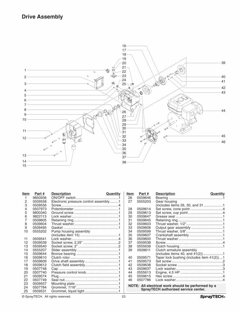
© SprayTECH. All rights reserved. 23
Item Part # Description Quantity1 9850936 ON/OFF switch ...........................................12 0509558 Electronic pressure control assembly.........13 0509556 Screw..........................................................44 0507973 Potentiometer .............................................15 9800340 Ground screw .............................................16 9822113 Lock washer................................................17 0509605 Retaining ring..............................................18 0509604 Thrust washer .............................................19 0509495 Gasket ........................................................110 0555202 Pump housing assembly
(includes item 15) .......................................111 0509541 Lock washer................................................412 0509539 Socket screw, 2.25” ....................................213 0509540 Socket screw, 2” .........................................214 0555207 Slider assembly ..........................................115 0509644 Bronze bearing ...........................................116 0509610 Clutch rotor .................................................117 0509609 Drive shaft assembly ..................................118 0509612 Clutch field assembly..................................119 0507748 Cap .............................................................120 0507740 Pressure control knob.................................121 0509574 Plug.............................................................122 0507749 Seal nut.......................................................123 0509557 Mounting plate ............................................124 0507784 Grommet, 7/16”...........................................125 0509531 Grommet, liquid tight ..................................1
Item Part # Description Quantity26 0509646 Bearing .......................................................127 0555203 Gear housing
(includes items 26, 30, and 31 ...................128 0509614 Set screw, cone point .................................429 0509613 Set screw, cup point ...................................430 0509647 Grease seal ................................................131 0509645 Retaining ring..............................................132 0509603 Thrust washer, 1/2”.....................................133 0509606 Output gear assembly ................................134 0509599 Thrust washer, 5/8”.....................................135 0509607 Crankshaft assembly ..................................136 0509600 Thrust washer .............................................137 0509538 Screw..........................................................438 0555639 Clutch housing............................................139 0509611 Clutch armature assembly
(includes items 40, and 41(2))....................140 0509571 Taper lock bushing (includes item 41(2))....141 0509573 Set screw....................................................242 0509638 Socket screw ..............................................343 0509637 Lock washer................................................344 0555613 Engine, 4.5 HP ...........................................145 0509615 Hex screw...................................................446 0507786 Lock washer................................................4
NOTE: All electrical work should be performed by aSprayTECH authorized service center.
Drive Assembly
44
3
1
4
910
11
13
12
1415
87
56
2
39
4041
4243
45
46
1920
222324
343536
32
26
31
33
2930
2827
3837
25
18
21
1716

24 © SprayTECH. All rights reserved.
Fluid Section Assembly (P/N 0555209)
1
2
3
7
8
12
13
14
15
9
18
16
17
19
20
21
10
11
4
5
6
22
Install lower packing with large beveled edge
facing up.
Install upper packing with raised lip facing down.
Raised Lip
Large Beveled Edge
Item Part # Description Quantity1 0508664 Retainer nut ................................................12 0508665 Piston guide................................................13 0509125 Upper packing assembly ............................14 0295559 Elbow, 90º...................................................15 0509595 Fitting ..........................................................16 0509585 Gasket ........................................................17 0509578 Fluid Section Housing.................................18 0509593 Lower packing assembly ............................19 0551537 Piston..........................................................1
10 0551258 Outlet cage .................................................111 0551259 Crush washer..............................................112 50164 Outlet valve ball ..........................................113 0507407 Outlet valve seat.........................................114 13481 Outlet valve retainer ...................................115 0509590 Piston bushing ............................................116 0508677 Inlet cage ....................................................117 0508678 Inlet valve ball .............................................118 0509739 Inlet valve seal............................................119 0551534 Inlet valve seat............................................120 0509582 O-ring, PTFE ..............................................121 0509593 Inlet valve housing......................................122 0551536 Piston assembly
(includes items 9–14) .................................1
0509909 Repacking kit (includes items 2, 3, 6, 8,12, 17, 18, and 20)
0509929 Lower packing insertion tool
NOTE: When repacking the fluid section, make surethe raised lip on the bottom of the lowerpacking is fully outside the packing aroundthe piston rod after insertion of the piston rod.

© SprayTECH. All rights reserved. 25
Cart Assembly
Item Part # Description Quantity1 0507766 Handle (includes items 2–5, 11, and 12) ....12 9841504 Snap button ................................................23 0295609 Handle washer............................................24 0295610 Roll pin........................................................25 0295607 Handle sleeve.............................................26 0555603 Strain relief..................................................27 0507784 Grommet.....................................................38 0509625 Axle cap......................................................29 0509626 Wheel spacer..............................................210 9885571 Plug.............................................................211 0509386 Lock washer................................................412 0295608 Screw..........................................................413 0555218 Cart (includes item 10) ...............................114 0509624 Wheel .........................................................2
11
12
13
14
8
2
3
4
5
7
6
9
10
1
Filter Assembly
Item Part # Description Quantity1 0508723 Filter body...................................................12 0508602 Filter spring .................................................13 0508748 Filter, 60 mesh (standard)...........................1
0508451 Filter, 30 mesh (optional)0508452 Filter, 100 mesh (optional)
4 0508603 Adapter .......................................................15 0508749 Filter support spring....................................16 0508725 O-ring, PTFE ..............................................17 0507737 Transducer..................................................18 0509420 Plug, 3/8” ....................................................19 5000527 Outlet fitting.................................................1
10 0295697 Plug, 1/4” ....................................................111 0507793 Fitting, 1/4”..................................................112 0555625 Filter housing ..............................................113 0507690 PRIME/SPRAY valve assembly..................1
1
2
3
4
5
7
10
11
8
9
6
12
13

26 © SprayTECH. All rights reserved.
PRIME/SPRAY Valve Assembly (P/N 0507690)
Item Part # Description Quantity1 0507736 Dowel pin ....................................................12 0507745 Gasket ........................................................13 5000529 O-ring, PTFE ..............................................14 0507741 O-ring, Viton................................................15 0507744 Valve housing .............................................16 0507746 Valve seat ...................................................17 0507743 Valve stem ..................................................18 5006547 O-ring, Viton................................................19 0507747 Spring .........................................................110 0507742 Valve retainer..............................................111 0507735 Cam base ...................................................112 5006543 Groove pin ..................................................113 0507662 Valve handle ...............................................1
1
2
3
4
5
6
7
8
9
10
11
12
13
5 Gallon Siphon Set (optional)
Item Part # Description Quantity1 0507964 Return hose ................................................12 0509185 Siphon hose................................................13 5006536 Inlet screen .................................................14 0507783 Clamp .........................................................15 0509727 Swivel elbow...............................................16 0509760 Adapter .......................................................17 0509761 Hose clamp.................................................18 0509788 Clip..............................................................19 0509789 Spring .........................................................1
1
2
3
5
4
6
89
7

© SprayTECH. All rights reserved. 27
AccessoriesPart No. Description0550xxx Tip Assembly0297078 Tip Guard (11/16”)0297070 Tip Guard (7/8”)0291004 Hose, Whip End, 3' x 3/16"0291003 Hose, Whip End, 5’ x 3/16”0291002 Hose, Wireless, 25’ x 1/4"0291000 Hose, Wireless, 50’ x 1/4"0093896 Hose Connector, 1/4” x 1/4”M0088154 Pressure Gauge, 0–5000 PSI0152308 9" Roller Cover, 3/8” Nap0152307 9" Roller Cover, 1/2” Nap0152309 9" Roller Cover, 3/4” Nap0152310 9" Roller Cover, 1-1/4” Nap0152235 12" Roller Cover, 1/2" Nap0152236 12" Roller Cover, 3/8" Nap0152237 12" Roller Cover, 3/4" Nap0152238 12" Roller Cover, 1-1/4" Nap0093930 Anti-Seize Compound0152909 R-10 Telescoping Roller, 9", 3/8" Nap0152900 R-10 Telescoping 12" Roller, 3/8" Nap0296329 G-10 XL Four Finger Airless Spray Gun (no tip)0296235 G-10 XL Four Finger Airless Spray Gun with
517 reversible tip0296260 G-10 XL Two Finger Airless Spray Gun (no tip)0296236 G-10 XL Two Finger Airless Spray Gun with
517 reversible tIp0296326 G-10 XL Four Finger Spray Pack with 50’ x 1/4”
airless hose0296327 G-10 XL Two Finger Spray Pack with 50” x 1/4”
airless hose0296297 G-12 XL Airless Spray Gun with
517 reversible tIp0296330 G-12 XL Spray Pack with 50’ x 1/4” airless hose0296470 G-15 XL Airless Spray Gun with
517 Reversible TIp0296328 G-15 XL Spray Pack with 50’ x 1/4” airless hose0279920 Separating oil0507958 Electrostatic discharge (ESD) wrist strap9870307 Grease, 6 lb. can
Electrical Schematic
LabelsPart # Description
0555897 Logo label, front0295840 Warning label, explosion0295841 Warning label, injection0295805 Shock hazard label0509819 “No Oil” label
Potentiometer
Transducer
E.P.C. Board
Switch
Engine
0555205
Clutch
J2
J3
J4
J7 J6
J5
Clutch Clutch
SwitchWhite

28 © SprayTECH. All rights reserved.
Limited WarrantySprayTECH, a division of Wagner Spray Tech Corporation ("SprayTECH"), warrants that at the time of delivery to the originalpurchaser for use (“End User”), the equipment covered by this warranty is free from defects in material and workmanship. Withthe exception of any special, limited, or extended warranty published by SprayTECH, SprayTECH ’s obligation under thiswarranty is limited to replacing or repairing without charge those parts which, to SprayTECH ’s reasonable satisfaction, are shownto be defective within twelve (12) months after sale to the End User. This warranty applies only when the unit is installed andoperated in accordance with the recommendations and instructions of SprayTECH.This warranty does not apply in the case of damage or wear caused by abrasion, corrosion or misuse, negligence, accident,faulty installation, substitution of non- SprayTECH component parts, or tampering with the unit in a manner to impair normaloperation.Defective parts are to be returned to an authorized SprayTECH sales/service outlet. All transportation charges, including returnto the factory, if necessary, are to be borne and prepaid by the End User. Repaired or replaced equipment will be returned to theEnd User transportation prepaid.THERE IS NO OTHER EXPRESS WARRANTY. SPRAYTECH HEREBY DISCLAIMS ANY AND ALL IMPLIED WARRANTIESINCLUDING, BUT NOT LIMITED TO, THOSE OF MERCHANTABILITY AND FITNESS FOR A PARTICULAR PURPOSE, TOTHE EXTENT PERMITTED BY LAW. THE DURATION OF ANY IMPLIED WARRANTIES WHICH CANNOT BE DISCLAIMED ISLIMITED TO THE TIME PERIOD SPECIFIED IN THE EXPRESS WARRANTY. IN NO CASE SHALL SPRAYTECH LIABILITYEXCEED THE AMOUNT OF THE PURCHASE PRICE. LIABILITY FOR CONSEQUENTIAL, INCIDENTAL OR SPECIALDAMAGES UNDER ANY AND ALL WARRANTIES IS EXCLUDED TO THE EXTENT PERMITTED BY LAW.SPRAYTECH MAKES NO WARRANTY AND DISCLAIMS ALL IMPLIED WARRANTIES OF MERCHANTABILITY AND FITNESSFOR A PARTICULAR PURPOSE WITH RESPECT TO ACCESSORIES, EQUIPMENT, MATERIALS OR COMPONENTS SOLDBUT NOT MANUFACTURED BY SPRAYTECH. THOSE ITEMS SOLD, BUT NOT MANUFACTURED BY SPRAYTECH (SUCHAS GAS ENGINES, SWITCHES, HOSES, ETC.) ARE SUBJECT TO THE WARRANTY, IF ANY, OF THEIR MANUFACTURER.SPRAYTECH WILL PROVIDE THE PURCHASER WITH REASONABLE ASSISTANCE IN MAKING ANY CLAIM FOR BREACHOF THESE WARRANTIES.
Material Safety Data Sheets (MSDS) are available on SprayTECH’s website or by calling Technical Service.
SprayTECH1770 Fernbrook LaneMinneapolis, MN 55447
Technical Assistance: 1-800-292-4637Order Entry: 1-800-443-4500
Fax: 1-800-525-9501
www.spraytechinc.com
PatentsThese products are covered by one or more of the following U.S. patents:
6,031,352 5,848,566 5,769,321 5,725,364 5,671,656 5,435,697 5,228,8425,346,037 5,252,210 5,217,238 5,192,425 4,908,538 4,768,929 4,744,571D384,676 6,179,222 5,934,883 4,723,892