Experimental plating of gun bores to retard erosion
108
a Bureau of Stanaaros Ibrary, S.W. Blds^ JUL 1 1380 PB 151405 ^eckniccil ^^ot& 46 EXPERIMENTAL PLATING OF GUN BORES TO RETARD EROSION U. S. DEPARTMENT OF COMMERCE NATIONAL BUREAU OF STANDARDS
-
Upload
khangminh22 -
Category
Documents
-
view
1 -
download
0
Transcript of Experimental plating of gun bores to retard erosion

a Bureau of Stanaaros
Ibrary, S.W. Blds^
JUL 1 1380
PB 151405
^eckniccil ^^ot& 46
EXPERIMENTAL PLATING
OF GUN BORES TO
RETARD EROSION
U. S. DEPARTMENT OF COMMERCENATIONAL BUREAU OF STANDARDS

THE NATIONAL BUREAU OF STANDARDS
Functions and Activities
The functions of the National Bureau of Standards are set forth in the Act of Congress, March,
3, 1901, as amended by Congress in Public Law 619, 1950. These include the development andmaintenance of the national standards of measurement and the provision of means and methods for
making measurements consistent with these standards; the determination of physical constants andproperties of materials; the development of methods and instruments for testing materials, devices,
and structures; advisory services to government agencies on scientific and technical problems; in-
vention and development of devices to serve special needs of the Government; and the development
of standard practices, codes, and specifications. The work includes basic and applied research,
development, engineering, instrumentation, testing, evaluation, calibration services, and various
consultation and information services. Research projects are also performed for other governmentagencies when the work relates to and supplements the basic program of the Bureau or when the
Bureau's unique competence is required. The scope of activities is suggested by the listing of
divisions and sections on the inside of the back cover.
Publications
The results of the Bureau's work take the form of either actual equipment and devices or pub-
lished papers. These papers appear either in the Bureau's own series of pubhcations or in the journals
of professional and scientific societies. The Bureau itself publishes three periodicals available fromthe Government Printing Office: The Journal of Research, published in four separate sections,
presents complete scientific and technical papers; the Technical News Bulletin presents summaryand preliminary reports on work in progress; and Basic Radio Propagation Predictions provides
data for determining the best frequencies to use for radio communications throughout the world.
There are also five series of nonperiodical publications: Monographs, Applied Mathematics Series,
Handbooks, Miscellaneous Publications, and Technical Notes.
Information on die Bureau's publications can be found in NBS Circular 460, Publications of the
National Biu%au of Standards ($1.25) and its Supplement ($1.50), available from the Superintendent
of Documents, Government Printing Office, Washington 25, D.C.

NATIONAL BUREAU OF STANDARDS
technical N^ote
46
MAY 1960
EXPERIMENTAL PLATING OF GUN BORES
TO RETARD EROSION
Vernon A. Lamb and John P. Young
The work described in this Technical Note was sponsoredby the Department of the Navy, Bureau of Ordnance; the
Department of the Army, Office of the Chief of Ordnance,ORDTS; and Springfield Armory.
NBS Technical Notes are designed to supplement the Bu-reau's regular publications program. They provide a
means for making available scientific data that are of
transient or limited interest. Technical Notes may belisted or referred to in the open literature. They are for
sale by the Office of Technical Services, U. S. Depart-ment of Commerce, Washington 25, D. C.
DISTRIBUTED BY
UNITED STATES DEPARTMENT OF COMMERCE
OFFICE OF TECHNICAL SERVICES
WASHINGTON 25, D. C.
Price $2.50

CONTENTSPage
1. HISTORY OF GUN BARREL PLATING 1
2. RESULTS OF THE PROGRAM SPONSORED BY THENATIONAL DEFENSE RESEARCH COMMITTEE 2
3. PHYSICAL PROPERTIES REQUIRED IN BORESURFACE COATINGS 4
4. CHARACTERISTICS OF ELECTRODEPOSITEDCHROMIUM AS RELATED TO ITS APPLICATION
TO GUN BORES 4
5. METHODS AND PROCEDURES FOR CHROMIUMPLATING GUN BARRELS 10
5.1 Preliminary treatments 10
5.2 Electropolishing 11
5. 3 Chromium plating 11
5.4 Fixtures for plating j4
5. 5 Special procedures for applying LC chromium 16
6. MISCELLANEOUS DATA RELATED TOCHROMIUM PLATING OF TUBES 20
6. 1 Effect of anode resistance on longitudinal
variation of plate thickness 20
6. 2 Effect of trivalent chromium and iron ondeposit taper 20
6. 3 Effect of current density on deposit taper 25
6. 4 Effect of anode eccentricity on plate
eccentricity 25
6. 5 Changes in land contours caused byelectropolishing and plating 25
IX

Page
7. SUMMARY OF THE PERFORMANCE OFCHROMIUM PLATE IN BARRELS.CALIBER . 22 TO 3 INCHES 28
7.1 Caliber . 22 barrels 28
7.2 Caliber . 30 barrels 29
7.3 Caliber . 45 pistol barrels 32
7.4 Caliber . 50 barrels 32
7.5 Caliber . 60 barrels 45
7.6 20 mm barrels 48
7.7 30 mm barrels 57
7.8 40 mm barrels 57
7.9 3 inch-50 caliber barrels 64
8. MISCELLANEOUS TESTS OF GUN BARRELS 66
8. 1 Heat-treatment of chromium plated barrels 66
8.2 Injection cooling of gun bores 68
8. 3 Tests of barrels coated by the "Chromizing"process 74
8.4 Tests of barrels pre -treated by "Vapor -Honing" ^^
8. 5 Tests of barrels plated with "Crack-Free" chromium- 79
8. 6 Bore coatings for combined corrosion and erosionprotection of barrels for submarine service 80
8. 7 Tests of barrels chromium plated by the
Hausner process 83
111

Page
8.8 Experimental rifling designs 85
9. OPERATING PROCEDURES 89
9.1 High speed plating 89
9. 2 Application of LC chromium without
forced solution flow 93
9.3 High speed electropolishing 93
9.4 Gas -port plating 93
lU. FUTURE WORK 96
11. ACKNOWLEDGMENTS 97
REFERENCES 98
IV

EXPERIMENTAL PLATING OF GUN BORES
TO RETARD EROSION
by
Vernon A. Lamb and John P. Young
Methods for plating the bores of gun barrels are described,
including details of fixture design, solution composition, andoperating conditions. Eixtensive firing tests were performed,which show that chromium plate increases the life of barrels
about 2- to 5-fold, depending on the type and caliber of barrel.
Optimum thickness of plate ranges from 0. 0015 inch in the
smallest calibers to 0. 015 inch in cannon.
Certain modifications of the barrels enhance the improve -
ment provided by the chromium plate. Choking of the bore at
the muzzle produces a marked improvement in accuracy life
of caliber 0. 30 and 0. 50 barrels. It is less effective in barrelsof larger caliber. Specially shaped lands, designed to reducethe concentration of engraving stresses at land corners, signifi-
cantly improve the performance of 20 mm barrels. Other modi-fications, such as hardening of the basis steel by nitriding andincreasing the length of the land "run-up", result in moderateimprovements in some types of barrels. Physical properties of
the chromium plates tested were varied. Ordinary "hard"chromium yields the best performance in most types of barrels.
Chromium plating has been adopted as standard production
practice tor caliber 0. 30, 0. 50, and 20 mm barrels, and for
several calibers of cannon.
1. HISTORY OF GUN BARREL PLATING
Application of plated coatings to gun barrels has a fairly long
history. In 1921, de Sveshnikoff and Haring of NBS carried out
some experiments (1) in which they deposited nickel, copper, andiron in gun bores. They made no firing tests, but recommendedthat further studies be made, preferably, with iron, nickel, cobalt,
and chromium.

Between 1926 and 1928 some caliber . 30 machine gun barrelswere chromium plated and tested at Frankford Arsenal by MajorJ. McDonald and Willard Scott (2). This work was continued at
Frankford Arsenal by Lt. A. Willink (3). These tests did not in-
dicate that chromium plating resulted in any outstanding improve-ment in barrel life.
From 1928 to about 1944, plating of the bores of Naval gunsfrom calibers of 1. 1 to 16 inches with 0. 0005 to 0. 001 inch thick-
ness of chromium was standard production practice at the Wash-ington Naval Gun Factory. These thin coatings did not greatly
increase the life of the barrels, but no doubt furnished some pro-tection against corrosion, especially in sea atmospheres. Addi-tional early interest in chromium plated gun barrels was also
evidenced by patents in this field (4, 5). Further tests by the ArmyOrdnance Department of a few barrels chromium plated by com-mercial firms still did not indicate any outstanding improvementdue to chromium plating (6).
None of this early work was extensive or systematic, and only
thin coatings were tried. The work done under the program at
NBS has shown that a thick chromium plate does result in signifi-
cant improvement in the life of a gun barrel. Similar findings
were made by Springfield Armory (7, 8), by Battelle MemorialInstitute, and Woolwich Arsenal, England (18).
2. RESULTS OF THE PROGRAM SPONSORED BY THENATIONAL DEFENSE RESEARCH COMMITTEE
The initial portion of the experimental program at the National
Bureau of Standards was performed in cooperation with the Geo-physical Laboratory, under sponsorship of Division 1 of the
National Defense Research Committee. The results of this por-tion of the program have been published elsewhere (9). For the
sake of completeness of this report, the progress made underthe above sponsorship (through 1945) is summarized briefly asfollows:
- 2 -

(a) Chromium electrodeposits prepared under a variety of bath
operating conditions had been tested in special erosion tests
and in barrel liners, and a type of chromium to be describedlater, designated as "LC" chromium, showed some promiseof improved performance over other types of plate in gunbarrels.
(b) Methods for depositing several erosion-resistant alloys, suchas cobalt-tungsten, had been developed and sonae erosion
tests of these materials had been made.(c) Work with the caliber . 50 aircraft machine gun barrel had
progressed to a point where the nitrided and chromiumplated barrel with a muzzle choke had a life about five -fold
that of the standard barrel. Pilot-plant and later full-plant
production was in effect at Doehler-Jarvis Company, GrandRapids, Michigan (under an Army contract). Even better
performance of the caliber . 50 barrel had been achieved with
chromium ahead of a Stellite liner and this type was also in
production. *
(d) Similar development had been started, but not completed to
the production point, with caliber . 30, . 60, and 20 mmbarrels.
''The NBS program did not include Stellite liner development.
- 3 -

3. PHYSICAL PROPERTIES REQUIRED IN BORE SURFACE COATINGS
Work done by NDRC Division 1 showed that, to resist erosion, the
bore surface material should have a high melting-point, high hot-strength and hot-hardness, adequate ductility both hot and cold,
should undergo no abrupt change of volunne with temperature, andshould be resistant to chemical attack by hot powder gases.
Unfortunately, no such ideal material exists. Extensive tests
have shown that of all of the elements, only the following and someof their alloys are resistant to chemical attack by powder gases:
chromium, molybdenum, tungsten, tantalum, nickel, cobalt,
copper, and certain platinum -group metals (10). The latter aretoo expensive and scarce to consider, and the melting points of
nickel, cobalt, and copper are too low. Of the remaining resistant
elements, only chromium can be electrodepo sited readily. Molyb-denvim, txingsten and tantalum cannot be deposited from aqueous baths.
Work has been done on the development of fused salt (II) and non-aqueous baths, but the methods to date are still in the laboratory stage.
Alloys of molybdenum and tungsten with cobalt can be deposited fromaqueous baths and have some favorable properties, such as good re-
sistance to powder gases and adequate ductility. They have therefore
been tried in gun barrels, but have been inferior to chromium, mainlyowing to low hot-hardness and to vmcertain adhesion.
One is therefore left with chromium as the only pure metal that
can be electrodeposited that has chemical and physical properties
approaching those required. These properties will be briefly de-scribed.
4. CHARACTERISTICS OF ELECTRODEPOSITED CHROMIUMAS RELATED TO ITS APPLICATION TO GUN BORES
As noted before, chromixim has excellent chemical resistance to
powder gases. Its physical properties in part fulfill the requirementsstated. For example, its melting-point of approximately 1900 C is
amply high. We have never observed evidence of melting of chromiumplate in a gun bore. Extensive work on other physical properties of
electrodeposited chromium has been reported (12). In Table 1 are
summarized the operating conditions and deposit properties for three
"types" of chromium that have been tried in gun bores.
- 4 -

TABLE 1
Correlation between operating conditions of the plating bath andsome properties of the plates, for three types of electro-
deposited chromium
Solution composition: Cr03, 250 g/ liter; H2SO4, 2. 5 g/ liter
Type
Standardhard chro-mium (HC)
Medium Soft or lowhardness (MH) contraction (LC)
Operatingtemp. C 50 75 85
Current density
(amp/dm^) 20 60 80
Hardness (Knoop)
at room temp. 920
at 600 C 167
at 800 C 70
685 550
111
48
Ductility zero zero zero
Tensile strength
(lb/in2) 15,000* 70,000
Oxide content
(wt % O2) 0.4
Linear contraction
after heating (%)
to 450 C 0.3to 1200 C 0..8
0. 12
0.1
0.05
0.1

Standard hard chromium is designated "HC" for its relatively highdegree of contraction as a result of successive heating and cooling.
This phenomenon is probably the result of loss of water and hydrogenfrom hydrated oxides that are occluded in the plate. Its hardness is
adequate, since swaging of the plate itself is rarely a cause of gunbarrel failure. Its main defects for gun barrel service, which arerevealed in Table 1, are: (a) it is brittle; and (b) successive cycles
of heating and cooling result in contraction which causes wideningof the inherently present stress -cracks. These adverse properties
lead to eventual failure of the plate in a gun barrel by the following
mechanisms. First, owing to its brittleness and low tensile strength,
the plate may chip off by breaking within itself, especially at highly
stressed locations such as land corners. The local thinning of the
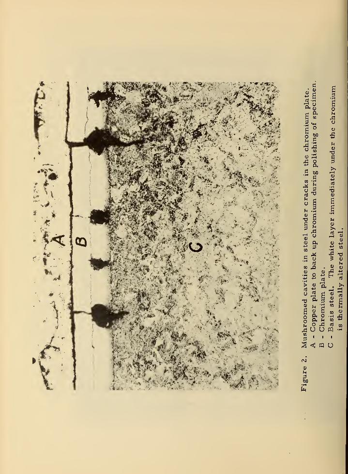
plate by this mechanism results in reduced protection to the under-lying steel in tiiese areas. Second, hot powder-gases gain accessto the steel below the plate through cracks. The steel undergoeschemical attack and is melted by the hot powder gases, with the for-
mation of a mushroomed cavity iinder the plate at a crack site. Join-
ing of two such cavities under the plate by their lateral growth, resiolts
in removal of chromium from the bore, and erosion of the exposed steel
proceeds at an accelerated rate. Figures 1 and 2 show typical failures
of these types.
The second mechanisnn of failure described above is partly the
result of the poor chemical resistance and low melting point of steel.
Another mechanism of failure is related to the low hot-hardness of
steel. Under impact from the projectiles, the steel of the lands
xuider the plate flatters out. The steel of the land flows both forwardand laterally. Forward flow may produce a constriction in the bore,
and lateral flow increases the land diameter and decreases the groovediameter. Figure 3 shows the latter effect. This distortion of the
original surface contour results in buckling and cracking of the plate,
which opens the way to erosion of the basis steel. In spite of the abovetypes of failure, properly applied HC chromivun produces a significant
improvement in barrel life.
It was apparent, however, that if the chromium were stronger andmore ductile, and if the basis steel had better hot -hardness, barrelimprovement would be much greater. Therefore "low -contraction"chromitim (Table 1) was tried, in conjunction with hardening of the
steel by nitriding. Nitriding of the basis steel has been found to
reduce the extent of barrel failure due to swaging. Low-contraction
- 6 -

o0)
p.CO
O
. tiO
(t 1—1
X! O
^^
B (^
O 0)M o +->^ -^ ni
O (U S CO
.q O ^ oj
S^U U WHillu <: cQ o
0)
•r-l
^' •^'^ -x^^- '-^^ ''^^
• ^_ -J
<'it
w
•'J -.;»
«5**J> \ ^'-^I
i-vA
'. •*.. .
4^'--
-*.
,c| o
.5 wj
to 'T^
u
a
I—
I
(U
-MCO
• 1-1
Bo
o
ou
o
13
(Ui-i
(D
.—
I
0)
•S "
CO ^^-^ O4-> !->
>
o
(1)
sOo
(U "a,4-> '^
pL, O
o ^ij U US • '
S <: pq
00
u
^•-^
^ d^ CM um a;
to -^
rt CO
PQ -^
I
U
t=M

o
o
a,
>>
0)
0) oCO 130
o
o
(0
CO
o
60e!
(30 ^CI ::!
^ HCO H(U .Ih
- O
I—
I
«. f^
^^.aI
^ ^ ^to <D Q.
O
(U
,^3
CO
0)
u0)
0)
a
so
(J
oi-H
a4->
O
. (UI-H -M0) CO
CO <U
T3?^ § W
=)
. . CU U CO M(tJ O 4:5 rt MJ;^U U fP (UMill
aJ < « U
GO

chromium results in better barrel life in some types and calibers
of barrels, while in others it is no better than the HC type. Its
chief defect is its low hot-hardness at medivim high temperatures(400-500 C), which permits flattening of the lands due to swagingof the plate and steel. This deformation of the bore resxilts in loss
of barrel accuracy. "Medixim -hardness" plate (Table 1) has beentried in the hope that it would combine the favorable properties of HCand LiC plates. Unfortunately, the intermediate hardness plate hasbeen found to combine their unfavorable properties.
In attempting to obtain greater improvennent in barrel life than
is afforded by chromium plate, a variety of other coatings have beentried. Some of these are: duplex coatings of HC and LC chromium;duplex coatings of chromium with copper, cobalt, or cobalt-tungsten
alloy; cobalt and nickel alone; alloys of chromium with iron, nickel,
and cobalt; and alloys of cobalt with tungsten (13). None of these aresuperior to chromium.
5. METHODS AND PROCEDURES FORCHROMIUM PLATING GUN BARRELS
5. 1 Preliminary treatmentsThere is no real difference between the processing steps reqtiired
for preparing and plating giux barrels and those, for plating many ordinaryitems. Following is a brief summary of the steps involved.
(a) Degrease the gun barrel by any standard method.(b) Remove, by standard acid pickling, any scale or film that
may be present, e.g. , from Parkerizing or nitriding.
Mechanical scrubbing with a cloth patch or a brush on a
ramrod may be helpful in this step.
(c) Inspect the bore visually with a horoscope. If smears of
copper, resulting from proof-firing, are present, removethem with any suitable copper stripping solution, e.g., a
standard chromic acid-sulfuric acid conaposition, a propri-
etary solution, or by making the bore anodic in a chromicacid solution.
(d) Rinse, dry, and measure the bore diameter with a "star -gage"or other suitable bore gage.
(e) Calculate the thickness of steel to be removed by electro
-
polishing and the electropolishing time. The thickness of
steel to be removed depends on the initial bore diameter^
the thickness of plate to be applied, and the final borediameter.
- 10 -

(f) Assemble the fixtures and carry out electropolishing for
the calculated length of time.
(g) Dismantle the fixtures, rinse and dry, and measure the
bore diameter.
5. 2 Electropolishing
Electropolishing is a valuable accessory process in gun boreplating, because: (a) it provides a convenient naethod for enlarging
the bores of stock barrels before plating; (b) it produces a desirable
rounding of land corners, thus preventing build-up of a bead of plate
at this point, as shown in Figure 4; and (c) it removes small slivers and
burrs of steel that remain after machining operations, thus contribut-
ing to the production of smooth, nodiile-free, chronnium plates.
The process has been described frequently in the literature.'"'
The following solution composition and operating conditions havebeen found practical (14):
Phosphoric acid (commercial 85%) 50% by volumeSulfuric acid (commercial 95%) 50% by volumeTemperature 40-60 CAnodic current density 25 to 50 amp/dmDensity 1. 69 to 1 . 74 g/cc
Permissible concentration of
dissolved salts, Fe plus Cr 70 g/liter
Rate of steel removal 0.003 to 0.006 inch/hr.
The lower values of temperature and current density have usually
been used, e. g. , 40 C and 25 amp/dm , but higher values, such as
60 C and 50 amp/dm can be used. In general, the higher currentdensities result in less iiniform removal of steel from end-to-end of
the bore. This is shown in Figure 5.
5.3 Chromium plating
The solution composition and operating conditions are indicated
in Table 1, though for application of HC chromium, the higher plating
rates obtained at higher temperatures and current densities, e. g. ,
55 C and 30 to 35 amp/dm , are often used. Operations immediatelypreceding plating are indicated as follows:
*At the beginning of the gun barrel plating progrann, valuable
information was obtained informally from C. L. Faust of
Battelle Memorial Institute.
- 11 -

Mfl (U
•iH +J
A rt
w 1—
1
•iH a.1—
1
0)
a. A-l->
!-i <+Hi-> •Ho
Tl1—
1
<U
(U
>s nJ
rD
TJ0)
,i3
Td TJo i—i
M ;3
fX o^1 ^^ +->
fSj
(-' XiPi +->
oo ^1
^1
•n O :i
d -MC +->
o Co o
XJ oQ> (1)
•n ^ T3a -M <U
:i (0 fl
4->
•i-(
^Oj
o0) o OJ
B •iHa
HH C d•T-l
o1—1
O
i->J
1
•r-(
1-H
m -M Oh;:! O rt.-H T)1—
1
<u•iH
(U F^
d ^ (U
< Ph ^
•tH

rM
tf> ^ CM
Sllif^ *a3A0IN3d 13318 AO SS3N>I0IH1
13
ni
o
•r-l
CO•iH1—
(
oftO?-<
+-)
u(1) M
QJ
Uo
o
o^1 .
o :^
CD ^
S in
S ^ UCO o
0) M-l,-1 O ij
u:=!
o
PI
0)
+->
nj
?H
0)
ft
T3
0)
PI (U •->
^ CD (D
CO ^ ^
o
n o
"H-l -rH
°a
u o
Ln
0)
0) tn
M nj
•S •'^ ^
O -w
f^i O H
0)
h
MB

5. 3. 1 CleaningSeveral methods of cleaning the bore are suitable, but usually one
of the following is used: (a) scrub mechanically with a cloth cleaning-
patch or a brush on a ramrod, using a mixture of pumice and hydro-
chloric acid, followed by rinsing; or (b) assemble the fixtures and
apply a short electropolish, rinse thoroughly, and transfer imme-diately to the chromic acid anodic etch. We prefer the latter methodand have found that it results in slightly superior and more uniformadhesion, as measured by the results of firing tests of 40 mm barrels.
The work of Williams and Hammond (15) also shows that a similar
treatment results in excellent adhesion.
5. 3. 2 x\nodic etching
Anodic etching is done in a chromic acid bath, which may bethe plating bath, but is preferably a separate bath, containing no
sulfate. Use of a separate etch bath free of sulfate avoids introduc-
tion of iron into the plating bath (resulting from anodic attack of the
bore surface) and also prevents formation of a chromium deposit on
the center electrode, which would subsequently dissolve in the plating
bath. Barrels are etched anodically for 3 to 5 minutes at 50 C and20 amp / dm . Carefully controlled firing tests showed that a relatively
long anodic etch resulted in improved adhesion of the plate. Etchingtime of longer than five minutes yielded even better adhesion, but could
not be generally used because on some steels a passivating film wasformed that prevented complete covering by chromium,
5. 3. 3 Plating
Transfer the barrel to the plating tank, etch anodically for anadditional period of 15 to 30 seconds, then reverse the current, makingthe barrel cathodic. Plate under the selected operating conditions for
the calculated length of time.
5. 3. 4 Final operations
At the end of the plating period, remove the barrel from the plating
tank, rinse, dismantle the fixtures, dry, measure the diameter of the
bore, and inspect it visually.
5. 4 Fixtures for plating
Typical fixtures are shown in Figure 6. A concentric electrodeis held in place along the axis of the bore with insulating plugs in the
end caps. The end caps are drilled with holes for solution circulation.
The barrel is plated in a vertical position. Some important criteriafor good fixture design are as follows:
- 14 -

<0
u
a
dI—
I
u
(U
u•1-1
&H
::!
bo

(a) End caps should seat positively so that they cannot wiggleor tip, thus misaligning the electrode.
(b) All surfaces on which anode concentricity depend must bemachined to close tolerances of fit and concentricity.
"Close tolerances" is a relative term in this case. Fora caliber . 30 barrel the anode should be concentric within
0. 001 to 0. 002 inch, while for a 3-inch cannon, an eccen-tricity of 0. 020 to 0. 030 inch may be permissible.
(c) Electrical connections must have adequate current-carry-ing capacity.
(d) The cross -sectional area of the solution circulation holes
must be sufficient so that flow of the solution is not re-
stricted, e. g. , two to four times the cross -section of the
bore.
The diameter of the electrodes and the material from whichthey are made varies widely, depending on the caliber of the
barrel and the desired longitudinal distribution of the plate thick-
ness. In all cases, plating anodes are coated with lead, or with
an alloy of 90% lead- 10% tin, which can be conveniently electro-
deposited (16). The lead-tin alloy coating is necessary on anodesused for applying LC chromium, since at 95C a high-resistance
film is formed on pure lead.
5. 5 Special procedures for applying LC chromium.The high current density employed in depositing LC chromium
results in excessive longitudinal taper in the thickness of the de-posit, with the thickness much less at the upper end of the bore(Figure 7). Two factors operate to produce this effect, namely,entrainment in the solution of the hydrogen and oxygen formed at
the electrodes, and a slight rise of the temperature of the solu-
tion as it passes upward through the bore. Entrainment of the
gases causes an increase in the electrical resistance between the
electrodes at the upper end of the bore. A higher solution tempera-ture lowers the cathode efficiency. The temperature of the solution
was measured at both the inlet and outlet of the bore while LCchromium was being plated. The observed temperature difference
of 2 C is too small to cause a significant change in cathode ef-
ficiency. Therefore gas entrainment must be the main cause of
the taper.
To eliminate this taper, three methods were tried, as follows:
- 16 -

0)
u
O T3
o
r-i ^.
•1-4 0) )L|
CO43
0)
PI< O
13•11 M rt
6 H<u
0)+->
.—1
£O1—
1
o aI—
1
•i-i
00 o ^1
tJ0)
o
a o o-iH ^ +j Tl^ U (0
• 1-1
T)I—
1
ont 00 C uC dj
CD
•H •\ > i^'0 (U •iH orH:3 Jh bO
+->;3
•iH M >->
GOrt a) (ti
o, 1
CO
rn
CO
rn(X
(1) (1)
u C! tio -i.^ X(1) r.j u U
flO u> <t
ft n® ^ d°l/"l*SS3N>IOIH± 3AllV13d
eg
d
o o
•M (J
,^ .x:
Q O
a.
oo
0)
u

5. 5.1 The moving anode methodA short anode, e.g. , one-fifth of the bore-length, is gradually-
drawn through the bore. This method does produce a uniform deposit.
However, the method was unsatisfactory because the deposits hadpoor adhesion. The poor adhesion was caused by the formation of a
passive film on the surface of the bore at areas ahead of the naoving
anode. These areas were in prolonged contact with the hot chromicacid solution before being covered with chromium. No remedy wasfound for this defect in the method.
5.5.2 The anode resistance methodIn theory, it should be possible to design an anode with longi-
tudinally varying resistance such that the drop in voltage and currentalong the anode exactly compensates for the gas -bubble and the temper-ature effects, with a resultant plate of uniform thickness. This hasbeen accomplished with 20 mm barrels, but it is not as yet a generally
practical method. A closely related method was successful with a
3 inch-50 caliber barrel, in which the bore diameter was tapered byelectropolishing with a moving cathode to compensate for the taper
in the chromium deposit.
5.5.3 The pximp -plating methodThis method, which was successfiil, consists of pumping the
plating solution through the bore at a high velocity. The concentration
of gas -bubbles at the upper end of the bore is reduced because the
bubbles are removed from the bore rapidly and they are also compressed.Longitudinal temperature variation is also eliminated. It was found that,
as an approximation, flow velocities 7 to 10 times the natural flow veloc-
ity practically eliminated longitudinal taper in plate thickness under plat-
ing conditions of 85 C and 80 amp/dm . Lower flow rates may be usedto produce small controlled tapers, thus creating intentionally chokedmuzzles. Pump-plating data are summarized in Figure 7 and Table 2.
It has been reported in the literature on chromium plating that a
high degree of agitation reduces the cathode current efficiency. In
this work, it was found that these high flow-rates did not reduce the
cathode efficiency.
In one case, in the plating of a barrel with an exceptionally high
ratio of length to bore diameter, it was necessary to p\imp-plate to
apply HC chromium uniformly. This was a 20 -mm barrel (0. 787 inch
bore diameter) with a length of 96 inches.
18 -

TABLE 2
Longitudinal variation of the thickneas of chromium plate in several calibers
of barrels aa a function of operating variables
Caliber Length Temp.Currentdensity
(inch) (C) (amp/dm )
AnodeDiam.( inch) Metal
Time Flow rate*
(hr) (liter per min)
Plate thickness on lands (mila) at given distance (inch)
from lower end of barrel
0. 3 inch 50 20 0. 1 Cu 2.550 20 0. 1 Al 3.850 20 0.1 Steel 5.585 60 0.1 Steel 3.085 80 0.1 Cu 2.7 5.0
1.1 1.2 1.1 1.2 1.2 1.2
1.8 1.8 1.8 2.1 2.2 2.32.2 2.3 2.6 3.3 3.. 6 4.01.4 1.1 0.9 0.9 0.9 0.9
3.33.3 3.7 3.9 3.8 3.6
0.5
0.5 inch 45 50
50
50
50
85
85
15
15
20
20
80
80
0.187 Cu 17.0
0.25 Cu 11.00.219 Steel 5.00.187 Steel 6.50. 187 Cu 2.40.187 Cu 3.2
20
27
6.3 6.1 6.0 5.8 5.7 5.84.0 4.3 3.8 3.7 3.7 3.81.4 1.4 1.5 2.0 2.5 3.1
1.5 1.6 1.7 2.2 3.6 5.36.0 - 5.4 3.5 3.0 2.8
6.8 - 6.8 6.1 6.0 5.9
0.5 25 45 54
. 6 inch 60 50 20 0.25 Cu 4.850 20 0.375 Steel 6.0
55 30 0.25 Cu 6.255 30 0.25 Steel 3.5
85 80 0.25 Cu 1. 1
85 80 0.25 Cu 1.3 24
2.5 2.1 2.0 2.1 2.1 2.0 1.73.8 3.5 3.3 3.4 3.7 . 4.05.7 5.7 5.4 5.5 5.5 5.6 5.61.6 1.8 1.7 2.7 3.3 . 6.75.2 3.0 1.5 1.2 0.8 0.8 1.0
4.1 3.3 3.5 3.9 3.2 2.9 3. 1
0.5 25 35
20 mm 50 20 0.25 Cu 19.2
55 35 0.25 Cu 10.0
65 100 0.25 Steel 1.0
9.5 9.5 9.5 9.5 9.5 9.5 9.511.5 11.5 11.3 11.5 U.O 10.7 10.76.5 6.0 6.0 5.5 6.0 5.5 5.5
0.25 60
88 55 35 0.5 Cu 5.2 - 6.0 5.5 5.0 5.0 5.0 5.0 5.0
85 75 0.5 Cu 5.0 28** 8.0 7.0 5.8 5.2 4.8 4.6 3.585 70 0.5 Cu 5.0 >200 5.5 5.5 5.3 5.2 5.3 5.2 4.7
64 84 104 124
55 35 1.25 Cu 485 75 1.25 Cu 5
6.5 6.5 6.5 6.5 6.5 7.5 7.5 7.5 6.53.0 13.0 13.0 13.0 U.O 10.0 7.0 7.0 6.0
* With the exception noted below (Note **) all barrels were plated with natural solution flow unless a value for flow rate is givenin this column, in which case the solution was pumped. By natural flow is meant the flow of solution induced through the boreby rising gas bubbles.
** Plated witii natural solution flow.

Pump-plating equipment is relatively simple. Three designsare shown schematically in Figure 8. The designs shown as Aand B have been used with good results, but C is believed best for
production plating.
6. MISCELLANEOUS DATA RELATEDTO CHROMIUM PLATING OF TUBES
6. 1 Effect of anode resistance on longitudinal
variation in plate thickness
It was found that most types and calibers of barrels are im-proved in both target pattern size and accuracy life if the borediameter tapers gradually to a smaller value at the muzzle (17).
By applying a plate having a tapering thickness, a choke can beproduced much more easily than if it were made by machining.
The value of the choke was first discovered during our work in
1944. It was produced by a combination of enlargement of the boreat the breech end and constriction of the bore at the muzzle end.
Breech enlargement was obtained by electropolishing with the breechend up, and muzzle constriction was obtained by plating in the sameposition with a copper anode, which yielded a plate that was slightly
thicker at the muzzle end. In September of 1944, a British report
appeared (18) which confirmed the value of the choked muzzle, but
their method for obtaining the choke by utilizing the resistance of a
lead-coated steel anode was more practical and was adopted by NBS.By suitable selection of anode resistance, almost any desired longi-
tudinal configuration of plate can be obtained. This is illustrated
in Figures 9 and 10.
6. 2 Effect of trivalent chromium and iron
in the plating bath on deposit taper
When plating is carried out with a resistance anode, the presenceof trivalent chromium or iron in the plating bath appreciably de-creases the degree of longitudinal taper in the thickness of the plate.
This is shown in Figure 11. We postulate that the effect is primarilydue to the fact that the trivalent ion causes an increase in cathodeefficiency which varies inversely with the current density. Thiseffect is of much importance in production plating of gun barrels to
close diametral specifications. Control of the concentration of
trivalent chromium is therefore usually necessary (19, 20). To avoid
the necessity for controlling the concentration of trivalent chromium,certain production contractors have compensated its effect by the use
of tapered anodes or by obtaining part of the required bore taper by
means of special electropolishing procedures (see Section 7. 4. 1. 7).
- 20 -

c:-^
CR BATH85''
C
^y//y// 7
//////////////
B
ICR BATH
85''
C
e
mUZ^
c
^////// / / y //////// ///
Figure 8. Diagrara of three pump-plating systems.
A - Open stand method.B - Tank submersion method.C - Quick -assembly method. In C, F is a quick-change solution-inlet fitting
to which the barrel is connected by a taper joint or a one -half turn thread
(detail not shown). J is a steel jacket which serves to collect the overflowfronn the top of the barrel and return it to the tank. In each case G is the
gun barrel. An auxiliary chromium solution maintained at 50 to 55 C is
required in each case, for anodic etching prior to plating (not shown for
B and C). Auxiliary items such as a flow -meter, pressure -gage, andflow-control valve are not shown.

X "O11
'
^v \\ \ 1^v \\ \ 1N. \\ \^v V 11^ 44 } i
\^ V \1
\ \1
\ ^A tD <-
\ \ 11\ \\ 11
\ \\l
\ |l\
Lt 1
\ *l\ yi> -
1
1 11 1
>
COtti
X
111
aelU
lOO
oflC
II.
lUo
o
- m
vO
vO
CO
U •
00CO
CO Oi
^ r^.
(O <D ^°i/"i*ss3N>ioiHi BAiivnau
M w

0)
u
oIT)
•iH
O
a, f^
CO Sh
o ™
t: o0]•iH
CO
^1
O
IT)
H
<0 «;f
°l/°\ 'OIlVd SS3N>IOJHi
60
CO to
O X
bo
t3
(U
o
o
CO
ua
oCO
(0
CO
u
I
oen
HT3c
T3
o
0}
CO
0)
Pi
O r-H
H o

nO
™ CO U2
;§ -"*
ao PI P4
« GO
I soo o(fi ro
5? §i
.^3
«}(1>
tS o . «^ ^
.5 • -O fo^
fl ^ o I S-^ .-T ! h.b§u
* « csl
°1/°1*883N>I0IH1 3AllVn3d
(30•r-t

6. 3 Effeict of current density on deposit taper
The effect of current density on the longitudinal variation in the
thickness of the deposit can be seen by examining the data in Table 2.
In general, increase in current density decreases the relative thick-
ness of the plate at the upper end of the bore,
6.4 Effect of anode eccentricity on plate eccentricity
Circumferentially vmiform thickness of plate in a gun barrel is
very important. Obviously, if the plate is only a fraction of the requiredthickness for good performance on one side of the bore, as a result of
anode eccentricity, the firing-life of the barrel will be sub-standard.
The results of a few measurements in caliber . 50 barrels areshown in Figure 12. As a rule-of-th\imb criterion, we have designedfixtures on the basis that the radial eccentricity of the anode should
not be more than 2% of the anode to cathode distance. Interpolating
in Figure 12, an anode eccentricity of 2% corresponds to a plate eccen-tricity of about 15%.
In addition to maintaining close concentricity of the plating fixtures,
the anode must be straight. Experience has shown that an anode bent
even slightly does not straighten completely when assembled under ten-
sion in a barrel. The British have made a careful study of anode prob-lems and their specification calls for miaximvim possible straightness
(21). They require a plumb-line straightness test and special packingand handling procedures to avoid flexing the anodes during shipping andassembly.
6. 5 Changes in land contours caused byelectropolishing and plating
At the request of the Artillery Branch, Research and DevelopmentDivision of the Office of the Chief of Ordnance, a study was undertakenin 1946 to obtain data on changes in land contours caused by electro
-
polishing and chromiium plating. These data were to be used in design-ing "as-machined" lands for barrels which were to be plated, so that
the final contours of the lands in the plated barrels woxild be as close
as possible to the standard design. In view of the more recent workon land design described in section 8. 8, it is doubtful whether it is
worthwhile to attempt to reproduce in a plated barrel the contours of
standard machined lands. However, the data are recorded here for
the sake of comipleteness.
- 25 -

12 ESTIMATED POINT.-
DEPOSIT TREEDON NEAR SIDE.
10
^^
ze
o<
UJzo
0.019 0.030 0X>45 0.060
RADIAL DISPLACEMENT OF ANODE, INCH
0.075
Figure 12. Eccentricity of plate as a tunction of anode eccentricity.
Bore diameter, 0. 5 inch; temperature, 50 C; current
density, 20 amp/dmi ; anode diameter, 3/ 16. inch.
Tj^ - plate thickness on side near the anode, and Tpon side far from anode.

Most of the work on this subject .utilized short sections of a 90 -mmbarrel. A few measurements were also made of the contours of the lands
in caliber .60 and 20 mm barrels.
The results with 90 mm sections are summarized as follows:
6. 5.1 Effect of electropolishing
The angle between the side -wall of the land and the radial line to
its base increases about 1. 2 degrees for each 0. 001 inch thickness of
steel removed by electropolishing, vmder polishing conditions of 50 Cand 25 amp/dm . The bath described in section 5. 2 was used. Theabove value of 1. 2 degrees/mil is the average for both sides of the land.
A inarked difference was noted between the two sides of the land, with the
rate of angular increase about 50 percent higher on the side of the land
against which the rising solution impinged. Therefore, if it is desiredto retain a iiniform angle on both sides of the land, it would be necessaryto electropolish in two steps, half the time with one end of the barrel
upward, and half the time with the barrel reversed.
The width of the land decreased about 0. 001 inch for each 0. 001 inch
removed from the top of the land. Electropolishing increased the radius
of the land corner slightly, but facilities were not available for measur-ing the radius accurately.
6.5.2 Effect of chromium plating
The following tabulation shows the change in side -wall angle for
three values of current density:
Decrease in angle/mil of plate
20 amp/dm , 50 C 0.8 degree30 amp/dm^, 55 C 1.3
40 amp/dm^, 60 C 1.8 "
The above values were obtained with plates in the range of thicknessof 0. 005 to 0. 008 inch. In one experiment at 50 C, 20 amp/dm , in whichthe plate thickness was 0.015 inch, the decrease in angle per mil of plate
was 1.1 degrees.
- 27

At 50 C, 20 amp/dm^, and 55 C, 30 amp/dm . no significant
distortion of the corner of the land was noted, with plates up to
0. 008 inch thick on a basis land that had been electropolished anequal amount. However, at 60 C and 40 amp/dm , the land-comersdid build up. In one experiment \inder these conditions, the thick-
ness of the deposit on the corner was 0. 01 inch in conaparison witii
0. 007 inch on top of the land.
In experiments in which different initial radii were formed ondifferent lands by filing, it was found that in order to avoid cornerbuild-up, an initial radius of at least 0. 01 inch was required under0.006 inch thickness of plate (50 C, 20 amp/dm )•
Because electropolishing reduces the width of a land faster thanplating restores its width, the combination of operations results in
narrowing the top of a land about OJ0OO5 inch for each 0. 001 inch thick-
ness of plate (50 C, 20 amp/dm )•
All of the above results were obtained with a 1 1/2 -inch diameteranode. Several experiments repeated with a 3 -inch diameter anodegave essentially the same results.
Experiments to deternmine the effect of electropolishing and plat-
ing on the land contour of caliber . 60 barrels showed that an electro
-
polish of 0. 001 inch is a satisfactory pretreatment for HC chromium,but that longer electropolishing is desirable. For deposits of 0. 01 inch
thickness, 0. 004 to 0. 005 inch electropolish is optimum. When deposit-
ing LC chronaium, an electropolish equal in depth to the total plate thick-
ness is necessary, or corner build-up will occur. When plating HCchromium 0. 01 inch thick in 20 mm barrels, an electropolish at least
0. 005 inch deep is required to prevent corner build-up.
7. SUMMARY OF THE PERFORMANCE OF CHROMIUMPLATE IN BARRELS. CALIBER . 22 TO 3 INCHES
7.1 Caliber .22 barrelsTwo barrels 28 inches long were plated for the Midwest Research
Institute, Kansas City, Missouri, in April 1954. A thickness of 0. 002
inch of HC chromium was applied from the standard bath at 50 C and
15 annp/dm . The anode was lead-plated copper, 1/8 inch diameter.
- 28 -

No test data for these barrels were received by NBS, but a verbalreport from ORDTS indicated that their performance was significantly-
better than that of unplated barrels.
7.2 Caliber . 30 barrels
Experimental chromium plating of caliber . 30 barrels was started
in 1945, and four barrels were prepared under the sponsorship of NDRC.The NDRC progrann terminated before these barrels were fired. Theywere, however, tested at Dahlgren in August 1946.
This group of plated caliber . 30 barrels included two with non-
nitrided steel and two with nitrided steel. Two standard unplated
barrels were fired as controls. In the plated barrels, a thickness of
0. 002 inch of HC chronnium was used, with the muzzles choked to
0. 291 to 0. 294 inch. They were fired on a schedule of two 300-round
bursts with two minutes air-cooling between bursts, and with complete
cooling after 600 rounds (abbreviated 2 x 3OO2).
The resxilts are summarized in Table 3. It is seen that the life of
liie plated barrels was four to five times longer than that of the unplated
barrels, and that the nitrided barrels were about 20 percent better than
the vmnitrided.
Not shown in the table is the fact that the barrels choked to about
0. 291 caused excessive build-up of copper in the muzzle recoil booster.
Subsequent work showed that 0. 294 to 0. 296 was an optimum muzzlediamieter.
In January of 1946, twelve caliber . 30 barrels, numbered C-1 to
C-12, were plated for Springfield Armory. These were not nitrided.
Plate thickness was 0. 002 inch at the origin of rifling. The barrelswere divided into three groups with respect to choke: one group with
no choke, one group choked to 0. 297, and one to 0. 294 inch. We haveno report on the test results.
No further work was done with caliber . 30 barrels until 1949, after
which several groups of barrels were plated for test-firing at AberdeenProving Ground. These are described in Table 4. Also included in
Table 4 is a group of barrels plated for the Aviation Ordnance Section
of Naval Ordnance.
- 29 -

(^
o•HMniU<D
fXOo 13o
ti
P!:3
•rH o13
id60
CM(-> > OCO o O
CO
CO
I—
1
I—
1
<L> rt(M
1-1 > DU rt 1—1
00 (t ^ ;3
^ 13
o•
r-lCO
<i ^4 ^ MH o;ni ti
Q •iH
1—1
o•iH
<+-!
:Sa;
V•rH
Bu
u
Ph
*•H-^ it.
O!h
H 43
<u•M
(U
2.S!30
a a
>
•rH ^.^
< " iso
B, ;3
CO oU u „,^1 "*
2i
fl h•H o t:^
QJ . rt
•r-la;
>
S4-> .
r, *13 ^•M-a 1—1
'^rt •U •
1—1 > .
•r-l 'ZJ f^-fJ rt•rH
•S ^1—
1
^M ""'
%tJ X
0^ ffi ^^<u = ^M O 0|rt o fl
u o ri<u 1—1
> 4->
fi
iH+J
1—1 Oh•iH
M o^4 COrt 0)
PQ 13
OB
V
^ C
2 E^ 3
O
CO
inCO
(tJ rg
o•
XCO
in
Pi1—
1
M •0)
rt o u- u
o i -
o 00oo
<u - 0)•
t3 ^ 1—1 m <4H
•
><
If)
'2 6
inCOo
^ Ti '-^
C30 rt <M
vO•
XCO
•
Pi 1—
1
O CO1—1
*> •0)
ci O ^H
_ u
o g ::
u o•i-i
13oo
•H " <u• ou u 1—
(
VH
•ti u CO
13 ffi
u1
c•iH
I 23 Uso 4J(U 'iH
in
o
inCOCO
ininr-1^
COI—
I
-. «J ^
J^(Tt nJ
..
CO
(U
n >ni <3
CO 43 --1.
13
ni
O(U•I—
J
o^4
ao
O•i-i
CQ
ud)
ftCQ
13
CQ
13a
O .
^H 13
OO(U
CQ
in a
^ o^ CM
^ o
•S .^o w
CQ 'o
a3
u3
o cd
CQ
CQ a0) oft '-*
x: >
0)
3ooa,
r^ CQ
oo
1—10) ^
"SS ^
(V) Cc 0) •rH
o ft ^ 0)
N «J '^ij
•i-H +J jaU <u
The turnoffi fe^f * *
•«• •Jf

TABLE 4
Summary of caliber . 30 barrels plated for tests at
Aberdeen Proving Ground
Date delivered
to APGDescription of
barrels
APGReport reference Results of tests
Sept. 1949 None nitrided.
All with 0.0025 inch
thickness HC Or at OR.4 - No choke3 - Choked to 0. 296
plus . 002
3 - Choked to 0.292plus .002
Model M1919A6
16th Report, Schedule, continuous x 2002. The choked barrelsOCO Project and comparison Stellite -lined barrels all had lives
No. TS3-3039, in the range 1200-1500 rounds. Unchoked barrels
Sept. 6, 1950 about 700 rounds. Corresponding data for plain
steel barrels not shown. Tests of Cr plate aheadof Stellite with an intermediate choke of 0. 294
plus .002 inch recommended.
Jan. 1951 4 barrels, Model A4None nitrided.
Stellite -lined, HC Crahead of liner, 0.003inch thick, choked to
0. 294 plus .002 inch.
No record. Schedule, continuous x 3002. 1500-1700 rounds
on 1st phase, 600-900 rounds on 2nd phase.No comparison data for unlined or plain steel
barrels available.
Jan. -March 19 barrels plated for SA,
1952 and 40 for APG. SomeStellite -lined, some plated
full-length, all 0.002-3inch thickness HC Cr,
choked to 0. 294 plus
.002 inch.
No reports received by NBS.
April 1953 10 BAR, caliber . 30, 39th Report,
M1918A2. 5 with 0.001-2 OCO Project
inch thickness, 5 with No. TS2-2015,0.002-3 inch thickness October 7, 1954
of HC Cr. All chokedto 0. 298-9 inch.
Schedule, 40 rounds/min. for 3 minutes,complete cooling each 120 rounds. On this
relatively mild schedule, none of the barrelsreached end of life at end of test (6000 rounds),
but the chromium plated barrels had superiorerosion resistance and the chromium plating
prevented formation of metallic fouling of the
bore with ball-type propellants.
Jan. 1955 8 machine gun barrels. Plated for Aviation
nitrided, 0.002 inch HC Ordnance Section of
chromium, choked to Naval Ordnance0. 294 inch.
No formal report on test procedure orperformance received by NBS. Verbalreports indicated 5 to 10 fold life in
comparison with unplated barrels.
No data on firing schedule.
In summary, it may be stated that no systematic study has beenmade of the effect on performance of thickness and type of plate in
caliber . 30 barrels, but that the thickness of about 0. 002 inch, whichhas been used in most of the test barrels, is probably a good choice.
A choke diameter of about 0. 296 inch has been established as optim\xm.
Barrels plated to these specifications have a performance life on severalfiring schedules about four tiraes that of unplated barrels.
7. 3 Caliber .45 pistol barrelsDuring the period from January to July 1955, a total of 115 caliber
.45 pistol barrels were plated with HC chromium for ORDTS-MG. Athickness of 0.0015 to 0.002 inch was applied. No performance data
are available to NBS.
7.4 Caliber .50 barrels
7.4.1 Aircraft type
The intensive prograra on the caliber . 50 aircraft barrel during
1944 and 1945, in cooperation with the Ueophysical Laboratory, whichinvolved test-firing of several hundred barrels, established many facts
and resulted in the specifications for plated barrels given in Table 5.
These specifications have been modified only slightly as the result of
later work. The performance of these barrels is described in reference
(9). Several questions concerning this type of barrel remained unansweredat the close of the NDRC program, and these were the basis for tests that
were continued in cooperation with the interested groups in Army Ordnance,during 1946 and 1947. Most of the test firing was done at the Naval Prov-ing Ground, Dahlgren, Virginia. Very little work directed primarilytoward the improvement of caliber . 50 barrels has been done since 1947.
However, this barrel has been used since then as a test vehicle for
several special tests, which are described in section 8 of this report.
Following is a discussion of the tests carried out in 1946-47.
7.4.1.1 Effect of a rough chromium plate
A number of barrels plated by a production contractor were found
on proof-firing to give immediate tipping, and in some cases, completekeyholing. Three of these barrels were examined by NBS and several
tests were made to determine the cause of this behavior. The only
visible defect was roughness of the plated bore. It was found that the
rough surface of the bore scraped off part of the material of the projectilejacket. This probably reduced its diameter sufficiently to prevent completeengagement with the rifling, thus resulting in reduced projectile spin.
- 32

CO
(USh
;h
a^-H»«(H
OJ
u, o^ ^U .rH
o rt
-^ o-O irt
d .
«» ^CO 0)
CO ^kne cali
CJ
in
sit
thi
plated
PQ |S<H -^.2
^ So o'^ ^H
M -f,c "o U^ ocd
•'^
^St; oO -rH
0) ma cW (U
m
o•1-1
H
0)
•H fl)
rt -
PQ 5n
Ao
ou
ocMn
nJ 1-1
ooo
•
o
1—4
oo
inoooo+1oOo
o in in in(M CO CO -^O o o oO o o o
• • • •
o o o o+ + + +o in o ocr^ in in cv]
CT^ Qx QV OS-^ ^ Ti< ^
» • • •
o o o o+j"
OJ
u (U
(U CO
fj<0 +>
a I-l1—
1
nJ :3
^ iri o o o
—
(M CO CO m0) (V3 o o o ofn O o o o oO O . • • •
m o o o od + + + ++ in o o oCO C50 vO m ro1—
1
o^ O^ O^ CT^
in ^ ^ -^ ^o o o o o
in
^ COCO (M
in
in
o o o in
fvj .-^ CO m o oCO CO rJ ^^ "-I
73
u
0)
oo
i «(U r-J
PcJ Ao
•2 o o*^ "*-• in
u <u •
O 4^
oa>
m
Q)
oCI
C!
uo
p, -CO
c
g
S ^ S o
•" ^ -o wCO (-L| -
rt
"5'S ^ .
-«-s - =
Jh « n
h ^ ^
o
uu(T)

The chromiiim was removed from some of the rough barrels by-
anodic stripping in an alkali solution. The surface of the bore in
these barrels was found to be rough, corresponding to the rough-ness of the plate. In two of the barrels the roughness appeared to
have been caused by severe etching of the steel. The etching may-have been the result of either defective Parkerizing or of defective
electropolishing. In one of the barrels, the roughness was of a dif-
ferent character, and was the result of incomplete de -coppering priorto electropolishing. These findings are cited to show the importanceof a smoothly plated bore surface.
7.4.1. 2 Effect of exterior barrel design
This factor is of importance primarily with barrels that arechromiiim plated ahead of a Stellite liner. Tests at the GeophysicalLiaboratory had shown that many barrels of this type failed undersevere firing schedules as a result of bulging of the steel opposite
the front end of the liner. Strengthening the barrels at this point
by shrinking on a reinforcing sleieve opposite the end of the liner
resulted in a naarked increase in the life of this type of barrel.
This type of reinforced barrel was in production for a period.
Testing of three new reinforced designs had been started, but
not completed, by the Geophysical Laboratory. Two of their designs
were designated as GLA and GLB. The third was a standard barrelreinforced -with a -wire winding. All of these performed significantly
better than the sleeve -reinforced barrel. The best performance wasobtained with the GLB design, which had a life of 5000 to 6000 roundscompared with a life of about 2000 rounds for the sleeve -reinforced
model. Comparative data for these barrels are shown in Table 6,
and the GLA and B designs are shown in Figures 13 and 14. Basedon our experience w^ith these barrels, a design that w^as believed to
be a further improvement was drawn, but no work was done with it
because the interest of the sponsors had shifted to the developmentof larger caliber barrels.
7.4.1. 3 Hot-hard die steels as barrel materialsIt has been pointed out in section 4 of this report that swaging
of the basis steel, owing to its low hot-hardness, is in part responsible
for ultimate failure of the chromium plate in a gun bore. Nitriding of
the steel is one approach toward overcoming this deficiency. , The staff
of the Geophysical Laboratory had considered the use of die steels,
which have fairly good hot-hardness to about 600 C, as experimentalbarrel materials for evaluating the effect of improved hot-hardnessin prolonging the life of chromium plate. The steels selected, fromwhich barrels were made, are "Potomac", made by Allegheny -Ludliim;
- 34 -

bO
13
O
<0
uuaXI
oIT)
U
•Hi-H
nj
o
0)
S 1
O
u
nl
s
4)
Oh
TO .H
1—1
Pi
f—
I
o
T3
u
yaV•o
I—
I
(U
uua
ino
00
00
*
oo
1—1
0<
" nCI u
nl U^1
-< il «i
s-^
>> 4)
-asO '-'
4) .«
O
Cl
o
W J3
vO o'-' o
0000
+
oM
o
*
o
au
>
4)
>O
nCO
u»->
t->
o o
00
+in
in
au
_ nl
cq -a-
hti [)M•fi x) r-H
c (1)
T(ni
^1
rH MnJ
f) CI43
iH rH•—
<
>^ (U Tl
-a u:)fl
n r4)
O4>
to4>
O COr- in
o
CO
2
o
OO
UUn!
>o
nJ
[0
nJ
4)
gnJ
CO
do•HCO
C
4-)4J
ni
CO nD
r- vo
+
+
CO
oo
Xin
u
4) >
% °^a)
uu
-Cl ^
•s.^
to
m>
n!
4)
ijm ni
^ r N4) sO 4)
'5 >«
§ °
4> Cl
/a 4)
o t-CO ovO vD
00
+
COo(M
ou
4>
a
(0
>orQnt
ni
CO*
o
oo :Sin
ri
ni'
•H
4)
>
I-H ,onl
nt
*^ 4) •
B'-S 2c Cl -tio o S
9 . 4)
g M^<
OJ ;5CO
r-1 '^ ^^
g 4) !i•^ +j ni
ftT)d (u
5 "
« (U
3IBo
uO T3
S 4) f^
ho M

18_: I*
Si
M
O _
_• I"
_I
W"
fO —m O- r
rt o* 5— r
oa•H
OM•H
^—
1
0)
uu(ti
,£3
4->
(ti
^1
oM
cq
oID J
*
(•5
U<u a,a bfl•w •rH1—1 rn
rt (Uo QM;3
O h+->
O d•r-(
u r-l
.—
1
0)rt +->
•H •tH
o I—
(
1—
t
(Ufl>
p^ •4->
w C/3
DO

"Peerless -A" and "Cro-mow", made by Crucible Steel Company;"TK", made by Carpenter Steel Company; and medium alloy steels
with 2% and 3% molybdenum. Plating and testing of these was com-pleted by NBS after the close of the program at the Geophysical
Laboratory.
It was known from previous general experience that it is difficult
to obtain good adhesion of chroraium or other electroplates to these
steels. Therefore before plating the barrels, considerable work wasdone on small specim.ens to develop a raethod for obtaining adequate
adhesion of the plate. A variety of acid and alkaline etch treatments,
and preplating treatments such as applying a flash of cobalt from a
cobalt fluoride bath were tried, as well as low current density anodic
and cathodic treatments in chromic acid, such as are used for plating
chromium on chromium or on stainless steels. A low current density
cathodic pretreatment in chromic acid was selected as most promisingand was used on one "Potomac" and one "Peerless A" barrel. Bothfailed as a result of poor adhesion in 400 to 500 rounds. It was not
considered practicable to pursue these experiments further, and nomore work has been done along this line.
7.4.1.4 Performance of thick chromium plates
During the 1944-45 period, it had been established that about0. 0015 inch thickness is a minimum for good performance, and that
0.002 to 0.003 inch is significantly better. Very limited tests of
thicker plates had been made. Therefore, two barrels were tested
that were plated with 0. 005 to 0. 006 inch thickness of HC chromium.Their life on a firing schedule of 5 x IOO2* was about VOO rounds.Nitrided barrels with chromiiim 0. 01 inch thick also had a life of
900 rounds. Comparison of these results with those given in reference
(9) (a life of 725 to 750 rounds on the same schedule) shows that the
gain with respect to barrels plated with 0.002 to 0.003 inch thicknessis significant, but probably not sufficient to warrant the additional
cost of the thicker plate, especially in view of the low barrel cost.
The same conclusion was reached regarding the value of a thicker
plate ahead of a Stellite liner.
*Five 100 round bursts with 2 minutes air-cooling between bursts,complete cooling after 500 rounds.
- 37 -

It may be noted at this point that a thickness of 0. 005 to 0. 006inch in this barrel yields a solid chromiiim land. That is, the plate
on the lands is not backed up laterally by steel. We have found that,
in general, in other calibers also, this situation leads to breakingof lands with the break in the chromium itself, owing to its relatively
low strength. In caliber .60, 20 mm and 40 mm barrels, optimiunthickness is about one -half to two -thirds of the land height. An excep-tion is foxind in the caliber . 50 heavy barrel, where 0. 005 to 0.006 inchthickness performs significantly better than 0.002 to 0.003 inch.
7.4.1. 5 Effect of an extreme chokeIn connection with a question concerning a waiter of the specified
minimum muzzle diameter of 0.492 inch, two barrels were test-fired
that had nnuzzle diameters of 0.4V0 inch. The barrels were otherwisethe standard full-length -plated type. Velocity and accuracy were normal,and the small muzzle diameter did not cause coppering of the muzzlerecoil booster that was used in the test. (Barrel Nos. Li2J143 and Li2J223,
May-Jtme 1946).
7. 4. 1. 6 Testing done to determine the best methodfor plating ahead of Stellite liners
Maniifacture of barrels that are chromium plated ahead of a
Stellite -liner involves several problems of choice between alternative
methods. The main question is: Is it better to plate tiie bore ahead of
the liner (or liner recess) before or after insertion of the liner? Fromthe standpoint of the plating problems encountered, it is preferable to
plate before insertion of the liner. However, from the standpoint of
the mechanical operations and the amount of handling and shipping
involved, it is preferable to plate after insertion of the liner.
The following problems are encountered in plating after insertion
of the liner:
(a) It is very difficult to electropolish the bore aliead of the
liner without some anodic etching and chemical attack of
the liner surface.
(b) Corrosive processing solutions, including acid dips, electro
-
polish solution and chromic acid solution, will flow into the
minute crevices behind the liner, in the retainer threads, etc. ,
and may be expected to cause corrosion during subsequentstorage of finished barrels, owing to the impossibility of
completely removing these materials by rinsing after plating.
38 -
(c) It is more difficult to meet diameter and thickness specifi-
cations when plating only the short segment of bore ahead of
the liner, than when plating the full length of the bore, as
can be done when the liner has not been inserted, by using
a "dummy" liner of steel.
The results of the firing tests led to the conclusion that the per-formance of the barrels was the sanae whether they were plated before
or after insertion of the liner. However, no satisfactory means werefound to eliminate the etching of the liner or the possibility of corrosionduring storage, so plating before insertion of the liner became the ac-cepted procedure.
Two difficulties were encountered in the course of the work with
Stellite -lined barrels that warrant mention. First, poor reproduc-ibility of barrel performance made it necessary to fire a large numberof barrels. It was determined that variability in the resistance of the
Stellite liner to swaging was the main cause of the poor reproducibility.
The forward end of the liner, as a resxilt of forward flow of the Stellite,
developed an undersize constriction that sheared the projectile jacket.
This caused tumbling of the projectile, even though the bore wasin excellent condition otherwise.
The second difficulty was related to the firing schedule and wascorrected. Because of the very long life of Stellite -lined barrels,
a severe schedule was adopted by the Geophysical Laboratory to
shorten the tests. This schedule, designated as the CGLi-350 schedule,
consisted of an initial continuous burst of 350 rounds, followed by com-plete cooling, after which a 5 x IOO2 schedule was fired. This schedule
was originally used with the M-2 gun at a rate of fire of 700 to 800
rounds /minute. With the M-3 gun, having a rate of fire of 1000 to 1200
rounds /minute, it was found to be too severe. The initial 350 roundburst caused bulging of the reinforced barrel wall near the forwardend of the liner, which ended the test before other factors, related
to the chromiiun plate, could be evaluated. Therefore the milderschedule of 5 x IOO2 was used, without the initial 350 round burst.
- 39 -

7.4. 1. 7 Anode designs for plating ahead of a Stellite liner
If a "d\iinmy" steel liner is used in the liner recess for plating
the forward end of the bore, plating can be done with tiie same anodeand under the same bath operating conditions as when plating a barrelfull-length. Tolerances for plate thickness and bore diameter will bemet. How^ever, the cost of investment and maintenance of plating fix-
tures is less if a non-conducting tube is used in the liner recess. It
is then necessary to use an anode with higher electrical resistance
than is used for plating the full length of the bore, in order to obtain
the required taper in the shorter bore.
In Figures 15 and 16 is shown the longitudinal variation in plate
thickness in a liner barrel, where the non-conducting tube is usedin the liner cavity, for anodes of several different materials, diam-eters, and tapers. A ratio of thickness (^^^ u) of at least 2.0 is
needed in order to meet thickness and diameter specifications for
this barrel. It is seen that a 3/16 inch diameter steel anode producesmuch too small a taper. The best anodes were 3/16 inch monel, or
a steel anode with a continuous taper from a diameter of 1/4 inch at
the muzzle (upper) end to 1/8 inch at the breech end.
Because of the cost of making an anode of the latter type, anodeswith stewed tapers were tried. These were made by butt-welding
segments of different diameters, and machining short tapers at the
joint. Barrels plated with anodes with very short connecting tapers,
e.g., one inch, had poor accuracy perfornnance. Longer connecting
tapers, such as 2 inches or nnore between 1/4 and 1/8 inch diameterrods, produced satisfactory barrels. Figure 16 shows that the plate
thickness follows the anode contour rather closely. One installation
(Springfield Armory) avoided the need for a large taper in plate thick-
ness by obtaining sonne of the taper in the electropolishing operation.
The barrels with which we worked were electropolished to a uniformdiameter.
7.4.1.8 Smooth bore barrelsIt has been observed frequently by NBS and others who have worked
on chromium plated gxin barrels, that the presence of rifling in a gun
bore contributes to the failure of the chromium plate. The engravingforces to which the plate is subjected, partic\ilarly on land corners at
the origin of rifling, are very large, and cause the chromiurn to crack.
- 40 -

Al •SS3N>I0IH1 3AliV13H
00
i^ -d ^ A
O o« .
^'^
M rt 0) ^S oain
'^ S 00 "
in ^ -^' ^ ' a
_j . 'd
•S OQ ^©" 'd s .-
is hU (U ^-.
.2 ^in
«J y ^ t;;
-. ^ ^^
o <« o « Q OJ o -43 H H
if»
0)
f4
>H
n)
Xi
mO73P!
(U
»4
0)
^o1-H •
I—
t
suhn)
^(U
«4Hu
rt 734-»
C!(0
•l-t(U
73 ;h
>•iH .—
1
GO MrtJ
nJ
m CO
V)ca
D0)
1
5
:3
bO

'\/9L SS3N>IOIHl*^3All\n3iJ
a;

Furthermore, the plate is thin in the groove corners, and this may-
lead to early failure. Loss of plate at either location is the start of
the process that leads to failure of the barrel. If the bore were smooth,these factors would be absent, and the life of the plate should be pro-longed. To check this prediction, a number of smooth-bore barrelsw^ere prepared.
Barrels were obtained from Springfield Armory which had a borediameter of 0.499 plus 0. 002 inch, but were not rifled. The breech-end enlargements referred to below were nnade by electropolishing
with a moving cathode. Twelve barrels were used for the tests.
Thicknesses of HC chromium tried ranged from 0.002 to 0.01 inch,
bore diameter from 0. 505 to 0.515 inch at the origin of rifling andfrora 0. 501 to 0. 510 inch at the muzzle. The firing tests showedthat optimum thickness was about 0. 003 inch, and optimum diameterat the origin of rifling was 0.513 inch. A muzzle diameter greater
than about 0. 503 inch was \indesirable. These barrels were fired
with standard projectiles, which of course had no spin and therefore
tumbled, so that neither velocity nor accuracy measurements had anymeaning. Performance was judged on the basis of rate of removal of
chromium and enlargement of the bore in the region of the origin of
rifling. These criteria indicated that the life of a chromiiim -plated,
smooth-bore barrel is about 75 percent greater than that of a corre-sponding rifled barrel.
The caliber . 50 barrel was used in these tests only because of
its convenience. Projectiles stabilized with fins could probably not
be designed for the caliber . 50, but may be feasible for larger cal-
iber barrels. The results indicated that smooth-bore barrels usedwith finned projectiles might have a significant advantage over rifled
barrels with respect to barrel life.
7.4.1.9 Barrels plated with low-contraction (LC) chromiumWork with LC chromium in caliber . 50 aircraft barrels was done
prior to 1946 and has been described in the NDRC summary report.
It is therefore merely mentioned here for completeness. In this type
barrel, LC chromium did not give better performance than HC chro-mium.
- 43

7. 4. Z Caliber . 50 - 45-inch heavy barrel
The life of the heavy, 45 inch caliber . 50 machine gun barrel,
without chromium plate was much greater than that of the unplated
aircraft barrel. Therefore there was less interest in improving it
and work did not start until progress on the aircraft barrel was well
along. A few barrels were plated at NBS and fired at the GeophysicalLaboratory, but since the results were incomplete^ they were not in-
cluded in detail in the NDRC Summary Report (9). Preliminary tests
included seven barrels. Three were plated with HC and four with LCchromium, with thickness ranging from 0.0015 to 0.005 inch. Twoxinplated control barrels were also fired. The results indicated that
for equal thickness of plate, LC chromium was superior to the HCtype. With regard to thickness, 0. 00 5 inch was better than the thinner
plates. On a schedule of 5 x 100 2, the standard barrels had a life of
500 to 700 rounds, based on both accuracy and velocity drop (200 fps),
while the best plated barrel (with 0. 00 5 inch of HC chromium) had a
velocity life of about 1300 rounds, but it still had good accuracy.
Based on these results, two rnore barrels were prepared with
0.005 inch thickness of LC chromium. At 1000 rounds these showedno loss of either accuracy or velocity and at this point had lost plate
for only about one inch at the origin of rifling. Analogous barrels
plated with HC chromium lost 3 to 4 inches of plate after 1000 rounds.
The barrels plated with LC chromium were not fired further, so their
ultimate life can only be estimated. It seems certain that it would beat least 1500 rounds on the 5 x IOO2 schedule.
To summarize, the limited tests that were made indicated that
the best performance was given -with 0. 00 5 inch thickness of LCplate, and that the life of barrels with this plate is 2 to 3 timies that
of plain steel barrels. The barrels plated in this manner were ni-
trided, and the muzzles were choked to 0. 492-. 495. The effects of
the nitriding and of the choked muzzles were not tested as isolated
variables, but by analogy with the aircraft barrels and other types
of barrels tested subsequently, it is probable that these modifications
are beneficial.
The fact that the thicker LC plate is best in the heavy barrel
while the thinner HC plate is best in the aircraft barrel is of interest.
Following is a probable explanation: The heavy barrel fires at a lower
rate and the bore does not get as hot as that of the aircraft barrel.
- 44 -

Therefore swaging of the LC plate, which softens at a lower temperaturethan does HC plate, does not occur in the heavy barrel. In the aircraft
barrel, LC plate fails as a result of excessive swaging. Thick HC plate
in the aircraft barrel failed because the chromium, which at this thick-
ness formed a solid chromi\im land, unsupported by steel, was too weakand tended to break off as a conaplete land segment. LC chromium is
sufficiently strong so that this type of failure does not occur.
In addition to the barrels described above, used for controlled
firing tests, many heavy caliber . 50 barrels were plated for other
agencies, mainly Franklin Institute and Crane Company. These wereused for special purposes and did not yield data on barrel performanceas such.
The pump-plating method described in section 5. 5. 3 was used for
applying LC chromium to these barrels.
7. 5 Caliber . 60 barrelsThe successful application of chromium plating to caliber . 50
barrels resulted in a request by Army Ordnance that a study be madeof the application of chromium plating to caliber . 60 barrels. This
project was started as part of the joint Geophysical Laboratory-NBSprogram, and was continued after 1945 by NBS.
About 170 caliber . 60 barrels were plated during this study.
These included barrels chromiiim plated full length, and plated
barrels fitted with either Stellite liners or with steel liners plated
with cobalt-tungsten alloy. A detailed summary of this work is
given in an NBS report (22).
Stripping of projectile jackets during firing tests was a majorproblem. Extreme bore temperatures softened the basis steel,
which flowed forward \xnder impact of the projectiles, forming a
severe construction at the edge of the cooler area of the barrel.
This condition was improved by forming a tapered enlargement in
the breech region of the bore for a distance of 5 to 10 inches. Thiswas done by electropolishing with a moving cathode. Most of the
work on caliber . 60 barrels is covered in the following six categories.
- 45

7.5.1 Barrels plated fxill -length
The caliber . 60 barrel was found to be unusual, in that for bestperformance a different thickness of chromium was required in thebreech and muzzle areas. At the breech, a thickness of at least 0. 005inch was required to prevent early erosion failure. However, if this
thickness was applied throughout the bore, the plate failed quickly in
the muzzle region due to removal caused by fractures within the chro-mium layer. Flexing of the barrel during firing, due to its long,
slender, design, appeared to be the most likely explanation of this
effect. If the plate thickness was less than about 0. 004 inch in the
muzzle region, the plate in this area did not fracture.
The best performiance of full-length plated barrels was obtainedwith a thickness of 0. 003 inch of HC chromium in the muzzle area(from muzzle to about 3 feet from muzzle), and with 0. 006 inch of
HC chromiiim in the breech end.
An enlarged bore at the breech end was necessary to preventbullet stripping as described above in section 7. 5. Optimiim diameterat the origin of rifling of about 0. 595 inch after plating, results in aninitial velocity 50 to 70 f. p. s. below normal.
The variable thickness plate can be applied either in two operations,
with a matched junction, or in one operation with a plate of tapering thick-
ness.
1 .5.2 Stellite -lined and plated barrelsChromium plate 0. 003 inch thick ahead of the liner increases the
velocity life about 20 percent and the accuracy life about 50 percent,
in comparison with a Stellite -lined but unplated barrel.
7. 5. 3 Two-piece barrels and muzzle chokeIt was characteristic of both plated breech sections and Stellite
liners to fail while the chromium plated muzzle region of the barrels
was in relatively good condition. In the expectation that an improvedliner would be developed, it w^as considered worth while to develop anoptimum plating system for the muzzle area. This was done by the useof two-piece barrels, as shown in Figure 17. Separate muzzle andbreech sections were joined w^ith a threaded collar. The breech section
was periodically replaced during the testing of a given muzzle section.
Table 7 shows that the life of a muzzle section was at least 4 timesgreater than that of the best breech sections.
- 46 -

a•r-l
aou
(J
^4
(U
0)
o(0
•4->
CO
(U»-»
<2
.—
I
)^
u(6
,n
d)
u•iH
a,
o
o
(D GO
I—I +->
0)
hi

The two-piece barrels were used mainly to evaluate a chokedmuzzle. Contrary to the results in other calibers, a muzzle chokewas found to produce very little improvement in the caliber . 60
barrel. A muzzle diameter of 0. 585 plus 0. 002 inch was found to
be best, but the accuracy advantage of these choked barrels overbarrels with standard muzzle diameter was so small that it may not
have been significant.
7.5.4 Other erosion-resistant coatings
Coatings other than chromium have not yielded promising results.
Cobalt-tungsten alloys have insufficient hot-hardness. Limited trials
of LC chromium indicate that it is as good or slightly better than HC,but its small advantage is over -shadowed by the difficulties involvedin applying it.
7.5.5 Modified Stellite liners
High bore temperature in the caliber . 60 barrels resulted in
plastic flow of the Stellite which caused a constriction in the liner
bore where it bears against the forward end of the liner recess.
The constriction caused stripping of driving bands. Several liners
were modified by relieving the outside contour in various ways(see Figure 18). A 45-degree taper on the forward end of the liner
was the easiest contour to machine and it gave the greatest reduction
in bullet stripping.
At the end of firing tests Stellite liners usually had holes meltedthrough the side. It was thought that poor thermal contact betweenthe liner and the liner recess resulted in excessive temperatures in
the liner. Two liners were plated with 0. 001 to 0. 002 inch thick
copper on the outside surface to improve conduction of heat away fromthe bore. These liners have not been test fired to date.
Table 7 lists firing data for typical examples of the more importantbarrel variations plated and tested. Table 8 shows a comparison of the
performance of the best types of plated barrels with that of unplated con-
trol barrels.
7. 6 20 mm barrels
The activity of this laboratory in plating and testing of 20 mmbarrels is fairly recent. Table 9 lists a few barrels plated for the
Bell and Gossett Company in 1946, and for others, mainly AberdeenProving Ground, in 1950-52. However, the types and thicknesses of
plate used were empirical choices. No controlled work to determinethe optimum type, thickness, etc. of chromium plate was done with
20 mm barrels until late in 1952.
- 48 -

TABLE 7
Typical examples of several variations of caliber . 60 barrels
plated and tested by NBS
Barreldescription
Firing
scheduleRoundsfired
Round to 200f.p.s. vel. drop
Vel. start and Av. patternfinish <£.p.s. ) at 1000"
HxV (inch)
Remarks
Thin HC Cr (.002")
on steel
Cont.
X 502
640 (680 f.p. s. dropat 450 rd.
)
35442571
10 X 15 Cr off 7" at
breech. 19"at muzzle.
Thick HC Cr (.006")
on nitrided steel
Cont.
x502199 3514
350814 X 17 Breech O. K.
Cr off lands
at muzzle.
Thick HC Cr (.006")
on nitrided steel.
Enlarged boreat breech
Cont.
X 50,
440 325 3479
2992
10 X 16 Cr off 12" at
breech. SomeCr off at muzzle.
*Thin HC Cr (.0025")
on nnuzzle, thick LC Cr(. 009") on breech.
Not nitrided.
6 X 5O2 358 3320 Cr partly off
4-5" at breech.Muzzle O.K.Schedule inter-
rupted during
3rd burst.
*Thin HC Cr (.0025")
on muzzle, thick HC Cr(.005") on breech.Nitrided steel.
Cont.
X 50,
690 375 34742425
9 X 10 Cr O. K. at mur-zle. off 6" at
breech.
Thin HC Cr (.002") onmuzzle, thick HC Cr(. 010") on breech.Muzzle choked . 010"
on diam.
6x502 340 275 3403
29889x8 Cr partly off
breech for 17"
Evidence of
poor adhesion.
Stellite liner, etched
oversize, .002" HC Crbeyond liner. Muzzlechoked . 008" on diam.
Cont.
X 50,
440 375
(hot)
3476 9x15 Slight Cr remov-3291 al. Rds. tumbling
Two piece barrel, HC Cr. 0025" thick in muzzlesection.
8 x 5O2 1759 (350 av. for breech 3423(muzzle sections) 3125section)
Av. 11 X 15 Some Cr off muz-zle section.
Bore swaged.Rds. tumbling
during last burst.
One piece barrels, plated with different thicknesses in nnuzzle and breech zones,in separate operations, with nnatching plated diameter at the junction.

0)
o
^1
•riI—
I
ni
O
o(0
O
u
O
00

TABLE 8
A summary of the performance of plated caliber . 60 barrels
Firing schedule - Continuous x 5O2
Average rounds to Average rounds200 f.p. s. velocity drop to tumbling
i. 0.006" HC Cr in breech end,
0.003" HC Cr in muzzle end, 354 578
with breech bore enlargement(0.005" diam.)
2. Stellite -lined with 0. 003" HC Crbeyond liner 388 550
3. Control barrelsa. plain steel 108 276
b, Stellite -lined, unplated
beyond liner 308 433

TABLE 9
20 mm Barrels plated for other groups
Date Agency Barrel description of Bbls. PurposeM24
1946 Bell & Gob sett 0.01" HC Cr 3 .-
1950 Bell & Gossett 0,01" HC Cr 2 -.
July 1952 APG 0.006" HC Cr 10 ..
Nov. 1952 ORDTS 0.006" HC Cr 20 --
Jan. 1953 Air Force 0.006" HC Cr 35 Field tests
Apr. 1953 ORX>TS 0.006" HC Cr 20 Field tests
July 1953 Air Force 0.006" HC Cr 36 Field tests
Apr. 1954 APG 0.006" HC Cr 6 Velocity detector -tests
Apr. 1954 Midwest Res. Inst. 0.006" HC Cr 2 Multi -projectile gun test
July 1954 APG 0.006" HC Cr 22 Velocity detector -tests
July 1954 APG 0.006" HC Cr 10 --
Jan. 1955 APG 0.006" HC Cr 20 --
MKll1951 APG 0.005" HC Cr 10 ..
Jan. 1952 APG 0.006" HC Cr 21 --
Mar. 1952 APG 0.006" HC Cr,nitrided
8 --
Nov. 1952 NPG 0.006" HC Cr 6 --
July 1953 NPG 0.006" HC Cr 3 Driving band test*
Apr. 1954 NPG 0.006" HC Cr 15 Ammunition tests
M39Nov. 1952 SA 0.006" HC Cr,
2 with 1/16" radius onbr. corner
12
Jan. 1953 SA 0.006"HC const,
twist
2 ^-
Apr. 1953 APG 0.006" HC Crspecial rifling, long
land run up
3 "
July 1954 APG 0.006" HC Cr 7 --
July 1954 APG 0.006"HC Crgain twist
1 —
Oct. 1954 APG 0.006"hC Crspecial heat treat
15 Test of steel with special
heat treatmentJan. 1955 APG 0.006"HC Cr 12 --
Apr. 1955 SA 0.006' HC Cr 6 —
T-171Jan. 1954 APG 0.006" HC Cr 6 --
Jan. 1955 NGF5TG
0.006" HC Cr,nitrided 96" barrel length,
required pump -plating
Erosion test
Barrels showed very little wear and improved the performance of plastic bands.

Since several models of 20 mm barrels have been used, and the
firing conditions and optinrixim plates vary, the different models will
be considered separately.
7.6.1 M-24 barrels7.6.1.1 Deposit thickness
During the first quarter of 1953, nine barrels were supplied to
Aberdeen Proving Ground, that had been plated with three thicknesses
of HC chromixim as follows:
3 with 0.002-3 inch
3 " 0.003-4 "
3 " 0.004-5 "
It was reported to us verbally that the thickest plate was best.
7. 6. 1. 2 Effect of a nitrided baseIn April of 1954, ten M-24 barrels plated with 0. 006 inch of HC
chromixim over nitrided steel were delivered to Aberdeen ProvingGround for testing in connparison with barrels that were plated but
not nitrided. No report of the results has been received.
7. 6.1. 3 Long land rtm-upThe origin of rifling is the zone in a chromium plated barrel
at which failure initiates. This is due in part to the fact that it is
here that the engraving of the projectile band exerts maximumforces on the lands, so that the plate chips from the land cornersand deforms and cracks due to yielding of the basis steel.
It was thought that if the run-up of the lands were longer (i. e. ,
the distance from the forward end of the bullet seat to the point at
which the lands reach full height), and hence the engraving of the
projectile occurred over a greater length of bore, the forces on the
plate and the basis steel w^ould be reduced, and this should contribute
to longer life of the plate.
The first tests of barrels witii a long run-up were completedin the period October -December 1953. Eight barrels witii 2, 4, and10 inch run-ups were tested at the Dahlgren Naval Proving Ground.Indications were that the barrels with a 10 -inch run-up, plated with0. 006 inch HC chromitim, were superior to standard plated barrels.
- 53

Therefore a more extensive test was carried out, in which a total of
22 barrels were used. The results have been described in an NBSQuarterly Report (23). All of these barrels had a run-up of 10 to 11
inches. The results are siimmarized in Table 10.
In the two series combined, 19 of the barrels failed due to tum-bling of projectiles. In most cases the tumbling was caused by swagingof the lands beneath the chromium. The long land run-up did not give
improved barrel life when used with a type and thickness of plate that
failed by swaging rather than by removal of chromiixm. The thick
(0. 012 inch) HC chromium plate, which normally fails by loss of chro-mi\im because of mechanical stress on the lands, gave excellent per-formance in barrels with long land run-up. There is no apparentexplanation for the large spread of barrel life for a given type of barrel,
shown in "Table 10. Further work on this phase of gun barrel improve-ment is planned.
7.6.2 MK- 11 barrels, 20 mmThis type of barrel is fired at an appreciably higher rate of fire
and muzzle velocity than the M-24. The consequent more severeerosion might be expected to require a different thickness, etc. of
plate than is used in the M-24. Since the Aircraft Armament Section
of the Navy Bureau of Ordnance was concerned with production of these
barrels, and it appeared that chromiiim plating would be necessary in
order to provide a practical barrel life, they requested NBS to under-take a program to develop an optimum plated barrel.
Prior to the above tests, which were started in the spring of 1955,
a number of MK-11 barrels had been plated for testing at Aberdeen bythe Naval Gun Factory, and a snnall number had been fired at the NavalProving Ground. The former are listed in Table 9, and the results
with the latter are combined with those for the barrels tested at the
Naval Proving Ground in 1955. The main variables were thickness,
type of plate, nitriding, and muzzle choke.
The results of tests of 56 barrels tested under this program are
shown in Table 11. Examination of these results leads to the following
conclusions:
54 -

TABLE 10
Performance of 20 mm, M24 barrels with
an eleven inch run-up at the origin of rifling
Type and thick
-
ness of plate (inch)
No. of
barrelsBarrel life, based on data for
both accuracy and velocity (rounds)
0.003 HCCr
0.003 LC Cr
0.006 HC Cr
0.006 LC Cr
0.012 HC Cr
0.006 HC. Std. 1/4"
run-up. (Control)
4
4
4
2
2
6
Spread
2016-5245
694-3083
1863-3435
1244-1821
5353-6263
2133-5712
Average
3376
1995
2734
1533
5808
3332

TABLE 11
Perforinance of 20 mm MK-11 barrels plated in connectionwith the production program of NGF and ReW4a
Data are averages of the number of barrels shown in the last column
Schedule: 12 x 5O2
Barrel-
description
Av. pattern at
1000" H X V (inch)
Velocity, initial
and final (f . p. b)
Total
roundsRds. at 200
f.p. 8. vel. dropRds. to
tumblingAv. cycli
rate (r.p.
c Type of
mj failure
Advance of
O.Bxx(inch)No. of
barrels
Nitrided steel (.025"
case) .006"HCCrMuzzle choked
8.5x9 3303 - 2601 1690 890 1515 932 Cr removal 17.5 1
Nitrided steel
. 006" LC Cr. Muz-zle choked
8.5 x8.
5
3251 - 2782 1869 1296 1670 938 Swaging andCr removal
27.5 2
Std. steel +.006" HC Cr 12 X 12.5 3212 - 2957 1371 1088 1212 949 Swaging 45 2
Std. steel
+
.003" LC Cr 12 X 11 3252 - 2943 1270 1246 1112 945 Swaging 28 2
Std. steel
+
.006" LC Cr 10.5 X 10 3230 - 3000 M45 1027 987 960 Swaging 33 4Std. steel +
.012" LC Cr 13 X 11.5 3127 - 2853 1089 1062 1089 972 Swaging 47 2
Nitrided steel +
.006" HC Cr 10.5 X 10.5 3255 - 2635 2067 1176 1661 953SwagingCr removal 23 3
Nitrided steel +
.006" LC Cr 11 X 10.5 3201 - 2695 1600 1275 1527 941 Cr removal 35 3
Nitrided steel +
.012'LC Cr 13 X 12 3156 - 2772 1261 1155 1141 949 Swaging 42.5 31
Std. steel
Control 13 X 11.5 3244 - 3059 536 536+ 440 915SwagingErosion 47.5 4
Nitrided steel
.006" HC CrStraight bore,
choke control
3324 - 2680 SwagingCr removal
Nitrided steel
.003" LC CrChoked muzzle
9x11 3347 - 2709 1823 1245 1724 978 Swaging 30 3
Nitrided ateelxxx
.003" to .006" LC Cr 14 X 13 3319 - 2688 1894 1430 1698 911 Dispersion 30 3
Nitrided steelxxx
.006" HC
.012 LC Cr15 X 13.5 3285 - 2676 1705 1377 1465 932 Swaging
Cr removal32 3
Nitrided steelxxx
.006" HC. .006" LC 16.5 X 14 3334 - 2639 1849 1159 1704 909SwagingCr removal 32.5 2
Nitrided steel"""
.003" to .006" HC CrL.R. n,»
15 X 13.5 3307 - 2832 1800 1580 1534 925 Dispersion 44 3
Nitrided steel x)^
.005" to .010" HC CrL.R. U,
13 X 11.5 3296 - 2795 1508 1403 1051 941 Cr removal 38 3
Nitrided steel
.003" LC CrChoked muzzleL.R. D.
3215 - 2997 1327 1329 986 Swaging
Nitrided steelxxx
.003" to .006"
MH** Cr15.5 X 13 3378 - 2656 1318 793 1165 924 Swaging
Cr removal32 3
Nitrided steel
.006" HS Cr***Choked muz zle
10.5 x9 3347 - 2538 1801 963 1630 932 SwagingCr removal
27 3
Cold test (-70C)
Nitrided steel
.006" HC CrChoked muzzle
9 x8.5 3102 - 2584 1826 1746 951 SwagingCr removal
*Long land run-up at the origin of rifling (approx. 10 inches).
**Medium hardness chromium.***Chromium plated at the high speed rate of 0.006 inch /hr.
xxOrigin of bore.
XXX Barrels described as having a range of plate thickness were plated with a tapered deposit,
using a resistance anode, and have choked m,uzzle8.' Those in which a combination plate
is indicated have HC plate from the muzzle to 38 inches from the muzde, and LC plate in
tiie breech region. Taper plated barrels have thick plate at breech end.
+ Barrels have partial choke at muzzle, averaging about 0. 003 inch below nominal diameter.(Full choke is 0. 006 to 0. 007 inch below nominal.
)

(a) All of the plated barrels, regardless of thickness, type of
plate, etc. , are significantly longer -lived than the unplated
control barrels by a factor of approximately 3.
(b) The performance of all of the plated barrels, regardless of
just how they are plated, has an over -all spread of about 20
percent based on velocity life, or 70 percent based on rounds
to keyholing. Keyholing generally occurs after a 200 f . p. s.
velocity drop. With the differences in life this small, espe-
cially with respect to velocity, it is difficult to draw signifi-
cant conclusions from this test as to what is the best plate.
(c) About 0.006 inch is an optimxim thickness.
(d) Nitriding of the basis steel produces about a 10 percentimprovement.
(e) LC plate, of the proper thickness and on a nitrided base,
is about 10 percent better than HC plate.
(f) A muzzle choke provides a 20 percent reduction in pattern
size at 1000 inches from the muzzle.
In view of the relatively small differences in performance, andto avoid the production problems involved in applying LC chromium,the Aircraft Armament Section of Navy Ordnance decided to adopt0. 006 inch of HC chromixxm for production.
7.6.3 M-39 barrels, 20 mmSeveral barrels were fired in tests to determine the optimum
thickness of chromium. No attempt can be made to interpret the
results as of December 31, 1955, because of the limited amount of
data available, and because of the occurrence of frequent gun stop-
pages during test firing. Tests are continuing.
7. 7 30 mm barrelsEight 30 mm barrels were plated with HC chromiiom during the
fourth quarter of 1953. Three were plated with a thickness of 0. 003inch and five with a thickness of 0.006 inch. They were delivered to
APG for test firing.
7. 8 40 mm barrelsSystematic experimental plating of 40 mm barrels was started
in the fall of 1948, shortly after the installation of plating tanks of
adequate depth. The work with these barrels was sponsored bySection ReS5a of the Department of the Navy, Bureau of Ordnance.
- 57 -

The resxilts were of interest for application to 40 mm barrels as
such, but were also intended to apply to larger cannon. The patternof wear and erosion in cannon is different than in small arms, andin general one cannot predict irom data on small arms what type of
chromium plating will be best in cannon, or what degree of improve-ment will be obtained. It was believed that the erosion character-istics of 40 mm barrels would be similar to those of larger cannon.Furthermore, it is practicable to plate 40 mm barrels in moderateexperimental quantities. Another factor that was considered in choos-ing this caliber was that the cost of amimunition for test-firing is mod-erate in comparison with that for larger cannon.
The work was divided into three distinct phases, which werecarried out in succession. These were, respectively, (a) deter-
mination of pre -plating procedures that yield maximum adhesion;
(b) determination of optimum thickness of plate; and (c) evaluation
of different types of plate. The results of each of these phases hasbeen described in detail in separate reports to the Bureau of Ordnance(24). The results with 40 mm barrels will be summarized under the
above headings.
7.8.1 Adhesion of chromiumThree basically different preplating cleaning procedures were
tried. These were; (a) scrubbing with a nnixture of pumice and hydro-chloric acid (concentrated HCl diluted with 1 volume of water), followed
by thorough swab and flow rinsing; (b) anodic alkali cleaning, followed
by rinsing; and (c) electropolishing, i.e. , transferring the barrel
directly frona the electropolishing to the plating bath, except for a
thorough rinse between baths. With each method, the barrels wereanodically etched in the plating bath at 20 amp/dm , before plating
current was applied. Anodic etch time was an additional variable,
ranging from zero to 10 minutes. For all tests, 0. 005 inch thick-
ness of HC chromium (50 C, 20 amp/dm ) was used. Three un-plated control barrels were fired along with the plated barrels.
In all, 18 barrels were used in the adhesion test programi. Theresults are summarized in Table 12.
Since adhesion was evaluated by firing perfornaance, conclusions
were based not only on the ultimate life of the barrel, but also on the
condition of the plate, e.g., the presence and extent of blistering,
and the amount of plate removed by erosion. A significant difference
in the rate of fire for different barrels also had to be considered in
judging the results.
- 58 -

bfl M M so 60(X
M 50 adq) fl a c C C P< _C C
—. (L)
•H •H •iH • iH 'i-\ o • iH1—1 1—1 f—
(
1—1 r~1 .—I 1—
1
h' 1—
1
^ 1—1 —4
^ ^ >o
a
>
a
^ t3 J2
• »-(
a3
J2
a3
-t-»
<u (U u U c• •
^H• u • • • O • • a
o• iH
CO « n en CO 1—1 CO 1—1 CO CD
Tl Tl fH X3 >H T3 T) 4; T) 4J TS ^3
Pi Pi O Pi O ai Cli > Pi > Pi Piei-4
•r-4
c•1-4
>-u CO
a*^
c8 to
o +^ -^5
CO u o *^ o1
:
1
11-^ 1—
t
p-H
1 1
1
-t-»
1—1 bs> . d0) u
P.
a, cru 3
O COnJ >—^ U Xi,Q n ^r-' M 3
B
CO
T3
o
i-lcu "c oo +^
O '^ u u -u vO r- o o 1—1 1—
1
vO (M 6 u ^>>•4->
•HOo1—
1
4)
>
O o o fO pj CM o CM t^ <iJ SJ
CO
1—1 1—1 1—1 »-H i-H i-H 1—4 ^H
^h'
•fH J, -r-trH i; ^—
1
- ^ §:
^ "^ "*
^ >-2<4-» t3 __^ u
"»aer- o" P nD f^ (M ^ o u-rj
00 O^00o 00 o lO sO
001—
t
in 00 p—
4
oro r~ QJ M ,o ' o 1 00 1 CO 1 i—i 1 00 1 CJ^ 1 ^H 1 o ^
O 0^ QJo 7i
^H ro r- o vO CM sO O in >*i nO 00 nO r^ 00 ^ ro1>5u <^ > ^ CO r- •H O r^ o 00 1-^
^"2 <: 5 sO vD ^ in sO vO n£) ro oo "5 "M-l Q,O 13 <D
<u oI—
(
•rH CD
-f-> Wh t(J
oPh •iH
CJ n '="
1—
1
a. o ^ Th ^ in CM r- COT3 ^ - CM
CO un CO r- r^ o 00 1—4 s£> +J
1—
1
a;
COi-H ^H -* CM (^ CM i-H ^H ^ "
t; -2^
a rt<! XI a ^^"^
<u1—1
oin
X
J3
1—1
O
2"u
I—
1
i-H
(M
in ro in
00
o
1—4
O!h
-t-"
Cou
OJ 4J
•H aQ u > 1—1 1—
(
1-H
X OJ
0)
h(ti _ X CT^
vO in 00 ro vD o0)
oOh
(X -*^ o o C3^ o (NJ* 1—
t
(M* C3^ inXCD ar^
^ ? o> o 1—
t
1—
1
^H ^H -H 1—405
1 «. go c S
<; <^j
la1—1 1—
<
1—1
U•iH
i-H
.aija
1—1
1^
1—4
1—4
u
03
ro-§
CO 4J o ^4-)
CO
4JCM A
CO<^:i-M
4.>
CO
CM
1—1
43
1—4'1—4
"1. ^1 ^ u o nJ O •iH d *iH a A *iH nJ ,r: •iH d V o < CC < M+j
CJ CJ CJ(->
<u+J 1—1 r-H 1—1 1—1 rH t) I—
1
'i CJ1—4 1—1 +J u
in CO 4-> CO dJ 1-) 0) O eu «- -Q cu 4J ft ^ 0< OJ •t->1 1 1
0) 0) CJ A -2 -^ a (U Ph ^ <i> Oh fi
g0)
CJ,
4)
u C ^4 rt
o!-> U CM
ou u
ou 5 «
o —
~
CJ CDCO 43 O
a
Oh
aID
• iH
ao1—1
CJ
(U1—1
W
ao
o1—1
CO
C.1-4
CJ—
o4)1—1
4)
CO
-iH
U
•f-l
ain
oOJ
1-H
H
" '3
c SM 00
o4J1—1
w
CO a•Sou ^
1—4
+->
o
The* conclusions reached were that: (a) Alkali clectrocleaning
is inferior to either pumice scrubbing or direct transfer from the
electropolish. (b) The difference between pumice scrubbing anddirect transfer from the electropolish is very slight. The differ-
ence is probably not significant, but since the result leaned towardsuperiority of direct transfer from the electropolish, this methodwas selected as best. Electropolish cleaning also requires less
hand labor and results in more uniform treatment than does handscrubbing, (c) Barrels which were not anodically etched weredefinitely inferior in firing life to anodically etched barrels. Anetch of 5 minutes duration is satisfactory. Etch times up to 10
minutes may be used, but do not result in significantly better ad-hesion than results from a 5-nninute etch.
7. 8. 2 Determination of the best thickness of plate
In this phase of the 40 mm program, use was made of the
preceding results. All barrels were treated by the direct polish
to plate method, with a 5-minute anodic etch. Thicknesses of
0.010, 0.015, and 0. 020 inch of HC chromium were used. A thick-
ness of 0. 005 inch was not used, because data for the barrels with
this thickness of plate, obtained in the first phase of the program,were included in the present thickness connparisons.
Interpretation of the results was connplicated by a unique type
of failure in a zone several inches long, starting 8 to 10 inches
beyond the origin of rifling. The failure consisted of breaking of
chromium from the lands. One theory is that the effect is caused bya shock-wave phenomenon. When service powder was used rather
than double -base powder, this abnormal type of failure did not occur.
Because of this difficulty the powder charge was later changed fromdouble base to a combination load consisting of 25 percent 1.1 inch
"master standard" powder and 75 percent double base powder. This
combination gave approximately the same ballistic characteristics
and inhibited the development of the eroded zone beyond the origin
of rifling. The presence of this eroded zone in some of the barrels
resulted in less than normal barrelTife and made it impossible to
evaluate the performance of the various thicknesses in terms of
barrel life. Rate of removal of chromium at the origin of rifling
was therefore chosen as a basis for evaluating the effect of plate
thickness. The following tabulation summarizes the results. Morecomplete data are shown in Table 13.
- 60
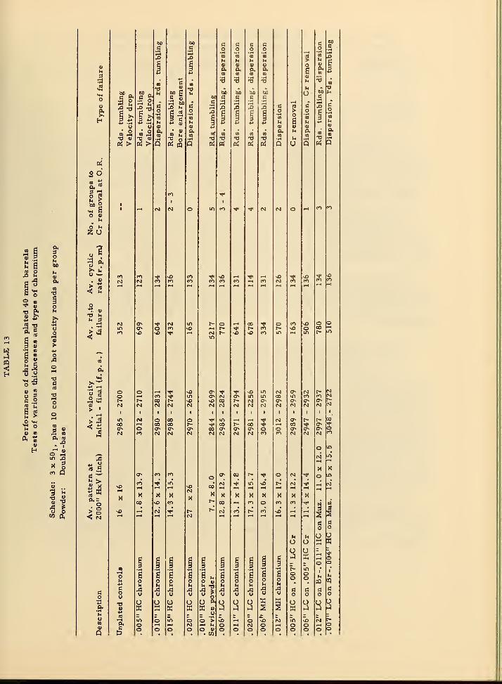
§•
« .2
M Bu60
rt^ uQ>
CI.
C -0
2 » N^ 4)
1?o1—
1
re
H gg 4)
3 V >w " -w
^s OA
5^ o
>!^ (3
?i
"-a
fi .22 ** u
it oO <<H
"r" tnu "
rt 0)
4) OQ A m0, ^
H "^ «o ^m ^" o^ Q
«•^ ^<
0) "O
43 ^yw (X
00 60(3 C! c a c BO
Ci c o o o
3 3 TO
u00
u
-1
CO
u
i-t
au u
1—1
OS
H H <a (0 lU <a ti H
^ J 0.CO
p.00
p<00
P.(0 s
P.CO B
60 _ 60 -
•60
•4->
<u
14
-0
60
t3
60
•3
Ml
fH
60
4)
>4
fH
u
•iH
t3 •
o
« S* « S' n 6£ d a c C; c;3 2 5 2
On
4->
60»4
13"
O-rH
00
33 3
•r4
2 o•iH
CO
u s
•rH
10
U
(3*
O• rH
09
UU o V <U <u u 0) o
«^ »^ 00CO u
0.Of B 00 DO 00
»4 P.CD
00p<00
T3 fl> O 4J fH 73 T3 TJ xl TS T) 'H ^ fH B •rH
fi, > Pi > Q b; Q cr! Pi (^ ffl PJ Q O Q Pj Q
fl
BOS,^3 ':i
2 t
CO Tf
60 2 1
^ s 1 ^H (M N o in CO * ^ PJ PJ o —
•
CO CO
o uhu20
ol•iH «
3 '^!>> bo «^
c«^ fO * vO CO •* nO ^H •* ,-4 vO -* nO 'Cf sO
. " N <VI CO CO CO CO CO CO CO PJ CO CO CO CO
< u^H -4 f* r^ " «—
1
r-^ •-* ^H
o•^ (U
-a nh =)
I-* PJ o^ •* rj in t- o *M 00 * o CO vO o oin CT- o CO >o 1—4 r- •* r~ CO r~ ^ o 00 •"1
CO vO vO * •—
<
PJ r~ o vO CO in .-H in r- in
<! in
^to
p.
<*i>»'-'•M i-l
1 so o 1-4 Tf o o^ * <)' vO in PJ Ov pa r- PJ
o i-t CO * in 0^ PJ o^ in in <» in CO CO PJr- r- 00 r- vO vO 00 r- N o^ o^ o^ a^ o^ r-
i>.
PO N N pj pj PJ PJ pj PJ PJ PJ PJ PJ PJ pj
> '
1 1 1 1 1 g 1
I-H
ITl «M O 00 o Tf in ^H .—
4
^ PJ o t~ r- 00
00 w^ 00 CO r- * 00 r- 00 * (—
(
00 -* <?^ *O^ O o a» o 00 o o^ ON o o o^ o (T- o(VJ fO N pj PJ PJ PJ PJ PJ CO CO PJ PJ PJ
o
CO
in
A PJ* in
X X
fi"^ O^ CO CO o
oo'
X
0^ 00 r- •* o PJ '^ o in
o
vOCO •<1<
idPJ
pj'tc" in vO r-^ PJ"
1—
1
pj
X
•^
00 sO
PO
CO
PJ
X00
pj'
X»-(
CO
XCO
XoC0°
1—
1
XCO
XCO
X
1 1a 13
O
h h o OU o ffi XO o
HI i-H o§ H § H H H H s § ^ . - o o
n •iH •H 'r-l 2 •rH •iH •fH 'T^ ••H •iH F- in • •
f-t
o g s s H e ». a fi S a g o o 1
IH uu s o g tq (£)•M »H H h u
" 5
u u (H u h ' *
(3
s 43 43 43 A A A 43 A 4h c fl (3 a
o o y y y y u u y y
U O U U o & U U U ffi s u U O OA. K X W ffi
_ yA q A s
fffi A J
»
A
b tQ-3.
U1 o in o -o •-H o vO PJ in vO PJ t~U o •—
1
-^ PJ -M ^^ o <-H PJ o rH o o >—
1
oV o o o o o <u o o o o o o o o oQ t) . w •

Number of the group (170 rd/group)Plate during which plate began to chip
thickness from origin of rifling •
0.00 5 inch 2
.010 "3
.015 " 4
.020 "1
It is seen that the duration of protection of the origin of rifling
by the chromium plate increased roughly linearly up to 0.015 inchthickness. With a thickness of 0.02 inch, the land is nearly solid
chromium. The chromiiom, which is weak, breaks off quickly whenxinsupported by a backing of steel.
Two barrels plated with 0.01 inch of HC chromiumi were fired
the same schedule, but with service powder. They had lives of
4900 and 5500 roxinds, respectively. Control results employing the
same powder with unplated barrels are not available.
Based on the above results, a thickness in the range of 0. 010
to 0.012 inch is considered a good compromise between the indicated
'T>est" thickness 0.015 inch, and a thickness that is practicable for
application in production.
7.8.3 Investigation of different types of
plate in 40 mm barrelsThe types of plate tried in 40 mm barrels included "low -contraction"
(LiC), "medixim hardness" (MH), and combinations of these. (See Table
1). Combinations tried were both "zonal", which refers to one type of
chromium in the breech end and another type in the muzzle end of the
barrel, and "superposed", which refers to one type of chromium asan overlay on another type. The performance of standard, or HC,plate had been determined in the previous phases of the 40 mm program.Uniform longitudinal distribution of thickness of both LC and MH plates
was obtained by the use of forced solution flow (pump -plating).
The firing tests showed that 0. 006 inch thickness of LC chromiiomgave about 10 percent longer life than the optimum thickness of HCchromium. Thicker LC deposits gave superior erosion resistance
at the origin of rifling, but the barrels failed earlier due to plastic
62 -

deformation of the configuration of the bore. Barrels plated with
MH chromiunn, or with either zonal or superposed combinations
had somewhat poorer performance than those plated with the opti-
mum thickness of HC chromium.
An attempt was made to determine the reason for the early-
failure due to poor accuracy of the barrels plated with thick coatings
of LC chromium (0.01-.02 inch). To this end, a detailed examination
of the condition of the bores, measurements of projectile spin, and
visual examination of the driving band of recovered projectiles weremade. It was concluded that a constriction of the bore that developed
a short distance forward of the origin of rifling caused the projectile
driving band to deform and swage undersize, thus preventing normalland engagement and resulting in about 50 percent reduction in spin.
The bore constriction resulted mainly from forward flow of the steel
under the plate, and in part from swaging of the plate itself. Theseresults for the different types of plate are sumnnarized in Table 13,
7.8, 3, 1 Effect of muzzle choke in 40 mm barrels
By tapering the bore of barrels plated with LC and MH chromiunnto a muzzle diameter two to four thousandths of an inch tinder the nonn-
inal minimunn, a 20 percent improvement in accuracy (size of target
pattern) was obtained,
7.8,4 Test of 40 mm barrels nitrided before chromium plating
Eight barrels were nitrided after electropolishing and beforeplating. Six of these were then plated as shown below:
Nitrided (0.015" case) - 0.006" HC Cr, 0.006" LC Cr, 0.012" LC CrNitrided (0.025" case) - 0,012" HC Cr, 0.006" LC Cr, 0.012" LC Cr
All barrels with the thinner nitrided case, and barrels with 0. 006inch thickness of plate on the thicker nitrided case, performed aboutthe same as corresponding non-nitrided barrels. The barrel with0,012 inch thickness of LC chromiunn on the thick nitrided case per-formed distinctly better (50 to 70 percent) than any other type of plated40 mm barrel. Since this result with one barrel cannot be consideredconclusive, it would be necessary to confirm it with additional tests.
These have not been nnade to date.
.63 -
7.9 3 inch-50 caliber barrelsAs a result of a decision by the Bureau of Ordnance, Department
of the Navy, to adopt heavy chromium plating of 3 inch-50 caliberbarrels for production, a limited experimental prograna with thesebarrels was undertaken. Since our experimental plating shop did
not have capacity for 3 inch-50 caliber barrels, the plating was donein close cooperation with the Washington Naval Gun Factory. Thebarrels were test-fired at the Dahlgren Naval Proving Ground. Workwas started in September 1950, and extended through the first quarterof 1955.
Three thicknesses of HC chromixim, namely 0.005, 0.010, and0,020 inch, and one thickness of LC chromium were tried. The thick-
ness of the LC plate tapered from 0. 005 inch at the muzzle end of the
barrel to 0. 010 inch at the origin of rifling. The chambers of the
barrels were plated.
In section 5. 5 of this report, the problems imposed as a result
of the taper normally obtained in LC deposits are described. As shownthere, the most practicable method for obtaining an untapered plate
involves pumping the solution through the bore at a high flow -rate.
The pumping method has been used successfully on an experimentalscale for all calibers through 40mm. For the 3 inch barrels, ade-quate pump capacity was not available, so another method of plating
was sought. The method selected, which was used and was satis-
factory, consisted of electropolishing the bore with a moving cathode,
thus producing a taper which matched the normal taper in the LC plate,
so that the final plated bore was straight. The normal taper in the
plate was first determined in a separate plating experiment. Theresults of the firing tests are shown in Table 14.
The general conclusions are that 0.01 inch thickness of HCchromium is about 15 percent better than 0.005 inch, with respect
to rate of loss of chromium at the origin of rifling, accuracy, andlife to VT fuse failure. The limiting factor in the life of these bar-rels is VT fuse performance. The criterion for end of life is that
at least 30 percent of the roiinds must function normally.
The barrels with 0. 020 inch thickness of HC chromium failed
early in the second group as a result of excessive loss of chromixina
fronn the bore. A plate of this tliickness is relatively unsupportedon the lands by basis steel, and tends to break off because the chro-mium itself lacks strength. The same result has been obtained with
- 64 -

«*
u
«
u4)
u
> ^
^ c
« o
It >u nl
o 2
U UD
e IZ o
u n)
*« S
« ou oC O
g.2
St«>
4) i>-i
0, 0.
«D
(NJ
m
a
bO
T3
oyVCO
o
G
>9)
(0
Oin
3
«
Um00c
^.5a z
uo
v-i
a10
ro
o
o Ud K
«•_ uCD U1—
<
O UCiE
_ hm uoo ud X
0£
ot—
1
oo uU
1
inoU
oo
^1
00
uX
uUO
u oO 2
rj
o
fO in 00 o
rj
00
o
M
00
00
CO
in sO 00 o- o
n)
(0•f-l
J?
l-H
uc
oc4>
uao
4-1
MO
n) C
O 4> -^
»<ij
O
00
T3 »H T3
(U 4)
W (0 (0
:3 ^ 3^ X
"*-
^ >
CO <-<
oH *-
> < -o
»
plates of this order of thickness in smaller caliber barrels.
The best performance was given by the barrel plated with the
tapered LC chromium plate, which had a life of ten firing groups,
compared with seven for the barrel with 0.01 inch HC chromixim,and six for the barrel with 0. 005 inch HC chromium.
8. MISCELLANEOUS TESTS OF GUN BARRELS
8. 1 Effect of heat-treatment of chromium-plated barrelsHeat -treatment of chromixim plated cutting tools, dies, etc. ,
to relieve stress and hydrogen embrittlement is a common practice.
It is therefore natural that the question of the possible value of heat-treatment of chromi\im-plated gun barrels should arise. In general,
it is considered that hydrogen embrittlement of chromium plated tools,
etc. , requires elimination through heat-treatment only if the hardnessof the basis steel is greater than Rockwell C-40. Since gvm steel is
not this hard, and since no gun barrel failures had been observed that
were attributable to hydrogen embrittlement, experimental tests of
chromivim -plated and heat-treated gun barrels had not been seriously
considered in the earlier stages of the program. However, due to
the persistence of interest in this question in several quarters, it
was decided early in 1950 to initiate some tests. During July 1950
four caliber . 50 barrels were plated to standard specifications with
HC chromium at NBS and heat-treated at the Naval Gun Factory.
Two were heated to 200 C for eight hours and two to 600 C for six
hours. The tennperature of 200 C was chosen because it is approx-imately that which is commonly used for relief of hydrogen erribrittle-
ment, and 600 C was chosen because it is close to the upper limit to
which the steel can be heated without changing its properties, yet
high enough to produce appreciable annealing of tiie chromium. Theperformance of these barrels is sho^vn in Table 15. Their firing life
was about tw^o -thirds that of unheated barrels, and one of the barrels
heated to 600 C burst during firing. Metallographic examination of
the steel showed normal structure and hardness for all of the barrels.
No explanation for their poor performance was found. About this timewe learned of the work on the same subject carried out at WoolwichArsenal (25) which indicated that the adhesion of chromium in 40 mmbarrels was improved by a cycle consisting of:
(a) Heating at 75 C/hour to 400 C(b) Holding at 400C for 1 hour(c) Slow cooling to room temperature in the furnace.
66

Barreldescription
TABLE 15
Performance of barrels heat-treated after chromium plating
Total Av. pattern at Round* to Velocity Croffatroundg 1000" HxV (inch) failure Initial - final (f. p. 6. ) O.R. (inch)
Nitrided, choked.0025" HC Cr. Heated8 hr. at 200 C
Type of failure
Caliber . 50 Schedule: five 100 rd. . bursts, 2 minute cooling, complete cooling 500 rds.
556 483 29 12 - 2584 2 to 4 Velocity dropTumbling
|
Duplicate of above 575 10 X 10 520 2889 - 2744 2 to 3 Tximbling
Same as above but
heated 6 hr. at 600 C 6.4 X 7.6 465 2930 - Barrel burst 5th burst
Duplicate of above 568 16 X 14.5 2969 - 2538 Velocity dropTumbling
Unheatsd Cr plated control(9) 725 (Average life based on 200 f. p. s. velocity drop)
Caliber 60 Schedule: eight 50 rd. bursts, 1 burst each 2 min. , complete cooling at 600 rdg .
Two piece barrel .003"
HC Cr on muzzle, .006" HC Cr 440
on breech. Heated in 2 1/2 hrs.
to 460 C for 1 hr.
8 X 12 3503 - 3379 Cr removal
Same as above 440 8 x8 -- 3492 - 3281 2.5 Velocity dropCr removal
Same as above 439 8. 5x 8 -- 3484 - 3405 2 Cr removal
Placed in furnace at
460 C for 1.5 hr. 904 8.3 X 10.2 539 3474 - 2732 Velocity drop
Same as above 908 10. 2x 11.3 540 3489 - 2688 14 Velocity drop
-Same as above 857 10.1 X 9.3 540 3554 - 3028 1.5 Velocity drop
40 mm
.006" LC Cr heated 1 hr.
at 400 C. 1082
Schedule: three 50 rd. bursts, 1 min. cooUng, complete cooling 170 rds.*
2996 - 2857 3
Av. pattern at 2000"
14 X 15 1082 Tumbling
.006" LC control-not heated 857 15 X 13.5 857 3050 - 2942 5 Dispersion of pattern
.006" HC Cr heated 1 hr.
at 400 C 1054 12. 5x 13 1054 3035 - 2887 4 Tumbling
.006" HC Cr control
not heated 1199 13.5 X 15 U99 3057 - 2890 1.5 Oversize bore
.012" HC Cr heated 1 hr.
at 400 C 1538 13. 5 X 12 1538 3046 - 2834 3 Oversize bore
.012" HC control
not heated 1545 11 X 12' 1545 3037 - 2865 1 Oversize bore ^
^Combination powder uaed for these tests (75% double-base, 25% 1. 1" "Master standard").

Two further tests were therefore carried out, one with caliber
. 60 barrels and one with 40 mm barrels. The results of thesetests are also shown in Table 15. The heating cycle used for the
caliber . 60 and 40 mm barrels was essentially the same as that
recommended in the Woolwich report. The higher temperaturesof 460 C used for the caliber . 60 barrels was in line with later
Woolwich recommendations for barrels to be used on rapid-fire
schedules.
In the heated caliber . 60 barrels, rate of removal of plate at
the origin of rifling was somewhat less than from unheated barrels,
but plate was lost slightly faster than normal from the muzzleregions. Overall performance, was if anything, slightly inferior
to that of unheated barrels.
The conclusion was that the results do not show that heat-
treating after plating has significant value. The reason for the
variance between this conclusion and the opposite conclusion reach-ed in the early Woolwich reports may lie in the difference in the
testing schedules or in differences in steels. The Woolwich report
did indicate that improvement was greater under single-shot
firing schedules than under rapid-fire schedules.
8. 2 Injection cooling of gun boresErosion of gun bores under conditions of rapid firing is pri-
marily a consequence of the high temperature reached by the sur-face of the bore. If the bore could be kept cool, performanceshould be improved. Several devices for this purpose were tested
by other NDRC contractors, but were not successful. Therefore,
one of the authors, working at the Geophysical Laboratory in 1945,
undertook to design an improved model of injection cooler 1^2 6j.
The initial tests appeared promising, so work was continued at
NBS after the termination of the gun barrel program at the Geo-physical Laboratory in 1945.
An injection cooler is a device for injecting coolant into the
bore, i. e. , for cooling the bore from the inside. This is the logi-
cal place to apply a coolant, since the heat imparted to the borecan then be removed without traveling through the barrel wall.
Cooling by means of an external water jacket is of course commonlyused for some types of guns, but this method has the disadvantage
that conduction of heat through the wall is slow, and under severerapid-fire schedules, the bore surface may still reach an ex-
cessively high temperature.
- 68 -

An injection cooling system may be designed to cool the borebetween each round, or during non-firing periods between bursts,
or both. An effective system must employ a coolant with high
heat capacity. Some of the earlier models which utilized a gas
as the coolant are inherently impractical, because the heat
capacity of any gas is relatively low and cannot remove enoughheat, at least during *'between-round"injection. Water absorbsapproximately 850 calories /gram in passing from liquid at a
temperature of 30° to vapor at 600° C, whereas for the sametemperature interval, air will absorb only about 150 and carbondioxide about 120 calories /gram. The advantage of water is
apparent.
The major part of the heat absorbed by water is that absorbedby vaporization. For vaporization to occur within the fraction of
a second available between rounds, the water must be inserted into
the bore in an atomized form, that is, as a fine spray. If it is
inserted as a "slug" of liquid, a negligible amount vaporizes andthe excess liquid passes ineffectively through the bore. Furtherrequirements for a practical injection cooler are: mechanicalsimplicity, lightness, non-interference with the normal function-
ing of the gun, and capability of operating satisfactorily under a
range of service conditions, e. g. , at low temperatures andagainst high wind pressures.
The design of the cooler is indicated in Figures 19 and 20. It
consists of a steel block mounted between the side plates of the
receiver. The block carries a hinged injector nozzle (A). Airand water are fed to the nozzle through tubes leading from the in-
puts (D). The nozzle is forced down by the forward motion of the
bolt when the gun mechanism goes into battery. Valves in the
cylinder (B) of the nozzle -hinge automatically stop the flow of air
and water when the nozzle is in this position. After the round is
fired and the cartridge case is extracted, the nozzle, activated
by a spring (C), returns to the injection position and the flow of
water, atomized by the air stream, automatically begins. In-
jection continues as long as the gun mechanism remains out of
battery.
In the tests described below, the flow of water was about 4 ml/round. Consumption of air during continuous operation was 25 cu.
ft. per minute (measured at atmospheric pressure). The operating
air pressure required is about 50 lb in. ^. Approximate estimates
- 69

o:s .,
PQ>4
4-*
oc a.
c• i-H
>>•iH
h u U0) (U
Xi i)*•>
••H UD rj1—4
u •t-t
^ 1 cO 0)
f—
1
u N •iH
o o <Z 1
1 Q•1-4 PQ
4^
c 0)
DCc
t—
1
o (0
u c aoVM c
f-l4->
(0o4->
>•ft^ y
<u0) 4->
•iH o> <;
o 1 1
^H < u
CT'
9)
U
oc•fl
tx4

oin
u
•H
u
a;
oo
aI—
I
oou
o

based, first, on the proportion of the energy of the propellant
that heats the barrel, and second, on the heat capacity andtemperature of the bore surface to a depth of about 1/16 inch,
both indicate that about 2 500 calories/ round must be absorbedto keep the temperature of the bore surface below about SOO^C.
Four ml of water per round, if heated to 600°, would absorb a
about 3400 calories. This rate of consumption of water is there-
fore of the required order of magnitude.
The results of the firing tests with this injection cooler aresummarized in Figure 21. It is seen that injection cooling pro-
duced appreciable improvement in barrel life. However, before
the injection cooler could be adopted, further improvement in
design would be necessary, particularly to prevent leakage of
water from imperfect valve seals into the gun nnechanism. It
would also be necessary to evaluate its performance at lowtemperatures, with a codant having a low freezing-point, andagainst high wind-pressures. These tests were notmade.
Some work was done on the application of a similar injection
,
cooler to the caliber . 60 gun, but the mechanical design problemswere not solved.
- 72 -

8§
OO
ooo
ooin acvj <n
o
- 8CVJ
Ss
in
cuI I 8Ol CM
incu
09
9)4*
OBI—
t
u
>» Qnl oh <u
()•<—
>
rt •4->
o n1in i-H
.
u ou
VXi u•ft1—4
It^
y tio
«M c
O (U
8 tl.
iH
1—
1
CJ
4>
M;J
O 60
^ h
O (0
CVl

8. 3 Tests of barrels coated by the
"Chromizing" process"Chromizing" is a process whereby a chromium -iron alloy is
formed on the surface of steel by heating it at a high temperaturein contact with chromivim powder or a chromium compound such aschromic chloride. Frona tinne to time this process has been pro-posed as a means for producing an erosion resistant bore surface.
Arrangements were therefore made by the Department of the Navy,Bureau of Ordnance, Section ReS5a, to have three MK-11 20 mmbarrels chromized by the Chromalloy Corporation, New York.
They were test-fired by NBS in cooperation with the Dahlgren NavalProving Ground. The results were the subject of a special report (27).
The barrels used for the test were cut off to a length of 28 inches
owing to the size limitations of the chromizing equipment. The per-formance of the short barrels could not be compared with that of full-
length barrels. Therefore two control barrels 28 inches long werefired along with the chromized barrels. One was an iinplated steel
barrel, and one was plated with 0.006 inch thickness of HC chromium.
Two disadvantageous effects of chromizing were noted. First,
it causes definite "growth" of the steel. It was necessary to reduce
the outside diameter of the chromized barrels by 0. 004-6 inch byelectropolishing before they could be assembled in the gun mechan-isms and it was also necessary to regrind the chamber before the
cartridge case would enter. Second, the temperature used for chro-mizing anneals the steel, so that reheat-treatment is necessary.
The surface hardness of the chromized layer was about 1400 Knoop,
both before and after firing, and its thickness as measured on a polished
section with a miicroscope was in the range 0.0006 to 0.0010 inch.
The resxilts of the tests are shown in Table 16. The average life
of the chromized barrels was about half that of the chromiiim plated
control barrel, but about 40 percent greater than that of the unplated
steel barrel. This degree of improvement is about what one wouldexpect from a chromium plate of the same thickness as that of the
chromized layer. A chromized layer several mils thick might give
barrel performance equivalent to that given by electroplated chromium.This would have to be determined by experiment. It is doubtful whethera thick chromized coating is practicable from the standpoint of appli-
cation.
- ,74 -

w
<
4>U'URj
«N•ri
6ouXIU
I
E
eo
uc
6uo
o
(NJ
0)
V
u
V
H
o w-4-) (dW Oh
o. (^
2-T3 O 1^O o^
^ ^ 00
V «M>
5 c
a: 3
< w 0)
.2 2 d« o .
O - >< « E
u
o
+
00
I
(M
o
X
V
4) -w
0)
U
TO *• i' Y vhO
c c E =>60 •'^
O O
00 V: ^ <
aM
W)'« 00c >> a•H '(I •Ht-t •i-l
,o o 3e^ ed 0) 3H > H
00
o
nO•-•
I
(M
00
00
4^ CD
O u ^^00 O 4J .
(Nj u m o
^4
U
00
oo00M
I
m00
X
-o 2** crt o
= ^ M00 4J nJ
(M CO /)

b.4 Tests of barrels prepared for plating by "Vapor -Honing"So-called "Vapor -Honing" is a process for smoothing the surface
of steel by removing machining burrs and rounding off sharp corners.In this process, a water suspension of a fine abrasive is blown againstthe steel surface with a high-pressure jet of air.
It has been pointed out in section 5.2 of this report that electro
-
polishing has been widely used in gun bore plating to enlarge the bore,remove burrs, and round off land corners prior to chromium plating.
However, electropolishing does have some disadvantages that haveled to a search for substitute procedures by agencies concerned with
plating of barrels in production quantities. One of the most trouble-
some difficulties thathas been encountered with electropolishing is
that the segregations or slag streamers that sometimes are presentin the bore surface are preferentially dissolved, leaving a pitted
surface that is difficult to cover completely with chromium. It is,
of course, probable that such a barrel will perform at least as well
as one in which such defects are covered over with a chromium plate.
Nevertheless, the barrel with the visible defects has the appearanceof being inferior. Other objections that have been raised against
electropolishing are that it is difficult to control the thickness of
steel remioved, the process is messy, the equipment costs are too
high, or the process is too slow. Any process may have both advantagesand disadvantages which must be weighed in deciding whether to use it,
or some competing process. We believe that these disadvantages in
the electropolishing process have been overemphasized, and that its
practicability has been proved by its extensive successful use. Onthe other hand, the convenience of vapor-honing as a production oper-ation is recognized.
Owing to its convenience as a production process, vapor -honing
of bores that had been made oversize by machining was adopted as
a method of surjface preparation in some production plants. Thequestion arose as to whether barrels prepared by the two methodswere equally good in firing performance. To answer this question
controlled tests were planned and carried out.
The tests included 20 mm, 40 mm, and 3 inch - 50 caliber
barrels. Vapor -honing and part of the plating was done by the
Gerrity-Michigan Corporation, Adrian, Michigan.
- 76 -

The Naval Gun Factory was responsible for the plating andtesting of the 3 inch - 50 caliber barrels. The 20 mm barrels
were prepared by NBS, but tested by Aberdeen Proving Gro\ind.
The tests of the 40 mm barrels were carried out entirely under
the responsibility of NBS and will be described first. They are
summarized in Table 17, which is an abstract of the more com-plete data reported in an NBS quarterly report (ZH).
It is seen from the table that differences in performance,
with respect to overall barrel life, were within the limits of
experimental variation.
The slightly better accuracy of the control barrel, which wasprepared for plating by electropolishing, appeared to be real andwas probably related to the fact that in this barrel, firing causedless chromium to be removed at the origin of rifling and along
land comers than was removed in the vapor -honed barrels.
The data available for the 3 inch - 50 caliber barrels arebased on the appearance of the barrels after a few rounds of proof-
firing. At this stage there was no significant difference betweenthe vapor -honed and the electropolished barrels.
The results of the tests of the 20 mm barrels have been reported
by Aberdeen Proving Grovmd (29). Their report states that firing
life of the electropolished barrels was about 35 percent greater than
that of the vapor -honed barrels on schedules of 40/30/600 andlOO/min/600. * On a firing schedule of 250/cc** the life of both
types of barrels was about the same.
*40/30/600 represents 40 round bursts at 30 seconds intervals
with complete cooling after 600 rounds. lOO/min/600 representslOU roiind bursts at 1 minute intervals with complete cooling at
600 rounds.
**250 roxind bursts witii complete cooling between bursts.
- 77 -

c c
'S v00c tt
(X
uling
rsio
drop
4)u •r4 u •o
CL S .o 4) ^ « -
H^-1
v2E3att
3 " a>
H Q > H Q >
• ^^ ^>s as m .
^H (11 •o tt tt*• t Ih 1—4 f-4
•^ « ,o ^«> s O JO ^
60 U o <4-l
o
tt ^
C fO <M•rt ^i^ ^^^ -^j^
-g
1 inc
h ^^ 1-^
O **Rt
aat
>0^
CO
ID
V•
- H > cu
Xi 6 c60 OB 0) vc M ^
1
u *tt Vi U .
13 'R^
00c O
o •
0,0o d.
ii -D
1^
J2o c
o •S o(X
E •
in
CO
0)
At
oao C
£oU
(0 ^ U
< 1t-l
1—4
oo>
E
«
. c
% E
m4 (0 o
At
c
2"oc
00 00
•-<
v h
^
inh r-t <-t ^4 ^^
»4
u X u >X
X X X XnJo
m u > «1t—
)
<M in r»^
B8o<*
V re < a •
pM «t ro
3 inoo
<—
<
> ^ ai
•-H ^^ I-* 1—
1
u • •^ o « o O^Vm CO o . u a vO ino
00c v < Vh
-H •-4
o • r-( 4.>
CO Vi m
u
Eu
om
bO00 cc 'S
uc <-H u
DOc
M O« X
0) At>4
•a 2 oO Atu At (90 ** >
Ri Iti J3 c u<*< a. y
•ao U ttU V
4> a 4) 5S M o « r! -^(fi a X > U a
co
•IH
MM4)
o.tt
o
o
o
>At
O1—
I
X
O
V
tt•1-1 r-t
o 2
Sco

The Aberdeen test also included barrels Ihat had been over-broached 0.0055 inch on radius, and electropolished 0.0005 inch
on radius prior to plating. These were slightly inferior to the
vapor -honed barrels. The conclusion stated in the Aberdeen report
is: "It is concluded that tubes manufactured using the electropolish
method (full depth polish) are superior to those manufactured using
preplating methods of overbroaching with slight electropolish andoverbroaching with vapor -honing. "
To sum up, the evidence indicates that electropolishing doesresvilt in better barrel performance than vapor-honing, although
the difference is not large.
8. 5 Tests of barrels plated with "Crack-Free" chromiuxn"Crack-free" chromixim is a proprietary* chromium plate
which, as the nanie implies, is free of the cracks characteristic
of HC chromium. Its physical properties are probably similar to
those of LiC chromium.
Four 20 mm MK-11 barrels were electropolished by NBS andplated by United Chromiuxn, Inc. Results of the testing of these
barrels has been reported in detail (30). The results were incon-
clusive as a consequence of the fact that the plate was extremelyrough. Even though the plates were smoothed as much as possible
by lapping, the residual roughness caused frequent schedule inter-
ruptions due to failure of cartridge cases to extract. This also
caused the rate of fire to be low^ The average firing life of the
crack-free barrels on a schedule of 12 x 5O2**, based on a velocity
drop of 200 ft/sec. , was 1766 rounds. This compared ^vith 1088
roxuids for a control barrel plated with HC chromium. It is not
possible to decide whether the apparently better performance of
the crack -free plate is due entirely to the stoppages and low rate
of fire, or whether it really is better than standard chromium.A conclusion must depend on further tests of crack -free plates
that are free of the surface roughness described above.
United Chromium, Inc. , New York, (a Division of Metal & ThermitCorporation.
)
**Twelve 50 round bursts at 2 minute intervals, followed by comiplete
cooling.
- 79 -

8.6 Bore coatings for combined corrosion and erosion
protection of barrels for submarine service
Coatings of HC chromium in the range of thickness used in
40 mm barrels, namely 0.005 to 0.010 inch, do afford some cor-rosion protection. However, other coating systems, that are free
of the crack -type porosity of HC chromium, would be expected to
afford better resistance to corrosion, which is important in barrelsfor submarine service.
At the request of the Bureau of Ordnance, ReS5a, a study of
the combined corrosion and erosion properties of other coating
systems was undertaken. The program was divided into two parts.
First, an experimental evaluation of coatings on steel panels, sub-jected to corrosion by aerated synthetic sea water, and second,
firing tests of 40 mm barrels plated with coatings selected on the
basis of the results of the tests of panels. The barrels were tested
on a schediile that combined alternate firing and immersion in
synthetic sea -water. The resvilts have been described in detail in
earlier NBS reports (31).
It was decided initially to include in the tests, coatings of chro-mium (both HC and LC), nickel, and cobalt, in various combinationsand thicknesses. The resiilts of the tests of the plated steel panelsare summarized briefly as follows:
(a) Nickel, or combinations of nickel with chromium, werein general superior to corresponding cobalt coatings.
This was due in part to the fact that we were unable to
consistently obtain cobalt coatings that did not developstress-cracks.
(b) A given thickness of LC chromium was markedly superior
to the same thickness of HC chromiiimi.
(c) Combination plates of thin nickel-thin chromiiim (0. 0005 Ni-0.001 Cr) were poorest of the combination plates, and cor-rosion resistance improved with increase in thickness of
either the nickel or the chromitun.
(d) There was no significant difference in corrosion performanceof the following 'Taest" coatings: (1) 0.005 inch Ni; (2) 0.005inch L.C Cr; (3) O.0005 inch Ni plus 0.005 inch HC Cr;
(4) 0.001 inch Ni plus 0.005 inch HC Cr; (5) 0.002 inch Niplus 0. 001 inch HC Cr; (6) 0. 002 inch Ni plus 0. 005 inch HCCr.
80 -

No combinations of LC chromivma over nickel were included because
of the difficvilties involved in obtaining good adhesion of LC chromiumto nickel. The duration of the sea-water immersion tests was 120 days.
Because of the high cost of firing tests, it was decided to select
only two of the most promising coating systems for application to
40 mm barrels. Coating (d-2) above (0.005 inch LC chromium,) waschosen in preference to 0. 005 inch nickel because of the known better
erosion resistance of the former. Fronci the above group of four 'Taest"
combination plates, (d-3 to d-6) the thickest, namely 0.002 inch nickel
plus 0.005 inch HC chromium (d-6) was chosen. This selection wasbased on the fact that the duration of the immersion tests of the panels
was too short for perforation of the thinner nickel layers to occur.
However, in long-term submarine servicei perforation of the nickel
might occur, and therefore a longer life should be expected from the
thicker coating. The combination with 0.005 inch chromium waschosen because this thickness is in the range previously found to besatisfactory from the standpoint of erosion resistance.
The description of the barrels and the results of the firing te'sts
are summarized in Table 18. The test cycle consisted of the follow-
ing steps:
(a) Fire one 50 -round burst.
(b) Cool, inspect, and submerge for six days in a vertical
position in a solution of synthetic sea -water at roomtemperature.
(c) Remove from the salt solution, rinse, dry, and inspect.
(d) Fire another 50 round burst, etc.
This cycle was continued initially for twelve weeks. After an inter-
ruption of ten weeks, during which time the barrels were stored asfired, firing of one barrel plated with LC chromium and one unplatedcontrol barrel was resumed, and continued for an additional 38 weeks.
The LC chromium plate, 0.006 inch thick, gave by far the bestoverall protection to the barrels. The combination plate of nickeland chromixim had superior corrosion resistance, but was lost fromi
the region of the origin of rifling in the early stages of the firing
period. This exposed the basis steel to erosion and corrosion.Poor adhesion of the nickel to the steel was responsible for this
failure. The nickel was applied by a competent commercial plating
firm (Chromiiun Corporation of America) experienced in nickel plating
- 81

u>.ueo«ouuouI
coaouve«
«
oaVu
£ Ji
^ £
M(Q
«u
B&o
•at)<>«
«uc«>
EhO
«0.
X
«
•3 ^
V£ su ••<
«00
m **
^ 2
(M
m«»
H
17
3==^
ue
4* -t
« X
> o
uu0)
V
(S
J3M
V
O
«
oZ
(M
m00
o•A
00
A u
o Eo Ao d
«soZ
soz
oN
0000
o
X
^0
«:o o• c
tn
00
in
<T- Of»1 t^00 00M rj
•* «>4
in in00 oo<M (M
u
O V
^0
" 2
X o -o
- <J &
'. z I° z E
•o«00
. «•2 E• "S*t 9m «•o .
5-3« hA Bfl O9U
§o
« «).« ett
• «•o B
afl bD fl
^ E
o
*t o* u
oq'Oit
'
•3 «!
(0 9
00
•4
oVJ3
«

of tube bores. The sulfuric acid anodic etch procedure was used to
obtain maximum adhesion of the nickel. Before the barrels werechromiiun plated, a ring was cut from the muzzle end of each nickel
plated barrel and the adhesion was tested by bending and chiseling
tests. It appeared to be excellent. The fact that nickel was never-theless removed from the bore during firing indicates that there is
little chance for this type of coating to be applied successfully.
The barrels plated with LC chromiiim showed some corrosionproducts on the bore after firing and immersion, due to rusting
through cracks and tiny areas of plate failure. The amount of
rusting of this type was too small to affect firing perfornaance.
Erosion was negligible.
In conclusion, it may be stated that a thick plate of LC chro-miium was the best tried, and does afford marked protection against
combined erosion and sea-water corrosion.
8. 7 Tests of chromium applied by the Hausner Process
The Hausner process of chromium plating consists of plating
from a chromic acid bath with a high-frequency alternating current
added to the normal direct current. This process, which was promotedin Germany following the war, became the subject of investigations byboth German and British technical groups. The findings of these in-
vestigators have been described in a Navy report (32) and in separatepublications ( 3 3 , 34)
.
Promoters of the process claimed the following improvementsover conventional chronaium plating: higher current efficiency,
improved throwing power, less porosity of the deposits, harderdeposits, and better adhesion of the chromium to the basis metal.The investigations of the process referred to above did not substan-
tiate any of these claims except the one concerning throwing power.Data on throwing power were conflicting, but there was evidencethat with respect to throwing power the process had some merit.
In the NBS gtin barrel program, we have taken part in two tests
of barrels plated by this process. The first was sponsored by ArmyOrdnance, ORDTS. It was carried out on November 19, 1953, at
- ^3-

Aberdeen Proving Ground and consisted of the test firing of onecaliber . 50 aircraft barrel plated by the Hausner process,* andtwo standard, full-length, taper -plated barrels prepared bySpringfield Armory. The nominal thickness of the chromium in
the Hausner barrel was 0. 001 inch and in the Springfield barrelswas 0.002 inch. They were fired on a schedule consisting of con-tinuous 400 roxind bursts with complete cooling between bursts.
The Hausner barrel, though fired a fiill 400 round burst, failed
by 100 percent keyholing before the end of the burst and gave inn-
mediate keyholing on attempting to fire a second burst. OneSpringfield barrel was fired 400 rounds (1 burst) with no failure
and was stopped at this point in order to compare its condition with
that of the Hausner barrel. The second Springfield barrel was fired
two 400 round bursts, at which point it was at, or close to, its end-of-life.
The firing -life of the Hausner barrel was therefore one -third
to one -half that of the standard plated barrel. This is about whatwould be expected of a barrel plated with a thickness of 0. 001 inch
of standard plate.
The second test was sponsored by the Navy Bureau of Ordnance,Section ReW4a. Three MK-U, 20 mm barrels which had previously
been electropolished by us were plated with 0.002 to 0.003 inch of
chromium by the Hausner process. ** They were fired at the DahlgrenNaval Proving Groxind during January-March 1956. A full report of
the res\ilts is given in our quarterly report for this period (35).
Control barrels with standard HC chromium, 0.006 inch thick, hadan average life 23 percent greater than that of the Hausner barrels.
Again, the performance of the Hausner plate was about the same as
would be expected of standard chromium of the same thickness.
*The plating was done by the Triumiph Manufacturing Co. , Chicago,
HI.
**The plating was done by the Neotronic Corporation, Chicago, 111.
- 84 -

Neither test indicated that chromixim deposited by the Hausnerprocess was superior to standard chromiTom with respect to per-formance in gun barrels. Conversely, the tests did not indicate
that it is inferior, when thickness is considered.
8.8 Experimental rifling designs
The lands in a gun barrel are subjected to severe stresses,
especially at the origin run-up. As has been already stated in
section 3, the physical properties of chromium are not all that is
desired with respect to ability to withstand these stresses. Con-sequently failure of the chromixim plate usually starts on land cor-
ners on the run-up or near the origin of rifling. If the stresses onthe plate could be reduced in magnitude, performance should be im-proved. Modifications of the bore that have already been describedthat were made for the purpose of minimizing this weakness of chro-mium are (a) a smooth, unrifled bore, and (b) a long "land run-up".
Another approach is to redesign the lands to minimize the forces
that act on them, or to redistribute the forces acting on them, so
that a local point, such as the corner of the driving side of the lands,
does not receive the major part of the stress.
It was believed an empirical approach to this problenn, namelythe trial of a number of land designs, would be preferable to attemptsto design an optimum form of land by a theoretical approach.
The six designs shown in Figure 22 were selected, and duplicate
barrels were made with each design, by Springfield Armory. M-39,20 mm barrels were used. They were plated at NBS with 0.006 inch
thickness of HC chromium, and test-fired at Aberdeen Proving Ground.The results are summarized in an NBS quarterly report (35). Eval-uation of the results was very difficult because of frequent schedule
interruptions due to break-down of guns, and because of failure of the
breech face by indentation or erosion prior to failure of the bore.
The results are summarized in Table 19. Four of the special riflings
performed appreciably better than standard rifling. Whether the dif-
ferences are real cannot be decided because of the firing difficulties
cited. Bands engraved by the sector and modified sector lands
(Figure 2 3) showed less slippage and more uniform engraving duringthe early life of the barrels than did those engraved by any of the
other types of lands. Bands engraved by standard lands (control bar-rels) showed some slippage and shearing even when the barrels were new.These results have sufficient promise to warrant further trials in othertypes of barrels.
85 -

DESCRIPTION CROSS SECTION
SPACED RATCHET12 LANDS PER BARREL
MACRO LANDS9 LANDS PER BARREL
SPACED RATCHETMtNOR LANDS24 LANDS PER BARREL
MINOR LANDSIS LANDS PER BARREL
'/^
LAND HEIGHT .016LAND WIDTH .090
/
LAND HEIGHT .016LAND WIDTH .090
/ y/z^^^^^^LAND HEIGHT .0085LAND WIDTH .060
v^y^'LAND HEIGHT ,0085LAND WIDTH .040
SECTOR LANDS12 LANDS PER BARREL
MODIFIED SECTOR LANDS12 LANDS PER BARREL
CONTROL BARREL9 STANDARD LANDS PERBARREL
/ //
LAND HEIGHT .Qie
LAND WIDTH .060
LAND HEIGHT .016
LAND WIDTH .080
V
LAND HEIGHTLAND WIDTH
/
y^.015
.058
Figure 22. Land designs used in tests of experimental riflingsin 20 mm M39 barrels.

0)
bOC••H«^V4•»4
)4 u)—
1
U10 OC0)E
B-
•ft iu oV o^
•
oVJi (D** r-*
gs
•ft0)
>4
^-1CD
J Mo«>
a1
<; ;QsH Vh
O •«
V gs
8org
MoMlM0)
(X
«a
10
Uu
PO»
1-4*IT) O r^ »-(
c {NJ PO GO 00<—
1
oIft
0)
•-4 oft
00 sO •sO PO
ID w-lr^ •^
+ Joo -Hv4 oX
OD
c
(0
C
CQ
C co
1—
1
3 to
O4J
1
n
TO0)
un
CM)
•Sf-H
4^ •-4
to
C
4>
otd
u
(»
no
(6
n)
(0
c
00c
4J
o»4
uu
s
»4
oc»4 o u ri n)
•r*
(<4 2 2 2 2fvj f\l o -* (M 00 O^
N —4 p-l <M ^^ ft
OD
•o
§o
o u * » «iTl c fO (T- (M <M 00 PO tM
•IH (M >o P^ ^ r~ r- ^HX vO PO <—
•
00 t- o OM
•ft
(NJ (Vl
n
r*4
1—
(
ou
^H ft
m'2
CD
•ocn>
f-4
0)
J3U
co
13C
uCD
(30
c•r*
U
c•M
•ft
u
OD
C
0)
ni
2u
1
n•oc CO
ft
C
(0
•r*
4->
V•r*
1C
ou
4) u -M<4 (0 C
&4> ^ 2
•fH
H (M PO (M * o O^ 00f^ ^H f^ CM 1—1
a.
Sou10
0)
00
V4J
coin
Oua>
0)
ovm0)
XI
X)4)
,i3
9)
UASvw
UV0)
CQ*

U
m
o
00
CO
bjO
C•1-1
.—
<
tt-t
•r-l
+-> UVr^
r—
'
o -M
Pi
^ •rH
;^
d 0)
•rH &S X
0)
X3
TD0)
>nJ
UfcUD
c0)
CO
CUI—
H
•H-t-J
OTJ •1—5
^H ort 5-.
CLh
rt-M •
w CO
o CM
o;
udbjo
ou
flH

9. OPERATING PROCEDURES
A general discussion of operating procedures has already beengiven in section 5. Section 9 is therefore limitsd to a discussion
of some special procedures and a description of recent efforts to
plate and electropolish barrels at high rates. These experimentshave been restricted to 20 mm barrels.
9. 1 High-speed plating
At the beginning of the work with 20 mm barrels, HC chromiumwas applied at 50 C and 20 amp/dm • Under these conditions, 10 to
12 hours are required to deposit 0. 005 to 0. 006 inch thickness. This
is an excessively long time for production operations, and therefore
work was done to define conditions that would permit application of
the plate in a shorter time. Table 20 shows the results obtained
under several sets of conditions,
A few experiments with anodes of higher resistance, namely1/4 inch diameter tool steel or stainless steel (coated with 0.01 inch
of lead-tin alloy), were also carried out, but are omitted from Table20 because the results indicated that the higher resistance had noadvantage. Since the plate in some of the runs under conditions
yielding 0.006 inch thickness per hour (No. 6 in Table 20) tendedto be nodular at land corners, several experinaents were carriedout to define the conditions more closely. It was foiind that the rangeof suitable conditions is quite narrow. Thus, a drop in temperatureof 3 degrees (No. 7), or an increase in current of 50 amperes (to a
total of 1050 amperes) caused formation of nodules. It was also
found that the tendency for nodules to form at the high plating rates
was less if the concentration of the plating bath is somewhat higherthan the usual value of 250 g of Cr03/liter. Therefore, as noted in
Table 20, a concentration of 300 g of Cr03/liter was used for mostof these experiments.
9. 1. 1 Firing tests of barrels plated,at a high rate
Five barrels plated at a rate of 0. 006 inch per hour (essentially
the conditions of No. 6, Table 20) were test-fired at the DahlgrenNaval Proving Ground. Table 21 shows a summary of the results
with the performance of a standard HC plate for comparison.
89 -

The performance of the high-speed plate was inferior to that
of standard HC plate. Three of the barrels failed by tumbling of
projectiles before a velocity drop of 200 ft/ sec. was reached.This was the result of swaging of the lands. In this respect the
plate in these barrels was similar to "medium hardness" plate
(Table 1). The hardness of a specimen of high-speed plate wasmeasured and found to be about 1100 V. P. N. , which is somewhathigher than that of HC plate produced under customary conditions
(Table 1). The behavior of the high-speed plate is therefore
anomalous. It is possible that it would perform better on a ni-
trided base.
The work on high-speed plating has shown that it is possible
to plate barrels at rates significantly higher than 0.0005 to 0.001inch per hour. Intermediate plating rates, e.g. , 0.003 inch/hrappear to be practicable and might lead to production economies.Barrels have been plated successfully at rates as high as 0.006inch/hr. Rates this high do not appear to be practicable at the
present stage of development because of the critical control re-
quired and because of the slightly inferior properties of the plate.
A decision as to whether a plant should be designed for the
usual plating rates or for high plating rates would depend on a
careful analysis of a number of factors, some of which are indi-
cated as follows:
In favor of high plating rates: (a) reduced plating time andthe consequent need for less tank capacity; (b) highercathode current efficiency.
Against high plating rates: (a) operating conditions morecritical, e.g., control of temperature, current density,
surface smoothness, fixture accuracy, etc.; (b) higherinvestment in power facilities, e.g. , 12 volts, highercurrent capacity rectifiers, higher investment in busbars, etc.
90 -
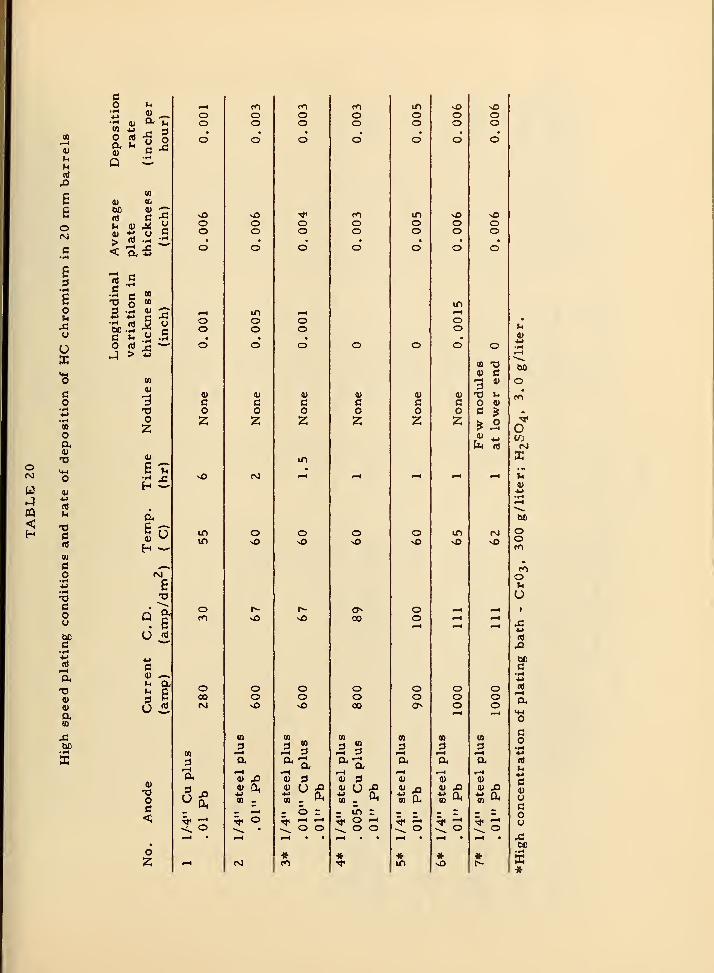
o
w
<
0)
uu(4
Bgo
E
8ou
u
UX
nOa
ni
C«>
(0
o
co
c•r-l
*^n>i-H
V0)
09
IS
O Vi
O n) -g 5
P ^
(0
bC « CT
«« .5
c C « .S
O2
0)
ET3
Eu «i"^
•Mc4> ^^u a,
3 EU .2-
Oc<;
o2
oo
oo
oo
4)
co2
vO
o
o00rg
(0
31-4
3u
COoo
vOoo
IT)
Oo
(1)
co2
rvj
O
1^
oo
0) ^
fva
POoo
oo
oo
co2
vn
o
oosO
CD
3 ".5 3
V 3
- b =^ -< •-<
CL o o
«CO
OO
COoo
0)
co2
o
oo00
CO
3I-H
a3
0) u -^
-^in zo ^o o
inoo
IT)
OO
co2
o
oo
ooo
Si ^« Oh
in
oo
oo
in
co2
in
ooo
m3I-H
*
oo
oo
CQ TJ9> C
a>
O 9)
ooo
li! Q^
o
o
Xu
00
oo
oVi
u
nt,£>
DCC•H
m
co•IH
(0
l-l
c4)
Uco(J
bO•»H
»
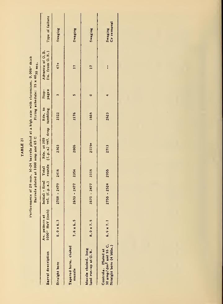
u
i «
S in
5 -E
«3o«i
uaBOChe
u
<
u
a C
u a
jO 1)
I o
E -o
E iJ
CO o.
O "^" V
u uc «A) (Q
E
«a.
«hi
3
4V4
"3boB
«>
a|
>- ^H W
m Td«^ o
• i+r-
u oc ^ 'T
> .
"D C<. C
• •a wo w foff A« s.
-1(M<M
OS 5w^(M
2
au•o
o _;o "eN 5w ro« '^
(*>• M
OS <«'^
a
-I«< S vOo 5
•a-
.s
«
1^»M ^
' '^ (M
1
5- 00
h-M
2u
^ ca) -S
fi ^ <»^
>- > ,
« X vO
S X X«a r,
>•§ CO
< -.
e
'*•
a•Mh4 VU hi
iTB *s^4 M« eoU ••<
U Rl
hi
in
eoB
ooCM
IM
00
wXou
O
o. E
H
60c60
5
B B
It"
w U
in
00
+in
in
Xo
BO .
g«
« (<
"« ?" Bii 2N
B
5JS
inm
Nm
inin
X
U" in ii"O — *«•• B ^
E O. -o .a•"" -
2 £ .?•g rt 18
O o £U fO V3

9. 2 Application of LC chromium to 20 mm barrels
without forced solution flow
It is possible to apply LC chromium to 20 mm barrels without
forced solution flow by using a resistance anode. A 1/4-inch diameter
steel anode with 0.010 to 0.015 inch thickness of lead -tin alloy plate
yields an LC deposit under conditions of 85 C and a total current of
680 to 700 amperes that is about 20 percent thicker at the lower end
of the barrel than at the upper end. This results in an acceptable
choke if the muzzle end is plated downward. A larger taper can beproduced by increasing the current density. It is especially important
when applying LC chromium that the anode be straight and accurately
centered, since the eccentricity of the plate is even greater for a
given anode eccentricity than with HC chromium (see Figure 12).
9. 3 High-speed electropolishing
Under the usual conditions for electropolishing, namely 40 to
45 C and 27 amp/dm^ 1. 5 to 2 hours is required to remove 0.005to 0.006 inch of steel. Shortening of this time would be advantageousin production. The results of a few experiments are shown in Table22 and in Figure 5.
While more work will be required to define suitable conditions
definitely, it appears that electropolishing can be readily done at
twice the usual rate.
9.4 Gas -port plating
A sketch showing the construction and assembly of a fixture for
plating the gas-port of a 20 mm barrel is shown in Figure 24. The gas-
port anode is an "intermediate" anode. Current for plating the gas-
port is adjusted by varying the distance between the main anode andthe end of the gas -port anode. No outside connection to the latter is
necessary. The fixture is centered by removing the anode height
adjustment screw and sighting through the hole in the fixture, or byinserting a pin of correct diameter through the hole in the fixture into
the gas-port. The point at which the gas-port anode just touches the
bore anode as the guide is screwed into place is determined by testing
for circuit continuity. The guide is then unscrewed the distance necessaryto adjust the plating current in the orifice to the proper value. Usuallythe correct current density is obtained on the gas-port wall if contact
between the two anodes is barely broken. The gas-ports of all barrelsprepared for testing by NBS, unless they have nnolybdenum inserts,
are plated with this fixture.
- 93

u
pq
<
It
u
o
n)
nCo
T3couoccJSa
•IH
oaou*ju
4)
aOB
o M
a
><
X >** o
< 2:
-s .s
C ft.
0)
m
3
a
M6T3
Q a•
8(«^^
4i»
rt^*»
4> aM hU9 rt
u
4)
o
U
in in0^ fo >o vO >o r- -* ^
^4 OH V4 pM
•
in
•
in in
•
1^
d 0*
m '^ <M <«> in ro fO fo PO m (M in•-4
• • • • • •0* d d
in in in in m in in »n infO •-4 w* (M fiX
c• • • • • • « « « ,
2 d
0) «) V 0)kH 1—1 <-< pn^ ja ja ^(«'M iS X 43 X! X 5 X
•B43a a a a ** 4J M ** 4J *3
V H)
u u u uu u u u g E 8 8 8 8 8 8< < < < (0 (A (A w w CO w CO
in in<NJ ro 4 nO p^ en po PO rO PO PO r-
•* '^ ''I' >o -* nO * * "* Tj' PC ""t
-* in in •^ in in in ""T in *lf> vO r* in r» <v> m -^ in r^ in
0^ !>-
r- «M rHin «o !>- in r- rj
C"t in r^ in (M
c ^^ _^i_ 1
t
0)
£
a>
nSteel
coat)4J3
•fH
*t *» ;) 4^ *» 4>» ** «*
^ 2** u U • ft •iH • <•<
**••4u •0 •0 T3 - ^ ^ -o T3 'X3 TJ TJ
^ 00 ^ ^<-^ rH t-4

o <^
t ^o -oa, o
a r;
bfl 0)
C -^
>—t (V)
Oh -M
J-4 1—1
o a,
££
0) ra
oa
0)
OC<1
u
S g
0) r-t
uua
H
O
' Q
0)
m
03
0)
o
^ w PQ ;C
IX! jg Ct
^ B B,"^^
O ^ -^ tU3
<; CM .r-l -.-I
CM
0)
fcuo

10. FUTURE WORK
One might expect that research on gun barrel plating as ex-tensive as has been described in this report should make it
possible to predict specifications for any new model of barrelthat would give, if not the best possible performance, somethingfairly close to the best. In spite of the fact that the data that
have been accumulated permit an approach to this goal, areasremain in which there is still possibility for improvement.Some of these will be indicated very briefly.
Much testing has been done with isolated variations, whichis necessary if the variation is to be evaluated. With some types
of barrels there has been no previous opportunity to combine all of
the favorable variations in one barrel. This is now being done in
40 mm barrels. More work is needed to define an optimum land
contour for all calibers. High-altitude conditions raise questions
concerning low temperatures; for example, does the stress result-
ing from a muzzle choke become an embrittlement hazard to the
barrel or the projectile at minus 70 C? Preliminary work on this
question indicates a negative answer. Designers might well con-sider further questions concerning clearance between the bore andthe projectile, and the possibility of improving driving band design,
to eliminate balloting. Improvements here would add to the life of
plated barrels.
In the field of plating procedures and techniques, it is still
possible to improve plating fixtures. Deposition of chromium at
very high rates may have potential production value, but still needsdevelopment before it is practicable. Significant savings could bemade in the cost of electropolishing and in the cost of disposal of
spent electropolish solutions if a simple method were developed for
removing dissolved metals, especially iron.
Finally, in the field of testing, local measurement of thickness
of chromium in the bore, non -destructively, would eliminate accep-tance of production barrels in which the plate is eccentric. This is
believed to be a common cause of large variations in life that aretoo frequently found in plated barrels. A gage for this purpose is
under development. A non-destructive method for measuring ad-hesion of the plate in barrels plated in production would have muchvalue. Test-firing procedures are in need of improvement. Thesuggestion has been made that barrels be pre -heated to a tempera-ture approximiating that reached in burst fire before test-firingr-
- 96-

The firing cycle could then be shortened with resultant saving
of ammunition (estimated as high as 75 percent). Furthermore,schedule interruptions would not vitiate test results, because the
barrel would remain hot. A few preliminary experiments havebeen made with electrical pre -heating of the barrel.
New models of guns and barrels are continually being develop-
ed. As indicated above, accumulated data permit a logical guessas to specifications for chromium plating these new types of
barrels. Nevertheless, test-firing of barrels plated with varia-
tions from the initially selected specifications will always bedesirable.
11. ACKNOWLEDGMENTS
The contributions of the following persons to this program is
acknowledged:
Dr. William Blum, Dr. Abner Brenner, Mr. Wm. H. Metzger, Jr.
Mr Arthur Fridinger, Mr. Robert Seegmiller, and others of the NBSstaff who were engaged on this project.
Acknowledgment is also made to the following organizations for
technical cooperation and financial support:
Department of the Navy, Bureau of Ordnance;Department of the Army, Office of the Chief of Ordnance,and Springfield Armory,
Other cooperating organizations were the Naval Proving Ground,Dahlgren, Virginia, Aberdeen Proving Ground, the WashingtonNaval Gun Factory, and the Geophysical Laboratory. We regretthat it is not practicable to list the names of all of the personnelof these organizations who have contributed to the program.
• 7 -

REFERENCES
(1) W. W. de Sveshnikoff and H. E. HaringArmy Ordnance 5^, 503 (1924).
(2) J. Q. McDonald and W. M. Scott, Brit. Pat. 299,298,Oct. 22, 1927.
(3) A. Willink, Frankford Arsenal Engineering Report, July 28, 1931
(4) Fabrique Nationale D'Armes de Guerre, Belgium Pat. 361,579,July 31, 1929.
(5) J. M. Olin and A. G. Schuricht (Western Cartridge Co.
)
U. S. Pat. 1,886,218, Nov. 1, 1933.
(6) T. K. Vincent, Report No. 87, BRL-APGAberdeen Proving Gro\ind, Nov. 3, 1937.
(7) Symposium on Chromiumi Plating, Washington, D. C.
May 14, 1943, Div. 1, NDRC, OSRD 6485, Report No. A-414.
(8) Investigation of Erosion in Caliber . 50 M2AC-BMG BarrelsPartial Tech, Report on SA-W0311, Engineering Dept. ,
Experimental Div. , Springfield Armory, Nov. 12, 1943;
March 1, 1944; and June 6, 1944.
(9) "Hypervelocity Guns and the Control of Gun Erosion"S\unniary Tech. Report of NDRC, Div. I, Vol. I, Washington, D. C. ,
1946 Chapters 20, 23, 24, 25, 31, and 32.
(1G> See Ref. (9) Chapters 16 to 21.
(11) S. Senderoff and A. Brenner, J. Electrochem. Soc. 101, 16(1954).
(12) A. Brenner, Polly Burkhead, and C. Jennings
Journal Res. National Bureau of Standards 40_, 31 (1948).
(13) A. Brenner, Polly Burkhead, and Emma Seegmiller
Journal Res. National Bureau of Standards 39, 351 (1947).
(14) C. L. Faust, U. S. Pat. 2,334,699, Nov. 23, 1943.
(15) C. Williams and R. A. F. Hammond, Trans. Inst, of Met. Finishing
(London),3J_,
124(1954).
(16) A. H. DuRose and D. M. Hutchinson, Plating 40, 470, 630(1953).
(17) V. A. Lamb and E. F. Osborn, U. S. Pat. 2,687,591, Aug. 31, 1954.
(18) Firing Trials with 0. 5 inch Browning M/G Barrels with ChroniiumPlated Bores. ARD Met. Report 206/44 (WA-2926-7H) Sept. 1944.
(19) R. Seegmiller and V. A. Lamb, Proc. Am. Electroplaters' Soc.
1948, 125.
(20) R. F. Ledford and L. O. Gilbert, Plating 4^, 1151 (1955).
- 98-
Ministry of Supply, Armament Res. Establishment, MetallurgyBranch, Woolwich Arsenal, Kent, England, Report No. MR 7614/72,
1953 (Confidential).
V. A. Lamb and J. P. Young, NBS Report No. 5A106, Nov. 30, 1951.
J. P. Young and W. H. Metzger, Jr. , NBS Report No. 5B153,
Jan. 1, 1956.
a. V. A. Lamb, Final Report on 1st Phase of Program onChromium Plated Barrels, on Work Performed to FindMethods for Obtaining Maximvim Adhesion of the Deposit.
Aug. 26, 1949.
b. V. A. Lamb, Report II, Chromium Plated Barrels,
Plating and Firing of Thickness Group, March 22, 1951.
c. J. P. Young, Report III, 40 mm M-1 Chromium Plated
Barrels, Investigations of Various Types of ChromiiunPlate for the Improvement of Gion Barrel Performanceand Life, NBS Report No. 3B101, Aug. 1, 1954.
ARD Metallurgical Report No. 5/50, Woolwich, EnglandJuly 1950.
John P. Young, U. S. Pat. 2,764,914, Oct. 2, 1956.
V. A. Lamb and J. P. Young, NBS Report No. 3297, May 13, 1954.
V. A. Lamb and J. P. Young, NBS Report No. 5B136, Jan. 1, 1954.
Erosion Tests of Bore Pre -plating Preparations, 88th Report onProj. No. TS 3-3014, Aberdeen Proving Ground, Dev. and ProofServices, Dec. 1, 1954.
V. A. La*nb and J. P. Young, NBS Report No. 5B151, Oct. 1, 1955.
a. V. A. Lamb, NBS Report No. 3099 (3988) Feb, 8, 1954.
b. V. A. Lamb and J. P. Young, NBS Report No. 5B151, Oct. 1, 1955.
(32) Dept. of the Navy, Bureau of Ordnance, Technical Library.
Library No. ONI-F, OANAR, Mp-B.(33) R. Bilfinger, Arkiv. :^ur Metalkunde, No. 4, 131, Nov. (1948).
(34) F. Muller, W. Eilender, and K. M. Wagner, ibid,, April, 135(1949).(35) J. P. Yoiing and W. H. Metzger, Jr., NBS Report No. 5B157,
April 1, 1956.
- 99 -


U.S. DEPARTMENT OF COMMERCEFrederick H. Mueller, Secretary
NATIONAL BUREAU OF STANDARDSA. V. Astin, Director
THE NATIONAL BUREAU OF STANDARDS
The scope of activities of the National Bureau of Standards at its major laboratories in Washington, D.C., and
Boulder, Colorado, is suggested in the following listing of the divisions and sections engaged in technical work.
In general, each section carries out specialized research, development, and engineering in the field indicated by-
its title. A brief description of the activities, and of the resultant publications, appears on the inside of the front
cover.
WASHINGTON, D.C.
Electricity and Electronics. Resistance and Reactance. Electron Devices. Electrical Instruments. Mag-netic Measurements. Dielectrics. Engineering Electronics. Electronic Instrumentation. Electrochemistry.
Optics and Metrology. Photometry and Colorimetry. Hiotographic Technology. Length. Engineering
Metrology.
Heat. Temperature Physics. Thermodynamics. Cryogenic Physics. Rbeology. Molecular Kinetics. Free
Radicals Research.
Atomic and Radiation Physics. Spectroscopy. Radiometry. Mass Spectrometry. Solid State Physics.
Electron Physics. Atomic Physics. Neutron Physics. Radiation Theory. Radioactivity. X-rays. High
Energy Radiation. Nucleonic Instrumentation. Radiological Equipment.
Chemistry. Organic Coatings. Surface Chemistry. Organic Chemistry. Analytical Chemistry. Inorganic
Chemistry. Electrodeposition. Molecular Structure and Properties of Cases. Physical Chemistry. Thermo-
chemistry. Spectrochemistry. Pure Substances.
Mechanics. Sound. Mechanical Instruments. Fluid Mechanics. Engineering Mechanics. Mass and Scale.
Capacity, Density, and Fluid Meters. Combustion Controls.
Organic and Fibrous Materials. Rubber. Textiles. Paper. Leather. Testing and Specifications. Poly-
mer Structure. Plastics. Dental Research.
Metallurgy. Thermal Metallurgy. Chemical Metallurgy. Mechanical Metallurgy. Corrosion. Metal
Physics.
Mineral Products. Engineering Ceramics. Glass. Refractories. Enameled Metals. Constitution and Mi-
crostructure.
Building Technology. Structural Engineering. Fire Protection. Air Conditioning, Heating, and Refrigera-
tion. Floor, Roof, and Wall Coverings. Codes and Safety Standards. Heat Transfer. Concreting Materials.
Applied Mathematics. Numerical Analysis. Computation. Statistical Engineering. Mathematical Physics.
Data Processing Systems. SEAC Engineering Group. Components and Techniques. Digital Circuitry.
Digital Systems. Analog Systems. Application Engineering.
• Office of Basic Instrumentation. • Office of Weights and Measures.
BOULDER, COLORADO
Cryogenic Engineering. Cryogenic Equipment. Cryogenic Processes. Properties of Materials. Gas Lique-
faction.
Radio Propagation Physics. Upper Atmosphere Research. Ionospheric Research. Regular Propagation
Services. Sun-Earth Relationships. YHF Research. Radio Warning Services. Airglow and Aurora. Radio
Astronomy and Arctic Propagation.
Radio Propagation Engineering. Data Reduction Instrumentation. Modulation Research. Radio Noise.
Tropospheric Measurements. Tropospheric Analysis. Propagation Obstacles Engineering. Radio-Meteor-
ology. Lower Atmosphere Physics.
Radio Standards. High Frequency Electrical Standards. Radio Broadcast Service. High Frequency Im-pedance Standards. Electronic Calibration Center. Microwave Physics. Microwave Circuit Standards.
Radio Communication and Systems. Low Frequency and Very Low Frequency Research. High Fre-
quency and Very High Frequency Research. Ultra High Frequency andSuperHigh Frequency Research. Modula-tion Research. Antenna Research. Navigation Systems. SyileiiM Amafytu. Field Operations.

4
:nbs: