Characterisation of green-glued wood adhesive bonds - DiVA ...
80
Characterisation of green-glued wood adhesive bonds
-
Upload
khangminh22 -
Category
Documents
-
view
0 -
download
0
Transcript of Characterisation of green-glued wood adhesive bonds - DiVA ...

Characterisation of green-glued wood adhesive bonds


Linnaeus University Dissertations
No 85/2012
CHARACTERISATION OF GREEN-GLUED
WOOD ADHESIVE BONDS
MAGDALENA STERLEY
LINNAEUS UNIVERSITY PRESS

CHARACTERISATION OF GREEN-GLUED WOOD ADHESIVE BONDS Doctoral dissertation, School of engineering, Linnaeus University 2012 ISBN: 978-91-86983-57-4 Tryck: Ineko AB, Kållered

ABSTRACT Sterley, Magdalena, (2012). Characterisation of green-glued wood adhesive bonds.
Linnaeus University Dissertations No 85/2012. ISBN: 978-91-86983-57-4. Written
in English with a summary in Swedish.
The gluing of unseasoned wood, called green gluing, is a relatively new sawmill
process, implying a radically changed order of material flow in the production of value-
added wood-based products. It facilitates the enhancement of raw material recovery
and value yield by integrating defect elimination and gluing already before kiln drying.
The present study evaluates green glued adhesive bonds in flatwise glued beams and
finger joints. The main part of this work deals with green gluing using a moisture
curing polyurethane adhesive (PUR). Standardised test methods and specially
designed, small scale, specimens were used for the determination of the strength,
fracture energy and the ductility of both dry- and green glued bonds in tension and in
shear. Using the small scale specimens it was possible to capture the complete stress
versus deformation curves, including also their unloading part. An optical system for
deformation measurement was used for the analysis of bond behaviour. The influence
of moisture content during curing and temperature after curing on the adhesive
chemical composition and on the mechanical properties was investigated.
Furthermore, the moisture transport through the adhesive bond during curing was
tested. Finally, microscopy studies were performed for analysis of bond morphology
and fracture. The results show that two significant factors influence the shear strength
of green glued bonds: wood density and adhesive spread rate. Bonds which fulfil the
requirements according to EN 386 could be obtained within a wide range of process
parameters. The small specimen tests showed that green glued PUR bonds can reach
the same strength and fracture energy, both in shear and in tension, as dry glued bonds
with the same adhesive amount. The local material properties of the bonds could be
determined, thanks to the failure in the tests taking place within the adhesive bond
itself and not in the wood. Following process factors were shown to cause lower bond
strength: a) a low adhesive spread rate, b) high pressure and c) short pressing time in
combination with low wood density and high moisture content. Moreover, the heat
treatment of the cured PUR adhesive during drying influenced the chemical
composition of the adhesive, providing for higher strength, stiffness and Tg of the
adhesive, caused by an increased amount of highly ordered bidentate urea.
Key words: green gluing, finger jointing, durability, shear strength, wood failure
percentage, fracture energy, tensile strength, PUR adhesive.
I

II

III
SAMMANFATTNING Våtlimning, d.v.s. limning av otorkat virke, möjliggör en effektiv tillverkning av limmade träprodukter. Våtlimning innebär en radikal förändring av materialflödet, och genom borttagning av defekter och limning före torkning kan såväl volymsutbyte som förädlingsvärde ökas. Denna doktorsavhandling behandlar utvärdering av våtlimmade limfogars och limförbands egenskaper, och omfattar såväl fingerskarvning som flatsideslimning av gran. Huvuddelen av arbetet handlar om våtlimning med enkomponents polyuretanlim (PUR). Standardiserade metoder användes för bestämning av limfogarnas skjuvhållfasthet och delaminering. Speciellt utformade provningsmetoder för små provkroppar användes för bestämning av hållfasthet, brottenergi och limfogens seghet vid skjuvning (Modus II) och dragning vinkelrät fogen (Modus I). Våtlimmade limfogar jämfördes med traditionellt torrlimmade fogar. Sambandet mellan kraft och deformation i en limfogs brottzon kunde studeras i detalj och både den uppåtgående och den nedåtgående (brottmjuknande) delen av arbetskurvan kunde registreras. En teknik för berörings-fri deformationsmätning användes för detaljerad analys av deformationer i limfogen under provning. Vattenmängdens och temperaturens inverkan på limmets kemiska sammansättning och limmets mekaniska egenskaper studerades. Fukttransporten genom limfogen under torkning undersöktes också. Slutligen genomfördes mikroskopistudier för analys av limmets penetration i träet och av brottytor i provade limfogar. Resultaten visar att skjuvhållfastheten hos våtlimmade limfogar bestäms av två signifikanta faktorer: träets densitet och mängden lim. Våtlimmade fogar tillverkade inom ett brett spektrum av processparametrar uppfyllde kraven för fogar i limträ enligt EN 386. Tester utförda med små provkroppar visade också att de våtlimmade fogarna kunde uppnå samma styrka och brottenergi som torrlimmade fogar med samma limmängd, både i skjuvning och i dragning. Med mikroskopistudier verifierades att brottet inträffade inom limfogen och inte i träet, vilket oftast sker med standardiserade provkroppar. Följande processparametrar medförde en lägre styrka hos de våtlimmade fogarna: a) liten limmängd b) högt presstryck och c) kort presstid i kombination med virke av låg densitet och med hög fuktkvot. Vid torkning av våtlimmade produkter utsätts den redan härdade limfogen för höga temperaturer. Denna värmebehandling visade sig ha inverkan på limmets kemiska sammansättning och gav en mer ordnad polymerstruktur vilket i sin tur ger en högre styvhet, styrka och glastransitionstemperatur, Tg. Nyckelord: våtlimning, fingerskarvning, beständighet, skjuvhållfasthet, träbrottsandel, brottenergi, draghållfasthet, PUR-lim.

IV
V
ACKNOWLEDGEMENTS This PhD thesis is the result of my work within research programmes carried out at the former Trätek institute (Swedish Institute for Wood Technology Research) and the Royal Institute of Technology (KTH), and continued at SP Wood Technology and Linnæus University (LnU), dealing with investigations of the green-gluing process.
Several organisations have financially supported the work described in this report. I wish gratefully to acknowledge the support from The Knowledge Foundation (KK-stiftelsen), Institute of Research and Competence Holding AB (IRECO), former NUTEK – The Swedish National Board for Industrial and Technical Development, former Assi Domän and Frans and Carl Kempe’s Foundation (Frans och Carl Kempes Minnesstiftelse 1984), CBBT (Centrum för Byggande och Boende med Trä), Södra Timber AB and, finally, my employer SP Technical Research Institute of Sweden.
The work would not have been possible without the advice and support from several experts, colleagues and friends. First of all, I would like to thank my supervisor at LnU, Professor Erik Serrano, for his support, for the endless discussions and for always being available for me. Part of the laboratory tests were carried out at the Division of Structural Mechanics, Lund Institute of Technology, with great help from Professor Per Johan Gustafsson, whom I wish to thank for very valuable comments. My former supervisor at KTH, Professor Ove Söderström, is recognised as being my first strong supporter of my studies. I would also like to express my gratitude to Mr. Bertil Enquist for carrying out the major part of the testing, development of testing set-ups and for all suggestions and discussions during the last four years. I would like to express my thanks to Professor Hans Petersson, LnU, for his deep engagement in the green gluing project, and also for being involved in my work at LnU. Dr. Stacy Trey (KTH) is recognised for her participation in the part of my work related to the field of chemistry, as well as Civ.ing. Åsa Lundevall at SWEREA IVF for collaboration in adhesive testing. Mr. Joachim Seltman is acknowledged for the preparation of microscope specimens with the excimer laser. Special thanks are directed to Dipl.ing. Hartwig Blümer, who initiated and led the green-gluing research at Trätek, and who was closely involved in the first part of my work by always being available as advisor and mentor.

VI
I wish to thank all my colleagues at the former Trätek and all new colleagues at SP Trä and LnU, many of whom have been helpful in several ways in accomplishment of this work. You all created the stimulating and friendly environment, which made this work possible. Special credits to the following persons must be recognised: Dr. Jarl-Gunnar Salin, Professor Bo Källsner, Dr. Birgit Östman, Civ. Ing Jan Oskarsson, Dipl.ing Boris Hajek, Dr. Marielle Henriksson and Dr. Johan Vessby.
I would like to thank my family for encouraging me and backing me up, dziekuje Mama Wanda i Tata Stefan. Finally, thank you Mikael, Daniel, Martin and Anna for your love and patience.
Växjö, Mars 2012 Magdalena Sterley

VII
CONTENTS ABSTRACT ........................................................................................................ I SAMMANFATTNING .................................................................................. III ACKNOWLEDGEMENTS ............................................................................ V CONTENTS ................................................................................................... VII 1 INTRODUCTION AND OVERVIEW ................................................ 1
1.1 General remarks ................................................................................... 1 1.2 The green gluing process ..................................................................... 2 1.3 Factors influencing wood adhesive bond properties ............................ 4 1.4 Adhesives used for green gluing – State of the art ............................... 5 1.5 Aim, scope and limitations .................................................................. 7 1.6 Structure of the thesis .......................................................................... 8 1.7 Appended papers ................................................................................. 8 1.8 Additional publications ........................................................................ 9 1.9 Division of work between the authors ................................................. 9
2 MECHANICAL CHARACTERISATION OF WOOD ADHESIVE BONDS ............................................................................ 13
2.1 Test methods ..................................................................................... 13 2.2 Bond components, adhesion aspects and failure paths ...................... 14
3 METHODS – PRESENT STUDY ...................................................... 17 3.1 Testing of adhesive bonds – block shear specimens........................... 17 3.2 Non-contact deformation measurements .......................................... 18 3.3 Testing of finger joints ....................................................................... 18
3.3.1 Bending strength and warp........................................................ 18 3.3.2 Tensile strength ......................................................................... 18 3.3.3 Accelerated aging test of finger joints ....................................... 20
3.4 Testing of adhesive bonds with small specimens – determination of material properties .......................................................................... 20
3.4.1 General remarks......................................................................... 20 3.4.2 Result evaluation methods ......................................................... 20 3.4.3 Shear test ................................................................................... 22 3.4.4 Tensile test ................................................................................. 23
3.5 Methods for bond morphology and bond fracture path studies ......... 24 3.6 Methods for testing of adhesive composition and influence
of cure conditions ............................................................................... 24 3.7 Method for measurement of water transport through
adhesive bond ..................................................................................... 25

VIII
4 RESULTS AND DISCUSSION ........................................................... 27 4.1 Standardised testing of shear strength of the adhesive bonds ............ 27 4.2 Testing of finger joints ....................................................................... 33
4.2.1 Bending strength and warp........................................................ 33 4.2.2 Tensile strength of finger joints ................................................. 33 4.2.3 Measurement of strain along the finger adhesive bond ............. 35 4.2.4 Accelerated ageing tests ............................................................. 38
4.3 Testing of small specimens ................................................................ 38 4.3.1 Failure process ........................................................................... 38 4.3.2 Shear test ................................................................................... 41 4.3.3 Tensile test ................................................................................. 42 4.3.4 Extension of the fracture process zone ...................................... 43
4.4 Microscopy study ............................................................................... 44 4.4.1 Small tensile specimens - SEM study ....................................... 44 4.4.2 Finger joints – X-ray microtomography .................................... 45
4.5 Adhesive testing – Influence of curing conditions and post-heating on adhesive properties ........................................................................ 48
4.6 Moisture profile across the adhesive bond during drying .................. 50 5 GREEN GLUING IN PRACTICE – PROCESS PARAMETERS . 53
5.1 Green wood as a substrate for gluing ................................................. 53 5.2 Lay-up ................................................................................................ 55 5.3 Open time, assembly time and adhesive spread rate .......................... 55 5.4 Pressure and pressing time - Penetration of the adhesive and initial
bond strength ...................................................................................... 56 5.5 Drying................................................................................................. 56 5.6 Final bond properties .......................................................................... 58
6 CONCLUSIONS AND FUTURE WORK ......................................... 59 6.1 Conclusions ........................................................................................ 59 6.2 Future work ........................................................................................ 60
7 REFERENCES ...................................................................................... 63

1
1 INTRODUCTION AND OVERVIEW
1.1 General remarks The sawmill industry has undergone great development over the last decades. To increase value and volume yield, modern sawmills apply new techniques to modernise the basic processes. Much effort is made to speed up production and to use state-of-the-art equipment. One such technique, that has been installed in several sawmills, is the use of equipment for 3D and x-ray scanning of logs and pre-cut blocks for optimisation of the best sawing pattern. Other valuable equipment in use includes profiling chippers, for optimising the best yield of raw material, combined with optimisers for un-edged side boards. High-speed grading of timber is the norm, and new grading techniques with optical scanning are continuously under improvement. Developments in timber drying, such as optimising of drying schemes, techniques for on-line drying, high-temperature drying and microwave drying, are adapted by the industry or under further development. Traceability methods, from forest raw material to industrial products such as customer-adapted components, are extensively studied and more or less ready to be used in production.
Generally, this development improves the efficiency of sawmills and leads to a reduced amount of waste, increased yield volume and volume of higher-quality products, consequently achieving higher value. Development extends over all individual operations of the traditional saw mill process. However, the traditional main flow of sawmill production has not changed since the beginning of its existence. The order of the flow is the same: timber is sawn, dried, planed, graded and finally glued. This traditional and conservative sawmill flow is rarely questioned in order further to improve the process.
There will always be a part of the raw material and of the sawn products that is difficult to upgrade to a higher value within this traditional sawmill process. Such material includes:
• Timber with smaller dimensions, such as thin side boards, with high production
and handling costs, but with lower sale value. • Small diameter logs. • Timber with quality defects, such as large knots, knot groups or high grain slope
causing warp. • Short length logs of hardwood, mostly of crooked shape that are difficult to
convert to components.

2
One way to upgrade this material can be achieved by eliminating defects and re-joining by gluing, such as finger jointing or/and flatwise gluing. This can result in enhanced timber properties, such as upgrading the timber for structural use, creating a higher market value and better price.
Further enhancement of raw material recovery can be achieved by integrating gluing and assembling as early in the process as at the “green part” of the log-cutting process, i.e. the part of the process taking place before kiln drying. This can be done in connection with modernisation of the green sorting line of sawmills and can then include installation of equipment similar to that conventionally found at the end of the dry finishing operations. Scanning and grading equipment could therefore be transferred to earlier stages in the process, before or directly after sawing. This alternative production flow, with application of green gluing (i.e. gluing of unseasoned timber) early in the production line, can create a huge increase in volume yield and economic benefits. It is also of great interest in relation to the diminishing quality of timber in Europe, as a result of shorter crop rotational periods, which places an increasing importance on making better use of all available resources. The implementation of green gluing involves new thinking in relation to the production flow, turning the traditional flow back to front.
Through re-engineering wood by green gluing it is possible to utilise the low value timber as high end-value commodities such as joinery blanks or construction grade timber (Cornwell et al. (2005)). The operations which are traditionally carried out on dry timber in the gluing process must, however, be adapted to the unseasoned timber and there is therefore a need for basic research to increase knowledge about the behaviour of green-glued wood adhesive bonds and on factors influencing their behaviour. The present work is a part of a larger project conducted (Serrano et al. (2011)) which in turn aims at studying the green gluing process in order to develop new value-added glued products for load bearing applications in construction.
The green gluing process is schematically shown in Figure 1.
1.2 The green gluing process Green finger jointing has been developed in order to create efficient gluing processes which can be applied by sawmills for upgrading of timber. The main economic advantages of this technology are as follows:
• it provides uniform lengths for kiln drying • there is no need to dry parts of wood containing undesired defects and knots,
which saves energy • green shorts can be used to create upgraded structural timber • green shorts with defects can be converted into pulp chips or used for energy
production

3
Figure 1. Simplified flowchart of the green gluing (left) and dry gluing (right) processes.

4
• fast-grown timber consisting of a large amount of juvenile wood, characterised by severe length shrinkage resulting in warp, can be upgraded by cutting into short lengths without the described defects
• degradation and lumber loss at final grading are reduced • cold-setting adhesives eliminate costs for pre-heating of joints and for press-
heating during assembling. Edge and face green gluing of timber is the next step in developing green gluing processes to create additional benefits. If gluing is introduced in the early stages of production, waste after drying is diminished and the handling of raw timber in the green sorting line is simplified or partially eliminated. In addition, in the case of flatwise gluing of side boards, the value of the small dimension boards can be upgraded to that of structural glued timber by the economically efficient process. This upgrading is possible thanks to the superior mechanical properties of the side boards which possess both high strength and, what is more important, high stiffness (Steffen et al (1997)). In the traditional non-structural use of side boards, these properties are not utilised.
In addition, by green splitting and reassembling by green gluing, and with optimal orientation of the wood fibres, further advantages such as shape stability improvement and warp reduction can be achieved (Maun and Cooper (1999), Ormarsson (1999), Serrano and Cassens (2001), Eriksson et al. (2004)).
As mentioned above, the green gluing process offers many possibilities for sawmills to increase value and improve volume yield. The challenge in this new process is to control and maintain the quality of the finished product. At present, green gluing quality control systems have not yet been developed to the same extent as for the dry gluing process, which is known and has been studied in an industrial context for about 100 years. Especially the adhesive bond formation process and the mechanical properties of the cured bonds are areas of great interest for research and development.
1.3 Factors influencing wood adhesive bond properties Traditionally, gluing of timber is carried out on dried timber, with a moisture content (MC) of 8-15 %. There are many factors affecting dry-glued bond formation and defining the final adhesive bond properties. One group of factors originates from the gluing process, such as assembling, pressing and curing time, clamping pressure, pressing temperature and climatic conditions at the time of gluing. A second group of factors is connected to the adhesive, such as adhesive type, viscosity, curing chemistry, wetting properties and spread rate. A third group of factors is associated with the wood substrate properties, such as surface roughness, porosity, chemical composition of the material and the surface, annual ring orientation, wood species, density and moisture content (Marra (1992)). All these factors act and interact when the adhesive cures, to determine the final

5
mechanical bond properties: bond strength, stiffness, fracture energy, fracture behaviour and long-term properties.
Factors influencing green-glued bonds will be similar to those affecting dry-glued bonds, but there are a few factors which differ from the dry-gluing case. Sawn, unseasoned timber is not distorted and therefore shallow planing or smoothing is sufficient. The green timber has a lower strength but is heavy due to its high water content, which must be taken into account in pressing and transportation. The MC of the green wood is above the fibre saturation point (FSP), and it varies within and between boards. Water is present in the cell lumens and pit pores are open and available for a penetrating adhesive. The large variation of wood MC is caused by the fact that the MC of sapwood is dependent on the dry density: green wood with higher dry density has lower MC than wood with a lower density. The MC of round timber can also vary, depending on storage time and felling time. Obviously, the kiln drying of the green glued wood will in general affect the curing and bond formation and, since drying is carried out after gluing, the timber is subjected to shrinkage stresses, which can affect the wood adhesive bond properties. How all the above mentioned factors influence the formation of green-glued bonds needs to be studied.
1.4 Adhesives used for green gluing – State of the art The present codes and standards for gluing of timber prescribe both the maximum allowed MC of timber, and the limits for difference in MC between the two pieces to be glued. A general argument for allowing gluing only at or below 18 % MC is that excessive penetration of the adhesive can occur at higher MC, and that conventional adhesives can be “washed out” or diluted by water, which can cause a “starved” glue line. The introduction of cold-setting, fast-curing adhesives has opened new possibilities for the development of gluing technologies by decreasing pressing time. These new adhesives are characterised by diminished mobility and rapid increase of molecular size during curing. The diminished mobility, causing limited penetration of the adhesive, appears to be crucial for green gluing. Adhesives with such properties belong to a well-known commercial adhesive system developed for finger jointing of green structural timber. This is a modified phenol resorcinol formaldehyde (PRF) adhesive system, referred to as Greenweld® (Parker et al. (1991) and Parker (1994)). Other adhesive systems used for green finger jointing are PRF/Tannin and PRF/Soy adhesives (Pizzi and Roux (1978), Pizzi et al. (1980), Pizzi and Cameron (1984), Kreibich and Hemingway (1985), (1987), (1996) and Kreibich et al. (1998)). A one-component polyurethane (PUR) adhesive can also be suitable for gluing timber with high MC, thanks to its hardening chemistry. The curing reaction of a one-component PUR adhesive starts when the isocyanate reacts with water in the air and in the wood. Water is not an obstacle but an initiator of the hardening reaction. This type of adhesive was recognised as very useful for green gluing, because of its possible application both for finger jointing and flatwise gluing.

6
The present work, to a large extent, comprises evaluation of one-component PUR bonds, and therefore an overview of research on dry-glued PUR bonds is presented below. The performance of PRF wood-adhesive bonds is well known, since PRF adhesives have been approved and used in timber constructions for at least 50 years. PUR wood-adhesive bond properties, on the other hand, are still under investigation. The long-term durability, creep resistance and temperature-dependent creep of PUR adhesives are still not well understood, and there remain critical issues that definitely have to be considered e.g. in structural applications. The temperature-dependent deformation of PUR glue lines was investigated by George et al. (2003), with the conclusion that PUR adhesive had poorer resistance to temperature, as low as 40 °C, compared with exterior PRF adhesive. Richter and Schirle (2002) obtained partially similar results, but also observed varying performance of different PUR adhesive brands. Radovic and Rothkopf (2003) studied static load-dependent deformation over time (i.e. creep) of PUR and PRF adhesives. Results after ten years’ testing showed that the two different PUR adhesives exhibited different creep behaviour, and that the best-performing PUR exhibited similar creep to the PRF adhesive. Vick and Okkonen (1998) investigated the resistance to deformation of PUR adhesives under static load, and showed that they withstood extremes of temperatures and relative humidity for 60 days, exceeding structural requirements according to ASTM D 2559-92. Furthermore, Vick and Okkonen (1998) and Rajakaruna (2001) reported severe delamination and low WFP of PUR bonds after accelerated ageing. A low WFP of PUR bonds, possibly caused by high wood density and high extractive content, has also been reported by Richter and Schirle (2002).
During the last decade, research dealing with moisture-cured PUR adhesives has concentrated on its creep performance, temperature-dependent creep, thermal stability, modification, chemical composition and understanding of adhesive interaction with wood. Conclusions are that the chemical composition, the creep and thermal stability properties of different one-component PUR adhesives vary from being very poor performing to being high performing.
Extensive research on polyurethanes for wood gluing was conducted by Properzi et al. (2003), Bin et al. (2005), Richter and Steiger (2005), Richter at al. (2006), Beaud et al. (2006), Clauss et al. (2011) and (2012), and Ren and Frazier (2012).
The higher ductility of PUR adhesives distinguishes them from PRF adhesives. Wernersson (1994) and Serrano (2000) showed that the fracture energy of PUR adhesive bonds was higher than that of PRF adhesive. PUR adhesives therefore have a high potential for use as structural adhesives, thanks to their higher ductility, or fracture energy, compared to the more brittle PRF adhesives. It has also been shown that it is possible to increase the wood adhesive joint strength by using a more ductile adhesive bond, even if this bond has a (somewhat) lower strength (Gustafsson 1987).
Studies on green-glued finger joints, with very promising results, were reported by several researchers in the past, see e.g. Verreault (1999) and (2000), Lange et al (2000), Sterley (2004), Karastergiou et al. (2008) and Mantanis (2011).

7
An extensive state-of-the-art review of green gluing, including an overview of previous tests carried out on green-glued products, is presented in Sterley (2004), Källander et al.(2005), Dunky et al. (2008). The most recent and still on-going projects on green gluing in Europe are being carried out in Sweden (Serrano et al. (2011)) and in France (Pommier et al (2006), Simon and Bredesen (2009)).
1.5 Aim, scope and limitations One overall aim of this work was to study flatwise and finger-jointed green-glued bonds’ properties in order to find the best gluing conditions for assessment of green-glued products as structural components. Another overall aim was to test other than standardised testing methods to be able to obtain not only strength of the green-glued adhesive bonds but also their fracture energy and ductility.
More detailed aims were:
• To evaluate edge and face gluing of green timber using a one-component PUR adhesive by determining shear strength and wood failure percentage of green-glued bonds. Influence of different pressing conditions, adhesive spread rate, different curing phases and different board orientations on the bond strength was investigated.
• To evaluate the strength and durability of green-glued finger joints compared to dry-glued joints. This part of the work comprised determination of bending strength and tensile strength of finger joints. Durability was assessed by investigating the moisture resistance of finger joints subjected to cyclic moisture and drying cycles. An additional part included x-ray studies of the adhesive penetration into the wood.
• To determine shear strength and fracture energy of green-glued one-component PUR adhesive bonds at a pure and uniform shear stress state. An effort was also made to study the influence of different MCs and pressing times on the fracture behaviour of PUR bonds.
• To determine tensile strength perpendicular to fibre direction for green-glued wood adhesive bonds. Influence of density and adhesive amount was studied.
• To compare green-glued and dry-glued PUR bonds in terms of both their mechanical properties and the chemical composition of adhesive.
• To investigate the morphology and fracture of bonds by means of microscopy studies.
• To investigate water transport across the green-glued bond during drying. The present work has been limited to tests with two brands of one-component PUR adhesives. Neither creep tests nor temperature-dependent deformations were studied. The drying strains and residual stresses after drying of the green-glued products were not determined. Adhesive alone was tested in order to study the influence of the green-gluing process on its properties, and the possible interaction of the adhesive with the wood during curing was not studied.

8
1.6 Structure of the thesis This thesis consists of this introductory part and seven appended papers. In the introductory part, a general overview and introduction to the subject of green gluing is given in Chapter 1. Following this, Chapter 2 gives an overview of the methods traditionally used in the characterisation of wood adhesive bonds, and also discusses the composition of such bonds. Chapter 3 gives an overview of the methods used in the present work for the characterisation of wood adhesive bond properties and, where appropriate, with references to the appended papers in which further details can be found. The main results of the present work are presented and discussed in Chapter 4, with detailed results in the appended papers. Chapter 5 presents an additional discussion of the green gluing process in order to put the findings into a more general framework. Chapter 6 summarises the overall conclusions of the present work and also presents suggestions for further research, while Chapter 7 lists the references cited in the introductory part.
1.7 Appended papers Paper 1 Sterley M., Blümer H. and M.E.P. Wålinder. 2004. Edge and face gluing of green timber using a one-component polyurethane adhesive. Holz Roh Werkst (2004) 62:479-482. Published 2004. Paper 2 Sterley M, Blümer H., Rydholm D. 2005 Finger jointing of green Scots pine. In Proceedings of International conference / workshop Green gluing of wood- process – products – market. Borås, April 7-8 2005, Edited by Björn Källander, COST Action E34 Bonding of Wood in cooperation with SP Swedish National Testing and Research Institute, ISBN 91-85533-31-9. Published 2005. Paper 3 Sterley M., Serrano E., Enquist B. Fracture characterisation of green glued polyurethane adhesive bonds in Mode I. Submitted to Materials and Structures, 2011-10-25, revised and re-submitted 2012-04-10 Paper 4 Sterley M. and P.J. Gustafsson. Shear Fracture Characterisation of Green Glued Polyurethane Wood Adhesive Bonds at Various Moisture and Gluing Conditions. Accepted Wood Material Science and Engineering and published online (DOI:10.1080/17480272.2012.662997) Paper 5 Sterley M., Trey S., Lundevall Å., Olsson S. Influence of cure conditions on the properties of a one component moisture cured polyurethane adhesive in the context
9
of green gluing of wood. Accepted Journal of Applied Polymer Science and published online (DOI 10.1002/app.36895) Paper 6 Sterley M., Serrano E., Enquist B. 2009 Flat wise green gluing of Norway spruce for structural application. In Proceedings Wood Adhesives 2009, Lake Tahoe Nevada, USA September 28-30 Paper 7 Sterley M., Serrano M., Enquist B., Hornatowska J. 2012. Finger jointing of freshly sawn Norway Spruce side boards – a comparative study of fracture properties of joints glued with phenol-resorcinol and one-component polyurethane adhesive. Manuscript.
1.8 Additional publications Apart from the above list of appended papers, which together with this introduction form the contents of this thesis, the following publications have also been published by the author.
Sterley M. (2004). Green gluing of wood. Licentiate Thesis. KTH - Royal Institute of Technology, Report TRITA-BYMA 2004:2, ISBN 91-7283-711-X. http://urn.kb.se/resolve?urn=urn:nbn:se:kth:diva-1737 Serrano E., Blixt J., Enquist B., Källsner B., Oscarsson J., Petersson H., and M. Sterley. (2011). Wet glued laminated beams using side boards of Norway spruce. Linnæus University, School of Engineering, Report No 5, 2011, ISBN: 978-91-86491-79-6, http://lnu.diva-portal.org/smash/get/diva2:439333/FULLTEXT01 Sterley M, Serrano E, Enquist B. (2008) Fracture characterisation of green glued polyurethane adhesive bonds in Mode I. In: Enhancing bondline performance. Proceedings of the Final Conference in COST E34: Cost Action E34, Sopron, Hungary, pp. 156-166. Hameury, S. and M. Sterley. (2006): Magnetic resonance imaging of moisture distribution in Pinus sylvestris L. exposed to daily indoor relative humidity fluctuations. Wood Material Science and Engineering, No 1, pp:116-126.
1.9 Division of work between the authors Sterley carried out all microscopy studies shown in this work, and carried out the MRI-experiments with moisture profiling during drying with the help of the methodology developed by Hameury and Sterley.

10
Paper 1 Sterley planned and performed the experimental part of the work, analysed the results and was the corresponding author. Blümer and Wålinder contributed in discussions and helped in writing of the paper. Paper 2 Sterley planned the testing, partially contributed to the experimental part, analysed the results and was the corresponding author. Rydholm carried out the experimental part and contributed to the analysis, Blümer contributed to the planning and the industrial trial, took part in discussions and helped to write the paper. Paper 3 Sterley planned the testing, prepared the specimens and partially contributed to the experimental part of the work, carried out the microscopy study, analysed the results and was also the corresponding author. Enquist participated in planning of the experiments, the design of the specimens, and carried out the main part of the testing and contributed to discussions. Serrano contributed to the discussions and helped in writing of the paper. Paper 4 Sterley planned, prepared the specimens and carried out the experimental part of the work, analysed the results and was the corresponding author. Gustafsson contributed in discussions and helped in writing of the paper. Paper 5 Sterley was the project leader of all experiments, contributed with the planning of the experiments, preparation of the adhesive films, performed the analysis of shear testing, the rheometry and DMTA tests, and partially the analysis of the FTIR. Sterley wrote the paper together with Trey. Trey supported the project as an expert in polymer chemistry, especially with carrying out and analysing the FTIR experiments, contributed greatly to the analysis of all the results, took part in discussions and in writing the paper. Lundevall carried out the rheometry and DMTA tests, and contributed to the analysis of the results, Olsson contributed to the FTIR experiments, to the preparation of the specimens and to the shear strength measurements. Paper 6 Sterley planned the testing, prepared the specimens and partially contributed to the experimental part of the work, carried out the microscopy study, analysed the results and was the corresponding author. Enquist participated in the planning of the experiments, in the design of the specimens and carried out the main part of the testing and also contributed to the discussions. Serrano contributed to the discussions and helped in writing the paper.
11
Paper 7 Sterley planned the testing, prepared the specimens, analysed the results and was the corresponding author. Enquist participated in the planning of the experiments, in the design and preparation of the specimens and carried out the main part of the tests as well as contributed to the discussions. Serrano contributed to discussions and helped in writing the paper. Hornatowska carried out the X-ray microtomography experiments.

12

13
2 MECHANICAL CHARACTERISATION OF WOOD ADHESIVE BONDS
2.1 Test methods The current standard test methods for evaluation of wood adhesive bonds are aimed at the determination of local shear strength, and also define how to evaluate the wood failure percentage (WFP) (according to standards such as EN 302-1, EN 392, ASTM D 905). However, these methods are not suitable for testing the bond performance in pure shear stress, since they suffer from the well-known drawbacks of non-uniform stress distribution and mixed shear and normal stress (Wernersson (1994) and Serrano (2004)). The WFP, which in traditional methods is often used as a main or a complementary measure of the quality of a wood adhesive bond, may indicate whether the local strength of the wood is lesser than that of the bond, but gives no information about the fracture ductility of the bond.
Wood adhesive joints are commonly designed to carry shear load in the adhesive bond. The two most important adhesive bond parameters determining the load-carrying capacity of a joint of given geometry are the local strength and the fracture energy of adhesive bond. Other parameters affecting the load-carrying capacity are stiffness of the wood substrate, geometry of the joint and state of stress. The local strength of the wood adhesive bond governs the load capacity of joints with a uniform stress distribution. The fracture energy of the bond, representing its ductility, governs the load capacity of joints with marked stress concentrations. A uniform stress is typically found in small joints glued with soft adhesives, and stress concentrations are typical for joints that fail by crack propagation. The load capacity of lap joints of common sizes under shear stress is more affected by the adhesive bond fracture energy than by its local shear strength (Gustafsson (1987)).
Tests of bond properties in terms of fracture energy or the corresponding fracture toughness have been carried out by several investigators, e.g. White (1977), Ebewele et al. (1979) and Gagliano and Frazier (2001), Singh et al (2010), de Moura et al. (2011 and Veigel et al (2012). In non-linear fracture mechanics, the properties of a bond are characterised by the complete stress versus deformation curve of the bond, also including the descending part of the curve. This curve comprises information about both the local strength of the bond and its fracture energy (Gustafsson (1987), Wernersson and Gustafsson (1987), Wernersson (1994) and Serrano (2000)). The determination of the local strength and fracture energy by

14
experimentally recording the complete shear stress versus deformation curve demands use of a stable test set-up and small specimens in order to ensure a uniform and pure state of stress. Testing of the complete stress versus deformation curve is estimated to give accurate information about the adhesive bond’s fracture properties and behaviour.
Generally, test methods for studying of wood adhesive bond properties can be divided into two groups, depending on the scale of specimen size and methodology used in testing:
• Testing of adhesive joints with standardised methods and/or testing of the
structural component (or its part) including the adhesive bond. The size of such specimens is of a few cm or larger, and such methods result often in wood failure (implying that the adhesive bond is stronger than the wood). Methods of this type used in the present work are standardised block shear testing in accordance with , EN 302-1, EN 392 and ASTM D 905, and bending and tensile testing of finger joints.
• Testing of adhesive bonds with small specimens resulting in adhesive bond failure, also using methods for deformation measurement, making it possible to study the complete failure process (capturing strength, fracture energy and ductility of the bonds).
2.2 Bond components, adhesion aspects and failure paths
There are some different interpretations of failure paths in the literature related to wood adhesion and in testing practice of wood adhesive bonds. This section therefore defines some necessary terminology and discusses some aspects of wood adhesion. A surface separates a condensed phase (a solid or a liquid) and a gas (or vacuum), e.g. the substrate surface or the non-cured adhesive surface exposed to air before gluing. An interface separates two condensed phases, e.g. the interface between a substrate and a cured adhesive within an adhesive bond, or the interface between the non-cured adhesive and the substrate when the adhesive is applied to the substrate. An interphase may exist between two phases; examples include the adhesive layer between two substrates and a contamination layer on a substrate. A so-called weak boundary layer is a weak interphase which, for example, may exist in the form of a layer between the wood substrate and the adhesive containing extractives, which in turn may cause poor bonding. Wood-adhesive interphase combines the volume of wood and the penetrating adhesive, which together creates a composite material. It is important to remember that while surfaces and interfaces are two-dimensional, i.e. they have no thickness, an interphase has a certain thickness and is three-dimensional. Wood adhesive bonds can be characterised as composed of the following parts (see Figure 2): 1) adhesive interphase; 2) wood-adhesive interphase; 3) wood-adhesive interfaces.

15
Figure 2. Microscope picture of a green-glued wood adhesive bond (finger joint) with one-component PUR adhesive.
An adhesional failure (or interfacial failure) occurs when an interface is separated. By contrast, a cohesive failure occurs within a condensed phase or interphase, i.e. creating completely new surfaces. The former corresponds to what is known as the work of adhesion and interfacial energy; that is, the work required to separate an interface. The latter includes the work of cohesion; that is, the work required to create new surfaces, which also corresponds to surface energy and surface tension.
Five main mechanisms of adhesion can be distinguished (Kinloch (1987)): 1) mechanical interlocking or adhesion, 2) chemical adhesion 3) adsorption theory, 4) diffusion theory and 5) electronic theory. Mechanical interlocking is regarded as crucial for establishing wood adhesive bonds, due to the porosity of wood. Mechanical interlocking occurs in the wood-adhesive interphase. The thickness of this interphase depends on the adhesive penetration, which in turn is influenced by many parameters, e.g. viscosity, adhesive type, wetting properties of the adhesive and of the wood, wood surface roughness and chemical composition, capillary forces, orientation of annual rings and diameter of wood cells (early- or latewood cells), pressing and curing conditions, wood density and MC (Marra 1992). The chemical adhesion describes the covalent bonding between adhesive and wood substrate and is important for e.g. durability of bonds and their strength. The

16
adsorption theory deals with adhesive wetting and contact angles, explaining e.g. weak boundary layers i.e. contaminated surfaces and adhesive penetration. The diffusion and electronic theory are not relevant for wood since diffusion deals with materials that are soluble in each other, and electronic theory deals with an attractive electrostatic force created between two materials (as metals).
It is important to point out that a wood adhesive bond failure involves both interface and interphase failures. The distinction between interface and interphase failures in the case of wood adhesive bond testing can be very difficult and is, in general, quite subjective, especially when only ocular investigation is used.
Testing of wood adhesive bonds sometimes includes estimation of the wood failure percentage (WFP), which is a measure of the failure path. A high WFP is then typically regarded as evidence for good bonding capability of an adhesive. The evaluation of WFP results is often complicated because the WFP is often not correlated with bond strength. This behaviour was explained using fracture mechanics by Gustafsson (1987) and further discussed by Wernersson (1994). The explanation related to two adhesive bonds with differing fracture behaviours: one bond with a higher strength, fracture energy and initial stiffness than the other bond. Wood strength is considered as lower than that of the adhesive bonds, and wood shows a more brittle behaviour than any of the bonds. When stress reaches wood strength, wood failure occurs but the two adhesive bonds will respond in different ways: in the stronger adhesive bond a significantly lower amount of fracture energy has been activated than in the weaker bond. Consequently, the load-carrying capacity of the joint with the stronger adhesive bond can be lower than that of the joint with the weaker adhesive bond, in spite of the fact that in both cases wood failure occurs. Therefore, the WFP may be irrelevant regarding the adhesive joint strength, which is instead dependent on other parameters, as described in 2.1. An adhesive test method should facilitate the determination of all bond properties and comprise not only the determination of bond strength, but also of fracture energy. Such methods should result in failure within the adhesive bond i.e. in the interphase, in the interface or in the adhesive layer.

17
3 METHODS – PRESENT STUDY
3.1 Testing of adhesive bonds – block shear specimens (Papers 1 and 6)
The standardised methods for determination of shear strength of adhesive bonds used in the present work were in accordance with two standards: EN 392 and ASTM D 905. The sizes of the specimens in both methods are similar, only the shape is different. Figure 3 presents specimens tested according to those standards. These methods were used for investigation of different parameters and also as a standard test procedure for assessment of structural adhesive bonds used in glulam. Different factors investigated in the present work are presented in Table 1.
a) b)
Figure 3. Block shear specimen as defined in a) ASTM D905 and b) EN 392.
Another standardised procedure commonly used for the assessment of wood adhesive bond quality is delamination testing. Delamination testing was carried out in accordance with EN 391 Cycle B. The procedure is based on cutting a slice of the full cross-section of the laminated product. Such a slice is then used to evaluate either the strength of the individual bond lines in shear tests, or is exposed to varying wetting and drying cycles to evaluate the resistance of the bond lines to wood shrinkage and swelling. The requirements for glulam bond lines, specified in EN 386, were compared with the obtained results.
50 mm
50 mm

18
3.2 Non-contact deformation measurements (Papers 3, 6 and 7)
The present study has used a non-contact deformation measurement system, ARAMIS™, which is based on white light digital image correlation (DIC). ARAMIS™ consists of two high-resolution cameras, equipment for calibration, a computer with frame-grabber and software for triggering the cameras and post-processing of results. A series of picture pairs are taken during testing. These pictures are then analysed using image correlation techniques. This is done by subdividing each picture into sub-pictures, or facets. The location and deformation of these pictures is then determined by the use of photogrammetric principles. After determining the position and shape of the facets, the in-plane strains are calculated. Strains ranging from 0.05 % up to more than 100 % (nominal strain) can be measured with an accuracy of up to 0.01 %. For optical measurements, one side of the specimen was covered with a pattern applied by spraying of black paint. The applied pattern deforms with the specimen during loading, and is continuously registered by the cameras of the non-contact measurement system.
3.3 Testing of finger joints 3.3.1 Bending strength and warp (Paper 2) The four-point flatwise bending strength of finger-jointed timber of Scots pine was determined according to EN 408. In addition, warp was also determined (twist, bow and spring). Details are presented in Paper 2.
The following three adhesive systems were used for the green-glued joints: 1) a two-component modified phenol resorcinol formaldehyde (PRF) adhesive, known as Greenweld®, 2) a two-component soy protein and PRF (Soy/PRF) adhesive, and 3) a one-component polyurethane (PUR) adhesive. A conventional exterior PRF adhesive applied on kiln-dried timber was used as the reference system.
3.3.2 Tensile strength (Paper 7) Tensile testing of full cross-section of finger joints was carried out. Three types of finger joints were tested: 1) green-glued with PUR adhesive, 2) dry-glued with PUR adhesive, and 3) dry-glued with a PRF adhesive. Two levels of wood density were included in all three groups of joints. Details are presented in Paper 7. The specially developed specimen for the tensile testing of finger joints is seen in Figure 4.

19
Figure 4. Test set-up of tensile testing of finger joints. Steel plates and reinforcement with glass fibre mats is seen. The spray pattern applied for the optical deformation measurement is visible on the surface of the specimen. In the foreground, the two cameras of the ARAMIS system are also shown.
For deformation measurements, two external Linear Variable Differential Transformers (LVDTs) were used. The LVDTs were mounted on both edges of the finger joint at a nominal distance of 45 mm, centered over the joint’s geometry.
A few of the specimens were also studied with the help of the ARAMIS™ optical deformation measurement system in order to study the strain distribution within the finger joint bonds.

20
3.3.3 Accelerated aging test of finger joints Tests aiming at determining the resistance of bonds in finger joints to cyclic soaking/boiling/drying treatment were also performed. The tests were carried out in accordance with ASTM D4688, and the results are presented both in Paper 2 and in Paper 7.
3.4 Testing of adhesive bonds with small specimens – determination of material properties
3.4.1 General remarks The obvious drawbacks of standard testing methods, such as EN 392, are non-uniform shear stress distribution and the presence of normal stresses in the bond line. It is therefore not possible to determine properties of the wood adhesive bonds such as fracture energy and strength in pure shear. This requires the use of a more refined testing method. Therefore, in this study, a small-specimen method, for both shear and tensile tests proposed by Gustafsson (1987) and further described by Wernersson and Gustafsson (1987) and by Wernersson (1994), Bodström (1992) and Serrano (2000), was chosen. The advantage of this method is that it facilitates recording of the complete force versus deformation curve at pure and uniform stress. Thus, not only the strength of the bond can be determined, but also its fracture energy (ductility). The small-specimen method is intended to determine material properties, i.e. the adhesive bond properties. These properties can subsequently be used in, for example, FE-models of glued wood products for prediction of their load-carrying capacity.
In order to obtain complete force-deformation curves, a stiff and fast responding testing machine was chosen to prevent sudden instability failure at peak load. The testing machine used for the small specimens was a closed-loop servo hydraulic MTS 810 machine, with a 100 kN load cell and a response time of a few milliseconds. The machine was programmed to give a constant rate of deformation which, in the case of instability tendencies, requires a fast closed-loop facility.
3.4.2 Result evaluation methods The recorded force was divided by the fracture area and the obtained nominal (normal or shear) stress was plotted against the measured deformation. Figure 5 shows an example of such a recorded (original) curve from tensile test.
The linear ascending part of the original curve represents an elastic range, and the deformation in this range is expected to be reversible. When evaluating the fracture energy these elastic deformations are first subtracted from the curve in order to analyse the inelastic, irreversible deformations only. Such a curve, with the elastic deformations subtracted, is also shown in Figure 5. The non-linear deformation of the ascending part of the curve can originate from both plastic deformation of the adhesive and possibly from micro-cracking (damage) of the bond line or adjacent wood material. After the maximum load has been reached, the

21
tested bond line starts to fail. Thus, the descending part of the curve describes the progressive failure of the bond line: after peak stress the bond line still has a load-bearing capacity, although this capacity gradually diminishes.
The fracture energy, Gf, was calculated as the area below the stress-deformation curve. An alternative to calculating the complete fracture energy is to calculate an effective fracture energy, Gf,eff. Gf,eff is here defined as the area below the curve defined from the peak stress to zero stress, at a slope equal to the steepest part after peak stress. This means that Gf,eff does not include the area beneath the “tail” of the curve (Figure 5). This effective fracture energy is often of greater importance than the total fracture energy, Gf, since the tail is usually not activated at the failure of structural-sized joints. Finally, the brittleness ratio ft2/Gf,eff was calculated to provide a quantification of the brittleness of the bond line – the higher the ratio, the more brittle the bond line. Another possible measure for brittleness, also calculated here, is the slope of the descending part of the stress-deformation curve (a negative slope here denoted K-) as suggested by Serrano (2001).
Figure 5. Example of stress-deformation curve and its evaluation. The dotted line is the original recorded curve: the solid thick line shows the curve after subtraction of elastic deformations, and the solid thin line represents the steepest negative slope.
Original curve
Curve without elastic deformation
Area representing Gf
Negative slope K-
Area representing Gf,eff
Deformation (mm)
Tens
ile s
tres
s (M
Pa)
0 00
0.1 0.2 0.3
2
4
6
8

22
3.4.3 Shear test (Paper 4) Green-glued, dry-glued and solid wood specimens of Norway spruce with different levels of MC and density were prepared. The adhesive used was one-component PUR adhesive. Two different press times were used: three hours (the recommended pressing time for this adhesive system used with dried wood), and 48 hours. The preparation of specimens, drying conditions and details of the test procedure are described in Paper 4. The shear specimen and test set-up are shown in Figure 6.
a) b) Figure 6. a) The small shear specimen and its dimensions. Two annual ring orientations are shown: RL and TL. b) The test set-up for small shear specimens according to Gustafsson (1987) and Wernersson and Gustafsson (1987).

23
3.4.4 Tensile test (Papers 3 and 6) Green-glued, dry-glued and solid wood specimens of Norway spruce side boards with different levels of MC and density were prepared. The adhesive used was one-component PUR adhesive. Two different adhesive spread rates were used. The preparation of specimens, and details of the test procedure are described in Paper 3 and Paper 6. The specimen and test set up are shown in Figure 7.
a) b)
c) Figure 7. a) Specimen for small specimen tensile test: b) the over-lay picture representing the area measured by ARAMIS system and c) the test set-up with the ARAMIS system for measurement of deformation c).
The deformation (the opening mode displacement in the direction normal to the bond line) was obtained from the external extensometer (measured between grips) and from the ARAMIS™ system. This was done by measuring the relative
Measurement length:1 mm, 1.8 mm and between grips
Bond line

24
displacement of two points on each side of the bond line, using the post-processing facilities included in the ARAMIS™ software. Two distances were used for evaluation of the bond line deformation: 1 and 1,8 mm.
3.5 Methods for bond morphology and bond fracture path studies (Papers 2, 3, 6 and 7)
Both a light microscope and a scanning electron microscope (SEM) Hitachi Tabletop Microscope TM-1000 were used to evaluate the adhesive penetration into the wood structure and to investigate fractured surfaces.
Cross-sections of bonds studied using the SEM were prepared using a pulsing UV excimer laser (Seltman (1995)) with a wavelength of 248 nm. The irradiation energy was 333 mJ and the frequency was 3 Hz.
Additionally, in order to study the penetration of the adhesive into the wood and to study the morphology of the green-glued bonds in finger joints, x-ray microtomography equipment was used. The specimens were cut from finger joints with dimensions 4 x 5 x 35 mm3, and the internal structure of the wood samples containing the adhesive joints was examined using micro-computed tomography with an XRadia MicroXCT-200 instrument.
3.6 Methods for testing of adhesive composition and influence of cure conditions (Paper 5)
The one-component PUR adhesive used in the present study is certified for structural use (i.e. in load-bearing wood structures) if used in the traditional dry-gluing process. It is a traditional moisture-curing isocyanate functional prepolymer, based on a polyol and methylene diphenyl diisocyanate. The following methods were used in order to investigate if the adhesive’s chemical composition and mechanical properties are affected by use in a green-gluing process (details are given in Paper 5):
• Rheometry: for studies of the curing of the adhesive with different amounts of
added water and at elevated temperatures. • Fourier Transform-Infrared Spectroscopy (FT-IR): for studies of the chemical
composition of adhesive films cured at different moisture levels and heated after curing.
• Dynamic Mechanical Thermal Analysis (DMTA): for studies of the glass temperature (Tg) of adhesive films and its possible dependence on different moisture levels at curing and on post-heating schemes.
• Sheer Lap Tensile: for studies on the influence of post-heating on specimens glued at high MCs.

25
3.7 Method for measurement of water transport through adhesive bond
The method used to study water transport through the green-glued bond is based on proton Magnetic Resonance Imaging (1H MRI), which is a versatile non-invasive tool widely used for investigating matter by probing the spatial distribution of a specific nucleus (Callaghan (1991), Blümich (2003) and Rosenkilde et al. (2002)).
The simplified principle of measurement is that hydrogen protons (which are present in water) placed in a magnetic field organise themselves along the field vector. They precess (spin) with a frequency proportional to the strength of the magnet. An RF signal with the same frequency (resonance frequency) is used to disturb the equilibrium and so protons start to disorganise. When the RF signal is removed, protons again find equilibrium and send a signal, which can be measured by the RF coil. This signal is directly proportional to the number of hydrogen molecules, and to the amount of water containing this hydrogen.
The present measurement is based on the methodology presented in Hameury and Sterley (2006). Two pieces of a spruce side board with an MC of 110 % were glued together with a PUR adhesive using a pressing time of 1 h and a pressure of 0.8 MPa. Directly after pressing, a cylindrical specimen was cut perpendicular to the bond. The diameter of the cylinder was 8 mm, and the total length of the specimen was 13.8 mm, with the bond placed at 4.5 mm depth from one of the flat surfaces (see Figure 8). The measurements were made using a low-field MARAN Benchtop Imager Magnet operating at 24.5 MHz, driven by a DRX Digital console and pre-amplifiers from Oxford Instruments Ltd., the same as described in Hameury and Sterley (2006), and the same SPI sequence was used to obtain 1D moisture profiles. Profiles of the water content in the specimen were obtained during drying with a resolution of 0.206 mm (68 points representing moisture content distribution along the specimen length). 200 scans were performed for each measurement. The cylindrical surfaces and one of the ends of the specimens were sealed with parafilm and an aluminium foil before drying (see Figure 8) to provide moisture evaporation through the un-sealed surface. Drying was carried out at 70 ºC, with six measurements being made each hour, with the specimens being weighed at each step. Finally, the specimens were dried to absolute dry mass in order to be able to determine the average moisture content at each step of drying. The first measurements refer to an average MC of 110 %, and the last one to an average MC of 12 %.

26
a)
b)
Figure 8. Specimen for MR-test: a) cutting of specimen out of the glued assembly, b) picture of specimen and schematic illustration of sealing during drying.

27
4 RESULTS AND DISCUSSION
4.1 Standardised testing of shear strength of the adhesive bonds
Table 1 and Figure 9 show average results from all the block shear tests. Different combinations of adhesive spread rate, pressure, pressing time, density and lay-ups were investigated. It should be pointed out that it is difficult to select the material in such a way that the MC of the green timber is at a specific level; the MC level is dependent on density and the history of felling and storing. Thus, the green moisture content was measured only before each test. Note also that Table 1 includes also results from Serrano et al. (2011).
The results are shown in Figure 9 where the requirements for structural bonds complying with glulam standard EN 386 are shown as solid lines. Almost all average strength and wood failure percentage (WFP) values fulfill these requirements, despite the varying conditions under which the bonds were produced. Only one case (No. 9) lies below the requirement line. The adhesive bonds in this case were glued with an extremely low adhesive amount, 135 g/m2, with a pressure of 1 MPa and using wood with a low density of 310 kg/m3. This low density also means that the green wood MC was high (150 %). Such a combination of process parameters can result in poor quality bonds with a lack of adhesive, creating a “starved” bond. The high MC of the wood will probably enhance the penetration of the PUR adhesive. The relatively high pressure used will help the adhesive to penetrate more deeply, especially into such low density wood with larger wood cell lumina.
As expected, the individual results show more variable results. There are individual values in the test series which do not fulfill the requirements, even if the average value of the series does. (See Papers 1, 6 and Serrano et al. 2011). The following general tendencies regarding the final quality of green, flatwise glued bonds, in terms of shear strength, WFP and delamination as required by current standards were found:
• Short press times diminish the initial strength of bonds. • The initial strength of green-glued bonds is about half that of the final strength
after drying. Regardless of whether the initial strength is measured directly after pressing or 24 h after pressing, heat must be applied to remove the excess water providing for final curing.
• High density results in higher shear strength of bonds.

28
• A low adhesive spread rate (135-150 g m2), especially in combination with lower density and higher MC, gives poor quality bonds with low strength and WFP.
• High density can cause increased delamination. • Wood which was subjected to climatic changes before testing can show an
increased delamination. • Presence of extractives and high density in pine diminishes strength.
Figure 9. Shear strength vs. Wood failure percentage of block shear specimens in accordance with EN 392 and ASTM D 905. Solid lines represent the requirements in accordance with glulam standard EN 386. Each point represents the average from different series (explained in Table 1).

29
Tab
le 1
. Resu
lts fr
om sh
ear t
estin
g of g
reen
-glu
ed bo
nds.
Cas
e nu
mbe
r T
ype
of
boar
ds
Spec
ies
and
lay-
up
No
Of
Sp.
Pres
s tim
e (m
in) Sp
read
ra
te
(g/m
2 )
Pres
sure
(M
Pa)
Ave
rage
de
nsity
(k
g/m
3 )
Ave
rage
MC
at
glui
ng (%
)
Shea
r str
engt
h (M
Pa)
WFP
(%
) D
elam
inat
ion
(cyc
le B)
(%)
Ave
rage
Std
. dev
A
vera
ge S
td. d
ev
11
Cen
tre
Pine
12
60
25
0 0.
50
470
60
9.80
1.
96
64
39
n.d.
21
Cen
tre
Pine
12
60
25
0 1.
00
470
60
10.4
0 0.
95
85
16
n.d.
31
Cen
tre
Pine
12
12
0 25
0 0.
50
470
60
11.1
0 0.
51
82
18
n.d.
41
Cen
tre
Pine
12
12
0 25
0 1.
00
470
60
11.4
0 0.
92
82
16
n.d.
51
Cen
tre
LA/S
pruc
e 27
60
25
0 1.
00
395
44
10.7
0 1.
35
52
29
n.d.
61
Cen
tre
LB/S
pruc
e 27
60
25
0 1.
00
395
44
9.40
1.
25
72
22
n.d.
72
Side
Sp
ruce
10
12
0 13
5 0.
33
340
160
8.59
0.
66
91
9 n.
d.
82 Si
de
Spru
ce
14
120
135
0.33
43
0 11
0 9.
09
1.08
93
12
n.
d.
92 Si
de
Spru
ce
13
120
135
1.00
31
0 15
0 7.
12
1.55
73
22
n.
d.
102
Side
Sp
ruce
12
12
0 13
5 1.
00
440
100
8.37
1.
08
86
20
n.d.
11
2 Si
de
Spru
ce
6 12
0 20
0 0.
33
350
160
9.37
0.
83
86
13
n.d.
12
2 Si
de
Spru
ce
12
120
200
0.33
43
0 11
0 10
.55
1.13
90
13
n.
d.
132
Side
Sp
ruce
13
12
0 20
0 1.
00
310
150
7.78
1.
05
82
14
n.d.
14
2 Si
de
Spru
ce
6 12
0 20
0 1.
00
430
110
10.9
2 1.
21
89
10
n.d.
15
3 Si
de
LA/S
pruc
e 48
90
20
0 0.
90
400
125
9.40
1.
50
94
12
3.4
163
Side
LB
/Spr
uce
24
90
200
0.90
40
0 12
5 10
.30
1.40
91
13
5.
5 17
3 Si
de
LA/S
pruc
e 24
90
15
0 0.
90
400
125
9.50
1.
90
86
13
5.9
183
Side
LA
/Spr
uce
24
90
200
0.90
40
0 12
5 9.
90
1.20
93
10
3.
1 R
equi
rem
ents
for a
vera
ge ac
cord
ing
to E
N 3
86
6
Min
90
8
Min
72
M
ax 5
≥1
1
Min
45
1 r
esul
ts fro
m P
aper
1;
2 res
ults
from
Ser
rano
et al
. 201
1, ch
apte
r 3.1
; 3 r
esul
ts fro
m P
aper
6;
n.d.
= n
ot d
eter
min
ed

30
In order to determine if there is any relationship between the process factors and the average strength or the WFP of the bond, a multiple linear regression was carried out using average values from Table 1. The software program, Statistica from StatSoft®, was used for these regressions. The results from this analysis, in terms of regression coefficients and the models’ coefficient of determination R2, R2 adjusted and standard error of estimate are presented in Table 2. The results of the prediction of bond strength with the presented models are presented with observed vs. predicted plots shown in Figure 10.
Three models are presented; Model 1 for shear strength, including all cases presented in Table 1, Model 2 for shear strength, including only those cases where side boards were used in the tests (Cases 7-18,) and Model 3 for WFP including all cases.
The significant coefficients for Model 1 turn out to be density and spread rate. The chosen significance level was 0.05. The higher the spread rate and wood density, the higher the shear strength of bond. The amount of adhesive must be sufficiently high to avoid “starved” bonds. Those two factors alone explain 69 % of the shear strength variation in Model 1 and all five factors result in a R2 of 73 %. Model 2 shows even higher goodness of fit, with R2 of 86 %, and even in this model the spread rate was a significant factor for strength. Density was significant at a slightly lower significance level of 0.08. Model 2 with only two factors (density and spread rate) showed R2 of 77% with both factors significant at 0.01 level. A model for WFP was also calculated, Model 3. This had a coefficient of determination of 0.71 and two significant coefficients: density and MC. Those two factors alone explained 69% of the WFP variation. Thus, a higher WFP is obtained for a higher wood density and a higher MC. Those results are, however, difficult to discuss because shear strength and WFP are not correlated. One would expect that a lower density should cause a higher WFP. In addition, a WFP model for side boards only was also tested and it turned out that this had no significant coefficient at all. This emphasises that, with average test results, it is not meaningful to develop regression models for WFP. The models presented here are calculated using average values, and a regression with individual values could give stronger relationships.

31
Table 2. Regression coefficients of linear models obtained with multiple regression for prediction of shear strength and WFP, dependent on green-gluing process and material factors. Model 1 shear strength includes all cases in Table 1, Model 2 shear strength includes only cases where side boards were used (Cases 7-18). Model 3 WFP includes all cases.
Model parameters Model 1 – Shear str. Model 2 – Shear str. Model 3 – WFP Constant term -1.12035 -11.8066 -45.6041 Press time coeff. 0.00552 -0.0025 0.0435 Spread rate coeff. 0.01657* 0.0171* 0.0142 Pressure coeff. -0.05127 -0.0497 4.8948 Density coeff. 0.01502* 0.0332** 0.1997* MC coeff. 0.00818 0.0428 0.3486* R2 0.73 0.86 0.71 R2adjusted 0.62 0.75 0.59 Std. error of estimate 0.72 0.56 7.2 R2 for significant coeff. 0.69 0.77 0.69 *Significant coefficient with significance level of 0.05 ** Significant coefficient at significance level of 0.08
Even if R2 for Model 1 and Model 2 are relatively high, at 0.73 and 0.86 respectively, validation with new data is needed in order to check the robustness of these models. When doing so, new levels of the tested factors should be applied.
Standardised shear testing results in extensive wood failure, and strength is mainly affected by the wood density. Wood failure when testing wood adhesive bonds means that the bonds are stronger than the surrounding wood.
The other testing method for assessing the quality of wood bonds is delamination, which comprises subjecting the bonds to varying shrinking and swelling stresses using drying at temperature 70 ºC. The results in this test method are considerably affected by density: a higher density causes higher stresses during climatic changes. Delamination, however, is also traditionally regarded as an evaluation of durability, and bonds which fulfil delamination requirements (e.g. for glulam) are considered to be able to withstand many years of climatic changes during service life.
The standardised methods are useful for certification processes, but they are not nuanced enough to measure the adhesive bond properties in terms of such material parameters which are needed for e.g. FE modelling with softening material behaviour. Other testing methods, methods in which bond failure can be induced, are needed in order to study the properties of adhesive bonds for this purpose. Tests series with small specimens, using especially designed methods, were therefore carried out.

32
a)
b)
Figure 10. Observed vs. predicted strength according to multiple regression models a) all values from Table 1 b) only values for tests including side boards (Cases 7-18). The solid lines are drawn at a 45° slope.

33
4.2 Testing of finger joints 4.2.1 Bending strength and warp The results from the determination of bending strength (see Paper 2) show that there is no significant difference in bending strength between conventional and green-glued finger joints or between the different systems used for green gluing. For all systems, the characteristic bending strength complies with the requirements for Strength Class C24 according to EN 338. A majority of the joints failed in the wood, close to the finger joint, and no difference in the failure behaviour between the adhesives was observed. Moreover, the results from the warp measurements i.e. twist, bow and spring, show that there was no significant difference between deformations of dry-glued or green-glued finger-jointed timber. This observation was indeed expected, since defects in the timber such as disturbance of grain and large knots were eliminated before finger jointing.
4.2.2 Tensile strength of finger joints Finger-joint tensile strength testing series (see Paper 7) included investigation of two wood densities and comparison between dry-glued PRF joints, dry-glued PUR joints and green-glued PUR joints. The PRF adhesive is known as brittle, in contrast to the PUR adhesive, which is a more ductile adhesive type. Adhesives with different properties with respect to fracture energy and ductility were chosen in order to investigate if the tensile strength of finger joints is dependent on those properties.
Results show that the strength of the high-density joints was significantly higher than that of the low-density joints, with the average strengths being 74 MPa and 54 MPa respectively. This was valid for all three types of joints. There were no significant differences between the strength of the green-glued or the dry-glued joints. However, there were some differences in terms of fracture path for the different joints, cf. Figure 11. High-density PRF joints failed mainly within the finger joint itself (i.e. adhesive failure and shallow wood failure within fingers (Figure 11 a), high-density dry-glued PUR joints failed partially in the surrounding wood and partially in the finger joint area, and high-density green-glued joints failed mainly outside the joint area (Figure 11 c), often in the wood under the steel plates at the specimen ends, and also partially in the vicinity of the finger joint area. Generally, for low-density joints, the wood failure percentage was higher than for high-density joints and much less adhesive failure was observed. Low-density PRF joints failed partially in the finger joint area (Figure 11 b) and partially in the wood, while low-density dry-glued PUR joints failed to a lesser extent in the finger joint area and also in the wood outside the finger-joint area, while the low-density green-glued joints failed mainly in the wood outside the joint area, and no finger joint failures were observed.
Comparing PRF and PUR joints, it can be seen that the PRF joints tend to fail within the adhesive bond line and the joint area, while the PUR joints have a

34
tendency to fail outside of the joint area. However, the average tensile strength of the joints did not differ between the two adhesives. This result suggests that the PUR bonds (dry-glued and especially the green-glued ones) are stronger than the PRF bonds and even stronger than the high-density wood specimens. Thus the PUR joints did not fail within the adhesive bond to the same extent as did the PRF joints. Examples of adhesive failure and wood failure within the joint are shown in Figure 11.
a)
b)
c)
Figure 11. Example of different types of failure in the joint area: adhesive failure (a), and wood failure in the joint PRF adhesive (b), wood failure in joint PUR adhesive (c).
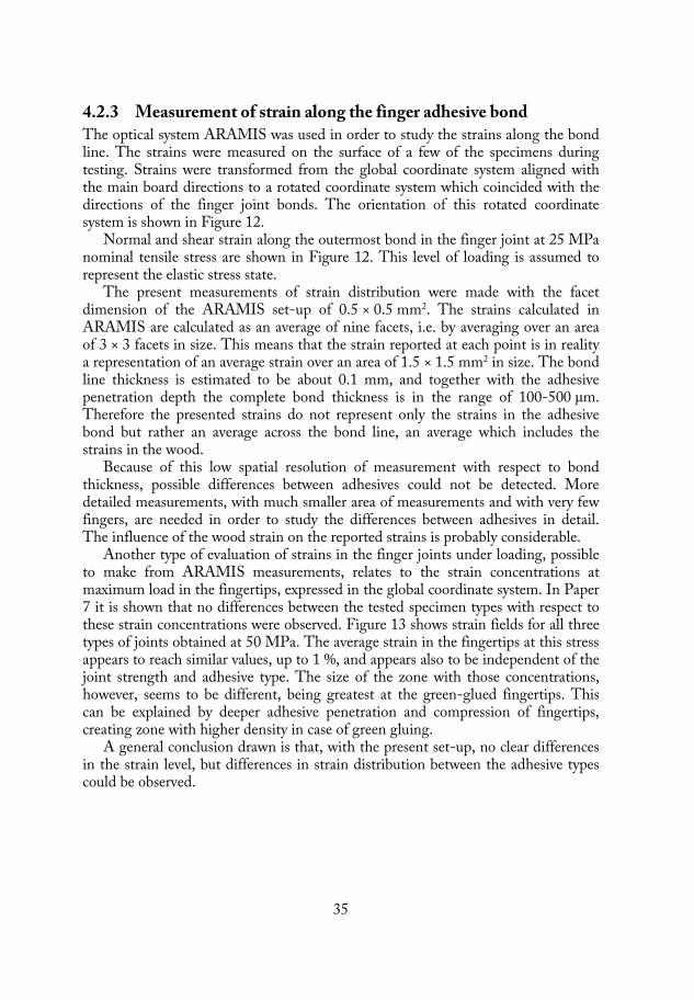
35
4.2.3 Measurement of strain along the finger adhesive bond The optical system ARAMIS was used in order to study the strains along the bond line. The strains were measured on the surface of a few of the specimens during testing. Strains were transformed from the global coordinate system aligned with the main board directions to a rotated coordinate system which coincided with the directions of the finger joint bonds. The orientation of this rotated coordinate system is shown in Figure 12.
Normal and shear strain along the outermost bond in the finger joint at 25 MPa nominal tensile stress are shown in Figure 12. This level of loading is assumed to represent the elastic stress state.
The present measurements of strain distribution were made with the facet dimension of the ARAMIS set-up of 0.5 × 0.5 mm2. The strains calculated in ARAMIS are calculated as an average of nine facets, i.e. by averaging over an area of 3 × 3 facets in size. This means that the strain reported at each point is in reality a representation of an average strain over an area of 1.5 × 1.5 mm2 in size. The bond line thickness is estimated to be about 0.1 mm, and together with the adhesive penetration depth the complete bond thickness is in the range of 100-500 μm. Therefore the presented strains do not represent only the strains in the adhesive bond but rather an average across the bond line, an average which includes the strains in the wood.
Because of this low spatial resolution of measurement with respect to bond thickness, possible differences between adhesives could not be detected. More detailed measurements, with much smaller area of measurements and with very few fingers, are needed in order to study the differences between adhesives in detail. The influence of the wood strain on the reported strains is probably considerable.
Another type of evaluation of strains in the finger joints under loading, possible to make from ARAMIS measurements, relates to the strain concentrations at maximum load in the fingertips, expressed in the global coordinate system. In Paper 7 it is shown that no differences between the tested specimen types with respect to these strain concentrations were observed. Figure 13 shows strain fields for all three types of joints obtained at 50 MPa. The average strain in the fingertips at this stress appears to reach similar values, up to 1 %, and appears also to be independent of the joint strength and adhesive type. The size of the zone with those concentrations, however, seems to be different, being greatest at the green-glued fingertips. This can be explained by deeper adhesive penetration and compression of fingertips, creating zone with higher density in case of green gluing.
A general conclusion drawn is that, with the present set-up, no clear differences in the strain level, but differences in strain distribution between the adhesive types could be observed.

36
a)
b)
c)
Figure 12. The strain distribution along the outermost bond (normal strain and shear angle (γ) vs. relative bond length) at 25 MPa nominal tensile stress: a) dry-glued PRF bond, b) dry-glued PUR bond and c) green-glued PUR bond.

37
a) b) c)
Figure 13. Shear strains ( /2)(mid row) and normal strains (bottom row) related to the global X-Y coordinate system. All plots are for 50 MPa nominal tensile stress. a) dry-glued PRF, 62 MPa, failure in adhesive and joint, b) dry-glued PUR, 57 MPa, failure in knot outside the joint, c) green-glued PUR, 52 MPa, failure in wood outside the joint.
y
x

38
4.2.4 Accelerated ageing tests Accelerated aging tests of finger joints in accordance with ASTM D 4688 were carried out, as reported in Paper 2 and Paper 7.
Results from the first study (Paper 2), show that the green-glued finger joints with PUR adhesive had significantly higher dry tensile strength than the dry-glued PRF, Greenweld and Soy/PRF systems. After moisture treatments, the wet tensile strength did not differ between the four adhesive systems.
Despite the fact that similar tensile wet strength was obtained for the tested types of finger joints, the failure paths were different. Results show that a majority of the dry tested specimens failed at the finger roots. After the moisture treatments, the green-glued joints tested in the wet state failed more often in the bond along the joint profile and much less frequently in the finger roots than did the dry-glued PRF bonds.
The results from the second study (Paper 7) show that there are no significant differences between dry tensile strength of green-glued joints and dry-glued joints. After moisture treatments, dry-glued joints with the PRF adhesive show higher strength after boiling and drying cycles than both green- and dry-glued joints with PUR adhesive do. However, the results for all three adhesives show that the respective wet reference strength values (specimens tested in wet conditions) are of the same level as the corresponding strength after boiling. It means that no significant difference exists for a certain combination of adhesive type and moisture content during gluing. Boiling did not affect the strength, but instead strength is affected only by the (high) moisture content at testing.
To summarise the durability tests, it can be concluded that the respective strength of all tested systems in the wet state after vacuum treatment did not differ from the strength after six cycles of boiling and five cycles of drying. This indicates good resistance to moisture changes. The differences between the two studies were: different brand of PUR adhesives were used, different wood species (Pine in the first series and Spruce in the second series), different MC levels (centre boards in the first series and side boards in the second series), different densities, and different orientation of annual rings. The second series resulted in higher levels of strength, both for tests in dry and in wet conditions.
4.3 Testing of small specimens 4.3.1 Failure process The small-scale specimens are designed with small dimensions, small length of the bond and notches to facilitate the failure within a certain volume - the wood adhesive bond. As was described in Chapter 2.2, failure can take different paths when testing wood adhesive bonds, and the challenge is to ensure that the failure occurs within the bond in order to determine bond properties. The properties needed for prediction of adhesive joint load-carrying capacity are strength, fracture

39
energy and ductility of the bond. This can be achieved by measuring stress-deformation curves, including both their ascending and the descending part, which in turn means that special set-ups and specimen designs have to be used. In addition, the optical system for measurement of deformation used in this work contributes to more detailed information on the strains in the vicinity of the bond. These conditions have been fulfilled in the present work, and detailed information on the properties of green glued bonds could be obtained. The following description of the failure process is an attempt to give a general explanation for what happens during testing of wood adhesive bonds if the present methodology is used.
Chapter 3.4.2 describes how the curves with deformations during the failure process are obtained (with elastic deformations subtracted). Figure 14 shows such curves (without elastic deformations) for a solid wood specimen, but the analysis is the same as for adhesive bonds, to which reference therefore also is made below. The three stress vs. deformation curves of Figure 14 represent the deformation measured along three different distances across the specimen. The ARAMIS software makes it possible to choose this distance and place of measurement after testing, which of course is of great value. Two of curves in Figure 14 are determined by measuring the deformation on the surface of the specimen with the ARAMIS system. These represent the results obtained when measuring the deformation along two different distances across the fracture plane (or the bond line): 1 and 1.8 mm respectively, both located in the centre of the specimen (see Figure 7). The third curve in Figure 14 was obtained by measuring the deformation between the steel grips using ARAMIS. This curve should be similar to the one obtained using the external extensometer (if no disturbances such as rotations are present), which was also confirmed.
The two curves obtained from measurements on the specimen’s surface represent not only the deformation taking place across the failure plane (or across the bond line), but also the additional deformation originating from the wood surrounding the bond line itself. The third curve includes also some possible deformation from the two bond lines between the wood and the steel to which the specimen is glued.

40
Figure 14. Example of analysed curves without elastic deformation. The figure shows deformation of the solid wood specimen measured across the tested surface over the length of 1 mm (solid curve) and 1.8 mm (dashed-dotted curve) and between steel grips (dashed curve). The tensile strain in the loading direction on the surface of the specimen is shown for three stages during the test: before fracture at 50 % of maximum load, at maximum load, and during fracture at 50 % of maximum load on the descending part of the curve.
Figure 14 also shows the strain fields obtained on the surface of the specimen using ARAMIS (normal strain in the loading direction). The images are taken at three different occasions (see Figure 14). At the beginning of loading, only elastic deformation occurs up to approximately 50 % of maximum load for this specimen, and the corresponding strain field represents only elastic strain (the deformation which is actually subtracted from the curves). The strain field image shows that, at this load level, strains are localised within the tested area and more or less uniformly distributed, but also that additional strains appear on the surface of specimen far away from the fracture zone. After this stage, pre-peak non-linear deformation develops, as micro-cracks and possible plastic deformations of the wood fibres or the adhesive. Those deformations are seen in Figure 14 as the pre-peak non-linear deformations. At maximum load, a fracture zone develops and failure starts.
For all the tested bond specimens, failure occurred in the adhesive bond, which is defined as the interface between the adhesive and the wood, a cohesive layer of adhesive and an interphase of wood penetrated with adhesive. This was also verified by an SEM study.
The strain field image for this particular specimen at maximum load reveals that the highest strains developed from one side of the specimen, which could represent a propagating crack. It can also be seen that the fracture zone is spread at some distance from the intended fracture zone (even longer than within 1 mm across the bond or tested wood), and that high strains are present at the upper edge of the specimen, clearly outside the intended fracture zone. These distant strains occur in

41
the weaker parts of the wood material, which could be less stiff early wood cells. Fracture deformation from this distant part of the specimen contributes to the higher total deformation measured between the steel grips (cf. the dotted line). After peak load is passed, the bond can still carry the load while fracture continues and deformation increases. The strain field image obtained after the load dropped 50 % shows that strains exceed 5 % at the fracture zone. At this stage, wood fibres are bridging a crack and are being pulled out from the wood matrix while load decreases until total separation. The fractured surfaces were examined in the SEM and Figure 18 shows such surfaces and cross-sections on which the pulled-out and torn wood cells filled with adhesive are seen.
The descending part of the stress-deformation curve describes the fracture process and gives information about the fracture brittleness. The steeper the slope of the descending part, the higher the fracture brittleness. Ideally, the deformation of the stress-deformation curve depicted in Figure 14 should represent the fracture deformation taking place within a distinct fracture plane. It is, however, clearly seen in Figure 14 that deformation during fracture is larger for the longer measurement lengths and that, consequently, fracture deformation occurs not only across a distinct fracture plane, but also within a zone including the material at some distance from the failure path. Actually, in the present case, fracture deformation seems to take place not only within the 1.0 or the 1.8 mm measurement distances used in evaluating the results with ARAMIS, but also at the edge of the specimen, outside these measurement lengths. Thus, for a longer reference length, a larger amount of fracture deformations will be included in the measurement, as illustrated by three different curves shown in Figure 14.
4.3.2 Shear test Figure 15 shows the main finding of the shear testing series (see Paper 4). The results show that the fracture energy and shear strength of green-glued bonds with PUR adhesive are dependent on the moisture content (MC) of wood, its density and the pressing time. The same fracture energy and strength can be obtained by green gluing as by dry gluing, but there seems to exist a maximum MC of the sapwood, between 78 % and 160 % (as tested in present study), and a minimum pressing time, in the range between 3 h and 48 h, for which it can be achieved.
The main conclusion from this test series was that green-glued bonds with high MC and low density wood need to be pressed for a longer time to reach the same strength as bonds with higher density and lower MC. Both dry- and green-glued polyurethane adhesive bonds were more ductile than solid wood.

42
a) b) Figure 15. Results from shear tests of green-glued PUR bonds: a) press time 3 hours b) press time 48 hours.
4.3.3 Tensile test Figure 16 shows examples of curves obtained for dry-glued PUR bonds and green-glued bonds (Paper 3 and 6). The dry-glued bond shows lower strength but higher ductility than does the green-glued bond. The fracture energy is, however, similar.
Figure 16. Stress vs. deformation curves for small tensile specimens a) dry-glued bond b) green-glued bond. Images of fractured surfaces of these specimens are shown in Figure 18.
The higher strength and the lower ductility of the green-glued bonds can be explained by the chemical composition of the adhesive (cf. Paper 5) and by the failure path within the bond, the latter being studied with SEM. Green-glued PUR adhesive bond is heat-treated after curing (during kiln drying of green-glued product). It was shown in Paper 5 that such treatment resulted in higher stiffness and stronger polymer structure of adhesive compared to untreated adhesive, which can provide for higher bond strength. In addition, failure of the heat-treated specimens occurred in the interphase, in contrast to failure of the untreated dry-glued specimens, which failed in the adhesive layer and interface. The lower strength of the untreated specimens can be explained by a larger amount of cavities within the adhesive (due to the formation of CO2 during curing). These cavities also contributed to the more ductile failure type found for these specimens.

43
In general, the high variability of the results affected the statistical analysis of significance, resulting in the conclusion that no statistically significant differences between the dry-glued and the green-glued bonds with the same adhesive amount and solid wood were obtained, whether in strength, in brittleness or in fracture energy.
A lower adhesive spread rate and a lower wood density caused poorer strength and higher ductility of the green-glued bonds, which was also seen in the shear tests. Fracture energy, however, was not affected by a lower adhesive spread rate in the tensile tests, contrary to what was found for the shear tests.
Close contact bonds, i.e. bonds with a thin adhesive layer between the wood substrates (as in a “starved” bond line), were obtained in some cases. This was a result of either a low adhesive spread rate in combination with the use of low-density wood (see Figure 17), which imply a high moisture content, causing over-penetration. The “starved" bond line could possibly be created by too high a gluing pressure, which resulted in squeezing adhesive out from the joint.
The solid wood specimens with higher density wood showed higher tensile strength and fracture energy compared to lower density wood, similar to what was found in the shear tests. The wood (in both the shear and tensile tests) showed a higher brittleness than the brittleness of both dry- and green-glued PUR bonds.
4.3.4 Extension of the fracture process zone The stress-deformation curves shown in Figure 16 reveal an interesting feature, similar to the one observed also for the solid wood specimen case of Figure 14. The deformation at a given stress level on the descending part of the curve represents the additional displacement that has taken place due to non-linear behaviour (plasticity and/or cracking). Studying the results from the measurements in the present study, we can conclude that bond line deformation seems to depend on the reference length used to determine the relative opening of the bond line. Going from a reference length of 1 mm to a reference length of 1.8 mm (or to length of 4 mm between steel grips) clearly results in a greater amount of non-linear deformation. This behaviour was present for all tested specimens, but to different extents. There are two possible explanations for this behaviour.
Firstly, if the fracture zone is not completely within the “gauge” length, some cracking occurs outside the measurement length in the weaker wood cells. Thus inelastic deformation has taken place outside the shorter reference length and it seems that the fracture of the specimens (micro-cracking) at least in part is not restricted to the bond line, but takes place in a wood zone, at least a few mm in size. This behaviour could not possibly be measured with any other technique than the one used here.
Secondly, the present measurements refer to only one side of the specimen, and to its outer face. Cracking on (for example) the back face of the specimen cannot be tracked without using additional cameras.
With the above discussion in mind, it is obvious that the (apparent) fracture energy calculated will depend on the reference length used, which is also true for the (apparent) brittleness of fracture or slope of the descending part of the curve.

44
4.4 Microscopy study 4.4.1 Small tensile specimens - SEM study Dry and green-glued bonds were investigated in the SEM in order to study the penetration of the adhesive and also the failure paths.
Figure 17 shows adhesive penetration of the green-glued PUR bonds: too small an adhesive spread rate, in combination with a low-density wood material, results in a very thin adhesive layer between two wood substrates, compared to the case when a larger adhesive spread rate is used. The penetration of the adhesive in both cases is very good, but the bond with the larger spread rate is more homogenous, with all cell lumens being filled in both substrates. The use of a lower spread rate results in empty and filled cells being distributed more randomly throughout the bond cross-section.
a) b)
Figure 17. Penetration of PUR adhesive in green wood: a) with 200g/m2 spread rate and high-density wood and b) with 135 g/m2 spread rate and low-density wood.
Two examples of failed bonds are shown in Figure 18, illustrating that the small tensile testing method resulted in fracture within the adhesive bond. It can also be seen that the dry-glued bond possessed cavities which resulted partially in failure in the adhesive layer. The green-glued bond failed within the wood-adhesive interphase zone. These different failure paths are also correlated to the different behaviour with respect to ductility, with the dry-glued bonds being more ductile than the green-glued bonds.

45
a) b)
c) d)
Figure 18. SEM pictures of fractured bonds: cross sections (left) and fracture surfaces (right) of dry-glued bonds (a) and b)) and green-glued bonds (c) and d)). The corresponding stress vs. deformation curves are shown in Figure 16.
4.4.2 Finger joints – X-ray microtomography The most interesting result from this study was the comparison between the dry-glued and green-glued PUR adhesive bonds from finger joints. The scheme of images taken with the x-ray microtomography is shown in Figure 19.

46
Figure 19. Imaging scheme to obtain different images with x-ray microtomography.
Comparing the bond morphology (see Figure 20) of the dry-glued and green-glued bonds shows that the green-glued bonds are characterised by a much deeper penetration of the adhesive compared to the dry-glued bonds (Figure 20 b) and e)). The green-glued bonds contain fewer and smaller cavities compared to the dry-glued bonds. The top of the finger is in closer contact with the finger root without any visible gaps (Figure 20 e) and f)). Such gaps, however, can be seen in the dry-glued bonds (Figure 20 c). This can explain the high strength of the green-glued joints, and can also be the reason why the green-glued-joints rarely failed within the adhesive bond. The cavities in the dry-glued bonds will result in more pronounced strain and stress concentrations, which can cause failure in the joint or in the adhesive. This behaviour could not, however, be confirmed by the ARAMIS measurements, due to the inadequate spatial resolution in the set-up used. The cavities shown within the adhesive and the finger top are approximately 0.1 mm in size and, as mentioned previously, the facet size used in the ARAMIS measurements was 0.5 mm, resulting in an averaging area for strain calculation of 1.5 × 1.5 mm. Another interesting result from the present study was that the end pressure of 5 MPa used in green gluing of the finger joints appears to be too high when low-density wood is used, due to the risk of splitting of the fingers, see Figure 21. The crack visible in Figure 21 could of course be the result of damaging the specimen during cutting of finger profiles. Such cracks were only seen in the low-density finger joints.

47
a) A-A d) A-A
b) B-B e) B-B
c) C-C f) C-C
Figure 20. Images from x-ray microtomography study of finger joints: a), b), c) dry-glued bond, d), e), f) green-glued bond.

48
Figure 21. Green-glued finger joint with low density wood.
4.5 Adhesive testing – Influence of curing conditions and post-heating on adhesive properties
The influence of different moisture levels on curing, and the influence of the post-heating used after curing, was investigated with different techniques. Details of both the methods used and the results obtained are described in Paper 5.
Liquid water was added to PUR adhesive at a proportion of 0 and up to 10 % by weight to study the effect on the hardening process. This was intended to simulate the wide range of moisture levels likely to be encountered on the surface of freshly sawn green timber: from dry to moisture contents above the wood fibre saturation point. It was observed by rheometry measurements that the cure rate of the PUR adhesive is indeed dependent on the water content added, resulting in the gel point between 10 and 2 minutes, for water content added 0.9 and 10% respectively. The higher amount of water the significantly faster cure rates (Figure 22 a). However, when the development of the storage moduli is studied (Figure 22 b) it can be seen that with the addition of 2.6 and 5.6 % by weight of water to the PUR adhesive, the storage moduli increase at the fastest rate and to the highest levels within the first 30 minutes. Above and below those moisture levels during curing, the elastic response is lower. Addition of more than 5.6 % of water plasticises the polymer, causing its lower stiffness, in spite of the gel point being reached. Below 2.6 %, there is too little water, and the storage modulus increases only very slowly. The different levels of moisture did not influence the chemical composition of the polymer or its glass transition temperature Tg (as measured by FT-IR and DMTA). However, post-heating affects both these properties. Post-heating of the adhesive at 70 ºC caused an increase in stiffness (as measured by rheometry) and a higher Tg (as measured by DMTA, Figure 22 d). The higher stiffness and Tg of the post-heated

49
PUR adhesive indicates that a larger amount of cross-linked polymer was created. This was verified with measurement of chemical composition of the post-heated PUR adhesive (with FT-IR), which revealed that a higher amount of highly ordered bidentate urea (Figure 22 c) and less residual isocyanate were created.
The results obtained (short time to gel point, plasticising of the adhesive by a high amount of water, higher Tg and stiffness of post-heated more cross-linked adhesive) can be used to develop and optimise the green gluing process and better to understand the mechanical performance of the green-glued PUR adhesive bonds. A higher strength of the green-glued bond was indeed observed both in the small specimen testing and in the finger joint testing.
a) b)
c) d) Figure 22. Results from a) rheometry: gel point dependent on moisture levels, b) rheometry: influence of moisture levels on storage modulus, c) FT-IR: influence of post-heating on chemical composition, d) DMTA: influence of post-heating on Tg.

50
4.6 Moisture profile across the adhesive bond during drying
One-dimensional moisture profiles obtained with MRI technique are shown in Figure 23. The first measurement (0h) was done when the average MC of the wood was 110 %, as determined on the wood directly before gluing. The second measurement shown in Figure 23 was made after two hours of drying (2h) in the oven at 70 ºC, and the average moisture content in the specimen reached 53 %. Drying was carried out from the surface on the left side of the picture. It can be observed that the moisture content close to or on the left surface is low, and that a clear moisture gradient is created towards the bond. The moisture content also decreases in the wood on the right side of the bond line, but to a lesser extent than on the left side. The right part of the specimen is cut with the tangential surface being orientated parallel to the bond line, and the annual rings are clearly visible. In general, a lower moisture amount is seen in the early wood, and higher moisture amount are found in the denser late wood. After two hours of drying, moisture starts to be more uniformly distributed, with the early wood having a slightly higher moisture level compared to the first measurement. This implies that moisture is transported from the late wood to the early wood, while the average moisture level diminishes. A moisture gradient is created with lower level on the dried surface, but there is no sharp border in the profile on the right side of the bond. Water or water vapour is transported through the adhesive bond, although this transport is (slightly) hindered, i.e. the diffusion of water through the bond seems to be slower than that through the wood. The following measurement was obtained after a total of six hours of drying (6h) and the average moisture content reached 12 %. It can be seen that the left side of the specimen dries at a higher rate than the right side. The right side has a different orientation than the left side, and the water transport takes place basically in the radial direction, which has a higher diffusivity. At the end of the test, a profile was obtained corresponding to the absolutely dry wood (0% MC), and the signal from the adhesive bond can be seen. This signal is very small, as is the noise. Each point in the moisture profile measured with the present technique represents an amount of water present in the volume of a slice of wood with thickness of 0.206 mm. The signal obtained in the measurements (Y-axis) is directly proportional to the amount of water expressed as kg/m3 wood. By calibration, a signal for moisture content (which is the quantity measured in kg/kg or %) can also be obtained. An example of such an calibration curve is shown in Figure 24.
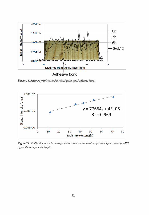
51
Figure 23. Moisture profile around the dried green-glued adhesive bond.
Figure 24. Calibration curve for average moisture content measured in specimen against average MRI signal obtained from the profile.

52

53
5 GREEN GLUING IN PRACTICE – PROCESS PARAMETERS
In the case of green gluing, fresh, unseasoned, wood is used, which implies that some important and special considerations have to be made with respect to industrial implementation. This chapter is dedicated to a general discussion on the most important wood material and process parameters.
5.1 Green wood as a substrate for gluing A fresh wood surface which never has been dried is open for the adhesive. The amount of available water is important, and particularly so for the moisture-cured PUR adhesive. Distortion is not a problem when working with unseasoned timber, and only shallow planing or smoothing is needed (as shown in testing of industrially manufactured beams (Paper 6)). When the surface is planed, the cut cell walls and capillaries create an open surface with torn cells from which immediate diffusion of water starts. Even if MC in the wood is far above the FSP and reaches more than 200 % (see Figure 25) the MC of a fresh sawn/planed surface is not very well defined, and a variable MC between 0 and more than 100 % can be expected (Salin (2008)). Moisture-curing PUR adhesives can easily penetrate such wood material, as was shown in the microscopy study carried out (Papers 2, 3, 6 and 7). The penetration of the adhesive is excellent and thanks to the fact that raw wood is soft, a very good contact between the two glued surfaces can be obtained. This can also be seen in the case of green-glued finger joints when no gaps in the finger roots are present, the bond is continuous and the fingertips together with the adhesive form a very strong interphase (Figure 20). In the case of low-density wood, which for green side boards means a high MC, exaggerated penetration can take place. This may result in “starved” bonds showing lower strength (Figure 17 and Paper 3).
Green-glued bonds are subjected to shrinkage stresses during drying when the bond has a role as a connector between two wood substrates. The substrates can possess different properties with respect to shrinkage and distortion due to such factors as differing density, different annual ring orientations and grain slope. The bond must be able to transfer and distribute such stresses, and it seems from the results of the present study that the “starved” bonds did not contain enough adhesive to do so, resulting in lower strength in the mechanical testing (Paper 3).
Figure 25 shows a plot of density (absolute dry weight and raw volume) versus MC obtained for Spruce side boards, which probably has high percentage of

54
sapwood. The trend is for such timber that a higher density means a lower MC in the green state. Consequently, a lower density would result in a higher MC in the green state, which can adversely affect the strength of the bonds. In the present study this effect was also was shown in Papers 3 and 4. Density was indeed a significant factor influencing the strength of the bonds, as shown with the regression models presented in Table 2. The influence of density on strength of green glued bonds with PUR adhesive can also be connected with effect of lower MC level, as mentioned above, or with the porosity of the wood. The high-density wood has higher amount of late wood with thicker cell walls compared to low-density wood. This means that high-density wood have lower amount of free water present in the cell lumen compared to the low-density wood. Both low-density wood with larger porosity and higher amount of free water in turn influence the penetration of the adhesive, with risk for “starved” bond.
Figure 25. The relationship between dry-raw density and MC of spruce side boards
The use of unseasoned wood with varying density and MC as shown in Figure 25 is challenging in terms of new process development and process control. In addition the green wood is heavier than dry wood and makes handling of it more difficult. Moreover, scanning and grading of green timber is in need of development as well as methods for control/monitoring of timber MC above FSP. The scanning of very moist, green wood surface for detection of grain slope and knots can appear to be different than scanning of dry surface.

55
5.2 Lay-up In some cases, for practical reasons, flatwise glued beams need to be split before drying, depending on the dimensions of the glued boards. Two different lay-ups are tested in the present study (other lay-ups are also presented in Serrano et al. (2011)): lay-up A (heartwood to sapwood) and lay-up B (sapwood to sapwood and heartwood to heartwood). It was shown that when splitting the full width beam into three beams, the bonds in the centre beam show higher strength and WFP compared to the outer beams. The influence of shrinkage in combination with the annual ring orientation can be a possible reason for the better performance of the bonds in the centre beams (in the centre beam the annual rings are symmetrically orientated with respect to the width direction). The delamination results (Table 1) showed that bonds in lay-up A can better withstand moisture-induced stresses, but lower density also had an influence on those results. Lay-up B beams possessed higher density, which could cause a higher degree of delamination.
5.3 Open time, assembly time and adhesive spread rate The moisture-cured PUR adhesive starts to cure immediately after contact with water, both from the air and from the wood material. As it was shown by the rheometry measurements, the gel point occurred in approximately two minutes with 10 % of added water (Figure 22 a). When an adhesive reaches its gel point it means that the curing reaction has advanced to the point that polymer networks start to develop. At the same time, the wetting of the wood by the adhesive and the penetration will be limited, and this will result in poor bonds. Therefore, it is important in the case of green gluing that the open time in production is as short as possible (a few minutes or so), and also that the assembly time is as short as possible. In the beams that were industrially produced, an assembly time of ten minutes was employed, which seemed to work well (Paper 6). It was also shown that even if the gel point is reached, the adhesive shows a slow increase in elastic modulus for adhesives with more than 5.6 % of added water (Figure 22 b). This means that even if the creation of cross-links progresses, the water present in the bonds acts as a plasticizer, making the adhesive soft enough during curing. This can also be favourable for the following drying process. It is important to avoid too long assembly times, which would pose a risk of extensive adhesive curing before pressure is applied, making the development of adequate bonds impossible.
The adhesive spread rate has a significant influence on the strength of the adhesive bonds in the standardised test (Table 1 and 2) and in the small specimen tensile tests (Paper 3). The higher the spread rate, the higher the strength of the bonds. A higher adhesive amount provides better control of the open time and the assembly time even if high amounts of water are available, since the larger adhesive amount implies a longer time to gel point. This is advantageous for the formation of the bond. An adhesive spread rate of 200 g/m2 was tested industrially (Paper 6, Paper 3) and seems to be enough to obtain good quality bonds.

56
5.4 Pressure and pressing time - Penetration of the adhesive and initial bond strength
The penetration of the PUR adhesive in green wood for both finger joints and flatwise gluing was shown to be very good, which should provide for good anchorage of the adhesive (Figure 17 and 20). Over-penetration of the adhesive should be prevented by the use of a suitable pressure and adhesive spread rate. Fewer cavities were present in the green-glued bonds (see Figure 20).
The pressure applied must be adjusted in order to prevent failure in the wood and to prevent squeezing out of water and washing out of the adhesive. Green wood has a lower strength than dried wood and, for example for finger jointing, the end pressure is reduced to 5 MPa as compared to 10 MPa used in conventional jointing. On the other hand, moisture-cured PUR adhesives need to be pressed with sufficient pressure to create thin bonds (PUR adhesives for dry gluing are certified only for bonds thinner than 0.3 mm) and to achieve bonds with as small amount of bubbles/cavities as possible. The CO2 emitted during curing needs to be removed from the bond, and must not be captured within the formed bond. In the case of flatwise gluing, different levels of pressure were tested in the laboratory tests, but pressure was not revealed as a significant factor influencing bond strength (Table 1). The pressure applied in the industrially manufactured specimens was 0.9 MPa, which seems to be a reasonable choice for a practical implementation.
Press time appeared, however, to be of greater importance. It was shown (Paper 1, Paper 4) that longer press times could contribute to higher shear strength of the bond. It is believed that press time can also be of importance when timber with higher MC or lower temperature is to be glued. The formation of the bond when there is an excess of water (low-density wood) or when the mobility of the adhesive has diminished due to a low temperature, takes longer time.
The initial shear strength (directly after pressing) was 22-50 % of the final strength after kiln drying, with failure mainly occurring in the adhesive layer (Paper 1). This could indicate that the adhesive was not completely cured. The rheometry tests, however, showed that the gel point has been passed and that the adhesive should indeed be cross-linked after pressing (i.e. during 1 or 2 hours pressing time). The initial shear strength should, however, be enough for (careful) handling of the products before kiln drying.
5.5 Drying Drying is a crucial operation in the green gluing process, because it will cause shrinkage of the wood and it will expose the material to elevated temperatures (typically 70 ºC). Different drying schemes were not the subject of the present investigation. However, the chosen drying schemes were based on the assumption that relatively low drying rates are applied and that a maximum temperature of 70 ºC is used in order to protect the adhesive bonds. Drying of wood is indeed an
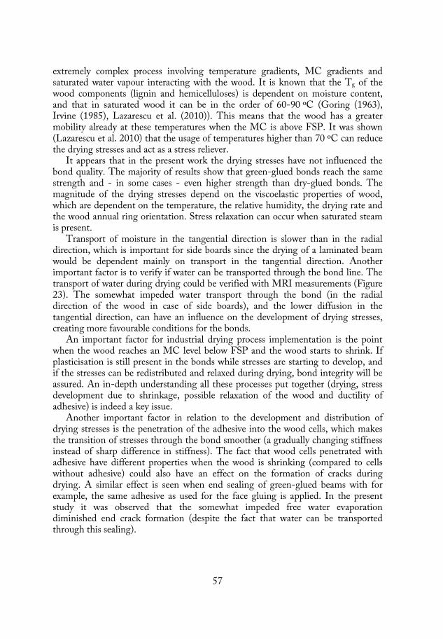
57
extremely complex process involving temperature gradients, MC gradients and saturated water vapour interacting with the wood. It is known that the Tg of the wood components (lignin and hemicelluloses) is dependent on moisture content, and that in saturated wood it can be in the order of 60-90 ºC (Goring (1963), Irvine (1985), Lazarescu et al. (2010)). This means that the wood has a greater mobility already at these temperatures when the MC is above FSP. It was shown (Lazarescu et al. 2010) that the usage of temperatures higher than 70 ºC can reduce the drying stresses and act as a stress reliever.
It appears that in the present work the drying stresses have not influenced the bond quality. The majority of results show that green-glued bonds reach the same strength and - in some cases - even higher strength than dry-glued bonds. The magnitude of the drying stresses depend on the viscoelastic properties of wood, which are dependent on the temperature, the relative humidity, the drying rate and the wood annual ring orientation. Stress relaxation can occur when saturated steam is present.
Transport of moisture in the tangential direction is slower than in the radial direction, which is important for side boards since the drying of a laminated beam would be dependent mainly on transport in the tangential direction. Another important factor is to verify if water can be transported through the bond line. The transport of water during drying could be verified with MRI measurements (Figure 23). The somewhat impeded water transport through the bond (in the radial direction of the wood in case of side boards), and the lower diffusion in the tangential direction, can have an influence on the development of drying stresses, creating more favourable conditions for the bonds.
An important factor for industrial drying process implementation is the point when the wood reaches an MC level below FSP and the wood starts to shrink. If plasticisation is still present in the bonds while stresses are starting to develop, and if the stresses can be redistributed and relaxed during drying, bond integrity will be assured. An in-depth understanding all these processes put together (drying, stress development due to shrinkage, possible relaxation of the wood and ductility of adhesive) is indeed a key issue.
Another important factor in relation to the development and distribution of drying stresses is the penetration of the adhesive into the wood cells, which makes the transition of stresses through the bond smoother (a gradually changing stiffness instead of sharp difference in stiffness). The fact that wood cells penetrated with adhesive have different properties when the wood is shrinking (compared to cells without adhesive) could also have an effect on the formation of cracks during drying. A similar effect is seen when end sealing of green-glued beams with for example, the same adhesive as used for the face gluing is applied. In the present study it was observed that the somewhat impeded free water evaporation diminished end crack formation (despite the fact that water can be transported through this sealing).

58
5.6 Final bond properties The heat treated adhesive exposed to an elevated temperature as in timber drying has a higher stiffness and Tg than unheated adhesive (Figure 22). These properties seem to be positively correlated to strength, as could be seen with in the finger joint tests and in the small specimen tests. The strength and fracture energy of green-glued adhesive bonds was shown to be at the same level as for the dry-glued bonds (both in shear and in tension). The ductility of the green-glued bonds, however, is lower than that of the dry-glued bonds, as shown in the tensile tests. This lower ductility of the post-heated adhesive could be explained by its chemical composition (Figure 22). The higher stiffness and Tg of the post-heated adhesive was caused by the presence of highly ordered urea (Figure 22) with more hydrogen bonds, which also provide for higher strength. The higher Tg of the post-heated adhesive is an important factor which is thought to influence the creep properties of the adhesive. Creep is of great concern for bonds in load-bearing wood structures.
Green-glued bonds appear to be sensitive to very high moisture content during curing which, in the case of sapwood, is connected with low-density wood. In such cases, lower shear strength and tensile strength could be observed. This could be explained by too thin (“starved”) bonds being formed. It seems that a spread rate of about 200 g/m2 and a pressure of 0.5 – 0.9 MPa should be sufficient to obtain good-quality adhesive bonds.
The strength of green-glued finger joints is the same as the strength of dry-glued joints, with the density of the wood being an important factor influencing strength. Furthermore, green-glued finger joints are characterised by deep penetration of the adhesive, with fewer cavities in the adhesive, as compared to the dry-glued PUR bonds. In terms of industrial implementation, attention should be paid to the end pressure used in finger jointing. Typically, this should be considerably less than the pressure used in dry-gluing applications.
Summarising it can be emphasised, that the variation in green wood properties (MC, density and planed surface state dependent on those two factors) may have an effect on process factors in different extend. This means that in some cases the unlucky combination of different effects can result in poorer performance of bonds. To prevent this the process should provide for carful control of timber before gluing to eliminate the wood, which can cause poor bonds and defect products (e.g extremely high MC, low-density timber and high grain slope).

59
6 CONCLUSIONS AND FUTURE WORK
6.1 Conclusions The general conclusions drawn from the present study was given in the previous discussions of Chapter 4 and 5. The list below briefly summarises the most important conclusions:
• The initial shear strength of green glued bonds, directly after pressing, was 22 % to 50 % of the final strength after kiln drying, with failure occurring mainly in the adhesive layer.
• Wood density and adhesive spread rate are positively correlated with shear strength of adhesive bonds tested with standardised methods. The average block shear strength of green-glued bonds fulfils the requirements of the EN 368 glulam standard. Standardised shear testing shows that a wide range of process parameters can result in bonds which fulfil those requirements.
• The strength of finger joints depends on wood density: the higher the density, the higher the strength, with no difference between green- and dry-glued joints.
• No difference between dry-glued PRF, dry-glued PUR or green-glued PUR finger joints’ tensile strength could be observed. However, green-glued joints did not fail in the adhesive bonds as the dry-glued joints did, which indicates that green-glued adhesive bonds can be stronger than the wood used for jointing.
• Durability testing of finger joints shows that the wet tensile strength of the green-glued PUR joints is not diminished after soaking and drying cycles. This confirms their good resistance to moisture changes with no difference compared to dry-glued PUR joints.
• Small specimen tests show that green-glued PUR bonds can reach the same strength and fracture energy, both in shear and tensile tests, as dry-glued bonds and using the same amount of adhesive.
• Both green-glued and dry-glued PUR adhesive bonds show lower brittleness than wood, both in shear and in tensile test.
• The chemical composition of the moisture-curing PUR adhesive appears to change by heat treatment after curing, providing for higher strength, stiffness and Tg. This is caused by a higher amount of highly ordered bidentate urea in the post-heated adhesive as compared to non-heated adhesive.

60
• A combination of low-density wood with a high MC and too high a pressure and too short pressing time can result in poorly performing green-glued bonds.
6.2 Future work Although the present work has included quite extensive experimental investigations of the mechanical behaviour of the adhesive bonds, it is believed that some additional investigations would be of great value.
As mentioned in the introduction, the work described here has not included any duration of load tests which, of course, in general are of great importance. In this context, the wood-adhesive interactions and the possible covalent bonding of the PUR adhesive to the wood, as well as the properties of modified (e.g. by fillers) PUR adhesives adapted for green gluing, should be carefully investigated.
The mechanical properties determined with the small-scale test specimens in the present work were determined with specimens loaded in pure Mode I or Mode II. An experimental campaign including small-scale mixed-mode testing of bonds cut from finger joints was recently planned (Figure 26). This type of tests is believed to give valuable additional information for a detailed understanding of the behaviour of the bonds.
a) b) Figure 26. Testing of small-scale specimens in mixed mode of loading: a) the overall set-up b) detail image with specimen glued in the machine grips.
It seems that there are no major technological obstacles for adaptation of the finger jointing process to green timber but the adhesives used must, of course, pass stipulated testing procedures and be certified for the intended end use. In general terms, flatwise green gluing technology has not been developed and implemented to the same extent as finger jointing of green timber. The current situation in Europe is such that any producer wanting to use the green gluing technology in production (aiming for load bearing products) must obtain such certification through what is known as a CUAP procedure. An important step in implementation of the green

61
gluing process in Europe, and especially for its possibilities to be used to a large extent, would be to propose such certification procedures. This could of course also be done by adjusting the existing standards relating to wood adhesives, finger jointing, glued laminated timber etc. to provide also for green gluing to be used for production of (for example) laminated beams (Figure 27). In such work, particular attention should be paid to the development of efficient quality control systems. The main questions to answer would then relate to the upper level limit of MC and other process parameters, and their possible dependence on wood species and adhesive system used.
Figure 27. Example of green-glued beams (products developed by Linnaeus University, SP and Södra Timber).
Important areas for future investigations relating to finger jointing include methods for defect detection and elimination, strength grading of green timber, cutting of fingers (with respect to surface roughness obtained in the green material) and optimisation of the end pressure applied during assembling of the finger joint. The essential area for future work relating to the green gluing process in general is the adjustment of the kiln-drying schedules used in order to minimise drying stresses.
Another interesting problem connected to finger jointing of green timber is the dimensional stability of the finished product with respect to different grain slopes within each jointed piece. Thus investigation of, for example, how the removal of zones containing distorted grain and knots improves the dimensional stability and strength of finger-jointed timber as compared to un-jointed dried timber would be of interest. The specific detection methods to be used in order to identify distorted grain and knots could also be another area for future studies. Such methods need to be used in the production of straight green-glued finger-jointed timber.
Detailed stress analyses of the mechanical behaviour of, for example, finger joints would also be of great interest. Such studies should focus on describing the differences between traditional adhesive systems and systems for green gluing with regards to the effects of the latter systems’ ability to form close contact and

62
homogeneous bonds. With such knowledge, the development of green-glued products could be carried out in a more systematic manner. Of course, also modelling for prediction of the load-carrying capacity of green-glued wood adhesive joints could be an aim. Here especially, studies of the influence of drying stresses on strength, and of the varying spiral grain of timber on the dimensional stability of the finished products, would be of interest. Finally, the global effort towards increased use of natural and ecological materials should imply further development towards bio-based adhesive systems, e.g. soy-based adhesives for finger jointing.

63
7 REFERENCES ASTM D 4688-95 Standard Test Methods for Evaluating Structural Adhesives for Finger
Jointing Lumber ASTM D 905-08 Standard Test Method for Strength Properties of Adhesive Bonds in Shear by
Compression Loading. Beaud F, Niemz P, Pizzi A. 2006. Structure-property relationships in one-component
polyurethane adhesives for wood: sensitivity to low moisture content. Journal of Applied Polymer Science;101(6):4181–92.
Bin N., Pizzi A., Delmotte L.,and X. Lu. 2005. One-Component Polyurethane Adhesives for Green Wood Gluing: Structure and Temperature-Dependent Creep. Journal of Applied Polymer Science, Vol. 96, pp. 1231–1243.
Blümich, B. 2003. NMR imaging of materials. Oxford: Clarendon Press. Boström, L. 1992. Method for determination of the softening behaviour of wood and the
applicability of nonlinear fracture mechanics model. Doctoral thesis. Report TVBM-1012, Lund University, Sweden. Division of Building Materials.
Callaghan, P. T. 1991. Principles of nuclear magnetic resonance spectroscopy. Oxford: Clarendon Press.
Clauss S., Allenspach K., Gabriel J. and P.Niemz. 2011. Improving the thermal stability of one-component polyurethane adhesives by adding filler materials. Wood Science and Technology Vol. 45, pp. 383-388
Clauss S.; Joscak M. and Niemz P. 2011. Thermal stability of glued wood joints measured by shear tests. European Journal of Wood and Wood Products Vol. 69, pp. 101-111
Clauss S., Gabriel J., Karbach A., Matner M. and Niemz, P. 2011. Influence of the adhesive formulation on the mechanical properties and bonding performance of polyurethane prepolymers. Holzforschung, 65(6), pp. 835-844.
Clauss, S., Dijkstra, D. J., Gabriel, J., Klausler, O., Matner, M., Meckel, W., and Niemz, P. 2011. Influence of the chemical structure of PUR prepolymers on thermal stability. International Journal of Adhesion and Adhesives, 31(6), pp. 513-523.
Clauss S., Dijkstra D. J., Gabriel J., Karbach A., Matner M., Meckel W. and Niemz P. 2012. Influence of the filler material on the thermal stability of one-component moisture-curing polyurethane adhesives. Journal of Applied Polymer Science, 124(5), pp. 3641-3649.
Cornwell M., Thorpe W. and Cooper G. 2005. Green gluing of timber: a feasibility study. BRE Information Paper no IP10/05. Published by BRE Bookshop Garston, Watford WD25 9XX. ISBN 1 86081 841 2.
Cornwell M., Cooper G. and D. Jones. 2005. The feasibility of creating a `green´ gluing enterprise based in the Greenwood Community Forest and surrounding regions of the UK. In Proceedings of International conference / workshop Green gluing of wood- process – products – market. Borås, April 7-8 2005, Edited by Björn Källander, COST Action E34 Bonding of Wood in cooperation with SP Swedish National Testing and Research Institute, ISBN 91-85533-31-9. Published 2005.

64
Dunky M., Källander B., Properzi M., Richter K., Van Leemput M.. 2008. Core document of the COST Action E34: Bonding of Timber. Part 2: Green gluing. Ed. By Källander B. ISSN 1681 – 2808. Published by Universität für Bodenkultur, Vienna. [email protected]
Ebewele R., River B. and J. Koutsky. 1979. Tapered Double Cantilever Beam Fracture Tests of Phenolic-Wood Adhesive Joints. Part I. Development of Specimen Geometry; effects of Bondline Thickness, Wood Anisotropy and Cure Time on Fracture Energy. Wood and Fiber 11(3), pp.197-213.
Eriksson J., Ormarsson S. and H. Petersson. 2004. An experimental study of shape stability in glued boards. European Journal of Wood and Wood Products, 62(3), pp. 225-232.
EN 302-1:992 1992. Adhesives for Load Bearing Timber Structures – Test methods – Part 1: Determination of bond strength in longitudinal tensile shear. European Committee for Standardisation.
EN 338: 1995. Structural timber – strength classes. EN 386: 1995. Glued Laminated Timber – Performance requirements and minimum production
requirements EN 392. 1995. Glued Laminated Timber – Shear test of glue lines EN 391:2001, Glued laminated timber - Delamination test of glue lines EN 408. 1995. Timber structures – structural timber and glued laminated timber – determination
of some physical and mechanical properties. Gagliano J.M. and C.E. Frazier. 2001. Improvements in the Fracture Cleavage Testing of
Adhesively-Bonded Wood. Wood and Fiber Science 33(3), pp.377-385. George, B., C. Simon, M. Properzi and A. Pizzi. 2003. Comparative creep characteristics of
structural glulam wood adhesives. Holz als Roh- und Werkstoff 61 pp.79-80. Goring D. I. A. 1963. Thermal softening of lignin, hemicelluloses and cellulose. Pulp and Paper
Magazine of Canada, 64, , pp. 517-527. Gustafsson P.J. 1987. Analysis of generalized Volkersen-joints in terms of non-linear fracture
mechanics. In Verchery G., Cardon H., editors. Mechanical Behaviour of Adhesive Joints. Paris, France: Edition Pluralis. pp. 323-338.
Hameury S. and M. Sterley. 2006: Magnetic resonance imaging of moisture distribution in Pinus sylvestris L. exposed to daily indoor relative humidity fluctuations. Wood Material Science and Engineering, 2006,1, pp:116-126.
Irvine G. M. 1985. The significance of the glass transition of lignin in thermomechanical pulping. Wood Science and Technology, 19(2), pp. 139-149.
Karastergiou S., Mantanis G. and K. Skoularakos 2008. Green gluing of oak wood (Quercus conferta L.) with a one-component polyurethane adhesive. Wood Material Science and Engineering 3-4: 79-82.
Kinloch A.J. 1987. Adhesion and Adhesives Science and Technology. Published by Chapman and Hall, New York, USA ISBN 0 412 27440 X.
Kreibich R.E. and R.W Hemingway. 1985. Condensed tannin-resorcinol adducts in laminating adhesives. Forest Products Journal Vol.35, No 3, pp. 23-25.
Kreibich R.E. and R.W.Hemingway. 1987. Condensed tannin-sulfonate derivatives in cold-setting wood-laminating adhesives. Forest products Journal Vol.37, No.2, pp.43-46.
Kreibich R.E. and R.W. Hemingway. 1996. Formulation of tannin-based adhesives of the ”honeymoon” type for end jointing wood at extreme ranges of moisture content. In Proceedings of Wood Adhesive Symposium 1995. Ed. by A.W.Christiansen & A.H.Conner, Forest Products Society, Madison.

65
Kreibich R.E., Steynberg P.J. and R.W. Hemingway. 1998. End Jointing Green Lumber with SoyBond. In Proceedings 2nd biennial residual wood conference, Wood residues into revenue; Swanson J.S., ed.1997 November 4-5; Richmond, BC, MCTI Communications, Inc. pp. 28-36.
Källander B (ed). 2005. Proceedings of the International Conference/Workshop "Green Gluing of Wood - Process - Products - Market", in Boras, Sweden on 7-8 April 2005. Published by SP Technical Research Institute of Sweden.
Lange D.A., Fields J.T. and S.A. Stirn. 2000. Fingerjoint Application Potentials for One-part Polyurethanes . In Proceedings No.7260 (EA). Wood Adhesives 2000 Extended Abstracts. Forest Products Society, Madison, WI, USA. pp.17-18.
Lazarescu C., Avramidis S., and Oliveira L. 2010. Modeling Shrinkage Response to Tensile Stresses in Wood Drying III. Stress—Tensile Set Correlation in Short Pieces of Lumber. Drying Technology, 28(6), 745-751.
Mantanis G., Karastergiou S. and Barboutis, I. 2011. Finger jointing of green Black pine wood. European Journal of Wood and Wood Products, 69(1), pp. 155-157.
Marra A.A. 1992. Technology of wood bonding. Principles in Practice. Van Nostrand Reinhold. ISBN 0-442-00797-3.
De Moura M.F.S.F., Oliveira J.M.Q., Morais J.J.L. and Dourado N. 2011. Mixed-mode (I+II) fracture characterization of wood bonded joints. Construction and Building Materials 25 pp 1956-1962.
Maun K. and G. Cooper. 1999. Re-Engineering Softwood for Constructional Use by Wet (Green) Gluing. In Eurowood Technical Workshop Proceedings Industrial End-Uses of Fast-Grown Species, Florence May 31st- June 1st. Edited by:S.Berti, N.Macchioni, M. Negri and E. Rachello. pp. 47-59.
Na B., Pizzi A., Dellmotte L. and X.Lu. 2005. One-component polyurethane adhesives for green wood gluing: Structure and temperature-dependent creep. Journal of Applied Polymer Science 96(4), pp. 1231-1243.
Ormarsson, S. 1999. Numerical Analysis of Moisture-Related Distortions in Sawn Timber. PhD Thesis, Publication 99:7. Department of Structural Mechanics, Chalmers University of Technology, Sweden.
Parker J.R., Taylor J.B.M., Placket D.V. and R.E. Lomax. 1991. Method of joining wood Patent NZ Appln. No. 260406 1990
Parker J.R., Taylor J.B.M., Placket D.V. and R.E. Lomax. 1991. Method of joining wood Patent US No. 5674338 1991
Parker J.R., Taylor J.B.M., Placket D.V. and R.E. Lomax. 1991. Method of Joining Wood. European Patent Application 91311852.7 1991 No. EP 0493010
Parker J.R. 1994. Greenweld process for engineered wood products. In Proceedings The International Panel and Engineered Wood Technology Exposition, 1994 October 5, Atlanta, GA, USA ,10 p.
Pizzi A. and D.G. Roux. 1978. The chemistry and development of tannin-based weather- and boil-proof cold-setting and fast-setting adhesives for wood. Journal of Applied Polymer Science No.22, pp. 1945-1954.
Pizzi A., du Rossouw D.T., Knuffel W.E. and M. Singmin. 1980. “Honeymoon” Phenolic and Tannin-based Adhesive Systems for Exterior Grade Finger-Joints. Holzforschung und Holzverwertung 32 (6), pp. 140- 150.
Pizzi A and F.A. Cameron. 1984. Fast-set adhesives for glulam. Forest Products Journal Vol.34, No.9, pp. 61-68.

66
Pommier, R., and G. Elbez. 2006. Finger-jointing green softwood: Evaluation of the interaction between polyurethane adhesive and wood. Wood Material Science and Engineering, 1, pp. 127-137.
Properzi M., Pizzi A. and L. Uzielli. 2003. Comparative wet wood gluing performance of different types of Glulam wood adhesives. Holz als Roh- und Werkstoff 61. pp.77-78.
Radovic B. and C. Rothkopf. 2003. Eignung von 1K-PUR-Klebstoffen für den Holzbau unter Berücksichtigung von 10-jähriger Erfahrung. Bauen mit Holz 6/2003. pp. 36-40.
Rajakaruna, M.P. 2001. Strength and Durability of Radiata Pine bonded with polyurethane adhesives. In Proceedings of the International RILEM Symposium Joints in Timber Structures. Edited by S. Aicher and H.-W. Reinhardt. RILEM Publications S.A.R.L. pp. 453-462.
Ren D. and Ch.E. Frazier. 2012. Wood/adhesive interactions and the phase morphology of moisture-cure polyurethane wood adhesives. International Journal of Adhesion and Adhesives vol.34 pp. 55–61.
Richter K. and M.A. Schirle. 2002. Behavior of 1 K PUR adhesives under increased moisture and temperature conditions. In Proceedings of the International Symposium on Wood Based Materials, Wood composites and Chemistry 19-20 September 2002, Vienna, Austria, Edited by A.Teischinger and R.Stingl. Published by COST Action E13. pp.149-154.
Richter K. and R. Steiger. 2005. Thermal stability of wood-wood and wood-FRP bonding with polyurethane and epoxy adhesives. Advanced Engineering Materials, 7(5), pp. 419-426
Richter K., Pizzi, A. and Despres A. 2006. Thermal stability of structural one-component polyurethane adhesives for wood--Structure-property relationship. Journal of Applied Polymer Science 102(6), pp. 5698-5707.
Rosenkilde A., and P. Glover. 2002. High resolution measurement of the surface layer moisture content during drying of wood using a novel magnetic resonance imaging technique. Holzforschung, 56, pp. 312-317.
Salin J.-G. 2008. Drying of Liquid Water in Wood as Influenced by the Capillary Fiber Network. Drying Technology, 26(5), pp. 560-567
Seltman J. (1995). Freilegen der Holzstruktur duch UV-Bestrahlung Holz Roh Werkst 53, pp. 225-228
Serrano E. 2000. Adhesive joints in timber engineering – modelling and testing of fracture properties. Doctoral thesis. Report. TVSM 00/1012. Lund University, Sweden. Division of Structural Mechanics.
Serrano, E. 2002. On the mechanical behaviour of test specimens for wood-adhesive bonds. Report TVSM-3063. Lund University, Sweden. Division of Structural Mechanics.
Serrano E. 2004. A Numerical Study of the Shear-Strength-Predicting Capabilities of Test Specimens for Wood-Adhesive Bonds. International Journal of Adhesion and Adhesives 24 (1). pp. 23-35.
Serrano E., Blixt J., Enquist B., Källsner B., Oscarsson J., Petersson H., and M. Sterley. 2011. Wet glued laminated beams using side boards of Norway spruce. Linnæus University, School of Engineering, Report No 5, 2011, ISBN: 978-91-86491-79-6, http://lnu.diva-portal.org/smash/get/diva2:439333/FULLTEXT01
Serrano R. and D. Cassens. 2001. Reducing warp and checking in plantation-grown yellow-poplar 4 by 4’s by reversing part positions and gluing in the green condition. Forest Product Journal Vol.51, No.11/12. pp. 37-40.
Simon F. and R. Bredesen. 2009. Innovative Programs Led in France to Promote the Use of Domestic Woods in the Field of Engineered Wood Products. In Proceedings Wood Adhesives 2009, Lake Tahoe Nevada, USA September 28-30.

67
Singh H. K., Chakraborty A., Frazier C. E. and Dillard, D. A. 2010. Mixed mode fracture testing of adhesively bonded wood specimens using a dual actuator load frame. Holzforschung, 64(3), pp. 353-361
Steffen A., Johansson C., and Wormuth E. 1997. Study of the relationship between flatwise and edgewise modul of elasticity of sawn timber as a means to improve mechanical strength grading technology. European Journal of Wood and Wood Products, 55(2), pp. 245-253.
Sterley M. 2004. Green gluing of wood. Licentiate Thesis. KTH-Royal Institute of technology , Report TRITA-BYMA 2004:2, ISBN 91-7283-711-X. http://urn.kb.se/resolve?urn=urn:nbn:se:kth:diva-1737
Veigel S., Follrich J., Gindl-Altmutter W., and Müller U. 2012. Comparison of fracture energy testing by means of double cantilever beam-(DCB)-specimens and lap joint testing method for the characterization of adhesively bonded wood. European Journal of Wood and Wood Products, 70(1-3), pp. 3-10.
Wernersson H. and PJ. Gustafsson. 1987. The Complete Stress-Slip Curve of Wood-Adhesives in Pure Shear. In Mechanical Behaviour of Adhesive Joints, edited by G. Verchery and A.H. Cardon, Editions Pluralis, Paris. pp. 139-150.
Wernersson H. 1994. Fracture characterisation of wood adhesive joints. Report TVSM 1006 Lund University, Sweden. Division of Structural Mechanics.
Verreault C. 1999. Performance evaluation of green gluing for finger jointing. Forintek Canada Corp. Report No.2295 April 1999.
Verreault C. 2000. Assesment of two green gluing processes for finger jointing. Forintek Canada Corp. Report No 2407 April 2000.
White M.S. 1977. Influence of Resin Penetration on the Fracture Toughness of Wood Adhesive Bonds. Wood Science, Vol.10. No.1, pp. 6-11.
Vick Ch.B. and E.A. Okkonen. 1998. Strength and durability of one-part polyurethane adhesive bonds to wood. Forest Products Journal Vol 48(11/12) pp. 71-76.