
Comparative Study of Transformer Topologies for Distributed IPT Systems
8
Comparative Study of Transformer Topologies for Distributed IPT Systems Evangelos Lanaras, Venugopal Prasanth, Student Member IEEE, Pavol Bauer, Senior Member IEEE Delft University of Technology [email protected], [email protected], [email protected] Abstract—Distributed inductive power transfer (IPT) systems address the range restrictions of electric vehicles (EVs), charging the battery on-road through a loosely coupled transformer. Comparing different primary and secondary coil topologies is the main objective of this paper. Variations including single and multiphase layouts are analyzed by laboratory experimentation and finite element simulations. A system parameter optimization algorithm is introduced, utilizing sensitivity analysis techniques and equivalent circuit representation. Interphase power circulation in multiphase system primaries is addressed by a terminal correction setup, minimizing the interphase mutual inductance. The optimized designs are compared in terms of power and efficiency under alignment variations. Index Terms—Inductive power transfer, interphase mutual inductance, optimization algorithm, quadrature pick-up I. INTRODUCTION The concept of inductive power tranfer (IPT) is based on the wireless transfer of power by means of the magnetic field between a loosely coupled set of primary and secondary coils. Variations of this topology for electric vehicle charging applications include the stationary chargers, referred to as concentrated IPT systems, as well as systems that transfer power on an electrified roadway, while the vehicle is in motion, referred to as distributed IPT systems [1], [2]. The primary winding of IPT systems consists of conductors placed on the road plane, normally powered by a very low to low frequency (VLF−LF) input. The secondary winding is a coil mounted on the chassis of the EV and its output is connected to the battery pack or the drivetrain after rectification. Ferromagnetic material is introduced to improve the magnetic coupling, by adequately shaping the generated magnetic field. The categorization of IPT systems is based on the primary layout topology. The concentrated type IPT systems usually implement mirrored layouts of primary and secondary coils in the form of pad or plate structures. In distributed IPT topologies, the primary coil is formed by a set of conductors laid along the vehicle route, transferring power to the secondary pick-up on the vehicle [3]−[7]. To increase the efficiency of the system, resonant operating conditions are applied [8], by capacitive compensation of the primary and secondary coils. According to the connection of the compensation capacitor to the respective winding, the basic compensation schemes are divided into series-series, parallel-series, series-parallel and parallel-parallel and have been analyzed in the literature [9]. In this line of work, series- series compensation is implemented, to ensure resonant operation even under varying load conditions, which can occur under primary to secondary alignment variations [7]. This paper studies the operation of single and three phase designs of distributed IPT systems, based on a roadway with lane width of 3.5m (11.5ft) and the air gap considered is 50mm from primary to secondary section. A scaling ratio of model:real-scale dimensions equal to 1:4 is assumed, resulting in a total air gap of 200mm, for an applicable car to ground clearing. In Section II, single phase topologies are categorized in unidirectional and bidirectional systems, according to the primary current direction that generates the magnetic field linking to the secondary coil. Three phase systems can be further classified as separate section layouts or designs that utilize vectorial flux addition, explained in Section III. The implementation problems are addressed by minimizing the interphase mutual inductance and the effect of multiple phase coupling to the same pick-up. The selected bidirectional systems are optimized, using the design process introduced in Section III and the optimization results are presented and compared in Section V. II. SINGLE PHASE LAYOUTS In all the systems considered, the primary layout is designed without the use of ferromagnetic material, consisting only of the primary conductors. Although the implementation of primary ferrites would greatly increase the coupling, the higher cost would hinder large scale application. To ensure a better coupling coefficient of the IPT system, the frequencies of interest range from 25kHz to 500kHz. Litz wire is used for the primary and secondary conductors to minimize the skin effect and the respective losses. Different layouts of a single phase IPT system are examined. In all systems the primary current produces a magnetic field around the primary conductors that scans the secondary coil, resulting in induced voltage and current flow in the secondary. Based on the primary current direction, the topologies can be categorized as bidirectional layouts, utilizing the current ‘go’ and ‘return’ direction, or as unidirectional layouts, utilizing only the current ‘go’ direction (Fig. 1), as in [3], [10]. In unidirectional systems, the return path of the current is utilized to power adjacent driving lanes. Ferromagnetic material is used in the secondary layout, to shape the magnetic field, and improve the coupling. Secondaries with I-shaped ferrite cores are considered for the unidirectional systems and the central limb of E-shaped cores 978-1-4799-2262-8/14/$31.00 ©2014 IEEE
Transcript of Comparative Study of Transformer Topologies for Distributed IPT Systems

Comparative Study of Transformer Topologies for Distributed IPT Systems
Evangelos Lanaras, Venugopal Prasanth, Student Member IEEE, Pavol Bauer, Senior Member IEEE
Delft University of Technology [email protected], [email protected], [email protected]
Abstract—Distributed inductive power transfer (IPT) systems address the range restrictions of electric vehicles (EVs), charging the battery on-road through a loosely coupled transformer. Comparing different primary and secondary coil topologies is the main objective of this paper. Variations including single and multiphase layouts are analyzed by laboratory experimentation and finite element simulations. A system parameter optimization algorithm is introduced, utilizing sensitivity analysis techniques and equivalent circuit representation. Interphase power circulation in multiphase system primaries is addressed by a terminal correction setup, minimizing the interphase mutual inductance. The optimized designs are compared in terms of power and efficiency under alignment variations.
Index Terms—Inductive power transfer, interphase mutual inductance, optimization algorithm, quadrature pick-up
I. INTRODUCTION
The concept of inductive power tranfer (IPT) is based on the wireless transfer of power by means of the magnetic field between a loosely coupled set of primary and secondary coils. Variations of this topology for electric vehicle charging applications include the stationary chargers, referred to as concentrated IPT systems, as well as systems that transfer power on an electrified roadway, while the vehicle is in motion, referred to as distributed IPT systems [1], [2].
The primary winding of IPT systems consists of conductors placed on the road plane, normally powered by a very low to low frequency (VLF−LF) input. The secondary winding is a coil mounted on the chassis of the EV and its output is connected to the battery pack or the drivetrain after rectification. Ferromagnetic material is introduced to improve the magnetic coupling, by adequately shaping the generated magnetic field. The categorization of IPT systems is based on the primary layout topology. The concentrated type IPT systems usually implement mirrored layouts of primary and secondary coils in the form of pad or plate structures. In distributed IPT topologies, the primary coil is formed by a set of conductors laid along the vehicle route, transferring power to the secondary pick-up on the vehicle [3]−[7].
To increase the efficiency of the system, resonant operating conditions are applied [8], by capacitive compensation of the primary and secondary coils. According to the connection of the compensation capacitor to the respective winding, the basic compensation schemes are divided into series-series, parallel-series, series-parallel and parallel-parallel and have been analyzed in the literature [9]. In this line of work, series-
series compensation is implemented, to ensure resonant operation even under varying load conditions, which can occur under primary to secondary alignment variations [7].
This paper studies the operation of single and three phase designs of distributed IPT systems, based on a roadway with lane width of 3.5m (11.5ft) and the air gap considered is 50mm from primary to secondary section. A scaling ratio of model:real-scale dimensions equal to 1:4 is assumed, resulting in a total air gap of 200mm, for an applicable car to ground clearing. In Section II, single phase topologies are categorized in unidirectional and bidirectional systems, according to the primary current direction that generates the magnetic field linking to the secondary coil. Three phase systems can be further classified as separate section layouts or designs that utilize vectorial flux addition, explained in Section III. The implementation problems are addressed by minimizing the interphase mutual inductance and the effect of multiple phase coupling to the same pick-up. The selected bidirectional systems are optimized, using the design process introduced in Section III and the optimization results are presented and compared in Section V.
II. SINGLE PHASE LAYOUTS
In all the systems considered, the primary layout is designed without the use of ferromagnetic material, consisting only of the primary conductors. Although the implementation of primary ferrites would greatly increase the coupling, the higher cost would hinder large scale application. To ensure a better coupling coefficient of the IPT system, the frequencies of interest range from 25kHz to 500kHz. Litz wire is used for the primary and secondary conductors to minimize the skin effect and the respective losses.
Different layouts of a single phase IPT system are examined. In all systems the primary current produces a magnetic field around the primary conductors that scans the secondary coil, resulting in induced voltage and current flow in the secondary. Based on the primary current direction, the topologies can be categorized as bidirectional layouts, utilizing the current ‘go’ and ‘return’ direction, or as unidirectional layouts, utilizing only the current ‘go’ direction (Fig. 1), as in [3], [10]. In unidirectional systems, the return path of the current is utilized to power adjacent driving lanes.
Ferromagnetic material is used in the secondary layout, to shape the magnetic field, and improve the coupling. Secondaries with I-shaped ferrite cores are considered for the unidirectional systems and the central limb of E-shaped cores
978-1-4799-2262-8/14/$31.00 ©2014 IEEE
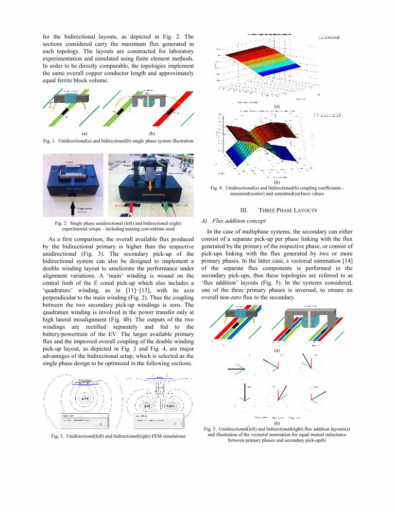
for the bidirectional layouts, as depicted in Fig. 2. The sections considered carry the maximum flux generated in each topology. The layouts are constructed for laboratory experimentation and simulated using finite element methods. In order to be directly comparable, the topologies implement the same overall copper conductor length and approximately equal ferrite block volume.
(a) (b)
Fig. 1. Unidirectional(a) and bidirectional(b) single phase system illustration
Fig. 2. Single phase unidirectional (left) and bidirectional (right)
experimental setups – including naming conventions used
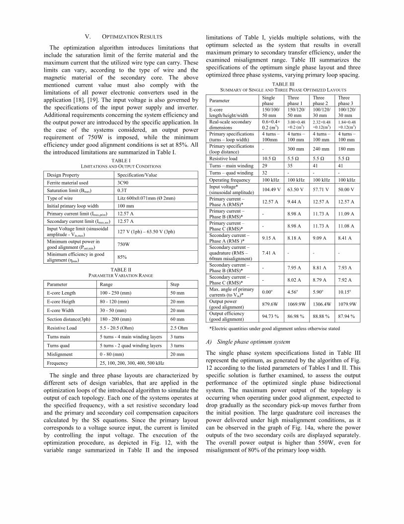
As a first comparison, the overall available flux produced by the bidirectional primary is higher than the respective unidirectional (Fig. 3). The secondary pick-up of the bidirectional system can also be designed to implement a double winding layout to ameliorate the performance under alignment variations. A ‘main’ winding is wound on the central limb of the E cored pick-up which also includes a ‘quadrature’ winding, as in [11]−[13], with its axis perpendicular to the main winding (Fig. 2). Thus the coupling between the two secondary pick-up windings is zero. The quadrature winding is involved in the power transfer only at high lateral misalignment (Fig. 4b). The outputs of the two windings are rectified separately and fed to the battery/powertrain of the EV. The larger available primary flux and the improved overall coupling of the double winding pick-up layout, as depicted in Fig. 3 and Fig. 4, are major advantages of the bidirectional setup, which is selected as the single phase design to be optimized in the following sections.
Fig. 3. Unidirectional(left) and bidirectional(right) FEM simulations
(a)
(b)
Fig. 4. Unidirectional(a) and bidirectional(b) coupling coefficients - measured(scatter) and simulated(surface) values
III. THREE PHASE LAYOUTS
A) Flux addition concept
In the case of multiphase systems, the secondary can either consist of a separate pick-up per phase linking with the flux generated by the primary of the respective phase, or consist of pick-ups linking with the flux generated by two or more primary phases. In the latter case, a vectorial summation [14] of the separate flux components is performed in the secondary pick-ups, thus these topologies are referred to as ‘flux addition’ layouts (Fig. 5). In the systems considered, one of the three primary phases is inversed, to ensure an overall non-zero flux to the secondary.
(a)
(b)
Fig. 5. Unidirectional(left) and bidirectional(right) flux addition layouts(a) and illustration of the vectorial summation for equal mutual inductance
between primary phases and secondary pick-up(b)

Concerning flux addition multiphase cirtopologies were examined, one with the plying next to each other and the other conductors in a triangular geometry, to eqinterphase mutual inductance (Fig. 6), simpof the terminal correction setup, to be following section.
(a)
Fig. 6. Experimental setups of planar(a) and equallydistribution in flux addition bidirectiona
B) Terminal correction to interphase mutu
The primary interphase mutual inductasystems links the flux generated by each padjacent phases, causing the input power the primary input [15]. This power ccompensated by a correction setup at therespective phases (Fig. 7). In this layout, affected phases are wound, so that the totalinductance is minimized.
Fig. 7. Terminal interphase mutual inductance cexperimental setup
If the mutual inductance introduced in orientation by the distributed layout is Mintroduce the same mutual inductance inorientation (M’). If the coupling between ton the core is k’, the relation can be express
| | · , ·Where Lself,1 and Lself,2 are the selfinductanprimary conductor sections on the correctio
Fig. 8. Magnetic flux path(left) and equivalent circuof the terminal correction layou
rcuits, two primary primary conductors
with the primary qualize the primary plifying the design introduced in the
(b)
y spaced (b) conductor al layouts
ual inductance
ance in multiphase phase current to the
to circulate within circulation can be e terminals of the conductors of the
l interphase mutual
correction layout -
the ‘constructive’ M, the setup must n the ‘destructive’ the wound sections sed as:
. (1)
nces of the wound on topology core.
it representation(right)
ut
The magnetic reluctance of tdepicted in Fig. 8, can be calcucore reluctance (Rm,core) and thesince the relative permeabilitylarger (2000-3000 times) than th, ,
Using the approximation for relations between the coil turnaccording to the design specific
, , Thus from (1) with lag long air g
· ·The introduced correction se
power problem, balancing the greatly limiting the interphase pverified by experimental measupair of primary conductors in th
(a)
(b)Fig. 9. Measured values of the interpha
correction (a) and corr
As observed in Fig. 9, the mprimary coils of the two phasescirculating in the primary inpuOn the other hand, the correctithe magnetic field along the trathe secondary will be lowerconductors of different phasedistance. The values for the seare both increased by the respec(3). Thus, a higher value for theneeded, in order for the system t
the magnetic path (Rm,path), as ulated by the sum of the ferrite e air gap reluctance (Rm,ag) and y of the ferrite core is much he air gap: , , (2)
the coil self inductances, the ns (N1 ,N2) can be calculated, ations: , , (3)
gap and Acore core surface: ·· · (4)
etup can solve the circulating primary multiphase input, by
primary mutual inductance, as urements, between an affected he topology of Fig. 6b.
)
) ase mutual inductance before and after ection percentage (b)
mutual inductance between the s is minimized, thus the power ut can be assumed negligible. ion topology cannot influence
ack, thus the coupling factor to r in systems where primary es run alongside at a close elfinductance of the primaries ctive values, Lself,1 and Lself,2 of e compensating capacitance is to resonate.

The above mentioned calculations arspecific pair of phases of the multiphasecorrection topologies are needed, each affphases, to limit the interphase mutual induthe primary coils. In the case that the prensures equal mutual inductance between as the system introduced in Fig. 6b, the dethe terminal correction is identical. Thematerial required also increases the overall but it is considered more cost effectivimplementing multiple ferrite blocks in the
Additional losses are also introduced byand hysteresis losses of the added ferrite, aslosses on the higher resistance of the condincreased proximity effects. The introducticorrection does not influence the magnetialong the primary tracks, apart from thcurrents due to the higher overall impedanc
Overall, despite the relatively higher corethe power circulation phenomenon can be major changes on the topology or zero pow
C) Coupling factor calculation
The coupling factor (k) of the IPT trcalculated as [16]:
· ΦΦ Where kprim-sec and ksec-prim the coupling factto secondary and secondary to primary rethe flux linking with the secondary becausgenerated by the primary current and Φ’primwith the primary because of the flux Φ’sesecondary current. Flux Φ’sec accordingopposes the change in the original primary
Thus, in the case of multiphase layouts flux to the secondary is generated by morthe flux Φ’prim is phase-shifted with respectprimary phase and resonant operation can(in case of the examined SS comimplementation of a single secondary on a system results in a difficult to prediccompensation requirement, which changesof the system is varied. In the system desigmentioned problem is bypassed by ensecondary is magnetically linked with phase, at each operating condition.
In the three phase topology, only a msecondary block is considered, to avointroduced by multiple primary phases cousecondary winding. For the same reason, ththe primary loops of adjacent phases is vareffect of multiphase coupling under variations.
re intended for a e system. Multiple fecting one pair of uctance between all rimary distribution primary coil pairs,
esign calculation of e additional ferrite
cost of the system, ve than solutions primary section. y the eddy current s well as the ohmic ductors, due to the ion of the terminal ic field generation
he relatively lower ce of the primary. e and ohmic losses, addressed without
wer points.
ransformer can be
(5) ΦΦ
tors of the primary espectively. Φsec is se of the flux Φprim m is the flux linking ec generated by the g to Lenz’s law, flux Φprim. where the linking
re than one phases, t to each respective nnot be established mpensation). The polyphase primary
ct reactive power s as the alignment gns considered, the nsuring that each only one primary
main winding per oid the problems upling to the same he spacing between ried to examine the primary topology
Fig. 10. Bidirectional three phase layoillustration and F
In the following section, aapplied for a single phase bidphase bidirectional layout with aphase (Fig. 10), according to optimization aims to determinensure maximum overall priefficiency, under the misalignm
IV. OPTIMIZ
A) Primary Optimization
The primary optimization invfor different number of turns onand different distance between paths, referred to as ‘primary wprimary width is affected by dimensions and is considered la
Fig. 11. Primary optimization parbetween primary and main secoprimary layouts – varying num
primary with varying c
out with separate sections per phase - FEM simulation
an optimization algorithm is directional layout and a three a separate secondary block per specified output criteria. The
ne the parameter values that imary to secondary transfer
ment range investigated.
ZATION PROCESS
volves simulating the systems n the primary end of the layout
the primary ‘go’ and ‘return’ width’ (Fig. 11a). The optimum
the secondary ferrite block ater in the system optimization.
(a)
(b)
rameters(a) – mutual inductance ondary winding for different
mber of turns(b) and four turn onductor distance(c)
(c)

The mutual inductance is measured anfinite element simulations for different latconditions in the range of operating frequeof primary specifications. From the results primary is selected with conductor spacincentre), considering both coupling and copp
B) Secondary Optimization
The optimization algorithm aims to sparameters that ensure the optimum efficieof the transformer to the resistive loalgorithm implements the design limitvoltage, the current limit of the wire used, of the core and the required power outpuassume a system with specified minimum utilizing litz wire to construct the conductlimit of 4A/mm2 [17]. The resistance odetermined by the winding length, skin andThe core losses, constituting by hysteresislosses, are implemented in the finite elemmeans of the ferrite complex permeabitangent of the material at each operatinalgorithm (Fig. 12) calculates the frequdimensions, the load resistance and the wisecondary windings that ensure the highetransfer efficiencies for the misalignment for different ferromagnetic secondary adequate for the respective operating freque
Fig. 12. System parameter optimization
The coupling coefficient is estimated ussimulations and sensitivity analysis techni
d calculated using teral misalignment encies, for each set of Fig. 11, a 4 turn g of 5mm (centre-per saving.
specify the design ency from the input oad (output). The tations, the input the saturation limit
ut. The simulations power output (P),
tors with a current f the windings is
d proximity effects. s and eddy current
ment simulation by ility and the loss ng frequency. The uency, the design nding turns for the st possible sum of range considered,
core materials, encies.
algorithm
sing finite element iques, according to
the ferrite block dimensions, thethe alignment between the primfrequency of operation. The simrange of frequencies and alignmvarying each dimension of the fother two dimensions constant. dimensions to the total system linearizing the results, for eacoupling factor of the primary estimated for the whole (lengthfrequencies and alignment coalgorithm is then compared to thvalues for different design speci
After verification of the coupof the total system output caequivalent circuit output (Fig. are performed, one for the singwith a main and a quadrature wphase bidirectional system wiblocks for each phase.
(a)
(b)Fig. 13. Equivalent circuit – single p
With the single phase inductanc
, ,Where Lself,prim , Lself,main , Lself,qthe primary, main and quadratinductances are calculated from
··
In a similar way, the threegenerated (six-by-six). The optidetermine the power profile forand to compare the single phasein terms of efficiency and powe
e ferromagnetic material used, mary and the secondary and the
mulations are conducted for a ment/misalignment conditions, ferrite block, while keeping the Thus, the effect of each of the coupling can be extracted by
ach operating condition. The to secondary windings is then h, height, width) mesh for all onditions. The output of the he simulated and experimental ifications. pling matrices, the simulation
an be conducted in terms of 13). Two optimization cases
gle phase bidirectional system, winding and one for the three ith separate secondary ferrite
)
)
phase(a) and three phase(b) systems ce matrix calculated as:
, 00 , (6)
uad are the self-inductances of ture windings and the mutual
m the coupling factors as:
, · , , · , (7)
e phase inductance matrix is imum systems are analyzed to r each misalignment condition e with the three phase topology r output.
V. OPTIMIZATION RESULTS
The optimization algorithm introduces limitations that include the saturation limit of the ferrite material and the maximum current that the utilized wire type can carry. These limits can vary, according to the type of wire and the magnetic material of the secondary core. The above mentioned current value must also comply with the limitations of all power electronic converters used in the application [18], [19]. The input voltage is also governed by the specifications of the input power supply and inverter. Additional requirements concerning the system efficiency and the output power are introduced by the specific application. In the case of the systems considered, an output power requirement of 750W is imposed, while the minimum efficiency under good alignment conditions is set at 85%. All the introduced limitations are summarized in Table I.
TABLE I LIMITATIONS AND OUTPUT CONDITIONS
Design Property Specification/Value Ferrite material used 3C90 Saturation limit (Bmax) 0.3T Type of wire Litz 600x0.071mm (Ø 2mm) Initial primary loop width 100 mm Primary current limit (Imax,prim) 12.57 A Secondary current limit (Imax,sec) 12.57 A Input Voltage limit (sinusoidal amplitude - Vin,max)
127 V (1ph) – 63.50 V (3ph)
Minimum output power in good alignment (Pout,min)
750W
Minimum efficiency in good alignment (ηmin)
85%
TABLE II PARAMETER VARIATION RANGE
Parameter Range Step
E-core Length 100 - 250 (mm) 50 mm
E-core Heigth 80 - 120 (mm) 20 mm
E-core Width 30 - 50 (mm) 20 mm
Section distance(3ph) 180 - 200 (mm) 60 mm
Resistive Load 5.5 - 20.5 (Ohm) 2.5 Ohm
Turns main 5 turns - 4 main winding layers 3 turns
Turns quad 5 turns - 2 quad winding layers 3 turns
Mislignment 0 - 80 (mm) 20 mm
Frequency 25, 100, 200, 300, 400, 500 kHz
The single and three phase layouts are characterized by different sets of design variables, that are applied in the optimization loops of the introduced algorithm to simulate the output of each topology. Each one of the systems operates at the specified frequency, with a set resistive secondary load and the primary and secondary coil compensation capacitors calculated by the SS equations. Since the primary layout corresponds to a voltage source input, the current is limited by controlling the input voltage. The execution of the optimization procedure, as depicted in Fig. 12, with the variable range summarized in Table II and the imposed
limitations of Table I, yields multiple solutions, with the optimum selected as the system that results in overall maximum primary to secondary transfer efficiency, under the examined misalignment range. Table III summarizes the specifications of the optimum single phase layout and three optimized three phase systems, varying primary loop spacing.
TABLE III SUMMARY OF SINGLE AND THREE PHASE OPTIMIZED LAYOUTS
Parameter Single phase
Three phase 1
Three phase 2
Three phase 3
E-core length/height/width
150/100/50 mm
150/120/50 mm
100/120/30 mm
100/120/30 mm
Real-scale secondary dimensions
0.6×0.4×0.2 (m3)
3.00×0.48×0.2 (m3)
2.32×0.48×0.12(m3)
1.84×0.48×0.12(m3)
Primary specifications (turns – loop width)
4 turns – 100mm
4 turns – 100 mm
4 turns – 100 mm
4 turns – 100 mm
Primary specifications (loop distance) - 300 mm 240 mm 180 mm
Resistive load 10.5 Ω 5.5 Ω 5.5 Ω 5.5 Ω Turns – main winding 29 35 41 41 Turns – quad winding 32 - - - Operating frequency 100 kHz 100 kHz 100 kHz 100 kHz Input voltage* (sinusoidal amplitude) 104.49 V 63.50 V 57.71 V 50.00 V
Primary current – Phase A (RMS)* 12.57 A 9.44 Α 12.57 A 12.57 A
Primary current – Phase B (RMS)* - 8.98 A 11.73 A 11.09 A
Primary current – Phase C (RMS)* - 8.98 A 11.73 A 11.08 A
Secondary current – Phase A (RMS )* 9.15 A 8.18 Α 9.09 A 8.41 A
Secondary current – quadrature (RMS – 60mm misalignment)
7.41 A - - -
Secondary current – Phase B (RMS)* - 7.95 A 8.81 A 7.93 A
Secondary current – Phase C (RMS)* - 8.02 A 8.79 A 7.92 A
Max. angle of primary currents (to Vin)* 0.00ο 4.56ο 5.90ο 10.15ο
Output power (good alignment) 879.6W 1069.9W 1306.4W 1079.9W
Output efficiency (good alignment) 94.73 % 86.98 % 88.88 % 87.94 %
*Electric quantities under good alignment unless otherwise stated
A) Single phase optimum system
The single phase system specifications listed in Table III represent the optimum, as generated by the algorithm of Fig. 12 according to the listed parameters of Tables I and II. This specific solution is further examined, to assess the output performance of the optimized single phase bidirectional system. The maximum power output of the topology is occurring when operating under good alignment, expected to drop gradually as the secondary pick-up moves further from the initial position. The large quadrature coil increases the power delivered under high misalignment conditions, as it can be observed in the graph of Fig. 14a, where the power outputs of the two secondary coils are displayed separately. The overall power output is higher than 550W, even for misalignment of 80% of the primary loop width.

(a)
(b)
Fig. 14. Single phase optimum system simulations - Power output of separate windings(a) and primary to secondary transfer efficiency(b)
The output power and efficiency curves, show that a frequency optimum can be calculated. Higher frequency operation generally results in better coupling between the primary and the secondary coils of the IPT system. As the frequency increases, however, skin and proximity effects give rise to higher resistance values for the primary and secondary windings thus increased resistive losses. The analysis results in the frequency value that ensures maximum overall efficiency for the loosely coupled coils, but variations of the design may be required, according to the specifications of the power electronic circuitry for different applications.
Fig. 15. Optimized single phase bidirectional layout - output power and efficiency under alignment variations – single phase system of Table III
The output power to efficiency graph (Fig. 15) shows the ability of the optimum system to operate at efficiency of 85% to 95%, in a large range of alignment variations (up to misalignments of 80% the primary loop width of 100mm), delivering power of 880W under good alignment operation.
B) Three phase optimum systems
To account for the multiple phase coupling to the same secondary blocks, the simulation of the system variations must implement the coupling coefficient values to the adjacent primaries. The multiphase coupling results in lower efficiency, as the reactive power compensation requirement is difficult to predict and varies, according to the secondary position, thus the resonant operation of the system under all alignment variations cannot be established, without the use of techniques such as variable frequency tuning of the system input. In this work, the performance of a system without tuning is investigated. The input voltage is assumed to be a balanced three phase sinusoidal voltage, with half the amplitude limit of the respective single phase designs. The SS compensation implemented results in operation close to resonance, but the phase difference between the primary current and voltage has larger values, as the secondary is misaligned with respect to the respective primary and the effect of adjacent phases is more pronounce.
Fig. 16. Optimized three phase bidirectional systems output – three phase
systems 1, 2 and 3 of Table III
The three phase bidirectional systems, annotated as three phase system 1-3 in Table III, are simulated, implementing different separation distance between the primary loops. Each of these layouts is characterized by the parameter set that ensures maximum overall primary to secondary transfer efficiency for the misalignment range of Table II, among the solutions of the respective primary loop distance.
The three phase systems investigated have higher output power capabilities, but lower efficiency under small misalignment range than the respective single phase system. They are, however, able to deliver a fraction of the initial output power under extreme misalignment cases (Fig. 16-17).
The larger overall dimensions of the three phase topologies results in systems difficult to fit within the the chassis of the vehicle and modifications might be needed to house the complete secondary section. Very large systems (System 1-Table III) have increased overall transfer efficiency, but the vehicle chassis must either be widened, or implement alternative techniques in charging state. These techniques may involve unfolding the secondary system when the EV is able to charge, after the detection of the primary segment underneath the vehicle. Systems with smaller dimensions (System 3-Table III) can be directly mounted on a moderately widened EV chassis, but the output capabilities are

considerably affected by the increased phase difference beween the primary currents and voltages, as a result of a higher coupling of adjacent phases. The three phase system 2 of Table III is selected as a good middle ground between the ease of implementation and the output performance. The specific three phase system is able to deliver 1.3kW at 88% transfer efficiency under good alignment operation.
Fig. 17. Optimized three phase bidirectional systems efficiency under high
misalignment operation – three phase systems 1, 2 and 3 of Table III
VI. CONCLUSIONS
In this work, different design layouts of the distributed IPT system transformer were examined and analyzed. Single phase and multiphase systems were compared regarding the transfer efficiency and power output under varying operating conditions, frequency and alignment. In the case of single phase designs, the introduction of a multi-winding pick-up greatly increases the power profile for large lateral misalignment. A terminal correction topology is also introduced, to minimize the primary interphase mutual inductance of multiphase systems, addressing the problem of power circulation within the primary phases.
Two bidirectional system designs were investigated, consisting of series compensated air-cored primary windings and ferrite-cored secondary. Optimization of the design parameters was performed, utilizing finite element simulations, sensitivity analysis techniques and equivalent circuit representation. According to the design specifications, the optimum solutions in terms of overall efficiency are generated, for different alignment conditions and the optimized single and three phase systems are compared according to the respective power profiles.
The single phase optimized topology is able to produce a power output of 880W under good alignment operation, at efficiency of 85-95% over a large misalignment range. The optimized three phase topologies have higher output power capabilities in good alignment, requiring however a larger amount of ferrite in the secondary than the respective single phase layout. The three phase layouts investigated are able to deliver up to 1.3kW of power at efficiency of 88% under good alignment operation. Even though the three-phase system performance is moderate under misalignment, it is able to transfer a fraction of the initial output power even in extreme misalignment cases.
REFERENCES [1] S. Chopra and P. Bauer, “Driving range extension of EV with on-road
contactless power transfer—a case study,” Industrial Electronics, IEEE Transactions on, vol.60, no.1, pp.329-338, Jan. 2013.
[2] T.-E. Stamati and P. Bauer, “Green energy for on-road charging of electric vehicles,” MECHATRONIKA, 2012 15th International Symposium , vol., no., pp.1-9, 5-7 Dec. 2012.
[3] G.A. Covic, J.T. Boys, M.L.G. Kissin and H.G. Lu, “A three-phase inductive power transfer system for roadway-powered vehicles,” Industrial Electronics, IEEE Transactions on , vol.54, no.6, pp.3370-3378, Dec. 2007.
[4] J. Shin, S. Shin, Y. Kim, S. Ahn, S. Lee, G. Jung, S.J. Jeon and D.H Cho, “Design and implementation of shaped magnetic-resonance-based wireless power transfer system for roadway-powered moving electric vehicles,” Industrial Electronics, IEEE Transactions on, vol.61, no.3, pp.1179-1192, March 2014.
[5] M.L.G. Kissin, Hao Hao and G.A. Covic, “A practical multiphase IPT system for AGV and roadway applications,” Energy Conversion Congress and Exposition, 2010 IEEE , vol., no., pp.1844-1850, 12-16 Sept. 2010.
[6] D.J. Thrimawithana and U.K. Madawala, “A three-phase bi-directional IPT system for contactless charging of electric vehicles,” Industrial Electronics, IEEE International Symposium on, vol., no., pp.1957-1962, 27-30 June 2011.
[7] V. Prasanth and P. Bauer, “Distributed IPT systems for dynamic powering – misalignment analysis,” Industrial Electronics, IEEE Transactions on, vol.PP, no.99, pp.1,1, March 2014.
[8] O. Dranga, B. Buti and I. Nagy, “Stability analysis of a feedback controlled resonant DC-DC converter”, IEEE Transactions on Industrial Electronics, USA, February 2003, Vol. 50, No.1. pp.141-152.
[9] S. Chopra and P. Bauer, “Analysis and design considerations for a contactless power transfer system,” Telecommunications Energy Conference (INTELEC), 2011 IEEE 33rd International , vol., no., pp.1-6, 9-13 Oct. 2011.
[10] J. Shin, B. Song, S. Lee, S. Shin, Y. Kim, G. Jung and S. Jeon, “Design of a buried power line for roadway-powered electric vehicle system,” Wireless Power Transfer, IEEE Conference on, vol., no., pp.56-57, 15-16 May 2013.
[11] V. Prasanth and P. Bauer, “Study of misalignment for on road charging,” Transportation Electrification Conference and Expo, IEEE Conference on, vol., no., pp.1-8, 16-19 June 2013.
[12] S. Raabe, G.A.J. Elliott, G.A. Covic, and J.T. Boys, “A quadrature pickup for inductive power transfer systems,” Industrial Electronics and Applications, 2007. ICIEA 2007. 2nd IEEE Conference on, vol., no., pp.68-73, 23-25 May 2007.
[13] G. Elliott, S. Raabe, G.A. Covic and J.T. Boys, “Multiphase pickups for large lateral tolerance contactless power-transfer systems,” Industrial Electronics, IEEE Transactions on, vol.57, no.5, pp.1590-1598, May 2010.
[14] C.Y. Xia, J. Zhang, N. Jia, Y.H. Zhuang and X.J. Wu, “Asymmetric magnetic unit of three-phase IPT system for achieving effective power transmission,” Electronics Letters, vol.49, no.11, pp.717-719, May 2013.
[15] M.L.G. Kissin, J.T. Boys and G.A. Covic, ”Interphase mutual inductance in polyphase inductive power transfer systems,” Industrial Electronics, IEEE Transactions on, vol.56, no.7, pp.2393-2400, July 2009.
[16] M.K. Kazimierczuk, High-Frequency Magnetic Components. Hoboken, NJ: Wiley, 2009.
[17] J. Sallan, J. L. Villa, A. Llombart and J. F. Sanz , “Optimal design of ICPT systems applied to electric vehicle battery charge,” Industrial Electronics, IEEE Transactions on, vol.56, no.6, pp.2140-2149, June 2009.
[18] F. van der Pijl, P. Bauer and M. Castilla, “Control method for wireless inductive energy transfer systems with relatively large air gap,” Industrial Electronics, IEEE Transactions on, vol.60, no.1, pp.382-390, Jan. 2013.
[19] F.F.A. van der Pijl, M. Castilla and P. Bauer, “Adaptive sliding-mode control for a multiple-user inductive power transfer system without need for communication,” Industrial Electronics, IEEE Transactions on, vol.60, no.1, pp.271-279, Jan. 2013.