Transmission Line, Transformer & Protection Laboratory
36
Transmission Line, Transformer & Protection Laboratory
-
Upload
khangminh22 -
Category
Documents
-
view
5 -
download
0
Transcript of Transmission Line, Transformer & Protection Laboratory

Transmission Line, Transformer & Protection Laboratory
2
Transmission Line,Transformer & Protection Laboratory
CONTENT PageCore Products
Transmission Laboratory.......................................................................................3-9Line Model MV1420.....................................................................................4
Optional Line Models Line Model MV2424.....................................................................................5Line Model MV1425.....................................................................................5Line Model MV1438.....................................................................................6Line Model MV2221.....................................................................................7Cable Model MV2222...................................................................................7Petersen Coil, Multi Unit MV2225................................................................7Power Factor Control Unit MV1439-235...................................................8,9Recommended Equipment for Transmission Lab........................................9
Transformer Laboratory............................................................................................10-11Transformer Single-Phase MV1911...........................................................10Transformer 3-Phase MV1915.................... ..............................................10Recommended equipment for Transformer Lab........................................11
Protection Relays Laboratory..................................................................................12-15Line Multi Protection Trainer MV1450.......................................................12Recommended Equipment for Line Protection Lab..................................13
Differential Relay Trainer MV1455.............................................................14Recommended Equipment forDiffertial Relay Lab.....................................15
Recommended Peripheral Equipment Power Supplies, Generators and Loads...................................................................16-22
Mobil Motor / Generator MV1305-405..................................................16,17Power Pack MV1300.................................................................................18Variable Transformer 3-phase MV1103.....................................................19Variable Transformer Single Phase...........................................................19Load Resistor MV1100..............................................................................20Load Reactor MV1101...............................................................................20Load Capacitor MV1102............................................................................21Load Capacitor MV1106............................................................................21Load Reactor MV1107...............................................................................22Rheostats MV1957, MV1959, MV1963.....................................................22
Instruments and Data Acquisition............................................................................23-28Digital Multimeter DMC9............................................................................23Digital Clampmeter AC/DC current MAT220349........................................23Ammeter MV1922/1923.............................................................................24Voltmeter MV1926.....................................................................................24Wattmeter MV1937....................................................................................24Power Factor Meter MV1929, MV1976.....................................................25Digital Timer MV1918-1.............................................................................25Differential Probe MV1971........................................................................25AC Power Energy Meter MV1939.............................................................26Analogue Output Module MV1943............................................................27Data Acquisition and Control Software MV2609..................................27,28
Other Accessories....................................................................................................29-32Terminal Board MV1429............................................................................29Load Switch MV1500................................................................................29Push Button Panel MV1400......................................................................29Current Transformer MV1931....................................................................29Contactor MV1402.....................................................................................30Three-phase Transformer MV1915-C........................................................30Laboratory Flexes......................................................................................31Flex Stand MV1904...................................................................................31Colouring of safety connections.................................................................32Manuals and Guarranty Terms...................................................................33
INDEX..............................................................................................................................34

3
Transmission Line,Transformer & Protection Laboratory
Line ModelsThe following Line Models and Cable Model are designed for realistic conditions, such as overvoltage, overcurrent, and a certain magnetic coupling between the wires.
As linear behaviour for excess values is required, the line inductances must be represented by non-saturable induction coils. To withstand certain overvoltages, overdimensioning of wiring and capacitors is necessary.
One of the overhead models is representing a high voltage line of 220 kV, and the other a feeder at medium level 40 kV. All models are constructed as π-links, the HV model and the cable model as adouble π-link.
Flexibility to simulate typical situations, such as compensating a long line at both ends and also in the middle, must also be available. Combination of the π-links make it possible to create other characteristic data, e.g. capacitors can be connected in ∆ instead of Y.

TRANSMISSION LABORATORY
4
Technical SpecificationsThe model corresponds to a power transmission line of a length 136 km, voltage 77 kV, amperage 100 A, power rating 13 MW.
Voltage 220-240 V, three-phase (corresponding to 77 kV) Amperage 5 A (corresponding to 100 A) Line resistance 1.5 ohms Line reactance 3.15 ohms
Line capacitance divided into capacitance to earth (4 µF) and mutual line capacitance between phases (8 µF).
Earth impedance 0.8 ohm Fuses 5 A
Dimensions: 410 x 245 x 160 mmWeight: 10 kg
The following studies can be made:
1. Measurements of characteristic data, resisance, reactance and capacitance of a line.2. As transmission line: Measurement of voltage drop and losses for different loads.3. For two-phase and especially three-phase short circuit measurements with two three- phase transformers, one at each end.4. For single-phase and two-phase earth fault measurements.
MV1420 Line Model
The network model can be used to complete a series of experiments with transmission lines. Those listed and described in detail in the instruction manual include:
• Characteristic data of the line• Voltage drop on the lines• Short circuit tests• Earth fault
Line Model
5
TRANSMISSION LABORATORY
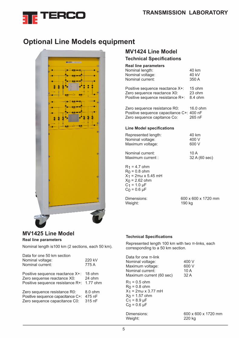
Optional Line Models equipmentMV1424 Line ModelTechnical SpecificationsReal line parametersNominal length: 40 kmNominal voltage: 40 kVNominal current: 350 A
Positive sequence reactance X+: 15 ohmZero sequence reactance X0: 23 ohmPositive sequence resistance R+: 8.4 ohm
Zero sequence resistance R0: 16.0 ohmPositive sequence capacitance C+: 400 nFZero sequence capitance Co: 265 nF
Line Model specificationsRepresented length: 40 kmNominal voltage: 400 VMaximum voltage: 600 V
Nominal current: 10 AMaximum current : 32 A (60 sec)
R1 = 4.7 ohmR0 = 0.8 ohmX1 = 2πω x 5.45 mHX0 = 2.62 ohmC1 = 1.0 µFC0 = 0.6 µF
Dimensions: 600 x 600 x 1720 mmWeight: 190 kg
MV1425 Line ModelReal line parametersNominal length is100 km (2 sections, each 50 km).
Data for one 50 km sectionNominal voltage: 220 kV Nominal current: 775 A
Positive sequence reactance X+ : 18 ohmZero sequense reactance X0: 24 ohmPositive sequence resistance R+: 1.77 ohm
Zero sequence resistance R0: 8.0 ohmPositive sequence capacitance C+: 475 nFZero sequence capacitance C0: 315 nF
Technical SpecificationsRepresented length 100 km with two π-links, each corresponding to a 50 km section.
Data for one π-linkNominal voltage: 400 VMaximum voltage: 600 VNominal current: 10 AMaximum current (60 sec) 32 A
R1 = 0.5 ohmR0 = 0.8 ohmX1 = 2πω x 3.77 mHX0 = 1.57 ohmC1 = 8.9 µFC0 = 0.6 µF
Dimensions: 600 x 600 x 1720 mmWeight: 220 kg

TRANSMISSION LABORATORY
6
Terco reserves the right to make changes in the design and modifications or improvements of the products at any time without incurring any obligations
MV1438 Cable ModelMV 1438 consists of two cable sections with a nose section cable area of 150 square mm and 240 square mm respectively.
Real line parameters Line Model SpecificationsPEX Cable 150 square mm Al (one π-link)Length 5 km corr. 5 kmNominal voltage 11 kV 400 VNominal current 260 A 6 ATransmission ability 5.0 MVA 2.4 kVAPositive sequence 0.45 µF 0.28 µFcapitance C+
Zero sequence 0.45 µF 0.28 µFcapitance C0Inductance 1.8 mH 2.84 mHResistance 1.1 ohm 1.8 ohmZero sequence 2.3 ohm 3.7 ohmreactance X0(approx.)
Real line parameters Line Model SpecificationsPEX Cable 240 square mm Al (one π-link)Length 5 km corr. 5 kmNominal voltage 11 kV 400 VNominal current 340 A 6 ATransmission ability 6.5 MVA 2.4 kVAPositive sequence 0.55 µF 0.26 µF capitance C+
Zero sequence 0.55 µF 0.26 µF capitance C0Inductance 1.6 mH 3.30 mHResistance 0.7 ohm 1.5 ohmZero sequence 2.1 ohm 4.3 ohmreactance X0(approx.)
Dimensions: 600 x 600 x 1720mmWeight: 190 kg

7
TRANSMISSION LABORATORY
The 3 coils have following values: L = 0.63 H and +/- 30 % terminals (70 kV)L = 1.00 H and +/- 30 % terminals (230 kV)L = 100 H and +/- 30 % terminals (11 kV)MV2225 is to be used together with the Line Models MV1420, MV2221 and MV2222.
Dimensions: 410 x 245 x 160 mmWeight : 11 kg
A Petersen coil is used together with OH-lines in the range of distribution voltage to medium voltage (MV).
The most common fault is line-to-earth where the current is limited by the phase voltage from the two healthy leads divided by the capacitive impedance added by the arc resistance and the remaining zero sequence impedance.
Since this current is mainly capacitive it could be balanced by an inductance between the neutral point of the transformer and ground. That is to say: when a line-to-earth fault occurs it will be extinguished automatically by the current in the Petersen coil and the re-closing device will connect power again in a fraction of a second.
Normally a HV-line has a firm ground. However, in this case we may also study a 230 kV model because of tutorial aspects.
Each inductance coil has three steps to optimize the reactance value for each line of “11 kV”, “70 kV” and “230 kV”.
MV2225 Petersen Coil, Multi Terminal Unit
MV2221 Line ModelLine Model 230 kV, 100 km, 400 V 3-phase.Three-phase model of an overhead power transmission line 100 km long, voltage 230 kV and ability 110 MVA.
Model value 400 V : R + 2.20 ohm, L 25 mH, C + 4uF, Co 2.5 uF.
The network model can be used to complete a series of experiments with transmission lines. Those listed and described in detail in the instruction manual include char-acteristic data of the line. Voltage drop on the lines. Short circuit. Earth fault.
Dimensions: 410 x 245 x 160 mmWeight: 10 kg
MV2222 Line ModelLine Model 11 kV, 5 km, 400 V 3-phase.Three-phase model of an overhead power transmission line 5 km long, voltage 11 kV and ability 5 MVA.Model value 400 V : R + 2.4 ohm, L 17 mH, C + 30 nF, Co 20 nF.
The network model can be used to complete a series of experiments with transmission lines. Those listed and described in detail in the instruction manual include char-acteristic data of the line. Voltage drop on the lines. Short circuit. Earth fault.
Dimensions: 410 x 245 x 160 mmWeight: 10 kg

TRANSMISSION LABORATORY
8
GeneralTERCO Power Factor Controller (PFC) is also a module within our Classical electrical Machine Program.
With the PFC you can minimise the currents caused by reactive losses of power and thereby optimising the transfer of energy between generation and loading.
This is becoming more and more important today when “Saving energy” is vital in a world with focus on pollution and shortage of energy.
Field of applicationInductive or mixed inductive and resistive networks in need of compensation, for example when starting and running induction motors.
Principles of operationDepending on the power factor of the loading network a microprocessor will connect groups of capacitors.By measuring phase voltages and current the micropro-cessor will calculate how many capacitive groups that has to be connected and also in which combinations.
Electrical detailsNumber of 3-ph groups 6 Power factor setting 0.7 inductive to 0.7 capacitiveNominal voltage 3 x 220-240 V 50 – 60 Hz Code no. MV 1439-235 3 x 380-440 V 50-60 Hz Code no MV1439-405
Nominal power 0 – 2 kVAr cap.PF-Controller Automatic or manual Adjustable delay times, switch- ing sequences and strategies.
Monitoring and Measurement on the controller: Voltage, Current and Power factorSwitching modes: Linear and circularIndication lamps: Indication lamps for the capacitor groups which are connected
Physical designThe Power Factor Control Unit is housed in a sturdy ap-paratus box with a clear mimic diagram explaining how to connect the supplying net from the left to the right side where the network in need for power factor com-pensation is connected.Readings, parameters and sub parameters are indi-cated on the front of the controller. Other settings and programming than the defaults are simply performed from the keyboard and displayed on the controller front.
General data:Power supply: 1-ph 220 - 240 V, 50 - 60 HzDimensions: 510 x 570 x 280 mmWeight: 24 kg
Typical Experiments with Terco PFC• The concept of active power, apparent power and reactive power• The concept of power factor and “cos”• The concept of measuring methods• Start current settings (C/k)• Delay times • Efficiency and losses• Linear and circular switching modes• PF-Controller design and schematics • Programming the controller• PF-Controller and resistive/inductive loads• PF-Controller and induction motor loads• Control range limits
MV1439 Power Factor Control Unit
MV1439-235 Power Factor Control unit3 x 220-240 V 50-60 Hz
MV1439-405 Power Factor Control Unit3 x 380-440 V 50-60 Hz

9
TRANSMISSION LABORATORY
ORDER DETAILS FOR TRANSMISSION LABORATORYCat. Code Description pc pageMV1420 Line Model 3-phase, 230V 1 4
Recommended peripheral equipment for MV1420MV1103 Variable Transformer, 3-phase 1 19MV1429 Terminal Board 1 29MV1100-235 Load Resistor 3-ph, 3.3kW 1 20MV1107 Load Reactor, 3-ph, 3 kVAr 1 20MV1102 Load Capacitor, 3-phase, 2.8 kVAr 1 21MV1500 Load Switch, 3-pole 16A 2 29MV1915 Transformer, 3-ph 2 kVA 50-60 Hz 2 10MV1939 AC Power Energy Meter 2 26MV1830-HF Flex Set, 100 Safety Leads, Safety Plugs 1 31MV1904 Flex Stand 1 31
Optional Line Models and equipment:MV1424 Line Model, 3-ph, 400V, one phi-link (40kV, 40km) 1 5MV1425 Line Model, 3-ph, 400, double phi-link (220kV, 100km) 1 5MV1438 Cable Line Model 400V, 3-phase (11kV, 5km) 1 6MV2221 Line Model 400V 3-phase (230kV, 100km) 1 7MV2222 Line Model 400V, 3-phase (11kV, 5km) 1 7MV2225 Petersen Coil, Multi Terminal 1 7MV1439-235 Power Factor Control Unit 1 8
Additional Equipment: Measuring and Data Acquisition for PCMV1943 Analog Output Module 1 27MV2609 Data Acquisition and Control Software 1 28,28
Alternative instrumentMV1922/23 Ammeter 0-10A, AC/DC 4 24MV1926 Voltmeter 0-50-250-500V AC/DC 3 24MV1937 Wattmeter 1-ph, 1-5A; 50-250-500V AC/DC 3 24MV1929 Power Factor Meter 3-ph, 0-5A, 230V 1 25MV1976 Power Factor Meter 3-ph, 0-5A, 400V 1 25

TRANSFORMER LABORATORY
10
MV1911 Transformer Single-PhaseRatings Single-phase 1 kVA, 50-60 Hz Primary: 230 V ± 5 % Secondary: 4 x 57.5 V ± 5 %
The secondary winding is divided into four windings for series or parallel connection.
No load losses Po = 25 WImpedance voltage ek = 8 %Resistance voltage ek = 3 %
MV 1911 can be used for determination of operating characteristics, losses and efficiency of a single-phase transformer by means of no load, short-circuit and load tests. The transformer has safety sockets mounted on the frontpanel with mimic diagrams.
Dimensions: 210 x 150 x 210 mmWeight: 22 kg
MV1915 Transformer 3-PhaseRatings Three-phase, 2 kVA, 50-60 Hz, 230/2 x 66.5 V per phasePrimary 0-133-230 V ± 5 % per phaseSecondary Two 66.5 V windings per phase, each winding having tappings for 0-38.4-44-66.5 V (± 5 %)
The tappings are so arranged that 230 V (star or delta connection) and 133 V (star, delta or zig-zag
connection) can be obtained for all standard connections.This transformer has safety sockets mounted on the frontpanel with mimic diagrams.
No load losses Po = 35 WImpedance voltage ek = 8%Resistance voltage ek = 3%
With MV 1915, asymmetrical loading and parallel connection of three-phase transformers for different three-phase combinations on the primary and
secondary side, can be studied.It can also be used for determination of operating characteristics, losses and efficiency.
Dimensions: 300 x 190 x 345 mmWeight: 33 kg
Experiment TransformersThese transformers are designed for studies of single and three-phase transformers, by the completion of a series of experiments, which are described indetail in the instruction manuals.
These include:
• Efficiency and short circuit impedance.
• Waveform of the no-load current.
• Inrush current.
• Three-phase connections.
• Unbalanced loading.
MV1911 Transformer single phase
MV1915 Transformer 3 phase 230V

11
TRANSFORMER LABORATORY
ORDER DETAILS FOR TRANSFORMER LABORATORYCat. Code Description pc pageMV1911 Transformer Single-Phase 1 10MV1915 Transformer 3-Phase 230V 1 10MV1972 Transformer 3-Phase 400V 1 11Recommended peripheral equipment for Transformer LaboratoryMV1103 Variable Transformer, 3-phase 1 19MV1429 Terminal Board 1 29MV1100-235 Load Resistor 1 20MV1101 Load Reactor, 3-phase, 2.5 kVAr 1 20MV1102 Load Capacitor, 3-phase, 2.8 kVAr 1 21MV1500 Load Switch, 3-pole 16A 1 29MV1939 Power Energy Meter 1 26MV1830-HF Flex Set, 100 Safety Leads, Safety Plugs 1 31MV1904 Flex Stand 1 31DMC9 Digital Multimeter. Equivalent instruments can be delivered and used. 1 23
Optional:MV1915-C Transformer 3-phase, sectioned 1 30MV1931 Current Transformer 1 30Alternative instruments instead of MV1939 above:MV1922/1923 Ammeter 4 24MV1926 Voltmeter 2 24MV1937 Wattmeter 3 24
MV1972 Transformer 3-phaseThis transformer has an E-type core and is suitable for setting up a variety of circuits for 3-phasetransformers. MV 1972 has safety sockets mounted on a frontpanel with mimic diagrams.
General DataPower rating Three-phase 2 kVA, 50-60 HzPrimary voltage 400 V ± 5 % or 230 V ± 5 % per phaseSecondary voltage 2 x 66.5 V ± 5 % per phaseTest voltage 2.5 kVEfficiency 92 %Percentage impedancevoltage 4 % approx.
Dimensions 350 x 165 x 260 mmWeight 30 kg
MV1915 Transformer 3 phase 400V

PROTECTION RELAYS LABORATORY
12
MV1450 Line Multi Protection Module
Technical Specification .Power Supply: 1-ph 220 - 240 V, 50 - 60 Hz Possible to supply a compatible device with powerPower bus: 3ph, 400VAC, 2A
Dimension: 483 x 356 x 422 mm. Weight: 37 kg
Protective earth: one 4mm safety connector for external components at the rear of the unit.
REF630 Important Protection functions• Capable of a 5 zone full-scheme high-speed line
distance protection with mho*), bullet and quadrilateral characteristics.• Three stages of over-current protection (Low, high
and instantaneous)• Directional earth-fault protection• Over-voltage protection• Over-power protection (configurable direction)
Protective Modules - Fully IEC 61850 compliant
The MV1450 Line Multi Protection Trainer module is intended for advanced training in modern line distance protection technology.
It is equipped with the fully IEC61850 compliant ABB protection REF630 which is one of the most modern and sophisticated protection units in the product family of Intelligent Electronic Devices (IEDs).
REF630 is designed for protection of transmission and distribution networks.
The use of a highly advanced IED enables great pos-sibilities to perform a wide range of laboratory experi-ments.
The protective relay REF630 used in MV1455 enables the student to learn and explore how to protect a varity of different power line configurations from various fault conditions.
Full access to protections relays including parameter setting and Disturbance Records is possible via a standard web browser.
It is possible to view important analogue current and voltage sinus waveform vectors in a suitable diagram, together with protection’s binary input and output status for in-depth fault analysis after such an event has occurred.
General Features• Colour coded power inlet- and outlets for easy rec-
ognition of each phase.• Mimic diagrams of the circuit along with large clear
symbols printed on the front panelPower bus circuit breaker switch: • A two state switch (ON/OFF) with LED indication of
CB (Circuit Breaker) status. • Internal circuitry prevents operation of the CB during
an unacknowledged trip.Trip reset button: • Button for quick reset of LEDs and acknowledge-
ment of a trip.• Control, monitoring and protection integrated in one
IED• Fully IEC 61850 compliant.• Four independent parameter setting groups.• Large HMI with single line diagram.• RJ-45 interface for communication with PC.• Protection and Control IED Manager PCM600:
Advanced software for configuration and parameter setting.
*) In order to retain dependability and security in cases of close-in faults when the loop voltage is zero, mho distance elements use cross-phase and/or memory polarization.

13
PROTECTION RELAYS LABORATORY
Terco reserves the right to make changes in the design and modifications or improvements of the products at any time without incurring any obligations
ORDER DETAILS FOR MV1450 LINE MULTI PROTECTION LABORATORYCat. Code Description pc pageMV1450 Line Multi Protection Trainer 1 12
Recommended peripheral equipment for MV1450MV1450-COMP PC with installed & pre-programmed software for MV1450 1 12MV1103 Variable Transformer, 3-phase 1 19MV1429 Terminal Board 1 29MV1100-235 Load Resistor 3-ph, 3.3kW 1 20MV1101 Load Reactor, 3-phase, 2.5 kVAr 1 20MV1102 Load Capacitor, 3-phase, 2.8 kVAr 1 21MV1500 Load Switch, 3-pole 16A 2 29MV1959 Rheostat 200W, 50 ohm,, 2A 1 22MV2221 Line Model 230kV, 100km, 400V, 3-phase 2 7MV2222 Line Model 11kV, 5km, 400V 3-phase 2 7MV1922/23 Ammeter 0-10A, AC/DC 2 24MV1926 Voltmeter 0-50-250-500V AC/DC 2 24MAT220349 Digital Clamp Meter AC / DC current 1 23MV1830-HF Flex Set, 100 Safety Leads, Safety Plugs 1 31MV1904 Flex Stand 1 31
Power supply of modules
The modules Power Sup-ply can be daisy-chained so that only one Power outlet is required
Every Module has two 1A fuse for Power Supply of the Module

PROTECTION RELAYS LABORATORY
14
The MV1455 Differtial Relay Module module is intended for advanced training in modern differential protection technology.
It is equipped with the fully IEC61850 compliant ABB RET615 protective relay which is one of the most so-phisticated protection unit in the product family of intel-ligent electronic devices (IEDs).
RET615 is designed for differential protection of trans-formers, generators, line sections and their combina-tions.
The use of a highly advanced IED enables great possibilities to perform a wide range of laboratory experiments.
The protective relay RET615 used in PTG1455 enables the student to learn and explore how to protect a variety of different power transformer connections with a differential protection scheme.
MV1455 Differential Relay Module
Technical SpecificationPower Supply: 1-ph 220 - 240 V, 50 - 60 Hz Possible to supply a compatible device with powerPower bus: (3-ph) 400V AC/ 2A with 4 mm safety connectors
Dimension: 357 x 483 x 420 mmWeight: 37 kg
Protective earth: one 4mm safety connector for external components at the rear of the unit.
General Features• Colour coded power inlet- and outlets for easy
recognition of each phase.• Mimic diagrams of the circuit along with large clear
symbols printed on the front panel.Power bus circuit breaker switch: • A two state switch (ON/OFF) with LED indication of
CB (Circuit Breaker) status. • Internal circuitry prevents operation of the CB during
an unacknowledged trip.Trip reset button: • Button for quick reset of LEDs and acknowledge-
ment of a trip.• Control, monitoring and protection integrated in one
IED• Fully IEC 61850 compliant.• Four independent parameter setting groups.• Large HMI with single line diagram.• RJ-45 interface for communication with PC• Three power lines; 1 incoming power line and 2
outgoing. Each line contain three phases L1, L2, L3 and Neutral wire.
• 12 Current Transformers which enables the student to study various CT-connections.
• Protection and Control IED Manager PCM600: Advanced software for configuration and parameter setting.
• Front panel switches that enable the student to test differential protection on a double-busbar.
RET615 Important Protection Functions• Differential Fault Protection• Three-phase non-directional overcurrent protection,
low, high and instantaneous stage• Non-directional earth-fault protection, low and high
stage• Negative-sequence overcurrent protection• Residual overvoltage protection
Full access to protections relays including parameter setting and Disturbance Records is possible via a standard web browser.
It is possible to view important analogue current and voltage sinus waveform vectors in a suitable diagram, together with protection’s binary input and output status for in-depth fault analysis after such an event has occurred.

15
PROTECTION RELAYS LABORATORY
Terco reserves the right to make changes in the design and modifications or improvements of the products at any time without incurring any obligations
ORDER DETAILS FOR MV1455 DIFFERENTIAL RELAY LABORATORYCat. Code Description pc pageMV1455 Line Multi Protection Trainer 1 14
Recommended peripheral equipment for MV1450MV1455-COMP PC with installed & preprogrammed software for MV1455 1 14MV1103 Variable Transformer, 3-phase 1 19MV1429 Terminal Board 1 29MV1100-235 Load Resistor 3-ph, 3.3kW 1 20MV1101 Load Reactor, 3-phase 2.5kVAr 1 20MV1102 Load Capacitor, 3-phase, 2.8 kVAr 1 21MV1500 Load Switch, 3-pole 16A 1 29MV1957 Rhestat 200W, 5 ohm, 6.3A 3 22MV1959 Rheostat 200W, 50 ohm,, 2A 1 22MV1400 Push Button Panel 1 29MV1911 Transformer 1-phase, 1kVA, 50-60 Hz 1 10MV1915 Transformer 3-phase, 2kVA, 50-60 Hz 1 10MV1922/23 Ammeter 0-10A, AC/DC 5 24MV1926 Voltmeter 0-50-250-500V AC/DC 2 24MAT220349 Digital Clamp Meter AC / DC current 1 23DMC9 Digital Multimeter 1 23MV1830-HF Flex Set, 100 Safety Leads, Safety Plugs 1 31MV1904 Flex Stand 1 31
Power supply of modules
The modules Power Sup-ply can be daisy-chained so that only one Power outlet is required
Every Module has two 1A fuse for Power Supply of the Module

Recommended Peripheral Equipment and Accessories
16
POWER SUPPLIES, GENERATORS AND LOADS
MV1305-405 Mobile Motor / Generator Unit
A standard laboratory for power transmission normally consists of one or two generators, which are con-nected to one or more transmission links which finally reach transformers, distribution units and loads. This configuration may look like the very left line in figure 1.However, a realistic network most likely looks like the complete network of figure 1. For example, here can be seen turbine/generators in parallel on the same busbar, a synchronous machine used as a synchro-nous compensator in the middle of a line, a single gen-erator unit and a heavy group of generators.Energy transfer, load shedding, static and dynamic sta-bility at disturbances as well as sophisticated protec-tion schemes can be studied under realistic forms. Not to forget compensation possibilities.Power- and current- paths in grid networks are compli-cated. The TERCO system will give understanding for this problem. The wide range flexibility will be given by the mobile generator station / synchronous alternator (compensa-tor) MV 1305.Two sets of MV 1305 can operate as described or work in parallel. In this case mechanical and electrical parameters might be changed by using e.g. flywheel (MV 1010) and different electrical connections.
Modes of OperationA. Control of active power (frequency): AC-
machine and frequency converter drive (”turbine”) + synchronous machine (gener-ator) in closed loop connection regarding frequency.
B. Control of active power (frequency) and reactive power (voltage): Two closed loops regarding frequency and voltage.
C. Synchronous compensating: AC-machine and frequency converter drive (”turbine”) idling, electrically disconnected or mechani-cally disconnected, synchronous machine in closed loop connection for voltage (=reac-tive power) control.
Technical Specification MV1305-405-235 Power Supply AC 3-ph 380-415 V Frequency 50 HzMax current 16A
Turbine/AC-machine freq.drive: Armature/stator Volt AC 323-528 VFrequency 0-63 HzArmature/stator current 3.4 AInput current 5.9 ARated output current 4.0 ARated output capacity 3.2 kVASpeed 0-1800 rpm
Synchronous generator: Armature volt AC 3-ph 0-140 / 240 VPower 1.2 kVACos ϕ 0.8Field volt 0-230 V DC
Speed Controll 0-1800 rpm Active power control SCR-frequency converter, electronic current limit setting, start- and stop ramps.Feedback systems Manual frequency setting. Automatic/Constant settingField current supply Integrated
Voltage control/Reactive power control PWM min. ripple-converter, electronic current limit settingFeedback systems Manual voltage setting. Automatic/Constant setting. Separate voltage feedback

17
Recommended Peripheral Equipment and AccessoriesPOWER SUPPLIES, GENERATORS AND LOADS
InstrumentsAC-machine freq.drive: Parameters and indications (Turbine simulator) selected by 4-lines display in
HMI-unit typically like: Frequency setpoint (F
50,00Hz) Stator Electric Frequency (H
51,00 Hz) Actual motor speed (from
encoder 1500 rpm) Motor current (A 2,20 A) DC-interlink voltage (V 520 V) Speed control potentiometer (=frequency control) Control method selector
AC-machine M/G: Armature voltage Voltage selector switch Armature current Voltage control potentiometer Control method selector Field current ammeter
Synchronizing devices: Synchronizing instrumentDouble voltmeterDouble frequency meterSynchronizing switchAutomatic or manual synchronizing
Auxiliary: Machines mounted on machine bed with slirails. Control panel integrated with machines to one mobile unit. Laboratory connections by 4 mm banana plug of safety type. Possibilities of connecting different types of step-up transformers as well as other instruments and protections.
Dimensions: 1550 x 800 x 1200 mmWeight: 200 kg (approx.)
Item Power Supply Synchronous GeneratorMV1305-405-235 380-415V 3-ph, 50Hz 220-240V 3-ph, 50HzMV1305-405-236 380-415V 3-ph, 60Hz 220-240V 3-ph, 60HzMV1305-405-405 380-415V 3-ph, 50Hz 220-240V 3-ph, 50Hz
MV1305-405-406 380-415V 3-ph, 60Hz 220-240V 3-ph, 60Hz

Recommended Peripheral Equipment and Accessories
18
POWER SUPPLIES, GENERATORS AND LOADS
MV1302 Power Pack Same as MV 1300-405 but with the following dataOutput voltage DC fixed 220 V 3.5 A DC variable 0-220 V 16 A AC fixed 400 / 230 V 10 A 3-ph AC variable 3 x 0-400 V 8 A 3-phSupply voltage 380-400 / 220-230 V 50 / 60 Hz 3-ph
MV1304 Power Pack As MV1300-415 but with the following dataOutput voltage DC fixed 220 V 3.5 A DC variable 0-220 V 16 A AC fixed 415 / 240 V 10 A 3-ph AC variable 3 x 0-415 V 10 A 3-phSupply voltage 415 / 240 V 50-60 Hz 3-ph
General DataSupply VoltageMV1300-235 220-240 / 127-140 V 50 / 60 Hz 3-ph.MV1300-405 380-400 / 220-230 V 50 / 60 Hz 3-ph.MV1300-415 415 / 240 V 50 / 60 Hz 3-ph.Output voltage DC fixed 220 V 3.5 A DC variable 0-220 V 16 A AC fixed 230/133 V 10 A 3-ph AC variable 3 x 0-230 V 10 A 3-phStandard Fixed AC 230 V 10 ADimensions 660 x 435 x 790 mmWeight 103 kg
MV1300 Power Pack This power supply unit is especially adapted for laboratory experiments on electric machines and power systems.
It can be used where variable or fixed AC or DC is re-quired and is particularly suited to the laboratory experi-ments with Terco´s torque meters and test machines. It is designed to slide under the lab table so that controls and connections are in a comfortable working position.
The contactor for variable voltages has a safety limit switch which eliminates switching on high voltages by mistake, thus protecting students and equipment espe-cially when working on electrical machines.All outputs are fused by MCB´s and have load switches.
The Power Pack has also Earth Leakages Circuit Break-er (ELCB).

19
Recommended Peripheral Equipment and AccessoriesPOWER SUPPLIES, GENERATORS AND LOADS
MV1103 Variable Transformer 3-phaseSupplied with a scale showing output voltage. Thermal overload protection for three output phases are placed on the front panel. A common shaft rotates all output voltage sliders in parallel. The unit is mobile on 4 wheels.
Input: 3 x 400 V, 8 A, 50-60 Hz Output: 3 x 0-450 V, 8 A
Dimensions: 280 x 290 x 560 mm Weight: 34 kg
MV1104 Variable Transformer Single PhaseThe annular core of this variable transformer is of high alloy transformer sheet with small losses.
The contact point on the winding, which is wound for a con-stant current obtained throughout the entire range, is provided by a sliding carbon contact. Thermal overload protector.
Switch with pilot lamp. Rubber pedestals at the bottom and rear for convenient placing in the most suitable position at any time.
Input: 230 V, 50-60HzOutput-max: 0-260 V, 8 A, 50-60 Hz, 4mm outletsDimensions: 200 x 190 x 205 mmWeight: 9 kg

Recommended Peripheral Equipment and Accessories
20
POWER SUPPLIES, GENERATORS AND LOADS
Modbus System
Modbus System
MV1100 Load Resistor MV1100 Load resistor contains three ganged resistors with continuous spindle regulation. The resistors are connected to terminals for 3-ph, single-phase or DC-voltage. The current in the resistor is limited by tubular wire fuses in each phase. The unit has handles and wheels for simple and quick movement and is en-closed in a perforated metal cabinet. MV1100 is supplied with safety sockets and a load switch.A cooling fan is placed at the bottom of the resistor.MV1100-235 Cooling fan supply 230 V AC 50 - 60 Hz MV1100-116 Cooling fan supply 110 V AC 60 HzGeneral Data3-phase 3.3 kW, continuously adjustable.Star connection 400 / 230 V 0.8-5 AStar connection 230 / 133 V 0.5-5 ADelta connection 400 / 230 V 2.4-8.7 ADelta connection 230 / 133 V 1.3-8.7 ADC parallel connection 220 V 2.3-15 AOverload capacity, brief duration, approx. 20 %.Dimensions): 630 x 250 x 890 mm Weight: 46 kg
MV1101 Load Reactor Enclosed in a strong metal cabinet. The front panel has mimic diagram, terminals, fuses and electrical data. The unit can be used on 1- and 3-phase sys-tems. 12 step regulation.
General Data2.5 kVAr, 50-60 HzV Connection Hz A230 star 50 0.2-2.2230 delta 50 0.6-6.6400 star 50 0.4-3.8230 star 60 0.2-1.9230 delta 60 0.5-5.6400 star 60 0.3-3.3Dimensions: 510 x 220 x 320 mm Weight: 40 kg

21
Recommended Peripheral Equipment and AccessoriesPOWER SUPPLIES, GENERATORS AND LOADS
MV1102 Load Capacitor Housed in a metal cabinet. Electrical data and sym-bols on the front panel with terminals and fuses. This unit can be used on 1- and 3-phase systems. 6 step regulation.
General Data2.8 kVAr at 50 Hz, 3.3 kVAr at 60 Hz.V Connection Hz A230 star 50 0.4-2.4 230 delta 50 1.2-7.2400 star 50 0.7-4.2230 III (parallel) 50 2.1-12.6230 star 60 0.5-2.8230 delta 60 1.4-8.6400 star 60 0.8-5.0230 III (parallel) 60 2.5-15Dimensions: 185 x 370 x 170 mmWeight: 7 kg
MV1106 Load CapacitorThe bank is made of metallized paper capacitors. The capacitors are fitted with discharging resistors. The capacitance of the bank can be varied in seven steps by means of rotary switches. It can be used in single-phase or three-phase circuits.
5.3 kVAr at 50 Hz, 6.3 kVAr at 60 HzV Connection Hz A230 delta 50 1.9-13.4400 star 50 1.1-7.7230 III 50 3.3-23.2230 delta 60 2.3-16.1400 star 60 1.3-9.2230 III 60 3.9-27.8Dimensions: 520 x 225 x 360 mm Weight 13 kg

22
Recommended Peripheral Equipment and AccessoriesPOWER SUPPLIES, GENERATORS AND LOADS
MV1957, MV1959, MV1963 RheostatsEach rheostat is enclosed in a robust metal case. The back, bottom and top of the case are perforated to provide optimum cooling. 2 glass fuses protect the resistor agains excessive current and incorrect con-nection.
A scale with 100 scale divisions shows the resistance setting.
A front panel of yellow painted steel with black screen painted symbols simplifies series and potentiometer connection.
Constructional featuresThe insulation is of high class ceramic material. The resistance wire used is of highest quality with very good linearity.Large flat brush with a sliding contact of copper graphite with specially balanced mounting guaran-tees perfect contact with negligible wear on the resistance.
Cat. no. W Ω I (A) Dimension HxWxD mm
Weight
MV1957 200 5 6.3140 x 130 x 145 1.5
MV1959 200 50 2.0MV1963 500 2500 0.45 215 x 195 x 230 3.5
MV1107 Load Reactor The reactor is continuously variable within the range 0.5-3.0 kVAr. When the reactor is connected to a sys-tem with 230 V between lines, the setting range can be increased to 0.15-3.0 kVAr by using Y-connection.The required reactive power is set by means of a crank. For easier setting, the load reactor has a ten-turn scale with 100 scale divisions for each turn. Each winding is fitted with a fuse.
3-phase 0.5-3.0 kVAr, 400 V Y, 230 V Y, 50-60 HzV Connection Hz A230 star / delta 50 0.4-7.8400 star 50 0.7-4.5230 star / delta 60 0.3-7.6400 star 60 0.6-3.7Dimensions: 340 x 170 x 380 mm Weight: 30 kg

Recommended Peripheral Equipment and AccessoriesINSTRUMENTS AND DATA ACQUISITION
23
MAT220349 Digital Clampmeter AC/DC current MAT229349 is a small and pliable clamp meter for AC and DC cur-rent up to 200 A. A clear and easy-to-read 3.5 digit LCD display with max reading of 1999.
The slim jaws have an inner diameter of 30 mm and is easy to fit in narrow places. The data-hold function freezes the value, and is useful when work-ing in the dark or hard to get areas where you cannot see the LCD. The measuring values are updated 2 times / sec.MAT220349 is delivered with manual, battery and soft case. Conforms with IEC safety requirements. Specifications:• Current (AC): 0-20 A, 0-150 A, 150-199, 9A• Current (DC): 0 - 20 A, 0 - 150 A, 150 - 199, 9A• Low battery indication: ”B” mark on LCD• Power supply (battery): 2 pcs RS-44 or 2 pcs LR-44
DMC9 Digital Multimeter
High-resolution, 3-3/4 digit LCD, 4000-count autoranging• 7 functions / 23 ranges• Battery Test function with Go/NoGo LED indicator• Industry standard test leads, safety rated• Protective holster included Voltage• DC Voltage 400 mV, 4V, 40V, 400V, 600V• AC Voltage 400 mV, 40V, 400V, 600V Current• DC Current 40 mA, 400 mA, 8 A, (10A for 10 min)• AC Current 40 mA, 400 mA, 8 A, (10A for 10 min) Resistance• 400 Ohm, 4 kOhm, 40 kOhm, 400 kOhm, 4 MOhm, 40 MOhm. Buzzer SoundsDiode TestOverload ProtectionIncluded accessories: Protective holster, test leads, battery and users manual. Dimensions: 140 x 78 x 50 mmWeight: 0.22 kg
Dimensions: 20 x 44 x 146 mmWeight: 0.1 kg
Recommended Peripheral Equipment and AccessoriesINSTRUMENTS AND DATA ACQUISITION
24
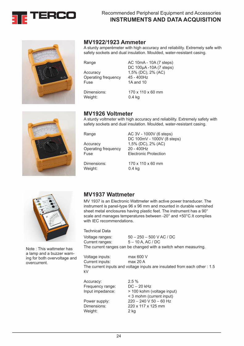
MV1922/1923 AmmeterA sturdy amperèmeter with high accuracy and reliability. Extremely safe with safety sockets and dual insulation. Moulded, water-resistant casing.
Range AC 10mA - 10A (7 steps) DC 100µA -10A (7 steps)Accuracy 1,5% (DC), 2% (AC)Operating frequency 45 - 400HzFuse 1A and 10
Dimensions: 170 x 110 x 60 mmWeight: 0.4 kg
MV1926 VoltmeterA sturdy voltmeter with high accuracy and reliability. Extremely safety with safety sockets and dual insulation. Moulded, water-resistant casing.
Range AC 3V - 1000V (6 steps) DC 100mV - 1000V (8 steps)Accuracy 1,5% (DC), 2% (AC)Operating frequency 20 - 400HzFuse Electronic Protection
Dimensions: 170 x 110 x 60 mmWeight: 0.4 kg
MV1937 Wattmeter MV 1937 is an Electronic Wattmeter with active power transducer. The instrument is panel-type 96 x 96 mm and mounted in durable varnished sheet metal enclosures having plastic feet. The instrument has a 90° scale and manages temperatures between -20° and +50°C.It complies with IEC recommendations.
Technical DataVoltage ranges: 50 – 250 – 500 V AC / DC Current ranges: 5 – 10 A, AC / DC The current ranges can be changed with a switch when measuring.
Voltage inputs: max 600 VCurrent inputs: max 20 AThe current inputs and voltage inputs are insulated from each other : 1.5 kV
Accuracy: 2.5 %Frequency range: DC – 20 kHzInput impedance: > 100 kohm (voltage input) < 3 mohm (current input)Power supply: 220 – 240 V 50 – 60 HzDimensions: 220 x 117 x 125 mmWeight: 2 kg
Note : This wattmeter has a lamp and a buzzer warn-ing for both overvoltage and overcurrent.

Recommended Peripheral Equipment and AccessoriesINSTRUMENTS AND DATA ACQUISITION
25
MV1929 Power Factor Meter Three-phase instrument, symmetric load.Measuring range cap. 0.5 ... 1 ... 0.5 ind.Current range 0-5 AVoltage range 220 V ± 20 % 3-phaseFrequency range 40-65 HzAccuracy class 1.5Dimensions: 220 x 117 x 125 mmWeight: 2 kg
MV1976 Power Factor Meter Three-phase instrument, symmetric load.Measuring range cap. 0.5 ... 1 ... 0.5 ind.Current range 0-5 AVoltage range 380 V ± 20 % 3-phaseFrequency range 40-65 HzAccuracy class 1.5Dimensions: 220 x 117 x 125 mmWeight: 2 kg
MV1918-1 Digital TimerSuitable for measuring the pick-up and drop-out times of relays and for physical experiments. The timer has two in-puts that can be wired either to start or stop timing. Timing is started or stopped by every change at the inputs (make or break). It is also possible to connect the timer to one of the inputs only, in which case the closing of a make contact starts the timer, and the opening of the circuit stops it. The inputs are protected for over-voltage, AC and DC.General DataTwo measuring ranges Timer 1 msec - 60 sec Counter 1 - 65 000 counts 230 V DC max. Accuracy ± 0.1 % of reading ± 1 digit Resolution 1 msec Height of digits 7 mm Mains supply 220-240 V, 50-60 HzDimensions: 175x200x90 mm Weight: 1 kg
MV1971 Differential ProbeVoltage up to 1200 VFrequency range: DC - 1 MHzImpedance in: approx. 1 MohmImpedance out: approx. 500 ohm
Dimensions (HxWxD): 40 x 120 x 65 mmWeight: 0.3 kg
Recommended Peripheral Equipment and AccessoriesINSTRUMENTS AND DATA ACQUISITION
26
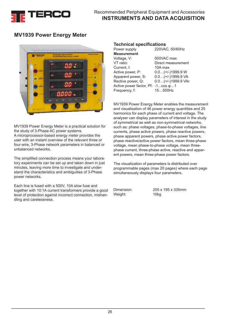
MV1939 Power Energy Meter is a practical solution for the study of 3-Phase AC power systems. A microprocessor-based energy meter provides the user with an instant overview of the relevant three or four-wire, 3-Phase network parameters in balanced or unbalanced networks.
The simplified connection process means your labora-tory experiments can be set up and taken down in just minutes, leaving more time to investigate and under-stand the characteristics and ambiguities of 3-Phase power networks.
Each line is fused with a 500V, 10A slow fuse and together with 10:1A current transformers provide a good level of protection against incorrect connection, mishan-dling and carelessness.
Technical specificationsPower supply 220VAC, 50/60HzMeasurementVoltage, V: 500VAC max VT ratio: Direct measurementCurrent, I: 10A maxActive power, P: 0.0…(+/-)1999.9 WApparent power, S: 0.0…(+/-)1999.9 VARective power, Q: 0.0…(+/-)1999.9 VArActive power factor, Pf: -1...cos φ…1Frequency, f: 15…500Hz
Dimension: 255 x 195 x 335mmWeight: 10kg
MV1939 Power Energy Meter
MV1939 Power Energy Meter enables the measurement and visualisation of 46 power energy quantities and 25 harmonics for each phase of current and voltage. The analyser can display parameters of interest in the study of symmetrical as well as non-symmetrical networks, such as: phase voltages, phase-to-phase voltages, line currents, phase active powers, phase reactive powers, phase apparent powers, phase active power factors, phase reactive/active power factors, mean three-phase voltage, mean phase-to-phase voltage, mean three-phase current, three-phase active, reactive and appar-ent powers, mean three-phase power factors.
The visualization of parameters is distributed over programmable pages (max 20 pages) where each page simultaneously displays four parameters.

Recommended Peripheral Equipment and AccessoriesINSTRUMENTS AND DATA ACQUISITION
27
Additional Equipment: Measuring and Data Acquisition for PC
Measurement values from the line models, loads and PFC
MV1939 AC Power Energy Meter
MV1943 Analogue Output Module
MV2609 Data Acquistion and Control Software
The system contains of an combination of Measuring units, Control Units, Data Interface Module and Data acquisition software, ena-bling the user to observe, control, record and inves-tigate relevant electrical data. An other typical applica-tion is electrical machines laboratory.
MV1420MV2221MV2222MV1424MV1425MV1438MV1439
MV1943 Analog Output Module
The MV1943 Analog Output Module integrates the commu-nication interface functionality of an USB to RS-485 adapter, with a 3-channel Modbus con-trolled 0-10V DC source in one compact unit.
Coupled with the MV2658 PWM Control unit, the MV1943 provides both communication
between Terco measuring units and a PC, as well as simultaneous motor control.The 3-channel analog output is controlled via PC using the Terco Data Acquisition Software and enables addi-tional features such as fully automatic data acquisition.
Technical SpecificationsCommunicationInterface USB plug and playOperating system virtual serial port driver 7/Vista/XP
Field interface RS485 Maximum devices 32 devices Power source USB portConsumption <100 mA
Voltage outputChannels 3Channel output 0-10 V Resolution 12 bit (2.5 mV)Isolation 1500 Vac, Field to LogicControl system Terco MV2609 Data Acquisition SoftwareGeneralPower supply: 220-240VAC, 50/60HzDimensions: 105 x 147 x 167 mmWeight: 0.3 kg
Recommended Peripheral Equipment and AccessoriesINSTRUMENTS AND DATA ACQUISITION
28
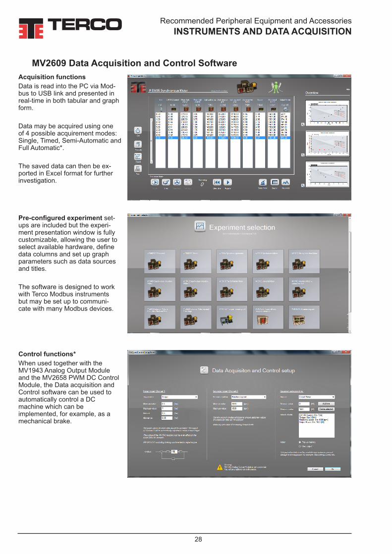
Acquisition functionsData is read into the PC via Mod-bus to USB link and presented in real-time in both tabular and graph form.
Data may be acquired using one of 4 possible acquirement modes: Single, Timed, Semi-Automatic and Full Automatic*.
The saved data can then be ex-ported in Excel format for further investigation.
MV2609 Data Acquisition and Control Software
Control functions*When used together with the MV1943 Analog Output Module and the MV2658 PWM DC Control Module, the Data acquisition and Control software can be used to automatically control a DC machine which can be implemented, for example, as a mechanical brake.
Pre-configured experiment set-ups are included but the experi-ment presentation window is fully customizable, allowing the user to select available hardware, define data columns and set up graph parameters such as data sources and titles.
The software is designed to work with Terco Modbus instruments but may be set up to communi-cate with many Modbus devices.

Recommended Peripheral Equipment and AccessoriesOTHER ACCESSORIES
29
MV1500 Load SwitchThree-pole, 16 A, 250 V- DC / 440 V-AC, switch in metal case. Front panel showing symbols and technical data.Marking of terminals input R, S, T output U, V, WDimensions (HxWxD): 95 x 200 x 80 mmWeight: 1 kg
MV1400 Push Button PanelMV1400 is a suitable control device It consists of :• a signal lamp• an OFF-button with one break and one make contact• an ON-button with one break and one make contact.The buttons are of non-locking type with instantaneous action so thatcontact operations are felt on depression of a button.
Dimensions (HxWxD): 75 x 175 x 130 mmWeight: 1 kg
MV1931 Current TransformerPrimary: 20-15-5 A/Sec. 1 A
Safety sockets
Accuracy class:1.0
Dimensions (HxWxD): 95 x 200 x 80 mmWeight: 6 kg
MV1429 Terminal BoardThe box has outlets (three phases, zero and earth) for labora-tory leads with 4 mm diameter plug ins. These outlets are con-nected to a 5 x 2.5 mm2 cable with a 3-phase CEE plug rated 16A. The connection box is equipped with miniature circuit breakers for 16 A. Dimensions: 250 x 240 x 75 mmWeight: 2.0 kg

Recommended Peripheral Equipment and AccessoriesOTHER ACCESSORIES
30
MV1402 ContactorThe contactor is one of the most common components in automation. It issued, for instance, in remote control and automatic control systems.
General data• 3 main contacts with thermal current rating 25 A at resistive load• 5 auxiliary contacts (3 make and 2 break) with thermal
current rating 10 A• Operating coil, 50 Hz or 60 Hz, 230 V
Dimensions (HxWxD) 150 x 245 x 130 mmWeight: 1.3 kg
MV1915-C Three-phase Transformer This transformer is cut-away to show the windings, coils, terminals, insulation, iron core etc.
Rated power: 2 kVA
Dimensions: 300 x 190 x 345 mmWeight: 27 kg
Note: It is not possible to do any practical experiments with this transformer.

Recommended Peripheral Equipment and AccessoriesOTHER ACCESSORIES
31
MV1830-HF Flex Set Area 1.5 mm2
Set of 100 leads in 5 different colours, red, yellow, blue, black, yellow/green, and 4 different lengths, 25, 50, 100 and 200 cm, 5 of each. 25 cm 50 cm 100 cm 200 cmRed 5 5 5 5Yellow 5 5 5 5Blue 5 5 5 5Black 5 5 5 5Yellow/green 5 5 5 5
Laboratory Flexes with Safety Plugs, Fixed Sleeve
Safety lead with 2 covered spring plugs of 4 mm diameter, with retract-able shroud covering the plugs, and 4 mm diameter axial bushings moulded with Polypropylen, fixed to 1.5 mm2 copper thread, PVC isolated, outer diameter 4 mm. Rated current 16 A.
MV1830-H Flex Set Area 1.5 mm2
Set of 100 leads in 5 different colours, red, yellow, blue, black, yellow/green, and 4 different lengths, 25, 50, 100 and 200 cm, 5 of each.Length 25 cm 50 cm 100 cm 200 cmRed 5 5 5 5 Yellow 5 5 5 5 Blue 5 5 5 5 Black 5 5 5 5 Yellow/green 5 5 5 5
Alternative Flexes: Laboratory Flexes with Safety Plugs, Retractable Shroud
MV1904 Flex Stand For suspension of laboratory flexes. The stand has 12 slots between parallel tubes with space for 10-15 laboratory flexes in each slot. Flexes of length 200 cm are suspended in a separate position above the stand. This rigid stand has a heavy steel plate pedestal.General Data Height: 1170 mm Weight: 9 kg
The plastic sleeve is pushed in to the flex when the plug is connected to the equipment.
The pin is protected by a plastic sleeve when the flex is not con-nected.

32
Transmission Line,Transformer & Protection Laboratory
Note the difference in colour marking of phases and neutral conductors according to International Standards
EU ASIA, Middle East
Brown
Black
Grey
Blue
Red
Yellow
Blue
Black
Standard Colouring of safety connections

Manuals
33
TERCO offers comprehensive manuals for each product upon delivery. On request we can also offer them in digital form.
All overseas deliveries are dispatched in special, made to order wooden crates, extremely sturdy and damage resistant.
The guarantee is valid for 24 months from delivery and covers repair or exchange of parts, defective due to faulty design or workmanship at our factory. Detailed conditions of guarantee are specified in our Terms of Guarantee.
Spare parts for 2-5 years of normal operation can be offered on request.
Regular after-sales service is performed by the worldwide network of Terco representatives, along with the advice and support of our engineers.
Commissioning and training is normally offered separately. Special training can be arranged on request either in Sweden or on site.
Terco is ISO 9001 certified
Guarantee & Terms

34
Transmission Line,Transformer & Protection Laboratory
INDEX Item Description Page DMC9 Digital Multimeter 23MAT220349 Digital Clampmeter Current 23MV1100 Load Resistor 20MV1101 Load Reactor 20MV1102 Load Capacitor 21MV1103 Variable Transformer 3-Phase 19MV1106 Load Capacitor 21MV1107 Load Reactor 22MV1300 Power Pack 18MV1305-405 Mobil Motor/ Generator 16,17MV1400 Push Button Panel 29MV1402 Contactor 30MV1420 Line Model 4MV1424 Line Model 5MV1425 Line Model 5MV1429 Terminal Board 29MV1438 Cable Model 7MV1439-235 Power Factor Control Unit 8,9MV1450 Line Multi Protection Trainer 12MV1450-COMP Line Multi Protection Trainer Software 12MV1455 Differential Relay Trainer 14MV1455-COMP Differential Relay Trainer Software 14MV1500 Load Switch 29MV1830-HF Laboratory Flexes 31MV1904 Flex Stand 31MV1911 Transformer Single-Phase 10MV1915 Transformer 3-Phase 10MV1915-C Three Phase Transformer 30MV1918-1 Digital Timer 25MV1922/23 Ammeter 24MV1926 Voltmeter 24MV1929 Power Facror Meter 25MV1931 Current Transformer 29MV1937 Wattmeter 24MV1939 AC Power Energy Meter 26MV1943 Analogue Output Module 27MV1957 Rheostat 22MV1959 Rheostat 22MV1963 Rheostat 22MV1971 Differential Probe 25MV1976 Power Factor Meter 25MV2221 Line Model 7MV2222 Line Model 7MV2225 Petersen Coil, Multi Terminal Unit 7MV2609 Data Acquisition and Control Software 27,28
35
Transmission Line,Transformer & Protection Laboratory
Notes

3636
TERCO AB P.O. Box 5014SE-14175 KUNGENS KURVA SWEDEN
Office/Works: Pyramidbacken 6SE-141 75 Kungens KurvaSTOCKHOLM
Phone: +46 8 506 855 00Fax +46 8 506 855 01e-mail [email protected] www.terco.se
Terco headoffice and factory outside Stockholm, Sweden
TERCO HEADOFFICE
TRAINING FOR TOMORROW´S WORLD
TERCO AB was founded in 1963 with the aim of producing and supplying practically oriented equipment for technical education.
TERCO develops, manufactures and markets advanced equip-ment and systems for technical education. TERCO is today represented in more than 50 countries world wide.
High Voltage
Process Control
Training
Energy
Furniture & Power Distribution
Mechatronics
Material Testing
Power Systems Electrical Machines & Drives
2019
-07-
11_2
51_2
52_2
53