
H26564 Dissectible Transformer NFU 267
14
version H26564 2016 H26564 Dissectible Transformer NFU 267 Purpose This apparatus has been designed primarily for demonstration of the basic principles of the A.C. transformer. The various coils and cores will also serve as the basis of many experiments in electromagnetism, using either direct or alternating current. To this end, the number of turns, the direction of winding, and the continuous maximum rated current are marked on each coil. Warnings Users should be aware that some combinations of coils can create dangerously high voltages in the secondary coil, even when a low voltage power supply is used on the primary. Such combinations must not be used. For your safety, this product should be used in accordance with these instructions, otherwise the protection provided may be impaired. This unit is intended for use in DRY conditions. Avoid spillage of water and other liquids on to the unit. If spillage occurs, disconnect the mains or power supply.
-
Upload
khangminh22 -
Category
Documents
-
view
4 -
download
0
Transcript of H26564 Dissectible Transformer NFU 267

version H26564 2016
H26564 Dissectible Transformer NFU 267
Purpose
This apparatus has been designed primarily for demonstration of the basic principles of the A.C.
transformer.
The various coils and cores will also serve as the basis of many experiments in electromagnetism, using
either direct or alternating current. To this end, the number of turns, the direction of winding, and
the continuous maximum rated current are marked on each coil.
Warnings
Users should be aware that some combinations of coils can create dangerously high
voltages in the secondary coil, even when a low voltage power supply is used on the
primary. Such combinations must not be used.
For your safety, this product should be used in accordance with these instructions, otherwise the
protection provided may be impaired.
This unit is intended for use in DRY conditions. Avoid spillage of water and other liquids on to the unit.
If spillage occurs, disconnect the mains or power supply.
version H26564 2016
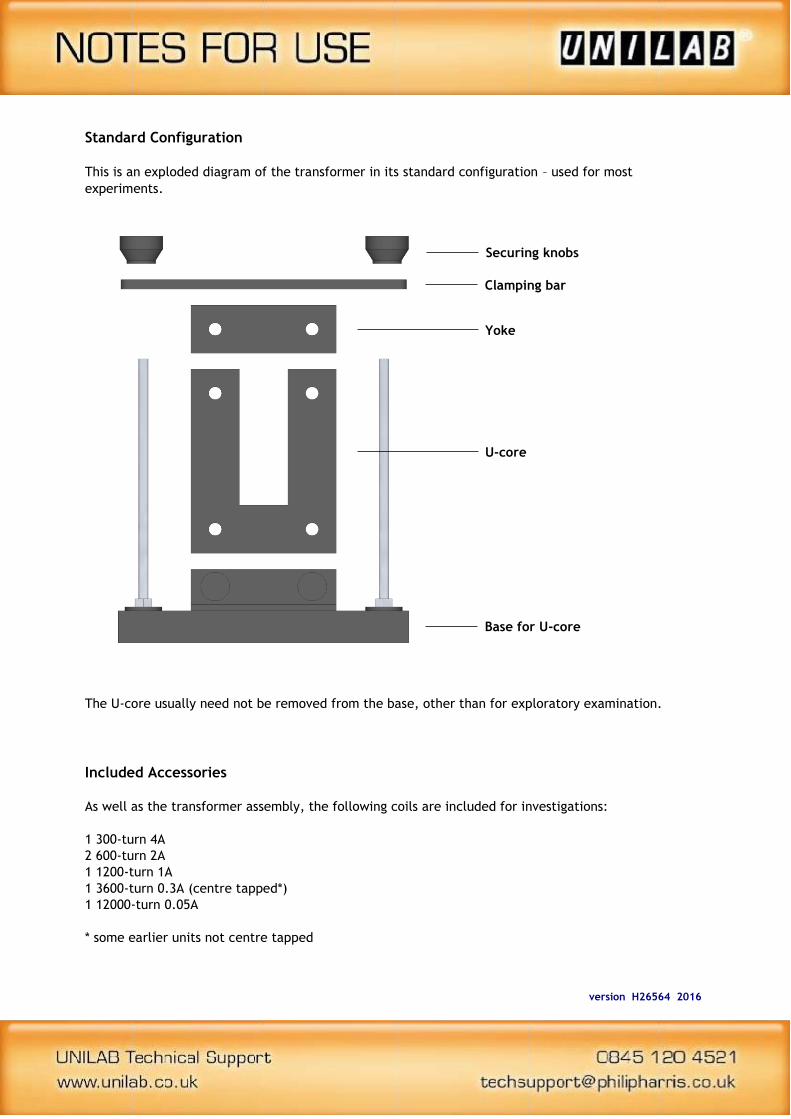
Standard Configuration
This is an exploded diagram of the transformer in its standard configuration – used for most
experiments.
The U-core usually need not be removed from the base, other than for exploratory examination.
Included Accessories
As well as the transformer assembly, the following coils are included for investigations:
1 300-turn 4A
2 600-turn 2A
1 1200-turn 1A
1 3600-turn 0.3A (centre tapped*)
1 12000-turn 0.05A
* some earlier units not centre tapped
Securing knobs
Clamping bar
Yoke
U-core
Base for U-core

version H26564 2016
The coils have two 4mm sockets for connection to a circuit. The centre-tapped coil has a third socket,
connected half-way along the coil (1800 turns). Arrows on the body of the coil indicate the direction
of the winding.
Each coil is enclosed in the same housing, such that any two coils can be mounted on the transformer
at a time (one on each side) as illustrated below.

version H26564 2016
Alternative Configuration
The pole pieces can be used in place of the yoke. This is for experiments involving the motor accessory
set, described in NFU 453. Contact Unilab for a copy of these instructions.
This is an exploded diagram of the configuration using the pole pieces. The pole pieces are secured on
to the top of the armatures of the U-core by thumb screws with long threads (not illustrated).
Warning
The continuous current through the coil should not exceed the specified value for any length of time,
as coils will overheat and may be irreparably damaged.
U-core
Base for U-core
Pole pieces
version H26564 2016
Experiments
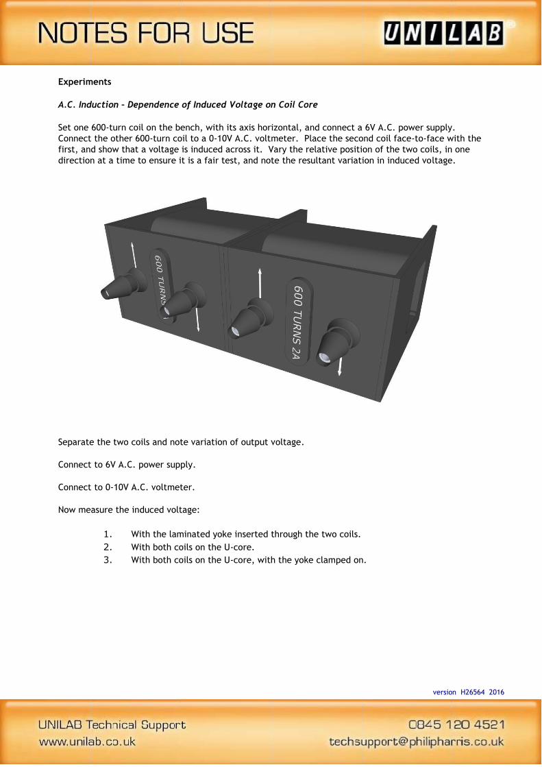
A.C. Induction – Dependence of Induced Voltage on Coil Core
Set one 600-turn coil on the bench, with its axis horizontal, and connect a 6V A.C. power supply.
Connect the other 600-turn coil to a 0-10V A.C. voltmeter. Place the second coil face-to-face with the
first, and show that a voltage is induced across it. Vary the relative position of the two coils, in one
direction at a time to ensure it is a fair test, and note the resultant variation in induced voltage.
Separate the two coils and note variation of output voltage.
Connect to 6V A.C. power supply.
Connect to 0-10V A.C. voltmeter.
Now measure the induced voltage:
1. With the laminated yoke inserted through the two coils.
2. With both coils on the U-core.
3. With both coils on the U-core, with the yoke clamped on.

version H26564 2016
The Relationship between Transformer Input and Output Voltage Waveforms
Set the two 600-turn coils on the U-core and clamp on the yoke. Connect one coil to a 12V A.C. power
supply and the other to the Y-input on an oscilloscope, with a suitably adjusted time base. Compare
the output waveform to the input one.
If a dual-beam oscilloscope is available, then the input and output signals can be viewed
simultaneously for easier comparison.
This practical can be extended by observing the dependence on phase difference on frequency, using a
Power Signal Generator to provide the input waveform.
Slow A.C. experiments involve frequencies of less than 1Hz. Instead of an oscilloscope, use large
demonstration meters to observe the “lag”.
If you have an oscilloscope with a trigger input, the input signal can be connected to the x-input, and
analysis of the phase different carried about by observing the Lissajous figure.
Connect to 12V A.C.
power supply
Connect to oscilloscope
Y-input

version H26564 2016
The Dependence of Transformer Output Voltage on the Turns Ratio of the Transformer Coils
Use a 600-turn coil as the primary, and use the 300, 600 and 1200 turn as the secondary, mounted on
the transformer with the yoke secured.
Connect the primary to a 12V A.C. power supply, and the secondary to a multi-range
A.C. voltmeter. Record the output voltage of each secondary coil, and plot a graph of output voltage
against number of turns on the secondary. Note the ratio of turns of the transformer (primary to
secondary) and compare this to the ratio of input voltage to output voltage.
Note: the voltmeter draws very little current from the transformer.
Vo
ltag
e O
utp
ut
(V)
Voltage Output per Turns on Secondary
0.00
4.00
8.00
12.00
16.00
20.00
0 300 600 900 1200
Number of Turns on Secondary

version H26564 2016
The Variation of Transformer Primary Current with Secondary Current
Set the 1200-turn and 300-turn coils on the transformer, with the yoke secured. Connect the 1200-turn
coil in series with 0.1A A.C. ammeter, and a 5V A.C. power supply. Connect the 300-turn coil with a 0-
135Ω 1.4A rheostat, a 0-16Ω 4A rheostat, and a 0-10A A.C. ammeter.
135 R 16 R
Set the rheostats to maximum resistance before turning on the power supply. Start by reducing the
resistance of the 135Ω rheostat before the 16Ω, so that the appropriate rheostat carries most of the
current. Reduce the secondary circuit resistance in steps, and record secondary current against
primary current. Compare this to the ratio of the number of turns in each coil.
Primary
Current
(A)
Secondary
Current
(A)
0.5
1.0
…
A A

version H26564 2016
- TEACHER ONLY
Transformer Efficiency and its Dependence on Load
Use the circuit in experiment 4 and connect a multi-range A.C. voltmeter, set on the 100V range,
across the output terminals of the transformer. Repeat experiment 4, measuring output voltage as
well as primary and secondary currents. Calculate the input power and output power, and hence,
transformer efficiency.
To calculate efficiency in percent, divide the output power by the input power, and multiply by 100.
Finally, plot a graph of efficiency against secondary current (i.e. load).
Primary Voltage (V)
Primary Current (A)
Primary Power (W)
Secondary Voltage (V)
Secondary Current (A)
Secondary Power (W)
Efficiency (%)
0.1
0.2
….
version H26564 2016
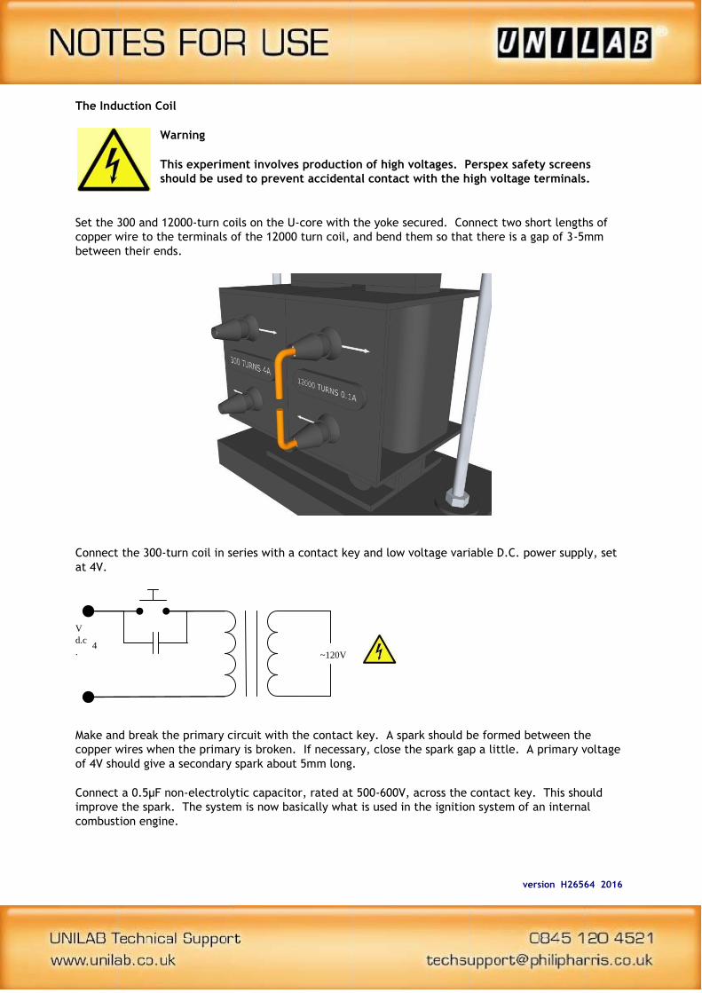
The Induction Coil
Warning
This experiment involves production of high voltages. Perspex safety screens
should be used to prevent accidental contact with the high voltage terminals.
Set the 300 and 12000-turn coils on the U-core with the yoke secured. Connect two short lengths of
copper wire to the terminals of the 12000 turn coil, and bend them so that there is a gap of 3-5mm
between their ends.
Connect the 300-turn coil in series with a contact key and low voltage variable D.C. power supply, set
at 4V.
Make and break the primary circuit with the contact key. A spark should be formed between the
copper wires when the primary is broken. If necessary, close the spark gap a little. A primary voltage
of 4V should give a secondary spark about 5mm long.
Connect a 0.5μF non-electrolytic capacitor, rated at 500-600V, across the contact key. This should
improve the spark. The system is now basically what is used in the ignition system of an internal
combustion engine.
4 V d.c .
~120V
version H26564 2016
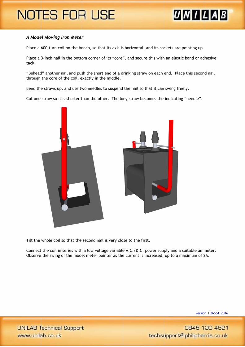
A Model Moving Iron Meter
Place a 600-turn coil on the bench, so that its axis is horizontal, and its sockets are pointing up.
Place a 3-inch nail in the bottom corner of its “core”, and secure this with an elastic band or adhesive
tack.
“Behead” another nail and push the short end of a drinking straw on each end. Place this second nail
through the core of the coil, exactly in the middle.
Bend the straws up, and use two needles to suspend the nail so that it can swing freely.
Cut one straw so it is shorter than the other. The long straw becomes the indicating “needle”.
Tilt the whole coil so that the second nail is very close to the first.
Connect the coil in series with a low voltage variable A.C./D.C. power supply and a suitable ammeter.
Observe the swing of the model meter pointer as the current is increased, up to a maximum of 2A.

version H26564 2016
Rectification of Alternating Current
Mount the 600 and 3600-turn coils to create a centre-tapped transformer.
Connect the circuits shown below, and show the resultant rectified waveform on an oscilloscope. The
circuits give:
1. Half-wave rectification.
2. Full-wave rectification with a centre-tapped* transformer.
3. Full-wave rectification with a diode-bridge rectifier.
In each case, set the value of the capacitance C, initially to zero, and then increase it in steps up to
1μF, noting the change in waveform and output voltage.
.
*requires centre tapped 3600 turn coil
3
V
k 10 0
0 - 100 V d.c.
C
5
V a.c
Os cill os co pe

version H26564 2016
Effect of Supply Frequency on Efficiency
Most transformers are forced to use the frequency of the mains supply (50 or 60Hz). However, is this
necessarily the best frequency to operate at?
Set up the apparatus as in experiment 5, using the low impedance output of a Power Signal Generator
as a variable frequency power supply.
Repeat experiment 5, once with the Power Signal Generator set to 25Hz, and again set to 100Hz. Plot
efficiency against load for both frequencies, and compare the curves with that obtained from
experiment 5.
What effect does the supply frequency have on efficiency:
a) At lower loads?
b) At higher loads?
c) Overall?

version H26564 2016
Warranty, repairs and spare parts
The dissectible transformer is guaranteed for a period of one year from the date of delivery to the
customer. This warranty does not apply to defects resulting from the action of a user such as misuse,
improper wiring, any operations outside of its specification, improper maintenance or repair, or
unauthorized modification.
Our liability is limited to repair or replacement of the product. Any failure during the warranty period
should be referred to Customer Services.
Please contact Customer Services or [email protected] for advice
Supplier details
Philip Harris Education, 2 Gregory Street, Hyde, Cheshire SK14 4RH
Orders and Information Tel: 0845 120 4521
Fax: 0800 138 8881
Repairs Tel: 0845 120 3211
E-mail: [email protected]
Website: www.philipharris.co.uk
© Philip Harris Education, 2002, 2014, 2016