ENERGY EFFICIENT TOPOLOGIES FOR WIRELESS SENSOR NETWORKS
14
E NERGY EFFICIENT T OPOLO GIES F OR WI RELESS S ENSOR N ETWO RKS Gurwinder Kaur 1 and Rachit Mohan Garg 2 1,2 Department of Education and Research, Infosys Limited, Mysore, India [email protected], [email protected] ABSTRACT A wireless network is a group of spatially dispersed specialized transducers with a sensing, computing and communication infrastructure which intends to give them the ability to sense and record various conditions in a monitored environment. They act as interfaces between real and virtual worlds. They are the most rapidly developing information technologies in today’s world due to their vast range of applications. This paper gives an overview of wireless sensor networks and provides a scenario based comparison for energy efficiency between different topologies used in these networks. KEYWORDS Wireless Sensor Networks, topologies, energy efficiency, lifetime, power consumption. 1. INTRODUCTION Wireless sensor networks are the networks which are formed with a group of devices equipped with sensors distributed in space. These devices are used to measure and record various environmental conditions in diverse locations. A sensor network is made of sensor nodes where each sensor node is equipped with a radio transceiver along with an antenna, a microcontroller, an interfacing electronic circuit and an energy source (usually a battery). Each sensor node can be imagined as a small computer consisting of a processing unit and a limited amount of computational power and memory. The main difference between the Wireless Sensor Networks (WSNs) and adhoc networks is that for WSNs, the main functions are monitoring and collecting the data whereas for the adhoc networks, the main focus is on communication aspects. A number of efforts have been made by industry and academia to develop and deploy WSN so that it can satisfy a variety of applications. But the biggest limitation of WSN devices is their power constraint which affects their lifetime and area of coverage. Proper area coverage ensures that the complete monitored area can be represented by the data collected from the sensors while the lifetime refers to the operating time of the WSN for collecting data from the entire network domain. In a given network domain, different deployment strategies of sensors often lead to different network coverage and lifetime values, which are very important design criteria for any WSN. Placing sensors in a controllable manner to achieve maximum network lifetime is the most effective approach of sensor deployment. But this approach may prove to be technically or practically non-feasible especially for large WSNs. Also, some locations of the network domain may not be reachable to the network planners due to geographical constraints.
-
Upload
independent -
Category
Documents
-
view
0 -
download
0
Transcript of ENERGY EFFICIENT TOPOLOGIES FOR WIRELESS SENSOR NETWORKS

ENERGY EFFICIENT TOPOLOGIES FOR WIRELESSSENSOR NETWORKS
Gurwinder Kaur1 and Rachit Mohan Garg2
1,2Department of Education and Research, Infosys Limited, Mysore, [email protected], [email protected]
ABSTRACTA wireless network is a group of spatially dispersed specialized transducers with a sensing, computing andcommunication infrastructure which intends to give them the ability to sense and record various conditions ina monitored environment. They act as interfaces between real and virtual worlds. They are the mostrapidly developing information technologies in today’s world due to their vast range of applications. Thispaper gives an overview of wireless sensor networks and provides a scenario based comparison for energyefficiency between different topologies used in these networks.
KEYWORDSWireless Sensor Networks, topologies, energy efficiency, lifetime, power consumption.
1. INTRODUCTION
Wireless sensor networks are the networks which are formed with a group of devices equippedwith sensors distributed in space. These devices are used to measure and record variousenvironmental conditions in diverse locations. A sensor network is made of sensor nodes whereeach sensor node is equipped with a radio transceiver along with an antenna, a microcontroller, aninterfacing electronic circuit and an energy source (usually a battery). Each sensor node can beimagined as a small computer consisting of a processing unit and a limited amount ofcomputational power and memory.
The main difference between the Wireless Sensor Networks (WSNs) and adhoc networks is thatfor WSNs, the main functions are monitoring and collecting the data whereas for the adhocnetworks, the main focus is on communication aspects.
A number of efforts have been made by industry and academia to develop and deploy WSN sothat it can satisfy a variety of applications. But the biggest limitation of WSN devices is theirpower constraint which affects their lifetime and area of coverage. Proper area coverage ensuresthat the complete monitored area can be represented by the data collected from the sensors whilethe lifetime refers to the operating time of the WSN for collecting data from the entire networkdomain.
In a given network domain, different deployment strategies of sensors often lead to differentnetwork coverage and lifetime values, which are very important design criteria for any WSN.Placing sensors in a controllable manner to achieve maximum network lifetime is the mosteffective approach of sensor deployment. But this approach may prove to be technically orpractically non-feasible especially for large WSNs. Also, some locations of the networkdomain may not be reachable to the network planners due to geographical constraints.
NnN
Typewritten Text
International Journal of Distributed and Parallel Systems (IJDPS) Vol.3, No.5, September 2012
NnN
Typewritten Text
NnN
Typewritten Text
DOI : 10.5121/ijdps.2012.3516 179

2. PARAMETERS FORMEASURING THE EFFECTIVENESS OF ATOPOLOGY:
2.1 Range and coverage: Range and coverage are probably the most obvious requirementsfor a WSN starting from the node to node range at a given transmission power / antenna gain anddata rate. The main factors affecting range of a wireless network are the quality of physical layerand the efficiency of data transmission through the network. The coverage requirements areelimination of dead spots in the network and the extent of coverage area in range, both of whichare closely related to range.
Fig. 1: An obstacle reduces the coverage of two cameras directed at different areas
2.2 Scalability: Scalability is the property of being able to cope up with network cells assmall as a few nodes to cells of thousands or even tens of thousands of nodes as well asincreasing the size of existing network by order of magnitude without employing expensivecellular communication or other long range solutions.
2.3 Expected Transmission Count (ETX): It accounts for data loss due to mediumaccess contention and environmental hazards and considers the number of transmissions neededto successfully transmit a packet over a link.
2.4 Hop Count: Hop count is the most commonly used metric in wireless multi-hopnetworks. The path having the minimum number of links between a given source and thedestination node is selected.
2.5 Power consumption/Network Longevity: In most of the published communicationprotocols for WSNs, network lifetime extension has been mentioned as an important optimizationobjective. The position of nodes can affect the network lifetime significantly. For example, a non-uniform node distribution in a given area may lead to bottlenecks and unbalanced traffic. On theother hand, uniform distribution of nodes in a network may result in depletion of energy of nodes
NnN
Typewritten Text
International Journal of Distributed and Parallel Systems (IJDPS) Vol.3, No.5, September 2012
NnN
Typewritten Text
180

that are close to the base station at a rate higher than the other nodes, which in turn will shortenthe network lifetime.
Fig 2: Nodes closer to the base station/ data collector die quickly due to more traffic.
3. TOPOLOGIES FOR AWIRELESS SENSOR NETWORK
The network structure of wireless network is not limited to one design. While designing thenetwork, the developer has several choices of topologies for configuring the network. Followingare the different topologies:
3.1 Single hop star topology: Single hop star topology is the simplest WSN topology. Inthis topology, every node communicates directly with the gateway or the data collector. Due tominimum networking concerns, this topology simplifies the network wherever it isrealizable. However, due to its design only, the biggest limitation it possesses is the problem ofscalability. The nodes that are at a large distance from the gateway will have poor qualityconnections with the gateway. Thus, this topology is good to be used only when the numberof nodes in the network is very small and the coverage area does not extend beyond the radiotransmission range of around 30 meters in a building.
NnN
Typewritten Text
International Journal of Distributed and Parallel Systems (IJDPS) Vol.3, No.5, September 2012
NnN
Typewritten Text
181
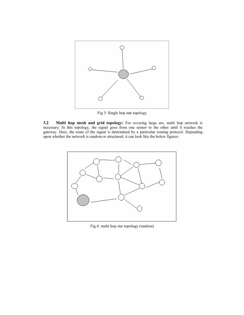
Fig 3: Single hop star topology
3.2 Multi hop mesh and grid topology: For covering large are, multi hop network isnecessary. In this topology, the signal goes from one sensor to the other until it reaches thegateway. Here, the route of the signal is determined by a particular routing protocol. Dependingupon whether the network is random or structured, it can look like the below figures:
Fig.4: multi hop star topology (random)
NnN
Typewritten Text
NnN
Typewritten Text
International Journal of Distributed and Parallel Systems (IJDPS) Vol.3, No.5, September 2012
NnN
Typewritten Text
NnN
Typewritten Text
182
NnN
Typewritten Text
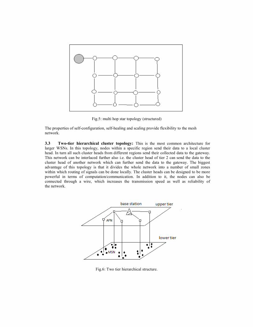
Fig.5: multi hop star topology (structured)
The properties of self-configuration, self-healing and scaling provide flexibility to the meshnetwork.
3.3 Two-tier hierarchical cluster topology: This is the most common architecture forlarger WSNs. In this topology, nodes within a specific region send their data to a local clusterhead. In turn all such cluster heads from different regions send their collected data to the gateway.This network can be interlaced further also i.e. the cluster head of tier 2 can send the data to thecluster head of another network which can further send the data to the gateway. The biggestadvantage of this topology is that it divides the whole network into a number of small zoneswithin which routing of signals can be done locally. The cluster heads can be designed to be morepowerful in terms of computation/communication. In addition to it, the nodes can also beconnected through a wire, which increases the transmission speed as well as reliability ofthe network.
Fig.6: Two tier hierarchical structure.
NnN
Typewritten Text
International Journal of Distributed and Parallel Systems (IJDPS) Vol.3, No.5, September 2012
NnN
Typewritten Text
183

2
4. COMPARISON OF DIFFERENT TOPOLOGIES:
Topology Node Degree Network diameter Network size
Linear Array 2 N-1 N nodesRing 2 Floor(N/2) N nodesCompletely connected N-1 1 N nodesBinary tree 3 2(h-1) h=ceil(log2N)Star N-1 2 N nodes2-D mesh 4 2(r-1) r*r mesh where r=√N
Here we are considering a scenario where the sensors are uniformly scattered on a straight line inthe interval [-D;D] and the fusion center is h meters away from the midpoint of the line (h>D).The distance between the sensor ‘i’ and sensor ‘n’ is denoted by d i,n.
Here in this scenario,a comparison of three different categories of topologies is done on the basisof energy efficiency & lifetime.Below are the categories of topologies:
4.1 Cluster based Sensor Network:Cluster based sensor network consists of two types ofsensors. Sensor β acts as cluster head and the rest of the sensors play the role of cluster members.The data to be transmitted from these cluster members is constrained to M bits. Each member ofthe cluster quantizes its observed data to M bits and transmits this quantized data to the clusterhead. The cluster head receives the quantized data from the other sensors and performs sourceextraction based on its own observation and the data received.
Fig.7: cluster based sensor network
4.1.1 Impact on energy efficiency:The task is to extract a signal frame with length L in eachround at the cluster head. In the cluster based sensor network, the total energy consumed forcommunications is calculated as below:
E(1)comm= 2(N-1) MLEelec+ MLϵfs∑ =0 i,β , i≠β
Where M is the number of quantization bits, L is the length of a signal frame, Eelecis the energyconsumed for running the electronic circuits and ϵfsis an amplifier energy factor. The computation
NnN
Typewritten Text
International Journal of Distributed and Parallel Systems (IJDPS) Vol.3, No.5, September 2012
NnN
Typewritten Text
184

sen c elec fs i,β
mainly consists of three parts: quantization, prewhitening and iteration of the fast fixed-point2 2algorithm which are approximated by LEc, N LEc and L Ec respectively, where Ecis
theunit energy for computation. Therefore, the total energy consumed for computation in thecluster based sensor network is :
E(1)comp = [(N-1)L+N2L+L2]Ec
The total energy consumed for sensing is Esen=NLEs, where Es is the unit of energy forsensing one sample point. This part of energy consumption is the same for all the sensor networks.Hence, the total energy consumption in the cluster based sensor network for extracting a signalframe is:
E(1) (1) (1)total = E comm + E comp +Esen
4.1.2 Impact on lifetime: Lifetime T is defined as the time from the round that the sensornetwork starts working to the round that only J surviving sensors can afford the energy to extracta signal frame. In the cluster-based sensor network, the energy budgets of the cluster head and thecluster members are E1 and E2 respectively. In the cluster-based sensor network, theenergy consumption of each cluster member and the cluster head is E + LE +MLE
+MLϵ d2 and Eh = Esen+(N-1) MLEelec+ (N2L+L2)Ecrespectively. Mathematically,
TEm,J≤ E2 < (T+1)Em,J
In the cluster based sensor network, the energy consumption of the cluster members is arranged indescending order. Mathematically,
TEh≤ E1 < (T+1)Eh , E2 ≥ TEm,J-1
orTEm,J-1 ≤ E2 < (T+1)Em,J-1 , E1≥ TEh.
The greater T derived from these two inequalities is the lifetime.
4.2 Sensor network with a fusion center: Here, the fusion center performs the operationof source extraction based on the received quantized data from the sensors.
4.2.1 Impact on energy efficiency:The equations below show the energy required incommunication and computation in Sensoe Network with fusion center.
E(2)comm=NMLEelec + MLϵmp∑ − 1
4
E(2)comp = NLEc
i,f
Where ϵmp is another amplifier energy factor, di,f is the distance from sensor ‘i’ to the fusioncenter.
4.2.2 Impact on lifetime: In the sensor network with a fusion center, the energy consumptionof each sensor is:
Esen+ LEc +MLEelec+MLϵmp d4i,f
The sensors that are nearest to the midpoint of the line consume least energy for broadcasting andare selected for performing iterations. T is defined as the time from the round that the sensor
NnN
Typewritten Text
NnN
Typewritten Text
International Journal of Distributed and Parallel Systems (IJDPS) Vol.3, No.5, September 2012
NnN
Typewritten Text
185

=1
2
2
2
2
2
2
network starts working to the round that only θ-1 surviving sensors in the selected sensor set canafford the energy to extract a signal frame. Mathematically,
TEm,θ-1 ≤ E0 < (T+1)Em,θ-1
4.3 Concatenated sensor network:Source extraction is performed by the sensors in theconcatenated network.
4.3.1 Impact on energy efficiency:The equations below show the energy required incommunication and computation in concatenated sensor network.
E(3)comm= [2N(N-1)ML+8J(θ-1)] Eelec
+MLϵfs∑=1 ∑ =1 i,n, n≠i
+4Jϵfs ∑− 1 2ϕ,ϕ+1
E(3)comp = (NL +θ N2 L+L2) Ec
θ is the number of iteration steps in the concatenated sensor network and the sensors indexed by 1to θ are those selected for performing the iteration. The selection criterion is to minimize theenergy consumed for broadcasting the quantization bits and propagating w relating to distances.The latter is approximated as that consumed for transmitting a 4-bit message. To extract a signalframe successfully, the number of sensors in the concatenated sensor network must satisfy N>=θ.
4.3.2 Impact on lifetime:In the concatenated sensor network, the energy consumption of thesensors is one of the following:
a. Esen + (L+N2L+L2/θ)Ec+ [2(N-1)ML+8J]Eelec+MLϵfs∑ =1 ϕ,n+4Jϵfsd ϕ,ϕ+1 ,n≠ϕ,ϕ>1;
2 2b. Esen + (L+N L+L /θ)Ec+ [2(N-1)ML+4J]Eelec+MLϵfs∑ =1 1,n+4Jϵfsd 1,2 ,n≠ 1;
c. Esen + (L+N2L+L2/θ)Ec+ [2(N-1)ML+4J]2Eelec+MLϵfs∑ =1 ϕ,n, n≠ϕ;
d. Esen+2(N-1)MLEelec+MLϵfs∑ =1 x,n, x=θ+1….N, n≠x.
5. COMPARISON OF TOPOLOGIES ON THE BASIS OF ENERGYEFFICIENCY: Below are the results obtained from the comparison of total energy consumptionin sensor networks:
2 2 4 2 2 4If M(N-2)Eelec + єfsM(N-1)D /3 +(N +L-1)Ec<єmpMN(D /5+2H D /3 +H ),then cluster based sensor network is more energy efficient than the sensor network with a fusioncenter and vice versa.
If M(N2-3N)E + 2є MN(N-1)D2/3+ (ΘN2+L)E >є MN(D4/5+2H2D2/3+H4),elec fs c mp
NnN
Typewritten Text
International Journal of Distributed and Parallel Systems (IJDPS) Vol.3, No.5, September 2012
NnN
Typewritten Text
NnN
Typewritten Text
186
NnN
Typewritten Text

The concatenated sensor network is less energy efficient than the sensor network with a fusioncenter and vice versa.
6. COMPARISON OF THE TOPOLOGIES ON THE BASIS OF LIFETIME:WhenN is sufficiently large, the lower bound of d2
i;βand d2i;n is zero and lower bound of d2
i;f is H4.
In the sensor network with a fusion center, it is certain that Em;Jwill approach Esen+ LEc+4MLEelec+ MLєmpH and T->E2/Em;J.
In the cluster-based sensor network, dJ-1;β will approach zero. Because (N-2) MEelec + (N2 +L-1)Ec>0, we have Eh > Em;J-1. It is easy to verify that T -> E1/Eh if E1/Eh< E2/Em;J-1-1; Em;J-
1 approaches Esen +LEc + MLEelec and T -> E2/Em;J-1 if E1/Eh> E2/Em;J-1 +1. Because the sensorsare energy limited, E1/Eh< E2/Em;J-1 - 1 is more likely than E1/Eh> E2/Em;J-1 + 1.
The sensor network with a fusion center has longer lifetime than the concatenated sensornetwork. The comparative lifetime of the cluster-based sensor network to the sensor network witha fusion center and the concatenated sensor network dependsupon E1/E2, the system parametersand theenergy parameters.
7. ENERGY EFFICIENCY OF THE TOPOLOGIES FOR THE GIVENSCENARIOConsider a grid of 10x10 as shown in the figure below. A sensor network can be arranged on thisgrid using a uniform distribution or random/Poisson distribution.
Fig.8 : 10x10 grid
The parameter values are given in the table below:
NnN
Typewritten Text
International Journal of Distributed and Parallel Systems (IJDPS) Vol.3, No.5, September 2012
NnN
Typewritten Text
187

Parameter Value
Energy consumption of a sensor, Eelec 50nJ/bit
Energy consumption of a sensor during sensing 50nJ
Energy consumption of a sensor during computation 5nJ
Initial energy of a sensor 2nJ
No. of quantization bits,M 4
Length of signal frame,L 100
Amplification energy factor for fusion sensor based,єmp .0031pJ/bit/m2
Amplifiction energy factor for cluster based, єfs 10pJ/bit/m2
No. of sensors,N 100
Distance between two adjacent sensors, di,n 1m
7.1 Case 1: Uniform distribution:In uniform distribution, a sensor is present at each point ofthe grid. Now using this arrangement, we apply both cluster based and fusion center basedapproaches.
Fig.9: Sensors arranged in a uniform order in the grid.
NnN
Typewritten Text
International Journal of Distributed and Parallel Systems (IJDPS) Vol.3, No.5, September 2012
NnN
Typewritten Text
188
2
-3
-9
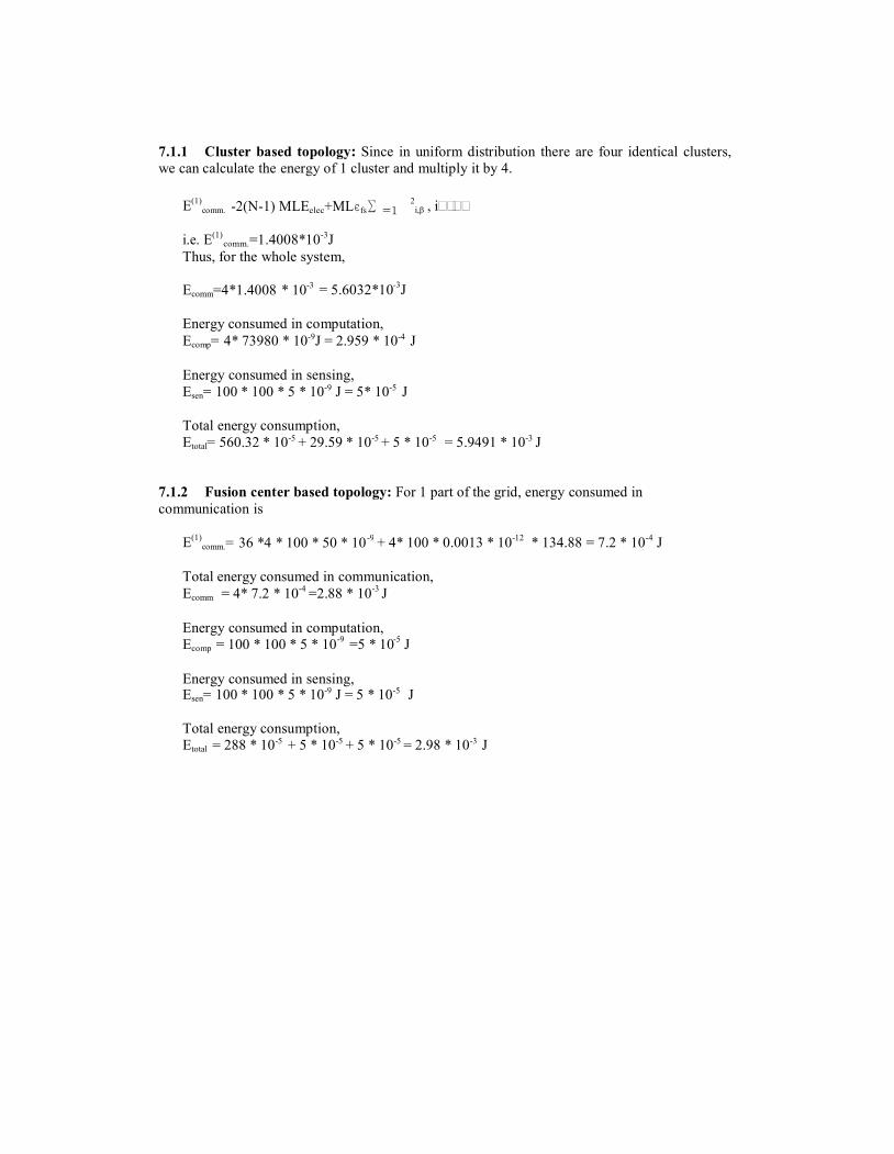
7.1.1 Cluster based topology: Since in uniform distribution there are four identical clusters,we can calculate the energy of 1 cluster and multiply it by 4.
E(1)comm. -2(N-1) MLEelec+MLєfs∑ =1 i,β , i≠β
i.e. E(1)comm.=1.4008*10-3J
Thus, for the whole system,
Ecomm=4*1.4008 * 10 = 5.6032*10-3J
Energy consumed in computation,Ecomp= 4* 73980 * 10-9J = 2.959 * 10-4 J
Energy consumed in sensing,Esen= 100 * 100 * 5 * 10-9 J = 5* 10-5 J
Total energy consumption,Etotal= 560.32 * 10-5 + 29.59 * 10-5 + 5 * 10-5 = 5.9491 * 10-3 J
7.1.2 Fusion center based topology: For 1 part of the grid, energy consumed incommunication is
E(1)comm.= 36 *4 * 100 * 50 * 10 + 4* 100 * 0.0013 * 10-12 * 134.88 = 7.2 * 10-4 J
Total energy consumed in communication,Ecomm = 4* 7.2 * 10-4 =2.88 * 10-3 J
Energy consumed in computation,-9 -5Ecomp = 100 * 100 * 5 * 10 =5 * 10 J
Energy consumed in sensing,Esen= 100 * 100 * 5 * 10-9 J = 5 * 10-5 J
Total energy consumption,Etotal = 288 * 10-5 + 5 * 10-5 + 5 * 10-5 = 2.98 * 10-3 J
NnN
Typewritten Text
International Journal of Distributed and Parallel Systems (IJDPS) Vol.3, No.5, September 2012
NnN
Typewritten Text
189

-5
-5
-5
7.2 Case 2: Random Distribution
Fig.10: sensors arranged in a random order in the grid.
7.2.1 Cluster based Topology:
The total energy consumption in communicationEcom = 2* 9 * 4 * 100 * 50 * 10-9 + 4 * 100 * 10 * 10-12 *53.380 J = 3.602 * 10-4 J
Total energy consumed in computationEcomp= [9 * 100 + 100 * 4 +16] * 5 * 10-9 J = 6.58 * 10-6 J
Total energy consumed in sensing,Esen = 10 * 100 * 5 * 10 = 5 * 10-2 J
Total energy consumptionEtotal= 360.2 * 10-6 +6.58 * 10-6 + 50000 * 10-6 = 5.0367 * 10-2 J
7.2.2 Fusion center based topology:
The total energy consumed in communication,Ecomm = 10 * 4 * 100 * 50 * 10-9 + 4 * 100 * .0013 * 10-12 * 3904.868 J = 2.0 * 10-4 J
The total energy consumed in computation,Ecomp = 10 * 100 * 5 * 10 = 5 * 10-2 J
The total energy consumed in sensing,Esen = 10 * 100 * 5 * 10 = 5 * 10-2 J
Total Energy Consuption,Etotal = .02 * 10-2 + 5 * 10-2 + 5 * 10-2 = .1 J
From the above calculations, it can be seen that in uniform distribution of sensors, fusion centerbased topology consumes less energy as compared to the cluster based topology. On the other
NnN
Typewritten Text
International Journal of Distributed and Parallel Systems (IJDPS) Vol.3, No.5, September 2012
NnN
Typewritten Text
190

hand, when the distribution of the sensors is random, cluster based topology gives better results ascompared to the fusion center based topology.
8. CONCLUSION
The presented paper provides a comparison of different topologies for the wireless sensornetwork. Cluster based topology and Fusion center based topology are used for the comparison.These topologies are compared on the basis of the two most important factors for a WSN i.e.lifetime and energy efficiency. From the above comparison, it is concluded that Fusion centerbased topology is more energy efficient in case of uniform distribution of sensors. On the otherhand, when the sensors are distributed randomly, cluster based topology proves to be moreefficient.
RELATEDWORK
1. Comparative Study of Wireless Sensor Networks Energy-Efficient Topologies and PowerSaver Protocols. Ewa Niewiadomska-Synkiewicz, Piotr Kwasniewski and IzabelaWindyga. Journal of Telecommunications and Information Technology, March 2009.
This paper addresses the issue of controlled data transmission in wireless sensor networks dueto limited power supply provider by batteries.
2. A Performance Comparison of Different Topologies for Wireless Sensor Networks.Shrestha, A. Technologies for Homeland Security, 2007 IEEE Conference on. Page(s): 280-285. 16-17 may 2007.
This paper compares various network topologies using performance criteria such as scalability,data-latency, network life, energy consumption, reliability etc. with main focus on reliabilitycomparison.
3. Developing Energy- Efficient Topologies and Routing for Wireless Sensor Networks. HuiTian, Hong Shen and Teruo Matsuzawa. Network and Parallel Computing, Lecture Notes inComputer Science, 2005, Vol. 3779/2005, 461-469.
This paper discusses and compares performance measures of different patterned topologies fordesigning wireless sensor networks so that required area coverage and connectivity can beachieved. A proposal for several routing protocols is also made for wireless sensor networks inthis paper.
REFERENCES
1. Impact of Topology on Performance and Energy Efficiency in Wireless Sensor Networks forSourceExtraction. Hongbin Chen, Chi K. Tse, and JiuchaoFeng. IEEE Transactions on ParallelAndDistributed Systems, Vol. 20, No. 6, June 2009
2. Strategies and techniques for node placement in wireless sensor networks: A survey.MohamedYounis, Kemal Akkaya. Adhoc Networks 6 (2008) 621–655
3. Handbook of Sensor Networks: Compact Wireless and Wired Sensing Systems CRC PRESSBocaRaton London New York Washington, D.C.
4. An Overview on Wireless Sensor Networks. Fabian Nack
5. G. Bell, “A time and a place for standards,” Queue, vol. 2, no. 6, pp. 66–74, 2004.
6. M. W. Chiang, Z. Zilic, J.-S. Chenard, and K. Radecka, “Architectures of increasedavailabilitywireless sensor network nodes,” Test Conference, International, vol. 0, pp. 1232–1241,2004.
NnN
Typewritten Text
International Journal of Distributed and Parallel Systems (IJDPS) Vol.3, No.5, September 2012
NnN
Typewritten Text
NnN
Typewritten Text
NnN
Typewritten Text
191

7. A. E. Kateeb, A. Ramesh, and L. Azzawi, “Wireless sensor nodes processor architecture anddesign”, Advanced Information Networking and Applications Workshops, InternationalConference on, vol. 0,pp. 892–897, 2008.
8. K. S. Low, H. A. Nguyen, and H. Guo, “Optimization of sensor node locations in a wirelesssensornetwork,” International Conference on Natural Computation, vol. 5, pp. 286–290, 2008.
9. M. A. Taleghan, A. Taherkordi, M. Sharifi, and T.-H. Kim, “A survey of system software forwirelesssensor networks,” Future Generation Communication and Networking, vol. 2, pp. 402–407, 2007
NnN
Typewritten Text
International Journal of Distributed and Parallel Systems (IJDPS) Vol.3, No.5, September 2012
NnN
Typewritten Text
192