Collapse analysis of masonry bridges taking into account arch–fill interaction
11
Engineering Structures 27 (2005) 605–615 www.elsevier.com/locate/engstruct Collapse analysis of masonry bridges taking into account arch–fill interaction Andrea Cavicchi, Luigi Gambarotta ∗ Department of Structural and Geotechnical Engineering, University of Genova, Via Montallegro, 1 - 16145 Genova, Italy Received 17 August 2004; received in revised form 7 December 2004; accepted 9 December 2004 Abstract Experimental collapse tests on full and model scale masonry bridges have shown that fill and spandrels can strongly affect the collapse behaviour and increase the load carrying capacity. To provide a structural description of the arch–fill interaction effects, a two-dimensional model of multi-span masonry bridges is developed in which arches and piers are described as beams made up of elastic, non-tensile resistant (NTR), ductile in compression material, and the fill as a Mohr–Coulomb material modified by a tension cut-off under plane strain conditions. The load carrying capacity is evaluated by a finite element limit analysis procedure based on the kinematic theorem. The fill domain is discretized by triangular elements connected by interface elements in order to allow possible velocity discontinuities at common sides of adjacent triangular elements; arches and piers are discretized by two-noded straight beam elements. By linearization of the limit domains in the generalized stress space, a linear programming problem is formulated and upper bounds of the collapse loads are obtained. Two examples are discussed, concerning a real single-span bridge, tested up to collapse, and a multi-span bridge. The ideal ductility assumption implicit in limit analysis is discussed by comparing the upper bound evaluations to the results obtained by incremental analysis in order to obtain the validity limits of the upper bound limit analysis for the proposed model. © 2005 Elsevier Ltd. All rights reserved. Keywords: Masonry bridges; Load carrying capacity; Arch–fill interaction; Limit analysis 1. Introduction Several models for predicting the load carrying capacity of masonry bridges have been developed either only considering the vaults, modelled as plane arches, or also including arch–pier interaction. In both cases the assumption of non-tensile resistant (NTR) material for masonry is made. The solving procedures can be divided into two large categories corresponding to incremental methods and limit analysis. The former can be referred to in Castigliano [1] and the latter in the works of Kooharian [2] and Heyman [3], who extended the plastic limit analysis theorems to structural systems under the hypothesis of a rigid non-tensile resistant constitutive material model. ∗ Corresponding author. Tel.: +39 010 353 2517; fax: +39 010 353 2534. E-mail address: [email protected] (L. Gambarotta). 0141-0296/$ - see front matter © 2005 Elsevier Ltd. All rights reserved. doi:10.1016/j.engstruct.2004.12.002 Experimental results obtained from collapse tests on full scale and model scale bridges [4,5] have shown the limits of the arch model for predicting the real behaviour of bridges, highlighting the strong influence of fill and spandrels on the collapse mechanism and the load carrying capacity. The growing need for assessing the real capacity of existing bridges has moved the research on to improving the above-mentioned methods in order to take into account the structural contribution of fill and spandrels. Structural modelling of the arch–fill interaction in mechanism analysis has been considered by Crisfield and Packam [6] and Hughes et al. [7], where the soil pressure is taken into account by applying additional horizontal forces to the arch; in the non- linear incremental FE models developed by Crisfield [8] and Choo et al. [9] the lateral response of the fill is modelled by one-dimensional horizontal elements having an elastic–ideal plastic constitutive equation with different responses at active and passive fill states.
-
Upload
independent -
Category
Documents
-
view
0 -
download
0
Transcript of Collapse analysis of masonry bridges taking into account arch–fill interaction

Engineering Structures 27 (2005) 605–615
www.elsevier.com/locate/engstruct
collapselnt.main is
omains inexamples
implicit inthe
Collapse analysis of masonry bridges taking into account arch–fillinteraction
Andrea Cavicchi, Luigi Gambarotta∗
Department of Structural and Geotechnical Engineering, University of Genova, Via Montallegro, 1 - 16145 Genova, Italy
Received 17 August 2004; received in revised form 7 December 2004; accepted 9 December 2004
Abstract
Experimental collapse tests on full and model scale masonry bridges have shown that fill and spandrels can strongly affect thebehaviour and increase the load carrying capacity. To provide a structural description of the arch–fill interaction effects, a two-dimensionamodel of multi-span masonry bridges is developed in which arches and piers are described as beams made up of elastic, non-tensile resista(NTR), ductile in compression material, and the fill as a Mohr–Coulomb material modified by a tension cut-off under plane strain conditionsThe load carryingcapacity is evaluated by a finite element limit analysis procedure based on the kinematic theorem. The fill dodiscretized by triangular elementsconnected by interface elements in order to allow possible velocity discontinuities at common sides ofadjacent triangular elements; arches and piers are discretized by two-noded straight beam elements. By linearization of the limit dthe generalized stress space, a linear programming problem is formulated and upper bounds of the collapse loads are obtained. Twoare discussed, concerning a real single-span bridge, tested up to collapse, and a multi-span bridge. The ideal ductility assumptionlimit analysis is discussed by comparing the upper bound evaluations to the results obtained by incremental analysis in order to obtainvalidity limits of the upper bound limit analysis for the proposed model.© 2005 Elsevier Ltd. All rights reserved.
Keywords: Masonry bridges; Load carrying capacity; Arch–fill interaction; Limit analysis
itynllsnisrgim
lan
on
dingcityinguntlis
byn-
1. Introduction
Several models for predicting the load carrying capacof masonry bridges have been developed either oconsidering the vaults, modelled as plane arches, or aincluding arch–pier interaction. In both cases the assumptioof non-tensile resistant (NTR) material for masonrymade. The solving procedures can be divided into two lacategories corresponding to incremental methods and lanalysis. The former can be referred to in Castigliano [1] andthe latter in the works of Kooharian [2] and Heyman [3], whoextended the plastic limit analysis theorems to structurasystems under the hypothesis of a rigid non-tensile resistconstitutive material model.
∗ Corresponding author. Tel.: +39 010 353 2517; fax: +39 010 353 2534E-mail address: [email protected] (L. Gambarotta).
0141-0296/$ - see front matter © 2005 Elsevier Ltd. All rights reserved.doi:10.1016/j.engstruct.2004.12.002
yealat
yo
eit
t
.
Experimental results obtained from collapse testsfull scale and model scale bridges [4,5] have shown thelimits of the arch model for predicting the real behaviourof bridges, highlighting the strong influence of fill anspandrels on the collapse mechanism and the load carrycapacity. The growing need for assessing the real capaof existing bridges has moved the research on to improvthe above-mentioned methods in order to take into accothe structural contribution of fill and spandrels. Structuramodelling of the arch–fill interaction in mechanism analyshas been considered by Crisfield and Packam [6] and Hugheset al. [7], where the soil pressure is taken into accountapplying additional horizontal forces to the arch; in the nolinear incremental FE models developed by Crisfield [8] andChoo et al. [9] the lateral response of the fill is modelled bone-dimensional horizontal elements having an elastic–idplastic constitutive equation with different responsesactive and passive fill states.

606 A. Cavicchi, L. Gambarotta / Engineering Structures 27 (2005) 605–615
isll
na
ans.eb
c
the
eniveta
sthe
redlea
oteav
nterthl
erthitsal.ns
rentso-
hil
artio
ts
tor
e,he
ulte
;
acte
ngdhehe
ss
ye
In this paper a numerical procedure for the limit analysof multi-span masonry bridges including the arch–fiinteraction is developed on the basis of the kinematictheorem. The procedure is based on a two-dimensiofinite element discretization of the masonry bridge [10].Arches and piers are modelled as plane beamsthe fill as a continuum under plane strain conditionThe fill is discretized by triangular elements and tharches and piers by two-noded beams characterizedtwo generalized hinges at the ends; four-noded interfaelements connect adjacent triangular elements in order toallow localized strains along their edges, according toSloan and Kleeman approach [11]. Interface elements arealso applied to allow displacement discontinuities betwethe fill and the arches at the extrados. The constitutmodel assumed for arches and piers is non-tensile resis(NTR) and ductile in compression, while the fill imodelled as a cohesive–frictional material according toMohr–Coulomb hypothesis with tension cut-off.
In order to evaluate the capability of the method foproviding realistic results, a first example is discusssimulating a collapse test conducted on an existing singspan bridge [12]. The second example concerns a three-spbridge in which the suitability of the method for taking intaccount complex interactions between the arch–pier sysand the fill is shown. The results obtained by assuming heand resistant fill are comparedwith the results obtained byassuming heavy but not resistant fill. This comparison poiout the effect of the fill resistance on the collapse multipliand the corresponding collapse mechanism. Moreover,dependence of the load carrying capacity on the mechanicaparameters of the fill and of the masonry is analysed.
The appreciable increase of the load carrying capacityprovided by the fill corresponds to a different and highdemand for the arch strength resources. In particular,increased exploitation of the masonry strength withbrittleness may turn out to be incompatible with the ideductility assumption implicit in the limit analysis theoremsIn order to check this eventuality, in both examples aincremental analysis of the models is developed that allowus to check the ductility demand corresponding to thecollapse mechanisms.
2. Structural model of the masonry bridge
Principal components of a typical masonry bridge avaults, piers, haunchings, fill and spandrels, as shown iFig. 1(a). With the aim of getting the most relevant effecof vault–fill interaction, in the present analysis a simple twdimensional model is assumed (Fig. 1(b)) which considersthe vaults, the piers and the fill as the resistant system, wit neglects the strengthening effect of the spandrels.
The fill is represented by the two-dimensional domainΩ f
under the hypothesis of plane strain. Vaults and piersmodelled as plane beams having rectangular cross secthe i -th beam occupies the two-dimensional regionΩ i
b
l
d
ye
nt
-n
my
s
e
e
e
en;
and is represented by its centrelineL i . The plane strainassumption for the fill implies the displacementu(x) =u1(x) u2(x)T at a point x = x1 x2T ∈ Ω f to becontained in the plane(O, x1, x2) of the reference system,and the strainε f (x) = ε11 ε22 γ12T to be represented bythe in-plane components.
The displacements of points on a section of vauland piers having the centroid located at pointx ∈ L i
depend on the displacementu(x) of the centroid andon the section rotation ϕ(x). Within the Euler–Bernoullihypothesis, the generalized strain is represented by vecεb(x) = εa χT , εa being the axial strain at the centroidand χ the curvature. If a local reference frame(t, n) isintroduced,t being the tangent andn theunit vectors normalto L i , the axial strain at the fibre on sectionx at a distancey from x along the unit vectorn is ε(x, y) = εa(x) − yχ(x).The piers are commonly considered built in at the baswhile the connection between the vault springings and ttop of the piers is assumed rigid.
Moreover, displacement discontinuities between the vaextrados and the fill are allowed. With reference to thi -th beam section having the centroid atx, the correspondingpoint at the extradosI i is x∗ = x + h
2n, h being the beamsection depth; the displacement jump atx∗ is [[u(x∗)]] =u f (x∗) − ub(x∗), u f (x∗) being the displacement of the filland ub(x∗) = u(x) − ϕ(x) h
2t(x) the displacement at theextrados, which depends on the displacementu(x) and onthe rotationϕ(x) at sectionx. In the following, the normal[[un(x∗)]] = nT [[u(x∗)]] and the tangential[[ut (x∗)]] =tT [[u(x∗)]] components of the velocity jump are collected inthe strain vector of the interfaceεI (x) = [[un]] [[ut ]]T ,x ∈ I i .
The loads applied to the fill are the body forceb(x),x ∈ Ω f , representative of the weight per unit area of thefill, and the line forcep(x), x ∈ ∂Ω f , defined over the upperboundary∂Ω f corresponding to the free surface of the fillp(x) is expressed asp(x) = sp(x), p(x) being a referenceload ands a load multiplier. The stress field in the fillΩ f is represented by the vectorσ f (x) = σ11 σ22 τ12T
of the independent stress components. Line tractionson the fill through the interfaces at the extrados of thvaults, representedby the normalσn and the tangentialτn component in the local reference(t, n) collected in theinterface stress vectorσI (x) = σn τ T , x ∈ I i . Vaultsand piers are subjected to external line forcesbb(x), x ∈L i , referred to the centroid of the section and representithe weight of the beam per unit length; externally appliecouples are ignored. Line tractions and couples act on tarches as an effect of the line tractions applied through textrados interface bythe fill. Internal forces in arches andpiers are represented by the axialN , shearT and bendingMstress resultants referred to points of the beam centrelineL .From the Euler–Bernoulli hypothesis the generalized strevectorσ b(x) = N MT at sectionx ∈ L is defined.
The fill is assumed isotropic linear elastic–perfectlplastic having a yielding function corresponding to th

A. Cavicchi, L. Gambarotta / Engineering Structures 27 (2005) 605–615 607
Fig. 1. (a) The bridge and its components;(b) the structural model of the bridge.
onehe
alin
s ih
ytisicninis
tin
ase
he
fionion
Mohr–Coulomb criterion under the plane strain assumptiand modified by introducing a tension cut-off. ThMohr–Coulomb admissible domain is expressed by tinequality
fc(σ f )=√
(σ11 − σ22)2 + 4τ212 + (σ11 + σ22) sinϕ
− 2c cosϕ ≤ 0, (1)
c and ϕ being the cohesion and the angle of internfriction, respectively. The tension cut-off admissible domais expressed by the inequality
ft (σ f )=√
(σ11 − σ22)2 + 4τ212 + (σ11 + σ22) − 2σt
≤ 0 (2)
whereσt is the largest traction admitted.In analogy, the displacement jump across the interface
ruled by the Coulomb admissible domain expressed by tinequality
fc(σI ) = |τ | + σn tanϕ − c ≤ 0, (3)
together with the tension cut-off condition
ft (σI ) = σn − σt ≤ 0. (4)
The constitutive model of vaults and piers is obtained bassuming vanishing tensile resistance of the mortar joinorthogonal to the centreline of the vaults and piers. Thfollows the constitutive model of the beam section as elastnon-tensile resistant (NTR) and ductile in compressio(σc denotes the masonry compressive strength). Withthe Euler–Bernoulli hypothesis, the constitutive modelexpressed in terms of internal forcesN and M, the axialstrainεa and the curvatureχ and is described by assumingmonotonically increasing applied forces. Four differenstates can be recognized for the beam section, correspondto the A, B, C and Dregions shown inFig. 2(b). Region Adefines elastic states for whichM = E Jχ , N = E Aεa, E , Jand A being, respectively, the Young modulus, the centroidmoment of inertia and the area of the section. The strestates in region B define a partially cracked section with thcompressed part still elastic; this region is defined by t
se
s
,
g
ls
Fig. 2. (a) The Mohr–Coulomb limit domain modified by tension cut-ofunder the plane strain assumption; (b) the limit domain of the beam sectunder the hypothesis of elastic, non-tensile resistant, plastic in compressbehaviour.
limits
−2
3
N
Np≤ |M|
Mp≤ −2N
Np
(1 + 4
3
N
Np
), −1
2≤ N
Np≤ 0,
whereNp = hb|σc| andMp = 14bh2|σc|; the corresponding
constitutive equation at fixed axial force is
|M|Mp
= −2N
Np
(1 − 2
3
√−1
6
Nh
|Me(χ)|
), (5)
where Me(χ) = E Jχ . Region C, whichis symmetric toregion B with respect to axis N
Np= −1
2 and is defined by thelimits
−2
3
N
Np≤ |M|
Mp≤ −2N
Np
(1 + 4
3
N
Np
), −1 ≤ N
Np≤ −1
2
608 A. Cavicchi, L. Gambarotta / Engineering Structures 27 (2005) 605–615
ge.
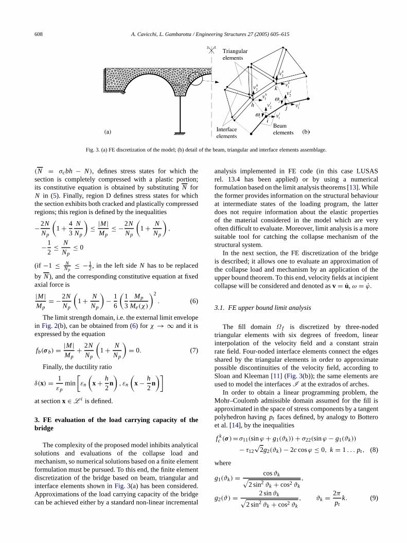
Fig. 3. (a) FE discretization of the model; (b) detail of the beam, triangular and interface elements assembla;
he
d
e
l
tnn.et
Sal
rteresry
e
fhent
arngeste
o
eisent
(N = σcbh − N), defines stress states for which thesection is completely compressed with a plastic portionits constitutive equation is obtained by substitutingN forN in (5). Finally, region D defines stress states for whicthe section exhibits both cracked and plastically compressregions; this region is defined by the inequalities
−2N
Np
(1 + 4
3
N
Np
)≤ |M|
Mp≤ −2N
Np
(1 + N
Np
),
−1
2≤ N
Np≤ 0
(if −1 ≤ NNp
≤ −12, in the left side N has to be replaced
by N ), and the corresponding constitutive equation at fixeaxial force is
|M|Mp
= −2N
Np
(1 + N
Np
)− 1
6
(1
3
Mp
Me(χ)
)2
. (6)
The limit strength domain, i.e. the external limit envelopin Fig. 2(b), can be obtained from (6) for χ → ∞ and it isexpressed by the equation
fb(σ b) = |M|Mp
+ 2N
Np
(1 + N
Np
)= 0. (7)
Finally, the ductility ratio
δ(x) = 1
εpmin
[εn
(x + h
2n)
, εn
(x − h
2n)]
at sectionx ∈ L i is defined.
3. FE evaluation of the load carrying capacity of thebridge
The complexity of the proposed model inhibits analyticasolutions and evaluationsof the collapse load andmechanism, so numerical solutions based on a finite elemenformulation must be pursued. To this end, the finite elemediscretization of the bridge based on beam, triangular ainterface elements shown inFig. 3(a) has been consideredApproximations of the load carrying capacity of the bridgcan be achieved either by a standard non-linear incremen
d
td
al
analysis implemented in FE code (in this case LUSArel. 13.4 has been applied) or by using a numericformulation based on thelimit analysis theorems [13]. Whilethe former provides information on the structural behaviouat intermediate states of the loading program, the latdoes not require information about the elastic propertiof the material considered in the model which are veoften difficult to evaluate. Moreover, limit analysis is a moresuitable tool for catching the collapse mechanism of thstructural system.
In the next section, the FE discretization of the bridgeis described; it allows one to evaluate an approximation othe collapse load and mechanism by an application of tupper bound theorem. To this end, velocity fields at incipiecollapse will be considered and denoted asv = u, ω = ϕ.
3.1. FE upper bound limit analysis
The fill domain Ω f is discretized by three-nodedtriangular elements with six degrees of freedom, lineinterpolation of the velocity field and a constant strairate field. Four-noded interface elements connect the edshared by the triangular elements in order to approximapossible discontinuities of the velocity field, according tSloan and Kleeman [11] (Fig. 3(b)); the same elements areused to model the interfacesI at the extrados of arches.
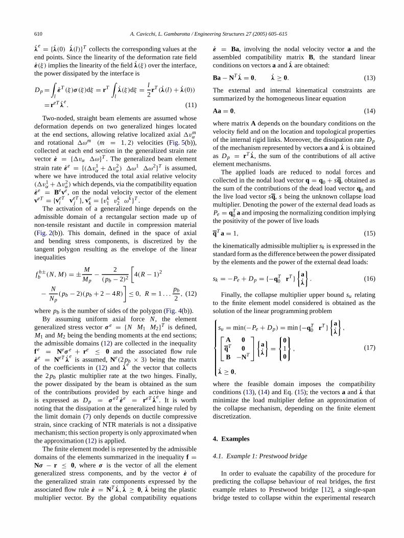
In order to obtain a linear programming problem, thMohr–Coulomb admissible domain assumed for the fillapproximated in the space of stress components by a tangpolyhedron havingpt faces defined, by analogy to Botteroet al. [14], by the inequalities
f kc (σ )=σ11(sinϕ + g1(ϑk)) + σ22(sinϕ − g1(ϑk))
− τ12√
2g2(ϑk) − 2c cosϕ ≤ 0, k = 1 . . . pt , (8)
where
g1(ϑk) = cosϑk√2 sin2 ϑk + cos2 ϑk
,
g2(ϑ) = 2 sinϑk√2 sin2 ϑk + cos2 ϑk
, ϑk = 2π
ptk. (9)

A. Cavicchi, L. Gambarotta / Engineering Structures 27 (2005) 605–615 609
no
rny
te
ticset.
or
e
eetnts
ng
e
y
nd
l
ed
e,
nd
Fig. 4. Piecewiselinearization of the admissible domains: (a) fill(pt = 8);(b) generalized hinges(pb = 6).
Analogously, the domain corresponding to the tensiocut-off condition is linearized by a polyhedron tangent tthe original domain havingpt faces, defined by the linearinequalities
f kt (σ )=σ11(1 + g1(ϑk)) + σ22(1 − g1(ϑk))
− τ12√
2g2(ϑk) − 2σt ≤ 0, k = 1 . . . pt . (10)
The resulting admissible domain in the stress space tuout to be the intersection of the polyhedra defined binequalities (8) and (10), as shown inFig. 4(a).
In order to apply the upper bound theorem, the associaflow rule is assumed. The uniform discrete strain rate fieldassumed in the triangular elements implies a uniform plasflow through the element domain, that allows one to impothe flow rule only at a point of each triangular elemenInequalities (8) and (10) are prescribed over the element,so the yielding admissibility conditions are collected inthe matrix form fe = Neσ e − re ≤ 0, from whichthe flow rule εe = NeT λ
efollows, Ne(2pt × 3) being
the matrix that collects the coefficients of the Eqs. (8)and (10) corresponding to the generalized stress vectσ e = Aeσ11 σ22 τ12T , (Ae is the element area),εe =ε11 ε22 γ12T the element strain rate vectors andλ the(2pt × 1) plastic multiplier vector. As a consequence, thpower dissipated by the element isDe
p = reT λ.The interface elements have four nodes and eight degr
of freedom (Fig. 5(a)). The two faces of the elemencorrespond to the edges of the two triangular elemeconnected by the interface. The velocity field at each elementface is obtained by linear interpolation of the correspondi
s
d
s
Fig. 5. (a) The interface element; (b) the beam element.
nodal velocities, in order to maintain compatibility with thevelocity field of triangular elements. The nodal velocities arcollected in the vectorve = ve
i vej ve
h vekT , whereve
q =vq
1 vq2T (q = 1 . . .4) andv
q1 andv
q2 are the nodal velocity
components of theq-th element node. The element velocitfield is described by thevectorvT (ξ) = v+T (ξ) v−T (ξ),v±(ξ) = v±
n v±t T , where subscripts n and t denote the
components in the local coordinate system, normal atangent to the interface, respectively, superscripts+ and− refer to the element faces andξ is a local coordinate(Fig. 5(a)).
Local strain is described by the velocity jumpε(ξ) =[[vn(ξ)]] [[vt (ξ)]]T , where [[vn(ξ)]] = v+
n (ξ) − v−n (ξ)
and [[vt (ξ)]] = v+t (ξ) − v−
t (ξ), and depends on the nodavelocities via the compatibility equationε(ξ) = B(ξ)ve.The linearity of the generalized strain rate field allows thcompatibility equations to be imposed only at the two enpoints of the element; defined byεe = ε(0) ε(l)T andBe = diag[B(0) B(l)], l being the interface length, theelement compatibility equation is expressed asεe = Beve.
Defining the interface stress vectorσ (ξ) = σn(ξ) τ (ξ)T,collecting the resolved normalσn(ξ) and tangentialτn(ξ)
stresses, the Coulomb admissible domain (3), expressed astwo linear equationsf1,2(σ ) = ±τ + σn tanϕ − c ≤ 0,and the tension cut-off condition (4) can be summarizedin the local inequalityf(σ (ξ)) = Nσ (ξ) − r ≤ 0. Thiscondition is specified at the end points of the interfacso yielding the element admissible domain asfe(σ e) =Neσ e − re ≤ 0, whereσ e = l
2σn(0) τn(0) σn(l) τn(l)T ,with Ne = 2
l diag[ N N ] the (6×4) matrix of the vectornormal to the faces of the limit domain andreT = rT rT .The corresponding associated flow rules areε(ξ) = NT λ(ξ)
and εe = NeT λe, respectively, where the vectorλ(ξ)
represents the plastic multiplier rate field at the interface a
610 A. Cavicchi, L. Gambarotta / Engineering Structures 27 (2005) 605–615
eld
ote
rat
itynt
tho
riaalth
ea
ns
e
,m
d
beivee
ib
t
th
s
re
es
nd
as
ted:
ty
f
rst
h
λe = λ(0) λ(l)T collects the corresponding values at th
end points. Since the linearity of the deformation rate fieε(ξ) implies the linearity of the fieldλ(ξ) over the interface,the power dissipated by the interface is
Dp =∫
lεT (ξ)σ (ξ)dξ = rT
∫lλ(ξ)dξ = l
2rT (λ(l) + λ(0))
= reT λe. (11)
Two-noded, straight beam elements are assumed whdeformation depends on two generalized hinges locaat the end sections, allowing relative localized axial vm
α
and rotational ωm (m = 1, 2) velocities (Fig. 5(b)),collected at each end section in the generalized strainvector ε = vα ωT . The generalized beam elemenstrain rate εe = ( v1
α + v2α) ω1 ω2T is assumed,
where we have introduced the total axial relative veloc( v1
α + v2α) which depends, via the compatibility equatio
εe = Beve, on the nodal velocity vector of the elemenveT = veT
i veTj , ve
k = vk1 vk
2 ωkT .The activation of a generalized hinge depends on
admissible domain of a rectangular section made upnon-tensile resistant and ductile in compression mate(Fig. 2(b)). This domain, defined in the space of axiand bending stress components, is discretized bytangent polygon resulting as the envelope of the lininequalities
f h±b (N, M) = ± M
Mp− 2
(pb − 2)2
[4(R − 1)2
− N
Np(pb − 2)(pb + 2 − 4R)
]≤ 0, R = 1 . . .
pb
2, (12)
wherepb is thenumber of sides of the polygon (Fig. 4(b)).By assuming uniform axial force N , the element
generalized stress vectorσ e = N M1 M2T is defined,M1 andM2 being the bending moments at the end sectiothe admissibledomains (12) are collected in the inequalityfe = Neσ e + re ≤ 0 and the associated flow rulεe = NeT λ
eis assumed,Ne(2pb × 3) being thematrix
of the coefficients in (12) and λe
the vector that collectsthe 2pb plastic multiplier rate at the two hinges. Finallythe power dissipated by the beam is obtained as the suof the contributions provided by each active hinge anis expressed asDp = σ eT εe = reT λ
e. It is worth
noting that the dissipation at the generalized hinge ruledthe limit domain (7) only depends on ductile compressivstrain, since cracking of NTR materials is not a dissipatmechanism; this section property is only approximated whthe approximation (12) is applied.
The finite element model is represented by the admissdomains of the elements summarized in the inequalityf =Nσ − r ≤ 0, whereσ is the vector of all the elemengeneralized stress components, and by the vectorε ofthe generalized strain rate components expressed byassociated flow ruleε = NT λ, λ ≥ 0, λ being the plasticmultiplier vector. By the global compatibility equation
sed
te
efl
er
;
y
n
le
e
ε = Ba, involving the nodal velocity vectora and theassembled compatibility matrixB, the standard linearconditions on vectorsa andλ are obtained:
Ba − NT λ = 0, λ ≥ 0. (13)
The external and internal kinematical constraints asummarized by the homogeneous linear equation
Aa = 0, (14)
where matrixA depends on the boundary conditions on thvelocity field and on the location and topological propertieof the internal rigid links. Moreover, the dissipation rateDp
of the mechanism represented by vectorsa andλ is obtainedas Dp = rT λ, the sum of the contributions of all activeelement mechanisms.
The applied loads are reduced to nodal forces acollected in the nodal load vectorq = q0 + sq, obtained asthe sumof the contributions of the dead load vectorq0 andthe live load vectorsq, s being the unknown collapse loadmultiplier. Denoting the power of the external dead loadsPe = qT
0 a and imposing the normalizing condition implyingthe positivity of the power of live loads
qT a = 1, (15)
the kinematically admissible multipliersk is expressed in thestandard form as the difference between the power dissipaby the elements and the power of the external dead loads
sk = −Pe + Dp = −qT0 rT
aλ
. (16)
Finally, the collapse multiplier upper boundsu relatingto the finite element model considered is obtained as thesolution of the linearprogramming problem
su = min(−Pe + Dp) = min−qT0 rT
aλ
,
A 0qT 0B −NT
a
λ
=
010
,
λ ≥ 0,
(17)
where the feasible domain imposes the compatibiliconditions (13), (14) and Eq. (15); the vectorsa andλ thatminimize the load multiplier define an approximation othe collapse mechanism, depending on the finite elementdiscretization.
4. Examples
4.1. Example 1: Prestwood bridge
In order to evaluate the capability of the procedure fopredicting the collapse behaviour of real bridges, the firexample relates to Prestwood bridge [12], a single-spanbridge tested to collapse within the experimental researc

A. Cavicchi, L. Gambarotta / Engineering Structures 27 (2005) 605–615 611
Fig. 6. Geometry of the model (mm).
rc
l
is
e
hee
ad
eg
a
an
idsmle
tho
s
g
ofg
ng
ah;
ofby
oms
n)perds
d
is
geod
ing
on masonry bridges supported by the Transport ReseaLaboratory (TRL).
The vault shape, having span = 6550 mm andupper rise f = 1428 mm, is distorted from the originallysegmental shape. The vault thickness ishs = 220 mm andcomprises asingle ring of bricks laid as headers; the fildepth at the crown ishr = 165 mm and the total bridgewidth is 3800 mm. The live load wasb = 300 mm wide andwas applied across thebridge at quarter-span (Fig. 6). Thefill density is γ f = 20 kN/m3 and the masonry density isγm = 20 kN/m3.
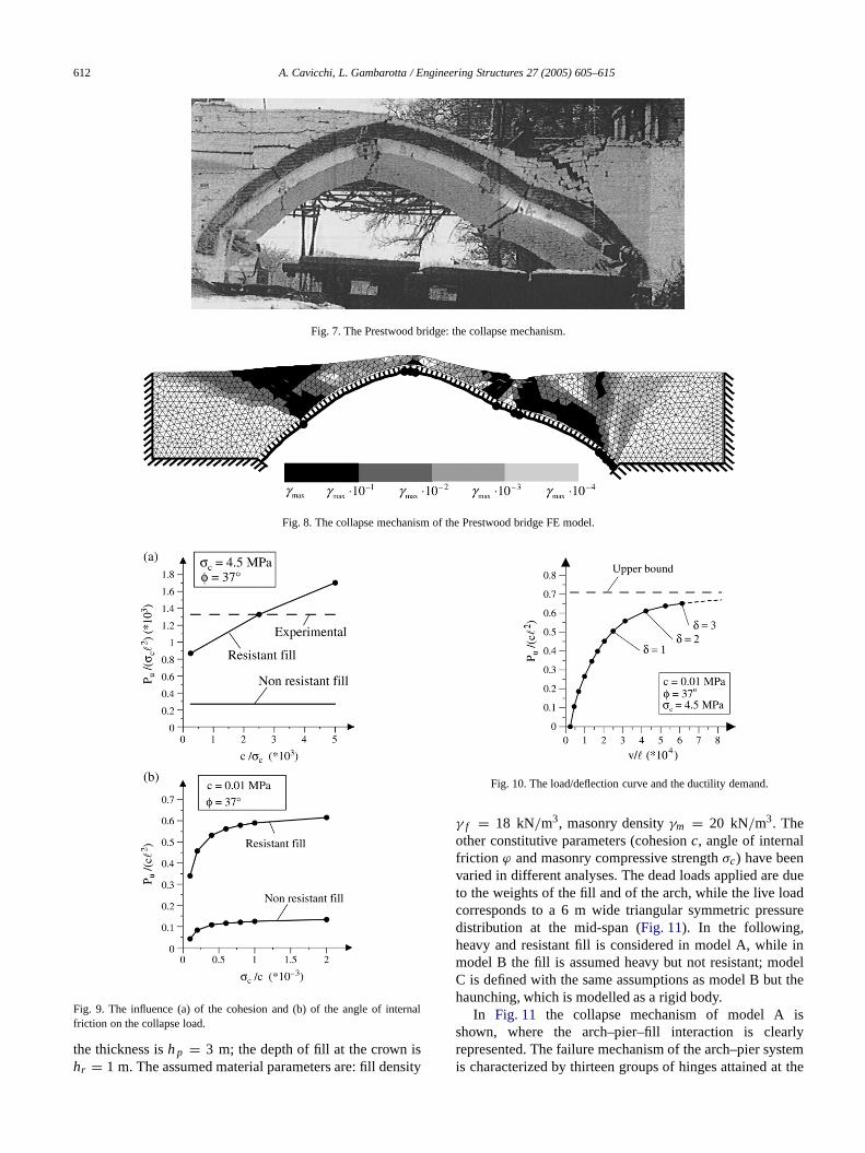
The experimental collapse mechanism of the bridgeshown in Fig. 7. The vault collapse mechanism exhibitsfour hinges that are clearly visible in the picture; thmechanism developed with negligible material crushing.The arch mechanism constrains the fill region under tapplied load to move downward and the fill at the other sidof the bridge to move upward; the experimental collapse lowasPexp = 228 kN.
In Fig. 8 the collapse mechanism resulting from thnumerical limit analysis is shown, obtained by assumincompressive strengthσc = 4.5 MPa for the arch masonryand angle of internal frictionϕ = 37 (see Ref. [4]) andcohesionc = 10 kPa for the fill. The small black circles onthe arch ring represent the active hinges, while the greyscin the fill domain denotes different values of the ratiosbetween the principal shear strain rate at each elementthe maximum in the fill.
As in the experimental test, in the numerical collapsemechanism four groups of hinges develop. The loaded sof the arch moves downward, and the arch mechanipushes the left side; as a consequence, the fill over theside is movedupward. The first hinge on the left side of thearch does not develop at the springing, as happens inarch where the fill is heavy but not resistant; the presencethe fill constrains the hingeto move upward. This behaviouragrees with the experimental result shown inFig. 7.
The diagrams inFig. 9(a), obtained by assuming aninternal friction angleϕ = 37 and a compressive strengthof the archσc = 4.5 MPa, show the influenceof the fillcohesionc on the collapse load; the lower line correspondto the valueobtained assuming no resistant fill,Pu =46.2 kN. Assuming c = 1 kPa, thecollapse load is
h
le
d
e
ft
ef
Pu = 149.1 kN, about 65% of the experimental valuePexp = 228 kN, which is obtained numerically assuminc = 10 kPa. The diagrams inFig. 9(b), obtained assumingthe internal friction angleϕ = 37 and cohesionc =10 kPa, show the influence of the compressive strengththe arch on the collapse load; the value obtained assuminunlimited compressive strength isPu = 267.9 kN, whichis about 17% higher than the value obtained assumiσc = 4.5 MPa, Pu = 228.0 kN; the corresponding valuesobtained assuming no resistant fill arePu = 57 kN andPu = 46.2 kN respectively.
The strengthening effects of the fill correspond tohigher exploitation of the strength resources of the arcin particular, the development of the collapse mechanismpredicted by the limit analysis requires the developmentplastic compressive strains higher than those predictedsimplified models without fill resistance that could be nlonger consistent with the masonry behaviour. The diagrain Fig. 10 show the load–deflection curve (referred to thevertical displacement of the section at the load positioobtained by the incremental analysis, compared to the upbound obtained by limit analysis; the different collapse loacorresponding to different ductilityδ valuesare shown. Theresults are obtained by assumingσc = 4.5 MPa,c = 10 kPaandϕ = 37; the elastic moduli assumed for masonry anfill in the incremental analysis areEm = 15 000 MPa andE f = 300 MPa, respectively.
The section of the arch that first reaches the compressiveelastic limit is located under the area where the loadapplied; the corresponding load step is indicated byδ = 1in the diagram ofFig. 10. Thedifference between the resultsprovided by the incremental analysis withδ ≤ 2 and theupper bound estimated from limit analysis is about 13%.
In this case the effect of a limitation of ductility on thedevelopment of the collapse mechanism is limited. Thisresult agrees with the experimental behaviour of the bridand shows that limit analysis can be applied with a goapproximation.
4.2. Example 2: A multi-span bridge
The second example relates to a three-span bridge havcircular arches, thicknesshs = 1 m, span = 14 m and spanto rise ratiof/ = 2. The height of the piers ish = 10 m and
612 A. Cavicchi, L. Gambarotta / Engineering Structures 27 (2005) 605–615
Fig. 7. The Prestwood bridge: the collapse mechanism.
Fig. 8. The collapse mechanism of the Prestwood bridge FE model.
ue
re
el
the
Fig. 9. The influence (a) of the cohesion and (b) of the angle of internalfriction on the collapse load.
the thickness ish p = 3 m; thedepth of fill atthe crown ishr = 1 m. The assumed material parameters are: fill density
Fig. 10. The load/deflection curve and the ductility demand.
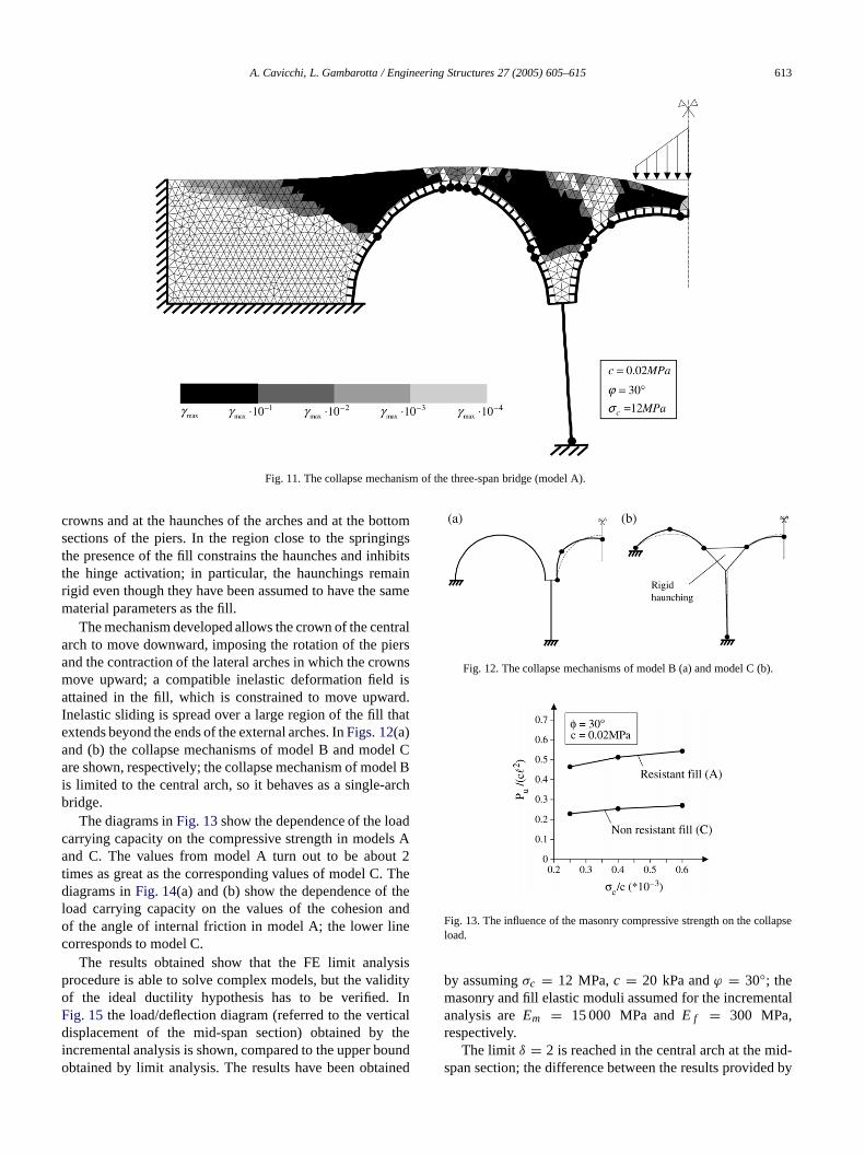
γ f = 18 kN/m3, masonry densityγm = 20 kN/m3. Theother constitutive parameters (cohesionc, angle of internalfriction ϕ and masonry compressive strengthσc) have beenvaried in different analyses. The dead loads applied are dto the weights of the fill and of the arch, while the live loadcorresponds to a 6 m wide triangular symmetric pressudistribution at the mid-span (Fig. 11). In the following,heavy and resistant fill is considered in model A, while inmodel B the fill is assumed heavy but not resistant; modC is defined with the same assumptions as model B but thehaunching, which is modelled as a rigid body.
In Fig. 11 the collapse mechanism of model A isshown, where the arch–pier–fill interaction is clearlyrepresented. The failure mechanism of the arch–pier systemis characterized by thirteen groups of hinges attained at
A. Cavicchi, L. Gambarotta / Engineering Structures 27 (2005) 605–615 613
Fig. 11. The collapse mechanism of the three-span bridge (model A).
ttostsnam
rsn
d.t
l Cl
A2
Then
isity
l
une
e
tal
by
crowns and at the haunches of the arches and at the bosections of the piers. In the region close to the springingthe presence of the fill constrains the haunches and inhibithe hinge activation; in particular, the haunchings remairigid even though they have been assumed to have the smaterial parameters as the fill.
The mechanism developed allows the crown of the centralarch to move downward, imposing the rotation of the pieand the contraction of the lateral arches in which the crowmove upward; a compatible inelastic deformation field isattained in the fill, which is constrained to move upwarInelastic sliding is spread over a large region of the fill thaextends beyond the ends of the external arches. InFigs. 12(a)and (b) the collapse mechanisms of model B and modeare shown, respectively; the collapse mechanism of modeis limited to the central arch, so it behaves as a single-archbridge.
The diagrams inFig. 13show the dependence of the loadcarrying capacity on the compressive strength in modelsand C. The values from model A turn out to be abouttimes as great as the corresponding values of model C.diagrams inFig. 14(a) and (b) show the dependence of thload carrying capacity on the values of the cohesion aof the angle of internal friction in model A; the lower linecorresponds to model C.
The results obtained show that the FE limit analysprocedure is able to solve complex models, but the validof the ideal ductility hypothesis has to be verified. InFig. 15 the load/deflection diagram (referred to the verticadisplacement of the mid-span section) obtained by theincremental analysis is shown, compared to the upper boobtained by limit analysis. The results have been obtain
m
e
s
B
e
d
dd
Fig. 12. The collapse mechanisms of model B (a) and model C (b).
Fig. 13. The influence of the masonry compressive strength on the collapsload.
by assumingσc = 12 MPa,c = 20 kPa andϕ = 30; themasonry and fill elastic moduli assumed for the incremenanalysis areEm = 15 000 MPa andE f = 300 MPa,respectively.
The limit δ = 2 is reached in the centralarch at the mid-span section; the difference between the results provided

614 A. Cavicchi, L. Gambarotta / Engineering Structures 27 (2005) 605–615
reo
neeEe
alonne
aelshel
netse
ntsheingrybee.nteds
salt
geeirnt
he
he
ses
on:
e
6;2:
O;
iv
e
Fig. 14. The influence of the cohesion (a) andof the angle of internal friction(b) of the fill on the collapse load.
the incremental analysis withδ ≤ 2 and the upper boundestimated from limit analysis is about 9%.
5. Conclusions
The structural model and the numerical proceduproposed here, which is based on the kinematic theoremlimit analysis, provide upper bounds of the collapse load athe corresponding collapse mechanisms of masonry bridgtaking into account arch–fill interaction. Two examples arconsidered in order to show the capabilities of the Fapproach and the strong influence of the fill on the bridgstrength. In particular, the first example concerning a rebridge tested to collapse has provided a good simulatiof the experimental results. The second example relatito a multi-span bridge has shown the capability of thprocedure for representing thecomplex interaction betweenpiers, arches and fill at collapse. The effectof a limitationof the masonry ductility has been analysed by developingreference incremental analysis of both the example moddescribed. The results obtained show that the collapmechanisms can develop almost completely even if tductility is limited, demonstrating that limit analysis can stilbe used successfully.
The approximations introduced have allowed us to defia simplified model able to describe some relevant aspecof the arch–fill interaction requiring less cumbersom
fds
g
se
Fig. 15. The load/deflection curve and ductility demand.
numerical analysis. On the other hand, the model presesome limitations that have to be taken into account. Tplane strain assumption for the fill corresponds to assumthe spandrels to be providing perfect smooth boundaconditions; the effects of this assumptions have toevaluated and depend on the geometry of the bridgMoreover, a more realistic description of the developmeof passive and active fill pressures at the arch extrados neto take account of different corresponding displacementthat are larger in the latter case. Finally, the numericrepresentation of discontinuities in the velocity field thacharacterizes the solutionsof collapse problems assuminperfect plasticity is still an open problem; the interfacelements used allow discontinuities to develop but thdirections are arbitrarily fixed by the triangular elemeshape.
Acknowledgement
The authors acknowledge financial support of t(MURST) Italian Department for University and Scientificand Technological Research in the framework of tresearch project PRIN 2002/2003 “Safety and Control ofMasonry Bridges”.
References
[1] Castigliano CAP. Theorie de l’equilibre des systemes elastiques etapplications. Torino: Augusto Federico Negro; 1879;Andrews ES. Elastic stresses in structures [Andrews Trans.]. LondScott Greenwood & Son; 1919.
[2] Kooharian A. Limit analysis of Voussoir (segmental) and concretarches. Proc Am Concr Inst 1953;89:317–28.
[3] Heyman J. The stone skeleton. Internat J Solids Structures 196249–79.
[4] Page J. Masonry arch bridges—TRL state of the art review. HMS1993.
[5] Royles R, Hendry AW. Model tests on masonry arches. Proc Inst CEng, Part 2 1991;91:299–321.
[6] Crisfield MA, Packam AJ. A mechanism program for computing thstrength of masonry arch bridges. Research report 124. Crowthorne:Transport Research Laboratory; 1985.
A. Cavicchi, L. Gambarotta / Engineering Structures 27 (2005) 605–615 615
auc
is
ry
tà
.
n,rt,
r:
nds
[7] Hughes TG, Hee SC, Soms E. Mechanism analysis of single spmasonry arch bridges using a spreadsheet. Proc Inst Civ Eng StrBuild 2002;152:341–50.
[8] Crisfield MA. Finite element and mechanism methods for the analysof masonry and brickwork arches,Research report 19. Crowthorne:Transport Research Laboratory; 1985.
[9] Choo BS, Coutie MG, Gong NG. Finite element analysis of masonarch bridges using tapered elements. Proc Inst Civ Eng, Part 2 1991;91:755–70.
[10] Cavicchi A. Analisi limite agli elementi finiti di archi murariinteragenti con il riempimento per la valutazione della capaciportante di ponti in muratura. Ph.D. thesis. Italy: Department of
nt
Structural and Geotechnical Engineering, University of Genova; 2004[11] Sloan SW, Kleeman PW. Upper bound limit analysis using
discontinuous velocity fields. Comput Methods Appl Mech Engrg1995;127:293–314.
[12] Page J. Load tests to collapse on two arch bridges at PrestoShropshire and Prestwood, Staffordshire. Department of TranspoTRRL Research report 110. Crowthorne (England): TRL; 1987.
[13] Jirásek M, Bažant ZP. Inelastic analysis of structures. ChichesteJ.Wiley & Sons; 2002.
[14] Bottero A, Negre R, Pastor J, Turgeman S. Finite element method alimit analysis theory for soil mechanics problems. Comput MethodAppl Mech Engrg 1980;22:131–49.