CLAMPS & WORKHOLDING - Above Board Electronics
70
310 CLAMPS & WORKHOLDING 310
-
Upload
khangminh22 -
Category
Documents
-
view
3 -
download
0
Transcript of CLAMPS & WORKHOLDING - Above Board Electronics

310
CLAMPS &WORKHOLDING
310

Power Clamps & Accessories
344-356
+11111
Hold Down Clamps
• e fif
Magnets & Magnetic Workholding
366 - 369
312-327
-.rut 4- 328 - 331 (4
Pull Action Latch Clamps ___"fors
or
1 Straight Line Action Clamps
332 c
311
Vises & Accessories
358-361
Setup Clamps
370 - 379
Bar Clamps & C-Clamps
362 - 365
Hold Down Clamps
312 - 327
Magnets & Magnetic Workholding
366 - 369
Power Clamps & Accessories
344 - 356
Pull Action Latch Clamps
328 - 331
Setup Clamps
370 - 379
Squeeze Action Plier Clamps
340 - 341, 362
Straight Line Action Clamps
332 - 339
Vises & Accessories
358 - 361
311
•••*".1
U-Bar, Flanged Base
U-Bar, Straight Base Straight Base E
E G
• tll
d) !IP
I I
A
...r.ii,--- ---4.......
..- PIDO CC‘ -.•• -......., _.,..... - -- D1 I H
Solid Bar
A A
A
Straight Base 'I-
E -.1 I.- B
A
oEsi •••••
Locldng Mechanism
A
Holding Pack Cap. Lbs. Qty.
Solid Bar, Flanged Base
500 375 750 600
F,
rliN CLAMPS & WORKHOLDING
VERTICAL HANDLE HOLD DOWN CLAMPS
Buy One or Buy Bulk&SIVE
Series TC-2002, 2007, 2010
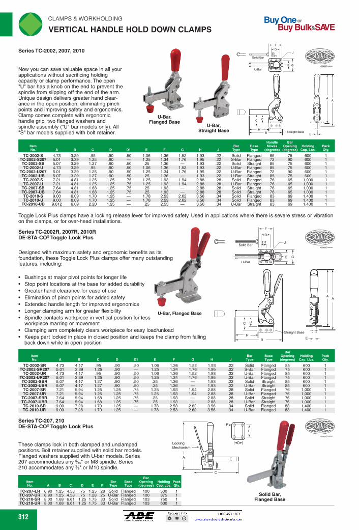
Now you can save valuable space in all your applications without sacrificing holding capacity or clamp performance. The open "U" bar has a knob on the end to prevent the spindle from slipping off the end of the arm. Unique design delivers greater hand clear-ance in the open position, eliminating pinch points and improving safety and ergonomics. Clamp comes complete with ergonomic handle grip, two flanged washers and spindle assembly ("U" bar models only). All "S" bar models supplied with bolt retainer.
TC-2002-S 4.73 3.29 .95 .90 .50 1.06 1.36 1.52 1.93 .22 Solid Flanged 85 75 600 1 TC-2002-S207 5.01 3.39 1.25 .90 - 1.25 1.34 1.76 1.95 .22 S-Bar Flanged 72 90 600 1 TC-2002-SB 5.07 3.29 1.27 .90 .50 .25 1.36 - 1.93 .22 Solid Straight 85 75 600 1 TC-2002-U 4.73 3.29 .95 .90 .50 1.06 1.36 1.52 1.93 .22 U-Bar Flanged 85 75 600 1
TC-2002-U207 5.01 3.39 1.25 .90 .50 1.25 1.34 1.76 1.95 .22 U-Bar Flanged 72 90 600 1 TC-2002-UB 5.07 3.29 1.27 .90 .50 .25 1.36 - 1.93 .22 U-Bar Straight 85 75 600 1 TC-2007-S 7.21 4.81 1.25 1.25 .75 1.25 1.93 1.94 2.88 .28 Solid Flanged 76 65 1,000 1 TC-2007-U 7.21 4.81 1.25 1.25 .75 1.25 1.93 1.94 2.88 .28 U-Bar Flanged 76 65 1,000 1
TC-2007-SB 7.64 4.81 1.68 1.25 .75 .25 1.93 - 2.88 .28 Solid Straight 76 65 1,000 1 TC-2007-UB 7.64 4.81 1.68 1.25 .75 .25 1.93 - 2.88 .28 Solid Straight 76 65 1,000 1 TC-2010-S 9.00 6.09 1.70 1.25 - 1.78 2.53 2.62 3.56 .34 Solid Flanged 83 69 1,400 1 TC-2010-U 9.00 6.09 1.70 1.25 - 1.78 2.53 2.62 3.56 .34 Solid Flanged 83 69 1,400 1
TC-2010-UB 9.612 6.09 2.20 1.25 .25 2.53 - 3.56 .34 U-Bar Straight 83 69 1,400 1
Toggle Lock Plus clamps have a locking release lever for improved safety. Used in applications where there is severe stress or vibration on the clamps, or for over-head installations.
Series TC-2002R, 2007R, 2010R DE-STA-CO.Toggle Lock Plus
Designed with maximum safety and ergonomic benefits as its foundation, these Toggle Lock Plus clamps offer many outstanding features, including:
• Bushings at major pivot points for longer life • Stop point locations at the base for added durability • Greater hand clearance for ease of use • Elimination of pinch points for added safety • Extended handle length for improved ergonomics • Longer clamping arm for greater flexibility U-Bar, Flanged Base • Spindle contacts workpiece in vertical position for less
workpiece marring or movement • Clamping arm completely clears workpiece for easy load/unload • Keeps part locked in place in closed position and keeps the clamp from falling
back down while in open position
Bar
.11=MMM D1 Bar
Typo Base Opening
(degrees) Holding
Cap. Lbs. Pack Qty.
TC-2002-SR 4.73 4.17 .95 .90 .50 1.06 1.36 1.52 1.93 .22 Solid Flanged 85 600 TC-2002-SR207 5.01 3.39 1.25 .90 - 1.25 1.34 1.76 1.95 .22 S-Bar Flanged 75 600
TC-2002-UR 4.73 4.17 .95 .90 .50 1.06 1.36 1.52 1.93 .22 U-Bar Flanged 85 600 TC-2002-UR207 5.01 3.39 1.25 .90 .50 1.25 1.34 1.76 1.95 .22 U-Bar Flanged 75 600 TC-2002-SBR 5.07 4.17 1.27 .90 .50 .25 1.36 - 1.93 .22 Solid Straight 85 600 TC-2002-UBR 5.07 4.17 1.27 .90 .50 .25 1.36 - 1.93 .22 U-Bar Straight 85 600 TC-2007-SR 7.21 5.94 1.25 1.25 .75 1.25 1.93 1.94 2.88 .28 Solid Flanged 76 1,000 TC-2007-UR 7.21 5.94 1.25 1.25 .75 1.25 1.93 1.94 2.88 .28 U-Bar Flanged 76 1,000
TC-2007-SBR 7.64 5.94 1.68 1.25 .75 .25 1.93 - 2.88 .28 Solid Straight 76 1,000 TC-2007-UBR 7.64 5.94 1.68 1.25 .75 .25 1.93 - 2.88 .28 U-Bar Straight 76 1,000 TC-2010-SR 9.00 7.28 1.70 1.25 - 1.78 2.53 2.62 3.56 .34 Solid Flanged 83 1,400 TC-2010-UR 9.00 7.28 1.70 1.25 - 1.78 2.53 2.62 3.56 .34 U-Bar Flanged 83 1,400
Series TC-207, 210 DE-STA-CO. Toggle Lock Plus
These clamps lock in both clamped and unclamped positions. Bolt retainer supplied with solid bar models. Flanged washers supplied with U-bar models. Series 207 accommodates any Vie" or M8 spindle. Series 210 accommodates any %" or M10 spindle.
item Bar Base Bar
Opening No. A B C D E F Type Type (degrees)
TC-207-LR 6.90 1.25 4.58 .75 1.25 .28 Solid Flanged 100 TC-207-UR 6.90 1.25 4.58 .75 1.28 .25 U-Bar Flanged 100 TC-210-SR 8.00 1.68 6.61 1.25 1.75 .33 Solid Flanged 103 TC-210-UR 8.00 1.68 6.61 1.25 1.75 .33 U-Bar Flanged 103
312 312
AA
E
E
D
D1
BH
C C
J
F
G
Straight Base
Solid Bar
U-Bar
Series TC-2002R, 2007R, 2010RDE-STA-CO® Toggle Lock Plus
Designed with maximum safety and ergonomic benefits as its foundation, these Toggle Lock Plus clamps offer many outstanding features, including:
Bushings at major pivot points for longer lifeStop point locations at the base for added durabilityGreater hand clearance for ease of useElimination of pinch points for added safetyExtended handle length for improved ergonomicsLonger clamping arm for greater flexibilitySpindle contacts workpiece in vertical position for less workpiece marring or movementClamping arm completely clears workpiece for easy load/unload Keeps part locked in place in closed position and keeps the clamp from falling back down while in open position
ItemNo. A B C D D1 E F G H J
BarType
BaseType
Bar Opening(degrees)
HoldingCap. Lbs.
PackQty.
TC-2002-SR 4.73 4.17 .95 .90 .50 1.06 1.36 1.52 1.93 .22 Solid Flanged 85 600 1TC-2002-SR207 5.01 3.39 1.25 .90 — 1.25 1.34 1.76 1.95 .22 S-Bar Flanged 75 600 1
TC-2002-UR 4.73 4.17 .95 .90 .50 1.06 1.36 1.52 1.93 .22 U-Bar Flanged 85 600 1TC-2002-UR207 5.01 3.39 1.25 .90 .50 1.25 1.34 1.76 1.95 .22 U-Bar Flanged 75 600 1TC-2002-SBR 5.07 4.17 1.27 .90 .50 .25 1.36 — 1.93 .22 Solid Straight 85 600 1TC-2002-UBR 5.07 4.17 1.27 .90 .50 .25 1.36 — 1.93 .22 U-Bar Straight 85 600 1TC-2007-SR 7.21 5.94 1.25 1.25 .75 1.25 1.93 1.94 2.88 .28 Solid Flanged 76 1,000 1TC-2007-UR 7.21 5.94 1.25 1.25 .75 1.25 1.93 1.94 2.88 .28 U-Bar Flanged 76 1,000 1
TC-2007-SBR 7.64 5.94 1.68 1.25 .75 .25 1.93 — 2.88 .28 Solid Straight 76 1,000 1TC-2007-UBR 7.64 5.94 1.68 1.25 .75 .25 1.93 — 2.88 .28 U-Bar Straight 76 1,000 1TC-2010-SR 9.00 7.28 1.70 1.25 — 1.78 2.53 2.62 3.56 .34 Solid Flanged 83 1,400 1TC-2010-UR 9.00 7.28 1.70 1.25 — 1.78 2.53 2.62 3.56 .34 U-Bar Flanged 83 1,400 1
These clamps lock in both clamped and unclamped positions. Bolt retainer supplied with solid bar models. Flanged washers supplied with U-bar models. Series 207 accommodates any 5⁄16" or M8 spindle. Series 210 accommodates any 3⁄8" or M10 spindle. B
LockingMechanism
A
D
E
F
C
Solid Bar, Flanged Base
ItemNo. A B C D E F
BarType
BaseType
Bar Opening(degrees)
HoldingCap. Lbs.
PackQty.
TC-207-LR 6.90 1.25 4.58 .75 1.25 .28 Solid Flanged 100 500 1TC-207-UR 6.90 1.25 4.58 .75 1.28 .25 U-Bar Flanged 100 375 1TC-210-SR 8.00 1.68 6.61 1.25 1.75 .33 Solid Flanged 103 750 1TC-210-UR 8.00 1.68 6.61 1.25 1.75 .33 U-Bar Flanged 103 600 1
U-Bar, Flanged Base
Series TC-2002, 2007, 2010
Now you can save valuable space in all your applications without sacrificing holding capacity or clamp performance. The open "U" bar has a knob on the end to prevent the spindle from slipping off the end of the arm. Unique design delivers greater hand clear-ance in the open position, eliminating pinch points and improving safety and ergonomics. Clamp comes complete with ergonomic handle grip, two flanged washers and spindle assembly ("U" bar models only). All "S" bar models supplied with bolt retainer.
AA
E
E
DD1
F
Straight BaseH
CC
J
G
Solid Bar
B
U-Bar
ItemNo. A B C D D1 E F G H J
BarType
BaseType
Handle Moves
(degrees)
Bar Opening(degrees)
HoldingCap. Lbs.
PackQty.
TC-2002-S 4.73 3.29 .95 .90 .50 1.06 1.36 1.52 1.93 .22 Solid Flanged 85 75 600 1TC-2002-S207 5.01 3.39 1.25 .90 — 1.25 1.34 1.76 1.95 .22 S-Bar Flanged 72 90 600 1TC-2002-SB 5.07 3.29 1.27 .90 .50 .25 1.36 — 1.93 .22 Solid Straight 85 75 600 1TC-2002-U 4.73 3.29 .95 .90 .50 1.06 1.36 1.52 1.93 .22 U-Bar Flanged 85 75 600 1
TC-2002-U207 5.01 3.39 1.25 .90 .50 1.25 1.34 1.76 1.95 .22 U-Bar Flanged 72 90 600 1TC-2002-UB 5.07 3.29 1.27 .90 .50 .25 1.36 — 1.93 .22 U-Bar Straight 85 75 600 1TC-2007-S 7.21 4.81 1.25 1.25 .75 1.25 1.93 1.94 2.88 .28 Solid Flanged 76 65 1,000 1TC-2007-U 7.21 4.81 1.25 1.25 .75 1.25 1.93 1.94 2.88 .28 U-Bar Flanged 76 65 1,000 1
TC-2007-SB 7.64 4.81 1.68 1.25 .75 .25 1.93 — 2.88 .28 Solid Straight 76 65 1,000 1TC-2007-UB 7.64 4.81 1.68 1.25 .75 .25 1.93 — 2.88 .28 Solid Straight 76 65 1,000 1TC-2010-S 9.00 6.09 1.70 1.25 — 1.78 2.53 2.62 3.56 .34 Solid Flanged 83 69 1,400 1TC-2010-U 9.00 6.09 1.70 1.25 — 1.78 2.53 2.62 3.56 .34 Solid Flanged 83 69 1,400 1
TC-2010-UB 9.612 6.09 2.20 1.25 — .25 2.53 — 3.56 .34 U-Bar Straight 83 69 1,400 1
U-Bar, Straight Base
U-Bar, Flanged Base
Toggle Lock Plus clamps have a locking release lever for improved safety. Used in applications where there is severe stress or vibration on the clamps, or for over-head installations.
Series TC-207, 210DE-STA-CO® Toggle Lock Plus
VERTICAL HANDLE HOLD DOWN CLAMPS
FWAHL
SmallO

T E
DETA•co
A
A A
B
Series TC-202
Steel models furnished with M6 spindle (TC-202208-M) and lock nuts. U-bar models also include flanged washers.
Fixed Bar, Flanged Base Straight Handle
r, •
Fixed Bar, Flanged Base Tee Handle
U-Bar, Straight Base Straight Handle
~DI.
7-
A
Note: Also available as power Model TC-802.
Vertical Handle Hold-Down Clamps
F.
•
MAP-Rare 0J
E G
E
C
ir,
CLAMPS & WORKHOLDING 'N
VERTICAL HANDLE HOLD DOWN CLAMPS
Series TC-201
Steel models furnished with a low cushion neoprene tipped M5 spindle (TC-305208-M), flanged washers and lock nuts. Stainless models furnished with stainless steel hex head spindle (TC-201943), without neoprene tip.
0 al .oi
U-Bar, Straight Base Straight Handle
it
U-Bar, Flanged Base Straight Handle
U-Bar, Flanged Base Tee Handle
Steel TC-201-U 3.03 .63 2.02 .63 .94 Straight U-Bar Flanged 55 100 100
TC-201-TU 2.25 .63 2.02 .63 .94 Tee U-Bar Flanged 55 100 100 TC-201-UB 3.13 .88 2.02 .63 .16 Straight U-Bar Straight 55 100 100
Stainless Steel TC-201-USS 3.03 .63 2.02 .63 .94 Straight U-Bar Flanged 55 100 100 1
Note: Also available as power Model TC-812.
,•,•••••••••
Steel TC-202 4.21 .94 2.31 .50 1.06 Straight Fixed Flanged 65 105 200 1
TC-202-T 2.81 .94 2.31 .50 1.06 Tee Fixed Flanged 65 105 200 1 TC-202-TU 2.81 .94 2.69 .50 1.06 Tee U-Bar Flanged 65 105 200 1 TC-202-B 4.40 1.13 2.31 .50 .25 Straight Fixed Straight 65 105 200 1 TC-202-U 4.21 .94 2.73 .50 1.06 Straight U-Bar Flanged 65 105 200 1
TC-202-UL 4.21 .94 3.27 .50 1.06 Straight U-Bar Flanged 65 105 200 1 TC-202-UB 4.40 1.13 2.73 .50 .25 Straight U-Bar Straight 65 105 200 1
Stainless Steel TC-202-SS 4.21 .94 2.31 .50 1.06 Straight Fixed Flanged 65 105 200 1
TC-202-USS 4.21 .94 2.73 .50 1.06 Straight U-Bar Flanged 65 105 200 1
Solid Bar, U-Bar, U-Bar, Solid Bar, Flanged Base Flanged Base Straight Base Straight Base
Straight Handle Straight Handle Straight Handle Straight Handle
All models have a blue vinyl grip handle. Supplied with spindle assembly.
Item No. A B C D E F G H J K
Bar Type
Base Type
Handle Type
ETC-11011 3.38 2.07 .73 .63 .95 1.00 1.32 1.06 .17 .77 U-Bar Flanged Straight ETC-11012 3.65 2.04 1.00 .63 .14 1.00 - 1.03 .17 .82 U-Bar Straight Straight ETC-11020 4.01 2.50 .98 .51 1.00 .98 1.50 1.28 .21 - Solid Flanged Straight ETC-11021 4.01 2.68 .95 .52 1.03 .98 1.50 1.68 .20 1.08 U-Bar Flanged Straight ETC-11022 4.27 2.68 1.18 .51 .26 .98 - 1.68 .21 1.08 U-Bar Straight Straight ETC-11025 4.23 2.48 1.15 .72 .24 .98 - 1.24 .21 - Solid Straight Straight
Spindle Size
Handle Moves
(degrees)
10-24 x 1.38 Bonded 56 10-24 x 1.38 Bonded 56 1/4-20 x 1.75 Bonded 60 1/4-20 x 1.75 Bonded 60 1/4-20 x 1.75 Bonded 60 1/4-20 x 1.75 Bonded 60
Holding Bar Moves Cap. Pack (degrees) Lbs. Qty.
100 100 100 100 100 200 100 200 100 200 100 200
313 313
VERTICAL HANDLE HOLD DOWN CLAMPS
Series TC-201
U-Bar, Straight BaseStraight Handle
E
D
11/64 Dia.
A A
BB
C
Steel models furnished with a low cushion neoprene tipped M5 spindle (TC-305208-M), flanged washers and lock nuts. Stainless models furnished with stainless steel hex head spindle (TC-201943), without neoprene tip.
Note: Also available as power Model TC-812.
U-Bar, Flanged BaseTee Handle
U-Bar, Flanged BaseStraight Handle
ItemNo. A B C D E
HandleType
BarType
BaseType
Handle Moves(degrees)
Bar Moves(degrees)
HoldingCap. Lbs.
PackQty.
SteelTC-201-U 3.03 .63 2.02 .63 .94 Straight U-Bar Flanged 55 100 100 1
TC-201-TU 2.25 .63 2.02 .63 .94 Tee U-Bar Flanged 55 100 100 1TC-201-UB 3.13 .88 2.02 .63 .16 Straight U-Bar Straight 55 100 100 1
Stainless SteelTC-201-USS 3.03 .63 2.02 .63 .94 Straight U-Bar Flanged 55 100 100 1
Series TC-202
U-Bar, Straight BaseStraight Handle
13/64 Dia.
E
D
A A
B B
C
Steel models furnished with M6 spindle (TC-202208-M) and lock nuts. U-bar models also include flanged washers.
Fixed Bar, Flanged BaseTee Handle
Fixed Bar, Flanged BaseStraight Handle
Note: Also available as power Model TC-802.
ItemNo. A B C D E
HandleType
BarType
BaseType
Handle Moves(degrees)
Bar Moves(degrees)
HoldingCap. Lbs.
PackQty.
SteelTC-202 4.21 .94 2.31 .50 1.06 Straight Fixed Flanged 65 105 200 1
TC-202-T 2.81 .94 2.31 .50 1.06 Tee Fixed Flanged 65 105 200 1TC-202-TU 2.81 .94 2.69 .50 1.06 Tee U-Bar Flanged 65 105 200 1TC-202-B 4.40 1.13 2.31 .50 .25 Straight Fixed Straight 65 105 200 1TC-202-U 4.21 .94 2.73 .50 1.06 Straight U-Bar Flanged 65 105 200 1
TC-202-UL 4.21 .94 3.27 .50 1.06 Straight U-Bar Flanged 65 105 200 1TC-202-UB 4.40 1.13 2.73 .50 .25 Straight U-Bar Straight 65 105 200 1
Stainless SteelTC-202-SS 4.21 .94 2.31 .50 1.06 Straight Fixed Flanged 65 105 200 1
TC-202-USS 4.21 .94 2.73 .50 1.06 Straight U-Bar Flanged 65 105 200 1
U-Bar,Straight Base
Straight Handle
Solid Bar, Straight Base
Straight Handle
All models have a blue vinyl grip handle. Supplied with spindle assembly.
U-Bar,Flanged Base
Straight Handle
Solid Bar, Flanged Base
Straight Handle
ItemNo. A B C D E F G H J K
BarType
BaseType
HandleType
SpindleSize
Handle Moves
(degrees)Bar Moves(degrees)
HoldingCap. Lbs.
PackQty.
ETC-11011 3.38 2.07 .73 .63 .95 1.00 1.32 1.06 .17 .77 U-Bar Flanged Straight 10-24 x 1.38 Bonded 56 100 100 1ETC-11012 3.65 2.04 1.00 .63 .14 1.00 — 1.03 .17 .82 U-Bar Straight Straight 10-24 x 1.38 Bonded 56 100 100 1ETC-11020 4.01 2.50 .98 .51 1.00 .98 1.50 1.28 .21 — Solid Flanged Straight 1⁄4-20 x 1.75 Bonded 60 100 200 1ETC-11021 4.01 2.68 .95 .52 1.03 .98 1.50 1.68 .20 1.08 U-Bar Flanged Straight 1⁄4-20 x 1.75 Bonded 60 100 200 1ETC-11022 4.27 2.68 1.18 .51 .26 .98 — 1.68 .21 1.08 U-Bar Straight Straight 1⁄4-20 x 1.75 Bonded 60 100 200 1ETC-11025 4.23 2.48 1.15 .72 .24 .98 — 1.24 .21 — Solid Straight Straight 1⁄4-20 x 1.75 Bonded 60 100 200 1
Vertical HandleHold-Down Clamps
CC
HB
AA
E
D
E
F
G
K
Ø J
FWAHL
SmallO

F fCTD.
*Supplied with spindle TC-225208-M Note: Also available as power Model TC-807-L, and as Toggle Lock Plus Model TC-207-LR and TC-207-UR.
Economy Vertical Handle Hold-Down Clamps
Handle Moves Bar Moves Holding Pack
K d • rees • • rees Ca.. Lbs. Item No. A B C 13
TC-229 9.94 7.13 2.06 .88 2.0 1.88 2.75 5.25 1/2-13 .33 2.75 180 115 1,000
rliN CLAMPS & WORKHOLDING
VERTICAL HANDLE HOLD DOWN CLAMPS
Bolt retainers are furnished with solid bar models. Two flanged washers are furnished with U-bar models. Accommodates any 5Ae" or M8 spindle.
Item No. A B C D
Handle Bar Base l•
Handle Moves • • rees
Bar Moves d • roes
Holding Ca.. Lbs.
Pack
Steel TC-207-L 6.89 1.25 5.02 .75 1.25 Straight Solid Flanged 57 99 500 1
TC-207-LB 7.48 1.55 5.02 .75 .25 Straight Solid Straight 57 99 500 1 TC-207-S 6.89 1.25 3.75 .75 1.25 Straight Solid Flanged 57 99 500 1
TC-207-SB 7.48 1.55 3.75 .75 .25 Straight Solid Straight 57 99 500 1 TC-207-U* 6.89 1.25 3.68 .75 1.25 Straight U-Bar Flanged 57 99 375 1
TC-207-UB* 7.48 1.55 3.68 .75 .25 Straight U-Bar Straight 57 99 375 1 TC-207-TU 4.36 1.25 3.75 .75 1.25 Tee U-Bar Flanged 57 99 375 1 TC-207-UL* 6.89 1.25 5.41 .75 1.25 Straight U-Bar Flanged 57 99 375 1
TC-207-ULB* 7.48 1.55 5.41 .75 .25 Straight U-Bar Straight 57 99 375 1 TC-207-TUL 4.36 1.25 5.41 .75 1.25 Tee U-Bar Flanged 57 99 375 1
Stainless Steel TC-207-USS 5.63 1.25 4.38 .75 1.25 Straight U-Bar Flanged 57 99 375 1
U-Bar, U-Bar, Flanged Base Straight Base
Straight Handle Straight Handle
All models have a blue vinyl grip handle. Supplied with spindle assembly.
Handle Holding Item Bar Base Handle Spindle Moves Bar Moves Cap. Pack No. A B C D E F G H J K L Type Type Type Size (degrees) (degrees) Lbs. Qty.
ETC-11018 5.60 5.43 1.25 .78 1.25 1.38 1.77 3.75 .27 2.79 - Long U-Bar Flanged Straight 5/113-18 x 2.50 Bonded ETC-11071 5.88 4.59 1.23 .75 1.25 1.38 1.82 2.85 .27 2.05 - U-Bar Flanged Straight 5/.3-18 x 2.50 Bonded ETC-11072 5.93 4.61 1.57 .75 .25 1.38 - 2.85 .27 2.03 - U-Bar Straight Straight 5A8-18 x 2.50 Bonded ETC-11073 4.10 4.60 1.23 .75 1.25 1.38 1.77 2.86 .27 2.10 am U-Bar Flanged Tee 5/.3-18 x 2.50 Bonded ETC-11074 5.90 3.75 1.26 .75 1.25 1.38 1.80 2.24 .27 - - Solid Bar Flanged Straight 5/113-18 x 2.50 Bonded
TC-229
11%1111''
EG EG
0
/rt.
A r
A
U-Bar, Flanged Base
Featuring a unique cam action, these clamps will hold workpieces of inconsistent height. Ideal for castings or forgings. Overall clamping range is 5/16 in. Furnished with 1/2 in. spindle assembly. H
B
OP' DES ""111 TA'CO
314
Solid Bar, Straight Base Straight Handle
U-Bar, Flanged Base Tee Handle
U-Bar, Flanged Base Straight Handle
ar'
Series TC-207
Solid Bar, Flanged Base
Straight Handle
E B
A A
Buy One or Buy Bulk&SIVE
DESR<0,
•••••
p.m I 7
U-Bar, Flanged Base
Tee Handle
100 500 100 200 100 375 100 375 100 375
60 60 60 60 60
314
VERTICAL HANDLE HOLD DOWN CLAMPS
Solid Bar, Straight BaseStraight Handle
TC-229
G
A
C
E
D
H
F
K
J
B
I
Featuring a unique cam action, these clamps will hold workpieces of inconsistent height. Ideal for castings or forgings. Overall clamping range is 5⁄16 in. Furnished with 1⁄2 in. spindle assembly.
U-Bar, Flanged Base
ItemNo. A B C D E F G H I J K
Handle Moves
(degrees)Bar Moves(degrees)
HoldingCap. Lbs.
PackQty.
TC-229 9.94 7.13 2.06 .88 2.0 1.88 2.75 5.25 1⁄2-13 .33 2.75 180 115 1,000 1
Economy Vertical HandleHold-Down Clamps
U-Bar, Flanged Base
Tee Handle
Solid Bar, Flanged Base
Straight Handle
All models have a blue vinyl grip handle. Supplied with spindle assembly.
AA
CC
HB
L
E
A A
D
E
F
G
K
Ø J
U-Bar,Straight Base
Straight Handle
U-Bar,Flanged Base
Straight Handle
ItemNo. A B C D E F G H J K L
BarType
BaseType
HandleType
SpindleSize
Handle Moves
(degrees)Bar Moves(degrees)
HoldingCap. Lbs.
PackQty.
ETC-11018 5.60 5.43 1.25 .78 1.25 1.38 1.77 3.75 .27 2.79 — Long U-Bar Flanged Straight 5⁄16-18 x 2.50 Bonded 60 100 500 1ETC-11071 5.88 4.59 1.23 .75 1.25 1.38 1.82 2.85 .27 2.05 — U-Bar Flanged Straight 5⁄16-18 x 2.50 Bonded 60 100 200 1ETC-11072 5.93 4.61 1.57 .75 .25 1.38 — 2.85 .27 2.03 — U-Bar Straight Straight 5⁄16-18 x 2.50 Bonded 60 100 375 1ETC-11073 4.10 4.60 1.23 .75 1.25 1.38 1.77 2.86 .27 2.10 3.86 U-Bar Flanged Tee 5⁄16-18 x 2.50 Bonded 60 100 375 1ETC-11074 5.90 3.75 1.26 .75 1.25 1.38 1.80 2.24 .27 — — Solid Bar Flanged Straight 5⁄16-18 x 2.50 Bonded 60 100 375 1
Series TC-207
U-Bar, Flanged BaseStraight Handle
A A
B B
C
E
D
Bolt retainers are furnished with solid bar models. Two flanged washers are furnished with U-bar models. Accommodates any 5⁄16" or M8 spindle.
*Supplied with spindle TC-225208-MNote: Also available as power Model TC-807-L, and as Toggle Lock Plus Model TC-207-LR and TC-207-UR.
U-Bar, Flanged BaseTee Handle
ItemNo. A B C D E
HandleType
BarType
BaseType
Handle Moves
(degrees)Bar Moves(degrees)
HoldingCap. Lbs.
PackQty.
SteelTC-207-L 6.89 1.25 5.02 .75 1.25 Straight Solid Flanged 57 99 500 1
TC-207-LB 7.48 1.55 5.02 .75 .25 Straight Solid Straight 57 99 500 1TC-207-S 6.89 1.25 3.75 .75 1.25 Straight Solid Flanged 57 99 500 1
TC-207-SB 7.48 1.55 3.75 .75 .25 Straight Solid Straight 57 99 500 1TC-207-U* 6.89 1.25 3.68 .75 1.25 Straight U-Bar Flanged 57 99 375 1
TC-207-UB* 7.48 1.55 3.68 .75 .25 Straight U-Bar Straight 57 99 375 1TC-207-TU 4.36 1.25 3.75 .75 1.25 Tee U-Bar Flanged 57 99 375 1TC-207-UL* 6.89 1.25 5.41 .75 1.25 Straight U-Bar Flanged 57 99 375 1
TC-207-ULB* 7.48 1.55 5.41 .75 .25 Straight U-Bar Straight 57 99 375 1TC-207-TUL 4.36 1.25 5.41 .75 1.25 Tee U-Bar Flanged 57 99 375 1
Stainless SteelTC-207-USS 5.63 1.25 4.38 .75 1.25 Straight U-Bar Flanged 57 99 375 1
FWAHL
SmallO
EG
Solid Bar Flanged Base
Straight Handle
E-.1
Holding
Cap. Pack
Lbs. Qty.
600 750 750
Holding Cap. Lbs.
Item No.
Bar TYPs
Handle Moves Bar Moves Pack Qty. C (degrees) (degrees) A B D E
TC-317-S Solid U-Bar
5.62 TC-317-U 5.62
2.67 6.44 .63 60 185 375 2.67 6.07 .63 60 185 375
_ -- DESTA•co_,•
U-Bar, Flanged Base
U-Bar model furnished with M8 bonded neoprene tipped spindle, flanged washers and lock nuts.
_t E
D 9/32 Dia.
Series TC-317
Solid Bar, Flanged Base
CLAMPS & WORKHOLDING rliN
VERTICAL HANDLE HOLD DOWN CLAMPS
Series TC-210
TIESI <C‘ A/0
A
A
21/64 Dia.
F.D.H
U-Bar, Flanged Base Solid Bar, Straight Base Straight Handle Straight Handle
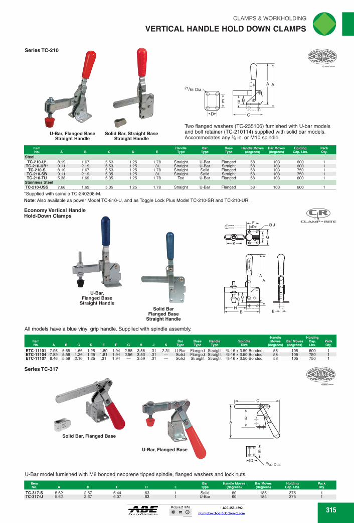
Two flanged washers (TC-235106) furnished with U-bar models and bolt retainer (TC-210114) supplied with solid bar models. Accommodates any % in. or M10 spindle.
Base Type
Handle Moves (degrees)
Bar Moves (degrees)
Holding Cap. Lbs.
Steel TC-210-U* 8.19 1.67 5.53 1.25 1.78 Straight U-Bar Flanged 58 103 600
TC-210-UB* 9.11 2.19 5.53 1.25 .31 Straight U-Bar Straight 58 103 600 TC-210-S 8.19 1.67 5.53 1.25 1.78 Straight Solid Flanged 58 103 750
TC-210-SB 9.11 2.19 5.35 1.25 .31 Straight Solid Straight 58 103 750 TC-210-TU 5.38 1.69 5.35 1.25 1.78 Tee U-Bar Flanged 58 103 600
Stainless Steel TC-210-USS 7.66 1.69 5.35 1.25 1.78 Straight U-Bar Flanged 58 103 600
*Supplied with spindle TC-240208-M.
Note: Also available as power Model TC-810-U, and as Toggle Lock Plus Model TC-210-SR and TC-210-UR.
Economy Vertical Handle Hold-Down Clamps
MINE. RETIE
111 U-Bar,
Flanged Base Straight Handle
All models have a blue vinyl grip handle. Supplied with spindle assembly.
Handle Item Bar Base Handle Moves Bar Moves No. A B C D E F G H K Type Type Type (degrees) (degrees)
ETC-11101 7.96 5.65 1.66 1.25 1.80 1.94 2.55 3.56 .31 2.31 U-Bar Flanged Straight %-16 x 3.50 Bonded 58 105 ETC-11104 7.89 5.59 1.26 1.25 1.81 1.94 2.56 3.53 .31 Solid Flanged Straight %-16 x 3.50 Bonded 58 105 ETC-11107 8.46 5.59 2.16 1.25 .31 1.94 3.59 .31 Solid Straight Straight %-16 x 3.50 Bonded 58 105
315 315
VERTICAL HANDLE HOLD DOWN CLAMPS
Series TC-210
B
21/64 Dia.
B
C
AA
E
D
U-Bar, Flanged BaseStraight Handle
Two flanged washers (TC-235106) furnished with U-bar models and bolt retainer (TC-210114) supplied with solid bar models. Accommodates any 3⁄8 in. or M10 spindle.
*Supplied with spindle TC-240208-M.Note: Also available as power Model TC-810-U, and as Toggle Lock Plus Model TC-210-SR and TC-210-UR.
Solid Bar, Straight BaseStraight Handle
ItemNo. A B C D E
HandleType
BarType
BaseType
Handle Moves(degrees)
Bar Moves(degrees)
HoldingCap. Lbs.
PackQty.
SteelTC-210-U* 8.19 1.67 5.53 1.25 1.78 Straight U-Bar Flanged 58 103 600 1
TC-210-UB* 9.11 2.19 5.53 1.25 .31 Straight U-Bar Straight 58 103 600 1TC-210-S 8.19 1.67 5.53 1.25 1.78 Straight Solid Flanged 58 103 750 1
TC-210-SB 9.11 2.19 5.35 1.25 .31 Straight Solid Straight 58 103 750 1TC-210-TU 5.38 1.69 5.35 1.25 1.78 Tee U-Bar Flanged 58 103 600 1
Stainless SteelTC-210-USS 7.66 1.69 5.35 1.25 1.78 Straight U-Bar Flanged 58 103 600 1
Series TC-317
AB
C
E
D9/32 Dia.
U-Bar model furnished with M8 bonded neoprene tipped spindle, flanged washers and lock nuts.
U-Bar, Flanged Base
Solid Bar, Flanged Base
ItemNo. A B C D E
BarType
Handle Moves(degrees)
Bar Moves(degrees)
HoldingCap. Lbs.
PackQty.
TC-317-S 5.62 2.67 6.44 .63 1 Solid 60 185 375 1TC-317-U 5.62 2.67 6.07 .63 1 U-Bar 60 185 375 1
U-Bar,Flanged Base
Straight Handle
Economy Vertical HandleHold-Down Clamps
All models have a blue vinyl grip handle. Supplied with spindle assembly.
Solid BarFlanged Base
Straight Handle
ItemNo. A B C D E F G H J K
BarType
BaseType
HandleType
SpindleSize
Handle Moves
(degrees)Bar Moves(degrees)
HoldingCap. Lbs.
PackQty.
ETC-11101 7.96 5.65 1.66 1.25 1.80 1.94 2.55 3.56 .31 2.31 U-Bar Flanged Straight 3⁄8-16 x 3.50 Bonded 58 105 600 1ETC-11104 7.89 5.59 1.26 1.25 1.81 1.94 2.56 3.53 .31 — Solid Flanged Straight 3⁄8-16 x 3.50 Bonded 58 105 750 1ETC-11107 8.46 5.59 2.16 1.25 .31 1.94 — 3.59 .31 — Solid Straight Straight 3⁄8-16 x 3.50 Bonded 58 105 750 1
CC
HB
AA
E
D
E
F
G
K
Ø J
FWAHL
SmallO

Handle Holding Bar Base Handle Spindle Moves Bar Moves Cap. Pack
K Type Type Type Size (degrees) (degrees) Lbs. Qty. Item No. A B C D E F G
Handle Holding Moves Bar Moves Cap. Pack
(degrees) (degrees) Lbs. Qty. Spind e
Size Item No. A B C D E F G H K Type Type Type
Bar Base Handle
60 140 1,200 ETC-11671 11.87 9.00 3.08 2.00 2.75 2.99 3.75 5.99 .48 4.33 U-Bar Flanged Straight 1/2-13 x 4.50 Plain
rliN CLAMPS & WORKHOLDING
VERTICAL HANDLE HOLD DOWN CLAMPS
Series TC-247
I
U-Bar, Flanged Base
Bolt retainer furnished with solid bar models. Flanged washers furnished with U-bar models. Accommodates any 1/2 in. or M12 spindle.
TC-247-U 8.69 2 6.87 1.25 1.78 Straight U-Bar TC-247-S 8.69 2 6.87 1.25 1.78 Straight Solid
Note: Also available as power Model TC-847.
Flanged 67 120 1,000 1 Flanged 67 120 1,000 1
Economy Vertical Handle Hold-Down Action Clamps
"z•
U-Bar, Flanged Base Solid Bar, Flanged Base
All models have a blue vinyl grip handle. Supplied with spindle assembly.
31/al Dia
Handle Bar Base Handle Moves Bar Moves Holding Pack Type Type Type (degrees) (degrees) Cap. Lbs. Qty.
TC-267-U 11.88 3.08 TC-267-S 11.88 3.08
2 2
8.92 8.88
°10FSIA<C
•••••
U-Bar, Flanged Base Solid Bar, Flanged Base
Bolt retainer furnished with solid bar models. Flanged washers furnished with U-Bar models. Accommodates any % in. or M16 spindle.
Series TC-267
ill
72 140 1,200 1 72 140 1,200 1
2.75 U-Bar Solid 2.75
Straight Straight
Flanged Flanged
Item No. A
316
(23J
CSR - ROTE
ft
F
E G
'DF of
AE E G
RAMP RETIE
K
A
C
(".=> H B
E
Solid Bar, Flanged Base
Buy One or
Buy Bulk&SIVE
E
D
ETC-11471 8.81 6.89 1.95 1.25 1.77 2.00 2.56 4.87 .35 2.98 U-Bar Flanged Straight 1/2-13 x 3.00 Plain ETC-11474 8.81 7.12 2.00 1.25 1.79 2.00 2.56 4.95 .35
70 - Solid Flanged Straight 1/2-13 x 3.00 Plain 70 135 1,000
135 1,000
Economy Vertical Handle Hold-Down Action Clamps
law
U-Bar, Flanged Base
Model has a blue vinyl grip handle. Supplied with spindle assembly.
C
316
Series TC-267
A
B
C
31/64 Dia.
E
D
Bolt retainer furnished with solid bar models. Flanged washers furnished with U-Bar models. Accommodates any 5⁄8 in. or M16 spindle.
ItemNo. A B C D E
HandleType
BarType
BaseType
Handle Moves(degrees)
Bar Moves(degrees)
HoldingCap. Lbs.
PackQty.
TC-267-U 11.88 3.08 8.92 2 2.75 Straight U-Bar Flanged 72 140 1,200 1TC-267-S 11.88 3.08 8.88 2 2.75 Straight Solid Flanged 72 140 1,200 1
U-Bar, Flanged Base Solid Bar, Flanged Base
Series TC-247
A
B
C
11/32 Dia.
E
D
Bolt retainer furnished with solid bar models. Flanged washers furnished with U-bar models. Accommodates any 1⁄2 in. or M12 spindle.
Note: Also available as power Model TC-847.
Solid Bar, Flanged BaseU-Bar, Flanged Base
ItemNo. A B C D E
HandleType
BarType
BaseType
Handle Moves(degrees)
Bar Moves(degrees)
HoldingCap. Lbs.
PackQty.
TC-247-U 8.69 2 6.87 1.25 1.78 Straight U-Bar Flanged 67 120 1,000 1TC-247-S 8.69 2 6.87 1.25 1.78 Straight Solid Flanged 67 120 1,000 1
Economy Vertical HandleHold-Down Action Clamps
All models have a blue vinyl grip handle. Supplied with spindle assembly.E
B
K
F
D ØJ
E G
C
A
HU-Bar, Flanged Base
Economy Vertical HandleHold-Down Action Clamps
Model has a blue vinyl grip handle. Supplied with spindle assembly.
D
F
E G
K
H
C
BE
A
ØJ
U-Bar, Flanged Base
ItemNo. A B C D E F G H J K
BarType
BaseType
HandleType
SpindleSize
Handle Moves
(degrees)Bar Moves(degrees)
HoldingCap. Lbs.
PackQty.
ETC-11471 8.81 6.89 1.95 1.25 1.77 2.00 2.56 4.87 .35 2.98 U-Bar Flanged Straight 1⁄2-13 x 3.00 Plain 70 135 1,000 1ETC-11474 8.81 7.12 2.00 1.25 1.79 2.00 2.56 4.95 .35 — Solid Flanged Straight 1⁄2-13 x 3.00 Plain 70 135 1,000 1
ItemNo. A B C D E F G H J K
BarType
BaseType
HandleType
SpindleSize
Handle Moves
(degrees)Bar Moves(degrees)
HoldingCap. Lbs.
PackQty.
ETC-11671 11.87 9.00 3.08 2.00 2.75 2.99 3.75 5.99 .48 4.33 U-Bar Flanged Straight 1⁄2-13 x 4.50 Plain 60 140 1,200 1
Solid Bar, Flanged Base
VERTICAL HANDLE HOLD DOWN CLAMPS
FWAHL
SmallO
New) ic
Handle Bar Holding Moves Opening Capacity Pack
Bar Type Base Type (degrees) (degrees) Lbs. Qty. dommAMMil
CLAMPS & WORKHOLDING
VERTICAL HANDLE HOLD DOWN CLAMPS
_L=WZMIgNII
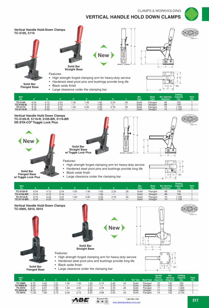
Vertical Handle Hold Down Clamps TC-5105-R, 5110-R, 5105-BR, 5110-BR DE-STA-CO.Toggle Lock Plus
'7.19;c7.
Solid Bar Straight Base
w/Toggle Lock Plus
Features: • High strength forged clamping arm for heavy-duty service • Hardened steel pivot pins and bushings provide long life • Black oxide finish • Large clearance under the clamping bar
New
Solid Bar Flanged Base
w/Toggle Lock Plus
11
Holding Bar Base Bar Opening Capacity Pack
F G Type Type (degrees) Lbs. qty.
Vertical Handle Hold-Down Clamps TC-5905, 5910, 5915
New
Solid Bar Straight Base
Features: • High strength forged clamping arm for heavy-duty service • Hardened steel pivot pins and bushings provide long life • Black oxide finish • Large clearance under the clamping bar
Solid Bar Flanged Base
TC-5905 6.75 4.00 1.51 1.00 1.50 1.50 2.13 2.49 .24 Solid TC-5905-B 6.24 4.00 1.27 - 1.51 - 2.74 - Solid TC-5910 9.27 6.01 1.99 1.50 2.00 2.24 2.76 3.76 .35 Solid
TC-5910-B 8.72 6.01 1.75 - 2.25 - 4.01 - Solid TC-5915 11.25 7.99 3.72 2.00 2.75 2.95 3.88 5.00 .55 Solid
70 135 750 70 135 750 71 132 1,600 71 132 1,600 74 132 2,750
Flanged Straight Flanged Straight Flanged
317
Vertical Handle Hold-Down Clamps TC-5105, 5110
Solid Bar Flanged Base
Solid Bar Straight Base
Features: • High strength forged clamping arm for heavy-duty service • Hardened steel pivot pins and bushings provide long life • Black oxide finish • Large clearance under the clamping bar
TC-5105 6.54 4.13 TC-5105-B 6.14 4.13 TC-5110 8.70 6.33
TC-5110-B 8.39 6.33
1.00 1.46 1.62 2.24 .26 Solid Flanged 89 700 1 1.00 Solid Straight 89 700 1
1.00 2.00 2.50 2.76 .35 Solid Flanged 74 1,150 1 1.50 Solid Straight 74 1,150 1
1.46 1.62 1.62
1.00 2.00 2.50 2.50
89 89 74 74
2.24
2.76
Flanged Straight Flanged Straight
700 700
1,150 1,150
2.54 2.14 3.37 3.05
.26 Solid - Solid .35 Solid - Solid
TC-5105-R 6.54 4.13 2.54 1.00 TC-5105-BR 6.14 4.13 2.14 TC-5110-R 8.70 6.33 3.37 TC-5110-BR 8.39 6.33 3.05
317
VERTICAL HANDLE HOLD DOWN CLAMPS
CC
F
A A
E G
ØJDF
B
Solid BarStraight Base
Solid BarFlanged Base
ItemNo. A B C D E F G J
BarType
BaseType
Bar Opening(degrees)
HoldingCapacity
Lbs.PackQty.
TC-5105 6.54 4.13 2.54 1.00 1.46 1.62 2.24 .26 Solid Flanged 89 700 1TC-5105-B 6.14 4.13 2.14 — — 1.00 — — Solid Straight 89 700 1TC-5110 8.70 6.33 3.37 1.00 2.00 2.50 2.76 .35 Solid Flanged 74 1,150 1
TC-5110-B 8.39 6.33 3.05 — — 1.50 — — Solid Straight 74 1,150 1
Vertical Handle Hold-Down ClampsTC-5905, 5910, 5915
C
HH
A A
C
E G
ØJDF
B
Solid BarStraight Base
Solid BarFlanged Base
ItemNo. A B C D E F G H J Bar Type Base Type
Handle Moves
(degrees)
Bar Opening(degrees)
HoldingCapacity
Lbs.PackQty.
TC-5905 6.75 4.00 1.51 1.00 1.50 1.50 2.13 2.49 .24 Solid Flanged 70 135 750 1TC-5905-B 6.24 4.00 1.27 — — 1.51 — 2.74 — Solid Straight 70 135 750 1TC-5910 9.27 6.01 1.99 1.50 2.00 2.24 2.76 3.76 .35 Solid Flanged 71 132 1,600 1
TC-5910-B 8.72 6.01 1.75 — — 2.25 — 4.01 — Solid Straight 71 132 1,600 1TC-5915 11.25 7.99 3.72 2.00 2.75 2.95 3.88 5.00 .55 Solid Flanged 74 132 2,750 1
Vertical Handle Hold Down ClampsTC-5105-R, 5110-R, 5105-BR, 5110-BRDE-STA-CO® Toggle Lock Plus
CC
F
A A
E G
ØJDF
B
Solid BarStraight Base
w/ Toggle Lock Plus
Solid BarFlanged Base
w/ Toggle Lock Plus
ItemNo. A B C D E F G J
BarType
BaseType
Bar Opening(degrees)
HoldingCapacity
Lbs.PackQty.
TC-5105-R 6.54 4.13 2.54 1.00 1.46 1.62 2.24 .26 Solid Flanged 89 700 1TC-5105-BR 6.14 4.13 2.14 — — 1.62 — — Solid Straight 89 700 1TC-5110-R 8.70 6.33 3.37 1.00 2.00 2.50 2.76 .35 Solid Flanged 74 1,150 1
TC-5110-BR 8.39 6.33 3.05 — — 2.50 — — Solid Straight 74 1,150 1
Vertical Handle Hold-Down ClampsTC-5105, 5110
Features:High strength forged clamping arm for heavy-duty serviceHardened steel pivot pins and bushings provide long lifeBlack oxide finishLarge clearance under the clamping bar
Features:High strength forged clamping arm for heavy-duty serviceHardened steel pivot pins and bushings provide long lifeBlack oxide finishLarge clearance under the clamping bar
Features:High strength forged clamping arm for heavy-duty serviceHardened steel pivot pins and bushings provide long lifeBlack oxide finishLarge clearance under the clamping bar
FWAHL
SmallO

Buy One or Buy Bulk&SIVE
rliN CLAMPS & WORKHOLDING
VERTICAL HANDLE HOLD DOWN CLAMPS
129 129
199 2,500 1 199 4,000 1
Handle Handle Moves Bar Moves Holding Pack Type (degrees) (degrees) Cap. Lbs. Qty.
Base Type
Item No.
10 12 11 12
475 600
1,000 1,600
Bar Max. Moves Holding Pack
F G H J K L MN (degrees) Cap. Lbs. Qty. Item No.
TC-548, 578
Straight Base
Item Handle Bar Base No. A B C Type Type Type
TC-548 9.44 2.25 7.50 Straight Solid Straight TC-578 11.00 2.75 8.63 Straight Solid Straight
TC-518 Holding Capacity: 500 Lbs Handle Moves: 75 Degrees, Bar Moves: 90 Degrees
Flanged Base H B -1
Features a forged hold-down bar and ergonomic plastic grip. Forged hold-down bar can be cut or welded to suit the fixture. Offers twice the normal clearance under the bar as other clamps this size.
Item No. A B C D E F G H
TC-518 6.88 4.28 2.5 1.00 .88 1.50 1.38 2.63
Largest capacity clamps. The "bar-guide' feature provides extra support and improves rigidity and repeatability.
TC-91090
U-Bar, Flanged Base
Front flange mount for mounting flexibility on vertical surfaces. Stainless steel rivets for increased strength. Guide bars allow for more clamp stability. Supplied with two flanged washers. Accommodates any Vie" or M8 spindle. Spindle not included.
Handle Bar Item Moves Moves Holding Pack No. A B C D E F G H J K L (degrees) (degrees) Cap. Lbs. Qty.
TC-91090 7.68 4.72 2.68 .80 1.29 1.32 2.09 2.99 .28 2.40 .33
Series TC-528
Solid Bar, Flanged Base
Solid Bar, Front Mount Flanged Base
TC-528 TC-528-F Front liFlolaunganged Straight
Cam Action Clamps
Automatically compensates for variations in part thickness. A high to low limit clamping range allows for normal part size varia-tion and eliminates adjustments. Normalized cast steel construc-tion for heavy duty use. Fast, one hand operation. Cam action resists vibration loosening. Accommodates from A" to 'A" part size variation.
318
TC-7-101 5.00 3.13 1.44 .50 1.75 1.25 .75 1.25 .25 TC-7-58 7.00 2.55 1.88 .56 2.25 1.69 1.00 1.62 .31 TC-7-59 8.50 3.50 2.19 .63 2.50 2.06 1.38 1.88 .31 TC-7-60 9.50 4.38 2.50 .88 2.88 2.44 1.62 2.12 .38
LT
H -n.
.25 .22 .50 .13
.34 .28 .50 .13
.39 .34 .63 .19
.44 .41 .75 .25
177 177
1,000 180 1,000 180
Solid Bar Flanged Base
60 100 385
613/16 3/4
3/16 ie
215h6 k tA, Front Mounting
Base 527-F Bottom Mounting
Base 527
1,:/32 For
-18 Screws 21/4 11/4
Handle Bar Moves Moves Holding Pack
(degrees) (degrees) Cap. Lbs. Qty. Pack J Qty.
.29
For tough, heavy-duty workholding. Clamp has square, cold drawn steel hold down bar. Pivot points have serrated, hardened bushings. Large Bar opening for greater part clearance.
eltESIA<,
G
318
TC-91090
LK
A
HB
C
J
FD
EG
Front flange mount for mounting flexibility on vertical surfaces. Stainless steel rivets for increased strength. Guide bars allow for more clamp stability. Supplied with two flanged washers. Accommodates any 5⁄16" or M8 spindle. Spindle not included.
U-Bar, Flanged Base
ItemNo. A B C D E F G H J K L
Handle Moves
(degrees)
Bar Moves
(degrees)Holding
Cap. Lbs.PackQty.
TC-91090 7.68 4.72 2.68 .80 1.29 1.32 2.09 2.99 .28 2.40 .33 60 100 385 1
Series TC-528
Front MountingBase 527-F
Bottom MountingBase 527
613/16
215/16423/16
3/4
21/4 11/4
13/323/8
ForScrews
For tough, heavy-duty workholding. Clamp has square, cold drawn steel hold down bar. Pivot points have serrated, hardened bushings. Large Bar opening for greater part clearance.
Solid Bar, Front Mount Flanged Base
Solid Bar, Flanged Base
TC-548, 578
A
C
B
Largest capacity clamps. The "bar-guide" feature provides extra support and improves rigidity and repeatability.
Straight Base
ItemNo. A B C
HandleType
BarType
BaseType
Handle Moves
(degrees)
Bar Moves
(degrees)Holding
Cap. Lbs.PackQty.
TC-548 9.44 2.25 7.50 Straight Solid Straight 129 199 2,500 1TC-578 11.00 2.75 8.63 Straight Solid Straight 129 199 4,000 1
Cam Action Clamps
Automatically compensates for variations in part thickness. A high to low limit clamping range allows for normal part size varia-tion and eliminates adjustments. Normalized cast steel construc-tion for heavy duty use. Fast, one hand operation. Cam action resists vibration loosening. Accommodates from 1⁄8" to 1⁄4" part size variation.
M D
N
NJ
AEH
C
F
BG
LK
ItemNo. A B C D E F G H J K L M N
Bar Moves
(degrees)
Max. Holding
Cap. Lbs.PackQty.
TC-7-101 5.00 3.13 1.44 .50 1.75 1.25 .75 1.25 .25 .25 .22 .50 .13 10 475 1TC-7-58 7.00 2.55 1.88 .56 2.25 1.69 1.00 1.62 .31 .34 .28 .50 .13 12 600 1TC-7-59 8.50 3.50 2.19 .63 2.50 2.06 1.38 1.88 .31 .39 .34 .63 .19 11 1,000 1TC-7-60 9.50 4.38 2.50 .88 2.88 2.44 1.62 2.12 .38 .44 .41 .75 .25 12 1,600 1
ItemNo.
BaseType
HandleType
Handle Moves
(degrees)Bar Moves(degrees)
HoldingCap. Lbs.
PackQty.
TC-528 Flanged Straight 177 180 1,000 1TC-528-F Front Mount/Flanged Straight 177 180 1,000 1
VERTICAL HANDLE HOLD DOWN CLAMPS
Solid BarFlanged Base
Features a forged hold-down bar and ergonomic plastic grip. Forged hold-down bar can be cut or welded to suit the fixture. Offers twice the normal clearance under the bar as other clamps this size.
ItemNo. A B C D E F G H J
PackQty.
TC-518 6.88 4.28 2.5 1.00 .88 1.50 1.38 2.63 .29 1
TC-518Holding Capacity: 500 LbsHandle Moves: 75 Degrees, Bar Moves: 90 Degrees
J
GE
DF
C
HB
A
Flanged Base
FWAHL
SmallO

Optimum stability is achieved through Maintenance-free, high quality swivel bushings. Constant use of force when opening and closing. the conical clamping arm and U-profile. Includes an internal bar lock with automatic safety.
Hole arrangement for Item No. KC-320
Hole arrangement for Item No. KC-315
CLAMPS & WORKHOLDING
VERTICAL HANDLE HOLD DOWN CLAMPS ftd
Vertical Hold Down Clamps with Safety Interlock With Flat Foot and Adjustable Clamping Spindle Series 05908
Hole arrangement for Item No. KC-350 and KC-355
Hole arrangement for Item No. KC-360
N
B
Hole arrangement for Item No. KC-365
Abk
New
411
-e EE-.14FkLt- °
A
Toggle clamp in the closed locked position
Toggle clamp locking mechanism is released by pulling back on the sides of the paddle grip
Holding Item Capacity Pack No. A C D E F G H M N P Lbs. Qty.
KC-350 162.9 24.7 86.5 5.5 14 7 12 27 38 53.4 M6 x 35 29.0 207 KC-355 191.4 32.7 107.0 6.8 21 9 19 32 45 51.1 M8 x 45 39.0 211 KC-360 230.5 38.7 153.0 9.0 32 8 27 45 64 56.5 M10 x 55 50.0 337 KC-365 249.1 46.7 173.5 8.8 32 10.5 45 63 56.5 M12 x 70 53.0 315
Vertical Hold Down Clamps With Flat Foot and Adjustable Clamping Spindle Series 05908
New)
H
Maintenance-free, high quality swivel bushings. Constant use of force when opening and closing. Optimum stability is achieved through the conical clamping arm and U-profile.
Item No. A C D
KC-300 108.5 19.1 63.5 4.5 16 4.5 14 24 33 KC-305 156.2 24.7 86.5 5.5 14 7 12 27 38 KC-310 183.9 32.7 107.0 6.8 21 9 19 32 45 KC-315 222.9 38.7 153.0 9.0 32 8 27 45 64 KC-320 242.4 46.7 173.5 8.8 32 10.5 45 63
de=MMEMI 22.5 M5 x 25 25 140 43.5 M6 x 35 29 207 41.5 M8 x 45 39 211 47.0 M10 x 55 50 337 47.0 M12 x 70 53 315
319
OD at
H
I G-0•11
Hole arrangement for Item No. KC-300
DH
01
G -0-1F1-4-E0-1
Hole arrangement for Item No. KC-305 and KC-310
319
VERTICAL HANDLE HOLD DOWN CLAMPS
P
C
MK
N
B
J
A
FGE
H
D
Hole arrangement for Item No. KC-350 and KC-355
GF E
D D
H
Hole arrangement for Item No. KC-360
F E
D
H
Hole arrangement for Item No. KC-365
Toggle clamp in the closed locked position
Toggle clamp locking mechanism is released by pulling back on the sides of the paddle grip
Maintenance-free, high quality swivel bushings. Constant use of force when opening and closing. Optimum stability is achieved through the conical clamping arm and U-profile. Includes an internal bar lock with automatic safety.
ItemNo. A B C D E F G H J M N P
HoldingCapacity
Lbs.PackQty.
KC-350 162.9 24.7 86.5 5.5 14 7 12 27 38 53.4 M6 x 35 29.0 207 1KC-355 191.4 32.7 107.0 6.8 21 9 19 32 45 51.1 M8 x 45 39.0 211 1KC-360 230.5 38.7 153.0 9.0 32 8 27 45 64 56.5 M10 x 55 50.0 337 1KC-365 249.1 46.7 173.5 8.8 32 10.5 — 45 63 56.5 M12 x 70 53.0 315 1
Vertical Hold Down Clamps with Safety InterlockWith Flat Foot and Adjustable Clamping SpindleSeries 05908
P
C
MK
N
B
J
A
D
GFE
H
Hole arrangement for Item No. KC-300
FGE
HD
Hole arrangement for Item No. KC-305 and KC-310
Vertical Hold Down ClampsWith Flat Foot and Adjustable Clamping SpindleSeries 05908
GFE
D D
H
Hole arrangement for Item No. KC-315
F E
D
H
Hole arrangement for Item No. KC-320
Maintenance-free, high quality swivel bushings. Constant use of force when opening and closing. Optimum stability is achieved through the conical clamping arm and U-profile.
ItemNo. A B C D E F G H J M N P
HoldingCapacity
Lbs.PackQty.
KC-300 108.5 19.1 63.5 4.5 16 4.5 14 24 33 22.5 M5 x 25 25 140 1KC-305 156.2 24.7 86.5 5.5 14 7 12 27 38 43.5 M6 x 35 29 207 1KC-310 183.9 32.7 107.0 6.8 21 9 19 32 45 41.5 M8 x 45 39 211 1KC-315 222.9 38.7 153.0 9.0 32 8 27 45 64 47.0 M10 x 55 50 337 1KC-320 242.4 46.7 173.5 8.8 32 10.5 — 45 63 47.0 M12 x 70 53 315 1
FWAHL
SmallO

Buy One or Buy Bulk&SAVE rliN CLAMPS & WORKHOLDING
VERTICAL HANDLE HOLD DOWN CLAMPS
A
Item No. KC-465
GE _3.
1 E
-01F
Hole arrangement for Hole arrangement for Item No. KC-460
Vertical Hold-Down Clamps With Straight Foot and Adjustable Clamping Spindle Series 05912
Vertical Hold Down Clamps with Safety Interlock With Straight Foot and Adjustable Clamping Spindle Series 05912
h4-P-Nd Hole arrangement for Item
No. KC-450 and KC-455
Maintenance-free, high quality swivel bushings. Constant use of force when opening and closing. Optimum stability is achieved through the conical clamping arm and U-profile. Includes an internal bar lock with automatic safety.
Holding Item Capacity Pack No. A F G H M N P Lbs. Qty.
KC-450 175.7 37.6 86.5 5.5 14 7 12 10.2 5.2 53.4 M6 x 35 29 207 KC-455 207.6 49.0 107.0 6.8 21 9 19 10.2 5.2 51.1 M8 x 45 39 221 KC-460 254.0 62.3 153.0 9.0 32 8 27 14.1 7.1 56.5 M10 x 55 50 337 KC-465 271.9 69.8 173.5 8.8 32 10.5 14.1 7.1 56.5 M12 x 70 53 315
F E-0.1
Hole arrangement for Item No. KC-400 and KC-415
Hole arrangement for Item No. KC-405 and KC-410
F Ii E
Hole arrangement for Item No. KC-420
Maintenance-free, high quality swivel bushings. Constant use of force when opening and closing. Optimum stability is achieved through the conical clamping arm and U-profile.
MIME ..0=MMMEgi= KC-400 120.3 30.8 KC-405 169.1 37.6 KC-410 200.1 49.0 KC-415 247.4 62.3 KC-420 265.5 69.8
320
63.5 4.5 16 4.5 14 8.1 4.1 22.5 M5 x 25 25 139 1 86.5 5.5 14 7 12 10.2 5.2 43.5 M6 x 35 29 207 1 107.0 6.8 21 9 19 10.2 5.2 41.5 M8 x 45 39 211 1 153.0 9.0 32 8 27 14.1 7.1 47.0 M10 x 55 50 337 1 173.5 8.8 32 10.5 - 14.1 7.1 47.0 M12 x 70 53 315 1
P=)614111 Toggle clamp in the closed locked position
2=*41110 Toggle clamp locldng mechanism is released by pulling back on the sides of the paddle grip
320
B
K
C
N
JH
A
MD
GF
EP
Hole arrangement for Item No. KC-450 and KC-455
D
GFE
D
Hole arrangement for Item No. KC-460
F E
D
Hole arrangement for Item No. KC-465
Toggle clamp in the closed locked position
Toggle clamp locking mechanism is released by pulling back on the sides of the paddle grip
Maintenance-free, high quality swivel bushings. Constant use of force when opening and closing. Optimum stability is achieved through the conical clamping arm and U-profile. Includes an internal bar lock with automatic safety.
ItemNo. A B C D E F G H J M N P
HoldingCapacity
Lbs.PackQty.
KC-450 175.7 37.6 86.5 5.5 14 7 12 10.2 5.2 53.4 M6 x 35 29 207 1KC-455 207.6 49.0 107.0 6.8 21 9 19 10.2 5.2 51.1 M8 x 45 39 221 1KC-460 254.0 62.3 153.0 9.0 32 8 27 14.1 7.1 56.5 M10 x 55 50 337 1KC-465 271.9 69.8 173.5 8.8 32 10.5 — 14.1 7.1 56.5 M12 x 70 53 315 1
Vertical Hold Down Clamps with Safety InterlockWith Straight Foot and Adjustable Clamping SpindleSeries 05912
VERTICAL HANDLE HOLD DOWN CLAMPS
Vertical Hold-Down ClampsWith Straight Foot and Adjustable Clamping SpindleSeries 05912
B
K
C
N
JH
A
M
D
GF E
D
Hole arrangement for Item No. KC-400 and KC-415
DGF
EP
Hole arrangement for Item No. KC-405 and KC-410
F E
D
Hole arrangement for Item No. KC-420
Maintenance-free, high quality swivel bushings. Constant use of force when opening and closing. Optimum stability is achieved through the conical clamping arm and U-profile.
ItemNo. A B C D E F G H J M N P
HoldingCapacity
Lbs.PackQty.
KC-400 120.3 30.8 63.5 4.5 16 4.5 14 8.1 4.1 22.5 M5 x 25 25 139 1KC-405 169.1 37.6 86.5 5.5 14 7 12 10.2 5.2 43.5 M6 x 35 29 207 1KC-410 200.1 49.0 107.0 6.8 21 9 19 10.2 5.2 41.5 M8 x 45 39 211 1KC-415 247.4 62.3 153.0 9.0 32 8 27 14.1 7.1 47.0 M10 x 55 50 337 1KC-420 265.5 69.8 173.5 8.8 32 10.5 — 14.1 7.1 47.0 M12 x 70 53 315 1
FWAHL
SmallO

DESII‘CO TC-2013-U, 2017-U, 2027-U Flanged Base
.75 1.27
.98 1.95 1.32 2.20
5.88 8.62 9.88
1.65 10-32 2.53 1/4-20 2.86 'Ae-18
71 73 68
295 560 840
TC-2013-U .53 TC-2017-U 1.03 TC-2027-U 1.03
Series TC-5305, 5310 DESprto
L C Flanged Base
Bar Opening Holding Pack
A B C H L L1 M (degrees) Cap. Lbs. Qty. Item No.
295 560 840
TC-2013-UR .53 .70 .75 1.27 5.88 1.65 10-32 70 TC-2017-UR 1.03 1.21 .98 1.95 8.62 2.53 1/4-20 73 TC-2027-UR 1.03 1.21 1.32 2.20 9.88 2.86 'Ae-18 70
OJ F L
F G Bar Base Bar Opening Holding Pack
J Type Type (degrees) Capacity Lbs. Qty. m
No. A
CLAMPS & WORKHOLDING
HORIZONTAL HOLD-DOWN CLAMPS
NED
Flanged Base
H
Features: • Robust design offers increased holding capacity over
TC-213-U, 217-U, 227-U • Low arm deflection under load (greater stiffness) • Mounting hole interchangeable with TC-213-U, 217-U, 227-U • Large handle clearance reduces pinch points • Fixed handle pivot provides smooth action
Bar Holding item Opening Cap. Pack No. A C H L L7 M (degrees) Lbs. Qty.
Features: • Solid clamping arm may be modified
to suit requirements • Hardened steel pivot pins and
bushings provide long life • Black oxide finish
Series TC-5305, 5310 DE-STA-CO.Toggle Lock Plus
600 1 600 1
1,300 1 1,300 1
Solid Bar Flanged Base
w/Toggle Lock Plus Abb.
New
0
Features: • Solid clamping arm may be modified to
suit requirements • Hardened steel pivot pins and bushings
provide long life • Black oxide finish
321
Horizontal Handle Hold-Down Clamps Series TC-5305, 5310
Solid Bar Flanged Base
Solid Bar Straight Base
I)
Cig1arpctos‘ ---,:... - ire,_ _..../
....•
TC-5305 1.51 8.36 .81 2.50 3.15 .98 .35 Solid Flanged 90 TC-5305-B 1.51 8.36 1.12 - - .79 - Solid Straight 90 TC-5310 2.00 11.13 1.00 3.63 4.63 1.50 .41 Solid Flanged 90
TC-5310-B 2.00 11.13 1.31 - - 1.13 - Solid Straight 90
Solid Bar Straight Base
w/Toggle Lock Plus
.35 3.15
4.63
2.50
3.63
.81 1.12 1.00 1.31
90 90 90 90
.98
.79 1.50 1.13
8.36 8.36 11.02 11.02
1.51 1.51 2.00 2.00
Flanged Straight Flanged Straight
600 600
1,300 1,300
Solid Solid
.41 Solid Solid
TC-5305-R TC-5305-BR TC-5310-R
TC-5310-BR
0J/ .-D F
New
) Coe ng \
/
A 1.- • Additional locking lever locks
handle in closed and open positions
• Robust design offers increased holding capacity over TC-213-U, 217-U, 227-U
• Low arm deflection under load (greater stiffness) • Mounting hole interchangeable with TC-213-U, 217-U, 227-U • Large handle clearance reduces pinch points • Fixed handle pivot provides smooth action
Features:
321
TC-2013-U, 2017-U, 2027-UFlanged Base
Features:Robust design offers increased holding capacity over TC-213-U, 217-U, 227-ULow arm deflection under load (greater stiffness)Mounting hole interchangeable with TC-213-U, 217-U, 227-ULarge handle clearance reduces pinch pointsFixed handle pivot provides smooth action
ItemNo. A C H L L1 M
Bar Opening(degrees)
HoldingCap. Lbs.
PackQty.
TC-2013-U .53 .75 1.27 5.88 1.65 10-32 71 295 1TC-2017-U 1.03 .98 1.95 8.62 2.53 1⁄4-20 73 560 1TC-2027-U 1.03 1.32 2.20 9.88 2.86 5⁄16-18 68 840 1
Series TC-5305, 5310
Features:Additional locking lever locks handle in closed and open positionsRobust design offers increased holding capacity over TC-213-U, 217-U, 227-ULow arm deflection under load (greater stiffness)Mounting hole interchangeable with TC-213-U, 217-U, 227-ULarge handle clearance reduces pinch pointsFixed handle pivot provides smooth action
ItemNo. A B C H L L1 M
Bar Opening(degrees)
HoldingCap. Lbs.
PackQty.
TC-2013-UR .53 .70 .75 1.27 5.88 1.65 10-32 70 295 1TC-2017-UR 1.03 1.21 .98 1.95 8.62 2.53 1⁄4-20 73 560 1TC-2027-UR 1.03 1.21 1.32 2.20 9.88 2.86 5⁄16-18 70 840 1
Horizontal Handle Hold-Down ClampsSeries TC-5305, 5310
Features:Solid clamping arm may be modified to suit requirementsHardened steel pivot pins and bushings provide long lifeBlack oxide finish
CCA
GG
DF
L
ØJ
Solid BarStraight Base
Solid BarFlanged Base
ItemNo. A L C D F G J
BarType
BaseType
Bar Opening(degrees)
HoldingCapacity Lbs.
PackQty.
TC-5305 1.51 8.36 .81 2.50 3.15 .98 .35 Solid Flanged 90 600 1TC-5305-B 1.51 8.36 1.12 — — .79 — Solid Straight 90 600 1TC-5310 2.00 11.13 1.00 3.63 4.63 1.50 .41 Solid Flanged 90 1,300 1
TC-5310-B 2.00 11.13 1.31 — — 1.13 — Solid Straight 90 1,300 1
Series TC-5305, 5310DE-STA-CO® Toggle Lock Plus
Features:Solid clamping arm may be modified to suit requirementsHardened steel pivot pins and bushings provide long lifeBlack oxide finish
CCA
GG
DF
L
ØJ
Solid BarStraight Base
w/ Toggle Lock Plus
Solid BarFlanged Base
w/ Toggle Lock Plus
ItemNo. A L C D F G J
BarType
BaseType
Bar Opening(degrees)
HoldingCapacity Lbs.
PackQty.
TC-5305-R 1.51 8.36 .81 2.50 3.15 .98 .35 Solid Flanged 90 600 1TC-5305-BR 1.51 8.36 1.12 — — .79 — Solid Straight 90 600 1TC-5310-R 2.00 11.02 1.00 3.63 4.63 1.50 .41 Solid Flanged 90 1,300 1
TC-5310-BR 2.00 11.02 1.31 — — 1.13 — Solid Straight 90 1,300 1
HORIZONTAL HOLD-DOWN CLAMPS
A
ML
CH
L1
Flanged Base
MOpening
H
AL1
L
B
CFlanged Base
FWAHL
SmallO
Series TC-205
rt
iLle
U-Bar, Straight Base
D I T
C
=
Solid Bar, Straight Base
Solid Bar, Left Flanged Base
Solid Bar, Right Flanged Base
B
Solid Bar, Flanged Base
U-Bar, Flanged Base
U-Bar, Right Flanged Base
A
E G T
Solid Bar, Flanged Base Nylon Spindle
F
U-Bar, Flanged Base U-Bar, Flanged Base
Bonded Spindle Nylon Spindle
EHH All models have a blue handle grip. Supplied with spindle assembly.
High U-Bar, Flanged Base 11/64 x 17/64 Slot
-A-E
10010°-f r ir
B
Handle Bar Holding Item Bar Base Moves Moves Cap. Pack No. A BCD E Type Type (degrees) (degrees) Lbs. Qty.
Stainless Steel TC-206-SS 1.06 .40 2.75 .53 .63 Low U-Bar Flanged 90 90 100 1
TC-206-HSS 1.06 .75 2.75 .53 .63 High U-Bar Flanged 90 90 100 1
rliN CLAMPS & WORKHOLDING
HORIZONTAL HOLD-DOWN CLAMPS Buy One or
Buy Bulk&SIVE
F4SIA•Dc AP%
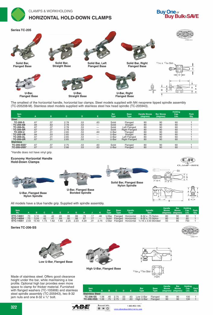
The smallest of the horizontal handle, horizontal bar clamps. Steel models supplied with M4 neoprene tipped spindle assembly (TC-205208-M). Stainless steel models supplied with stainless steel hex head spindle (TC-205943).
Steel TC-205-S .67 .37 2.78 .53 .63 Solid Flanged 80 90 60 1
TC-205-SB .84 .63 2.78 .53 - Solid Straight 80 90 60 1 TC-205-SL .67 .37 2.78 .53 - Solid Left Flanged 80 90 60 1 TC-205-SR .67 .37 2.78 .53 - Solid Right Flanged 80 90 60 1 TC-205-U .67 .31 2.65 .53 .63 U-Bar Flanged 80 90 60 1
TC-205-UB .84 .53 2.65 .53 - U-Bar Straight 80 90 60 1 TC-205-UL .67 .31 2.65 .53 - U-Bar Left Flanged 80 90 60 1 TC-205-UR .67 .31 2.65 .53 U-Bar Right Flanged 80 90 60 1
Stainless TC-205-SSS* .67 .37 2.75 .53 .63 Solid Flanged 80 90 60 1 TC-205-USS* .67 .31 2.66 .53 .63 U-Bar Flanged 80 90 60 1
*Handle does not have vinyl grip.
Economy Horizontal Handle Hold-Down Clamps
M.6412.-RITE
Handle Bar Holding item Bar Base Handle Spindle Moves Moves Cap. Pack No. A B C D E F G H J K Type Type Type Size (degrees) (degrees) Lbs. Qty.
ETC-14051 .70 3.10 .34 .42 .65 .95 .98 .78 .17 .48 U-Bar Flanged Horizontal 8-32 x .75 Nylon
80
90
60 ETC-14054 .73 3.24 .42 .41 .64 .95 .98 .87 .17 Solid Flanged Horizontal 8-32 x .75 Nylon
80
90
60 ETC-14351 2.55 10.40 1.73 1.62 1.60 2.25 2.23 4.29 .31 2.75 U-Bar Flanged Horizontal %-16 x 3.50 Bonded
50
85
750
Series TC-206-SS
eye* f01[5:11ft;
Low U-Bar, Flanged Base
Made of stainless steel. Offers good clearance height under the bar, while maintaining a low profile. Optional high bar provides even more space to clamp for thicker material. Furnished with flanged washers (TC-105906) and stainless steel spindle assembly (TC-205943), two 8-32 jam nuts and one 8-32 x 34" bolt.
322 322
E
D
11/16 x 17/64 Slot
C
A AB B
Solid Bar, Flanged Base
Solid Bar, Straight Base
Solid Bar, Left Flanged Base
Solid Bar, Right Flanged Base
U-Bar, Flanged Base
U-Bar, Straight Base
U-Bar, Right Flanged Base
Series TC-205
The smallest of the horizontal handle, horizontal bar clamps. Steel models supplied with M4 neoprene tipped spindle assembly (TC-205208-M). Stainless steel models supplied with stainless steel hex head spindle (TC-205943).
*Handle does not have vinyl grip.
ItemNo. A B C D E
BarType
BaseType
Handle Moves(degrees)
Bar Moves(degrees)
HoldingCap.Lbs.
PackQty.
SteelTC-205-S .67 .37 2.78 .53 .63 Solid Flanged 80 90 60 1
TC-205-SB .84 .63 2.78 .53 — Solid Straight 80 90 60 1TC-205-SL .67 .37 2.78 .53 — Solid Left Flanged 80 90 60 1TC-205-SR .67 .37 2.78 .53 — Solid Right Flanged 80 90 60 1TC-205-U .67 .31 2.65 .53 .63 U-Bar Flanged 80 90 60 1
TC-205-UB .84 .53 2.65 .53 — U-Bar Straight 80 90 60 1TC-205-UL .67 .31 2.65 .53 — U-Bar Left Flanged 80 90 60 1TC-205-UR .67 .31 2.65 .53 — U-Bar Right Flanged 80 90 60 1
StainlessTC-205-SSS* .67 .37 2.75 .53 .63 Solid Flanged 80 90 60 1TC-205-USS* .67 .31 2.66 .53 .63 U-Bar Flanged 80 90 60 1
Economy Horizontal HandleHold-Down Clamps
All models have a blue handle grip. Supplied with spindle assembly.
C C
HB E
A A
K
D
F
ØJ
E G
ItemNo. A B C D E F G H J K
BarType
BaseType
HandleType
SpindleSize
Handle Moves
(degrees)
Bar Moves
(degrees)
HoldingCap. Lbs.
PackQty.
ETC-14051 .70 3.10 .34 .42 .65 .95 .98 .78 .17 .48 U-Bar Flanged Horizontal 8-32 x .75 Nylon 80 90 60 1ETC-14054 .73 3.24 .42 .41 .64 .95 .98 .87 .17 — Solid Flanged Horizontal 8-32 x .75 Nylon 80 90 60 1ETC-14351 2.55 10.40 1.73 1.62 1.60 2.25 2.23 4.29 .31 2.75 U-Bar Flanged Horizontal 3⁄8-16 x 3.50 Bonded 50 85 750 1
U-Bar, Flanged BaseNylon Spindle
Solid Bar, Flanged BaseNylon Spindle
U-Bar, Flanged BaseBonded Spindle
Made of stainless steel. Offers good clearance height under the bar, while maintaining a low profile. Optional high bar provides even more space to clamp for thicker material. Furnished with flanged washers (TC-105906) and stainless steel spindle assembly (TC-205943), two 8-32 jam nuts and one 8-32 x 3⁄4" bolt.
ItemNo. A B C D E
BarType
BaseType
Handle Moves
(degrees)
Bar Moves
(degrees)
HoldingCap. Lbs.
PackQty.
Stainless SteelTC-206-SS 1.06 .40 2.75 .53 .63 Low U-Bar Flanged 90 90 100 1
TC-206-HSS 1.06 .75 2.75 .53 .63 High U-Bar Flanged 90 90 100 1
A
C
D
E
B
11/64 x 17/64 Slot
High U-Bar, Flanged Base
Low U-Bar, Flanged Base
Series TC-206-SS
HORIZONTAL HOLD-DOWN CLAMPS
FWAHL
SmallO

.96 .98 .87
E
D
17/64 "ID Dia.
90 500 90 500
C
ow
CLAMPS & WORKHOLDING 'IN
HORIZONTAL HOLD-DOWN CLAMPS
Series TC-213, 217, 227, 237, 245
Safety designed to give more hand clearance between the bar and handle when clamps are in full, open position. Bar guide feature gives extra lateral support and rigidity to hold-down bar at front of base. Steel models are supplied with a neoprene tipped spindle assembly and flanged washers. Stainless Steel models are supplied with a stainless steel hex head spindle assembly. U-bar type.
Handle Bar Holding item Moves Base Moves Cap. Pack No. A B C D E F d=sees A•= d=sees Lbs.
Steel TC-213-U 1.39 .72 4.12 .53 .70 M5 60 Flanged 90 150 1 TC-217-U 1.95 .97 6.56 1.03 1.12 M6 76 Flanged 92 200 1 TC-227-U 2.43 1.30 7.56 1.03 1.22 M8 62 Flanged 92 500 1 TC-237-U 3.20 1.62 10.67 1.63 1.69 M10 63 Flanged 92 750 1 TC-245-U 4.25 2.25 12.33 1.63 1.63 1/2-13 67 Flanged 105 1,000 1
Stainless Steel TC-213-USS 1.36 .75 3.94 .53 .69 10-32 60 Flanged 90 150 1 TC-217-USS 1.97 .97 6.30 1.03 1.15 1/4-20 76 Flanged 92 250 1 TC-227-USS 2.39 1.31 7.24 1.03 1.23 Vie-18 62 Flanged 92 600 1
Series TC-215
Steel models furnished with M6 bonded neoprene spindle (TC-202208-M), jam nuts and flanged washers or bolt retainer. Stainless steel model supplied with stainless steel hex head spindle (TC-202943), without neoprene tip.
Handle Bar Item Bar Base Moves Moves Holding Pack No. A B C D E Type Type (degrees) (degrees) Cap. Lbs. Qty.
Steel
TC-215-S 1.53 1.03 5.50 1 .88 Solid Flanged 70 90 200 1 TC-215-U 1.53 1.03 5.50 1 .88 U-Bar Flanged 70 90 200 1
Stainless Steel
TC-215-USS* 1.53 1.03 5.50 1 .88 U-Bar Flanged 70 90 200 1
*Handle does not have vinyl grip.
U-Bar, Straight Base Bonded Spindle
U-Bar, Flanged Base Bonded Spindle
All models have a blue handle grip. Supplied with spindle assembly. E
Item Handle Bar
Bar Base Moves Moves Holding Pack No. A BCD E F G H J K Type Type Handle Type Spindle Size (degrees) (degrees) Cap. Lbs. Qty.
CC
tx H-4-1
Series TC-225
Steel model furnished with M8 bonded neoprene tipped spindle (TC-225208-M), flanged washers and lock nuts. Stainless steel model supplied with stainless steel hex head spindle (TC-207943), without neoprene tip.
Handle Bar Holding item Bar Base Moves Moves Cap. Pack No. A B C D E Type Type (degrees) (degrees) Lbs. Qty.
Steel
TC-225-U 1.84 1.32 6.70 1 .88 U-Bar Flanged 70 92 500 1 Stainless Steel
TC-225-USS* 1.84 1.32 6.70 1 .88 U-Bar Flanged 70 92 600 1
*Handle does not have vinyl grip.
Economy Horizontal Handle Hold-Down Clamps
NM.
U-Bar, Flanged Base Bonded Spindle
All models have a blue handle grip. Supplied with spindle assembly.
U-Bar, Straight Base Bonded Spindle
Holding item Bar Base Handle Spindle Handle Moves Bar Moves Cap. Pack No. A B C D E F G H J K Typo Type Type Size (degrees) (degrees) Lbs. Qty.
323
•=0444.4
U-Bar Flanged Base
.-I
U-Bar Flanged Base
E A
D
C
Economy Horizontal Handle Hold-Down Clamps
s • 11111mb
CSR E G rerre -A- T
I-4- F.-1
ETC-14151 1.52 5.90 1.46 1.36 2.29 .21 1.51 U-Bar Flanged Horizontal 1/4-20 x 2.13 Bonded 200 1 2.28 .21 1.33 U-Bar Straight Horizontal 'A-20 x 2.13 Bonded 60 85 200 1
60 85 ETC-14152 1.76 5.90 1.23 .98 xx 1.46
C
U-Bar Flanged Base
Cr- P-DESIA<c‘ 41/
•=1,4444,
-Y- A -js in E G
Y FUTE -A-
65 ETC-14252 2.18 6.88 1.66 .99 xx 1.51 - 2.91 .28 1.42 U-Bar Straight Horizontal Vre-18 x 3.00 Bonded 65 ETC-14251 1.96 6.88 1.31 .99 .89 1.51 1.36 2.91 .28 1.31 U-Bar Flanged Horizontal 5/1e-18 x 3.00 Bonded
f
L
323
ItemNo. A B C D E F G H J K
BarType
BaseType
HandleType
SpindleSize
Handle Moves(degrees)
Bar Moves(degrees)
HoldingCap. Lbs.
PackQty.
ETC-14251 1.96 6.88 1.31 .99 .89 1.51 1.36 2.91 .28 1.31 U-Bar Flanged Horizontal 5⁄16-18 x 3.00 Bonded 65 90 500 1ETC-14252 2.18 6.88 1.66 .99 xx 1.51 — 2.91 .28 1.42 U-Bar Straight Horizontal 5⁄16-18 x 3.00 Bonded 65 90 500 1
Series TC-213, 217, 227, 237, 245
E
D
CF Thd.
AA
BB
Safety designed to give more hand clearance between the bar and handle when clamps are in full, open position. Bar guide feature gives extra lateral support and rigidity to hold-down bar at front of base. Steel models are supplied with a neoprene tipped spindle assembly and flanged washers. Stainless Steel models are supplied with a stainless steel hex head spindle assembly. U-bar type. U-Bar
Flanged Base
ItemNo. A B C D E F
Handle Moves
(degrees)BaseType
Bar Moves
(degrees)
HoldingCap. Lbs.
PackQty.
SteelTC-213-U 1.39 .72 4.12 .53 .70 M5 60 Flanged 90 150 1TC-217-U 1.95 .97 6.56 1.03 1.12 M6 76 Flanged 92 200 1TC-227-U 2.43 1.30 7.56 1.03 1.22 M8 62 Flanged 92 500 1TC-237-U 3.20 1.62 10.67 1.63 1.69 M10 63 Flanged 92 750 1TC-245-U 4.25 2.25 12.33 1.63 1.63 1⁄2-13 67 Flanged 105 1,000 1
Stainless SteelTC-213-USS 1.36 .75 3.94 .53 .69 10-32 60 Flanged 90 150 1TC-217-USS 1.97 .97 6.30 1.03 1.15 1⁄4-20 76 Flanged 92 250 1TC-227-USS 2.39 1.31 7.24 1.03 1.23 5⁄16-18 62 Flanged 92 600 1
Series TC-225
C
17/64Dia.
D
E
AB
Steel model furnished with M8 bonded neoprene tipped spindle (TC-225208-M), flanged washers and lock nuts. Stainless steel model supplied with stainless steel hex head spindle (TC-207943), without neoprene tip.
*Handle does not have vinyl grip.
U-BarFlanged Base
Series TC-215
AB
C
D
E
Steel models furnished with M6 bonded neoprene spindle (TC-202208-M), jam nuts and flanged washers or bolt retainer. Stainless steel model supplied with stainless steel hex head spindle (TC-202943), without neoprene tip.
*Handle does not have vinyl grip.
U-BarFlanged Base
ItemNo. A B C D E
BarType
BaseType
Handle Moves
(degrees)
Bar Moves
(degrees)Holding
Cap. Lbs.PackQty.
SteelTC-215-S 1.53 1.03 5.50 1 .88 Solid Flanged 70 90 200 1TC-215-U 1.53 1.03 5.50 1 .88 U-Bar Flanged 70 90 200 1
Stainless SteelTC-215-USS* 1.53 1.03 5.50 1 .88 U-Bar Flanged 70 90 200 1
ItemNo. A B C D E
BarType
BaseType
Handle Moves
(degrees)
Bar Moves
(degrees)
HoldingCap. Lbs.
PackQty.
SteelTC-225-U 1.84 1.32 6.70 1 .88 U-Bar Flanged 70 92 500 1
Stainless SteelTC-225-USS* 1.84 1.32 6.70 1 .88 U-Bar Flanged 70 92 600 1
C C
HB E
A A
K
D
F
ØJ
E G
All models have a blue handle grip. Supplied with spindle assembly.
U-Bar, Straight BaseBonded Spindle
U-Bar, Flanged BaseBonded Spindle
ItemNo. A B C D E F G H J K
BarType
BaseType Handle Type Spindle Size
Handle Moves
(degrees)
Bar Moves
(degrees)Holding
Cap. Lbs.PackQty.
ETC-14151 1.52 5.90 .96 .98 .87 1.46 1.36 2.29 .21 1.51 U-Bar Flanged Horizontal 1⁄4-20 x 2.13 Bonded 60 85 200 1ETC-14152 1.76 5.90 1.23 .98 xx 1.46 — 2.28 .21 1.33 U-Bar Straight Horizontal 1⁄4-20 x 2.13 Bonded 60 85 200 1
Economy Horizontal HandleHold-Down Clamps
C C
HB E
A A
K
D
F
ØJ
E G
All models have a blue handle grip. Supplied with spindle assembly.
U-Bar, Straight BaseBonded SpindleU-Bar, Flanged Base
Bonded Spindle
Economy Horizontal HandleHold-Down Clamps
HORIZONTAL HOLD-DOWN CLAMPS
FWAHL
SmallO

TC-225-UR,235-UR DE-STA-CO. Toggle Lock Plus
Item No.
Base Handle Moves Bar Move - (degrees) (degree) A D E F Type
Holding Cap. Lbs.
Pack Qty.
TC-225-UR 1.92 .88 1.63
1.32 1.75
1.00 1.63
7.14 10.50 TC-235-UR 2.50
92 70 .27 .33
500 U-Bar U-Bar
Flanged Flanged 92 70 750
150 350 750
.63 M8 170 90 1.16 M8 170 90 1.50 M10 170 90
.63 M8 170 90 200 1.16 Me-18 170 90 350 1.50 %-16 170 90 750
Small compact clamps provide considerable holding capacity in a small size. T-handle can be operated from either side or from behind. All have U-Bar and flanged base. Handles move 170 degrees, bars move 90 degrees. Steel versions supplied with neoprene tipped spindle except TC-309 which comes with slip on neoprene cap. Stainless steel versions supplied with hex head spindle.
Steel TC-305-U 1.38 .50 2.22 .53 TC-307-U 2.40 .87 3.60 .91 TC-309-U 3.55 1.30 5.18 1.38
Stainless Steel TC-305-USS 1.38 .50 2.22 .53 TC-307-USS 2.40 .87 3.60 .91 TC-309-USS 3.55 1.30 5.18 1.38
T
D
Series TC-305, 307, 309
(305) - For #8 Screw (307) - For Screw (309) - For 511e' Screw
F Thd.
B
A
U-Bar Flanged Base
All models have a blue handle grip. Supplied with spindle assembly.
.53
.91 1.38
.66 1.03 1.17 1.72 1.50 2.52
TC-305-UR 1.44 2.25 U-Bar
Flanged Based
Handle Bar Holding Spindle Moves Opening Cap. Pack
Assembly (degrees) (degrees) Lbs. Qty. Flanged Washer C D E F
Item No. A B G H J K
TA
I
TC-102111 TC-305208-M 175 92 150
TC-305-UR, 307-UR DE-STA-Clr Toggle Lock Plus
TC-307-UR 2.44 3.61
These clamps feature a compact locking lever, which locks in the clamped position only. Provided with red vinyl handle grip and flanged washers. Supplied with neoprene-tipped spindle assemblies.
TC-507107 TC-307208-M 175 92 350 .50 .53 .63 1.03 1.00 1.22 .17 .50 .88 .91 1.16 1.72 1.81 1.89 .28 .75
Handle Bar Holding Moves Moves Cap. Pack
(degrees) (degrees) Lbs. Qty. ETC-16051 1.47 2.30 .65 ETC-16071 2.49 3.68 .89 ETC-16091 3.73 5.33 1.31
1.26 .17 .44 1.32 U-Bar Flanged Tee 1.93 .28 .77 2.01 U-Bar Flanged Tee 2.81 .31 1.32 2.48 U-Bar Flanged Tee
10-24 x 1.38 Bonded 5/113-18 x 2.50 Bonded %-16 x 3.50 Bonded
170 90 150 170 90 350 170 90 750
1.03 1.82 2.52
324
rliN CLAMPS & WORKHOLDING
HORIZONTAL HOLD-DOWN CLAMPS
Series TC-235
Steel model furnished with M10 bonded neoprene tipped spindle (TC-240208-M), flanged washers and lock nuts. Stainless steel model supplied with stainless steel hex head spindle (TC-237943), without neoprene tip.
TC-235-USS 2.55 1.75 10.87 1.63 1.63 U-Bar Flanged 55 90 750 1
U-Bar Flanged Base
21/64,,P Dia. E
D
Buy One or Buy Bulk&SIVE
C
U-Bar, Flanged Base M10 Bonded Neoprene
Tipped Spindle
F
LOCKING MECHANISM
Equipped with a locking lever which locks in clamped position only. Large handle pad for greater comfort. TC-225-UR supplied with an M8 neoprene tipped spindle assembly (TC-225208-M) and two washers (TC-507107). TC-235-UR furnished with M10 bonded neoprene tipped spindle (TC-240208-M), flanged washers and jam nuts.
Handle Bar Bar Base Moves Moves Holding Pack
AB C DE Type Type (degrees) (degrees) Cap. Lbs. Qty. Steel
TC-235-U 2.55 1.75 10.87 1.63 1.63 U-Bar Flanged 55 90 750 1 Stainless Steel
E
324
U-BarFlanged Base
Equipped with a locking lever which locks in clamped position only. Large handle pad for greater comfort. TC-225-UR supplied with an M8 neoprene tipped spindle assembly (TC-225208-M) and two washers (TC-507107). TC-235-UR furnished with M10 bonded neoprene tipped spindle (TC-240208-M), flanged washers and jam nuts.
ItemNo. A B C D E F
BarType
BaseType
Handle Moves(degrees)
Bar Moves(degree)
HoldingCap. Lbs.
PackQty.
TC-225-UR 1.92 1.32 7.14 1.00 .88 .27 U-Bar Flanged 70 92 500 1TC-235-UR 2.50 1.75 10.50 1.63 1.63 .33 U-Bar Flanged 70 92 750 1
TC-225-UR,235-URDE-STA-CO® Toggle Lock Plus
LOCKINGMECHANISM
C
BA
D
EF
U-Bar, Flanged BaseM10 Bonded Neoprene
Tipped Spindle
Small compact clamps provide considerable holding capacity in a small size. T-handle can be operated from either side or from behind. All have U-Bar and flanged base. Handles move 170 degrees, bars move 90 degrees. Steel versions supplied with neoprene tipped spindle except TC-309 which comes with slip on neoprene cap. Stainless steel versions supplied with hex head spindle.
ItemNo. A B C D E F
Handle Moves(degrees)
Bar Moves(degrees)
HoldingCap. Lbs.
PackQty.
SteelTC-305-U 1.38 .50 2.22 .53 .63 M8 170 90 150 1TC-307-U 2.40 .87 3.60 .91 1.16 M8 170 90 350 1TC-309-U 3.55 1.30 5.18 1.38 1.50 M10 170 90 750 1
Stainless SteelTC-305-USS 1.38 .50 2.22 .53 .63 M8 170 90 200 1TC-307-USS 2.40 .87 3.60 .91 1.16 5⁄16-18 170 90 350 1TC-309-USS 3.55 1.30 5.18 1.38 1.50 3⁄8-16 170 90 750 1
Series TC-305, 307, 309
E
D
B
C
A
(305) - For #8 Screw(307) - For 1/4" Screw(309) - For 5/16" Screw
F Thd.
U-BarFlanged Base
All models have a blue handle grip. Supplied with spindle assembly.
ItemNo. A B C D E F G H J K L
BarType
BaseType
HandleType
SpindleSize
Handle Moves
(degrees)
Bar Moves
(degrees)
HoldingCap. Lbs.
PackQty.
ETC-16051 1.47 2.30 .65 .53 .66 1.03 1.03 1.26 .17 .44 1.32 U-Bar Flanged Tee 10-24 x 1.38 Bonded 170 90 150 1ETC-16071 2.49 3.68 .89 .91 1.17 1.72 1.82 1.93 .28 .77 2.01 U-Bar Flanged Tee 5⁄16-18 x 2.50 Bonded 170 90 350 1ETC-16091 3.73 5.33 1.31 1.38 1.50 2.52 2.52 2.81 .31 1.32 2.48 U-Bar Flanged Tee 3⁄8-16 x 3.50 Bonded 170 90 750 1
Economy Horizontal T-HandleHold-Down Clamps
FD ØJ
E GL
K
These clamps feature a compact locking lever, which locks in the clamped position only. Provided with red vinyl handle grip and flanged washers. Supplied with neoprene-tipped spindle assemblies.
ItemNo. A B C D E F G H J K
FlangedWasher
SpindleAssembly
Handle Moves
(degrees)
Bar Opening(degrees)
HoldingCap. Lbs.
PackQty.
TC-305-UR 1.44 2.25 .50 .53 .63 1.03 1.00 1.22 .17 .50 TC-102111 TC-305208-M 175 92 150 1TC-307-UR 2.44 3.61 .88 .91 1.16 1.72 1.81 1.89 .28 .75 TC-507107 TC-307208-M 175 92 350 1
TC-305-UR, 307-URDE-STA-CO® Toggle Lock Plus
HB
A
C
FD
GE
J
K
U-BarFlanged Based
A
C
HB
Series TC-235
Steel model furnished with M10 bonded neoprene tipped spindle (TC-240208-M), flanged washers and lock nuts. Stainless steel model supplied with stainless steel hex head spindle (TC-237943), without neoprene tip.
ItemNo. A B C D E
BarType
BaseType
Handle Moves
(degrees)
Bar Moves
(degrees)Holding
Cap. Lbs.PackQty.
SteelTC-235-U 2.55 1.75 10.87 1.63 1.63 U-Bar Flanged 55 90 750 1
Stainless SteelTC-235-USS 2.55 1.75 10.87 1.63 1.63 U-Bar Flanged 55 90 750 1
HORIZONTAL HOLD-DOWN CLAMPS
C
21/64Dia.
D
E
AB
FWAHL
SmallO

0 °0 1 WO*
0000
STC-HH50 1.79 .84 8.25 1.00 STC-HH70 2.50 1.54
8.25 1.00
1.52 2.24 2.00 25-550 700 1 1.52 2.24 2.75 25-550 700 1
Pages 17, 22, 34, 36, 37
CLAMPS & WORKHOLDING ,' N
AUTO-ADJUST HORIZONTAL HANDLE HOLD DOWN CLAMPS ._,1
Horizontal Toggle Clamps -4- -I.
B y
0 o
Auto-Adjust - The Bessey auto-adjust toggle clamp automatically adjusts to variations in work piece dimensions while maintaining constant clamping force. No more time-consuming manual adjustment of the spindle height to maintain safe and correct clamping force. The removable non-marring plastic cap is included on the '/8" diameter pads. Adjusting Clamping Force - The integrated clamping force adjustment screw can be used to create an actually applied clamping force from 25 to 550 lbs. (max holding capacity 700 lbs.) One Bessey auto -adjust toggle clamp can replace a range of competitive clamps. Adaptable Base Plate - The large (2'/4" x 2'/2") flange base is designed for use with '4" or M6 fasteners. Mounting holes are sized and spaced for easy mounting and versatility. Extra Large Handle - The large 1" x 2'43" handle offers greater user comfort and ease of operation.
-M!M!!!!!!!!MEEIWEMSM Note: Clamping force range is variable and dependent on spindle settings, pressure screw setting, force applied, etc.
...use these knobs with our hold-down clamps.
325 325
FOR QUICK PLUNGER ADJUSTMENTS...
...use these knobs with our hold-down clamps.
Pages 17, 22, 34, 36, 37
Horizontal Toggle Clamps
Auto-Adjust - The Bessey auto-adjust toggle clamp automatically adjusts to variations in work piece dimensions while maintaining constant clamping force. No more time-consuming manual adjustment of the spindle height to maintain safe and correct clamping force. The removable non-marring plastic cap is included on the 7⁄8" diameter pads.Adjusting Clamping Force - The integrated clamping force adjustment screw can be used to create an actually applied clamping force from 25 to 550 lbs. (max holding capacity 700 lbs.) One Bessey auto -adjust toggle clamp can replace a range of competitive clamps.Adaptable Base Plate - The large ( 21⁄4" x 21⁄2") flange base is designed for use with 1⁄4" or M6 fasteners. Mounting holes are sized and spaced for easy mounting and versatility.Extra Large Handle - The large 1" x 21⁄8" handle offers greater user comfort and ease of operation.
Note: Clamping force range is variable and dependent on spindle settings, pressure screw setting, force applied, etc.
B
A
C
G E
D
ItemNo. A B C D E G Opening
ClampingForce Range
HoldingCap. Lbs.
PackQty.
STC-HH50 1.79 .84 8.25 1.00 1.52 2.24 2.00 25-550 700 1STC-HH70 2.50 1.54 8.25 1.00 1.52 2.24 2.75 25-550 700 1
AUTO-ADJUST HORIZONTAL HANDLE HOLD DOWN CLAMPS
FWAHL
SmallO

Horizontal Hold Down Clamps with Safety Interlock Flat Foot and Adjustable Clamping Spindle Series 05900
New
cpp
D
T
".• Hole arrangement for Item No. KC-150, KC-155, and KC-160
E F
Hole arrangement for Item No. KC-165
H K /4-
-e-F1
2=11E2416 Toggle clamp in the closed locked position
Toggle clamp locking mechanism is released by pulling back on the sides of the paddle grip
Horizontal Hold Down Clamps With Flat Foot and Adjustable Clamping Spindle Series 05900
H K -0+1. I-C
D .-0-1
F-N-1 1-4-E-04
Hole arrangement for Item No. KC-110,
KC-115, and KC-120
H
E-0-1 1-*F
Hole arrangement for Item No. KC-125
T
Hole arrangement for Item No. KC-105
New
Hole arrangement for Item No. KC-100
C
rli N CLAMPS & WORKHOLDING
HORIZONTAL HOLD-DOWN CLAMPS Buy One or
Buy Bulk&SIVE
Maintenance-free, high quality swivel bushings. Constant use of force when opening and closing. Optimum stability is achieved through the conical clamping arm and U-profile. Includes an internal bar lock with automatic safety.
item No. A B C D E F G
KC-150 63.3 25.5 193.3 5.5 26.0 6.5 KC-155 73.9 32.2 230.3 6.2 26.0 9 KC-160 94.8 40.0 286.0 8.8 41.5 9 KC-165 104.9 52.3 321.3 8.5 44.0 10 40
Holding Capacity Pack
H M N P Lbs. Qty.
39 162 44 187 59 270 65 225
28
39
53.4
M6 x 35mm 31
45
51.1
M8 x 45mm 43
59
56.5
M10 x 55mm 42
67
56.5
M12 x 70mm
Maintenance-free, high quality swivel bushings. Constant use of force when opening and closing. Optimum stability is achieved through the conical clamping arm and U-profile.
Item No. A M N P
Holding Capacity Pa
Lbs.
KC-100 29.3 11.7 91.8 4.2 16.0 4 12.74 16.0 24 20.0 M4 x 16 24 56 KC-105 43.4 18.0 126.3 5.5 18.0 4.5 13.5 16.8 27 22.5 M5 x 25 27 124 KC-110 63.2 25.5 186.7 5.5 26.0 6.5 28.0 39 43.5 M6 x 35 39 162 KC-115 73.9 32.2 223.2 6.2 26.0 9 31.0 45 41.5 M8 x 45 44 187 KC-120 94.8 40.0 279.4 8.8 41.5 9 43.0 59 47.0 M10 x 55 59 270 KC-125 104.8 52.3 314.7 8.5 44.0 10 40 42.0 67 47.0 M12 x 70 65 225
326 326
B
N
P
A
C
J
M
H K
F E
D
Hole arrangement for Item No. KC-150, KC-155, and KC-160
GFE
H
D
Hole arrangement for Item No. KC-165
Toggle clamp in the closed locked position
Toggle clamp locking mechanism is released by pulling back on the sides of the paddle grip
Maintenance-free, high quality swivel bushings. Constant use of force when opening and closing. Optimum stability is achieved through the conical clamping arm and U-profile. Includes an internal bar lock with automatic safety.
ItemNo. A B C D E F G H J M N P
HoldingCapacity
Lbs.PackQty.
KC-150 63.3 25.5 193.3 5.5 26.0 6.5 — 28 39 53.4 M6 x 35mm 39 162 1KC-155 73.9 32.2 230.3 6.2 26.0 9 — 31 45 51.1 M8 x 45mm 44 187 1KC-160 94.8 40.0 286.0 8.8 41.5 9 — 43 59 56.5 M10 x 55mm 59 270 1KC-165 104.9 52.3 321.3 8.5 44.0 10 40 42 67 56.5 M12 x 70mm 65 225 1
Horizontal Hold Down Clamps with Safety InterlockFlat Foot and Adjustable Clamping SpindleSeries 05900
B
N
P
A
M
J
C
H K
GF E
D
H
Hole arrangement for Item No. KC-100
F E
D
Hole arrangement for Item No. KC-110,
KC-115, and KC-120
GF E
H
D
Hole arrangement for Item No. KC-105
GFE
H
D
Hole arrangement for Item No. KC-125
Maintenance-free, high quality swivel bushings. Constant use of force when opening and closing. Optimum stability is achieved through the conical clamping arm and U-profile.
ItemNo. A B C D E F G H J M N P
HoldingCapacity
Lbs.PackQty.
KC-100 29.3 11.7 91.8 4.2 16.0 4 12.74 16.0 24 20.0 M4 x 16 24 56 1KC-105 43.4 18.0 126.3 5.5 18.0 4.5 13.5 16.8 27 22.5 M5 x 25 27 124 1KC-110 63.2 25.5 186.7 5.5 26.0 6.5 — 28.0 39 43.5 M6 x 35 39 162 1KC-115 73.9 32.2 223.2 6.2 26.0 9 — 31.0 45 41.5 M8 x 45 44 187 1KC-120 94.8 40.0 279.4 8.8 41.5 9 — 43.0 59 47.0 M10 x 55 59 270 1KC-125 104.8 52.3 314.7 8.5 44.0 10 40 42.0 67 47.0 M12 x 70 65 225 1
Horizontal Hold Down ClampsWith Flat Foot and Adjustable Clamping SpindleSeries 05900
HORIZONTAL HOLD-DOWN CLAMPS
FWAHL
SmallO

Horizontal Hold Down Clamps with Safety Interlock With Straight Foot and Adjustable Clamping Spindle Series 05904
New,
K (e)
C F•1 GE
Hole arrangement for Item No. KC-265
[4 p
Hole arrangement for Item No. KC-250, KC-255, and KC-260
2==041114 Toggle clamp in the closed locked position
Toggle clamp locking mechanism is released by pulling back on the sides of the paddle grip
INE=MMMI RE MI Holding Capacity
Pack Lbs. Qty.
FH-E G
Hole arrangement for Item No. KC-200
-ED
f B
K
C
IMMENIM%li
CLAMPS & WORKHOLDING
HORIZONTAL HOLD-DOWN CLAMPS
Maintenance-free, high quality swivel bushings. Constant use of force when opening and closing. Optimum stability is achieved through the conical clamping arm and U-profile. Includes an internal bar lock with automatic safety.
KC-250 74.3 37.0 193.7 5.5 26.0 6.5 14.1 9.1 53.4 M6 x 35 39 162 KC-255 88.2 46.5 230.3 6.2 26.0 9 14.1 9.1 51.1 M8 x 45 44 187 KC-260 114.4 59.6 286.4 8.8 41.5 9 16.2 9.2 56.5 M10 x 55 59 270 KC-265 128.4 75.9 321.3 8.5 44.0 10 40 16.2 9.2 56.5 M12 x 70 65 225
Horizontal Hold Down Clamps With Straight Foot and Adjustable Clamping Spindle Series 05904
< New
E
Hole arrangement for Item No. KC-220
-0-1 1 1--D E p )1
Hole arrangement for Item No. KC-205,
KC-210, and KC-215
F
Maintenance-free, high quality swivel bushings. Constant use of force when opening and closing. Optimum stability is achieved through the conical clamping arm and U-profile.
KC-200 51.8 26.0 125.7 5.5 18.0 4.5 13.5 8.1 4.1 22.5 M5 x 25 27 124 KC-205 74.2 37.0 186.8 5.5 26.0 6.5 14.1 9.1 43.5 M6 x 35 39 162 KC-210 88.2 46.5 273.5 6.2 26.0 9 14.1 9.1 41.5 M8 x 45 44 187 KC-215 114.4 59.6 279.3 8.8 41.5 9 16.2 9.2 47.0 M10 x 55 59 270 KC-220 128.4 75.9 314.7 8.5 44.0 10 40 16.2 9.2 47.0 M12 x 70 65 225
327 327
B
N
M
JH
K
A
CF
EP
Hole arrangement for Item No. KC-250, KC-255, and KC-260
D
GF E
D
Hole arrangement for Item No. KC-265
Toggle clamp in the closed locked position
Toggle clamp locking mechanism is released by pulling back on the sides of the paddle grip
Maintenance-free, high quality swivel bushings. Constant use of force when opening and closing. Optimum stability is achieved through the conical clamping arm and U-profile. Includes an internal bar lock with automatic safety.
ItemNo. A B C D E F G H J M N P
HoldingCapacity
Lbs.PackQty.
KC-250 74.3 37.0 193.7 5.5 26.0 6.5 — 14.1 9.1 53.4 M6 x 35 39 162 1KC-255 88.2 46.5 230.3 6.2 26.0 9 — 14.1 9.1 51.1 M8 x 45 44 187 1KC-260 114.4 59.6 286.4 8.8 41.5 9 — 16.2 9.2 56.5 M10 x 55 59 270 1KC-265 128.4 75.9 321.3 8.5 44.0 10 40 16.2 9.2 56.5 M12 x 70 65 225 1
Horizontal Hold Down Clamps with Safety InterlockWith Straight Foot and Adjustable Clamping SpindleSeries 05904
B
N
M
JH
K
A
C
FD
EP
Hole arrangement for Item No. KC-205,
KC-210, and KC-215
D
GF E
D
Hole arrangement for Item No. KC-220
GF E
D
Hole arrangement for Item No. KC-200
Horizontal Hold Down ClampsWith Straight Foot and Adjustable Clamping SpindleSeries 05904
Maintenance-free, high quality swivel bushings. Constant use of force when opening and closing. Optimum stability is achieved through the conical clamping arm and U-profile.
ItemNo. A B C D E F G H J M N P
HoldingCapacity
Lbs.PackQty.
KC-200 51.8 26.0 125.7 5.5 18.0 4.5 13.5 8.1 4.1 22.5 M5 x 25 27 124 1KC-205 74.2 37.0 186.8 5.5 26.0 6.5 — 14.1 9.1 43.5 M6 x 35 39 162 1KC-210 88.2 46.5 273.5 6.2 26.0 9 — 14.1 9.1 41.5 M8 x 45 44 187 1KC-215 114.4 59.6 279.3 8.8 41.5 9 — 16.2 9.2 47.0 M10 x 55 59 270 1KC-220 128.4 75.9 314.7 8.5 44.0 10 40 16.2 9.2 47.0 M12 x 70 65 225 1
HORIZONTAL HOLD-DOWN CLAMPS
FWAHL
SmallO

4.00 ETC-12010 1.88 8.40 .75 1.22 1.38 1.72 .28 .60 .12 1.59 Fixed Hook
.39 .63 .75 1.02 1.11 .79
.56 .75 1.25 1.56 1.75 1.00
.75 1.63 1.50 2.38 2.13 1.50
Steel TC-323 1.13 4.00 TC-331 1.96 5.97 TC-341 2.89 7.50
Stainless Steel TC-323-SS 1.13 4.00 .39 .63 .75 1.02 1.11 .79 1.81 .17 .17 .75 .52 .13 .47 360 1 TC-331-SS 1.96 5.97 .56 .75 1.25 1.56 1.75 1.00 1.75 .27 .27 1.00 .69 .17 .66 720 1 TC-341-SS 2.89 7.50 .75 1.63 1.50 2.38 2.13 1.50 2.50 .33 .33 1.75 1.19 .31 .94 2,000 1
rli N CLAMPS & WORKHOLDING
HORIZONTAL PULL-ACTION LATCH CLAMPS
Series TC-301, 311
Fixed stop automatically limits handle travel at various clamping positions once the clamp is installed. Red vinyl handle for comfortable operation.
Drawing Holding Pack No. A B D E F G J K N Movement Cap. Lbs. Qty.
Steel
TC-301 1.91 8.40 .75 1.25 1.38 1.75 .28 .56 .12 4.00 375 1 TC-311 2.44 9.52 1.25 1.78 1.91 2.53 .33 .56 .13 3.38 1,200 1
Stainless Steel TC-301-SS 1.91 8.40 .75 1.25 1.38 1.75 .28 .56 .12 4.00 450 1
Economy Pull-Action Latch Clamps
111111.
-71 4t1*-
Economy Pull Action Latch Clamps
.inallalg51.7.411:11111. N D - 0J
r- f K tlw E G
-44-f Y
(4-0
13 375
Item Drawing Holding Pack No. A BCD E F G H Movement J J1 K L NO Cap. Lbs. Qty.
1.81 .17 .17 .75 .52 .13 .47 360 1 1.75 .27 .27 1.00 .69 .17 .66 720 1 2.50 .33 .33 1.75 1.19 .31 .94 2,000 1
p
a All models have a blue handle grip. Clamps are supplied with latch plates.
Holding Q Hook Drawing Cap. Pack
N 0 Min. Max. Size Movement Lbs. r . Item
K No. A M4 M5 M8
1.81 1.75 2.50
360 1 700 1
2,000 1
.44 1.84 2.57
.50 2.53 3.69
.83 4.39 5.37
.17 .80 .55 .13
.28 1.00 .79 .17
.34 1.75 1.17 .31
ETC-12230 1.31 4.18 .40 .62 .76 1.03 1.12 .78 ETC-12310 1.91 6.56 .48 .78 1.25 1.52 1.75 1.01 ETC-12410 2.75 8.48 .76 1.62 1.44 2.39 2.12 1.17
Drawing Holding Pack A B C D E F G H J 0 Movement Cap. Lbs. Qty.
Item No.
4.00 .39 .63 .75 1.02 1.11 .79 .17 .47 1.17 360 5.97 .56 .75 1.25 1.56 1.75 1.00 .27 .68 1.75 700 7.50 .75 1.63 1.50 2.38 2.12 1.50 .33 .94 2.50 2,000
Steel TC-323-R 1.23 TC-331-R 2.08 TC-341-R 2.89
Stainless Steel TC-323-RSS 1.23 4.00 .39 .63 .75 1.02 1.11 .79 .17 .47 1.17 360 TC-331-RSS 2.08 5.97 .56 .75 1.25 1.56 1.75 1.00 .27 .68 1.75 720 TC-341-RSS 2.89 7.50 .75 1.63 1.50 2.38 2.12 1.50 .33 .94 2.50 2,000
All models have a blue handle grip. Item Bar Drawing Holding Pack No. A B D E F G J K NO Type Movement Cap. Lbs. Qty.
Series TC-323, 331, 341
The threaded U-bolt permits easy adjustment and provides a positive connection with the supplied latch plate. Furnished with a thumb control lever.
L
B
i(11 ,r,C1 D H
F> <
A 0 1
Series TC-323-R, TC-331-R, 341-R DE-STA-004° Toggle Lock Plus
Supplied with a locking lever catch which allows clamp to lock in closed position only. The threaded U-bolt provides easy adjustment and a positive connection with the supplied latch plate.
•=)•••••••
328
Buy One or Buy Bulk&SIVE
ir'"-DESPtC0-"4 -•16,
A t E G
A
328
Series TC-301, 311
Fixed stop automatically limits handle travel at various clamping positions once the clamp is installed. Red vinyl handle for comfortable operation.
ItemNo. A B D E F G J K N
DrawingMovement
HoldingCap. Lbs.
PackQty.
SteelTC-301 1.91 8.40 .75 1.25 1.38 1.75 .28 .56 .12 4.00 375 1TC-311 2.44 9.52 1.25 1.78 1.91 2.53 .33 .56 .13 3.38 1,200 1
Stainless SteelTC-301-SS 1.91 8.40 .75 1.25 1.38 1.75 .28 .56 .12 4.00 450 1
Series TC-323, 331, 341
The threaded U-bolt permits easy adjustment and provides a positive connection with the supplied latch plate. Furnished with a thumb control lever.
ItemNo. A B C D E F G H
DrawingMovement J J1 K L N O
HoldingCap. Lbs.
PackQty.
SteelTC-323 1.13 4.00 .39 .63 .75 1.02 1.11 .79 1.81 .17 .17 .75 .52 .13 .47 360 1TC-331 1.96 5.97 .56 .75 1.25 1.56 1.75 1.00 1.75 .27 .27 1.00 .69 .17 .66 720 1TC-341 2.89 7.50 .75 1.63 1.50 2.38 2.13 1.50 2.50 .33 .33 1.75 1.19 .31 .94 2,000 1
Stainless SteelTC-323-SS 1.13 4.00 .39 .63 .75 1.02 1.11 .79 1.81 .17 .17 .75 .52 .13 .47 360 1TC-331-SS 1.96 5.97 .56 .75 1.25 1.56 1.75 1.00 1.75 .27 .27 1.00 .69 .17 .66 720 1TC-341-SS 2.89 7.50 .75 1.63 1.50 2.38 2.13 1.50 2.50 .33 .33 1.75 1.19 .31 .94 2,000 1
Series TC-323-R, TC-331-R, 341-RDE-STA-CO® Toggle Lock Plus
Supplied with a locking lever catch which allows clamp to lock in closed position only. The threaded U-bolt provides easy adjustment and a positive connection with the supplied latch plate.
ItemNo. A B C D E F G H J O
DrawingMovement
HoldingCap. Lbs.
PackQty.
SteelTC-323-R 1.23 4.00 .39 .63 .75 1.02 1.11 .79 .17 .47 1.17 360 1TC-331-R 2.08 5.97 .56 .75 1.25 1.56 1.75 1.00 .27 .68 1.75 700 1TC-341-R 2.89 7.50 .75 1.63 1.50 2.38 2.12 1.50 .33 .94 2.50 2,000 1
Stainless SteelTC-323-RSS 1.23 4.00 .39 .63 .75 1.02 1.11 .79 .17 .47 1.17 360 1TC-331-RSS 2.08 5.97 .56 .75 1.25 1.56 1.75 1.00 .27 .68 1.75 720 1TC-341-RSS 2.89 7.50 .75 1.63 1.50 2.38 2.12 1.50 .33 .94 2.50 2,000 1
FJ
K
ND
E G
B
A
J
K L
JB
DH
C
F
OA
G
EN
J
O
B
CF
D
H
A
GE
Economy Pull ActionLatch Clamps
All models have a blue handle grip.
ØJ
FD
E G
N
K
O A
B
ItemNo. A B D E F G J K N O
BarType
DrawingMovement
HoldingCap. Lbs.
PackQty.
ETC-12010 1.88 8.40 .75 1.22 1.38 1.72 .28 .60 .12 1.59 Fixed Hook 4.00 375 1
Economy Pull-Action Latch Clamps
All models have a blue handle grip. Clamps are supplied with latch plates.
L
ON
K G
A
E
CH
DF
ØJ
Q
B
ItemNo. A B C D E F G H J K L N O
QMin.
QMax.
HookSize
DrawingMovement
HoldingCap. Lbs.
PackQty.
ETC-12230 1.31 4.18 .40 .62 .76 1.03 1.12 .78 .17 .80 .55 .13 .44 1.84 2.57 M4 1.81 360 1ETC-12310 1.91 6.56 .48 .78 1.25 1.52 1.75 1.01 .28 1.00 .79 .17 .50 2.53 3.69 M5 1.75 700 1ETC-12410 2.75 8.48 .76 1.62 1.44 2.39 2.12 1.17 .34 1.75 1.17 .31 .83 4.39 5.37 M8 2.50 2,000 1
HORIZONTAL PULL-ACTION LATCH CLAMPS
FWAHL
SmallO

4111101°
Flanged Plate Weld-on Type A Type B Type C Type C Type D
Latch plate is not included (except for TC-375-B). All models furnished with a thumb control lever.
G L E
Drawing Holding Pack A B C DE F G H K L NO Movement Cap. Lbs. Qty.
Item No. Type
Item Drawing Holding Pack No. Type A B C D E F G H J K L NO Movement Cap. Lbs. Qty.
Item la Drawing Holding Pack No. A B C D E F G K N Cl Min. Max. Movement Cap. Lbs. Qty.
.75 1,500 1 TC-3051 1.77 8.98 .69 .75 1.38 2.03 1.93 .39 .31 1.99 2.50
3.50 4,000 1 2.19 7,500 1
C
ir,
CLAMPS & WORKHOLDING 'N
HORIZONTAL PULL-ACTION LATCH CLAMPS
TC-375, 375-B, 385, 385-L DESTko
TC-375 A TC-375-B* B
TC-385 TC-385-L D
TC-375509 Weld-on TC-385102 Flanged
4.19 9.63 1.38 2.25 2.25 3.44 3.19 2.25 1.75 3.13 .39 1.13 3.50 4.19 9.63 - - 2.81 1.00 1.38 1.75 .88 .39 1.13 3.50 3.63 8.75 1.38 2.25 2.25 3.44 3.19 2.25 2.13 3.13 .47 1.13 2.1875 1.94 9.16 1.38 2.25 2.25 3.44 3.19 2.25 2.13 3.13 .47 1.13 2.1875
Latch Plate For TC.375 Series and TC-385 Series Latch Plate For TC.375 and TC-385 only
4,000 4,000 7,500 7,500
B
*Narrow base
ETC-12750 A 3.96 11.39 1.37 2.24 2.28 3.43 3.21 2.32 .41 1.71 3.14 .39 1.17 6.22 7.21 M10 3.50 4,000 1 ETC-12850 B 3.63 10.18 1.37 2.24 2.26 3.43 3.17 2.32 .41 2.06 3.14 .46 1.08 6.13 7.25 M12 2.19 7,500 1
K? ICILANIM. MOVIE
Type B
---r t•• 11
Type A
Economy Pull Action Latch Clamps I I I I I I I I I 111 1111
Holding Hook Drawing Cap. Pack
K L N 0 Min. Max. Size Movement Lbs. Qty. Item No. Type A
0J
All models have a blue handle grip. Clamps are supplied with latch plates.
-A- 0
<0,-1 1Y-13-.1 Q
B
1T L E
TC-375-R, 385-R DE-STA-004°Toggle Lock Plus
Flanged Weld-on Type A Type B Plate Type C
(4, or..It...r- rgo.. Y
L E K G A
Heavy duty models. Supplied with a locking lever which locks into the forged steel base in closed position only. Latch plate not included.
TC-375-R A 4.19 9.63 1.28 2.25 2.25 3.44 3.13 2.25 .41 1.75 3.13 .39 1.13 TC-385-R B 3.63 8.75 1.38 2.25 2.25 3.44 3.19 2.25 .41 2.13 3.13 .47 1.13 TC-375509 Weld-on Latch Plate For TC-375 Series and TC-385 Series TC-385102 Flanged Latch Plate For TC-375 and TC-385 only
TC-3051 Applications: Assembly checking and welding fixtures, closure devices
• Safe, single-handed operation for containers and latches for molds. • Innovative controlled motion • Simple setup and adjustment • Clamp hook/arm moves and stays safely out of the way
TC-3051-R DE-STA-004°Toggle Lock Plus
• Secure toggle locking action Applications: Assembly checking and welding fixtures, closure devices
• Safe single handed operation for containers and latches for molds. • Innovative controlled motion • Simple setup and adjustment • Clamp hook/arm moves and stays safely out of the way
IESIMMERMI!!!!!MEREEEI TC-3051-R 1.77 8.98 .69 .75 1.38 2.03 1.93 .39 .31 1.99 2.50 .75 1,500 1
329
SON
A
DRAWING 1.10VEMENT
DRAWING 1.10VEMENT
329
TC-375, 375-B, 385, 385-L
Latch plate is not included (except for TC-375-B). All models furnished with a thumb control lever.
*Narrow base
ItemNo. Type A B C D E F G H K L N O
DrawingMovement
HoldingCap. Lbs.
PackQty.
TC-375 A 4.19 9.63 1.38 2.25 2.25 3.44 3.19 2.25 1.75 3.13 .39 1.13 3.50 4,000 1TC-375-B* B 4.19 9.63 — — — 2.81 1.00 1.38 1.75 .88 .39 1.13 3.50 4,000 1
TC-385 C 3.63 8.75 1.38 2.25 2.25 3.44 3.19 2.25 2.13 3.13 .47 1.13 2.1875 7,500 1TC-385-L D 1.94 9.16 1.38 2.25 2.25 3.44 3.19 2.25 2.13 3.13 .47 1.13 2.1875 7,500 1
TC-375509 Weld-on Latch Plate For TC-375 Series and TC-385 Series 1TC-385102 Flanged Latch Plate For TC-375 and TC-385 only 1
TC-375-R, 385-RDE-STA-CO® Toggle Lock Plus
Heavy duty models. Supplied with a locking lever which locks into the forged steel base in closed position only. Latch plate not included.
ItemNo. Type A B C D E F G H J K L N O
DrawingMovement
HoldingCap. Lbs.
PackQty.
TC-375-R A 4.19 9.63 1.28 2.25 2.25 3.44 3.13 2.25 .41 1.75 3.13 .39 1.13 3.50 4,000 1TC-385-R B 3.63 8.75 1.38 2.25 2.25 3.44 3.19 2.25 .41 2.13 3.13 .47 1.13 2.19 7,500 1
TC-375509 Weld-on Latch Plate For TC-375 Series and TC-385 Series 1TC-385102 Flanged Latch Plate For TC-375 and TC-385 only 1
TC-3051
Safe, single-handed operationInnovative controlled motionSimple setup and adjustmentClamp hook/arm moves and stays safely out of the way
ItemNo. A B C D E F G K N Q Min.
Q Max.
DrawingMovement
HoldingCap. Lbs.
PackQty.
TC-3051 1.77 8.98 .69 .75 1.38 2.03 1.93 .39 .31 1.99 2.50 .75 1,500 1
TC-3051-RDE-STA-CO® Toggle Lock Plus
Secure toggle locking actionSafe single handed operationInnovative controlled motionSimple setup and adjustmentClamp hook/arm moves and stays safely out of the way
ItemNo. A B C D E F G K N Q Min.
Q Max.
DrawingMovement
HoldingCap. Lbs.
PackQty.
TC-3051-R 1.77 8.98 .69 .75 1.38 2.03 1.93 .39 .31 1.99 2.50 .75 1,500 1
Weld-onType C
GKEL
B
H
C
O
N
FD
A
Type DFlanged Plate
Type A Type B
Flanged Plate
GKEL
B
H
C
O
N
FD
A
J
Type A Type B
57°
M Q
AC
NK
G E
D
BF
DRAWINGMOVEMENT
57°
M Q
AC
NK
G E
D
BF
DRAWINGMOVEMENT
Type C
Economy Pull ActionLatch Clamps
All models have a blue handle grip. Clamps are supplied with latch plates.
ØJ
L E
H F
K G
B
A
C D
O
ØN
Q
Type BType A
ItemNo. Type A B C D E F G H J K L N O
QMin.
QMax.
HookSize
DrawingMovement
HoldingCap. Lbs.
PackQty.
ETC-12750 A 3.96 11.39 1.37 2.24 2.28 3.43 3.21 2.32 .41 1.71 3.14 .39 1.17 6.22 7.21 M10 3.50 4,000 1ETC-12850 B 3.63 10.18 1.37 2.24 2.26 3.43 3.17 2.32 .41 2.06 3.14 .46 1.08 6.13 7.25 M12 2.19 7,500 1
Applications: Assembly checking and welding fixtures, closure devices for containers and latches for molds.
Applications: Assembly checking and welding fixtures, closure devices for containers and latches for molds.
Weld-onType C
HORIZONTAL PULL-ACTION LATCH CLAMPS
FWAHL
SmallO

N
K
0K ON
C c
Economy Pull-Action Latch Clamps
11
1D H
All models have a blue handle grip. Item No. A B C D E F G N
ETC-12510 1.45 8.33 .74 94 1.44 1.50 1.99 .24 .30 ETC-12710 2.17 11.46 .96 1.25 1.97 1.86 2.61 .35 .39 ETC-12810 2.62 13.80 1.82 1.13 2.49 2.13 3.30 .41 .47
B
Min. Max. Hook Size
Drawing Movement
1.53 2.70 2.75
3.11 3.44 3.60
M8 M10 M12
4.00 5.38 6.13
Holding Pack Cap. Lbs. Qty.
375 750
1,000
TC-351-R, 371-R DE-STA-CO. Toggle Lock Plus
C ##
GE 7
..11 H
B
rliN CLAMPS & WORKHOLDING
PULL-ACTION LATCH CLAMPS
Buy One or Buy Bulk&SIO/E
Series TC-330, 351, 371, 381
N
GE
0-1
J-hook is threaded for convenient adjustment. Furnished with a thumb control lever.
Item No. A B C D E F G J K N q Min. Q Max.
Drawing Holding Movement Cap. Lbs.
Pack Qty.
Steel TC-330 .90 5.64 .56 .50 1.23 1.00 1.69 .22 .31 .19 1.60 1.85 2.31 200 1 TC-351 1.34 8.56 .75 .75 1.38 1.50 1.94 .20 .38 .31 1.75 2.18 4.00 375 1
TC-351-B* 1.34 8.56 .86 1.50 2.00 .56 .27 .44 .31 1.75 2.18 4.00 375 1 TC-371 2.23 12.00 1.42 1.25 1.94 1.94 2.62 .34 .50 .39 2.02 2.83 5.38 750 1 TC-381 2.71 13.45 1.81 1.13 2.38 2.13 3.38 .41 .63 .47 2.17 3.10 6.13 1,000 1
Stainless Steel TC-330-55 .90 5.64 .56 .50 1.23 1.00 1.69 .22 .31 .19 1.60 1.85 2.31 200 1 TC-351-SS 1.34 8.56 .75 .75 1.38 1.50 1.94 .20 .44 .31 1.75 2.18 4.00 375 1
TC-351-BSS* 1.34 8.56 .86 1.50 - 2.00 .56 .27 .44 .31 1.75 2.18 4.00 375 1 TC-371-SS 2.23 12.00 1.42 1.25 1.94 1.94 2.62 .34 .50 .39 2.02 2.83 5.38 750 1
*Narrow base
Supplied with a locking lever catch which allows the clamp to lock in closed position only. Large handle pad improves operability. J-hook is threaded for adjustment.
Item Drawing Holding Pack No. A Movement Cap. Lbs. Qty.
TC-351-R 1.42 9.10 .75 .75 1.38 1.50 1.94 2.18 .22 .38 .31 4.00 375 TC-371-R 2.25 12.88 1.42 1.25 1.94 1.94 2.62 2.83 .34 .50 .39 5.38 750
MORE ESSENTIAL SOLUTIONS
SOCKET HEAD CAP SCREWS
LATCH PLATES
CLAMP SPINDLES Page 766 - 769
Page 343
Page 342 - 343
330 330
Economy Pull-ActionLatch Clamps
All models have a blue handle grip. BQ
ØNØK
AC
D
EG
F
ØJ
ItemNo. A B C D E F G J N
QMin.
QMax.
HookSize
DrawingMovement
HoldingCap. Lbs.
PackQty.
ETC-12510 1.45 8.33 .74 .94 1.44 1.50 1.99 .24 .30 1.53 3.11 M8 4.00 375 1ETC-12710 2.17 11.46 .96 1.25 1.97 1.86 2.61 .35 .39 2.70 3.44 M10 5.38 750 1ETC-12810 2.62 13.80 1.82 1.13 2.49 2.13 3.30 .41 .47 2.75 3.60 M12 6.13 1,000 1
Series TC-330, 351, 371, 381
J-hook is threaded for convenient adjustment. Furnished with a thumb control lever.
*Narrow base
B
Q
C A
FD
J
EN
G K
ItemNo. A B C D E F G J K N Q Min. Q Max.
DrawingMovement
HoldingCap. Lbs.
PackQty.
SteelTC-330 .90 5.64 .56 .50 1.23 1.00 1.69 .22 .31 .19 1.60 1.85 2.31 200 1TC-351 1.34 8.56 .75 .75 1.38 1.50 1.94 .20 .38 .31 1.75 2.18 4.00 375 1
TC-351-B* 1.34 8.56 .86 1.50 — 2.00 .56 .27 .44 .31 1.75 2.18 4.00 375 1TC-371 2.23 12.00 1.42 1.25 1.94 1.94 2.62 .34 .50 .39 2.02 2.83 5.38 750 1TC-381 2.71 13.45 1.81 1.13 2.38 2.13 3.38 .41 .63 .47 2.17 3.10 6.13 1,000 1
Stainless SteelTC-330-SS .90 5.64 .56 .50 1.23 1.00 1.69 .22 .31 .19 1.60 1.85 2.31 200 1TC-351-SS 1.34 8.56 .75 .75 1.38 1.50 1.94 .20 .44 .31 1.75 2.18 4.00 375 1
TC-351-BSS* 1.34 8.56 .86 1.50 — 2.00 .56 .27 .44 .31 1.75 2.18 4.00 375 1TC-371-SS 2.23 12.00 1.42 1.25 1.94 1.94 2.62 .34 .50 .39 2.02 2.83 5.38 750 1
TC-351-R, 371-RDE-STA-CO® Toggle Lock Plus
Supplied with a locking lever catch which allows the clamp to lock in closed position only. Large handle pad improves operability. J-hook is threaded for adjustment.
G
AC
E
N
K
BH
F
DJ
ItemNo. A B C D E F G H J K N
DrawingMovement
HoldingCap. Lbs.
PackQty.
TC-351-R 1.42 9.10 .75 .75 1.38 1.50 1.94 2.18 .22 .38 .31 4.00 375 1TC-371-R 2.25 12.88 1.42 1.25 1.94 1.94 2.62 2.83 .34 .50 .39 5.38 750 1
MORE ESSENTIALSOLUTIONS
SOCKET HEAD CAP SCREWSPage 766 - 769
CLAMP SPINDLESPage 342 - 343
LATCH PLATESPage 343
PULL-ACTION LATCH CLAMPS
FWAHL
SmallO
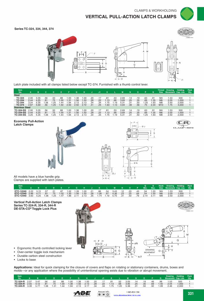
Series TC-324, 334, 344, 374
E G
B
-0
Latch plate included with all clamps listed below except TC-374. Furnished with a thumb control lever.
ITI
Economy Pull-Action Latch Clamps
E
ICILZUMIF" RETIE
0J
All models have a blue handle grip. Clamps are supplied with latch plates.
B
A-Dr4c-cr
Q ON
A I~Op I P H
C DRAwING
oTt- MOVEMENT E G
r
K 0J1
CLAMPS & WORKHOLDING
VERTICAL PULL-ACTION LATCH CLAMPS
Item No. A B C D E F G N J J1 K L M N 0 0
Thread Drawing Holding Size Movement Cap. Lbs.
Pack Qty.
Steel TC-324 2.00 3.35 .56 .50 .88 1.00 1.38 1.00 .20 .17 .81 .53 2.69 .14 .19 .63 .91 M4 1.53 500 1 TC-334 2.44 4.25 .81 .75 1.00 1.31 1.56 1.50 .28 .22 1.13 .68 3.69 .25 .35 .69 1.35 M6 2.00 1,000 1 TC-344 3.24 5.35 1.06 1.25 1.44 1.94 2.13 2.13 .34 .34 1.75 1.19 5.31 .31 .50 1.25 1.93 M8 2.50 2,000 1 TC-374 2.67 5.69 .56 1.25 1.50 2.50 2.50 2.72 .41 .25 1.63 1.13 4.94 .39 .56 .75 2.34 M10 1.75 4,000 1
Stainless Steel TC-324-SS 2.00 3.35 .56 .50 .88 1.00 1.38 1.00 .20 .17 .81 .53 2.69 .14 .19 .63 .91 M4 1.53 500 1 TC-334-SS 2.44 4.25 .81 .75 1.00 1.31 1.56 1.50 .28 .22 1.13 .68 3.69 .25 .35 .69 1.35 M6 2.00 1,000 1 TC-344-SS 3.25 5.35 1.06 1.25 1.44 1.94 2.13 2.13 .34 .34 1.75 1.19 5.31 .31 .50 1.25 1.93 M8 2.50 2,000 1
Item 13 Hook Drawing Holding Pack No. A B C D E F G N J K L M N 0 P Min. Max. Size Movement Cap. Lbs. Qty.
ETC-12240 2.22 3.15 .57 .51 .87 1.02 1.39 1.00 .21 .86 .54 3.43 .12 .20 .43 .54 1.20 M4 1.53 500 ETC-12340 2.86 4.71 .81 .75 1.02 1.30 1.56 1.50 .28 1.06 .67 4.36 .23 .25 .64 .54 1.50 M6 2.00 1,000 ETC-12440 3.60 5.25 1.06 1.25 1.47 1.86 2.11 2.13 .35 1.74 1.19 5.75 .31 .50 .79 2.14 3.11 M8 2.50 2,000
Vertical Pull-Action Latch Clamps Series TC-324-R, 334-R, 344-R DE-STA-004°Toggle Lock Plus
• Ergonomic thumb controlled locking lever • Over-center toggle lock mechanism • Durable carbon steel construction • Locks to base
Applications: Ideal for quick clamping for the closure of covers and flaps on rotating or stationary containers, drums, boxes and molds-or any application where the possibility of unintentional opening exists due to vibration or abrupt movement.
Item Drawing Holding Pack No. A B C D E F G N J J1 K L M N 0 P 0 Movement Cap. Lbs. Qty.
TC-324-R 2.07 3.47 .56 .50 .88 1.00 1.38 1.00 .20 .17 .81 .52 3.05 .14 .19 .46 .98 1.53 500 TC-334-R 2.55 4.12 .81 .75 1.00 1.38 1.56 2.13 .28 .22 1.13 .68 3.95 .25 .35 .69 1.40 2.04 1,000 TC-344-R 3.39 5.77 1.06 1.31 1.44 1.94 2.13 3.17 .34 .34 1.75 1.20 5.38 .31 .50 .92 1.99 2.46 2,000
331 331
Series TC-324, 334, 344, 374
Latch plate included with all clamps listed below except TC-374. Furnished with a thumb control lever.
F
GE
B
D J
O
PH
Q
MA
N
C
L
K J
ItemNo. A B C D E F G H J J1 K L M N O P Q
ThreadSize
DrawingMovement
HoldingCap. Lbs.
PackQty.
SteelTC-324 2.00 3.35 .56 .50 .88 1.00 1.38 1.00 .20 .17 .81 .53 2.69 .14 .19 .63 .91 M4 1.53 500 1TC-334 2.44 4.25 .81 .75 1.00 1.31 1.56 1.50 .28 .22 1.13 .68 3.69 .25 .35 .69 1.35 M6 2.00 1,000 1TC-344 3.24 5.35 1.06 1.25 1.44 1.94 2.13 2.13 .34 .34 1.75 1.19 5.31 .31 .50 1.25 1.93 M8 2.50 2,000 1TC-374 2.67 5.69 .56 1.25 1.50 2.50 2.50 2.72 .41 .25 1.63 1.13 4.94 .39 .56 .75 2.34 M10 1.75 4,000 1
Stainless SteelTC-324-SS 2.00 3.35 .56 .50 .88 1.00 1.38 1.00 .20 .17 .81 .53 2.69 .14 .19 .63 .91 M4 1.53 500 1TC-334-SS 2.44 4.25 .81 .75 1.00 1.31 1.56 1.50 .28 .22 1.13 .68 3.69 .25 .35 .69 1.35 M6 2.00 1,000 1TC-344-SS 3.25 5.35 1.06 1.25 1.44 1.94 2.13 2.13 .34 .34 1.75 1.19 5.31 .31 .50 1.25 1.93 M8 2.50 2,000 1
Vertical Pull-Action Latch ClampsSeries TC-324-R, 334-R, 344-RDE-STA-CO® Toggle Lock Plus
Ergonomic thumb controlled locking leverOver-center toggle lock mechanismDurable carbon steel constructionLocks to base
Applications: Ideal for quick clamping for the closure of covers and flaps on rotating or stationary containers, drums, boxes and molds—or any application where the possibility of unintentional opening exists due to vibration or abrupt movement.
A
M
Q
O
HP
MOVEMENTDRAWING
øN
K øJ1L
CGE
FD J
B
ItemNo. A B C D E F G H J J1 K L M N O P Q
DrawingMovement
HoldingCap. Lbs.
PackQty.
TC-324-R 2.07 3.47 .56 .50 .88 1.00 1.38 1.00 .20 .17 .81 .52 3.05 .14 .19 .46 .98 1.53 500 1TC-334-R 2.55 4.12 .81 .75 1.00 1.38 1.56 2.13 .28 .22 1.13 .68 3.95 .25 .35 .69 1.40 2.04 1,000 1TC-344-R 3.39 5.77 1.06 1.31 1.44 1.94 2.13 3.17 .34 .34 1.75 1.20 5.38 .31 .50 .92 1.99 2.46 2,000 1
Economy Pull-Action Latch Clamps
All models have a blue handle grip. Clamps are supplied with latch plates.
A
Q
M
H
O
Ø N
PL
C
Ø J
K
B
Ø J
E G
D
F
ItemNo. A B C D E F G H J K L M N O P
QMin.
QMax.
HookSize
DrawingMovement
HoldingCap. Lbs.
PackQty.
ETC-12240 2.22 3.15 .57 .51 .87 1.02 1.39 1.00 .21 .86 .54 3.43 .12 .20 .43 .54 1.20 M4 1.53 500 1ETC-12340 2.86 4.71 .81 .75 1.02 1.30 1.56 1.50 .28 1.06 .67 4.36 .23 .25 .64 .54 1.50 M6 2.00 1,000 1ETC-12440 3.60 5.25 1.06 1.25 1.47 1.86 2.11 2.13 .35 1.74 1.19 5.75 .31 .50 .79 2.14 3.11 M8 2.50 2,000 1
VERTICAL PULL-ACTION LATCH CLAMPS
FWAHL
SmallO
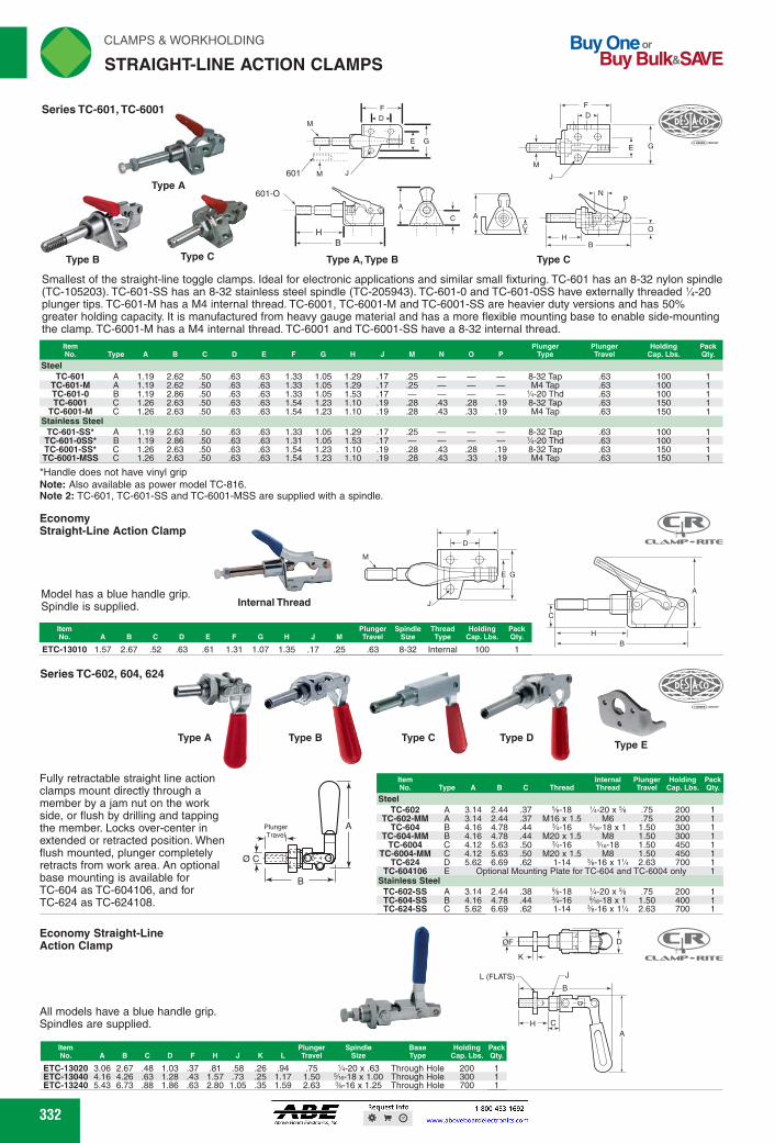
Buy One or Buy Bulk&SIO/E
rli N CLAMPS & WORKHOLDING
STRAIGHT-LINE ACTION CLAMPS
Series TC-601, TC-6001
Type A
rv; ▪ t 40
901 Type B Type C
F
601
0
B
Type C
B
C▪ A
Type A, Type B
601-0
E G
Item Plunger Spindle Thread Holding Pack No. A BCD E F G H J M Travel Size Type Cap. Lbs. Qty.
Internal Thread
Economy Straight-Line Action Clamp
Model has a blue handle grip. Spindle is supplied.
F HDH
CSR FUTIE
H
C
Type E
Steel TC-602 A 3.14
TC-602-MM A 3.14 TC-604 B 4.16
TC-604-MM B 4.16 TC-6004 C 4.12
TC-6004-MM C 4.12
2.44 .37 %-18 2.44 .37 M16 x 1.5 4.78 .44 3/4-16 4.78 .44 M20 x 1.5 5.63 .50 3/4-16 5.63 .50 M20 x 1.5
Smallest of the straight-line toggle clamps. Ideal for electronic applications and similar small fixturing. TC-601 has an 8-32 nylon spindle (TC-105203). TC-601-SS has an 8-32 stainless steel spindle (TC-205943). TC-601-0 and TC-601-OSS have externally threaded'/4-20 plunger tips. TC-601-M has a M4 internal thread. TC-6001, TC-6001-M and TC-6001-SS are heavier duty versions and has 50% greater holding capacity. It is manufactured from heavy gauge material and has a more flexible mounting base to enable side-mounting the clamp. TC-6001-M has a M4 internal thread. TC-6001 and TC-6001-SS have a 8-32 internal thread.
Holding Cap. Lbs.
Pack Qty.
8-32 Tap .63 100 M4 Tap .63 100
'A-20 Thd .63 100 8-32 Tap .63 150 M4 Tap .63 150
8-32 Tap .63 100 1 'A-20 Thd .63 100 1 8-32 Tap .63 150 1 M4 Tap .63 150 1
Steel TC-601
A 1.19 2.62 .50 .63 .63 1.33 1.05 1.29 .17 .25
TC-601-M A 1.19 2.62 .50 .63 .63 1.33 1.05 1.29 .17 .25 -
TC-601-0 B 1.19 2.86 .50 .63 .63 1.33 1.05 1.53 .17 - -
TC-6001
C 1.26 2.63 .50 .63 .63 1.54 1.23 1.10 .19 .28 .43 .28 .19 TC-6001-M C 1.26 2.63 .50 .63 .63 1.54 1.23 1.10 .19 .28 .43 .33 .19
Stainless Steel
TC-601-SS* A 1.19 2.63 .50 .63 .63 1.33 1.05 1.29 .17 .25 -
TC-601-OSS* B 1.19 2.86 .50 .63 .63 1.31 1.05 1.53 .17 - - TC-6001-SS* C 1.26 2.63 .50 .63 .63 1.54 1.23 1.10 .19 .28 .43 .28 .19 TC-6001-MSS C 1.26 2.63 .50 .63 .63 1.54 1.23 1.10 .19 .28 .43 .33 .19
*Handle does not have vinyl grip Note: Also available as power model TC-816. Note 2: TC-601, TC-601-SS and TC-6001-MSS are supplied with a spindle.
ETC-13010 1.57 2.67 .52 .63 .61 1.31 1.07 1.35 .17 .25 .63 8-32 Internal 100
Series TC-602, 604, 624
Fully retractable straight line action clamps mount directly through a member by a jam nut on the work side, or flush by drilling and tapping the member. Locks over-center in extended or retracted position. When flush mounted, plunger completely retracts from work area. An optional base mounting is available for TC-604 as TC-604106, and for TC-624 as TC-624108.
Item
Internal Plunger Holding Pack No. Type A B C Thread Thread Travel Cap. Lbs. Qty.
1/4-20 x % .75 200 1 M6 .75 200 1
5/113-18 x 1 1.50 300 1 M8 1.50 300 1
5/113-18 1.50 450 1 M8 1.50 450 1
TC-624 D 5.62 6.69.62 1-14 %-16 x 1% 2.63 700 1 TC-604106 E Optional Mounting Plate for TC-604 and TC-6004 only 1
Stainless Steel TC-602-SS A 3.14 2.44 .38 %-18 'A-20 x % .75 200 1 TC-604-SS B 4.16 4.78 .44 %-16 5/113-18 x 1 1.50 400 1 TC-624-SS C 5.62 6.69 .62 1-14 %-16 x 1% 2.63 700 1
Plunger 111 tilTravelkc
0 C EgOingri9
1 _, MANI 0
Economy Straight-Line Action Clamp
All models have a blue handle grip. Spindles are supplied.
L (FLATS)
111=LAP6111.- FEITIE
Item
Plunger Spindle Base Holding Pack No. A B C D F H J K LTravel Size Typo Cap. Lbs. Qty.
ETC-13020 3.06 2.67 .48 1.03 .37 .81 .58 .26 .94 .75 'A-20 x .63 Through Hole 200 ETC-13040 4.16 4.26 .63 1.28 .43 1.57 .73 .25 1.17 1.50 5/113-18 x 1.00 Through Hole 300 ETC-13240 5.43 6.73 .88 1.86 .63 2.80 1.05 .35 1.59 2.63 %-16 x 1.25 Through Hole 700
332 332
Type A
Type C
Smallest of the straight-line toggle clamps. Ideal for electronic applications and similar small fixturing. TC-601 has an 8-32 nylon spindle (TC-105203). TC-601-SS has an 8-32 stainless steel spindle (TC-205943). TC-601-0 and TC-601-0SS have externally threaded 1⁄4-20 plunger tips. TC-601-M has a M4 internal thread. TC-6001, TC-6001-M and TC-6001-SS are heavier duty versions and has 50% greater holding capacity. It is manufactured from heavy gauge material and has a more flexible mounting base to enable side-mounting the clamp. TC-6001-M has a M4 internal thread. TC-6001 and TC-6001-SS have a 8-32 internal thread.
*Handle does not have vinyl gripNote: Also available as power model TC-816.Note 2: TC-601, TC-601-SS and TC-6001-MSS are supplied with a spindle.
FD
E G
JM
M
601
A
C
601-O
HB
Type A, Type B
FD
M
J
GE
P
O
BH
N
CA
Type CType B
ItemNo. Type A B C D E F G H J M N O P
PlungerType
PlungerTravel
HoldingCap. Lbs.
PackQty.
SteelTC-601 A 1.19 2.62 .50 .63 .63 1.33 1.05 1.29 .17 .25 — — — 8-32 Tap .63 100 1
TC-601-M A 1.19 2.62 .50 .63 .63 1.33 1.05 1.29 .17 .25 — — — M4 Tap .63 100 1TC-601-0 B 1.19 2.86 .50 .63 .63 1.33 1.05 1.53 .17 — — — — 1⁄4-20 Thd .63 100 1TC-6001 C 1.26 2.63 .50 .63 .63 1.54 1.23 1.10 .19 .28 .43 .28 .19 8-32 Tap .63 150 1
TC-6001-M C 1.26 2.63 .50 .63 .63 1.54 1.23 1.10 .19 .28 .43 .33 .19 M4 Tap .63 150 1Stainless Steel
TC-601-SS* A 1.19 2.63 .50 .63 .63 1.33 1.05 1.29 .17 .25 — — — 8-32 Tap .63 100 1TC-601-0SS* B 1.19 2.86 .50 .63 .63 1.31 1.05 1.53 .17 — — — — 1⁄4-20 Thd .63 100 1TC-6001-SS* C 1.26 2.63 .50 .63 .63 1.54 1.23 1.10 .19 .28 .43 .28 .19 8-32 Tap .63 150 1TC-6001-MSS C 1.26 2.63 .50 .63 .63 1.54 1.23 1.10 .19 .28 .43 .33 .19 M4 Tap .63 150 1
Series TC-601, TC-6001
Series TC-602, 604, 624
Type C Type D
Ø C
B
APlungerTravel
Type E
Fully retractable straight line action clamps mount directly through a member by a jam nut on the work side, or flush by drilling and tapping the member. Locks over-center in extended or retracted position. When flush mounted, plunger completely retracts from work area. An optional base mounting is available for TC-604 as TC-604106, and for TC-624 as TC-624108.
Type BType A
ItemNo. Type A B C Thread
InternalThread
PlungerTravel
HoldingCap. Lbs.
PackQty.
SteelTC-602 A 3.14 2.44 .37 5⁄8-18 1⁄4-20 x 5⁄8 .75 200 1
TC-602-MM A 3.14 2.44 .37 M16 x 1.5 M6 .75 200 1TC-604 B 4.16 4.78 .44 3⁄4-16 5⁄16-18 x 1 1.50 300 1
TC-604-MM B 4.16 4.78 .44 M20 x 1.5 M8 1.50 300 1TC-6004 C 4.12 5.63 .50 3⁄4-16 5⁄16-18 1.50 450 1
TC-6004-MM C 4.12 5.63 .50 M20 x 1.5 M8 1.50 450 1TC-624 D 5.62 6.69 .62 1-14 3⁄8-16 x 11⁄4 2.63 700 1
TC-604106 E Optional Mounting Plate for TC-604 and TC-6004 only 1Stainless Steel
TC-602-SS A 3.14 2.44 .38 5⁄8-18 1⁄4-20 x 5⁄8 .75 200 1TC-604-SS B 4.16 4.78 .44 3⁄4-16 5⁄16-18 x 1 1.50 400 1TC-624-SS C 5.62 6.69 .62 1-14 3⁄8-16 x 11⁄4 2.63 700 1
EconomyStraight-Line Action Clamp
Model has a blue handle grip. Spindle is supplied.
E G
M
J
FD
Internal Thread
ItemNo. A B C D E F G H J M
PlungerTravel
SpindleSize
ThreadType
HoldingCap. Lbs.
PackQty.
ETC-13010 1.57 2.67 .52 .63 .61 1.31 1.07 1.35 .17 .25 .63 8-32 Internal 100 1
Economy Straight-LineAction Clamp
All models have a blue handle grip. Spindles are supplied. CH
B
A
JL (FLATS)
ØF
K
D
ItemNo. A B C D F H J K L
PlungerTravel
SpindleSize
BaseType
HoldingCap. Lbs.
PackQty.
ETC-13020 3.06 2.67 .48 1.03 .37 .81 .58 .26 .94 .75 1⁄4-20 x .63 Through Hole 200 1ETC-13040 4.16 4.26 .63 1.28 .43 1.57 .73 .25 1.17 1.50 5⁄16-18 x 1.00 Through Hole 300 1ETC-13240 5.43 6.73 .88 1.86 .63 2.80 1.05 .35 1.59 2.63 3⁄8-16 x 1.25 Through Hole 700 1
A
C
HB
STRAIGHT-LINE ACTION CLAMPS
FWAHL
SmallO

M
B
C
ir,
CLAMPS & WORKHOLDING 'N
STRAIGHT-LINE ACTION CLAMPS
(DESTItco
This straight-line action toggle clamp has a large holding capacity for its size. The TC-603 works well in confined areas because of its small size and low height. TC-603 plunger is tapped 5/16-18 x 1" deep for spindle. TC-603-M plunger has a M8x1.25 spindle thread.
-A- Steel
TC-603 3.28 .97 4.71 1.44 1.31 .44 11/4 600 1 D TC-603-M 3.28 .97 4.71 1.44 1.31 .44 11/4 600 1
Stainless Steel TC-603-SS 3.28 .97 4.71 1.44 1.31 .44 11/4 600 1
Note: Also available as Power Model TC-803.
Economy Straight-Line Action Clamp
Tf
F Series TC-605
For push and pull clamping. Furnished with red vinyl grip. B
Plunger on TC-605 is tapped 5/16-18 x 1" deep for adjustment item Plunger Holding
Cap. Pack spindle. Base is heat treated for added strength. TC-605-M has No. A B C D E F GM Travel Lbs. Qty.
M8 x 1.25 spindle thread. TC-605 3.16 5.47 .97 1.38 1.63 3.41 2.19 .44 1.25 300 TC-605-M 3.16 5.47 .97 1.38 1.63 3.41 2.19 .44 1.25 300
Economy Straight-Line Action Clamp CSR
aawr- ROTC
All models have a blue handle grip. Spindles are supplied.
Item Plunger Spindle Holding Pack No. A BCD E F G H J M Travel Size Cap. Lbs. Qty.
ETC-13050 3.14 5.45 .98 1.38 1.64 3.55 2.22 1.90 .22 .47 1.25 %e-18 x 1.00 300
F
OM
333
Series TC-603
All models have a blue handle grip. Spindles are supplied.
Item Plunger Spindle No. A B C D E F G H J M Travel Size
ETC-13030 3.34 4.88 .98 1.44 1.32 2.30 1.85 2.03 .23 .43 1.25 Vie-18 x 1.00 600 Straight
D
Handle Type Holding Pack (degrees) Cap. Lbs. Qty.
333
Series TC-603
D
E
A
7/32
F
B
C
This straight-line action toggle clamp has a large holding capacity for its size. The TC-603 works well in confined areas because of its small size and low height. TC-603 plunger is tapped 5⁄16-18 x 1" deep for spindle. TC-603-M plunger has a M8x1.25 spindle thread.
Note: Also available as Power Model TC-803.
ItemNo. A B C D E F
PlungerTravel
HoldingCap. Lbs.
PackQty.
SteelTC-603 3.28 .97 4.71 1.44 1.31 .44 11⁄4 600 1
TC-603-M 3.28 .97 4.71 1.44 1.31 .44 11⁄4 600 1Stainless SteelTC-603-SS 3.28 .97 4.71 1.44 1.31 .44 11⁄4 600 1
Series TC-605
For push and pull clamping. Furnished with red vinyl grip. Plunger on TC-605 is tapped 5⁄16-18 x 1" deep for adjustment spindle. Base is heat treated for added strength. TC-605-M has M8 x 1.25 spindle thread.
ItemNo. A B C D E F G M
PlungerTravel
HoldingCap. Lbs.
PackQty.
TC-605 3.16 5.47 .97 1.38 1.63 3.41 2.19 .44 1.25 300 1TC-605-M 3.16 5.47 .97 1.38 1.63 3.41 2.19 .44 1.25 300 1
F
M
D
E G
A
B
C
Economy Straight-LineAction Clamp
All models have a blue handle grip. Spindles are supplied.
FD
ØJ
E G
ØM
A
C
HB
ItemNo. A B C D E F G H J M
PlungerTravel
SpindleSize
HoldingCap. Lbs.
PackQty.
ETC-13050 3.14 5.45 .98 1.38 1.64 3.55 2.22 1.90 .22 .47 1.25 5⁄16-18 x 1.00 300 1
B
A
C
Ø M
C
A
H
D
E G
Ø JF
M
All models have a blue handle grip. Spindles are supplied.
ItemNo. A B C D E F G H J M
PlungerTravel
SpindleSize
Handle Type(degrees)
HoldingCap. Lbs.
PackQty.
ETC-13030 3.34 4.88 .98 1.44 1.32 2.30 1.85 2.03 .23 .43 1.25 5⁄16-18 x 1.00 Straight 600 1
Economy Straight-LineAction Clamp
STRAIGHT-LINE ACTION CLAMPS
FWAHL
SmallO

Buy One or Buy Bulk&SIO/E
rliN CLAMPS & WORKHOLDING
STRAIGHT-LINE ACTION CLAMPS
CED Sptc0,
For use in confined areas. The ergonomic handle is slanted forward to provide an adequate grip. Clamp locks over-center in both the extended and retracted positions while the locking lever secures the clamp in the extended position only. Plunger is tapped for 5/16-18 adjustment spindle or detail.
M Plunger Holding Pack Travel Cap. Lbs. Qty.
Item No. A
TC-603-R 3.42 4.69 .97 1.44 1.31 2.00 1.86 2.16 .27 .44 1.25 600
M I I -
TC-6015-R and TC-6015-MR - Compact Size DE-STA-CO. Toggle Lock Plus
F DI
1-rT-
E G
J
'
Compact size allows use in confined areas and on small fixtures, where safety is a concern. Features a locking lever which locks in the clamped position only.
Plunger Thread
Plunger Travel
TC-6015-R 1.60 TC-6015-MR 1.60
2.95 2.95
.50
.50 1.75 1.75
.88
.88 2.25 2.25
1.25 1.25
.70
.70 .22 .22
.38
.38 1/4-20 M6
.70
.70
Series TC-620
,
E
0.34 A
OF
"' D ]-.-•
C
B A
TC-620 features a reverse handle action. As handle moves back and down to horizontal lock position, plunger moves forward. Can be positioned for angular clamping by drilling base or may be used without base. TC-620 plungers are tapped %-16 x 1" deep. TC-620-M plunger has M10 thread.
Features an unusual 180 degrees swiveling handle and linkage. Can be mounted in many positions with the handle remaining in an up-right or other convenient position. This feature along with a narrow base permits use where other clamps won't fit. Heat treated base. TC-606 has a diameter plunger tapped 5/16-18 x 1" deep.
B C D E F G Plunger Holding Travel Cap. Lbs.
TC-606 2.62 6.72 .88 1.25 .63 1.75 1.13 .44 1% 450 1
A E G -A- Y
M jar- F D >t< 13.1
1.67 11.70 1.63 1.63 1.67 11.70 1.63 1.63
.62 1% 600
.62 1% 600
E F Pack Qty.
DrSTA•co
B
Item No. A
TC-620 2.25 TC-620-M 2.25
TC-606
334
TC-603-R DE-STA-004° Toggle Lock Plus
C 1
F D
-- E G
A
Holding Pack Cap. Lbs. Qty.
560 560
334
TC-606
F
GE
DDM
A
HB
C
TC-603-RDE-STA-CO® Toggle Lock Plus
For use in confined areas. The ergonomic handle is slanted forward to provide an adequate grip. Clamp locks over-center in both the extended and retracted positions while the locking lever secures the clamp in the extended position only. Plunger is tapped for 5⁄16-18 adjustment spindle or detail.
FD
E G
J
M
A
C
HB
ItemNo. A B C D E F G H J M
PlungerTravel
HoldingCap. Lbs.
PackQty.
TC-603-R 3.42 4.69 .97 1.44 1.31 2.00 1.86 2.16 .27 .44 1.25 600 1
TC-6015-R and TC-6015-MR - Compact SizeDE-STA-CO® Toggle Lock Plus
Compact size allows use in confined areas and on small fixtures, where safety is a concern. Features a locking lever which locks in the clamped position only.
A
DF
J
GE
M
CH
B
ItemNo. A B C D E F G H J M
PlungerThread
PlungerTravel
HoldingCap. Lbs.
PackQty.
TC-6015-R 1.60 2.95 .50 1.75 .88 2.25 1.25 .70 .22 .38 1⁄4-20 .70 560 1TC-6015-MR 1.60 2.95 .50 1.75 .88 2.25 1.25 .70 .22 .38 M6 .70 560 1
Series TC-620
E
DØ.34
AB
ØFC
TC-620 features a reverse handle action. As handle moves back and down to horizontal lock position, plunger moves forward. Can be positioned for angular clamping by drilling base or may be used without base. TC-620 plungers are tapped 3⁄8-16 x 1" deep. TC-620-M plunger has M10 thread.
ItemNo. A B C D E F
PlungerTravel
HoldingCap. Lbs.
PackQty.
TC-620 2.25 1.67 11.70 1.63 1.63 .62 11⁄8 600 1TC-620-M 2.25 1.67 11.70 1.63 1.63 .62 11⁄8 600 1
Features an unusual 180 degrees swiveling handle and linkage. Can be mounted in many positions with the handle remaining in an up-right or other convenient position. This feature along with a narrow base permits use where other clamps won't fit. Heat treated base. TC-606 has a 7⁄16" diameter plunger tapped 5⁄16-18 x 1" deep.
ItemNo. A B C D E F G M
PlungerTravel
HoldingCap. Lbs.
PackQty.
TC-606 2.62 6.72 .88 1.25 .63 1.75 1.13 .44 11⁄2 450 1
STRAIGHT-LINE ACTION CLAMPS
FWAHL
SmallO

Item Plunger Holding Peek No. A BCD E F H M Travel Cap. Lbs. Qty.
1% 850 TC-608 4.04 6.13 1.25 1.63 1.63 2.31 2.25 3.00 .33 .62
MINE. RITE
850 .63 1.65 %-16 x 1.25 Straight
C
ir,
CLAMPS & WORKHOLDING 'N
STRAIGHT-LINE ACTION CLAMPS
6.02 6.02 6.02
1.38 1.38 1.38
1.63 1.63 1.63
% dia. % dia. % sq.
1% 1% 1%
800 800 800
.51 1.63 5/113-18 x 1.00 800 .28 .35 .63 2.00 %-16 x 1.25 2,500
ETC-13070 3.28 ETC-13300 2.93
6.10 .68 1.38 1.63 1.63 4.30 2.18 1.86 7.06 .88 1.38 1.39 1.63 5.25 2.24 1.82
Item Plunger Plunger Holding Peek No. A B C D E Type Travel Cap. Lbs. Qty.
TC-607 3.59
TC-607-M 3.59 TC-607-SQ 3.59
.69
.69
.69
tarj. --DESTItoc
Compact, low silhouette clamp locks in either extended or retracted position. Available with '/2" round plunger or '/2" square plunger for multiple point locating. TC-607 and TC-607-SQ are drilled and tapped 5/16-18 x 1" deep for spindle and TC-607-M.
Series TC-607
3:12:1:12111Olikreind. 1.9921111111111.11.T.14
Dia.
H B
ICL.46.1•411." - FINTIE
Economy Straight-Line Action Clamp
D 1 D1-.1 F
All models have a blue handle grip. Spindle assemblies are supplied.
Item Plunger Spindle Holding Peek No. A B C D D1 E F G H J M Travel Size Cap. Lbs. Qty.
TC-608
Economy Straight-Line Action Clamp
D
G t c
H
ETC-13485 4.19 6.41 1.25 1.62 1.63 2.33 2.25 3.13 .33
Item Plunger Holding Peek No. A BCD E F G H J M Travel Cep. Lbs. Qty.
300 300
TC-609 3.25 5.48 .97 1.38 1.62 aso 2.19 1.88 .27 .44 1% TC-609-B 4.28 5.48 1.56 1.38 - aso .25 1.88 .27 .44 1%
Item Plunger Spindle Holding Peek No. A BCD E F G H J M Travel Size Cep. Lbs. Qty.
Locks over-center in either extended or retracted positions. The 1/2" diameter plunger is drilled and tapped 5/16-18 to accept customized fixture or neoprene tipped spindle. Plunger retracts completely to clear the work area. Available with a straight base,TC-609-B or a flanged base TC-609.
Economy Straight-Line Action Clamp
All models have a blue handle grip. Spindles are supplied.
E G
A
c c 7 y
609_g
OM
B
Low profile clamp with cast base. Plunger locks over-center in either retracted or extended positions. Plunger is tapped for %-16 adjustment spindle.
0J F
335
Series TC-607
E
ED
9/32" Dia.
B
C
A
Compact, low silhouette clamp locks in either extended or retracted position. Available with 1⁄2" round plunger or 1⁄2" square plunger for multiple point locating. TC-607 and TC-607-SQ are drilled and tapped 5⁄16-18 x 1" deep for spindle and TC-607-M.
ItemNo. A B C D E
PlungerType
PlungerTravel
HoldingCap. Lbs.
PackQty.
TC-607 3.59 .69 6.02 1.38 1.63 1⁄2 dia. 15⁄8 800 1TC-607-M 3.59 .69 6.02 1.38 1.63 1⁄2 dia. 15⁄8 800 1
TC-607-SQ 3.59 .69 6.02 1.38 1.63 1⁄2 sq. 15⁄8 800 1
TC-608 FD
E
J
M
G
A
C
HB
Low profile clamp with cast base. Plunger locks over-center in either retracted or extended positions. Plunger is tapped for 3⁄8-16 adjustment spindle.
ItemNo. A B C D E F G H J M
PlungerTravel
HoldingCap. Lbs.
PackQty.
TC-608 4.04 6.13 1.25 1.63 1.63 2.31 2.25 3.00 .33 .62 15⁄8 850 1
Series TC-609 F
HB
609
609-B 609-BG
CC
A A
M
JD
E G
Locks over-center in either extended or retracted positions. The 1⁄2" diameter plunger is drilled and tapped 5⁄16-18 to accept customized fixture or neoprene tipped spindle. Plunger retracts completely to clear the work area. Available with a straight base,TC-609-B or a flanged base TC-609.
ItemNo. A B C D E F G H J M
PlungerTravel
HoldingCap. Lbs.
PackQty.
TC-609 3.25 5.48 .97 1.38 1.62 3.60 2.19 1.88 .27 .44 11⁄4 300 1TC-609-B 4.28 5.48 1.56 1.38 — 3.60 .25 1.88 .27 .44 11⁄4 300 1
Economy Straight-LineAction Clamp
All models have a blue handle grip. Spindle assemblies are supplied.
D D1F
E G
Ø M
Ø J
ItemNo. A B C D D1 E F G H J M
PlungerTravel
SpindleSize
HoldingCap. Lbs.
PackQty.
ETC-13070 3.28 6.10 .68 1.38 1.63 1.63 4.30 2.18 1.86 .28 .51 1.63 5⁄16-18 x 1.00 800 1ETC-13300 2.93 7.06 .88 1.38 1.39 1.63 5.25 2.24 1.82 .35 .63 2.00 3⁄8-16 x 1.25 2,500 1
Economy Straight-LineAction Clamp
All models have a blue handle grip. Spindles are supplied.
F
D
ØJ
E G
A
H
C
B
ØM
ItemNo. A B C D E F G H J M
PlungerTravel
SpindleSize
HoldingCap. Lbs.
PackQty.
ETC-13090 4.10 5.00 .85 1.57 1.33 3.27 1.95 1.71 .26 .47 1.25 5⁄16-18 x 1.00 300 1
D
E G
Ø JF
M
All models have a blue handle grip. Spindles are supplied.
ItemNo. A B C D E F G H J M
PlungerTravel
SpindleSize
Handle Type(degrees)
HoldingCap. Lbs.
PackQty.
ETC-13485 4.19 6.41 1.25 1.62 1.63 2.33 2.25 3.13 .33 .63 1.65 3⁄8-16 x 1.25 Straight 850 1
Economy Straight-LineAction Clamp
STRAIGHT-LINE ACTION CLAMPS
C
B
A
H
B
A
C
Ø M
C
A
H
FWAHL
SmallO
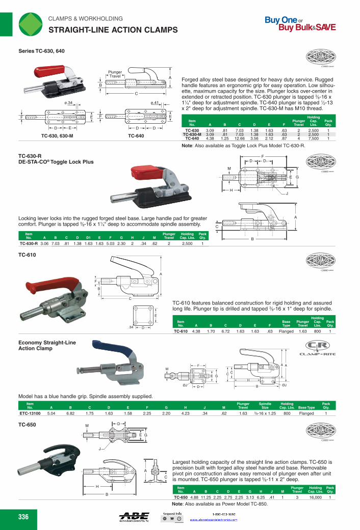
rliN CLAMPS & WORKHOLDING
STRAIGHT-LINE ACTION CLAMPS Buy One or
Buy Bulk&SIO/E
TC-630-R DE-STA-004° Toggle Lock Plus
item Plunger Holding Pack No. A BCDME F H J M Travel Cap. Lbs. Qty.
.34 .62 2 2,500 TC-630-R 3.06 7.03 .81 1.38 1.63 1.63 5.03 2.30 2
1131-c1.1 RETIE
Economy Straight-Line Action Clamp
Spindle Holding Pack Size Cap. Lbs. Base Type Qty.
Plunger Travel
Item No. A M C D E F G H
4.23
34 .62 1.63 %-16 x 1.25 800
Item Plunger Holding Pack No. A B C D E G H J M Travel Cap. Lbs. Qty.
3 16,000 1 TC-650 4.88 11.25 2.25 2.75 2.25 3.13 6.25 .41 1
„DFSIA•co
Forged alloy steel base designed for heavy duty service. Rugged handle features an ergonomic grip for easy operation. Low silhou-ette, maximum capacity for the size. Plunger locks over-center in extended or retracted position. TC-630 plunger is tapped %-16 x 11/4" deep for adjustment spindle. TC-640 plunger is tapped 1/2-13 x 2" deep for adjustment spindle. TC-630-M has M10 thread.
ISINEW=MITEM TC-630 3.09 .81 7.03 1.38 1.63 .63 2 2,500 1
TC-630-M 3.09 .81 7.03 1.38 1.63 .63 2 2,500 1 TC-640 4.38 1.25 12.66 3.56 2.12 .87 4 7,500 1
Note: Also available as Toggle Lock Plus Model TC-630-R.
Locking lever locks into the rugged forged steel base. Large handle pad for greater comfort. Plunger is tapped %-16 x 11/a" deep to accommodate spindle assembly.
Dr2P1CO
TC-610 features balanced construction for rigid holding and assured long life. Plunger tip is drilled and tapped %-16 x 1" deep for spindle.
Holding item Base Plunger Cap. Pack No. A B C D E F Type Travel Lbs. Qty.
TC-610 4.38 1.70 6.72 1.63 1.63 .63 Flanged 1.63 800 1
Model has a blue handle grip. Spindle assembly supplied.
Largest holding capacity of the straight line action clamps. TC-650 is precision built with forged alloy steel handle and base. Removable pivot pin construction allows easy removal of plunger even after unit is mounted. TC-650 plunger is tapped %-11 x 2" deep.
E G
JOESTIZ 'S.\
TC-610
FT- ID
F
ETC-13100 5.04 6.82 1.75 1.63 1.58 2.25 2.20
TC-650 H-DH
H
B
Series TC-630, 640
4111.1r Plunger
- h` Travel "I
-
sae- _t
-1- -PH
H-D EH
TC-630, 630-M
I
E -0- -0- -0-,
D D
TC-640
Note: Also available as Power Model TC-850.
336 336
F
E G
DØJ
M
Model has a blue handle grip. Spindle assembly supplied.ItemNo. A B C D E F G H J M
PlungerTravel
SpindleSize
HoldingCap. Lbs. Base Type
PackQty.
ETC-13100 5.04 6.82 1.75 1.63 1.58 2.25 2.20 4.23 .34 .62 1.63 3⁄8-16 x 1.25 800 Flanged 1
Economy Straight-LineAction Clamp
Series TC-630, 640
D E
ø.34
EF
TC-630, 630-M
A
C
PlungerTravel
D
ø.41
E
B
F
D
TC-640
Forged alloy steel base designed for heavy duty service. Rugged handle features an ergonomic grip for easy operation. Low silhou-ette, maximum capacity for the size. Plunger locks over-center in extended or retracted position. TC-630 plunger is tapped 3⁄8-16 x 11⁄4" deep for adjustment spindle. TC-640 plunger is tapped 1⁄2-13 x 2" deep for adjustment spindle. TC-630-M has M10 thread.
Note: Also available as Toggle Lock Plus Model TC-630-R.
ItemNo. A B C D E F
PlungerTravel
HoldingCap. Lbs.
PackQty.
TC-630 3.09 .81 7.03 1.38 1.63 .63 2 2,500 1TC-630-M 3.09 .81 7.03 1.38 1.63 .63 2 2,500 1
TC-640 4.38 1.25 12.66 3.56 2.12 .87 4 7,500 1
TC-630-R DE-STA-CO® Toggle Lock Plus
F
J
C
B
A
H
M
GE
D D
Locking lever locks into the rugged forged steel base. Large handle pad for greater comfort. Plunger is tapped 3⁄8-16 x 11⁄4" deep to accommodate spindle assembly.
ItemNo. A B C D D1 E F G H J M
PlungerTravel
HoldingCap. Lbs.
PackQty.
TC-630-R 3.06 7.03 .81 1.38 1.63 1.63 5.03 2.30 2 .34 .62 2 2,500 1
TC-610
A
C
F
B
D.34
E
TC-610 features balanced construction for rigid holding and assured long life. Plunger tip is drilled and tapped 3⁄8-16 x 1" deep for spindle.
ItemNo. A B C D E F
BaseType
PlungerTravel
HoldingCap. Lbs.
PackQty.
TC-610 4.38 1.70 6.72 1.63 1.63 .63 Flanged 1.63 800 1
TC-650 D
B
H
C
A
GE
J
M
Largest holding capacity of the straight line action clamps. TC-650 is precision built with forged alloy steel handle and base. Removable pivot pin construction allows easy removal of plunger even after unit is mounted. TC-650 plunger is tapped 5⁄8-11 x 2" deep.
Note: Also available as Power Model TC-850.
ItemNo. A B C D E G H J M
PlungerTravel
HoldingCap. Lbs.
PackQty.
TC-650 4.88 11.25 2.25 2.75 2.25 3.13 6.25 .41 1 3 16,000 1
STRAIGHT-LINE ACTION CLAMPS
CC
H
ØJB
A A
FWAHL
SmallO
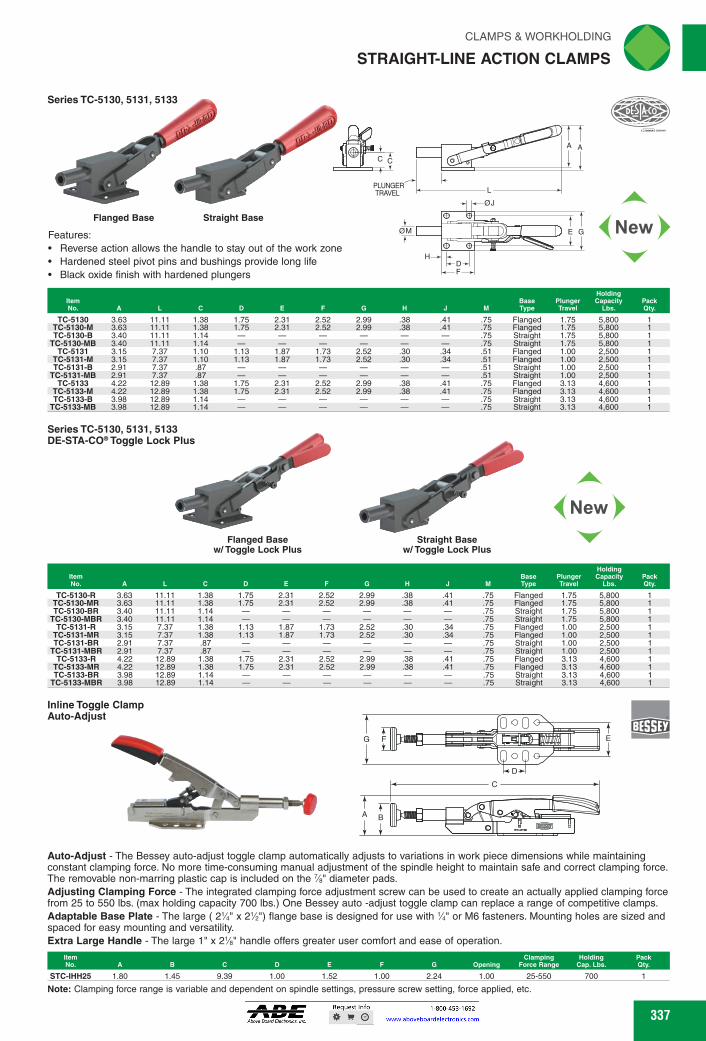
I] 1) D < New Flanged Base Straight Base
Features: • Reverse action allows the handle to stay out of the work zone • Hardened steel pivot pins and bushings provide long life • Black oxide finish with hardened plungers
Tr
C
PLUNGER
-
PLUNGER TRAVEL L
Series TC-5130, 5131, 5133
S
oro
H-
Series TC-5130, 5131, 5133 DE-STA-004°Toggle Lock Plus
.38
.38 2.99 2.99
2.52 2.52
2.99 2.99
.41
.41
.34
.34
2.52 2.52
1.73 1.73
2.52 2.52
.30
.30
.38
.38
2.31 2.31
1.87 1.87
2.31 2.31
1.75 1.75
1.1- 3 1.13
1.7- 5 1.75
1.38 1.38 1.14 1.14 1.38 1.38 .87 .87
1.38 1.38 1.14 1.14
11.11 11.11 11.11 11.11 7.37 7.37 7.37 7.37 12.89 12.89 12.89 12.89
1.75 1.75 1.75 1.75 1.00 1.00 1.00 1.00 3.13 3.13 3.13 3.13
Flanged Flanged Straight Straight Flanged Flanged Straight Straight Flanged Flanged Straight Straight
5,800 5,800 5,800 5,800 2,500 2,500 2,500 2,500 4,600 4,600 4,600 4,600
TC-5130-R 3.63 TC-5130-MR 3.63 TC-5130-BR 3.40
TC-5130-MBR 3.40 TC-5131-R 3.15
TC-5131-MR 3.15 TC-5131-BR 2.91
TC-5131-MBR 2.91 TC-5133-R 4.22
TC-5133-MR 4.22 TC-5133-BR 3.98
TC-5133-MBR 3.98
.75
.75
.75
.75
.75
.75 - .75 - .75 .41 .75 .41 .75 - .75 - .75
F
Inline Toggle Clamp Auto-Adjust
.141iLlari=5
0 o 0 D *-
C
A
IB
C
ip?
CLAMPS & WORKHOLDING 'IN
STRAIGHT-LINE ACTION CLAMPS
TC-5130 am 11.11 1.38 1.75 2.31 2.52 2.99 .38 .41 .75 Flanged 1.75 5,800 1
TC-5130-M am 11.11 1.38 1.75 2.31 2.52 2.99 .38 .41 .75 Flanged 1.75 5,800 1 TC-5130-B 3.40 11.11 1.14 - - - - - - .75 Straight 1.75 5,800 1
TC-5130-MB 3.40 11.11 1.14 - - - - - - .75 Straight 1.75 5,800 1
TC-5131 3.15 7.37 1.10 1.13 1.87 1.73 2.52 .30 .34 .51 Flanged 1.00 2,500 1
TC-5131-M 3.15 7.37 1.10 1.13 1.87 1.73 2.52 .30 .34 .51 Flanged 1.00 2,500 1 TC-5131-B 2.91 7.37 .87 - - - - - - .51 Straight 1.00 2,500 1
TC-5131-MB 2.91 7.37 .87 - - - - - - .51 Straight 1.00 2,500 1
TC-5133 4.22 12.89 1.38 1.75 2.31 2.52 2.99 .38 .41 .75 Flanged 3.13 4,600 1
TC-5133-M 4.22 12.89 1.38 1.75 2.31 2.52 2.99 .38 .41 .75 Flanged 3.13 4,600 1 TC-5133-B 3.98 12.89 1.14 - - - - - - .75 Straight 3.13 4,600 1
TC-5133-MB 3.98 12.89 1.14 - - - - - - .75 Straight 3.13 4,600 1
if."411110
New
Flanged Base
Straight Base w/ Toggle Lock Plus w/Toggle Lock Plus
Holding Item
Base Plunger Capacity Pack No. A
M Type Travel Lbs. Qty.
Auto-Adjust - The Bessey auto-adjust toggle clamp automatically adjusts to variations in work piece dimensions while maintaining constant clamping force. No more time-consuming manual adjustment of the spindle height to maintain safe and correct clamping force. The removable non-marring plastic cap is included on the 7/8" diameter pads. Adjusting Clamping Force - The integrated clamping force adjustment screw can be used to create an actually applied clamping force from 25 to 550 lbs. (max holding capacity 700 lbs.) One Bessey auto -adjust toggle clamp can replace a range of competitive clamps. Adaptable Base Plate - The large (2'/4" x 2'/2") flange base is designed for use with '/4" or M6 fasteners. Mounting holes are sized and spaced for easy mounting and versatility. Extra Large Handle - The large 1" x 2'43" handle offers greater user comfort and ease of operation.
Item Clamping Holding Pack No. A B C D E F G Opening Force Range Cap. Lbs. Qty.
STC-IHH25 1.80 1.45 9.39 1.00 1.52 1.00 2.24 1.00 25-550
700
Note: Clamping force range is variable and dependent on spindle settings, pressure screw setting, force applied, etc.
337 337
New
Features:Reverse action allows the handle to stay out of the work zoneHardened steel pivot pins and bushings provide long lifeBlack oxide finish with hardened plungers
Inline Toggle ClampAuto-Adjust
Auto-Adjust - The Bessey auto-adjust toggle clamp automatically adjusts to variations in work piece dimensions while maintaining constant clamping force. No more time-consuming manual adjustment of the spindle height to maintain safe and correct clamping force. The removable non-marring plastic cap is included on the 7⁄8" diameter pads.Adjusting Clamping Force - The integrated clamping force adjustment screw can be used to create an actually applied clamping force from 25 to 550 lbs. (max holding capacity 700 lbs.) One Bessey auto -adjust toggle clamp can replace a range of competitive clamps.Adaptable Base Plate - The large ( 21⁄4" x 21⁄2") flange base is designed for use with 1⁄4" or M6 fasteners. Mounting holes are sized and spaced for easy mounting and versatility.Extra Large Handle - The large 1" x 21⁄8" handle offers greater user comfort and ease of operation.
Note: Clamping force range is variable and dependent on spindle settings, pressure screw setting, force applied, etc.
ItemNo. A B C D E F G Opening
ClampingForce Range
HoldingCap. Lbs.
PackQty.
STC-IHH25 1.80 1.45 9.39 1.00 1.52 1.00 2.24 1.00 25-550 700 1
Series TC-5130, 5131, 5133
AA
LPLUNGERTRAVEL
ØM
ØJ
E G
HDF
CC
Straight BaseFlanged Base
ItemNo. A L C D E F G H J M
BaseType
PlungerTravel
HoldingCapacity
Lbs.PackQty.
TC-5130 3.63 11.11 1.38 1.75 2.31 2.52 2.99 .38 .41 .75 Flanged 1.75 5,800 1TC-5130-M 3.63 11.11 1.38 1.75 2.31 2.52 2.99 .38 .41 .75 Flanged 1.75 5,800 1TC-5130-B 3.40 11.11 1.14 — — — — — — .75 Straight 1.75 5,800 1
TC-5130-MB 3.40 11.11 1.14 — — — — — — .75 Straight 1.75 5,800 1TC-5131 3.15 7.37 1.10 1.13 1.87 1.73 2.52 .30 .34 .51 Flanged 1.00 2,500 1
TC-5131-M 3.15 7.37 1.10 1.13 1.87 1.73 2.52 .30 .34 .51 Flanged 1.00 2,500 1TC-5131-B 2.91 7.37 .87 — — — — — — .51 Straight 1.00 2,500 1
TC-5131-MB 2.91 7.37 .87 — — — — — — .51 Straight 1.00 2,500 1TC-5133 4.22 12.89 1.38 1.75 2.31 2.52 2.99 .38 .41 .75 Flanged 3.13 4,600 1
TC-5133-M 4.22 12.89 1.38 1.75 2.31 2.52 2.99 .38 .41 .75 Flanged 3.13 4,600 1TC-5133-B 3.98 12.89 1.14 — — — — — — .75 Straight 3.13 4,600 1
TC-5133-MB 3.98 12.89 1.14 — — — — — — .75 Straight 3.13 4,600 1
Series TC-5130, 5131, 5133DE-STA-CO® Toggle Lock Plus
Straight Basew/ Toggle Lock Plus
Flanged Basew/ Toggle Lock Plus
ItemNo. A L C D E F G H J M
BaseType
PlungerTravel
HoldingCapacity
Lbs.PackQty.
TC-5130-R 3.63 11.11 1.38 1.75 2.31 2.52 2.99 .38 .41 .75 Flanged 1.75 5,800 1TC-5130-MR 3.63 11.11 1.38 1.75 2.31 2.52 2.99 .38 .41 .75 Flanged 1.75 5,800 1TC-5130-BR 3.40 11.11 1.14 — — — — — — .75 Straight 1.75 5,800 1
TC-5130-MBR 3.40 11.11 1.14 — — — — — — .75 Straight 1.75 5,800 1TC-5131-R 3.15 7.37 1.38 1.13 1.87 1.73 2.52 .30 .34 .75 Flanged 1.00 2,500 1
TC-5131-MR 3.15 7.37 1.38 1.13 1.87 1.73 2.52 .30 .34 .75 Flanged 1.00 2,500 1TC-5131-BR 2.91 7.37 .87 — — — — — — .75 Straight 1.00 2,500 1
TC-5131-MBR 2.91 7.37 .87 — — — — — — .75 Straight 1.00 2,500 1TC-5133-R 4.22 12.89 1.38 1.75 2.31 2.52 2.99 .38 .41 .75 Flanged 3.13 4,600 1
TC-5133-MR 4.22 12.89 1.38 1.75 2.31 2.52 2.99 .38 .41 .75 Flanged 3.13 4,600 1TC-5133-BR 3.98 12.89 1.14 — — — — — — .75 Straight 3.13 4,600 1
TC-5133-MBR 3.98 12.89 1.14 — — — — — — .75 Straight 3.13 4,600 1
A
C
B
FG E
D
STRAIGHT-LINE ACTION CLAMPS
FWAHL
SmallO

Holding Base Plunger Capacity Pack Type Travel Lbs. Qty. H
Plunger Plunger Holding Pack A B C D E F G H J M Thread Travel Cap. Lbs. Qty.
Item No.
.39
.55
.75
M6 M8 M12
98 1.50 1.97
550 1,100 1,650
PLUNGER TRAVEL
Straight Base
DESTA•co ."" or.
4New>
rliN CLAMPS & WORKHOLDING
STRAIGHT-LINE ACTION CLAMPS
Series TC-5150
itz. 460t,e•
Flanged Base
iT
L
-4-0J
Buy One or Buy Bulk&SIVE
• Square plunger provides positive radial location • Reverse action allows the handle to stay out of the work zone • Hardened steel pivot pins and bushings provide long life • Black oxide finish with hardened plungers
Series TC-5150 DE-STA-CO. Toggle Lock Plus
(New
Flanged Base
C C
PLUNGER TRAVEL
om ll E
"
-4-0J
F
H
.38 .41
.38 .41 .75 Flanged 1.00 5,800 1 .75 Flanged 1.00 5,800 1 .75 Straight 1.00 5,800 1 .75 Straight 1.00 5,800 1
,._DESIkco ••••••••••-_,Ing,
Straight Base
Features: • Square plunger provides positive radial location • Reverse action allows the handle to stay out of the work zone • Hardened steel pivot pins and bushings provide long life • Black oxide finish with hardened plungers
Item No. A
TC-5150-R 3.63 11.55 1.37 1.75 2.31 2.52 2.99 TC-5150-MR 3.63 11.55 1.37 1.75 2.31 2.52 2.99 TC-5150-BR 3.89 11.55 1.14
TC-5150-MBR 3.89 11.55 1.14
L
.41 .38 .38 .41
.75
.75
.75
.75
Flanged Flanged Straight Straight
TC-5150 3.84 11.68 1.37 1.75 2.31 2.52 2.99 TC-5150-M 3.84 11.68 1.37 1.75 2.31 2.52 2.99 TC-5150-B 3.60 11.68 1.14 - - - -
TC-5150-MB 3.60 11.68 1.14 - - - -
1.00 5,800 1.00 5,800 1.00 5,800 1.00 5 800
TC-95030, 95040, 95050, 95060
Low profile to use where overhead clearance is a problem. Plunger is tapped with metric thread.
TC-95030 2.32 4.13 .31 .98 .98 3.07 1.38 .20 .22 TC-95040 3.00 5.91 .39 1.38 1.38 4.33 1.97 .33 .26 TC-95050 3.50 7.52 .55 1.77 1.77 5.59 2.56 .39 .33
338
PLUNGER TRAVEL
C .t t
B
J 0-1 k- F
foWfoWe M E G
OM
H-.-
••,•••••
F-.
338
Features:Square plunger provides positive radial locationReverse action allows the handle to stay out of the work zoneHardened steel pivot pins and bushings provide long lifeBlack oxide finish with hardened plungers
Series TC-5150
Square plunger provides positive radial locationReverse action allows the handle to stay out of the work zoneHardened steel pivot pins and bushings provide long lifeBlack oxide finish with hardened plungers
AA
LPLUNGERTRAVEL
ØM
ØJ
E G
HDF
CC
Straight BaseFlanged Base
ItemNo. A L C D E F G H J M
BaseType
PlungerTravel
HoldingCapacity
Lbs.PackQty.
TC-5150 3.84 11.68 1.37 1.75 2.31 2.52 2.99 .38 .41 .75 Flanged 1.00 5,800 1TC-5150-M 3.84 11.68 1.37 1.75 2.31 2.52 2.99 .38 .41 .75 Flanged 1.00 5,800 1TC-5150-B 3.60 11.68 1.14 — — — — — — .75 Straight 1.00 5,800 1
TC-5150-MB 3.60 11.68 1.14 — — — — — — .75 Straight 1.00 5,800 1
Series TC-5150DE-STA-CO® Toggle Lock Plus
AA
LPLUNGERTRAVEL
ØM
ØJ
E G
HDF
CC
Straight Base
Flanged Base
ItemNo. A L C D E F G H J M
BaseType
PlungerTravel
HoldingCapacity
Lbs.PackQty.
TC-5150-R 3.63 11.55 1.37 1.75 2.31 2.52 2.99 .38 .41 .75 Flanged 1.00 5,800 1TC-5150-MR 3.63 11.55 1.37 1.75 2.31 2.52 2.99 .38 .41 .75 Flanged 1.00 5,800 1TC-5150-BR 3.89 11.55 1.14 — — — — — — .75 Straight 1.00 5,800 1
TC-5150-MBR 3.89 11.55 1.14 — — — — — — .75 Straight 1.00 5,800 1
TC-95030, 95040, 95050, 95060
A
C
B
TRAVELPLUNGER
H D D
F
E GM
J
Low profile to use where overhead clearance is a problem. Plunger is tapped with metric thread.
ItemNo. A B C D E F G H J M
PlungerThread
PlungerTravel
HoldingCap. Lbs.
PackQty.
TC-95030 2.32 4.13 .31 .98 .98 3.07 1.38 .20 .22 .39 M6 .98 550 1TC-95040 3.00 5.91 .39 1.38 1.38 4.33 1.97 .33 .26 .55 M8 1.50 1,100 1TC-95050 3.50 7.52 .55 1.77 1.77 5.59 2.56 .39 .33 .75 M12 1.97 1,650 1
STRAIGHT-LINE ACTION CLAMPS
FWAHL
SmallO

TC-2000, 2030 Foot Mount - Hand Knob
eTh
4tivi 35
t -------
40 Hand Knob No TC-1000 G-082/40 8 M5 x .80
Type C Type D Type C, Type D
TC-1010 G-121/45 12 M6 x 1.00 45 No 600
45
60
12 12 16 16
No Yes No Yes
600 600
2,000 2,000
M6 x 1.00 M6 x 1.00 M8 x 1.25 M8 x 1.25
TC-3000 FL-121/45 A TC5010* FL-120/-- B TC-3020 FL-161/60 C TC5030* FL-160/-- D
TC-1000 Through Hole Mount - Hand Knob
(
....
Afir DESR•CO Nies_
TC-3000, 3010, 3020, 3030 Flange Mount - Locking Lever
m24 .1.5 Metric
Plunger Plunger item Dia. Tapped Stroke Handle interchg. Holding Pack No. De-Sta-Co mm Thread mm Lgth. mm Type Plungers Cap. Lbs. Qty.
TC-1010 Through Hole Mount - Lever
300
Ii
Type A
81.1 6.5 Die. 2 Holes
Type A, Type B
Plunger Item Plunger Tapped Stroke interchg. Holding Pack No. De-Sta-Co DIa. mm Thread mm Lgth. mm Plungers Cap. Lbs. Qty.
Item Plunger Plunger Tapped Stroke interchg. Holding Pack No. De-Sta-Co Type Dia. mm Thread mm Lgth. mm Plungers Cap. Lbs. Qty.
*Long stroke models. Attached levers. Interchangeable plungers sold separately.
CLAMPS & WORKHOLDING riliN
STRAIGHT-LINE ACTION CLAMPS ._,1
Designed for quick action where there are wide size variations from part to part or where the opening and closing motions need to be long. In operation, the plunger is pushed forward until it contacts the work piece. The locking lever is then rotated clockwise which advances the plunger and simultaneously locks it with the collet action. Short stroke models are single handled and long stroke models (with interchangeable length plungers) have a separate locking handle. All dimensions below are metric. Accessory plungers for long stroke models and plunger tips are sold separately.
41,0
80 28.5
-11111111k_ 41- 40
item Plunger
Plunger Tapped Stroke Holding Pack No. De-Sta-Co Type Dia. mm Thread mm Lgth. mm Cap. Lbs. Qty.
TC-2000 FO-082/40 A TC-2030 FO-122/45 B
,.12 -.115
20
62
55
Type B
8j
11. 7
M 9 mi
18
Type A
8 M5 x .80 12 M6 x 1.00
40 45
300 600
Series TC-4000 Plungers for Long Stroke Models
S
I:41 (7°‘ ••-•••
k A
dit=MEGIME TC-4000 12/100 198 12 29 M6 x 1.00 100 1 TC-4010 12/200 298 12 29 M6 x 1.00 200 1 TC-4020 12/300 400 12 29 M6 x 1.00 300 1 TC-4030 16/100 215 16 35 M8 x 1.25 100 1 TC-4040 16/200 315 16 35 M8 x 1.25 200 1 TC-4050 16/300 416 16 35 M8 x 1.25 300 1
A No. De-Sta-Co mm mm mm Item Thread D Pack
mm Qty.
10 12.5 M6 x 1.00 14.8 14 M8 x 1.25
Series TC-5000 Swivel Face Thrust Pads for Plunger Tips
A h C
TC-5020 K816 810 TC-5010 K612
CI 9, 2.5 II
M6 ' qtr°k° I 115 II
All lirdt F[;---eitill 4% ,f, 4.., EA.
.4 -• .-I 40 4 Ir t,..,&,.
h-70—H so
TC-2010, 2020, 2040, 2050 Foot Mount - Locking Lever
12 115R
26R
Type A, Type B
Plunger item Plunger Tapped Stroke interchg. Holding Pack No. De-Sta-Co Type Dia. mm Thread mm Lgth. mm Plungers Cap. Lbs. Qty.
TC-2010 FO-121/45 A 12 M6 x 1.00 TC-2020* FO-120/-- B 12 M6 x 1.00 TC-2040 FO-161/60 C 16 M8 x 1.25 TC-2050* FO-160/-- D 16 M8 x 1.25
45 No 600 Yes 600
60 No 2,000 Yes 2,000
Type D
17r,
BE=6111Mill
23 1-40.1
Type C, Type D
2
04.5 (2) Holes
339
Series TC-4000Plungers for Long Stroke Models
CAB
D
ItemNo. De-Sta-Co
Amm
Bmm
Cmm
Dmm
Strokemm
PackQty.
TC-4000 12/100 198 12 29 M6 x 1.00 100 1TC-4010 12/200 298 12 29 M6 x 1.00 200 1TC-4020 12/300 400 12 29 M6 x 1.00 300 1TC-4030 16/100 215 16 35 M8 x 1.25 100 1TC-4040 16/200 315 16 35 M8 x 1.25 200 1TC-4050 16/300 416 16 35 M8 x 1.25 300 1
Series TC-5000Swivel Face Thrust Pads for Plunger Tips
A
7 MAX. TILT
B D
C
ItemNo. De-Sta-Co
Amm
Bmm
Cmm
Thread Dmm
PackQty.
TC-5010 K612 8.5 12.5 10 M6 x 1.00 1TC-5020 K816 10 14.8 14 M8 x 1.25 1
TC-3000, 3010, 3020, 3030Flange Mount - Locking Lever
Type C Type D
12 18
43.5
40
6
12
30
2380R
52
8R 6.5 Dia.2 Holes
Type A, Type B
58.8
20
46
40
14
14
30
23115R
51
10R
17
Type C, Type D
Type B
Type A
ItemNo. De-Sta-Co Type
PlungerDia. mm
Plunger TappedThread mm
StrokeLgth. mm
Interchg.Plungers
HoldingCap. Lbs.
PackQty.
TC-3000 FL-121/45 A 12 M6 x 1.00 45 No 600 1TC-3010* FL-120/-- B 12 M6 x 1.00 — Yes 600 1TC-3020 FL-161/60 C 16 M8 x 1.25 60 No 2,000 1TC-3030* FL-160/-- D 16 M8 x 1.25 — Yes 2,000 1
*Long stroke models. Attached levers. Interchangeable plungers sold separately.
Designed for quick action where there are wide size variations from part to part or where the opening and closing motions need to be long. In operation, the plunger is pushed forward until it contacts the work piece. The locking lever is then rotated clockwise which advances the plunger and simultaneously locks it with the collet action. Short stroke models are single handled and long stroke models (with interchangeable length plungers) have a separate locking handle. All dimensions below are metric. Accessory plungers for long stroke models and plunger tips are sold separately.
TC-1000Through Hole Mount - Hand Knob
10
M24 x 1.5 Metric
35Dia.
ItemNo. De-Sta-Co
PlungerDia.mm
Plunger Tapped
Thread mmStroke
Lgth. mmHandleType
Interchg.Plungers
HoldingCap. Lbs.
PackQty.
TC-1000 G-082/40 8 M5 x .80 40 Hand Knob No 300 1
TC-1010Through Hole Mount - Lever
23
80R
40
1212
M30 x 1.5 Metric
18
ItemNo. De-Sta-Co
PlungerDia. mm
Plunger Tapped
Thread mmStroke
Lgth. mmInterchg.Plungers
HoldingCap. Lbs.
PackQty.
TC-1010 G-121/45 12 M6 x 1.00 45 No 600 1
TC-2000, 2030Foot Mount - Hand Knob
49
5
18
8 9
40
(2) Holes4.5
44 56
25
Type A
60 28.5
6
20
12 15
55
(2) Holes6.5
52 67.5
Type B
ItemNo. De-Sta-Co Type
PlungerDia. mm
Plunger Tapped
Thread mmStroke
Lgth. mmHolding
Cap. Lbs.PackQty.
TC-2000 FO-082/40 A 8 M5 x .80 40 300 1TC-2030 FO-122/45 B 12 M6 x 1.00 45 600 1
TC-2010, 2020, 2040, 2050Foot Mount - Locking Lever
Type C Type D
M6 115
4220
2.5
44Stroke
12 40
3 2
12
Type A, Type B
23115R
17 20 74
3058
7090
26R
23 4012
Type C, Type D
*Long stroke models. Attached lever. Interchangeable plungers sold separately.
Type BType A
ItemNo. De-Sta-Co Type
PlungerDia. mm
Plunger Tapped
Thread mmStroke
Lgth. mmInterchg.Plungers
HoldingCap. Lbs.
PackQty.
TC-2010 FO-121/45 A 12 M6 x 1.00 45 No 600 1TC-2020* FO-120/-- B 12 M6 x 1.00 — Yes 600 1TC-2040 FO-161/60 C 16 M8 x 1.25 60 No 2,000 1TC-2050* FO-160/-- D 16 M8 x 1.25 — Yes 2,000 1
STRAIGHT-LINE ACTION CLAMPS
FWAHL
SmallO

Buy One or Buy Bulk&SIVE
rliN CLAMPS & WORKHOLDING
SQUEEZE ACTION PLIER CLAMPS
'T.ESTA0 •=7
r°1
TC-345 Series TC-325
TC-431
60 800
Designed for attachment by welding front of top of base to container or cover. Forged alloy steel jaw moves 90 degrees to clear completely. Red vinyl grip provides easy operation and good-looking appearance. TC-325 is furnished with M12 hex head spindle (TC-325203-M) and jam nut. TC-325-SS furnished with stainless steel M12 hex head spindle (TC-325943-M) and jam nut.
Item Jaw
Moves Handle Moves
Holding Cap. Pack
No. A B C D E F G H (degrees) (degrees) Lbs. Qty.
Steel
TC-325 8.68 2.62 1.78 .75 Stainless Steel
2.94 1.25 .50 .27 90 50 800 1
TC-325-SS 8.68 2.62 1.78 .75 2.94 1.25 .50 .27 90 50 800 1
Type B Type A
(6}
TC-425, 435, 470 619;c-20
TE
F
C
Designed for bolting or welding to a fixture at any point along base, or base can be cut off for end welding. This model has a forged steel jaw with M10 swivel foot spindle assembly (TC-468206-M).
Jaw Item Spindle Moves No. B C D F Thread (degrees)
TC-345 6.56 10.12 .69 2.69 M10 86
Series TC-441
D
J
441
441-2
TC-441 has a M8 adjustment spindle (TC-441203-M). TC-441-2 has two adjustment spindles (TC-461203-M). Maximum jaw opening is 255/64".
Item Holding Pack No. A B C D E F Cap. Lbs. Qty.
TC-441 1.97 6.06 1.25 .50 2.86 1.77 350 TC-441-2 1.97 6.06 1.25 .50 2.86 1.77 350
Item Holding
Spindle Cap. Pack No.TypeA BCD E F Supplied Lbs. Qty.
C Holding Pack
D E F Cap. Lbs. Qty. Item No. A
TC-431 2.41 6.88 .75 .50 3.06 2.92 100
C .71=moss
Type C
These high strength squeeze action clamps are ideal for rugged clamping applications. Made from SAE 1045 steel for strength. Two way trigger release allows for fast unclamping. Supplied with spindle.
TC-425 A 1.63 5.55 1.10 .39 2.56 1.83 (1) M6 x 1.0 500 1 TC-435 B 1.63 5.55 1.77 .39 3.23 1.83 2) M6 x 1.0 500 1 TC-470 C 2.00 8.27 3.35 .63 5.63 2.76 ( ) M10 x 1.0 2,000 1
340
;
Ai 1_.c
H
Tempered spring-steel jaws have exceptional 215/le" jaw depth. TC-431 has single neoprene tipped adjustment spindle (TC-424208-M). Maximum opening is Tile".
Handle Holding Moves Cap. Pack
(degrees) Lbs. Qty.
CDE-Sptco:
340
Series TC-325
Designed for attachment by welding front of top of base to container or cover. Forged alloy steel jaw moves 90 degrees to clear completely. Red vinyl grip provides easy operation and good-looking appearance. TC-325 is furnished with M12 hex head spindle (TC-325203-M) and jam nut. TC-325-SS furnished with stainless steel M12 hex head spindle (TC-325943-M) and jam nut.
ItemNo. A B C D E F G H
Jaw Moves
(degrees)
Handle Moves
(degrees)
HoldingCap. Lbs.
PackQty.
SteelTC-325 8.68 2.62 1.78 .75 2.94 1.25 .50 .27 90 50 800 1
Stainless SteelTC-325-SS 8.68 2.62 1.78 .75 2.94 1.25 .50 .27 90 50 800 1
TC-345
B
D
C
F
Designed for bolting or welding to a fixture at any point along base, or base can be cut off for end welding. This model has a forged steel jaw with M10 swivel foot spindle assembly (TC-468206-M).
ItemNo. B C D F
SpindleThread
Jaw Moves
(degrees)
Handle Moves
(degrees)
HoldingCap. Lbs.
PackQty.
TC-345 6.56 10.12 .69 2.69 M10 86 60 800 1
TC-425, 435, 470
D
B
CE
F
A
Type A
B
AE C
F
D
Type B
These high strength squeeze action clamps are ideal for rugged clamping applications. Made from SAE 1045 steel for strength. Two way trigger release allows for fast unclamping. Supplied with spindle.
ItemNo. Type A B C D E F
SpindleSupplied
HoldingCap. Lbs.
PackQty.
TC-425 A 1.63 5.55 1.10 .39 2.56 1.83 (1) M6 x 1.0 500 1TC-435 B 1.63 5.55 1.77 .39 3.23 1.83 (2) M6 x 1.0 500 1TC-470 C 2.00 8.27 3.35 .63 5.63 2.76 (2) M10 x 1.0 2,000 1
Series TC-441
D
B
441-2
441
CE
F
A
TC-441 has a M8 adjustment spindle (TC-441203-M). TC-441-2 has two adjustment spindles (TC-461203-M). Maximum jaw opening is 255⁄64".
ItemNo. A B C D E F
HoldingCap. Lbs.
PackQty.
TC-441 1.97 6.06 1.25 .50 2.86 1.77 350 1TC-441-2 1.97 6.06 1.25 .50 2.86 1.77 350 1
TC-431
AC
431-2431
E
F
B
D
Tempered spring-steel jaws have exceptional 215⁄16" jaw depth. TC-431 has single neoprene tipped adjustment spindle (TC-424208-M). Maximum opening is 31⁄16".
ItemNo. A B C D E F
HoldingCap. Lbs.
PackQty.
TC-431 2.41 6.88 .75 .50 3.06 2.92 100 1
D
CEA
B
F
Type C
SQUEEZE ACTION PLIER CLAMPS
FWAHL
SmallO
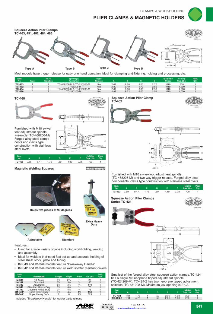
Standard Adjustable
TC-424 1.94 4.75 .50 2.06 1.08 200 TC-424-2 1.94 4.75 1 .50 2.06 1.08 200
C
r,
CLAMPS & WORKHOLDING 'N
PLIER CLAMPS & MAGNETIC HOLDERS
Squeeze Action Plier Clamps TC-463, 491, 482, 484, 486
T B
I-
D
Type A Type B Type C Type D
Most models have trigger release for easy one hand operation. Ideal for clamping and fixturing, holding and processing, etc.
Item No. Type
No. of Spindles
Spindle(s) Furnished
Trigger Release A B C D
E Spindle Thread
Holding Cap. Lbs.
TC-463 A 2 TC-468206-M & TC-210203-M Yes 2.69 8.50 3.00 2.72 M10 700 TC-482 B 1 TC-468206-M Yes 2.80 9.19 1.70 2.56 M10 1,200 TC-484 C 2 TC-468206-M & TC-210203-M Yes 2.69 9.06 3.83 2.56 M10 1,200 TC-486 D 2 TC-240203-M Yes 2.88 9.22 6.00 2.56 M10 1,000
Squeeze Action Plier Clamp TC-462 ."-DESfit<c‘
Furnished with M10 swivel foot adjustment spindle assembly (TC-468206-M). Forged alloy steel compo-nents and clevis type construction with stainless steel rivets.
Item Holding Holding Pack No. A B C D E F Cap. Lbs. Qty.
TC-468 2.66 8.47 1.75 .69 4.10 2.75 700
TC-468
1:400mmivAile#811111111
•0"':
011:4F/
462-S MAC-MATE' Magnetic Welding Squares
Furnished with M10 swivel-foot adjustment spindle (TC-468206-M) and two-way trigger release. Forged alloy steel components, clevis type construction with stainless steel rivets.
Item Holding Pack No. A B C D E F Cap. Lbs. Qty.
TC-462 2.69 8.47 1.75 .69 4.10 2.78 700
Squeeze Action Plier Clamps Series TC-424
Holds two pieces at 90 degrees
r 1.1
Extra Heavy Duty
B
A
Features: • Used for a wide variety of jobs including workholding, welding
and assembly • Ideal for welders that need fast set-up and accurate holding of
steel sheet stock, plate and tubing • IM-343 and IM-344 models feature "Breakaway Handle" • IM-342 and IM-344 models feature weld spatter resistant covers
Item No. Description Length Height Width Pull Lbs.
Pack Qty.
IM-338 10 Angle 3% 2%e % 23 1 IM-339 Standard 3% 3% % 55 1 IM-340 Adjustable 6% 3% % 110 1 IM-341 Standard Heavy Duty 3% 4% % 75 1 IM-342 Covered Heavy Duty 3% 4% % 75 1 IM-343* Extra Heavy Duty 3% 4% 1% 150 1 IM-344* Super Heavy Duty 8 8 1% 325 1
*Includes "Breakaway Handle" for easier parts release
424-2
C
Smallest of the forged alloy steel squeeze action clamps. TC-424 has a single M6 neoprene tipped adjustment spindle (TC-424208-M). TC-424-2 has two neoprene tipped adjustment spindles (TC-431208-M). Maximum jaw opening is Ve".
Item Holding Pack No. A B C D E F Cap. Lbs. Qty.
341
E Spindle Thread
T
Pack Qty.
341
Furnished with M10 swivel foot adjustment spindle assembly (TC-468206-M). Forged alloy steel compo-nents and clevis type construction with stainless steel rivets.
TC-468
B
468
AC
F
E
D
ItemNo. A B C D E F
HoldingCap. Lbs.
PackQty.
TC-468 2.66 8.47 1.75 .69 4.10 2.75 700 1
Squeeze Action Plier ClampsTC-463, 491, 482, 484, 486
Type C Type D
Most models have trigger release for easy one hand operation. Ideal for clamping and fixturing, holding and processing, etc.
DC
B A
E Spindle Thread
Type BType A
ItemNo. Type
No. ofSpindles
Spindle(s)Furnished
TriggerRelease A B C D
E SpindleThread
HoldingCap. Lbs.
PackQty.
TC-463 A 2 TC-468206-M & TC-210203-M Yes 2.69 8.50 3.00 2.72 M10 700 1TC-482 B 1 TC-468206-M Yes 2.80 9.19 1.70 2.56 M10 1,200 1TC-484 C 2 TC-468206-M & TC-210203-M Yes 2.69 9.06 3.83 2.56 M10 1,200 1TC-486 D 2 TC-240203-M Yes 2.88 9.22 6.00 2.56 M10 1,000 1
Squeeze Action Plier ClampTC-462
D
B
462
AE
462-S
F
C
Furnished with M10 swivel-foot adjustment spindle (TC-468206-M) and two-way trigger release. Forged alloy steel components, clevis type construction with stainless steel rivets.
ItemNo. A B C D E F
HoldingCap. Lbs.
PackQty.
TC-462 2.69 8.47 1.75 .69 4.10 2.78 700 1
Squeeze Action Plier ClampsSeries TC-424
B
E C
424-2
424
F
A
D
Smallest of the forged alloy steel squeeze action clamps. TC-424 has a single M6 neoprene tipped adjustment spindle (TC-424208-M). TC-424-2 has two neoprene tipped adjustment spindles (TC-431208-M). Maximum jaw opening is 21⁄16".
ItemNo. A B C D E F
HoldingCap. Lbs.
PackQty.
TC-424 1.94 4.75 1 .50 2.06 1.08 200 1TC-424-2 1.94 4.75 1 .50 2.06 1.08 200 1
Features:Used for a wide variety of jobs including workholding, welding and assemblyIdeal for welders that need fast set-up and accurate holding of steel sheet stock, plate and tubingIM-343 and IM-344 models feature "Breakaway Handle"IM-342 and IM-344 models feature weld spatter resistant covers
*Includes "Breakaway Handle" for easier parts release
ItemNo. Description Length Height Width Pull Lbs.
PackQty.
IM-338 10 Angle 33⁄8 29⁄16 1⁄2 23 1IM-339 Standard 33⁄8 33⁄8 5⁄8 55 1IM-340 Adjustable 61⁄8 33⁄8 5⁄8 110 1IM-341 Standard Heavy Duty 33⁄4 43⁄8 3⁄4 75 1IM-342 Covered Heavy Duty 33⁄4 43⁄8 3⁄4 75 1IM-343* Extra Heavy Duty 33⁄4 43⁄8 11⁄2 150 1IM-344* Super Heavy Duty 8 8 15⁄8 325 1
Magnetic Welding Squares
Adjustable
Holds two pieces at 90 degrees
Extra Heavy Duty
Standard
PLIER CLAMPS & MAGNETIC HOLDERS
FWAHL
SmallO

Buy One or Buy Bulk&SAVE
rliN CLAMPS & WORKHOLDING
CLAMP ACCESSORIES
Clamp Accessories Plunger-Matic Assemblies
Knurled End
Fully Threaded
Inch TC-207206 1/4-20 TC-507206 Vie-18 TC-468206* %-16 TC-210206 %-16 TC-250206 1/2-13
Metric TC-468206-M M10
Clamp Accessories Cone-Tip Bonded Neoprene Cap Assemblies with Jam Nuts
Item No. Thread Thread Lgth.
Pack OAL Qty.
TC-305208 10-32 1.00 1.44 TC-213208 1/4-20 1.50 2.13 TC-509208 Vie-18 2.25 2.94 TC-519208 Vie-18 4.75 5.38 TC-210208 %-16 2.50 3.44
Automatically compensates for variations in part thicknesses. To be mounted to plunger clamps.
Item Thread Lbs. Max. Spring Pack No. Thread Lgth. OAL Pressure Compression Qty.
TC-905 Vie-18 .75 2.50 135 Vie TC-920 %-16 1.13 3.63 308
Note: Pressure value is per'/8 deflection.
Clamp Accessories Swivel Foot Assemblies with Jam Nuts
*Threaded to the foot with knurled end
Clamp Accessories Neoprene Swivel Foot Assemblies
Item Thread Pack No. Thread Lgth. OAL Pad Dia. Qty.
TC-207209 1/4-20 1.50 TC-507209 Vie-18 1.94 TC-210209 %-16 2.44
Clamp Accessories Polyurethane Caps
Cone Tip
Internally threaded to screw on to spindle. High oil and abrasion resistance. Good memory.
Flat Tip TC-215219 TC-225219 TC-235219 Cone TIp TC-215319 TC-225319 TC-235319
1 Vie 9i6
1 1
'A 1 Vie 1 9 6 1
Item No. Thread
Thread Lgth. OAL
Pack Qty.
1.50 2.38 1 1.94 2.75 1 2.00 3.00 1 2.44 3.38 1 3.50 4.63 1
2.00 3.00
2.63 1.00 3.00 1.50 3.63 2.00
TO,
DFT.T
Clamp Accessories Hex Head Assemblies with Jam Nuts
F DEq.itCC ‘
Clamp Accessories Neoprene Caps
For Spindle Pack
ID Dia. Qty. Item No. OD Height
Item No.
Pack Qty. For Spindle Dia.
Clamp Accessories Flat-Tip Bonded Assemblies with Neoprene Cap and Jam Nuts
Low Cushion
TC-205208-M TC-201208-M TC-213208-M TC-305208-M TC-307208-M
M4 .76 .87 M4 1.06 1.26 M5 1.14 1.34 M5 .94 1.14 M8 1.34 1.69
Clamp Accessories Neoprene Caps
Designed to fit over the threaded end of a spindle.
TC-235110 TC-424107
Item No. Thread
Thread Lgth. OAL
Pack Qty.
Steel - Inch TC-105203 8-32 Nylon Bolt .75 .84 TC-305203 10-32 1.00 1.09 TC-205203 1/4-20 1.69 1.88 TC-202203 1/4-20 3.00 3.13 TC-461203 Vie-18 .81 1.00 TC-441203 Vie-18 1.75 1.94 TC-207203 Vie-18 2.50 2.75 TC-491203 %-16 1.25 1.50 TC-210203 %-16 2.75 3.00 TC-240203 %-16 4.00 4.25 TC-527203 %-16 5.00 5.25 TC-325203 'A-13 2.50 2.75 TC-220203 'A-13 3.00 3.31 TC-250203 %-11 4.00 4.38
Steel - Metric TC-205203-M M6 1.77 1.93 TC-461203-M M8 .81 1.00 TC-207203-M M8 2.76 2.97 TC-441203-M M8 1.75 1.94 TC-491203-M M10 1.25 1.50 TC-210203-M M10 2.76 3.03 TC-240203-M M10 4.00 4.25 TC-325203-M M12 2.56 2.83 TC-267203-M M16 4.72 5.12 Stainless Steel - Inch
TC-205943 8-32 .75 86 TC-201943 10-32 1.03 1.13 TC-202943 Ye-20 1.38 1.50 TC-207943 Vie-18 2.31 2.50 1 TC-237943 %-16 2.25 2.50 1
Stainless Steel - Metric TC-207943-M M8 2.56 2.77 1
rreeer
Flat Tip - InchMd TC-201208 10-32 1.00 1.38 1 TC-431208 1/4-20 .63 1.00 1 TC-424208 1/4-20 1.13 1.50 1 TC-202208 TC-215208
A-20 1/4-20
1.25 1.66
1.63 2.19
TC-225208 Vie-18 1.50 2.25 TC-507208 Vie-18 2.31 3.06 TC-240208 TC-527208
%-16 %-16
2.31 2.50
3.31 3.50
TC-235208 %-16 4.88 5.88 TC-247208 1/2-13 2.69 4.00 TC-267208 %-11 3.63 5.00
Flat TIp - Metric TC-431208-M M6 .63 1.00 TC-424208-M M6 1.13 1.50 TC-202208-M M6 1.25 1.73 TC-215208-M M6 1.66 2.19 TC-225208-M M8 1.50 2.25 TC-507208-M M8 2.31 3.06 TC-240208-M M10 2.31 3.31 TC-235208-M M10 4.88 5.88 TC-247208-M M12 2.68 3.82 Flat TIp Low Cushion w/ Jam Nuts - Metric
Slip on the heads of the hex head spindles.
TC-215119 .63 .44 .25 TC-225119 .75 .50 .31 TC-235119 .78 .53 .38
DESIA<CO
Nylon Bolt
Stainless Steel Bolt
Flat Tip
1/4 Vie
342
Clamp AccessoriesHex Head Assemblies with Jam Nuts
Stainless Steel Bolt
Nylon Bolt
ItemNo. Thread
Thread Lgth. OAL
PackQty.
Steel - InchTC-105203 8-32 Nylon Bolt .75 .84 1TC-305203 10-32 1.00 1.09 1TC-205203 1⁄4-20 1.69 1.88 1TC-202203 1⁄4-20 3.00 3.13 1TC-461203 5⁄16-18 .81 1.00 1TC-441203 5⁄16-18 1.75 1.94 1TC-207203 5⁄16-18 2.50 2.75 1TC-491203 3⁄8-16 1.25 1.50 1TC-210203 3⁄8-16 2.75 3.00 1TC-240203 3⁄8-16 4.00 4.25 1TC-527203 3⁄8-16 5.00 5.25 1TC-325203 1⁄2-13 2.50 2.75 1TC-220203 1⁄2-13 3.00 3.31 1TC-250203 5⁄8-11 4.00 4.38 1
Steel - MetricTC-205203-M M6 1.77 1.93 1TC-461203-M M8 .81 1.00 1TC-207203-M M8 2.76 2.97 1TC-441203-M M8 1.75 1.94 1TC-491203-M M10 1.25 1.50 1TC-210203-M M10 2.76 3.03 1TC-240203-M M10 4.00 4.25 1TC-325203-M M12 2.56 2.83 1TC-267203-M M16 4.72 5.12 1Stainless Steel - Inch
TC-205943 8-32 .75 .86 1TC-201943 10-32 1.03 1.13 1TC-202943 1⁄4-20 1.38 1.50 1TC-207943 5⁄16-18 2.31 2.50 1TC-237943 3⁄8-16 2.25 2.50 1
Stainless Steel - MetricTC-207943-M M8 2.56 2.77 1
Clamp AccessoriesFlat-Tip Bonded Assemblieswith Neoprene Cap and Jam Nuts
Low Cushion
Flat Tip
ItemNo. Thread
Thread Lgth. OAL
PackQty.
Flat Tip - InchTC-201208 10-32 1.00 1.38 1TC-431208 1⁄4-20 .63 1.00 1TC-424208 1⁄4-20 1.13 1.50 1TC-202208 1⁄4-20 1.25 1.63 1TC-215208 1⁄4-20 1.66 2.19 1TC-225208 5⁄16-18 1.50 2.25 1TC-507208 5⁄16-18 2.31 3.06 1TC-240208 3⁄8-16 2.31 3.31 1TC-527208 3⁄8-16 2.50 3.50 1TC-235208 3⁄8-16 4.88 5.88 1TC-247208 1⁄2-13 2.69 4.00 1TC-267208 5⁄8-11 3.63 5.00 1
Flat Tip - MetricTC-431208-M M6 .63 1.00 1TC-424208-M M6 1.13 1.50 1TC-202208-M M6 1.25 1.73 1TC-215208-M M6 1.66 2.19 1TC-225208-M M8 1.50 2.25 1TC-507208-M M8 2.31 3.06 1TC-240208-M M10 2.31 3.31 1TC-235208-M M10 4.88 5.88 1TC-247208-M M12 2.68 3.82 1Flat Tip Low Cushion w/ Jam Nuts - MetricTC-205208-M M4 .76 .87 1TC-201208-M M4 1.06 1.26 1TC-213208-M M5 1.14 1.34 1TC-305208-M M5 .94 1.14 1TC-307208-M M8 1.34 1.69 1
Clamp AccessoriesNeoprene Caps
Slip on the heads of the hex head spindles.
ItemNo. OD Height ID
For Spindle
Dia.PackQty.
TC-215119 .63 .44 .25 1⁄4 1TC-225119 .75 .50 .31 5⁄16 1TC-235119 .78 .53 .38 3⁄8 1
Clamp AccessoriesNeoprene Caps
Designed to fit over the threaded end of a spindle.ItemNo. For Spindle Dia.
PackQty.
TC-235110 11⁄32 1TC-424107 7⁄32 1
Clamp AccessoriesCone-Tip Bonded Neoprene Cap Assemblies with Jam Nuts
ItemNo. Thread Thread Lgth. OAL
PackQty.
TC-305208 10-32 1.00 1.44 1TC-213208 1⁄4-20 1.50 2.13 1TC-509208 5⁄16-18 2.25 2.94 1TC-519208 5⁄16-18 4.75 5.38 1TC-210208 3⁄8-16 2.50 3.44 1
Clamp AccessoriesPlunger-Matic Assemblies
Automatically compensates for variations in part thicknesses. To be mounted to plunger clamps.
Note: Pressure value is per 1⁄8 deflection.
ItemNo. Thread
Thread Lgth. OAL
Lbs.Pressure
Max. SpringCompression
PackQty.
TC-905 5⁄16-18 .75 2.50 135 3⁄16 1TC-920 3⁄8-16 1.13 3.63 308 3⁄8 1
Clamp AccessoriesSwivel Foot Assemblies with Jam Nuts
*Threaded to the foot with knurled end
Knurled End
Fully Threaded
ItemNo. Thread
Thread Lgth. OAL
PackQty.
InchTC-207206 1⁄4-20 1.50 2.38 1TC-507206 5⁄16-18 1.94 2.75 1TC-468206* 3⁄8-16 2.00 3.00 1TC-210206 3⁄8-16 2.44 3.38 1TC-250206 1⁄2-13 3.50 4.63 1
MetricTC-468206-M M10 2.00 3.00 1
Clamp AccessoriesNeoprene Swivel Foot Assemblies
ItemNo. Thread
Thread Lgth. OAL Pad Dia.
PackQty.
TC-207209 1⁄4-20 1.50 2.63 1.00 1TC-507209 5⁄16-18 1.94 3.00 1.50 1TC-210209 3⁄8-16 2.44 3.63 2.00 1
Clamp AccessoriesPolyurethane Caps
Internally threaded to screw on to spindle. High oil and abrasion resistance. Good memory.
Cone Tip
Flat TipItemNo. For Spindle Dia.
PackQty.
Flat TipTC-215219 1⁄4 1TC-225219 5⁄16 1TC-235219 3⁄8 1Cone TipTC-215319 1⁄4 1TC-225319 5⁄16 1TC-235319 3⁄8 1
CLAMP ACCESSORIES
FWAHL
SmallO

Clamp Accessories Latch Plates
411 AtisIcc7 AM/
• ••••
Clamp Accessories Flanged Washers for U-Bar Clamps
Item No.
Pack Qty. Description
TC-207105 TC-210114 TC-247110 TC-110122
1.25 Bolt Retainer for Vie Spindle 1.50 Bolt Retainer for % Spindle 1.63 Bolt Retainer for'/ Spindle 1.88 Bolt Retainer for % Spindle
Item No.
Pack Qty. D G L
1/81.A.00
Clamp Accessories Hook Assemblies with Locknuts
DESTA•co
*Supplied with two jam nuts
Clamp Accessories Ergonomic Grips
Provides a safe and comfort-able gripping surface for vertical hold down clamps. The additional guard helps protect against potential pinch points.
Item No.
Pack Qty. Description
L L1 Pack Qty.
Item No. No.
=141 U-Hook
J-Hook
Item For Use Pack Item For Use Pack No. Style w/ Clamp Qty. No. Style w/ Clamp Qty.
Steel Stainless Steel TC-323215 U-Hook TC-323 1 TC-323915 U-Hook TC-323-SS 1 TC-324215 U-Hook TC-324 1 TC-331915 U-Hook TC-331-SS 1 TC-331215 U-Hook TC-331 1 TC-341915 U-Hook TC-341-SS 1 TC-334215 U-Hook TC-334 1 TC-344915 U-Hook TC-344-SS 1 TC-341215 U-Hook TC-341 1 TC-324915 U-Hook TC-324-SS 1 TC-344215 U-Hook TC-344 1 TC-334915 U-Hook TC-334-SS 1 TC-375215 U-Hook TC-375, 375-R 1 TC-330915* J-Hook TC-330-SS 1 TC-385215 U-Hook TC-385 1 TC-351915 J-Hook TC-351-SS 1 TC-351215 J-Hook TC-351 1 TC-371915 J-Hook TC-371-SS 1 TC-330215* J-Hook TC-330 1 TC-371215 J-Hook TC-371 1
TC-202305 Fits 202 and 2002 series clamps TC-207305 Fits 207 and 2007 series clamps
Economy Clamp Accessories Bonded Neoprene Spindles
ETC-19312 .88 %-16 3.44 2.60 ETC-19218 .59 %-20 2.17 1.59 ETC-19316 .49 Vie-18 3.05 2.31
Item No.
For Spindle Pack DIa. Qty.
Item No.
For Spindle Pack DIa. Qty.
Steel Stainless Steel TC-102111 #10 Spindle TC-102911 #10 Spindle TC-105106 #8 Spindle TC-105906 #8 Spindle TC-215105 'A Spindle TC-215905 % Spindle TC-507107 Vie Spindle TC-507907 Vie Spindle TC-235106 % Spindle TC-235906 % Spindle TC-247109 % Spindle TC-267102 % Spindle
Clamp Accessories Bolt Retainers for Clamps with Solid Hold Down Bars
Economy Clamp Accessories Hex Head Spindles
ETC-19338 .55 ETC-19310 .74 ETC-19112 .43 ETC-19212 .49
3.00 3.00 1.50 2.50
3.23 3.31 1.65 2.71
Ll
CLAMPS & WORKHOLDING ' c N
CLAMP ACCESSORIES
Bolt-on Type A
Bolt-on Weld-on Type B Type C
Flanged Plate
Item No. Type
For Use Pack Item w/ Clamp Qty. No. 11,0
For Use Pack w/ Clamp Qty.
Steel TC-323104-M A TC-323
Stainless Steel TC-323104-MSS A TC-323-SS
TC-324101 B TC-324 TC-331905 A TC-331-SS TC-331005 TC-334101
A B
TC-331, 331-R TC-334
TC-341905 TC-324901
A B
TC-341-SS TC-324-SS
TC-341005 A TC-341,341-R TC-334901 B TC-334-SS TC-344101 B TC-344 TC-375509 C Series TC-375 & TC-385 TC-385102 D TC-375, 385
343 343
Clamp AccessoriesLatch Plates
Weld-onType C
Flanged PlateBolt-onType B
Bolt-onType A
ItemNo. Type
For Usew/ Clamp
PackQty.
ItemNo. Type
For Usew/ Clamp
PackQty.
Steel Stainless SteelTC-323104-M A TC-323 1 TC-323104-MSS A TC-323-SS 1
TC-324101 B TC-324 1 TC-331905 A TC-331-SS 1TC-331005 A TC-331, 331-R 1 TC-341905 A TC-341-SS 1TC-334101 B TC-334 1 TC-324901 B TC-324-SS 1TC-341005 A TC-341,341-R 1 TC-334901 B TC-334-SS 1TC-344101 B TC-344 1 TC-375509 C Series TC-375 & TC-385 1 TC-385102 D TC-375, 385 1
Clamp AccessoriesHook Assemblies with Locknuts
*Supplied with two jam nuts
J-HookU-Hook
ItemNo. Style
For Usew/ Clamp
PackQty.
ItemNo. Style
For Usew/ Clamp
PackQty.
Steel Stainless SteelTC-323215 U-Hook TC-323 1 TC-323915 U-Hook TC-323-SS 1TC-324215 U-Hook TC-324 1 TC-331915 U-Hook TC-331-SS 1TC-331215 U-Hook TC-331 1 TC-341915 U-Hook TC-341-SS 1TC-334215 U-Hook TC-334 1 TC-344915 U-Hook TC-344-SS 1TC-341215 U-Hook TC-341 1 TC-324915 U-Hook TC-324-SS 1TC-344215 U-Hook TC-344 1 TC-334915 U-Hook TC-334-SS 1TC-375215 U-Hook TC-375, 375-R 1 TC-330915* J-Hook TC-330-SS 1TC-385215 U-Hook TC-385 1 TC-351915 J-Hook TC-351-SS 1TC-351215 J-Hook TC-351 1 TC-371915 J-Hook TC-371-SS 1TC-330215* J-Hook TC-330 1 TC-371215 J-Hook TC-371 1
Clamp AccessoriesErgonomic Grips
Provides a safe and comfort-able gripping surface for vertical hold down clamps. The additional guard helps protect against potential pinch points.
ItemNo. Description
PackQty.
TC-202305 Fits 202 and 2002 series clamps 1TC-207305 Fits 207 and 2007 series clamps 1
Clamp AccessoriesFlanged Washers for U-Bar Clamps
ItemNo.
For Spindle Dia.
PackQty.
ItemNo.
For Spindle Dia.
PackQty.
Steel Stainless SteelTC-102111 #10 Spindle 1 TC-102911 #10 Spindle 1TC-105106 #8 Spindle 1 TC-105906 #8 Spindle 1TC-215105 1⁄4 Spindle 1 TC-215905 1⁄4 Spindle 1TC-507107 5⁄16 Spindle 1 TC-507907 5⁄16 Spindle 1TC-235106 3⁄8 Spindle 1 TC-235906 3⁄8 Spindle 1TC-247109 1⁄2 Spindle 1 TC-267102 5⁄8 Spindle 1
Clamp AccessoriesBolt Retainers for Clamps with Solid Hold Down Bars
ItemNo. Description
PackQty.
TC-207105 1.25 Bolt Retainer for 5⁄16 Spindle 1TC-210114 1.50 Bolt Retainer for 3⁄8 Spindle 1TC-247110 1.63 Bolt Retainer for 1⁄2 Spindle 1TC-110122 1.88 Bolt Retainer for 5⁄8 Spindle 1
Economy Clamp AccessoriesHex Head Spindles
L1L
D
G
ItemNo. D G L L1
PackQty.
ETC-19338 .55 3⁄8-16 3.23 3.00 1ETC-19310 .74 1⁄2-13 3.31 3.00 1ETC-19112 .43 1⁄4-20 1.65 1.50 1ETC-19212 .49 5⁄16-18 2.71 2.50 1
Economy Clamp AccessoriesBonded Neoprene Spindles
L1
L
D
G
ItemNo. D G L L1
PackQty.
ETC-19312 .88 3⁄8-16 3.44 2.60 1ETC-19218 .59 1⁄4-20 2.17 1.59 1ETC-19316 .49 5⁄16-18 3.05 2.31 1
CLAMP ACCESSORIES
FWAHL
SmallO
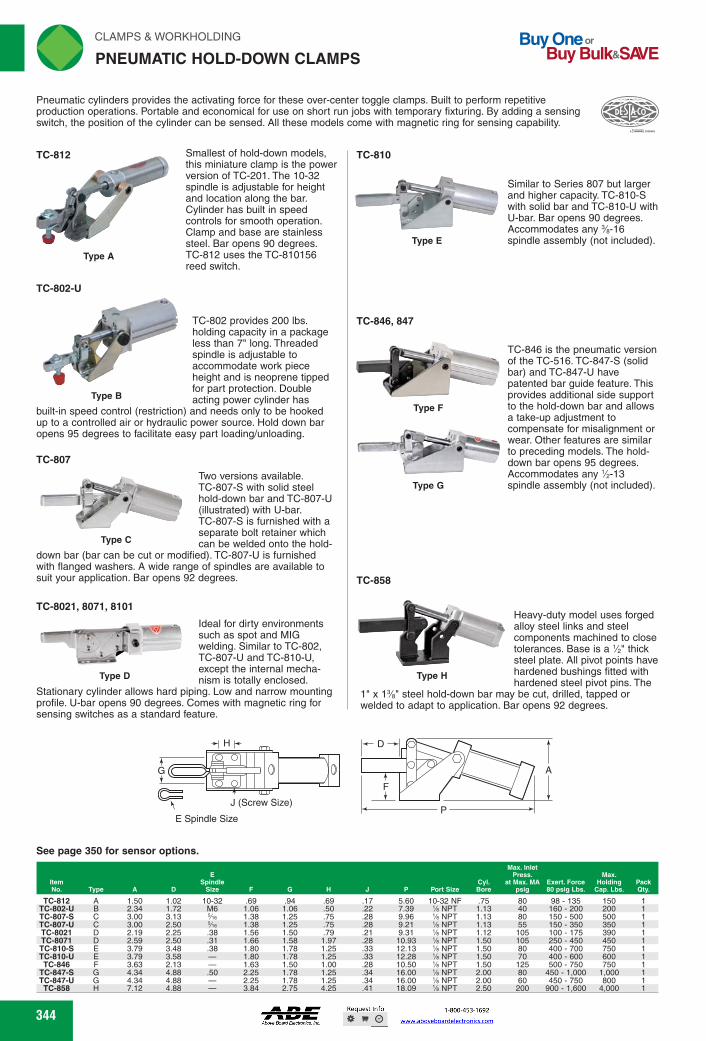
TC-810
Type E
TC-846, 847
Type F
Type G
TC-858
Type H
G 0
J (Screw S ze)
Max. Inlet Press. Max.
at Max. MA Exert. Force Holding Pack psig 80 psig Lbs. Cap. Lbs. Qty.
E Spindle
Size
CYL Port Size Bore
TC-812 A 1.50 1.02 TC-802-U B 2.34 1.72 TC-807-S C 3.00 3.13 TC-807-U C 3.00 2.50 TC-8021 D 2.19 2.25 TC-8071 D 2.59 2.50 TC-810-S E 3.79 3.48 TC-810-U E 3.79 3.58 TC-846 F 3.63 2.13
TC-847-S G 4.34 4.88 TC-847-U G 4.34 4.88 TC-858 H 7.12 4.88
.69 .94 .69 .17 5.60 1.06 1.06 .50 .22 7.39 1.38 1.25 .75 .28 9.96 1.38 1.25 .75 .28 9.21 1.56 1.50 .79 .21 9.31 1.66 1.58 1.97 .28 10.93 1.80 1.78 1.25 .33 12.13 1.80 1.78 1.25 .33 12.28 1.63 1.50 1.00 .28 10.50 2.25 1.78 1.25 .34 16.00 2.25 1.78 1.25 .34 16.00 3.84 2.75 4.25 .41 18.09
10-32 NF % NPT % NPT % NPT % NPT % NPT % NPT % NPT % NPT % NPT % NPT Us NPT
.75 80 98 - 135 150 1.13 40 160 - 200 200 1.13 80 150 - 500 500 1.13 55 150 - 350 350 1.12 105 100 - 175 390 1.50 105 250 - 450 450 1.50 80 400 - 700 750 1.50 70 400 - 600 600 1.50 125 500 - 750 750 2.00 80 450 - 1,000 1,000 2.00 60 450 - 750 800 2.50 200 900 - 1,600 4,000
10-32 M6 Vie Vie .38 .31 .38 - - .50 - -
rliN CLAMPS & WORKHOLDING
PNEUMATIC HOLD-DOWN CLAMPS
Buy One or Buy Bulk&SIVE
Pneumatic cylinders provides the activating force for these over-center toggle clamps. Built to perform repetitive production operations. Portable and economical for use on short run jobs with temporary fixturing. By adding a sensing switch, the position of the cylinder can be sensed. All these models come with magnetic ring for sensing capability.
TC-812
TC-802-U
Smallest of hold-down models, this miniature clamp is the power version of TC-201. The 10-32 spindle is adjustable for height and location along the bar. Cylinder has built in speed controls for smooth operation. Clamp and base are stainless steel. Bar opens 90 degrees. TC-812 uses the TC-810156 reed switch.
Similar to Series 807 but larger and higher capacity. TC-810-S with solid bar and TC-810-U with U-bar. Bar opens 90 degrees. Accommodates any %-16 spindle assembly (not included).
TC-802 provides 200 lbs. holding capacity in a package less than 7" long. Threaded spindle is adjustable to accommodate work piece height and is neoprene tipped for part protection. Double
Type B acting power cylinder has built-in speed control (restriction) and needs only to be hooked up to a controlled air or hydraulic power source. Hold down bar opens 95 degrees to facilitate easy part loading/unloading.
TC-807
Two versions available. TC-807-S with solid steel
* hold-down bar and TC-807-U (illustrated) with U-bar. TC-807-S is furnished with a separate bolt retainer which
Type C can be welded onto the hold- down bar (bar can be cut or modified). TC-807-U is furnished with flanged washers. A wide range of spindles are available to suit your application. Bar opens 92 degrees.
TC-8021, 8071, 8101
Ideal for dirty environments such as spot and MIG welding. Similar to TC-802, TC-807-U and TC-810-U, except the internal mecha-nism is totally enclosed.
Stationary cylinder allows hard piping. Low and narrow mounting profile. U-bar opens 90 degrees. Comes with magnetic ring for sensing switches as a standard feature.
TC-846 is the pneumatic version of the TC-516. TC-847-S (solid bar) and TC-847-U have patented bar guide feature. This provides additional side support to the hold-down bar and allows a take-up adjustment to compensate for misalignment or wear. Other features are similar to preceding models. The hold-down bar opens 95 degrees. Accommodates any 1/2-13 spindle assembly (not included).
Heavy-duty model uses forged alloy steel links and steel components machined to close tolerances. Base is a'/2" thick steel plate. All pivot points have hardened bushings fitted with hardened steel pivot pins. The
1" x 1% steel hold-down bar may be cut, drilled, tapped or welded to adapt to application. Bar opens 92 degrees.
. Jr,
Type D
E Spindle Size
See page 350 for sensor options.
344 344
Pneumatic cylinders provides the activating force for these over-center toggle clamps. Built to perform repetitive production operations. Portable and economical for use on short run jobs with temporary fixturing. By adding a sensing switch, the position of the cylinder can be sensed. All these models come with magnetic ring for sensing capability.
TC-812 Smallest of hold-down models, this miniature clamp is the power version of TC-201. The 10-32 spindle is adjustable for height and location along the bar. Cylinder has built in speed controls for smooth operation. Clamp and base are stainless steel. Bar opens 90 degrees. TC-812 uses the TC-810156 reed switch.
Type A
TC-802 provides 200 lbs. holding capacity in a package less than 7" long. Threaded spindle is adjustable to accommodate work piece height and is neoprene tipped for part protection. Double acting power cylinder has
built-in speed control (restriction) and needs only to be hooked up to a controlled air or hydraulic power source. Hold down bar opens 95 degrees to facilitate easy part loading/unloading.
Type B
TC-807
Two versions available. TC-807-S with solid steel hold-down bar and TC-807-U (illustrated) with U-bar. TC-807-S is furnished with a separate bolt retainer which can be welded onto the hold-
down bar (bar can be cut or modified). TC-807-U is furnished with flanged washers. A wide range of spindles are available to suit your application. Bar opens 92 degrees.
Type C
TC-8021, 8071, 8101
Ideal for dirty environments such as spot and MIG welding. Similar to TC-802, TC-807-U and TC-810-U, except the internal mecha-nism is totally enclosed.
Stationary cylinder allows hard piping. Low and narrow mounting profile. U-bar opens 90 degrees. Comes with magnetic ring for sensing switches as a standard feature.
Type D
TC-810
Similar to Series 807 but larger and higher capacity. TC-810-S with solid bar and TC-810-U with U-bar. Bar opens 90 degrees. Accommodates any 3⁄8-16 spindle assembly (not included).Type E
TC-846, 847
TC-846 is the pneumatic version of the TC-516. TC-847-S (solid bar) and TC-847-U have patented bar guide feature. This provides additional side support to the hold-down bar and allows a take-up adjustment to compensate for misalignment or wear. Other features are similar to preceding models. The hold-down bar opens 95 degrees. Accommodates any 1⁄2-13 spindle assembly (not included).Type G
Type F
TC-858
Heavy-duty model uses forged alloy steel links and steel components machined to close tolerances. Base is a 1⁄2" thick steel plate. All pivot points have hardened bushings fitted with hardened steel pivot pins. The
1" x 13⁄8" steel hold-down bar may be cut, drilled, tapped or welded to adapt to application. Bar opens 92 degrees.
Type H
A
D
P
F
H
G
J (Screw Size)
E Spindle Size
ItemNo. Type A D
ESpindle
Size F G H J P Port SizeCyl.Bore
Max. Inlet Press.
at Max. MA psig
Exert. Force80 psig Lbs.
Max. Holding
Cap. Lbs.PackQty.
TC-812 A 1.50 1.02 10-32 .69 .94 .69 .17 5.60 10-32 NF .75 80 98 - 135 150 1TC-802-U B 2.34 1.72 M6 1.06 1.06 .50 .22 7.39 1⁄8 NPT 1.13 40 160 - 200 200 1TC-807-S C 3.00 3.13 5⁄16 1.38 1.25 .75 .28 9.96 1⁄8 NPT 1.13 80 150 - 500 500 1TC-807-U C 3.00 2.50 5⁄16 1.38 1.25 .75 .28 9.21 1⁄8 NPT 1.13 55 150 - 350 350 1TC-8021 D 2.19 2.25 .38 1.56 1.50 .79 .21 9.31 1⁄8 NPT 1.12 105 100 - 175 390 1TC-8071 D 2.59 2.50 .31 1.66 1.58 1.97 .28 10.93 1⁄8 NPT 1.50 105 250 - 450 450 1TC-810-S E 3.79 3.48 .38 1.80 1.78 1.25 .33 12.13 1⁄8 NPT 1.50 80 400 - 700 750 1TC-810-U E 3.79 3.58 — 1.80 1.78 1.25 .33 12.28 1⁄8 NPT 1.50 70 400 - 600 600 1TC-846 F 3.63 2.13 — 1.63 1.50 1.00 .28 10.50 1⁄8 NPT 1.50 125 500 - 750 750 1
TC-847-S G 4.34 4.88 .50 2.25 1.78 1.25 .34 16.00 1⁄8 NPT 2.00 80 450 - 1,000 1,000 1TC-847-U G 4.34 4.88 — 2.25 1.78 1.25 .34 16.00 1⁄8 NPT 2.00 60 450 - 750 800 1TC-858 H 7.12 4.88 — 3.84 2.75 4.25 .41 18.09 1⁄8 NPT 2.50 200 900 - 1,600 4,000 1
See page 350 for sensor options.
TC-802-U
PNEUMATIC HOLD-DOWN CLAMPS
FWAHL
SmallO
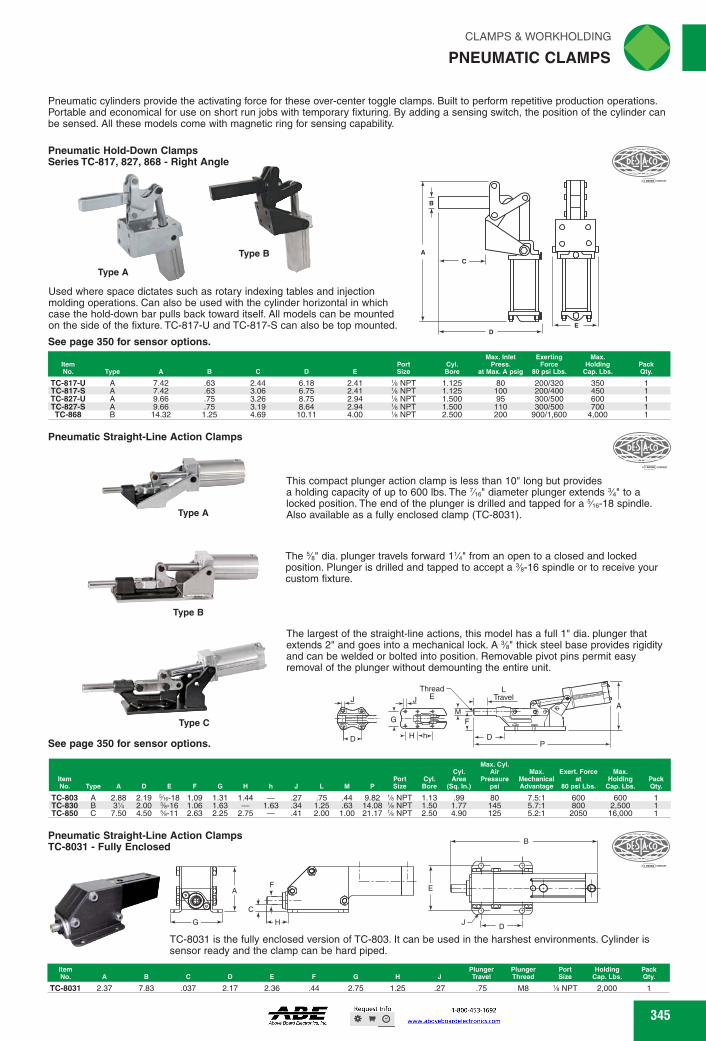
DESTitel
AM/
A
D
E Port Size
CYl• Bare
Max. Inlet Press.
at Max. A psig
Exerting Force
80 psi Lbs.
Max. Holding Pack
Cap. Lbs. Qty. 2.44 6.18 2.41 % NPT 1.125 80 200/320 350 3.06 6.75 2.41 NPT 1.125 100 200/400 450 3.26 8.75 2.94 NPT 1.500 95 300/500 600 3.19 8.64 2.94 NPT 1.500 110 300/500 700 4.69 10.11 4.00 % NPT 2.500 200 900/1,600 4,000
TC-817-U A 7.42 .63 TC-817-S A 7.42 .63 TC-827-U A 9.66 .75 TC-827-S A 9.66 .75 TC-868 B 14.32 1.25
Type C
See page 350 for sensor options.
Max. Cyl. Cyl. Air Max. Exert. Force Max.
Port Cyl. Area Pressure Mechanical at Holding Pack Size Bore (Sq. In.) psi Advantage 80 psi Lbs. Cap. Lbs. Qty. M
Item No. Type A
.27 .75 .44 9.82 % N PT 1.13
.34 1.25 .63 14.08 % NPT 1.50
.41 2.00 1.00 21.17 % NPT 2.50
TC-803 A 2.88 2.19 5/18-18 1.09 1.31 1.44 - TC-830 B 3% 2.00 %-16 1.06 1.63 - 1.63 TC-850 C 7.50 4.50 %-11 2.63 2.25 2.75 -
.99 1.77 4.90
600 800 2050
600 2,500 16,000
80 7.5:1 145 5.7:1 125 5.2:1
Plunger Plunger Travel Thread
Port Holding Pack Size Cap. Lbs. Qty.
% NPT TC-8031 2.37 7.83 .037 2.17 2.36 .44 2.75 1.25 M8 2,000 .27 .75
Pneumatic Straight-Line Action Clamps TC-8031 - Fully Enclosed
HJ
TC-8031 is the fully enclosed version of TC-803. It can be used in the harshest environments. Cylinder is sensor ready and the clamp can be hard piped.
B
3 E
CLAMPS & WORKHOLDING riliN
PNEUMATIC CLAMPS ._„,
Pneumatic cylinders provide the activating force for these over-center toggle clamps. Built to perform repetitive production operations. Portable and economical for use on short run jobs with temporary fixturing. By adding a sensing switch, the position of the cylinder can be sensed. All these models come with magnetic ring for sensing capability.
Pneumatic Hold-Down Clamps Series TC-817, 827, 868 - Right Angle
Type A
Used where space dictates such as rotary indexing tables and injection molding operations. Can also be used with the cylinder horizontal in which case the hold-down bar pulls back toward itself. All models can be mounted on the side of the fixture. TC-817-U and TC-817-S can also be top mounted.
See page 350 for sensor options.
•
Pneumatic Straight-Line Action Clamps
AK,
• LI•1117
This compact plunger action clamp is less than 10" long but provides a holding capacity of up to 600 lbs. The 7/1 6" diameter plunger extends 3/4" to a locked position. The end of the plunger is drilled and tapped for a 5/16-18 spindle. Also available as a fully enclosed clamp (TC-8031). Type A
The %" dia. plunger travels forward 14" from an open to a closed and locked
-.....14. - %
-111 0r position. Plunger is drilled and tapped to accept a -16 spindle or to receive your
6 custom fixture.
Type B
The largest of the straight-line actions, this model has a full 1" dia. plunger that extends 2" and goes into a mechanical lock. A %" thick steel base provides rigidity and can be welded or bolted into position. Removable pivot pins permit easy removal of the plunger without demounting the entire unit.
L hTravel
D P
Thread
4 M
GH Ix Y_
H HhH
345 345
See page 350 for sensor options.
Pneumatic cylinders provide the activating force for these over-center toggle clamps. Built to perform repetitive production operations. Portable and economical for use on short run jobs with temporary fixturing. By adding a sensing switch, the position of the cylinder can be sensed. All these models come with magnetic ring for sensing capability.
Pneumatic Hold-Down ClampsSeries TC-817, 827, 868 - Right Angle
Used where space dictates such as rotary indexing tables and injection molding operations. Can also be used with the cylinder horizontal in which case the hold-down bar pulls back toward itself. All models can be mounted on the side of the fixture. TC-817-U and TC-817-S can also be top mounted.
See page 350 for sensor options.
ED
CA
B
Type B
Type A
ItemNo. Type A B C D E
PortSize
Cyl.Bore
Max. Inlet Press.
at Max. A psig
Exerting Force
80 psi Lbs.
Max.Holding
Cap. Lbs.PackQty.
TC-817-U A 7.42 .63 2.44 6.18 2.41 1⁄8 NPT 1.125 80 200/320 350 1TC-817-S A 7.42 .63 3.06 6.75 2.41 1⁄8 NPT 1.125 100 200/400 450 1TC-827-U A 9.66 .75 3.26 8.75 2.94 1⁄8 NPT 1.500 95 300/500 600 1TC-827-S A 9.66 .75 3.19 8.64 2.94 1⁄8 NPT 1.500 110 300/500 700 1TC-868 B 14.32 1.25 4.69 10.11 4.00 1⁄8 NPT 2.500 200 900/1,600 4,000 1
Pneumatic Straight-Line Action Clamps
This compact plunger action clamp is less than 10" long but provides a holding capacity of up to 600 lbs. The 7⁄16" diameter plunger extends 3⁄4" to a locked position. The end of the plunger is drilled and tapped for a 5⁄16-18 spindle. Also available as a fully enclosed clamp (TC-8031).Type A
The 5⁄8" dia. plunger travels forward 11⁄4" from an open to a closed and locked position. Plunger is drilled and tapped to accept a 3⁄8-16 spindle or to receive your custom fixture.
Type B
The largest of the straight-line actions, this model has a full 1" dia. plunger that extends 2" and goes into a mechanical lock. A 3⁄8" thick steel base provides rigidity and can be welded or bolted into position. Removable pivot pins permit easy removal of the plunger without demounting the entire unit.
Type C
ItemNo. Type A D E F G H h J L M P
PortSize
Cyl.Bore
Cyl. Area
(Sq. In.)
Max. Cyl.Air
Pressure psi
Max. MechanicalAdvantage
Exert. Force at
80 psi Lbs.
Max. Holding
Cap. Lbs.PackQty.
TC-803 A 2.88 2.19 5⁄16-18 1.09 1.31 1.44 — .27 .75 .44 9.82 1⁄8 NPT 1.13 .99 80 7.5:1 600 600 1TC-830 B 31⁄4 2.00 3⁄8-16 1.06 1.63 — 1.63 .34 1.25 .63 14.08 1⁄8 NPT 1.50 1.77 145 5.7:1 800 2,500 1TC-850 C 7.50 4.50 5⁄8-11 2.63 2.25 2.75 — .41 2.00 1.00 21.17 1⁄8 NPT 2.50 4.90 125 5.2:1 2050 16,000 1
LTravel
ThreadE
DP
A
FM
JJ
H hD
G
Pneumatic Straight-Line Action ClampsTC-8031 - Fully Enclosed
TC-8031 is the fully enclosed version of TC-803. It can be used in the harshest environments. Cylinder is sensor ready and the clamp can be hard piped.
AF
HG
C
E
B
JD
ItemNo. A B C D E F G H J
PlungerTravel
PlungerThread
PortSize
HoldingCap. Lbs.
PackQty.
TC-8031 2.37 7.83 .037 2.17 2.36 .44 2.75 1.25 .27 .75 M8 1⁄8 NPT 2,000 1
PNEUMATIC CLAMPS
FWAHL
SmallO

C
I lit B
E
G *-1 RIMMI/•••5-
1111r4WrAMM
.- -t
MENEM ,L.0:_,A,, ABIRWW,,
0 ri a K
)--Ill -4- E
[ N
180 ARM
TC-840 .375 1.375 10 .625 100 1.812 TC-841 .375 1.375 10 .625 100 1.812
Note: Maximum inlet pressure: 150 psig.
.28 .875 - 3.69 1.875 2.563 1.000 - 1.5 Equiv. 180 1,500 475 3:1 90 1,500 475 3:1 .28 .875 3.25 - 1.875 2.563 1.000 5.47 1.5 Equiv.
0
TC-860 .375 TC-861 .375 TC-890 .375 TC-891 .375
TC-1001A .500
.34 1.130 4.50 2.188 2.500 2.313 2.00 180 3,000 1,250 5:1
.34 1.130 4.00 2.188 2.500 2.313 6.47 2.00 90 3,000 1,250 5:1
.41 1.250 5.50 2.500 3.560 2.760 2.50 180 5,000 2,600 6.5:1
.41 1.250 5.00 2.500 3.560 2.760 8.06 2.50 90 5,000 2,600 6.5:1
.53 1.750 7.00 3.500 3.750 3.500 11.31 3.25 90 10,000 6,000 9:1
1.75 11.63 .625
96
2.50
1.75 12.25 .625
110
2.50
2.00 13.00 .690
96
3.06
2.00 13.63 .690
119
3.06
2.63 17.88 1.000
122
3.75
See page 350 for sensor options.
Type A Type B
TC-870,
ki 3/4 "
5/8 ( Ate,
41/4 < for minimum distance between clamping points. Four-way mounting surface for full mounting flexibility. Built-in pre-stop eliminates need to
11/2 bottom out cylinder. Gives extra travel to automatically compensate for wear. Also
permits arm to be machined accurately relative to mounting surface. TC-870-2 maximum opening is 112 degrees, cylinder stroke is 2%".TC-871-2 maximum opening is 126 degrees, cylinder stroke is 274". The magnetic ring cylinders are used when there is a need to sense the open or closed position of the cylinder. By adding a tie rod mounted reed switch, the position of the cylinder can be sensed. All these models come with magnetic ring for sensing capability.
TC-871 3/4
Typ. for 1/4 Saews 5/32 (4) Slots
, -4 33/8
31/8 13/4
1/4 NPT
67/8 Max. (871) 63/8 Max. (870)
1/4 NPT 21/8
I Y 21/8
25/32
These models use a roller and cam principle to enable clamping work of inconsistent thickness while still maintaining a locked condition. Modular units 21/e" square can stack together
Item No. 11,0
A B
CYl• Bore
1.5 TC-870-2 TC-871-2 1.5
Cyl. Area Max. Cylinder Max. Hold Mechanical Exerting Force Sq. In. Air Pressure psig Capacity Lbs. Advantage 80 psig Lbs.
1.767 250 psig 2,000 1.2 to 2.5:1 170/350 1.767 250 psig 2,000 1.2 to 2.5 170/350
rliN CLAMPS & WORKHOLDING
PNEUMATIC HEAVY DUTY HOLD-DOWN CLAMPS
Buy One or Buy Bulk&SIVE
TC-840, 841 DE-STA-004°Toggle Lock Plus
See page 350 for sensor options.
Designed for high production applications, these pneumatic clamps offer exceptional clamping forces and holding capabilities. Does not require greater pressure to open than to close. The TC-840 and TC-841 have oval cylinders which allows them to be used in close quarters or they can be ganged together in multiple installations. The even numbered models feature a 180 degrees clamping arm which travels to an over-center locked position parallel (180 degrees) to the clamps center line. The correspond-ing odd numbered models have a 90 degrees arm. The angular locked position of both versions is precisely controlled by the hardened steel insert. The magnetic ring cylinders are used when there is a need to sense the open or closed position of the cylin-der. Then by adding a tie rod mounted reed switch, the position of the cylinder can be sensed.
Hold Cap. Max. Exert. Mechanical Range of 0 3' from Force 0 80
Advantage
Item
E
Arm Pivot to psig 2' from 2' from Pivot Pack No. A BCD (degrees) F
G H J K L
M N 0 Bore (degrees) Load Point Pivot Point
Point Qty.
TC-860, 861, 890, 891,1001A
See page 350 for sensor options.
Designed for high production applications, these pneumatic clamps offer exceptional clamping forces and holding capabilities. Does not require greater pressure to open than to close. The even numbered models feature a 180 degrees clamping arm which travels to an over-center locked position parallel (180 degrees) to the clamps center line. The corresponding odd numbered models have a 90 degrees arm. The angular locked position of both versions is precisely controlled by the hardened steel insert. The magnetic ring cylinders are used when there is a need to sense the open or closed position of the cylinder. Then by adding a tie rod mounted reed switch, the position of the cylin-der can be sensed.
E A B C D (degrees) F G H J
Hold Cap. Max. Exert. Mechanical Range of @ 3' from Force @ 80 Advantage
Arm Pivot to psig 2' from 2' from Pack K L M N 0 Bore (degrees) Load Point Pivot Point Pivot Point Qty.
TC-870, 871 Power Roller .--DESTA<C‘
346 346
TC-840, 841DE-STA-CO® Toggle Lock Plus
Designed for high production applications, these pneumatic clamps offer exceptional clamping forces and holding capabilities. Does not require greater pressure to open than to close. The TC-840 and TC-841 have oval cylinders which allows them to be used in close quarters or they can be ganged together in multiple installations. The even numbered models feature a 180 degrees clamping arm which travels to an over-center locked position parallel (180 degrees) to the clamps center line. The correspond-ing odd numbered models have a 90 degrees arm. The angular locked position of both versions is precisely controlled by the hardened steel insert. The magnetic ring cylinders are used when there is a need to sense the open or closed position of the cylin-der. Then by adding a tie rod mounted reed switch, the position of the cylinder can be sensed.See page 350 for sensor options.
Note: Maximum inlet pressure: 150 psig.
A
C
N B
F K
M
G DE
EH
OJ
L
ItemNo. A B C D
E(degrees) F G H J K L M N O Bore
Range of Arm
(degrees)
Hold Cap. @ 3" from
Pivot to Load Point
Max. Exert. Force @ 80psig 2" from Pivot Point
Mechanical Advantage
2" from Pivot Point
PackQty.
TC-840 .375 1.375 10 .625 100 1.812 .28 .875 — 3.69 1.875 2.563 1.000 — 1.5 Equiv. 180 1,500 475 3:1 1TC-841 .375 1.375 10 .625 100 1.812 .28 .875 3.25 — 1.875 2.563 1.000 5.47 1.5 Equiv. 90 1,500 475 3:1 1
TC-860, 861, 890, 891,1001A
Designed for high production applications, these pneumatic clamps offer exceptional clamping forces and holding capabilities. Does not require greater pressure to open than to close. The even numbered models feature a 180 degrees clamping arm which travels to an over-center locked position parallel (180 degrees) to the clamps center line. The corresponding odd numbered models have a 90 degrees arm. The angular locked position of both versions is precisely controlled by the hardened steel insert. The magnetic ring cylinders are used when there is a need to sense the open or closed position of the cylinder. Then by adding a tie rod mounted reed switch, the position of the cylin-der can be sensed.See page 350 for sensor options.
A
K
J
H
O
L
FG
D
E
B
C
NM
E
ItemNo. A B C D
E(degrees) F G H J K L M N O Bore
Range of Arm
(degrees)
Hold Cap. @ 3" from
Pivot to Load Point
Max. Exert. Force @ 80psig 2" from Pivot Point
Mechanical Advantage
2" from Pivot Point
PackQty.
TC-860 .375 1.75 11.63 .625 96 2.50 .34 1.130 — 4.50 2.188 2.500 2.313 — 2.00 180 3,000 1,250 5:1 1TC-861 .375 1.75 12.25 .625 110 2.50 .34 1.130 4.00 — 2.188 2.500 2.313 6.47 2.00 90 3,000 1,250 5:1 1TC-890 .375 2.00 13.00 .690 96 3.06 .41 1.250 — 5.50 2.500 3.560 2.760 — 2.50 180 5,000 2,600 6.5:1 1TC-891 .375 2.00 13.63 .690 119 3.06 .41 1.250 5.00 — 2.500 3.560 2.760 8.06 2.50 90 5,000 2,600 6.5:1 1
TC-1001A .500 2.63 17.88 1.000 122 3.75 .53 1.750 7.00 — 3.500 3.750 3.500 11.31 3.25 90 10,000 6,000 9:1 1
TC-870, 871Power Roller
These models use a roller and cam principle to enable clamping work of inconsistent thickness while still maintaining a locked condition. Modular units 21⁄8" square can stack together for minimum distance between clamping points. Four-way mounting surface for full mounting flexibility. Built-in pre-stop eliminates need to bottom out cylinder. Gives extra travel to automatically compensate for wear. Also
permits arm to be machined accurately relative to mounting surface. TC-870-2 maximum opening is 112 degrees, cylinder stroke is 23⁄8". TC-871-2 maximum opening is 126 degrees, cylinder stroke is 27⁄8". The magnetic ring cylinders are used when there is a need to sense the open or closed position of the cylinder. By adding a tie rod mounted reed switch, the position of the cylinder can be sensed. All these models come with magnetic ring for sensing capability.See page 350 for sensor options.
67/8 Max. (871)63/8 Max. (870)33/8
13/431/8
TC-871
11
41/4
TC-870
21/8
3/4
Typ. for 1/4 Screws9/32 (4) Slots
5/83/8
1
21/8NPT1/4 NPT1/4
25/32
11/2
Type BType A
ItemNo. Type
Cyl.Bore
Cyl. AreaSq. In.
Max. CylinderAir Pressure psig
Max. HoldCapacity Lbs.
MechanicalAdvantage
Exerting Force80 psig Lbs.
PackQty.
TC-870-2 A 1.5 1.767 250 psig 2,000 1.2 to 2.5:1 170/350 1TC-871-2 B 1.5 1.767 250 psig 2,000 1.2 to 2.5 170/350 1
PNEUMATIC HEAVY DUTY HOLD-DOWN CLAMPS
FWAHL
SmallO

G
E C
J K L M N Mtg. Input
P Holes Pressure Exerting Pack
Force Qty. Item No. Type A D E F G H
.26 70-150
Item No. B116 B1 B7 B10 B11a
Holding Torque Clamping Torque Max. (In.-Lbs.) Max. (In.-Lbs.)
Pack B111 L1 L6 L7 1J11 Qty.
55 132 280
105 105 105 'A
55 132 280
105 105 105 'A
25 53 179.5 18 20 60 211 20 25 74 242 20
25 53 179.5 18 20 60 211 20 25 74 242 20
Without Sensor TC-82L2G20300H0 TC-82L3G20300H0 TC-82L4G20300H0 With Sensor TC-82L2G203B8H0 TC-82L3G203B8H0 TC-82L4G203B8H0
Pneumatic Retractor Clamps Series TC-800
y_ 1/
2
Eby -.1
'AY 5/16 -4- B
HY- M t
Clamping Arm
C
o?
CLAMPS & WORKHOLDING .qN
PNEUMATIC CLAMPS
Operates on an ordinary shop line air (properly filtered and lubricated). Clamp arm completely retracts from the work area for ease in part loading/unloading. Model 800-E has an extended arm. Min. operating pressure is 70 psig.
TC-800 A 1.63 4.81 2.72 .25 2.21 .25 3.13 1.19 .59 .19 .50 'A NPT 2.31 1.50 TC-800-E B 1.63 4.81 2.72 .25 2.21 .25 3.13 1.19 .59 .16 .50 'A NPT 2.31 1.50 .50 .26 70-150 650 - 1,200
Note: Use with pneumatic power only. 3-Way air valve required to power unit (single-acting spring return).
850 - 1,500
9 12 15 15
4.5 5.75
9 9
104 119 151 151
9 15 20 20
15 20 20 20
39 53 57 159
221 531 885 885
4.5 5.75
9
104 119 151
24 15 30 20 35 20
39 57 150
177 354 708
Horizontal TC-81L12-10100 TC-81L16-10100 TC-81L20-10100 TC-81 L25-10100 Vertical TC-81L12-14100 TC-81L16-14100 TC-81L25-14100
M4 x 6 24 M5 x 5 30 M6 x 8 35 M6 x 8 35
M4 x6 M5 x5 M6 x8
15 20 25 25
15 9 20 12 25 15
27 31.5 28 30 39.5 30
30.5 40 40 40.5 50 40
9 27 31.5 28 15 30 39.5 30 20 40.5 50 40
Automation Power Clamps Series TC-82L Without Hand Lever
• Lightweight aluminum design
• Enclosed model • Contaminant
resistant • Compact design • High holding
torques • Long life cycle
See page 350 for sensors.
Automation Power Clamps Series TC-82L With Hand Lever
Features: • Lightweight
aluminum design • Enclosed model • Contaminant
resistant • Compact design • High holding
torques • Long life cycle
See page 350 for sensors.
CIf DESPYCO ..... =..11, .....,
347
Type A
>P K r
-4- Type B
DESTA•Co
Automation Power Clamps Series TC-81L Miniature Design
Horizontal Vertical
'rt
Clamping Arm Clamping Arm
See page 350 for sensors.
'-DESIA•6‘
Clamping, holding, gripping and positioning of metal sheets and other parts in jigs and handling systems. Features compact design, long life cycle, high holding torques, two mount-ing areas (front and rear), and toggle action mechanism. These models can be quickly fitted with magnetic position sensors. Horizontal clamping arms have 120 degrees standard opening angle and the vertical clamping arms have 90 degrees standard opening angle.
Opening Angle
81L"-141 Opening Angle
Area of Interference
B11b
Pivot
k Tg.3)
Right Hand T-slot for sensor111111111
Left Hand Round slot for sensor [-v--B
Powered with compressed air max. 6 Bar Operation with oil free air is permissible
179.5 211 242
55 132 280
42 50
18 1 20 1 20 1
179.5 211 242
25 20 25
42 50
18 1 20 1 20 1
55 132 280
Without Sensor TC-82L2G2030000 TC-82L3G2030000 TC-82L4G2030000 With Sensor TC-82L2G203B800 TC-82L3G203B800 TC-82L4G203B800
25 53 20 3 60 25 35 74
53 3 60 35 74
Max. Holding Opening Angle Air Pack Torque Lbs. (degrees) Connection B7 B23 L1 1-111 Qt
Re No.
347
Features:
resistant
torques
See page 350 for sensors.
ItemNo.
Max. HoldingTorque Lbs.
Opening Angle(degrees)
AirConnection B7 B23 L1 L9
PackQty.
Without SensorTC-82L2G20300H0 55 105 1⁄8 25 53 179.5 18 1TC-82L3G20300H0 132 105 1⁄8 20 60 211 20 1TC-82L4G20300H0 280 105 1⁄4 25 74 242 20 1With SensorTC-82L2G203B8H0 55 105 1⁄8 25 53 179.5 18 1TC-82L3G203B8H0 132 105 1⁄8 20 60 211 20 1TC-82L4G203B8H0 280 105 1⁄4 25 74 242 20 1
Automation Power ClampsSeries TC-82LWith Hand Lever
L1 MAX
L9
B7
B23
A
P K
J
IType B
Pneumatic Retractor ClampsSeries TC-800
Note:
ItemNo. Type A B C D E F G H I J K L M N P
Mtg.Holes
InputPressure
ExertingForce
PackQty.
TC-800 A 1.63 4.81 2.72 .25 2.21 .25 3.13 1.19 .59 .19 .50 1⁄4 2.31 1.50 — .26 1TC-800-E B 1.63 4.81 2.72 .25 2.21 .25 3.13 1.19 .59 .16 .50 1⁄4 2.31 1.50 .50 .26 1
GF
D
E C
MB
HN
L
Clamping Arm
A
K
J
I
Type A
Automation Power ClampsSeries TC-82LWithout Hand Lever
L8a
L1 MAXB7a
(L9a)
B23 MAX
L9
B7
resistant
torques
See page 350 for sensors.
ItemNo.
Max. HoldingTorque Lbs. B7 B7a B23 L1 L8a L9
PackQty.
Without SensorTC-82L2G2030000 55 25 — 53 179.5 — 18 1TC-82L3G2030000 132 20 3 60 211 42 20 1TC-82L4G2030000 280 25 35 74 242 50 20 1With SensorTC-82L2G203B800 55 25 — 53 179.5 — 18 1TC-82L3G203B800 132 20 3 60 211 42 20 1TC-82L4G203B800 280 25 35 74 242 50 20 1
Automation Power ClampsSeries TC-81LMiniature Design
See page 350 for sensors.
Opening AngleOpeningAngle
Area of Interference
Pivot
Right Hand: T-slot for sensorLeft Hand: Round slot for sensor
Powered with compressed air max. 6 BarOperation with oil-free air is permissible
B1
B10
L7
L6
81**-101
B10
B7
L9
D3(8x)L1
B18
81L**-141
B11b
B11a
Vertical Clamping Arm
Horizontal Clamping Arm
ItemNo.
Holding TorqueMax. (In.-Lbs.)
Clamping TorqueMax. (In.-Lbs.) D3 B1 B7 B10 B11a B11b B18 L1 L6 L7 L9
PackQty.
HorizontalTC-81L12-10100 221 39 24 15 9 27 31.5 28 104 4.5 15 9 1TC-81L16-10100 531 53 30 20 15 30 39.5 30 119 5.75 20 12 1TC-81L20-10100 885 57 35 20 20 30.5 40 40 151 9 25 15 1TC-81L25-10100 885 159 35 20 20 40.5 50 40 151 9 25 15 1VerticalTC-81L12-14100 177 39 24 15 9 27 31.5 28 104 4.5 15 9 1TC-81L16-14100 354 57 30 20 15 30 39.5 30 119 5.75 20 12 1TC-81L25-14100 708 150 35 20 20 40.5 50 40 151 9 25 15 1
PNEUMATIC CLAMPS
FWAHL
SmallO
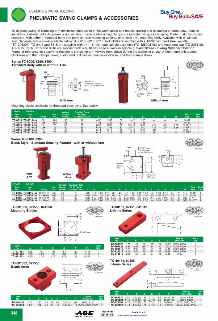
C Bore for 'C." Socket Heed Cap Screw 3 Holes on a 14" Bolt Circle
E Dia.
With Arm
Mounting blocks available for threaded body style. See below.
Without Arm
D tiiC0 441).
1%-16 1.25 - - 10-32 1
1%-16 1.25 - - 10-32 1 21/4-12 3.00 1.16 .25 2.66 % NPT 1 21/4-12 3.00 1.16 .25 2.66 % NPT 1 1%-12 2.13 .98 - % NPT 1 1%-12 2.13 .98 - % NPT 1
1<-1A -c
.cr Dia. Tin (2 Places) Arm Arm
w/ Arm w/o Arm Vertical Exerting Force Item item Rot. Clamp @ 80 psi w/ No. No. Swing TM. Stroke Standard Arm A B C D E F
TC-8115 TC-8115-LA RH Hand .466 .38 22 4.88 3.50 1.25 1.25 .62 .47 TC-8116 TC-8116-LA LH Hand .466 .38 22 4.88 3.50 1.25 1.25 .62 .47 TC-8315 TC-8315-LA TC-8316 TC-8316-LA
RH Hand LH Hand
.75
.75 .50 .50
80 80
6.36 6.36
4.27 4.27
3.00 3.00
2.00 2.00
1.00 1.00
.72
.72
Series TC-8100, 8300 Block Style - Standard Sensing Feature - with or without Arm
With Without
Clamp Port Unclamp Port
Port Pack G H J K L M N P Q R Size Qty.
.47 1.00 1.12 1.00 .25 1.00 1.57 .35 .20 #10 10-32 1
.47 1.00 1.12 1.00 .25 1.00 1.57 .35 .20 #10 10-32 1 1.22 2.25 .53 2.37 .44 2.25 1.016 .65 .40 .313 % NPT 1 1.22 2.25 .53 2.37 .44 2.25 1.016 .65 .40 .313 % NPT 1
4) MTG Holes for Tr Socket Heal Cap Soren
J
E
[..G.].G.] 4
DESfas.. TC-801553, 821553, 841550
Mounting Blocks
E (4 Places)
.50
TC-801553 1.38 .69 1.08 .54 .20 1%-16 1 TC-841550 2.00 1.00 1.60 .80 .28 1%-12 1 TC-821553 2.50 1.25 2.12 1.06 .27 21/4-12 1
TC-801532, 821556 Blank Arms
B D
DESfko IN/
V
A '-F
Item Use w/ No. A B C D E F Series No.
Pack Qty.
TC-801528 1.75 1.12 .39 TC-801529 2.87 2.25 .39 TC-821512 2.75 2.00 .75 TC-821513 3.75 3.00 .75 TC-841512 2.31 1.58 .75
.27 .62 10-32 8000, 8100 1
.27 .62 10-32 8000, 8100 1
.37 .75 %-16 8200, 8300 1
.37 .75 %-16 8200, 8300 1
.37 .75 %-16 8400 1
Item No. A B C D E
Use w/ Pack Series No. Qty.
TC-80153, 80155 T-Arms Series
E
A
C p # #
F
TC-801530 2.87 1.12 2 .39 .27 2 .62 10-32 (2 8000, 8100 1 TC-801531 5.12 2.25 2 .39 .27 2 .62 10-32 (2 8000, 8100 1 TC-821554 4.75 2.00 2 .75 .37 2 .75 %-16 (2 8200, 8300, 8400 1 TC-821555 6.75 3.00 2 .75 .37 2 .75 %-16 (2 8200, 8300, 8400 1
A
E
E
C A D
TC-80152, 82151, 841512 L-Arms Series eCllifC-07
,̀7._1-__--n!.." A ......,
Item Use w/ Pack No. A B C D E F G Series No. Qty.
TC-801532 1.37 1.00 .39 .25 .62 10-32 (2) .62 8000, 8100 1
TC-821556 1.50 1.06 .75 .37 .75 1/4-20 (2) .75 8200, 8300, 8400 1
348
P"N CLAMPS & WORKHOLDING
PNEUMATIC SWING CLAMPS & ACCESSORIES
Buy One or Buy Bulk&SIVE
90 degrees swing of clamping arm minimizes obstruction in the work space and makes loading and unloading of parts easy. Ideal for installations where hydraulic power is not suitable. These double acting clamps are intended for quick clamping. Made of aluminum, red anodized, with either a threaded body that permits three mounting options, or a block style mounting body. Available with or without arm. Separate arm options available below. TC-8015, 8016, 8115 and 8116 are supplied with a 10-32 hex head steel spindle (TC-305203). TC-8415 and 8416 are supplied with a %-16 hex head spindle assembly (TC-485203-AL) and neoprene cap (TC-235110). TC-8215, 8216, 8315 and 8316 are supplied with a %-16 hex head aluminum spindle (TC-485203-AL). Swing Cylinder Rotation: Frame of reference for specifying rotation is the clamp arm viewed from above during the clamping stroke. A right-hand unit rotates clockwise and then clamps down; a left-hand unit rotates counter-clockwise, and then clamps down.
Series TC-8000, 8200, 8400 Threaded Body with or without Arm
w/ Arm w/o Arm
Swing Rot. TM.
Vertical Clamp Stroke
Exerting Force @ 80 psi
w/ Standard Arm A Item Item No. No.
TC-8015 TC-8015-LA RH .466 .38 22 4.88 2.87 .62 TC-8016 TC-8016-LA LH .466 .38 22 4.88 2.87 .62 TC-8215 TC-8215-LA RH .75 .50 80 6.36 3.36 .87 TC-8216 TC-8216-LA LH .75 .50 80 6.36 3.36 .87 TC-8415 TC-8415-LA RH .75 .50 62 6.14 3.17 .88 TC-8416 TC-8416-LA LH .75 .50 62 6.14 3.17 .88
348
ItemNo. A B C D E F
Use w/Series No.
PackQty.
TC-801530 2.87 1.12 (2) .39 .27 (2) .62 10-32 (2) 8000, 8100 1TC-801531 5.12 2.25 (2) .39 .27 (2) .62 10-32 (2) 8000, 8100 1TC-821554 4.75 2.00 (2) .75 .37 (2) .75 3⁄8-16 (2) 8200, 8300, 8400 1TC-821555 6.75 3.00 (2) .75 .37 (2) .75 3⁄8-16 (2) 8200, 8300, 8400 1
TC-80153, 80155T-Arms Series
A
FBB
E
C D
90 degrees swing of clamping arm minimizes obstruction in the work space and makes loading and unloading of parts easy. Ideal for installations where hydraulic power is not suitable. These double acting clamps are intended for quick clamping. Made of aluminum, red anodized, with either a threaded body that permits three mounting options, or a block style mounting body. Available with or without arm. Separate arm options available below. TC-8015, 8016, 8115 and 8116 are supplied with a 10-32 hex head steel spindle (TC-305203). TC-8415 and 8416 are supplied with a 3⁄8-16 hex head spindle assembly (TC-485203-AL) and neoprene cap (TC-235110). TC-8215, 8216, 8315 and 8316 are supplied with a 3⁄8-16 hex head aluminum spindle (TC-485203-AL). Swing Cylinder Rotation: Frame of reference for specifying rotation is the clamp arm viewed from above during the clamping stroke. A right-hand unit rotates clockwise and then clamps down; a left-hand unit rotates counter-clockwise, and then clamps down.
Series TC-8000, 8200, 8400Threaded Body with or without Arm
Mounting blocks available for threaded body style. See below.
C Bore for “G”Socket Head Cap Screw3 Holes on a “H” Bolt Circle
UnclampPort
D Thd.B
C
AF
E Dia.
ClampPort
With Arm
F
EUnclampPort
ClampPort
A
B
C
D Thread
Without Arm
w/ Arm w/o Arm
SwingRot.Trvl.
Vertical ClampStroke
Exerting Force@ 80 psi
w/ Standard Arm A B C D E F G HPortSize
PackQty.
ItemNo.
ItemNo.
TC-8015 TC-8015-LA RH .466 .38 22 4.88 2.87 .62 11⁄8-16 1.25 — — — 10-32 1TC-8016 TC-8016-LA LH .466 .38 22 4.88 2.87 .62 11⁄8-16 1.25 — — — 10-32 1TC-8215 TC-8215-LA RH .75 .50 80 6.36 3.36 .87 21⁄4-12 3.00 1.16 .25 2.66 1⁄8 NPT 1TC-8216 TC-8216-LA LH .75 .50 80 6.36 3.36 .87 21⁄4-12 3.00 1.16 .25 2.66 1⁄8 NPT 1TC-8415 TC-8415-LA RH .75 .50 62 6.14 3.17 .88 13⁄4-12 2.13 .98 — — 1⁄8 NPT 1TC-8416 TC-8416-LA LH .75 .50 62 6.14 3.17 .88 13⁄4-12 2.13 .98 — — 1⁄8 NPT 1
Series TC-8100, 8300Block Style - Standard Sensing Feature - with or without Arm
F ED
GG
FA
J
H
K
L
“Q” Dia. Thru(2 Places)
M
C
P
UnclampPort
Clamp Port
N
4) MTG Holesfor “R” SocketHead Cap Screws
B
Without Arm
With Arm
w/ Arm w/o Arm
SwingRot.Trvl.
Vertical ClampStroke
Exerting Force@ 80 psi w/
Standard Arm A B C D E F G H J K L M N P Q RPortSize
PackQty.
ItemNo.
ItemNo.
TC-8115 TC-8115-LA RH Hand .466 .38 22 4.88 3.50 1.25 1.25 .62 .47 .47 1.00 1.12 1.00 .25 1.00 1.57 .35 .20 #10 10-32 1TC-8116 TC-8116-LA LH Hand .466 .38 22 4.88 3.50 1.25 1.25 .62 .47 .47 1.00 1.12 1.00 .25 1.00 1.57 .35 .20 #10 10-32 1TC-8315 TC-8315-LA RH Hand .75 .50 80 6.36 4.27 3.00 2.00 1.00 .72 1.22 2.25 .53 2.37 .44 2.25 1.016 .65 .40 .313 1⁄8 NPT 1TC-8316 TC-8316-LA LH Hand .75 .50 80 6.36 4.27 3.00 2.00 1.00 .72 1.22 2.25 .53 2.37 .44 2.25 1.016 .65 .40 .313 1⁄8 NPT 1
TC-80152, 82151, 841512L-Arms Series
AF
B
E
CD
ItemNo. A B C D E F
Use w/Series No.
PackQty.
TC-801528 1.75 1.12 .39 .27 .62 10-32 8000, 8100 1TC-801529 2.87 2.25 .39 .27 .62 10-32 8000, 8100 1TC-821512 2.75 2.00 .75 .37 .75 3⁄8-16 8200, 8300 1TC-821513 3.75 3.00 .75 .37 .75 3⁄8-16 8200, 8300 1TC-841512 2.31 1.58 .75 .37 .75 3⁄8-16 8400 1
TC-801532, 821556Blank Arms
E
FAB
D
G
C
ItemNo. A B C D E F G
Use w/Series No.
PackQty.
TC-801532 1.37 1.00 .39 .25 .62 10-32 (2) .62 8000, 8100 1TC-821556 1.50 1.06 .75 .37 .75 1⁄4-20 (2) .75 8200, 8300, 8400 1
TC-801553, 821553, 841550Mounting Blocks
F
E (4 Places)
.50
A
B
D
C
ItemNo. A B C D E F
PackQty.
TC-801553 1.38 .69 1.08 .54 .20 11⁄8-16 1TC-841550 2.00 1.00 1.60 .80 .28 13⁄4-12 1TC-821553 2.50 1.25 2.12 1.06 .27 21⁄4-12 1
PNEUMATIC SWING CLAMPS & ACCESSORIES
FWAHL
SmallO
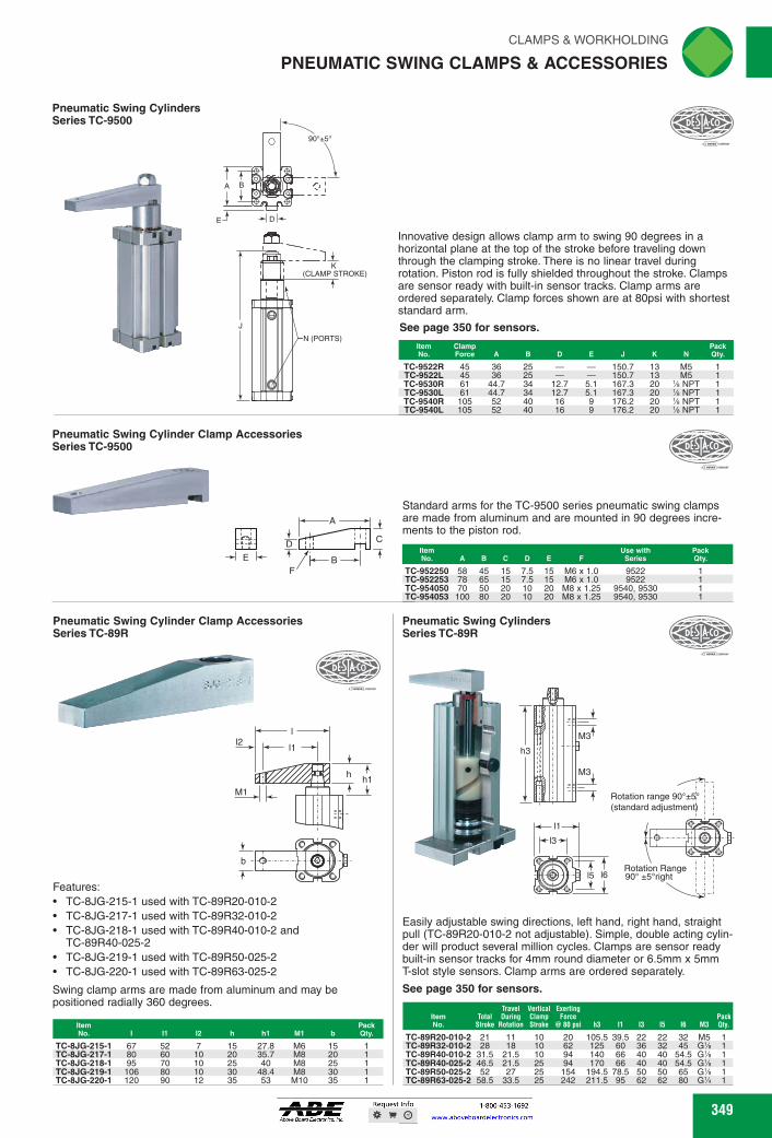
A
E ► ID I.-
K (CLAMP STROKE)
N (PORTS)
Pneumatic Swing Cylinders Series TC-9500
111
Pneumatic Swing Cylinder Clamp Accessories Series TC-9500
sou
MEMMENEMm. Peek Qty.
Pneumatic Swing Cylinders Series TC-89R
Easily adjustable swing directions, left hand, right hand, straight pull (TC-89R20-010-2 not adjustable). Simple, double acting cylin-der will product several million cycles. Clamps are sensor ready built-in sensor tracks for 4mm round diameter or 6.5mm x 5mm T-slot style sensors. Clamp arms are ordered separately.
See page 350 for sensors.
M3
Rotation range 90°±5' (standard adjustment)
Rotation Range 90° ±Wright
h3
11 sr.-
r_,31
Item No. Stroke Rotation Stroke
TC-89R20-010-2 21
11
10 TC-89R32-010-2 28 18
10
TC-89R40-010-2 31.5 21.5
10 TC-89R40-025-2 46.5 21.5 25 TC-89R50-025-2 52 27
25
TC-89R63-025-2 58.5 33.5 25
@ 80 psi 63 11 q 15 16 M3
20 105.5 39.5 22 22 32 M5 62 125 60 36 32 45 G% 94 140 66 40 40 54.5 G% 94 170 66 40 40 54.5 G%
154 194.5 78.5 50 50 65 G% 242 211.5 95 62 62 80 G%
Travel Vertical Exerting Total During Clamp Force Pack
Qty.
CLAMPS & WORKHOLDING riliN
PNEUMATIC SWING CLAMPS & ACCESSORIES usip,
Innovative design allows clamp arm to swing 90 degrees in a horizontal plane at the top of the stroke before traveling down through the clamping stroke. There is no linear travel during rotation. Piston rod is fully shielded throughout the stroke. Clamps are sensor ready with built-in sensor tracks. Clamp arms are ordered separately. Clamp forces shown are at 80psi with shortest standard arm.
See page 350 for sensors.
ilEMEM-AMMMWESI TC-9522R 45 36 25 - - 150.7 13 M5 1 TC-9522L 45 36 25 - - 150.7 13 M5 1 TC-9530R 61 44.7 34 12.7 5.1 167.3 20 % NPT 1 TC-9530L 61 44.7 34 12.7 5.1 167.3 20 % NPT 1 TC-9540R 105 52 40 16 9 176.2 20 % NPT 1 TC-9540L 105 52 40 16 9 176.2 20 % NPT 1
.11:0ESTA<0
E
Pneumatic Swing Cylinder Clamp Accessories Series TC-89R
DFS1kCI A a'
Features: • TC-8JG-215-1 used with TC-89R20-010-2 • TC-8JG-217-1 used with TC-89R32-010-2 • TC-8JG-218-1 used with TC-89R40-010-2 and
TC-89R40-025-2 • TC-8JG-219-1 used with TC-89R50-025-2 • TC-8JG-220-1 used with TC-89R63-025-2
Swing clamp arms are made from aluminum and may be positioned radially 360 degrees.
Item No. 11 12 h h1 M1 b
Peek Qty.
TC-8JG-215-1 67 52 7 15 27.8 M6 15 1 TC-8JG-217-1 80 60 10 20 35.7 M8 20 1 TC-8JG-218-1 95 70 10 25 40 M8 25 1 TC-8JG-219-1 106 80 10 30 48.4 M8 30 1 TC-8JG-220-1 120 90 12 35 53 M10 35 1
Standard arms for the TC-9500 series pneumatic swing clamps are made from aluminum and are mounted in 90 degrees incre-ments to the piston rod.
TC-952250 58 45 15 7.5 15 M6 x 1.0 9522 TC-952253 78 65 15 7.5 15 M6 x 1.0 9522 TC-954050 70 50 20 10 20 M8 x 1.25 9540, 9530 TC-954053 100 80 20 10 20 M8 x 1.25 9540, 9530
349 349
Pneumatic Swing CylindersSeries TC-9500
J
(CLAMP STROKE)K
N (PORTS)
BA
DE
90°±5°
Innovative design allows clamp arm to swing 90 degrees in a horizontal plane at the top of the stroke before traveling down through the clamping stroke. There is no linear travel during rotation. Piston rod is fully shielded throughout the stroke. Clamps are sensor ready with built-in sensor tracks. Clamp arms are ordered separately. Clamp forces shown are at 80psi with shortest standard arm.
See page 350 for sensors.
ItemNo.
ClampForce A B D E J K N
PackQty.
TC-9522R 45 36 25 — — 150.7 13 M5 1TC-9522L 45 36 25 — — 150.7 13 M5 1TC-9530R 61 44.7 34 12.7 5.1 167.3 20 1⁄8 NPT 1TC-9530L 61 44.7 34 12.7 5.1 167.3 20 1⁄8 NPT 1TC-9540R 105 52 40 16 9 176.2 20 1⁄8 NPT 1TC-9540L 105 52 40 16 9 176.2 20 1⁄8 NPT 1
Pneumatic Swing Cylinder Clamp AccessoriesSeries TC-9500
D C
A
BF
E
Standard arms for the TC-9500 series pneumatic swing clamps are made from aluminum and are mounted in 90 degrees incre-ments to the piston rod.
ItemNo. A B C D E F
Use withSeries
PackQty.
TC-952250 58 45 15 7.5 15 M6 x 1.0 9522 1TC-952253 78 65 15 7.5 15 M6 x 1.0 9522 1TC-954050 70 50 20 10 20 M8 x 1.25 9540, 9530 1TC-954053 100 80 20 10 20 M8 x 1.25 9540, 9530 1
Pneumatic Swing Cylinders Series TC-89R
l6l5
l3
l1
M3
M3
Rotation Range90° ±5°right
Rotation range 90°±5°(standard adjustment)
h3
Easily adjustable swing directions, left hand, right hand, straight pull (TC-89R20-010-2 not adjustable). Simple, double acting cylin-der will product several million cycles. Clamps are sensor ready built-in sensor tracks for 4mm round diameter or 6.5mm x 5mm T-slot style sensors. Clamp arms are ordered separately.
See page 350 for sensors.
ItemNo.
TotalStroke
Travel During
Rotation
Vertical ClampStroke
Exerting Force
@ 80 psi h3 I1 I3 I5 I6 M3PackQty.
TC-89R20-010-2 21 11 10 20 105.5 39.5 22 22 32 M5 1TC-89R32-010-2 28 18 10 62 125 60 36 32 45 G1⁄8 1TC-89R40-010-2 31.5 21.5 10 94 140 66 40 40 54.5 G1⁄8 1TC-89R40-025-2 46.5 21.5 25 94 170 66 40 40 54.5 G1⁄8 1TC-89R50-025-2 52 27 25 154 194.5 78.5 50 50 65 G1⁄8 1TC-89R63-025-2 58.5 33.5 25 242 211.5 95 62 62 80 G1⁄4 1
Pneumatic Swing Cylinder Clamp AccessoriesSeries TC-89R
b
hh1
l
l1l2
M1
Features:
TC-8JG-215-1 used with TC-89R20-010-2TC-8JG-217-1 used with TC-89R32-010-2TC-8JG-218-1 used with TC-89R40-010-2 and TC-89R40-025-2TC-8JG-219-1 used with TC-89R50-025-2TC-8JG-220-1 used with TC-89R63-025-2
ItemNo. I I1 I2 h h1 M1 b
PackQty.
TC-8JG-215-1 67 52 7 15 27.8 M6 15 1TC-8JG-217-1 80 60 10 20 35.7 M8 20 1TC-8JG-218-1 95 70 10 25 40 M8 25 1TC-8JG-219-1 106 80 10 30 48.4 M8 30 1TC-8JG-220-1 120 90 12 35 53 M10 35 1
Swing clamp arms are made from aluminum and may be positioned radially 360 degrees.
PNEUMATIC SWING CLAMPS & ACCESSORIES
FWAHL
SmallO
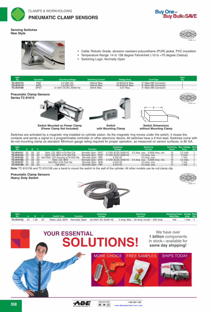
Operating Voltage Switching Current Pack
Voltage Drop Cord Type Qty.
100mA Max. 100mA Max. 50mA Max.
.5V@50mA Max.
.5V@50mA Max. 3.0V Max.
6" Male M8 Connector 6" Male M8 Connector 6" Male M8 Connector
4.5-28V DC 4.5-28V DC
5-120V DC/AC 50/60 Hz
TC-810173 PNP TC-810174 NPN TC-810169 SPST
Switch Switch Mounted on Power Clamp (Power Clamp Not Included) with Mounting Clamp without Mounting Clamp
Switch Dimensions
.=)••••..
Note: TC-810156 and TC-810158 use a band to mount the switch to the wall of the cylinder. All other models use tie rod clamp clip.
Pneumatic Clamp Sensors Heavy Duty Switch
Switching Voltage
Switching Current
Switching Power Voltage Pack Watts Max. Drop Qty.
Item No. A B C Switch Type Function
Reed, LED, MOV Normally Open 24-240V AC 50/60 HZ 4 Amp. Max. - 50 Amp. Inrush - .005 Amp. 100 TC-810153 .87 1.30 .67 1 Volt 1
Switches are activated by a magnetic ring installed on cylinder piston. As the magnetic ring moves under the switch, it closes the contacts and sends a signal to a programmable controller or other electronic device. All switches have a 9 foot lead. Switches come with tie-rod mounting clamp as standard. Minimum gauge rating required for proper operation, as measured on sensor surfaces, is 85 GA.
Item No. A B C Type Function
Switching Voltage
Switching Current
Switching Rawer
Max. Voltage Pack Drop Qty.
TC-810151 .37 .93 .53 Reed, LED, MOV %Vile Rod Clip Normally Open - SPST 5-120V AC/DC 50/60 HZ 0.5 Amp. max. - 0.0005 Amp. min. 10 3.5 Volts TC-810154 .37 .93 .53 Reed, LED, MOV %Vile Rod Clip Normally Open - SPST 0-120V AC/DC 50/60 HZ 0.5 Amp. max. 10 0 Volts TC-810155 .37 .93 .53 Hall Effect, LED Sourcing 'Wile Rod Clip Normally Open - PNP 6-24V DC 0.5 Amp. max. 12 1 Volt TC-810156 .37 .93 .53 Reed, LED, MOV Normally Open - SPST 5-120V AC/DC 50/60 HZ 0.5 Amp. max. - 0.0005 Amp. min. 10 3.5 Volts TC-810157 .37 .93 .53 Hall Effect %Vile Rod Clip Normally Open - NPN 6-24V DC 0.5 Amp. max. 12 1 Volt TC-810158 .37 .93 .53 Hall Effect Normally Open - PNP 6-24V DC 0.5 Amp. max. 12 1 Volt
YOUR ESSENTIAL
SOLUTIONS! MORE CHOICE FREE SAMPLES SHIPS TODAY
We have over 1 billion components in stock-available for same day shipping!
-ssrisk_
Pneumatic Clamp Sensors Series TC-81015
ht-BSI
A
C\
,r
)
C
P
LA
N
M
E
P
USM&ATICCLAMP
WORKHOLDING II
SENSORS
Sensing Switches New Style
Buy One or Buy Bulk&SIO/E
(Tt 961PYCO "'A
• Cable: Robotic Grade, abrasion resistant polyurethane (PUR) jacket, PVC insulation • Temperature Range: 14 to 158 degree Fahrenheit (-10 to +70 degree Celsius) • Switching Logic: Normally Open
350 350
B
A
C
Switch Dimensionswithout Mounting Clamp
Switchwith Mounting Clamp
Switch Mounted on Power Clamp(Power Clamp Not Included)
Switches are activated by a magnetic ring installed on cylinder piston. As the magnetic ring moves under the switch, it closes the contacts and sends a signal to a programmable controller or other electronic device. All switches have a 9 foot lead. Switches come with tie-rod mounting clamp as standard. Minimum gauge rating required for proper operation, as measured on sensor surfaces, is 85 GA.
Note: TC-810156 and TC-810158 use a band to mount the switch to the wall of the cylinder. All other models use tie rod clamp clip.
ItemNo. A B C Type Function
SwitchingVoltage
SwitchingCurrent
SwitchingPower
Max. VoltageDrop
PackQty.
TC-810151 .37 .93 .53 Reed, LED, MOV w/Tie Rod Clip Normally Open - SPST 5-120V AC/DC 50/60 HZ 0.5 Amp. max. - 0.0005 Amp. min. 10 3.5 Volts 1TC-810154 .37 .93 .53 Reed, LED, MOV w/Tie Rod Clip Normally Open - SPST 0-120V AC/DC 50/60 HZ 0.5 Amp. max. 10 0 Volts 1TC-810155 .37 .93 .53 Hall Effect, LED Sourcing w/Tie Rod Clip Normally Open - PNP 6-24V DC 0.5 Amp. max. 12 1 Volt 1TC-810156 .37 .93 .53 Reed, LED, MOV Normally Open - SPST 5-120V AC/DC 50/60 HZ 0.5 Amp. max. - 0.0005 Amp. min. 10 3.5 Volts 1TC-810157 .37 .93 .53 Hall Effect w/Tie Rod Clip Normally Open - NPN 6-24V DC 0.5 Amp. max. 12 1 Volt 1TC-810158 .37 .93 .53 Hall Effect Normally Open - PNP 6-24V DC 0.5 Amp. max. 12 1 Volt 1
Pneumatic Clamp SensorsSeries TC-81015
Pneumatic Clamp SensorsHeavy Duty Switch
ItemNo. A B C Switch Type Function
SwitchingVoltage
SwitchingCurrent
Switching PowerWatts Max.
VoltageDrop
PackQty.
TC-810153 .87 1.30 .67 Reed, LED, MOV Normally Open 24-240V AC 50/60 HZ 4 Amp. Max. - 50 Amp. Inrush - .005 Amp. 100 1 Volt 1
Cable: Robotic Grade, abrasion resistant polyurethane (PUR) jacket, PVC insulationTemperature Range: 14 to 158 degree Fahrenheit (-10 to +70 degree Celsius)Switching Logic: Normally Open
ItemNo. Operation Operating Voltage Switching Current Voltage Drop Cord Type
PackQty.
TC-810173 PNP 4.5-28V DC 100mA Max. .5V@50mA Max. 6" Male M8 Connector 1TC-810174 NPN 4.5-28V DC 100mA Max. .5V@50mA Max. 6" Male M8 Connector 1TC-810169 SPST 5-120V DC/AC 50/60 Hz 50mA Max. 3.0V Max. 6" Male M8 Connector 1
Sensing SwitchesNew Style
PNEUMATIC CLAMP SENSORS
YOUR ESSENTIAL
SOLUTIONS!We have over
1 billion components in stock—available for same day shipping!
FWAHL
SmallO

D F(H EX SIZE)
E(PORT SIZE)
Hydraulic Power Workholding Threaded Cylinders
C
ir,
CLAMPS & WORKHOLDING 'N
HYDRAULIC POWER WORK HOLDING
Hydraulic Power Workholding Semi Automatic - Air / Hydraulic Boosters
."-DETitCCT‘ A
Converts normal normal shop line air pressure to high pressure hydraulic power. With the system filled, the volume of oil required to actuate a cylinder or pressure point is only equal to the cubic content of the piston displacement. Boosters have built in manifold and are made of corrosion and wear-resistant materials. Hydraulic piston tube has wear rings and the air piston is self centering for long life. Boosters offer automatic relief of system overcharge as well as complete automatic bleeding with each return, eliminating prefilling. Large volume visible oil reservoir automatically replenishes the system with available reserves. 100 psig max. input air pressure.
Reservoir Capacity Cu. In.
TC-70101 33.87 1 10.4 4% 10% TC-70104 32.41 4 42 6% 16%
Hydraulic Power Workholding Hollow Cylinders B
A
These hollow cylinders can be used to push or pull depending on the position of the ram. They will actuate a rod of any length or shape and are extremely effective in translating power to a remote location. Larger piston diameter provides greater clamping force. Hardened steel piston and rod. Supplied with through hole insert threaded into the top. Maximum input pressure is 3,500 psig.
Item No. ID Port A C Stroke
011 Displacement Cu. In.
Lbs. Force @ 3000 psig
TC-020-011-011 .38 #2 SAE 2.13 1.88 2.25 .375 .547 4,380 TC-020-012-021 .50 #4 SAE 3.00 2.63 2.88 .500 1.35 8,100 TC-020-013-031 .63 #4 SAE 3.25 3.00 3.63 .625 2.51 12,066
Note: Inside Diameter is clearance for rod or bolt
Single-acting with spring return action, these cylinders can be used singly or combined by using a common manifold. Easily mounted. Can be used in any attitude and requires only a single inlet port. Threaded cylinders can be directly inserted into a fixture or used with mounting blocks.. The 15/le" through 2'/2" diameters are furnished with a radial port as well as axial.
TC-010-210-400 1/2-20 .219 1.66 .15 .16 #2 .44 .024 TC-010-210-501 A-16 .313 588 2.25 1.97 .22 .28 #4 .62 .061 TC-010-210-702 1-12 .500 1,326 2.56 2.31 .24 .31 #4 .75 .221 TC-010-211-002 1%e-16 .500 2,355 2.63 2.25 .64 1.25 #4 1.00 .393 TC-010-211-004 1%e-16 1.000 2,355 3.63 3.25 .64 1.25 #4 1.00 .785 TC-010-211-502 1%-16 .500 5,301 2.94 2.57 1.00 1.75 #4 1.50 .884 TC-010-212-004 21/2-16 1.000 9,423 4.13 3.76 1.50 2.38 #4 2.00 3.142 Note: Force shown is rated at 3,000 psi
351
DESTA<C$
•
351
Hydraulic Power WorkholdingSemi Automatic - Air / Hydraulic Boosters
Converts normal shop line air pressure to high pressure hydraulic power. With the system filled, the volume of oil required to actuate a cylinder or pressure point is only equal to the cubic content of the piston displacement. Boosters have built in manifold and are made of corrosion and wear-resistant materials. Hydraulic piston tube has wear rings and the air piston is self centering for long life. Boosters offer automatic relief of system overcharge as well as complete automatic bleeding with each return, eliminating prefilling. Large volume visible oil reservoir automatically replenishes the system with available reserves. 100 psig max. input air pressure.
A
B
ItemNo.
PressureRatio
Nom. Displac. PerStroke Cu. In.
Reservoir CapacityCu. In.
NPTPorts A B
PackQty.
TC-70101 33.87 1 10.4 1⁄8 41⁄2 107⁄8 1TC-70104 32.41 4 42 1⁄4 61⁄2 163⁄8 1
Hydraulic Power WorkholdingHollow Cylinders
These hollow cylinders can be used to push or pull depending on the position of the ram. They will actuate a rod of any length or shape and are extremely effective in translating power to a remote location. Larger piston diameter provides greater clamping force. Hardened steel piston and rod. Supplied with through hole insert threaded into the top. Maximum input pressure is 3,500 psig.
Note: Inside Diameter is clearance for rod or bolt
B
A
C
ItemNo. ID Port A B C Stroke
Oil DisplacementCu. In.
Lbs. Force @3000 psig
PackQty.
TC-020-011-011 .38 #2 SAE 2.13 1.88 2.25 .375 .547 4,380 1TC-020-012-021 .50 #4 SAE 3.00 2.63 2.88 .500 1.35 8,100 1TC-020-013-031 .63 #4 SAE 3.25 3.00 3.63 .625 2.51 12,066 1
Hydraulic Power WorkholdingThreaded Cylinders
Single-acting with spring return action, these cylinders can be used singly or combined by using a common manifold. Easily mounted. Can be used in any attitude and requires only a single inlet port. Threaded cylinders can be directly inserted into a fixture or used with mounting blocks.. The 15⁄16" through 21⁄2" diameters are furnished with a radial port as well as axial.
Note: Force shown is rated at 3,000 psi
BDA
C
F(HEX SIZE)
E(PORT SIZE)
ItemNo. Thread Stroke
Lbs. Force @3,000 psig A B C D
SAEE F
Oil DisplaceCu. In.
PackQty.
TC-010-210-400 1⁄2-20 .219 279 1.66 1.41 .15 .16 #2 .44 .024 1TC-010-210-501 3⁄4-16 .313 588 2.25 1.97 .22 .28 #4 .62 .061 1TC-010-210-702 1-12 .500 1,326 2.56 2.31 .24 .31 #4 .75 .221 1TC-010-211-002 15⁄16-16 .500 2,355 2.63 2.25 .64 1.25 #4 1.00 .393 1TC-010-211-004 15⁄16-16 1.000 2,355 3.63 3.25 .64 1.25 #4 1.00 .785 1TC-010-211-502 17⁄8-16 .500 5,301 2.94 2.57 1.00 1.75 #4 1.50 .884 1TC-010-212-004 21⁄2-16 1.000 9,423 4.13 3.76 1.50 2.38 #4 2.00 3.142 1
HYDRAULIC POWER WORK HOLDING
FWAHL
SmallO
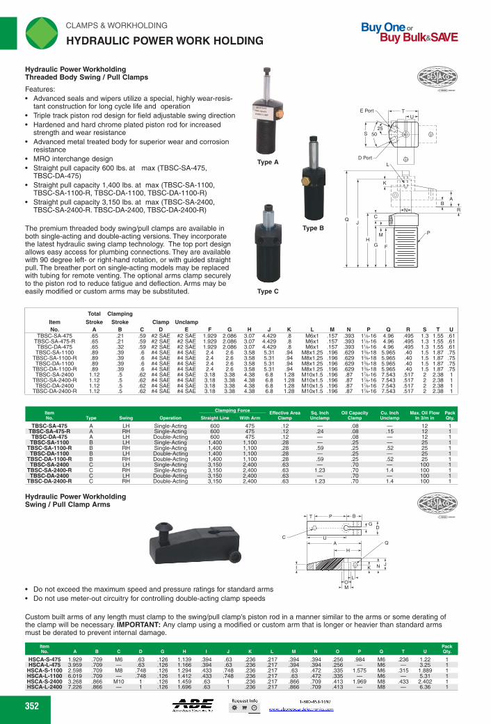
'1:49i-or`
Type B
Type A
rli N CLAMPS & WORKHOLDING
HYDRAULIC POWER WORK HOLDING
Buy One or Buy Bulk&SIVE
Hydraulic Power Workholding Threaded Body Swing / Pull Clamps
Features: • Advanced seals and wipers utilize a special, highly wear-resis-
tant construction for long cycle life and operation • Triple track piston rod design for field adjustable swing direction • Hardened and hard chrome plated piston rod for increased
strength and wear resistance • Advanced metal treated body for superior wear and corrosion
resistance • MRO interchange design • Straight pull capacity 600 lbs. at max (TBSC-SA-475,
TBSC-DA-475) • Straight pull capacity 1,400 lbs. at max (TBSC-SA-1100,
TBSC-SA-1100-R, TBSC-DA-1100, TBSC-DA-1100-R) • Straight pull capacity 3,150 lbs. at max (TBSC-SA-2400,
TBSC-SA-2400-R. TBSC-DA-2400, TBSC-DA-2400-R)
The premium threaded body swing/pull clamps are available in both single-acting and double-acting versions. They incorporate the latest hydraulic swing clamp technology. The top port design allows easy access for plumbing connections. They are available with 90 degree left- or right-hand rotation, or with guided straight pull. The breather port on single-acting models may be replaced with tubing for remote venting. The optional arms clamp securely to the piston rod to reduce fatigue and deflection. Arms may be easily modified or custom arms may be substituted. Type C
Item No.
Total
Stroke A
Clamping
Stroke B C
Clamp D
Unclamp E F G H J K L M N P Q R S T U
TBSC-SA-475 .65 .21 .59 #2 SAE #2 SAE 1.929 2.086 3.07 4.429 .8 M6x1 .157 .393 1%-16 4.96 .495 1.3 1.55 .61 TBSC-SA-475-R .65 .21 .59 #2 SAE #2 SAE 1.929 2.086 3.07 4.429 .8 M6x1 .157 .393 1%-16 4.96 .495 1.3 1.55 .61 TBSC-DA-475 .65 .32 .59 #2 SAE #2 SAE 1.929 2.086 3.07 4.429 .8 M6x1 .157 .393 1%-16 4.96 .495 1.3 1.55 .61
TBSC-SA-1100 .89 .39 .6 #4 SAE #4 SAE 2.4 2.6 3.58 5.31 .94 M8x1.25 .196 .629 1%-18 5.965 .40 1.5 1.87 .75 TBSC-SA-1100-R .89 .39 .6 #4 SAE #4 SAE 2.4 2.6 3.58 5.31 .94 M8x1.25 .196 .629 1%-18 5.965 .40 1.5 1.87 .75 TBSC-DA-1100 .89 .39 .6 #4 SAE #4 SAE 2.4 2.6 3.58 5.31 .94 M8x1.25 .196 .629 1%-18 5.965 .40 1.5 1.87 .75
TBSC-DA-1100-R .89 .39 .6 #4 SAE #4 SAE 2.4 2.6 3.58 5.31 .94 M8x1.25 .196 .629 1%-18 5.965 .40 1.5 1.87 .75 TBSC-SA-2400 1.12 .5 .62 #4 SAE #4 SAE 3.18 3.38 4.38 6.8 1.28 M10x1.5 .196 .87 1%-16 7.543 .517 2 2.38 1
TBSC-SA-2400-R 1.12 .5 .62 #4 SAE #4 SAE 3.18 3.38 4.38 6.8 1.28 M10x1.5 .196 .87 1%-16 7.543 .517 2 2.38 1 TBSC-DA-2400 1.12 .5 .62 #4 SAE #4 SAE 3.18 3.38 4.38 6.8 1.28 M10x1.5 .196 .87 1%-16 7.543 .517 2 2.38 1
TBSC-DA-2400-R 1.12 .5 .62 #4 SAE #4 SAE 3.18 3.38 4.38 6.8 1.28 M10x1.5 .196 .87 1%-16 7.543 .517 2 2.38 1
Item Ives Swing
Clamping Force
Straight Line With Arm Effective Area
Clamp Sq. Inch Unciamp
011 Capacity Clamp
Cu. Inch Unciamp
Max. 011 Flow Pack in 3/m in Qty.
TBSC-SA-475 A LH Single-Acting 600 475 .12 .08 12 TBSC-SA-475-R A RH Single-Acting 600 475 .12 .24 .08 .15 12
TBSC-DA-475 A LH Double-Acting 600 475 .12 .08 12 TBSC-SA-1100 B LH Single-Acting 1,400 1,100 .28 .25 25
TBSC-SA-1100-R B RH Single-Acting 1,400 1,100 .28 .59 .25 .52 25 TBSC-DA-1100 B LH Double-Acting 1,400 1,100 .28 .25 25
TBSC-DA-1100-R B RH Double-Acting 1,400 1,100 .28 .59 .25 .52 25 TBSC-SA-2400 C LH Single-Acting 3,150 2,400 .63 .70 100
TBSC-SA-2400-R C RH Single-Acting 3,150 2,400 .63 1.23 .70 1.4 100 TBSC-DA-2400 C LH Double-Acting 3,150 2,400 .63 .70 100
TBSC-DA-2400-R C RH Double-Acting 3 150 2 400 .63 1.23 .70 1.4 100
Hydraulic Power Workholding Swing / Pull Clamp Arms
C
.- ,mi,----,iio... AP DESTI‘CO NIL._ ........,____,,,,
T
rs:C1I-fG D
A A
0 • Do not exceed the maximum speed and pressure ratings for standard arms
M
• Do not use meter-out circuitry for controlling double-acting clamp speeds
Custom built arms of any length must clamp to the swing/pull clamp's piston rod in a manner similar to the arms or some derating of the clamp will be necessary. IMPORTANT: Any clamp using a modified or custom arm that is longer or heavier than standard arms must be derated to prevent internal damage.
Item No. A B C D G N J K M N 0 P 0 T U
Pack Qty.
HSCA-S-475 1.929 .709 M6 .63 .126 1.139 .394 .63 .236 .217 .394 .394 .256 .984 M6 .236 1.22 1 HSCA-L-475 3.959 .709 .63 .126 1.166 .394 .63 .236 .217 .394 .394 .256 M6 3.25 1
HSCA-S-1100 2.598 .709 M8 .748 .126 1.294 .433 .748 .236 .217 .63 .472 .335 1.575 M6 .315 1.889 1 HSCA-L-1100 6.019 .709 .748 .126 1.412 .433 .748 .236 .217 .63 .472 .335 M6 5.31 1 HSCA-S-2400 3.268 .866 M10 1 .126 1.459 .63 1 .236 .217 .866 .709 .413 1.969 M8 .433 2.402 1 HSCA-L-2400 7.226 .866 1 .126 1.696 .63 1 .236 .217 .866 .709 .413 M8 6.36 1
352 352
Hydraulic Power WorkholdingThreaded Body Swing / Pull Clamps
Type C
Total Clamping
Item Stroke Stroke Clamp UnclampNo. A B C D E F G H J K L M N P Q R S T U
TBSC-SA-475 .65 .21 .59 #2 SAE #2 SAE 1.929 2.086 3.07 4.429 .8 M6x1 .157 .393 11⁄8-16 4.96 .495 1.3 1.55 .61TBSC-SA-475-R .65 .21 .59 #2 SAE #2 SAE 1.929 2.086 3.07 4.429 .8 M6x1 .157 .393 11⁄8-16 4.96 .495 1.3 1.55 .61TBSC-DA-475 .65 .32 .59 #2 SAE #2 SAE 1.929 2.086 3.07 4.429 .8 M6x1 .157 .393 11⁄8-16 4.96 .495 1.3 1.55 .61TBSC-SA-1100 .89 .39 .6 #4 SAE #4 SAE 2.4 2.6 3.58 5.31 .94 M8x1.25 .196 .629 13⁄8-18 5.965 .40 1.5 1.87 .75
TBSC-SA-1100-R .89 .39 .6 #4 SAE #4 SAE 2.4 2.6 3.58 5.31 .94 M8x1.25 .196 .629 13⁄8-18 5.965 .40 1.5 1.87 .75TBSC-DA-1100 .89 .39 .6 #4 SAE #4 SAE 2.4 2.6 3.58 5.31 .94 M8x1.25 .196 .629 13⁄8-18 5.965 .40 1.5 1.87 .75
TBSC-DA-1100-R .89 .39 .6 #4 SAE #4 SAE 2.4 2.6 3.58 5.31 .94 M8x1.25 .196 .629 13⁄8-18 5.965 .40 1.5 1.87 .75TBSC-SA-2400 1.12 .5 .62 #4 SAE #4 SAE 3.18 3.38 4.38 6.8 1.28 M10x1.5 .196 .87 17⁄8-16 7.543 .517 2 2.38 1
TBSC-SA-2400-R 1.12 .5 .62 #4 SAE #4 SAE 3.18 3.38 4.38 6.8 1.28 M10x1.5 .196 .87 17⁄8-16 7.543 .517 2 2.38 1TBSC-DA-2400 1.12 .5 .62 #4 SAE #4 SAE 3.18 3.38 4.38 6.8 1.28 M10x1.5 .196 .87 17⁄8-16 7.543 .517 2 2.38 1
TBSC-DA-2400-R 1.12 .5 .62 #4 SAE #4 SAE 3.18 3.38 4.38 6.8 1.28 M10x1.5 .196 .87 17⁄8-16 7.543 .517 2 2.38 1
Features:Advanced seals and wipers utilize a special, highly wear-resis-tant construction for long cycle life and operationTriple track piston rod design for field adjustable swing directionHardened and hard chrome plated piston rod for increased strength and wear resistanceAdvanced metal treated body for superior wear and corrosion resistanceMRO interchange designStraight pull capacity 600 lbs. at max (TBSC-SA-475, TBSC-DA-475)Straight pull capacity 1,400 lbs. at max (TBSC-SA-1100, TBSC-SA-1100-R, TBSC-DA-1100, TBSC-DA-1100-R)Straight pull capacity 3,150 lbs. at max (TBSC-SA-2400, TBSC-SA-2400-R. TBSC-DA-2400, TBSC-DA-2400-R)
The premium threaded body swing/pull clamps are available in both single-acting and double-acting versions. They incorporate the latest hydraulic swing clamp technology. The top port design allows easy access for plumbing connections. They are available with 90 degree left- or right-hand rotation, or with guided straight pull. The breather port on single-acting models may be replaced with tubing for remote venting. The optional arms clamp securely to the piston rod to reduce fatigue and deflection. Arms may be easily modified or custom arms may be substituted.
TU
S 50
D Port
25
E Port
L
QJ
HG F
M
CN
P
K
AB
R
Type B
Type A
ItemNo. Type Swing Operation
Clamping Force Effective AreaClamp
Sq. InchUnclamp
Oil CapacityClamp
Cu. InchUnclamp
Max. Oil FlowIn 3/m in
PackQty.Straight Line With Arm
TBSC-SA-475 A LH Single-Acting 600 475 .12 — .08 — 12 1TBSC-SA-475-R A RH Single-Acting 600 475 .12 .24 .08 .15 12 1TBSC-DA-475 A LH Double-Acting 600 475 .12 — .08 — 12 1TBSC-SA-1100 B LH Single-Acting 1,400 1,100 .28 — .25 — 25 1
TBSC-SA-1100-R B RH Single-Acting 1,400 1,100 .28 .59 .25 .52 25 1TBSC-DA-1100 B LH Double-Acting 1,400 1,100 .28 — .25 — 25 1
TBSC-DA-1100-R B RH Double-Acting 1,400 1,100 .28 .59 .25 .52 25 1TBSC-SA-2400 C LH Single-Acting 3,150 2,400 .63 — .70 — 100 1
TBSC-SA-2400-R C RH Single-Acting 3,150 2,400 .63 1.23 .70 1.4 100 1TBSC-DA-2400 C LH Double-Acting 3,150 2,400 .63 — .70 — 100 1
TBSC-DA-2400-R C RH Double-Acting 3,150 2,400 .63 1.23 .70 1.4 100 1
Hydraulic Power WorkholdingSwing / Pull Clamp Arms
Do not exceed the maximum speed and pressure ratings for standard armsDo not use meter-out circuitry for controlling double-acting clamp speeds
Custom built arms of any length must clamp to the swing/pull clamp's piston rod in a manner similar to the arms or some derating of the clamp will be necessary. IMPORTANT: Any clamp using a modified or custom arm that is longer or heavier than standard arms must be derated to prevent internal damage.
Q
DG
BPT
C UA
H
I
LOM
NKJ
ItemNo. A B C D G H I J K L M N O P Q T U
PackQty.
HSCA-S-475 1.929 .709 M6 .63 .126 1.139 .394 .63 .236 .217 .394 .394 .256 .984 M6 .236 1.22 1HSCA-L-475 3.959 .709 — .63 .126 1.166 .394 .63 .236 .217 .394 .394 .256 — M6 — 3.25 1
HSCA-S-1100 2.598 .709 M8 .748 .126 1.294 .433 .748 .236 .217 .63 .472 .335 1.575 M6 .315 1.889 1HSCA-L-1100 6.019 .709 — .748 .126 1.412 .433 .748 .236 .217 .63 .472 .335 — M6 — 5.31 1HSCA-S-2400 3.268 .866 M10 1 .126 1.459 .63 1 .236 .217 .866 .709 .413 1.969 M8 .433 2.402 1HSCA-L-2400 7.226 .866 — 1 .126 1.696 .63 1 .236 .217 .866 .709 .413 — M8 — 6.36 1
HYDRAULIC POWER WORK HOLDING
FWAHL
SmallO

Cylinder Cylinder Effective Oil Max. Capacity Max. Capacity 46 Hydraulic Stroke Retracted Area (Sq. In.) (Cu. In.) Arm Pressure
item No. Enerpac Arm Swing Cylinder Type Max. psi (Lbs.) Total Clamping Height Pull Push Pull
Push Lgth. PSI 2,640 1.50 .50 7.37 .980 1.767 1.470 2.650 None 3,000
Single or 2,164 1.50 .50 7.37 .980 1.767 1.470 2.650 2.00 3,000
VE-354 SC-1 Double-acting, 1,960 Straight, Left 1.50 .50 7.37 .980 1.767 1.470 2.650 3.00 3,000 or Right 1,740 1.50 .50 7.37 .980 1.767 1.470 2.650 4.00 3,000
1,200 Pull 1.50 .50 7.37 .980 1.767 1.470 2.650 5.00 2,400 840 1.50 .50 7.37 .980 1.767 1.470 2.650 6.00 2,000
VE-352 SC-3 Straight, Left or Right
Single or 700 .75 .25 4.52 .245 .442 .184 .331 None 3,000 Double-acting, 500 .75 .25 4.52 .245 .442 .184 .331 1.00 3,000
Pull 250 .75 .25 4.52 .245 .442 .184 .331 2.00 2,000
Threaded
Threaded Single Acting
Threaded Double Acting
ceng Port
G Clamp Port
Lower Flange
J
Upper Flange Lower Flange Single and Single and Double
Double Acting Acting
1.-J -.I Manifold Port (Fbdure Hole Dia.. 9)
L M GCe Port
Unclinp
l
Por
t )(FFF
M
iurirnt 9)
1?o:arnPL-..1 m
P N
Magfold
(Frtuga Undemp .
.19) Port (S/AVent Plug)
Clamped Position
1*-
CLAMPS & WORKHOLDING ,Th
HYDRAULIC POWER WORK HOLDING ._,1
Hydraulic Power Workholding Swing Cylinders With Arms
ENERPACA
N 0
O-.
Type A
Type A
Type B
Type B
These swing cylinders rotate 90 degrees as they begin their stroke, continuing without rotation for the final clamping stroke. Cylinders can be changed to left swing, right swing, or pull applications by loosening the side plug and then rotating the plunger to a desired position. The VE-354 and VE-352 have a retract spring for single-acting operations. Clamp arm provided. Can be mounted with the built-in flange by securing the swinger to the top or bottom of a tooling plate or by screwing the threaded body into a mounting bracket.
Item Pack No. Enerpac Type A BCD E F G H J K M N O P Q R S T W X Qty.
VE-354 SC-1 A 7.37 8.88 5.74 3.00 2.87 1/4-18 %-27 3.31 .50 .38-16 .44 .88 1%-16 1.88 1.28 2.90 2.06 2.00 .40 5.87 1/2-13 1.000 1 VE-352 SC-3 B 4.26 5.27 3.48 2.13 2.03 %-27 %-27 2.15 - .250-20 .32 .63 1-12 1.13 .75 2.00 1.50 1.00 .20 3.71 Vie-24 .500 1
Note: Standard clamping arm supplied. Longer arms indicated in chart can be fabricated by the user.
Hydraulic Power Workholding
ENERPACA Swing Cylinders w/o Arms Light Duty
These swing cylinders rotate 90 degrees as they begin their stroke, continuing without rotation for the final clamping stroke. Cylinders can be changed to left swing, right swing or pull applications by loosening the bottom plug. All single acting cylinders come with a retract spring for single-acting operations. Max. psi 5,000. Body styles available are threaded with upper flange or non-threaded with lower or upper flange.
Clamp arms not included but sold separately on page 356.
Item No. Enerpac
Body Style
Cylinder Capacity w/ Std. Arm
Hydraulic Stroke
Total Clamping
Effective Area
(Sq. In.)
Oil Capacity (Cu. In.) A B C D E F G H I J
K (degrees) L M N
Pack Qty.
Double Acting VE-70 SURD-51 Upper Flange 1,250 .89 .39 .28 .28 5.31 4.42 2.60 .98 1.82 1.08 SAE #4 .39 1.57 1%-18 25 1.12 .75 1.50 1 vE-71 SLRD-51 Lower Flange 1,250 .89 .39 .28 .28 5.31 4.42 2.60 .98 1.08 1.50 SAE #4 .39 1.57 1%-18 25 1.12 .75 1.50 1 VE-72* STRD-121 Threaded 2,600 1.12 .50 .63 .70 6.75 5.63 3.38 1.00 2.25 1.06 SAE #4 .38 2.00 1%-16 .81 1.38 1.00 2.00 1 VE-73 SURD-121 Upper Flange 2,600 1.12 .50 .63 .70 6.75 5.63 3.38 1.00 2.25 1.06 SAE #4 .38 2.00 1%-16 25 1.38 1.00 2.00 1 VE-74 SLRD-121 Lower Flange 2,600 1.12 .50 .63 .70 6.75 5.63 3.38 1.00 2.25 1.06 SAE #4 .38 2.00 1%-16 25 1.38 1.00 2.00 1
Single Acting VE-600-1* STRS-21 Threaded 475 .65 .32 .12 .08 4.41 3.76 2.09 .98 1.67 1.04 SAE #2 .39 .97 1%-16 25 .94 .61 1.30 1
VE-75 SURS-51 Upper Flange 1,100 .89 .39 .28 .28 5.31 4.42 2.60 .98 1.82 1.08 SAE #4 .39 1.57 1%-18 25 1.12 .75 1.50 1 VE-76 SLRS-51 Lower Flange 1,100 .89 .39 .28 .28 5.31 4.42 2.60 .98 1.82 1.08 SAE #4 .39 1.57 1%-18 25 1.12 .75 1.50 1
VE-610-1* STRS-121 Threaded 2,400 1.12 .50 .63 .70 6.75 5.63 3.38 1.00 2.25 1.06 SAE #4 .38 2.00 1%-16 25 1.38 1.00 2.00 1
*All threaded bodies have upper flange
353 353
Hydraulic Power WorkholdingSwing Cylinders With Arms
These swing cylinders rotate 90 degrees as they begin their stroke, continuing without rotation for the final clamping stroke. Cylinders can be changed to left swing, right swing, or pull applications by loosening the side plug and then rotating the plunger to a desired position. The VE-354 and VE-352 have a retract spring for single-acting operations. Clamp arm provided. Can be mounted with the built-in flange by securing the swinger to the top or bottom of a tooling plate or by screwing the threaded body into a mounting bracket.
Note: Standard clamping arm supplied. Longer arms indicated in chart can be fabricated by the user.
P
ON
Q D
JR
S
G
FB
A
C
H
M
E
TLK
X
W
F
I
Type A
P
ON
Q D
JR
S
G
FB
A
C
H
M
E
TLK
X
W
Type BType BType A
ItemNo. Enerpac Type A B C D E F G H I J K L M N O P Q R S T W X
PackQty.
VE-354 SC-1 A 7.37 8.88 5.74 3.00 2.87 1⁄4-18 1⁄8-27 3.31 .50 .38-16 .44 .88 17⁄8-16 1.88 1.28 2.90 2.06 2.00 .40 5.87 1⁄2-13 1.000 1VE-352 SC-3 B 4.26 5.27 3.48 2.13 2.03 1⁄8-27 1⁄8-27 2.15 — .250-20 .32 .63 1-12 1.13 .75 2.00 1.50 1.00 .20 3.71 5⁄16-24 .500 1
Cylinder Capacity @
Max. psi (Lbs.)
Cylinder Effective Oil Max. Capacity Max.Hydraulic Stroke Retracted Area (Sq. In.) (Cu. In.) Arm Pressure
Item No. Enerpac Arm Swing Cylinder Type Total Clamping Height Pull Push Pull Push Lgth. PSI
VE-354 SC-1 Straight, Left or Right
Single or Double-acting,
Pull
2,6402,1641,9601,7401,200840
1.501.501.501.501.501.50
.50
.50
.50
.50
.50
.50
7.377.377.377.377.377.37
.980
.980
.980
.980
.980
.980
1.7671.7671.7671.7671.7671.767
1.4701.4701.4701.4701.4701.470
2.6502.6502.6502.6502.6502.650
None2.003.004.005.006.00
3,0003,0003,0003,0002,4002,000
VE-352 SC-3 Straight, Left or Right
Single or Double-acting,
Pull
700500250
.75
.75
.75
.25
.25
.25
4.524.524.52
.245
.245
.245
.442
.442
.442
.184
.184
.184
.331
.331
.331
None1.002.00
3,0003,0002,000
HYDRAULIC POWER WORK HOLDING
Hydraulic Power WorkholdingSwing Cylinders w/o Arms Light Duty
Lower Flange
AB
EF
H
R
J
C
D
I
BoltsIncluded
Arm NotIncluded
N
ML
K
P
QGUnclampPort(S/A VentPlug)
ManifoldPort (FixtureHole Dia. .19)
G ClampPort
Manifold Port(Fixture HoleDia. .19)
Upper FlangeSingle and
Double Acting
I
AB
EF
JC
D
R
H
Bolts Included
Arm NotIncluded
L M
P N
Q
ManifoldPorts(FixtureHole Dia..19)
GUnclampPort(S/A Vent Plug)
G ClampPort
K
Lower FlangeSingle and Double
Acting
These swing cylinders rotate 90 degrees as they begin their stroke, continuing without rotation for the final clamping stroke. Cylinders can be changed to left swing, right swing or pull applications by loosening the bottom plug. All single acting cylinders come with a retract spring for single-acting operations. Max. psi 5,000. Body styles available are threaded with upper flange or non-threaded with lower or upper flange.
Clamp arms not included but sold separately on page 356.
*All threaded bodies have upper flange
L
M
K
I
A
D
N
C
B
J
H
FE
GClamp
Port
ArmNot
Included
GUnclamp Port
ThreadedSingle Acting
Unclamp Port(S/A Vent Plug)
K
K
G Clamp Port
M
N
L
I
A
ClampedPosition
D
C
B
J
HF
E
ArmNot
Included
ThreadedDouble Acting
Threaded
Upper Flange
ItemNo. Enerpac
BodyStyle
CylinderCapacityw/ Std.
Arm
Hydraulic Stroke Effective
Area(Sq. In.)
Oil Capacity(Cu. In.) A B C D E F G H I J
K(degrees) L M N
PackQty.Total Clamping
Double ActingVE-70 SURD-51 Upper Flange 1,250 .89 .39 .28 .28 5.31 4.42 2.60 .98 1.82 1.08 SAE #4 .39 1.57 13⁄8-18 25 1.12 .75 1.50 1VE-71 SLRD-51 Lower Flange 1,250 .89 .39 .28 .28 5.31 4.42 2.60 .98 1.08 1.50 SAE #4 .39 1.57 13⁄8-18 25 1.12 .75 1.50 1VE-72* STRD-121 Threaded 2,600 1.12 .50 .63 .70 6.75 5.63 3.38 1.00 2.25 1.06 SAE #4 .38 2.00 17⁄8-16 .81 1.38 1.00 2.00 1VE-73 SURD-121 Upper Flange 2,600 1.12 .50 .63 .70 6.75 5.63 3.38 1.00 2.25 1.06 SAE #4 .38 2.00 17⁄8-16 25 1.38 1.00 2.00 1VE-74 SLRD-121 Lower Flange 2,600 1.12 .50 .63 .70 6.75 5.63 3.38 1.00 2.25 1.06 SAE #4 .38 2.00 17⁄8-16 25 1.38 1.00 2.00 1
Single ActingVE-600-1* STRS-21 Threaded 475 .65 .32 .12 .08 4.41 3.76 2.09 .98 1.67 1.04 SAE #2 .39 .97 11⁄8-16 25 .94 .61 1.30 1
VE-75 SURS-51 Upper Flange 1,100 .89 .39 .28 .28 5.31 4.42 2.60 .98 1.82 1.08 SAE #4 .39 1.57 13⁄8-18 25 1.12 .75 1.50 1VE-76 SLRS-51 Lower Flange 1,100 .89 .39 .28 .28 5.31 4.42 2.60 .98 1.82 1.08 SAE #4 .39 1.57 13⁄8-18 25 1.12 .75 1.50 1
VE-610-1* STRS-121 Threaded 2,400 1.12 .50 .63 .70 6.75 5.63 3.38 1.00 2.25 1.06 SAE #4 .38 2.00 17⁄8-16 25 1.38 1.00 2.00 1
FWAHL
SmallO

B
M
Double Acting
D E 11111111111111 F
C G
AB Jht
Single Acting
Cyl. Item Cap. @ Hyd. Robes. No. Enerpac Type Max. psi Stroke Height
VE-372 RW-50 A 9,940 .62 1.62 VE-373 RW-51
B 9,940 1.00 4.12 VE-377 RW-53
B 9,940 3.00 6.25 VE-378 RW-55
B 9,940 5.00 8.25 VE-375 RW-102 B 22,300 2.00 4.53
Bore DIa.
Cyl. Eff. Area 011 Cap.
(Sq. In.) (Cu. In.) A B C E F G H J K L M Pack Qty.
1.12 .994 .620 1.62 2.25 1.50 1.12 .22 %-18 1.00 .56 1.12 2.31 .75 1 1.12 .994 .994 4.37 5.37 4.12 1.00 %-20 %-18 .75 .12 1.12 - %-16 1 1.12 .994 3.20 6.50 9.50 6.25 1.00 %-20 %-18 .75 .12 1.12 - %-16 1 1.12 .994 5.20 8.50 13.50 8.25 1.00 %-20 %-18 .75 .12 1.12 - %-16 1 1.69 2.236 4.75 4.78 6.78 4.53 1.38 Vie-18 %-18 .75 .19 1.06 - 1-8 1
rliN CLAMPS & WORKHOLDING
HYDRAULIC POWER WORK HOLDING
Buy One or Buy Bulk&SIO/E
Hydraulic Power Workholding
ENERPACE Single-Acting Manifold Cylinder
B A C
F DH D H
A B
Type B
A * HE Fv
Type A
G D
These threaded miniature cylinders were designed specifically for tooling. All cylinders are single-acting with spring return action for rapid work release. They have threaded bodies for all types of mountings. Cylinders may be inserted directly in a fixture or used with standard brackets. Stainless steel construction. Maximum operating pressure 5,000 psi.
Item Na Enerpac Type
Max. Clamp Force Stroke
Eff. Area (Sq. In.)
Oil Cap. (Cu. In.) A B C D E F G
Pack H Qty.
VE-412 CST-2131 380 .51 .08 .04 1.99 2.50 .97 .69 .19 6-32 Me-20 1/2-20 VE-413* CST-471 980 .28 .20 .05 1.87 2.15 1.71 .65 .27 8-32 Me-20 %-16 VE-83 CST-9131 1,950 .51 .39 .20 2.50 3.01 2.28 .81 .39 1/4-28 Me-20 1-12 VE-86 CST-9381 1,950 1.50 .39 .59 4.11 5.61 3.89 .81 .39 1/4-28 Me-20 1-12 VE-424 CST-18131 3,860 .51 .77 .40 2.76 3.27 2.50 1.22 .63 Me-24 Me-20 1%e-16 VE-425 CST-18251 3,860 .98 .77 .77 3.52 4.51 3.27 1.22 .63 Me-24 Me-20 1%e-16
*Nitro carburized
Hydraulic Power Workholding
ENERPACEI Threaded Cylinders
Cylinders can be fixtured into manual strap or bridge clamp assemblies. Fully threaded bodies allow cylinders to be threaded directly into tapped holes of the fixture for easy installation. Available as single-acting spring return or double acting hydraulic return. The VE-90 can use carbide grippers.
Cylinder
Capacity @ Cylinder 011 Capacity
Max. psi Effective Area Area
Item (Lbs.) Hydraulic Retr. Bore (Sq. In.) (Cu. In.)
No. Ener • as Push Pull Stroke H. t. DIa. Push Pull Push Pull A B C D E F G Pack
H I J K L M..
Single Acting VE-88 WRT-21 3,900 - .50 3.25 1.00 .79 .39 - 3.25 Double Acting VE-90 WMT-39 3,900 2,700 .50 3.26 1.00 .79 .54 .39 .27 3.26
3.75 2.00 1.23 .75 1/4-28 x .32
3.76 .73 1.30 .56 1/4-28 x .39
Vie-24 .62 .24 .30 1.06 .25 1%-18 1
% - 27 NPT .73 - .27 - - 1%-18 1
Hydraulic Power Workholding
ENERPACA Clamping Cylinders Single-Acting
D
Type A Type B
Used for a wide range of production tooling applications, heavy duty force requirements and high cycle applications. Block shaped clamps provide a high amount of force in a tight area. Designed to be surface mounted on the machine tool bed or on a fixture surface. Provide force in horizontal or vertical direction. Cylindrical clamps have collar threads and base holes for mounting. All have spring return operation for easy unloading of workpiece and faster cycling. Spring is designed to return plunger only.
Note: Cylinder capacity shown is rated at 10,000 psi
354 354
Hydraulic Power WorkholdingSingle-Acting Manifold Cylinder
These threaded miniature cylinders were designed specifically for tooling. All cylinders are single-acting with spring return action for rapid work release. They have threaded bodies for all types of mountings. Cylinders may be inserted directly in a fixture or used with standard brackets. Stainless steel construction. Maximum operating pressure 5,000 psi.
*Nitro carburized
C
AB
EF
HD
G
Type B
BA
C
G DFEH
Type A
ItemNo. Enerpac Type
Max.Clamp Force Stroke
Eff. Area(Sq. In.)
Oil Cap.(Cu. In.) A B C D E F G H
PackQty.
VE-412 CST-2131 A 380 .51 .08 .04 1.99 2.50 .97 .69 .19 6-32 7⁄16-20 1⁄2-20 1VE-413* CST-471 B 980 .28 .20 .05 1.87 2.15 1.71 .65 .27 8-32 7⁄16-20 3⁄4-16 1VE-83 CST-9131 B 1,950 .51 .39 .20 2.50 3.01 2.28 .81 .39 1⁄4-28 7⁄16-20 1-12 1VE-86 CST-9381 B 1,950 1.50 .39 .59 4.11 5.61 3.89 .81 .39 1⁄4-28 7⁄16-20 1-12 1
VE-424 CST-18131 B 3,860 .51 .77 .40 2.76 3.27 2.50 1.22 .63 5⁄16-24 7⁄16-20 15⁄16-16 1VE-425 CST-18251 B 3,860 .98 .77 .77 3.52 4.51 3.27 1.22 .63 5⁄16-24 7⁄16-20 15⁄16-16 1
Hydraulic Power WorkholdingThreaded Cylinders
Cylinders can be fixtured into manual strap or bridge clamp assemblies. Fully threaded bodies allow cylinders to be threaded directly into tapped holes of the fixture for easy installation. Available as single-acting spring return or double acting hydraulic return. The VE-90 can use carbide grippers.
BA
C
GD
F
E
KG H
M
J
Double Acting
C
GD
F H
M
JAB
I
EL
Single Acting
ItemNo. Enerpac
Cylinder Capacity @
Max. psi (Lbs.) Hydraulic
StrokeRetr.Hgt.
BoreDia.
Cylinder Effective Area
(Sq. In.)
Oil Capacity Area
(Cu. In.)
A B C D E F G H I J K L MPackQty.Push Pull Push Pull Push Pull
Single ActingVE-88 WRT-21 3,900 — .50 3.25 1.00 .79 — .39 — 3.25 3.75 2.00 1.23 .75 1⁄4-28 x .32 5⁄16-24 .62 .24 .30 1.06 .25 13⁄8-18 1Double ActingVE-90 WMT-39 3,900 2,700 .50 3.26 1.00 .79 .54 .39 .27 3.26 3.76 .73 1.30 .56 1⁄4-28 x .39 1⁄8 - 27 NPT .73 — .27 — — 13⁄8-18 1
Hydraulic Power WorkholdingClamping Cylinders Single-Acting
Used for a wide range of production tooling applications, heavy duty force requirements and high cycle applications. Block shaped clamps provide a high amount of force in a tight area. Designed to be surface mounted on the machine tool bed or on a fixture surface. Provide force in horizontal or vertical direction. Cylindrical clamps have collar threads and base holes for mounting. All have spring return operation for easy unloading of workpiece and faster cycling. Spring is designed to return plunger only.
Note: Cylinder capacity shown is rated at 10,000 psi
MED
F
CG
H
I JB
A
Type B
ItemNo. Enerpac Type
Cyl. Cap. @Max. psi
Hyd.Stroke
Retrac.Height
Bore Dia.
Cyl. Eff. Area
(Sq. In.)Oil Cap.(Cu. In.) A B C E F G H I J K L M
PackQty.
VE-372 RW-50 A 9,940 .62 1.62 1.12 .994 .620 1.62 2.25 1.50 1.12 .22 3⁄8-18 1.00 .56 1.12 2.31 .75 — 1VE-373 RW-51 B 9,940 1.00 4.12 1.12 .994 .994 4.37 5.37 4.12 1.00 1⁄4-20 3⁄8-18 .75 .12 1.12 — — 3⁄4-16 1VE-377 RW-53 B 9,940 3.00 6.25 1.12 .994 3.20 6.50 9.50 6.25 1.00 1⁄4-20 3⁄8-18 .75 .12 1.12 — — 3⁄4-16 1VE-378 RW-55 B 9,940 5.00 8.25 1.12 .994 5.20 8.50 13.50 8.25 1.00 1⁄4-20 3⁄8-18 .75 .12 1.12 — — 3⁄4-16 1VE-375 RW-102 B 22,300 2.00 4.53 1.69 2.236 4.75 4.78 6.78 4.53 1.38 5⁄16-18 3⁄8-18 .75 .19 1.06 — — 1-8 1
H
F
JI
C
K
DE
BA
G
L
Type A
HYDRAULIC POWER WORK HOLDING
FWAHL
SmallO

A NAP...NO
•• • • .
VE-326 RWH-120
A VE-327 RWH-121
A VE-355 RWH-20
A VE-347 CY1254-25
B VE-350 CY2129-25
B VE-349 CY2129-5
B VE-351 CY2754-5
B
2.19 2.50 1.19 2.75 1.38 %-16 .39 Vie-18 .19 .770 2%-16 3.19 4.19 1.19 2.75 1.38 8A-16 .53 Vie-18 .19 .770 2%-16 2.06 2.38 1.50 1.79 1.00 .53 .28 %-20 .12 1/2-20 1%-16 2.00 2.25 .91 1.75 .56 %-16 .29 %-20 1.75 .390 .86 2.00 2.31 .75 2.50 1.13 %-10 .31 %-16 2.50 .765 .86 2.73 3.36 1.48 2.50 1.13 %-10 .31 %-16 2.50 .765 1.06 3.00 3.63 1.55 3.13 1.25 -9 .31 %-16 3.13 .890 1.50
2.76 2.76 1.32 .87
2.47 2.47 4.44
27,600 27,600 4,000 2,610 7,410 7,410 13,320
.86 2.76 .41 .22 .77
1.56 2.80
Pack S T U Qty.
Support Plunger Item Cap. @ Hyd, Spring Force Lbs. on Cap. No. Enereac Max. psi Stroke Extended Retracted (Cu. In.) ABC CO E F H I J J1 K L M N Q
Fluid Advanced
ENERPAC.Z Hydraulic Power Workholding Turbo Air / Hydraulic Pumps
A turbo air pump is recommended where input air pressure is limited. Engineered to recycle exhaust air to help power the pump. Maintains a tight pressure range for reliable clamping performance. Pump will automatically restart in the event of a pressure drop in the hydraulic system. Mounting plate allows for horizontal or vertical machine-side mounting. Buna-N polyurethane and PTFE seals.
Vertical Horizontal SAE #4 SAE #4
15 70 127 72:1 5,000 40-120 15 70 127 50:1 5,000 40-120
VE-391 PACG5002SB 2,500 VE-392 PACG-3002SB 1,400
Note: Clamping pressure at 10,000 psi, except for VE-355 which is 3,000 psi
Hydraulic Power Workholding Work Supports
Work supports provide additional support to avoid excessive movement or deflection of the workpiece during machining. When hydraulic pressure is applied to the work support, a piston pushes against an internal adjustable spring that advances the work support plunger against a workpiece at the force set by the adjustable spring. As more hydraulic pressure is applied, an internal sleeve will grip and lock the plunger in that position. Available as a spring or fluid advance unit. The spring advanced unit can be converted to air by simply removing the internal adjustment spring and attaching a low pressure air line to the air breather vent tube. Operating pressure is 700 psi minimum, 5,000 psi maximum.
VE-19 WFL-111 2,500 .38 3.4 5.2 .06 3.53 3.91 3.10 1%-18 .63 .49 .56 1.08 .18 .57 M10 x 1.5 1.50 Spring Advanced
VE-21 WSL-111 2,500 .38 3.4 5.2 .02 2.97 3.35 2.54 1%-18 .63 .49 .44 .94 .18 .57 M10 x 1.5 1.50
.70 .73 .28 1.62 2.38 .94 .17 1
.30 .73 .28 1.62 2.38 .94 .17 1
ENERPAC.RI
$ _ - CONTACT BOLT 1: INCLUDED
AIR BREATHER/ FILTER VENT 1/9 27 NPT
SAE *4 1-.J1/
J1 AIR PORT
OPTIONAL MANIFOLD-MOUNT PORT (FIXTURE HOLE -.0.17)
Hydraulic Pressure Range psi Item Hydraulic Hydraulic Output Air Consume. Air Pressure No. Ener • c Min. Max. Air Ratio Ports SCFM Ran.° .51
Usable Oil Capacity (Cu. In.) Pack
R F.
CLAMPS & WORKHOLDING riliN
HYDRAULIC POWER WORK HOLDING ._,1
Hydraulic Power Workholding ENERPAC.I
Hollow Cylinders E
‘001.71M1711.111114
74--8 A
V, 18 NFT
Type A
MI 27 Manifold PNT and NTP (except VE-347)
Type B
These hollow cylinders combine compactness with power and versatility. Any application requiring either a pushing or pulling action is easily handled with this type of cylinder. The cylinders are threaded and can be placed over a bolt or a stud to upgrade most existing manual clamping fixtures.
Item Eff. Alga Clamp Oil Cap. Pack No. Enerpac Type B C D E F H J K L (Sq. In.) Pres. (Cu. In.) Qty.
355 355
Hydraulic Power WorkholdingHollow Cylinders
These hollow cylinders combine compactness with power and versatility. Any application requiring either a pushing or pulling action is easily handled with this type of cylinder. The cylinders are threaded and can be placed over a bolt or a stud to upgrade most existing manual clamping fixtures.
Note: Clamping pressure at 10,000 psi, except for VE-355 which is 3,000 psi
K
I
D
C
LEFJ
B A 5°
H
1/4 18 NPTI
K 1/8 27 ManifoldPNT and NTP(except VE-347)
DJL
C
EF
H
A B
1/8 27 NPT
Type BType A
ItemNo. Enerpac Type A B C D E F H I J K L
Eff. Area(Sq. In.)
ClampPres.
Oil Cap.(Cu. In.)
PackQty.
VE-326 RWH-120 A 2.19 2.50 1.19 2.75 1.38 3⁄4-16 .39 5⁄16-18 .19 .770 23⁄4-16 2.76 27,600 .86 1VE-327 RWH-121 A 3.19 4.19 1.19 2.75 1.38 3⁄4-16 .53 5⁄16-18 .19 .770 23⁄4-16 2.76 27,600 2.76 1VE-355 RWH-20 A 2.06 2.38 1.50 1.79 1.00 .53 .28 1⁄4-20 .12 1⁄2-20 17⁄8-16 1.32 4,000 .41 1VE-347 CY1254-25 B 2.00 2.25 .91 1.75 .56 3⁄8-16 .29 1⁄4-20 1.75 .390 .86 .87 2,610 .22 1VE-350 CY2129-25 B 2.00 2.31 .75 2.50 1.13 3⁄4-10 .31 3⁄8-16 2.50 .765 .86 2.47 7,410 .77 1VE-349 CY2129-5 B 2.73 3.36 1.48 2.50 1.13 3⁄4-10 .31 3⁄8-16 2.50 .765 1.06 2.47 7,410 1.56 1VE-351 CY2754-5 B 3.00 3.63 1.55 3.13 1.25 7⁄8-9 .31 3⁄8-16 3.13 .890 1.50 4.44 13,320 2.80 1
Work supports provide additional support to avoid excessive movement or deflection of the workpiece during machining. When hydraulic pressure is applied to the work support, a piston pushes against an internal adjustable spring that advances the work support plunger against a workpiece at the force set by the adjustable spring. As more hydraulic pressure is applied, an internal sleeve will grip and lock the plunger in that position. Available as a spring or fluid advance unit. The spring advanced unit can be converted to air by simply removing the internal adjustment spring and attaching a low pressure air line to the air breather vent tube. Operating pressure is 700 psi minimum, 5,000 psi maximum.
Q
T
SRF
L
E
K
CONTACT BOLTINCLUDEDJ
BA C
H
SAE #4
U
J1J1.28
MI
AIR BREATHER/FILTER VENT1/8 27 NPT
N
D
AIR PORT
OPTIONAL MANIFOLD-MOUNT PORT(FIXTURE HOLE ¯.0.17)
U
ItemNo. Enerpac
Cap. @Max. psi
Hyd.Stroke
Support Plunger Spring Force Lbs. Oil Cap.
(Cu. In.) A B C D E F H I J J1 K L M N Q R S T UPackQty.Extended Retracted
Fluid AdvancedVE-19 WFL-111 2,500 .38 3.4 5.2 .06 3.53 3.91 3.10 13⁄8-18 .63 .49 .56 1.08 .18 .57 M10 x 1.5 1.50 .70 .73 .28 1.62 2.38 .94 .17 1
Spring AdvancedVE-21 WSL-111 2,500 .38 3.4 5.2 .02 2.97 3.35 2.54 13⁄8-18 .63 .49 .44 .94 .18 .57 M10 x 1.5 1.50 .30 .73 .28 1.62 2.38 .94 .17 1
Hydraulic Power WorkholdingTurbo Air / Hydraulic Pumps
A turbo air pump is recommended where input air pressure is limited. Engineered to recycle exhaust air to help power the pump. Maintains a tight pressure range for reliable clamping performance. Pump will automatically restart in the event of a pressure drop in the hydraulic system. Mounting plate allows for horizontal or vertical machine-side mounting. Buna-N polyurethane and PTFE seals.
ItemNo. Enerpac
Hydraulic Pressure Range psi HydraulicAir Ratio
Hydraulic Output Ports
Air Consump. SCFM
Air Pressure Range psi
Usable Oil Capacity (Cu. In.) PackQty.Min. Max. Vertical Horizontal
VE-391 PACG5002SB 2,500 5,000 72:1 SAE #4 15 40-120 70 127 1VE-392 PACG-3002SB 1,400 5,000 50:1 SAE #4 15 40-120 70 127 1
Hydraulic Power WorkholdingWork Supports
HYDRAULIC POWER WORK HOLDING
FWAHL
SmallO
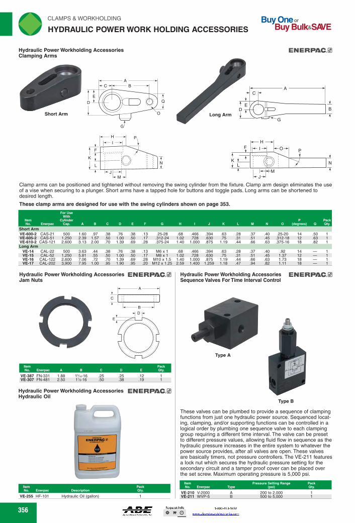
K N
L
H>1 M <Jk M ~
EN ERPAC.0 Hydraulic Power Workholding Accessories Clamping Arms
-4-0 F
K N
A
_t
B Short Arm
Item Pressure Setting Range Pack No. &icor= Type (Psi) Qty.
Hydraulic Power Workholding Accessories ENERPAC.0 Sequence Valves For Time Interval Control
Type A
Type B
These valves can be plumbed to provide a sequence of clamping functions from just one hydraulic power source. Sequenced locat-ing, clamping, and/or supporting functions can be controlled in a logical order by plumbing one sequence valve to each clamping group requiring a different time interval. The valve can be preset to different pressure values, allowing fluid flow in sequence as the hydraulic pressure increases in the entire system to whatever the power source provides, after all valves are open. These valves are basically timers, not pressure controllers. The VE-211 features a lock nut which secures the hydraulic pressure setting for the secondary circuit and a tamper proof cover can be placed over the set screw. Maximum operating pressure is 5,000 psi.
VE-210 V-2000 VE-211 VVVP-5 B
A 200 to 2,000 500 to 5,000
Item No. Enerpac A
Pack Qty. D E
A
C
B
E
rliN CLAMPS & WORKHOLDING Buy One or HYDRAULIC POWER WORK HOLDING ACCESSORIES Buy Bulk&SNE
Clamp arms can be positioned and tightened without removing the swing cylinder from the fixture. Clamp arm design eliminates the use of a vise when securing to a plunger. Short arms have a tapped hole for buttons and toggle pads. Long arms can be shortened to desired length.
These clamp arms are designed for use with the swing cylinders shown on page 353.
Item No. Enerpac
For Use with
Cylinder Cap. A BCD E F G N J K M N 0 (degrees) 12
Pack Qty.
Short Arm VE-600-2 CAS-21 500 1.60 .97 .38 .76 .38 .13 .25-28 .68 .466 .394 .63 .28 .37 .40 .25-20 14 .50 1 VE-605-2 CAS-51 1,250 2.39 1.57 .50 1.00 .50 .17 .312-24 1.02 .728 .630 .75 .31 .51 .45 .312-18 12 .63 1 VE-610-2 CAS-121 2,600 3.13 2.00 .70 1.39 .69 .28 .375-24 1.40 1.000 .875 1.19 .44 .66 .63 .375-16 18 .82 1 Long Arm
VE-14 CAL-22 500 3.63 .44 .38 .76 .38 .13 M6 x 1 .68 .466 .394 .63 .28 .37 .40 .92 14 1 VE-15 CAL-52 1,250 5.81 .55 .50 1.00 .50 .17 M8 x 1 1.02 .728 .630 .75 .31 .51 .45 1.37 12 1 VE-16 CAL-122 2,600 7.06 .72 .70 1.39 .69 .28 M10 x 1.5 1.40 1.000 .875 1.19 .44 .66 .63 1.73 18 1 VE-17 CAL-202 3,900 7.95 1.00 .95 1.90 .95 .20 M12 x 1.25 2.59 1.400 1.259 1.18 .47 .94 .82 1.11 18 1
Hydraulic Power Workholding Accessories ENERPAC33 Jam Nuts
VE-387 FN-331 1.88 1./18-16 .25 .25 .12 VE-307 FN-481 2.50 1%-16 .50 .38 .19
Hydraulic Power Workholding Accessories ENERPACE Hydraulic Oil
ENEHP C7
6
Item
Pack No. Enerpac Description
Qty.
VE-255 HF-101 Hydraulic Oil (gallon)
356
356
Hydraulic Power Workholding AccessoriesClamping Arms
Clamp arms can be positioned and tightened without removing the swing cylinder from the fixture. Clamp arm design eliminates the use of a vise when securing to a plunger. Short arms have a tapped hole for buttons and toggle pads. Long arms can be shortened to desired length.
These clamp arms are designed for use with the swing cylinders shown on page 353.
CA
B
G
ED
KL
FH
I O
MJ
N
P
ABC
D
E
G
Q
O
K
F
L
H
IP
JM
N
Long ArmShort Arm
ItemNo. Enerpac
For Use With
Cylinder Cap. A B C D E F G H I J K L M N O
P(degrees) Q
PackQty.
Short Arm VE-600-2 CAS-21 500 1.60 .97 .38 .76 .38 .13 .25-28 .68 .466 .394 .63 .28 .37 .40 .25-20 14 .50 1VE-605-2 CAS-51 1,250 2.39 1.57 .50 1.00 .50 .17 .312-24 1.02 .728 .630 .75 .31 .51 .45 .312-18 12 .63 1VE-610-2 CAS-121 2,600 3.13 2.00 .70 1.39 .69 .28 .375-24 1.40 1.000 .875 1.19 .44 .66 .63 .375-16 18 .82 1Long Arm
VE-14 CAL-22 500 3.63 .44 .38 .76 .38 .13 M6 x 1 .68 .466 .394 .63 .28 .37 .40 .92 14 — 1VE-15 CAL-52 1,250 5.81 .55 .50 1.00 .50 .17 M8 x 1 1.02 .728 .630 .75 .31 .51 .45 1.37 12 — 1VE-16 CAL-122 2,600 7.06 .72 .70 1.39 .69 .28 M10 x 1.5 1.40 1.000 .875 1.19 .44 .66 .63 1.73 18 — 1VE-17 CAL-202 3,900 7.95 1.00 .95 1.90 .95 .20 M12 x 1.25 2.59 1.400 1.259 1.18 .47 .94 .82 1.11 18 — 1
Hydraulic Power Workholding AccessoriesJam Nuts
ItemNo. Enerpac A B C D E
PackQty.
VE-387 FN-331 1.88 15⁄16-16 .25 .25 .12 1VE-307 FN-481 2.50 17⁄8-16 .50 .38 .19 1
Hydraulic Power Workholding AccessoriesHydraulic Oil
ItemNo. Enerpac Description
PackQty.
VE-255 HF-101 Hydraulic Oil (gallon) 1
Hydraulic Power Workholding AccessoriesSequence Valves For Time Interval Control
These valves can be plumbed to provide a sequence of clamping functions from just one hydraulic power source. Sequenced locat-ing, clamping, and/or supporting functions can be controlled in a logical order by plumbing one sequence valve to each clamping group requiring a different time interval. The valve can be preset to different pressure values, allowing fluid flow in sequence as the hydraulic pressure increases in the entire system to whatever the power source provides, after all valves are open. These valves are basically timers, not pressure controllers. The VE-211 features a lock nut which secures the hydraulic pressure setting for the secondary circuit and a tamper proof cover can be placed over the set screw. Maximum operating pressure is 5,000 psi.
Type B
Type A
ItemNo. Enerpac Type
Pressure Setting Range (psi)
PackQty.
VE-210 V-2000 A 200 to 2,000 1VE-211 WVP-5 B 500 to 5,000 1
C
A
B
D
E
HYDRAULIC POWER WORK HOLDING ACCESSORIES
FWAHL
SmallO
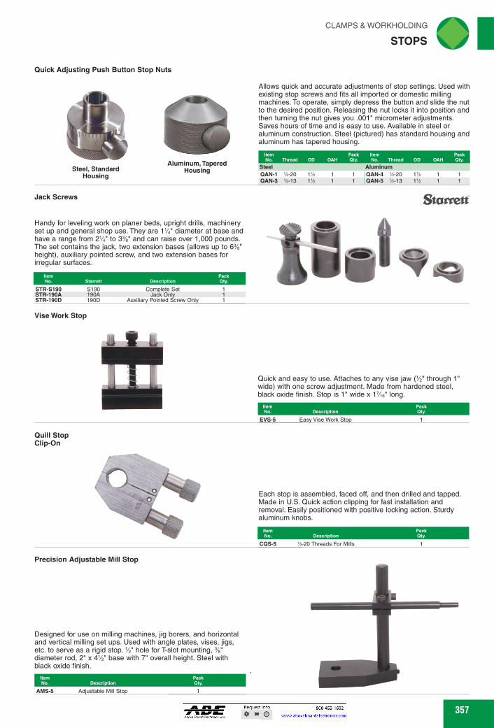
Starrett' Jack Screws
Handy for leveling work on planer beds, upright drills, machinery set up and general shop use. They are 1W diameter at base and have a range from 2W to 3% and can raise over 1,000 pounds. The set contains the jack, two extension bases (allows up to 6% height), auxiliary pointed screw, and two extension bases for irregular surfaces.
Quill Stop Clip-On
Quick and easy to use. Attaches to any vise jaw ('/2" through 1" wide) with one screw adjustment. Made from hardened steel, black oxide finish. Stop is 1" wide x 1 7/1 e" long.
EVS-5 Easy Vise Work Stop
Each stop is assembled, faced off, and then drilled and tapped. Made in U.S. Quick action clipping for fast installation and removal. Easily positioned with positive locking action. Sturdy aluminum knobs.
CQS-5 'h-20 Threads For Mills 1
AMS-5 Adjustable Mill Stop 1
CLAMPS & WORKHOLDING riN STOPS
Quick Adjusting Push Button Stop Nuts
Allows quick and accurate adjustments of stop settings. Used with existing stop screws and fits all imported or domestic milling machines. To operate, simply depress the button and slide the nut to the desired position. Releasing the nut locks it into position and then turning the nut gives you .001" micrometer adjustments. Saves hours of time and is easy to use. Available in steel or aluminum construction. Steel (pictured) has standard housing and aluminum has tapered housing.
Item Pack Item Pack No. Thread OD OAH qty. No. Thread OD OAH Qty.
Steel Aluminum QAN-1 'A-20 Ph 1 1 QAN-4 1/2-20 11/2 1 1 QAN-3 'A-13 Ph 1 1 QAN-5 1/2-13 11/2 1 1
STR-5190 S190 Complete Set 1 STR-190A 190A Jack Only 1 STR-190D 190D Auxiliary Pointed Screw Only 1
Vise Work Stop
Precision Adjustable Mill Stop
Designed for use on milling machines, jig borers, and horizontal and vertical milling set ups. Used with angle plates, vises, jigs, etc. to serve as a rigid stop. '/2" hole for T-slot mounting, %" diameter rod, 2" x 4'/2" base with 7" overall height. Steel with black oxide finish. •
Steel, Standard Housing
Aluminum, Tapered Housing
Item No. Description
357
Quick Adjusting Push Button Stop Nuts
Jack Screws
Handy for leveling work on planer beds, upright drills, machinery set up and general shop use. They are 11⁄4" diameter at base and have a range from 21⁄4" to 33⁄8" and can raise over 1,000 pounds. The set contains the jack, two extension bases (allows up to 63⁄8" height), auxiliary pointed screw, and two extension bases for irregular surfaces.
Vise Work Stop
Precision Adjustable Mill Stop
Quill StopClip-On
Each stop is assembled, faced off, and then drilled and tapped. Made in U.S. Quick action clipping for fast installation and removal. Easily positioned with positive locking action. Sturdy aluminum knobs.
ItemNo. Description
PackQty.
CQS-5 1⁄2-20 Threads For Mills 1
ItemNo. Starrett Description
PackQty.
STR-S190 S190 Complete Set 1STR-190A 190A Jack Only 1STR-190D 190D Auxiliary Pointed Screw Only 1
Designed for use on milling machines, jig borers, and horizontal and vertical milling set ups. Used with angle plates, vises, jigs, etc. to serve as a rigid stop. 1⁄2" hole for T-slot mounting, 3⁄8" diameter rod, 2" x 41⁄2" base with 7" overall height. Steel with black oxide finish.
ItemNo. Description
PackQty.
AMS-5 Adjustable Mill Stop 1
Quick and easy to use. Attaches to any vise jaw (1⁄2" through 1" wide) with one screw adjustment. Made from hardened steel, black oxide finish. Stop is 1" wide x 17⁄16" long.
ItemNo. Description
PackQty.
EVS-5 Easy Vise Work Stop 1
Allows quick and accurate adjustments of stop settings. Used with existing stop screws and fits all imported or domestic milling machines. To operate, simply depress the button and slide the nut to the desired position. Releasing the nut locks it into position and then turning the nut gives you .001" micrometer adjustments. Saves hours of time and is easy to use. Available in steel or aluminum construction. Steel (pictured) has standard housing and aluminum has tapered housing.
Aluminum, Tapered HousingSteel, Standard
Housing
ItemNo. Thread OD OAH
PackQty.
ItemNo. Thread OD OAH
PackQty.
Steel AluminumQAN-1 1⁄2-20 11⁄2 1 1 QAN-4 1⁄2-20 11⁄2 1 1QAN-3 1⁄2-13 11⁄2 1 1 QAN-5 1⁄2-13 11⁄2 1 1
STOPS
FWAHL
SmallO

Buy One or Buy Bulk&SIO/E
rli N CLAMPS & WORKHOLDING
VISES
WINN Utility Workshop Industrial Vise
3% Swivel Base 62 WLT-25 4 6%
Pipe Capacity
Shipping Weight
item Jaw No. Width
Max. Opening
Pack Qty.
1/4-2% 1/4-3%
5% 5 6
50 64 5%
WLT-110 WLT-115
Jaw Width
Jaw Opening
5% 4% 1/4-3% 6 WLT-746
WILICN Vise Accessories Copper Jaw Caps
Prism
Jaw Width
Pack
Standard Fiber Prism Rubber
item item item item No. No. No. No.
4 4% 5 6
WLT-435 WLT-465 WLT-495 WLT-525 WLT-440 — WLT-500 — WLT-445 — WLT-505 WLT-535 WLT-450 — WLT-510 WLT-540
MINK Vise Accessories Soft Jaws Magnetic Jaw Caps
WLT-60 Grooved 59/18 Yellow 1
Tradesman Industrial Vise
For general purpose service or maintenance shops not requiring the strength of a combination vise. PI 60,000 psi ductile iron body parts hardened steel top and pipe jaws. Base swivels. Enclosed construc-tion keeps lubricants in and contaminants out.
item No.
Jaw Width
Max. Opening
Pipe Capacity
Throat Depth
Shipping Pack Weight Qty.
WLT-150 4% 4 1/4-2% 3% 33 WLT-155 5% 5 1/4-3 3% 49 WLT-160 6% 6% 1/4-3% 4 70 WLT-165 8 7 %-3% 4% 105
A versatile all-around vise. Features a formed steel channel beam and a hefty 30,000 psi body casting. Replaceable, serrated steel top jaws and built in pipe jaws. 180 degrees locking swivel base.
WLT-180 4 3% %-2% 17% 1 WLT-185 51/2 5 4 '43-37/18 30 1 WLT-190 61/2 51/2 5 ',13-3"Ae 40 1 WLT-195 6 6 6 Us-3'1/4e 66 1 WLT-200 8 71/2 8 '43-41/2 80 1
Machinists' Industrial Vise
Built for performance and endurance. Stress parts are 60,000 psi ductile iron. Hardened steel jaw. Replaceable inserts are serrated for safe, sure grip. Straight line design - horizontal spindle and nut eliminate thread wear. Swivel base allows for 360 degrees rotation and has double lockdowns for non-slip holding and four mounting points.
High Visibility Industrial Safety Vise
Coated in high visibility yellow which conforms to OSHA safety color standard. Heavy duty casting, 30,000 psi. Replaceable hardened steel jaw inserts and replaceable pipe jaws to provide sure grip for a variety of work holding applications. 360 degree swivel base.
Mechanics' Industrial Vise
This vise has a swivel base that rotates 365 degrees with double lockdowns ensuing maximum stability. The powder coat paint resists scratches and provides a e tough, durable finish. It also features replaceable hardened steel top and pipe jaws and a large anvil work surface.
358
Max. Throat
Pipe Shipping
Pack Opening
Depth
Capacity Weight
Qty.
Item No.
Max. Throat
Shipping Pack Opening
Depth
Description Weight Qty.
WIDON.
WAIN
Pack Qty.
Pipe Capacity
Throat Depth
Designed to fit any size vise to avoid marring the surface of softer metals and to protect jaw faces. They have polished faces and pliable copper extensions to fit on any make of vise. Sold in pairs.
113-•11M2M WLT-385 WLT-390 4 WLT-395 4% WLT-400 5 WLT-405 6
Vise Accessories Magnefix Jaw Caps
11111.mmi
Standard
Rubber
Designed to protect both the vise jaws and the work piece from marring and distortion. Constructed from hardened aluminum alloy with two built-in circular magnets on the back side which hold the caps securely on the vise. They are right-angled and surface-parallel to fit any vise type including machine and bench type. Sold in pairs.
Soft polyurethane protects work from damage. Impervious to solutions and chemicals. Strong magnets hold caps in place. Grooved for round or tube applications. Sold in pairs.
Fiber
358
Vise AccessoriesSoft Jaws Magnetic Jaw Caps
Vise AccessoriesCopper Jaw Caps
Designed to fit any size vise to avoid marring the surface of softer metals and to protect jaw faces. They have polished faces and pliable copper extensions to fit on any make of vise. Sold in pairs.
ItemNo.
JawWidth
PackQty.
WLT-385 31⁄2 1WLT-390 4 1WLT-395 41⁄2 1WLT-400 5 1WLT-405 6 1
Vise AccessoriesMagnefix Jaw Caps
Prism
Rubber
Designed to protect both the vise jaws and the work piece from marring and distortion. Constructed from hardened aluminum alloy with two built-in circular magnets on the back side which hold the caps securely on the vise. They are right-angled and surface-parallel to fit any vise type including machine and bench type. Sold in pairs.
Fiber
Standard
Standard Fiber Prism Rubber
JawWidth
PackQty.
ItemNo.
ItemNo.
ItemNo.
ItemNo.
WLT-435 WLT-465 WLT-495 WLT-525 4 1WLT-440 — WLT-500 — 41⁄2 1WLT-445 — WLT-505 WLT-535 5 1WLT-450 — WLT-510 WLT-540 6 1
Soft polyurethane protects work from damage. Impervious to solutions and chemicals. Strong magnets hold caps in place. Grooved for round or tube applications. Sold in pairs.
ItemNo. Style Width Color
PackQty.
WLT-60 Grooved 59⁄16 Yellow 1
Machinists' Industrial Vise
This vise has a swivel base that rotates 365 degrees with double lockdowns ensuing maximum stability. The powder coat paint resists scratches and provides a tough, durable finish. It also features replaceable hardened steel top and pipe jaws and a large anvil work surface.
ItemNo.
JawWidth
JawOpening
ThroatDepth
PipeCapacity
PackQty.
WLT-746 6 53⁄4 41⁄8 1⁄4-31⁄2 1
Mechanics' Industrial Vise
A versatile all-around vise. Features a formed steel channel beam and a hefty 30,000 psi body casting. Replaceable, serrated steel top jaws and built in pipe jaws. 180 degrees locking swivel base.
ItemNo.
JawWidth
Max.Opening
ThroatDepth
PipeCapacity
ShippingWeight
PackQty.
WLT-180 41⁄2 4 31⁄2 1⁄8-25⁄8 171⁄2 1WLT-185 51⁄2 5 4 1⁄8-37⁄16 30 1WLT-190 61⁄2 51⁄2 5 1⁄8-311⁄16 40 1WLT-195 6 6 6 1⁄8-311⁄16 66 1WLT-200 8 71⁄2 8 1⁄8-41⁄2 80 1
Utility Workshop Industrial Vise
For general purpose service or maintenance shops not requiring the strength of a combination vise. 60,000 psi ductile iron body parts hardened steel top and pipe jaws. Base swivels. Enclosed construc-tion keeps lubricants in and contaminants out.
ItemNo.
JawWidth
Max.Opening
PipeCapacity
Throat Depth
ShippingWeight
PackQty.
WLT-150 41⁄2 4 1⁄4-21⁄2 31⁄4 33 1WLT-155 51⁄2 5 1⁄4-3 33⁄4 49 1WLT-160 61⁄2 61⁄2 1⁄4-31⁄2 4 70 1WLT-165 8 7 1⁄8-31⁄2 43⁄4 105 1
Tradesman Industrial Vise
Coated in high visibility yellow which conforms to OSHA safety color standard. Heavy duty casting, 30,000 psi. Replaceable hardened steel jaw inserts and replaceable pipe jaws to provide sure grip for a variety of work holding applications. 360 degree swivel base.
ItemNo.
JawWidth
Max.Opening
PipeCapacity
ShippingWeight
PackQty.
WLT-110 5 51⁄4 1⁄4-21⁄2 50 1WLT-115 6 53⁄4 1⁄4-31⁄2 64 1
High Visibility Industrial Safety Vise
Built for performance and endurance. Stress parts are 60,000 psi ductile iron. Hardened steel jaw. Replaceable inserts are serrated for safe, sure grip. Straight line design - horizontal spindle and nut eliminate thread wear. Swivel base allows for 360 degrees rotation and has double lockdowns for non-slip holding and four mounting points.
ItemNo.
JawWidth
Max.Opening
ThroatDepth Description
ShippingWeight
PackQty.
WLT-25 4 61⁄2 31⁄2 Swivel Base 62 1
VISES
FWAHL
SmallO

heinrich GETn GNP WMI 101.1101
Grip-Master Screwless Vises
Jaw Plates
Item No.
Pack
JP-4 JP-6
Pack J Qty.
1% 1% 1% 1% 1% 1%
GETn GRIP MTH MINCH
Woodworker's Vise
CLAMPS & WORKHOLDING riliN
VISES _,,,
V-Block Attachment Holds Round Stock
The Grip-Master screwless vise offers many advantages. Instantaneous, effortless setting by simply pushing on the knob controlling the movable jaw. Guaranteed positive locking by light press on locking lever. Built-in, recessed parallels level work. Large loading and unloading capacity. Hardened and ground bars and locking mechanism insure long life. Straight through drilling permit-ted by extra-wide clearance in base. Hardened and ground V-block attachment available for holding round or oval work securely.
Speed Type Vises
Designed for speed. Screw and nut hardened for long life. Heavy semi-steel castings, for strength. Heavy steel base plate, for rigid-ity. Standardized holes in jaws, for attaching interchangeable jaw plates and fixtures. The screw is held positively in the nut when the vise is clamped. It cannot slip; yet it is released instantly with a half-turn. Lift the screw and the jaw is free to slide to its full opening. Slide the jaw to the closed position, drop the screw into the nut and lock with a half turn. Combination of jaw plates are grooved for holding round parts, notched for holding parts above base of vise, smooth on back side. They are accurately machined, hardened and ground. Socket cap screws supplied for attaching them to vise. Vises are supplied without jaw plates.
Pack Item Qty. No.
GM-1 3 3 VA % 1 VB-1 GM-2 4 4Wee VA % 1 VB-2 GM-3 6 6% 119/e % 1 VB-3 GM-4 8 8% 2 % 1 VB-4
Vises Without Jaw Plates
Item No.
Jaw Width
Jaw •th
Jaw 0 nin •
Weight Lbs.
CV-4 4 11/2 4 121/2 CV-6 6 2 6 31 CV-7 6 2 8 40
Grip-Master Fixture Locks
hehrich GETf GRP W111111131.1101
Adaptable to a wide range of applications and simplifies jig and fixture designing and eliminates special locking details. A simple push or pull on the bar knob sets the bar instantaneously at any position between fully open or fully closed. A light press on the locking lever gives an extra forceful forward motion to the bar, exerting a holding pressure, adjustable from 400 to 1,100 pounds. Actually compensates for variations in size of work. Its long stroke assures wide work clearance and permits quick removal of chips and burrs. No screw threads to wear or strip. Hardened and ground bar and locking mechanism. Bar left soft for 1" on work end for easy machining when adapting it to fixture.
Drill Press Vises
Item Jaw
Jaw
Jaw No. Width
Opening
Depth
Weight Lbs.
Pack Qty.
DPV-20
6
10
2
21 DPV-30
8
10
2'A 36
Item No. A BCD E F G H
GMF-1 2% 9 .493 21/2 2%e 1% 1% GMF-1-10 3%e 3%e 2% 10 .493 21/2 23 e 13he 1% GMF-1-12 3%e 3%e 2% 12 .493 21/2 23 e 13he 1 GMF-1-14 3%e 3%e 2% 14 .493 21/2 23 e 13he 1 GMF-1-16 3%e 3%e 2% 16 .493 21/2 23 e 13he 1 GMF-1-18 3%e 3%e 2% 18 .493 21/2 23 e 13he 1 GMF-1-24 3%e 3%e 2% 24 .493 21/2 23 e 13he 1
GMF-2 4% 3Wee 3% 10 .742 31/2 2% 17/16 2% GMF-2-12 4% 3Wee 3% 12 .742 31/2 2% 17/16 2% GMF-2-14 4% 3Wee 3% 14 .742 31/2 2% 1%3 2% GMF-2-16 4% 3Wee 3'%e 16 .742 31/2 2% 1%3 2% GMF-2-20 4% 3Wee 3'%e 20 .742 31/2 2% 1%3 2% GMF-2-24 3Wee 24 .742 31/2 2% Wie 2%
These handy drill press vises can be used from three sides. Work can be leveled quickly because jaws have built-in parallels. Widely spaced jaw guide bars, permit drilling clear through work. Jaw sides are precision ground at right angle to parallels to permit accurate drilling from the sides without resetting the work. Horizontal V-groove, holds round stock firmly for side and end drilling.
Features: Pm;
• Castings - gray iron with orange baked-enamel finish • Jaws - drilled and tapped or countersunk holes for attachment
of wood facings • Dog - solid steel
This light and medium-duty vise features double guide-bars, continuous screw action and solid steel dog.
AC-27090 7
9 1
359
Woodworker's ViseFeatures:
Castings - gray iron with orange baked-enamel finishJaws - drilled and tapped or countersunk holes for attachment of wood facingsDog - solid steel
This light and medium-duty vise features double guide-bars, continuous screw action and solid steel dog.
ItemNo.
JawWidth Maximum Opening
PackQty.
AC-27090 7 9 1
Grip-Master Screwless Vises
The Grip-Master screwless vise offers many advantages. Instantaneous, effortless setting by simply pushing on the knob controlling the movable jaw. Guaranteed positive locking by light press on locking lever. Built-in, recessed parallels level work. Large loading and unloading capacity. Hardened and ground bars and locking mechanism insure long life. Straight through drilling permit-ted by extra-wide clearance in base. Hardened and ground V-block attachment available for holding round or oval work securely.
V-Block AttachmentHolds Round Stock
Vises
PackQty.
V-Blocks
ItemNo.
JawWidth
Max.Open
JawDepth
ParallelDepth
ItemNo.
GM-1 3 3 11⁄4 5⁄8 1 VB-1GM-2 4 411⁄16 11⁄4 5⁄8 1 VB-2GM-3 6 65⁄16 113⁄16 5⁄8 1 VB-3GM-4 8 83⁄8 2 5⁄8 1 VB-4
Grip-Master Fixture Locks
Adaptable to a wide range of applications and simplifies jig and fixture designing and eliminates special locking details. A simple push or pull on the bar knob sets the bar instantaneously at any position between fully open or fully closed. A light press on the locking lever gives an extra forceful forward motion to the bar, exerting a holding pressure, adjustable from 400 to 1,100 pounds. Actually compensates for variations in size of work. Its long stroke assures wide work clearance and permits quick removal of chips and burrs. No screw threads to wear or strip. Hardened and ground bar and locking mechanism. Bar left soft for 1" on work end for easy machining when adapting it to fixture.
ItemNo. A B C D E F G H I J
PackQty.
GMF-1 35⁄16 33⁄16 27⁄8 9 .493 21⁄2 23⁄16 13⁄32 11⁄2 3⁄4 1GMF-1-10 35⁄16 33⁄16 27⁄8 10 .493 21⁄2 23⁄16 13⁄32 11⁄2 3⁄4 1GMF-1-12 35⁄16 33⁄16 27⁄8 12 .493 21⁄2 23⁄16 13⁄32 11⁄2 3⁄4 1GMF-1-14 35⁄16 33⁄16 27⁄8 14 .493 21⁄2 23⁄16 13⁄32 11⁄2 3⁄4 1GMF-1-16 35⁄16 33⁄16 27⁄8 16 .493 21⁄2 23⁄16 13⁄32 11⁄2 3⁄4 1GMF-1-18 35⁄16 33⁄16 27⁄8 18 .493 21⁄2 23⁄16 13⁄32 11⁄2 3⁄4 1GMF-1-24 35⁄16 33⁄16 27⁄8 24 .493 21⁄2 23⁄16 13⁄32 11⁄2 3⁄4 1
GMF-2 45⁄16 311⁄16 315⁄16 10 .742 31⁄2 27⁄8 17⁄16 21⁄8 11⁄4 1GMF-2-12 45⁄16 311⁄16 315⁄16 12 .742 31⁄2 27⁄8 17⁄16 21⁄8 11⁄4 1GMF-2-14 45⁄16 311⁄16 315⁄16 14 .742 31⁄2 27⁄8 17⁄16 21⁄8 11⁄4 1GMF-2-16 45⁄16 311⁄16 315⁄16 16 .742 31⁄2 27⁄8 17⁄16 21⁄8 11⁄4 1GMF-2-20 45⁄16 311⁄16 315⁄16 20 .742 31⁄2 27⁄8 17⁄16 21⁄8 11⁄4 1GMF-2-24 45⁄16 311⁄16 315⁄16 24 .742 31⁄2 27⁄8 17⁄16 21⁄8 11⁄4 1
Drill Press Vises
These handy drill press vises can be used from three sides. Work can be leveled quickly because jaws have built-in parallels. Widely spaced jaw guide bars, permit drilling clear through work. Jaw sides are precision ground at right angle to parallels to permit accurate drilling from the sides without resetting the work. Horizontal V-groove, holds round stock firmly for side and end drilling.
ItemNo.
JawWidth
JawOpening
JawDepth
WeightLbs.
PackQty.
DPV-20 6 10 2 21 1DPV-30 8 10 21⁄2 36 1
Speed Type Vises
Designed for speed. Screw and nut hardened for long life. Heavy semi-steel castings, for strength. Heavy steel base plate, for rigid-ity. Standardized holes in jaws, for attaching interchangeable jaw plates and fixtures. The screw is held positively in the nut when the vise is clamped. It cannot slip; yet it is released instantly with a half-turn. Lift the screw and the jaw is free to slide to its full opening. Slide the jaw to the closed position, drop the screw into the nut and lock with a half turn. Combination of jaw plates are grooved for holding round parts, notched for holding parts above base of vise, smooth on back side. They are accurately machined, hardened and ground. Socket cap screws supplied for attaching them to vise. Vises are supplied without jaw plates.
Vises Without Jaw Plates
PackQty.
Jaw Plates
ItemNo.
JawWidth
JawDepth
JawOpening
WeightLbs.
ItemNo.
CV-4 4 11⁄2 4 121⁄2 1 JP-4CV-6 6 2 6 31 1 JP-6CV-7 6 2 8 40 1 —
F A D
H
G
B
CI
E
J 13/32 Dia.
GET A GRIP WITH HEINRICH
GET A GRIP WITH HEINRICH
GET A GRIP WITH HEINRICH
VISES
FWAHL
SmallO

Buy One or Buy Bulk&SIO/E
rliN CLAMPS & WORKHOLDING
VISES
Pack Qty.
Item No. Fits Vise Width
KV-D30-45 3 - 4" Wide
WOW' Angled Drill Press Vises
Overall Height
Shipping Pack Wgt. Lbs. Qty.
Item No.
Jaw Width
Max. Opening
Jaw Depth
2% WLT-250
2% 3% WLT-255 3
Item No.
Max. Opening Capacity
Vise keys are used to align your vise to your milling machine table. All keys are hardened. Step keys are used when keyway in the vise is different than that of the machine T-slot. Sold in pairs.
Item No.
Pack Qty Key Size Vise Size
KV-D30-33A KV-D50-33A KV-D50-33B
fz x % x%
x "Ae
3" and 4" 5" and 6" 5" and 6"
WLT-1130 2% 2 2'A 13
• h— h-2
h 3 h 4 '1
Swivel Base
The Kurt Anglock D-series vises are designed for precision part clamping on basic machine tools such as knee-type mills, grinders, and machining centers. Vises are ideal for extremely high accuracy tool and mold applications and for use in running production parts where datums, flatness and parallelism is important. Anglock design assures the movable jaw does not lift. Semi-hard steel screw, 80,000 psi ductile iron construction. Both are machined, which allows you to indicate alignment during set up. Swivel base (sold separately) allows positioning increments of 1 degrees.
Note: KV-D810 shipped via truck.
Vise Accessories Speed Handles
Aluminum center hub with all steel handles and knobs. Black oxide finish.
111!!!!!!!•-, VSH-5 Fits 4" Vise (Vie" Hex 1
VSH-15 Fits 6" Vise (%" Hex 1 VSH-20 Fits 8" Vise (3/4" Hex 1
Vise Accessories Work Stops
400
KV-360PWS 5 - 6" Wide
41011k
*Fi
r
Mounted on an angle base allowing the vise to be adjusted quickly to any angle from 0 degrees to 90 degrees vertical. Precision locking bolts, linked by side plates of high quality steel, lock the vise securely. It is calibrated for vertical angle readings.
360
3%e 4%
12 17
Anglock® Vises
F
,TH c fl H j_1=
4-11.-3 (4 Places)
11.50 14.32 17.03 .750 13.50 17.25 20.75 .875
8.80 6 16.81 8.75 .725 .688 4.61 78 1 10.00 8 21.81 11.50 1.075 .813 3.31 158 1
Swivel Base Only for KV-D688 1
KV-D688 8.80 KV-D810 10.00
KV-D60-4-SA
KV-KPS6000
Vise Accessories Keys - Stepped
Clamp-On Vise
This portable clamp-on vise allows for use in many different applications. Features a fully enclosed spindle, double lock downs, grooved replace-able jaws and a swivel base.
Item No.
Jaw Width
Max. Opening
Shipping Wgt. Lbs.
Pack Qty.
Vise Accessories Parallel Keeper
.%Nft4,
4
%4It
%
1444,
Pack Qty.
360
Vise
Anglock® Vises
The Kurt Anglock D-series vises are designed for precision part clamping on basic machine tools such as knee-type mills, grinders, and machining centers. Vises are ideal for extremely high accuracy tool and mold applications and for use in running production parts where datums, flatness and parallelism is important. Anglock design assures the movable jaw does not lift. Semi-hard steel screw, 80,000 psi ductile iron construction. Both are machined, which allows you to indicate alignment during set up. Swivel base (sold separately) allows positioning increments of 1 degrees.
Note: KV-D810 shipped via truck.
AFF
H
G (4 Places)
C
Hex
BE
D 2.00
1
3 4
2
Swivel Base
ItemNo.
Max. Capacities
Hex Size
Jaw OpeningMax. A B D E F G
+/-.001H
Wt.Lbs.
PackQty.1 2 3 4
KV-D688 8.80 11.50 14.32 17.03 .750 8.80 6 16.81 8.75 .725 .688 4.61 78 1KV-D810 10.00 13.50 17.25 20.75 .875 10.00 8 21.81 11.50 1.075 .813 3.31 158 1
KV-D60-4-SA Swivel Base Only for KV-D688 1
Vise AccessoriesSpeed Handles
Aluminum center hub with all steel handles and knobs. Black oxide finish.
ItemNo. Description
PackQty.
VSH-5 Fits 4" Vise (9⁄16" Hex) 1VSH-15 Fits 6" Vise (3⁄4" Hex) 1VSH-20 Fits 8" Vise (7⁄8" Hex) 1
Vise AccessoriesWork Stops
ItemNo. Fits Vise Width
PackQty.
KV-D30-45 3 - 4" Wide 1KV-360PWS 5 - 6" Wide 1
Vise AccessoriesParallel Keeper
ItemNo.
Max. Opening Capacity
PackQty.
KV-KPS6000 6" 1
Vise AccessoriesKeys - Stepped
Vise keys are used to align your vise to your milling machine table. All keys are hardened. Step keys are used when keyway in the vise is different than that of the machine T-slot. Sold in pairs.
ItemNo. Key Size Vise Size
PackQty.
KV-D30-33A 1⁄2 x 5⁄8 3" and 4" 1KV-D50-33A 11⁄16 x 5⁄8 5" and 6" 1KV-D50-33B 11⁄16 x 13⁄16 5" and 6" 1
Angled Drill Press Vises
Mounted on an angle base allowing the vise to be adjusted quickly to any angle from 0 degrees to 90 degrees vertical. Precision locking bolts, linked by side plates of high quality steel, lock the vise securely. It is calibrated for vertical angle readings.
ItemNo.
JawWidth
Max.Opening
JawDepth
OverallHeight
ShippingWgt. Lbs.
PackQty.
WLT-250 21⁄2 21⁄2 11⁄2 37⁄16 12 1WLT-255 3 31⁄8 13⁄4 41⁄4 17 1
Clamp-On Vise
This portable clamp-on vise allows for use in many different applications. Features a fully enclosed spindle, double lock downs, grooved replace-able jaws and a swivel base.
ItemNo.
JawWidth
JawDepth
Max.Opening
ShippingWgt. Lbs.
PackQty.
WLT-1130 21⁄2 2 21⁄2 13 1
VISES
FWAHL
SmallO

Jaw Width
Wgt. Lbs.
Pack Qty.
Jaw Opening
2% 3 11 WLT-1210
Toolmaker's Screwless Precision Vises VVILICN
WOW. Features: • Used on milling and drilling machines where quick centering is required • Automatically adjusts workpiece to its center • Made of close-grained cast iron • Swivel base provides positive locking mechanism that adjusts through 360 degrees • Opposite threads for quick, accurate centering
WLT-1235 4 4 1% 32 1
Pow-R-Arm Ergonomic Work Positioner Midget 345 WOW
Pow-R-Arm Ergonomic Work Positioner Veep 344
WLT-300 2% 41/ 1,18-24
Item No.
Base Dia.
Pack Qty.
Overall Hgt.
The horizontal handle is easily accessible. Steel body. '/2" receptacle with set screw for vise, printed circuit board holder or special fixture. 20 lbs. capacity.
Overall Hgt.
Pack Qty.
••
3% 4%
WIDION Pow-R-Arm Ergonomic Work Positioner Junior 343
Base Dia.
Pack Qty.
Overall Hgt.
WLT-310 4% 5%
CLAMPS & WORKHOLDING riliN
VISES ._,1
Toolmaker's Precision Vise
is0:060.̀..1.°6
Features: • Made from specially selected alloy steel • Precision ground square and parallel to .0002 in. • Heat treated for hardness • Completely stress relieved
WILION 'rN
Self Centering Precision Vise
These work positioners put the workpiece where you want it and hold it tight for hands free production. Repositions workpieces easily and accurately, eliminating time consuming clamping and unclamping.
Fast on-off action with horizontal handle. All parts are steel. For intricate small work. 6 lbs. capacity.
Item Base Overall Mounting Pack No. Dia. Hgt. Stud Qty.
Pow-R-Arm Ergonomic Work Positioner Mechanical 301
Extra strong, heavy duty positioner with exceptionally fast on-off action. Body is machined steel, all steel parts. Mounting holes are 5/1e-18 on center. Designed for high production assembly lines. 70 lbs. capacity.
WLT-315 6 8
Mounting Hole
Item Table No. Size
Base Size
Work Load Lbs.
Pack Height Qty.
10 WP-4 4x4x% 48 (1/4-20) 1%x 11/4 x%
Universal Work Positioner
This all purpose, all position workholding fixture allows you to move your workpiece to any position, eliminating the need for elaborate setups with clamps, vises, angle plates, etc. It is machined from 6061-T6 aluminum (no castings) and has been hardcoated, adding wear resistance to the work surface and threaded mounting holes. Allows spherical movement of 180 degrees and a table rotation of a full 360 degrees. Only one torque setting is required per setup. Excellent for soldering, welding, brazing, assembly, model making, electronic device mounting, etc.
WIL 1\J
Item No.
Item No.
Jaw Width
Item
Jaw
Jaw
Jaw No. Width
Opening
Depth
Item No.
Features: • All steel body uses rapid positioning notches to obtain positive
downward clamping force • Horizontal and vertical vees in sliding jaws hold workpieces
securely and accurately • Squareness and parallelism to within .0003 in.
Wgt. Lbs.
Jaw Opening
Jaw Depth
Pack Qty.
2 WLT-1215 WLT-1220 3
3% 3%
8 11
Fast on-off action with horizontal moving lock handles. Body is cast aluminum with steel parts. Mounting holes are 1/4-20 on 24" centers. T-bracket. 30 lbs. capacity.
361
Universal Work Positioner
This all purpose, all position workholding fixture allows you to move your workpiece to any position, eliminating the need for elaborate setups with clamps, vises, angle plates, etc. It is machined from 6061-T6 aluminum (no castings) and has been hardcoated, adding wear resistance to the work surface and threaded mounting holes. Allows spherical movement of 180 degrees and a table rotation of a full 360 degrees. Only one torque setting is required per setup. Excellent for soldering, welding, brazing, assembly, model making, electronic device mounting, etc.
ItemNo.
TableSize
MountingHole
BaseSize
WorkLoad Lbs. Height
PackQty.
WP-4 4 x 4 x 3⁄8 48 (1⁄4-20) 11⁄2 x 11⁄2 x 1⁄4 10 37⁄8 1
Toolmaker's Precision Vise
ItemNo.
JawWidth
JawOpening
JawDepth
Wgt.Lbs.
PackQty.
WLT-1210 23⁄4 3 19⁄16 11 1
Toolmaker's Screwless Precision Vises
ItemNo.
JawWidth
JawOpening
JawDepth
Wgt.Lbs.
PackQty.
WLT-1215 2 31⁄8 1 8 1WLT-1220 3 33⁄4 13⁄8 11 1
Self Centering Precision Vise
ItemNo.
JawWidth
JawOpening
JawDepth
Wgt.Lbs.
PackQty.
WLT-1235 4 4 11⁄2 32 1
Features:Made from specially selected alloy steelPrecision ground square and parallel to .0002 in.Heat treated for hardnessCompletely stress relieved
Features:All steel body uses rapid positioning notches to obtain positive downward clamping forceHorizontal and vertical vees in sliding jaws hold workpieces securely and accuratelySquareness and parallelism to within .0003 in.
Features:Used on milling and drilling machines where quick centering is requiredAutomatically adjusts workpiece to its centerMade of close-grained cast ironSwivel base provides positive locking mechanism that adjusts through 360 degreesOpposite threads for quick, accurate centering
These work positioners put the workpiece where you want it and hold it tight for hands free production. Repositions workpieces easily and accurately, eliminating time consuming clamping and unclamping.
Pow-R-Arm Ergonomic Work PositionerMidget 345
Fast on-off action with horizontal handle. All parts are steel. For intricate small work. 6 lbs. capacity.
Pow-R-Arm Ergonomic Work PositionerVeep 344
Pow-R-Arm Ergonomic Work PositionerMechanical 301
The horizontal handle is easily accessible. Steel body. 1⁄2" receptacle with set screw for vise, printed circuit board holder or special fixture. 20 lbs. capacity.
Extra strong, heavy duty positioner with exceptionally fast on-off action. Body is machined steel, all steel parts. Mounting holes are 5⁄16-18 on center. Designed for high production assembly lines. 70 lbs. capacity.
Pow-R-Arm Ergonomic Work PositionerJunior 343
Fast on-off action with horizontal moving lock handles. Body is cast aluminum with steel parts. Mounting holes are 1⁄4-20 on 21⁄4" centers. T-bracket. 30 lbs. capacity.
ItemNo.
BaseDia.
OverallHgt.
MountingStud
PackQty.
WLT-300 21⁄2 41⁄4 5⁄16-24 1 ItemNo.
BaseDia.
OverallHgt.
PackQty.
WLT-305 33⁄4 41⁄4 1
ItemNo.
BaseDia.
OverallHgt.
PackQty.
WLT-310 41⁄4 51⁄4 1
ItemNo.
BaseDia.
OverallHgt.
PackQty.
WLT-315 6 8 1
VISES
FWAHL
SmallO
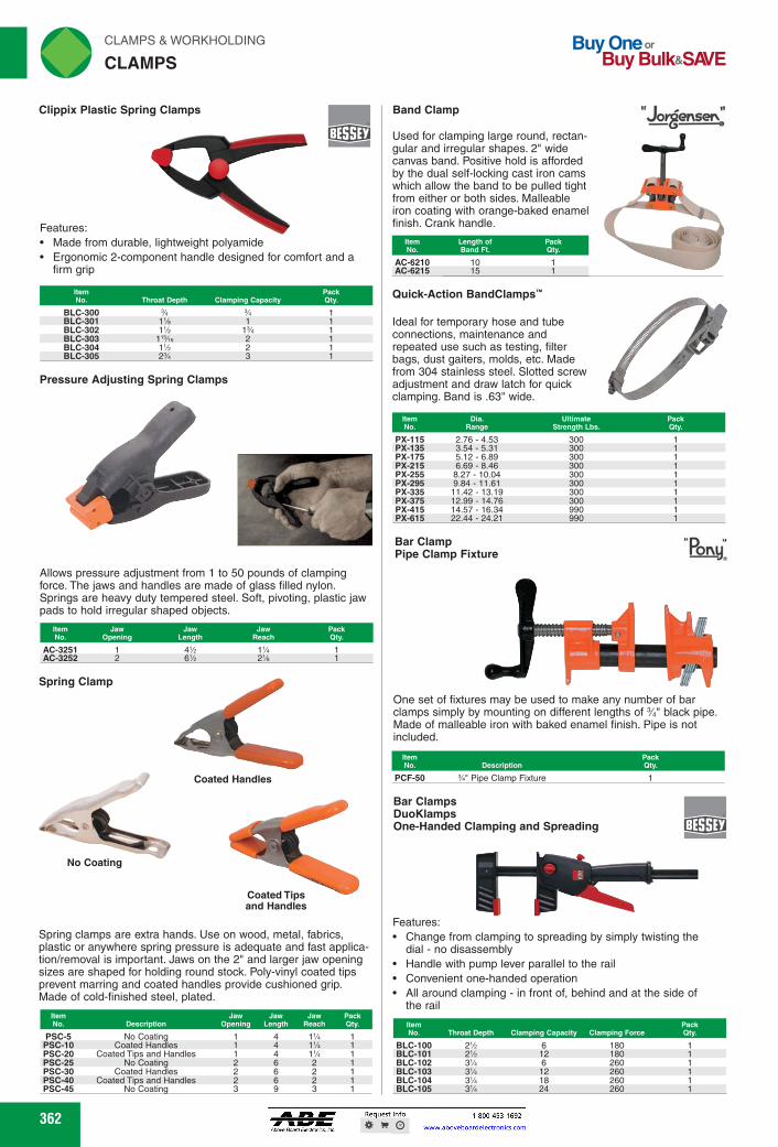
Buy One or Buy Bulk&SNE
rliN CLAMPS & WORKHOLDING
CLAMPS
orgenser." Band Clamp
Length of Band Ft.
Item No.
Pack Qty.
10 15
AC-6210 AC-6215
Quick-Action BandClamps—
Ideal for temporary hose and tube connections, maintenance and repeated use such as testing, filter bags, dust gaiters, molds, etc. Made from 304 stainless steel. Slotted screw adjustment and draw latch for quick clamping. Band is .63" wide.
Throat Depth Clamping Capacity Pack Qty.
BLC-300 BLC-301 BLC-302 BLC-303 BLC-304 BLC-305
1% 1 1% 1%
1'%e 2 1% 2 2% 3
Spring Clamp
a Coated Handles
I •
rY
1111. No Coating 411r
Coated Tips and Handles
Clippix Plastic Spring Clamps
Features: • Made from durable, lightweight polyamide • Ergonomic 2-component handle designed for comfort and a
firm grip
Pressure Adjusting Spring Clamps
Allows pressure adjustment from 1 to 50 pounds of clamping force. The jaws and handles are made of glass filled nylon. Springs are heavy duty tempered steel. Soft, pivoting, plastic jaw pads to hold irregular shaped objects.
Pack Qty.
AC-3251 1 4% 1% AC-3252 2 6% 2%
Bar Clamps DuoKlamps One-Handed Clamping and Spreading
Features: • Change from clamping to spreading by simply twisting the
dial - no disassembly • Handle with pump lever parallel to the rail • Convenient one-handed operation • All around clamping - in front of, behind and at the side of
the rail
Item No. Throat Depth Clamping Capacity Clamping Force
BLC-100 2% 6 180 BLC-101 2% 12 180 BLC-102 3% 6 260 BLC-103 3% 12 260 BLC-104 3% 18 260 BLC-105 3% 24 260
Item No.
Used for clamping large round, rectan-gular and irregular shapes. 2" wide canvas band. Positive hold is afforded by the dual self-locking cast iron cams which allow the band to be pulled tight from either or both sides. Malleable iron coating with orange-baked enamel finish. Crank handle.
Item Dia. Ultimate Pack No. Range Strength Lbs. Qty.
PX-115 2.76 - 4.53 300 PX-135 3.54 - 5.31 300 PX-175 5.12 - 6.89 300 PX-215 6.69 - 8.46 300 PX-255 8.27 - 10.04 300 PX-295 9.84 - 11.61 300 PX-335 11.42 - 13.19 300 PX-375 12.99 - 14.76 300 PX-415 14.57 - 16.34 990 PX-615 22.44 - 24.21 990
Bar Clamp Pipe Clamp Fixture any
One set of fixtures may be used to make any number of bar clamps simply by mounting on different lengths of 34" black pipe. Made of malleable iron with baked enamel finish. Pipe is not included.
IEN±I!!!!! PCF-50 %" Pipe Clamp Fixture
Spring clamps are extra hands. Use on wood, metal, fabrics, plastic or anywhere spring pressure is adequate and fast applica-tion/removal is important. Jaws on the 2" and larger jaw opening sizes are shaped for holding round stock. Poly-vinyl coated tips prevent marring and coated handles provide cushioned grip. Made of cold-finished steel, plated.
Item No. Description
Jaw Opening
Jaw Length
Jaw Pack Reach Qty.
PSC-5 No Coating 4 11/4 PSC-10 Coated Handles 4 11/4 PSC-20 Coated Tips and Handles 1 4 11/4 PSC-25 No Coating 2 6 2 PSC-30 Coated Handles 2 6 2 PSC-40 Coated Tips and Handles 2 6 2 PSC-45 No Coating 3 9 3
362 362
Used for clamping large round, rectan-gular and irregular shapes. 2" wide canvas band. Positive hold is afforded by the dual self-locking cast iron cams which allow the band to be pulled tight from either or both sides. Malleable iron coating with orange-baked enamel finish. Crank handle.
ItemNo.
Length ofBand Ft.
PackQty.
AC-6210 10 1AC-6215 15 1
Quick-Action BandClamps™
Ideal for temporary hose and tube connections, maintenance and repeated use such as testing, filter bags, dust gaiters, molds, etc. Made from 304 stainless steel. Slotted screw adjustment and draw latch for quick clamping. Band is .63" wide.
ItemNo.
Dia.Range
UltimateStrength Lbs.
PackQty.
PX-115 2.76 - 4.53 300 1PX-135 3.54 - 5.31 300 1PX-175 5.12 - 6.89 300 1PX-215 6.69 - 8.46 300 1PX-255 8.27 - 10.04 300 1PX-295 9.84 - 11.61 300 1PX-335 11.42 - 13.19 300 1PX-375 12.99 - 14.76 300 1PX-415 14.57 - 16.34 990 1PX-615 22.44 - 24.21 990 1
Spring Clamp
Coated Tipsand Handles
No Coating
Coated Handles
Spring clamps are extra hands. Use on wood, metal, fabrics, plastic or anywhere spring pressure is adequate and fast applica-tion/removal is important. Jaws on the 2" and larger jaw opening sizes are shaped for holding round stock. Poly-vinyl coated tips prevent marring and coated handles provide cushioned grip. Made of cold-finished steel, plated.
ItemNo. Description
JawOpening
JawLength
JawReach
PackQty.
PSC-5 No Coating 1 4 11⁄4 1PSC-10 Coated Handles 1 4 11⁄4 1PSC-20 Coated Tips and Handles 1 4 11⁄4 1PSC-25 No Coating 2 6 2 1PSC-30 Coated Handles 2 6 2 1PSC-40 Coated Tips and Handles 2 6 2 1PSC-45 No Coating 3 9 3 1
Clippix Plastic Spring Clamps
ItemNo. Throat Depth Clamping Capacity
PackQty.
BLC-300 3⁄4 3⁄4 1BLC-301 11⁄8 1 1BLC-302 11⁄2 13⁄4 1BLC-303 115⁄16 2 1BLC-304 11⁄2 2 1BLC-305 23⁄4 3 1
Pressure Adjusting Spring Clamps
Allows pressure adjustment from 1 to 50 pounds of clamping force. The jaws and handles are made of glass filled nylon. Springs are heavy duty tempered steel. Soft, pivoting, plastic jaw pads to hold irregular shaped objects.
ItemNo.
JawOpening
JawLength
JawReach
PackQty.
AC-3251 1 41⁄2 11⁄4 1AC-3252 2 61⁄2 21⁄8 1
ItemNo. Throat Depth Clamping Capacity Clamping Force
PackQty.
BLC-100 21⁄2 6 180 1BLC-101 21⁄2 12 180 1BLC-102 31⁄4 6 260 1BLC-103 31⁄4 12 260 1BLC-104 31⁄4 18 260 1BLC-105 31⁄4 24 260 1
Bar ClampPipe Clamp Fixture
ItemNo. Description
PackQty.
PCF-50 3⁄4" Pipe Clamp Fixture 1
One set of fixtures may be used to make any number of bar clamps simply by mounting on different lengths of 3⁄4" black pipe. Made of malleable iron with baked enamel finish. Pipe is not included.
Bar ClampsDuoKlampsOne-Handed Clamping and Spreading
CLAMPS
Band Clamp
Features:Made from durable, lightweight polyamideErgonomic 2-component handle designed for comfort and a firm grip
Features:Change from clamping to spreading by simply twisting the dial - no disassemblyHandle with pump lever parallel to the railConvenient one-handed operationAll around clamping - in front of, behind and at the side of the rail
FWAHL
SmallO

CLAMPS & WORKHOLDING rliN
C-CLAMPS ._41
2% 3% 4% 5
Vie 3,500 6,200 6,900 6,600
WLT-655 0-3 WLT-660 0-4% WLT-665 0-6%e WLT-670 0-8%
Opening Throat Spindle Min. Proof Pack Capacity Depth Dla. Test Lbs. Qty.
Item No.
WLT-710 0-4 2% 10,000
C-Clamps Regular Duty - Slip-Not
Opening Throat Spindle Min. Proof Pack Capacity Depth Dla. Test Lbs. Qty.
Item No.
C-Clamps Regular Duty - High Visibility
Features: • Drop forged steel frame • High visibility yellow - meets OSHA standards • Tough durable finish • V-grooved anvil prevents slippage
Opening Throat Spindle Min. Proof Pack Capacity Depth Dla. Test Lbs. Qty.
C-Clamp Heavy Duty
Features: • For heavy industrial applications • Forged from superior quality steel • Spindle turned from single piece of square bar stock • Grey lacquer finish
warN
Features: • Drop forged steel frame • Grooved anvil- to grip and hold tight • Serrated pad for sure bite and secure clamping • Plated to resist weld spatter
C-Clamp Pads
Update your Wilton clamps (and other American manufactured C-clamps) with these adapter swivels. Includes pad and C-clip. Installs with a screwdriver.
51122•1_ WLT-1105 Vue and % 1 WLT-1110 % and % 1
WILII
0-3 0-4% 0-6%e
WLT-755 WLT-760 WLT-765
WIIMN
••••••••
2% 3,500 3% 6,200 4% 6,900
WILN
363
Features: • Drop forged steel frame • Tough durable finish • Extra deep throat
WLT-402 0-2% 2% WLT-403 0-3 2% WLT-404 0-4 3% WLT-406 0-6%e 4% WLT-408 0-8% 5 WLT-410 2-10% 6 WLT-412 2-12% 6%e
WININ
EM;JEJ.. Throat Spindle Pack Depth Dia. Oty.
Vue Vue
Ye
C-Clamps Regular Duty
363
C-ClampsRegular Duty
ItemNo.
OpeningCapacity
ThroatDepth
SpindleDia.
PackQty.
WLT-402 0-21⁄2 21⁄4 9⁄16 1WLT-403 0-3 21⁄2 9⁄16 1WLT-404 0-4 31⁄4 3⁄4 1WLT-406 0-61⁄16 41⁄8 3⁄4 1WLT-408 0-81⁄4 5 3⁄4 1WLT-410 2-101⁄8 6 3⁄4 1WLT-412 2-121⁄4 65⁄16 7⁄8 1
C-ClampsRegular Duty - High Visibility
ItemNo.
OpeningCapacity
ThroatDepth
SpindleDia.
Min. ProofTest Lbs.
PackQty.
WLT-655 0-3 21⁄2 9⁄16 3,500 1WLT-660 0-41⁄2 31⁄4 3⁄4 6,200 1WLT-665 0-61⁄16 41⁄8 3⁄4 6,900 1WLT-670 0-81⁄4 5 3⁄4 6,600 1
C-ClampHeavy Duty
ItemNo.
OpeningCapacity
ThroatDepth
SpindleDia.
Min. ProofTest Lbs.
PackQty.
WLT-710 0-4 23⁄8 3⁄4 10,000 1
C-ClampsRegular Duty - Slip-Not
ItemNo.
OpeningCapacity
ThroatDepth
SpindleDia.
Min. ProofTest Lbs.
PackQty.
WLT-755 0-3 21⁄2 5⁄8 3,500 1WLT-760 0-41⁄2 31⁄4 3⁄4 6,200 1WLT-765 0-61⁄16 41⁄8 3⁄4 6,900 1
C-Clamp Pads
Update your Wilton clamps (and other American manufactured C-clamps) with these adapter swivels. Includes pad and C-clip. Installs with a screwdriver.
ItemNo.
ForSpindle
PackQty.
WLT-1105 9⁄16 and 5⁄8 1WLT-1110 3⁄4 and 7⁄8 1
Features:Drop forged steel frameHigh visibility yellow - meets OSHA standardsTough durable finishV-grooved anvil prevents slippage
Features:For heavy industrial applicationsForged from superior quality steelSpindle turned from single piece of square bar stockGrey lacquer finish
Features:Drop forged steel frameGrooved anvil- to grip and hold tightSerrated pad for sure bite and secure clampingPlated to resist weld spatter
Features:Drop forged steel frameTough durable finishExtra deep throat
C-CLAMPS
FWAHL
SmallO
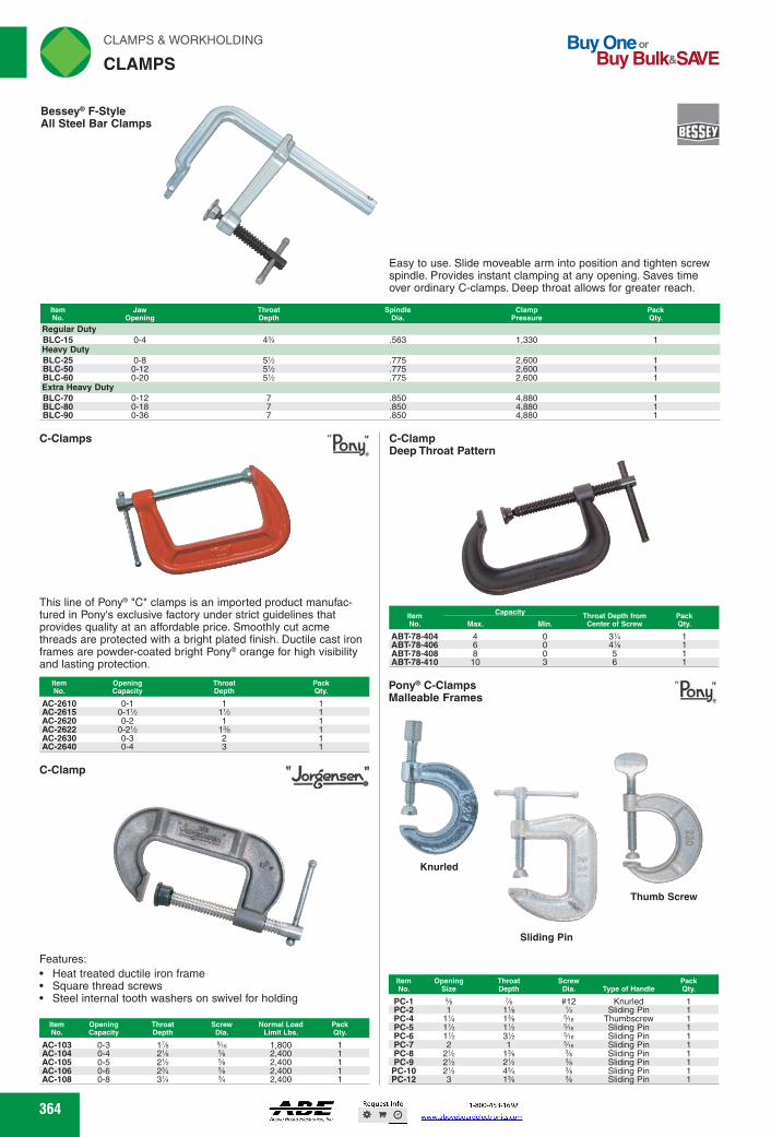
C-Clamps Pony
,
This line of Pony® "C" clamps is an imported product manufac-tured in Pony's exclusive factory under strict guidelines that provides quality at an affordable price. Smoothly cut acme threads are protected with a bright plated finish. Ductile cast iron frames are powder-coated bright Pony® orange for high visibility and lasting protection.
EimlEinmEEEmWMP AC-2610 0-1 AC-2615 0-1% 1% 1 AC-2620 0-2 1 1 AC-2622 0-2% 1% 1 AC-2630 0-3 2 1 AC-2640 0-4 3 1
C-Clamp
Features: • Heat treated ductile iron frame • Square thread screws • Steel internal tooth washers on swivel for holding
Item No.
Opening Capacity
AC-103 0-3 AC-104 0-4 AC-105 0-5 AC-106 0-6 AC-108 0-8
Throat
Screw Normal Load Pack Depth
Dia. Limk Lbs. Qty. 1% Vie 1,800 1 2% % 2,400 1 2% % 2,400 1 2% % 2,400 1 3% % 2,400 1
C-Clamp Deep Throat Pattern
Capacity Throat Depth from Min. Center of Screw
Item No.
Pack Qty. Max.
Pony° C-Clamps Malleable Frames
Knurled
Pony
Thumb Screw
4 6 8 10
0 3% 0 4% 0 5 3 6
ABT-78-404 ABT-78-406 ABT-78-408 ABT-78-410
Sliding Pin
Item Opening Throat Screw Pack No. Size Depth Dia. Type of Handle Qty.
#12 1
1% 1%
1% Vie 1'A
1'A Vie 1'A
3'A Vie 2 1 Vie
2'A 1% 2'A 2% 2'A 49 9/e 3 1%
Knurled Sliding Pin
Thumbscrew Sliding Pin Sliding Pin Sliding Pin Sliding Pin Sliding Pin Sliding Pin Sliding Pin
PC-1 PC-2 PC-4 PC-5 PC-6 PC-7 PC-8 PC-9 PC-10 PC-12
rliN CLAMPS & WORKHOLDING
CLAMPS
Buy One or Buy Bulk&SNE
Besseye F-Style All Steel Bar Clamps
GED
Easy to use. Slide moveable arm into position and tighten screw spindle. Provides instant clamping at any opening. Saves time over ordinary C-clamps. Deep throat allows for greater reach.
Item No.
Jaw Opening
Throat Depth
Spindle Dia.
Clamp Pack Pressure Qty.
Regular Duty BLC-15 0-4 4% .563 1,330 Heavy Duty BLC-25 0-8 5% .775 2,600 BLC-50 0-12 5% .775 2,600 BLC-60 0-20 5% .775 2,600 Extra Heavy Duty BLC-70 0-12 7 .850 4,880 BLC-80 0-18 7 .850 4,880 BLC-9O 0-36 7 .850 4,880
364 364
C-Clamps
This line of Pony® "C" clamps is an imported product manufac-tured in Pony's exclusive factory under strict guidelines that provides quality at an affordable price. Smoothly cut acme threads are protected with a bright plated finish. Ductile cast iron frames are powder-coated bright Pony® orange for high visibility and lasting protection.
ItemNo.
OpeningCapacity
ThroatDepth
PackQty.
AC-2610 0-1 1 1AC-2615 0-11⁄2 11⁄2 1AC-2620 0-2 1 1AC-2622 0-21⁄2 13⁄8 1AC-2630 0-3 2 1AC-2640 0-4 3 1
C-Clamp
ItemNo.
OpeningCapacity
ThroatDepth
ScrewDia.
Normal LoadLimit Lbs.
PackQty.
AC-103 0-3 17⁄8 9⁄16 1,800 1AC-104 0-4 21⁄8 5⁄8 2,400 1AC-105 0-5 21⁄2 5⁄8 2,400 1AC-106 0-6 23⁄4 5⁄8 2,400 1AC-108 0-8 31⁄4 3⁄4 2,400 1
C-ClampDeep Throat Pattern
ItemNo.
Capacity Throat Depth fromCenter of Screw
PackQty.Max. Min.
ABT-78-404 4 0 31⁄4 1ABT-78-406 6 0 41⁄8 1ABT-78-408 8 0 5 1ABT-78-410 10 3 6 1
Pony® C-ClampsMalleable Frames
Thumb Screw
Sliding Pin
Knurled
ItemNo.
OpeningSize
ThroatDepth
ScrewDia. Type of Handle
PackQty.
PC-1 5⁄8 7⁄8 #12 Knurled 1PC-2 1 11⁄8 1⁄4 Sliding Pin 1PC-4 11⁄4 13⁄8 5⁄16 Thumbscrew 1PC-5 11⁄2 11⁄2 5⁄16 Sliding Pin 1PC-6 11⁄2 31⁄2 5⁄16 Sliding Pin 1PC-7 2 1 5⁄16 Sliding Pin 1PC-8 21⁄2 13⁄8 3⁄8 Sliding Pin 1PC-9 21⁄2 21⁄2 3⁄8 Sliding Pin 1PC-10 21⁄2 43⁄4 3⁄8 Sliding Pin 1PC-12 3 13⁄8 3⁄8 Sliding Pin 1
Bessey® F-StyleAll Steel Bar Clamps
Easy to use. Slide moveable arm into position and tighten screw spindle. Provides instant clamping at any opening. Saves time over ordinary C-clamps. Deep throat allows for greater reach.
ItemNo.
JawOpening
ThroatDepth
SpindleDia.
ClampPressure
PackQty.
Regular DutyBLC-15 0-4 43⁄4 .563 1,330 1Heavy DutyBLC-25 0-8 51⁄2 .775 2,600 1BLC-50 0-12 51⁄2 .775 2,600 1BLC-60 0-20 51⁄2 .775 2,600 1Extra Heavy DutyBLC-70 0-12 7 .850 4,880 1BLC-80 0-18 7 .850 4,880 1BLC-90 0-36 7 .850 4,880 1
Features:Heat treated ductile iron frameSquare thread screwsSteel internal tooth washers on swivel for holding
CLAMPS
FWAHL
SmallO

EMM .1.11FM
1% KT-410-8 3 KT-415-8 4% 2%
T-Handle
1% KT-510 3 5 5% 1% 1,200 KT-515 4% 2% 6% 7 2% 1,500
Clamps T-Handle and L-Handle - Copper Plated Jaws
L-Handle
T-Handle L-Handle Item Item No. No.
Max. A
Max. Rated Pack Load Qty.
KT-401 — 1%e 1% 2% % 350 KT-405 KT-405-L 2 1% 3% 3% 1% 800 KT-407 KT-407-L 27/le 2 4%e 4% 1'%e 700 KT-410 KT-410-L 3 1% 5 5% 1% 1,500 KT-415 KT-415-L 2% 6% 7 2% 1,700 KT-420 — 6 2% 8% 8% 3% 2,000 KT-421 — 6 4% 10 11 5% 2,000 KT-430 — 9 3% 13 12 5% 2,500 KT-435 — 10 6 15 16 7 3,500
Clamps T-Handle - 303 Stainless Steel
Item Max. Max. Rated Pack No. A B C D E Load City.
Clamps Round Handle - Copper Plated Jaws
Item No.
Max. A
Max. C D E
Rated Pack Load Qty.
KT-396 % 1% 1% spy 200 KT-401-1 1%e 1% 2% 350 KT-405-1 2 1% 3% 3% 1% 800
Clamps T-Handle - Polyurethane Jaws
.44N, v. •
Item Max. Max. B
Rated Pack No. A Load Qty.
5 5% 1% 1,500 6% 7 2% 1,700
Clamp Accessories Handle Grips
GED Iccc=)) For use with T-handle clamps. Made of high quality ABS plastic. Taps easily on and off.
KT-1 % 1% 401 1 KT-2 Wie 2% 405, 407 1 KT-3 % 4 410, 415, 510, 515 1 KT-6 1% 5 420, 421 1
CLAMPS & WORKHOLDING riliN
CLAMPS ._„,
The Kant-Twist® multi-purpose clamps combine the best features of ordinary C-clamps and parallel clamps. Lightweight, yet 40% stronger than C-clamps. Designed to eliminate distorting or twist-ing action and the floating jaws always stay parallel. Built-in V-blocks for round stock. Copper plated jaws and screws are ideal for welding clamps.
Quick Acting Hold Down Clamps
For holding where thickness and surface are not exact from part to part. Offers quick-set and release with adjustable pressure after clamping. High tensile strength. Can be bolted or welded down or T-Slot can be used for milling tables. KT-411 and KT-423 do not come with a base plate. KT-411-2 and KT-423-1 come with a T-Slot base and bolt.
Rated Item Load Pack No. A B C D E Lbs. City.
KT-411-2 T-Slot 2% 2% 4% KT-423 2%o 2% 3% 3% 6%
KT-423-1 T-Slot 3% 4 7%
KT-411 1%o 1% 2% 2% 4 1,500 1,500 3,200 3,200
365 365
The Kant-Twist® multi-purpose clamps combine the best features of ordinary C-clamps and parallel clamps. Lightweight, yet 40% stronger than C-clamps. Designed to eliminate distorting or twist-ing action and the floating jaws always stay parallel. Built-in V-blocks for round stock. Copper plated jaws and screws are ideal for welding clamps.
ClampsRound Handle - Copper Plated Jaws
DE
AB
C
ItemNo.
Max.A
Max.B C D E
RatedLoad
PackQty.
KT-396 3⁄4 3⁄8 13⁄8 11⁄2 3⁄8 200 1KT-401-1 11⁄16 1⁄2 13⁄4 21⁄8 1⁄2 350 1KT-405-1 2 11⁄8 31⁄4 31⁄2 11⁄4 800 1
ClampsT-Handle and L-Handle - Copper Plated Jaws
T-Handle L-Handle
Max.A
Max.B C D E
RatedLoad
PackQty.
ItemNo.
ItemNo.
KT-401 — 11⁄16 1⁄2 13⁄4 21⁄8 1⁄2 350 1KT-405 KT-405-L 2 11⁄8 31⁄4 31⁄2 11⁄4 800 1KT-407 KT-407-L 27⁄16 2 41⁄16 41⁄8 113⁄16 700 1KT-410 KT-410-L 3 11⁄4 5 51⁄4 13⁄4 1,500 1KT-415 KT-415-L 41⁄2 21⁄4 63⁄4 7 21⁄2 1,700 1KT-420 — 6 21⁄8 81⁄4 81⁄4 33⁄8 2,000 1KT-421 — 6 41⁄2 10 11 51⁄2 2,000 1KT-430 — 9 33⁄8 13 12 51⁄4 2,500 1KT-435 — 10 6 15 16 7 3,500 1
ClampsT-Handle - Polyurethane Jaws
ItemNo.
Max.A
Max.B C D E
RatedLoad
PackQty.
KT-410-8 3 11⁄4 5 51⁄4 13⁄4 1,500 1KT-415-8 41⁄2 21⁄4 63⁄4 7 21⁄2 1,700 1
ClampsT-Handle - 303 Stainless Steel
ItemNo.
Max.A
Max.B C D E
RatedLoad
PackQty.
KT-510 3 11⁄4 5 51⁄4 13⁄4 1,200 1KT-515 41⁄2 21⁄2 63⁄4 7 21⁄2 1,500 1
Clamp AccessoriesHandle Grips
A
B
For use with T-handle clamps. Made of high quality ABS plastic. Taps easily on and off.
L-Handle
T-Handle
Quick Acting Hold Down Clamps
For holding where thickness and surface are not exact from part to part. Offers quick-set and release with adjustable pressure after clamping. High tensile strength. Can be bolted or welded down or T-Slot can be used for milling tables. KT-411 and KT-423 do not come with a base plate. KT-411-2 and KT-423-1 come with a T-Slot base and bolt.
ItemNo. A B C D E
RatedLoad Lbs.
PackQty.
KT-411 19⁄10 11⁄2 211⁄16 21⁄4 4 1,500 1KT-411-2 T-Slot — 211⁄16 21⁄4 41⁄8 1,500 1KT-423 29⁄10 25⁄8 33⁄4 33⁄4 67⁄8 3,200 1
KT-423-1 T-Slot — 33⁄4 4 71⁄4 3,200 1
ItemNo. A B For Use With Models
PackQty.
KT-1 1⁄2 11⁄2 401 1KT-2 11⁄16 21⁄2 405, 407 1KT-3 7⁄8 4 410, 415, 510, 515 1KT-6 11⁄8 5 420, 421 1
CLAMPS
FWAHL
SmallO
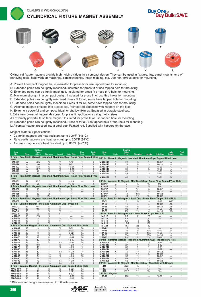
rli N CLAMPS & WORKHOLDING
CYLINDRICAL FIXTURE MAGNET ASSEMBLY Buy One or
Buy Bulk&SIO/E
A B C D
E F
G H I J K L Cylindrical fixture magnets provide high holding values in a compact design. They can be used in fixtures, jigs, panel mounts, end of retrieving tools, hold work on machines, catches/latches, insert molding, etc. Use non-ferrous bolts for mounting.
A: Powerful compact magnet that is insulated for press fit or use tapped hole for mounting. B: Extended poles can be lightly machined. Insulated for press fit or use tapped hole for mounting. C: Extended poles can be lightly machined. Insulated for press fit or use thru-hole for mounting. D: Maximum strength in a compact design. Insulated for press fit or use thru-holes for mounting. E: Extended poles can be lightly machined. Press fit for all, some have tapped hole for mounting. F: Extended poles can be lightly machined. Press fit for all, some have tapped hole for mounting. G: Alcomax magnet pressed into a steel cup. Painted red. Supplied with keepers on the face. H: Extremely powerful and compact. Ideal for shallow fixtures. Encased in durable steel cup. I: Extremely powerful magnet designed for press fit applications using metric sizes. J: Extremely powerful flush face magnet. Insulated for press fit or use tapped hole for mounting. K: Extended poles can be lightly machined. Press fit for all, use tapped hole or thru-hole for mounting. L: Alcomax magnet pressed into a steel cup. Painted red. Supplied with keepers on the face.
Magnet Material Specifications: • Ceramic magnets are heat resistant up to 300°F (148°C) • Rare earth magnets are heat resistant up to 200°F (94°C) • Alcomax magnets are heat resistant up to 800°F (427°C)
Hole Depth
Pack item Qty. No. Style
Holding Value (Lbs.) Diameter Length Hole Size
Hole Pack Depth Qty.
Holding item Value No. Style (Lbs.) Diameter Length Hole Size
1 Pole - Rare Earth Magnet - insulated Aluminum Cup -Press Fit or Tapped Blind 3 Pole - Ceramic Magnet - insulated Aluminum Cup -Tapped Blind Hole Hole IM-125 A 0.5 % % 6-32 % 1 MAG-110 F 23 % 1 10-32 3Ae IM-126 A 2.6 % % 8-32 % 1 MAG-112 F 24 % 1% 10-32 3Ae IM-127 A 5.3 'h 'h 10-24 % 1 MAG-114 F 10 1 % %-20 3Ae IM-128 A 8.7 % % 10-24 % 1 MAG-116 F 32 1 % %-20 3Ae IM-129 A 12 % % 10-24 % 1 MAG-118 F 42 1 1 %-20 % IM-130 A 15 1 % %-20 A 1 MAG-120 F 43 1 1% %-20 %
3 Pole - Rare Earth Magnet - insulated Aluminum Cup - Press Fit or Tapped Thru MAG-122 F Hole 45 1 1% %-20 %
IM-131 B 15.5 1 % %-20 — 1 2 Pole - Alcomax ill Magnet - Mild Steel Cup - Press Fit or Tapped Thru Hole IM-132 B 26 1% % 343-18 — 1 829NF G 2 % lem M3 — 1
4 Pole - Rare Earth Magnet - insulated Aluminum Cup - Press Fit or Thru Hole 830NF G 4 % % M4 — 1 IM-133 C 45 2 % % — 1 831NF G 6 "Ae % 10-32 1 IM-134 C 50 2 % % — 1 832NF G 9 '%e % 10-32 1 IM-135 C 60 2 1 % — 1 833NF G 14 1'/e 1 10-32 — 1 IM-136 C 90 2% 1 % — 1 834NF G 44 1% '%e 10-32 — 1
3 Pole - Rare Earth Magnet - insulated Aluminum Cup - Press Fit or Thru Hole 2 Pole - Rare Earth Magnet - Steel Cup - Press Fit or Tapped Blind Hole IM-137 D 145 3 1 % — 1 IM-61 H 6 % % 8-32 .085 1
2 Pole - Ceramic Magnet - insulated Aluminum Cup - Press Fit IM-63 H 16 % % 10-32 .15 1 MAG-2 E 0.4 % % 1 IM-65 H 44 % % 10-32 .15 1 MAG-4 E 0.5 % % 1 IM-67 H 92 1
IM-69 H 102 1% % %e-18 % %-20 .15 1
MAG-6 E 1 % % 1 2 Pole - Rare Earth Magnet - insulated Brass Cup - Press Fit
.15 1 MAG-8 E 2 % % 1
MAG-10 E 2.5 % 1 1 IM-316 I 0.9 6 20 — 1 MAG-12 E 3 % % 1 IM-317 I 4.4 10 20 — 1 MAG-14 E 4 % % — — 1 IM-318 I 6.6 13 20 1 MAG-16 E 5 % 1 — — 1 IM-319 I 13.8 16 20 1
2 Pole - Ceramic Magnet - insulated Aluminum Cup -Tapped Blind Hole IM-321 I 44.1 25 30 — — 1 MAG-62 E 3 % % 8-32 %e 1 IM-71 J 12 % % — — 1 MAG-64 E 7 % % 8-32 %e 1 IM-75 J 36 % 13/e 1/4-20 % 1 MAG-66 E 8 % 1 8-32 %e 1 IM-77 J 86 1 13Ae Y.-20 5/18 1 MAG-68 E 4 3/ % 10-32 %e 1 IM-81 J 204 1% 2%e Me-18 3Ae 1 MAG-70 E 12 % % 10-32 %e 1 IM-83 J 344 2 2% %-16 5/le 1 MAG-72 E 17 % 1 10-32 3Ae 1 3 Pole - Ceramic Magnet - insulated Aluminum Cup -Tapped Thru Hole MAG-74 E 20 % 1% 10-32 3Ae 1 MAG-208 K 10 1 % 8-32 — 1 MAG-76 E 3.3 1 % %-20 % 1 MAG-210 K 27 1 % 8-32 — 1 MAG-78 E 15 1 % %-20 % 1 MAG-212 K 30 1 1 8-32 1 MAG-80 E 23 1 1 %-20 % 1 MAG-214 K 33 1 1% 8-32 1 MAG-84 E 32 1 1% %-20 % 1 MAG-218 K 10 1% % 10-32 1 MAG-86 E 10 1% % %-20 3Ae 1 MAG-220 K 33 1% % 10-32 1 MAG-88 E 24 1% % %-20 3Ae 1 MAG-222 K 50 1% 1 10-32 — 1 MAG-90 E 32 1% 1 %-20 % 1 MAG-224 K 61 1% 1% 10-32 — 1 MAG-92 E 40 1% 1% %-20 % 1 MAG-226 K 66 1% 1% 10-32 — 1 MAG-94 E 48 1% 1% 1/4-20 % 1 2 Pole - Alcomax ill Magnet - Mild Steel Cup -Thru Hole with Keeper
3 Pole - Ceramic Magnet - insulated Aluminum Cup -Tapped Blind Hole 826 L 6.61 % 3Ae V32 - 1 MAG-100 F 8 % % 8-32 %e 1 827 L 11 1% '% 13,6, 1 MAG-102 F 13 % % 8-32 %e 1 828 L 28.7 1% lem leA, 1 MAG-104 F 14 % 1 8-32 3Ae 1 2 Pole - Magnet MAG-106 F 10 % % 10-32 3Ae 1 IM-79 J 120 1% %-20 Vie 1 MAG-108 F 18 % % 10-32 3Ae 1
* Diameter and Length are measured in millimeters (mm)
366
E
Cylindrical fixture magnets provide high holding values in a compact design. They can be used in fixtures, jigs, panel mounts, end of retrieving tools, hold work on machines, catches/latches, insert molding, etc. Use non-ferrous bolts for mounting.
K
F
JH I
DCBA
G L
* Diameter and Length are measured in millimeters (mm)
ItemNo. Style
HoldingValue(Lbs.) Diameter Length Hole Size
HoleDepth
PackQty.
ItemNo. Style
HoldingValue(Lbs.) Diameter Length Hole Size
HoleDepth
PackQty.
1 Pole - Rare Earth Magnet - Insulated Aluminum Cup - Press Fit or Tapped Blind Hole 3 Pole - Ceramic Magnet - Insulated Aluminum Cup - Tapped Blind Hole
IM-125 A 0.5 1⁄4 1⁄2 6-32 1⁄4 1 MAG-110 F 23 3⁄4 1 10-32 3⁄16 1IM-126 A 2.6 3⁄8 1⁄2 8-32 1⁄4 1 MAG-112 F 24 3⁄4 11⁄4 10-32 3⁄16 1IM-127 A 5.3 1⁄2 1⁄2 10-24 1⁄4 1 MAG-114 F 10 1 1⁄2 1⁄4-20 3⁄16 1IM-128 A 8.7 5⁄8 1⁄2 10-24 1⁄4 1 MAG-116 F 32 1 3⁄4 1⁄4-20 3⁄16 1IM-129 A 12 3⁄4 1⁄2 10-24 1⁄4 1 MAG-118 F 42 1 1 1⁄4-20 1⁄4 1IM-130 A 15 1 1⁄2 1⁄4-20 1⁄4 1 MAG-120 F 43 1 11⁄4 1⁄4-20 1⁄4 1
3 Pole - Rare Earth Magnet - Insulated Aluminum Cup - Press Fit or Tapped Thru Hole MAG-122 F 45 1 11⁄2 1⁄4-20 1⁄4 1
IM-131 B 15.5 1 3⁄4 1⁄4-20 — 1 2 Pole - Alcomax III Magnet - Mild Steel Cup - Press Fit or Tapped Thru HoleIM-132 B 26 11⁄4 3⁄4 5⁄16-18 — 1 829NF G 2 3⁄8 19⁄32 M3 — 1
4 Pole - Rare Earth Magnet - Insulated Aluminum Cup - Press Fit or Thru Hole 830NF G 4 1⁄2 5⁄8 M4 — 1IM-133 C 45 2 1⁄2 1⁄4 — 1 831NF G 6 11⁄16 5⁄8 10-32 — 1IM-134 C 50 2 3⁄4 1⁄4 — 1 832NF G 9 13⁄16 3⁄4 10-32 — 1IM-135 C 60 2 1 1⁄4 — 1 833NF G 14 11⁄16 1 10-32 — 1IM-136 C 90 21⁄2 1 1⁄4 — 1 834NF G 44 13⁄8 13⁄16 10-32 — 1
3 Pole - Rare Earth Magnet - Insulated Aluminum Cup - Press Fit or Thru Hole 2 Pole - Rare Earth Magnet - Steel Cup - Press Fit or Tapped Blind HoleIM-137 D 145 3 1 1⁄4 — 1 IM-61 H 6 3⁄8 1⁄2 8-32 .085 1
2 Pole - Ceramic Magnet - Insulated Aluminum Cup - Press Fit IM-63 H 16 1⁄2 1⁄2 10-32 .15 1MAG-2 E 0.4 1⁄4 1⁄2 — — 1 IM-65 H 44 3⁄4 1⁄2 10-32 .15 1MAG-4 E 0.5 1⁄4 3⁄4 — — 1 IM-67 H 92 1 1⁄2 1⁄4-20 .15 1MAG-6 E 1 3⁄8 1⁄2 — — 1 IM-69 H 102 11⁄4 1⁄2 5⁄16-18 .15 1MAG-8 E 2 3⁄8 3⁄4 — — 1 2 Pole - Rare Earth Magnet - Insulated Brass Cup - Press Fit
MAG-10 E 2.5 3⁄8 1 — — 1 IM-316 I 0.9 6 20 — — 1MAG-12 E 3 1⁄2 1⁄2 — — 1 IM-317 I 4.4 10 20 — — 1MAG-14 E 4 1⁄2 3⁄4 — — 1 IM-318 I 6.6 13 20 — — 1MAG-16 E 5 1⁄2 1 — — 1 IM-319 I 13.8 16 20 — — 1
2 Pole - Ceramic Magnet - Insulated Aluminum Cup - Tapped Blind Hole IM-321 I 44.1 25 30 — — 1MAG-62 E 3 5⁄8 1⁄2 8-32 3⁄16 1 IM-71 J 12 1⁄2 1⁄2 — — 1MAG-64 E 7 5⁄8 3⁄4 8-32 3⁄16 1 IM-75 J 36 3⁄4 13⁄16 1⁄4-20 1⁄4 1MAG-66 E 8 5⁄8 1 8-32 3⁄16 1 IM-77 J 86 1 15⁄16 1⁄4-20 5⁄16 1MAG-68 E 4 3⁄4 1⁄2 10-32 3⁄16 1 IM-81 J 204 11⁄2 21⁄16 5⁄16-18 5⁄16 1MAG-70 E 12 3⁄4 3⁄4 10-32 3⁄16 1 IM-83 J 344 2 27⁄8 3⁄8-16 5⁄16 1MAG-72 E 17 3⁄4 1 10-32 3⁄16 1 3 Pole - Ceramic Magnet - Insulated Aluminum Cup - Tapped Thru HoleMAG-74 E 20 3⁄4 11⁄4 10-32 3⁄16 1 MAG-208 K 10 1 1⁄2 8-32 — 1MAG-76 E 3.3 1 1⁄2 1⁄4-20 1⁄4 1 MAG-210 K 27 1 3⁄4 8-32 — 1MAG-78 E 15 1 3⁄4 1⁄4-20 1⁄4 1 MAG-212 K 30 1 1 8-32 — 1MAG-80 E 23 1 1 1⁄4-20 1⁄4 1 MAG-214 K 33 1 11⁄4 8-32 — 1MAG-84 E 32 1 11⁄2 1⁄4-20 1⁄4 1 MAG-218 K 10 11⁄4 1⁄2 10-32 — 1MAG-86 E 10 11⁄4 1⁄2 1⁄4-20 3⁄16 1 MAG-220 K 33 11⁄4 3⁄4 10-32 — 1MAG-88 E 24 11⁄4 3⁄4 1⁄4-20 3⁄16 1 MAG-222 K 50 11⁄4 1 10-32 — 1MAG-90 E 32 11⁄4 1 1⁄4-20 1⁄4 1 MAG-224 K 61 11⁄4 11⁄4 10-32 — 1MAG-92 E 40 11⁄4 11⁄4 1⁄4-20 1⁄4 1 MAG-226 K 66 11⁄4 11⁄2 10-32 — 1MAG-94 E 48 11⁄4 11⁄2 1⁄4-20 1⁄4 1 2 Pole - Alcomax III Magnet - Mild Steel Cup - Thru Hole with Keeper
3 Pole - Ceramic Magnet - Insulated Aluminum Cup - Tapped Blind Hole 826 L 6.61 3⁄4 5⁄16 5⁄32 — 1MAG-100 F 8 5⁄8 1⁄2 8-32 3⁄16 1 827 L 11 11⁄8 11⁄32 13⁄64 — 1MAG-102 F 13 5⁄8 3⁄4 8-32 3⁄16 1 828 L 28.7 11⁄2 13⁄32 16⁄64 — 1MAG-104 F 14 5⁄8 1 8-32 3⁄16 1 2 Pole - MagnetMAG-106 F 10 3⁄4 1⁄2 10-32 3⁄16 1 IM-79 J 120 11⁄4 — 1⁄4-20 5⁄16 1MAG-108 F 18 3⁄4 3⁄4 10-32 3⁄16 1
CYLINDRICAL FIXTURE MAGNET ASSEMBLY
A: Powerful compact magnet that is insulated for press fit or use tapped hole for mounting. B: Extended poles can be lightly machined. Insulated for press fit or use tapped hole for mounting. C: Extended poles can be lightly machined. Insulated for press fit or use thru-hole for mounting. D: Maximum strength in a compact design. Insulated for press fit or use thru-holes for mounting. E: Extended poles can be lightly machined. Press fit for all, some have tapped hole for mounting. F: Extended poles can be lightly machined. Press fit for all, some have tapped hole for mounting. G: Alcomax magnet pressed into a steel cup. Painted red. Supplied with keepers on the face. H: Extremely powerful and compact. Ideal for shallow fixtures. Encased in durable steel cup. I: Extremely powerful magnet designed for press fit applications using metric sizes. J: Extremely powerful flush face magnet. Insulated for press fit or use tapped hole for mounting. K: Extended poles can be lightly machined. Press fit for all, use tapped hole or thru-hole for mounting. L: Alcomax magnet pressed into a steel cup. Painted red. Supplied with keepers on the face.
Magnet Material Specifications:Ceramic magnets are heat resistant up to 300°F (148°C)Rare earth magnets are heat resistant up to 200°F (94°C)Alcomax magnets are heat resistant up to 800°F (427°C)
FWAHL
SmallO
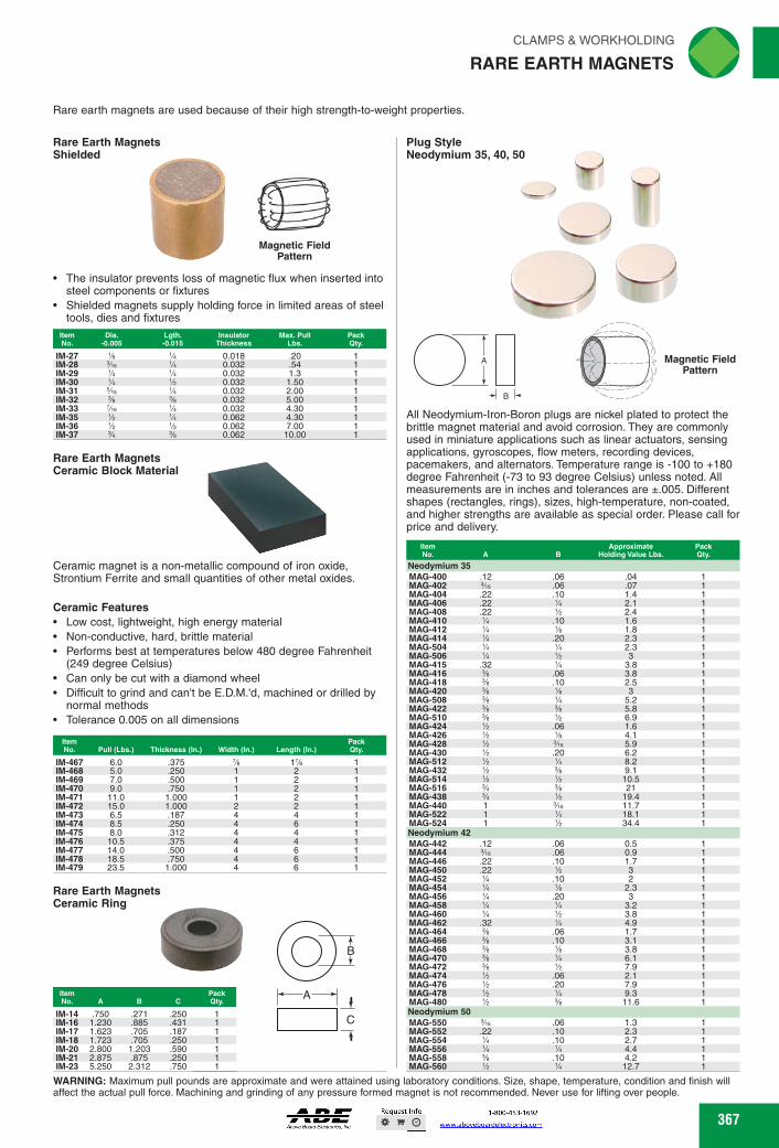
Rare Earth Magnets Ceramic Ring
CLAMPS & WORKHOLDING rliN
RARE EARTH MAGNETS ._41
Rare earth magnets are used because of their high strength-to-weight properties.
Rare Earth Magnets Shielded
Magnetic Field Pattern
• The insulator prevents loss of magnetic flux when inserted into steel components or fixtures
• Shielded magnets supply holding force in limited areas of steel tools, dies and fixtures
Item Dia. Lgth. Insulator Max. Pull Pack No. -0.005 -0.015 Thickness Lbs. Qty.
IM-27 Ye 0.018 .20 IM-28 %e 0.032 .54 IM-29 0.032 1.3 IM-30 0.032 1.50 IM-31 5/16 0.032 2.00 IM-32 spy spy 0.032 5.00 IM-33 Yie 0.032 4.30 IM-35 0.062 4.30 IM-36 0.062 7.00 IM-37 spy 0.062 10.00
Rare Earth Magnets Ceramic Block Material
Ceramic magnet is a non-metallic compound of iron oxide, Strontium Ferrite and small quantities of other metal oxides.
Ceramic Features • Low cost, lightweight, high energy material • Non-conductive, hard, brittle material • Performs best at temperatures below 480 degree Fahrenheit
(249 degree Celsius) • Can only be cut with a diamond wheel • Difficult to grind and can't be E.D.M.'d, machined or drilled by
normal methods • Tolerance 0.005 on all dimensions
Item No. Pull (Lbs.) Thickness (In.) Width (In.)
Pack Length (In.) Qty.
IM-467 6.0 .375 1% IM-468 5.0 .250 2 IM-469 7.0 .500 2 IM-470 9.0 .750 2 IM-471 11.0 1.000 2 IM-472 15.0 1.000 2 2 IM-473 6.5 .187 4 4 IM-474 8.5 .250 4 6 IM-475 8.0 .312 4 4 IM-476 10.5 .375 4 4 IM-477 14.0 .500 4 6 IM-478 18.5 .750 4 6 IM-479 23.5 1.000 4 6
Item No. A B C
Pack Qty.
IM-14 IM-16
.750 1.230
.271
.885 .250 .431 C
IM-17 1.623 .705 .187 IM-18 1.723 .705 .250 IM-20 2.800 1.203 .590 IM-21 2.875 .875 .250 IM-23 5.250 2.312 .750
Plug Style Neodymium 35, 40, 50
)) z Magnetic Field )) Pattern
B _ _ -
All Neodymium-Iron-Boron plugs are nickel plated to protect the brittle magnet material and avoid corrosion. They are commonly used in miniature applications such as linear actuators, sensing applications, gyroscopes, flow meters, recording devices, pacemakers, and alternators. Temperature range is -100 to +180 degree Fahrenheit (-73 to 93 degree Celsius) unless noted. All measurements are in inches and tolerances are ±.005. Different shapes (rectangles, rings), sizes, high-temperature, non-coated, and higher strengths are available as special order. Please call for price and delivery.
Item No. A B
Approximate Hokling Value Lbs.
Pack City.
Neodymium 35 MAG-400 .12 .06 .04 1 MAG-402 %e .06 .07 1 MAG-404 .22 .10 1.4 1 MAG-406 .22 2.1 1 MAG-408 .22 2.4 1 MAG-410 .10 1.6 1 MAG-412 1.8 1 MAG-414 .20 2.3 1 MAG-504 2.3 1 MAG-506 3 1 MAG-415 .32 'A 3.8 1 MAG-416 sib .06 3.8 1 MAG-418 sib .10 2.5 1 MAG-420 sib 3 1 MAG-508 sib 'A 5.2 1 MAG-422 sib sb 5.8 1 MAG-510 sib 6.9 1 MAG-424 .06 1.6 1 MAG-426 4.1 1 MAG-428 %e 5.9 1 MAG-430 .20 6.2 1 MAG-512 'A 8.2 1 MAG-432 sb 9.1 1 MAG-514 10.5 1 MAG-516 sb 21 1 MAG-438 19.4 1 MAG-440 1 %e 11.7 1 MAG-522 1 'A 18.1 1 MAG-524 1 34.4 1 Neodymium 42 MAG-442 .12 .06 0.5 1 MAG-444 3/113 .06 0.9 1 MAG-446 .22 .10 1.7 1 MAG-450 .22 % 3 1 MAG-452 % .10 2 1 MAG-454 % % 2.3 1 MAG-456 % .20 3 1 MAG-458 % % 3.2 1 MAG-460 % % 3.8 1 MAG-462 .32 % 4.9 1 MAG-464 % .06 1.7 1 MAG-466 % .10 3.1 1 MAG-468 % % 3.8 1 MAG-470 % % 6.1 1 MAG-472 % % 7.9 1 MAG-474 % .06 2.1 1 MAG-476 % .20 7.9 1 MAG-478 % % 9.3 1 MAG-480 % % 11.6 1 Neodymium 50 MAG-550 %e .06 1.3 1 MAG-552 .22 .10 2.3 1 MAG-554 .10 2.7 1 MAG-556 4.4 1 MAG-558 sib .10 4.2 1 MAG-560 12.7 1
WARNING: Maximum pull pounds are approximate and were attained using laboratory conditions. Size, shape, temperature, condition and finish will affect the actual pull force. Machining and grinding of any pressure formed magnet is not recommended. Never use for lifting over people.
367 367
The insulator prevents loss of magnetic flux when inserted into steel components or fixturesShielded magnets supply holding force in limited areas of steel tools, dies and fixtures
ItemNo.
Dia.-0.005
Lgth.-0.015
InsulatorThickness
Max. PullLbs.
PackQty.
IM-27 1⁄8 1⁄4 0.018 .20 1IM-28 3⁄16 1⁄4 0.032 .54 1IM-29 1⁄4 1⁄4 0.032 1.3 1IM-30 1⁄4 1⁄2 0.032 1.50 1IM-31 5⁄16 1⁄4 0.032 2.00 1IM-32 3⁄8 3⁄8 0.032 5.00 1IM-33 7⁄16 1⁄4 0.032 4.30 1IM-35 1⁄2 1⁄4 0.062 4.30 1IM-36 1⁄2 1⁄2 0.062 7.00 1IM-37 3⁄4 3⁄8 0.062 10.00 1
Rare Earth MagnetsShielded
Magnetic Field Pattern
Ceramic magnet is a non-metallic compound of iron oxide, Strontium Ferrite and small quantities of other metal oxides.
Ceramic FeaturesLow cost, lightweight, high energy materialNon-conductive, hard, brittle materialPerforms best at temperatures below 480 degree Fahrenheit (249 degree Celsius)Can only be cut with a diamond wheelDifficult to grind and can't be E.D.M.'d, machined or drilled by normal methodsTolerance 0.005 on all dimensions
ItemNo. Pull (Lbs.) Thickness (In.) Width (In.) Length (In.)
PackQty.
IM-467 6.0 .375 7⁄8 17⁄8 1IM-468 5.0 .250 1 2 1IM-469 7.0 .500 1 2 1IM-470 9.0 .750 1 2 1IM-471 11.0 1.000 1 2 1IM-472 15.0 1.000 2 2 1IM-473 6.5 .187 4 4 1IM-474 8.5 .250 4 6 1IM-475 8.0 .312 4 4 1IM-476 10.5 .375 4 4 1IM-477 14.0 .500 4 6 1IM-478 18.5 .750 4 6 1IM-479 23.5 1.000 4 6 1
Rare Earth MagnetsCeramic Block Material
ItemNo. A B C
PackQty.
IM-14 .750 .271 .250 1IM-16 1.230 .885 .431 1IM-17 1.623 .705 .187 1IM-18 1.723 .705 .250 1IM-20 2.800 1.203 .590 1IM-21 2.875 .875 .250 1IM-23 5.250 2.312 .750 1
Rare Earth MagnetsCeramic Ring
A
C
B
All Neodymium-Iron-Boron plugs are nickel plated to protect the brittle magnet material and avoid corrosion. They are commonly used in miniature applications such as linear actuators, sensing applications, gyroscopes, flow meters, recording devices, pacemakers, and alternators. Temperature range is -100 to +180 degree Fahrenheit (-73 to 93 degree Celsius) unless noted. All measurements are in inches and tolerances are ±.005. Different shapes (rectangles, rings), sizes, high-temperature, non-coated, and higher strengths are available as special order. Please call for price and delivery.
Rare earth magnets are used because of their high strength-to-weight properties.
Plug Style Neodymium 35, 40, 50
Magnetic Field Pattern
A
B
ItemNo. A B
ApproximateHolding Value Lbs.
PackQty.
Neodymium 35MAG-400 .12 .06 .04 1MAG-402 3⁄16 .06 .07 1MAG-404 .22 .10 1.4 1MAG-406 .22 1⁄4 2.1 1MAG-408 .22 1⁄2 2.4 1MAG-410 1⁄4 .10 1.6 1MAG-412 1⁄4 1⁄8 1.8 1MAG-414 1⁄4 .20 2.3 1MAG-504 1⁄4 1⁄4 2.3 1MAG-506 1⁄4 1⁄2 3 1MAG-415 .32 1⁄4 3.8 1MAG-416 3⁄8 .06 3.8 1MAG-418 3⁄8 .10 2.5 1MAG-420 3⁄8 1⁄8 3 1MAG-508 3⁄8 1⁄4 5.2 1MAG-422 3⁄8 3⁄8 5.8 1MAG-510 3⁄8 1⁄2 6.9 1MAG-424 1⁄2 .06 1.6 1MAG-426 1⁄2 1⁄8 4.1 1MAG-428 1⁄2 3⁄16 5.9 1MAG-430 1⁄2 .20 6.2 1MAG-512 1⁄2 1⁄4 8.2 1MAG-432 1⁄2 3⁄8 9.1 1MAG-514 1⁄2 1⁄2 10.5 1MAG-516 3⁄4 3⁄8 21 1MAG-438 3⁄4 1⁄2 19.4 1MAG-440 1 3⁄16 11.7 1MAG-522 1 1⁄4 18.1 1MAG-524 1 1⁄2 34.4 1Neodymium 42MAG-442 .12 .06 0.5 1MAG-444 3⁄16 .06 0.9 1MAG-446 .22 .10 1.7 1MAG-450 .22 1⁄2 3 1MAG-452 1⁄4 .10 2 1MAG-454 1⁄4 1⁄8 2.3 1MAG-456 1⁄4 .20 3 1MAG-458 1⁄4 1⁄4 3.2 1MAG-460 1⁄4 1⁄2 3.8 1MAG-462 .32 1⁄4 4.9 1MAG-464 3⁄8 .06 1.7 1MAG-466 3⁄8 .10 3.1 1MAG-468 3⁄8 1⁄8 3.8 1MAG-470 3⁄8 1⁄4 6.1 1MAG-472 3⁄8 1⁄2 7.9 1MAG-474 1⁄2 .06 2.1 1MAG-476 1⁄2 .20 7.9 1MAG-478 1⁄2 1⁄4 9.3 1MAG-480 1⁄2 3⁄8 11.6 1Neodymium 50MAG-550 3⁄16 .06 1.3 1MAG-552 .22 .10 2.3 1MAG-554 1⁄4 .10 2.7 1MAG-556 1⁄4 1⁄4 4.4 1MAG-558 3⁄8 .10 4.2 1MAG-560 1⁄2 1⁄4 12.7 1
WARNING: Maximum pull pounds are approximate and were attained using laboratory conditions. Size, shape, temperature, condition and finish will affect the actual pull force. Machining and grinding of any pressure formed magnet is not recommended. Never use for lifting over people.
RARE EARTH MAGNETS
FWAHL
SmallO

C D Item No. A
'A
Supplied with keepers.
B
E801 Me
Pull Pack Lbs. Qty.
3
Side Pole Rotor Cast Alnico 5 and 6
A
Item
Pull Pack No. A
E
Lbs. Qty.
Supplied with keepers.
E821
'A
%az 9h2 ly,,, 1.5 E822
7/s2 Wu Me 4 E825 A
% 'A Me 8 E823
1
7/s2 '%s2 Me 8 E824 1%
Me 'A %2 11
A
E844 Wee E845 137/64 E846 22%. 39/0.1 1%.
1
"ea 1 13A, 1
rliN CLAMPS & WORKHOLDING
ALNICO MAGNET MATERIAL
Buy One., Buy Bulk SAVE
Alnico permanent magnets are made from an alloy of aluminum (Al), nickel (Ni) and cobalt (Co) with iron, and may contain trace amounts of copper (Cu) and/or titanium (Ti). Alcomax is a trade name for magnets made from Alnico materials. Alnico magnets provide good magnetic performance at a reasonable cost compared to rare-earth magnets, which feature a higher strength-to-weight performance at a higher price. Alnico magnets are hard, but brittle and require special machining techniques. Magnetic performance is superior to steel magnets, at a sacrifice of some mechanical strength.
Rod Sintered Alnico 8H
Item
Pack No. A
B
Qty.
MAG-8105 .120 .375 MAG-8106 .124 .250 MAG-8108 .250 .375
E D C
B
Holding item Alnico No. Force Pack No. Grade Poles A BCD E F Lbs. Qty.
MAG-940 Alnico 5
4 .75 .250 1.000 .500 .500 .250
18 MAG-947 Alnico 5 6 .75 .219 1.250 .625 - .250
30
MAG-941 Alnico 6
6 1.25 .375 1.813 .750 .625 .313
50
Pocket Magnet Alnico
Supplied with keeper.
Item
Pull Pack No. A
B C
D
E
Lbs Qty.
E802
1%
Me '
5
Ring Cast Alnico 5 Magnet Material
r
EMEnilM=MigilM MAG-1429 1.00 .750 .500 3.5 1 MAG-1430 1.50 1.125 .750 8.0 1
Item Pack No. A B Qty.
MAG-110-4 .125 4 MAG-120-6 .250 6 MAG-130-6 .375 6 MAG-140-6 .500 6
Shielded Alnico
Non-Magnetic Brass Insulator
A'L ANEW
Used to supply holding force in limited areas of steel tools, dies and fixtures. The shield prevents undue loss of magnetic strength when inserted directly into steel components.
Item
Insulator Max. Pull Pack No. A B Thickness Lbs. Qty.
IM-38
'A IM-39 IM-41
'A IM-45 IM-47
'A IM-49 IM-51 spy
IM-53
3/4 IM-57
'h IM-59
Cylindrical Bar Magnets Alcomax
A B
Minor Magnet Alnico
.1 A )
E
A
IL- D I.
Round Bar Cast Alnico 5
Magnetic Material
.018
.018
.032
.032
.032
.032
.032
.032
.032
.062
.050
.080
.110
.280
.120
.350
.200
.400
.450
.136
D
D T
Button Magnets Alnico
No keepers.
Item
Pack A B Qty.
E805 Wee E806 89/es E807 1Me
Rectangular Bar Magnets Alcomax
No keeper.
C I B
Pack B C Qty.
Power Magnets Alcomax
Pocket Horseshoe Magnet Alnico
(GENERAL)
0
Supplied with keepers.
Item
Pull Pack No. A
B C
D
E
Lbs. Qty.
811 13/m
Me 'hz 10 812 1Me
Me 17 813 1%
Me 23
368
For retrieving small steel parts and screws from hard to reach places.
Item No.
A
GEN-370-1 1 2.25 1
368
ItemNo. A B
PackQty.
MAG-8105 .120 .375 1MAG-8106 .124 .250 1MAG-8108 .250 .375 1
RodSintered Alnico 8H
BA
Alnico permanent magnets are made from an alloy of aluminum (Al), nickel (Ni) and cobalt (Co) with iron, and may contain trace amounts of copper (Cu) and/or titanium (Ti). Alcomax is a trade name for magnets made from Alnico materials. Alnico magnets provide good magnetic performance at a reasonable cost compared to rare-earth magnets, which feature a higher strength-to-weight performance at a higher price. Alnico magnets are hard, but brittle and require special machining techniques. Magnetic performance is superior to steel magnets, at a sacrifice of some mechanical strength.
Side Pole RotorCast Alnico 5 and 6
A
E D C
B
F
Supplied with keepers.
ItemNo.
AlnicoGrade
No.Poles A B C D E F
Holding Force Lbs.
PackQty.
MAG-940 Alnico 5 4 .75 .250 1.000 .500 .500 .250 18 1MAG-947 Alnico 5 6 .75 .219 1.250 .625 — .250 30 1MAG-941 Alnico 6 6 1.25 .375 1.813 .750 .625 .313 50 1
Minor MagnetAlnico
Supplied with keeper.
ItemNo. A B C D
PullLbs.
PackQty.
E801 7⁄8 7⁄16 5⁄16 1⁄4 3 1
Pocket Magnet Alnico
Supplied with keepers.
ItemNo. A B C D E
PullLbs
PackQty.
E802 7⁄8 11⁄8 1 5⁄16 1⁄4 5 1
Button Magnets Alnico
Supplied with keepers.ItemNo. A B C D E
PullLbs.
PackQty.
811 13⁄16 3⁄4 3⁄4 9⁄16 5⁄32 10 1812 19⁄16 1 1 3⁄4 3⁄16 17 1813 13⁄4 13⁄16 13⁄16 7⁄8 3⁄16 23 1
ItemNo. A B C D E
PullLbs.
PackQty.
E821 1⁄2 3⁄8 5⁄32 9⁄32 11⁄64 1.5 1E822 — 1⁄2 7⁄32 11⁄32 3⁄16 4 1E825 7⁄8 3⁄4 1⁄4 1⁄4 3⁄16 8 1E823 1 5⁄8 7⁄32 11⁄32 3⁄16 8 1E824 11⁄4 1 5⁄16 1⁄2 9⁄32 11 1
Power Magnets Alcomax
Ring Cast Alnico 5 Magnet Material
C
AB
ItemNo. A B C
Holding Force Lbs.
2 Poles 1 FacePackQty.
MAG-1429 1.00 .750 .500 3.5 1MAG-1430 1.50 1.125 .750 8.0 1
Round Bar Cast Alnico 5
BA
ItemNo. A B
PackQty.
MAG-110-4 .125 4 1MAG-120-6 .250 6 1MAG-130-6 .375 6 1MAG-140-6 .500 6 1
Shielded Alnico
Used to supply holding force in limited areas of steel tools, dies and fixtures. The shield prevents undue loss of magnetic strength when inserted directly into steel components.
ItemNo. A B
InsulatorThickness
Max. PullLbs.
PackQty.
IM-38 3⁄16 1⁄4 .018 .050 1IM-39 3⁄16 1⁄2 .018 .080 1IM-41 1⁄4 1⁄4 .032 .110 1IM-45 1⁄4 1⁄2 .032 .280 1IM-47 5⁄16 1⁄4 .032 .120 1IM-49 5⁄16 1⁄2 .032 .350 1IM-51 3⁄8 3⁄8 .032 .200 1IM-53 3⁄8 3⁄4 .032 .400 1IM-57 1⁄2 1⁄2 .032 .450 1IM-59 3⁄4 3⁄4 .062 .136 1
Cylindrical Bar Magnets Alcomax
A
B
No keepers.ItemNo. A B
PackQty.
E805 51⁄64 1⁄4 1E806 63⁄64 5⁄16 1E807 13⁄16 25⁄64 1
Rectangular Bar Magnets Alcomax
BA
C
For retrieving small steel parts and screws from hard to reach places.
ItemNo.
SizeOz. Pull
PackQty.
GEN-370-1 1 2.25 1
No keeper.ItemNo. A B C
PackQty.
E844 51⁄64 25⁄64 13⁄64 1E845 137⁄64 1⁄2 13⁄64 1E846 223⁄64 39⁄64 13⁄64 1
Pocket Horseshoe Magnet Alnico
ALNICO MAGNET MATERIAL
FWAHL
SmallO

Holding Value Lbs.
Item Pack Qty. No. A
185 1
Ceramic IM-76 1%
1%
75
1 Neodymium IM-74 1 1%
Overall Height
Magnet Dia.
Pack Qty.
Item No. Amperage Stud Type
3% 2% 3% 2%
Brass 250 800 Copper
29/63 3% 3% 4% 4% 4% 8
23 55 110 75 75 150 325
3/4 3/4 1% 1%
IM-338 10 Angle 3% IM-339 Standard 3% IM-340 Adjustable 6% IM-341 Standard Heavy Duty 3% IM-342 Covered Heavy Duty 3% IM-343* Extra Heavy Duty 3% IM-344* Super Heavy Duty 8
Style A Style D
A
Style B Style C
A
C
Style A
T
Style B A
o
Item No.
Hole Pull Pack Style A B c D Dia. Lbs. Qty.
CMA-74 CMA-76 CMA-72 CMA-78 D
A B C
1 1 1 2
.312
.625
.250
.312
8 45 7 6
.812 1
.875
.937
.187
.187
.125 2.625 .160
Pack Qty.
Item No. A Holding Value Lbs.
MAG-364 1% 250 1
Rectangular Fixturing Magnet Three Pole
1/2
21/4 11/4
(2) 9/32 Drill 13/32 Dia. C19ore
31/8 L( 7/16 I-4— 4
13/16
Rectangular Fixturing Magnets
41-r, vor
— Style D Style C
Constructed of steel plates or channels with magnets. Mounting holes provide for easy attachment.
Magnetic Welding Squares
Features: • Used for a wide variety of jobs including workholding, welding
and assembly • Ideal for welders that need fast set-up and accurate holding of
steel sheet stock, plate and tubing • IM-343 and IM-344 models feature "Breakaway Handle" • IM-342 and IM-344 models feature weld spatter resistant covers
*Includes "Breakaway Handle" for easier parts release
Holds two pieces at 90 degrees
.1:111\"11
Extra Heavy Duty
Adjustable
Item Pack No. Description Length Height Width Pull Lbs. Qty.
Type D
Type E
•
•
Type A (2) 9/92 Drill - 13/92 Bore
I
4 23/8
T H13/8 N 13/8 23/4
4111111" Type B
23/0 11/2
The
T 1.-13/8
Type C C211.1 — c•
25/3
13/9
43/0 T IF
51/2
Type MAG-302 Me 80 A MAG-306 Me 42 B MAG-310 Me 34 E MAG-316 Me 57 C MAG-320 Me 108 D
tern No. T Holding Value Lbs.
Pack Qty.
Rectangular Fixturing Magnets Ceramic and Neodymium Two Pole
Ideal for holding heavy parts. Effective holding against shear force. High impact epoxy encapsulated. Aluminum insulated. These magnets can be drilled, tapped, milled, sawed or ground at either end for mounting. Do not machine or drill between magnetic poles.
Magnetic Welding Grounds
• Powerful magnet attaches securely to steel surfaces
• Spring loaded '/2" dia. stud assures constant electrical ground contact
• Release handle • Holds 35 lbs.
IM-345 IM-346
OWOFF Magnetic Welding Grounds
The switchable ON/OFF rare earth magnetic grounds let welders set up, weld and move on to the next job in a flash, thanks to this new magnetic technology. Simply place it on a work surface, turn it on and start welding. Makes welding quicker and easier than ever before. Will work on flat or pipe. Featuring magswitch technology.
Item No. Hold (Lbs.) Ht. (In.) Width (in.) Length (in.)
IM-503 30 2% 1% 2% IM-504 56 2% 1% 2% IM-505 104 2% 2% 4
CLAMPS & WORKHOLDING riN • MAGNETS Al
Rectangular Fixturing Magnets Ceramic and Neodymium Two Pole
Pack Amp Qty. 200 300 600
369 369
Features:Used for a wide variety of jobs including workholding, welding and assemblyIdeal for welders that need fast set-up and accurate holding of steel sheet stock, plate and tubingIM-343 and IM-344 models feature "Breakaway Handle"IM-342 and IM-344 models feature weld spatter resistant covers
*Includes "Breakaway Handle" for easier parts release
ItemNo. Description Length Height Width Pull Lbs.
PackQty.
IM-338 10 Angle 33⁄8 29⁄16 1⁄2 23 1IM-339 Standard 33⁄8 33⁄8 5⁄8 55 1IM-340 Adjustable 61⁄8 33⁄8 5⁄8 110 1IM-341 Standard Heavy Duty 33⁄4 43⁄8 3⁄4 75 1IM-342 Covered Heavy Duty 33⁄4 43⁄8 3⁄4 75 1IM-343* Extra Heavy Duty 33⁄4 43⁄8 11⁄2 150 1IM-344* Super Heavy Duty 8 8 15⁄8 325 1
Magnetic Welding Squares
Adjustable
Extra Heavy Duty
Standard
Powerful magnet attaches securely to steel surfacesSpring loaded 1⁄2" dia. stud assures constant electrical ground contactRelease handleHolds 35 lbs.
ItemNo. Amperage Stud Type
MagnetDia.
OverallHeight
PackQty.
IM-345 250 Brass 31⁄2 21⁄4 1IM-346 800 Copper 31⁄2 21⁄4 1
Magnetic Welding Grounds
ON/OFF Magnetic Welding Grounds
The switchable ON/OFF rare earth magnetic grounds let welders set up, weld and move on to the next job in a flash, thanks to this new magnetic technology. Simply place it on a work surface, turn it on and start welding. Makes welding quicker and easier than ever before. Will work on flat or pipe. Featuring magswitch technology.
ItemNo. Hold (Lbs.) Ht. (In.) Width (In.) Length (In.) Amp
PackQty.
IM-503 30 21⁄2 11⁄8 21⁄4 200 1IM-504 56 21⁄2 11⁄2 23⁄4 300 1IM-505 104 23⁄4 23⁄4 4 600 1
Ideal for holding heavy parts. Effective holding against shear force. High impact epoxy encapsulated. Aluminum insulated. These magnets can be drilled, tapped, milled, sawed or ground at either end for mounting. Do not machine or drill between magnetic poles.
ItemNo. A B
HoldingValue Lbs.
PackQty.
CeramicIM-76 11⁄4 11⁄4 75 1NeodymiumIM-74 1 11⁄4 185 1
Rectangular Fixturing MagnetsCeramic and Neodymium Two Pole
ItemNo. T Holding Value Lbs. Type
PackQty.
MAG-302 9⁄16 80 A 1MAG-306 9⁄16 42 B 1MAG-310 9⁄16 34 E 1MAG-316 9⁄16 57 C 1MAG-320 9⁄16 108 D 1
ItemNo. A Holding Value Lbs.
PackQty.
MAG-364 17⁄8 250 1
Rectangular Fixturing MagnetThree Pole
Constructed of steel plates or channels with magnets. Mounting holes provide for easy attachment.
ItemNo. Style A B C D
HoleDia.
PullLbs.
PackQty.
CMA-74 A .812 1 .312 — .187 8 1CMA-76 B 1 1 .625 — .187 45 1CMA-72 C .875 1 .250 — .125 7 1CMA-78 D .937 2 .312 2.625 .160 6 1
MAGNETS
Style C Style D
Style A
Style C
Style B
Style D
Style A Style B
Type A
T
23/811/2
10-32
16
11/8
7/16
13/8
Type B
T
23/82
(2) 9/32 Drill
11/813/4
1
21/4
9/161/4
T
13/81
(2) 9/32 Drill
21/825/8
1/2
31/4
5/16
9/16
Type D
Type E
A
B
2"
41/2"
Rectangular Fixturing MagnetsCeramic and Neodymium Two Pole
Rectangular Fixturing Magnets
Holds two pieces at 90 degrees
Type C
FWAHL
SmallO
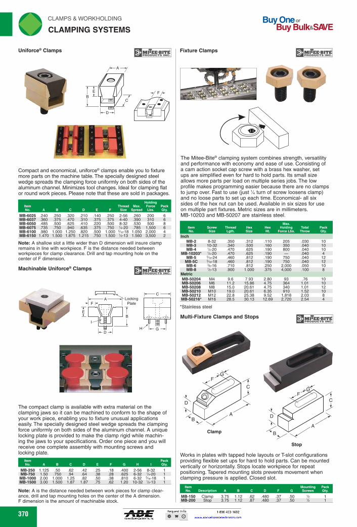
Buy One or Buy Bulk&SIVE
rliN CLAMPS & WORKHOLDING
CLAMPING SYSTEMS
sulks-sr1 Fixture Clamps
Item Mounting Pack No. Description A B C D F G Screws Qty.
MITss-BPRODUCTSITE Uniform° Clamps
A 7
B
PRODUCTS INc. Machinable Uniform° Clamps
LI I ui,,,,,,
A :"•-• Locking F Plate
E
Compact and economical, uniforce® clamps enable you to fixture more parts on the machine table. The specially designed steel wedge spreads the clamping force uniformly on both sides of the aluminum channel. Minimizes tool changes. Ideal for clamping flat or round work pieces. Please note that these are sold in packages.
Item No. A F
Thread Max. Size Spread
Holding Force Lbs.
Pack Qty.
MB-6025 .240 .250 .320 .210 .140 .250 2-56 .260 200 6 MB-6037 .360 .375 .470 .310 .375 .375 4-40 .390 310 6 MB-6050 .485 .500 .625 .410 .220 .500 8-32 .530 500 8 MB-6075 .735 .750 .940 .635 .375 .750 1/4-20 .785 1,500 6 MB-6100 .980 1.000 1.250 .820 .500 1.000 Vie-18 1.050 2,000 4 MB-6150 1.470 1.500 1.875 1.215 .750 1.500 1/2-13 1.560 3,500 2
Note: A shallow slot a little wider than D dimension will insure clamp remains in line with workpiece. F is the distance needed between workpieces for clamp clearance. Drill and tap mounting hole on the center of F dimension.
The compact clamp is available with extra material on the clamping jaws so it can be machined to conform to the shape of your work piece, enabling you to fixture unusual applications easily. The specially designed steel wedge spreads the clamping force uniformly on both sides of the aluminum channel. A unique locking plate is provided to make the clamp rigid while machin-ing the jaws to your specifications. Order one piece and you will receive one complete assembly with mounting screws and locking plate.
Item No. A E F G H
Pack Qty.
MB-250 1.125 .50 .62 .42 .25 .18 .400 2-56 8-32 MB-750 1.50 .750 .94 .64 .38 .28 .625 6-32 1/4-20 MB-1000 2.00 1.000 1.25 .82 .50 .38 .810 6-32 5/16-18 MB-1500 3.00 1.500 1.87 1.87 .75 .62 1.20 10-32 1/2-13
Note: A is the distance needed between work pieces for clamp clear-ance, drill and tap mounting holes on the center of the A dimension. F dimension is the amount of machinable stock.
370
14111100 41. 111
The Mitee-Bite® clamping system combines strength, versatility and performance with economy and ease of use. Consisting of a cam action socket cap screw with a brass hex washer, set ups are simplified even for hard to hold parts. Its small size allows more parts per load on multiple series jobs. The low profile makes programming easier because there are no clamps to jump over. Fast to use (just 1/4 turn of screw loosens clamp) and no loose parts to set up each time. Economical- all six sides of the hex nut can be used. Available in six sizes for use on multiple part fixtures. Metric sizes are in millimeters. MB-10203 and MB-50207 are stainless steel.
Size Thread Lath.
Hex Size
Hex Ht.
Max. Holding
Force Lbs. Total
Throw Pack
Inch MB-2 8-32 .350 .312 .110 205 .030 10 MB-3 10-32 .340 .500 .160 350 .040 10 MB-4 1/4-20 .470 .625 .190 800 .040 10
MB-10203* 1/4-20 .470 .625 .190 .040 4 MB-5 5/1e-24 .460 .812 .190 750 .040 12
MB-5C 5/1e-18 .460 .812 .190 750 .040 12 MB-6 %-16 .710 .812 .250 2,000 .050 10 MB-8 1/2-13 .900 1.000 .375 4,000 .100 8
Metric MB-50204 M4 9.6 7.93 2.80 93 .76 10 MB-50206 M6 11.2 15.86 4.75 364 1.01 10 MB-50208 M8 15.0 20.61 4.75 340 1.01 12 MB-50210 M10 19.0 20.61 6.35 910 1.52 10 MB-50212 M12 22.8 25.38 9.52 1,818 2.03 8 MB50216* M16 28.5 30.13 12.69 2,720 2.54 4
*Stainless steel
11AFEE-BI:rd PRODUCTS Multi-Fixture Clamps and Stops
Stop
A
Clamp
4 4
Works in plates with tapped hole layouts or T-slot configurations providing flexible set ups for hard to hold parts. Can be mounted vertically or horizontally. Stops locate workpiece for repeat positioning. Tapered mounting slots prevents movement when clamping pressure is applied. Closed slot.
MB-150 Clamp 3.75 1.12 .62 .480 .37 .50 MB-200 Stop 3.75 1.12 .87 .480 .37 .50
C
370
Fixture Clamps
The Mitee-Bite® clamping system combines strength, versatility and performance with economy and ease of use. Consisting of a cam action socket cap screw with a brass hex washer, set ups are simplified even for hard to hold parts. Its small size allows more parts per load on multiple series jobs. The low profile makes programming easier because there are no clamps to jump over. Fast to use (just 1⁄4 turn of screw loosens clamp) and no loose parts to set up each time. Economical- all six sides of the hex nut can be used. Available in six sizes for use on multiple part fixtures. Metric sizes are in millimeters. MB-10203 and MB-50207 are stainless steel.
*Stainless steel
ItemNo.
ScrewSize
ThreadLgth.
HexSize
HexHt.
Max. Holding
Force Lbs.Total
ThrowPackQty.
InchMB-2 8-32 .350 .312 .110 205 .030 10MB-3 10-32 .340 .500 .160 350 .040 10MB-4 1⁄4-20 .470 .625 .190 800 .040 10
MB-10203* 1⁄4-20 .470 .625 .190 — .040 4MB-5 5⁄16-24 .460 .812 .190 750 .040 12
MB-5C 5⁄16-18 .460 .812 .190 750 .040 12MB-6 3⁄8-16 .710 .812 .250 2,000 .050 10MB-8 1⁄2-13 .900 1.000 .375 4,000 .100 8
MetricMB-50204 M4 9.6 7.93 2.80 93 .76 10MB-50206 M6 11.2 15.86 4.75 364 1.01 10MB-50208 M8 15.0 20.61 4.75 340 1.01 12MB-50210 M10 19.0 20.61 6.35 910 1.52 10MB-50212 M12 22.8 25.38 9.52 1,818 2.03 8MB-50216* M16 28.5 30.13 12.69 2,720 2.54 4
Multi-Fixture Clamps and Stops
C
GF
D
BA
Clamp
C
GF
D
B
A
Stop
Works in plates with tapped hole layouts or T-slot configurations providing flexible set ups for hard to hold parts. Can be mounted vertically or horizontally. Stops locate workpiece for repeat positioning. Tapered mounting slots prevents movement when clamping pressure is applied. Closed slot.
ItemNo. Description A B C D F G
MountingScrews
PackQty.
MB-150 Clamp 3.75 1.12 .62 .480 .37 .50 1⁄2 1MB-200 Stop 3.75 1.12 .87 .480 .37 .50 1⁄2 1
Uniforce® Clamps
A
C
D
EB
F
Compact and economical, uniforce® clamps enable you to fixture more parts on the machine table. The specially designed steel wedge spreads the clamping force uniformly on both sides of the aluminum channel. Minimizes tool changes. Ideal for clamping flat or round work pieces. Please note that these are sold in packages.
Note: A shallow slot a little wider than D dimension will insure clamp remains in line with workpiece. F is the distance needed between workpieces for clamp clearance. Drill and tap mounting hole on the center of F dimension.
ItemNo. A B C D E F
ThreadSize
Max.Spread
HoldingForce Lbs.
PackQty.
MB-6025 .240 .250 .320 .210 .140 .250 2-56 .260 200 6MB-6037 .360 .375 .470 .310 .375 .375 4-40 .390 310 6MB-6050 .485 .500 .625 .410 .220 .500 8-32 .530 500 8MB-6075 .735 .750 .940 .635 .375 .750 1⁄4-20 .785 1,500 6MB-6100 .980 1.000 1.250 .820 .500 1.000 5⁄16-18 1.050 2,000 4MB-6150 1.470 1.500 1.875 1.215 .750 1.500 1⁄2-13 1.560 3,500 2
Machinable Uniforce® Clamps
F
D
B
A LockingPlate
E
I
C
H G
The compact clamp is available with extra material on the clamping jaws so it can be machined to conform to the shape of your work piece, enabling you to fixture unusual applications easily. The specially designed steel wedge spreads the clamping force uniformly on both sides of the aluminum channel. A unique locking plate is provided to make the clamp rigid while machin-ing the jaws to your specifications. Order one piece and you will receive one complete assembly with mounting screws and locking plate.
Note: A is the distance needed between work pieces for clamp clear-ance, drill and tap mounting holes on the center of the A dimension. F dimension is the amount of machinable stock.
ItemNo. A B C D E F G H I
PackQty.
MB-250 1.125 .50 .62 .42 .25 .18 .400 2-56 8-32 1MB-750 1.50 .750 .94 .64 .38 .28 .625 6-32 1⁄4-20 1
MB-1000 2.00 1.000 1.25 .82 .50 .38 .810 6-32 5⁄16-18 1MB-1500 3.00 1.500 1.87 1.87 .75 .62 1.20 10-32 1⁄2-13 1
PRODUCTS INC.
PRODUCTS INC.
PRODUCTS INC.
PRODUCTS INC.
CLAMPING SYSTEMS
FWAHL
SmallO

ID Xpansion- Clamps G-.1 • Side-Loc Xpansion Clamps paqisUCTS
pli
DI 17 " A
tB
.'G F
The side-loc xpansion clamp is an ideal way to clamp on the I.D. when the part has a blind bore. It is actuated by turning a socket head cam on the side, which moves a tapered plunger to expand the clamp. The side-loc xpansion clamp is designed in two styles, one for milling operations and one for lathe applications. Presently one size is available for each model. The mill side-loc xpansion clamp can be machined from 1.120 to .710 and the lathe version from 2.09 to .710. The lathe version has a straight mounting shank of 1". Used for Lathe Used for Milling
Peek Qty.
Holding Force Lbs.
Hex Key Size
M6 4,000 M6 4,000
Note: Six mounting screws included.
Machinable PitbuIP Clamps
D
CLAMPS & WORKHOLDING rliN
CLAMPING SYSTEMS ...1
Applications: • Ideal for secondary operations on lathe parts • Excellent for palletized setups
Features: • Easily machined to size on lathe or mill • Allows more parts per work cube or fixture plates • Clamp body made of mild steel for machinability • Tighten with hex key or hydraulic pull cylinders
(drill clearance hole for longer bolt into cylinder) • Three mounting screws included
These clamps are ideal to hold multiple parts on an inside diameter for machining on a machining center. These clamps are produced in ten sizes and can hold internal diameters from .16" to 4.06". Expand clamp approximately .005" over relaxed diameter and machine to fit work piece bore.
Item No.
r..000:.002 H Mounting Screws
Peek Qty.
MB-31000 .42 .30 .24 .12 .787 .29 .16 256 on .540 BHC 2-56 .16 MB-31050 .86 .63 .59 .23 1.170 .49 .28 6-32 on .825 BHC 8-32 .30 MB-31100 .98 .75 .59 .23 1.240 .56 .48 6-32 on .910 BHC 1/4-20 .50 MB-31150 .98 .75 .59 .23 1.476 .79 .53 6-32 on 1.140 BHC 5A8-18 .56 MB-31200 1.13 .88 .69 .25 1.968 1.06 .71 8-32 on 1.550 BHC %-16 .71 MB-31250 1.25 1.00 .81 .25 2.205 1.39 .90 8-32 on 1.790 BHC 1/2-13 .71 MB-31300 1.56 1.25 1.06 .31 2.736 1.65 1.15 10-32 on 2.200 BHC %-11 .79 MB-31350 1.56 1.25 1.06 .31 2.972 2.03 1.15 10-32 on 2.515 BHC %-11 .79 MB-31400 1.79 1.48 1.27 .31 4.232 3.06 1.15 1/4-20 on 3.646 BHC %-11 .79 MB-31450 1.79 1.48 1.27 .31 5.232 4.06 1.15 'A-20 on 4.648 BHC %-11 .79 MB-31500 1.79 1.48 1.27 .31 5.232 6.89 1.15 1/4-20 on 4.648 BHC %-11 .79
Note: The G dimension is the minimum diameter that the F dimension can be machined or turned (down) to.
Item No. Used For A C D E F G H
MB-31210 Milling 1.625 .875 .69 .75 1.968 1.13 .71 8-32 on 1.550 BHC MB-31370 Lathe 1.750 1.00 .84 .75 2.10 2.10 .71 1.0
PRODUCTS INC.
This new Pitbull fixture clamp is a machinable version of the popular Pitbull clamp. The clamp has positive down force and a very low gripping profile. The machinable Pitbull clamp is made of tool steel and heat treated to about 43 Rc for long life, yet still machin-able. There is additional material on the clamping face to allow for machining a radius. A dowel pin is included in each package to locate the clamp during the machining process.
MB-26077 Tool Steel, Machinable MB-26088 Tool Steel, Machinable
Note: D is clamp height.
Screw Max. Holding Torque Total Dowel Peek D E Size Force Lbs. In-Lbs. Throw Pin Size Qty.
.400 .450 1.00 .250 .710 1.00 %-16 6,000 360 .050 4
.600 .640 1.50 .375 .770 1.50 1/2-13 12,000 1,300 .075 'I 2
Modular Pitbull Clamps
gairmmTrd
The slotted modular Pitbull® clamp with a step offers increased versatility through its unique riser design. This clamp supports the work piece off the machine table for through milling and drilling. The hardened and ground clamps are designed for use on work cubes, as well as machined tables with tapped holes or T-slot configurations. The compact modular Pitbull® clamp is ideal for clamping work pieces in a series by using the back surface of a clamp to locate the next work piece. The back of the clamp is ground square to the bottom for precise location of parts. The height of the clamp can be adjusted by the depth of the milled slot used to locate the clamp.
Slotted
G H
Max. Movement Holding Peek
Force Lbs. Qty. MB-26220 Medium/Compact 2.25 1.23 98 NA .62 1.50 .024 3,600 MB-26230 Large/Compact 2.70 1.48 1.24 NA .74 1.85 .050 6,000 MB-26240 Medium/Slotted 4.08 1.25 .99 .730 .36 1.70 .50 .024 3,600 MB-26250 Large/Slotted 4.20 1.50 1.61 1.378 .36 1.52 .43 .050 6,000
371 371
CLAMPING SYSTEMS
Side-Loc Xpansion Clamps
The side-loc xpansion clamp is an ideal way to clamp on the I.D. when the part has a blind bore. It is actuated by turning a socket head cam on the side, which moves a tapered plunger to expand the clamp. The side-loc xpansion clamp is designed in two styles, one for milling operations and one for lathe applications. Presently one size is available for each model. The mill side-loc xpansion clamp can be machined from 1.120 to .710 and the lathe version from 2.09 to .710. The lathe version has a straight mounting shank of 1".
Note: Six mounting screws included.
AC B
F
D
H
G
EH
G
E
H
F
CA
B
D
Used for LatheUsed for Milling
ItemNo. Used For A B C D E F G H
Hex KeySize
HoldingForce Lbs.
PackQty.
MB-31210 Milling 1.625 .875 .69 .75 1.968 1.13 .71 8-32 on 1.550 BHC M6 4,000 1MB-31370 Lathe 1.750 1.00 .84 .75 2.10 2.10 .71 1.0 M6 4,000 1
Machinable Pitbull® Clamps
This new Pitbull fixture clamp is a machinable version of the popular Pitbull clamp. The clamp has positive down force and a very low gripping profile. The machinable Pitbull clamp is made of tool steel and heat treated to about 43 Rc for long life, yet still machin-able. There is additional material on the clamping face to allow for machining a radius. A dowel pin is included in each package to locate the clamp during the machining process.
Note: D is clamp height.
D A
B
C
E
Modular Pitbull® Clamps
The slotted modular Pitbull® clamp with a step offers increased versatility through its unique riser design. This clamp supports the work piece off the machine table for through milling and drilling. The hardened and ground clamps are designed for use on work cubes, as well as machined tables with tapped holes or T-slot configurations. The compact modular Pitbull® clamp is ideal for clamping work pieces in a series by using the back surface of a clamp to locate the next work piece. The back of the clamp is ground square to the bottom for precise location of parts. The height of the clamp can be adjusted by the depth of the milled slot used to locate the clamp.
F
BA
C
E
H F
D
C
B
A
G
ECompact
ItemNo. Description A B C D E F G
HMax. Movement
HoldingForce Lbs.
PackQty.
MB-26220 Medium/Compact 2.25 1.23 .98 NA .62 1.50 — .024 3,600 1MB-26230 Large/Compact 2.70 1.48 1.24 NA .74 1.85 — .050 6,000 1MB-26240 Medium/Slotted 4.08 1.25 .99 .730 .36 1.70 .50 .024 3,600 1MB-26250 Large/Slotted 4.20 1.50 1.61 1.378 .36 1.52 .43 .050 6,000 1
ID Xpansion™ Clamps
AC
D
J
B
F
I
E
G
H
Applications:Ideal for secondary operations on lathe partsExcellent for palletized setups
Features:Easily machined to size on lathe or millAllows more parts per work cube or fixture platesClamp body made of mild steel for machinabilityTighten with hex key or hydraulic pull cylinders (drill clearance hole for longer bolt into cylinder)Three mounting screws included
Note: The G dimension is the minimum diameter that the F dimension can be machined or turned (down) to.
ItemNo. A B C D
+.000/-.002E F G
HMounting Screws
IThread J
PackQty.
MB-31000 .42 .30 .24 .12 .787 .29 .16 2-56 on .540 BHC 2-56 .16 1MB-31050 .86 .63 .59 .23 1.170 .49 .28 6-32 on .825 BHC 8-32 .30 1MB-31100 .98 .75 .59 .23 1.240 .56 .48 6-32 on .910 BHC 1⁄4-20 .50 1MB-31150 .98 .75 .59 .23 1.476 .79 .53 6-32 on 1.140 BHC 5⁄16-18 .56 1MB-31200 1.13 .88 .69 .25 1.968 1.06 .71 8-32 on 1.550 BHC 3⁄8-16 .71 1MB-31250 1.25 1.00 .81 .25 2.205 1.39 .90 8-32 on 1.790 BHC 1⁄2-13 .71 1MB-31300 1.56 1.25 1.06 .31 2.736 1.65 1.15 10-32 on 2.200 BHC 5⁄8-11 .79 1MB-31350 1.56 1.25 1.06 .31 2.972 2.03 1.15 10-32 on 2.515 BHC 5⁄8-11 .79 1MB-31400 1.79 1.48 1.27 .31 4.232 3.06 1.15 1⁄4-20 on 3.646 BHC 5⁄8-11 .79 1MB-31450 1.79 1.48 1.27 .31 5.232 4.06 1.15 1⁄4-20 on 4.648 BHC 5⁄8-11 .79 1MB-31500 1.79 1.48 1.27 .31 5.232 6.89 1.15 1⁄4-20 on 4.648 BHC 5⁄8-11 .79 1
These clamps are ideal to hold multiple parts on an inside diameter for machining on a machining center. These clamps are produced in ten sizes and can hold internal diameters from .16" to 4.06". Expand clamp approximately .005" over relaxed diameter and machine to fit work piece bore.
ItemNo. Description A B C D E
ClampWidth
ScrewSize
Max. HoldingForce Lbs.
TorqueIn-Lbs.
TotalThrow
DowelPin Size
PackQty.
MB-26077 Tool Steel, Machinable .400 .450 1.00 .250 .710 1.00 3⁄8-16 6,000 360 .050 1⁄8 4MB-26088 Tool Steel, Machinable .600 .640 1.50 .375 .770 1.50 1⁄2-13 12,000 1,300 .075 1⁄4 2
Slotted
PRODUCTS INC.
PRODUCTS INC.
PRODUCTS INC.
PRODUCTS INC.
FWAHL
SmallO

Cam action, positive down force clamps can be used in series. Clamp base should be installed in a slot to retain location. Clamp base provides for higher clamping; height is determined by depth of slot. Mounting screws included.
Item No.
Total Distance Key Mounting Pack
A B C D E F G of Movement Size Screw Qty.
MB-24106 1.70 .75 .50 1.00 .090 .75 .25 MB-24108 2.12 1.00 .45 1.32 .110 1.00 .38 .100
.050 3/48 Me-18 x 3/4 1 Vie %-16 x % 1
:c> rt,E-Evrd
rli N CLAMPS & WORKHOLDING
CLAMPING SYSTEMS
I
A low profile cam action clamp with positive down force. This clamp is mounted in the T-slots of machine tables by sliding the clamp to the work piece and tightening the locking screw. Total distance of movement .100". Two clamping edges, smooth for machined surface, and serrated for rough cut material.
T-Slot Toe Clamps
MB-24128 MB-24148 Ye
Item No. T-Slot Size
1 MB-24168 1
MITE livrd Knife Edge Clamps
Low profile, fast cam action. Hardened steel bites into workpiece for secure clamping for castings and rough cut stock. Follows contour of part for maximum contact.
MB-12584 MB-12588 MB-12592
%-16
%-11
MB-22584 MB-22588 MB-22592
8 8 4
c• MITES-BIPRODUCTS .TE
Replacement Washer
Compact Toe Clamps
\t„
E A
B
Buy One or Buy Bulk&SIVE
ritcserd Pitbull® Clamps
A
iu
C
Knife Edne
Blunt Edge
Steel, Knife
Brass, Blunt
Steel, Blunt
The Pitbull clamp is a revolutionary new fixture clamp with positive down force and a low gripping profile. High vertical and horizontal clamping forces are generated, considering the size of the Pitbull Clamps. It uses a standard cap screw and an oil resis-tant 0-ring. The Pitbull Clamp is available in 5 sizes and several styles, a tool steel knife edge for aggressive stock removal, a tool steel blunt edge for general purpose and a brass version to help prevent marring in the work piece.
Item No. Material/Edge A B C
Screw Size
Max. Holding Force Lbs.
PBCL-2 Steel/Blunt .150 .140 .375 4-40 650 PBCL-3 Brass/Blunt .150 .140 .375 4-40 650 PBCL-4 SteeVKnife .200 .187 .500 8-32 1,500 PBCL-5 Steel/Blunt .200 .187 .500 8-32 1,500 PBCL-6 Brass/Blunt .200 .187 .500 8-32 1,500 PBCL-7 SteeVKnife .300 .280 .750 1/4-20 3,600 PBCL-8 Steel/Blunt .300 .280 .750 1/4-20 3,600 PBCL-9 Brass/Blunt .300 .280 .750 1/4-20 3,600
These hardened and ground clamps can produce holding forces of over 19,000 lbs. The OK-Vise clamp achieves this by its cross-wedge construction, which allows the clamp to lock firmly in every direction as it is tightened down. Jaws with 30-34 HRC can be machined to suit the geometry of the workpiece. Includes mount-ing screws.
3,300 3,300 6,600 6,600
48-52 48-52 48-52 30-34
Pressing Rae Jaw
of Jaws !tartness Pack Lbs. (NC) Q.
Mounting Jaw
Item No. Min. Optimum Mas. B C Cl B E F
A
*Ends of jaws are smooth
OK-Vise Low Profile Clamps Double Wedge
Pull down action towards the work piece.
ou'Es-BI.TE
A max. A min
MITES BITE OK-Vise Low Profile Clamps Single Wedge
A max. A min. 7.1.* 7
J
C
F
Completely free of play.
item No. Min. Optimum Max. BC D E F
MB-471 1.06 1.14 1.22 1.14 .59 .83 .10 .040 MB-479 1.06 1.14 1.22 1.14 .59 .83 .10 .040 MB-472 1.65 1.77 1.93 1.61 .87 1.18 .16 .080 MB-475 2.05 2.17 2.32 1.61 .87 1.18 .16 .080
Peeks Forte Jaw
of Jaws !tartness Pack Lbs. (MC) Qty.
Months New
%e-18 x % Me-18 1/2-13 x 1% 1/2-13 x 1%
MB-477 1.65 1.77 1.93 1.61 1.42 1.18 1.18 .20 .080 1/2-13 x 1% 11,000 48 - 52 1 MB-478 2.24 2.40 2.64 2.20 1.97 1.65 1.65 .20 .120 %-11 x 2% 19,800 48 - 52 1
372
Total Pack Throw Qty.
.0075
.0075
.0160
.0160
.0160
.0240
.0240
.0240
372
T-Slot Toe Clamps
1.12
.62
1.94
.38
1.00
A low profile cam action clamp with positive down force. This clamp is mounted in the T-slots of machine tables by sliding the clamp to the work piece and tightening the locking screw. Total distance of movement .100". Two clamping edges, smooth for machined surface, and serrated for rough cut material.
ItemNo. T-Slot Size
PackQty.
ItemNo. T-Slot Size
PackQty.
MB-24128 9⁄16 1 MB-24168 11⁄16 1MB-24148 5⁄8 1
Knife Edge Clamps
Low profile, fast cam action. Hardened steel bites into workpiece for secure clamping for castings and rough cut stock. Follows contour of part for maximum contact.
SetsReplacement
Washer
ItemNo.
ThreadSize
PackQty.
ItemNo.
MB-22584 3⁄8-16 8 MB-12584MB-22588 1⁄2-13 8 MB-12588MB-22592 5⁄8-11 4 MB-12592
Compact Toe Clamps
D
GF
C
AE
B
Cam action, positive down force clamps can be used in series. Clamp base should be installed in a slot to retain location. Clamp base provides for higher clamping; height is determined by depth of slot. Mounting screws included.
ItemNo. A B C D E F G
Total Distance
of MovementKeySize
MountingScrew
PackQty.
MB-24106 1.70 .75 .50 1.00 .090 .75 .25 .050 3⁄16 5⁄16-18 x 3⁄4 1MB-24108 2.12 1.00 .45 1.32 .110 1.00 .38 .100 5⁄16 3⁄8-16 x 3⁄4 1
Pitbull® Clamps
Brass, Blunt
B
A
C
O-Ring
Clamp
CapScrew
KnifeEdge
Blunt Edge
The Pitbull clamp is a revolutionary new fixture clamp with positive down force and a low gripping profile. High vertical and horizontal clamping forces are generated, considering the size of the Pitbull Clamps. It uses a standard cap screw and an oil resis-tant O-ring. The Pitbull Clamp is available in 5 sizes and several styles, a tool steel knife edge for aggressive stock removal, a tool steel blunt edge for general purpose and a brass version to help prevent marring in the work piece.
Steel, BluntSteel, Knife
ItemNo. Material/Edge A B C
ScrewSize
Max. HoldingForce Lbs.
TotalThrow
PackQty.
PBCL-2 Steel/Blunt .150 .140 .375 4-40 650 .0075 8PBCL-3 Brass/Blunt .150 .140 .375 4-40 650 .0075 8PBCL-4 Steel/Knife .200 .187 .500 8-32 1,500 .0160 8PBCL-5 Steel/Blunt .200 .187 .500 8-32 1,500 .0160 8PBCL-6 Brass/Blunt .200 .187 .500 8-32 1,500 .0160 8PBCL-7 Steel/Knife .300 .280 .750 1⁄4-20 3,600 .0240 6PBCL-8 Steel/Blunt .300 .280 .750 1⁄4-20 3,600 .0240 6PBCL-9 Brass/Blunt .300 .280 .750 1⁄4-20 3,600 .0240 6
These hardened and ground clamps can produce holding forces of over 19,000 lbs. The OK-Vise clamp achieves this by its cross-wedge construction, which allows the clamp to lock firmly in every direction as it is tightened down. Jaws with 30-34 HRC can be machined to suit the geometry of the workpiece. Includes mount-ing screws.
OK-Vise Low Profile ClampsSingle Wedge
BD
F
OK-VISE A max.A min.
E
C
Completely free of play.
*Ends of jaws are smooth
ItemNo.
A
B C D E FMounting
Screw
Pressing Force
of Jaws Lbs.
JawHardness
(HRC)PackQty.Min. Optimum Max.
MB-471 1.06 1.14 1.22 1.14 .59 .83 .10 .040 5⁄16-18 x 3⁄4 3,300 48-52 1MB-479 1.06 1.14 1.22 1.14 .59 .83 .10 .040 5⁄16-18 x 3⁄4 3,300 48-52 1MB-472 1.65 1.77 1.93 1.61 .87 1.18 .16 .080 1⁄2-13 x 11⁄4 6,600 48-52 1MB-475 2.05 2.17 2.32 1.61 .87 1.18 .16 .080 1⁄2-13 x 11⁄4 6,600 30-34 1
OK-Vise Low Profile ClampsDouble Wedge
BD
F
OK-VISE
A max.A min.
E
CC1
Pull down action towards the work piece.
ItemNo.
A
B C C1 D E FMounting
Screw
Pressing Force
of Jaws Lbs.
JawHardness
(HRC)PackQty.Min. Optimum Max.
MB-477 1.65 1.77 1.93 1.61 1.42 1.18 1.18 .20 .080 1⁄2-13 x 11⁄2 11,000 48 - 52 1MB-478 2.24 2.40 2.64 2.20 1.97 1.65 1.65 .20 .120 5⁄8-11 x 21⁄4 19,800 48 - 52 1
PRODUCTS INC.
PRODUCTS INC.
PRODUCTS INC.
PRODUCTS INC.
PRODUCTS INC.
PRODUCTS INC.
CLAMPING SYSTEMS
FWAHL
SmallO

11111.11•IN Vise Jaw
Grip
mike-urn! PRODUCTS INC
3 31C
mirmarni PRODUCTS INC.
Vise Jaw
Grip
VersaGrip allows you the versatility of clamping standard vise work as well as providing a solution for difficult applications that would normally require fixturing or machining soft-jaws. By simply replacing your current jaws with the VersaGrip system you can securely hold odd shaped parts while machining at speeds and feeds you never thought possible. This system can accommodate a wide range of part sizes as well as holding multiple parts in a single cycle. The hardened (52-54 RC) VersaGrip has penetrating teeth designed to bite into your workpiece preventing lateral and horizontal movements. These grips will hold flame cut parts, castings, even parts with a negative draft.
VersaGrip- Vise Jaws Systems Steel Vise Jaw Sets Set includes 4 VersaGrips-
EMEItm AMIMMI MB-32166 4 / 6 6.00 1.88 1.0 MB-32168 6 8.00 1.88 1.0
VersaGrip- Vise Jaws Systems VersaGrips-
2.5/3.88 .688/.94 1 3.88 .94 1
L_ MB-32175 .750 .375
M5 .060 - .140 2
Cam Action Clamps
A L
B
Standard H I-4-Stud
E
A
Extended
D E
TalonGrip vise jaws systems is a new and innovative product that will increase the versatility of your standard 4" and 6" vises. It is a simple bolt on system that will allow you to perform aggressive machining operations while clamping on as little as .060 of an inch. Ideal for small lot sizes, difficult application or prototype work when building a fixture would not be beneficial. TalonGrips are also available with the Pitbull clamp or soft jaw applications.
TalonGrip"' Vise Jaws Systems Steel Vise Jaw Set Set includes 4 TalonGrips-, 1 stop with M5 screws.
Item
Peek No. Vise Size A
C D E
qty.
MB-32044 4 2.5 .688 1.49 4.0 1.0 MB-32066 4 / 6 2.5/3.88 .688/.94 1.74 6.0 1.0 MB-32068 6 3.88 .94 1.74 8.0 1.0
TalonGrip- Vise Jaw Systems Vise Jaw Grips and Stops
i'MEEEEME1 MB-32050 Grips .75 .500 .250 10.32 .06 - .075 2 MB-33050 Grips .75 .500 .250 M5 .06 - .075 2 MB-32025 Stop 10.32 1 MB-33025 Stop M5 1
TalonGrip- Vise Jaws Systems Fixture Grips
iil!=!NEEEWM MB-32075 .75 .75 .312 10.32 .06 - .120 2 MB-33075 .75 .75 .312 M5 .06 - .120 2 MB-32100 .75 1.00 .312 10.32 .06 - .120 1 MB-33100 .75 1.00 .312 M5 .06 - .120 1
CLAMPS & WORKHOLDING riliN
CLAMPING SYSTEMS ...1
Low profile quick action clamp. Jaw pivots forward and downward at the same time when the handle is turned. Locks positively at any position within its 180 degrees turn, so that it will hold parts that vary slightly in dimension. Clamps with extended base allow position adjustment on machine tables.
Item No. Base Stud A B C D E
Peek F G City.
CAC-5 Standard 5',,e-18 1M 1% 1% 5 CAC-10* Extended Me-18 VA 1% 3% 5 CAC-15 Standard 1/2-13 1 1% 2% 2% 7% 54. CAC-20* Extended 1/2-13 1 1% 2% 4% 7% 542 *Stud not included in extended base clamps
373 373
TalonGrip™ Vise Jaws SystemsSteel Vise Jaw SetSet includes 4 TalonGrips™, 1 stop with M5 screws.
C
AD
B
E
Vise Jaw
DC
B A
Grip
TalonGrip vise jaws systems is a new and innovative product that will increase the versatility of your standard 4" and 6" vises. It is a simple bolt on system that will allow you to perform aggressive machining operations while clamping on as little as .060 of an inch. Ideal for small lot sizes, difficult application or prototype work when building a fixture would not be beneficial. TalonGrips are also available with the Pitbull clamp or soft jaw applications.
ItemNo. Vise Size A B C D E
PackQty.
MB-32044 4 2.5 .688 1.49 4.0 1.0 1MB-32066 4 / 6 2.5/3.88 .688/.94 1.74 6.0 1.0 1MB-32068 6 3.88 .94 1.74 8.0 1.0 1
TalonGrip™ Vise Jaw SystemsVise Jaw Grips and Stops
ItemNo. Description A B C D
RecommendedGripping Height
PackQty.
MB-32050 Grips .75 .500 .250 10-32 .06 - .075 2MB-33050 Grips .75 .500 .250 M5 .06 - .075 2MB-32025 Stop — — — 10-32 — 1MB-33025 Stop — — — M5 — 1
TalonGrip™ Vise Jaws SystemsFixture Grips
ItemNo. A B C D
RecommendedGripping Height
PackQty.
MB-32075 .75 .75 .312 10-32 .06 - .120 2MB-33075 .75 .75 .312 M5 .06 - .120 2MB-32100 .75 1.00 .312 10-32 .06 - .120 1MB-33100 .75 1.00 .312 M5 .06 - .120 1
VersaGrip™ Vise Jaws SystemsSteel Vise Jaw SetsSet includes 4 VersaGrips™
C
B
E
D
A
Vise Jaw
VersaGrip allows you the versatility of clamping standard vise work as well as providing a solution for difficult applications that would normally require fixturing or machining soft-jaws. By simply replacing your current jaws with the VersaGrip system you can securely hold odd shaped parts while machining at speeds and feeds you never thought possible. This system can accommodate a wide range of part sizes as well as holding multiple parts in a single cycle. The hardened (52-54 RC) VersaGrip has penetrating teeth designed to bite into your workpiece preventing lateral and horizontal movements. These grips will hold flame cut parts, castings, even parts with a negative draft.
ItemNo. Vise Size A B C D E
PackQty.
MB-32166 4 / 6 6.00 1.88 1.0 2.5/3.88 .688/.94 1MB-32168 6 8.00 1.88 1.0 3.88 .94 1
VersaGrip™ Vise Jaws SystemsVersaGrips™
ItemNo. A B C
RecommendedGripping Height
PackQty.
MB-32175 .750 .375 M5 .060 - .140 2
C
Stud
ED
B
A
F
G
C
ED
B
A
F
ExtendedStandard
Low profile quick action clamp. Jaw pivots forward and downward at the same time when the handle is turned. Locks positively at any position within its 180 degrees turn, so that it will hold parts that vary slightly in dimension. Clamps with extended base allow position adjustment on machine tables.
*Stud not included in extended base clamps
ItemNo. Base Stud A B C D E F G
PackQty.
CAC-5 Standard 5⁄16-18 11⁄4 1 15⁄8 13⁄4 5 1⁄8 — 1CAC-10* Extended 5⁄16-18 11⁄4 1 15⁄8 31⁄8 5 1⁄8 1 1CAC-15 Standard 1⁄2-13 17⁄8 11⁄2 21⁄2 23⁄4 71⁄2 5⁄32 — 1CAC-20* Extended 1⁄2-13 17⁄8 11⁄2 21⁄2 43⁄4 71⁄2 5⁄32 11⁄2 1
A
C
B
Grip
PRODUCTS INC. PRODUCTS INC.
CLAMPING SYSTEMS
Cam Action Clamps
FWAHL
SmallO
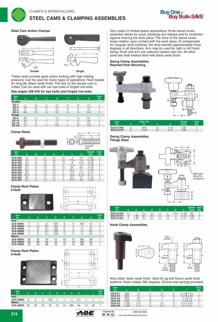
Very useful in limited space applications. Knob swivel screw assembly allows for quick clamping and release and for protection against marring the work piece. The shoe of the swivel screw stops rotation upon contact with the work piece. To compensate for irregular work surfaces, the shoe swivels approximately three degrees in all directions. Arm may be used for right or left hand swing. Knob and arm are cadmium plated cast iron. All other parts are heat treated steel with black oxide finish.
Swing Clamp Assemblies Reamed Hole Mounting
Swing Clamp Assemblies Flange Base
Alternate Stop Pin Locations
Item No. A B C D E F G H
Thread Pack Travel Qty.
SCA-21202 1% 1 1% 1% #10 Vie-18 .40 SCA-21211 3 1.25 21/4 21/4 1% 1% 1/4 1/2-13 1.00 SCA-21223 4 1.25 21/4 21/4 11/4 1% % %-11 1.25
Hook Clamp Assemblies
Alloy steel, black oxide finish. Ideal for jig and fixture quick build systems. Hook rotates 360 degrees. Screws and springs provided.
EMMEE11. 11.: 1341 HCA-C1 .625 'Vie 'A "/e % 5/e-18 x 1% 1 HCA-S1 .625 'Vie % Vie % 5/e-18 x 2% 1 HCA-C2 .875 1% % 1 % 1/2-13 x 3 1 MA-92 .875 1% % 1 % 1/2-13 x 4 1 HCA-C3 1.125 1% Ye Wie % %-11 x 3% 1 HCA-S3 1.125 1% Ye Wie % %-11 x 5 1
Item ..000/-.001 No. B C
SCA-21205 2 .874 1% SCA-21219 3 1.123 1%
Thread Pack D Travel Qty.
1/2-13
1.00 1.50
Clamp Rest Plates 4-Hole
B A
rli N CLAMPS & WORKHOLDING
STEEL CAMS & CLAMPING ASSEMBLIES
Buy One - 13uy Bulk SAVE
Steel Cam Action Clamps
E -
OG
Double Single
These cams provide quick action locking with high holding pressure. Can be used for many types of operations. Heat treated for long life. Black oxide finish. The slot on the double cam is milled. Can be used with our eye bolts or forged rod ends. See pages 438-439 for eye bolts and forged rod ends.
Double ..1•101
DC-1 Vie 1/4 3',e % Vie Vie 1 DC-2 3% % Vie Vet % 'A 'Vie 1 DC-3 5 1% % Wu % % 'Vie 1 DC-4 5% 11/4 % Vie % % 13/e 1
Single SC-0 2% Vie Wee Yee 39/e it 1
SC-15 31/4 1/4 % 1/4 3 lei. . 1 SC-1A 4% % eye, Vie Wee 1 SC-2A 5 % 29/se % 1%e 1
Clamp Rests
Item No. A B C D E
1—/Atik B C
F
A E F
G 1111111111111111111111111111111
Thread Size
Thread Pack G Size Qty
ACA-200 1% Vie Vee OA, 1/4-20 ACA-205 1% 7/32 Yee 1Vie Vie-18 ACA-220 2% Yee 2 1% %-16 ACA-225 2% Ye Me 1% 1/2-13 ACA-230 3% Yee 3% 3Ve %-16 ACA-235 3% Ye 333'e 3 1/2-13 ACA-240 2% Ye 1Wie %-11 ACA-245 Ye % 3% 2W,6 %-11 ACA-250 2% Ye v. Vie 1% %-10 ACA-255 3% 3/4 v. 2% 2% 3/4-10
Clamp Rest Plates 2-Hole
B
D D
H
Its N•
Inch C D E F G H
Pack Qty.
JCA-35901 1 1 2 .475 % #10 1% 1 JCA-35902 1% 1% 2% .60 % % 1/4 2 1 JCA-35904 1 2 3% .720 % % Vie 2% 1 JCA-35905 1 3 4% .720 % % Vie 3% 1 JCA-35906 1 4 5% .720 % % Vie 4% 1 Metric JCA-35951 25 25 50 12 10 13 M5 38 1 JCA-35952 25 38 64 15 13 13 M6 50 1 JCA-35954 25 50 89 18 16 19 M8 70 1
Item No. A B C D E F G H J
Pack Qty.
Inch JCA-35903 2 2 3 .725 % % 1/4 2% % 1 1 Metric JCA-35953 50 50 75 18 12 13 M6 64 13 25 1
374 374
Very useful in limited space applications. Knob swivel screw assembly allows for quick clamping and release and for protection against marring the work piece. The shoe of the swivel screw stops rotation upon contact with the work piece. To compensate for irregular work surfaces, the shoe swivels approximately three degrees in all directions. Arm may be used for right or left hand swing. Knob and arm are cadmium plated cast iron. All other parts are heat treated steel with black oxide finish.
Swing Clamp AssembliesReamed Hole Mounting
C
B
A
D
D
ItemNo. A
+.000/-.001B C D
ThreadTravel
PackQty.
SCA-21205 2 .874 11⁄8 1⁄2-13 1.00 1SCA-21219 3 1.123 13⁄8 5⁄8-11 1.50 1
Swing Clamp AssembliesFlange Base
H
A
E
F
AlternateStop PinLocations
G
B
C
D
ItemNo. A B C D E F G H
ThreadTravel
PackQty.
SCA-21202 11⁄2 1 17⁄16 11⁄2 3⁄4 1 #10 5⁄16-18 .40 1SCA-21211 3 1.25 21⁄4 21⁄4 11⁄8 13⁄8 1⁄4 1⁄2-13 1.00 1SCA-21223 4 1.25 21⁄4 21⁄4 11⁄4 11⁄2 3⁄8 5⁄8-11 1.25 1
Hook Clamp Assemblies
C
B
FCap
Screw
AReam
C
B
FStud
AReam
D
E
Cap Screw
Alloy steel, black oxide finish. Ideal for jig and fixture quick build systems. Hook rotates 360 degrees. Screws and springs provided.
ItemNo. A B C D E F
PackQty.
HCA-C1 .625 15⁄16 1⁄2 11⁄16 3⁄8 5⁄16-18 x 13⁄4 1HCA-S1 .625 15⁄16 1⁄2 11⁄16 3⁄8 5⁄16-18 x 21⁄2 1HCA-C2 .875 15⁄8 5⁄8 1 1⁄2 1⁄2-13 x 3 1HCA-S2 .875 15⁄8 5⁄8 1 1⁄2 1⁄2-13 x 4 1HCA-C3 1.125 113⁄16 7⁄8 17⁄16 3⁄4 5⁄8-11 x 31⁄2 1HCA-S3 1.125 113⁄16 7⁄8 17⁄16 3⁄4 5⁄8-11 x 5 1
Clamp Rests
ItemNo. A B C D E F G
ThreadSize
PackQty.
ACA-200 11⁄4 7⁄16 5⁄32 5⁄64 11⁄64 1 29⁄32 1⁄4-20 1ACA-205 17⁄8 1⁄2 7⁄32 3⁄16 7⁄32 115⁄32 15⁄16 5⁄16-18 1ACA-220 21⁄2 9⁄16 11⁄32 5⁄32 11⁄32 2 113⁄16 3⁄8-16 1ACA-225 23⁄8 7⁄8 11⁄32 3⁄16 1⁄2 111⁄16 11⁄2 1⁄2-13 1ACA-230 37⁄8 9⁄16 11⁄32 5⁄32 11⁄32 33⁄8 33⁄16 3⁄8-16 1ACA-235 37⁄8 7⁄8 11⁄32 3⁄16 1⁄2 33⁄16 3 1⁄2-13 1ACA-240 25⁄8 7⁄8 11⁄32 3⁄16 1⁄2 115⁄16 111⁄16 5⁄8-11 1ACA-245 327⁄32 7⁄8 11⁄32 3⁄16 1⁄2 35⁄32 215⁄16 5⁄8-11 1ACA-250 23⁄4 7⁄8 11⁄32 3⁄16 1⁄2 21⁄16 17⁄8 3⁄4-10 1ACA-255 31⁄2 7⁄8 11⁄32 3⁄16 1⁄2 213⁄16 23⁄8 3⁄4-10 1
Clamp Rest Plates2-Hole
A
G
D
H
E
BC
F
ItemNo. A B C D E F G H
PackQty.
InchJCA-35901 1 1 2 .475 3⁄8 1⁄2 #10 11⁄2 1JCA-35902 11⁄2 11⁄2 21⁄2 .60 1⁄2 1⁄2 1⁄4 2 1JCA-35904 1 2 31⁄2 .720 5⁄8 3⁄4 5⁄16 23⁄4 1JCA-35905 1 3 41⁄2 .720 5⁄8 3⁄4 5⁄16 33⁄4 1JCA-35906 1 4 51⁄2 .720 5⁄8 3⁄4 5⁄16 43⁄4 1MetricJCA-35951 25 25 50 12 10 13 M5 38 1JCA-35952 25 38 64 15 13 13 M6 50 1JCA-35954 25 50 89 18 16 19 M8 70 1
Clamp Rest Plates4-Hole
AJ
I
G
B
CF
D
H
E
ItemNo. A B C D E F G H I J
PackQty.
InchJCA-35903 2 2 3 .725 1⁄2 1⁄2 1⁄4 21⁄2 1⁄2 1 1MetricJCA-35953 50 50 75 18 12 13 M6 64 13 25 1
A
F
C
E
B
D
H ØG
Double
AD
E
HØG
B
Single
These cams provide quick action locking with high holding pressure. Can be used for many types of operations. Heat treated for long life. Black oxide finish. The slot on the double cam is milled. Can be used with our eye bolts or forged rod ends.
ItemNo. A B C D F G H
PackQty.
DoubleDC-1 — 9⁄16 1⁄4 3⁄16 3⁄8 3⁄16 9⁄16 1DC-2 31⁄2 5⁄8 5⁄16 9⁄32 1⁄2 1⁄4 11⁄16 1DC-3 5 11⁄8 1⁄2 13⁄32 5⁄8 3⁄8 15⁄16 1DC-4 53⁄8 11⁄4 5⁄8 9⁄16 7⁄8 5⁄8 13⁄16 1
SingleSC-0 23⁄8 3⁄16 — 27⁄64 — 5⁄32 33⁄64 1SC-15 31⁄4 1⁄4 — 1⁄2 — 1⁄4 39⁄64 1SC-1A 41⁄2 3⁄8 — 41⁄64 — 5⁄16 25⁄32 1SC-2A 5 1⁄2 — 29⁄32 — 3⁄8 13⁄32 1
See pages 438-439 for eye bolts and forged rod ends.
STEEL CAMS & CLAMPING ASSEMBLIES
Steel Cam Action Clamps
FWAHL
SmallO

Center Cam Single End Clamp Assemblies
Center Cam Double End Clamp Assemblies
4-1 E
B
D H
See page 374 for additional steel cam handles.
Used where high clamping pressures are needed and vibration could cause loosening. They have a spherical flange nut and washer for greater flexibility. Extra long, true milled slot allows more clearance for placing and removing work.
Item No. A B C D E F G
Pack Thread Qty.
JCA-12701* % % 2 1% 1/4-20 JCA-12703 11/2 3% 1% 2'%e 17/le %-16 JCA-12705 11/2 4% 1% 2'%e 1% %-16 JCA-12707 1% 1% 1% 4% 1% 3 2% 1/2-13 JCA-12710 1% 1% 1% 6 2 3 26 1/2-13 JCA-12711 2% 1% 1% 5 1% e 2% %-11 JCA-12713 2% 1% 1% 7 2% e 3% %-11 JCA-12714 1% 1% 1'/ 5 1% 4% 2% 3/4-10 JCA-12716 1% 1% 1% 7 2% 4% 3% %-10
*Finger handle not included. See page 103 for finger handle. Note: G dimension represents an optimum dimension.
Radius End Flange Nut Clamp Assemblies
•
OP
For heavy duty clamping of plain surfaces with spherical flange nut and washer for angular flexibility. Radius end strap and spring loaded stud for quick release.
Item No. A B C D E F G
Pack Thread City
JCA-14103 2 1% %-20 JCA-14105 1% 1% 3% 1% 2% 17/18 %-16 JCA-14108 1% 1% 4% 1% 3 1/2-13 JCA-14111 3% 1% *A, 5 1% 5Yie 2 %-11 JCA-14114 2% 1% 5 1% 4% 2% %-10
Strap Clamp Assemblies
D
Spherical washers compensate for irregularities between clamp strap and part being clamped allowing for more rigid clamping. Double end clamp straps can be used for clamping flat work pieces or they can be inverted for holding round work pieces in V-blocks or other nesting arrangements. All parts (except jam nuts) are heat treated steel with black oxide finish.
Item
Thread Pack No. A B C D E F G Size City
ACA-107 7A3
2%
2% 7A3 %-20 JCA-13515 1%
3'/2
3% 1% %-16 JCA-13516 13/4 4'/2
3% 1% %-16
B
E
Flange Nut Clamp Assemblies
CLAMPS & WORKHOLDING rliN
CLAMP ASSEMBLIES usip,
See page 374 for additional steel cam handles.
Item No. A B C D E G H
Pack Thread Qty.
ACA-305 2 2% %-20 ACA-307 2% 2% %-20
JCA-12513 1% *A, 2% 3/4 37/18 Vie-18 JCA-12514 1% *A, 3% 1% 37/18 Vie-18 JCA-12515 1% 1% 3% 1% Wie 37/18 %-16 JCA-12516 1% 1% 4% 1% 17/18 37/18 %-16 ACA-332 1% 1% 4% 1% 1% 5 1/2-13
JCA-12518 1% 1% 6 2 1% 5 1/2-13 JCA-12519 1% 1% 5 1% 1% 5Vie %-11
ACA-350 12523 1% 1% % 4 1% 5 1/2-13 1 ACA-354 12524 1% 1% % 5 1% 5 1/2-13 1 ACA-368 12526 1% 1% 'As 6 1% 5%e %-11 1
Double Cam Clamp Assemblies
Features fast-action, light duty holding of plain surface work where quick movements are required in a restricted space. Long end slot for lateral adjustment. Spring loaded stud member under sturdy double cam lever.
See page 374 for additional steel cam handles. Item Pack No. A B C D E G H Thread Qty.
JCA-12501* % % % 2 % 7A3 2% %-20 1 JCA-12502 Wie 1% 7A3 3% 1% 1Y,e 37/18 %-16 1
*Finger handle not included. See page 103 for finger handle. Note: G dimension represents an optimum dimension.
Radius Swing Clamp Assemblies
Item No. A B C D E F G
Pack Thread Qty.
JCA-14123 2 1 1% % 1/4-20 JCA-14125 1% 1% 3% 1% 215/e 1% %-16 JCA-14128 1% 1% 4% 113/e 3 115/e 1/2-13 JCA-14134 2% 1% 5 2%e 4% 2%e %-10
375 375
StrapClamp Assemblies
Spherical washers compensate for irregularities between clamp strap and part being clamped allowing for more rigid clamping. Double end clamp straps can be used for clamping flat work pieces or they can be inverted for holding round work pieces in V-blocks or other nesting arrangements. All parts (except jam nuts) are heat treated steel with black oxide finish.
ItemNo. A B C D E F G
ThreadSize
PackQty.
ACA-107 7⁄8 5⁄8 3⁄8 21⁄2 1 21⁄4 7⁄8 1⁄4-20 1JCA-13515 13⁄4 11⁄4 5⁄8 31⁄2 11⁄8 31⁄2 17⁄16 3⁄8-16 1JCA-13516 13⁄4 11⁄4 5⁄8 41⁄2 15⁄8 31⁄2 17⁄16 3⁄8-16 1
Flange NutClamp Assemblies
F
GThreadSize
A
C
B
DE
Used where high clamping pressures are needed and vibration could cause loosening. They have a spherical flange nut and washer for greater flexibility. Extra long, true milled slot allows more clearance for placing and removing work.
ItemNo. A B C D E F G Thread
PackQty.
JCA-12701* 3⁄4 5⁄8 1⁄2 2 5⁄8 15⁄8 7⁄8 1⁄4-20 1JCA-12703 11⁄2 11⁄4 7⁄8 31⁄2 11⁄8 215⁄16 17⁄16 3⁄8-16 1JCA-12705 11⁄2 11⁄4 7⁄8 41⁄2 15⁄8 215⁄16 115⁄16 3⁄8-16 1JCA-12707 11⁄8 11⁄2 11⁄8 41⁄2 11⁄4 3 21⁄8 1⁄2-13 1JCA-12710 11⁄8 11⁄2 11⁄8 6 2 3 27⁄8 1⁄2-13 1JCA-12711 25⁄8 13⁄4 13⁄8 5 11⁄2 51⁄16 21⁄8 5⁄8-11 1JCA-12713 25⁄8 13⁄4 13⁄8 7 21⁄2 51⁄16 31⁄8 5⁄8-11 1JCA-12714 13⁄4 13⁄4 11⁄2 5 11⁄2 43⁄8 21⁄8 3⁄4-10 1JCA-12716 13⁄4 13⁄4 11⁄2 7 21⁄2 43⁄8 31⁄8 3⁄4-10 1
Radius End Flange NutClamp Assemblies
F
GThreadSize
A
C
B
DE
For heavy duty clamping of plain surfaces with spherical flange nut and washer for angular flexibility. Radius end strap and spring loaded stud for quick release.
ItemNo. A B C D E F G Thread
PackQty.
JCA-14103 7⁄8 5⁄8 3⁄8 2 5⁄8 15⁄8 7⁄8 1⁄4-20 1JCA-14105 13⁄4 11⁄4 5⁄8 31⁄2 11⁄8 215⁄16 17⁄16 3⁄8-16 1JCA-14108 11⁄2 11⁄2 3⁄4 41⁄2 11⁄4 3 17⁄8 1⁄2-13 1JCA-14111 31⁄8 13⁄4 7⁄8 5 11⁄2 51⁄16 2 5⁄8-11 1JCA-14114 21⁄4 13⁄4 1 5 11⁄2 43⁄8 21⁄8 3⁄4-10 1
Center CamSingle EndClamp Assemblies
H
E
D
B
C
A
G
ThreadSize
See page 374 for additional steel cam handles.
ItemNo. A B C D E G H Thread
PackQty.
ACA-305 3⁄4 5⁄8 3⁄8 2 5⁄8 7⁄8 21⁄2 1⁄4-20 1ACA-307 3⁄4 5⁄8 3⁄8 21⁄2 1 7⁄8 21⁄2 1⁄4-20 1
JCA-12513 11⁄8 7⁄8 1⁄2 21⁄2 3⁄4 11⁄4 37⁄16 5⁄16-18 1JCA-12514 11⁄8 7⁄8 1⁄2 31⁄2 11⁄4 11⁄4 37⁄16 5⁄16-18 1JCA-12515 11⁄2 11⁄4 5⁄8 31⁄2 11⁄8 17⁄16 37⁄16 3⁄8-16 1JCA-12516 11⁄2 11⁄4 5⁄8 41⁄2 15⁄8 17⁄16 37⁄16 3⁄8-16 1ACA-332 13⁄8 11⁄2 3⁄4 41⁄2 11⁄4 17⁄8 5 1⁄2-13 1
JCA-12518 13⁄8 11⁄2 3⁄4 6 2 17⁄8 5 1⁄2-13 1JCA-12519 15⁄8 13⁄4 7⁄8 5 11⁄2 115⁄16 51⁄16 5⁄8-11 1
Center CamDouble EndClamp Assemblies
See page 374 for additional steel cam handles.
ItemNo. Jergens A B C D E H Thread
PackQty.
ACA-350 12523 13⁄8 11⁄2 3⁄4 4 11⁄4 5 1⁄2-13 1ACA-354 12524 13⁄8 11⁄2 3⁄4 5 11⁄4 5 1⁄2-13 1ACA-368 12526 15⁄8 15⁄8 7⁄8 6 11⁄2 51⁄16 5⁄8-11 1
Features fast-action, light duty holding of plain surface work where quick movements are required in a restricted space. Long end slot for lateral adjustment. Spring loaded stud member under sturdy double cam lever.
ItemNo. A B C D E G H Thread
PackQty.
JCA-12501* 5⁄8 5⁄8 1⁄2 2 5⁄8 7⁄8 21⁄2 1⁄4-20 1JCA-12502 15⁄16 11⁄4 7⁄8 31⁄2 11⁄8 17⁄16 37⁄16 3⁄8-16 1
Radius SwingClamp Assemblies
90°
B
DThread Size
F
GE
C
A
ItemNo. A B C D E F G Thread
PackQty.
JCA-14123 7⁄8 5⁄8 3⁄8 2 1 15⁄8 11⁄16 1⁄4-20 1JCA-14125 13⁄4 11⁄4 5⁄8 31⁄2 11⁄2 215⁄16 11⁄4 3⁄8-16 1JCA-14128 11⁄2 11⁄2 3⁄4 41⁄2 113⁄16 3 115⁄16 1⁄2-13 1JCA-14134 21⁄4 13⁄4 1 5 21⁄16 43⁄8 23⁄16 3⁄4-10 1
CLAMP ASSEMBLIES
Double CamClamp Assemblies
GThreadSize
A
C
B
DE
H
See page 374 for additional steel cam handles.
*Finger handle not included. See page 103 for finger handle.Note: G dimension represents an optimum dimension.
*Finger handle not included. See page 103 for finger handle.Note: G dimension represents an optimum dimension.
FWAHL
SmallO

rli N CLAMPS & WORKHOLDING
STRAP CLAMPS
Strap Clamps Tempered Steel - Varnished Finish Plain
E
B
Item
Peek No. A Bolt Size B C D E F G Qty.
AMF-9 .43 AMF-10 .55 AMF-12 .71 AMF-13 .71 AMF-14 .87 AMF-15 .71
%, M10 3.15 .59 1.18
%, M12, M14 3.94 .79 1.57
%, M16, M18 4.92 .98 1.97
%, M16, M18 6.30 .98 1.97 %, M20, M22 6.30 1.18 2.36 %, M20, M22 7.87 1.18 2.36
.47 .59 1.18
.55 .83 1.57
.71 1.02 1.77
.71 1.02 2.56
.87 1.18 2.36
.87 1.18 3.15
(=_,A V
-4-0 -44
C -A-
-f D
I
A D I -X
Item Peek
(
B
AMF-34 .87 %, M20, M22 9.84 1.58 2.36 1.38 1.77 2.68 No. A Bolt Size B C D E G H Qty.
7 E
• -;11w-. Air
3.15 .59 1.18
Strap Clamps Radius 304 Stainless Steel D
E C
G
B
-A-A
CSS-1501 1/4 1% CSS-1876 /e 3%
1% 3
CSS-1632 1/4 CSS-1881 'A /e
Strap Clamps Flat 304 Stainless Steel
El= C -K F
E C
G
B
Compatible with universal step blocks AMF-40, 41, and 42. Peek
A Bolt Size B C D E F G Qty.
376
Item Peek No. A B C D E G H J Qty.
CSS-1503 1/4 'A 1% Me % 10-32 %az 'Me 1 CSS-1504 1/4 1/4 1% 71w % 10-32 Yaz 'Me 1 CSS-1629 Me % 2 % Y3 1/4-20 VS Y3 1 CSS-1755 % % 3 % 15/e 5/e-18 Wu 1% 1 CSS-1878 1 / 2 Ye 3 % 15/e %-16 15/e 1
Item Peek No. A B C D E F G Qty.
.47 AMF-18 .55 %, M12, M14 3.94 .79 1.57 .55
.59 1.18 1
.83 1.57 1 %, M10 AMF-17 .43
Peek No. A B C D E G H Qty.
1 1
Item
Me 1
Strap Clamps Tempered Steel - Varnished Finish Single Goose-Neck
Item Peek No. A Bolt Size B C D E F G H J Qty.
AMF-35 .55 %, M12, M14 4.92 .79 1.57 .79 .63 1.57 1.57 1.10 1 AMF-38 .87 %, M20, M22 6.30 1.18 2.36 1.18 .94 2.17 2.17 1.74 1
Strap Clamps Tempered Steel - Varnished Finish Forked Clamp with Shoe
Strap Clamps Tempered Steel - Varnished Finish Step Clamps
Buy One or Buy Bulk&SIVE
Strap Clamps Tapped End Radius
A Stud Size G
Heat Treated Steel
-A- B
Thd.
The specially designed end provides maximum pressure for edge clamping. Long slot allows for lateral adjustment.
Item
Peek No. A B C D E F G N Qty.
CTE-2 1/4 2 % % % 1 7h2 1/4-20 1 CTE-4 1/4 2% % % % 1% 1/22 1/4-20 1 CTE-6 Me 2% % 1 Me 1% 362 5/e-18 1 CTE-8 Me 31/4 % 1 'Me 1% 362 5/e-18 1 CTE-12 % 3 % 1% % 1'Me Me %-16 1 CTE-14 % 4 % 1% 1 23'ie Me %-16 1 CTE-16 % 5 % 1% 1% 2'Me Me %-16 1 CTE-18 ',4 4 % 1% 1 21/4 Me 1/2-13 1 CTE-20 ',4 4% % 11/4 1% 21/4 Me 1/2-13 1 CTE-22 ',4 5 % 1% 1% 21/4 Me 1/2-13 1 CTE-24 ',4 6 % 1% 1% 21/4 Me 1/2-13 1 CTE-26 % 4% % 1% 1 2% % %-11 1 CTE-28 % 5 % 1% 1% 2% % %-11 1 CTE-30 % 6 % 1% 1% 2% % %-11 1
Strap Clamps Single End Radius Finger Grip Heat Treated Steel A Stud Size
G
_t The long slot increases the length of strap, allowing more clamp-ing pressure to be applied to the part. Finger grip on both sides of the clamp allows for easier lateral travel adjustments.
Item Peek No. A B C D E F G H Qty.
CSE-2 1/4 2
1 Me CSE-4 1/4 2%
1% Me CSE-6 Me 2%
1% 1/4 CSE-8 Me 31/4
1% 1/4 CSE-12
3
1%
1'Me
Vet CSE-14
4
1%
2s/,e
Vet CSE-18
4
1%
21/4
Vet CSE-20
4%
1%
21/4
Vet CSE-22
5
1%
21/4
Vet CSE-24
6
1%
21/4
Vet CSE-26 4% % 1%
2%
CSE-30
6
1%
2% CSE-32
6 1
1%
31/4
Vie
Strap Clamps Tapped End Radius 304 Stainless Steel
376
Strap ClampsTapped End RadiusHeat Treated Steel
C
D
FH
Thd.
GA Stud Size
EB
The specially designed end provides maximum pressure for edge clamping. Long slot allows for lateral adjustment.
ItemNo. A B C D E F G H
PackQty.
CTE-2 1⁄4 2 3⁄8 5⁄8 1⁄2 1 7⁄32 1⁄4-20 1CTE-4 1⁄4 21⁄2 3⁄8 5⁄8 1⁄2 11⁄8 7⁄32 1⁄4-20 1CTE-6 5⁄16 23⁄4 1⁄2 1 7⁄16 11⁄2 9⁄32 5⁄16-18 1CTE-8 5⁄16 31⁄4 1⁄2 1 13⁄16 11⁄2 9⁄32 5⁄16-18 1CTE-12 3⁄8 3 5⁄8 11⁄4 3⁄4 111⁄16 5⁄16 3⁄8-16 1CTE-14 3⁄8 4 5⁄8 11⁄4 1 23⁄16 5⁄16 3⁄8-16 1CTE-16 3⁄8 5 5⁄8 11⁄4 11⁄2 211⁄16 5⁄16 3⁄8-16 1CTE-18 1⁄2 4 5⁄8 11⁄4 1 21⁄4 7⁄16 1⁄2-13 1CTE-20 1⁄2 41⁄2 5⁄8 11⁄4 11⁄2 21⁄4 7⁄16 1⁄2-13 1CTE-22 1⁄2 5 5⁄8 11⁄4 11⁄2 21⁄4 7⁄16 1⁄2-13 1CTE-24 1⁄2 6 5⁄8 11⁄4 11⁄2 21⁄4 7⁄16 1⁄2-13 1CTE-26 5⁄8 41⁄2 7⁄8 11⁄2 1 21⁄2 1⁄2 5⁄8-11 1CTE-28 5⁄8 5 7⁄8 11⁄2 11⁄2 21⁄2 1⁄2 5⁄8-11 1CTE-30 5⁄8 6 7⁄8 11⁄2 11⁄2 21⁄2 1⁄2 5⁄8-11 1
Strap ClampsSingle End RadiusHeat Treated Steel
H
G
FEB
C
D
A Stud SizeFinger Grip
The long slot increases the length of strap, allowing more clamp-ing pressure to be applied to the part. Finger grip on both sides of the clamp allows for easier lateral travel adjustments.
ItemNo. A B C D E F G H
PackQty.
CSE-2 1⁄4 2 3⁄8 5⁄8 1⁄2 1 3⁄16 1⁄8 1CSE-4 1⁄4 21⁄2 3⁄8 5⁄8 1⁄2 11⁄8 3⁄16 1⁄8 1CSE-6 5⁄16 23⁄4 1⁄2 1 7⁄16 11⁄2 1⁄4 3⁄16 1CSE-8 5⁄16 31⁄4 1⁄2 1 13⁄16 11⁄2 1⁄4 3⁄16 1
CSE-12 3⁄8 3 5⁄8 11⁄4 3⁄4 111⁄16 3⁄8 9⁄32 1CSE-14 3⁄8 4 5⁄8 11⁄4 1 23⁄16 3⁄8 9⁄32 1CSE-18 1⁄2 4 5⁄8 11⁄4 1 21⁄4 3⁄8 9⁄32 1CSE-20 1⁄2 41⁄2 5⁄8 11⁄4 11⁄2 21⁄4 3⁄8 9⁄32 1CSE-22 1⁄2 5 5⁄8 11⁄4 11⁄2 21⁄4 3⁄8 9⁄32 1CSE-24 1⁄2 6 5⁄8 11⁄4 11⁄2 21⁄4 3⁄8 9⁄32 1CSE-26 5⁄8 41⁄2 7⁄8 11⁄2 1 21⁄2 1⁄2 9⁄32 1CSE-30 5⁄8 6 7⁄8 11⁄2 11⁄2 21⁄2 1⁄2 9⁄32 1CSE-32 3⁄4 6 1 13⁄4 13⁄4 31⁄4 1⁄2 5⁄16 1
Strap ClampsTapped End Radius304 Stainless Steel
GE
B
C
D
A
J
H
ItemNo. A B C D E G H J
PackQty.
CSS-1503 1⁄4 1⁄2 11⁄2 5⁄16 5⁄8 10-32 7⁄32 11⁄16 1CSS-1504 1⁄4 1⁄2 13⁄4 7⁄16 3⁄4 10-32 7⁄32 13⁄16 1CSS-1629 5⁄16 5⁄8 2 1⁄2 7⁄8 1⁄4-20 9⁄32 7⁄8 1CSS-1755 3⁄8 3⁄4 3 7⁄8 15⁄16 5⁄16-18 11⁄32 13⁄8 1CSS-1878 1⁄2 7⁄8 3 3⁄4 15⁄16 3⁄8-16 13⁄32 15⁄16 1
Strap ClampsFlat304 Stainless Steel
G
E
B
C
D
A
F
Item
No. A B C D E F GPackQty.
CSS-1632 1⁄4 5⁄8 13⁄4 1⁄2 3⁄4 9⁄32 1⁄8 1CSS-1881 1⁄2 7⁄8 3 1 13⁄8 13⁄32 1⁄8 1
Strap ClampsRadius304 Stainless Steel
G
E
B
C
D
A
H
ItemNo. A B C D E G H
PackQty.
CSS-1501 1⁄4 1⁄2 13⁄4 7⁄16 3⁄4 3⁄32 7⁄32 1CSS-1876 1⁄2 7⁄8 31⁄2 1 11⁄2 1⁄8 13⁄32 1
Strap ClampsTempered Steel - Varnished FinishPlain
G
E
B
C
DA
F
ItemNo. A Bolt Size B C D E F G
PackQty.
AMF-9 .43 3⁄8, M10 3.15 .59 1.18 .47 .59 1.18 1AMF-10 .55 1⁄2, M12, M14 3.94 .79 1.57 .55 .83 1.57 1AMF-12 .71 5⁄8, M16, M18 4.92 .98 1.97 .71 1.02 1.77 1AMF-13 .71 5⁄8, M16, M18 6.30 .98 1.97 .71 1.02 2.56 1AMF-14 .87 3⁄4, M20, M22 6.30 1.18 2.36 .87 1.18 2.36 1AMF-15 .71 3⁄4, M20, M22 7.87 1.18 2.36 .87 1.18 3.15 1
Strap ClampsTempered Steel - Varnished FinishSingle Goose-Neck
G
E
B
C
DA
F
J
H
ItemNo. A Bolt Size B C D E F G H J
PackQty.
AMF-35 .55 1⁄2, M12, M14 4.92 .79 1.57 .79 .63 1.57 1.57 1.10 1AMF-38 .87 3⁄4, M20, M22 6.30 1.18 2.36 1.18 .94 2.17 2.17 1.74 1
Strap ClampsTempered Steel - Varnished FinishForked Clamp with Shoe
G
E
B
C
DA
H
C/4
ItemNo. A Bolt Size B C D E G H
PackQty.
AMF-34 .87 3⁄4, M20, M22 9.84 1.58 2.36 1.38 1.77 2.68 1
Strap ClampsTempered Steel - Varnished FinishStep Clamps
G
E
B
C
DA
F
Compatible with universal step blocks AMF-40, 41, and 42.
ItemNo. A Bolt Size B C D E F G
PackQty.
AMF-17 .43 3⁄8, M10 3.15 .59 1.18 .47 .59 1.18 1AMF-18 .55 1⁄2, M12, M14 3.94 .79 1.57 .55 .83 1.57 1
STRAP CLAMPS
FWAHL
SmallO

A
Best suited for low work pieces. Clamping height is easily adjusted with adjusting screw. Adjusting screw (included) has knurled screw or socket head. Made from tempered steel, varnished finish. See pages 433 and 435 for T-bolts and nuts.
-.HD H.-
L
AMF-1 3.94 .83 1.58 M12 39 - 1.81 .55 1 AMF-2 4.92 1.02 1.77 M16 .51 - 2.05 .71 1 AMF-3 6.30 1.18 2.36 M20 .63 - 2.56 .87 1
Note: Clamping Range depends on depth of slot and position of fixture nut
Forged from 1030 steel for toughness. Because of draft or taper on forgings minimum dimensions of slot are given.
Drop Forged Steel Strap Clamps Plain Slot Pattern
Drop Forged Steel Strap Clamps Goose Neck Pattern
Item No. Lgth. Width
,46410:14
Slot Neck Pack Thickness Lgth. Width Offset Qty.
L Width Thickness
Slot Pack Qty. Lgth. Width
PS-4 PS-6 PS-8 PS-10
4 6 8 10
1% 1% 2% 2%
1% 1%
1%
2"Vie 3%
G N-4 G N-6 G N-8
4 6 8
1% 1% 2%
1"Yie 1% 1%
Drop Forged Steel Strap Clamps Screw Heel
111110 Drop Forged Steel Strap Clamps U Pattern
mtuMit Item No. Lgth. Width Thickness Lgth.
Slot Width
Pack Qty.
Item No. Lgth. Width Thickness
Slot
Lgth. Width Screw Pack Qty.
UP-4 UP-6 UP-8 UP-10 UP-12
4 6 8 10 12
1% 2
2% 2% 3%
1%
1'%
1%
3% 5% 7% 9 11
Tie
1Yie
PS-12 PS-14 PS-16
4 6 8
1% 1% 2% 1%
"I,e
1"Ae 27/16
1/2-13 x 1% %-11 x 1% %-10 x 1%
1 1 1
Strap Clamp Spring Lifters
Designed to speed set-ups wherever strap clamps are used. Spring lifter slides over T-slot bolt or stud and is held by tightening the set screw on locking collar. The strap clamp rests on the support collar and the spring holds the clamp just above the final tightened height, permitting the work to be quickly and easily slid underneath.
Item Pack item Pack No. Fits Die. Qty. No. Fits Die. Qty.
SCL-801 % 1 SCL-805 % SCL-803 % 1 SCL-806 % SCL-804 .1 / 2 1
Adjustable Clamp Rests
A hat Mr B C D E Pack Qty.
111111111111111111111 CSS-6205 1 .190
% % Vie
% Wie 13,e 1%
10-32 1/4-20 Ye-20 3,e-18
Yie Yee Yee 34e
1 1 1 1
C CSS-6256 1
413-C4DE
CSS-6258 1% CSS-6320 1% CSS-6321 1% CSS-6382 1%
Vie %
1% 1%
3,e-18 %-16
34e %
1 1
CSS-6384 2% % 2% %-16 % 1
Strap Clamp Set Up Wedges
Item Max. Pack No. Lgth. Width Thickness Qty.
SUW-950
3
'A SUW-951
5 SUW-952
6
) CLAMPS & WORKHOLDING "r
STRAP CLAMPS
Strap Clamps Plain with Adjusting Screw
377 377
Forged from 1030 steel for toughness. Because of draft or taper on forgings minimum dimensions of slot are given.
Drop Forged SteelStrap ClampsPlain Slot Pattern
ItemNo. Lgth. Width Thickness
Slot PackQty.Lgth. Width
PS-4 4 15⁄8 3⁄4 13⁄8 11⁄16 1PS-6 6 13⁄4 7⁄8 21⁄16 11⁄16 1PS-8 8 21⁄8 11⁄8 213⁄16 13⁄16 1PS-10 10 21⁄2 13⁄8 311⁄16 15⁄16 1
Drop Forged SteelStrap ClampsScrew Heel
ItemNo. Lgth. Width Thickness
Slot
ScrewPackQty.Lgth. Width
PS-12 4 15⁄8 3⁄4 15⁄16 11⁄16 1⁄2-13 x 11⁄4 1PS-14 6 13⁄4 7⁄8 111⁄16 11⁄16 5⁄8-11 x 11⁄2 1PS-16 8 21⁄8 11⁄8 27⁄16 13⁄16 3⁄4-10 x 13⁄4 1
Drop Forged SteelStrap ClampsGoose Neck Pattern
ItemNo. Lgth. Width Thickness
Slot NeckOffset
PackQty.Lgth. Width
GN-4 4 13⁄8 3⁄4 15⁄16 11⁄16 13⁄16 1GN-6 6 13⁄4 7⁄8 111⁄16 11⁄16 15⁄16 1GN-8 8 21⁄8 11⁄8 27⁄16 13⁄16 11⁄8 1
Drop Forged SteelStrap ClampsU Pattern
ItemNo. Lgth. Width Thickness
Slot PackQty.Lgth. Width
UP-4 4 13⁄4 3⁄4 31⁄2 11⁄16 1UP-6 6 2 7⁄8 51⁄2 11⁄16 1UP-8 8 23⁄8 11⁄8 73⁄8 13⁄16 1UP-10 10 23⁄4 11⁄4 9 15⁄16 1UP-12 12 31⁄4 13⁄8 11 11⁄16 1
Strap Clamp Spring Lifters
Designed to speed set-ups wherever strap clamps are used. Spring lifter slides over T-slot bolt or stud and is held by tightening the set screw on locking collar. The strap clamp rests on the support collar and the spring holds the clamp just above the final tightened height, permitting the work to be quickly and easily slid underneath.
ItemNo. Fits Dia.
PackQty.
ItemNo. Fits Dia.
PackQty.
SCL-801 1⁄4 1 SCL-805 5⁄8 1SCL-803 3⁄8 1 SCL-806 3⁄4 1SCL-804 1⁄2 1
Adjustable Clamp Rests
AC
DE
B
ItemNo. A B C D E
PackQty.
CSS-6205 1 .190 3⁄4 10-32 1⁄16 1CSS-6256 1 1⁄4 11⁄16 1⁄4-20 5⁄64 1CSS-6258 11⁄2 1⁄4 13⁄16 1⁄4-20 5⁄64 1CSS-6320 15⁄8 5⁄16 13⁄8 5⁄16-18 3⁄32 1CSS-6321 17⁄8 5⁄16 15⁄8 5⁄16-18 3⁄32 1CSS-6382 15⁄8 3⁄8 13⁄8 3⁄8-16 1⁄8 1CSS-6384 25⁄8 3⁄8 23⁄8 3⁄8-16 1⁄8 1
ItemNo. Lgth. Width
Max.Thickness
PackQty.
SUW-950 3 1 1⁄4 1SUW-951 5 1 1⁄2 1SUW-952 6 11⁄4 3⁄4 1
Strap ClampsPlain with Adjusting Screw
E B C
DA
Best suited for low work pieces. Clamping height is easily adjusted with adjusting screw. Adjusting screw (included) has knurled screw or socket head. Made from tempered steel, varnished finish. See pages 433 and 435 for T-bolts and nuts.
Note: Clamping Range depends on depth of slot and position of fixture nut
ItemNo. A B C D E Slot Width
PackQty.
AMF-1 3.94 .83 1.58 M12 .39 - 1.81 .55 1AMF-2 4.92 1.02 1.77 M16 .51 - 2.05 .71 1AMF-3 6.30 1.18 2.36 M20 .63 - 2.56 .87 1
STRAP CLAMPS
Strap ClampSet Up Wedges
FWAHL
SmallO
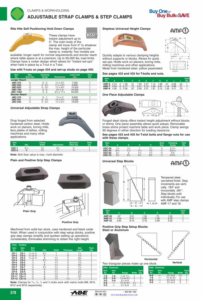
Item No. D E
Pack Qty. A
.75 1.40 2.68
2.01 4.21 8.19
1.30 2.60 5.16
1.50 2.76 5.32
.87 1.54 2.80
AMF-40 AMF-41 AMF-42
Steel Aluminum Item item Pack No. No. Range Width Qty.
1% 1%
1-S 2-S 3-S 4-S 5-S
1-A 2-A 3-A
% to 1% 1% to 2% 2% to 6
1% to 3% 2% to 6
Steel Aluminum Item item Pack No. No. Range Width Qty. 6-S 7-S 8-S 9-S
- to 9 1% - 1% to 3% 2 - 2'h to 6 2 - t0 9 2
Positive Grip Step Setup Blocks Steel or Aluminum
Horizontal Two triangular pieces make up one block. Vertical
Clamp Maximum Pack Width
Adjustment
T-Bolt Dia. Qty. USC-1 5'Ae 1% 2% USC-2 8 1% 4
Note: Bolt Size value is max. t-bolt diameter
Plain and Positive Grip Step Clamps
Plain Grip
Positive Grip
Machined from solid bar stock, case hardened and black oxide finish. When used in conjunction with step setup blocks, positive grip step clamps simplify and quicken setting up operations considerably. Eliminates shimming to obtain the right height.
CP-1 CS-1 Vie or % 2% 1 % 1% 1 CP-2 CS-2 %e or % 4 1 Ye 1% 1 CP-3 CS-3 Vie or % 6 1% % 2% 1 CP-4 CS-4
% 2% 1% % 1% 1 CP-5 CS-5
% 4 1% % 1% 1 CP-6 CS-6
% 6 1% Ye 2% 1 CP-7 CS-7
% 2% 1% Ye 1% 1 CP-8 CS-8
% 4 1% l'e 1% 1 CP-9 CS-9
% 6 1% Ye 2% 1 CP-10 CS-10
% 4 1% % 1% 1 CP-11 CS-11
% 6 1% 1 2% 1 CP-12 CS-12
% 8 1% 1% 3 1
Note: Clamps for Me, %, 1/2 and % bolts work with metric bolts M8, M10, M12 and M16 respectively.
378
Stepless Universal Height Clamps
FD-alFA
Universal Step Blocks
-At
B
1.18k-
rli N CLAMPS & WORKHOLDING
ADJUSTABLE STRAP CLAMPS & STEP CLAMPS Buy One or
Buy Bulk&SIO/E
Rite Hite Self Positioning Hold Down Clamps
These clamps have instant adjustment up to 5". The main body of the clamp will move from 0" to whatever the max. height of the particular clamp is, instantly. Two models are
available; longer reach for normal requirements and shorter reach where table space is at a premium. Up to 65,000 lbs. load limits. Clamps have a rocker design which allows for "instant set-ups" when held in place by a T-nut in a T-slot.
Use with T-nuts on page 434 and set-up studs on page 440.
Item Max. Clamping Load Limit
Pack No. Stud Size Range Dimensions Lbs. Qty•
Longer Reach JMC-375 JMC-500 JMC-625 JMC-750
JMC-1000 Shorter Reach JMC-376 JMC-501 JMC-626
Universal Adjustable Strap Clamps
Drop forged from selected hardened carbon steel. Holds work on planers, boring mills, face plates of lathes, milling machines and many other applications.
Quickly adapts to various clamping heights without supports or blocks. Allows for quick set-ups. Holds work on planers, boring mills, milling machines and other applications. Made from hardened steel, yellow passivated.
See pages 433 and 435 for T-bolts and nuts.
AMF-6 2.24 0 - 1.38 .51 1.50 3.47 1.10 1.89 .91 2.68 .55 1 AMF-7 3.54 0 - 2.17 .71 2.21 5.12 1.50 2.91 1.14 3.98 .71 1 AMF-8 4.06 0 - 2.56 .87 2.60 5.51 1.81 3.15 1.26 4.41 .79 1
One Piece Adjustable Clamps
D U @ 1
C
A -2-1.-B
Forged steel clamp offers instant height adjustment without blocks or shims. One piece assembly allows quick setups. Removable brass shims protect machine table and work piece. Clamp swings 90 degrees in either direction for loading clearance. See pages 433 and 435 for T-slot bolts and flange nuts for use with these clamps.
Stud Clamping Pack N • C D
Size Range Qty.
USC-40 1% 1%
0-1% USC-50 2%e 17/16
'h 0-2'Ae
USC-60 3% 2
56 0-3 USC-70 3% 2%
04%
Tempered steel, varnished finish. Step increments are verti-cally .183" and horizontally .091". Step blocks sold individually. For use with AMF step clamps AMF-17 and 18.
56
1
0-5 0-2% 0-3% 0-5 0-5
7,000 8,800 14,500 24,000 65,000
'h 0-1
0-1% 0-2%
1% x 3 1% x 1% x 5%
8,800 13,200 19,000
378
Rite Hite Self Positioning Hold Down Clamps
These clamps have instant adjustment up to 5". The main body of the clamp will move from 0" to whatever the max. height of the particular clamp is, instantly. Two models are
available; longer reach for normal requirements and shorter reach where table space is at a premium. Up to 65,000 lbs. load limits. Clamps have a rocker design which allows for "instant set-ups" when held in place by a T-nut in a T-slot.
Use with T-nuts on page 434 and set-up studs on page 440.
ItemNo.
Max.Stud Size
ClampingRange Dimensions
Load LimitLbs.
PackQty.
Longer ReachJMC-375 3⁄8 0 - 5 11⁄8 x 31⁄2 7,000 1JMC-500 1⁄2 0 - 21⁄2 17⁄16 x 53⁄4 8,800 1JMC-625 5⁄8 0 - 31⁄2 17⁄8 x 63⁄4 14,500 1JMC-750 3⁄4 0 - 5 21⁄8 x 9 24,000 1
JMC-1000 1 0 - 5 27⁄8 x 111⁄8 65,000 1Shorter ReachJMC-376 3⁄8 0 - 1 11⁄8 x 3 8,800 1JMC-501 1⁄2 0 - 13⁄4 13⁄8 x 41⁄4 13,200 1JMC-626 5⁄8 0 - 23⁄4 17⁄8 x 51⁄2 19,000 1
Stepless Universal Height Clamps
JE
D
C
HL
AB
F G
Quickly adapts to various clamping heights without supports or blocks. Allows for quick set-ups. Holds work on planers, boring mills, milling machines and other applications. Made from hardened steel, yellow passivated.
See pages 433 and 435 for T-bolts and nuts.
ItemNo. A B C D E F G H J L
PackQty.
AMF-6 2.24 0 - 1.38 .51 1.50 3.47 1.10 1.89 .91 2.68 .55 1AMF-7 3.54 0 - 2.17 .71 2.21 5.12 1.50 2.91 1.14 3.98 .71 1AMF-8 4.06 0 - 2.56 .87 2.60 5.51 1.81 3.15 1.26 4.41 .79 1
Universal Adjustable Strap Clamps
Drop forged from selected hardened carbon steel. Holds work on planers, boring mills, face plates of lathes, milling machines and many other applications.
Note: Bolt Size value is max. t-bolt diameter
ItemNo. OAL
ClampWidth Adjustment
MaximumT-Bolt Dia.
PackQty.
USC-1 51⁄16 15⁄8 21⁄4 5⁄8 1USC-2 8 13⁄4 4 3⁄4 1
One Piece Adjustable Clamps
C
BA
D
Forged steel clamp offers instant height adjustment without blocks or shims. One piece assembly allows quick setups. Removable brass shims protect machine table and work piece. Clamp swings 90 degrees in either direction for loading clearance.See pages 433 and 435 for T-slot bolts and flange nuts for use with these clamps.
ItemNo. A B C D
StudSize
ClampingRange
PackQty.
USC-40 17⁄8 11⁄8 1 11⁄4 3⁄8 0-13⁄4 1USC-50 25⁄16 17⁄16 17⁄16 15⁄8 1⁄2 0-21⁄16 1USC-60 31⁄4 2 17⁄8 17⁄8 5⁄8 0-3 1USC-70 31⁄2 21⁄8 21⁄4 25⁄8 3⁄4 0-41⁄4 1
1.18
B
C E
DA
Tempered steel, varnished finish. Step increments are verti-cally .183" and horizontally .091". Step blocks sold individually. For use with AMF step clamps AMF-17 and 18.
ItemNo. A B C D E
PackQty.
AMF-40 .87 2.01 1.30 .75 1.50 1AMF-41 1.54 4.21 2.60 1.40 2.76 1AMF-42 2.80 8.19 5.16 2.68 5.32 1
HorizontalVerticalTwo triangular pieces make up one block.
Plain and Positive Grip Step Clamps
Plain Grip
Positive Grip
Machined from solid bar stock, case hardened and black oxide finish. When used in conjunction with step setup blocks, positive grip step clamps simplify and quicken setting up operations considerably. Eliminates shimming to obtain the right height.
Note: Clamps for 5⁄16, 3⁄8, 1⁄2 and 5⁄8 bolts work with metric bolts M8, M10, M12 and M16 respectively.
Plain Positive
BoltSize OAL Width Thickness
SlotLength
PackQty.
ItemNo.
ItemNo.
CP-1 CS-1 5⁄16 or 3⁄8 21⁄2 1 1⁄2 11⁄4 1CP-2 CS-2 5⁄16 or 3⁄8 4 1 5⁄8 17⁄8 1CP-3 CS-3 5⁄16 or 3⁄8 6 11⁄8 3⁄4 25⁄8 1CP-4 CS-4 1⁄2 21⁄2 11⁄8 1⁄2 11⁄4 1CP-5 CS-5 1⁄2 4 11⁄4 3⁄4 17⁄8 1CP-6 CS-6 1⁄2 6 11⁄4 7⁄8 25⁄8 1CP-7 CS-7 5⁄8 21⁄2 11⁄4 5⁄8 11⁄4 1CP-8 CS-8 5⁄8 4 11⁄2 3⁄4 17⁄8 1CP-9 CS-9 5⁄8 6 11⁄2 7⁄8 25⁄8 1CP-10 CS-10 3⁄4 4 11⁄2 3⁄4 17⁄8 1CP-11 CS-11 3⁄4 6 15⁄8 1 23⁄4 1CP-12 CS-12 3⁄4 8 13⁄4 11⁄8 3 1
ADJUSTABLE STRAP CLAMPS & STEP CLAMPS
Universal Step Blocks
Positive Grip Step Setup BlocksSteel or Aluminum
Steel Aluminum
Range WidthPackQty.
ItemNo.
ItemNo.
1-S 1-A 3⁄4 to 11⁄2 1 12-S 2-A 11⁄8 to 21⁄2 1 13-S 3-A 21⁄2 to 6 1 14-S — 13⁄4 to 33⁄4 11⁄2 15-S — 21⁄2 to 6 11⁄2 1
Steel Aluminum
Range WidthPackQty.
ItemNo.
ItemNo.
6-S — 31⁄2 to 9 11⁄2 17-S — 13⁄4 to 33⁄4 2 18-S — 21⁄2 to 6 2 19-S — 31⁄2 to 9 2 1
FWAHL
SmallO

Low Grip
C
A
B
t F.
Thread Size
CLAMPS & WORKHOLDING riliN
TOE CLAMPS & JACKS ._,1
Powerful, low profile clamp that grips on the side of the work leaving the top surface open. No interference with cutting tools or reading and measuring instruments. Ideal for use on mills, planers, jig bores, drill presses or faceplates. Heat treated steel, black oxide finish. Toe is moved by an actuating screw. T-wrenches are sold separately. Toe moves on a 45 degree angle, forcing the workpiece down. 3 degree taper prevents back-off. To help prevent possi-ble damage by the anchor screw, a special washer is provided with each clamp.
Toe Clamps Slotted for 5/16 or M8 Socket Head Cap Screw
Steel Toe Brass Toe Item Item No. No. A B C D E F G H
Pack Qty.
Low Grip NTC-41101 NTC-41131 2 % 'Ae % % 1 % 1 NTC-41102 — 2% % Yte 11/4 ',4 % 1 ',4 1 NTC-41103 — 3 % Yte 1% % % 1 ',13 1 High Grip NTC-41110 NTC-41121 2 % Yte % % % 1 % 1 NTC-41111 — 2% % Yte 11/4 % % 1 % 1 NTC-41112 — 3 % Yte 1% % % 1 % 1
Jack Screws
Jack screws are used in fixtures to work pieces, such as castings and to of thinner materials during machining. oxide finish.
Fixture Jacks
Staight Knurl
Item A B C
Peek D E Qty.
3/8 IN No. 1.1111111111111111111
SJS-500 SJS-510
%-16 %-16 1%
1% 1% 21/4 E
SJS-515 %-16 2 1% 2% SJS-520 1/2-13 1% 1 i6
support irregularly shaped SJS-525 1/2-13 1% 1% 21/4 eliminate bowing or warping SJS-530 1/2-13 2 1% 2%
SJS-535 Heat treated steel, black SJS-540 1/2-13 %-11
2% 1%
1% 1%
3% 21/4
SJS-545 %-11 2 1% 2% SJS-550 %-11 2% 1% 3%
Designed as a positive locking jack for irregular clamping to achieve various heights requiring a positive pressure stop on milling fixtures, drill jigs, etc. Adjustable to fit irregularities of milling operations. Available in either smooth round head or hardened serrated gripping surface. Pin construction elevates vertically, no rotation Outer diameter of bushing ground for press fit. Made of ledloy, heat treated. Black oxide finish.
Item 13
No. A B C Mln. Max. E
Radius Head JFJ-24901 % 1 V e 35e %e 11/2 1 J F J -24902 1 1% e Ye 2YA e JFJ-24903 1% 2% l'te Ye 3% 1% Serrated Head JFJ-25101 % 18A e 35e %e 11/2 1 JFJ-25102 1 1% Ye 2Yle 1Vie JFJ-25103 11/4 2% Yte Ye 3% 1%
F G J Peek
Thread Qty.
'A % % % -16 1 '% VA % -11 1 'Ve 'h Vie 1-8 1
'A % % % -16 1 '% VA %-11 1 'Vie 1/4 Vie 1-8 1
Serrated Head
G
C-'H < D
° 3 F
*
45°
E
A
Toe Clamps Slotted for 1/2 or M12 Socket Head Cap Screw
A B C D E F G H Pack Qty.
Low Grip NTC-41001 4Yte 'Ve 2 1/4 743 1% 1/4 1 NTC-41002 5% 'Ve 'h 2% 1/4 743 1% 1/4 1 NTC-41003 TAe 'Ve 1 3% 1/4 743 1% 1/4 1 High Grip NTC-41010 4Yte ',13 2 i6 'A 1% 'A 1 NTC-41011 5% 'Vie 'h 2% 'A 'A 1% 'A 1 NTC-41012 TAe 'Ve 1 3% 743 743 1% 743 1
379
.Vri•
-̀4101* Low Grip
Toe Clamps Slotted for % or M16 Socket Head Cap Screw
High Grip
Item No. A B
Low Grip NTC-41051 4Yte 'Vie NTC-41052 5% 'Vie High Grip NTC-41061 4Yte 'Vie NTC-41062 5% 'Vie
C D E F
'A 2 1/4 'A 'h 2% 1/4 743
'A 2 Ye 'A 'h 2% Ye 7,13
G H Peek Qty.
11/2 'A 1 1% 'A 1
1'Fi i6 1 1'/ 7,13 1
379
Powerful, low profile clamp that grips on the side of the work leaving the top surface open. No interference with cutting tools or reading and measuring instruments. Ideal for use on mills, planers, jig bores, drill presses or faceplates. Heat treated steel, black oxide finish. Toe is moved by an actuating screw. T-wrenches are sold separately. Toe moves on a 45 degree angle, forcing the workpiece down. 3 degree taper prevents back-off. To help prevent possi-ble damage by the anchor screw, a special washer is provided with each clamp.
Toe ClampsSlotted for 5⁄16 or M8 Socket Head Cap Screw
HE
BA
F
C D
3°
45°
G
High GripLow Grip
Steel Toe Brass Toe
A B C D E F G HPackQty.
ItemNo.
ItemNo.
Low GripNTC-41101 NTC-41131 2 1⁄2 1⁄16 3⁄4 1⁄8 5⁄8 1 1⁄8 1NTC-41102 — 21⁄2 1⁄2 1⁄16 11⁄4 1⁄8 5⁄8 1 1⁄8 1NTC-41103 — 3 1⁄2 1⁄16 13⁄4 1⁄8 5⁄8 1 1⁄8 1High GripNTC-41110 NTC-41121 2 1⁄2 1⁄16 3⁄4 5⁄8 5⁄8 1 5⁄8 1NTC-41111 — 21⁄2 1⁄2 1⁄16 11⁄4 5⁄8 5⁄8 1 5⁄8 1NTC-41112 — 3 1⁄2 1⁄16 13⁄4 5⁄8 5⁄8 1 5⁄8 1
Toe ClampsSlotted for 1⁄2 or M12 Socket Head Cap Screw
High Grip
Low Grip
ItemNo. A B C D E F G H
PackQty.
Low GripNTC-41001 41⁄16 13⁄16 1⁄8 2 1⁄4 7⁄8 11⁄2 1⁄4 1NTC-41002 51⁄2 13⁄16 1⁄2 23⁄4 1⁄4 7⁄8 11⁄2 1⁄4 1NTC-41003 77⁄16 13⁄16 1 33⁄4 1⁄4 7⁄8 11⁄2 1⁄4 1High GripNTC-41010 41⁄16 13⁄16 1⁄8 2 7⁄8 7⁄8 11⁄2 7⁄8 1NTC-41011 51⁄2 13⁄16 1⁄2 23⁄4 7⁄8 7⁄8 11⁄2 7⁄8 1NTC-41012 77⁄16 13⁄16 1 33⁄4 7⁄8 7⁄8 11⁄2 7⁄8 1
Toe ClampsSlotted for 5⁄8 or M16 Socket Head Cap Screw
High GripLow Grip
ItemNo. A B C D E F G H
PackQty.
Low GripNTC-41051 41⁄16 13⁄16 1⁄8 2 1⁄4 7⁄8 11⁄2 1⁄4 1NTC-41052 51⁄2 13⁄16 1⁄2 23⁄4 1⁄4 7⁄8 11⁄2 1⁄4 1High GripNTC-41061 41⁄16 13⁄16 1⁄8 2 7⁄8 7⁄8 11⁄2 7⁄8 1NTC-41062 51⁄2 13⁄16 1⁄2 23⁄4 7⁄8 7⁄8 11⁄2 7⁄8 1
Staight Knurl
E BD
A
C 3/8
Jack screws are used in fixtures to support irregularly shaped work pieces, such as castings and to eliminate bowing or warping of thinner materials during machining. Heat treated steel, black oxide finish.
ItemNo. A B C D E
PackQty.
SJS-500 3⁄8-16 11⁄4 11⁄8 17⁄8 3⁄8 1SJS-510 3⁄8-16 15⁄8 11⁄8 21⁄4 3⁄8 1SJS-515 3⁄8-16 2 11⁄8 25⁄8 3⁄8 1SJS-520 1⁄2-13 11⁄4 11⁄8 17⁄8 3⁄8 1SJS-525 1⁄2-13 15⁄8 11⁄8 21⁄4 3⁄8 1SJS-530 1⁄2-13 2 11⁄8 25⁄8 3⁄8 1SJS-535 1⁄2-13 21⁄2 11⁄8 31⁄8 3⁄8 1SJS-540 5⁄8-11 15⁄8 13⁄8 21⁄4 3⁄8 1SJS-545 5⁄8-11 2 13⁄8 25⁄8 3⁄8 1SJS-550 5⁄8-11 21⁄2 13⁄8 31⁄8 3⁄8 1
F
D
C
E
ThreadSize
G
A
B
J
Designed as a positive locking jack for irregular clamping to achieve various heights requiring a positive pressure stop on milling fixtures, drill jigs, etc. Adjustable to fit irregularities of milling operations. Available in either smooth round head or hardened serrated gripping surface. Pin construction elevates vertically, no rotation Outer diameter of bushing ground for press fit. Made of ledloy, heat treated. Black oxide finish.
ItemNo. A B C
D
E F G J ThreadPackQty.Min. Max.
Radius HeadJFJ-24901 5⁄8 13⁄16 3⁄16 9⁄16 11⁄2 1 1⁄4 5⁄32 3⁄8 3⁄8-16 1JFJ-24902 1 15⁄8 3⁄16 7⁄8 27⁄16 15⁄16 15⁄32 7⁄16 7⁄16 5⁄8-11 1JFJ-24903 11⁄2 23⁄4 3⁄16 7⁄8 31⁄2 13⁄4 13⁄16 1⁄2 9⁄16 1-8 1Serrated HeadJFJ-25101 5⁄8 13⁄16 3⁄16 9⁄16 11⁄2 1 1⁄4 5⁄32 3⁄8 3⁄8-16 1JFJ-25102 1 15⁄8 3⁄16 7⁄8 27⁄16 15⁄16 15⁄32 7⁄16 7⁄16 5⁄8-11 1JFJ-25103 11⁄2 23⁄4 3⁄16 7⁄8 31⁄2 13⁄4 13⁄16 1⁄2 9⁄16 1-8 1
Serrated Head
Radius Head
TOE CLAMPS & JACKS
Jack Screws
Fixture Jacks
FWAHL
SmallO