Chapter 5 Policy for the Development Plan of the urban ...
77
Preparatory Survey on the Urban Railway Project Final Report in Pune City 5-1 Chapter 5 Policy for the Development Plan of the urban railway from the central of Pune to Hinjawadi IT park 5.1 Policy for the Development Plan 5.1.1 Conditions to be Considered Here, we will set the basic conditions of the railway plan that will be considered in 5.1.2. 1) Basic conditions for designing the alignment of the railway (1) Horizontal alignment Horizontal alignment will be designed based on the following basic conditions. (a) Elevated section: Trains should basically run through public road sites (b) At-grade section: Trains should basically run through public road sites (c) Radius of the curve: At least 20m, preferably 40m or more (2) Surface level of the track Surface level of the track will be set based on the following basic directions. (a) Elevated stations with road traffic running underneath: Height will be basically 13.5m or higher measured from the road surface level taking into account the structure gauge (i.e. 5.5m or higher), girder height, clearance between floor level and ceiling at concourse, and structurally appropriate height of track structure. (b) Elevated part: Height will be basically 8.5m or higher measured from the road surface level taking into account the structure gauge (i.e. 5.5m or higher), girder height, and structurally appropriate height of track structure. (c) At-grade part: It will be basically road surface level. However, necessary modifications will be made to avoid steep slopes at at-grade stations. (3) Vertical alignment Vertical alignment will be designed based on the following basic directions. (a) Vertical gradient: 70‰ or lower, preferably 50‰ or lower (b) Vertical alignment at elevated areas between stations
-
Upload
khangminh22 -
Category
Documents
-
view
3 -
download
0
Transcript of Chapter 5 Policy for the Development Plan of the urban ...

Preparatory Survey on the Urban Railway Project Final Report in Pune City
5-1
Chapter 5 Policy for the Development Plan of the urban railway from the central of Pune to Hinjawadi IT park
5.1 Policy for the Development Plan
5.1.1 Conditions to be Considered
Here, we will set the basic conditions of the railway plan that will be considered in 5.1.2.
1) Basic conditions for designing the alignment of the railway
(1) Horizontal alignment
Horizontal alignment will be designed based on the following basic conditions.
(a) Elevated section: Trains should basically run through public road sites
(b) At-grade section: Trains should basically run through public road sites
(c) Radius of the curve: At least 20m, preferably 40m or more
(2) Surface level of the track
Surface level of the track will be set based on the following basic directions.
(a) Elevated stations with road traffic running underneath:
Height will be basically 13.5m or higher measured from the road surface level taking into
account the structure gauge (i.e. 5.5m or higher), girder height, clearance between floor level
and ceiling at concourse, and structurally appropriate height of track structure.
(b) Elevated part:
Height will be basically 8.5m or higher measured from the road surface level taking into
account the structure gauge (i.e. 5.5m or higher), girder height, and structurally appropriate
height of track structure.
(c) At-grade part:
It will be basically road surface level. However, necessary modifications will be made to
avoid steep slopes at at-grade stations.
(3) Vertical alignment
Vertical alignment will be designed based on the following basic directions.
(a) Vertical gradient: 70‰ or lower, preferably 50‰ or lower
(b) Vertical alignment at elevated areas between stations
Preparatory Survey on the Urban Railway Project Final Report in Pune City
5-2
While we have set in (2) (b) above the height of elevated parts to be 8.5m or greater above the road
surface level, it will be kept at a higher level if it is considered preferable to do so in between
stations.
2) Basic directions for selecting railway structure (elevated, at-grade and under-ground areas)
Railway structure (elevated, at-grade and under-ground area) will be selected based on the
following basic directions.
Adopt a structure that can reduce construction cost to the extent possible
Avoid purchasing land to the extent possible by constructing basically on public land and
thereby avoid the delay, cancellation, and revision of the plan of the project
In order to minimize the impact on road traffic, basically avoid at grade intersections with
major roads and secure two lanes each way
3) Exclusive use of the railway, and conditions for using it in combination with road traffic
The following direction will be applied with regards to whether to use the railway exclusively or in
combination with road traffic.
In order to ensure safety and manage the operation soundly, the railway will be used
exclusively, setting up fences in at-grade sections
4) Railway operation in at-grade sections
Railway operation in at-grade sections will be carried out based on the following directions.
Taking into account passenger accessibility, the level of impact stations have on road traffic,
and the operational plan of BRT as well as some other factors, railway operation will
basically take place at each side of the roads with traveling directions consistent with the
road traffic
Railway operation should not interfere with road traffic running in a straight line
5.1.2 Railway Plan
1) Present and future road planning
In this study, we have surveyed the area where the planned LRT railway lines are to be developed,
namely, a 15km area stretching from around Sancheti Hospital of Pune City to Shivaji Chowk
which is the entrance to Hinjawadi IT Park. Nevertheless, since the objective of the technical survey
was to understand the basic alignment and railway structures and to estimate the general project cost,
it was not an in-depth survey. The survey area on both sides of the road was generally up to the
public and private border and was a cross-section and horizontal survey every 100m. Please refer to
the survey drawing shown in 5.1.2 7). Furthermore, since then the railway plan only covered an
approximately 15km area up to the entrance to Hinjawadi IT Park, measurement within the IT Park

Preparatory Survey on the Urban Railway Project Final Report in Pune City
5-3
had not been carried out and consideration would be made based on existing documents and satellite
images available on the Internet.
The road situation within the PMC is: narrow and complex in the area from the starting point (i.e.
JM Temple) to Pune University with a major trunk road with heavy traffic and three flyovers; and a
simple layout for a while without any major intersections until after past Pune University. Road
work is taking place within PCMC, with some sections already completed, to widen the road to 45m
so that a BRT can run. A four-lane road (two lanes each way) with a relatively undulating surface
runs within Hinjawadi IT Park. The situation of the existing roads on the planned LRT route and
their road widening plans are shown in Table 5.1.1.

Preparatory Survey on the Urban Railway Project Final Report in Pune City
5-4
Table 5.1.1 Existing Roads on the Planned LRT Route and Road Widening Plans
Current Composition of Road Width Planned Composition of Road Width Sr.
No. Section
(survey km post)
Administrative Category under
Jurisdiction
Traveling Direction of
Traffic
Composition of Road Width
Traveling Direction of
Traffic
Composition of Road Width
1 0+000 – 0+600 One-way Four lanes 2 200.000 –
520.000 One-way Two right turn lanes; Two
straight lanes; Two left turn lanes
3 520.000 – 840.000
Two-way Three lanes one way
4 840.000 – 1250.000
Two-way Two lanes one way at-grade; Two lanes one way flyover
5 1250.000 – 2230.000
Two-way Three lanes one way
6 2230.000 – 2580.000
Two-way at-grade; one-way flyover
Two lanes one way at-grade; Two lanes on flyover
7 2580.000 – 2920.000
Two-way at-grade; one-way flyover
Two lanes one way at-grade; Two lanes flyover (one lane at-grade around 2600.000)
8 2920.000 – 3100.000
Two-way at-grade; one-way flyover
Two lanes one way at-grade; Four lanes flyover
9 3100.000 – 3370.000
Two-way at-grade; one-way flyover
Two lanes one way at-grade; Two lanes flyover
10 3370.000 – 5600.000
Two-way Two lanes one way + Two side ways one way
11 5600.000 – 5850.000
Two-way Two lanes one way
12 5850.000 – 6450.000
Two-way Two lanes one way
13 6450.000 – 6650.000
PMC
Two-way Two lanes one way (river bridge)
14 6650.000 – 9700.000
Two-way Road widening taking place to a 45m road
Two-way BRT at center of the road; 45m-long, three lane one way road
15 9700.000 – 10250.000
Two-way One lane one way
16 10250.000 – 11050.000
Two-way Two lanes one way
17 11050.000 – 12900.000
Two-way Road widening taking place to a 45m road
Two-way BRT at center of the road; 45m-long, three lane one way road
18 12900.000 – 13570.000
PCMC
Two-way One lane one way (flyover)
19 13570.000 – 14220.000
Two-way Two lanes one way Two-way Road widening plan exists
20 14220.000 – 14900.000
Two-way Three lanes one way
21 14900.000 – 15300.000
Two-way Two lanes one way Two-way Road widening plan exists
22 15300.000 -
MIDC
Two-way Two lanes one way
Source: JICA Study Team
Preparatory Survey on the Urban Railway Project Final Report in Pune City
5-5
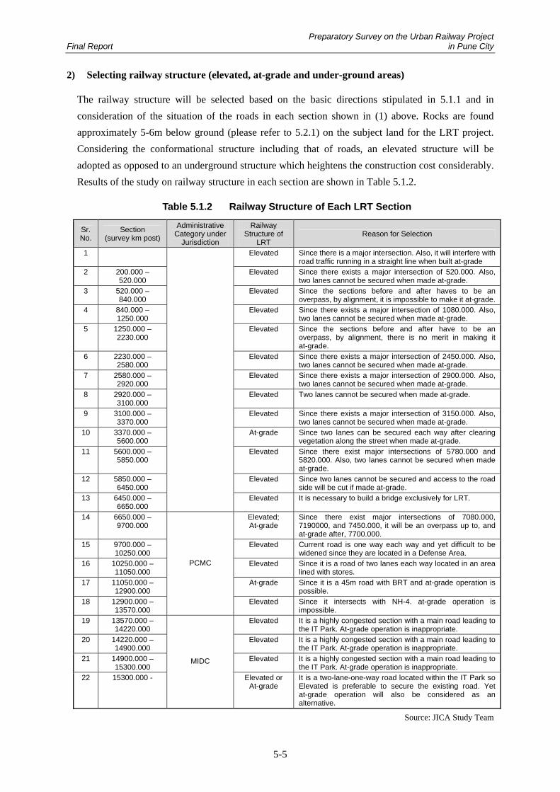
2) Selecting railway structure (elevated, at-grade and under-ground areas)
The railway structure will be selected based on the basic directions stipulated in 5.1.1 and in
consideration of the situation of the roads in each section shown in (1) above. Rocks are found
approximately 5-6m below ground (please refer to 5.2.1) on the subject land for the LRT project.
Considering the conformational structure including that of roads, an elevated structure will be
adopted as opposed to an underground structure which heightens the construction cost considerably.
Results of the study on railway structure in each section are shown in Table 5.1.2.
Table 5.1.2 Railway Structure of Each LRT Section
Sr. No.
Section (survey km post)
Administrative Category under
Jurisdiction
Railway Structure of
LRT Reason for Selection
1 Elevated Since there is a major intersection. Also, it will interfere with road traffic running in a straight line when built at-grade
2 200.000 – 520.000
Elevated Since there exists a major intersection of 520.000. Also, two lanes cannot be secured when made at-grade.
3 520.000 – 840.000
Elevated Since the sections before and after haves to be an overpass, by alignment, it is impossible to make it at-grade.
4 840.000 – 1250.000
Elevated Since there exists a major intersection of 1080.000. Also, two lanes cannot be secured when made at-grade.
5 1250.000 – 2230.000
Elevated Since the sections before and after have to be an overpass, by alignment, there is no merit in making it at-grade.
6 2230.000 – 2580.000
Elevated Since there exists a major intersection of 2450.000. Also, two lanes cannot be secured when made at-grade.
7 2580.000 – 2920.000
Elevated Since there exists a major intersection of 2900.000. Also, two lanes cannot be secured when made at-grade.
8 2920.000 – 3100.000
Elevated Two lanes cannot be secured when made at-grade.
9 3100.000 – 3370.000
Elevated Since there exists a major intersection of 3150.000. Also, two lanes cannot be secured when made at-grade.
10 3370.000 – 5600.000
At-grade Since two lanes can be secured each way after clearing vegetation along the street when made at-grade.
11 5600.000 – 5850.000
Elevated Since there exist major intersections of 5780.000 and 5820.000. Also, two lanes cannot be secured when made at-grade.
12 5850.000 – 6450.000
Elevated Since two lanes cannot be secured and access to the road side will be cut if made at-grade.
13 6450.000 – 6650.000
Elevated It is necessary to build a bridge exclusively for LRT.
14 6650.000 – 9700.000
Elevated; At-grade
Since there exist major intersections of 7080.000, 7190000, and 7450.000, it will be an overpass up to, and at-grade after, 7700.000.
15 9700.000 – 10250.000
Elevated Current road is one way each way and yet difficult to be widened since they are located in a Defense Area.
16 10250.000 – 11050.000
Elevated Since it is a road of two lanes each way located in an area lined with stores.
17 11050.000 – 12900.000
At-grade Since it is a 45m road with BRT and at-grade operation is possible.
18 12900.000 – 13570.000
PCMC
Elevated Since it intersects with NH-4. at-grade operation is impossible.
19 13570.000 – 14220.000
Elevated It is a highly congested section with a main road leading to the IT Park. At-grade operation is inappropriate.
20 14220.000 – 14900.000
Elevated It is a highly congested section with a main road leading to the IT Park. At-grade operation is inappropriate.
21 14900.000 – 15300.000
Elevated It is a highly congested section with a main road leading to the IT Park. At-grade operation is inappropriate.
22 15300.000 -
MIDC
Elevated or At-grade
It is a two-lane-one-way road located within the IT Park so Elevated is preferable to secure the existing road. Yet at-grade operation will also be considered as an alternative.
Source: JICA Study Team
Preparatory Survey on the Urban Railway Project Final Report in Pune City
5-6
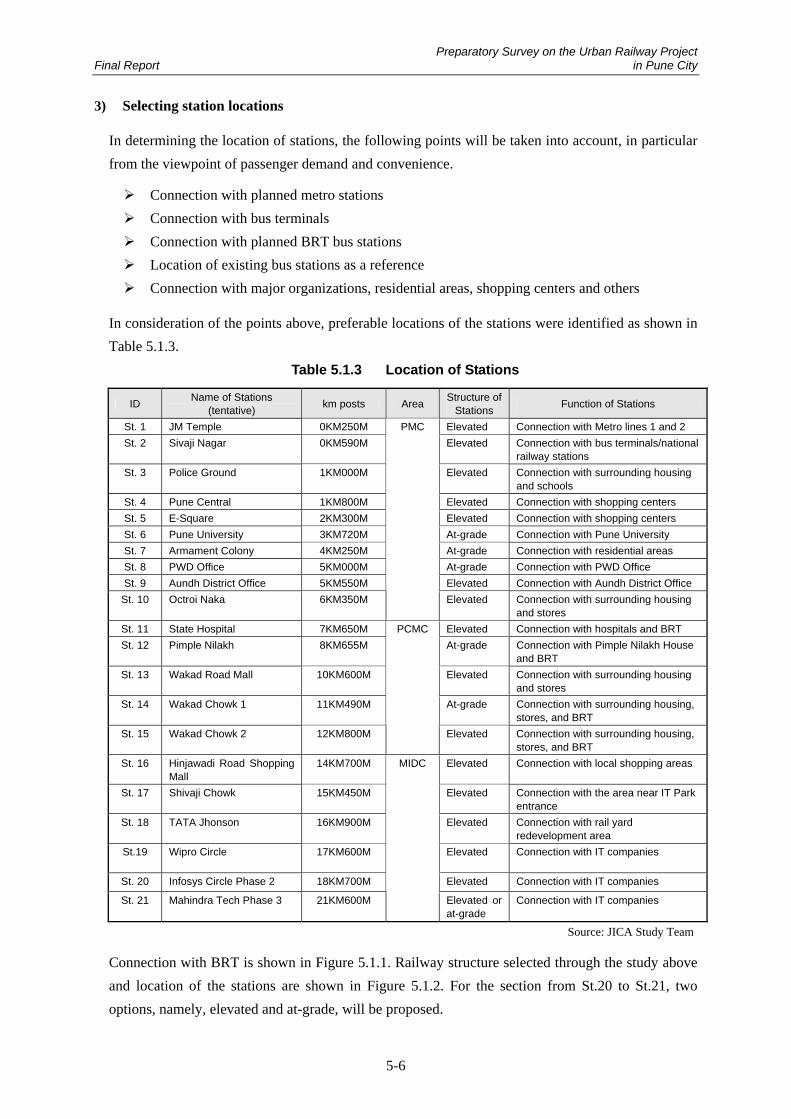
3) Selecting station locations
In determining the location of stations, the following points will be taken into account, in particular
from the viewpoint of passenger demand and convenience.
Connection with planned metro stations
Connection with bus terminals
Connection with planned BRT bus stations
Location of existing bus stations as a reference
Connection with major organizations, residential areas, shopping centers and others
In consideration of the points above, preferable locations of the stations were identified as shown in
Table 5.1.3.
Table 5.1.3 Location of Stations
ID Name of Stations (tentative) km posts Area Structure of
Stations Function of Stations
St. 1 JM Temple 0KM250M Elevated Connection with Metro lines 1 and 2 St. 2 Sivaji Nagar 0KM590M Elevated Connection with bus terminals/national
railway stations St. 3 Police Ground 1KM000M Elevated Connection with surrounding housing
and schools St. 4 Pune Central 1KM800M Elevated Connection with shopping centers St. 5 E-Square 2KM300M Elevated Connection with shopping centers St. 6 Pune University 3KM720M At-grade Connection with Pune University St. 7 Armament Colony 4KM250M At-grade Connection with residential areas St. 8 PWD Office 5KM000M At-grade Connection with PWD Office St. 9 Aundh District Office 5KM550M Elevated Connection with Aundh District Office
St. 10 Octroi Naka 6KM350M
PMC
Elevated Connection with surrounding housing and stores
St. 11 State Hospital 7KM650M Elevated Connection with hospitals and BRT St. 12 Pimple Nilakh 8KM655M At-grade Connection with Pimple Nilakh House
and BRT St. 13 Wakad Road Mall 10KM600M Elevated Connection with surrounding housing
and stores St. 14 Wakad Chowk 1 11KM490M At-grade Connection with surrounding housing,
stores, and BRT St. 15 Wakad Chowk 2 12KM800M
PCMC
Elevated Connection with surrounding housing, stores, and BRT
St. 16 Hinjawadi Road Shopping Mall
14KM700M Elevated Connection with local shopping areas
St. 17 Shivaji Chowk 15KM450M Elevated Connection with the area near IT Park entrance
St. 18 TATA Jhonson 16KM900M Elevated Connection with rail yard redevelopment area
St.19 Wipro Circle 17KM600M Elevated Connection with IT companies
St. 20 Infosys Circle Phase 2 18KM700M Elevated Connection with IT companies
St. 21 Mahindra Tech Phase 3 21KM600M
MIDC
Elevated or at-grade
Connection with IT companies
Source: JICA Study Team
Connection with BRT is shown in Figure 5.1.1. Railway structure selected through the study above
and location of the stations are shown in Figure 5.1.2. For the section from St.20 to St.21, two
options, namely, elevated and at-grade, will be proposed.

Preparatory Survey on the Urban Railway Project Final Report in Pune City
5-7
St. 16: Hinjawad Road Shopping Mall(14KM700)
St. 15: Wakad Chowk 2(12KM800)
St. 14: Wakad Chowk 1(11KM490)
St. 13: Doctors Colny(10KM600)
St. 9: AundhDistrict Office(5KM550)
St. 8: PWD Office(5KM000)
NH-4
Mula RiverSt. 10: Octroi Naka
(6KM350)
BRTBRT
St. 12: Pimple Nilakh(8KM655)
St. 11: State Hospital(7KM650)
PCMC
Interchange Stations bwtween LRT and BRT
Figure 5.1.1 Connection with BRT
Source: JICA Study Team
St. 16(14KM700)
St. 15(12KM800)
St. 14(11KM490)
St. 13(10KM600)
St. 9(5KM550)
St. 8(5KM000)
St. 6(3KM720)
St. 5(2KM300)
St. 3(1KM000)
St. 1(0KM250)
St. 2(0KM590)
St. 7(4KM250)
St. 12(8KM655)
St. 11(7KM650)
St. 4(1KM800)
St. 17(15KM450)
St. 18(16KM900)
St. 19(17KM600)
St. 20(18KM700)
St. 21(21KM600)
Legend
: Station : Elevated Structure (Viaduct) : At-grade Structure : Depot
PMCPCMCMIDC
NH-4
Mula River
St. 10(6KM350)
Depot
Mah
inda
ra Tec
h Pha
se
3
TATA
Joh
nson
Wak
ad C
howk 2
Pim
ple Nila
kh
St.2
1
Infosy
s Circ
le Pha
se 2
St.2
0
Wipo Circ
leSt.1
9
St.1
8
Shivaji C
howk
St.1
7
Hinjawad
i Roa
d
Sho
pping Mall
St.1
6
St.1
5
Wak
ad C
howk 1
St.1
4
Wak
ad R
oad Mall
St.1
3
St.1
2
State Hos
pital
St.1
1
St.6
Aund
h District
Office
St.9
PWD O
ffice
St.8
JM Tem
ple
St.1
Police Groun
dSt.3
Sivaji N
agar
St.2
E-S
quare
St.5
Pun
e Cen
tral
St.4
Armam
ent C
olon
ySt.7
Octroi N
aka
St.1
0
Pun
e Unive
rsity
RL = 13.5 m
Mula RiverNH-4Depot
RL = 8.5 - 13.5 mRL = 11.5 - 13.5 mRL = 8.5 - 13.5 m
Figure 5.1.2 Railway Structure and Locations of Stations
Source: JICA Study Team

Preparatory Survey on the Urban Railway Project Final Report in Pune City
5-8
4) Selecting spatial alignment
Taking into account the situation along the road, traffic volume, and others, patterns as shown in
Table 5.1.4 are considered for the spatial alignment of the at-grade LRT.
Table 5.1.4 Spatial Alignment for At-grade LRT Operation
Spatial Alignment of the Railway
Alignment at Road Center
LRT LRT
軌道敷 車道車道 歩道歩道
Alignment at Both Sides of Road
LRT LRT
車道 軌道敷軌道敷 歩道歩道
Alignment at One Side of Road
LRT LRT
車道 軌道敷 歩道歩道 歩道
Characteristics
In this case, the railway is aligned at the center of the road. It can minimize the impact on ordinary buses running parallel to the LRT and also prevent pedestrians from entering the railway because it is far from the walkway. On the other hand, stations ought to be set at the center and passengers need to cross the road to reach the station. At intersections, there will be congestion with right-turning automobiles.
In this case, the railway is aligned at both sides of the road. One merit of this pattern is that users do not need to cross the roads, allowing them to more easily access facilities along the track. On the other hand, it also allows pedestrians to easily walk into the railway, renders LRTs running in different directions to be far apart, and requires reconsideration of the location of ordinary bus stations.
In this case, the railway is located at the one side of the roadway. It can minimize congestion with automobiles but requires reallocation of road space.
Source: JICA Study Team
Not restricted to the results of the study in 5.1.2 2), where the following sections were selected to be
at-grade: one section within PMC; two sections within PCMC; and the section from St.20 to St.21
within Hinjawadi IT Park, the best spatial alignment will be identified for each section taking into
account the characteristics of each LRT alignment as shown in the table above.
(1) Spatial Alignment within PMC
The proposed at-grade sections within the PMC are the area from Pune University with km posts of
36000.000-5100.000 to that before reaching the intersection of Aundh District Office. This section
is a two-lane one way road with a road width of approximately 34m. By clearing some parts of the
boulevard trees covering the roadway, the spatial area for the LRT as well as the present two-lane
one way road can be secured. The railway is considered preferable to be aligned at both sides/ways
of the road taking into account: accessibility from facilities along the railway; alignment of the road
at the station under the ‘Alignment at Road Center’ option; relocation of street lamps in the dividing
strip; and others. The railway spatial alignment in this section is shown in Figure 5.1.3 and 5.1.4.
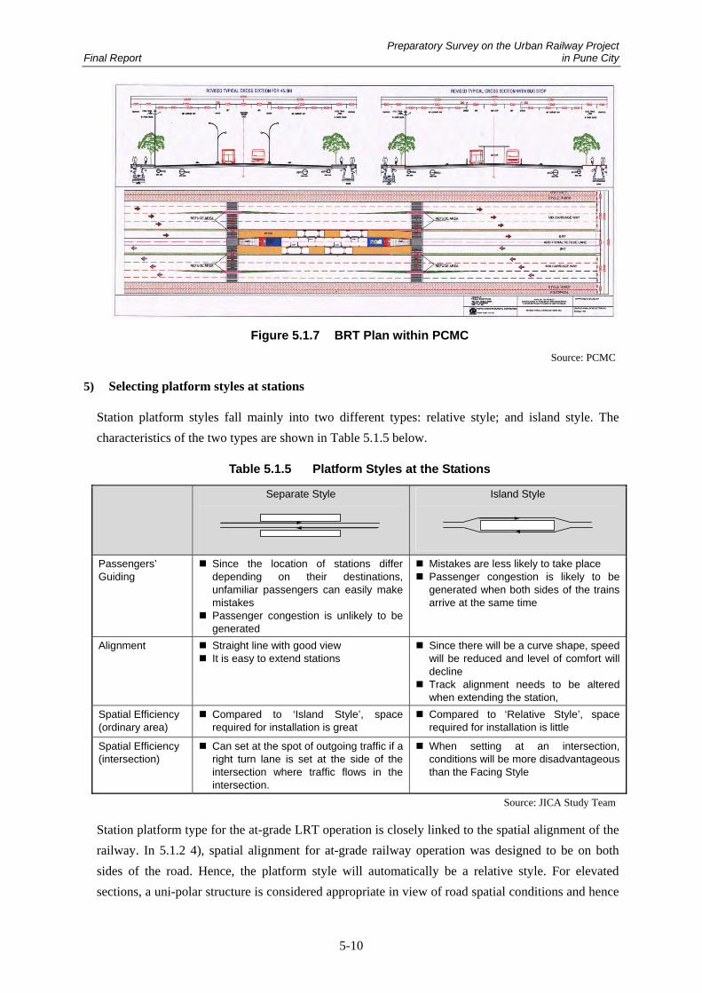
(2) Spatial Alignment within PCMC
The two at-grade sections are 45m-width roads with a BRT operational plan, namely, section of km
posts of 8100.000-9300.000 and that of 11400.000-12300.000. Spatial alignment of the 45m road is
shown in Figure 5.1.7. PCMC has agreed on using one lane per direction, two lanes in total, as the
spatial alignment of the LRT. Nevertheless, it is considered preferable that spatial alignment of the
LRT be at the center of the road as BRT, which is also planned to be centrally-aligned, taking into

Preparatory Survey on the Urban Railway Project Final Report in Pune City
5-9
account that the LRT is going to be developed after BRT. By doing so, it can avoid significant
modifications to the road and BRT lane and can avoid curved alignment at the station. Figures of
the spatial alignment of a 45m road are shown in Figure 5.1.5 and 5.1.6.
(3) Spatial Alignment within Hinjawadi IT Park
At-grade operation is also considered as an alternative for the section from St.20 to St.21 within
Hinjawadi IT Park. Alignment at one side of the road is considered preferable in this case for this
section taking into account the situation where there is a roundabout but no major intersection and
returning of the LRT at the final stop.
1,3751,725 2,9002,900 1,375 1,725
1,435
PlatformPlatform
3,5003,500 3,500 3,5002,0003,000
34,000
3,000
FootpathFootpath
19,450
Carriage Carriage Carriage Carriage
300
Figure 5.1.3 Spatial Alignment of the LRT at Station within PMC
(area of at-grade operation) Source: JICA Study Team
1,7251,7252,5502,5501,725 1,725
1,435
3,5003,500 3,500 3,5002,0003,000
34,000
3,000
FootpathFootpath
24,550
Carriage Carriage Carriage Carriage
Figure 5.1.4 Spatial Alignment of the LRT in between Stations within PMC
(area of at-grade operation) Source: JICA Study Team
1,3751,725 2,9002,900 1,375 1,725
1,435
PlatformPlatform
4,000
7,000
11,000
7,000
4,000
45,000
BRT BRT
LRT LRT
28,450
3,500 3,500 3,5003,500
Footpath & Cycle Footpath & CycleCarriageCarriageCarriageCarriage
300
Figure 5.1.5 Spatial Alignment of the LRT at Station within PCMC
(area of at-grade operation) Source: JICA Study Team
1,7251,7251,5501,5501,725 1,725
1,435
5,0008,550
11,00
8,550
5,000
45,000
BRT BRT
LRT LRT
31,550
3,500 3,500 3,5003,500
Footpath & Cycle Carriage Carriage Footpath & CycleCarriage Carriage
Figure 5.1.6 Spatial Alignment of the LRT in between Stations within PCMC
(area of at-grade operation) Source: JICA Study Team
Preparatory Survey on the Urban Railway Project Final Report in Pune City
5-10
Figure 5.1.7 BRT Plan within PCMC
Source: PCMC
5) Selecting platform styles at stations
Station platform styles fall mainly into two different types: relative style; and island style. The
characteristics of the two types are shown in Table 5.1.5 below.
Table 5.1.5 Platform Styles at the Stations
Separate Style
Island Style
Passengers’ Guiding
Since the location of stations differ depending on their destinations, unfamiliar passengers can easily make mistakes
Passenger congestion is unlikely to be generated
Mistakes are less likely to take place Passenger congestion is likely to be
generated when both sides of the trains arrive at the same time
Alignment Straight line with good view It is easy to extend stations
Since there will be a curve shape, speed will be reduced and level of comfort will decline
Track alignment needs to be altered when extending the station,
Spatial Efficiency (ordinary area)
Compared to ‘Island Style’, space required for installation is great
Compared to ‘Relative Style’, space required for installation is little
Spatial Efficiency (intersection)
Can set at the spot of outgoing traffic if a right turn lane is set at the side of the intersection where traffic flows in the intersection.
When setting at an intersection, conditions will be more disadvantageous than the Facing Style
Source: JICA Study Team
Station platform type for the at-grade LRT operation is closely linked to the spatial alignment of the
railway. In 5.1.2 4), spatial alignment for at-grade railway operation was designed to be on both
sides of the road. Hence, the platform style will automatically be a relative style. For elevated
sections, a uni-polar structure is considered appropriate in view of road spatial conditions and hence

Preparatory Survey on the Urban Railway Project Final Report in Pune City
5-11
it is difficult structurally to adopt an island style. Instead, the relative style is appropriate, which
also allows a linear railway alignment.
Table 5.1.6 Platform Types at Stations
ID Name of Stations (tentative) km posts Area Structure of Stations Platform Type
St. 1 JM Temple 0KM250M Elevated Relative St. 2 Sivaji Nagar 0KM590M Elevated Relative St. 3 Police Ground 1KM000M Elevated Relative St. 4 Pune Central 1KM800M Elevated Relative St. 5 E-Square 2KM300M Elevated Relative St. 6 Pune University 3KM720M At-grade Relative St. 7 Armament Colony 4KM250M At-grade Relative St. 8 PWD Office 5KM000M At-grade Relative St. 9 Aundh District Office 5KM550M Elevated Relative St. 10 Octroi Naka 6KM350M
PMC
Elevated Relative St. 11 State Hospital 7KM650M Elevated Relative St. 12 Pimple Nilakh 8KM655M At-grade Relative St. 13 Wakad Road Mall 10KM600M Elevated Relative St. 14 Wakad Chowk 1 11KM490M At-grade Relative St. 15 Wakad Chowk 2 12KM800M
PCMC
Elevated Relative St. 16 Hinjawadi Road Shopping Mall 14KM700M Elevated Relative St. 17 Shivaji Chowk 15KM450M Elevated Relative St. 18 TATA Jonson 16KM900M Elevated Relative St.19 Wipro Circle 17KM600M Elevated Relative St. 20 Infosys Circle Phase 2 18KM700M Elevated Relative
St. 21 Mahindra Tech Phase 3 21KM600M
MIDC
Elevated /At-grade Relative
Source: JICA Study Team
6) Considering exclusive and/or combined use of the railway
Areas considered to be at-grade have a large traffic volume and the speed of the traffic is relatively
high. For this reason, it is preferable to ensure stable LRT operation by preventing accidental
contacts of LRT and road traffic as well as pedestrians entering into the railway. With the exception
of certain parts such as crossing areas, the railway would be of exclusive use for the LRT,
separating the area by fences and/or others to stop people from entering into the railway.
7) Selecting alignment
Concrete alignment will be designed based on the above mentioned considerations. The design
criteria for determining the alignment is shown in Table 5.1.7.

Preparatory Survey on the Urban Railway Project Final Report in Pune City
5-12
Table 5.1.7 Design Criteria for Alignment
Item Design Criteria Space (distance between the center of railways)
3,050mm (straight line section)
Radius of Plane Curve Main line Station
20m or above (preferably 40m or above) 300m or above
Steepness Main line Station
70‰ or lower (preferably 50‰ or lower) 0‰ (if unavoidable, 5‰ or lower)
Radius of Vertical Curve 1,500m or above Length of platform 62m (at-grade station), 65m (elevated station)
Source: JICA Study Team
Please refer to Figures 5.4.1 and 5.4.2 for the size of the structure.
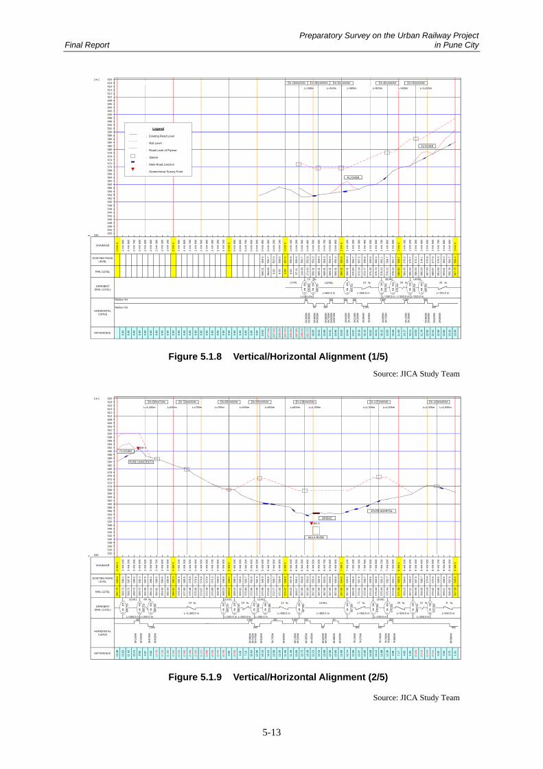
Plane alignment
The minimum radius of the curve in this LRT line is 50m for the intersections located
between St. 1 and St. 2. In addition, there is an 80m radius curve situated between St. 1 and
St. 2 and a 60m radius curve across Mula River in PCMC. Others are over 200m. The plane
spatially difficult section is that where a flyover runs in parallel from E Square near
2K200M to Pune University near 3K400M. In general, the road width is narrow. The road in
front of E Square is particularly narrow which hence shall be avoided and instead a flyover
be developed. Please refer to the reference material at the end of the report for the ground
plan and to Figures 5.1.8-5.1.12 for elements of the plane alignment.
Vertical alignment
Maximum grade in this LRT line is 68‰ in front of Pune University where one line of the
elevated bridge crosses over the road and drops to the ground level. The standard is set to be
70‰ or lower but a preferable slope is 50‰ or lower in order to ensure stable operation.
Hence, it is considered suitable to slightly move the planned location of Pune University
Station to reduce the grade and make sure that it is approximately 50‰. For other steep
slopes, the area close to Wippro Circle in Hinjawadi IT Park exceeds 50‰ but this is
considered inevitable given its unique geography. Please refer to Figures 5.1.8-5.1.12 for
vertical alignment.
8) Comparison between partial at- grade and whole elevated for LRT
This study shows partial at-grade plan in order to take into consideration of the characteristics of
LRT systems. On the other hand the whole elevated plan which separates LRT and road traffic is
shown in APPENDIX-28.
9) Toward to further study
In considering alternative plans in the individual locations, it is needed to consider the scale of the
land acquisition, the number of resettlement and the negative impact of the environment.
Preparatory Survey on the Urban Railway Project Final Report in Pune City
5-13
▽
LEVEL LEVELLEVEL ‰ ‰ ‰
L=150.0mRadius (m)
Radius (m)0K
350M
0K39
0M
0K49
0M0K
555M
0K68
0M0K
730M
0K82
0M0K
870M
1K04
0M1K
100M
1K21
5M1K
290M
1K39
0M
1K44
5M
1K69
5M1K
725M
2K12
0M2K
165M
2K45
0M2K
500M
2K62
0M
2K69
0M
569.
315500
KM0
【St.5】2KM300M【St.4】1KM800M
0.00
0.00
0.00
[ m ]
0.00
0.00
0.00
0.00
KM
KM
0.00
0.00
0.00
0.00
200
0.00
KM
KM
0.00
KM
100
-0
0K
M
0.00
(271
.04)
0.00
11.7
9
13.1
7
13.5
0
15.2
1
16.3
1
15.6
2
578.
229
KM1
L=200.0 m
KM
16.1
2
13.5
0
10.5
8
0.00
14.9
9
14.4
1
13.9
6
(438
.42)
0.00
0.00
(555
.80)
14.8
1
(557
.50)
16.0
5
(557
.00)
(558
.50)
0.00
(381
.37)
0.00
0.00
0.00
11.0
5
0.00
0.00
0.00
0.00
595.
78
585.
93
12.5
8
12.8
4
597.
75
569.
31
100
569.
315
KM1
573.
77
576.
74
585.
93
2
593.
81
583.
36
589.
87
591.
84
0.00
569.
31
284.
66RAIL LEVEL
550548546544
EXISTING ROADLEVEL 55
7.0
555.
8
558.
5
555.
7
557.
5
0K
M3
584.
4
592
5980
536534
CHAINAGE
KM
-3
530
612
602
608606604
590588586
564
620618
614
610
616
560
570568566
562
596
578576
552
582
574572
580
584
594
554.
5
KM
-2
KM
554
532
KM
-2
600
582.
7
554.
3
556.
3
581.
0
570.
2
570.
7
572.
4
574.
1
575.
8
567.
7
559.
6
560.
4
554.
0
552.
7
555.
8
KM
KM
KM
KM
900
800
700
600
500
KM
600
900
800
100
0K
M
KM
KM
KM
-0
700
400
0
300
200
KM
400
300
500
300
400
KM
-1
700
KM
-1
900
KM
-1
400
KM
-1
KM
-1
500
800
-2
300
100
KM
-2
KM
-2
200
500
KM
-2-2
KM
-2
800
KM
-2
700
400
KM
900
0K
M-2
0.00
0.00
700
800
KM
554.
9
553.
3
KM
57.1
5
0
114.
30
171.
45
15.3
1
L=600.0 m
80
500
564.
7
562.
1
KM
1111 1K
M
KM
KM
KM
575.
26
578.
23
26
1
578.
23
578.
23
580.
80
L=200.0 m
22258
5.93
258
7.90
1
200
2
569.
7
900
700
FLYOVER
2 2
400
300
220
0
KM
KM
KM
20
L=700.0 m
13.1
0
13.3
6
12.3
2
-0-1
KM
KM
00 00-0 -0
600
200
100
-1
KM
-1K
M
KM
-1-1 -0-0
700
800
KM
-0
KM
KM
555.
0
0-0
200
500
1
556.
7
10
KM
900
KM
KM
KM
100
0
KM
KM
0
600HORIZONTAL
CURVE
GRADIENT(RAIL LEVEL)
DIFFERENCE
556
542540538
600
558
900
570.
80
569.
31
600
569.
31
0
569.
31
569.
31
569.
31
569.
31
【St.2】0KM590M
555.
4
FLYOVER
100
0
KM
600
KM
552.
8
【St.3】1KM000M
2
557.
2
KM
300
500
2
579.
3
KM
2
577.
6
L=300.0 m
400
558.
6
12.0
5
KM2
KM 585.
932
578.
229
585.
93
500
500
(497
.85)
1,000
1,000
13.0
4
14.0
7
15.1
0
13.5
0
600
L=500m L=1,420mL=800m
2,800250
L=410m L=800m
350
KM 571.
500
15 ‰
1 157
2.29
15
L=600.0 m
15.1
3
LEVEL
【St.1】0KM250M
L=340m
800
Legend
: Existing Road Level
: Rail Level
: Road Level of Flyover
: Station
: Main Road Junction
: Geotechnical Survey Point
Figure 5.1.8 Vertical/Horizontal Alignment (1/5)
Source: JICA Study Team
▽
LEVEL ‰ LEVEL LEVEL LEVEL‰ ‰ ‰ LEVEL ‰ ‰ ‰ ‰
3K31
0M
3K42
0M
3K57
5M
3K62
0M
5K38
0M5K
415M
5K47
0M
5K51
5M
5K75
5M
5K84
0M
6K13
5M6K
220M
6K35
5M
6K45
0M
6K62
0M6K
700M
6K88
5M
6K94
0M
7K15
5M
7K37
0M
7K70
0M
7K76
0M7K
820M
7K86
0M
8K98
0M
L=200.0 mL=850.0 m
567.
600
KM7
550
L=250.0 mL=450.0 m
【St.6】3KM720M
EXISTING ROADLEVEL
17
L=300.0 m
DIFFERENCE
586.
1
11.9
2
13.3
6
599.
72
KM
578
[ m ]
650
574.
488
KM5
5
13.0
9
12.2
057
1.62
569.
01
572.
66
L=600.0 m
557.
9
5
(0.0
3)
5
573.
0656
3.1
565.
3
8
563.
9
564.
6
562.
2
8
STATE HOSPITAL
900
575.
0456
0.9
KM
7 7
555.
26
554.
9
76
556.
6
7
800
KM
77
800
【St.11】7KM650M
553.
3
554.
6
554.
0
66 6
【St.8】5KM000M
568.
9
559.
4
KM
9.98
7.17
4.50
0.50
1.83
(0.1
4)
(0.2
4)
(0.0
2)
KM
550
571.
000
KM8
-20
575.
042
KM
6
12.2
1
L=450.0 m
13.0
8
18
13.0
8
12.9
5
570.
47
1.01
0.70
569.
11
500
450
0.00
568.
10
12.1
4
14.1
2
12.8
8
14.5
8
13.3
7
574.
488
7
554.
5
100
568.
17
574.
49
570.
84
574.
49
12.3
6
(0.0
1)
0.32
567.
59
567.
60
567.
60
567.
60
568.
35
567.
11
566.
94
568.
56
570.
19
570.
62
569.
86
567.
60
580.
63
572.
28
568.
10
570.
89
577.
85
567.
60
573.
67
576.
46
579.
24
567.
60
568.
10
567.
60
569.
32
567.
60
(0.4
4)56
9.49
(1.2
7)
(1.5
4)
(0.6
9)
(0.3
3)
575.
06
1,000
(1.6
2)
(0.7
3)
0.00
(1.1
0)
10.2
1
(1.3
3)
8.50
5.97
555.
4
3
8 8
(2.6
0)
(2.3
6)
554.
5
559.
7
576.
6
565.
6
563.
7
573.
0
573.
91
572.
77
(2.2
1)
600 -14
555.
4
566.
6
570.
4
575.
04
575.
0456
2.7
570.
6
569.
5
569.
10
RAIL LEVEL
597.
75
GRADIENT(RAIL LEVEL) KM
3
400
13.6
2
KM
KM
KM
KM
KM
KM
KM
KM
KM
KM
KM
KM
KM
KM
KM
KM
KM
5 65
KM
KM
KM
KM
4 4 44
550
544542
KM
KM
KM
KM
KM
KM
576574572
554
560
564
558556
562
552
548
CHAINAGE
538536534
530532
540
546
586
592
588590
608606604
594596
KM
【St.7】4KM250M
100
800
900
L=750m
400
KM
560.
4
559.
6
5
100
3 33
KM
KM
3
KM
562.
6
561.
6
568.
1
568.
1
569.
9
KM
571.
2
KM
KM
500
200
300
KM
KM
KM
KM
600
700
586.
2
592.
9658
7.0
3 3
KM58
6.21
L=200.0 m300
584.
558
3.42
574.
9
582.
3
581.
5
578.
8
580.
5
L=200.0 m L=350.0 m
583.
458
2.03
54 4 54 54
KM
KM
586.
206
585.
558
4.81
KM59
9.72
599.
718
-68
3
587.
8
591.
2
589.
5
599.
72
358
4.4
64 5
100
900
568.
100
3,000
4
558.
9
BH-2
800
KM
3 3
KM
3
700
600
0
13.6
5
12.1
6
13.8
5
12.6
6
BRIDGE
500
66
KM
KM
KM
6
【St.10】6KM350M
11.5
9
11.4
6
13.0
0
MULA RIVER
L=1,300m
BH-3
60
KM
500
555.
5
7
0
KM
7
0600
88 8 8
567.
6
568.
6
800
10.0
3
12.9
0
14.1
0
【St.9】5KM550M
14.3
1
L=550m L=800m
500
350
800
14.2
8
12.7
225
0 16
8
575.
042
KM7
-8
L=550.0 m
300
568.
7
KM
570.
91
7
KM
8
KM
KM
557.
5
558.
7
7
800
250
300
566.
122
567.
0
L=300.0 m
400
820
0K
MKM
4
568.
100
KM
3.45
(0.7
6)
620618
584
616614612
602600598
610
582580
HORIZONTALCURVE
570568566
60
7.10
2,500
5KM
200
KM
5
300
900
567.
600
KM
-11
KM
0 600
300
900
567.
60
KM
700
L=1,005mL=750m L=800m L=1,300m
0 100
200
300
400
700
100
500
600
PUNE UNIVERSITY
FLYOVER
900
400
200
600
500
400
L=1,420m L=530m
0
L=1,300.0 m
599.
72
200
300
KM
100
599.
718
571.
08
700
100
0【St.12】8KM655M
900
9
800
700
800 600
800
L=1,005m L=1,945m
100
400
559.
6
572.
56
574.
21
569.
25
Figure 5.1.9 Vertical/Horizontal Alignment (2/5)
Source: JICA Study Team

Preparatory Survey on the Urban Railway Project Final Report in Pune City
5-14
▽
‰ LEVEL LEVEL‰ ‰ ‰ ‰ ‰ ‰ ‰ LEVEL ‰ ‰
9K17
0M
9K70
0M
9K81
5M9K
875M
9K93
5M
10K
310M
10K
395M
10K
655M
10K
740M
11K
060M
11K
120M
11K
250M
11K
315M
11K
490M
11K
640M
11K
965M
12K
035M
12K
120M
12K
275M
12K
380M
12K
520M
12K
605M
12K
665M
12K
920M
13K
035M
13K
290M
13K
375M
13K
500M
13K
705M
13K
810M
14K
090M
14K
165M
14K
235M
14K
330M
14K
395M
14K
560M
14K
640M
14K
770M
14K
830M
14K
945M
15K
045M
0
13 13
300
558.
998
KM12
400
200 650
300 1500
450
650
578.
987
538
L=350.0 mL=250.0 mL=350.0 m
578.
987
KM10
LEVAL
0
570.
4
570.
2KM
9
565.
2
13.2
6
562560558
RAIL LEVEL
568.
4
567.
59
566.
84
567.
74
EXISTING ROADLEVEL
536534
572
KM
KM
KM
[ m ]
KM14
13
L=500.0 m
500
574.
308
KM10
10 10KM
-9 -19
13.9
1
14.2
2
300
1
750
560.
3
556.
7
574.
31
573.
808
10K
M
13.6
7
11.3
1
14.3
4
11.9
9
14.2
9
14.7
6
13.5
0
10.3
1
11.1
8
10.0
2
0.43
0.00
0.20
0.16
13.6
2
14.2
1
15.7
8
14.2
9
13.5
5
12.8
0
15.0
4
9.52
14.0
3
12.4
6
11.6
0
13.5
0
13.9
8
12.0
6
3.61
0.00
0.00
3.92
(0.5
3)
0.00
571.
7
574.
6
566.
6
566.
8
567.
1
570.
3
559.
5
500
KM
KM
1460
0
【St.13】10KM600M
557.
8
11
558.
9
KM
556.
0
556.
3
11 11 11
556.
0
KM
KM
KM
10
KM
KM
111010
KM
569.
8
560.
8
563.
2
564.
2
562.
7
564.
9
564.
0
567.
2
9 9
KM
400
970
0568
544
600
550
546
200
540542
548
566
14 14
584
552
582580
592
1514 14 14 141414 14
568.
8
12 12
800
10 11
576.
18
575.
24
KM
558.
8
KM
KM
13
KM
KM
13
558.
8
559.
6
558.
0
573.
83
12
560.
312
560.
6
559.
657
0.12
573.
83
556.
1
557.
1
556.
3
1155
6.0
11
556.
1
579.
49
573.
83
573.
83
562.
6
564.
2
573.
83
563.
5
564.
3
562.
8
556.
04
557.
93
563.
44
556.
32
588.
27
582.
32
585.
30
573.
83
573.
83
575.
25
582.
32
582.
32
576.
66
578.
08
573.
83
573.
83
573.
83
573.
83
570.
75
578.
05
570.
95
577.
34
578.
99
578.
99
578.
99
574.
31
574.
31
577.
12
572.
85
555.
99
558.
46
559.
74
556.
10
555.
97
556.
86
557.
39
569.
04
567.
13
KM
KM
KM
11
KM
KM
KM
KM
KM
KM
KM
KM
KM
KM
KM
KM
KM
0
KM
KM
KM
KM
KM
KM
KM
400
KM
10
200
100
600
500
KM
10 10 10
KM
9
530
564
556
532
0 100
CHAINAGE
9 9
554
612610
606604
608
570
576
588
620618
594
578.
9956
9.4
9 9
KM
900
Y JUNCTION
569.
8
300
570.
0
9
L=250.0 m
9
450
200
400
574
598596
578
586
590
616614
500
600
500
800
900
0
30
1000
400
800
900
0
BH-4
L=1,310m
200
1155
6.4
12 1255
9.0
557.
2
557.
7
12
KM
KM
KM
KM
KM
KM
KM
13 13
KM
KM
KM
1212
100
400
200
300
100
900
800
700
14
562.
5
558.
7
562.
6
563.
8
566.
6
567.
6
573.
83
560.
3
561.
0
700
566.
41
562.
71
1255
9.00
559.
0
500
600
400
0 100
700
800
900
7.16
FLYOVER
NH - 4
573.
83
573.
8356
1.8
13
13.0
8
300
9.21
800
L=500.0 m
5
1000 800
11.2
3
10.0
0
9
11.0
5
DIFFERENCE 1.01
0.00
0.63
12.9
6
7.12
11.8
1
9.56
100
566.
835
KM9
L=400.0 m
37
7.75
10.4
9
13.5
070
0
573.
830
KM12
0.24
0.95
3.67
9.00
556.
324
KM11
556.
03933
L=300.0 m
569.
098
935
0KM
L=300.0 m
11
HORIZONTALCURVE
GRADIENT(RAIL LEVEL) KM
11
400
KM
200
300
580.
91
200
13.8
8
KM
1313
L=1,300.0 m
573.
830 600
KM14L=600.0 m
14
200
568.
65
574.
04
600602
300
800
900
100
600
700
KM
KM
500
0800
KM
300
567.
133 -37
100
400
700
0
13.1
8
【St.14】11KM490M 【St.15】12KM800M
L=550.0 m
0.00
0.00
L=400.0 m
L=1,945m L=890m L=890m L=1,310m
582.
323
582.
323 800
L=750m
【St.16】14KM700M
KM
250
350L=200.0 m
400 1000400
KM
L=1,900m L=1,900m
500
Figure 5.1.10 Vertical/Horizontal Alignment (3/5)
Source: JICA Study Team
▽
LEVEL ‰‰ LEVEL ‰ LEVEL ‰ LEVEL ‰
15K
045M
15K
250M
15K
360M
15K
720M
15K
800M
15K
870M
15K
920M
15K
980M
16k0
20M
16k1
80M
16k2
50M
16k3
40M
16k3
95M
16k4
25M
16k4
80M
16k7
00M
16k8
00M
17K
000M
17K
200M
17K
500M
17K
700M
18K
100M
18K
350M
18K
750
18K
900M
19K
450M
19K
550M
20K
600M
20K
700M
500
KM17
700
KM
500 500
609.
000
KM20
600 400
400
KM19
350 800 250
1716
604.
562
500
KM18
600
800 500
604.
562 90
0
BH-5
591.
3
591.
1
589.
86
16 16 16
593.
53
592.
45
591.
32
SHIVAJI CHOWK
ENTRANCE OF PAHSE 3
INFOSYS CIRCLE
WIPRO CIRCLE
612
618616614
596
620
584582
594
610608606604602600598
592590588586
572570
580578
【St.18】16KM900M
L=1,450m L=700m L=700m
558556
800
900
CHAINAGE
0 100
200
KM
554
0
550
300
400
100
200
552
KM
500
600
700
300
400
KM KM
700
600
500
600
400
500
500
600
800
700
800
900
0 100
200
300
900
0 100
200
300
400
KM KM KM KMKM KM KM KM
700
800
700
800
300
400
900
0 100
200
900
0500
600
900
0500
600
700
800
KM KMKM KM KM KM KM KM KM KM KM KM KM KMKM KM KM KMKM KM KM KM KM KM KM KMKM KM KM KM KM KM KM KM KM KMKM KM KM KM KM KM KM KM KM
15 15 15 15 15 15 15 15
KM
1716 16 16 16 16 16 17 1717 17 18 18 1817 17 17 17 18 18 1918 19 1918 1918 18 18 19 19 19 19 2119 20 20 20 20 20 20 20
EXISTING ROADLEVEL 57
4.6
577.
3
580.
5
604.
1
591.
1
593.
5
593.
5
592.
0
591.
3
592.
5
620.
8
621.
0
622.
0
593.
4
595.
3
607.
0
609.
6
614.
1
619.
8
599.
4
616.
1
618.
8
616.
1
621.
6
623.
9
624.
2
623.
7
620.
8
616.
1
616.
1
616.
1
615.
0
616.
1
609.
0
616.
1
616.
1
616.
1
616.
1
616.
1
615.
0
614.
14
619.
79
604.
09
620.
75
606.
99
609.
64
621.
63
623.
68
621.
98
623.
95
624.
23
621.
02
620.
84
618.
79
616.
11
615.
00
616.
11
616.
11
616.
11
616.
11
616.
11
616.
11
616.
11
615.
00
615.
00
615.
00
20 20 2061
5.0
615.
0
KM
616.
1161
6.1
300
400
KM
616.
11
GRADIENT(RAIL LEVEL)
L=550.0 m
30
L=400.0 m
100
200
616.
11
616.
1161
6.1
1961
6.11
616.
11
KM61
6.11
616.
1
616.
1
616.
1
616.
1
616.
1
616.
11
616.
11
616.
11
HORIZONTALCURVE
200
591.
26
591.
06
RAIL LEVEL
588.
27
591.
25
350
200
598.
69
13.4
9
598.
688
KM15
594.
22
350
598.
69
598.
69
598.
69
598.
69
584.
7
585.
515 15
0.00
0.00
589.
9
583.
759
7.20
598.
69
598.
69
584.
8
585.
5
591.
09
16
598.
69
L=750.0 m
590.
0
586.
3
589.
5
590.
4
DIFFERENCE
13.6
7
13.9
9
13.6
9
0.00
0.00
13.8
5
13.1
5
12.4
1
13.9
9
13.1
9
9.17
8.33
8.72
0.00
0.00
0.00
0.00
0.00
0.00
0.00
0.00
0.00
0.00
0.00
0.00
0.00
0.00
0.00
0.00
0.00
0.00
0.00
7.11
0.00
0.00
0.00
0.00
0.00
0.00
0.00
0.00
0.00
0.00
0.00
0.00
0.00
0.00
0.00
0.00
0.00
0.00
0.00
0.00
0.00
0.00
0.00
0.00
0.00
100
KM16
17
KM
593.
49
592.
01
593.
36
595.
34
599.
37
L=400.0 m L=200.0 m L=200.0 m
0
46
【St.19】17KM600M
632.
289
624.
613
-19
650
50KM
17
KM17
200
616.
11
800
598.
688
L=550.0 m
11 41
L=450.0 m
623.
142
623.
142
632.
289
L=900.0 m
560
622624626
568566564562
576574
628630632634 L=1,100m
【St.20】18KM700M
L=1,100m
[ m ]
636638640
【St.17】15KM450M
L=750m L=1,450m
Figure 5.1.11 Vertical/Horizontal Alignment (4/5)
Source: JICA Study Team

Preparatory Survey on the Urban Railway Project Final Report in Pune City
5-15
▽
21K2
50M
21K4
00M
0.00
0.00
0.00
0.00
0.00
0.00
0.00
0.00
0.00
0.00
0.00
0.00
0.00
0.00
0.00
0.00
0.00
0.00
0.00
0.00
0.00
0.00
0.00
0.00
0.00
0.00
0.00
0.00
0.00
0.00
0.00
0.00
0.00
0.00
0.00
0.00
0.00
0.00
0.00
0.00
0.00
0.00
0.00
0.00
0.00
0.00
0.00
0.00
0.00
0.00
0.00
0.00
0.00
0.00
0.00
0.00
0.00
HORIZONTALCURVE
250
DIFFERENCE
0.00
0.00
0.00
0.00
GRADIENT(RAIL LEVEL)
RAIL LEVEL
615.
00
615.
00
615.
00
615.
00
615.
00
615.
00
618.
00
615.
0
615.
0
615.
0
618.
0EXISTING ROADLEVEL 61
5.0
615.
0
615.
0
26 26 26 2726 26 26 2625 26 26 2625 25 25 2525 25 25 2524 24 24 2524 24 24 2423 24 24 2423 23 23 2323 23 23 2322 22 22 2322 22 22 2221 22 22 2221 21 21 2121 21 21 21
KM KM KM KMKM KM KM KMKM KM KM KMKM KM KM KMKM KM KM KMKM KM KM KMKM KM KM KMKM KM KM KMKM KM KM KMKM KM KM KMKM KM KM KMKM KM KM KMKM KM KM KMKM KM KM KMKM KM KM KM
700
800
900
0300
400
500
600
900
0 100
200
500
600
700
800
100
200
300
400
700
800
900
0300
400
500
600
900
0 100
200
500
600
700
800
100
200
300
400
700
800
900
0300
400
500
600
900
0 100
200
500
600
700
800
100
200
300
400
552550
CHAINAGE
0KM
21
556554
560558
568566564562
576574572570
582580578
588586584
596594592590
604602600598
610608606
616614612
618
[ m ] 640638636634
624622620
【St.21】15KM600M
632630628626
Figure 5.1.12 Vertical/Horizontal Alignment (5/5)
Source: JICA Study Team

Preparatory Survey on the Urban Railway Project Final Report in Pune City
5-16
5.2 Baseline Information of the Targeted LRT Line (Geological Conditions・
Underground Installations・Other Obstructive Structures)
5.2.1 Geological Conditions
In this project, five boring surveys were implemented along the targeted LRT line. These were aimed
to obtain the reference information for the basic design of the LRT structure and for the construction
plan to grasp the trend of the geological soil information. Location and the length between the boring
sites were designed considering the grade separation for the existing roads and bridge parts mainly.
The locations of the boring survey sites are shown in Table 5.2.1 and Figure 5.2.1.
Table 5.2.1 Locations of the Boring Sites
Coordinates Sr. No. BH No. Site Km post
N E 1 BH-1 Riverside area of Mutha River - 2049029 03798092 BH-2 In front of Pune University 3250.000 2050622 03763423 BH-3 Riverside area of Mula River 6500.000 2053396 0374621
4 BH-4 Along the NH-4 Flyover 13200.000 2056129 0368999
5 BH-5 Along the T-junction in Hinjawadi area of Phase 1 16100.000 2056397 0366209
Source: JICA Study Team
Figure 5.2.1 Locations of the Boring Sites
Source: JICA Study Team
From the result of these boring surveys, it is confirmed that there are rocks between 1.1m and 5.5m
from the GL under the targeted LRT line. At the sites of BH-1, BH-3, and BH-5, rocks are observed
between 1.1m and 2.1m from the surface of the boring survey site. This is because the boring surveys
were implemented at the riverside and in a low-lying depression, hence the depth from the GL of the
road will be 5 to 6m. Table 5.2.2 shows the relationship between the results of the boring surveys and

Preparatory Survey on the Urban Railway Project Final Report in Pune City
5-17
the depths from the GL of the boring sites to the rock layers. The boring log and result of the
laboratory tests are shown in the Appendix.
Table 5.2.2 Geological condition of upper part and depth of rock layers
St. No. BH No. Geological condition of upper part
(Geological condition from the surface to the rock layers) Depth of rock layers
1 BH-1 Deposited materials such as rubble and compacted sandy soils 2.1m
2 BH-2 Cohesive soil with sand and cobble stone size basalt 5.5m
3 BH-3 Sand and gravel 1.2m
4 BH-4 Compacted silt and very compacted sand 4.0m
5 BH-5 Sandy silt 1.1m
Source: JICA Study Team
Figure 5.2.2 Sample of boring survey(BH-3)
Source: JICA Study Team
5.2.2 Underground Installations
It is required to check the detailed information of the types and locations of underground installations.
In the area of this targeted LRT line, it is reported that there are underground installations under the
dividing strip and sidewalk part but not under the road.
5.2.3 Obstructive Structures and Trees
Table 5.2.3 shows the obstructive structures and trees in this LRT project.

Preparatory Survey on the Urban Railway Project Final Report in Pune City
5-18
Table 5.2.3 Obstructive Structures and Trees
No. Infrastructure Site 1 Junction crossing the two BRT lines in PCMC (near St.13) 2 Road with 45 m width in PCMC (near St.14) 3
High-voltage electrical power lines / Towers
In the Hinjawadi IT Park (near St.18) 4 Near St.1, St.3, and St.5 5
Trees Between St.6 and St.7, some parts of the section between St.7 and St.9
Source: JICA Study Team
The summary of obstructive structures is shown below.
1) High-voltage electrical power line (near St.13)
There is high-voltage electrical power line running north-south and the height is 8 to 10 m. The
bridge of the LRT flyover will be obstructed near this line.
2) High-voltage electrical power line (near St.14)
There is a high-voltage electrical power line crossing the 45m wide road. This part is designed
to be elevated and the LRT line will be obstructed by this power line.
3) High-voltage electrical power line (near St.18)
There is a high-voltage electrical power line along the road. This will obstruct the elevated
station and elevated bridges because the height of the power line is relatively low.
4) Boulevard trees (near St.1, St.3. St.5)
There are boulevard trees near the LRT stations and they will obstruct the plan.
5) Boulevard trees (between St.6 and St.7 and between St.7 and St.9)
Boulevard trees in front of Pune University will be obstructive because these trees are located
near the center of the road. In some parts of the section between St.7 and St.9, boulevard trees
can also obstruct the LRT station and some other parts.
These High-voltage electrical power lines will be raised to the height that these lines do not obstruct
this LRT project. The specific plan for relocation and elevation will be discussed with the Power
Distribution Company in charge. The Cost will be covered by this project.
5.2.4 Earthquake Circumstances
Pune area is located in the Zone III of earthquake intensity level. This is the middle level and lower
than the Zone IV of Delhi and higher than the Zone II of Hyderabad and Bangalore. It is required to
consider the appropriate earthquake intensity level to implement the basic design and detailed design.

Preparatory Survey on the Urban Railway Project Final Report in Pune City
5-19
Figure 5.2.3 Earthquake Intensity Level Map for India
Source: Internet
5.3 Demand Forecast and Operation plans
5.3.1 Demand Forecast
See Chpter 3.
5.3.2 Train Operation Plan
Route of the Line
Route of the line is indicated in Figure 5.3.1.
The route connects the centre of Pune City to Hinjawadi IT Park along the existing road and the
length is approximately 21.6km. The structure consists of elevated and at grade segments.
From St5 to St18 will be opened in 2018 as Stage 1 and the rest will be opened in 2020 as Stage 2.
In Hinjawadi IT Park there are two options for construction from St20 to St21. Option 1 is at grade
and Option 2 is elevated.

Preparatory Survey on the Urban Railway Project Final Report in Pune City
5-20
Figure 5.3.1 Rout of the Line
Source: JICA Study Team
Demand Forecast
The forecast number of passengers at peak section in peak hour per direction (PPHPD) is indicated
in Table 5.3.1. Train operation is planned based on PPHPD.
Table 5.3.1 Demand forecast
Year 2018 2028 2038 Demand forecast
(PPHPD) 6,978 10,865 15,102
Source: JICA Study Team
St1
St3
St2
St4
St5
St6
St7
St8
St9
St10
St11
St12
St13
St14
St15
St16
St17
St18
St19
St20
St21
At grade section
Elevated section
At grade station
Elevated station
St1
St3
St2
St4
St5
St6
St7
St8
St9
St10
St11
St12
St13
St14
St15
St16
St17
St18
St19
St20
St21
Stage 1
Stage 2
Stage 2
Option 1 Option 2

Preparatory Survey on the Urban Railway Project Final Report in Pune City
5-21
Train Capacity
Specification of the rolling stock is indicated in chapter 5.5.2 of this report. Capacity of one train
set is 460 passengers with seating and 4 persons per square meter standing. Transportation
capacity is estimated at 150% of this capacity that is 690 passengers per train.
Head way and transportation capacity of the peak hour is indicated in Table 5.3.2.
Table 5.3.2 Transportation capacity per hour
Headway (min) 10 8 6 5 4 3.3 3 2.5Trains per hour 6 7.5 10 12 15 18 20 24Capacity (persons/hour) 4,140 5,175 6,900 8,280 10,350 12,420 13,800 16,560
Source: JICA Study Team
Based on the demand forecast and train capacity, the headway of peak hour in each year is decided
as follows. There is no demand forecast for years 2023 and 2033, it is assumed that demand will
increase at equal rate.
Table 5.3.3 Headway and Transportation Capacity
Year 2018 2023 2028 2033 2038 Demand Forecast (PPHPD) 6,978 8,695 10,865 12,780 15,102 Operational Headway 5 4 3.3 3 2.5 Transportation Capacity 8,280 10,350 12,420 13,800 16,560
Source: JICA Study Team
Running Time
Running time is calculated by simulation based on rolling stock performance and route data and
regular running time is decided by the time calculated by the simulation. Maximum speed is set as
follows.
Elevated section 80km/h
At grade section 50km/h
In elevated sections it is difficult for people or cars get onto the track so maximum speed is set at
80km/h which is the maximum specified speed of the rolling stock. At grade section track will be
segregated by fences but there will be the possibility that people or cars will get onto the track so
maximum track speed will be limited to 50km/h.
Regular running time of each station in option 1 is indicated in Table 5.3.4 and Table 5.3.5

Preparatory Survey on the Urban Railway Project Final Report in Pune City
5-22
Table 5.3.4 Regular running Time (Outbound)
Station Dwell time Running time Arrival Departure St1 --- 0:00:00 St2 30 1:30 0:01:30 0:02:00 St3 30 0:45 0:02:45 0:03:15 St4 30 1:20 0:04:35 0:05:05 St5 30 0:50 0:05:55 0:06:25 St6 30 1:45 0:08:10 0:08:40 St7 30 1:00 0:09:40 0:10:10 St8 30 1:15 0:11:25 0:11:55 St9 30 1:00 0:12:55 0:13:25
St10 30 1:10 0:14:35 0:15:05 St11 30 2:35 0:17:40 0:18:10 St12 30 1:40 0:19:50 0:20:20 St13 30 2:10 0:22:30 0:23:00 St14 30 1:15 0:24:15 0:24:45 St15 30 2:10 0:26:55 0:27:25 St16 30 2:25 0:29:50 0:30:20 St17 30 1:10 0:31:30 0:32:00 St18 30 2:10 0:34:10 0:34:40 St19 30 1:10 0:35:50 0:36:20 St20 30 1:45 0:38:05 0:38:35 St21 4:25 0:43:00 ---
Source: JICA Study Team
Table 5.3.5 Regular running Time (Inbound)
Station Dwell time Running time Arrival Departure St21 --- 0:00:00 St20 30 4:25 0:04:25 0:04:55 St19 30 1:45 0:06:40 0:07:10 St18 30 1:10 0:08:20 0:08:50 St17 30 2:15 0:11:05 0:11:35 St16 30 1:10 0:12:45 0:13:15 St15 30 2:25 0:15:40 0:16:10 St14 30 2:10 0:18:20 0:18:50 St13 30 1:25 0:20:15 0:20:45 St12 30 2:10 0:22:55 0:23:25 St11 30 1:40 0:25:05 0:25:35 St10 30 2:40 0:28:15 0:28:45 St9 30 1:05 0:29:50 0:30:20 St8 30 0:55 0:31:15 0:31:45 St7 30 1:15 0:33:00 0:33:30 St6 30 1:00 0:34:30 0:35:00 St5 30 1:45 0:36:45 0:37:15 St4 30 0:50 0:38:05 0:38:35 St3 30 1:20 0:39:55 0:40:25 St2 30 0:45 0:41:10 0:41:40 St1 1:25 0:43:05 ---
Source: JICA Study Team

Preparatory Survey on the Urban Railway Project Final Report in Pune City
5-23
In Option 2 running time between St20 and St21 will be 1 minute shorter. Total running time
becomes 42 minutes in outbound and 42 minutes and 5 seconds in inbound.
Track Layout of Terminal Station
Track layout of each terminal station is indicated in Figure 5.3.2 to Figure 5.3.6.
St1
St1 is the terminal for the Centre of Pune. The trains will arrive at either the upper track or the
lower track and the passengers alight and load and depart from the same track.
Figure 5.3.2 Track Layout of St1
Source: JICA Study Team
St5
St5 will be the terminal station at Stage 1 and track layout is the same as St1. After opening of the
entire section, a cross over will be used for the train to turn back in an emergency.
Figure 5.3.3 Track Layout of St5
Source: JICA Study Team
St18
St18 will be the terminal station at Stage 1. A turn back track will be provided at the west end of
St18. Train arriving will disembark the passengers and will move to the turn back track and back
to the opposite side platform of the station to load the passengers.
St5 St6 ~ St18
St1 St2 ~ St21

Preparatory Survey on the Urban Railway Project Final Report in Pune City
5-24
Figure 5.3.4 Track Layout of St18
Source: JICA Study Team
St21
St 21is the terminal station of Hinjawadi. Track layout will be different in the at-grade station and
elevated station.
In Option 1 St 21 will be an at grade station. There is not enough space for a turn back track,
therefore, a cross over will be provided before the station. Trains will double back directly from the
platform.
Figure 5.3.5 Track Layout of St 21(at grade)
Source: JICA Study Team
In Option 2 the station is elevated and turn back tracks are provided at the back of the station.
Figure 5.3.6 Track layout of St 21 (elevated)
Source: JICA Study Team
Turn Back Time
In turning back at a terminal station it is assumed that it will take 30 seconds for alighting, 30
seconds for loading and 1 minute for changing the cab at the minimum. When there is a cross over
in front of the station and trains will turn back directly at the station changing cab can be done at the
same time as alighting and loading, 1 minute is assumed as the minimum time. When there are
To Depot St18 St1 ~ St17 turn back track
St21 St1 ~ St20 turn back track
St21 St1 ~ St20

Preparatory Survey on the Urban Railway Project Final Report in Pune City
5-25
turn back tracks at the back of the station it is assumed 30 seconds for moving from station to turn
back track, minimum 3 minutes will be assumed for turning back.
Based on the regular running time and turn back time, round trip time is assumed as follows.
Table 5.3.6 Round Trip Time
Source: JICA Study Team
Rolling Stock Procurement Plan
Required number of trains to operate at peak hour in each year become as shown in the following
table.
Table 5.3.7 Required Number of Trains in Operation
2018 2020 2023 2028 2033 2038 Headway in Peak Hour 5 5 4 3.3 3 2.5 Number of Trains in Peak Hour 12 12 15 18 20 24
Stage 1 13 - - - - - Option 1 - 18 23 27 30 36
Required Number of Train Sets in Operation Stage 2
Option 2 - 18 23 27 30 36 Source: JICA Study Team
Required number of train sets including reserved trains is indicated in Table 5.3.8. Reserved
number of trains is assumed to be 8% for reserved for inspection and 1 train for contingency.
Table 5.3.8 Required Number of Train sets
2018 2020 2023 2028 2033 2038 Trains in Operation 13 18 23 27 30 36 Reserved Trains 3 3 3 4 4 4 Total Number of Trains 16 21 26 31 34 40
Operation Hours
Operation hours will be 6:00 to 24:00. Peak hours to operate maximum number of trains will be
7:00 to 9:00 in the morning and 17:00 to 19:00 in the evening. In off peak, the number of trains
will be half of peak hours.
Stage 2 (St1-St21) Stage 1
(St5-St18) Option 1 (St20-St21 at grade)
Option 2 (St20-St21elevated)
running time outbound 27min. 5sec. 43 min. 42 min. turn back time (St18,St21) 3 min. 1 min. 3 min. running time inbound 27min. 55sec. 43 min. 5 sec. 42 min. 5 sec. turn back time (St1,St5) 1 min. 1 min. 1 min. round trip time 59 min. 10 sec. 88 min. 5 sec. 88 min. 5 sec.

Preparatory Survey on the Urban Railway Project Final Report in Pune City
5-26
Operation in Emergency
Operation procedure in an emergency such as rolling stock failure will be as follows.
Propulsion failure
One unit fails
Operate until the terminal and deadhead to depot.
Two units up to half of the trains fail
Operate to nearest station and evacuate the passengers then deadhead to depot.
More than half of the trains fail
Rescue by following revenue train and pushed to next station. After evacuating passengers of
both trains, deadhead to depot.
Brake System Failure
One unit up to half of the trains fail
Operate to nearest station and evacuate the passengers then deadhead to depot.
More than half of the trains fail
Rescued by following revenue train and pushed to next station. After evacuating passengers
of both train deadhead to depot.
Required performance of rolling stock for emergency
To meet the procedures above, the following performance is required of the rolling stock.
Train can start at maximum gradient with cutting out one propulsion unit with full loading
(150% of capacity).
Train can operate without affecting the schedule with cutting out one propulsion unit by
turning on the high acceleration switch.
Train can start at maximum gradient with cutting out half of the propulsion units with full
loading.
Train is capable of pushing or pulling another defective train with full loading at maximum
gradient.
5.4 Civil Engineering Facilities Plan
Since Dehli Metro which was opened for the passenger in 2002 is the first best model project except
Kolkata Metro project opened in 1984, the Dehli Metro project is the design standard and quality
standard for a urban railroad project in India.
The railroad project of other cities is actually drawing up the Detailed Project Report (DPR) of

Preparatory Survey on the Urban Railway Project Final Report in Pune City
5-27
feasibility study referred to Dehli Metro project. On theother hand, Pune LRT project applies another
railway standard due to different system from a Dehli metro project.
Design basis are set up to design the civil engineering facility and shown in Table 5.4.1.
Table 5.4.1 Design Basis for Civil Engineering Facility Plan
Items Design basis
Length of track gauge 1,435mm (Standard gauge)
Distance between the tracks 3,050mm (Straight section) Width limit of LRT 2,650mm Height limit of LRT 3,800mm
Width of architectural restrictions 3,450mm Ground station 62m
Platform length Elevated station 65m Ground station 2.5~3.0m
Platform width Elevated station 4.0~5.0m (including the steps and escalator
facilities) Source: JICA Study Team
In the elevated part, space 800mm wide is designed for the maintenance and escape roads along the
railway line and for the signals and communication line boxes. Section size for a single track line is
shown in Figure 5.4.1 and section size for a double track line is shown in Figure 5.4.2.
250
8001,725
2,5203,050
4,2954,295
8,590
1,725800
2,520250
Figure 5.4.1 Section Size of Double Track Line (unit: mm)
Source: JICA Study Team
250
8001,725
2,7752,1254,900
2,125
400 1,725
2,520
Figure 5.4.2 Section Size of Single Track Line (unit: mm)
Source: JICA Study Team

Preparatory Survey on the Urban Railway Project Final Report in Pune City
5-28
As discussed in 5.1.1, basically civil engineering facilities will be constructed in the public space, and
the structures will be designed to minimize the effect on the road traffic. The basic structures for
elevated sections and ground sections that are selected in section 5.1.2 2) are shown below.
5.4.1 Elevated Area
Basic required conditions of the Construction plan of the elevated structure inside urban areas are as
follows.
In considering prioritization of local material procurement and use of conventional technology,
the elevated structure is planned to be built from Reinforced Concrete and Pre-stressed
Concrete.
To shorten the construction period, typical structure design such as uniformed span or
same-sized structure elements, is established.
So as to not to impair existing road traffic function, the scale of the substructure and foundation
should be designed as small as possible.
The construction method which does not restrain existing traffic as possible should be adopted.
1) Superstructure
From the view point of scale of the substructure, the rail-train load and scale of girder erection
equipment, the typical span of the elevated railway structure is set at 25 m.
As the result of the study of comparison of superstructures shown in the next page, PC Box Girder
is proposed for the Superstructure Type.
2) Substructure and Foundation
In order to make the area occupied by the completed structure and construction work as small as
possible, the pier shape is designed as a single column type.
From the result of the geological survey, it is found that the rock stratum, which is able to firmly
support the load of elevated structure, is below about 5m from ground surface. Accordingly, a
spread-foundation may be adapted, after replacement of existing soil with aggregate. The PC-well
type foundation, which is able to be built without temporary walls for excavation, is employed.

Preparatory Survey on the Urban Railway Project Final Report in Pune City
5-29
Tab
le 5
.4.2
1s
t C
om
par
iso
n T
able
of
Su
per
stru
ctu
re T
ype
for
Ele
vate
d S
ecti
on
Cra
ne
Ere
ctio
n gi
rder
Lege
nd:A
pplie
d G
ener
ally
Inap
prop
riate
for c
urvi
edst
ruct
ure
1/16
~1/
25
1/17
~1/
23
Hig
h co
st re
lativ
elly
Feat
ure
1/15
~1/
18
1/11
~1/
16In
appr
opria
te fo
r mid
dle
and
long
er s
pan
leng
th
Inap
prop
riate
for m
iddl
ean
d lo
nger
spa
n le
ngth
(Gird
erH
eigh
t/Spa
n)
1/20
~1/
24
Cas
t-on-
stag
e
Pre
cast
Seg
men
t
1/14
~1/
18
Cas
t-on-
stag
e
PC
-BoX
Gird
er
Ere
ctio
n M
etho
d10
20
Can
tilev
er m
etho
d
Cas
t-on-
stag
e
Hol
low
Sla
b B
eam
Sla
b B
eam
PC
Hol
low
Sla
b B
eam
Gird
er
Brid
ge T
ype
5060
70
Rei
nfor
ced
Con
cret
eG
irder
3040
T-s
hape
d P
C G
irder
App
licab
ility
App
licab
le S
pan
Leng
th (m
)
Pre
stre
ssed
Con
cret
eG
irder
Ste
el G
irder
1/18
~1/
36
No
t ad
op
ted
No
t ad
op
ted
No
t ad
op
ted
Ext
ract
ed
for
2nd
Co
mp
aris
on
Ext
ract
ed
for
2nd
Co
mp
aris
on
Ext
ract
ed
for
2nd
Co
mp
aris
on
Po
ssib
le d
epen
do
n s
ite
con
dit
ion
No
t ad
op
ted
Ext
ract
ed
for
2nd
Co
mp
aris
on
stag
e an
d cr
ane
stag
e an
d cr
ane
Hig
h co
st re
lativ
elly
Inap
prop
riate
for c
urvi
edst
ruct
ure
Ste
el P
late
Gird
er
Ste
el B
ox G
irder
1/16
~1/
20
1/16
~1/
25
:Pos
sibl
e
Sou
rce:
JIC
A S
tudy
Tea
m

Preparatory Survey on the Urban Railway Project Final Report in Pune City
5-30
Tab
le 5
.4.3
2n
d C
om
par
iso
n T
able
of
Su
per
stru
ctu
re T
ype
for
Ele
vate
d S
ecti
on
Ada
ptat
ion
tocu
rved
stru
ctur
eM
ost s
uita
ble
Ver
ygo
odP
osss
ible
Nor
mal
Sui
tabl
eG
ood
Res
ista
nce
ofto
rsio
nM
ost s
uita
ble
Ver
ygo
odP
osss
ible
Nor
mal
Sui
tabl
eG
ood
Con
st.P
riod
Con
stru
ctio
n pe
riod
is n
orm
alG
ood
Con
stru
ctio
n pe
riod
is n
orm
alG
ood
Con
stru
ctio
n pe
riod
on s
ite is
sho
rter
than
PC
gird
er.
How
ever
Fab
licat
ion
of g
irder
isne
cece
ary
at g
irder
Nor
mal
Initi
al c
ost
1.00
1.00
1.50
0.30
Re-
pain
ting
,3tim
esin
50y
ears
(1
time/
10~
15ye
ars)
Tota
l Cos
t1.
001.
001.
80
Goo
dG
ood
Uns
uita
ble
-
Supe
rstru
ctur
e ty
pe
Opt
ion
Pro
po
sed
PC
BO
X G
irder
Out
line
View
Mai
nten
ance
cos
t-
Ove
rall
Eva
luat
ion
Con
stru
ctab
ility
Initi
al c
ost a
ndM
aint
enan
ceco
st
12
3
PC H
ollo
w S
lab
Beam
Gird
erSt
eel B
ox G
irder
S
ourc
e: J
ICA
Stu
dy T
eam
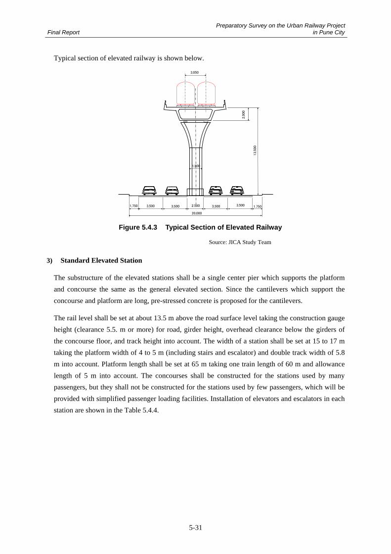
Preparatory Survey on the Urban Railway Project Final Report in Pune City
5-31
Typical section of elevated railway is shown below.
3,500 3,500 3,500 3,500 1.7501,750
20,000
2,500
1,800
2,0
00
3,050
13,5
00
Figure 5.4.3 Typical Section of Elevated Railway
Source: JICA Study Team
3) Standard Elevated Station
The substructure of the elevated stations shall be a single center pier which supports the platform
and concourse the same as the general elevated section. Since the cantilevers which support the
concourse and platform are long, pre-stressed concrete is proposed for the cantilevers.
The rail level shall be set at about 13.5 m above the road surface level taking the construction gauge
height (clearance 5.5. m or more) for road, girder height, overhead clearance below the girders of
the concourse floor, and track height into account. The width of a station shall be set at 15 to 17 m
taking the platform width of 4 to 5 m (including stairs and escalator) and double track width of 5.8
m into account. Platform length shall be set at 65 m taking one train length of 60 m and allowance
length of 5 m into account. The concourses shall be constructed for the stations used by many
passengers, but they shall not be constructed for the stations used by few passengers, which will be
provided with simplified passenger loading facilities. Installation of elevators and escalators in each
station are shown in the Table 5.4.4.
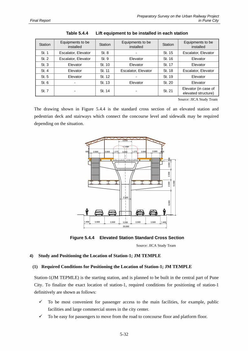
Preparatory Survey on the Urban Railway Project Final Report in Pune City
5-32
Table 5.4.4 Lift equipment to be installed in each station
Station Equipments to be installed Station Equipments to be
installed Station Equipments to be installed
St. 1 Escalator, Elevator St. 8 - St. 15 Escalator, Elevator St. 2 Escalator, Elevator St. 9 Elevator St. 16 Elevator St. 3 Elevator St. 10 Elevator St. 17 Elevator St. 4 Elevator St. 11 Escalator, Elevator St. 18 Escalator, Elevator St. 5 Elevator St. 12 - St. 19 Elevator St. 6 - St. 13 Elevator St. 20 Elevator
St. 7 - St. 14 - St. 21 Elevator (in case of elevated structure)
Source: JICA Study Team
The drawing shown in Figure 5.4.4 is the standard cross section of an elevated station and
pedestrian deck and stairways which connect the concourse level and sidewalk may be required
depending on the situation.
3,500 3,500 3,500 3,500 1,4001,400
20,000
3,200
2,500
2,0
00
3,050
3,0501,3753,0002,000600 3,000 2,000 6001,375
17,000
13,5
00
2,5
00
2,5
00
6,0
00
500
Figure 5.4.4 Elevated Station Standard Cross Section
Source: JICA Study Team
4) Study and Positioning the Location of Station-1; JM TEMPLE
(1) Required Conditions for Positioning the Location of Station-1; JM TEMPLE
Station-1(JM TEPMLE) is the starting station, and is planned to be built in the central part of Pune
City. To finalize the exact location of station-1, required conditions for positioning of station-1
definitively are shown as follows:
To be most convenient for passenger access to the main facilities, for example, public
facilities and large commercial stores in the city center.
To be easy for passengers to move from the road to concourse floor and platform floor.

Preparatory Survey on the Urban Railway Project Final Report in Pune City
5-33
To be easy and convenient for passengers transferring to the Station of the Pune City Metro
Line 2.
To be a moderate structural plan for construction.
To take into account the doubling back for trains arriving at the starting station.
Examination of Extracted Location
The following 3 options were examined and compared.
Option 1: Positioning at Shivaj Maharaj Road
Station 2
Station 1
Metro Line1(Underground)
Metro Line2(Elevated)
Road Underpass Plan
Figure 5.4.5 Plan and Section of Option-1
Source: JICA Study Team
Evaluations
Location Condition: Positioning at the most central area in the city. (Very good)
Convenience for Passengers: Easy to rise from road level to concourse and platform floor.
(Good). Normal height between concourse floor and platform floor (Good).
Convenience and easy to transfer to Metro station: Short distance to transfer due to
positioning near the station of the Pune city Metro Line 2, and same concourse level. (Very
good)
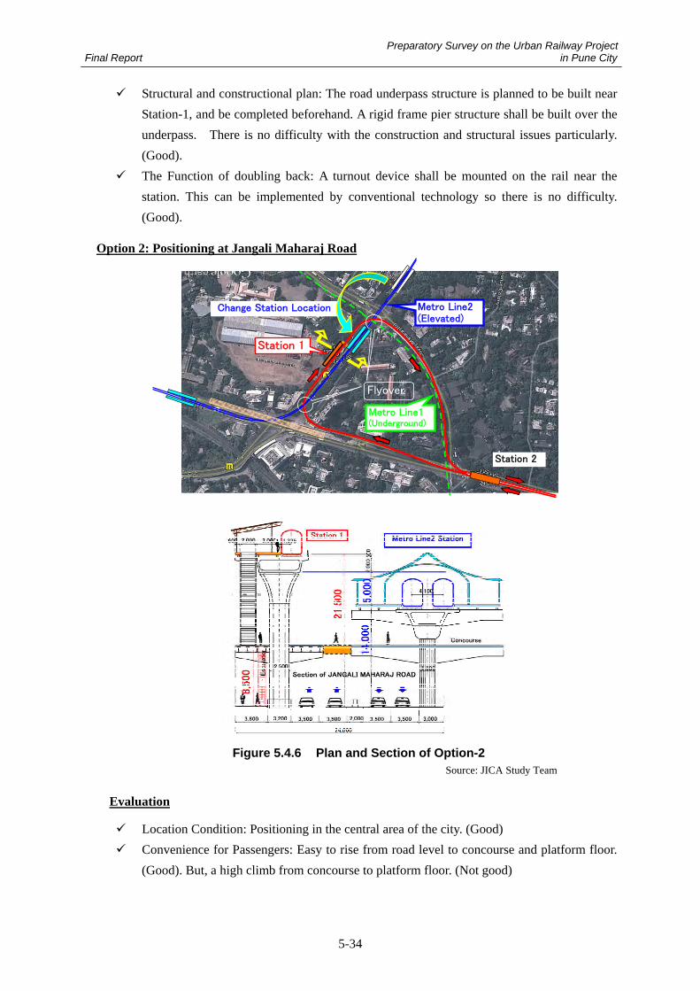
Preparatory Survey on the Urban Railway Project Final Report in Pune City
5-34
Structural and constructional plan: The road underpass structure is planned to be built near
Station-1, and be completed beforehand. A rigid frame pier structure shall be built over the
underpass. There is no difficulty with the construction and structural issues particularly.
(Good).
The Function of doubling back: A turnout device shall be mounted on the rail near the
station. This can be implemented by conventional technology so there is no difficulty.
(Good).
Option 2: Positioning at Jangali Maharaj Road
Station 2
Station 1
Flyover
Change Station Location Metro Line2(Elevated)
Metro Line1(Underground)
Figure 5.4.6 Plan and Section of Option-2
Source: JICA Study Team
Evaluation
Location Condition: Positioning in the central area of the city. (Good)
Convenience for Passengers: Easy to rise from road level to concourse and platform floor.
(Good). But, a high climb from concourse to platform floor. (Not good)

Preparatory Survey on the Urban Railway Project Final Report in Pune City
5-35
Convenient and easy for transfer to Metro station: Short distance to transfer due to
positioning near the station of the Pune city Metro Line 2. (Good). But, passengers must
walk along inclined pedestrian deck for changing levels between both platforms. (Not
good)
Structural and constructional plan: The height of the Station-1 reaches over 20 m due to the
need for a flyover across the viaduct of Metro Line 2. (Not good)
The Function of doubling back: Doubling back is operated along the loop. Rail structure is
simple, but if an accident happens on the loop, the problem remains until repairs are
completed. (Not good
Option 3: Positioning at Samgaam Bridge Road
Station 2
Station 1
Flyover
Metro Line1(Underground)
Metro Line2(Elevated)
Figure 5.4.7 Plan and Section of Option-3
Source: JICA Study Team
Evaluation
Location Condition: Positioning outside the central area of the city. (Not good)
Convenience for Passengers: Easy to climb from road to concourse floor. (Good). Normal
height from concourse floor to platform floor (Good).

Preparatory Survey on the Urban Railway Project Final Report in Pune City
5-36
Convenient and easy to transfer to Metro station: Short distance to transfer due positioning
near the station of the Pune city Metro Line 2, and same concourse level. (Very good)
Structural and constructional plan: Typical elevated station structure (good) can be adopted,
but additional land acquisition is required outside of the road to build piers and foundations.
(Not good)
The Function of doubling back: A turnout device shall be mounted on the rail near the
station. This can be implemented by conventional technology so there is no difficulty.
(Good).
(2) Definitive Position of Station-1; JM TEMPLE
As the result of the above examination, it is proven that Option-1 is the most suitable plan
considering location, convenience for passengers, ease for transferring, and structural and
contractual plan. Accordingly, the location of the Station-1 (JM TEMPLE) in option-1 is proposed.
Station 2
Station 1
Figure 5.4.8 Definitive Location of Station-1
Source: JICA Study Team
5) MULA River Bridge
The Bridge over the MULA River is located near Station-10 and is planed to be constructed
upstream from the existing Road Bridge crossing the river. Two feasible methods can be planed.
One is setting the typical girder span the same as the other elevated sections, and the other is for
long continuous girders for the purpose of reducing the number of piers constructed in the river.

Preparatory Survey on the Urban Railway Project Final Report in Pune City
5-37
(a) The Plan Setting Typical Girder Spans cross the River
4-Single-SpanPC-BoxGirder L=120m
30m 30m25m
A1 A2
25m30m
Road Level
Riverbed
Single-Span PC-BoxGirder
13m
13m
25m 25m 25m
Single-Span PC-BoxGirder
P1
30m 30m
P2 P3
Pune City
25m
25m30m
25m
25m
4-Span ContinuousPC Box Girder L=120m
30m 30m 25m25m
A1 P1
A29m
25m
P2
30m30m
Figure 5.4.9 Profile and Plan of Typical girder span
Source: JICA Study Team
Technical Features
The equipment for typical PC-box girder for construction of other sections is available for
use. (Good)
Relatively many substructures and temporary cofferdams are necessary. Construction
schedule for Foundation and substructure need a long period (Not Good)
Temporary bridge for construction piers and girder erection is required along the whole
width of the river. (Not Good)
The reduction of the cross-sectional area of the river during the construction is greater.
Therefore, it is necessary to confirm the impacts on the river in consultation with the
authority of river administration. (Not Good)

Preparatory Survey on the Urban Railway Project Final Report in Pune City
5-38
(b) The Plan for Long Continuous Girder cross the River
25m30m
25m
25m
3-Span ContinuousPC Box Girder L=120m
35m50m 25m25m
A1 P1
A29m
25m
P2
35m
2-Span-ContinuousPC-BoxGirder L=120m
35m 50m25m
A1 P1
25m30m 25m 25m 25m
Road Level
Riverbed
Single-Span PC-BoxGirder
Single-Span PC-BoxGirder
13m
13m
Pune City
35m
P2 A2
25m
Figure 5.4.10 Profile and Plan of Long Continuous Girder
Source: JICA Study Team
Technical Features
Cantilever method is the type of the method in which a girder is overhanging and extending
from the pier-head sequentially using a temporary working-truck. There are a number of
proven methods that are employed when the construction space under the girder is not
assured. (Good)
Since special equipment is needed for the cantilever, construction of the superstructure
costs more than plan (a). (Not Good)
Length of the temporary bridge is about half of the width of the river because there is only
one pier in the river. The reduction of the cross-sectional area of the river is small; to the
impact on the river is small during construction. (Good)
While there is only one Pier, the scale of the temporary cofferdam becomes larger. (Not
Good)
Detail survey and study for the bridge crossing the river will be implemented in a coming step of the
basic design phase and detail design phase, meeting with the authority of river administration. After
that, details of the bridge will be defined.
The meeting with the river administration authority will discuss:
To confirm accumulated water level records for the past at the cross section of the river
where the new bridge will be constructed.

Preparatory Survey on the Urban Railway Project Final Report in Pune City
5-39
To confirm whether further rehabilitation plans for the river are established or not
To confirm obtaining of permission for using the area inside the river to construct the new
bridge
To confirm the possibility of the working in the area inside the river during the rainy
season, and documents that shall be submitted to the river administration authority for
obtaining the approval of the work.
5.4.2 At-grade Section
1) General at-grade section
The LRT shall run on both sides of the road and fences shall be constructed on both sides of the
carriageway side and footpath side to avoid entering of vehicles and pedestrians. The general cross
section is shown in Figure 5.4.11 and Figure 5.4.12. Regarding the structure of the track refer to
5.5.1 Track Facility.
1,7251,7252,5502,5501,725 1,725
1,435
3,5003,500 3,500 3,5002,0003,000
34,000
3,000
FootpathFootpath
24,550
Carriage Carriage Carriage Carriage
Figure 5.4.11 General at-grade Section in PMC (Unit: mm)
Source: JICA Study Team
1,7251,7251,5501,5501,725 1,725
1,435
5,0008,550
11,00
8,550
5,000
45,000
BRT BRT
LRT LRT
31,550
3,500 3,500 3,5003,500
Footpath & Cycle Carriage Carriage Footpath & CycleCarriage Carriage
Figure 5.4.12 General at-grade Section in PCMC (Unit: mm)
Source: JICA Study Team
2) At-grade Station
Platforms will be constructed on the both sides of the road for at-grade stations. The width of a
platform shall be 2.5 to 3.0 m and the length of the platform shall be 62 m taking train length of 60
m and allowance length of 2 m into account. The height of the platform must be adjusted for the
specifications of the rolling stock and 300 mm or less is proposed for the height. General cross
sections for at-grade stations are shown in Figure 5.4.13 and Figure 5.4.14.

Preparatory Survey on the Urban Railway Project Final Report in Pune City
5-40
1,3751,725 2,9002,900 1,375 1,725
1,435
PlatformPlatform
3,5003,500 3,500 3,5002,0003,000
34,000
3,000
FootpathFootpath
19,450
Carriage Carriage Carriage Carriage
300
Figure 5.4.13 At-grade Station in PMC (Unit: mm)
Source: JICA Study Team
1,3751,725 2,9002,900 1,375 1,725
1,435
PlatformPlatform
4,000
7,000
11,000
7,000
4,000
45,000
BRT BRT
LRT LRT
28,450
3,500 3,500 3,5003,500
Footpath & Cycle Footpath & CycleCarriageCarriageCarriageCarriage
300
Figure 5.4.14 At-grade Station in PCMC (Unit: mm)
Source: JICA Study Team
3) The Method of Traffic Control in the Intersection
The railway is planned to cross an intersection near station-12. A traffic signal system would be
employed to control the Vehicles crossing the railway and to prioritize railway traffic across the
intersection.
Figure 5.4.15 Location of Intersection
Source: JICA Study Team

Preparatory Survey on the Urban Railway Project Final Report in Pune City
5-41
3,500 3,500 3,500
45,000
2,0003,500 3,5003,500
c
c
SignControal
Rai
l W
ay
SignControal
Rai
l W
ay
c
Figure 5.4.16 Traffic Control Plan in Intersection
Source: JICA Study Team
5.4.3 Depot and Workshop
A depot and workshop will be provided beside the line. The depot is for stabling and light
maintenance of rolling stock and the workshop is for heavy maintenance of rolling stock. Maintenance
of the main tracks will be conducted at night while service is suspended. The fleet of the trains should
be stabled in the depot so that the track is cleared for maintenance work and for passing of
maintenance vehicles in the night.
Location of the Depot
The depot requires a huge land space more than 11 ha for stabling all the rolling stock and its
maintenance. The candidate for the location is south of St 18. The area adjacent to St18 in the
depot complex is also planned for commercial space and office space.
Access track to the depot is branched from west of St18 and from where it drops down and crosses
under the elevated main line with grade separation.
Facilities of Rolling Stock Depot and Workshop
The following facilities and tracks will be provided in the rolling stock depot.
Stabling tracks: for storage of trains
Inspection track: for regular inspection and occasional repair of rolling stock
Washing track: for manual washing of the trains
Train washing plant: to wash the outside of the train automatically by passing through an
automated train wash machine

Preparatory Survey on the Urban Railway Project Final Report in Pune City
5-42
Wheel re-profiling machine: to re-profile the wheel tread without dismantling the wheel set
Mounting and dismounting track: for mounting/dismounting the bogies to/from the body.
The track will have a pit and lifting jacks and will be provided in the workshop
Stabling track for maintenance vehicles: for storage of trackwork vehicles
Shed for road rail vehicle: for storage and maintenance of road rail vehicle that will be used for
track maintenance and emergency rescue
Maintenance of Rolling Stock
Maintenance of Rolling Stock is classified as follows.
Pre-departure inspection (daily inspection): check the function for running
Regular inspection (monthly inspection): checking condition and function of major devices.
Important parts inspection (semi overhaul): detaching important parts such as bogies and brake
equipment to inspect and restore
General inspection (overhaul): disassemble all the major parts to inspect and restore
Interval and duration of each maintenance item is indicated in Table 5.4.5.
Table 5.4.5 Interval and Duration of Inspection
Class Interval Duration Pre-departure inspection One day 1 hour Regular inspection 3 months 8 hours Important parts inspection 3 years 20 days General inspection 6 years 30 days
Source: JICA Study Team
Number of Tracks for Storage and Inspection
The depot and workshop are planned to have enough inspection and storage tracks for year 2038
when the number of train sets will be 40.
Required number of tracks for inspection becomes as follows.
Table 5.4.6 Number of Tracks for Strorage and Inspection
Track Class of inspection calculation Required
number
Pre-departure inspection
36 trains will be in operation. Peak hours (6 hours/day) are not available for inspection. 36/(24-6)=2
2 Inspection track
Regular inspection 8 hours x 40/90=6 (hours/day) 1
Important parts inspection 20 days x 40/(6 x 365)=0.37
Mounting/dismounting track (workshop) General
inspection 30 days x 40/(6 x 365)=0.56 1
Source: JICA Study Team

Preparatory Survey on the Urban Railway Project Final Report in Pune City
5-43
Required number of inspection tracks is 3, however, including occasional inspections 4 tracks are
required.
Interval of important parts inspection is 3 years, however, general inspection is required every 6
years, therefore, the actual interval of important parts inspection becomes 6 years. Required
number of tracks in the workshop becomes 0.92. tracks for 1 train may be enough but it is difficult
to plan the schedule of heavy maintenance without idling time.
Including occasional repair tracks for 2 trains will be required for the workshop.
Based on the calculation above the following number of tracks will be provided.
Stabling track: 2 train sets x 18 tracks
Washing track: 2 train sets x 2 tracks
Inspection track: 4 tracks
Mounting/dismounting track: 1car x 4 tracks
Considering the increase of passengers after 2038, the number of trains will increase by reducing
the headway, therefore, space on the stabling track for 10 more train sets is provided. Layout of
Depot is indicated in Figure 5.4.17.

Preparatory Survey on the Urban Railway Project Final Report in Pune City
5-44
Figure 5.4.17 Layout of depot and workshop
Source: JICA Study Team
Maintenance of the tracks
Vehicles for trackwork will be stabled in the same complex in the rolling stock depot and workshop.
The following vehicles will be prepared for trackwork
Flat wagon: for carrying the materials for trackwork
Track inspection car: measuring the alignment of the track
Road rail vehicle: vehicle that can run on both road and rail. Will be used for hauling the
flat car or LRT trains.
Figure 5.4.18 shows a sample of a road rail vehicle.
St18
100m
workshop
Inspection track
Washing
Wheel re-profiling machine
Stabling track
Stabling track for trackwork vehicle
Train washing plant
Site area:12ha
Space for commercial and office buildings
Shed for road rail vehicle

Preparatory Survey on the Urban Railway Project Final Report in Pune City
5-45
Figure 5.4.18 Sample of Road Rail Vehicle (Manila LRT Line 1)
Source: The photo was taken by JICA Study Team
5.5 Railway Systems
5.5.1 Overall System Concepts
1) Selection of Optimum Transportation System
<Future Demand Forecast>
In response to the result of the future demand forecast discussed in Chapter 3, it is projected that
peak-hour passenger demand (PPHPD) will be approximately 7,000 persons in 2018 and 15,000
persons in 2038.
The “Detailed Project Report on Pune Metro Project” (July 2009) by Delhi Metro Rail Corporation
mentions that Experience has shown that in mixed traffic conditions, comprising slow and fast moving traffic prevailing in most of our cities, road buses can optimally carry 8,000 persons per hour per direction. Bus-based transportation system could be suitable for traffic density with less
than 8,000 persons per hour.
As shown in the following figure quoted from the Ministry of Land, Infrastructure, Transport and
Tourism in Japan, it describes the optimum transportation system in relation with PPHPD and
Operation Speed. Passenger demand for the proposed corridor is suitable for an LRT system as
indicated below. On the other hand, MRT has great potential for its capacity with more than 20,000
persons.

Preparatory Survey on the Urban Railway Project Final Report in Pune City
5-46
Figure 5.5.1 Applicable System and Passenger Demand
Source: JICA study Team
<Corridor Alignment>
The alignment has been set under the basic policy that an alignment basically passes through public
land space along a corridor as mentioned in Chapter 5.1.1. Land acquisition for private land is one
of the biggest issues in any county when a transport system is constructed.
In terms of flexibility of alignment setting, the LRT system has a big advantage in comparison with
the MRT system. Minimum radius curvature of LRT is 20 meters, while MRT is 200 meters in
general. This feature can largely contribute to the reduction of land acquisition area.
The next figure indicates our proposed alignment and minimum radius curvature with less than 200
meters. On the proposed corridor, it often falls below 200 meters, and minimal radius is 50 meters
near Shivaji Nagar. Land acquisition along the entire route can be minimized by introducing an
LRT System. The detail information on minimum radius is described in Figures 5.1.8 ~ 5.1.12.
If an MRT system had been selected for this corridor it would have required re-alignment and huge
additional land acquisition due to the minimum radius of curvature. From the viewpoints of demand
forecast, alignment and land acquisition, it is concluded that the optimum solution is to introduce a
flexible system, an “LRT system”
40km/h20km/h 30km/h10km/h
2.0
1.5
0.5
8.0
TramTram
LRTLRT
AGTAGTMonorailMonorail
MRTMRT
Operation SpeedOperation Speed
PP
HP
DP
PH
PD
((10
,000
10,0
00p
axp
ax// h
ou
rh
ou
r //d
irec
tio
nd
irec
tio
n
BusBus
LRTLRT
Appropriate System for Pune-Hinjawedi Corridor

Preparatory Survey on the Urban Railway Project Final Report in Pune City
5-47
Figure 5.5.2 Proposed Alignment and Min. Radius Curvature
Source: JICA Study Team
2) Concept of LRT Systems
In terms of future passenger demand, it is most suitable to adopt an LRT (Tram) system as a
mid-capacity transportation system. An LRT (Tram) system basically operates a vehicle by
receiving electric power from an overhead catenary during running. However, an LRT (Tram)
system with on-board electric power storage is proposed in this study. This is a battery-driven rail
system which can operate continuously without any disruptions of electricity supply (hereinafter
called a “Battery Tram System”).
The next figure describes basic concept of the Battery Tram system. The electric power can be
recharged to an on-board rechargeable battery at the station during passenger’s boarding and
alighting time through the station post (Battery and Charger). In addition, it is possible to utilize
regenerative energy for recharging its battery. This energy is generated by braking behavior, and it
can contribute much to the improvement of energy efficiency. By adopting a high efficiency and
easy maintenance motor, the operation and maintenance cost can be reduced.

Preparatory Survey on the Urban Railway Project Final Report in Pune City
5-48
Figure 5.5.3 Basic Concept of Battery Tram System
Source: JICA Study Team
3) Advantages of Battery Tram System
A Battery Tram System equips a rechargeable battery on board as a power storage device and
provides electrical power from its battery to on-board facilities and equipment for driving and
control. It therefore does not need to receive electric power continuously from an overhead catenary
line during running. The following advantages for a Battery Tram system are specified compared
with conventional LRT system (power supply from overhead catenary) and MRT system (see Table
5.5.1). The system enables:
To stably operate under any electric circumstances;
To eliminate the construction, operation and maintenance cost of an overhead catenary;
To preserve the city’s landscape;
To reduce energy consumption by regenerative energy use;
To reduce the number of traction substations;
To reduce the land space for substation facilities; and
To minimize life-cycle cost (LCC).

Preparatory Survey on the Urban Railway Project Final Report in Pune City
5-49
Tab
le 5
.5.1
C
om
par
iso
n a
mo
ng
Rai
l-b
ased
Tra
nsp
ort
atio
n S
yste
ms
S
yste
ms
It
ems
B
atte
ry T
ram
Sys
tem
C
on
ven
tio
nal
LR
T S
yste
m
MR
T S
yste
m
Imag
e
Po
wer
So
urc
e O
n-b
oar
d B
atte
ry
*Bat
tery
is
re
char
ged
at
stat
ion
thro
ugh
over
head
cat
enar
y
Ove
rhea
d C
aten
ary
Ove
rhea
d C
aten
ary
Pas
sen
ger
’s D
eman
d
~ 1
5,00
0 P
PH
PD
~
15,
000
PP
HP
D
25,0
00
PP
HP
D ~
Min
. C
urv
e R
ad
ius
20m
Adv
anta
ge to
pas
s th
roug
h ro
ad in
ters
ectio
n *
R=1
00m
for m
ixed
use
sec
tions
30m
A
dvan
tage
to p
ass
thro
ugh
road
inte
rsec
tion
* R
=100
m fo
r mix
ed u
se s
ectio
ns
200
m
Max
. Gra
die
nt
70‰
Eas
y to
pas
s th
roug
h ro
ad g
rade
sep
arat
ion
70‰
E
asy
to p
ass
thro
ugh
road
gra
de s
epar
atio
n
30‰
En
erg
y S
avi
ng
E
xcel
len
t w
ith R
egen
erat
ed E
nerg
y (A
ppro
xim
atel
y 20
% e
nerg
y sa
ving
) G
oo
d
Go
od
Op
erat
ion
in P
ow
er F
ailu
re
Op
erat
ion
Co
nti
nu
e W
ith
only
on
-boa
rd
batte
ry,
a tra
m
can
trans
port
pass
enge
rs
from
or
igin
to
de
stin
atio
n st
atio
n (2
1.6k
m).
Op
erat
ion
Su
spen
ded
O
per
atio
n S
usp
end
ed
Sou
rce:
JIC
A S
tudy
Tea
m a
nd G
ener
al I
nfor
mat
ion

Preparatory Survey on the Urban Railway Project Final Report in Pune City
5-50
Tab
le 5
.5.2
C
om
par
iso
n a
mo
ng
Rai
l-b
ased
Tra
nsp
ort
atio
n S
yste
ms
(co
nti
nu
ed)
S
yste
ms
It
ems
B
atte
ry T
ram
Sys
tem
C
on
ven
tio
nal
LR
T S
yste
m
MR
T S
yste
m
Inte
rval
of
Su
bst
atio
ns
(Fee
din
g V
olt
age)
N
ot
Nec
ess
ary
In
terv
al:
3km
(D
C75
0V)
Inte
rva
l: 5
km (
DC
1,5
00V
) In
terv
al:
ove
r 20
km
(A
C2
5,0
00V
)
Nec
ess
ary
La
nd
Are
a fo
r T
ract
ion
Su
bst
atio
n
No
t N
ece
ssa
ry
Med
ium
L
arg
e
Ove
rhea
d C
aten
ary
Sys
tem
fo
r R
un
nin
g
No
t N
ece
ssa
ry
Nec
ess
ary
Nec
ess
ary
(o
r Thi
rd-ra
il sy
stem
)
Tota
l: 1
96 (M
unba
i Met
ro N
o1)*1
To
tal:
199
(Hyd
erab
ad M
etro
)*1
Tota
l: 1
25 (D
elhi
Airp
ort M
etro
)*1
Cap
ital
Co
st E
stim
atio
n
(cro
re R
s./k
m)
E&
M:
95.7
C
ivil:
86.
2 To
tal:
181
.9
E&
M:
90.7
C
ivil:
86.
2 To
tal:
176
.9
Tota
l: 2
43 (P
une
Met
ro N
o.1)
*2
Tota
l: 1
30 (P
une
Met
ro N
o.2)
*2
Op
erat
ion
& M
ain
ten
ance
C
ost
Est
imat
ion
in a
vera
ge
(c
rore
Rs.
/km
/yea
r)
11.8
13
.4
18.9
*2
Sou
rce:
JIC
A S
tudy
Tea
m a
nd G
ener
al I
nfor
mat
ion
*1: C
alcu
late
d ba
sed
on th
e re
port
fro
m F
eedb
ack
Infr
astr
uctu
re S
ervi
ces
Pri
vate
Lim
ited
*2
: Est
imat
ed b
ased
on
“Det
ail P
roje
ct R
epor
t on
Pun
e M
etro
Pro
ject
(20
08)”
, Del
hi M
etro
Rai
l Cor
pora
tion

Preparatory Survey on the Urban Railway Project Final Report in Pune City
5-51
4) Features of Battery Tram System
The features of a Battery Tram system are summarized as follows.
It is possible to stably operate under any electric power situation.
For the at-grade section, a “Resin” track structure", in which the rail is fixed by resin is
employed for the purpose of vibration suppression and noise reduction. The elevated section
adopts a T-shape rail and slab structure with the rail tied directly to the slab.
To operate a tram under an unstable electric power situation, it is proposed to employ a tram
equipped with electric power storage. The vertical distance between the rail surface and the
floor level is designed as a low floor with fewer steps in which barrier-free design is taken into
consideration.
At the station electric power storage facilities that mate with the on-board storage are
furnished to recharge the on-board storage from the station side. To recharge the on-board
storage, this system provides a rapid recharge function to complete the recharge in a short term.
Meanwhile, the station post is recharged slowly by a power supply from a substation.
At every station, the fare is collected automatically by automatic ticket gate and IC card/token
to avoid congestion in the vehicle. An IC card/token is issued manually by staff at the station.
The necessary information is recorded on IC chips embedded in plastic cards. This is possible
because these IC chips are rewritable and reusable.
To manage road traffic at the intersections of at-grade sections, LRT signals are established at
the intersection. This implements an LRT Priority Signal measure to assure the punctuality and
operates simultaneously with traffic signals subject to coordination with the road
administrator.
To realize efficient operation, the information on train operation and location are centralized at
the Operation Control Center (OCC). The OCC monitors and manages this information.
To increase the safety in the elevated section, an automatic block system, which allows only
one train to enter a block section, is employed and it is also equipped Automatic Train Stop
(ATS) function so that a train can be stopped automatically in the event of an emergency.
As a backbone of the transmission network, optical fiber cable is to be installed along the
entire route and it connects the OCC, stations, depot and other facilities. A radio system is
installed to communicate between the ground facilities and the vehicles. At the stations,
passenger information, public address and CCTV systems are furnished for the purpose of
information provision and passenger safety.
To remotely control and monitor the condition of necessary facilities, facility monitoring and
control systems will be installed in the operation control center.
A Maintenance Management Information System (MMIS) is implemented to manage assets
and to schedule maintenance works.
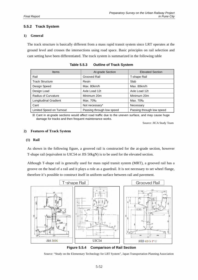
Preparatory Survey on the Urban Railway Project Final Report in Pune City
5-52
5.5.2 Track System
1) General
The track structure is basically different from a mass rapid transit system since LRT operates at the
ground level and crosses the intersections using road space. Basic principles on rail selection and
cant setting have been differentiated. The track system is summarized in the following table
Table 5.5.3 Outline of Track System
Items At-grade Section Elevated Section Rail Grooved Rail T-shape Rail Track Structure Resin Slab Design Speed Max. 80km/h Max. 80km/h Design Load Axle Load 12t Axle Load 12t Radius of Curvature Minimum 20m Minimum 20m Longitudinal Gradient Max. 70‰ Max. 70‰ Cant Not necessary* Necessary Limited Speed on Turnout Passing through low speed Passing through low speed
※ Cant in at-grade sections would affect road traffic due to the uneven surface, and may cause huge damage for tracks and then frequent maintenance works.
Source: JICA Study Team
2) Features of Track System
(1) Rail
As shown in the following figure, a grooved rail is constructed for the at-grade section, however
T-shape rail (equivalent to UIC54 or JIS 50kgN) is to be used for the elevated section.
Although T-shape rail is generally used for mass rapid transit system (MRT), a grooved rail has a
groove on the head of a rail and it plays a role as a guardrail. It is not necessary to set wheel flange,
therefore it’s possible to construct itself in uniform surface between rail and pavement.
Figure 5.5.4 Comparison of Rail Section
Source: “Study on the Elementary Technology for LRT System”, Japan Transportation Planning Association
T-shape Rail Grooved Rail
UIC54

Preparatory Survey on the Urban Railway Project Final Report in Pune City
5-53
(2) Track Structure
Basically the ballast track is applied for the depot area and the slab track for the elevated section.
For the at-grade section, a “Resin” Track is employed which is not jointed by bolts but fixed by a
special resin. This can reduce vibration and noise; therefore, it is suitable for the at-grade section.
As it is completely fixed with resin, it has advantages such as high sealing performance, and
prevention of deterioration by water leakage. This Resin Track is widely used in Europe。
The comparison of track structure is shown in the following table.
Table 5.5.4 Comparison of Track Structure
Structure Resin Track Slab Track Ballast Track
Section Implemented At grade Section Elevated Section Depot
Roadbed RC、PC Concrete RC Concrete Ballast
Rail Joint Fixed in Groove by Special Resin
Jointed with Slab by Bolts Jointed with Sleeper by Bolts
Structure
Pavement Surface
Concrete Asphalt Concrete Block Lawn
Asphalt Concrete Block Lawn
Concrete Asphalt Concrete
Vibration Small Moderate Moderate
Track Irregularity None None Often
Rail Wear Little Corrugations occur Little
Deflection Measure
Pat+Special Resin Hard resin under a rail Ballast
Water Leakage Water Proofed by Special Resin
Prevented by Resin High Drainage Performance
Checking (Inner Structure)
Not necessary for Inner Checking
Impossible to check inside such as bolts due to pavement
Necessary to check rail fasteners
Rail Replacement
Possible to replace a rail without pavement removal
Necessary to pave again after pavement removal
Possible to replace a rail without pavement removal
Function & P
erformance
Electric Corrosion
Not necessary No countermeasure No countermeasure
Construction Moderate Moderate Low Cost O&M Low Moderate High
Source: “Study on the Elementary Technology for LRT System”, Japan Transportation Planning Association
Figure 5.5.5 Cross Section of Resin Track (Reference)
Source: “Study on the Elementary Technology for LRT System”, Japan Transportation Planning Association
Concrete Slab
Resin Grooved Rail
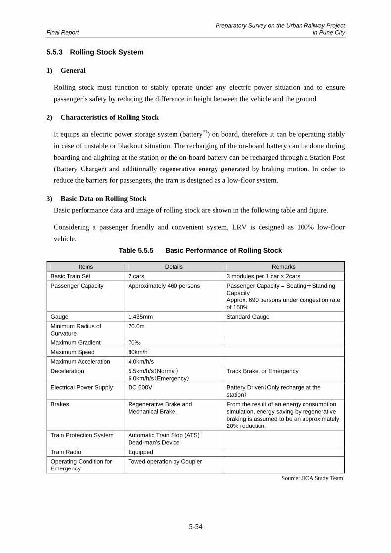
Preparatory Survey on the Urban Railway Project Final Report in Pune City
5-54
5.5.3 Rolling Stock System
1) General
Rolling stock must function to stably operate under any electric power situation and to ensure
passenger’s safety by reducing the difference in height between the vehicle and the ground
2) Characteristics of Rolling Stock
It equips an electric power storage system (battery*1) on board, therefore it can be operating stably
in case of unstable or blackout situation. The recharging of the on-board battery can be done during
boarding and alighting at the station or the on-board battery can be recharged through a Station Post
(Battery Charger) and additionally regenerative energy generated by braking motion. In order to
reduce the barriers for passengers, the tram is designed as a low-floor system.
3) Basic Data on Rolling Stock
Basic performance data and image of rolling stock are shown in the following table and figure.
Considering a passenger friendly and convenient system, LRV is designed as 100% low-floor
vehicle.
Table 5.5.5 Basic Performance of Rolling Stock
Source: JICA Study Team
Items Details Remarks Basic Train Set 2 cars 3 modules per 1 car × 2cars Passenger Capacity Approximately 460 persons Passenger Capacity = Seating+Standing
Capacity Approx. 690 persons under congestion rate of 150%
Gauge 1,435mm Standard Gauge Minimum Radius of Curvature
20.0m
Maximum Gradient 70‰ Maximum Speed 80km/h Maximum Acceleration 4.0km/h/s Deceleration 5.5km/h/s(Normal)
6.0km/h/s(Emergency) Track Brake for Emergency
Electrical Power Supply DC 600V Battery Driven(Only recharge at the station)
Brakes Regenerative Brake and Mechanical Brake
From the result of an energy consumption simulation, energy saving by regenerative braking is assumed to be an approximately 20% reduction.
Train Protection System Automatic Train Stop (ATS) Dead-man’s Device
Train Radio Equipped Operating Condition for Emergency
Towed operation by Coupler

Preparatory Survey on the Urban Railway Project Final Report in Pune City
5-55
Table 5.5.6 Basic Specification on Rolling Stock
Items Details LRV 100% Low-floor Vehicle Width of LRV 2,650mm Length of LRV 60m (30m car×2 cars) Other Facilities Master Controller, Speed Meter, Radio Facility, Monitors, Train Destination
Indicator, Onboard Information Board, Broadcasting Equipment, Air Conditioning, Signal Lamp (Front, Back) etc.
Source: JICA Study Team
Figure 5.5.6 Image of Rolling Stock
Source: JICA Study Team
Figure 5.5.7 Image of Seat Placement (30m Module)
Source: JICA Study Team
4) Clearance Gauge for Rolling Stock
In general, the clearance gauge has not been set for LRT systems in Europe. From the safety
viewpoint, it however, could be set at 40cm away from both sides of the rolling stock. If any
structural objects exist in the median such as poles, an additional 40cm between the vehicle and the
object should be set.
The height of the vehicle is approximately 3,800mm with the pantograph retracted. The overhead
catenary which is installed only at the station to recharge the on-board battery, is temporarily set at a
height of 5,000mm from ground level.
Basic concepts of the cross sections are shown in the following figure.
30mCar 30mCar
Length 60m
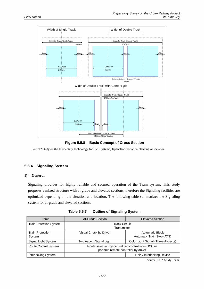
Preparatory Survey on the Urban Railway Project Final Report in Pune City
5-56
Figure 5.5.8 Basic Concept of Cross Section
Source:“Study on the Elementary Technology for LRT System”, Japan Transportation Planning Association
5.5.4 Signaling System
1) General
Signaling provides for highly reliable and secured operation of the Tram system. This study
proposes a mixed structure with at-grade and elevated sections, therefore the Signaling facilities are
optimized depending on the situation and location. The following table summarizes the Signaling
system for at-grade and elevated sections.
Table 5.5.7 Outline of Signaling System
Items At-Grade Section Elevated Section Train Detection System Track Circuit
Transmitter Train Protection System
Visual Check by Driver Automatic Block Automatic Train Stop (ATS)
Signal Light System Two Aspect Signal Light Color Light Signal (Three Aspects) Route Control System Route selection by centralized control from OCC or
portable remote controller by driver Interlocking System - Relay Interlocking Device
Source: JICA Study Team
400mm400mm
Car Width
2,650mm
Space for Track (Single Track)
6,500mm
Distance between Center of Tracks3,050mm
400mm400mm 400mm
Car Width
2,650mm
Space for Track (Double Track)
6,500mm
Distance between Center of Tracks3,450mm+Width of Structure
400mm
Car Width
2,650mm
Space for Track (Double Track)
6,900mm+Pole Width
40mm40mm 40mm40mm
400mm
Width of Single Track Width of Double Track
Width of Double Track with Center Pole

Preparatory Survey on the Urban Railway Project Final Report in Pune City
5-57
2) Systems Configuration
(1) Train Detection System
The Train Detection System enables collection of the information on the position of trams on the
line.
In the elevated section as well as at the location where turnouts are located, a train is detected by a
track circuit. By using tram location information, the OCC controller can monitor the locations of
all trams in operation, and control the turnout remotely from OCC. In the elevated section, an
Automatic Block System and Automatic Train Stop System can assure the safety and operation
speed using the tram location information.
(2) Train Protection System
Train Protection System ensures safe tram operation and ensures the safe distance between trams.
Train protection is assured by the driver’s visual confirmation for at-grade sections as a tram
operates at relatively slow speed. On the other hand, an automatic block signal system is installed in
the elevated section which allows only one tram in each block section.
With an Automatic Train Stop system, a tram will be stopped automatically by an emergency brake
if a driver misses a stop sign at a block signal, etc.
(3) Signal Light System
An indication of signal lights is designed in 3 aspects; Proceed, Slowdown and Stop.
The tram location information is transmitted to the road traffic signals for appropriate traffic control
i.e. extension of green signal duration or reduction of red signal duration.
(4) Route Control System
Sensors of the remote controller for turnouts are installed along the track. A driver operates the
portable remote controller for switching the turnout. Inside the depot area and lead-in track, the
turnouts can be controlled remotely by the OCC controller.
(5) Interlocking System
By using the train detection information, the Interlocking system basically detects vacancies at
points and track sections, and controls switching or locking of turnouts and control signals, but it is
not limited to the abovementioned functions. It is installed at the station where the turnout is located
and the lead-in-track to the depot area.
(6) Operation Control Center (OCC)
The Operation Control Center is established to manage and control the LRT system. An Operation
Management System which has the following functions is installed in the OCC.

Preparatory Survey on the Urban Railway Project Final Report in Pune City
5-58
① Train Schedule Management
There are two types of train diagrams; one is a scheduled diagram, and the other is the actual
diagram which is drawn based on actual train operation. Both diagrams can be indicated
independently or integrally on the same display. It helps the OCC controller to understand
any delay in tram operation well.
② Train Location Indicator
Train location information collected by the train detection system can be shown on the route
map. The train number is also shown on the same map.
③ peration Monitoring System
The Operation Monitoring System continuously monitors the scheduled and actual diagrams.
If a delay from the scheduled diagram exceeds a certain time, the system automatically
raises an alarm on the display.
Traffic Signals at Intersections
During operation in the at-grade section, a tram is running in the road space. It is necessary to take a
measure to ensure the tram’s punctuality in the mixed road space where trams, cars, motorcycles,
buses, rickshaws and pedestrians exist.
If a tram is approaching the intersection, the punctuality of tram operation will be assured by
reducing the red signal or extending the green signal. In Pune Municipal Corporation (PMC), a BRT
priority signal has been installed on the BRT route as shown in the picture below. Such system
could be beneficial to introduce LRT Priority Signals for the LRT system. It can give priority to a
tram when a tram approaches the intersection. At the intersections without traffic signals, it is
proposed to install traffic signals as well as the LRT signal.
Figure 5.5.9 BRT Priority Signals along BRT Route in PMC
Source: JICA Study Team

Preparatory Survey on the Urban Railway Project Final Report in Pune City
5-59
5.5.5 Telecommunications System
1) General
The telecommunications system is significant to exchange information supporting the safe and
secure operation. For the purpose of comfortable usage, this system also provides passengers with
several items of information such as train approaching, departing time, delay information.
Table 5.5.8 Outline of Telecommunications System
Functions Facilities Remarks Backbone Transmission Network
Optical Fiber Cable Broadband Radio
Constructed along the main line Connected between OCC and each base
Radio System Central Radio Server Including Recording Function Radio Base Station Train Radio Handy Radio Public Address System Public Address (PA) Information Board Sign for Train Approaching Telephone System Dedicated Telephone Dedicated Line within the company Clock System Clock OCC, Stations, and LRVs Surveillance Camera CCTV Each Station, Major Intersections, Bridges,
Depot Video data is transmitted to OCC through
optical fiber cable. Facility Monitoring and Control System
SCADA Remote facility control, Information collection of equipment failures
Maintenance Management Information System
MMIS
2) System Configurations
(1) Backbone Transmission Network
The Backbone Transmission Network transmits the train location, video and passenger information
among the OCC, depot and stations etc.
It makes it possible to communicate with the OCC, Depot and Stations and other facilities.
It forms a fault-resistant structure with a dual cable network in preparation for cable breaks and
equipment failure.
The network cable is accommodated between the tracks in the at-grade section and inside the
trackside cable trough in the elevated section.
Other than optic fiber cable, the broadband radio system as a backbone transmission network will be
considered.
Source: JICA Study Team

Preparatory Survey on the Urban Railway Project Final Report in Pune City
5-60
(2) Radio System
The Radio System makes it possible to communicate among the OCC controller, drivers, and
maintenance staff etc. by voice and data communication. It covers all trackside and inside buildings
as a call-enabled area.
Furthermore, it can issue a warning at the same time from the OCC controller to drivers and
maintenance staff and record a call log between the OCC controller and drivers in the OCC
recording device.
(3) Public Address System
By using the train location information collected from the track circuit, the Public Address System
announces the train approaching to the stations through the information board (text data) and by
speaker (voice data).
In case of operational problems due to accidents, its system can send text and voice information
from the OCC controller to the passengers through the broadcasting equipment.
(4) Clock System
The Clock System is installed to operate and manage the LRT system with unified time. A master
clock could be placed in the OCC, and servant clocks in stations, the depot and on board. Servant
clocks will be synchronized with the master clock through the backbone transmission network. This
helps to control the entire LRT system under the same time system.
(5) Surveillance Camera System (CCTV)
Surveillance cameras will be installed at platforms and ticket booths to monitor suspicious
individuals and ensure passenger security. The information retrieved from the cameras is
transmitted to the OCC, and the OCC controller can monitor these video pictures on the monitor.
(6) Facility Monitoring and Control System (SCADA)
The Facility Monitoring and Control System can collect the failure information on facilities
equipped in substations, stations, wayside, the OCC and the depot, and issue a warning on the OCC
monitor and output an alarm. This failure information will be stored in the system as a history.
(7) Maintenance Management Information System (MMIS)
The MMIS functions in maintenance planning and asset management to keep the LRT system in the
best condition without any negative impacts to passenger transportation.
① Maintenance Plan
This produces maintenance and repair schedules for each facility in consideration of the
condition of the inspection cycle/facilities and hours worked.
Preparatory Survey on the Urban Railway Project Final Report in Pune City
5-61
② Asset Management
This system manages the numbered facilities and keeps a history (purchase, failure, repair
etc.). In addition, it examines the life-cycle cost of each facility by calculating its asset value
and makes a list of facilities with a short life span.
5.5.6 Substation System
1) General
This chapter mentions the power supply system for the Battery Tram system without overhead
wires.
It consists of a facility to receive the power from the electric power company, a substation facility to
convert the received voltage to an electric voltage for the purpose of railway system usage, and
distribution facilities to distribute it to each facility at the station, along the wayside and other
operation-related facilities. Since the battery tram does not need an overhead catenary or a traction
substation for this system, the land space for a traction substation could be eliminated.
2) System Configurations
(1) BSS(Bulk Substation)
The BSS receives the electric power from MSEDCL(Maharashtra State Electricity Distribution Co.,
Ltd.) in Pune. In order to supply power to every station and substation along the line, a Bulk
Substation is constructed at each end point of the route. Receiving voltage is 22kV each and
converted to 6.6kV. In a normal case, the area of electric supply extends to a Switching Post
(mentioned in the following (2) SW Post).
To establish redundancy, it is required to possess the ability to supply electric power from one BSS
to the entire line in case of emergency.
(2) SW Post(Switching Post)
In order to establish redundancy, a Switching Post (SW Post) is constructed in the middle of the
distribution line in case multiple BSS have been constructed. A circuit breaker in the SW post is
normally open. If failures happen at one of two BSSs and it disables the power supply, the circuit
breaker of the SW Post will be closed so that the other healthy BSS can supply the electric power.
This function increases the reliability and redundancy of the system.
(3) Station Post
A Station Post (located at each station) converts the distributed electricity of 6.6kV from the BSS to
AC voltage, supplies the electricity to the load of the station such as lighting and elevators etc. In
addition, the battery post will be equipped in order to realize rapid charge of the on-board battery
when the train stops at the station. A PCS (Power Condition System) is equipped at the primary side

Preparatory Survey on the Urban Railway Project Final Report in Pune City
5-62
of the battery and converts to DC600V, which is the charging voltage of the battery. DC circuit
breakers are equipped on both sides of the battery, and charging/discharging could be switched by
DC circuit breakers. The following figure describes a concept of switching charge/discharge by DC
circuit breaker.
Figure 5.5.10 Switching scheme of charge/discharge of the battery
Source: JICA Study Team
(4) Depot SS(Substation)
The Depot SS is a substation for supplying the electric power to the Depot. It supplies the electric
power to equipment and facilities in the depot as well as makes it possible to recharge LRVs which
are parked in the depot.
(5) SCADA(Supervisory Control And Data Acquisition)
SCADA is equipped at the Operational Control Center (OCC). It plays roles to; (a) control each
piece of equipment at the station post and substation (b) supervise the states of each post.
5.5.7 Automatic Fare Collection System
1) General
Fare is a significant financial source to operate a tram adequately. There are several types of fare
collection systems. The system should avoid disruption at the station and/or in the train, and ensure
the expandability with other public transportation systems. In this study, the contactless IC
card/token is adopted as the ticket type, and the tickets will be sold at ticket booths near the station.
The following table summarizes the fare collection system. The details are indicated in Annex 2.

Preparatory Survey on the Urban Railway Project Final Report in Pune City
5-63
Table 5.5.9 Outline of Automatic Fare Collection System
Methods Detail Method Remarks Type of Fare Collection Ticket Gate Type of Ticket Contactless IC Token
Contactless IC Card IC Card for Train Pass
Standard of IC Card Felica Suitable to process huge amount of passengers
Others Possible system to use commonly among BRT, Bus, MRT and LRT in the future
Need to follow the movement of Indian Common Mobility Card
Source: JICA Study Team
2) Features of Ticketing System
(1) Ticketing Type
There are some issues for fare collection method such as ticket issuing and fare collection at every
ride. However, they can be solved with a “Pre-paid” and “Post-paid” card system. This card system
is suitable for this kind of transportation system because it does not need to issue the ticket every
time at the station and it is re-writable and re-usable.
The advantages of an IC card system are:
i) to be compatible with different operators and different fare systems by writing several pieces
of information on the card such as boarding station, boarding time etc.
ii) to promote the efficiency of train operation by reducing fare collection by an employee on
board
iii) to ensure the reliable fare collection among other operators; and
iv) to understand the passenger trends.
Table 5.5.10 Advantage of IC Card
Advantage of IC Card Advantage of Commoditized Ticket User‘s Benefit Possible to get on a train smoothly
Cashless System Reduce time for fare adjustment No need to take out from pass case congestion relief at station/ticket gate
Possible to use one card for several transport systems
Seamless transfer to other transport modes Improvement of convenience by integration
with other functions such as goods purchaseOperator’s Benefit
Alleviation of Traffic Jams by reducing the stop time at the station
Reduction of Maintenance Cost Anti-counterfeit Customer retention by unification with
credit card Downsizing of station and congestion
relief at station/ticket gate
Possible to set flexible fare structure Possible to take actions for promotion of
utilization
Social Benefit Promotion of IC Card Recycling Alleviation of Traffic Jams by reducing the stop time at the station Downsizing of station and congestion relief at station/ticket gate
Source: “Study on the Elementary Technology for LRT System”, Japan Transportation Planning Association

Preparatory Survey on the Urban Railway Project Final Report in Pune City
5-64
In India, the IC Card system has been employed for Metro systems. It is mentioned that the
proposed Pune Metro system plans to adopt the contactless IC card system. Consequently, this study
decided to employ a contactless IC card system for several passes and IC token for single trips in
order to facilitate share usage with other systems.
(2) Standard of IC Card
One of the biggest railway operators in Japan, the East Japan Railway Company, has employed the
contactless IC card system called “Suica”. This is a “Felica” system which was developed by Sony.
As shown in the following table, the IC Card system is standardized throughout the world by the
International Organization for Standardization (ISO).
Table 5.5.11 Major Standards for ISO/IEC14443 (Contactless IC Card)
Standard Proposed Company CPU Processing
Speed Examples
Type A Philips Infinion
N/A 106kbps~
Japan (Fukushima)「IC Card」 Japan 「IC Telephone Card」 Card for entering or leaving a building etc.
Type B Motorola Built-in 106kbps~
Japan 「Resident Registration Card」 etc.
Type C (FeliCa)
Sony Built-in 211kbps~
Japan (JR East)「Suica」 Japan (JR West)「ICOCA」 Hong Kong「Octopus」 Singapore「ez-link card」 India(Delhi)「Travel Card」 Thailand(Bangkok)「Metro Card」 Electronic Money「Edy」 etc.
Source: “Study on the Elementary Technology for LRT System”, Japan Transportation Planning Association
This study decided to employ Type C (Felica). It is important for a transportation card to assure the
processing ability and speed.
On the other hand, the “Common Mobility Card” system has been considered in India for the
purpose of having a unique transportation card system. It should be taken into consideration to
realize shared usage.
(3) Ticket Gate
The automatic gate, which is installed at the ticket gate or the ticket collection gate, is a machine
that reads or collects tickets on behalf of the station staff. The types of automatic gates are for both
entrance and exit. At the entrance, the gates read the necessary information from the IC card and
write the entrance record on it. At the exit gate, the gate again reads the card and the fare is adjusted
and confirmed based on the entrance record. It is suitable to employ “Flap type” gates as the
simplest gate from the point of processing speed.
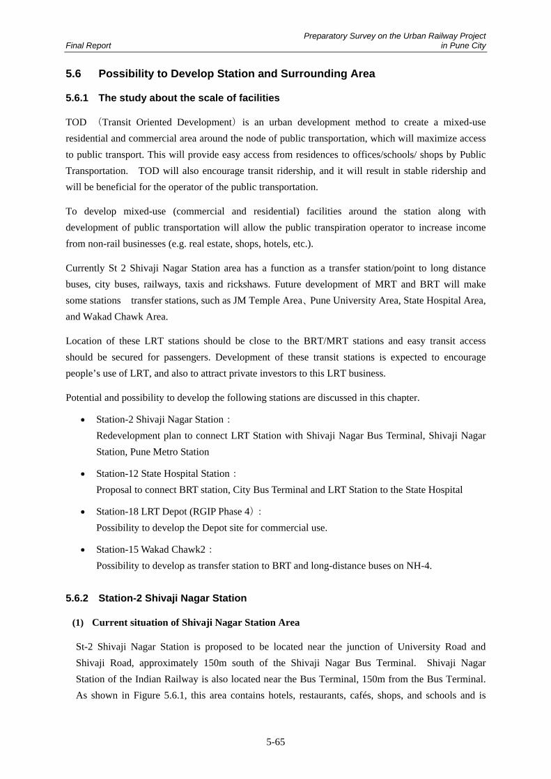
Preparatory Survey on the Urban Railway Project Final Report in Pune City
5-65
5.6 Possibility to Develop Station and Surrounding Area
5.6.1 The study about the scale of facilities
TOD (Transit Oriented Development)is an urban development method to create a mixed-use
residential and commercial area around the node of public transportation, which will maximize access
to public transport. This will provide easy access from residences to offices/schools/ shops by Public
Transportation. TOD will also encourage transit ridership, and it will result in stable ridership and
will be beneficial for the operator of the public transportation.
To develop mixed-use (commercial and residential) facilities around the station along with
development of public transportation will allow the public transpiration operator to increase income
from non-rail businesses (e.g. real estate, shops, hotels, etc.).
Currently St 2 Shivaji Nagar Station area has a function as a transfer station/point to long distance
buses, city buses, railways, taxis and rickshaws. Future development of MRT and BRT will make
some stations transfer stations, such as JM Temple Area、Pune University Area, State Hospital Area,
and Wakad Chawk Area.
Location of these LRT stations should be close to the BRT/MRT stations and easy transit access
should be secured for passengers. Development of these transit stations is expected to encourage
people’s use of LRT, and also to attract private investors to this LRT business.
Potential and possibility to develop the following stations are discussed in this chapter.
Station-2 Shivaji Nagar Station:
Redevelopment plan to connect LRT Station with Shivaji Nagar Bus Terminal, Shivaji Nagar
Station, Pune Metro Station
Station-12 State Hospital Station:
Proposal to connect BRT station, City Bus Terminal and LRT Station to the State Hospital
Station-18 LRT Depot (RGIP Phase 4):
Possibility to develop the Depot site for commercial use.
Station-15 Wakad Chawk2:
Possibility to develop as transfer station to BRT and long-distance buses on NH-4.
5.6.2 Station-2 Shivaji Nagar Station
(1) Current situation of Shivaji Nagar Station Area
St-2 Shivaji Nagar Station is proposed to be located near the junction of University Road and
Shivaji Road, approximately 150m south of the Shivaji Nagar Bus Terminal. Shivaji Nagar
Station of the Indian Railway is also located near the Bus Terminal, 150m from the Bus Terminal.
As shown in Figure 5.6.1, this area contains hotels, restaurants, cafés, shops, and schools and is
Preparatory Survey on the Urban Railway Project Final Report in Pune City
5-66
crowded with passengers, students, auto-rickshaws, taxis, motorcycles and private cars in general.
A new station of PUNE METRO Line 1 is planned to be constructed under the Bus Terminal, and is
expected to cause more traffic in this area.
In order to mitigate the traffic congestion in this area, PMC proposed to construct a skywalk from
the Bus Terminal towards Mandai along the Shivaji Road, but the plan was canceled because of the
insufficient user rate expected.
Shivaji Nagar Bus Terminal is one of the four Bus Terminals for long distance buses in PUNE. This
Bus Terminal owns 153 buses, and the number of buses that comes to / goes from Shivaji Nagar
Bus Terminal per day is between 800 and 1,100. This number of buses and frequency of Bus
arrivals/departures are far beyond the expected number when the terminal was built in 1968.
According to the Maharashtra State Road Transport Corporation (MSRTC), owner of this Bus
Terminal, this Bus Terminal obviously must be expanded, but it is difficult to find available area
around the existing terminal.
In order to secure smooth bus operations, MSRTC desires to improve the traffic flow of the area by
limiting the encroachment by small shops, taxis, and rickshaws around the Bus Terminal.

Preparatory Survey on the Urban Railway Project Final Report in Pune City
5-67
Source: Base map : PMC Land Use Development Plan, PMC Web.
Proposed Metro Line and Station: General Alignment Drawing of Pune Metro 2008, DMRC Proposed LRT Line & Station : JICA study team
Figure 5.6.1 Proposed location of LRT Shivaji Nagar Station
Table 5.6.1 shows the summary of the current situation of Shivaji Nagar Bus Terminal and Railway
Station area.
Table 5.6.1 LRT Shivaji Nagar Station Area: Target sites for redevelopment
Land Ownership Land Use Area F.S.I PlotShivaji Nagar Bus Terminal MSRTC Bus Terminal, Bus Depot,
Drivers Accommodation, etc. 10,600m2 2.0 A
Plaza and Car Parking Spaces(bikes and cars) 3,100 m2 2.0 B
Hostel for family members of Indian Railway Staff 3,100 m2 2.0 C
Shivaji Nagar Station Area
Indian Railway (Possibility to be partially purchased by PMC )
Slum 3,500 m2 2.0 D
Slum Area Slum Improvement Corporation Slum 11,500 m2 2.5 E
Source: Land Use Development Department, PMC

Preparatory Survey on the Urban Railway Project Final Report in Pune City
5-68
Figure 5.6.2 Station2 Shivaji Nagar Staion Surrounding Condition
Source: Boundary of the land from Land Use Development Plan PMC, Proposed Metro Line and Station from General Alignment Drawing of Pune Metro 2008, DMRC, Information of Shibaji Nagar Bus Terminal from Maharashtra State Road Transport Corporation, others from JICA Study Team

Preparatory Survey on the Urban Railway Project Final Report in Pune City
5-69
(2) Study on possibility to redevelop around the Shivaji Nagar Station
With the proposed LRT station (St-2) and new station of Pune Metro under the Bus Terminal, this
area will be an intermodal center for several public transportation modes. Because of this, this
area has a high potential to be re-developed as a mixed use center with a TOD Concept, and
redevelopment of this area is assumed to encourage development of the local economy.
In addition, integration with Railways, long-distance buses, city buses, taxis and rickshaws, and the
new Pune Metro at this station will raise the value of this area, and is expected to increase the
convenience of the LRT system and attract more passengers.
On the other hand, this intermodal center with mixed-use development will attract more taxis,
rickshaws, and private vehicles, and integrated and comprehensive redevelopment of this area is
required to improve the traffic circulation of this area as well as to encourage commercial
development.
Accordingly, the possibility to re-develop this area was studied based on the following objectives;
to improve traffic congestion of this area,
to enhance passenger convenience as an intermodal center of public transportation,
to encourage local economic activities by re-development based on the TOD concept.
The following three optional scenarios were studied and pros and cons. of these options were
compared.
- Option 1: Skywalk to connect LRT St 2 with the Bus Terminal and Metro Station, and
redevelopment of the Bus Terminal are proposed.
- Option 2: Skywalk to connect LRT St 2 with the Bus Terminal, Pune Metro Station, and
Shivaji Nagar Station Plaza, and redevelopment of the Bus Terminal and Station Plaza are
proposed.
- Option 3: Skywalk to connect LRT St 2 with the Bus Terminal, Pune Metro Station, and
Shivaji Nagar Station, and redevelopment of the Bus Terminal, Station Plaza and Slum area
in front of the Station.
The following instructions given by PMC office are applied to this study.
1) F.S.I.
Government owned land, and development for public use : F.S.I 2.0
Redevelopment of Slum Area : F.S.I 2.5
There is a discussion that F.S.I of the area within 500m from Metro Station is changed to
4.0. The case which is applied F.S.I 4.0 was also studied.
2) Exemption of floor area for FSI calculation
Floor area for Public Car Parking can be exempted from the floor area calculation.
(ceiling height should be between 2.4m to 2.8m.

Preparatory Survey on the Urban Railway Project Final Report in Pune City
5-70
There is no rule for parking space for public buses at this moment. However, according to
the discussion/advice from PMC, there is a possibility to establish an additional rule for
exempting the public bus parking space. The bus parking area was exempted from the
calculation.
3) Building Height Limitation
According to the PMC office, the building height limitation for Shivaji Nagar Area is
100m.
Table 5.6.2 Comparison of re-development scenario options of Shivaji Nagar Station Area
Option 1 Option 2 Option 3
Target Sites A A, B, C A,B, C, D, E
Site Area A : 10,600m2 A : 10,600m2 B+C:6,200 m2
A : 10,600m2 B+C+D:9,700 m2 E: 11,500 m2
F.S.I.2.0 and F.S.I. 2.5
A : 21,200m2 A : 21,200m2 B+C:12,400 m2
A : 21,200m2 B+C+D:19,400 m2 E: 28,800 m2
Limit of Total Floor Area
F.S.I. 4.0 A : 42,400m2 A : 42,400m2 B+C:24,800 m2
A : 42,400m2 B+C+D:38,800 m2 E: 46,000 m2
Use of Buildings
Bus Terminal Complex: Bus Terminal, Bus Depot, Metro Station, Waiting Space, MSRTC Office, Accommodations for Bus Drivers, Commercial & Office uses, etc.
Bus Terminal Complex:ditto Station Plaza:
City Bus Stops, Taxi, Stands, Rickshaw Stands, etc.
Indian Railway Complex: Public Parking Spaces, Hospital for family members of Indian Railway Staff, Staff Accommodations, Public Service Facilities (post office, clinic, etc.) Commercial & Office Use.
Bus Terminal Complex:ditto Station Plaza:
ditto Indian Railway Complex:dittoSlum Redevelopment
Building: Public Parking Spaces,
Commercial and Residential uses.
Building Capacity (FSI 2.0) Leasable Area
Bus Terminal Complex:10F 10,000m2
Bus Terminal Complex:10F Indian Rail Complex : 11F 16,000m2
Bus Terminal Complex:10F Indian Rail Complex : 11F Slum Redevelopment.
Building:13F 34,000m2
Building Capacity (FSI 4.0) Leasable Area
Bus Terminal Complex:16F 26,000m2
Bus Terminal Complex:16F Indian Rail Complex : 22F 39,000m2
Bus Terminal Complex:16F Indian Rail Complex : 22F Slum Redevelopment.
Building:22F 71,000m2
Development Contents
Public Parking Spaces
Nil 80 Cars, 400 Bikes 200 Cars, 700 Bikes
Source: JICA Study Team

Preparatory Survey on the Urban Railway Project Final Report in Pune City
5-71
Figure 5.6.3 Optional Scenarios for Redevelopment of Shivaji Nagar Station Area
Source: JICA Study Team

Preparatory Survey on the Urban Railway Project Final Report in Pune City
5-72
Table shows a comparison of the three options’ pros and cons.
Table 5.6.3 Comparison of the Three Options
Option 1 Option 2 Option 3 Pros * Skywalk from LRT station to
Bus Terminal and Metro Station will reduce pedestrian crossings around the Bus Terminal.
* Redevelopment of the Bus Terminal will improve its function and reduce traffic congestion/confusion around the Bus Terminal.
* Skywalk from LRT station, Bus Terminal, Metro Station, and Railway Station, will improve connectivity among several public transportation modes.
* Capacity of Bus-Terminal will be expanded, and traffic congestion around the area will be reduced.
* Resettlement of residents is not required. Hostel for the family members of Indian Railway staff will be in the redeveloped building.
* Re-development of the Bus Terminal, Station Plaza, Slum etc, will make rearrangement of the traffic circulation system and integration of public transpiration possible.
* Maximize utilization of area with node of public transportation with TOD Concept.
* Redevelopment of the Slum area will improve image/impression of the Station area.
Cons * Only Bus Terminal’s redevelopment is not enough to improve the traffic congestion in the area.
* Coordination with MSRTC and Pune Metro is required.
* Area which has high potential for re-development with node of public transpiration modes will not be developed.
* Coordination with MSRTC, Pune Metro, and Indian Railways is required.
* Resettlement of residents in Slum Area is required.
* Coordination with MSRTC, Pune Metro, Indian Railways, and Slum redevelopment are required.
Source: JICAStudy Team
(3) Summary and Issues
In order to improve the traffic circulation around the Bus Terminal and Railway Station, and
improve the convenience of intermodal connectivity, redevelopment of the wider area including the
Station Plaza is recommended (Option 2 or Option 3).
From the view points of effectiveness for activating the local economy, Option 3 will provide more
opportunity for commercial development, and is expected to attract more private investors.
However, this Option 3 requires resettlement of slum residents, and necessary procedures, including
guarantees, should be discussed carefully before implementation.
For further study on the possibility and feasibility, coordination with MSRTC, the owner of the Bus
Terminal, Indian Railway, the owner of land around the station, and Pune Metro SPC, is required.
As Pune Metro SPC is under the process of formulation as a joint corporation of PMC, PCMC,
State Government, and Indian Railway, coordination with this Pune Metro SPC will help to
coordinate with MSRTC and Indian Railway as well.
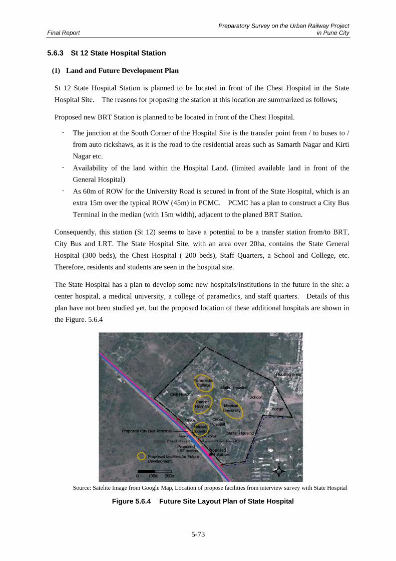
Preparatory Survey on the Urban Railway Project Final Report in Pune City
5-73
5.6.3 St 12 State Hospital Station
(1) Land and Future Development Plan
St 12 State Hospital Station is planned to be located in front of the Chest Hospital in the State
Hospital Site. The reasons for proposing the station at this location are summarized as follows;
Proposed new BRT Station is planned to be located in front of the Chest Hospital.
- The junction at the South Corner of the Hospital Site is the transfer point from / to buses to /
from auto rickshaws, as it is the road to the residential areas such as Samarth Nagar and Kirti
Nagar etc.
- Availability of the land within the Hospital Land. (limited available land in front of the
General Hospital)
- As 60m of ROW for the University Road is secured in front of the State Hospital, which is an
extra 15m over the typical ROW (45m) in PCMC. PCMC has a plan to construct a City Bus
Terminal in the median (with 15m width), adjacent to the planed BRT Station.
Consequently, this station (St 12) seems to have a potential to be a transfer station from/to BRT,
City Bus and LRT. The State Hospital Site, with an area over 20ha, contains the State General
Hospital (300 beds), the Chest Hospital ( 200 beds), Staff Quarters, a School and College, etc.
Therefore, residents and students are seen in the hospital site.
The State Hospital has a plan to develop some new hospitals/institutions in the future in the site: a
center hospital, a medical university, a college of paramedics, and staff quarters. Details of this
plan have not been studied yet, but the proposed location of these additional hospitals are shown in
the Figure. 5.6.4
Source: Satelite Image from Google Map, Location of propose facilities from interview survey with State Hospital
Figure 5.6.4 Future Site Layout Plan of State Hospital

Preparatory Survey on the Urban Railway Project Final Report in Pune City
5-74
(2) Study on the possibility of the Hospital Station
To locate St 12 adjacent to the BRT Station and City Bus Terminal, which are planned to be in the
median of the University Road, will enable integration of LRT with BRT and City Bus Services and
St 12 becomes a transit station. As St 12 will be elevated, it will be connected to BRT and Bus
Terminal by elevators and staircases.
A Pedestrian Overpass will provide safe access from the Hospital Site to St 12, the BRT station and
City Bus Terminal. All passengers of BRT, Bus and LRT will be able to access the Hospital Site
via the Pedestrian Overpass without crossing the road on the ground.
As this integrated transit station is expected to attract more passengers rather than hospital visitors,
public parking for motorcycles / bicycles will be required for people from residences and students.
A transit station in front of the large hospital is assumed to have potential to develop commercial
facilities. The space above the City Bus Terminal and Public Bike Parking Space are proposed to be
for commercial use. It is expected that commercial developments in and near this station would
have many customers, such as hospital visitors (patients, families and staff), staff in the colleges,
residents who use the BRT/Bus/LRT, and future staff/visitors of the planned hospitals.
A universal design should be applied to all station buildings and pedestrian overpasses, and covered
walkways within the hospital site.
In addition, due to the scattered buildings in the state hospital site, connectivity from station to each
hospital building is one of the critical issues regarding accessibility. For the time being, Rickshaw
stands at the station will help patients to /from the hospital buildings. But internal circulation Buses
from the hospitals to the station, and a network of covered footways will be helpful.
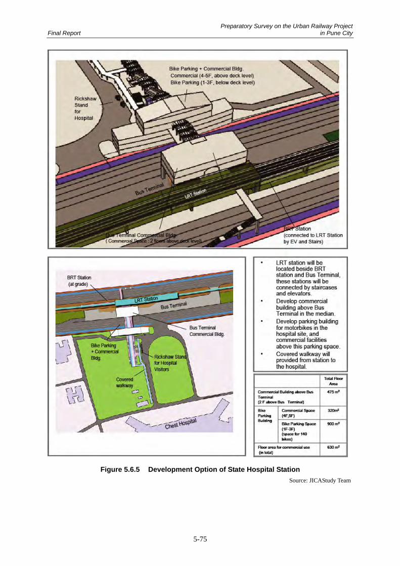
Preparatory Survey on the Urban Railway Project Final Report in Pune City
5-75
Figure 5.6.5 Development Option of State Hospital Station
Source: JICAStudy Team

Preparatory Survey on the Urban Railway Project Final Report in Pune City
5-76
5.6.4 St 15 Wakad Chowk 2
The proposed LRT line crosses NH-4 at the JAKAT NAKA fly-over on the West side of Wakad
Chowk in PCMC. This NH-4 is a route for Long Distance Buses to Mumbai, and many passengers
were observed to get on/off the buses from the bus stop under the flyover. There is a public parking
space for motorbikes under the flyover, and it is fully occupied in general.
People waiting for buses on NH-4 near the flyover Bike parking space under the flyover
In the Wakad area, several large-scale new township developments are on going now, and a significant
increase of population is forecast for this area. The majority of the target population of these new
developments are now employees of Hinjawadi Industrial Area. However, residents that are working
in PUNE but prefer to stay in the Wakad area due to the expensive housing cost in the PUNE area, are
also an important target of this market.
Consequently, St 15 Wakad Chawk2 station will be a transfer station to BRT, and also be a transit
point for City Buses / Long Distance Buses on NH-4. In addition, it is also expected that this station
will have a high demand for Park & Ride from residents of the new township developments.
In this area, construction work on the road expansion with 45m ROW is now on going, and acquisition
of the land and demolition of the buildings has been started. On the other hand, new housing
buildings are under construction along the road. Currently, most of the lands along the street are
categorized as “residential” in the PCMC land use plan. As most of the lands are owned by private
owners, the available land has not been confirmed yet in this area, therefore, the possibility to develop
a Park & Ride facility is studied with temporary sites as shown in Figure.5.6.8.
For this study, F.S.I 1.8, which is for the area along a BRT corridor is applied.
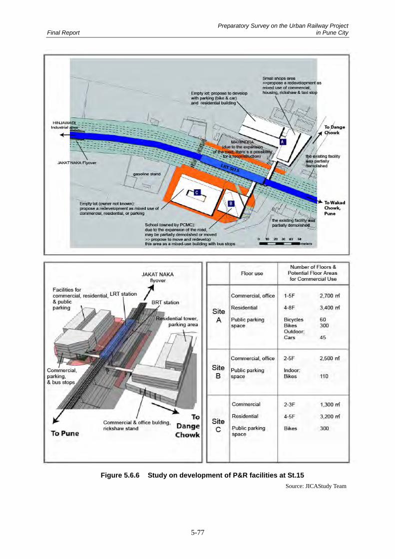
Preparatory Survey on the Urban Railway Project Final Report in Pune City
5-77
Figure 5.6.6 Study on development of P&R facilities at St.15
Source: JICAStudy Team