Chapter 1- Introduction - Power Unit
900
Chapter 1- Introduction Chapter 1 Introduction 30/10/2014 1
-
Upload
khangminh22 -
Category
Documents
-
view
0 -
download
0
Transcript of Chapter 1- Introduction - Power Unit

Chapter 1- Introduction
Chapter 1 Introduction30/10/2014 1

Topics covered
Professional software development
What is meant by software engineering.
Software engineering ethics
A brief introduction to ethical issues that affect software
engineering.
Case studies
An introduction to three examples that are used in later chapters
in the book.
Chapter 1 Introduction30/10/2014 2

Software engineering
The economies of ALL developed nations are
dependent on software.
More and more systems are software controlled
Software engineering is concerned with theories,
methods and tools for professional software
development.
Expenditure on software represents a
significant fraction of GNP in all developed countries.
Chapter 1 Introduction30/10/2014 3

Software costs
Software costs often dominate computer system costs.
The costs of software on a PC are often greater than the
hardware cost.
Software costs more to maintain than it does to develop.
For systems with a long life, maintenance costs may be
several times development costs.
Software engineering is concerned with cost-effective
software development.
Chapter 1 Introduction30/10/2014 4

Software project failure
Increasing system complexity
As new software engineering techniques help us to build larger,
more complex systems, the demands change. Systems have to
be built and delivered more quickly; larger, even more complex
systems are required; systems have to have new capabilities
that were previously thought to be impossible.
Failure to use software engineering methods
It is fairly easy to write computer programs without using
software engineering methods and techniques. Many companies
have drifted into software development as their products and
services have evolved. They do not use software engineering
methods in their everyday work. Consequently, their software is
often more expensive and less reliable than it should be.
Chapter 1 Introduction30/10/2014 5

Professional software development
Chapter 1 Introduction30/10/2014 6

Frequently asked questions about software
engineering
Question Answer
What is software? Computer programs and associated documentation.
Software products may be developed for a particular
customer or may be developed for a general market.
What are the attributes of good software? Good software should deliver the required functionality
and performance to the user and should be
maintainable, dependable and usable.
What is software engineering? Software engineering is an engineering discipline that is
concerned with all aspects of software production.
What are the fundamental software
engineering activities?
Software specification, software development, software
validation and software evolution.
What is the difference between software
engineering and computer science?
Computer science focuses on theory and fundamentals;
software engineering is concerned with the practicalities
of developing and delivering useful software.
What is the difference between software
engineering and system engineering?
System engineering is concerned with all aspects of
computer-based systems development including
hardware, software and process engineering. Software
engineering is part of this more general process.
Chapter 1 Introduction30/10/2014 7

Frequently asked questions about software
engineering
Question Answer
What are the key challenges facing
software engineering?
Coping with increasing diversity, demands for reduced
delivery times and developing trustworthy software.
What are the costs of software
engineering?
Roughly 60% of software costs are development costs,
40% are testing costs. For custom software, evolution
costs often exceed development costs.
What are the best software engineering
techniques and methods?
While all software projects have to be professionally
managed and developed, different techniques are
appropriate for different types of system. For example,
games should always be developed using a series of
prototypes whereas safety critical control systems require
a complete and analyzable specification to be developed.
You can’t, therefore, say that one method is better than
another.
What differences has the web made to
software engineering?
The web has led to the availability of software services
and the possibility of developing highly distributed service-
based systems. Web-based systems development has led
to important advances in programming languages and
software reuse.
Chapter 1 Introduction30/10/2014 8

Software products
Generic products
Stand-alone systems that are marketed and sold to any
customer who wishes to buy them.
Examples – PC software such as graphics programs, project
management tools; CAD software; software for specific markets
such as appointments systems for dentists.
Customized products
Software that is commissioned by a specific customer to meet
their own needs.
Examples – embedded control systems, air traffic control
software, traffic monitoring systems.
Chapter 1 Introduction30/10/2014 9

Product specification
Generic products
The specification of what the software should do is owned by the
software developer and decisions on software change are made
by the developer.
Customized products
The specification of what the software should do is owned by the
customer for the software and they make decisions on software
changes that are required.
Chapter 1 Introduction30/10/2014 10

Essential attributes of good software
Product characteristic Description
Maintainability Software should be written in such a way so that it can evolve to
meet the changing needs of customers. This is a critical attribute
because software change is an inevitable requirement of a
changing business environment.
Dependability and
security
Software dependability includes a range of characteristics
including reliability, security and safety. Dependable software
should not cause physical or economic damage in the event of
system failure. Malicious users should not be able to access or
damage the system.
Efficiency Software should not make wasteful use of system resources such
as memory and processor cycles. Efficiency therefore includes
responsiveness, processing time, memory utilisation, etc.
Acceptability Software must be acceptable to the type of users for which it is
designed. This means that it must be understandable, usable and
compatible with other systems that they use.
Chapter 1 Introduction30/10/2014 11

Software engineering
Software engineering is an engineering discipline that is
concerned with all aspects of software production from
the early stages of system specification through to
maintaining the system after it has gone into use.
Engineering discipline
Using appropriate theories and methods to solve problems
bearing in mind organizational and financial constraints.
All aspects of software production
Not just technical process of development. Also project
management and the development of tools, methods etc. to
support software production.
Chapter 1 Introduction30/10/2014 12

Importance of software engineering
More and more, individuals and society rely on advanced
software systems. We need to be able to produce
reliable and trustworthy systems economically and
quickly.
It is usually cheaper, in the long run, to use software
engineering methods and techniques for software
systems rather than just write the programs as if it was a
personal programming project. For most types of
system, the majority of costs are the costs of changing
the software after it has gone into use.
Chapter 1 Introduction30/10/2014 13
Software process activities
Software specification, where customers and engineers
define the software that is to be produced and the
constraints on its operation.
Software development, where the software is designed
and programmed.
Software validation, where the software is checked to
ensure that it is what the customer requires.
Software evolution, where the software is modified to
reflect changing customer and market requirements.
Chapter 1 Introduction30/10/2014 14

General issues that affect software
Heterogeneity
Increasingly, systems are required to operate as distributed
systems across networks that include different types of computer
and mobile devices.
Business and social change
Business and society are changing incredibly quickly as
emerging economies develop and new technologies become
available. They need to be able to change their existing software
and to rapidly develop new software.
Chapter 1 Introduction30/10/2014 15

General issues that affect software
Security and trust
As software is intertwined with all aspects of our lives, it is
essential that we can trust that software.
Scale
Software has to be developed across a very wide range of
scales, from very small embedded systems in portable or
wearable devices through to Internet-scale, cloud-based
systems that serve a global community.
Chapter 1 Introduction30/10/2014 16

Software engineering diversity
There are many different types of software system and
there is no universal set of software techniques that is
applicable to all of these.
The software engineering methods and tools used
depend on the type of application being developed, the
requirements of the customer and the background of the
development team.
Chapter 1 Introduction30/10/2014 17

Application types
Stand-alone applications
These are application systems that run on a local computer,
such as a PC. They include all necessary functionality and do
not need to be connected to a network.
Interactive transaction-based applications
Applications that execute on a remote computer and are
accessed by users from their own PCs or terminals. These
include web applications such as e-commerce applications.
Embedded control systems
These are software control systems that control and manage
hardware devices. Numerically, there are probably more
embedded systems than any other type of system.
Chapter 1 Introduction30/10/2014 18

Application types
Batch processing systems
These are business systems that are designed to process data
in large batches. They process large numbers of individual
inputs to create corresponding outputs.
Entertainment systems
These are systems that are primarily for personal use and which
are intended to entertain the user.
Systems for modeling and simulation
These are systems that are developed by scientists and
engineers to model physical processes or situations, which
include many, separate, interacting objects.
Chapter 1 Introduction30/10/2014 19

Application types
Data collection systems
These are systems that collect data from their environment using
a set of sensors and send that data to other systems for
processing.
Systems of systems
These are systems that are composed of a number of other
software systems.
Chapter 1 Introduction30/10/2014 20

Software engineering fundamentals
Some fundamental principles apply to all types of
software system, irrespective of the development
techniques used:
Systems should be developed using a managed and understood
development process. Of course, different processes are used
for different types of software.
Dependability and performance are important for all types of
system.
Understanding and managing the software specification and
requirements (what the software should do) are important.
Where appropriate, you should reuse software that has already
been developed rather than write new software.
Chapter 1 Introduction30/10/2014 21

Internet software engineering
The Web is now a platform for running application and
organizations are increasingly developing web-based
systems rather than local systems.
Web services (discussed in Chapter 19) allow
application functionality to be accessed over the web.
Cloud computing is an approach to the provision of
computer services where applications run remotely on
the ‘cloud’.
Users do not buy software buy pay according to use.
Chapter 1 Introduction30/10/2014 22

Web-based software engineering
Web-based systems are complex distributed systems
but the fundamental principles of software engineering
discussed previously are as applicable to them as they
are to any other types of system.
The fundamental ideas of software engineering apply to
web-based software in the same way that they apply to
other types of software system.
Chapter 1 Introduction30/10/2014 23

Web software engineering
Software reuse
Software reuse is the dominant approach for constructing web-
based systems. When building these systems, you think about how
you can assemble them from pre-existing software components and
systems.
Incremental and agile development
Web-based systems should be developed and delivered
incrementally. It is now generally recognized that it is impractical to
specify all the requirements for such systems in advance.
Chapter 1 Introduction30/10/2014 24

Web software engineering
Service-oriented systems
Software may be implemented using service-oriented software
engineering, where the software components are stand-alone
web services.
Rich interfaces
Interface development technologies such as AJAX and HTML5
have emerged that support the creation of rich interfaces within a
web browser.
Chapter 1 Introduction30/10/2014 25

Software engineering ethics
Chapter 1 Introduction30/10/2014 26

Software engineering ethics
Software engineering involves wider responsibilities than
simply the application of technical skills.
Software engineers must behave in an honest and
ethically responsible way if they are to be respected as
professionals.
Ethical behaviour is more than simply upholding the law
but involves following a set of principles that are morally
correct.
Chapter 1 Introduction30/10/2014 27

Issues of professional responsibility
Confidentiality
Engineers should normally respect the confidentiality of their employers or clients irrespective of whether or not a formal confidentiality agreement has been signed.
Competence
Engineers should not misrepresent their level of competence. They should not knowingly accept work which is outwith their competence.
Chapter 1 Introduction30/10/2014 28

Issues of professional responsibility
Intellectual property rights
Engineers should be aware of local laws governing the use of
intellectual property such as patents, copyright, etc. They should
be careful to ensure that the intellectual property of employers
and clients is protected.
Computer misuse
Software engineers should not use their technical skills to
misuse other people’s computers. Computer misuse ranges from
relatively trivial (game playing on an employer’s machine, say) to
extremely serious (dissemination of viruses).
Chapter 1 Introduction30/10/2014 29

ACM/IEEE Code of Ethics
The professional societies in the US have cooperated to produce a code of ethical practice.
Members of these organisations sign up to the code of practice when they join.
The Code contains eight Principles related to the behaviour of and decisions made by professional software engineers, including practitioners, educators, managers, supervisors and policy makers, as well as trainees and students of the profession.
Chapter 1 Introduction30/10/2014 30

Rationale for the code of ethics
Computers have a central and growing role in commerce,
industry, government, medicine, education, entertainment and
society at large. Software engineers are those who contribute by
direct participation or by teaching, to the analysis, specification,
design, development, certification, maintenance and testing of
software systems.
Because of their roles in developing software systems, software
engineers have significant opportunities to do good or cause
harm, to enable others to do good or cause harm, or to influence
others to do good or cause harm. To ensure, as much as
possible, that their efforts will be used for good, software
engineers must commit themselves to making software
engineering a beneficial and respected profession.
Chapter 1 Introduction30/10/2014 31

The ACM/IEEE Code of Ethics
Software Engineering Code of Ethics and Professional Practice
ACM/IEEE-CS Joint Task Force on Software Engineering Ethics and Professional Practices
PREAMBLE
The short version of the code summarizes aspirations at a high level of the abstraction; the
clauses that are included in the full version give examples and details of how these
aspirations change the way we act as software engineering professionals. Without the
aspirations, the details can become legalistic and tedious; without the details, the
aspirations can become high sounding but empty; together, the aspirations and the details
form a cohesive code.
Software engineers shall commit themselves to making the analysis, specification, design,
development, testing and maintenance of software a beneficial and respected profession. In
accordance with their commitment to the health, safety and welfare of the public, software
engineers shall adhere to the following Eight Principles:
Chapter 1 Introduction30/10/2014 32

Ethical principles
1. PUBLIC - Software engineers shall act consistently with the public interest.
2. CLIENT AND EMPLOYER - Software engineers shall act in a manner that is in the best
interests of their client and employer consistent with the public interest.
3. PRODUCT - Software engineers shall ensure that their products and related
modifications meet the highest professional standards possible.
4. JUDGMENT - Software engineers shall maintain integrity and independence in their
professional judgment.
5. MANAGEMENT - Software engineering managers and leaders shall subscribe to and
promote an ethical approach to the management of software development and
maintenance.
6. PROFESSION - Software engineers shall advance the integrity and reputation of the
profession consistent with the public interest.
7. COLLEAGUES - Software engineers shall be fair to and supportive of their colleagues.
8. SELF - Software engineers shall participate in lifelong learning regarding the practice of
their profession and shall promote an ethical approach to the practice of the profession.
Chapter 1 Introduction30/10/2014 33

Case studies
Chapter 1 Introduction30/10/2014 34

Ethical dilemmas
Disagreement in principle with the policies of senior
management.
Your employer acts in an unethical way and releases a
safety-critical system without finishing the testing of the
system.
Participation in the development of military weapons
systems or nuclear systems.
Chapter 1 Introduction30/10/2014 35

Case studies
A personal insulin pump
An embedded system in an insulin pump used by diabetics to
maintain blood glucose control.
A mental health case patient management system
Mentcare. A system used to maintain records of people receiving
care for mental health problems.
A wilderness weather station
A data collection system that collects data about weather
conditions in remote areas.
iLearn: a digital learning environment
A system to support learning in schools
Chapter 1 Introduction30/10/2014 36

Insulin pump control system
Collects data from a blood sugar sensor and calculates
the amount of insulin required to be injected.
Calculation based on the rate of change of blood sugar
levels.
Sends signals to a micro-pump to deliver the correct
dose of insulin.
Safety-critical system as low blood sugars can lead to
brain malfunctioning, coma and death; high-blood sugar
levels have long-term consequences such as eye and
kidney damage.
Chapter 1 Introduction30/10/2014 37

Insulin pump hardware architecture
Chapter 1 Introduction30/10/2014 38

Activity model of the insulin pump
Chapter 1 Introduction30/10/2014 39

Essential high-level requirements
The system shall be available to deliver insulin when
required.
The system shall perform reliably and deliver the correct
amount of insulin to counteract the current level of blood
sugar.
The system must therefore be designed and
implemented to ensure that the system always meets
these requirements.
Chapter 1 Introduction30/10/2014 40

Mentcare: A patient information system for
mental health care
A patient information system to support mental health
care is a medical information system that maintains
information about patients suffering from mental health
problems and the treatments that they have received.
Most mental health patients do not require dedicated
hospital treatment but need to attend specialist clinics
regularly where they can meet a doctor who has detailed
knowledge of their problems.
To make it easier for patients to attend, these clinics are
not just run in hospitals. They may also be held in local
medical practices or community centres.
Chapter 1 Introduction30/10/2014 41

Mentcare
Mentcare is an information system that is intended for
use in clinics.
It makes use of a centralized database of patient
information but has also been designed to run on a PC,
so that it may be accessed and used from sites that do
not have secure network connectivity.
When the local systems have secure network access,
they use patient information in the database but they can
download and use local copies of patient records when
they are disconnected.
Chapter 1 Introduction30/10/2014 42

Mentcare goals
To generate management information that allows health
service managers to assess performance against local
and government targets.
To provide medical staff with timely information to
support the treatment of patients.
Chapter 1 Introduction30/10/2014 43

The organization of the Mentcare system
Chapter 1 Introduction30/10/2014 44

Key features of the Mentcare system
Individual care management
Clinicians can create records for patients, edit the information in
the system, view patient history, etc. The system supports data
summaries so that doctors can quickly learn about the key
problems and treatments that have been prescribed.
Patient monitoring
The system monitors the records of patients that are involved in
treatment and issues warnings if possible problems are detected.
Administrative reporting
The system generates monthly management reports showing the
number of patients treated at each clinic, the number of patients
who have entered and left the care system, number of patients
sectioned, the drugs prescribed and their costs, etc. Chapter 1 Introduction30/10/2014 45

Mentcare system concerns
Privacy
It is essential that patient information is confidential and is never
disclosed to anyone apart from authorised medical staff and the
patient themselves.
Safety
Some mental illnesses cause patients to become suicidal or a
danger to other people. Wherever possible, the system should
warn medical staff about potentially suicidal or dangerous
patients.
The system must be available when needed otherwise safety
may be compromised and it may be impossible to prescribe the
correct medication to patients.
Chapter 1 Introduction30/10/2014 46

Wilderness weather station
The government of a country with large areas of
wilderness decides to deploy several hundred weather
stations in remote areas.
Weather stations collect data from a set of instruments
that measure temperature and pressure, sunshine,
rainfall, wind speed and wind direction.
The weather station includes a number of instruments that
measure weather parameters such as the wind speed and
direction, the ground and air temperatures, the barometric
pressure and the rainfall over a 24-hour period. Each of these
instruments is controlled by a software system that takes
parameter readings periodically and manages the data collected
from the instruments.
Chapter 1 Introduction30/10/2014 47

The weather station’s environment
Chapter 1 Introduction30/10/2014 48

Weather information system
The weather station system
This is responsible for collecting weather data, carrying out some
initial data processing and transmitting it to the data management
system.
The data management and archiving system
This system collects the data from all of the wilderness weather
stations, carries out data processing and analysis and archives the
data.
The station maintenance system
This system can communicate by satellite with all wilderness
weather stations to monitor the health of these systems and provide
reports of problems.
Chapter 1 Introduction30/10/2014 49

Additional software functionality
Monitor the instruments, power and communication
hardware and report faults to the management system.
Manage the system power, ensuring that batteries are
charged whenever the environmental conditions permit
but also that generators are shut down in potentially
damaging weather conditions, such as high wind.
Support dynamic reconfiguration where parts of the
software are replaced with new versions and where
backup instruments are switched into the system in the
event of system failure.
Chapter 1 Introduction30/10/2014 50

iLearn: A digital learning environment
A digital learning environment is a framework in which a
set of general-purpose and specially designed tools for
learning may be embedded plus a set of applications
that are geared to the needs of the learners using the
system.
The tools included in each version of the environment
are chosen by teachers and learners to suit their specific
needs.
These can be general applications such as spreadsheets,
learning management applications such as a Virtual Learning
Environment (VLE) to manage homework submission and
assessment, games and simulations.
Chapter 1 Introduction30/10/2014 51

Service-oriented systems
The system is a service-oriented system with all system
components considered to be a replaceable service.
This allows the system to be updated incrementally as
new services become available.
It also makes it possible to rapidly configure the system
to create versions of the environment for different groups
such as very young children who cannot read, senior
students, etc.
Chapter 1 Introduction30/10/2014 52

iLearn services
Utility services that provide basic application-
independent functionality and which may be used by
other services in the system.
Application services that provide specific applications
such as email, conferencing, photo sharing etc. and
access to specific educational content such as scientific
films or historical resources.
Configuration services that are used to adapt the
environment with a specific set of application services
and do define how services are shared between
students, teachers and their parents.
Chapter 1 Introduction30/10/2014 53

iLearn architecture
Chapter 1 Introduction30/10/2014 54

iLearn service integration
Integrated services are services which offer an API
(application programming interface) and which can be
accessed by other services through that API. Direct
service-to-service communication is therefore possible.
Independent services are services which are simply
accessed through a browser interface and which operate
independently of other services. Information can only be
shared with other services through explicit user actions
such as copy and paste; re-authentication may be
required for each independent service.
Chapter 1 Introduction30/10/2014 55

Key points
Software engineering is an engineering discipline that is
concerned with all aspects of software production.
Essential software product attributes are maintainability,
dependability and security, efficiency and acceptability.
The high-level activities of specification, development,
validation and evolution are part of all software
processes.
The fundamental notions of software engineering are
universally applicable to all types of system
development.
Chapter 1 Introduction30/10/2014 56

Key points
There are many different types of system and each
requires appropriate software engineering tools and
techniques for their development.
The fundamental ideas of software engineering are
applicable to all types of software system.
Software engineers have responsibilities to the
engineering profession and society. They should not
simply be concerned with technical issues.
Professional societies publish codes of conduct which
set out the standards of behaviour expected of their
members.
Chapter 1 Introduction30/10/2014 57

Chapter 2 – Software Processes
Chapter 2 Software Processes 130/10/2014

Topics covered
Software process models
Process activities
Coping with change
Process improvement
Chapter 2 Software Processes 230/10/2014

The software process
A structured set of activities required to develop a
software system.
Many different software processes but all involve:
Specification – defining what the system should do;
Design and implementation – defining the organization of the
system and implementing the system;
Validation – checking that it does what the customer wants;
Evolution – changing the system in response to changing
customer needs.
A software process model is an abstract representation
of a process. It presents a description of a process from
some particular perspective.
Chapter 2 Software Processes 330/10/2014

Software process descriptions
When we describe and discuss processes, we usually
talk about the activities in these processes such as
specifying a data model, designing a user interface, etc.
and the ordering of these activities.
Process descriptions may also include:
Products, which are the outcomes of a process activity;
Roles, which reflect the responsibilities of the people involved in
the process;
Pre- and post-conditions, which are statements that are true
before and after a process activity has been enacted or a
product produced.
Chapter 2 Software Processes 430/10/2014

Plan-driven and agile processes
Plan-driven processes are processes where all of the
process activities are planned in advance and progress
is measured against this plan.
In agile processes, planning is incremental and it is
easier to change the process to reflect changing
customer requirements.
In practice, most practical processes include elements of
both plan-driven and agile approaches.
There are no right or wrong software processes.
Chapter 2 Software Processes 530/10/2014

Software process models
Chapter 2 Software Processes 630/10/2014

Software process models
The waterfall model
Plan-driven model. Separate and distinct phases of specification
and development.
Incremental development
Specification, development and validation are interleaved. May
be plan-driven or agile.
Integration and configuration
The system is assembled from existing configurable
components. May be plan-driven or agile.
In practice, most large systems are developed using a
process that incorporates elements from all of these
models.Chapter 2 Software Processes 730/10/2014

The waterfall model
Chapter 2 Software Processes 830/10/2014

Waterfall model phases
There are separate identified phases in the waterfall
model:
Requirements analysis and definition
System and software design
Implementation and unit testing
Integration and system testing
Operation and maintenance
The main drawback of the waterfall model is the difficulty
of accommodating change after the process is
underway. In principle, a phase has to be complete
before moving onto the next phase.
Chapter 2 Software Processes 930/10/2014

Waterfall model problems
Inflexible partitioning of the project into distinct stages
makes it difficult to respond to changing customer
requirements.
Therefore, this model is only appropriate when the requirements
are well-understood and changes will be fairly limited during the
design process.
Few business systems have stable requirements.
The waterfall model is mostly used for large systems
engineering projects where a system is developed at
several sites.
In those circumstances, the plan-driven nature of the waterfall
model helps coordinate the work.
Chapter 2 Software Processes 1030/10/2014

Incremental development
Chapter 2 Software Processes 1130/10/2014

Incremental development benefits
The cost of accommodating changing customer
requirements is reduced.
The amount of analysis and documentation that has to be
redone is much less than is required with the waterfall model.
It is easier to get customer feedback on the development
work that has been done.
Customers can comment on demonstrations of the software and
see how much has been implemented.
More rapid delivery and deployment of useful software to
the customer is possible.
Customers are able to use and gain value from the software
earlier than is possible with a waterfall process.
Chapter 2 Software Processes 1230/10/2014

Incremental development problems
The process is not visible.
Managers need regular deliverables to measure progress. If
systems are developed quickly, it is not cost-effective to produce
documents that reflect every version of the system.
System structure tends to degrade as new increments
are added.
Unless time and money is spent on refactoring to improve the
software, regular change tends to corrupt its structure.
Incorporating further software changes becomes increasingly
difficult and costly.
Chapter 2 Software Processes 1330/10/2014

Integration and configuration
Based on software reuse where systems are integrated
from existing components or COTS (Commercial-off-the-
shelf) systems.
Reused elements may be configured to adapt their
behaviour and functionality to a user’s requirements
Reuse is now the standard approach for building many
types of business system
Reuse covered in more depth in Chapter 15.
Chapter 2 Software Processes 1430/10/2014

Types of reusable software
Stand-alone application systems (sometimes called
COTS) that are configured for use in a particular
environment.
Collections of objects that are developed as a package
to be integrated with a component framework such as
.NET or J2EE.
Web services that are developed according to service
standards and which are available for remote invocation.
Chapter 2 Software Processes 1530/10/2014

Reuse-oriented software engineering
Chapter 2 Software Processes 1630/10/2014

Key process stages
Requirements specification
Software discovery and evaluation
Requirements refinement
Application system configuration
Component adaptation and integration
Chapter 2 Software Processes 1730/10/2014

Advantages and disadvantages
Reduced costs and risks as less software is developed
from scratch
Faster delivery and deployment of system
But requirements compromises are inevitable so system
may not meet real needs of users
Loss of control over evolution of reused system elements
Chapter 2 Software Processes 1830/10/2014

Process activities
Chapter 2 Software Processes 1930/10/2014

Process activities
Real software processes are inter-leaved sequences of
technical, collaborative and managerial activities with the
overall goal of specifying, designing, implementing and
testing a software system.
The four basic process activities of specification,
development, validation and evolution are organized
differently in different development processes.
For example, in the waterfall model, they are organized
in sequence, whereas in incremental development they
are interleaved.
Chapter 2 Software Processes 2030/10/2014

The requirements engineering process
Chapter 2 Software Processes 2130/10/2014

Software specification
The process of establishing what services are required
and the constraints on the system’s operation and
development.
Requirements engineering process
Requirements elicitation and analysis
• What do the system stakeholders require or expect from the system?
Requirements specification
• Defining the requirements in detail
Requirements validation
• Checking the validity of the requirements
Chapter 2 Software Processes 2230/10/2014
Software design and implementation
The process of converting the system specification into
an executable system.
Software design
Design a software structure that realises the specification;
Implementation
Translate this structure into an executable program;
The activities of design and implementation are closely
related and may be inter-leaved.
Chapter 2 Software Processes 2330/10/2014

A general model of the design process
Chapter 2 Software Processes 2430/10/2014

Design activities
Architectural design, where you identify the overall
structure of the system, the principal components
(subsystems or modules), their relationships and how
they are distributed.
Database design, where you design the system data
structures and how these are to be represented in a
database.
Interface design, where you define the interfaces
between system components.
Component selection and design, where you search for
reusable components. If unavailable, you design how it
will operate. Chapter 2 Software Processes 2530/10/2014

System implementation
The software is implemented either by developing a
program or programs or by configuring an application
system.
Design and implementation are interleaved activities for
most types of software system.
Programming is an individual activity with no standard
process.
Debugging is the activity of finding program faults and
correcting these faults.
Chapter 2 Software Processes 2630/10/2014

Software validation
Verification and validation (V & V) is intended to show
that a system conforms to its specification and meets the
requirements of the system customer.
Involves checking and review processes and system
testing.
System testing involves executing the system with test
cases that are derived from the specification of the real
data to be processed by the system.
Testing is the most commonly used V & V activity.
Chapter 2 Software Processes 2730/10/2014

Stages of testing
Chapter 2 Software Processes 2830/10/2014

Testing stages
Component testing
Individual components are tested independently;
Components may be functions or objects or coherent groupings
of these entities.
System testing
Testing of the system as a whole. Testing of emergent properties
is particularly important.
Customer testing
Testing with customer data to check that the system meets the
customer’s needs.
Chapter 2 Software Processes 2930/10/2014

Testing phases in a plan-driven software
process (V-model)
Chapter 2 Software Processes 3030/10/2014

Software evolution
Software is inherently flexible and can change.
As requirements change through changing business
circumstances, the software that supports the business
must also evolve and change.
Although there has been a demarcation between
development and evolution (maintenance) this is
increasingly irrelevant as fewer and fewer systems are
completely new.
Chapter 2 Software Processes 3130/10/2014

System evolution
Chapter 2 Software Processes 3230/10/2014

Coping with change
Chapter 2 Software Processes 3330/10/2014

Coping with change
Change is inevitable in all large software projects.
Business changes lead to new and changed system
requirements
New technologies open up new possibilities for improving
implementations
Changing platforms require application changes
Change leads to rework so the costs of change include
both rework (e.g. re-analysing requirements) as well as
the costs of implementing new functionality
Chapter 2 Software Processes 3430/10/2014

Reducing the costs of rework
Change anticipation, where the software process
includes activities that can anticipate possible changes
before significant rework is required.
For example, a prototype system may be developed to show
some key features of the system to customers.
Change tolerance, where the process is designed so that
changes can be accommodated at relatively low cost.
This normally involves some form of incremental development.
Proposed changes may be implemented in increments that have
not yet been developed. If this is impossible, then only a single
increment (a small part of the system) may have be altered to
incorporate the change.
Chapter 2 Software Processes 3530/10/2014

Coping with changing requirements
System prototyping, where a version of the system or
part of the system is developed quickly to check the
customer’s requirements and the feasibility of design
decisions. This approach supports change anticipation.
Incremental delivery, where system increments are
delivered to the customer for comment and
experimentation. This supports both change avoidance
and change tolerance.
Chapter 2 Software Processes 3630/10/2014

Software prototyping
A prototype is an initial version of a system used to
demonstrate concepts and try out design options.
A prototype can be used in:
The requirements engineering process to help with requirements
elicitation and validation;
In design processes to explore options and develop a UI design;
In the testing process to run back-to-back tests.
Chapter 2 Software Processes 3730/10/2014

Benefits of prototyping
Improved system usability.
A closer match to users’ real needs.
Improved design quality.
Improved maintainability.
Reduced development effort.
Chapter 2 Software Processes 3830/10/2014

The process of prototype development
Chapter 2 Software Processes 3930/10/2014

Prototype development
May be based on rapid prototyping languages or tools
May involve leaving out functionality
Prototype should focus on areas of the product that are not well-
understood;
Error checking and recovery may not be included in the
prototype;
Focus on functional rather than non-functional requirements
such as reliability and security
Chapter 2 Software Processes 4030/10/2014

Throw-away prototypes
Prototypes should be discarded after development as
they are not a good basis for a production system:
It may be impossible to tune the system to meet non-functional
requirements;
Prototypes are normally undocumented;
The prototype structure is usually degraded through rapid
change;
The prototype probably will not meet normal organisational
quality standards.
Chapter 2 Software Processes 4130/10/2014

Incremental delivery
Rather than deliver the system as a single delivery, the
development and delivery is broken down into
increments with each increment delivering part of the
required functionality.
User requirements are prioritised and the highest priority
requirements are included in early increments.
Once the development of an increment is started, the
requirements are frozen though requirements for later
increments can continue to evolve.
Chapter 2 Software Processes 4230/10/2014

Incremental development and delivery
Incremental development
Develop the system in increments and evaluate each increment
before proceeding to the development of the next increment;
Normal approach used in agile methods;
Evaluation done by user/customer proxy.
Incremental delivery
Deploy an increment for use by end-users;
More realistic evaluation about practical use of software;
Difficult to implement for replacement systems as increments
have less functionality than the system being replaced.
Chapter 2 Software Processes 4330/10/2014

Incremental delivery
Chapter 2 Software Processes 4430/10/2014

Incremental delivery advantages
Customer value can be delivered with each increment so
system functionality is available earlier.
Early increments act as a prototype to help elicit
requirements for later increments.
Lower risk of overall project failure.
The highest priority system services tend to receive the
most testing.
Chapter 2 Software Processes 4530/10/2014

Incremental delivery problems
Most systems require a set of basic facilities that are
used by different parts of the system.
As requirements are not defined in detail until an increment is to
be implemented, it can be hard to identify common facilities that
are needed by all increments.
The essence of iterative processes is that the
specification is developed in conjunction with the
software.
However, this conflicts with the procurement model of many
organizations, where the complete system specification is part of
the system development contract.
Chapter 2 Software Processes 4630/10/2014

Process improvement
Chapter 2 Software Processes 4730/10/2014

Process improvement
Many software companies have turned to software
process improvement as a way of enhancing the quality
of their software, reducing costs or accelerating their
development processes.
Process improvement means understanding existing
processes and changing these processes to increase
product quality and/or reduce costs and development
time.
Chapter 2 Software Processes 4830/10/2014

Approaches to improvement
The process maturity approach, which focuses on
improving process and project management and
introducing good software engineering practice.
The level of process maturity reflects the extent to which good
technical and management practice has been adopted in
organizational software development processes.
The agile approach, which focuses on iterative
development and the reduction of overheads in the
software process.
The primary characteristics of agile methods are rapid delivery of
functionality and responsiveness to changing customer
requirements.
Chapter 2 Software Processes 4930/10/2014

The process improvement cycle
Chapter 2 Software Processes 5030/10/2014

Process improvement activities
Process measurement
You measure one or more attributes of the software process or
product. These measurements forms a baseline that helps you
decide if process improvements have been effective.
Process analysis
The current process is assessed, and process weaknesses and
bottlenecks are identified. Process models (sometimes called
process maps) that describe the process may be developed.
Process change
Process changes are proposed to address some of the identified
process weaknesses. These are introduced and the cycle
resumes to collect data about the effectiveness of the changes.
Chapter 2 Software Processes 5130/10/2014

Process measurement
Wherever possible, quantitative process data
should be collected
However, where organisations do not have clearly defined
process standards this is very difficult as you don’t know what to
measure. A process may have to be defined before any
measurement is possible.
Process measurements should be used to
assess process improvements
But this does not mean that measurements should drive the
improvements. The improvement driver should be the
organizational objectives.
Chapter 2 Software Processes 5230/10/2014

Process metrics
Time taken for process activities to be
completed
E.g. Calendar time or effort to complete an activity or process.
Resources required for processes or activities
E.g. Total effort in person-days.
Number of occurrences of a particular event
E.g. Number of defects discovered.
Chapter 2 Software Processes 5330/10/2014

Capability maturity levels
Chapter 2 Software Processes 5430/10/2014

The SEI capability maturity model
Initial
Essentially uncontrolled
Repeatable
Product management procedures defined and used
Defined
Process management procedures and strategies defined
and used
Managed
Quality management strategies defined and used
Optimising
Process improvement strategies defined and used
Chapter 2 Software Processes 5530/10/2014

Key points
Software processes are the activities involved in
producing a software system. Software process models
are abstract representations of these processes.
General process models describe the organization of
software processes.
Examples of these general models include the ‘waterfall’ model,
incremental development, and reuse-oriented development.
Requirements engineering is the process of developing a
software specification.
Chapter 2 Software Processes 5630/10/2014

Key points
Design and implementation processes are concerned
with transforming a requirements specification into an
executable software system.
Software validation is the process of checking that the
system conforms to its specification and that it meets the
real needs of the users of the system.
Software evolution takes place when you change
existing software systems to meet new requirements.
The software must evolve to remain useful.
Processes should include activities such as prototyping
and incremental delivery to cope with change.
Chapter 2 Software Processes 5730/10/2014

Key points
Processes may be structured for iterative development
and delivery so that changes may be made without
disrupting the system as a whole.
The principal approaches to process improvement are
agile approaches, geared to reducing process
overheads, and maturity-based approaches based on
better process management and the use of good
software engineering practice.
The SEI process maturity framework identifies maturity
levels that essentially correspond to the use of good
software engineering practice.
Chapter 2 Software Processes 5830/10/2014

Chapter 3 – Agile Software Development
Chapter 3 Agile Software Development 130/10/2014

Topics covered
Agile methods
Agile development techniques
Agile project management
Scaling agile methods
Chapter 3 Agile Software Development 230/10/2014

Rapid software development
Rapid development and delivery is now often the most
important requirement for software systems
Businesses operate in a fast –changing requirement and it is
practically impossible to produce a set of stable software
requirements
Software has to evolve quickly to reflect changing business needs.
Plan-driven development is essential for some types of
system but does not meet these business needs.
Agile development methods emerged in the late 1990s
whose aim was to radically reduce the delivery time for
working software systems
Chapter 3 Agile Software Development 330/10/2014

Agile development
Program specification, design and implementation are
inter-leaved
The system is developed as a series of versions or
increments with stakeholders involved in version
specification and evaluation
Frequent delivery of new versions for evaluation
Extensive tool support (e.g. automated testing tools)
used to support development.
Minimal documentation – focus on working code
Chapter 3 Agile Software Development 430/10/2014

Plan-driven and agile development
Chapter 3 Agile Software Development 530/10/2014

Plan-driven and agile development
Plan-driven development
A plan-driven approach to software engineering is based around
separate development stages with the outputs to be produced at
each of these stages planned in advance.
Not necessarily waterfall model – plan-driven, incremental
development is possible
Iteration occurs within activities.
Agile development
Specification, design, implementation and testing are inter-
leaved and the outputs from the development process are
decided through a process of negotiation during the software
development process.
Chapter 3 Agile Software Development 630/10/2014

Agile methods
Chapter 3 Agile Software Development 730/10/2014

Agile methods
Dissatisfaction with the overheads involved in software
design methods of the 1980s and 1990s led to the
creation of agile methods. These methods:
Focus on the code rather than the design
Are based on an iterative approach to software development
Are intended to deliver working software quickly and evolve this
quickly to meet changing requirements.
The aim of agile methods is to reduce overheads in the
software process (e.g. by limiting documentation) and to
be able to respond quickly to changing requirements
without excessive rework.
Chapter 3 Agile Software Development 830/10/2014

Agile manifesto
We are uncovering better ways of developing software
by doing it and helping others do it. Through this work
we have come to value:
Individuals and interactions over processes and tools
Working software over comprehensive documentation
Customer collaboration over contract negotiation
Responding to change over following a plan
That is, while there is value in the items on the right, we
value the items on the left more.
Chapter 3 Agile Software Development 930/10/2014

The principles of agile methods
Chapter 3 Agile Software Development 10
Principle Description
Customer involvement Customers should be closely involved throughout the
development process. Their role is provide and prioritize new
system requirements and to evaluate the iterations of the
system.
Incremental delivery The software is developed in increments with the customer
specifying the requirements to be included in each increment.
People not process The skills of the development team should be recognized and
exploited. Team members should be left to develop their own
ways of working without prescriptive processes.
Embrace change Expect the system requirements to change and so design the
system to accommodate these changes.
Maintain simplicity Focus on simplicity in both the software being developed and
in the development process. Wherever possible, actively work
to eliminate complexity from the system.
30/10/2014

Agile method applicability
Product development where a software company is
developing a small or medium-sized product for sale.
Virtually all software products and apps are now developed
using an agile approach
Custom system development within an organization,
where there is a clear commitment from the customer to
become involved in the development process and where
there are few external rules and regulations that affect
the software.
Chapter 3 Agile Software Development 1130/10/2014

Agile development techniques
Chapter 3 Agile Software Development 1230/10/2014

Extreme programming
A very influential agile method, developed in the late 1990s, that introduced a range of agile development techniques.
Extreme Programming (XP) takes an ‘extreme’ approach to iterative development.
New versions may be built several times per day;
Increments are delivered to customers every 2 weeks;
All tests must be run for every build and the build is only accepted if tests run successfully.
Chapter 3 Agile Software Development 1330/10/2014

The extreme programming release cycle
Chapter 3 Agile Software Development 1430/10/2014

Extreme programming practices (a)
Chapter 3 Agile Software Development 15
Principle or practice Description
Incremental planning Requirements are recorded on story cards and the stories to be
included in a release are determined by the time available and
their relative priority. The developers break these stories into
development ‘Tasks’. See Figures 3.5 and 3.6.
Small releases The minimal useful set of functionality that provides business
value is developed first. Releases of the system are frequent
and incrementally add functionality to the first release.
Simple design Enough design is carried out to meet the current requirements
and no more.
Test-first development An automated unit test framework is used to write tests for a
new piece of functionality before that functionality itself is
implemented.
Refactoring All developers are expected to refactor the code continuously as
soon as possible code improvements are found. This keeps the
code simple and maintainable.
30/10/2014

Extreme programming practices (b)
Chapter 3 Agile Software Development 16
Pair programming Developers work in pairs, checking each other’s work and
providing the support to always do a good job.
Collective ownership The pairs of developers work on all areas of the system, so that
no islands of expertise develop and all the developers take
responsibility for all of the code. Anyone can change anything.
Continuous integration As soon as the work on a task is complete, it is integrated into
the whole system. After any such integration, all the unit tests in
the system must pass.
Sustainable pace Large amounts of overtime are not considered acceptable as
the net effect is often to reduce code quality and medium term
productivity
On-site customer A representative of the end-user of the system (the customer)
should be available full time for the use of the XP team. In an
extreme programming process, the customer is a member of
the development team and is responsible for bringing system
requirements to the team for implementation.
30/10/2014
XP and agile principles
Incremental development is supported through small,
frequent system releases.
Customer involvement means full-time customer
engagement with the team.
People not process through pair programming, collective
ownership and a process that avoids long working hours.
Change supported through regular system releases.
Maintaining simplicity through constant refactoring of
code.
Chapter 3 Agile Software Development 1730/10/2014

Influential XP practices
Extreme programming has a technical focus and is not
easy to integrate with management practice in most
organizations.
Consequently, while agile development uses practices
from XP, the method as originally defined is not widely
used.
Key practices
User stories for specification
Refactoring
Test-first development
Pair programming
Chapter 3 Agile Software Development 1830/10/2014

User stories for requirements
In XP, a customer or user is part of the XP team and is
responsible for making decisions on requirements.
User requirements are expressed as user stories or
scenarios.
These are written on cards and the development team
break them down into implementation tasks. These tasks
are the basis of schedule and cost estimates.
The customer chooses the stories for inclusion in the
next release based on their priorities and the schedule
estimates.
Chapter 3 Agile Software Development 1930/10/2014

A ‘prescribing medication’ story
Chapter 3 Agile Software Development 2030/10/2014

Examples of task cards for prescribing
medication
Chapter 3 Agile Software Development 2130/10/2014

Refactoring
Conventional wisdom in software engineering is to design for change. It is worth spending time and effort anticipating changes as this reduces costs later in the life cycle.
XP, however, maintains that this is not worthwhile as changes cannot be reliably anticipated.
Rather, it proposes constant code improvement (refactoring) to make changes easier when they have to be implemented.
Chapter 3 Agile Software Development 2230/10/2014

Refactoring
Programming team look for possible software
improvements and make these improvements even
where there is no immediate need for them.
This improves the understandability of the software and
so reduces the need for documentation.
Changes are easier to make because the code is well-
structured and clear.
However, some changes requires architecture
refactoring and this is much more expensive.
Chapter 3 Agile Software Development 2330/10/2014

Examples of refactoring
Re-organization of a class hierarchy to remove duplicate
code.
Tidying up and renaming attributes and methods to make
them easier to understand.
The replacement of inline code with calls to methods that
have been included in a program library.
Chapter 3 Agile Software Development 2430/10/2014

Test-first development
Testing is central to XP and XP has developed an
approach where the program is tested after every
change has been made.
XP testing features:
Test-first development.
Incremental test development from scenarios.
User involvement in test development and validation.
Automated test harnesses are used to run all component tests
each time that a new release is built.
Chapter 3 Agile Software Development 2530/10/2014

Test-driven development
Writing tests before code clarifies the requirements to be implemented.
Tests are written as programs rather than data so that they can be executed automatically. The test includes a check that it has executed correctly.
Usually relies on a testing framework such as Junit.
All previous and new tests are run automatically when new functionality is added, thus checking that the new functionality has not introduced errors.
Chapter 3 Agile Software Development 2630/10/2014

Customer involvement
The role of the customer in the testing process is to help
develop acceptance tests for the stories that are to be
implemented in the next release of the system.
The customer who is part of the team writes tests as
development proceeds. All new code is therefore
validated to ensure that it is what the customer needs.
However, people adopting the customer role have limited
time available and so cannot work full-time with the
development team. They may feel that providing the
requirements was enough of a contribution and so may
be reluctant to get involved in the testing process.
Chapter 3 Agile Software Development 2730/10/2014
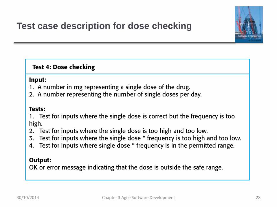
Test case description for dose checking
Chapter 3 Agile Software Development 2830/10/2014

Test automation
Test automation means that tests are written as
executable components before the task is implemented
These testing components should be stand-alone, should
simulate the submission of input to be tested and should check
that the result meets the output specification. An automated test
framework (e.g. Junit) is a system that makes it easy to write
executable tests and submit a set of tests for execution.
As testing is automated, there is always a set of tests
that can be quickly and easily executed
Whenever any functionality is added to the system, the tests can
be run and problems that the new code has introduced can be
caught immediately.
Chapter 3 Agile Software Development 2930/10/2014

Problems with test-first development
Programmers prefer programming to testing and
sometimes they take short cuts when writing tests. For
example, they may write incomplete tests that do not
check for all possible exceptions that may occur.
Some tests can be very difficult to write incrementally.
For example, in a complex user interface, it is often
difficult to write unit tests for the code that implements
the ‘display logic’ and workflow between screens.
It difficult to judge the completeness of a set of tests.
Although you may have a lot of system tests, your test
set may not provide complete coverage.
Chapter 3 Agile Software Development 3030/10/2014

Pair programming
Pair programming involves programmers working in pairs, developing code together.
This helps develop common ownership of code and spreads knowledge across the team.
It serves as an informal review process as each line of code is looked at by more than 1 person.
It encourages refactoring as the whole team can benefit from improving the system code.
Chapter 3 Agile Software Development 3130/10/2014

Pair programming
In pair programming, programmers sit together at the
same computer to develop the software.
Pairs are created dynamically so that all team members
work with each other during the development process.
The sharing of knowledge that happens during pair
programming is very important as it reduces the overall
risks to a project when team members leave.
Pair programming is not necessarily inefficient and there
is some evidence that suggests that a pair working
together is more efficient than 2 programmers working
separately.
Chapter 3 Agile Software Development 3230/10/2014

Agile project management
Chapter 3 Agile Software Development 3330/10/2014

Agile project management
The principal responsibility of software project managers
is to manage the project so that the software is delivered
on time and within the planned budget for the project.
The standard approach to project management is plan-
driven. Managers draw up a plan for the project showing
what should be delivered, when it should be delivered
and who will work on the development of the project
deliverables.
Agile project management requires a different approach,
which is adapted to incremental development and the
practices used in agile methods.
Chapter 3 Agile Software Development 3430/10/2014

Scrum
Scrum is an agile method that focuses on managing
iterative development rather than specific agile practices.
There are three phases in Scrum.
The initial phase is an outline planning phase where you
establish the general objectives for the project and design the
software architecture.
This is followed by a series of sprint cycles, where each cycle
develops an increment of the system.
The project closure phase wraps up the project, completes
required documentation such as system help frames and user
manuals and assesses the lessons learned from the project.
Chapter 3 Agile Software Development 3530/10/2014

Scrum terminology (a)
Scrum term Definition
Development team A self-organizing group of software developers, which should be no more than
7 people. They are responsible for developing the software and other
essential project documents.
Potentially shippable
product increment
The software increment that is delivered from a sprint. The idea is that this
should be ‘potentially shippable’ which means that it is in a finished state and
no further work, such as testing, is needed to incorporate it into the final
product. In practice, this is not always achievable.
Product backlog This is a list of ‘to do’ items which the Scrum team must tackle. They may be
feature definitions for the software, software requirements, user stories or
descriptions of supplementary tasks that are needed, such as architecture
definition or user documentation.
Product owner An individual (or possibly a small group) whose job is to identify product
features or requirements, prioritize these for development and continuously
review the product backlog to ensure that the project continues to meet critical
business needs. The Product Owner can be a customer but might also be a
product manager in a software company or other stakeholder representative.
Chapter 3 Agile Software Development 3630/10/2014

Scrum terminology (b)
Scrum term DefinitionScrum A daily meeting of the Scrum team that reviews progress and prioritizes
work to be done that day. Ideally, this should be a short face-to-face
meeting that includes the whole team.
ScrumMaster The ScrumMaster is responsible for ensuring that the Scrum process is
followed and guides the team in the effective use of Scrum. He or she is
responsible for interfacing with the rest of the company and for ensuring
that the Scrum team is not diverted by outside interference. The Scrum
developers are adamant that the ScrumMaster should not be thought of
as a project manager. Others, however, may not always find it easy to
see the difference.
Sprint A development iteration. Sprints are usually 2-4 weeks long.
Velocity An estimate of how much product backlog effort that a team can cover in
a single sprint. Understanding a team’s velocity helps them estimate
what can be covered in a sprint and provides a basis for measuring
improving performance.
Chapter 3 Agile Software Development 3730/10/2014

Scrum sprint cycle
Chapter 3 Agile Software Development 3830/10/2014

The Scrum sprint cycle
Sprints are fixed length, normally 2–4 weeks.
The starting point for planning is the product backlog,
which is the list of work to be done on the project.
The selection phase involves all of the project team who
work with the customer to select the features and
functionality from the product backlog to be developed
during the sprint.
Chapter 3 Agile Software Development 3930/10/2014

The Sprint cycle
Once these are agreed, the team organize themselves to
develop the software.
During this stage the team is isolated from the customer
and the organization, with all communications
channelled through the so-called ‘Scrum master’.
The role of the Scrum master is to protect the
development team from external distractions.
At the end of the sprint, the work done is reviewed and
presented to stakeholders. The next sprint cycle then
begins.
Chapter 3 Agile Software Development 4030/10/2014

Teamwork in Scrum
The ‘Scrum master’ is a facilitator who arranges daily
meetings, tracks the backlog of work to be done, records
decisions, measures progress against the backlog and
communicates with customers and management outside
of the team.
The whole team attends short daily meetings (Scrums)
where all team members share information, describe
their progress since the last meeting, problems that have
arisen and what is planned for the following day.
This means that everyone on the team knows what is going on
and, if problems arise, can re-plan short-term work to cope with
them.
Chapter 3 Agile Software Development 4130/10/2014

Scrum benefits
The product is broken down into a set of manageable
and understandable chunks.
Unstable requirements do not hold up progress.
The whole team have visibility of everything and
consequently team communication is improved.
Customers see on-time delivery of increments and gain
feedback on how the product works.
Trust between customers and developers is established
and a positive culture is created in which everyone
expects the project to succeed.
Chapter 3 Agile Software Development 4230/10/2014

Distributed Scrum
Chapter 3 Agile Software Development 4330/10/2014

Scaling agile methods
Chapter 3 Agile Software Development 4430/10/2014

Scaling agile methods
Agile methods have proved to be successful for small
and medium sized projects that can be developed by a
small co-located team.
It is sometimes argued that the success of these
methods comes because of improved communications
which is possible when everyone is working together.
Scaling up agile methods involves changing these to
cope with larger, longer projects where there are multiple
development teams, perhaps working in different
locations.
Chapter 3 Agile Software Development 4530/10/2014

Scaling out and scaling up
‘Scaling up’ is concerned with using agile methods for
developing large software systems that cannot be
developed by a small team.
‘Scaling out’ is concerned with how agile methods can
be introduced across a large organization with many
years of software development experience.
When scaling agile methods it is importaant to maintain
agile fundamentals:
Flexible planning, frequent system releases, continuous
integration, test-driven development and good team
communications.
Chapter 3 Agile Software Development 4630/10/2014

Practical problems with agile methods
The informality of agile development is incompatible with
the legal approach to contract definition that is commonly
used in large companies.
Agile methods are most appropriate for new software
development rather than software maintenance. Yet the
majority of software costs in large companies come from
maintaining their existing software systems.
Agile methods are designed for small co-located teams
yet much software development now involves worldwide
distributed teams.
Chapter 3 Agile Software Development 4730/10/2014

Contractual issues
Most software contracts for custom systems are based
around a specification, which sets out what has to be
implemented by the system developer for the system
customer.
However, this precludes interleaving specification and
development as is the norm in agile development.
A contract that pays for developer time rather than
functionality is required.
However, this is seen as a high risk my many legal departments
because what has to be delivered cannot be guaranteed.
Chapter 3 Agile Software Development 4830/10/2014

Agile methods and software maintenance
Most organizations spend more on maintaining existing
software than they do on new software development. So,
if agile methods are to be successful, they have to
support maintenance as well as original development.
Two key issues:
Are systems that are developed using an agile approach
maintainable, given the emphasis in the development process of
minimizing formal documentation?
Can agile methods be used effectively for evolving a system in
response to customer change requests?
Problems may arise if original development team cannot
be maintained.
Chapter 3 Agile Software Development 4930/10/2014
Agile maintenance
Key problems are:
Lack of product documentation
Keeping customers involved in the development process
Maintaining the continuity of the development team
Agile development relies on the development team
knowing and understanding what has to be done.
For long-lifetime systems, this is a real problem as the
original developers will not always work on the system.
Chapter 3 Agile Software Development 5030/10/2014

Agile and plan-driven methods
Most projects include elements of plan-driven and agile
processes. Deciding on the balance depends on:
Is it important to have a very detailed specification and design
before moving to implementation? If so, you probably need to use
a plan-driven approach.
Is an incremental delivery strategy, where you deliver the software
to customers and get rapid feedback from them, realistic? If so,
consider using agile methods.
How large is the system that is being developed? Agile methods
are most effective when the system can be developed with a small
co-located team who can communicate informally. This may not be
possible for large systems that require larger development teams
so a plan-driven approach may have to be used.
Chapter 3 Agile Software Development 5130/10/2014

Agile principles and organizational practice
Principle PracticeCustomer involvement This depends on having a customer who is willing and able to
spend time with the development team and who can represent all
system stakeholders. Often, customer representatives have other
demands on their time and cannot play a full part in the software
development.
Where there are external stakeholders, such as regulators, it is
difficult to represent their views to the agile team.
Embrace change Prioritizing changes can be extremely difficult, especially in
systems for which there are many stakeholders. Typically, each
stakeholder gives different priorities to different changes.
Incremental delivery Rapid iterations and short-term planning for development does
not always fit in with the longer-term planning cycles of business
planning and marketing. Marketing managers may need to know
what product features several months in advance to prepare an
effective marketing campaign.
Chapter 3 Agile Software Development 5230/10/2014

Agile principles and organizational practice
Principle PracticeMaintain simplicity Under pressure from delivery schedules, team members may not have
time to carry out desirable system simplifications.
People not process Individual team members may not have suitable personalities for the
intense involvement that is typical of agile methods, and therefore may
not interact well with other team members.
Chapter 3 Agile Software Development 5330/10/2014

Agile and plan-based factors
Chapter 3 Agile Software Development 5430/10/2014

System issues
How large is the system being developed?
Agile methods are most effective a relatively small co-located team
who can communicate informally.
What type of system is being developed?
Systems that require a lot of analysis before implementation need
a fairly detailed design to carry out this analysis.
What is the expected system lifetime?
Long-lifetime systems require documentation to communicate the
intentions of the system developers to the support team.
Is the system subject to external regulation?
If a system is regulated you will probably be required to produce
detailed documentation as part of the system safety case.
Chapter 3 Agile Software Development 5530/10/2014

People and teams
How good are the designers and programmers in the
development team?
It is sometimes argued that agile methods require higher skill
levels than plan-based approaches in which programmers simply
translate a detailed design into code.
How is the development team organized?
Design documents may be required if the team is dsitributed.
What support technologies are available?
IDE support for visualisation and program analysis is essential if
design documentation is not available.
Chapter 3 Agile Software Development 5630/10/2014

Organizational issues
Traditional engineering organizations have a culture of
plan-based development, as this is the norm in
engineering.
Is it standard organizational practice to develop a
detailed system specification?
Will customer representatives be available to provide
feedback of system increments?
Can informal agile development fit into the organizational
culture of detailed documentation?
Chapter 3 Agile Software Development 5730/10/2014

Agile methods for large systems
Large systems are usually collections of separate,
communicating systems, where separate teams develop each
system. Frequently, these teams are working in different
places, sometimes in different time zones.
Large systems are ‘brownfield systems’, that is they include
and interact with a number of existing systems. Many of the
system requirements are concerned with this interaction and
so don’t really lend themselves to flexibility and incremental
development.
Where several systems are integrated to create a system, a
significant fraction of the development is concerned with
system configuration rather than original code development.
Chapter 3 Agile Software Development 5830/10/2014

Large system development
Large systems and their development processes are
often constrained by external rules and regulations
limiting the way that they can be developed.
Large systems have a long procurement and
development time. It is difficult to maintain coherent
teams who know about the system over that period as,
inevitably, people move on to other jobs and projects.
Large systems usually have a diverse set of
stakeholders. It is practically impossible to involve all of
these different stakeholders in the development process.
Chapter 3 Agile Software Development 5930/10/2014

Factors in large systems
Chapter 3 Agile Software Development 6030/10/2014

IBM’s agility at scale model
Chapter 3 Agile Software Development 6130/10/2014

Scaling up to large systems
A completely incremental approach to requirements
engineering is impossible.
There cannot be a single product owner or customer
representative.
For large systems development, it is not possible to focus only
on the code of the system.
Cross-team communication mechanisms have to be designed
and used.
Continuous integration is practically impossible. However, it is
essential to maintain frequent system builds and regular
releases of the system.
Chapter 3 Agile Software Development 6230/10/2014

Multi-team Scrum
Role replication
Each team has a Product Owner for their work component and
ScrumMaster.
Product architects
Each team chooses a product architect and these architects
collaborate to design and evolve the overall system architecture.
Release alignment
The dates of product releases from each team are aligned so
that a demonstrable and complete system is produced.
Scrum of Scrums
There is a daily Scrum of Scrums where representatives from
each team meet to discuss progressand plan work to be done.
Chapter 3 Agile Software Development 6330/10/2014

Agile methods across organizations
Project managers who do not have experience of agile
methods may be reluctant to accept the risk of a new approach.
Large organizations often have quality procedures and
standards that all projects are expected to follow and, because
of their bureaucratic nature, these are likely to be incompatible
with agile methods.
Agile methods seem to work best when team members have a
relatively high skill level. However, within large organizations,
there are likely to be a wide range of skills and abilities.
There may be cultural resistance to agile methods, especially in
those organizations that have a long history of using
conventional systems engineering processes.
Chapter 3 Agile Software Development 6430/10/2014

Key points
Agile methods are incremental development methods that focus on
rapid software development, frequent releases of the software,
reducing process overheads by minimizing documentation and
producing high-quality code.
Agile development practices include
User stories for system specification
Frequent releases of the software,
Continuous software improvement
Test-first development
Customer participation in the development team.
Chapter 3 Agile Software Development 6530/10/2014

Key points
Scrum is an agile method that provides a project
management framework.
It is centred round a set of sprints, which are fixed time periods
when a system increment is developed.
Many practical development methods are a mixture of
plan-based and agile development.
Scaling agile methods for large systems is difficult.
Large systems need up-front design and some documentation
and organizational practice may conflict with the informality of
agile approaches.
Chapter 3 Agile Software Development 6630/10/2014

Chapter 4 – Requirements Engineering
Chapter 4 Requirements Engineering 130/10/2014

Topics covered
Functional and non-functional requirements
Requirements engineering processes
Requirements elicitation
Requirements specification
Requirements validation
Requirements change
Chapter 4 Requirements Engineering 230/10/2014

Requirements engineering
The process of establishing the services that acustomer
requires from a system and the constraints under which
it operates and is developed.
The system requirements are the descriptions of the
system services and constraints that are generated
during the requirements engineering process.
Chapter 4 Requirements Engineering 330/10/2014

What is a requirement?
It may range from a high-level abstract statement of a service or of a system constraint to a detailed mathematical functional specification.
This is inevitable as requirements may serve a dual function
May be the basis for a bid for a contract - therefore must be open to interpretation;
May be the basis for the contract itself - therefore must be defined in detail;
Both these statements may be called requirements.
Chapter 4 Requirements Engineering 430/10/2014

Requirements abstraction (Davis)
Chapter 4 Requirements Engineering 5
“If a company wishes to let a contract for a large software development
project, it must define its needs in a sufficiently abstract way that a
solution is not pre-defined. The requirements must be written so that
several contractors can bid for the contract, offering, perhaps, different
ways of meeting the client organization’s needs. Once a contract has
been awarded, the contractor must write a system definition for the
client in more detail so that the client understands and can validate what
the software will do. Both of these documents may be called the
requirements document for the system.”
30/10/2014
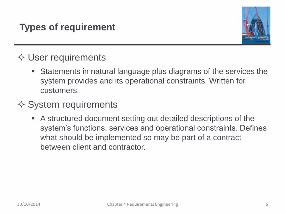
Types of requirement
User requirements
Statements in natural language plus diagrams of the services the
system provides and its operational constraints. Written for
customers.
System requirements
A structured document setting out detailed descriptions of the
system’s functions, services and operational constraints. Defines
what should be implemented so may be part of a contract
between client and contractor.
Chapter 4 Requirements Engineering 630/10/2014

User and system requirements
Chapter 4 Requirements Engineering 730/10/2014

Readers of different types of requirements
specification
Chapter 4 Requirements Engineering 830/10/2014

System stakeholders
Any person or organization who is affected by the
system in some way and so who has a legitimate interest
Stakeholder types
End users
System managers
System owners
External stakeholders
Chapter 4 Requirements Engineering 930/10/2014

Stakeholders in the Mentcare system
Patients whose information is recorded in the system.
Doctors who are responsible for assessing and treating
patients.
Nurses who coordinate the consultations with doctors
and administer some treatments.
Medical receptionists who manage patients’
appointments.
IT staff who are responsible for installing and maintaining
the system.
Chapter 4 Requirements Engineering 1030/10/2014

Stakeholders in the Mentcare system
A medical ethics manager who must ensure that the
system meets current ethical guidelines for patient care.
Health care managers who obtain management
information from the system.
Medical records staff who are responsible for ensuring
that system information can be maintained and
preserved, and that record keeping procedures have
been properly implemented.
Chapter 4 Requirements Engineering 1130/10/2014

Agile methods and requirements
Many agile methods argue that producing detailed
system requirements is a waste of time as requirements
change so quickly.
The requirements document is therefore always out of
date.
Agile methods usually use incremental requirements
engineering and may express requirements as ‘user
stories’ (discussed in Chapter 3).
This is practical for business systems but problematic for
systems that require pre-delivery analysis (e.g. critical
systems) or systems developed by several teams.
Chapter 4 Requirements Engineering 1230/10/2014

Functional and non-functional requirements
Chapter 4 Requirements Engineering 1330/10/2014

Functional and non-functional requirements
Functional requirements
Statements of services the system should provide, how the system should react to particular inputs and how the system should behave in particular situations.
May state what the system should not do.
Non-functional requirements
Constraints on the services or functions offered by the system such as timing constraints, constraints on the development process, standards, etc.
Often apply to the system as a whole rather than individual features or services.
Domain requirements
Constraints on the system from the domain of operation
Chapter 4 Requirements Engineering 1430/10/2014

Functional requirements
Describe functionality or system services.
Depend on the type of software, expected users and the
type of system where the software is used.
Functional user requirements may be high-level
statements of what the system should do.
Functional system requirements should describe the
system services in detail.
Chapter 4 Requirements Engineering 1530/10/2014

Mentcare system: functional requirements
A user shall be able to search the appointments lists for
all clinics.
The system shall generate each day, for each clinic, a
list of patients who are expected to attend appointments
that day.
Each staff member using the system shall be uniquely
identified by his or her 8-digit employee number.
Chapter 4 Requirements Engineering 1630/10/2014

Requirements imprecision
Problems arise when functional requirements are not
precisely stated.
Ambiguous requirements may be interpreted in different
ways by developers and users.
Consider the term ‘search’ in requirement 1
User intention – search for a patient name across all
appointments in all clinics;
Developer interpretation – search for a patient name in an
individual clinic. User chooses clinic then search.
Chapter 4 Requirements Engineering 1730/10/2014

Requirements completeness and consistency
In principle, requirements should be both complete and
consistent.
Complete
They should include descriptions of all facilities required.
Consistent
There should be no conflicts or contradictions in the descriptions
of the system facilities.
In practice, because of system and environmental
complexity, it is impossible to produce a complete and
consistent requirements document.
Chapter 4 Requirements Engineering 1830/10/2014

Non-functional requirements
These define system properties and constraints e.g. reliability, response time and storage requirements. Constraints are I/O device capability, system representations, etc.
Process requirements may also be specified mandating a particular IDE, programming language or development method.
Non-functional requirements may be more critical than functional requirements. If these are not met, the systemmay be useless.
Chapter 4 Requirements Engineering 1930/10/2014

Types of nonfunctional requirement
Chapter 4 Requirements Engineering 2030/10/2014

Non-functional requirements implementation
Non-functional requirements may affect the overall
architecture of a system rather than the individual
components.
For example, to ensure that performance requirements are met,
you may have to organize the system to minimize
communications between components.
A single non-functional requirement, such as a security
requirement, may generate a number of related
functional requirements that define system services that
are required.
It may also generate requirements that restrict existing
requirements.
Chapter 4 Requirements Engineering 2130/10/2014

Non-functional classifications
Product requirements
Requirements which specify that the delivered product must
behave in a particular way e.g. execution speed, reliability, etc.
Organisational requirements
Requirements which are a consequence of organisational
policies and procedures e.g. process standards used,
implementation requirements, etc.
External requirements
Requirements which arise from factors which are external to the
system and its development process e.g. interoperability
requirements, legislative requirements, etc.
Chapter 4 Requirements Engineering 2230/10/2014

Examples of nonfunctional requirements in the
Mentcare system
Chapter 4 Requirements Engineering 23
Product requirementThe Mentcare system shall be available to all clinics during normal working hours (Mon–Fri, 0830–17.30). Downtime within normal working hours shall not exceed five seconds in any one day.
Organizational requirementUsers of the Mentcare system shall authenticate themselves using their health authority identity card.
External requirementThe system shall implement patient privacy provisions as set out in HStan-03-2006-priv.
30/10/2014

Goals and requirements
Non-functional requirements may be very difficult to state
precisely and imprecise requirements may be difficult to
verify.
Goal
A general intention of the user such as ease of use.
Verifiable non-functional requirement
A statement using some measure that can be objectively tested.
Goals are helpful to developers as they convey the
intentions of the system users.
Chapter 4 Requirements Engineering 2430/10/2014

Usability requirements
The system should be easy to use by medical staff and
should be organized in such a way that user errors are
minimized. (Goal)
Medical staff shall be able to use all the system functions
after four hours of training. After this training, the
average number of errors made by experienced users
shall not exceed two per hour of system use. (Testable
non-functional requirement)
Chapter 4 Requirements Engineering 2530/10/2014

Metrics for specifying nonfunctional
requirements
Chapter 4 Requirements Engineering 26
Property Measure
Speed Processed transactions/second
User/event response time
Screen refresh time
Size Mbytes
Number of ROM chips
Ease of use Training time
Number of help frames
Reliability Mean time to failure
Probability of unavailability
Rate of failure occurrence
Availability
Robustness Time to restart after failure
Percentage of events causing failure
Probability of data corruption on failure
Portability Percentage of target dependent statements
Number of target systems
30/10/2014
Requirements engineering processes
Chapter 4 Requirements Engineering 2730/10/2014

Requirements engineering processes
The processes used for RE vary widely depending on the application domain, the people involved and the organisation developing the requirements.
However, there are a number of generic activities common to all processes
Requirements elicitation;
Requirements analysis;
Requirements validation;
Requirements management.
In practice, RE is an iterative activity in which these processes are interleaved.
Chapter 4 Requirements Engineering 2830/10/2014

A spiral view of the requirements engineering
process
Chapter 4 Requirements Engineering 2930/10/2014

Requirements elicitation
Chapter 4 Requirements Engineering 3030/10/2014

Requirements elicitation and analysis
Sometimes called requirements elicitation or
requirements discovery.
Involves technical staff working with customers to find
out about the application domain, the services that the
system should provide and the system’s operational
constraints.
May involve end-users, managers, engineers involved in
maintenance, domain experts, trade unions, etc. These
are called stakeholders.
Chapter 4 Requirements Engineering 3130/10/2014

Requirements elicitation
Chapter 4 Requirements Engineering 3230/10/2014

Requirements elicitation
Software engineers work with a range of system
stakeholders to find out about the application domain,
the services that the system should provide, the required
system performance, hardware constraints, other
systems, etc.
Stages include:
Requirements discovery,
Requirements classification and organization,
Requirements prioritization and negotiation,
Requirements specification.
Chapter 4 Requirements Engineering 3330/10/2014

Problems of requirements elicitation
Stakeholders don’t know what they really want.
Stakeholders express requirements in their own terms.
Different stakeholders may have conflicting
requirements.
Organisational and political factors may influence the
system requirements.
The requirements change during the analysis process.
New stakeholders may emerge and the business
environment may change.
Chapter 4 Requirements Engineering 3430/10/2014

The requirements elicitation and analysis
process
Chapter 4 Requirements Engineering 3530/10/2014

Process activities
Requirements discovery
Interacting with stakeholders to discover their requirements. Domain requirements are also discovered at this stage.
Requirements classification and organisation
Groups related requirements and organises them into coherent clusters.
Prioritisation and negotiation
Prioritising requirements and resolving requirements conflicts.
Requirements specification
Requirements are documented and input into the next round of the spiral.
30/10/2014 Chapter 4 Requirements Engineering 36

Requirements discovery
The process of gathering information about the required
and existing systems and distilling the user and system
requirements from this information.
Interaction is with system stakeholders from managers to
external regulators.
Systems normally have a range of stakeholders.
Chapter 4 Requirements Engineering 3730/10/2014

Interviewing
Formal or informal interviews with stakeholders are part
of most RE processes.
Types of interview
Closed interviews based on pre-determined list of questions
Open interviews where various issues are explored with
stakeholders.
Effective interviewing
Be open-minded, avoid pre-conceived ideas about the
requirements and are willing to listen to stakeholders.
Prompt the interviewee to get discussions going using a
springboard question, a requirements proposal, or by working
together on a prototype system.
Chapter 4 Requirements Engineering 3830/10/2014

Interviews in practice
Normally a mix of closed and open-ended interviewing.
Interviews are good for getting an overall understanding of what stakeholders do and how they might interact with the system.
Interviewers need to be open-minded without pre-conceived ideas of what the system should do
You need to prompt the use to talk about the system by suggesting requirements rather than simply asking them what they want.
30/10/2014 Chapter 4 Requirements Engineering 39

Problems with interviews
Application specialists may use language to describe their work that isn’t easy for the requirements engineer to understand.
Interviews are not good for understanding domain requirements
Requirements engineers cannot understand specific domain terminology;
Some domain knowledge is so familiar that people find it hard to articulate or think that it isn’t worth articulating.
Chapter 4 Requirements Engineering 4030/10/2014

Ethnography
A social scientist spends a considerable time observing
and analysing how people actually work.
People do not have to explain or articulate their work.
Social and organisational factors of importance may be
observed.
Ethnographic studies have shown that work is usually
richer and more complex than suggested by simple
system models.
Chapter 4 Requirements Engineering 4130/10/2014
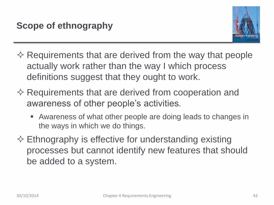
Scope of ethnography
Requirements that are derived from the way that people
actually work rather than the way I which process
definitions suggest that they ought to work.
Requirements that are derived from cooperation and
awareness of other people’s activities.
Awareness of what other people are doing leads to changes in
the ways in which we do things.
Ethnography is effective for understanding existing
processes but cannot identify new features that should
be added to a system.
Chapter 4 Requirements Engineering 4230/10/2014

Focused ethnography
Developed in a project studying the air traffic control process
Combines ethnography with prototyping
Prototype development results in unanswered questions which focus the ethnographic analysis.
The problem with ethnography is that it studies existing practices which may have some historical basis which is no longer relevant.
Chapter 4 Requirements Engineering 4330/10/2014

Ethnography and prototyping for requirements
analysis
Chapter 4 Requirements Engineering 4430/10/2014

Stories and scenarios
Scenarios and user stories are real-life examples of how
a system can be used.
Stories and scenarios are a description of how a system
may be used for a particular task.
Because they are based on a practical situation,
stakeholders can relate to them and can comment on
their situation with respect to the story.
30/10/2014 Chapter 4 Requirements Engineering 45

Photo sharing in the classroom (iLearn)
Jack is a primary school teacher in Ullapool (a village in northern Scotland). He has
decided that a class project should be focused around the fishing industry in the area,
looking at the history, development and economic impact of fishing. As part of this,
pupils are asked to gather and share reminiscences from relatives, use newspaper
archives and collect old photographs related to fishing and fishing communities in the
area. Pupils use an iLearn wiki to gather together fishing stories and SCRAN (a
history resources site) to access newspaper archives and photographs. However,
Jack also needs a photo sharing site as he wants pupils to take and comment on
each others’ photos and to upload scans of old photographs that they may have in
their families.
Jack sends an email to a primary school teachers group, which he is a member of to
see if anyone can recommend an appropriate system. Two teachers reply and both
suggest that he uses KidsTakePics, a photo sharing site that allows teachers to check
and moderate content. As KidsTakePics is not integrated with the iLearn
authentication service, he sets up a teacher and a class account. He uses the iLearn
setup service to add KidsTakePics to the services seen by the pupils in his class so
that when they log in, they can immediately use the system to upload photos from
their mobile devices and class computers.
Chapter 4 Requirements Engineering 4630/10/2014

Scenarios
A structured form of user story
Scenarios should include
A description of the starting situation;
A description of the normal flow of events;
A description of what can go wrong;
Information about other concurrent activities;
A description of the state when the scenario finishes.
Chapter 4 Requirements Engineering 4730/10/2014

Uploading photos iLearn)
Initial assumption: A user or a group of users have one or more digital photographs
to be uploaded to the picture sharing site. These are saved on either a tablet or
laptop computer. They have successfully logged on to KidsTakePics.
Normal: The user chooses upload photos and they are prompted to select the
photos to be uploaded on their computer and to select the project name under which
the photos will be stored. They should also be given the option of inputting keywords
that should be associated with each uploaded photo. Uploaded photos are named by
creating a conjunction of the user name with the filename of the photo on the local
computer.
On completion of the upload, the system automatically sends an email to the project
moderator asking them to check new content and generates an on-screen message
to the user that this has been done.
Chapter 4 Requirements Engineering 4830/10/2014

Uploading photos
What can go wrong:
No moderator is associated with the selected project. An email is automatically
generated to the school administrator asking them to nominate a project moderator.
Users should be informed that there could be a delay in making their photos visible.
Photos with the same name have already been uploaded by the same user. The user
should be asked if they wish to re-upload the photos with the same name, rename
the photos or cancel the upload. If they chose to re-upload the photos, the originals
are overwritten. If they chose to rename the photos, a new name is automatically
generated by adding a number to the existing file name.
Other activities: The moderator may be logged on to the system and may approve
photos as they are uploaded.
System state on completion: User is logged on. The selected photos have been
uploaded and assigned a status ‘awaiting moderation’. Photos are visible to the
moderator and to the user who uploaded them.
Chapter 4 Requirements Engineering 4930/10/2014

Requirements specification
Chapter 4 Requirements Engineering 5030/10/2014

Requirements specification
The process of writing donw the user and system
requirements in a requirements document.
User requirements have to be understandable by end-
users and customers who do not have a technical
background.
System requirements are more detailed requirements
and may include more technical information.
The requirements may be part of a contract for the
system development
It is therefore important that these are as complete as possible.
Chapter 4 Requirements Engineering 5130/10/2014

Ways of writing a system requirements
specification
Chapter 4 Requirements Engineering 52
Notation Description
Natural language The requirements are written using numbered sentences in natural language.
Each sentence should express one requirement.
Structured natural
language
The requirements are written in natural language on a standard form or
template. Each field provides information about an aspect of the
requirement.
Design description
languages
This approach uses a language like a programming language, but with more
abstract features to specify the requirements by defining an operational
model of the system. This approach is now rarely used although it can be
useful for interface specifications.
Graphical notations Graphical models, supplemented by text annotations, are used to define the
functional requirements for the system; UML use case and sequence
diagrams are commonly used.
Mathematical
specifications
These notations are based on mathematical concepts such as finite-state
machines or sets. Although these unambiguous specifications can reduce
the ambiguity in a requirements document, most customers don’t understand
a formal specification. They cannot check that it represents what they want
and are reluctant to accept it as a system contract
30/10/2014

Requirements and design
In principle, requirements should state what the system should do and the design should describe how it does this.
In practice, requirements and design are inseparable
A system architecture may be designed to structure the requirements;
The system may inter-operate with other systems that generate design requirements;
The use of a specific architecture to satisfy non-functional requirements may be a domain requirement.
This may be the consequence of a regulatory requirement.
30/10/2014 Chapter 4 Requirements Engineering 53

Natural language specification
Requirements are written as natural language sentences
supplemented by diagrams and tables.
Used for writing requirements because it is expressive,
intuitive and universal. This means that the requirements
can be understood by users and customers.
Chapter 4 Requirements Engineering 5430/10/2014

Guidelines for writing requirements
Invent a standard format and use it for all requirements.
Use language in a consistent way. Use shall for
mandatory requirements, should for desirable
requirements.
Use text highlighting to identify key parts of the
requirement.
Avoid the use of computer jargon.
Include an explanation (rationale) of why a requirement
is necessary.
30/10/2014 Chapter 4 Requirements Engineering 55

Problems with natural language
Lack of clarity
Precision is difficult without making the document difficult to
read.
Requirements confusion
Functional and non-functional requirements tend to be mixed-up.
Requirements amalgamation
Several different requirements may be expressed together.
30/10/2014 Chapter 4 Requirements Engineering 56

Example requirements for the insulin pump
software system
Chapter 4 Requirements Engineering 57
3.2 The system shall measure the blood sugar and deliver insulin, if required, every 10 minutes. (Changes in blood sugar are relatively slow so more frequent measurement is unnecessary; less frequent measurement could lead to unnecessarily high sugar levels.)
3.6 The system shall run a self-test routine every minute with the conditions to be tested and the associated actions defined in Table 1. (A self-test routine can discover hardware and software problems and alert the user to the fact the normal operation may be impossible.)
30/10/2014

Structured specifications
An approach to writing requirements where the freedom
of the requirements writer is limited and requirements
are written in a standard way.
This works well for some types of requirements e.g.
requirements for embedded control system but is
sometimes too rigid for writing business system
requirements.
Chapter 4 Requirements Engineering 5830/10/2014

Form-based specifications
Definition of the function or entity.
Description of inputs and where they come from.
Description of outputs and where they go to.
Information about the information needed for the
computation and other entities used.
Description of the action to be taken.
Pre and post conditions (if appropriate).
The side effects (if any) of the function.
30/10/2014 Chapter 4 Requirements Engineering 59

A structured specification of a requirement for
an insulin pump
Chapter 4 Requirements Engineering 6030/10/2014

A structured specification of a requirement for
an insulin pump
Chapter 4 Requirements Engineering 6130/10/2014

Tabular specification
Used to supplement natural language.
Particularly useful when you have to define a number of
possible alternative courses of action.
For example, the insulin pump systems bases its
computations on the rate of change of blood sugar level
and the tabular specification explains how to calculate
the insulin requirement for different scenarios.
30/10/2014 Chapter 4 Requirements Engineering 62

Tabular specification of computation for an
insulin pump
Chapter 4 Requirements Engineering 63
Condition Action
Sugar level falling (r2 < r1) CompDose = 0
Sugar level stable (r2 = r1) CompDose = 0
Sugar level increasing and rate of
increase decreasing
((r2 – r1) < (r1 – r0))
CompDose = 0
Sugar level increasing and rate of
increase stable or increasing
((r2 – r1) ≥ (r1 – r0))
CompDose =
round ((r2 – r1)/4)
If rounded result = 0 then
CompDose =
MinimumDose
30/10/2014

Use cases
Use-cases are a kind of scenario that are included in the
UML.
Use cases identify the actors in an interaction and which
describe the interaction itself.
A set of use cases should describe all possible
interactions with the system.
High-level graphical model supplemented by more
detailed tabular description (see Chapter 5).
UML sequence diagrams may be used to add detail to
use-cases by showing the sequence of event processing
in the system.
Chapter 4 Requirements Engineering 6430/10/2014

Use cases for the Mentcare system
Chapter 4 Requirements Engineering 6530/10/2014

The software requirements document
The software requirements document is the official
statement of what is required of the system developers.
Should include both a definition of user requirements
and a specification of the system requirements.
It is NOT a design document. As far as possible, it
should set of WHAT the system should do rather than
HOW it should do it.
Chapter 4 Requirements Engineering 6630/10/2014

Users of a requirements document
Chapter 4 Requirements Engineering 6730/10/2014

Requirements document variability
Information in requirements document depends on type
of system and the approach to development used.
Systems developed incrementally will, typically, have
less detail in the requirements document.
Requirements documents standards have been
designed e.g. IEEE standard. These are mostly
applicable to the requirements for large systems
engineering projects.
Chapter 4 Requirements Engineering 6830/10/2014

The structure of a requirements document
Chapter 4 Requirements Engineering 69
Chapter Description
Preface This should define the expected readership of the document and describe
its version history, including a rationale for the creation of a new version
and a summary of the changes made in each version.
Introduction This should describe the need for the system. It should briefly describe the
system’s functions and explain how it will work with other systems. It
should also describe how the system fits into the overall business or
strategic objectives of the organization commissioning the software.
Glossary This should define the technical terms used in the document. You should
not make assumptions about the experience or expertise of the reader.
User requirements
definition
Here, you describe the services provided for the user. The nonfunctional
system requirements should also be described in this section. This
description may use natural language, diagrams, or other notations that are
understandable to customers. Product and process standards that must be
followed should be specified.
System architecture This chapter should present a high-level overview of the anticipated system
architecture, showing the distribution of functions across system modules.
Architectural components that are reused should be highlighted.
30/10/2014

The structure of a requirements document
Chapter Description
System
requirements
specification
This should describe the functional and nonfunctional requirements in more detail.
If necessary, further detail may also be added to the nonfunctional requirements.
Interfaces to other systems may be defined.
System models This might include graphical system models showing the relationships between
the system components and the system and its environment. Examples of
possible models are object models, data-flow models, or semantic data models.
System evolution This should describe the fundamental assumptions on which the system is based,
and any anticipated changes due to hardware evolution, changing user needs,
and so on. This section is useful for system designers as it may help them avoid
design decisions that would constrain likely future changes to the system.
Appendices These should provide detailed, specific information that is related to the
application being developed; for example, hardware and database descriptions.
Hardware requirements define the minimal and optimal configurations for the
system. Database requirements define the logical organization of the data used
by the system and the relationships between data.
Index Several indexes to the document may be included. As well as a normal alphabetic
index, there may be an index of diagrams, an index of functions, and so on.
Chapter 4 Requirements Engineering 7030/10/2014

Requirements validation
Chapter 4 Requirements Engineering 7130/10/2014

Requirements validation
Concerned with demonstrating that the requirements
define the system that the customer really wants.
Requirements error costs are high so validation is very
important
Fixing a requirements error after delivery may cost up to 100
times the cost of fixing an implementation error.
Chapter 4 Requirements Engineering 7230/10/2014

Requirements checking
Validity. Does the system provide the functions which
best support the customer’s needs?
Consistency. Are there any requirements conflicts?
Completeness. Are all functions required by the
customer included?
Realism. Can the requirements be implemented given
available budget and technology
Verifiability. Can the requirements be checked?
Chapter 4 Requirements Engineering 7330/10/2014

Requirements validation techniques
Requirements reviews
Systematic manual analysis of the requirements.
Prototyping
Using an executable model of the system to check requirements. Covered in Chapter 2.
Test-case generation
Developing tests for requirements to check testability.
Chapter 4 Requirements Engineering 7430/10/2014

Requirements reviews
Regular reviews should be held while the requirements
definition is being formulated.
Both client and contractor staff should be involved in
reviews.
Reviews may be formal (with completed documents) or
informal. Good communications between developers,
customers and users can resolve problems at an early
stage.
Chapter 4 Requirements Engineering 7530/10/2014

Review checks
Verifiability
Is the requirement realistically testable?
Comprehensibility
Is the requirement properly understood?
Traceability
Is the origin of the requirement clearly stated?
Adaptability
Can the requirement be changed without a large impact on other requirements?
Chapter 4 Requirements Engineering 7630/10/2014

Requirements change
Chapter 4 Requirements Engineering 7730/10/2014

Changing requirements
The business and technical environment of the system
always changes after installation.
New hardware may be introduced, it may be necessary to
interface the system with other systems, business priorities may
change (with consequent changes in the system support
required), and new legislation and regulations may be introduced
that the system must necessarily abide by.
The people who pay for a system and the users of that
system are rarely the same people.
System customers impose requirements because of
organizational and budgetary constraints. These may conflict
with end-user requirements and, after delivery, new features may
have to be added for user support if the system is to meet its
goals.Chapter 4 Requirements Engineering 7830/10/2014

Changing requirements
Large systems usually have a diverse user community,
with many users having different requirements and
priorities that may be conflicting or contradictory.
The final system requirements are inevitably a compromise
between them and, with experience, it is often discovered that
the balance of support given to different users has to be
changed.
Chapter 4 Requirements Engineering 7930/10/2014

Requirements evolution
Chapter 4 Requirements Engineering 8030/10/2014

Requirements management
Requirements management is the process of managing
changing requirements during the requirements
engineering process and system development.
New requirements emerge as a system is being
developed and after it has gone into use.
You need to keep track of individual requirements and
maintain links between dependent requirements so that
you can assess the impact of requirements changes.
You need to establish a formal process for making
change proposals and linking these to system
requirements.
Chapter 4 Requirements Engineering 8130/10/2014

Requirements management planning
Establishes the level of requirements management detail
that is required.
Requirements management decisions:
Requirements identification Each requirement must be uniquely
identified so that it can be cross-referenced with other requirements.
A change management process This is the set of activities that
assess the impact and cost of changes. I discuss this process in
more detail in the following section.
Traceability policies These policies define the relationships between
each requirement and between the requirements and the system
design that should be recorded.
Tool support Tools that may be used range from specialist
requirements management systems to spreadsheets and simple
database systems.Chapter 4 Requirements Engineering 8230/10/2014

Requirements change management
Deciding if a requirements change should be accepted
Problem analysis and change specification
• During this stage, the problem or the change proposal is analyzed
to check that it is valid. This analysis is fed back to the change
requestor who may respond with a more specific requirements
change proposal, or decide to withdraw the request.
Change analysis and costing
• The effect of the proposed change is assessed using traceability
information and general knowledge of the system requirements.
Once this analysis is completed, a decision is made whether or not
to proceed with the requirements change.
Change implementation
• The requirements document and, where necessary, the system
design and implementation, are modified. Ideally, the document
should be organized so that changes can be easily implemented.Chapter 4 Requirements Engineering 8330/10/2014
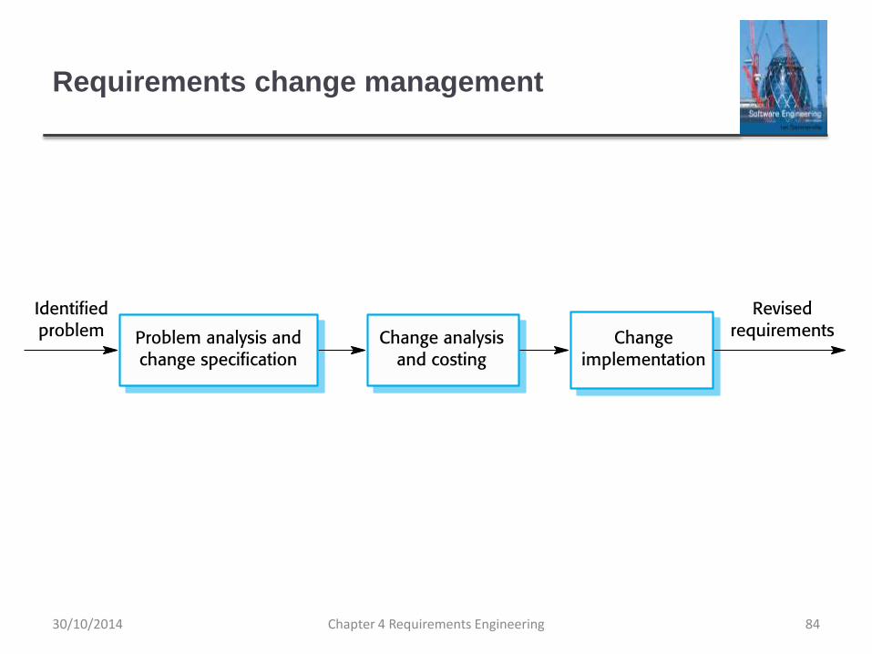
Requirements change management
Chapter 4 Requirements Engineering 8430/10/2014

Key points
Requirements for a software system set out what the
system should do and define constraints on its operation
and implementation.
Functional requirements are statements of the services
that the system must provide or are descriptions of how
some computations must be carried out.
Non-functional requirements often constrain the system
being developed and the development process being
used.
They often relate to the emergent properties of the
system and therefore apply to the system as a whole.
Chapter 4 Requirements Engineering 8530/10/2014

Key points
The requirements engineering process is an iterative
process that includes requirements elicitation,
specification and validation.
Requirements elicitation is an iterative process that can
be represented as a spiral of activities – requirements
discovery, requirements classification and organization,
requirements negotiation and requirements
documentation.
You can use a range of techniques for requirements
elicitation including interviews and ethnography. User
stories and scenarios may be used to facilitate
discussions.Chapter 4 Requirements Engineering 8630/10/2014

Key points
Requirements specification is the process of formally
documenting the user and system requirements and
creating a software requirements document.
The software requirements document is an agreed
statement of the system requirements. It should be
organized so that both system customers and software
developers can use it.
Chapter 4 Requirements Engineering 8730/10/2014

Key points
Requirements validation is the process of checking the
requirements for validity, consistency, completeness,
realism and verifiability.
Business, organizational and technical changes
inevitably lead to changes to the requirements for a
software system. Requirements management is the
process of managing and controlling these changes.
Chapter 4 Requirements Engineering 8830/10/2014

Chapter 5 – System Modeling
Chapter 5 System Modeling 130/10/2014

Topics covered
Context models
Interaction models
Structural models
Behavioral models
Model-driven engineering
Chapter 5 System Modeling 230/10/2014

System modeling
System modeling is the process of developing abstract
models of a system, with each model presenting a
different view or perspective of that system.
System modeling has now come to mean representing a
system using some kind of graphical notation, which is
now almost always based on notations in the Unified
Modeling Language (UML).
System modelling helps the analyst to understand the
functionality of the system and models are used to
communicate with customers.
Chapter 5 System Modeling 330/10/2014

Existing and planned system models
Models of the existing system are used during requirements
engineering. They help clarify what the existing system does
and can be used as a basis for discussing its strengths and
weaknesses. These then lead to requirements for the new
system.
Models of the new system are used during requirements
engineering to help explain the proposed requirements to
other system stakeholders. Engineers use these models to
discuss design proposals and to document the system for
implementation.
In a model-driven engineering process, it is possible to
generate a complete or partial system implementation from
the system model.Chapter 5 System Modeling 430/10/2014

System perspectives
An external perspective, where you model the context or
environment of the system.
An interaction perspective, where you model the
interactions between a system and its environment, or
between the components of a system.
A structural perspective, where you model the
organization of a system or the structure of the data that
is processed by the system.
A behavioral perspective, where you model the dynamic
behavior of the system and how it responds to events.
Chapter 5 System Modeling 530/10/2014

UML diagram types
Activity diagrams, which show the activities involved in a
process or in data processing .
Use case diagrams, which show the interactions
between a system and its environment.
Sequence diagrams, which show interactions between
actors and the system and between system components.
Class diagrams, which show the object classes in the
system and the associations between these classes.
State diagrams, which show how the system reacts to
internal and external events.
Chapter 5 System Modeling 630/10/2014

Use of graphical models
As a means of facilitating discussion about an existing or
proposed system
Incomplete and incorrect models are OK as their role is to
support discussion.
As a way of documenting an existing system
Models should be an accurate representation of the system but
need not be complete.
As a detailed system description that can be used to
generate a system implementation
Models have to be both correct and complete.
Chapter 5 System Modeling 730/10/2014

Context models
Chapter 5 System Modeling 830/10/2014

Context models
Context models are used to illustrate the operational
context of a system - they show what lies outside the
system boundaries.
Social and organisational concerns may affect the
decision on where to position system boundaries.
Architectural models show the system and its
relationship with other systems.
Chapter 5 System Modeling 930/10/2014

System boundaries
System boundaries are established to define what is
inside and what is outside the system.
They show other systems that are used or depend on the system
being developed.
The position of the system boundary has a profound
effect on the system requirements.
Defining a system boundary is a political judgment
There may be pressures to develop system boundaries that
increase / decrease the influence or workload of different parts of
an organization.
Chapter 5 System Modeling 1030/10/2014

The context of the Mentcare system
Chapter 5 System Modeling 1130/10/2014

Process perspective
Context models simply show the other systems in the
environment, not how the system being developed is
used in that environment.
Process models reveal how the system being developed
is used in broader business processes.
UML activity diagrams may be used to define business
process models.
Chapter 5 System Modeling 1230/10/2014

Process model of involuntary detention
Chapter 5 System Modeling 1330/10/2014

Interaction models
Chapter 5 System Modeling 1430/10/2014

Interaction models
Modeling user interaction is important as it helps to
identify user requirements.
Modeling system-to-system interaction highlights the
communication problems that may arise.
Modeling component interaction helps us understand if a
proposed system structure is likely to deliver the required
system performance and dependability.
Use case diagrams and sequence diagrams may be
used for interaction modeling.
Chapter 5 System Modeling 1530/10/2014

Use case modeling
Use cases were developed originally to support
requirements elicitation and now incorporated into the
UML.
Each use case represents a discrete task that involves
external interaction with a system.
Actors in a use case may be people or other systems.
Represented diagramatically to provide an overview of
the use case and in a more detailed textual form.
Chapter 5 System Modeling 1630/10/2014

Transfer-data use case
A use case in the Mentcare system
Chapter 5 System Modeling 1730/10/2014

Tabular description of the ‘Transfer data’ use-
case
Chapter 5 System Modeling 18
MHC-PMS: Transfer data
Actors Medical receptionist, patient records system (PRS)
Description A receptionist may transfer data from the Mentcase
system to a general patient record database that is
maintained by a health authority. The information
transferred may either be updated personal information
(address, phone number, etc.) or a summary of the
patient’s diagnosis and treatment.
Data Patient’s personal information, treatment summary
Stimulus User command issued by medical receptionist
Response Confirmation that PRS has been updated
Comments The receptionist must have appropriate security
permissions to access the patient information and the
PRS.
30/10/2014
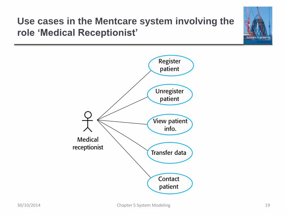
Use cases in the Mentcare system involving the
role ‘Medical Receptionist’
Chapter 5 System Modeling 1930/10/2014

Sequence diagrams
Sequence diagrams are part of the UML and are used to
model the interactions between the actors and the
objects within a system.
A sequence diagram shows the sequence of interactions
that take place during a particular use case or use case
instance.
The objects and actors involved are listed along the top
of the diagram, with a dotted line drawn vertically from
these.
Interactions between objects are indicated by annotated
arrows.
Chapter 5 System Modeling 2030/10/2014

Sequence diagram for View patient information
Chapter 5 System Modeling 2130/10/2014

Sequence
diagram for
Transfer DataChapter 5 System Modeling 2230/10/2014

Structural models
Chapter 5 System Modeling 2330/10/2014

Structural models
Structural models of software display the organization of
a system in terms of the components that make up that
system and their relationships.
Structural models may be static models, which show the
structure of the system design, or dynamic models,
which show the organization of the system when it is
executing.
You create structural models of a system when you are
discussing and designing the system architecture.
Chapter 5 System Modeling 2430/10/2014

Class diagrams
Class diagrams are used when developing an object-
oriented system model to show the classes in a system
and the associations between these classes.
An object class can be thought of as a general definition
of one kind of system object.
An association is a link between classes that indicates
that there is some relationship between these classes.
When you are developing models during the early stages
of the software engineering process, objects represent
something in the real world, such as a patient, a
prescription, doctor, etc.
Chapter 5 System Modeling 2530/10/2014

UML classes and association
Chapter 5 System Modeling 2630/10/2014

Classes and associations in the MHC-PMS
Chapter 5 System Modeling 2730/10/2014

The Consultation class
Chapter 5 System Modeling 2830/10/2014

Generalization
Generalization is an everyday technique that we use to
manage complexity.
Rather than learn the detailed characteristics of every
entity that we experience, we place these entities in
more general classes (animals, cars, houses, etc.) and
learn the characteristics of these classes.
This allows us to infer that different members of these
classes have some common characteristics e.g.
squirrels and rats are rodents.
Chapter 5 System Modeling 2930/10/2014

Generalization
In modeling systems, it is often useful to examine the classes in
a system to see if there is scope for generalization. If changes
are proposed, then you do not have to look at all classes in the
system to see if they are affected by the change.
In object-oriented languages, such as Java, generalization is
implemented using the class inheritance mechanisms built into
the language.
In a generalization, the attributes and operations associated with
higher-level classes are also associated with the lower-level
classes.
The lower-level classes are subclasses inherit the attributes and
operations from their superclasses. These lower-level classes
then add more specific attributes and operations.
Chapter 5 System Modeling 3030/10/2014

A generalization hierarchy
Chapter 5 System Modeling 3130/10/2014

A generalization hierarchy with added detail
Chapter 5 System Modeling 3230/10/2014
Object class aggregation models
An aggregation model shows how classes that are
collections are composed of other classes.
Aggregation models are similar to the part-of relationship
in semantic data models.
Chapter 5 System Modeling 3330/10/2014

The aggregation association
Chapter 5 System Modeling 3430/10/2014

Behavioral models
Chapter 5 System Modeling 3530/10/2014

Behavioral models
Behavioral models are models of the dynamic behavior
of a system as it is executing. They show what happens
or what is supposed to happen when a system responds
to a stimulus from its environment.
You can think of these stimuli as being of two types:
Data Some data arrives that has to be processed by the system.
Events Some event happens that triggers system processing.
Events may have associated data, although this is not always
the case.
Chapter 5 System Modeling 3630/10/2014

Data-driven modeling
Many business systems are data-processing systems
that are primarily driven by data. They are controlled by
the data input to the system, with relatively little external
event processing.
Data-driven models show the sequence of actions
involved in processing input data and generating an
associated output.
They are particularly useful during the analysis of
requirements as they can be used to show end-to-end
processing in a system.
Chapter 5 System Modeling 3730/10/2014

An activity model of the insulin pump’s
operation
Chapter 5 System Modeling 3830/10/2014

Order processing
Chapter 5 System Modeling 3930/10/2014

Event-driven modeling
Real-time systems are often event-driven, with minimal
data processing. For example, a landline phone
switching system responds to events such as ‘receiver
off hook’ by generating a dial tone.
Event-driven modeling shows how a system responds to
external and internal events.
It is based on the assumption that a system has a finite
number of states and that events (stimuli) may cause a
transition from one state to another.
Chapter 5 System Modeling 4030/10/2014

State machine models
These model the behaviour of the system in response to
external and internal events.
They show the system’s responses to stimuli so are
often used for modelling real-time systems.
State machine models show system states as nodes and
events as arcs between these nodes. When an event
occurs, the system moves from one state to another.
Statecharts are an integral part of the UML and are used
to represent state machine models.
Chapter 5 System Modeling 4130/10/2014

State diagram of a microwave oven
Chapter 5 System Modeling 4230/10/2014

Microwave oven operation
Chapter 5 System Modeling 4330/10/2014

States and stimuli for the microwave oven (a)
Chapter 5 System Modeling 44
State Description
Waiting The oven is waiting for input. The display shows the current time.
Half power The oven power is set to 300 watts. The display shows ‘Half power’.
Full power The oven power is set to 600 watts. The display shows ‘Full power’.
Set time The cooking time is set to the user’s input value. The display shows
the cooking time selected and is updated as the time is set.
Disabled Oven operation is disabled for safety. Interior oven light is on.
Display shows ‘Not ready’.
Enabled Oven operation is enabled. Interior oven light is off. Display shows
‘Ready to cook’.
Operation Oven in operation. Interior oven light is on. Display shows the timer
countdown. On completion of cooking, the buzzer is sounded for five
seconds. Oven light is on. Display shows ‘Cooking complete’ while
buzzer is sounding.
30/10/2014

States and stimuli for the microwave oven (b)
Chapter 5 System Modeling 45
Stimulus Description
Half power The user has pressed the half-power button.
Full power The user has pressed the full-power button.
Timer The user has pressed one of the timer buttons.
Number The user has pressed a numeric key.
Door open The oven door switch is not closed.
Door closed The oven door switch is closed.
Start The user has pressed the Start button.
Cancel The user has pressed the Cancel button.
30/10/2014

Model-driven engineering
Chapter 5 System Modeling 4630/10/2014

Model-driven engineering
Model-driven engineering (MDE) is an approach to
software development where models rather than
programs are the principal outputs of the development
process.
The programs that execute on a hardware/software
platform are then generated automatically from the
models.
Proponents of MDE argue that this raises the level of
abstraction in software engineering so that engineers no
longer have to be concerned with programming
language details or the specifics of execution platforms.
Chapter 5 System Modeling 4730/10/2014
Usage of model-driven engineering
Model-driven engineering is still at an early stage of
development, and it is unclear whether or not it will have
a significant effect on software engineering practice.
Pros
Allows systems to be considered at higher levels of abstraction
Generating code automatically means that it is cheaper to adapt
systems to new platforms.
Cons
Models for abstraction and not necessarily right for
implementation.
Savings from generating code may be outweighed by the costs
of developing translators for new platforms.
Chapter 5 System Modeling 4830/10/2014

Model driven architecture
Model-driven architecture (MDA) was the precursor of
more general model-driven engineering
MDA is a model-focused approach to software design
and implementation that uses a subset of UML models to
describe a system.
Models at different levels of abstraction are created.
From a high-level, platform independent model, it is
possible, in principle, to generate a working program
without manual intervention.
Chapter 5 System Modeling 4930/10/2014

Types of model
A computation independent model (CIM)
These model the important domain abstractions used in a
system. CIMs are sometimes called domain models.
A platform independent model (PIM)
These model the operation of the system without reference to its
implementation. The PIM is usually described using UML models
that show the static system structure and how it responds to
external and internal events.
Platform specific models (PSM)
These are transformations of the platform-independent model
with a separate PSM for each application platform. In principle,
there may be layers of PSM, with each layer adding some
platform-specific detail.
Chapter 5 System Modeling 5030/10/2014

MDA transformations
Chapter 5 System Modeling 5130/10/2014

Multiple platform-specific models
Chapter 5 System Modeling 5230/10/2014

Agile methods and MDA
The developers of MDA claim that it is intended to
support an iterative approach to development and so can
be used within agile methods.
The notion of extensive up-front modeling contradicts the
fundamental ideas in the agile manifesto and I suspect
that few agile developers feel comfortable with model-
driven engineering.
If transformations can be completely automated and a
complete program generated from a PIM, then, in
principle, MDA could be used in an agile development
process as no separate coding would be required.
Chapter 5 System Modeling 5330/10/2014

Adoption of MDA
A range of factors has limited the adoption of MDE/MDA
Specialized tool support is required to convert models
from one level to another
There is limited tool availability and organizations may
require tool adaptation and customisation to their
environment
For the long-lifetime systems developed using MDA,
companies are reluctant to develop their own tools or
rely on small companies that may go out of business
Chapter 5 System Modeling 5430/10/2014

Adoption of MDA
Models are a good way of facilitating discussions about a
software design. Howeverthe abstractions that are useful
for discussions may not be the right abstractions for
implementation.
For most complex systems, implementation is not the
major problem – requirements engineering, security and
dependability, integration with legacy systems and
testing are all more significant.
Chapter 5 System Modeling 5530/10/2014

Adoption of MDA
The arguments for platform-independence are only valid
for large, long-lifetime systems. For software products
and information systems, the savings from the use of
MDA are likely to be outweighed by the costs of its
introduction and tooling.
The widespread adoption of agile methods over the
same period that MDA was evolving has diverted
attention away from model-driven approaches.
Chapter 5 System Modeling 5630/10/2014

Key points
A model is an abstract view of a system that ignores system details.
Complementary system models can be developed to show the
system’s context, interactions, structure and behavior.
Context models show how a system that is being modeled is
positioned in an environment with other systems and processes.
Use case diagrams and sequence diagrams are used to describe
the interactions between users and systems in the system being
designed. Use cases describe interactions between a system and
external actors; sequence diagrams add more information to these
by showing interactions between system objects.
Structural models show the organization and architecture of a
system. Class diagrams are used to define the static structure of
classes in a system and their associations.
Chapter 5 System Modeling 5730/10/2014

Key points
Behavioral models are used to describe the dynamic behavior
of an executing system. This behavior can be modeled from
the perspective of the data processed by the system, or by
the events that stimulate responses from a system.
Activity diagrams may be used to model the processing of
data, where each activity represents one process step.
State diagrams are used to model a system’s behavior in
response to internal or external events.
Model-driven engineering is an approach to software
development in which a system is represented as a set of
models that can be automatically transformed to executable
code.
Chapter 5 System Modeling 5830/10/2014

Chapter 6 – Architectural Design
Chapter 6 Architectural Design 102/01/2015

Topics covered
Architectural design decisions
Architectural views
Architectural patterns
Application architectures
Chapter 6 Architectural Design 202/01/2015

Architectural design
Architectural design is concerned with understanding
how a software system should be organized and
designing the overall structure of that system.
Architectural design is the critical link between design
and requirements engineering, as it identifies the main
structural components in a system and the relationships
between them.
The output of the architectural design process is an
architectural model that describes how the system is
organized as a set of communicating components.
Chapter 6 Architectural Design 302/01/2015

Agility and architecture
It is generally accepted that an early stage of agile
processes is to design an overall systems architecture.
Refactoring the system architecture is usually expensive
because it affects so many components in the system
Chapter 6 Architectural Design 402/01/2015

The architecture of a packing robot control
system
Chapter 6 Architectural Design 502/01/2015

Architectural abstraction
Architecture in the small is concerned with the
architecture of individual programs. At this level, we are
concerned with the way that an individual program is
decomposed into components.
Architecture in the large is concerned with the
architecture of complex enterprise systems that include
other systems, programs, and program components.
These enterprise systems are distributed over different
computers, which may be owned and managed by
different companies.
Chapter 6 Architectural Design 602/01/2015

Advantages of explicit architecture
Stakeholder communication
Architecture may be used as a focus of discussion by system stakeholders.
System analysis
Means that analysis of whether the system can meet its non-functional requirements is possible.
Large-scale reuse
The architecture may be reusable across a range of systems
Product-line architectures may be developed.
Chapter 6 Architectural Design 702/01/2015

Architectural representations
Simple, informal block diagrams showing entities and
relationships are the most frequently used method for
documenting software architectures.
But these have been criticised because they lack
semantics, do not show the types of relationships
between entities nor the visible properties of entities in
the architecture.
Depends on the use of architectural models.The
requirements for model semantics depends on how the
models are used.
Chapter 6 Architectural Design 802/01/2015

Box and line diagrams
Very abstract - they do not show the nature of
component relationships nor the externally visible
properties of the sub-systems.
However, useful for communication with stakeholders
and for project planning.
Chapter 6 Architectural Design 902/01/2015

Use of architectural models
As a way of facilitating discussion about the system
design
A high-level architectural view of a system is useful for
communication with system stakeholders and project planning
because it is not cluttered with detail. Stakeholders can relate to
it and understand an abstract view of the system. They can then
discuss the system as a whole without being confused by detail.
As a way of documenting an architecture that has been
designed
The aim here is to produce a complete system model that shows
the different components in a system, their interfaces and their
connections.
Chapter 6 Architectural Design 1002/01/2015

Architectural design decisions
Chapter 6 Architectural Design 1102/01/2015

Architectural design decisions
Architectural design is a creative process so the process
differs depending on the type of system being
developed.
However, a number of common decisions span all
design processes and these decisions affect the non-
functional characteristics of the system.
Chapter 6 Architectural Design 1202/01/2015

Architectural design decisions
Chapter 6 Architectural Design 1302/01/2015

Architecture reuse
Systems in the same domain often have similar
architectures that reflect domain concepts.
Application product lines are built around a core
architecture with variants that satisfy particular customer
requirements.
The architecture of a system may be designed around
one of more architectural patterns or ‘styles’.
These capture the essence of an architecture and can be
instantiated in different ways.
Chapter 6 Architectural Design 1402/01/2015

Architecture and system characteristics
Performance
Localise critical operations and minimise communications. Use large rather than fine-grain components.
Security
Use a layered architecture with critical assets in the inner layers.
Safety
Localise safety-critical features in a small number of sub-systems.
Availability
Include redundant components and mechanisms for fault tolerance.
Maintainability
Use fine-grain, replaceable components.Chapter 6 Architectural Design 1502/01/2015

Architectural views
Chapter 6 Architectural Design 1602/01/2015

Architectural views
What views or perspectives are useful when designing
and documenting a system’s architecture?
What notations should be used for describing
architectural models?
Each architectural model only shows one view or
perspective of the system.
It might show how a system is decomposed into modules, how
the run-time processes interact or the different ways in which
system components are distributed across a network. For both
design and documentation, you usually need to present multiple
views of the software architecture.
Chapter 6 Architectural Design 1702/01/2015

Architectural views
Chapter 6 Architectural Design 1802/01/2015

4 + 1 view model of software architecture
A logical view, which shows the key abstractions in the
system as objects or object classes.
A process view, which shows how, at run-time, the
system is composed of interacting processes.
A development view, which shows how the software is
decomposed for development.
A physical view, which shows the system hardware and
how software components are distributed across the
processors in the system.
Related using use cases or scenarios (+1)
Chapter 6 Architectural Design 1902/01/2015

Representing architectural views
Some people argue that the Unified Modeling Language
(UML) is an appropriate notation for describing and
documenting system architectures
I disagree with this as I do not think that the UML
includes abstractions appropriate for high-level system
description.
Architectural description languages (ADLs) have been
developed but are not widely used
Chapter 6 Architectural Design 2002/01/2015

Architectural patterns
Chapter 6 Architectural Design 2102/01/2015

Architectural patterns
Patterns are a means of representing, sharing and
reusing knowledge.
An architectural pattern is a stylized description of good
design practice, which has been tried and tested in
different environments.
Patterns should include information about when they are
and when the are not useful.
Patterns may be represented using tabular and graphical
descriptions.
Chapter 6 Architectural Design 2202/01/2015

The Model-View-Controller (MVC) pattern
Name MVC (Model-View-Controller)
Description Separates presentation and interaction from the system data. The system is
structured into three logical components that interact with each other. The
Model component manages the system data and associated operations on
that data. The View component defines and manages how the data is
presented to the user. The Controller component manages user interaction
(e.g., key presses, mouse clicks, etc.) and passes these interactions to the
View and the Model. See Figure 6.3.
Example Figure 6.4 shows the architecture of a web-based application system
organized using the MVC pattern.
When used Used when there are multiple ways to view and interact with data. Also used
when the future requirements for interaction and presentation of data are
unknown.
Advantages Allows the data to change independently of its representation and vice versa.
Supports presentation of the same data in different ways with changes made
in one representation shown in all of them.
Disadvantages Can involve additional code and code complexity when the data model and
interactions are simple.
Chapter 6 Architectural Design 2302/01/2015

The organization of the Model-View-Controller
Chapter 6 Architectural Design 2402/01/2015

Web application architecture using the MVC
pattern
Chapter 6 Architectural Design 2502/01/2015

Layered architecture
Used to model the interfacing of sub-systems.
Organises the system into a set of layers (or abstract
machines) each of which provide a set of services.
Supports the incremental development of sub-systems in
different layers. When a layer interface changes, only the
adjacent layer is affected.
However, often artificial to structure systems in this way.
Chapter 6 Architectural Design 2602/01/2015

The Layered architecture pattern
Name Layered architecture
Description Organizes the system into layers with related functionality
associated with each layer. A layer provides services to the layer
above it so the lowest-level layers represent core services that
are likely to be used throughout the system. See Figure 6.6.
Example A layered model of a system for sharing copyright documents
held in different libraries, as shown in Figure 6.7.
When used Used when building new facilities on top of existing systems;
when the development is spread across several teams with each
team responsibility for a layer of functionality; when there is a
requirement for multi-level security.
Advantages Allows replacement of entire layers so long as the interface is
maintained. Redundant facilities (e.g., authentication) can be
provided in each layer to increase the dependability of the
system.
Disadvantages In practice, providing a clean separation between layers is often
difficult and a high-level layer may have to interact directly with
lower-level layers rather than through the layer immediately
below it. Performance can be a problem because of multiple
levels of interpretation of a service request as it is processed at
each layer.
Chapter 6 Architectural Design 2702/01/2015

A generic layered architecture
Chapter 6 Architectural Design 2802/01/2015

The architecture of the iLearn system
Chapter 6 Architectural Design 2902/01/2015

Repository architecture
Sub-systems must exchange data. This may be done in two ways:
Shared data is held in a central database or repository and may be accessed by all sub-systems;
Each sub-system maintains its own database and passes data explicitly to other sub-systems.
When large amounts of data are to be shared, the repository model of sharing is most commonly used a this is an efficient data sharing mechanism.
Chapter 6 Architectural Design 3002/01/2015

The Repository pattern
Name Repository
Description All data in a system is managed in a central repository that is
accessible to all system components. Components do not
interact directly, only through the repository.
Example Figure 6.9 is an example of an IDE where the components use
a repository of system design information. Each software tool
generates information which is then available for use by other
tools.
When used You should use this pattern when you have a system in which
large volumes of information are generated that has to be
stored for a long time. You may also use it in data-driven
systems where the inclusion of data in the repository triggers
an action or tool.
Advantages Components can be independent—they do not need to know
of the existence of other components. Changes made by one
component can be propagated to all components. All data can
be managed consistently (e.g., backups done at the same
time) as it is all in one place.
Disadvantages The repository is a single point of failure so problems in the
repository affect the whole system. May be inefficiencies in
organizing all communication through the repository.
Distributing the repository across several computers may be
difficult.Chapter 6 Architectural Design 3102/01/2015

A repository architecture for an IDE
Chapter 6 Architectural Design 3202/01/2015

Client-server architecture
Distributed system model which shows how data and processing is distributed across a range of components.
Can be implemented on a single computer.
Set of stand-alone servers which provide specific services such as printing, data management, etc.
Set of clients which call on these services.
Network which allows clients to access servers.
Chapter 6 Architectural Design 3302/01/2015

The Client–server pattern
Name Client-server
Description In a client–server architecture, the functionality of the system is
organized into services, with each service delivered from a
separate server. Clients are users of these services and access
servers to make use of them.
Example Figure 6.11 is an example of a film and video/DVD library organized
as a client–server system.
When used Used when data in a shared database has to be accessed from a
range of locations. Because servers can be replicated, may also be
used when the load on a system is variable.
Advantages The principal advantage of this model is that servers can be
distributed across a network. General functionality (e.g., a printing
service) can be available to all clients and does not need to be
implemented by all services.
Disadvantages Each service is a single point of failure so susceptible to denial of
service attacks or server failure. Performance may be unpredictable
because it depends on the network as well as the system. May be
management problems if servers are owned by different
organizations.
Chapter 6 Architectural Design 3402/01/2015

A client–server architecture for a film library
Chapter 6 Architectural Design 3502/01/2015

Pipe and filter architecture
Functional transformations process their inputs to produce outputs.
May be referred to as a pipe and filter model (as in UNIX shell).
Variants of this approach are very common. When transformations are sequential, this is a batch sequential model which is extensively used in data processing systems.
Not really suitable for interactive systems.
Chapter 6 Architectural Design 3602/01/2015

The pipe and filter pattern
Name Pipe and filter
Description The processing of the data in a system is organized so that each
processing component (filter) is discrete and carries out one type of
data transformation. The data flows (as in a pipe) from one component
to another for processing.
Example Figure 6.13 is an example of a pipe and filter system used for
processing invoices.
When used Commonly used in data processing applications (both batch- and
transaction-based) where inputs are processed in separate stages to
generate related outputs.
Advantages Easy to understand and supports transformation reuse. Workflow style
matches the structure of many business processes. Evolution by
adding transformations is straightforward. Can be implemented as
either a sequential or concurrent system.
Disadvantages The format for data transfer has to be agreed upon between
communicating transformations. Each transformation must parse its
input and unparse its output to the agreed form. This increases system
overhead and may mean that it is impossible to reuse functional
transformations that use incompatible data structures.
Chapter 6 Architectural Design 3702/01/2015

An example of the pipe and filter architecture
used in a payments system
Chapter 6 Architectural Design 3802/01/2015

Application architectures
Chapter 6 Architectural Design 3902/01/2015

Application architectures
Application systems are designed to meet an
organisational need.
As businesses have much in common, their application
systems also tend to have a common architecture that
reflects the application requirements.
A generic application architecture is an architecture for a
type of software system that may be configured and
adapted to create a system that meets specific
requirements.
Chapter 6 Architectural Design 4002/01/2015

Use of application architectures
As a starting point for architectural design.
As a design checklist.
As a way of organising the work of the development team.
As a means of assessing components for reuse.
As a vocabulary for talking about application types.
Chapter 6 Architectural Design 4102/01/2015

Examples of application types
Data processing applications
Data driven applications that process data in batches without
explicit user intervention during the processing.
Transaction processing applications
Data-centred applications that process user requests and update
information in a system database.
Event processing systems
Applications where system actions depend on interpreting
events from the system’s environment.
Language processing systems
Applications where the users’ intentions are specified in a formal
language that is processed and interpreted by the system.
Chapter 6 Architectural Design 4202/01/2015

Application type examples
Two very widely used generic application architectures are transaction processing systems and language processing systems.
Transaction processing systems
E-commerce systems;
Reservation systems.
Language processing systems
Compilers;
Command interpreters.
Chapter 6 Architectural Design 4302/01/2015

Transaction processing systems
Process user requests for information from a database or requests to update the database.
From a user perspective a transaction is:
Any coherent sequence of operations that satisfies a goal;
For example - find the times of flights from London to Paris.
Users make asynchronous requests for service which are then processed by a transaction manager.
Chapter 6 Architectural Design 4402/01/2015

The structure of transaction processing
applications
Chapter 6 Architectural Design 4502/01/2015

The software architecture of an ATM system
Chapter 6 Architectural Design 4602/01/2015

Information systems architecture
Information systems have a generic architecture that can
be organised as a layered architecture.
These are transaction-based systems as interaction with
these systems generally involves database transactions.
Layers include:
The user interface
User communications
Information retrieval
System database
Chapter 6 Architectural Design 4702/01/2015

Layered information system architecture
Chapter 6 Architectural Design 4802/01/2015

The architecture of the Mentcare system
Chapter 6 Architectural Design 4902/01/2015

Web-based information systems
Information and resource management systems are now
usually web-based systems where the user interfaces
are implemented using a web browser.
For example, e-commerce systems are Internet-based
resource management systems that accept electronic
orders for goods or services and then arrange delivery of
these goods or services to the customer.
In an e-commerce system, the application-specific layer
includes additional functionality supporting a ‘shopping
cart’ in which users can place a number of items in
separate transactions, then pay for them all together in a
single transaction.Chapter 6 Architectural Design 5002/01/2015

Server implementation
These systems are often implemented as multi-tier client
server/architectures (discussed in Chapter 17)
The web server is responsible for all user communications, with
the user interface implemented using a web browser;
The application server is responsible for implementing
application-specific logic as well as information storage and
retrieval requests;
The database server moves information to and from the
database and handles transaction management.
Chapter 6 Architectural Design 5102/01/2015

Language processing systems
Accept a natural or artificial language as input and generate
some other representation of that language.
May include an interpreter to act on the instructions in the
language that is being processed.
Used in situations where the easiest way to solve a
problem is to describe an algorithm or describe the system
data
Meta-case tools process tool descriptions, method rules, etc
and generate tools.
Chapter 6 Architectural Design 5202/01/2015

The architecture of a language processing
system
Chapter 6 Architectural Design 5302/01/2015

Compiler components
A lexical analyzer, which takes input language tokens
and converts them to an internal form.
A symbol table, which holds information about the names
of entities (variables, class names, object names, etc.)
used in the text that is being translated.
A syntax analyzer, which checks the syntax of the
language being translated.
A syntax tree, which is an internal structure representing
the program being compiled.
Chapter 6 Architectural Design 5402/01/2015

Compiler components
A semantic analyzer that uses information from the
syntax tree and the symbol table to check the semantic
correctness of the input language text.
A code generator that ‘walks’ the syntax tree and
generates abstract machine code.
Chapter 6 Architectural Design 5502/01/2015

A repository architecture for a language
processing system
Chapter 6 Architectural Design 5602/01/2015

A pipe and filter compiler architecture
Chapter 6 Architectural Design 5702/01/2015

Key points
A software architecture is a description of how a software
system is organized.
Architectural design decisions include decisions on the
type of application, the distribution of the system, the
architectural styles to be used.
Architectures may be documented from several different
perspectives or views such as a conceptual view, a
logical view, a process view, and a development view.
Architectural patterns are a means of reusing knowledge
about generic system architectures. They describe the
architecture, explain when it may be used and describe
its advantages and disadvantages.Chapter 6 Architectural Design 5802/01/2015

Key points
Models of application systems architectures help us
understand and compare applications, validate
application system designs and assess large-scale
components for reuse.
Transaction processing systems are interactive systems
that allow information in a database to be remotely
accessed and modified by a number of users.
Language processing systems are used to translate
texts from one language into another and to carry out the
instructions specified in the input language. They include
a translator and an abstract machine that executes the
generated language.Chapter 6 Architectural Design 5902/01/2015

Chapter 7 – Design and Implementation
Chapter 7 Design and Implementation 130/10/2014

Topics covered
Object-oriented design using the UML
Design patterns
Implementation issues
Open source development
Chapter 7 Design and Implementation 230/10/2014

Design and implementation
Software design and implementation is the stage in the
software engineering process at which an executable
software system is developed.
Software design and implementation activities are
invariably inter-leaved.
Software design is a creative activity in which you identify
software components and their relationships, based on a
customer’s requirements.
Implementation is the process of realizing the design as a
program.
Chapter 7 Design and Implementation 330/10/2014

Build or buy
In a wide range of domains, it is now possible to buy off-
the-shelf systems (COTS) that can be adapted and
tailored to the users’ requirements.
For example, if you want to implement a medical records system,
you can buy a package that is already used in hospitals. It can
be cheaper and faster to use this approach rather than
developing a system in a conventional programming language.
When you develop an application in this way, the design
process becomes concerned with how to use the
configuration features of that system to deliver the
system requirements.
Chapter 7 Design and Implementation 430/10/2014

Object-oriented design using the UML
Chapter 7 Design and Implementation 530/10/2014

An object-oriented design process
Structured object-oriented design processes involve developing a number of different system models.
They require a lot of effort for development and maintenance of these models and, for small systems, this may not be cost-effective.
However, for large systems developed by different groups design models are an important communication mechanism.
Chapter 7 Design and Implementation 630/10/2014

Process stages
There are a variety of different object-oriented design
processes that depend on the organization using the
process.
Common activities in these processes include:
Define the context and modes of use of the system;
Design the system architecture;
Identify the principal system objects;
Develop design models;
Specify object interfaces.
Process illustrated here using a design for a wilderness
weather station.
Chapter 7 Design and Implementation 730/10/2014

System context and interactions
Understanding the relationships between the software
that is being designed and its external environment is
essential for deciding how to provide the required system
functionality and how to structure the system to
communicate with its environment.
Understanding of the context also lets you establish the
boundaries of the system. Setting the system boundaries
helps you decide what features are implemented in the
system being designed and what features are in other
associated systems.
Chapter 7 Design and Implementation 830/10/2014

Context and interaction models
A system context model is a structural model that
demonstrates the other systems in the environment of
the system being developed.
An interaction model is a dynamic model that shows how
the system interacts with its environment as it is used.
Chapter 7 Design and Implementation 930/10/2014

System context for the weather station
Chapter 7 Design and Implementation 1030/10/2014

Weather station use cases
Chapter 7 Design and Implementation 1130/10/2014
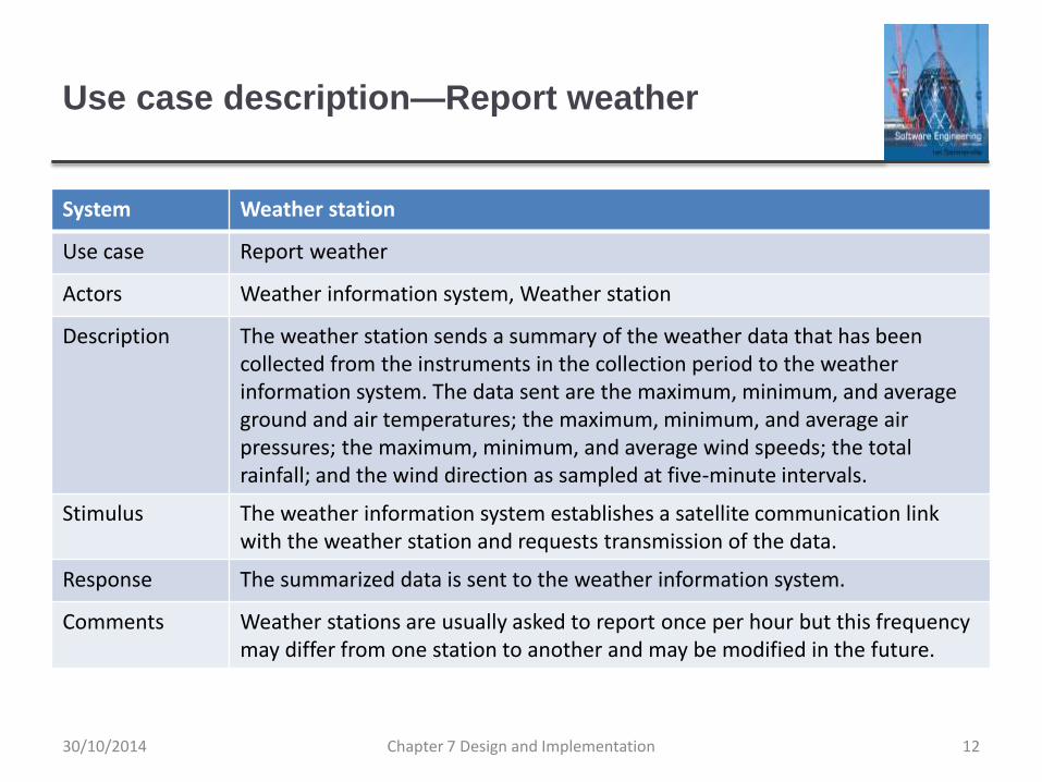
Use case description—Report weather
System Weather station
Use case Report weather
Actors Weather information system, Weather station
Description The weather station sends a summary of the weather data that has been collected from the instruments in the collection period to the weather information system. The data sent are the maximum, minimum, and average ground and air temperatures; the maximum, minimum, and average air pressures; the maximum, minimum, and average wind speeds; the total rainfall; and the wind direction as sampled at five-minute intervals.
Stimulus The weather information system establishes a satellite communication link with the weather station and requests transmission of the data.
Response The summarized data is sent to the weather information system.
Comments Weather stations are usually asked to report once per hour but this frequency may differ from one station to another and may be modified in the future.
Chapter 7 Design and Implementation 1230/10/2014

Architectural design
Once interactions between the system and its
environment have been understood, you use this
information for designing the system architecture.
You identify the major components that make up the
system and their interactions, and then may organize the
components using an architectural pattern such as a
layered or client-server model.
The weather station is composed of independent
subsystems that communicate by broadcasting
messages on a common infrastructure.
Chapter 7 Design and Implementation 1330/10/2014

High-level architecture of the weather station
Chapter 7 Design and Implementation 1430/10/2014

Architecture of data collection system
Chapter 7 Design and Implementation 1530/10/2014

Object class identification
Identifying object classes is often a difficult part of object
oriented design.
There is no 'magic formula' for object identification. It
relies on the skill, experience
and domain knowledge of system designers.
Object identification is an iterative process. You are
unlikely to get it right first time.
Chapter 7 Design and Implementation 1630/10/2014

Approaches to identification
Use a grammatical approach based on a natural
language description of the system.
Base the identification on tangible things in the
application domain.
Use a behavioural approach and identify objects based
on what participates in what behaviour.
Use a scenario-based analysis. The objects, attributes
and methods in each scenario are identified.
Chapter 7 Design and Implementation 1730/10/2014

Weather station object classes
Object class identification in the weather station system
may be based on the tangible hardware and data in the
system:
Ground thermometer, Anemometer, Barometer
• Application domain objects that are ‘hardware’ objects related to the
instruments in the system.
Weather station
• The basic interface of the weather station to its environment. It
therefore reflects the interactions identified in the use-case model.
Weather data
• Encapsulates the summarized data from the instruments.
Chapter 7 Design and Implementation 1830/10/2014

Weather station object classes
Chapter 7 Design and Implementation 1930/10/2014
Design models
Design models show the objects and object classes and
relationships between these entities.
There are two kinds of design model:
Structural models describe the static structure of the system in
terms of object classes and relationships.
Dynamic models describe the dynamic interactions between
objects.
Chapter 7 Design and Implementation 2030/10/2014

Examples of design models
Subsystem models that show logical groupings of
objects into coherent subsystems.
Sequence models that show the sequence of object
interactions.
State machine models that show how individual objects
change their state in response to events.
Other models include use-case models, aggregation
models, generalisation models, etc.
Chapter 7 Design and Implementation 2130/10/2014

Subsystem models
Shows how the design is organised into logically related
groups of objects.
In the UML, these are shown using packages - an
encapsulation construct. This is a logical model. The
actual organisation of objects in the system may be
different.
Chapter 7 Design and Implementation 2230/10/2014

Sequence models
Sequence models show the sequence of object interactions that take place
Objects are arranged horizontally across the top;
Time is represented vertically so models are read top to bottom;
Interactions are represented by labelled arrows, Different styles of arrow represent different types of interaction;
A thin rectangle in an object lifeline represents the time when the object is the controlling object in the system.
Chapter 7 Design and Implementation 2330/10/2014

Sequence diagram describing data collection
Chapter 7 Design and Implementation 2430/10/2014

State diagrams
State diagrams are used to show how objects respond to different service requests and the state transitions triggered by these requests.
State diagrams are useful high-level models of a system or an object’s run-time behavior.
You don’t usually need a state diagram for all of the objects in the system. Many of the objects in a system are relatively simple and a state model adds unnecessary detail to the design.
Chapter 7 Design and Implementation 2530/10/2014

Weather station state diagram
Chapter 7 Design and Implementation 2630/10/2014

Interface specification
Object interfaces have to be specified so that the objects
and other components can be designed in parallel.
Designers should avoid designing the interface
representation but should hide this in the object itself.
Objects may have several interfaces which are
viewpoints on the methods provided.
The UML uses class diagrams for interface specification
but Java may also be used.
Chapter 7 Design and Implementation 2730/10/2014

Weather station interfaces
Chapter 7 Design and Implementation 2830/10/2014

Design patterns
Chapter 7 Design and Implementation 2930/10/2014

Design patterns
A design pattern is a way of reusing abstract knowledge
about a problem and its solution.
A pattern is a description of the problem and the essence
of its solution.
It should be sufficiently abstract to be reused in different
settings.
Pattern descriptions usually make use of object-oriented
characteristics such as inheritance and polymorphism.
Chapter 7 Design and Implementation 3030/10/2014

Patterns
Patterns and Pattern Languages are ways to describe
best practices, good designs, and capture experience in
a way that it is possible for others to reuse this
experience.
Chapter 7 Design and Implementation 3130/10/2014

Pattern elements
Name
A meaningful pattern identifier.
Problem description.
Solution description.
Not a concrete design but a template for a design solution that
can be instantiated in different ways.
Consequences
The results and trade-offs of applying the pattern.
Chapter 7 Design and Implementation 3230/10/2014
The Observer pattern
Name
Observer.
Description
Separates the display of object state from the object itself.
Problem description
Used when multiple displays of state are needed.
Solution description
See slide with UML description.
Consequences
Optimisations to enhance display performance are impractical.
Chapter 7 Design and Implementation 3330/10/2014

The Observer pattern (1)
Pattern
name
Observer
Description Separates the display of the state of an object from the object itself and
allows alternative displays to be provided. When the object state
changes, all displays are automatically notified and updated to reflect the
change.
Problem
description
In many situations, you have to provide multiple displays of state
information, such as a graphical display and a tabular display. Not all of
these may be known when the information is specified. All alternative
presentations should support interaction and, when the state is changed,
all displays must be updated.
This pattern may be used in all situations where more than one
display format for state information is required and where it is not
necessary for the object that maintains the state information to know
about the specific display formats used.
Chapter 7 Design and Implementation 3430/10/2014

The Observer pattern (2)
Pattern name Observer
Solution
description
This involves two abstract objects, Subject and Observer, and two concrete
objects, ConcreteSubject and ConcreteObject, which inherit the attributes of the
related abstract objects. The abstract objects include general operations that are
applicable in all situations. The state to be displayed is maintained in
ConcreteSubject, which inherits operations from Subject allowing it to add and
remove Observers (each observer corresponds to a display) and to issue a
notification when the state has changed.
The ConcreteObserver maintains a copy of the state of ConcreteSubject and
implements the Update() interface of Observer that allows these copies to be kept
in step. The ConcreteObserver automatically displays the state and reflects
changes whenever the state is updated.
Consequences The subject only knows the abstract Observer and does not know details of the
concrete class. Therefore there is minimal coupling between these objects.
Because of this lack of knowledge, optimizations that enhance display
performance are impractical. Changes to the subject may cause a set of linked
updates to observers to be generated, some of which may not be necessary.
Chapter 7 Design and Implementation 3530/10/2014

Multiple displays using the Observer pattern
Chapter 7 Design and Implementation 3630/10/2014

A UML model of the Observer pattern
Chapter 7 Design and Implementation 3730/10/2014

Design problems
To use patterns in your design, you need to recognize
that any design problem you are facing may have an
associated pattern that can be applied.
Tell several objects that the state of some other object has
changed (Observer pattern).
Tidy up the interfaces to a number of related objects that have
often been developed incrementally (Façade pattern).
Provide a standard way of accessing the elements in a
collection, irrespective of how that collection is implemented
(Iterator pattern).
Allow for the possibility of extending the functionality of an
existing class at run-time (Decorator pattern).
Chapter 7 Design and Implementation 3830/10/2014

Implementation issues
Chapter 7 Design and Implementation 3930/10/2014

Implementation issues
Focus here is not on programming, although this is
obviously important, but on other implementation issues
that are often not covered in programming texts:
Reuse Most modern software is constructed by reusing existing
components or systems. When you are developing software, you
should make as much use as possible of existing code.
Configuration management During the development process,
you have to keep track of the many different versions of each
software component in a configuration management system.
Host-target development Production software does not usually
execute on the same computer as the software development
environment. Rather, you develop it on one computer (the host
system) and execute it on a separate computer (the target
system).Chapter 7 Design and Implementation 4030/10/2014

Reuse
From the 1960s to the 1990s, most new software was
developed from scratch, by writing all code in a high-
level programming language.
The only significant reuse or software was the reuse of functions
and objects in programming language libraries.
Costs and schedule pressure mean that this approach
became increasingly unviable, especially for commercial
and Internet-based systems.
An approach to development based around the reuse of
existing software emerged and is now generally used for
business and scientific software.
Chapter 7 Design and Implementation 4130/10/2014

Reuse levels
The abstraction level
At this level, you don’t reuse software directly but use knowledge
of successful abstractions in the design of your software.
The object level
At this level, you directly reuse objects from a library rather than
writing the code yourself.
The component level
Components are collections of objects and object classes that
you reuse in application systems.
The system level
At this level, you reuse entire application systems.
Chapter 7 Design and Implementation 4230/10/2014

Software reuse
Chapter 7 Design and Implementation 4330/10/2014

Reuse costs
The costs of the time spent in looking for software to
reuse and assessing whether or not it meets your needs.
Where applicable, the costs of buying the reusable
software. For large off-the-shelf systems, these costs
can be very high.
The costs of adapting and configuring the reusable
software components or systems to reflect the
requirements of the system that you are developing.
The costs of integrating reusable software elements with
each other (if you are using software from different
sources) and with the new code that you have
developed. Chapter 7 Design and Implementation 4430/10/2014

Configuration management
Configuration management is the name given to the
general process of managing a changing software
system.
The aim of configuration management is to support the
system integration process so that all developers can
access the project code and documents in a controlled
way, find out what changes have been made, and
compile and link components to create a system.
See also Chapter 25.
Chapter 7 Design and Implementation 4530/10/2014
Configuration management activities
Version management, where support is provided to keep track
of the different versions of software components. Version
management systems include facilities to coordinate
development by several programmers.
System integration, where support is provided to help
developers define what versions of components are used to
create each version of a system. This description is then used
to build a system automatically by compiling and linking the
required components.
Problem tracking, where support is provided to allow users to
report bugs and other problems, and to allow all developers to
see who is working on these problems and when they are
fixed.
Chapter 7 Design and Implementation 4630/10/2014

Configuration management tool interaction
Chapter 7 Design and Implementation 4730/10/2014

Host-target development
Most software is developed on one computer (the host),
but runs on a separate machine (the target).
More generally, we can talk about a development
platform and an execution platform.
A platform is more than just hardware.
It includes the installed operating system plus other supporting
software such as a database management system or, for
development platforms, an interactive development environment.
Development platform usually has different installed
software than execution platform; these platforms may
have different architectures.
Chapter 7 Design and Implementation 4830/10/2014

Host-target development
Chapter 7 Design and Implementation 4930/10/2014

Development platform tools
An integrated compiler and syntax-directed editing
system that allows you to create, edit and compile code.
A language debugging system.
Graphical editing tools, such as tools to edit UML
models.
Testing tools, such as Junit that can automatically run a
set of tests on a new version of a program.
Project support tools that help you organize the code for
different development projects.
Chapter 7 Design and Implementation 5030/10/2014

Integrated development environments (IDEs)
Software development tools are often grouped to create
an integrated development environment (IDE).
An IDE is a set of software tools that supports different
aspects of software development, within some common
framework and user interface.
IDEs are created to support development in a specific
programming language such as Java. The language IDE
may be developed specially, or may be an instantiation
of a general-purpose IDE, with specific language-support
tools.
Chapter 7 Design and Implementation 5130/10/2014

Component/system deployment factors
If a component is designed for a specific hardware architecture, or
relies on some other software system, it must obviously be deployed
on a platform that provides the required hardware and software
support.
High availability systems may require components to be deployed
on more than one platform. This means that, in the event of platform
failure, an alternative implementation of the component is available.
If there is a high level of communications traffic between
components, it usually makes sense to deploy them on the same
platform or on platforms that are physically close to one other. This
reduces the delay between the time a message is sent by one
component and received by another.
Chapter 7 Design and Implementation 5230/10/2014

Open source development
Chapter 7 Design and Implementation 5330/10/2014

Open source development
Open source development is an approach to software
development in which the source code of a software
system is published and volunteers are invited to
participate in the development process
Its roots are in the Free Software Foundation
(www.fsf.org), which advocates that source code should
not be proprietary but rather should always be available
for users to examine and modify as they wish.
Open source software extended this idea by using the
Internet to recruit a much larger population of volunteer
developers. Many of them are also users of the code.
Chapter 7 Design and Implementation 5430/10/2014

Open source systems
The best-known open source product is, of course, the
Linux operating system which is widely used as a server
system and, increasingly, as a desktop environment.
Other important open source products are Java, the
Apache web server and the mySQL database
management system.
Chapter 7 Design and Implementation 5530/10/2014

Open source issues
Should the product that is being developed make use of
open source components?
Should an open source approach be used for the
software’s development?
Chapter 7 Design and Implementation 5630/10/2014

Open source business
More and more product companies are using an open
source approach to development.
Their business model is not reliant on selling a software
product but on selling support for that product.
They believe that involving the open source community
will allow software to be developed more cheaply, more
quickly and will create a community of users for the
software.
Chapter 7 Design and Implementation 5730/10/2014

Open source licensing
A fundamental principle of open-source development is
that source code should be freely available, this does not
mean that anyone can do as they wish with that code.
Legally, the developer of the code (either a company or an
individual) still owns the code. They can place restrictions on
how it is used by including legally binding conditions in an open
source software license.
Some open source developers believe that if an open source
component is used to develop a new system, then that system
should also be open source.
Others are willing to allow their code to be used without this
restriction. The developed systems may be proprietary and sold
as closed source systems.
Chapter 7 Design and Implementation 5830/10/2014

License models
The GNU General Public License (GPL). This is a so-called
‘reciprocal’ license that means that if you use open source
software that is licensed under the GPL license, then you
must make that software open source.
The GNU Lesser General Public License (LGPL) is a variant
of the GPL license where you can write components that link
to open source code without having to publish the source of
these components.
The Berkley Standard Distribution (BSD) License. This is a
non-reciprocal license, which means you are not obliged to re-
publish any changes or modifications made to open source
code. You can include the code in proprietary systems that
are sold.
Chapter 7 Design and Implementation 5930/10/2014

License management
Establish a system for maintaining information about
open-source components that are downloaded and
used.
Be aware of the different types of licenses and
understand how a component is licensed before it is
used.
Be aware of evolution pathways for components.
Educate people about open source.
Have auditing systems in place.
Participate in the open source community.
Chapter 7 Design and Implementation 6030/10/2014

Key points
Software design and implementation are inter-leaved activities. The
level of detail in the design depends on the type of system and
whether you are using a plan-driven or agile approach.
The process of object-oriented design includes activities to design
the system architecture, identify objects in the system, describe the
design using different object models and document the component
interfaces.
A range of different models may be produced during an object-
oriented design process. These include static models (class models,
generalization models, association models) and dynamic models
(sequence models, state machine models).
Component interfaces must be defined precisely so that other
objects can use them. A UML interface stereotype may be used to
define interfaces.Chapter 7 Design and Implementation 6130/10/2014

Key points
When developing software, you should always consider the
possibility of reusing existing software, either as components,
services or complete systems.
Configuration management is the process of managing changes to
an evolving software system. It is essential when a team of people
are cooperating to develop software.
Most software development is host-target development. You use an
IDE on a host machine to develop the software, which is transferred
to a target machine for execution.
Open source development involves making the source code of a
system publicly available. This means that many people can
propose changes and improvements to the software.
Chapter 7 Design and Implementation 6230/10/2014

Chapter 8 – Software Testing
Chapter 8 Software Testing 130/10/2014

Topics covered
Development testing
Test-driven development
Release testing
User testing
Chapter 8 Software Testing 230/10/2014

Program testing
Testing is intended to show that a program does what it is
intended to do and to discover program defects before it is put
into use.
When you test software, you execute a program using
artificial data.
You check the results of the test run for errors, anomalies or
information about the program’s non-functional attributes.
Can reveal the presence of errors NOT their
absence.
Testing is part of a more general verification and validation
process, which also includes static validation techniques.
Chapter 8 Software Testing 330/10/2014

Program testing goals
To demonstrate to the developer and the customer that
the software meets its requirements.
For custom software, this means that there should be at least
one test for every requirement in the requirements document.
For generic software products, it means that there should be
tests for all of the system features, plus combinations of these
features, that will be incorporated in the product release.
To discover situations in which the behavior of the
software is incorrect, undesirable or does not conform to
its specification.
Defect testing is concerned with rooting out undesirable system
behavior such as system crashes, unwanted interactions with
other systems, incorrect computations and data corruption.
Chapter 8 Software Testing 430/10/2014

Validation and defect testing
The first goal leads to validation testing
You expect the system to perform correctly using a given set of
test cases that reflect the system’s expected use.
The second goal leads to defect testing
The test cases are designed to expose defects. The test cases in
defect testing can be deliberately obscure and need not reflect
how the system is normally used.
Chapter 8 Software Testing 530/10/2014

Testing process goals
Validation testing
To demonstrate to the developer and the system customer that
the software meets its requirements
A successful test shows that the system operates as intended.
Defect testing
To discover faults or defects in the software where its behaviour
is incorrect or not in conformance with its specification
A successful test is a test that makes the system perform
incorrectly and so exposes a defect in the system.
Chapter 8 Software Testing 630/10/2014

An input-output model of program testing
Chapter 8 Software Testing 730/10/2014

Verification vs validation
Verification:
"Are we building the product right”.
The software should conform to its specification.
Validation:
"Are we building the right product”.
The software should do what the user really requires.
Chapter 8 Software Testing 830/10/2014

V & V confidence
Aim of V & V is to establish confidence that the system is ‘fit for purpose’.
Depends on system’s purpose, user expectations and marketing environment
Software purpose
• The level of confidence depends on how critical the software is to an organisation.
User expectations
• Users may have low expectations of certain kinds of software.
Marketing environment
• Getting a product to market early may be more important than finding defects in the program.
Chapter 8 Software Testing 930/10/2014

Inspections and testing
Software inspections Concerned with analysis of
the static system representation to discover problems
(static verification)
May be supplement by tool-based document and code
analysis.
Discussed in Chapter 15.
Software testing Concerned with exercising and
observing product behaviour (dynamic verification)
The system is executed with test data and its operational
behaviour is observed.
Chapter 8 Software Testing 1030/10/2014

Inspections and testing
Chapter 8 Software Testing 1130/10/2014

Software inspections
These involve people examining the source
representation with the aim of discovering anomalies and
defects.
Inspections not require execution of a system so may be
used before implementation.
They may be applied to any representation of the system
(requirements, design,configuration data, test data, etc.).
They have been shown to be an effective technique for
discovering program errors.
Chapter 8 Software Testing 1230/10/2014

Advantages of inspections
During testing, errors can mask (hide) other errors.
Because inspection is a static process, you don’t have to
be concerned with interactions between errors.
Incomplete versions of a system can be inspected
without additional costs. If a program is incomplete, then
you need to develop specialized test harnesses to test
the parts that are available.
As well as searching for program defects, an inspection
can also consider broader quality attributes of a
program, such as compliance with standards, portability
and maintainability.
Chapter 8 Software Testing 1330/10/2014

Inspections and testing
Inspections and testing are complementary and not
opposing verification techniques.
Both should be used during the V & V process.
Inspections can check conformance with a specification
but not conformance with the customer’s real
requirements.
Inspections cannot check non-functional characteristics
such as performance, usability, etc.
Chapter 8 Software Testing 1430/10/2014

A model of the software testing process
Chapter 8 Software Testing 1530/10/2014

Stages of testing
Development testing, where the system is tested during
development to discover bugs and defects.
Release testing, where a separate testing team test a
complete version of the system before it is released to
users.
User testing, where users or potential users of a system
test the system in their own environment.
Chapter 8 Software Testing 1630/10/2014

Development testing
Chapter 8 Software Testing 1730/10/2014

Development testing
Development testing includes all testing activities that
are carried out by the team developing the system.
Unit testing, where individual program units or object classes are
tested. Unit testing should focus on testing the functionality of
objects or methods.
Component testing, where several individual units are integrated
to create composite components. Component testing should
focus on testing component interfaces.
System testing, where some or all of the components in a
system are integrated and the system is tested as a whole.
System testing should focus on testing component interactions.
Chapter 8 Software Testing 1830/10/2014

Unit testing
Unit testing is the process of testing individual
components in isolation.
It is a defect testing process.
Units may be:
Individual functions or methods within an object
Object classes with several attributes and methods
Composite components with defined interfaces used to access
their functionality.
Chapter 8 Software Testing 1930/10/2014

Object class testing
Complete test coverage of a class involves
Testing all operations associated with an object
Setting and interrogating all object attributes
Exercising the object in all possible states.
Inheritance makes it more difficult to design object class
tests as the information to be tested is not localised.
Chapter 8 Software Testing 2030/10/2014

The weather station object interface
Chapter 8 Software Testing 2130/10/2014

Weather station testing
Need to define test cases for reportWeather, calibrate,
test, startup and shutdown.
Using a state model, identify sequences of state
transitions to be tested and the event sequences to
cause these transitions
For example:
Shutdown -> Running-> Shutdown
Configuring-> Running-> Testing -> Transmitting -> Running
Running-> Collecting-> Running-> Summarizing -> Transmitting
-> Running
Chapter 8 Software Testing 2230/10/2014

Automated testing
Whenever possible, unit testing should be automated so
that tests are run and checked without manual
intervention.
In automated unit testing, you make use of a test
automation framework (such as JUnit) to write and run
your program tests.
Unit testing frameworks provide generic test classes that
you extend to create specific test cases. They can then
run all of the tests that you have implemented and
report, often through some GUI, on the success of
otherwise of the tests.
Chapter 8 Software Testing 2330/10/2014

Automated test components
A setup part, where you initialize the system with the test
case, namely the inputs and expected outputs.
A call part, where you call the object or method to be
tested.
An assertion part where you compare the result of the
call with the expected result. If the assertion evaluates to
true, the test has been successful if false, then it has
failed.
Chapter 8 Software Testing 2430/10/2014

Choosing unit test cases
The test cases should show that, when used as
expected, the component that you are testing does what
it is supposed to do.
If there are defects in the component, these should be
revealed by test cases.
This leads to 2 types of unit test case:
The first of these should reflect normal operation of a program
and should show that the component works as expected.
The other kind of test case should be based on testing
experience of where common problems arise. It should use
abnormal inputs to check that these are properly processed and
do not crash the component.
Chapter 8 Software Testing 2530/10/2014

Testing strategies
Partition testing, where you identify groups of inputs that
have common characteristics and should be processed
in the same way.
You should choose tests from within each of these groups.
Guideline-based testing, where you use testing
guidelines to choose test cases.
These guidelines reflect previous experience of the kinds of
errors that programmers often make when developing
components.
Chapter 8 Software Testing 2630/10/2014

Partition testing
Input data and output results often fall into different
classes where all members of a class are related.
Each of these classes is an equivalence partition or
domain where the program behaves in an equivalent
way for each class member.
Test cases should be chosen from each partition.
Chapter 8 Software Testing 2730/10/2014

Equivalence partitioning
Chapter 8 Software Testing 2830/10/2014

Equivalence partitions
Chapter 8 Software Testing 2930/10/2014

Testing guidelines (sequences)
Test software with sequences which have only a single
value.
Use sequences of different sizes in different tests.
Derive tests so that the first, middle and last elements of
the sequence are accessed.
Test with sequences of zero length.
Chapter 8 Software Testing 3030/10/2014

General testing guidelines
Choose inputs that force the system to generate all error
messages
Design inputs that cause input buffers to overflow
Repeat the same input or series of inputs numerous
times
Force invalid outputs to be generated
Force computation results to be too large or too small.
Chapter 8 Software Testing 3130/10/2014

Component testing
Software components are often composite components
that are made up of several interacting objects.
For example, in the weather station system, the reconfiguration
component includes objects that deal with each aspect of the
reconfiguration.
You access the functionality of these objects through the
defined component interface.
Testing composite components should therefore focus
on showing that the component interface behaves
according to its specification.
You can assume that unit tests on the individual objects within
the component have been completed.
Chapter 8 Software Testing 3230/10/2014

Interface testing
Objectives are to detect faults due to interface errors or
invalid assumptions about interfaces.
Interface types
Parameter interfaces Data passed from one method or
procedure to another.
Shared memory interfaces Block of memory is shared between
procedures or functions.
Procedural interfaces Sub-system encapsulates a set of
procedures to be called by other sub-systems.
Message passing interfaces Sub-systems request services from
other sub-systems
Chapter 8 Software Testing 3330/10/2014

Interface testing
Chapter 8 Software Testing 3430/10/2014

Interface errors
Interface misuse
A calling component calls another component and makes an
error in its use of its interface e.g. parameters in the wrong order.
Interface misunderstanding
A calling component embeds assumptions about the behaviour
of the called component which are incorrect.
Timing errors
The called and the calling component operate at different speeds
and out-of-date information is accessed.
Chapter 8 Software Testing 3530/10/2014

Interface testing guidelines
Design tests so that parameters to a called procedure
are at the extreme ends of their ranges.
Always test pointer parameters with null pointers.
Design tests which cause the component to fail.
Use stress testing in message passing systems.
In shared memory systems, vary the order in which
components are activated.
Chapter 8 Software Testing 3630/10/2014

System testing
System testing during development involves integrating
components to create a version of the system and then
testing the integrated system.
The focus in system testing is testing the interactions
between components.
System testing checks that components are compatible,
interact correctly and transfer the right data at the right
time across their interfaces.
System testing tests the emergent behaviour of a
system.
Chapter 8 Software Testing 3730/10/2014

System and component testing
During system testing, reusable components that have
been separately developed and off-the-shelf systems
may be integrated with newly developed components.
The complete system is then tested.
Components developed by different team members or
sub-teams may be integrated at this stage. System
testing is a collective rather than an individual process.
In some companies, system testing may involve a separate
testing team with no involvement from designers and
programmers.
Chapter 8 Software Testing 3830/10/2014

Use-case testing
The use-cases developed to identify system interactions
can be used as a basis for system testing.
Each use case usually involves several system
components so testing the use case forces these
interactions to occur.
The sequence diagrams associated with the use case
documents the components and interactions that are
being tested.
Chapter 8 Software Testing 3930/10/2014

Collect weather data sequence chart
Chapter 8 Software Testing 4030/10/2014

Test cases derived from sequence diagram
An input of a request for a report should have an
associated acknowledgement. A report should ultimately
be returned from the request.
You should create summarized data that can be used to check
that the report is correctly organized.
An input request for a report to WeatherStation results in
a summarized report being generated.
Can be tested by creating raw data corresponding to the
summary that you have prepared for the test of SatComms and
checking that the WeatherStation object correctly produces this
summary. This raw data is also used to test the WeatherData
object.
Chapter 8 Software Testing 4130/10/2014

Testing policies
Exhaustive system testing is impossible so testing
policies which define the required system test coverage
may be developed.
Examples of testing policies:
All system functions that are accessed through menus should be
tested.
Combinations of functions (e.g. text formatting) that are
accessed through the same menu must be tested.
Where user input is provided, all functions must be tested with
both correct and incorrect input.
Chapter 8 Software Testing 4230/10/2014

Test-driven development
Chapter 8 Software Testing 4330/10/2014

Test-driven development
Test-driven development (TDD) is an approach to
program development in which you inter-leave testing
and code development.
Tests are written before code and ‘passing’ the tests is
the critical driver of development.
You develop code incrementally, along with a test for that
increment. You don’t move on to the next increment until
the code that you have developed passes its test.
TDD was introduced as part of agile methods such as
Extreme Programming. However, it can also be used in
plan-driven development processes.
Chapter 8 Software Testing 4430/10/2014

Test-driven development
Chapter 8 Software Testing 4530/10/2014

TDD process activities
Start by identifying the increment of functionality that is
required. This should normally be small and
implementable in a few lines of code.
Write a test for this functionality and implement this as
an automated test.
Run the test, along with all other tests that have been
implemented. Initially, you have not implemented the
functionality so the new test will fail.
Implement the functionality and re-run the test.
Once all tests run successfully, you move on to
implementing the next chunk of functionality.
Chapter 8 Software Testing 4630/10/2014

Benefits of test-driven development
Code coverage
Every code segment that you write has at least one associated
test so all code written has at least one test.
Regression testing
A regression test suite is developed incrementally as a program
is developed.
Simplified debugging
When a test fails, it should be obvious where the problem lies.
The newly written code needs to be checked and modified.
System documentation
The tests themselves are a form of documentation that describe
what the code should be doing.
Chapter 8 Software Testing 4730/10/2014

Regression testing
Regression testing is testing the system to check that
changes have not ‘broken’ previously working code.
In a manual testing process, regression testing is
expensive but, with automated testing, it is simple and
straightforward. All tests are rerun every time a change is
made to the program.
Tests must run ‘successfully’ before the change is
committed.
Chapter 8 Software Testing 4830/10/2014

Release testing
Chapter 8 Software Testing 4930/10/2014

Release testing
Release testing is the process of testing a particular release
of a system that is intended for use outside of the
development team.
The primary goal of the release testing process is to
convince the supplier of the system that it is good enough
for use.
Release testing, therefore, has to show that the system delivers its
specified functionality, performance and dependability, and that it
does not fail during normal use.
Release testing is usually a black-box testing process
where tests are only derived from the system specification.
Chapter 8 Software Testing 5030/10/2014

Release testing and system testing
Release testing is a form of system testing.
Important differences:
A separate team that has not been involved in the system
development, should be responsible for release testing.
System testing by the development team should focus on
discovering bugs in the system (defect testing). The objective of
release testing is to check that the system meets its
requirements and is good enough for external use (validation
testing).
Chapter 8 Software Testing 5130/10/2014

Requirements based testing
Requirements-based testing involves examining each
requirement and developing a test or tests for it.
Mentcare system requirements:
If a patient is known to be allergic to any particular medication,
then prescription of that medication shall result in a warning
message being issued to the system user.
If a prescriber chooses to ignore an allergy warning, they shall
provide a reason why this has been ignored.
Chapter 8 Software Testing 5230/10/2014

Requirements tests
Set up a patient record with no known allergies. Prescribe medication for
allergies that are known to exist. Check that a warning message is not
issued by the system.
Set up a patient record with a known allergy. Prescribe the medication to
that the patient is allergic to, and check that the warning is issued by the
system.
Set up a patient record in which allergies to two or more drugs are recorded.
Prescribe both of these drugs separately and check that the correct warning
for each drug is issued.
Prescribe two drugs that the patient is allergic to. Check that two warnings
are correctly issued.
Prescribe a drug that issues a warning and overrule that warning. Check
that the system requires the user to provide information explaining why the
warning was overruled.
Chapter 8 Software Testing 5330/10/2014

A usage scenario for the Mentcare system
Chapter 8 Software Testing 54
George is a nurse who specializes in mental healthcare. One of his responsibilities is to visit patients at home to check that their treatment is effective and that they are not suffering from medication side effects.
On a day for home visits, George logs into the Mentcare system and uses it to print his schedule of home visits for that day, along with summary information about the patients to be visited. He requests that the records for these patients be downloaded to his laptop. He is prompted for his key phrase to encrypt the records on the laptop.
One of the patients that he visits is Jim, who is being treated with medication for depression. Jim feels that the medication is helping him but believes that it has the side effect of keeping him awake at night. George looks up Jim’s record and is prompted for his key phrase to decrypt the record. He checks the drug prescribed and queries its side effects. Sleeplessness is a known side effect so he notes the problem in Jim’s record and suggests that he visits the clinic to have his medication changed. Jim agrees so George enters a prompt to call him when he gets back to the clinic to make an appointment with a physician. George ends the consultation and the system re-encrypts Jim’s record.
After, finishing his consultations, George returns to the clinic and uploads the records of patients visited to the database. The system generates a call list for George of those patients who He has to contact for follow-up information and make clinic appointments.
30/10/2014

Features tested by scenario
Authentication by logging on to the system.
Downloading and uploading of specified patient records
to a laptop.
Home visit scheduling.
Encryption and decryption of patient records on a mobile
device.
Record retrieval and modification.
Links with the drugs database that maintains side-effect
information.
The system for call prompting.
Chapter 8 Software Testing 5530/10/2014

Performance testing
Part of release testing may involve testing the emergent
properties of a system, such as performance and
reliability.
Tests should reflect the profile of use of the system.
Performance tests usually involve planning a series of
tests where the load is steadily increased until the
system performance becomes unacceptable.
Stress testing is a form of performance testing where the
system is deliberately overloaded to test its failure
behaviour.
Chapter 8 Software Testing 5630/10/2014
User testing
Chapter 8 Software Testing 5730/10/2014

User testing
User or customer testing is a stage in the testing process
in which users or customers provide input and advice on
system testing.
User testing is essential, even when comprehensive
system and release testing have been carried out.
The reason for this is that influences from the user’s working
environment have a major effect on the reliability, performance,
usability and robustness of a system. These cannot be replicated
in a testing environment.
Chapter 8 Software Testing 5830/10/2014

Types of user testing
Alpha testing
Users of the software work with the development team to test the
software at the developer’s site.
Beta testing
A release of the software is made available to users to allow
them to experiment and to raise problems that they discover with
the system developers.
Acceptance testing
Customers test a system to decide whether or not it is ready to
be accepted from the system developers and deployed in the
customer environment. Primarily for custom systems.
Chapter 8 Software Testing 5930/10/2014

The acceptance testing process
Chapter 8 Software Testing 6030/10/2014

Stages in the acceptance testing process
Define acceptance criteria
Plan acceptance testing
Derive acceptance tests
Run acceptance tests
Negotiate test results
Reject/accept system
Chapter 8 Software Testing 6130/10/2014

Agile methods and acceptance testing
In agile methods, the user/customer is part of the
development team and is responsible for making
decisions on the acceptability of the system.
Tests are defined by the user/customer and are
integrated with other tests in that they are run
automatically when changes are made.
There is no separate acceptance testing process.
Main problem here is whether or not the embedded user
is ‘typical’ and can represent the interests of all system
stakeholders.
Chapter 8 Software Testing 6230/10/2014

Key points
Testing can only show the presence of errors in a
program. It cannot demonstrate that there are no
remaining faults.
Development testing is the responsibility of the software
development team. A separate team should be
responsible for testing a system before it is released to
customers.
Development testing includes unit testing, in which you
test individual objects and methods component testing
in which you test related groups of objects and system
testing, in which you test partial or complete systems.
Chapter 8 Software Testing 6330/10/2014

Key points
When testing software, you should try to ‘break’ the software by
using experience and guidelines to choose types of test case that
have been effective in discovering defects in other systems.
Wherever possible, you should write automated tests. The tests are
embedded in a program that can be run every time a change is
made to a system.
Test-first development is an approach to development where tests
are written before the code to be tested.
Scenario testing involves inventing a typical usage scenario and
using this to derive test cases.
Acceptance testing is a user testing process where the aim is to
decide if the software is good enough to be deployed and used in its
operational environment.
Chapter 8 Software Testing 6430/10/2014

Chapter 9 – Software Evolution
Chapter 9 Software Evolution 130/10/2014

Topics covered
Evolution processes
Legacy systems
Software maintenance
Chapter 9 Software Evolution 230/10/2014

Software change
Software change is inevitable
New requirements emerge when the software is used;
The business environment changes;
Errors must be repaired;
New computers and equipment is added to the system;
The performance or reliability of the system may have to be
improved.
A key problem for all organizations is implementing and
managing change to their existing software systems.
Chapter 9 Software Evolution 330/10/2014

Importance of evolution
Organisations have huge investments in their software systems - they are critical business assets.
To maintain the value of these assets to the business, they must be changed and updated.
The majority of the software budget in large companies is devoted to changing and evolving existing software rather than developing new software.
Chapter 9 Software Evolution 430/10/2014

A spiral model of development and evolution
Chapter 9 Software Evolution 530/10/2014

Evolution and servicing
Chapter 9 Software Evolution 630/10/2014

Evolution and servicing
Evolution
The stage in a software system’s life cycle where it is in
operational use and is evolving as new requirements are
proposed and implemented in the system.
Servicing
At this stage, the software remains useful but the only changes
made are those required to keep it operational i.e. bug fixes and
changes to reflect changes in the software’s environment. No
new functionality is added.
Phase-out
The software may still be used but no further changes are made
to it.
Chapter 9 Software Evolution 730/10/2014

Evolution processes
Chapter 9 Software Evolution 830/10/2014
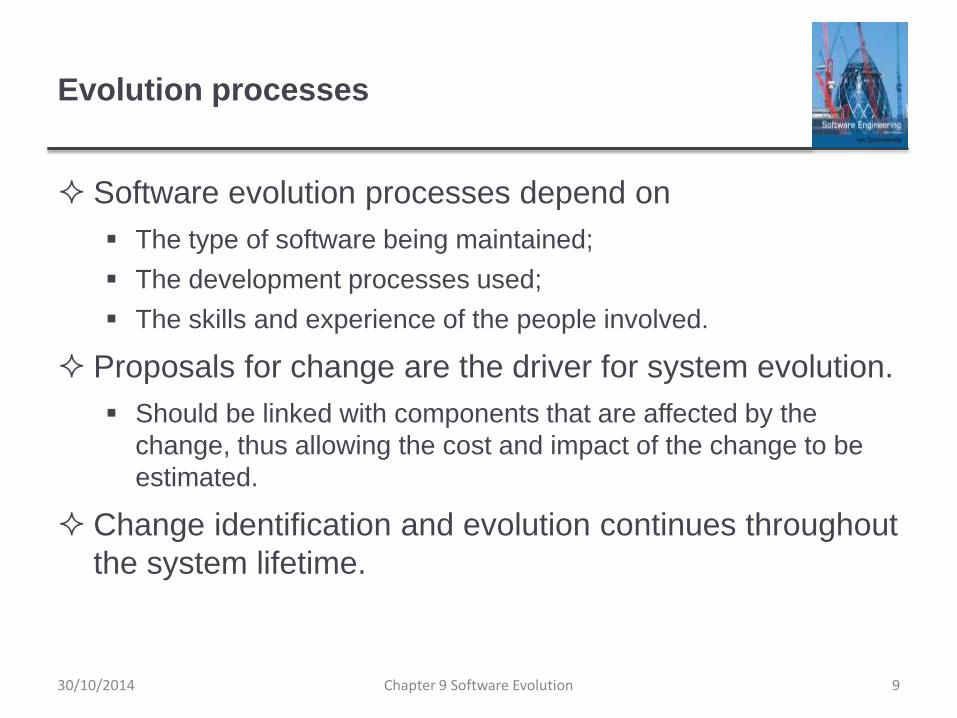
Evolution processes
Software evolution processes depend on
The type of software being maintained;
The development processes used;
The skills and experience of the people involved.
Proposals for change are the driver for system evolution.
Should be linked with components that are affected by the
change, thus allowing the cost and impact of the change to be
estimated.
Change identification and evolution continues throughout
the system lifetime.
Chapter 9 Software Evolution 930/10/2014

Change identification and evolution processes
Chapter 9 Software Evolution 1030/10/2014

The software evolution process
Chapter 9 Software Evolution 1130/10/2014

Change implementation
Chapter 9 Software Evolution 1230/10/2014

Change implementation
Iteration of the development process where the revisions
to the system are designed, implemented and tested.
A critical difference is that the first stage of change
implementation may involve program understanding,
especially if the original system developers are not
responsible for the change implementation.
During the program understanding phase, you have to
understand how the program is structured, how it
delivers functionality and how the proposed change
might affect the program.
Chapter 9 Software Evolution 1330/10/2014

Urgent change requests
Urgent changes may have to be implemented without
going through all stages of the software engineering
process
If a serious system fault has to be repaired to allow normal
operation to continue;
If changes to the system’s environment (e.g. an OS upgrade)
have unexpected effects;
If there are business changes that require a very rapid response
(e.g. the release of a competing product).
Chapter 9 Software Evolution 1430/10/2014

The emergency repair process
Chapter 9 Software Evolution 1530/10/2014

Agile methods and evolution
Agile methods are based on incremental development so
the transition from development to evolution is a
seamless one.
Evolution is simply a continuation of the development process
based on frequent system releases.
Automated regression testing is particularly valuable
when changes are made to a system.
Changes may be expressed as additional user stories.
Chapter 9 Software Evolution 1630/10/2014

Handover problems
Where the development team have used an agile
approach but the evolution team is unfamiliar with agile
methods and prefer a plan-based approach.
The evolution team may expect detailed documentation to
support evolution and this is not produced in agile processes.
Where a plan-based approach has been used for
development but the evolution team prefer to use agile
methods.
The evolution team may have to start from scratch developing
automated tests and the code in the system may not have been
refactored and simplified as is expected in agile development.
Chapter 9 Software Evolution 1730/10/2014

Legacy systems
Chapter 9 Software Evolution 1830/10/2014

Legacy systems
Legacy systems are older systems that rely on
languages and technology that are no longer used for
new systems development.
Legacy software may be dependent on older hardware,
such as mainframe computers and may have associated
legacy processes and procedures.
Legacy systems are not just software systems but are
broader socio-technical systems that include hardware,
software, libraries and other supporting software and
business processes.
Chapter 9 Software Evolution 1930/10/2014
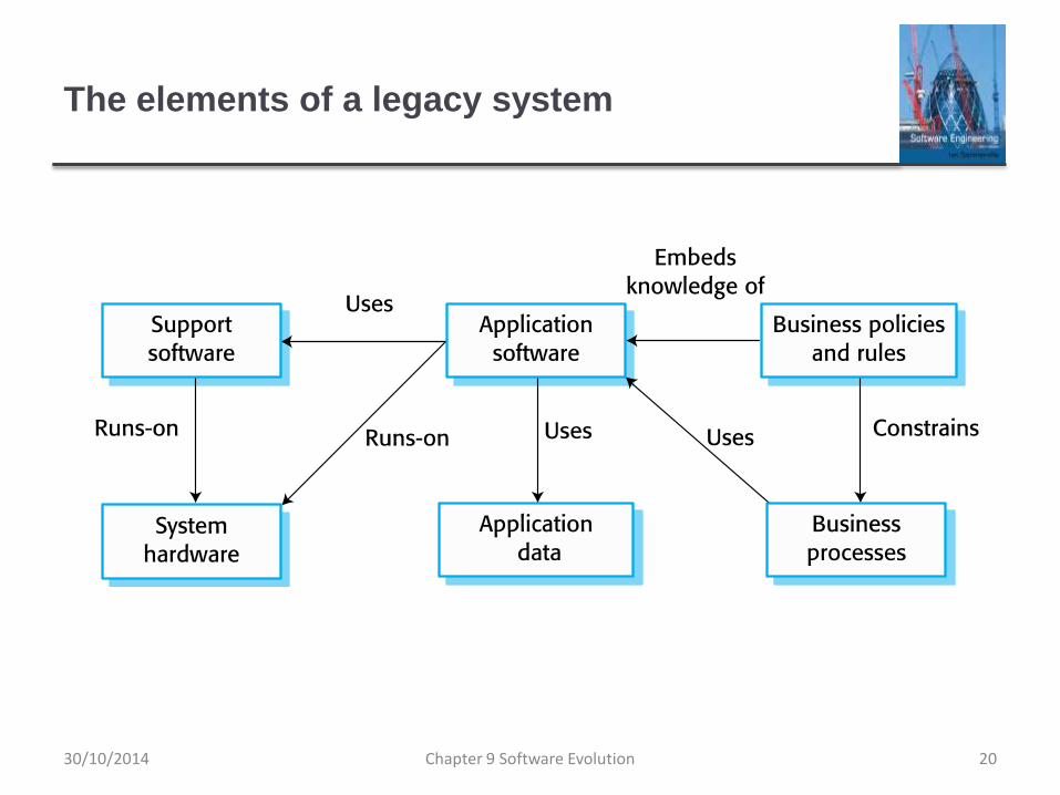
The elements of a legacy system
Chapter 9 Software Evolution 2030/10/2014

Legacy system components
System hardware Legacy systems may have been
written for hardware that is no longer available.
Support software The legacy system may rely on a
range of support software, which may be obsolete or
unsupported.
Application software The application system that
provides the business services is usually made up of a
number of application programs.
Application data These are data that are processed by
the application system. They may be inconsistent,
duplicated or held in different databases.
Chapter 9 Software Evolution 2130/10/2014

Legacy system components
Business processes These are processes that are used
in the business to achieve some business objective.
Business processes may be designed around a legacy
system and constrained by the functionality that it
provides.
Business policies and rules These are definitions of how
the business should be carried out and constraints on
the business. Use of the legacy application system may
be embedded in these policies and rules.
Chapter 9 Software Evolution 2230/10/2014

Legacy system layers
Chapter 9 Software Evolution 2330/10/2014

Legacy system replacement
Legacy system replacement is risky and expensive so
businesses continue to use these systems
System replacement is risky for a number of reasons
Lack of complete system specification
Tight integration of system and business processes
Undocumented business rules embedded in the legacy system
New software development may be late and/or over budget
Chapter 9 Software Evolution 2430/10/2014

Legacy system change
Legacy systems are expensive to change for a number
of reasons:
No consistent programming style
Use of obsolete programming languages with few people
available with these language skills
Inadequate system documentation
System structure degradation
Program optimizations may make them hard to understand
Data errors, duplication and inconsistency
Chapter 9 Software Evolution 2530/10/2014

Legacy system management
Organisations that rely on legacy systems must choose
a strategy for evolving these systems
Scrap the system completely and modify business processes so
that it is no longer required;
Continue maintaining the system;
Transform the system by re-engineering to improve its
maintainability;
Replace the system with a new system.
The strategy chosen should depend on the system
quality and its business value.
Chapter 9 Software Evolution 2630/10/2014

Figure 9.13 An example of a legacy system
assessment
Chapter 9 Software Evolution 2730/10/2014

Legacy system categories
Low quality, low business value
These systems should be scrapped.
Low-quality, high-business value
These make an important business contribution but are
expensive to maintain. Should be re-engineered or replaced if a
suitable system is available.
High-quality, low-business value
Replace with COTS, scrap completely or maintain.
High-quality, high business value
Continue in operation using normal system maintenance.
Chapter 9 Software Evolution 2830/10/2014

Business value assessment
Assessment should take different viewpoints into
account
System end-users;
Business customers;
Line managers;
IT managers;
Senior managers.
Interview different stakeholders and collate results.
Chapter 9 Software Evolution 2930/10/2014

Issues in business value assessment
The use of the system
If systems are only used occasionally or by a small number of
people, they may have a low business value.
The business processes that are supported
A system may have a low business value if it forces the use of
inefficient business processes.
System dependability
If a system is not dependable and the problems directly affect
business customers, the system has a low business value.
The system outputs
If the business depends on system outputs, then the system has
a high business value.
Chapter 9 Software Evolution 3030/10/2014

System quality assessment
Business process assessment
How well does the business process support the current goals of
the business?
Environment assessment
How effective is the system’s environment and how expensive is
it to maintain?
Application assessment
What is the quality of the application software system?
Chapter 9 Software Evolution 3130/10/2014

Business process assessment
Use a viewpoint-oriented approach and seek answers from system stakeholders
Is there a defined process model and is it followed?
Do different parts of the organisation use different processes for the same function?
How has the process been adapted?
What are the relationships with other business processes and are these necessary?
Is the process effectively supported by the legacy application software?
Example - a travel ordering system may have a low business value because of the widespread use of web-based ordering.
Chapter 9 Software Evolution 3230/10/2014

Factors used in environment assessment
Factor Questions
Supplier stability Is the supplier still in existence? Is the supplier financially stable and
likely to continue in existence? If the supplier is no longer in business,
does someone else maintain the systems?
Failure rate Does the hardware have a high rate of reported failures? Does the
support software crash and force system restarts?
Age How old is the hardware and software? The older the hardware and
support software, the more obsolete it will be. It may still function
correctly but there could be significant economic and business
benefits to moving to a more modern system.
Performance Is the performance of the system adequate? Do performance
problems have a significant effect on system users?
Chapter 9 Software Evolution 3330/10/2014

Factors used in environment assessment
Factor Questions
Support requirements What local support is required by the hardware and
software? If there are high costs associated with this
support, it may be worth considering system replacement.
Maintenance costs What are the costs of hardware maintenance and support
software licences? Older hardware may have higher
maintenance costs than modern systems. Support software
may have high annual licensing costs.
Interoperability Are there problems interfacing the system to other systems?
Can compilers, for example, be used with current versions
of the operating system? Is hardware emulation required?
Chapter 9 Software Evolution 3430/10/2014

Factors used in application assessment
Factor Questions
Understandability How difficult is it to understand the source code of the current
system? How complex are the control structures that are used?
Do variables have meaningful names that reflect their function?
Documentation What system documentation is available? Is the documentation
complete, consistent, and current?
Data Is there an explicit data model for the system? To what extent is
data duplicated across files? Is the data used by the system up to
date and consistent?
Performance Is the performance of the application adequate? Do performance
problems have a significant effect on system users?
Chapter 9 Software Evolution 3530/10/2014

Factors used in application assessment
Factor Questions
Programming language Are modern compilers available for the programming
language used to develop the system? Is the programming
language still used for new system development?
Configuration
management
Are all versions of all parts of the system managed by a
configuration management system? Is there an explicit
description of the versions of components that are used in
the current system?
Test data Does test data for the system exist? Is there a record of
regression tests carried out when new features have been
added to the system?
Personnel skills Are there people available who have the skills to maintain the
application? Are there people available who have experience
with the system?
Chapter 9 Software Evolution 3630/10/2014

System measurement
You may collect quantitative data to make an
assessment of the quality of the application system
The number of system change requests; The higher this
accumulated value, the lower the quality of the system.
The number of different user interfaces used by the system; The
more interfaces, the more likely it is that there will be
inconsistencies and redundancies in these interfaces.
The volume of data used by the system. As the volume of data
(number of files, size of database, etc.) processed by the system
increases, so too do the inconsistencies and errors in that data.
Cleaning up old data is a very expensive and time-consuming
process
Chapter 9 Software Evolution 3730/10/2014

Software maintenance
Chapter 9 Software Evolution 3830/10/2014

Software maintenance
Modifying a program after it has been put into use.
The term is mostly used for changing custom software.
Generic software products are said to evolve to create
new versions.
Maintenance does not normally involve major changes to
the system’s architecture.
Changes are implemented by modifying existing
components and adding new components to the system.
Chapter 9 Software Evolution 3930/10/2014

Types of maintenance
Fault repairs
Changing a system to fix bugs/vulnerabilities and correct
deficiencies in the way meets its requirements.
Environmental adaptation
Maintenance to adapt software to a different operating
environment
Changing a system so that it operates in a different environment
(computer, OS, etc.) from its initial implementation.
Functionality addition and modification
Modifying the system to satisfy new requirements.
Chapter 9 Software Evolution 4030/10/2014

Maintenance effort distribution
Chapter 9 Software Evolution 4130/10/2014

Maintenance costs
Usually greater than development costs (2* to
100* depending on the application).
Affected by both technical and non-technical
factors.
Increases as software is maintained.
Maintenance corrupts the software structure so
makes further maintenance more difficult.
Ageing software can have high support costs
(e.g. old languages, compilers etc.).
Chapter 9 Software Evolution 4230/10/2014

Maintenance costs
It is usually more expensive to add new features to a
system during maintenance than it is to add the same
features during development
A new team has to understand the programs being maintained
Separating maintenance and development means there is no
incentive for the development team to write maintainable
software
Program maintenance work is unpopular
• Maintenance staff are often inexperienced and have limited domain
knowledge.
As programs age, their structure degrades and they become
harder to change
Chapter 9 Software Evolution 4330/10/2014

Maintenance prediction
Maintenance prediction is concerned with assessing
which parts of the system may cause problems and have
high maintenance costs
Change acceptance depends on the maintainability of the
components affected by the change;
Implementing changes degrades the system and reduces its
maintainability;
Maintenance costs depend on the number of changes and costs
of change depend on maintainability.
Chapter 9 Software Evolution 4430/10/2014

Maintenance prediction
Chapter 9 Software Evolution 4530/10/2014

Change prediction
Predicting the number of changes requires and
understanding of the relationships between a system
and its environment.
Tightly coupled systems require changes whenever the
environment is changed.
Factors influencing this relationship are
Number and complexity of system interfaces;
Number of inherently volatile system requirements;
The business processes where the system is used.
Chapter 9 Software Evolution 4630/10/2014

Complexity metrics
Predictions of maintainability can be made by assessing
the complexity of system components.
Studies have shown that most maintenance effort is
spent on a relatively small number of system
components.
Complexity depends on
Complexity of control structures;
Complexity of data structures;
Object, method (procedure) and module size.
Chapter 9 Software Evolution 4730/10/2014

Process metrics
Process metrics may be used to assess maintainability
Number of requests for corrective maintenance;
Average time required for impact analysis;
Average time taken to implement a change request;
Number of outstanding change requests.
If any or all of these is increasing, this may indicate a
decline in maintainability.
Chapter 9 Software Evolution 4830/10/2014

Software reengineering
Restructuring or rewriting part or all of a
legacy system without changing its
functionality.
Applicable where some but not all sub-systems
of a larger system require frequent
maintenance.
Reengineering involves adding effort to make
them easier to maintain. The system may be re-
structured and re-documented.
Chapter 9 Software Evolution 4930/10/2014

Advantages of reengineering
Reduced risk
There is a high risk in new software development. There may be
development problems, staffing problems and specification
problems.
Reduced cost
The cost of re-engineering is often significantly less than the
costs of developing new software.
Chapter 9 Software Evolution 5030/10/2014

The reengineering process
Chapter 9 Software Evolution 5130/10/2014

Reengineering process activities
Source code translation
Convert code to a new language.
Reverse engineering
Analyse the program to understand it;
Program structure improvement
Restructure automatically for understandability;
Program modularisation
Reorganise the program structure;
Data reengineering
Clean-up and restructure system data.
Chapter 9 Software Evolution 5230/10/2014

Reengineering approaches
Chapter 9 Software Evolution 5330/10/2014

Reengineering cost factors
The quality of the software to be reengineered.
The tool support available for reengineering.
The extent of the data conversion which is required.
The availability of expert staff for reengineering.
This can be a problem with old systems based on technology that is no longer widely used.
Chapter 9 Software Evolution 5430/10/2014

Refactoring
Refactoring is the process of making improvements to a
program to slow down degradation through change.
You can think of refactoring as ‘preventative
maintenance’ that reduces the problems of future
change.
Refactoring involves modifying a program to improve its
structure, reduce its complexity or make it easier to
understand.
When you refactor a program, you should not add
functionality but rather concentrate on program
improvement.
Chapter 9 Software Evolution 5530/10/2014

Refactoring and reengineering
Re-engineering takes place after a system has been
maintained for some time and maintenance costs are
increasing. You use automated tools to process and re-
engineer a legacy system to create a new system that is
more maintainable.
Refactoring is a continuous process of improvement
throughout the development and evolution process. It is
intended to avoid the structure and code degradation
that increases the costs and difficulties of maintaining a
system.
Chapter 9 Software Evolution 5630/10/2014

‘Bad smells’ in program code
Duplicate code
The same or very similar code may be included at different
places in a program. This can be removed and implemented as a
single method or function that is called as required.
Long methods
If a method is too long, it should be redesigned as a number of
shorter methods.
Switch (case) statements
These often involve duplication, where the switch depends on
the type of a value. The switch statements may be scattered
around a program. In object-oriented languages, you can often
use polymorphism to achieve the same thing.
Chapter 9 Software Evolution 5730/10/2014

‘Bad smells’ in program code
Data clumping
Data clumps occur when the same group of data items (fields in
classes, parameters in methods) re-occur in several places in a
program. These can often be replaced with an object that
encapsulates all of the data.
Speculative generality
This occurs when developers include generality in a program in
case it is required in the future. This can often simply be
removed.
Chapter 9 Software Evolution 5830/10/2014

Key points
Software development and evolution can be thought of
as an integrated, iterative process that can be
represented using a spiral model.
For custom systems, the costs of software maintenance
usually exceed the software development costs.
The process of software evolution is driven by requests
for changes and includes change impact analysis,
release planning and change implementation.
Legacy systems are older software systems, developed
using obsolete software and hardware technologies, that
remain useful for a business.
Chapter 9 Software Evolution 5930/10/2014

Key points
It is often cheaper and less risky to maintain a legacy
system than to develop a replacement system using
modern technology.
The business value of a legacy system and the quality of
the application should be assessed to help decide if a
system should be replaced, transformed or maintained.
There are 3 types of software maintenance, namely bug
fixing, modifying software to work in a new environment,
and implementing new or changed requirements.
Chapter 9 Software Evolution 6030/10/2014

Key points
Software re-engineering is concerned with re-structuring
and re-documenting software to make it easier to
understand and change.
Refactoring, making program changes that preserve
functionality, is a form of preventative maintenance.
Chapter 9 Software Evolution 6130/10/2014

Chapter 10 – Dependable systems
30/10/2014 Chapter 10 Dependable Systems 1
Topics covered
Dependability properties
Sociotechnical systems
Redundancy and diversity
Dependable processes
Formal methods and dependability
30/10/2014 Chapter 10 Dependable Systems 2

System dependability
For many computer-based systems, the most important
system property is the dependability of the system.
The dependability of a system reflects the user’s degree
of trust in that system. It reflects the extent of the user’s
confidence that it will operate as users expect and that it
will not ‘fail’ in normal use.
Dependability covers the related systems attributes of
reliability, availability and security. These are all inter-
dependent.
3Chapter 10 Dependable Systems30/10/2014

Importance of dependability
System failures may have widespread effects with large
numbers of people affected by the failure.
Systems that are not dependable and are unreliable,
unsafe or insecure may be rejected by their users.
The costs of system failure may be very high if the failure
leads to economic losses or physical damage.
Undependable systems may cause information loss with
a high consequent recovery cost.
4Chapter 10 Dependable Systems30/10/2014

Causes of failure
Hardware failure
Hardware fails because of design and manufacturing errors or because components have reached the end of their natural life.
Software failure
Software fails due to errors in its specification, design or implementation.
Operational failure
Human operators make mistakes. Now perhaps the largest single cause of system failures in socio-technical systems.
5Chapter 10 Dependable Systems30/10/2014
Dependability properties
30/10/2014 Chapter 10 Dependable Systems 6

The principal dependability properties
30/10/2014 Chapter 10 Dependable Systems 7

Principal properties
Availability
The probability that the system will be up and running and able
to deliver useful services to users.
Reliability
The probability that the system will correctly deliver services as
expected by users.
Safety
A judgment of how likely it is that the system will cause damage
to people or its environment.
8Chapter 10 Dependable Systems30/10/2014

Principal properties
Security
A judgment of how likely it is that the system can resist
accidental or deliberate intrusions.
Resilience
A judgment of how well a system can maintain the continuity of
its critical services in the presence of disruptive events such as
equipment failure and cyberattacks.
30/10/2014 Chapter 10 Dependable Systems 9

Other dependability properties
Repairability
Reflects the extent to which the system can be repaired in the event of a failure
Maintainability
Reflects the extent to which the system can be adapted to new requirements;
Error tolerance
Reflects the extent to which user input errors can be avoided and tolerated.
10Chapter 10 Dependable Systems30/10/2014

Dependability attribute dependencies
Safe system operation depends on the system being
available and operating reliably.
A system may be unreliable because its data has been
corrupted by an external attack.
Denial of service attacks on a system are intended to
make it unavailable.
If a system is infected with a virus, you cannot be
confident in its reliability or safety.
Chapter 10 Dependable Systems 1130/10/2014

Dependability achievement
Avoid the introduction of accidental errors when
developing the system.
Design V & V processes that are effective in discovering
residual errors in the system.
Design systems to be fault tolerant so that they can
continue in operation when faults occur
Design protection mechanisms that guard against
external attacks.
Chapter 10 Dependable Systems 1230/10/2014

Dependability achievement
Configure the system correctly for its operating
environment.
Include system capabilities to recognise and resist
cyberattacks.
Include recovery mechanisms to help restore normal
system service after a failure.
30/10/2014 Chapter 10 Dependable Systems 13

Dependability costs
Dependability costs tend to increase exponentially as
increasing levels of dependability are required.
There are two reasons for this
The use of more expensive development techniques and
hardware that are required to achieve the higher levels of
dependability.
The increased testing and system validation that is required to
convince the system client and regulators that the required levels
of dependability have been achieved.
14Chapter 10 Dependable Systems30/10/2014

Cost/dependability curve
30/10/2014 Chapter 10 Dependable Systems 15

Dependability economics
Because of very high costs of dependability achievement, it may be more cost effective to accept untrustworthy systems and pay for failure costs
However, this depends on social and political factors. A reputation for products that can’t be trusted may lose future business
Depends on system type - for business systems in particular, modest levels of dependability may be adequate
16Chapter 10 Dependable Systems30/10/2014

Sociotechnical systems
30/10/2014 Chapter 10 Dependable Systems 17

Systems and software
Software engineering is not an isolated activity but is part
of a broader systems engineering process.
Software systems are therefore not isolated systems but
are essential components of broader systems that have
a human, social or organizational purpose.
Example
The wilderness weather system is part of broader weather
recording and forecasting systems
These include hardware and software, forecasting processes,
system users, the organizations that depend on weather
forecasts, etc.
Chapter 10 Dependable Systems 1830/10/2014

The sociotechnical systems stack
30/10/2014 Chapter 10 Dependable Systems 19

Layers in the STS stack
Equipment
Hardware devices, some of which may be computers. Most
devices will include an embedded system of some kind.
Operating system
Provides a set of common facilities for higher levels in the
system.
Communications and data management
Middleware that provides access to remote systems and
databases.
Application systems
Specific functionality to meet some organization requirements.
Chapter 10 Dependable Systems 2030/10/2014

Layers in the STS stack
Business processes
A set of processes involving people and computer systems that
support the activities of the business.
Organizations
Higher level strategic business activities that affect the operation
of the system.
Society
Laws, regulation and culture that affect the operation of the
system.
Chapter 10 Dependable Systems 2130/10/2014

Holistic system design
There are interactions and dependencies between the
layers in a system and changes at one level ripple
through the other levels
Example: Change in regulations (society) leads to changes in
business processes and application software.
For dependability, a systems perspective is essential
Contain software failures within the enclosing layers of the STS
stack.
Understand how faults and failures in adjacent layers may affect
the software in a system.
Chapter 10 Dependable Systems 2230/10/2014

Regulation and compliance
The general model of economic organization that is now
almost universal in the world is that privately owned
companies offer goods and services and make a profit
on these.
To ensure the safety of their citizens, most governments
regulate (limit the freedom of) privately owned
companies so that they must follow certain standards to
ensure that their products are safe and secure.
30/10/2014 Chapter 10 Dependable Systems 23

Regulated systems
Many critical systems are regulated systems, which
means that their use must be approved by an external
regulator before the systems go into service.
Nuclear systems
Air traffic control systems
Medical devices
A safety and dependability case has to be approved by
the regulator. Therefore, critical systems development
has to create the evidence to convince a regulator that
the system is dependable, safe and secure.
Chapter 10 Dependable Systems 2430/10/2014

Safety regulation
Regulation and compliance (following the rules) applies
to the sociotechnical system as a whole and not simply
the software element of that system.
Safety-related systems may have to be certified as safe
by the regulator.
To achieve certification, companies that are developing
safety-critical systems have to produce an extensive
safety case that shows that rules and regulations have
been followed.
It can be as expensive develop the documentation for
certification as it is to develop the system itself.
30/10/2014 Chapter 10 Dependable Systems 25

Redundancy and diversity
30/10/2014 Chapter 10 Dependable Systems 26

Redundancy and diversity
Redundancy
Keep more than a single version of critical components so that if one fails then a backup is available.
Diversity
Provide the same functionality in different ways in different components so that they will not fail in the same way.
Redundant and diverse components should be independent so that they will not suffer from ‘common-mode’ failures
For example, components implemented in different programming languages means that a compiler fault will not affect all of them.
27Chapter 10 Dependable Systems30/10/2014

Diversity and redundancy examples
Redundancy. Where availability is critical (e.g. in e-
commerce systems), companies normally keep backup
servers and switch to these automatically if failure
occurs.
Diversity. To provide resilience against external attacks,
different servers may be implemented using different
operating systems (e.g. Windows and Linux)
28Chapter 10 Dependable Systems30/10/2014

Process diversity and redundancy
Process activities, such as validation, should not depend
on a single approach, such as testing, to validate the
system.
Redundant and diverse process activities are important
especially for verification and validation.
Multiple, different process activities the complement
each other and allow for cross-checking help to avoid
process errors, which may lead to errors in the software.
Chapter 10 Dependable Systems 2930/10/2014

Problems with redundancy and diversity
Adding diversity and redundancy to a system increases the system complexity.
This can increase the chances of error because of unanticipated interactions and dependencies between the redundant system components.
Some engineers therefore advocate simplicity and extensive V & V as a more effective route to software dependability.
Airbus FCS architecture is redundant/diverse; Boeing 777 FCS architecture has no software diversity
30/10/2014 Chapter 10 Dependable Systems 30

Dependable processes
30/10/2014 Chapter 10 Dependable Systems 31

Dependable processes
To ensure a minimal number of software faults, it is
important to have a well-defined, repeatable software
process.
A well-defined repeatable process is one that does not
depend entirely on individual skills; rather can be
enacted by different people.
Regulators use information about the process to check if
good software engineering practice has been used.
For fault detection, it is clear that the process activities
should include significant effort devoted to verification
and validation.
32Chapter 10 Dependable Systems30/10/2014

Dependable process characteristics
Explicitly defined
A process that has a defined process model that is used to drive
the software production process. Data must be collected during
the process that proves that the development team has followed
the process as defined in the process model.
Repeatable
A process that does not rely on individual interpretation and
judgment. The process can be repeated across projects and with
different team members, irrespective of who is involved in the
development.
30/10/2014 Chapter 10 Dependable Systems 33

Attributes of dependable processes
Process characteristic Description
Auditable The process should be understandable by people apart
from process participants, who can check that process
standards are being followed and make suggestions for
process improvement.
Diverse The process should include redundant and diverse
verification and validation activities.
Documentable The process should have a defined process model that
sets out the activities in the process and the
documentation that is to be produced during these
activities.
Robust The process should be able to recover from failures of
individual process activities.
Standardized A comprehensive set of software development
standards covering software production and
documentation should be available.
34Chapter 10 Dependable Systems30/10/2014

Dependable process activities
Requirements reviews to check that the requirements
are, as far as possible, complete and consistent.
Requirements management to ensure that changes to
the requirements are controlled and that the impact of
proposed requirements changes is understood.
Formal specification, where a mathematical model of the
software is created and analyzed.
System modeling, where the software design is explicitly
documented as a set of graphical models, and the links
between the requirements and these models are
documented.
30/10/2014 Chapter 10 Dependable Systems 35

Dependable process activities
Design and program inspections, where the different
descriptions of the system are inspected and checked by
different people.
Static analysis, where automated checks are carried out
on the source code of the program.
Test planning and management, where a comprehensive
set of system tests is designed.
The testing process has to be carefully managed to demonstrate
that these tests provide coverage of the system requirements
and have been correctly applied in the testing process.
30/10/2014 Chapter 10 Dependable Systems 36

Dependable processes and agility
Dependable software often requires certification so both
process and product documentation has to be produced.
Up-front requirements analysis is also essential to
discover requirements and requirements conflicts that
may compromise the safety and security of the system.
These conflict with the general approach in agile
development of co-development of the requirements and
the system and minimizing documentation.
30/10/2014 Chapter 10 Dependable Systems 37

Dependable processes and agility
An agile process may be defined that incorporates
techniques such as iterative development, test-first
development and user involvement in the development
team.
So long as the team follows that process and documents
their actions, agile methods can be used.
However, additional documentation and planning is
essential so ‘pure agile’ is impractical for dependable
systems engineering.
30/10/2014 Chapter 10 Dependable Systems 38
Formal methods and dependability
30/10/2014 Chapter 10 Dependable Systems 39

Formal specification
Formal methods are approaches to software
development that are based on mathematical
representation and analysis of software.
Formal methods include
Formal specification;
Specification analysis and proof;
Transformational development;
Program verification.
Formal methods significantly reduce some types of
programming errors and can be cost-effective for
dependable systems engineering.
40Chapter 10 Dependable Systems30/10/2014

Formal approaches
Verification-based approaches
Different representations of a software system such as a
specification and a program implementing that specification are
proved to be equivalent.
This demonstrates the absence of implementation errors.
Refinement-based approaches
A representation of a system is systematically transformed into
another, lower-level represention e.g. a specification is
transformed automatically into an implementation.
This means that, if the transformation is correct, the
representations are equivalent.
30/10/2014 Chapter 10 Dependable Systems 41

Use of formal methods
The principal benefits of formal methods are in reducing
the number of faults in systems.
Consequently, their main area of applicability is in
dependable systems engineering. There have been
several successful projects where formal methods have
been used in this area.
In this area, the use of formal methods is most likely to
be cost-effective because high system failure costs must
be avoided.
42Chapter 10 Dependable Systems30/10/2014

Classes of error
Specification and design errors and omissions.
Developing and analysing a formal model of the software may
reveal errors and omissions in the software requirements. If the
model is generated automatically or systematically from source
code, analysis using model checking can find undesirable states
that may occur such as deadlock in a concurrent system.
Inconsistences between a specification and a program.
If a refinement method is used, mistakes made by developers
that make the software inconsistent with the specification are
avoided. Program proving discovers inconsistencies between a
program and its specification.
30/10/2014 Chapter 10 Dependable Systems 43
Benefits of formal specification
Developing a formal specification requires the system
requirements to be analyzed in detail. This helps to detect
problems, inconsistencies and incompleteness in the
requirements.
As the specification is expressed in a formal language, it can
be automatically analyzed to discover inconsistencies and
incompleteness.
If you use a formal method such as the B method, you can
transform the formal specification into a ‘correct’ program.
Program testing costs may be reduced if the program is
formally verified against its specification.
44Chapter 10 Dependable Systems30/10/2014

Acceptance of formal methods
Formal methods have had limited impact on practical software development:
Problem owners cannot understand a formal specification and so cannot assess if it is an accurate representation of their requirements.
It is easy to assess the costs of developing a formal specification but harder to assess the benefits. Managers may therefore be unwilling to invest in formal methods.
Software engineers are unfamiliar with this approach and are therefore reluctant to propose the use of FM.
Formal methods are still hard to scale up to large systems.
Formal specification is not really compatible with agile development methods.
45Chapter 10 Dependable Systems30/10/2014

Key points
System dependability is important because failure of
critical systems can lead to economic losses, information
loss, physical damage or threats to human life.
The dependability of a computer system is a system
property that reflects the user’s degree of trust in the
system. The most important dimensions of dependability
are availability, reliability, safety, security and resilience.
Sociotechnical systems include computer hardware,
software and people, and are situated within an
organization. They are designed to support
organizational or business goals and objectives.
30/10/2014 Chapter 10 Dependable Systems 46

Key points
The use of a dependable, repeatable process is
essential if faults in a system are to be minimized. The
process should include verification and validation
activities at all stages, from requirements definition
through to system implementation.
The use of redundancy and diversity in hardware,
software processes and software systems is essential to
the development of dependable systems.
Formal methods, where a formal model of a system is
used as a basis for development help reduce the number
of specification and implementation errors in a system.
30/10/2014 Chapter 10 Dependable Systems 47

Chapter 11 – Reliability Engineering
1Chapter 11 Reliability Engineering30/10/2014

Topics covered
Availability and reliability
Reliability requirements
Fault-tolerant architectures
Programming for reliability
Reliability measurement
2Chapter 11 Reliability Engineering30/10/2014

Software reliability
In general, software customers expect all software to be
dependable. However, for non-critical applications, they
may be willing to accept some system failures.
Some applications (critical systems) have very high
reliability requirements and special software engineering
techniques may be used to achieve this.
Medical systems
Telecommunications and power systems
Aerospace systems
3Chapter 11 Reliability Engineering30/10/2014

Faults, errors and failures
Term Description
Human error or
mistake
Human behavior that results in the introduction of faults into a system. For
example, in the wilderness weather system, a programmer might decide that the
way to compute the time for the next transmission is to add 1 hour to the current
time. This works except when the transmission time is between 23.00 and
midnight (midnight is 00.00 in the 24-hour clock).
System fault A characteristic of a software system that can lead to a system error. The fault is
the inclusion of the code to add 1 hour to the time of the last transmission,
without a check if the time is greater than or equal to 23.00.
System error An erroneous system state that can lead to system behavior that is unexpected
by system users. The value of transmission time is set incorrectly (to 24.XX
rather than 00.XX) when the faulty code is executed.
System failure An event that occurs at some point in time when the system does not deliver a
service as expected by its users. No weather data is transmitted because the
time is invalid.
4Chapter 11 Reliability Engineering30/10/2014

Faults and failures
Failures are a usually a result of system errors that are derived from faults in the system
However, faults do not necessarily result in system errors
The erroneous system state resulting from the fault may be transient and ‘corrected’ before an error arises.
The faulty code may never be executed.
Errors do not necessarily lead to system failures
The error can be corrected by built-in error detection and recovery
The failure can be protected against by built-in protection facilities. These may, for example, protect system resources from system errors
5Chapter 11 Reliability Engineering30/10/2014

Fault management
Fault avoidance
The system is developed in such a way that human error is avoided and thus system faults are minimised.
The development process is organised so that faults in the system are detected and repaired before delivery to the customer.
Fault detection
Verification and validation techniques are used to discover and remove faults in a system before it is deployed.
Fault tolerance
The system is designed so that faults in the delivered software do not result in system failure.
6Chapter 11 Reliability Engineering30/10/2014

Reliability achievement
Fault avoidance
Development technique are used that either minimise the possibility of mistakes or trap mistakes before they result in the introduction of system faults.
Fault detection and removal
Verification and validation techniques are used that increase the probability of detecting and correcting errors before the system goes into service are used.
Fault tolerance
Run-time techniques are used to ensure that system faults do not result in system errors and/or that system errors do not lead to system failures.
7Chapter 11 Reliability Engineering30/10/2014
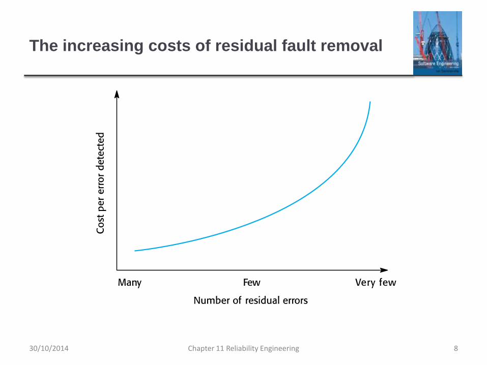
The increasing costs of residual fault removal
8Chapter 11 Reliability Engineering30/10/2014

Availability and reliability
9Chapter 11 Reliability Engineering30/10/2014

Availability and reliability
Reliability
The probability of failure-free system operation over a specified time in a given environment for a given purpose
Availability
The probability that a system, at a point in time, will be operational and able to deliver the requested services
Both of these attributes can be expressed quantitatively e.g. availability of 0.999 means that the system is up and running for 99.9% of the time.
10Chapter 11 Reliability Engineering30/10/2014

Reliability and specifications
Reliability can only be defined formally with respect to a
system specification i.e. a failure is a deviation from a
specification.
However, many specifications are incomplete or
incorrect – hence, a system that conforms to its
specification may ‘fail’ from the perspective of system
users.
Furthermore, users don’t read specifications so don’t
know how the system is supposed to behave.
Therefore perceived reliability is more important in
practice.
11Chapter 11 Reliability Engineering30/10/2014

Perceptions of reliability
The formal definition of reliability does not always reflect the user’s perception of a system’s reliability
The assumptions that are made about the environment where a system will be used may be incorrect
• Usage of a system in an office environment is likely to be quite different from usage of the same system in a university environment
The consequences of system failures affects the perception of reliability
• Unreliable windscreen wipers in a car may be irrelevant in a dry climate
• Failures that have serious consequences (such as an engine breakdown in a car) are given greater weight by users than failures that are inconvenient
12Chapter 11 Reliability Engineering30/10/2014

A system as an input/output mapping
13Chapter 11 Reliability Engineering30/10/2014

Availability perception
Availability is usually expressed as a percentage of the
time that the system is available to deliver services e.g.
99.95%.
However, this does not take into account two factors:
The number of users affected by the service outage. Loss of
service in the middle of the night is less important for many
systems than loss of service during peak usage periods.
The length of the outage. The longer the outage, the more the
disruption. Several short outages are less likely to be disruptive
than 1 long outage. Long repair times are a particular problem.
14Chapter 11 Reliability Engineering30/10/2014

Software usage patterns
15Chapter 11 Reliability Engineering30/10/2014

Reliability in use
Removing X% of the faults in a system will not
necessarily improve the reliability by X%.
Program defects may be in rarely executed sections of
the code so may never be encountered by users.
Removing these does not affect the perceived reliability.
Users adapt their behaviour to avoid system features
that may fail for them.
A program with known faults may therefore still be
perceived as reliable by its users.
16Chapter 11 Reliability Engineering30/10/2014

Reliability requirements
Chapter 11 Reliability Engineering 1730/10/2014

System reliability requirements
Functional reliability requirements define system and
software functions that avoid, detect or tolerate faults in
the software and so ensure that these faults do not lead
to system failure.
Software reliability requirements may also be included to
cope with hardware failure or operator error.
Reliability is a measurable system attribute so non-
functional reliability requirements may be specified
quantitatively. These define the number of failures that
are acceptable during normal use of the system or the
time in which the system must be available.
18Chapter 11 Reliability Engineering30/10/2014

Reliability metrics
Reliability metrics are units of measurement of system reliability.
System reliability is measured by counting the number of operational failures and, where appropriate, relating these to the demands made on the system and the time that the system has been operational.
A long-term measurement programme is required to assess the reliability of critical systems.
Metrics
Probability of failure on demand
Rate of occurrence of failures/Mean time to failure
Availability
19Chapter 11 Reliability Engineering30/10/2014

Probability of failure on demand (POFOD)
This is the probability that the system will fail when a
service request is made. Useful when demands for
service are intermittent and relatively infrequent.
Appropriate for protection systems where services are
demanded occasionally and where there are serious
consequence if the service is not delivered.
Relevant for many safety-critical systems with exception
management components
Emergency shutdown system in a chemical plant.
20Chapter 11 Reliability Engineering30/10/2014

Rate of fault occurrence (ROCOF)
Reflects the rate of occurrence of failure in the system.
ROCOF of 0.002 means 2 failures are likely in each
1000 operational time units e.g. 2 failures per 1000
hours of operation.
Relevant for systems where the system has to process a
large number of similar requests in a short time
Credit card processing system, airline booking system.
Reciprocal of ROCOF is Mean time to Failure (MTTF)
Relevant for systems with long transactions i.e. where system
processing takes a long time (e.g. CAD systems). MTTF should be
longer than expected transaction length.
21Chapter 11 Reliability Engineering30/10/2014

Availability
Measure of the fraction of the time that the system is available for use.
Takes repair and restart time into account
Availability of 0.998 means software is available for 998 out of 1000 time units.
Relevant for non-stop, continuously running systems
telephone switching systems, railway signalling systems.
22Chapter 11 Reliability Engineering30/10/2014

Availability specification
Availability Explanation
0.9 The system is available for 90% of the time. This means that, in a
24-hour period (1,440 minutes), the system will be unavailable for
144 minutes.
0.99 In a 24-hour period, the system is unavailable for 14.4 minutes.
0.999 The system is unavailable for 84 seconds in a 24-hour period.
0.9999 The system is unavailable for 8.4 seconds in a 24-hour period.
Roughly, one minute per week.
23Chapter 11 Reliability Engineering30/10/2014

Non-functional reliability requirements
Non-functional reliability requirements are specifications
of the required reliability and availability of a system
using one of the reliability metrics (POFOD, ROCOF or
AVAIL).
Quantitative reliability and availability specification has
been used for many years in safety-critical systems but
is uncommon for business critical systems.
However, as more and more companies demand 24/7
service from their systems, it makes sense for them to
be precise about their reliability and availability
expectations.
Chapter 11 Reliability Engineering 2430/10/2014

Benefits of reliability specification
The process of deciding the required level of the
reliability helps to clarify what stakeholders really need.
It provides a basis for assessing when to stop testing a
system. You stop when the system has reached its
required reliability level.
It is a means of assessing different design strategies
intended to improve the reliability of a system.
If a regulator has to approve a system (e.g. all systems
that are critical to flight safety on an aircraft are
regulated), then evidence that a required reliability target
has been met is important for system certification.
Chapter 11 Reliability Engineering 2530/10/2014

Specifying reliability requirements
Specify the availability and reliability requirements for
different types of failure. There should be a lower
probability of high-cost failures than failures that don’t
have serious consequences.
Specify the availability and reliability requirements for
different types of system service. Critical system services
should have the highest reliability but you may be willing
to tolerate more failures in less critical services.
Think about whether a high level of reliability is really
required. Other mechanisms can be used to provide
reliable system service.
Chapter 11 Reliability Engineering 2630/10/2014

ATM reliability specification
Key concerns
To ensure that their ATMs carry out customer services as
requested and that they properly record customer transactions in
the account database.
To ensure that these ATM systems are available for use when
required.
Database transaction mechanisms may be used to
correct transaction problems so a low-level of ATM
reliability is all that is required
Availability, in this case, is more important than reliability
Chapter 11 Reliability Engineering 2730/10/2014

ATM availability specification
System services
The customer account database service;
The individual services provided by an ATM such as ‘withdraw
cash’, ‘provide account information’, etc.
The database service is critical as failure of this service
means that all of the ATMs in the network are out of
action.
You should specify this to have a high level of availability.
Database availability should be around 0.9999, between 7 am
and 11pm.
This corresponds to a downtime of less than 1 minute per week.
Chapter 11 Reliability Engineering 2830/10/2014

ATM availability specification
For an individual ATM, the key reliability issues depends
on mechanical reliability and the fact that it can run out of
cash.
A lower level of software availability for the ATM software
is acceptable.
The overall availability of the ATM software might
therefore be specified as 0.999, which means that a
machine might be unavailable for between 1 and 2
minutes each day.
Chapter 11 Reliability Engineering 2930/10/2014

Insulin pump reliability specification
Probability of failure (POFOD) is the most appropriate
metric.
Transient failures that can be repaired by user actions
such as recalibration of the machine. A relatively low
value of POFOD is acceptable (say 0.002) – one failure
may occur in every 500 demands.
Permanent failures require the software to be re-installed
by the manufacturer. This should occur no more than
once per year. POFOD for this situation should be less
than 0.00002.
30Chapter 11 Reliability Engineering30/10/2014

Functional reliability requirements
Checking requirements that identify checks to ensure
that incorrect data is detected before it leads to a failure.
Recovery requirements that are geared to help the
system recover after a failure has occurred.
Redundancy requirements that specify redundant
features of the system to be included.
Process requirements for reliability which specify the
development process to be used may also be included.
31Chapter 11 Reliability Engineering30/10/2014

Examples of functional reliability requirements
RR1: A pre-defined range for all operator inputs shall be defined and
the system shall check that all operator inputs fall within this pre-defined
range. (Checking)
RR2: Copies of the patient database shall be maintained on two
separate servers that are not housed in the same building. (Recovery,
redundancy)
RR3: N-version programming shall be used to implement the braking
control system. (Redundancy)
RR4: The system must be implemented in a safe subset of Ada and
checked using static analysis. (Process)
32Chapter 11 Reliability Engineering30/10/2014

Fault-tolerant architectures
Chapter 11 Reliability Engineering 3330/10/2014

Fault tolerance
In critical situations, software systems must be fault tolerant.
Fault tolerance is required where there are high availability requirements or where system failure costs are very high.
Fault tolerance means that the system can continue in operation in spite of software failure.
Even if the system has been proved to conform to its specification, it must also be fault tolerant as there may be specification errors or the validation may be incorrect.
Chapter 11 Reliability Engineering 3430/10/2014

Fault-tolerant system architectures
Fault-tolerant systems architectures are used in
situations where fault tolerance is essential. These
architectures are generally all based on redundancy and
diversity.
Examples of situations where dependable architectures
are used:
Flight control systems, where system failure could threaten the
safety of passengers
Reactor systems where failure of a control system could lead to
a chemical or nuclear emergency
Telecommunication systems, where there is a need for 24/7
availability.
Chapter 11 Reliability Engineering 3530/10/2014

Protection systems
A specialized system that is associated with some other
control system, which can take emergency action if a
failure occurs.
System to stop a train if it passes a red light
System to shut down a reactor if temperature/pressure are too
high
Protection systems independently monitor the controlled
system and the environment.
If a problem is detected, it issues commands to take
emergency action to shut down the system and avoid a
catastrophe.
Chapter 11 Reliability Engineering 3630/10/2014

Protection system architecture
Chapter 11 Reliability Engineering 3730/10/2014

Protection system functionality
Protection systems are redundant because they include
monitoring and control capabilities that replicate those in
the control software.
Protection systems should be diverse and use different
technology from the control software.
They are simpler than the control system so more effort
can be expended in validation and dependability
assurance.
Aim is to ensure that there is a low probability of failure
on demand for the protection system.
Chapter 11 Reliability Engineering 3830/10/2014

Self-monitoring architectures
Multi-channel architectures where the system monitors
its own operations and takes action if inconsistencies are
detected.
The same computation is carried out on each channel
and the results are compared. If the results are identical
and are produced at the same time, then it is assumed
that the system is operating correctly.
If the results are different, then a failure is assumed and
a failure exception is raised.
Chapter 11 Reliability Engineering 3930/10/2014

Self-monitoring architecture
Chapter 11 Reliability Engineering 4030/10/2014

Self-monitoring systems
Hardware in each channel has to be diverse so that
common mode hardware failure will not lead to each
channel producing the same results.
Software in each channel must also be diverse,
otherwise the same software error would affect each
channel.
If high-availability is required, you may use several self-
checking systems in parallel.
This is the approach used in the Airbus family of aircraft for their
flight control systems.
Chapter 11 Reliability Engineering 4130/10/2014

Airbus flight control system architecture
Chapter 11 Reliability Engineering 4230/10/2014

Airbus architecture discussion
The Airbus FCS has 5 separate computers, any one of
which can run the control software.
Extensive use has been made of diversity
Primary systems use a different processor from the secondary
systems.
Primary and secondary systems use chipsets from different
manufacturers.
Software in secondary systems is less complex than in primary
system – provides only critical functionality.
Software in each channel is developed in different programming
languages by different teams.
Different programming languages used in primary and
secondary systems.Chapter 11 Reliability Engineering 4330/10/2014

N-version programming
Multiple versions of a software system carry out
computations at the same time. There should be an odd
number of computers involved, typically 3.
The results are compared using a voting system and the
majority result is taken to be the correct result.
Approach derived from the notion of triple-modular
redundancy, as used in hardware systems.
Chapter 11 Reliability Engineering 4430/10/2014

Hardware fault tolerance
Depends on triple-modular redundancy (TMR).
There are three replicated identical components that
receive the same input and whose outputs are
compared.
If one output is different, it is ignored and component
failure is assumed.
Based on most faults resulting from component failures
rather than design faults and a low probability of
simultaneous component failure.
Chapter 11 Reliability Engineering 4530/10/2014

Triple modular redundancy
Chapter 11 Reliability Engineering 4630/10/2014

N-version programming
Chapter 11 Reliability Engineering 4730/10/2014

N-version programming
The different system versions are designed and implemented by different teams. It is assumed that there is a low probability that they will make the same mistakes. The algorithms used should but may not be different.
There is some empirical evidence that teams commonly misinterpret specifications in the same way and chose the same algorithms in their systems.
Chapter 11 Reliability Engineering 4830/10/2014

Software diversity
Approaches to software fault tolerance depend on
software diversity where it is assumed that different
implementations of the same software specification will
fail in different ways.
It is assumed that implementations are (a) independent
and (b) do not include common errors.
Strategies to achieve diversity
Different programming languages
Different design methods and tools
Explicit specification of different algorithms
Chapter 11 Reliability Engineering 4930/10/2014

Problems with design diversity
Teams are not culturally diverse so they tend to tackle
problems in the same way.
Characteristic errors
Different teams make the same mistakes. Some parts of an
implementation are more difficult than others so all teams tend to
make mistakes in the same place;
Specification errors;
If there is an error in the specification then this is reflected in all
implementations;
This can be addressed to some extent by using multiple
specification representations.
Chapter 11 Reliability Engineering 5030/10/2014

Specification dependency
Both approaches to software redundancy are susceptible
to specification errors. If the specification is incorrect, the
system could fail
This is also a problem with hardware but software
specifications are usually more complex than hardware
specifications and harder to validate.
This has been addressed in some cases by developing
separate software specifications from the same user
specification.
Chapter 11 Reliability Engineering 5130/10/2014

Improvements in practice
In principle, if diversity and independence can be
achieved, multi-version programming leads to very
significant improvements in reliability and availability.
In practice, observed improvements are much less
significant but the approach seems leads to reliability
improvements of between 5 and 9 times.
The key question is whether or not such improvements
are worth the considerable extra development costs for
multi-version programming.
Chapter 11 Reliability Engineering 5230/10/2014

Programming for reliability
Chapter 11 Reliability Engineering 5330/10/2014

Dependable programming
Good programming practices can be adopted that help
reduce the incidence of program faults.
These programming practices support
Fault avoidance
Fault detection
Fault tolerance
Chapter 11 Reliability Engineering 5430/10/2014
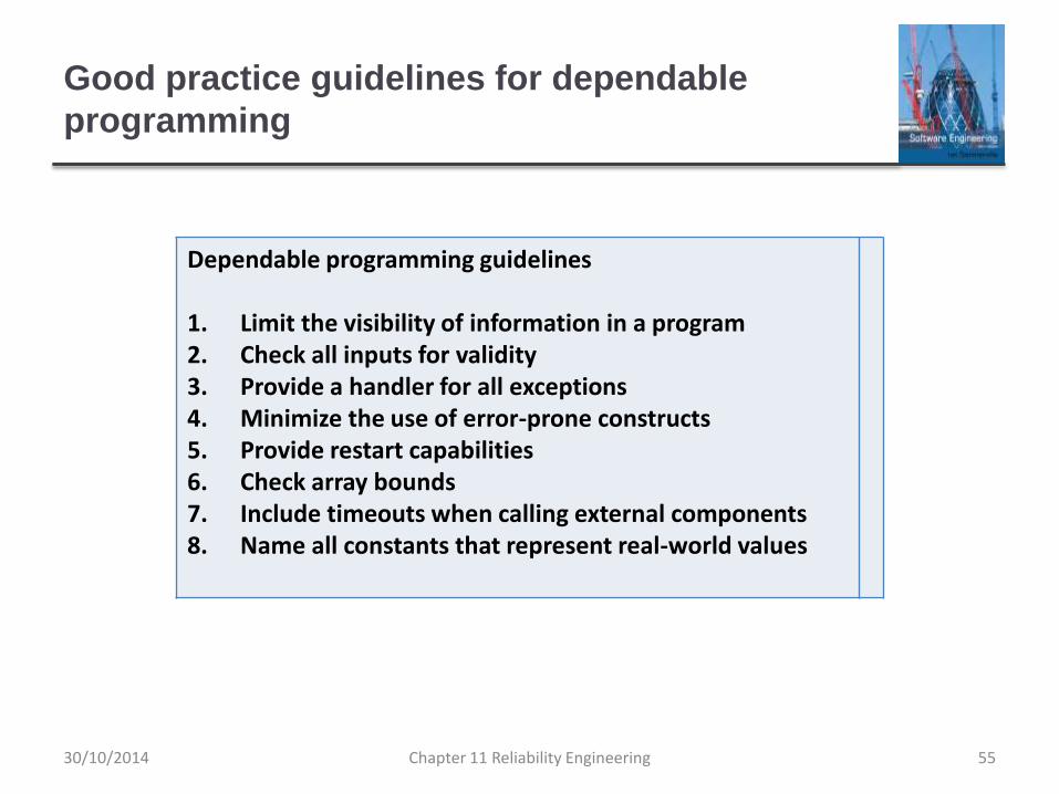
Good practice guidelines for dependable
programming
Chapter 11 Reliability Engineering 55
Dependable programming guidelines
1. Limit the visibility of information in a program2. Check all inputs for validity3. Provide a handler for all exceptions4. Minimize the use of error-prone constructs5. Provide restart capabilities6. Check array bounds7. Include timeouts when calling external components8. Name all constants that represent real-world values
30/10/2014

(1) Limit the visibility of information in a program
Program components should only be allowed access to
data that they need for their implementation.
This means that accidental corruption of parts of the
program state by these components is impossible.
You can control visibility by using abstract data types
where the data representation is private and you only
allow access to the data through predefined operations
such as get () and put ().
Chapter 11 Reliability Engineering 5630/10/2014

(2) Check all inputs for validity
All program take inputs from their environment and make
assumptions about these inputs.
However, program specifications rarely define what to do
if an input is not consistent with these assumptions.
Consequently, many programs behave unpredictably
when presented with unusual inputs and, sometimes,
these are threats to the security of the system.
Consequently, you should always check inputs before
processing against the assumptions made about these
inputs.
Chapter 11 Reliability Engineering 5730/10/2014

Validity checks
Range checks
Check that the input falls within a known range.
Size checks
Check that the input does not exceed some maximum size e.g.
40 characters for a name.
Representation checks
Check that the input does not include characters that should not
be part of its representation e.g. names do not include numerals.
Reasonableness checks
Use information about the input to check if it is reasonable rather
than an extreme value.
Chapter 11 Reliability Engineering 5830/10/2014

(3) Provide a handler for all exceptions
A program exception is an error or some
unexpected event such as a power failure.
Exception handling constructs allow for such
events to be handled without the need for
continual status checking to detect exceptions.
Using normal control constructs to detect
exceptions needs many additional statements to be
added to the program. This adds a significant
overhead and is potentially error-prone.
Chapter 11 Reliability Engineering 5930/10/2014

Exception handling
Chapter 11 Reliability Engineering 6030/10/2014

Exception handling
Three possible exception handling strategies
Signal to a calling component that an exception has occurred
and provide information about the type of exception.
Carry out some alternative processing to the processing where
the exception occurred. This is only possible where the
exception handler has enough information to recover from the
problem that has arisen.
Pass control to a run-time support system to handle the
exception.
Exception handling is a mechanism to provide some fault
tolerance
Chapter 11 Reliability Engineering 6130/10/2014

(4) Minimize the use of error-prone constructs
Program faults are usually a consequence of human
error because programmers lose track of the
relationships between the different parts of the system
This is exacerbated by error-prone constructs in
programming languages that are inherently complex or
that don’t check for mistakes when they could do so.
Therefore, when programming, you should try to avoid or
at least minimize the use of these error-prone constructs.
Chapter 11 Reliability Engineering 6230/10/2014

Error-prone constructs
Unconditional branch (goto) statements
Floating-point numbers
Inherently imprecise. The imprecision may lead to invalid comparisons.
Pointers
Pointers referring to the wrong memory areas can corrupt data. Aliasing can make programs difficult to understand and change.
Dynamic memory allocation
Run-time allocation can cause memory overflow.
Chapter 11 Reliability Engineering 6330/10/2014

Error-prone constructs
Parallelism
Can result in subtle timing errors because of unforeseen interaction between parallel processes.
Recursion
Errors in recursion can cause memory overflow as the program stack fills up.
Interrupts
Interrupts can cause a critical operation to be terminated and make a program difficult to understand.
Inheritance
Code is not localised. This can result in unexpected behaviour when changes are made and problems of understanding the code.
Chapter 11 Reliability Engineering 6430/10/2014

Error-prone constructs
Aliasing
Using more than 1 name to refer to the same state variable.
Unbounded arrays
Buffer overflow failures can occur if no bound checking on arrays.
Default input processing
An input action that occurs irrespective of the input.
This can cause problems if the default action is to transfer control elsewhere in the program. In incorrect or deliberately malicious input can then trigger a program failure.
Chapter 11 Reliability Engineering 6530/10/2014

(5) Provide restart capabilities
For systems that involve long transactions or user
interactions, you should always provide a restart
capability that allows the system to restart after failure
without users having to redo everything that they have
done.
Restart depends on the type of system
Keep copies of forms so that users don’t have to fill them in
again if there is a problem
Save state periodically and restart from the saved state
Chapter 11 Reliability Engineering 6630/10/2014

(6) Check array bounds
In some programming languages, such as C, it is
possible to address a memory location outside of the
range allowed for in an array declaration.
This leads to the well-known ‘bounded buffer’
vulnerability where attackers write executable code into
memory by deliberately writing beyond the top element
in an array.
If your language does not include bound checking, you
should therefore always check that an array access is
within the bounds of the array.
Chapter 11 Reliability Engineering 6730/10/2014

(7) Include timeouts when calling external
components
In a distributed system, failure of a remote computer can
be ‘silent’ so that programs expecting a service from that
computer may never receive that service or any
indication that there has been a failure.
To avoid this, you should always include timeouts on all
calls to external components.
After a defined time period has elapsed without a
response, your system should then assume failure and
take whatever actions are required to recover from this.
Chapter 11 Reliability Engineering 6830/10/2014

(8) Name all constants that represent real-world
values
Always give constants that reflect real-world values
(such as tax rates) names rather than using their
numeric values and always refer to them by name
You are less likely to make mistakes and type the wrong
value when you are using a name rather than a value.
This means that when these ‘constants’ change (for
sure, they are not really constant), then you only have to
make the change in one place in your program.
Chapter 11 Reliability Engineering 6930/10/2014

Reliability measurement
Chapter 11 Reliability Engineering 7030/10/2014

Reliability measurement
To assess the reliability of a system, you have to collect
data about its operation. The data required may include:
The number of system failures given a number of requests for
system services. This is used to measure the POFOD. This
applies irrespective of the time over which the demands are
made.
The time or the number of transactions between system failures
plus the total elapsed time or total number of transactions. This
is used to measure ROCOF and MTTF.
The repair or restart time after a system failure that leads to loss
of service. This is used in the measurement of availability.
Availability does not just depend on the time between failures but
also on the time required to get the system back into operation.
Chapter 11 Reliability Engineering 7130/10/2014

Reliability testing
Reliability testing (Statistical testing) involves running the
program to assess whether or not it has reached the
required level of reliability.
This cannot normally be included as part of a normal
defect testing process because data for defect testing is
(usually) atypical of actual usage data.
Reliability measurement therefore requires a specially
designed data set that replicates the pattern of inputs to
be processed by the system.
Chapter 11 Reliability Engineering 7230/10/2014

Statistical testing
Testing software for reliability rather than fault detection.
Measuring the number of errors allows the reliability of
the software to be predicted. Note that, for statistical
reasons, more errors than are allowed for in the reliability
specification must be induced.
An acceptable level of reliability should be
specified and the software tested and amended until that
level of reliability is reached.
Chapter 11 Reliability Engineering 7330/10/2014

Reliability measurement
Chapter 11 Reliability Engineering 7430/10/2014

Reliability measurement problems
Operational profile uncertainty
The operational profile may not be an accurate reflection of the real use of the system.
High costs of test data generation
Costs can be very high if the test data for the system cannot be generated automatically.
Statistical uncertainty
You need a statistically significant number of failures to compute the reliability but highly reliable systems will rarely fail.
Recognizing failure
It is not always obvious when a failure has occurred as there may be conflicting interpretations of a specification.
Chapter 11 Reliability Engineering 7530/10/2014

Operational profiles
An operational profile is a set of test data whose
frequency matches the actual frequency of these inputs
from ‘normal’ usage of the system. A close match with
actual usage is necessary otherwise the measured
reliability will not be reflected in the actual usage of the
system.
It can be generated from real data collected from an
existing system or (more often) depends on assumptions
made about the pattern of usage of a system.
Chapter 11 Reliability Engineering 7630/10/2014

An operational profile
Chapter 11 Reliability Engineering 7730/10/2014

Operational profile generation
Should be generated automatically whenever possible.
Automatic profile generation is difficult for interactive
systems.
May be straightforward for ‘normal’ inputs but it is difficult
to predict ‘unlikely’ inputs and to create test data for
them.
Pattern of usage of new systems is unknown.
Operational profiles are not static but change as users
learn about a new system and change the way that they
use it.
Chapter 11 Reliability Engineering 7830/10/2014

Key points
Software reliability can be achieved by avoiding the
introduction of faults, by detecting and removing faults
before system deployment and by including fault
tolerance facilities that allow the system to remain
operational after a fault has caused a system failure.
Reliability requirements can be defined quantitatively in
the system requirements specification.
Reliability metrics include probability of failure on
demand (POFOD), rate of occurrence of failure
(ROCOF) and availability (AVAIL).
79Chapter 11 Reliability Engineering30/10/2014

Key points
Functional reliability requirements are requirements for
system functionality, such as checking and redundancy
requirements, which help the system meet its non-
functional reliability requirements.
Dependable system architectures are system
architectures that are designed for fault tolerance.
There are a number of architectural styles that support
fault tolerance including protection systems, self-
monitoring architectures and N-version programming.
Chapter 11 Reliability Engineering 8030/10/2014

Key points
Software diversity is difficult to achieve because it is
practically impossible to ensure that each version of the
software is truly independent.
Dependable programming relies on including
redundancy in a program as checks on the validity of
inputs and the values of program variables.
Statistical testing is used to estimate software reliability.
It relies on testing the system with test data that matches
an operational profile, which reflects the distribution of
inputs to the software when it is in use.
Chapter 11 Reliability Engineering 8130/10/2014

Chapter 13 – Security Engineering
Chapter 13 Security Engineering 112/11/2014

Topics covered
Security and dependability
Security and organizations
Security requirements
Secure systems design
Security testing and assurance
Chapter 13 Security Engineering 212/11/2014

Security engineering
Tools, techniques and methods to support the
development and maintenance of systems that can resist
malicious attacks that are intended to damage a
computer-based system or its data.
A sub-field of the broader field of computer security.
Chapter 13 Security Engineering 312/11/2014

Security dimensions
Confidentiality
Information in a system may be disclosed or made accessible to
people or programs that are not authorized to have access to
that information.
Integrity
Information in a system may be damaged or corrupted making it
unusual or unreliable.
Availability
Access to a system or its data that is normally available may not
be possible.
12/11/2014 Chapter 13 Security Engineering 4

Security levels
Infrastructure security, which is concerned with
maintaining the security of all systems and networks that
provide an infrastructure and a set of shared services to
the organization.
Application security, which is concerned with the security
of individual application systems or related groups of
systems.
Operational security, which is concerned with the secure
operation and use of the organization’s systems.
12/11/2014 Chapter 13 Security Engineering 5

System layers where security may be
compromised
Chapter 13 Security Engineering 612/11/2014

Application/infrastructure security
Application security is a software engineering problem
where the system is designed to resist attacks.
Infrastructure security is a systems management
problem where the infrastructure is configured to resist
attacks.
The focus of this chapter is application security rather
than infrastructure security.
Chapter 13 Security Engineering 712/11/2014

System security management
User and permission management
Adding and removing users from the system and setting up
appropriate permissions for users
Software deployment and maintenance
Installing application software and middleware and configuring
these systems so that vulnerabilities are avoided.
Attack monitoring, detection and recovery
Monitoring the system for unauthorized access, design
strategies for resisting attacks and develop backup and recovery
strategies.
Chapter 13 Security Engineering 812/11/2014

Operational security
Primarily a human and social issue
Concerned with ensuring the people do not take actions
that may compromise system security
E.g. Tell others passwords, leave computers logged on
Users sometimes take insecure actions to make it easier
for them to do their jobs
There is therefore a trade-off between system security
and system effectiveness.
12/11/2014 Chapter 13 Security Engineering 9

Security and dependability
12/11/2014 Chapter 13 Security Engineering 10

Security
The security of a system is a system property that reflects the system’s ability to protect itself from accidental or deliberate external attack.
Security is essential as most systems are networked so that external access to the system through the Internet is possible.
Security is an essential pre-requisite for availability, reliability and safety.
11Chapter 13 Security Engineering12/11/2014

Fundamental security
If a system is a networked system and is insecure then
statements about its reliability and its safety are
unreliable.
These statements depend on the executing system and
the developed system being the same. However,
intrusion can change the executing system and/or its
data.
Therefore, the reliability and safety assurance is no
longer valid.
12Chapter 13 Security Engineering12/11/2014

Security terminology
Term Definition
Asset Something of value which has to be protected. The asset may be the software
system itself or data used by that system.
Attack An exploitation of a system’s vulnerability. Generally, this is from outside the
system and is a deliberate attempt to cause some damage.
Control A protective measure that reduces a system’s vulnerability. Encryption is an
example of a control that reduces a vulnerability of a weak access control
system
Exposure Possible loss or harm to a computing system. This can be loss or damage to
data, or can be a loss of time and effort if recovery is necessary after a security
breach.
Threat Circumstances that have potential to cause loss or harm. You can think of these
as a system vulnerability that is subjected to an attack.
Vulnerability A weakness in a computer-based system that may be exploited to cause loss or
harm.
13Chapter 13 Security Engineering12/11/2014

Examples of security terminology (Mentcare)
Term Example
Asset The records of each patient that is receiving or has received treatment.
Exposure Potential financial loss from future patients who do not seek treatment
because they do not trust the clinic to maintain their data. Financial loss
from legal action by the sports star. Loss of reputation.
Vulnerability A weak password system which makes it easy for users to set
guessable passwords. User ids that are the same as names.
Attack An impersonation of an authorized user.
Threat An unauthorized user will gain access to the system by guessing the
credentials (login name and password) of an authorized user.
Control A password checking system that disallows user passwords that are
proper names or words that are normally included in a dictionary.
14Chapter 13 Security Engineering12/11/2014

Threat types
Interception threats that allow an attacker to gain access
to an asset.
A possible threat to the Mentcare system might be a situation
where an attacker gains access to the records of an individual
patient.
Interruption threats that allow an attacker to make part of
the system unavailable.
A possible threat might be a denial of service attack on a system
database server so that database connections become
impossible.
Chapter 13 Security Engineering 1512/11/2014

Threat types
Modification threats that allow an attacker to tamper with
a system asset.
In the Mentcare system, a modification threat would be where an
attacker alters or destroys a patient record.
Fabrication threats that allow an attacker to insert false
information into a system.
This is perhaps not a credible threat in the Mentcare system but
would be a threat in a banking system, where false transactions
might be added to the system that transfer money to the
perpetrator’s bank account.
12/11/2014 Chapter 13 Security Engineering 16

Security assurance
Vulnerability avoidance
The system is designed so that vulnerabilities do not occur. For example, if there is no external network connection then external attack is impossible
Attack detection and elimination
The system is designed so that attacks on vulnerabilities are detected and neutralised before they result in an exposure. For example, virus checkers find and remove viruses before they infect a system
Exposure limitation and recovery
The system is designed so that the adverse consequences of a successful attack are minimised. For example, a backup policy allows damaged information to be restored
17Chapter 13 Security Engineering12/11/2014

Security and dependability
Security and reliability
If a system is attacked and the system or its data are corrupted
as a consequence of that attack, then this may induce system
failures that compromise the reliability of the system.
Security and availability
A common attack on a web-based system is a denial of service
attack, where a web server is flooded with service requests from
a range of different sources. The aim of this attack is to make the
system unavailable.
12/11/2014 Chapter 13 Security Engineering 18

Security and dependability
Security and safety
An attack that corrupts the system or its data means that
assumptions about safety may not hold. Safety checks rely on
analysing the source code of safety critical software and assume
the executing code is a completely accurate translation of that
source code. If this is not the case, safety-related failures may be
induced and the safety case made for the software is invalid.
Security and resilience
Resilience is a system characteristic that reflects its ability to
resist and recover from damaging events. The most probable
damaging event on networked software systems is a cyberattack
of some kind so most of the work now done in resilience is
aimed at deterring, detecting and recovering from such attacks.
12/11/2014 Chapter 13 Security Engineering 19

Security and organizations
12/11/2014 Chapter 13 Security Engineering 20

Security is a business issue
Security is expensive and it is important that security
decisions are made in a cost-effective way
There is no point in spending more than the value of an asset to
keep that asset secure.
Organizations use a risk-based approach to support
security decision making and should have a defined
security policy based on security risk analysis
Security risk analysis is a business rather than a
technical process
12/11/2014 Chapter 13 Security Engineering 21

Organizational security policies
Security policies should set out general information
access strategies that should apply across the
organization.
The point of security policies is to inform everyone in an
organization about security so these should not be long
and detailed technical documents.
From a security engineering perspective, the security
policy defines, in broad terms, the security goals of the
organization.
The security engineering process is concerned with
implementing these goals.
12/11/2014 Chapter 13 Security Engineering 22

Security policies
The assets that must be protected
It is not cost-effective to apply stringent security procedures to all
organizational assets. Many assets are not confidential and can
be made freely available.
The level of protection that is required for different types
of asset
For sensitive personal information, a high level of security is
required; for other information, the consequences of loss may be
minor so a lower level of security is adequate.
12/11/2014 Chapter 13 Security Engineering 23

Security policies
The responsibilities of individual users, managers and
the organization
The security policy should set out what is expected of users e.g.
strong passwords, log out of computers, office security, etc.
Existing security procedures and technologies that
should be maintained
For reasons of practicality and cost, it may be essential to
continue to use existing approaches to security even where
these have known limitations.
12/11/2014 Chapter 13 Security Engineering 24

Security risk assessment and management
Risk assessment and management is concerned with
assessing the possible losses that might ensue from
attacks on the system and balancing these losses
against the costs of security procedures that may reduce
these losses.
Risk management should be driven by an organisational
security policy.
Risk management involves
Preliminary risk assessment
Life cycle risk assessment
Operational risk assessment
Chapter 13 Security Engineering 2512/11/2014

Preliminary risk assessment
The aim of this initial risk assessment is to identify
generic risks that are applicable to the system and to
decide if an adequate level of security can be achieved
at a reasonable cost.
The risk assessment should focus on the identification
and analysis of high-level risks to the system.
The outcomes of the risk assessment process are used
to help identify security requirements.
12/11/2014 Chapter 13 Security Engineering 26
Design risk assessment
This risk assessment takes place during the system
development life cycle and is informed by the technical
system design and implementation decisions.
The results of the assessment may lead to changes to
the security requirements and the addition of new
requirements.
Known and potential vulnerabilities are identified, and
this knowledge is used to inform decision making about
the system functionality and how it is to be implemented,
tested, and deployed.
12/11/2014 Chapter 13 Security Engineering 27

Operational risk assessment
This risk assessment process focuses on the use of the
system and the possible risks that can arise from human
behavior.
Operational risk assessment should continue after a
system has been installed to take account of how the
system is used.
Organizational changes may mean that the system is
used in different ways from those originally planned.
These changes lead to new security requirements that
have to be implemented as the system evolves.
12/11/2014 Chapter 13 Security Engineering 28

Security requirements
12/11/2014 Chapter 13 Security Engineering 29

Security specification
Security specification has something in common with safety
requirements specification – in both cases, your concern is to avoid
something bad happening.
Four major differences
Safety problems are accidental – the software is not operating in a
hostile environment. In security, you must assume that attackers have
knowledge of system weaknesses
When safety failures occur, you can look for the root cause or weakness
that led to the failure. When failure results from a deliberate attack, the
attacker may conceal the cause of the failure.
Shutting down a system can avoid a safety-related failure. Causing a
shut down may be the aim of an attack.
Safety-related events are not generated from an intelligent adversary.
An attacker can probe defenses over time to discover weaknesses.
30Chapter 13 Security Engineering12/11/2014

Types of security requirement
Identification requirements.
Authentication requirements.
Authorisation requirements.
Immunity requirements.
Integrity requirements.
Intrusion detection requirements.
Non-repudiation requirements.
Privacy requirements.
Security auditing requirements.
System maintenance security requirements.31Chapter 13 Security Engineering12/11/2014

Security requirement classification
Risk avoidance requirements set out the risks that
should be avoided by designing the system so that these
risks simply cannot arise.
Risk detection requirements define mechanisms that
identify the risk if it arises and neutralise the risk before
losses occur.
Risk mitigation requirements set out how the system
should be designed so that it can recover from and
restore system assets after some loss has occurred.
12/11/2014 Chapter 13 Security Engineering 32

The preliminary risk assessment process for
security requirements
33Chapter 13 Security Engineering12/11/2014

Security risk assessment
Asset identification
Identify the key system assets (or services) that have to be
protected.
Asset value assessment
Estimate the value of the identified assets.
Exposure assessment
Assess the potential losses associated with each asset.
Threat identification
Identify the most probable threats to the system assets
34Chapter 13 Security Engineering12/11/2014

Security risk assessment
Attack assessment
Decompose threats into possible attacks on the system and the
ways that these may occur.
Control identification
Propose the controls that may be put in place to protect an
asset.
Feasibility assessment
Assess the technical feasibility and cost of the controls.
Security requirements definition
Define system security requirements. These can be
infrastructure or application system requirements.
35Chapter 13 Security Engineering12/11/2014

Asset analysis in a preliminary risk assessment
report for the Mentcare system
Asset Value Exposure
The information system High. Required to support all
clinical consultations. Potentially
safety-critical.
High. Financial loss as clinics
may have to be canceled. Costs
of restoring system. Possible
patient harm if treatment cannot
be prescribed.
The patient database High. Required to support all
clinical consultations. Potentially
safety-critical.
High. Financial loss as clinics
may have to be canceled. Costs
of restoring system. Possible
patient harm if treatment cannot
be prescribed.
An individual patient record Normally low although may be
high for specific high-profile
patients.
Low direct losses but possible
loss of reputation.
36Chapter 13 Security Engineering12/11/2014

Threat and control analysis in a preliminary risk
assessment report
Threat Probability Control Feasibility
An unauthorized user
gains access as
system manager and
makes system
unavailable
Low Only allow system
management from
specific locations that are
physically secure.
Low cost of implementation but
care must be taken with key
distribution and to ensure that
keys are available in the event
of an emergency.
An unauthorized user
gains access as
system user and
accesses confidential
information
High Require all users to
authenticate themselves
using a biometric
mechanism.
Log all changes to
patient information to
track system usage.
Technically feasible but high-
cost solution. Possible user
resistance.
Simple and transparent to
implement and also supports
recovery.
37Chapter 13 Security Engineering12/11/2014

Security requirements for the Mentcare system
Patient information shall be downloaded at the start of a
clinic session to a secure area on the system client that
is used by clinical staff.
All patient information on the system client shall be
encrypted.
Patient information shall be uploaded to the database
after a clinic session has finished and deleted from the
client computer.
A log on a separate computer from the database server
must be maintained of all changes made to the system
database.
38Chapter 13 Security Engineering12/11/2014

Misuse cases
Misuse cases are instances of threats to a system
Interception threats
Attacker gains access to an asset
Interruption threats
Attacker makes part of a system unavailable
Modification threats
A system asset if tampered with
Fabrication threats
False information is added to a system
Chapter 13 Security Engineering 3912/11/2014

Misuse cases
12/11/2014 Chapter 13 Security Engineering 40

Mentcare use case – Transfer data
12/11/2014 Chapter 13 Security Engineering 41
Mentcare system: Transfer data
Actors Medical receptionist, Patient records system (PRS)
Description A receptionist may transfer data from the Mentcare system to a
general patient record database that is maintained by a health
authority. The information transferred may either be updated
personal information (address, phone number, etc.) or a
summary of the patient’s diagnosis and treatment.
Data Patient’s personal information, treatment summary.
Stimulus User command issued by medical receptionist.
Response Confirmation that PRS has been updated.
Comments The receptionist must have appropriate security permissions to
access the patient information and the PRS.

Mentcare misuse case: Intercept transfer
Mentcare system: Intercept transfer (Misuse case)
Actors Medical receptionist, Patient records system (PRS), Attacker
Description A receptionist transfers data from his or her PC to the Mentcare
system on the server. An attacker intercepts the data transfer and
takes a copy of that data.
Data
(assets)
Patient’s personal information, treatment summary
Attacks A network monitor is added to the system and packets from the
receptionist to the server are intercepted.
A spoof server is set up between the receptionist and the
database server so that receptionist believes they are interacting
with the real system.
12/11/2014 Chapter 13 Security Engineering 42

Misuse case: Intercept transfer
12/11/2014 Chapter 13 Security Engineering 43
Mentcare system: Intercept transfer (Misuse case)
Mitigations All networking equipment must be maintained in a locked
room. Engineers accessing the equipment must be
accredited.
All data transfers between the client and server must be
encrypted.
Certificate-based client-server communication must be
used
Requirements All communications between the client and the server
must use the Secure Socket Layer (SSL). The https
protocol uses certificate based authentication and
encryption.

Secure systems design
12/11/2014 Chapter 13 Security Engineering 44

Secure systems design
Security should be designed into a system – it is very
difficult to make an insecure system secure after it has
been designed or implemented
Architectural design
how do architectural design decisions affect the security of a
system?
Good practice
what is accepted good practice when designing secure systems?
Chapter 13 Security Engineering 4512/11/2014

Design compromises
Adding security features to a system to enhance its
security affects other attributes of the system
Performance
Additional security checks slow down a system so its response
time or throughput may be affected
Usability
Security measures may require users to remember information
or require additional interactions to complete a transaction. This
makes the system less usable and can frustrate system users.
12/11/2014 Chapter 13 Security Engineering 46

Design risk assessment
Risk assessment while the system is being developed
and after it has been deployed
More information is available - system platform,
middleware and the system architecture and data
organisation.
Vulnerabilities that arise from design choices may
therefore be identified.
Chapter 13 Security Engineering 4712/11/2014

Design and risk assessment
Chapter 13 Security Engineering 4812/11/2014
Protection requirements
Protection requirements may be generated when
knowledge of information representation and system
distribution
Separating patient and treatment information limits the
amount of information (personal patient data) that needs
to be protected
Maintaining copies of records on a local client protects
against denial of service attacks on the server
But these may need to be encrypted
12/11/2014 Chapter 13 Security Engineering 49

Design risk assessment
12/11/2014 Chapter 13 Security Engineering 50

Design decisions from use of COTS
System users authenticated using a name/password
combination.
The system architecture is client-server with clients
accessing the system through a standard web browser.
Information is presented as an editable web form.
Chapter 13 Security Engineering 5112/11/2014

Vulnerabilities associated with technology
choices
Chapter 13 Security Engineering 5212/11/2014

Security requirements
A password checker shall be made available and shall
be run daily. Weak passwords shall be reported to
system administrators.
Access to the system shall only be allowed by approved
client computers.
All client computers shall have a single, approved web
browser installed by system administrators.
Chapter 13 Security Engineering 5312/11/2014

Architectural design
Two fundamental issues have to be considered when
designing an architecture for security.
Protection
• How should the system be organised so that critical assets can be
protected against external attack?
Distribution
• How should system assets be distributed so that the effects of a
successful attack are minimized?
These are potentially conflicting
If assets are distributed, then they are more expensive to protect.
If assets are protected, then usability and performance
requirements may be compromised.
Chapter 13 Security Engineering 5412/11/2014
Protection
Platform-level protection
Top-level controls on the platform on which a system runs.
Application-level protection
Specific protection mechanisms built into the application itself
e.g. additional password protection.
Record-level protection
Protection that is invoked when access to specific information is
requested
These lead to a layered protection architecture
Chapter 13 Security Engineering 5512/11/2014

A layered protection architecture
Chapter 13 Security Engineering 5612/11/2014

Distribution
Distributing assets means that attacks on one system do
not necessarily lead to complete loss of system service
Each platform has separate protection features and may
be different from other platforms so that they do not
share a common vulnerability
Distribution is particularly important if the risk of denial of
service attacks is high
Chapter 13 Security Engineering 5712/11/2014

Distributed
assets in an
equity
trading
systemChapter 13 Security Engineering 5812/11/2014

Design guidelines for security engineering
Design guidelines encapsulate good practice in secure
systems design
Design guidelines serve two purposes:
They raise awareness of security issues in a software
engineering team. Security is considered when design decisions
are made.
They can be used as the basis of a review checklist that is
applied during the system validation process.
Design guidelines here are applicable during software
specification and design
Chapter 13 Security Engineering 5912/11/2014

Design guidelines for secure systems
engineering
Security guidelines
Base security decisions on an explicit security policy
Avoid a single point of failure
Fail securely
Balance security and usability
Log user actions
Use redundancy and diversity to reduce risk
Specify the format of all system inputs
Compartmentalize your assets
Design for deployment
Design for recoverability
Chapter 13 Security Engineering 6012/11/2014

Design guidelines 1-3
Base decisions on an explicit security policy
Define a security policy for the organization that sets out the
fundamental security requirements that should apply to all
organizational systems.
Avoid a single point of failure
Ensure that a security failure can only result when there is more
than one failure in security procedures. For example, have
password and question-based authentication.
Fail securely
When systems fail, for whatever reason, ensure that sensitive
information cannot be accessed by unauthorized users even
although normal security procedures are unavailable.
Chapter 13 Security Engineering 6112/11/2014

Design guidelines 4-6
Balance security and usability
Try to avoid security procedures that make the system difficult to
use. Sometimes you have to accept weaker security to make the
system more usable.
Log user actions
Maintain a log of user actions that can be analyzed to discover
who did what. If users know about such a log, they are less likely
to behave in an irresponsible way.
Use redundancy and diversity to reduce risk
Keep multiple copies of data and use diverse infrastructure so
that an infrastructure vulnerability cannot be the single point of
failure.
Chapter 13 Security Engineering 6212/11/2014

Design guidelines 7-10
Specify the format of all system inputs
If input formats are known then you can check that all inputs are
within range so that unexpected inputs don’t cause problems.
Compartmentalize your assets
Organize the system so that assets are in separate areas and
users only have access to the information that they need rather
than all system information.
Design for deployment
Design the system to avoid deployment problems
Design for recoverability
Design the system to simplify recoverability after a successful
attack.
Chapter 13 Security Engineering 6312/11/2014

Secure systems programming
12/11/2014 Chapter 13 Security Engineering 64

Aspects of secure systems programming
Vulnerabilities are often language-specific.
Array bound checking is automatic in languages like Java so this
is not a vulnerability that can be exploited in Java programs.
However, millions of programs are written in C and C++ as these
allow for the development of more efficient software so simply
avoiding the use of these languages is not a realistic option.
Security vulnerabilities are closely related to program
reliability.
Programs without array bound checking can crash so actions
taken to improve program reliability can also improve system
security.
12/11/2014 Chapter 13 Security Engineering 65

Dependable programming guidelines
12/11/2014 Chapter 13 Security Engineering 66
Dependable programming guidelines
1. Limit the visibility of information in a program2. Check all inputs for validity3. Provide a handler for all exceptions4. Minimize the use of error-prone constructs5. Provide restart capabilities6. Check array bounds7. Include timeouts when calling external components8. Name all constants that represent real-world values

Security testing and assurance
12/11/2014 Chapter 13 Security Engineering 67

Security testing
Testing the extent to which the system can protect itself from external attacks.
Problems with security testing
Security requirements are ‘shall not’ requirements i.e. they specify what should not happen. It is not usually possible to define security requirements as simple constraints that can be checked by the system.
The people attacking a system are intelligent and look for vulnerabilities. They can experiment to discover weaknesses and loopholes in the system.
68Chapter 13 Security Engineering12/11/2014

Security validation
Experience-based testing
The system is reviewed and analysed against the types of attack that are known to the validation team.
Penetration testing
A team is established whose goal is to breach the security of the system by simulating attacks on the system.
Tool-based analysis
Various security tools such as password checkers are used to analyse the system in operation.
Formal verification
The system is verified against a formal security specification.
69Chapter 13 Security Engineering12/11/2014

Examples of entries in a security checklist
Security checklist
1. Do all files that are created in the application have appropriate access permissions?
The wrong access permissions may lead to these files being accessed by unauthorized
users.
2. Does the system automatically terminate user sessions after a period of inactivity?
Sessions that are left active may allow unauthorized access through an unattended
computer.
3. If the system is written in a programming language without array bound checking, are
there situations where buffer overflow may be exploited? Buffer overflow may allow
attackers to send code strings to the system and then execute them.
4. If passwords are set, does the system check that passwords are ‘strong’? Strong
passwords consist of mixed letters, numbers, and punctuation, and are not normal
dictionary entries. They are more difficult to break than simple passwords.
5. Are inputs from the system’s environment always checked against an input
specification? Incorrect processing of badly formed inputs is a common cause of
security vulnerabilities.
70Chapter 13 Security Engineering12/11/2014

Key points
Security engineering is concerned with how to develop
systems that can resist malicious attacks
Security threats can be threats to confidentiality, integrity
or availability of a system or its data
Security risk management is concerned with assessing
possible losses from attacks and deriving security
requirements to minimise losses
To specify security requirements, you should identify the
assets that are to be protected and define how security
techniques and technology should be used to protect
these assets.
Chapter 13 Security Engineering 7112/11/2014

Key points
Key issues when designing a secure systems
architecture include organizing the system structure to
protect key assets and distributing the system assets to
minimize the losses from a successful attack.
Security design guidelines sensitize system designers to
security issues that they may not have considered. They
provide a basis for creating security review checklists.
Security validation is difficult because security
requirements state what should not happen in a system,
rather than what should. Furthermore, system attackers
are intelligent and may have more time to probe for
weaknesses than is available for security testing.Chapter 13 Security Engineering 7212/11/2014

Chapter 22 – Project Management
04/12/2014 Chapter 22 Project management 1

Topics covered
Risk management
Managing people
Teamwork
04/12/2014 Chapter 22 Project management 2

Software project management
Concerned with activities involved in ensuring
that software is delivered on time and on
schedule and in accordance with the
requirements of the organisations developing
and procuring the software.
Project management is needed because software
development is always subject to budget and schedule
constraints that are set by the organisation developing
the software.
04/12/2014 Chapter 22 Project management 3

Success criteria
Deliver the software to the customer at the agreed time.
Keep overall costs within budget.
Deliver software that meets the customer’s expectations.
Maintain a coherent and well-functioning development
team.
04/12/2014 Chapter 22 Project management 4

Software management distinctions
The product is intangible.
▪ Software cannot be seen or touched. Software project managers
cannot see progress by simply looking at the artefact that is
being constructed.
Many software projects are 'one-off' projects.
▪ Large software projects are usually different in some ways from
previous projects. Even managers who have lots of previous
experience may find it difficult to anticipate problems.
Software processes are variable and organization
specific.
▪ We still cannot reliably predict when a particular software
process is likely to lead to development problems.
04/12/2014 Chapter 22 Project management 5

Factors influencing project management
Company size
Software customers
Software size
Software type
Organizational culture
Software development processes
These factors mean that project managers in different
organizations may work in quite different ways.
04/12/2014 Chapter 22 Project management 6

Universal management activities
Project planning
▪ Project managers are responsible for planning. estimating and
scheduling project development and assigning people to tasks.
▪ Covered in Chapter 23.
Risk management
▪ Project managers assess the risks that may affect a project,
monitor these risks and take action when problems arise.
People management
▪ Project managers have to choose people for their team and
establish ways of working that leads to effective team
performance.
04/12/2014 Chapter 22 Project management 7
Management activities
Reporting
▪ Project managers are usually responsible for reporting on the
progress of a project to customers and to the managers of the
company developing the software.
Proposal writing
▪ The first stage in a software project may involve writing a
proposal to win a contract to carry out an item of work. The
proposal describes the objectives of the project and how it will be
carried out.
04/12/2014 Chapter 22 Project management 8

Risk management
04/12/2014 Chapter 22 Project management 9

Risk management
Risk management is concerned with identifying risks and drawing up plans to minimise their effect on a project.
Software risk management is important because of the inherent uncertainties in software development.
▪ These uncertainties stem from loosely defined requirements, requirements changes due to changes in customer needs, difficulties in estimating the time and resources required for software development, and differences in individual skills.
You have to anticipate risks, understand the impact of these risks on the project, the product and the business, and take steps to avoid these risks.
04/12/2014 Chapter 22 Project management 10
Risk classification
There are two dimensions of risk classification
▪ The type of risk (technical, organizational, ..)
▪ what is affected by the risk:
Project risks affect schedule or resources;
Product risks affect the quality or performance of the software being developed;
Business risks affect the organisation developing or procuring the software.
04/12/2014 Chapter 22 Project management 11

Examples of project, product, and business risks
Risk Affects Description
Staff turnover Project Experienced staff will leave the project before it is
finished.
Management change Project There will be a change of organizational
management with different priorities.
Hardware unavailability Project Hardware that is essential for the project will not
be delivered on schedule.
Requirements change Project and product There will be a larger number of changes to the
requirements than anticipated.
Specification delays Project and product Specifications of essential interfaces are not
available on schedule.
Size underestimate Project and product The size of the system has been underestimated.
CASE tool
underperformance
Product CASE tools, which support the project, do not
perform as anticipated.
Technology change Business The underlying technology on which the system
is built is superseded by new technology.
Product competition Business A competitive product is marketed before the
system is completed.
04/12/2014 Chapter 22 Project management 12

The risk management process
Risk identification
▪ Identify project, product and business risks;
Risk analysis
▪ Assess the likelihood and consequences of these risks;
Risk planning
▪ Draw up plans to avoid or minimise the effects of the risk;
Risk monitoring
▪ Monitor the risks throughout the project;
04/12/2014 Chapter 22 Project management 13

The risk management process
04/12/2014 Chapter 22 Project management 14

Risk identification
May be a team activities or based on the individual
project manager’s experience.
A checklist of common risks may be used to identify risks
in a project
▪ Technology risks.
▪ Organizational risks.
▪ People risks.
▪ Requirements risks.
▪ Estimation risks.
04/12/2014 Chapter 22 Project management 15

Examples of different risk types
Risk type Possible risks
Estimation The time required to develop the software is underestimated. (12)
The rate of defect repair is underestimated. (13)
The size of the software is underestimated. (14)
Organizational The organization is restructured so that different management are responsible for
the project. (6)
Organizational financial problems force reductions in the project budget. (7)
People It is impossible to recruit staff with the skills required. (3)
Key staff are ill and unavailable at critical times. (4)
Required training for staff is not available. (5)
Requirements Changes to requirements that require major design rework are proposed. (10)
Customers fail to understand the impact of requirements changes. (11)
Technology The database used in the system cannot process as many transactions per
second as expected. (1)
Reusable software components contain defects that mean they cannot be reused
as planned. (2)
Tools The code generated by software code generation tools is inefficient. (8)
Software tools cannot work together in an integrated way. (9)
04/12/2014 Chapter 22 Project management 16

Risk analysis
Assess probability and seriousness of each risk.
Probability may be very low, low, moderate, high or very
high.
Risk consequences might be catastrophic, serious,
tolerable or insignificant.
04/12/2014 Chapter 22 Project management 17

Risk types and examples
Risk Probability Effects
Organizational financial problems force reductions in the
project budget (7).
Low Catastrophic
It is impossible to recruit staff with the skills required for the
project (3).
High Catastrophic
Key staff are ill at critical times in the project (4). Moderate Serious
Faults in reusable software components have to be repaired
before these components are reused. (2).
Moderate Serious
Changes to requirements that require major design rework
are proposed (10).
Moderate Serious
The organization is restructured so that different
management are responsible for the project (6).
High Serious
The database used in the system cannot process as many
transactions per second as expected (1).
Moderate Serious
04/12/2014 Chapter 22 Project management 18

Risk types and examples
Risk Probability Effects
The time required to develop the software is
underestimated (12).
High Serious
Software tools cannot be integrated (9). High Tolerable
Customers fail to understand the impact of requirements
changes (11).
Moderate Tolerable
Required training for staff is not available (5). Moderate Tolerable
The rate of defect repair is underestimated (13). Moderate Tolerable
The size of the software is underestimated (14). High Tolerable
Code generated by code generation tools is inefficient (8). Moderate Insignificant
04/12/2014 Chapter 22 Project management 19

Risk planning
Consider each risk and develop a strategy to manage that risk.
Avoidance strategies
▪ The probability that the risk will arise is reduced;
Minimization strategies
▪ The impact of the risk on the project or product will be reduced;
Contingency plans
▪ If the risk arises, contingency plans are plans to deal with that risk;
04/12/2014 Chapter 22 Project management 20
What-if questions
What if several engineers are ill at the same time?
What if an economic downturn leads to budget cuts of
20% for the project?
What if the performance of open-source software is
inadequate and the only expert on that open source
software leaves?
What if the company that supplies and maintains
software components goes out of business?
What if the customer fails to deliver the revised
requirements as predicted?
04/12/2014 Chapter 22 Project management 21

Strategies to help manage risk
Risk Strategy
Organizational financial
problems
Prepare a briefing document for senior management
showing how the project is making a very important
contribution to the goals of the business and presenting
reasons why cuts to the project budget would not be cost-
effective.
Recruitment problems Alert customer to potential difficulties and the possibility of
delays; investigate buying-in components.
Staff illness Reorganize team so that there is more overlap of work and
people therefore understand each other’s jobs.
Defective components Replace potentially defective components with bought-in
components of known reliability.
Requirements changes Derive traceability information to assess requirements
change impact; maximize information hiding in the design.
04/12/2014 Chapter 22 Project management 22

Strategies to help manage risk
Risk Strategy
Organizational
restructuring
Prepare a briefing document for senior management
showing how the project is making a very important
contribution to the goals of the business.
Database
performance
Investigate the possibility of buying a higher-performance
database.
Underestimated
development time
Investigate buying-in components; investigate use of a
program generator.
04/12/2014 Chapter 22 Project management 23

Risk monitoring
Assess each identified risks regularly to decide whether
or not it is becoming less or more probable.
Also assess whether the effects of the risk have
changed.
Each key risk should be discussed at management
progress meetings.
04/12/2014 Chapter 22 Project management 24

Risk indicators
Risk type Potential indicators
Estimation Failure to meet agreed schedule; failure to clear reported defects.
Organizational Organizational gossip; lack of action by senior management.
People Poor staff morale; poor relationships amongst team members; high staff
turnover.
Requirements Many requirements change requests; customer complaints.
Technology Late delivery of hardware or support software; many reported
technology problems.
Tools Reluctance by team members to use tools; complaints about CASE
tools; demands for higher-powered workstations.
04/12/2014 Chapter 22 Project management 25

Managing people
04/12/2014 Chapter 22 Project management 26

Managing people
People are an organisation’s most important assets.
The tasks of a manager are essentially people-oriented.
Unless there is some understanding of people,
management will be unsuccessful.
Poor people management is an important contributor to
project failure.
04/12/2014 Chapter 22 Project management 27

People management factors
Consistency
▪ Team members should all be treated in a comparable way without favourites or discrimination.
Respect
▪ Different team members have different skills and these differences should be respected.
Inclusion
▪ Involve all team members and make sure that people’s views are considered.
Honesty
▪ You should always be honest about what is going well and what is going badly in a project.
04/12/2014 Chapter 22 Project management 28

Motivating people
An important role of a manager is to motivate the people working on a project.
Motivation means organizing the work and the working environment to encourage people to work effectively.
▪ If people are not motivated, they will not be interested in the work they are doing. They will work slowly, be more likely to make mistakes and will not contribute to the broader goals of the team or the organization.
Motivation is a complex issue but it appears that their are different types of motivation based on:
▪ Basic needs (e.g. food, sleep, etc.);
▪ Personal needs (e.g. respect, self-esteem);
▪ Social needs (e.g. to be accepted as part of a group).
04/12/2014 Chapter 22 Project management 29

Human needs hierarchy
04/12/2014 Chapter 22 Project management 30

Need satisfaction
In software development groups, basic physiological and safety needs are not an issue.
Social
▪ Provide communal facilities;
▪ Allow informal communications e.g. via social networking
Esteem
▪ Recognition of achievements;
▪ Appropriate rewards.
Self-realization
▪ Training - people want to learn more;
▪ Responsibility.
04/12/2014 Chapter 22 Project management 31

Case study: Individual motivation
04/12/2014 Chapter 22 Project management 32
Alice is a software project manager working in a company that develops alarm systems.
This company wishes to enter the growing market of assistive technology to help elderly and
disabled people live independently. Alice has been asked to lead a team of 6 developers
than can develop new products based around the company’s alarm technology.
Alice’s assistive technology project starts well. Good working relationships develop within
the team and creative new ideas are developed. The team decides to develop a peer-to-
peer messaging system using digital televisions linked to the alarm network for
communications. However, some months into the project, Alice notices that Dorothy, a
hardware design expert, starts coming into work late, the quality of her work deteriorates
and, increasingly, that she does not appear to be communicating with other members of the
team.
Alice talks about the problem informally with other team members to try to find out if
Dorothy’s personal circumstances have changed, and if this might be affecting her work.
They don’t know of anything, so Alice decides to talk with Dorothy to try to understand the
problem.

Case study: Individual motivation
04/12/2014 Chapter 22 Project management 33
After some initial denials that there is a problem, Dorothy admits that she has lost
interest in the job. She expected that she would be able to develop and use her
hardware interfacing skills. However, because of the product direction that has been
chosen, she has little opportunity for this. Basically, she is working as a C programmer
with other team members.
Although she admits that the work is challenging, she is concerned that she is not
developing her interfacing skills. She is worried that finding a job that involves
hardware interfacing will be difficult after this project. Because she does not want to
upset the team by revealing that she is thinking about the next project, she has
decided that it is best to minimize conversation with them.

Comments on case study
If you don’t sort out the problem of unacceptable work,
the other group members will become dissatisfied and
feel that they are doing an unfair share of the work.
Personal difficulties affect motivation because people
can’t concentrate on their work. They need time and
support to resolve these issues, although you have to
make clear that they still have a responsibility to their
employer.
Alice gives Dorothy more design autonomy and
organizes training courses in software engineering that
will give her more opportunities after her current project
has finished. 04/12/2014 Chapter 22 Project management 34

Personality types
The needs hierarchy is almost certainly an over-
simplification of motivation in practice.
Motivation should also take into account different
personality types:
▪ Task-oriented people, who are motivated by the work they do. In
software engineering.
▪ Interaction-oriented people, who are motivated by the presence
and actions of co-workers.
▪ Self-oriented people, who are principally motivated by personal
success and recognition.
04/12/2014 Chapter 22 Project management 35

Personality types
Task-oriented.
▪ The motivation for doing the work is the work itself;
Self-oriented.
▪ The work is a means to an end which is the achievement of
individual goals - e.g. to get rich, to play tennis, to travel etc.;
Interaction-oriented
▪ The principal motivation is the presence and actions of
co-workers. People go to work because they like to go to
work.
04/12/2014 Chapter 22 Project management 36

Motivation balance
Individual motivations are made up of elements
of each class.
The balance can change depending on personal
circumstances and external events.
However, people are not just motivated by personal
factors but also by being part of a group and culture.
People go to work because they are motivated by the
people that they work with.
04/12/2014 Chapter 22 Project management 37

Teamwork
04/12/2014 Chapter 22 Project management 38

Teamwork
Most software engineering is a group activity
▪ The development schedule for most non-trivial software projects is such that they cannot be completed by one person working alone.
A good group is cohesive and has a team spirit. The people involved are motivated by the success of the group as well as by their own personal goals.
Group interaction is a key determinant of group performance.
Flexibility in group composition is limited
▪ Managers must do the best they can with available people.
04/12/2014 Chapter 22 Project management 39

Group cohesiveness
In a cohesive group, members consider the group to be more important than any individual in it.
The advantages of a cohesive group are:
▪ Group quality standards can be developed by the group members.
▪ Team members learn from each other and get to know each other’s work; Inhibitions caused by ignorance are reduced.
▪ Knowledge is shared. Continuity can be maintained if a group member leaves.
▪ Refactoring and continual improvement is encouraged. Group members work collectively to deliver high quality results and fix problems, irrespective of the individuals who originally created the design or program.
04/12/2014 Chapter 22 Project management 40

Team spirit
04/12/2014 Chapter 22 Project management 41
Alice, an experienced project manager, understands the importance of creating a
cohesive group. As they are developing a new product, she takes the opportunity of
involving all group members in the product specification and design by getting them to
discuss possible technology with elderly members of their families. She also encourages
them to bring these family members to meet other members of the development group.
Alice also arranges monthly lunches for everyone in the group. These lunches are an
opportunity for all team members to meet informally, talk around issues of concern, and
get to know each other. At the lunch, Alice tells the group what she knows about
organizational news, policies, strategies, and so forth. Each team member then briefly
summarizes what they have been doing and the group discusses a general topic, such as
new product ideas from elderly relatives.
Every few months, Alice organizes an ‘away day’ for the group where the team spends
two days on ‘technology updating’. Each team member prepares an update on a relevant
technology and presents it to the group. This is an off-site meeting in a good hotel and
plenty of time is scheduled for discussion and social interaction.

The effectiveness of a team
The people in the group
▪ You need a mix of people in a project group as software
development involves diverse activities such as negotiating with
clients, programming, testing and documentation.
The group organization
▪ A group should be organized so that individuals can contribute to
the best of their abilities and tasks can be completed as
expected.
Technical and managerial communications
▪ Good communications between group members, and between
the software engineering team and other project stakeholders, is
essential.
04/12/2014 Chapter 22 Project management 42

Selecting group members
A manager or team leader’s job is to create a cohesive
group and organize their group so that they can work
together effectively.
This involves creating a group with the right balance of
technical skills and personalities, and organizing that
group so that the members work together effectively.
04/12/2014 Chapter 22 Project management 43
Assembling a team
May not be possible to appoint the ideal people to work on
a project
▪ Project budget may not allow for the use of highly-paid staff;
▪ Staff with the appropriate experience may not be available;
▪ An organisation may wish to develop employee skills on a
software project.
Managers have to work within these constraints especially
when there are shortages of trained staff.
04/12/2014 Chapter 22 Project management 44

Group composition
Group composed of members who share the
same motivation can be problematic
▪ Task-oriented - everyone wants to do their own thing;
▪ Self-oriented - everyone wants to be the boss;
▪ Interaction-oriented - too much chatting, not enough work.
An effective group has a balance of all types.
This can be difficult to achieve software engineers are
often task-oriented.
Interaction-oriented people are very important as they
can detect and defuse tensions that arise.
04/12/2014 Chapter 22 Project management 45

Group composition
04/12/2014 Chapter 22 Project management 46
In creating a group for assistive technology development, Alice is aware of the
importance of selecting members with complementary personalities. When interviewing
potential group members, she tried to assess whether they were task-oriented, self-
oriented, or interaction-oriented. She felt that she was primarily a self-oriented type
because she considered the project to be a way of getting noticed by senior
management and possibly promoted. She therefore looked for one or perhaps two
interaction-oriented personalities, with task-oriented individuals to complete the team.
The final assessment that she arrived at was:
Alice—self-oriented
Brian—task-oriented
Bob—task-oriented
Carol—interaction-oriented
Dorothy—self-oriented
Ed—interaction-oriented
Fred—task-oriented

Group organization
The way that a group is organized affects the decisions
that are made by that group, the ways that information is
exchanged and the interactions between the
development group and external project stakeholders.
▪ Key questions include:
• Should the project manager be the technical leader of the group?
• Who will be involved in making critical technical decisions, and how
will these be made?
• How will interactions with external stakeholders and senior company
management be handled?
• How can groups integrate people who are not co-located?
• How can knowledge be shared across the group?
04/12/2014 Chapter 22 Project management 47

Group organization
Small software engineering groups are usually organised
informally without a rigid structure.
For large projects, there may be a hierarchical structure
where different groups are responsible for different sub-
projects.
Agile development is always based around an informal
group on the principle that formal structure inhibits
information exchange
04/12/2014 Chapter 22 Project management 48

Informal groups
The group acts as a whole and comes to a consensus
on decisions affecting the system.
The group leader serves as the external interface of the
group but does not allocate specific work items.
Rather, work is discussed by the group as a whole and
tasks are allocated according to ability and experience.
This approach is successful for groups where all
members are experienced and competent.
04/12/2014 Chapter 22 Project management 49

Group communications
Good communications are essential for effective group
working.
Information must be exchanged on the status of work,
design decisions and changes to previous decisions.
Good communications also strengthens group cohesion
as it promotes understanding.
04/12/2014 Chapter 22 Project management 50

Group communications
Group size
▪ The larger the group, the harder it is for people to communicate with other group members.
Group structure
▪ Communication is better in informally structured groups than in hierarchically structured groups.
Group composition
▪ Communication is better when there are different personality types in a group and when groups are mixed rather than single sex.
The physical work environment
▪ Good workplace organisation can help encourage communications.
04/12/2014 Chapter 22 Project management 51

Key points
Good project management is essential if software engineering
projects are to be developed on schedule and within budget.
Software management is distinct from other engineering
management. Software is intangible. Projects may be novel or
innovative with no body of experience to guide their management.
Software processes are not as mature as traditional engineering
processes.
Risk management involves identifying and assessing project risks to
establish the probability that they will occur and the consequences
for the project if that risk does arise. You should make plans to
avoid, manage or deal with likely risks if or when they arise.
04/12/2014 Chapter 22 Project management 52

Key points
People management involves choosing the right people to work on a
project and organizing the team and its working environment.
People are motivated by interaction with other people, the
recognition of management and their peers, and by being given
opportunities for personal development.
Software development groups should be fairly small and cohesive.
The key factors that influence the effectiveness of a group are the
people in that group, the way that it is organized and the
communication between group members.
Communications within a group are influenced by factors such as
the status of group members, the size of the group, the gender
composition of the group, personalities and available communication
channels.
04/12/2014 Chapter 22 Project management 53

Chapter 23 – Project planning
10/12/2014 Chapter 23 Project Planning 1

Topics covered
Software pricing
Plan-driven development
Project scheduling
Agile planning
Estimation techniques
COCOMO cost modeling
10/12/2014 Chapter 23 Project Planning 2

Project planning
Project planning involves breaking down the work into
parts and assign these to project team members,
anticipate problems that might arise and prepare
tentative solutions to those problems.
The project plan, which is created at the start of a
project, is used to communicate how the work will be
done to the project team and customers, and to help
assess progress on the project.
10/12/2014 Chapter 23 Project Planning 3

Planning stages
At the proposal stage, when you are bidding for a
contract to develop or provide a software system.
During the project startup phase, when you have to plan
who will work on the project, how the project will be
broken down into increments, how resources will be
allocated across your company, etc.
Periodically throughout the project, when you modify
your plan in the light of experience gained and
information from monitoring the progress of the work.
10/12/2014 Chapter 23 Project Planning 4

Proposal planning
Planning may be necessary with only outline software
requirements.
The aim of planning at this stage is to provide
information that will be used in setting a price for the
system to customers.
Project pricing involves estimating how much the
software will cost to develop, taking factors such as staff
costs, hardware costs, software costs, etc. into account
10/12/2014 Chapter 23 Project Planning 5

Project startup planning
At this stage, you know more about the system
requirements but do not have design or implementation
information
Create a plan with enough detail to make decisions
about the project budget and staffing.
▪ This plan is the basis for project resource allocation
The startup plan should also define project monitoring
mechanisms
A startup plan is still needed for agile development to
allow resources to be allocated to the project
10/12/2014 Chapter 23 Project Planning 6

Development planning
The project plan should be regularly amended as the
project progresses and you know more about the
software and its development
The project schedule, cost-estimate and risks have to be
regularly revised
10/12/2014 Chapter 23 Project Planning 7

Software pricing
10/12/2014 Chapter 23 Project Planning 8

Software pricing
Estimates are made to discover the cost, to the
developer, of producing a software system.
▪ You take into account, hardware, software, travel, training and
effort costs.
There is not a simple relationship between the
development cost and the price charged to the customer.
Broader organisational, economic, political and business
considerations influence the price charged.
10/12/2014 Chapter 23 Project Planning 9

Factors affecting software pricing
Factor Description
Contractual terms A customer may be willing to allow the developer to retain
ownership of the source code and reuse it in other projects.
The price charged may then be less than if the software
source code is handed over to the customer.
Cost estimate
uncertainty
If an organization is unsure of its cost estimate, it may
increase its price by a contingency over and above its
normal profit.
Financial health Developers in financial difficulty may lower their price to
gain a contract. It is better to make a smaller than normal
profit or break even than to go out of business. Cash flow is
more important than profit in difficult economic times.
10/12/2014 Chapter 23 Project Planning 10

Factors affecting software pricing
Factor Description
Market opportunity A development organization may quote a low price
because it wishes to move into a new segment of the
software market. Accepting a low profit on one project may
give the organization the opportunity to make a greater
profit later. The experience gained may also help it develop
new products.
Requirements volatility If the requirements are likely to change, an organization
may lower its price to win a contract. After the contract is
awarded, high prices can be charged for changes to the
requirements.
10/12/2014 Chapter 23 Project Planning 11

Pricing strategies
Under pricing
▪ A company may underprice a system in order to gain a contract
that allows them to retain staff for future opportunities
▪ A company may underprice a system to gain access to a new
market area
Increased pricing
▪ The price may be increased when a buyer wishes a fixed-price
contract and so the seller increases the price to allow for
unexpected risks
10/12/2014 Chapter 23 Project Planning 12

Pricing to win
The software is priced according to what the software
developer believes the buyer is willing to pay
If this is less that the development costs, the software
functionality may be reduced accordingly with a view to
extra functionality being added in a later release
Additional costs may be added as the requirements
change and these may be priced at a higher level to
make up the shortfall in the original price
10/12/2014 Chapter 23 Project Planning 13

Plan-driven development
10/12/2014 Chapter 23 Project Planning 14

Plan-driven development
Plan-driven or plan-based development is an approach
to software engineering where the development process
is planned in detail.
▪ Plan-driven development is based on engineering project
management techniques and is the ‘traditional’ way of managing
large software development projects.
A project plan is created that records the work to be
done, who will do it, the development schedule and the
work products.
Managers use the plan to support project decision
making and as a way of measuring progress.
10/12/2014 Chapter 23 Project Planning 15

Plan-driven development – pros and cons
The arguments in favor of a plan-driven approach are
that early planning allows organizational issues
(availability of staff, other projects, etc.) to be closely
taken into account, and that potential problems and
dependencies are discovered before the project starts,
rather than once the project is underway.
The principal argument against plan-driven development
is that many early decisions have to be revised because
of changes to the environment in which the software is to
be developed and used.
10/12/2014 Chapter 23 Project Planning 16

Project plans
In a plan-driven development project, a project plan sets
out the resources available to the project, the work
breakdown and a schedule for carrying out the work.
Plan sections
▪ Introduction
▪ Project organization
▪ Risk analysis
▪ Hardware and software resource requirements
▪ Work breakdown
▪ Project schedule
▪ Monitoring and reporting mechanisms
10/12/2014 Chapter 23 Project Planning 17

Project plan supplements
Plan Description
Configuration management plan Describes the configuration management procedures
and structures to be used.
Deployment plan Describes how the software and associated hardware
(if required) will be deployed in the customer’s
environment. This should include a plan for migrating
data from existing systems.
Maintenance plan Predicts the maintenance requirements, costs, and
effort.
Quality plan Describes the quality procedures and standards that
will be used in a project.
Validation plan Describes the approach, resources, and schedule used
for system validation.
10/12/2014 Chapter 23 Project Planning 18

The planning process
Project planning is an iterative process that starts when
you create an initial project plan during the project
startup phase.
Plan changes are inevitable.
▪ As more information about the system and the project team
becomes available during the project, you should regularly revise
the plan to reflect requirements, schedule and risk changes.
▪ Changing business goals also leads to changes in project plans.
As business goals change, this could affect all projects, which
may then have to be re-planned.
10/12/2014 Chapter 23 Project Planning 19

The project planning process
10/12/2014 Chapter 23 Project Planning 20

Planning assumptions
You should make realistic rather than optimistic
assumptions when you are defining a project plan.
Problems of some description always arise during a
project, and these lead to project delays.
Your initial assumptions and scheduling should therefore
take unexpected problems into account.
You should include contingency in your plan so that if
things go wrong, then your delivery schedule is not
seriously disrupted.
10/12/2014 Chapter 23 Project Planning 21

Risk mitigation
If there are serious problems with the development work
that are likely to lead to significant delays, you need to
initiate risk mitigation actions to reduce the risks of
project failure.
In conjunction with these actions, you also have to re-
plan the project.
This may involve renegotiating the project constraints
and deliverables with the customer. A new schedule of
when work should be completed also has to be
established and agreed with the customer.
10/12/2014 Chapter 23 Project Planning 22

Project scheduling
10/12/2014 Chapter 23 Project Planning 23

Project scheduling
Project scheduling is the process of deciding how the
work in a project will be organized as separate tasks,
and when and how these tasks will be executed.
You estimate the calendar time needed to complete each
task, the effort required and who will work on the tasks
that have been identified.
You also have to estimate the resources needed to
complete each task, such as the disk space required on
a server, the time required on specialized hardware,
such as a simulator, and what the travel budget will be.
10/12/2014 Chapter 23 Project Planning 24

Project scheduling activities
Split project into tasks and estimate time and resources
required to complete each task.
Organize tasks concurrently to make optimal
use of workforce.
Minimize task dependencies to avoid delays
caused by one task waiting for another to complete.
Dependent on project managers intuition and
experience.
10/12/2014 Chapter 23 Project Planning 25

The project scheduling process
10/12/2014 Chapter 23 Project Planning 26

Scheduling problems
Estimating the difficulty of problems and hence the cost
of developing a solution is hard.
Productivity is not proportional to the number of people
working on a task.
Adding people to a late project makes it later because of
communication overheads.
The unexpected always happens. Always allow
contingency in planning.
10/12/2014 Chapter 23 Project Planning 27

Schedule presentation
Graphical notations are normally used to illustrate the
project schedule.
These show the project breakdown into tasks. Tasks
should not be too small. They should take about a week
or two.
Calendar-based
▪ Bar charts are the most commonly used representation for
project schedules. They show the schedule as activities or
resources against time.
Activity networks
▪ Show task dependencies
10/12/2014 Chapter 23 Project Planning 28

Project activites
Project activities (tasks) are the basic planning element.
Each activity has:
▪ a duration in calendar days or months,
▪ an effort estimate, which shows the number of person-days or
person-months to complete the work,
▪ a deadline by which the activity should be complete,
▪ a defined end-point, which might be a document, the holding of a
review meeting, the successful execution of all tests, etc.
10/12/2014 Chapter 23 Project Planning 29

Milestones and deliverables
Milestones are points in the schedule against which you
can assess progress, for example, the handover of the
system for testing.
Deliverables are work products that are delivered to the
customer, e.g. a requirements document for the system.
10/12/2014 Chapter 23 Project Planning 30

Tasks, durations, and dependencies
Task Effort (person-
days)
Duration (days) Dependencies
T1 15 10
T2 8 15
T3 20 15 T1 (M1)
T4 5 10
T5 5 10 T2, T4 (M3)
T6 10 5 T1, T2 (M4)
T7 25 20 T1 (M1)
T8 75 25 T4 (M2)
T9 10 15 T3, T6 (M5)
T10 20 15 T7, T8 (M6)
T11 10 10 T9 (M7)
T12 20 10 T10, T11 (M8)10/12/2014 Chapter 23 Project Planning 31

Activity bar chart
10/12/2014 Chapter 23 Project Planning 32

Staff allocation chart
10/12/2014 Chapter 23 Project Planning 33

Agile planning
10/12/2014 Chapter 23 Project Planning 34

Agile planning
Agile methods of software development are iterative
approaches where the software is developed and
delivered to customers in increments.
Unlike plan-driven approaches, the functionality of these
increments is not planned in advance but is decided
during the development.
▪ The decision on what to include in an increment depends on
progress and on the customer’s priorities.
The customer’s priorities and requirements change so it
makes sense to have a flexible plan that can
accommodate these changes.
10/12/2014 Chapter 23 Project Planning 35

Agile planning stages
Release planning, which looks ahead for several months
and decides on the features that should be included in a
release of a system.
Iteration planning, which has a shorter term outlook, and
focuses on planning the next increment of a system. This
is typically 2-4 weeks of work for the team.
10/12/2014 Chapter 23 Project Planning 36

Approaches to agile planning
Planning in Scrum
▪ Covered in Chapter 3
Based on managing a project backlog (things to be
done) with daily reviews of progress and problems
The planning game
▪ Developed originally as part of Extreme Programming (XP)
▪ Dependent on user stories as a measure of progress in the
project
10/12/2014 Chapter 23 Project Planning 37

Story-based planning
The planning game is based on user stories that reflect the features
that should be included in the system.
The project team read and discuss the stories and rank them in
order of the amount of time they think it will take to implement the
story.
Stories are assigned ‘effort points’ reflecting their size and difficulty
of implementation
The number of effort points implemented per day is measured giving
an estimate of the team’s ‘velocity’
This allows the total effort required to implement the system to be
estimated
10/12/2014 Chapter 23 Project Planning 38

The planning game
10/12/2014 Chapter 23 Project Planning 39

Release and iteration planning
Release planning involves selecting and refining the
stories that will reflect the features to be implemented in
a release of a system and the order in which the stories
should be implemented.
Stories to be implemented in each iteration are chosen,
with the number of stories reflecting the time to deliver
an iteration (usually 2 or 3 weeks).
The team’s velocity is used to guide the choice of stories
so that they can be delivered within an iteration.
10/12/2014 Chapter 23 Project Planning 40

Task allocation
During the task planning stage, the developers break
down stories into development tasks.
▪ A development task should take 4–16 hours.
▪ All of the tasks that must be completed to implement all of the
stories in that iteration are listed.
▪ The individual developers then sign up for the specific tasks that
they will implement.
Benefits of this approach:
▪ The whole team gets an overview of the tasks to be completed in
an iteration.
▪ Developers have a sense of ownership in these tasks and this is
likely to motivate them to complete the task.
10/12/2014 Chapter 23 Project Planning 41

Software delivery
A software increment is always delivered at the end of
each project iteration.
If the features to be included in the increment cannot be
completed in the time allowed, the scope of the work is
reduced.
The delivery schedule is never extended.
10/12/2014 Chapter 23 Project Planning 42

Agile planning difficulties
Agile planning is reliant on customer involvement and
availability.
This can be difficult to arrange, as customer
representatives sometimes have to prioritize other work
and are not available for the planning game.
Furthermore, some customers may be more familiar with
traditional project plans and may find it difficult to engage
in an agile planning process.
10/12/2014 Chapter 23 Project Planning 43

Agile planning applicability
Agile planning works well with small, stable development
teams that can get together and discuss the stories to be
implemented.
However, where teams are large and/or geographically
distributed, or when team membership changes
frequently, it is practically impossible for everyone to be
involved in the collaborative planning that is essential for
agile project management.
10/12/2014 Chapter 23 Project Planning 44

Estimation techniques
10/12/2014 Chapter 23 Project Planning 45

Estimation techniques
Organizations need to make software effort and cost
estimates. There are two types of technique that can be
used to do this:
▪ Experience-based techniques The estimate of future effort
requirements is based on the manager’s experience of past
projects and the application domain. Essentially, the manager
makes an informed judgment of what the effort requirements are
likely to be.
▪ Algorithmic cost modeling In this approach, a formulaic approach
is used to compute the project effort based on estimates of
product attributes, such as size, and process characteristics,
such as experience of staff involved.
10/12/2014 Chapter 23 Project Planning 46

Estimate uncertainty
10/12/2014 Chapter 23 Project Planning 47

Experience-based approaches
Experience-based techniques rely on judgments based
on experience of past projects and the effort expended in
these projects on software development activities.
Typically, you identify the deliverables to be produced in
a project and the different software components or
systems that are to be developed.
You document these in a spreadsheet, estimate them
individually and compute the total effort required.
It usually helps to get a group of people involved in the
effort estimation and to ask each member of the group to
explain their estimate.
10/12/2014 Chapter 23 Project Planning 48

Problem with experience-based approaches
The difficulty with experience-based techniques is that a
new software project may not have much in common
with previous projects.
Software development changes very quickly and a
project will often use unfamiliar techniques such as web
services, application system configuration or HTML5.
If you have not worked with these techniques, your
previous experience may not help you to estimate the
effort required, making it more difficult to produce
accurate costs and schedule estimates.
10/12/2014 Chapter 23 Project Planning 49

Algorithmic cost modelling
Cost is estimated as a mathematical function of product, project and process attributes whose values are estimated by project managers:
▪ Effort = A ´ SizeB ´ M
▪ A is an organisation-dependent constant, B reflects thedisproportionate effort for large projects and M is a multiplierreflecting product, process and people attributes.
The most commonly used product attribute for cost estimation is code size.
Most models are similar but they use different values for A, B and M.
10/12/2014 Chapter 23 Project Planning 50

Estimation accuracy
The size of a software system can only be known accurately when it is finished.
Several factors influence the final size
▪ Use of reused systems and components;
▪ Programming language;
▪ Distribution of system.
As the development process progresses then the size estimate becomes more accurate.
The estimates of the factors contributing to B and M are subjective and vary according to the judgment of the estimator.
10/12/2014 Chapter 23 Project Planning 51

Effectiveness of algorithmic models
Algorithmic cost models are a systematic way to
estimate the effort required to develop a system.
However, these models are complex and difficult to use.
There are many attributes and considerable scope for
uncertainty in estimating their values.
This complexity means that the practical application of
algorithmic cost modeling has been limited to a relatively
small number of large companies, mostly working in
defense and aerospace systems engineering.
10/12/2014 Chapter 23 Project Planning 52

COCOMO cost modeling
10/12/2014 Chapter 23 Project Planning 53

COCOMO cost modeling
An empirical model based on project experience.
Well-documented, ‘independent’ model which is not tied
to a specific software vendor.
Long history from initial version published in 1981
(COCOMO-81) through various instantiations to
COCOMO 2.
COCOMO 2 takes into account different approaches to
software development, reuse, etc.
10/12/2014 Chapter 23 Project Planning 54

COCOMO 2 models
COCOMO 2 incorporates a range of sub-models that produce increasingly detailed software estimates.
The sub-models in COCOMO 2 are:
▪ Application composition model. Used when software is composed from existing parts.
▪ Early design model. Used when requirements are available but design has not yet started.
▪ Reuse model. Used to compute the effort of integrating reusable components.
▪ Post-architecture model. Used once the system architecture has been designed and more information about the system is available.
10/12/2014 Chapter 23 Project Planning 55

COCOMO estimation models
10/12/2014 Chapter 23 Project Planning 56

Application composition model
Supports prototyping projects and projects where there
is extensive reuse.
Based on standard estimates of developer productivity in
application (object) points/month.
Takes software tool use into account.
Formula is
▪ PM = ( NAP ´ (1 - %reuse/100 ) ) / PROD
▪ PM is the effort in person-months, NAP is the number of
application points and PROD is the productivity.
10/12/2014 Chapter 23 Project Planning 57
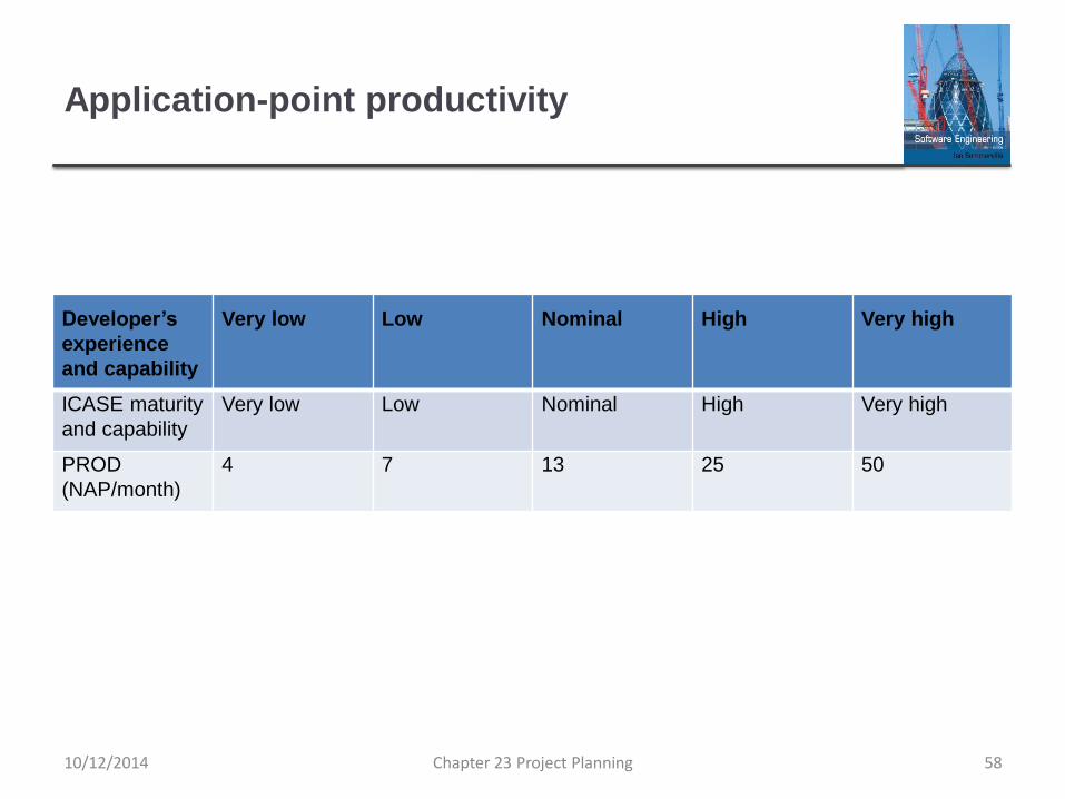
Application-point productivity
Developer’s
experience
and capability
Very low Low Nominal High Very high
ICASE maturity
and capability
Very low Low Nominal High Very high
PROD
(NAP/month)
4 7 13 25 50
10/12/2014 Chapter 23 Project Planning 58

Early design model
Estimates can be made after the requirements have been agreed.
Based on a standard formula for algorithmic models
PM = A ´ SizeB ´ M where
▪ M = PERS ´ RCPX ´ RUSE ´ PDIF ´ PREX ´ FCIL ´ SCED;
▪ A = 2.94 in initial calibration,
▪ Size in KLOC,
▪ B varies from 1.1 to 1.24 depending on novelty of the project,development flexibility, risk management approaches and theprocess maturity.
10/12/2014 Chapter 23 Project Planning 59

Multipliers
Multipliers reflect the capability of the developers, the non-functional requirements, the familiarity with the development platform, etc.
▪ RCPX - product reliability and complexity;
▪ RUSE - the reuse required;
▪ PDIF - platform difficulty;
▪ PREX - personnel experience;
▪ PERS - personnel capability;
▪ SCED - required schedule;
▪ FCIL - the team support facilities.
10/12/2014 Chapter 23 Project Planning 60
The reuse model
Takes into account black-box code that is reused without change and code that has to be adapted to integrate it with new code.
There are two versions:
▪ Black-box reuse where code is not modified. An effort estimate (PM) is computed.
▪ White-box reuse where code is modified. A size estimate equivalent to the number of lines of new source code is computed. This then adjusts the size estimate for new code.
10/12/2014 Chapter 23 Project Planning 61

Reuse model estimates 1
For generated code:
PM = (ASLOC * AT/100)/ATPROD
▪ ASLOC is the number of lines of generated code
▪ AT is the percentage of code automatically generated.
▪ ATPROD is the productivity of engineers in integrating this code.
10/12/2014 Chapter 23 Project Planning 62

Reuse model estimates 2
When code has to be understood and integrated:
ESLOC = ASLOC * (1-AT/100) * AAM.
▪ ASLOC and AT as before.
▪ AAM is the adaptation adjustment multiplier computed from the
costs of changing the reused code, the costs of understanding
how to integrate the code and the costs of reuse decision
making.
10/12/2014 Chapter 23 Project Planning 63

Post-architecture level
Uses the same formula as the early design model but
with 17 rather than 7 associated multipliers.
The code size is estimated as:
▪ Number of lines of new code to be developed;
▪ Estimate of equivalent number of lines of new code computed
using the reuse model;
▪ An estimate of the number of lines of code that have to be
modified according to requirements changes.
10/12/2014 Chapter 23 Project Planning 64

The exponent term
This depends on 5 scale factors (see next slide). Their sum/100 is added to 1.01
A company takes on a project in a new domain. The client has not defined the process to be used and has not allowed time for risk analysis. The company has a CMM level 2 rating.
▪ Precedenteness - new project (4)
▪ Development flexibility - no client involvement - Very high (1)
▪ Architecture/risk resolution - No risk analysis - V. Low .(5)
▪ Team cohesion - new team - nominal (3)
▪ Process maturity - some control - nominal (3)
Scale factor is therefore 1.17.
10/12/2014 Chapter 23 Project Planning 65

Scale factors used in the exponent computation
in the post-architecture model
Scale factor Explanation
Architecture/risk resolution Reflects the extent of risk analysis carried out. Very low means little
analysis; extra-high means a complete and thorough risk analysis.
Development flexibility Reflects the degree of flexibility in the development process. Very low
means a prescribed process is used; extra-high means that the client
sets only general goals.
Precedentedness Reflects the previous experience of the organization with this type of
project. Very low means no previous experience; extra-high means that
the organization is completely familiar with this application domain.
Process maturity Reflects the process maturity of the organization. The computation of
this value depends on the CMM Maturity Questionnaire, but an
estimate can be achieved by subtracting the CMM process maturity
level from 5.
Team cohesion Reflects how well the development team knows each other and work
together. Very low means very difficult interactions; extra-high means
an integrated and effective team with no communication problems.
10/12/2014 Chapter 23 Project Planning 66

Multipliers
Product attributes
▪ Concerned with required characteristics of the software product being developed.
Computer attributes
▪ Constraints imposed on the software by the hardware platform.
Personnel attributes
▪ Multipliers that take the experience and capabilities of the peopleworking on the project into account.
Project attributes
▪ Concerned with the particular characteristics of the softwaredevelopment project.
10/12/2014 Chapter 23 Project Planning 67

The effect of cost drivers on effort estimates
Exponent value 1.17
System size (including
factors for reuse and
requirements volatility)
128,000 DSI
Initial COCOMO estimate
without cost drivers
730 person-months
Reliability Very high, multiplier = 1.39
Complexity Very high, multiplier = 1.3
Memory constraint High, multiplier = 1.21
Tool use Low, multiplier = 1.12
Schedule Accelerated, multiplier = 1.29
Adjusted COCOMO
estimate
2,306 person-months
10/12/2014 Chapter 23 Project Planning 68

The effect of cost drivers on effort estimates
Exponent value 1.17
Reliability Very low, multiplier = 0.75
Complexity Very low, multiplier = 0.75
Memory constraint None, multiplier = 1
Tool use Very high, multiplier = 0.72
Schedule Normal, multiplier = 1
Adjusted COCOMO
estimate
295 person-months
10/12/2014 Chapter 23 Project Planning 69

Project duration and staffing
As well as effort estimation, managers must estimate the calendar time required to complete a project and when staff will be required.
Calendar time can be estimated using a COCOMO 2 formula
▪ TDEV = 3 ´ (PM)(0.33+0.2*(B-1.01))
▪ PM is the effort computation and B is the exponent computed as discussed above (B is 1 for the early prototyping model). This computation predicts the nominal schedule for the project.
The time required is independent of the number of people working on the project.
10/12/2014 Chapter 23 Project Planning 70

Staffing requirements
Staff required can’t be computed by diving the development time by the required schedule.
The number of people working on a project varies depending on the phase of the project.
The more people who work on the project, the more total effort is usually required.
A very rapid build-up of people often correlates with schedule slippage.
10/12/2014 Chapter 23 Project Planning 71

Key points
The price charged for a system does not just depend on its
estimated development costs and the profit required by the
development company. Organizational factors may mean that the
price is increased to compensate for increased risk or decreased to
gain competitive advantage.
Software is often priced to gain a contract and the functionality of the
system is then adjusted to meet the estimated price.
Plan-driven development is organized around a complete project
plan that defines the project activities, the planned effort, the activity
schedule and who is responsible for each activity.
10/12/2014 Chapter 23 Project Planning 72

Key points
Project scheduling involves the creation of various graphical
representations of part of the project plan. Bar charts, which show
the activity duration and staffing timelines, are the most commonly
used schedule representations.
A project milestone is a predictable outcome of an activity or set of
activities. At each milestone, a formal report of progress should be
presented to management. A deliverable is a work product that is
delivered to the project customer.
The agile planning game involves the whole team in project
planning. The plan is developed incrementally and, if problems
arise, it is adjusted so that software functionality is reduced instead
of delaying the delivery of an increment.
10/12/2014 Chapter 23 Project Planning 73

Key points
Estimation techniques for software may be experience-based, where
managers judge the effort required, or algorithmic, where the effort
required is computed from other estimated project parameters.
The COCOMO II costing model is a mature algorithmic cost model
that takes project, product, hardware and personnel attributes into
account when formulating a cost estimate.
10/12/2014 Chapter 23 Project Planning 74