CHAPTER ONE INTRODUCTION 1
50
CHAPTER ONE INTRODUCTION 1.0 Background of Study. Communication is the transference of information from one source to another. It is said to be the process of sharing among two or more sources i.e. knowledge or ideas in form of data. Communication is carried out over a medium, however communication medium are in different form, for this project the medium under study is the mobile and wireless medium. Wireless communication is the transmission of information i.e. data using air as the medium of transfer (air is the transfer channel). Wireless communications encompasses various types of fixed, mobile, and portable two-way radios, cellular telephones, personal digital assistants (PDAs), and wireless networking. Transmission of data involves moving data from a source through the transmission channel into the receiver which is the destination of the information being transferred. Effective communication implies that the receiver understands the message sent to it and takes the 1
Transcript of CHAPTER ONE INTRODUCTION 1
CHAPTER ONE
INTRODUCTION
1.0 Background of Study.
Communication is the transference of information from one source
to another. It is said to be the process of sharing among two or more
sources i.e. knowledge or ideas in form of data. Communication is
carried out over a medium, however communication medium are in
different form, for this project the medium under study is the mobile
and wireless medium.
Wireless communication is the transmission of information i.e.
data using air as the medium of transfer (air is the transfer
channel). Wireless communications encompasses various types of fixed,
mobile, and portable two-way radios, cellular telephones, personal
digital assistants (PDAs), and wireless networking.
Transmission of data involves moving data from a source through
the transmission channel into the receiver which is the destination of
the information being transferred. Effective communication implies
that the receiver understands the message sent to it and takes the
1
necessary action on the message. Other means of transmission channels
include:
i. Wireless channels
ii. Guided electromagnetic waves channels
iii. Optical channels
As communication revolution evolves, there is an increasing
number of communications thriving, although with a growing shortage of
bandwidth and the possibility of errors corrupting transmission
systems, there is a need to improve communication systems with regards
to protecting these systems from corruption of errors, while
simultaneously enhancing the efficiency of bandwidth use as well as
providing highly reliable and error free systems which should not be
taken for granted given the nature of wireless communication channels
It should be noted that communication system does not end in
transmission, i.e. it’s a thing to transmit data, its’ another to get
an uncorrupted message. Therefore, for communication to be effective,
the data received at the destination end must be uncorrupted.
Some of the information gets corrupted during transmission this
is because of the difficulties encountered which includes:
2
Multipath propagation of signals
Interference from other communication devices.
Propagation path loss.
Noise.
For example when the data to be transmitted is of the form
01010101 and at the receiving end the data gotten is 11010101, this is
quite different from the data sent, this makes the system to be
incorrect.
A receiver must be able to detect and correct any irregularity in
the information it has received in other to give a perfect result to
the user of the information.
Therefore error detection in wireless communication is the
identification of unwanted or corrupted data in a transmitted message
or information. While error correction is the process of rectifying
the identified corrupted errors. Error correction coding makes
wireless communications more robust in the presence of noise. The
noise source is the main focus in implementing error correcting codes.
3

Due to much errors found in the communication channel computer
scientist developed a number of techniques in identifying and
correcting these errors which include:
Parity check
Blocking code
Convolutional coding
Turbo coding
Reed Solomon
BCH code etc.
1.2 Statement of Problem
Errors usually happen at transmission or during storage of
information due to some interference such as noise. Detection and
correction of these errors at the receiving end is therefore essential
to having a quality and original information at the destination end.
1.3 Aim and Objectives
Due to the increase in the rate in which personal computers and
workstations are becoming portable, the desire to maintain
connectivity and high quality of data transmitted is important. The
4
purpose of this project is therefore to have a data transmission over
a mobile and wireless medium that is free from errors and when there’s
an occurrence of error, the channel has the capability to detect and
do the appropriate correction required for the channel to an effective
one.
OBJECTIVES
The objectives of this project include:
To ensure that information or message sent and received
are of good quality..
To evaluate some error correction and detection
techniques.
To detect errors in the transmission line
Understand the concept of error correction and detection
in wireless communication systems.
1.4 Scope of Study
Since transmission can be done over several medium, this study is
limited to the detection and correction of errors in the mobile and
wireless communication.
5
.
CHAPTER TWO.
LITERATURE REVIEW
2.1 Background of Study.
The error correction and detection started some centuries back
through the translation of one scroll in one language to another. The
Jewish scribe started the earliest famous error detection, by copying
the Jewish bible beginning before Christ. Emphasis were made on the
minute detail of the words and spelling which evolved into a perfect
6
text in 135CE, that makes a deviation from the strictures render the
Torah scroll invalid.
The method of summing numbers of words per line and page and
checking the middle paragraph, words and letters against the original
text i.e. if a single mistake is found on a page, the page is rendered
invalid, while three mistake on a page renders the whole manuscript
invalid. It therefore has to be re-written i.e. retransmission. The
effectiveness of their method was verified by the accuracy of copying
through the centuries, demonstrated by the Discovery of the Dead Sea
Scrolls in 1947- 1956. (Wikipedia, 2013).
The idea of achieving error detection and correction is to add
some extra data to a message in other for the receiver to check the
consistency of the message delivered and to recover the data said to
be corrupted. (Wikipedia, 2013).
2.2 Error Detection and Correction.
The theory of error detection and correction is a branch of
engineering and mathematics that deals with reliable transmission and
storage of message. Information media are not 100% reliable in
7
practice due to the interference such as noise which causes frequent
distortion of data. (Barbara Rosario, 2000). However, dealing with
this situation involves some form of redundancy being added to the
original data to do away with the undesired effect of interference.
Error detection refers to the class of techniques for detecting
errors i.e. garbled messages while error correction is the process of
correcting errors in data that have been corrupted during
transmission. ( Webopedia).
Error detection and correction scheme can either be systematic or
non-systematic. In systematic scheme, the transmitter sends the
original data and attaches a fixed check bits derived from data by the
deterministic algorithm. If only detection is required, then receiver
can simply apply the same algorithm to the received data bits and
compare its output with the received check bit; if the values do not
match then error as occurred at some point in transmission.
( Wikipedia 2013).
However, in non-systematic scheme, the original message is
transformed into an encoded message that has at least as many bits as
the original data.
8
2.3 Error Correction
In electronic systems, information is represented in the binary
form. When binary information is passed from one point to another,
there are always the chances that error will occur, a “1” interpreted
as a “0” or otherwise. This can be caused difference type of
interference. When a bit is mistakenly misinterpreted, a bit error has
occurred. Therefore, there’s need for correction.
Error correction can either be done on the hardware or on the
software depending upon how fast it has to be done. In most cases, it
is usually done on the hardware such as magnetic disk drive or semi-
conductor memory. Errors are to be corrected at the same rate as data
is being read into the disk i.e. “on-the-fly”. The “on-the-fly”
performance requirement usually means the error correction
implementation must be done in digital logic. (Varnit, 2001).
2.4 Error Correcting Codes
Error correction codes are a means of including redundancy in a
stream of information bits to allow the detection and correction of
symbol errors during transmission. The approach to error correction
9
coding taken by modern digital communication systems started in the
late 1940’s with the ground breaking work of Shannon, Hamming and
Golay (Valenti, 1999). The birth of error correction coding showed
that Shannon’s channel capacity could be achieved when transmitting
information through a noisy channel (Jemibewon, 2000).
Several researches have been carried out on error correction
codes for different types of systems. In Huang (1997), the evaluation
of soft output decoding for turbo codes was carried out in which the
performance of turbo codes were evaluated through computer simulation.
Coding theory related to this research was also studied, including
convolution encoding and Viterbi decoding. Simulation of error
correction codes on wireless communication systems investigates the
performance of error correcting codes for data signals used in
wireless systems; cellular phones, internet, geo location/GPS,
emergency services, radio and television broadcasting etc.
Error correcting codes add redundancy into bits to improve the
performance of a system. They are widely used in almost all digital
systems as they provide a method for dealing with the unknown, noise.
But this capability has several costs and trade-offs. Apart from
10
needing an extra encoder and decoder, we have to transmit more
information in the same amount of time i.e. increased data rates which
translates into more bandwidth (Vats and Kacewicz, 2005).
Error Correction Codes (ECC) encodes data in such a way that a
decoder can identify and correct certain errors in the data. Channel
capacity is a theoretical measure of the fastest rate at which error
free transmission can be realized. Traditional modulation techniques
deliver performance significantly inferior to that predicted by
Shannon’s work, but when incorporated with error correction coding
most digital modulation schemes can achieve performance that
approaches channel capacity (Jemibewon, 2000). Shannon also
established the fundamental limits in transmission speeds in the
systems of digital communications and led to the search for coding
techniques for approaching the limit of this capacity (Morales, 2008).
When digital data is stored in a memory, it is crucial to have a
mechanism that can detect and correct a certain number of errors.
Usually data strings are encoded by adding a number of redundant bits
to them. When the original data is reconstructed, a decoder examines
the encoded message, to check for any errors (Valenti, 1999).
11
Practically all systems that transmit or store digital data use
some form of error correction technique. In the presence of real-world
phenomenon, designers of these systems have to face the certain
outcome that some transmitted or stored bits of information will not
be received the way they were intended.
The choice of how to handle errors ranges from doing nothing to
using elaborate error detection and correction methods. Selecting
between the choices depends on the accuracy, speed, and latency
requirement of the information, and whether or not there is
simultaneous bidirectional communications between the sender and
receiver (Rossi, 1998).
2.5 Error Control Techniques.
There are two major error control techniques. They are the
Forward Error Correction and the Automatic Repeat Request. Also
there’s is the Hybrid Automatic Repeat Request.
2.5.1 Forward Error Correction.
12
Forward Error Correction (FEC) which employs error correcting
codes to combat bit errors (due to channel imperfections) by adding
redundancy (henceforth parity bits) to information packets before they
are transmitted. This redundancy is used by the receiver to detect and
correct errors. They are indispensible due to the strict delay
requirement. The reconstructed data is what is said to be the original
data. FEC schemes maintain constant throughput and have bounded time
delay. A typical FEC schemes are stationary and must be implemented to
guarantee a certain Quality of Service (QOS requirement for the worst
case channel characteristics. As a consequence, FEC techniques are
associated with unnecessary overhead that reduces throughput when the
channel is relatively error free. (H. Liu et al.). There two main
types of correction methods under the FEC, which are the block codes
and the convolutional codes
2.5.2 Automatic Repeat Request
This can also be referred to as the backward error correction
wherein only error detection capability is provided and no attempt to
correct any packets received in error is made; instead it is requested
that the packets received in error be retransmitted. ARQ is simple
13

and achieves reasonable throughput levels if the error rates are not
very large. However, in its simplest form, ARQ leads to variable
delays which are not acceptable for real-time services. (H. Liu et al.)
2.5.3 Hybrid Automatic Repeat Request
This is the combination of the forward error correction and the
automatic repeat request. It allows the minor errors to be corrected
without retransmission while the major ones are corrected through the
request for retransmission. This is in order to overcome their
individual drawbacks.
2.6 Block coding
Block coding schemes divide a bit stream into nonoverlapping
blocks and code each block independently. Block codes used in
practical applications today belong to the class of linear cyclic
codes, since these codes lend themselves to easier implementations. A
coding scheme is referred to as being linear if the sum of two code
vectors is also a code vector.
14
Similarly, a coding scheme is referred to as being cyclic if all
cyclic shifts of a code vector results in a valid code vector. Binary
Bose–Chaudhuri–Hocquenghem (BCH) codes and non-binary Reed–Solomon
(RS) codes are two kinds of widely used linear cyclic block codes. (H.
Liu et al). Block codes are codes that require data being compiled
into blocks before coding or decoding can take place (Houghton, 1997).
They are based rigorously on finite field arithmetic and abstract
algebra. They can be used to either detect or correct errors. Each
codeword in the set is a linear combination of a set of generator code
words. They have very high code rates and are useful in situations
where Bit Error Rate (BER) of a channel is relatively low, bandwidth
availability is limited (Shelton, 1999). Block codes are also referred
to as (n, k) codes where a block of k data bits is encoded to become a
block of n bits called a code word (Valenti, 1999).
By predetermined rules, n-k redundant bits are added to the k
information bits to form the n coded bits. Block codes, also known as
redundancy codes, are thought of as giving external protection in the
encoding process. Some of the commonly used block codes are Hamming
codes, Golay codes, Bose–Chadhuri–Hocquenghem (BCH) codes, and Reed
15

Solomon codes (which uses non binary symbols) (Vats and Kacewicz,
2005).
2.6.1 Bose–Chaudhuri–Hocquenghem (BCH) codes
For any positive integers, m > 3 and t < 2m−1, there is a binary
BCH code with the following parameters, (referred to as an (n, k, t)
BCH code): _ block length: n = 2m − 1, _ number of parity check bits:
n − k 6 mt, _ minimum distance: dmin > 2t + 1. Each binary BCH code (n,
k, t) can correct up to t-bit errors, and thus it is also referred to
as a t-error-correcting code. (H,Liu et al,1997).
2.6.2 Reed–Solomon (RS) codes
The binary BCH codes can be generalized to non-binary codes. If p
is a prime number and q is any power of p, there exist BCH codes with
q-ary symbols. For any choice of positive integer s and t, a q-ary BCH
code is of length n = qs−1, which is capable of correcting any
combination of t or fewer symbol errors and requires no more than 2s
parity-check symbols. RS codes are a subclass of non-binary BCH codes
with s = 1. A (n, k, t) RS code wit q-ary symbols has the following
parameters:
_ block length: n = q − 1,
16
_ number of parity-check bits: n − k = 2t,
_ minimum distance: dmin = 2t + 1:
An (n, k, t) RS code is capable of correcting any combination of t
or fewer symbol errors. In practical applications, RS codes with code
symbols from q = 2m are chosen.
BCH and RS block coding schemes have a well-defined algebraic
structure, which has facilitated the development of efficient coding
and decoding schemes. In addition, RS codes have optimal “distance
properties”, i.e., provide optimal error correction capability given a
fixed number of parity bits, and excellent “burst error suppression”
capabilities. (H,Liu et al,1997).
2.6.3 Hamming Codes
A commonly known linear Block Code is the Hamming code. Hamming
codes can detect and correct a single bit-error in a block of data. In
these codes, every bit is included in a unique set of parity bits. The
presence and location of a single parity bit-error can be determined
by analyzing parities of combinations of received bits to produce a
table of parities each of which corresponds to a particular bit-error
combination. This table of errors is known as the error syndrome. If
17
all parity is correct according to this pattern, it can be concluded
that there is not a single bit-error in the message (there may be
multiple bit-errors). If there are errors in the parities caused by a
single bit-error, the erroneous data bit can be found by adding up the
positions of the erroneous parities.
While Hamming codes are easy to implement, a problem arises if
more than one bit in the received message is erroneous. In some cases,
the error may be detected but cannot be corrected. In other cases, the
error may go undetected resulting in an incorrect interpretation of
transmitted information. Hence, there is a need for more robust error
detection and correction schemes that can detect and correct multiple
errors in a transmitted message. (vikas et al,2012)
2.6.4 Cyclic codes and Cyclic Redundancy Checks (CRC)
Cyclic Codes are linear block codes that can be expressed by the
following mathematical property. If C = [c n-1 cn-2 … c1 c0] is a code
word of a cyclic code, then [c n-2 cn-3 … c0 cn-1], which is obtained
by cyclically shifting all the elements to the left, is also a code
word.(Wikipedia,2001). In other words, every cyclic shift of a
codeword results in another codeword. This cyclic structure is very
useful in encoding and decoding operations because it is very easy to
18

implement in hardware. A cyclic redundancy check or CRC is a very
common form of cyclic code which is used for error detection purposes
in communication systems. At the transmitter, a function is used to
calculate a value for the CRC check bits based on the data to be
transmitted. These check bits are transmitted along with the data to
the receiver. The receiver performs the same calculation on the
received data and compares it with the CRC check bits that it has
received. If they match, it is considered that no bit-errors have
occurred during transmission. While it is possible for certain
patterns of error to go undetected, a careful selection of the
generator function will minimize this possibility. Using different
kinds of generator polynomials, it is possible to use CRC‘s to detect
different kinds of errors such as all single bit-errors, all double
bit errors, any odd number of errors, or any burst error of length
less than a particular value. Due to these properties, the CRC check
is a very useful form of error detection. The IEEE 802.11 standard for
CRC check polynomial is the CRC-32. (Vikas,et al, 2012)
2.7 Convolution Codes
19
Block coding schemes are frequently referred to as memoryless
since successive information blocks are coded independently.
Convolutional codes are a popular class of coders with memory, i.e.,
the coding of an information block is a function of the previous
blocks.
These are alternatives to block coding in which coding and
decoding can take place on a continuous data bit stream (Houghton,
1997). They are used in applications that require good performance
with low implementation cost. They operate on data stream not static
block. They are usually denoted by (n, k, l) (Er. Liu, 2004). The
code words produced depend on both the data message and a given number
of previously encoded messages. The encoder changes state with every
message processed. The length of the code word is usually constant
(Valenti, 1999).
In almost all applications of digital communications, convolution
codes are used as the main error correction code because of its ease
of implementation compared to an equivalent block code. Convolution
codes convert the entire data stream into one single codeword. The
encoded bits depend not only on the current input bits but also on
20

past input bits. The main decoding strategy for convolution codes is
based on the widely used Viterbi algorithm (Huang, 1997).
2.8 PROPERTIES OF CONVOLUTION CODES
Passing the information sequence to be transmitted through a
linear finite state shift register generates convolution codes.
Convolution codes can be summed up as codes without a block structure
(Vats and Kacewicz, 2005). Convolution codes are one of the most
widely used channel codes in practical communication systems. These
codes are developed with a separate strong mathematical structure and
are primarily used for real time error correction. They are usually
denoted by (n, k, l) Where,
n- Number of output bits
k- Number of input bits
l- Code memory depth
To encode a block code, an infinite data stream is divided into
blocks and then the code is applied on each individual block. The
final output depends on the corresponding block it came from in the
21
input stream. For convolution codes, the stream is again divided into
blocks, but the blocks are much smaller.
The final output for convolution codes depends on multiple blocks
from the input stream (Vats and Kacewicz, 2005). There are three
parameters which define the convolution code:
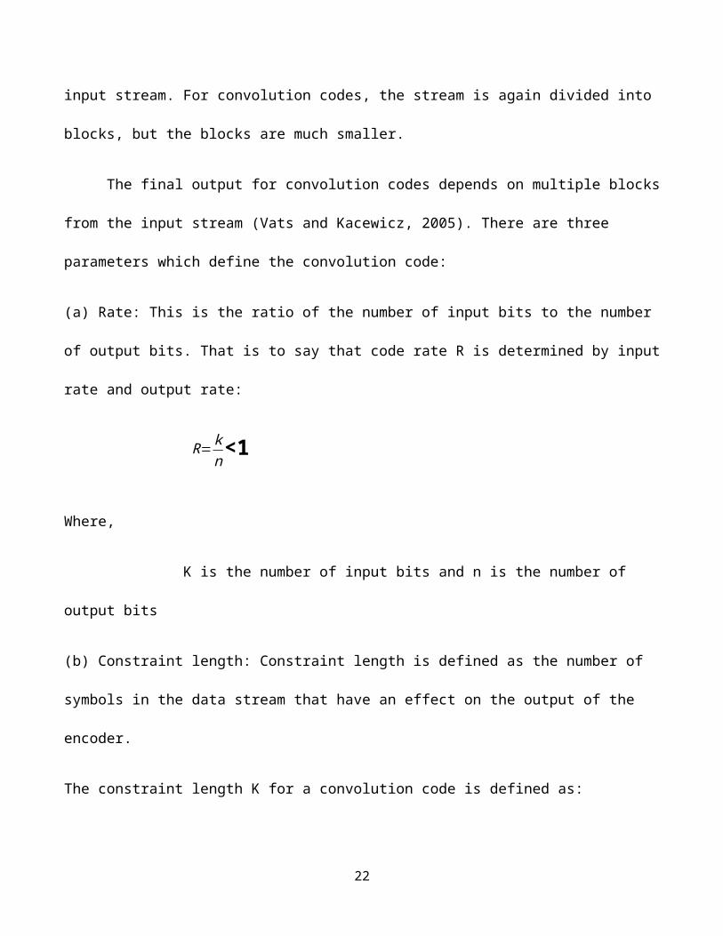
(a) Rate: This is the ratio of the number of input bits to the number
of output bits. That is to say that code rate R is determined by input
rate and output rate:
R=kn<1
Where,
K is the number of input bits and n is the number of
output bits
(b) Constraint length: Constraint length is defined as the number of
symbols in the data stream that have an effect on the output of the
encoder.
The constraint length K for a convolution code is defined as:
22
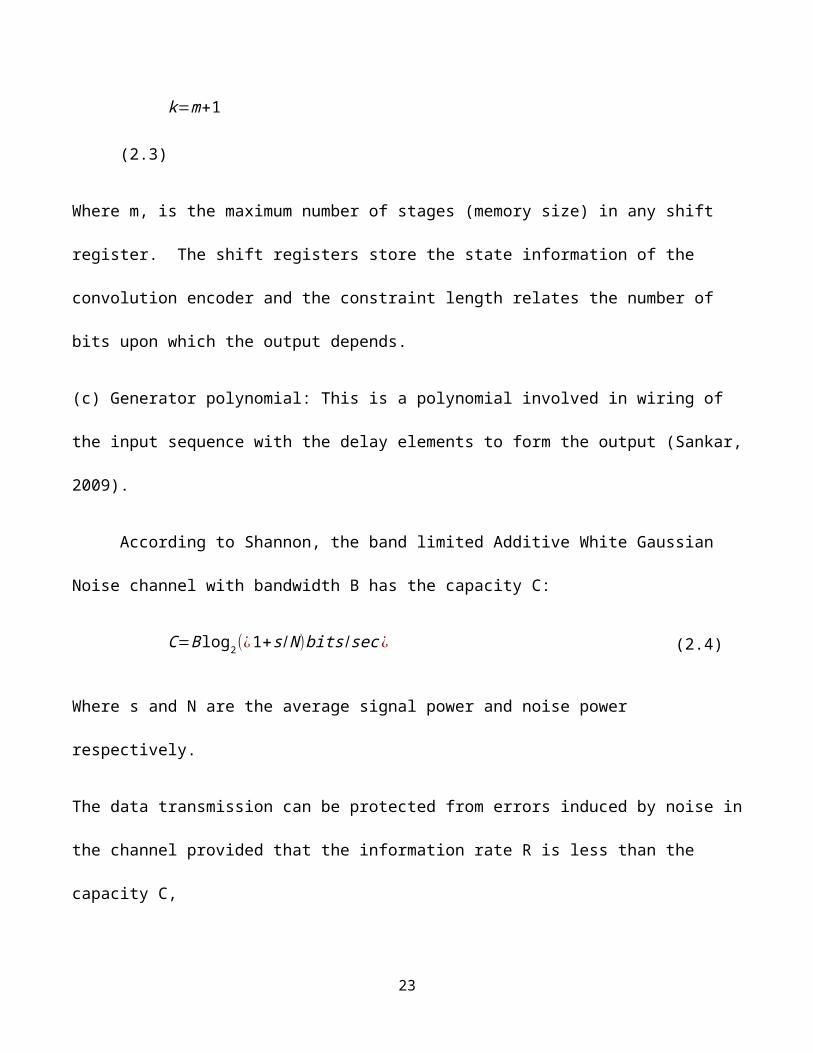
k=m+1
(2.3)
Where m, is the maximum number of stages (memory size) in any shift
register. The shift registers store the state information of the
convolution encoder and the constraint length relates the number of
bits upon which the output depends.
(c) Generator polynomial: This is a polynomial involved in wiring of
the input sequence with the delay elements to form the output (Sankar,
2009).
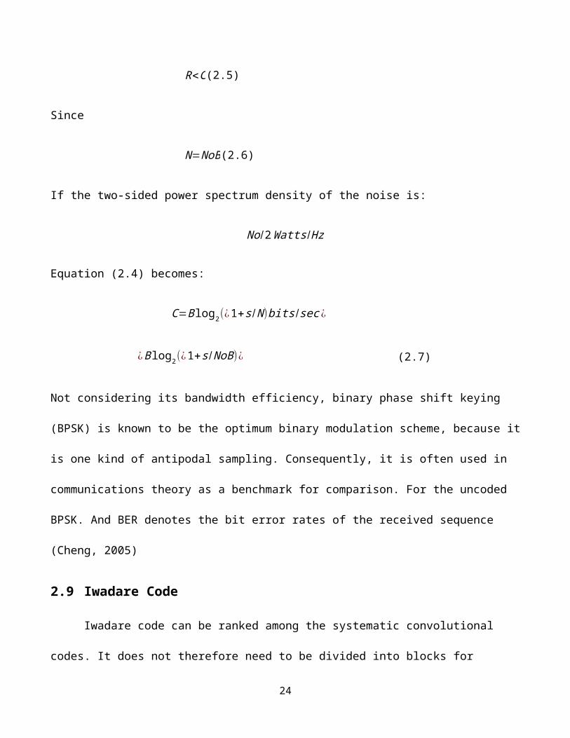
According to Shannon, the band limited Additive White Gaussian
Noise channel with bandwidth B has the capacity C:
C=Blog2(¿1+s /N)bits /sec ¿ (2.4)
Where s and N are the average signal power and noise power
respectively.
The data transmission can be protected from errors induced by noise in
the channel provided that the information rate R is less than the
capacity C,
23
R<C(2.5)
Since
N=NoB(2.6)
If the two-sided power spectrum density of the noise is:
No/2Watts/Hz
Equation (2.4) becomes:
C=Blog2(¿1+s /N)bits /sec ¿
¿Blog2(¿1+s /NoB)¿ (2.7)
Not considering its bandwidth efficiency, binary phase shift keying
(BPSK) is known to be the optimum binary modulation scheme, because it
is one kind of antipodal sampling. Consequently, it is often used in
communications theory as a benchmark for comparison. For the uncoded
BPSK. And BER denotes the bit error rates of the received sequence
(Cheng, 2005)
2.9 Iwadare Code
Iwadare code can be ranked among the systematic convolutional
codes. It does not therefore need to be divided into blocks for
24
security reasons. The resulting transmitted code combination can be
divided into information elements and security elements. If the
threshold security capability is exceeded, the infinite error
intrusion into the information itself does not occur. Iwadare code is
capable of correcting error bursts b if there is security interval A
among these bursts where the respective information is transmitted
error-free.( Ing. Vítězslav Křivánek,2006).
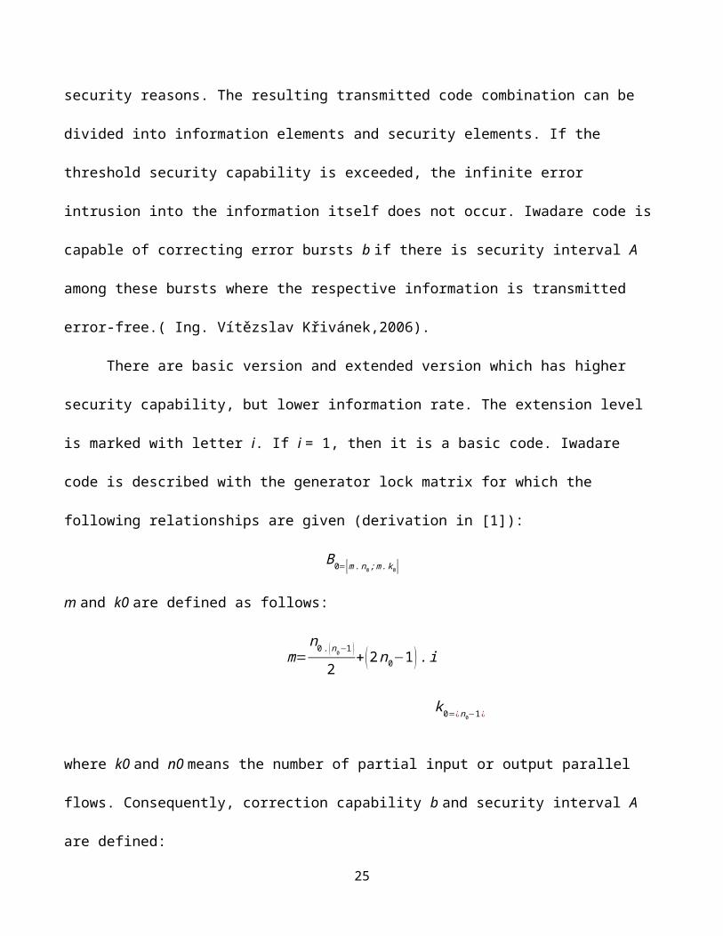
There are basic version and extended version which has higher
security capability, but lower information rate. The extension level
is marked with letter i. If i = 1, then it is a basic code. Iwadare
code is described with the generator lock matrix for which the
following relationships are given (derivation in [1]):
B0=⟦m.n0;m.k0⟧
m and k0 are defined as follows:
m=n0.(n0−1 )
2+(2n0−1).i
k0=¿n0−1¿
where k0 and n0 means the number of partial input or output parallel
flows. Consequently, correction capability b and security interval A
are defined:
25
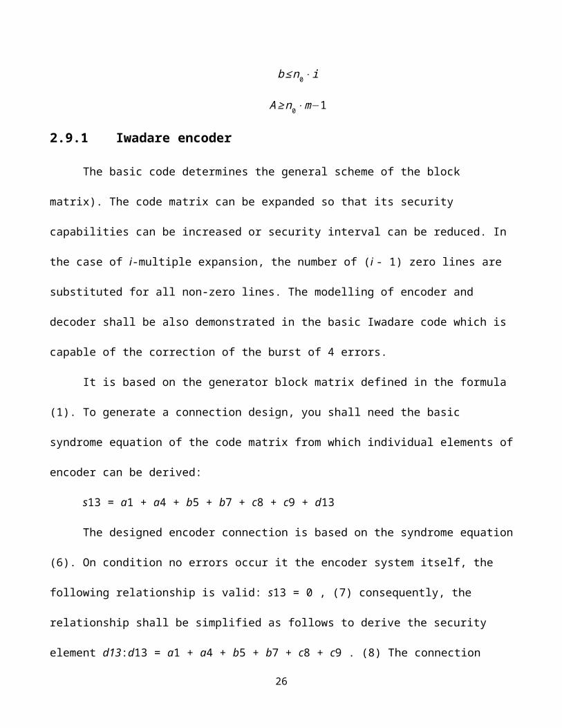
b≤n0⋅i
A≥n0⋅m−1
2.9.1 Iwadare encoder
The basic code determines the general scheme of the block
matrix). The code matrix can be expanded so that its security
capabilities can be increased or security interval can be reduced. In
the case of i-multiple expansion, the number of (i - 1) zero lines are
substituted for all non-zero lines. The modelling of encoder and
decoder shall be also demonstrated in the basic Iwadare code which is
capable of the correction of the burst of 4 errors.
It is based on the generator block matrix defined in the formula
(1). To generate a connection design, you shall need the basic
syndrome equation of the code matrix from which individual elements of
encoder can be derived:
s13 = a1 + a4 + b5 + b7 + c8 + c9 + d13
The designed encoder connection is based on the syndrome equation
(6). On condition no errors occur it the encoder system itself, the
following relationship is valid: s13 = 0 , (7) consequently, the
relationship shall be simplified as follows to derive the security
element d13:d13 = a1 + a4 + b5 + b7 + c8 + c9 . (8) The connection
26

diagram of the basic encoder (see Fig. 7) can be uniquely determined
from the equation (8). In the figure of the encoder and decoder, only
the first and the last memory cell of the respective section are
marked for the reason of clarity.
2.9.2 Iwadare decoder
The basic principle of the decoder consists in the use of the
threshold decoding principle. It is necessary to find the
orthogonality relation towards the element whose correctness after the
transmission is just being checked. To derive the decoder connection,
you shall need the syndrome equation system. The number of necessary
equations is determined by the requirement of the existence of at
least two orthogonality sums for one corrected bit. The basic
substance and condition are as follows: The corrected bit occurs in
both of these equations while the other bits do not and shall not
occur in both the equations.
The above-mentioned example of Iwadare code corrects the
erroneous bursts b ≤ 4 . Yet, it does not deal with the correction of
the security bit di because its correction is of no significance for
the transmitted information. The following three information bits ai,
bi, ci are only corrected. To design the Iwadare decoder, one can use
27
the fact that it is a systematic code which is organized as follows:
security bits follow only after information bits of the respective
transmission. One more syndrome equation in relation to the basic
syndrome equation (6) shall be therefore found. If you define the
syndrome equation for specific time, you shall find bits participating
in security in previous time in relation to the bits contained in this
equation. The second syndrome equation
:s12 = a0 + a3 + b4 + b6 + c7 + c8 + d12 . (9)
Using these two syndrome equations (6) and (9), the correction of bit
c8 can be made:
s13 ⋅ s12 = 0 ∧ s13 ⋅ s12 = 1 , (10)
where the result equals zero if bit c8 is correct, and the syndrome
product equals one if there is an error. If you want to correct other
bits, you have to go “deeper in the history” and determine other
necessary syndrome equations for the correction of bits b5, a1. On the
basis of knowledge of other syndrome equations, it’s possible to model
a decoder.
2.10Code shortening
Often, a block code of desirable natural length or suitable
number of information digits may not exist. In this case code shortening
28
is performed, which involves choosing a code with block length greater
than the required length and subsequently shortening it to meet the
requirement. Code shortening is most easily done by setting a selected
number of the information symbols to zero in the encoding operation.
For example, given an (n, k) code C, consider the se of code vectors
for which the b leading high-order information symbols are equal to
zero. Such code vectors form a subset of code C. If the b zero
information symbols are deleted from each of these code vectors, we
obtain a set of vectors of length n − b. These shortened vectors form
an (n−b, k−b) code. The error detection and correction capability of
the shortened code is at least as great as the code from which it was
derived. For RS codes, the minimum distance is unchanged after
shortening. (H lui, et al, 2007)
2.11Interleaving
An alternative to choosing long codes to combat the effect of
burst errors is interleaving. Interleaving simply involves
interleaving symbols from two or more codewords before transmission on
the channel. The number of codewords that are interleaved is referred
to as the depth of the interleaver, m. The reverse process is
29

performed at the deinterleaver. Therefore, between successive symbols
of any given codeword there are m − 1 symbols that belong to
the m − 1 other codewords being interleaved. If the interleaver has
sufficient depth the fading processes that affect successive symbols
belonging to the same codeword will be uncorrelated.
Therefore, from the perspective of any single codeword,
interleaving makes a burst error channel appear as one which has only
random errors. Interleaving does not decrease the long-term bit error
rate but it is successful in decreasing the number of errors in each
codeword, therefore the codeword should have enough capability to
correct the erroneous symbols in it after deinterleaving. Result in
[34] show that the FEC and interleaving strategy is effective when tm
exceeds 1=r where t is the code error correction capability and 1=r is
the average burst length. Note that interleaving results in extra
delay because deinterleaving can be started only after all the
interleaved data is received. For the above example, a delay on the
order f 1=rt codewords is introduced. (H lui, et al, 2007).
2.12 Code puncturing
30
The characteristics of a wireless channel typically vary with
time, and therefore to obtain optimal performance it is necessary to
adapt the error coding scheme to the changing channel characteristics.
Code puncturing allows an encoder/ decoder pair to change code rates,
i.e., code error correction capabilities, without changing their basic
structure. Code puncturing involves not transmitting (i.e., deleting)
certain code bits. It is important to note that both convolutional
codes and block codes can be punctured. Punctured convolutional codes
were first introduced by Clark et al. [9]. Hagenauer modified the
concept of punctured convolutional codes for the generation of a
family of rate compatible punctured convolutional (RCPC) codes by
adding a rate-compatibility restriction to the puncturing rule [12].
The rate-compatibility restriction implies that all he code bits of a
high rate code of the family are used by the lower rate codes. These
codes are attracting more and more attention because of their
flexibility. We now discuss in some detail the process of puncturing
codes. A low rate 1=n convolutional code (called mother code) is
periodically punctured with period p to obtain a family of codes with
rate p=v, where v can be varied between p + 1 and np. As an example,
we consider punctured convolutional codes obtained from a rate 1=3
31
mother code. To generate a rate p=v punctured convolutional code (p=v
> 1=3), we delete (3p − v) bits from every 3p code bits corresponding
to the encoded output of p information bits by the original rate 1=3
code. The resulting rate is then equal to the desired rate r = p=v.
The punctured codes have the same number of states as the mother
code, i.e. the same memory length m. The deleted bit pattern must be
carefully chosen to obtain desirable performance. The elements of
puncturing matrices are only zeros and ones. A zero in a puncturing
matrix means that the corresponding code bit will not be transmitted,
a one means that it is inserted in the channel bit stream. For
example, to generate a 8=22 code, puncturing matrix p(8=22) is used.
Encoding of 8 information bits with the three generator polynomials
results in 38 intermediate bits at the three output branches. (H lui,
et al, 2007).
Every fourth and eighth output bit of the third branch is
deleted. Instead of transmitting 3,8 bits, only 22 bits are
transmitted per 8 information bits. Therefore, a rate 8/22 code is
generated. In general, the puncturing matrix p(r = p=v) = [pij ] for a
mother code of rate 1=n and a puncturing period of p has n rows and p
columns. The number of zeros in the puncturing table is equal to np−v.
32
Two punctured convolutional codes, obtained from the same mother code,
are said to be rate-compatible if all the code bits in the higher rate
code are used in the lower rate codes.
2.13ERROR-CORRECTION CODE SELECTION
Through research, both theoretical and numerical, must precede the
design of error correction codes. There are many error-correcting
codes and their combinations, each fitting a particular task. The
basic issues to be taken into account in order to choose an error-
correcting code (ECC) are:
Physical channel characteristics (Signal to noise ratio, presence
of memory, e.g. fading)
Modulation type
Desirable channel characteristics (information rate, BER - bit
error probability).
A simple measure for the quality of a code is the information rate
which is the measure of how much of the code is the message. The rate
is given as:
log2C /n
33
Where,C represents the number of code words in the code.
Having discussed various coding schemes, we now consider criteria
that must be taken into account when selectin a FEC scheme for any
given application.
1. Probability of uncorrected errors: Since it is impossible for
any coding scheme to detect all errors and correct them, it is
important to choose coding schemes for which the probability of both
undetectable and uncorrectable (but detectable) errors is minimized
(or satisfies the application under consideration).
2. Overhead: The FEC codes should add as little as possible overhead
and maximize the code rate. However increased code capability
generally leads to lower code rate.
3. Complexity: The implementation complexity of the coding/decoding
scheme which typically increases with increase in code length and its
capability to detect and correct errors.
2.14Automatic Repeat Request (ARQ)
ARQ is an error control mechanism that relies on retransmitting
data that is received with errors [20]. In such schemes, messages are
divided into blocks of suitable size that are transmitted after a
34

small number of parity bits have been added. At the receiver these
parity bits are used to detect the presence of errors in the received
packet. In case errors are detected in a received packet, the receiver
requests a retransmission of the packet.
Automatic Repeat Request (ARQ) protocols roughly operate as
follows: The transmitter numbers the packets to be transmitted
sequentially (using numbers from a finite set) and maintains a timer
for each packet it transmits. The receiver acknowledges, at the very
least, the receipt of each successful packet (a packet that is
received with no errors) by transmitting a packet, referred to as an
ACK bearing the sequence number of the packet being acknowledged.
Packets that have not been successfully acknowledged, i.e., an ACK has
not been received, in a predetermined time interval, henceforth
referred to as timeout, are assumed to be lost (or corrupted) and are
retransmitted. In some cases, negative acknowledgements (NAKs) are
transmitted by the receiver for every packet received error. If NAKs
are employed, a packet is retransmitted following the receipt of a
negative acknowledgement. Since some of the transmitted packets can be
lost or misrouted NAKs cannot be transmitted for these lost packets.
35
There three most popular ARQ protocols – Stop and Wait, Selective
Repeat, and Go-Back-N. (H, Liu et,al).
2.14.1 Stop and Wait
When using the Stop and Wait (SW) ARQ protocol, the DLC protocol
transmits a packet only when all previously transmitted packets have
been successfully acknowledged. Hence, when using SW, the transmitter
after transmitting a packet waits for its acknowledgement. Once its
acknowledgement has been received the next packet is transmitted.
However, if an acknowledgement does not arrive until a timeout
timer expires, the packet is retransmitted. Therefore, in SW there is
never more than a single packet that s unacknowledged at any given
instant of time. Since the transmitter does not use the available
channel during time intervals it waits for an ACK, the maximum data
transfer rate that can be supported is limited. This limits cases
where the SW ARQ protocol can be employed.
2.14.2 Selective Repeat
Unlike SW, when using Selective Repeat (SR), packets, if available,
are transmitted continuously by the DLC layer. As before, the receiver
36
acknowledges each successfully received packet by transmitting an ACK
bearing the sequence number of the packet being acknowledged. If an
acknowledgement is not received for a packet before the expiration of
the timeout, the packet is retransmitted.
Once a packet has been retransmitted the transmitter resumes
transmission of packets from where it left off, i.e., if a is the
packet with the largest sequence number that has been transmitted,
packet with sequence number a+1 is transmitted next (assuming that no
other timers have expired in the meantime). Since when the SR ARQ
protocol is employed, packets are continuously being transmitted the
inefficiency associated with SW is eliminated. Observe that when SR is
employe packets can be accepted out of sequence. Hence, packets
received out of sequence have to be buffered and sequenced before they
can be delivered. (Vikas et al, 2012)
2.14.3 Go-Back-N
When Go-Back-N (GBN) is employed, packets are transmitted
continuously as in SR. However, at the receiver, the DLC layer accepts
packets only in the order in which they were transmitted. Packets
received out of sequence are discarded and not acknowledged. Since the
receiver accepts packets only in-sequence, after a timeout, the
37
transmitter retransmits the packet that timed out and all packets with
sequence numbers that follow the one that was retransmitted. Hence,
each time a timeout occurs all packets that are yet to be acknowledged
are retransmitted. It is important to observe that GBN attempts to
combine the desirable features of SR and SW, i.e., packets are
transmitted continuously, as in SR, without the need to buffer out of
sequence packets and there is no re sequencing overhead.(H,liu et al)
2.15ERROR DETECTION
Error detection is much simpler than error correction and one or
more "check" digits are commonly embedded in credit card numbers in
order to detect mistakes. Early space probes like Mariner used a type
of error-correcting code called a block code, and more recent space
probes use convolution codes. Error-correcting codes are also used in
CD players, high speed modems, and cellular phones. Modems use error
detection when they compute, checksum which are sums of the digits in
a given transmission modulo some number. Error detection codes also
includes: repetition scheme, parity, ( Wolfram mathworld ).
38

2.15.1 Repetition Schemes
Repetition code is another mechanism that relates to error
detection. It is a coding schema that repeats bits across channels to
achieve error-free communication. Data bits in a stream of data are
divided into blocks of bits. Every block is transmitted a
predetermined number of times. They are not as effective as parity,
because the occurrence of errors in the same place leads to more
problems. However, they are simple and used in the transmission of
number stations.
Variations on this theme exist. Given a stream of data that is to
be sent, the data is broken up into blocks of bits, and in sending,
each block is sent some predetermined number of times. For example, if
we want to send "1011", we may repeat this block three times each.
Suppose we send "1011 1011 1011", and this is received as "1010 1011
1011".
As one group is not the same as the other two, we can determine
that an error has occurred. This scheme is not very efficient, and can
be susceptible to problems if the error occurs in exactly the same
place for each group e.g. "1010 1010 1010" in the example above will
39

be detected as correct in this scheme. The scheme however is extremely
simple, and is in fact used in some transmissions of numbers stations.
(Dinesh Thakur)
2.15.2 Checksum
Checksum is an error detection method that is a modular
arithmetic sum of message code words of fixed word length. Checksum
schemes involve longitudinal redundancy checks, parity bits and check
digits. A checksum of a message is an arithmetic sum of message code
words of a certain word length, for example byte values, and their
carry value. The sum is negated by means of ones-complement, and
stored or transferred as an extra code word extending the message. On
the receiver side, a new checksum may be calculated, from the extended
message. If the new checksum is not 0, error is detected. Checksum
schemes include parity bits, check digits, and longitudinal redundancy
check. Suppose we have a fairly long message, which can reasonably be
divided into shorter words (a 128 byte message, for instance). We can
introduce an accumulator with the same width as a word (one byte, for
instance), and as each word comes in, add it to the accumulator.
40
When the last word has been added, the contents of the
accumulator are appended to the message (as a 129th byte, in this
case). The added word is called a checksum. Now, the receiver performs
the same operation, and checks the checksum. If the checksums agree,
we assume the message was sent without error. (Dinesh Thakur)
2.15.3 Parity Method for Error Detection
The oldest method of error correction involves using parity. It
works by adding an additional bit to each character word transmitted.
The state of the bit is determined by a number of factors such as the
type of parity and the number of logic-one bits in the data character.
The movement of digital data from one location to another can
result in transmission errors, the receiver not receiving the same
signal as transmitted by the transmitter as a result of electrical
noise in the transmission process. Sometimes a noise pulse may be
large enough to alter the logic level of the signal. For example, the
transmitted sequence 1001 may be incorrectly received as 1101. In
41
order to detect such errors a parity bit is often used. A parity bit is
an extra 0 or 1 bit attached to a code group at transmission. In
the even parity method the value of the bit is chosen so that the total
number of 1s in the code group, including the parity bit, is an even
number. For example, in transmitting 1001 the parity bit used would be
0 to give 01001, and thus an even number of 1s. In transmitting 1101
the parity bit used would be 1 to give 11101, and thus an even number
of 1s. With odd parity the parity bit is chosen so that the total number
of 1s, including the parity bit, is odd. Thus if at the receiver the
number of 1s in a code group does not give the required parity, the
receiver will know that there is an error and can request that the
code group be retransmitted.
An extension of the parity check is the checksum in which a block
of code may be checked by sending a series of bits representing their
binary sum. Parity and checksums can only detect single errors in
blocks of code, double errors go undetected. Also, the error is not
located so that correction by the receiver can be made. Multiple-error
detection techniques and methods to pinpoint errors have been devised.
42
CHAPTER THREE.
METHODOLOGY.
3.1 INTRODUCTION.
The purpose of this work is to evaluate the performance of some
error detection and correction codes used in detecting and correcting
errors in mobile and wireless communication. Particularly, this work
will be focused on block codes (Reed-Solomon code) and the
convolutional codes. This will help in the designing and understanding
of digital communication systems that are reliable.
The methodologies applied throughout in this project would be
purely analytical and computer simulation. This chapter includes the
description of the algorithm for generating random binary data, using
Galois array, encoding the data, passing the data through a noise
channel, detecting the errors and correcting the errors.
The encoders and decoders would be modeled using MATLAB; these
are then used in simulating a communication system with view of
evaluation to demonstrate the benefits and limitations.
3.2 ALGORITHMS.
3.2.1 Description of the algorithm.
43
The steps involved in simulating a communication channel using
Galois array block and convolutional decoding from the transition of
the original message to the final message are below the Galois field
array is a function in MATLAB that has 2^m element where m is an
integer between 1 and 16 the other variable must also be an integer
between 0 and 2^m-1.
3.2.1.1 Generating the data.
Generating the data to be transmitted through the channel can
simply be done using a random number generator which would produce a
uniform distribution of numbers on the internal 0 to a maximum value
using RANDINT provided in MATLAB. Using the Galois array, it is
specified that the non-zero element should be used.
Data= randint (nw,k).
3.2.1.2 Encoding the data.
The encoder used at this stage is the RSENC. The Reed- Solomon
encoder encodes the message in MSG using an (N, K) Reed-Solomon
encoder with the narrow sense generator polynomial. MSG is a Galois
array of symbols over GF (2m). Each k-element row of the MSG
represents a message word, where the leftmost is the most significant
44
symbol. If N is smaller than 2m-1, and then RSENC uses a shortened RS
code. Parity symbols are at the end of each word in the output Galois
array code
Simplex syntax for encoding
Coded = rsenc (msg_galois, n, k)
3.2.1.3 Adding noise to the data.
Coding with this code is to be treated to a channel in which the
transmitted signal is corrupted mainly by Additive White Gaussian
Noise (AWGN). White noise is a random signal (or process) with a flat
power spectral density. Gaussian noise is statistical
noise that has a probability density function of the
normal distribution (also known as Gaussian distribution).
In other words, the values that the noise can take on are
Gaussian-distributed. It is most commonly used as additive white
noises to yield additive white Gaussian noise (AWGN).
Noise = randerr (nw, n.t);
Cnoisy=coded + noise;
3.2.1.4 Decoding the data
45
A RSDEC decoder is used at this stage. The Reed-Solomon decoder
attempt to decode the received signal in the code using an (N, K)
Reed-Solomon decoder with the narrow sense generator polynomial. The
code is a Galois array of symbols over GF (2m) where m is the number
of bits per symbol. Each N-element row of code represents a corrupted
systematic codeword, where the parity symbols are at the end and the
leftmost is the most significant symbol. If N is smaller than 2^m-1,
then RSDEC assumes that the code is a corrupted version of a shortened
code.
[corrcode, nerrs, decoded] = rsdec (cnoisy, n, k).
3.3 Algorithm for convolutional code.
3.3.1 Convolutional code encoder.
Convolution codes protect information by adding redundant bits.
This accepts a sequence of binary input vectors to produce a sequence
of binary output. The encoder takes k input bit streams i.e 2k
possible input symbol, the block input vector length will be L*K for
some positive integer. And will produce n output bit streams. A
trellis structure is used in describing convolution codes. A trellis
description of a convolution encoder shows how each possible input to
the encoder will influence both the output and the state transitions
46

of the encoder. To specify the encoder using its constraint length,
generator polynomial, the poly2trellis command is used. It parameters
are the constraint length and code generator polynomial. A convolution
encoder is called so because it performs a convolution of the input
stream with encoder's impulse responses: Where x is an input sequence,
y is a sequence from output and h is an impulse response for output.
3.3.2 Convolutional decoder.
Convolution code decoding algorithms infer the values of the
input information sequence from the stream of received distorted
output symbols. The major decoding algorithm for convolutional code is
the Viterbi algorithm. The goal of the Viterbi algorithm is to find
the transmitted sequence (or codeword) that is closest to the received
sequence. It finds the maximum likelihood path to the trellis. As long
as the distortion is not too severe, this will be the correct
sequence.
To evaluate the performance of the convolution codes in the noisy
channel, an Additive White Gaussian Noise (AWGN) channel is modeled.
Adding Gaussian noise to the encoded data is done by generating
Gaussian random numbers with desired energy per symbol to noise ratio.
47

48
REFERENCE.
Cheng, L. (2005). Pruned Convolution codes and Viterbi decoding
with levenshtein distance metric. Journal of the Department of
Electrical and Electronics Engineering, University of
Johannesburg, Johannesburg, South Africa. 97(2). 140-146
Er. Liu. (2004). Convolution Coding and Viterbi Algorithm.
Postgraduate seminar on Radio Communications S-72.333. Helsinki
University of Technology, Porland.
Error Correcting Codes (Online).Available from:
http://mathworld.wolfram.com/Error correcting Code
Error Correcting Codes (Online).Available from:
http://mathworld.wolfram.com/Error correcting Code
H. liu et al (1997), Mobile Network and Application 2: Error control
schemes for networks; (167-182)
Jemibewon, A. (2000). A smart implementation of turbo decoding
for improved power . Thesis(M.Sc). Virginia Polytechnic Institute
and State University. Retrieved 21stMarch, 2010.
Morales, C. A. (2008). VLSI Architectures for Turbo Codes Adapted
for the Standard Mobile Communications WCDMA (3GPP TS 25.212).
Thesis (M.Sc), University of Guadalajara, Mexico.
49

Rosario,B (2000), Computer based communication systems and
networks. Error detection and correction ( Electronic version)
Spring
Sankar K. (2009). Convolution Code. Signal Processing for
Communication article. Retrieved on 07/10/09 through:
http://www.dsplog.com/2009/01/04/convolutioncode
S helton, C.P. (1999). Coding for Error Detection and Correction.
Dependable Embedded Systems, Carnegie Mellon University.18(84).
9b.
V, Krivanek( 2006), International Journal of Computer Science and
Network Security: The Use of Matlab for the Simulation of the Burst Error
Correction 6(7B),(141-145).
Varnit,S ( 2005), “Error Control in Wireless Communication: A
performance Evaluation”
W. Bolton,(1999). Mechatronics: “Electronic Control Systems in
Mechanical and Electrical Engineering”(2nd Edition), Longman, New
York
50