CFO Study on Computational Thermal Manikin- Part II - AIVC
8
TABLE OF CONTENTS 4202 AIVC 11871 MAIN PAGE Numerical Simulation of Contaminant Distribution Around a Modeled Human Body: CFO Study on Computational Thermal Manikin- Part II · Shuzo Murakami, Dr.Eng. Member ASHRAE Shinsuke Kato, Dr.Eng. Member ASHRAE Jie Zeng ABSTRACT The rising stream around a human body attributable to metabolic heat can car contaminants fm the floor level to the human breathing system. Thus, the quali of the breathing air greatly depends on the concentration distribution in the lower part of the room and the characteristics of the local air motion aund the body. In this pape a modeled human body (computational thermal manikin) is placed in a room that is air-conditioned with a displacement ventilation system. Flow and temperature fields around the manikin are analyzed by computational fluid dynamics ( CFD) using a low-Reynolds- number type k-E model. Based on the predicted flow field, the age of supply air and the residualletime of air in the room are also numerically calculated by CFD. Three cases of prediction of the concentration distribution are carried out with diff erent locations of contaminant generation. The quality of the breath- ing air is assessed using the newly defined index, indicating the effective entrainment tio of the lower region air to the breath- ing air. Results of the CFD analysis agree well with previous experimental data. INTRODUCTION In a previous paper (Murakami et al. 1997), the local air motions around a modeled human body (computational ther- mal manikin) that is placed in various types of flow field were analyzed by computational fluid dynamics (CFD). The rising stream observed around the manikin plays an important role in the chacteristics of convective heat transr from the mani- kin. It also carries contaminants om the floor level to the human breathing zone. The phenomenon has been examined experimentally (Kim et al. 1991; Brohus and Nielsen 1994; Hyldgaard 1994 ). This paper cuses on the effect of the rising stream on the quality of the breathing air and evaluates it with the aid ofCFD analysis. However, the effect of breathing is not taken into account at this stage. The displacement ventilation system is widely used because of its high ventilation efficiency. This system can supply relatively esh and cooled air directly to an occupied zone. One of the important characteristics of this system is the ability to produce vertical temperature stratification. Such stratification suppresses the vertical mixing of air so that a vertical concentration gradient appears (Hyldgaard 1994). This enables the occupied zone to be kept clean and thermally comfortable. this type of stagnant flow field, the rising stream generated around a human body by metabolic heat becomes the essential factor in transporting air om lower to higher levels (Kim et al. 1991). Under these circumstances, the contaminant concentration distribution depends on two decisive factors: (a) the position of the contaminant generation and (b) the vertical transport properties om the rising stream. In this paper, utilizing ventilation efficiency indices, the relationship between the concentration distribution and the above decisive factors is analyzed. The indices used here are (a) the age of supply air, (b) the residual litime of air (Murakami 1992; Kato et al. 1992), and (c) the effective entrainment ratio of the lower air to the breathing air. This ratio was first proposed as the effectiveness of entrainment in the human boundy layer by Brohus and Nielsen ( 1994), then modified by the authors (Kato et al. 1996). EFFECTIVE ENTRAINMENT RATIO OF THE LOWER AIR TO THE BREATHING AIR In a room with a displacement ventilation system, there is usually an apparent vertical stratification of concentration distribution. Using the characteristics of this stratification, the room space is divided into several zones. As shown in Figure 1, inasmuch as the steep concentration gradient in the vertical direction appears at the middle height of the space, it is possi- ble to divide the room space into two zones, the lower and the upper zone. The third zone is defined around the human body. Shuzo Murakami is a professor, Shinsuke Kato is associate professor, andJie Zeng is a post-graduate student at the Institute oflndusial Science TS), University of Tokyo, Japan. THIS PREPRINT IS FOR DISCUSSION PURPOSES ONLY, FOR INCLUSION IN ASHRAE TRANSACTIONS 1998, V. 104, Pt. 2. Not to be reprinted in whole or in part without written permission of the American Society of Heating, Refrigerating and Air-Conditioning Engineers, Inc., 1791 Tullis Circle, NE, Atlanta, GA 30329. Opinions, findings, conclusions, or recommendations expressed in this paper are those of the author(s) and do not necessarily reflect the views of ASHRAE. Written questions and comments regarding this paper should be received at ASHRAE no later than July 10, 1998.
-
Upload
khangminh22 -
Category
Documents
-
view
5 -
download
0
Transcript of CFO Study on Computational Thermal Manikin- Part II - AIVC

TABLE OF CONTENTS 4202
AIVC 11871
MAIN PAGE
Numerical Simulation of Contaminant Distribution Around a Modeled Human Body: CFO Study on Computational Thermal Manikin-Part II
·
Shuzo Murakami, Dr.Eng. Member ASHRAE
Shinsuke Kato, Dr.Eng. Member ASHRAE
Jie Zeng
ABSTRACT
The rising stream around a human body attributable to metabolic heat can carry contaminants from the floor level to the human breathing system. Thus, the quality of the breathing air greatly depends on the concentration distribution in the lower part of the room and the characteristics of the local air motion around the body. In this paper, a modeled human body (computational thermal manikin) is placed in a room that is air-conditioned with a displacement ventilation system. Flow and temperature fields around the manikin are analyzed by computational fluid dynamics ( CFD) using a low-Reynoldsnumber type k-E model. Based on the predicted flow field, the age of supply air and the residual lifetime of air in the room are also numerically calculated by CFD. Three cases of prediction of the concentration distribution are carried out with different locations of contaminant generation. The quality of the breathing air is assessed using the newly defined index, indicating the effective entrainment ratio of the lower region air to the breathing air. Results of the CFD analysis agree well with previous experimental data.
INTRODUCTION
In a previous paper (Murakami et al. 1997), the local air motions around a modeled human body (computational thermal manikin) that is placed in various types of flow field were analyzed by computational fluid dynamics (CFD). The rising stream observed around the manikin plays an important role in the characteristics of convective heat transfer from the manikin. It also carries contaminants from the floor level to the human breathing zone. The phenomenon has been examined experimentally (Kim et al. 1991; Brohus and Nielsen 1994;
Hyldgaard 1994 ). This paper focuses on the effect of the rising stream on the quality of the breathing air and evaluates it with the aid ofCFD analysis. However, the effect of breathing is not taken into account at this stage.
The displacement ventilation system is widely used because of its high ventilation efficiency. This system can supply relatively fresh and cooled air directly to an occupied zone. One of the important characteristics of this system is the ability to produce vertical temperature stratification. Such stratification suppresses the vertical mixing of air so that a vertical concentration gradient appears (Hyldgaard 1994).
This enables the occupied zone to be kept clean and thermally comfortable. In this type of stagnant flow field, the rising stream generated around a human body by metabolic heat becomes the essential factor in transporting air from lower to higher levels (Kim et al. 1991). Under these circumstances, the contaminant concentration distribution depends on two decisive factors: (a) the position of the contaminant generation and (b) the vertical transport properties from the rising stream.
In this paper, utilizing ventilation efficiency indices, the relationship between the concentration distribution and the above decisive factors is analyzed. The indices used here are (a) the age of supply air, (b) the residual lifetime of air (Murakami 1992; Kato et al. 1992), and (c) the effective entrainment ratio of the lower air to the breathing air. This ratio was first proposed as the effectiveness of entrainment in the human boundary layer by Brohus and Nielsen ( 1994), then modified by the authors (Kato et al. 1996).
EFFECTIVE ENTRAINMENT RATIO OF THE LOWER AIR TO THE BREATHING AIR
In a room with a displacement ventilation system, there is usually an apparent vertical stratification of concentration distribution. Using the characteristics of this stratification, the room space is divided into several zones. As shown in Figure 1, inasmuch as the steep concentration gradient in the vertical direction appears at the middle height of the space, it is possible to divide the room space into two zones, the lower and the upper zone. The third zone is defined around the human body.
Shuzo Murakamiis a professor, Shinsuke Kato is an associate professor, andJie Zeng is a post-graduate student at the Institute oflndustrial Science (ITS), University of Tokyo, Japan.
THIS PREPRINT IS FOR DISCUSSION PURPOSES ONLY, FOR INCLUSION IN ASHRAE TRANSACTIONS 1998, V. 104, Pt. 2. Not to be reprinted in whole or in part without written permission of the American Society of Heating, Refrigerating and Air-Conditioning Engineers, Inc., 1791 Tullis Circle, NE, Atlanta, GA 30329. Opinions, findings, conclusions, or recommendations expressed in this paper are those of the author(s) and do not necessarily reflect the views of ASH RAE. Written questions and comments regarding this paper should be received at ASH RAE no later than July 10, 1998.

BreRthing height c. : Concentration of
breathing uir,
the breat�ing position
Cr!),: Concentrution
apart from the body at
breathing height
Boundary height
� C,: Concontrulion � near the floor
� Figure 1 Entrainment of lower air to breathing air
(Tl* e > 0).
This zone is characterized by the rising stream attributable to metabolic heat production.
To evaluate the effect of entrainment and transport of air from the lower zone to the br(fathing position, Brohus and Nielsen (1994) proposed the concept of the effective entrainment ratio of the lower -air to the breathing air, which is expressed in Equation 1.
where Ce =
cref =
cf
. ·. i contaminant concentraffo1i of breathing air (cf. Figure 1), contaminant concen�ration apart from the body at breathing height, �·· contaminant concentration near the floor.
(1)
Ce ": :ri.�1+ (1-l].)O;ej (2) - .. ,. t . I .
As shown i11 Equation 2, the bJeathing air is composed of the air in the lower zone Df the room (Cr) and the air apart from the body al breathing height (Cref). 'Ile �how� the mixing [iltiO of these two component!!. Thus, Tie means the ability to entrain the air in the lower zone and to transport it to the breathing position by the rising stn;am. Considering the quality of breathing air, the authors extel).ded Tie to Tl* e (the modified effective entrainment ratio. 9f the lower air to the breathing air), which is shown in Equation 3 .(figure 1, Note A).
"
11* e = 11. · sig(c;.r c;)i":, (C;r•r c.>iJc,.r C� (3) Here, cf� Ce� crefor CTI// � c,,, � C1 is. assumed.
sfg(x) =sign function, x ;e: 0 sig ;"' 1, x < 0 sig j= -1 Depending on whether the air. iri. the lower wne is clean
or not, 11° e ha plus or minus value. If the air in the lower zone is relatively clean, and fhis clean air is transported to the breathing position by the r!sing stream, i1",. become larger than 0. This shows th� po·ili ve ef,fe.ct.of lhe entraimn�nc. if the air il1 the lower regioniS relatively di«y,.11 • e becCJmes less than 0, showing the negative effect or'the entrainm�nl on !he quality of the breathing air. in the c'ase ofrr"e = l�1the1airtn lhel �er zone is clean, and the breathing air is completely transported
2
BACK TO PAGE ONE
Heat loss of manikin by convection: A 33.8W (20W/m')
Figure 2 Flow field analyzed.
from there. The breathing air is not rnixed1with the air at the breathing height In the case ofTJ•e = -1, the breathing air is completely composed of the dirty air from the lower zone. In the case of Ce= Cref' n * e =- 0, the breathing air comes from the· breathing height, and the rising stream around the body has no influence on the quality of the breathing air (Note B).
With CFD simulation, the concentration of contaminants in the room is easily 'cakufated and the repr�sentative concen'tration of each divided zone is easily estimated. In this paper, the representative concentration of each zone uch as c,,.1, Cf' refers to !he mean value of contamfoanl concentration through each zone.
CFO METHODS . The flow field analyzed is shown in Figure 2. A heated
ip�nikin is placed h:i a room that is air conditioned with a displacement ventilation system. The �hape of the manikiff is simplified from a real human body shape, with feet and arms put together close to tthe body. The manikin· has the' standard height (1.651 m) and weight (65�5; kg) of a Japanese Itiale adult. The area of manikin skin urface is calculated as
1.688 �i2 (SHASE 1987). The metabolic heat produciion for a standin9, rela;Xe.d. human �ody !s reco,n�riierydcd as 70 W/rn2 (1.2 m
.�t) (A. HRAE 1993�. 1qs reas\)nable to · ssumc that,
Heat loss from the liddy by cimveclion is abou� one-third of the total metaboHc heal production in the norm�l indoor environment. This paper i only
' concerned with cocyvec_tive hcl\t transfer. Thus,' th� man'ik'in is su�ply spedfied fo unifonnly relea$.C heat by convecLion at 20
11W/m1 �ough the whole surfa��.
This becomes the. boundary condition of tne mani ·in surfac� for olv·ing the temp,e.rature 1ra11�port eq�aupn. ln order to remove co wective lieal los from the manikiJ\ and to ensure . ' I . 1 1 •• ' t
the exhaust tempe�atur� at 21°C, the supply t�mpe��ur� i ·
s'peclfied a 22°C for !he low supply velocity at 0.1 2 m/ . T!1« airflow rate'. air change rate, and nominal li�e
· consta;1t of 11\e room are aBol.ilf-59 m3/h, 1.7 ASH and 0. h., resp�cti�ell· The air change .ratl! i "slightly lower than that of a noanal displacem7nt ventila�iot) ystem Ca9. ut 5 A:CH). The cPD analy. is is conducted baseo on � La\lnd.er-Sh<.mp a Y,pe, "low;, Reynolds;rm:nb��· l_<.·e.' turbule1�ce mo9e\ (Laun�er and Shanna '1974)'. Tables J anCI 2 detail he numerical method ..
... ,, . � t 1 • • .. •
4202·'

Turbulence Model
Numerical· Schemes
Grid system
Supply Opening
Exhaust Opening
Wall Boundory
;
TABLE 1 Numerical Methods
Low-Reynolds-number k-e model (Launder-Sharma Type)
Space difference: hybrid Time difference: backward
Computational domain is discretized into 125,568 cells with BFC. In the normal direc-tiqn of the manikin sui-face, the grid is spaced with geometric progression. The y+ of the first cell near the manikin is less than 5. Consider-ing the syram(ltrical property of the flow field, half of the space is calculated.
TABLE 2 Boundary C�nditi.ons
U/11 = 0.12 mis, Ti11 = 22°C, ki11 = 0.002 Ui/, · £;11 = k;11312/(0.3D)i D = 0.24 m
u, k, e, T: &ee slip ' ,,
I
[!,k, �: Uw=O,'kw:•; ! : '
(ak(Ox;)w = 0, (,�)w,=:=O
adiabatic wall : car1ax;)w b: 0 '
Manikin surface: Qw= 20 W/m2 ,,. ' (quantity of convective heat loss)
and boundary conditions. The contaminants are considered'.!iS passive scalar particles. This means the contaminants have the same properties, 'such as density, viscosity, velocity, etc., as thoile of air. Tiie CFD method·is detailed in a previous paper (Murakami et at 1991). . , ,. : '
· ·· 1•
, i" CHARAC7fERIS:t"ICS OFFL:OW ANO: TEMPERAliURE FIELDS :i · "
The fio\\v fi.elo1i �hown in Figure 3. It is cl.ear that the warm rising $treari1 appear's' arOlUld the 'manikin, while the flow field apart from the odcf y is ai.ipost Sla�J)ant, fo the uppef zone above the m'anikin,' a rising thermal plume i oovious.'lt reac
.hes a maximum velocit�· Of 6.26 mis. ,
. ' ·.
1 •
The temperature fieid i� shown'(� Figure�- A ·,�erticaI tempera( �e gl'adienl hppeitrs (n 'the fo'Om wiol Lh.e displacen'iei10L 'vei{filation system. Bdt�een llie, feet �p1the. �ai.sl Jevcl of Lhe body (Figu1;p 4), the gradient beeomes very s.t�ep.
• i ' 1 1 . ·'
However, tl)e ve.rtical temperature �rachent is slightly steeper than 'i ri'the'1cas¢. or: con�lder[ng, lhe q1tliati�n as well as ,the con\Tectibn· which' cortesponq's beitcr' to the ac_lu!!l.situ�tion (Zeng'e'i al. 1991). As a resuli, the effect_ofthe risrng:strearn is slightly ov�rpredicied. The 'm�an rur iemperalltre of the ro��;i' i�
·�alcu,tawt �s Z?.O��.·ai1.d the r�e�n,Lem��_aLur�o·�'�e manikin surface 1s 3l.0°C (Mura�an11 el al. 1997) . . T��r� is
about S.0°C leniperature differendc betwcbn the imµ1ikin smface a;1d the st'.1rrounding ail 'This �O'nes�c>�cts f:o"an' a6 t�ial 0 siLliation in a·noHifai i ndaor1environmenl� · • ' ·' ... "' '
, A� stiiled'. li�oJe, l�e ro·o'm' sp.:�cl? i:�. �f�idet��LO�,t�ree zo'nes : tb'e upper tone;tlie lower z6ne, and the zone around l 1e
4202
BACK TO PAGE ONE
. --·;- ':-'." .---: -. . -r-.. _-_._,:-;" :;-.-.-.-;:-:,,.__-_ -_ ,T_ ---
• • -.-. -. -. ,---:::ll0::"'.:1_
Supply opening
······'' ':::·· . · · ·: Exhnusl ... " • ·1· opening .. . . . -,• ::.:· . . :.:···.··
. ....... ; . . . ······· ..
.
�:·=:��;�!�.
Figure 3 Velocity di,stribution.
" ,
RegionD
Region C
Region C'
Region B
------·--
··Figure 4 Terriperatur� distribution (Section ABCD'.· °C)
•,1· 1.
. � I.
• .. I ')fj,,)t"'
.... • : � • ... • 'I I
··�·.
. )'
.. ...
• _ I·., .. $uppl)fr, '' . :. openi ng . . -· =--. (, .. � �.���1d=:' .:J ! I . ' ' t I h
: .:11 • :
, . -, ;11: : ,r:
I '
3

TABLE 3 Cases of Contaminant Diffusion Simulation
Position of Contaminant Source Flow Field
Case 1 Uniform generation Shown in Figure 3 throughout room
Case 2 As above Virtual flow field
with time-reversed
Case 3 Uniform generation from ceiling Shown in Figure 3 Case 4 Uniform generation from floor As above
Case 5 Uniform generation As above
from manikin surface
body. In this paper, the authors call the lower zone Region B. The upper zone is divided into three regions: Regions C', C, and D (Fig�re 4 and Note A). The mean concen�ation of Region B is definf)d as Cf.and that of Region C as C ref"
Figure 5 shows a time-reversed virtual flow field obtained from the real flow field shown in Figure 3 . As the reversed time passes, the flow comes from· the exhaust opening, diverges into the room space, converges, and returns to the supply opening. By using the virtual' flow field, the residual lifetime of air is easily calculated with uniform contaminant generation throughout the space (Kato et al. 1992).
CALCULATION OF CONCENTRATION DISTRIBUTION
Cases Analyzed
Five cases are analyzed here. Table .3 shows the details of each case. The age of the supply air is the average time taken for supply air (fresh) enteting.the space to reach any specified location within the space .. In Case 1, tqe contaminants are generated uniformly throughout the room; thus, the predicted contaminant concentration corresponds to the age of the supply air (Kato et at 1992). The distribution of the age of supply air can explain how effective ventilation is in getting fresh air to the body. The residual lifetime of air is the time taken for air at any location to be exhausted from the space. In Case 2, the po ition of contaminant generation is the same as in Case 1. The time-reversed virtual flow' field (Figure' 5 ), however, is used here. The predicted contaminant concentration indicates the residual lifetime of air. From this case, the.· ventilation efficiency in removing contaminants from the vicinity of the manikin is analyzed. In Case 3 , the coq.tanii.nants are generated uniformly from the ceiling,�This C()rresponds to an actual situation in which the contaminants, such '
as volatile organic compounds, are generated from the paint of the ceiling surface. In this case, the air in the1lower zone ofthe room is relatively clean. In Case 4, contrary to Case 3, the contaminants are generated uniformly from the. floor. The contaminants, including dust generated frqm the floor; have a, large influence on the indoor air quality. In Case 5 , the contaminants are generated uniformly from the manikin surface. In
4
BACK TO PAGE ONE
this case, the bioeffluent of the human body is examined. In all cases, the contaminant concentration is nondimensionalized by the perfect mixing concentration (which equals the average contaminant concentration of the exhaust opening).
Case 1: Uniform Generation of Contaminants Throughout the Room (Age of Supply Air)
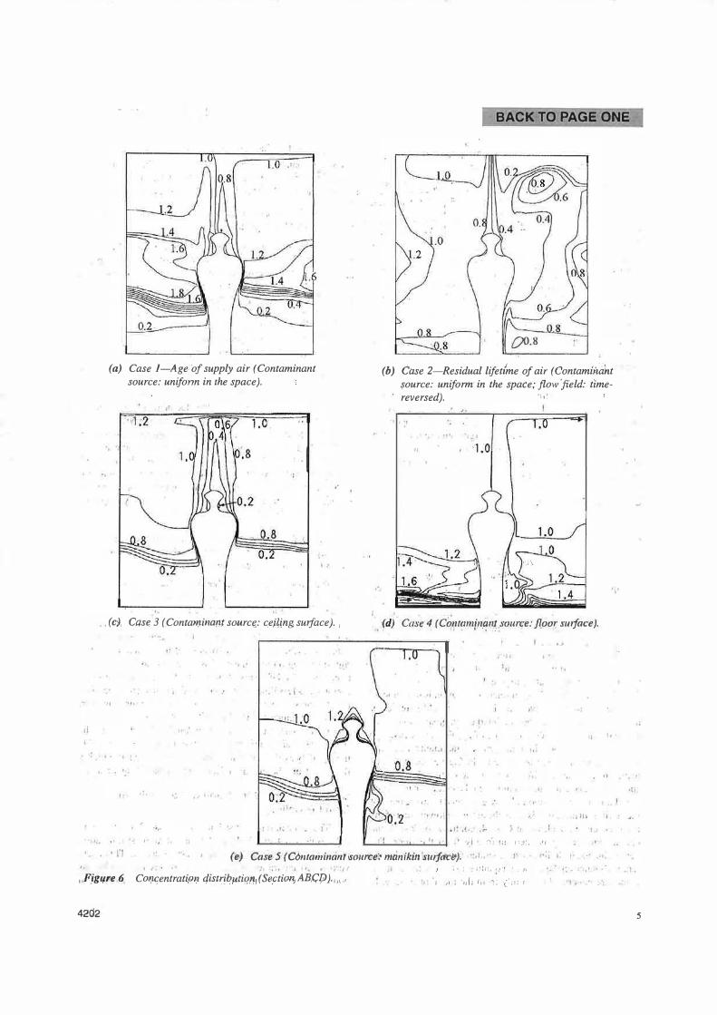
The concentratipn distribution in Case l is shown in Figure 6a and Table 4. This corresponds to the age of supply air. The mean age of supply air in Region B is 0.30. Compared with the other regions, this is the minimum value because the fresh air is supplied directly to Region B from the supply opening located near the floor. The breathing air has a value of 0.50, lower than that of the air at the breathing height (1.28). The young air is entrained and transported to the breathing position from the lower part of the room (Region B) by the rising streaip. Some part of the rising stream around the manikin is exhausted through the exhaust opening near the ceiling. The rest descends to the lower region apart from the body and then becomes old. In Region D, it has a valu� of 1. 1. The age of air becomes more than 1.8 in the region between the body's waist and breast levels. This is the highest value in the room. The obvious boundary line between the highest and the lowest value region is observed at wais� level. In Case l the modified effective entrainment ratio of the 'lower air to the breathing air is 79% (Table 4). This means 79% of the breathing air can be provided from Region B, where air is relatively young and fresh, by the rising stream.
Case 2: Uniform Generation of Contaminants Throughout the Room with Time-Reversed �irtual Field (Residual Lifetime of Air) ·
The concentration distribution in Case 2 is shown in Figure 6b and Table 4. This corresponds to the residual lifetime of air. The air near the exhaust opening has the lowest value and is quickly exhausted. The· air in Region B has the maximum value of 0.96 and takes much longer to be exhausted. Concerning the two sides of the human body, the right-hand region near the exhaust opening has lower values than that of the left. This means that the air in the right-hand region takes less timt; to be exhausted. The·mean residual lifetime of the whole space is 0.91. The breathing air, however, has a lower value of0.50. The value in Region A also becomes low at 0.69. These low values mean that the air is driven by the rising stream around' the body, rises to the upper space, and is then quickly exhausted. Thus, the contaminants can be quickly removed f�o� the vi�inity of the body by the rising stream.
Case 3: Onif9rm Generation of Contaminants fr.om the Ceiling
i The concentratron distribution in Case 3 is shown in Figures 6c and 7 and Table 4. The concentration stratification atthewaist level of the.manikin is clearly observed. This steep, vertical concentration gradient corresponds to the obvious bounaa[y' berween· 'the highest filtd lowest· concentr-atibn
4202
(a) Case I-Age of supply air (Contaminant source: unifonn in the space).
'•
':I
,.
. . (c), Case 3 (Contarl'J.incmt sourc�: ce!Ung, surface). ,
'II
. ...
.. ,.
.·
'·
' I
BACK TO PAGE ONE
£'.?0.8
(b) Case 2-Residual lifetfme of air (Contamin�'nt source: uniform· in the space; flow field: time-reversed). ·' • !
· .
...
,, ' '1.0
., .(d) Case� (C��1tamf11.�n� source: floor swface) .
I I
! ., I
f tJ I q
• • • f • -�·
, . . ... . ,
' . '
...
J" a '
..
' I
' I I :- ! f(! I �Y. .�,
•. 'l
" '
. . ,
••, . I (e) Case 5'(Clmtami11anti'io11rte:• mlinikihlslafaciJ). "•, • I' • •I
. ,, I , 1. • ' {
, F.ig1�re .� CQJ!<;entratiprJ qistributio,�1 (Sectiorv1Bl;lj) ). , 11.,
42Q2
,. : :i,1:1;. :i·r · .. )\ ·. 1: .• .t •
J �1 ; '1J!J r11 , '( ; (:1: r
5

TABLE 4 ! ,,,
. Case 1 'Case 2 Case 3 Case 4 Case 5
Mean Concentration of Room 0.91 0.9 1 0.60 1.05 0.63 Region A (near the manikin) 0.68 0.69 0.37 0.99 0.54 Region B (th� lower zone:C1) 0.30 0.96 0.02 1.20 0.06
Concentration . Region C' 0.91 0.95 0.43 1.06 o:46 Region C (breathing height: C,.1) 1.28 0.95 0.94 1:04 Q:98 Region i> ..
1.10 0.80 1.00 1.04 1.00 ' ! Breathing Air: c. 0.50 0.50 0.25 1.15 1.20
Modified Effective Entrainment Ratio of Lower Air to Breathing Aili,• 79% - 75% -69% -
,.
Concen tration I. Human body
2 ��
l -/!,, µAll: -
/!,,
0. 8 •/'i .. � /';
0. 6" ' (;.
c. ' " c.: 4_,._ r--zt /'; Case 3 A I
0.
2-.... ' :"'/!,, l
0 Case 4, ......... .-0.
(} ; •j
0.5 o'.1n 0:9 1'.1 1'.3 11.5 1.7' 11.9 2. x (th)
Figure 7 Horizantal concentration distribution at breathing level (Z = l.45"m).
'.\
; ){ It jl 1-.... •
regions obsery7d in Case L The mean. c;ont�minant concen-tratj\:!n throu&�out the room is 0.6p. T,Q.� valut'. in Regioq, I3 is· rel�tively"low at 0.02, but in RegioJ1 D it becomes .ti�gher at 1.00, equaling the contamina,ni concentrati0n of th� exhaust opening. The contaminant concentration of the breathing afr b�co;nes much lower (0.25) than that of 1Regioni C (0.94), which is located at the breathing height. This is caused1by the entrainment effect of the clean air in Region B atttibutable to the rising stream. The eharact�bstics are"also observed irt Figure 7. The modified efff:'ctive ehtralt:lhl�riiratio Of the lower rur ro the breathing air is 7:S�. c9fi!esg'on'ai;}g ��eh ·�ith Case 1: The value of 75o/o means tliat 75% �f the)jeathiqg air i transp�rted}ro� Region B. �her1, ��-�r is re°La�i�ely c�e110, The quality of tpe b,�ea�1inz �r i1_1 C�. �;;3 i� ,9u_i.te _good although the cont.amin,an� c9nc.entrali. n �t _the rbre�thing qeig� .is rather. high. The phenomeqa i;ire al�o confirme4 by th� exp,erill),eP,.t (Brphus< .and Nii�sen, 19&4). . .
;•.;r:: < H {\ ; ! • I I� I' . . . fl
Case 4: Uniform Generation of C'ontaminants from the Floor · ,r·
The concentration distrib�ilo� in Case 4 'i� sho�n in Figures 6d and 7 and Table 4. nasmu�h a. the conlaininant are generated from the floor, oie· con taminants ten<i' �o cay in
l � ' • I • , • o ,
the lower region (Region B), where th.e mean contaminant con'centration is high al 111.20. In Case· 4, the 1 contaminant concentration is dis�ibuted almost uniformly in the other regio�� of the room (Regions C, �·.and b: 'l.04 - '1.06). This distribution.properly is ?ifferent from the other cases in which the· concentration sfratification·· t · clearly ob erved. The contaminant c-0ncenu·ation of the breathing air (1. 1'5) is higher than .that qf Regiori c· (1.04) because 1he dirty air ifi Region B (1.04) converges around the body and then rises to th� 'reathing position (Figure '7). The modified effective entrainment ratio ofU1e lower air'io lhe breathing aif is-6�%.ttie abs9lute value corresponds well 'with Ca es I and 3. The chara·c1ed tic show tiiat to improve tke quality of the bre�tlling air i'/1 a room with a displacement ventilation system, itfs important to avoid contaminant generation in the lower part of the roon,i. .'.r''
Case 5: Uniform Generation of Cor,itaminants from the ManiJcin..SQiiace ·
The concentiati'on :ciistribution1\in Cas� 5 is shown in Figure fo and.Table 4. The contaminants generated from the1 manikin surface are transported from_ theJower to the upper region with the risiqg'strea)il. The m;i,*iµmm vertical gradient of contaminant concentration apPr?ars ii� wa.i t level, where the concent ration stratification is clearly observed. The mean contaminant concentration ''throughout" the' room 'is 0.63. Below the steep vertical concentration gradient, the mean contaminant concentration in Region ,B iris relativdy low at 0.06. Conversely, the contaminaJ;J,t c.oncE;ntration pf the upper, region abov t.h� bo�y. head i� �igb,at).00, whic}l equals that of the exhaust opening. The concentration f the breathing air is higher at 1.20 because the contaminants are generated from the bod)t sllrfike'itself. In this ca'se ( otie persdi\ in a room), the concept of the effective entrainment ratio of the loWer air to the broathing aif is n�t available (Note'B):1However; in the situa�
,:;11, .
4202

tion where many people are in a room, the contaminant concentration in the upper zone of the room is proportional to the number of people and becomes higher. The breathing air, however, is still relatively clean because the people do hot.· contaminate the air in the lower zone.
CONCLUSIONS 1. Similar to temperature stratification, concentration stratifi
cation nlso appears in Lhe stngnan.t flow field in a room that 'is air-conditioned with a displacement ventilation system. This property is clearly explained by the distribution of the age of supply air.
2. The rising stream from metabolic heat production, as well as the concentration stratificatiOn, has great influence on the quality of the breathing air. These characteristics are clearly ,comprehensible with the distrib�tion of the age of supply air and the residual lifetime of air.
3. To evaluate the influence of the entrainment effect with the ri ing stream ori the quali.ty of the breaU1i11g air, llle modified effective entr'ainmen)., ratio of the lower air to lhe breathi'ng air is proposed. 'J;11e useft1lness of �ie ind�x is . dernonst.ra�ed wit 1 several !ocati.ons of contammrun gener-ation.
'fi
4. If the ri�ing s,tre� arou�d the body surface is not broken by the surrounding airflow, ;\}'hether it enharices or decre�es the quality of the breathing air deP,ends. on the location of i;he contaminant generation. The rising s).!:eam has a P.OSitive influence on th�· quality of the bre'\�hing air when the cor!Fnants are g�nerate<;l ip. the upper part of �e; room, abo,y� the breaLhing he;.ight, and the ai� in the lower part of t:he roQrn is ri;:)ativeJy clean. Conyer.ely, the r,i. ing si:ream h� a n�gative effect when the contaminanL is genei;ated in u:1e lower paq,qf d1e room, below �e breaihing height, and the air in the lower p�·� is relalivelY, dirty. . . . . . .
NOMENCLATURE A
c. cf c,..,f . ,
D k p Q T u E
1lt • ) ,
11, c
4202'
= area()f'Supply opening, m2 ,, I
= contaminant concentration 6f breathing air = contaminant concentration neat Jloor ·:. ' ·
= contaminant concentration apart· from body at breathing-height ' '
= · hydraulihliameter, D = 4'A/P,'rri
= turbulent energy, m2!s2 ' ' . :::: perimeter of supply opc�ing, � _ . ,
= convec.tive heal tran.�fer rate, W/m2, , • · • •
= mean temp.�rature, ?C , · : · .. ··
=·mean veloeity,m/s .r: ·'' · · 1
· = dlSs-ipa1jon'ra1e·oftutbulenL1energy, fu2ts3,' ' . r 11/2 2 ,. ' ,, ' :
t = t-v(dk /dx) . , =, eff�t.i ve �nti1\i���ent ratio oflower !lir tq bryathi11g
air '" ' ' :i·
= modified, effective enJ;rainment ratio of kiwer air. to breathing air
BACK TO PAGE ONE
Subscripts ·= 1, 2, and 3, denotes x, y, and z directions, respectively
in = value of supply opening w :: value of surface
NOTE A' "
In thi.s 'paper, to es'timate the representative concentrations such as c1and Cref the author divided the room space into five regions: Region A, arourid the manikin within 30 cm, where the rising stream is located; Region B, between floor level and waist level,.where the temperature gradient is steepest; Region C', up to the neck levdi Region C, up to a little higher than head level, called the J:u;eathing height; and Region D, the remainder.
NOTE B There are actually a few cases in which the boundary
between the zones of high concentration and low concentration cannot, be clearly differentjated. The applicability of differentiating these two zone.� in the given space would require further discussion. The index Tl*• cannot be well estimated in the following cases: (a) when the contaminant concentration is distributed almost uniformly and the concentration stratification does not obviously appear, which often occurred in the room with a traditional mixing-type air-conditioning system; (b) when the position of the concentration stratification is located above the breathing position; ( c) when the contami.J1ants are generated frorn a human body's surface, the contamfi:iant.concenlration of the. breathing air cannot be decided by those' two components, i.e., cf and c,.p
REFERENCES. ASHRAE. 1993. 1993 ASHRAE handbook_:_Fundamentals,
Chapter 8. Atlanta: Amedcan Society of_ Heating, ·Refrigerating anlfAir-Conditioning Engineers, Inc.
Brohus, H., and P.V. N'Ielseh: 1994. Contaminaht distribution ! around persons in 'rooms ventilated by displaceinent
ventilation. P.roc'eedings of Roomvent '94, · Poland, pp. 294-312.
Hyldgaard, C:E. !1994. Mumans as a source of heat and air pollutiqn. Pror;eedings of R.oomvent .'94, Poland, .pp. 4p-43,3.
Kato, S., S. Murakami, and H, Kobayashi. 1992. New scales ' for \:V.ajµating
'ventiiattp� �fficiency as affected by sup
. ply' an� exhau�t opening based on pal\al distri.bµtion of coniiminanis. Proceedings oj !SRACVE, Universil"J
'"o/T�kjo· pp.''.h1:332. · r· '
Kato, 'S.,1 s'. Murakami, and J. Zeng. 1996. Numcri'cal 'imalysis o'f con·taminant 'd��tribuLion around'
a human body. RO(')MVENT '96, Vol."2.·pp. !'29-136:•
.
Kim, LG., H. Plomma,'·afld E.t-Nihonnya. '1991. Mov6merit and distribution of occupant product ventilation subjects in a room. Part 8, Influence of numbers of models on
7

ventilation efficiency. Proceedings of Annual Technical Meeting of SHASE, pp. 1093-1096 (in Japanese).
L11under, B.E., and B.I. Sharma. 1974. Application of the energy-dissipation model of turbulence to the calculation of flow near a spinning disc. Letters in Heat and Mass Transfer 1: 131-138.
Murakami, S. 1992. New scales for ventilation efficiency and their application based on numerical simulation of room airflow. Proceedings of ISRACVE, University of Tokyo, pp. 22-37.
Murakami, S., S. Kato, and J. Zeng. 1997. Flow and temperature fields around human body with various room air
8
BACK TO PAGE ONE
distributions, CFD study on computational thermal
manikin-Part 1. ASHRAE Transactions 1 03 (1): 3-15.
SHASE. 1987. Benran 1 (fundamentals), Chapter 3 (in Japa
nese).
Zeng, J., S. Murakami, S. Kato, and T. Hayashi. 1997. Study
on computational thermal manikin-Part 9, Coupled
simulation of convective and radiant heat transfer of
thermal nianikin with low-Reynolds-number type k-E (B model). Proceedings of Annual Technical Meeting of
SHASE, pp. 101-104 (in Japanese).
4202