
airbase_4354.pdf - AIVC
10
Building Serv. Eng. Res. Technol . 9(3) 89-98 (1988) Printed in Great Britain Summary The paper describes a study of variable pitch and variable speed fans in temperature controlled and constant pressure controlled VAV systems using computer simulated building models and weather data. Comparison of variable pitch fans and variable speed fans variable air volume system . 1n a CM JOHNSON The Brian Warwicker Parmership, BWP House, The Street, Ardleigh, Colchester, C07 7LD, UKt Received 6 April 1987, in final form 11 January l988l 1 Introduction One of the ways in which building services design has been changing is to make building systems more economic both in initial design and installation and in running costs. Both criteria must be met while still producing the highest stan- dards of comfort within a space. The correct conditions within a space obviously depend upon the room load at any given time; over the years it has become apparent to most energy users that they can vary the flow of conditioned air and water and, to some extent, electricity into a space and vary the energy consumed, thus saving money. Perhaps the most effective way to the economic and efficient control of a room space is to vary the volume of air supplied to that space according to its heating or cooling loads. These loads may be machine, solar, human or even animal depending upon the space application. The mass flow of air has an effect on the main plant both through initial sizing and through running times, so that as the air flow is varied, not only is the fan using different amounts of electricity, but · so is the main plant. This has the beneficial effect of saving energy in all forms and reducing the chemical dosage costs in water systems. The type of system which varies air flow with load is known as a variable air volume system or VAV for short. In this system the fans are the prime movers and they fall into two distinct categories, variable pitch and variable speed fans. It is the aim of this paper to identify the suitability of each type of variable volume fan in a VAV system. 2 Space simulation In a study of this type, it is obviously a good idea to use an existing system and replace the fans when each stage of the observation is complete. This is always a difficult task because it is not always easy to persuade a user to allow one to 'mess around' with bis building over a two-year period while readings are taken and fans changed. It is also expens- ive in both time and equipment costs. Space simulation by computer model is the quickest and most economical solution and after approaching several com- panies we collaborated with a well-known company which is part of a prominent building services consultancy. The t The author submitted the paper while at Myson Fans Limited, Colchester. l The paper was presented at the 1987 CIBSE Technical Conference company provided a space which could be studied in all respects through their special building services simulation program. This program allows changes in main plant without changing the overall system and shows the effect of the changes on the space both in air change rate and running cost, allowing a designer to optimise his design before ic is installed. Energy management systems may also be simu- lated and their effects studied. For this investigation the company provided one floor of an office block which was already on computer file. There are indications of a trend towards sublet floors of large office blocks and other buildings having their own self- contained and metered main plant systems, removing the requirement for large central plant. To achieve a 'typical' floor simulation, we decided that a mid floor should be used to focus the effect of the fans and to remove extra roof gains and floor losses. The floor dimensions are given in Figure 1. The area was sub-divided into five zones: Zone I-Central Zone-30 m long x 10 m wide; Zone 2-North Zone-5 m long x 20 m wide; Zone 3-East Zone-40 m long x 5 m wide; Zone 4--West Zone--40 m long x 5 m wide· Zone 5-South Zone-5 m long x 20 m wide. The building is located in the London area with a north-south orientation, although the floor in question is nee affected by shading from other buildings. According to the computer output the space is a standard building structure comprising concrete cladding external walls and 70% double glazing of the absorptive tYPe. To separate the zones, internal parritions made of plasterboard with glass fibre insulation are used. The whole structure ' E / N ' In / A 'f - --( I 10ml CONCRETE I I CONCRETE FLOOR/SLAB CLADDING le I e I { 0 10 I .., IM I I 15m I I I I I }- ---t.. I· Sm / ' / ' I· 20m ·I ABSORPTIVE DOUBLE GLAZING Figure 1 Building plan and dimensions © 1988 The Chartered Institution of Building Services Engineers 89 ;· I ,I ;i l ;. ' i ,,
-
Upload
khangminh22 -
Category
Documents
-
view
1 -
download
0
Transcript of airbase_4354.pdf - AIVC

Building Serv. Eng. Res. Technol . 9(3) 89-98 (1988) Printed in Great Britain
Summary The paper describes a study of variable pitch and variable speed fans in temperature controlled and constant pressure controlled VAV systems using computer simulated building models and weather data.
Comparison of variable pitch fans and variable speed fans variable air volume system
. 1n a
CM JOHNSON The Brian Warwicker Parmership, BWP House, The Street, Ardleigh, Colchester, C07 7LD, UKt
Received 6 April 1987, in final form 11 January l988l
1 Introduction
One of the ways in which building services design has been changing is to make building systems more economic both in initial design and installation and in running costs. Both criteria must be met while still producing the highest standards of comfort within a space. The correct conditions within a space obviously depend upon the room load at any given time; over the years it has become apparent to most energy users that they can vary the flow of conditioned air and water and, to some extent, electricity into a space and vary the energy consumed, thus saving money.
Perhaps the most effective way to the economic and efficient control of a room space is to vary the volume of air supplied to that space according to its heating or cooling loads. These loads may be machine, solar, human or even animal depending upon the space application. The mass flow of air has an effect on the main plant both through initial sizing and through running times, so that as the air flow is varied, not only is the fan using different amounts of electricity, but ·so is the main plant. This has the beneficial effect of saving energy in all forms and reducing the chemical dosage costs in water systems.
The type of system which varies air flow with load is known as a variable air volume system or VAV for short. In this system the fans are the prime movers and they fall into two distinct categories, variable pitch and variable speed fans. It is the aim of this paper to identify the suitability of each type of variable volume fan in a VAV system.
2 Space simulation
In a study of this type, it is obviously a good idea to use an existing system and replace the fans when each stage of the observation is complete. This is always a difficult task because it is not always easy to persuade a user to allow one to 'mess around' with bis building over a two-year period while readings are taken and fans changed. It is also expensive in both time and equipment costs.
Space simulation by computer model is the quickest and most economical solution and after approaching several companies we collaborated with a well-known company which is part of a prominent building services consultancy. The
t The author submitted the paper while at Myson Fans Limited, Colchester.
l The paper was presented at the 1987 CIBSE Technical Conference
company provided a space which could be studied in all respects through their special building services simulation program. This program allows changes in main plant without changing the overall system and shows the effect of the changes on the space both in air change rate and running cost, allowing a designer to optimise his design before ic is installed. Energy management systems may also be simulated and their effects studied. For this investigation the company provided one floor of an office block which was already on computer file.
There are indications of a trend towards sublet floors of large office blocks and other buildings having their own selfcontained and metered main plant systems, removing the requirement for large central plant. To achieve a 'typical' floor simulation, we decided that a mid floor should be used to focus the effect of the fans and to remove extra roof gains and floor losses. The floor dimensions are given in Figure 1.
The area was sub-divided into five zones: Zone I-Central Zone-30 m long x 10 m wide; Zone 2-North Zone-5 m long x 20 m wide; Zone 3-East Zone-40 m long x 5 m wide; Zone 4--West Zone--40 m long x 5 m wide· Zone 5-South Zone-5 m long x 20 m wide. The building is located in the London area with a north-south orientation, although the floor in question is nee affected by shading from other buildings.
According to the computer output the space is a standard building structure comprising concrete cladding external walls and 70% double glazing of the absorptive tYPe. To separate the zones, internal parritions made of plasterboard with glass fibre insulation are used. The whole structure
' E / N ' In
/ A 'f - --( I 10ml CONCRETE
I I CONCRETE FLOOR/SLAB CLADDING
le I e I
{ 0 10 I .., IM I I 15m I I I I I }- ---t.. I· Sm
/ ' / ' I· 20m ·I ABSORPTIVE
DOUBLE GLAZING
Figure 1 Building plan and dimensions
© 1988 The Chartered Institution of Building Services Engineers 89
;·
I
,I
;i
l ;.
' i ~·! ,,
CM Johnson
100
PERCENTAGE FLOW RATE OF FRESH AIR
I I ---r----- ---
1 I I I I I I I I 1 I I I I I I I I
10 i--- ---f·- ____ I ___ ..._ ___ _ 0 I I
0 4 10 14 20 21 30
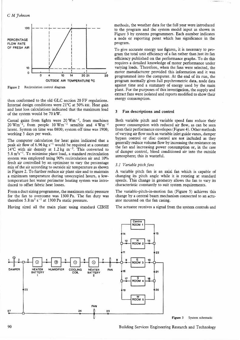
OUTSIDE AIR TEMPERATURE oc Figure 2 Recirculation control diagram
then conformed to the old GLC section 20 FF regulations. Internal design conditions were 21°C at 50% RH. Heat gain and heat loss calculations indicated that the maximum load of the system would be 70 kW.
Casual gains from lights were 20 Wm -z, from machines 2owm- 2, from people 10wm-2 sensible and 4Wm-2
latent. System on time was 0800; system off time was 1900; working 5 days per week.
The computer calculation for heat gains indicated that a peak air flow of 6.96 kg s- 1 would be required at a constant 14°C with air density at 1.2 kg m-3• This converted to 5.8 m3s- 1
• To minimise plant load, a standard recirculation system was employed using 90% recirculation air and 10% fresh air controlled by an optimiser to vary the percentage mix of the air according to outside air temperature as shown in Figure 2. To further reduce air plant size and to maintain a minimum temperature during unoccupied hours, a lowtemperature hot water perimeter heating system was introduced to offset fabric heat losses.
From a duct sizing programme, the maximum static pressure for the fan to overcome was 1300 Pa. The fan duty was therefore 5.8 m3 s- 1 at 1300 Pa static pressure.
Having sized all the main plant using standard CIBSE
2
DAMPER
25
FAN
27 24 23
90
methods, the weather data for the full year were introduced to the program and the system model input as shown in Figure 3 by systems programmers. Each number indicates a node or reporting point which has significance in the program.
To give accurate energy use figures, it is necessary to program the total unit efficiency of a fan rather than just its fan efficiency published on the performance graphs. To do this requires a detailed knowledge of motor performance under varying loads. Therefore, when the fans were selected, the motor manufacturer provided this information and it was programmed into the computer. At the end of its run, the program normally gives full psychrometric data, node data against time and a summary of energy used by the main plant. For the purposes of this investigation, the supply and extract fans were isolated and reports modified to show their energy consumption.
3 Fan descriptions and control
Both variable pitch and variable speed fans reduce their power consumption with reduced air flow, as can be seen from their performance envelopes (Figure 4). Other methods of varying air flow such as variable inlet guide vanes , damper bypass control or disc control are not included as they generally reduce volume flow by increasing the resistance on the fan and increasing power consumption or, in the case of damper control, bleed conditioned air into the outside atmosphere; this is wasteful.
3 .1 Variable pitch fans
A variable pitch fan is an axial fan which is capable of changing its pitch angle while it is rotating at standard speeds. This change in geometry allows the fan to vary its characteristic constantly to suit system requirements.
The variable-pitch-in-motion fan (Figure 5) achieves this change by a central beam mechanism connected to an actuator mounted on the fan casing.
The actuator receives a signal from the system controls and
Centre ROOM 1
14 15
N ROOM 2
22
E 10 ROOM 3
21
s ROOM 4
19 20
w ROOM 5
Figure 3 System schematic
Building Services Engineering Research and Technology

VOLUMETRIC FLOW .. 101 1.- 110 XM 111 J06 l•IOGI
" ,. !>I 6fi I 6 8 ~ lft'l•O
-wa.---,..--.---r----.- --.---r---r--i----ri
Ill a: ~ •ool-----11-t\--i'j,-!--\-l--H>,----'1.-----P.....,.--!.,..-#-l---+-1 I/I Ill * ~ •ool---h-':~~;.,...>/r---j'-\---'<->r-!--'.....+~r-¥_,_-f---+-1 u ~ •ool---l--~i--"+li<-~----'__,,---\-#-~-+--t;..,--+-1 ... I/I
* ~ •ool---1-----li>\-'---lrt<.-->ti-...,------Jf-\--lf--\--i-t+-"Mt--:---+-i II.
9 Jool---l---l--\~f-+-"li--'-..,j~~__,r+-t""'1,.-,\"~""t-1
IL
Qdn1 0 lO .. ., .. . .. "' '"' ·· ~-,..-~.---,.L-~-~---+.,.--,.-----,-,
" 00 l---l-----li---li----1----1--:::::1:=-'-t--t----H
630mm VARIABLE PITCH FAN 2990 RPM 415/ 3ph/ SO Hz
20 ).JO 1000
171.80 17~
101,60 1000
Ill.PO 7!'10
1•1091 0 0
•w 18.6-tl
14.914
, 1.186
7A57
'~"
Fans in V AV systems
VOLUMETRIC FLOW
... .. '" ,,,.,,1) .. , ],8 )8 d, / )I,,/ II.fl 1,6 8!'1
"'"'WG ii'• iM w 0 ' .--,..---.--.-------,----,-.....-.,.--.,.--,----. '"·"' T ""' Ill t---i---1.-----t-----1-----+.,__--+--+-~ 1!'11.40 1.-.00 a: :I I/I I/I Ill a: IL
u 5 ... I/I
z c II.
-• IL
630mm VARISPEED FAN
16.JO ISO
'" • 0
hlOOI
24" PITCH ANGLE AEROFOIL IMPELLER Figure 4 Typical performance envelopes for variable pitch and variable speed fans showing power reduction with flow reduction
moves the beam either backwards or forwards depending on the signal. The beam is pivoted at the bottom of the casing and is attached to the hub or impeller by a mechanical link on the fan centre line.
The link is attached to a control disc via a push-pull bearing. The control disc slides along a specially coated low-friction shaft and has a groove around its maximum circumference into which the arms of carrier units are connected.
These carrier units are fixed to the wing roots to turn the linear movement of the disc into a rotary motion at the wing,
ADJUSTABLE CYLINDER LINK
CONTROL CYLINDER
Figure 5 Layout of variable pitch fan (schematic)
Vol. 9 No. 3 (1988)
I --- _,
ft
so that as the beam moves foward, the pitch angle of the blades increases, increasing air flow. The forces on the controller are reduced when a lower pitch angle is required because the centrifugal and aerodynamic forces on the wings assist it to reduce pitch angle naturally.
The motor is mounted directly to the impeller and is cooled by the airstream in the duct flowing over it. It is also mounted using downstream guide vanes which increase the fan's pressure development and straighten the air flow after the impeller.
The fan chosen for this simulation was a 630 mm diameter, nine-wing unit operating at 2990 rpm and using a 160 frame size air stream rated motor.
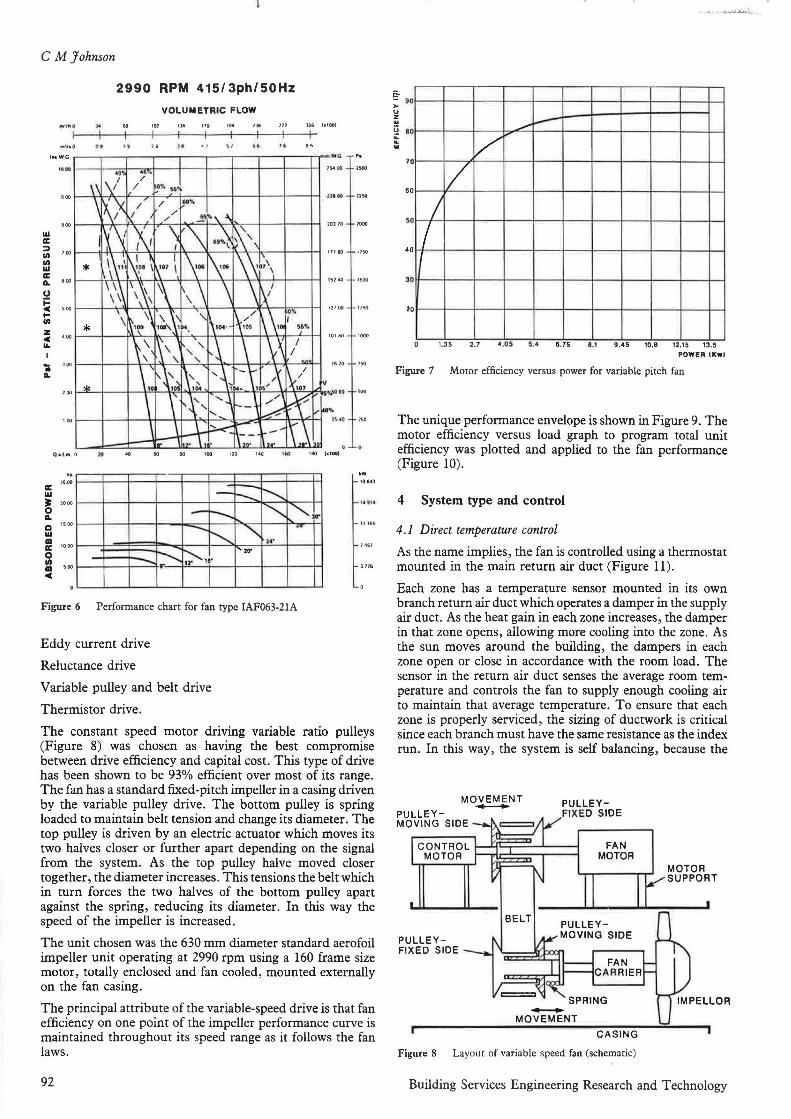
As can be seen from the performance curve (Figure 6) this fan has an optimum efficiency point where the wing design, pitch angle, speed of rotation and motor size are at their peak performance. Thereafter, the fan efficiency reduces at all volumes and pressures. To input the fan characteristics into the computer, the motor efficiency versus load characteristic was required. The motor manufacturer provided this information and Figure 7 was plotted and applied to the fan performance.
3 .2 Vari.able speed fans
There are several methods of varying fan speed:
Inverter drive
91
CM Johnson
2990 RPM 415/3ph/50Hz
VOLUMETRIC FLOW .. 101 136 110 11M "' J06 1•1001
Ill IC ::i .,, .,, I.II
.,..,.o •• •• .. , , u ,. "
~ oool-----il'r-':--\.4.-...\\.----.+.\-->r----'r-l--\--t--\--'f-..._l----iH 0
~ •ool-----il--'~--4+4.~r-+-'<--+-~+-----:"'"""~1=---iH ... Ill
~ •ool--~l---f'°\->---ft"<-"\f-"'""<--1--'r--+-'t---H--T-lt-~H I&.
~ 1ool--~l---~-4-..:...+4--~~"<+--4>-r:l--+--1:-'+.,f--"">iH a..
IC Ill
Qc l m 0
hp
2!H>O
:r: 2000
0 a.. a 1soo
I.II Ill a: 1000
0 .,, Ill soo c
..
-..... -............. "
-,__ - t--. ~ - r--..t-.. ~ "-., .. -- " ..
r--...... ,.. ~, .. ", ..
Figure 6 Performance chart for fan type IAF063-21A
Eddy current drive
Reluctance drive
Variable pulley and belt drive
Thermistor drive.
..
111 80 1750
151.IO 1500
12100 oso
101 60 1000
16 io 1SO
n.•o 2so
1864)
11181i
)118
The constant speed motor driving variable ratio pulleys (Figure 8) was chosen as having the best compromise between drive efficiency and capital cost. This type of drive has been shown to be 93% efficient over most of its range. The fan has a standard fixed-pitch impeller in a casing driven by the variable pulley drive. The bottom pulley is spring loaded to maintain belt tension and change its diameter. The top pulley is driven by an electric actuator which moves its two halves closer or further apart depending on the signal from the system. As the top pulley halve moved closer together, the diameter increases. This tensions the belt which in turn forces the two halves of the bottom pulley apart against the spring, reducing its diameter. In this way the speed of the impeller is increased.
The unit chosen was the 630 mm diameter standard aerofoil impeller unit operating at 2990 rpm using a 160 frame size motor, totally enclosed and fan cooled, mounted externally on the fan casing.
The principal attribute of the variable-speed drive is that fan efficiency on one point of the impeller performance curve is maintained throughout its speed range as it follows the fan laws.
92
§- 90 ,_ u z .. (j 80 ii: .. ...
70
60
50
40
30
20
----/"
1/ I I I
1.35 2.7 4 .05 5 .4 6 .75 8.1 9.45 10.B 12.15 13.5
POWER IKwl
Figure 7 Motor efficiency versus power for variable pitch fan
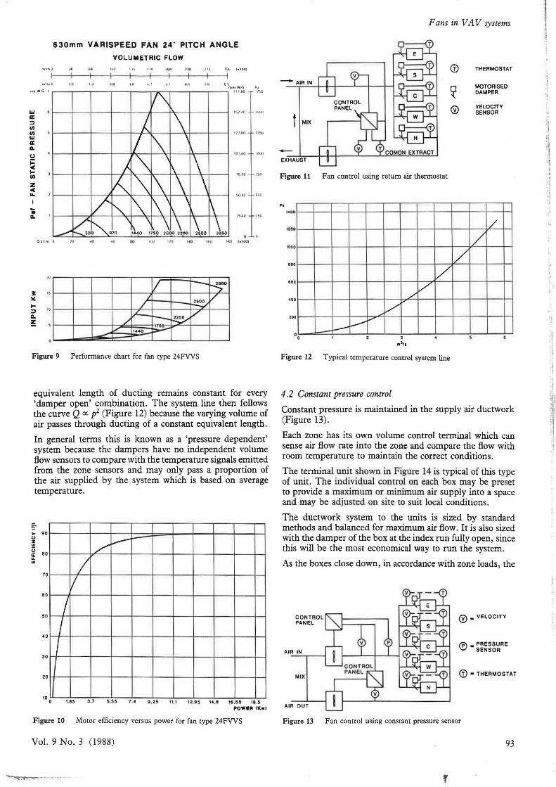
The unique performance envelope is shown in Figure 9. The motor efficiency versus load graph to program total unit efficiency was plotted and applied to the fan performance (Figure 10).
4 System type and control
4. I Direct temperature control
As the name implies, the fan is controlled using a thermostat mounted in the main return air duct (Figure 11).
Each zone has a temperature sensor mounted in its own branch return air duct which operates a damper in the supply air duct. As the heat gain in each zone increases, the damper in that zone opens, allowing more cooling into the zone. As the sun moves around the building, the dampers in each zone open or close in accordance with the room load. The sensor in the return air duct senses the average room temperature and controls the fan to supply enough cooling air to maintain that average temperature. To ensure that each zone is properly serviced, the sizing of ductwork is critical since each branch must have the same resistance as the index run. In this way, the system is self balancing, because the
MOVEMENT -PULLEYMOVING SIDE
CONTROL MOTOR
PULLEYFIXED SIDE
PULLEYFIXED SIDE
FAN MOTOR
-MOVEMENT
CASING
Figure 8 Layout of variable speed fan (schematic)
Building Services Engineering Research and Technology
Ill a: ::I en Ill w a: G.
0 j:::
"' I-Ill
z "' ... I -• G.
630mm VARISPEED FAN 24· PITCH ANGLE
VOLUMETRIC FLOW .. 10} IJ'i 110 IO• 1,)1 Il l JOt. 1•1001
15, 40
t HOO
IOI.Ml
76'0
5080
1lil.40
• Qclm O " .. 60 .. •oo 110 ... 160 ISO C• tOOI
v --~o J /
/ ~ IL v
,,I - ~ 1750
" "
..... 1• •0 ,,,_...
Figure 9 Performance chart for fan type 24FVVS
.. 1150
1751J
100~
''°
500
'"
equivalent length of ducting remains constant for every 'damper open' combination. The system line then follows the curve Q cc p2 (Figure 12) because the varying volume of air passes through ducting of a constant equivalent length.
In general terms this is known as a 'pressure dependent' system because the dampers have no independent volume flow sensors to compare with the temperature signals emitted from the zone sensors and may only pass a proportion of the air supplied by the system which is based on average temperature.
§-,.. 90 u z .. §
BO ... / ---... .. 70
I I
60
5 0
40
I I I
30
20
1.85 3.7 5.55 7.4 9 . 2 5 11.1 12.95 14 .8 18 .65 18.5 POWEii IK•I
Figure 10 Motor efficiency versus power for fan type 24FVVS
Vol. 9 No. 3 (1 988)
Fans in VA V systems
(j) THERMOSTAT
-AIRIN
~ MOTORISED DAMPER
© VELOCITY SENSOR t MIX
-EXHAUST
Figure 11 Fan control using return air thermostat
Pl
i:too /
10D0 /
/ BOO v 800
/ /
_,,V .... 4 00
20 0 ....-i---~ -0
Figure 12 T ypical temperature control system line
4.2 Constant pressure control
Constant pressure is maintained in the supply air ductwork (Figure 13).
Each zone has its own volume control terminal which can sense air flow rate into the zone and compare the flow with room temperatur~ to maintain the correct conditions.
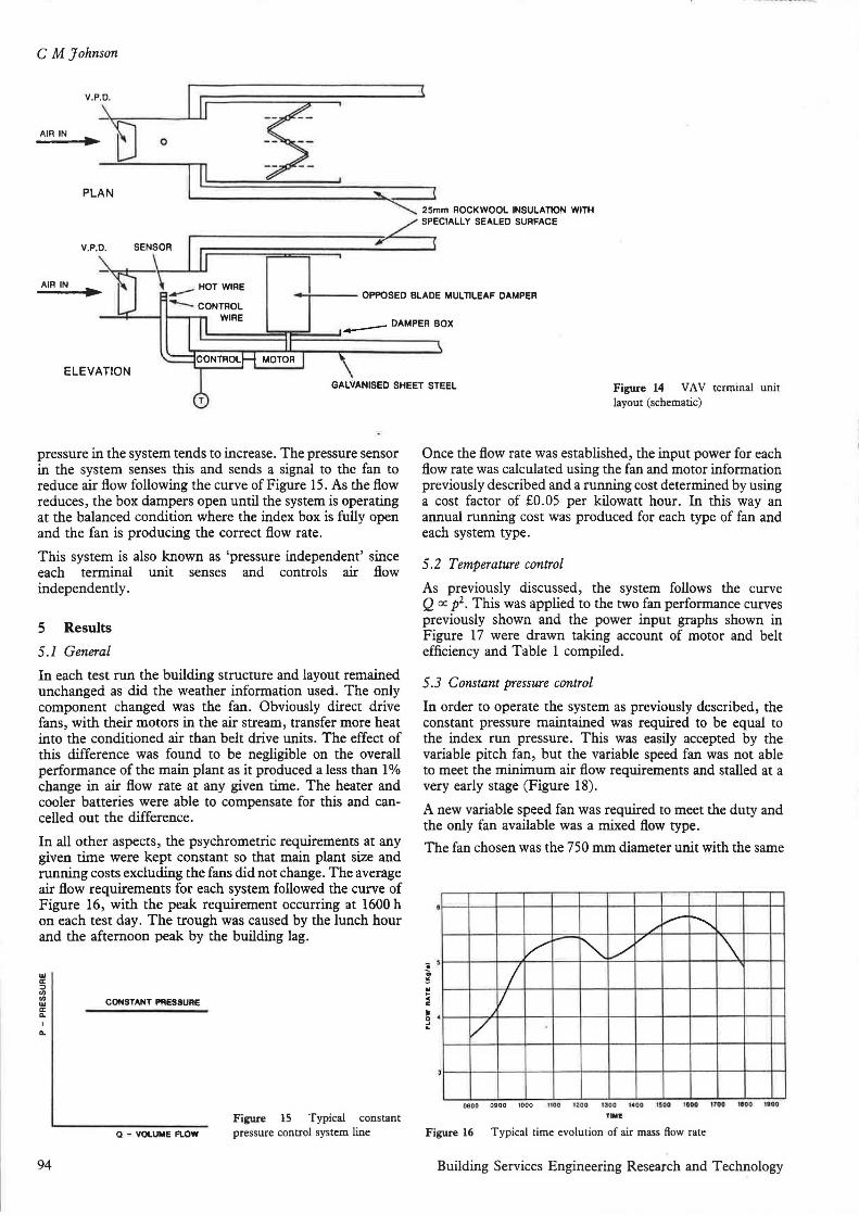
The terminal unit shown in Figure 14 is typical of this type of unit. The individual control on each box may be preset to provide a maximum or minimum air supply into a space and may be adjusted on site to suit local conditions .
The ductwork system to the units is sized by standard methods and balanced for maximum air flow. It is also sized with the damper of the box at the index run fully open, since this will be the most economical way to run the system.
As the boxes close down, in accordance with zone loads, the
CONTROL PANEL
AIR IN
MIX
AIR OUT
©•VELOCITY
(j) • THERMOSTAT
Figure 13 Fan control using constant pressure sensor
93
'
; ' .. .,
'I ' I :\ i
·1
,I
' i ~ I
'
CM Johnson
AIR IN
PLAN "--. 25mm ROCKWOOL INSULATION WITH
SPECIALLY SEALED SURFACE
AIR IN .. -..;,....--- - OPPOSED BLADE MUL TlLEAF DAMPER
ELEVATION
pressure in the system tends to increase. The pressure sensor in the system senses this and sends a signal to the fan to reduce air flow following the curve of Figure 15. As the flow reduces, the box dampers open until the system is operating at the balanced condition where the index box is fully open and the fan is producing the correct fl.ow rate.
This system is also known as 'pressure independent' since each terminal unit senses and controls air flow independently.
5 Results
5.1 General
In each test run the building structure and layout remained unchanged as did the weather information used. The only component changed was the fan. Obviously direct drive fans, with their motors in the air stream, transfer more heat into the conditioned air than belt drive units. The effect of this difference was found to be negligible on the overall performance of the main plant as it produced a less than 1 % change in air flow rate at any given time. The heater and cooler batteries were able to compensate for this and cancelled out the difference.
In all other aspects, the psychrometric requirements at any given time were kept constant so that main plant size and running costs excluding the fans did not change. The average air flow requirements for each system followed the curve of Figure 16, with the peak requirement occurring at 1600 h on each test day. The trough was caused by the lunch hour and the afternoon peak by the building lag.
w a: :i
"' "' w a: 0..
I
0..
94
CONSTANT PRESSURE
Figure 15 Typical constant Q - VOl.UME F\.OW pressure control system line
Figure 14 VA V terminal unit layout (schematic)
Once the flow rate was established, the input power for each flow rate was calculated using the fan and motor information previously described and a running cost determined by using a cost factor of £0.05 per kilowatt hour. In this way an annual running cost was produced for each type of fan and each system type.
5.2 Temperature control
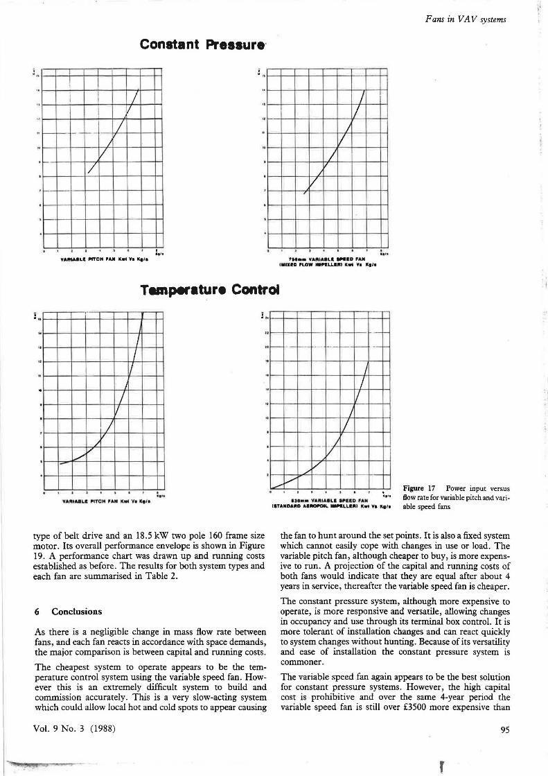
As previously discussed, the system follows the curve Q cc p2• This was applied to the two fan performance curves previously shown and the power input graphs shown in Figure 17 were drawn taking account of motor and belt efficiency and Table 1 compiled.
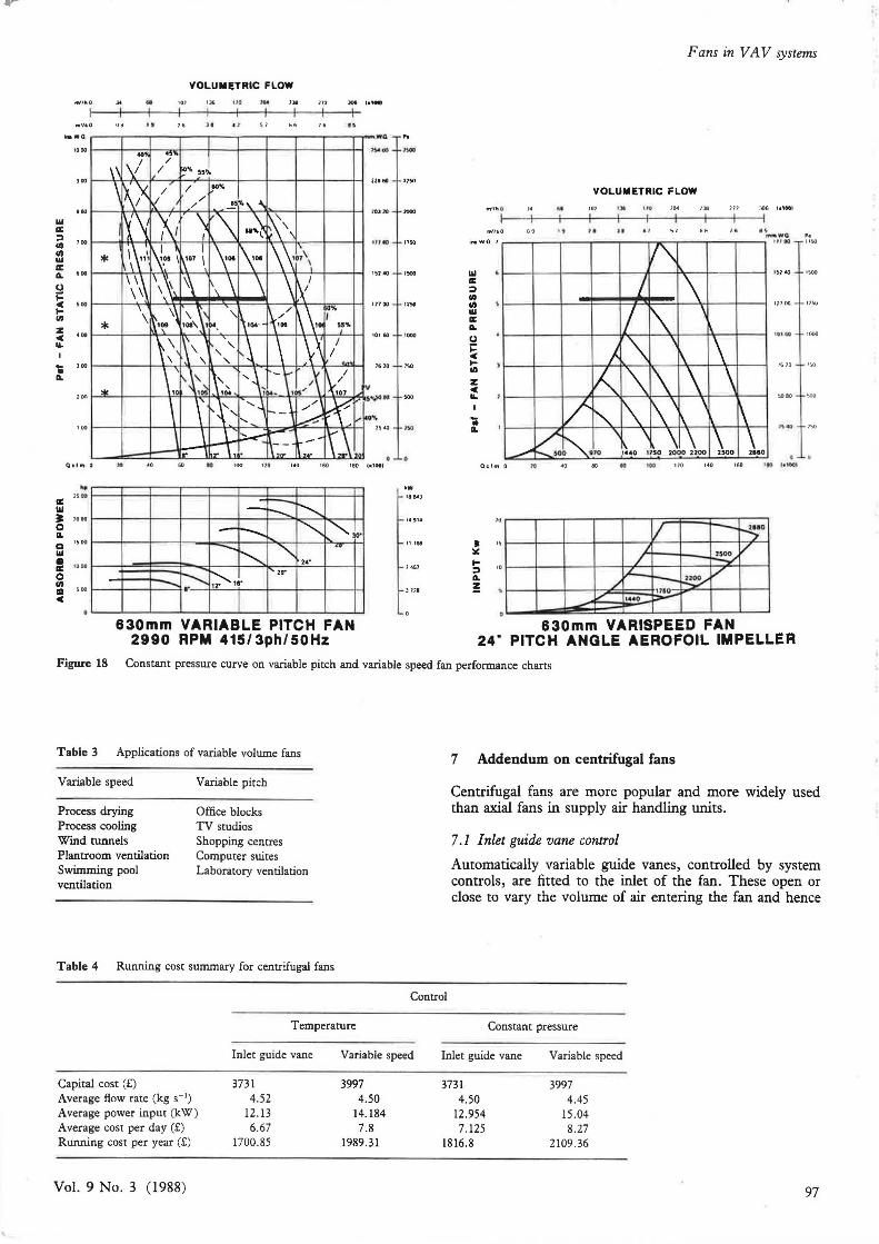
5 .3 Constant pressure control
In order to operate the system as previously described, the constant pressure maintained was required to be equal to the index run pressure. This was easily accepted by the variable pitch fan, but the variable speed fan was not able to meet the minimum air fl.ow requirements and stalled at a very early stage (Figure 18).
A new variable speed fan was required to meet the duty and the only fan available was a mixed flow type.
The fan chosen was the 750 mm diameter unit with the same
/ v-~
/,_ ~ / \ /
I v J
/
080 0 0900 1000 1100 l:i.!00 1300 1•00 ISOO 1000 1700 11100 UIOO
TIME
Figure 16 Typical time evolution of air mass How rate
Building Services Engineering Research and Technology
·--• .
I
I I
I _.,___
II
I I
/
-
I v
I
Constant Pressure·
. .,,.
..
..
.
VAlllA8LI PITCH PAii II.wt Vo ... lo
I I
J I
/ /
J
/ ,
fl••• VAlllAaLa -·D PAM llllHD PLOW _.LLRlll K• Vo K1lo
Fans in VA V systems
T.mperature Control
i . ..
I /
/
/ ,,,,, . -
I
I I
I I I
. .....
. . ..
type of belt drive and an 18.S kW two pole 160 frame size motor. Its overall performance envelope is shown in Figure 19. A performance chart was drawn up and running costs established as before. The results for both system types and each fan are summarised in Table 2.
6 Conclusions
As there is a negligible change in mass flow rate between fans, and each fan reacts in accordance with space demands, the major comparison is between capital and running costs.
The cheapest system to operate appears to be the temperature control system using the variable speed fan. However this is an extremely difficult system to build and commission accurately. This is a very slow-acting system which could allow local hot and cold spots to appear causing
Vol. 9 No. 3 (1988)
- -- -- ,__ ·-· - -
I
/ I
J
I - ---_J
v /
/
_,.,... v UOM• VAIUAaLll WHO PAM
llTAllDAllD Aa-L -LLalll Kwl Yo K9/1
Figure 17 Power input versus flow rate for variable pitch and variable speed fans
the fan to hunt around the set points. It is also a fixed system which cannot easily cope with changes in use or load. The variable pitch fan, although cheaper to buy, is more expensive to run. A projection of the capital and running costs of both fans would indicate that they are equal after about 4 years in service, thereafter the variable speed fan is cheaper.
The constant pressure system, although more expensive to operate, is more responsive and versatile, allowing changes in occupancy and use through its terminal box control. It is more tolerant of installation changes and can react quickly to system changes without hunting. Because of its versatility and ease of installation the constant pressure system is commoner.
The variable speed fan again appears to be the best solution for constant pressure systems. However, the high capital cost is prohibitive and over the same 4-year period the variable speed fan is still over £3500 more expensive than
95
r
CM Johnson
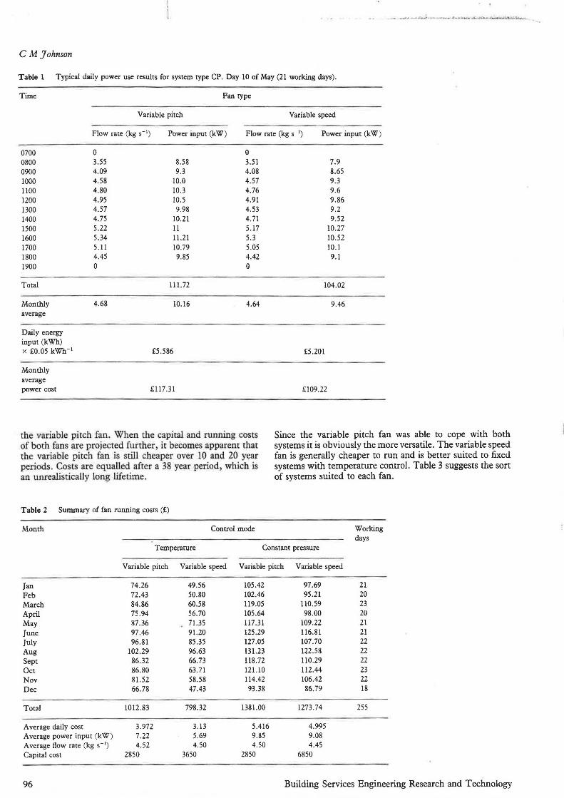
Table 1 Typical daily power use results for system type CP. Day 10 of May (21 working days).
Time Fan type
Variable pitch Variable speed
Flow rate (kg s- 1) Power input (kW) Flow rate (kg s- 1) Power input (kW)
0700 0800 0900 1000 llOO 1200 1300 1400 1500 1600 1700 1800 1900
Total
Monthly average
Daily energy input (kWh) X £0.05 kWh-I
Monthly average power cost
0 3.55 4.09 4.58 4.80 4.95 4.57 4.75 5.22 5.34 5.11 4.45 0
4.68
0 8.58 3.51 9.3 4.08
10.0 4.57 10.3 4.76 10.5 4.91 9.98 4.53
10.21 4.71 ll 5.17 11.21 5.3 10.79 5.05 9.85 4.42
0
111.72
10.16 4.64
£5 .586
£117.31
the variable pitch fan. When the capital and running costs of both fans are projected further, it becomes apparent that the variable pitch fan is still cheaper over 10 and 20 year periods. Costs are equalled after a 38 year period, which is an unrealistically long lifetime.
Table 2 Summary of fan running costs (£)
Month Control mode
7.9 8.65 9.3 9.6 9.86 9.2 9.52
10.27 10.52 10.1 9.1
104.02
9.46
£5.201
£109.22
Since the variable pitch fan was able to cope with both systems it is obviously the more versatile. The variable speed fan is generally cheaper to run and is better suited to fixed systems with temperature control. Table 3 suggests the sort of systems suited to each fan.
Working days
Temperature Constant pressure
Jan Feb March April May June July Aug Sept Oct Nov Dec
Total
Average daily cost Average power input (kW) Average flow rate (kg s- 1
)
Capital cost
96
Variable pitch
74.26 72.43 84.86 75.94 87.36 97.46 96.81
102.29 86.32 86.80 81.52 66.78
1012.83
3.972 7.22 4.52
2850
Variable speed
49.56 50.80 60.58 56.70 71.35 91.20 85.35 96.63 66.73 63.71 58 .58 47.43
798.32
3.13 5.69 4.50
3650
Variable pitch
105.42 102.46 119.05 105.64 117.31 125.29 127 .OS 131.23 ll8.72 121.10 114.42 93.38
1381.00
5.416 9.85 4.50
2850
Variable speed
97.69 95.21
ll0.59 98.00
109.22 116.81 107.70 122.58 ll0.29 ll2 .44 106.42 86.79
1273.74
4.995 9.08 4.45
6850
21 20 23 20 21 21 22 22 22 23 22 18
255
Building Services Engineering Research and Technology
Ill a:
m'lhO
m'l•O
.. 09 "
VOLUMETRIC FLOW
"' 136 110 l'Oot ,,.
18 " " ..
; 100 1---il-l'l--- -'---\+-++----'l.---t'r---k--+---+-!
II> Ill a: a. • 00 t---+.->-t--f..--'W--+'1---'r-~~-t--+-'t-........ +---+-!
(,)
5 ... 1---l--~~~~~~~~~~l--~~r---6:---1--l Ill>
~ •ool----l--~,_._--ft.,..._~_.,-1-+-+-1-+-1,...+-.i--'--l--I IL
'; a.
a: Ill 3l 0 a. a Ill • a: 0 II> ID c
Qclm O
.. "" lOOO
.... 1000
...
lO •o 60 .. "' ... '80
--~ - r--. - r--..i.... "" "" ··· ... -- " ..
!'..._ 2•"
-..... ~ ~, .. I' 20"
630mm VARIABLE PITCH FAN 2990 RPM 415/3ph/50Hz
,..., -
,,, ., 1750
l!i] 40 1500
117 00 1150
101 60 1000
11110 l!iO
•w 1864)
14914
11186
1451
J1'11
Ill a: :::> II> II> Ill a: a. (,)
5 Ill>
z c IL
'; a.
I ~
I-:::> a. !
,.,.,~ .
'"'''o
Oclm 0 ,.
" ,,
.. "
Fans in VA V systems
VOLUMETRIC FLOW
"
60
....
llt ti\'! 1CM
"
JOf, l•IOGJ
.. ,,,.
1610 1!)0
.. 100 1'0 ,., ..o • l lO hl!)OI
v --~· I /
/ ~ L...._ /
/ --~ \TSO 1440 -
630mm VARISPEED FAN 24" PITCH ANGLE AEROFOIL IMPELLER
Figure 18 Constant pressure curve on variable pitch and variable speed fan performance charts
Table 3 Applications of variable volume fans
Variable speed
Process drying Process cooling Wind tunnels Plantroom ventilation Swimming pool ventilation
Variable pitch
Office blocks TV studios Shopping centres Computer suites Laboratory ventilation
Table 4 Running cost summary for centrifugal fans
7 Addendum on centrifugal fans
Centrifugal fans are more popular and more widely used than axial fans in supply air handling units.
7.1 Inlet guide vane control
Automatically variable guide vanes, controlled by system controls, are fitted to the inlet of the fan. These open or close to vary the volume of air entering the fan and hence
Control
Capital cost (£) Average flow rate (kg s- 1)
Average power input (kW) Average cost per day (£) Running cost per year (£)
Vol. 9 No. 3 (1988)
Temperature
Inlet guide vane
3731 4.52
12. 13 6.67
1700.85
Variable speed
3997 4.50
14.184 7.8
1989.31
Constant pressure
Inlet guide vane Variable speed
3731 3997 4.50 4.45
12.954 15.04 7.125 8.27
1816.8 2109.36
97
CM Johnson
8000 7200 6400 5600
I
I I I
I I
I
4800 3600
4000 3200 -
3200
2800 -2400
2400 -2200 -1600 2000 -
1800 -
.. 160Q_ Q.
Ill 800 a: 1400 ::> 720 -
/ '::;\ \ /
J=-J-.J-l--Htt1r--7''~ \ ' ' '-.;_ ' I
} " I \ -_J_-J.- 1-Ht"trr=t't::'- '\ I I
~-t-+-Hlnl//' 'f \ i ' I I/ "X \ I
""- ! \ \
I r-...
1~ J I I
I rx \ j I
I "\ \ \ ' ' ' ! I
~ 640 Y.. ' ~ 560
1200-Q. 480
400 1000-
320
- -240 ~ 800
:0 ll 0 Q.
~ / .4
I
I • :0
ll 0
I Q.
... ' ;1
I
I
I
i
r-. I '\
/ \ '
. \ -~' i
.6 1.2 1.6 2 4
VOLUME m3 i•
6 8 12 16 20
UllD .. ,.. JIOO JZOO 2IOO 2400 2200 2000 1IOO 1800 1400 1200 '000 800
Kw . A.II r~ 100"" 51.3 31.1 24.2 15_2 11.7 UO 8,41 • 50 J.02 \80 \'Kl 0.56
90UllD daW ~ ~1 N ~ 92 10 87 85 82 78 73 M
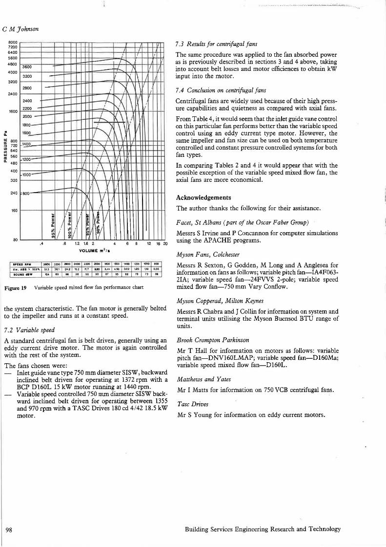
Figure 19 Variable speed mixed flow fan performance chart
the system characteristic. The fan motor is generally belted to the impeller and runs at a constant speed.
7.2 Variable speed
A standard centrifugal fan is belt driven, generally using an eddy current drive motor. The motor is again controlled with the rest of the system.
The fans chosen were:
98
Inlet guide vane type 750 mm diameter SISW, backward inclined belt driven for operating at 1372 rpm with a BCP Dl60L 15 kW motor running at 1440 rpm. Variable speed controlled 750 mm diameter SISW backward inclined belt driven for operating between 1355 and 970 rpm with a TASC Drives 180 cd 4 /42 18.5 kW motor.
7.3 Results for centrifugal fans
The same procedure was applied to the fan absorbed power as is previously described in sections 3 and 4 above, taking into account belt losses and motor efficiences to obtain kW input into the motor.
7.4 Conclusion on centrifugal fans
Centrifugal fans are widely used because of their high pressure capabilities and quietness as compared with axial fans.
From Table 4, it would seem that the inlet guide vane control on this particular fan performs better than the variable speed control using an eddy current type motor. However, the same impeller and fan size can be used on both temperature controlled and constant pressure controlled systems for both fan types.
In comparing Tables 2 and 4 it would appear that with the possible exception of the variable speed mixed flow fan, the axial fans are more economical.
Acknowledgements
The author thanks the following for their assistance .
Facet, St Albans (part of the Oscar Faber Group)
Messrs S Irvine and P Concannon for computer simulations using the APACHE programs.
Myson Fans, Colchester
Messrs R Sexton, G Godden, M Long and A Anglesea for information on fans as follows ; variable pitch fan-IA4F063-21A; variable speed fan-24FVVS 2-pole; variable speed mixed flow fan-750 mm Vary Confiow.
Myson Copperad, Milton Keynes
Messrs R Chabra and J Collin for information on system and terminal units utilising the Myson Buensod BTU range of units.
Brook Crompton Parkinson
Mr T Hall for information on motors as follows: variable pitch fan-DNV160LMAP; variable speed fan-Dl60Ma; variable speed mixed flow fan-Dl60L.
Matthews and Yates
Mr I Matts for information on 750 VCB centrifugal fans.
Tasc Drives
Mr S Young for information on eddy current motors.
Building Services Engineering Research and Technology
. I