
CFD analysis of free shear layer approximations for a pulsed air jet
10
CFD analysis of free shear layer approximations for a pulsed air jet Nawel Khaldi a,⇑ , Salwa Marzouk a , Hatem Mhiri a , Philippe Bournot b a UTTPI, National Engineering School of Monastir, Monastir, Tunisia b IUSTI, UMR CNRS 6595, 5 rue Enrico Fermi, Technopole de Château-Gombert, 1303 Marseille, France article info Article history: Received 17 December 2013 Received in revised form 5 March 2014 Accepted 4 April 2014 Keywords: Pulsed Air jet Free shear layer approximations Laminar Isothermal Heated CFD abstract We propose a numerical investigation on the validity of the free shear layer approximations for laminar 2D pulsed jets in both isothermal and heated configurations. More precisely, we determine the range of values for the Strouhal number St and amplitude of the perturbation A for which these approximations remains valid. For this, we have considered a two-dimensional air jet exhausting into a quiescent environment. At the nozzle exit, the flow is characterized by a uniform temperature T 0 and submitted to a longitudinal and periodic velocity disturbance: u = u 0 + a ⁄ sin(xt). A finite volume method is performed to solve the general Navier–Stokes equations governing this flow type. The present study is evaluated by comparing with previous numerical results. Conclusions are drawn about the ability of a model that does not consider the shear layer approximations to handle properly the behavior of pulsed air jet. The discussion relates to the effect of the most significant parameters, such as the pulsation frequency and amplitude, on the flow characteristic fields. The effect of Reynolds and Grashof numbers was also examined. The results state that the free shear layer approximations are valid in different regions of the isothermal or the heated pulsed jet, and this, only for high Strouhal numbers (St P 1) and for low pulsation amplitude (A < 3%) Otherwise, these approximations remain valid for a free pulsed jet only in the fully developed flow region. Ó 2014 Elsevier Ltd. All rights reserved. 1. Introduction Due to the fact of their diverse aspects and their applications, typical jet flows present a constant interest. The characteristics of such a flow are not yet precisely defined, particularly for a pulsed jet, what has stimulated the investigations of researchers. Unlike a steady jet, the pulsed jet is known to play an important role in industrial and engineering areas. Theoretical analysis (Seikmann, 1963) shows that for the same nozzle exit mass flow, the average thrust of a pulsed jet is higher than the equivalent steady jet. The fact that a pulsed jet produces higher thrust than the correspond- ing steady jet has been exploited by the Germans during World War II. They developed the V-1 guided missile, also known as the buzz bomb that was powered by a pulsed jet engine. Pulsed jets can be found in a variety of applications ranging from blood flow in heart, to pulse detonation engines. Earlier work on this wide subject was provided by Sato (1959). It was shown that the pulsed jet becomes unstable for Reynolds numbers higher than 50 and a Strouhal number equal to about 0.17. Favre-Marinet and Binder (1978) treated experimentally the influence of high pulse amplitude on the symmetric axis jet devel- opment. Chambers and Goldschmidt (1981, 1997) have found, using an experimental study of a disturbed air jet, that for some frequencies, the turbulent intensity and Reynolds stress increase in the jet core (in the nozzle vicinity). Further downstream of the nozzle, the acoustic perturbation has no effect on the quantities of the flow. An experimental study was also carried out by Thomas and Goldschmidt (1981) to determine the effects of a peri- odic acoustic perturbation on a two-dimensional turbulent jet. They showed that the rate of the jet expansion is larger for Strouhal numbers ranging between 0.34 and 0.42. This is in agreement with those reported by Goldschmidt and Kaiser (1971) and Chambers and Goldschmidt (1981, 1997). One of the most important characteristics of a pulsed jet is mass entrainment. Using an acoustically forced jet, Vermeulen et al., 1986 measured the mass entrainment and found that the entrain- ment reached a peak at around a Strouhal number of 0.24. It was also shown by the studies of by Gutmark and Ho (1983) that a Strouhal number range from 0.2 to 0.5 can facilitate the preferred mode of a jet which in turn can enhance the entrainment of the ambient fluid. This indicates that the pulsing frequency of the jet plays a significant role in the entrainment mechanism of a pulsed jet. Bremhorst and Hollis (1990) and Bremhorst and Gehrke (2000) http://dx.doi.org/10.1016/j.tust.2014.04.006 0886-7798/Ó 2014 Elsevier Ltd. All rights reserved. ⇑ Corresponding author. Tel.: +216 98 540 398; fax: +216 72540398. E-mail address: [email protected] (N. Khaldi). Tunnelling and Underground Space Technology 43 (2014) 49–58 Contents lists available at ScienceDirect Tunnelling and Underground Space Technology journal homepage: www.elsevier.com/locate/tust
Transcript of CFD analysis of free shear layer approximations for a pulsed air jet
Tunnelling and Underground Space Technology 43 (2014) 49–58
Contents lists available at ScienceDirect
Tunnelling and Underground Space Technology
journal homepage: www.elsevier .com/ locate/ tust
CFD analysis of free shear layer approximations for a pulsed air jet
http://dx.doi.org/10.1016/j.tust.2014.04.0060886-7798/� 2014 Elsevier Ltd. All rights reserved.
⇑ Corresponding author. Tel.: +216 98 540 398; fax: +216 72540398.E-mail address: [email protected] (N. Khaldi).
Nawel Khaldi a,⇑, Salwa Marzouk a, Hatem Mhiri a, Philippe Bournot b
a UTTPI, National Engineering School of Monastir, Monastir, Tunisiab IUSTI, UMR CNRS 6595, 5 rue Enrico Fermi, Technopole de Château-Gombert, 1303 Marseille, France
a r t i c l e i n f o
Article history:Received 17 December 2013Received in revised form 5 March 2014Accepted 4 April 2014
Keywords:PulsedAir jetFree shear layer approximationsLaminarIsothermalHeatedCFD
a b s t r a c t
We propose a numerical investigation on the validity of the free shear layer approximations for laminar2D pulsed jets in both isothermal and heated configurations. More precisely, we determine the range ofvalues for the Strouhal number St and amplitude of the perturbation A for which these approximationsremains valid. For this, we have considered a two-dimensional air jet exhausting into a quiescentenvironment. At the nozzle exit, the flow is characterized by a uniform temperature T0 and submittedto a longitudinal and periodic velocity disturbance: u = u0 + a ⁄ sin(xt). A finite volume method isperformed to solve the general Navier–Stokes equations governing this flow type. The present study isevaluated by comparing with previous numerical results. Conclusions are drawn about the ability of amodel that does not consider the shear layer approximations to handle properly the behavior of pulsedair jet. The discussion relates to the effect of the most significant parameters, such as the pulsationfrequency and amplitude, on the flow characteristic fields. The effect of Reynolds and Grashof numberswas also examined. The results state that the free shear layer approximations are valid in differentregions of the isothermal or the heated pulsed jet, and this, only for high Strouhal numbers (St P 1)and for low pulsation amplitude (A < 3%) Otherwise, these approximations remain valid for a free pulsedjet only in the fully developed flow region.
� 2014 Elsevier Ltd. All rights reserved.
1. Introduction
Due to the fact of their diverse aspects and their applications,typical jet flows present a constant interest. The characteristics ofsuch a flow are not yet precisely defined, particularly for a pulsedjet, what has stimulated the investigations of researchers. Unlike asteady jet, the pulsed jet is known to play an important role inindustrial and engineering areas. Theoretical analysis (Seikmann,1963) shows that for the same nozzle exit mass flow, the averagethrust of a pulsed jet is higher than the equivalent steady jet. Thefact that a pulsed jet produces higher thrust than the correspond-ing steady jet has been exploited by the Germans during WorldWar II. They developed the V-1 guided missile, also known as thebuzz bomb that was powered by a pulsed jet engine. Pulsed jetscan be found in a variety of applications ranging from blood flowin heart, to pulse detonation engines.
Earlier work on this wide subject was provided by Sato (1959).It was shown that the pulsed jet becomes unstable for Reynoldsnumbers higher than 50 and a Strouhal number equal to about0.17. Favre-Marinet and Binder (1978) treated experimentally the
influence of high pulse amplitude on the symmetric axis jet devel-opment. Chambers and Goldschmidt (1981, 1997) have found,using an experimental study of a disturbed air jet, that for somefrequencies, the turbulent intensity and Reynolds stress increasein the jet core (in the nozzle vicinity). Further downstream of thenozzle, the acoustic perturbation has no effect on the quantitiesof the flow. An experimental study was also carried out byThomas and Goldschmidt (1981) to determine the effects of a peri-odic acoustic perturbation on a two-dimensional turbulent jet.They showed that the rate of the jet expansion is larger for Strouhalnumbers ranging between 0.34 and 0.42. This is in agreement withthose reported by Goldschmidt and Kaiser (1971) and Chambersand Goldschmidt (1981, 1997).
One of the most important characteristics of a pulsed jet is massentrainment. Using an acoustically forced jet, Vermeulen et al.,1986 measured the mass entrainment and found that the entrain-ment reached a peak at around a Strouhal number of 0.24. It wasalso shown by the studies of by Gutmark and Ho (1983) that aStrouhal number range from 0.2 to 0.5 can facilitate the preferredmode of a jet which in turn can enhance the entrainment of theambient fluid. This indicates that the pulsing frequency of the jetplays a significant role in the entrainment mechanism of a pulsedjet. Bremhorst and Hollis (1990) and Bremhorst and Gehrke (2000)
Nomenclature
A flow pulse amplitude, A = a/u0
b width of the nozzle (m)f pulsation frequency (s�1)Gr Grashof number based on the width of the nozzle,
Gr = gb(T0 � T1)b3/m2
Pr Prandtl number, Pr = m/aRe Reynolds number, Re = u0b/vFr Froude number, Fr = Re2/GrSt Strouhal number, St = fb/u0
t time (s)T temperature (K)u, v dimensional axial and radial velocity (m s�1)U, V dimensionless axial and radial velocityx, y dimensional axial and radial coordinate (m)X, Y dimensionless axial and radial coordinate
Greek symbolsa thermal diffusivity of the fluid (m2 s�1)b thermal expansion coefficient (K�1)q density of the fluid (kg m�3)h dimensionless temperature, h = (T � T1)/(T0 � T1)m kinematic viscosity of the fluid (m2 s�1)s dimensionless timex angular velocity, x = 2pf(rds�1)
Subscriptsc jet axism modified quantity0 nozzle exit1 ambient environment
50 N. Khaldi et al. / Tunnelling and Underground Space Technology 43 (2014) 49–58
carried out studies on fully pulsed jets. For the purpose of turbulencemodeling, (Bremhorst and Gehrke, 2000) measured the Reynoldsstresses at downstream locations that are greater than fifty nozzlediameters. However, (Bremhorst and Hollis, 1990) considered thenear field of the pulsed jet. They reported a pulse-dominated regionthat extended fifty nozzle diameters downstream. Beyond this loca-tion, the jet exhibited behavior similar to that of a steady jet.
Shock tubes, rotating valves, reciprocating engines, piston driv-ers, rotating disks, and resonant tubes are the usual methods usedfor the generation of pulsed jets. However, experimental studiesare often difficult to achieve, very long and expensive. Throughthe development of computational resources, numerical modelscan now describe better the jet behavior.
Among the numerous works, (Lai and Simmons, 1981) con-ducted a numerical solution of periodically pulsed laminar freejets. It was shown that the transformation technique used in solv-ing the thin shear layer equations of the unsteady laminar jet issuccessful in reducing the number of grid points in the transversedirection, when compared with alternative methods. Mhiri et al.(1998) have accomplished an accurate description for the differentregions of the steady free jet (isothermal or non-isothermal) andshowed that the emission profiles affect the flow in the jet core;while in the fully developed flow region these latter no longeraffect the flow parameters. In the same context, a numerical studywas carried out by Marzouk et al. (2003a) to reveal the influence ofan initial perturbation on the dynamic and thermal quantities of aplane jet in laminar regime. They showed that for an isothermalplane jet and for a fixed pulsation amplitude, the fluctuations dis-appear at a distance close to X = 30 (X ¼ x
b) for very low Strouhalnumbers (St = 0.1), while for a fixed Strouhal number these fluctu-ations disappear completely at a distance closer to X = 10. Beyondthis distance, the centerline velocity obtained for a pulsed jet coin-cides with a non-pulsed one. In the case of a plane jet in a mixedconvection regime, these authors showed that fluctuations disap-pear at a distance X of about 14, for a fixed Strouhal number andfor various pulsation amplitudes values. Marzouk et al. (2003b)proposed later a numerical study of the Strouhal numbers and pul-sation amplitudes influence on an isothermal or non-isothermalplane jet in turbulent regime and in a forced convection mode.
Recently, Wassim et al. (2008) conducted a numerical study of afree pulsed plane jet with variable density in unsteady and laminarmode. It was shown that the pulsation affects the flow particularlyin the vicinity of the nozzle and that the Strouhal number hasno influence on the flow mixture degree, while the pulsation
amplitude affects the mixture and, consequently, the concentra-tion jet core length. Vermeulen et al. (2004) showed that pulsingprimary jet flow improved ejector performance and that a sinusoi-dal pulse superimposed on a steady flow is very efficient. Detailedcharacteristics of the sound generated by a heated pulsating jetwere numerically explored by Jiang et al. (2006), where the effectsof pulsating frequency and amplitude on the flow structure andsound generation of the subsonic jet have been examined.
An examination of the literature reveals that the majority of thestudies (Lai and Simmons, 1981; Mhiri et al., 1998; Marzouk et al.,2003a,b; Wassim et al., 2008; Vermeulen et al., 2004; Jiang et al.,2006) limit itself to numerical resolution using the shear layerapproximations which ignore the lateral velocity. Schlichting,(1933) was the first to apply laminar shear layer theory to the steadyflow produced by a free two-dimensional jet emerging into a fluid atrest. Later, (Bickley, 1937) solved the differential equation analyti-cally. The application of the shear layer approximation to laminarjets is discussed fully in standard texts such as by Schlichting(1980), Schlichting and Gersten (2000), Rosenhead (1963) andMason (2002). The standard procedure was to obtain a similaritysolution by assuming a certain form for the stream function.
These approximations may put in default the discovered resultsespecially in the case of a pulsed free jet where the longitudinalvelocity increases the entrainment of the surrounding air on thejet core and subsequently enhances the heat exchange betweenthe jet and the ambient conditions. This fact supports the studyof the present paper which proposes a new approach that doesnot consider the shear layer approximations. Thus, the main objec-tive of the current work is to determine the range of parameters(St, A) for which these approximations, used in earlier papers, arevalid. Effect of several parameters such as Reynolds and Grashofnumbers on dynamical and thermal characteristics of the pulsedfree jet is discussed.
2. Simulation method
2.1. Governing equations
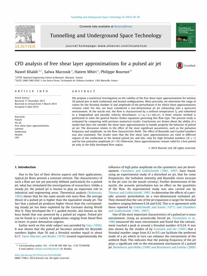
The considered jet is issued from a rectangular plane nozzle intoa quiescent surrounding. The thickness of the nozzle b is assumedvery small compared to its width in order to neglect the edgeeffects and have a two-dimensional vertical jet; the jet and theambient environment are constituted of the same fluid. Theconsidered fluid is air assumed Newtonian and incompressible.
b/2
The jet core
Transition region
Fully developed flow
region
u
Potential core
Fig. 1. Geometry setup of the plane free jet.
Table 1Mesh distribution and tests performed.
Tests Edges Mesh density (cells)
1 2 3
#1 15 BS = 0.45 50 SR = 1.04 125 SR = 1.02 14,375#2 25 BS = 0.45 75 SR = 1.04 200 SR = 1.02 35,000#3 30 BS = 0.45 100 SR = 1.04 250 SR = 1.02 57,500
N. Khaldi et al. / Tunnelling and Underground Space Technology 43 (2014) 49–58 51
For the used range of Grashof numbers, the fluid density varies lin-early with the temperature in the buoyancy term, it is consideredconstant elsewhere, according to the Boussinesq assumptions. Thepressure is supposed constant in the jet. At the nozzle exit, the flowis submitted to a longitudinal and periodic velocity disturbance.
Given the above assumptions, in a Cartesian coordinates system(Fig. 1), the mass, momentum and energy equations of a planevertical jet in laminar regime, can be written as follows:
@u
@xþ @v
@y¼ 0 ð1Þ
Fig. 2. Computational grid
q0 þ@u@tþ q0 u
@u@xþ v @u
@y
� �¼ � @P
@xþ l @2u
@x2 þ@2u@y2
!þ qg ð2Þ
q0 þ@v@tþ q0 u
@v@xþ v @v
@y
� �¼ � @P
@yþ l @2v
@x2 þ@2v@y2
!ð3Þ
q0cp@T@tþ q0cp u
@T@xþ v @T
@y
� �¼ k
@2T@x2 þ
@2T@y2
!ð4Þ
These equations are written in a Cartesian coordinate systemsuch as the axes origin (O) is located in the middle of the jet exitsection (Fig. 1). The associated boundary and ejection conditionsto the Eqs. (1)–(4) are described as:
x > 0
V ¼ @u@y ¼ @T
@y ¼ 0; y ¼ 0
u! 0; y!1
T ! T1; y!1
8>><>>: ð5Þ
x ¼ 0
� if 0 � y < 0:5b
v ¼ 0; T ¼ T0
u ¼ u0; Steady jet
u ¼ u0 þ a � sinð2pu0St � t=bÞ; Pulsed jet
� if 0:5b � y � 40b
u ¼ v ¼ 0; T ¼ T1
8>>>>>>>>>><>>>>>>>>>>:
ð6Þ
s of the plane free jet.
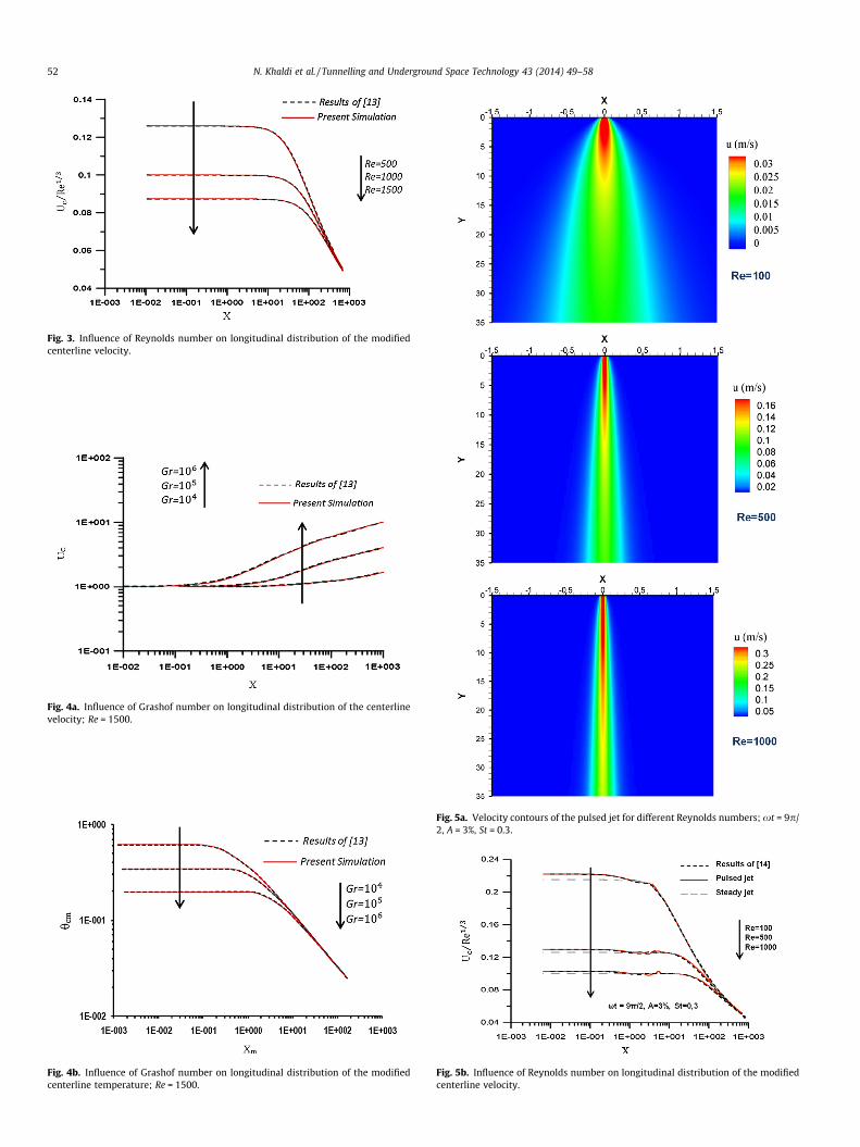
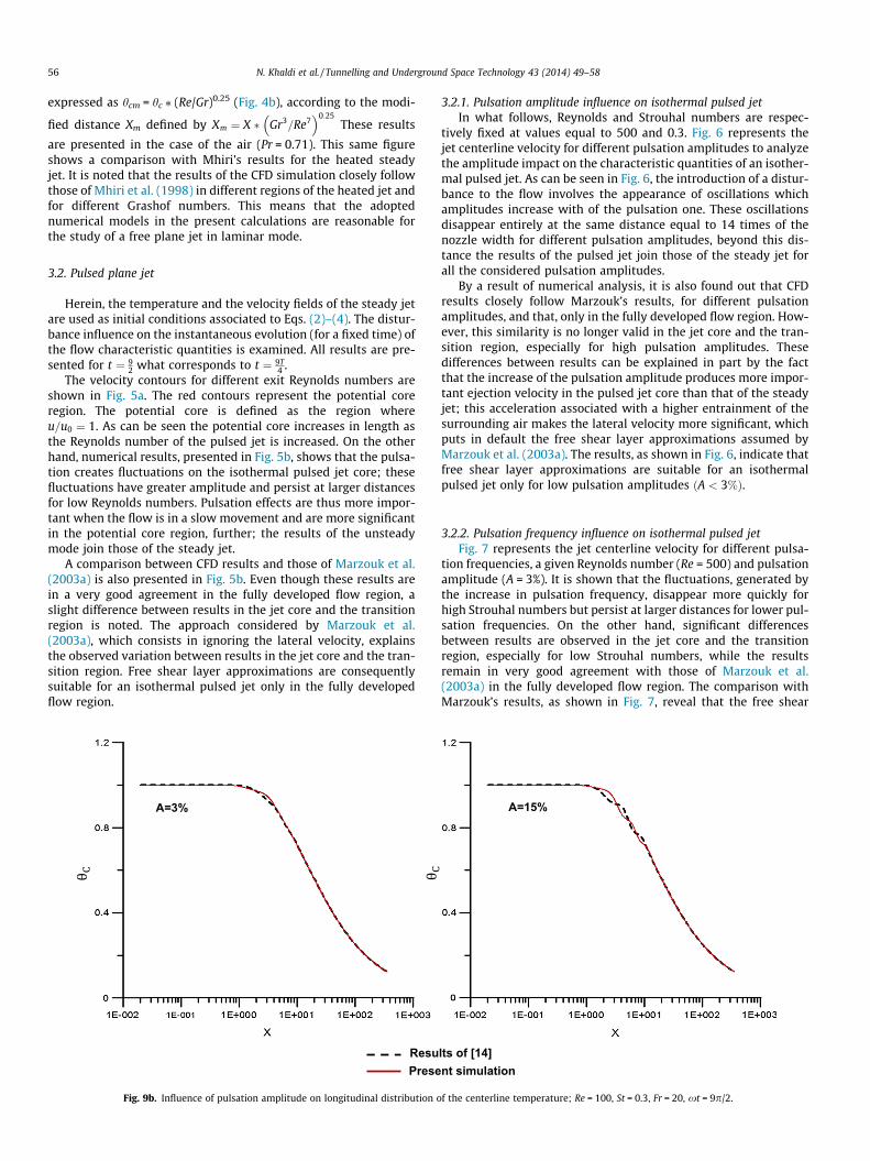
Fig. 3. Influence of Reynolds number on longitudinal distribution of the modifiedcenterline velocity.
Fig. 4a. Influence of Grashof number on longitudinal distribution of the centerlinevelocity; Re = 1500.
Fig. 4b. Influence of Grashof number on longitudinal distribution of the modifiedcenterline temperature; Re = 1500.
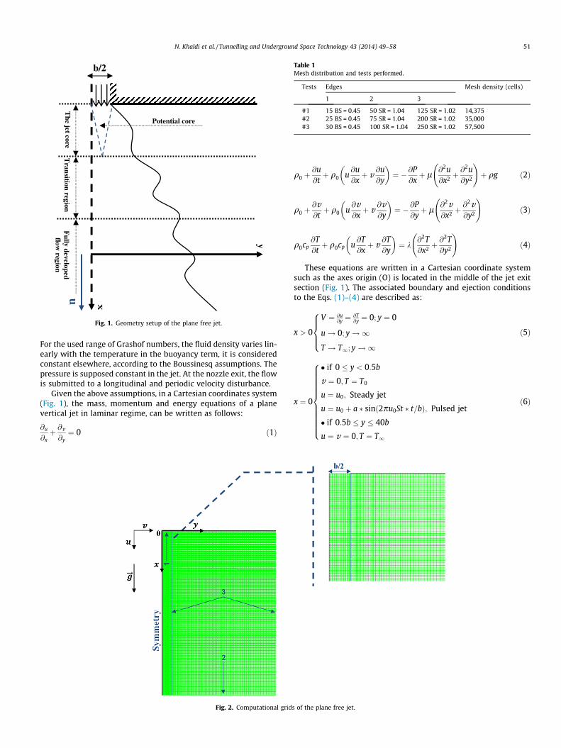
Fig. 5a. Velocity contours of the pulsed jet for different Reynolds numbers; xt = 9p/2, A = 3%, St = 0.3.
Fig. 5b. Influence of Reynolds number on longitudinal distribution of the modifiedcenterline velocity.
52 N. Khaldi et al. / Tunnelling and Underground Space Technology 43 (2014) 49–58
A=3%
Results of [14]Present simulation
A=40%
A=10%
A=20%
A=7%
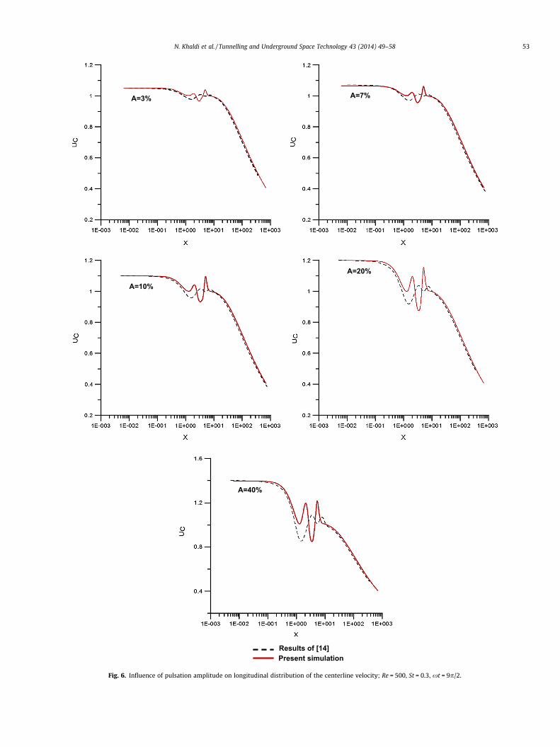
Fig. 6. Influence of pulsation amplitude on longitudinal distribution of the centerline velocity; Re = 500, St = 0.3, xt = 9p/2.
N. Khaldi et al. / Tunnelling and Underground Space Technology 43 (2014) 49–58 53
St=0,1
St=0,7
St=2
Results of [14]Present simulation
St=0,3
St=1
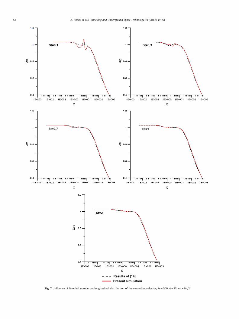
Fig. 7. Influence of Strouhal number on longitudinal distribution of the centerline velocity; Re = 500, A = 3%, xt = 9p/2.
54 N. Khaldi et al. / Tunnelling and Underground Space Technology 43 (2014) 49–58
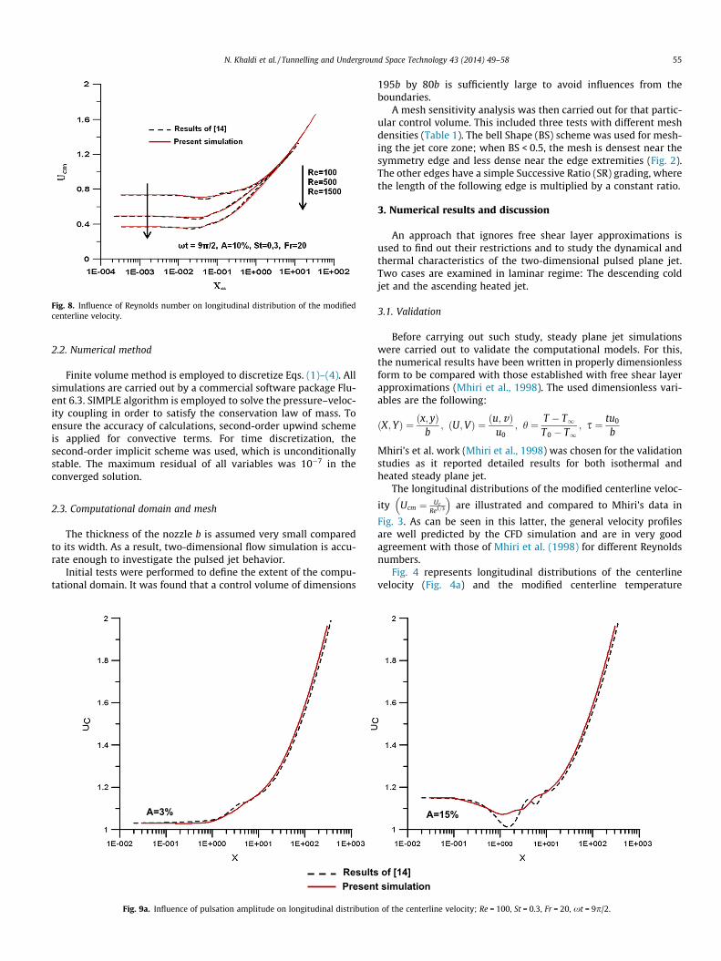
Fig. 8. Influence of Reynolds number on longitudinal distribution of the modifiedcenterline velocity.
N. Khaldi et al. / Tunnelling and Underground Space Technology 43 (2014) 49–58 55
2.2. Numerical method
Finite volume method is employed to discretize Eqs. (1)–(4). Allsimulations are carried out by a commercial software package Flu-ent 6.3. SIMPLE algorithm is employed to solve the pressure–veloc-ity coupling in order to satisfy the conservation law of mass. Toensure the accuracy of calculations, second-order upwind schemeis applied for convective terms. For time discretization, thesecond-order implicit scheme was used, which is unconditionallystable. The maximum residual of all variables was 10�7 in theconverged solution.
2.3. Computational domain and mesh
The thickness of the nozzle b is assumed very small comparedto its width. As a result, two-dimensional flow simulation is accu-rate enough to investigate the pulsed jet behavior.
Initial tests were performed to define the extent of the compu-tational domain. It was found that a control volume of dimensions
A=3%
ResultsPresen
Fig. 9a. Influence of pulsation amplitude on longitudinal distribution
195b by 80b is sufficiently large to avoid influences from theboundaries.
A mesh sensitivity analysis was then carried out for that partic-ular control volume. This included three tests with different meshdensities (Table 1). The bell Shape (BS) scheme was used for mesh-ing the jet core zone; when BS < 0.5, the mesh is densest near thesymmetry edge and less dense near the edge extremities (Fig. 2).The other edges have a simple Successive Ratio (SR) grading, wherethe length of the following edge is multiplied by a constant ratio.
3. Numerical results and discussion
An approach that ignores free shear layer approximations isused to find out their restrictions and to study the dynamical andthermal characteristics of the two-dimensional pulsed plane jet.Two cases are examined in laminar regime: The descending coldjet and the ascending heated jet.
3.1. Validation
Before carrying out such study, steady plane jet simulationswere carried out to validate the computational models. For this,the numerical results have been written in properly dimensionlessform to be compared with those established with free shear layerapproximations (Mhiri et al., 1998). The used dimensionless vari-ables are the following:
ðX;YÞ ¼ ðx; yÞb
; ðU;VÞ ¼ ðu;vÞu0
; h ¼ T � T1T0 � T1
; s ¼ tu0
b
Mhiri’s et al. work (Mhiri et al., 1998) was chosen for the validationstudies as it reported detailed results for both isothermal andheated steady plane jet.
The longitudinal distributions of the modified centerline veloc-
ity Ucm ¼ Uc
Re1=3
� �are illustrated and compared to Mhiri’s data in
Fig. 3. As can be seen in this latter, the general velocity profilesare well predicted by the CFD simulation and are in very goodagreement with those of Mhiri et al. (1998) for different Reynoldsnumbers.
Fig. 4 represents longitudinal distributions of the centerlinevelocity (Fig. 4a) and the modified centerline temperature
of t simulation
[14]
A=15%
of the centerline velocity; Re = 100, St = 0.3, Fr = 20, xt = 9p/2.
56 N. Khaldi et al. / Tunnelling and Underground Space Technology 43 (2014) 49–58
expressed as hcm = hc ⁄ (Re/Gr)0.25 (Fig. 4b), according to the modi-
fied distance Xm defined by Xm ¼ X � Gr3=Re7� �0:25
These results
are presented in the case of the air (Pr = 0.71). This same figureshows a comparison with Mhiri’s results for the heated steadyjet. It is noted that the results of the CFD simulation closely followthose of Mhiri et al. (1998) in different regions of the heated jet andfor different Grashof numbers. This means that the adoptednumerical models in the present calculations are reasonable forthe study of a free plane jet in laminar mode.
3.2. Pulsed plane jet
Herein, the temperature and the velocity fields of the steady jetare used as initial conditions associated to Eqs. (2)–(4). The distur-bance influence on the instantaneous evolution (for a fixed time) ofthe flow characteristic quantities is examined. All results are pre-sented for t ¼ 9
2 what corresponds to t ¼ 9T4 .
The velocity contours for different exit Reynolds numbers areshown in Fig. 5a. The red contours represent the potential coreregion. The potential core is defined as the region whereu=u0 ¼ 1. As can be seen the potential core increases in length asthe Reynolds number of the pulsed jet is increased. On the otherhand, numerical results, presented in Fig. 5b, shows that the pulsa-tion creates fluctuations on the isothermal pulsed jet core; thesefluctuations have greater amplitude and persist at larger distancesfor low Reynolds numbers. Pulsation effects are thus more impor-tant when the flow is in a slow movement and are more significantin the potential core region, further; the results of the unsteadymode join those of the steady jet.
A comparison between CFD results and those of Marzouk et al.(2003a) is also presented in Fig. 5b. Even though these results arein a very good agreement in the fully developed flow region, aslight difference between results in the jet core and the transitionregion is noted. The approach considered by Marzouk et al.(2003a), which consists in ignoring the lateral velocity, explainsthe observed variation between results in the jet core and the tran-sition region. Free shear layer approximations are consequentlysuitable for an isothermal pulsed jet only in the fully developedflow region.
A=3%
ResuPrese
Fig. 9b. Influence of pulsation amplitude on longitudinal distribution o
3.2.1. Pulsation amplitude influence on isothermal pulsed jetIn what follows, Reynolds and Strouhal numbers are respec-
tively fixed at values equal to 500 and 0.3. Fig. 6 represents thejet centerline velocity for different pulsation amplitudes to analyzethe amplitude impact on the characteristic quantities of an isother-mal pulsed jet. As can be seen in Fig. 6, the introduction of a distur-bance to the flow involves the appearance of oscillations whichamplitudes increase with of the pulsation one. These oscillationsdisappear entirely at the same distance equal to 14 times of thenozzle width for different pulsation amplitudes, beyond this dis-tance the results of the pulsed jet join those of the steady jet forall the considered pulsation amplitudes.
By a result of numerical analysis, it is also found out that CFDresults closely follow Marzouk’s results, for different pulsationamplitudes, and that, only in the fully developed flow region. How-ever, this similarity is no longer valid in the jet core and the tran-sition region, especially for high pulsation amplitudes. Thesedifferences between results can be explained in part by the factthat the increase of the pulsation amplitude produces more impor-tant ejection velocity in the pulsed jet core than that of the steadyjet; this acceleration associated with a higher entrainment of thesurrounding air makes the lateral velocity more significant, whichputs in default the free shear layer approximations assumed byMarzouk et al. (2003a). The results, as shown in Fig. 6, indicate thatfree shear layer approximations are suitable for an isothermalpulsed jet only for low pulsation amplitudes ðA < 3%Þ.
3.2.2. Pulsation frequency influence on isothermal pulsed jetFig. 7 represents the jet centerline velocity for different pulsa-
tion frequencies, a given Reynolds number (Re = 500) and pulsationamplitude (A = 3%). It is shown that the fluctuations, generated bythe increase in pulsation frequency, disappear more quickly forhigh Strouhal numbers but persist at larger distances for lower pul-sation frequencies. On the other hand, significant differencesbetween results are observed in the jet core and the transitionregion, especially for low Strouhal numbers, while the resultsremain in very good agreement with those of Marzouk et al.(2003a) in the fully developed flow region. The comparison withMarzouk’s results, as shown in Fig. 7, reveal that the free shear
lts of [14]nt simulation
A=15%
f the centerline temperature; Re = 100, St = 0.3, Fr = 20, xt = 9p/2.
St=0,01
Results of Present si
St=2
[14]mulation
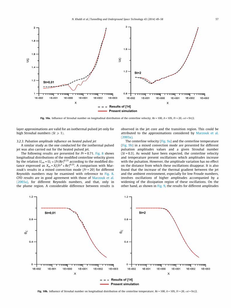
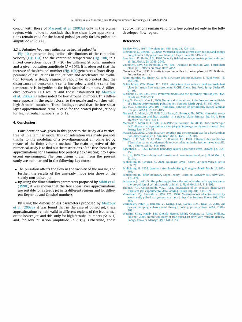
Fig. 10a. Influence of Strouhal number on longitudinal distribution of the centerline velocity; Re = 100, A = 10%, Fr = 20, xt = 9p/2.
N. Khaldi et al. / Tunnelling and Underground Space Technology 43 (2014) 49–58 57
layer approximations are valid for an isothermal pulsed jet only forhigh Strouhal numbers ðSt P 1Þ.
3.2.3. Pulsation amplitude influence on heated pulsed jetA similar study as the one conducted for the isothermal pulsed
jet was also carried out for the heated pulsed jet.The following results are presented for Pr = 0.71. Fig. 8 shows
longitudinal distributions of the modified centerline velocity givenby the relation Ucm = UC ⁄ (Fr/Re)0.25 according to the modified dis-tance expressed as Xm = X/(Fr3 ⁄ Re)0.25. A comparison with Mar-zouk’s results in a mixed convection mode (Fr = 20) for differentReynolds numbers may be examined with reference to Fig. 8.CFD results are in good agreement with those of Marzouk et al.(2003a), for different Reynolds numbers, and that, only inthe plume region. A considerable difference between results is
St=0,01
ResultPresen
Fig. 10b. Influence of Strouhal number on longitudinal distribution of
observed in the jet core and the transition region. This could beattributed to the approximations considered by Marzouk et al.(2003a).
The centerline velocity (Fig. 9a) and the centerline temperature(Fig. 9b) in a mixed convection mode are presented for differentpulsation amplitudes values and a given Strouhal number(St = 0.3). As would have been expected, the centerline velocityand temperature present oscillations which amplitudes increasewith the pulsation. However, the amplitude variation has no effecton the distance from which these oscillations disappear. It is alsofound that the increase of the thermal gradient between the jetand the ambient environment, especially for low Froude numbers,involves oscillations of higher amplitudes accompanied by awidening of the dissipation region of these oscillations. On theother hand, as shown in Fig. 9, the results for different amplitudes
s of t si
[14]mulation
St=2
the centerline temperature; Re = 100, A = 10%, Fr = 20, xt = 9p/2.
58 N. Khaldi et al. / Tunnelling and Underground Space Technology 43 (2014) 49–58
concur with those of Marzouk et al. (2003a) only in the plumeregion, which allow to conclude that free shear layer approxima-tions remain valid for the heated pulsed jet only for low pulsationamplitude ðA < 3%Þ.
3.2.4. Pulsation frequency influence on heated pulsed jetFig. 10 represents longitudinal distributions of the centerline
velocity (Fig. 10a) and the centerline temperature (Fig. 10b) in amixed convection mode (Fr = 20) for different Strouhal numbersand a given pulsation amplitude (A = 10%). It is observed that theincrease of the Strouhal number (Fig. 10b) generates a faster disap-pearance of oscillations in the jet core and accelerates the evolu-tion towards a steady regime. It should be also noted that thedisturbance influence on the centerline velocity and the centerlinetemperature is insignificant for high Strouhal numbers. A differ-ence between CFD results and those established by Marzouket al. (2003a) is rather noted for low Strouhal numbers. This differ-ence appears in the region closer to the nozzle and vanishes withhigh Strouhal numbers. These findings reveal that the free shearlayer approximations remain valid for the heated pulsed jet onlyfor high Strouhal numbers ðSt P 1Þ.
4. Conclusion
Consideration was given in this paper to the study of a verticalfree jet in a laminar mode. This consideration was made possiblethanks to the modeling of a two-dimensional air plane jet bymeans of the finite volume method. The main objective of thisnumerical study is to find out the restrictions of the free shear layerapproximations for a laminar free pulsed jet exhausting into a qui-escent environment. The conclusions drawn from the presentstudy are summarized in the following key notes:
� The pulsation affects the flow in the vicinity of the nozzle, andfurther, the results of the unsteady mode join those of thesteady non-pulsed jet.� By using the dimensionless parameters proposed by Mhiri et al.
(1998), it was shown that the free shear layer approximationsare suitable for a steady jet in its different regions and for differ-ent Reynolds and Grashof numbers.
By using the dimensionless parameters proposed by Marzouket al. (2003a), it was found that in the case of pulsed jet, theseapproximations remain valid in different regions of the isothermalor the heated jet, and this, only for high Strouhal numbers ðSt P 1Þand for low pulsation amplitude ðA < 3%Þ. Otherwise, these
approximations remain valid for a free pulsed jet only in the fullydeveloped flow region.
References
Bickley, W.G., 1937. The plane jet. Phil. Mag. 23, 727–731.Bremhorst, K., Gehrke, P.J., 2000. Measured Reynolds stress distributions and energy
budgets of a fully pulsed round air jet. Exp. Fluids 28, 519–531.Bremhorst, K., Hollis, P.G., 1990. Velocity field of an axisymmetric pulsed subsonic
air jet. AIAA J. 28, 2043–2049.Chambers, P.W., Goldschmidt, V.W., 1981. Acoustic interaction with a turbulent
plane jet – effects on mean flow. AIAA.Chambers, P.W., 1997. Acoustic interaction with a turbulent plane jet. Ph. D. thesis,
Purdue University.Favre-Marinet, M., Binder, G., 1978. Structure des jets pulsants. J. Fluid Mech. 18,
355–394.Goldschmidt, V.W., Kaiser, K.F., 1971. Interaction of an acoustic field and turbulent
plane jet: mean flow measurements. AICHE, Chem. Eng. Prod. Symp. Series 67,91–98.
Gutmark, E., Ho, C.M., 1983. Preferred modes and the spreading rates of jets. Phys.Fluids 26, 2932–2938.
Jiang, X., Zhao, H., Cao, L., 2006. Numerical simulations of the flow and sound fieldsof a heated axisymmetric pulsating jet. Comput. Math. Appl. 51, 643–660.
Lai, J.C.S., Simmons, J.M., 1981. Numerical solution of periodically pulsed laminarfree jets. AIAA J. 19, 813–815.
Marzouk, S., Mhiri, H., EL Golli, S., Le Palec, G., Bournot, Ph., 2003a. Numerical studyof momentum and heat transfer in a pulsed plane laminar jet. Int. J. HeatTransfer. 46, 4319–4334.
Marzouk, S., Mhiri, H., EL Golli, S., Le Palec, G., Bournot, Ph., 2003b. Etude numériquede l’influence de la pulsation sur un jet plan immerge en régime turbulent. Rev.Energy Ren. 6, 25–34.
Mason, D.P., 2002. Group Invariant solution and conservation law for a free laminartwo-dimensional jet. J. Nonlinear Math. Phys. 9, 92–101.
Mhiri, H., El CoIli, S., Le Palec, G., Bournot, Ph., 1998. Influence des conditionsd’émission sur un écoulement de type jet plan laminaire isotherme ou chauffé.Int. J. Therm. Sci. 37, 898–910.
Rosenhead, L., 1963. Lanunar Boundary Layers. Clorendon Press, Oxford, pp. 254–256.
Sato, H., 1959. The stability and transition of two-dimensional jet. J. Fluid Mech. 7,53–84.
Schlichting, H., Gersten, K., 2000. Boundary Layer Theory. Springer-Verlag, Berlin(Ch. 7).
Schlichting, H., 1933. Laminare strahlausbreitung. Z. Angew. Math. Mech. 13, 260–263.
Schlichting, H., 1980. Boundary-Layer Theory, sixth ed. McGraw-Hill, New York,170–174.
Seikmann, J., 1963. On the pulsating jet from the end of a tube, with application tothe propulsion of certain aquatic animals. J. Fluid Mech. 15, 318–399.
Thomas, F.O., Goldschmidt, V.W., 1981. Interaction of an acoustic disturbanceturbulent jet: experimental data. ASME J. Fluids Eng. 105, 134–139.
Vermeulen, P.J., Ramesh, V., Wai, K.Y., 1986. Measurements of entrainment byacoustically pulsed axisymmetric air jets. J. Eng. Gas Turbines Power 108, 479–484.
Vermeulen, Peter, J., Ramesh, V., Guang, C.M., Daniel, N.M., Neal, D., 2004. Airejector pumping enhancement through pulsing primary flow. AIAA, 2604–2621.
Wassim, Kriaa, Habib, Ben Cheikh, Hatem, Mhiri, Georges, Le Palec, Philippe,Bournot, 2008. Numerical study of free pulsed jet flow with variable density.Energy Convers. Manage. 49, 1141–1155.