Cell growth as a sheet on three-dimensional sharp-tip nanostructures
14
Cell growth as a sheet on three-dimensional sharp-tip nanostructures Chang-Hwan Choi, 1 Sepideh Heydarkhan-Hagvall, 2,3 Benjamin M. Wu, 2 James C. Y. Dunn, 2,3 Ramin E. Beygui, 3 * Chang-Jin ‘‘CJ’’ Kim 1 1 Mechanical and Aerospace Engineering Department, University of California, Los Angeles, California 90095 2 Department of Bioengineering, University of California, Los Angeles, California 90095 3 Department of Surgery, University of California, Los Angeles, California 90095 Received 7 January 2008; revised 5 March 2008; accepted 26 March 2008 Published online 3 June 2008 in Wiley InterScience (www.interscience.wiley.com). DOI: 10.1002/jbm.a.32101 Abstract: Cells in vivo encounter with and react to the extracellular matrix materials on a nanometer scale. Recent advances in nanofabrication technologies allowing the pre- cise control of a nanostructure’s pattern, periodicity, shape, and height have enabled a systematic study of cell interac- tions with three-dimensional nanotopographies. In this report, we examined the behavior of human foreskin fibro- blasts on well-ordered dense arrays (post and grate pat- terns with a 230-nm pitch) of sharp-tip nanostructures with varying three-dimensionalities (from 50 to 600 nm in structural height) over time—until a cell sheet was formed. Although cells started out smaller and proliferated slower on tall nanostructures (both posts and grates) than on smooth surfaces, they became confluent to form a sheet in 3 weeks. On grate patterns, significant cell elongation in alignment with the underlying pattern was observed and maintained over time. On tall nanostructures, cells grew while raised on sharp tips, resulting in a weak total adher- ence to the solid surface. A sheet of cells was easily peeled off from such surfaces, suggesting that nanoscale topogra- phies can be used as the basis for cell-sheet tissue engi- neering. Ó 2008 Wiley Periodicals, Inc. J Biomed Mater Res 89A: 804–817, 2009 Key words: nanotopography; cell morphology; cell prolif- eration; cell attachment/detachment; cell sheet INTRODUCTION Within the extracellular matrix, cells interact with three-dimensional (3D) projections and depressions that vary in composition, size, and periodicity on a nanometer scale. 1–3 The matrix nanotopography is important for the formation of proper adhesions and the activation of desired intracellular pathways, affecting cell behaviors in several ways such as mor- phology, cytoskeletal arrangement, migration, prolif- eration, surface antigen display, and gene expres- sion. Thus, a systematic understanding of the com- plex effects of the 3D nanotopography on cell behaviors is necessary. One of the practical aims of such an understanding is to design novel biomateri- als for tissue engineering or implantable medical devices. Although the effects of surface topographies on the cell behaviors had been studied with various micro- and nanostructured surfaces, 4–6 the inability to independently control the dimension and period of the structures in the nanoscale range has pre- cluded a systematic study. For a systematic study of the nanotopographical 3D effects on cell behaviors, well-defined nanostructures with good regularity and controllability of their pattern, size, and shape over a relatively large sample area are necessary. A recent achievement in nanofabrication has made it possible to fabricate well-ordered, dense-array nanostructures (nanoperiodic post and grate struc- tures) over a large sample area (several cm 2 ) with in- dependent controllability for structural size (height up to 1 lm) and shape (sidewall profile and tip sharpness). 7 The well-regulated nanostructure surfa- ces have provided a unique opportunity to elucidate the 3D effect of the surface nanotopography on cell behaviors. 8 Previously in Ref. 8, we reported on the cell interactions of human foreskin fibroblasts with *Present address: Department of Cardiothoracic Surgery, Stanford University School of Medicine, Stanford, CA 94305, USA. Correspondence to: C.-H. Choi, Department of Mechanical Engineering, Stevens Institute of Technology, Hoboken, NJ 07030, USA; e-mail: [email protected] Contract grant sponsor: National Science Foundation (NSF) Nanoscale Interdisciplinary Research Teams (NIRT); contract grant number: 0103562 Contract grant sponsor: Fubon Foundation Contract grant sponsor: American Heart Association Ó 2008 Wiley Periodicals, Inc.
-
Upload
independent -
Category
Documents
-
view
2 -
download
0
Transcript of Cell growth as a sheet on three-dimensional sharp-tip nanostructures

Cell growth as a sheet on three-dimensional sharp-tipnanostructures
Chang-Hwan Choi,1 Sepideh Heydarkhan-Hagvall,2,3 Benjamin M. Wu,2 James C. Y. Dunn,2,3
Ramin E. Beygui,3* Chang-Jin ‘‘CJ’’ Kim1
1Mechanical and Aerospace Engineering Department, University of California, Los Angeles, California 900952Department of Bioengineering, University of California, Los Angeles, California 900953Department of Surgery, University of California, Los Angeles, California 90095
Received 7 January 2008; revised 5 March 2008; accepted 26 March 2008Published online 3 June 2008 in Wiley InterScience (www.interscience.wiley.com). DOI: 10.1002/jbm.a.32101
Abstract: Cells in vivo encounter with and react to theextracellular matrix materials on a nanometer scale. Recentadvances in nanofabrication technologies allowing the pre-cise control of a nanostructure’s pattern, periodicity, shape,and height have enabled a systematic study of cell interac-tions with three-dimensional nanotopographies. In thisreport, we examined the behavior of human foreskin fibro-blasts on well-ordered dense arrays (post and grate pat-terns with a 230-nm pitch) of sharp-tip nanostructureswith varying three-dimensionalities (from 50 to 600 nm instructural height) over time—until a cell sheet was formed.Although cells started out smaller and proliferated sloweron tall nanostructures (both posts and grates) than on
smooth surfaces, they became confluent to form a sheet in3 weeks. On grate patterns, significant cell elongation inalignment with the underlying pattern was observed andmaintained over time. On tall nanostructures, cells grewwhile raised on sharp tips, resulting in a weak total adher-ence to the solid surface. A sheet of cells was easily peeledoff from such surfaces, suggesting that nanoscale topogra-phies can be used as the basis for cell-sheet tissue engi-neering. � 2008 Wiley Periodicals, Inc. J Biomed Mater Res89A: 804–817, 2009
Key words: nanotopography; cell morphology; cell prolif-eration; cell attachment/detachment; cell sheet
INTRODUCTION
Within the extracellular matrix, cells interact withthree-dimensional (3D) projections and depressionsthat vary in composition, size, and periodicity on ananometer scale.1–3 The matrix nanotopography isimportant for the formation of proper adhesions andthe activation of desired intracellular pathways,affecting cell behaviors in several ways such as mor-phology, cytoskeletal arrangement, migration, prolif-eration, surface antigen display, and gene expres-sion. Thus, a systematic understanding of the com-
plex effects of the 3D nanotopography on cellbehaviors is necessary. One of the practical aims ofsuch an understanding is to design novel biomateri-als for tissue engineering or implantable medicaldevices. Although the effects of surface topographieson the cell behaviors had been studied with variousmicro- and nanostructured surfaces,4–6 the inabilityto independently control the dimension and periodof the structures in the nanoscale range has pre-cluded a systematic study. For a systematic study ofthe nanotopographical 3D effects on cell behaviors,well-defined nanostructures with good regularityand controllability of their pattern, size, and shapeover a relatively large sample area are necessary.
A recent achievement in nanofabrication has madeit possible to fabricate well-ordered, dense-arraynanostructures (nanoperiodic post and grate struc-tures) over a large sample area (several cm2) with in-dependent controllability for structural size (heightup to 1 lm) and shape (sidewall profile and tipsharpness).7 The well-regulated nanostructure surfa-ces have provided a unique opportunity to elucidatethe 3D effect of the surface nanotopography on cellbehaviors.8 Previously in Ref. 8, we reported on thecell interactions of human foreskin fibroblasts with
*Present address: Department of Cardiothoracic Surgery,Stanford University School of Medicine, Stanford, CA94305, USA.Correspondence to: C.-H. Choi, Department of Mechanical
Engineering, Stevens Institute of Technology, Hoboken, NJ07030, USA; e-mail: [email protected] grant sponsor: National Science Foundation
(NSF) Nanoscale Interdisciplinary Research Teams (NIRT);contract grant number: 0103562Contract grant sponsor: Fubon FoundationContract grant sponsor: American Heart Association
� 2008 Wiley Periodicals, Inc.
3D sharp-tip nanopost and nanograte structures atan early culture stage (i.e., in 3 days), including cellmorphology and proliferation, which were also dis-cussed in conjunction with the extension of filopodiaand the formation of adhesion molecules complex onthe nanostructures. In this article, we examine howthe cell behaviors on the 3D sharp-tip nanostructuresevolve over time. In addition to the evolution of thecell morphology and proliferation of the human fore-skin fibroblasts, we report the further observation ofcell attachment and detachment on the 3D sharp-tipnanopost and nanograte structures until a cell sheetis formed, envisioning the potential application pos-sibility of the 3D sharp-tip nanostructured surface asthe basis for cell-sheet tissue engineering.
MATERIALS AND METHODS
Fabrication of 3D sharp-tip nanostructures
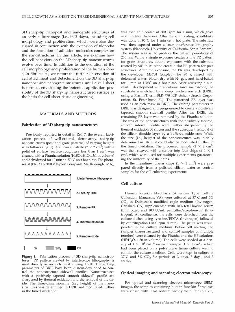
Previously reported in detail in Ref. 7, the overall fabri-cation process of well-ordered, dense-array, sharp-tipnanostructures (post and grate patterns) of varying heightsis as follows (Fig. 1). A silicon substrate (2 3 2 cm2) with apolished surface (surface roughness less than 1 nm) wascleaned with a Piranha solution (H2SO4:H2O2, 3:1 in volume)and dehydrated for 10min at 1508C on a hot plate. The photo-resist (PR), SPR3001 (Shipley Company, Marlborough, MA),
was then spin-coated at 5000 rpm for 1 min, which gives�50 nm film thickness. After the spin coating, a soft-bakewas done at 958C for 1 min on a hot plate. The substratewas then exposed under a laser interference lithographysystem (Nanotech, University of California, Santa Barbara).The system was set to produce the pattern periodicity of230 nm. While a single exposure creates a line PR patternfor grate structures, double exposures with the substraterotated by 908 in its plane create a dot PR pattern for poststructures. After the exposure, the PR was developed bythe developer, MF701 (Shipley), for 20 s, rinsed withdeionized water, blown dry with N2 gas, and hard-bakedfor 1 min at 1108C on a hot plate. After assessing a suc-cessful development with an atomic force microscope, thesubstrate was etched by a deep reactive ion etch (DRIE)using a PlasmaTherm SLR 770 ICP etcher (Unaxis Corpo-ration, St. Petersburg, FL). The patterned PR layer wasused as an etch mask in DRIE. The etching parameters inDRIE was designed and programmed to create a positivelytapered, smooth sidewall profile. After the DRIE, theremaining PR layer was removed by the Piranha solution.The tips of the nanostructures with the positively tapered,smooth sidewall profile were further sharpened by thethermal oxidation of silicon and the subsequent removal ofthe silicon dioxide layer by a buffered oxide etch. Whilethe size (i.e., height) of the nanostructures was initiallydetermined in DRIE, it could also be modulated further inthe timed oxidation. The processed sample (2 3 2 cm2)was then cleaved with a scriber into four chips of 1 3 1cm2, which were used for multiple experiments guarantee-ing the uniformity of the chips.
In the meantime, planar chips (1 3 1 cm2) were pre-pared directly from a polished silicon wafer as controlsamples for the cell-culturing experiments.
Cell culture
Human foreskin fibroblasts (American Type CultureCollection, Manassas, VA) were cultured at 378C and 5%CO2 in Dulbecco’s modified eagle medium (Invitrogen,Carlsbad, CA) supplemented with 10% fetal bovine serum(Invitrogen) and 100 U/mL penicillin/streptomycin (Invi-trogen). At confluence, the cells were detached from theculture dishes using tyrosine/EDTA (Invitrogen) followedby centrifugation (1000 rpm, 5 min). The pellet was resus-pended in the culture medium. Before cell seeding, thesamples (nanostructured and control samples of multiplenumber) were cleaned by the Piranha and the HF solutions(HF:H2O, 1:50 in volume). The cells were seeded at a den-sity of 1 3 104 cm22 on each sample (1 3 1 cm2), whichhad been placed on a polystyrene tissue culture well tocontain the culture medium. Cells were kept in culture at378C and 5% CO2 for periods of 3 days, 7 days, and 3weeks.
Optical imaging and scanning electron microscopy
For optical and scanning electron microscope (SEM)images, the samples containing human foreskin fibroblastswere rinsed with 0.1M sodium cacodylate buffer (pH 7.2)
Figure 1. Fabrication process of 3D sharp-tip nanostruc-tures.7 PR pattern created by interference lithography isused directly as an etch mask during DRIE. The etchingparameters of DRIE have been custom-developed to con-trol the nanostructure sidewall profiles. Nanostructureswith a positively tapered smooth sidewall profile aresharpened by thermal oxidation and the removal of the ox-ide. The three-dimensionality (i.e., height) of the nano-structures was determined in DRIE and modulated furtherin the timed oxidation.
CELL GROWTH AS A SHEET ON THREE-DIMENSIONAL SHARP-TIP NANOSTRUCTURES 805
Journal of Biomedical Materials Research Part A

supplemented with 5% sucrose for 10 min, and fixed for30 min in 2% paraformaldehye/2% glutaraldehyde in 0.1Msodium cacodylate buffer (pH 7.2) supplemented with 5%sucrose, followed by dehydration (30, 50, 70, 80, and 95%ethanol for 10 min each, 100% ethanol for 10 min threetimes, and finally 100% ethanol for 40 min). The sampleswere then dried by incubating in 100% ethanol/hexame-thyldisilazane (1:1) for 20 min, followed by pure hexame-thyldisilazane for 20 min. Then, the pure hexamethyldisila-zane solution was evaporated over 20 min by air-drying.For SEM images, once dry, the samples were coated with�10-nm thick gold/palladium (Au/Pd) by Denton Desk IIsputtering system and examined with a Hitachi S-4700field emission SEM.
Image analysis
The SEM images were analyzed by using ImageJ soft-ware (free download available at http://rsbweb.nih.gov/ij/) for the quantification of cell density, size, elongation,and alignment. The program used automated detection ofcell outline and calculated the number of pixels coveredby cells. It also calculated the lengths of the major (longest)and minor (shortest) of a cell by fitting the cell outline toan optimized ellipse shape. Elongation was defined as thelength ratio of the major to the minor. Alignment wasdefined as the angle between the major axis and the zero-angle base line which was set to be parallel to the directionof nanopatterns. For the quantification, four images (1mm2 each) per sample (four replicates per sample) weretaken and averaged. Student’s t-test (for two samples,assuming unequal variances) was used to compare statisti-cal significance between samples. Results of p < 0.05 wereconsidered significant.
RESULTS
3D sharp-tip nanostructures
Figure 2 shows the SEM images of the 3D sharp-tip silicon nanostructures used in this article. Thewell-ordered dense-array nanostructures were cre-ated uniformly (less than 10% deviation in structuralsize and shape) over the sample area (1 3 1 cm2).The two different patterns, ‘‘Nanopost" and ‘‘Nano-grate,’’ afforded the investigation of the pattern effect(e.g., the degree of anisotropy along axes on a sur-face) on cell behaviors. On the other hand, to differ-entiate the nanotopographical 3D effect of the pat-terns, only structure height for a given pattern wasvaried from ‘‘Low’’ (50–100 nm in height), ‘‘Mid’’(200–300 nm), to ‘‘High’’ (500–600 nm), while the pat-tern periodicity (230 nm) and the tip sharpness(sharp tips with less than 10 nm in apex radius ofcurvature) were fixed.
Cell morphology and proliferation
Figure 3 shows the SEM images of fibroblasts cul-tured on Nanopost samples for 3 and 7 days. In 3days, cells on the smooth control surface [Fig. 3(a)]exhibited typical cell morphology on two-dimen-sional (2D) planar substrates, well spread, and flat-tened. On Nanopost-Low [Fig. 3(c)], although wellspread and flattened, an elongated cell morphologywas observed. On Nanopost-Mid [Fig. 3(e)], while a
Figure 2. SEM images of 3D sharp-tip nanostructures. Well-ordered silicon nanostructures (a–c: ‘‘Nanopost,’’ d–f: ‘‘Nano-grate’’) covered the surface of the sample (1 3 1 cm2) uniformly. While the pattern periodicity was maintained to be 230nm and the structural tips were sharpened to be less than 10 nm in apex radius of curvature for all the samples, the struc-tural heights were varied from ‘‘Low’’ (a,d: 50–100 nm), ‘‘Mid’’ (b,e: 200–300 nm) to ‘‘High’’ (c,f: 500–600 nm), representingthe samples’ nanotopographical three-dimensionalities.
806 CHOI ET AL.
Journal of Biomedical Materials Research Part A

more enhanced elongation with a slender morphol-ogy was shown, cell size was significantly smaller.On Nanopost-High [Fig. 3(g)], fibroblasts did notspread very well, exhibiting a rounded-up (swollenor thick) morphology with a much smaller cell size.In 7 days, cell population, spreading, and size
increased on all the samples overall. Cells on asmooth surface [Fig. 3(b)] and Nanopost-Low [Fig.3(d)] maintained the flattened cell morphology withpromoted spreading and increased size, while theelongated morphology on Nanopost-Low [Fig. 3(d)]was still sustained. Compared to those in 3 days,
Figure 3. SEM images (top view) of human foreskin fibroblast cells cultured on Nanopost samples (a,b: smooth samplesused as controls, c,d: Nanopost-Low, e,f: Nanopost-Mid, g,h: Nanopost-High) over time (left column: 3 days, right column:7 days). Each inset in (c–h) represents the orientation of the Nanopost array on the sample. Detached cells, as indicated bythe arrows (?) in (e,h), were often observed on Nanopost-Mid and Nanopost-High samples during the sample prepara-tion for SEM.
CELL GROWTH AS A SHEET ON THREE-DIMENSIONAL SHARP-TIP NANOSTRUCTURES 807
Journal of Biomedical Materials Research Part A
cells on Nanopost-Mid [Fig. 3(f)] and Nanopost-High [Fig. 3(h)] became spread, flattened, and en-larged significantly, also with an enhanced elonga-tion and a slender morphology. However, comparedto those on a smooth surface [Fig. 3(b)] and a Nano-post-Low [Fig. 3(d)], cells exhibited a smaller sizeand swollen morphology, most pronouncedly onNanopost-High [Fig. 3(h)]. Cells often detached dur-ing the sample preparation for SEM, as indicated byarrows in the figures [Fig. 3(e,h)], suggesting a pooradherence of cells to the tall and sharp-tip nano-structures.
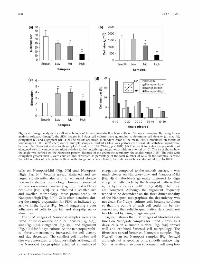
The SEM images of Nanopost samples were ana-lyzed for the quantification of cell density [Fig. 4(a)],size [Fig. 4(b)], elongation [Fig. 4(c)], and alignment[Fig. 4(d)] for 3 days culture. As the nanotopographi-cal three-dimensionality increased, the cell densityand size decreased. The smallest cell number andsize were measured on Nanopost-High. Although allthe Nanopost topographies exhibited an enhanced
elongation compared to the smooth surface, it wasmuch clearer on Nanopost-Low and Nanopost-Mid[Fig. 4(c)]. Fibroblasts generally preferred to alignalong the path made by the Nanopost pattern, thatis, the tips or valleys [0–108 in Fig. 4(d)], when theyare elongated. Although the alignment frequencytended to be dependent on the three-dimensionalityof the Nanopost topographies, the dependency wasnot clear. For 7 days’ culture, cells became confluentso that the outline of each cell could not be dis-cerned and that reliable quantitative data could notbe obtained by using image analysis.
Figure 5 shows the SEM images of fibroblasts cul-tured on Nanograte samples for 3 and 7 days. In 3days, cells on a smooth surface [Fig. 5(a)] spreadwell and exhibited flattened cell morphology. Thefibroblasts spread better on Nanograte samples [Fig.5(c,e,g)] than on Nanopost samples [Fig. 3(c,e,g)]although not as good as on a smooth surface [Fig.5(a)]. A relatively swollen (thickened) cell morphol-
Figure 4. Image analyses for cell morphology of human foreskin fibroblast cells on Nanopost samples. By using imageanalysis software (ImageJ), the SEM images in 3 days cell culture were quantified to determine cell density (a), size (b),elongation (c), and alignment (d). (a–c) The results are mean 6 standard error of the mean (SEM), calculated on means offour images (1 3 1 mm2 each) out of multiple samples. Student’s t-test was performed to evaluate statistical significancebetween the Nanopost and smooth samples (*t-test, p < 0.05; **t-test, p < 0.01). (d) The result indicates the population ofelongated cells in certain orientations relative to the underlying nanopatterns with an interval of 108. The inset shows howthe angle was defined on the Nanopost pattern. Because of the geometric symmetry, the angles range 0–458. The cells withelongation greater than 3 were counted and expressed as percentage of the total number of cells on the samples. Becausethe total number of cells includes those with elongation smaller than 3, the data for each case do not add up to 100%.
808 CHOI ET AL.
Journal of Biomedical Materials Research Part A

ogy was shown on Nanograte samples, especially onNanograte-Mid [Fig. 5(e)] and Nanograte-High [Fig.5(g)], as was the case for Nanopost samples. How-ever, more significant cell elongation with clearalignment to the underlying grate direction wasobserved on Nanograte samples. The elongated andslender cell morphology became more pronouncedas the nanotopographical three-dimensionality (i.e.,
Nanograte height) increased (from Low, Mid, toHigh). As was the case for Nanopost samples, cellsoften detached on tall nanostructures during thesample preparation for SEM, as indicated by arrowsin the figures [Fig. 5(e,g)], illustrating a weak cell ad-herence to the tall, sharp-tip nanostructures. In 7days, overall, cell population, spreading, and sizeincreased on all the samples. Cells on a smooth sur-
Figure 5. SEM images (top view) of human foreskin fibroblast cells cultured on Nanograte samples (a,b: smooth samplesused as controls, c,d: Nanograte-Low, e,f: Nanograte-Mid, g,h: Nanograte-High) over time (left column: 3 days, right col-umn: 7 days). Each inset in (c–h) represents the orientation of the Nanograte array on the sample. Detached cells, as indi-cated by the arrows (?) in (e,g), were often observed on Nanograte-Mid and Nanograte-High samples during the samplepreparation for SEM.
CELL GROWTH AS A SHEET ON THREE-DIMENSIONAL SHARP-TIP NANOSTRUCTURES 809
Journal of Biomedical Materials Research Part A
face [Fig. 5(b)] maintained the flattened cell mor-phology with enhanced spreading. Although cells onNanograte samples, when compared to those in 3days, spread better with a flattened morphology andenlarged size, the alignment and elongation alongthe grate direction were maintained. The elongationwas observed more pronounced and cell morphol-ogy more slender on the taller Nanograte samples.
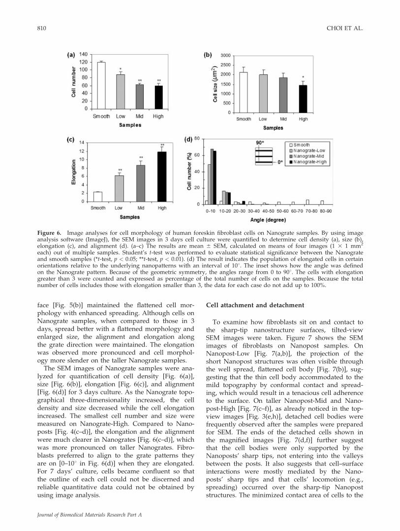
The SEM images of Nanograte samples were ana-lyzed for quantification of cell density [Fig. 6(a)],size [Fig. 6(b)], elongation [Fig. 6(c)], and alignment[Fig. 6(d)] for 3 days culture. As the Nanograte topo-graphical three-dimensionality increased, the celldensity and size decreased while the cell elongationincreased. The smallest cell number and size weremeasured on Nanograte-High. Compared to Nano-posts [Fig. 4(c–d)], the elongation and the alignmentwere much clearer in Nanogrates [Fig. 6(c–d)], whichwas more pronounced on taller Nanogrates. Fibro-blasts preferred to align to the grate patterns theyare on [0–108 in Fig. 6(d)] when they are elongated.For 7 days’ culture, cells became confluent so thatthe outline of each cell could not be discerned andreliable quantitative data could not be obtained byusing image analysis.
Cell attachment and detachment
To examine how fibroblasts sit on and contact tothe sharp-tip nanostructure surfaces, tilted-viewSEM images were taken. Figure 7 shows the SEMimages of fibroblasts on Nanopost samples. OnNanopost-Low [Fig. 7(a,b)], the projection of theshort Nanopost structures was often visible throughthe well spread, flattened cell body [Fig. 7(b)], sug-gesting that the thin cell body accommodated to themild topography by conformal contact and spread-ing, which would result in a tenacious cell adherenceto the surface. On taller Nanopost-Mid and Nano-post-High [Fig. 7(c–f)], as already noticed in the top-view images [Fig. 3(e,h)], detached cell bodies werefrequently observed after the samples were preparedfor SEM. The ends of the detached cells shown inthe magnified images [Fig. 7(d,f)] further suggestthat the cell bodies were only supported by theNanoposts’ sharp tips, not entering into the valleysbetween the posts. It also suggests that cell–surfaceinteractions were mostly mediated by the Nano-posts’ sharp tips and that cells’ locomotion (e.g.,spreading) occurred over the sharp-tip Nanopoststructures. The minimized contact area of cells to the
Figure 6. Image analyses for cell morphology of human foreskin fibroblast cells on Nanograte samples. By using imageanalysis software (ImageJ), the SEM images in 3 days cell culture were quantified to determine cell density (a), size (b),elongation (c), and alignment (d). (a–c) The results are mean 6 SEM, calculated on means of four images (1 3 1 mm2
each) out of multiple samples. Student’s t-test was performed to evaluate statistical significance between the Nanograteand smooth samples (*t-test, p < 0.05; **t-test, p < 0.01). (d) The result indicates the population of elongated cells in certainorientations relative to the underlying nanopatterns with an interval of 108. The inset shows how the angle was definedon the Nanograte pattern. Because of the geometric symmetry, the angles range from 0 to 908. The cells with elongationgreater than 3 were counted and expressed as percentage of the total number of cells on the samples. Because the totalnumber of cells includes those with elongation smaller than 3, the data for each case do not add up to 100%.
810 CHOI ET AL.
Journal of Biomedical Materials Research Part A

surface by the tall and sharp-tip Nanoposts wouldresult in reduced cell adherence to the surface, caus-ing the cell detachment during the sample prepara-tions for the SEM images.
Figure 8 shows the tilted-view SEM images offibroblasts on Nanograte samples. On Nanograte-Low [Fig. 8(a,b)], unlike on Nanopost-Low [Fig.7(b)], a clear projection of the imprinted Nanogratepattern was not visible through the cell bodies [Fig.8(b)]. Rather than conforming to the Nanograte sur-face topography, it was occasionally observed thatcells reached the bottom valley surface by formingshort filopodia [see an arrow in Fig. 8(b)]. As alreadyseen in the top-view images [Fig. 5(e,g)], detachedcell bodies were frequently observed on tall Nano-grate samples [Fig. 8(c,e)]. The magnified tilted-view
images of cleaved samples on the right columnclearly show that on tall Nanograte samples [Fig.8(d,f)] cell bodies are only supported by the sharp-tip ridges and did not go down into the valleys.Consistent with the case of Nanopost samples, it isbelieved that the minimized cell–solid contact areaby tall and sharp-tip Nanograte structures resultedin the self-detachment of the cell bodies during thesample preparation for the SEM images.
Cell sheeting
Fibroblasts were also cultured on the nanostruc-tured surfaces for an extended period (past the 7days) to see if they could proliferate enough to form
Figure 7. SEM images (tilted view) of human foreskin fibroblast cells cultured on Nanopost samples: Nanopost-Low (a,b:3 days), Nanopost-Mid (c,d: 3 days), and Nanopost-High (e,f: 7 days). The high-magnification image (b) is from the sam-ple cleaved through the silicon substrate and cell to show the cross section. While already discussed with the top-viewimages in Figure 3, the tilted-view images more clearly show the detachment of cell bodies from the Nanopost-Mid andNanopost-High. Cells detached during the sample preparation for SEM.
CELL GROWTH AS A SHEET ON THREE-DIMENSIONAL SHARP-TIP NANOSTRUCTURES 811
Journal of Biomedical Materials Research Part A

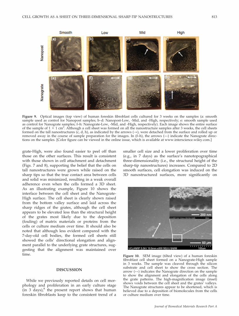
a 3D sheet of cells that could be peeled off. Figure 9shows the optical images of the fibroblasts culturedfor 3 weeks on the samples. Although the fibroblastsproliferated slower on the tall nanostructures in thebeginning, a sheet of cells eventually formed on thenanostructured surfaces after 3 weeks, while itformed a few days earlier on smooth control surfa-ces. It should be noted that during the sample prep-aration for the image (i.e., fixation and drying), thecell sheets on Nanopost-Mid [Fig. 9(c)] and Nano-post-High [Fig. 9(d)] detached from one side andtheir edges curled up, while the cell sheets on a
smooth control surface [Fig. 9(a)] and Nanopost-Low[Fig. 9(b)] remained attached. A part of a cell sheeton the Nanograte samples also detached and curledaway from the surface (parallel to the grate direc-tion) in the course of the sample preparation. Thedetachment was more pronounced on taller struc-tures [Fig. 9(f–h)], while a whole cell sheet on asmooth control surface remained attached [Fig. 9(e)].In a simple peel test using tweezers, before drying(i.e., in a cell culture medium) as well as after dry-ing, the cell sheets formed on the tall nanostructures,that is, Nanopost-Mid, Nanopost-High, and Nano-
Figure 8. SEM images (tilted view) of human foreskin fibroblast cells cultured on Nanograte samples: Nanograte-Low(a,b: 3 days), Nanograte-Mid (c,d: 3 days), and Nanograte-High (e,f: 3 days). The high-magnification images on the rightcolumn (b,d,f) are from the sample cleaved through the silicon substrate and cell to show the cross sections. On Nano-grate-Low, it was often observed that lamellipodia touched the bottom valleys with short filopodia as indicated by anarrow (?) in (b). While already discussed with the top-view images in Figure 5, the tilted-view images more clearly showthe detachment of cell bodies from the Nanograte-Mid and Nanograte-High. Cells detached during the sample preparationfor SEM.
812 CHOI ET AL.
Journal of Biomedical Materials Research Part A
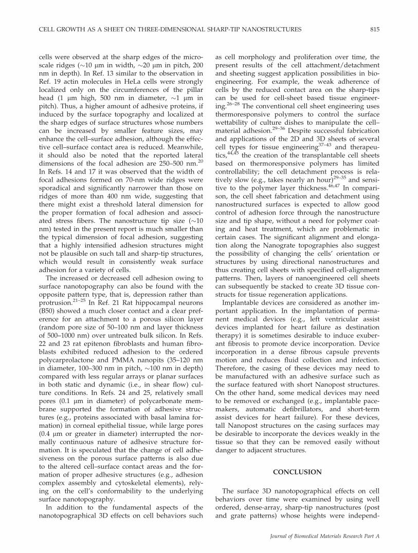
grate-High, were also found easier to peel off thanthose on the other surfaces. This result is consistentwith those shown in cell attachment and detachment(Figs. 7 and 8), supporting the belief that the cells ontall nanostructures were grown while raised on thesharp tips so that the true contact area between cellsand solid was minimized, resulting in a weak overalladherence even when the cells formed a 3D sheet.As an illustrating example, Figure 10 shows theinterface between the cell sheet and the Nanograte-High surface. The cell sheet is clearly shown raisedfrom the bottom valley surface and laid across thesharp ridges of the grates, although the cell sheetappears to be elevated less than the structural heightof the grates most likely due to the deposition(fouling) of matrix materials or proteins from thecells or culture medium over time. It should also benoted that although less evident compared with the7-day-old cell bodies, the formed cell sheets stillshowed the cells’ directional elongation and align-ment parallel to the underlying grate structures, sug-gesting that the alignment was maintained overtime.
DISCUSSION
While we previously reported details on cell mor-phology and proliferation in an early culture stage(in 3 days),8 the present report shows that humanforeskin fibroblasts keep to the consistent trend of a
smaller cell size and a lower proliferation over time(e.g., in 7 days) as the surface’s nanotopographicalthree-dimensionality (i.e., the structural height of thesharp-tip nanostructures) increases. Compared to 2Dsmooth surfaces, cell elongation was induced on the3D nanostructured surfaces, more significantly on
Figure 9. Optical images (top view) of human foreskin fibroblast cells cultured for 3 weeks on the samples (a: smoothsample used as control for Nanopost samples; b–d: Nanopost-Low, -Mid, and -High, respectively; e: smooth sample usedas control for Nanograte samples; f–h: Nanograte-Low, -Mid, and -High, respectively). Each image shows the entire surfaceof the sample of 1 3 1 cm2. Although a cell sheet was formed on all the nanostructure samples after 3 weeks, the cell sheetsformed on the tall nanostructures (c, d, h), as indicated by the arrows (?), were detached from the surface and rolled up orremoved away in the course of sample preparation for the images. In (f–h), the arrows ($) indicate the Nanograte direc-tions on the samples. [Color figure can be viewed in the online issue, which is available at www.interscience.wiley.com.]
Figure 10. SEM image (tilted view) of a human foreskinfibroblast cell sheet formed on a Nanograte-High samplein 3 weeks. The sample was cleaved through the siliconsubstrate and cell sheet to show the cross section. Thearrow ($) indicates the Nanograte direction on the sampleto show the alignment and elongation of the cells alongthe grate patterns. The high-magnification image (inset)shows voids between the cell sheet and the grates’ valleys.The Nanograte structures appear to be shortened, which isbelieved due to a deposition of biomolecules from the cellsor culture medium over time.
CELL GROWTH AS A SHEET ON THREE-DIMENSIONAL SHARP-TIP NANOSTRUCTURES 813
Journal of Biomedical Materials Research Part A

Nanogrates than Nanoposts, and maintained overtime. Prominent cell alignment was also presentedalong Nanogrates and persisted over time. The con-tact guidance by a grate pattern, particularly theelongation, was more pronounced as the height ofNanogrates increased. To our best knowledge, oursharp-tip Nanogrates of �10-nm wide ridges are thesmallest feature size that has been reported toinduce the contact guidance. It is also noteworthythat, although the cells started to be smaller and pro-liferated slower on nanostructured surfaces (espe-cially tall nanostructures) than on a smooth surface,fibroblasts became confluent over time and a sheetof cells was formed on the nanostructured surfaces(in 3 weeks). Our further observation that the cellsheet became easier to peel off when grown on tallernanostructures suggests that sheet fabrication and re-moval is possible for a variety of cells9 by using 3Dnanostructured surfaces.
When nanostructures were short, for example, onNanopost-Low [Fig. 7(b)] or Nanograte-Low [Fig.8(b)], the well spread and flattened cell bodies (i.e.,thin lamellipodia) were able to conform to the sur-face nanotopograpy or contact to the bottom valleysurface by projecting short filopodia. Meanwhile, ontaller nanostructures [Fig. 7(d,f) for Nanopost; Fig.8(d,f), and Fig. 10 for Nanogrates], the cell bodieswere not capable of conforming to the surface nano-topography and contacted only with the nanostruc-tures’ sharp tips, not entering into the valleys. It isspeculated that the altered cell-surface adhesive areais an explanation of the raised adhesion on shortnanostructures and diminished adhesion on tallnanostructures. Our result and speculation agreewell with the reports by others.10–14 In Refs. 10–11,electron microscopy and immunofluorescenceshowed that human fibroblasts tried to endocytosethe poly(methyl methacrylate) (PMMA) nanocol-umns (�160 nm high, �100 nm diameter, randombut submicron pitch). A SEM examination showedthat, in the endocytosis-attempted areas, the shapeof the short nanocolumns was clearly visible underthe thin cell lamellae, suggesting that such nanoim-printing of surface structures onto cells possiblyincreases the cell adhesion on the surface. In Ref. 12,electron microscopy showed that primary murineastrocytes sunk to the bottom of the metal (platinumand gold) nanopillars (1.6–2.6 lm high, �600 nmdiameter, random pitch ranging in 1–10 lm) when thespacing (i.e., pitch) was relatively large (�10 lm),while cell membrane rested on tips of pillars whenthe spacing was relatively small (�1 lm). In Ref. 13,it was shown that HeLa cells adhered only to thehead of polystyrene nanopillars (1 lm high, 500 nmdiameter, �1 lm pitch) and were easily removedfrom the nanopillar surface. In Ref. 14, a SEMrevealed that lamellipodia at the leading and trailing
edges of the human corneal epithelial cells did notdescend into the silicon grooves, for groove widthsranging from 950 nm (2000-nm pitch) down to 330nm (400 nm pitch), on both 150-nm and 600-nm-deep grooves. On 2100-nm-wide grooves, lamellipo-dia frequently conformed to the grooves on 150-nm-deep grooves and were sometimes able to contactthe floor of the grooves on 600-nm-deep grooves.Reinforcing and furthering these other reports,10–14
our present report suggests that taller (or high-as-pect-ratio) structures in smaller spacing (or pitch)should be more desirable to sustain cells over thesurface, which would result in a reduced cell–surfacecontact area and a consequently weaker cell adher-ence on the surface. It is believed that the cell me-chanical properties (e.g., elasticity or rigidity of a cellmembrane) needed to conform the surface nanoto-pography are only amenable for the widely scatteredor low-aspect-ratio nanostructures, which willrequire a relatively small curvature of a cell mem-brane. If tall and slender surface nanostructures aredensely populated (i.e., providing high-aspect-ratiovalleys), the limited pliability of the cell membranewill prevent the conformal contact (or endocytosis-like process) since a high curvature of a cell mem-brane is energetically unfavorable.15 At a given pitchand structural height, one can see that the grate pat-tern is more advantageous than the post pattern insustaining cells across the nanostructures tops, sincethe grate pattern geometrically requires a higher cur-vature than the post at the same pitch and height.
In addition to the true cell–surface contact area(i.e., geometric effect), it should also be noted thatother factors such as cell types and the effectiveamount of the adhesion complexes also affect theoverall cell–surface adherence. In Ref. 16, althoughhuman corneal epithelial cells showed restrictive con-tact to the tops of the ridges (220–2200 nm in width,400–4000 nm in pitch, 250–600 nm in depth, respec-tively), increased cell adhesion was observed onsmaller feature sizes compared to larger ones or aplanar surface. Although human corneal keratocytesexhibited an opposite trend (i.e., lower adherence onsmaller feature sizes) suggesting that cell type has aninfluence on the adhesive responses to topographicalstimuli,17 it was speculated that more surface discon-tinuities with the smaller features might contribute tothe increased adhesion by providing more availablebinding sites that ensure favorable cell–substratumadhesion protein conformations. Such speculationcan be supported by a few other reports.13,18,19 InRef. 18, human gingival fibroblasts cultured on tita-nium-coated microscale grooves (6–10 lm in pitch, 3lm in depth) produced a higher amount of the adhe-sive protein fibronectin as compared to those on asmooth surface. In Ref. 19, a confined contact and alocalized high adhesion of rat epitenon fibroblast
814 CHOI ET AL.
Journal of Biomedical Materials Research Part A
cells were observed at the sharp edges of the micro-scale ridges (�10 lm in width, �20 lm in pitch, 200nm in depth). In Ref. 13 similar to the observation inRef. 19 actin molecules in HeLa cells were stronglylocalized only on the circumferences of the pillarhead (1 lm high, 500 nm in diameter, �1 lm inpitch). Thus, a higher amount of adhesive proteins, ifinduced by the surface topography and localized atthe sharp edges of surface structures whose numberscan be increased by smaller feature sizes, mayenhance the cell–surface adhesion, although the effec-tive cell–surface contact area is reduced. Meanwhile,it should also be noted that the reported lateraldimensions of the focal adhesion are 250–500 nm.20
In Refs. 14 and 17 it was observed that the width offocal adhesions formed on 70-nm wide ridges weresporadical and significantly narrower than those onridges of more than 400 nm wide, suggesting thatthere might exist a threshold lateral dimension forthe proper formation of focal adhesion and associ-ated stress fibers. The nanostructure tip size (�10nm) tested in the present report is much smaller thanthe typical dimension of focal adhesion, suggestingthat a highly intensified adhesion structures mightnot be plausible on such tall and sharp-tip structures,which would result in consistently weak surfaceadhesion for a variety of cells.
The increased or decreased cell adhesion owing tosurface nanotopography can also be found with theopposite pattern type, that is, depression rather thanprotrusion.21–25 In Ref. 21 Rat hippocampal neurons(B50) showed a much closer contact and a clear pref-erence for an attachment to a porous silicon layer(random pore size of 50–100 nm and layer thicknessof 500–1000 nm) over untreated bulk silicon. In Refs.22 and 23 rat epitenon fibroblasts and human fibro-blasts exhibited reduced adhesion to the orderedpolycarprolactone and PMMA nanopits (35–120 nmin diameter, 100–300 nm in pitch, �100 nm in depth)compared with less regular arrays or planar surfacesin both static and dynamic (i.e., in shear flow) cul-ture conditions. In Refs. 24 and 25, relatively smallpores (0.1 lm in diameter) of polycarbonate mem-brane supported the formation of adhesive struc-tures (e.g., proteins associated with basal lamina for-mation) in corneal epithelial tissue, while large pores(0.4 lm or greater in diameter) interrupted the nor-mally continuous nature of adhesive structure for-mation. It is speculated that the change of cell adhe-siveness on the porous surface patterns is also dueto the altered cell–surface contact areas and the for-mation of proper adhesive structures (e.g., adhesioncomplex assembly and cytoskeletal elements), rely-ing on the cell’s conformability to the underlyingsurface nanotopography.
In addition to the fundamental aspects of thenanotopographical 3D effects on cell behaviors such
as cell morphology and proliferation over time, thepresent results of the cell attachment/detachmentand sheeting suggest application possibilities in bio-engineering. For example, the weak adherence ofcells by the reduced contact area on the sharp-tipscan be used for cell-sheet based tissue engineer-ing.26–28 The conventional cell sheet engineering usesthermoresponsive polymers to control the surfacewettability of culture dishes to manipulate the cell–material adhesion.29–36 Despite successful fabricationand applications of the 2D and 3D sheets of severalcell types for tissue engineering37–43 and therapeu-tics,44,45 the creation of the transplantable cell sheetsbased on thermoresponsive polymers has limitedcontrollability; the cell detachment process is rela-tively slow (e.g., takes nearly an hour)29–35 and sensi-tive to the polymer layer thickness.46,47 In compari-son, the cell sheet fabrication and detachment usingnanostructured surfaces is expected to allow goodcontrol of adhesion force through the nanostructuresize and tip shape, without a need for polymer coat-ing and heat treatment, which are problematic incertain cases. The significant alignment and elonga-tion along the Nanograte topographies also suggestthe possibility of changing the cells’ orientation orstructures by using directional nanostructures andthus creating cell sheets with specified cell-alignmentpatterns. Then, layers of nanoengineered cell sheetscan subsequently be stacked to create 3D tissue con-structs for tissue regeneration applications.
Implantable devices are considered as another im-portant application. In the implantation of perma-nent medical devices (e.g., left ventricular assistdevices implanted for heart failure as destinationtherapy) it is sometimes desirable to induce exuber-ant fibrosis to promote device incorporation. Deviceincorporation in a dense fibrous capsule preventsmotion and reduces fluid collection and infection.Therefore, the casing of these devices may need tobe manufactured with an adhesive surface such asthe surface featured with short Nanopost structures.On the other hand, some medical devices may needto be removed or exchanged (e.g., implantable pace-makers, automatic defibrillators, and short-termassist devices for heart failure). For these devices,tall Nanopost structures on the casing surfaces maybe desirable to incorporate the devices weakly in thetissue so that they can be removed easily withoutdanger to adjacent structures.
CONCLUSION
The surface 3D nanotopographical effects on cellbehaviors over time were examined by using wellordered, dense-array, sharp-tip nanostructures (postand grate patterns) whose heights were independ-
CELL GROWTH AS A SHEET ON THREE-DIMENSIONAL SHARP-TIP NANOSTRUCTURES 815
Journal of Biomedical Materials Research Part A

ently controlled. Although cell population was sig-nificantly lower and cell size smaller with increasingnanostructure height (which was more pronouncedon post patterns than on grate patterns), humanforeskin fibroblast cells proliferated over time andconstituted a 3D cell sheet on the sharp-tip nano-structure surfaces. The significant elongation andalignment along the grate patterns (which was morepronounced as the grate height increased) was main-tained over time such that a cell sheet with direc-tional cell pattern was formed on the grate patterns.In regard to cell attachment, when the nanostructureheight was relatively short, fibroblasts adhered wellto the entire surface including the valleys. When thenanostructure was tall, however, cells grew specifi-cally on the sharp tips of the nanostructures. As aresult, the cell adherence to the surface was weak sothat the cell sheet formed on the tall nanostructureswas easily peeled off. The large-area, well-ordered,dense-array nanostructures with controllable patternperiodicity, size, and shape can open new applica-tion possibilities in bioengineering, such as cell-sheetbased tissue engineering.
References
1. Cukierman E, Pankov R, Stevens DR, Yamada KM. Takingcell–matrix adhesions to the third dimension. Science 2001;294:1708–1712.
2. Cukierman E, Pankov R, Yamada KM. Cell interactions withthree-dimensionalmatrices. Curr OpinCell Biol 2002;14:633–639.
3. Abrams GA, Goodman SL, Nealey PF, Franco M, Murphy CJ.Nanoscale topography of the basement membrane underlyingthe corneal epithelium of the rhesus macaque. Cell TissueRes 2000;299:39–46.
4. Curtis A, Wilkinson C. Topographical control of cells. Bioma-terials 1997;18:1573–1583.
5. Flemming RG, Murphy CJ, Abrams GA, Goodman SL, Nea-ley PF. Effects of synthetic micro- and nano-structured surfa-ces on cell behavior. Biomaterials 1999;20:573–588.
6. Curtis A. Tutorial on the biology of nanotopography. IEEETrans Nanobios 2004;3:293–295.
7. Choi C-H, Kim C-J. Fabrication of dense array of tall nano-structures over a large sample area with sidewall profile andtip sharpness control. Nanotechnology 2006;17:5326–5333.
8. Choi C-H, Hagvall SH, Wu BM, Dunn JCY, Beygui RE, KimC-J. Cell interaction with three-dimensional sharp-tip nanoto-pography. Biomaterials 2007;28:1672–1679.
9. Choi C-H, Hagvall SH, Dunn JCY, Wu BM, Kim C-J. Cell ad-hesion on nanoturf surfaces. In: Proc 19th Int Conf MicroElectro Mechanical Systems (Istanbul, Turkey). Piscataway:IEEE; 2006. p 402–405.
10. Dalby MJ, Berry CC, Riehle MO, Sutherland DS, Agheli H,Curtis ASG. Attempted endocytosis of nano-environmentproduced by colloidal lithography by human fibroblasts. ExpCell Res 2004;295:387–394.
11. Curtis ASG, Dalby MJ, Gadegaard N. Nanoimprinting ontocells. J R Soc Interface 2006;3:393–398.
12. Gimsa U, Iglic A, Fiedler S, Zwanzig M, Kralj-Iglic V, JonasL, Gimsa J. Actin is not required for nanotubular protrusionsof primary astrocytes grown on metal nano-lawn. MolMembr Biol 2007;24:243–255.
13. Nomura S, Kojima H, Ohyabu Y, Kuwabara K, Miyauchi A,Uemura T. Cell culture on nanopillar sheet: Study of HeLacells on nanopillar sheet. Jpn J Appl Phys 2005;44:L1184–L1186.
14. Teixeira AI, Abrams GA, Bertics PJ, Murphy CJ, Nealey PF.Epithelial contact guidance on well-defined micro- and nano-structured substrates. J Cell Sci 2003;116:1881–1892.
15. Lipowsky R. The conformation of membranes. Nature 1991;349:475–481.
16. Karuri NW, Liliensiek S, Teixeria AI, Abrams G, Campbell S,Nealey PF, Murphy CJ. Biological length scale topographyenhanced cell–substratum adhesion of human corneal epithe-lial cells. J Cell Sci 2004;117:3153–3164.
17. Teixeria AI, Nealey PF, Murphy CJ. Responses of human ker-atocytes to micro- and nanostructured substrates. J BiomedMater Res 2004;71A:369–376.
18. Chou L, Firth JD, Uitto VJ, Brunette DM. Substratum surfacetopography alters cell shape and regulates fibronectin mRNAlevel, mRNA stability, secretion and assembly in humanfibroblasts. J Cell Sci 1995;108:1563–1573.
19. Curtis ASG, Casey B, Gallagher JO, Pasqui D, Wood MA,Wilkinson CDW. Substratum nanotopography and the adhe-sioin of biological cells. Are symmetry or regularity of nano-topography important? Biophys Chem 2001;94:275–283.
20. Ohara PT, Buck RC. Contact guidance in vitro: A light, trans-mission, and scanning electron microscopic study. Exp CellRes 1979;121:235–249.
21. Sapelkin AV, Bayliss SC, Unal B, Charalambou A. Interactionof B50 rat hippocampal cells with stain-etched porous silicon.Biomaterials 2006;27:842–846.
22. Curtis ASG, Gadegaard N, Dalby MJ, Riehle MO, WilkinsonCDW, Aitchison G. Cells react to nanoscale order and sym-metry in their surroundings. IEEE Trans Nanobiosci 2004;3:61–65.
23. Martines E, McGhee K, Wilkinson C, Curtis A. A parallel-plate flow chamber to study initial cell adhesion on a nano-featured surface. IEEE Trans Nanobiosci 2004;3:90–95.
24. Evans MDM, Dalton BA, Steele JG. Persistent adhesion ofepithelial tissue is sensitive to polymer topography. J BiomedMater Res 1999;46:485–493.
25. Evans MDM, Taylor S, Dalton BA, Lohmann D. Polymerdesign for corneal epithelial tissue adhesion: Pore density. JBiomed Mater Res 2003;64A:357–364.
26. Kikuchi A, Okano T. Nanostructured designs of biomedicalmaterials: Applications of cell sheet engineering to functionalregenerative tissues and organs. J Control Release 2005;101:69–84.
27. Yang J, Yamato M, Konno C, Nishimoto A, Sekine H, FukaiF, Okano T. Cell sheet engineering: Recreating tissues with-out biodegradable scaffolds. Biomaterials 2005;26:6415–6422.
28. Yang J, Yamato M, Shimizu T, Sekine H, Ohashi K, KanzakiM, Ohki T, Nishida K, Okano T. Reconstruction of functionaltissues with cell sheet engineering. Biomaterials 2007;28:5033–5043.
29. Kushida A, Yamato M, Konno C, Kikuchi A, Sakurai Y,Okano T. Decrease in culture temperature releases monolayerendothelial cell sheets together with deposited fibronectinmatrix from temperature-responsive culture surfaces. J Bio-med Mater Res 1999;45:355–362.
30. Kwon OH, Kikuchi A, Yamato M, Sakurai Y, Okano T. Rapidcell sheet detachment from poly(N-isopropylacrylamide)-grafted porous cell culture membranes. J Biomed Mater Res2000;50:82–89.
31. Kwon OH, Kikuchi A, Yamato M, Okano T. Accelerated cellsheet recovery by co-grafting of PEG with PIPAAm onto po-rous cell culture membranes. Biomaterials 2003;24:1223–1232.
32. Tsuda Y, Kikuchi A, Yamato M, Sakurai Y, Umezu M, OkanoT. Control of cell adhesion and detachment using tempera-
816 CHOI ET AL.
Journal of Biomedical Materials Research Part A
ture and thermoresponsive copolymer grafted culture surfa-ces. J Biomed Mater Res 2004;69A:70–78.
33. Hatakeyama H, Kikuchi A, Yamato M, Okano T. Influence ofinsulin immobilization to thermoresponsive culture surfaceson cell proliferation and thermally induced cell detachment.Biomaterials 2005;26:5167–5176.
34. Xu FJ, Zhong SP, Yung LYL, Tong YW, Kang ET, Neoh KG.Thermoresponsive comb-shaped copolumer-Si(100) hybridsfor accelerated temperature-dependent cell detachment. Bio-materials 2006;27:1236–1245.
35. Hatakeyama H, Kikuchi A, Yamato M, Okano T. Bio-func-tionalized thermoresponsive interfaces facilitating cell adhe-sion and proliferation. Biomaterials 2006;27:5069–5078.
36. Hatakeyama H, Kikuchi A, Yamato M, Okano T. Patternedbiofunctional designs of thermoresponsive surfaces for spa-tiotemporally controlled cell adhesion, growth, and thermallyinduced detachment. Biomaterials 2007;28:3632–3643.
37. Nandkumar MA, Yamato M, Kushida A, Konno C, Hirose M,Kikuchi A, Okano T. Two-dimensional cell sheet manipula-tion of heterotypically co-cultured lung cells utilizing temper-ature-responsive culture dishes results in long-term mainte-nance of differentiated epithelial cell functions. Biomaterials2002;23:1121–1130.
38. Harimoto M, Yamato M, Hirose M, Takahashi C, Isoi Y,Kikuchi A, Okano T. Novel approach for achieving double-layered cell sheets co-culture: Overlaying endothelial cellsheets onto monolayer hepatocytes utilizing temperature-re-sponsive culture dishes. J Biomed Mater Res 2002;62:464–470.
39. Shimizu T, Yamato M, Kikuchi A, Okano T. Cell sheet engi-neering for myocardial tissue construction. Biomaterials 2003;24:2309–2316.
40. Tsuda Y, Kikuchi A, Yamato M, Nakao A, Sakurai Y, UmezuM, Okano T. The use of patterned dual thermoresponsivesurfaces for the collective recovery as co-cultured cell sheets.Biomaterials 2005;26:1885–1893.
41. Ide T, Nishida K, Yamato M, Sumide T, Utsumi M, Nozaki T,Kikuchi A, Okano T. Tano Y. Structural characterization ofbioengineered human corneal endothelial cell sheets fabri-cated on temperature-responsive culture dishes. Biomaterials2006;27:607–614.
42. Kubato A, Nishida K, Yamato M, Yang J, Kikuchi A, OkanoT, Tano Y. Transplantable retinal pigment epithelial cellsheets for tissue engineering. Biomaterials 2006;27:3639–3644.
43. Kanzaki M, Yamato M, Yang J, Sekine H, Kohno C, Takagi R,Hatakeyama H, Isaka T, Okano T, Onuki T. Dynamic sealingof lung air leaks by the transplantation of tissue engineeredcell sheets. Biomaterials 2007;28:4294–4302.
44. Watanabe K, Yamato M, Hayashida Y, Yang J, Kikuchi A,Okano T, Tano Y, Nishida K. Development of transplantablegenetically modified corneal epithelial cell sheets for genetherapy. Biomaterials 2007;28:745–749.
45. Chen CH, Chang Y, Wang CC, Huang CH, Huang CC, YehYC, Hwang SM, Sung HW. Construction and characterizationof fragmented mesenchymal-stem-cell sheets for intramuscu-lar injection. Biomaterials 2007;28:4643–4651.
46. Akiyama Y, Kikuchi A, Yamato M, Okano T. Ultra thinpoly(N-isopropylacrylamide) grafted layer on poly(styrene)surfaces for cell adhesion/detachment control. Langmuir2004;20:5506–5511.
47. Mizutani A, Kikuchi A, Yamato M, Kanazawa H, Okano T.Preparation of thermoresponsive polymer brush surfaces andtheir interaction with cells. Biomaterials 2008;29:2073–2081.
CELL GROWTH AS A SHEET ON THREE-DIMENSIONAL SHARP-TIP NANOSTRUCTURES 817
Journal of Biomedical Materials Research Part A