Cavitron® JET Plus - Ultrasonic Scaler & Air Polishing ...
60
Cavitron ® JET Plus Ultrasonic Scaler & Air Polishing Prophylaxis System Installation and Service Manual with Please read carefully and completely before operating unit. Downloaded from www.Manualslib.com manuals search engine
-
Upload
khangminh22 -
Category
Documents
-
view
2 -
download
0
Transcript of Cavitron® JET Plus - Ultrasonic Scaler & Air Polishing ...

i
Cavitron® JET PlusUltrasonic Scaler &Air Polishing Prophylaxis System
Installation and Service Manual
with
Please read carefully and completely before operating unit.
Downloaded from www.Manualslib.com manuals search engine
3
Quick Reference GuideDiagnostic Display
ON/OFFIlluminates when the Main Power On/Off Power switch is in the “ON” (I) position.
TURBO Offers the ability to increase power to the system by up to 25% with the push of a button. Purple arrows illuminate when in use.
BOOSTIlluminates when the Boost Mode is activated by the Tap-On TM
Wireless Foot Pedal. To activate, fully depress Tap-OnTM Foot Pedal to the second position (all the way to the floor). To deactivate, release Tap-OnTM Foot Pedal to the first position.
PURGE BUTTONIlluminates when Purge function is activated. To activate Purge, remove insert from handpiece, turn the Handpiece Lavage Control to maximum water flow, press the Purge Button on the Diagnostic Display. Water will purge through system lines for two minutes. To deactivate during two minute cycle, press Purge button again or press Tap-OnTM Foot Pedal.
SERVICEIlluminates when the system is not functioning properly. This display has three distinct modes:
Slow blink (1 blink per •second) means the system is not operating within factory specifications.Fast blink (3 blinks per second) •indicates an improper set-up.Steady light indicates the system •is overheating.
LOW BATTERYIlluminates when the Tap-OnTM
Foot Pedal battery power is approaching end of life. Replace batteries as instructed in Section 7.9.
Power ControlPower Level ControlTurn knob to select ultrasonic power level for operation. Turning the knob clockwise increases the distance the insert tip moves (the stroke) without changing frequency; turning knob counter-clockwise decreases the distance the insert tip moves (the stroke) without changing the frequency.
RINSERinse mode is used during an ultrasonic scaling procedure when lavage is required to flush the procedural area. To activate, turn Power Level Control Knob fully counter-clockwise until a “click” is heard.
BLUE ZONEProvides an extended low-power range for improved patient comfort when subgingivally scaling.
Downloaded from www.Manualslib.com manuals search engine

4
TABLE OF CONTENTSQuiCk STARTiNSTALLATiON iNSTRuCTiONS 1QuiCk START uSER GuiDE 2QuiCk REFERENCE GuiDE:DiAGNOSTiC DiSPLAy 3iNTRODuCTiON 5PRODuCT OvERviEw 5TEChNiCAL SuPPORT 6SuPPLiES & REPLACEmENT PARTS 6iNDiCATiONS FOR uSE 6 1 1 Ultrasonic Procedures 6 1 2 Air Polishing Procedures 6CONTRAiNDiCATiONS 6wARNiNGS 6-7PRECAuTiONS 4 1 System Precautions 7 4 2 Procedural Precautions 7 Ultrasonics 7 Air Polishing 7-8
ADvERSE REACTiONS 8iNFECTiON CONTROL 6 1 General Infection Control 8 6 2 Water Supply Recommendations 8iNSTALLATiON iNSTRuCTiONS 7 1 Water Line Requirements 8 7 2 Air Line Requirements &: Recommendations 8 7 3 Electrical Requirements 9 7 4 Unpacking the System 9 7 5 System Installation 9 7 6 Power Cord Connection 9 7 7 Water Supply Line Connection 9-10 7 8 Air Supply Line Connection 10 7 9 Tap-OnTM Foot Pedal Battery Installation/ Replacement 10 7 10 Tap-OnTM Foot Pedal Synchronization 10-11CAviTRON® JET PLuS COmBiNATiON SySTEm DESCRiPTiON 8 1 System Controls 12 8 2 Diagnostic Display Indicators and Controls 13 8 3 Handpiece/Cable 14 8 4 Cavitron® 30K™ Ultrasonic Inserts 14 8 5 Cavitron JET Air Polishing Inserts 15 8 6 Tap-OnTM Wireless Foot Pedal Operation 15 8 7 Accessories and User Replaceable Parts 15
8 7 1 Accessories 15 8 7 2 User Replaceable Part Kits 15
SySTEm SETuP, OPERATiON AND TEChNiQuES FOR uSE 9 1 Handpiece Setup 16 9 2 Turbo Mode 16 9 3 Boost Mode 16 9 4 Patient Positioning 16 9 5 Performing Ultrasonic Scaling Procedures 16-17 9 6 Patient Comfort Considerations 17 9 7 Air Polishing Powder Bowl 17 9 8 Performing Air Polishing Procedures 17-18 9 9 Proper Angulation of the Air Polishing Insert 18
SySTEm CARE 10 1 Daily Maintenance 19 Start-up procedures at the beginning of the day 19 Between patients 19 Shut-down procedures at the end of the day 20 10 2 Weekly Maintenance 20 10 3 Monthly Maintenance 20 Water Line Filter Maintenance 20 10 4 Air Supply Line Filter Maintenance 20 10 5 Powder Bowl Maintenance 20-21
TROuBLEShOOTiNG 11 1 Troubleshooting Guide 21-22 11 2 Technical Support and Repairs 22
wARRANTy PERiOD 22
SPECiFiCATiONS 22-23
CLASSiFiCATiONS 23
DiSPOSAL OF uNiT 23
ELECTROmAGNETiC COmPATiBiLiTy PRECAuTiONS 24-26
QuiCk REFERENCE GuiDE:TROuBLEShOOTiNG 27
TROuBLEShOOTiNG & ANALySiS 28-36
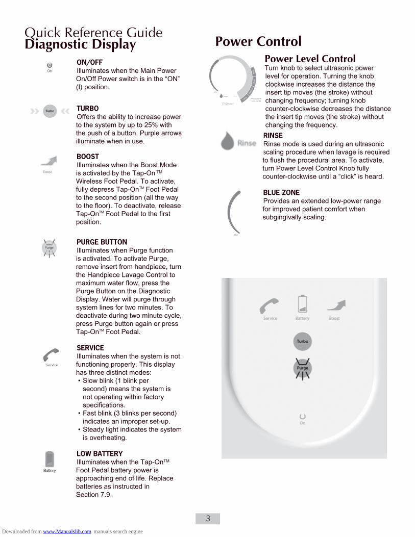
DiSASSEmBLy AND SERviCE PROCEDuRES 37-44
AiR AND wATER FLOw DiAGRAm 45
SERviCE PARTS 46-55
Downloaded from www.Manualslib.com manuals search engine

5
iNTRODuCTiON Congratulations!
Your decision to add the Cavitron® JET Plus Ultrasonic Scaler and Air Polishing Prophylaxis Combination System with Tap-On™ Technology to your practice represents a wise investment in good dentistry.
For over four decades, dental professionals have preferred the clinical benefits and labor-saving advantages inherent in Cavitron ultrasonic scalers. Clinical studies and independent research have confirmed the speed, efficiency and versatility of ultrasonic scaling.*
With the addition of air polishing capabilities in the Cavitron® JET Plus Combination System, your Cavitron® JET Plus system becomes a compact prophylaxis center that optimizes the time spent performing scaling and polishing procedures and minimizes the need for strenuous calculus and stain removal with hand instruments. Clinical studies have proven that air polishing is far superior to traditional cup and pumice for stain and plaque removal.* With proper technique and simple daily maintenance, your Cavitron® JET Plus Combination System will immediately become an indispensable component in your practice of modern preventive dentistry.
DENTSPLY Professional is an ISO 13485 registered company. All DENTSPLY Professional medical devices sold in Europe are CE marked in conformance with Council Directive 93/42/EEC.
Website: www.professional.dentsply.com
CAUTION: United States Federal Law restricts this device to sale by or on the order of, a licensed dental professional.
PRODuCT OvERviEwThe Cavitron® JET Plus Combination System is a precision engineered and manufactured instrument. It contains controls and components for ultrasonic scaling and air polishing modes. In the scaling mode, the system produces 30,000 strokes per second at the ultrasonic insert’s working tip that when combined with the cavitational effect of the
coolant lavage creates a synergistic action that is designed to “power away” even the heaviest calculus deposits while maintaining operator and patient comfort. In the air polishing mode, the system delivers a precise air/water/powder mixture at the JET air polishing insert tip that polishes the tooth enamel without contact so there is less abrasion to enamel and no physical pressure or heat build-up that could cause discomfort in sensitive patients.
The Cavitron® JET Plus Combination System is equipped with the Sustained Performance System™ (SPS Technology), which offers a constant balance between scaling efficiency and patient comfort by maintaining clinical power when the insert tip encounters tenacious deposits, allowing the clinician to effectively scale even at a decreased/lower power setting. The Cavitron® JET Plus System has extended the SPS technology by expanding the Blue Zone range, providing finer resolution to the power settings.
Advanced features that make the Cavitron® JET Plus a wise investment include a Tap-OnTM Wireless Foot Pedal with Tap-On™ Technology, Turbo Mode, Prophy Mode Auto Cycles, illuminated diagnostic display, rinse setting, automated purge function, JET-Mate™ detachable sterilizable handpiece, and 330˚ swivel handpiece cable with more precise lavage water control. These features combined with a low power range (Blue Zone™) and hands-free Boost Mode are designed to deliver a positive ultrasonic scaling and air polishing experience for your patients while providing your practice with the quality and reliability you’ve come to expect from Cavitron brand ultrasonic systems.
The Cavitron® JET Plus Combination System is UL/ULC certified and approved. The Cavitron® JET Plus Combination System is classified by Underwriters Laboratories Inc. with respect to electric shock, fire, mechanical hazards in accordance with the IEC 60601 Standard. The Cavitron® JET Plus Combination System complies with Part 15 of the FCC Rules. Operation is subject to the following two conditions: 1) this device may not cause harmful interference, and 2) this device must accept any interference received, including interference that may cause undesired operation. Cavitron® JET Plus base FCC certification/registration number: FCC ID: TF3-DPD73227323; IC: 4681B-73227323. Cavitron® JET Plus Tap-OnTM Foot Pedal FCC certification/registration number: FCC ID: TF3-DPD81675; IC: 4681B-81675. The term IC before the certification/registration number signifies that the Industry Canada technical specifications were met.
* data on file
Downloaded from www.Manualslib.com manuals search engine

6
TEChNiCAL SuPPORTFor technical support and repair assistance in the U.S., call the DENTSPLY Professional Cavitron CareSM Factory Certified Service at 1-800-989-8826, Monday through Friday, 8:00 A.M. to 5:00 P.M. (Eastern Time). For other areas, contact your local DENTSPLY Professional representative.
SuPPLiES &REPLACEmENT PARTSTo order supplies or replacement parts in the U.S., contact your local DENTSPLY Professional Distributor or call 1-800-989-8826, Monday through Friday, 8:00 A.M. to 5:00 P.M. (Eastern Time). For other areas, contact your local DENTSPLY Professional Representative.
SECTiON 1: indications For use 1 1 ultrasonic Procedures
All general supra and subgingival scaling applications•
Periodontal debridement for all types of periodontal • diseases
Endodontic procedures • 1 2 Air Polishing Procedures
Removal of a variety of extrinsic stains, e.g. tobacco, • coffee, tea, chlorhexidine.
Prophylaxis of orthodontic patients.•
Preparing tooth surfaces prior to bonding and sealant • procedures.
SECTiON 2: Contraindications
Ultrasonic Systems should not be used for restorative • dental procedures involving the condensation of amalgam.
Cavitron• ® PROPHY-JET Prophy Powder is a water-soluble Sodium Bicarbonate powder. Therefore, this powder is not recommended for patients on a sodium restricted diet. Cavitron® JET-Fresh Prophy Powder is a sodium free powder and can be used on patients who are on sodium restricted diets.
SECTiON 3: warningsPersons fitted with cardiac pacemakers, defibrillators •
and other active implanted medical devices, have been cautioned that some types of electronic equipment might interfere with the operation of the device. Although no instance of interference has ever been reported to DENTSPLY, we recommend that the handpiece and cables be kept 6 to 9 inches (15 to 23 cm) away from any device and their leads during use.
There are a variety of pacemakers and other medically • implanted devices on the market. Clinicians should contact the device manufacturer or the patient’s physician for specific recommendations. This unit complies with IEC 60601 Medical Device Standards.
It is the responsibility of the Dental Healthcare • Professional to determine the appropriate uses of this product and to understand: – the health of each patient, – the dental procedures being undertaken, – and applicable industry and governmental agency recommendations for infection control in dental healthcare settings, – requirements, and regulations for safe practice of dentistry; and – the Directions for Use sections in their entirety, including Section 4 Precautions, Section 6 Infection Control, and Section 10 System Care.
The use of High Volume Saliva Evacuation to reduce • the quantity of aerosols released during treatment is highly recommended.
Do not direct the air polishing stream at soft tissue or • into the sulcus. Tissue emphysema has been reportedly caused when the air/water/powder stream was directed at the soft tissue or into the sulcus.
Where asepsis is required or deemed appropriate in • the best professional judgment of the Dental Healthcare Professional, this product should not be used.
During boil-water advisories, this product should not • be operated as an open water system (e.g. connected to a public water system). A Dental Healthcare Professional should disconnect the system from the central water source. The Cavitron DualSelect system can be attached to this unit and operated as a closed system until the advisory is cancelled. When the advisory is cancelled, flush all incoming waterlines from the public water system (e.g. faucets, waterlines and dental equipment) in accordance with the manufacturer’s instructions for a minimum of 5 minutes.
Prior to beginning treatment, patients should rinse with • an antimicrobial such as Chlorhexidine Gluconate 0.12%. Rinsing with an antimicrobial reduces the chance of infection and reduces the number of microorganisms released in the form of aerosols during treatment.
Downloaded from www.Manualslib.com manuals search engine

7
Per FCC Part 15.21, changes or modifications not • expressly approved by the party responsible for compliance could void the user’s authority to operate this equipment.
Failure to follow recommendations for environmental • operating conditions, including input water temperature, could result in injury to patients or users.
Insufficient water flow could result in elevated water • and tip temperature. When operated at the input water temperature specified in the Water Line Requirements Section 7.1 and with sufficient water flow, the water and tip temperature should not exceed 50o C (122o F).
SECTiON 4: Precautions4 1 System Precautions
Do not place the system on or next to a radiator or • other heat source. Excessive heat may damage the system’s electronics. Place the system where air is free to circulate on all sides and beneath it.
The system is portable, but must be handled with care • when moving.
Equipment flushing and dental water supply system • maintenance are strongly recommended. See Section 10: System Care.
Close manual shut-off valve on the dental office water • supply every night before leaving the office.
The use of an in-line water filter is recommended.•
The use of an air dryer on the compressor line supplying • the System will prevent condensation from forming in the air line which in turn may cause “caking” of the air polishing powder and clogging of the lines and air polishing nozzle.
Cavitron• ® Prophy Powders are specially formulated for use in Cavitron® Air Polishing Systems. Do not use any other materials in the air polishing powder reservoir.
Empty the air polishing powder bowl at the end of the • day to prevent “caking” of the powder and clogging of the lines and air polishing nozzle.
Residual prophy powder in threads of the bowl and cap •can result in excessive wear and disengagement of the cap during unit operation. Be sure to clean threads regularly as per Section 10 System Care.
4 2 Procedural Precautions
General
As with all dental procedures, use universal precautions • (i.e., wear face mask, eyewear, or face shield, gloves and protective gown).
Ultrasonics
The Cavitron• ® JET Plus unit works with Cavitron inserts as a system, and was designed and tested to deliver maximum performance for all currently available Cavitron brand ultrasonic inserts. Companies that manufacture, repair or modify inserts carry the sole responsibility for proving the efficacy and performance of their products when used as a part of this system. Users are cautioned to understand the operating limits of their insert before using in a clinical setting.
Like bristles of a toothbrush, ultrasonic inserts “wear” • with use. Inserts with just 2 mm of wear lose about 50% of their scaling efficiency. In general it is recommended that ultrasonic inserts be discarded and replaced after one year of use to maintain optimal efficiency and avoid breakage. A DENTSPLY Professional Insert Efficiency Indicator is enclosed for your use.
If excessive wear is noted, or the insert has been • bent, reshaped or otherwise damaged, discard the insert immediately.
Ultrasonic insert tips that have been bent, damaged, or • reshaped are susceptible to in-use breakage and should be discarded and replaced immediately.
Retract the lips, cheeks and tongue to prevent contact • with the insert tip whenever it is placed in the patient’s mouth. Air Polishing
Patients should wear safety glasses or eye protection •during air polishing treatment.
Patients wearing contact lenses should remove them • prior to air polishing treatment.
Patients who have severe respiratory illness should • consult their physician before undergoing air polishing prophylaxis procedures.
Avoid use on cementum or dentin.•
Direct contact of prophy powder with surfaces and • marginal areas of dental restorations should be avoided.
Set the air polishing powder flow control to the maximum • (H) position only when it is necessary to remove particularly difficult stains. Return the powder flow control to the medium position upon the completion of the procedure.
JET Air Polishing Insert nozzles that have been bent, • damaged or re-shaped, are susceptible to in-use breakage and should be discarded and replaced immediately.
Check o-ring and threads on powder bowl cap to • ensure a tight seal. If o-ring or threads are worn, replace immediately.
Downloaded from www.Manualslib.com manuals search engine

8
Residual prophy powder in threads of the powder bowl •and cap can result in excessive wear and disengagement of the cap during unit operation. Be sure to clean the threads regularly as per Section 10: System Care.
SECTiON 5: Adverse ReactionsNone Known.
SECTiON 6: infection Control6 1 General infection Control
For operator and patient safety, carefully practice the • infection control procedures detailed in the Infection Control Information Booklet accompanying your System. Additional booklets can be obtained by calling Customer Service at 1-800-989-8826, Monday through Friday, 8:00 A.M. to 5:00 P.M. (Eastern Time). For areas outside the U.S., contact your local DENTSPLY Professional representative.
As with high speed handpieces and other dental devices, • the combination of water and ultrasonic vibration from the Cavitron® JET Plus Combination System will create aerosols. Following the procedural guidelines in Section 9 of this manual can effectively control and minimize aerosol dispersion.
6 2 water Supply Recommendations
It is highly recommended that all dental water supply • systems conform to applicable CDC (Centers for Disease Control and Prevention) and ADA (American Dental Association) standards, and that all recommendations be followed in terms of flushing, chemical flushing, and general infection control procedures. See Sections 7.1 and 10.
As a medical device, this product must be installed • in accordance with applicable local, regional, and national regulations, including guidelines for water quality (e.g. drinking water). As an open water system, such regulation may require this device to be connected to a centralized water control device. The Cavitron® DualSelect™ Dispensing System may be installed to allow this unit to operate as a closed water system.
SECTiON 7: installation instructions Anyone installing a Cavitron® JET Plus System should observe the following requirements and recommendations.
7 1 water Line Requirements
A water supply line with user-replaceable filter is • supplied with your system. See Section 10 System Care for replacement instructions.
Incoming water supply line pressure to the system must • be 20 psi (138 kPa) to 40 psi (275 kPa). If your dental water system’s supply line pressure is above 40 psi, install a water pressure regulator on the water supply line to your Cavitron® JET Plus Combination System.
A manual shut-off valve on the dental water system • supply line should be used so that the water can be completely shut-off when the office is unoccupied.
In addition to the water filter supplied, it is recommended • that a filter in the dental water system supply line be installed so that any particulates in the water supply will be trapped before reaching the Cavitron system.
After the above installations are completed on the dental • water supply system, the dental office water line should be thoroughly flushed prior to connection to the Cavitron system.
Incoming water temperature to the Cavitron System • should not exceed 25˚C (77˚F). If needed a device should be installed to maintain a temperature within this specification, or a Cavitron DualSelect Dispensing System attached to allow this system to be operated as a closed water system.
7 2 Air Line Requirements & Recommendations
An air supply line with a user-replaceable filter assembly • is supplied with your Cavitron® JET Plus Combination System. Refer to Section 7.8 Air Supply Line Connection.
Incoming air supply line pressure to the system must be • 65 psig (448 kPa) to 100 psig (690 kPa). If your office air line pressure is above 100 psig (690 kPa), install an air pressure regulator on the supply line to your Cavitron® JET Plus Combination System.
A manual shut-off valve on the office air supply line should • be used so that the air line can be completely shut-off, and the line pressure relieved when the office is unoccupied.
The Cavitron System must be supplied with clean, dry • air to help prevent water condensation from forming in the air supply line which may cause it to malfunction. In addition to the air filter supplied with your System, it is strongly recommended that an air dryer be used on the compressor line supplying the Cavitron System.
Downloaded from www.Manualslib.com manuals search engine

9
7 3 Electrical RequirementsIncoming power to the system must be 100 volts AC to•
240 volts AC, single phase 50/60 Hz capable of supplying 1.0 amps.
The system power should be supplied through the AC • power cord provided with your system.
7 4 unpacking the System
Carefully unpack your Cavitron® JET Plus Combination System and verify that all components and accessories are included:
1. Cavitron® JET Plus Combination System with Handpiece Cable Assembly with swivel 2. Air Line Assembly (Black) with Filter and Quick Disconnect 3. Water Line Assembly (Blue) with Filter and Quick Disconnect 4. Additional Water Line Filter 5. Detachable AC Power Cord (not shown) 6. Cavitron® Tap-OnTM Wireless Foot Pedal 7. “AA” Batteries (4-Pack) 8. Auxiliary Cable for Tap-OnTM Foot Pedal 9. Cavitron® JET Air Polishing Insert with cleaning tool 10. JET-Mate Detachable Sterilizable Handpiece 11. Prophy Handpiece Cleaning Wire (not shown) 12. Cavitron® Ultrasonic Inserts (quantity optional) 13. Efficiency Indicator for Cavitron Inserts 14. Literature Packet 15. PROPHY-JET® Sodium Bicarbonate Prophy Powder 16. JET-Fresh® Aluminum Trihydroxide Prophy Powder (may not be included in all kits) 17. Powder Removal Container
7 5 System installationThe Cavitron• ® JET Plus Combination System is designed
to rest on a level surface. Be sure unit is stable and resting on four feet.
Placing unit in direct sunlight may discolor plastic • housing.
The system has been equipped with a Cavitron• ® Tap-OnTM Wireless Foot Pedal which was factory synchronized to operate with the system’s base unit. If your office
has more than one Cavitron® JET Plus system, it is recommended that you mark the Tap-OnTM Foot Pedal and base unit for easy reference as to which Tap-OnTM Foot Pedal operates with which base unit. Should resynchronization be necessary, follow the instructions in Section 7.10.
7 6 Power Cord Connection
Verify the Main Power ON/OFF switch, located at the • center front underside of the System, is set to the OFF (O) position before proceeding.
Insert the AC power cord into the power input on the • back of the System.
Insert the pronged plug into an AC wall outlet. •
7 7 water Supply Line ConnectionGrasp the Water Supply Line (blue hose) by the end •
opposite the quick-disconnect and insert it into the water inlet connector until fully seated.
Connect the quick-disconnect to the dental office water• supply or a Cavitron DualSelect Dispensing System.
Inspect all connections to make certain there are no • leaks.
To remove the water line from the Cavitron• ® JET Plus Combination System, turn off the dental office water supply. Disconnect the water supply line from the dental office water supply. If a quick-disconnect connector is attached to the end of the hose, relieve the water
Downloaded from www.Manualslib.com manuals search engine

10
pressure by pressing the tip of the connector in an appropriate container and allow water to drain. To remove the hose from the system, push on the outer ring of the system’s water inlet and gently pull out the water line. 7 8 Air Supply Line Connection
Grasp the Air Supply Line (black hose) by the end • opposite the quick-disconnect and insert it into the air inlet connector until fully seated.
Connect the quick-disconnect to the dental office air • supply or a Cavitron DualSelect Dispensing System.
Inspect all connections to make certain there are no • leaks.
A filter mounting bracket is included for hanging the air •filter. Mount the bracket to a suitable vertical surface and slide the filter onto the bracket. The clear bowl should hang downward allowing for moisture separation and drainage of water from the air filter. See Section 10 System Care for replacement instructions.
To remove the air supply line from the Cavitron• ® JET Plus Combination System, turn off the dental office air supply. Disconnect the air supply line from the dental office air supply, then push on the outer ring of the system’s air inlet and gently pull out the air line. If a quick-disconnect connector is attached to the end of the hose, relieve the air pressure by pressing the tip of the connector and allowing the air to escape.
7 9 Tap-OnTm Foot Pedal Battery installation/Replacement
Turn Tap-On• TM Wireless Foot Pedal over and using a Philips screwdriver carefully remove battery cover screw and battery cover. If applicable, remove used batteries and install two new “AA” batteries as shown. Do not depress Tap-OnTM Foot Pedal while installing batteries.
The communication light will blink for approximately • two seconds to indicate the Tap-OnTM Foot Pedal’s ability to communicate with the unit. If the light does not blink, check the batteries. If the batteries are good and the light doesn’t blink, a communications error may exist. To re-establish communication with Tap-OnTM Foot Pedal review Synchronization procedure, Section 7.10.
The remote frequency communication can be bypassed •using the auxillary Tap-OnTM Foot Pedal cable. Refer to Section 11.2 Technical Support and Repair for further action.
Replace the battery cover and screw and hand tighten •cover with Philips screwdriver.
Remove batteries if Tap-On• TM Foot Pedal is to be stored for an extended period of time.
7 10 Tap-OnTM Foot Pedal Synchronization
The Tap-OnTM Wireless Foot Pedal supplied with your system has been factory synchronized with the base unit. Should a replacement Tap-OnTM Foot Pedal be necessary, synchronization will be required prior to system operation. Perform the following steps to synchronize the Tap-OnTM Foot Pedal with the base unit.
1.Turn the MainPower switch located at the center front underside of the system to the OFF (O) position.
Press ring to releasewater supply tube.
Press ring to releaseair supply tube.
Look for blinkingcommunicationslight.
7 9 Tap-OnTm Foot Pedal Battery installation/Replacement
Downloaded from www.Manualslib.com manuals search engine

11
2. Install a new set of “AA” batteries into the Foot Pedal (see Section 7.9). Leave the battery cover of the Tap-OnTM Foot Pedal open so the red push button is accessible.
3. Maintain a distance of no more than 10 feet (3 meters) between the base unit and Tap-OnTM Foot Pedal during the synchronization process.
4. Remove any inserts from the handpiece and adjust the Power Level Control out of Rinse Mode. Turn the Main Power switch to the ON (I) position and wait for the Diagnostic Display graphics to light (refer to Section 8.2).
5. While all graphics are lit, press the Purge button, located on the Diagnostic Display.
The graphics will begin to blink in a sequential pattern, representing the synchronization mode. This mode will last 5 to 6 seconds.
6. During this mode, press the red button located in the battery compartment of the Tap-OnTM Foot Pedal. This will complete the synchronization process.
7. Synchronization is successful when all graphic lights blink at the same time.
8. To verify proper communication, press the Foot Pedal to the Boost position (Tap-OnTM Foot Pedal fully depressed – 2nd position) and ensure the Boost graphic on base unit illuminates.
9. Attach battery cover and tighten the screw.
10. In the event communication cannot be established, temporarily use the supplied Auxillary Tap-OnTM Foot Pedal Cable to connect the Tap-OnTM Foot Pedal directly to the unit.
PURGE
Downloaded from www.Manualslib.com manuals search engine

12
Main Power ON/OFF Switch ON/OFF Switch located at the center front underside of the system.
Prophy Mode Auto Cycles Automatically cycle between air polish and rinse without pumping foot pedal. Choose short, medium or long prophy cycle times. See Section 9.8 for more details.
Ultrasonic Power Level Control Turn knob to select the ultrasonic power level for operation. Turning the knob clockwise increases the distance the insert tip moves (stroke) without changing the frequency; turning the knob counterclockwise decreases the distance the insert tip moves (stroke) without changing the frequency.
The Blue Zone is an extended low-power range for improved patient comfort when subgingivally scaling.
Rinse Turn the ultrasonic power level control knob fully counterclockwise until a “click” is heard. Rinse mode is for use during an ultrasonic scaling procedure when lavage is desired with minimal cavitation.
Diagnostic Display See Section 8.2 for more details.
Rinse
Blue Zone
JET-Mate™Handpiece Accepts all Cavitron® 30K™ Ultrasonic inserts and Cavitron JET Air Polishing Inserts. Auto- matically selects air polishing or scaling mode. See Section 8.3 for more details.
Handpiece Holder Securely holds the system’s handpiece, or cable connector when handpiece is not installed.
Tap-OnTM Wireless Foot Pedal Eliminates the need to hold down or pump foot pedal.See Section 8.6 for more details.
SECTiON 8: Cavitron® JET Plus Combination System Description
8 1 System Controls
Powder Flow ControlRotate clear Powder FlowControl to adjust powder flow rates. For minimum powder flow turn controlclockwise to “L”. For maximum flow turn to “H”.
Downloaded from www.Manualslib.com manuals search engine

13
Power Indicator Illuminates (3 sec. delay) when the Main Power ON/OFF Control Switch is ON (“I” position).
Low Battery Indicator Illuminates when the Tap-OnTM Foot Pedal battery power is approaching end of life. Replace batteries as instructed in Section 7.9.Service Indicator
Illuminates when the system is not functioning properly. This display has three distinct modes.
•Afastblink(3blinksper second) indicates an improper set-up.
•Aslowblink(1blinkper second) means the system is operating out of factory specifications.
•Asteadylightindicates the system is overheating. Refer to Section 11.1 for Troubleshooting guidelines.
Boost Indicator Illuminates when the Boost Mode has been activated with the Tap-OnTM Foot Pedal.
Turbo Mode When pressed, extra power is delivered to the system, up to 25%. This will increase the stroke of the tip. Turbo power remains on until the button is pressed again or unit is turned off. (Purple arrows illuminate when Turbo Mode is on).
Purge Control Illuminates when the Purge function is activated. To activate Purge, remove insert from the handpiece, turn the handpiece lavage control to maximum water flow and press the Purge button. Water will purge through system for 2 minutes. To deactivate mode during the 2 minute cycle, press Purge button again or press Tap-OnTM Foot Pedal.
The Purge Control is also used during the Tap-OnTM Foot Pedal Synchronization process. See Section 7.10 for more details.
8 2 Diagnostic Display indicators and Control
Downloaded from www.Manualslib.com manuals search engine

14
Lavage ControlTurn the Lavage Control to select flow rate during system operation. Flow rate is based on a scale from 1 to 6. Turn clockwise toward 6 to increase flow at insert tip. Turn counter-clockwise toward 1 to decrease flow. The flow rate through the handpiece also determines the temperature of the lavage. Lower flow rates produce warmer lavage. Higher water flow rates produce cooler lavage. If the handpiece becomes warm, increase the flow rate. With experience the Dental Healthcare Professional will be able to determine the best flow rate setting for optimum operating efficiency and patient comfort.
Swivel FeatureReduces cable drag as handpiece rotates during procedures.
Soft Nozzle GripErgonomically designed to provide for a comfortable grasp of the handpiece. The grip is a replaceable wear component. Prior to use, verify that the grip is flush with the hard plastic of the insert port.
Powder Delivery PortCreates an airtight seal between the air polishing insert and the handpiece. Replace when wear is noticed or powder is leaking at nozzle interface.
Insert PortThe Cavitron® JET-Mate Sterilizable Handpiece accepts all Cavitron® 30K Ultrasonic Inserts and JET Air Polish inserts.
O-Ring Provides seal for handpiece coolant. O-ring should be replaced when worn.
Connecting BodyTransfers and amplifies mechanical motion of stack to insert tip.
Magnetostrictive StackConverts energy provided by the handpiece into mechanical oscillations used to activate the insert tip.
Insert MarkingManufacturer, Date (YDDD=Single digit year and triple digit day of year), Frequency, Type, Tip Lot Number (if applicable).
Finger GripInsert TipShape and size of tip determines access and adaptation. Preheated Lavage directed to tip.
The many styles of Cavitron and Cavitron Bellissima 30K Ultrasonic Inserts are easily interchangeable for various procedures and applications. See enclosed literature for specific information.
8 3 handpiece / Cable
8 4 Cavitron 30k ultrasonic inserts
Downloaded from www.Manualslib.com manuals search engine

15
Tap-OnTM Technology feature can be enabled by simultaneously holding the Purge and Turbo buttons for a period of approximately 5 seconds. The two buttons will blink approximately 6 times to confirm Tap-OnTM mode has been enabled.
Using Foot Pedal without Tap-OnT M Mode
For scaling operation, the first position activates both the ultrasonic energy and lavage at the insert tip. The second position activates the Boost Mode. The Boost Mode (fully depressed Tap-OnTM Foot Pedal) increases the ultrasonic power level for quick removal of tenacious deposits without adjusting the power level knob. To deactivate Boost Mode, release Tap-OnTM Foot Pedal to first position.
For prophy operation, the first position activates Rinse Mode. The second position activates Air Polishing Mode. (Boost Indicator will not illuminate.)
8 7 Accessories and user Replaceable Parts 8.7.1 Accessories1. AC Power Cord 2. Tap-OnTM Technology Wireless Foot Pedal 3. Auxiliary Tap-OnTM Foot Pedal Power Cable4. Cavitron JET-Mate Sterilizable Handpiece5. Prophy Handpiece Cleaning Wire6. Cavitron 30K Ultrasonic Inserts7. Cavitron DualSelect Dispensing system8. Cavitron JET Air Polishing Insert9. Cavitron JET Nozzle Cleaning Tool 8.7.2 User Replaceable Part Kits 1. Powder Bowl Cap O-Ring, Part Number 6280520012. Powder Bowl Cap, Part Number 817283. Cavitron Insert Replacement O-ring Kits, 12/packs Part Number 62351 (black) for plastic and soft grips Part Number 62605 (green) for metal grips and air polishing insert4. Handpiece Cable O-Ring, Part Number 793575. JET-Mate Handpiece Nozzle Grip, 817176. Lavage (Water) Filter, 10/Pack, Part Number 90158
For detailed information, contact your local DENTSPLY Professional Representative or authorized DENTSPLY Professional Distributor.
8 6 Tap–On™ Technology wireless Foot Pedal Operation
Using Foot Pedal in Tap-OnT M Mode
For scaling procedures,Tap-OnTM Technology eliminates the need to hold the pedal down. Tapping the foot pedal once activates ultrasonic power or rinse mode for approximately 4 minutes. Tapping the foot pedal while in Tap-OnTM mode disables the ultrasonic power and water flow. Boost is still available while scaling in Tap-OnTM mode. To use Boost, simply depress the foot pedal to the second position (all the way to the floor) to activate and hold as long as Boost is desired. Release foot pedal to return to Tap-OnTM mode.
For prophy procedures, Tap-OnT M Technology and Prophy Mode Auto Cycles eliminate the need to pump the pedal by automatically cycling between rinse and polish. Tapping the foot pedal once will enable an automatic air polishing/rinse cycle that lasts for approximately 1 minute. Tapping the pedal a second time disables the automatic air polishing/rinse cycle. See Prophy Mode Auto Cycles in Section 9.8 for cycle details.
TIPS:
Tap-OnTM Technology will not run water unless an insert or air polishing insert is in the handpiece
A sensor in the handpiece holder will prevent Tap-OnTM Technology from operating when the handpiece is in the holder.
If the foot pedal is not tapped quickly, it will function in a conventional manner.
How to Disable and Enable Tap-OnTM Technology
Tap-OnTM Technology feature can be disabled by simultaneously holding the Purge and Turbo Buttons for a period of approximately 5 seconds. The two buttons will blink approximately 6 times. When the buttons are released, they will blink an additional 6 times to confirm Tap-OnTM mode has been disabled.
NON-DEPRESSED DEPRESSED 1st POSITION
DEPRESSED 2nd POSITION
Prophy Powder Delivery Tube: Directs air/powder flow to insert tip.
O-Ring: Seals water when Insert is fully seated in Handpiece. O-ring should be replaced when worn.
Insert Heater Rod: Heats the delivered water for patient comfort.
Air Polishing Insert Nozzle: Tube-in-a-tube design delivers precise air/water/powder mixture at point of delivery.
Insert Marking: Manufacturer, Date (YDDD=Single digit year and triple digit day of the year).
8 5 Cavitron JET Air Polishing insert
Downloaded from www.Manualslib.com manuals search engine

16
SECTiON 9: System Setup, Operation and Techniques for use9 1 handpiece Setup
Follow Precautions listed in the general and ultrasonic •sections of 4.2 Procedural precautions. This handpiece is sterilizable. Refer to Infection Control Information Booklet for sterilization instructions prior to using handpiece.
Connect the Handpiece to the Cable Assembly by • aligning the electrical connections. If Cable Assembly does not seat into the handpiece, gently rotate the handpiece until contacts align, then fully insert handpiece.
Hold empty handpiece in a semi-upright position over a •sink or drain. Activate the Tap-OnTM Foot Pedal until water exits to release any air bubbles that might be trapped inside the handpiece. Avoid letting water into the Powder Delivery Port as clogging may result. NOTE: Tap-OnTM Technology only operates when an insert or an air polishing insert is in the handpiece.
Lubricate the O-ring on the insert with water before • placing it into the handpiece. Fully seat insert with a gentle push-twist motion. DO NOT FORCE. If using the air polishing insert, align the powder delivery tube with the powder delivery port and gently push into the handpiece until fully seated. DO NOT FORCE.
Turn the Lavage Control to select flow rate during •system operation. Flow rate is placed on a scale from 1 to 6. Turn control clockwise toward 6 to increase flow at insert tip. Turn control counter-clockwise toward 1 to decrease flow. The flow rate through the handpiece also determines the temperature of the lavage. Lower
water flow rates produce warmer lavage. Higher flow rates produce cooler lavage. If the handpiece becomes warm, increase the flow rate. With experience the Dental Healthcare Professional will be able to determine the best flow rate setting for optimum operating efficiency and patient comfort.
9 2 Turbo modePressing the “Turbo” button on the scaling unit increases the unit’s ultrasonic power up to 25%. When you need more power for an extended period of time, simply press the Turbo button on the display panel (arrows will illuminate to show you are in “Turbo” mode).
DENTSPLY recommends that the clinician familiarize themselves with the available power levels throughout the power knob rotation in both normal and turbo modes. To do this, simply hold your favorite insert over the sink and adjust the power knob while observing the inserts spray pattern and toggling between both normal and turbo modes.
9 3 Boost mode Boost provides a temporary increase in ultrasonic scaling power for quick removal of tenacious calculus without touching the unit. Boost is activated by fully depressing the Tap-OnTM Foot Pedal to second position (all the way to the floor). When Boost is activated, the Boost icon will illuminate on the display panel. Boost remains on as long as the clinician has the foot pedal pressed all the way down. In order to deactivate Boost, release the Tap-OnTM Foot Pedal to first position.
9 4 Patient Positioning
For optimal access to both the upper and lower arches, the backrest of the chair should be adjusted as for other dental procedures. This assures patient comfort and clinician visibility. Have the patient turn his/her head to the right or left. Also position chin up or down depending upon the quadrant and surface being treated. Evacuate irrigant using either a saliva ejector or High Volume Evacuator (HVE).
9 5 Performing ultrasonic Scaling Procedures
Note: Refer to the Infection Control Information booklet supplied with your system and Section 10 of this manual for general procedures to be followed at the beginning of each day and between patients.
Follow precautions listed in the General and Ultrasonics • sections of 4.2 Procedural Precautions.
The edges of Cavitron Ultrasonic Inserts are intentionally • rounded so there is minimal danger of tissue laceration with proper ultrasonic scaling technique. Whenever the
Downloaded from www.Manualslib.com manuals search engine

17
insert tip is placed in the patient’s mouth, the lips, cheek and tongue should be retracted to prevent accidental (prolonged) contact with the activated tip.
Turn Power Level Control to select ultrasonic power level •for operation. Clockwise increases system power. Power level will increase throughout the full range of the control. Hold the handpiece over a sink or drain. While in Tap-OnTM mode, simply tap the Tap-OnTM Foot Pedal to activate the system. (If Tap-OnTM mode is turned off, press and hold the Tap-OnTM Foot Pedal down to activate the system.) Check water spray to verify fluid is reaching the working end of the insert tip. Adjust the water lavage control until the water (lavage) flows with a rapid drip or small spray. Higher water flow settings provide cooler irrigation.
It may be necessary to adjust lavage with the system in •“Boost” mode (Tap-OnTM Foot Pedal fully depressed) so adequate fluid will be available to cool tip to tooth interface.
In general, it is suggested that a “feather-light-touch” be • used for ultrasonic scaling. The motion of the activated tip and acoustic effects of the irrigating fluid, in most cases, are adequate to remove even the most tenacious calculus.
Periodically check the Cavitron Ultrasonic Insert for wear • with the Cavitron Insert Efficiency Indicator.
The use of a saliva ejector or High Volume Evacuator • (HVE) is recommended during all procedures.
Set the system’s Power Level Control to the lowest • efficient power setting for the application and the selected insert.
Keep the foot pedal near your foot to make it convenient •to access.
9 6 Patient Comfort Considerations
Reasons for sensitivity
Incorrect tip placement. The point should never be • directed toward tooth root surfaces.
Not keeping tip in motion on tooth. Do not allow the • insert to remain in a static position on any one area of the tooth. Change the insert’s path of motion.
Applying excessive pressure. Use a very light grasp • and pressure, with a soft tissue fulcrum whenever possible, especially on exposed cementum.
If sensitivity persists, decrease power setting and/or move from the sensitive tooth to another and then return.
9 7 Air Polishing Powder BowlUse only Cavitron• ® Prophy Powders in your Cavitron® JET
Plus Combination System. Any other substance or additives may clog the system and will void the warranty. For your convenience, the prophy powders are supplied
in bottles. Keep stored in a location that does not exceed 95o F.
A special container is provided with your System for use • in emptying the powder bowl.
It is strongly recommended that the powder bowl be • emptied at the end of each day. This will reduce moisture absorption and minimize clogging.
To fill, or refill, the powder bowl:
Turn the System OFF.•
Unscrew the Powder Bowl Cap.•
With the cap of the powder bottle closed, shake the • powder bottle vigorously to break up any lumps that may have formed from settling. Carefully pour powder into the bowl until the level reaches the top of the center tube.
Using a soft dry cloth, remove powder adhering to the • cap and bowl threads. Secure the cap on the powder bowl.
Turn the System ON.•
NOTE: Use only Cavitron® Prophy Powders in the system. Powder should be kept dry and stored between 32oF/0oC and 95oF/ 35oC.
To adjust the flow of powder:
Adjust the powder flow rate by positioning the control • pointer on the cap at H (12 o’clock), M (9 o’clock) or L (6 o’clock).
For heavy stain removal, set the control to H.•
For light stain removal, set the control to L.•
The control can be set at any position between H and L.•
The view window at the center of the pointer lets you • observe the powder flow (small white circle of powder) during operation. If no flow is seen, check for clogging or add prophy powder.
9 8 Performing Air Polishing Procedures
Follow precautions listed in the General and Air Polishing • sections of 4.2 Procedural Precautions.
Place a 2 x 2 gauze on lip.•
Select the proper amount of powder and water to create • the slurry needed using the Powder Flow Control on the powder bowl cap and the Lavage Control on the handpiece cable. Ensure that the system’s Power Level Control is in the “Prophy Mode” range. Use more powder for heavy stains and less powder for light stains. With experience the Dental Healthcare Professional will be able to determine the best flow rate settings for optimum efficiency and patient comfort. Never operate the system with powder only.
Downloaded from www.Manualslib.com manuals search engine

18
Flush the patient’s tongue with water to help reduce the • saline taste.
The recommended normal procedure is to clean 1-3 •teeth with the air polishing spray and then rinse the area with water in order to inspect the work site before proceeding to the next 1-3 teeth. When using Tap-OnTM Technology and Prophy Mode Auto Cycle, the system will automatically cycle between rinse and air polish. When Tap-OnTM Technology is turned off, the air polishing spray is activated when Tap-OnTM Foot Pedal is depressed to the second position (all the way to the floor) and rinse is activated when the Tap-OnTM Foot Pedal is in the first position. If desired, the bleed air passing through the air polishing insert tip can be used to dry the work site during inspection (bleed air occurs when the Tap-OnTM Foot Pedal is released).
Use your free hand and the patient’s cheeks or lips to • form a cup to contain aerosols. Tilt the patient’s head toward you to help prevent puddling in the cupped lip and minimize aerosol dispersion. Rinse excessive slurry from the patient’s mouth thoroughly and often.
Maintain a 2 to 4 mm tip-to-tooth operating distance. • Keep the tip in constant circular motion and maintain a sweeping motion from interproximal to interproximal. When air polishing the anteriors, center the spray on the middle third of the tooth. The edge of the spray will clean the teeth to the gingiva. Refer to Section 9.9 Proper Angulations for all tooth surfaces.
Use adequate evacuation. Use of a high-speed suction • (High-Volume Evacuator) with the aid of a dental assistant is recommended. When performing air polishing without the aid of a dental assistant, the use of a saliva ejector and/or aerosol-reduction device is recommended.
Do not aim directly at the soft tissue.•
Avoid use on surfaces and marginal areas of dental • restorations.
Prophy Mode Auto Cycles: When performing air polishing •procedures, it is recommended to clean 1-3 teeth with air polishing spray and then rinse the area with water in order to inspect the work site before proceeding to the next 1-3 teeth. Prophy Mode Auto Cycles allow for automatic cycling between air polishing and rinse while the foot pedal is in Tap-OnTM mode. A small burst of air is released before the Prophy Mode Auto Cycle begins to alert the clinician that the cycle is beginning.
If at any time continuous air polishing is needed, simply •depress the foot pedal all the way to the floor. Release of the foot pedal will disable Prophy Mode Auto Cycle.
9 9 Proper Angulation of the Air Polishing insert
Recommended angulation on the anterior teeth is 60o with the tip aimed at the middle third of the tooth surface.
Recommended angulation on the buccal and lingual surfaces of posterior teeth is 80o with the tip aimed slightly distally.
Recommended angulation to occlusal surfaces is 90o
Air Polish
0.75 sec2.0 sec3.0 sec
Rinse
1.25 sec1.0 sec2.0 sec
Approximate Cycle Times
Prophy Mode
NONE*SHORT**MEDIUM **LONG**
CONVENTIONAL
*The ‘NONE’ selection does not cycle between air polish and rinse, it allows user to air polish conventionally.
**‘SHORT’, ‘MEDIUM’, and ‘LONG’ selections will cycle between air polish and rinse at approximately the times listed in the table to the left.
Downloaded from www.Manualslib.com manuals search engine

19
SECTiON 10: System CareIt is recommended that you perform the following maintenance procedures.
10 1 Daily maintenance
START-UP PROCEDURES AT THE BEGInnInG OF THE DAy:
1. Open the manual shut-off valve on the dental office water supply system.
2. With the Cavitron® JET Plus Combination System OFF, unscrew the powder bowl cap. Verify the powder bowl is empty. Turn the system ON for 15 seconds to eliminate residual moisture in the lines. Turn the system OFF.
3. Shake the powder bottle well to create an even consistency of powder mixture.
4. Pour enough powder into the bowl for the procedure to be performed. With experience the Dental Healthcare Professional will be able to determine the amount of powder required. Do not fill above the top of the center tube.
5. Secure the cap on the powder bowl.
6. Install a sterilized JET-Mate Handpiece onto the handpiece cable.
7. Set the Power Level Control to minimum and the Lavage Control to maximum.
8. Turn the system ON.
9. If powder fluffing is observed when the Tap-OnTM Foot Pedal is not in use, this would indicate an air leak. To correct, turn the System OFF, remove the Powder Cap, clean any residual powder from the O-ring seal and threads, replace the Powder Cap, tighten, and turn the System back ON.
10. Hold the sterilized handpiece (without an insert or nozzle insert installed) over a sink or drain. Activate the Purge Control button.
•ThePurgebuttonwilllightfortwominutesindicating proper activation of the purge function. •IfthePurgebuttonisactivatedwithaninsertpresent in the handpiece, the button will blink for 3 seconds and disable. Remove the insert from the handpiece and press the Purge button again. •ThePurgefunctioncanbeinterruptedatanytime during the two minute cycle by pressing the Purge button again or by pressing the Tap-OnTM Foot Pedal.
11. After completing the purge cycle, place a sterilized 30kHz Cavitron® Ultrasonic Insert into the handpiece and set the Power Level Control and Lavage Control to your preferred operating position for ultrasonic scaling. For air polishing, place a sterilized JET Air
Polishing Insert into the handpiece and adjust the Power Level Control to Prophy Mode, and the Powder Flow and Lavage Controls to your preferred operating positions.
BETWEEn PATIEnTS:
1. Remove the used Cavitron® Ultrasonic Insert or JET Air Polishing Insert. Clean and sterilize following the Infection Control Procedures that were enclosed with your insert.
2. Hold the handpiece over a sink or drain and activate Purge function as described in Step 10 of the Start-Up procedure.
3. After the purge cycle is complete, turn the System to the OFF (0) position.
4. Remove the JET-Mate handpiece, clean and sterilize following the procedures outlined in the Cavitron Systems Infection Control Procedures booklet that was enclosed with your system.
5. Disinfect the surfaces of the cabinet, Power Cord, Handpiece Cable, Tap-OnTM Foot Pedal and Cable assembly (if applicable), Water Supply and Air Supply lines by applying an approved non-immersion type disinfectant solution* carefully following the instructions provided by the disinfectant solution manufacturer. To clean the system, generously spray disinfectant solution on a clean towel and wipe all surfaces. Discard used towel. Dry with a clean cloth. To disinfect the system, generously spray disinfectant on a clean towel and wipe all surfaces. Allow disinfectant solution to air dry. Never spray disinfectant solution directly on the system.
6. Inspect the handpiece cable for any breaks or tears.
7. If using a closed water supply or DualSelect Dispensing System, check for adequate fluid volumes for the next patient.
8. Check the powder bowl for sufficient powder for the next procedure.
9. When ready to use, place a sterilized JET-Mate Handpiece onto the handpiece cable assembly and insert a sterilized ultrasonic insert or air polishing insert into the handpiece and adjust system controls as preferred.
*NOTE: Water-based disinfection solutions are preferred. Some alcohol-based disinfectant solutions may be harmful and may discolor plastic materials.
Downloaded from www.Manualslib.com manuals search engine

20
SHUT-DOWn PROCEDURES AT THE EnD OF THE DAy: 1. Follow the “Between Patients“ maintenance procedures, steps 1 through 6. In addition, it is recommended to close the manual shut-off valve on the dental water supply system.
2. Unscrew the powder bowl cap.
3. Remove the powder bowl from the unit and discard the unused powder.
4. Holding the open end of the powder bowl away from you, activate the system for 15 seconds to clear the bowl. A high volume evacuator can be used to remove any residual powder.
5. Remove the o-ring seal from the powder bowl cap and using a soft dry cloth, wipe residual powder from the cap, the o-ring and the powder bowl threads. Be careful not to scratch or otherwise damage the cap.
6. Return the o-ring to the cap and secure the cap on the powder bowl.
10 2 weekly maintenance
Remove residual prophy powder from the cap and bowl • threads using a soft brush (toothbrush). If not removed, caked powder in threads can result in thread wear and powder bowl cap disengagement.
It is strongly recommended that this system be • disinfected by chemically flushing the waterlines with a 1:10 Sodium Hypochlorite solution (NaOCl) at the end of each week. This can be accomplished by connecting this device to the Cavitron DualSelect Dispensing System or a number of other devices available from your local distributors. Where this device is connected to the Cavitron DualSelect Dispensing System, please follow the DualSelect system’s Directions for Use manual. If connected to another device, please follow those directions for use, keeping in mind that a chemical flush should be performed at maximum water flow for at least 30 seconds. The system should be left undisturbed for 10 minutes but no more than 30 minutes to allow the sodium hypochlorite solution to soak in the lines. As a suggestion, it is recommended that a sign be placed on the system stating that the SYSTEM IS BEING DISINFECTED WITH A STRONG DISINFECTANT AND SHOULD NOT BE USED. When ready, flush system with clean water for at least 30 seconds or until sodium hypochlorite odor disappears. ALL CHEMICALS MUST BE FLUSHED FROM THE SYSTEM BEFORE IT IS READY FOR PATIENT USE. 10 3 monthly maintenance
WATER LInE FILTER MAInTEnAnCE: When the water line filter becomes discolored, the filter should be replaced to prevent reduced water flow to the Cavitron® JET Plus system. A 10-pack of replacement filters is available
by ordering Part Number 90158 from your local DENTSPLY Professional distributor.
1. Verify that the system is turned OFF.
2. Disconnect the water supply hose from the dental office water supply. If a quick disconnect connector is attached to the end of the hose, relieve the water pressure by pressing the tip of the connector in an appropriate container and drain the water.
3. Grasp the fittings on either side of the filter disk and twist counterclockwise. Remove the filter section from either side of the water hose.
4. Install the replacement filter onto the water hose fittings. The filter should be positioned to match up with the correct hose fitting.
5. Hand tighten one hose fitting onto filter in a clockwise direction. Tighten second hose onto filter in clockwise direction. Reconnect the water supply line, operate unit to bleed the air and test for leaks.
10 4 Air Supply Line Filter maintenance
Water build up in the air supply line filter should be drained. This can be accomplished by turning the knob on the bottom of the filter counter-clockwise to open. After draining, turn the knob fully clockwise to close (some filters drain by depressing the Schrader valve stem at the bottom of the filter). If the inner filter element becomes discolored or dirty, a new filter assembly should be installed. Replacement filter assemblies are available by ordering Part Number 90088 from your local DENTSPLY Professional distributor.
1. Verify that the system is turned OFF.
2. Disconnect the air supply line from the dental office air source.
3. Using a 7/16“ wrench, loosen the nuts on the side fittings of the filter. Unscrew the nuts and slide them down the hose. Disconnect hoses from the filter and discard the used filter.
4. Insert the short hose into the input port of the filter and the long hose into the output port of the filter. Slide the nuts up the hoses and screw onto the fittings. Tighten using pliers or a wrench.
5. Turn the System ON, operate the system and check for leaks.
10 5 Powder Bowl maintenance
1. Turn the System OFF.
2. Allow the powder bowl to depressurize and unscrew the Powder Cap.
3. Empty powder from the bowl and use the high suction to remove any residual powder in the bowl.
4. Turn the System ON and check for strong air flow from the center tube of the powder bowl.
Downloaded from www.Manualslib.com manuals search engine

21
5. If no or low air flow is present, turn the System OFF.
6. Unscrew the knurled ring at the bottom of the bowl assembly and remove the fitting assembly.
7. Using the JET Air Polishing Insert nozzle cleaning wire tool, clean clogged powder from the fitting assembly. Turn the System ON and check for strong air flow. Turn the system OFF.
8. Check that the o-ring is properly positioned in the groove of the fitting assembly and reassemble the fitting assembly to the bowl. Tighten knurled ring. Place powder bowl into System.
9. Fill the powder bowl with fresh prophy powder and test for flow and leaks.
10. Remove residual powder from thread on the cap and bowl with a soft, dry cloth.
SECTiON 11: TroubleshootingAlthough service and repair of the Cavitron® JET Plus Combination System should be performed by DENTSPLY personnel, the following are some basic troubleshooting procedures that will help avoid unnecessary service calls. Generally, check all lines and connections to and from the System. A loose plug or connection will often create problems. Check the settings on the System’s controls.
11 1 Troubleshooting GuideSymptom:System operates: Tap-On™ Technology is not working
1. Tap-OnTM Technology might be disabled. Refer to Section 8.6.
2. Check to see if handpiece is in holder. Tap-OnTM Technology is disabled when handpiece is in holder.
3. Check to see if the insert is secured inside the handpiece. Tap-OnTM Technology is disabled when there is no insert in the handpiece.
Symptom: System will not operate: No Power ON indicator 1. Check that the Main Power Switch is in the ON (l) position, and that the detachable Power Cord is fully seated in the receptacle on back of System. 2. Check that the system’s power cord plug is fully seated in an approved AC wall outlet. 3. Check that the wall outlet is functional.
Symptom:System will not operate: Power ON Indicator is illuminated
1. If the office has more than one Tap-OnTM Foot Pedal, test each to ensure that the proper Tap-OnTM Foot Pedal is being used. With a handpiece and insert installed, depress the Tap-OnTM Foot Pedal to the first position. The system should dispense water. If
none of the Tap-OnTM Foot Pedals operate the system, continue to the next step.
2. Resynchronize one Tap-OnTM Foot Pedal to the system (see Section 7.10 Tap-OnTM Foot Pedal Synchronization).
Symptom:System operates: No water flow to insert tip or handpiece overheats 1. Assure that handpiece lavage control is properly adjusted. 2. Check for clogged insert. Replace insert if necessary. 3. Check that dental office water supply valves are open. 4. If the system is connected to DualSelect Dispensing System, check that fluid level in the selected bottle is sufficient. Make sure valves are open when using external water source. 5. Check that the water line filter is clean. Replace filter if needed.
Symptom: System operates: No insert cavitation 1. Check that the Power Level Control is not in Rinse Mode. 2. Check the insert for damage and that it is properly installed in the handpiece. 3. Check that the handpiece is properly installed to the cable assembly. 4. Verify that the soft nozzle grip is flush with the hard plastic of the insert port. 5. Turn the system’s Main Power Switch to the OFF (0) position. Wait 5 seconds and turn the system back ON. 6. If problem still exists, replace both “AA” batteries in
Tap-OnTM Foot Pedal with new “AA” batteries (Refer to Section 7.9) or connect the Auxiliary Tap-OnTM Foot Pedal Cable.
Symptom:System operates: Purge Mode will not function – icon flashing 1. Check that there is no insert in the handpiece. 2. Check that handpiece is properly installed to the cable assembly.
Symptom:System operates: Service Indicator blinking • FastBlinking(3blinkspersecond) – Indicates improper set-up 1. If insert is in the handpiece, remove. Verify the handpiece is properly seated and hold the foot control for 2 seconds. If blinking stops, the system is ready for use. If blinking remains, continue to the next step. 2. Attach a NEW handpiece and hold Tap-OnTM Foot
Pedal for 2 seconds. If blinking stops, the system is ready for use. Discard the old handpiece or return if within warranty. If blinking remains, continue to the next step.
3. Install and fully seat an insert into handpiece. Hold Tap-OnTM Foot Pedal for 2 seconds. If blinking stops, the system is ready for use. If blinking
Downloaded from www.Manualslib.com manuals search engine

22
remains, continue to the next step.4. Install and fully seat a NEW insert in handpiece and
hold Tap-OnTM Foot Pedal for 2 seconds. If blinking stops, system is ready for use. Discard old insert or return if within warranty. If blinking remains, refer to Section 11.2 Technical Support and Repairs to have unit serviced as soon as possible.
• SlowBlinking(1blinkpersecond) -- The system is not operating within factory specifications. 1. Remove insert. 2. Turn Main Power Switch OFF, (O) position. Wait five seconds. Turn unit ON, (I) position. 3. Operate Purge function. 4. If service indicator still blinks, refer to Section 11.2 Technical Support and Repairs to have unit serviced as soon as possible.
Symptom:System operates: Service Indicator illuminated 1. Ensure that the base unit has adequate ventilation and is not near a heat source (i.e. radiator, heat lamp, sunlight or other heat producing operatory equipment). 2. Turn Main Power Switch to the OFF (O) position. Allow system to cool for 10 minutes and turn system to the ON (I) position. Verify light is not illuminated. 3. If light is still illuminated, refer to Section 11.2 Technical Support and Repairs to have unit serviced as soon as possible.
Symptom:System operates: Air Polishing Insert nozzle blocks repeatedly 1. Powder is contaminated (lumpy). Discard powder. 2. Air Supply Line Air Filter is contaminated. Refer to Section 10.4 Air Supply Line Air Filter Maintenance. 3. Dental office air source should be serviced to eliminate the source of the contamination.
Symptom:System operates: No bleed air 1. Blocked JET Air Polishing insert nozzle. Clean nozzle using supplied tool. 2. Blocked air bleed “duckbill” air filter. Refer to Section 11.2 Technical Support and Repairs to have unit serviced as soon as possible.
Symptom:System operates: No or poor cleaning action 1. Very low powder level or empty powder bowl. Fill Powder bowl. 2. Blocked JET Air Polishing insert nozzle. Clean nozzle using supplied tool. 3. Powder Cap loose. Turn Main Power switch to the OFF (O) position. Tighten Powder Cap to powder bowl and turn System ON. If cap does not fit tightly, check for thread wear and replace cap, o-ring seal, or bowl assembly. 4. Clogged fitting assembly on powder bowl. Refer to
Section 10.5 Powder Bowl Maintenance. 5. Dental office air source should be serviced to eliminate the source of the contamination.
Symptom:System operates: Continuous powder agitation 1. Powder Cap not securely sealed. Turn Main Power switch to the OFF (O) position and remove Powder Cap. 2. Remove the o-ring seal from the Powder Cap and clean residual powder from the cap. Be careful not to scratch or otherwise damage the plastic cap. 3. Wipe off the o-ring and place it in the Powder Cap. Tighten Powder Cap to Powder Bowl and turn system ON. Worn caps and o-rings should be replaced when wear is noted.
11 2 Technical Support and Repairs
For technical support and repair assistance call DENTSPLY Professional Cavitron CareSM Factory Certified Service at 1-800-989-8826 Monday through Friday, 8:00 A.M. to 5:00 P.M. (Eastern Time). For areas outside the U.S., contact your local DENTSPLY Professional representative.
SECTiON 12: warranty Period
The Cavitron® JET Plus Combination Ultrasonic Scaler and Air Polishing System is warranted for TWO YEARS from date of purchase. The JET-Mate Handpiece enclosed with your system is warranted for SIX MONTHS from date of purchase. Refer to the Warranty Statement Sheet furnished with your system for full Warranty Statement and Terms.
SECTiON 13: SpecificationsElectrical Voltage Continuous (100-240 VAC)
Current 1.0 Amperes, Maximum
Phase Single
Frequency 50/60 Hertz
Water Pressure 20 to 40 psig (138 to 275 kPa)
Water Temperature < 25oC (77oF)
Water Flow Rate Minimum Setting (CCW) < 15 ml/min Maximum Setting (CW) > 55 ml/min
Air Pressure 65 to 100 psig (448 to 600 kPa)
Weight 4.4 lbs (2 Kg)
Downloaded from www.Manualslib.com manuals search engine

23
SECTiON 13: Specifications, continuedDimensions Height: 6 in. (15,24 cm) Width: 9.5 in. (24,13 cm) Depth: 8 in. (20,32 cm) Handpiece Cable length: 6.5 ft. (2.0 M) Auxillary Footswitch Cable length: 8 ft. (2.4 M) Water Supply Line length: 8 ft. (2.4 M) Air Supply Line length: 10 ft. (3.04 M)
Footswitch Protection Class IPX1. Not for operating theatres.
Remote Communication Frequency: 2405 to 2480 MHz Power: < 1mW Channels: 16
Operating Environment Temperature: 15 to 40 Deg. Celsius (59 to 104 Deg. Fahrenheit) Relative Humidity: 30% to 75% (non-condensing)
Transport and Storage Conditions Temperature: -40 to 70 Deg. Celsius (-40 to 158 Deg. Fahrenheit) Relative Humidity: 10% to 100% (non-condensing) Atmospheric Pressure: 500 to 1060 hPaSymbol identification
•Typeofprotectionagainstelectricshock: Class1•Degreeofprotectionagainstelectricshock: TypeB•Degreeofprotectionagainsttheharmfulingressofwater: Ordinary•Modeofoperation: Continuous•Degreeofsafetyofapplicationinthepresenceofaflammable Equipmentnotsuitableforuseinthepresenceof anaesthetic mixture with air or with oxygen or nitrous oxide: flammable anaesthetic or oxygen. •Accordingtomedicaldevicedirective: IIA(rule9)
SECTiON 15: Disposal of unitU.S. - Dispose of the system components in accordance with state and local laws. EU - Dispose of in accordance with the Waste Electrical and Electronic Equipment Directive 2002/96/EC of the European Parliament and the Council of the European Union.
MEDICAL EQUIPMENTWITH RESPECT TO ELECTRIC SHOCK, FIRE AND MECHANICAL HAZARDS ONLY IN ACCORDANCE WITH UL-2601-1/60601-1, CAN/CSA C22.2 NO.601.113VA
IPX1
This device complies with part 15 of the FCC Rules.Operation is subject to the following two conditions:1) this device may not cause harmful interference, and2) this device must accept any interference received, including interference that may cause undesired operation.
Dispose of in accordance with the Waste Electrical and Electronic Equipment Directive 2002/96/EC of the European Parliament and the Council of the European Union
This is a wireless device.
WEEEO/ I
Foot pedal: FCC ID:TF3-DPD81675 IC: 4681B-81675Base: FCC ID:TF3-DPD73227323 IC: 4681B-73227323
AC POWER
TYPE B APPLIED PART EQUIPMENT
PROTECTIVE EARTH (GROUND)
Footswitch not for operating theatres Protection Class- IPX1 IPX1 Classification of ingress of water
Caution: Refer to accompanying documents
AC Power Switch (0 = Off, | = On)
SECTiON 14: Classifications
Downloaded from www.Manualslib.com manuals search engine

24
SECTiON 16: Electromagnetic Compatibility Precautions
Guidance And Manufacturer’s Declaration - Electromagnetic Emissions
The Ultrasonic Scaler model G137 is intended for use in the electromagnetic environment specified below. The customer or the user of the Ultrasonic Scaler should assure that it is used in such an environment.
Emissions test Compliance Electromagnetic environment – guidance
RF emissions
CISPR 11
Group 1 The Ultrasonic Scaler uses RF energy only for its internal function. Therefore, its RF emissions are very low and are notlikely to cause any interference in nearby electronic equipment.
RF Emissions
CISPR 11
Class B The Ultrasonic Scaler is suitable for use in all establishments, including domestic establishments and those directly connected to the public low-voltage power supply network thatsupplies buildings used for domestic purposes.
Harmonic emissions
IEC 61000-3-2
Class A Not Applicable
Voltage fluctuations/flicker emissions
IEC 61000-3-3
Not Applicable The Ultrasonic Scaler is suitable for use in all establishments, including domestic establishments and those directly connected to the public low-voltage power supply network that suppliesbuildings used for domestic purposes.
Guidance And Manufacturer’s Declaration – Electromagnetic ImmunityThe Model G137 is intended for use in the electromagnet environment specified below. The customer or the end user of the Model should assure that it is used in such an environment.
Immunity test IEC 60601Test level
Compliance level Electromagnetic environment - guidance
Electrostatic discharge (ESD) IEC 61000-4-2
+6 kV contact +8 kV air
Floors should be wood, concrete or ceramic tile. If floors are covered with synthetic material, the relative humidity should be at least 30%.
Power frequency (50/60 Hz) magneticfieldIEC 61000-4-8
3 A/m 3 A/m Power frequency magnetic fields should be at levels characteristic of a typical location in a typical commercial or hospital environment.
-+6 kV contact +8 kV air-
--
Downloaded from www.Manualslib.com manuals search engine

25
Guidance And Manufacturer’s Declaration - Electromagnetic EmissionsThe Model G137 is intended for use in the electromagnetic environment specified below. The customer or the user of the Model G137 should assure that it is used in such an environment.
Immunity test IEC 60601Test level
ComplianceLevel
Electromagnetic environment - guidance
Radiated RF
IEC 61000-4-3
3 V/m
26 MHz to 2.5 GHz
3 V/m Portable and mobile RF communications equipment should be used no closer to any part of the Model G135, including cables, than the Recommended separation distance calculated from the equation applicable to the frequency of the transmitter.
d = 1.7 P 80 MHz to 800 MHz
d = 2.3 P 800 MHz to 2.5 GHz
Where P is the maximum output power rating of the -transmitter in watts (W) according to the transmitter manufacturer and d is the recommended separation distance in meters (m).
Field strengths from fixed RF transmitters, as determined by an electromagnetic site surveya should be less than the compliance level in each frequency rangeb
Interference may occur in the vicinity of equipmentmarked with the following symbol:
NOTE 1 At 80 MHz and 800 MHz, the higher frequency range applies.
NOTE 2 These guidelines may not apply in all situations. Electromagnetic propagation is affected by absorption and reflection from structures, objects and people.
a Field strengths from fixed transmitters, such as base stations for radio (cellular/cordless) telephones and land mobile radios, amateur radio, AM and FM radio broadcast and TV broadcast cannot be predicted theoretically with accuracy. To assess the electromagnetic environment due to fixed RF transmitters, an electromagnetic site survey should be considered. If the measured field strength in the location in which the Model G137 is used exceeds the applicable RF compliance level above, the Model G137 should be observed to verify normal operation. If abnormal performance is observed, additional measures may be necessary, such as reorienting or relocating the Model G137.
b Over the frequency range 150 kHz to 80 MHz, field strengths should be less than 3 V/m.
Downloaded from www.Manualslib.com manuals search engine

26
Recommended separation distance between Portable and mobile RF communications equipment and the model @ 3Vrms
The model G137 is intended for use in an electromagnetic environment in which radiated RF disturbances are controlled. The customer or the user of the Model G137 can help prevent electromagnetic interference by maintaining a minimum distance between portable and mobile RF communications equipment (transmitters) and the Model G137 as recommended below, according to the maximum output power of the communications equipment.
Rated maximum output power of transmitter W
Separation distance according to frequency of transmitter m
150 kHz to 80 MHz
80 MHz to 800 MHz
800 MHz to 2.5 GHz
0.01 - 0.12 0.23
0.1 - 0.34 0.74
1 - 1.7 2.3
10 - 3.7 7.4
100 - 11.7 23.3
For transmitters rated at a maximum output power not listed above, the recommended separation distance d in
meters (m) can be estimated using the equation applicable to the frequency of the transmitter, where P is the
maximum output rating of the transmitter in watts (W) according to the transmitter manufacturer.
Note 1: At 80 MHz and 800 MHz, the separation distance for the higher frequency range applies.
Note 2: These guidelines may not apply in all situations. Electromagnetic propagation is affected by absorption and reflection from structures, objects and people.
Recommended separation distance between Portable and mobile RF communications equipment and the model @ 10Vrms
The model G137 is intended for use in an electromagnetic environment in which radiated RF disturbances are
controlled. The customer or the user of the Model G137 can help prevent electromagnetic interference by
maintaining a minimum distance between portable and mobile RF communications equipment (transmitters) and the
Model G137 as recommended below, according to the maximum output power of the communications equipment.
Rated maximum output
power of transmitter W
Separation distance according to frequency of transmitter m
150 kHz to 80 MHz
80 MHz to 800 MHz
800 MHz to 2.5 GHz
0.01 - 0.035 0.07
0.1 - 0.11 0.22
1 - 0.35 0.7
10 - 1.1 2.2
100 - 3.5 7
For transmitters rated at a maximum output power not listed above, the recommended separation distance d in meters (m) can be estimated using the equation applicable to the frequency of the transmitter, where P is the maximum output rating of the transmitter in watts (W) according to the transmitter manufacturer.
Note 1: At 80 MHz and 800 MHz, the separation distance for the higher frequency range applies.
Note 2: These guidelines may not apply in all situations. Electromagnetic propagation is affected by absorption and reflection from structures, objects and people.
Downloaded from www.Manualslib.com manuals search engine

27
ACTiON TAkEN1. Check that the Main Power Switch is in the ON (I) position, and that the detachable power cord is fully seated in the receptacle on back of system. 2. Check that the system’s power cord plug is fully seated in an appropriate AC wall outlet. 3. Check that the wall outlet is functional.
1. If the office has more than one Tap-OnTM Foot Pedal, test each to ensure that the proper Tap-OnTM Foot Pedal is being used. With a handpiece and insert installed, depress the Tap-OnTM Foot Pedal to the first position. The system should dispense water. If none of the Tap-OnTM Foot Pedals operate the system, continue to the next step.
2. Resynchronize one Tap-OnTM Foot Pedal to the system (see Section 7.10 Tap-OnTM Foot Pedal Synchronization).
1. Assure that handpiece lavage control is properly adjusted.2. Check for clogged insert. Replace insert if necessary.3. Check that dental office water supply valves are open.4. If the system is connected to DualSelect Dispensing System, check that fluid level in the selected bottle is sufficient. Make sure valves are open when using external water source.5. Check that the water line filter is clean. Replace filter, if needed.
1. Check that the Power Control is not in Rinse Mode.2. Check the insert for damage and that it is properly installed in the Handpiece.3. Check that the handpiece is properly installed to the cable assembly.4. Verify that the soft nozzle grip is flush with the hard plastic of the insert port.5. Turn the system’s Main Power Switch OFF, (O) position. Wait 5 seconds and turn the system back ON. 6. If problem still exists, replace both “AA” batteries in Tap-OnTM Foot Pedal with new “AA” batteries (Refer to Section 7.9) or
connect Auxiliary Tap-OnTM Foot Pedal Cable.
1. Fast blinking (3 blinks per second) – Indicates improper set-upA. If insert is in the handpiece, remove. Verify the handpiece is properly seated and hold the Tap-OnTM Foot Pedal for
2 seconds. If blinking stops, the system is ready for use. If blinking remains, continue to the next step.B. Attach a NEW handpiece and depress Tap-OnTM Foot Pedal for 2 seconds. If blinking stops, the system is ready
for use. Discard the old handpiece or return if within warranty. If blinking remains, continue to the next step.C. Install and fully seat an insert into handpiece. Depress Tap-OnTM Foot Pedal for 2 seconds. If blinking stops, the
system is ready for operation. If blinking remains, continue to the next step.D. Install and fully seat a NEW insert in handpiece and depress Tap-OnTM Foot Pedal for 2 seconds. If blinking stops,
system is ready for use. Discard old insert or return if within warranty. If blinking remains, refer to Section 11.2 Technical Support and Repairs to have unit serviced as soon as possible.
2. Slow blinking (1 blink per second) - The system is not operating within factory specifications. A. Remove insert. B. Turn Main Power Switch OFF, (O) position. Wait five seconds. Turn unit ON, (I) position. C. Operate Purge function. D. If service indicator still blinks, refer to Section 11.2 Technical Support and Repairs to have unit serviced as soon as possible.
1. Ensure that the base unit has adequate ventilation and is not near a heat source (i.e. radiator, heat lamp, sunlight or other heat producing operatory equipment).2. Turn Main Power Switch OFF (O) position. Allow system to cool for 10 minutes and turn system to the ON (I) position. Verify light is not illuminated.3. If light is still illuminated, refer to Section 11.2 Technical Support and Repairs to have unit serviced as soon as possible.
1. Check that there is no insert in the handpiece. 2. Check that Handpiece is properly installed to the cable assembly.
1. Powder is contaminated (lumpy). Discard powder.2. Air Supply Line Air Filter is contaminated. Refer to Section 10.4 Air Supply Line Air Filter Maintenance. 3. Dental office air source should be serviced to eliminate the source of the contamination.
1. Blocked JET Air Polishing insert nozzle. Clean nozzle using supplied tool.2. Blocked air bleed “duckbill” air filter. Refer to Section 11.2 Technical Support and Repairs to have unit serviced as soon as possible.
1. Very low powder level or empty powder bowl. Fill Powder Bowl.2. Blocked JET Air Polishing insert nozzle. Clean nozzle using supplied tool.3. Powder Cap loose. Turn Main Power switch to the OFF (O) position. Tighten Powder Cap to powder bowl and turn System ON. If cap does not fit tightly, check for thread wear and replace cap, o-ring seal, or bowl assembly.4. Clogged fitting assembly on powder bowl. Refer to Section 10.5 Powder Bowl Maintenance.
1. Powder Cap not securely sealed. Turn Main Power switch to the OFF (O) position and remove Powder Cap.2. Remove the o-ring seal from the Powder Cap and clean residual powder from the cap. Be careful not to scratch or otherwise damage the plastic cap.3. Wipe off the o-ring and place it in the Powder Cap. Tighten Powder Cap to powder bowl and turn system ON. Worn caps and o-rings should be replaced when wear is detected.
1. Tap-On™ Mode might be disabled. Refer to Section 8.6.2. Check to see if handpiece is in holder. Tap-On™ mode is disabled when handpiece is in holder3. Check to see if the insert is secured inside the handpiece. Tap-On™ mode is disabled when there is no insert in the
handpiece.
QuiCk REFERENCE GuiDE: TROuBLEShOOTiNGSymPTOm
System will not operate: No Power
ON Indicator
System will not operate: Power ON
Indicator is illuminated
System operates: No water flow to insert tip or
handpiece overheats
System operates: No insert cavitation
System operates:Service
indicatorblinking
System operates: Service indicator
illuminated
System operates: Purge mode will not
function - icon flashing
System operates: Air Polishing Insert
Nozzle blocks repeatedly
System operates: No bleed air
System operates:No or poor
cleaning action
System operates:Continuous powder
agitation
System operates:No Tap-On™ Mode
SECTiON 17:
Downloaded from www.Manualslib.com manuals search engine

28
SECTiON 18:G137 Cavitron® JET Plus Troubleshooting and AnalysisThis troubleshooting section is meant for use by qualified Cavitron® Service Technicians.
SymPTOmS CAuSES CORRECTivE mEASuRESCavitron® JET Plus does not power up: pilot light does not illuminate.
1. Faulty wall outlet.
2. Damaged power cord.
3. Fuse F3 and/or F4 blown.
4. Damaged On/Off switch.
1. Check wall outlet and if faulty take necessary corrective measures.
2. Replace the power cord.
3. Replace internal fuses F3 and F4 with specified fuses.
4. Replace the On/Off switch.
Slo-Blo Fuses good. No power to circuitry.
1. Unit is installed in a confined area (such as a cabinet), or is too close to a heat source to insure proper air circulation around unit.
1. Provide adequate air circulation around unit.
Slo-Blo Fuse F3 and/or F4 failed.
1. Short in Power supply assembly.
2. Short in Power Drive PC Board assembly.
1. Replace the Power Supply assembly.
2. Replace the Power Drive PC Board assembly.
Low insert scaling power or insert stops vibrating when contacting tooth surface.
1. Insert malfunction.
2. Insert is not pushed in far enough for automatic pick-up.
3. Unit improperly calibrated.
1. Test with another Cavitron® insert. If test insert works properly, discard the original insert.
2. a. Check if insert is fully seated in the handpiece.
b. Verify that the soft nozzle grip is flush with the hard plastic of the insert port. The soft nozzle grip is a user replaceable part which should be changed if worn or leaking.
3. a. Return the Cavitron® JET Plus unit to DENTSPLY for factory certified service.
b. Refer to DENTSPLY Professional Division- Product Service SOP PS-00176.
Downloaded from www.Manualslib.com manuals search engine

29
SECTiON 18:G137 Cavitron® JET Plus Troubleshooting and Analysis, cont This troubleshooting section is meant for use by qualified Cavitron® Service Technicians.
SymPTOmS CAuSES CORRECTivE mEASuRESIntermittent scaling power or no scaling power.
1. Insert malfunction.
2. Insert is not pushed in far enough for automatic pick-up.
3. Malfunction in JET-Mate™ Handpiece.
4. Bent or missing electrical pin in JET-Mate™ Handpiece.
5. Open or intermittent wires in handpiece cable assembly.
6. Loose wiring or defective solder joint in the unit wiring.
7. Foot Pedal batteries are weak.
8. Foot Pedal not synchronized to the unit.
1. Test with another Cavitron® insert. If test insert works properly, discard the original insert.
2. a. Check if insert is fully seated in the handpiece.
b. Verify that the soft nozzle grip is flush with the hard plastic of the insert port. The soft nozzle grip is a user replaceable part which should be changed if worn or leaking.
3. Replace JET-Mate™ Handpiece.
4. Replace JET-Mate™ Handpiece.
5. Install a working JET-Mate™ Handpiece on the cable. Unplug the Handpiece cable connector at J3 of the Power Drive PC Board and check the continuity of the wires. a. Connect the ohmmeter between RED-GRN wire terminals. Flex the handpiece cable and check for intermittent readings. If the ohmmeter reading is not consistent or it is indicating an open circuit, the handpiece cable assembly is likely to be damaged and should be replaced.
b. Connect the ohmmeter between WHT-GRN wire terminals and repeat the procedure above.
6. Troubleshoot unit wiring and connectors.
7. a. Check information center for low battery light indication. Replace batteries as needed.
b. Connect an auxiliary Foot Pedal cable between the Foot Pedal and the unit. The unit can be operated with the cable until the batteries are replaced.
8. a. Follow the Cavitron® JET Plus Directions for Use and Service Manual instructions for Foot Control synchronizing. b. Connect the auxiliary Foot Pedal cable between the Foot Pedal and unit. Unit can be operated with the cable until the Foot Pedal is synchronized.
Downloaded from www.Manualslib.com manuals search engine

30
SECTiON 18:G137 Cavitron® JET Plus Troubleshooting and Analysis, cont This troubleshooting section is meant for use by qualified Cavitron® Service Technicians.
SymPTOmS CAuSES CORRECTivE mEASuRESIntermittent scaling power or no scaling power.
(Continued)
9. Foot Pedal malfunction. 9. Connect the auxiliary Foot Pedal cable between the Foot Pedal and the unit. If the unit will not operate with the auxiliary cable connected, replace the Foot Pedal. Follow the Cavitron® JET Plus Directions for Use and Service Manual instructions for Foot Pedal synchronizing.
Handpiece heats up. 1. Insufficient water to cool handpiece.
2. Air trapped in the handpiece.
3. Insert water passageway clogged.
4. Handpiece cable not supported during procedure.
5. Worn insert being used.
6. Operatory water supply temperature is high.
1. Increase the setting on the handpiece lavage control until handpiece runs cool.
2. When the inserts are changed, hold the handpiece in an upright position until the trapped air is removed and the water flows properly.
3. Replace the Cavitron® insert and check operation.
4. Loop handpiece cable around arm or support with finger to prevent water restriction.
5. Replace with a new Cavitron® insert. Worn inserts require higher power settings producing more heat.
6. Flush water system before use or use a DualSelect Dispenser as a water source.
Insert vibrates but no water or insufficient water flows from the handpiece.
1. Low incoming dental office water pressure.
2. Water filter clogged.
3. Handpiece cable water tubing and wires twisted.
4. Damaged handpiece cable flow control.
5. Obstruction or mineral deposits in the water system in the unit.
1. Measure water pressure at dental office. Adjust incoming source water pressure to specification. Water pressure should be 20-40 psi.
2. Replace the water filter when discolored or restriction occurs.
3. Remove restriction if possible or replace handpiece cable assembly.
4. Replace handpiece cable assembly.
5. a. Remove the insert and turn the water valve fully open. Observe the water flow. If the flow is good then the obstruction is in the insert.
b. If the obstruction is not in the insert, then remove the handpiece water line at solenoid and check the water flow. If flow is good, then the obstruction is in handpiece supply line.
Downloaded from www.Manualslib.com manuals search engine

31
SECTiON 18:G137 Cavitron® JET Plus Troubleshooting and Analysis, cont This troubleshooting section is meant for use by qualified Cavitron® Service Technicians.
SymPTOmS CAuSES CORRECTivE mEASuRESNo water flow from handpiece with no insert installed.
1. High dental office water pressure. 1. Install a water pressure regulator on the main water supply line and reduce the pressure to 20-40 psi.
Water spray from insert is not properly covering the operating area of the activated tip.
1. Improper water flow adjustment.
2. P-style insert water tube incorrectly aimed.
3. Insert or airpolishing nozzle insert is partially clogged.
1. Refer to the Cavitron® JET Plus Directions for Use for instructions on water flow adjustment.
2. Use small smooth pliers, reposition the water tube and direct the spray at the back of the insert tip.
3. Replace the insert or airpolishing nozzle insert.
Water drips from the handpiece when not operating.
1. Water solenoid valve leaking due to trapped debris.
1. Try plugging the water supply hose into an air source to blow out the dirt. If the leak persists, replace the Water Regulator/Solenoid assembly. Be sure the external hose filter is installed.
Water leak from the handpiece while in operation.
1. O-ring worn on insert.
2. Water leak in plastic water line at handpiece or inside the JET-Mate™ Handpiece.
1. Replace the O-ring with genuine Cavitron® O-rings. O-rings are available in packs of 12: Green O-Rings P/N 62605 Black O-Rings P/N 62351
2. a. Unplug the JET-Mate™ handpiece from the cable and replace the small O-ring on the connector. Part No. 79357 (12-Pack)
b. Replace the JET-Mate™ handpiece and/or cable assembly.
Water flow not controllable by turning the handpiece flow control knob.
1. Malfunction of Water Regulator/Solenoid assembly.
1. Replace the Water Regulator/Solenoid valve assembly. Adjust the water regulator to specifications.
Intermittent activation or no activation when stepping on the Foot Pedal.
1. Foot Pedal batteries are weak. 1. a. Check Foot Pedal battery condition. Replace batteries as required.
b. Connect the auxiliary Foot Pedal cable between the Foot Pedal and unit. The unit can be operated with the cable until the batteries are replaced.
Downloaded from www.Manualslib.com manuals search engine

32
SECTiON 18:G137 Cavitron® JET Plus Troubleshooting and Analysis, cont This troubleshooting section is meant for use by qualified Cavitron® Service Technicians.
SymPTOmS CAuSES CORRECTivE mEASuRESIntermittent activation or no activation when stepping on the Foot Pedal.
(Continued)
2. Foot Pedal is not synchronized to the base unit.
3. Malfunction in the Foot Pedal.
2. a. Follow the Cavitron® JET Plus Directions for Use and Service Manual instructions for Foot Control synchronization.
b. Connect the Auxiliary Foot Pedal cable between the Foot Pedal and the unit. The unit can be operated with the cable until the Foot Pedal is re-synchronized.
3. Replace the Foot Pedal. Follow the Cavitron® JET Plus Directions for Use and Service Manual instructions for Foot Pedal synchronization.
Boost Power mode does not activate. Information Center “Boost” LED does not illuminate.
1. Foot Pedal not fully depressed.
2. Airpolishing nozzle insert is installed in the handpiece.
3. The Foot Pedal is defective.
1. Depress the Foot Pedal fully. The “Boost” LED should illuminate.
2. Scaling insert must be installed in the handpiece for the Boost mode to activate.
3. Replace the Foot Pedal. Follow the Cavitron® JET Plus Directions for Use and Service Manual instructions for Foot Pedal synchronization.
Scaling inserts cannot be installed in the handpiece properly.
1. O-ring on the insert is dry.
2. Incorrect or damaged O-ring installed on the insert.
1. Lubricate the O-ring with water. If the O-ring is worn, replace it.
2. Replace the insert O-ring with Cavitron® O-rings. O-rings are available in packs of 12: Green O-Rings P/N 62605 Black O-Rings P/N 62351
Purge mode does not activate and the Purge light blinks five times when depressed.
1. Scaling insert or Air Polishing insert is installed in the handpiece.
2. The JET-Mate™ is not installed on the handpiece cable assembly.
3. Open coil or connection in the JET-Mate™ handpiece.
4. Open connection on the handpiece cable assembly.
5. Problem on the PC board(s).
1. Purge mode will only operate with the handpiece empty. Remove the insert and re-press the Purge button.
2. Install a JET-Mate™ on the handpiece cable assembly. Press the Purge button.
3. Replace the JET-Mate™ with a known good handpiece. Press the Purge button.
4. Replace the handpiece cable assembly. Press the Purge Button.
5. Return the Cavitron® JET Plus unit to DENTSPLY for factory certified service.
Downloaded from www.Manualslib.com manuals search engine

33
SECTiON 18:G137 Cavitron® JET Plus Troubleshooting and Analysis, cont This troubleshooting section is meant for use by qualified Cavitron® Service Technicians.
SymPTOmS CAuSES CORRECTivE mEASuRESInfo Center Service light is blinking fast (3 blinks per second).
1. The JET-Mate™ handpiece is not installed on the end of the handpiece cable.
2. Open coil or connection on the JET-Mate™ handpiece.
3. Open connection on the handpiece cable assembly.
4. Problem on the PC board(s).
1. Install the JET-Mate™ on the handpiece cable and activate the Foot Pedal.
2. Replace the JET-Mate™ with a known good one. Activate the Foot Pedal.
3. Replace handpiece cable assembly.
4. Return the Cavitron® JET Plus unit to DENTSPLY for factory certified service.
Info Center Service light is blinking slowly (1 blink per second).
1. Insert is damaged or out of specification.
2. JET-Mate™ handpiece is faulty.
3. Base unit is out of calibration.
4. Problem on the PC board(s).
1. Install a new 30K Cavitron insert in the handpiece and activate the Foot Pedal.
2. Install a new JET-Mate™ handpiece on the handpiece cable and activate the Foot Pedal.
3. Return the Cavitron® JET Plus unit to DENTSPLY for factory certified service.
4. Return the Cavitron® JET Plus unit to DENTSPLY for factory certified service.
Info Center Service light stays lit.
1. Unit is installed in a confined area (such as a cabinet), or is too close to a heat source to insure proper air circulation around unit.
2. Problem on the PC board(s).
1. Provide adequate air circulation around unit. Service light will turn off when the unit returns to normal operating temperature.
2. Return the Cavitron® JET Plus unit to DENTSPLY for factory certified service.
Tap-On™ Technology is not working.
1. Tap-On™ Technology is disabled.
2. The handpiece is in the handpiece holder.
3. Insert is not secured in the handpiece.
4. The Foot Pedal was not tapped quickly.
1. Tap-On™ Technology feature can be enabled by simultaneously holding the Purge and Turbo buttons for a period of approximately 5 seconds. The two buttons will blink approximately 6 times to confirm Tap-On™ has been enabled.
2. A sensor in the handpiece holder prevents the Tap-On™ Technology from operating when the handpiece is in the holder.
3. Tap-On™ Technology is disabled when there is no insert in the handpiece. Fully seat the insert.
4. If the Foot Pedal is not tapped quickly, the Tap-On™ Technology will not operate. It will operate as a conventional manner.
Downloaded from www.Manualslib.com manuals search engine

34
SECTiON 18:G137 Cavitron® JET Plus Troubleshooting and Analysis, cont This troubleshooting section is meant for use by qualified Cavitron® Service Technicians.
SymPTOmS CAuSES CORRECTivE mEASuRESAir Polishing inserts are difficult to install in the handpiece or leak.
1. The Airpolishing nozzle insert O-ring is damaged or deformed.
2. O-ring was not lubricated with water before inserting.
3. The handpiece soft nozzle grip connector is deformed.
1. Replace the green O-ring on the nozzle heater rod. O-rings are available in packs of 12: Green O-Rings P/N 62605
2. Fill the handpiece and wet the Airpolishing Nozzle insert O-ring before inserting.
3. Remove, clean the ridged handpiece with a soft brush and replace the Handpiece soft nozzle grip connector. P/N 81717.
Cleaning air flow from the nozzle is normal but there is little or no powder flow.
1. Powder flow pointer on the bowl cap is in the wrong position.
2. Clogged center tube in the powder bowl.
3. Caked powder in the bowl assembly.
4. Powder bowl L-Nozzle clogged.
5. Handpiece and/or Air Polishing insert are partially clogged.
1. Adjust the pointer to the “H“ or 12 o‘clock position.
2. Dump out the powder and clean out the bowl assembly.
3. Remove the tube attached to the bowl bottom L-Nozzle and check airflow.
4. Use the cleaning tool and clean out the L-Nozzle from both ends.
5. Use the cleaning wires and clean out the handpiece and Air Polishing insert.
Cleaning air flow from the Air Polishing nozzle is insufficient- no powder delivery.
1. Improper daily Cavitron® JET Plus unit maintenance by the operator.
2. Insufficient air pressure is being supplied to the unit.
3. Use of non-DENTSPLY® powder.
4. Use of old or moisture contaminated powder.
5. Powder bowl cap leaking air.
6. Clogged powder bowl fitting or bowl bottom nozzle.
1. Refer the operator to the Cavitron® JET Plus Directions for Use manual or Air Polishing maintenance information.
2. Check the dental office air supply for 65 to 100 psi air pressure.
3. Replace the powder with fresh DENTSPLY®
Prophy-JET® or JET-Fresh™ Powder.
4. Replace the powder with fresh DENTSPLY®
Prophy-JET® or JET-Fresh™ Powder.
5. Unscrew the cap and remove the cap O-ring. Use water to wash both, dry thoroughly and reinstall. Replace the cap assembly or O-ring as needed. Cap assembly P/N 81728, O-Ring P/N 628052001.
6. Empty the powder bowl, unscrew the bowl bottom nozzle at the bottom of the bowl and clean out any caked powder.
Downloaded from www.Manualslib.com manuals search engine

35
SECTiON 18:G137 Cavitron® JET Plus Troubleshooting and Analysis, cont This troubleshooting section is meant for use by qualified Cavitron® Service Technicians.
SymPTOmS CAuSES CORRECTivE mEASuRESCleaning air flow from the Air Polishing nozzle is insufficient- no powder delivery.
(Continued)
7. Oil or moisture in the air supply to the Cavitron® JET Plus unit. Check for wet or discolored external and internal filter elements.
8. Duckbill filters were removed or installed in reverse.
9. Main air regulator in the Cavitron® JET Plus unit is set too low.
10. Clogged air tubing in the Cavitron® JET Plus or the handpiece.
7. a. Have the dental office air compressor serviced. b. An air dryer and filter should be installed to remove moisture and contaminants. c. Return the Cavitron® JET Plus unit to DENTSPLY for factory certified service.
8. Return the Cavitron® JET Plus unit to DENTSPLY for factory certified service.
9. Return the Cavitron® JET Plus unit to DENTSPLY for factory certified service.
10. Return the Cavitron® JET Plus unit to DENTSPLY for factory certified service.
Cavitron® JET Plus unit has no bleed air.
1. The Air Polishing insert is clogged.
2. The Cavitron® JET Plus unit air supply is not hooked up. 3. The manifold bleed air needle valve is set too low.
4. The bleed air duckbill filter is clogged or installed incorrectly.
5. The Y-Fitting is clogged.
6. The JET-Mate™ handpiece air/ powder tube is clogged.
7. The handpiece cable tubing is clogged.
8. The air manifold is defective or clogged.
1. Remove the Air Polishing insert and check the handpiece for bleed air. Use the cleaning tool to clear the Air Polishing insert if it is clogged.
2. Check the unit air hose and air compressor.
3. Connect a calibrated bleed air gauge and adjust the needle valve to specifications.
4. Remove the filter assembly and inspect. Replace if clogged or damaged. P/N 60367.
5. Remove the tubes and clear the obstruction with a cleaning wire.
6. Unplug and clean out the handpiece with the long cleaning wire.
7. Unplug and clean out the handpiece assembly by applying compressed air to the HP tubing.
8. Remove the bleed air tubing at the air manifold and check for air flow. Repair or replace the air manifold as needed.
Downloaded from www.Manualslib.com manuals search engine

36
SECTiON 18:G137 Cavitron® JET Plus Troubleshooting and Analysis, cont This troubleshooting section is meant for use by qualified Cavitron® Service Technicians.
SymPTOmS CAuSES CORRECTivE mEASuRESAbnormally high bleed air with powder leaking.
(Foot Pedal not activated)
1. The pinch valve assembly is leaking air and not fully sealing the red pinch tube.
2. Non-Cavitron® red pinch tubing installed in the unit.
1. Return the Cavitron® JET Plus unit to DENTSPLY for factory certified service.
2. Only Cavitron® red pinch tubing should be installed in the unit. Replace tubing. P/N 61631.
Nozzle and/or handpiece tubing is clogged.
1. Oil or moisture is in the air supply to the unit.
2. Bleed air is set too low.
3. Y-Connector in the unit is clogged with powder.
1. a. Have the office air compressor serviced.
b. Return the Cavitron® JET Plus unit to DENTSPLY for factory certified service.
2. Connect a calibrated Bleed Air gauge and adjust the needle valve to specifications.
3. Clean out the Y-Connector with a cleaning wire.
Powder bowl cap cannot be unscrewed.
1. Cavitron® JET Plus unit is still powdered up.
2. Powder bowl chamber is not fully depressurized.
3. Powder bowl internal chamber filter is clogged.
4. Main air solenoid not sealing when the unit is powered down.
1. Switch off the power and allow the bowl chamber to depressurize.
2. Allow sufficient time (about 10 seconds) for the powder bowl to depressurize.
3. Remove the tubing on the bowl bottom L-Nozzle. Allow the bowl to depressurize then disassemble the bowl assembly and clean the filter.
4. a. Replace the Air Manifold assembly. b. Return the Cavitron® JET Plus unit to DENTSPLY for factory certified service.
Water spray pattern from the Air Polishing insert is not uniform.
1. The concentric tubes of the Air Polishing Nozzle insert are clogged with dirt or are off center.
1. a. Insert a cleaning wire in the front of the nozzle, gently rotate the center tube around to dislodge any dirt with the water spray. Un-concentric tubes can be corrected by gently bending the outer tube.
b. Replace the Air Polishing insert with a new one. P/N 63740.
Downloaded from www.Manualslib.com manuals search engine
37
SECTiON 19: Disassembly and Service Procedures CAUTION: THIS UNIT CONTAINS COMPONENTS WHICH ARE SUBJECT TO ELECTROSTATIC DISCHARGE (ESD) DAMAGE. THE WORKSTATION SURFACE AND REPAIR TECHNICIAN MUST BE PROPERLY GROUNDED PRIOR TO REMOVAL OF THE COVER.
iNDEX A. Top Cover Removal B. Fuse Testing Procedure C. Fuse Replacement D. Handpiece Cable Assembly Replacement E. Water Solenoid/Regulator Replacement F. Power Supply Assembly Replacement G. Power Drive PC Board Replacement H. Information Center PC Board Replacement I. Main Controller PC Board Replacement J. Air Manifold Assembly Replacement K. Pinch Valve Replacement L. Pinch Tube Replacement M. Air Manifold Connections
A Top Cover Removal: 1. Power off the Cavitron® JET Plus unit using the front rocker switch. 2. Unplug the Power Cord from the rear receptacle. 3. If the auxiliary Foot Pedal cable was being used, disconnect it from the rear of the unit. 4. Disconnect the blue water hose by unplugging the quick disconnect at the supply. Depress the tip of the quick disconnect in a suitable container to relieve the water pressure. 5. Turn the Cavitron® JET Plus unit over. Place it on a clean non-abrasive surface to prevent damage to the Top Cover. 6. Use a screwdriver and remove the six #6 x 1/2” Hi-Lo recessed screws located along the front and back of the unit. 7. Support the Top Cover against the Bottom Housing and return the scaler to the upright position. Collect and save the six screws for re-assembly. 8. Lift the Top Cover from the front and support it adjacent to the Bottom Housing to prevent damage to the ribbon cable.
B Fuse Testing Procedure:
1. Follow this procedure to test the condition of fuses, F3 and F4, without removing the protective cover on the power entry module. 2. Unplug the power cord from the rear Power Entry module. 3. Follow the steps above in Section A for “Top Cover Removal”. 4. Ensure that the Power Switch is in the ON position. 5. Use a DVM in the Resistance “Ω” setting to measure the continuity. 6. Place one probe on the LEFT terminal of the Power Entry module. 7. Place the other probe on the WHITE wire connector at the front of the Power Supply assembly. 8. If the DVM reads continuity, the F4 fuse is good. 9. Repeat Steps 6 thru 8 to test fuse F3 using the RIGHT terminal of the power entry module and BLACK wire.
C Fuse Replacement: 1. Follow the steps above in Section A for “Top Cover Removal”. Ensure that the power cord has been unplugged from the rear power entry module. 2. The Power Drive PC board is mounted vertically in the left-rear of the base cabinet. Unplug the Top Cover ribbon cable at J5 on the Power Drive PC board and place the Top Cover to the side. Unplug the power supply harness from J1 on the Power Drive PC board. 3. Remove the plastic barrier from the center of the unit. Pull the plastic barrier away from the heatsink to release the two-sided tape and lift the barrier out of the unit. 4. Use a screwdriver and remove the two #8 x 1/2 Hi-Lo screws at the base of the heatsink bracket. Work carefully to prevent damage to the Power Drive PC board components. 5. Use a screwdriver and remove the two #6 x 1/2” Hi- Lo screws located at the back corners of the Power Supply assembly. 6. Tilt the Power Supply assembly up to allow the Power Drive PC board to be lifted out of position. Use care not to damage connector J7. It is mounted on the back of the Power Drive PC board and protrudes through the rear cabinet housing. This will allow access to the power entry cover. 7. Use a screwdriver and remove the #6-32 x 3/8” screw on the Power Entry cover.
Black WireWhite Wire
Downloaded from www.Manualslib.com manuals search engine

38
8. Lift the protective cover from the Power Entry module. The fuses are mounted vertically under the cover. Use a small flat blade screwdriver and lift the fuses from the clips. 9. Replace the fuses with the specified current rating and voltage. Be sure the fuses are securely retained by the clips. 10. Replace the Power Entry module cover. Insert and tighten the cover screw. Lower and align the heatsink bracket and tighten the two screws with a screwdriver. Check for proper alignment of the auxiliary Foot Control cable connector on the back panel and that no wires are trapped. 11. Install and tighten the two #6 x 1/2” Hi Lo screws at the rear corners of the Power Supply assembly. 12. Align the plastic barrier with the Bottom Housing and fully seat it. Replace the two-sided tape, if necessary, to secure the barrier to the heatsink. 13. Reconnect the ribbon cable from the Top Cover. Support the Top Cover on the rear of the base cabinet. 14. Plug the power cord into the power entry module. 15. Power up the unit using the power rocker switch and test unit operation. 16. Calibrate and final test the Cavitron® JET Plus unit using the DENTSPLY Professional - Product Service Standard Operating Procedure, PS-00176. 17. Align the Top Cover on the Bottom Housing and securely fasten the six #6 x 1/2” Hi-Lo screws using a screwdriver.
D handpiece Cable Assembly Replacement: 1. If possible, plug the water supply hose into a compressed air source (40 psi max.) and operate the unit to discharge all water from the unit and handpiece. 2. Follow the steps above in Section A for “Top Cover Removal”. 3. Unplug the Top Cover ribbon cable at J5 on the Power Drive PC board and place the Top Cover to the side. 4. Remove the plastic barrier from the unit. Pull the barrier away from the heatsink to release the two- sided tape and lift the barrier out of the unit. 5. Unplug the 3-wire Handpiece cable from J3 on the Power Drive PC board. 6. Carefully disconnect the clear Handpiece water tubing from the Water Regulator/Solenoid tube. Protect electronics components from water. 7. Unplug the red Handpiece air/powder tubing from the metal Y-connector. 8. Cut the cable tie for the Snap-On Ferrite block on the Water Regulator/Solenoid. The latch to open the Snap-On Ferrite block is positioned downward. Rotate the block to gain access to the latch. Open the Snap-On Ferrite block and release the Handpiece cable. 9. Apply slight pressure upward on the Handpiece cable strain relief. At the same time, separate the plastic clips and fully disengage the handpiece strain relief and cable from the cabinet base.
10. Pass the wiring and water tubing through the Bottom Housing opening. 11. Insert the new handpiece wire connector, water and powder tubing through the opening in the Bottom housing. Align and snap the strain relief into the tabs. 12. Route the handpiece cable through the Snap-On Ferrite block. Create a loop and route the cable through the block opening again. Close the two halves of the Ferrite block. Attach the ferrite block to the water regulator and secure it with a cable tie. The latch for the ferrite block should face downward. Plug the 3-wire connector into J3 of the Power Drive PC board.
13. Align the plastic barrier with the Bottom Housing and fully seat it. Replace the two-sided tape, if necessary, to secure the plastic barrier to the heatsink. 14. Route the handpiece water tubing by first creating a counter-clockwise loop above the strain relief. Then route the tubing along the chassis between the Pinch Valve and Air Manifold. Connect it to the Water Regulator/Solenoid fitting tube. 15. Connect the red Handpiece air/powder tubing to the Y-connector. Be sure the tubing is fully seated and not kinked. 16. Reconnect the ribbon cable at J5 on the Power Drive PC board. Support the Top Cover to prevent damage to cable. 17. Power up the unit, install an insert in the Handpiece, and check the scaling power and water flow. Inspect the clear Handpiece water tubing for any water leaks. 18. Calibrate and final test the Cavitron® JET Plus unit using DENTSPLY Professional - Product Service Standard Operating Procedure, PS-00176. 19. Align the Top Cover on the Bottom Housing and securely fasten the six #6 x 1/2” Hi-Lo screws using a screwdriver.
E water Regulator/Solenoid Assembly Replacement: 1. Follow the steps above in Section A for “Top Cover Removal”. 2. Unplug the Top Cover ribbon cable at J5 on the Power Drive PC board and place the Top Cover to the side.
Downloaded from www.Manualslib.com manuals search engine

39
To ClearHandpiece
Tubing
To Water Supply Inlet - John Guest Fitting
Rear View of WaterRegulator / Solenoid
3. Unplug the blue water hose assembly at the source and relieve the water pressure by depressing the quick disconnect tip in a suitable container. Disconnect the blue water hose at the rear of the unit by fully depressing the gray connector ring and gently pulling out the hose. 4. Unplug the black air hose assembly at the source and relieve the air pressure by depressing the quick disconnect tip. Disconnect the black air hose at the rear of the unit by fully depressing the connector ring and gently pulling out the hose. 5. Remove the plastic barrier from the unit. Pull the plastic barrier away from the heatsink to release the two-sided tape and lift the barrier out of the unit. 6. Unplug the Water Regulator/Solenoid assembly at J2 on the Power Drive PC board. 7. Cut the cable tie and release the Snap-On Ferrite block on the Water Regulator/Solenoid. Unplug the Handpiece cable connector from the Power Drive PC board at J3. 8. Disconnect the small clear Handpiece water tubing at the Water Regulator/Solenoid fitting. Also disconnect the blue tube from the Water Regulator/Solenoid to the inlet fitting by fully depressing the gray connector ring and gently pulling out the blue tube. 9. Use a screwdriver and remove the two #6 x 1/2” Hi-Lo screws at the front corners of the water chassis assembly. Then remove the #6-32 x 3/8” screw on the Power Entry cover. Carefully lift up the water chassis assembly. 10. Use a screwdriver and remove the two #6 x 3/8” screws directly under the Water Regulator/Solenoid assembly. Position the replacement Water Regulator/ Solenoid assembly over the same chassis holes and fasten with the removed screws. 11. Lower the water chassis assembly and slide it back under the molded tab located adjacent to the water inlet hole. Fasten the water chassis to the Bottom Housing using the #6 x 1/2” Hi-Lo screws. Place the ground terminal and lockwasher under the left screw. 12. Connect the small clear Handpiece tube to the top port of the Water Regulator/Solenoid tube.
13. Attach the Snap-On Ferrite block to the back of the Water Regulator/Solenoid and secure it with a cable tie. The latch for the Snap-On Ferrite block should face downward. Plug the 3-wire connector onto J3 of the Power Drive PC board. 14. Ensure that the Regulator/Solenoid wires, Handpiece cable assembly, Handpiece water tubing and blue supply tube are not trapped. 15. Use a screwdriver and fasten the Power Entry cover to the water chassis assembly with the two 6-32 x 3/8” screws. 16. Plug the Water Regulator/Solenoid Wire connector into J2 on the Power Drive PC board.
17. Insert the blue water hose into the lower right-hand hose connector in the back panel. Be sure it is fully seated. 18. Align the plastic barrier with the Bottom Housing and fully seat it. Replace the two-sided tape, if necessary, to secure the barrier to the heatsink. 19. Reconnect the ribbon cable at J5 on the Power Drive PC board. Support the Top Cover to prevent damage to the cable. 20. Calibrate and final test the Cavitron® JET Plus unit using DENTSPLY Professional - Product Service Standard Operating Procedure, PS-00176. 21. Align the Top Cover on the Bottom Housing and securely fasten the six #6 x 1/2” Hi-Lo screws using a screwdriver.
F Power Supply Assembly Replacement: 1. Follow the steps in Section A for “Top Cover Removal”. 2. Unplug the Top Cover ribbon cable at J5 on the Power Drive PC board and place the Top Cover to the side. 3. Remove the plastic barrier from the unit. Pull the barrier away from the heatsink to release the two-sided tape and lift the barrier out of the unit. 4. Locate the BLK-WHT wire harness that is connected to the power switch and unplug it from the Power Supply assembly. 5. Unplug the Ground Lug at the front corner of the Power Supply assembly.
J3
J2
J1
Power Drive PCB Bracket
Assembly
24 VDC Power Inlet
HP
Water Regulator/Solenoid
Main Air Solenoid J4
Pinch Solenoid J6
Downloaded from www.Manualslib.com manuals search engine

40
6. Unplug the BLK-RED wire connector at J1 on the Power Drive PC board. 7. Use a screwdriver and remove the two #6 x 1/2” Hi-Lo screws at the back corners of the Power Supply assembly. 8. Lift and slide the Power Supply assembly toward the rear of the unit to disengage it from the front mounted tabs and remove. 9. Inspect the Bottom Housing for the presence of the two D-section support cushions. Replace if damaged or missing. 10. Position the replacement Power Supply assembly with the RED-BLK wire connector at the rear.
11. Slide the Power Supply assembly under the front molded tabs on the Bottom Housing and fasten with the two #6 x 1/2” Hi-Lo screws at the back of the assembly. 12. Reconnect the RED-BLK wire connector to J1 on the Power Drive PC board. 13. Reconnect the BLK-WHT mains voltage wires from the rocker switch to the Power Supply connector. Install the Ground wire to the tab at the right front corner on the Power Supply. Ensure all connectors are fully seated. 14. Align the plastic barrier with the Bottom Housing and fully seat it. Replace the two-sided tape, if necessary, to secure the plastic barrier to the heatsink. 15. Reconnect the ribbon cable at J5 on the Power Drive PC board. Support the Top cover to prevent damage to the cable. 16. Calibrate and final test the Cavitron® JET Plus unit using DENTSPLY Professional - Product Service Standard Operating Procedure, PS-00176. 17. Align the Top Cover on the Bottom Housing and securely fasten the six #6 x 1/2” Hi-Lo screws using a screwdriver.
G Power Drive PC Board Replacement: 1. Follow the steps above in Section A for “Top Cover Removal”. 2. Unplug the Top Cover ribbon cable at J5 on the Power Drive PC board and place the Top Cover to the side. 3. Remove the plastic barrier from the unit. Pull the barrier away from the heatsink to release the two-sided tape and lift it out of the unit. 4. Unplug the BLK-RED wire connector from the Power Drive PC board at J1. 5. Unplug the Handpiece Cable assembly at J3 on the Power Drive PC board. 6. Unplug the Water Regulator/Solenoid assembly cable at J2 on the Power Drive PC board. 7. Unplug the main Air Inlet Solenoid assembly cable at J6 on the Power Drive PC board. 8. Unplug the Pinch Solenoid assembly cable at J4 on the Power Drive PC board. 9. Use a screwdriver and remove the two #6 x 1/2” Hi-Lo screws at the back corners of the Power Supply assembly. 10. Use a screwdriver and remove the two #8-18 x 1/2” Hi-Lo heatsink bracket screws at the bottom. Tilt the Power Supply assembly up to allow the Power Drive PC board to be lifted out of position. Remove the Power Drive PC board/heatsink bracket assembly from the unit. The Power Drive PC board, pink Sil-pad and heatsink bracket are manufactured, tested and available only as a complete assembly.
11. Lower the replacement Power Drive PC board assembly back into the Bottom Housing. Use caution to prevent damage to connector J7 on the back of the Power Drive PC board. 12. Securely fasten the Power Drive PC board assembly with the two #8 x 1/2” Hi-Lo screws using a screwdriver. Install and tighten the two #6 x 1/2” Hi-Lo screws in the Power Supply assembly. 13. Reconnect the Pinch Solenoid cable to J6, the Handpiece cable to J3, the Water Regulator/Solenoid at J2 and the main Air Solenoid to J4. (The Pinch Solenoid was designed with a longer cable to reach the J6 position.) 14. Reconnect the BLK-RED wire connector from the Power Supply Assembly to J1. Be careful not to hit the capacitor on the left side of the Power Drive Bracket assembly.
ScrewLocations
Power Drive PC Board
24 VDC Power Supply
Assembly
Screws
AC PowerSupply Harness
Connector
Power Supply Assembly
24 Volt DCConnector
GroundConnection
Downloaded from www.Manualslib.com manuals search engine

41
15. Align the plastic barrier with the Bottom Housing and fully seat it. Replace the two-sided tape, if necessary, to secure the plastic barrier to the heatsink. 16. Reconnect the ribbon cable at J5 on the Power Drive PC board. Support the Top Cover to prevent damage to the cable. 17. Calibrate and final test the Cavitron® JET Plus unit using DENTSPLY Professional - Product Service Standard Operating Procedure, PS-00176. 18. Align the Top Cover on the Bottom Housing and securely fasten the six #6 x 1/2” Hi-Lo screws using a screwdriver.
h information Center PC Board Replacement: 1. Follow the steps above in Section A for “Top Cover Removal”. 2. Unplug the ribbon cable at the Power Drive PC board at J5 to allow better access to the Top Cover assembly. 3. Unplug the ribbon cable that is plugged into J1 on the Information Center PC board. Carefully unplug the Overlay Label assembly pigtail cable from J2 of the Info Center PC board. Use a screwdriver and remove the four 4-24 x 1/2” Hi-Lo screws. 4. On the replacement Info Center PC board, insert one foam seal around the “ON/OFF” light pipe or adhere two white D-Section seals horizontally (one above and one below) the “ON/OFF” light pipe. 5. Place the replacement Information Center PC board on the Top Cover. Reinstall the protective cover over the board. Align the board against the molded overlay panel and fasten with the four 4-24 x 1/2” Hi-Lo screws. Be sure the leveling washers are correctly positioned. Do not over-tighten the screws. Reconnect the ribbon cable to J1 on the Info Center PC board. Carefully plug the pigtail cable from the Overlay Label assembly into J2. 6. Reconnect the ribbon cable at J5 on the Power Drive PC board. Support the Top Cover to prevent damage to the cable. 7. Calibrate and final test the Cavitron® JET Plus unit using DENTSPLY Professional - Product Service Standard Operating Procedure, PS-00176.
8. Align the Top Cover on the Bottom Housing and securely fasten the six #6 x 1/2” Hi-Lo screws using a screwdriver.
i main Controller PC Board Replacement: 1. Follow the steps above in Section A for “Top Cover Removal”. 2. Unplug the ribbon cable at J5 on the Main Controller PC board. 3. Unplug the ribbon cable from the Information Center PC board at J1 on the Main Controller PC board. 4. Unplug the Power Potentiometer cable harness at J4 on the Main Controller PC board. 5. Use a screwdriver and remove the four 4-24 x 1/2” Hi-Lo screws. Lift off the leveling washers. 6. Lift off the Main Controller PC board and install the replacement, with grommets over the molded studs. Be sure the board is level. Use the four 4-24 x 1/2” Hi-Lo screws and leveling washer to secure the PC board. The leveling washers must be rotated to have the thicker profile facing the rear of the Top Cover. 7. Reinstall the Power Potentiometer cable harness at J4. Secure the cable harness to the post with a cable tie. 8. Install the connector on the ribbon cable from the Information Center PC board at J1. Also plug the ribbon cable into J5 on the rear of the Main Controller PC board. 9. Position the Top Cover assembly behind the Bottom Housing and install the ribbon cable at J5 on the Power Drive PC board. 10. Calibrate and final test the Cavitron® JET Plus unit using DENTSPLY Professional - Product Service Standard Operating Procedure, PS-00176. 11. Align the Top Cover on the Bottom Housing and securely fasten the six #6 x 1/2” Hi-Lo screws using a screwdriver.
Main Controller Board
FoldedRibbon Cable
Info Center PCB
PotentiometerHarness
MoldedOverlay
Powder BowlAssembly
J3
J2
J1
Power Drive PCB Bracket
Assembly
24 VDC Power Inlet
HP
Water Regulator/Solenoid
Main Air Solenoid J4
Pinch Solenoid J6
Downloaded from www.Manualslib.com manuals search engine

42
J Air manifold Assembly Replacement: 1. Follow the steps above in Section A for “Top Cover Removal”. 2. Unplug the Top Cover ribbon cable at J5 on the Power Drive PC board and place the Top Cover to the side. 3. Unplug the blue water hose assembly at the source and relieve the water pressure by depressing the quick disconnect tip in a suitable container. Disconnect the blue water hose at the rear of the unit by fully depressing the gray connector ring and gently pulling out the hose. 4. Unplug the black air hose assembly at the source and relieve the air pressure by depressing the quick disconnect tip. Disconnect the black air hose at the rear of the unit by fully depressing the connector ring and gently pulling out the hose. 5. Remove the plastic barrier from the unit. Pull the plastic barrier away from the heatsink to release the two-sided tape and lift the barrier out of the unit. 6. Unplug the main Air Inlet Solenoid cable at J4 on the Power Drive PC board. 7. Unplug the Pinch Solenoid cable at J6 on the Power Drive PC board. 8. Disconnect the clear Pinch Valve tubing from the top Air Manifold barbed fitting. 9. Disconnect the (upper) Duckbill filter with gray tubing from the center Air Manifold barbed fitting. 10. Disconnect the (lower) Duckbill filter with the clear tubing from the bottom Air Manifold barbed fitting. 11. Disconnect the yellow tubing from the bottom Air Manifold fitting location with the Restrictor barbed fitting. 12. Cut the cable tie and release the Snap-On Ferrite block on the Water Regulator/Solenoid. Unplug the Handpiece cable connector from the Power Drive PC board at J3.
13. Use a screwdriver and remove the two #6 x 1/2” Hi-Lo screws at the front corners of the Air/Water chassis assembly. Carefully lift up the chassis. 14. Lift up the bracket and use a screwdriver to remove the two #6-32 x 5/16 screws under the Air Manifold Assembly. Position the replacement Air Manifold assembly over the same mounting bracket holes and fasten with the removed Phillips screws. The three (clear, yellow & red) tubes from the powder bowl assembly and the Handpiece water tube should be routed between the Air Manifold and the Pinch Valve assemblies. 15. Route the two pairs of solenoid wires down and under the black air inlet on the Air Manifold housing. Tie them to the Air Manifold block with a cable tie. 16. Lower the mounting bracket and slide it back under the molded tab located adjacent to the water inlet hole. Install the two #6 x 1/2” Hi-Lo screws at the front corners of the Air/Water chassis assembly and fasten the bracket to the Bottom Housing. The Ground wire terminal must be reinstalled over the left mounting bracket tab. Place the lock-washer between the screw head and the Ground wire terminal. Be sure wires or tubing are not trapped under the bracket.
17. Route the yellow tube on top of the Pinch Valve assembly and plug it onto the bottom Air Manifold Restrictor barbed fitting. 18. Re-connect the Duckbill filter with clear tubing onto the (bottom) forward-facing barbed fitting. 19. Re-connect the Duckbill filter with grey tubing onto the (center) forward-facing barbed fitting. Refer to the drawings in Section M. 20. Re-connect the clear Pinch Valve tubing onto the top Air Manifold barbed fitting. Replace any damaged or deteriorated tubing as needed. 21. Route the two pairs of Air Solenoid wires under the blue inlet supply hose. Plug the main Air Solenoid cable connector to J4 on the Power Drive PC board. Plug the Pinch Solenoid cable connector to J6 on the Power Drive PC board.
Air SupplyInlet Yellow Tube-
Powder BowlAir PressureRegulator
Bleed AirNeedle Valve
Clear Tube-Duckbill Filter
Gray Tube-Duckbill Filter
Clear Tube-Pinch Valve
Main Controller Board
FoldedRibbon Cable
Info Center PCB
PotentiometerHarness
MoldedOverlay
Powder BowlAssembly
Downloaded from www.Manualslib.com manuals search engine
43
22. Attach the Snap-On Ferrite block to the back of the Water Regulator/Solenoid and secure it with a cable tie. The latch for the Snap-On Ferrite block should face downward. Plug the 3-wire connector onto J3 of the Power Drive PC board. 23. Align the plastic barrier with the Bottom Housing and fully seat it. Replace the two-sided tape, if necessary, to secure the plastic barrier to the heatsink. 24. Reconnect the ribbon cable at J5 on the Power Drive PC board. Support the Top Cover to prevent damage to the cable. 25. Insert the blue Water hose into the lower right-hand hose connector in the back panel. Be sure it is fully seated. 26. Insert the black Air hose into the lower left-hand (corner) hose connector in the back panel. Be sure it is fully seated. 27. Calibrate and final test the Cavitron® JET Plus unit using DENTSPLY Professional - Product Service Standard Operating Procedure, PS-00176. 28. Align the Top Cover on the Bottom Housing and securely fasten the six #6 x 1/2” Hi-Lo screws using a screwdriver.
k Pinch valve Replacement: 1. Follow the steps above in Section A for “Top Cover Removal”. 2. Unplug the Top Cover ribbon cable at J5 on the Power Drive PC board and place the Top Cover to the side. 3. Unplug the blue Water hose assembly at the source and relieve the water pressure by depressing the quick disconnect tip in a suitable container. Disconnect the blue Water hose at the rear of the unit by fully depressing the gray connector ring and gently pulling out the hose. 4. Unplug the black Air hose assembly at the source and relieve the air pressure by depressing the quick disconnect tip. Disconnect the black Air hose at the rear of the unit by fully depressing the connector ring and gently pulling out the hose. 5. Remove the plastic barrier from the unit. Pull the plastic barrier away from the heatsink to release the two-sided tape and lift the barrier out of the unit. 6. Unplug the clear Pinch Valve tubing from the top Pinch Valve barbed fitting. 7. Cut the cable tie and release the Snap-On Ferrite block on the Water Regulator/Solenoid. Unplug the Handpiece cable connector from the Power Drive PC board at J3. 8. Use a screwdriver and remove the two #6 x 1/2” Hi-Lo screws at the front corners of the Air/Water Chassis assembly. Carefully lift up the chassis. 9. Use a screwdriver to remove the four 6-32 x 7/8” screws. Replace the Pinch Valve assembly and components of the valve. Tighten the four screws uniformly to 15 ± 1 in-lbs. 10. Lower the chassis and slide it back under the molded tab located adjacent to the water inlet hole. Install the two #6 x 1/2” Hi-Lo screws at the front corners of the Air/Water chassis assembly. The Ground wire
terminal must be reinstalled over the left mounting bracket tab. Place the lock-washer between the screw head and the Ground wire terminal. Be sure no wires or tubing are trapped under the bracket. 11. Re-connect the clear Pinch Valve tubing onto the top Pinch Valve barbed fitting. Refer to the drawings in Section M. 12. Attach the Snap-On Ferrite block to the back of the Water Regulator/Solenoid and secure it with a cable tie. The latch for the Snap-On Ferrite block should face downward. Plug the 3-wire connector onto J3 of the Power Drive PC board. 13. Align the plastic barrier with the Bottom Housing tabs and fully seat it. Replace the two-sided tape, if necessary, to secure the plastic barrier to the heatsink. 14. Insert the blue Water hose into the lower right-hand hose connector in the back panel. Be sure it is fully seated. 15. Insert the black Air hose into the lower left-hand (corner) hose connector in the back panel. Be sure it is fully seated. 16. Calibrate and final test the Cavitron® JET Plus unit using DENTSPLY Professional - Product Service Standard Operating Procedure, PS-00176. 17. Align the Top Cover on the Bottom Housing and securely fasten the six #6 x 1/2” Hi-Lo screws using a screwdriver.
L Pinch Tube Replacement: 1. Follow the steps above in Section A for “Top Cover Removal”. 2. Unplug the Top Cover ribbon cable at J5 on the Power Drive PC board and place the Top Cover to the side. 3. Disconnect the Red Pinch Tube at the Powder Bowl assembly. 4. Disconnect the other end at the Y-Fitting. Cut the two wire ties and remove the Red Pinch Tube from the unit. 5. Measure 17.75 ± .25” of Red Tube (P/N 61631). Follow the curvature of the Clear and Yellow tubes from the Powder Bowl, route the Red Pinch Tube through the Pinch Valve assembly. 6. Connect the Red Pinch Tube to the Powder Bowl side fitting. 7. Group the Red, Yellow and Clear Powder Bowl tubes together and tie with two cable ties. 8. Loop the Red Pinch Tube up and around connecting it to the Y-fitting. The Pinch Tube must be free to slide through the Pinch Valve to allow for repositioning. Be sure the tube is fully seated at both ends. Refer to the drawings in Section M. 9. Reconnect the ribbon cable at J5 on the Power Drive PC board. Support the Top Cover to prevent damage to the cable. 10. Calibrate and final test the Cavitron® JET Plus unit using DENTSPLY Professional - Product Service Standard Operating Procedure, PS-00176. 11. Align the Top Cover on the Bottom Housing and securely fasten the six #6 x 1/2” Hi-Lo screws using a screwdriver.
Downloaded from www.Manualslib.com manuals search engine

44
m Air manifold Connections:
Use numbers to reference the components and tube routing on the drawings at right.
1. 2.0 ± .125” - 1/8” Clear Tube (P/N 61693) 2. 18.0 ± .125” - 1/8” Yellow Tube (P/N 625036012)
3. 17.75 ± .25” - 1/8” Red Tube (P/N 61631) 4. 0.50 ± .125” - 1/8” Gray Tube (P/N 625036010)
5. 5.50 ± .25” - 1/8 Gray Tube (P/N 625036010) 6. 0.50 ± .125” - 1/8” Clear Tube (P/N 61693)
7. 12.25 ± .25” - 1/8” Clear Tube (P/N 61693) 8. 3 Nylon Cable Ties (P/N 60366)
9. 2 Tested Filter Assemblies (P/N 60367) 10. Y-Connector (P/N 60245)
9
9
10
1
2
6
7
8
4
8
Downloaded from www.Manualslib.com manuals search engine

45
SECTiON 20: Air and water Flow Diagram
G-1
37 C
avitr
on® J
ET
Plus
with
Tap
-On™
Tech
nolo
gyAi
r an
d W
ater
Flo
w
Dia
gram
Downloaded from www.Manualslib.com manuals search engine

46
SECTiON 21: Service Parts
G-137 Cavitron® JET Plus - Generator Assembly ITEM QUANTITY PART NO. DESCRIPTION 1 1 81651 Power Drive PCB Bracket Assembly 2 1 81635 Protective Cover, Power Entry 3 1 81665 Baffle (Electrical Protection) 4 1 81661-1 24V Power Supply Assembly 5 1 81713 Air/Water Chassis Assembly 6 1 81843 Decorated Base 7 1 81878 Handpiece Holder 8 1 565179001 Rocker Switch, Snap-In 9 4 592051001 Rubber Feet, Self Adhesive 10 2 592055001 D-Section Seal, 1 Inch 11 1 568270002 Power Entry Module 12 4 586172005 #6-19 x 1/2” HI-LO Torx, Pan Head Screw 1 745-06002 #6 Lockwasher (For Ground Terminal) 13 2 586172003 #8-18 x 1/2” HI-LO Torx, Pan Head Screw 14 2 586174003 #6-19 x 3/8” HI-LO PPH Screw 15 1 62857 #6-32 x 3/8” PH Pan Head Screw 16 2 557034018 Fuse, 1.25A, 250V, Slo-Blo, 0.8” Long 17 1 81645 4” Ribbon Cable 18 1 603034001 Ferrite Block, Snap-On (For HP Cable) 19 1 555049007 Cable Tie (For Ferrite Block) 20 1 81686 DC Wire Harness 1 81662 Fuse Label 1 81682 Air / Water Label
Downloaded from www.Manualslib.com manuals search engine

47
Service Parts, continued
G-137 Cavitron® JET Plus - Air / Water Chassis Assembly ITEM QUANTITY PART NO. DESCRIPTION 1 1 629205003 Water Regulator/Solenoid (Burkert) 2 1 623072001 Straight Union Fitting (John Guest) 3 1 712-00004 Plastic Cable Tie 4 1 81647 Mounting Bracket 5 2 586174003 #6-19 x 3/8” HI-LO PPH Screws 6 1 61679 Straight Fitting, 1/16 Barb x 10-32 7 1 60386 Washer, Buna & Fibre 8 1 81730 Pinch Plate 9 1 26109 Dynamic Seal 10 1 26105 Piston 11 1 80688 Pinch Cylinder 12 4 586009169 #6-32 x 7/8” Phillips Screw 13 1 81714 Air Manifold Assembly 1 60366 Wire Tie (For Solenoid Wires) 14 2 586133181 6-32 x 5/16” Phillips Screw 15 2 60367 Filter Assembly 16 1 60245 “Y” Connector, POM w/Brass Fittings 17 1 586161002 Pressure Relief Screw, 4-40 x 1/8”
Downloaded from www.Manualslib.com manuals search engine

48
Service Parts, continued
G-137 Cavitron® JET Plus - Cover Assembly ITEM QUANTITY PART NO. DESCRIPTION 1 1 81891 Powder Bowl Assembly 2 1 80502-1 Knob, Molded 3 1 81638 Pot Switch Harness 1 60366 Cable Tie (For Pot-Switch Harness) 4 1 81879 Cover, Decorated 5 1 81881 Molded Overlay & Label, Info Center 6 14 586172002 #4-24 x 1/2” Hi Lo Screws 7 6 62970 Washers 8 1 81852 Info Center PC Board 1 81720 Protective Cover (Info PC Board) 1 592059001 Foam Seal (For “ON/OFF” Light Pipe) 2 592055001 D-Section Seal (For “ON/OFF” Light Pipe) 9 4 81636-2 Leveling Washers, Info Center 10 1 81848 Main Controller PC Board 11 4 81636-1 Leveling Washers, Main Controller 12 2 81645 4” Ribbon Cable 13 1 592056001 Shaft Seal/Nut
Downloaded from www.Manualslib.com manuals search engine

49
Service Parts, continued
G-137 Cavitron® JET Plus - Powder Bowl Assembly ITEM QUANTITY PART NO. DESCRIPTION 1 1 80677 Pointer 2 2 628052002 O-Ring 3 1 80676 Powder Chamber Deflector 4 1 80675-1 Powder Bowl Cap 5 1 81634-1 Bowl Mount Skirt 6 2 81710 L-Shape Brackets 7 2 60898 #6-32 x 3/8” Machine Screws 8 1 81712 Powder Bowl Housing 9 2 586172001 4-24 x 5/16” HI-LO Torx PH Screw 10 1 60382 Filter Element 11 1 60384 O-Ring 12 1 623071001 1/16” Elbow Barb 13 1 80668 Bushing 14 1 80672 Powder Bent Tube 15 1 60374 Powder Bowl 16 1 81711 “L” Nozzle 17 1 60379 Knurl Nut 18 1 628052001 O-Ring 19 1 81893 Cap Assembly, Replacement Kit 1 81891 Powder Bowl Assembly, Complete
Downloaded from www.Manualslib.com manuals search engine
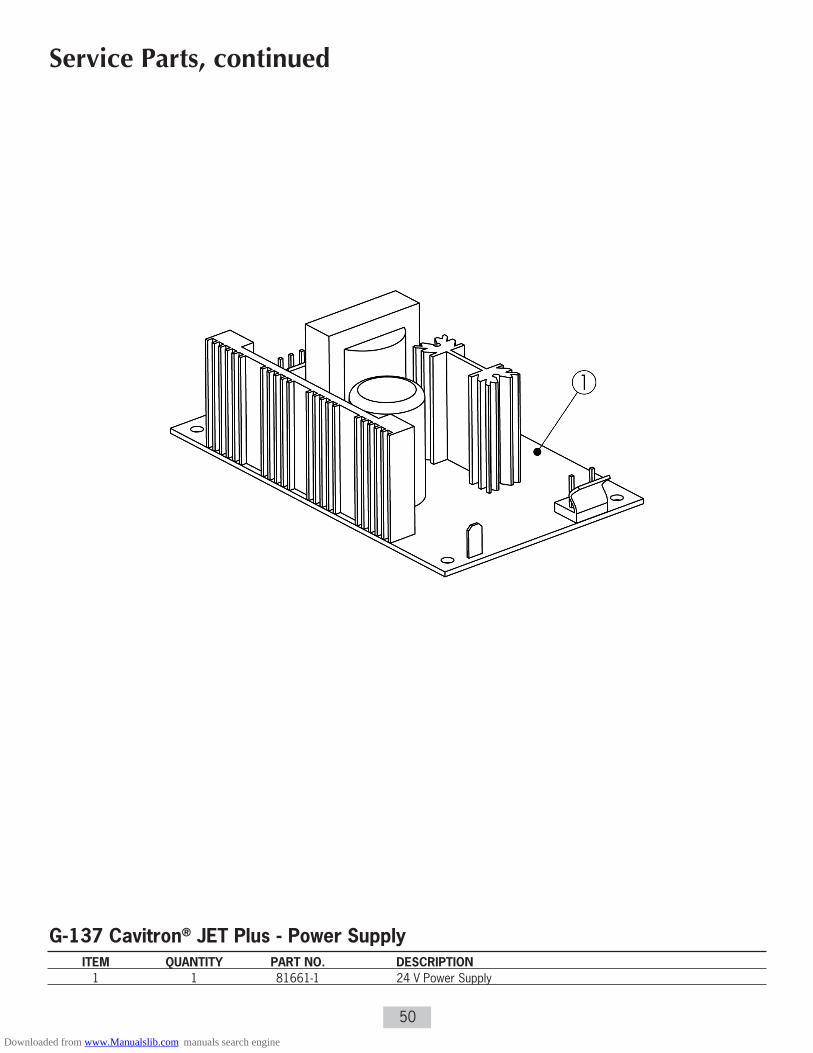
50
Service Parts, continued
G-137 Cavitron® JET Plus - Power Supply ITEM QUANTITY PART NO. DESCRIPTION 1 1 81661-1 24 V Power Supply
Downloaded from www.Manualslib.com manuals search engine
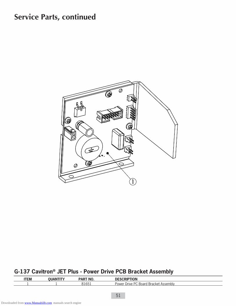
51
Service Parts, continued
G-137 Cavitron® JET Plus - Power Drive PCB Bracket Assembly ITEM QUANTITY PART NO. DESCRIPTION 1 1 81651 Power Drive PC Board Bracket Assembly
Downloaded from www.Manualslib.com manuals search engine
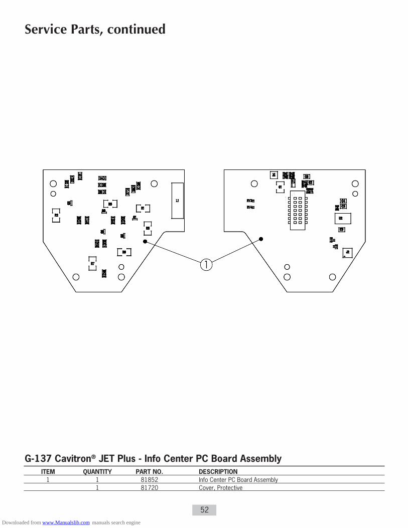
52
Service Parts, continued
G-137 Cavitron® JET Plus - Info Center PC Board Assembly ITEM QUANTITY PART NO. DESCRIPTION 1 1 81852 Info Center PC Board Assembly 1 81720 Cover, Protective
Downloaded from www.Manualslib.com manuals search engine

53
Service Parts, continued
G-137 Cavitron® JET Plus - Main Controller PC Board Assembly ITEM QUANTITY PART NO. DESCRIPTION 1 1 81848 Main Controller PC Board Assembly
Downloaded from www.Manualslib.com manuals search engine

54
Service Parts, continued
G-137 Cavitron® JET Plus - Tap-On™ Foot Pedal ITEM QUANTITY PART NO. DESCRIPTION 1 1 81872 Foot Pedal, Tap-On™ (Packed w/Synchronizing Instructions and 4 “AA” Batteries) 1 81680 Battery Door and Screw Kit 1 81681 Foot Pedal Pad (Bottom) 1 81663-2 Auxiliary Foot Pedal Cable with Ferrite
Downloaded from www.Manualslib.com manuals search engine

55
Service Parts, continued
G-137 Cavitron® JET Plus - Miscellaneous Parts ITEM QUANTITY PART NO. DESCRIPTION 1 6 586172005 #6-19 x 1/2” HI-LO Torx, Pan (Base to Cover) 2 1 8170201 JET-Mate Handpiece (1-Pack) 8170203 JET-Mate Handpiece (3-Pack) 3 1 81717 Nozzle Grip, JET-Mate Handpiece 1 81884 G-132 Handpiece Cable, Black 1 603034001 Ferrite Block, Snap-On (For HP Cable) 1 555049007 Cable Tie (For Ferrite Block) 1 81075 Cleaning Wire, JET-Mate 1 63740 JET Air Polishing Nozzle 1 776030199 Cleaning Wire, Nozzle 1 78119 Powder Jar
1 81872 Foot Pedal, Tap-On™ (Package w/Synchronizing Instructions and 4 “AA” Batteries) 1 81663-2 Auxiliary Foot Pedal Cable
1 90088 Air Filter with Fittings 1 81721 Air Filter & Hose Assembly 1 90125 Water Filter & Hose Assembly 90158 Water Filter (10 Pack)
2’ 61693 Clear Tubing, per Foot 2’ 61631 Red Tubing, per Foot 1’ 625036010 Gray Tubing, per Foot 2’ 625036012 Yellow Tubing, per Foot 2 60367 Duckbill Filter Assemblies 1 60245 “Y” Connector, POM w/Brass Fittings 4 60366 Nylon Cable Ties
1 81648-2 Wire Harness, Switch to Power Supply (Black Wire, White Wire) 1 81649-2 Wire Harness, Power Entry to Switch (Black Wire, White Wire, 2 Ground Wires and 2 Ferrite Beads)
1 554102003 Power Cord, 115/100 Volt 1 78118 Power Cord, 200 to 240 Volt 1 554109001 Power Cord, 240/230 Volt-UK
1 81888 Instruction Manual (DFU) G-137 1 81889 Service Manual, G-137 1 81870 Installation Quick Guide
Downloaded from www.Manualslib.com manuals search engine

worldwide Service Centers
U n i t e d S t a t e s o f A m e r i c a
DEnTSPLy ProfessionalTechnical Service and Repair Department1301 Smile Wayyork, PA 17404-1785Phone: (800) 989-8826 or (717) 767-8502
D e u t s ch l a n d Fra n c e Au s t r a l i a
DEnTSPLy DeTrey GmbH DEnTSPLy DeTrey DEnTSPLy (Australia) Pty LtdDe-Trey-Strasse 1 17 Michael FARADAy 11-21 Gilby Road78467 Konstanz 78380 Montigny Le Bretonneux Mount Waverley, Victoria 3149Germany France AustraliaPhone: 7531 583 0 Phone: (1) 30 14 77 77 Phone: (61) 3-9538-8280
U n i t e d K i n g d o m I t a l i a C a n a d a
DEnTSPLy Ltd DEnTSPLy DeTrey Italia s r l DEnTSPLy CanadaBuilding 1 Via A Cavaglieri, 26 161 Vinyl CourtAviator Park I-00173 Roma Woodbridge, OntarioStation Road Italia L4L 4A3 CanadaAddlestone Phone: (06) 723 3626 Phone: (905) 851-6060SurreyKT15 2PGPhone: (0) 800 072 3313
PN: 81889 Rev. 2 (05/12)
Manufactured by:DEnTSPLy ProfessionalDEnTSPLy International1301 Smile Wayyork, PA 17404-1785 USA
Imported &Distributed by:DEnTSPLy CanadaWoodbridge, OntarioL4L 4A3
DEnTSPLy DeTrey GmbHDe-Trey-Str 178467 KonstanzGermany
Downloaded from www.Manualslib.com manuals search engine