
Caching Optimization in Service Oriented Architecture - IS MUNI
148
MASARYK UNIVERSITY FACULTY OF I NFORMATICS Caching Optimization in Service Oriented Architecture PH.D. THESIS Miroslav Kubásek Brno, September 2006
-
Upload
khangminh22 -
Category
Documents
-
view
0 -
download
0
Transcript of Caching Optimization in Service Oriented Architecture - IS MUNI

MASARYK UNIVERSITY
FACULTY OF INFORMATICS
}w���������� ������������� !"#$%&'()+,-./012345<yA|Caching Optimization in Service
Oriented Architecture
PH.D. THESIS
Miroslav Kubásek
Brno, September 2006
Declaration
Hereby I declare, that this paper is my original authorial work, which I have worked out bymy own. All sources, references and literature used or excerpted during elaboration of thiswork are properly cited and listed in complete reference to the due source.
Advisor: Prof. RNDr. Jirí Hrebícek, CSc.
ii

Acknowledgement
I would like to thank to my supervisor, Prof. RNDr. Jirí Hrebícek, CSc. for supporting mein my work a motivating me. I would also like to thank to my colleagues for their helpand advice: Tomáš Pitner, Jaroslav Rácek a Jan Pavlovic. I want to thank all the staff of theInstitute of Biostatistics and Analyses, Masaryk University Brno, especially Ladislav Dušekand Jan Mužík for their help and support.
Furthermore, I’d like to thank my parents and friends for their patience.
iii

Abstract
Service Oriented Architecture (SOA) is an architectural style, which allows interaction ofdiverse applications regardless of their platform, implementing languages and locations byutilizing generic and reliable services that can used as application building block. In mywork I define and give a brief overview of the SOA and related technology.
There are several factors that contribute to the performance in Web Services environ-ment. Network transaction time, time to take to handle the message and time the serviceitself takes to execute are the main three frequent factors to culprit in ill-performing WebServices.
Current Web caching systems are not able to speed up Web Services because they areintended only for common web content. In my thesis I introduce fundamentals in cachingand briefly describe various avenues of approach for using the cache in miscellaneous dis-tributed computing systems. I review when and where to use caching and look at somereal-world scenarios to demonstrate the power of adding a cache to Web Services environ-ment. I also describe motivation for research in the area of caching Web Services.
I give an exhausting outline of the specification of replacement strategies designed forcaching and compare some of the replacement algorithms. This experiment is tested in theWeb Services environment and focuses on the reduction of the average downloading latency.
I introduce the semantic caching as a possible solution for caching SOAP messages anddefine Web Service Tree as a possible representation of SOAP requests. I also propose amodel of the Semantic Transparent Cache for Web Services based on these tree indexes.
Finally I introduce an XML-based declarative language to extend WSDL documents withinformation about the caching-relevant semantics. I present some results of performance ex-periments testing the prototype of implementation. The results of these experiments confirmfunctionality and effectiveness of the proposed prototype. I also show several projects basedon SOA where we apply semantic-based approach architecture for caching of Web Services.
iv
Keywords
SOA, Cache, Web Services, XML, SOAP, Optimization
v

Contents
1 Introduction . . . . . . . . . . . . . . . . . . . . . . . . . . . . . . . . . . . . . . . . . 11.1 Thesis Objective . . . . . . . . . . . . . . . . . . . . . . . . . . . . . . . . . . . . 3
2 Service Oriented Architecture . . . . . . . . . . . . . . . . . . . . . . . . . . . . . . 52.1 Introduction to Service Oriented Architecture . . . . . . . . . . . . . . . . . . . 5
2.1.1 Evolution of Computing Systems . . . . . . . . . . . . . . . . . . . . . . 62.1.2 Object Oriented Architecture . . . . . . . . . . . . . . . . . . . . . . . . 92.1.3 Component Oriented Architecture . . . . . . . . . . . . . . . . . . . . . 102.1.4 Distributed Computing . . . . . . . . . . . . . . . . . . . . . . . . . . . 11
2.2 Definition of Service Oriented Architecture . . . . . . . . . . . . . . . . . . . . 112.2.1 SOA Entities and Characteristics . . . . . . . . . . . . . . . . . . . . . . 122.2.2 SOA Layered Architecture . . . . . . . . . . . . . . . . . . . . . . . . . . 15
2.3 Web Services . . . . . . . . . . . . . . . . . . . . . . . . . . . . . . . . . . . . . . 172.3.1 Definition . . . . . . . . . . . . . . . . . . . . . . . . . . . . . . . . . . . 182.3.2 Characteristics . . . . . . . . . . . . . . . . . . . . . . . . . . . . . . . . 192.3.3 Architecture . . . . . . . . . . . . . . . . . . . . . . . . . . . . . . . . . . 20
2.4 Web Services Protocols . . . . . . . . . . . . . . . . . . . . . . . . . . . . . . . . 222.4.1 Transport Network . . . . . . . . . . . . . . . . . . . . . . . . . . . . . . 222.4.2 XML Messaging - SOAP . . . . . . . . . . . . . . . . . . . . . . . . . . . 222.4.3 Service Description - WSDL . . . . . . . . . . . . . . . . . . . . . . . . 252.4.4 Service Publication & Discovery - UDDI . . . . . . . . . . . . . . . . . 27
3 State of the Art . . . . . . . . . . . . . . . . . . . . . . . . . . . . . . . . . . . . . . . 293.1 Fundamentals of Caching . . . . . . . . . . . . . . . . . . . . . . . . . . . . . . 29
3.1.1 Consistency and Coherence . . . . . . . . . . . . . . . . . . . . . . . . . 303.1.2 Replacement . . . . . . . . . . . . . . . . . . . . . . . . . . . . . . . . . . 313.1.3 Cacheability . . . . . . . . . . . . . . . . . . . . . . . . . . . . . . . . . . 323.1.4 Granularity . . . . . . . . . . . . . . . . . . . . . . . . . . . . . . . . . . 323.1.5 Caching Architectures . . . . . . . . . . . . . . . . . . . . . . . . . . . . 33
3.2 Caching in Distributed Systems . . . . . . . . . . . . . . . . . . . . . . . . . . . 353.2.1 Web Caching . . . . . . . . . . . . . . . . . . . . . . . . . . . . . . . . . 373.2.2 Adaptive Caching . . . . . . . . . . . . . . . . . . . . . . . . . . . . . . 383.2.3 Database Caching . . . . . . . . . . . . . . . . . . . . . . . . . . . . . . . 383.2.4 Application Level Solutions . . . . . . . . . . . . . . . . . . . . . . . . . 39
3.3 Motivation for Caching Web Services . . . . . . . . . . . . . . . . . . . . . . . . 403.4 Summary . . . . . . . . . . . . . . . . . . . . . . . . . . . . . . . . . . . . . . . . 41
4 Caching . . . . . . . . . . . . . . . . . . . . . . . . . . . . . . . . . . . . . . . . . . . 434.1 Overview of Cache Replacement Strategies . . . . . . . . . . . . . . . . . . . . 43
4.1.1 Recency-Based Strategies . . . . . . . . . . . . . . . . . . . . . . . . . . 444.1.2 Frequency-Based Strategies . . . . . . . . . . . . . . . . . . . . . . . . . 484.1.3 Recency/Frequency-Based Strategies . . . . . . . . . . . . . . . . . . . 504.1.4 Function-Based Strategies . . . . . . . . . . . . . . . . . . . . . . . . . . 52
vi

4.1.5 Randomized Strategies . . . . . . . . . . . . . . . . . . . . . . . . . . . . 564.2 Performance of Replacement Algorithms . . . . . . . . . . . . . . . . . . . . . 57
4.2.1 Setting . . . . . . . . . . . . . . . . . . . . . . . . . . . . . . . . . . . . . 574.2.2 Used Method . . . . . . . . . . . . . . . . . . . . . . . . . . . . . . . . . 574.2.3 Results . . . . . . . . . . . . . . . . . . . . . . . . . . . . . . . . . . . . . 60
5 Semantic-based Caching . . . . . . . . . . . . . . . . . . . . . . . . . . . . . . . . . . 635.1 Page based caching . . . . . . . . . . . . . . . . . . . . . . . . . . . . . . . . . . 635.2 Tuple based caching . . . . . . . . . . . . . . . . . . . . . . . . . . . . . . . . . 635.3 Query Caching . . . . . . . . . . . . . . . . . . . . . . . . . . . . . . . . . . . . 645.4 Semantic-based Caching . . . . . . . . . . . . . . . . . . . . . . . . . . . . . . . 65
5.4.1 Semantic Caching Strategy by Chidlovski . . . . . . . . . . . . . . . . . 665.5 Semantic-based Caching Model . . . . . . . . . . . . . . . . . . . . . . . . . . . 69
5.5.1 Web Service Tree definitions . . . . . . . . . . . . . . . . . . . . . . . . . 695.5.2 Representation . . . . . . . . . . . . . . . . . . . . . . . . . . . . . . . . 745.5.3 Answering . . . . . . . . . . . . . . . . . . . . . . . . . . . . . . . . . . . 765.5.4 Maintaining of WS tree indexes . . . . . . . . . . . . . . . . . . . . . . . 785.5.5 Model Outline . . . . . . . . . . . . . . . . . . . . . . . . . . . . . . . . . 79
6 Semantic-based Cache for Web Services . . . . . . . . . . . . . . . . . . . . . . . . 816.1 Example Used . . . . . . . . . . . . . . . . . . . . . . . . . . . . . . . . . . . . . 816.2 Implementation details . . . . . . . . . . . . . . . . . . . . . . . . . . . . . . . . 826.3 Semantic-based Caching in SCWS . . . . . . . . . . . . . . . . . . . . . . . . . 866.4 Performance Evaluation . . . . . . . . . . . . . . . . . . . . . . . . . . . . . . . 91
7 Case studies . . . . . . . . . . . . . . . . . . . . . . . . . . . . . . . . . . . . . . . . . 967.1 SVOD - analysis of tumor epidemiology of the Czech Republic . . . . . . . . . 967.2 E-learning System above Digital Sources . . . . . . . . . . . . . . . . . . . . . . 997.3 EnviWeb - environmental web portal . . . . . . . . . . . . . . . . . . . . . . . . 1017.4 WSRP4PHP - implementation of WSRP specification . . . . . . . . . . . . . . . 103
8 Conclusion and Future Work . . . . . . . . . . . . . . . . . . . . . . . . . . . . . . . 106Glossary . . . . . . . . . . . . . . . . . . . . . . . . . . . . . . . . . . . . . . . . . . . . . 113Bibliography . . . . . . . . . . . . . . . . . . . . . . . . . . . . . . . . . . . . . . . . . . . 122A Replacement Algorithms Simulation Results . . . . . . . . . . . . . . . . . . . . . 123B XML Schema for extension of WSDL . . . . . . . . . . . . . . . . . . . . . . . . . . 127C Extended WSDL description of SVOD service . . . . . . . . . . . . . . . . . . . . . 137Index . . . . . . . . . . . . . . . . . . . . . . . . . . . . . . . . . . . . . . . . . . . . . . . 141
vii

Chapter 1
Introduction
From the period of the earliest computing units development to the present times, which wecall Information Age, software architectures evolve rapidly to achieve building of sophisti-cated application structures capable of not only fulfilling basic functionalities expected fromeach computing systems, but also effecting human life by providing corporate agility, opera-tional efficiency and innovative improvements that result in utilization of universally sharedapplication functionalities and services. Service Oriented Architecture (SOA) provides a vi-sion how to cope with technical complexities faced with enterprise application developmentand integration, as well as aligning business needs and providing coarse grained businessfunctionalities.
SOA is an architectural style and a combination of methodologies that aims to achieve in-teroperability of remote or local homogeneous and heterogeneous applications by utilizingreusable service logic. Service orientation shows variation in adopting technology for imple-mentation, rather than focusing on the technology itself, as SOA considers the description ofthe problem domain before concentrating on the usage of a specific execution environment.SOA is based on principle of communication using Simple Object Access Protocol’s (SOAP).
SOAP is a fundamental part of the Web Services (WS) technology stack. As a stan-dardized packaging protocol for the messages shared by the applications it uses ExtensibleMarkup Language (XML) as the mechanism for information exchange and it relies heavilyon XML standards like XML Schema and XML Namespaces for its definition and function.SOAP specifies exactly how to encode an HTTP header and an XML file so that one com-puter can call a program in another computer and pass its information. It also specifies howthe called program can return a response. There are two main reasons why this approachprovides a flexible way for applications to communicate through SOAP messages. The firstis the fact that web protocols, which are used to transport SOAP messages, are installed andare widely available for applications by all major operating system platforms. The second isthat XML provides an already at-hand solution to the problem of how programs run underdifferent operating systems in a network.
Although Web Services may represent a boon for developers, their weighty text-basedXML messages, which are many times larger than the payload they’re responsible for car-rying, demand opening, rewrapping, and pushing across highly distributed network pathswhich causes the SOAP requests and responses to mount up. And that is the reason why it
1

1. INTRODUCTION
is processing and communications capabilities will soon show their shortfall.
There are at least three factors that contribute to the performance, or lack thereof, inWeb Services. The first is network transaction time. It means how long it takes the client tomake a request to the remote Web Service. The second factor is the time to take to handlethe message. Specifically the XML parsing, any flow management, invocation of the service,and the final response encoding. Last performance factor is the time the service itself takesto execute. This third factor is often the major culprit in ill-performing services. It is easyforgotten that useful code can take some time to perform its function.
Web Services provide a common interface for increasingly complex functions. Whilethere is no specification for the underlying service, the basic notion is that you write bitsof code and deploy them into the network. You might leverage this function through mul-tiple transports, most commonly HTTP. Therein lies the inefficiency of Web Services. Manytransports are not performance-centric and the wrappering and parsing of XML messagescause that the time to perform the Web Service is longer than the time which direct proce-dure call takes. However, as Albert Einstein once said, time is relative.
Caching as a possible solution in the area of Web Services has been presented in [97] [107][88] and has been also designed in two scenarios by W3C [79]. Their proposed approachesare very abstract and are limited to simply storing and sending SOAP message responses.Approach in Microsoft’s experiment described in [113] uses .NET My Services by reasonof publicly available, non-trivial XML Web Services. The experiment was scoped to pocketdevices and demonstrate that Web Services such as the one examined can be used duringdisconnection interval.
Here are also some other approaches in the area of acceleration of Web Services. Thecaching architecture based on XML canonicalization has been proposed in [112] and theapproach based on binary optimization of SOAP messages using XML-binary OptimizedPackage (XOP) has been described by W3C [116]. The second one is only in recommendationstadium and requires the provider and consumer of Web Service to be able to code anddecode binary SOAP messages.
Our approach is different in that it takes advantage of the fact that query-style requestscan be cached more efficiently using semantic caching approach. I will describe a semanticcaching architecture suitable for caching Web Services. Current web caching systems useunique identifiers pointing to content fragments. While Web Services over the HTTP trans-port have endpoints (URLs), the parts of the SOAP message that make it unique are thevalues for parameters in the SOAP request. These unique parameters of SOAP requests arestored in cache memory which is based on query pattern tree indexes and is maintained bymodified GDS replacement algorithm.
Existing semantic caching schemes for database systems or Web sources cannot be ap-plied directly because there is no semantic knowledge about the requests and responsesof Web Services. Because Web Services are in general described using WSDL documents,
2

1.1. THESIS OBJECTIVE
I will propose extensions to annotate WSDL documents with information about the caching-relevant semantics knowledge. It is true that protocol level caching in general cannot be asefficient as an application level cache, but benefit of generic usability and good applicabilityto a wide range of existing Web Services is a good reason to put mind to this research. Per-formance experiment results and experience in case studies demonstrate the effectiveness ofthe proposed semantic caching architecture.
1.1 Thesis Objective
There are two major objectives of this Ph.D. thesis: I will describe and experimentally verifya suitable replacement algorithms which are applicable to cache replacement policy in thearea of caching of SOAP messages. The second is to propose a model of semantic proxycache for Web Services and create and verify the prototype of this cache. This cache conceptis able to speed up interaction with Web Services and is predetermined to using in SOAenvironment. We used this caching approach in several projects from the field of medicinestatistics, e-learning systems, environmental information systems and also in prototype ofimplementation WSRP specification1.
The thesis is organized as follows. In the following chapter, I will define and give a briefoverview of the Service Oriented Architecture and related technology. In this chapter I willalso provide the necessary background on commonly used technology in SOA environment.
The third chapter gives a State of the Art in the area of caching. I will introduce funda-mentals in caching and briefly describes various avenues of approach for using the cache inmiscellaneous distributed computing systems. I will review when and where to use cachingand look at some real-world scenarios to demonstrate the power of adding a cache to WebServices. I will also describe the motivation for caching Web Services.
The fourth chapter gives an introduction to caching theory. I will give an exhaustingspecification of replacement strategies designed for caching and I will compare some of thereplacement strategies. This experiment will be performed in the Web Services environmentand will focus on the reduction of the average downloading latency.
In the fifth chapter, I will introduce the semantic caching theory as a possible solutionfor caching SOAP messages. I will define Web Service Tree as a possible representation ofSOAP requests and possibility to use it in transparent semantic cache. I will propose modelof the Semantic Transparent Cache for Web Services based on tree indexes.
In the sixth chapter, I will describe implementation details of prototyle of semantic-basedcache and introduce an XML-based declarative language to extend WSDL documents withinformation about the caching-relevant semantics of requests and responses. Using this in-formation semantic cache can answer requests based on the responses of similar previously
1. Web Services for Remote Portlets, http://www.oasis-open.org/committees/wsrp/
3

1.1. THESIS OBJECTIVE
executed requests. Performance experiments conducted using our prototype implementa-tion demonstrate the effectiveness of the proposed semantic caching scheme.
Chapter seven shows several projects, where we enforced semantic-based approach forcaching of Web Services results.
The Final chapter concludes this thesis.
4
Chapter 2
Service Oriented Architecture
In this chapter, we give a brief overview of the Service Oriented Architecture (SOA). We willintroduce the evolution of SOA approach and define basic characteristics of SOA. In thischapter we will also provide the necessary background on commonly used technology inSOA environment.
2.1 Introduction to Service Oriented Architecture
Software development turns out to be more challenging as the needs and desires grows tohave complex infrastructures capable of solving real-world problems. Similarly, technolog-ical improvements through many tendencies and alternatives grounds to build compoundarchitectures for developing software systems.
The architecture of software explores the software system infrastructure by describingits components and high level interactions between each of them. These components are ab-stract modules built as a “unit” with other components. The high level interactions betweencomponents are called “connectors” [1].
The software architecture of a program or computing system is the structure or structuresof the system, which comprise software components, the externally visible properties ofthose components, and the relationship among them [3]. To simplify the complexity of thearchitecture, conventionally, the system is built with modules, which involves functions,objects, components and services.
However, from the early days of the computing to the nowadays software developmenthas passed through certain development stages, which broaden the scope of building ap-plications from small departments to the enterprise and finally to the Internet. These stagesshape the architecture of software systems and result in more powerful, capable and effec-tive software which aims to meet the sophisticated expectations from computing systems.
Service Oriented Architecture is a particular type of software architecture which has dis-tinguished features and characteristics. The concept of SOA emerged in the early 1980s andbecome a significant architectural style especially after invention of Web Services.
5
2.1. INTRODUCTION TO SERVICE ORIENTED ARCHITECTURE
2.1.1 Evolution of Computing Systems
The improvements in hardware technologies and specially the invention of networking en-force the software developers to gain more benefit from these enhancements and build com-posite software systems which endorse these technologies.
Networking has evolved from a few unified machines to enormous interconnected com-puting resources on the Internet. Accordingly, the complexity, size and power of the comput-ing systems have advanced from monolithic programs to distributed computing infrastruc-tures. Based on these emerging trends in computing technologies, developers and architectsought to renew their visions to replace the old approaches of application development tothe expansion of new logical models for current enabling technologies.
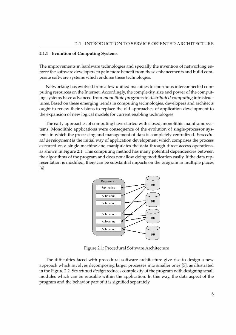
The early approaches of computing have started with closed, monolithic mainframe sys-tems. Monolithic applications were consequence of the evolution of single-processor sys-tems in which the processing and management of data is completely centralized. Procedu-ral development is the initial way of application development which comprises the processexecuted on a single machine and manipulates the data through direct access operations,as shown in Figure 2.1. This computing method has many potential dependencies betweenthe algorithms of the program and does not allow doing modification easily. If the data rep-resentation is modified, there can be substantial impacts on the program in multiple places[4].
Figure 2.1: Procedural Software Architecture
The difficulties faced with procedural software architecture give rise to design a newapproach which involves decomposing larger processes into smaller ones [5], as illustratedin the Figure 2.2. Structured design reduces complexity of the program with designing smallmodules which can be reusable within the application. In this way, the data aspect of theprogram and the behavior part of it is signified separately.
6

2.1. INTRODUCTION TO SERVICE ORIENTED ARCHITECTURE
Figure 2.2: Structured Software Architecture
Client-server computing is the evolution of software architecture in which the empha-sis is given to building of individual application systems. The design in this architectureinvolves separation of the client and business logic from the keeper of the data, which isserver, in both logical and physical way. It is an important factor because the client-serverarchitecture allows user to process data over network connection. The technology resultedin the evolution of file-sharing system, which is still used to access the available global filesystems over supporting protocol such as HTTP, and database-server technologies. Thesearchitecture is closely related with the evolution of distributed computing technologies.
In this period, transaction-processing monitors have grown to enable the consistent andreliable maintenance of data integrity across distributed systems. Another development be-tween the late 1980s and early 1990s is the groupware technologies which allow email andhigher forms of interactive applications, such as chat rooms and videoconferencing.
Starting from early 1990s, the necessity to support clean separation of data and applica-tion logic layer from the presentation layer caused to replace client-server technologies withN-tier component-oriented solutions. The additional layers reduced the coupling betweenthe modules and allowed more clients to access and converse with the business logic tier, asshown in Figure 2.3.
The first approach to software design is mainly from private vendors, which control theconstruction of software through each step of product releases. These software are calledProprietary Software and mostly dependent on the vendor which produces it. Today’s sys-tems are based on proprietary software to varying degrees. The capabilities and quality ofproprietary software can be high because of continuous debugging and supporting featuresconsistent with the expectations of the end-user from the owner vendor of the software.
The other major category is a Open Software, which is an approach to develop softwarein which multiple vendors collaborate to build specifications of the technology independentfrom proprietary software. The main benefit of the open software is that it provides a uni-
7

2.1. INTRODUCTION TO SERVICE ORIENTED ARCHITECTURE
Figure 2.3: Client-Server and N-tier Software Developments
form terminology of its software structure, which is the foundation for building standardtechnology appropriate for many end-users. The additional benefit is the interoperabilitythat it may provide between different software applications.
With the introduction of the World Wide Web, a new era for software architectures is inprogress. The Internet initially began as a way to publish scientific papers and evolved intodynamic HTML (Hypertext Markup Language) and eventually to XML (Extensible MarkupLanguage), which is a meta-language and a fundamental, standard, and enabling technol-ogy for data exchange between different platforms.
XML describes the data in an application-independent manner, and Web Services usethis technology to enable the sharing of distributed processes between heterogeneous com-puting environments. Today’s application architecture involves creating independent ser-vices accessible through the firewall and support one discrete function. Clients interact withservices, which are assembled to build the application infrastructure.
Figure 2.4: Physical Evolution of Computing Systems
8

2.1. INTRODUCTION TO SERVICE ORIENTED ARCHITECTURE
2.1.2 Object Oriented Architecture
Object Oriented approach supports the development of software with encapsulating bothdata and behavior into abstract data types, called classes [6]. Instances of classes are formedinto small modules, called objects, as shown in Figure 2.5. Any changes in data representa-tion only affect the immediate object that encapsulates the data. Classes can live everlast-ingly, however objects have a limited lifetime.
Figure 2.5: Object Oriented Architecture
Objects communicate each other through messaging. Object based development advancessoftware design by providing more support for hiding behavior and data through objectsand classes. There is almost no dependency between objects, however a large number ofinterconnected objects create dependencies that can be difficult to manage.
In Object Oriented development, everything is an object. The primary characteristics ofObject Oriented development are as follows:
• Encapsulation - An object contains both the physical properties, called data, and thefunctionality of this data, described as behavior, to form a distinct software module,which is called as package.
• Information Hiding - An object keeps its internal mechanism and does not revealobject-specific information to the outside from its well-structured architecture andinterfaces.
• Associations and Inheritance - Classes and objects can associate to each other. Inher-
9

2.1. INTRODUCTION TO SERVICE ORIENTED ARCHITECTURE
itance is a special form of association which states is-a-relationship between objectsand classes and forms a hierarchical structure by allowing classes to be extended intosubclasses.
• Polymorphism - Object oriented development allows different implementations ofthe same message through two or more separate classes.
2.1.3 Component Oriented Architecture
Components are more sophisticated software modules than objects and require fundamen-tal changes in systems thinking, software processes, and technology utilization. Componentarchitecture allows developers to create more complex, high quality systems, because it pro-vides better means of managing complexities and dependencies within an application.
A software component is defined as a unit of composition with contractually specifiedinterfaces and explicit context dependencies. A software component can be deployed inde-pendently and is subject to composition by third parties [7]. It is a group of objects with hasa specified interface, working together to provide an application function (See Figure 2.6).
Figure 2.6: Component Oriented Architecture
Reusable components are good reflection of effective software design. The architectureprovides the design context in which the components are built and reused. The other im-portant aspect for components is that the development of software architecture based oncomponent specifications support parallel and independent building of the system parts.These computational boundaries that define an individual system part are testable subsys-tems and can be divided to one or more distributed project teams.
Many platform vendors have already produced software infrastructures which supportcomponent oriented technology. With support of XML, Web Services and other standards,these technologies can co-operate for building sophisticated software applications.
10

2.2. DEFINITION OF SERVICE ORIENTED ARCHITECTURE
2.1.4 Distributed Computing
Although Service Oriented Architecture is not a direct implication of distributed computing,it has to incorporate existing middleware technologies and distributed computing concepts.A successful SOA should overcome the difficulties faced with existing middleware tech-nologies by supporting an effective approach to application development and upcomingtechnologies with consideration of obtainable concepts and technologies.
The early approach to distributed computing is to set up a communication between twodistributed programs directly on the raw physical network protocol [8]. Higher level proto-cols such as SNA, TCP/IP and IPX provided APIs that helped reduce the implementationefforts and technology dependencies. As the next evolutionary step, a communication mid-dleware framework enables to access a remote application without knowledge of technicaldetails such as operating systems, lower-level information of the network protocol, and thephysical network address.
As distributed computing technologies evolve, it becomes increasingly necessary to pro-vide multiple network implementations to satisfy various quality-of-service requirements.These requirements may include timeliness of message delivery, performance, throughput,reliability, security and other nonfunctional requirements.
2.2 Definition of Service Oriented Architecture
Service Oriented Architecture is an architectural style which utilizes methods and technolo-gies that provides for enterprises to dynamically connect and communicate software appli-cations between different business partners and platforms by offering generic and reliableservices that can be used as application building blocks. In this way it is possible to developricher and more advanced applications and information systems.
Although SOA is not a new concept, especially after the invention of Web Services, thenew developments in this area bring about a new way of constructing software applicationarchitectures, a new approach to rebuild available software infrastructures and possibilityof communicating with other enterprises according to the available services.
However, building SOA is still challenging for the following reasons:
• The way SOA approaches to software resources is different from traditional architec-tures,
• SOA needs a level of architectural regulation,
• SOA implementation needs an environment capable of being accessed by differententerprises.
11

2.2. DEFINITION OF SERVICE ORIENTED ARCHITECTURE
• Definition and composition of services into new ones in a secured and managed en-vironment is another aspect that needs a particular concentration.
2.2.1 SOA Entities and Characteristics
Service Oriented Architecture is an architectural style that defines an interaction model be-tween three main functional units, in which the consumer of the service interacts with theservice provider to find out a service that matches its requirements through searching reg-istry. A meta-model describing this interaction is shown in Figure 2.7.
Figure 2.7: Service Oriented Architecture Conceptual Model
SOA contains 6 entities in its conceptual model, described as follows [1]:
• Service Consumer: It is the entity in SOA that looks for a service to execute a requiredfunction. The consumer can be an application, another service, or some other type ofsoftware module that needs the service. The location of the service is discovered eitherby looking up the registry, or if it is known, the consumer may directly interact withthe service provider.
• Service Provider: It is the network addressable entity that accepts and executes re-quests from consumers. It provides the definite service description and the imple-mentation of the service. The service provider can be a component, or other type ofsoftware system that fulfills the service consumer’s requirements.
• Service Registry: It is a directory which can be accessible through network and con-tains available services. Its main function is to store and publish service descriptionsfrom providers and deliver these descriptions to interested service consumers.
• Service Contract: A service contract is the description that clarifies the way of in-teraction between the service consumer and provider. It contains information about
12

2.2. DEFINITION OF SERVICE ORIENTED ARCHITECTURE
request-response message format, the conditions in which the service should be exe-cuted, and quality aspects of the service.
• Service Proxy: It assists the interaction between service provider and service con-sumer by providing an API written in the local language of the consumer. It is sup-plied by the service provider and a convenience entity for the consumer. As well as itcan enhance performance and provides caching facilities. Service proxy is an optionalentity in SOA.
• Service Lease: It specifies the amount of time that a service contract is valid. It is man-aged by registry and determines the executive well-defined timeframes of binding tothe services. Usage of service lease supports loose coupling between service providerand consumer and maintenance of state information for the service.
Service oriented architecture reflects specific principles and characteristics that need to beapplied when building service-oriented application infrastructures [9], which are describedas follows:
• Services are discoverable and dynamically bound: Services need to be discover-able dynamically at run-time. The consumer of the service finds the required servicethrough searching of registry and gets all the information necessary to execute theservice. There is no compile-time dependency to bind to the service, apart from theservice contract that the registry provides.
• Services are self contained and modular: A service supports unified and functionalinterfaces aggregated to perform specific and concrete business logic. These interfacesare related to each other in the context of a module and contain sufficient informationto be authentic without any dependency to other software modules or applications.
• Services are interoperable: Services express the ability to communicate with eachother without any platform and language dependencies. Because each software mod-ule might have proprietary and tightly coupled structures, service based architectureutilizes interoperable technologies that support the protocols and data formats of theservice’s current and potential consumers.
• Services are loosely coupled: Coupling describes the level of dependencies betweensoftware modules. Loosely coupled modules are flexible and have well-defined de-pendencies, on the contrary, tight coupled software systems are difficult to configurebecause of unknown requirements of modules within the software structure. Serviceoriented architecture stress the development of loosely coupled services as the soft-ware construction unit. Loosely coupled is achieved by usage of service registries. Theservice requires no other system specific information to be executed autonomously.However, tight coupling cannot be avoided at the interface definition level or bindingto a specific protocol.
• Services have a network-addressable interface: A service should publish its interface
13

2.2. DEFINITION OF SERVICE ORIENTED ARCHITECTURE
on the network to conform service oriented architecture design principles, so that theconsumer is able to invoke the service in a distributed manner over the network. Inthis way it is probable to use the service at any time with different consumers. A ser-vice can also be accessed through local interface without usage of network. However,one of the main aims in building SOA is to allow the consuming of services in alocation-independent manner.
• Services have coarse-grained interfaces: The concept of granularity is related withthe way of implementation of interfaces within software system. If the interface sup-ports all the functions necessary for complete business logic, it is a coarse-grainedinterface. In contrast, if the interface implements only a part of certain functionality,it is considered fine-grained. Granularity can be applied to the entire service imple-mentation, and also to the individual methods of the interface execution. A serviceoriented software system supports coarse-grained interface design by nature with dif-ferent granularity levels. The objects which build the service may still be fine-grained,however these objects is kept inside the physical structure of the service.
Figure 2.8: Granularity
• Services are location transparent: SOA promotes location transparency, which meansthe consumer of the service does not have pre-knowledge about the position of theservice until to execute it at run-time through registry. The only dependency betweenconsumer and provider is the service contract, which can shift from one location toanother one without affecting consumer.
• Services can be composed into new applications: Another key characteristic of SOAis to enable building new applications composed from existing services. Compositionis an effective design which mainly focuses on service modularity and reuse of ser-vice functionality without having pre-knowledge of which applications will use theservice in the future.
• SOA supports self-healing: Self-healing is described as the ability of a system torecover itself in case an error occurs during its execution. Service oriented systems
14

2.2. DEFINITION OF SERVICE ORIENTED ARCHITECTURE
should give more importance to support self-healing than other architecture styles asthe services are combined to execute a business function at run-time. The consumershould have the ability to find different services on the network that supports thesame functionality for the aim of a proper and regular execution of the software sys-tem.
2.2.2 SOA Layered Architecture
The early systems are structured as two-tier layers in which the client have direct accessto database and network APIs without any logical model in between. This approach canstill be used in software systems where the development is small-sized and prototypical.As well, some modules in advanced systems may apply this approach to provide certainfunctionalities. However, two-tier application development is limited to short life-cycledsystems and does not support flexible APIs. It does not provide sufficient implementationcode isolation from the client which makes the architecture rigid and not scalable to manyconcurrent users.
Currently the most frequently used application development model is based on three-tier architectural structure, which supports an additional layer between client and data stor-age tiers. The additional layer, called as business logic layer, provides code isolation fromclient and sharing of the application logic between various client implementations. It is acompetent approach to software development for flexible managing of data and usage ofsystem resources.
Figure 2.9: Two-tier and Three-tier Architectural Models
SOA is based on n-tier application development in which services are layered on topof components that are responsible for providing certain functionalities and maintainingquality of service requirements for services [2], as shown in Figure 2.10.
15
2.2. DEFINITION OF SERVICE ORIENTED ARCHITECTURE
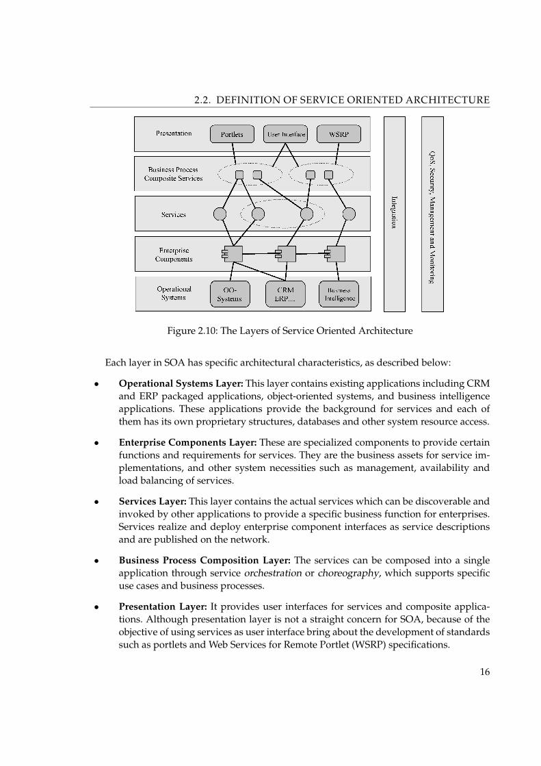
Figure 2.10: The Layers of Service Oriented Architecture
Each layer in SOA has specific architectural characteristics, as described below:
• Operational Systems Layer: This layer contains existing applications including CRMand ERP packaged applications, object-oriented systems, and business intelligenceapplications. These applications provide the background for services and each ofthem has its own proprietary structures, databases and other system resource access.
• Enterprise Components Layer: These are specialized components to provide certainfunctions and requirements for services. They are the business assets for service im-plementations, and other system necessities such as management, availability andload balancing of services.
• Services Layer: This layer contains the actual services which can be discoverable andinvoked by other applications to provide a specific business function for enterprises.Services realize and deploy enterprise component interfaces as service descriptionsand are published on the network.
• Business Process Composition Layer: The services can be composed into a singleapplication through service orchestration or choreography, which supports specificuse cases and business processes.
• Presentation Layer: It provides user interfaces for services and composite applica-tions. Although presentation layer is not a straight concern for SOA, because of theobjective of using services as user interface bring about the development of standardssuch as portlets and Web Services for Remote Portlet (WSRP) specifications.
16

2.3. WEB SERVICES
Other concern for SOA is the integration of services and composite applications withinthe enterprise by supporting the features such as reliability, proper routing and coordinationof services, and managing other technical details including protocol and integrating partyagreements. QoS (quality of service) requirements, security, management and monitoring ofservices are also other requirements that need to be clarified when designing service basedapplication architectures.
2.3 Web Services
Web Services are currently more and more used in application development, they provide adistributed environment in which any number of applications, or application components,can interoperate seamlessly with each other. The most important benefit of Web Servicesare that such applications need not be written in a same program language and need notrun on a same platform. It is never so easy that an application written in .NET running onwindows communicate with an application written in Java running on Linux. Web Servicesare realized using standard Internet technologies.
The fundamental concept is not new; at the low layer Web Services let the consumermake Remote Procedure Calls (RPCs) against an object over the Internet or a network. Be-fore Web services there are many technologies to allow developer to do this, for example,CORBA, RMI and DCOM. But these technologies don’t support every platform (i.e. DCOMonly on Windows, RMI just for Java Runtime Environment etc.) and gateways are needed toconvert an unsupported protocol and data format to let the target platform understand thecalls. On the other hand, Web Services use platform-neutral standards such as HTTP, XML,SOAP, and UDDI for system interoperability and are supported by virtually every tech-nology vendor in existence. This makes Web Services platform-independent. The platformindependence is also predominant on the World Wide Web. A Web site is developed usinga large number of languages and platforms that are irrelevant for the customer’s browser.The browser gets the data from a Web site using HTTP as protocol and HTML as contentformat. The browser does not need to know the information of the languages and platformsat the server site and also does not need to change anything when the server changes its lan-guages and platforms. These same principles apply to Web Services: the client needs only toknow the URL of the services and the data types used for the methods calls. It can consumethe Web Services without knowing whether the services was built in Java and is runningon Linux, or is a .NET Web service running on Windows. The implementation details arehidden from the client.
17

2.3. WEB SERVICES
2.3.1 Definition
Dozens of vendors and organization are developing Web Services and many of them havetheir own definition of the Web Services. Here are some important definitions from them:
A Web Service is a software system identified by a URI, whose public interfaces andbindings are defined and described using XML. Its definition can be discovered by othersoftware systems. These systems may then interact with the Web Service in a manner pre-scribed by its definition, using XML based messages conveyed by internet protocols.(World Wide Web Consortium, http://www.w3.org)
Web Services are self-describing applications that can discover and engage other Webapplications to complete complex tasks over the Internet.(Sun Microsystems, http://www.w3.org)
Web Services are self-contained, modular applications that can be described, published,located, and invoked over a network, generally, the Web.(IBM, http://www.ibm.com)
A Web Service is a unit of application logic providing data and Services to other appli-cations. Applications access Web Services via ubiquitous Web protocols and data formatssuch as HTTP, XML, and SOAP, with no need to worry about how each Web Service is im-plemented. Web Services combine the best aspects of component-based development andthe Web, and are a cornerstone of the Microsoft .NET programming model.(Microsoft, http://www.microsoft.com)
Web Services are self-contained, modular business applications that have open, internet-oriented, standards-based interfaces.(Hewlett Packard, http://www.hp.com)
A Web Service is a software component whose functionality can be accessed by sendingXML (Extensible Markup Language) messages over common web protocols.(BEA, http://www.bea.com)
A Web Service is a piece of business logic, located somewhere on the Internet, that isaccessible through standard-based Internet protocols such as HTTP or SMTP.(Java Web Services, http://www.oreilly.com)
Many definitions usually get more specific, mentioning for example the use of HTTP,XML in Web Services. I prefer the definitions from Hewlett Packard because it focuses moreon what a Web Service is, rather than the detail about the implementation. When it comes tothe implementation, there are many things that are currently the standard of Web Services.For example HTTP is usually used as the transport, although other standard protocols, suchas Simple Mail Transport Protocol (SMTP) are also allowed. The SOAP standards are nearlyalways used for transporting XML documents. But it is still possible to replace nearly all of
18

2.3. WEB SERVICES
these in the future, if better technologies are developed. So it is best to think of a Web serviceseparate from the implementation technologies.
2.3.2 Characteristics
A Web Service has many behavioral characteristics, below are the most important [73], [65]:
• Loosely coupled - a system’s degree of coupling directly affects its modifiability. Themore tightly coupled a system is, the more a change in a service will require changesin service consumers. Coupling is increased when a service consumer requires a largeamount of information about the service provider to use the service. A consumer ofa Web Service is not tied to that Web Service directly; the Web Service interface canchange over time without compromising the client’s ability to interact with the ser-vice. A tightly coupled system implies that the client and server logic are closely tiedto one another, implying that if one interface changed, the other must also be up-dated. Adopting loosely coupled architecture tends to make software systems moremanageable and allows simpler integration between different systems.
• Coarse-grained - object-oriented technologies such as Java expose their services throughindividual methods of objects and classes. An individual method is too fine an oper-ation to provide any useful capability at a corporate level. Building a Java programfrom scratch requires the creation of several fine-grained methods that are then com-posed into a coarse-grained service that is consumed by either a client or anotherservice. Businesses and the interfaces that they expose should be coarse-grained.
• Synchronous and Asynchronous - synchronicity refers to the binding of the client tothe execution of the service. In synchronous invocations, the client blocks and waitsfor the service to complete its operation before continuing. Asynchronous operationsallow a client to invoke a service and then execute other functions. Asynchronousclients retrieve their result at a later point in time, while synchronous clients receivetheir result when the service has completed. Asynchronous capability is a key factoron enabling loosely coupled systems
• XML-based - XML-based is very important characteristic of Web Services currently.By using XML as the data representation for all Web Services protocols and technolo-gies that are created, these technologies can be interoperable at their core level. As adata transport, XML eliminates any networking, operating system, or platform bind-ing that a protocol has.
• Supports Remote Procedure Calls (RPCs) - Web Services allow clients to invoke pro-cedures, functions, and methods on remote systems using an XML-based protocol.Remote procedures expose input and output parameters that a Web Service mustsupport. Component development through Enterprise JavaBeans (EJBs) and .NET
19

2.3. WEB SERVICES
Components has increasingly become a part of architectures and enterprise deploy-ments over the past couple of years. Both technologies are distributed and accessiblethrough a variety of RPC mechanisms. A Web Services supports RPC by providingservices of its own, equivalent to those of a traditional component, or by translatingincoming invocations into an invocation of an EJB or a .NET component.
• Supports Document exchange - one of the key advantages of XML is its generic wayof representing not only data, but also complex documents. These documents can besimple, such as when representing a price list, or they can be complex, representinga database. Web Services support the transparent exchange of documents to facilitatebusiness integration.
2.3.3 Architecture
There are many obvious benefits of Web Services, for example, the interoperability amongheterogeneous platforms, the ability to invoke a Web Service over ubiquitous network tech-nologies. They use a set of shared organizing principles of SOA to be able to work togetherwell (See Section 2.2).
Figure 2.11 show the Web Services Model diagram. In this typical Web Services modeldiagram, there are three kinds of roles in a typical Web Services environment and the opera-tions that they perform in order to make Web Services work. The roles shown in the diagramare as follows [68]:
Figure 2.11: Web Services Model diagram
• Service Provider - a service provider is the entity that creates the Web Service. Typi-cally, the service provider exposes certain business functionality in their organizationas a Web Services for any organization to invoke. The services provider needs to do
20

2.3. WEB SERVICES
two things: first, it needs to describe the Web Service in a standard format, which isunderstandable by all organizations that will be using that Web service; secondly, toreach a wider audience, the service provider needs to publish the details about itsWeb Service in a central registry that is publicly available to everyone.
• Service Requester - any organization using the Web Service created by a Serviceprovider is called a service Requester. The service requester can know the functional-ity of a Web Service from the description made available by the service provider. Toretrieve these details, the service requester does a Find in the registry to which theservice provider had published its Web Service description. More importantly, theservice requester is able to get from service description, the mechanism to bind to theservice provider’s Web Services and in turn to invoke that Web Service.
• Service Registry - a service registry is a known, central location where the serviceprovider can publish its Web Services, and where a service requester can search forWeb Services. Service providers normally publish their Web Service capabilities inthe service registry for service requesters to find and then bind to their Web Service.Typically, information like company details, the Web Services that it provides, andthe details about each Web Service including technical details is stored in the serviceregistry.
In the Web Services model, there are three operations that are fundamental to makingWeb Services work: publish, find, and bind. Interapplication communication need to beachieved irrespective of the kind of language the application is written in, the platform theapplication is running on, and so on. To make this happen, standards for each of these op-erations and a standard way are needed for a service provider to describe their Web Serviceirrespective of the language that it is written in:
• A standard way to describe Web Services - the Web Service Description Language(WSDL) is a standard that uses XML format to describe Web Services. Basically, theWSDL document for a Web Service would define the methods that are present in theWeb Service, the input/output parameters for each of the methods, the data types,the transport protocol used, and the end point URL at which the Web Service will behosted.
• A standard protocol to publish or find Web Services - the Universal Description, Dis-covery, and Integration (UDDI) standard provides a way for service providers to pub-lish details about their organization and the Web Services that they provide to theregistry. This is the description part in UDDI. It also provides a standard for servicerequesters to find service providers and details about their Web Services. This is thediscovery’ part in UDDI.
• A standard protocol for applications to bind to Web Services - the simple Object Ac-cess Protocol (SOAP) is a XML mechanism used to exchange information betweenapplications regardless of the operation system, programming language, or object
21

2.4. WEB SERVICES PROTOCOLS
model.
2.4 Web Services Protocols
In this section, I will introduce more details of the three standards: SOAP, WSDL, and UDDI,conceptually within the context of Web Services architecture. The full technical detail of eachstandard will be not described, for interesting see the specification.
In the previous section I described the fundamental operations, publish, find, and bind,in a Web Services environment. In order to make that possible, a basic Web Services stack isneeded. Such a basic Web Services protocol layer stack is shown in the Figure 2.12.
Figure 2.12: Web Services Protocol Layer stack
2.4.1 Transport Network
This layer of the Web Services protocol layer stack is responsible for making the Web ser-vices accessible by using ubiquitous application protocols, like HTTP, SMTP, FTP, as trans-port protocols. These existing communication standards make the Web Services transport-independent. Today HTTP is the most ubiquitous application protocol.
2.4.2 XML Messaging - SOAP
The next layer in the basic Web Services stack is XML Messaging . In this layer SOAP is usedas standard message format for application communication. It is an XML-based messagingand RPC specification that enables the exchange of information among distributed systems.
We can see the XML Messaging layer is built on top on the Transport Network layer,so, SOAP is not bound to a hardware platform, operating system, programming language,particular transport protocol, or network hardware. Currently SOAP is XML over HTTP, butit can be replaced by any other transport protocol like SMTP, FTP.
22

2.4. WEB SERVICES PROTOCOLS
The SOAP Protocol contains fewer features than other distributed computing protocols;this makes the protocol less complex. It just passes XML data over HTTP and does notattempt to define a new programming model or APIs that are complex to implement. Itprovides only the overall framework for an XML message to be communicated between asender and a receiver.
SOAP provides several advantages over other distributed systems, among them [68]:
• SOAP can easily traverse firewalls, when it uses HTTP.
• SOAP data is structured using XML
• SOAP can potentially be used in combination with several standard transport proto-cols, such as HTTP, SMTP, and Java Message Service (JMS)
• SOAP maps to the request/response pattern of HTTP and HTTP Extension Frame-work
• SOAP is easily extensible via XML
• There is SOAP support from many vendors, including Microsoft, IBM, and Sun.
SOAP protocol has also many drawbacks, amongst which are [68]:
• Lack of interoperability between SOAP toolkits: Even though SOAP has widespreadsupport, there are still incompatibility issues between different SOAP implementa-tions
• Security mechanisms are immature: SOAP doesn’t define a mechanism for authenti-cating a message before it is processed. It also doesn’t define a mechanism for encrypt-ing the contents of a SOAP message to prevent others from obtaining the contents ofthe message (eavesdropping).
• No guaranteed message delivery: If the system fails while a message is being trans-ferred, a SOAP enabled system doesn’t know how to handle the error case. There areno such semantics like “at-most-once”, “at-least-once”, and “exactly-once” defined inSOAP.
• No publish and subscribe model: A SOAP client doesn’t have the ability to send arequest to multiple servers without sending the request to all of the servers individu-ally.
A SOAP message is a well-formed XML document that contains an Envelope elementand optional Header element, and a mandatory Body element (See Figure 2.13).
The Envelope element serves as a container for the Body and Header elements and alsoas an indicator to the processing node that the XML is a SOAP message. The key use of the
23

2.4. WEB SERVICES PROTOCOLS
Figure 2.13: SOAP message structure
envelope is to indicate the start and end of the message to the receiver. Once the receivercomes across the </Envelope> tag, it knows the message has ended and can start process-ing it (or picking up the attachments, if any). The envelope is essentially just a packagingstructure.
The Header element is optional, but if present, it should be the first immediate childelement of the Envelope element. SOAP does not define any individual header entries orXML elements in the header block.
The Body contains the actual, mandatory message intended for the final recipient. Thisis usualy XML elements that describe a procedure invocation - for example, describing ar-guments and parameters along with a procedure namer, or contain a response from WebService - for example, array of values.
As Figure 2.12 shows, a SOAP message has to be layered on top of a transport protocol.The rules that pertain to how a SOAP message is to be sent over a particular protocol arecalled the SOAP binding to that protocol. While the header elements may determine howa SOAP node processes the message, the protocol binding framework determines how amessage travels between processing nodes.
24
2.4. WEB SERVICES PROTOCOLS
2.4.3 Service Description - WSDL
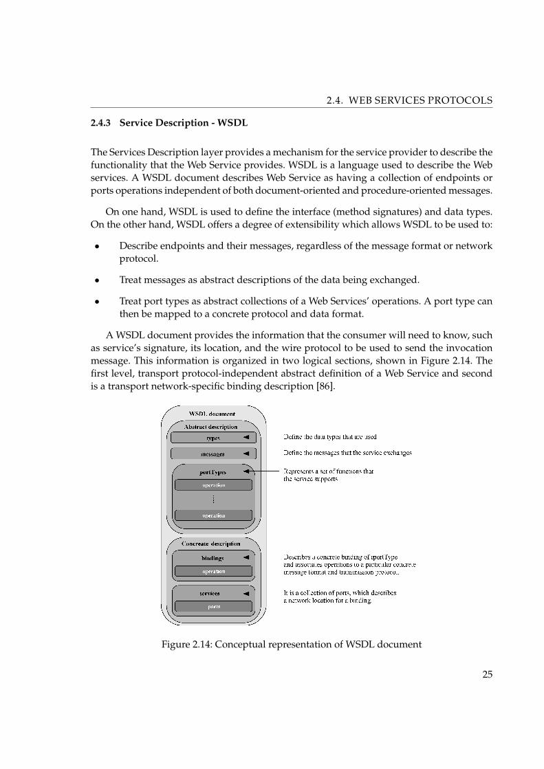
The Services Description layer provides a mechanism for the service provider to describe thefunctionality that the Web Service provides. WSDL is a language used to describe the Webservices. A WSDL document describes Web Service as having a collection of endpoints orports operations independent of both document-oriented and procedure-oriented messages.
On one hand, WSDL is used to define the interface (method signatures) and data types.On the other hand, WSDL offers a degree of extensibility which allows WSDL to be used to:
• Describe endpoints and their messages, regardless of the message format or networkprotocol.
• Treat messages as abstract descriptions of the data being exchanged.
• Treat port types as abstract collections of a Web Services’ operations. A port type canthen be mapped to a concrete protocol and data format.
A WSDL document provides the information that the consumer will need to know, suchas service’s signature, its location, and the wire protocol to be used to send the invocationmessage. This information is organized in two logical sections, shown in Figure 2.14. Thefirst level, transport protocol-independent abstract definition of a Web Service and secondis a transport network-specific binding description [86].
Figure 2.14: Conceptual representation of WSDL document
25

2.4. WEB SERVICES PROTOCOLS
When an object (with one public method or with multiple methods) interacts with otherobjects, many messages will be exchanged. To represent the information about the object,we should:
I Describe all the data types used in all messages.
II List all messages that can be exchanged and represent the message as a set of data types.
III Describe each method (interaction with the object) as a collection of input, output, andexception type messages.
IV Describe what the object does as a collection of possible interactions.
For a Web Service, these descriptions would need to be captured in a platform- andlanguage-independent manner, which is the way a WSDL document organizes information.In WSDL each of these four abstract descriptions is an element in the WSDL document type:
I types - contain the platform- and language-independent data type definitions
II messages - contain input and output parameters for the service and describe differentmessages the service exchanges. This is similar to a method signature.
III operations - represent a particular interaction with the service and describes the input,output, and exception messages possible during that interaction. This is just like a nor-mal method call.
IV portTypes - use the messages section to describe function signatures (operation name,input and output parameters) and represents a set of operations supported by the ser-vice. This is analogous to an interface in Java.
Each Web Service or “endpoint” runs on a network address. The Web Service is bound toa particular protocol, or format, in which messages and data are sent to it. These aspects ofthe service description are specific to the implementation of the service and are thus logicallygrouped into one category. In short, the concrete descriptions define the implementation-specific descriptions for the Web Service. Two significant elements in the WSDL fall into thiscategory:
I bindings - specifies binding of each operation in the portTypes section. It associates theabstract descriptions of a portType with a protocol, for example HTTP.
II services - in addition to protocol-specific information, the WSDL document should alsodescribe where the service is deployed. The association between a binding and the net-work address at which it can be found is defined by a port. The service element is acollection of ports, and a port describes a network location for a binding.
The logical separation of abstract information (such as methods, parameters, and errormessages) from information that changes with implementation type (such as transport pro-tocols) allows reuse of abstract definitions of the service across different implementations
26

2.4. WEB SERVICES PROTOCOLS
of the service. As an example, the same service may be exposed as an HTTP-based serviceand an SMTP-based Web Service. In both cases, the service performs the same function, sothe abstract description of the service and its methods can be reused, and only the concrete,implementation-specific information needs to be changed across the two instances of theservice.
The role of the seven key elements in a WSDL document is illustrated in Figure 2.15. Formore technical details read the WSDL specification or [86].
Figure 2.15: Roles of key elements in a WSDL document
2.4.4 Service Publication & Discovery - UDDI
From a WSDL document, a service requester can get the Web Service details like the differ-ent operations, data types, the end points, the binding protocols, and so on. Now it is neededto develop a technology to make it possible that all consumers can easily find and access theWSDL document. This can be realized by publishing the WSDL document to every possi-ble client. But a better solution is using a central registry, where the service providers canpublish all information about their business and services to. The registry is easily accessedby all services requester and the service requesters can evaluate them independently be-fore integrating them into their application. The registry provides a search engine based onbusiness categories, so that the consumers can find the business, that they want to use, inthat category using related information (for example, company’s name, phone number, etc.)and then go down to find all the Web Services that the business offers. Conceptually a spec-
27

2.4. WEB SERVICES PROTOCOLS
ification need to be developed for publishing and discovering business information – theservice requesters and service providers don’t exchange the business information amongthem selves directly, a central registry works between them. This specification is the UDDIspecification.
The UDDI specification is an attempt for organizations to accomplish the following tasks[86]:
• Create an industry-accepted, standardized approach to reach partners and customerswith information on their services and convey the preferred method for integrationbetween disparate systems.
• Characterize how business transactions are used in commerce, once a preferred part-ner is selected through electronic means.
From a Web Service consumer’s point of view, A UDDI registry contains four types ofinformation [86]:
• Business entity - every business entity holds a unique identifier, the business name,simple contact information, a brief description of the business, a listing of categoriesthat describes and classifies the business, and a URL that points to additional infor-mation about the business.
• Business service - every business service entity includes a business description ofthe service, a listing of categories that describe and classify the service, and a URLreferencing further information about the service.
• Specification pointers - each business service entity includes a list of binding tem-plates that point to additional information about a service. A binding template maypoint to a URL that provides information on how a service is invoked. The specifica-tion pointers also contain information that associates the service with a service type.
• Service types - a technical model defines a service type. Multiple businesses mayoffer the same type of service as defined by a technical model. A technical model de-fines the information contained for the service, such as the technical model name, thename of the organization that issued the technical model, the categories that definethe services type, and pointers to specifications for the service type, including inter-face definitions, message protocols and formats, and security protocols. Typically, thisis the WSDL document for a service.
28
Chapter 3
State of the Art
In this chapter I will give a brief overview of fundamentals in caching and briefly describesconcurrent various avenues of approach for using the cache in miscellaneous distributedcomputing systems. I review when and where to use caching and look at some real-worldscenarios to demonstrate the power of adding a cache to Web Services. I will conclude thischapter with motivation to caching Web Services and I will sketch possible Web Servicecaching architecture.
3.1 Fundamentals of Caching
Caching is a fundamental concept of this thesis, therefore introduction to caching is nec-essary. In its original meaning, a cache is a hiding place or a secure place of storage forconcealing and preserving provisions, which are inconvenient to carry. In computer science,caches generally denote small fast memories holding recently accessed data that is slow orexpensive to fetch, designed to speed up subsequent access to the same data. Since cacheshave been used over several decades in very different fields of computer science, we willgive a general overview in this section.
Based on the idea that data queried or computed once will probably be needed againin the near future, caches store (a limited amount of) data retrieved from a certain remotesource location near to its local sink. The meaning of “remote” and “local” depends entirelyon the concrete context of use.
In contrast to replication of data, caching does not address availability and fault-toleranceof the augmented systems. While replicas may cooperate in an equal fashion, caches alwaysrepresent only the “soft state” of a certain primary copy, usually the server. Furthermore,caches retain data that has been referenced; replicas may be filled in advance. Lenz in [85]distinguishes three levels of data objects application domain, logical level and physical level.At the physical level, several copies (replicas) of logical objects may exist. Logical objectsmap to real world objects of the application domain. They may contain redundancy in termsof overlapping information, which can be computed as a function of other data objects. Inthe context of this work, cached method results represent potentially redundant data itemsat the logical level, which may be replicated several times at the physical level.
29

3.1. FUNDAMENTALS OF CACHING
The exploitation of locality of reference is the most important way to achieve both goals,performance and scalability. There are several different distinctions for reference locality,whereof the first two account for the most common subset:
• Temporal Locality: Once referenced objects will probably be accessed again in thenear future;
• Spatial Locality: Given a certain object, referencing “nearby” objects increases thelikelihood of accessing that object;
• Geographic Locality: Geographically collocated clients will access similar objects (onlyrelevant for distributed systems).
• Semantic Locality: Knowledge about the semantics of accessed data may help to ex-tract result data of subsequent queries, or at least portions thereof.
The sequence of accessed objects is usually modeled as a stack, i.e., when an object isaccessed, it is “put” on top of the stack and it gradually moves deeper as other objects areaccessed. The maximum number of objects on the stack, i.e., the stack depth, is referredas the working set. This terminology shows the obvious parallels to memory and buffermanagement in operating systems and databases. Almeida in [66] showed that temporallocality can also be characterized by the marginal distribution of the stack distance trace,whereas spatial locality relates to the notion of self-similarity, i.e., long-range correlations inthe dataset.
The effectiveness of caching depends upon a number of factors, including the size of theuser population that a cache is serving and the size of the cache serving that population (i.e.,the cardinality of its working set).
In the following, we will discuss common problems in connection with caching and theirsolutions.
3.1.1 Consistency and Coherence
Just like replication, caching introduces global redundancy by creating multiple copies ofsingle data items. Redundant copies have to be kept consistent to a defined degree, i.e.,coherence of copies has to be ensured in such a way that different copies give the same val-ues. This problem becomes even more pressing if multiple users/clients may concurrentlyalter these copies. Caches are usually client replicas grouped around one (or few) centralserver(s). Different degrees of consistency are achievable depending on the selected meth-ods. A comprehensive overviews of existing cache consistency protocols can be found in[30] and [76].
• Strong Cache Consistency - strong consistency is usually defined by one-copy seri-alizability, which is already a weaker degree of consistency than strict or atomic con-
30

3.1. FUNDAMENTALS OF CACHING
sistency (all processes see all operations in the same global order). There are severalalternative approaches for achieving strong cache consistency, based on the assump-tion that modifications are synchronized at the primary copy (i.e., the server), e.g.,Client validation assumes polling the status of a cache item upon every access, whichdoes however not prevent concurrent modifications between the server’s validationreply and the client’s actual access. Server invalidation is based on invalidation mes-sages the server broadcasts upon modifications of cache items, which is prone to poorscalability due to client state managed at server side. To achieve strong consistencywith server invalidation, updates have to be delayed until all client caches have beeninvalidated, which in turn raises the question for appropriate time-out values. A morethorough discussion of client validation vs. server invalidation in the context of Webcaching can be found in [44].
• Weak Cache Consistency - in general, weak consistency refers to any degree of con-sistency weaker than sequential consistency. The idea is to specify constraints for con-vergence, i.e., after a given period of time without modifications of cache items, cachesconverge to the same state. Strategies may include a number of heuristics, e.g., adap-tive expiration timers assume that the average time between changes also applies inthe future. The server responds to a list of cache items for which validation was re-quested or it proactively emits a list of outdated items.
3.1.2 Replacement
Cache size is usually limited, and if it gets exhausted, replacement strategies decide whichitems to keep and which to discard. For instance, Podlipnig [41] mention the following char-acteristics for classifying replacement strategies: recency (time since last reference to an ob-ject), frequency (number of requests to an object), size of an object, cost of fetching an object,time since last modification, and (heuristic) expiration time. Different factors may be com-bined in weighted functions as a basis for replacement strategies. Furthermore, randomizedstrategies exist that incorporate a nondeterministic element into their decisions.
In [17] they explained that the optimal replacement strategy is the one, which replacesthe object that will not be used for the longest time in the future. This optimum cannot beachieved because this would imply fortunetelling. However, it poses a goal and limit forrealistic replacement strategies. The success of a cache replacement strategy is characterizedby a low cache miss rate (i.e., number of objects transferred from the original data source pertotal number of objects served), which corresponds to page faults in memory management.A number of cache replacement strategies are compared in Section 4.2.
31

3.1. FUNDAMENTALS OF CACHING
3.1.3 Cacheability
Another issue in caching systems is which data items should be cached and which not -the cacheability of data. The simplest approach is to cache everything. This may howeverbe too inefficient for application scenarios where (a subset of) data is too volatile, i.e., thatchanges too rapidly. The overhead for frequent invalidation would frustrate the benefits ofcaching, leading to a worse overall performance than simple access without any caching atall. Therefore, ways to specify cacheability of individual data items or classes of items havebeen introduced in areas where data items vary in expiration time, size, and cost for fetching.For instance, HTTP/1.11 defines a simple method for per-object specification of cacheability[28].
3.1.4 Granularity
Granularity generally refers to the size of parts of a greater whole. Given the need to transfera certain amount of data D in packets of a certain size, the granularity g - the number ofrequired interactions n can simply be calculated by
n =D
g
which generally shows that the number of required interactions increases reciprocally pro-portional with the granularity:
n ∼ 1g
Let to denote the constant overhead time for each interaction and t the factor time per data.The time per interaction t is then given by
t(g) = τg + t0
and the overall transfer time by
T (g) = D(t0g
+ τ)
Theoretically, the optimal case would be n = 1 for g = D, i.e., to transfer needed dataall at once in T = t0 + t. However, it is usually impossible to determine in advance whichspecific data items actually belong to D. Responsiveness, i.e., the user-perceived time be-tween request and delivery of data items, would furthermore increase to its maximum valuet = tδ + t0. For caches, coarsegrained cache items may waste bandwidth but save overheadfor additional interactions required by fine grained cache items. Coarser grained cache itemsmay additionally introduce benefits because of spatial locality of reference, i.e., subsequently
1. Hypertext Transfer Protocol - HTTP/1.1, http://www.w3.org/Protocols/rfc2616/rfc2616.html
32

3.1. FUNDAMENTALS OF CACHING
required data may already be contained in the current working set. In practice, the optimalcase is usually a trade-off between different factors, including overhead for interactions,expected average response time, cache size, etc.
3.1.5 Caching Architectures
Proxy Caching
A proxy cache server intercepts HTTP requests from clients, and if it finds the requestedobject in its cache, it returns the object to the user. If the object is not found, the cache goesto the object’s home server - the originating server on behalf of the user, gets the object,possibly deposits it in its cache, and finally returns the object to the user.
Proxy caches are usually deployed at the edges of a network (i.e., at company or institu-tional gateway or firewall hosts) so that they can serve a large number of internal users. Theuse of proxy caches typically results in wide-area bandwidth savings, improved responsetime, and increased availability of static web-based data and objects.
Standalone proxy configuration is shown in Figure 3.1a). Notice that one disadvantageto this design is that the cache represents a single point of failure in the network. Whenthe cache is unavailable, the network also appears unavailable to users. Also, this approachrequires that all user web browsers be manually configured to use the appropriate proxycache.
Subsequently, if the server is unavailable (due to a long term outage or other adminis-trative reason), all of the users must reconfigure their browsers in order to use a differentcache.
A final issue related to the standalone approach has to do with scalability. As demandrises, one cache must continue to handle all requests. There is no way to dynamically addmore caches when needed, as is possible with transparent proxy caching.
Reverse Proxy Caching
An interesting twist to the proxy cache approach is the notion of reverse proxy caching,in which caches are deployed near the origin of the content, instead of near clients. Thisis an attractive solution for servers that expect a high number of requests and want to as-sure a high level of quality of service. Reverse proxy caching is also a useful mechanismwhen supporting web hosting farms (virtual domains mapped to a single physical site), anincreasingly common service for many Internet service providers.
Note that reverse proxy caching is totally independent of client-side proxy caching. Infact, they may co-exist and collectively improve overall performance.
Transparent Caching
33

3.1. FUNDAMENTALS OF CACHING
Transparent proxy caching eliminates one of the big drawbacks of the proxy server ap-proach: the requirement to configure clients. Transparent caches work by intercepting HTTPrequests and redirecting them to web cache servers or cache clusters. This style of cachingestablishes a point at which different kinds of administrative control are possible, for exam-ple, deciding how to load balance requests across multiple caches.
The strength of transparent caching is also its main weakness: it violates the end-to-endargument by not maintaining constant the end points of the connection. This is a problemwhen an application requires that state is maintained throughout successive requests orduring a logical request involving multiple objects.
Figure 3.1: Types of transparent proxy caching: (a) standalone, (b) router-transparent, (c)switch
The filtering of HTTP requests from all outbound Internet traffic adds additional latency.For example, caches deployed in conjunction with switches (Figure 3.1c) rely on the factthat these switches intercept TCP traffic that is directed at port 80 and send all other trafficdirectly to the WAN router.
There are two ways to deploy transparent proxy caching: at the switch level and at therouter level. Router-based transparent proxy caching (Figure 3.1b) uses policy-based routingto direct requests to the appropriate cache(s).
In switch-based transparent proxy caching (Figure 3.1c), the switch acts as a dedicatedload balancer. This approach is attractive because it reduces the overhead normally incurredby policy-based routing. Although it adds extra cost to the deployment, switches are gener-ally less expensive than routers.
Adaptive Web Caching
Adaptive web caching [58] views the caching problem as one of optimizing global datadissemination. A key problem adaptive caching targets is the "hot spot" phenomenon, where
34

3.2. CACHING IN DISTRIBUTED SYSTEMS
various, short-lived Internet content can, overnight, become massively popular and in highdemand. Adaptive caching consists of multiple, distributed caches which dynamically joinand leave cache groups based on content demand (See [58]).
Push Caching
As described in [57], the key idea behind push caching is to keep cached data close tothose clients requesting that information. Data is dynamically mirrored as the originatingserver identifies where requests originate.
As with adaptive caching, one main assumption of push caching is the ability to launchcaches that may cross administrative boundaries. However, push caching is targeted mostlyat content providers, which will most likely control the potential sites at which the cachescould be deployed. Unlike adaptive caching, it does not attempt to provide a general solu-tion for improving content access for all types of content, from all providers.
Active Caching
Active caching approach uses applets, located in the cache, to customize objects thatcould otherwise not be cached. When a request for personalized content is first issued, theoriginating server provides the objects and any associated cache applets. When subsequentrequests are made for that same content, the cache applets perform functions locally thatwould otherwise be performed at the originating server. Thus, applets enable customizationwhile retaining the benefits of caching.
3.2 Caching in Distributed Systems
Locality of reference is an important principle of data access, which should be observedwhen building any kind of applications. This implies that data and the logic operating uponit should be moved as close together as possible. A general observation in distributed ap-plications is the need of clients to manipulate data stored on servers. To maintain efficiency,application architectures have to be designed in such a way that either data is transferred tologic, closer to clients, or logic has to be implemented near data, closer to servers. A trend inmulti-tiered architectures (which has been observed by C. Mohan [37]) is to move interac-tions as close to clients as possible. Caching is a key technique to reduce costs and improveuser-perceived response times in this respect.
Looking at the example of J2EE/Enterprise JavaBeans as a typical multi-tiered architec-ture, several starting points for caching become obvious. Considerable effort has gone intodevelopment of efficient data access paths on the server side as depicted in Figure 3.2.
DB Caches hook in below and above the database connectivity (JDBC) layer. Their maingoal is to eliminate unnecessary database queries by caching the results of previously exe-cuted SQL statements. Also more sophisticated front-end database caches are deployable at
35

3.2. CACHING IN DISTRIBUTED SYSTEMS
Figure 3.2: Possible Approaches for Caching in Enterprise JavaBeans Architecture
this point.
Bean Caches and Pooling are container-level mechanisms for performance optimization.Usually, containers keep a number of bean instances ready in a pool of configurable size.In case of subsequent accesses to the same bean, the state doesn’t have to be reloaded onevery call because it is readily available from the pool due to temporal locality of reference.But even for access to different instances, the overhead for instantiation can be saved byreusing instances from the pool. Pooling is a mechanism for exclusive assignment of sharedresources, while caching is a technique to speed up access to read-only or mostly-read data.
Fragment Caches are used by Web servers to save the effort for repeatedly constructingthe same dynamic page or fragments thereof when several requests refer to the same Uni-form Resource Identifier (URI) [15]. Some application servers, e.g., BEA WebLogic [14], useadditional tags for controlling cacheability in the JSPs themselves, which may prevent partsof a JSP from being retransformed or recalculated. Servlets have to be programmed explic-itly to reuse cached data. But since web servers are not necessarily deployed on the samenetwork node or within the same process as the EJB container, the whole presentation tierwill also benefit from caching at the proxy layer (see below).
Web Caches include Web proxies and browser caches like they can be found in almostevery Web browser. Both of them retain HTTP response data mapped to the correspondingURIs. This strategy is only partially effective in its original form in many of today’s scenar-ios, due to dynamic, personalized contents.
Proxy Objects are used by distributed middleware platforms to provide distributiontransparency. Both client logic and presentation logic use this abstraction level for program-ming. This opens up two possibilities for caching implementations: Either on top of thisabstraction as an extension of external component interfaces of the business tier or below as
36

3.2. CACHING IN DISTRIBUTED SYSTEMS
an additional middleware service.
3.2.1 Web Caching
Caching of Web documents is surely the most prominent example of caching in distributedsystems, which has received the greatest attention during the last decade due to the tremen-dous growth of the World Wide Web. The HTTP protocol [28] forms the basis for transferof data objects on the WWW. Every data object is globally locatable by a Uniform ResourceIdentifier (URI) [15]. Users typically have browsers as (graphical) user interfaces for down-loading and displaying data objects, i.e., hypertext documents and embedded multimediafiles.
Web caching is technically accomplished by buffering responses to HTTP requests alongtheir path from server to client. This can either be done by caches directly in front of theservers, by relaying proxy caches anywhere on the network, or by browser caches on theclient machines. Server-side caches, also known as reverse caches, primarily aim at reduc-ing server load. Client-side caches run by Internet service providers (ISPs) or local intranetproviders are also called forward caches; their goal is to reduce latency for their local userpopulation. HTTP specifies the conditions and details for caching of requests [28]: Protocolheaders may essentially control cacheability and give a “time to live” (TTL ), i.e., a cacheexpiration time.
A considerable amount of cache replacement strategies have been proposed especiallyfor Web caching. I give a comprehensive survey of the current state of the art in this field inSection 4.1.
I have already mentioned above that per-object caching as defined by HTTP becomesincreasingly inefficient for today’s highly interactive and personalized Web applications be-cause of the decreasing percentage of static content. However, the realization that fragmentsof dynamic Web pages can be categorized into static and dynamic content again enabledcaching at a lower level. This enables Fragment Caching for Web servers Fragment as de-picted in Figure 3.2.
But since HTTP has no knowledge about the inner structure of transferred data objects,the bottleneck between Web servers and clients persists. This led to the proposal of so-called Edge Servers, i.e., the infrastructure of Web servers, application servers, and databaseservers is moved closer to data centers on the “edge” to clients. Since Web applications typ-ically make state accessible that is maintained by a central databases, reliable caching solu-tions are in turn required to bridge the gaps between the architecture tiers. Database cachesaddress the bottleneck between application servers and databases by introducing front-endcaches in the back-end of the business tier. Application servers may themselves make useof a variety of caching techniques. Business logic running on application servers may alsoleverage caching services provided by their cluster middleware.
37

3.2. CACHING IN DISTRIBUTED SYSTEMS
A brief overview of current trends in Web caching reader can find in [37] or [44].
3.2.2 Adaptive Caching
The term adaptive caching “Adaptive caching” is slightly overloaded. I will briefly discuss afew exemplary approaches that try make various aspects of caching adaptive. For instance,the existence of adaptive replacement strategies [41] has already been mentioned in the con-text of Web caching.
Web proxies usually employ a heuristic for cache validation called adaptive TTL basedon the assumption that Web objects tend to remain unchanged if they have not been mod-ified for a while [44] The adaptive time-to- live tTTL is computed as a fraction of the timebetween download tsent and last modification tmodified at the originating server:
tTTL = min(kx(tsent − tmodified), tthreshold)
where k = [0.1 · · · 0.2] is a constant and tthreshold ensures that very old objects are occasion-ally validated.
3.2.3 Database Caching
addresses the connection between business tier and database tier. Scalability is intendedto be improved by reducing the workload on backend database servers. Much researchhas already been done in the context of Object-Oriented Database Management Systems(OODBMS) [89], which already provided solutions for non-persistent caching in their client-side object buffers.
If database caches are not only expected to answer queries that have been identicallyissued before but also ones whose answer is a subset or union of previous queries, the cacheneeds query processing capabilities and the challenge of query containment arises.
One solution for this problem is semantic data caching for client-server relational databaseenvironments [33]. It has been shown that semantic caching outperforms page and tuplecaching because of the smaller amount of result data that has to be transferred. This isachieved by issuing potentially smaller remainder queries after intersecting a client’s cur-rent cache content with the expected query result. The principle is depicted in Figure 3.3:Let Q be a query Q = (x ≥ x1 ∧ x < x2 ∧ y > y1 ∧ y < y2) The current cache content canbe described by C = (x ≤ x2 ∨ ∧y ≤ y2) Hence, Q can be split into probe query P andremainder query R:
P (Q,C) = (x ≥ x1 ∧ x ≤ x2 ∧ y > y1 ∧ y < y2)
andR(Q,C) = (x > x2 ∧ x < x3 ∧ y > y1 ∧ y < y2)
38

3.2. CACHING IN DISTRIBUTED SYSTEMS
Semantic caching exploits semantic locality rather than spatial or temporal locality of ref-erence for its cache management metadata. Individual cache entries are represented by se-mantic regions containing constraint queries as references and lists of data tuples as content.Similar approach I will use in our Semantic caching model for Web Services described inSection 5.5.
Figure 3.3: Example of Semantic caching
3.2.4 Application Level Solutions
In this subsection, I will concentrate on solutions for caching data access to the business tierabove the level of proxy objects (Figure 3.2), within the accessing applications themselves.
Caching implementations based on the abstraction level of component interfaces have tointroduce a proxy layer for encapsulating caching logic for other client application modules.The closer this proxy layer follows the original component’s interfaces, the less modifica-tions to existing client modules are needed.
The described caching layer can simply try to keep copies of query results but usuallyseveral queries are triggered in sequence, e.g., because more than one attribute of a compo-nent is needed by client applications to do their work. In modern middleware there exist anumber of similar patterns and approaches, which are all more or less related to the patternsState Object and Session Facades.
The State Object pattern is a structural extension of the Proxy pattern. The main part ofthe pattern is formed by a simple holder object that is used as a “virtual attribute”. Thisstrategy makes granularity of data access coarser, thus saving a number of network round-trips as several attributes are queried together instead of being fetched individually.
39

3.3. MOTIVATION FOR CACHING WEB SERVICES
A similar solution called Access Beans is integrated in IBM’s Enterprise Java-Beans prod-uct line [48]. Plain (non-remote) JavaBean components are used to wrap EJBs. Extended ver-sions, called Copy Helpers and Rowsets, add caching functionality for single and multipleEJB instances in one Access Bean.
Instead of creating additional State Object classes, Astral Clones, as proposed in [46], tryto reuse (EJB) bean implementations out of a container’s scope for this purpose after someminor modifications. These modified beans are called Astral Clones. Serialized instancescontaining the component’s state can be transferred to clients by additional methods. Sincethese classes already contain all necessary data manipulation logic, they can be used byclients just like their remote equivalents.
3.3 Motivation for Caching Web Services
Service-oriented architectures based on Web Services are emerging as the dominant applica-tion on the Internet. Mission critical services like business-to-business (B2B) or business-to-consumer (B2C) services often require more performance, scalability, and availability thana single server can provide. Server side caching [95] and some kind of cluster architecturealleviate some of these problems. Figure 3.4 a) shows this central caching architecture. Onthe right-hand side, there is a Web Service using a database as back-end like many real-world services do. The local cache shown in the figure can be a cache for the DBMS and/ora cache for XML fragments. A major drawback of this architecture is that all clients muststill access the Web Service directly over the Internet, possibly resulting in high latency, highbandwidth consumption, and high server load.
Figure 3.4: Web Service caching Architecture
One solution to these scalability problems appears to be distributing Web Service in-stances across strategic locations on the Internet, i.e., edge servers. A similar approach is al-ready known in the context of traditional Web servers where static content like images, text,or videos is replicated on servers around the world using content distribution networks [81][67].
This approach works well with traditional Web content assembled from a compositeHTML page and other resources like images, referenced via URLs in the HTML page. Thus,
40

3.4. SUMMARY
static resources can easily be moved from the origin server to a content distribution net-works. However, this approach is not particularly suitable for Web services because their re-sults are typically monolithic XML documents without links to other documents. Thus, thedistinction between static and dynamic content is more difficult and the data is not availablein predetermined fragments like images and HTML pages.
Furthermore, applying this approach to Web Services including their back-end databasesrequires replication of the application logic as well as utilization of some kind of distributedDBMS or local database cache for the service instances [78]. This must be done individuallyfor every service and is very time-consuming and costly. Therewith, this is one of the maindisadvantages of this approach.
A different usage of caching for Web Services is presented in [113]. They use cachingtechniques for reliable access to Web Services from, e.g., PDAs or similar unreliably con-nected mobile devices. While connected to the Internet, the cache stores requests and asso-ciated results but does not answer them itself. In the case of a disconnection, the cache triesto answer the requests and additionally caches them. The cache plays the requests back tothe origin server as soon as it is online again. The authors use one representative service todemonstrate the benefits of a Web Service cache and expose a number of issues in cachingWeb Services. They do not present a generic solution, but they do conclude that extensionsto WSDL are needed to support cache managers. It seems that the language presented inthis chapter constitutes a good base for such extensions.
Possible approach to achieving higher performance and scalability is Semantic Web Ser-vices Cache. The performance increase is based on semantic caching of responses from WebServices in request/response message exchange patterns on the SOAP [90] protocol level.The resulting Web Service architecture is shown in Figure 3.4 b). Clients are not directly ac-cessing the origin service anymore; instead they are accessing instances of Semantic WebServices Cache. As long as requests can be answered based on cached data, the origin serverhosting the Web Service is not involved anymore. Therefore, the load at the origin serveris reduced, bandwidth consumption is diminished, and latency is reduced. The proposedmodel for Semantic caching of Web Services is in detail described in Section 5.5.
3.4 Summary
In this chapter, a number of approaches for reducing access latency in different applicationdomains have been presented. Starting with the possibilities and limitations of Web caching,we have shown that the trend is shifting towards dynamic content, which is increasinglyhard to cache by conventional architectures. Edge Servers have been introduced in ContentDelivery Networks to move the business tier closer to clients and end-users. Flexible cachingsupport is needed for finer grained data caching below the level of whole HTML pages. Inthe Web Services Semantic caching a number of parallels have been drawn to the field of
41

3.4. SUMMARY
database caching.
We can thus summarize our survey of related work as follows:
• Caching at the level of proxy objects at the interface of business components runningon application servers has hardly been addressed at all.
• Application-level solutions based on design patterns require massive code modifica-tions on both client and server side and thus cannot provide our the required degreeof transparency and flexibility.
• Adapting cacheability properties at runtime has only been tackled by more remoteexamples, e.g., adaptive TTL in Web caching. However, this concept has not yet beenapplied to Web Services environment.
42

Chapter 4
Caching
In this section I will give a comprehensive overview of replacement strategies designed forcaching and I will compare some of the replacement strategies. This experiment will beplatformed in the Web Services environment and will focus on the reduction of the averagedownloading latency.
4.1 Overview of Cache Replacement Strategies
We assume the following simple replacement process. On a cache miss, the cache acquiresand stores the requested object. If the size of all cached objects exceeds the given cache size,the cache evicts a certain number of objects. In practical implementations, the cache uses twomarks H (high watermark) and L (low watermark), with H > L, to guide the replacementprocess. If the size of all cached objects exceeds H , the cache evicts objects until the sizeof the remaining objects is below L. It should be noted that some authors assume that thecache stores initially only descriptive information about the object. During the replacementprocess the cache decides whether this new object is accepted (physically) into the cache andsome objects are removed or the new object is not accepted and the cache content remainsunmodified.
To represent the replacement strategies in a consistent way, we use a set of uniformidentifiers for often used factors. These identifiers are given in Table 4.1. Some replacementstrategies use additional special identifiers.
In the following, I mainly survey the applied caching literature. This means that theseproposals were evaluated empirically (in simulated or real environments). There exists an-other scientific studies of caching from a more theoretical point of view. The proposed algo-rithms are compared to optimal algorithms via so-called competitive analysis.
There are also new proposals for cache replacement in theoretical research. Most of thesealgorithms were proposed for scenarios with equally sized objects. Some algorithms wereproposed for the more general case where objects can have different size and/or differentcosts, etc. In the following we will comment on some of these algorithms and present them ifit is possible. Some algorithms require a more exhaustive description of the assumed modeland the proposed procedure. Although their theoretical performance bounds are known
43

4.1. OVERVIEW OF CACHE REPLACEMENT STRATEGIES
Identifier Descriptionsi Size of object i
ti Last request time of object i
Ti Time since last request to object i
fi Number of past requests to object i
li Access latency for object i
ci Cost to fetch object i from its origin server; ci has amore general meaning than li (e.g., number of net-works hops, latency)
Table 4.1: Used identifiers
and often better than the performance bounds of more simple algorithms, it is questionableif these algorithms will be implemented in practical environments.
I will present for each replacement algorithm a short summary that describes the princi-ple of the proposed algorithm. I will not try to describe any algorithm in detail because thisgoes beyond the scope of this overview. Furthermore, there exist replacement algorithmsthat are used in other domains (e.g., database systems) that were not tested in the Web do-main. I did not include such algorithms. The interested reader can see the original literatureto get more information about aspects of presented algorithms.
4.1.1 Recency-Based Strategies
These strategies use recency as a main factor. Most of them are more or less extensions ofthe well-known LRU strategy. LRU has been applied successfully in many different areas.LRU is based on the locality of reference seen in request streams. Locality of reference char-acterizes the ability to predict future accesses to objects from past accesses. There are twomain types of locality: temporal and spatial. Temporal locality refers to repeated accesses tothe same object within short time periods. It implies that recently accessed objects are likelyto be accessed again in the future. Spatial locality refers to access patterns where accesses tosome objects imply accesses to certain other objects. It implies that references to some objectscan be a predictor of future references to other objects. Recency-based strategies exploit thetemporal locality seen in Web request streams.
FIFO - in this strategy objects are added to the cache as they are accessed, putting themin a queue or buffer and not changing their location in the buffer; when the cache isfull, objects are ejected in the order they were added. Algorithm can be implementedusing just an array and an index.
44

4.1. OVERVIEW OF CACHE REPLACEMENT STRATEGIES
LRU - this strategy added objects to the cache as they are accessed; when the cache is full,the least recently used object is ejected. This type of cache is typically implementedas a linked list, so that an item in cache, when it is accessed again, can be moved backup to the head of the queue; objects are ejected from the tail of the queue. It is widelyused in different areas (e.g., database buffer management, paging, disk buffers).
LRU-Threshold [10] - an object i is not cached when si exceeds a given threshold. Other-wise this strategy works like LRU.
LRU2(Least Recently Used Twice) - objects are added to the main cache the second timethey are accessed; when the cache is full, the object whose second most recent accessis ejected. Because of the need to track the two most recent accesses, access overheadincreases logarithmically with cache size, which can be a disadvantage. In addition,accesses have to be tracked for some objects not yet in the cache. There may also be asecond, smaller, time limited cache to capture temporally clustered accesses, but theoptimal size of this cache relative to the main cache depends strongly on the dataaccess pattern, so there’s some tuning effort involved.
2Q(Two Queues) - objects are added to an LRU cache as they are accessed. If accessedagain, they are moved to a second, larger, LRU cache. Items are typically ejected soas to keep the first cache at about 1/3 the size of the second. This algorithm attemptsto provide the advantages of LRU2 while keeping cache access overhead constant,rather than having it increase with cache size. Published data seems to indicate that itlargely succeeds.
Pitkow/Recke´ rs strategy [42] - this uses LRU. Objects that are requested on the same dayare differentiated by their size and the largest files are removed first.
SIZE [54] - this strategy removes the biggest object. The LRU strategy is applied to objectswith the same size. One variant is LOG2-SIZE which uses blog2(si)c instead of si.
LRU-Min [10] - this is a variant of LRU that tries to minimize the number of documentsreplaced. Let L0 and T denote, respectively, a list and a threshold.
i Set T to S, where S is the size of the requested document.
ii Set L0 to all documents whose size is equal to or larger than T (L0 may be empty)
iii Apply LRU to L0 until the list is empty or the free cache space is at least T .
iv If the free cache space is not at least S, set T to T2 and go to step (ii)
45

4.1. OVERVIEW OF CACHE REPLACEMENT STRATEGIES
EXP1 [45] - LRU uses the time period between the current time and the last request timeto weight the importance of an object. This can be extended to an algorithm that usesmore time periods. EXP1 chooses object i if 1
µi= min( 1
µj) with j = 1, · · · , N (set
of N objects). µi is calculated by applying exponential smoothing techniques to thesuccessive time periods between different requests to object i. For further datails see[45].
Value-Aging [56] - value aging uses the following formula for replacement (Vnew(i) is up-dated at each request to object i):
Vnew(i) = Vold(i) + Ct ∗√
Ct − ti2
where Ct is the current time.
HLRU [52] - HLRU introduces a scheme to support the history of the number of referencesto a specific Web object. Let r1, r2, · · · , rn be the requests for cached Web objects at thetimes t1, t2, · · · , tn. A history function is defined as follows:
hist(x, h) ={ ti, if there are exactly h− 1 references between ti and tn
0, otherwise
hist(x, h) defines the time of the past h-th reference to a specific cached object x.HLRU replaces the object with the maximum hist value. If there are many cachedobjects with hist = 0, the original LRU is considered for replacement.
PSS (Pyramidal Selection Scheme) [11] - this strategy makes a pyramidal classification ofobjects depending upon their size. All objects of class i have sizes ranging between2i−1 and 2i − 1. Thus, there are N = dlog2(M + 1)e different classes, where M isthe cache size. Each class has a separate LRU list (See Figure 4.1). Whenever there is areplacement, the values of the least recently used objects in each class are compared.PSS chooses object i if its value si∆Ti is the largest one among all values of theseobjects. Ti is the number of accesses since the last time object i was requested.
LRU-LSC [31] - this strategy uses a normal LRU list to determine the “activity” of thedifferent cache objects. During replacement, objects with less activity (starting fromthe end of the LRU list) are placed in a second list as long as the total size of this newlist is less than ΘB. B is the total cache size and Θ{0 < Θ < 1} a threshold parameterthat determines the fraction of the cache list to be moved to the new list. It can be setstatically or dynamically. The new list is sorted according to some value spci = ci
siti
46

4.1. OVERVIEW OF CACHE REPLACEMENT STRATEGIES
Figure 4.1: Groups of PSS
(activity) is used as a tie breaker. Then objects are removed from this new list untiltheir accumulated size subtracted from the size of all cached objects is lower than aspecific mark.
Partitioned Caching [38] - this strategy classifies all Web objects according to their sizeinto three different groups (small, medium, large). The thresholds for this classifica-tion are derived from prior Web traces. Each class has its own cache space and ismanaged independently from the other two classes with the LRU strategy. This pro-posal is very general and could also use any replacement strategy in each class. LetSC be the size of the cache and Sc1, Sc2, Sc3 (with Sc1 + Sc2 + Sc3 = SC) the size of thethree partitions (small =1, medium =2, large =3). In [38] they showed experimentallythat the following should hold: Sc1 < Sc2 < Sc3.
The advantages of recency-based strategies are as follows:
• They consider temporal locality, as a main factor. As Web request streams usually ex-hibit some sort of temporal locality, this is an advantageous procedure. Furthermore,these strategies are rather adaptive to workload changes (e.g., new very popular ob-jects).
• They are simple to implement and fast. Most of these strategies use an LRU list. Newrequested objects are inserted at the head of the list. On a hit the object is removedfrom its current position and inserted at the head. Replacement takes place at the endof the list. So insertion and deletion add low complexity. Furthermore, searching canbe supported by hashing techniques.
The disadvantages are as follows::
47

4.1. OVERVIEW OF CACHE REPLACEMENT STRATEGIES
• Simple LRU variants do not combine recency and size in a useful, balanced way. AsWeb objects are usually of different size, size should be considered at every replace-ment. The SIZE strategy does this; however, it is too aggressive as it places too muchemphasis on the size of objects. LRU-Min is also focused more on size. The PSS strat-egy is a laudable exception, as it is simple to implement, is fast, and combines size andrecency in a more balanced way. Additionally, a properly parameterized partitionedLRU caching strategy can be very simple and fast.
• They do not consider frequency information. This could be an important indicator inmore static environments.
Nevertheless recency-based strategies are often used in proxy caches. Many cache ven-dors use a simple LRU strategy or variants of it.
4.1.2 Frequency-Based Strategies
These strategies use frequency as a main factor. Frequency-based strategies are more or lessextensions of the well known LFU strategy. They are based on the fact that different Webobjects have different popularity values and that this popularity values result in differentfrequency values. Frequency-based strategies track these values and use them for future de-cisions. It should be noted that LFU (and its extensions) can be implemented in two differentforms:
• Perfect LFU counts all requests to an object i. Request counts persist across replace-ments. On the one hand, this assures that the request counts represent all requestsfrom the past. On the other hand, these statistics have to be kept for all objects seenin the past (space overhead).
• With In-Cache LFU, the counts are defined for cache objects only. Although this doesnot represent all requests in the past, it assures a simpler management (less spaceoverhead).
In the following we assume in-cache LFU:
LFU - removes the least frequently requested object.
LFU* - is similar to the LFU policy in that a reference count is maintained for each file inthe cache. The LFU* policy differs from the LFU policy in that on a cache miss, thenewly requested document is not always added to the cache. More specifally, onlyfiles with a reference count of one in the cache are candidates for replacement. Inother words, the LFU* policy is really a restricted version of LFU that only allowsfiles with a current reference count of one to be removed from the cache. A newly
48

4.1. OVERVIEW OF CACHE REPLACEMENT STRATEGIES
referenced document enters the cache only if there is enough replaceable space for it.Otherwise, the document doesnot enter the cache, and no replaceable documents areremoved.
LFU-Aging [13] - with LFU objects that were very popular during one time period canremain in the cache even when they are not requested for a long time period. Thisis due to their high frequency count. To avoid this cache pollution, an aging effectcan be introduced. LFU-Aging uses, therefore, a threshold. If the average value of allfrequency counters exceeds this threshold, all frequency counters are divided by 2.Furthermore, this strategy uses a maximal value for the frequency
LFU-DA [13] - the performance of LFU-Aging depends heavily on the chosen parameters(threshold, maximal frequency value). LFU-DA tries to remove this problem. A re-quest for object i triggers a (re)calculation of its value Ki:
Ki = fi + L
where L is an aging factor. L is initialized to zero. LFU-DA chooses the object withthe smallest Ki-value. The value of this object is assigned to L.
α-Aging [56] - this is an explicit aging method with a periodic aging function:
f(v) = α ∗ fi |0 ≤ α ≤ 1Ki = fi + L
Each virtual clock tick (e.g., 1 hr) the value of every object is decreased to α times itsoriginal value. Each hit causes f(v) to be increased by one. Changing α from 0 to 1,one can obtain a spectrum of algorithms ranging from LRU (α = 0) to LFU (α = 1)
swLFU (Server-Weighted LFU) [34] - this strategy uses a weighted frequency counter. Theweight wi for an object i indicates how much the server of i appreciates the caching ofobject i. Therefore, the server can influence the caching of object i. The LRU strategyis applied to objects with the same weighted frequency value, that is, LRU is usedas a tie breaker. One extension to this original strategy is A-swLFU (Aged-swLFU)This strategy evicts the LRU-object on every k replacement. k = 0 corresponds to theoriginal swLFU strategy. k = 1 corresponds to LRU. k < 0 gives a mixture of recencyand frequency.
The disadvantages are as follows:
• Complexity - LFU-based strategies require a more complex cache management. LFUcan be implemented, for example with a priority queue.
49

4.1. OVERVIEW OF CACHE REPLACEMENT STRATEGIES
• Cache pollution - Frequency counts are to static for dynamic changes in the workload.Therefore, aging was introduced. But aging is nothing but a recency-based technique.It is questionable if sophisticated aging techniques are better than simple recency-based techniques in dynamically changing environments. Furthermore, they add com-plexity to the replacement process.
• Similar values - Many objects can have the same frequency count. In this case, a tiebreaker factor is needed.
4.1.3 Recency/Frequency-Based Strategies
These strategies use recency and frequency and maybe further factors to find an object forreplacement:
SLRU (Segmented LRU) [12] - the SLRU strategy partitions the cache into two segments:an unprotected segment and a protected segment (reserved for popular objects). Onthe first request for an object, this object is inserted into the unprotected segment. Ona cache hit, the object is moved to the protected segment. Both segments are managedwith the LRU strategy, but only objects from the unprotected segment are removed.Objects from the protected segment are moved back in the unprotected segment asthe most recently used object. This strategy requires a parameter which determineswhat percentage of the cache space is allocated to the protected segment.
Generational Replacement [40] - all objects are stored in n(n > 1) lists. Each list i < 1contains objects that were requested i times. List n contains all objects with n or morerequests. A request to an object causes its deletion in its current list and its insertionin the next list (at the beginning). Objects in list n are inserted at the beginning of listn. Replacement takes place at the end of list 1.
LRU* [20] - all requested objects are stored in one LRU list. Each object has a requestcounter. When a cached document is hit, it is moved to the start of the list and itshit count is incremented by one. At each replacement run, the hit count of the leastrecently used object is checked. If it is zero, the object is discarded. Otherwise the hitcount is decreased by one, and the object is moved to the beginning of the list.
LRU-Hot [36] - manages two LRU lists: one for hot (popular) objects and one for cold (notso popular) objects. An object is hot, if its request frequency at the original server isabove a threshold. This information is sent with the object to the client (and proxy).According to this information, the object is inserted into the corresponding list. These
50

4.1. OVERVIEW OF CACHE REPLACEMENT STRATEGIES
lists are treated differently. LRU-Hot uses two reference counters: a base counter and acounter for hot objects. Both counters are initialized to zero. Each request increases thebase counter by one. The hot counter is increased by one at every α requests. When anobject is requested (miss or hit), it is stored at the beginning of the corresponding list,and it is assigned an access value that is equal to the actual base counter value. Upona replacement, the cache recomputes values for the two objects at the end of the twolists. Let tail_hot and tail_cold be the values of these objects. Then the reaccessibilityvalues for these two objects are given as:
hot_value = tail_hot− hot reference counter
cold_value = tail_cold− cold reference counter
The object with the smaller value is removed from the cache. The algorithm iteratesuntil there is enough space for the new incoming object.
HYPER-G [54] - this strategy combines LRU, LFU, and SIZE. At first the least frequentlyused object is chosen. If there is more than one object that meets this criterion, thecache chooses the least recently used among them. If this still does not give a uniqueobject to replace, the largest object is chosen.
CSS (Cubic Selection Scheme) [51] - CSS is an extension of the PSS strategy. CSS is basedon a cube-like data structure. The CSS cube is formed by a matrix whose elements arelists of objects that correspond to one class. Objects in one class have size blog sic andrequest frequency blog fic Let MaxF be the maximum possible value for fi. Then theheight of the matrix is given by blog MaxF c+1 and the width by blog Mc+1. The con-sideration of size and frequency requires more cache management. A modification ofthe frequency value can cause a reorganization of the lists, because the correspondingobject has to be inserted in a new list. CSS also uses a more sophisticated replacementprocedure, where the LRU objects of the diagonals of the CSS matrix are considered.Furthermore, CSS applies an aging mechanism to the frequency counters.
LRU-SP [22] - is another extension of PSS. Similarly to PSS, LRU-PS uses different classes.The class of object i is determined by blog(si/fi)c. Each class maintains a separate LRUlist. A request to a cached object i can cause its rearrangement into another list. On areplacement, the values of the least recently used objects in each class are compared.LRU-SP chooses object i if its value (∆Tisi)/fi is the largest one among all values ofthis objects. ∆Ti is the number of accesses since the last time object i was requested(like in PSS).
The advantage of these strategies is as follows:
• They combine recency and frequency. If designed properly, such strategies can avoid
51
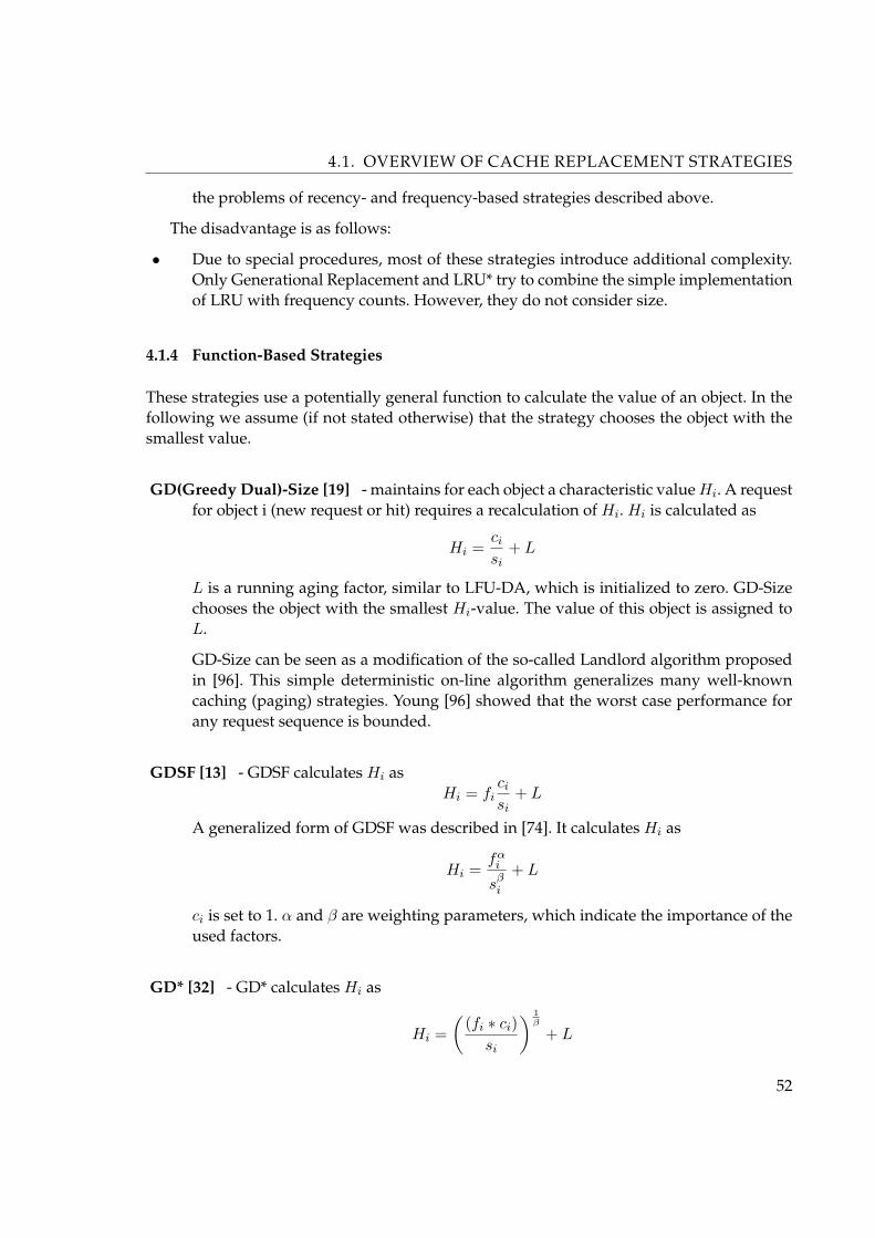
4.1. OVERVIEW OF CACHE REPLACEMENT STRATEGIES
the problems of recency- and frequency-based strategies described above.
The disadvantage is as follows:
• Due to special procedures, most of these strategies introduce additional complexity.Only Generational Replacement and LRU* try to combine the simple implementationof LRU with frequency counts. However, they do not consider size.
4.1.4 Function-Based Strategies
These strategies use a potentially general function to calculate the value of an object. In thefollowing we assume (if not stated otherwise) that the strategy chooses the object with thesmallest value.
GD(Greedy Dual)-Size [19] - maintains for each object a characteristic value Hi. A requestfor object i (new request or hit) requires a recalculation of Hi. Hi is calculated as
Hi =ci
si+ L
L is a running aging factor, similar to LFU-DA, which is initialized to zero. GD-Sizechooses the object with the smallest Hi-value. The value of this object is assigned toL.
GD-Size can be seen as a modification of the so-called Landlord algorithm proposedin [96]. This simple deterministic on-line algorithm generalizes many well-knowncaching (paging) strategies. Young [96] showed that the worst case performance forany request sequence is bounded.
GDSF [13] - GDSF calculates Hi asHi = fi
ci
si+ L
A generalized form of GDSF was described in [74]. It calculates Hi as
Hi =fα
i
sβi
+ L
ci is set to 1. α and β are weighting parameters, which indicate the importance of theused factors.
GD* [32] - GD* calculates Hi as
Hi =(
(fi ∗ ci)si
) 1β
+ L
52
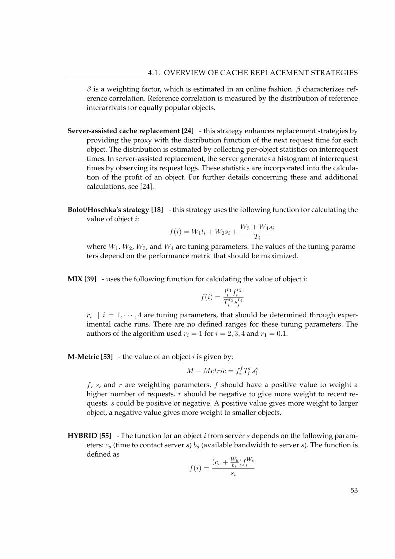
4.1. OVERVIEW OF CACHE REPLACEMENT STRATEGIES
β is a weighting factor, which is estimated in an online fashion. β characterizes ref-erence correlation. Reference correlation is measured by the distribution of referenceinterarrivals for equally popular objects.
Server-assisted cache replacement [24] - this strategy enhances replacement strategies byproviding the proxy with the distribution function of the next request time for eachobject. The distribution is estimated by collecting per-object statistics on interrequesttimes. In server-assisted replacement, the server generates a histogram of interrequesttimes by observing its request logs. These statistics are incorporated into the calcula-tion of the profit of an object. For further details concerning these and additionalcalculations, see [24].
Bolot/Hoschka’s strategy [18] - this strategy uses the following function for calculating thevalue of object i:
f(i) = W1li + W2si +W3 + W4si
Ti
where W1, W2, W3, and W4 are tuning parameters. The values of the tuning parame-ters depend on the performance metric that should be maximized.
MIX [39] - uses the following function for calculating the value of object i:
f(i) =lr1i f r2
i
T r3i sr4
i
ri | i = 1, · · · , 4 are tuning parameters, that should be determined through exper-imental cache runs. There are no defined ranges for these tuning parameters. Theauthors of the algorithm used ri = 1 for i = 2, 3, 4 and r1 = 0.1.
M-Metric [53] - the value of an object i is given by:
M −Metric = ffi T r
i ssi
f , s, and r are weighting parameters. f should have a positive value to weight ahigher number of requests. r should be negative to give more weight to recent re-quests. s could be positive or negative. A positive value gives more weight to largerobject, a negative value gives more weight to smaller objects.
HYBRID [55] - The function for an object i from server s depends on the following param-eters: cs (time to contact server s) bs (available bandwidth to server s). The function isdefined as
f(i) =(cs + Wb
bs)fWs
i
si
53

4.1. OVERVIEW OF CACHE REPLACEMENT STRATEGIES
where Wb and Wn are weighting parameters. Estimates for cs and bs are based on thetime to fetch documents from server s in the recent past.
LNC-R-W3 [49] - the so called profit p(i) of an objecti is calculated as
p(i) =filisi
For this calculation, fi is calculated in consideration of the last K | K > 1 requesttimes (sliding window of K requests):
fi =K
(t− tk)sbi
where t corresponds to the actual time and tk is the time of the oldest request time inthe sliding window. b is used to weight the importance of different object sizes.
LRV [47] - this strategy chooses the object with lowest relative value which is a function ofthe probability that the document is accessed again. This probability Pr is calculatedas
Pr(fi, Ti, si) ={ P (1, si)(1− D(Ti)), if fi = 1
P (fi)(1− D(Ti)), otherwise
Pr is the probability that object i is requested fi + 1 times given that it is requestedfi times. For objects with only one request, this probability depends on the size ofthe object and is given by (P (1, si)). D(Ti) denotes the distribution of the interaccesstimes.
LUV [16] - this strategy calculates for every object i a value V (i) as
V (i) = W (i)p(i)
W (i) is the relative cost to fetch the object from its original server and is defined asW (i) = ci/si. p(i) is the probability that object i is referenced in the future. p(i) iscalculated as
p(i) =Fi∑
k=1
F (tc − tk)
where tc is the actual time and tk is the oldest request time in a sliding window of k
request times. F (x) should be decreasing, to give more weight to more recent refer-ences. One possibility is
F (x) =(12)λx | (0 ≤ λ ≤ 1)
54

4.1. OVERVIEW OF CACHE REPLACEMENT STRATEGIES
LR(Logistic Regression)-Model [29] - the goal of this model is to express the outcome of adependent variable Y , in terms of its predictors, (1, X1, · · · , Xk) and their respectiveco- efficients (β0, β1, · · · , βk). The LR proba- bility is given by
PLR = P (Y = 1 or 0|1, X1, · · · , Xk) =1
1− e−z
where
z =k∑
f=0
βjXj | −∞ < z < +∞
Given a set of observed data, the coefficients are obtained using the method of max-imum likelihood estimation (learning phase). Once these coefficients are known, theLR probability can be calculated for other objects (prediction phase). In the cachingcontext, the event of interest is whether a document is reaccessed at least once in thenext N accesses. The predictors are factors like recency, frequency, size, and cost.
This class contains most of the proposed replacement strategies. Many of these strategiesuse similar factors and weighting schemes. The advantages of these proposals are as follows:
• They do not assume a fixed combination of factors or fixed usage of data structures.Through the proper choice of weighting parameters, one can try to optimize any per-formance metric.
• They consider a number of factors for handling different workload situations.
The disadvantages are as follows:
• Choosing appropriate weights is a difficult task. Some proposals assume that theweights are derived from Web trace studies. This is a simple but errorprone approach.Web workloads change over time and require some adaptive setting of the parame-ters. Adaptivity adds new complexity to the replacement process. Furthermore, thereexist no exhaustive treatment of this sort of adaptivity in the literature.
• Using latency in the value calculation can introduce some problems. Recency and fre-quency information can be attained easily from the past request stream at the proxy.Latency is sampled at the proxy but influenced by many components on the pathbetween server and proxy (or client). Statistical fluctuations complicate any accuratedecision making. Furthermore, new technologies that support the movement of Webobjects introduce further sources for inaccurate latency estimations. Therefore, usinglatency can lead to inferior replacement decisions.
55

4.1. OVERVIEW OF CACHE REPLACEMENT STRATEGIES
4.1.5 Randomized Strategies
These strategies use randomized decisions to find an object for replacement. The followingstrategies were proposed:
RAND - this strategy removes a random object.
HARMONIC [31] - whereas RAND uses equal probability for each object, HARMONICremoves from cache one item at random with a probability inversely proportional toits specific cost cost = ci/si.
LRU-C [50] - is a randomized version of LRU. Let cmax = max{c1, c2, · · · , cN} be the max-imum of the access costs of all N objects of a request sequence. Let ci = ci/cmax be thenormalized cost for object i. When an object i is requested, it is moved to the head ofthe cache with probability ci; otherwise, nothing is done.
LRU-S [50] - uses the size instead of the cost. Let smin = min{s1, s2, . . . , sN} be the sizeof the smallest objects among the N documents, and di = smin/si be the normalizeddensity of object i. LRU-S acts as LRU with probability di; otherwise the cache state isleft unmodified.
Possible is a algorithm which deals with both varying-size and varying-cost objects.The following quantities were defined:
βi =ci
si; βmax = max(βi) |∀i ∈ N ; βi =
βi
βmax
Upon a request for object i, this algorithm performs the same operation as LRU withprobability βi i and with 1− βi will leave the cache state unmodified.
Randomized replacement with general value functions [43] - This strategy draws N ob-jects randomly from the cache and evicts the least useful object in the sample. Theusefulness of a document can be determined by any utility function. After replacingthe least useful object, the next M | M < N least useful objects are retained in mem-ory. At the next replacement, N −M new samples are drawn from the cache and theleast useful of these N −M and M previously retained is evicted. The M least usefulof the remaining are stored in memory and so on.
Randomization presents a different approach to cache replacement. Randomized strate-gies try to reduce the complexity of the replacement process without sacrificing the qualitytoo much. The advantages are as follows:
56

4.2. PERFORMANCE OF REPLACEMENT ALGORITHMS
• Randomized strategies do not need special data structures for inserting and deletingobjects. Searching can be supported by special data structures.
• Randomized strategies are simple to implement.
The disadvantage is as follows:
• Randomized strategies are more cumbersome to evaluate. For example, different sim-ulation runs on the same Web request trace will give slightly different results.
4.2 Performance of Replacement Algorithms
Three basic aspects of Web Proxy cache can potentially improve network performance. Atfirst it is the number of requests that reaches the server, the second is the volume of trans-ferred data through the network and the last it is the latency of retrieving a desired mes-sage. A lot of efforts in researchs have been done for comparing the performance of vari-ous caching algorithms in terms of the first two points of view. In this chapter, I compareLRU, four Frequency-based algorithms and four GD-Size-based algorithms in terms of be-fore mentioned three criteria. In this comparing I will put the accent on the average down-loading latency.
4.2.1 Setting
For comparing I used logged records of SOAP messages transfer. I used a week trace fromproxy server of web-portal SVOD. The proxy is configured to record information about eachSOAP request processed by the proxy server. Each line in the log contains information abouta requests and responses to/from a Web Services used in this portal. Used log columnsrelated to the performance experiments are described in Table 4.2.
At first the trace was preprocessed by using a integer to stand for each column in thetrace entry. The Table 4.3 shows the summary of access log.
In experiment I use a assumed simplified proxy cache model. At first, the cache canonly completed SOAP messages to be added or removed from the cache. Second, cachingonly work with SOAP messages. Third, in the simulation, the consistency between the copyof message in the proxy memory and the original message obtained by the server is notconsidered.
4.2.2 Used Method
Three performance metrics are used to evaluate the performance of the caching algorithms:
57

4.2. PERFORMANCE OF REPLACEMENT ALGORITHMS
Column Descriptiontime_stamp the time a request arrives at the proxyelapsed_time the time interval from a request being processed by
the proxy to the last bit of the corresponding responsebeing sent to the network
client identification of client who sends the requestaction the proxy’s response to the request (cache hit or cache
miss)size the size of SOAP response messagehash is the hash of SOAP request message (identification
of request)
Table 4.2: Used Log Columns
ItemAccess Log Duration one weekSOAP Requests 1 387 321Total Data Volume 2 149 MBUnique Request 468 503
Table 4.3: Summary of access log
• Cache Hit Ratio - the cache hit ratio we defined as the number of requests that hitin the proxy cache. It is presented as a percentage of the total requests made by theclients.
• Byte Hit Ratio - the byte hit ratio refers to the number of bytes that transferred directlyfrom the proxy cache. It is presented as a percentage of the total data volume retrievedin the trace.
• Reduced Latency
There are two kinds of latencies: server latency and client latency [60].
Client latency (client response time) is defined as the time interval from a request beingsent to the server to a responding message being received from the server. The client latencyis important because it describes the quality of the service that the end-user can experience.However, in our experiment is studied a proxy trace, which only provides the record of theserver latency.
The server latency (server response time) is defined as the time interval from a requestbeing processed by the server to the last bit of the response being sent to the network. Ap-parently, client latency includes the server latency plus the time spent in the network andthe time a response is processed and displayed by the client. By reason of a proxy is always
58

4.2. PERFORMANCE OF REPLACEMENT ALGORITHMS
located near to the clients, the server latency (recorded in the proxy log as elapsedtime) isused as an indication of client latency.
The third measure - reduced latency is defined as the sum of elapsedtime that hit in cachehit as a percentage of the sum of all elapsedtime in the trace. It indicates the time saved whenmessages are returned directly from the proxy instead of fetched from the server far way.
Two main factors are used in these experiments: cache size and cache replacement policy.Before deciding on the levels of cache sizes, an experiment was done to determine the max-imum possible cache hit ratio. Byte hit ratio and reduced latency that a proxy cache couldever achieve assuming an infinite size of cache (no file is ever removed from the cache). Theresult of this experiment is showed in Table 4.4.
Maximum Cache size 762 MBMaximum Hit Ratio 32.7 %Maximum Reduced latency 22.6 %
Table 4.4: Summary of access log
Because is used limited cache storage for all simulations, the performance that any re-placement algorithm can achieve will be less than these results. All the following simulationresults are presented as a percentage of the corresponding maximum values listed in Ta-ble 4.4.
The distribution of file sizes shows the consistent result with [61], that a lot of cachedSOAP messages are small while there is a area which corresponds to some extremely largeobjects. Considering the result, the cache sizes investigated in the simulations were chosenby taking a fixed percentage of the total size of all distinct messages requested. Becausethe concentration of small messages, the percentages selected are relatively small. They are0.2%, 0.5%, 1%, 2%, 5%, 10%, 30% of the maximum cache size. Furthermore, the simulationresults when cache size equals to 30% of the maximum size are fairly close to the maximumvalues. This indicates the effectiveness of the cache size lever selected.
Cache replacement policy is used in the case when a cache miss happens and there is in-sufficient free spaces left in the cache. Replacement policy decide which message is removedfrom the cache until the amount of free cache space equals or exceeds the size of the newretrieved message. The decision depends on different kinds of replacement strategies used.Three mail categories of replacement strategies are examined: Frequency-based strategies,Least-Recently-Used(LRU) and GD-Size-Based algorithms.
Below are used implementations of replacement strategies in experiments. For detaileddescription of concurent replacement strategies see Section 4.1.
During the warm-up stage, many of the cache misses occur because the cache is empty.Replacement algorithms play diferent role in the performance of the cache until the cache
59
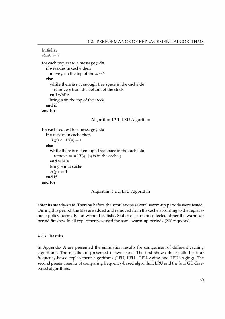
4.2. PERFORMANCE OF REPLACEMENT ALGORITHMS
Initializestock ⇐ ∅
for each request to a message p doif p resides in cache then
move p on the top of the stock
elsewhile there is not enough free space in the cache do
remove p from the bottom of the stockend whilebring p on the top of the stock
end ifend for
Algorithm 4.2.1: LRU Algorithm
for each request to a message p doif p resides in cache then
H(p) ⇐ H(p) + 1else
while there is not enough free space in the cache doremove min(H(q) | q is in the cache )
end whilebring p into cacheH(p) ⇐ 1
end ifend for
Algorithm 4.2.2: LFU Algorithm
enter its steady-state. Thereby before the simulations several warm-up periods were tested.During this period, the files are added and removed from the cache according to the replace-ment policy normally but without statistic. Statistics starts to collected afther the warm-upperiod finishes. In all experiments is used the same warm-up periods (200 requests).
4.2.3 Results
In Appendix A are presented the simulation results for comparison of different cachingalgorithms. The results are presented in two parts. The first shows the results for fourfrequency-based replacement algorithms (LFU, LFU*, LFU-Aging and LFU*-Aging). Thesecond present results of comparing frequency-based algorithm, LRU and the four GD-Size-based algorithms.
60

4.2. PERFORMANCE OF REPLACEMENT ALGORITHMS
InitializeL ⇐ 0
for each request to a message p doif p resides in cache then
H(p) ⇐ H(p) + L
elsewhile there is not enough free space in the cache do
L ⇐ min(H(q) | q is in the cache )remove q such that H(q) value
end whilebring p into cacheH(p) ⇐ L
end ifend for
Algorithm 4.2.3: LFU-Aging Algorithm
InitializeL ⇐ 0
for each request to a message p doif p resides in cache then
H(p) ⇐ L + n ∗ c(p)/s(p)else
while there is not enough free space in the cache doL ⇐ min(H(q) | q is in the cache )remove q such that H(q) value
end whilebring p into cacheH(p) ⇐ L + c(p)/s(p)
end ifend for
In GD-SIZE: c(p) = 1, n = 1In GD-Size-Frequency: c(p) = 1, n = reference countIn GD-Size(Latency): c(p) = downloading latency, n = 1In GD-Size-Frequency(Latency): c(p) = downloading latency, n = reference count
Algorithm 4.2.4: Greedy Dual Size Algorithms
In general, all cache algorithms allocate a “weight” to each message in the cache. In caseof a replacement, the message(s) with the lowest “weight” is(are) removed from cache until
61

4.2. PERFORMANCE OF REPLACEMENT ALGORITHMS
sufficient space is available for the incoming message. The “weight” can be reference countin LFU, can be the size of the file in SIZE or can be the locality in LRU.
However, in order for a proxy cache to improve its performance, this ‘weight’ shouldtake the following factors into account:
• The size of the message - this factor considers data volume needed to be stored andtransferred. The smaller the file is, the less the data volumes are transferred in thenetwork and the more the number of messages can be stored in the cache.
• The time for a message to be retrieved from the server to proxy - the reason for thisconcern is obvious: removing a message retrieved from a server located in a far siteshould be taken with great care than the decision to discard a message obtained froma closer site.
• the frequency that a message has been accessed - there are some very “hot” mes-sages and a lot of other “cold” messages. Thus, if a message is accessed frequentlyin the past, i.e. it is a “hot” message, it will probably remain “hot” and be accessedfrequently in the future. Thus, the priority should be given to the message with highreference count.
Thus, a good proxy replacement algorithm should combine all the above concerns to-gether. GD-Size combines size and locality. However, GD-Size-Frequency(Latency) whichcombines size, latency, locality and frequency concerns all together but did not perform aswell as GD-Size-Frequency.
62

Chapter 5
Semantic-based Caching
Before describing the semantic caching strategy, I will compare it to traditional cache man-agement architectures. They are page caching, tuple caching and query caching. More detailsabout them can be found in [25]. Next I will describe the Semantic Caching strategy how ispresented in the area of caching in database environment and in the XML Queries area. Inthe end I will make a proposal of Semantic caching model devoted to Web Services, whichis based on tree indexes.
5.1 Page based caching
In page based caching architectures, the unit of transfer between clients and servers is apage. Queries are processed locally on the client down to the level of requests for individualpages. In case a required page is not present in the local cache, a request is sent to the server.In response to this request, the server will obtain the desired page from disk and send itback to the client. On the client side, page caching is supported through a mechanism that isidentical to the traditional page-based database buffer manager. A client can perform partialscans on indexed attributes by first accessing the index and then accessing desired datapages. If no index is present then a page cache will scan an entire relation, again faultingin any missing pages. As with a buffer manager, a page cache is managed using simplereplacement strategies based on the usage of the data items, such as LRU or MRU.
5.2 Tuple based caching
Tuple caching is in many ways analogous to page caching, but the primary difference is thatthe client cache is maintained in terms of individual tuples (objects) rather than entire pages.Caching at the granularity of a single item allows maximal flexibility in the tuning of cachecontents to the access locality properties of applications. As described in [25], however, thefaulting in of individual tuples can lead to performance problems due to the expense ofsending large numbers of small messages. In order to reduce this problem, a tuple cachingsystem must group client requests for multiple tuples into a single message and must alsogroup the tuples to be sent from servers to clients into blocks.
63

5.3. QUERY CACHING
Scans of indexed attributes can be answered in a manner similar to page caching. Forscans of non-indexed attributes however, there are two options. One option is for the clientto first perform the scan locally, and then send a list of all qualifying tuples that it has incache, along with the scan constraint to the server. The server can then process the scan,sending back to the client only those qualifying tuples that are not in the client’s cache. Analternative is for the client to simply ignore its cache contents when performing a scan on anon-indexed attribute. In this case, the scan constraint is sent to the server, and all qualifyingtuples are returned; duplicate tuples can be discarded at the client.
Finally, the tuple cache, like a page cache, is managed using an access-based replacementpolicy such as LRU. Unlike the page cache, however, there is no notion of spatial locality fortuples, so only temporal locality is exploited.
5.3 Query Caching
Question Answering (QA) system is a system that returns direct answers to user’s naturallanguage questions by querying its knowledge base. Web QA (WQA) system is the systemwhich treats the whole Web as its knowledge base.
Most of the WQA systems are based on separate third-party Web search engines, so thecommunication cost between the WQA systems and the Web search engines is sometimeshigh. To decrease that cost and further improve the performance of the WQA systems, de-ploying a caching strategy at WQA side is a feasible solution. But an investigation on themajor WQA systems shows that it is only WebQA [35] that addresses a caching strategy inits design. However, since WebQA only deals with exact matching case where a hit hap-pens when a new question is exactly matched against a previous cached one, its capabilityis limited.
Data chaching, tuple caching and query caching are three widely used strategies for Webcaching. As regards to the data/tuple caching strategy, a major concern is whether the datagranularity in the cache is page/tuple. In this strategy, special proxy servers maintain thepages or tuples recently accessed and when users request same pages or tuples by URL, thecache will return its corresponding content directly to users so that it can save the communi-cation cost between proxy servers and user clients. But in many data integration system suchas a Meta Web search engine or a WebQA system, user queries do not contain URL infor-mation, instead they contain bag of keywords. Under this factor the query caching strategyworks well, which is also known as “semantic caching”. The semantic caching strategy man-ages semantic region grouping a collection of data objects corresponding to a specific query.For our interest in caching of a Web Services, a semantic region normally contains a SOAPresponse returned by Web Service on the request, that is a composition of variables of calledfunction.
64

5.4. SEMANTIC-BASED CACHING
5.4 Semantic-based Caching
Semantic caching is a client-side caching technique designated for DBMSs to exploit thesemantic locality of queries [23] [25] [84]. A semantic cache is managed as a collection of se-mantic regions. Semantic regions group together semantically related objects and are com-posed of region descriptor and region content. The descriptor basically contains a regionpredicate describing the region content. The region content stores the objects related to aregion descriptor. Access history is maintained and cache replacement is performed at thegranularity of semantic regions.
Every query sent to a semantic cache is split into two disjoint parts: a probe query and aremainder query. The probe query extracts the relevant portion of the result already avail-able in the cache while the remainder query is sent to the origin server to fetch the missing(not cached) part of the result. If the remainder query is empty, the cache does not interactwith the origin server. If a client wants to pose a query A and the cache already contains theresult for the query A ∧B, it sends a remainder query A ∧¬B to retrieve the missing results.
Generally, there are three main issues concerned for a semantic caching strategy: cacheregion organization, matching mechanism, and cache replacement policy.
With respect to the first issue, data objects are organized into semantic regions corre-sponding to queries e.g., relational predicates in relational database or set of variables fromSOAP request message in Web Services area. Further the regions may or may not be disjoint,depending on design of different systems. There are also special techniques used for cacheorganization in different systems, for example, signature method is used in Chidlovskii’sstrategy [23] and reference counter technique is used in strategy in CoWeb [84].
As for the issue of matching mechanism, generally there are four matching types: exactmatching, query containment, region containment, and intersection matching. Briefly put,exact matching happens when a new query is exactly the same as the region formula, i.e.,the description of the region; query containment indicates the case in which a new query issubordinate to at least one region formula so that it can be entirely satisfied by the cache,here “a formula A is subordinate to a formula B” means that the complete query result cor-responding to A is a proper set of that corresponding to B; inversely, region containmentmeans at least a region formula in the cache is subordinate to the query formula so that thequery can be satisfied partially by the cache; at last, the intersection matching type is thecase when the result of the query and the data residing in a semantic region are not disjoint,but neither of them is subordinate to the other. Since both of the query containment and theregion containment can be associated with multiple semantic regions, there are altogethersix matching cases, which are demonstrated in the following Figure 5.1. Once the matchingcase is determined, a probe part for the query can be generated from the matched semanticregions, and the rest results i.e., the remainder part of the query, can be fetched by infor-mation retrieval. At last the probe part and the remainder part together make up the query
65

5.4. SEMANTIC-BASED CACHING
result.
Figure 5.1: Matching types in semantic caching
Replacement strategies widely deployed in semantic caching are normally the classicalor the variants of the LRU (Least Recently Used) strategy.
There is a lot of research work on semantic caching, e.g., Chidlovskii’s semantic cachingstrategy on Meta Web search engine [23], Lee’s semantic caching strategy in CoWeb [84] andXCache a semantic caching architecture for XML [21]. Among them, Chidlovskii’s strategyis closest to the case in Web Services architecture, so I summarize important issues of thisstrategy in the sequel.
5.4.1 Semantic Caching Strategy by Chidlovski
A query formula in this strategy is a conjunctive predicate consisting of positive or negativequery terms in form of “Attr Op Value”, where “Attr” represents attribute names specificto particular Web sources and “Op” is an operator such as “Contains” or “Equals”. Forexample, given a Web document A, a query formula of “(A Contains ‘Web’) and (A Contains‘Services’)” can be used to represent a query for all the Web documents containing keywords“Web” and “Services”. Actually, such a case is equivalent to a pair of keywords {“Web”,“Services”}.
Signature method, which was originally designed for full-text fragments retrieval [77],is adopted to accelerate the process of query matching. In Chidlovskii’s strategy, each termin region formula is assigned with a signature represented as a binary sequence of ones and
66
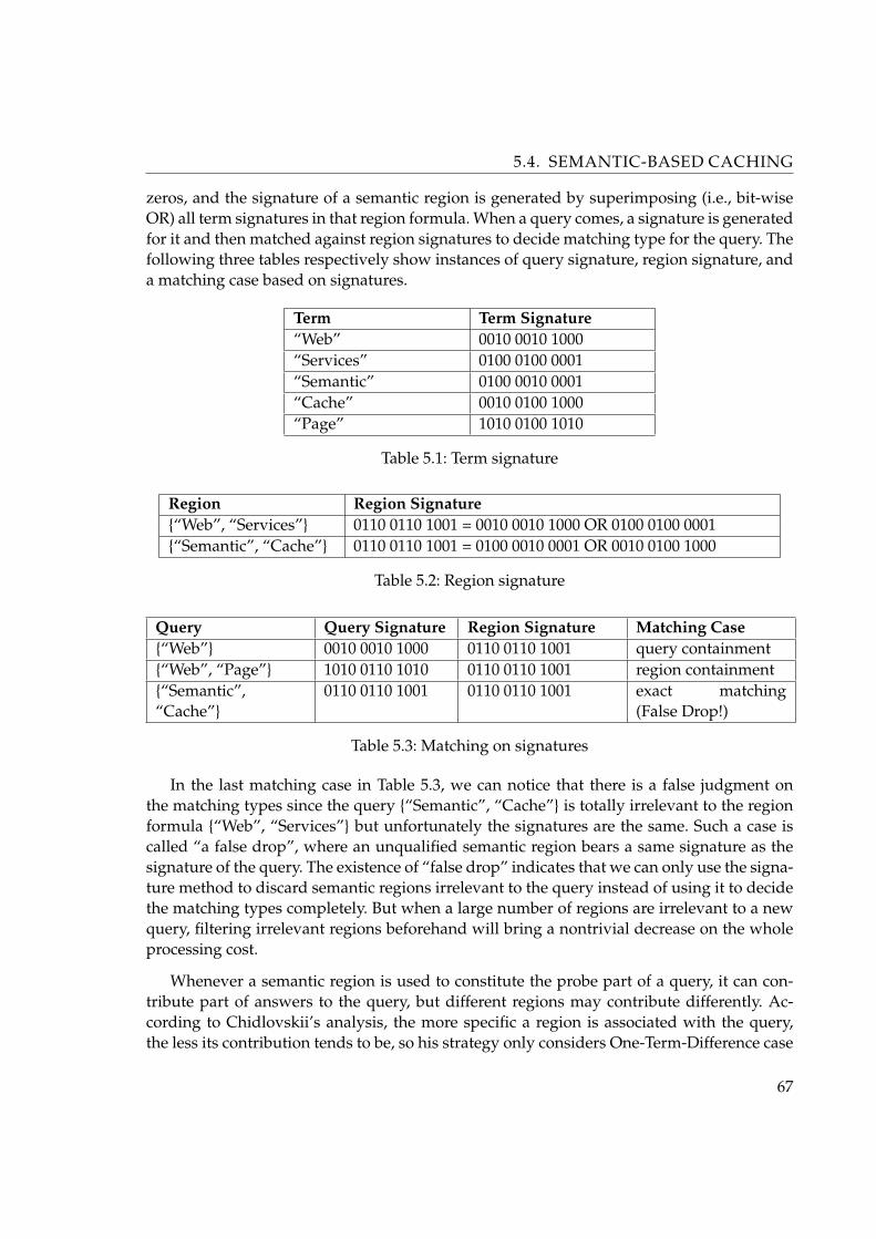
5.4. SEMANTIC-BASED CACHING
zeros, and the signature of a semantic region is generated by superimposing (i.e., bit-wiseOR) all term signatures in that region formula. When a query comes, a signature is generatedfor it and then matched against region signatures to decide matching type for the query. Thefollowing three tables respectively show instances of query signature, region signature, anda matching case based on signatures.
Term Term Signature“Web” 0010 0010 1000“Services” 0100 0100 0001“Semantic” 0100 0010 0001“Cache” 0010 0100 1000“Page” 1010 0100 1010
Table 5.1: Term signature
Region Region Signature{“Web”, “Services”} 0110 0110 1001 = 0010 0010 1000 OR 0100 0100 0001{“Semantic”, “Cache”} 0110 0110 1001 = 0100 0010 0001 OR 0010 0100 1000
Table 5.2: Region signature
Query Query Signature Region Signature Matching Case{“Web”} 0010 0010 1000 0110 0110 1001 query containment{“Web”, “Page”} 1010 0110 1010 0110 0110 1001 region containment{“Semantic”,“Cache”}
0110 0110 1001 0110 0110 1001 exact matching(False Drop!)
Table 5.3: Matching on signatures
In the last matching case in Table 5.3, we can notice that there is a false judgment onthe matching types since the query {“Semantic”, “Cache”} is totally irrelevant to the regionformula {“Web”, “Services”} but unfortunately the signatures are the same. Such a case iscalled “a false drop”, where an unqualified semantic region bears a same signature as thesignature of the query. The existence of “false drop” indicates that we can only use the signa-ture method to discard semantic regions irrelevant to the query instead of using it to decidethe matching types completely. But when a large number of regions are irrelevant to a newquery, filtering irrelevant regions beforehand will bring a nontrivial decrease on the wholeprocessing cost.
Whenever a semantic region is used to constitute the probe part of a query, it can con-tribute part of answers to the query, but different regions may contribute differently. Ac-cording to Chidlovskii’s analysis, the more specific a region is associated with the query,the less its contribution tends to be, so his strategy only considers One-Term-Difference case
67

5.4. SEMANTIC-BASED CACHING
of region containment and intersection matching types. Simply put, the difference of a se-mantic region from a query is the set of terms existing in region formula which are not inquery’s formula; and “One-Term-Difference” case indicates that there is just one term exist-ing in the region formula which is not in query’s formula. For example, given a semanticregion {“Web”, “Services”} and a query {“Web”, “Page”}, a matching of the query againstthe region is a “One-Term-Difference” case concerning there is only one different keywordin the region i.e., “Services”.
Design issues based on incomplete resulting set is touched on in the strategy and canbe demonstrate to caching of Meta Web search engine. Since Meta Web search engines arenormally based on Web search engines. To process all the thousands of documents returnedby the search engines is both intractable and unnecessary. So most of the Meta Web searchengines only employ the top limited number of Web documents. Under this circumstance,the matching type of query containment is affected. Remember that a matching is regardedas a query containment matching case only if the query’s formula is subordinate to the re-gion formula so that when the resulting set in the region is complete, the region can entirelysatisfy the query. But when the resulting set is incomplete, neither could we claim that theregion can satisfy the query entirely, nor we can easily judge the quantity of the intersectionbetween the region and the query. For example in Figure 5.2, where R1 is the actual docu-ment set in the region corresponding to the region formula, it’s clear that although the queryformula Q is subordinate to the formula of region R, we can’t say that R satisfies query Qentirely since the part of the R1 only intersects with Q rather than containing it.
Figure 5.2: Query containment case when resulting set is incomplete
The replacement policy in Chidlovskii’s strategy is a variant of LRU strategy, which takesboth region contribution and region size into consideration. According to the notation ofthe paper [Chidlovskii], “the most recent value” is defined as Vtop. Each time when a newquery is launched, Vtop will increase by one and the value Vtop
size is assigned to the newlygenerated region where size is the number of data objects in the region; for other regions,their replacement value is assigned as Vr+(Vtop−VR)×p
size where VR is the current replacementvalue of the region and p is the involvement ratio of the region in the query calculated byp = TQ
size , TQ is the number of the data objects in the region matching the query.
68
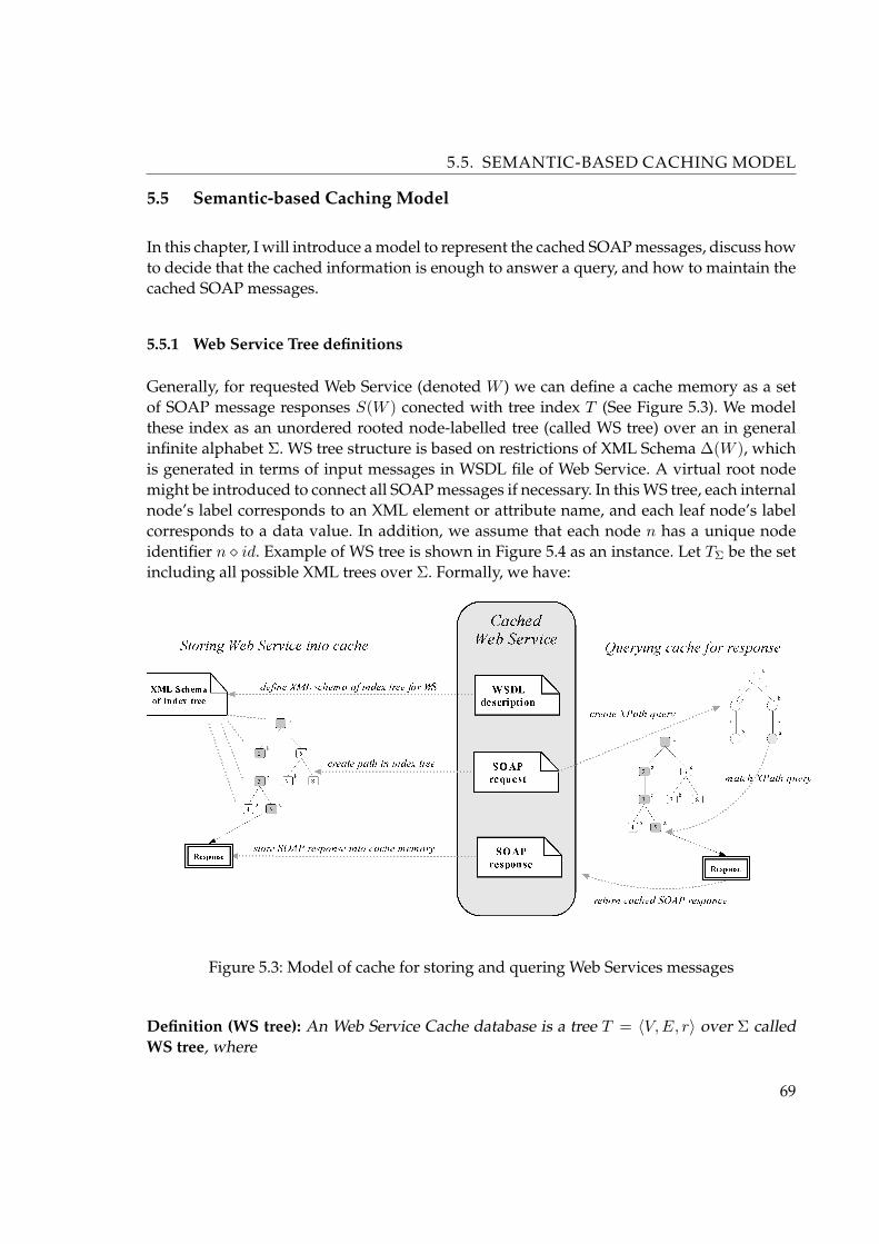
5.5. SEMANTIC-BASED CACHING MODEL
5.5 Semantic-based Caching Model
In this chapter, I will introduce a model to represent the cached SOAP messages, discuss howto decide that the cached information is enough to answer a query, and how to maintain thecached SOAP messages.
5.5.1 Web Service Tree definitions
Generally, for requested Web Service (denoted W ) we can define a cache memory as a setof SOAP message responses S(W ) conected with tree index T (See Figure 5.3). We modelthese index as an unordered rooted node-labelled tree (called WS tree) over an in generalinfinite alphabet Σ. WS tree structure is based on restrictions of XML Schema ∆(W ), whichis generated in terms of input messages in WSDL file of Web Service. A virtual root nodemight be introduced to connect all SOAP messages if necessary. In this WS tree, each internalnode’s label corresponds to an XML element or attribute name, and each leaf node’s labelcorresponds to a data value. In addition, we assume that each node n has a unique nodeidentifier n � id. Example of WS tree is shown in Figure 5.4 as an instance. Let TΣ be the setincluding all possible XML trees over Σ. Formally, we have:
Figure 5.3: Model of cache for storing and quering Web Services messages
Definition (WS tree): An Web Service Cache database is a tree T = 〈V,E, r〉 over Σ calledWS tree, where
69

5.5. SEMANTIC-BASED CACHING MODEL
1. V is the node set and E is the edge set.
2. The r ∈ V is the root of T .
3. Each node n ∈ V has a label, denoted as n� label, whose value is n� label ∈ {′∗′,′ //′}∪Σ.
4. Each node n ∈ V has a unique node identifier denoted as n � id. 2
Definition (Size): Given an WS tree T = 〈V,E, r〉, the size of T is defined as the cardinalityof V , and we also say that T ′ = 〈V ′, E′, r′〉 is a subtree of T if V ′ ⊆ V and E′ = (V ×V )∩E.
Definition (Rooted subtree): Given an WS tree T = 〈V,E, r〉, a rooted subtree T ′ = 〈V ′, E′, r′〉is a subtree of T if it satisfied the folowing conditions: r′ = r and V ′ ⊆ V and E′ ⊆ E.
Next I will use fragment of XPath queries denoted as XPQ. This fragment consists oflabel tests, child axes(/), descendant axes(//), branches([]) and wildcards(*). It can be recur-sively represented by the following grammar:
q 7−→ v | ∗ | q/q | q//q | q[q] | v ∈ Σ
Any q ∈ XPQ can be represented as a labelled tree (called query pattern tree) with thesame semantics (See Figure 5.4 b).
Definition (query pattern tree): A query pattern tree P is a tree P = 〈V,E, r, o〉 over Σ∪{′∗′},where V is the node set and E is the edge set, and:
1. Each node n ∈ V has a label from Σ ∪ {′∗′}, denoted as n � label;
2. Each edge e ∈ E has a label from {′/′,′ //′}, denoted as e � label. The edge with label′/′ is called child edge, otherwise called descendent edge;
3. r ∈ V is the root node of P and o ∈ V is the output node of P .
In order to decide if a WS tree T is included in some query pattern tree P , we need todefine the semantics of tree inclusion. Several definitions of tree inclusion exist includingsubtree inclusion [63], tree embedding [64] and tree subsumption [62]. The most relevantdefinition is the subtree inclusion, which states that a WS subtree T ′ is included in some WStree T if and only if there exists a subtree of T that is identical with T ′.
However, this definition is too restrictive for XML query pattern trees where handling ofwildcards and relative paths are necessary.
Consider the an WS trees T = 〈Vt, Et, rt〉 and query pattern tree P = 〈Vp, Ep, rp, op〉 inFigure 5.4. Let match(p, q) denote that a node p ∈ Vt is mapped to a node q ∈ Vp.
70

5.5. SEMANTIC-BASED CACHING MODEL
Figure 5.4: Example of tree and pattern tree
Since we are dealing with rooted subtrees, we can carry out a top-down matching. Here,(’a’,’a’) is mapped first. Next, we check that each subtree of ’a’ in T matches with some sub-tree of ’a’ in P . This requires that the subtree rooted at section of T (denoted as subtree(section))has to be matched against the subtrees rooted at ‘b’ and ’*’ of P . We need to consider whether‘//’ indicates zero or many nodes in the path:Case 1: ‘//’ means zero length. Then subtree(2) must be included in either subtree(5) of P ,which is not the case here.Case 2: ‘//’ means many nodes. This implies that section has been mapped to some ‘un-known’ node in P . From all the possible subtrees of section, only one subtree, i.e., subtree(3),must be included by subtree(‘//’).
I now define an pattern match (also called embedding) from a query pattern tree to anWS tree as follows:
Definition (pattern match): Given an WS tree T = 〈Vt, Et, rt〉 and a query pattern treeP = 〈Vp, Ep, rp, op〉, an pattern match from P to T is a function match() : Vp 7−→ Vt, withfollowing properties:
1. Root preserving: match(rp) = rt;
2. Label preserving: ∀n ∈ Vp:if n � label 6= ′∗′ ⇒ n � label = match(n) � label;
3. Structure preserving: ∀e = (n1, n2) | n1, n2 ∈ Ep:
71

5.5. SEMANTIC-BASED CACHING MODEL
if e � label = ′/′ then e(n2) is a child of e(n1) in T ; otherwise, e(n2) is a descendent ofe(n1) in T .
Function match() maps the output node op of P to a node n ∈ Vt. We say that the node n
is the result of this embedding. As an example, dashed lines between Figure 5.4 (a) and (b)shows an embedding, and its result is the node with id = 8. Actually, there could be morethan one embedding from P to T . We define the result of P over T , denoted as P (T ), as theunion of results of all embeddings, i.e.,
P (T ) =⋃
m∈M
{m(op)}
where M is the set including all pattern matches from P to T .
For a given XML tree T , we also consider evaluating a set of patterns ST = P1, P2, ..., Pn
over T . The result, denoted as ST , is the union of the result of evaluating each Pi ∈ S overT , formally defined as:
ST =⋃
Pi∈S
{Pi(T )}
Lemma: For any two patterns P1 and P2, we said that P1 is contained in P2 (denoted asP1 v P2) if ∀T ∈ TΣ | P1(T ) ⊆ P2(T ).
Lemma: For any pattern P and pattern set SP , we said that a pattern P is contained in apattern set SP (denoted as p v SP ) if ∀T ∈ TΣ | P (T ) ⊆ ST .
Lemma: For any two pattern sets SP1 and SP
2 , we said that pattern set SP1 is contained in a
pattern set SP2 (denoted as SP
1 v SP2 ) if ∀T ∈ TΣ | ST
1 ⊆ ST2 .
We can also show that SP1 v SP
2 if ∀Pi ∈ S1 | Pi v SP2 . However, it’s not always true that
P v SP ⇒ ∃P ′ ∈ SP | P v P ′.
Proof: Below is describet algorithm for contains which check the containment of tree pat-terns. It maintains a two-dimensional array status , which is initialized with stutus[v, w] =null to indicate that v ∈ nodes(p) and w ∈ nodes(q) have not been compared. Otherwise,status[v, w] ∈ {true, false} sutch that status[v, w] = true if and only if subtree(w, q) vsubrtee(v, p). Clearly q v p if and only if status(vroot, wroot) = true where vroot is the rootnode of p and wroot is the root node of q. 2
72
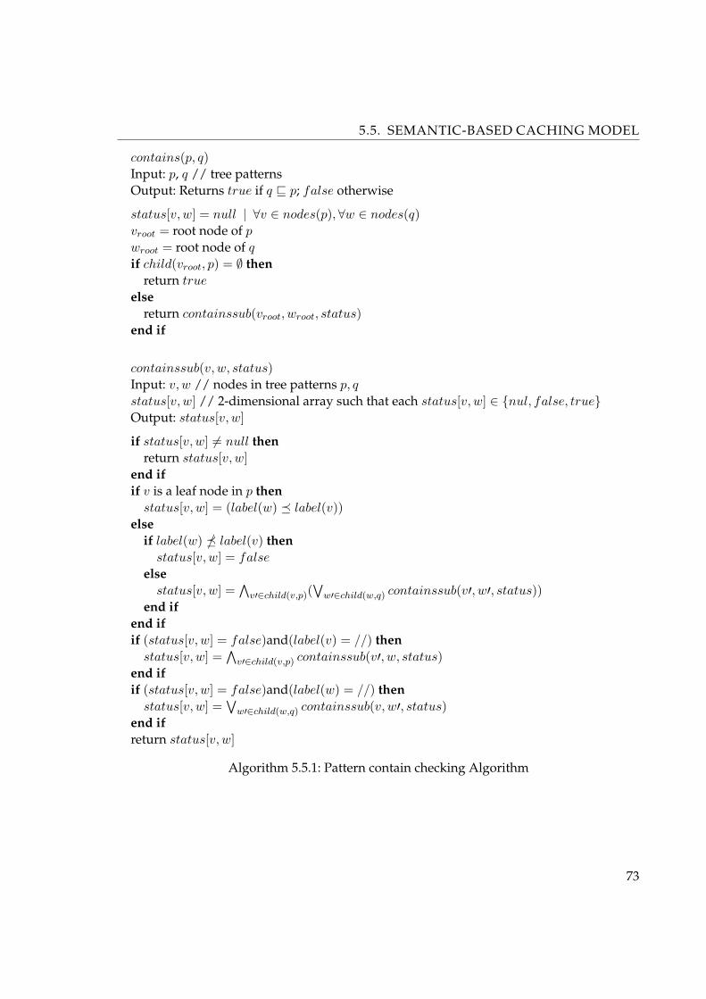
5.5. SEMANTIC-BASED CACHING MODEL
contains(p, q)Input: p, q // tree patternsOutput: Returns true if q v p; false otherwise
status[v, w] = null | ∀v ∈ nodes(p),∀w ∈ nodes(q)vroot = root node of p
wroot = root node of q
if child(vroot, p) = ∅ thenreturn true
elsereturn containssub(vroot, wroot, status)
end if
containssub(v, w, status)Input: v, w // nodes in tree patterns p, q
status[v, w] // 2-dimensional array such that each status[v, w] ∈ {nul, false, true}Output: status[v, w]
if status[v, w] 6= null thenreturn status[v, w]
end ifif v is a leaf node in p then
status[v, w] = (label(w) � label(v))else
if label(w) � label(v) thenstatus[v, w] = false
elsestatus[v, w] =
∧v′∈child(v,p)(
∨w′∈child(w,q) containssub(v′, w′, status))
end ifend ifif (status[v, w] = false)and(label(v) = //) then
status[v, w] =∧
v′∈child(v,p) containssub(v′, w, status)end ifif (status[v, w] = false)and(label(w) = //) then
status[v, w] =∨
w′∈child(w,q) containssub(v, w′, status)end ifreturn status[v, w]
Algorithm 5.5.1: Pattern contain checking Algorithm
73

5.5. SEMANTIC-BASED CACHING MODEL
5.5.2 Representation
Now I will describe possible representation of the cached SOAP messages in caching system.The main idea is that the cached SOAP message M is in general indexed by a set of patternsindex(M) ≡ SP , and this representation must satisfy two requirements:
• index must be a rooted sub-tree of the WS tree (build in terms of WSDL definition ofinput message type);
• index must totally answer any pattern P ∈ S, it means that for any pattern P ∈ SP
we can get the SOAP message from cached equal to SOAP message we get from theoriginal Web Service, invoked with variables represented by pattern P .
I will describe this representation, satisfying the above requirements, by defining the WStree to be cached for a pattern set SP . We formalize the representation for one pattern first,and then extend it to a pattern set later.
Before introducing the representation, I define the embedding node set of a pattern P
over an WS tree T . This set includes all nodes in T mapped from nodes in P by an embed-ding between P and T . Hence, nodes in this set may be queried or accessed in the evaluationof P over T . Formally, we have:
Definition (set of pattern matches): Given an WS tree T = 〈Vt, Et, rt〉 and a pattern P =〈Vp, Ep, rp, op〉, an set of pattern matches P over T we denoted as:
SPT (P, T ) =⋃
m∈EB
(⋃
vi∈VP
{m(vi) � id})
where SPT is the set including all possible pattern matches from P to T and m is anmatch.
In example in Figure 5.5, there are four matchings from pattern P shown in (a) to an WStree T shown in (b). The continuous lines represent one matching, and it maps nodes in P tonodes with id = 1, 2, 6 in T . The second one maps nodes in P to the nodes with id = 1, 4, 8in T . There are also more two matchings with id = 1, 2, 8 and id = 1, 4, 6. So, the matchingnode set for P is the union of nodes matched by these matchings:
SN = {1, 2, 6} ∪ {1, 4, 8} ∪ {1, 2, 8} ∪ {1, 4, 6} = {1, 2, 4, 6, 8}
We next define a covered tree for any node set SN over an WS tree T .
74

5.5. SEMANTIC-BASED CACHING MODEL
Figure 5.5: Example of pattern matching
Definition (covered tree): Given an WS tree T = 〈V,E, r〉 and a set of nodes SN ⊆ Vt. Wesay that a rooted subtree T ′〈V ′, E′, r′, 〉 of T is a covered tree (denoted CNT ) for SN over T
if SN ⊆ V ′. 2
However, there can be more than one covered trees for a set of nodes SN over an WStree T . We are only interested in those with the minimum size. We say CNT
min is the minimalcovered tree for N over T if CNT
min is a covered tree for N over T and any covered tree CNT ′
for N over T has larger size than CNTmin.
Not only minimal covered trees have the smallest sizes, but also they have very goodproperties shown in the following lemma.
Lemma: Given an WS tree T and a set of tree nodes N . CNTmin, which is a minimized covered
tree for N over T , has the following properties:
1. For any covered tree CNT ′ for N over T , CNTmin is a rooted subtree of CNT ′;
2. CNTmin is unique, i.e., any other minimized covered tree is identical to CNT
min
The WS tree represented by a pattern P over an WS tree T is the minimal covered treefor the node set SNT over T , denoted as CNT
min.
We generalize now the above definitions to a pattern set SP = {P1, P2, ..., Pn}.
75

5.5. SEMANTIC-BASED CACHING MODEL
Definition (covered tree of pattern set): Given an WS tree T , we say that the pattern matchesnode set for SP , denoted as SPT (SP , T ), is the union of the pattern matches node sets foreach Pi ∈ SP , i.e.,
SPT (SP , T ) =⋃
Pi∈SP
SPT (Pi, T )
and the WS tree represented by this pattern set SP , denoted as TSP, is the minimal cov-
ered tree for the node set SPT (SP , T ) over T . 2
This representation satisfies the two requirements listed in the beginning of this subsec-tion. The first one is obvious, and the second one is guaranteed by the following theorem.
Corollary 1: Given an WS tree T and a pattern set SP , the WS tree TSPrepresented by SP
can totally answer any pattern Pi ∈ SP | Pi(T ) = Pi(TS). 2
5.5.3 Answering
Given an WS T created from SOAP message of Web Service and a set of tree pattern SP ,we have the ST in the cache. We want to use this ST to answer patterns created from SOAPrequests. But, we need to assure that ST can totally answer them, before evaluating themagainst ST . From Corollary 1, we know that ST can totally answer those patterns includedin SP . However, ST can totally answer more patterns not only in SP . This advantage ofSemantic Caching Model will be further discuss. The problem is how to decide whether ST
can totally The problem is how to decide whether ST can totally answer a pattern P or not.The basic idea is to check whether TP (represented by P ) is a rooted subtree of ST or not.We have the following result:
Lemma: Given an WS tree T , a pattern P and a pattern set SP , ST can totally answer P ifTP is a rooted subtree of ST . 2
From the above lemma, the problem is reduced to decide whether or not TP is a rootedsubtree of ST . We can further reduce our problem to decide whether SPT ⊆ SST
or not inour next result.
76

5.5. SEMANTIC-BASED CACHING MODEL
Lemma: Given an WS tree T = 〈V,E, r〉 and two node sets N | N ⊆ V and N ′ | N ′ ⊆ V ,the minimal covered tree for N over T is a rooted subtree of the minimal covered tree for N ′
over T if N ⊆ N ′.
Proof: Hence, TP is a rooted subtree of ST if SPT ⊆ SST. However, there could be some
patterns that ST can totally answer but their embedding node sets are not included in SST.
For a given pattern P , the nodes in SPT mapped from the internal nodes of P are redun-dant to represent an WS tree. The following definitions and lemmas are given to deal withthis case.
Definition (matches leaf node set): Given an WS tree T and a tree pattern P 〈V,E, r, o〉, anmatches leaf node set SPT
leaf is defined as
SPTleaf =
⋃m∈M
(⋃
vi∈Vleaf
{m(vi) � id})
where M is a set including all possible pattern matches from P to T and Vleaf ⊆ V
includes all leaf nodes of P . 2
For an WS tree T , we similarly define that the matches leaf node set for a pattern set SP ,denoted as SSP T
leaf , is the union of the embedding leaf node set for each pi ∈ SP |⋃
pi∈SP SPTleaf (Pi, T ).
We have the following results:
Lemma: Let t be an WS tree. For a given pattern P and a pattern set SP , the following hold:
• The minimal covered tree for CPTmin over TP is identical to the minimal covered tree
for SCPTmin over T .
• The minimal covered tree for CPT P
min over ST Pis identical to the minimal covered tree
for SCPTP
min over T . 2
From previous three lemmas we easily have that TP is a rooted subtree of ST if SCPTmin ⊆
SCPTP
min .
So far, we reduce the problem of deciding whether ST can totally answer P or not to theproblem that whether SCPT ⊆ SCSP , T or not. We next consider how to decide SCPT ⊆SCSP , T .
We denote a pattern P 〈V,E, r, o〉 as P.o , where o ∈ V is the output node. We also canchoose any node v ∈ V as the output node of P . For example, the pattern P with a node v1
instead of o as the output node can be denoted as P.v1 . For a pattern P , we introduce a tree
77

5.5. SEMANTIC-BASED CACHING MODEL
pattern set SP.T including all patterns by choosing each node in P as the output node, andthis pattern set can be formally defined
SP.T =⋃
vi∈V
{P.vi}
If we only choose leaf nodes in P as the output node to build the set, we denote it asSP.T
leaf .
Next result shows that the node set SCPTis equal to the result of evaluating the pattern
set SP.Tleaf over T .
Lemma: Given an WS tree T and a pattern P , SPTleaf = SP.T
leaf .
For a pattern set S, we similarly define a pattern set
SSP
. Tleaf =
⋃pi∈SP
SPi.Tleaf
From the above lemma, we can have SSP Tleaf = S
SP. T
leaf .
By combining all above lemmas, we finally have the following conclusion:
Corollary 2: Given an WS tree set ST T , a pattern P and a pattern set SP . ST can totally
answer P if SP.Tleaf v S
SP. T
leaf .
We reduce the problem deciding whether ST can totally answer P or not to the contain-
ment problem between two pattern sets SP.Tleaf and S
SP. T
leaf .
5.5.4 Maintaining of WS tree indexes
When the XML data represented by some patterns in caching system are expired or lessqueried by clients, we need to consider clearing out them and incorporating new data. Inthis subsection, I discuss how to incrementally maintain the cached WS tree when a patternis added to or removed from the semantic scheme, which is a pattern set.
Given an WS tree T , let’s assume we already have pattern set ST . When we want to adda pattern P to ST , the problem is how to get ST ∪ {P} from ST . The idea is that we acquireP¬T tree from Web Service response, and then merge P¬T to ST .
We can get P¬T by pruning all nodes in T whose descendants don’t include any node inSPT
leaf . The merge of P¬T and ST works as follows: We assume that ST has nodes e1, ..., ek as
78

5.5. SEMANTIC-BASED CACHING MODEL
its children, and P¬T has nodes n1, ..., nl as its children. For each node ei(1 ≤ i ≤ k), if thereis a node nj(1 ≤ j ≤ l) that has the same id as ei, we recursively merge the subtree of P¬T ,which is rooted at nj and includes all its descendants, to the subtree of ST , which is rootedat ei and all its descendants. Otherwise, we put the subtree rooted at nj under the root ST
as its new subtree. We have the following result about this merged tree:
Lemma: Given a pattern P and a pattern set ST , the tree merged from P¬T and ST is theminimal covered tree for SST∪{P},T
leaf , i.e., ST ∪ {P}.
Proof: When we remove a pattern P from ST , our problem is how to get ST \{P}. We only
need to compute SST \{P},Tleaf . Similar to acquire P¬T , we can get ST \{P} by pruning all nodes
in ST whose descendants don’t include any node in SST \{P},Tleaf .
5.5.5 Model Outline
In this subsection, I will describe the architecture of caching system, based on tree indexes.This architecture is designed to work with SOAP messages to improve Web Services perfor-mance.
Generally, Web Services are running at servers and they provide services and comunicatewith clients throught SOAP messages. When Web Services got service requests from clients,they would issue a series of process and return the SOAP response (XML message) to clients.
The caching system runs as an independent application in the proxy server (web server).Its architecture is shown in Figure 5.6. This system intercepts all SOAP messages transportedfrom clients to Web Services, and tries to answer them by using local cached SOAP messagesinstead of submitting them to the colled Web Service. This system consists of several com-ponents described below.
The main part of this cache model is The Cache Storage, which stores SOAP messageswith their indexes and appropriate semantic scheme. This semantic scheme consists of a setof XML Schemas, and describes the structure of the index. This index is organized as an WStree and leaves pointed to the memory, where are stored SOAP response messages.
When cache received an SOAP request message, the Query Manager decides whether thecached WS tree can totally answer this query according to current semantic scheme or not.It means that we can get the same result of evaluating this query over the cached WS tree asthat of running it on the server. If yes, the Query Manager will run this request against thelocal cached WS tree and get the SOAP response message; otherwise submit SOAP requestitto the server.
79
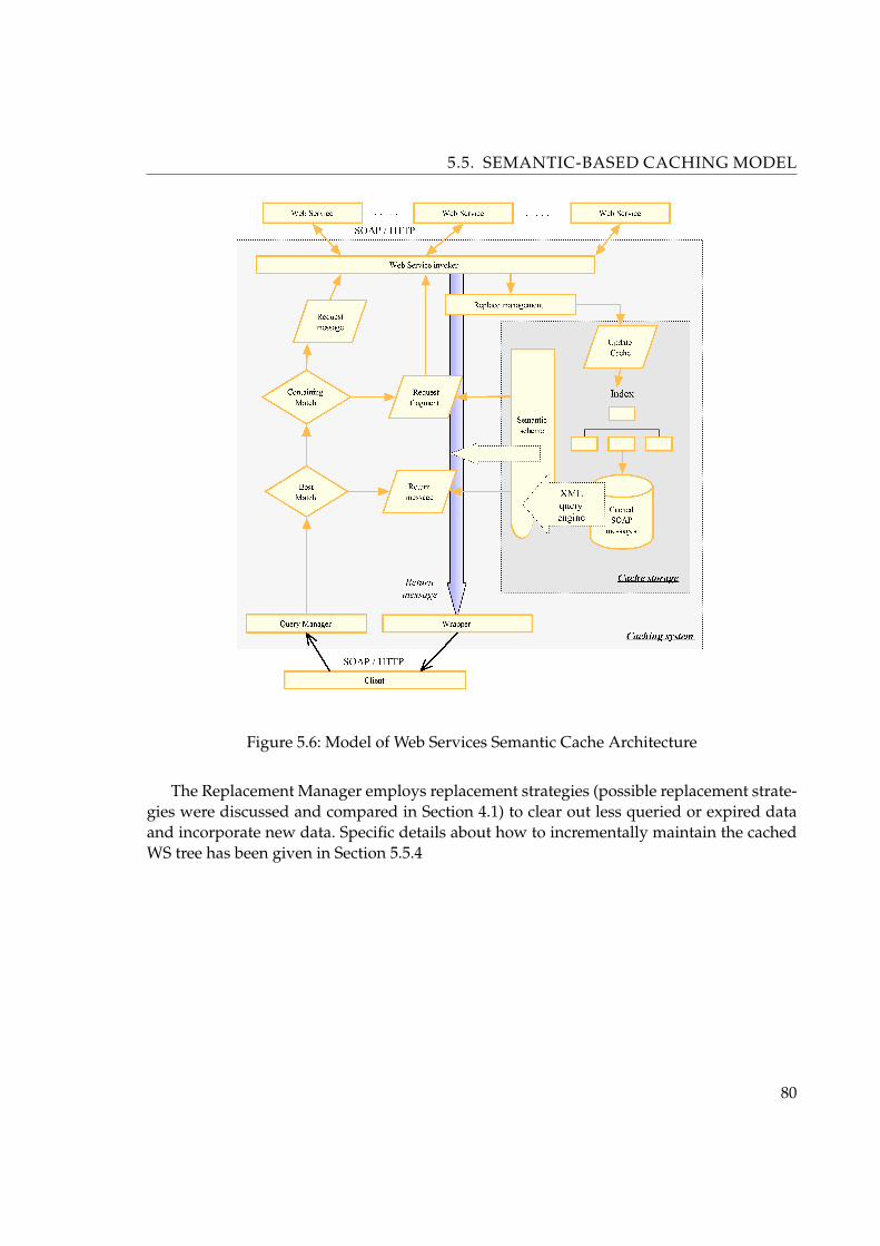
5.5. SEMANTIC-BASED CACHING MODEL
Figure 5.6: Model of Web Services Semantic Cache Architecture
The Replacement Manager employs replacement strategies (possible replacement strate-gies were discussed and compared in Section 4.1) to clear out less queried or expired dataand incorporate new data. Specific details about how to incrementally maintain the cachedWS tree has been given in Section 5.5.4
80

Chapter 6
Semantic-based Cache for Web Services
In this chapter I will describe the implementation and evaluation of semantic-based cachefor Web Services (SCWS ). At first I will present the used example of Web Service and de-scribe SOAP messages used by this Web Service. Next I will describe basic parts of this cacheand demonstrate possible examples how cache can take advantage of knowledge in seman-tic of requested Web Service. At the end of this chapter I will present performance results ofthis cache with comparing to cache without semantic knowledge.
The proposed cache model has been implemented in the SVOD portal to measure im-provement of this system. Detailed information about SVOD portal is described in Sec-tion 7.1
6.1 Example Used
In project SVOD1 [91] we offer a number of SOAP-based Web Services which provide accessin to a huge database of National Cancer Registry of Czech Republic [87]. As a example inthis section I will use subset of offered statistic functions of portal SVOD. It is the “Timedevelopment of incidence and mortality” Web Service which is a relevant function of thisportal.
As described in Section 2.4.2, the SOAP has four message exchange patterns definedwithin the WSDL specification: request/response, solicit/response, one-way, and notifica-tion. In implementation of SCWS will be used only request/response message exchangepattern, because it is the only message exchange pattern suitable for caching. This kind ofoperations expects one SOAP message as input and generates one output SOAP message.In SCWS prototype is implement the SOAP 1.1 binding, which is defined in the WSDL 1.1specification as the most commonly used binding.
In the area of Web Services, no such standardized declarative language exists. Useddeclarative language for the extension of WSDL documents with information about caching-relevant semantics is able to apply semantic caching to Web Services. I will now describe indetail basic parts of the WSDL document of SVOD service (see Appendix C where is whole
1. Web portal for information on cancer epidemiology http://www.svod.cz
81

6.2. IMPLEMENTATION DETAILS
<SOAP-ENV:Envelopexmlns:SOAP-ENV="http://schemas.xmlsoap.org/soap/envelope/"xmlns:SOAP-ENC="http://schemas.xmlsoap.org/soap/encoding/"xmlns:xsi="http://www.w3.org/2001/XMLSchema-instance"xmlns:xsd="http://www.w3.org/2001/XMLSchema">
<SOAP-ENV:Body><m:get_incmor xmlns:m="urn:SVOD"SOAP-ENV:encodingStyle="http://schemas.xmlsoap.org/soap/encoding/">
<diag xsi:type="xsd:string">C43</diag><stage xsi:type="xsd:string">I+II+III+IV+X</stage><period_from xsi:type="xsd:integer">1977</period_from><period_to xsi:type="xsd:integer">2003</period_to>
</m:get_incmor></SOAP-ENV:Body>
</SOAP-ENV:Envelope>
Example 6.1.1: Example of SOAP Request to SVOD portal
extended WSDL document). Example 6.2.1 shows a fragment of a WSDL document definingthe port type of the SVOD service (SVODPortType) having one operation (get_incmor).This operation expects an get_incmorRequestmessage as input and returned an get_incmorResponsemessage as an output document. These messages are defined above the portType element.These messages are composed from several parts and elements. As is shown in the Exam-ple 6.2.1, the request message has only one part of type get_incmorRequest and the re-sponse message has only one part of type ArrayOfData. These types are defined usingXML Schema [93] in another fragment of the WSDL document, which is shown in Exam-ple 6.2.2.
6.2 Implementation details
The main issue is necessity to instruct the SCWS cache which Web Services can be cachedand how long it can stay in the cache memory. Because there is not any features of transportprotocol to bring any implicit caching knowledge about Web Services, let’s assume that thisknowledge is specified by providers of Web Services.
Proper place for this knowledge is WSDL description file of Web Service. This descriptionfile can be extended with informations about caching-relevant semantics of offered WebService. XML schema for this extension is included in Appendix B.
Because cache memory space is a limited resource, the cache may have some mechanismsto make free memory by removing some unused memory places. In Section 4.1 I have de-scribed comprehensive list of possible replacement strategies. After experiments with possi-ble replacement algorithms (see Section 4.2), I implemented in SCWS possible modificationof FIFO and Greedy Dual Size replacement algorithm (GDSWS ). In GDSWS algorithm I took
82

6.2. IMPLEMENTATION DETAILS
<SOAP-ENV:EnvelopeSOAP-ENV:encodingStyle="http://schemas.xmlsoap.org/soap/encoding/"xmlns:SOAP-ENV="http://schemas.xmlsoap.org/soap/envelope/"xmlns:xsd="http://www.w3.org/2001/XMLSchema"xmlns:xsi="http://www.w3.org/2001/XMLSchema-instance"xmlns:SOAP-ENC="http://schemas.xmlsoap.org/soap/encoding/"xmlns:tns="urn:SVOD">
<SOAP-ENV:Body><get_incmorResponse>
<return xsi:type="SOAP-ENC:Array"SOAP-ENC:arrayType="tns:Data[27]">
<item xsi:type="tns:Data"><year xsi:type="xsd:integer">1977</year><incidence xsi:type="xsd:real">4.87509621707</incidence><mortality xsi:type="xsd:real">0.440520742507</mortality><sample_size_incidencexsi:type="xsd:integer">498</sample_size_incidence><sample_size_mortalityxsi:type="xsd:integer">45</sample_size_mortality>
</item><!--...other items...-->
</return></get_incmorResponse>
</SOAP-ENV:Body></SOAP-ENV:Envelope>
Example 6.1.2: Example of SOAP Response from SVOD portal
in account the fact, that a XML message m stored in the cache memory can only partiallyfulfil the request for XML message q.
Architecture of this replacement algorithm is based on two queues which are in the samecache memory. The first queue (Q1) is simply organized using a FIFO strategy. Every XMLmessage which is requested for the first time is inserted into queue Q1. If an XML messageis requested for a second time while it is still contained in Q1, the object is considered as ahot spot and is moved to the other queue Qm which is organized using the GDSWS strat-egy. Every time an XML message contained in Qm is requested, the corresponding entry ismoved to the top of the queue. Objects reaching the tail of Q1 or Qm are removed if memoryis required for new objects. Which queue is selected for deletion depends on the proportionP size of Q1 to Qm. In implemented cache is used proportion:
P =maxsize(Q1)maxsize(Qm)
= 1
The replacement strategy determines which message will be inserted into cache memoryand how long it will stay in cache memory. There are also other legal issues affecting this
83

6.2. IMPLEMENTATION DETAILS
InitializeL ⇐ 0
for each request to a message q doif q can be answered from cache then
if q is answered from one XML message m thenif m 6∈ Qm then
bring m into Qm
end ifH(q) ⇐ L + n ∗ latency(q) ∗ size(q)
size(m)
elsefor each message mi answered q do
if mi 6∈ Qm thenbring mi into Qm
end ifH(mi) ⇐ L + n ∗ size(q)
size(mi)
end forend if
elsewhile there is not enough free space in the cache do
if size(Q1)size(Qm) > P thenremove m from bottom of Q1
elseL ⇐ min(H(m) | m is in the Qm )remove m such that H(m) value
end ifend whilebring q on top of Q1
end ifend for
Q1, Qm - cache memory queuesP - proportion of queueslatency(m) = downloading latency, size(m) = message size, n = reference count
Algorithm 6.2.1: Modified GDS Algorithm for SCWS
decision [69]. The SCWS is designed as transparent cache for end users and other Web Ser-vices. For the client angle of view responses from the cache look like responses generatedby the origin Web Service itself. There are a lot of other problems related to caches, e.g., is itallowed to cache the responses from a pay or user-specify services? Therefore, SCWS givesto providers possibility to control distribution and cache consistency using a SOAP header
84

6.2. IMPLEMENTATION DETAILS
<message name="get_incmorRequest"><part name="diag" type="xsd:string"/><part name="stage" type="xsd:string"/><part name="period_from" type="xsd:integer"/><part name="period_to" type="xsd:integer"/>
</message><message name="get_incmorResponse">
<part name="return" type="typens:ArrayOfData"/></message><portType name="SVODPortType">
<operation name="get_incmor"><input message="tns:get_incmorRequest"/><output message="tns:get_incmorResponse"/><ChHandleHeader>
<Cacheable>true</Cacheable><CacheConsistency>
<TTL>86400</TTL></CacheConsistency>
</ChHandleHeader></operation>
</portType>
Example 6.2.1: Messages and Port Types of SVOD
extension. In case of there is no consistency information, SCWS won ’t cache a response aspostulated by [88] and [69]. Web Service providers can also explicitly forbid caching.
There are several techniques described in the literature offering weak or strong cacheconsistency guarantees. The most commonly used weak consistency techniques are client-driven and easy to handle: time-to-live (TTL) and expiry-time [75]. Strong consistency tech-niques, e.g.,server invalidation or lease-based techniques [75], [81], are typically server-driven and are more complex. As already mentioned, these techniques can only be appliedin a reasonable way if SCWS is used as a reverse-proxy or an edge cache. Using these tech-niques, SCWS can even handle highly dynamic Web services. Since cache consistency mech-anisms are not the focus of this work and it is not required in experiments, we simply assumeonly TTL extension.
In our case, if a provider allows caching, it must explicitly state some cache consistencyinformation. Prototype use Cacheable element to allows caching of the message and TTLelement which states that the response is fresh for at least the given duration (24 hours).After this duration, the cached version of the response must be removed from the cachememory (See Example 6.2.1).
Using a cache requires a large amount of memory to be able to serve lots of clients. Disksare considerably larger and cheaper than memory, it is obviously a good idea to use themfor the storage of cached messages. The simplest way is to keep only indexes in memory
85
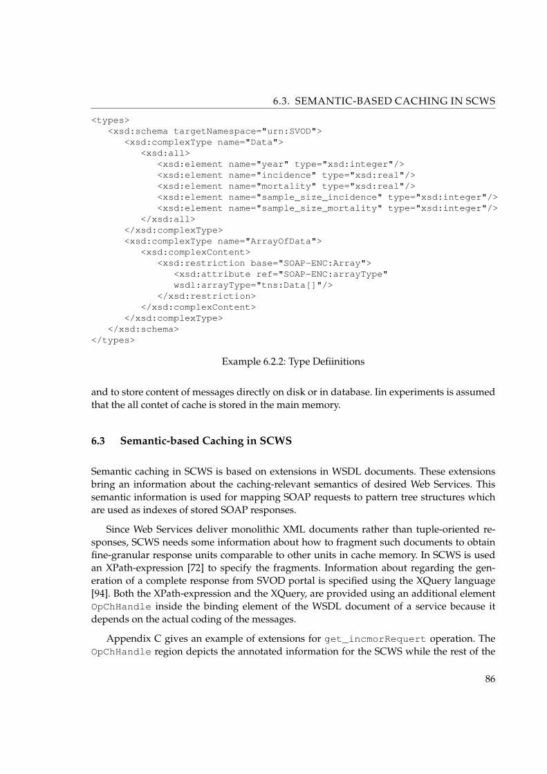
6.3. SEMANTIC-BASED CACHING IN SCWS
<types><xsd:schema targetNamespace="urn:SVOD">
<xsd:complexType name="Data"><xsd:all>
<xsd:element name="year" type="xsd:integer"/><xsd:element name="incidence" type="xsd:real"/><xsd:element name="mortality" type="xsd:real"/><xsd:element name="sample_size_incidence" type="xsd:integer"/><xsd:element name="sample_size_mortality" type="xsd:integer"/>
</xsd:all></xsd:complexType><xsd:complexType name="ArrayOfData">
<xsd:complexContent><xsd:restriction base="SOAP-ENC:Array">
<xsd:attribute ref="SOAP-ENC:arrayType"wsdl:arrayType="tns:Data[]"/>
</xsd:restriction></xsd:complexContent>
</xsd:complexType></xsd:schema>
</types>
Example 6.2.2: Type Defiinitions
and to store content of messages directly on disk or in database. Iin experiments is assumedthat the all contet of cache is stored in the main memory.
6.3 Semantic-based Caching in SCWS
Semantic caching in SCWS is based on extensions in WSDL documents. These extensionsbring an information about the caching-relevant semantics of desired Web Services. Thissemantic information is used for mapping SOAP requests to pattern tree structures whichare used as indexes of stored SOAP responses.
Since Web Services deliver monolithic XML documents rather than tuple-oriented re-sponses, SCWS needs some information about how to fragment such documents to obtainfine-granular response units comparable to other units in cache memory. In SCWS is usedan XPath-expression [72] to specify the fragments. Information about regarding the gen-eration of a complete response from SVOD portal is specified using the XQuery language[94]. Both the XPath-expression and the XQuery, are provided using an additional elementOpChHandle inside the binding element of the WSDL document of a service because itdepends on the actual coding of the messages.
Appendix C gives an example of extensions for get_incmorRequert operation. TheOpChHandle region depicts the annotated information for the SCWS while the rest of the
86

6.3. SEMANTIC-BASED CACHING IN SCWS
document constitutes a standard SOAP binding. Referring to SVOD example, we are inter-ested in the items (years, count, incidence, mortality) contained in a response document ofused service. The XPath-expression shown inside the fragmentatXPath element in Ap-pendix C can be used to fragment a response document accordingly. This XPath-expressioncan be figured out by examination of the type definition part of the service’s WSDL docu-ment (see Example 6.2.2) and of an example response of the service (see Example 6.1.2).
The XQuery to reassemble a response is shown in the example inside the rXQuery ele-ment. The macros @Output_Items@ (represent exactly the fragments) and @Count_Output_Items@(represents number of fragments) are expanded by the SCWS before evaluating the XQueryin to a complete response document.
I will explain the extensions using get_incmor example. The original type definitionis get_incmorRequert, which is the request type of used service (See Example 6.1.1).Currently, we assume that if there are several parameters defined in a request, i.e., diag,stage, period_from and period_to, they are combined by an AND operator. Thus,the request shown in Example 6.1.1 means that we are require the time development ofincidence and mortality statistics for diagnose C43 (Malignant melanoma of skin) from year1977 to year 2003. Additionally, we assume that if there are several elements inside an array,the elements are logically ANDed together, too.
WSDL extended every parameter of the request using one or more ChHandle elements.It is necessary to specify some context information because a message can be used for sev-eral operations having different semantics. Also, if another binding is used, the coding ofthe message might be different, requiring some modifications inside the ChHandle element.Thus, the context information given by the attributes of ChHandle defines when to use theinformation inside the ChHandle element. The information shown in Appendix C can onlybe used to analyze an input message for the get_incmor operation. A StringParameterelement defines that the parameter is of type string and IntegerParameter element de-fines that the parameter is of type integer. The content of this element gives more detailedinformation about how to handle this parameter. Each of these elements contains furtherinformation (e.g., operators) depending on the parameter type.
Looking at the Appendix C, we observe that the diag parameter is mandatory (requiredelement). If a parameter is optional, a default value of the parameter that is used in caseof absence of the parameter in a request must be specified using a default element. ThefragmentXPath element specifies how to extract the information from result fragmentsthat correspond to this parameter (compare Example 6.1.2). For example, if we ask for statis-tics for concrete years, the fragmentXPath can be used to find the particular years in theresult fragments. If, as in our example, an XPath is specified, the cache can inspect the frag-ments to look up the statistics for actual year. This information can be used to filter all frag-ments contained in a semantic region. If there is no XPath specified, the cache is not able todo such filtering because it is constrained to the information obtained from the request.
87

6.3. SEMANTIC-BASED CACHING IN SCWS
The element implicitOperator defines the operator of the parameter. Currently, pro-totype support the following operators (for appropriate parameter types): greater, GE(greater than or equal to), smaller, SE (smaller than or equal to), equals, contains,contains whole world, starts with, and ends with. In example is used the op-erator SE which is a compare operator and contains whole world which is containsoperator. Contains operator looks for whole word only occurrences of the given patternin a string, i.e., “C50,D05” does not contain “C5” as a whole world, but it contains twostrings “C50” AND “D05”. The comparison of strings is case insensitive as defined by thecaseSensitive element.
The next parameter is stage. This is not mandatory string parameter and it is a case in-sensitive “equals”. There is no fragmentXPath defined because in the response documentof our Web Service no explicit information about level of the stage ( I+II+III+IV+X, I,II, I+II, III, IV, III+IV, X ) result is contained. As this information is contained in therequest and therefore is stored as part of the WS tree.
Matching
Using these extensions cache is now able to understand the caching-relevant semanticsof requests and responses. I will now describe how this information is used for caching. Thecontrol flow of SCWS is shown in Figure 6.1. First of all, a SOAP request R is mapped to apattern P as described above. In used example we have this pattern:
/get_incmor[diag="C50,D05"][stage="I+II"][period_from>=1980][period_to>=1990]
On base of WSDL extension we know that diag element has the separator “,” and thestage element is consist from tree structure and is defined as (I ⊆ I + II) ∧ (II ⊆ I + II).Therefore, we can transform this pattern to this form:
/get_incmor[diag="C50" or diag="D05" or diag="C50,D05"][stage="I" or stage="II" or stage="I+II"][period_from >= 1980][period_to >= 1990]
This pattern is before execution transfered into this XQuery query:
let $a := /cachefor $p in $a/get_incmorwhere (
fn:starts-with($p/diag,"C50")or fn:starts-with($p/diag,"D05")or fn:starts-with($p/diag,"C50,D05"))
and ((fn:contains($p/stage,"I")or fn:contains($p/stage,"II")or fn:contains($p/stage,"I+II"))
and $p/period_from <= 1980and $p/period_to >= 1990
88

6.3. SEMANTIC-BASED CACHING IN SCWS
)return <message>{string($p/@id)}</message>
Figure 6.1: Flow Chart of the Semantic Based Caching Process
In cache are used matche types (compare with [71] and [84]) as shown in Figure 6.2.The best match type for a query and the cache is the exact match. In thic case we simplyreturn the cached SOAP response. The next best match type is a containing match becausewe only have to apply filter on SOAP response to aliminate the not-required items fromSOAP response. I’t possible then the query will be find in more SOAP responses, which cananswer query q. In this case we’ll select the message, with the biggest value of H(m). In casethat none cached message can answer query, but some of them can partucullary answerwhole query we’ll select the messages, with the biggest value of H(m) to create desiredSOAP response message.We’ll extract relevant regions from cached messages and join theseregions together to create desired SOAP response message.
Other matches required interaction with called Web Service. In these cases we need toextract regions from cached messages and establish which region is missed. In this case wehave two options. In the first we create from missed region the SOAP request and we’ll sendit to the Web Service to get the missed region. Afther that we join all regions together tocreate desired SOAP response message and obtained missed SOAP rensponse we’ll insertinto cache memory. The second possibility is send whole SOAP request to the Web Service,return to user obtained response and store this SOAP response message into cache memory.
89
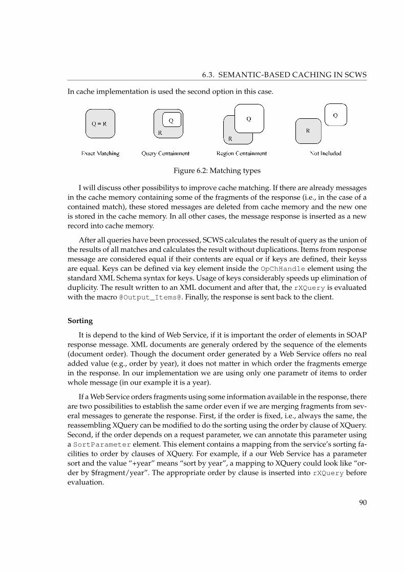
6.3. SEMANTIC-BASED CACHING IN SCWS
In cache implementation is used the second option in this case.
Figure 6.2: Matching types
I will discuss other possibilitys to improve cache matching. If there are already messagesin the cache memory containing some of the fragments of the response (i.e., in the case of acontained match), these stored messages are deleted from cache memory and the new oneis stored in the cache memory. In all other cases, the message response is inserted as a newrecord into cache memory.
After all queries have been processed, SCWS calculates the result of query as the union ofthe results of all matches and calculates the result without duplications. Items from responsemessage are considered equal if their contents are equal or if keys are defined, their keyssare equal. Keys can be defined via key element inside the OpChHandle element using thestandard XML Schema syntax for keys. Usage of keys considerably speeds up elimination ofduplicity. The result written to an XML document and after that, the rXQuery is evaluatedwith the macro @Output_Items@. Finally, the response is sent back to the client.
Sorting
It is depend to the kind of Web Service, if it is important the order of elements in SOAPresponse message. XML documents are generaly ordered by the sequence of the elements(document order). Though the document order generated by a Web Service offers no realadded value (e.g., order by year), it does not matter in which order the fragments emergein the response. In our implementation we are using only one parametr of items to orderwhole message (in our example it is a year).
If a Web Service orders fragments using some information available in the response, thereare two possibilities to establish the same order even if we are merging fragments from sev-eral messages to generate the response. First, if the order is fixed, i.e., always the same, thereassembling XQuery can be modified to do the sorting using the order by clause of XQuery.Second, if the order depends on a request parameter, we can annotate this parameter usinga SortParameter element. This element contains a mapping from the service’s sorting fa-cilities to order by clauses of XQuery. For example, if a our Web Service has a parametersort and the value “+year” means “sort by year”, a mapping to XQuery could look like “or-der by $fragment/year”. The appropriate order by clause is inserted into rXQuery beforeevaluation.
90

6.4. PERFORMANCE EVALUATION
Generalization
Another enhancement of our semantic caching scheme is the usage of generalization forbetter decisions on the query containment subsumption problem. Our SCWS supports twodifferent types of generalization. The first is tree-structured containment relations for valuesof parameters can be defined. In our service we have a parameter defining the stage ofdesired statistics, we are able to annotate this parameter to fulfil these conditions:
(I ⊆ I+II) ∧ (II ⊆ I+II)(III ⊆ III+IV) ∧ (IV ⊆ III+IV)
(I+II ⊆ I+II+II+IV+X) ∧ (III+IV ⊆ I+II+II+IV+X) ∧ (X ⊆ I+II+II+IV+X)
This information is used during match type computation and for filtering.
The second type of generalization can be also seen in used example. There are parametersperiod_from and period_to that influences the number of years in the response. Sincethe used source response simply contain some extra items, it is possible to define an XQueryfilter to transform the wider rensponse to the shorter desired response by removing theunwanted elements in SOAP response. This information is also used during match typecomputation and region filtering.
6.4 Performance Evaluation
I implemented a prototype of the Web Service Cache build in Java environment. Cache hasbeen placed on standard computer with Pentium4 with 3 GHz nad 1GB main memory, op-erating system SUSE Linux 9.3 and has been connected with web portal by 100 Mbit/s net-work adapter. As a runtime was used Java SDK ver. 1.4.2, XQEngine2 ver. 0.69 as Xqueryinterpreter, Xerces3 ver. 1.4.4 as XML parser and Axis4 v. 1.4 as implementation of SOAPprotocol. The web portal SVOD is runing on on Pentium 4, 3.2 GHz, 1.5GB main memory,operating system SUSE Linux 9.3, Apache/2.0.49, PHP5 ver. 4.3.4, MySQL6 ver. 4.1.21 andas implementation of SOAP is used NuSOAP7 ver. 0.6.3.
The first scenario is related to the browsing scenario [92] with some necessery modifi-cations to adjust the benchmark to the context of SCWS cache. The benchmark scenario ismodel on the SOAP interface of SVOD portal. I used in benchmarks following SOAP inter-faces of epidemiological analyses: “incidence and mortality”, “regional overviews”, “time
2. http://xqengine.sourceforge.net/3. http://xerces.apache.org/xerces-j/4. http://ws.apache.org/axis/5. http://www.php.net/6. http://www.mysql.com/7. http://dietrich.ganx4.com/nusoap/
91

6.4. PERFORMANCE EVALUATION
trends”, “clinical stages” and “age of patients”).
Figure 6.3: Request Size Distribution
For experiments the TTL of responses was set to 60 minutes. The data volume of allresponses was about 28.3 MB and every execution of a trace lasted for 300 minutes. I per-formed these experiments with longer running time, but these results were very similar toresults which we got from 300 min. experiments.
The maximum size for responses to be cached was set to 20 kB. Larger responses werefetched from the remote Web service and forwarded to the client without caching. I con-ducted the experiments using three different cache sizes: small (10% of the data volume ofthe unique-trace), standard (20%), and large (30%). In used example the data volume on theunique-trace was 32 MB and cache sizes was set up to: small: 3200 kB; standard: 6500 kB;large: 9800 kB. The cache was warmed up by running every trace twice and measuring thesecond one, although there are only minor differences between the two runs.
Figure 6.4: Match Distribution Varying Cache Size
92

6.4. PERFORMANCE EVALUATION
The main goal of the SCWS is to improve scalability and performance of Web Services.Figure 6.4 shows that already the smallest semantic cache is able to answer 43.7% (ex-act matches +containing matches) of all requests using data stored in the cache, reducingprocessing demands on the central servers significantly. A traditional non-semantic cacheachieves much smaller hit rates (27.9%). The bigger the caches are, the better the hit ratesbecome even though the increase rate is not linear with the cache size increment. This is dueto the fact that already the standard cache size is large enough to cache most of the hot spotresponses. The only advantage of a larger cache is that it is able to additionally store someof the less frequently requested responses. SCWS benefits more from a larger cache thannon-semantic cache because semantic cache can exploit the semantics of the requests.
Figure 6.5: Transfer Volume Varying Cache Size
Figure 6.5 demonstrates the reduction of bandwidth consumption. Running the tracewithout cache results in the transfer of 28.3 MB across the network. The smallest semanticcache reduces the transfer volume by approximately 25%, the standard semantic cache byapproximately 42%. The large semantic cache reduces the transfer volume even more, butthe difference is not linear with the cache size increment due again to the reasons above.On average, the transfer volume of non-semantic cache is more than 17% larger than that ofSCWS.
Figure 6.6 shows results for varying time-to-live periods. The longer the TTL period is,the more effective the caches are. Depending on the TTL, SCWS performs about 46% to 55%better than non-semantic cache.
The average distribution of the requests of used traces (see Figure 6.3) shows that largeresponses are accessed very infrequently. Thus, the caching of large responses is not benefi-cial in the presented scenario. Both non-semantic cache and SCWS suffer equally from largermaximum cached response sizes.
93

6.4. PERFORMANCE EVALUATION
Figure 6.6: Match Distribution Varying TTL
Figure 6.7: Match Distribution Varying Slot Size
Next I test the caching methods on objects of sizes uniformly distributed between 1kBand 20kB. Let’s assume that there are 10000 different objects, with one object of each sizei. The objects were chosen to have a Zipf-like frequency distribution [83]. The reason thata Zipf-like distribution has been chosen was to study the effect of frequency skew on thecaching methods. Thus the frequency of object i is proportional to 1/PI(i)θ, where θ is theZipf parameter, and PI is a permutation vector. By varying PI I can affect the relationshipbetween the size and frequency.
Figure 6.8 and Figure 6.9 show the results for varying value of the theta (θ) parameterof the Zipf distribution for the SCWS respectively for a non-semantic cache. The larger thevalue of theta is, the more distinct the hot spots of a trace are. In terms of distribution ofthe requests of used traces (See Figure 6.3) I used complete negative correlation betweenobject size and frequency. The value of PI(i) is chosen to be equal to i, so that the i-thobject has size i and relative frequency 1/iθ. Thus the largest object has the lowest frequency.
94
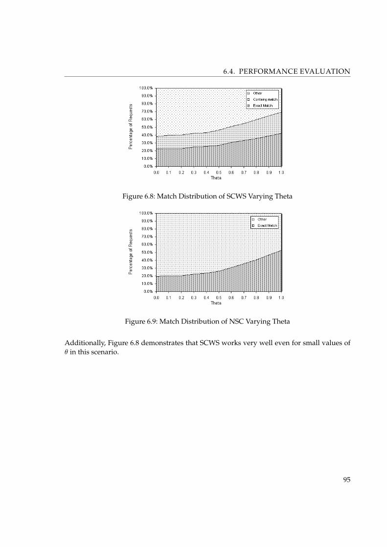
6.4. PERFORMANCE EVALUATION
Figure 6.8: Match Distribution of SCWS Varying Theta
Figure 6.9: Match Distribution of NSC Varying Theta
Additionally, Figure 6.8 demonstrates that SCWS works very well even for small values ofθ in this scenario.
95

Chapter 7
Case studies
In this chapter I will introduce several projects which have been used for implementationof proposed cache. These projects focused on various fields of interests (medicine, environ-ment, e-learning...) are describet in more details below.
7.1 SVOD - analysis of tumor epidemiology of the Czech Republic
Cancer epidemiology can be regarded as one of the most important and most frequentlyanalysed topic in the field of human risk assessment. It is not only due to remarkable pub-lic concern about growing population risk, cancer incidence and mortality is evident andclearly reachable endpoint for risk assessment studies. We can enter this problem from theviewpoint of risk factors as agents initiating carcinogenesis, but epidemiological parameterscan retrospectively indicate hazardous impact on population of a large scale. The bioindi-cation from epidemiological data of course requires sufficient data sources. It means repre-sentative longterm profiles of incidence and mortality and a very good awareness of mostimportant risk factors.
All analyses require easily available large data sets that are itself very expensive andtypically not directly available – epidemiological cancer registries. In addition to it, we mustaggregate cancer data with demographic data in order to attain for example age-specificprofiles of incidence. That is why there is growing interest of many professional groups(health care managers, environmental experts, risk assessors) in accessibility of these data.In our experience however, the demand for data cannot be easily fulfilled by blind databasesof primary population data. The analyses are very time-consuming and finally, the outputsmight be ambiguous and not safe to be communicated with public. Therefore, we developedprofessional web portal that offers automatically generated and verified epidemiologicalanalyses on cancer incidence and mortality in Czech Republic. These analysis are computedfrom National Oncologic Register (NOR) which is managed by Institute of Health Informa-tion and Statistics (UZIS CR). It offers validated epidemiological data from the years 1977 -2003. This represents a unique representative data set at least in European region (currentlythere is about 1.6 million records).
The whole web portal is placed on two servers (See Figure 7.1). The first is database
96
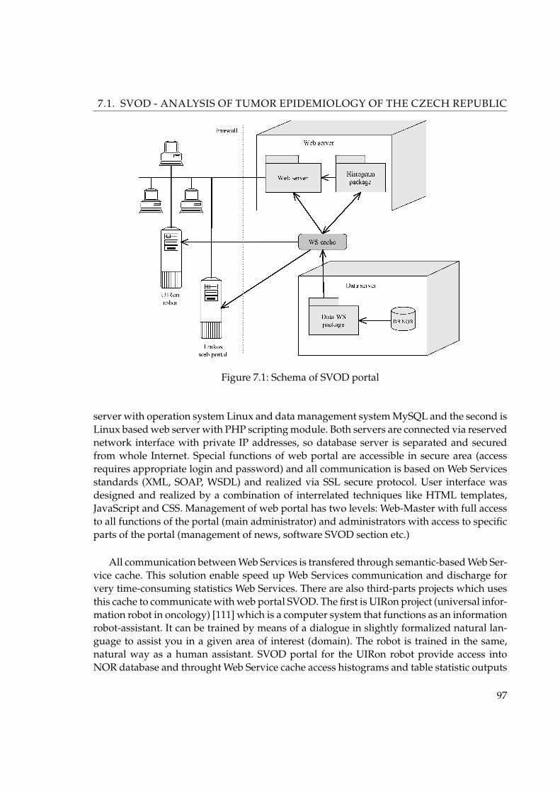
7.1. SVOD - ANALYSIS OF TUMOR EPIDEMIOLOGY OF THE CZECH REPUBLIC
Figure 7.1: Schema of SVOD portal
server with operation system Linux and data management system MySQL and the second isLinux based web server with PHP scripting module. Both servers are connected via reservednetwork interface with private IP addresses, so database server is separated and securedfrom whole Internet. Special functions of web portal are accessible in secure area (accessrequires appropriate login and password) and all communication is based on Web Servicesstandards (XML, SOAP, WSDL) and realized via SSL secure protocol. User interface wasdesigned and realized by a combination of interrelated techniques like HTML templates,JavaScript and CSS. Management of web portal has two levels: Web-Master with full accessto all functions of the portal (main administrator) and administrators with access to specificparts of the portal (management of news, software SVOD section etc.)
All communication between Web Services is transfered through semantic-based Web Ser-vice cache. This solution enable speed up Web Services communication and discharge forvery time-consuming statistics Web Services. There are also third-parts projects which usesthis cache to communicate with web portal SVOD. The first is UIRon project (universal infor-mation robot in oncology) [111] which is a computer system that functions as an informationrobot-assistant. It can be trained by means of a dialogue in slightly formalized natural lan-guage to assist you in a given area of interest (domain). The robot is trained in the same,natural way as a human assistant. SVOD portal for the UIRon robot provide access intoNOR database and throught Web Service cache access histograms and table statistic outputs
97

7.1. SVOD - ANALYSIS OF TUMOR EPIDEMIOLOGY OF THE CZECH REPUBLIC
Figure 7.2: Web portal SVOD
of tumor epidemiology. Next one is the web portal of Czech Oncology Society1 where theyprovide summary views of statistic oncology trends and uses histograms from web portalSVOD.
From the point of view of Web Services performance we can on grounds of our exper-iments enuciate, that using cache for Web Services we can save about 40% of trafic of WebServices responses and with using semantic-based cache we can save approximately 56% oftrafic of Web Services responses.
Ministry of Health Care Czech Republic supports development of Web portal SVOD.Research and developmental teams are granted by research project MZO 00209805 solvedin Masaryk Memorial Cancer Institute, Brno. Risk assessment analyses are supported by re-search project INCHEMBIOL, Ministry of Education Czech Republic project no. 0021622412.Web portal is accessible through the following address: http://www.svod.cz. The portal isdeveloped in Czech and English version. Related publication: [108] [109] [110].
1. http://www.linkos.cz
98
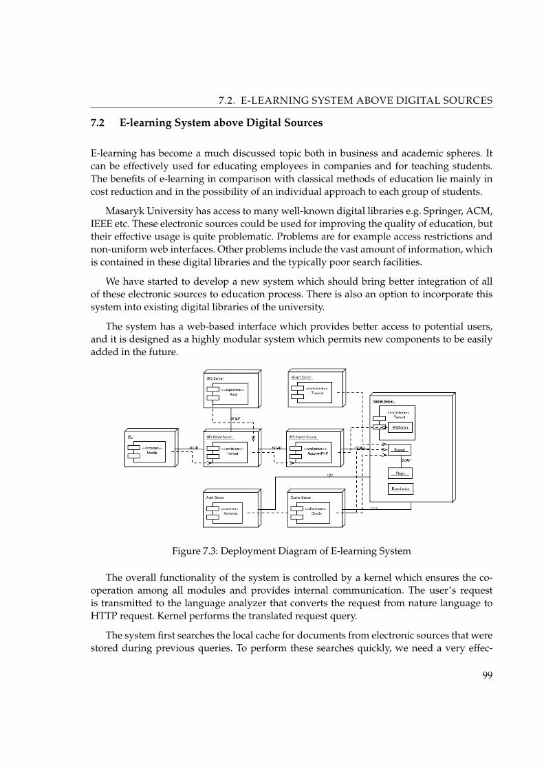
7.2. E-LEARNING SYSTEM ABOVE DIGITAL SOURCES
7.2 E-learning System above Digital Sources
E-learning has become a much discussed topic both in business and academic spheres. Itcan be effectively used for educating employees in companies and for teaching students.The benefits of e-learning in comparison with classical methods of education lie mainly incost reduction and in the possibility of an individual approach to each group of students.
Masaryk University has access to many well-known digital libraries e.g. Springer, ACM,IEEE etc. These electronic sources could be used for improving the quality of education, buttheir effective usage is quite problematic. Problems are for example access restrictions andnon-uniform web interfaces. Other problems include the vast amount of information, whichis contained in these digital libraries and the typically poor search facilities.
We have started to develop a new system which should bring better integration of allof these electronic sources to education process. There is also an option to incorporate thissystem into existing digital libraries of the university.
The system has a web-based interface which provides better access to potential users,and it is designed as a highly modular system which permits new components to be easilyadded in the future.
Figure 7.3: Deployment Diagram of E-learning System
The overall functionality of the system is controlled by a kernel which ensures the co-operation among all modules and provides internal communication. The user’s requestis transmitted to the language analyzer that converts the request from nature language toHTTP request. Kernel performs the translated request query.
The system first searches the local cache for documents from electronic sources that werestored during previous queries. To perform these searches quickly, we need a very effec-
99
7.2. E-LEARNING SYSTEM ABOVE DIGITAL SOURCES
tive indexing of documents. In the next phase of the project we will include an transparentsemantic-based web wervices proxy (see Chapter 6, “Semantic-based Cache for Web Ser-vices”) which will answer all of already requested queries from the WS client to the WSserver. The position WS cache is described on the Figure 7.3.
In the next step the system calls special plugins which are able to look in specific elec-tronic sources. The modular architecture of the system provides an easy way of adding newsources. We have to implement a simple plugin for each new source. The relevant docu-ments are returned to the user and stored in the cache and analyzed.
For each document the system collects and extracts meta information. Some of it comesfrom electronic sources like author name and abstract. Other information is automaticallyobtained from documents themselves. For example this kind of information also includesbibliography records.
The whole system is implemented in Java JSP/Servlets. System structure is based onthe Model View Controller2 architecture. The main part of the system: kernel contains fromcentral logic unit which control the functionality of the system. According to this conceptwe may simply add new components. The Kernel is implemented through Web Servicesframework Axis3.
The searching for the documents is dedicated to the searching plugins. Each plugin isspecific for the one digital source. The communication between plugin and server in man-aged by the SOAP protocol with specified form. This is why the plugins are do not dependon the programming language. The main target of the plugin is to obtain the requesteddocuments and meta-data. This can be in most cases simply done by the transformationof the digital source HTML page to the XHTML by JTidy4. In the next step the XHTML istransformed with the XSLT stylesheet to the XML from where are data mined by the XPathqueries.
The database cache serves for storing the documents and the metadata. Access to thedatabase is implemented by JDBC through JNDI Datasource. In the preliminary phase ofdevelopment we used pure Java database HSQLDB5 which is very useful for functionalitytesting. Nowadays we are testing several databases (Oracle, PostgreSQL and Firebird) forthe performance with blobs.
The Web Services client is based on Apache Axis WS framework. The client reads themetadata about digital sources from the multilingual RDF file. Most of the metadata arestored in Dublic Core6 standard. Thanks to SOAP communication between WS client andWS server we are able to set on the WS cache proxy which will dramatically improve the
2. http://en.wikipedia.org/wiki/MVC/3. http://ws.apache.org/axis/4. http://sourceforge.net/projects/jtidy/5. http://hsqldb.sourceforge.net/6. http://dublincore.org/
100

7.3. ENVIWEB - ENVIRONMENTAL WEB PORTAL
performance.
This projest is supported by the Czech National Program Information Society ’E-learningin the Semantic Web Context’, grant No. 1ET208050401. Related publication: [105] [106]
7.3 EnviWeb - environmental web portal
The EnviWeb web portal is primarily intended for experts, professional public, firms, gov-ernment and citizens. The main purpose of the EnviWeb is to provide public environmentalinformation and to enable free access to environmental information. For foreign users, whodo not understand the Czech language, there are English, German, Russian and Italian ver-sions of the EnviWeb. There is also a possibility of accessing the EnviWeb by hand-heldvendors (e.g. PalmPC).
Figure 7.4: Web portal EnviWeb
101

7.3. ENVIWEB - ENVIRONMENTAL WEB PORTAL
The EnviWeb portal contains a large amount of varied environmental information, whichare collected and verified by the group of environmental experts. Information are dividedinto several portal sections to cover particular elements of environment. The EnviWeb por-tal is composed of the following sections (see Figure 7.4): Water (water management andits aspects), Air (air protection problems, monitoring of pollution sources and their reduc-tion), Waste (waste management, demeaning pro-duction of waste and waste recycling),Chemicals (environmental aspects of chemi-cal treatment and their influence on the livingenvironment), Disasters (prevention of serious industrial accidents, reactions to accidentsand removing their conse-quences), Noise (noise problems, noise measurement, noise re-duction, modeling and abnormal noise prevention), Nature (problems concerning natureprotection), Soil (soil conservation and ecological agronomy), Forest (forest managementand forest protection), Geology (environmental aspects of geologic prospecting, extractionand rehabilitation), EIA (Environmental Impact Assessment), EMS (Environ-mental Man-agement Systems and Program EMAS of EU), IPPC (Integrated Pre-vention and PollutionControl), Misc. (this section contains articles, links, firms etc., which can’t be placed into thespecific sections or are universal in scope). The EnviWeb is like a crossroads to environmentsources in the Czech Republic. For this reason a huge catalogue of links to other special websites is maintained.
The portal EnviWeb was initiated and developed as a complex environmental web-portalof the Czech Internet. It is dedicated to provide comprehensive and up-to-date environmen-tal information and news to public. After two years it turned into a daily environmentalinformation source for hundreds of visitors who are professionals in the environment, en-terprise environ-mentalists, managers of companies providing services in the branch andproducing or selling products and technology for environmental protection and labor safety.The EnviWeb helps students of high school or university who are interested in the environ-mental protection, informs representatives and members of professional unions, employeesof public administration, organizers and participants in special events, editors and readersof professional publications. It acts as an information broker for environmental informationin the Czech Republic.
The portal is divided to several independent servers. They are web server, server withlegislation and news server (see Figure 7.5). All servers run operation system Linux and asdata management they use MySQL7 database engine. All servers comunicate through SOAPmessaging. In the middle of this communication is semantic-based Web Services cache toimprove responses from Web Services. Web Services are implemented in PHP by NuSOAP8
library and on the side of web server are used standard web server technologies as PHP,XHTML, CSS and JavaScript.
Distribution of servers and using cache in this web portal architecture is a key attribute toimprove performance and time responsibility for end user. Engaged cache is implemented as
7. http://www.mysql.com/8. http://dietrich.ganx4.com/nusoap/
102

7.4. WSRP4PHP - IMPLEMENTATION OF WSRP SPECIFICATION
Figure 7.5: Schema of EnviWeb
a PHP application and is build on Alternative PHP Cache9 (APC). Based on trafic statistic wecan say, that caching of Web Services save about 45% of trafic between servers. EnviWeb isapproximately daily visited by 1500 users and they retrieve daily about 9000 pages. Relatedpublications: [98] [99] [100] [101] [102] [103] [104]
7.4 WSRP4PHP - implementation of WSRP specification
Web Services for Remote Portals10 (WSRP) are visual, user-facing Web Services componentsthat plug-n-play with portals or other intermediary web applications that aggregate contentor applications from different sources. They are designed to enable businesses to providecontent or applications in a form that does not require any manual content or application-specific adaptation by consuming intermediary applications. As Web Services for RemotePortals include presentation, service providers determine how their content and applica-tions are visualized for end-users and to which degree adaptation, transcoding, translationetc may be allowed.
9. http://php.net/apc10. http://www.oasis-open.org/committees/wsrp/
103

7.4. WSRP4PHP - IMPLEMENTATION OF WSRP SPECIFICATION
Figure 7.6: Example of WSRP4PHP client
The WSRP services can be published into public or corporate service directories (UDDI)where they can easily be found by intermediary applications that want to display their con-tent. The Web application deployment vendors can wrap and adapt their middleware foruse in the WSRP-compliant services. Using WSRP, portals can easily integrate content andapplications from many internal and external content providers. The portal administratorsimply picks the desired services from a list and integrates them. No programmers are re-quired to tie new content and applications into the portal.
To accomplish these goals, the WSRP standard defines a Web Services interface descrip-tion using WSDL and all the semantics and behavior that Web Services and consuming ap-plications must comply with in order to be pluggable as well as the meta-information thathas to be provided when publishing WSRP services into UDDI directories. The standardallows WSRP services to be implemented in very different ways (as a Java/J2EE based WebService, a Web Service implemented on Microsoft’s .NET platform or a portlet published asa WSRP Service by a portal). The standard enables use of generic adapter code to plug inany WSRP service into intermediary applications rather than requiring specific proxy code.
The WSRP services are WSIA component services built on standard technologies includ-ing SOAP, UDDI, and WSDL. WSRP adds several context elements including user profile,information about the client device, locale and desired markup language passed to them inSOAP requests. A set of operations and contracts are defined that enable WSRP plug-n-play.
During my PhD. studies I was initiated the WSRP4PHP open source project11 to facili-tate quick adoption of the WSRP standard by content and application providers and portal
11. http://www.fi.muni.cz/~xkubasek/wsrp4php/
104

7.4. WSRP4PHP - IMPLEMENTATION OF WSRP SPECIFICATION
Figure 7.7: Possible locations of cache in WSRP4PHP framework
vendors. They can use WSRP4PHP as a platform for developing and hosting WSRP compli-ant Web Services. Aim of the project is implementation WSRP interface by specification ofOASIS in the PHP language. Main benefits of WSRP4PHP are simplicity of administrationof Web Services with WSRP interface, platform independent and offer framework for creat-ing Web Services with WSRP interface. I hope the WSRP4PHP project will get started broadadoption of the WSRP standard and result in a large number of cool WSRP services runningon free, open source software.
Design of WSRP Framework can be divided to two main parts. WSRP portal - the partwhich enable placement of Web Services. You can use it like a stand alone application (desk-top mode), where you can run remote WSRP services alike they are a web applications.The main way of use the WSRP portal is the portal mode, where you can build your ownweb portal from available WSRP services. The second part of WSRP framework is a WSRPportlet, the part which provide the tools for creating your own WSRP services.
There are essentially three places (and so three types of contents) in the WSRP architec-ture, where can be cached the result (see Figure 7.7): The first one (1) is on the WSRP serviceside and enable cache answers, which are sending to portal (the case, where more portals usethe same WSRP service); The second is on the WSRP portal side (2), where can be cachedanswer from WSRP services (the case, where more end-users need the same service); Thethird cache can be on the output from WSRP portal (3) (4), where can be stock final HTMLcodes (the case, where more end-users using the same page e.g. entering page of portal).
Proposed semantic-based Web Services cache is placed in points (1) and (2) in this project.By reason that WSRP4PHP is the first framework of implementatin WSRP in PHP languageand WSRP is not widely used yet, we can’t bring the measurement of performance of thissolution. Related publications: [114] [115].
105

Chapter 8
Conclusion and Future Work
The objective of this thesis was to describe and experimentally verify a suitable replacementalgorithms which are applicable to cache replacement policy in the area of caching of SOAPmessages and propose a model of semantic proxy cache for Web Services and create andverify the prototype of this cache.
In Chapter 4, “Caching” I give an exhaustive survey of cache replacement strategiesproposed for Web caches and also compared LRU, four frequency-based algorithms andfour GD-Size-based algorithms in terms of cache hit ratio, byte hit ratio and reduced la-tency in the environment of SOAP messages. This indicates the effectiveness for a proxycaching algorithm to improve the performance by taking more related factors into account.Results from this comparison show that GD-size based replacement algorithms are suitablefor caching of SOAP messages.
In Section 5.5 I presented a semantic proxy cache assigned to caching SOAP requests andresponses. For storing the SOAP messages I have used the tree index structure. The structureof this tree was build on pattern which was created from extended WSDL descriptions ofcached Web Services. This tree was used as an index for searching and accessing into cachememory and was built up from variables and values which were contained in SOAP requestmessages. This technique enabled to recognize if two SOAP requests represented the samecalling of function with the same values of variables.
Contribution of semantic caching with using the tree index structure is that cache is ableto answer not only cached SOAP responses, but also can return responses which can be puttogether from another’s stored responses. This semantic caching can recognize, if desiredanswer is contained in another stored message or if any part of response is contained in anystored message. It can also recognize if desired response can be constructed from any subsetof stored messages.
In Chapter 6, “Semantic-based Cache for Web Services” I introduced possible XML-based declarative language to extend WSDL documents with information about the caching-relevant semantics. I implemented the primary semantic cache and executed several perfor-mance experiments to discover useability of these solutions. I designed a modification ofGD-size replacement algorithm and I used it in the implementation of SCWS. I comparedproposed cache with and without semantic extensions and the results show that the seman-
106

8. CONCLUSION AND FUTURE WORK
tic can improve cache hit percentage ratio approximately about 65% of cache hits withoutsemantic.
For comparison I used the Web Services from SVOD web portal providing statistic epi-demiology data of cancer in Czech Republic. This huge database contain about 1.6 millionrecords of patients. Used statistic computations are very time-consuming and using trans-parent semantic cache is a solution how to improve the time responsibility of SVOD webportal for end user. In this thesis I also showed using this cache model in our other projectsfocused on various fields of interests (medicine, environment, e-learning...).
Furthermore, future work can test performance of other settings of SCWS. There areinteresting benchmarks to examine, e.g. comparing the performance of semantic cachingprototype with and without possibility of sorting, generalization or others improvements.The big challenge is to create the automated proxy cache with possibility to recognize thesemantic of a Web Service based e.g. on OWL-S. The proposed WSDL extension could bealso used with a modification to integrate additional semantic knowledge e.g. from OWLknowledge base.
107
Glossary
B
Binding A protocol and data format with which to invoke a Web Service. For example, aservice may have a SOAP binding, as well as a HTTP GET binding.
B2B ( business-to-business )
Between separate businesses. B2B is a handy term used to describe transactions, col-laborations or other interactions that span separate business entities. It is used to dis-tinguish these external interactions from those that occur within a single organization,and also from those that run from businesses to individuals (ie business-to-consumer,or B2C).
C
Cache A cache is a specialized form of computer memory to store recently-used informationin a place where it can be accessed extremely fast. In the case of Internet, “cache” iscommonly used in the context of “browser cache”. Cache is designed to speed up thecomputer by prioritizing its contents for quick access.
D
DBMS ( Database Management System )
It is sometimes just called a database manager, is a program that lets one or more com-puter users create and access data in a database. The DBMS manages user requests(and requests from other programs) so that users and other programs are free fromhaving to understand where the data is physically located on storage media and, in amulti-user system, who else may also be accessing the data.
DTD ( Document Type Definition )
Is one component inside an SGML or XML environment. It defines the syntactic rulesaccording to which a document can be composed. Using a DTD and an XML Pro-cessor, a document can be validated against the DTD, which means it can be testedwhether it conforms to a given DTD.
108

GLOSSARY
E
EJB ( Enterprise JavaBeans )
Software components for networked Java applications. Defined by the Enterprise Jav-aBeans specification, EJBs are the basic building blocks of software applications onthe J2EE platform, which has been the preferred choice for many enterprises whenbuilding large-scale, web-accessed applications.
H
HTTP ( HyperText Transfer Protocol )
The Web’s communication standard. Stabilized at HTTP/1.1, it defines the universalmechanism for exchanging application-level messages between Web devices. All webservices run over HTTP.
J
JDBC ( Java Database Connectivity )
Set of application programming interfaces (APIs) providing a standard to allow Javaapplets access to a database.
JMS ( Java Message Service )
Java-based messaging standard. Part of J2EE, JMS defines a vendor-neutral (but Java-specific) set of programming interfaces for interacting with asynchronous messagingsystems. Messages can contain XML documents, Java objects or other formats, andcan be sent either to a publish-subscribe list or to a message queue (the two mainforms of application messaging).
O
OWL ( Web Ontology Language )
Is a set of markup languages which are designed for use by applications that need toprocess the content of information instead of just presenting information to humans.OWL ontologies describe the hierarchical organization of ideas in a domain, in a way
109

GLOSSARY
that can be parsed and understood by software. OWL has more facilities for express-ing meaning and semantics than XML, RDF, and RDF-S, and thus OWL goes beyondthese languages in its ability to represent machine interpretable content on the Web.
OWL-S ( Ontology Web Language for Services )
he Ontology Web Language for Services (OWL-S) is a core set of markup languageconstructs for describing the properties and capabilities of Web services in unam-biguous, computer-interpretable form. OWL-S is based on ontologies of objects andconcepts defined using the Ontology Web Language (OWL) See also “OWL”.
R
RPC ( Remote Procedure Call )
A request for a software event sent over a network. An application issues an RPCwhen it wants to use a function running on another system in the same network. AnRPC request is synchronous, which means it requires an immediate response beforethe application can continue with its work, and it assumes software compatibility ateach end of the communication.
S
Service semantics The semantics of a service is the behavior expected when interactingwith the service. The semantics expresses a contract (not necessarily a legal contract)between the provider entity and the requester entity. It expresses the effect of invok-ing the service. A service semantics may be formally described in a machine readableform, identified but not formally defined, or informally defined via an out of bandagreement between the provider and the requester entity. See also “WS”.
SMTP ( Simple Mail Transfer Protocol )
A protocol used to send email on the Internet. SMTP is a set of rules regarding theinteraction between a program sending email and a program receiving email.
SOA ( Service-oriented architecture )
A set of components which can be invoked, and whose interface descriptions can bepublished and discovered. See also “”.
SOAP ( Simple Object Access Protocol )
110

GLOSSARY
Provides a way for applications to communicate with one another over the Internet,independent of platform. SOAP relies on XML to define the format of the informationand then adds the necessary HTTP headers to send it. See also “WS”.
SSL ( Secure Sockets Layer )
Security protocol for internet communications. SSL provides a mechanism to verifythe identity of an internet client and/or server, and to encrypt the messages sent be-tween them. Thus it can be used to provide authentication and confidentiality for webservices that run directly between a client and a server. It uses a public key infrastruc-ture (PKI) system based on digital certificates.
T
TTL ( Time To Live )
On an IP based network (such as TCP/IP), TTL is the number of hops an IP packetmay make across the network. As part of DNS, TTL indicates how long a DNS recordis valid. Caching algorithms may also incorporate a TTL value, in which case it isnormally the length of time something is to be cached before being discarded (orrefreshed). See also “WS”.
U
UDDI ( Universal Discovery, Description, and Integration )
A standard for publishing and finding businesses, Web sites, and Web Services. A UDDIdatabase can be private (within an organisation), or public (such as the one jointly runby IBM, Microsoft, and SAP). See also “WS”.
URI ( Uniform Resource Identifier )
The address of an Internet resource. A URI is the unique name used to access theresource. It is not necessarily a specific file location (it may be a call to an applicationor a database, for example), which is why it is preferred over the similar acronymURL (Uniform Resource Locator).
W
WS ( Web Service )
111

GLOSSARY
There are many things that might be called “Web Services” in the world at large.However, for the purpose of this Working Group and this architecture, and withoutprejudice toward other definitions, we will use the following definition:
A Web Service is a software system designed to support interoperable machine-to-machine interaction over a network. It has an interface described in a machine-processableformat (specifically WSDL). Other systems interact with the Web Service in a mannerprescribed by its description using SOAP-messages, typically conveyed using HTTPwith an XML serialization in conjunction with other Web-related standards. See also“SOAP”. See also “WSDL”. See also “UDDI”.
WSDL ( Web Services Description Language )
An XML- formatted language used to describe a Web Service’s capabilities as collec-tions of communication endpoints that can exchanging messages. See also “WS”.
WSRP ( Web Services for Remote Portlets )
Dynamic plug-ins for portal pages. Officially ratified as an OASIS standard in Septem-ber 2003, WSRP defines how to plug remote web services into the pages of onlineportals and other user-facing applications. This allows portal or application ownersto easily embed a web service from a third party into a section of a portal page (a’portlet’).
X
XHTML ( Extensible Hypertext Markup Language )
XHTML is a reformulation of HTML in XML. HTML is based on SGML and uses somefeatures of SGML which are not available in XML (most notably, markup minimiza-tion), and consequently HTML documents typically are not valid XML documents.XHTML redefines HTML as an XML DTD, and also gives some recommendationshow to use the markup in order to make XHTML compatible with older browsers,which only understand HTML.
XML ( Extensible Markup Language )
XML is a markup language for structuring arbitrary data. XML was designed to re-place HTML, which was deemed too restricted with its fixed set of elements and at-tributes.
XML Schema ( )
Is an XML Schema Language for XML. After XML’s success for B2B applications, itquickly became apparent that XML’s built-in XML Schema Language, the DTD, didnot meet the requirements of application developers. XML Schema has thus been
112
GLOSSARY
standardized by the W3C and extends DTD considerably, in particular with a typesystem supporting type derivation, and with a number of built-in simple types (suchas integer, float, date, and time). While XML Schema is much more powerful thanDTDs, it is also much more complex, but it is very likely that over time XML Schemawill replace DTDs. See also “XML Schema Language”. See also “DTD”.
XML Schema Language ( )
Is a method for specifying a Grammar or rules for a class of XML documents. Eventhough the XML standard itself already contains such an XML Schema Language (theDTD), this XML Schema Language has a number of shortcomings, most notably notype derivation, and almost no support for data types. See also “DTD”.
XPath ( XML Path Language )
Is a language for selecting parts of an XML document. While XPath is a full-fledgedexpression language which can be used for arithmetics, string functions and otherevaluations, in most cases it is regarded as a way to select parts of an XML documentby selecting nodes which match certain criteria. XPath can be used as a stand-alonelanguage, but in most cases it is embedded into host languages, the two most impor-tant host languages are XSLT and XML Schema. See also “XML Schema”.
XQuery ( XML Query )
XQuery is a specification for a query language that allows a user or programmer to ex-tract information from an Extensible Markup Language (XML) file or any collectionof data that can be XML-like. The syntax is intended to be easy to understand anduse. Using XQuery, it is possible to view a relational database table as an XML doc-ument. XQuery is an evolving specification under development by the World WideWeb Consortium (W3C) and has broad support from several major vendors includingIBM, Microsoft, and Oracle. See also “XPath”.
113

Bibliography
[1] McGovern, J. and Tyagi, S. and Stevens, M. and Mathew, S.: Java Web Services Archi-tecture, Morgan Kaufmann Publishers, 2003, . 2.1, 2.2.1
[2] Arsanjani, A.: How to Identify, Specify and Realize Services for your SOA (Part II andIII),, IBM, 2005, . 2.2.2
[3] Bass, L. and Clements, P. and Kazman, R.: Software Architecture in Practice, Addision-Wesley, 1997, ISBN: 0-321-15495-9. 2.1
[4] Malveau, R. and Mowbray, T.: Software Architecture: Basic Training, Prentice HallPTR, 2004, ISBN: 0-131-41227-2. 2.1.1
[5] Yourdon, E. and Constantine, L.: Structured Design, Prentice Hall, 1975, ISBN: 0-138-54471-9. 2.1.1
[6] Booch, G.: Object Oriented Design with Applications, Benjamin-Cummings Publish-ing, 1990, . 2.1.2
[7] Szyperski, C.: Component Software: Beyond Object-Oriented Programming,Addision-Wesley, 1998, . 2.1.3
[8] Slama, D. and Banke, K. and Krafzig, D.: Service Oriented Architecture: Inventory ofDistributed Computing Concepts, Prentice Hall PTR, 2004, . 2.1.4
[9] Bieber, G. and Carpenter, J. and Stevens, K.: Jini Technology Architectural Overview,Sun Microsystems, 2001, . 2.2.1
[10] Abrams, M. and R. Standridge, C. and Abdulla, G. and Williams, S. and Fox, E.:Caching proxies: Limitations and potentials., In Proceedings of the 4th InternationalWorld Wide Web Conference, 1995., . 4.1.1
[11] C. Aggarwai, C. and L. Wolf, J. and S. Yu, P.: Caching on the World Wide Web. , IEEETrans. Knowl. Data Eng. 11, 1 (Jan.), 1999, . 4.1.1
[12] Arlitt, M. and J. Fridedrich, R. and Y. Jin, T.: Performance evaluation of Web proxycache replacement policies., Tech. rep. HPL-98-97(R.1), Hewlett-Packard Company,Palo Alto, USA, 1996, . 4.1.3
[13] Arlitt, M. and Cherkasova, L. and Dilley, L. and J. Fridedrich, R. and Y. Jin, T.: Eval-uating content management techniques for Web proxy caches. , ACM SIGMETRICSPerform. Eval. Rev., 2000, . 4.1.2, 4.1.4
[14] Using Custom WebLogic JSP Tags (cache, process, repeat), BEA Systems, WebLogicserver 6.0 edition, 2000, . 3.2
114

[15] Berners-Lee, T. and T. Fielding, R. and Masinter, L.: Uniform Resource Identifiers(URI): Generic Syntax., Internet Engineering Task Force, Network Working Group,August 1998. IETF RFC 2396., . 3.2, 3.2.1
[16] Bahn, H. and Koh, K. and Min, S. and Noh, S.: Efficient replacement of nonuniformobjects in Web caches., IEEE Comput. 35, 2002, . 4.1.4
[17] A. Belady, L.: A study of replacement algorithms for a virtual-storage computer., IBMSystems Journal, 5(2):79–101, 1966., . 3.1.2
[18] Bolot, J. and Hoschka, P.: Performance engineering of the World Wide Web: Appli-cation to dimensioning and cache design. , In Proceedings of the 5-th InternationalWorld Wide Web Conference. Elsevier, Amsterdam, The Netherlands, 1996., . 4.1.4
[19] Cao, P. and Irani, S.: Cost-aware WWW proxy caching algorithms. , In Proceedings ofthe USENIX Symposium on Internet Technologies and Systems, 1997., . 4.1.4
[20] Chang, C. and McGregor, T. and Holmes, G.: The LRU* WWW proxy cache documentreplacement algorithm. , In Proceedings of the Asia Pacific Web Conference., 1999., .4.1.3
[21] Chen, L. and A. Rundensteiner, E. and Wang, S.: XCache - A Semantic Caching Systemfor XML Queries, SIGMOD Conference 2002., . 5.4
[22] Cheng, K. and Kambayashi, Y.: A size-adjusted and popularity-aware LRU replace-ment algorithm for Web caching. , In Proceedings of the 24th International ComputerSoftware and Applications Conference (COMPSAC). IEEE Computer Society, Piscat-away, USA, 2000., . 4.1.3
[23] Chidlovskii, B. and M. Borghoff, U.: Semantic Caching of Web Queries, VLDB Journal9, 2000., . 5.4, 5.4
[24] Cohen, E. and Krishnamurthy, B. and Rexford, J.: Evaluating server-assisted cachereplacement in the Web., In Proceedings of the 6-th European Symposium on Al-gorithms. Lecture Notes in Computer Science, vol. 1461, Springer-Verlag, Germany,1998., . 4.1.4
[25] Dar, S. and J. Franklin, M. and T. Jonsson, B. and Srivastava, D. and Tan, M.: SemanticData Caching and Replacement, Proceedings of the 22nd VLDB Conference Mum-bai(Bombay), India, 1996., . 5, 5.2, 5.4
[26] J. Franklin, M. and J. Carey, M. and Livny, M.: Transactional client-server cacheconsistency: alternatives and performance., ACM Transactions on Database Systems(TODS), 22(3):315–363, September 1997., . 3.1.1
[27] A. Bernstein, P. and Hadzilacos, V. and Goodman, N.: Concurrency control and recov-ery in database systems., Addison-Wesley, Boston, MA, USA, 1987., ISBN 0-201-10715-5. 3.1.1
115

[28] T. Fielding, R. and Gettys, J. and Mogul, J. and F. Nielsen, H. and Leach, P. and Berners-Lee, T.: Hypertext Transfer Protocol – HTTP/1.1., Internet Engineering Task Force,Network Working Group, June 1999. IETF RFC 2616., . 3.1.3, 3.2.1
[29] Foong, A. and Hu, Y. and Heisey, D.: Essence of an effective Web caching algorithm.,In Proceedings of the International Conference on Internet Computing, 2000., . 4.1.4
[30] E. Gruber, R.: Optimism vs. Locking: A Study of Concurrency Control for Client-Server Object-Oriented Databases., PhD thesis, Massachusetts Institute of Technology,Cambridge, MA, USA, February 1997. Technical Report MIT/LCS/TR-708., . 3.1.1
[31] Hosseini-Khayat, S.: Investigation of generalized caching. , Ph.D. dissertation. Wash-ington University, St. Louis, USA, 1997., . 4.1.1, 4.1.5
[32] Jin, S. and Bestavros, A.: GreedyDual*: Web caching algorithms exploiting the twosources of temporal locality in Web request streams. , In Proceedings of the 5-th Inter-national Web Caching and Content Delivery Workshop, 2000., . 4.1.4
[33] M. Keller, A. and Basu, J.: A predicate-based caching scheme for client-server databasearchitectures., In Proceedings of the 3rd International Conference on on Parallel andDistributed Information Systems (PDIS’94), pages 229–238, Austin, TX, USA, 28–30September 1994. IEEE Computer Society Press., . 3.2.3
[34] Kelly, T. and Jamin, S. and MacKie-Mason, J.: Variable QoS from shared Web caches:User cen-tered design and value-sensitive replacement., In Proceedings of the MITWorkshop on Internet Service Quality Economics, 1999, . 4.1.2
[35] Lam, S. and Özsu, M.: Querying Web Data - The WebQA Approach, Proc. 3rd Int.Conf. on Web Information Systems Engineering (WISE), 2002., . 5.3
[36] Menaud, J. and Issarny, V. and Banatre, M.: Improving effectiveness of Web caching.In Recent Advances in Distributed Systems., Lecture Notes in Computer Science, vol.1752. Springer-Verlag, Berlin, Germany, 2000., . 4.1.3
[37] Mohan, C.: Caching technologies for Web applications., In Tutorial at VLDB Confer-ence 2001, Rome, Italy, 2001, . 3.2, 3.2.1
[38] D. Murta, C. and A. F. Almeida, V. and Meira, W.: Analyzing performance of parti-tioned caches for the WWW. , In Proceedings of the 3rd Interna-tional WWW CachingWorkshop, 1998, . 4.1.1
[39] Niclausse, N. and Liu, Z. and Nain, P.: A new efficient caching policy for the WorldWide Web., In Proceedings of the Workshop on Internet Server Performance, 1998., .4.1.4
[40] Osawa, N. and Yuba, T. and Hakozaki, K.: Generational replacement schemes for aWWW proxy server. , In High-Performance Computing and Networking (HPCN’97).
116

Lecture Notes in Com-puter Science, vol. 1225. Springer-Verlag, Berlin, Germany,1997., . 4.1.3
[41] Podlipnig, S. and Boszormenyi, L.: A survey of web cache replacement strategies.,ACM Computing Surveys, 2003., . 3.1.2, 3.2.2
[42] Pitkow, J. and Recker, M.: A simple yet robust caching algorithm based on dynamicaccess patterns. , In Proceedings of the 2nd International World Wide Web Conference.1994., . 4.1.1
[43] Psounis, K. and Prabhakar, B.: A randomized Web-cache replacement scheme., In Pro-ceedings of the IEEE INFOCOM. IEEE Computer Society, Piscataway, USA, 2001., .4.1.5
[44] Rabinovich, M. and Spatscheck, O.: Web Caching and Replication., Addison-Wesley,January 2002, . 3.1.1, 3.2.1, 3.2.2
[45] Reddy, M. and P. Fletcher, G.: Intelligent Web caching using document life histories:A comparison with existing cache management techniques. , In Proceedings of the 3rdInterna-tional Web Caching Workshop. 1998, . 4.1.1
[46] Res, M.: Reduce EJB network traffic with astral clones., JavaWorld, January 2001., .3.2.4
[47] Rizzo, L. and Vicisano, L.: Replacement policies for a proxy cache. , IEEE/ACM Trans.Netw., 2000, . 4.1.4
[48] Stevenson, R. and Theivendra, L.: Developing EJB Access Beans in VisualAge for Java.,Whitepaper, IBM Toronto Lab, October 2000., . 3.2.4
[49] Scheuermann, P. and Shim, J. and Vingralek, R.: A Case for delay-conscious cachingof Web-documents., In Proceedings of the 6-th International WWW Conference, 1997.,. 4.1.4
[50] Starobinski, D. and Tse, D.: Probabilistic methods for Web caching., Perform. Eval. 46,2001., . 4.1.5
[51] Tatarinov, I.: An efficient LFU-like policy for Web caches., Tech. Rep. NDSU-CSORTR-98-01, Computer Science Department, North Dakota State University, Wahpeton,USA, 1998., . 4.1.3
[52] Vakali, A.: LRU-based algorithms for Web cache replacement. , In International Con-ference on Electronic Commerce and Web Technologies. Lecture Notes in ComputerScience, vol. 1875. Springer-Verlag, Berlin, Germany, 2000, . 4.1.1
[53] Wessels, D.: Intelligent caching for World-Wide-Web objects., M.S. thesis, Universityof Colorado at Boulder, Boulder, USA, 1995., . 4.1.4
117

[54] Williams, S. and Abrams, M. and R. Standridge, C. and Abdula, G. and A. Fox, E.:Removal policies in network caches for World-Wide Web documents., In Proceedingsof ACM SIGCOMM. ACM Press, New York, USA, 1996, . 4.1.1, 4.1.3
[55] Wooster, R. and Abrams, M.: Proxy caching that estimates page load delays., In Pro-ceedings of the 6th International World Wide Web Conference, 1997, . 4.1.4
[56] Zhang, J. and Izmailov, R. and Reininger, D. and Ott, M.: Web caching framework:Analytical models and beyound. , In Proceedings of the IEEE Workshop on InternetApplications. IEEE Computer Society, Piscataway, USA, 1999, . 4.1.1, 4.1.2
[57] Gwertzman, J. and Seltzer, M.: The case for geographical push caching., Fifth AnnualWorkshop on Hot Operating Systems, 1995., . 3.1.5
[58] Michel, S. and Nguyen„ K. and Rosenstein, A. and Zhang, L. and Floyd, S. and Jacob-son, V.: Adaptive web caching: towards a new global caching architecture., ComputerNetworks & ISDN Systems, 1998., . 3.1.5
[59] Caceres, R. and Douglis, F. and Feldmann, F. and Rabinovich, M.: Web proxy caching:The devil is in the details., Proceedings of the Workshop on Internet Server Perfor-mance, 1998., .
[60] Dilley, J. and Friedrich, R. and Jin, T. and Rolia, J.: Web Server Performance measure-ment and Modeling Techniques, Performance Evaluation, vol. 33, 1998, . 4.2.2
[61] Arlitt, M. and Friedrich, R. and Jin, T.: Using Workload Characterization to ImproveProxy Cache Management, Technical Report HPL-98-07, Hewlett-Packard Laborato-ries, 1998., . 4.2.2
[62] Giunchiglia, F. and Walsh, T.: Tree Subsumption: Reasoning with Outlines, 10th Euro-pean Conference on Artificial Intelligence, 1992., . 5.5.1
[63] Ramesh, R. and V. Ramakrishnan, L.: Nonlinear pattern matching in trees, Journal ofthe ACM, 1992., . 5.5.1
[64] Zaki, M.: Efficiently Mining Frequent Trees in a Forest. , ACM SIGKDD, 2002., . 5.5.1
[65] Armstrong, E. and Bodoff, S. and Carson, D. and Fischer, M. and Green, D. and Haase,K.: The Java Web Services Tutorial, Addison-Wesley, March 2002. 2.3.2
[66] Bradley, N.: The XML Companion, Addison Wesley Longman Limited, Harlow 1998,0-201-34285-5. 3.1
[67] Akamai Technologies, .: Akamai:The Business Internet., http://www.akamai.com, .3.3
[68] Jeelani Basha, S. and Galbraith, B. and Hendricks, M. and Irani, R. and Milbery, J. andModi, T. and Tost, A. and Toussaint, A.: Professional Java Web Services, Wrox PressLtd. 2001. 2.3.3, 2.4.2
118

[69] Berghel, H.: Responsibe Web Caching., Communications of the ACM (CACM), 45(9):15 –20, 2002., . 6.2
[70] Bradley, N.: The XML Companion, Addison Wesley Longman Limited, Harlow 1998,0-201-34285-5.
[71] Chidlovskii, B. and Borghoff, U.: Semantic Caching of Web Queries., The VLDB Jour-nal, 9(1):2 –17, 2000., . 6.3
[72] Clark, J. and DeRose., S.: XML Path Language (XPath)version 1.0., http://www.w3.org/TR/1999/REC-xpath-19991116, November 1999. World Wide Web Con-sortium (W3C), W3C Recommendation., . 6.3
[73] Chappell, D. and Jewell, T.: Java Web Services, O’Reilly, March 2002. 2.3.2
[74] Cerkasova, L. and Ciardo, G.: Role of aging, frequency and size in Web caching re-placement strategies., In Proceedings of the 2001 Conference on High-PerformanceComputing and Networking (HPCN’01). Lecture Notes in Computer Science, vol.2110. Springer-Verlag, Berlin, Germany, 2001., . 4.1.4
[75] L.Y. Cao, . and M.T. Ozsu., .: Evaluation of Strong Consistency Web Caching Tech-niques., World Wide Web, 5(2):95 –124, 2002., . 6.2
[76] Bradley, N.: The XML Companion, Addison Wesley Longman Limited, Harlow 1998,0-201-34285-5. 3.1.1
[77] Faloutsos, C.: Signature Files: Design and Performance Comparison of some SignatureExtraction Methods., In Proceedings of ACM SIGMOD Int. Conf. on Management ofData., Austin, USA, 1985., . 5.4.1
[78] Gao, L. and Dahlin, M. and Nayate, A. and Zheng, J. and Iyengar, A.: ApplicationSpecific Data Replication for Edge Services., In Proceedings of the International WorldWide Web Conference (WWW), pages 449 –460, Budapest, Hungary, May 2003., . 3.3
[79] He, H. and Haas, H. and Orchard, D.: Web Services Architecture Usage Scenarios,W3C Working Group, 2004. 1
[80] Iyengar, A. and Nahum, E. and Shaikh, A. and Tewari, A.: Enhancing Web Per-formance., In Communication Systems:The State of the Art (IFIP World ComputerCongress), volume 220 of IFIP Conference Proceedings, pages 95 – 126, Montreal,Canada, August 2002., . 3.3, 6.2
[81] Iyengar, A. and Nahum, E. and Shaikh, A. and Tewari, R.: Enhancing Web Per-formance., In Communication Systems:The State of the Art (IFIP World ComputerCongress), volume 220 of IFIP Conference Proceedings, pages 95 – 126, Montreal, Que-bec, Canada, August 2002., . 3.3, 6.2
119

[82] Kubásek, M. and Pavlovic, J. and Gregar, T.: Performance Solution of SOA Infrastruc-ture for Knowledge Computing., In Proceedings of the 6th International Conferenceon Knowledge Management, Graz, Austria, 2006 (to appear)., .
[83] Knuth, D.: The Art of Computer Programming., Vol. 3, Addison Wesley, Reading, MA,1973., . 6.4
[84] Lee, D. and Chu, W.: Towards Intelligent Semantic Caching for Web Sources., Journalof Intelligent Information Systems (JIIS), 17(1): 23 –45, 2001., . 5.4, 5.4, 6.3
[85] Bradley, N.: The XML Companion, Addison Wesley Longman Limited, Harlow 1998,0201342855. 3.1
[86] Mcgovern, J. and Tyagi, S. and E. Stevens, M. and Mathew, S.: Java Web Services Ar-chitecture, Morgan Kaufmann publishers, May 2003. 2.4.3, 2.4.3, 2.4.4
[87] Institute of health information and statistics of the Czech republic, .: Czech CancerRegistry, http://www.uzis.cz/info.php?article=18&mnu_id=7310, . 6.1
[88] Nottingham, M.: SOAP Optimisation Modules: Response Caching.,http://lists.w3.org/Archives/Public/www-ws/2001Aug/att-0000/01-ResponseCache.html, 2001., . 1, 6.2
[89] Franklin, M.: Client Data Caching: A Foundation for High Performance Object Ori-ented Database Systems, Kluwer, 1996., 0-7923-9701-0. 3.2.3
[90] W3C, .: SOAP Version 1.2, W3C Recommendation 24 June 2003,http://www.w3.org/TR/soap/, . 3.3
[91] L. Dušek et al, .: The National Web Portal for Cancer Epidemiology in the Czech Re-public., In Proceedings of the EnviroInfo 2005, Brno, 2005., . 6.1
[92] Transaction Processing Performance Council, .: TPC Benchmark W Version 1.8, 2002.,http://www.tpc.org/tpcw/spec/tpcw_V1.8.pdf, . 6.4
[93] W3C, .: XML Schema Part 0:Primer., W3C Recommendation, 2001,http://www.w3.org/TR/2001/REC-xmlschema-0-20010502, . 6.1
[94] Boag, S. and Chamberlin, D. and Fernandez, M. and Florescu., D.and Robie, J. and Simeon, J.: XQuery 1.0:An XML Query Language.,http://www.w3.org/TR/2003/WD-xquery-20031112 , November 2003. WorldWide Web Consortium (W3C), W3C Working Draft., . 6.3
[95] Yagoub, K. and Florescu, D. and Issarny, V. and Valduriez, P.: Caching Strategies forData-Intensive Web Sites., In Proceedings of the International Conference on VeryLarge Data Bases (VLDB), pages 188 –199, Cairo, Egypt, September 2000., . 3.3
[96] Young, N.: On-line file caching, In Proceedings of the 9th Annual ACM-SIAM Sympo-sium on Discrete Algorithms. ACM Press, New York, USA, 1998., . 4.1.4
120
[97] Goodman, B.: Accelerate your Web Services with caching, IBM Advanced InternetTechnology, 2002. 1
[98] Kubásek, M.: The Case Study of Environment Web portal., In 19. International Con-ference Informatics for Environmental Protection EnviroInfo 2005 - Networking Envi-ronmental Information, Masaryk University, Brno, 2005., 80-210-3780-6. 7.3
[99] Kubásek, M. and Hrebícek, J.: EnviWeb and Environmental Web Services - A casestudy of environmental Web portal., In Environmental Online Communication, Aus-tralia, Springer-Verlag, 2004., 1-85233-783-4. 7.3
[100] Kubásek, M. and Hrebícek, J. and Rácek, J.: Environmental Web Portals as a Tool forSpreading Information in Crisis Situation., In International Symposium on Environ-mental Software Systems, James Madison University, Virginia, USA, 2004, 1-85233-783-4. 7.3
[101] Kubásek, M.: Web Services for environment e-society., In Digital Earth - Informa-tion Resources for Global Sustainability, The 3rd. International Symposium on DigitalEarth Brno, Masaryk University, Brno, 2003., 80-210-3223-5. 7.3
[102] Kubásek, M.: Enviweb - vstupní brána do oboru životního prostredí., In Tvorba soft-waru 2002. Ostrava : TANGER, s.r.o., Ostrava, 2002., 80-85988-74-7. 7.3
[103] Kubásek, M.: Enviweb and its Role in Public Environmental Communication in theCzech Republic., In Environmental Communication in the Information Society: pro-ceedings of 16th International Conference, Informatics for Environmental Protection,Vienna, 2002., 3-9500036-7-3. 7.3
[104] Kubásek, M.: Semantic Web Technology - Ontology Extraction from EnvironmentalWebs., In The Information Society and Enlargement of the European Union. Marburg,Metropolis-Verlag, 2003., 3-89518-440-3. 7.3
[105] Kubásek, M. and Pavlovic, J. and Pitner, T.: Digital Library for PDA Facilities, In Pro-ceedings of the IADIS International Conference Mobile Learning 2005. Qawra, Malta: IADIS Press, 2005., 972-8939-02-7. 7.2
[106] Barton, S. and Kubásek, M. and Pavlovic, J. and Pitner, T. and Svoboda, L.: Searchingand E-learning System above Digital Sources, In Proceedings SCO2005, Brno, 2005.,80-210-3699-0. 7.2
[107] Tatemura, J. and Hsiung, W. and Li, W.: Acceleration of Web Service Workflow Exe-cution through Edge Computing, In proceedings of the Twelfth International WorldWide Web Conference, WWW2003, Hungary, 2003.. 1
[108] Mužík, J. and Dušek, L. and Koptíková, J. and Kubásek, M. and Pavliš, P. and Vyzula,R. and Žaloudík, J.: SVOD - Information System for Inventive Analysis of Cancer Epi-
121

demiology., In Proceedings of the the 1st International Summer School on Computa-tional Biology, Masaryk University, Brno, 2005., 80-210-3907-8. 7.1
[109] Kubásek, M. and Brabec, P. and Dušek, L. and Koptíková, J. and Mužík, J. and Vyzula,R. and Žaloudík, J.: Technological Background of Web Portal SVOD as National Infor-mation Platform for Cancer Epidemiology in the Czech Republic, In Proceedings ofthe the 1st International Summer School on Computational Biology, Masaryk Univer-sity, Brno, 2005., 80-210-3907-8. 7.1
[110] Dušek, L. and Kubásek, M. and Brabec, P. and Koptíková, J. and Mužík, J. and Vyzula,R. and Žaloudík, J.: The Nationam Web Portal for Cancer Epidemiology in the CzechRepublic., In 19. International Conference Informatics for Environmental ProtectionEnviroInfo 2005Networking Environmental Information, Masaryk University, Brno,2005., 80-210-3780-6. 7.1
[111] Lidman, P. and Stanícek, Z. and Procházka, F. and Mužík, J. and Dušek, L. and Vyzula,R. and Andres, P.: Project UIRON (“Universal information robot in oncology”): ben-efits of artificial intelligence methods in biomedicine & clinical practice, In Vybranéotázky onkologie IX. Praha, 2005., 80-7262-382-6. 7.1
[112] Takase, T. and Nakamura, Y. and Neyama, R. and Eto, H.: A Web Services Cache Archi-tecture Based on XML Canonicalization, In proceedings of the Eleventh InternationalWorld Wide Web Conference, WWW2002, Hawaii, 2002.. 1
[113] Ramasubramanian, V. and B. Terry, D. and Li, W.: Caching of XML Web Services forDisconnected Operation, Microsoft Research, USA, 2002.. 1, 3.3
[114] Kubásek, M. and Majkus, M. and Jurácek, M.: Integration Web Services with UserInterface in to Web Portals., In ZNALOSTI 2004. Brno, 2004, 80-248-0456-5. 7.4
[115] Kubásek, M.: Implementation of Web Services with PHP, In Informacní technologiepro praxi. Ostrava, 2003., 80-85988-90-9. 7.4
[116] Gudgin, M. and Mendelsohn, N. and Nottingham, M. and Ruellan, H.: XML-binaryOptimized Packaging, W3C Working Group, 2005. 1
122
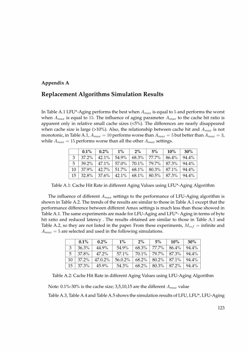
Appendix A
Replacement Algorithms Simulation Results
In Table A.1 LFU*-Aging performs the best when Amax is equal to 5 and performs the worstwhen Amax is equal to 15. The influence of aging parameter Amax to the cache hit ratio isapparent only in relative small cache sizes (<5%). The differences are nearly disappearedwhen cache size is large (>10%). Also, the relationship between cache hit and Amax is notmonotonic, in Table A.1, Amax = 10 performs worse than Amax = 5 but better than Amax = 3,while Amax = 15 performs worse than all the other Amax settings.
0.1% 0.2% 1% 2% 5% 10% 30%3 37.2% 42.1% 54.9% 68.3% 77.7% 86.4% 94.4%5 39.2% 47.1% 57.0% 70.1% 79.7% 87.3% 94.4%10 37.9% 42.7% 51.7% 68.1% 80.3% 87.1% 94.4%15 32.8% 37.6% 42.1% 68.1% 80.5% 87.3% 94.4%
Table A.1: Cache Hit Rate in different Aging Values using LFU*-Aging Algorithm
The influence of different Amax settings to the performance of LFU-Aging algorithm isshown in Table A.2. The trends of the results are similar to those in Table A.1 except that theperformance difference between different Amax settings is much less than those showed inTable A.1. The same experiments are made for LFU-Aging and LFU*- Aging in terms of bytehit ratio and reduced latency . The results obtained are similar to those in Table A.1 andTable A.2, so they are not listed in the paper. From these experiments, Mref = infinite andAmax = 5 are selected and used in the following simulations.
0.1% 0.2% 1% 2% 5% 10% 30%3 36.3% 44.9% 54.9% 68.3% 77.7% 86.4% 94.4%5 37.8% 47.2% 57.1% 70.1% 79.7% 87.3% 94.4%10 37.2% 47.0.2% 56.0.2% 68.2% 80.2% 87.1% 94.4%15 37.3% 45.9% 54.3% 68.2% 80.3% 87.2% 94.4%
Table A.2: Cache Hit Rate in different Aging Values using LFU-Aging Algorithm
Note: 0.1%-30% is the cache size; 3,5,10,15 are the different Amax value
Table A.3, Table A.4 and Table A.5 shows the simulation results of LFU, LFU*, LFU-Aging
123

A. REPLACEMENT ALGORITHMS SIMULATION RESULTS
and LFU*-Aging in terms of cache hit ratio, byte hit ratio and reduced latency respectively.The four algorithms perform almost the same when cache sizes are large(>10%), this is prob-ably because the trace used in the simulation is only one-day trace, this small data volumeremoves some performance differences from the “actual” results. Thus, in the following dis-cussion, the focus is put on the relatively small cache sizes(<10%).
0.1% 0.2% 1% 2% 5% 10% 30%LFU*-Aging 39.2% 47.3% 57.1% 70.1% 79.7% 87.6% 94.4%LFU-Aging 37.8% 47.2% 57.3% 70.1% 79.7% 87.5% 94.4%
LFU 37.4% 45.2% 54.1% 68.2% 80.1% 87.3% 94.4%LFU* 26.6% 33.9% 42.3% 68.1% 80.2% 87.1% 94.4%
Table A.3: Comparison of Frequency-based Caching Algorithms, Cache Hit Ratio
0.1% 0.2% 1% 2% 5% 10% 30%LFU*-Aging 36.2% 45.1% 55.3% 68.7% 77.9% 85.2% 93.8%LFU-Aging 35.4% 45.3% 55.3% 68.3% 77.9% 85.2% 93.8%
LFU 33.1% 40.1% 49.2% 65.2% 77.9% 85.2% 93.8%LFU* 17.7% 24.3% 38.3% 62.1% 77.9% 85.2% 93.8%
Table A.4: Comparison of Frequency-based Caching Algorithms, Byte Hit Ratio
0.1% 0.2% 1% 2% 5% 10% 30%LFU*-Aging 34.8% 42.7% 51.8% 66.9% 77.4% 85.6% 95.1%LFU-Aging 33.1% 42.2% 51.8% 66.9% 77.4% 85.6% 95.2%
LFU 32.8% 41.4% 50.9% 66.4% 77.2% 85.6% 95.3%LFU* 23.3% 30.8% 42.7% 65.4% 77.2% 85.6% 95.0%
Table A.5: Comparison of Frequency-based Caching Algorithms, Reduced Latency
Note: : 0.1%-30% is different cache sizes used.
Folowing are tables which presents the simulation results of six caching replacementpolicies: LRU, LFU*-Aging, four Greedy-Size algorithms GD-Size, GD-Size(Latency), GD-Size-Frequency and GD-Size-Frequency(Latency).
The cache hit ratio, byte hit ratio and reduced latency all increase for all policies as thecache size increase. The difference between all the policies is evident on relatively smallercache sizes ( where good replacement algorithm is important) but becomes much small onlarge cache size( when fewer replacements occur). When cache size equals to 30%, for nearlyall algorithms, cache hit ratio, byte hit ratio and reduced latency are all over 90%, somevalues are even over 92%. This seems indicating that for proxy caching, less than half of themaximum size can already provide satisfying performance.
124

A. REPLACEMENT ALGORITHMS SIMULATION RESULTS
Table A.6 shows the results of cache hit ratio. GD-Size-Frequency performs the best andGD-Size ranks the second. When cache size is equal to 10%, both achieve over 92% of themaximum hit ratio and when cache size is 30%, the hit ratios are over 99%. This indicatesthat GD-Size-Frequency and GD-Size are appropriate algorithms to maximize hit ratio. LRUachieves the lowest cache hit ratio among all algorithms. This indicates that LRU does notwork well in variable-size case.
0.1% 0.2% 1% 2% 5% 10% 30%GD-Size-Freq 50.9% 62.4% 71.8% 83.2% 91.1% 96.7% 99.2%
GD-Size 46.2% 57.0% 67.1% 80.0% 89.2% 95.8% 99.3%GD-Size-Freq (Lat) 40.4% 50.2% 60.7% 73.7% 83.2% 91.3% 97.1%
LFU*-Aging 39.3% 47.2% 57.0% 70.1% 79.7% 87.0% 94.4%GD-Size(Latency) 34.7% 43.8% 53.6% 67.4% 77.7% 87.2% 95.2%
LRU 29.1% 37.6% 46.7% 60.0% 69.3% 80.3% 92.2%
Table A.6: Simulation results of All Caching Algorithms, Cache Hit Rate
Table A.7 shows the results of byte hit ratio. LFU*-Aging has the best byte hit ratio overother algorithms. In contrast to the highest cache hit ratio, GD-Size-Frequency has lowerbyte hit ratio than LFU*-Aging, this perhaps because GD-Size-Frequency does not use agingstrategy. However, compared with GD-Size whose byte hit ratio is worse than LRU, GD-Size-Frequency does increase byte hit ratio performance of GD-Size.
0.1% 0.2% 1% 2% 5% 10% 30%LFU*-Aging 36.2% 45.1% 55.3% 68.0% 77.9% 85.2% 93.8%
GD-Size-Freq 29.0% 37.1% 46.7% 61.3% 72.2% 84.1% 94.9%LRU 28.1% 37.3% 45.9% 59.3% 68.2% 79.4% 91.9%
GD-Size 24.6% 32.2% 41.8% 55.3% 67.3% 80.9% 93.6%GD-Size-Freq(Lat) 21.0% 27.9% 37.1% 52.2% 65.8% 78.9% 91.6%GD-Size(Latency) 18.3% 24.3% 32.4% 46.3% 57.9% 71.4% 86.7%
Table A.7: Simulation results of All Caching Algorithms, Byte Hit Rate
Table A.8 shows the results of reduced latency of these six algorithms. Not surprising,GD-Size-Frequency and GD-Size ranks the first two. GD-Size(Latency), which is designedto minimize the average downloading latency does not perform as expected. However, GD-Size-Frequency(Latency), which adds frequency concern into the algorithm performs evenbetter than LFU*-Aging, this indicates the effectiveness of adding frequency concern intothe algorithm.
125

A. REPLACEMENT ALGORITHMS SIMULATION RESULTS
0.1% 0.2% 1% 2% 5% 10% 30%GD-Size-Freq 43.6% 55.7% 66.1% 79.3% 88.1% 94.9% 98.8%
GD-Size 39.2% 50.1% 61.3% 75.7% 86.3% 93.5% 98.4%GD-Size-Freq(Lat) 37.1% 47.6% 57.2% 71.3% 81.7% 90.7% 97.4%
LFU*-Aging 34.8% 42.7% 51.8% 66.9% 77.4% 85.6% 95.1%GD-Size(Latency) 32.4% 41.4% 50.2% 65.4% 76.6% 87.3% 95.9%
LRU 25.4% 32.0% 40.8% 55.1% 66.7% 79.3% 93.7%
Table A.8: Simulation results of All Caching Algorithms, Reduced Latency
126

Appendix B
XML Schema for extension of WSDL
<?xml version="1.0" encoding="UTF-8"?><xsd:schema xmlns:xsd="http://www.w3.org/2001/XMLSchema"xmlns="http://www.svod.cz/schema/soap-cache"targetNamespace="http://www.svod.cz/schema/soap-cache">
<!-- ============================================================= --><!-- Operation Handle Cache --><!-- ============================================================= --><xsd:element name="OpChHandle" type="OpChHandleType"/><xsd:complexType name="OpChHandleType">
<xsd:sequence><xsd:element name="namespaces" type="xsd:string"/><xsd:element name="fragments" type="FragType"/><xsd:element name="ignoreDocumentOrder" type="xsd:boolean"default="false" minOccurs="0"/><xsd:element name="maxRemainderQueries" type="xsd:integer"/><xsd:element name="rXQuery" type="xsd:string"/>
</xsd:sequence></xsd:complexType><xsd:complexType name="FragType">
<xsd:sequence><xsd:element name="FragXPath" type="xsd:string"/><xsd:element name="distinct" type="xsd:boolean"default="false" minOccurs="0"/><xsd:choice>
<xsd:element ref="xsd:key"/><xsd:element name="equal">
<xsd:simpleType><xsd:restriction base="xsd:string">
<xsd:enumeration value="tree"/><xsd:enumeration value="list"/>
</xsd:restriction></xsd:simpleType>
</xsd:element></xsd:choice>
</xsd:sequence></xsd:complexType><!-- ============================================================= --><!-- Cache Handle -->
127

B. XML SCHEMA FOR EXTENSION OF WSDL
<!-- ============================================================= --><xsd:element name="ChHandle" type="ChHandleType"/><xsd:complexType name="ChHandleType">
<xsd:choice><xsd:element name="StringParameter" type="StringParType"/><xsd:element name="IntegerParameter" type="IntegerParType"/><xsd:element name="DateParameter" type="DateParType"/><xsd:element name="ArrayParameter" type="ArrayParType"/><xsd:element name="SortParameter" type="SortParType"/>
</xsd:choice><xsd:attribute name="context" type="xsd:string" use="required"/><xsd:attribute name="bindingContext" type="xsd:string" use="required"/>
</xsd:complexType><!-- ============================================================= --><!-- String Type --><!-- ============================================================= --><xsd:complexType name="StringParType">
<xsd:sequence><xsd:group ref="requiredOrDefaultGroup"/><xsd:group ref="resultXPathGroup"/><xsd:group ref="implicitStringOperatorGroup"/><xsd:group ref="isCaseSensitiveGroup"/><xsd:group ref="isIrrelevantGroup"/><xsd:group ref="stringOperatorsGroup"/><xsd:group ref="generalisationGroup"/>
</xsd:sequence></xsd:complexType><!-- ============================================================= --><!-- Array Type --><!-- ============================================================= --><xsd:complexType name="ArrayParType">
<xsd:choice><xsd:element name="StringParameter" type="StringParType"/><xsd:element name="IntegerParameter" type="IntegerParType"/>
</xsd:choice><xsd:attribute name="operator" type="xsd:string" default="and"/>
</xsd:complexType><!-- ============================================================= --><!-- Integer Type --><!-- ============================================================= --><xsd:complexType name="IntegerParType">
<xsd:sequence><xsd:group ref="requiredOrDefaultGroup"/><xsd:group ref="resultXPathGroup"/><xsd:group ref="implicitIntegerOperatorGroup"/><xsd:group ref="isIrrelevantGroup"/><xsd:group ref="integerOperatorsGroup"/>
</xsd:sequence>
128

B. XML SCHEMA FOR EXTENSION OF WSDL
</xsd:complexType><!-- ============================================================= --><!-- Range Type --><!-- ============================================================= --><xsd:complexType name="RangeParType">
<xsd:sequence><xsd:element name="FromParameter" type="IntegerParType"/><xsd:element name="ToParameter" type="IntegerParType"/>
</xsd:sequence></xsd:complexType><!-- ============================================================= --><!-- Date Type --><!-- ============================================================= --><xsd:complexType name="DateParType">
<xsd:sequence><xsd:group ref="requiredOrDefaultGroup"/><xsd:group ref="resultXPathGroup"/><xsd:group ref="implicitDateOperatorGroup"/><xsd:element name="dateFormat" type="xsd:string"/><xsd:group ref="isIrrelevantGroup"/><xsd:group ref="dateOperatorsGroup"/>
</xsd:sequence></xsd:complexType><!-- ============================================================= --><!-- Groups --><!-- ============================================================= --><xsd:group name="requiredOrDefaultGroup">
<xsd:sequence><xsd:element name="required" type="xsd:boolean" minOccurs="0"/><xsd:element name="default" type="xsd:anySimpleType" minOccurs="0"/>
</xsd:sequence></xsd:group><xsd:group name="resultXPathGroup">
<xsd:sequence><xsd:element name="fragmentXPath" type="xsd:string" minOccurs="0"/>
</xsd:sequence></xsd:group><xsd:group name="implicitStringOperatorGroup">
<xsd:sequence><xsd:element name="implicitOperator">
<xsd:simpleType><xsd:restriction base="xsd:string">
<xsd:enumeration value="equals"/><xsd:enumeration value="contains"/><xsd:enumeration value="contains_whole_world"/><xsd:enumeration value="starts_with"/><xsd:enumeration value="ends_with"/>
</xsd:restriction>
129
B. XML SCHEMA FOR EXTENSION OF WSDL
</xsd:simpleType></xsd:element>
</xsd:sequence></xsd:group><xsd:group name="implicitIntegerOperatorGroup">
<xsd:sequence><xsd:element name="implicitOperator">
<xsd:simpleType><xsd:restriction base="xsd:string">
<xsd:enumeration value="eq"/><xsd:enumeration value="gt"/><xsd:enumeration value="lt"/><xsd:enumeration value="ge"/><xsd:enumeration value="le"/><xsd:enumeration value="counter"/>
</xsd:restriction></xsd:simpleType>
</xsd:element></xsd:sequence>
</xsd:group><xsd:group name="implicitDateOperatorGroup">
<xsd:sequence><xsd:element name="implicitOperator">
<xsd:simpleType><xsd:restriction base="xsd:string">
<xsd:enumeration value="eq"/><xsd:enumeration value="gt"/><xsd:enumeration value="lt"/><xsd:enumeration value="ge"/><xsd:enumeration value="le"/>
</xsd:restriction></xsd:simpleType>
</xsd:element></xsd:sequence>
</xsd:group><xsd:group name="isCaseSensitiveGroup">
<xsd:sequence><xsd:element name="caseSensitive" type="xsd:boolean"default="true" minOccurs="0"/>
</xsd:sequence></xsd:group><xsd:group name="isIrrelevantGroup">
<xsd:sequence><xsd:element name="irrelevant" type="xsd:boolean"default="false" minOccurs="0"/>
</xsd:sequence></xsd:group><xsd:group name="stringOperatorsGroup">
130

B. XML SCHEMA FOR EXTENSION OF WSDL
<xsd:sequence><xsd:element name="operators" type="stringOperatorsType" minOccurs="0"/>
</xsd:sequence></xsd:group><xsd:complexType name="stringOperatorsType">
<xsd:group ref="oneStringOperatorType" maxOccurs="unbounded"/></xsd:complexType><xsd:group name="oneStringOperatorType">
<xsd:choice><xsd:element name="parenthesis" type="parenthesisType"/><xsd:element name="and" type="xsd:string"/><xsd:element name="or" type="xsd:string"/>
</xsd:choice></xsd:group><xsd:complexType name="parenthesisType">
<xsd:sequence><xsd:element name="left" type="xsd:string"/><xsd:element name="right" type="xsd:string"/>
</xsd:sequence></xsd:complexType><xsd:group name="integerOperatorsGroup">
<xsd:sequence><xsd:element name="operators" type="integerOperatorsType"/>
</xsd:sequence></xsd:group><xsd:complexType name="integerOperatorsType">
<xsd:sequence><xsd:group ref="oneIntegerOperatorType"minOccurs="0" maxOccurs="unbounded"/>
</xsd:sequence></xsd:complexType><xsd:group name="oneIntegerOperatorType">
<xsd:choice><xsd:element name="parenthesis" type="parenthesisType"/><xsd:element name="and" type="xsd:string"/><xsd:element name="or" type="xsd:string"/>
</xsd:choice></xsd:group><xsd:group name="dateOperatorsGroup">
<xsd:sequence><xsd:element name="operators" type="dateOperatorsType"/>
</xsd:sequence></xsd:group><xsd:complexType name="dateOperatorsType">
<xsd:sequence><xsd:group ref="oneDateOperatorType"minOccurs="0" maxOccurs="unbounded"/>
</xsd:sequence>
131

B. XML SCHEMA FOR EXTENSION OF WSDL
</xsd:complexType><xsd:group name="oneDateOperatorType">
<xsd:choice><xsd:element name="parenthesis" type="parenthesisType"/><xsd:element name="and" type="xsd:string"/><xsd:element name="or" type="xsd:string"/>
</xsd:choice></xsd:group><!-- ============================================================= --><!-- Generalisation --><!-- ============================================================= --><xsd:group name="generalisationGroup">
<xsd:sequence><xsd:element name="generalisation" type="generalisationType" minOccurs="0"/>
</xsd:sequence></xsd:group><xsd:complexType name="generalisationType">
<xsd:choice><xsd:element ref="fragmentGeneralisation"/><xsd:element ref="documentGeneralisation"/>
</xsd:choice></xsd:complexType><xsd:element name="fragmentGeneralisation">
<xsd:complexType><xsd:sequence>
<xsd:element name="map" maxOccurs="unbounded"><xsd:complexType>
<xsd:simpleContent><xsd:extension base="xsd:string">
<xsd:attribute name="from"type="xsd:string" use="required"/><xsd:attribute name="to"type="xsd:string" use="required"/>
</xsd:extension></xsd:simpleContent>
</xsd:complexType></xsd:element>
</xsd:sequence></xsd:complexType>
</xsd:element><xsd:element name="documentGeneralisation">
<xsd:complexType><xsd:sequence>
<xsd:element name="category" maxOccurs="unbounded"><xsd:complexType>
<xsd:sequence><xsd:element name="map"type="HierarchyMappingType" minOccurs="0"/>
132

B. XML SCHEMA FOR EXTENSION OF WSDL
<xsd:element name="subcategories"type="SubcategoriesType" minOccurs="0"/>
</xsd:sequence><xsd:attribute name="id" type="xsd:string"/>
</xsd:complexType></xsd:element>
</xsd:sequence></xsd:complexType><xsd:key name="pId">
<xsd:selector xpath="category"/><xsd:field xpath="@id"/>
</xsd:key><xsd:keyref name="fId" refer="pId">
<xsd:selector xpath="category/subcategories/category"/><xsd:field xpath="@ref"/>
</xsd:keyref></xsd:element><!-- ============================================================= --><!-- Hierarchy Mapping --><!-- ============================================================= --><xsd:complexType name="HierarchyMappingType">
<xsd:sequence><xsd:element name="value" type="xsd:string" maxOccurs="unbounded"/>
</xsd:sequence></xsd:complexType><xsd:complexType name="SubcategoriesType">
<xsd:sequence><xsd:element name="category" maxOccurs="unbounded">
<xsd:complexType><xsd:complexContent>
<xsd:restriction base="xsd:anyType"><xsd:attribute name="ref" type="xsd:string"/>
</xsd:restriction></xsd:complexContent>
</xsd:complexType></xsd:element>
</xsd:sequence><xsd:attribute name="cover" type="xsd:boolean" default="false"/><xsd:attribute name="disjoint" type="xsd:boolean" default="false"/>
</xsd:complexType><!-- ============================================================= --><!-- Sorting Type --><!-- ============================================================= --><xsd:complexType name="SortParType">
<xsd:sequence><xsd:element name="required" type="xsd:boolean" minOccurs="0"/><xsd:group ref="isCaseSensitiveGroup"/><xsd:element name="sortCriteria">
133

B. XML SCHEMA FOR EXTENSION OF WSDL
<xsd:complexType><xsd:complexContent>
<xsd:restriction base="SomeSortParameterCriteria"><xsd:sequence>
<xsd:element name="xpath" type="xsd:string"/><xsd:element name="default" type="xsd:string"/><xsd:element name="map" type="StandardMappingType"minOccurs="0" maxOccurs="unbounded"/>
</xsd:sequence></xsd:restriction>
</xsd:complexContent></xsd:complexType>
</xsd:element></xsd:sequence><xsd:attribute name="sequencenumber" type="xsd:integer"/>
</xsd:complexType><xsd:complexType name="ComplexSortParType">
<xsd:complexContent><xsd:extension base="SortParType">
<xsd:sequence><xsd:element name="orderCriteria">
<xsd:complexType><xsd:complexContent>
<xsd:restriction base="SomeSortParameterCriteria"><xsd:sequence>
<xsd:element name="xpath" type="xsd:string"/><xsd:element name="default" type="xsd:string"/><xsd:element name="map" type="StandardMappingType"minOccurs="0" maxOccurs="unbounded"/>
</xsd:sequence></xsd:restriction>
</xsd:complexContent></xsd:complexType>
</xsd:element><xsd:element name="nullValueHandling">
<xsd:complexType><xsd:complexContent>
<xsd:restriction base="SomeSortParameterCriteria"><xsd:sequence>
<xsd:element name="xpath" type="xsd:string"/><xsd:element name="default" type="xsd:string"/><xsd:element name="map" type="StandardMappingType"minOccurs="0" maxOccurs="unbounded"/>
</xsd:sequence></xsd:restriction>
</xsd:complexContent></xsd:complexType>
</xsd:element>
134
B. XML SCHEMA FOR EXTENSION OF WSDL
<xsd:element name="collationHandling"><xsd:complexType>
<xsd:complexContent><xsd:restriction base="SomeSortParameterCriteria">
<xsd:sequence><xsd:element name="xpath" type="xsd:string"/><xsd:element name="default" type="xsd:string"/>
</xsd:sequence></xsd:restriction>
</xsd:complexContent></xsd:complexType>
</xsd:element></xsd:sequence><xsd:attribute name="orderSpecifications" type="xsd:string" use="optional"/>
</xsd:extension></xsd:complexContent>
</xsd:complexType><xsd:complexType name="SomeSortParameterCriteria">
<xsd:sequence><xsd:element name="xpath" type="xsd:string"/><xsd:element name="default" type="xsd:string"/><xsd:element name="map" type="MappingType"minOccurs="0" maxOccurs="unbounded"/>
</xsd:sequence></xsd:complexType><xsd:complexType name="MappingType" abstract="true">
<xsd:sequence><xsd:any namespace="##any" minOccurs="0" maxOccurs="unbounded"/>
</xsd:sequence><xsd:attribute name="from" type="xsd:string"/><xsd:anyAttribute/>
</xsd:complexType><xsd:complexType name="StandardMappingType">
<xsd:complexContent><xsd:restriction base="MappingType">
<xsd:attribute name="from" type="xsd:string"/><xsd:attribute name="to" type="xsd:string"/>
</xsd:restriction></xsd:complexContent>
</xsd:complexType><xsd:complexType name="OrderMappingType">
<xsd:complexContent><xsd:restriction base="StandardMappingType">
<xsd:attribute name="to"><xsd:simpleType>
<xsd:restriction base="xsd:string"><xsd:enumeration value="ascending"/><xsd:enumeration value="descending"/>
135

B. XML SCHEMA FOR EXTENSION OF WSDL
</xsd:restriction></xsd:simpleType>
</xsd:attribute></xsd:restriction>
</xsd:complexContent></xsd:complexType><xsd:complexType name="NullValueHandlingMappingType">
<xsd:complexContent><xsd:restriction base="StandardMappingType">
<xsd:attribute name="to"><xsd:simpleType>
<xsd:restriction base="xsd:string"><xsd:enumeration value="greatest"/><xsd:enumeration value="least"/>
</xsd:restriction></xsd:simpleType>
</xsd:attribute></xsd:restriction>
</xsd:complexContent></xsd:complexType>
</xsd:schema>
136

Appendix C
Extended WSDL description of SVOD service
<?xml version="1.0" encoding="UTF-8"?><definitions name="SVOD" xmlns:SOAP-ENV="http://schemas.xmlsoap.org/soap/envelope/"xmlns:xsd="http://www.w3.org/2001/XMLSchema"xmlns:xsi="http://www.w3.org/2001/XMLSchema-instance"xmlns:SOAP-ENC="http://schemas.xmlsoap.org/soap/encoding/"xmlns:soap="http://schemas.xmlsoap.org/wsdl/soap/"xmlns:wsdl="http://schemas.xmlsoap.org/wsdl/"xmlns:typens="urn:SVOD" xmlns:tns="urn:SVOD"xmlns="http://schemas.xmlsoap.org/wsdl/" targetNamespace="urn:SVOD">
<types><xsd:schema xmlns="http://www.w3.org/2001/XMLSchema"targetNamespace="urn:SVOD">
<xsd:complexType name="Data"><xsd:all>
<xsd:element name="note" type="xsd:string"/><xsd:element name="x" type="xsd:integer"/><xsd:element name="y1" type="xsd:integer"/><xsd:element name="y2" type="xsd:integer"/><xsd:element name="y3" type="xsd:integer"/><xsd:element name="y4" type="xsd:integer"/><xsd:element name="y5" type="xsd:integer"/>
</xsd:all></xsd:complexType><xsd:complexType name="ArrayOfData">
<xsd:complexContent><xsd:restriction base="SOAP-ENC:Array">
<xsd:attribute ref="SOAP-ENC:arrayType"wsdl:arrayType="tns:Data[]"/>
</xsd:restriction></xsd:complexContent>
</xsd:complexType></xsd:schema>
</types><message name="get_incmorRequest"><part name="diag" type="xsd:string"/><part name="period_from" type="xsd:string"/><part name="period_to" type="xsd:string"/><part name="stage" type="xsd:string"/>
137

C. EXTENDED WSDL DESCRIPTION OF SVOD SERVICE
</message><message name="get_incmorResponse">
<part name="return" type="typens:ArrayOfData"/></message><portType name="SVODPortType">
<operation name="get_incmor"><input message="tns:get_incmorRequest"/><output message="tns:get_incmorResponse"/>
</operation></portType><complexType name="get_incmorRequest">
<all><element name="diag" type="string">
<extension><appinfo>
<ChHandle context="get_incmorRequest"bindingContext="BSLBinding">
<StringParameter><required>true</required><fragmentXPath>diag/text()
</fragmentXPath><implicitOperator>contains whole world</implicitOperator><caseSensitive>false</caseSensitive><operators>
<or> </or><or>,</or>
</operators></StringParameter>
</ChHandle></appinfo>
</extension></element><element name="stage" type="string">
<extension><appinfo>
<ChHandle context="get_incmorRequest"bindingContext="BSLBinding">
<StringParameter><required>false</required><defaultValue>I+II+III+IV+X</defaultValue><fragmentXPath>stage/text()
</fragmentXPath><implicitOperator>contains whole world</implicitOperator><caseSensitive>false</caseSensitive><operators>
<or>+</or>
138
C. EXTENDED WSDL DESCRIPTION OF SVOD SERVICE
</operators></StringParameter>
</ChHandle></appinfo>
</extension></element><element name="period_from" type="integer">
<extension><appinfo>
<ChHandle context="get_incmorRequest"bindingContext="BSLBinding">
<IntegerParameter><required>false</required><defaultValue>1977</defaultValue><fragmentXPath>period_from/text()
</fragmentXPath><implicitOperator>GE</implicitOperator>
</IntegerParameter></ChHandle>
</appinfo></extension>
</element><element name="period_to" type="integer">
<extension><appinfo>
<ChHandle context="get_incmorRequest"bindingContext="BSLBinding">
<IntegerParameter><required>false</required><defaultValue>2003</defaultValue><fragmentXPath>period_to/text()
</fragmentXPath><implicitOperator>SE</implicitOperator>
</IntegerParameter></ChHandle>
</appinfo></extension>
</element></all>
</complexType><binding name="SVODBinding" type="tns:SVODPortType">
<soap:binding style="rpc" transport="http://schemas.xmlsoap.org/soap/http"/><operation name="get_incmor">
<soap:operation soapAction="urn:get_incmor" style="rpc"/><input>
<soap:body use="encoded" namespace="urn:SVOD"
139

C. EXTENDED WSDL DESCRIPTION OF SVOD SERVICE
encodingStyle="http://schemas.xmlsoap.org/soap/encoding/"/></input><output>
<soap:body use="encoded" namespace="urn:SVOD"encodingStyle="http://schemas.xmlsoap.org/soap/encoding/"/>
</output><OpChHandle>
<FragXPath>/Envelope/Body/get_incmorResponse/item
</FragXPath><rXQuery><![CDATA[
let $items := @Output_Items@return
<EnvelopeencodingStyle="http://schemas.xmlsoap.org/soap/encoding/"><Body>
<get_incmorResponse><return xsi:type="SOAP-ENC:Array"SOAP-ENC:arrayType="tns:Data[@Count_Output_Items@]">
{$items}</return></get_incmorResponse>
</Body></Envelope>
]]></rXQuery></OpChHandle>
</operation></binding><service name="SVOD">
<port name="SVODPort" binding="tns:SVODBinding"><soap:address location="http://www.svod.cz/db/"/>
</port></service>
</definitions>
140

Index
Active Caching, 35Adaptive caching, 38Adaptive Web Caching, 34
Bean Caches, 36Business-to-Business, 40Business-to-Consumer, 40
Cache Replacement Strategy, 43Cacheability, 32Caching, 29Client latency, 58CORBA, 17
Database caching, 38DB Caches, 35DCOM, 17
Fragment Caches, 36FTP, 22
GDSWS, 82Granularity, 32
HTTP, 17, 37
OODBMS, 38
Page Based Caching, 63Pattern Match, 71Pooling, 36Proxy Caching, 33Proxy Object, 36Push Caching, 35
Query Caching, 64Query Pattern Tree, 70
Reduced latency, 59Remote Procedure Calls, 17Replacement strategies, 31Replication, 29, 30Reverse Proxy Caching, 33RMI, 17
SCWS, 81Semantic Based Caching, 65Semantic region, 65Server latency, 58SMTP, 18, 22SOA, 5, 11SOAP, 17, 21, 22Strong Cache Consistency, 30
TTL, 37Tuple Based Caching, 63
UDDI, 17, 21, 27URI, 36, 37
Weak Cache Consistency, 31Web Cache, 36Web Caching, 37Web caching, 37Web Services, 18Web Services Tree, 69WSDL, 21, 25WSRP, 103WSRP4PHP, 103
XML, 17XML Messaging, 22
141