Bifurcation and collapse analysis of stringer and ring-stringer stiffened cylindrical shells with...
41
General Disclaimer One or more of the Following Statements may affect this Document This document has been reproduced from the best copy furnished by the organizational source. It is being released in the interest of making available as much information as possible. This document may contain data, which exceeds the sheet parameters. It was furnished in this condition by the organizational source and is the best copy available. This document may contain tone-on-tone or color graphs, charts and/or pictures, which have been reproduced in black and white. This document is paginated as submitted by the original source. Portions of this document are not fully legible due to the historical nature of some of the material. However, it is the best reproduction available from the original submission. Produced by the NASA Center for Aerospace Information (CASI)
-
Upload
independent -
Category
Documents
-
view
1 -
download
0
Transcript of Bifurcation and collapse analysis of stringer and ring-stringer stiffened cylindrical shells with...

General Disclaimer
One or more of the Following Statements may affect this Document
This document has been reproduced from the best copy furnished by the
organizational source. It is being released in the interest of making available as
much information as possible.
This document may contain data, which exceeds the sheet parameters. It was
furnished in this condition by the organizational source and is the best copy
available.
This document may contain tone-on-tone or color graphs, charts and/or pictures,
which have been reproduced in black and white.
This document is paginated as submitted by the original source.
Portions of this document are not fully legible due to the historical nature of some
of the material. However, it is the best reproduction available from the original
submission.
Produced by the NASA Center for Aerospace Information (CASI)

[
t I '
. s •__
• t
BIFURCATION AND COLLAPSE ANALYSIS OF STRINGER ANDRING-STRINGER STIFFENED CYLINDRICAL SHELLS WITH CUTOUTS
1^1f^1J1 ;by
A. N. Palazotto N ((Associate Professor (Structures)
Mechanics 6 Engineering Systems Department ^^'a1^ fMClllrtAir Force Institute of Technology, WPAFB ,e Dayton, OH 45433, ,^ • _^^
& ABSTRACT
This paper presents resultsfor cylindric,l shell configurations
z~ using the STAGS computer program. Discontinuities have been imposed
upon the shell's skin by incorporating symmetrical cutout openings.e^1 -
In addition, the surface is stiffened with both stringer and ring-
-w stringer arrangements.W M0 -w E4
0
CO .aN
'.The cutout problem has been shown to be highly nonlinear for i
P4 ^ --tawHwV
L) z v u smooth surface shells, but the author has found that bifurcation andH T.
QxeE-4Hw collapse loads are close when one is considering stiffened skin con- f
0 z t figurations. In order to arrive at this conclusion, it was necessaryHE-404
H .a
" to evaluate the following:U A S ^*2 x
"C
En V
Hcomparison between smeared and discrete stiffener theory for
H a,.aIx
`p a'u 4.4
linear solutionsx cc -
^.r-HHA
H N numerical finite difference convergence as directed toward
w H buckling determination.-a0W w
0N collapse load results with the various skin stiffeners.
V H x 0I4 to
:04;utit w
N'This paper also includes a linear bifurcation study relating to
EniC
6.44 H •r4Z4 tn ^ stiffening effects around cutout areas present within stringer and
siag-stringer shell surfaces. Comparisons have been made between a
vititty of geometric positions considering cutout frame and thickened
akfn additions. Th y° investigation points toward an optimum positioning.
,11 PAGE laQUALMOF ppOR

i
1
t
kNOMENCLATURE
2a - cutout dimension
A1 ,A2 - cross sectional area of stringer and ring
bl,b2 - spacing of stringer and rings
E - modulus of elasticity
GJ torsional stiffness
h,t - shell thickness
Iy ,I, - moment of inertia of stringer,
L - length of shell
Nxy - resultant shear force per unit length
n - number of nodes in finite difference scheme
P =cr bifurcation load
P . bifurcation load for shell with no cutout0
R = radius of shell
u,v,w - displacement in x, y and radial direction
x,y,8 - coordinates
Z - Batdorf shell parameter (1 - v2)h(L/R)2(R/h)
B - slope of deflected surface at boundary
v = Poisson's ratio
INTRODUCTION
It is obvious the cylindrical shell is an important structural
configuration within the aerospace industry. One finds an unlimited
amount of research papers directed toward this common shell surface.
Yet, the practical consideration of skin cutouts and their stiffening
has, for the most part, presented certain amounts of analytical
difficulties. Until-recently, the stiffening of these cutouts became
an experimental trial and error procedure [1]. It is now possible to
2

obtain a computational evaluation of cutout effects and reinforcements
using an all purpose shell program developed by Lockheed. This program
has been named STAGS (Structural Analysis of General Shells). It con-
tains the overall capabilities of either nonlinear or linear shell
analysis leading to bifurcation or collapse loads for several different
shell geometries, in particular cylindrical shells [2, 3, 4, 53.
Studies have shown that a shell buckling resistance is increased
with the addition of stringers and rings [6, 7]. As mentioned previously,
the positioning of cutouts as geometric discontinuities creates a struc-
ture which is extremely practical. A literature search indicated very
little work, either experimental or analytical, in the area of stiffened
cylindrical shells.with cutouts. Thus, the author has carried out such
a study with the assistance of the STAGS program. The remaining portion
of this paper will discuss the
linear bifurcation solutions for both ring and ring-stringer
stiffened cylindrical shells with particular interest given to conver-
gence of results due to finite difference refinements.
• collapse nonlinear solutions for the above mentioned shell
structures. Comparison has been made between linear and nonlinear
solutions.
• comparison between smeared and discrete stiffener results.
• geometry and stiffener effect on buckling.
• buckling load increase due to stiffening in the area of the
cutout.
LINEAR AND NONLINEAR RESULTS
The primary concern of this section is to establish, for the shell
^UTG^ IB-""; ^3

i
I
1
geometries investigated, a finite difference mesh arrangement which
can be used in collapse load solutions. Thus, one is looking for a
grid system that reduces convergence difficulties and also handles any
large displacement gradient which may arise in the nonlinear solution.
In order to approach the optimum finite difference approximation
economically, one should first do a great deal of parametric study
using the simpler linear bifurcation theory.
Figure 1 shows the shell properties incorporated into the conver-
gence and nonlinear investigations. One should notice the clamped
boundary conditions assumed plus the rectangular shaped internal
stringer. Since the loading conditions are taken to be axially sym-
metric, the analysis has been carried out over a one-eighth shell sec-
tion imposing the prebuckling and buckling boundary conditions for a
linear solution.
As previously mentioned, a collapse shell load value can only be
confidently evaluated, using a numerical finite difference technique,
if convergence characteristics are established. This is usually done
through first considering linear bifurcation results. Figure 2 indicates
per values found for a shell with a 24" x 24" cutout using various nodal
arrangements. One notices the increase in the number of nodes within
a finite difference mesh arrangement. Figure 3 shows that, if a dis-
crete stiffener approach is incorporated into the s ..udy, convergence
becomes erratic; i.e., the buckling load is not monotonically increas-
ing or decreasing with respect to the number of nodes. Yet, smeared
theory results show a definite convergence trend from above. In both
sets of results, a scatter of solutions amounts to no more than 3
percent. Consequently, it is possible to obtain good results, again
4
1qAtj,

IEi
I
for the governing conditions, using approximately 600 nodal points
spaced such that a circumferential mesh llne is present at and between
stringers and an axial mesh line is separated as far apart as the
stringers spacing.;
In order to further convince the reader that a detailed refine-
ment of mesh size is unnecessary even with a 24" x 24" cutout, one
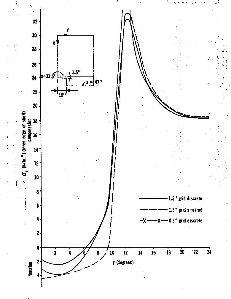
may observe the next sequence of diagrams. Figurer 4 through 8 present
data representing stress flow and buckling modes in the:area of the
cutout. Discrete and smeared theory are evaluated making use of two
different mesh refinements. It becomes obvious that not only do the
smeared and discrete theories give close results, but a mesh arrange-
ment of one line between stringers gives almost the same stress values
as an arrangement with three mesh lines. This insensitivity is
apparently due to the stiffening effect produced by the stringers.
The author believes that it is now possible to evaluate a collapse
load for the structure considered using a mesh arrangement consisting
of 602 node points with one mesh line at and between stringers. Figures
9 and 10 give values that are both within reason and satisfy good
convergence characteristics. Figure 9 shows the closeness between
collapse and bifurcation loads. The figure depicts a load displacement
curve for that point displacing the greatest quantity using a nonlinear
technique. From Figure 10, it may be observed that a collapse wave,
along the bottom boundary, contains no large displacement gradients.
Furthermore, it is interesting to note that the pre-bifurcation curve
is much different than the collapse displacement. Yet, the buckling
loads are relatively close. This is due primarily to the increased
stiffness present in a linear analysis which produces a less sensitive
moment effect.

1
'^ I
h ^^
The work discussed up to this point relates to stringer stiffened
cylindrical shells. A like study has been carried out for a shell
stiffened by both internal stringers and rings with a 27" x 24" cutout.
A smeared theory approach was only used in the convergence
investigation for this particular skin configuration. Again, as
Fig. 11 indicates, the smeared theory gives convergence from above.
One obtains a critical load value, for 714 node points with mesh lines
between stringers and at the ring locations, which is within 4percent
of the value obtained using 2262 nodes. Thus, mesh refinement does
not appear to be necessary. Figures 12 and 13 present the collapse
load and mechanism for the shell. There is a larger collapse load
compared to the bifurcation value, but the difference amounts to only
ll . percent. Furthermore, it is shown in Fig. 13 that the displace-
meat collapse wave does not change drastically and therefore can be
considered well behaved with at least five nodes per half wave. Thus,
it appears the mesh arrangement is adequate.
STIFFENING AROUND CUTOUTS
A limited investigation has been carried out into discrete stiff-
ever effect upon shell cutouts. This section discusses certain find-
ings for such a study.
It is conceivable to use the STAGS program as a tool analogous
to physical experimentation. As stated in the Introduction, most
cutout stiffener problems are handled through a trial and error solu-
tion. A good illustration of this experimentation approach can be
obtained in research performed by McDonnell Douglas El]. In this work
a thin stiffening frame was placed adjacent to a cutout within the
nE 6 .
.I

5
interior surface of a Thor Delta Interstage cylinder. The effects of
a cutout and its reinforcement on buckling behavior were explored ex-
perimentally by physically varying the stiffener position to overcome
any skin rippling. It is now possible to explore the same problem by
Incorporating STAGS into the solution without resorting to extensive
experimentation.
Figure 14 indicates cutout stiffening results for the stringer
stiffened shell geometry (27" x 24" cutout) di:zussed previously using
the 602 node finite difference scheme shown in Fig. 2. Two types of
stiffened arrangements have been studied. The first is a discrete
rectangular frame (Area - 2.18 sq. in.) placed internally around the
opening. A plot is shown for each frame position relating a ratio of
stiffener weight to cutout weight removed against the critical load
normalized to a shell with no openings. It can be observed that as
the discrete frame is increased in volume, through a change in posi-
tion, the critical buckling value approaches results close to those
possible without any shell opening.- An optimum frame position is
possible which gives a higher buckling value compared to other positions
(see position 4). 'The second cutout stiffener studied is developed by
increasing the shell thickness along its internal surface. The cross
section and a plot of the weight to critical load ratio can also be
found in Fig. 14. 'Two stiffener widths have been evaluated producing
points A and B in the plot. It is apparent that as the size of cross
section increases the critical buckling ratio approaches the value for
a shell with no cutout.
The reader can observe in Fig. 15 bifurcation comparisons for a
ring and stringer stiffened shell with cutout reinforcements similar
I:
7
ORIGINAL PAGE ISOF POOR QUALITY

II
to the stringer stiffened shell just discussed. It is shown that as
the discrete frame volume increases with location, the bifurcation ratio
P/Po decreases. Yet, as the thickened reinforcement increases in volume,
a bifurcation ratio almost equal to one occurs.
STRESS SURROUNDING THE STIFFENED CUTOUT
M attempt has been made to determine the overall effect due to
cutout stiffening by investigating stress redistribution and eigen-
vector comparison at bifurcations. Figure 16 presents the stress field,
at the interior stringer stiffened shell surfa a, surrounding a cutout
in which a stiffening frame is positioned adjacent to the opening
similar to Fig. 14. In order to compare values to non-stiffened cutouts,
stress quantities have been normalized. The reader can observe that
the stress values decrease in areas adjacent to the discrete stiffener.
Yet,"immediately above the frame one can find highly concentrated ax
contours. Figure 17 indicates, for the same frame positioning shown
in Fig. 16, the complete reorientation of bifurcation waves along the
cutout edge as well as other frame axial coordinates. Points of maxi-
mum buckling wave amplitudes are depicted for specific angular measure-
ments. One can appreciate that not only are the half wave locations
different between shells without cutout frame stiffeners, but the
circumferential wave number is also affected. Figure 18 is a presen-
tation of the same'stress and buckling wave effect discussed in the
above two mentioned figures, but in this case cutout stiffening is
created by a thickened shell skin. Results indicate a similar total
effect.
EFFECT OF SHELL JLND STIFFENER GEOMETRY
Investigators of . problems related to cutouts in smooth surface
cylindrical shells [8] have determined a generalized cutout parameter.
ORIGINAI; PAGE 1S e
OF POOR QUALM

This parameter is the a /(Rt)^ ratio in which 2a equals the cutout width;
R and t are the shell's radius and thickness respectively. The writer
tried to produce a similar parameter for cutouts in stiffened shells.
This section described some of the work performed.
Figure 19 shows a plot of cutout parameters used in reference [8]
for thn present problems. It becomes obvious that a parameter similar
to smooth surfaced shells was not appropriate for stiffened shells
since a common curve is not obtained. The cutout effect turns out to
be very different compared to smooth shells because of the stiffening
produced in cutout regions. Therefore, a study of possible stiffener
geometry effects on cutouts was pursued. Figures 20 and 21 indicate
a greater shell sensitivity to variations in a stringer's axial rigidity
for given cutout sizes as compared to a stringer's flexural stiffness.
Consequently, the author explored various axial stiffness parameter
combinations by including or excluding the shells axial rigidity. The
success in obtaining an ideal function can be found in Figs. 22 to 24.
Observation reveals that simple geometric stiffener area is not enough
to establish a basic parameter. Yet, one may note an important property
coming from this particular set of figures. It can be stated that non-
linear shell effects become apparent using small stiffener area; e.g.,
0.05 sq. in., since the bifurcation curve reaches a minimum and
increases for an increase in a /(Rt)^ ratios. This has also been ob-
served in reference C8]. A reason for this inconsistency may be attrib-
V. uted to the elimination of moment effects in linear bifurcation theory
and thus, as cutout size increases a tension field occurs using linear
analysis which would normally be overcome if nonlinear relationships
were incorporated.
}^^:aItiAL GSU AL1'^^OF POOP.4 9

Ii
f
6F
An additional study wa4 pursued, this time in relation to the
stiffener and shell flexural rigidity. It was previously stated that
a cutout is less sensitive to a flexural parameter. Results verified
this conclusion as shown in Figs. 25 and 26.
As a final investigation phase, the author attempted to combine
r,dal and flexural rigidity. Figure 27 indicates some success for
rrasonable shell thicknesses.
' CONCLUSIONS
It is now possible to make the following .,conclusions:
1). The STAGS program has been used in studying buckling charac-
teriritics for a stringer stiffened, in addition to a ring and stringer
stiffened, shells. The bifurcation load is within 11 percent of the
collapse force for each configuration, and thus it is possible to
study buckling loads using linear analysis for configurations similar
to those investigated herein.
2) . Previously, cutout adm•fozrsaeat A+ detemol ed by ,e, trial
and error experimental approach. STAGS makes it possible to,investi-
gate this problem and determine the most effective reinforcement
kposition.
and 3). The study reported upon reveals that the parameter a/(Rt)
used in isotropic shells considering cutouts is not appropriate for
stiffened shells.
10

r
4
REFERENCES
E R. F. Snell, Experimental Evaluation of the Effects of Cutouts
on the Stress State and Buckling Stability of the Isogrid
Structures of the Thor Delta Interstage and Fairing, MDC
Report 62873, April, 1972.
(2) D. Bushnell, B. 0. Almroth and F. Brogan, Finite Difference
Energy Method for Nonlinear Shell Analysis, Computers and
Structures, Vol. 1, pp. 361-387.
(3) F. Brogan and B. 0. Almroth, Buckling of ,cylinders with Cut-
outs, AIAAJ., Vol. 8, No. 2, Feb. 1970, pp. 236-241.
(4) B. 0. Almroth and A .M.C. Holmes, Buckling of Shells with Cutouts,
Experiment and Analysis, Int. J. Solids and Structures, Vol. 8,
pp. 1057-1071, 1972.
(5) B. 0. Almroth and F. A. Brogan, Bifurcation Buckling as an
Approximation of the Collaps± Load for General Shells, AIAA J.
Vol. 10, No. 4, April 1972, pp. 463-467.
(6) J. Singer, Buckling of Integrally Stiffened Cylindrical Shells -
A Review of Experiment and Theory pressnt ±d at Van Der Neut
Symposium, 1972.
(7) D. L. Block, Influence of Discrete Ring Stiffeners and Pre-
buckling Deformations on The Buckling of Eccentrically Stiffened
Orthotropic Cylinders, NASA TN D-4283, January 1968.
(8) J. H. Starnes, The Effect of a Circular Hole on the Bu ,-kling of
Cylindrical Shells, Ph.D. thesis, California Inst. of Tech.,
1970.
big 11a33 11
U^

I
FIGURE CAPTIONS
Fig. 1 Shell Geometric Properties -=
Fig. 2 Mesh Arrangement
Fig. 3 Number of Nodes vs. Pcr (Stringer Stiffened)
Fig. 4 axAlong x 29 in. Mesa Line
Fig. 5 c Along x 33.5 in. Mesh Linex
Fig. 6 Comparing Various Mesh Arrangements for 8XY
Fig. 7 Nxy Near Cutout
Fig. 8 Eigenvectors
Fig. 9 N vs w (Stringer Stiffened)X
Fig. 10 Displacement at x 47 inches
Fig. 11 Number of Nodes vs. P cr (Ring and Stringer Stiffened)
Fig. 12 N vs. w (Ming and Stringer Stiffened)
Fig. 13 Displacement at Collapse Along x - 47 inches
Fig. 14 Cutout Weight Ratio (Stringer Stiffened)
Fig. 15 Cutout Weight Ratio (Ring and Stringer Stiffened)
Fig. 16 ox at Bifurcation With Discrete Stiffener at Cutout
Fig. 17 Effect on Bifurcation Wave Due to Cutout Stiffeners
Fig.. 18 Bifurcation Wave and Stresses for,Thickened Skin
Fig. 19 Linear Buckling for Cylindrical Stiffened Shell
Fig. 20 Effect of Stringer Area on Pcr
Fig. 21 Effect of Stringer Inertia on Pcr
Fig. 22 Effect of Stringer Area and Opening on Pcr
Fig. 23 Effect of Stringer and Shell Extensional Area on Pcr
(Al 0.28 sq. in.)
Fig. 24 Effect of Stringer and Shell Extensional Area on Pcr
(A1 - 0.08 sq. in.)^
O'EXEDING PAGE ^3 v^ LG1I ^43;'fi`1
4F ^

Fig. 25 Effect of Stringer's Moment of Inertia on Pcr (A 0.08
Fig. 26 Effect of Shell and Stringer's Moment of Inertia on P cr
(A 0.08 sq. in.)
?IS. 27 Effect of Combined Perimeters on P cr
. .= day ^^

it
sT-
or T tKh0,35"
A = area of stringer
0_$„ I Y = 0.01493 in.4Y
GJ = 30302"in.2
t
b
E. =10,000 ksi;
A : = area of ringi
Clampedpre—buckling buckling
Q ; v4 -0
Q ; u 0 same
®v/3 =o
Q ; w=r /,;s 0 w-r=uU. 0.09 in. =/j=0
•--09, Y
O
Q Q)x

1i
' t 24 at 1.5" 1 18 at 3" 24 at 1.5 01at 3"
4 3t 4 at7 -{
5"5„
9^d 18 at3 14x43 1.5" 23x43= .T
j a n 602 0=989
Pcr =629,171Pcr =618,930#
12 at36 at 1". 18 at 3" . 1,36 at..Q.S:_.- 1.S" 18 at 3" ..... .
• 4 at Oat5„ 4„
13 at32 x 55= 1 " 54 x 67 a
-
27 at n =1769 n=3618 1
36 att0.511
Pcr =631,562Pcr = 627,757#
n number of wales
R = 51.3" L= 94 91 1 = 0.28 " b i = 3"
Cutout =24" x 24" Discrete Stringer Approach Used
^RIP^^ ^ ^
1
^
^t z

•
GO; gym"..
•N m Cghs
•. v N SM
v
b y yS ^^
tj toN Nd
'• y0
44 m
j' N
VS Hjf:. y O t
tics i •
S'i . • _ '
4 OMO
ND
s
4c; -

w .
x =29"
R =57.3"
L= 94"
r
1.5" grid discrete
-- — ---1.5" grid smeared
•--x---x 0,5" grid discrete
yPon
x
22
x =29" , I
20 11"
12"
18 — — __ x 41"
h16
8'.
114C Nv b
0 12
bx.10
•^^ 8i
6 1
.^
'21
2 44
6 8 10 11 14 16 18 10 22 14
= 2. y (degrees)
4,QIJ ,I7I
so ^
24 X=33.511i
I.! X s 4110
Iaid discrete
— --1.511 aid smeared
-)(-X-0.5" aid discrete
1
8 / 10 12 14 16 18 20 22 24
/ y (degrees)i
-X 4

1
Y
i^
im
1000
-^- x n 33.5"2'
^ 12" J400-
x = 47.. - — -
200
z0
2 8 10.t
-10 `y(degrees)
-4
-60
-800
x w 33.5"
/00-f 16 18 10 22 14
1.5" grid Discrete
---1.5" grid Smeared
-X--X-0.5" grid Discrete

C
V •^
Y-
600-
• goo ^ ^ '
x- t9'^t
400 x = 33.5"
_ 12"A 200 x- 47"—* —
x = 29"r.3dc 0
4 4 6 8 10 12 16 18 20 22 24
—200 y(degrees)
using 1.5" grid discrete—400
i
—600x - 33.5"
—800 Shear Distribution
OP PGO Q PAGE
QUA
• 9

c
M N rl O ..r N 91 ^ W! wO O O O O O' Co O' O' If

0 .05 .10 .15 .20 .25 .30 .35 .40-NAL PAGE ZS w (displacement) in.
-UOR
C!
310

0 0 0 0 01
l'u !) „M„ N011031A30

2 17x42 =n -714
i
10 at1 2 at 0.15" .-1 -1 .5" 15 at3_ ,GS'^
4 at4.5of
4 atLAW
39 x 58 —30 at o - 22620.75"
1211
13.5"
Pa - 953,505
26 at 1.511 1 _15 at 3.68".
26 at 1.5" 15 at 30FI
4 at4.5"
4 at1.625"
24x4215 at A • 1009
0.75"
Pcr -965,024
n - number of nodesR-60" L-94A ) -0.28 " b l- 3"
A - 0.079 " b - 4.5"2 2
cutout 27" x 24"smeared approachRing—Stringer
cr - 985,527'
990
980
970
g 960
a.^ 950
1000 1500 2000
2500
number of nodes (n)

3000r
.U4 Mf .14 J's .L4 du .34 .3y.44 .44
w (displacement) in.INTERNAL RINGS & STRINGERS
C!
N
ftZ
dA

qt M N -i O NO O O O O O
1 1Vui) A, N011031J3a
CL
v.i
N
s m
C7 ^o
d
faCD
s,V A19 M1
tj
^ NN ^IN N
N v
of IS- VAZI P^0 QII 818

rr
INCREASED SHELLTHICKNESS ATCUTOUT
301
P/Po
DISCRETE FRAMEPOSITIONS
^+^2.25'2.25"
(3) 2.25"(2)
4.511
(1) 12..
3" 1.51.51.5
27 9qx24" CUTOUT
r
0.9Z0.76" 0.1 (B) (4)
o..A = 2.18
0.90 (2) (3)(1) 0.8,.
0.88(5) 2.725"
(A)
0.86W= wt. of added stiffener
0.84wo removal wt.P a PCr
0,82 Po Per no cutout
=8.30,822*
0.80—T
1.0 1.5 2.0 2.5 3.0 3.5
P/Po (no reinf) = 0.78w/w0
(Strin;er Stiffened Cylindrical Shell)
fJ,%-Wx

i
VARIATION IN 279#x24" CUTOUTTHICKNESS AT DISCRETECUTOUT (4) FRAME
(3) POSITIONS(2)(1) 12' ►W;
4 A 1.5 1.5"B 3" I 4.5"C 4.5"
0.9" 0.1"g..
(C)0.98 ' (B)
0.96
0.94 (A)FRAME'S X AREA= 2.180"
0.920.8"
0.90 2.725"
P/p` 0.88-f r(2)
0.86 (3)A = 0.28 0"
0.84 A 0.07911"2
0.82 w-wt. of added stiffenerwon removed wt. at cutout
PAGE
cr0.80 P = Pcr
oRI^Il3tTAI1 P" P no cutout
OF POOR Q0.18 -1,420,7134
fie,)0.76 '--j-
0.5 1.0 1.5 2.0 2.5 3.0
P/Po (no cutout) w./wo
- 0.68 (Ring—Stringer Cylindrical Shell)

1
1
I
i-S; r^:.R.. • ^ fly `T• • I• ..
or
mash 1 ,135
flo
1,34 133 1:05 . 1.,.6.:..:.:.
t -t
2.25" Stiff. Frare (—^iJ) ; (—iG) `z
1.24 ':.
1. 123 0155 0.95 1.054.50"- ..,;
1.119 0.55 0 t
1 0.53 0689
0 1 85 ^ -.: 0.51 0*. 85~ _.•._.._
IGINAL' FAGE IS
POOR QuA1,Tly1315 M .1
016 0, 43 I r 1:05
normalized vXto stress 0.86 1.1 0
field with no frame• r
o 15 a:43 095 1.05 ti•' • •!^
^. at 6ifurc^ition ( inner edge of shell) (ctringer stiffierad cyl. shell) ,•r:^ti
r^ 1 t I ^ ^. 1'^-^ 1

0
{Il
i'1 ,
2,25'
frame
Point of greatest ratio
2,9 6.75"
z - 33.5"
n= circumferential full value
0
max, ampl. at x = 33.5"frame 0°, 24°, 41°, 58°, 72 0 n=10
no frame 0 0 , 14°, 300 , 480 , 62 0 , 760 n =12
1 2.2
9"
ime
X=
U
max. ampl. at x = 33.5"
frame 0', 117°, 29°, 44°, 58°, 76° n=12
no frame 0°, 140 , 30°, 48°, 62°, 76° n X12
^*- 4.5 11 imax. ampl. at x = 33.5"
frame 160 , 21°, 44°, 580 , 720n=10
no frame 0°, 14°, 30 0 , 480 , 62°, 16°n-12
max. ampl. x 26.75"
frame 14°, 260 , 44°, 580 , 720n-10
no frame 0°, 16°, 300 , 480 , 62 0 , 76°n-12
Note: 2 .2 (multiple of stress atpoint with no frame)
max. ampl. at x=24.5" (frame) ampl.=amplitudeframe 190 , 21°, 44°, 58°, 76° n-10
no frame 0°, 16°, 30°, 48°, 62°, 76 0n=12
(stringer stiffened cylindrical shell)
r^q ^_

I I I I ^ ^
0 1"
0.16"
Sect. A—A
^ I' A 1.54 1.64 1.03
x 2^"0.2K0.36;M 0.98
= _(}1)0.47 0.73 1.0
4.5"x = 33.5 0.56 0.51
(-15)0.^5 0.88
(-23)I (ks0
normalized to
stress field with no
stiffener
max. ampl. at x = 29"—
frame 0", 240 , 410 , 58 0 , 72 0n-10
no fra me 01 , 140 , 30°, 480 , 62° 76° n- 12
max. ampl. at x = 33.5" ampl.= amplitude
frame 0°, 24°, 41°, 58°, 72 0n-10
no frame 0°, 14°, 300 , 480 , 620 , 76 0 n-12
n—full buckle wave
(Stringer Stiffened Cylindrical Shell)
! 4 n
ORIGINAL PAGE JSOF POOR QUALITY

ii
P/PoClamped Stringer Shell
Po-Buckling Load — No Cutout1.0
6t -0.05"
0.9
.R /t=1146
R/t =5130.8
24x24
0.1 R./t=286
0.6
t =0.2"0.5
0.4
5 10 15 20
25
2a./(RtY'
MGIN AL PAGE ISOF POOR QUALITY

aoas
0
o ..a
N
O1a m
i
c
AgiSM

t -
N
R On O u^
mi8 n rJ2
q HSc C2
m
DRIGINAD PAGE MOF POOR QUAL y.
d° r► '*CL. c a o c
t -

t
I
F,
0.8-`
0.1 t = 0.0
0.6
A,=
0.5
0.4
1
00
Pipo
1,0 ^
0.9
"
pF paoR ^V^-,r-^
5 10 15 20 25 30 35 40
aI(Rt) %/A , /bt

1 Z 3 4 5 6 1
a/(Rt) 11/1+ A, At
t
P/Pe
1.0
0,9
0.8
0.1
0.1
0.^
0,

PRO
.I
O
0
0,
0.
0.;
a/(Rt, "A + A I /bt

0 5 10 15 20 25 30 33
a/(Rt)'' /(I I /bt' )
L
:. PIPo
1.

PRO
1,0
1p
IS
0.8
0.1
0.1
0:
0.,
0.
* ^ i
1 z i + J
a/(RtP/(1+I I /bt 3)
r, Y r

0
i
1
P/Poto Sher thickness
LOA v-a (0.1811") area of iffener
^^ / t=0.05" (0.08)
(0.28)
t=0.05" (0.28) ^, it =.2
^`` rrt=0.1 (O.QB)t=0.2(0.28)
t- 0.1"(0.08)
r
0.]♦.
0.6
!rte
0.5 1.0 1.5 2.0 2.5 3.0 3.5 4.0
a/(Rt0/(1 + A I /bt) (1 ♦ I /bt 3 )
r_` ey ,,