Behavior of Single Pile in Liquefied Deposits during Earthquakes
9
Technical Note Behavior of Single Pile in Liquefied Deposits during Earthquakes V. S. Phanikanth 1 ; Deepankar Choudhury, M.ASCE 2 ; and G. R. Reddy 3 Abstract: Analysis of pile foundations for earthquake loads requires the consideration of inertial loads that result from the soil-pile- superstructure interaction, as well as the evaluation of kinematic interactions that result from the movement of the surrounding soil and the pile. Such soil-pile interaction analyses must consider the stiffness degradation that results from earthquake loading. In the current study, the soil-pile interaction analysis considers stiffness degradation effects for a range of earthquakes with different amplitudes [maximum horizontal acceler- ation (MHA)], mean time periods, and different durations of earthquakes. Effects of both kinematic and inertial interactions are evaluated using a seismic-deformation method. A computer program was developed using MATLAB for the analysis. Results of a ground-response analysis obtained from a separate study were used for the soil-pile interaction analysis. Pile response for kinematic interactions were validated with the available theoretical solutions in the literature. In addition, kinematic pile response was compared with field observations for an actual earthquake, and the results are presented. Parametric studies were carried out to understand the effect of the presence of a liquefying soil layer, depth of the liquefying layer, etc., and the results are presented. The results indicate that the effect of the depth of the liquefying layer has a significant influence on the pile-bending response and that the peak bending moment occurs at the interface of the liquefying and nonliquefying layers. DOI: 10.1061/(ASCE)GM.1943-5622.0000224. © 2013 American Society of Civil Engineers. CE Database subject headings: Soil-pile interactions; Ground motion; Earthquakes; Spread foundations; Kinematics; Soil liquefaction. Author keywords: Pile-soil interaction; Ground-response analysis; Lateral spreading; Kinematic interactions; Liquefying soils. Introduction Pile response under seismic loading involves the estimation of kine- matic bending that results from the lateral displacements and curva- tures imposed on a pile because of ground motion and the inertial forces acting on the cap mass, which represents the superstructure. Several approaches have been proposed for soil-pile response anal- ysis, including sophisticated mathematical or numerical analyses and simplified methods. The finite-difference technique is most commonly used because of its simplicity, although finite-element techniques have more flexibility for performing seismic analysis of soil-pile interaction in both frequency and time domains. Application of these methods to soil-pile interaction in liquefied soils needs to represent the mesh size fine enough to eliminate numerical inaccu- racy. According to Semblat and Brioist (2000), the estimation of wave propagation is affected by errors resulting from numerical dispersion and depends on parameters such as mesh refinement, time integration scheme, and element type. The classical rule is to choose the element size between one-tenth and one-twentieth of the wavelength. A number of simplified procedures are available in the litera- ture for the evaluation of kinematic bending moments along piles, such as dynamic Winkler models and the P-Y static models (Novak 1974; Flores-Berrones and Whitman 1982; Nogami and Chen 1987; Makris and Gazetas 1992; Kavvads and Gazetas 1993; Choudhury et al. 2009; Maheshwari and Watanabe 2009). Maheshwari and Sarkar (2011) performed parametric studies on the seismic behavior of soil-pile-superstructure interaction in liquefiable soils. The pa- rametric studies also included the effects of inertial interaction, and the studies revealed that the soil-pile-superstructure interaction increases the period of the structure and tends to decrease the peak response. Rayhani and El Naggar (2008) developed a numerical model using the finite-difference program fast Lagrangian analysis of continua (FLAC)(2006) to predict the seismic response of a rigid foundation in soft soil. The validated model was then used to study the effects of the thickness of soil profile and layering on earthquake amplification and soil structure interaction. The embedment effects on foundation input motions also were investigated. Haldar and Babu (2010) carried out parametric studies on the failure mecha- nisms of pile foundations in liquefiable soils, considering plain- strain analysis based on the finite-difference technique. Numerical analysis was carried out using FLAC (2006), and their model also considered mechanical and fluid-flow behavior. In the current study, a pseudo-static analysis was carried out using a seismic deformation method, and the behavior of liquefying soils under earthquake loads was studied. The influence of the presence of a liquefying layer and the depth of the liquefied layer on the pile-bending response was investigated. Design Approaches The current design methods for piles under earthquake loads focus on evaluating pile bending moments due to lateral loads such as inertia load and loads resulting from ground movement, i.e., lateral 1 Scientific Officer (G), Bhabha Atomic Research Centre, Architecture & Civil Engineering Division, Trombay, Mumbai 400085, India; formerly, Ph.D. Research Scholar, Dept. of Civil Engineering, Indian Institute of Technology, Bombay, Powai, Mumbai 400076, India. E-mail: [email protected] 2 Professor, Dept. of Civil Engineering, Indian Institute of Technology Bombay, Powai, Mumbai 400076, India (corresponding author). E-mail: [email protected] 3 Homi Bhabha Professor and Scientific Officer (H), Bhabha Atomic Re- search Centre, Trombay, Mumbai 400085, India. Note. This manuscript was submitted on January 19, 2011; approved on May 16, 2012; published online on May 19, 2012. Discussion period open until January 1, 2014; separate discussions must be submitted for individual papers. This technical note is part of the International Journal of Geo- mechanics, Vol. 13, No. 4, August 1, 2013. ©ASCE, ISSN 1532-3641/ 2013/4-454–462/$25.00. 454 / INTERNATIONAL JOURNAL OF GEOMECHANICS © ASCE / JULY/AUGUST 2013 Int. J. Geomech. 2013.13:454-462. Downloaded from ascelibrary.org by National Cheng Kung University on 12/09/13. Copyright ASCE. For personal use only; all rights reserved.
Transcript of Behavior of Single Pile in Liquefied Deposits during Earthquakes

Technical Note
Behavior of Single Pile in Liquefied Depositsduring Earthquakes
V. S. Phanikanth1; Deepankar Choudhury, M.ASCE2; and G. R. Reddy3
Abstract: Analysis of pile foundations for earthquake loads requires the consideration of inertial loads that result from the soil-pile-superstructure interaction, as well as the evaluation of kinematic interactions that result from the movement of the surrounding soil and the pile.Such soil-pile interaction analysesmust consider the stiffness degradation that results from earthquake loading. In the current study, the soil-pileinteraction analysis considers stiffness degradation effects for a range of earthquakes with different amplitudes [maximum horizontal acceler-ation (MHA)], mean time periods, and different durations of earthquakes. Effects of both kinematic and inertial interactions are evaluated usinga seismic-deformation method. A computer program was developed using MATLAB for the analysis. Results of a ground-response analysisobtained from a separate study were used for the soil-pile interaction analysis. Pile response for kinematic interactions were validated with theavailable theoretical solutions in the literature. In addition, kinematic pile response was compared with field observations for an actualearthquake, and the results are presented. Parametric studies were carried out to understand the effect of the presence of a liquefying soil layer,depth of the liquefying layer, etc., and the results are presented. The results indicate that the effect of the depth of the liquefying layer hasa significant influence on the pile-bending response and that the peak bendingmoment occurs at the interface of the liquefying and nonliquefyinglayers. DOI: 10.1061/(ASCE)GM.1943-5622.0000224. © 2013 American Society of Civil Engineers.
CE Database subject headings: Soil-pile interactions; Ground motion; Earthquakes; Spread foundations; Kinematics; Soil liquefaction.
Author keywords: Pile-soil interaction; Ground-response analysis; Lateral spreading; Kinematic interactions; Liquefying soils.
Introduction
Pile response under seismic loading involves the estimation of kine-matic bending that results from the lateral displacements and curva-tures imposed on a pile because of ground motion and the inertialforces acting on the cap mass, which represents the superstructure.Several approaches have been proposed for soil-pile response anal-ysis, including sophisticated mathematical or numerical analysesand simplified methods. The finite-difference technique is mostcommonly used because of its simplicity, although finite-elementtechniques have more flexibility for performing seismic analysis ofsoil-pile interaction in both frequency and time domains. Applicationof these methods to soil-pile interaction in liquefied soils needs torepresent the mesh size fine enough to eliminate numerical inaccu-racy.According toSemblat andBrioist (2000), the estimation of wavepropagation is affected by errors resulting from numerical dispersionand depends on parameters such as mesh refinement, time integrationscheme, and element type. The classical rule is to choose the elementsize between one-tenth and one-twentieth of the wavelength.
A number of simplified procedures are available in the litera-ture for the evaluation of kinematic bending moments along piles,such as dynamic Winkler models and the P-Y static models (Novak1974; Flores-Berrones andWhitman 1982; Nogami and Chen 1987;Makris and Gazetas 1992; Kavvads and Gazetas 1993; Choudhuryet al. 2009; Maheshwari and Watanabe 2009). Maheshwari andSarkar (2011) performed parametric studies on the seismic behaviorof soil-pile-superstructure interaction in liquefiable soils. The pa-rametric studies also included the effects of inertial interaction,and the studies revealed that the soil-pile-superstructure interactionincreases the period of the structure and tends to decrease the peakresponse. Rayhani and El Naggar (2008) developed a numericalmodel using the finite-difference program fast Lagrangian analysisof continua (FLAC) (2006) to predict the seismic response of a rigidfoundation in soft soil. The validated model was then used to studythe effects of the thickness of soil profile and layering on earthquakeamplification and soil structure interaction. The embedment effectson foundation input motions also were investigated. Haldar andBabu (2010) carried out parametric studies on the failure mecha-nisms of pile foundations in liquefiable soils, considering plain-strain analysis based on the finite-difference technique. Numericalanalysis was carried out using FLAC (2006), and their model alsoconsidered mechanical and fluid-flow behavior. In the current study,a pseudo-static analysis was carried out using a seismic deformationmethod, and the behavior of liquefying soils under earthquake loadswas studied. The influence of the presence of a liquefying layer andthe depth of the liquefied layer on the pile-bending response wasinvestigated.
Design Approaches
The current design methods for piles under earthquake loads focuson evaluating pile bending moments due to lateral loads such asinertia load and loads resulting from ground movement, i.e., lateral
1Scientific Officer (G), Bhabha Atomic Research Centre, Architecture &Civil Engineering Division, Trombay,Mumbai 400085, India; formerly, Ph.D.Research Scholar, Dept. of Civil Engineering, Indian Institute of Technology,Bombay, Powai, Mumbai 400076, India. E-mail: [email protected]
2Professor, Dept. of Civil Engineering, Indian Institute of TechnologyBombay, Powai, Mumbai 400076, India (corresponding author). E-mail:[email protected]
3Homi Bhabha Professor and Scientific Officer (H), Bhabha Atomic Re-search Centre, Trombay, Mumbai 400085, India.
Note. This manuscript was submitted on January 19, 2011; approved onMay 16, 2012; published online on May 19, 2012. Discussion period openuntil January 1, 2014; separate discussions must be submitted for individualpapers. This technical note is part of the International Journal of Geo-mechanics, Vol. 13, No. 4, August 1, 2013. ©ASCE, ISSN 1532-3641/2013/4-454–462/$25.00.
454 / INTERNATIONAL JOURNAL OF GEOMECHANICS © ASCE / JULY/AUGUST 2013
Int. J. Geomech. 2013.13:454-462.
Dow
nloa
ded
from
asc
elib
rary
.org
by
Nat
iona
l Che
ng K
ung
Uni
vers
ity o
n 12
/09/
13. C
opyr
ight
ASC
E. F
or p
erso
nal u
se o
nly;
all
righ
ts r
eser
ved.
spreading. The most commonly used methods (Bhattacharya 2007;Liyanapathirana and Poulos 2005) are1. Force-based method or limit-equilibrium method: In this
method, lateral pressure acting on the pile is estimated andthe response of the pile is evaluated. Pile yielding and allow-able deflection are checked.
2. Displacement-based method or p-y method or seismic defor-mation method: In this method, free-field ground displacementis evaluated and the displacement profile is applied on the pileand pile response is evaluated.
For the seismic analysis of piles in liquefying soils, Liyanapa-thirana and Poulos (2005) proposed the pseudostatic method be-cause it is simple and practicable and yet gives reasonably accurateresults. The method mainly involves two solution stages. In the firststage, a free-field ground-response analysis is carried out to obtainmaximum ground displacement along the depth of the pile and max-imum ground surface acceleration. In the second stage, a pseudostaticanalysis is carried out for the pile that is subjected to the maximumfree-field ground displacements along the depth, and the pseudostaticloading at the pile head is computed by multiplying the cap mass withthe maximum ground acceleration. In this study, a similar approach isused, and the ground response analysis results obtained in stage I, usingdifferent earthquake loadings, are used to obtain the pile response inthe second stage.
Seismic Deformation Method or p-y Method
The most commonly used model for predicting the nonlinear be-havior of soil is using p-y curves [American Petroleum Institute(API) 2003]. The p-y curves are required for solving the basicdifferential equation of laterally loaded piles, and the equation isshown as
EId4ydz4
þ Esy ¼ F (1)
where y 5 lateral deflection of pile at depth below ground level(GL); z 5 distance along pile from the top; EI 5 flexural rigidityof pile; Es 5 soil modulus; and F 5 applied force per unit length ofpile.
In earthquake engineering, Eq. (1) is modified as [ArchitecturalInstitute of Japan (AIJ) 2001]
EId4ydz4
¼ 2 khD�y2 yg
�(2)
where yg 5 ground displacement; D 5 diameter of pile; and kh 5subgrade modulus.
Using this equation, pile response resulting from kinematicinteractions may be evaluated. Also, by adding inertial loads on theright side of Eq. (2) and using the principle of superposition, thecombined pile response as the result of kinematic and inertial loadingmay be obtained.
In the case of liquefying soils, the subgrademodulus is degraded,and the degradation of khn with increasing displacement is expressedas (Tokimatsu et al. 1998; Tokimatsu 1999)
kh ¼ khnsf (3)
where sf 5 scaling factor for the liquefied soil.Variation of horizontal subgrade modulus, khn (for nonliquefied
soils), with depth in the soil deposits is correlated with the standardpenetration test (SPT) N values. The modulus of subgrade reactionfor nonliquefied soils, khn, proposed by the AIJ (2001) is
khn ¼ 80EoD20:75 (4)
Eo ¼ 0:7N (5)
where khn 5 modulus of subgrade reaction in MN=m3; Eo 5modulus of deformation in MN=m2; N 5 SPT value; and D 5diameter of the pile in cm.
As soil liquefies, the stiffness of soil degrades. It can be foundfrom the case studies that the modulus of subgrade reaction for thelaterally spreading soils can be reduced by a scaling factor, termed asstiffness degradation parameter, sf varying from 0.001 to 0.01(Ishihara and Cubrinovski 1998), as compared with normal soilconditions in which there is no liquefaction. The degree of stiffnessdegradation in the laterally flowing deposits is related to the dis-placement of the pile relative to the surrounding soil. In this study,Eo was computed using Eq. (5), though a more accurate repre-sentation may be achieved by considering data based on in situ fieldtesting. Comparison between in situ tests and indirect estimates ofdeformation modulus are reported by Palmström and Singh (2001).
Pile Response in Laterally Spreading Ground
For large ground displacements, the soil is assumed as a Winkler-type material with lateral force from soil that is proportional to therelative displacement between pile and soil. Thus,
p ¼ kh½y2 gðz, xÞ� (6)
where, gðz, xÞ5 permanent ground displacement profile with depthz near the pile; and x 5 lateral distance from pile.
When lateral spreading occurs near the waterfront, the permanenthorizontal ground displacement generally decreases toward inlandwith a maximum value at the waterfront. The affected distance ofsuch lateral spreading from thewaterfront, Ls is given as (Tokimatsuet al. 1998)
Ls=L2 ¼ ð25 to 100Þgo=L2 (7)
where Ls 5 affected distance of laterally spread ground from wa-terfront; L2 5 thickness of liquefied soil layer (see Fig. 1); and go 5permanent horizontal ground displacement at the waterfront, whichis defined as
go ¼ minðgmax, gwÞ (8)
inwhich gw 5 displacement of the quay wall; and gmax 5maximumpossible permanent ground surface displacement of the liquefiedsoil. gmax is found using the relation (Hamada et al. 1986)
Fig. 1. Pile passing through liquefied layer
INTERNATIONAL JOURNAL OF GEOMECHANICS © ASCE / JULY/AUGUST 2013 / 455
Int. J. Geomech. 2013.13:454-462.
Dow
nloa
ded
from
asc
elib
rary
.org
by
Nat
iona
l Che
ng K
ung
Uni
vers
ity o
n 12
/09/
13. C
opyr
ight
ASC
E. F
or p
erso
nal u
se o
nly;
all
righ
ts r
eser
ved.

gmax ¼ 0:75ðL2Þ0:5ðslÞ0:33 (9)
where gmax and L2 are in meters; and sl 5 slope of the base of theliquefied layer or the gradient of the surface topography, whicheveris greatest.
The horizontal ground displacement at a distance x from thewaterfront gx is expressed in a normalized form (Shamato et al. 1998)
gx=go ¼ 0:55x=Ls þ�12 0:55x=Ls
�ðgrs=goÞ (10)
where grs 5 permanent horizontal displacement of the level groundfar away from the waterfront, which may be assumed to be zero.
The permanent horizontal ground displacement profile withdepth z at a distance x of a laterally spreading deposit, gðz, xÞmay beapproximated as (Tokimatsu 1999)
For z, L1, gðz, xÞ ¼ gx
For z$ L1 and z# ðL1 þ L2Þ, gðz, xÞ ¼ gxcos
�pðz2 L1Þ
2L2
�
For z. ðL1 þ L2Þ, gðz, xÞ ¼ 0
(11)
Validation of Pile Response under LaterallySpreading Ground
Based on Eq. (2), a computer program was developed for a single pilein liquefied soil using MATLAB using a finite-difference program(Poulos and Davis 1980) and using appropriate boundary conditionsfor free-headed piles with floating tips (Phanikanth et al. 2011).
The program was initially validated by using available solutionsfound in the literature (Meera and Basudhar 2008) for kinematicinteractions––the validation on flexural behavior of pile for free-headed tops with floating tips at the base. The notations used are asfollows: nonliquefied depth factor r ðL1=LÞ; liquefied depth factors ðL2=LÞ; embedded depth factor t ðL3=LÞ; pile flexibility factorR ½EpIp=ðEsL4Þ�; ratio of Young’s modulus of the pile to the soilmodulus K ðEp=EsÞ; pile length to pile diameter ratio L=D (slen-derness ratio); soil modulus to soil strength ratio Q ðEs=suÞ; verticalload factor VF ð4P=pD2EsÞ (P5 axial load); horizontal load factorHF (H=suD2); moment factor MF ðMT=suD3Þ; ratio of distance oflocation of pile from the waterfront to the affected distance of lateralspreading, i.e., location factor Lx ðx=LsÞ; scale factor for liquefiedsoil (sf ); and gradient of surface topography (sl). The pile deflectionsand moments also depend on the gradient of the surface topog-raphy and therefore are evaluated by considering various slopes.The results are given in terms of nondimensional coefficients. Thenondimensional deflection coefficient is Yp 5 y=D, where y 5 piledeflection and D 5 diameter of pile; the nondimensional bendingmoment coefficient is Mp 5Mp=ðsuD3Þ, where Mp 5 bendingmoment developed at the pile soil interface and su 5 undrained shearstrength of soil. The various input parameters considered for ob-taining the effect of lateral spreading are: L=D5 25; r5 0:20;s5 0:60; K5 500; R5 1:03 1024; Q5 200; sf 5 0:01; Lx 5 0;VF 5 0; HF 5 0; and MF 5 0.
The soil-pile interaction was performed with the previous inputparameters, and the results of the current study are compared withresults obtained by Meera and Basudhar (2008), which are given inTable 1. Clearly, it can be seen that the results are in good agreementwith that of available solutions in the literature. In addition, thevariation of nondimensional pile deflection and bending-moment co-efficients are plotted in Figs. 2(a and b), respectively, by consideringvarious ground surface topographies (slopes). The results show that
the ground surface slope has a significant influence on the pileresponse and that the amplification factor is about 1.60 for non-dimensional deflection and bending-moment coefficients when theground surface slope is increased from 10 to 40%; therefore, piledesignmust consider the slope effects in laterally spreading grounds.Furthermore, the maximum bending moments are observed at theinterface of the liquefying soil layer and the nonliquefied layer.
In this study, an attempt has been made to compare the pile re-sponse obtained using the present method with the field observa-tions during an actual earthquake event. Field observations of theNiigata Family Courthouse (NFCH), a three-story building foundedon RC piles of 350-mm diameter (O’Rourke et al. 1994) was takenas the benchmark problem. Meera et al. (2007) also attempted tovalidate their results with this field observation study. The soil pro-file for this site consisted of the upper 7.0–8.0 m of soil with SPTvalues less than 10, thus forming a loose liquefiable deposit. Thegroundwater table was reported to be 1.0–2.0 m below groundsurface. The end of the pilewas found to be in a loose sand layer. Theupper 1.5 m consisted of a nonliquefied soil layer, and therefore thevalue sf 5 1:0 was considered.
It is well known that the 1964 Niigata earthquake induced lateralspreading (magnitude 7.5 and epicenter 50 km away from Niigata),and the field observations revealed that the maximum ground sur-face displacement was about 0.66 m, as reported by O’Rourke et al.(1994). The analytical results of Meera et al. (2007) on pile de-flections were reported as 672.4 mm, and the maximum pile de-flection reported in the field was 0.67 m (O’Rourke et al. 1994).Kinematic pile deflections and pile-bending moments were evalu-ated in the current study using the observed ground deformationsreported by O’Rourke et al. (1994). The SPT values reported byMeera et al. (2007) were used for computing the subgrade modulususing the equations already discussed in an earlier section. In theabsence of input data on Young’s modulus, the value used was2:743 107 kN=m2. Fig. 3(a) shows the comparison of the piledeflection profile obtained in this study with those obtained byO’Rourke et al. (1994) and Meera et al. (2007). The comparisonindicates that the present results are closer to the field-observedvalues for similar soil and pile conditions. The variation in the upper2 m can be attributed to the fact that actual soil data were not avail-able for the layer to incorporate into the present finite-differenceprogram. Although the soil movement may be trapezoidal, the pilemovement need not be. In addition, the values for the maximumdepth coefficient parameter (L=T) indicate that the pile behavior isrigid/semirigid, and the same is observed in the pile kinematic re-sponse of the current study, as shown in Fig. 3(a).
Themaximum bendingmoment estimated byMeera et al. (2007)was 53.8 kNm, and the field bending moment was 55.9 kNm(O’Rourke et al. 1994). In the current study, the maximum pile-bending moment was 57.9 kNm. Figs. 3(a and b) show the com-parison of the results from present study with those of O’Rourkeet al. (1994) and Meera et al. (2007) for pile deflections and
Table 1. Variations of Nondimensional Deflection Coefficient Yp andNondimensional Moment Coefficient Mp with Slope: This Study VersusThose Obtained by Meera and Basudhar (2008)
Slopesl (%)
This studyMeera and
Basudhar 2008Percent difference
(absolute)
Yp Mp Yp Mp Yp Mp
10 2.193 204.89 2.232 214.70 1.75 4.5720 2.756 257.55 2.805 269.88 1.75 4.5730 3.151 294.43 3.207 308.52 1.75 4.5740 3.465 323.75 3.526 339.25 1.73 4.57
456 / INTERNATIONAL JOURNAL OF GEOMECHANICS © ASCE / JULY/AUGUST 2013
Int. J. Geomech. 2013.13:454-462.
Dow
nloa
ded
from
asc
elib
rary
.org
by
Nat
iona
l Che
ng K
ung
Uni
vers
ity o
n 12
/09/
13. C
opyr
ight
ASC
E. F
or p
erso
nal u
se o
nly;
all
righ
ts r
eser
ved.

pile-bending moments, respectively. The results show that thecurrent study is in reasonable agreement with the field observationsof O’Rourke et al. (1994) and Meera et al. (2007).
Seismic Loads
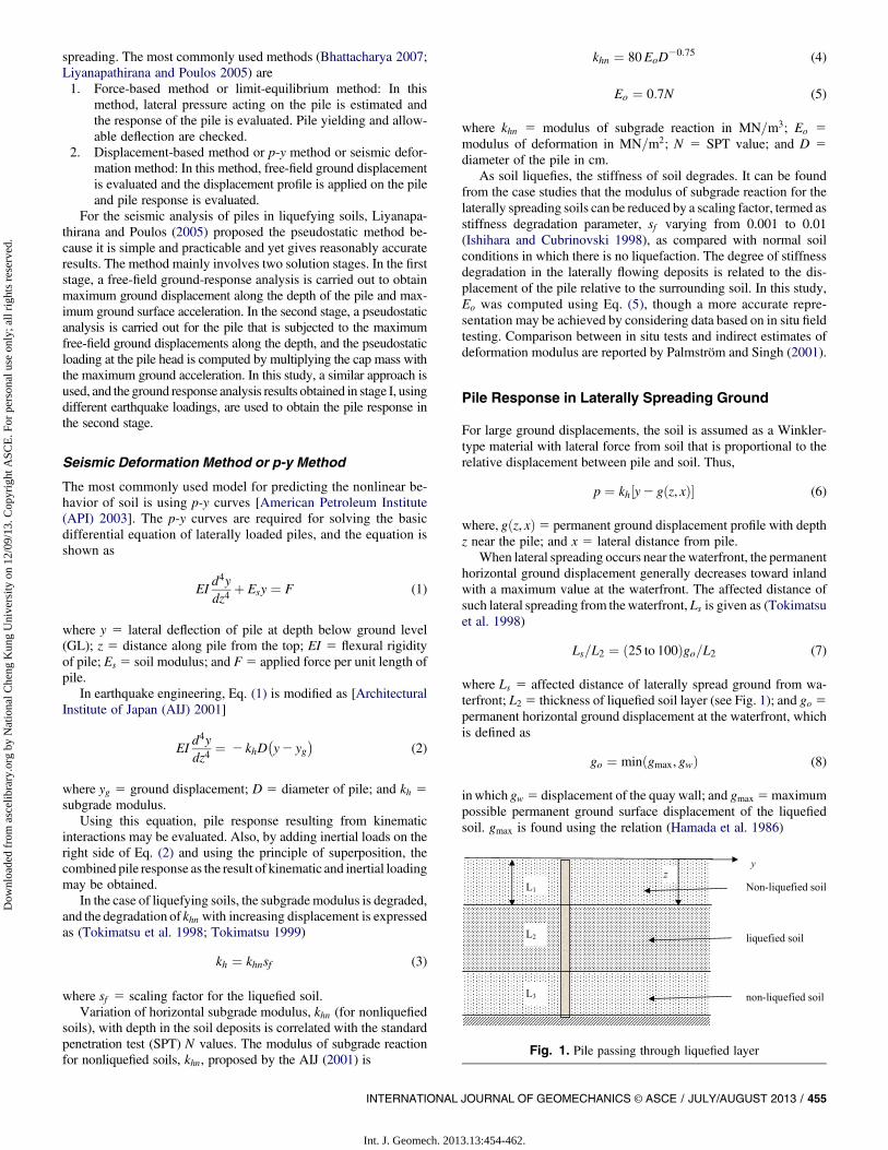
In this study, four typical strong-motion earthquake events that cor-respond to the Bhuj earthquake (2001), the Loma Prieta earthquake(1989), the Loma Gilroy motion (1989), and the Kobe earthquake(1995) were considered for obtaining the pile behavior in liquefy-ing and nonliquefying soils and for free-headed and floating-tip pileboundary conditions. These earthquakes represent wide ranges ofamplitudes [maximum horizontal accelerations (MHA) of 0:106gfor Bhuj (2001), 0:278g for Loma Prieta (1989), 0:442g for LomaGilroy (1989), and 0:834g for Kobe (1989) motion], frequency con-tents, and durations.
Earthquake characteristics, such as date of occurrence, recordingstation, distance from source, maximumhorizontal acceleration, andmoment magnitude Mw, of these strong motion earthquakes arepresented in Table 2. Strong motion records of Kobe (1995), LomaPrieta (1989), and Loma Gilroy (1989) are from Hashash et al.(2008) and Choudhury and Savoikar (2009). Table 2 also showsthe predominant period, mean period, bracketed duration, and
significant duration of the earthquake motions. These results werederived using the seismo-signal program (Earthquake EngineeringSoftware Solutions 2002).
Response of Laterally Loaded Pile in Liquefying Soils
The pile behavior under seismic loads considering stiffness degra-dation was studied for free-headed pile with floating-tip boundaryconditions. The field bore-log data of the Mangalwadi site ofMumbai city, India was considered for obtaining the pile response,and the typical bore-log data (MBH#1) is given in Table 3. Forobtaining the pile response, the results obtained from equivalentlinear ground-response analysis of local soil siteswere approximatedas linearly varying along the depth of soil deposits. The peak groundaccelerations at ground surface obtained from ground-responseanalysis (Phanikanth et al. 2011) were 0:251g for Bhuj (2001)motion, 0:641g for Loma Prieta (1989) motion, 1:136g for LomaGilroy (1989) motion, and 0:917g for Kobe (1995) motion, re-spectively. In this study, the pile length used was 10.0 m and the pilediameter was 0.50 m. Young’s modulus of the pile was assumed tobe 2:743 107 kN=m2. It was assumed that the entire soil depositwas liquefying, and therefore stiffness degradation effects were con-sidered with sf 5 0:01 for evaluating the pile response.
Fig. 2. (a) Nondimensional pile-deflection coefficients in liquefied soils along the depth of soil deposit for various ground surface slopes (free-headedpile with floating tip); (b) nondimensional pile-bending moment coefficients in liquefied soils along the depth of soil deposit (free-headed pile withfloating tip)
INTERNATIONAL JOURNAL OF GEOMECHANICS © ASCE / JULY/AUGUST 2013 / 457
Int. J. Geomech. 2013.13:454-462.
Dow
nloa
ded
from
asc
elib
rary
.org
by
Nat
iona
l Che
ng K
ung
Uni
vers
ity o
n 12
/09/
13. C
opyr
ight
ASC
E. F
or p
erso
nal u
se o
nly;
all
righ
ts r
eser
ved.

In this study, kinematic and inertial loads were imposed sepa-rately, and the combined response was algebraically added. Thekinematic interaction response was obtained by considering theground deformations, ygi, alone in the first stage, and therefore,H5M5 0. In the second stage, inertial loads (H) alone were ap-plied at the pile top as equivalent static loads, and the pile bendingresponse was obtained. Tokimatsu et al. (2005) and Tokimatsu andSuzuki (2005) suggested that the peak pile bending moment in thepile can be estimated by the square root of the sum of squares(SRSS) of the individual moments when Tb (natural period ofstructure) . Tg (ground natural period) as the result of the inertialand kinematic loads and when Tb , Tg algebraic addition is carriedout. In the current study, the bending moments in the pile con-sidering kinematic and inertial interactions are algebraically addedat various nodes along the pile length.
In the current study, the ultimate pile capacity with a suitablesafety factor (allowable load) was estimated as 883.0 kN, and theinertial loads (H) were applied at the pile top, which was obtainedby multiplying cap mass with peak ground acceleration at theground surface. Thus, the inertial loads for Bhuj (2001) inputmotion, Loma Prieta (1989) motion, Loma Gilroy (1989) motion,and Kobe (1995) motion are estimated to be 222.0, 567.0, 1,003.0,and 810.0 kN, respectively. The various input parameters considered
for seismic soil pile interaction, representing SPT, modulus of de-formation, subgrade reaction, ground displacements etc., at variousdepths are presented in Tables 3 and 4.
The maximum depth coefficient (L=T) [where T 5 relativestiffness factors for the pile soil system 5 ðEpIp=hhÞ0:20; EpIp 5flexural stiffness of pile; and hh 5 constant of subgrade reactionkN=m3] for the pile soil system varies from approximately 2.8 to3.4, as can be seen in Table 4, and, therefore, the pile behavioris expected to be rigid/semirigid. The soil pile response in liq-uefying soils considering subgrade modulus evaluated withsf 5 0:01 ð1=100Þ was obtained, and the pile-bending response isshown in Fig. 4, with inertial response and kinematic responseadded algebraically. The peak bending moments were also eval-uated for nonliquefying soils (i.e., without degradation effect,sf 5 1:0), and their results with fully liquefying soils are compared,as shown in Table 5. Clearly, it can be seen that the pile responseis significantly affected in the presence of a liquefiable layer, andthe amplification factor is approximately 2.50 in peak bendingmoments. Kagawa (1992) reported that the amplification in peakbending moments for liquefying soils is as high as 6.0 compared withnonliquefying soils, and many failures observed during earthquakesare because of the inability of pile to sustain such large bendingmoments.
Fig. 3. Verification of present study with field observations (O’Rourke et al. 1994; Meera et al. 2007): (a) pile deflections; (b) bending moments
458 / INTERNATIONAL JOURNAL OF GEOMECHANICS © ASCE / JULY/AUGUST 2013
Int. J. Geomech. 2013.13:454-462.
Dow
nloa
ded
from
asc
elib
rary
.org
by
Nat
iona
l Che
ng K
ung
Uni
vers
ity o
n 12
/09/
13. C
opyr
ight
ASC
E. F
or p
erso
nal u
se o
nly;
all
righ
ts r
eser
ved.
Effect of Depth of Liquefying Layer
In general, the presence of loose saturated cohesionless soils isvulnerable to liquefaction hazards, and the presence of such layersreduces the stiffness of the surrounding soil, which will affect thepile performance. The behavior of pile in liquefied deposits duringearthquakes is a complex dynamic soil-pile interaction problem,which involves the ability to predict whether the soil will liquefy. Toevaluate the depth of liquefying layer methods proposed by Seedand Idriss (1971), Seed (1979), and Iwasaki (1986) may be helpful.In the current study, the effect of the depth of the liquefying layer onthe soil-pile response was studied for free-headed and floating-tipboundary conditions. The overall length of the pile was assumed
to be 10.0 m. As seen in Fig. 1, the parameter L2 denotes the depthof the liquefied layer, andL is the overall length of the pile. The depthof the liquefied layer varies in terms of L2=L from 0.20 to 1.0 (L1 isconsidered to be 0.0). The combined pile-bending responses areplotted in Fig. 5. It can be seen that the maximum bending momentoccurs at the interface between the liquefied layer and the non-liquefied layer. In actual practice, ground deformation is assumed asa trapezoidal distribution with linear distribution in the liquefyinglayer and constant ground deformation in the nonliquefied soil layerpresent above the liquefied soil layer (Meera et al. 2007). However,in the present analysis, linear ground deformation is assumed in eval-uating the pile response, in the two-layer soil deposits considered inthis study. The combined pile-bending response resulting from this
Table 2. Strong-Motion Parameters for Different Earthquakes Considered in the Present Analysis
Earthquake strong motionparameters
Earthquake
Bhuj Loma Prieta Loma Gilroy Kobe
Date of occurrence January 26, 2001 October 17, 1989 October 18, 1989 January 17, 1995Magnitude, Mw 7.7 6.9 7.0 6.9Recording station Passport office building,
AhmedabadPalo Alto Station 1601 Gilroy Array Station 1,
CA-Gavilan College,Water Tank, CA
KJMA station
Distance from source (km) 230 36.3 21. 0.6Maximum horizontal acceleration 0:106g 0:278g 0:442g 0:834gPredominant period (s) 0.26 0.30 0.38 0.36Mean period (s) 0.603 0.652 0.391 0.641Bracketed duration (s) 69.80 29.70 16.22 21.92Significant duration (s) 15.78 11.57 3.70 8.34
Table 3. Input Parameters for Soil-Pile Interaction––Liquefied Condition
Bore hole MBH# 1: Mangalwadi site, Mumbai
Layerno. Stratum
Layerthickness
(m)
Depth belowground level
(m)
Standardpenetrationtest value (N) Eo ðMPaÞ
PilediameterD (cm) khn ðMN=m3Þ sf kh 5 khnsf ðkN=m3Þ Ip ðm4Þ
1 Filled up soil (loose sand) 1.5 1.5 10 7 50 29.78 0.01 297.82 0.00312 Yellowish loose sand 1.5 3 12 8.4 50 35.74 0.01 357.39 0.0031
1.5 4.5 13 9.1 50 38.72 0.01 387.17 0.00311.5 6 16 11.2 50 47.65 0.01 476.52 0.0031
3 Black clayey soil 2 8 20 14 50 59.57 0.01 595.65 0.00314 Yellowish clayey soil 1.8 9.8 25 17.5 50 74.46 0.01 744.56 0.00315 Greyish hard rock .9.8
Table 4. Ground Displacements and Stiffness Factors for the Soil Pile Interaction Analysis––Liquefied Condition
Depth belowground level (m)
yg (m)
Bhuj (2001) Kobe (1995) Loma Prieta (1989) Loma Gilroy (1989) kh ðkN=m3Þ khD ðkN=m2Þ T ½ðEpIp=hhÞ0:2� L=T
0 0.0016 0.1420 0.0433 0.0678 297.82 148.91 3.55 2.821 0.0015 0.1278 0.0390 0.0610 297.82 148.91 3.55 2.822 0.0013 0.1136 0.0347 0.0542 297.82 148.91 3.55 2.823 0.0011 0.0994 0.0303 0.0475 357.39 178.69 3.42 2.924 0.0010 0.0852 0.0260 0.0407 357.39 178.69 3.42 2.925 0.0008 0.0710 0.0217 0.0339 387.17 193.59 3.37 2.976 0.0006 0.0568 0.0173 0.0271 476.52 238.26 3.23 3.097 0.0005 0.0426 0.0130 0.0203 476.52 238.26 3.23 3.098 0.0003 0.0284 0.0087 0.0136 595.65 297.82 3.09 3.249 0.0002 0.0142 0.0043 0.0068 595.65 297.82 3.09 3.24
10 0.0000 0.0000 0.0000 0.0000 744.56 372.28 2.96 3.38
INTERNATIONAL JOURNAL OF GEOMECHANICS © ASCE / JULY/AUGUST 2013 / 459
Int. J. Geomech. 2013.13:454-462.
Dow
nloa
ded
from
asc
elib
rary
.org
by
Nat
iona
l Che
ng K
ung
Uni
vers
ity o
n 12
/09/
13. C
opyr
ight
ASC
E. F
or p
erso
nal u
se o
nly;
all
righ
ts r
eser
ved.

assumption may not alter the overall pile response significantly, askinematic pile-bending moments are negligible compared withpile-bending moments resulting from inertial loads. Also, the resultsindicate that the bending moments are at their maximum when thethickness of the liquefied layer is approximately 60% of the totallayer thickness. If the thickness of the liquefying layer is greater,the pile bending moments are reduced. This may be the result ofsoil failure preceding the pile failure (soil stresses exceeding thesoil strength or passive pressures developed are beyond the shear
strength of the soil). Dobry andO’Rourke (1983) andNikolaou et al.(2001) had proposed simple models for obtaining pile-bendingmoments at the interface of soil layers with stiffness contrast.The kinematic pile-bending moment determined by Dobry andO’Rourke (1983) depends on the shear moduli of the soil layer andthe flexural rigidity of the pile and does not take into account thethickness of soil layers, natural frequency of earthquakes, and thenumber of cycles of earthquakes, which were considered in the sim-plified model of Nikolaou et al. (2001).
Fig. 4. Pile bending moments (combined) in liquefied soils (sf 5 0:01) considering various ground motions (free-headed pile with floating tip)
Table 5. Pile Response in Liquefying Soil versus Nonliquefying Soil
Ground motion
Nonliquefying soil sf 5 1:0 Liquefying soil sf 5 00:01 Amplification
Deflection attop (mm)
Peak bendingmoment (kNm)
Deflection attop (mm)
Peak bendingmoment (kNm)
Deflectionamplification top (mm)
Amplification in peakbending moment (kNm)
Bhuj (2001) 14.50 142.46 542.97 356.77 37.44 2.50Loma Prieta (1989) 76.74 362.67 1,426.32 911.35 18.59 2.51Loma Gilroy (1989) 125.91 642.71 2,513.61 1,611.84 19.96 2.51Kobe (1995) 188.93 519.04 2,117.18 1,301.68 11.21 2.51
Fig. 5. Effect of depth of liquefying layer on the pile bending moments (combined) along depth for the Bhuj earthquake (2001) (free-headed pile withfloating tip)
460 / INTERNATIONAL JOURNAL OF GEOMECHANICS © ASCE / JULY/AUGUST 2013
Int. J. Geomech. 2013.13:454-462.
Dow
nloa
ded
from
asc
elib
rary
.org
by
Nat
iona
l Che
ng K
ung
Uni
vers
ity o
n 12
/09/
13. C
opyr
ight
ASC
E. F
or p
erso
nal u
se o
nly;
all
righ
ts r
eser
ved.

Conclusions
1. Pile response under kinematic loads was validated with avail-able solutions in the literature, and the results are in goodagreement with the available solutions. The ground surfaceslope has significant influence on the pile response, and theresults indicate that the amplification factor was about 1.60 fornondimensional deflection and bending-moment coefficientswhen the ground surface slope was increased from 10 to 40%,and, therefore, pile design must consider the slope effects inlaterally spreading grounds.
2. The pile response in liquefied soils was significantly am-plified compared with that in nonliquefying soils, and theamplification in peak pile-bending moments was as high as2.50.
3. The effect of the depth of the liquefied layer has a significantinfluence on the soil-pile response. Maximum pile-bendingmoments occur at the interface of the liquefying and non-liquefying layers. Maximum pile-bending moments are devel-oped when the thickness of the liquefying soil layer isapproximately 60% of the total thickness of the soil layer.
4. Kinematic pile response was compared with the field obser-vations for an actual earthquake, and the results showeda reasonable agreement with the data from available field-observation studies.
Notation
The following symbols are used in this paper:D 5 diameter of the pile;Eo 5 modulus of deformation (MN=m2);Ep 5 Young’s modulus of pile;Es 5 Young’s modulus of soil;
EpIp 5 flexural rigidity of pile;gmax 5 maximum possible permanent ground displacement
of the liquefied soil;go 5 permanent horizontal ground displacement at the
water front;grs 5 permanent horizontal displacement of the level
ground;gw 5 displacement of the quay wall;
gðz, xÞ 5 permanent ground displacement profile with depth z,near the pile;
H 5 horizontal inertial loads at pile top;kh 5 subgrade modulus of liquefied soil;khn 5 subgrade modulus of nonliquefied soil;L 5 total length of pile;Ls 5 affected distance of lateral-spread ground from water
front;L1 5 nonliquefiable soil cover above liquefied layer;L2 5 depth of liquefied soil layer;L3 5 depth of embedment of pile below liquefied
layer;N 5 standard penetration test (SPT) value;R 5 pile-flexibility factor;sf 5 scaling factor for the liquefied soil;sl 5 gradient of the surface topography;su 5 undrained shear strength;T 5 characteristic length of pile;y 5 pile deflection;yg 5 ground displacement; andz 5 distance from top (ground level).
References
American Petroleum Institute (API). (2003). “Recommended practice forplanning designing and constructing fixed offshore platforms.” API-RP2A-WSD, 21st Ed., Washington, DC.
Architectural Institute of Japan (AIJ). (2001). Recommendations for de-signing of building foundations, Tokyo (in Japanese).
Bhattacharya, S. (2007). “Design of foundations in seismic areas: Prin-ciples and applications.” Proc., Intl. Workshop on Earthquake Geo-technical Engineering, National Information Centre for EarthquakeEngineering, Shibpur, India.
Choudhury,D., Phanikanth,V.S., andReddy,G.R. (2009). “Recent advancesin analysis and design of pile foundations in liquefiable soils duringearthquake: A review.” Proc. Natl. Acad. Sci. India, 79(A), 141–152.
Choudhury, D., and Savoikar, P. (2009). “Equivalent-linear seismic analysesof MSW landfills using DEEPSOIL.” Eng. Geol., 107(3–4), 98–108.
Dobry, R., andO’Rourke,M. J. (1983). “Discussion of “Seismic response ofend bearing piles” by Raul Flores-Berrones and Robert V. Whitman(April, 1982).” J. Geotech. Eng., 109(5), 778–781.
Earthquake Engineering Software Solutions. (2002). Seismo-signal pro-gram. Æhttp://www.SeismoSoft.comæ.
FLAC. (2006). Fast Lagrangian analysis of Continua. User manual version5.0. Itasca Consulting Group, Minneapolis.
Flores-Berrones, R., and Whitman, R.V. (1982). “Seismic response of endbearing piles.” J. Geotech. Eng. Div., 108(4), 554–569.
Haldar, S., and Babu, G. L. S. (2010). “Failure mechanisms of pile foun-dations in liquefiable soil: Parametric study.” Int. J. Geomech., 10(2),74–84.
Hamada, M., Yasuda, S., Isoyama, R., and Emoto, K. (1986). Study onliquefaction induced permanent ground displacements. Association forthe Development of Earthquake Prediction, Tokyo, Japan.
Hashash, Y. M. A., Groholski, D.R., Philips, C.A., and Park, D. (2008).DEEPSOIL v3.5 beta. User Manual and tutorial.” University of Illinoisat Urbana-Champaign, Urbana, IL.
Ishihara, K., and Cubrinovski, M. (1998). “Soil-pile interaction in liquefieddeposits undergoing lateral spreading.” Proc., XI Danube-EuropeanConf., Geotechnical Hazards, A. A. Balkema, Rotterdam, 51–64.
Iwasaki, T. (1986). “Soil liquefaction studies in Japan: State of-the-art.”Soil. Dyn. Earthquake Eng., 5(1), 2–68.
Kagawa, T. (1992). “Lateral pile response in liquefying sand.” Proc., 10thWorld Conf. on Earthquake Engineering, Madrid, Spain, Paper No.1761.
Kavvads, M., and Gazetas, G. (1993). “Kinematic seismic response andbending of free-head piles in layered soil.”Geotechnique, 43(2), 207–222.
Liyanapathirana, D. S., and Poulos, H. G. (2005). “Pseudo-static approachfor seismic analysis of piles in liquefying soil.” J. Geotech. Geoenviron.Eng., 131(12), 1480–1487.
Maheshwari, B. K., and Sarkar, R. (2011). “Seismic behavior of soil-pile-structure interaction in liquefiable soils: Parametric study.” Int. J.Geomech., 11(4), 335–347.
Maheshwari, B. K., and Watanabe, H. (2009). “Seismic analysis of pilefoundations using simplified approaches.” Int. J. Geotech. Eng., 3(3),387–404.
Makris, N., andGazetas, G. (1992). “Dynamic pile-soil-pile interaction. PartII: Lateral and seismic response.” Earthquake Eng. Struct. Dynam.,21(2), 145–162.
MATLAB 7.0 [Computer software]. (2004). Natick, MA, MathWorks.Meera, R. S., and Basudhar, P. K. (2008). “Effect of soil liquefaction on
flexural behavior of axially and laterally loaded piles.” Proc., Geo-technical Earthquake Engineering and Soil Dynamics IV, ASCE,Reston, VA, 1–10.
Meera, R. S., Shanker, K., and Basudhar, P. K. (2007). “Flexural responseof piles under liquefied soil conditions.” Geotech. Geol. Eng., 25(4),409–422.
Nikolaou, S., Mylonakis, G., Gazetas, G., and Tazoh, T. (2001). “Kinematicpile bending during earthquakes: Analysis and field measurements.”Geotechnique, 51(5), 425–440.
Nogami, T., and Chen, H. L. (1987). “Prediction of dynamic lateral responseof nonlinear single pile by using Winkler soil model.” Proc., Session
INTERNATIONAL JOURNAL OF GEOMECHANICS © ASCE / JULY/AUGUST 2013 / 461
Int. J. Geomech. 2013.13:454-462.
Dow
nloa
ded
from
asc
elib
rary
.org
by
Nat
iona
l Che
ng K
ung
Uni
vers
ity o
n 12
/09/
13. C
opyr
ight
ASC
E. F
or p
erso
nal u
se o
nly;
all
righ
ts r
eser
ved.
on Dynamic Response of Pile Foundations-Experiments, Analysis andObservation, ASCE, Atlantic City, NJ, 39–52.
Novak,M. (1974). “Dynamic stiffness and damping of piles.”Can.Geotech.J., 11(4), 574–597.
O’Rourke, T. D., Meyersohn, W. D., Shiba, Y., and Chaudhuri, D. (1994).“Evaluation of pile response to liquefaction induced lateral spread.”Technical Rep. NCEER-94-0026, National Center for Earthquake En-gineering Research (NCEER), Buffalo, NY, 457–479.
Palmström, A., and Singh, R. (2001). “The deformation modulus of rockmasses––Comparisons between in situ tests and indirect estimates.”Tunnelling Underground Space Technol., 16(2), 115–131.
Phanikanth, V. S., Choudhury, D., and Reddy, G. R. (2011). “Equivalentlinear ground response analysis of some typical sites in Mumbai city.”Geotech. Geol. Eng., 29(6), 1109–1126.
Poulos, H. G., and Davis, E. H. (1980). Pile foundation analysis and design,Wiley, New York.
Rayhani, M. H. T., and El Naggar, M. H. (2008). “Numerical modeling ofseismic response of rigid foundation on soft soil.” Int. J. Geomech., 8(6),336–346.
Seed, H. B. (1979). “Soil liquefaction and cyclic mobility evaluation forlevel ground during earthquakes.” J. Geotechnical Eng. Div., 105(2),201–255.
Seed, H. B., and Idriss, I. M. (1971). “Simplified procedures for evaluatingsoil liquefaction potential.” J. Soil Mech. Found. Div., 97(9), 1249–1273.
Semblat, J. F., and Brioist, J. J. (2000). “Efficiency of higher order finiteelements for the analysis of seismic wave propagation.” J. SoundVibrat.,231(2), 460–467.
Shamato,Y., Zhang, J.M., andTokimatsu,K. (1998). “Methods for predictingresidual post-liquefaction ground settlement and lateral spreading.” SoilsFound., 38(special issue No. 2), 69–83.
Tokimatsu, K. (1999). “Performance of pile foundations in laterally spread-ing soils.” Proc., 2nd Int. Conf. on Earthquake Geotechnical Engi-neering, Lisbon, Portugal, 957–964.
Tokimatsu, K., Oh-oka, H., Satake, K., Shamoto, Y., and Asaka, Y.(1998).“Effects of lateral ground movements on failure patterns of pilesin the 1995 Hyogoken-Nambu earthquake.” Geotechnical EarthquakeEngineering and Soil Dynamics 3rd Conf., ASCE, 1175–1186.
Tokimatsu, K., and Suzuki, H. (2005).“Effect of inertial and kinematicinteractions on seismic behavior of pile foundations based on largeshaking table tests.”Proc., 2nd CUEE Conf. on Urban EarthquakeEngineering, Tokyo Institute of Technology (Japan).
Tokimatsu, K., Suzuki, H., and Sato, M. (2005). “Effects of dynamic soil-pile structure interaction on pile stresses.” J. Struct. Construct. Eng.,587, 125–132.
462 / INTERNATIONAL JOURNAL OF GEOMECHANICS © ASCE / JULY/AUGUST 2013
Int. J. Geomech. 2013.13:454-462.
Dow
nloa
ded
from
asc
elib
rary
.org
by
Nat
iona
l Che
ng K
ung
Uni
vers
ity o
n 12
/09/
13. C
opyr
ight
ASC
E. F
or p
erso
nal u
se o
nly;
all
righ
ts r
eser
ved.