risk assessment of liquefied petroleum gas storage facility
80
RISK ASSESSMENT OF LIQUEFIED PETROLEUM GAS STORAGE FACILITY A DISSERTATION Submitted In partial fulfillment of the requirements for the award of the degree of MASTER OF TECHNOLOGY In CHEMICAL ENGINEERING (With Specialization In Industrial Safety and Hazards Management) I C,. L OO Data By /, 141RUFAMA DEPARTMENT OF CHEMICAL ENGINEERING INDIAN INSTITUTE OF TECHNOLOGY ROORKEE ROORKEE -247 SIT (INDIA) JUNE, 2010
-
Upload
khangminh22 -
Category
Documents
-
view
1 -
download
0
Transcript of risk assessment of liquefied petroleum gas storage facility

RISK ASSESSMENT OF LIQUEFIED PETROLEUM GAS STORAGE FACILITY
A DISSERTATION Submitted In partial fulfillment of the
requirements for the award of the degree of
MASTER OF TECHNOLOGY In
CHEMICAL ENGINEERING (With Specialization In Industrial Safety and Hazards Management)
IC,.
LOO Data
By /,
141RUFAMA
DEPARTMENT OF CHEMICAL ENGINEERING INDIAN INSTITUTE OF TECHNOLOGY ROORKEE
ROORKEE -247 SIT (INDIA) JUNE, 2010

CANDIDATE'S DECLARATION
I hereby declare that the work, which is being presented by me in this project report titled "RISK ASSESSMENT OF LIQUEFIED PETROLEUM GAS STORAGE FACILITY", in partial fulfilment of the requirements for the award of the degree of Master of Technology in Chemical Engineering with specialization in "Industrial Safety and Hazards Management", is an authentic record of the work carried out by me under the guidance of Dr. Shishir Sinha, Associate Professor and Dr. Prakash Biswas Assistant Professor, Department of Chemical Engineering, Indian Institute of Technology Roorkee. The matter embodied in this work has not been submitted for the award of any other degree.
Date: t_ 16 I-WO
Place: Indian Institute of Technology Roorkee (NIRUPAMA)
CERTIFICATE
This is to certify that the above statement made by the candidate is correct to the best of my knowledge.
Dr. Shishir Sinha Dr. Prakash Biswas Associate Professor Assistant Professor Department of Chemical Engineering Department of Chemical Engineering Indian Institute of Technology Roorkee Indian Institute of Technology Roorkee

. ACKNOWLEDGEMENT
Nothing worth more than praising and acknowledgement at the way outset, the eternal and immense benevolence of the Almighty God who endowed with the power of intellect and convergence. It is His will which has enabled me to accomplish my work which otherwise would not have been possible.
It is with a deep sense of gratitude that I profoundly acknowledge my indebtness to my guide Dr. Shishir Sinha, Associate Professor and co-guide Dr. Prakash Biswas, Assistant Professor, Chemical Engineering Department for their perceptive suggestions and comments that helped me to remain motivated and enthused in compiling my dissertation work. Their infallible supervision and guidance has made this work a more rewarding experience for me.
I would like to thank Dr. I D Mall, Head of the Chemical Engineering Department _ for providing various facilities during the course of this project work. I would like to thank all the teaching and non teaching staff members who have contributed directly or indirectly in successful completion of my project work. Thanks are due to CAD Centre facilities.
I am greatly indebted to all my friends for their enthusiastic support, encouragement and help during dissertation work.
I would also like to express my gratitude to the authors and publishers of textbook, magazines, journals and websites from where I have collected the materials and information for this report.
Last but not the least, it is all owed to the blessings of my parents which helped me to complete the work in due time.
NIRUPAMA

ABSTRACT
Storage tanks are very important for containing small to large volumes of flammable and
hazardous chemicals at elevated temperature and pressure in chemical process industries.
There are various organizations and engineering societies who published strict engineering
guidelines and standards for the construction, material selection, design and safe management
of storage tanks and their accessories. Even after following these standards and guidelines in
the design, construction and operation, tank accidents do happen. By preventing equipment
failure rate, the frequency of risk reduces but its impact is still high. Therefore, scope of risk
assessment in the process industries widen to cover hazards related to workers and property
in and near the plant.
Liquefied Petroleum Gas (LPG) is very common fuel for domestic and industrial
purpose. LPG storage tank has severe degree of hazard. A simple risk assessment method was
used to find the risk associated with the three LPG storage tanks having 100 tonnes each of a
LPG bottling plant. Fault tree analysis was used to identify the hazards and its frequency.
Four main events were identified which can lead to fire and explosion: overfilling,
overpressure, mal-operation and mechanical failure/damage which can further lead to open
vapour cloud explosion and catastrophic failure of the tank. Impact of various accident
scenarios (pool fire, fireball and vapour cloud explosion), was calculated in terms of
individual risk to the society. It was found out that pool fire contributes less hazards to people
but it can cause accident in the nearby equipment or property due to its thermal radiation. The
largest contribution to the individual risk is due to vapour cloud explosion. Impact of worst
case scenario was calculated and found that risk near 600 m from the LPG storage tank
location was acceptable.

PAPER COMMUNICATED
RISK ASSESSMENT OF LIQUEFIED PETROLEUM GAS STORAGE FACILITY•
Submitted to Chemical Sciences Journal on May 19th 2010, authored by Nirupama and Shishir Sinha.
A

rARJeY Y 1►1~~;
PAGE NO.
CANDIDATE'S DECLARATION I
ACKNOWLEDGEMENT II
ABSTRACT III
CONTENTS V
LIST OF FIGURES VII
LIST OF TABLES VIII
NOMENCLATURE IX
1. CHAPTER 1
INTRODUCTION 1
1.1 Risk Assessment 2
1.2 Acceptable Risk
2
1.3 Liquefied Petroleum Gases 3
1.4 LPG Related Hazard
3
1.5 Aim and Objective 5
2. CHAPTER 2
LITERATURE REVIEW
3
3. CHAPTER 3
RISK ASSESSMENT METHODOLOGY 20
3.1 Some Important Definitions Related to Risk Assessment 20
3.2 Risk Assessment 20
4. CHAPTER 4
DEFINITION OF THE PROBLEM 29
4.1 Storage Tank Accessories
30
4.2 Properties of LPG 30
4.3 Sources for creating Hazardous scenarios 30
5. CHAPTER 3
RESULT AND DISCUSSION
33
5.1 Hazard Survey 33
V

5.2 Hazard identification 34
5.3 Frequency Estimation 41
5.4 Consequences Analysis 43
5.5 Measure of Risk
50
CONCLUSION 51
REFERENCES 53
APPENDIX 57
VI

LIST OF FIGURES
S. No. Figure Description Page No.
1 4.1 LPG Bottling Plant 29
2 4.2 Schematic Diagram of an LPG Storage Tank 32
3 5.1 Fault tree for fire/ explosion due to release of LPG to the 35
atmosphere
4 5.2 Fault tree for Overfilling 36
5 5.3 Fault tree for Overpressure 37
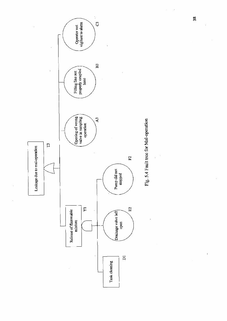
6 5.4 Fault tree for Mal-operation 38
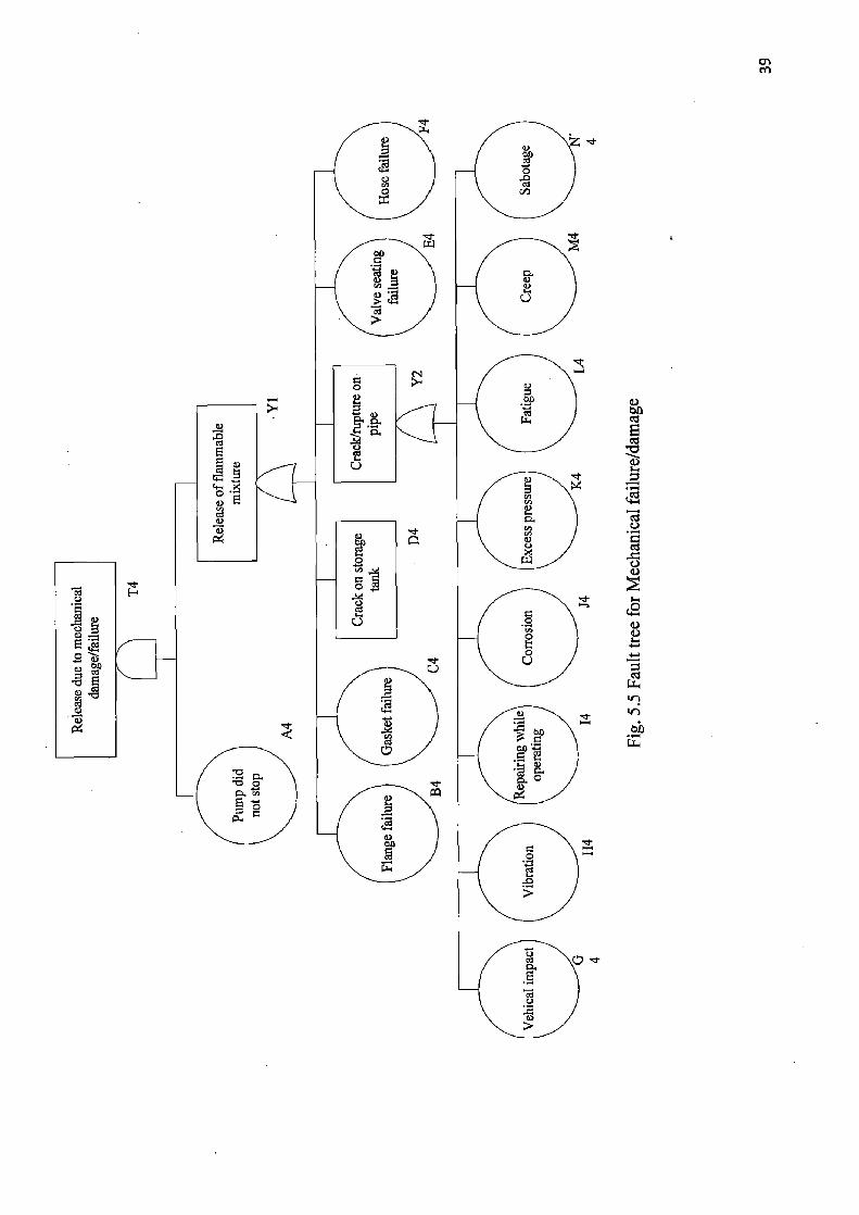
7 5.5 Fault tree for Mechanical failure/damage 39
8 5.6 Fault tree for catastrophic failure of tank 40
9 5.7 Conditional probability of human death vs human death 44
for fireball due to catastrophic failure of one LPG storage
tank
10 5.8 Conditional probability of human death vs human death 45
for fireball due to catastrophic failure of two LPG storage
tanks
11 5.9 Conditional Probability of Human Death Vs Human 45
Death for Fireball Due to Catastrophic Failure of All the
Three LPG Storage Tanks
12 5.10 Conditional probability of human death vs human death 47
for VCE due to catastrophic failure of one LPG storage
tank
13 5.11 Conditional probability of human death vs human death 48
for VCE due to catastrophic failure of two LPG storage
tanks
14 5.12 Conditional probability of human death vs human death 48
for VCE due to catastrophic failure of three LPG storage
tanks
15 5.13 The Individual Risk Contours 50
VII

LIST OF TABLES
S. No. Table Description Page No.
1 2.1 Summary of Literature Review 9
2 3.1 Dow Fire &Explosion Index (Dow F&EI) Degrees of 21
Hazards
3 3.2 Boolean logic functions used for fault tree 22
4 3.3 Basic probability relation 23
5 3.4 The conditional probabilities of a human death in 24
dependence on the probit-function Pr Values
6 5.1 Result of Dow fire & explosion (F&EI) 33
7 5.2 Impact distance for percentage death/injury of human 46
due to different scenario of fireball
8 5.3 Damage distances for different thermal heat radiation 46
in case worst case
9 5.4 Impact distance for percentage death of human due to 49
different scenario of VCE
NOMENCLATURE
Fl General process hazards
F2 Special process hazards
F3 Process unit hazards factor
Pr Probit-function
t An effective exposure time, s
q Thermal radiation intensity, kW/m2
to Characteristic time of a fire detection,s
x Distance from human location to safe zone, m
u Velocity of a human motion to safe zone, m/s
Ef Mean flame surface radiation intensity, kW/m2 Fq Angle coefficient
i Coefficient of atmosphere transparency
r Distance from geometric pool fire centre to an object, m
d Effective pool diameter, m
H Flame height, m
m' Specific mass of burning liquid, kg/m2s
Pb Ambient air density, kg/m3
g Gravitational constant, m/s2 Ds effective fireball diameter, m
m Mass of a combustible substance participating in the fireball formation, kg
Hb height of the fireball centre over the ground surface, m
rb Distance from an object to a point on the ground surface under fireball centre, m
V ( 17500 8-a + r 290 1 0 ' 3
l AP ) AP Maximum pressure in a shock wave, Pa
i Impulse of a shock wave
Po Atmospheric pressure, Pa
re Distance from a geometric centre of a vapour cloud to an object, m
ms Specific mass of a combustible vapour in cloud, kg
Qc specific heat of a vapour combustion, J/kg
Q, Constant equals to 4.52 x 10⁶ J/kg IX

Z Coefficient of a vapour participating in an explosion
m,, Vapour mass in the cloud, kg
n Number of event or scenario
Qdi Conditional probability of a human death which is given in probit-function
Q(A1) A year probability of realization of the i-th event per year
X
CHAPTER 1
INTRODUCTION
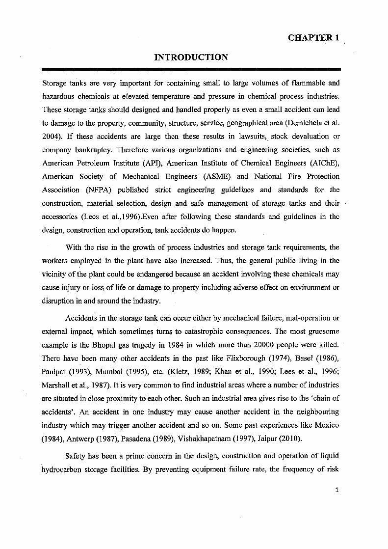
Storage tanks are very important for containing small to large volumes of flammable and
hazardous chemicals at elevated temperature and pressure in chemical process industries.
These storage tanks should designed and handled properly as even a small accident can lead
to damage to the property, community, structure, service, geographical area (Demichela et al.
2004). If these accidents are large then these results in lawsuits, stock devaluation or
company bankruptcy. Therefore various organizations and engineering societies, such as
American Petroleum Institute (API), American Institute of Chemical Engineers (AIChE),
American Society of Mechanical Engineers (ASME) and National Fire Protection
Association (NFPA) published strict engineering guidelines and standards for the
construction, material selection, design and safe management of storage tanks and their
accessories (Lees et al.,1996).Even after following these standards and guidelines in the
design, construction and operation, tank accidents do happen.
With the rise in the growth of process industries and storage tank requirements, the
workers employed in the plant have also increased. Thus, the general public living in the
vicinity of the plant could be endangered because an accident involving these chemicals may
cause injury or loss, of life or damage to property including adverse effect on environment or
disruption in and around the industry.
Accidents in the storage tank can occur either by mechanical failure, mal-operation or
external impact, which sometimes turns to catastrophic consequences. The most gruesome
example is the Bhopal gas tragedy in 1984 in which more than 2000.0 people were killed.
There have been many other accidents in the past like Flixborough (1974), Basel (1986),
Panipat (1993), Mumbai (1995), etc. (Kletz, 1989; Khan et al., 1990; Lees et al., 1996;
Marshall et al., 1987). It is very common to find industrial areas where a number of industries
are situated in close proximity to each other. Such an industrial area gives rise to the `chain of
accidents'. An accident in one industry may cause another accident in the neighbouring
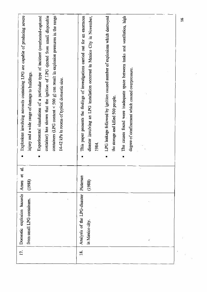
industry which may trigger another accident and so on. Some past experiences like Mexico
(1984), Antwerp (1987), Pasadena (1989), Vishakhapatnam (1997), Jaipur (2010).
Safety has been a prime concern in the design, construction and operation of liquid
hydrocarbon storage facilities. By preventing equipment failure rate, the frequency of risk
1
reduces but its impact is still high. Therefore, scope of risk assessment in the process
industries widen to cover hazards related to workers and property in and near the plant. This
led to the rise of Risk Assessment as a powerful tool in the process industries.
1.1 RISK ASSESSMENT
Risk assessment is a step in a risk management process and very important tool for analysing
the systems and proposing cost effective mitigation measures thus making industries safer
and more reliable. Risk assessment includes incident identification and consequence analysis.
Incident identification describes how an accident occurs. It frequently includes an analysis of
the probabilities. Consequence analysis describes the expected damage. This includes loss of
life, damage to the environment or capital equipment and days outage. Risk assessment is the
determination of quantitative or qualitative value of risk and to find the hazards associated.
Quantitative risk assessment is the calculation of two components of risk, first is the
magnitude of the potential loss and second is the probability of the occurrence of the loss.
Dealing with these hazards following questions have to be answered:
• to what extent can a technological hazard be considered acceptable?
• to what extent should the hazards that are considered conditionally acceptable be
reduced in the light of societal and economic factors?
1.2 ACCEPTABLE RISK
The goal of risk assessment is to reduce risks to an acceptable or tolerable level. A zero risk
level is not possible. The basis of design is ALARP which stands for `As Low As Reasonably
Practicable'. Principle of ALARP is associated with the design and development of safety
systems and captures the notion that the risk to individuals, society and the environment
should be low as reasonably practicable. A risk should be low enough such that attempting to
make it lower would actually be more costly than any cost likely to come from the risk itself.
This is called tolerable risk. Risk reduction involves cost which increases exponentially with
the reduction measures implemented and thus, infinite time, effort and money will be
required to reduce a risk to zero. It should not be understood as simply a quantitative measure
of benefit against detriment. A major factor that comes into the ALARP principle is the cost
of assessing the improvement gained in an attempted risk reduction. In extremely complex
systems, this can be very high and could be the limiting factor in practicality of risk reduction
(Lees et al., 1996). It has now become an essential part in any industry to identify the
hazards, assess the associated risks and to bring the risks to a tolerable level.

1.3 LIQUEFIED PETROLEUM GASES (LPG)
Liquefied petroleum gas is one of the most common and an alternative fuels used in the world
today. Liquefied petroleum gas is also called as LPG, LP Gas, or Auto gas. LPG is obtained
as a by product when refining crude oil or natural gas and is primarily composed of propane
and butane with smaller amounts of propylene and butylenes. LPG is widely used and stored
for domestic, leisure, commercial and industrial purpose and is widely transported by road,
rail and through pipelines. LPG is kept in containers ranging in capacity from a few grams to
thousands of tonnes and in both fixed and mobile or portable systems.
For economical transportation, petroleum gases are liquefied. These liquefied gases
are stored in either pressure, semi-pressure or fully refrigerated condition. The vessels are
surrounded with a bund in case of any leakage due to failure of vessel. Small quantity Iike
100 tonnes is mostly stored in pressure vessels and very large quantity in semi-pressure or
fully refrigerated (Buschmann, 1974).Pressure vessel is suitable for storing LPG and stored at
petroleum storage terminals, chemical works and many non chemical factories (Lees et al.,
1996).
1.4 LPG RELATED HAZARD
The fire and explosion hazard of LPG storage vessel is extremely high (Shebeko et al.,
1995a). There are a number of possible hazardous scenarios which can occur in the LPG
installation, irrespective of its size (Melchers et al., 2001).
These hazard are well documented in literatures, some of the most significant hazards are:
1.4.1 Boiling Liquid Expanding Vapor Explosion (BLEVE): BLEVE is defined as a major
container failure, into two or more pieces when the contained liquid is at a temperature well
above its boiling point at atmospheric pressure. The rupture of LP-gas containers is one
particular type of BLEVE that has drawn much attention due to the destructive and
spectacular effects of the failure (Abbasi et al. 2007). LP-gas containers are steel pressure
vessels equipped with pressure relief devices set to maintain sufficient pressure to keep the
LP-gas as liquid but to relieve any pressure greater than the container is designed to
withstand. Heat radiation is the main hazard associated with BLEVE (Ruj et al. 2006).
1.4.2 Fireball: When superheated liquid like LPG release, if immediately ignited, may burn
as a fireball. The fireball grows larger and moves upward continuously because of buoyancy.
The duration of the fireball is small but the radiation levels are intense. Within the radius of
the fireball there will be severe damage to process equipment and buildings. Beyond this, the
3

danger is mainly for the people that may be affected by the radiation. Therefore, the fireball
radius is defined as the domino effects radius.
1.4.3 Unconfined Vapor Cloud Explosions (UVCE): When LPG release from the tank and
form clouds of vapour without ignition taking place, it ignited later at a considerable distance
from the release point. Overpressure is important in terms of consequences to human and
property. The effects have ranged from minor damage to structures to major damage to the
entire plant..
1.4.4 Flash Fire: This is a lesser form of UVCE due to less amount of gas involved. Heat
radiation is more significant than overpressure in terms of consequences.
1.4.5 Jet Fire: A high pressure release of vapour or vapour/aerosol into free space, if ignited,
will burn as a flame jet. Any equipment on which that flame jet impinges would be subjected
to very high thermal loads, often exceeding the capacity of fixed water sprays. Outside the
flame jet, radiation hazards are very small.
1.4.6 Pool Fire: Pool fires can occur when a significant quantity of liquid is released and
immediately ignited. These can be confined, e.g. in case of releases in containment dikes or
unconfined, e.g. in case of releases from LPG storage tank (Mudan, 1984). There will be less
problems if plants have proper layout and drainage.
In the present work, risk assessment of Liquefied Petroleum Gas (LPG) storage
facilities was done. Risk analysis for LPG storage facilities is described in many papers
(Drysdale et al., 1979/80; Roberts et al., 1981; Pietersen et al., 1988; Crocker et al., 1988;
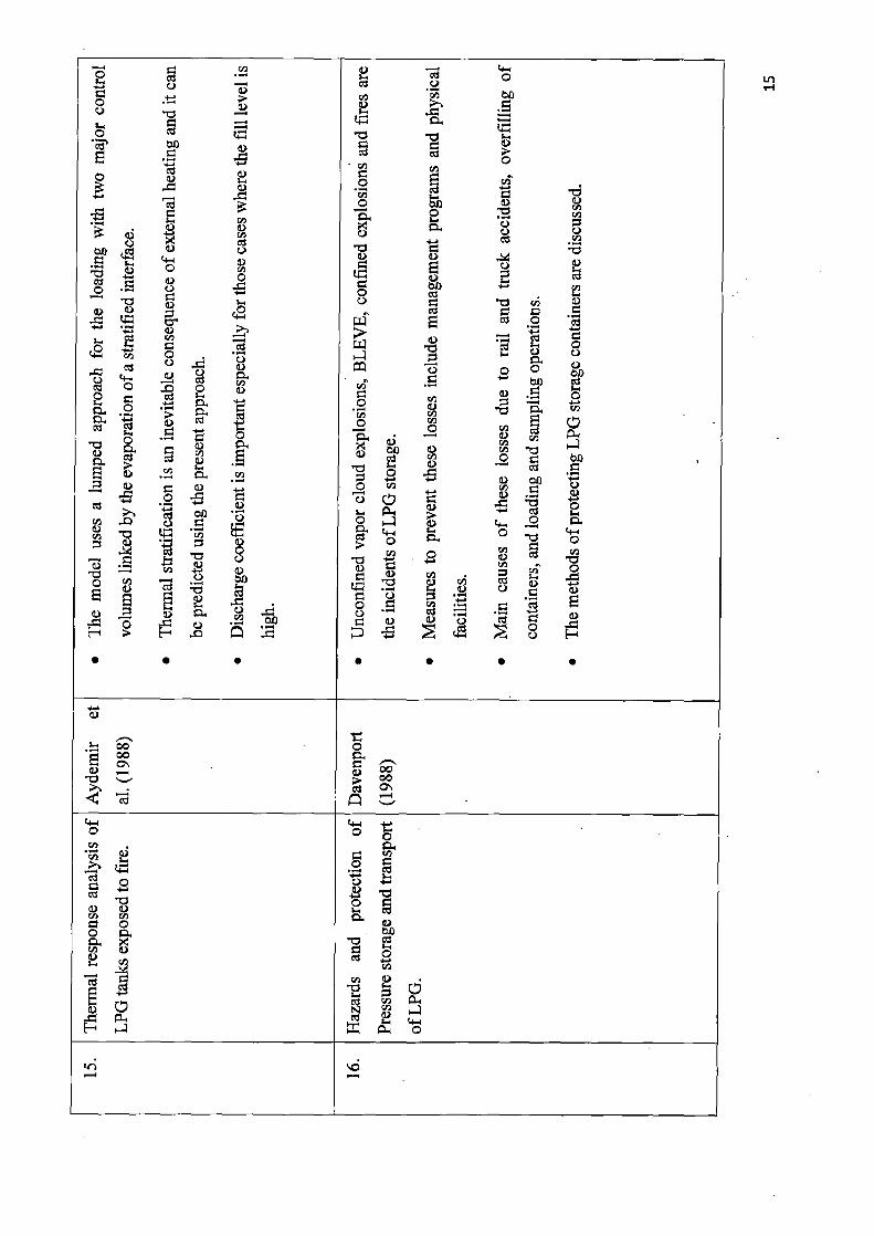
Ames et al., 1988; Aydemir et al. 1988; Davenport et al. 1988; Khan, 1990; Pietersen et al.,
1990; Shebeko et al.,1995; Melchers et al., 2001; Robert et al., 2001; Stawczyk et al., 2003;
Demichela et al., 2004; Ruj et al. 2006; Park et al., 2006; Bubbico et al., 2008; Razus et al.,
2009). Most of the papers are based on hazard analysis of accidental release of LPG from
storage facility and during refuelling. Some papers analyse the hazards on the basis of
experiments and some are from the past accidents. In present work simple risk assessment
methodologies are used to quantify the risk associated with the LPG storage facilities.
4

1.5 AIM AND OBJECTIVE
To assess risk imposed by LPG bottling plant with focus on LPG storage tank by the
following methodology:
1. Characterizing and analysing hazard using Dow fire and explosion index.
2. Determination of Individual Risk of LPG storage tank by the following steps:
i. Identification of major process hazards using fault tree analysis and
calculation of overall hazard frequency.
ii. Calculation. of impact of thermal radiation and overpressure for various
accident scenarios such as pool fire, fire ball and vapour cloud explosion.
3. Critically examine the result obtained and suggest risk reduction if needed.
5

CHAPTER 2
LITERATURE REVIEW
Flixborough accident (1974) which was shortly followed by Beek (1975), Bhopal gas tragedy
(1984), Mexico city (1984) (Lees et al., 1996) shook the chemical process industries (CPI)
and forced it towards the massive revamp with special attention to the safety and loss
prevention. With the increasing public concern and awareness and government initiatives,
risk reduction became an integral part. This led to the development of the special field of
safety engineering with entire gamut of techniques and extensive studies about hazards and
risks posed by the chemical process industries (Crowl et al., 1990).
The Loss Prevention is very important to countless companies, municipalities and
governments around the world, because of the trend for processing plants to become larger
and often be situated in or close to densely populated areas, thus increasing the hazard of loss
of life or property. Lees et al., 1996 gave a complete collection of information on the theory,
practice, design elements, equipment, regulations and laws covering the field of process
safety. He discussed about the hazard assessment which is the important tool for decision-
making on hazards. The main focus was process industries, but the process aspects of related
industries, notably nuclear power, oil and gas platform are briefly touched. Guidelines of
CCPS/AIChE were followed and cover all the aspects of hazard, fire, explosion and toxicity
in a very fine manner. Reliability engineering, design relief valve system and transportation
of the chemicals were also included.
Dow fire and explosion index hazard classification guide designed to help the user to
quantify the expected damage of potential fire and explosion incidents in realistic terms,
identify the equipment likely to contribute to the creation or escalation of an incident and
communicate the fire and explosion risk potential to management. It was first published in
1964 as a tool for plant engineers to give relative value to the risk of individual process unit
losses due to fires and explosions and to communicate these risk to management in terms
easily understood, i.e., potential of financial losses due to lost production and damage to plant
facilities. This index is still widely used and has been upgraded seven times. This index
estimates the hazards of a single process unit based on chemical properties and inventories,
and then uses plant construction cost or replacement cost to estimate the potential risk in
dollar terms. This communicate to develop an index, which is a measure of risk and takes
0

into account risk reduction measures implemented or proposed for the plant unit, such as
process control systems, material isolation systems and fire protection systems. Thus as the
F&EI rates the hazards, the proposed index rates the risk. The index has been adjusted based
on both internal and external data as well as qualitative and quantitative analysis. The main
aim of this tool is to communicate the risk to management in such a way that management
may take appropriate actions to reduce the risk. The purpose is not to rate a given facility as
safe or unsafe, but to give a relative ranking of hazards and risks within an organization. The
current version of the guide is available from AIChE (1994), and is referred to as the F&EI
Guide in the remainder of this communication.
Crowl et al., 1990 described and combined academic theory with practical industry
experience, updated to include the latest regulations and references, covers hazard
identification, risk assessment and inherent safety. They also included case studies and
problems to enhance learning. He gave primary focus on technical fundamentals of chemical
process safety which provides a solid groundwork for understanding with full coverage of
both prevention and mitigation measures. In addition, he also included an overview of
government regulations, dispersion modeling, source modeling, flammability
characterization, fundamentals of static electricity and explosion venting. He also has given
extensively new case histories, as well as important material from the American Institute of
Chemical Engineers' Center for Chemical Process Safety. Firstly he has given overview of
the risks of chemical processes and then the nature of accidents leading approaches to
chemical engineering safety and the ethics of chemical engineering. Next, he reviewed the
fundamentals of toxicology, showing how toxicants enter and are eliminated from biological
organisms: their impact, the dose vs response relationship and other key issues. Coverage
includes industrial hygiene identification, evaluation, and control source models of liquid
flow, toxic release and dispersion models, the nature and prevention of fires and explosions,
the use of reliefs, the identification of hazards and more.
Khan et al. 1999 briefly recapitulated some of the major accidents in chemical process
industries which occurred during 1926-1997. In these case studies they had analysed with a
view to understand the damage potential of various types of accidents, and the common
causes or errors which have led to disasters. An analysis of different types of accidental
events such as fire, explosion and toxic release had also been done to assess the damage
potential of such events. Finally they concluded that vapour cloud explosion (VCE) poses the
greatest risk of damage. Their study highlights the need for accident forecasting, consequence
7

assessment, and development of up-to date emergency preparedness and disaster
management plans in the chemical process industries.
Chang et al., 2006 reviews 242 accidents of storage tanks that occurred in industrial
facilities over last 40 years. The causes and the contributing failures that led to accidents were
expressed with a fishbone diagram in a systematic way. Corrective actions are also provided
to help operating engineers handling similar situations in the future. They had shown that
74% of accidents occurred in petroleum refineries, oil terminals or storage. Fire and
explosion account for 85% of the accidents. There were 80 accidents (33%) caused by
lightning and 72 (30%) caused by human errors including poor operations and maintenance.
Other causes were equipment failure, sabotage, crack and rupture, leak and line rupture, static
electricity, open flames, etc. Most of those tank accidents would have been avoided if good
engineering in design, construction, maintenance and operation has been practiced and safety
management program has been implemented and executed.
8

G)
I
C i
A
•y
a) C
O
r/)
N
N
'~' bA O
iii
4- U
¢
5.
4 Lr" O
~U
0
cxd G) U
~' v] s' }~ Lr
rn y
o 0 0 y
O
U --~
O ...
•ice+
o cd
vO~i
O+ C
a).'
y
o
>>
O
c- y
OO ~,
C U O am
0 y
o V
O
Oa)
N
y
v
- eC bA
.O U
b4 ri~ U
U
o
N
M y
..a
~'
f'~ 4~
~~ O
~1.
[~
0 c~G
b
rA
~L
~4O•I
'C
E O
y~ ~ i
cn 0
*~ b p U
fl
O
cad v 0
inn
.
O
O y
cd -d O
0
F4 4.4
0
by
0
O -
Cd
bA
•bp O
U O
N 0 U
~+ + -i'' O y
vUi . U
b0
Qom' ,~ C~.~
0
9
tl.
U
rn
- 4 a)
" ;
a,
U U
b
O CCS
2
rte+
V
i
G)
O
O O
a)
- N a-~+ 4•. O
E
T3
U
N
o.
O U
b U ID.
O
U
W
O~7
F~•i
O
~
• U_
'O
Qa u
O y cI
> CA
a
r U
c
O U
•~ U ¢
N
H
w
E
a >
0
o
¢ a
z ~ N
a

..
nn - U
a'
CI ^d
V
bn
9 •i:
Cl)
•~
r,
.0
C
—
•~
Cd
U
En - ..
y U
N
;~ ~ ,
'
X a) N
U
aS °
Cl)
3
o o
O
' 5-
- ~i °
- Cd
v ~
C)
O
a) E
°' a
Cc
C °'
~. o
0 .E 3 o
U C) (1) a~ 0
o
3 Q)
y ~'
—
4i O 0
'b U
° O.
o ° U'
N C) °'
it
b
e,
o
0
y
0 cd U
U
y
N
p
0
~a
..
`0 0 • vn ed
~' 44
O
Cd
C/)
O 'C
cu,
• p
O
U
-d
rn U
CA v~'i
~n
U
i
a)
-d U 0
5-
° O
.9 N
Cd O
..
v1
U
a
O
a)
~ N
cd
v
r U 4r
Cd Cd id 4-4 4.'
Cd - O
bn w
°' • C
W ai 0 U
C 0
C
o
Cl)
- C, LL
•~
CC/)l)
Cl) .0
O
~ ~
~v1 '~ U
N
v] y-%
,.r
U : 0
M

o
4-a
aA •
..-
4-.
v
b
H
0
d
o bO
bA
b
0
V
a)
°
pa
as
a)
0 o
>, -
a) .
N ci) ~
3
o
-
C
c
~~
a
U
a)
L~ a
m
°
_
Fr
0 •—
on •~
—
vn
v
cd 3
o
~
a
ci)
c—
E b
cn
o .~
.d 3
E
pp
'C
N
.d
o Cl) N cd
bO
IL
O
0+
ci)
y
o
a) °
E C
'w awn
O
v
U
b
vii
b
.~
c
O
N
•O
i U ^
.- a v
~
O
o
as
aa) ' a
'4 -r.
aa) o

0
U cd
4 i
,
&
can tu
a ~.
N 0
. 0 ~ -
`d cd
cad
U
o
a a,
E
cd
U
CS O v~
o
n
O
0
U
L8
is
y O p
•
vii Cd " ~
-
'~
vUi
p
to U
2 a) G) 0
U - .
O `~ . U'
U
bA
U
O bA
Cd
'~ rn
O O ¢•
O O
ai
,sue'
t~d
O
°'
U' }2.
a)
p Cl) y --
0 U
-
O
O„
b ~t cd
O U' y --
U
c
O O
U
~ U
O
o o
p
., cad it
+r
a)0
-d
4 '
'r' y
4-
k O p
U
6 C
C
'
I~ k
0
E o
O
d) N
o
a)
a)
E 2 y O
0 r U 4 s
3 - S~
-
bA c~ ~+ v O
• . . . . .
as
~ x M
►~i u C1] u bO
•
b N N
rID
v
U
0 O
_+
Q'
'-' U 0Oi C U ~ O p
Q'
U
a) N
'Cy cad
p
j, S`. Q
.~."
0
0
N
7 c~
^u
N e-1

cd
O
y
W
>,
a
°A 1
O •~
3
0
G'
..
O
o
a~
w
rj
.E
O
0
bi
a.
v
C'
0
•~
3 a i ... o V
3 b
0 C _l
0
p'
O
a)
9
¢,
H
.
o
_N
r
•
0
.,
)
a3
0 U
N
a)
bA 0
0
;
O
cd
.
j,
p„
a
°
- 0°
1...
~°
°' En
•o o C/)
O
4°
..
0-
U
O O
...
0 >
~•
o
o
V
O
•b
0
y
.S"-.
0 y
+., N
O
.~ -
n 0
~'
OO
a z
p i ~
• . . . . . C) C
© ON
an -b - V)
j 0 Cd
v) C)
O
0 N
•E
a) N
0
O d' -
a.).)
O O -
N
U
•~ ;
b
~ W
b
- 404
O 1
co
M e-I

C7 a ~ °' o
°
>
a) a)
° -d
w o
G)
o
Cl) U
o
U tU,
4o
t
O
"Cy C)
~
O O
rn
O
O
O °
E G) £)
..i
.
c3
C)
O
-.
U
,O
°'
Y
O ¢
>
° C
y
a
U
>
l.'
„
o
U
U
bA
> -
Gam)
4
O
N
bA
N
.
r--.
m
>
-
U - U
U
. .
ON C) U
V v
U O
a)
C/) N fr
p O
ray
r
r•+
C iti•I
2
aS
rn
O
C) H
C)
4=~
4-a O O
o
U
.0
ci)
v
O
U
>
U
c) 'tom
U E-
4- r y
0 Q4
w
Cl)
L.'
`b
Q+
r. C)
,yU+
U
O
O ~'•
0
U
_. N
r
C
V
7
Cl)
y
C)
o U
• O
°
°
0
cn
a
O te+
Cl)
c~
o
U y
Cl)
'"
+
;
O ¢, 0
G3
U
• _
U
O
b[)
U
U
V
C
~~,
N v
4- 4-r O
N
O
C
cn
•t"
c
Cd
^C3 N
U C/)_
U
O U
Aq
N
O ^d
0 00
C) O n oo
Q~ cad Q
o 0
0 ~
U O
+~+ c
cn
O C
0
is
H a x
C
a o
0
0 a~
C
O
bO
o
W
,a
a)
a
U
" '"
U
o `-'
O
•~
W
°)
~
E 0
a
c v
v
0
G)
y
i -.
.5
O
y
v
O -d
p
°
s,,,
° • a)
O
N
a
[i
°
.D
o
• ••"
U o
O
~u
US"r
°
N
O
4),
-
, ~
r 0
' 4)i~
_ •'
.o
o
0
CL
=
~~r
b 0 Cd
~.
a G)
4
-o
E--
i-, "
U
b
c9
O Cl) 00
00 ' N
0 00
E
a)
m
Lo
cd ~
O CID
r.+ p U
~Sr
o p
4)
E o
00
tD

- O
a
co
Cl) 2
0
00
y
-
a
cn
w o
0
a
U
3
2
cn
'
U
-' -
0
-a o
3
o >,
cC
O
o
p
`m
c -
CC
o
U .o
. E
r.
..
o
U
3)
°
W
a o
o
N
C 4°
b
°
az
C—
b
2 U
4: on
%
o
O
v'i
U
0
>
2 ~'
.~ a°
c
o
O
•rs
-b
.a `~
°
8
U +s-'
o
a
V
o.
0
a
°
:O
.. C
Cd ~,
r
a)
E
3
C
0
~
"C
a~i
b
3
1
U
4i
o
o c
J..+
>
a)
U 00 O
00 y 0
r" ON
c ~ O
N O
C
ti
C0 Uj
o T
E
0
O
a~ ~I
bO ed
~ N

° 4Q V
vii
U
O • :
E
U o
-
>
o •;
U
O
-
O
~.
c'
U
O
L
vii U
y
-
CL
0
c
ran
CG
y
v)
O
S.
v
0 O U
• a
O
4-~ 0
y
E-
' fV \p i.
•U U
°
cv
c;
c
O
U ~°" y ,
U
U
cad
O
C Cd
~
U
;
G)
O r+
.4 X
~.
C
A
a)
Cd
C
a " Cd 4°
C w ° a) •o
N x ~ a
00

2.1 Conclusion from the Literature Review
Following conclusion can be derived from the above literature survey:
• Risk Assessment is vital in planning for emergency situations encountered in process
industries. This can be qualitative as well as quantitative measures.
• There is no possibility of eliminating all the hazards completely and the concept of
tolerable risk is important.
• Guidelines for risk assessment are available from the source such as Centre For
Chemical Process Safety (CCPS), British Health safety Executive (HSE), SEVESO
Directive etc.
• Strict engineering guidelines and standards for the construction, material selection,
design and safe management of storage tanks and their accessories available in
various organizations and engineering societies such as American Petroleum Institute
(API), American Institute of Chemical Engineers (AIChE), American Society of
Mechanical Engineers (ASME) and National Fire Protection Association (NFPA).
• Safety has been a prime concern in the design, 'construction and operation of liquid
hydrocarbon storage facilities.
• Main causes of accident in process industries are due to the poor maintenance,
inadequate instrumentation system, mal-operation and poor safety management
system.
• Quantitative Risk Assessment is a tool that is being used increasingly to help prevent
rare but potentially catastrophic events. Expressed in terms of absolute risk which can
be compared to established levels of unacceptability.
• Quantitative Risk Assessment increasingly but there is always a danger in using its
results blindly without sound engineering and management judgement.
• All explosion parameters are strongly dependent on initial pressure of fuel—air
mixture and on fuel/air ratio.
• Unconfined vapour cloud explosions, BLEVE, confined explosions and fires are the
incidents of LPG storage.
19

CHAPTER 3
RISK ASSESSMENT METHODOLOGY
3.1 SOME IMPORTANT DEFINITIONS RELATED TO RISK ASSESSMENT
GIVEN IN CENTRE FOR CHEMICAL PROCESS SAFETY (CCPS):
Hazard: Hazard is a physical or chemical condition that has potential to damage the people,
property and environment. This is also defined as phenomena that cause thread to people,
structure or economic assets.
Accident: An accident is an unplanned or uncontrolled event, which has led to damage, ill
health or injury.
Consequence: A consequence can be simply defined as an outcome of an accident.
Severity: The nature and extent of the consequence is defined as severity.
Likelihood or frequency: This is the chance or probability that a hazard may result in an
accident and consequence.
Risk: Risk is the likelihood that a hazard will give rise to a consequence with a particular
severity in terms of damage, ill health, injury etc.
Individual Risk: The risk to a person in the vicinity of a hazard. This includes the nature of
the injury to the individual, the likelihood of the injury occurring, and the time period over
which the injury might occur.
Societal risk: A measure of risk to a group of people. It is most often expressed in terms of
the frequency distribution of multiple casualty events.
3.2 RISK ASSESSMENT METHODOLOGY:
• Process screening
• Hazard identification
• Frequency estimation
• Consequences analysis
• Measure of risk
20

3.2.1 Process screening
Dow fire and explosion index (F&EI) is a quick and systematic procedure for ranking
processes by their intrinsic hazards given in Dow Fire and Explosion Index hazard
Classification Guide. The Dow Fire and Explosion Index system is a useful tool to identify
the hazardous equipment (i.e. equipment that would be likely to create or escalate an
incident) and make engineers aware of the potential losses in each process area. It is based on
historic loss data, the energy potential of the processed materials in the chemical plants and
the current application of loss prevention practices. The fire and explosion index determines
the realistic maximum loss occurring under the most adverse operating conditions and is
applicable to processes where flammable, combustible or reactive materia 's stored or
processed.
3.2.1.1 Factors in Dow F&EI
• Material Factor (MF)
• General process hazards (F1 )
• Special process hazards (F2)
GENTS G' Ca 2oz~i
ZACC No ................
Date.............
R00vk'~~~,
• Process unit hazards factor (F3)
The Unit Hazard Factor for process unit is the product of general and special process hazards.
F3 =F1 xF2 (3.1)
Dow Fire and Explosion Index (F&EI)
Dow F&EI = MF x F3 (3.2)
Table 3.1 Dow Fire &Explosion Index (Dow F&EI) Degrees of Hazards
F&EI Degrees of Hazards
1-60 Light
61 —96 Moderate
97 — 127 Intermediate
128-158 Heavy
159 up Severe
The further use of the Dow F&EI is to undertake a process risk analysis, covering property
damage and business interruption. The Dow F&EI used to obtain the exposure radius (ER)
21

and hence area of exposure. The value of the area of exposure (VAE) is obtained from are of
exposure and capital density. Then damage factor (DF) is calculated from F&EI- and the
process unit hazard factor. Then base maximum probable property damage (MPPD) is
calculated my multiplying DF and VAE (Lees et al., 1996).
3.2.2 Hazard identification
The main objective of hazard identification to answer the question: what can go wrong? This
is the most important step because hazards that are not identified will not be quantified. Some
of the techniques used for hazard identification include HAZard and Operability (HAZOP)
Analysis, Failure Mode and Effects Analysis (FMEA), Fault Tree, 'What If Analysis,
Preliminary Hazard Analysis (PHA) and Checklist Analysis (Lees et al., 1996).
Fault tree method was used in present work for risk assessment. Fault tree is a
deductive method for identifying ways using Boolean symbols in which hazards can lead to
accident. There are AND and OR gates to name only the mostly used Boolean logic
functions. The approach starts with well defined accidents, or top event and work backward
toward the various scenarios that can cause accident (Crowl et al., 1990).
Table 3.2 Boolean logic functions used for fault tree (Crowl et al., 1990; Lees et al., 1996)
AND gate The output event occurs only when all the input fl events exist simultaneously
OR gate The output event occurs if any of the input events occur
INTERMEDIATE A fault event that result from the interactions of
Event other fault events that are developed through logic gates such as those defined above Intermediate
BASIC Event A component failure that required no further development. A basic event is the lowest level of resolution in a fault tree
EXTERNAL or A condition or an event that is assumed to exit as a
fl HOUSE Event boundary condition for the fault tree
TRANSFER This symbol indicates that the fault tree is developed
Symbols further on another page and is labelled further using number code. Transfer symbol are often used to avoid repairing identical logic in several places in a fault tree model
22
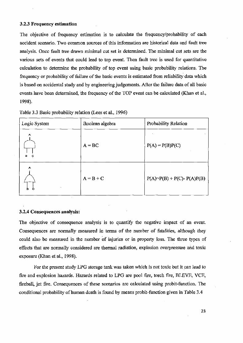
3.2.3 Frequency estimation
The objective of frequency estimation is to calculate the frequency/probability of each
accident scenario. Two common sources of this information are historical data and fault tree
analysis. Once fault tree drawn minimal cut set is determined. The minimal cut sets are the
various sets of events that could lead to top event. Then fault tree is used for quantitative
calculation to determine the probability of top event using basic probability relations. The
frequency or probability of failure of the basic events is estimated from reliability data which
is based on accidental study and by engineering judgements. After the failure data of all basic
events have been determined, the frequency of the TOP event can be calculated (Khan et al.,
1998).
Table 3.3 Basic probability relation (Lees et al., 1996)
Logic System Boolean algebra Probability Relation
A
A = BC P(A) = P(B)P(C)
B C
A
A = B + C P(A)=P(B) + P(C)- P(A)P(B)
3.2.4 Consequences analysis:
The objective of consequence analysis is to quantify the negative impact of an event.
Consequences are normally measured in terms of the number of fatalities, although they
could also be measured in the number of injuries or in property loss. The three types of
effects that are normally considered are thermal radiation, explosion overpressure and toxic
exposure (Khan et al., 1998).
For the present study LPG storage tank was taken which is not toxic but it can lead to
fire and explosion hazards. Hazards related to LPG are pool fire, torch fire, BLEVE, VCE,
fireball, jet fire. Consequences of these scenarios are calculated using probit-function. The
conditional probability of human death is found by means probit-function given in Table 3.4
23
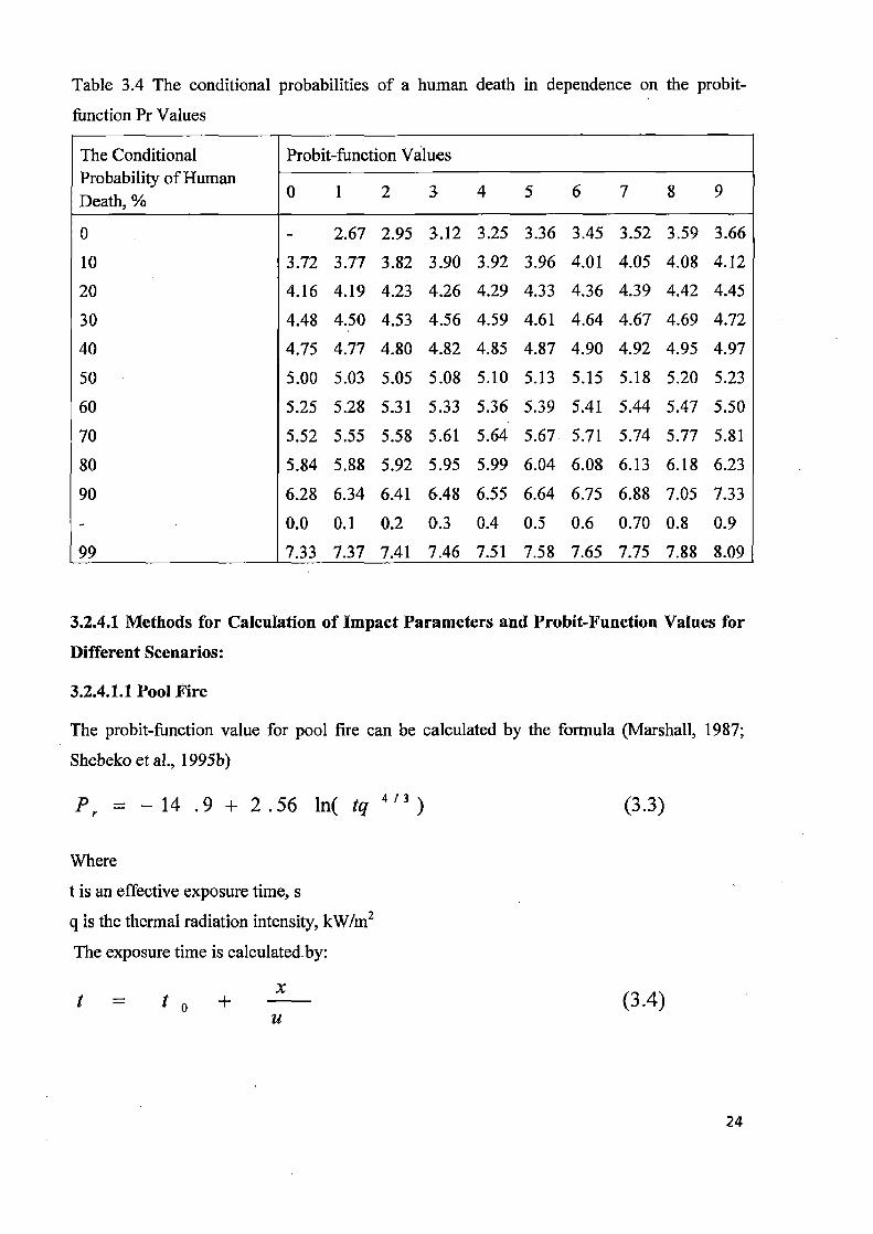
Table 3.4 The conditional probabilities of a human death in dependence on the probit-
function Pr Values
The Conditional Probability of Human Death, %
Probit-function Values
0 1 2 3 4 5 6 7 8 9
0 - 2.67 2.95 3.12 3.25 3.36 3.45 3.52 3.59 3.66 10 3.72 3.77 3.82 3.90 3.92 3.96 4.01 4.05 4.08 4.12 20 4.16 4.19 4.23 4.26 4.29 4.33 4.36 4.39 4.42 4.45 30 4.48 4.50 4.53 4.56 4.59 4.61 4.64 4.67 4.69 4.72 40 4.75 4.77 4.80 4.82 4.85 4.87 4.90 4.92 4.95 4.97 50 5.00 5.03 5.05 5.08 5.10 5.13 5.15 5.18 5.20 5.23 60 5.25 5.28 5.31 5.33 5.36 5.39 5.41 5.44 5.47 5.50 70 5.52 5.55 5.58 5.61 5.64 5.67. 5.71 5.74 5.77 5.81 80 5.84 5.88 5.92 5.95 5.99 6.04 6.08 6.13 6.18 6.23 90 6.28 6.34 6.41 6.48 6.55 6.64 6.75 6.88 7.05 7.33 - 0.0 0.1 0.2 0.3 0.4 0.5 0.6 0.70 0.8 0.9 99 7.33 7.37 7.41 7.46 7.51 7.58 7.65 7.75 7.88 8.09
3.2.4.1 Methods for Calculation of Impact Parameters and Probit-Function Values for
Different Scenarios:
3.2.4.1.1 Pool Fire
The probit-function value for pool fire can be calculated by the formula (Marshall, 1987;
Shebeko et al., 1995b)
P r = - 14 .9 + 2.56 ln( tq 4/3) (3.3)
Where
t is an effective exposure time, s
q is the thermal radiation intensity, kW/m2 The exposure time is calculated-by:
t = t o + x (3.4)
M
24

Where
to is a characteristic time of a fire detection (expected to be 5s),
x is a distance from human location to safe zone (q lower than 4 kW/m2)
u is a velocity of a human motion to safe zone (expected to be 5m/s)
Thermal radiation intensity can be calculated by the formula (Lees et al., 1996)
q = E f .F q .z
(3.5)
Where
Ef is a mean flame surface radiation intensity, kW/m2 (for LPG it is 100 kW/m2)
Fq is an angle coefficient
i is the coefficient of atmosphere transparency
The angle coefficient for pool fire is determined by formula (Lees et al., - 1996)
F q = F 2 + F h2 (3.6)
B--1/S 1 (B+1).(S--1) x an 1 B 2 -1 (B -1).(S'+1 )
FI, = —. (3.7) 7r (A-1/S) 1 (A+1).(S-1) A2_1 - x
A = (h 2 + S 2 + 1)/(2.S) (3.8)
B = (1+ S 2 )l(2.S) (3.9)
S = 2r/d (3.10)
h=2H/d (3.11)
Where
r is the distance from geometric pool fire centre to an object, m
d is the effective pool diameter, m
H is the height (m) of the flame determine by formula (Lees et al., 1996) 0.61
H = 42 . d . m d (3.12) Pb
25

Where
m is a specific mass of burning liquid, (kg/mzs) (0.1 kg/m2s for LPG)
Pb is an ambient air density, kg/m3
g is the gravitational constant, m/s2
The coefficient of the atmosphere transparency is determined by the expression:
r = exp[ —7.0 x 10 - 4 (r — 0.5d)] (3.13)
3.2.4.1.2 Fireball
The probit-function value for fireball can be calculated by formula (1). The effective fireball
diameter (m) can be calculated by formula (Lees et al., 1996)
D 9 = 5.33
(3.14)
Where
m is the mass of a combustible substance participating in the fireball formation, kg
The effective exposure time can be calculated by formula:
= 6 .48 m 0.325 (3.15)
Thermal radiation q can be determined by equ. 3.5. The E£ value is 450 kW/m2 (Shebeko et
al., 1995b)
Fq can be calculated by following formula (Lees et al., 1996):
Fq = ( HbID,+0.5) (3.16) q
3/2 4 [(H b IDS +0.5)]
2 + ( rb IDS )
Z
Where
Hb is height of the fireball centre over the ground surface (m) which is equal to D/2
rb rb is a distance fron an object to a point on the ground surface immediately under fireball
centre,m
i can be determine by formula:
= exp[ —7.0x10 -4 x( rb2 +Hb —D 5 /2)] (3.17)
►z.

3.2.4.1.3 Vapour Cloud Explosion (VCE)
For vapour cloud explosion, the probit-function is calculated by formula (Shebeko et al.,
1995b; Lees et al., 1996)
Pr = 5 — 0.26 • In V (3.18)
Where
V = 17500 8.4 + 290 0.3 OP i
(3.19)
AP is the maximum pressure in a shock wave, Pa
i is the impulse of a shock wave AP calculated by formula:
[O.8m33 3mo.66 5m=S + ? + 3S
J (3.20)
~e re re
Where
P,, is atmoshpheric pressure, Pa
re is a distance from a geometric centre of a vapour cloud to an object, m
ms is the specific mass of a combustible vapour in cloud (kg) which is calculated by formula:
ms=(Q,/Q0).m.Z'
(3.21)
Where
Q,, is a specific heat of a vapour combustion, J/kg
Qo is a constant equals to 4.52 x 10⁶ J/kg
Z is a coefficient of a vapour participating in an explosion, which is expected to be 0.1
m is the vapour mass in the cloud, kg
The impulse of a shock wave i can be calculated by formula:
i = 123 e m 0.66 /re (3.22)
3.2.5 Measure of risk
Last step of risk assessment is to calculate actual risk. A number of accident scenarios have
been identified. Frequency and consequences have been calculated for each and risk can now
be determined. Quantitative risk assessment is plotted in terms of risk contour where
27

individual risk is measured instead of societal risk. Individual risk (IR) can be calculated by
formula:
IR = Q di •Q (A~) (3.23)
Where
n is the number of event or scenario
Qdi is a conditional probability of a human death which is given in probit-function shown in
Table 3.4
Q(A1) is a year probability of realization of the i-th event (pool fire, fireball, vapour cloud
explosion) per year
Population distribution is not taken into account with individual risk. The contour is still very
useful because particular point can be shown at the plant fence line.
28
CHAPTER 4
DEFINITION OF THE PROBLEM
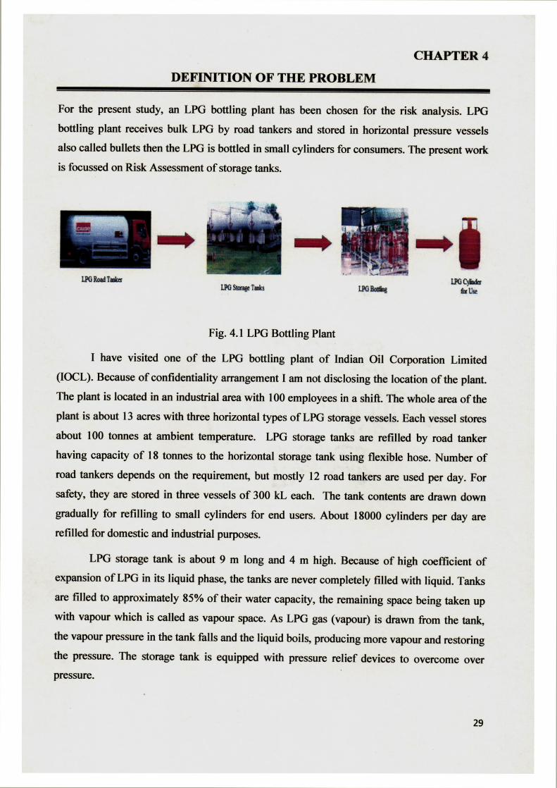
For the present study, an LPG bottling plant has been chosen for the risk analysis. LPG
bottling plant receives bulk LPG by road tankers and stored in horizontal pressure vessels
also called bullets then the LPG is bottled in small cylinders for consumers. The present work
is focussed on Risk Assessment of storage tanks.
I.PG ROM( T(IOk I PO $tome ioln
L%C- BC b Gx
Fig. 4.1 LPG Bottling Plant
I have visited one of the LPG bottling plant of Indian Oil Corporation Limited
(IOCL). Because of confidentiality arrangement I am not disclosing the location of the plant.
The plant is located in an industrial area with 100 employees in a shift. The whole area of the
plant is about 13 acres with three horizontal types of LPG storage vessels. Each vessel stores
about 100 tonnes at ambient temperature. LPG storage tanks are refilled by road tanker
having capacity of 18 tonnes to the horizontal storage tank using flexible hose. Number of
road tankers depends on the requirement, but mostly 12 road tankers are used per day. For
safety, they are stored in three vessels of 300 kL each. The tank contents are drawn down
gradually for refilling to small cylinders for end users. About 18000 cylinders per day are
refilled for domestic and industrial purposes.
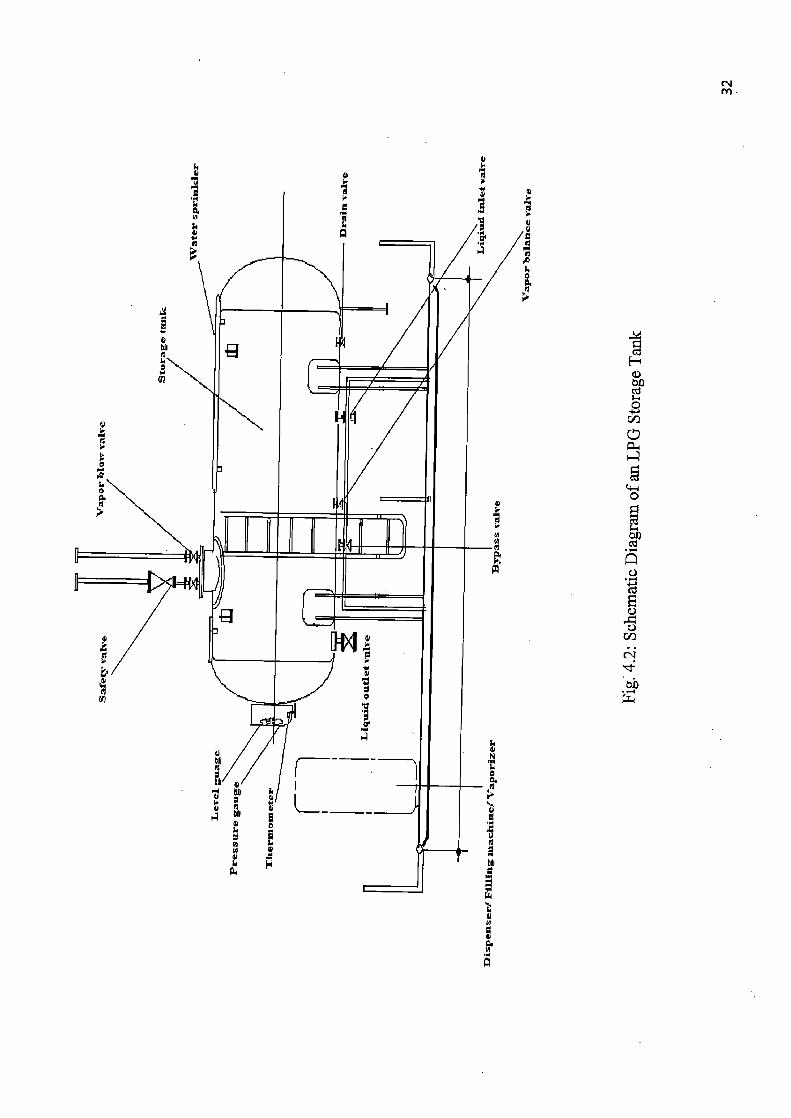
LPG storage tank is about 9 m long and 4 m high. Because of high coefficient of
expansion of LPG in its liquid phase, the tanks are never completely filled with liquid. Tanks
are filled to approximately 85% of their water capacity, the remaining space being taken up
with vapour which is called as vapour space. As LPG gas (vapour) is drawn from the tank,
the vapour pressure in the tank falls and the liquid boils, producing more vapour and restoring
the pressure. The storage tank is equipped with pressure relief devices to overcome over pressure.
29

4.1 STORAGE TANK ACCESSORIES
• LPG transfer pump or compressor
• LPG vaporizer
• Emergency shut of valve
• Gas leak detection system
• Water sprinkler system
• Excess flow check valve
• Pressure and temperature gauge
• High and low level alarm
4.2 PROPERTIES OF LPG (MSDS)
• LPG forms a flammable mixture with air in concentrations of between 2% and 10%.
• LPG is approximately twice as heavy as air when in gas form and will tend to sink to
the lowest possible level and may accumulate in cellars, pits, drains, etc.
• LPG in liquid form can cause severe cold burns to the skin owing to its rapid
vaporisation.
• Vaporisation can cool equipment so that it may be cold enough to cause cold burns.
• It can create fire and explosion hazard if stored or used incorrectly.
• Vapour/air mixtures arising from leakage may be ignited. some distance from the point
of escape and the flame can travel back to the source of the leak.
• At very high concentrations when mixed with air, vapour is an anaesthetic and
subsequently an asphyxiant by diluting the available oxygen.
• A vessel that has contained LPG is nominally empty but may still contain LPG vapour
and be potentially dangerous. Therefore treat all LPG vessels as if they were full.
4.3 SOURCES FOR CREATING HAZARDOUS SCENARIOS
4.3:1 Catastrophic Failure: Sudden failure of the tank may occur due to metal fatigue and
fracture, overfilling followed by excessive pressure build-up and fracture, weakening of the
vessel due to metal corrosion, etc.
4.3.2 Flame Impingement: Ignition of LPG released due to rupture/crack of vessel, pipe-
work, hose, relief valve, etc.
30

4.3.3 External Impact: Rupture of hoses or pipe due to external impact, mostly from vehicles.
4.3.4 Mal-operation: This includes operator error during the loading and unloading or
sampling of LPG.
4.3.5 Poor Maintenance: Includes hose wear and tear, corrosion in valves, pump seal failure,
connection seats, etc.
4.3.6 Sabotage: During assessing of LPG via the drain valve.
31
N M
w
N
y

CHAPTER 5
RESULT AND DISCUSSION
Risk assessment was used to determine the events that can produce an accident, frequency of those events and consequences.
For the present work a flied study on LPG storage tank of LPG bottling plant was
performed for the risk assessment. Risk assessment is - done considering the worst case
scenario. Necessary data for the risk assessment is taken from the literature available.
For risk assessment following methodology was considered:
5.1 Hazard Survey (Hazard characterization and analysis)
5.2 Hazard Identification (Identification of accident scenarios)
5.3 Frequency Estimation (Estimation of frequency of each scenario)
5.4 Consequences analysis (Consequences analysis of each scenario)
5.5 Measure of Risk (Estimation of total risk)
5.1 HAZARD SURVEY
Hazard survey is done using Dow fire and explosion index (F&EI). Following results obtained from Dow F&EI calculation:
Table 5.1 Result of Dow fire & explosion (F&EI)
1. General process hazards factor 2
2. Special process hazards factor 4.55 3. Process unit hazards factor 9.1 4. Fire and explosion index 191.1 5. Loss of Credit factor 0.31 6. Exposure radius 53 m 7. Area of exposure 8829 m2
8. Value of exposure 197.77Crores
9. Damage factor 1
10. Base MPPD 197.77Crores 11. Actual MPPD 61.31 Crores
*Maximmum allowable F&EI is 168 (Lees et al., 1996)
*Assuming cost of the plant to be 2.24 lakh/ m2 (Gupta, 2003)
33
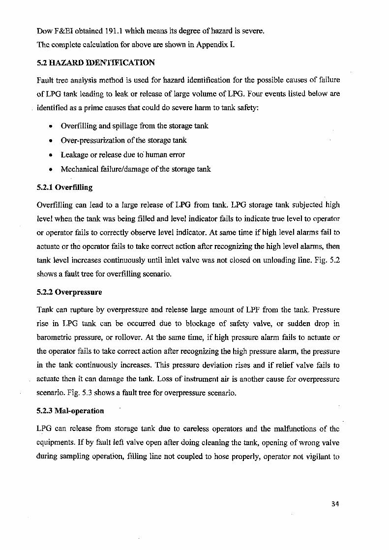
Dow F&EI obtained 191.1 which means its degree of hazard is severe.
The complete calculation for above are shown in Appendix I.
5.2 HAZARD IDENTIFICATION
Fault tree analysis method is used for hazard identification for the possible causes of failure
of LPG tank leading to leak or release of large volume of LPG. Four events listed below are
identified as a prime causes that could do severe harm to tank safety:
• Overfilling and spillage from the storage tank
• Over-pressurization of the storage tank
• Leakage or release due to human error
• Mechanical failure/damage of the storage tank
5.2.1 Overfilling
Overfilling can lead to a large release of LPG from tank. LPG storage tank subjected high
level when the tank was being filled and level indicator fails to indicate true level to operator
or operator fails to correctly observe level indicator. At same time if high level alarms fail to
actuate or the operator fails to take correct action after recognizing the high level alarms, then
tank level increases continuously until inlet valve was not closed on unloading line. Fig. 5.2
shows a fault tree for overfilling scenario.
5.2.2 Overpressure
Tank can rupture by overpressure and release large amount of LPF from the tank. Pressure
rise in LPG tank can be occurred due to blockage of safety valve, or sudden drop in
barometric pressure, or rollover. At the same time, if high pressure alarm fails to actuate or
the operator fails to take correct action after recognizing the high pressure alarm, the pressure
in the tank continuously increases. This pressure deviation rises and if relief valve fails to
actuate then it can damage the tank. Loss of instrument air is another cause for overpressure
scenario. Fig. 5.3 shows a fault tree for overpressure scenario.
5.2.3 Mal-operation
LPG can release from storage tank due to careless operators and the malfunctions of the
equipments. If by fault left valve open after doing cleaning the tank, opening of wrong valve
during sampling operation, filling line not coupled to hose properly, operator not vigilant to
34

F
on
iH :
vi on
Q
0
~ F 0
E 0 C)
K.
0

V 4:
w U
+O U V •1~' a~"•+ OO o
~ N
bA
H
0 M
E
0
U
L

p
•4 o~ bA w L=~
N m
A
0
ts. 0
vi
Co m
E
~ k 0 c
eo
W
rfl
O III:Y
U

O C a° .5
Q
O ~ A
O
I I
~
Q rJ-
R I
O 0
U o
Ep 'er
Ho
0 lqr
E

alarm and at the same time pump not stopped can led to large release of LPG from the
tank. Fig. 5.4 shows a fault tree for mal-operation scenario.
5.2.4 Mechanical failure/damage Due to failure/damage of LPG can release from tank. Failure of equipment like flange
failure, valve seating failure, hose failure, gasket failure or crack/rupture of tank led to
LPG release and if pump is not stopped. Fig.5.5 shows a fault tree for mechanical
failure/damage scenario.
These events if not identified and controlled then they can lead to following events:
• A large leakage of LPG followed by catastrophic explosion of a flammable
vapour cloud in the open. Fault tree for this is shown in Fig. 5.1.
• A fire causing sudden rupture of the tank and a large fireball; Fault tree for shown
in Fig.5.6. Sudden rupture of vessel due to overpressure and weakening of
material burst open to the atmosphere called (boiling liquid expanding vapour
cloud explosion) BLEVE. As a result of expansion and flashoff a pressure wave
occurs and a fireball formed.
5.3 FREQUENCY ESTIMATION
Using frequency data from literature, frequency is estimated for each scenario. Frequency
data used for find frequency of top event is given in appendix II.
Minimal cut sets is determined for all the fault trees by applying Boolean algebra.
Minimal cut sets is the smallest combination, if they all occur, will cause the tope event
to occur. The calculation of probability of triggering of top event due to particular
minimal cut set calculated below:
Overfilling
Minimal cut set for overfilling (Fig. 5.2)
P(T1) = A1'YI
= A1 (Y2'Y3)
=A1 (B1'Y4), (C1+D1)
= Al , (B1' (E1+ F1))'(Cl+D1)
41

= Al - (Bl El+B1-Fl)-(CI+D1)
=A1B1C1E1 + AIB1D1E1+ AIB1C1F1+ A1B1D1F1
There are four minimal cut sets obtained: Al B 1 C 1 E 1, A 1 B 1 D 1 E 1, A 1 B 1 C 1 F 1 and
A1B1DIF1
Probability calculation for each minimal cut sets:
P(A1B1C1E1) = P(A1): • P(Bl) - P(Cl) - P(El)
=0.1 X 10-6 X 10-3 X 10 3 =10-13/y
Similarly
P(A1B1DIE1) = 5 x 10-12/y
P(A1BIC1F1) = 10"'°/y
P(A1BICIE1) = 5 x 10'9/y
The probability of top event:
P(T1) = P(A1B1CIE1) + P(A1B1D1E1)+ P(A1B1C1F1)+ P(A1B1DIF1)
=10-3/y
Similar calculation is done for all the fault trees and result is shown in appendix III.
From above calculation frequency of occurrence of overfilling is 10-3 per year which means once in 1 000years.
Similar calculation for frequency of other scenario obtained as: Overpressure (Fig.5.3)
Mal-operation (Fig.5.4)
Mechanical failure/damage (Fig. 5.5)
Fire/Explosion (Fig. 5.1)
Catastrophic failure of tank (Fig.5.6)
5.6 x 10⁻⁸ per year
Once in a 1.8 x 10⁷ years 3 x 10⁻⁴ per year Once in a 3.3 x 10³ years 3.1 x 10⁻⁵ per year Once in a 3.2 x 10⁴ years
3.85 x 10⁻⁵ per year Once in a 2.5 x 10⁴ years
1.6 x 10⁻⁶ per year Once in a 6.25 x 10⁵ years
42

These frequencies of these events can be reduced by Proper design, construction,
maintenance and operation of storage tank; increasing the reliability of the relief valve;
by avoiding valves, flanges, sampling points or any other potential location for leakage
beneath the tank; trained/skilled labours; use of appropriate fire fighting systems;
implementation of safety management program and regular safety audit of the plant.
5.4 CONSEQUENCES ANALYSIS
Following events can occur in case of any leakage/release of LPG from LPG storage tank
• Pool fire
• Fireball
• Torch
• Flash fire
• Vapour cloud explosion
• Vapour cloud without ignition
For the present study three events are considered they are pool fire, fireball and
vapour cloud explosion. Flash fire was considered as vapour cloud explosion and torch
fire as pool fire. Conditional probability of human death for these three events is
calculated by considering worst case scenario.
5.4.1 Pool fire
Accidental release of LPG can result in pool fire. Thermal radiation hazards from pool
fires depend on the composition, the size and shape of the fire, the duration of the fire, the
distance to the object, and the characteristics of the object exposed to thermal radiation.
Consequences due to pool fire were calculated using etus 3.3-3.14. Pool fire pool
diameter was taken from the literature i.e 20 m (Mudan et al., 1984), this from large pool
fire experiment. For this diameter flame height 36.87 metre and effective time of
exposure 14 second was obtained.
Thermal radiation intensity, probit function value and conditional probability of
human death with distance are shown in Appendix IV.
From the result shown in Appendix IV it seen that the probability of human death
is very less only 7 % upto 15 m. Risk to human death is very less but thermal radiation
43

100
90 44 o 80
70
oc 60
50
40 0 x 30
U 20
10
0
—4--Conditional probability of human death vs distance
from pool can act as a trigger for the nearby storage tank or property and cause injury to
people. If proper distance is maintained between two tanks then its risk can be eliminated.
5.4.2 Fireball
When superheated LPG released and immediately ignited may burn as a fireball. The
fireball grows larger and moves upward continuously because of buoyancy. For
consequences analysis equations 3.3 and 3.15 - 3.18 and Table 3.4 were used.
Thermal radiation intensity, probit function value and conditional probability of
human death with distance are shown in Appendix V
Graphs are plotted between conditional probability of human death vs. distance for three
worst accidents.
• Catastrophic failure of one tank (Fig.5.7)
• Catastrophic failure of two tanks (Fig.5.8)
• Catastrophic failure of all three tanks (Fig.5.9)
0 200 400 600
Distance (m)
Fig.5.7 Conditional probability of human death vs human death for fireball due to
catastrophic failure of one LPG storage tank
44

100 90
80
70
60 o c a q 50 —4—Conditional probability of human
0 40 death vs distance
•30
U 20
10
0
0 200 400 600
Distance (m)
Fig.5.8 Conditional probability of human death vs human death for fireball due to
catastrophic failure of two LPG storage tanks
100
90
0 80
if
70
60
a Q 50 —0—Conditional Probability of
40 Human Death Vs Distance
30
U 20
10
0
0 200 400 600 800
Distance (m)
Fig.5.9 Conditional probability of human death vs human death for fireball due to
catastrophic failure of all the three LPG storage tanks
45

From graphs between conditional probability of human death and distance it was
observed that probability of death depends on the amount of LPG release. Probability of
human death increases with LPG release due to increase in thermal radiation intensity
and effective exposure time.
Observation from Fig.5.7, Fig.5.8, Fig.5.9 and Appendix V.
Table 5.2 Impact distance for percentage death/injury of human due to different scenario
of fireball:
Consequences on
Human
Impact Distance (radius in m)
Failure of one Failure of two Failure of three
tank tank tank
100% death probability 72 133 180
99% death probability 128 192 240
50 % death probability 450 335 397
1%death probability 363 473 553
Human injury 800 980 1080
Table 5.3 Damage distances for different thermal heat radiation in case worst case:
Thermal radiation intensity Effect Damage distance
(kW/m2) (radius in m)
37.5* Sufficient to cause damage to 378
process equipment
12.5* Minimum energy required for
piloted ignition of wood and 618
melting of plastic tubing
4* Sufficient cause pain to personnel 916
within 20 s
* Heat flux value for different experience (Ruj et al., 2006)
46

5.1.4.3 Vapour cloud explosion (VCE)
When LPG release and form cloud of vapour without ignition taking place, it ignited later
to a considerable distance from the release point. Three worst case scenarios were
considered for calculation vapour cloud formation due to release of total LPG present in
one tank, two tank and all the three tanks. For calculation for consequences due to VCE equs 3.19-3.22 and Table 3.4 were used.
Maximum overpressure, probit function value and conditional probability of human death with distance are shown in appendix VI.
Graphs are plotted between conditional probability of human death vs distance for three worst accidents.
1. Open vapour Cloud explosion of one tank (Fig.5.10) 2. Open vapour Cloud explosion of two tanks (Fig.5.11) 3. Catastrophic failure of all three tanks (Fig.5.12)
120
100
O
Via° 80
O n a 60 ~p C C ~ o E r 40
0 U
{
—4—conditional probability of human death vs diastance
1 1/ 111 171,
Distance (m)
Fig.5.10 Conditional probability of human death vs human death for VCE due to catastrophic failure of one LPG storage tank
47

120
0 500 1000
Distance (m)
—4—conditional probability of human death vs distance
1500
w, 100 0
80
o 1 a b 60
40
0 V 20
U
Fig.5.11 Conditional probability of human death vs human death for VCE due to
catastrophic failure of two LPG storage tanks
120
100
80
o c o..-b 60
40 c ~ U 20
IC
conditional probability of human death vs distance
0 500 1000 1500
Distance (m)
Fig.5.12 Conditional probability of human death vs human death for VCE due to
catastrophic failure of three LPG storage tanks
48

Observation from Fig. 5.10, Fig. 5.11, Fig. 5.12 and APPENDIX V.
Table 5.4 Impact distance for percentage death of human due to different scenario of VCE:
Consequences on
Human Damage Distance (radius in m)
Failure of one Failure of two Failure of three tank tank tank
100% death probability 146 182 207 99% death probability 172 220 251 50 % death probability 336 425 485 1%death probability 755 950 1050
From the study of various scenarios i.e. pool fire, fireball and VCE it is observed that
impact distance for human death and probability of occurrence of VCE than fireball.
10, VCE Fireball
— Total Risk
105
co -o
C
Iw £VV JUV 4w ODU ODU ((Al t5(U 990 1000 Distance m
10'
o L 0
Fig. 5.13 The Individual Risk Contours
49

5.5 MEASURE OF RISK
This was the last step of risk assessment to calculate actual risk. Individual risk contour
was plotted for fireball, VCE and total risk.
5.1.5.1 Individual Risk
Individual risk was calculated for the identified scenario with its frequency and
consequences. Individual risk is calculated using formula (.22). Calculated risk of
fireball, VCE and total risk is given in Appendix VII.
In Fig.5.13 the individual risk contours are shown. From the graph it is observed
that the largest contribution to the individual risk is the scenario with vapour cloud
explosion. This is due to two reasons first due to large distance travelled by cloud and
second is due to high conditional probability of occurrence. Fireball has less contribution
to total risk due to less frequency of occurrence catastrophic failure of tan contribution to
the individual risk due to less condition probability of VCE.
The HSE quotes 1 x 10⁻⁶ per year as a risk of fatality that regarded broadly as
acceptable and 1 x 10⁻⁴per year as boundary between tolerable and unacceptable for the
public (Jo et al., 2005). From the fig.15 distance near 600 m from the LPG storage
observed as acceptable risk.
50
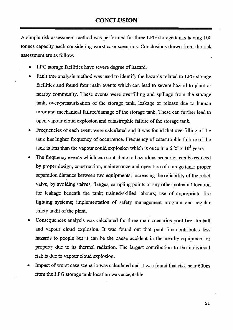
CONCLUSION
A simple risk assessment method was performed for three LPG storage tanks having 100
tonnes capacity each considering worst case scenarios. Conclusions drawn from the risk assessment are as follow:
• LPG storage facilities have severe degree of hazard.
• Fault tree analysis method was used to identify the hazards related to LPG storage
facilities and found four main events which can lead to severe hazard to plant or
nearby community. These events were overfilling and spillage from the storage
tank, over-pressurization of the storage tank, leakage or release due to human
error and mechanical failure/damage of the storage tank. These can further lead to
open vapour cloud explosion and catastrophic failure of the storage tank.
• Frequencies of each event were calculated and it was found that overfilling of the
tank has higher frequency of occurrence. Frequency of catastrophic failure of the
tank is less than the vapour could explosion which is once in a 6.25 x 10⁵ years. • The frequency events which can contribute to hazardous scenarios can be reduced
by properdesign, construction, maintenance and operation of storage tank; proper
separation distance between two equipments; increasing the reliability of the relief
valve; by avoiding valves, flanges, sampling points or any other potential location
for leakage beneath the tank; trained/skilled labours; use of appropriate fire
fighting systems; implementation of safety management program and regular safety audit of the plant.
• Consequences analysis was calculated for three main scenarios pool fire, fireball
and vapour cloud explosion. It was found out that pool fire contributes less
hazards to people but it can be the cause accident in the nearby equipment or
property due to its thermal radiation. The largest contribution to the individual
risk is due to vapour cloud explosion.
• Impact of worst case scenario was calculated and it was found that risk near 600m
from the LPG storage tank location was acceptable.
51

FUTURE PLAN OF THE STUDY
The present study is focused on the risk assessment of LPG storage facility of a small
bottling plant. This study can be extended to assessing the risk of large bottling plant and
also to other chemical storage facilities. For more detailed safety analysis, risk
assessment should be carried out at each stage of the bottling operation that happens at
the LPG bottling plant.
52

REFERENCES
[1] Abbasi T., Abbasi S.A, 2007. The Boiling Liquid Expanding Vapour Explosion
(BLEVE): Mechanism, Consequence Assessment, Management. Journal of
Hazardous Materials, 141: 489-519.
[2] Ames S., Crowhurst D., 1988. Domestic Explosion Hazards from Small LPG
Containers. Journal of Hazardous Materials, 19: 183-194.
[3] Aydemir N.U., Magapu V.K., Sousa A.C.M., Venart J.E.S., 1988. Thermal
response analysis of LPG tanks exposed to fire. Journal of Hazardous Materials, 20: 39-262.
[4] Bubbico R., Marchini M., 2008. Assessment of an Explosive LPG Release
Accident: A Case Study. Journal of Hazardous Materials, 155: 558-565.
[5] Buschmann C.H., 1974. Proceeding of the First International Loss Prevention
Symposium, the Hague/ Delft. Loss Prevention and Safety Promotion in the Process Industries the Netherland.
[6] Centre For Chemical Process Safety (CCPS), 2005. Combined Glossary of Terms.
[7] Chang J.I., Cheng-Chung Lin, 2006. A study of storage tank accidents. Journal of
Loss Prevention in the Process Industries, 19: 51-59.
[8] Crocker W.P., Napier D.H., 1988. Assessment of mathematical models for fire
and explosion hazards of liquefied petroleum gas. Journal of Hazardous Materials, 20: 109-135.
[9] Crowl, DA, Louvar JF, 1990. Chemical process safety fundamentals with
applications. New Jersey: Prentice-Hall.
[ 10] Davenport J.A., 2006. Hazards and Protection of Pressure Storage and Transport
of LPG. Journal of Hazardous Materials, 20: 3-19.
[11] Demichela M., Piccinini N., Poggio A., 2004. Analysis of an LPG Accidental
Release. Process Safety and Environmental Protection 82(B2) : 128-131.
53

[12] Dow Fire and Explosion Index hazard Classification Guide, 1994. 7th Edition,
New York: American Institute of Chemical Engineers.
[13] Drysdale D.D., David G.J., 1979/80. Hazard analysis for a storage sphere of pressurised liquefied flammable gas. Fire Safety Journal, 2: 91-103.
[14] Gary R., Sciver V., 1990. Quantitative risk analysis in the chemical process industry. Reliability Engineering and System Safety, 29: 55-68.
[15] Gupta J.P., Khemani G., Sam Mannan M., 2003. Calculation of Fire and
Explosion Index (F&EI) value for the Dow Guide taking credit for the Loss
Control Measures. Journal of Loss Prevention in the Process Industries, 16: 235-241.
[16] Jo Y.D., Ahn B.J., 2005. A Method of Quantitative Risk Assessment for
Transmission Pipeline carrying natural Gas. Journal of Hazardous Materials, A123: 1-12.
[17] Khan A.A., 1990. Risk analysis of an LPG storage facility in India. Journal of
Loss Prevention in the Process Industries, 3: 406-408.
[18] Khan F.I., Abbasi S.A., 1998. Techniques and methodologies for risk analysis in
chemical process industries. Journal of Loss Prevention in the Process Industries, 11: 261-277.
[19] Khan F.I., Abbasi S.A., 1999. Major accidents in process industries and an
analysis of causes and consequences. Journal of Loss Prevention in the Process Industries, 12: 361-378.
[20] Kim K.H., Shin D., Yoon E.S., 2003. Risk analysis using automatically
synthesized robust accident scenarios and consequence assessment for chemical
processes: process partition and consequence analysis approach. Korean Journal
Chemical Engineering, 20 (6): 992-999.
[21] Kletz, T. A., 1989. What went wrong. London: Gulf.
[22] Lees F.P., 1996. Loss prevention in chemical process industries. London: Butterworth, Vol. 1-3.
54

[23] Marshall V.C., 1989. Major chemical hazards. Chichester: Ellis Horwood.
[24] Melchers R.E., Feutrill W.R., 2001. Risk assessment of LPG automotive
refuelling facilities. Reliability Engineering and System Safety, 74: 283-290.
[25] Mudan K.S., 1984. Thermal radiation hazards from hydrocarbon pool fires. Prog.
Energy. Combust. Sci., 10: 59-80.
[26] ' Park K., Mannanb M.S., Jo Y., Kim J., Keren N., Wang Y., 2006. Incident
analysis of bucheon LPG filling station pool fire and BLEVE. Journal of Hazardous Materials, A137: 62-67.
[27] Pietersen C.M., 1988. Analysis of the LPG-disaster in Mexico City. Journal of
Hazardous Materials, 20: 5-107.
[28] Pietersen C.M., 1990. Consequences of Accidental Releases of Hazardous
Material. Journal of Loss Prevention in the Process Industries, 3: 136-141.
[29] Razus D., Brinzea V., Mitu M., and Oancea D., 2009. Explosion characteristics
of LPG—air mixtures in closed vessels. Journal of Hazardous Materials, 165: 1248-1252.
[30] Robert, E., Melchers, Feutrill, W. R., 2001. Risk Assessment of LPG Automotive
Refuelling Facilities. Reliability Engineering and System Safety 74, 283-290.
[31] Roberts A.F., 1981. Thermal Radiation Hazards from Releases of LPG from Pressurised Storage, Fire Safety Journal, 4: 197 — 212.
[32] Ruj B., Rehman I., and Banyopadhya A.K., 2006. Off-site emergency scenario: A
case study from a LPG Bottling plant. Journal of Loss Prevention in the Process
Industries, 19: 645-647.
[33] Shebeko Y. N., Smolin I.M., Korolchenko A.Y., Shevchuk A.P., Borodkin A.N.,
Malkin V. L., Simonov O.A., Gurinovich L.V., Popov S.A., Kolosov V.A.,
Smirnov E.V., 1995. Some aspects of fire and explosion hazards of large LPG
storage vessels. Journal of Hazardous Materials, 8: 163-168 (a).
55

[34] Shebeko Y.N., Korolchenko A.Y., Shevchuk A.P., Kolosov V.A., Smolin I.M., 1995. Fire and explosion risk assessment for LPG storage. Fire Science & Technology, 15 (1, 2): 37-45 (b).
[35] Shell LPG, Material Safety Data Sheet.
[36] Stawczyk J., 2003. Experimental evaluation of LPG tank explosion hazards. Journal of Hazardous Materials, B96: 189-200.
56
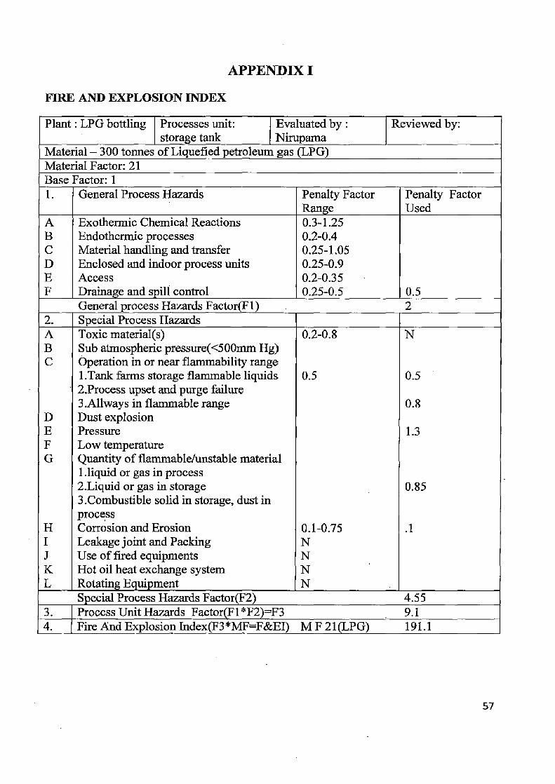
APPENDIX I
FIRE AND EXPLOSION INDEX
Plant: LPG bottling Processes unit: Evaluated by: Reviewed by: storage tank Nirupama
Material - 300 tonnes of Liquefied petroleum gas (LPG) Material Factor: 21 Base Factor: 1 1. General Process Hazards Penalty Factor Penalty Factor
Range Used A Exothermic Chemical Reactions 0.3-1.25 B Endothermic processes 0.2-0.4 C Material handling and transfer 0.25-1.05 D Enclosed and indoor process units 0.25-0.9 E Access 0.2-0.35 F Drainage and spill control 0.25-0.5 0.5
General process Hazards Factor(F1) 2 2. Special Process Hazards A Toxic material(s) 0.2-0.8 N B Sub atmospheric pressure(<500mm Hg) C Operation in or near flammability range
1.Tank farms storage flammable liquids 0.5 0.5 2.Process upset and purge failure 3.Allways in flammable range 0.8
D Dust explosion E Pressure 1.3 F Low temperature G Quantity of flammable/unstable material
1.liquid or gas in process 2.Liquid or gas in storage 0.85 3.Combustible solid in storage, dust in process
H Corrosion and Erosion 0.1-0.75 .1 I Leakage joint and Packing N J Use of fired equipments N K Hot oil heat exchange system N L Rotating Equipment N
Special Process Hazards Factor(F2) 4.55 3. Process Unit Hazards Factor(F1* F2)=F3 9.1 4. Fire And Explosion Index(F3*MF=F&EI) M F 21(LPG) 191.1
57

Process control (C1) Emergency power 0.98 Cooling 0.97 Explosion control 0.84 Cl 0.7
Material isolation (C2) Remote control valve 0.96 Drainage 0.91
C2 0.8
Fire protection (C3)
Leak detection 0.94 Structural steel 0.95 Water supply 0.94 Special system 0.91
C3 0.51
Emergency shutdown 0.96 Other hazard analysis 0.91
Interlock 0.98
Sprinkler system 0.74 Water curtains 0.97 Hand extinguisher 0.93
5. Credit factor (CF)= C) x C2 x C3 = 0.31 6. Exposure radius = 0.84 X F&EI/3.028 = 53 m 7. Area of exposure = 8829 m2 8. Value of area of exposure (VAE) (2.24 lakh/m2) = 197.77 Crores 9. Damage factor (DF) = 1
10. Base MPPD =VAE x DF =197.77crores 11. Actual MPPD = Base MPPD x CF = 61.31 Crores
58

APPENDIX II
Failure probability data from literatures (Drysdale et al., 1979/80; Lees et al., 1996) Factor Frequency per year
Instrumentation system fails to actuate 10"
Operator fails to observe level indicator correctly iO 3
Operation fails to respond on instrumentation system 5 x 10²
Indicator fails to indicate true level to operator 10"
Filling tank 0.1
Fails to actuate to close unloading line 10
Tank pressure rises due to rollover 10
Pressure control valve fails to open 10"
Tank pressure rises due to increase in barometric pressure 02
Operator fails to open safety valve 10.2
Human fault 10"
Pump did not stop 10"
Tank cleaning 0.1
Flange failure 4 x 10"
Gasket failure 5 x 10
Hose failure 4 x 10
Valve seating failure 3 x10 2
Vehicle impact 10"
Crack on the tank 10"
Vibration 10
Repairing while operating 10-
Corrosion 10
Excess pressure 10"
Fatigue 10
Creep 10"
Sabotage 2 x 10"
Weather condition ignition within plant to give open
flammable cloud explosion
0.3
Effective ignition source 2.5 x 10°
59

Water supply fails 10
Brigade slow to act 10
Flame impinge on vessel above liquid level 0.5
Water shut off 10 2
Activation fails 2 x 10-
System frozen 5 x 10
Low main pressure 3 x 10
Sprinkler system damage 10
Pipe completely blocked iO 4
Pipe partially blocked 3 x 10
Sprinkler system head damage 8 x 10
60
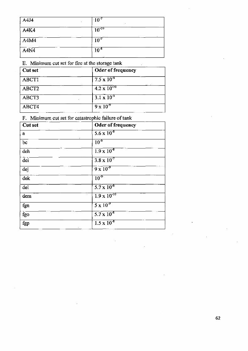
A4J4 10
A4K4 10"
A4M4 10"
A4N4 108
E. Minimum cut set for fire at the storage tank Cut set Oder of frequency
ABCT1 7.5 x 10"
ABCT2 4.2 x 10"
ABCT3 3.1 x 10`
ABCT4 9x10 9
F. Minimum cut set for catastrophic failure of tank Cut set Oder of frequency a 5.6 x 10"
be 10
deh 1.9 x 10"
dei 3.8x10 7
dej 9x10 9 "
dek 10 ,
del 5.7 x 10"
dem 1.9x10'°
fgn 5x10⁹
fgo •5.7x 10"
fgp 1.5x10⁸
62

APPENDIX IV
POOL FIRE
Distance (m) Thermal Radiation Intensity (kW/m2)
Probit Function Value Conditional Probability of Human Death (%)
15 30.67246 3.541073 7
20 18.81781 1.873451 0
25 12.54756 0.490102 0
30 8.776268 -0.73008 0
35 6.347933 -1.83573 0
40 4.710043 -2.85438 0
45 3.57142 -3.79897 0
50 2.761583 -4.67674 0
55 2.17054 -5.49876 0
60 1.73809 -6.25717 0
65 1.404858 -6.9837 0
70 1.150644 -7.66505 0
75 0.945964 -8.33363 0
80 0.79031 -8.94727 0
85 0.664198 -9.54066 0
90 0.567323 -10.0788 0
95 0.48054 -10.6455 0
100 0.422525 -11.0846 0
63

APPENDIX V
FIREBALL
A. Fireball due to catastrophic failure of one LPG storage tank Distance (m)
Effective exposure time (s)
Effective fireball diameter (m)
Thermal Radiation Intensity (kW/m2)
Probit Function Value
Conditional Probabilities of Human Death (%)•
50 17 273.26 106.4156 8.284255 100
100 17 273.26 91.06298 7.752455 99.7
150 17 273.26 72.3485 6.967195 98
200 17 273.26 54.90373 6.025411 85
250 17 273.26 40.7298 5.006116 50
300 17 273.26 30.01071 3.963665 15
350 17 273.26 22.17841 2.931353 3
400 17 273.26 16.52826 1.927671 0
450 17 273.26 12.45449 0.961729 0
500 17 273.26 9.498953 0.037059 0
550 17 273.26 7.333719 -0.84597 0
600 17 273.26 5.729317 -1.68867 0
650 17 273.26 4.526224 -2.49322 0
700 17 273.26 3.613298 -3.26213 0
750 17 273.26 2.912567 -3.998 0
800 17 273.26 2.368817 -4.70335 0
850 17 273.26 1.942529 -5.38055 0
900 17 273.26 1.605107 -6.03182 0
950 17 273.26 1.335623 -6.65916 0
1000 17 273.26 1.118596 -7.26443 0
64

B. Fireball due to catastrophic failure of first and second LPG storage tank Distance (m) Effective
exposure time (s)
Effective fireball diameter (m)
Thermal Radiation Intensity kW/m2)
Probit Function Value
Conditional Probabilities of Human Death (%)
50 20.3567 342.302 108.4494 ' 8.810179 100
100 20.3567 342.302 .97.62761. 8.451357 100
150 20.3567 342.302 83.09415 7.901175 99.8
200 20.3567 342.302 67.89398 7.21159 99
250 20.3567 342.302 54.02463 6.431618 92
300 20.3567 342.302 42.35654 5.601096 73
350 20.3567 342.302 33.00256 4.749341 40
400 20.3567 342.302 - 25.70544 3.896408 13
450 20.3567 342.302, 20.09068 3.055203 3
500 20.3567 342.302 15.7924 2.233523 0
550 20.3567 342.302 12.50077 1.435694 0
600 20.3567 342.302 9.970603 0.663771 0
650 20.3567 342.302 8.014545 -0.08164 0
700 20.3567 342.302 6.491908 -0.80084 0
750 20.3567 342.302 5.297823 -1.49463 0
800 20.3567 342.302 4.354238 -2.16415 0
850 20.3567 342.302 3.602933 -2.81064 0
900 20.3567 342.302 3.000286 -3.43541 0
950 20.3567 342.302 2.513424 -4.03978 0
1000 20.3567 342.302 2.117411 -4.62501 0
65

C. Fireball due to catastrophic failure of all three LPG storage tank Distance (m) Effective
exposure time (s)
Effective fireball diameter (m)
Thermal Radiation Intensity (kW/m2)
Probit Function Value
Conditional Probabilities of Human Death (%)
50 22.92 390.5165 109.3061 9.140653 100
100 22.92 390.5165 100.5648 8.856151 100
150 22.92 390.5165 88.30966 8.412578 100
200 22.92 390.5165 74.78265 7.845065 100
250 22.92 390.5165 61.70603 7.189008 98
300 22.92 390.5165 50.06524 6.475435 93
350 22.92 390.5165 40.23313 5.729157 77
400 22.92 390.5165 32.1982 4.968734 49
450 22.92 390.5165 25.76061 4.207341 24
500 22.92 390.5165 20.65827 3.453914 6
550 22.92 390.5165 16.63341 2.714236 2
600 22.92 390.5165 13.46066 1.99183 0
650 22.92 390.5165 10.95463 1.288655 0
700 22.92 390.5165 8.967872 0.605598 0
750 22.92 390.5165 7.385222 -0.05716 0
800 22.92 390.5165 6.117652 -0.6999 0
850 22.92 390.5165 5.096599 -1.32319 0
900 22.92 390.5165 4.269299 -1.92777 0
950 22.92 390.5165 3.595066 -2.51448 0
1000 22.92 390.5165 3.042426 -3.08419 0

APPENDIX VI
VAPOUR CLOUD EXPLOSION (VCE)
A. Vapour cloud explosion (VCE) from one LPG storage tank Distance (m) Maximum
Overpressure (Pa) Probit Function
Value Conditional
Probabilities of Human Death (%)
50 734015.5 11.87492 100
100 149904.4 9.65657 100
150 67051.56 7.931844 100
200 40116.95 6.811484 97
250 27764.11 6.007881 84
300 20923.52 5.390156 65
350 16660 4.892529 46
400 13779.73 4.47799 30
450 11717.41 4.123922 19
500 10174.71 3.815608 12
550 8980.731 3.542996 7
600 8031.213 3.298945 4
650 7259.197 3.078217 3
700 6619.866 2.876867 2
750 6082.165 2.691851 1
800 5623.934 2.52078 0
850 5228.964 2.361746 0
900 4885.134 2.213198 0
950 4583.211 2.073866 0
1000 4316.04 1.942692 0
67

B. Vapour cloud explosion (VCE) from two LPG storage tank Distance (m) Maximum
Overpressure (Pa) Probit Function
Value Conditional
Probabilities of Human Death (%)
50 1310385 12.98195 100
100 246843.7 10.74788 100
150 104539.2 8.902507 100
200 60215.79 7.698689 100
250 40548.06 6.835143 87
300 29938.19 6.172645 78
350 23464.24 5.640506 74
400 19166.53 5.19866 58
450 16134.07 4.822506 43
500 13893.65 4.495997 31
550 12178.07 4.208157 21
600 10826.28 3.951188 15
650 9736.033 3.719372 10
700 8839.562 3.508406 7
750 8090.339 3.314976 5
800 7455.438 3.136485 3
850 6910.95 2.970858 2
900 6439.123 2.816417 2
950 6026.517 2.671786 1
1000 5662.779 2.535822 0
68

C. Vapour cloud explosion (VCE) from all three LPG storage tanks Distance (m) Maximum
Overpressure (Pa) Probit Function Value
Conditional Probabilities of Human Death (%)
50 1857667 13.62938 100
100 335105.8 11.41303 100
150 137545.7 9.501966 100
200 77442.6 8.248236 100
250 51269.02 7.347524 99
300 37364.05 6.656572 95
350 28986.45 6.102101 87
400 23483.93 5.642346 - 74
450 19636.36 5.251555 60
500 16815.74 4.912889 46
550 14670.39 4.614807 35
600 12989.89 4.349103 23
650 11641.56 4.109758 19
700 10537.96 3.892238 13
750 9619.419 3.693057 10
800 8843.901 3.509479 7
850 8181.032 3.339324 5
900 7608.351 3.180827 3
950 7108.924 3.032543 2
1000 6669.752 2.893274 2
1050 6280.708 2.762015 1
1100 5933.787 2.63792 0
1150 5622.585 2.520266 0
1200 5341.922 2.408432 0

APPENDIX VII
INDIVIDUAL RISK
Individual risk for worst scenario Distance (m) Vapour Cloud Fireball Total Risk
Explosion
50 3.85E-05 1.6E-06 0.0000401
100 3.85E-05 1.6E-06 0.0000401 150 3.85E-05 1.6E-06 0.0000401 200 3.85E-05 1.6E-06 4.01 E-05 250 3.81E-05 1.58E-06 3.97E-05 300 3.66E-05 1.49E-06 3.806E-05 350 3.35E-05 1.23E-06 3.473E-05 400 2.85E-05 7.84E-07 2.927E-05 450
2.31E-05 3.84E-07 2.348E-05 500 1.77E-05 9.6E-08 1.781E-05 550
1.35E-05 3.2E-08 1.351E-05 600
8.86E-06 0 8.855E-06 650
7.32E-06 0 7.315E-06 700
5.01E-06 0 5.005E-06 750 3.85E-06 0 3.85E-06 800
2.7E-06 0 2.695E-06 850
1.93E-06 0 1.925E-06 900
1.16E-06 0 1.155E-06 950 7.7E-07 0 7.7E-07 1000 7.7E-07
0 7.7E-07
70