b23064353.pdf - PolyU Electronic Theses
91
-
Upload
khangminh22 -
Category
Documents
-
view
1 -
download
0
Transcript of b23064353.pdf - PolyU Electronic Theses


i
The Hong Kong Polytechnic University
Department of Building and Real Estate
Using a real time integrated communication system to monitor the progress and quality of
construction works
LEUNG Sze Wing
A thesis submitted in partial fulfillment of the requirements for the degree of Master of Philosophy
July 2008

ii
CERTIFICATE OF ORIGINALITY
I hereby declare that this thesis is my own work and that, to the best of
my knowledge and belief, it reproduces no material previously published
or written, nor material that has been accepted for the award of any
other degree or diploma, except where due acknowledgement has been
made in the text.
LEUNG Sze Wing

iii
Abstract
The endeavor of this thesis focuses on designing a monitoring system to
provide a cost-effective solution on quality assurance for construction
projects. The construction site monitoring system integrates a long-
range wireless network, network cameras, and a web-based
collaborative platform. The users of the system could obtain the most
updated status of construction sites, such as behaviors of workers,
project progress, and site events anywhere with Internet connectivity. It
was carefully configured in order to maintain the reliability under the
reactive conditions of the construction sites. This thesis reports the
architecture of the monitoring system and reviews the related
technologies. The system has been implemented and tested on two
construction sites and promising results were obtained.

iv
Acknowledgements
I would like to express my deep and sincere gratitude to my supervisor,
Professor Stephen Mak for his guidance, encouragement, excellent
advice, and more importantly, his patience, throughout this study.
I wish to express my warm and sincere thanks to Mr. Lee Lap-Piu for his
fruitful collaboration and valuable assistance in the research.
I would also acknowledge the generous financial support of SMILE
Technologies Limited, via the Teaching Company Scheme, to enable
me to complete this research.
Finally, I would like to thank a few good friends, who prefer to remain
anonymous, for their help and comments.

v
Table of Contents
Chapter 1 Introduction .........................................................................................1 Chapter 2 Background and Objective of Research ..............................................4
2.1 Challenges in the Construction Industry ....................................................4 2.1.1 Uncertainty and Interdependence........................................................6 2.1.2 Ineffective / Inefficient Communications ...........................................9
2.2 Research Motivation and Objective .........................................................11 Chapter 3 Research Planning .............................................................................14
3.1 Identify Needs and Establish Requirements: users’ view........................15 3.2 Identify Needs and Establish Requirements: system designer’s view.....18
Chapter 4 System Design...................................................................................21 4.1 From Requirements to Technologies .......................................................21
4.1.1 The Internet .......................................................................................21 4.1.2 Wireless Network..............................................................................22 4.1.3 Network Camera ...............................................................................26 4.1.4 Signal Transmission..........................................................................31 4.1.5 Web-based Collaborative System .....................................................38
4.2. Architecture of the Monitoring System ..................................................40 4.2.1 Monitoring Viewpoint.......................................................................41 4.2.2 Site Office .........................................................................................43 4.2.3 Authenticated Devices ......................................................................44 4.2.4 Network Security Issues....................................................................48
Chapter 5 Design Justifications..........................................................................52 5.1 Design Justifications for Test Site A........................................................52 5.2 Design Justifications for Test Site B........................................................55
Chapter 6 Prototyping ........................................................................................57 6.1 Virtual Prototyping...................................................................................57 6.2 Virtual Prototype for Test Site A .............................................................59 6.3 Virtual Prototype for Test Site B .............................................................62
Chapter 7 Implementation and Testing ..............................................................65 7.1 Implementation on the Test Sites.............................................................65 7.2 Image Quality...........................................................................................68 7.3 Reliability.................................................................................................71 7.4 Visibility at dark environment .................................................................71
Chapter 8 Conclusions .......................................................................................73 Appendix ............................................................................................................77 References ..........................................................................................................78

vi
List of Figures
Figure 1. User-centered design model ..............................................................15 Figure 2. Field of View of a camera .................................................................28 Figure 3A. Image taken by a fish-eye lens with 180 degrees diagonal FOV....29 Figure 3B. Image taken by a standard lens with 48 degrees diagonal FOV ... 22 Figure 4. Pan / Tilt motions of a camera...........................................................30 Figure 5A. Signal range of an omni-directional antenna (plan)........................34 Figure 5B. Signal range of a unidirectional antenna.........................................28 Figure 6. A long-range point-to-multipoint wireless network ..........................38 Figure 7. Architecture of the monitoring system ..............................................41 Figure 8. Web-based User Control Interface ....................................................45 Figure 9. The integrated collaborative environment .........................................48 Figure 10. Plan of Test Site A...........................................................................53 Figure 11. Metal cabinet with rubber weatherproof sealing .............................54 Figure 12. Plan of Test Site B ...........................................................................55 Figure 13. Network camera inside a dome housing..........................................56 Figure 14. Tower crane models in the 3D warehouse.......................................58 Figure 15A. Overview of the virtual prototype of Site A .................................60 Figure 15B. Monitoring viewpoint of Site A ....................................................52 Figure 16. Simulated view of the camera inside the cabinet.............................62 Figure 17A. Overview of the virtual prototype of Site B .................................63 Figure 17B. Monitoring viewpoint of Site B ....................................................56 Figure 18. Installation setting of the monitoring viewpoint (Site A)................66 Figure 19. An omni-directional antenna and a wireless router connected to the
Internet ......................................................................................................67 Figure 20. Monitoring viewpoint on the tower crane .......................................68 Figure 21. Image clarity is still good after fifteen months................................70 Figure 22. Image captured at June, 8:30p.m. ....................................................72

vii
List of Tables
Table 1. Summary of IEEE 802.11 standards ....................................................32 Table 2. Price of components for one monitoring viewpoint.............................51

1
Chapter 1
Introduction
Quality control represents increasingly critical concerns for the practitioners of the
construction industry. The aim of it is to provide a product quality that is satisfactory to
the stakeholders of different parties, compliant with the recognized standards in the
industry, completed on schedule, within budgets and so on. Research reports show that
up to 12.4 percent of construction cost is wasted due to rework of defective components
detected late in the construction phase (Burati et al., 1992; Josephson and Hammarlund,
1999). In the worst case, some defects may cause injuries or fatalities. Even with minor
defects, re-construction may be required and facility operations impaired. Increased
costs and delays are the result. Indeed, most construction defects are related to human
factors such as unskilled workers or insufficient supervision in construction projects
(Atkinson, 1999; Opfer, 1999). Therefore, the faster and more information of site
activities and worker behaviors the project stakeholders know about, the higher
possibility to avoid undesirable outcomes. If project team members could obtain the
site information instantaneously, it is believed that some human errors could be
prevented.
Therefore, one of the indispensable procedures in assuring construction quality may be
site monitoring. It does not only minimize construction defects and human errors but
also supports project team members making strategic decisions like contingency plans
at critical points throughout the construction phases. In practice, quality control
procedures are conducted by the contractor, client’s representative or consultant. They

2
have to ensure the quality of materials and work on site is in accordance with the agreed
specifications and accepted standards. However, due to the limitation of manpower and
the reactive environment of a construction site, where unplanned changes to work
regularly occur (Ward, 2004), it is rather infeasible to monitor site activities, behaviors
of workers and progresses effectively from time to time. Furthermore, the construction
industry is widely considered as a fragmented industry such that massive amount of
organizations and stakeholders are involved in a construction project. When quality
problem is observed, stakeholders from different companies, or even from different
geographic locations have to make critical decisions and consolidate a contingency
solution as soon as possible. The efficiency of this kind of collaborative tasks intensely
relies on the approach of communication. Remarkably, communication difficulties or
disorders in construction projects could directly lead to a sharp increase in the volume
of unnecessary expenditure, and also affect the progress and quality of the projects
(Anumba et al., 1997; Anumba and Evbuowan, 1999; Higgin and Jessop, 2001).
Conclusively, in order to achieve site quality control, the construction industry requires
not only a site-monitoring infrastructure, but also an efficient communication and
collaborative environment. This thesis presents a cost-effective construction site
monitoring system integrating a long-range wireless network, network cameras, and a
web-based collaborative platform. The system supports simultaneous user access
therefore project team members could view real-time captured images or video of a
construction site, discuss and exchange ideas with gadgets such as video conference,
text and shared whiteboard at a distance via the Internet. It was carefully configured in
order to maintain the reliability under the messy and muddy environment of

3
construction sites. The system has been implemented and tested on two construction
sites and promising results were obtained.
The thesis includes the studies on common construction site monitoring practice,
rationales of the design of the proposed system, implementation process, difficulties
encountered as well as the testing results. This thesis is organized as follows. Firstly it
reviews the major technologies used in this study and work that has been done by
others. Then it reveals the architecture of the system and the rationales on hardware
selection. It will discuss the implementation experience and results in two construction
sites. Finally the paper ends with conclusions and future research directions.

4
Chapter 2
Background and Objective of Research
2.1 Challenges in the Construction Industry
The construction industry is well known as being a fragmented and divisive industry in
that multitude of companies, professions, and occupations involved in the construction
project life cycle (Kanji and Wong, 1998; Milakovich 1995). As a result, the
achievement of building quality inevitably relies on the cooperation, communications,
as well as negotiations among the stakeholders, such as the representatives of owners,
architects, contractors, subcontractors, suppliers, and so on. The owner perceives a need
to invest in a building project then he employs consultants, architects and engineers to
start the project. After that, a main contractor will be employed to implement. Indeed,
construction projects are becoming increasingly complex and dynamic in their nature
(Carr and Tah, 2001). Winch (1987) even criticizes construction projects as one of the
most complex of all undertakings. Because of the complexity, there are dozens of
factors affecting the success of a construction projects. Chan et al. (2004) identifies the
critical success factors from 43 literatures and summarizes them into five categories,
namely, (i) project management, (ii) project procedures, (iii) project-related factors, (iv)
external environment, and (v) human-related factors. The authors argue that project
management is a key for project success, which is also confirmed by other researchers
(Hubbard, 1990; Jaselskis and Ashley, 1991; Walker and Vines, 2000; Chiang, 2008).
Noticeably, although not mentioned by Chan et al., four of the nine factors under project
management category are related to the communication and interactions between

5
project team members; namely (i) communication system, (ii) control mechanism, (iii)
feedback capabilities, and (iv) control of sub-contractor’s works. As suggested by
Jaselskis and Ashley (1991), in order to maximize the project’s chance of success,
stakeholders should adopt management tools. In this information age, appropriate and
adequate use of information and communication technology (ICT) can be an effective
tool to facilitate a communication and interaction environment among construction team
members.
In construction project management, because of the highly fragmented nature of the
industry that caused by geographical distribution of projects team members, the
different responsibilities of various parties, and different time to join the construction
teams, it has highlighted the importance of communication. Communication difficulties
or disorders during the projects process can directly lead to a sharp increase in the
volume of unnecessary expenditure, and also affect the progress and quality of the
project (Anumba et al., 1997, Anumba and Evbuowan, 1999; Higgin and Jessop, 2001).
In Hong Kong, the fragmentation characteristic is perhaps more prominent because of
the multiple layers of subcontractors. They are typically very small firms but
collectively undertake most of the works. Chiang (2008) suggests that the extent of
subcontracting is even larger due to further subcontracting down the stream by
subcontractors with or without the knowledge or consent of the contractors or the
clients. This kind of partnering relationship may cause quality issues due to the
temporary or one-off nature of construction projects, where the project team members
may not be familiarized with the competence, especially the practice behavior of each
other. In fact, the construction industry is persecuted by some common partnering
problems such as ineffective communication, limited trust, and lack of cooperation

6
(Chan et al., 2004). This kind of adversarial relationship between stakeholders could
cause project delays, cost overruns, difficulty in resolving claims, litigation, and a win-
lost climate (Moore et al., 1992). Therefore, it could be foreseen that if a party has more
knowledge about its partner(s), the some risks could be reduced.
As the construction industry is so complex, the above-mentioned challenges are
possibly not the exhaustive collection. However, according to the literature reviewed,
one major challenge is the lack of effective communications. Theother one is
uncertainty, that is, not havingsufficient knowledge of party and project status. The
following two sections will further investigate the said challenges.
2.1.1 Uncertainty and Interdependence
The complex procedures and party relationships may cause inefficiency of operations
(Cox and Thompson, 1997) and there is a trend of increase in degree of complexity
(Gidado, 1996) that brings negative effects to the industry. For example, by comparing
the level of acceptance in adopting new techniques with other industries, Shammas-
Thona et al. (1998) argue that the construction industry has failed to adopted quality
management techniques that have improved performance in other industries, while
Vrijhoef and Koskela (2000) and Cox (1996) believe the supply chain management in
the construction industry lags behind others. Gidado (1996) concluded that the
complexity in the industry originates from several causes, namely, the environment of
construction sites, the quality resources employed, the level of scientific knowledge,
and the number and interaction of different parts of the workflow.

7
“The contractor needs to gauge a price for a project not yet built, for which he may not
have seen the detailed drawings, on a site of which he may have no knowledge, and with
a labour work force not yet organized” (Hillebrandt, 1974)
Although Hillebrandt (1974) gave the above comment over three decades ago, the
situation still exists today. The complexity in the construction industry, according to
Gidado (1996), could be divided into two categories. One is related to “uncertainty” and
deals with “the components that are inherent in the operation of individual tasks and
originate form the resources employed or the environment”. Dubois and Gadde (2002)
further explain that there are four factors in this category: (1) management is unfamiliar
with local resources and the local environment; (2) lack of complete specification for
the activities at the construction site; (3) lack of uniformity of materials, work, and
teams with regard to place and time; and (4) unpredictability of the environment. Factor
(2) and (3) are related to the organization of construction-based records that shared
amongst the team members (Beastall, 1998), where the effect of them could be
alleviated through the adoption of content management systems or CRM (Craig and
Sommerville, 2007). During the last decade, the construction industry has widely
adopted the use of IT and the concept of managing projects using web-based
technologies is closer to reality than ever before (Nikas et al., 2007) because it could
simplify the methods for recording information generated throughout the life cycle of a
project (Rankin and Froese, 2002). Stewart (2007) further explains that these systems
are capable to reduce the high levels of waste on construction projects usually caused by
information that is inadequate, inappropriate, and inconsistent. Although these systems
increase the efficiency of storage, organization, and retrieval of construction
information and documents, they lack the capability to capture the status of the

8
environment of a construction site instantly. Factor (1) and (4) are related to
construction environment – an environment that changes dynamically with project
progress, parties involved in, unexpected incidents, and so on. Therefore, an active and
instantaneous site inspection mechanism may be required in order to assist stakeholders
to acquire site status and make decisions in a timely fashion.
Another category relates to “interdependence” among tasks, and represents the sources
of complexity that “originate from bringing different parts together to form a
workflow”. There are also three factors causing the “interdependence”: (1) the number
of technologies and the interdependences among them; (2) the rigidity of sequence
between the various main operations; and (3) the overlapping of stages or elements of
construction Gidado (1996). Simply speaking, in a construction project, stakeholders
implement their own parts independently but they have to cooperate with each other in a
rigorous workflow. As a result, inordinate amounts of information are not only existed
within an organization, but also shared between organizations. Although Inter-
organizational information and records management systems are now being used for
this purpose (Caldas and Soibelman, 2003), and some researchers believe that an
effective information and records management system could solve many of the
information related problems (Lam and Chang, 2002; Mak, 2001), over 90 percent of
company documentation exists on paper only (Veal, 2001). Loesch and Theodori (2004)
further comment that the records and documents are locked in drawers and filing
cabinets with no global access to the information contained within. The findings reveal
that the industry greatly focus on paper work but the information on papers are rarely
shared within organizations. The closed, and to a certain extent, protective practice may
lead to another challenge: ineffective / inefficient communication.

9
2.1.2 Ineffective / Inefficient Communications
In addition to the challenge of complexity, ineffective communication between
organizations is another critical factor causing fragmentation. Some researchers argue
that the construction industry could be treated as a system (Ozel and Kohler 2004,
Dubois and Gadde 2000, Love and Gunasekaran, 1997). Shoesmith (1991) described it
as a Temporary Multi-Organization (TMO). To a certain extent, it could be considered
as a loosely coupled system (Dubois and Gadde, 2002) because the stakeholders tend to
implement their works independently. In other words, the industry strongly relies on
localized decision-making and financial control. However, when the construction
parties focus on paying the attention to conform their contractual requirements, they are
actually informatively and even financially linked with each other. According to Wong
and Fung (1999), to a contractor, the overhead or preliminary items of a project only
take up about 18 percent of the total construction costs, while 82 percent is represented
by materials and services provided by the subcontractors and suppliers. Research also
reveals that communication between parties is critical to the success of an alliance
(Wikforss and Lofgren, 2007; Hau et al., 2005; Cheng et al., 2001). Nevertheless, in
practice, various stakeholders usually handle different stages of the building life cycle
independently and overlook the importance of communications, which results in
incomplete and loosely-coupled construction processes. Bateman and Snell (1999)
reported that only 20 percent of the information passed down the hierarchy from the top
management might reach the site workers. The Gartner group also agrees the
communications between stakeholders are limited and identifies that the highest level of
interaction across organizations generally occurs between the middle level managers in
an organization (Alshawi and Ingirige, 2003). Cheng et al. (2001) explain the possible

10
factors of poor communication in the industry may be inappropriate / inefficient /
ineffective channels, unexpected communication breakdown, and not having open lines
of communication protocols.
In order to tackle the communication problems, researchers suggest that online
collaboration tools can facilitate not only easier management of the construction project,
but also allows better access and exchange of project records resulting in time and cost
savings and streamlining the overall construction processes (Nikas et al., 2007).
Moreover, Tai et al. (2009) recommend that the industry should make full use of
existing ICT tools to explore the possibility of new organizational forms for the
construction project teams and establish a uniform communication standard for
construction information across the whole industry. Meanwhile, stakeholders of the
industry also perceive the importance of adopting ICT as a communication media. In a
study involving a combined group of 22 contractors, consultants, and some industry
associations, over 55 percent of the organizations believe collaborative and multimedia
applications are vital applications that can contribute to the future performance of the
industry (Sarshar and Isikdag, 2004). Unfortunately, in practice, construction
professionals are still quite attached to their conventional means of communications
such as paper documents (Stewart, 2007). Emails are already considered as the most
“sophisticated” use of the ICT for the majority of the construction firms (Bjork, 2003).
Samuelson (2002) comments that the lack of effective applications for the core business
of the construction industry may be one explanation of the low ICT adoption rate. This
is synonymous to Acar et al. (2005)’s suggestion that there is no single “magic” ICT
solution for the industry. It implies that the construction industry has the demand of a

11
custom-made ICT solution. A system that is simply “borrowed” from other industries
could not gain the applause of the construction practitioners.
2.2 Research Motivation and Objective
The above-mentioned challenges may not be the exhaustive collection of challenges that
the construction industry encounters. Instead, they simply represent the most concerned
problems in the industry. While there is no panacea to solve all these problems
immediately, according to the literature reviewed, a tailor-made system that facilitates a
site monitoring function and provides an effective communication channel for project
team members may be one of the solutions.
In construction quality management, site monitoring is a critical process that provides
information in developing contingency plans and prevents structural disaster to occur.
For instance, the rate of defects in construction projects could be minimized if the
construction processes are closely monitored and examined throughout the construction
stages. Research reports show more than 12 percent of construction cost is wasted due
to rework of defective components detected late in the construction phase (Burati et al.,
1992; Josephson and Hammarlund, 1999). Indeed, most construction defects are related
to human factors such as unskilled workers or insufficient supervision in construction
projects (Atkinson, 1999; Opfer, 1999). All these statistics reveal that construction site
monitoring and instantaneous actions could enable significant cost saving and avoid
project delay. This is particularly important for large-scale projects that involve many
organizations coming from different geographical locations. Effective site monitoring,
surveillance and communication among project team members become very

12
challenging. Raftery et al. (1998) suggested that the trend of globalization in
construction project has resulted in an increase in foreign participation in the
construction industries in many countries. And these are mostly developing countries.
The challenge is that the stakeholders from different geographical locations need a way
to monitor the current status of a construction project, and to effectively communicate
among themselves to make timely decisions.
The research in the use of ICT for monitoring purpose is not vey prevalent in the
construction industry. As it is not a new technology, a stereo vision system with two
cameras was proposed for recognizing bricks (Slivovsky et al., 1996) a decade ago. In
more recent literature, researchers tried to combine cameras with robots to identify
defective tiles (Navon, 2000) and used digital images to analyze the coating surface of
bridges (Lee et al., 2006). In order to obtain large quantities of figures describing the as-
built conditions, laser scanners and embedded sensors are the target of research (Foltz,
2000; Tepke and Tikalsky, 2001). The above-mentioned technologies capture site
information and data but they cannot visualize what is happening in the site, including
the behavior of workers, project progress, or other unexpected events. For the
applications in video monitoring, Cheng and Chen (2002) attached a V8 video camera
to a tower crane to monitor an erection operation of prefabricated structural components
and the video signal was sent to the site office using a coaxial cable. However, there are
two drawbacks in this approach. Firstly, it is costly for the data cable installation; and
secondly, project members or stakeholders outside the site office could not use the
proposed system to monitor the site in real-time.
Conclusively, the research question of this thesis is:

13
How to facilitate a construction site monitoring environment using information and
communication technologies so that team members could view real-time site status and
communicate with each other anytime and anywhere?
Therefore, this thesis proposes a system that aims to speed up decision-making process,
especially when unexpected site incidents happen. It is because the team members could
discuss the monitored results through the Internet instantly. In addition, the system
could reduce uncertainties, risks, the complex processes incurred from fragmentation as
well as outturn costs. The research plan, design and implementation details of the
system are presented in subsequent chapters.

14
Chapter 3
Research Planning
After the challenges and the objectives are known, the next step is to start the design
processes. One of the main objectives of this thesis is to design and implement a cost-
effective construction site monitoring system with real time collaborative functions.
Stakeholders could monitor a site and meet together not only within the site area, but
also at any place with network connection. Since the proposed system allows many
users to access it and interact with each user simultaneously, it is essential to involve the
users in the design phase in order to achieve higher usability. For a more systemic
design and implementation flow, User-Centered Design approach (Vredenburg et al.,
2001) was adopted in this study. User-centered design can be characterized as a multi-
stage problem solving process that not only requires designers to analyze and foresee
how users are likely to use an interface, but to test the validity of their assumptions with
regards to user behaviors in real world tests with actual users. In general, the design
phase includes four processes, namely, i) Establish requirements and Identify needs; ii)
Design / redesign; iii) Prototyping; and iv) Test and evaluate. The relationships between
the stages are illustrated in Figure 1.

15
Figure 1. User-centered design model
As shown in Figure 1, the processes of the user-centered design approach are iterative,
that is, the flow of a design process may not be unidirectional. In most projects,
designers may go through the processes back and forth until a stable and satisfied
design is obtained. It is called “user-centered” because the process involves the potential
users who will ultimately use or intend to use the system (Vredenburg et al., 2001). This
chapter focuses on establishing requirements and identifying the needs of the
stakeholders.
3.1 Identify Needs and Establish Requirements: users’ view
There are various kinds of requirements such as functional requirements, data
requirements, environmental requirements, user requirements, etc. Usually some of the
requirements are provided by users but most users do not know exactly what they want
and have fewer ideas about what the product concretely looks like. They often have rich

16
abstractive ideas in mind and thus the designers of a project have to “establish” the
requirements together with the users before going through the actual design processes.
Therefore, before system design, semi-structural interviews were conducted with the
practitioners of the construction industry, including owners, contractors, engineers, and
IT supporting staff in order to collect their expectations and user requirements. Suppose
there is a system that allows project team members to monitor site activities, according
to the interview scripts (Appendix), they wish the system to:
1.) allow them to keep their eyes on different parts of a construction site;
2.) let them focus on a particular region so that they can take immediate actions
before an unexpected incident happens;
3.) be able to use the system anytime and anywhere;
4.) provide a clear image, especially at night, to act as a security surveillance
system;
5.) be able to archive the monitored results for future / further reference;
6.) provide a user-friendly interface (some of the subjects raised a concern that
some people in the industry are still not keen on computing);
7.) be inexpensive; although the subjects usually could not tell their willingness
to pay because they have never tried any similar solution before; and
8.) be technologically secure to ensure the system only allows authenticated
users to access;
Based on each of the expectation or user requirement, a list of system requirements is
established as followings:

17
A.) The effective viewing angle of the system should be large enough in order to
cover the entire construction site area. In other words, it provides a “bird’s
view” of a construction site.
B.) In addition to a bird’s view, the system can concentrate on part of a site and
let the users monitor an activity in detail. Technically speaking, the viewing
angle is smaller but a closer image is obtained.
C.) The system works stably, reliably and continuously in a 7x24 fashion.
D.) The optical quality of the system is good enough in order to maintain a good
quality image source and in particular in low light environment. Moreover,
during image transmission, the image quality should not be distorted too
much. Therefore the image compression rate and the bandwidth of the
transmission media are the critical considerations of this requirement.
E.) The system has to have a mechanism for storing a large amount of images
and log data. They should be accessible by the users easily.
F.) The system should be easy to use, including the installation. The interface of
it should be very similar to popular computer applications, such as a web
browser. The aim of this requirement is to make minimize the need for user
training.

18
G.) The system has to be innovative but it is not essential to use the components
that are the most technically superior. In fact, mature and second-superior
components are dramatically cheaper. Most importantly, they are more
stable and reliable.
H.) Secure measures should be taken, both physically and digitally. The
hardware, especially the one that stores archived results should not be placed
in a location that is reachable by unauthenticated parties. Also, all data
transfer through the network should be encrypted.
3.2 Identify Needs and Establish Requirements: system designer’s view
From the view of the users, they are more concerned about the functions of the
proposed system rather than the implementation difficulties. There may be some system
requirements that are induced from the use environment, technology limitations,
component integration, etc. Therefore it is essential to figure out more system
requirements before designing the system.
The fundamental difference of the design consideration between a construction site
monitoring system and an ordinary surveillance system is that the former works in a
relatively reactive area, where the stability of the system is probably influenced by
external factors such as weather conditions (temperature, humidity, rain, wind, etc.), dirt,
and even flying debris. Therefore:

19
I.) The system should be protected by durable and sturdy material, especially
for the components that are located outdoor and within the construction site.
Another major design concern is the cables of the monitoring system. To site workers,
any visible cable could cause disturbances such as safety and performance issues; to the
monitoring system, a single and small defect of a cable could cause the entire system
malfunctioned. Most importantly, the existence of cables makes the relocation of the
system costly and problematic. For example, along with the progress of a building
project, the number of floors built increases with time so that part of the system has to
be repositioned in order to maintain the viewable area. The long cables that link
between the components definitely introduce cable-fixing and signal attenuation issues.
Take 100Base-Tx, still a common Fast Ethernet connection standard nowadays, as an
example, the maximum segment length of the network cable is just 100 meters (IEEE,
1995). This may be too short for connecting the components that are far apart within a
construction site (e.g., between the roof of a building and site office). Adding a repeater
between two segments is a solution but it causes more problems in cabling, as a repeater
requires power supply. Therefore:
J.) The system should use as less cable as possible. The cables could not be too
long and should be protected in order to decrease the probability of
defection.

20
There are ten requirements (A-J) gathered before the system design stage. As depicted
in Figure 1, this set of requirements may not be the final and stable one and it may need
further refinements after the design stage.

21
Chapter 4
System Design
This chapter describes the design process that is based on the ten requirements specified
in the previous chapter. Through analyzing the requirements, related technologies are
studied with literature review. On one hand, some of the technologies are commonly
adopted in the construction industry and have proved to be working reliably in
construction sites such as local communications using wireless networks. On the other
hand, some of the studied technologies could not be found in the literature of the
industry, such as the use of unidirectional and omni-directional antennas to solve the
cabling problems.
4.1 From Requirements to Technologies
4.1.1 The Internet
The proposed system aims to facilitate an environment for users to monitor site
activities anywhere and anytime, which is also one of the user requirements. Obviously
the Internet is a convenient and economic solution because it is maturely developed and
is accessible by the public at a very low cost. Recently, a concept of how the Web and
its associated technologies can be used to manage construction projects has attracted
much attention by construction practitioners (O’Brien, 2000). Moreover, Engineering
News Record (ENR) in the United States reports that the number of construction firms
using web-based project management has risen by 16 percent within year 2001 to 2002

22
(Hurtado, 2003). It is also estimated that the number of construction firms prepared to
set up a web-based system is doubling every 6 months. All these statistics reveal that
many construction firms are well prepared to adopt any new web-based applications, in
terms of computer equipment and knowledge. It is also implied that the perceived ease
of use of a new system by a user may be correlated to the knowledge and experience
that the user has. As discussed in Chapter 3, one of the requirements of the system is
“easy to use”. Therefore the proposed monitoring system is a web-based product, where
the users would find it easy to use if they get used to the interface of a web browser. It is
noted that although the Internet is indispensable for the proposed system, technical
discussion of Internet is left behind in this thesis because the Internet infrastructure is
not configurable by users.
4.1.2 Wireless Network
Another critical requirement is to reduce the disturbances that could be caused by
cables. Long cables do not only affect the safety and performance of site workers but
also the reliability of the system. “Using fewer cables and wires” is a solution but
“using no cables and wires” is an even better solution. In practice, current electricity
technologies only eliminate power cables of a device that requires little energy, such as
a micro-machine. Moreover the distance between the power source and the
consumption device must be very short in order to minimize power low during
transmission in air (Scheible et al., 2002). Fortunately power cable is not a major
concern in this system since it is indispensable in a construction site and power source
can be obtained easily. Apart from power cables, another kind of cable is network cable
to transmit data. It is relatively inconvenient to ubiquitously connect a device to the
Internet within a construction site. Nowadays it is common to have Internet connectivity

23
in construction site, but for site office only. Most importantly, according to one
requirement, the effective viewing angle of the system has to cover the entire
construction site area. Under this circumstance, the devices and components such as
cameras may have to be separated in long distances. Therefore, using no network or
data cables and wires to implement data connections within a construction site may be
the one and only one solution in this project.
The use of wireless technology in the construction industry is not uncommon.
Researchers of the industry studied several common wireless communication models,
such as General Packet Radio Service (GPRS), Bluetooth, and Wireless Local Area
Network (WLAN), where their coverage, power consumption, and data bandwidth were
compared (Delsing et al., 2004). Ward et al. (2004) implemented a wireless system
using WLAN to collect various kinds of data of a construction site such as casing and
drilling information. Recently the Radio Frequency Identification (RFID) technology
has become a hot topic in information and communication application of the industry.
For example, Goodrum et al. (2006) studied the feasibility in using RFID technology to
track tool inventory and tested the performance under different temperature conditions.
In general, wireless technologies offer a cost-effective solution in connecting
heterogeneous network devices and computers because the installation is relatively
simple. It is particularly suitable for construction sites since there is no network cable
affecting operations and safety.
There are several types of mature wireless technologies available nowadays, including
Bluetooth, WLAN, 3G, and WiMax. They can be coexist because they are designed to
serve different applications having different constraints such as power consumption,

24
transmission range, speed, radio frequency, and so on. By summarizing the literature
reviewed (Scheible et al., 2002; Delsing et al., 2004; Ward et al., 2004; Goodrum et al.,
2006; http://www.ieee802.org), they are briefly described and compared in the
following paragraphs.
Bluetooth
Bluetooth is a wireless networking standard that provides short-range (about 10 meters)
connectivity to electrical devices such as mobile phones, computers and their
peripherals, PDA (Personal Digital Assistant), etc. Data is transmitted via small radio
transmitter/receivers installed in each electronic device. There are several benefits to
using this technology. Firstly, it does away with all the wires, connectors, and
attachments needed to connect several peripherals to a computer system - whether a
user is using them indoors or on the go. This technology is also easy to use with little
user input. Finally, Bluetooth devices need very little power to operate and therefore
they are particularly suitable for data transfers among low-powered handhelds where
battery life is critical. However, the trade-off is that the bandwidth of Bluetooth
connection is only about 1 - 3Mbits/sec nowadays (Version 2.0), which may not be
sufficient to handle multimedia data such as images and motion pictures.
Wi-Fi (WLAN)
Wi-Fi is a wireless technology that can support a wireless Local Area Network
(WLAN) and provides high-speed access to the Internet with data transmission rates
approaching 54Mbps (or higher specified the draft standard). The most popular Wi-Fi
standard is 802.11b/g. Wi-Fi networks operate over a limited range within 110 meters.
Now almost all laptops and desktop computers come with built-in Wi-Fi transmitters.

25
Most Wi-Fi access points are run privately within homes or businesses, but there are
also numerous public Wi-Fi access points or “hotspots”. According to ABI’s research
report (2008), by the end of 2008, global hotspots grew by 40 percent over 2007. Now
Wi-Fi is currently available at more than 220,000 public hotspots and tens of millions of
homes, corporations, and university campuses throughout the world. Therefore, Wi-Fi is
a relatively mature, stable and widely accepted technology, when comparing with other
similar technologies.
3G
3G is the third generation of mobile phone network standards and technologies. With
3G, network operators can offer users a wide range of advanced services within a
mobile environment including: wireless voice telephony, video calls, broadband
wireless data and HSPA data transmission. In contrast to Wi-Fi, 3G networks are wide
area networks, which means users can hook up from virtually anywhere with coverage
of mobile phone network. This added flexibility, however, comes with a higher price
tag and a problem of stability. It is because the connection relies on the services
provided mobile phone carriers, which are usually charged on pro rata basis and the
bandwidth may be shared with a huge amount of mobile phone users.
WiMAX
WiMAX means Worldwide Inter-operability for Microwave Access. It is an emerging
technology that provides high-throughput broadband connections to a large geographic
area. Considered the successor to Wi-Fi, WiMAX provides improved performance and
usage over much greater distances. WiMAX supports peak data speeds of about
74Mbits/sec, with a transmission range of a few kilometers. Obviously this is an ideal

26
technology for long-range communication and high bandwidth data traffic, but
unfortunately, this service is still not available in Hong Kong (up to March 2009).
By considering services availability, data bandwidth and cost (power consumption is a
minor consideration because a construction site can provide sufficient electric power
easily), Wi-Fi (WLAN) is used as the major wireless solution in this thesis. The
standard transmission range of Wi-Fi (110 meters) may not be long enough to be used
in a construction site, but with additional components, it can offer a wider coverage area
up to several kilometers. Detailed information will be described in Section 4.1.4.
In addition, 3G (or its predecessor, GPRS) is used as an optional connection for
ubiquitous site monitoring using mobile phones, more information is revealed in
Section 4.2.
4.1.3 Network Camera
For any surveillance system, camera acts as its “eye” and the entry point, that is, the
scene being monitored is visually input to the camera. Conventionally the camera
outputs the captured images to a display device (e.g., monitor) or / and a storage device
(e.g., video recorder). Nowadays some cameras can be connected to computer networks
so that the captured images could be transmitted to anywhere via Internet connectivity.
Network cameras can be used for very cheap surveillance solutions. The basic hardware
requirement for such a system is just one network camera, some Ethernet cabling, and
one computer. In this thesis, network cameras are connected wirelessly in order to avoid
the annoyance and infeasibility of cables. The still images and video could be shared to
any authenticated parties who have Internet connectivity.

27
Technically, network cameras are analogue or digital video cameras, plus an embedded
video server having an Internet Protocol (IP) address, capable of streaming still images,
videos (note that a video is actually produced from a sequence of images), and
sometimes, even audio. Due to the fact that network cameras are embedded devices that
do not need to output an analogue image, the resolution or, the perceived sharpness of a
digital camera is often higher than that of a closed-circuit television (CCTV) analogue
camera. A typical analogue CCTV camera has a PAL (768x576 pixels) or NTSC
(720x480 pixels), whereas network cameras may have VGA (640x480 pixels), SVGA
(800x600 pixels) or XGA (1280x960 pixels, also referred to as “mega-pixels”)
resolutions. An analogue or digital camera connected to a video server acts as a network
camera, but the image size is restricted to that of the video standard of the camera.
However, optical components including lenses and image sensors, and image
compression rate (the lower the better) used in the network camera, are the factors that
determine the image quality.
Except the issues of image quality, according to the requirement list, the system should
be able to monitor the entire region of a construction site. This requirement is definitely
related to the field of view (FOV) of the lens of the network camera. As illustrated in
Figure 2, FOV describes the angular extent (horizontal, vertical or diagonal) of a given
scene that is imaged by a camera (Guy, 2006). In other words, the value of FOV (in
degrees) represents the amount of sight that the user can see at a moment. The larger the
FOV is, the more comprehensive view the user can obtain. Ultra wide-angle lenses, also
known as fisheye lenses, can cover up to 180 degrees. However a fisheye lens produces

28
an image with a large amount of barrel distortion so the image looks like being mapped
around a sphere.
Figure 2. Field of View of a camera
There is always a trade-off between level of detail and comprehensiveness. Another
drawback of using a too-wide lens for monitoring purpose is that the users could always
have a rough idea about the activities happen in a site but lack of detail information of a
specific event. For instance, a safety manager may not be interested to know if all site
workers are working hardly. Instead, he may be delighted to know if they are always
wearing the necessary safety gears, without walking around the site frequently. Figure
3A and B contrast the image outputs of an ultra-wide lens with approximate 180
degrees of FOV and a standard lens with about 48 degrees of FOV, respectively. It is
observed that the ultra-wide one has a barrel distortion and gives an overview of the site
while the standard one provides a close-up image view but only focuses on a smaller
region.

29
Figure 3A. Image taken by a fish-eye lens with 180 degrees diagonal FOV
Figure 3B. Image taken by a standard lens with 48 degrees diagonal FOV

30
In order to enable both overview and a specific view, the camera should have the
capability to change its FOV, that is, the zoom function. Nevertheless, it is not sufficient
by only employing the zoom function. When the camera is zoomed in (FOV decreased),
only a smaller area of the construction site could be seen. In order to view different
parts of the site with the FOV is small, the camera must be able to turn around, i.e. pan
and tilt. Panning refers to the horizontal rotation motion of a camera on the vertical axis
while tilting means the rotation on the horizontal axis, as shown in Figure 4. Noticeably
the amount of angular movement of pan / tilt again affects the entire viewable area.
Finally, one camera may not be enough to cover the whole construction area, therefore
the system should preferably have the capability to attach and manipulate multiple
network cameras simultaneously.
Figure 4. Pan / Tilt motions of a camera

31
4.1.4 Signal Transmission
As specified in section 4.1.2, in order to minimize the annoyances caused by cables and
wires, signal transmissions of the system within a construction site are in wireless
mode. Nowadays, the embedded technology of Wireless Local Area Network (WLAN)
is based on the IEEE 802.11 standards, which is also commonly known as Wi-Fi
(Wireless Fidelity), a brand licensed by the Wi-Fi Alliance (IEEE, 2007). The latest
version of the IEEE 802.11 standard is IEEE 802.11n, but it is still under development.
Instead, IEEE 802.11b and IEEE 802.11g are widely used in mobile devices such as
laptop computers, personal data assistants (PDA), mobile phones, portable video game
consoles, etc. They use the 2.4GHz frequency band, operating legally under the rules
and regulations in most countries. Table 1 shows the summary of IEEE 802.11
standards. In this project, Wi-Fi is adopted because it is more cost-effective, faster in
transmission speed, and able to offer a relatively long communication distance for
network devices, when comparing with several common wireless standards (Delsing et
al., 2004). Nevertheless, the standard transmission range of Wi-Fi is still not broad
enough to cover most construction site. Take IEEE 802.11g as an example, its outdoors
theoretical maximum transmission range is about 110 meters, but the indoor theoretical
transmission range dramatically drops to about 35. These figures imply the transmission
performance of IEEE802.11 standards is very sensitive to obstacles, while a
construction site might be full of obstacles.

32
Standard Release Date Operation Frequency
Data Rate (Max)
Range (Indoor)
Range (Outdoor)
Legacy 1997 2.4-2.5 GHz 2 Mbit/s ~Depends on walls ~75 meters
802.11a 1999 5.15-5.25/5.25-5.35/5.745-5.825 GHz
54 Mbit/s ~30 meters ~100 meters
802.11b 1999 2.4-2.5 GHz 11 Mbit/s ~35 meters ~110 meters 802.11g 2003 2.4-2.5 GHz 54 Mbit/s ~35 meters ~110 meters
802.11n
2007 (draft 2.0)
Ratification timeline pushed to late 2008.
2.4 GHz and/or 5 GHz
248 Mbit/s = 2x2 antenna ~70 meters ~160 meters
Table 1. Summary of IEEE 802.11 standards
Therefore it is not very feasible to implement the project by adopting the current Wi-Fi
technologies without signal amplification. For the devices that communicate using radio
frequency, generally there are two ways to amplify the signal. The first approach is to
increase the signal power amplifier by connecting a power amplifier into the existing
antenna. The power amplifier, or called "range extender amplifiers", which is a small
device that aims to add around half to one watt of power to the antenna. Although these
power amplifiers offer a cheap (around HK$1,500 – HK$ 2,500) and minimal setup that
can be easily added to any existing network, they need extra power supply and therefore
cause the problem of weather proofing. Another drawback is that it gives only about
two to three times of range extension theoretically, which is still not strong enough for
use in large construction areas.
Another approach is to replace the original antenna with a high-gain antenna. Specially-
shaped antennas can be used to increase the range of a Wi-Fi transmission without
having to drastically increase transmission power. This low-cost approach allows Wi-Fi

33
signals transmitting over distances of several kilometers by using very simple enhanced
antennas while keeping the standard protocols and hardware intact. Two types of
antennas can strengthen the signal, namely, unidirectional and omni-directional
antennas. Antennas produce a three dimensional radiation pattern, but for purposes of
discussion, books and literature often consider only the azimuth pattern (Ward et al.,
2004; Carr, 1993). This pattern is as seen from a "bird's eye" view above the antenna.
For simplicity, the following paragraphs describe these two antennas in brief with four
different signals (A, B, C, and D) arriving from different directions (in actual situations,
of course, the signals will arrive from any direction).
Omni-directional Antenna
The omni-directional antenna radiates or receives equally well in all directions. It is also
called the "non-directional" antenna because it does not favor any particular direction.
Figure 5A shows the pattern for an omni-directional antenna, with the four cardinal
signals. This type of pattern is commonly associated with verticals, ground planes and
other antenna types in which the radiator element is vertical with respect to the Earth's
surface. The key factor to note is that for receivers all four signals (or signals from any
direction, for that matter) are received equally well. For transmitters, the radiated signal
has the same strength in all directions. This pattern is useful for broadcasting a signal to
all points of the “compass”, or when listening for signals from all points. A simple
metaphor to describe this operation is that the signal of an omni-directional antenna is
like a flame of candle giving off light in all directions.

34
Figure 5A. Signal range of an omni-directional antenna (plan view)
Unidirectional Antenna
If the signal of an omni-directional antenna acts like a candle flame, then a
unidirectional antenna works more like an electric torch that gives off light primarily in
one direction. It radiates greater power in one direction allowing increased performance
on transmission and reception and reducing interferences from unwanted sources.
Figure 5B shows a unidirectional signal pattern. The antenna consists of a main-lobe,
two side-lobes and a back-lode (Carr, 1993). The main-lobe is the direction with
maximum radiation or reception, while the side-lobes and back-lode attempt to

35
minimize the signal. As shown in the figure, only signal A is maximized (pointing to
the main-lobe), other three signals are suppressed.
Figure 5B. Signal range of a unidirectional antenna (plan view)
It is noted that the unidirectional antenna propagates signals to one direction, with a
restricted azimuth around 12 to 75 degrees (Ward et al., 2004). When comparing with

36
the two antennas, there is no absolute winner or loser. An Omni-directional antenna has
a 360-degree of signal transmission / reception region but relatively shorter in range,
while a unidirectional antenna has a concentrated and long signal transmission /
reception capability. Therefore, when using them together, they could compensate each
other’s insufficiency and contribute broader application possibilities. As one of the
requirements specifies that the system should be able to monitor the entire construction
site. In certain circumstances, using one camera may not satisfy the requirement, since
obstacles may block the view, as well as the signal, of the camera. To tackle this
problem, a point-to-multipoint network infrastructure could be used. That is, to connect
two or more cameras to a single reception device (e.g., network router) that distributes
the monitoring results to the users, of course, wirelessly. It is not very feasible to use
only one type of the antennas. For example, when both the cameras and reception
device are equipped with omni-directional antennas, the transmission range may not be
long enough for use in construction sites (“candle flame”), although it is not necessary
to align the antennas as they propagate the signals in all directions, Alternatively, using
unidirectional antennas could overcome the problem of insufficient transmission range
(“electric torch light”) but it causes a problem of antenna aligning. As a signal of a
unidirectional antenna can only propagates in one direction, the reception device can
receive one camera output only at a time.
Figure 6 depicts a solution for a long-range point-to-multipoint wireless network.
Although the communication range of “omni-to-uni” configuration is not as long as a
“uni-to-uni” combination, it allows several cameras to connect to the reception point.
From the perspective of construction practitioners, they may be interested to know the
maximum number of monitoring viewpoint there can be. In other words, under this

37
point-to-multipoint configuration, the number of cameras that can operate
simultaneously may be a concern to the users. Indeed, this question is tricky to answer
because the number is composed of many variables and factors. One of the most
prominent factors is the bandwidth of the wireless network. Take IEEE802.11g as an
example, its theoretical maximum transfer speed is 54 Megabits per second (Mbps). If
each monitoring viewpoint (camera) requires 2 Mbps of data rate, this point-to-
multipoint network theoretically supports up to 54 / 2 = 27 monitoring viewpoints.
However, the data rate of each viewpoint depends on the quality of images it captures,
which is basically affected by several factors such as resolution, colour depth, frame
rate, compression algorithm used, etc (Shuman, 2003). In terms of human perception,
those factors principally affect the sharpness and fluency of motion of images we see in
a computer monitor. Using the quality of video-CD (VCD) and DVD video, the two
common video media formats nowadays, as a reference, the video data rate of the
former is around 1.2 Mbps, while the latter one requires around 7 Mbps in average. It is
important to note the number of simultaneous working viewpoints with acceptable
image quality is theoretically calculated under the condition of no signal interference,
attenuation, and blockage. In fact, research reveals that the actual performance of
wireless network is always below the specification, even operating in an open and less-
interfered environment (Wijesinha et al., 2005). Therefore, site tests are required.

38
Figure 6. A long-range point-to-multipoint wireless network
4.1.5 Web-based Collaborative System
As mentioned previously, the proposed monitoring system is actually a collaborative
system, which not only allows multiple users to monitor the most updated status of a
construction site, but also facilities a real-time meeting environment for discussion and

39
making immediate decisions anytime and anywhere. As the Internet interconnects
computer devices worldwide, doubtlessly a web-based system is an appropriate and
hands-on companion to the proposed monitoring system. The major advantage of web-
based systems is that users are not required to install any special software packages. A
computer with a web browser, Internet connection and probably a few free-of-charge
software plug-ins are suffice. Another important benefit is that it simplifies the
establishment of a collaborative environment among project team members.
Researchers have been spending efforts to develop project management information
systems using ICT (information and communication technologies) for the industry
(Rojas and Songer, 1999; Tam, 1999; Deng et al., 2001). Nitithamyong and
Skibniewski (2004) summarized and compared the features of commercial web-based
construction project management systems. Recently, with the development of mobile
devices, project management systems become portable and wireless. For example, Aziz
et al. (2004) designed a multi-tier mobile collaboration support infrastructure and
Kimoto et al. (2005) implemented a system with personal digital assistants (PDA).
The proposed monitoring system was planned to integrate with a mature web-based
collaborative application in such a way that the user interface is very similar to other
web applications, that is, users could find the system as easy as navigating a web page.
Nevertheless, not all existing web-based collaborative platforms could be feasibly
integrated with the proposed system. “Openness” of a platform is the critical
consideration for the integration process because when the owner of the platform does
not possess the right of accessing the core part (e.g., source code, application
programming interface, etc.) of the platform, there is no way to integrate any
component to other proprietary systems legally. Another issue is about the degree of

40
customization of the platform. The higher the degree of customization, the more the
suitable user interface could be provided to construction practitioners.
4.2. Architecture of the Monitoring System
After studying the major technologies and related components that may be involved in
the project, the next step is to design a proper system architecture in order to link all the
components together. The system mainly consists of five types of hardware
components; namely, (i) network camera(s) (with zooming, panning and tilting
features); (ii) wireless routers; (iii) outdoor antennas (uni- and omni- directional); (iv)
media/web server (for storage and collaborative services); and (v) client devices. Since
a construction site is more of a reactive environment, each component is carefully
configured and protected in order to maintain the reliability and performance of the
system. The architecture of the system is shown in Figure 7. The system is divided into
three parts that include (i) monitoring viewpoint(s), (ii) site office, and
(iii) authenticated devices and their functions are deliberated below.

41
Figure 7. Architecture of the monitoring system
4.2.1 Monitoring Viewpoint
For the location of monitoring viewpoint, the three core hardware components, i.e. a
network camera, a wireless router and an outdoor unidirectional antenna are connected
using network cable (CAT5 UTP between the router and the camera; coaxial between
the router and the antenna) in order to provide image capture and transmission
functions. This segment is suitable to be placed above the construction site (e.g., on the
top of the mast of a tower crane or the roof of a building nearby) to enable a bird’s-eye
view of the site. In order to enhance flexibility and provide sufficient viewable angles, a
network camera that can zoom, pan and tilt was chosen. The camera used in this study
has a 21x optical zoom, pan scans from -175 to + 175 degrees, and tilt scans from -120

42
to 90 degrees. It employs a VGA (640 x 480 pixels) color CCD image sensor and
captures images at a speed of 30 frames per second. Last but not least, the camera has a
built-in web server so that the captured image frames can be sent to the Internet through
its Ethernet network interface (10-Base-T/100Base-Tx).
Since it is costly to install and maintain an Ethernet connection to the Internet on a
tower crane or the roof of a building. To tackle this problem, the network camera is
connected to a wireless router using an Ethernet (CAT 5 UTP) cable. The wireless
router acts as a transmitter to transmit image data captured by the camera. Another
wireless router located in the site office receives the data. A potential technical problem
is that the communication distance between the two routers may not be long enough.
Therefore, the long-range point-to-multipoint wireless configuration described in the
previous section is adopted in order to extend the signal propagation distance. An
outdoor unidirectional antenna is attached to the wireless router. According to the
specification of the unidirectional antenna used in this project, it concentrates the signal
and extends the range up to around three kilometers (assuming two unidirectional
antennas are used, one for each router) and it is weatherproofed. It is noted that the
unidirectional antenna propagates signals to one direction, with a restricted azimuth
around 12 to 75 degrees (Ward et al., 2004), which implies the antenna of the
monitoring viewpoint have to be aligned with the receiver’s antenna. The antennas that
were used provide a signal gain of 14dB.
Since the monitoring viewpoint is located outdoors, the gears (i.e. the camera and
router) have to be sheltered by protection housings. Although there are some
weatherproof network cameras available, they were not chosen in this study because

43
they may not be able to survive the dirty and hazardous environment in a construction
site and can easily be damaged by flying debris. Instead, some durable, weatherproof
and low cost metal cabinets, dome-shaped housings, reinforced plastic containers, and
so on are readily available in retail stores in Hong Kong. They could be chosen and
modified according to the installation location of the monitoring viewpoint. However,
the choice of housing cannot be confirmed during the design stage because test
construction site(s) was /were not confirmed yet (details of the housings is described in
the next chapter).
4.2.2 Site Office
The ubiquitous Internet makes it easy and sometimes necessary for contractors to install
broadband Internet connection in site offices, which is usually provided by telecom
carriers using ADSL (Asymmetrical Digital Subscriber Line) technology via traditional
telephone lines. Aziz et al. (2006) reviewed the enabling technologies of Web services
used in construction sites and some of them require broadband Internet connection for
better performance. In this thesis, the site office is installed with two hardware
components, that is, as shown in Figure 7, a wireless router and an omni-directional
antenna. The wireless router is sheltered inside a metal cabinet with rubber
weatherproof sealing. It is connected to the Internet using a broadband network and
attached with the omni-directional antenna. An omni-directional one extends the range
of the wireless signal at 360 degrees and forms a point-to-multipoint configuration as
depicted in Figure 6 (the router acts as the reception device). That means signals from
multiple monitoring viewpoints could be received by using a single wireless router
located at the site office. Therefore these devices installed in the site office facilitate as
an Internet hub for not only all monitoring viewpoints, but also portable end-user

44
devices such as tablet PC or PDA within the construction site area. Although the
combination of uni- and omni-directional antennas decreases the communication range
to around one kilometer, the range is still long enough for an ordinary construction site.
Even without Internet connectivity, the above configurations allow supervisory staff or
site manager to monitor construction operations in the site office. With Internet
connectivity, nevertheless, the usability of the system increases tremendously as site
conditions and operations can be accessed by stakeholders off-site.
4.2.3 Authenticated Devices
In this study, any device that has access rights to the network camera(s) is considered an
authenticated device. Figure 7 shows some authenticated devices such as portable
computers, desktop computers, mobile phones, and a media/web server. A user could
use different kinds of authenticated devices to access the network camera(s), depending
on the access location. For examples, a safety supervisor may zoom and pan the camera
regularly by using a computer in the site office to see if there is any implicit risk or
malpractice; a site foreman could always have a bird’s-eye view of the site by using his
Tablet PC within the site area (connected to the wireless router of the site office), which
is convenient in observing different construction tasks simultaneously when the site is
large; even the owner may be delighted to view the progress of his or her properties
anytime, anywhere by using a mobile phone that is compatible with the network camera
and with GPRS/WiFi/3G Data connectivity.

45
The system employs a web-based user control interface and therefore a Web browser is
all that is required for manipulating the network camera and viewing the motion image
in real-time. As shown in Figure 8, the camera can pan, tilt, zoom and focus by
pointing/clicking/dragging the icons in the control panel. The view of the camera is
displayed on the right next to the panel and the image size (640x480, 320x240, and
160x120) and quality are configurable by the users. According to the specification of
the camera, it supports up to 30 concurrent users. This means multiple stakeholders
could monitor a construction site in real-time simultaneously.
Figure 8. Web-based User Control Interface
Although having the stakeholders to view the progress of the construction is a step
forward, it was considered that this is not good enough because the stakeholders are not
connected with each other. As a result, they cannot communicate their ideas

46
immediately. Moreover, as they do not always have time to use the system, to monitor a
site in real-time is obviously inflexible to them. To rectify the above shortcomings, a
media/web server was introduced. This server serves two major purposes. One objective
is that it archives captured (still) images and facilities a collaborative environment for
different stakeholders. A system administrator could configure the network camera
using any authenticated device to capture and transfer snapshots of the site on a
periodical basis, say one image per minute. This allows stakeholders to review what has
happened in the construction site. For example, the construction manager can propose a
solution to the architect or owner by using one of the images stored in the server, or
images from similar projects.
Noticeably, by replacing the proposed web/media server with a higher-grade model
with video streaming function and more storage capacity, it is technically feasible to
record motion pictures (video). However the proposed system is not composed of the
video recording feature because the cost, including human resources is too high. An
experiment was done to investigate the extra cost for facilitating the video recording
feature. Apple QuickTime Pro (http://www.apple.com/quicktime) was used to encode
the video output of the proposed wireless camera in MPEG-4 H.264 format, a widely
accepted video coding standard with efficient data compression nowadays (Lanfranchi
and Bing, 2008; Marpe et al., 2006). The test video is configured with a resolution of
640 x 480 pixels (matches the native resolution of the camera), medium quality (the
quality is perceived as between VCD and DVD video), 24 frames per second. It was
found that the average data rate of the video is around 1.5 Mega bits per second,
therefore for a 24-hour H.264 video recording, 16.2 Giga Bytes (1.5M x 60 x 60 x 24 /
8) storage is required. In other words, a 500-Giga-Byte hard disk drive is just enough to

47
store a one-month monitoring result. Moreover, backing up such a huge amount of data
without doubling server hardware cost requires extra daily manual process. For
monetary cost, the server that is capable to handle streaming video data was HK$20,000
(excludes maintenance cost) more than the one for storing still images.
The other objective of adopting the server is to facilitate a collaborative environment. A
new application called vMeeting was developed to integrate with the camera system,
which is an online web-based collaborative platform (http://www.smile-
tech.hk/html2/product.htm#vmeeting) to establish an online virtual meeting among the
stakeholders synchronously. It was fortunate that the originator of vMeeting is
interested in participating this project and agreed to customize vMeeting in order to
integrate the proposed monitoring system. The integrated system, as shown in Figure 9,
allows users to communicate through video conferencing (using low-cost desktop
webcams), browsing archived photos, watching the real-time monitoring view as well as
sharing text and drawings. It synchronizes the screens of all participants, that is, all
computers show the same real-time monitoring view, archived photo and other
information concurrently. As a result, this approach offers an efficient virtual meeting
environment, which was considered by some of the users to be better than a
conventional face-to-face meeting as the most-updated status of a construction site is
available. Major decisions could be made immediately during a meeting, e.g. issuing
architect’s instructions when the owner has made a decision on modifications.

48
Figure 9. The integrated collaborative environment
4.2.4 Network Security Issues
Since a long-range wireless LAN connection is incorporated in the system, it is
unavoidable that wireless signal propagates outside the site area and therefore it is
subject to being hacked by malicious users. From the feedbacks of the user, some
subjects are also concerned about the security of the system, as they are worried if any
unauthorized party could obtain any monitored results.
Wired Equivalent Privacy (WEP) encryption is a popular and common practice to
prevent the unauthorized access the network. However, research reveals that using WEP
is insecure because by using some commonly available software and equipment, it is
indeed not difficult to eavesdrop on WEP-protected networks from distances of a mile
Real-time Network Camera View
Captured Image: the users of the meeting could draw
anything on it

49
or more from the target (Cam-Winget et al., 2003). The latest practice of WLAN
security is to use Wi-Fi Protected Access (WPA). One major improvement in WPA
over WEP is the Temporal Key Integrity Protocol (TKIP), which dynamically changes
keys as the system is used (Wi-Fi Alliance, 2004). Moreover, to further enhance the
security level, some researchers suggested disabling the broadcast of the Service Set
Identifier (SSID) (Ward et al., 2004). This approach reduces the chance for hackers to
discover the existence of a wireless network, unless they know the SSID. In this study,
except using WPA and disabling the broadcast of SSID, Media Access Control (MAC)
address filter is enabled in the wireless routers. As each network device (includes
computer or PDA) has a unique MAC address, the filter is capable to deny the access of
any device that is not registered in the wireless router. The registration of a MAC in the
router can easily be done. Some routers is capable of reporting MAC addresses of
nearby devices and prompts the administrator to set “allow” or “deny” access to each
device, without having to key in the 10-byte long hex codes. Using the above security
measures, only the registered devices of the project team members are authorized to use
the system.
In summary, during the design phase, the following system specifications were drafted
in order to fulfill the system requirements established in the previous chapter:
1. The Internet is used to connect the onsite components to off-site components such
as computers in contractor’s company (fulfills F).

50
2. Wireless network is adopted for connecting components within a construction site
(fulfills J).
3. A network camera acts as the “eye” of a monitoring viewpoint, which features pan,
tilt, and zoom functions (fulfills A, B).
4. The outdoor gears of the system are protected by weatherproof housings, the choice
of which is dependent on the installation location of the monitoring viewpoints
(fulfills I).
5. The combination of outdoor omni – and uni – directional antennas strengthens the
signal of the wireless network and enables point-to-multipoint connections of the
monitoring viewpoints (fulfills J).
6. A web-based collaborative platform is integrated with the monitoring system,
which should have a certain level of openness, in terms of usage permission and the
degree of customization. vMeeting was selected because the originator of it agreed
to open their platform exclusively for this project. It is installed in a web/media
server that stores monitored images as well (fulfills E, F).
7. The data during transmission are encrypted so that unauthorized parties cannot
access it (fulfills H).
It is noted that requirement C and D are related to stability and performance and
therefore they cannot be fulfilled during the design phase. Requirement G is about the

51
cost of building the system. Whether it is cost-effective or not depends on the
construction project scale and the perception of the stakeholders. Nonetheless the price
of all components of the proposed design is listed below.
Component Quantity Required
Unit Price (HKD)
Subtotal (HKD)
Network camera with pan/tilt/zoom 1 7,800 7,800
Unidirectional antenna 1 2,400 2,400 Omni-directional antenna 1 1,750 1,750 Wireless router 2 460 920 Coaxial cable, 5 meters (connecting router to antenna)
2 850 1,700
Antenna wall mount plate 2 530 1,060 Weatherproof cuboids cabinet (protects routers)
2 200 400
*Weatherproof cuboids cabinet with acrylic glass (protects camera)
1 250 250
*Weatherproof dome housing (protects camera)
1 1,200 1,200
**Web / Media Server 1 9,800 9,800
Total Price (using cabinet to protect the camera) 26,080
Total Price (using dome housing to protect the camera) 27,030
* The selection of housings for the network camera depends on the installation location of the monitoring viewpoint ** If using a server that is capable to store movie files, about HK$20,000 should be added to the total price
Table 2. Price of components for one monitoring viewpoint

52
Chapter 5
Design Justifications
The draft design was then reviewed by the subjects interviewed before. They do not
have major comment on the design but they wished to see something more concrete.
Fortunately one of the subjects, who is a property owner showed great interest in the
proposed system and agreed to share two of his construction sites as testing sites.
Although the design supports multiple monitoring viewpoints, the owner was willing to
install one monitoring viewpoint per site only. His rationales were that the area of both
sites are not large (4,386 and 3,950 square meters respectively) and he wanted to
minimize the disruption and discomfort to the site workers, as they may feel that they
are being monitored. There is no major revision for the draft design but the installation
location of the monitoring viewpoints and their housings had to be confirmed according
to the status of the two testing sites. The following sections introduce the two testing
sites and the configurations of the viewpoints.
5.1 Design Justifications for Test Site A
The first test site, Site A, is an ideal location for testing the system. It is because the
works has just started and the owner owns a completed building, Property P next to Site
A. It is ideal because we do not need to install the devices inside the construction site.
Figure 10 shows the plan of site A and the Property P. Site A has a construction area of
4,386 square meters and the longest side of it is opposite to P. Since the building of A
will be shorter than that of P, it is feasible to install the monitoring viewpoint on the

53
roof of P and point it to A and the owner was pleased to approve this configuration.
Indeed, by doing so, a long-range wireless connection may not be necessary because the
monitoring viewpoint could use the broadband service inside P. However, in order to
test the performance, it was decided to implement the original design (i.e., signal from
the roof of P propagates to the site office of A).
Figure 10. Plan of Test Site A
For the housing of the monitoring viewpoint, two metal cabinets with rubber
weatherproof sealing were used to protect the network camera and wireless router
respectively (Figure 11). Basically the two cabinets have the same design but one side

54
of the cabinet that covers the network camera is partially cut and replaced by a hardened
acrylic glass for camera viewing. Since the captured image quality may be affected by
dust and dirt on the acrylic glass, it is suggested that the camera is set to focus to
infinity. By doing so, dust and dirt would not actually make much difference in image
quality under most circumstances since dust and dirt are far enough from the focusing
point (Guy, 2006). As the camera and the router are fixed inside their cabinets that are
in cuboids shape, it is not difficult to fix them in a horizontal surface such as on the
parapet wall on the roof of a building. Further, it is convenient in reconfiguring their
location without the hassle of damaging them. Lastly, as the equipment is fixed off site,
it is less prone to be damaged or vandalized.
Figure 11. Metal cabinet with rubber weatherproof sealing

55
5.2 Design Justifications for Test Site B
Another test site, Test Site B (Figure 12), has a smaller in site area (3,950 square
meters) and it was more challenging to implement the proposed system. The onsite
activities started a few months before the owner agreed to install the proposed system.
Therefore, there is no more suitable location other than the tower crane located in the
center of the site.
Figure 12. Plan of Test Site B
The monitoring viewpoint was designed to hoist near the operator’s cabinet of the tower
crane. Since there is only one viewpoint allowed to be installed and the installation
location is roughly on the centre of the site, the camera in it must have a 360-degree of
view, without the blockage of the housing sheltering it. If the cuboids cabinet of Site A
on site B is used, most angles of view would be blocked. Although it is possible to use a

56
transparent cabinet that is made of strengthened acrylic glass, the corner of it seriously
distort the captured images. Therefore, a weatherproof dome housing case was used to
protect the network camera. As shown in Figure 13, it offers a 360-degree of viewing
angle for the camera when it is inversely hoisted. The convenience of hoisting the
equipment there is that power supply is readily available (as the tower crane is driven by
electricity). For the router of the viewing point, the housing configuration is the same as
the one of Site A.
Figure 13. Network camera inside a dome housing

57
Chapter 6
Prototyping
While all components of the system were confirmed, there was still a need to make a
prototype for it. Otherwise, it may be costly to find an optimal position of the
monitoring viewpoint by trial and error. Moreover, up to this stage, all the proposed
designs just theoretically work, and no concrete object was made. In fact, prototyping
could be used for study, training, or testing and to determine if the apparatus can be
manufactured easily and economically (Morris, 1992). In recent years there have been
attempts to apply virtual prototyping (VP) to various sectors of the construction industry
because of the low cost of this mature technology in terms of hardware and software.
VP was used in this project to find an optimal setting, such as the best mounting
position of the viewpoints and the pointing angle of the unidirectional antenna, as well
as analyzing the impact of the environment, such as the lens flare caused by the sun.
6.1 Virtual Prototyping
VP is a computer-aided design (CAD) process using realistic three-dimensional (3D)
graphical simulation that addresses the broad issues of physical layout, operational
concept, functional specifications, etc. under various operation environments. Huang et
al. (2007) categorize and summarize some IT tools such as layout planning, 4D, and
virtual reality that are useful to implement VP in the industry. Recently, a freeware
called “Google SketchUp” has started to arouse interest among the academic field
(Bilasco et al., 2007). It is actually a trimmed-down, freely downloadable version of

58
“SketchUp”, a 3D modeling program designed for professional architects, civil
engineers, and other users like filmmakers and game developers. Different from other
3D CAD programs, Google SketchUp is marketed as an easy-to-use conceptual tool
with a simple interface but offering powerful tools for creating, viewing, and modifying
3D ideas quickly. The most beautiful feature of it is the online 3D warehouse. Users
could upload and contributes the 3D models they built and download any models from
the warehouse. Because most common objects in the real world are available to
download, users can save enormous time for prototyping. In the warehouse, many
construction-related models are available, including tower cranes, bulldozers,
wheelbarrows, and even construction workers. Figure 14 shows the 3D warehouse
interface. This project made use of this useful tool to visualize the two test sites
installed with the monitoring system. The models were built in one to one scale so the
stakeholders might spot some hidden problem before the implementation process.
Figure 14. Tower crane models in the 3D warehouse

59
6.2 Virtual Prototype for Test Site A
For Site A, the monitoring viewpoint was installed on the roof of the building (P) next
to it, where cuboids cabinets protect the gears of the viewpoint. Figure 15A illustrates
the overview of the VP of Site A, while Figure 15B and C show a closer view of the
monitoring viewpoint and the site office, respectively. One critical test is to investigate
if there was any obstacle, including the cabinet, blocking the view of the camera. The
VP simulates the pan, tilt, and zoom movements of the camera, by moving horizontally
along the roof of P in order to find the largest viewable area. Figure 16 shows the
leftmost and rightmost views of what the camera can “see” when the viewpoint is
placed in the optimal position. Although a small amount view was blocked by the
cabinet, the view of the camera covered over 80 percent of Site A. It is also valuable to
note that the software is able to simulate the direction of sunlight and the position of
shadows for all months and times, which is useful to test if there is a chance for direct
sunlight to pass through the camera lens causing lens flare. Coincidentally the testing
result showed that lens flare was not a concern, as the shadows of the buildings
surround Site A blocked the direct sunlight.

60
Figure 15A. Overview of the virtual prototype of Site A
Figure 15B. Monitoring viewpoint of Site A
Monitoring Viewpoint
Site Office
Camera inside cabinet
Unidirectional Antenna

61
Figure 15C. Site office in Site A
Omni-directional Antenna
Wireless Router inside cabinet

62
Figure 16. Simulated view of the camera inside the cabinet
6.3 Virtual Prototype for Test Site B
Comparing with Site A, the main difference of implementing the system in Site B is that
the monitoring viewpoint was hoisted on the tower crane. As shown in Figure 17A and
Camera turns to the rightmost position
Camera turns to the leftmost position

63
B, the dome housing not only provided a 360-degree of viewing angle, but also
protected the camera from the damages caused by bad weather and flying particles. The
key concern for this site is the variation of the pointing direction of the unidirectional
antenna. As the tower crane rises with the progress of the site, the pointing direction of
the unidirectional antenna needs to be adjusted on a regular basis so that it is always
pointing to the omni-directional antenna at the site office. As the restricted azimuth of
the unidirectional antenna is around 12 to 75 degrees, the VP simulated different heights
of the tower crane and adjusted the pointing direction in order to test if the signal could
always propagate within the restricted azimuth range.
Figure 17A. Overview of the virtual prototype of Site B
Monitoring Viewpoint
Site Office

64
Figure 17B. Monitoring viewpoint of Site B
Camera inside dome housing
Unidirectional Antenna

65
Chapter 7
Implementation and Testing
The core process of the system is to capture images using a network camera in a
construction site, to send them to authenticated devices through a wireless network that
cooperates with outdoor antennas and via the Internet. Since some researchers have
already studied the performance of wireless network in construction areas (Ward et al.,
2004; Meissner et al., 2001), the test mainly focused on the quality of the captured
images, the reliability of the system and the visibility in dark environment. The system
was installed in the two construction test sites, Site A and Site B in Hong Kong for over
fifteen and ten months respectively. This chapter presents the implementation processes
as well as the testing results.
7.1 Implementation on the Test Sites
For Site A, the actual installation settings of the monitoring viewpoint are shown in
Figure 18. The two cabinets protect all electrical devices such as the network camera,
wireless router, power adaptors, and the electricity sockets. The cables that were used to
link between the cabinets and the antenna were also wrapped by flexible corrugated
steel tubes for higher durability. Lightning rod was not required because there are taller
objects nearby. As presented in Figure 19, the electrical gears of the reception point
were also sheltered by a weatherproof cabinet. It is noted that both antennas were not
required being enclosed because they are already weatherproof products.

66
Figure 18. Installation setting of the monitoring viewpoint (Site A)
Unidirectional Antenna
Wireless Router
Network Camera

67
Figure 19. An omni-directional antenna and a wireless router connected to the Internet
In order to implement the system in Site B, more efforts were needed. Since the
monitoring viewpoint was installed on the tower crane, the installation task was
completed by the site workers of Site B. As the workers were not very familiar with the
components, it took much time in briefing the purpose of the research and the related
process. The VP of Site B was useful again: visualization was better than a thousand
words. They might not be very clear about the research background but they got the
idea about the allocations of the components very quickly after seeing the VP. During
Omni-directional Antenna
Wireless Router

68
the installation of the unidirectional antenna, walkie-talkie communication was used to
fine adjusting the pointing direction. Figure 20 depicts the installed monitoring
viewpoint.
Figure 20. Monitoring viewpoint on the tower crane
7.2 Image Quality
For image quality, two major factors were used: fluency of real-time motion and clarity
of images. The perceived motion fluency is subjective. To be more scientific, we have
to measure the actual frame rate displayed on the computer screen instead of telling it is
fluent or not. Although the manufacturer of the network camera claims that it is able to
capture 30 frames per second (fps) under the resolution of 320 x 240 pixels, due to
contention for a wireless environment, the actual throughput of the camera is
Unidirectional Antenna
Network Camera inside Dome Housing

69
substantially lower than when it is connected to a wired LAN. In fact, it has been tested
that the speed of a WLAN is always below the maximum data rate of the standard
(Wijesinha et al., 2005). In addition, due to signal attenuation of a long-range wireless
transmission, degradation in frame rate is expected. However, it is almost impossible to
count the frame rate manually, especially for a fluent motion with high frame rate.
Therefore, an experiment was designed with the following steps:
1. place a digital clock with millisecond digit in front of the network camera read
the display of the clock with an authenticated device (a PC in this case);
2. use Microsoft Media Encoder (a screen capture software) to capture the screen
of the PC at 30 frames per second for five minutes and save it as a windows
media video (wmv) file;
3. watch the wmv file in slow motion and count the number of distinct time digits
captured;
4. divide the total number of distinct time digits by 300 (5 minutes) to get the
frame rate;
For both sites, the experiment was repeated several times and similar results were
obtained. When a computer is connected directly to the router of the site office, the
frame rate is about 25fps at 320 x 240 pixels and 21 fps at 640x480 pixels. The
result is considered good as the frame rate does not deviate too much from the
specified performance of 30fps. When a computer is connected through the Internet,

70
however, the frame rate drops to 16fps and 12fps at 320 x 240 pixels and 640 x 480
respectively.
The network camera transfers snapshots in JPEG format, therefore one of the factors
influencing the clarity of the image is the compression ratio (Wallace, 1991). The
standard size of snapshots taken by the camera is 640x480pixels and occupies about 40
kilobytes, which translates to a compression ratio of about 1:23. This is clear enough for
monitoring purpose, bearing in mind that the compression ratio of images for medical
screening is 1:20 (Basu et al., 2003). Another factor that affects the image clarity is dust
and dirt. The casing of the camera in both sites has never been cleaned since they were
installed. In site A, dust and dirt do affect the image quality but the effect is minor
because they are not within the focusing plan of the camera (Figure 21). For site B, we
have yet to observe serious effect of dust and dirt.
Figure 21. Image clarity is still good after fifteen months

71
7.3 Reliability
The systems on both sites have been running 7x24 (i.e. non stop) for over fifteen and
ten months respectively. They still function perfectly and no maintenance call was
received so far. They behave stably even during the typhoon season (June to September
in Hong Kong) or under inclement weather conditions. The functioning of the systems
is particularly important during inclement weather condition as it serves as a
surveillance of the construction site in case the temporary works becomes unstable or
poses danger to the public. Last but not least, in site B, the movement of the tower crane
may result in flickering images but the impact is considered insignificant because the
motions of workers and equipment are normally not very fast.
7.4 Visibility at dark environment
Basically the network camera gives a relatively blur image in low light environment. As
shown in Figure 22, there is no light source directly shining site B, only little
illumination produced by the facilities nearby. Under such situation, the camera gives
an image with large amount of noise but users can still roughly recognize the outline
and contour of the objects within the monitoring area. For example, it is possible to see
someone walking inside the site but we may not know whether the person is a security
guard or an intruder. Therefore it is suggested that if users use the system at night, a
light source pointing to the target area is required.
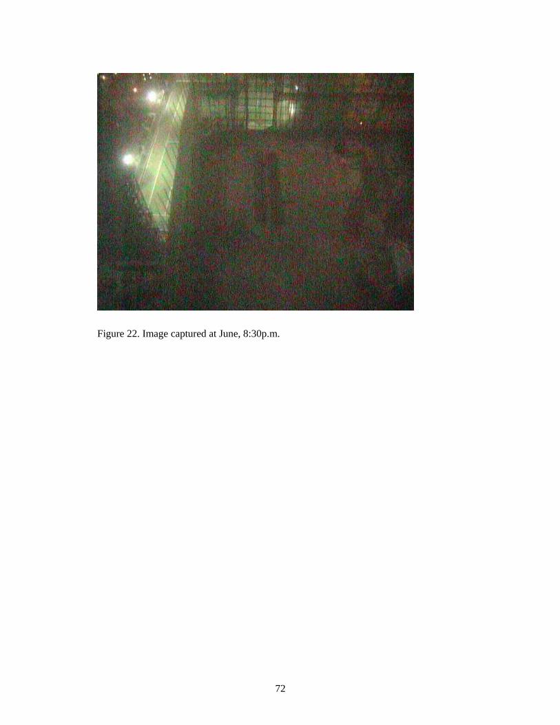
72
Figure 22. Image captured at June, 8:30p.m.

73
Chapter 8
Conclusions
Conventionally most of the monitoring processes in the construction industry are
conducted manually. For instance, a site foreman ensures the workers are compliant
with the regulations, a safety officer are concerned with the safety and health of
persons, and so on. The system introduced in this thesis automates part of the manual
processes so that the workload of the involved team members could be reduced and
therefore they may be more focused on decisional and managerial issues. Most
importantly, although the proposed system is named as a “monitoring” system, indeed it
also assists stakeholders in collaboration and decision-makings. It is because the system
provides a real-time virtual meeting and interactive environment for users to analyze
and comment on the monitored results anytime and anywhere with Internet
connectivity.
The endeavor of this thesis focuses on designing and implementing a monitoring system
to provide a cost-effective solution on quality assurance for construction projects
therefore this thesis is more technical orientated. The system integrates long-range
wireless network technologies, network cameras, and collaborative systems to form a
comprehensive monitoring and meeting environment for project team members. The
system has been tested in actual construction sites and the results of image quality and
reliability are more than satisfactory so far. Up to the moment of writing this thesis, no
other literature is found to be using similar configuration for construction site
monitoring purpose. Therefore this thesis could be act as a guideline for parties who are

74
interested on implementing not only electronic site monitoring, but also any wireless
information and communication applications for construction projects.
Nevertheless there is one potential research limitation. Although the proposed system is
point-to-multipoint ready, no test was conducted to test this feature in a construction
site. When several viewpoints operate simultaneously, interferences may exist and data
bandwidth provided by the proposed wireless network technology may not be sufficient
resulting in degradation in system performance. The degradations perhaps include
dropping of frame rate (i.e., fluency of motion of video is decreased) and increase of
recoverable data transmission errors (affects the clarity of images). Fortunately there is
a new wireless network standard, named “802.11n”, which will be introduced in year
2009 (http://www.ieee802.org/). The new standard is now in draft stage but its
transmission speed is expected to be about five times of the current standard and the
transmission range is also doubled. Therefore, theoretically it may be feasible to
implement the monitoring system on a small construction site without using the long-
range antennas. Further test is required to confirm this prediction and it may be regarded
as part of future research.
Although this thesis focuses on design and implementation of an ICT application in the
construction domain, some human factors like the decision on accepting and adopting
new technologies should not be neglected. It is doubtless that the appropriate use of ICT
does more good than harm to a construction project, and therefore many researchers and
developers have been trying their best to investigate innovative and effective ICT
solutions for the industry, and some of them are described in this thesis. Unfortunately,
practitioners’ intention of adopting new ICT in construction project is still rare. It is

75
found that the penetration rate of ICT within the core processes of the construction
industry is still relatively poor when comparing with other industries (Nikas et al.,
2007). Rather than technical and financial issues, researchers have been trying to figure
out some factors to explain this phenomenon. For instance, the stakeholders are often
satisfied with their conventional business method so that they are reluctant to change
(Samuelson, 2002), culture and psychological factors may be barriers to widespread
adoption of ICT (Backblom et al., 2003; Bjork, 2003), and so on. Although the study of
this rather pessimistic phenomenon is not the theme of this thesis, it is hoped that more
resources could be spent on advertising the R&D results to the business domain. The
mission could not be accomplished by just the efforts of research teams, attitude and
policy of the Government is the most critical success factor.
Further Research
By enlarging the scale of this project and the adoption of the said new wireless
transmission standard, more applications could be implemented. While this project only
focuses on building construction sites, by using the long-range and point-to-multipoint
communication capability, larger civil engineering projects such as railway and
highway construction could adopt the solution to implement inspection and quality
control. As described in Section 4.2.3, in theory, it is possible to record videos by
upgrading the proposed server to a video streaming server, but the cost is too high for
pilot studying purpose and therefore only still images are stored in the server (note:
observers could see fluid real-time monitoring motions, but the pictures not continuous
stored in frame-by-frame fashion). If the proposed system is mainly used for
surveillance purposes, the capability of archiving videos may be an essential feature.
When a video streaming server is adopted, it is recommended to focus more on server

76
maintenance because the server has to deal with large data traffic, and those 7 x 24 non-
stop video files are thirsty for hard disk space. Therefore more effort has to be spent in
“monitoring the monitoring system”.
Being a pilot study using real life construction projects, this thesis confirms the
technological feasibility of the proposed system. However, it is also valuable to further
investigate the system from different angles such as managerial perception, workers’
acceptability (e.g. any behavioral changes), legal issues, system adoption criteria, the
impact on project planning, and so on. Although the monitoring system is beneficial to
the managerial stakeholders and the owner, the perceptions of the construction workers
who are monitored should not be neglected. With the growth of the adoption of
information and communication technology in construction projects, it could be
anticipated that more construction firms will attempt to equip with electronic gears and
gadgets for site monitoring or surveillance purposes in the future. As the construction
workers may be the major group of project team members being monitored, ethically it
is essential to investigate their level of acceptance on the monitoring systems.

77
Appendix
Interview with stakeholders of the construction industry Interviewees:
1. Owner 2. Contractor 3. Engineer
Questions: Supposed there is a monitor system that could be able to let you see the activities in construction sites through a computing device.
1. What activities you are interested to be monitored through the device? 你希望透過這個裝置可以監控到甚麼?
2. When do you use it? (Do you need to monitor the site at late night time?) 你會在甚麼時候使用?(有需要在深夜使用嗎?)
3. Which part of the site do you want to monitor? How details? E.g. do you need to
recognize the faces? (powerful zoom feature) 你希望監控地盆內哪一部份?要多細緻?例如需要見到樣貌嗎?
4. Is there a need to archive the images? If so, keep how many days? For how
long? 有需要儲存那些影像嗎?要多少日,存放多久?
5. Who should be able to use the system?
哪些人會用這系統?
6. How much do you wish to spend on the system? 你會願意花多少錢?
7. Have you used any surveillance system before? If so, what is your comments?
你之前有用過任何監察系統嗎?如有,有甚麼意見?
8. Do you have any concerns on placing the monitoring system in a construction site? 你對在地盆放置一個監察系統,有沒有擔心或任何掛慮?

78
References
Alshawi, M., Ingirige, B., Web-enabled project management: an emerging paradigm in construction, Automation in Construction 12 (4) (2003) pp.349-364
Anumba, C.J., Baron, G., Duke, A. Information and Communications Technologies to Facilitate Concurrent Engineering in Construction, BT Technology Journal 15 (3) (1997) pp.199-207
Anumba, C.J., Evbuowan, N.F.O., Taxonomy for Communication Facets in Concurrent Life-cycle Design and Construction, Computer-Aided and Infrastructure Engineering 14 (1999) pp.37-44
Atkinson, A.R., The role of human error in construction defects, Structural Survey 17 (4) (1999) pp. 231-236
Aziz, Z., Anumba, C., Ruikar, D., Carrillo, P., Bouchlaghem, D., Semantic web based services for intelligent mobile construction collaboration (2004)
Aziz, Z., Anumba, C.J., Ruikar, D., Carrillo, P., Bouchlaghem, D., Intelligent wireless web services for construction—A review of the enabling technologies, Automation in Construction 15 (2) (2006) pp. 113-123
Backblom, M., Ruohtula, A., Bjork, B., Use of document management systems - a case study of the Finnish construction industry. Electronic Journal of Information Technology in Construction 8, Special Issue: eWork and eBusiness (2003) pp.367–380
Basu, A., Kamal, A.D., Illahi, W., Khan, M., Stavrou, P., Ryder, R.E.J., Is digital image compression acceptable within diabetic retinopathy screening?, Diabetic Medicine 20 (9) (2003) pp. 766-771
Beastall, G., Records management meets knowledge gathering, Records Management Journal 8 (2) (1998) pp.89-94
Bjork, B.C., Electronic document management in construction – research issues and results, Electronic Journal of Information Technology in Construction 8 (2003) pp.105–117

79
Burati, J.L.J., Farrington, J.J., Ledbetter, W.B., Causes of Quality Deviations in Design and Construction, Journal of Construction Engineering and Management 118 (1) (1992) pp. 34-49
Cam-Winget, N., Housley, R., Wagner, D., Walker, J., Security flaws in 802.11 data link protocols, Communications of the ACM 46 (5) (2003) pp. 35-39
Carr, Joseph J., Joe Carr's Receiving Antenna Handbook, Solana Beach, CA:HighText Publications (1993)
Carr V., Tah, J.H.M., A fuzzy approach to construction project risk assessment and analysis: construction project risk management system, Advances in Engineering Software 32 (10-11) pp.847-857
Cheng, Eddie W.L., Li, Heng, Love, Peter E.D., Irani, Zahir, Network communication in the construction industry, Corporate Communications: An International Journal Volume: 6 Issue: 2 (2001) pp. 61-70
Cheng, M.-Y., Chen, J.-C., Integrating barcode and GIS for monitoring construction progress, Automation in Construction 11 (1) (2002) pp. 22-33
Delsing, J., Lindgren, P., Östmark, A.k., Mobile Internet Enable Senors Using Mobile Phones as Access Network, ITCon 9 (2004) pp. 381-388
Deng, Z.M., Li, H., Tam, C.M., Shen, Q.P., Love, P.E.D., An application of the Internet-based project management system, Automation in Construction 10 (2) (2001) pp. 239-246
Foltz, B., 3D laser scanner provides benefits for PennDOT bridge and rockface surveys, Professional Surveyor 20 (5) (2000) pp.22–28
Goodrum, P.M., McLaren, M.A., Durfee, A., The Application of Active Radio Frequency Identification Technology for Tool Tracking on Construction Job Sites, Automation in Construction 15 (3) (2006) pp. 292-302
Guy, N., Choosing a lens and basic lens, http://photonotes.org/articles/beginner-faq/lenses.html (2006)

80
Higgin, G., Jessop, N., Communication in the Building Industry, Tavistock Publications, London (2001)
Hillebrandt, P.M., Economic theory and the construction industry, Halsted Press, New York (London) (1974)
Huang, Ting, Kong, C.W., Guo, H.L., Baldwin, Andrew, Li, Heng, A virtual prototyping system for simulating construction processes, Automation in Construction (16) (2007) pp. 576-585
Hurtado, M.C., New survey points to spending growth, Engineering News Record vol. 246 (21), McGraw-Hill, New York, USA (2003) pp. 21
IEEE 2007, http://standards.ieee.org/getieee802/802.11.html
IEEE Std 802.3u-1995 (Supplement to ISO/IEC 8802-3: 1993; ANSI/IEEE Std 802.3, 1993 Edition), http://ieeexplore.ieee.org/xpl/freeabs_all.jsp?tp=&isnumber=30223&arnumber=1388753&punumber=9535
Josephson, P.E., Hammarlund, Y., The causes and costs of defects in construction A study of seven building projects, Automation in Construction 8 (6) (1999) pp. 681-687
Kimoto, K., Endo, K., Iwashita, S., Fujiwara, M., The application of PDA as mobile computing system on construction management, Automation in Construction 14 (4) (2005) pp. 500-511
Lam, H.F., Chang, T.Y.P., Web-based information management system for construction projects, Computer Aided Civil and Infrastructure Engineering, 17 (2002) pp.280-293
Lanfranchi, L.I., Bing, B.K., MPEG-4 Bandwidth Prediction for Broadband Cable Networks, IEEE Transaction on Broadcasting, 54 (4) (2008) pp.741-751
Lee, S., Chang, L.-M., Skibniewski, M., Automated recognition of surface defects using digital color image processing, Automation in Construction 15 (4) (2006) pp. 540-549

81
Loesch, J.E., Theodori, J., Document management: a case study, Journal of Facilities Management 3 (3)_(2004) pp.273-283
Mak, S., A model of information management for construction using information technology, Automation in Construction 10 (2001) pp.257-63
Marpe, D., Wiegand, T., Sullivan, G.J., The H.264/MPEG4 advanced video coding standard and its applications, IEEE Communications Magazine, 44 (8) (2006) pp.134-143
Meissner, A., Mathes, I., Sa, I., Peania, G., Baxevanaki, L., Dore, G., Generati, O., Branki, C., Integrated Mobile Operations Support for the Construction Industry: The COSMOS Solution in: Proc. of the 5th World Multi-Conference on Systemics, Cybernetics and Informatics, SCI, Orlando, USA (2001)
Morris, C. (ed.), Academic Press Dictionary of Science and Technology Academic Press, Inc., San Diego (1992)
Navon, R., Process and quality control with a video camera, for a floor-tiling robot, Automation in Construction 10 (1) (2000) pp. 113-125
Nikas, A., Poulymenakou, A., Kriaris, P., Investigating antecedents and drivers affecting the adoption of collaboration technologies in the construction industry, Automation in Construction 16 (5) (2007) pp.632-641
Nitithamyong, P., Skibniewski, M.J., Web-based construction project management systems: how to make them successful?, Automation in Construction 13 (4) (2004) pp. 491-506.
O'Brien, W.J., Implementing issues in project web sites: a practitioner's viewpoint, in: Journal of Management in Engineering vol. 16 (3), ASCE, New York, USA (2000) pp. 34–39
Opfer, N.D., Construction Defect Education in Construction Management, ASC, in: Proc of the 35th Annual Conference, California Polytechnic State University–San Luis Obispo, California, April (1999) pp. 7-10
Raftery, J., Pasadilla, B., Chiang, Y.H., Hui, E.C.M., Tang, B.-S., Globalization and construction industry development: implications of recent developments in the construction sector in Asia, Construction Management and Economics 16 (6) (1998) pp. 729-737

82
Rankin, J.H., Froese, T.M., Information population of an integrated construction management system, Computer Aided Civil and Infrastructure Engineering 17 (2002) pp.256-268
Rojas, E.M., Songer, A.D., Web-centrics systems: a new paradigm for collaborative engineering, Journal of Management in Engineering 15 (1) (1999) pp. 39-45
Sarshar, M., Isikdag, U., A survey of ICT use in the Turkish construction industry, Engineering, Construction and Architectural Managament 4 (2004) pp.238–247
Scheible, G., Schutz, J., Apneseth, C., Novel wireless power supply system for wireless communication devices in industrial automation systems, in: IECON '02, Industrial Electronics Society, the 28th Annual Conference of the IEEE (2002) pp. 1358-1363
Shoesmith, D.R. Procurement and performance in building services in Hong Kong: A study of the temporary multi-organization, its nature and management, MPhil Dissertation, University of Bath (1991)
Shuman, Jim, Multimedia Concepts: Enhanced Edition -Illustrated Introductory,
Thomson Course Technology (2003), ISBN: 061911052X
Slivovsky, L.A., Rahardja, K, Edwards, J., Kak, A., Tanaka, Y., An outdoor stereo
vision brick recognition system for construction robots, in: Proc of the 13th International Symposium on Automation and Robotics in Construction, Tokyo (1996) pp. 561-570
Stewart, R., IT enhanced project information management in construction: pathways to improved performance and strategic competitiveness, Automation in Construction 16 (4) (2007) pp.511-517
Tai, S., Wang, Y., Anumba, C.J., A survey on communications in large-scale construction projects in China, Engineering Construction and Architectural Management 16 (2) (2009) pp.136-149
Tam, C.M., Use of the Internet to enhance construction communication: Total Information transfer system, International Journal of Project Management 17 (2) (1999) pp. 107-110

83
Tepke D., Tikalsky, P.J., Concrete maturity progress: survey of departments of transportation, Transportation Research Record 1775 (2001) pp.125–131
Veal, D.C., Techniques of document management: a review of text retrieval and related technologies, Journal of Documentation 57 (2) (2001) pp.192-217
Vredenburg, Karel, Isensee, Scott, Righi, Carol, User-Centered Design: An Integrated Approach with Cdrom, Prentice Hall PTR, Upper Saddle River, NJ, 2001
Wallace, G.K., The JPEG still picture compression standard, Communications of the ACM 34 (4) (1991) pp. 30-44
Ward, M., Thorpe, T., Price, A., Wren, C., Implementation and Control of Wireless Data Collection on Construction Sites, ITCon 9 (2004) pp.297-311
Wi-Fi Alliance, WPA Deployment Guidelines for Public Access Wi-Fi Networks, Wi-Fi Alliance White Paper, October 28 (2004)
Wijesinha, A.L., Song, Y., Krishnan, M., Mathur, V., Ahn, J., Shyamasundar, V., Throughput measurement for UDP traffic in an IEEE 802.11 g WLAN, in: Proc of the 6th International Conference on Software Engineering, Artificial Intelligence, Networking and Parallel/Distributed Computing, 2005 and First ACIS International Workshop on Self-Assembling Wireless Networks (2005) pp. 220–225
Wikforss, Ö, Löfgren, A, Rethinking communication in construction, ITcon Vol. 12 (2007) pp. 337-346
Winch, G., The construction firm and the construction process: the allocation of resources to the construction project. In Lansley, P. and Harlow, P (eds.) Managing construction worldwide (1987) vol. 2: Productivity and Human factors