B DIFFERENCES FROM SERIES 0i-C - CNC Zone
53
B.DIFFERENCES FROM SERIES 0i-C APPENDIX B-64304EN-2/01 - 246 - B DIFFERENCES FROM SERIES 0i-C Appendix B, "Differences from Series 0i-C", consists of the following sections: B.1 SETTING UNIT ............................................................................................................................. 247 B.2 AUTOMATIC TOOL OFFSET...................................................................................................... 247 B.3 CIRCULAR INTERPOLATION .................................................................................................... 249 B.4 HELICAL INTERPOLATION ....................................................................................................... 250 B.5 SKIP FUNCTION ........................................................................................................................... 251 B.6 MANUAL REFERENCE POSITION RETURN ........................................................................... 253 B.7 WORKPIECE COORDINATE SYSTEM...................................................................................... 255 B.8 LOCAL COORDINATE SYSTEM................................................................................................ 257 B.9 Cs CONTOUR CONTROL ............................................................................................................ 258 B.10 SERIAL/ANALOG SPINDLE CONTROL.................................................................................... 259 B.11 CONSTANT SURFACE SPEED CONTROL ............................................................................... 259 B.12 TOOL FUNCTIONS....................................................................................................................... 260 B.13 TOOL COMPENSATION MEMORY ........................................................................................... 261 B.14 CUSTOM MACRO ........................................................................................................................ 261 B.15 INTERRUPTION TYPE CUSTOM MACRO ............................................................................... 264 B.16 PROGRAMMABLE PARAMETER INPUT (G10)....................................................................... 264 B.17 AI ADVANCED PREVIEW CONTROL /AI CONTOUR CONTROL ........................................ 264 B.18 MACHINING CONDITION SELECTION FUNCTION .............................................................. 267 B.19 AXIS SYNCHRONOUS CONTROL............................................................................................. 268 B.20 ARBITRARY ANGULAR AXIS CONTROL ............................................................................... 272 B.21 RUN HOUR AND PARTS COUNT DISPLAY ............................................................................ 273 B.22 MANUAL HANDLE FEED ........................................................................................................... 274 B.23 PMC AXIS CONTROL .................................................................................................................. 275 B.24 EXTERNAL SUBPROGRAM CALL (M198)............................................................................... 279 B.25 SEQUENCE NUMBER SEARCH ................................................................................................. 280 B.26 STORED STROKE CHECK .......................................................................................................... 281 B.27 STORED PITCH ERROR COMPENSATION .............................................................................. 283 B.28 SCREEN ERASURE FUNCTION AND AUTOMATIC SCREEN ERASURE FUNCTION ...... 284 B.29 RESET AND REWIND .................................................................................................................. 285 B.30 MANUAL ABSOLUTE ON AND OFF......................................................................................... 285 B.31 EXTERNAL DATA INPUT ........................................................................................................... 287 B.32 DATA SERVER FUNCTION ........................................................................................................ 289 B.33 POWER MATE CNC MANAGER ................................................................................................ 289 B.34 CUTTER COMPENSATION/TOOL NOSE RADIUS COMPENSATION .................................. 290 B.35 CANNED CYCLE FOR DRILLING ............................................................................................. 295 B.36 CANNED GRINDING CYCLE ..................................................................................................... 296 B.37 SINGLE DIRECTION POSITIONING.......................................................................................... 297 B.38 OPTIONAL ANGLE CHAMFERING AND CORNER ROUNDING .......................................... 297
-
Upload
khangminh22 -
Category
Documents
-
view
1 -
download
0
Transcript of B DIFFERENCES FROM SERIES 0i-C - CNC Zone
B.DIFFERENCES FROM SERIES 0i-C APPENDIX B-64304EN-2/01
- 246 -
B DIFFERENCES FROM SERIES 0i-C Appendix B, "Differences from Series 0i-C", consists of the following sections: B.1 SETTING UNIT .............................................................................................................................247 B.2 AUTOMATIC TOOL OFFSET......................................................................................................247 B.3 CIRCULAR INTERPOLATION....................................................................................................249 B.4 HELICAL INTERPOLATION.......................................................................................................250 B.5 SKIP FUNCTION...........................................................................................................................251 B.6 MANUAL REFERENCE POSITION RETURN ...........................................................................253 B.7 WORKPIECE COORDINATE SYSTEM......................................................................................255 B.8 LOCAL COORDINATE SYSTEM................................................................................................257 B.9 Cs CONTOUR CONTROL ............................................................................................................258 B.10 SERIAL/ANALOG SPINDLE CONTROL....................................................................................259 B.11 CONSTANT SURFACE SPEED CONTROL ...............................................................................259 B.12 TOOL FUNCTIONS.......................................................................................................................260 B.13 TOOL COMPENSATION MEMORY...........................................................................................261 B.14 CUSTOM MACRO ........................................................................................................................261 B.15 INTERRUPTION TYPE CUSTOM MACRO ...............................................................................264 B.16 PROGRAMMABLE PARAMETER INPUT (G10).......................................................................264 B.17 AI ADVANCED PREVIEW CONTROL /AI CONTOUR CONTROL ........................................264 B.18 MACHINING CONDITION SELECTION FUNCTION ..............................................................267 B.19 AXIS SYNCHRONOUS CONTROL.............................................................................................268 B.20 ARBITRARY ANGULAR AXIS CONTROL ...............................................................................272 B.21 RUN HOUR AND PARTS COUNT DISPLAY ............................................................................273 B.22 MANUAL HANDLE FEED...........................................................................................................274 B.23 PMC AXIS CONTROL ..................................................................................................................275 B.24 EXTERNAL SUBPROGRAM CALL (M198)...............................................................................279 B.25 SEQUENCE NUMBER SEARCH .................................................................................................280 B.26 STORED STROKE CHECK ..........................................................................................................281 B.27 STORED PITCH ERROR COMPENSATION ..............................................................................283 B.28 SCREEN ERASURE FUNCTION AND AUTOMATIC SCREEN ERASURE FUNCTION ......284 B.29 RESET AND REWIND..................................................................................................................285 B.30 MANUAL ABSOLUTE ON AND OFF.........................................................................................285 B.31 EXTERNAL DATA INPUT...........................................................................................................287 B.32 DATA SERVER FUNCTION ........................................................................................................289 B.33 POWER MATE CNC MANAGER ................................................................................................289 B.34 CUTTER COMPENSATION/TOOL NOSE RADIUS COMPENSATION..................................290 B.35 CANNED CYCLE FOR DRILLING .............................................................................................295 B.36 CANNED GRINDING CYCLE .....................................................................................................296 B.37 SINGLE DIRECTION POSITIONING..........................................................................................297 B.38 OPTIONAL ANGLE CHAMFERING AND CORNER ROUNDING..........................................297

B-64304EN-2/01 APPENDIX B.DIFFERENCES FROM SERIES 0i-C
- 247 -
B.1 SETTING UNIT
B.1.1 Differences in Specifications
Function Explanation Diameter/radius specification in the move command for each axis
- Make a selection using bit 3 (DIAx) of parameter No. 1006. Bit 3 (DIAx) of parameter No. 1006 The move command for each axis specifies: 0: Radius. 1: Diameter. With Series 0i-C, in order for an axis whose diameter is specified to travel the specified distance, it is necessary not only to set 1 in bit 3 (DIAx) of parameter No. 1006 but also to make either of the following two changes: - Reduce the command multiplier (CMR) to half. (The detection unit does not need to
be changed.) - Reduce the detection unit to half, and double the flexible feed gear (DMR). With Series 0i-D, by contrast, just setting 1 in bit 3 (DIAx) of parameter No. 1006 causes the CNC to reduce the command pulses to half, eliminating the need to make the changes described above (when the detection unit is not changed). Note that, when the detection unit is reduced to half, both the CMR and DMR need to be doubled.
B.1.2 Differences in Diagnosis Display None.
B.2 AUTOMATIC TOOL OFFSET
B.2.1 Differences in Specifications
Function Series 0i-C Series 0i-D Operation of the current offset for the measurement result
- Added to the current offset. - Select whether to add or subtract, by using bit 6 (MDC) of parameter No. 6210.
Bit 6 (MDC) of parameter No. 6210 The measurement result of automatic tool length measurement (system M) or automatic tool compensation (system T) is:0: Added to the current offset. 1: Subtracted from the current offset.

B.DIFFERENCES FROM SERIES 0i-C APPENDIX B-64304EN-2/01
- 248 -
Function Series 0i-C Series 0i-D Setting of the feedrate for measurement
- Set the value in parameter No. 6241. This is a parameter common to the measuring position reached signals (XAE, YAE, and ZAE).
- Parameter No. 6241 This is a parameter for the measuring position reached signals (XAE1 and GAE1).
- Parameter No. 6242 This is a parameter for the measuring position reached signals (XAE2 and GAE2).
- Parameter No. 6243 This is a parameter for the measuring position reached signals (XAE3 and GAE3).
NOTE When 0 is set in parameter Nos. 6242 and 6243, the value in parameter No. 6241 becomes valid.
Setting of the γ value - Set the value in parameter No. 6251. This is a parameter common to the measuring position reached signals (XAE, YAE, and ZAE).
- Parameter No. 6251 This is a parameter for the measuring position reached signals (XAE1 and GAE1).
- Parameter No. 6252 This is a parameter for the measuring position reached signals (XAE2 and GAE2).
- Parameter No. 6253 This is a parameter for the measuring position reached signals (XAE3 and GAE3).
NOTE When 0 is set in parameter No. 6252 and 6253, the value in parameter No. 6251 becomes valid.
Setting of the ε value - Set the value in parameter No. 6254. This is a parameter common to the measuring position reached signals (XAE, YAE, and ZAE).
- Parameter No. 6254 This is a parameter for the measuring position reached signals (XAE1 and GAE1).
- Parameter No. 6255 This is a parameter for the measuring position reached signals (XAE2 and GAE2).
- Parameter No. 6256 This is a parameter for the measuring position reached signals (XAE3 and GAE3).
NOTE When 0 is set in parameter Nos. 6255 and 6256, the value in parameter No. 6254 becomes valid.
B.2.2 Differences in Diagnosis Display None.
B-64304EN-2/01 APPENDIX B.DIFFERENCES FROM SERIES 0i-C
- 249 -
B.3 CIRCULAR INTERPOLATION
B.3.1 Differences in Specifications
Function Series 0i-C Series 0i-D If the difference between the radius values of the start point and end point of an arc is greater than the value set in parameter No. 3410, alarm PS0020 is issued. If the difference is smaller (the end point is not on the arc), circular interpolation is performed as follows.
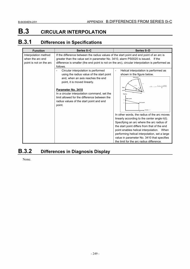
Interpolation method when the arc end point is not on the arc
- Circular interpolation is performed using the radius value of the start point and, when an axis reaches the end point, it is moved linearly.
Parameter No. 3410 In a circular interpolation command, set the limit allowed for the difference between the radius values of the start point and end point.
- Helical interpolation is performed as shown in the figure below.
γe γ(t)
γs
Start
point中心
End point
θ(t) θ
Start point
End point
Center θ θ
γs
γe
Radius
θts)e(s(t) )(θγγ
γγ−
+=
In other words, the radius of the arc moves linearly according to the center angle θ(t). Specifying an arc where the arc radius of the start point differs from that of the end point enables helical interpolation. When performing helical interpolation, set a large value in parameter No. 3410 that specifies the limit for the arc radius difference.
B.3.2 Differences in Diagnosis Display None.
B.DIFFERENCES FROM SERIES 0i-C APPENDIX B-64304EN-2/01
- 250 -
B.4 HELICAL INTERPOLATION
B.4.1 Differences in Specifications
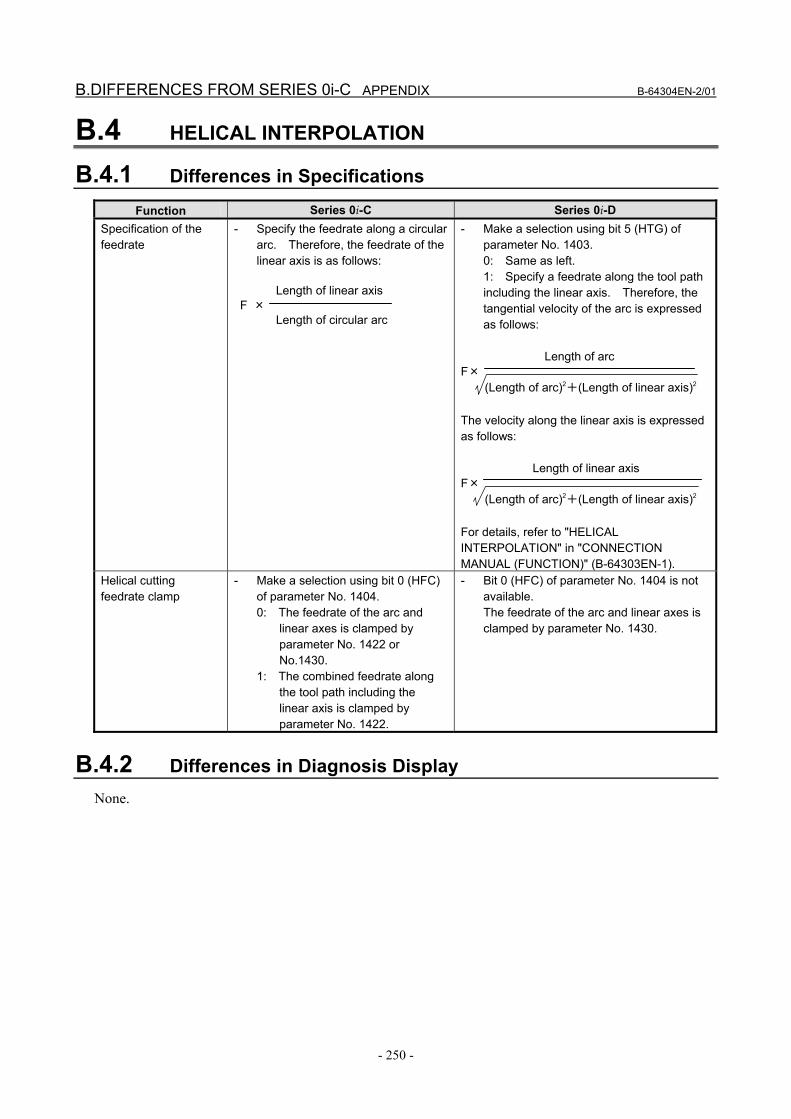
Function Series 0i-C Series 0i-D Specification of the feedrate
- Specify the feedrate along a circular arc. Therefore, the feedrate of the linear axis is as follows:
Length of linear axis F × Length of circular arc
- Make a selection using bit 5 (HTG) of parameter No. 1403. 0: Same as left. 1: Specify a feedrate along the tool path including the linear axis. Therefore, the tangential velocity of the arc is expressed as follows:
Length of arc
F× (Length of arc)2+(Length of linear axis)2 The velocity along the linear axis is expressed as follows:
Length of linear axis F× (Length of arc)2+(Length of linear axis)2 For details, refer to "HELICAL INTERPOLATION" in "CONNECTION MANUAL (FUNCTION)" (B-64303EN-1).
Helical cutting feedrate clamp
- Make a selection using bit 0 (HFC) of parameter No. 1404. 0: The feedrate of the arc and
linear axes is clamped by parameter No. 1422 or No.1430.
1: The combined feedrate along the tool path including the linear axis is clamped by parameter No. 1422.
- Bit 0 (HFC) of parameter No. 1404 is not available. The feedrate of the arc and linear axes is clamped by parameter No. 1430.
B.4.2 Differences in Diagnosis Display None.
B-64304EN-2/01 APPENDIX B.DIFFERENCES FROM SERIES 0i-C
- 251 -
B.5 SKIP FUNCTION
B.5.1 Differences in Specifications
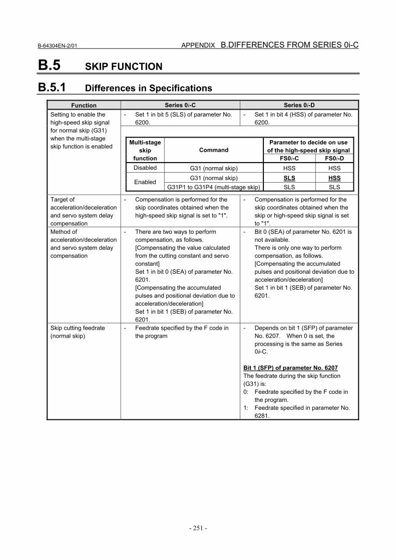
Function Series 0i-C Series 0i-D - Set 1 in bit 5 (SLS) of parameter No.
6200. - Set 1 in bit 4 (HSS) of parameter No.
6200. Setting to enable the high-speed skip signal for normal skip (G31) when the multi-stage skip function is enabled
Parameter to decide on use of the high-speed skip signal
Multi-stage skip
function Command
FS0i-C FS0i-D Disabled G31 (normal skip) HSS HSS
G31 (normal skip) SLS HSS Enabled
G31P1 to G31P4 (multi-stage skip) SLS SLS
Target of acceleration/deceleration and servo system delay compensation
- Compensation is performed for the skip coordinates obtained when the high-speed skip signal is set to "1".
- Compensation is performed for the skip coordinates obtained when the skip or high-speed skip signal is set to "1".
Method of acceleration/deceleration and servo system delay compensation
- There are two ways to perform compensation, as follows. [Compensating the value calculated from the cutting constant and servo constant] Set 1 in bit 0 (SEA) of parameter No. 6201. [Compensating the accumulated pulses and positional deviation due to acceleration/deceleration] Set 1 in bit 1 (SEB) of parameter No. 6201.
- Bit 0 (SEA) of parameter No. 6201 is not available. There is only one way to perform compensation, as follows. [Compensating the accumulated pulses and positional deviation due to acceleration/deceleration] Set 1 in bit 1 (SEB) of parameter No. 6201.
Skip cutting feedrate (normal skip)
- Feedrate specified by the F code in the program
- Depends on bit 1 (SFP) of parameter No. 6207. When 0 is set, the processing is the same as Series 0i-C.
Bit 1 (SFP) of parameter No. 6207 The feedrate during the skip function (G31) is: 0: Feedrate specified by the F code in
the program. 1: Feedrate specified in parameter No.
6281.
B.DIFFERENCES FROM SERIES 0i-C APPENDIX B-64304EN-2/01
- 252 -
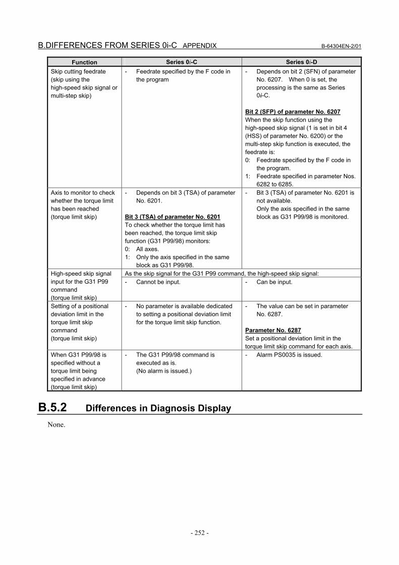
Function Series 0i-C Series 0i-D Skip cutting feedrate (skip using the high-speed skip signal or multi-step skip)
- Feedrate specified by the F code in the program
- Depends on bit 2 (SFN) of parameter No. 6207. When 0 is set, the processing is the same as Series 0i-C.
Bit 2 (SFP) of parameter No. 6207 When the skip function using the high-speed skip signal (1 is set in bit 4 (HSS) of parameter No. 6200) or the multi-step skip function is executed, the feedrate is: 0: Feedrate specified by the F code in
the program. 1: Feedrate specified in parameter Nos.
6282 to 6285. Axis to monitor to check whether the torque limit has been reached (torque limit skip)
- Depends on bit 3 (TSA) of parameter No. 6201.
Bit 3 (TSA) of parameter No. 6201 To check whether the torque limit has been reached, the torque limit skip function (G31 P99/98) monitors: 0: All axes. 1: Only the axis specified in the same
block as G31 P99/98.
- Bit 3 (TSA) of parameter No. 6201 is not available. Only the axis specified in the same block as G31 P99/98 is monitored.
As the skip signal for the G31 P99 command, the high-speed skip signal: High-speed skip signal input for the G31 P99 command (torque limit skip)
- Cannot be input. - Can be input.
Setting of a positional deviation limit in the torque limit skip command (torque limit skip)
- No parameter is available dedicated to setting a positional deviation limit for the torque limit skip function.
- The value can be set in parameter No. 6287.
Parameter No. 6287 Set a positional deviation limit in the torque limit skip command for each axis.
When G31 P99/98 is specified without a torque limit being specified in advance (torque limit skip)
- The G31 P99/98 command is executed as is. (No alarm is issued.)
- Alarm PS0035 is issued.
B.5.2 Differences in Diagnosis Display None.
B-64304EN-2/01 APPENDIX B.DIFFERENCES FROM SERIES 0i-C
- 253 -
B.6 MANUAL REFERENCE POSITION RETURN
B.6.1 Differences in Specifications
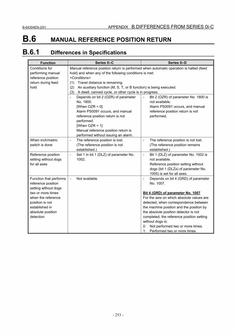
Function Series 0i-C Series 0i-D Manual reference position return is performed when automatic operation is halted (feed hold) and when any of the following conditions is met: <Conditions> (1) Travel distance is remaining. (2) An auxiliary function (M, S, T, or B function) is being executed. (3) A dwell, canned cycle, or other cycle is in progress.
Conditions for performing manual reference position return during feed hold
- Depends on bit 2 (OZR) of parameter No. 1800. [When OZR = 0] Alarm PS0091 occurs, and manual reference position return is not performed. [When OZR = 1] Manual reference position return is performed without issuing an alarm.
- Bit 2 (OZR) of parameter No. 1800 is not available. Alarm PS0091 occurs, and manual reference position return is not performed.
When inch/metric switch is done
- The reference position is lost. (The reference position is not established.)
- The reference position is not lost. (The reference position remains established.)
Reference position setting without dogs for all axes
- Set 1 in bit 1 (DLZ) of parameter No. 1002.
- Bit 1 (DLZ) of parameter No. 1002 is not available. Reference position setting without dogs (bit 1 (DLZx) of parameter No. 1005) is set for all axes.
Function that performs reference position setting without dogs two or more times when the reference position is not established in absolute position detection
- Not available. - Depends on bit 4 (GRD) of parameter No. 1007.
Bit 4 (GRD) of parameter No. 1007 For the axis on which absolute values are detected, when correspondence between the machine position and the position by the absolute position detector is not completed, the reference position setting without dogs is: 0: Not performed two or more times. 1: Performed two or more times.

B.DIFFERENCES FROM SERIES 0i-C APPENDIX B-64304EN-2/01
- 254 -
Function Series 0i-C Series 0i-D Behavior when manual reference position return is started on a rotation axis with the deceleration dog pressed before a reference position is established
- Does not depend on bit 0 (RTLx) of parameter No. 1007. Movement is made at the reference position return feedrate FL even if the grid is not established. Releasing the deceleration dog before the grid is established causes alarm PS0090.
- [Rotation axis type = A and bit 0 (RTLx) of parameter No. 1007 = 0] Movement is made at the reference position return feedrate FL even if the grid is not established. Releasing the deceleration dog before the grid is established causes alarm PS0090. [Rotation axis type = A and bit 0 (RTLx) of parameter No. 1007 = 1] Movement is made at the rapid traverse feedrate until the grid is established. If the deceleration dog is released before the grid is established, one revolution is made at the rapid traverse feedrate, thus establishing the grid. Pressing the deceleration dog again establishes the reference position. [Rotation axis type = B] Does not depend on bit 0 (RTLx) of parameter No. 1007. Movement is made at the reference position return feedrate FL even if the grid is not established. Releasing the deceleration dog before the grid is established causes alarm PS0090.
Reference position shift function setting
- The function is enabled for all axes by setting 1 in bit 2 (SFD) of parameter No. 1002.
- Bit 2 (SFD) of parameter No. 1002 is not available. Set bit 4 (SFDx) of parameter No. 1008 for each axis.
Setting of whether to preset the coordinate system upon high-speed manual reference position return
- Not available. The coordinate system is not preset.
- Depends on bit 1 (HZP) of parameter No. 1206.
Bit 1 (HZP) of parameter No.1206 Upon high-speed manual reference position return, the coordinate system is: 0: Preset. 1: Not preset (FS0i-C compatible
specification).

B-64304EN-2/01 APPENDIX B.DIFFERENCES FROM SERIES 0i-C
- 255 -
Function Series 0i-C Series 0i-D G28/G30 command in the coordinate system rotation, scaling, or programmable mirror image mode
- Not available. Cancel the mode before executing the command.
- The command can be executed only when all of the conditions described below are met. Otherwise, alarm PS0412 occurs.
<Conditions> [Conditions required before specifying the command] (1) An absolute command is specified for
the target axis of coordinate system rotation, scaling, or programmable mirror image.
(2) Tool length compensation has not been performed for the target axis of coordinate system rotation, scaling, or programmable mirror image when it is moved by reference position return.
(3) Tool length compensation has been canceled.
[Conditions required when specifying the command]
(4) In an incremental command, the travel distance of the middle point is 0.
[Conditions required after specifying the command]
(5) The first move command specified for the target axis of coordinate system rotation, scaling, or programmable mirror image is an absolute command.
B.6.2 Differences in Diagnosis Display None.
B.7 WORKPIECE COORDINATE SYSTEM
B.7.1 Differences in Specifications
Function Series 0i-C Series 0i-D Change in absolute position display when the workpiece zero point offset value is changed
- Make a selection using bit 5 (AWK) of parameter No. 1201.
Bit 5 (AWK) of parameter No. 1201 When the workpiece zero point offset value is changed: 0: Changes the absolute position display
when the program executes the block that is buffered next.
1: Changes the absolute position display immediately.
In either case, the changed value does not take effect until the block that is buffered next.
- Bit 5 (AWK) of parameter No. 1201 is not available. The tool always behaves as when AWK is set to 1.

B.DIFFERENCES FROM SERIES 0i-C APPENDIX B-64304EN-2/01
- 256 -
B.7.2 Differences in Diagnosis Display None.

B-64304EN-2/01 APPENDIX B.DIFFERENCES FROM SERIES 0i-C
- 257 -
B.8 LOCAL COORDINATE SYSTEM
B.8.1 Differences in Specifications
Function Series 0i-C Series 0i-D Clearing of the local coordinate system after servo alarm cancellation
- The processing is determined by the settings of bit 5 (SNC) and bit 3 (RLC) of parameter No. 1202.
Bit 3 (RLC) of parameter No. 1202 Upon reset, the local coordinate system is: 0: Not canceled. 1: Canceled. Bit 5 (SNC) of parameter No. 1202 After servo alarm cancellation, the local coordinate system is: 0: Cleared. 1: Not cleared. NOTE When the RLC bit of the parameter is set to 1, the local coordinate system is cleared, even if the SNC bit of the parameter is set to 1.
- The processing is determined by the settings of bit 7 (WZR) of parameter No. 1201, bit 3 (RLC) of parameter No. 1202, bit 6 (CLR) of parameter No. 3402, and bit 6 (C14) of parameter No. 3407. Bit 5 (SNC) of parameter No. 1202 is not available.
Bit 7 (WZR) of parameter No. 1201 If the CNC is reset by the reset key on the MDI panel, external reset signal, reset and rewind signal, or emergency stop signal when bit 6 (CLR) of parameter No. 3402 is set to 0, the G code of group number 14 (workpiece coordinate system) is: 0: Placed in the reset state. 1: Not placed in the reset state. NOTE When bit 6 (CLR) of parameter No. 3402 is set to 1, the processing depends on the setting of bit 6 (C14) of parameter No. 3407. Bit 3 (RLC) of parameter No. 1202 Upon reset, the local coordinate system is: 0: Not canceled. 1: Canceled. NOTE - When bit 6 (CLR) of parameter No. 3402 is set to 0
and bit 7 (WZR) of parameter No. 1201 is set to 1, the local coordinate system is canceled, regardless of the setting of this parameter.
- When bit 6 (CLR) of parameter No. 3402 is set to 1 and bit 6 (C14) of parameter No. 3407 is set to 0, the local coordinate system is canceled, regardless of the setting of this parameter.
Bit 6 (CLR) of parameter No. 3402 The reset key on the MDI panel, external reset signal, reset and rewind signal, or emergency stop signal places the local coordinate system in: 0: Reset state. 1: Clear state. Bit 6 (C14) of parameter No. 3407 If the CNC is reset by the reset key on the MDI panel, external reset signal, reset and rewind signal, or emergency stop signal when bit 6 (CLR) of parameter No. 3402 is set to 1, the G code of group number 14 (workpiece coordinate system) is: 0: Placed in the clear state. 1: Not placed in the clear state.
B.DIFFERENCES FROM SERIES 0i-C APPENDIX B-64304EN-2/01
- 258 -
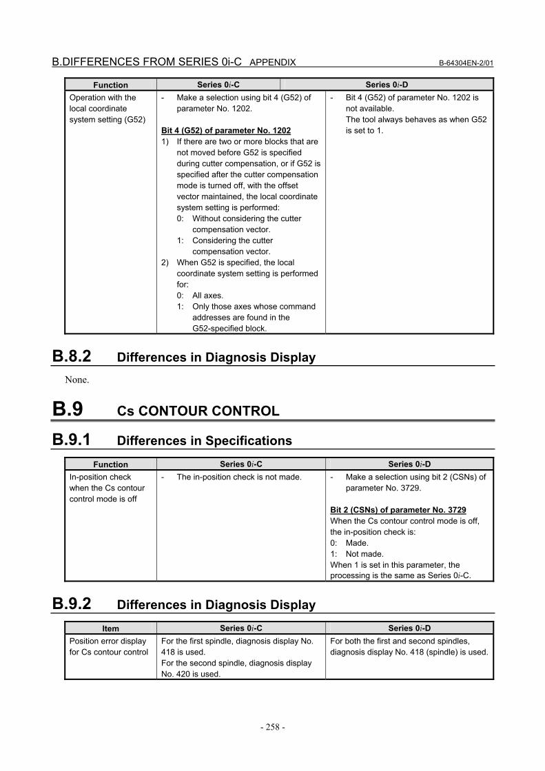
Function Series 0i-C Series 0i-D Operation with the local coordinate system setting (G52)
- Make a selection using bit 4 (G52) of parameter No. 1202.
Bit 4 (G52) of parameter No. 1202 1) If there are two or more blocks that are
not moved before G52 is specified during cutter compensation, or if G52 is specified after the cutter compensation mode is turned off, with the offset vector maintained, the local coordinate system setting is performed: 0: Without considering the cutter
compensation vector. 1: Considering the cutter
compensation vector. 2) When G52 is specified, the local
coordinate system setting is performed for: 0: All axes. 1: Only those axes whose command
addresses are found in the G52-specified block.
- Bit 4 (G52) of parameter No. 1202 is not available. The tool always behaves as when G52 is set to 1.
B.8.2 Differences in Diagnosis Display None.
B.9 Cs CONTOUR CONTROL
B.9.1 Differences in Specifications
Function Series 0i-C Series 0i-D In-position check when the Cs contour control mode is off
- The in-position check is not made. - Make a selection using bit 2 (CSNs) of parameter No. 3729.
Bit 2 (CSNs) of parameter No. 3729 When the Cs contour control mode is off, the in-position check is: 0: Made. 1: Not made. When 1 is set in this parameter, the processing is the same as Series 0i-C.
B.9.2 Differences in Diagnosis Display
Item Series 0i-C Series 0i-D Position error display for Cs contour control
For the first spindle, diagnosis display No. 418 is used. For the second spindle, diagnosis display No. 420 is used.
For both the first and second spindles, diagnosis display No. 418 (spindle) is used.
B-64304EN-2/01 APPENDIX B.DIFFERENCES FROM SERIES 0i-C
- 259 -
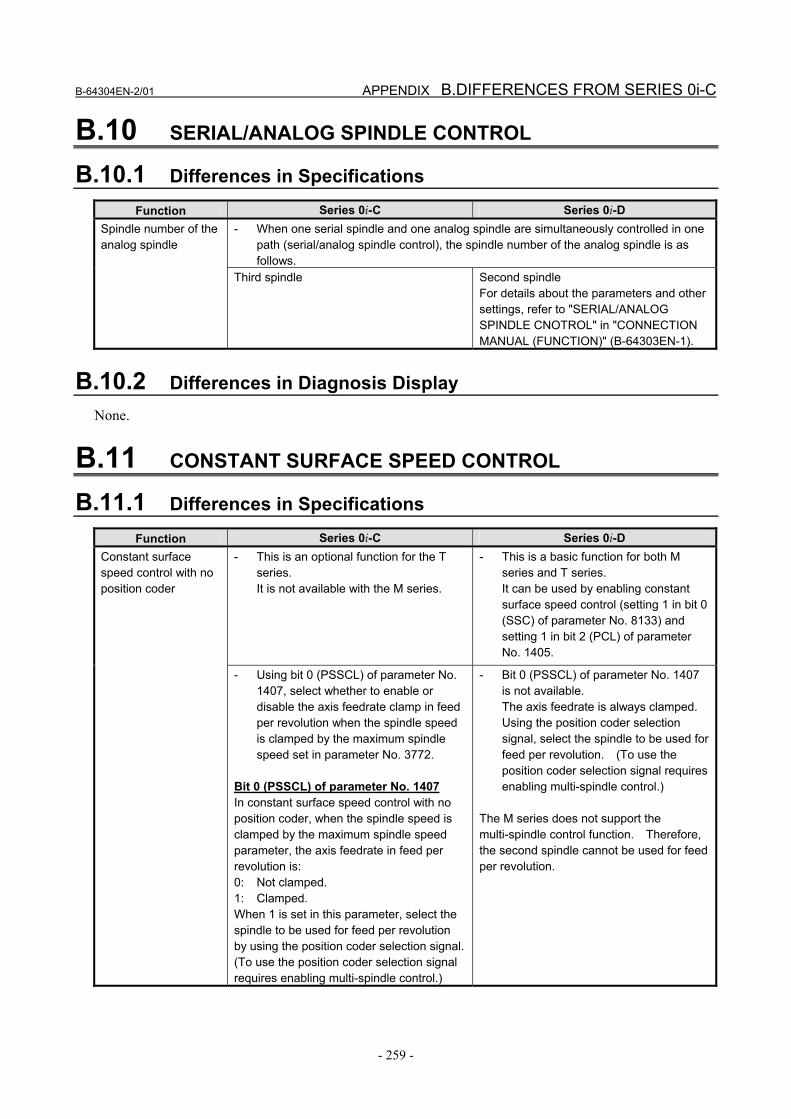
B.10 SERIAL/ANALOG SPINDLE CONTROL
B.10.1 Differences in Specifications
Function Series 0i-C Series 0i-D - When one serial spindle and one analog spindle are simultaneously controlled in one
path (serial/analog spindle control), the spindle number of the analog spindle is as follows.
Spindle number of the analog spindle
Third spindle Second spindle For details about the parameters and other settings, refer to "SERIAL/ANALOG SPINDLE CNOTROL" in "CONNECTION MANUAL (FUNCTION)" (B-64303EN-1).
B.10.2 Differences in Diagnosis Display None.
B.11 CONSTANT SURFACE SPEED CONTROL
B.11.1 Differences in Specifications
Function Series 0i-C Series 0i-D - This is an optional function for the T
series. It is not available with the M series.
- This is a basic function for both M series and T series. It can be used by enabling constant surface speed control (setting 1 in bit 0 (SSC) of parameter No. 8133) and setting 1 in bit 2 (PCL) of parameter No. 1405.
Constant surface speed control with no position coder
- Using bit 0 (PSSCL) of parameter No. 1407, select whether to enable or disable the axis feedrate clamp in feed per revolution when the spindle speed is clamped by the maximum spindle speed set in parameter No. 3772.
Bit 0 (PSSCL) of parameter No. 1407 In constant surface speed control with no position coder, when the spindle speed is clamped by the maximum spindle speed parameter, the axis feedrate in feed per revolution is: 0: Not clamped. 1: Clamped. When 1 is set in this parameter, select the spindle to be used for feed per revolution by using the position coder selection signal. (To use the position coder selection signal requires enabling multi-spindle control.)
- Bit 0 (PSSCL) of parameter No. 1407 is not available. The axis feedrate is always clamped. Using the position coder selection signal, select the spindle to be used for feed per revolution. (To use the position coder selection signal requires enabling multi-spindle control.)
The M series does not support the multi-spindle control function. Therefore, the second spindle cannot be used for feed per revolution.
B.DIFFERENCES FROM SERIES 0i-C APPENDIX B-64304EN-2/01
- 260 -
B.11.2 Differences in Diagnosis Display None.
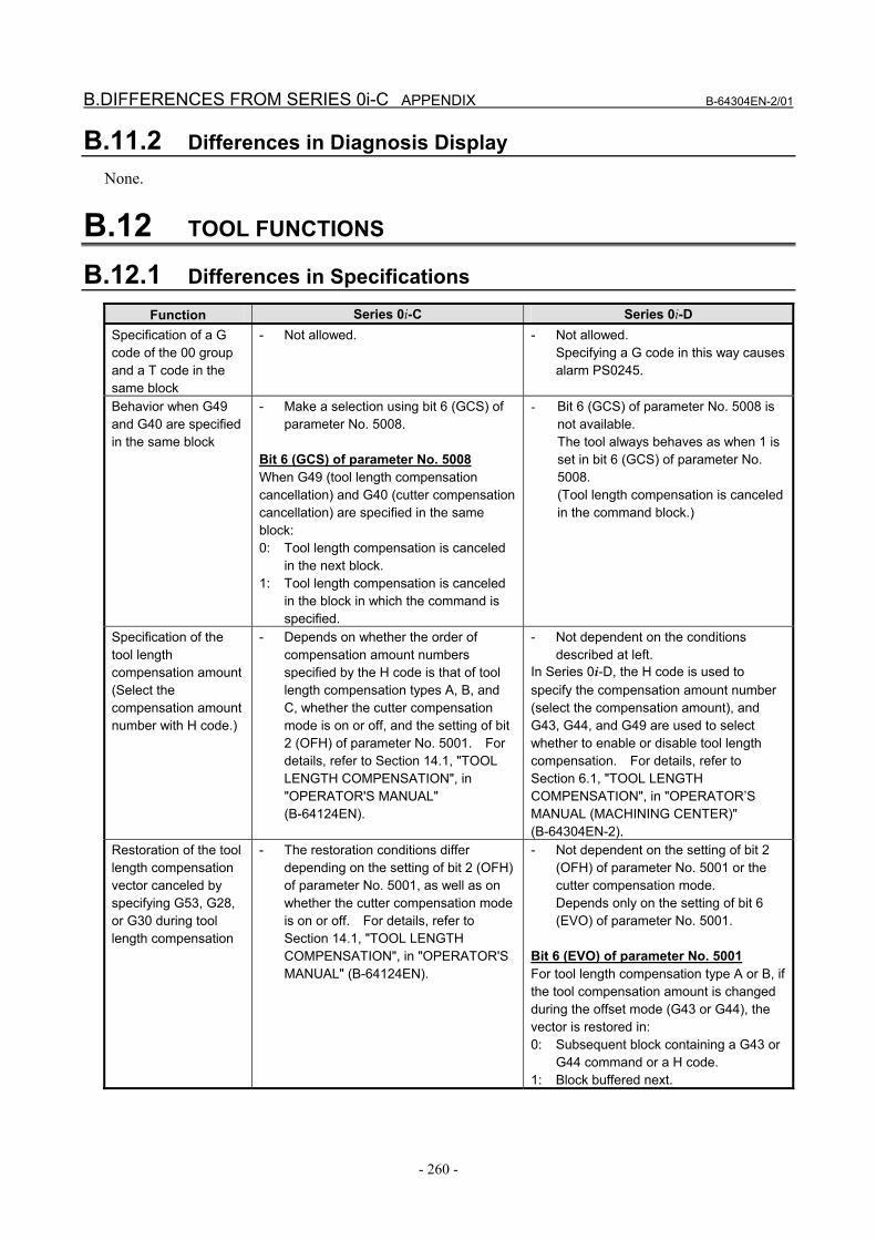
B.12 TOOL FUNCTIONS
B.12.1 Differences in Specifications
Function Series 0i-C Series 0i-D Specification of a G code of the 00 group and a T code in the same block
- Not allowed. - Not allowed. Specifying a G code in this way causes alarm PS0245.
Behavior when G49 and G40 are specified in the same block
- Make a selection using bit 6 (GCS) of parameter No. 5008.
Bit 6 (GCS) of parameter No. 5008 When G49 (tool length compensation cancellation) and G40 (cutter compensation cancellation) are specified in the same block: 0: Tool length compensation is canceled
in the next block. 1: Tool length compensation is canceled
in the block in which the command is specified.
- Bit 6 (GCS) of parameter No. 5008 is not available. The tool always behaves as when 1 is set in bit 6 (GCS) of parameter No. 5008. (Tool length compensation is canceled in the command block.)
Specification of the tool length compensation amount (Select the compensation amount number with H code.)
- Depends on whether the order of compensation amount numbers specified by the H code is that of tool length compensation types A, B, and C, whether the cutter compensation mode is on or off, and the setting of bit 2 (OFH) of parameter No. 5001. For details, refer to Section 14.1, "TOOL LENGTH COMPENSATION", in "OPERATOR'S MANUAL" (B-64124EN).
- Not dependent on the conditions described at left.
In Series 0i-D, the H code is used to specify the compensation amount number (select the compensation amount), and G43, G44, and G49 are used to select whether to enable or disable tool length compensation. For details, refer to Section 6.1, "TOOL LENGTH COMPENSATION", in "OPERATOR’S MANUAL (MACHINING CENTER)" (B-64304EN-2).
Restoration of the tool length compensation vector canceled by specifying G53, G28, or G30 during tool length compensation
- The restoration conditions differ depending on the setting of bit 2 (OFH) of parameter No. 5001, as well as on whether the cutter compensation mode is on or off. For details, refer to Section 14.1, "TOOL LENGTH COMPENSATION", in "OPERATOR'S MANUAL" (B-64124EN).
- Not dependent on the setting of bit 2 (OFH) of parameter No. 5001 or the cutter compensation mode. Depends only on the setting of bit 6 (EVO) of parameter No. 5001.
Bit 6 (EVO) of parameter No. 5001 For tool length compensation type A or B, if the tool compensation amount is changed during the offset mode (G43 or G44), the vector is restored in: 0: Subsequent block containing a G43 or
G44 command or a H code. 1: Block buffered next.

B-64304EN-2/01 APPENDIX B.DIFFERENCES FROM SERIES 0i-C
- 261 -
B.12.2 Differences in Diagnosis Display None.
B.13 TOOL COMPENSATION MEMORY
B.13.1 Differences in Specifications
Function Series 0i-C Series 0i-D Unit and range of tool compensation values
- The unit and range of tool compensation values are determined by the setting unit.
- Set the unit and range using bit 0 (OFA) and bit 1 (OFC) of parameter No. 5042.
Bit 0 (OFA) and bit 1 (OFC) of parameter No. 5042 Select the setting unit and range of tool offset values. Metric input
OFC OFA Unit Range 0 1 0.01mm ±9999.99mm 0 0 0.001mm ±9999.999mm 1 0 0.0001mm ±9999.9999mm
Inch input
OFC OFA Unit Range 0 1 0.001inch ±999.999inch 0 0 0.0001inch ±999.9999inch 1 0 0.00001inch ±999.99999inch
Automatic conversion of tool compensation values upon inch/metric switch
- Make a selection using bit 0 (OIM) of parameter No. 5006.
Bit 0 (OIM) of parameter No. 5006 Upon inch/metric switch, automatic conversion of tool compensation values is: 0: Not performed. 1: Performed. If the setting of this parameter is changed, set the tool compensation data again.
- Bit 0 (OIM) of parameter No. 5006 is not available. Tool compensation values are always converted automatically.
B.13.2 Differences in Diagnosis Display None.
B.14 CUSTOM MACRO
B.14.1 Differences in Specifications
Function Series 0i-C Series 0i-D Keep-type common - The default value is <null>. - The default value is 0.
B.DIFFERENCES FROM SERIES 0i-C APPENDIX B-64304EN-2/01
- 262 -
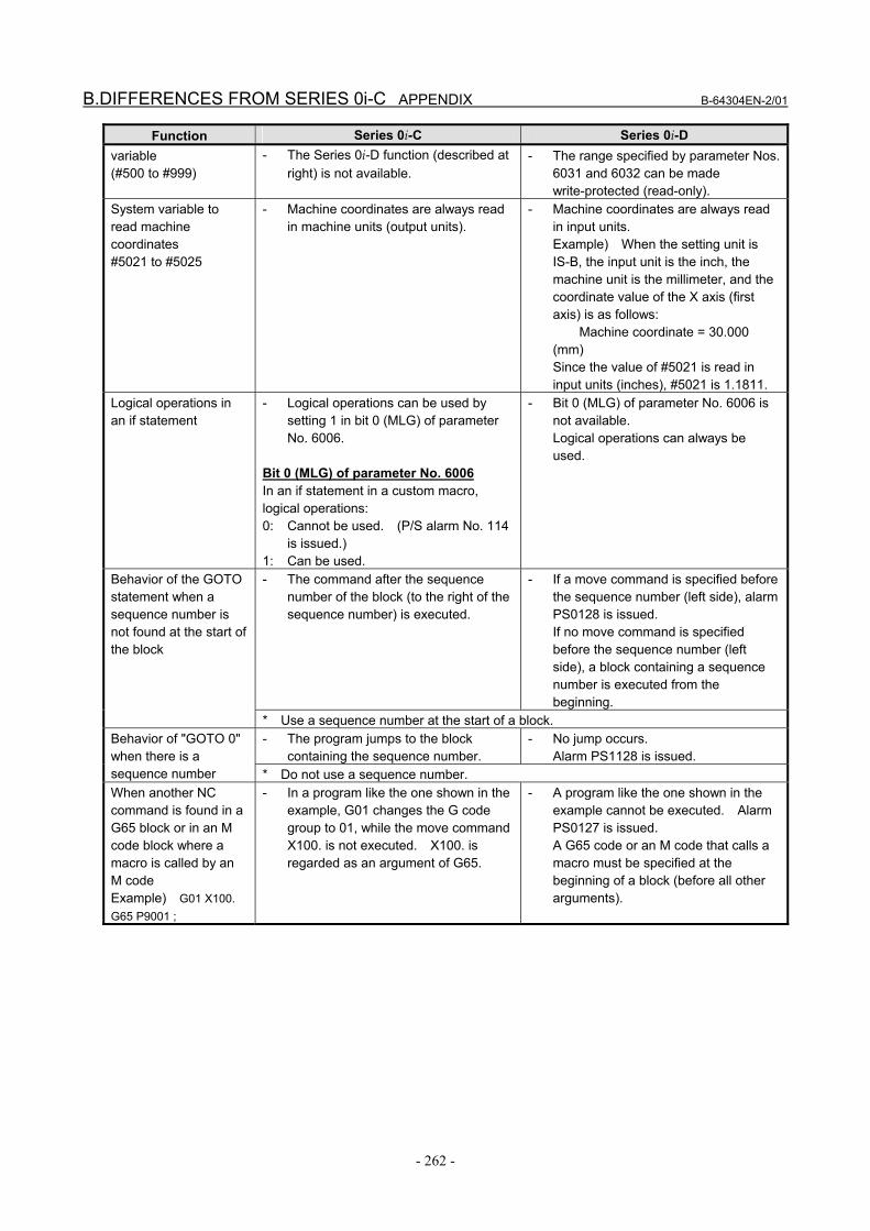
Function Series 0i-C Series 0i-D variable (#500 to #999)
- The Series 0i-D function (described at right) is not available.
- The range specified by parameter Nos. 6031 and 6032 can be made write-protected (read-only).
System variable to read machine coordinates #5021 to #5025
- Machine coordinates are always read in machine units (output units).
- Machine coordinates are always read in input units. Example) When the setting unit is IS-B, the input unit is the inch, the machine unit is the millimeter, and the coordinate value of the X axis (first axis) is as follows: Machine coordinate = 30.000 (mm) Since the value of #5021 is read in input units (inches), #5021 is 1.1811.
Logical operations in an if statement
- Logical operations can be used by setting 1 in bit 0 (MLG) of parameter No. 6006.
Bit 0 (MLG) of parameter No. 6006 In an if statement in a custom macro, logical operations: 0: Cannot be used. (P/S alarm No. 114
is issued.) 1: Can be used.
- Bit 0 (MLG) of parameter No. 6006 is not available. Logical operations can always be used.
- The command after the sequence number of the block (to the right of the sequence number) is executed.
- If a move command is specified before the sequence number (left side), alarm PS0128 is issued. If no move command is specified before the sequence number (left side), a block containing a sequence number is executed from the beginning.
Behavior of the GOTO statement when a sequence number is not found at the start of the block
* Use a sequence number at the start of a block. - The program jumps to the block
containing the sequence number. - No jump occurs.
Alarm PS1128 is issued. Behavior of "GOTO 0" when there is a sequence number * Do not use a sequence number. When another NC command is found in a G65 block or in an M code block where a macro is called by an M code Example) G01 X100. G65 P9001 ;
- In a program like the one shown in the example, G01 changes the G code group to 01, while the move command X100. is not executed. X100. is regarded as an argument of G65.
- A program like the one shown in the example cannot be executed. Alarm PS0127 is issued.
A G65 code or an M code that calls a macro must be specified at the beginning of a block (before all other arguments).
B-64304EN-2/01 APPENDIX B.DIFFERENCES FROM SERIES 0i-C
- 263 -
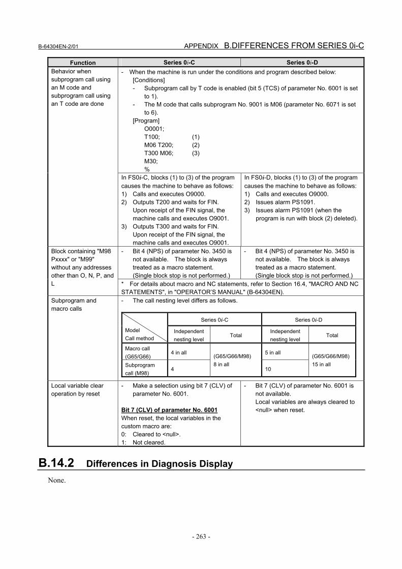
Function Series 0i-C Series 0i-D - When the machine is run under the conditions and program described below:
[Conditions] - Subprogram call by T code is enabled (bit 5 (TCS) of parameter No. 6001 is set
to 1). - The M code that calls subprogram No. 9001 is M06 (parameter No. 6071 is set
to 6). [Program] O0001; T100; (1) M06 T200; (2) T300 M06; (3) M30; %
Behavior when subprogram call using an M code and subprogram call using an T code are done
In FS0i-C, blocks (1) to (3) of the program causes the machine to behave as follows: 1) Calls and executes O9000. 2) Outputs T200 and waits for FIN.
Upon receipt of the FIN signal, the machine calls and executes O9001.
3) Outputs T300 and waits for FIN. Upon receipt of the FIN signal, the machine calls and executes O9001.
In FS0i-D, blocks (1) to (3) of the program causes the machine to behave as follows: 1) Calls and executes O9000. 2) Issues alarm PS1091. 3) Issues alarm PS1091 (when the
program is run with block (2) deleted).
- Bit 4 (NPS) of parameter No. 3450 is not available. The block is always treated as a macro statement. (Single block stop is not performed.)
- Bit 4 (NPS) of parameter No. 3450 is not available. The block is always treated as a macro statement. (Single block stop is not performed.)
Block containing "M98 Pxxxx" or "M99" without any addresses other than O, N, P, and L * For details about macro and NC statements, refer to Section 16.4, "MACRO AND NC
STATEMENTS", in "OPERATOR’S MANUAL" (B-64304EN). Subprogram and macro calls
- The call nesting level differs as follows.
Series 0i-C Series 0i-D
Model Call method
Independent nesting level
Total Independent nesting level
Total
Macro call (G65/G66)
4 in all 5 in all
Subprogram call (M98)
4
(G65/G66/M98) 8 in all
10
(G65/G66/M98)15 in all
Local variable clear operation by reset
- Make a selection using bit 7 (CLV) of parameter No. 6001.
Bit 7 (CLV) of parameter No. 6001 When reset, the local variables in the custom macro are: 0: Cleared to <null>. 1: Not cleared.
- Bit 7 (CLV) of parameter No. 6001 is not available. Local variables are always cleared to <null> when reset.
B.14.2 Differences in Diagnosis Display None.
B.DIFFERENCES FROM SERIES 0i-C APPENDIX B-64304EN-2/01
- 264 -
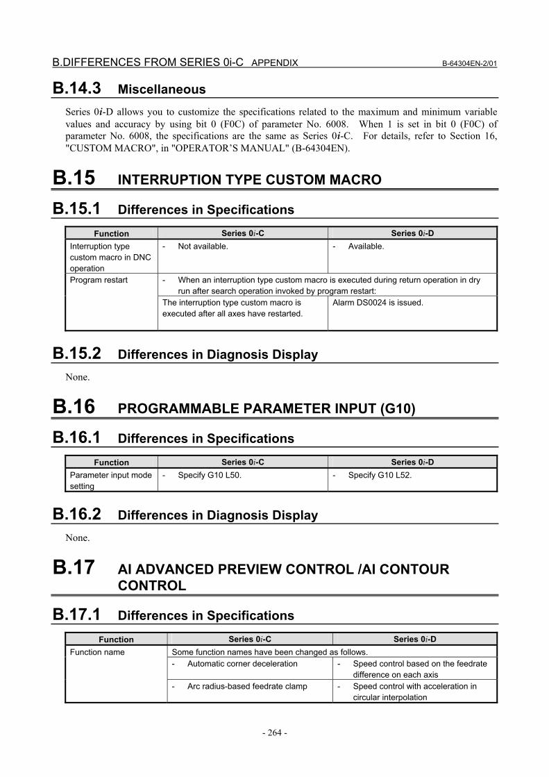
B.14.3 Miscellaneous Series 0i-D allows you to customize the specifications related to the maximum and minimum variable values and accuracy by using bit 0 (F0C) of parameter No. 6008. When 1 is set in bit 0 (F0C) of parameter No. 6008, the specifications are the same as Series 0i-C. For details, refer to Section 16, "CUSTOM MACRO", in "OPERATOR’S MANUAL" (B-64304EN).
B.15 INTERRUPTION TYPE CUSTOM MACRO
B.15.1 Differences in Specifications
Function Series 0i-C Series 0i-D Interruption type custom macro in DNC operation
- Not available. - Available.
- When an interruption type custom macro is executed during return operation in dry run after search operation invoked by program restart:
Program restart
The interruption type custom macro is executed after all axes have restarted.
Alarm DS0024 is issued.
B.15.2 Differences in Diagnosis Display None.
B.16 PROGRAMMABLE PARAMETER INPUT (G10)
B.16.1 Differences in Specifications
Function Series 0i-C Series 0i-D Parameter input mode setting
- Specify G10 L50. - Specify G10 L52.
B.16.2 Differences in Diagnosis Display None.
B.17 AI ADVANCED PREVIEW CONTROL /AI CONTOUR CONTROL
B.17.1 Differences in Specifications
Function Series 0i-C Series 0i-D Some function names have been changed as follows. - Automatic corner deceleration - Speed control based on the feedrate
difference on each axis
Function name
- Arc radius-based feedrate clamp - Speed control with acceleration in circular interpolation
B-64304EN-2/01 APPENDIX B.DIFFERENCES FROM SERIES 0i-C
- 265 -
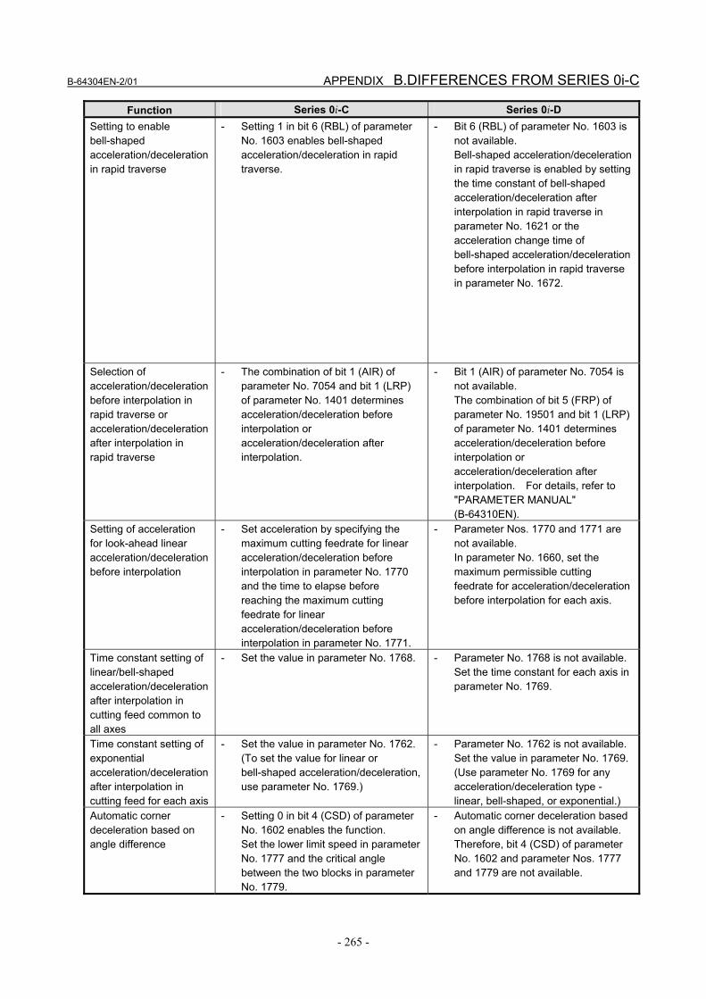
Function Series 0i-C Series 0i-D Setting to enable bell-shaped acceleration/deceleration in rapid traverse
- Setting 1 in bit 6 (RBL) of parameter No. 1603 enables bell-shaped acceleration/deceleration in rapid traverse.
- Bit 6 (RBL) of parameter No. 1603 is not available. Bell-shaped acceleration/deceleration in rapid traverse is enabled by setting the time constant of bell-shaped acceleration/deceleration after interpolation in rapid traverse in parameter No. 1621 or the acceleration change time of bell-shaped acceleration/deceleration before interpolation in rapid traverse in parameter No. 1672.
Selection of acceleration/deceleration before interpolation in rapid traverse or acceleration/deceleration after interpolation in rapid traverse
- The combination of bit 1 (AIR) of parameter No. 7054 and bit 1 (LRP) of parameter No. 1401 determines acceleration/deceleration before interpolation or acceleration/deceleration after interpolation.
- Bit 1 (AIR) of parameter No. 7054 is not available. The combination of bit 5 (FRP) of parameter No. 19501 and bit 1 (LRP) of parameter No. 1401 determines acceleration/deceleration before interpolation or acceleration/deceleration after interpolation. For details, refer to "PARAMETER MANUAL" (B-64310EN).
Setting of acceleration for look-ahead linear acceleration/deceleration before interpolation
- Set acceleration by specifying the maximum cutting feedrate for linear acceleration/deceleration before interpolation in parameter No. 1770 and the time to elapse before reaching the maximum cutting feedrate for linear acceleration/deceleration before interpolation in parameter No. 1771.
- Parameter Nos. 1770 and 1771 are not available. In parameter No. 1660, set the maximum permissible cutting feedrate for acceleration/deceleration before interpolation for each axis.
Time constant setting of linear/bell-shaped acceleration/deceleration after interpolation in cutting feed common to all axes
- Set the value in parameter No. 1768. - Parameter No. 1768 is not available. Set the time constant for each axis in parameter No. 1769.
Time constant setting of exponential acceleration/deceleration after interpolation in cutting feed for each axis
- Set the value in parameter No. 1762. (To set the value for linear or bell-shaped acceleration/deceleration, use parameter No. 1769.)
- Parameter No. 1762 is not available. Set the value in parameter No. 1769.(Use parameter No. 1769 for any acceleration/deceleration type - linear, bell-shaped, or exponential.)
Automatic corner deceleration based on angle difference
- Setting 0 in bit 4 (CSD) of parameter No. 1602 enables the function. Set the lower limit speed in parameter No. 1777 and the critical angle between the two blocks in parameter No. 1779.
- Automatic corner deceleration based on angle difference is not available. Therefore, bit 4 (CSD) of parameter No. 1602 and parameter Nos. 1777 and 1779 are not available.

B.DIFFERENCES FROM SERIES 0i-C APPENDIX B-64304EN-2/01
- 266 -
Function Series 0i-C Series 0i-D Permissible speed difference common to all axes for automatic corner deceleration based on angle difference (speed control based on the feedrate difference on each axis)
- Set the value in parameter No. 1780. - Parameter No. 1780 is not available. Set the permissible speed difference for each axis in parameter No. 1783.
Setting of arc radius-based feedrate clamp (speed control with acceleration in circular interpolation)
- Set the upper limit of the feedrate and the corresponding arc radius value in parameter Nos. 1730 and 1731, respectively.
- Parameter Nos. 1730 and 1731 are not available. Set the permissible acceleration for each axis in parameter No. 1735.
Setting of the maximum cutting feedrate common to all axes
- Set the value in parameter No. 1431. - Parameter No. 1431 is not available. Set the maximum cutting feedrate for each axis in parameter No. 1432.
Rapid traverse block overlap
- Disabled in the advanced preview control (T series), AI advanced preview control (M series), or AI contour control (M series) mode.
- Enabled only when acceleration/deceleration after interpolation is used in the advanced preview control (T series), AI advanced preview control (M series), or AI contour control (M series) mode.
Some function names have been changed as follows. Function name - Acceleration-based feedrate clamp - Speed control with the acceleration
on each axis Setting of acceleration-based feedrate clamp (speed control with the acceleration on each axis)
- Set the permissible acceleration by specifying the time to elapse before reaching the maximum cutting feedrate in parameter No. 1785. The maximum cutting feedrate set in parameter No. 1432 is used.
- Parameter No. 1785 is not available. Set the permissible acceleration for each axis in parameter No. 1737.
Differences regarding AI contour control
Function Series 0i-C Series 0i-D Time constant of acceleration/deceleration in rapid traverse in the AI contour control mode
- Set parameter Nos. 1773 and 1774. If these parameters are not set, parameter Nos. 1620 and 1621 are used.
- Parameter Nos. 1773 and 1774 are not available. In the case of acceleration/deceleration before interpolation in rapid traverse, set parameter Nos. 1660 and 1672. In the case of acceleration/deceleration after interpolation in rapid traverse, set parameter Nos. 1620 and 1621.
Setting to enable look-ahead bell-shaped acceleration/deceleration before interpolation
- Setting 1 in bit 7 (BEL) of parameter No. 1603 enables bell-shaped acceleration/deceleration before interpolation.
- Bit 7 (BEL) of parameter No. 1603 is not available. Setting the acceleration change time of bell-shaped acceleration/deceleration before interpolation in parameter No. 1772 enables bell-shaped acceleration/deceleration before interpolation.

B-64304EN-2/01 APPENDIX B.DIFFERENCES FROM SERIES 0i-C
- 267 -
B.17.2 Differences in Diagnosis Display None.
B.18 MACHINING CONDITION SELECTION FUNCTION
B.18.1 Differences in Specifications
Function Series 0i-C Series 0i-D Parameters set by "acceleration/deceleration before interpolation" (machining parameter adjustment screen)
- The following parameters are set according to the precision level: [Parameter No. 1770] Maximum cutting feedrate in linear acceleration/deceleration before interpolation [Parameter No. 1771] Time before the maximum cutting feedrate in linear acceleration/deceleration before interpolation (parameter No. 1770) is reached
- The following parameters are set according to the precision level: [Parameter No. 1660] Maximum permissible cutting feedrate in acceleration/deceleration before interpolation on each axis (Series 0i-D does not have parameter Nos. 1770 and 1771.)
Parameter 1 set by "permissible acceleration"(machining parameter adjustment screen)
- The following parameters are set according to the precision level: [Parameter No. 1730] Upper limit of the feedrate by arc radius-based feedrate clamp [Parameter No. 1731] Arc radius corresponding to the upper limit of the feedrate by arc radius-based feedrate clamp (parameter No. 1730)
- The following parameters are set according to the precision level: [Parameter No. 1735] Permissible acceleration in speed control with acceleration in circular interpolation (Series 0i-D does not have parameter Nos. 1730 and 1731. Also, "arc radius-based feedrate clamp" has been renamed "speed control with acceleration in circular interpolation".)
Parameter 2 set by "permissible acceleration"(machining parameter adjustment screen)
- The following parameters are set according to the precision level: [Parameter No. 1432] Maximum cutting feedrate [Parameter No. 1785] Time before the maximum cutting feedrate (parameter No. 1432) is reached (Set this to determine the permissible acceleration for acceleration-based feedrate clamp.)
- The following parameters are set according to the precision level: [Parameter No. 1737] Permissible acceleration for speed control with the acceleration on each axis (Series 0i-D does not have parameter No. 1785. Also, "acceleration-based feedrate clamp" has been renamed "speed control with the acceleration on each axis".)
B.18.2 Differences in Diagnosis Display None.
B.DIFFERENCES FROM SERIES 0i-C APPENDIX B-64304EN-2/01
- 268 -
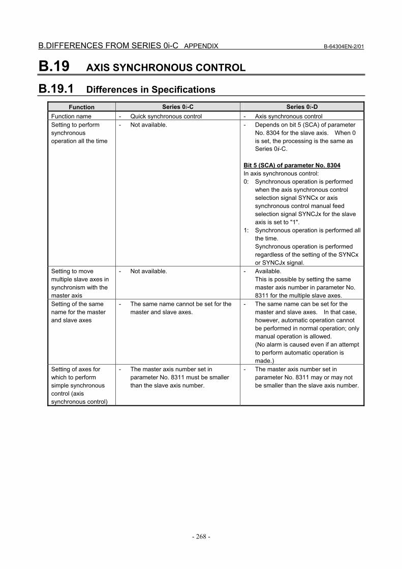
B.19 AXIS SYNCHRONOUS CONTROL
B.19.1 Differences in Specifications
Function Series 0i-C Series 0i-D Function name - Quick synchronous control - Axis synchronous control Setting to perform synchronous operation all the time
- Not available. - Depends on bit 5 (SCA) of parameter No. 8304 for the slave axis. When 0 is set, the processing is the same as Series 0i-C.
Bit 5 (SCA) of parameter No. 8304 In axis synchronous control: 0: Synchronous operation is performed
when the axis synchronous control selection signal SYNCx or axis synchronous control manual feed selection signal SYNCJx for the slave axis is set to "1".
1: Synchronous operation is performed all the time. Synchronous operation is performed regardless of the setting of the SYNCx or SYNCJx signal.
Setting to move multiple slave axes in synchronism with the master axis
- Not available. - Available. This is possible by setting the same master axis number in parameter No. 8311 for the multiple slave axes.
Setting of the same name for the master and slave axes
- The same name cannot be set for the master and slave axes.
- The same name can be set for the master and slave axes. In that case, however, automatic operation cannot be performed in normal operation; only manual operation is allowed. (No alarm is caused even if an attempt to perform automatic operation is made.)
Setting of axes for which to perform simple synchronous control (axis synchronous control)
- The master axis number set in parameter No. 8311 must be smaller than the slave axis number.
- The master axis number set in parameter No. 8311 may or may not be smaller than the slave axis number.
B-64304EN-2/01 APPENDIX B.DIFFERENCES FROM SERIES 0i-C
- 269 -
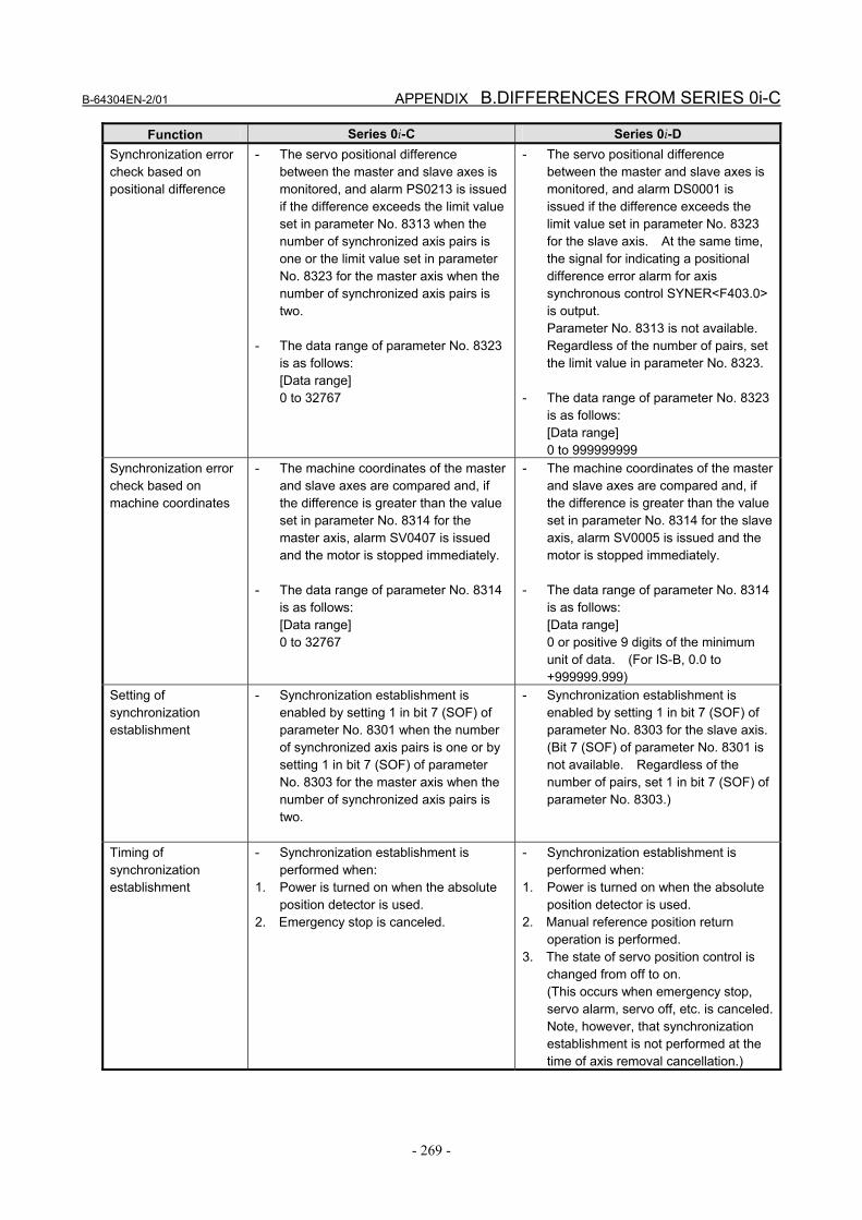
Function Series 0i-C Series 0i-D Synchronization error check based on positional difference
- The servo positional difference between the master and slave axes is monitored, and alarm PS0213 is issued if the difference exceeds the limit value set in parameter No. 8313 when the number of synchronized axis pairs is one or the limit value set in parameter No. 8323 for the master axis when the number of synchronized axis pairs is two.
- The data range of parameter No. 8323
is as follows: [Data range] 0 to 32767
- The servo positional difference between the master and slave axes is monitored, and alarm DS0001 is issued if the difference exceeds the limit value set in parameter No. 8323 for the slave axis. At the same time, the signal for indicating a positional difference error alarm for axis synchronous control SYNER<F403.0> is output. Parameter No. 8313 is not available. Regardless of the number of pairs, set the limit value in parameter No. 8323.
- The data range of parameter No. 8323
is as follows: [Data range] 0 to 999999999
Synchronization error check based on machine coordinates
- The machine coordinates of the master and slave axes are compared and, if the difference is greater than the value set in parameter No. 8314 for the master axis, alarm SV0407 is issued and the motor is stopped immediately.
- The data range of parameter No. 8314
is as follows: [Data range] 0 to 32767
- The machine coordinates of the master and slave axes are compared and, if the difference is greater than the value set in parameter No. 8314 for the slave axis, alarm SV0005 is issued and the motor is stopped immediately.
- The data range of parameter No. 8314
is as follows: [Data range] 0 or positive 9 digits of the minimum unit of data. (For IS-B, 0.0 to +999999.999)
Setting of synchronization establishment
- Synchronization establishment is enabled by setting 1 in bit 7 (SOF) of parameter No. 8301 when the number of synchronized axis pairs is one or by setting 1 in bit 7 (SOF) of parameter No. 8303 for the master axis when the number of synchronized axis pairs is two.
- Synchronization establishment is enabled by setting 1 in bit 7 (SOF) of parameter No. 8303 for the slave axis.(Bit 7 (SOF) of parameter No. 8301 is not available. Regardless of the number of pairs, set 1 in bit 7 (SOF) of parameter No. 8303.)
Timing of synchronization establishment
- Synchronization establishment is performed when:
1. Power is turned on when the absolute position detector is used.
2. Emergency stop is canceled.
- Synchronization establishment is performed when:
1. Power is turned on when the absolute position detector is used.
2. Manual reference position return operation is performed.
3. The state of servo position control is changed from off to on. (This occurs when emergency stop, servo alarm, servo off, etc. is canceled. Note, however, that synchronization establishment is not performed at the time of axis removal cancellation.)

B.DIFFERENCES FROM SERIES 0i-C APPENDIX B-64304EN-2/01
- 270 -
Function Series 0i-C Series 0i-D Maximum compensation for synchronization
- Set the value in parameter No. 8315 when the number of synchronized axis pairs is one or in parameter No. 8325 for the master axis when the number of synchronized axis pairs is two. If the compensation amount exceeds the values set in the relevant parameter, alarm SV0410 occurs.
- The data unit and data range of
parameter Nos. 8315 and 8325 are as follows: [Data unit] Detection unit [Data range] 0 to 32767
- Set the value in parameter No. 8325 for the slave axis. If the compensation amount exceeds the values set in this parameter, alarm SV0001 occurs. (Parameter No. 8315 is not available. Regardless of the number of pairs, set the value in parameter No. 8325.)
- The data unit and data range of
parameter No. 8325 are as follows: [Data unit] Machine unit [Data range] 0 or positive 9 digits of the minimum unit of data. (For IS-B, 0.0 to +999999.999)
Automatic setting for grid position matching
- Enable automatic setting for grid position matching by setting 1 in bit 0 (ATE) of parameter No. 8302 when the number of synchronized axis pairs is one or in bit 0 (ATE) of parameter No. 8303 when the number of synchronized axis pairs is two.
- Start automatic setting for grid position
matching by setting 1 in bit 1 (ATS) of parameter No. 8302 when the number of synchronized axis pairs is one or in bit 1 (ATS) of parameter No. 8303 when the number of synchronized axis pairs is two.
- Set 1 in bit 0 (ATE) of parameter No. 8303 for the slave axis to enable automatic setting for grid position matching. (Bit 0 (ATE) of parameter No. 8302 is not available. Regardless of the number of pairs, set the value in bit 0 (ATE) of parameter No. 8303.)
- Set 1 in bit 1 (ATS) of parameter No.
8303 for the slave axis to start automatic setting for grid position matching. (Bit 1 (ATS) of parameter No. 8302 is not available. Regardless of the number of pairs, set the value in bit 1 (ATS) of parameter No. 8303.)
Difference between the master axis reference counter and slave axis reference counter obtained through automatic setting for grid positioning
- Set the value in parameter No. 8316 when the number of synchronized axis pairs is one or in parameter No. 8326 for the master axis.
- Set the value in parameter No. 8326 for the slave axis. (Parameter No. 8316 is not available. Regardless of the number of pairs, set the value in parameter No. 8326.)
Time from the servo preparation completion signal SA <F000.6> being set to 1 until torque difference alarm detection is started
- Set the value in parameter No. 8317 when the number of synchronized axis pairs is one or in parameter No. 8327 for the master axis when the number of synchronized axis pairs is two.
- Set the value in parameter No. 8327 for the slave axis. (Parameter No. 8317 is not available. Regardless of the number of pairs, set the value in parameter No. 8327.)

B-64304EN-2/01 APPENDIX B.DIFFERENCES FROM SERIES 0i-C
- 271 -
Function Series 0i-C Series 0i-D Setting to use the external machine coordinate system shift function for the slave axis
- When 1 is set in bit 3 (SSE) of parameter No. 8302, setting an external machine coordinate system shift for the master axis causes the slave axis to shift as well. This parameter is used for all the pairs.
- Bit 3 (SSE) of parameter No. 8302 is not available. By setting 1 in bit 7 (SYE) of parameter No. 8304 for the slave axis, the slave axis is shifted as well when an external machine coordinate system shift is set for the corresponding master axis. This parameter is used individually for each slave axis.
Setting to prevent slave axis movement from being added to the actual feedrate display
- Setting 1 in bit 7 (SMF) of parameter No. 3105 prevents slave axis movement from being added to the actual feedrate display. This parameter is used for all the pairs.
- Bit 7 (SMF) of parameter No. 3105 is not available. Setting 0 in bit 2 (SAF) of parameter No. 8303 prevents slave axis movement from being added to the actual feedrate display. (Note that the meaning of the value is the opposite from bit 7 (SMF) of parameter No. 3105.) This parameter is used individually for each slave axis.
Change of the synchronization state during a program command
- Specify an M code that is not to be buffered. Using this M code, change the input signal - SYNCx<G138> or SYNCJx<G140> - from the PMC side.
- Specify an M code that changes the synchronization state (parameter No. 8337 or 8338). By changing the input signal - SYNCx<G138> or SYNCJx<G140> - from the PMC side using this M code, it is possible to change the synchronization state during a program command.
Parameter No. 8337 Specify an M code that changes synchronous operation to normal operation. Parameter No. 8338 Specify an M code that changes normal operation to synchronous operation.
Automatic slave axis parameter setting
- This function is enabled by setting 1 in bit 4 (SYP) of parameter No. 8303 for the master axis.
- Bit 4 (TRP) of parameter No. 12762 is not available. This function is enabled by setting 1 in bit 4 (SYP) of parameter No. 8303 for the master and slave axes.
Mirror image for the slave axis
- A mirror image cannot be applied to a slave axis during simple synchronous control. It can be applied only to the T series.
- By setting parameter No. 8312 for the slave axis, a mirror image can be applied to a slave axis during simple synchronous control.
Parameter No. 8312 This parameter sets mirror image for the slave axis. When 100 or a more value is set with this parameter, the mirror image function is applied to synchronous control.

B.DIFFERENCES FROM SERIES 0i-C APPENDIX B-64304EN-2/01
- 272 -
Function Series 0i-C Series 0i-D Setting to cancel the check of positional difference between the master and slave axes during synchronization establishment
- Depends on bit 5 (SYE) of parameter No. 8301.
Bit 5 (SYE) of parameter No. 8301 During synchronization establishment, the positional difference limit is: 0: Checked. 1: Not checked.
- Not available. Therefore, bit 5 (SYE) of parameter No. 8301 is not available. Since the positional difference is always checked, parameter No. 8318 is not available, either.
Parameter No. 8318 Set the time from the synchronization establishment function outputting a compensation pulse to the slave axis until the check of the positional difference limit between the master and slave axes starts.
B.19.2 Differences in Diagnosis Display
Item Series 0i-C Series 0i-D Positional difference between the master and slave axes
- This item is displayed in diagnosis No. 540 for the master axis when the number of synchronized axis pairs is one or in diagnosis No. 541 for the master axis when the number of synchronized axis pairs is two.
- This item is displayed in diagnosis No. 3500 for the slave axis. (Regardless of the number of pairs, the item is displayed in diagnosis No. 3500.)
B.20 ARBITRARY ANGULAR AXIS CONTROL
B.20.1 Differences in Specifications
Function Series 0i-C Series 0i-D Angular and perpendicular axes when an invalid value is set in parameter No. 8211 or 8212
Series 0i-C Series 0i-D
Angular axis
Perpendicular axis Angular axis Perpendicular axis
M series
Y axis (2nd axis)
Z axis (3rd axis)
Y-axis of the basic three axes (axis with 2 set in parameter No. 1022)
Z-axis of the basic three axes (axis with 3 set in parameter No. 1022)
Reference position return completion signal ZP for the perpendicular axis moved with the angular axis <Fn094, Fn096, Fn098, Fn100>
- Select the signal using bit 3 (AZP) of parameter No. 8200. When the bit is set to 0, ZP is not set to "0". (The signal is not cleared.) When the bit is set to 1, ZP is set to "0". (The signal is cleared.)
- Bit 3 (AZP) of parameter No. 8200 is not available. ZP is always set to "0". (The signal is cleared.)
When an angular axis is specified individually in machine coordinate system selection (G53) during arbitrary angular axis control
- Select the perpendicular axis operation using bit 6 (A53) of parameter No. 8201. When the bit is set to 0, the perpendicular axis is also moved. When the bit is set to 1, only the angular axis is moved.
- Bit 6 (A53) of parameter No. 8201 is not available. Only the angular axis is always moved.

B-64304EN-2/01 APPENDIX B.DIFFERENCES FROM SERIES 0i-C
- 273 -
Function Series 0i-C Series 0i-D G30 command during arbitrary angular axis control
- Select the operation using bit 0 (A30) of parameter No. 8202. When the bit is set to 0, the operation is for the perpendicular coordinate system. When the bit is set to 1, the operation is for the angular coordinate system.
- Bit 0 (A30) of parameter No. 8202 is not available. The operation is always for the angular coordinate system.
B.20.2 Differences in Diagnosis Display None.
B.21 RUN HOUR AND PARTS COUNT DISPLAY
B.21.1 Differences in Specifications
Function Series 0i-C Series 0i-D Parameter No. 6710 The data range of the M code that counts the number of machined parts is as follows.
Data range of the M code that counts the number of machined parts - 0 to 255 - 0 to 99999999 (8 digits)
Parameter No. 6713 The data range of the number of parts required is as follows.
Data range of the number of parts required
- 0 to 9999 - 0 to 999999999 (9 digits) Parameter No. 6711 Number of parts machined
Parameter No. 6712 Total number of parts machined
The data range is as follows.
Data range of the number and total number of parts machined
- 0 to 99999999 (8 digits) - 0 to 999999999 (9 digits) Parameter No. 6750 Integrated value of power-on period
Parameter No. 6752 Integrated value of time during automatic operation
Parameter No. 6754 Integrated value of cutting time
Parameter No. 6756 Integrated value of time when input signal TMRON (G053.0) is on
Parameter No. 6758 Integrated value of one automatic operation time
The data range is as follows.
Data range of the power-on period, time during automatic operation, cutting time, input signal TMRON on time, and one automatic operation time
- 0 to 99999999 (8 digits) - 0 to 999999999 (9 digits)
B.21.2 Differences in Diagnosis Display None.

B.DIFFERENCES FROM SERIES 0i-C APPENDIX B-64304EN-2/01
- 274 -
B.22 MANUAL HANDLE FEED
B.22.1 Differences in Specifications
Function Series 0i-C Series 0i-D If manual handle feed exceeding the rapid traverse rate is specified, whether to ignore or accumulate handle pulses exceeding the rapid traverse feedrate can be set as follows.
Handle pulses exceeding the rapid traverse rate - Depends on bit 4 (HPF) of parameter
No. 7100. The amount of pulses to be accumulated is set in parameter No. 7117.
- Bit 4 (HPF) of parameter No. 7100 is not available. Whether to ignore or accumulate excess handle pulses is determined by the amount to be accumulated that is set in parameter No. 7117. [When parameter No. 7117 = 0] Ignored. [When parameter No. 7117 > 0] Accumulated in the CNC without being ignored.
Permissible amount of pulses for manual handle feed
- The value range of parameter No. 7117 is 0 to 99999999 (8 digits).
- The value range of parameter No. 7117 is 0 to 999999999 (9 digits).
- For parameter Nos. 7113, 7131, 7133, and 12350, magnification ranges from 1 to 127. For parameter Nos. 7114, 7132, 7134, and 12351, magnification ranges from 1 to 1000.
- For parameter No. 7113, 7114, 7131, 7132, 7133, 7134, 12350, and 12351, magnification ranges from 1 to 2000.
Parameter No. 7113 Magnification when manual handle feed amount selection signals MP1 = 0 and MP2 = 1
Parameter No. 7114 Magnification when manual handle feed amount selection signals MP1 = 1 and MP2 = 1
[When bit 5 (MPX) of parameter No. 7100 = 0] Magnification common to all the generators in the path
[When bit 5 (MPX) of parameter No. 7100 = 1] Magnification used by the first generator in the path
Parameter No. 7131 Magnification when manual handle feed amount selection signals MP21 = 0 and MP22 = 1
Parameter No. 7132 Magnification when manual handle feed amount selection signals MP21 = 1 and MP22 = 1
When bit 5 (MPX) of parameter No. 7100 is set to 1, the magnification used by the second generator in the path applies. Parameter No. 7133 Magnification when manual handle feed amount selection signals MP31 = 0 and MP32 = 1
Parameter No. 7134 Magnification when manual handle feed amount selection signals MP31 = 1 and MP32 = 1
When bit 5 (MPX) of parameter No. 7100 is set to 1, the magnification used by the third generator in the path applies.
Value range of the magnification parameter for manual handle feed
Parameter No. 12350 Magnification when per-axis manual handle feed amount selection signals MP1 = 0 and MP2 = 1
Parameter No. 12351 Magnification when per-axis manual handle feed amount selection signals MP1 = 1 and MP2 = 1
Number of manual pulse generators used
- Set the value in parameter No. 7110. - Parameter No. 7110 is not available. Up to two generators can be used without setting the parameter.
B-64304EN-2/01 APPENDIX B.DIFFERENCES FROM SERIES 0i-C
- 275 -
B.22.2 Differences in Diagnosis Display None.
B.23 PMC AXIS CONTROL
B.23.1 Differences in Specifications
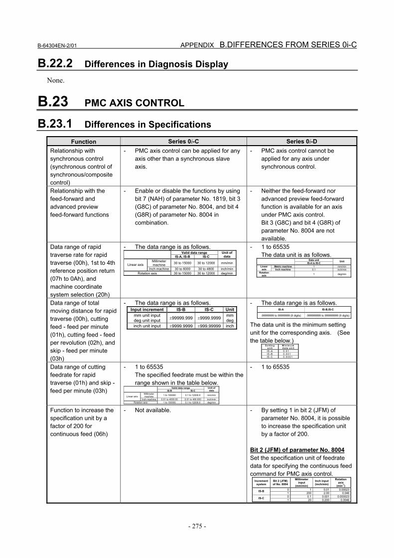
Function Series 0i-C Series 0i-D Relationship with synchronous control (synchronous control of synchronous/composite control)
- PMC axis control can be applied for any axis other than a synchronous slave axis.
- PMC axis control cannot be applied for any axis under synchronous control.
Relationship with the feed-forward and advanced preview feed-forward functions
- Enable or disable the functions by using bit 7 (NAH) of parameter No. 1819, bit 3 (G8C) of parameter No. 8004, and bit 4 (G8R) of parameter No. 8004 in combination.
- Neither the feed-forward nor advanced preview feed-forward function is available for an axis under PMC axis control. Bit 3 (G8C) and bit 4 (G8R) of parameter No. 8004 are not available.
Data range of rapid traverse rate for rapid traverse (00h), 1st to 4th reference position return (07h to 0Ah), and machine coordinate system selection (20h)
- The data range is as follows. Valid data range IS-A, IS-B IS-C
Unit of data
Millimeter machine 30 to 15000 30 to 12000 mm/minLinear axis
Inch machine 30 to 6000 30 to 4800 inch/minRotation axis 30 to 15000 30 to 12000 deg/min
- 1 to 65535 The data unit is as follows.
Data unit IS-A to IS-C
Unit
Metric machine 1 mm/min Linear axis Inch machine 0.1 inch/min
Rotation axis 1 deg/min
Data range of total moving distance for rapid traverse (00h), cutting feed - feed per minute (01h), cutting feed - feed per revolution (02h), and skip - feed per minute (03h)
- The data range is as follows. Input increment IS-B IS-C Unit
mm unit input deg unit input ±99999.999 ±9999.9999 mm
deginch unit input ±9999.9999 ±999.99999 inch
- The data range is as follows. IS-A IS-B,IS-C
-99999999 to 99999999 (8 digits) -999999999 to 999999999 (9 digits)
The data unit is the minimum setting unit for the corresponding axis. (See the table below.)
S e tt in g u n it
M in im u m d a ta u n it
IS -A 0 .0 1 IS -B 0 .0 0 1 IS -C 0 .0 0 0 1
Data range of cutting feedrate for rapid traverse (01h) and skip - feed per minute (03h)
- 1 to 65535 The specified feedrate must be within the range shown in the table below.
Valid data range IS-B IS-C Unit of
data Millimeter machine 1 to 100000 0.1 to 12000.0 mm/min Linear axis
Inch machine 0.01 to 4000.00 0.01 to 480.000 inch/min Rotation axis 1 to 100000 0.1 to 12000.0 deg/min
- 1 to 65535
Function to increase the specification unit by a factor of 200 for continuous feed (06h)
- Not available. - By setting 1 in bit 2 (JFM) of parameter No. 8004, it is possible to increase the specification unit by a factor of 200.
Bit 2 (JFM) of parameter No. 8004 Set the specification unit of feedrate data for specifying the continuous feed command for PMC axis control.
Increment system
Bit 2 (JFM) of No. 8004
Millimeter input
(mm/min) Inch input(inch/min)
Rotation axis
(min-1) 0 1 0.01 0.00023IS-B 1 200 2.00 0.0460 0.1 0.001 0.000023IS-C 1 20 0.200 0.0046
B.DIFFERENCES FROM SERIES 0i-C APPENDIX B-64304EN-2/01
- 276 -
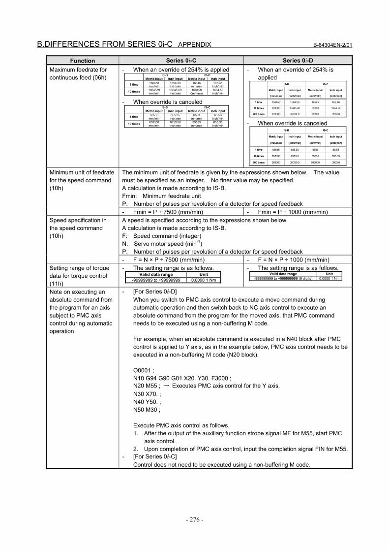
Function Series 0i-C Series 0i-D Maximum feedrate for continuous feed (06h)
- When an override of 254% is applied IS-B IS-C Metric input Inch input Metric input Inch input
1 time 166458 mm/min
1664.58 inch/min
16645 mm/min
166.45 inch/min
10 times 1664589 mm/min
16645.89 inch/min
166458 0mm/min
1664.58 inch/min
- When override is canceled IS-B IS-C Metric input Inch input Metric input Inch input
1 time 65535 mm/min
655.35 inch/min
6553 mm/min
65.53 inch/min
10 times 655350 mm/min
6553.50 inch/min
65535 mm/min
655.35 inch/min
- When an override of 254% is applied IS-B IS-C
Metric input
(mm/min)
Inch input
(inch/min)
Metric input
(mm/min)
Inch input
(inch/min)
1 time 166458 1664.58 16645 166.46
10 times 999000 16645.89 99900 1664.58
200 times 999000 39330.0 99900 3933.0
- When override is canceled IS-B IS-C
Metric input
(mm/min)
Inch input
(inch/min)
Metric input
(mm/min)
Inch input
(inch/min)
1 time 65535 655.35 6553 65.53
10 times 655350 6553.5 65535 655.35
200 times 999000 39330.0 999000 3933.0
The minimum unit of feedrate is given by the expressions shown below. The value must be specified as an integer. No finer value may be specified. A calculation is made according to IS-B. Fmin: Minimum feedrate unit P: Number of pulses per revolution of a detector for speed feedback
Minimum unit of feedrate for the speed command (10h)
- Fmin = P ÷ 7500 (mm/min) - Fmin = P ÷ 1000 (mm/min) A speed is specified according to the expressions shown below. A calculation is made according to IS-B. F: Speed command (integer) N: Servo motor speed (min-1) P: Number of pulses per revolution of a detector for speed feedback
Speed specification in the speed command (10h)
- F = N × P ÷ 7500 (mm/min) - F = N × P ÷ 1000 (mm/min) Setting range of torque data for torque control (11h)
- The setting range is as follows. Valid data range Unit
-99999999 to +99999999 0.0000 1 Nm
- The setting range is as follows. Valid data range Unit
-999999999 to +999999999 (9 digits) 0.0000 1 Nm
Note on executing an absolute command from the program for an axis subject to PMC axis control during automatic operation
- [For Series 0i-D] When you switch to PMC axis control to execute a move command during automatic operation and then switch back to NC axis control to execute an absolute command from the program for the moved axis, that PMC command needs to be executed using a non-buffering M code. For example, when an absolute command is executed in a N40 block after PMC control is applied to Y axis, as in the example below, PMC axis control needs to be executed in a non-buffering M code (N20 block). O0001 ; N10 G94 G90 G01 X20. Y30. F3000 ; N20 M55 ; → Executes PMC axis control for the Y axis. N30 X70. ; N40 Y50. ; N50 M30 ; Execute PMC axis control as follows. 1. After the output of the auxiliary function strobe signal MF for M55, start PMC
axis control. 2. Upon completion of PMC axis control, input the completion signal FIN for M55.
- [For Series 0i-C] Control does not need to be executed using a non-buffering M code.
B-64304EN-2/01 APPENDIX B.DIFFERENCES FROM SERIES 0i-C
- 277 -
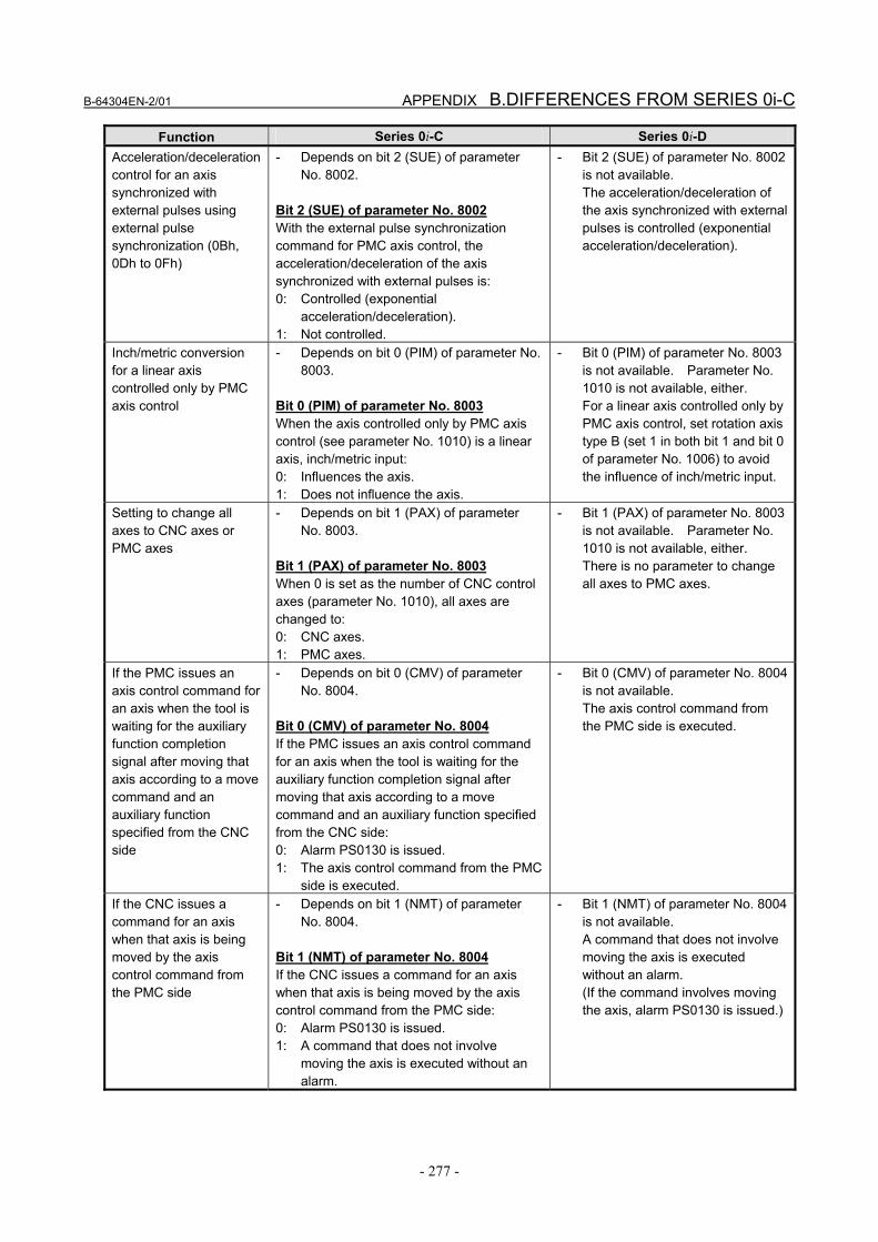
Function Series 0i-C Series 0i-D Acceleration/deceleration control for an axis synchronized with external pulses using external pulse synchronization (0Bh, 0Dh to 0Fh)
- Depends on bit 2 (SUE) of parameter No. 8002.
Bit 2 (SUE) of parameter No. 8002 With the external pulse synchronization command for PMC axis control, the acceleration/deceleration of the axis synchronized with external pulses is: 0: Controlled (exponential
acceleration/deceleration). 1: Not controlled.
- Bit 2 (SUE) of parameter No. 8002 is not available. The acceleration/deceleration of the axis synchronized with external pulses is controlled (exponential acceleration/deceleration).
Inch/metric conversion for a linear axis controlled only by PMC axis control
- Depends on bit 0 (PIM) of parameter No. 8003.
Bit 0 (PIM) of parameter No. 8003 When the axis controlled only by PMC axis control (see parameter No. 1010) is a linear axis, inch/metric input: 0: Influences the axis. 1: Does not influence the axis.
- Bit 0 (PIM) of parameter No. 8003 is not available. Parameter No. 1010 is not available, either. For a linear axis controlled only by PMC axis control, set rotation axis type B (set 1 in both bit 1 and bit 0 of parameter No. 1006) to avoid the influence of inch/metric input.
Setting to change all axes to CNC axes or PMC axes
- Depends on bit 1 (PAX) of parameter No. 8003.
Bit 1 (PAX) of parameter No. 8003 When 0 is set as the number of CNC control axes (parameter No. 1010), all axes are changed to: 0: CNC axes. 1: PMC axes.
- Bit 1 (PAX) of parameter No. 8003 is not available. Parameter No. 1010 is not available, either. There is no parameter to change all axes to PMC axes.
If the PMC issues an axis control command for an axis when the tool is waiting for the auxiliary function completion signal after moving that axis according to a move command and an auxiliary function specified from the CNC side
- Depends on bit 0 (CMV) of parameter No. 8004.
Bit 0 (CMV) of parameter No. 8004 If the PMC issues an axis control command for an axis when the tool is waiting for the auxiliary function completion signal after moving that axis according to a move command and an auxiliary function specified from the CNC side: 0: Alarm PS0130 is issued. 1: The axis control command from the PMC
side is executed.
- Bit 0 (CMV) of parameter No. 8004 is not available. The axis control command from the PMC side is executed.
If the CNC issues a command for an axis when that axis is being moved by the axis control command from the PMC side
- Depends on bit 1 (NMT) of parameter No. 8004.
Bit 1 (NMT) of parameter No. 8004 If the CNC issues a command for an axis when that axis is being moved by the axis control command from the PMC side: 0: Alarm PS0130 is issued. 1: A command that does not involve
moving the axis is executed without an alarm.
- Bit 1 (NMT) of parameter No. 8004 is not available. A command that does not involve moving the axis is executed without an alarm. (If the command involves moving the axis, alarm PS0130 is issued.)

B.DIFFERENCES FROM SERIES 0i-C APPENDIX B-64304EN-2/01
- 278 -
Function Series 0i-C Series 0i-D Setting of diameter/radius specification for the amount of travel and feedrate when diameter programming is specified for a PMC-controlled axis
- This item is determined by using bit 7 (NDI) of parameter No. 8004 and bit 1 (CDI) of parameter No. 8005 in combination.
- Bit 7 (NDI) of parameter No. 8004 is not available. The item is determined by bit 1 (CDI) of parameter No. 8005.
Bit 1 (CDI) of parameter No. 8005 In PMC axis control, when diameter programming is specified for a PMC-controlled axis: 0: The amount of travel and feedrate
are each specified with a radius. 1: The amount of travel is specified
with a diameter while the feedrate is specified with a radius.
Individual output of the auxiliary function
- Depends on bit 7 (MFD) of parameter No. 8005.
Bit 7 (MFD) of parameter No. 8005 The individual output of the auxiliary function for PMC axis control function is: 0: Disabled. 1: Enabled.
- Bit 7 (MFD) of parameter No. 8005 is not available. The individual output of the auxiliary function for PMC axis control function is enabled.
Function to exert position control for the speed command (10h)
- Depends on bit 4 (EVP) of parameter No. 8005.
Bit 4 (EVP) of parameter No. 8005 The speed of PMC axis control is specified by: 0: Speed command. 1: Position command.
- Depends on bit 4 (EVP) of parameter No. 8005. Note that, for the EVP=1 setting to take effect, 1 must be set in bit 2 (VCP) of parameter No. 8007.
Bit 2 (VCP) of parameter No. 8007 The speed command in PMC axis control is: 0: FS10/11 type. 1: FS0 type.
In-position check for an axis controlled only by PMC axis control
- Depends on bit 2 (IPA) of parameter No. 8006.
Bit 2 (IPA) of parameter No. 8006 In the case of an axis controlled only by PMC axis control (see parameter No. 1010), in-position check is: 0: Performed when no move command is
specified for the PMC axis. 1: Always not performed.
- Bit 2 (IPA) of parameter No. 8006 is not available. Parameter No. 1010 is not available, either. The check is performed when no move command is specified for the PMC axis. Otherwise, the processing is determined by bit 6 (NCI) of parameter No. 8004.
Bit 6 (NCI) of parameter No. 8004 When the PMC-controlled axis is decelerated, in-position check is: 0: Performed. 1: Not performed.
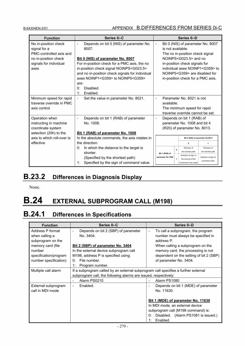
B-64304EN-2/01 APPENDIX B.DIFFERENCES FROM SERIES 0i-C
- 279 -
Function Series 0i-C Series 0i-D No in-position check signal for a PMC-controlled axis and no in-position check signals for individual axes
- Depends on bit 0 (NIS) of parameter No. 8007.
Bit 0 (NIS) of parameter No. 8007 For in-position check for a PMC axis, the no in-position check signal NOINPS<G023.5> and no in-position check signals for individual axes NOINP1<G359> to NOINP5<G359> are: 0: Disabled. 1: Enabled.
- Bit 0 (NIS) of parameter No. 8007 is not available. The no in-position check signal NOINPS<G023.5> and no in-position check signals for individual axes NOINP1<G359> to NOINP5<G359> are disabled for in-position check for a PMC axis.
Minimum speed for rapid traverse override in PMC axis control
- Set the value in parameter No. 8021. - Parameter No. 8021 is not available. The minimum speed for rapid traverse override cannot be set.
Operation when instructing in machine coordinate system selection (20h) to the axis to which roll-over is effective
- Depends on bit 1 (RAB) of parameter No. 1008.
Bit 1 (RAB) of parameter No. 1008 In the absolute commands, the axis rotates in the direction: 0: In which the distance to the target is
shorter. (Specified by the shortest path)
1: Specified by the sign of command value.
- Depends on bit 1 (RAB) of parameter No. 1008 and bit 4 (R20) of parameter No. 8013.
Bit 4 (R20) of parameter No.8013
0 1
0 Direction of
the shortest path
Direction of
the shortest path Bit 1 (RAB) of
parameter No.10081
Direction of sign of
the amount of the
movement to be made
Direction of sign of
command value
B.23.2 Differences in Diagnosis Display None.
B.24 EXTERNAL SUBPROGRAM CALL (M198)
B.24.1 Differences in Specifications
Function Series 0i-C Series 0i-D Address P format when calling a subprogram on the memory card (file number specification/program number specification)
- Depends on bit 2 (SBP) of parameter No. 3404.
Bit 2 (SBP) of parameter No. 3404 In the external device subprogram call M198, address P is specified using: 0: File number. 1: Program number.
- To call a subprogram, the program number must always be specified in address P. When calling a subprogram on the memory card, the processing is not dependent on the setting of bit 2 (SBP) of parameter No. 3404.
If a subprogram called by an external subprogram call specifies a further external subprogram call, the following alarms are issued, respectively:
Multiple call alarm
- Alarm PS0210 - Alarm PS1080 External subprogram call in MDI mode
- Enabled. - Depends on bit 1 (MDE) of parameter No. 11630.
Bit 1 (MDE) of parameter No. 11630 In MDI mode, an external device subprogram call (M198 command) is: 0: Disabled. (Alarm PS1081 is issued.) 1: Enabled.

B.DIFFERENCES FROM SERIES 0i-C APPENDIX B-64304EN-2/01
- 280 -
B.24.2 Differences in Diagnosis Display None.
B.25 SEQUENCE NUMBER SEARCH
B.25.1 Differences in Specifications
Function Series 0i-C Series 0i-D - The calling program is searched from
the beginning, and control is returned to the first block found to have sequence number Nxxxxx.
- The calling program is searched in a forward direction from the block that called the subprogram, and control is returned to the first block found to have sequence number Nxxxxx. If the specified sequence number is not found, the calling program is searched from the beginning, and control is returned to the first block found to have sequence number Nxxxxx.
Example) Main program O0001 ; N100 ; (1) N100 ; (2) M98 P9001 ; N100 ; (3) N100 ; (4) M30 ;
Sub program O9001 ; M99 P100 ;
- [For Series 0i-C] Control is returned to block (1).
- [For Series 0i-D] Control is returned to block (3).
Return from a subprogram to the calling program's block that has a specified sequence number Sequence number search when (M99 Pxxxxx) is executed
WARNING Be sure to avoid writing two or more identical sequence numbers in a program.
Doing so may cause the search to find unintended blocks.
B.25.2 Differences in Diagnosis Display None.
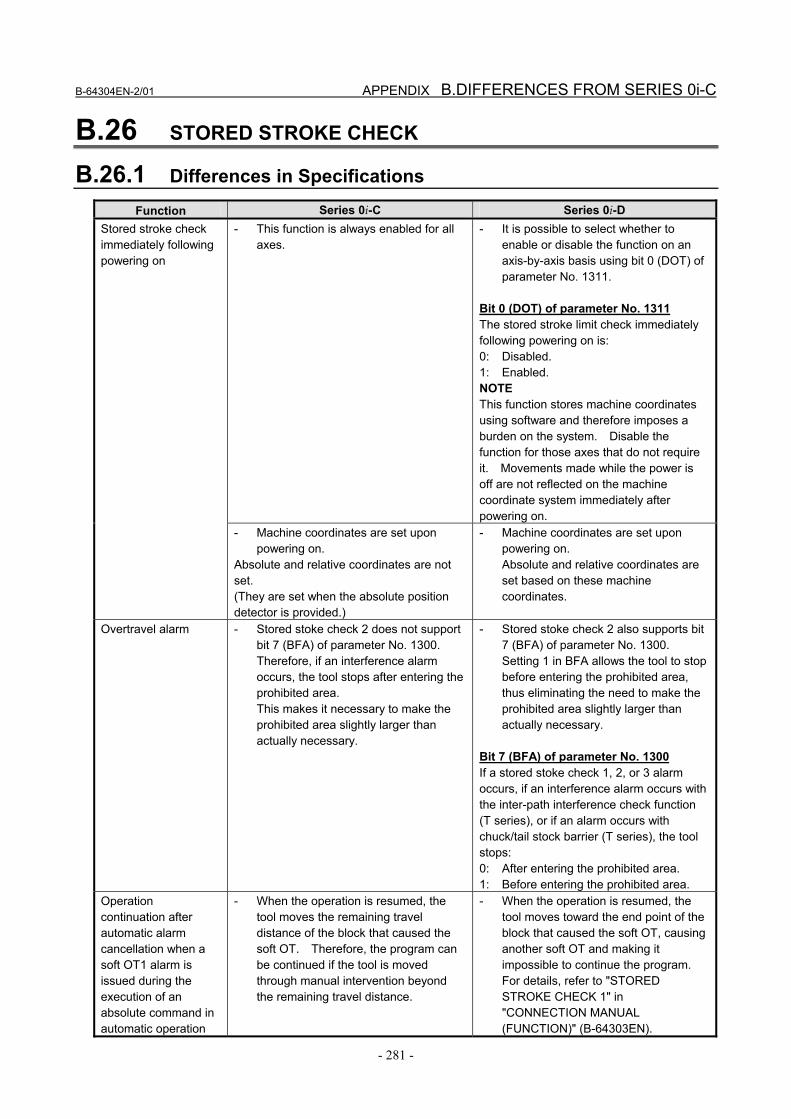
B-64304EN-2/01 APPENDIX B.DIFFERENCES FROM SERIES 0i-C
- 281 -
B.26 STORED STROKE CHECK
B.26.1 Differences in Specifications
Function Series 0i-C Series 0i-D - This function is always enabled for all
axes. - It is possible to select whether to
enable or disable the function on an axis-by-axis basis using bit 0 (DOT) of parameter No. 1311.
Bit 0 (DOT) of parameter No. 1311 The stored stroke limit check immediately following powering on is: 0: Disabled. 1: Enabled. NOTE This function stores machine coordinates using software and therefore imposes a burden on the system. Disable the function for those axes that do not require it. Movements made while the power is off are not reflected on the machine coordinate system immediately after powering on.
Stored stroke check immediately following powering on
- Machine coordinates are set upon powering on.
Absolute and relative coordinates are not set. (They are set when the absolute position detector is provided.)
- Machine coordinates are set upon powering on. Absolute and relative coordinates are set based on these machine coordinates.
Overtravel alarm - Stored stoke check 2 does not support bit 7 (BFA) of parameter No. 1300. Therefore, if an interference alarm occurs, the tool stops after entering the prohibited area. This makes it necessary to make the prohibited area slightly larger than actually necessary.
- Stored stoke check 2 also supports bit 7 (BFA) of parameter No. 1300. Setting 1 in BFA allows the tool to stop before entering the prohibited area, thus eliminating the need to make the prohibited area slightly larger than actually necessary.
Bit 7 (BFA) of parameter No. 1300 If a stored stoke check 1, 2, or 3 alarm occurs, if an interference alarm occurs with the inter-path interference check function (T series), or if an alarm occurs with chuck/tail stock barrier (T series), the tool stops: 0: After entering the prohibited area. 1: Before entering the prohibited area.
Operation continuation after automatic alarm cancellation when a soft OT1 alarm is issued during the execution of an absolute command in automatic operation
- When the operation is resumed, the tool moves the remaining travel distance of the block that caused the soft OT. Therefore, the program can be continued if the tool is moved through manual intervention beyond the remaining travel distance.
- When the operation is resumed, the tool moves toward the end point of the block that caused the soft OT, causing another soft OT and making it impossible to continue the program. For details, refer to "STORED STROKE CHECK 1" in "CONNECTION MANUAL (FUNCTION)" (B-64303EN).
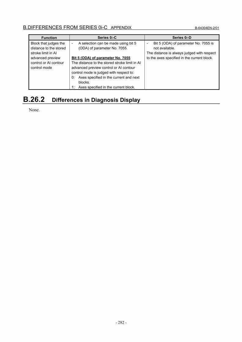
B.DIFFERENCES FROM SERIES 0i-C APPENDIX B-64304EN-2/01
- 282 -
Function Series 0i-C Series 0i-D Block that judges the distance to the stored stroke limit in AI advanced preview control or AI contour control mode
- A selection can be made using bit 5 (ODA) of parameter No. 7055.
Bit 5 (ODA) of parameter No. 7055 The distance to the stored stroke limit in AI advanced preview control or AI contour control mode is judged with respect to: 0: Axes specified in the current and next
blocks. 1: Axes specified in the current block.
- Bit 5 (ODA) of parameter No. 7055 is not available.
The distance is always judged with respect to the axes specified in the current block.
B.26.2 Differences in Diagnosis Display None.
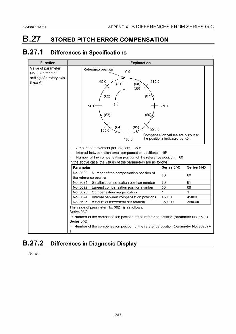
B-64304EN-2/01 APPENDIX B.DIFFERENCES FROM SERIES 0i-C
- 283 -
B.27 STORED PITCH ERROR COMPENSATION
B.27.1 Differences in Specifications
Function Explanation Value of parameter No. 3621 for the setting of a rotary axis (type A)
0.0
45.0
90.0
135.0
180.0
225.0
270.0
315.0(68)(60)
(67)
(66)
(65)(64)
(63)
(62)
(61)
(+)
Reference position
Compensation values are output at the positions indicated by ○.
- Amount of movement per rotation: 360° - Interval between pitch error compensation positions: 45° - Number of the compensation position of the reference position: 60 In the above case, the values of the parameters are as follows.
Parameter Series 0i-C Series 0i-D No. 3620: Number of the compensation position of the reference position
60 60
No. 3621: Smallest compensation position number 60 61 No. 3622: Largest compensation position number 68 68 No. 3623: Compensation magnification 1 1 No. 3624: Interval between compensation positions 45000 45000 No. 3625: Amount of movement per rotation 360000 360000
The value of parameter No. 3621 is as follows. Series 0i-C = Number of the compensation position of the reference position (parameter No. 3620) Series 0i-D = Number of the compensation position of the reference position (parameter No. 3620) + 1
B.27.2 Differences in Diagnosis Display None.
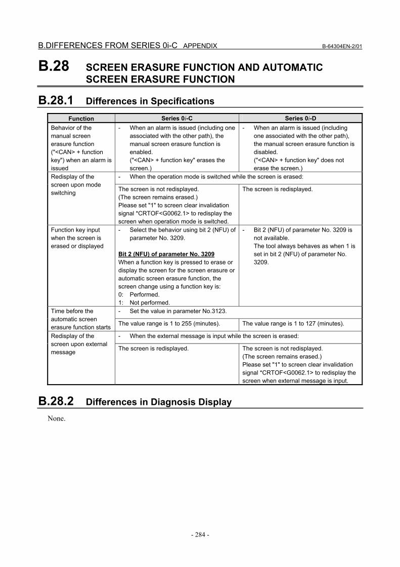
B.DIFFERENCES FROM SERIES 0i-C APPENDIX B-64304EN-2/01
- 284 -
B.28 SCREEN ERASURE FUNCTION AND AUTOMATIC SCREEN ERASURE FUNCTION
B.28.1 Differences in Specifications
Function Series 0i-C Series 0i-D Behavior of the manual screen erasure function ("<CAN> + function key") when an alarm is issued
- When an alarm is issued (including one associated with the other path), the manual screen erasure function is enabled. ("<CAN> + function key" erases the screen.)
- When an alarm is issued (including one associated with the other path), the manual screen erasure function is disabled. ("<CAN> + function key" does not erase the screen.)
- When the operation mode is switched while the screen is erased: Redisplay of the screen upon mode switching The screen is not redisplayed.
(The screen remains erased.) Please set "1" to screen clear invalidation signal *CRTOF<G0062.1> to redisplay the screen when operation mode is switched.
The screen is redisplayed.
Function key input when the screen is erased or displayed
- Select the behavior using bit 2 (NFU) of parameter No. 3209.
Bit 2 (NFU) of parameter No. 3209 When a function key is pressed to erase or display the screen for the screen erasure or automatic screen erasure function, the screen change using a function key is: 0: Performed. 1: Not performed.
- Bit 2 (NFU) of parameter No. 3209 is not available. The tool always behaves as when 1 is set in bit 2 (NFU) of parameter No. 3209.
- Set the value in parameter No.3123. Time before the automatic screen erasure function starts The value range is 1 to 255 (minutes). The value range is 1 to 127 (minutes).
- When the external message is input while the screen is erased: Redisplay of the screen upon external message The screen is redisplayed. The screen is not redisplayed.
(The screen remains erased.) Please set "1" to screen clear invalidation signal *CRTOF<G0062.1> to redisplay the screen when external message is input.
B.28.2 Differences in Diagnosis Display None.
B-64304EN-2/01 APPENDIX B.DIFFERENCES FROM SERIES 0i-C
- 285 -
B.29 RESET AND REWIND
B.29.1 Differences in Specifications
Function Series 0i-C Series 0i-D - If reset occurs during the execution of a block, the states of the modal G codes and
modal addresses (N, F, S, T, M, etc.) specified in that block are handled as follows. Modal data when reset during the execution of a block Maintained. Not maintained. The states return to
those of the modal data specified in the preceding blocks. (The modal data is updated after the specified block is fully executed.) Example) If reset occurs before positioning is completed in the N2 block in the program shown below, the T code and offset return to the data of the preceding tool (T0101) data. N1 G00 X120. Z0. T0101 ; ; N2 G00 X180. Z20. T0202 ; ;
Information in a block that is pre-read when a reset is made during an automatic operation (contents of the buffer)
- The information in the block may or may not be held depending on whether MDI mode is in progress. In MDI mode
The information in the block is held.
In modes other than MDI mode The information in the block is not held.
- The information in the block is not held regardless whether MDI mode is in progress.
B.29.2 Differences in Diagnosis Display None.
B.30 MANUAL ABSOLUTE ON AND OFF
B.30.1 Differences in Specifications
Function Series 0i-C Series 0i-D - If tool compensation is automatically changed when the manual absolute signal
*ABSM(Gn006.2) is set to 1, absolute coordinates are handled as follows. Absolute coordinates during automatic tool compensation change Absolute coordinates are not changed. Absolute coordinates are changed
according to the amount of tool compensation resulting from the coordinate shift.
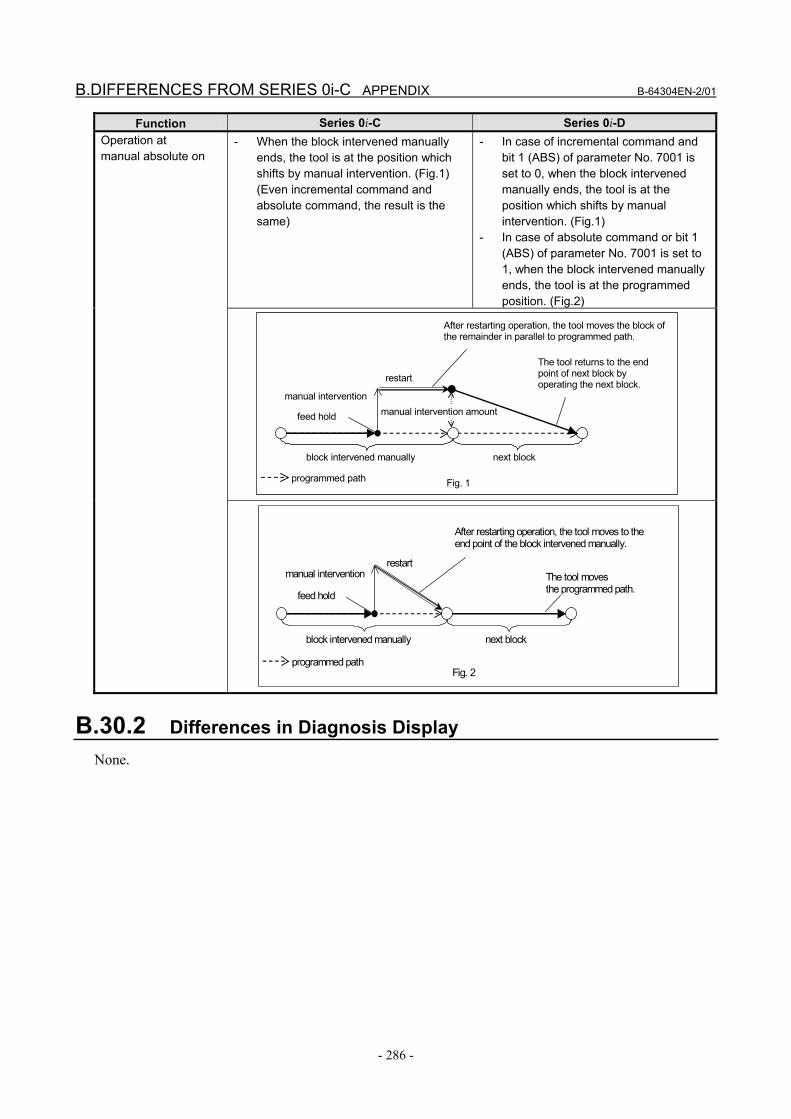
B.DIFFERENCES FROM SERIES 0i-C APPENDIX B-64304EN-2/01
- 286 -
Function Series 0i-C Series 0i-D - When the block intervened manually
ends, the tool is at the position which shifts by manual intervention. (Fig.1) (Even incremental command and absolute command, the result is the same)
- In case of incremental command and bit 1 (ABS) of parameter No. 7001 is set to 0, when the block intervened manually ends, the tool is at the position which shifts by manual intervention. (Fig.1)
- In case of absolute command or bit 1 (ABS) of parameter No. 7001 is set to 1, when the block intervened manually ends, the tool is at the programmed position. (Fig.2)
Operation at manual absolute on
B.30.2 Differences in Diagnosis Display None.
next block
programmed path
block intervened manually
feed hold
manual intervention
restart
manual intervention amount
After restarting operation, the tool moves the block of the remainder in parallel to programmed path.
The tool returns to the end point of next block by operating the next block.
Fig. 1
next block
programmed path
block intervened manually
feed hold
manual intervention restart
After restarting operation, the tool moves to the end point of the block intervened manually.
The tool moves the programmed path.
Fig. 2

B-64304EN-2/01 APPENDIX B.DIFFERENCES FROM SERIES 0i-C
- 287 -
B.31 EXTERNAL DATA INPUT
B.31.1 Differences in Specifications
Function Series 0i-C Series 0i-D Number of external alarm messages and message length
- [Number of messages that can be set at a time] Up to 4 messages [Length of a message] Up to 32 characters
- [Number of messages that can be set at a time] Depends on bit 1 (M16) of parameter No. 11931. When 0 is set, the processing is the same as Series 0i-C.
Bit 1 (M16) of parameter No. 11931 The maximum number of external alarm messages or external operator messages that can be displayed in connection with external data input or external messages is: 0: 4. 1: 16. [Length of a message] Up to 32 characters
Display format of external alarm messages
- [Alarm numbers that can be sent] 0 to 999 [How to distinguish these numbers from general alarm numbers] Add 1000 to the number sent
- Depends on bit 0 (EXA) of parameter No. 6301.
Bit 0 (EXA) of parameter No. 6301 Select the external alarm message specification. 0: The alarm numbers that can be sent
range from 0 to 999. The CNC displays an alarm number, with 1000 added to the number following the character string "EX".
1: The alarm numbers that can be sent range from 0 to 4095. The CNC displays an alarm number, with the character string "EX" added in front of it.
Number of external operator messages and message length
- Depends on bit 0 (OM4) of parameter No. 3207.
Bit 0 (OM4) of parameter No. 3207 The external operator message screen can display: 0: Up to 256 characters in up to 1
message. 1: Up to 64 characters in up to 4
messages.
- Bit 0 (OM4) of parameter No. 3207 is not available. [Number of messages that can be set at a time] Depends on bit 1 (M16) of parameter No. 11931. Select either up to 4 or 16 messages. [Length of a message] 256 characters or less
B.DIFFERENCES FROM SERIES 0i-C APPENDIX B-64304EN-2/01
- 288 -
Function Series 0i-C Series 0i-D Display format of external operator messages
- [Message numbers that can be sent] 0 to 999 [How to distinguish these numbers from alarm and other numbers] Messages from 0 to 99 The message is displayed on the screen along with the number. The CNC adds 2000 to this number for distinction. Messages from 100 to 999 Only the message is displayed on the screen without the number.
- Depends on bit 1 (EXM) of parameter No. 6301. When 0 is set, the processing is the same as Series 0i-C.
Bit 1 (EXM) of parameter No. 6301 Select the external operator message specification. 0: The message numbers that can be
sent range from 0 to 999. A message from 0 to 99 is displayed on the screen along with the number. The CNC adds 2000 to this number for distinction. As for the messages from 100 to 999, only the message is displayed on the screen without the number.
1: The message numbers that can be sent range from 0 to 4095. A message from 0 to 99 is displayed on the screen along with the number. The CNC adds the character string "EX" in front of the number. As for the messages from 100 to 4095, only the message is displayed on the screen without the number.
Parameter No. 6310 The data range of external operator message numbers is as follows.
Data range of external operator message numbers
- 0 to 1000 - 0 to 4096 When an external program number search is done with 0 set as the program number
- An alarm is not issued; the search is not done, either.
- Alarm DS0059 is issued.
Input of an external tool offset for an invalid function compensation value
- The input is ignored without issuing an alarm.
- Alarm DS1121 is issued.
B.31.2 Differences in Diagnosis Display None.
B-64304EN-2/01 APPENDIX B.DIFFERENCES FROM SERIES 0i-C
- 289 -
B.32 DATA SERVER FUNCTION
B.32.1 Differences in Specifications
Function Series 0i-C Series 0i-D Memory operation mode
- The memory operation mode is not supported.
- In the memory operation mode, the following operations can be performed for a program registered with the data server:
1. Select the program on the data
server as the main program and run it in the memory mode.
2. Call a subprogram or custom macro in the same directory as the main program on the data server.
3. Edit the program, including inserting, deleting, and replacing words.
B.32.2 Differences in Diagnosis Display None.
B.33 POWER MATE CNC MANAGER
B.33.1 Differences in Specifications
Function Series 0i-C Series 0i-D 4-slave display function
- By setting 1 in bit 0 (SLV) of parameter No. 0960, it is possible to split the screen into four windows, enabling up to four slaves to be displayed.
Bit 0 (SLV) of parameter No. 0960 When Power Mate CNC Manager is selected, the screen: 0: Displays one slave. 1: Is split into four windows, enabling up
to four slaves to be displayed.
- Bit 0 (SLV) of parameter No. 0960 is not available. One slave is always displayed. When there is more than one slave, you switch the active slave by using the relevant soft key.
B.33.2 Differences in Diagnosis Display None.
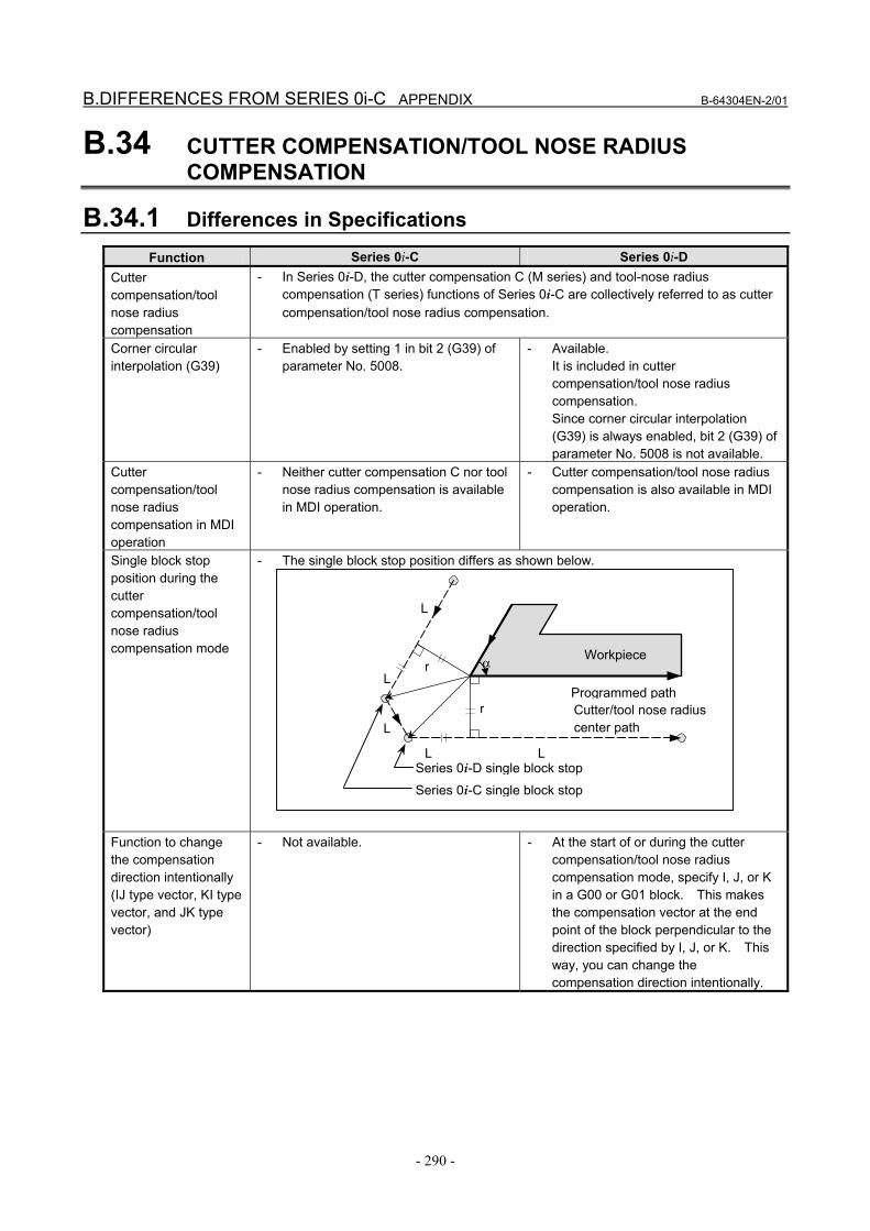
B.DIFFERENCES FROM SERIES 0i-C APPENDIX B-64304EN-2/01
- 290 -
B.34 CUTTER COMPENSATION/TOOL NOSE RADIUS COMPENSATION
B.34.1 Differences in Specifications
Function Series 0i-C Series 0i-D Cutter compensation/tool nose radius compensation
- In Series 0i-D, the cutter compensation C (M series) and tool-nose radius compensation (T series) functions of Series 0i-C are collectively referred to as cutter compensation/tool nose radius compensation.
Corner circular interpolation (G39)
- Enabled by setting 1 in bit 2 (G39) of parameter No. 5008.
- Available. It is included in cutter compensation/tool nose radius compensation. Since corner circular interpolation (G39) is always enabled, bit 2 (G39) of parameter No. 5008 is not available.
Cutter compensation/tool nose radius compensation in MDI operation
- Neither cutter compensation C nor tool nose radius compensation is available in MDI operation.
- Cutter compensation/tool nose radius compensation is also available in MDI operation.
Single block stop position during the cutter compensation/tool nose radius compensation mode
- The single block stop position differs as shown below.
Function to change the compensation direction intentionally (IJ type vector, KI type vector, and JK type vector)
- Not available. - At the start of or during the cutter compensation/tool nose radius compensation mode, specify I, J, or K in a G00 or G01 block. This makes the compensation vector at the end point of the block perpendicular to the direction specified by I, J, or K. This way, you can change the compensation direction intentionally.
α
Programmed path
L
L L
L
r
r
Cutter/tool nose radius center path L
Workpiece
Series 0i-D single block stop
Series 0i-C single block stop

B-64304EN-2/01 APPENDIX B.DIFFERENCES FROM SERIES 0i-C
- 291 -
Function Series 0i-C Series 0i-D - If the specified radius value for circular interpolation is smaller than that for cutter
compensation/tool nose radius compensation, as in the example below, performing compensation inwardly through cutter compensation/tool nose radius compensation causes overcutting, generating an alarm and stopping the tool. The stop position differs.
Stop position upon an overcutting alarm
[When single block stop occurs in the preceding block in Series 0i-C] Since the tool moves until it reaches the end point of the block (P3 in the figure),
overcutting may result. [When single block stop does not occur in the preceding block in Series 0i-C] The tool stops immediately after executing the block (P2 in the figure). [In the case of Series 0i-D] Since the tool stops at the start point of the block (P1 in the figure), regardless of the
single block state, overcutting can be prevented. Single block stop in a block created internally for cutter compensation/tool nose radius compensation
- Not available. - Depends on bit 0 (SBK) of parameter No. 5000.
Bit 0 (SBK) of parameter No. 5000 In a block created internally for cutter compensation/tool nose radius compensation, single block stop is: 0: Not performed. 1: Performed. This parameter is used to check a program including cutter compensation/tool nose radius compensation.
Cutting as programmed causes
Programmed path
Cutter/tool nose radius center path
Workpiece
P1P2
P3
N1
N2
N3

B.DIFFERENCES FROM SERIES 0i-C APPENDIX B-64304EN-2/01
- 292 -
Function Series 0i-C Series 0i-D - Set 1 in bit 0 (CNI) of parameter No.
5008. In the example below, an interference check is made on the vectors inside V1 and V4, and the interfering vectors are deleted. As a result, the tool center path is from V1 to V4.
- Not available. (Bit 0 (CNI) of parameter No. 5008 is not available.) To prevent overcutting, the interference check avoidance function (bit 5 (CAV) of parameter No. 19607) is used. In the example below, interference occurs between V1 and V4 and between V2 and V3. Therefore, vectors VA and VB are created. The tool center path is from VA to VB.
Setting to disable interference checking and to delete interfering vectors
[In the case of Series 0i-C] [In the case of Series 0i-D]
Number of blocks to be read in the cutter compensation/tool nose radius compensation mode
- Always 3 blocks - The number can be set in parameter No. 19625. The specifiable range is 3 to 8 blocks. If the parameter is not set (0 is set), the same number as Series 0i-C (3 blocks) is assumed.
Tool center path
Programmed path
V2V3
V1V4
Tool center path
Programmed pathVA
V2V3
V1
VB
V4
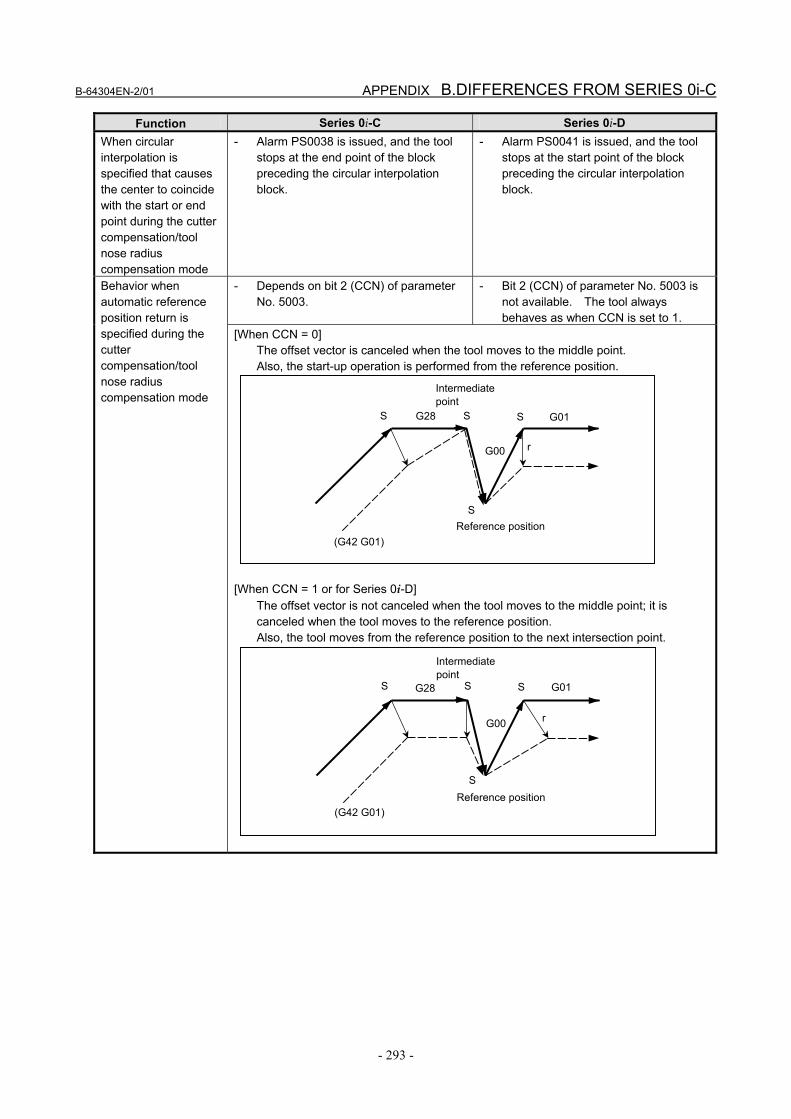
B-64304EN-2/01 APPENDIX B.DIFFERENCES FROM SERIES 0i-C
- 293 -
Function Series 0i-C Series 0i-D When circular interpolation is specified that causes the center to coincide with the start or end point during the cutter compensation/tool nose radius compensation mode
- Alarm PS0038 is issued, and the tool stops at the end point of the block preceding the circular interpolation block.
- Alarm PS0041 is issued, and the tool stops at the start point of the block preceding the circular interpolation block.
- Depends on bit 2 (CCN) of parameter No. 5003.
- Bit 2 (CCN) of parameter No. 5003 is not available. The tool always behaves as when CCN is set to 1.
Behavior when automatic reference position return is specified during the cutter compensation/tool nose radius compensation mode
[When CCN = 0] The offset vector is canceled when the tool moves to the middle point. Also, the start-up operation is performed from the reference position.
[When CCN = 1 or for Series 0i-D]
The offset vector is not canceled when the tool moves to the middle point; it is canceled when the tool moves to the reference position. Also, the tool moves from the reference position to the next intersection point.
S S
S
S
r
(G42 G01)
Intermediate point
G28
G00
G01
Reference position
S S
S
S
r
(G42 G01)
Intermediate point
G28
G00
G01
Reference position
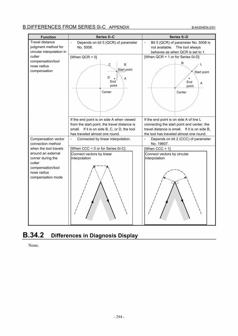
B.DIFFERENCES FROM SERIES 0i-C APPENDIX B-64304EN-2/01
- 294 -
Function Series 0i-C Series 0i-D - Depends on bit 5 (QCR) of parameter
No. 5008. - Bit 5 (QCR) of parameter No. 5008 is
not available. The tool always behaves as when QCR is set to 1.
[When QCR = 0]
[When QCR = 1 or for Series 0i-D]
Travel distance judgment method for circular interpolation in cutter compensation/tool nose radius compensation
If the end point is on side A when viewed from the start point, the travel distance is small. If it is on side B, C, or D, the tool has traveled almost one round.
If the end point is on side A of line L connecting the start point and center, the travel distance is small. If it is on side B, the tool has traveled almost one round.
- Connected by linear interpolation. - Depends on bit 2 (CCC) of parameter No. 19607.
Compensation vector connection method when the tool travels around an external corner during the cutter compensation/tool nose radius compensation mode
[When CCC = 0 or for Series 0i-C] Connect vectors by linear interpolation
[When CCC = 1] Connect vectors by circular interpolation
B.34.2 Differences in Diagnosis Display None.
C
A
B Start point
End point
Center
D
A
B L
Start point
End point
Center
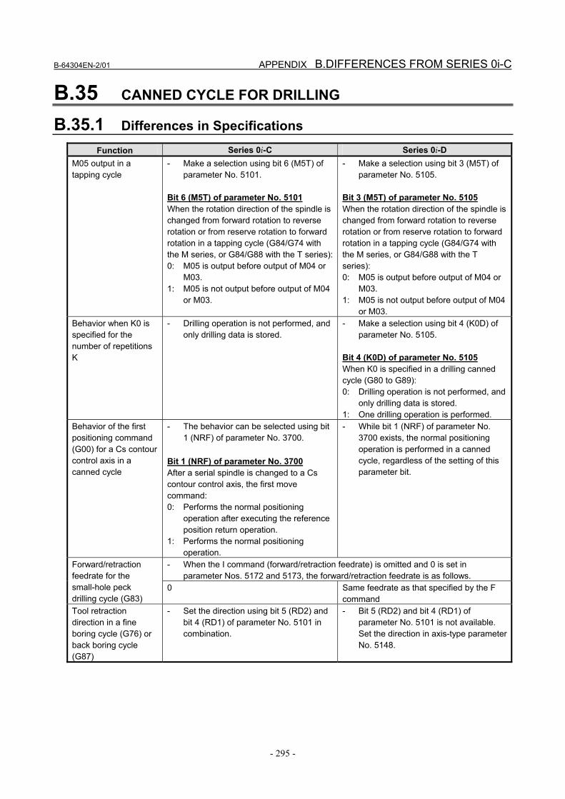
B-64304EN-2/01 APPENDIX B.DIFFERENCES FROM SERIES 0i-C
- 295 -
B.35 CANNED CYCLE FOR DRILLING
B.35.1 Differences in Specifications
Function Series 0i-C Series 0i-D M05 output in a tapping cycle
- Make a selection using bit 6 (M5T) of parameter No. 5101.
Bit 6 (M5T) of parameter No. 5101 When the rotation direction of the spindle is changed from forward rotation to reverse rotation or from reserve rotation to forward rotation in a tapping cycle (G84/G74 with the M series, or G84/G88 with the T series):0: M05 is output before output of M04 or
M03. 1: M05 is not output before output of M04
or M03.
- Make a selection using bit 3 (M5T) of parameter No. 5105.
Bit 3 (M5T) of parameter No. 5105 When the rotation direction of the spindle is changed from forward rotation to reverse rotation or from reserve rotation to forward rotation in a tapping cycle (G84/G74 with the M series, or G84/G88 with the T series): 0: M05 is output before output of M04 or
M03. 1: M05 is not output before output of M04
or M03. Behavior when K0 is specified for the number of repetitions K
- Drilling operation is not performed, and only drilling data is stored.
- Make a selection using bit 4 (K0D) of parameter No. 5105.
Bit 4 (K0D) of parameter No. 5105 When K0 is specified in a drilling canned cycle (G80 to G89): 0: Drilling operation is not performed, and
only drilling data is stored. 1: One drilling operation is performed.
Behavior of the first positioning command (G00) for a Cs contour control axis in a canned cycle
- The behavior can be selected using bit 1 (NRF) of parameter No. 3700.
Bit 1 (NRF) of parameter No. 3700 After a serial spindle is changed to a Cs contour control axis, the first move command: 0: Performs the normal positioning
operation after executing the reference position return operation.
1: Performs the normal positioning operation.
- While bit 1 (NRF) of parameter No. 3700 exists, the normal positioning operation is performed in a canned cycle, regardless of the setting of this parameter bit.
- When the I command (forward/retraction feedrate) is omitted and 0 is set in parameter Nos. 5172 and 5173, the forward/retraction feedrate is as follows.
Forward/retraction feedrate for the small-hole peck drilling cycle (G83)
0 Same feedrate as that specified by the F command
Tool retraction direction in a fine boring cycle (G76) or back boring cycle (G87)
- Set the direction using bit 5 (RD2) and bit 4 (RD1) of parameter No. 5101 in combination.
- Bit 5 (RD2) and bit 4 (RD1) of parameter No. 5101 is not available. Set the direction in axis-type parameter No. 5148.

B.DIFFERENCES FROM SERIES 0i-C APPENDIX B-64304EN-2/01
- 296 -
Function Series 0i-C Series 0i-D - In a high-speed peck drilling cycle (G73), peck drilling cycle (G83), and small-hole
peck drilling cycle (G83), when the address Q (amount of each-time cutting) command is not specified or Q0 is specified:
Address Q command in a high-speed peck drilling cycle (G73), peck drilling cycle (G83), or small-hole peck drilling cycle (G83)
Select the operation using bit 1 (QZA) of parameter No. 5103. Bit 1 (QZA) of parameter No. 5103 0: The tool repeats the upward and
downward movement at the same position without cutting.
1: P/S alarm No. 045 is issued.
Bit 1 (QZA) of parameter No. 5103 is not available. The tool always behaves as when 1 is set in bit 1 (QZA) of parameter No. 5103. (Alarm PS0045 is issued.)
Tool length compensation (G43 or G44) in a canned cycle when tool length compensation type C is selected (1 is set in bit 0 (TLC) of parameter No. 5001)
- Select the axis for which to enable tool length compensation, by using bit 4 (TCE) of parameter No. 5006.
Bit 4 (TCE) of parameter No. 5006 When tool length compensation (G43 or G44) is specified in a canned cycle, tool length compensation is enabled for: 0: Axis selected according to tool length
compensation type C. 1: Drilling axis.
- Bit 4 (TCE) of parameter No. 5006 is not available. The tool always behaves as when 1 is set in bit 4 (TCE) of parameter No. 5006.
B.35.2 Differences in Diagnosis Display None.
B.36 CANNED GRINDING CYCLE
B.36.1 Differences in Specifications
Function Series 0i-C Series 0i-D Grinding axis specification
- The grinding axis is the X or Z axis. - Set the grinding axes for the individual canned grinding cycles in parameter Nos. 5176 to 5179. If the same axis number as the cutting axis is specified in any of these parameters, or if a canned grinding cycle is executed when 0 is set, alarm PS0456 is issued.
Behavior of the first positioning command (G00) for a Cs contour control axis in a canned cycle
- The behavior can be selected using bit 1 (NRF) of parameter No. 3700.
Bit 1 (NRF) of parameter No. 3700 After a serial spindle is changed to a Cs contour control axis, the first move command: 0: Performs the normal positioning
operation after executing the reference position return operation.
1: Performs the normal positioning operation.
- While bit 1 (NRF) of parameter No. 3700 exists, the normal positioning operation is performed in a canned cycle, regardless of the setting of this parameter bit.

B-64304EN-2/01 APPENDIX B.DIFFERENCES FROM SERIES 0i-C
- 297 -
Function Series 0i-C Series 0i-D Dressing axis specification
- The dressing axis is always the fourth axis.
- Set the dressing axes for the individual canned grinding cycles in parameter Nos. 5180 to 5183. If the same axis number as the cutting axis or grinding axis is specified in any of these parameters, or if a canned grinding cycle is executed when 0 is set, alarm PS0456 is issued.
B.36.2 Differences in Diagnosis Display None.
B.37 SINGLE DIRECTION POSITIONING
B.37.1 Differences in Specifications
Function Series 0i-C Series 0i-D If positioning of linear interpolation type is used (1 is set in bit 1 (LRP) of parameter No. 1401), and if the state of mirror image when a single direction positioning block is looked ahead differs from the state of mirror image when the execution of the block is started, the following alarms are issued, respectively.
Behavior when linear interpolation type positioning is used with mirror image
- Alarm PS5254 - Alarm DS0025
B.37.2 Differences in Diagnosis Display None.
B.38 OPTIONAL ANGLE CHAMFERING AND CORNER ROUNDING
B.38.1 Differences in Specifications
Function Series 0i-C Series 0i-D Optional angle chamfering and corner rounding commands for a plane including a parallel axis
- Not available. Alarm PS0212 is issued.
- Available.
Single block operation - Single block stop is not performed at the start point of an inserted optional angle chamfering or corner rounding block.
- Whether to perform single block stop at the start point of an inserted block depends on bit 0 (SBC) of parameter No. 5105.
Bit 0 (SBC) of parameter No. 5105 In a drilling canned cycle, chamfer cycle/corner rounding (T series) or optional angle chamfering/corner rounding cycle (M series): 0: Single block stop is not performed. 1: Single block stop is performed.

B.DIFFERENCES FROM SERIES 0i-C APPENDIX B-64304EN-2/01
- 298 -
Function Series 0i-C Series 0i-D Negative value specified in a ,C_ or ,R_ command
- The value is regarded as positive. - Alarm PS0006 is issued.
Number of dwells to be inserted between two blocks for which to perform optional angle chamfering or corner rounding
- Not limited. - Only one block can be inserted. Inserting more than one block causes alarm PS0051.
DNC operation - Optional angle chamfering and corner rounding are not available in DNC operation.
- Optional angle chamfering and corner rounding are also available in DNC operation.
B.38.2 Differences in Diagnosis Display None.