User Manual - gsk controller, cnc machines
406
GSK980TD Turning Machine CNC System User Manual GSK CNC Equipment
-
Upload
khangminh22 -
Category
Documents
-
view
3 -
download
0
Transcript of User Manual - gsk controller, cnc machines

GSK980TD
Turning Machine CNC System
User Manual
GSK CNC Equipment


Preface
Warning!
Please read the user manual and a user manual from machine manufacturercompletely before installation, programming and operation, and operate thesystem and machine according to user manuals, otherwise which may damage thesystem and machine, workpiece and even injure the operator.
Functions, technical index
system. Actual functions a
tool with the system are d
to its user manual;
The system is employed w
press keys on machine co
Functions of press keys
program. Please notice it!
Refer to user manual from
meanings of press keys on m
This manual suits for software version
All specification and designs are subje
Notice!
es described in the user manual are for the
nd technical performance of CNC machine
efined by machine manufacturer, and refer
ith intergrated machine control panel and
ntrol panel are defined by PLC program.
in the user manual are for standard PLC
machine manufacturer about functions and
achine control panel.
:V06.03.23.
ct to change without notice.

Notice
Notice
■ Delivery and storage
There are 6-layer packing box at most in pile
Never climb the packing box, neither stand on it, nor place heavy items on it
Do not use cable connected with product to drag or move it
Forbid crash, hurt panel and display
Packing box is protected from damp, sun and rain
■ Open packing box to check
Ensure things in packing box are the required ones
Ensure it is not damaged in delivery
Ensure things in packing box are these of order
Contact with us in time if its type is inconsistent with the order, there is short of accessories, or it is
damaged in delivery
■ Connection
Only qualified persons can connect the system or check the connection.
The system must be earthed, its resistance must be less than 4 Ω and the ground wire cannot be replaced
by zero wire
Connection must be correct and firm to avoid the product to be damaged or other unexpected result
Connect with surge diode in the specified direction to avoid to damage the system
Switch off power supply before pulling out plug or opening electric box
■ Troubleshooting
Switch off power supply before troubleshooting or changing components
Troubleshoot and then startup the system when there is short circuit or overload
Do not switch off it and a meantime is 1 minute at least after it is switched on again.

Book 1 Program
ming fundam
entals ok 1 Program
ming fundam
entals
BOOK 1 BOOK 1
PROGRAMMING PROGRAMMING
Chapter1:Programming Fundamentals
Chapter2:M.S.F.T Instructions
Chapter3: G Instructions
Chapter4:Tool Nose Radius Compensation (G41,G42)


Contents
Chapter 1 PROGRAMMING FUNDAMENTALS............................................................................ Ⅰ-1 B
ook 1 Pro gramm
ing fundamentals
1.1 INTRODUCTION of GSK980TD ........................................................................................ Ⅰ-1 1.2 CNC SYSTEMS of MACHINE TOOLS and CNC MACHINE TOOLS ............................. Ⅰ-6 1.3 PROGRAMMING FUNDAMENTALS................................................................................ Ⅰ-9
1.3.1 Coordinates Definition................................................................................................. Ⅰ-9 1.3.2 Machine Coordinate System and Machine Reference Point ..................................... Ⅰ-10 1.3.3 Workpiece Coordinate System and Program Reference Point .................................. Ⅰ-10 1.3.4 Interpolation Function ............................................................................................... Ⅰ-11 1.3.5 Absolute Programming and Incremental Programming ............................................ Ⅰ-12 1.3.6 Diameter and Radius Programming........................................................................... Ⅰ-12
1.4 STRUCTURE of an NC PROGRAM.................................................................................. Ⅰ-13 1.4.1 General Structure of Program.................................................................................... Ⅰ-14 1.4.2 Main Program and Subprogram................................................................................. Ⅰ-17
1.5 PROGRAM RUN ................................................................................................................ Ⅰ-18 1.5.1 Sequence of Program Run ......................................................................................... Ⅰ-18 1.5.2 Execution Sequence of Word..................................................................................... Ⅰ-19
Chapter 2 M.S.F.T INSTRUCTION................................................................................................... Ⅱ-1 2.1 M INSTRUCTION(AUXILIARY FUNCTION) ............................................................. Ⅱ-1
2.1.1 End of Program M02 ................................................................................................... Ⅱ-1 2.1.2 End of Program Run M30............................................................................................ Ⅱ-1 2.1.3 Subprogram Call M98 ................................................................................................. Ⅱ-2 2.1.4 Return from Subprogram M99 .................................................................................... Ⅱ-2 2.1.5 Macro Program Call .................................................................................................... Ⅱ-3 2.1.6 M Instructions Defined by Standard PLC Ladder Diagram ........................................ Ⅱ-4 2.1.7 Program Stop M00....................................................................................................... Ⅱ-4 2.1.8 Spindle Control M03,M04,M05 ............................................................................ Ⅱ-4 2.1.9 Coolant Control M08,M09 ....................................................................................... Ⅱ-5 2.1.10 Tailstock Control M10,M11.................................................................................... Ⅱ-5 2.1.11 Chuck Control M12,M13........................................................................................ Ⅱ-5 2.1.12 Lubrication Control M32,M33 .................................................................................. Ⅱ-5 2.1.13 Spindle Automatic Gear Shifting M41, M42, M43, M44.......................................... Ⅱ-5
2.2 SPINDLE FUNCTION(S FUNCTION) .......................................................................... Ⅱ-6 2.2.1 Spindle Speed Switching Value CONTROL ............................................................... Ⅱ-6 2.2.2 Spindle Speed Analog Voltage Control ....................................................................... Ⅱ-7 2.2.3 Constant Surface Speed Control G96, Constant Rotational Speed Control G97 ........ Ⅱ-7 2.2.4 Spindle Override........................................................................................................ Ⅱ-10
2.3 TOOL FUNCTION (T FUNCTION) ............................................................................ Ⅱ-10 2.4 FEEDRATE FUNCTION (F FUNCTION) ......................................................................... Ⅱ-14
2.4.1 Cutting Feed(G98/G99,F Instruction) ............................................................... Ⅱ-14 2.4.2 Thread Cutting ........................................................................................................... Ⅱ-16 2.4.3 Manual Feed .............................................................................................................. Ⅱ-16 2.4.4 Handwheel/Step Feed ................................................................................................ Ⅱ-15 2.4.5 Automatic Acceleration/Deceleration........................................................................... Ⅱ-15
Chapter 3 G INSTRCUTIONS........................................................................................................... Ⅲ-1 3.1 INTRODUCTION ................................................................................................................. Ⅲ-1
I

GSK980TD Turning Machine CNC System
Book 1 Program
ming fundam
entals
3.1.1 Modal, Non-modal and Initial Mode ........................................................................... Ⅲ-2 3.1.2 Omit a Word................................................................................................................. Ⅲ-2 3.1.3 Related Definitions ...................................................................................................... Ⅲ-4
3.2 RAPID TRAVERSE MOVEMENT G00 .............................................................................. Ⅲ-4 3.3 LINEAR INTERPOLATION G01......................................................................................... Ⅲ-5 3.4 CIRCULAR INTERPOLATION G02, G03 .......................................................................... Ⅲ-6 3.5 DWELL G04.......................................................................................................................... Ⅲ-9 3.6 MACHINE REFERNCE POINT RETURN G28................................................................ Ⅲ-10 3.7 WORKPIECE COORDINATE SYSTEM G50................................................................... Ⅲ-11 3.8 FIXED CYCLE INSTRUCTIONS...................................................................................... Ⅲ-13
3.8.1 Axial Cutting Cycle G90 ........................................................................................... Ⅲ-13 3.8.2 Radial Cutting Cycle G94.......................................................................................... Ⅲ-16 3.8.3 Cautions of Fixed Cycle Instructions ........................................................................ Ⅲ-19
3.9 MULTIPLE CYCLE INSTRUCTIONS .............................................................................. Ⅲ-19 3.9.1 Axial Roughing Cycle G71 ....................................................................................... Ⅲ-19 3.9.2 Radial Roughing Cycle G72...................................................................................... Ⅲ-24 3.9.3 Closed Cutting Cycle G73 ......................................................................................... Ⅲ-28 3.9.4 Finishing Cycle G70 .................................................................................................. Ⅲ-33 3.9.5 Axial Grooving Multiple Cycle G74 ......................................................................... Ⅲ-34 3.9.6 Radial Grooving Multiple Cycle G75........................................................................ Ⅲ-37
3.10 THREAD CUTTING......................................................................................................... Ⅲ-41 3.10.1 Thread Cutting with Constant Lead G32................................................................. Ⅲ-41 3.10.2 Thread Cutting with Variable Lead G34.................................................................. Ⅲ-43 3.10.3 Thread Cutting in Z Direction G33 ......................................................................... Ⅲ-45 3.10.4 Thread Cutting Cycle G92....................................................................................... Ⅲ-47 3.10.5 Multiple Thread Cutting Cycle G76 ........................................................................ Ⅲ-50
3.11 CONSTANT SURFACE SPEED CONTROL G96, CONSTANT ROTATIONAL SPEED CONTROL G97................................................................................................................... Ⅲ-54
3.12 FEEDRATE per MINUTE G98, FEEDRATE per REV G99............................................ Ⅲ-57 3.13 MACRO INSTRUCTIONS............................................................................................... Ⅲ-58
3.13.1 Macro Variables ....................................................................................................... Ⅲ-58 3.13.2 Operation and Jump Instruction G65....................................................................... Ⅲ-60 3.13.3 PROGRAM EXAMPLE with MACRO INSTRUCTION ...................................... Ⅲ-64
Chapter 4 TOOL NOSE RADIUS COMPENSATION (G41,G42)................................................. Ⅳ-1 4.1 APPLICATION...................................................................................................................... Ⅳ-1
4.1.1 Overview...................................................................................................................... Ⅳ-1 4.1.2 Imaginary Tool Nose Direction ................................................................................... Ⅳ-2 4.1.3 Compensation Value Setting........................................................................................ Ⅳ-5 4.1.4 Instruction Format ....................................................................................................... Ⅳ-6 4.1.5 Compensation Direction .............................................................................................. Ⅳ-6 4.1.6 Cautious ....................................................................................................................... Ⅳ-8 4.1.7 Application .................................................................................................................. Ⅳ-9
4.2 TOOL NOSE RADIUS COMPENSATION OFFSET PATH.............................................. Ⅳ-10 4.2.1 Inner and Outer Side.................................................................................................. Ⅳ-10 4.2.2 Tool Traverses when Starting Tool ............................................................................ Ⅳ-10 4.2.3 Tool Traversing in Offset Mode................................................................................. Ⅳ-13 4.2.4 Tool Traversing in Offset Canceling Mode ............................................................... Ⅳ-18

Contents
4.2.5 Tool Interference Check............................................................................................. Ⅳ-19 4.2.6 Instructions for Canceling Compensation Vector Temperarily.................................. Ⅳ-21 4.2.7 Particular.................................................................................................................... Ⅳ-23 B
ook 1 Pro gramm
ing fundamentals
III

Chapter 1 Programming Fundamentals
Ⅰ-1
Book 1 Program
ming fundam
entals
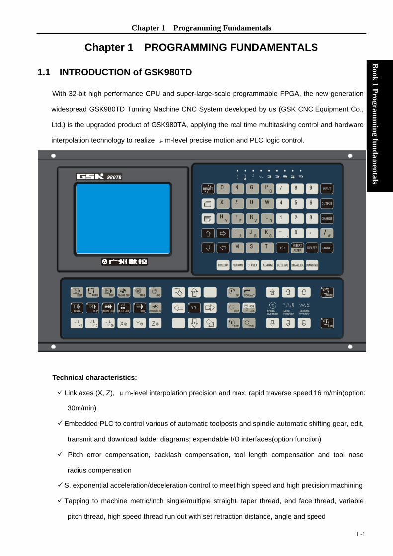
Chapter 1 PROGRAMMING FUNDAMENTALS
1.1 INTRODUCTION of GSK980TD
With 32-bit high performance CPU and super-large-scale programmable FPGA, the new generation
widespread GSK980TD Turning Machine CNC System developed by us (GSK CNC Equipment Co.,
Ltd.) is the upgraded product of GSK980TA, applying the real time multitasking control and hardware
interpolation technology to realize μm-level precise motion and PLC logic control.
Technical characteristics:
Link axes (X, Z), μm-level interpolation precision and max. rapid traverse speed 16 m/min(option:
30m/min)
Embedded PLC to control various of automatic toolposts and spindle automatic shifting gear, edit,
transmit and download ladder diagrams; expendable I/O interfaces(option function)
Pitch error compensation, backlash compensation, tool length compensation and tool nose
radius compensation
S, exponential acceleration/deceleration control to meet high speed and high precision machining
Tapping to machine metric/inch single/multiple straight, taper thread, end face thread, variable
pitch thread, high speed thread run out with set retraction distance, angle and speed

GSK980TD Turning Machine CNC System
Ⅰ-2
Book 1 Program
ming fundam
entals
Chinese and English display interface selected by parameters
Large memory capacity( 6144KB,384 part programs) with full screen edit
Convenient management for the system with multilevel operation password
Bidirectional communication between CNC and PC, CNC and CNC; communication upgrading
CNC software and PLC programs
Installing dimension, electric interfaces, instruction system and operating windows being
compatible with those of GSK980TA Turning CNC System
Technical specifications Controllable axes: 2(X, Z); simultaneous controllable axes: 2 (X, Z) Interpolation: linear, arc interpolation in X, Z direction Dimension for programs: -9999.999~9999.999mm; min. unit: 0.001mm Electronic gear:instruction multiplying 1~32767 and dividing 1~32767 Rapid traverse speed: max. 16000mm/min(option:30000mm/min) Rapid override: time real tuning F0, 25%, 50%,100% Cutting feedrate: max.8000mm/min(option:15000mm/min) or 500mm/rev
(feedrate per rev) Feedrate override: 16 steps real time tuning for 0~150% Manual feedrate: 16 steps real time tuning for 0~1260mm/min Handwheel feedrate: 0.001, 0.01, 0.1mm
Motion control
Acceleration/deceleration: S acceleration/deceleration for rapid traverse movement and exponential acceleration/deceleration for cutting feed
G instructions
28 kinds of G instructions: G00, G01, G02, G03, G04, G28, G32, G33, G34, G40, G41, G42, G50, G65, G70, G71, G72, G73, G74, G75, G76, G90, G92, G94, G96, G97, G98, G99 and macro instruction G65 to execute 27 kinds of calculation, logic operation and program skipping Tapping to machine metric/inch single/multiple straight thread, taper thread, end face thread, variable pitch thread. High speed thread run out with set retraction distance, angel and speed; pitch: 0.001~500mm or 0.06~25400 tooth/inch Spindle encoder: lines can be set (100~5000p/r)
Thread machining
Drive ratio between encoder and spindle: (1~255):(1~255) Backlash compensation: (X, Z)0~2.000mm Pitch error compensation: 255 compensation points with ± 0.255mm ×
compensation override for each one in X, Z direction Precision compensation Tool compensation: 32 groups tool length compensation, tool nose radius
compensation (tool compensation C) Toolsetting method: fixed-point toolsetting, trial cutting toolsetting Tool compensation executing methods: traversing tool or coordinate offset M instructions(no repetition): M02, M30, M98, M99, M9000~M9999 Other M□□ instructions are defined and executed by PLC programs M
instructions M instructions defined by standard PLC program: M00, M03, M04, M05, M08, M09, M10, M11, M12, M13, M32, M33, M41, M42, M43, M44

Chapter 1 Programming Fundamentals
Ⅰ-3
Book 1 Program
ming fundam
entals
T instruction
Most 32 tool selections(T01□□~T32□□), the time sequence of tool change is defined by PLC programs. The tool selection is set to 1 and the tool change is not executed by PLC when the line-up toolpost is employed. The standard PLC programs is s is optional to 2~8 tool selections toolpost, clockwise rotation for selecting tools and counterclockwise rotation for clamping toolpost. Speed switching value control: S□□ instruction is defined and executed by PLC programs, direct output of S1, S2, S3, S4 is controlled by the standard PLC programs and S0 is used for stopping output of S1, S2, S3, S4 Spindle speed
Speed analog voltage control: S instructions specifying the spindle speed per minute or the cutting surface speed (constant surface speed control) , the system outputting 0~10V voltage to spindle converter, 4 gears spindle speed with stepless shifting gear 9 kinds of elementary instruction, 23 kinds of function instruction, 2 grades PLC program, max. 5000 steps and 2μs for each step, refresh cycle for the first grade program is 8ms, ladder diagram editing software, PLC program communication download PLC
function Integrated machine control panel: 41 input points (press keys), 42 output points (LED) Basic I/O interfaces: 16 input points /16 output points (optional I/O interface: 16 input points /16 output points) Display: 320×240 lattice, 5.7” monochrome liquid crystal display(LCD), CCFL in a poor light
Displaying window
Display method: Chinese or English window is set by parameter, displaying machining path of workpiece Program capacity: 6144KB, max. 384 programs, supporting user macro program calling and four-embedded subprogram
Program editing
Editing method: incremental coordinates, absolute coordinate and compound coordinates programming with full screen edit
Communication Bidirectional communication for programs and parameters between CNC and PC, CNC and CNC; communication upgrading and downloading CNC software and PLC programs
Optional driving
DA98 Series Digital AC Servo or DY3 Series Stepper Driver with input pulse and direction signal
G instructions Instructions Functions Instructions Functions
G00 Rapid traverse movement G70 Finishing cycle G01 Linear interpolation G71 Axial roughing cycle G02 Circular interpolation (CW) G72 Radial roughing cycle G03 Circular interpolation (CCW) G73 Closed cutting cycle G04 Dwell time preset G74 Axial grooving cycle G28 Machine reference point automatic
return
G75 Radial grooving cycle
G32 Thread cutting with constant lead
G76 Multiple thread cutting cycle
G33 Tapping cycle in Z direction G90 Axial cutting cycle G34 Thread cutting with variable lead G92 Thread cutting cycle G40 Canceling tool nose radius G94 Radial cutting cycle

GSK980TD Turning Machine CNC System
Ⅰ-4
Book 1 Program
ming fundam
entals
compensation G41 Tool nose radius compensation left of
contour
G96 Constant surface speed ON
G42 Tool nose radius compensation right of contour
G97 Constant surface speed OFF
G50 Setting workpiece coordinate system G98 Feed per minute G65 Macro instruction G99 Feed per rev
PLC instruction list
Elementary instructions
Functions Function instructions
Functions
LD Read normally-open contact TMRB Timer LDI Read normally-closed contact CODB Binary conversion
OUT Output coil ROTB Binary rotation control AND Normally-open contact in series MOVN Data copy ANI Normally-closed contact in series DECB Binary decoding
OR Parallel normally-open contact JMPB Program skipping(jumping) ORI Parallel normally-closed contact SP Subprogram ORB Parallel series circuit block SPE End of subprogram ANB Parallel circuit block in series ADDB Binary data adding
SUBB Binary data subtracting
Function instructions
Functions ALT Alternative output
END1 End of grade one program DIFU Up set
END2 End of grade two program DIFD Down set
SET Set MOVE And
RST Reset PARI Parity check
CMP Comparative set LBL Program skipping label
CTRC Counter CALL Subprogram calling

Chapter 1 Programming Fundamentals
Ⅰ-5
Book 1 Program
ming fundam
entals
Type significations GSK 980TD—□
Assembly form:none:standard panel(420×260mm) B: boxed assembly
980TD Turning Machine CNC
Symbol of GSK CNC Equipment Co., Ltd.
Type Specification
GSK980TD 420×260mm aluminium alloy solid operator panel
GSK980TD-B GSK980TD matching with AP01(445mm×345mm×
182mm)
Standard functions All optional functions without being remarked in the provided technical specifications are as follows: Max. rapid traverse speed 16m/min, max. feedrate 8m/min, pitch error compensation, tool nose radius compensation, spindle analog voltage control(converter spindle),communication, 16 input points, 16 output points, standard PLC ladder, I/O interfaces being compatible with those of GSK980TA CNC system, 4-gear spindle automatic shifting gear(only test 1st and 2nd gear), hydraulic chuck, hydraulic tailstock, 4~8 tool selections toolpost(unidirectional selecting tool), safeguard, low pressure alarm etc.
Note 1: Modify or redesign PLC ladder diagram when other functions including executing the bidirectional tool change or testing 4-gear spindle are incompatible with those of 980TA CNC System.
Note 2: Please remark the detailed control requirements in order lists when special PLC ladder diagram (I/O interfaces are incompatible with those of GSK 980TA CNC System) is required.
Optional functions 1. Max. rapid traverse speed 30m/min and max. feedrate 15m/min; 2. I/O expansion: 16 input points (XS41 interface) and 16 output points (XS42 interface);
Standard accessories Power switch: GSK-PB (assembled) Connector: CNC interfaces are connected by one set of plug( DB9 female×3, DB15 male×3, DB25
female×1, DB25 male×1) Note: Corresponding plugs along with cables are supplied when they along with other components
including driver are delivered. Accessory cables: 12m 10-core shield cable (3m for each X axis, Z axis, input interface XS40, output
interface XS39); 9m 8-core shield cable with (3m for spindle encoder, input interface XS40, output
interface XS39);

GSK980TD Turning Machine CNC System
Ⅰ-6
Book 1 Program
ming fundam
entals
3m 4-core shield cable (converter interface); Note: The above-mentioned cables as wires are supplied. Signal cables with welded plugs are
supplied when a whole set of driver and toolpost controller is delivered. The requirements for cable length and welding should be remarked in the order list.
Anti-interference components: 1N4007×8、0.1μF/630V×6 Technical documents: GSK980 Turning Machine CNC System User Manual(without PLC User
Manual)
Optional accessories Communication components: one piece of 5m communication cable and one installation diskette of
communication software TDComm2; Power filter:FN2060-6-06 Handwheel: Dongxin RE45T1SO5B1(option: AP01) or Changchun LGF-001-100(option: AP02); Additional panel:AP01(aluminum alloy 420×71 ㎜) can be assembled under of GSK980TD operator
panel; AP02(aluminum alloy 100×260 ㎜)can be assembled at the side of GSK980TD operator panel;
Emergent stop button: LAY3-02ZS/1( it has been installed when GSK980TD-B is delivered); No self-locking button: KH-516-B11(blue or red); Self-locking button: KH-516-B21(blue or red); GSK980TD PLC User Manual Ladder diagram programming software: one GSKCC installation diskette Note 1: Communication functions are standard ones but communication components are optional
accessories; Note 2: Optional accessories as product ones (without being installed and connected) are supplied
and it should be remarked in the order list when they are required to install and connect.
1.2 CNC SYSTEMS of MACHINE TOOLS and CNC MACHINE TOOLS
CNC machine tool is an electro-mechanical integrated product, composed of Numerical Control Systems of Machine Tools, machines, electric control components, hydraulic components, pneumatic components, lubricant, coolant and other subsystems (components), and CNC systems of machine tools are control cores of CNC machine tools. CNC systems of machine tools are made up of computerized numerical control(CNC), servo (stepper) motor drive devices, servo (or stepper) motor and etc. Operational principles of CNC machine tools: according to requirements of machining technology, edit user programs and input them to CNC, then CNC outputs motion control instructions to the servo (stepper) motor drive devices, and last the servo (or stepper) motor completes the cutting feed of machine tool by mechanical driving device; logic control instructions in user programs to control spindle start/stop, tool selections, coolant ON/OFF, lubricant ON/OFF are output to electric control systems of machine tools from CNC, and then the electric control systems control output components including buttons, switches, indicators, relays, contactors and so on. Presently, the electric control systems are employed with Programmable Logic Controller (PLC) with characteristics of compact, convenience and high reliance. Thereof, the motion control systems and logic control systems are the
Chapter 1 Programming Fundamentals
Ⅰ-7
Book 1 Program
ming fundam
entals
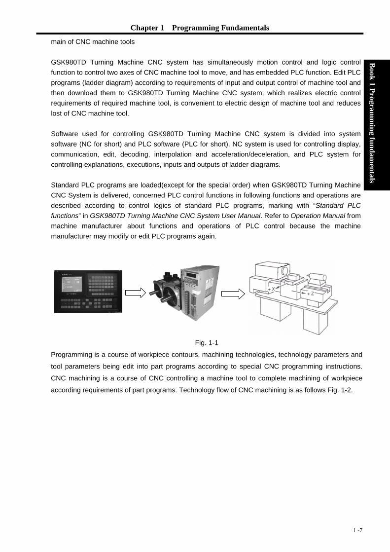
main of CNC machine tools GSK980TD Turning Machine CNC system has simultaneously motion control and logic control function to control two axes of CNC machine tool to move, and has embedded PLC function. Edit PLC programs (ladder diagram) according to requirements of input and output control of machine tool and then download them to GSK980TD Turning Machine CNC system, which realizes electric control requirements of required machine tool, is convenient to electric design of machine tool and reduces lost of CNC machine tool. Software used for controlling GSK980TD Turning Machine CNC system is divided into system software (NC for short) and PLC software (PLC for short). NC system is used for controlling display, communication, edit, decoding, interpolation and acceleration/deceleration, and PLC system for controlling explanations, executions, inputs and outputs of ladder diagrams. Standard PLC programs are loaded(except for the special order) when GSK980TD Turning Machine CNC System is delivered, concerned PLC control functions in following functions and operations are described according to control logics of standard PLC programs, marking with “Standard PLC functions” in GSK980TD Turning Machine CNC System User Manual. Refer to Operation Manual from machine manufacturer about functions and operations of PLC control because the machine manufacturer may modify or edit PLC programs again.
Fig. 1-1
Programming is a course of workpiece contours, machining technologies, technology parameters and
tool parameters being edit into part programs according to special CNC programming instructions.
CNC machining is a course of CNC controlling a machine tool to complete machining of workpiece
according requirements of part programs. Technology flow of CNC machining is as follows Fig. 1-2.

GSK980TD Turning Machine CNC System
Ⅰ-8
Book 1 Program
ming fundam
entals
Fig. 1-2
O0001;
G00 X3.76 Z0;
G01 Z-1.28 F50;
…
M30;
%
Confirm machining technologies
after analyzing workpiece drawings
Edit part programs and record into
CNC
Test part programs and execute trial
running
Check part dimension and modify part
programs and compensations
Execute toolsetting and set tool
offsets and coordinates
Run part programs and machine
workpieces
The machining ends and the workpiece
is formed

Chapter 1 Programming Fundamentals
Book 1 Program
ming fundam
entals
1.3 PROGRAMMING FUNDAMENTALS
1.3.1 Coordinates Definition Sketch map of CNC turning machine is as follows:
Fig. 1-3
The system is employed with a rectangular coordinate system composed of X, Z axis. X axis is
perpendicular with axes of spindle and Z axis is parallel with axes of spindle; negative directions of
them approach to the workpiece and positive ones are away from it.
There are a front toolpost and a rear toolpost of NC turning machine according to their relative position
between the toolpost and the spindle, Fig. 1-4 is a coordinate system of the front toolpost and Fig. 1-5
is a rear toolppost one. It shows exactly the opposite direction in X direction but the same direction in Z
direction from figures. In the manual, it will introduce programming application employed with the front
toolpost coordinate system in following figures and examples.
X
Z
X
Z
Fig.1-4 Front toolpost c
oordinate system Fig. 1-5 Rear toolpost c
Ⅰ-9
oordinate system

GSK980TD Turning Machine CNC System
Ⅰ-10
Book 1 Program
ming fundam
entals
1.3.2 Machine Coordinate System and Machine Reference Point Machine tool coordinate system is a benchmark one used for CNC counting coordinates and a fixed
one on the machine tool. Machine tool origin is named machine reference point or machine zero.
The position of machine reference point is specified by a reference point return switch on the machine
tool. Usually, the reference point return switch is installed on max. stroke in X, Z positive direction. The
system considers the current coordinates of machine tool as zeroes and sets the machine tool
coordinate system according to the current position as the coordinate origin after having executed the
machine reference point return.
Note: Do not execute the machine reference point return without the reference point switch installed on
the machine tool.
1.3.3 Workpiece Coordinate System and Program Reference Point Workpiece coordinate system is set to a rectangular coordinate system according to part drawings
named floating coordinate system. After the workpiece is clamped on the machine tool, G50 is
executed to set an absolute coordinates of tool’s current position according to the relative position of
tool and workpiece, and so the workpiece system has been created. The current position of tool is
named program reference point and the tool returns to the position after executing the program
reference point return. Usually, Z axis is consistent with the axes of spindle and X axis is placed on the
heading or the ending of workpiece. The workpiece will be valid until it is replaced by a new one.
The current position of workpiece coordinate system set by G50 is named the program reference point
and the system returns to it after executing the program reference point return.
Note: Do not execute the machine reference point return without using G50 to set the workpiece
coordinate system after power on.
In the above figure, XOZ is the coordinate system of machine tool,X1O1Z1 is the workpiece Fig.1-6
(x,z) (x1,z1)(x2,z2)
(0,0)
O2 O1Z1 (Z2)
X2 X1
z2
z1
x1/2 (x2/2)
x/2
z
Rod Workpiece
O
x
z

Chapter 1 Programming Fundamentals
Book 1 Program
ming fundam
entals
coordinate system of X axis located at the heading of workpiece, X2O2Z2 is the one of X axis located at the ending of workpiece, O point is the machine reference point, A point is the tool nose and coordinates of A point in the above-mentioned coordinate systems is as follows:
A point in the machine tool coordinate system: (x,z); A point in X1O1Z1 coordinate system: (x1,z1);
A point in X2O2Z2 coordinate system: (x2,z2);
1.3.4 Interpolation Function Interpolation is defined as a planar or three dimensional contour formed by path of 2 or multiple axes moving at the same time, also called Contour control. The controlled moving axis is called link axis when the interpolation is executed. The moving distance, direction and speed of it are controlled synchronously in the course of running to form the required complex motion path. Fixed point control is defined that the motion path in the course of running are not controlled but end point of one axis or multiple axes moving.
X and Z in the system are link axes and 2 axes link CNC system. The system possesses linear, circular and thread interpolation function.
Linear interpolation: Complex motion path in X, Z direction is a straight line from starting point to end
point. Circular interpolation: Complex motion path in X, Z direction is arc radius defined by R or the circle
center (I, K) from starting point to end point.
Thread interpolation: Moving distance in X or Z direction or X and Z direction is defined by rotation angle of spindle to form spiral cutting path on the workpiece surface to realize the thread cutting. For thread interpolation, the feed axis rotates along with the spindle, the long axis moves one pitch when the spindle rotates one rev, and the short axis and the long axis directly interpolate.
Example:
…
Ⅰ-11Fig. 1-7

GSK980TD Turning Machine CNC System
Ⅰ-12
Book 1 Program
ming fundam
entals
G32 W-27 F3; (B→C;thread interpolation) G1 X50 Z-30 F100; G1 X80 Z-50; (D→E;linear interpolation) G3 X100 W-10 R10; (E→F;circular interpolation) …
M30;
1.3.5 Absolute Programming and Incremental Programming Specify coordinate values of path’s end point or target position in programming and there are 3 kinds of programming method according to coordinate values in programming: absolute programming, incremental programming and compound programming Absolute coordinate value to program(present with X, Z) in X, Z direction is absolute programming; Incremental movement to program (present with U, W)in X, Z direction is incremental programming; In the system, X,Z axis is separately employed with absolute programming and incremental program, which is called compound programming
Example:A→B linear interpolation
Absolute programming:G01 X200. Z50.Incremental programming:G01 U100. WCompound programming:G01 X200. W
Note: When there are instruction address X, U
Example:G50 X10. Z20.;
G01 X20. W30. U20. Z30
1.3.6 Diameter and Radius ProgramminDiameter programming: when NO.001 Bit2 is
coordinate in X direcRadius programming: when NO.001 Bit2 is 1
coordinate in X directio
Table 1-1: Address, data relate
F
; -50.;-50.;or G01 U100. Z50.;
or Z, W simultaneously, X,Z are valid.
.;【End point of the block(X20,Z30)】
g 0, input instruction value in diameter in X direction and
tion is in diameter at the moment; , input instruction value in diameter in X direction and
n is diameter at the moment
d to diameter or radius programming
ig. 1-8

Chapter 1 Programming Fundamentals
Ⅰ-13
Book 1 Program
ming fundam
entals
Address, data Explanation Diameter programming
Radius programming
Coordinate in X direction X
G50 setting X axis In diameter In radius
Increment in X direction In diameter In radius U Allowance of finishing in X
direction in G71、G72、G73In diameter In radius
Moving distance of tool retraction after cutting in G75
In diameter In radius
Address, data related to diam
eter or radius program
ming
R Moving distance of tool retraction when cutting to the end point in G74
In diameter In radius
Except for addresses and data in Table 1-1, others (arc radius, taper in G90) are unrelated to diameter or radius programming, and their input values in X direction are defined by the radius. It is employed with the diameter programming except for the special indication in the following explanation.
1.4 STRUCTURE of an NC PROGRAM
User needs to compile part programs (called program) according to instruction formats of CNC system.
CNC system executes programs to control the machine tool movement, the spindle starting/stopping,
the coolant and the lubricant ON/OFF to complete the machine of workpiece. Program example:
Fig. 1-9
O0001 ; (Program name) N0005 G0 X100 Z100; (Rapid positioning to A point) N0010 M12; (Workpiece clamped) N0015 T0101; (Changing No.1 tool and execute its offset) N0020 M3 S600; (Starting the spindle with 600 rev/min) N0025 M8 (Coolant ON) N0030 G1 X50 Z0 F600; (Approaching B point with 600mm/min)

GSK980TD Turning Machine CNC System
Ⅰ-14
Book 1 Program
ming fundam
entals
N0040 W-30 F200; (Cutting from B point to C point) N0050 X80 W-20 F150; (Cutting from C point to D point) N0060 G0 X100 Z100; (Rapid retracting to A point) N0070 T0100; (Canceling the tool offset) N0080 M5 S0; (Stopping the spindle) N0090 M9; (Coolant OFF) N0100 M13; (Workpiece unclamped) N0110 M30; (End of program, spindle stopping and coolant OFF)
The tool leaves the path of A→B→C→D→A after the above-mentioned programs are executed.
1.4.1 General Structure of Program A program consists of a sequence of blocks, beginning with “OXXXX”(program name)and ending with “%”; a block begins with block number (omitted) and ends with “;” or “*”. See the general structure of program as follows:
Fig. 1-10 General structure of program
Program name
There are most 384 programs stored in the system. To identify it, each program has only one program
name(there is no the same program name)beginning with instruction address O and the following 4-bit
digits.
○ □□□□
Program number(0000~9999,the leading zero can be omitted) Instruction address O
Word A word is the basic instruction unit to command CNC system to complete the control function,
composed of an English letter (called instruction address) and the following number (operation
instruction with/without sign). The instruction address describes the meaning of its following operation
instruction and there may be different meaning in the same instruction address when the different
words are combined together. See Table 1-2 words in the system.
Explanation of program
Program
Block Number
Skipping character of block
Program name
Ending character of program
Word
Ending character of program
Block

Chapter 1 Programming Fundamentals
Ⅰ-15
Book 1 Program
ming fundam
entals
X 1000
Instruction instruction address value
W ord
Table 1-2 Word list
Instruction address
Range of instruction value Function
O 0~9999 Program name N 0~9999 Block number G 00~99 Preparatory function
-9999.999~9999.999(mm) Coordinate in X direction X
0~9999.999(s) Dwell time Z -9999.999~9999.999(mm) Coordinate in Z direction
-9999.999~9999.999(mm) Increment in X direction 0~9999.999(s) Dwell time
-99.999~99.999(mm) Finishing allowance in X direction in G71, G72, G73
0.001~99.999(mm) Cutting depth in G71 U
-9999.999~9999.999(mm)Moving distance of tool retraction in X direction in G73
-9999.999~9999.999(mm) Increment in Z direction 0.001~9999.999(mm) Cutting depth in G72 -99.999~99.999(mm) Finishing allowance in Z direction in
G71,G72, G73 W
-9999.999~9999.999(mm) Moving distance of tool retraction in Z direction in G73
-9999.999~9999.999(mm) Arc radius 0.001~9999.999(mm) Moving distance of cycle tool retraction
in G71,G72 1~9999 (times) Cycle times of roughing in G73
0.001~9999.999(mm) Moving distance of tool retraction after Cutting in G74, G75
0.001~9999.999(mm) Moving distance of tool retraction after cutting to the end point in G74, G75
0.001~9999.999(mm) Finishing allowance in G76
R
-9999.999~9999.999(mm) Taper in G90, G92, G94, G96 -9999.999~9999.999(mm) Vector of arc center relative to starting point
in X direction I 0.06~25400(tooth/inch) Inch thread tooth
K -9999.999~9999.999(mm) Vector of arc center relative to starting point
in Z direction

GSK980TD Turning Machine CNC System
Ⅰ-16
Book 1 Program
ming fundam
entals
Instruction address
Range of instruction value Function
0~8000(mm/min) Feedrate per minute 0.0001~500(mm/r) Feedrate per rev F 0.001~500(mm) Metric thread lead 0~9999(rev/min) Specified spindle speed
S 00~04 Multi-gear spindle output
T 01~32 Tool function 00~99 Auxiliary function output, program executed
flow, subprogram call M 9000~9999 Subprogram call
0~9999999(0.001s) Dwell time 0~9999 Called subprogram number 0~999 Calling times of subprogram
0~9999999(0.001mm) Circular moving distance in X direction in G74, G75
Thread cutting parameter in G76
P
0~9999 Initial block number of finishing in the compound cycle instruction
0~9999 Terminative block number of finishing in the compound cycle instruction
0~9999999(0.001mm) Circular moving distance in Z direction in G74, G75
1~9999999(0.001mm) The first cutting depth in G76
Q
1~9999999(0.001mm) Min. cutting depth in G76 H 01~99 Operator in G65
Block
A block which is basic unit of CNC program consists of a sequence of words, ending with “;” or “*” .
There is the character “;” or “*” between blocks. “;” is employed to separate blocks in the manual as
follows:
/ N0030 G0 X20 Z30 ;
One block may be with a number of words or only with“;”(ending character) instead of words. There
must be one or more blank space between words.
There is only one for other addresses except for N, G, S, T, H, L in one block, otherwise the system
alarms. The last word in the same address is valid when there are more N, G, S, T, H, L in the same
block. The last G instruction is valid when there are more G instructions which are in the same group in
one block.
Ending character of block
Block number
Skipping character of block

Chapter 1 Programming Fundamentals
Ⅰ-17
Book 1 Program
ming fundam
entals
Block number
A block number consists of an address N and its following 4-bit digit as N0000~N9999,and the leading
zero can be omitted. The block number must be at the beginning of block, otherwise the block is
invalid.
The block number can be omitted, but there must be the block number when the program calls/skips
the target block. The increment of block number is at will and it better to increase or decrease the
sequence of block number in order to conveniently search and analyze programs.
When “Block number” is set to “ON”, block numbers will be automatically created incrementally and
their increment is defined by №42.
Block skipping character
Insert “/” in the front of block and startup SKIP when some block cannot be executed (cannot be deleted), and the system skips the block and executes the next one. The block with “/” in the front of it
will be executed if SKIP is not started.
Ending character of program
“ %” is an ending character of program. “%” is a mark of communication ended when the program is
transmitted. The system will automatically insert “%” at the end of program.
Program annotation
A program annotation has less than 20 characters (10 Chinese characters) for each program, lies in a
bracket following its program name and is expressed only in English and digitals in CNC system; it can
be edit in Chinese in PC and displayed in Chinese in CNC system after being downloaded.
1.4.2 Main Program and Subprogram To simply the programming, when the same or similar machining path and control procedure is used
many times, its program instructions are edited to a sole program to call. The main program is defined
to call others and the subprogram is to be called. They both take up the program capacity and storage
space of system. The subprogram has own name, and can be called at will by the main program and
also can run separately. The system returns to the main program to continue when the subprogram
ends as follows:

GSK980TD Turning Machine CNC System
Ⅰ-18
Book 1 Program
ming fundam
entals
1.5 PROGRAM RUN
1.5.1 Sequence of Program Run Open the current program in Auto mode. The system only open one program, and so only one run any time. When opening the first block, the cursor located in the heading of the first block and can be moved in Edit mode. The program stops in Auto mode and starts run after the cycle start signal
( RUN is pressed or external cycle start signal)startups the program to run from a block pointed by
current cursor, usually blocks are executed one by one according to programming sequence, the program stops run after executing M02 or M30. The cursor moves along with program and is located at the heading of current block. Sequence and state of program run are changed in the followings:
The program stops run after pressingRESET
or emergent stop button;
The program stops run when the system or PLC alarms; Single block stops run (the current block pauses after it runs completely) in Edit, MDI mode, and
then a block pointed by the current cursor starts run after the system switches into Auto mode,
RUN is pressed or external cycle start signal is switched on; The program stops run in Manual(Jog), Handwheel(MPG), Single Block, Program Reference Point
Return, Machine Reference Point Return mode and it continuously runs from current position after
the system is switched into Auto mode and RUN is pressed or the external cycle start signal is switched on;
The program pauses after pressing PAUSE or the external cycle start signal is switched off, and it
continuously runs from current position after pressing RUN or the external cycle start signal is switched on;
When Single Block is ON, the program pauses after every block is executed completely,and then
it continuously runs from the next block after RUN is pressed or the external cycle start signal is
O0001;
G50 X100 Z100;
M3 S1 T0101;
G0 X0 Z0;
G1 U200 Z200 F200;
M98 P21006;
G0 X100 Z100;
M5 S0 T0100;
M30;
%
O1006;
G1 X50 Z50;
U100 W200;
U30 W-15 R15 F250;
M99;
%
Call
Return
Main program Subprogram Fig.1-11

Chapter 1 Programming Fundamentals
Ⅰ-19
Book 1 Program
ming fundam
entals
switched on;
Block with “/” in the front of it is not executed when the block skipping switch is ON;
The system skips to the target block to run after executing G65;
Please see Section Three G Instructions about execution sequence of G70~73;
Call corresponding subprograms or macro program to run when executing M98 or M9000~M9999;
the system returns to main program to call the next block when executing M99(if M99 specifies a
target block number, the system returns to it to run) after the subprograms or macro programs run
completely;
The system return to the first block to run and the current program is executed repetitively when
M99 is executed in a main program.
1.5.2 Execution Sequence of Word There are many words(G, X, Z, F, R, M, S, T and so on ) and most of M, S, T is transmitted to PLC by
NC explanation and others is directly executed by NC. M98, M99, M9000~M9999, S word for
specifying spindle speed (rev/min, m/min) is directly executed by NC.
NC firstly executes G and then M instructions( without transmitting M signal to PLC) when G
instructions and M98, M99, M9000~M9999 are in the same block.
When G instructions and M, S, T executed by PLC are in the same block, PLC defines M, S, T and G to
be executed simultaneously, or execute M, S ,T after G instructions. Please see User Manual of
machine manufacturer for execution sequence of instructions.
Execution sequence of G, M, S, T in the same block defined by GSK980TD standard PLC program is
as follows:
M3, M4, M8, M10, M12, M32, M41, M42 ,M43,M44,S□□, T□□□□ and G instructions are executed
simultaneously;
M5, M9, M11, M13, M33 after G instructions are executed;
M00, M02, M30 after other instructions of current block are executed.


Chapter 2 M.S.F.T Instruction
Chapter 2 M.S.F.T INSTRUCTION Chapter 2 M.S.F.T INSTRUCTION Book 1 Program
ming fundam
entalsok 1 Program
ming fundam
entals
2.1 M INSTRUCTION(AUXILIARY FUNCTION) 2.1 M INSTRUCTION(AUXILIARY FUNCTION)
M instruction consists of instruction address M and its following 1~2 or 4 bit digits, used for controlling the
flow of executed program or outputting M instructions to PLC.
M instruction consists of instruction address M and its following 1~2 or 4 bit digits, used for controlling the
flow of executed program or outputting M instructions to PLC.
M □□□□M □□□□
Instruction value(00~99, 9000~9999,the leading zero can be omitted) Instruction address
M98, M99, M9000~M9999 is executed by NC separately and NC does not output M instructions to PLC. Nc defines M02, M03 end of programs and outputs M instructions to PLC which can control spindle, coolant and so on. M98, M99, M9000~M9999 are defined to call programs, M02, M30 are defined to end of program which are not changed by PLC. Other M instructions output to PLC and their function are defined by PLC. Please refer to User Manual from machine manufacturer. There is only one M instruction in one block, otherwise the system alarms.
Table 2-1 M instructions Instructions Functions
M02 End of program M30 End of program M98 Call subprograms
M99 Return from a subprogram; it is executed repeatedly when the program ends in M99(the current program is not called by other programs)
M9000~M9999 Call macro programs(their program numbers are more than 9000)
2.1.1 End of Program M02
Instruction format: M02 or M2
Instruction function: In Auto mode, after other instructions of current block are executed, the automatic run stops,
and the cursor stops a block in M02 and does not return to the start of program. The cursor
must return to the start of program when the program is executed again.
Except for the above-mentioned function executed by NC, function of M002 is also defined by PLC ladder
diagram as follows: current output of CNC is reserved after executing M02.
2.1.2 End of Program Run M30
Instruction format: M30
Ⅱ-1

GSK980TD Turning Machine CNC System
Instruction function: In Auto mode, after other instructions of current block are executed in M30, the automatic
run stops, the amount of workpiece is added 1, the tool nose radius compensation is
cancelled and the cursor returns to the start of program (whether the cursor return to the
start of program or not is defined by parameters).
Book 1 Program
ming fundam
entals
k 1 Programm
ing fundamentals
If NO.005 Bit 4 is set to 0, the cursor does not return to the start of program, and the cursor returns immediately If NO.005 Bit 4 is set to 0, the cursor does not return to the start of program, and the cursor returns immediately
after the program is executed completely when NO.005 Bit 4 is set to 1. after the program is executed completely when NO.005 Bit 4 is set to 1.
Except for the above-mentioned function executed by NC, the function of M30 is also defined by PLC ladder Except for the above-mentioned function executed by NC, the function of M30 is also defined by PLC ladder
diagram as follows: the system closes M03, M04 or M08 signal output and outputs M05 signal after executing diagram as follows: the system closes M03, M04 or M08 signal output and outputs M05 signal after executing
M30. M30.
2.1.3 Subprogram Call M98 2.1.3 Subprogram Call M98 Instruction format: Instruction format: M98 P○○○ □□□□ M98 P○○○ □□□□
Instruction function: In Auto mode, after other instructions are executed in M98, CNC calls subprograms specified by P, and subprograms are executed 9999 times at most. M98 is invalid in MDI mode.
Instruction function: In Auto mode, after other instructions are executed in M98, CNC calls subprograms specified by P, and subprograms are executed 9999 times at most. M98 is invalid in MDI mode.
2.1.4 Return from Subprogram M99 2.1.4 Return from Subprogram M99
Instruction format: M99 P○○○○ Instruction format: M99 P○○○○
Calling times: 1-9999. The calling times cannot be input when it is 1.
Called subprogram number(0000~9999). The leading zero of subprogram number can be omitted when the calling times is not input; the subprogram number must be with 4-bit digits when the calling times is input.
Executed block after returning to the main program is
0000~9999,and its leading zero can be omitted.
Instruction function: After other instructions of current block in the subprogram are executed, Instruction function: After other instructions of current block in the subprogram are executed,
the system returns to the main program and continues to execute next block specified by P, and calls a block following M98 of current subprogram when P is not input. The current program is executed repeatedly when M99 is defined to end of program (namely, the current program is executed without calling other programs). M98 is invalid in MDI mode.
the system returns to the main program and continues to execute next block specified by P, and calls a block following M98 of current subprogram when P is not input. The current program is executed repeatedly when M99 is defined to end of program (namely, the current program is executed without calling other programs). M98 is invalid in MDI mode.
Example: Execution path of calling subprogram (with P in M99) as Fig. 2-1. Example: Execution path of calling subprogram (with P in M99) as Fig. 2-1.
Execution path of program without P in M99. Execution path of program without P in M99.
Ⅱ-2

Chapter 2 M.S.F.T Instruction
Main program Subprogram Main program Subprogram
O1009; N0010 ………; N0020……….; N0030……….; N0040 M98 P1010; N0050……….; N0060……….; N0070……….; ……..
O1010; N1020………; N1030………; ……… ……… N1100 M99 P0070; %
Fig.2-1
Book 1 Program
ming fundam
entalsok 1 Program
ming fundam
entals
O0001; G50 X100 Z100; M3 S1 T0101; G0 X0 Z0; G1 U200 Z200 F200;M98 P21006; G0 X100 Z100; M5 S0 T0100; M30; %
O1006; G1 X50 Z50; U100 W200; U30 W-15 R15 F250; M99; %
Call
Return
Fig.2-2Subprogram Main program
The system can call fourfold-embedded subprograms, namely can call other subprograms in another subprogram as Fig. 2-3. The system can call fourfold-embedded subprograms, namely can call other subprograms in another subprogram as Fig. 2-3.
O 1 0 0 1; . . . . . . . . . M 9 8 P 1 0 0 2 ; . . . . . . . . . . . . M 3 0 ;
M a in p ro g r a m
O n e -e m b e d d e d b d d d
T w o -e m b e d d e d
O 1 0 0 3;. . .. . .. . .M 9 8 P 1 0 0 4 ;. . .. . .. . .. . .M 9 9 ;
S u b p ro g ra m
O 1 0 0 4; . . .. . .. . .M 9 8 P 1 0 0 5 ; . . .. . .. . .. . .M 9 9 ;
S u b p r o g ra m
O 1 0 0 2; . . . . . . . . . M 9 8 P 1 0 0 3 ; . . . . . . . . . . . . M 9 9 ;
S u b p ro g r a m
O 1 0 0 5;. . .. . .. . .M 9 8 P 1 0 0 5 ;. . .. . .. . .. . .M 9 9 ;
S u b p ro g ra m
T h re e - e m b e d d e d F o u r - e m b e d d e d
Fig. 2-3 Subprogram embedding
2.1.5 Macro Program Call Instruction format: M□□□□ 9000~9999 Instruction function: call macro programs corresponding to instruction values(O9000~O9999). Macro programs: O9000~O9999 programs
Macro programs: O9000~O9999 programs are for machine manufacturer, used for editing subprogram with
special functions, called macro programs. The system must have 2 grades operation legal power(machine
Ⅱ-3

GSK980TD Turning Machine CNC System
manufacturer)when editing O9000~O9999, and macro programs calling instructions are executed to call with
3~5 grades operation legal. M9000~M9999 are invalid in MDI mode.
Book 1 Program
ming fundam
entals
2.1.6 M Instructions Defined by Standard PLC Ladder Diagram
Other M instructions are defined by PLC except for the above-mentioned ones(M02、M30、M98、M99、
M9000~M9999). The following M instructions are defined by standard PLC, and GSK980TD Turning
Machine CNC system is used for controlling machine tool. Refer to instructions of machine manufacturer about
functions, significations, control time sequence and logic of M instructions.
M instructions defined by standard PLC ladder diagram Instruction Function Remark
M00 Program pause M03 Spindle clockwise M04 Spindle counterclockwise
*M05 Spindle stop
Functions interlocked and states reserved
M08 Coolant ON *M09 Coolant OFF
Functions interlocked and states reserved
M10 Tailstock forward M11 Tailstock backward
Functions interlocked and states reserved
M12 Chuck clamping M13 Chuck unclamping
Functions interlocked and states reserved
M32 Lubricant ON *M33 Lubricant OFF
Functions interlocked and states reserved
*M41、M42、M43、M44
Spindle automatic gear shifting Functions interlocked and states reserved
Note: Instructions with “*” defined by standard PLC is valid when power on.
2.1.7 Program Stop M00 Instruction format: M00 or M0
Instruction function: After executing M00, the program stops with “Pause”, and continuously runs after pressing
the cycle start key.
2.1.8 Spindle Control M03,M04,M05
Instruction format: M03 or M3
M04 or M4;
M05 or M5.
Instruction function: M03:Spindle rotation CW;
M04: Spindle rotation CCW; M05: Spindle stop.
Note: Refer to time sequence of output defined by standard PLC ladder in Ⅳ Installation and Connection.
Ⅱ-4

Chapter 2 M.S.F.T Instruction
2.1.9 Coolant Control M08,M09 Book 1 Program
ming fundam
entals
Instruction format: M08 or M8;
M09 or M9;
Instruction function: M08: Coolant ON;
M09: Coolant OFF.
Note: Refer to time sequence and logic of M08, M09 defined by standard PLC ladder in Ⅳ Installation and Connection.
2.1.10 Tailstock Control M10,M11
Instruction format: M10; M11;
Instruction function:M10:tailstock going forward;
M11:tailstock going backward.
Note: Refer to time sequence and logic of M10, M11 defined by standard PLC ladder in Ⅳ Installation and
Connection.
2.1.11 Chuck Control M12,M13
Instruction format: M12; M13;
Instruction function: M12:chuck clamping;
M13:chuck unclamping.
Note: Refer to time sequence and logic of M10, M11 defined by standard PLC ladder in Ⅳ Installation and
Connection.
2.1.12 Lubrication Control M32,M33
Instruction format: M32; M33;
Instruction function:M32:lubricant ON; M33:lubricant OFF.
Note: Refer to time sequence and logic of M32, M33 defined by standard PLC ladder in Ⅳ Installation and
Connection.
2.1.13 Spindle Automatic Gear Shifting M41, M42, M43, M44
Instruction format:M4n;(n=1、2、3、4)
Instruction function: the spindle automatically gears to No. n gear when M4n is executed.
Ⅱ-5

GSK980TD Turning Machine CNC System
Note: Refer to time sequence and logic of M41, M42, M44 defined by standard PLC ladder in Ⅳ Installation
and Connection.
Note: Refer to time sequence and logic of M41, M42, M44 defined by standard PLC ladder in Ⅳ Installation
and Connection.
Book 1 Program
ming fundam
entals
2
k 1 Programm
ing fundamentals
.2 SPINDLE FUNCTION(S FUNCTION) 2.2 SPINDLE FUNCTION(S FUNCTION)
S instruction is used for controlling spindle speed and there are two methods to control that of GSK980TD: S instruction is used for controlling spindle speed and there are two methods to control that of GSK980TD: Spindle speed switching value control: S□□(2-bit digits instruction value)is executed by PLC, and PLC
outputs switching value signal to machine tool to change spindle speed with grades Spindle speed switching value control: S□□(2-bit digits instruction value)is executed by PLC, and PLC
outputs switching value signal to machine tool to change spindle speed with grades
Spindle speed analog voltage control: S□□□□(4-bit digits instruction value)specifies actual speed of spindle and NC outputs 0~10V analog voltage signal to spindle servo or inverter to realize stepless spindle speed
Spindle speed analog voltage control: S□□□□(4-bit digits instruction value)specifies actual speed of spindle and NC outputs 0~10V analog voltage signal to spindle servo or inverter to realize stepless spindle speed
2.2.1 Spindle Speed Switching Value CONTROL 2.2.1 Spindle Speed Switching Value CONTROL Spindle speed is controlled by switching value when NO.001 BIT4 is set to 0. There is only one S instruction in
a block, otherwise the system alarms.
Spindle speed is controlled by switching value when NO.001 BIT4 is set to 0. There is only one S instruction in
a block, otherwise the system alarms.
Their executing sequence is defined by PLC when S instruction and word for moving function are in the same
block. Please refer to User Manual from machine manufacturer.
Their executing sequence is defined by PLC when S instruction and word for moving function are in the same
block. Please refer to User Manual from machine manufacturer.
When spindle speed is control led by switching value, GSK980TD Turning CNC system is used for machine
tool and the time sequence and logic of executing S instruction is according to User Manual from machine
manufacturer. Refer to S instruction defined by standard PLC of GSK980TD as follows:
When spindle speed is control led by switching value, GSK980TD Turning CNC system is used for machine
tool and the time sequence and logic of executing S instruction is according to User Manual from machine
manufacturer. Refer to S instruction defined by standard PLC of GSK980TD as follows:
Instruction format: S□□ Instruction format: S□□
00~04(the leading zero can be omitted):No.1~4 gear of spindle
speed is controlled by switching value.
In spindle speed switching value control mode, after S signal transmits to PLC, the system dwells time defined
by NO.081, then return FIN signal, and the dwell time is called runtime of S instruction.
Start to execute S instruction Dwell time
Start to execute the following word or block
S01, S02, S03, S04 output are reserved when resetting CNC.
S1~S4 output are invalid when CNC is switched on. The corresponding S signal output is valid and reserved,
and others are cancelled at the same time when executing one of S01, S02, S03, S04. When executing S00, S1~
S4 output are cancelled and only one of S1~S4 is valid at the same time.
Ⅱ-6

Chapter 2 M.S.F.T Instruction
2.2.2 Spindle Speed Analog Voltage Control 2.2.2 Spindle Speed Analog Voltage Control Book 1 Program
ming fundam
entalsok 1 Program
ming fundam
entals
Spindle speed is controlled by analog voltage when NO.001 BIT4 is set to 1. Spindle speed is controlled by analog voltage when NO.001 BIT4 is set to 1.
Instruction format:S OOOO Instruction format:S OOOO
0000~9999(the leading zero can be omitted.):Spindle speed
analog voltage control
Instruction function: the spindle speed is defined, and the system outputs 0~10V analog voltage to control
spindle servo or inverter to realize the stepless timing. S instruction value is not reserved,
and it is 0 after the system is switched on.
When the spindle speed analog voltage control is valid, there are 2 methods to input the spindle speed: the
spindle fixed speed is defined by S instruction( rev/min), and is invariant without changing S instruction value,
which is called constant speed control(G97 modal); other is the tangent speed of tool relative to the outer circle
of workpiece defined by S instruction, which is called constant surface speed control (G96 modal), and the
spindle speed is changed along with the absolute coordinates value of X absolute coordinates in programming
path when cutting feed is executed in the constant surface speed. Please refer to Section 2.2.3.
The system can execute 4 gears spindle speed. Count the analog voltage value corresponding to the specified
speed according to setting value(corresponding to NO.037~NO.040) of max. spindle speed (analog voltage is
10V)of current gear, and then output to spindle servo or inverter to ensure that the spindle actual speed and the
requirement are the same.
After the system is switched on, the analog output voltage is 0V. The analog output voltage is reserved (except
that the system is in cutting feed in the surface speed control mode and the absolute value of X absolute
coordinates is changed) after S instruction is executed. The analog output voltage is 0V after S0 is executed. The
analog output voltage is reserved when the system resets and emergently stops.
Parameters relative to the analog voltage control of spindle speed:
System parameter NO.21: offset value of output voltage with max. spindle speed (the analog output voltage is
10V);
System parameter NO.36: offset value of output voltage with spindle speed 0 (the analog output
voltage is 10V);
System parameter NO.037~NO.040: max. spindle speed (the analog output voltage is 10V) with spindle 1~
4 gears.
2.2.3 Constant Surface Speed Control G96, Constant Rotational Speed Control G97
Instruction format:G96 S__;(S0000~S9999,the leading zero can be omitted.)
Instruction function:the constant surface speed control is valid, the cutting surface speed is defined (m/min)
and the constant rotational speed control is cancelled. G96 is modal G instruction. If the
current modal is G96, G96 cannot be input.
Instruction format:G97 S__;(S0000~S9999,the leading zero can be omitted.)
Instruction function:the constant surface speed control is cancelled, the constant rotational speed control is
Ⅱ-7

GSK980TD Turning Machine CNC System
valid and the spindle speed is defined(rev/min). G96 is modal G instruction. If the
current modal is G97, G97 cannot be input.
valid and the spindle speed is defined(rev/min). G96 is modal G instruction. If the
current modal is G97, G97 cannot be input. Book 1 Program
ming fundam
entals
k 1 Programm
ing fundamentals
Instruction format:G50 S__;(S0000~S9999,the leading zero can be omitted.) Instruction format:G50 S__;(S0000~S9999,the leading zero can be omitted.)
Instruction function: define max. spindle speed limit (rev/min) in the constant surface speed control and take
the current position as the program reference point.
Instruction function: define max. spindle speed limit (rev/min) in the constant surface speed control and take
the current position as the program reference point.
G96, G97 are the modal word in the same group but one of them is valid. G97 is the initial word and the
system defaults G97 is valid when the system is switched on.
G96, G97 are the modal word in the same group but one of them is valid. G97 is the initial word and the
system defaults G97 is valid when the system is switched on.
When the machine tool is turning it, the workpiece rotates based on the axes of spindle as the center line, the
cutting point of tool cutting workpiece is a circle motion around the axes, and the instantaneous speed in the
circle tangent direction is called cutting surface(for short surface speed). There are different surface speed
for the different workpeice and tool with different material.
When the machine tool is turning it, the workpiece rotates based on the axes of spindle as the center line, the
cutting point of tool cutting workpiece is a circle motion around the axes, and the instantaneous speed in the
circle tangent direction is called cutting surface(for short surface speed). There are different surface speed
for the different workpeice and tool with different material. When the spindle speed controlled by the analog voltage is valid, the constant surface control is valid. The spindle speed is changed along with the absolute value of X absolute coordinates of programming path in the constant speed control. If the absolute value of X absolute coordinates adds, the spindle speed reduces, and vice verse, which make the cutting surface speed as S instruction value. The constant speed control to cut the workpiece makes sure all smooth finish on the surface of workpiece with diameter changing.
When the spindle speed controlled by the analog voltage is valid, the constant surface control is valid. The spindle speed is changed along with the absolute value of X absolute coordinates of programming path in the constant speed control. If the absolute value of X absolute coordinates adds, the spindle speed reduces, and vice verse, which make the cutting surface speed as S instruction value. The constant speed control to cut the workpiece makes sure all smooth finish on the surface of workpiece with diameter changing. Surface speed=spindle speed× |X| × π ÷1000 (m/min) Surface speed=spindle speed× |X| × π ÷1000 (m/min) Spindle speed: rev/min Spindle speed: rev/min
|X|:absolute value of X absolute coordinates value (diameter value), mm |X|:absolute value of X absolute coordinates value (diameter value), mm π≈3.14 π≈3.14
(n)
300028002600240022002000180016001400
10001200
800
400600
200
0 40 80 120 160 200240280320360400440480520560600
0
0 510 0
2 00
300
400
S为600 m min
Fig. 2-4
Unit(mm,diameter)
In G96, the spindle speed is changed along with the absolute value of X absolute coordinates value of programming path in cutting feed (interpolation), but it is not changed in G00 because there is no actual cutting and is counted based on the surface speed of end point in the program block.
In G96, the spindle speed is changed along with the absolute value of X absolute coordinates value of programming path in cutting feed (interpolation), but it is not changed in G00 because there is no actual cutting and is counted based on the surface speed of end point in the program block.
In G96, Z coordinates axis of workpiece system must consist with the axes of spindle (rotary axis of workpiece),
otherwise, there is different between the actual surface speed and the defined one.
In G96, Z coordinates axis of workpiece system must consist with the axes of spindle (rotary axis of workpiece),
otherwise, there is different between the actual surface speed and the defined one.
In G96, G50 S_ can limit max. spindle speed (rev/min). The spindle actual speed is the limit value of max. speed
when the spindle speed counted by the surface speed and X coordinates value is more than the max. spindle
speed set by G50 S_. After the system powers on, max. spindle speed limit value is not defined and its function
Ⅱ-8

Chapter 2 M.S.F.T Instruction
Book 1 Program
ming fundam
entalsok 1 Program
ming fundam
entals
is invalid. Max. spindle speed limit value defined by G50 S_ is reserved before it is defined again and its
function is valid in G96. Max. spindle speed defined by G50 S_ is invalid in G97 but its limit value is reserved.
is invalid. Max. spindle speed limit value defined by G50 S_ is reserved before it is defined again and its
function is valid in G96. Max. spindle speed defined by G50 S_ is invalid in G97 but its limit value is reserved.
Note: In G96, the spindle speed is limited to 0 rev/min (the spindle does not rotate) if G50, S0 are executed; G50
S_ is executed to set max. spindle speed limit value of constant surface speed and also set the current
position to the program reference point at the same time, and the tool returns to the current position
after the program reference point return is executed.
When the constant surface speed is controlled by the system parameter NO.043, the spindle speed is lower limit,
which is higher than one counted by the surface speed and X axis coordinates value
When the constant surface speed is controlled by the system parameter NO.043, the spindle speed is lower limit,
which is higher than one counted by the surface speed and X axis coordinates value
Example: Example:
Fig. 2-5
O0001 ; (Program name) N0010 M3 G96 S300; (Spindle rotates clockwise, the constant surface speed control is valid and
the surface speed is 300m/min) N0020 G0 X100 Z100; (Rapid traverse to A point with spindle speed 955 rev/min) N0030 G0 X50 Z0; (Rapid traverse to B point with spindle speed 1910 rev/min) N0040 G1 W-30 F200; (Cut from B to C with spindle speed 1910 rev/min) N0050 X80 W-20 F150; (Cut from C to D with spindle speed 1910 rev/min and surface
speed 1194 rev/min) N0060 G0 X100 Z100; (Rapid retract to A point with spindle speed 955 rev/min) N0110 M30; (End of program, spindle stopping and coolant OFF) N0120 %
Note 1: S value commanded in G96 is also reserved in G97. Its value is resumed when the system is in G96
again.
Example:
G96 S50; (Cutting surface speed 50m/min)
G97 S1000;(Spindle speed 1000 rev/min)
G96 X3000;(Cutting surface speed 50m/min)
Note 2: The constant surface speed control is valid when the machine tool is locked (X, Z axis do not move
when their motion instruction are executed);
Note 3: To gain the precise thread machining, it should not be adopted with the constant surface speed control
Ⅱ-9

GSK980TD Turning Machine CNC System
but the constant rotational speed (G97) in the course of thread cutting; but the constant rotational speed (G97) in the course of thread cutting;
Note 4: From G96 to G97, if none of S instruction (rev/min) is commanded in the program block in G97, the
last spindle speed in G96 is taken as S instruction in G97, namely, the spindle speed is not changed at
this time;
Note 4: From G96 to G97, if none of S instruction (rev/min) is commanded in the program block in G97, the
last spindle speed in G96 is taken as S instruction in G97, namely, the spindle speed is not changed at
this time;
Book 1 Program
ming fundam
entals
2
k 1 Programm
ing fundamentals
Note 5: In G96, when the spindle speed counted by the cutting surface speed is more than max. speed of current
spindle gear (system parameter NO.037~NO.040), at this time, the spindle speed is limited to max.
one of current spindle gear.
Note 5: In G96, when the spindle speed counted by the cutting surface speed is more than max. speed of current
spindle gear (system parameter NO.037~NO.040), at this time, the spindle speed is limited to max.
one of current spindle gear.
.2.4 Spindle Override 2.2.4 Spindle Override When the spindle speed analog voltage control is valid, the spindle actual speed can be tuned real time by the
spindle override and is limited by max spindle speed of current gear after the spindle override is tuned, and it also limited by limited values of max. and min. spindle speed in constant surface speed control mode.
When the spindle speed analog voltage control is valid, the spindle actual speed can be tuned real time by the spindle override and is limited by max spindle speed of current gear after the spindle override is tuned, and it also limited by limited values of max. and min. spindle speed in constant surface speed control mode.
The system supplies 8 steps for spindle override (50%~120% increment of 10%). The actual steps and tune
of spindle override are defined by PLC ladder and introductions from machine manufacturer is referred when
using it. Refer to the following functions of GSK980TD standard PLC ladder.
The system supplies 8 steps for spindle override (50%~120% increment of 10%). The actual steps and tune
of spindle override are defined by PLC ladder and introductions from machine manufacturer is referred when
using it. Refer to the following functions of GSK980TD standard PLC ladder.
The spindle actual speed specified by GSK980TD standard PLC ladder can be tuned real time by the spindle
override tune key at 8 steps in 50%~120% and it is not reserved when the spindle override is switched off.
Refer to the operations of spindle override in Ⅲ Operation.
The spindle actual speed specified by GSK980TD standard PLC ladder can be tuned real time by the spindle
override tune key at 8 steps in 50%~120% and it is not reserved when the spindle override is switched off.
Refer to the operations of spindle override in Ⅲ Operation.
2.3 TOOL FUNCTION (T FUNCTION) 2.3 TOOL FUNCTION (T FUNCTION)
T functions of GSK980TD: automatic tool change and executing tool offset. Control logic of automatic tool
change is executed by PLC and tool offset is executed by NC.
T functions of GSK980TD: automatic tool change and executing tool offset. Control logic of automatic tool
change is executed by PLC and tool offset is executed by NC.
Instruction format: Instruction format: T □□T □□ ○○
Target tool number(01-32,the leading zero cannot be omitted)
Tool offset number(00-32,the leading zero cannot be omitted)
Instruction function: The automatic toolpost rotates to the target tool number and the tool offset of tool offset
number commanded is executed. The tool offset number can be the same as the tool
number, and also cannot be the same as it, namely, one tool can corresponds to many tool
offset numbers. After executing tool offset and then T□□00, the system reversely offset
the current tool offset and the system its operation mode from the executed tool length
compensation into the non-compensation, which course is called the canceling tool offset,
called canceling tool compensation. When the system is switched on, the tool offset
number and the tool offset number displayed by T instruction is the state before the system
is switched off. Only one T instruction is in a block, otherwise the system alarms.
Toolsetting is executed to gain the position offset data before machining (called tool offset), and the system
automatically executes the tool offset after executing T instruction when programs are running. Only edit
Ⅱ-10

Chapter 2 M.S.F.T Instruction
Book 1 Program
ming fundam
entalsok 1 Program
ming fundam
entals
programs for each tool according to part drawing instead of relative position of each tool in the machine
coordinate system. If there is error caused by the wearing of tool, directly modify the tool offset according to the
dimension offset.
programs for each tool according to part drawing instead of relative position of each tool in the machine
coordinate system. If there is error caused by the wearing of tool, directly modify the tool offset according to the
dimension offset.
Fig. 2-4 Tool offset
The tool offset is used for the programming. The offset corresponding to the tool offset number in T instruction
is added or subtracted on the end point of each block. Tool offset in X direction in diameter or radius is set by
NO.004 Bit4. For tool offset in diameter or radius in X direction, The external diameter is changed along with
diameter or radius when the tool length compensation is changed.
Example: Example:
Course of creation, execution and cancellation of tool offset by movement is as Fig. 2-5. Course of creation, execution and cancellation of tool offset by movement is as Fig. 2-5.
Motion path of coordinates
Programming path
F
G01 X10G01 X10G01 W1G01 W1G01 U15G01 U15
There are twoThere are twoBit4=0: The tBit4=0: The tBit4=1: The tBit4=1: The t
ExampleExample
ig. 2-5 Creation, execution and cancellation of tool length compensation
0 Z100 T0101; (Block 1,start to execute the tool offset) 0 Z100 T0101; (Block 1,start to execute the tool offset) 50; (Block 2,tool offset) 50; (Block 2,tool offset) 0 W100 T0100; (Block 3, canceling tool offset) 0 W100 T0100; (Block 3, canceling tool offset) methods defined by NO.003 Bit4 to execute the tool length compensation: methods defined by NO.003 Bit4 to execute the tool length compensation: ool length compensation is executed by the tool traversing; ool length compensation is executed by the tool traversing; ool length compensation is executed by modifying the coordinates; ool length compensation is executed by modifying the coordinates; : :
Table 2-4 Table 2-4
Tool offset number Tool offset number X X Z Z
00 0.000 0.000
01 0.000 0.000
02 12.000 -23.000
03 24.560 13.452
Ⅱ-11

GSK980TD Turning Machine CNC System
Book 1 Program
ming fundam
entals
k 1 Programm
ing fundamentals
Change No.3 tool and execute its offsetby the tool traversingwith 12.56mm in Xpositive direction and36.452mm in Zpositive direction
Change No.2 tool and execute its offsetby the tool traversingwith 12mm in Xpositive direction and23mm in Z negativedirection
No. 01 tool withoutthe toolcompensation
Coordinates displaying (Incremental coordinates) U:0.000 W:0.000 (Absolute coordinates) X:0.000 Z:0.000
State of T T0100
Coordinates displaying (Incremental coordinates) U:24.560 W:13.452 (Absolute coordinates) X:0.000 Z:0.000
State of T T0303
Coordinates displaying (Incremental coordinates) U:12.000 W:-23.000 (Absolute coordinates) X:0.000 Z:0.000
State of T T0202
Fi.g 2-6 Tool traversing mode Fi.g 2-6 Tool traversing mode
Change No.3 tool and execute itsoffset by modifyingthe coordinates
Coordinates displaying (Incremental coordinates) U:0.000 W:0.000 (Absolute coordinates) X:24.560 Z:13.452
State of T T0303
Change No.2 tool and execute itsoffset by modifyingthe coordinates
Coordinates displaying (Incremental coordinates) U:0.000 W:0.000 (Absolute coordinates) X:12.000 Z:-23.000
State of T T0202
No. 01 toolwithout the toolcompensation
Coordinates displaying (Incremental coordinates) U:0.000 W:0.000 (Absolute coordinates) X:0.000 Z:0.000
State of T T0100
Fig. 2-7 Modifying the coordinates mode Fig. 2-7 Modifying the coordinates mode
Ⅱ-12

Chapter 2 M.S.F.T Instruction
Book 1 Program
ming fundam
entalsok 1 Program
ming fundam
entals
In Edit and Auto mode, a sole T word in executing tool offset (it is not with the motion instruction in the same
block) is relative to NO.004 BIT3 setting (as Fig.2-6 and Fig.2-7). When NO.003 Bit4=1 and a sole T
instruction is executed, the tool offset number is displayed in poor, which is cleared out(tool offset number is
still displayed in poor when tool offset is not executed for one axis, the previous bit of tool offset number is for
X axis tool compensation and the next one is for Z axis tool compensation) after executing tool offset.
Example: When NO.003 Bit is 1 and a sole T0102 is executed, the system displays after executing Z axis as
follows:
Example: When NO.003 Bit is 1 and a sole T0102 is executed, the system displays after executing Z axis as
follows:
PROGRAM STATE
BLOCK VALUE
PROGRAM STATE
BLOCK VALUE MODAL VALUE MODAL VALUE
MDI MDI
Executing a sole T0102 Executing W0 after T0102
Tool offset of two axes are not executed tool offset in X direction is not executed and it in Z direction is not
When T instruction and the motion instruction are in the same block and execute tool offset by modifying
coordinates, the motion instruction and T instruction are executed at the same time, the system executes by
adding the current tool offset to coordinates of motion instruction and whether the traverse speed is employed
the cutting feedrate or the rapid traverse speed defined by the motion instruction.
When T instruction and the motion instruction are in the same block and execute tool offset by traversing tool,
the motion instruction or T instruction is executed separately. Firstly tool change is executed and then the
motion instruction is executed. The tool offset is executed at current rapid traverse speed.
The tool offset is cancelled after one of the following operations is executed:
1. Execute T□□00 instruction;
2. Execute G28 or manual machine reference point return (only the tool offset of coordinate axis which is
executed machine reference point return is cancelled, and another one which is not executed machine
reference point return is not cancelled);
When NO.084 is not 1 (2~32) and target tool number is not equal to current display tool number, the control
sequence and logic of toolpost is defined by PLC ladder diagram after commanding T instruction, please see
User Manual of machine tool manufacturer. GSK980TD standard PLC ladder diagram defines as follows:
clockwise rotation for selecting tool, counterclockwise rotation for toolpost clamping, directly inputting tool
selection signal for tool change. Please refer to Ⅲ Installation and Connection.
When the system is employed with line-up toolpost, NO.084 should be set to 1 and different tool
number is executed by different tool offset as T0101、T0102、T0103.
Ⅱ-13

GSK980TD Turning Machine CNC System
2.4 FEEDRATE FUNCTION (F FUNCTION) Book 1 Program
ming fundam
entals
2.4.1 Cutting Feed(G98/G99,F Instruction) Instruction format: G98 F__;(F0001~F8000, the leading zero can be omitted, feedrate per minute is specified,
mm/min)
Instruction function: cutting feedrate is specified as mm/min, G98 is the modal G instruction. G98 cannot be
input if the current instruction is G98 modal.
Instruction format: G99 F__;(F0.0001~F500, the leading zero can be omitted).
Instruction function: cutting feedrate is specified as mm/min, G99 is a modal G instruction. G99 cannot be input
if the current instruction is G98 modal. When G99F is executed, the arithmetic product of
F instruction value(mm/rev) and current spindle speed(rev/min) is taken as feedrate to
command actual cutting feedrate which is changed along with spindle speed. The cutting
feedrate per rev specified by G99 F_ is contributed to the equable cutting line on the
surface of workpiece. In G99, the machine tool must be employed with the spindle encoder
to machine the workpiece on the machine tool.
G98, G99 are the modal G instruction in the same group and only one is valid. G98 is the initial state G
instruction and the system defaults G98 is valid when the system switched on.
Reduction formula of feed between per rev and per min:
Fm = Fr×S
Fm:feed per min (mm/min);
Fr:feed per rev(mm/r);
S:spindle speed (r/min)
After the system is switched on, the feedrate is 0 and F value is reserved after F is commanded. The feedrate is 0
after F0 is executed. F value is reserved when the system resets and emergently stops.
Note: In G99 modal, there is the uneven cutting feedrate when the spindle speed is lower than 1 rev/min; there is
the follow error in the actual cutting feedrate when there is the swing in the spindle speed. To gain the high
machining quality, it is recommended that the selected spindle speed should be not lower than min. speed of
spindle servo or inverter.
Cutting feed: The system can control the motions in X, Z direction contributed that the motion path of tool and
the defined path by instructions (line straight, arc )is consistent, and also instantaneous speed on
the tangent of motion path and F word is consistent, which motion control is called cutting feed or
interpolation. The cutting feedrate is specified by F, the system divides the cutting feedrate
specified by F according to the programming path into vector in X, Z direction, also controls the
instantaneous speed in X, Z direction to contributed that the combined speed of vector in X, Z
direction is equal to F instruction value.
Ⅱ-14

Chapter 2 M.S.F.T Instruction
Book 1 Program
ok 1 Program
2 2
2 2
xx
x z
zz
x z
df Fd d
df Fd d
= •+
= •+
F
Example: In Fig. 2-8, the data in the brackets adirection), the system parameterapid override and feedrate over
Example: In Fig. 2-8, the data in the brackets adirection), the system parameterapid override and feedrate over
f
Program as follows: G50 X160 Z80;(Create a workpeice coG0 G98 X50 Z0;(Rapid traverse from
7600mm/min in X dirspeed 0mm/min in X d
G1 W-30 F100;(B→C,rapid traverseX100 W-20; (C→D,rapid traverseX140; (D→E,rapid traverseG3 W-100 R20;(EFG circular interpol
W-10; (G→H,rapid traversM30;
The system supplies 16 steps for spindle overrways of spindle override and whether the actuswitched off, which is referred to User Manualfollowing functions of GSK980TD standard PLThe cutting feedrate can be tuned real time by
is the combined speed of vector of instantaneous speed in X, Z direction;
dx is the instantaneous(dt) increment in X direction,fx is the instantaneous speed in X direction; dz is the instantaneous(dt) increment in Z axis,fz
ming fundam
entalsm
ing fundamentals
is the instantaneous speed in Z direction
re the coordinates for each point (it is the diameter in X r NO.022 is 3800, the system parameter NO.023 is 7600, the ride are 100%.
re the coordinates for each point (it is the diameter in X r NO.022 is 3800, the system parameter NO.023 is 7600, the ride are 100%.
z
fx
Starting point
Fig. 2-8
ordinates system) A to B through M point. A→M: rapid traverse speed ection, 7600mm/min in Z direction, M→B: rapid traverse irection, 7600mm/min in Z direction)
speed 0mm/min in X direction, 100mm/min in Z direction) speed 156mm/min in X direction, 62mm/min in Z direction) speed 200mm/min in X direction, 0mm/min in Z direction)
ation, E point: instantaneous speed 200mm/min in X direction, 0mm/min in Z direction
F point: instantaneous speed 0mm/min in X direction, 100mm/min in Z direction)
e speed 0mm/min in X direction , 100mm/min in Z direction)
ide (0%~150%, increment of 10%).PLC ladder defines tune al feedrate override steps is reserved or not after the system is from machine manufacturer when using the system. Refer to the C ladder.
the feedrate override key on the operator panel or the external
Ⅱ-15
GSK980TD Turning Machine CNC System
override switch, and the actual cutting feedrate is tuned at 16 steps in 0~150% (increment of 10%) but it is invalid for thread cutting to tune the feedrate override.
Book 1 Program
ming fundam
entals
Refer to Ⅲ Operation about cutting feedrate override.
Parameters:
System parameter NO.027: the upper limit value of cutting feedrate(they are the same in X, Z direction,
diameter/min in X direction);
System parameter NO.029: exponential function for time constant of acceleration/deceleration when cutting
feed and manual feed;
System parameter NO.030: initial (ultimate) speed of acceleration/deceleration in exponential function when
cutting feed and manual feed.
2.4.2 Thread Cutting Thread cutting: The system specifies a pitch to execute thread cutting along with spindle rotating. The tool
moves a pitch when the spindle rotates one rev. Feedrate is relevant to the specified pitch, actual spindle speed. The system must be employed with spindle encoder which transmits the spindle actual speed to CNC in thread cutting. The thread cutting is not relevant to feedrate override and rapid override.
F = f×S
F:Thread cutting feedrate(mm/min);
f:Specified pitch(mm);
S:Spindle actual speed(r/min).
Parameters:
Data parameter NO.026: Acceleration/deceleration time constant of short axis in thread run-out
Data parameter NO.028: Feedrate lower limit in thread cutting;
Data parameter NO.029: Exponential acceleration/deceleration time constant in cutting feed and manual feed;
Data parameter NO.070: Set spindle encoder lines: 100~5000;
Data parameter NO.106: Max. absolute value of spindle speed fluctuation in thread cutting
Data parameter NO.107: Thread run-out speed in thread cutting
Data parameter NO.111: Set encoder teeth
Data parameter NO.110: Set spindle teeth
Data parameter NO.175 Bit4(THDACC): Set exponential or linear acceleration/deceleration when starting to
thread cutting.
2.4.3 Manual Feed Manual feed: the tool traverses in X or Z direction at the current manual feedrate in Manual but does not traverse in X, Z direction at the same time. The system supplies 16 steps for manual feedrate(0%~150%, increment of 10%). Actual feedrate override and its tune ways are defined by PLC ladder, which is referred to instructions from machine manufacturer when using the system. Refer to the following functions of GSK980TD standard PLC ladder.
Ⅱ-16
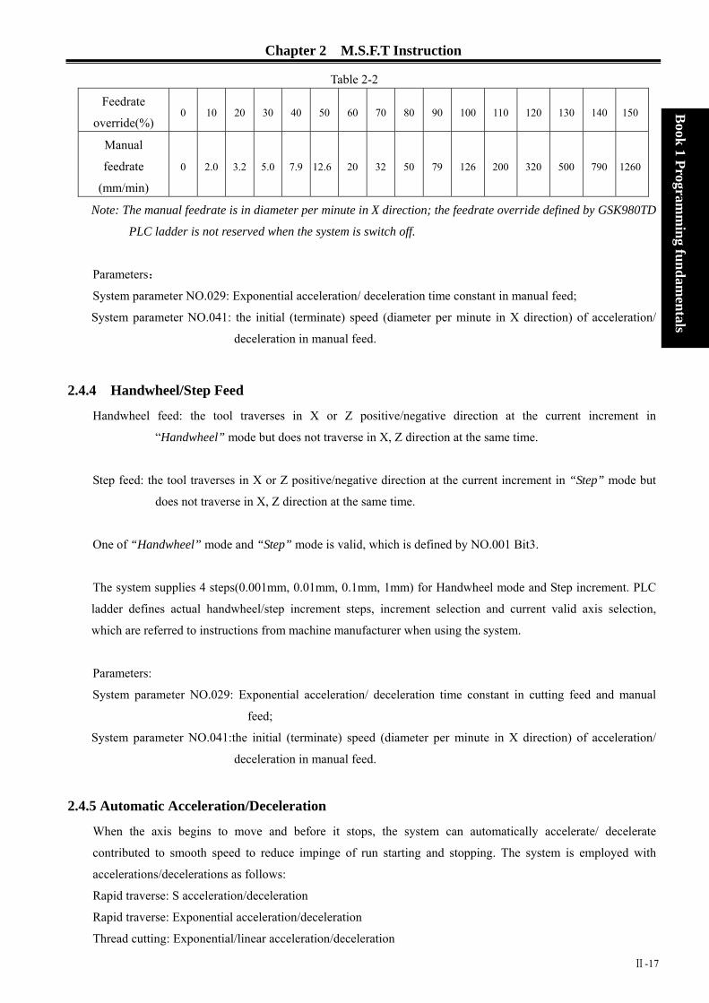
Chapter 2 M.S.F.T Instruction
Table 2-2
Feedrate
override(%) 0 10 20 30 40 50 60 70 80 90 100 110 120 130 140 150
Manual
feedrate
(mm/min)
0 2.0 3.2 5.0 7.9 12.6 20 32 50 79 126 200 320 500 790 1260
Book 1 Program
ming fundam
entals
Note: The manual feedrate is in diameter per minute in X direction; the feedrate override defined by GSK980TD
PLC ladder is not reserved when the system is switch off.
Parameters:
System parameter NO.029: Exponential acceleration/ deceleration time constant in manual feed;
System parameter NO.041: the initial (terminate) speed (diameter per minute in X direction) of acceleration/
deceleration in manual feed.
2.4.4 Handwheel/Step Feed
Handwheel feed: the tool traverses in X or Z positive/negative direction at the current increment in
“Handwheel” mode but does not traverse in X, Z direction at the same time.
Step feed: the tool traverses in X or Z positive/negative direction at the current increment in “Step” mode but
does not traverse in X, Z direction at the same time.
One of “Handwheel” mode and “Step” mode is valid, which is defined by NO.001 Bit3.
The system supplies 4 steps(0.001mm, 0.01mm, 0.1mm, 1mm) for Handwheel mode and Step increment. PLC
ladder defines actual handwheel/step increment steps, increment selection and current valid axis selection,
which are referred to instructions from machine manufacturer when using the system.
Parameters:
System parameter NO.029: Exponential acceleration/ deceleration time constant in cutting feed and manual
feed;
System parameter NO.041:the initial (terminate) speed (diameter per minute in X direction) of acceleration/
deceleration in manual feed.
2.4.5 Automatic Acceleration/Deceleration
When the axis begins to move and before it stops, the system can automatically accelerate/ decelerate
contributed to smooth speed to reduce impinge of run starting and stopping. The system is employed with
accelerations/decelerations as follows:
Rapid traverse: S acceleration/deceleration
Rapid traverse: Exponential acceleration/deceleration
Thread cutting: Exponential/linear acceleration/deceleration
Ⅱ-17
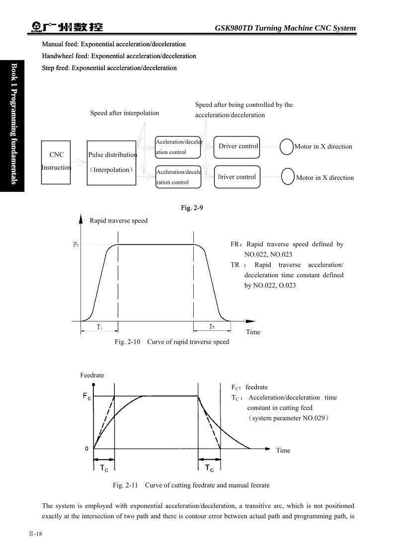
GSK980TD Turning Machine CNC System
Manual feed: Exponential acceleration/deceleration Manual feed: Exponential acceleration/deceleration
Handwheel feed: Exponential acceleration/deceleration Handwheel feed: Exponential acceleration/deceleration Book 1 Program
ming fundam
entals
k 1 Programm
ing fundamentals
Step feed: Exponential acceleration/deceleration Step feed: Exponential acceleration/deceleration
Speed after being controlled by the acceleration/deceleration Speed after interpolation
Motor in X direction CNC
Instruction
Pulse distribution
(Interpolation)
Aceleration/deceler
ation control
Aceleration/decele
ration control
Driver control
Driver control Motor in X direction
Fig. 2-9 Fig. 2-9
Rapid traverse speed
FR:Rapid traverse speed defined byNO.022, NO.023
TR : Rapid traverse acceleration/deceleration time constant definedby NO.022, O.023
TimeFig. 2-10 Curve of rapid traverse speed
Feedrate
FC:feedrate TC : Acceleration/deceleration time
constant in cutting feed (system parameter NO.029)
Time
Fig. 2-11 Curve of cutting feedrate and manual feerate
The system is employed with exponential acceleration/deceleration, a transitive arc, which is not positioned exactly at the intersection of two path and there is contour error between actual path and programming path, is
Ⅱ-18

Chapter 2 M.S.F.T Instruction
Book 1 Program
ming fundam
entalsok 1 Program
ming fundam
entals
formed at a path intersection of neighboring two blocks in cutting feed caused by acceleration/ deceleration when the system parameter NO.007 Bit3 is 0. To avoid the contour error, execute G04 in two blocks or set NO.007 Bit3 to 1. At this moment, the previous block runs and positions exactly to its end point with zero mm/min and then the system starts to execute the next block, which increases program’s running time and reduces machining efficiency.
formed at a path intersection of neighboring two blocks in cutting feed caused by acceleration/ deceleration when the system parameter NO.007 Bit3 is 0. To avoid the contour error, execute G04 in two blocks or set NO.007 Bit3 to 1. At this moment, the previous block runs and positions exactly to its end point with zero mm/min and then the system starts to execute the next block, which increases program’s running time and reduces machining efficiency.
The system executes the transition of program as Table 2-3 between neighboring blocks. The system executes the transition of program as Table 2-3 between neighboring blocks.
Table 2-3 Table 2-3 Previous block Previous block
Next block Next block Rapid positioning Rapid positioning Cutting feed Cutting feed No traversing No traversing
Rapid positioning X X X Cutting feed X O X No traversing X X X
Note: X: The next block can be executed after the previous block is exactly positioned on its end point. O: Acceleration/deceleration is employed for each axis between the neighboring blocks and there is a
transitive arc (it is not exactly positioned)in the intersection path.
Example:(NO.007 Bit3=0): G01 U-100;(Traverse in X negative direction)
W-200; (Traverse in Z negative direction)
Z
Actual motion path
Programming path
X Fi.g 2-12
Ⅱ-19

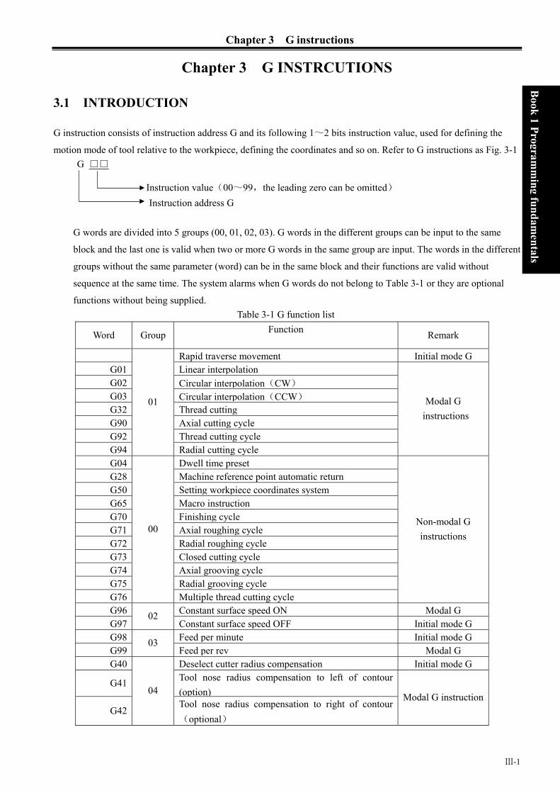
Chapter 3 G instructions
Ⅲ-1
Book 1 Program
ming fundam
entals B
ook 1 Programm
ing fundamentals
Chapter 3 G INSTRCUTIONS
3.1 INTRODUCTION
G instruction consists of instruction address G and its following 1~2 bits instruction value, used for defining the
motion mode of tool relative to the workpiece, defining the coordinates and so on. Refer to G instructions as Fig. 3-1 G □□
G words are divided into 5 groups (00, 01, 02, 03). G words in the different groups can be input to the same
block and the last one is valid when two or more G words in the same group are input. The words in the different
groups without the same parameter (word) can be in the same block and their functions are valid without
sequence at the same time. The system alarms when G words do not belong to Table 3-1 or they are optional
functions without being supplied. Table 3-1 G function list
Word Group Function Remark
Rapid traverse movement Initial mode G G01 Linear interpolationG02 Circular interpolation(CW)
G03 Circular interpolation(CCW)
G32 Thread cuttingG90 Axial cutting cycleG92 Thread cutting cycleG94
01
Radial cutting cycle
Modal G instructions
G04 Dwell time presetG28 Machine reference point automatic returnG50 Setting workpiece coordinates systemG65 Macro instructionG70 Finishing cycle G71 Axial roughing cycleG72 Radial roughing cycleG73 Closed cutting cycleG74 Axial grooving cycleG75 Radial grooving cycleG76
00
Multiple thread cutting cycle
Non-modal G instructions
G96 Constant surface speed ON Modal G G97
02 Constant surface speed OFF Initial mode G
G98 Feed per minute Initial mode G G99
03 Feed per rev Modal G
G40 Deselect cutter radius compensation Initial mode G
G41 Tool nose radius compensation to left of contour (option)
G42
04 Tool nose radius compensation to right of contour(optional)
Modal G instruction
Instruction value(00~99,the leading zero can be omitted) Instruction address G

GSK980TD Turning Machine CNC System
Ⅲ-2
Book 1 Program
ming fundam
entals
3.1.1 MODAL, NON-MODAL and INITIAL MODE
G instructions are divided into 5 groups (00, 01, 02, 03, 04). The instructions in the 00 group are non-modal and
ones in other groups are modal, and G00, G97, G98, G40 are initial mode.
After G instructions are executed, their defined functions and states are valid until they are changed by others in
the same group, which instructions are called modal G instructions. After the modal G words are executed, and
before their defined functions and states are changed, the G instruction cannot be input again when they are
executed by the following block.
The defined function and state are valid one time after G instruction is executed, and the G word must be input
again when it is executed every time, which instruction is called non-modal G instruction.
After the system is switched on, the valid modal G instructions which are not executed their functions or states
are called initial mode G instruction. Take it as the initial mode G instruction to be executed when it is not be
input after the system is switched on. The initial words of the system include G00, G40, G97, G98.
3.1.2 OMIT a WORD To simplify the programming, their instruction values are reserved after executing words in Table 3-2. If the words are contained in the previous blocks, they cannot be input when using the words with the same values and definitions in the following blocks.
Table 3-2 Instruction address
Function Initial value when power on
U Cutting depth in G71 NO.51 parameter value
U Move distance of tool retraction in X direction in G73
NO.53 parameter value
W Cutting depth in G72 NO.51 parameter value
W Move distance of tool retraction in Z direction in G73
NO.54 parameter value
R Move distance of tool retraction in G71, G72 cycle NO.52 parameter value
R Cycle times of stock removal in turning in G73 NO.55 parameter value
R Move distance of tool retraction after cutting in G74,G75
NO.56 parameter value
R Allowance of finishing in G76 NO.60 parameter value
R Taper in G90,G92,G94,G96 0
(G98)F Feed rate per minute(G98) NO.030 parameter value
(G99)F Feedrate per rev (G99) 0
F Metric pitch(G32,G92,G76) 0
I Inch pitch(G32,G92,) 0
S Spindle speed specified(G97) 0
S Spindle surface speed specified(G96) 0
S Spindle speed switching value output 0

Chapter 3 G instructions
Ⅲ-3
Book 1 Program
ming fundam
entals B
ook 1 Programm
ing fundamentals
Instruction address
Function Initial value when power on
P Finishing times of thread cutting in G76; Tool retraction width of thread cutting in G76; Angle of tool nose of thread cutting in G76;
NO.57 parameter value NO.19 parameter value NO.58 parameter value
Q Min. cutting value in G76 NO.59 parameter value
Note 1: For the instruction addresses with functions (such as F, used for feedrate per minute, feedrate per rev and metric pitch and so on), they can be omitted not to input when executing the same function to definite words after the words are executed. For example, after executing G98 F_ without executing the thread instruction, the pitch must be input with F word when machining metric thread;
Note 2:They can be omitted not to input when the address characters X(U), Z(W)are the coordinates of end point of block and the system defaults the current absolute coordinates in X or Z direction to the coordinate value of end point of block;
Note 3: The corresponding words must be input when the instruction addresses which are not in Table 3-2 are used.
Example 1: O0001;
G0 X100 Z100; (rapid traverse to X100 Z100; the modal G0 is valid)
X20 Z30; (rapid traverse to X20 Z30; the modal G0 is not input)
G1 X50 Z50 F300; (linear interpolation to X50 Z50, feedrate 300mm/min; the modal G1 is valid)
X100; (linear interpolation to X100 Z50, feedrate 300mm/min; Z coordinates is not input and
is the current coordinates Z50; F300 is kept, G1 is modal and is not input)
G0 X0 Z0; (rapid traverse to X0 Z0 and the modal G0 is valid)
M30;
Example 2:
O0002;
G0 X50 Z5; (rapid traverse to X50 Z5)
G04 X4; (dwell 4 seconds)
G04 X5; (dwell 5 seconds again, G04 is non-modal and is needed to input again)
M30;
Example 3(the first run after power on):
O0003; G98 F500 G01 X100 Z100; (Feedrate per minute 500mm/min in G98) G92 X50 W-20 F2 ; (F value is a pitch and must be input in thread cutting) G99 G01 U10 F0.01 (Feedrate per rev in G99 must be input again)
G00 X80 Z50 M30;

GSK980TD Turning Machine CNC System
Ⅲ-4
Book 1 Program
ming fundam
entals
3.1.3 RELATED DEFINITIONS In the user manual, the definitions of Word are as follows except for the especial explanations:
Starting point: position before the current block runs; End point: position after the current block ends; X: absolute coordinates of end point in X direction; U: different value of absolute coordinates between starting point and end point; Z: absolute coordinates of end point in Z direction; W: different value of absolute coordinates between starting point and end point; F: cutting feedrate.
3.2 RAPID TRAVERSE MOVEMENT G00
Instruction format::G00 X(U) Z(W) ;
Instruction function:X, Z axis rapidly traverses at the respective traverse speed to the end points from their
starting point. G00 is initial instruction as Fig.3-1.
X, Z axis traverses at the respective traverse speed, the short axis arrives the end
point and the length axis continuously moves to the end point and the compound path
maybe be not linear.
Instruction specification: G00 is initial mode;
Range of X, U, Z, W: -9999.999~+9999.999mm;
Can omit one or all instruction addresses X(U), Z(W). The coordinate values of starting point and end point are
the same when omitting one instruction address; the end point and the starting point are in the same position
when all are omitted. X, Z are valid, and U, W are invalid when X, U, Z and W are in the same one block.
Instruction path:
Fig. 3-1
The respective rapid traverse speed of X,Z axis is defined by the system parameter NO.022, NO.023, and their traverse speed can changed by rapid override key on the machine control panel.
Example: The tool rapidly traverses to B from A as Fig. 3-2.
Z axis
X axis

Chapter 3 G instructions
Ⅲ-5
Book 1 Program
ming fundam
entals B
ook 1 Programm
ing fundamentals
Fig. 3-2
G0 X20 Z25; (absolute programming)
G0 U-22 W-18; (incremental programming)
G0 X20 W-18; (compound programming)
G0 U-22 Z25; (compound programming)
3.3 LINEAR INTERPOLATION G01
Instruction format:G01 X(U)_ Z(W)_ F_;
Instruction function: the movement path is a straight line from starting point to end point as Fig.3-3.
Instruction specification: G01 is modal.
Range of X, U, Z, W: -9999.999~+9999.999mm;
Can omit one or all instruction addresses X(U), Z(W). The coordinate values of starting point and end point are the
same when omitting one instruction address; the end point and the starting point are in the same position when all
are omitted.
F instruction value is the compound speed of vector of instantaneous speed in X and Z direction and the actual
cutting feedrate is the product between the feedrate override and F instruction value.
After F instruction value is executed, it has been reserved unless the new one is executed. Do not repeat it when
the following G instructions adopt functions of F word.
Range of value as follows:
Instruction
function
G98(mm/min) G99(mm/rev)
Range 1~8000 0.001~500 Instruction path:
X axis
25
Z axis
11
A
B
18

GSK980TD Turning Machine CNC System
Ⅲ-6
Book 1 Program
ming fundam
entals
Example: Cutting path from Φ40 toΦ60 as follows:
3.4 CIRCULA
Instruction form
Instruction fun
Fig. 3-3
Program: G01 X60 Z7 F500; (Absolute programming)G01 U20 W-25; (Incremental programming)G01 X60 W-25; (Compound programming)G01 U20 Z7; (Compound programming)
End point Starting point
Starting pointEnd point
R INTERPOLAT
at : G02 X(U)__
G03
ction: G02 movement path
toolpost coord
G03 movem
counterclockw
point as Fig. 3
Fi.g 3-4
ION G02, G03
R__ Z(W)__ I__ K__
is clockwise(rear toolpost coordinate system/counterclockwise (front
inates system) arc from starting point to end point as Fig.3-5.
ent path is clockwise(rear toolpost coordinate system/
ise (front toolpost coordinates system) arc from starting point to end
.6.

Chapter 3 G instructions
Book 1 Program
ming fundam
entals B
ook 1 Programm
ing fundamentals
Instruction path :
Fig.3-5 G02 path Fig.3-6 G03 path
Instruction specification: G02, G03 are modal;
R:arc radius(0~9999.999mm);
I:difference value between circle center and starting point of arc in radius in X direction(-9999.999~
9999.999mm);
K:difference value between circle center and starting point of arc in Z direction(-9999.999~9999.999mm);
Center point of arc is specified by address I, K which separately corresponds to amount(increment) of vector from
starting point to center point of arc in X, Z direction as Fig. 3-6-1.
I=Coordinates of center point-that of starting point in X direction; K= Coordinates of center point-that of starting
point in Z direction;
I, K are with sign symbol, directions of I, K are the same those of X, Z axis.
Arc direction: G02/G03 direction (clock
system and the rear one a
X
X a x i s
Z a x i s
U / 2
K
W
Starting pint of arc
End point of
arc
Z
I
End point of arc
X
U/2
X axis
K
I
Z axis
ZW
R
Start
ing poin
t of arc
End point
Starting point
Ⅲ-7
wise/counterclockwise)is opposite on the front toolpost coordinate
s Fig.3-7:
Fig. 3-6-1

GSK980TD Turning Machine CNC System
Ⅲ-8
Book 1 Program
ming fundam
entals
Cautions:
When I = 0 or K = 0, they can be om
R is valid and I, K are invalid when
R value must be equal to or more th
end point is not on the arc defined b Omit all or one of X(U), Z(W); c
omitting ones, the path is a full circl
(0°)when center point is specifi
R should be used for programming
point of arc path are the specified on
When the distance from center poin
system automatically adjusts positio
specified ones; when the distance fr
Arc path can be more than and less t
negative, and it is less than or equal
Example: Arc cutting path fromΦ45
X
X
X
itted; one of I, K or R must be input, oth
they are input at the same time;
an half distance from starting point to en
y R instruction; oordinates of starting point and end po
e(360°) in G02/G03 when center po
ed by R.
. The system executes in R= 2 KI +
es in I,K programming.
t to end point is not equal to R(R=
n of center point to ensure starting poi
om center point to end point is more than
han 180°when R is commanded, the ar
to 180°when R is positive.
.25 toΦ63.06 as Fig. 3-8.
Fig. 3-7
Z
Z
Z
X
erwise the sy
d point, and
int of this a
int are specif
2 to ensure
22 KI + ) in
nt and end p
2R, and the
c is more tha
Z
stem alarms.
the system alarms if the
xis are the same when
ied by I,K; the path is 0
starting point and end
I,K programming, the
oint of arc path are the
system alarms.
n180°when R is
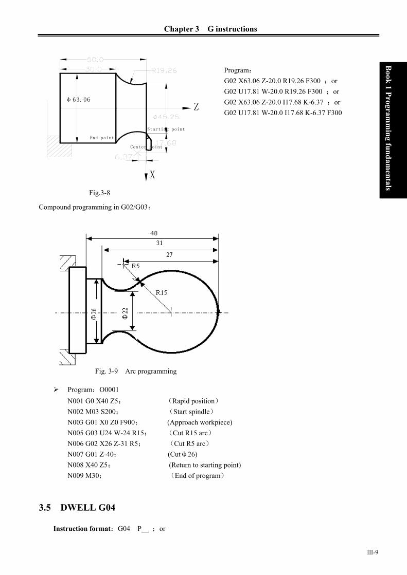
Chapter 3 G instructions
Book 1 Program
ming fundam
entals B
ook 1 Programm
ing fundamentals
φ63.06
X
Z
Starting point
Center point
End point
Compound programming in G02/G03:
ProN0N0N0N0N0N0N0N0
3.5 DW
Instruct
Fig.3-8
Program: G02 X63.06 Z-20.0 R19.26 F300 ;or G02 U17.81 W-20.0 R19.26 F300 ;or G02 X63.06 Z-20.0 I17.68 K-6.37 ;or G02 U17.81 W-20.0 I17.68 K-6.37 F300
Fig. 3-9 Arc programming
Ⅲ-9
gram:O0001 01 G0 X40 Z5; (Rapid position) 02 M03 S200; (Start spindle) 03 G01 X0 Z0 F900; (Approach workpiece) 05 G03 U24 W-24 R15; (Cut R15 arc) 06 G02 X26 Z-31 R5; (Cut R5 arc) 07 G01 Z-40; (Cutф26) 08 X40 Z5; (Return to starting point) 09 M30; (End of program)
ELL G04
ion format:G04 P__ ;or

GSK980TD Turning Machine CNC System
Ⅲ-10
Book 1 Program
ming fundam
entals
G04 X__ ;or
G04 U__ ;or
G04;
Instruction function: X and Z axis stop, the modal of G instructions and the reserved data, state are not
changed, and execute the next block after dwelling the defined time.
Instruction specification: G04 is non-modal.
The dwell time is defined by the word P__,X__ or U__.
Range of P, X, U: 0.001~99999.999 seconds.
Time of P__, X__ or U__ is as follows:
Table 3-3
Instruction
address
P U X
Unit 0.001 second Second Second
Cautions: The system exactly stop a block when P, X, U are not input or P, X , U specify negative values. P is valid when P, X, U are in the same block; X is valid when X, U are in the same block. When the system executes the feed hold in G04, dwell can be executed after the current delay time.
3.6 MACHINE REFERNCE POINT RETURN G28
Instruction format:G28 X(U) Z(W) ;
Instruction function: the tool rapid traverses to the middle point defined by X(U), Z(W) from starting point and
then return to reference point of machine.
Instruction specifications:
G28 is no-modal.
X:absolute coordinates of middle point in X direction;
U:Difference value of absolute coordinates between middle point and starting point in X direction;
Z:absolute coordinates of middle point in Z direction;
W:Difference value of absolute coordinates between middle point and starting point in Z direction.
Can omit all or one of X(U), Z(W) as follows:
Table 3-4
Instruction Function
G28 X(U) Return to machine reference point in X
direction and remain in previous position in Z
direction
G28 Z(W) Return to machine reference point in Z direction
and remain in previous position in X direction

Chapter 3 G instructions
Book 1 Program
ming fundam
entals B
ook 1 Programm
ing fundamentals
Instruction Function
G28 X, Z axis are in the previous positions and
continuously execute nest block
G28 X(U) Z(W) Return to machine reference point in X, Z
direction
Running path(as Fig. 3-10): (1)Rapid traverse to middle point of specified axis from current position(A point→B point);
(2)Rapid traverse to reference point from the middle point(B point→R point);
(3) If the machine is not locked, LED is ON when the machine reference point return is completed.
Z
X
Middle point
B(X,Z)
Machine reference
point R
Starting
point A
Note 1: Machine reference point retu
and signals per rev must be de
Note 2: X and Z axis move at the resp
is not always a straight line.
Note 3: The system cancels the tool l
return of machine;
Note 4: Do not execute G28 and mac
machine.
3.7 WORKPIECE COORD
Instruction format:G50 X(U)
Instruction function: define the abs
system(call
current pos
position as
reference p
workpiece c
system unti
F
Ⅲ-11
rns in Jog mode and in G28 are the same and their deceleration signals
tected;
ectively rapid traverse speed from A to B and from B to R, and so the path
ength compensation after executing G28 to perform the reference point
hine reference point return without the reference point signal on the
INATE SYSTEM G50
Z(W) ;
olute coordinates of current position and create the workpiece coordinates
ed floating coordinates system) by setting the absolute coordinates of
ition in the system. After executing G50, the system takes the current
reference point of program (program reference point) and returns to the
oint after executing the reference point return of program. After the
oordinate system is created, input the coordinate values in the coordinate
l the next workpiece coordinate system is created again when executing the
ig.3-10
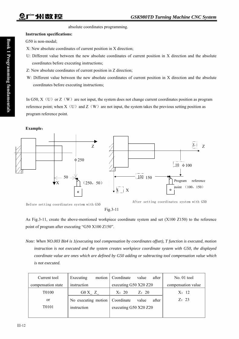
GSK980TD Turning Machine CNC System
Ⅲ-12
Book 1 Program
ming fundam
entals
absolute coordinates programming.
Instruction specifications:
G50 is non-modal;
X: New absolute coordinates of current position in X direction;
U: Different value between the new absolute coordinates of current position in X direction and the absolute
coordinates before executing instructions;
Z: New absolute coordinates of current position in Z direction;
W: Different value between the new absolute coordinates of current position in X direction and the absolute
coordinates before executing instructions;
In G50, X(U)or Z(W)are not input, the system does not change current coordinates position as program
reference point; when X(U)and Z(W)are not input, the system takes the previous setting position as
program reference point.
Example:
As Fig.3-11, create the above-mentioned workpiece coordinate system and set (X100 Z150) to the reference
point of program after executing “G50 X100 Z150”.
Note: When NO.003 Bit4 is 1(executing tool compensation by coordinates offset), T function is executed, motion
instruction is not executed and the system creates workpiece coordinate system with G50, the displayed
coordinate value are ones which are defined by G50 adding or subtracting tool compensation value which
is not executed.
Current tool
compensation state
Executing motion
instruction
Coordinate value after
executing G50 X20 Z20
No. 01 tool
compensation value
G0 X Z X:20 Z:20 T0100
or
T0101 No executing motion
instruction
Coordinate value after
executing G50 X20 Z20
X:12
Z:23
Fig.3-11
After setting coordinates system with G50Before setting coordinates system with G50
Program reference
point (100,150) X
φ100
150
Z
(250,50)
X
150
X
Z
50
φ250

Chapter 3 G instructions
Ⅲ-13
Book 1 Program
ming fundam
entals B
ook 1 Programm
ing fundamentals
※※※ X:8 Z:-3
or
X:32 Z:43
3.8 FIXED CYCLE INSTRUCTIONS
To simplify programming, the system defines G instruction of single machining cycle with one block to complete the
rapid traverse to position, linear/thread cutting and rapid traverse to return to the starting point:
G90: axial cutting cycle;
G92: thread cutting cycle;
G94: radial cutting cycle;
G92 will be introduced in Section Thread Function
3.8.1 AXIAL CUTTING CYCLE G90
Instruction format:G90 X(U)__ Z(W)__ F__; (cylinder cutting)
G90 X(U)__ Z(W)__ R__ F__;(taper cutting)
Instruction function: From starting point, the cutting cycle of cylindrical surface or taper surface is completed by
radial feeding(X axis) and axial(Z axis or X and Z) cutting.
Instruction specifications:
G90 is modal;
Starting point of cutting:starting position of linear interpolation(cutting feed)
End point of cutting: end position of linear interpolation(cutting feed)
X:absolute coordinates of cutting end point in X direction
U:different value of absolute coordinates between end point and starting point of cutting in X direction
Z:different value of absolute coordinates between end point and starting point of cutting in Z direction
W:different value of absolute coordinates between end point and starting point of cutting in Z direction
R:different value (radius value) of absolute coordinates between end point and start point of cutting in X
direction. When the signs of R is not the same that of U, R│≤│U/2│
Cycle process:
① The tool rapidly traverses from starting point to cutting starting point in X direction;
② Cutting feed(linear interpolation) from the cutting starting point to cutting end point;
③ Retract the tool at feedrate in X direction (opposite direction to the above-mentioned ①), and return to the
position which the absolute coordinates and the starting point are the same;
④ The tool rapidly traverses to return to the starting point and the cycle is completed.

GSK980TD Turning Machine CNC System
Ⅲ-14
Book 1 Program
ming fundam
entals
Z
X
Z W
3(F)
4(R)
2(F)R
1(R)
X axis
Fig.3-13
Fig.3-12
U/2
X/2
Z axis

Chapter 3 G instructions
Book 1 Program
ming fundam
entals B
ook 1 Programm
ing fundamentals
Cutting path: Relative position between cutting end point and starting point with U,W is as Fig.3-14:
Example:Fig. 3-15,rod Φ125×110
Φ120
U/2 ③
X
3) U>0,W>0,R<0 、│R│≤│U/2│ 4) U<0,W>0,R>0、│R│≤│U/2│
④
R
W
U/2③
②
①
Z
X
R
W
U/2
②
①
④
③
Z
F
Fig.3-15
X
1) U>0,W<0,R>0 2) U<0,W<0,R<0
W
①
②
④ R
W Z Z
X
①
②
③
④
U/2
R
Φ60
ig. 3-14
Ⅲ-15
axis

GSK980TD Turning Machine CNC System
Ⅲ-16
Book 1 Program
ming fundam
entals
Program :O0002; M3 S300 G0 X130 Z3; G90 X120 Z-110 F200; (A→D,cut Φ120) X110 Z-30; X100; X90; X80; X70; X60; G0 X120 Z-30; G90 X120 Z-44 R-7.5 F150; Z-56 R-15 Z-68 R-22.5 Z-80 R-30 M30;
3.8.2 RADIAL CUTTING CYCLE G94
Instruction format:G94 X(U)__ Z(W)__ F__; (face cutting)
G94 X(U)__ Z(W)__ R__ F__;(taper face cutting)
Instruction function: From starting point, the cutting cycle of cylindrical surface or taper surface is completed
by radial feeding(X axis) and axial(Z axis or X and Z) cutting.
Instruction specifications:
G94 is modal;
Starting point of cutting: starting position of linear interpolation(cutting feed).Unit:mm;
End point of cutting: end position of linear interpolation(cutting feed) Unit:mm;
X:absolute coordinates of end point of cutting in X direction Unit:mm;
U:different value of absolute coordinates from end point to starting point of cutting in X direction, Unit:mm;
Z:absolute coordinates of end point of cutting in Z direction, Unit:mm;
W:different value of absolute coordinates from end point to starting point of cutting in X direction, Unit:mm;
R:different value(R value) of absolute coordinates from end point to starting point of cutting in X direction.
When the sign of R is not the same that of U, R, │R│≤│W│.
Radial linear cutting is as Fig. 3-16, radial taper cutting is as Fig. 3-17, Unit:mm
Cycle process:
① The tool rapidly traverses from starting point to cutting starting point in Z direction;
② Cutting feed (linear interpolation) from the cutting starting point to cutting end point;
③ Retract the tool at the cutting feedrate in Z direction (opposite direction to the above-mentioned ①), and
return to the position which the absolute coordinates and the starting point are the same;
④ The tool rapidly traverses to return to the starting point and the cycle is completed.
( A → B , 6 times cutting cycleΦ60,increment of 10mm)
(B→C,4 times taper cutting)

Chapter 3 G instructions
Ⅲ-17
Book 1 Program
ming fundam
entals B
ook 1 Programm
ing fundamentals
Fig.3-17
Rapid traverse Cutting feed A:Starting point(end point)B:Cutting starting point C:Cutting end point
Fig.3-16

GSK980TD Turning Machine CNC System
Ⅲ-18
Book 1 Program
ming fundam
entals
Cutting path: Relative position between cutting end point and starting point with U,W is as Fig.3-18:
Fig. 3-18
Example:Fig. 3-19,rod Φ125×112
Φ120 Φ
60
axis
axis
1) U>0 W<0 R<0 2) U<0 W<0 R<0
R
W
U/2
①
②
③
④
R
W
U/2
①
②
③
④
Z
X
Z
X
(3)U>0 W>0 R<0 (│R│≤│W│) 4)U<0 W>0 R<0 (│R│≤│W│)
R
U/2
①
②
③
④
R
U/2
W
W
Z
X
Z
X
①
②
③
④
Fig.3-19

Chapter 3 G instructions
Ⅲ-19
Book 1 Program
ming fundam
entals B
ook 1 Programm
ing fundamentals
Program:O0003;
G00 X130 Z5 M3 S1;
G94 X0 Z0 F200 Face cutting
X120 Z-110 F300;
G00 X120 Z0
G94 X108 Z-30 R-10
X96 R-20
X84 R-30
X72 R-40
X60 R-50;
M30;
3.8.3 CAUTIONS OF FIXED CYCLE INSTRUCTIONS 1)After X(U), Z(W), R are executed in the canned cycle instruction, their instruction values are value if X
(U),Z(W),R are not redefined by executing a new canned cycle instructions. The instruction values of X(U),Z(W),R are cleared if non-modal G instruction(00 Group) except for G04 or G00, G01,G02, G03, G32 is executed.
2)In MDI mode, the previous canned cycle can be executed by pressing the cycle start key after the canned
cycle is completed.
3)One cycle cannot be executed repetitively in G90~G94 when the next block of G90~G94 is M, S, T
instruction; the previous cycle is executed repetitively in G90~G94 when the next block is ended( EOB;).
Example: … N010 G90 X20.0 Z10.0 F400; N011 ; (executed G90 one time repetitively )
… 4)Pause or single block is executed in G90, G94, the single block stops after the tool moves end point of current
path.
3.9 MULTIPLE CYCLE INSTRUCTIONS
Multiple cycle instructions of the system includes axial roughing cycle G71, radial roughing cycle G72, closed
cutting cycle G73, finishing cycle G70, axial grooving multiple cycle G74, axial grooving multiple cycle G75 and
multiple thread cutting cycle G76. When the system executes these instructions, it automatically counts the cutting
times and the cutting path according to the programmed path, travels of tool infeed and tool retraction, executes
multiple machining cycle(tool infeed →cutting→retract tool→tool infeed ), automatically completes the roughing,
finishing workpiece and the starting point and the end point of instruction are the same one.
3.9.1 AXIAL ROUGHING CYCLE G71 Instruction format:G71 U(∆d) R(e) F S T ; ⑴
G71 P(ns) Q(nf) U(∆u) W(∆w); ⑵
(Outer cutting Φ120)
(C→B→A,cutting Φ60)

GSK980TD Turning Machine CNC System
Ⅲ-20
Book 1 Program
ming fundam
entals
N(ns) .....; ........;
....F; ....S; .... ⑶ ·
N(nf).....;
Instruction function: G71 is divided into three parts:
⑴:1st blocks for defining the travels of tool infeed and retract tool, the cutting feedrate, the spindle speed and
the tool function when roughing; ⑵:2nd blocks for defining the block interval, finishing allowance;
⑶:3rd blocks for some continuous finishing path, counting the roughing path without being executed actually
when executing G71. According to the finishing path, the finishing allowance, the path of tool infeed and tool retract, the system automatically counts the path of roughing,the tool cuts the workpiece in paralleling with Z axis, and the roughing is completed by multiple executing the cutting cycle tool infeed→cutting→tool retraction. The starting point and the end point are the same one. The instruction is applied to the formed roughing of non-formed rod.
Relevant definitions:
Finishing path: the above-mentioned Part 3 of G71(ns~nf block)defines the finishing path, and the starting
point of finishing path (starting point of ns block)is the same these of starting point and end
point of G71, called A point; the first block of finishing path(ns block)is used for X rapid
traversing or tool infeed, and the end point of finishing path is called to B point; the end point
of finishing path(end point of nf block)is called to C point. The finishing path is A→B→C.
Roughing path: The finishing path is the one after offsetting the finishing allowance(∆u,∆w)and is the path
contour formed by executing G71. A, B, C point of finishing path after offset corresponds
separately to A’,B’,C’point of roughing path, and the final continuous cutting path of G71 is
B’→C’point.
∆d:it is each travel(unit:mm,radius value)of tool infeed without in X direction when roughing, and the
direction of tool infeed is defined by move direction of ns block. The instruction value ∆d is reserved
after executing U(∆d)and the value of system parameter NO.051 is rewritten to ∆d×1000(unit:0.001
mm). The value of system parameter NO.051 is regarded as the travel of tool infeed when U(∆d)is not
input.
e: it is each travel(unit:mm,radius value)of tool infeed without in X direction when roughing, and the
direction of tool retraction is opposite to that of tool infeed, the instruction value e is reserved and the value
of system parameter NO.052 is rewritten to e×1000(unit:0.001 mm)after R(e)is executed. The value of
system parameter NO.052 is regarded as the travel of tool retraction when R(e)is not input.

Chapter 3 G instructions
Ⅲ-21
Book 1 Program
ming fundam
entals B
ook 1 Programm
ing fundamentals
ns: Block number of the first block of finishing path.
nf: Block number of the last block of finishing path.
∆u:finishing allowance in X direction is -99.999~99.999 (unit: mm in diameter). the coordinates offset in X
direction of roughing path compared to finishing path, i.e. the different value of absolute coordinates in X
direction between A’and A. The system defaults ∆u=0 when U(∆u) is not input, i.e. there is no finishing
allowance in X direction for roughing cycle.
∆w:finishing allowance in Z direction is -99.999~99.999 with sign symbol (unit: mm in diameter). the
coordinates offset in Z direction of roughing path compared to finishing path, i.e. the different value of
absolute coordinates in Z direction between A’and A. The system defaults ∆w=0 when W(∆w) is not
input, i.e. there is no finishing allowance in Z direction for roughing cycle.
F: Feedrate; S: Spindle speed; T: Tool number, tool offset number.
M, S, T, F: They can be specified in the first G71 or the second ones or program ns~nf. M, S, T, F functions of M, S,
T, F blocks are invalid in G71, and they are valid in G70 finishing blocks.
Execution process:(Fig. 3-20)
① Rapid traverse to A’ from A point, the travel in X direction is ∆u, and the travel in Z direction is ∆w
② The travel in X direction from A’is ∆d( tool infeed), ns block is for tool infeed at rapid traverse speed with
G0, is for tool infeed at feedrate F with G71, and its direction of tool infeed is that of A→B point;
③ Cutting feeds to the roughing path in Z direction, and its direction is the same that of coordinates in Z
direction A→B point;
④ The travel of tool retraction is e (45°straight line)at feedrate in X, Z direction, the directions of tool
retraction is opposite to that of too infeed;
⑤ Rapid retract at rapid traverse speed in Z direction to the position which is the same that of the coordinates
in Z direction;
⑥ After executing the tool infeed (∆d+e)again in X direction, the end point of traversing tool is still on the
middle point of straight line between A’and B’(the tool does not reach or exceed B’), and after executing
the tool infeed (∆d+e)again, execute ③;after executing the tool infeed (∆d+e)again, the end point of tool
traversing reaches B’point or exceeds the straight line between A’→B’point and execute the tool infeed to
B’point in X direction and the execute the next step;
⑦ Cutting feed from B’to C’point along the roughing path;
⑧ Rapid traverse to A from C’point and the program jumps to the next clock following nf block after G71
cycle is ended.
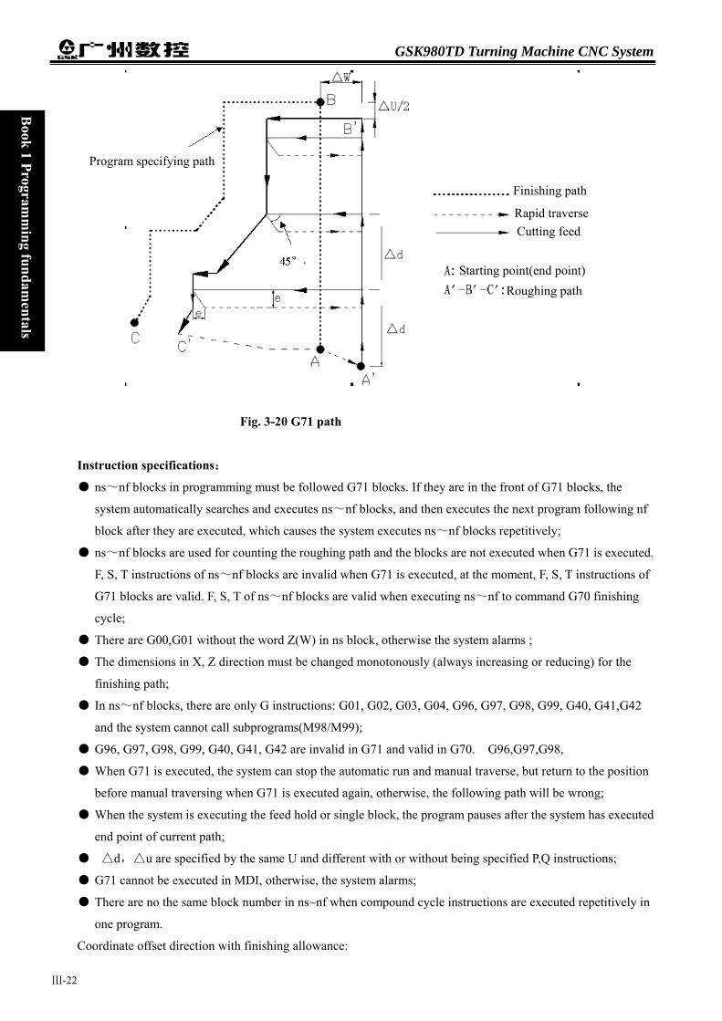
GSK980TD Turning Machine CNC System
Ⅲ-22
Book 1 Program
ming fundam
entals
Fig. 3-20 G71 path
Instruction specifications:
● ns~nf blocks in programming must be followed G71 blocks. If they are in the front of G71 blocks, the
system automatically searches and executes ns~nf blocks, and then executes the next program following nf
block after they are executed, which causes the system executes ns~nf blocks repetitively;
● ns~nf blocks are used for counting the roughing path and the blocks are not executed when G71 is executed.
F, S, T instructions of ns~nf blocks are invalid when G71 is executed, at the moment, F, S, T instructions of
G71 blocks are valid. F, S, T of ns~nf blocks are valid when executing ns~nf to command G70 finishing
cycle;
● There are G00,G01 without the word Z(W) in ns block, otherwise the system alarms ;
● The dimensions in X, Z direction must be changed monotonously (always increasing or reducing) for the
finishing path;
● In ns~nf blocks, there are only G instructions: G01, G02, G03, G04, G96, G97, G98, G99, G40, G41,G42
and the system cannot call subprograms(M98/M99);
● G96, G97, G98, G99, G40, G41, G42 are invalid in G71 and valid in G70. G96,G97,G98,
● When G71 is executed, the system can stop the automatic run and manual traverse, but return to the position
before manual traversing when G71 is executed again, otherwise, the following path will be wrong;
● When the system is executing the feed hold or single block, the program pauses after the system has executed
end point of current path;
● △d,△u are specified by the same U and different with or without being specified P,Q instructions;
● G71 cannot be executed in MDI, otherwise, the system alarms;
● There are no the same block number in ns~nf when compound cycle instructions are executed repetitively in
one program.
Coordinate offset direction with finishing allowance:
Finishing path
Rapid traverse
Roughing path Starting point(end point)
Cutting feed
Program specifying path

Chapter 3 G instructions
Book 1 Program
ming fundam
entals B
ook 1 Programm
ing fundamentals
∆u,∆w define the coordinates offset and its direction of finishing, and their sign symbols are as follows Fig. 3-21:
B→C for finishing path, B’→C’for roughing path and A is the starting point.
E
Example:Fig.3-22
ed
Program:O0004; G00 X200 Z10 M3 S800; G71 U2 R1 F200; G71 P80 Q120 U0.5 W0.2;
Fig.
1
Fig.3-2Ⅲ-23
cb a
0.5
2Starting point
(200,10)
(Spindle clockwise with 800 rev/min) (Cutting depth each time 4mm,tool retraction [in diameter]) (roughing a---e,machining allowance 0.5mm in X direction,
3-22

GSK980TD Turning Machine CNC System
Ⅲ-24
Book 1 Program
ming fundam
entals
0.2mm in Z direction)
N80 G00 X40 S1200; (Positioning)
G01 Z-30 F100 ; (a→b)
X60 W-30; (b→c) a→b→c→d→e blocks for finishing path W-20; (c→d) N120 X100 W-10; (d→e) G70 P80 Q120; (a---e blocks for finishing path)
M30; (End of block)
3.9.2 RADIAL ROUGHTING CYCLE G72 Instruction format: G72 W(∆d) R(e) F S T ; ⑴
G72 P(ns) Q(nf) U(∆u) W(∆w); ⑵ N (ns) .....;
........; ....F; ....S; ....; ⑶ ·
N (nf).....;
Instruction function:G72 is divided into three parts:
⑴ 1st blocks for defining the travels of tool infeed and tool retraction, the cutting speed, the spindle speed and
the tool function when roughing;
⑵ 2nd blocks for defining the block interval, finishing allowance;
⑶ 3rd blocks for some continuous finishing path, counting the roughing path without being executed actually when executing G72.
According to the finishing path, the finishing allowance, the path of tool infeed and retract tool, the system automatically counts the path of roughing,the tool cuts the workpiece in paralleling with Z axis, and the roughing is completed by multiple executing the cutting cycle tool infeed→cutting feed→tool retraction. The starting point and the end point of G72 are the same one. The instruction is applied to the formed roughing of non-formed rod.
Relevant definitions:
Finishing path: the above-mentioned Part⑶ of G71(ns~nf block)defines the finishing path, and the starting
point of finishing path (i.e. starting point of ns block)is the same these of starting point and
end point of G72, called A point; the first block of finishing path(ns block)is used for Z rapid
traversing or cutting feed, and the end point of finishing path is called to B point; the end
point of finishing path(end point of nf block)is called to C point. The finishing path is A→B
→C.
Roughing path: The finishing path is the one after offsetting the finishing allowance(∆u,∆w)and is the path
contour formed by executing G72. A, B, C point of finishing path after offset corresponds

Chapter 3 G instructions
Ⅲ-25
Book 1 Program
ming fundam
entals B
ook 1 Programm
ing fundamentals
separately to A’,B’,C’point of roughing path, and the final continuous cutting path of G72 is B’
→C’point.
∆d:it is each travel(unit:mm,)of tool infeed without in Z direction when roughing, and the direction of tool infeed
is defined by move direction of ns block. The instruction value ∆d is reserved after executing U(∆d)and the
value of system parameter NO.051 is rewritten to ∆d×1000(unit:0.001 mm). The value of system parameter
NO.051 is regarded as the travel of tool infeed when U(∆d)is not input.
e: it is each travel(unit:mm)of tool infeed without in Z direction when roughing, and the direction of tool
retraction is opposite to that of tool infeed, the instruction value e is reserved and the value of system parameter
NO.052 is rewritten to e×1000(unit:0.001 mm)after R(e)is executed. The value of system parameter NO.052
is regarded as the travel of tool retraction when R(e)is not input.
ns: Block number of the first block of finishing path.
nf: Block number of the last block of finishing path.
∆u:finishing allowance in X direction when roughing( the coordinates offset in X direction of roughing path
compared to finishing path, i.e. the different value of absolute coordinates in X direction between A’and A,
unit: mm).
∆w:finishing allowance in Z direction when roughing( the coordinates offset in Z direction of roughing path
compared to finishing path, i.e. the different value of absolute coordinates in X direction between A’and A,
unit: mm).
F: Cutting feedrate; S: Spindle speed; T: Tool number, tool offset number.
M, S, T, F: They can be specified in the first G72 or the second ones or program ns~nf. M, S, T, F functions of M,
S, T, F blocks are invalid in G72, and they are valid in G70 finishing blocks.
Execution process : Fig. 3-23
○1 Rapid traverse to A’from A point, the travel in X direction is ∆u, and the travel in Z direction is ∆w;
○2 The travel in Z direction from A’is ∆d( tool infeed), ns block is for tool infeed at rapid traverse
speed with G0, is for tool infeed at G72feedrate F in G1, and its direction of tool infeed is that of A
→B point;
○3 Cutting feeds to the roughing path in X direction, and its direction is the same that of coordinates in
X direction B→C point;
○4 The travel of tool retraction is e (45°straight line)at feedrate in X, Z direction, the directions of tool
retraction is opposite to that of tool infeed ;
○5 Rapidly retract at rapid traverse speed in X direction to the position which is the same that of the
coordinates in Z direction ;
○6 After executing the tool infeed (∆d+e)again in Z direction, the end point of traversing tool is still on
the middle point of straight line between A’and B’(the tool does not reach or exceed B’), and after
executing the tool infeed (∆d+e)again, execute ③;after executing the tool infeed (∆d+e)again, the
end point of tool traversing reaches B’point or exceeds the straight line between A’→B’point and
execute the tool infeed to B’point in Z direction and the execute the next step;
○7 Cutting feed from B’to C’point along the roughing path;

GSK980TD Turning Machine CNC System
Ⅲ-26
Book 1 Program
ming fundam
entals
○8 Rapidly traverse to A from C’point and the program jumps to the next clock following nf block after
G71 cycle is completed.
Fig. 3-23
Instruction specifications:
● ns~nf blocks in programming must be followed G72 blocks. If they are in the fron
system automatically searches and executes ns~nf blocks, and then executes the n
block after they are executed, which causes the system executes ns~nf blocks repe
● ns~nf blocks are used for counting the roughing path and the blocks are not execu
F, S, T instructions of ns~nf blocks are invalid when G72 is executed, at the mome
G72 blocks are valid. F, S, T of ns~nf blocks are valid when executing ns~nf to c
cycle;
● There are G00,G01 without the word X(U) in ns block, otherwise the system alarm
● The dimensions in X, Z direction must be changed monotonously (always increasin
finishing path;
● In ns~nf blocks, there are only G instructions: G01, G02, G03, G04, G96, G97, G9
and the system cannot call subprograms(M98/M99);
● G96, G97, G98, G99, G40, G41, G42 are invalid in G71 and valid in G70;G96,G97
● When G72 is executed, the system can stop the automatic run and manual traverse,
before manual traversing when G72 is executed again, otherwise, the following pat
● When the system is executing the feed hold or single block, the program pauses afte
end point of current path;
● △d,△u are specified by the same U and different with or without being specified
● There are no the same block number in ns~nf when compound cycle instructions ar
one program;
Program specifying path
Finishing path
Rapid traverse
Starting poinR
Cutting feed
t(end point)
t of G72 blocks, the
ext program following nf
titively.
ted when G72 is executed.
nt, F, S, T instructions of
ommand G70 finishing
s.
g or reducing) for the
8, G99, G40, G41,G42
,G98,
but return to the position
h will be wrong;
r the system has executed
P,Q instructions;
e executed repetitively in
oughing path

Chapter 3 G instructions
Book 1 Program
ming fundam
entals B
ook 1 Programm
ing fundamentals
● G72 cannot be executed in MDI, otherwise, the system alarms.
Coordinate offset direction with finishing allowance:
Coordinate offset direction with finishing allowance:
∆u,∆w define the coordinates offset and its direction of finishing, and their sign symbols are as follows Fig.
3-24: B→C for finishing path, B’→C’for roughing path and A is the starting point.
Example:Fig.3-25
φφφ
起点
( 176, 10)
Program:O0005;
G00 X176 Z10 M03 S500
G72 W2.0 R0.5 F300;
G72 P10 Q20 U0.2 W0.1;
F
Starting point
Ⅲ-27
(Change No.2 tool and execute its compensation,
spindle rotation with 500 rev/min)
(Tool infeed 2mm, tool retraction 2mm)
(Roughing a--d,roughing allowance 0.2mm in X
direction and 0.1mm in Z direction)
ig.3-25
GSK980TD Turning Machine CNC System
Ⅲ-28
Book 1 Program
ming fundam
entals
N10 G00 Z-55 S800 ; (Rapid traverse)
G01 X160 F120; (Infeed to a point)
X80 W20; (Machining a—b) Blocks for finishing path
W15; (Machining b—c)
N20 X40 W20 ; (Machining c—d)
G70 P050 Q090 M30; (Finishing a—d)
3.9.3 CLOSED CUTTING CYCLE G73
Instruction format:G73 U(Δi) W (Δk) R (d) F S T ; ⑴ G73 P(ns) Q(nf) U(Δu) W(Δw); ⑵ N (ns) .....; .......; ....F; ....S; ....; ⑶
·
N (nf).....;
Instruction functions: G73 is divided into three parts:
⑴ blocks for defining the travels of tool infeed and tool retraction, the cutting speed, the spindle speed and the
tool function when roughing;
⑵ blocks for defining the block interval, finishing allowance;
⑶ blocks for some continuous finishing path, counting the roughing path without being executed actually
when executing G73.
According to the finishing allowance, the travel of tool retraction and the cutting times, the system
automatically counts the travel of roughing offset,the travel of each tool infeed and the path of roughing, the
path of each cutting is the offset travel of finishing path, the cutting path approaches gradually the finishing
one, and last cutting path is the finishing one according to the finishing allowance. The starting point and end
point of G73 are the same one, and G73 is applied to roughing for the formed rod. G73 is non-modal and its
path is as Fig.3-26.
Relevant definitions: Finishing path: the above-mentioned Part 3 of G73(ns~nf block)defines the finishing path, and the starting
point of finishing path (start point of ns block)is the same these of starting point and end point
of G73, called A point; the end point of the first block of finishing path(ns block)is called B
point; the end point of finishing path(end point of nf block)is called C point. The finishing
path is A→B→C.
Roughing path: It is one group of offset path of finishing one, and the roughing path times are the same that of
cutting. After the coordinates offset, A,B,C of finishing path separately corresponds to An,Bn,Cn of
Chapter 3 G instructions
Ⅲ-29
Book 1 Program
ming fundam
entals B
ook 1 Programm
ing fundamentals
roughing path(n is the cutting times, the first cutting path is A1,B1,C1 and the last one is Ad,Bd,Cd).
The coordinates offset value of the first cutting compared to finishing path is (Δi×2+∆u,∆w+
Δk)(diameter programming), the coordinates offset value of the last cutting compared to
finishing path is(∆u,∆w),the coordinates offset value of each cutting compared to the previous
one is as follows:
Δi:Travel of tool retraction for roughing is -9999.999~9999.999(unit:mm,radius value with sign symbol)in
X direction , Δi is equal to the coordinates offset value (radius value)of A1 point in X direction compared
to Ad point. The total cutting travel(radius value)in X direction is equal to |Δi|when roughing, and the cutting
direction in X direction is opposite to the sign of Δi: Δi>0, cut in X negative direction when roughing. It is
reserved afterΔi instruction value is executed and the value of system parameter NO.053 is rewritten to ∆i×
1000(unit:0.001 mm). The value of system parameter NO.053 is regarded as the travel of tool retraction of
roughing in X direction when U(∆i)is not input.
Δk:It is travel of tool retraction for roughing -9999.999~9999.999 (unit:mm,radius value with sign symbol)
in Z direction , Δk is equal to the coordinates offset value (radius value)of A1 point in Z direction
compared to Ad point. The total cutting travel(radius value)in Z direction is equal to |Δk|when roughing, and
the cutting direction in Z direction is opposite to the sign of Δk: Δk>0, cut in Z negative direction when
roughing. It is reserved afterΔk instruction value is executed and the value of system parameter NO.054 is
rewritten to ∆k×1000(unit:0.001 mm). The value of system parameter NO.054 is regarded as the travel of
tool retraction of roughing in Z direction when W(∆k)is not input.
d: It is the cutting times 1~9999 (unit: times). R5 means the closed cutting cycle is completed by 5 times
cutting. R (d)is reserved after it is executed and the value of system parameter NO.055 is rewritten to d
(unit: times). The value of system parameter NO.055 is regarded as the cutting times when R (d)is not
input.
ns: Block number of the first block of finishing path.
nf: Block number of the last block of finishing path.
∆u:It is the finishing allowance -99.999~99.999 (unit: mm, diameter value with sign symbol)in X direction and is
the coordinates offset in X direction of roughing contour compared to finishing path, i.e. the different value of
absolute coordinates of A1 compared to A in X direction. ∆u>0,it is the offset of the last roughing path
compared to finishing path in X positive direction The system defaults ∆u=0 when U(∆u) is not input, i.e.
there is no finishing allowance in X direction for roughing cycle.
∆w:It is the finishing allowance -99.999~99.999 (unit: mm )in Z direction and is the coordinates offset in Z
direction of roughing contour compared to finishing path, i.e. the different value of absolute coordinates
)11000
,11000
2(−×
∆−
−××∆
−d
kd
i
GSK980TD Turning Machine CNC System
Ⅲ-30
Book 1 Program
ming fundam
entals
of A1 compared to A in Z direction. ∆w>0,it is the offset of the last roughing path compared to finishing
path in Z positive direction The system defaults ∆w=0 when U(∆w) is not input, i.e. there is no
finishing allowance in Z direction for roughing cycle.
F: Feedrate; S: Spindle speed; T: Tool number, tool offset number.
M, S, T, F: They can be specified in the first G73 or the second ones or program ns~nf. M, S, T, F functions of M, S,
T, F blocks are invalid in G73, and they are valid in G70 finishing blocks.
Execution process:(Fig. 3-26)
① A→A1:Rapid traverse;
② First roughing A1→B1→C1 :
A1→B1:Rapid traverse speed in ns block in G0, cutting feedrate specified by G73 in ns
block in G1;
B1→C1:Cutting feed.
③ C1→A2:Rapid traverse;
④ Second roughing A2→B2→C2 :
A2→B2:Rapid traverse speed in ns block in G0, cutting feedrate specified by G73 in ns
block in G1;
B2→C2:Cutting feed.
⑤ C2→A3:rapid traverse;
…………
No. n times roughing,An→Bn→Cn :
An→Bn:ns Rapid traverse speed in ns block in G0, cutting feedrate
specified by G73 in ns block in G1;
Bn→Cn:Cutting feed.
Cn→An+1:Rapid traverse;
…………
Last roughing,Ad→Bd→Cd :
Ad→Bd:Rapid traverse speed in ns block in G0, cutting feedrate specified by G73 in ns
block in G1;
Bd→Cd:Cutting fee.
Cd→A:Rapid traverse to starting point;
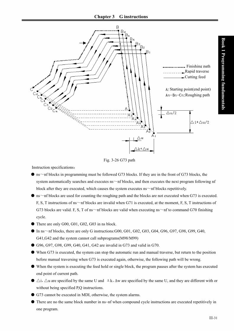
Chapter 3 G instructions
Ⅲ-31
Book 1 Program
ming fundam
entals B
ook 1 Programm
ing fundamentals
Fig. 3-26 G73 path
Instruction specifications:
● ns~nf blocks in programming must be followed G73 blocks. If they are in the front of G73 blocks, the
system automatically searches and executes ns~nf blocks, and then executes the next program following nf
block after they are executed, which causes the system executes ns~nf blocks repetitively.
● ns~nf blocks are used for counting the roughing path and the blocks are not executed when G73 is executed.
F, S, T instructions of ns~nf blocks are invalid when G71 is executed, at the moment, F, S, T instructions of
G73 blocks are valid. F, S, T of ns~nf blocks are valid when executing ns~nf to command G70 finishing
cycle.
● There are only G00, G01, G02, G03 in ns block.
● In ns~nf blocks, there are only G instructions:G00, G01, G02, G03, G04, G96, G97, G98, G99, G40,
G41,G42 and the system cannot call subprograms(M98/M99)
● G96, G97, G98, G99, G40, G41, G42 are invalid in G73 and valid in G70.
● When G73 is executed, the system can stop the automatic run and manual traverse, but return to the position
before manual traversing when G73 is executed again, otherwise, the following path will be wrong.
● When the system is executing the feed hold or single block, the program pauses after the system has executed
end point of current path.
● △i,△u are specified by the same U and Δk,∆w are specified by the same U, and they are different with or
without being specified P,Q instructions.
● G73 cannot be executed in MDI, otherwise, the system alarms.
● There are no the same block number in ns~nf when compound cycle instructions are executed repetitively in
one program.
Finishing path Rapid traverse Cutting feed
Starting point(end point)Roughing path
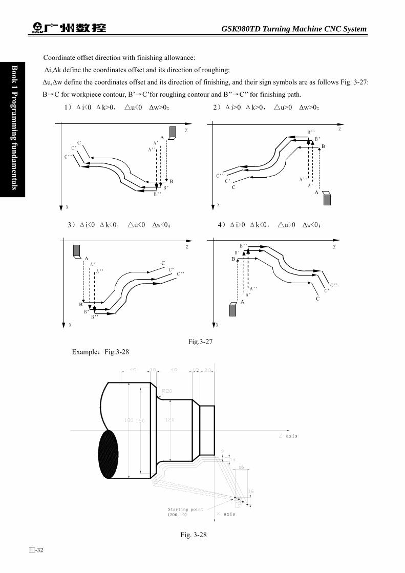
GSK980TD Turning Machine CNC System
Ⅲ-32
Book 1 Program
ming fundam
entals
Coordinate offset direction with finishing allowance:
∆i,∆k define the coordinates offset and its direction of roughing;
∆u,∆w define the coordinates offset and its direction of finishing, and their sign symbols are as follows Fig. 3-27:
B→C for workpiece contour, B’→C’for roughing contour and B’’→C’’ for finishing path.
Example:Fig.3-28
16
axis
axisStarting point
(200,10)
F
1)Δi<0 Δk>0, △u<0 ∆w>0; 2)Δi>0 Δk>0, △u>0 ∆w>0;
A ’
B
A Z
X
Z
X
B ’
A ’’
B ’’
C C ’
C ’’
A A ’
A ’’
B B ’
B ’’
CC ’
C ’’
3)Δi<0 Δk<0, △u<0 ∆w<0; 4)Δi>0 Δk<0, △u>0 ∆w<0;
Z
X
Z
X
A A ’
A ’’ C
C ’C ’’
B B ’
B ’’
A ’
B ’B ’’
C ’
A
A ’’
B
C
C ’’
Fig.3-27
ig. 3-28

Chapter 3 G instructions
Ⅲ-33
Book 1 Program
ming fundam
entals B
ook 1 Programm
ing fundamentals
Program:O0006;
G99 G00 X200 Z10 M03 S500; (Specify feedrate per rev and position starting point and start
spindle)
G73 U1.0 W1.0 R3 ; (Tool retraction with 2mm in X direction, 1mm in Z direction)
G73 P14 Q19 U0.5 W0.3 F0.3 ; (Roughing with 0.5 allowance in X direction and 0.mm in Z
direction) N14 G00 X80 W-40 ; G01 W-20 F0.15 S600 ; X120 W-10 ;
W-20 ; Blocks for finishing G02 X160 W-20 R20 ; N19 G01 X180 W-10 ; G70 P14 Q19 M30; (Finishing)
3.9.4 FINISHING CYCLE G70
Instruction format:G70 P(ns) Q(nf);
Instruction function:The tool executes the finishing of workpiece from starting point along with the finishing
path defined by ns~nf blocks. After executing G71, G72 or G73 to roughing, execute
G70 to finishing and single cutting of finishing allowance is completed. The tool returns
to starting point and execute the next block following G70 block after G70 cycle is
completed.
ns:Block number of the first block of finishing path
nf: Block number of the last block of finishing path.
G70 path is defined by programmed one of ns~nf blocks. Relationships of relative position of ns,nf block in
G70~G73 blocks are as follows: ........
G71/G72/G73 ……; N (ns) ...... ........
· F · S Blocks for finishing path · ·
N (nf)…… ...
G70 P(ns) Q(nf); ...
Instruction specifications:
● ns~nf blocks in programming must be followed G70 blocks. If they are in the front of G71 blocks, the
system automatically searches and executes ns~nf blocks, and then executes the next program following nf
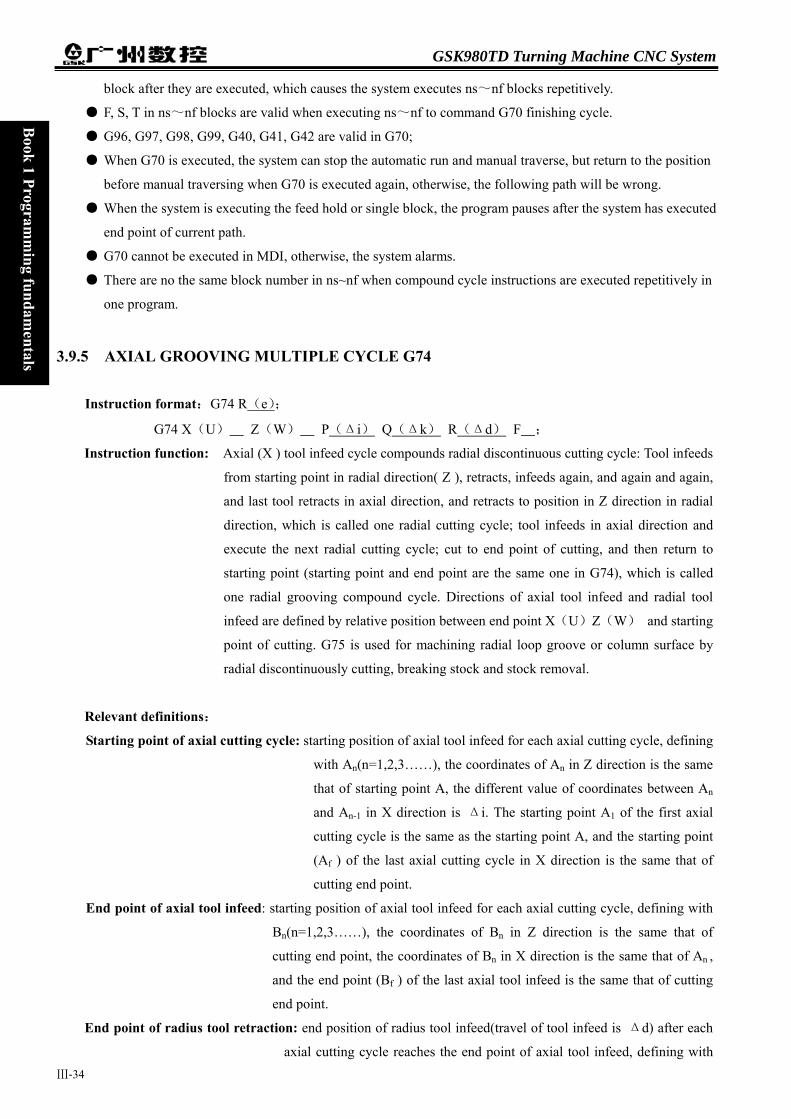
GSK980TD Turning Machine CNC System
Ⅲ-34
Book 1 Program
ming fundam
entals
block after they are executed, which causes the system executes ns~nf blocks repetitively.
● F, S, T in ns~nf blocks are valid when executing ns~nf to command G70 finishing cycle.
● G96, G97, G98, G99, G40, G41, G42 are valid in G70;
● When G70 is executed, the system can stop the automatic run and manual traverse, but return to the position
before manual traversing when G70 is executed again, otherwise, the following path will be wrong.
● When the system is executing the feed hold or single block, the program pauses after the system has executed
end point of current path.
● G70 cannot be executed in MDI, otherwise, the system alarms.
● There are no the same block number in ns~nf when compound cycle instructions are executed repetitively in
one program.
3.9.5 AXIAL GROOVING MULTIPLE CYCLE G74
Instruction format:G74 R(e);
G74 X(U) Z(W) P(Δi) Q(Δk) R(Δd) F ;
Instruction function: Axial (X ) tool infeed cycle compounds radial discontinuous cutting cycle: Tool infeeds
from starting point in radial direction( Z ), retracts, infeeds again, and again and again,
and last tool retracts in axial direction, and retracts to position in Z direction in radial
direction, which is called one radial cutting cycle; tool infeeds in axial direction and
execute the next radial cutting cycle; cut to end point of cutting, and then return to
starting point (starting point and end point are the same one in G74), which is called
one radial grooving compound cycle. Directions of axial tool infeed and radial tool
infeed are defined by relative position between end point X(U)Z(W) and starting
point of cutting. G75 is used for machining radial loop groove or column surface by
radial discontinuously cutting, breaking stock and stock removal.
Relevant definitions:
Starting point of axial cutting cycle: starting position of axial tool infeed for each axial cutting cycle, defining
with An(n=1,2,3……), the coordinates of An in Z direction is the same
that of starting point A, the different value of coordinates between An
and An-1 in X direction is Δi. The starting point A1 of the first axial
cutting cycle is the same as the starting point A, and the starting point
(Af ) of the last axial cutting cycle in X direction is the same that of
cutting end point.
End point of axial tool infeed: starting position of axial tool infeed for each axial cutting cycle, defining with
Bn(n=1,2,3……), the coordinates of Bn in Z direction is the same that of
cutting end point, the coordinates of Bn in X direction is the same that of An ,
and the end point (Bf ) of the last axial tool infeed is the same that of cutting
end point.
End point of radius tool retraction: end position of radius tool infeed(travel of tool infeed is Δd) after each
axial cutting cycle reaches the end point of axial tool infeed, defining with

Chapter 3 G instructions
Ⅲ-35
Book 1 Program
ming fundam
entals B
ook 1 Programm
ing fundamentals
Cn(n=1,2,3……), the coordinates of Cn in Z direction is the same that of
cutting end point, and the different value of coordinates between Cn and An
in X direction is Δd;
End point of axial cutting cycle: end position of axial tool retraction from the end point of radius tool retraction,
defining with Dn(n=1,2,3……), the coordinates of Dn in Z direction is the
same that of starting point, the coordinates of Dn in X direction is the same
that of Cn (the different value of coordinates in X direction between it and An
is Δd);
Cutting end point: it is defined by X(U) Z(W) ,and is defined with Bf of the last axial tool infeed.
R(e): it is the travel(0~99.999,unit:mm) of tool retraction after each axial(Z axis) tool infeed without signs.
The instruction value is reserved after executing R(e)and the value of system parameter NO.056 is
rewritten to e×1000(unit:0.001 mm). The value of system parameter NO.056 is regarded as the travel
of tool retraction when R(e)is not input.
X: Absolute coordinate value of cutting end point Bf in X direction (unit:mm)
U: Different value of absolute coordinates in X direction between cutting end point Bf and starting point.
Z: Absolute coordinate value of cutting end point Bf in Z direction (unit:mm).
W: Different value of absolute coordinates in Z direction between cutting end point Bf and starting point.
P(Δi) :travel of radial(X axis) cutting for each axial cutting cycle without signs.
Q(Δi) :travel of discontinuous tool infeed in Z direction without signs when axial(Z axis) cutting.
R(Δd):travel (unit: mm, radius value)of radial (X axis) tool retraction after cutting to end point of axial cutting.
The radial tool retraction is 0 when the system defaults the axial cutting end point. The system defaults
the tool retraction is executed in positive direction when X(U)and P(Δi) are omitted.
Execution process:(Fig. 3-29)
① Axial (Z axis) cutting feed △k from the starting point of axial cutting cycle, feed in Z negative
direction when the coordinates of cutting end point is less than that of starting point in Z direction,
otherwise, feed in Z positive direction;
②Axial(Z axis) rapid tool retraction e and its direction is opposite to the feed direction of ①;
③ Cutting feed(∆k+e) again in Z direction, the end point of cutting feed is still in it between starting
point An of axial cutting cycle and end point of axial tool infeed, cutting feed (∆k+e)again in Z
direction and execute ②; after cutting feed (∆k+e)again in Z direction, the end point of cutting
feed is on Bn or is not on it between An and Bn cutting feed to Bn in Z direction and then execute
○4 ;
④ Radial(X axis) rapid tool retraction △d(radius value)to Cn , when the coordinates of Bf (cutting
end point) is less than that of A (starting point) in X direction, retract tool in X positive, otherwise,
retract tool in X negative direction;
⑤ Axial(Z axial) rapid retract tool to Dn, No. n axial cutting cycle is completed. If the current axial
cutting cycle is not the last one, execute ⑥ ; if it is the previous one before the last axial cutting
cycle, execute ⑦;
⑥ Radial(X axial)rapid tool infeed, and it direction is opposite to ④ retract tool. If the end point of
tool infeed is still on it between A and Af (starting point of last axial cutting cycle) after tool infeed

GSK980TD Turning Machine CNC System
Ⅲ-36
Book 1 Program
ming fundam
entals
(△d+△i) (radius value) in X direction, i.e. Dn→An+1 and then execute ① (start the next axial
cutting cycle); if the end point of tool infeed is not on it between Dn and Af after tool infeed (△d+
△i) (radius value) in X direction, rapidly traverse to Af and execute ① to start the first axial
cutting cycle;
⑦ Rapidly traverse to return to A in X direction, and G74 is completed.
Instruction specifications:
● The cycle movement is executed by Z(W)and P(Δk)blocks of G74, and the movement is no
only “G74 R(e);” block is executed;
● Δd and e are specified by the same address and whether there are Z(W)and P(Δk)word or
to distinguish them;
● The tool can stop in Auto mode and traverse in Manual mode when G74 is executed, but the too
to the position before executing in Manual mode when G74 is executed in G74 again, otherwise
following path will be wrong.
● When the single block is running, programs dwell after each axial cutting cycle is completed.
● R(Δd)must be omitted in blind hole cutting .and so there is no distance of tool retraction when
to axial end point of cutting.
Starting point of radial retraction
R
Z W
Fig. 3-29 G74 path
Starting point of axial cutting
End point of axial feed End point of axial cutting
t executed if
not in blocks
l must return
the
the tool cuts
apid traverse
Cutting feed

Chapter 3 G instructions
Book 1 Program
ming fundam
ental B
ook 1 Programm
ing fundament
Example:
Program:O0007;
G0 X40 Z5 M3 S500;
G74 R0.5 ;
G74 X20 Z60 P3000 Q5000 F5
M30;
3.9.6 RADIAL GROOVING MULInstruction format:G75 R(e);
G75 X(U)
Instruction function: Axial (Z axis
infeeds from
again, and last
radial directio
and execute th
starting point
one radial gro
infeed are defi
point of cuttin
radial disconti
Relevant definitions:
Starting point of radial cutting cyc
Fig. 3-30
Ⅲ-37
s als
(Start spindle and position to starting point of machining)
(Machining cycle)
0; (Tool infeed 5mm in Z axis and tool retraction 0.5mm each time;
rapid return to starting point(Z5) after cutting feed to end
point(Z60), tool infeed 3mm in X direction and cycle the
above-mentioned steps)
(End of program)
TIPLE CYCLE G75
Z(W) P(Δi) Q(Δk) R(Δd) F ;
) tool infeed cycle compounds radial discontinuous cutting cycle: Tool
starting point in radial direction, retracts, infeeds again, and again and
tool retracts in axial direction, and retracts to position in X direction in
n, which is called one radial cutting cycle; tool infeeds in axial direction
e next radial cutting cycle; cut to end point of cutting, and then return to
(starting point and end point are the same one in G75), which is called
oving compound cycle. Directions of axial tool infeed and radial tool
ned by relative position between end point X(U)Z(W) and starting
g. G75 is used for machining radial loop groove or column surface by
nuously cutting, breaking stock and stock removal.
le: starting position of axial tool infeed for each radial cutting cycle,
defined by An(n=1,2,3……), the coordinates of An in X direction is the
same that of starting point A, the different value of coordinates
between An and An-1 in X direction is Δk. The starting point A1 of
the first radial cutting cycle is the same as the starting point A, and the

GSK980TD Turning Machine CNC System
Ⅲ-38
Book 1 Program
ming fundam
entals
starting point (Af ) of the last axial cutting cycle in Z direction is the
same that of cutting end point.
End point of radial tool infeed: starting position of radial tool infeed for each radial cutting cycle, defined
by Bn(n=1,2,3……), the coordinates of Bn in X direction is the same that
of cutting end point, the coordinates of Bn in Z direction is the same that
of An , and the end point (Bf ) of the last radial tool infeed is the same that
of cutting end point.
End point of axial tool retraction: end position of axial tool infeed(travel of tool infeed is Δd) after each
axial cutting cycle reaches the end point of axial tool infeed, defining
with Cn(n=1,2,3……), the coordinates of Cn in X direction is the same
that of cutting end point, and the different value of coordinates
between Cn and An in Z direction is Δd;
End point of radial cutting cycle: end position of radial tool retraction from the end point of axial tool
retraction, defined by Dn(n=1,2,3……), the coordinates of Dn in X
direction is the same that of starting point, the coordinates of Dn in Z
direction is the same that of Cn (the different value of coordinates in Z
direction between it and An is Δd);
Cutting end point: it is defined by X(U) Z(W) ,and is defined with Bf of the last radial tool infeed.
R(e): it is the travel(unit: mm) of tool retraction after each radial(X axis) tool infeed without signs. The
instruction value is reserved after executing R(e)and the value of system parameter NO.056 is
rewritten to e×1000(unit:0.001 mm). The value of system parameter NO.056 is regarded as the
travel of tool retraction when R(e)is not input.
X: Absolute coordinate value of cutting end point Bf in X direction (unit:mm)
U: Different value of absolute coordinates in X direction between cutting end point Bf and starting point.
Z: Absolute coordinate value of cutting end point Bf in Z direction (unit:mm).
W: Different value of absolute coordinates in Z direction between cutting end point Bf and starting point.
P(Δi) :travel(0~9999999) of radial(X axis) discontinuous tool infeed for each axial cutting cycle without
signs.
Q(Δk):travel of discontinuous tool infeed in Z direction without signs when axial(Z axis) cutting.
R(Δd):travel (unit: mm, radius value)of axial (Z axis) tool retraction after cutting to end point of radial
cutting. The system defaults the tool retraction is executed in positive direction when Z(W)and
Q(Δk) are omitted.
Travel of axial(Z axis) tool retraction is 0 after the system defaults radial cutting end point when
R(Δd) is omitted.
The system defaults the tool retraction is executed in positive direction when Z(W)and Q(Δ
k) are omitted.

Chapter 3 G instructions
Book 1 Program
ming fundam
entals B
ook 1 Programm
ing fundamentals
Execution process:(Fig. 3-31)
① Radial (X axis
direction when
otherwise, feed
② Radial(X axis)
③ Cutting feed(∆
point An of rad
direction and e
feed is on Bn o
④ Axial(Z axis) r
end point) is le
retract tool in Z
⑤ Radial(Z axis)
cutting cycle is
cycle, execute
⑥ Axial(X axis)r
tool infeed is
infeed (△d+△
radial cutting c
(△d+△k) in
cycle;
⑦ Rapidly travers
W Z
Rapid traverse
Cutting feed
An: Starting point of radial cutting
Bn: End point of radial feed
Cn: Starting point of axial tool retraction
Dn: End point of radial cutting
N=1, 2, 3…..
Ⅲ-39
) cutting feed △i from the starting point of radial cutting cycle, feed in X negative
the coordinates of cutting end point is less than that of starting point in X direction,
in X positive direction;
rapid tool retraction e and its direction is opposite to the feed direction of ①;
k+e) again in X direction, the end point of cutting feed is still in it between starting
ial cutting cycle and end point of radial tool infeed, cutting feed (∆i+e)again in X
xecute ②; after cutting feed (∆i+e)again in X direction, the end point of cutting
r is not on it between An and Bn cutting feed to Bn in X direction and then execute○4 ;
apid tool retraction △d(radius value)to Cn , when the coordinates of Bf (cutting
ss than that of A (starting point) in Z direction, retract tool in Z positive, otherwise,
negative direction;
rapid retract tool to Dn, No. n radial cutting cycle is completed. The current radial
not the last one, execute ⑥ ; if it is the previous one before the last radial cutting
⑦;
apid tool infeed, and it direction is opposite to ④ retract tool. If the end point of
still on it between A and Af (starting point of last radial cutting cycle) after tool
k) (radius value) in Z direction, i.e. Dn→An+1 and then execute ① (start the next
ycle); if the end point of tool infeed is not on it between Dn and Af after tool infeed
Z direction, rapidly traverse to Af and execute ① to start the first radial cutting
e to return to A in Z direction, and G75 is completed.
Fig. 3-31 G75 path
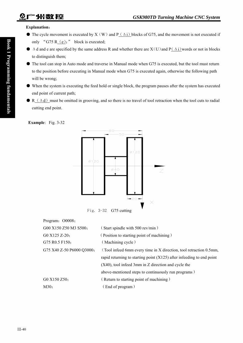
GSK980TD Turning Machine CNC System
Ⅲ-40
Book 1 Program
ming fundam
entals
Explanation:
● The cycle movement is executed by X(W)and P(Δi)blocks of G75, and the movement is not executed if
only “G75 R(e);” block is executed;
● Δd and e are specified by the same address R and whether there are X(U)and P(Δi)words or not in blocks
to distinguish them;
● The tool can stop in Auto mode and traverse in Manual mode when G75 is executed, but the tool must return
to the position before executing in Manual mode when G75 is executed again, otherwise the following path
will be wrong;
● When the system is executing the feed hold or single block, the program pauses after the system has executed
end point of current path;
● R(Δd)must be omitted in grooving, and so there is no travel of tool retraction when the tool cuts to radial
cutting end point.
Example:Fig. 3-32
Program:O0008;
G00 X150 Z50 M3 S500
G0 X125 Z-20; G75 R0.5 F150;
G75 X40 Z-50 P6000 Q
G0 X150 Z50;
M30;
g
Fig. 3-32 G75 cuttin; (Start spindle with 500 rev/min)
(Position to starting point of machining) (Machining cycle)
3000; (Tool infeed 6mm every time in X direction, tool retraction 0.5mm,
rapid returning to starting point (X125) after infeeding to end point
(X40), tool infeed 3mm in Z direction and cycle the
above-mentioned steps to continuously run programs)
(Return to starting point of machining)
(End of program)

Chapter 3 G instructions
Ⅲ-41
Book 1 Program
ming fundam
entals B
ook 1 Programm
ing fundamentals
3.10 THREAD CUTTING
GSK980TD CNC system can machine many kinds of thread cutting, including metric/inch single, multi threads,
thread with variable lead and tapping cycle. Length and angle of thread run-out can be changed, multiple cycle thread
is machined by single sided to protect tool and improve smooth finish of its surface. Thread cutting includes:
continuous thread cutting G32, thread cutting with variable lead G34, Thread cutting in Z direction G33, Thread
cutting cycle G92, Multiple thread cutting cycle G76
The machine used for thread cutting must be installed with spindle encoder which lines are set by NO.070m. Drive
ratio between spindle and encoder is set by NO.110 and NO.111. X or Z axis traverses to start machine after the
system receives spindle signal per rev in thread cutting, and so one thread is machined by multiple roughing,
finishing without changing spindle speed. The system can machine many kinds of thread cutting, such as thread cutting without tool retraction groove. There is a big error in the thread pitch because there are the acceleration and the deceleration at the starting and ending of thread cutting in X, Z direction, and so there is length of thread lead-in and distance of tool retraction at the actual starting and ending of thread cutting。 The traverse speed of tool in X, Z direction is defined by spindle speed instead of cutting feedrate override in thread cutting when the pitch is defined. The spindle override control is valid in thread cutting. When the spindle speed is changed, there is error in pitch caused by acceleration/deceleration in X, Z direction, and so the spindle speed cannot be changed and the spindle cannot be stopped in thread cutting, which will cause tool and workpiece to be damaged.
3.10.1 THREAD CUTTING WITH CONSTANT LEAD G32 Instruction format:G32 X(U)_ Z(W)_ F(I)_ J_ K_ Q_
Instruction function: The path of tool traversing is a straight line from starting point to end point as Fig.3-33; the
longer moving distance from starting point to end point(radius value in X direction) is called as
the long axis and another is called as the short axis. In course of motion, the long axis traverses
one lead when the spindle rotates one rev, and the short axis and the long axis execute the
linear interpolation. Form one spiral grooving with variable lead on the surface of workpiece to
realize thread cutting with constant lead. Metric pitch and inch pitch are defined respectively
by F, I. Metric or inch straight, taper, end face thread and continuous multi-section thread can
by machined in G32:
Instruction specification:
G32 is modal;
Pitch is defined to moving distance when the spindle rotates one rev(X axis in radius);
Cutting straight thread when starting point and end point in X direction are the same one(not to input X or U);
Cutting end face thread when starting point and end point in X direction are the same one(not to input Z or W);
Cutting taper thread when starting point and end point in X,Z direction are not the same one;
F: Metric pitch is moving distance of long axis when the spindle rotates one rev: 0.001~500 mm. After F is executed,
it is valid until F with specified pitch is executed again.
I: Teeth per inch. It is ones per inch(25.4 mm) in long axis, and also is circles of spindle rotation when the long

GSK980TD Turning Machine CNC System
Ⅲ-42
Book 1 Program
ming fundam
entals
axis traverses one inch(25.4 mm):0.06~25400 tooth/inch. After I is executed, it is valid until I with specified
pitch is executed again.
K: Length in long axis when thread run-out: 0~9999.999(unit:mm). If the long axis is X, its value is in radius
without direction; K is modal parameter.
Q: Initial angle(offset angle)between spindle rotation one rev and starting point of thread cutting: 0~360000(unit:
0.001 degree). Q is non-modal parameter, must be defined every time, otherwise it is 00.
Q rules:
1. Its initial angle is 00 if Q is not specified;
2. For continuous thread cutting, Q specified by its following thread cutting block except for the first block is
invalid, namely Q is omitted even if it is specified;
3. Multi threads formed by initial angle is not more than 65535;
4. Unit : 0.0010 . Q180000 is input in program if it offsets 1800 with spindle one rev; if Q180 or Q180.0, it is
0.180.
Difference between long axis and short axis is as Fig. 3-33.
X axis
Current point
Z axis
W
U/2
X
Z
Fx
Fz
a
End point
Cautions:
● J, K are modal. The thread run-out is previous J, K v
continuous thread cutting. Their mode are cancelled
● There is no thread run-out when J, or J, K are omitte
● There is no thread run-out when J=0 or J=0,K=0;
Fig. 3-3
Starting point
End point
is long axis when Lz≥Lx(ɑ≤45)
Skew thre
alue when
when no t
d; K=J is
3 G32 pat
J
X )
ad
axis is long axis when Lx≥Lz (ɑ≤45
Z axisthey are omitted in the next block in
hread cutting are executed;
the thread run-out value when K is omitted;
h
Tool path
End point of G32 program
K
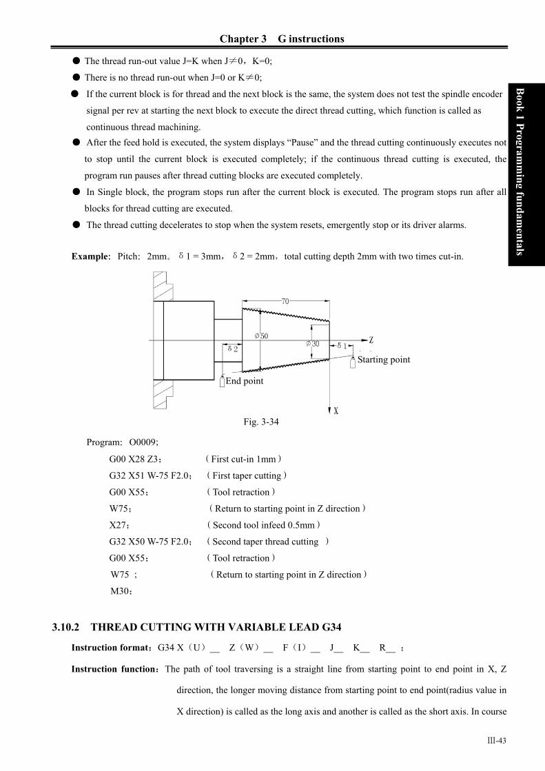
Chapter 3 G instructions
Ⅲ-43
Book 1 Program
ming fundam
entals B
ook 1 Programm
ing fundamentals
● The thread run-out value J=K when J≠0,K=0;
● There is no thread run-out when J=0 or K≠0;
● If the current block is for thread and the next block is the same, the system does not test the spindle encoder
signal per rev at starting the next block to execute the direct thread cutting, which function is called as
continuous thread machining. ● After the feed hold is executed, the system displays “Pause” and the thread cutting continuously executes not
to stop until the current block is executed completely; if the continuous thread cutting is executed, the
program run pauses after thread cutting blocks are executed completely.
● In Single block, the program stops run after the current block is executed. The program stops run after all
blocks for thread cutting are executed.
● The thread cutting decelerates to stop when the system resets, emergently stop or its driver alarms.
Example:Pitch:2mm。δ1 = 3mm,δ2 = 2mm,total cutting depth 2mm with two times cut-in.
Program:O0009;
G00 X28 Z3; (First cut-in 1mm)
G32 X51 W-75 F2.0; (First taper cutting)
G00 X55; (Tool retraction)
W75; (Return to starting point in Z direction)
X27; (Second tool infeed 0.5mm)
G32 X50 W-75 F2.0; (Second taper thread cutting )
G00 X55; (Tool retraction)
W75 ; (Return to starting point in Z direction)
M30;
3.10.2 THREAD CUTTING WITH VARIABLE LEAD G34
Instruction format:G34 X(U)__ Z(W)__ F(I)__ J__ K__ R__ ;
Instruction function:The path of tool traversing is a straight line from starting point to end point in X, Z
direction, the longer moving distance from starting point to end point(radius value in
X direction) is called as the long axis and another is called as the short axis. In course
Fig. 3-34
Starting point
End point

GSK980TD Turning Machine CNC System
Ⅲ-44
Book 1 Program
ming fundam
entals
of motion, the long axis traverses one lead when the spindle rotates one rev, the pitch
increases or decreases a specified value per rev and one spiral grooving with variable
lead on the surface of workpiece to realize thread cutting with variable lead. Tool
retraction can be set in thread cutting.
F, I are specified separately to metric, inch pitch. Machine metric or inch straight, taper, end face
thread with variable pitch.
Instruction specifications:
G34 is modal;
Functions of X(U), Z(W),J, K are the same that of G32;
F: Metric thread of first pitch from starting point: 0.001~500 mm;
I: Inch thread of first pitch from starting point: 0.06~25400 tooth/inch;
R: Increment or decrement of pitch per rev, R=F1-F2, with direction; F1>F2, pitch decreases when R is negative;
F1<F2, pitch increases when R is positive (as Fig. 3-35);
R: ±0.001~±500.000 mm/pitch (metric thread);
±0.060~±25400 tooth/inch (inch thread).
The system alarms when R exceeds the above-mentioned range or the pitch exceeds permissive value or is negative
owing to R increases or decreases.
Caution:
● It is the same that of G32.
Example:First pitch of starting point :4mm,increment 0.2mm per rev of spindle.
Fig. 3-35 Variable pitch lead machining
Starting point of machining

Chapter 3 G instructions
Ⅲ-45
Book 1 Program
ming fundam
entals B
ook 1 Programm
ing fundamentals
δ2
X
Zδ1
50
70
Fig. 3-36 Variable thread machining
When G34 is used many times, use macro variables to simplify programming. δ1 = 4mm,δ2 = 4mm,
total cutting depth 4mm, total cutting cycle 15 times; first tool infeed 0.8mm, gradual decreasing cutting every
time 0.2mm, min. infeed 0.2mm.
Program: O0010;
G00 X60 Z4 M03 S500;
G65 H01 P#202 Q800;
G65 H01 P#203 Q0;
N10 G65 H02 P#204 Q#203 R1;
G65 H01 P#203 Q#204;
G65 H81 P30 Q#204 R15;
G00 U-10;
G65 H01 P#200 Q#202;
G00 U-#200; G34 W-78 F3.8 J5 K2 R0.2;
G00 U10;
Z4;
G65 H03 P#201 Q#200 R200;
G65 H01 P#202 Q#201;
G65 H86 P20 Q#202 R200;
G65 H80 P10;
N20 G65 H01 P#202 R200; G65 H80 P10;
N30 M30;
First tool infeed:: evaluation #202=0.8mm
Cycle count:evaluation #203=0
Cycle count starting:#204=#203+1
#203=#204
Total cutting cycle times:#204=15,jump to block N30
Tool infeed to Ф50
Cutting infeed:#200=#202
Tool infeed Variable pitch cutting
Tool retraction
Return to starting point in Z direction
Decreasing of cutting feed again:#201=#200—0.2
Evaluation again #202=#201
Infeed:Jump to block N20 when #202≦0.2mm Unconditionally jump to block N10
Min. infeed:#202=0.2 Unconditionally jump to block N10
3.10.3 THRED CUTTING in Z DIRECTION G33
Instruction format:G33 Z(W)__ F(I)__ L__ ;
Instruction function: Tool path is from starting point to end point and then from end point to starting point. The
tool traverses one pitch when the spindle rotates one rev, the pitch is consistent with

GSK980TD Turning Machine CNC System
Ⅲ-46
Book 1 Program
ming fundam
entals
pitch of tool and there is spiral grooving in internal hole of workpiece and the
internal machining can be completed one time.
Instruction specification: G33 is modal instruction;
Z(W): starting point and end point in Z direction are the same one not to execute the thread
cutting when Z or W is not input;
F: metric thread pitch 0.001~500 mm;
I: teeth per inch thread 0.06~25400 teeth/inch;
L: multi threads 1~99. It is single thread when L is omitted.
Cycle process:
① Tool infeed in Z direction (start spindle before G33 is executed);
② M05 signal outputs after the tool reaches the specified end point in Z direction in progamming;
③ Test spindle after completely stopping;
④ Spindle rotation (CCW) signal outputs;
⑤ The tool retracts to starting point in Z direction;
⑥ M05 signal outputs and the spindle stops;
⑦ Repeat the steps ①~⑤ if multi threads are machined. Example:Fig.3-37,thread M10×1.5
Program:O0011;
G00 Z90 X0 M03; G33 Z50 F1.5; TM03 G00 X60 Z100; M30
Note 1: Before tapping, define rotrotation after the tapping continuously.
Note 2: G33 is for rigid tapping. Thetool continuously infeeds in Zhole is deeper than requireme
Note 3: Rapid traverse speed in tapcutting feedrate override.
Note 4: In Single block to feed hold, thstarting point when the system d
F
Start spindle ap cycle Start spindle again Machine continuously
ation direction of spindle according to tool rotating. The spindle stops is completed and the spindle is started again when machining thread
spindle decelerates to stop after its stop signal is valid, at the moment, the direction along with the spindle rotating, and so the actual cutting bottom nt and the length is defined by the spindle speed and its brake in tapping.
ping in Z direction is defined by spindle speed and pitch is not related to
e tapping cycle continuously executes not to stop until the tool returns to isplays “Pause”.
ig. 3-37

Chapter 3 G instructions
Ⅲ-47
Book 1 Program
ming fundam
entals B
ook 1 Programm
ing fundamentals
Note5: The thread cutting decelerates to stop when the system resets, emergently stop or its driver alarms.
3.10.4 THREAD CUTTING CYCLE G92
Instruction format:G92 X(U)_ Z(W)_ F_ J_ K_ L ;(Metric straight thread cutting cycle)
G92 X(U)_ Z(W)_ I_ J_ K_ L ; (Inch straight thread cutting cycle)
G92 X(U)_ Z(W)_ R_ F_ J_ K_ L ; (Metric taper thread cutting cycle)
G92 X(U)_ Z(W)_ R_ I_ J_ K_ L ; (Metric taper thread cutting cycle)
Instruction function: Tool infeeds in radial(X axis) direction and cuts in axial(Z axis or X, Z axis) direction
from starting point of cutting to realize straight thread, taper thread cutting cycle with
constant thread pitch. Thread run-out in G92: at the fixed distance from end point of
thread cutting, the tool executes thread interpolation in Z direction and retracts with
exponential or linear acceleration in X direction, and retracts at rapidly traverse speed
in X direction after it reaches to end point of cutting in Z direction as Fig. 3-41.
Instruction specifications:
G92 is modal;
Starting point of cutting: starting position of thread interpolation;
End point of cutting: end position of thread interpolation;
X: absolute coordinate of end point of cutting in X direction, unit:mm;
U: different value of absolute coordinate from end point to starting point of cutting in X direction, unit:mm;
Z: absolute coordinate of end point of cutting in Z direction, unit:mm;
W: different value of absolute coordinate from end point to starting point of cutting in X direction, unit:mm;
R: different value(R value) of absolute coordinate from end point to starting point of cutting in X direction.
When the sign of R is not the same that of U, R│≤│U/2│, unit:mm.
F=0.001~500 mm, metric thread pitch. After F value is executed, it is reserved and can be omitted;
I=0.06~25400 tooth/inch, metric thread teeth per inch, After F value is executed, it is
not reserved and can be not omitted;
J: Moving distance in the short axis in thread run-out is 0~9999.999 (unit:mm) without direction ( automatically
define its direction according to starting position of program), and it is modal parameter. If the short axis
is X, its value is specified by radius;
K: Moving distance in the long axis in thread run-out is 0~9999.999 (unit:mm) without direction ( automatically
define its direction according to starting position of program), and it is modal parameter. If the long axis is X, its
value is specified by radius;
L: Multi threads: 1~99 and it is modal parameter. ( the system defaults it is single thread when L is omitted)
GSK980TD Turning Machine CNC System
Ⅲ-48
Book 1 Program
ming fundam
entals
X
X/2
Fig. 3-40
The system can machine one thread with
and end face thread. Definition of thread p
is a moving distance of long axis(it is in ra
Pitch of taper thread is defined that it is a
absolute value of coordinate difference be
( in radius), Z axis is long axis; and vice ve
Cycle process: straight thread as Fig.3-39 and t
① The tool rapidly traverses from starting poin
② Thread interpolates(linear interpolation) fro
○3 ○4
○2
D
C
Width of th
切削终点
○3 ○4
○2
Width o f thread run-
D
C
F
Tool
many to
itch in G
dius in X
moving
tween B
rsa.
aper thre
t to cutt
m the cu
read ru
○1
out
F
B
Z
ol infeeds in
92 is the sam
direction) w
distance of lo
point and C
ad as Fig.3-4
ing starting p
tting starting
○1
B
A
n-out
Rapid traverse Thread cutting A:Starting point(end point)
B:Starting point of cutting
C:End point of cutting
ig.3-39
G92, but cannot do continuous two thread
e that of G32, and a pitch is defined that it
hen the spindle rotates one rev.
ng axis(it is in radius in X direction). When
point in Z direction is more than that of X
0.
oint in X direction;
point to cutting end point;
Rapid traverse Thread cutting A:Starting point(end point)
B:Starting point of cutting
C:End point of cutting

Chapter 3 G instructions
Book 1 Program
ming fundam
entals B
ook 1 Programm
ing fundamentals
③ Retract the tool at the cutting feedrate in X direction (opposite direction to the above-mentioned ①), and
return to the position which the absolute coordinate in X direction and the starting point are the same;
④ The tool rapidly traverses to return to the starting point in Z direction and the cycle is completed. Cautions:
Length of thread run-out is specified by NO.019 when J, K are omitted; Length of thread run-out is K in the long direction and is specified by NO.019 when J is omitted; Length of thread run-out is J=K when K is omitted; There is no thread run-out when J=0 or J=0, K=0; Length of thread run-out is J=K when J≠0,K=0; There is no thread run-out when J=0,K≠0; After executing the feed hold in thread cutting, the system does not stop cutting until the thread cutting
is completed with Pause on screen; After executing single block in thread cutting, the program run stops after the system returns to starting
point(one thread cutting cycle is completed). Thread cutting decelerates to stop when the system resets, emergently stop or its driver alarms.
Instruction path: relative position between thread cutting end point and starting point with U, W, R and tool path and
thread run-out direction with different U, W, R signs as Fig. 3-41:
3)
1) U>0,W<0,R>0 2) U<0,W<0,R<0
W
U/2 ③ ①
②
④ R
W Z
X
Z
X
①
②
③
④
U/2
R
J
K
J
K
Ⅲ-49
Fig. 3-41
U>0,W>0,R<0 、│R│≤│U/2│ 4) U<0,W>0,R>0、│R│≤│U/2│
④
R
W
U/2③
②
①
Z
X
R
W
U/2
②
①
④
③
Z
X
JK
J
K

GSK980TD Turning Machine CNC System
Ⅲ-50
Book 1 Program
ming fundam
entals
Example:Fig.3-42
Φ
axis
axis
Program:O0012; M3 S300 G0 X150 Z50 T0101; (Thread tool)
G0 X65 Z5; (Rapid positioning)
G92 X58.7 Z-28 F3 J3 K1; (Machine thread with 4 times cutting, the first tool infeed 1.3mm)
X57.7 ; (The second tool infeed 1mm)
X57; (The third tool infeed 0.7mm)
X56.9; (The fourth tool infeed 0.1mm)
M30;
3.10.5 MULTIPLE THREAD CUTTINInstruction format:G76 P(m)(r)(a
G76 X(U) Z(
Instruction function:Machining thread w
multiple roughing and
path of roughing is fro
defined angle of thread
thread run-out path, wh
the wear of tool and t
used for machining the
Relevant definitions:
Starting point(end point): position befor
End point of thread(D point): end point
The tool will not reach the point in cutt
Starting point of thread(C point): its a
value of absolute coordinates between C
cannot reach C point in cutting when th
Reference point of thread cutting depth
and the different value of absolute coor
Fig. 3-42
G CYCLE G76 ) Q(△dmin) R(d);
W) R(i) P(k) Q(△d) F(I) ;
ith specified depth of thread (total cutting depth)is completed by
finishing, if the defined angle of thread is not 0°, thread run-in
m its top to bottom, and angle of neighboring thread teeth is the
. G76 can be used for machining the straight and taper thread with
ich is contributed to thread cutting with single tool edge to reduce
o improve the precision of machining thread. But G76 cannot be
face thread. machining path is as Fig. 3-43(a):
e block runs and behind blocks run, defined by A point;
of thread cutting defined by X(U) Z(W) ,.
ing if there is the thread run-out path;
bsolute coordinates is the same that of A point and the different
and D in X direction is i(thread taper with radius value). The tool
e defined angle of thread is not 0°;
(B point): its absolute coordinates is the same that of A point
dinates between B and C in X direction is k(thread taper with
Chapter 3 G instructions
Ⅲ-51
Book 1 Program
ming fundam
entals B
ook 1 Programm
ing fundamentals
radius value).The cutting depth of thread at B point is 0 which is the reference point used for
counting each thread cutting depth by the system;
Thread cutting depth: it is the cutting depth for each thread cutting cycle. It is the different value
(radius value, without signs) of absolute coordinates in X direction between B and intersection of
reversal extension line for each thread cutting path and straight line BC. The cutting depth for each
roughing is n ×△d , n is the current roughing cycle times, △d is the thread cutting depth of
first roughing;
Travel of thread cutting: different value between the current thread current depth and the previous
one: :( n - 1n − )×△d;
End point of tool retraction: it is the end position of radial (X axis) tool retraction after the thread
cutting in each thread roughing, finishing cycle is completed, defining with E point;
Run-in path of thread:
X: Absolute coordinates (unit: mm) of thread end point in X direction;
U: Different value (unit: mm) of absolute coordinates between thread end point and starting point in X
direction;
Z: Absolute coordinates (unit: mm) of thread end point in Z direction;
W: Different value (unit: mm) of absolute coordinates between thread end point and starting point in Z
direction;
P(m):Times of thread finishing: 00~99 (unit:times) with 2-digit digital. It is valid after m instruction
value is executed, and the value of system parameter NO.057 is rewritten to m. The value of system
parameter No.057 is regarded as finishing times when m is not input. The thread is finished
according to the programmed thread path, the first finishing cutting travel is d and the following
one is 0,
P(r):Width of thread run-out 00~99(unit: 0.1×L,L is the thread pitch) with 2-digit digital. It is valid
after r instruction value is executed and the value of system parameter NO.019 is rewritten to r. The
value of system parameter NO.019 is the width of thread run-out when r is not input. The thread
run-out function can be applied to thread machining without tool retraction groove and the width of
thread run-out defined by system parameter NO.019 is valid for G92;
P(a):Angles at taper of neighboring two tooth are 00, 29, 30, 55, 60, 80, unit: degree(°),with 2-digit
digital. It is valid after a instruction value is executed and the value of system parameter NO.058 is
rewritten to a. The value of system parameter NO.058 is regarded as angle of thread tooth. The actual
angle of thread in defined by tool ones and so a should be the same as the tool angle;
△ Q(△dmin):Minimum cutting travel of thread roughing(unit: 0.001mm, radius value without signs).
When ( n - 1n − )×△d<△dmin, △dmin is regarded as the cutting travel of current roughing,
i.e. depth of current thread cutting is ( 1n − ×△d+△dmin).
△dmin is applied because the cutting travel of roughing is undersize and the times of roughing is
excessive, which is caused the cutting travel of thread roughing gradually decreases. After Q(△dmin)
is executed, the instruction value △dmin is value and the value of system parameter NO.059 is
rewritten to minimum cutting travel;
R(d): It is the cutting travel of thread finishing, and is the different value(unit:mm, radius value without
signs) of absolute coordinates in X direction between cut-in point Be of thread finishing and Bf of

GSK980TD Turning Machine CNC System
Ⅲ-52
Book 1 Program
ming fundam
entals
thread roughing. After R(d)is executed, the instruction value d is value and the value of system
parameter NO.060 is rewritten to d×1000(unit:0.001 mm). The value of system parameter NO.060
is regarded as the cutting travel of thread finishing when R(d)is not input.
R(i):It is thread taper and is the different value of absolute coordinates between thread starting point and
end point in X direction(unit:mm, radius value). The system defaults i=0(straight thread) when i is not
input;
P(k):It is the depth of thread tooth and is also the total cutting depth of thread(unit: 001mm, radius value
without signs);
Q(△d):It is the first depth of thread cutting (unit: 0.001mm, radius value without signs).The system
alarms when △d is not input;
F: 0.001~500 mm,metric thread pitch.
I: 0.06~25400 tooth/inch, thread teeth per inch for inch thread.
Fig.3-43(a) X
z
Thread cutting
Rapid traverse
RS
Starting point(end point)
eference point of thread cutting depth tarting point of threadEnd point of thread

Chapter 3 G instructions
E
Caut
Ⅲ-53
Book 1 Program
ming fundam
entals B
ook 1 Programm
ing fundamentals
Fig. 3-43(b)
Pitch is defined to moving distance ( radius value in X direction) of long axis when the spindle rotates one
rev. Z axis is long when absolute value of coordinate difference between C point and D point in Z direction
is more than that of X direction ( radius value, be equal to absolute value of i); and vice versa.
xecution process:
① The tool rapidly traverses to B1 ,and the thread cutting depth is △d. The tool only traverses in X
direction when a=0; the tool traverses in X and Z direction and its direction is the same that of A→D
when a≠0;
② The tool cuts threads paralleling with C→D to the intersection of D→E (r≠0: thread run-out);
③ The tool rapidly traverses to E point in X direction;
④ The tool rapidly traverses to A point in Z direction and the single roughing cycle is completed;
⑤ The tool rapidly traverses again to tool infeed to Bn ( is the roughing times), the cutting depth is the
bigger value of ( ×△d),( 1n − ×△d+△dmin), and execute ② if the cutting depth is less
than(k-d); if the cutting depth is more than or equal to(k-d), the tool infeeds(k-d)to Bf ,and then,
execute ⑥ to complete the last thread roughing;
⑥ The tool cuts threads paralleling with C→D to the intersection of D→E (r≠0: thread run-out);
⑦ The tool rapidly traverses to E point in X direction;
⑧ The tool rapidly traverses to A point in Z direction and the thread roughing cycle is completed to
execute the finishing;
⑨ After the tool rapidly traverses to B(the cutting depth is k and the cutting travel is d), execute the
thread finishing, at last the tool returns to A point and so the thread finishing cycle is completed;
⑩ If the finishing cycle times is less than m, execute ⑨ to perform the finishing cycle, the thread
cutting depth is k and the cutting travel is 0; if the finishing cycle times is equal to m, G76 compound
thread machining cycle is completed. ions:
● In thread cutting, execute the feed hold, the system displays Pause after the thread cutting is executed
completely, and then the program run pauses;
● Execute single block in thread cutting, the program run stops after returning to starting point(one thread
cutting cycle is completed);
n
Cut-in method as follows:3-43(b)

GSK980TD Turning Machine CNC System
Ⅲ-54
Book 1 Program
ming fundam
entals
● The thread cutting decelerates to stop when the system resets and emergently stop or the driver alarms;
● Omit all or some of G76 P(m)(r)(a) Q(△dmin) R(d). The omitted address runs according to
setting value of parameters;
● m, r, a used for one instruction address P are input one time. Program runs according to setting value of
NO.57, 19, 58 when m, r, a are all omitted; Setting value is a when address P is input with 1 or 2-bit
digits; setting values are r, a when address P is input with 3 or 4-bit digits;
● The direction of A→C→D→E is defined by signs of U,W , and the direction of C→D is defined by the
sign of R(i). There are four kinds of sign composition of U, W corresponding to four kinds of
machining path as Fig. 3-44.
Example:Fig. 3-44,thread M68×6。
6
60.64
68
62
Program:O0013;
G50 X100 Z50 M3 S300;
G00 X80 Z10;
G76 P020560 Q150 R0.1;
G76 X60.64 Z-62 P3680 Q1800 F6;
G00 X100 Z50 ;
M30;
3.11 CONSTANT SURFACE
ROTATIONAL SPEED CON
Instruction format:G96 Sxxxx;(S0000~S
Instruction function:the constant surface spee
the constant rotatio
current modal is G9
Cutting point zooming out
Fig. 3-44
(Set workpiece coordinate system, start spindle and specify
spindle speed)
(Rapid traverse to starting point of machining)
(Finishing 2 times, chamfering width 0.5mm, tool angle 60°,
min. cutting depth 0.15, finishing allowance 0.1)
(Tooth height 3.68, the first cutting depth1.8)
(Return to starting point of program)
(End of program)
SPEED CONTROL G96, CONSTANT
TROL G97
9999,)
d control is valid, the cutting surface speed is defined (m/min) and
nal speed control is cancelled. G96 is modal G instruction. If the
6, G96 can not be input.

Chapter 3 G instructions
Ⅲ-55
Book 1 Program
ming fundam
entals B
ook 1 Programm
ing fundamentals
Instruction format:G97 Sxxxx;(S0000~S9999,the leading zero can be omitted.)
Instruction function:the constant surface speed control is cancelled, the constant rotational speed control is valid
and the spindle speed is defined(rev/min). G96 is modal G instruction. If the current modal
is G97, G97 cannot be input.
Instruction format:G50 Sxxxx;(S0000~S9999,the leading zero can be omitted.)
Instruction function: define max. spindle speed limit (rev/min) in the constant surface speed control and take the
current position as the program reference point.
G96, G97 are the modal word in the same group but one of them is valid. G97 is the initial word and the system
defaults G97 is valid when the system turns on.
When the machine tool cuts it, the workpiece rotates based on the axes of spindle as the center line, the cutting
point of tool cutting workpiece is a circle motion around the axes of spindle, and the instantaneous speed in the
circle tangent direction is called the cutting surface(for short surface speed). There are different surface speed for
the different workpiece and tool with different material. When the spindle speed controlled by the analog voltage is valid, the constant surface control is valid. The spindle speed is changed along with the absolute value of X absolute coordinates of programming path in the constant speed control. If the absolute value of X absolute coordinates adds, the spindle speed reduces, and vice verse, which make the cutting surface speed as S instruction value. The constant speed control to cut the workpiece makes sure all smooth finish on the surface of workpiece with diameter changing. Surface speed=spindle speed× |X| × π ÷1000 (m/min) Spindle speed: rev/min
|X|:absolute value of X absolute coordinate value (diameter value), mm π≈3.14
In G96, the spindle speed is changed along with the absolute value of programming path X absolute coordinate value in the course of cutting feed (interpolation), but it is not changed in G00 because there is no actual cutting
40 80 120 160 200240280320360400440480520560600
200
600 400
800
12001000
140016001800200022002400260028003000
0
0
0 510 0
2 0 0 3 0 0
400
S为6 0 m min
Unit(mm,diameter)
(n)
Fig.2-4

GSK980TD Turning Machine CNC System
Ⅲ-56
Book 1 Program
ming fundam
entals
and is counted based on the surface speed of end point in the program block. In G96, Z coordinates axis of workpiece system must consist with the axes of spindle (rotary axis of workpiece), otherwise, there is different between the actual surface speed and the defined one.
In G96, G50 S_ can limit max. spindle speed (rev/min). The actual spindle speed is the limit value of max. speed
when the spindle speed counted by the surface speed and X coordinate value is more than the max. spindle speed
set by G50 S_. After the system powers on, max. spindle speed limit value is not defined and its function is
invalid. Max. spindle speed limit value defined by G50 S_ is reserved before it is defined again and its function
is valid in G96. Max. spindle speed defined by G50 S_ is invalid in G97 but its limit value is reserved.
Note: In G96, the spindle speed is limited to 99 rev/min (set by NO.043) if G50, S0 are executed.
When the constant surface speed is controlled by the system parameter NO.043, the spindle speed is lower limit,
which is higher than one counted by the surface speed and X axis coordinate value
Example:
Program:O0014; M3 G96 S300; (Spindle rotates clockwise, the constant surface speed control is valid and
the surface speed is 300m/min) G0 X100 Z100; (Rapid traverse to A point with spindle speed 955 rev/min) G0 X50 Z0; (Rapid traverse to B point with spindle speed 1910 rev/min) G1 W-30 F200; (Cut from B to C with spindle speed 1910 rev/min) X80 W-20 F150; (Cut from C to D with spindle speed 1910 rev/min and surface
speed 1194 rev/min) G0 X100 Z100; (Rapid retract to A point with spindle speed 955 rev/min) M30; (End of program, spindle stop and coolant OFF)
Note 1: In G96, S value commanded is reserved in g97. Its value is resumed after it returns to G96. Example:
G96 S50; (Cutting surface speed 50m/min)
G97 S1000; (Spindle speed 1000 rev/min
G96 G01 X200;(Cutting surface speed 50m/min)
Note 2: The constant surface speed control is valid when the machine tool is locked (X, Z axis do not move

Chapter 3 G instructions
Ⅲ-57
Book 1 Program
ming fundam
entals B
ook 1 Programm
ing fundamentals
when their motion instruction are executed);
Note 3: To gain the precise thread machining, it should not be adopted with the constant surface speed control
but the constant rotational speed (G97) in the course of thread cutting;
Note 4: From G96 to G97, if none of S instruction (rev/min) is commanded in the program block in G97, the
last spindle speed in G96 is taken as S instruction in G97, namely, the spindle speed is not changed at
this time;
Note 5: In G96, when the spindle speed counted by the cutting surface speed is more than max. speed of current
spindle gear (system parameter NO.037~NO.040), at this time, the spindle speed is limited to max. one
of current spindle gear.
3.12 FEEDRATE per MINUTE G98, FEEDRATE per REV G99
Instruction format:G98 Fxxxx;(F0001~F8000,the leading zero can be omitted, feed rate per minute is specified, mm/min)
Instruction function: cutting feed rate is specified as mm/min, G98 is the modal G instruction. G98 cannot be
input if the current instruction is G98 modal.
Instruction format:G99 Fxxxx;(F0.0001~F500,the leading zero can be omitted)
Instruction function: cutting feed rate is specified as mm/min, G99 is the modal G instruction. G99 cannot be
input if the current instruction is G98 modal.
The cutting feed per rev specified by G99 F_ is contributed to the equable cutting line on the
surface of workpiece. In G99, the machine tool must be adopted with the spindle encoder to machine
the workpiece on the machine tool
G98, G99 are the modal G instruction in the same group and only one is valid. G98 is the initial state G
instruction and the system defaults G98 is valid when the system turns on.
Reduction formula of feed between per rev and per min:
Fm = Fr×S
Fm:feed per min (mm/min);
Fr:feed per rev(mm/r);
S:spindle speed (r/min).
After the system turns on, the feedrate is ones set by NO.030 and F value is reserved after F is commanded. The
feed rate is 0 after F0 is executed. F value is reserved when the system resets and emergently stops.
Parameters:
System parameter NO.027: the upper limit value of cutting feed rate(they are the same in X, Z axis,
diameter/min in X axis);
System parameter NO.029: exponential function for time constant of acceleration/ deceleration when cutting
feed and manual feed;
System parameter NO.030: initial (ultimate) speed of acceleration/deceleration in exponential function when
cutting feed and manual feed.
Note: In G99 modal, there is the uneven cutting feed rate when the spindle speed is lower than 1 rev/min; there

GSK980TD Turning Machine CNC System
Ⅲ-58
Book 1 Program
ming fundam
entals
is the follow error in the actual cutting feed rate when there is the swing in the spindle speed. To gain the
high machining quality, it is recommended that the selected spindle speed should be not lower than min.
speed of spindle servo or inverter
3.13 MACRO INSTRUCTIONS
The system provides the macro instruction which similar to the high language, and can realize the variable
evaluation, add and subtract operation, logic decision and conditional jump by user macro instruction,
contributed to compiling part program for special workpiece, reduce the fussy counting and simplify the user
program
3.13.1 MACRO VARIABLES
(1)Usage of macro variables
Macro variables can command the address values in program, or evaluate the variable or set directly
variable by keyboard. Many macro variables can be used in program and they can distinguish with macro
variables number.
Presentation of macro variables
Present with“#”+ macro variables number.;
Format:# i(i=200,202,203,……);
Example:#205,#209,#225。
Macro variables reference
1,Macro variables can replace instruction values
Format:﹤Address﹥+“# i”或﹤Address﹥+“-# I”. It shows the system takes variable valueor
negative value of variable value as address value.
Example:F#203…when #203=15,its function is the same as F15; Z-#210…when #210=250,its function is the same as Z-250;
G#230…when #230=3,its function is the same as G3.
2. Macro variables can replace macro variables values.
Format: “#”+“9”+macro variables number
Example: if #200 = 205,#205 = 500, The instruction function of X#9200 is the same as X500; The instruction function of X-#9200 is the same as X-500
Note 1: The address 0 and N cannot refer macro variables; Note 2: If macro variables values exceed the maximum rang of instruction values, they cannot be used;
Example: M#230 exceeds max. instruction value when #230 = 120.

Chapter 3 G instructions
Book 1 Program
ming fundam
entals B
ook 1 Programm
ing fundamentals
(2)Variety of macro variables
According to macro variable numbers, macro variables are divided into common macro variables and system
macro variables.
Common macro variables
Common macro variables(#200~#231,#500~#515) are common in all user programs, i.e. Macro
variables defined in the program 1 can be applied to the program 2 or program 3.
The values of common variables( #200~#231,#500~#515) are reserved after power off
System macro variables
Use of system macro variables are fixed in the system with interface input signals #1000~#1015 and
interface output signals #1100~#1107,
Interface input/output signal of system variables and other function interface signals share one
interface which is valid set by parameters, and the interface input signal of system variables is valid
when the corresponding interface signal is valid.
The system judges and executes other operations including jumping after it reads value of interface
input signal #1000~1015(values of #1005—#1015corresponds to 0/1)
Interface signals of system variables #1000~#1015 are defined as follows:
Bit No.:7 6 5 4 3 2 1 0
M
D
Ma
S
Di
S
S
*TCP DIQP *DECX BDT T04 T03 T02 T01
DITW
#1007 #1006 #1005 #1004 #1003 #1002 #1001 #1000
XS6:49 XS6:47 XS40:1 XS40:2 XS40:3 XS40:4 XS40:5 XS40:6
Diagnostic No.00
acro variable No.
ocket pin No.
*SP *ST *DECZ *ESP
#1015 #1014 #1013 #1012
iagnostic No. 001
XS40:7 XS40:8 XS40:9 XS40:10
T08 T07 T06 T05
M42I M41I *SPEN
*OV8 *0V4 *0V2 *0V1
#1011 #1010 #1009 #1008
cro variable No. ocket pin No.
agnostic No.002
Macro variable No.
XS40:19 XS40:20 XS40:21 XS40:22
Ⅲ-59
Evaluation of #1100~1105 is 1 or 0, and output state of its interface signals can be changed.
Interface signals of system variables #1100~#1105 are defined as follows:
ocket pin No.

GSK980TD Turning Machine CNC System
Ⅲ-60
Book 1 Program
ming fundam
entals
3.13.2 OPERATION and JUMP INSTRUCTION G65 Instruction format:
G65 Hm P# i Q# j R# k;
m: operation or jump instruction, range 01~99.
# I: macro variables name for storing values.
# j: macro variables name 1 for operation, can be constant. # k: macro variables name 2 for operation, can be constant.
Instruction functions: # i = #j O # k
Example:P#200 Q#201 R#202…..#P#200 Q#201 R15….#200 = #20P#200 Q-100 R#202…..#200 = -
Explanation:
The values of macro vari
the same that of each add Macro variable name has
Instruction format
G65 H01 P#I Q#J
Ev
G65 H02 P#i Q#j R#k; DeG65 H03 P#i Q#j R#k; DeG65 H04 P#i Q#j R#k; DeG65 H05 P#i Q#j R#k; DeG65 H11 P#i Q#j R#k; BiG65 H12 P#i Q#j R#k; BiG65 H13 P#i Q#j R#k; Bi
G65 H21 P#i Q#j; De
G65 H22 P#i Q#j; DeG65 H23 P#i Q#j R#k; DeG65 H24 P#i Q#j; DeG65 H25 P#i Q#j; Bi
G65 H26 P#i Q#j R#k;Deop
M13 M11 S04 S03 S02 S01
U05 U04 M44 M43 M43 M41
DOQPS DOTWS U03 U02 U01 U00
#1105 #1104 #1103 #1102 #1101 #1100
XS39:10 XS39:9 XS39:8 XS39:14 XS39:1 XS39:5
Diagnostic No.005
Macro variable No.
Socket pin No.
Operating sign specified by Hm
200 = #201 O #202; 1 O 15; 100 O #202;ables have no decimal points and function of values of each macro variables is
ress without decimal point; no “#” when it is presented directly with constant.
Macro instruction list Functions Definitions
aluation # i = # j assign value of j to i
cimal add operation # i = # j + # k cimal subtract operation # i = # j - # k cimal multiplication operation # i = # j×# k cimal division operation # i = # j÷# k nary addition # i = # j OR # k nary multiplication(operation) # i = # j AND # k nary exclusive or # i = # j XOR # k
cimal square root # i = j#
cimal absolute value # i = |# j | cimal remainder Remainder of # i = (#j÷# k) cimal into binary # i = BIN(# j ) nary into decimal # i = DEC(# j ) cimal multiplication/division eration
# i = # i×# j÷# k

Chapter 3 G instructions
Ⅲ-61
Book 1 Program
ming fundam
entals B
ook 1 Programm
ing fundamentals
Instruction format Functions Definitions
G65 H27 P#i Q#j R#k; Compound square root # i = 22 ## kj +
G65 H31 P#i Q#j R#k; Sine # i = # j×sin(# k) G65 H32 P#i Q#j R#k; Cosine # i = # j×cos(# k) G65 H33 P#i Q#j R#k; Tangent # i = # j×tan(# k) G65 H34 P#i Q#j R#k; Arc tangent # i = ATAN(# j / # k) G65 H80 Pn; Unconditional jump Jump to block n
G65 H81 Pn Q#j R#k; Conditional jump 1 Jump to block n if # j = # k,
otherwise the system executes in order
G65 H82 Pn Q#j R#k; Conditional jump 2 Jump to block n if # j ≠ # k,
otherwise the system executes in order
G65 H83 Pn Q#j R#k; Conditional jump 3 Jump to block n if # j ﹥ # k,
otherwise the system executes in order
G65 H84 Pn Q#j R#k; Conditional jump 4 Jump to block n if # j ﹤ # k,
otherwise the system executes in order
G65 H85 Pn Q#j R#k; Conditional jump 5 Jump to block n if # j ≥ # k,
otherwise the system executes in order
G65 H86 Pn Q#j R#k; Conditional jump 6 Jump to block n if # j ≤# k,
otherwise the system executes in order
G65 H99 Pn; P/S alarm (500+n)alarms 1 Operation instructions
Evaluation of macro variables:# I = # J
G65 H01 P#I Q#J
(Example)G65 H01 P# 201 Q1005; (#201 = 1005)
G65 H01 P#201 Q#210; (#201 = #210)
G65 H01 P#201 Q-#202; (#201 = -#202)
2)Decimal add operation:# I = # J+# K
G65 H02 P#I Q#J R#K
(Example)G65 H02 P#201 Q#202 R15; (#201 = #202+15)
3)Decimal subtract operation:# I = # J-# K
G65 H03 P#I Q#J R# K
(Example)G65 H03 P#201 Q#202 R#203; (#201 = #202-#203)
4)Decimal multiplication operation:# I = # J×# K
G65 H04 P#I Q#J R#K (Example)G65 H04 P#201 Q#202 R#203; (#201 = #202×#203)

GSK980TD Turning Machine CNC System
Ⅲ-62
Book 1 Program
ming fundam
entals
5)Decimal division operation:# I = # J÷# K
G65 H05 P#I Q#J R#K
(Example)G65 H05 P#201 Q#202 R#203; (#201 = #202÷#203)
6)Binary logic add(or):# I = # J.OR. # K
G65 H11 P#I Q#J R#K
(Example)G65 H11 P#201 Q#202 R#203; (#201 = #202.OR. #203)
7)Binary logic multiply(and):# I = # J.AND. # K
G65 H12 P#I Q#J R#K (Example )G65 H12 P# 201 Q#202 R#203; (#201 = #202.AND.#203)
8)Binary executive or:# I = # J.XOR. # K
G65 H13 P#I Q#J R#K
(Example)G65 H13 P#201 Q#202 R#203; (#201 = #202.XOR. #203)
9)Decimal square root:# I = J#
G65 H21 P#I Q#J
(Example)G65 H21 P#201 Q#202 ; (#201 = 202# )
10)Decimal absolute value:# I = | # J |
G65 H22 P#I Q#J (Example)G65 H22 P#201 Q#202 ; (#201 = | #202 |)
11)Decimal remainder:# I = # J-TRUNC(#J/#K)×# K,TRUNC:omit decimal fraction
G65 H23 P#I Q#J R#K
(Example)G65 H23 P#201 Q#202 R#203; (#201 = #202- TRUNC (#202/#203)×#203
12)Decimal converting into binary:# I = BIN (# J)
G65 H24 P#I Q#J
(Example)G65 H24 P#201 Q#202 ; (#201 = BIN(#202))
13)Binary converting into decimal:# I = BCD (# J)
G65 H25 P#I Q#J (Example)G65 H25 P#201 Q#202 ; (#201 = BCD(#202))
14)Decimal multiplication/division operation:# I =(# I×# J)÷# K
G65 H26 P#I Q#J R# k (Example)G65 H26 P#201 Q#202 R#203; (#201 =(# 201×# 202)÷# 203)
15)Compound square root:# I = 2## KJ 2 +
G65 H27 P#I Q#J R#K
(Example)G65 H27 P#201 Q#202 R#203; (#201 = 22 203#202# + )
16)Sine:# I = # J•SIN(# K)(Unit:‰)
G65 H31 P#I Q#J R#K
(Example)G65 H31 P#201 Q#202 R#203; (#201 = #202•SIN(#203))
Chapter 3 G instructions
Ⅲ-63
Book 1 Program
ming fundam
entals B
ook 1 Programm
ing fundamentals
17)Cosine:# I = # J•COS(# K)(Unit:‰)
G65 H32 P#I Q#J R# k (Example)G65 H32 P#201 Q#202 R#203; (#201 =#202•COS(#203))
18)Tangent:# I = # J•TAM(# K)(Unit:‰)
G65 H33 P#I Q#J R# K
(Example)G65 H33 P#201 Q#202 R#203; (#201 = #202•TAM(#203))
19)Cosine:# I = ATAN(# J /# K)(Unit:‰)
G65 H34 P#I Q#J R# k (Example)G65 H34 P#201 Q#202 R#203; (#201 =ATAN(#202/#203))
Note 1: Unit of(P)~(S): degree, 1‰ degree; Note 2: Variable value is integer, and decimal is omitted. Unit: µm; Note 3: Variable value displays correctly -9999999~9999999 in -232~+232-1, otherwise the system displays
*******.
2 Jump instruction
1) Unconditional jump
G65 H80 Pn; n:Block number
(Example)G65 H80 P120;(jump to N120)
2)Conditional jump 1 #J.EQ.# K ( = )
G65 H81 Pn Q#J R# K; n:Block number
(Example) G65 H81 P1000 Q#201 R#202;
The program jumps N1000 when # 201= #202 and executes in order when #201 ≠#202.
3)Conditional jump 2 #J.NE.# K ( ≠ )
G65 H82 Pn Q#J R# K; n:Block number
(Example) G65 H82 P1000 Q#201 R#202;
The program jumps N1000 when # 201 ≠ #202 and executes in order when #201 = #202.
4)Conditional jump 3 #J.GT.# K ( > )
G65 H83 Pn Q#J R# K; n:Block number
(Example) G65 H83 P1000 Q#201 R#202;
The program jumps N1000 when # 201 > #202 and executes in order when #201 ≤ #202.
5)Conditional jump 4 #J.LT.# K ( < =)
G65 H84 Pn Q#J R# K; n:Block number (example) G65 H84 P1000 Q#201 R#202;
The program jumps N1000 when # 201< #202 and executes in order when #201≥#202.
6)Conditional jump 5 #J.GE.# K ( ≥ )
G65 H85 Pn Q#J R# K; n:Block number (例) G65 H85 P1000 Q#201 R#202;
The program jumps N1000 when # 201 ≤ #202 and executes in order when #201 < #202.
7)Conditional jump 6 #J.LE.# K ( ≤ )
G65 H86 Pn Q#J R# K; n:Block number
(Example) G65 H86 P1000 Q#201 R#202;

GSK980TD Turning Machine CNC System
8)P/S alarm
G65 H99 Pi; i:alarm number +500 Book 1 Program
ming fundam
entals
(Example) G65 H99 P15;
P/S alarm 515.
Note: Block number can be specified by variables. Such as: G65 H81 P#200 Q#201 R#202; program jump to block of its the block number specified by #200
3.13.3 PROGRAM EXAMPLE with MACRO INSTRUCTION
Example :Automatically feed rod with system variables
Program:
O0001
N10 G0 X100 Z100 T101; (Set coordinate system for tool change)
G00 X50 Z1 ; (Rapidly position)
N20 G65 H01 P#1100 Q1; (Start rod infeed when XS39 Pin5 output low level)
G65 H82 P20 Q#1009 R1; (Execute N20 block when XS40 Pin21 is switched off +24V; and execute the
next block when XS P21 is switched on. +24V)
G65 H01 P#1100 Q0; (Close output signal of XS39 Pin5 and stop rod infeed)
G01 X30 W-10 F300; (Start to machine workpiece)
……
……
G01 X80 Z-50; (End of machining)
M99 P10; (Execute repetitively main program and automatically feed rods)
Ⅲ-64

Chapter 4 Tool nose radius compensation
Chapter 4 TOOL NOSE RADIUS COMPENSATION (G41,G42) Chapter 4 TOOL NOSE RADIUS COMPENSATION (G41,G42) B
ook 1 Programm
ing fundamentals
fundamentals
4.1 APPLICATION 4.1 APPLICATION
4.1.1 Overview 4.1.1 Overview
Part program is compiled generally for one point of tool according to a workpiece contour. The point is regarded generally as the tool nose A point in an imaginary state(there is no the imaginary tool nose point in fact and the tool nose radius can be omitted when using the imaginary tool nose point to program) or as the center point of tool nose arc( as Fig. 3-41). Its nose of turning tool is not the imaginary point but one arc owing to the technology and other requirement in the actual machining. There is the warp between the actual cutting point and the cutting point in imaginary state, which will cause the excessive or less cutting to not to gain the perfect precision.
Part program is compiled generally for one point of tool according to a workpiece contour. The point is regarded generally as the tool nose A point in an imaginary state(there is no the imaginary tool nose point in fact and the tool nose radius can be omitted when using the imaginary tool nose point to program) or as the center point of tool nose arc( as Fig. 3-41). Its nose of turning tool is not the imaginary point but one arc owing to the technology and other requirement in the actual machining. There is the warp between the actual cutting point and the cutting point in imaginary state, which will cause the excessive or less cutting to not to gain the perfect precision.
Fig. 4-1 Tool
B type tool compensation is defined that a workpiece contour path is offset one tool nose radius, which cause
there is excessive cutting at a intersection of two programs because of executing motion path of next after
completing the previous block.
To avoid of the above-mentioned ones, the system is employed with C type tool compensation method
(namely, tool nose radius compensation). The system will read next block instead of executing it immediately
after reading a block in C type tool compensation method, and count corresponding motion path according to
intersection of blocks. Contour can be compensated precisely because of pretreatment of reading two blocks as
Fig.4-2.
Tool path with
imaginary tool nose
and C compensation
Workpiece
Tool nose
Error
Tool nose center path with C compensation
Tool nose center path without C compensation
Tool path with imaginary tool nose and without C compensation
4)Arc—arc
Ⅳ-1

GSK980TD Turning Machine CNC System
4.1.2 Imaginary Tool Nose Direction Suppose that it is generally difficult to set the tool nose radius center on the initial position as Fig. 4-3;suppose that it is easily set the tool nose on it as Fig. 4-4; The tool nose radius can be omitted in programming. Fig. 4-5 and Fig.4-6 correspond separately to the tool paths of tool nose center programming and imaginary tool nose programming when tool nose radius is executed or not.
Book 1 Program
ming fundam
entals
Programming with tool nose center Programming with imaginary tool nose
Starting point
Starting point
Tool nose path is the same as programm
path without using tool nose radius co
center path
Tool nose
Program path
Fig. 4-5 Tool pTool nose path is the same as pr
path without using tool nose ra
Program path
Imaginary tool
nose path
Fig. 4-6 Too
The tool is supposed to one point in pro
machining technology. Because the cutti
can be deleted by tool nose arc radius
position relationship between tool nose
direction of imaginary tool nose.
Ⅳ-2
Fig. 4-4
ing Finishing when using tool nose radius
mpensation compensation
center path
Tool nose
Start compensation
Program path
ath in tool nose programmingogramming Finishing when using tool
dius compensation nose radius compensation
Program path
Start compensation
Imaginary tool
nose path
l path in imaginary tool nose programming
gramming but the actual cutting blade is not one ideal point owing to
ng blade is not one point but one arc, machining error is caused which
compensation. In actual machining, suppose that there are different
point and tool nose arc center point, and so it must create correct its

Chapter 4 Tool nose radius compensation
From tool nose center to imaginary tool nose, set imaginary tool nose numbers according to tool direction in
cutting. Suppose there are 10 kinds of tool nose setting and 9 directions for position relationship. The tool nose
directions are different in different coordinate system(rear toolpost coordinate system and front toolpost
coordinate system) even if they are the same tool nose direction numbers as the following figures. In figures, it
represents relationships between tool nose and starting point, and end point of arrowhead is the imaginary tool
nose; T1~T8 in rear toolpost coordinate system is as Fig. 4-7; T1~T8 in front toolpost coordinate system is
as Fig. 4-8. the tool nose center and starting point for T0 and T9 as Fig. 4-9.
Book 1 Program
ming fundam
entalsfundam
entals
X axis
Z ax
Imaginary toolnose No.1
Imaginary tool nose No. 2
Imaginary toolnose No.3
Imaginary toolnose No.4
Imaginary toolnose No.5
I m a g i n a r y t o o ln o s e N o . 6
Rear toolpost coordinate system
Ⅳ-3

GSK980TD Turning Machine CNC System
Imaginary toolnose No.7
I m a g i n a r y t o o l n o s e N o . 8
Book 1 Program
ming fundam
entals
Fig. 4-7 Imaginary tool nose number in rear toolpost coordinate system
Z axis
F
Ⅳ-4
X axis
Imaginary tool nose No. 1
Imaginary tool nose No.2
Imaginary toolnose No.3
Imaginary tool nose No.4
Imaginary tool nose No.5
Imaginary tool nose No.6
ront toolpost coordinate system

Chapter 4 Tool nose radius compensation
Book 1 Program
ming fundam
entals
Imaginary tool nose No.7
I m a g i n a r y t o o l n o s e N o . 8
Fig. 4-8 Imaginary tool nose number in front toolpost coordinate system
Fig. 4-9 Tool nose center on starting point
4.1.3 Compensation Value Setting Preset imaginary tool nose number and tool nose radius value for each tool before executing tool nose radius compensation. Set the tool nose radius compensation value in “Offset” window (as Fig. 4-1), R is tool nose radius compensation value and T is imaginary tool nose number.
Table 4-1 Display window of system tool nose radius compensation value
Number X Z R T
000 0.000 0.000 0.000 0 001 0.020 0.030 0.020 2 002 1.020 20.123 0.180 3 … … … … …
032 0.050 0.038 0.300 6 Note: Tool offset value can be specified in diameter or radius in X direction, set by No.004 Bit4 ORC, offset
value is in radius when ORC=1 and is in diameter when ORC=0. In toolsetting, the tool nose is also imaginary tool nose point of Tn (n=0~9) when taking Tn(n=0~9) as
imaginary tool nose. For the same tool, offset value from standard point to tool nose radius center( imaginary tool nose is T3) is different with that of ones from standard point to imaginary tool nose( imaginary tool nose is T3) when
T0 and T3 tool nose points are selected to toolsetting in rear toolpost coordinate system, taking toolpost center as standard point. It is easier to measure distances from the standard point to the tool nose radius center than from the standard point to the imaginary tool nose, and so set the tool offset value by measuring distance from the standard point to the imaginary tool nose(tool nose direction of T3).
Ⅳ-5

GSK980TD Turning Machine CNC System
Book 1 Program
ming fundam
entals
Fig. 4-10 Tool offset value of toolpost center as benchmark
4.1.4 Instruction Format
X Z T ;
Instructions Function specifications Remark
G40 Cancel the tool nose radius compensation
G41
Tool nose radius left compensation is specified by G41 in rear toolpost coordinate system and tool nose radius right compensation is specified by G41 in front toolpost coordinate system
G42
Tool nose radius right compensation is specified by G42 in rear toolpost coordinate system and tool nose radius left compensation is specified by G42 in front toolpost coordinate system
See Fig.4-11 and 4-12
4.1.5 Compensation Direction Specify its direction according to relative position between tool nose and workpiece when executing tool
nose radius compensation as Fig. 4-11 and Fig.4-12.
G40 G41 G42
G00 G01
X
Z
Define distance from standard point
to tool nose for compensation value Define distance from standard point to
center of tool nose for compensation
Tool compensation in Z direction
Tool compensation in X direction Tool compensation in X direction
Tool compensation in Z direction
Starting point on imaginary tool nose Starting point on center of tool nose
Ⅳ-6
Chapter 4 Tool nose radius compensation
Book 1 Program
ming fundam
entals
Z
X
G42:Tool is right to workpiece from its movement direction
G41:Tool is left to workpiece from its movement direction
Workpiece
Tool
Fig. 4-11 Compensation direction of rear coordinate system 后刀座坐标系补偿方向
Ⅳ-7

GSK980TD Turning Machine CNC System
Book 1 Program
ming fundam
entals
Z
G41:Tool is right to workpiece from its movement direction
G42:Tool is left to workpiece from its movement direction
Workpiece
Tool
X
Fig. 4-12 Compensation direction of front coordinate system
4.1.6 Cautious The system is in tool nose radius compensation mode at initial state, and starts to create tool nose radius
compensation offset mode when executing G41 or G42. When the system starts to execute compensation, it pre-read two blocks, and the next block is saved to storage for tool nose radius compensation when executing one of them. The system reads two blocks in “Single” mode and stops after executing end point of the first block.
In tool nose radius compensation mode, the tool nose center moves to end point of previous block and is
vertical to its path when the system executes two block or more than blocks without motion instruction. The system cannot create and cancel tool nose radius compensation Tool nose radius R is without negative value, otherwise there is a mistake running path.
Tool nose radius compensation is created and cancelled in G00 or G01 instead of G02 or G03, otherwise, the
system alarms.
The system cancels the tool nose radius compensation mode when pressing “PESET” key.
G40 must be specified to cancel offset mode before the program is ended, otherwise the tool path offsets one
tool nose radius.
The system executes the tool nose radius compensation in main program and subprogram but must cancel it
before calling subprogram and then create it again in the subprogram.
The system does not execute the tool nose radius compensation in G71, G72, G73, G74, G75, G76 and cancel
it temporarily.
Ⅳ-8
Chapter 4 Tool nose radius compensation
The system executes the tool nose radius compensation in G90, G94, it offsets one tool nose radius for G41 or
G42.
Book 1 Program
ming fundam
entals
4.1.7 Application
Machine a workpiece in the front toolpost coordinate system as Fig. 3-54. Tool number: T0101, tool nose
radius R=2, imaginary tool nose number T=3.
X
Z
R6
Fig. 3-54
For toolsetting in Offset Cancel mode, after toolsetting, Z axis offsets one tool nose radius and its direction is
relative to that of imaginary tool nose and toolsetting point, otherwise the system excessively cuts tool nose
radius when it starts to cut.
Set the tool nose radius R and imaginary tool nose direction in “Offset” window as Fig.
Table 3-7
Number X Z R T
001 2.000 3 002 … … … … … … … … …
007 … … … … 008 … … … …
Program: G00 X100 Z50 M3 T0101 S600; (Position, start spindle, tool change and execute tool
compensation) G42 G00 X0 Z3; (Set tool nose radius compensation) G01 Z0 F300; (Start cutting) X16; Z-14 F200; G02 X28 W-6 R6;
Ⅳ-9

GSK980TD Turning Machine CNC System
G01 W-7; G01 W-7; X32; X32; Z-35; Z-35; Book 1 Program
ming fundam
entals
4
4
k 1 Programm
ing fundamentals
G40 G00 X90 Z40; (Cancel tool nose radius compensation) G40 G00 X90 Z40; (Cancel tool nose radius compensation) G00 X100 Z50 T0100; G00 X100 Z50 T0100; M30; M30;
.2 TOOL NOSE RADIUS COMPENSATION OFFSET PATH 4.2 TOOL NOSE RADIUS COMPENSATION OFFSET PATH
.2.1 Inner and Outer Side 4.2.1 Inner and Outer Side
Inside is defined that an angle at intersection of two motion blocks is more than or equal to 180°; Outside is
0~180°.
Inside is defined that an angle at intersection of two motion blocks is more than or equal to 180°; Outside is
0~180°.
Workpiece side
Inside
Program path
Program path
Outside
Workpiece side
4.2.2 Tool Traverses when Starting Tool 3 steps to execute tool nose radius compensation: tool compensation creation, tool compensation execution and tool compensation canceling. Tool traverse is called tool compensation creation (starting tool) from offset canceling to G41 or G42
execution. Note: Meanings of S, L, C in the following figures are as follows: S――Stop point of single block;L――straight line;C――arc。
Ⅳ-10
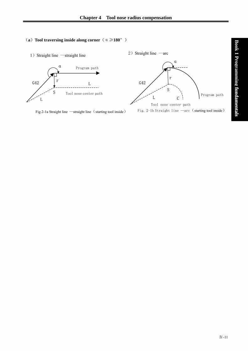
Chapter 4 Tool nose radius compensation
(a)Tool traversing inside along corner(α≥180°) B
ook 1 Programm
ing fundamentals
fundamentals
2)Straight line —arc 1)Straight line —straight line α
r
Tool nose center path
C
S
L
G42
Fig. 2-1b Straight line —arc(starting tool inside)Fig.2-1a Straight line —straight line(starting tool inside)
Tool nose center path
Program path
r
α
L
S
L
G42
Program path
Ⅳ-11

GSK980TD Turning Machine CNC System
(b)Tool traversing inside along corner(180°>α≥90°) (b)Tool traversing inside along corner(180°>α≥90°) B
ook 1 Programm
ing fundamentals
k 1 Program
ming fundam
entals
(c)Tool traversing inside along corner (α<90°)
(d)Tool traversing inside along corner(α≦1°),straight line →straight line
2)Straight line—arc 1)Straight line —straight line
Tool nose center path
r r
C S
L
α
G42
Program path
L r
Program path
G42
Tool nose center path
α
S L
L
Tool nose center path Program path
S
α<1°
L
r
L
Program path
Fig. 2-4a Straight line—straight line(α<1°, starting tool outside)
G41
Tool nose center path
2)Straight line—arc
CS
L
G42
r
rα
L S
L
Tool nose center path
L
r Program path
G42
α
1)Straight line —straight line
Fig. 2-3b straight line—arc(starting tool outside)Fig.2-3a Straight line —straight line(starting tool outside)
Fig.2-2b Straight line—arc(starting tool outside) Fig.2-2a Straight line —straight line(starting tool outside)
Ⅳ-12
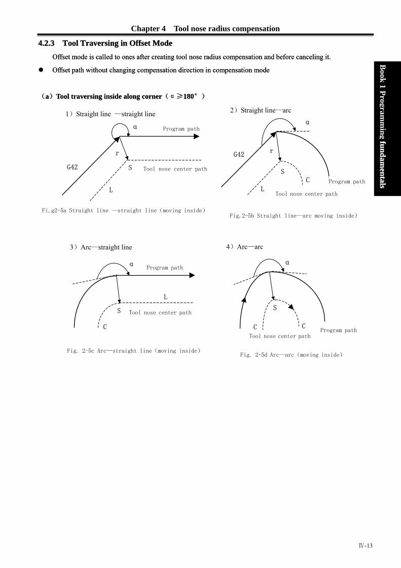
Chapter 4 Tool nose radius compensation
4.2.3 Tool Traversing in Offset Mode 4.2.3 Tool Traversing in Offset Mode
Offset mode is called to ones after creating tool nose radius compensation and before canceling it. Offset mode is called to ones after creating tool nose radius compensation and before canceling it.
Book 1 Program
ming fundam
entalsfundam
entals
Offset path without changing compensation direction in compensation mode Offset path without changing compensation direction in compensation mode
(a)Tool traversing inside along corner(α≥180°) (a)Tool traversing inside along corner(α≥180°)
2)Straight line—arc 1)Straight line —straight line α
G42
C S
L
r
Program path
Tool nose center path
S
L
r
Program path
G42 Tool nose center path
α
Fi.g2-5a Straight line —straight line(moving inside)Fig.2-5b Straight line—arc moving inside)
Tool nose center pathProgram path C
S
C
Fig. 2-5d Arc—arc(moving inside)
α
4)Arc—arc 3)Arc—straight line
C
S
L
Program path
Tool nose center path
α
Fig. 2-5c Arc—straight line(moving inside)
Ⅳ-13

GSK980TD Turning Machine CNC System
5)Machining inside (α<1°) and zoom out the compensation vector 5)Machining inside (α<1°) and zoom out the compensation vector
(b)Tool traversing outside along corner(180°>α≥90°)
B
ook 1 Programm
ing fundamentals
k 1 Program
ming fundam
entals
Fig. 2-5e Straight line —straight line(α<1°, moving inside)
Tool nose center path
α<1°
Program pathr
LL
r
1)Straight line —straight line
α
Tool nose center path
Program path
L
S
r
SC
L
Program path
α
2)Straight line—arc
S
Tool nose center path
C
C
r
SL
r
Program path
α
Tool nose center path
4)Arc—arc
S Tool nose center path
r
L
C
Program pathα
3)Straight line —straight line
Fig. 2-6c Arc—straight line
(180°>α≥90°moving outside)
Fig. 2-6c Arc—arc
(180°>α≥90°moving outside)
Fig. 2-6b Straight line—arc
(180°>α≥90°, moving outside)
Fig. 2-6a Straight line —straight line
(180°>α≥90°, moving outside)
Ⅳ-14

Chapter 4 Tool nose radius compensation
(c)Tool traversing outside along corner(α<90°) (c)Tool traversing outside along corner(α<90°)
(d) Special cutting
Book 1 Program
ming fundam
entalsfundam
entals
2)Straight line—arc
C
r
SL
L r
r
L r Program path
G42
α
1)Straight line—straight line
Program path
G42
Tool nose center path
α
L Tool nose center path
S
Fig.2-7b Straight line—arc
(α<90°, moving outside )
4)Arc—arc 3)Arc—straight line
Fig.2-7a Straight line—Straight line
(α<90°, moving outside )
C
r
S
r
CProgram path
L
Tool nose center path
α
S
r
C
r Program path
α
L
LL
Tool nose center path
1 )Without intersection
There is no intersection of
compensation paths when the
tool radius is small; no one
when the radius is big and the
tool stops at the end point of
previous block and the system
alarms.
Alarm and stop
Program path
Small compensation
Big compensation
Center of arc B Center of arc A r r
Fig.2-7c Arc—straight line
(α<90°, moving outside )
Fig.2-7c Arc—arc
(α<90°,moving outside )
Fig. 2-8 Paths without intersection after offset
2)Center point and starting point of arc being the same one
Ⅳ-15

GSK980TD Turning Machine CNC System
Tool nose center path Book 1 Program
ming fundam
entals
k 1 Programm
ing fundamentals
Stop
Program path
Fig. 2-9 Center point and startin
Offset path of compensation direction in compensation modThe compensation direction of tool nose radius is specified by
Table 2-1
Sign symbol of compensation value
G instruction
G41 Left c
G42 Right c
The compensation direction can be changed in compensationstarting block and its following one. There is no inside ancompensation direction. The following compensation value is
r
Program
2)Stra
G42
Tool nose center path Program path
L
r
r
L
G41
S
1)Straight line—straight line
(changing compensation direction)
Fig. 2-10 straight line—straight line
(chang
Fig. 2-
Ⅳ-16
Alarm: Starting point or end point of
arc is the same as center
point; they are end point of
previous block
(G41)
B56 G01 W20;
N6 GO2 W10 I K0;
N7 G03 U-10 I-10;
g point of arc being the same one
e G41 and G42 and the sign symbol is as follows:
+ -
ompensation Right compensation
ompensation Left compensation
mode in special cutting, it cannot be changed at d outside cutting when the system changes the supposed to be positive.
Tool nose center path
path
L
G41
r C
S
G42
ight line —arc
ing compensation direction) 10 straight line—arc

Chapter 4 Tool nose radius compensation
Book 1 Program
ming fundam
entals
3)Arc—straight line
G42
S
C r
G41 r
L
Program path
Tool nose center path
S
G42
C
r
G41
rC
Tool nose center path
Program path
4)Arc—arc
(changing compensation direction)
Fig. 2-12 Arc—straight line
(changing compensation direction)
Fig. 2-13 Arc—arc
5)Without intersection when compensation is executed normally When the system executes G41 and G42 to change the offset direction between block A and B, a vector perpendicular to block B is created from its starting point.
L
Fig. 2-14b Straight
Fig. 2-14a Straight l
i ) Straight line----Straight line
L
S
rG41
S
G42
Program path r Tool nose center path
L
Program path
Tool nose center path
ii ) Straight line ---arc
Tool nose c
Program pa
line—arc without intersection(changing compeine—straight line without intersection(cha
G41
G42
r
SL
enter path
G42th
G41L
C
S
O
nsation direction)nging compensation direction)
Ⅳ-17

GSK980TD Turning Machine CNC System
iii ) Arc-----arc
Book 1 Program
ming fundam
entals
O2G41
CC
Tool nose center path G42 Program path
O1
Fig. 2-14c Arc—arc without intersection(changing compensation direction)
4.2.4 Tool Traversing in Offset Canceling Mode
In compensation mode, when the system executes a block with one of the followings, it enters compensation
canceling mode, which is defined to compensation canceling of block
1. Execute G40 in a program;
2. Execute M30.
The system cannot execute G02 and G03 when canceling C tool compensation (tool nose radius compensation),
otherwise the system alarms and stops run.
In compensation canceling mode, the system executes the block and ones in the register for tool nose radius
compensation. At the moment, the run stops after executing one block when single block is ON. The system
executes the next one but does not read its following one when pressing “Start” button again.
When the system is still in compensation canceling mode, the next block without others to be executed is read
into buffer register for tool nose radius compensation.
(a)Tool traversing inside along corner(α≥180°)
Ⅳ-18
α
Program path Tool nose center path C
G40 S
L
rProgram path
Tool nose center path G40
S
L
L
r
α
2)Arc → Straight line 1)Straight line → Straight line
Fig. 2-15a Arc-straight line(moving
inside and canceling offset)
Fig. 2-15b Arc-straight line(moving
inside and canceling offset)

Chapter 4 Tool nose radius compensation
(b)Tool traversing outside along corner(180°>α≥90°) (b)Tool traversing outside along corner(180°>α≥90°)
(c)Tool traversing outside along corner(α<90°)
(d) Tool traversing outside along corner(
Book 1 Program
ming fundam
entalsfundam
entals
2)Arc →straight line 1)Straight line →straight line
L
G40
r
C
r
α
SIntersection
Tool nose center pathTool nose center path
L
G40
r Program path
α
Intersection
L
Program path
Fig. 2-16b Arc—straight line(α≥90°
moving outside and canceling offset)moving outside and canceling offset)
Fig. 2-16a Arc—straight line(α≥90°
2)Arc → straight line 1)Straight line→straight line
r S
LG40
α
L
r
S
L L Tool nose center path
Program path
r G40
αL
L
Fig. 2-17a Straight line—straight line(α
cutting outside and canceling offset)
α<1°
G42 L
r
L
G
S
Fig. 2-18 Straight line—straight
4.2.5 Tool Interference Check
“Interference” is defined that the tool cut
the interference check is executed even
rL L
α<1°);straight line→straight line
Tool nose center path C
Program path
Fig. 2-17a Straight line—straight line(α<90°
cutting outside and canceling offset)
<90°
40
Program path
Tool nose center path
line (α<1°cutting outside and canceling offset)
s workpiece excessively and it can find out excessive cutting in advance,
if the excessive cutting is not created, but the system cannot find out all
Ⅳ-19

GSK980TD Turning Machine CNC System
tool interferences.
Book 1 Program
ming fundam
entals
(1) Fundamental conditions
1) The tool path direction is different that of program path(angle is 90°~270° ).
2) There is a big difference (α>180°)for two angles between starting point and end point of tool nose center
path, and between starting point and end point of program path.
Example: linear machining Tool nose center path
r rProgram path
Directions of two paths(180°)
Directions o (2) Executing it without ac
1) Concave groove less
Fig. 2
A
Program path To
Ⅳ-20
Fig. 2-19a Machining interference (1)
Program path
Tool nose center path
f two paths (180°)
Fig. 2-19b Machining interference (2)
tual interference than compensation value
-21 Executing interferenceB
Stop
C
ol nose center path
(1)

Chapter 4 Tool nose radius compensation
Book 1 Program
ming fundam
entals
Directions of block B and tool nose radius compensation path are opposite without interference, the tools
stops and the system alarms.
2) Concave channel less than compensation value
AB
C
Tool nose center path Program path
Fig. 2-22 Executing interference(2)
Directions of block B and tool nose radius compensation path are opposite without interference, the tools
stops and the system alarms.
4.2.6 Instructions for Canceling Compensation Vector Temperarily
In compensation mode, the compensation vector is cancelled temporarily in G50, G71~G76 and is automatically
resumed after executing the instructions. At the moment, the compensation is cancelled temporarily and the tool
directly moves from intersection to a point for canceling compensation vector. The tool directly moves again to
the intersection after the compensation mode is resumed.
Setting coordinate system in G50
Note: The tool stops at S position in “Single Block” mode.
N9
SS
rr
SSN5 N6
N7
N8
LL
LLTool nose center path
Program path
G50 blocks
Fig. 3-1 Cancel compensation vector temporarily in G50
Ⅳ-21

GSK980TD Turning Machine CNC System
Reference point automatic return in G28 In compensation mode, the compensation is cancelled in a middle point and is automatically resumed after executing the reference point return in G28.
Book 1 Program
ming fundam
entals
Middle point G28
G42L
Machine reference point Tool nose center path Program path
rrG00
S
S
S
L
G71~G76 compoun
When executing G71~
and cancel it temporaril
G71~G
G32、G
G90, G94 Compensation method
A. Each cycle path and
B. Offset directions ar
C. When the system c
radius vector, and t
Ⅳ-22
Fig. 4-23 Cancel compensation vector temporarily in G28
d cycle; G32, G33, G34 thread cutting
G76 , G32, G33, G34 , the system does not execute the tool nose radius compensation
y, and executes it in the next blocks of G00, G01, G02, G03, G70.
r
r
S
S
N8
Program path
N576
33
Tool nose center path
N7
N6
Fig. 4-23 Cancel compensation vector temporarily in G71~G76of tool nose radius compensation in G90 or G94:
tool nose center path are parallel to program path.
e the same in G41 and G42 as the following figure.
ompensates the imaginary tool nose direction NO. 0, the motion path offsets a tool nose
he system does not count any intersections in cycle.

Chapter 4 Tool nose radius compensation
Fig.3-3 Offset direction of tool noseradius compensation in G94
Book 1 Program
ming fundam
entals
Fig. 3-3 Offset direction of tool noseradius compensation in G90
4.2.7 Particular
Inside chamfer machining less than tool nose radius
At the moment, the tool inside offset causes an excessive cutting. The tool stops and the system alarms ( P/S41)
when starting the previous block or chamfer moving. But the tool stops the end point of previous block when
‘Single Block’ is ON.
3.6 Machining concave less than tool nose diameter
There is an excessive cutting when the tool nose center path is opposite to program path caused by tool nose
radius compensation. At the moment, the tool stops and the system alarms when starting the previous block or
chamfer moving.
3.7 Machining sidestep less than tool nose radius
The tool center path can be opposite to program path when the sidestep is less than tool nose radius and is an arc
in program. At the moment, the system automatically ignores the first vector and directly moves end point of
second vector linearly. The program stops at the end point in single block and otherwise the cycle machining is
continuously executed. If the sidestep is a straight line, compensation is executed correctly and the system does
not alarm(but the not-cutting is still reserved).
3.8 Subprograms in G instructions
The system must be in canceling compensation mode before calling subprograms. After calling subprograms, the
offset is executed and the system must be in canceling compensation mode before returning to main programs,
otherwise the system alarms.
Ⅳ-23

GSK980TD Turning Machine CNC System
3.9 Changing compensation value
(a) Change compensation value in canceling tool change mode. New compensation value is valid after tool
change when the compensation value is changed in compensation mode.
(b) Compensation value sign symbol and tool nose center path
G41 and G42 are exchanged each other if the compensation value is negative(-). The tool moves along
inside when its center moves along outside of workpiece, and vice versa.
Generally, the compensation value is positive(+) in programming. The compensation value is negative(-) when
the tool path is as the above-mentioned (a), and vice versa.
Besides, direction of tool nose offset changes when offset value sign symbol is changed, but we suppose the
direction of tool nose is not changed. Generally, the offset value sign symbol is not changed.
Book 1 Program
ming fundam
entals
3.10 End point of programming arc out of arc
The tool stops and the system alarms and displays “End point of arc is not on arc” when the end point of arc is
not on arc in programs.
Ⅳ-24

BOOK 2
OPERATION
Chapter1:Operation and Display
Chapter2:Power on/off and Safety Operation
Chapter3:Manual Operation
Chapter4:Handwheel/ Single Step Operation
Chapter5:MDI Operation
Chapter6:Program Edit and Management
Chapter7:Tool Offset and Tool Adjusting
Chapter8:Automatic Operation
Chapter9:Zero Point Return
Chapter10:Setting, Backup and Resuming of Data
Chapter11:Communication
Chapter12:Process Examples
Book2
operation


Contents
Chapter 1 OPERATION and DISPLAY .............................................................................................Ⅰ-1 1.1 PANEL COMPARTMENT ................................................................................................Ⅰ-1
1.1.1 Status Indications ......................................................................................................Ⅰ-1 1.1.2 Editing Keyboard ......................................................................................................Ⅰ-2 1.1.3 Display Menu............................................................................................................Ⅰ-3 1.1.4 Machine Operation Panel..........................................................................................Ⅰ-3
1.2 GENERAL OPERATION..................................................................................................Ⅰ-6 1.3 DISPLAY ...........................................................................................................................Ⅰ-7
1.3.1 Position Interface ......................................................................................................Ⅰ-8 1.3.2 Program Interface.................................................................................................... Ⅰ-11 1.3.3 Tool Offset, Macro Variable Interface ....................................................................Ⅰ-12 1.3.4 Alarm Interface .......................................................................................................Ⅰ-13
Book2
operation
1.3.5 Setting Interface ......................................................................................................Ⅰ-14 1.3.6 Status Parametr, Data Parameter, Pitch Error Compensation Parameter InterfacesⅠ-17 1.3.7 CNC Diagnosis, PLC Status, PLC Data, Tool Panel, Version Information Interfaces ........ Ⅰ-18 1.3.8 LCD Brightness Adjusting....................................................................................Ⅰ-21
1.4 COMMON OPERATION TABLE .....................................................................................Ⅰ-21Chapter 2 POWER on/off and SAFETY OPERATION .....................................................................Ⅱ-1
2.1 POWER on............................................................................................................................Ⅱ-1 2.2 POWER off ...........................................................................................................................Ⅱ-1 2.3 OVERRIDE PROTECTION ................................................................................................Ⅱ-1
2.3.1 Override Protection for Hardware................................................................................Ⅱ-1 2.3.2 Override Protection for Software.................................................................................Ⅱ-2
2.4 EMERGENCY OPERATION...............................................................................................Ⅱ-2 2.4.1 Reset.............................................................................................................................Ⅱ-3 2.4.2 Emergency Stop ...........................................................................................................Ⅱ-3 2.4.3 Feed Hold.....................................................................................................................Ⅱ-3 2.4.4 Cutting off the Power...................................................................................................Ⅱ-3
Chapter 3 MANUAL OPERATION ...................................................................................................Ⅲ-1 3.1 MOVEMENT of AXIES.......................................................................................................Ⅲ-1
3.1.1 Manual Feed..............................................................................................................Ⅲ-1 3.1.2 Manual Rapid Traverse .............................................................................................Ⅲ-1 3.1.3 Speed Adjusting ........................................................................................................Ⅲ-2 3.1.4 Reset for Relative Coordinates Value .......................................................................Ⅲ-3
3.2 Other MANUAL OPERATIONS..........................................................................................Ⅲ-4 3.2.1 Spindle Rotation forward/reverse and Stop Control .................................................Ⅲ-4 3.2.2 Spindle Step Feed......................................................................................................Ⅲ-4 3.2.3 Coolant Control.........................................................................................................Ⅲ-4 3.2.4 Lubrication Control...................................................................................................Ⅲ-4 3.2.5 Manual Tool Change.................................................................................................Ⅲ-5 3.2.6 Spindle Override Adjusting.......................................................................................Ⅲ-5
Chapter 4 HANDWHEEL/ SINGLE STEP OPERATION.................................................................Ⅳ-1 4.1 SINGLE STEP FEED ...........................................................................................................Ⅳ-1
4.1.1 Increment Selecting .....................................................................................................Ⅳ-1
I

GSK980TD Turning Machine CNC System
4.1.2 Moving Direction Selecting..........................................................................................Ⅳ-2 4.2 HANDWHEEL FEED...........................................................................................................Ⅳ-2
4.2.1 Increasement Selecting .................................................................................................Ⅳ-2 4.2.2 The axis to be Moved and Direction Selecting.............................................................Ⅳ-3 4.2.3 Other Operations...........................................................................................................Ⅳ-3 4.2.4 Notes .............................................................................................................................Ⅳ-4
Chapter 5 MDI OPERATION..............................................................................................................Ⅴ-1 5.1 DICTATE INPUT ..................................................................................................................Ⅴ-1 5.2 DICTATE PERFORMING ....................................................................................................Ⅴ-2 5.3 PARAMETER SETTING......................................................................................................Ⅴ-2 5.4 DATA MODIFYING .............................................................................................................Ⅴ-2 5.5 OTHER OPERATION...........................................................................................................Ⅴ-3
Chapter 6 PROGRAM EDIT and MANAGEMENT ..........................................................................Ⅵ-1 6.1 SET up PROGRAM...............................................................................................................Ⅵ-1
6.1.1 Generation of Program Sequence .................................................................................Ⅵ-1
Book2 operation
6.1.2 Input of Program Content .............................................................................................Ⅵ-1 6.1.3 Searches of Characters..................................................................................................Ⅵ-2 6.1.4 Character insert ..........................................................................................................Ⅵ-4 6.1.5 Character Deleting ........................................................................................................Ⅵ-5 6.1.6 Character Modifying.....................................................................................................Ⅵ-5 6.1.7 Single Block Deleting...................................................................................................Ⅵ-6 6.1.8 Part Programs Deleting.................................................................................................Ⅵ-7 6.1.9 Block deleting...............................................................................................................Ⅵ-8
6.2 PROGRAM REMARK .........................................................................................................Ⅵ-9 6.2.1 Set up the Program Remark..........................................................................................Ⅵ-9 6.2.2 Program Remark Modifying.......................................................................................Ⅵ-10
6.3 PROGRAM DELETING.....................................................................................................Ⅵ-10 6.3.1 Single Program Deleting.............................................................................................Ⅵ-10 6.3.2 All Programs Deleting ................................................................................................Ⅵ-10
6.4 PROGRAM SELECTING...................................................................................................Ⅵ-10 6.4.1 Searching ....................................................................................................................Ⅵ-10 6.4.2 Scaning .......................................................................................................................Ⅵ-10 6.4.3 Cursor Confirming......................................................................................................Ⅵ-11
6.5 PROGRAM PERFORMING...............................................................................................Ⅵ-12 6.6 RENAME of PROGRAM ...................................................................................................Ⅵ-12 6.7 COPY PROGRAM ..............................................................................................................Ⅵ-12 6.8 PROGRAM MANAGEMENT............................................................................................Ⅵ-12
6.8.1 Program Content .........................................................................................................Ⅵ-12 6.8.2 Soft Version.................................................................................................................Ⅵ-12 6.8.3 Program Amount of Workpieces.................................................................................Ⅵ-12 6.8.4 Memory Size and Used Size.......................................................................................Ⅵ-13
6.9 Other OPERATION under EDIT MODE ............................................................................Ⅵ-13 Chapter 7 TOOL OFFSET and TOOL ADJUSTING ..........................................................................Ⅶ-1
7.1 TOOL OFFSET INPUT by MOVING the TOOL to a FIXED POINT.................................Ⅶ-1 7.2 DIRECT INPUT of TOOL OFFSET by TRAIL CUTTING .................................................Ⅶ-1 7.3 TOOL ADJUSTING by RETURNING to MACHINE ZERO POINT .................................Ⅶ-3
II
Contents
7.4 TOOL OFFSET MODIFYING.............................................................................................Ⅶ-5 7.4.1 Absolute Value Input....................................................................................................Ⅶ-6 7.4.2 Increasement Input.......................................................................................................Ⅶ-6 7.4.3 Tool Offset Modifying under the Communication Mode ............................................Ⅶ-6 7.4.4 Reset the Tool Offset Value..........................................................................................Ⅶ-7
Chapter 8 AUTOMATICE OPERATION ...........................................................................................Ⅷ-1 8.1 AUTOMATIC RUN..............................................................................................................Ⅷ-1
8.1.1 Automatic Run Selecting .............................................................................................Ⅷ-1 8.1.2 Start Automatic Run.....................................................................................................Ⅷ-1 8.1.3 Stop Automatic Run .....................................................................................................Ⅷ-2 8.1.4 Automatic Run from any Part Program........................................................................Ⅷ-3 8.1.5 Feed and Rapid Traverse Adjusting .............................................................................Ⅷ-3 8.1.6 Spindle Speed Adjusting ..............................................................................................Ⅷ-4
8.2 STATUS under RUN.............................................................................................................Ⅷ-5
Book2
operation
8.2.1 Single Run....................................................................................................................Ⅷ-5 8.2.2 Dry running..................................................................................................................Ⅷ-6 8.2.3 Machine Lock Run.......................................................................................................Ⅷ-6 8.2.4 Auxiliary Lock Run......................................................................................................Ⅷ-7 8.2.5 Part Program Skipping.................................................................................................Ⅷ-8
8.3 Other OPERATION ..............................................................................................................Ⅷ-8 Chapter 9 ZERO POINT RETURN....................................................................................................Ⅸ-1
9.1 PROGRAM ZERO POINT RETURN..................................................................................Ⅸ-1 9.1.1 Program Zero Point......................................................................................................Ⅸ-1 9.1.2 The Steps of Program Zero Point Return.....................................................................Ⅸ-1
9.2 MACHINE ZERO POINT RETURN...................................................................................Ⅸ-1 9.2.1 Machine Zero Point......................................................................................................Ⅸ-1 9.2.2 The Steps of Machine Zero Point Return.....................................................................Ⅸ-2
9.3 Other OPERATION under ZERO POINT RETURN...........................................................Ⅸ-2 Chapter 10 SETTING, BACKUP and RESUMING of DATA ...........................................................Ⅹ-1
10.1 DATA SETTING.................................................................................................................Ⅹ-1 10.1.1 Switch Setting ............................................................................................................Ⅹ-1 10.1.2 Graph Setting .............................................................................................................Ⅹ-1 10.1.3 Parameter Setting .......................................................................................................Ⅹ-4
10.2 RESUMING and BACKUP DATA.....................................................................................Ⅹ-9 10.3 PASSWORD SETTING and MODIFYING.....................................................................Ⅹ-10
10.3.1 Enter Operation Level..............................................................................................Ⅹ-10 10.3.2 Password Change ..................................................................................................... Ⅹ-11 10.3.3 Set Lower Level .......................................................................................................Ⅹ-12
Chapter 11 COMMUNICATION........................................................................................................Ⅺ-1 11.1 Introdcution of the GSK980TD communication software, TDComm2a............................Ⅺ-1
11.1.1 File Downloading(PC→CNC)..............................................................................Ⅺ-2 11.1.2 File Uploading (CNC→PC).................................................................................Ⅺ-6 11.1.3 Setting Option ............................................................................................................Ⅺ-8 11.1.4 Preparations before communication........................................................................... 8Ⅺ-
11.3 DATA INPUT(PC→CNC).............................................................................................Ⅺ-9 11.3.1 Program Input.............................................................................................................Ⅺ-9
III

GSK980TD Turning Machine CNC System
11.3.2 Tool Offset Input .......................................................................................................Ⅺ-11 11.3.3 Parameter Input.........................................................................................................Ⅺ-12
11.4 DATA OUTPUT(CNC→PC) .......................................................................................Ⅺ-13 11.4.1 Single Program Output .............................................................................................Ⅺ-13 11.4.2 All Program Output...................................................................................................Ⅺ-16 11.4.3 Tool Offset Output ....................................................................................................Ⅺ-16 11.4.4 Parameter Output ......................................................................................................Ⅺ-17
11.5 COMMUNICATION betweent CNC and CNC ................................................................Ⅺ-18 Chapter 12 PROCESS EXAMPLE .....................................................................................................Ⅻ-1
12.1 PROGRAM EDIT ...............................................................................................................Ⅻ-1 12.2 PROGRAM INPUT.............................................................................................................Ⅻ-3
12.2.1 Look over the Preserve Programs...............................................................................Ⅻ-3 12.2.2 Set up a New Program ................................................................................................Ⅻ-3
12.3 PROGRAM TEST ...............................................................................................................Ⅻ-4 12.3.1 Graph Setting ..............................................................................................................Ⅻ-4
Book2 operation
12.3.2 Program Test ...............................................................................................................Ⅻ-5 12.4 TOOL ADJUSTING and RUN............................................................................................Ⅻ-6
IV

Chapter 1 Chapter 1 Operation and Display
Ⅰ-1
Book2
operation
Chapter 1 OPERATION and DISPLAY
The operation panel of GSK980TD is made of aluminium alloy as below:
1.1 PANEL COMPARTMENT
GSK980TD adopts integrated operation panel, and it is compartmentalized as follows:
MST
INSERT
ALARMOFFSET
ALTER
SETTING
EOB DELETE CANCEL
CHANGE
OUTPUT
RESET INPUT
×10×1 ×100
SKIPSINGLE DRY
MST
EDIT AUTO MDI MPG JOG
CCW TOOL
STOP LUR.
JOG
OVERRIDEOVERRIDEOVERRIDE
RAPIDSPINDE FEEDRATE
RUN
CW COOLANT PAUSE
LCD
Status indications
Editing keyboard
Display menu
Machine operation panel
1.1.1 Status Indications
X, Z return completion LED
Rapid traverse LED
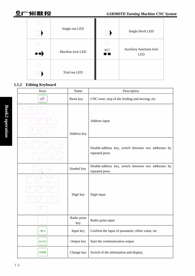
GSK980TD Turning Machine CNC System
Ⅰ-2
Book2 operation
Single run LED
Single block LED
Machine lock LED MST
Auxiliary functions lock
LED
Trial run LED
1.1.2 Editing Keyboard Keys Name Description
Reset key CNC reset, stop of the feeding and moving, etc.
Address input
Address key
Double-address key, switch between two addresses by repeated press
, Symbol key
Double-address key, switch between two addresses by repeated press
Digit key Digit input
Radix point key
Radix point input
Input key Confirm the input of parameter, offset value, etc
Output key Start the communication output
Change key Switch of the imfomation and display.

Chapter 1 Chapter 1 Operation and Display
Ⅰ-3
Book2
operation
Keys Name Description
Edit key
Insert, modify or delete the part program or field In
editing. (INSERT
ALTER can switch between inserting and modifying by repeated press)
EOB
EOB key End prompt of block input
cursor move key
Move the cursor in different directions.
Page up/down
key Page up/down on display
1.1.3 Display Menu Menu keys Comment
Enter the position interface. There are four display models including relative coordinate, absolute coordinate, integrated coordinate, coordinate & program.
Enter the program interface. There are three display models including the content of program, the list of program, the program status.
OFFSET
Enter the tool offset interface, macro variable interface (two interfaces can be switched by repeated press). Tool offset interface displays the tool offset value; macro variable interface displays the macros variable of the CNC.
ALARM
Enter the alarm interface. There are two display models including CNC alarm and PLC alarm.
SETTING
Enter the setup interface, graph interface (two interfaces can be switched by repeated press). There are switchs setup, data backup, and password setup; And there are graph setup interface and graph display interface in graph interface.
Enter the interfaces of status parameter.datas parameter and screw compensation parameter interface (interfaces can be switched by repeated press)
Enter the interfaces of diagnosis, PLC status, PLC datas, machine soft panel, version information (interfaces can be switched by repeated press). The interfaces of diagnosis, PLC status, PLC data, the internal signal status of CNC and the status of the PLC addresses and the data. It can be operated on the machine soft panel; The version of the CNC software, hardware and PLC are displayed in the version information interface.
1.1.4 Machine Operation Panel The functions of each key on the machine panel for GSK980TD is defined by PLC programs (ladder diagram).
For the defined functions of each key, please refer to the operation manual of the machine supplier. The functions of Keys in initial PLC program are as follows:
Keys Name Description Available operation mode
PAUSE Feedhold key Program, MDI dictates pause Auto and MDI modes
RUN Loop start key
Start to run the programs and MDI dictates
Auto and MDI modes

GSK980TD Turning Machine CNC System
Ⅰ-4
Book2 operation
Keys Name Description Available operation mode
F E E D R AT E
O V E R RI D E
Feedrate key Adjust the feedrate
Auto, MDI, Edit, Machine zero point return, Handwheel(MPG), Single block, JOG, Program zero point return modes
OVERRIDE
RAPID
Rapid speed key Adjust the rapid move speed
Auto, MDI, Machine zero point return, Manual, Program zero point return modes
OVERRIDE
SPINDE
Spindle speed key
Adjust the spindle speed (available under the simulate spindle rev mode)
Auto, MDI, Edit, Machine zero point return, Handwheel (MPG), Single block, Manual, Program zero point return modes
TOOL
Manual toolchange key
Manual change of tools
Machine zero point return, Handwheel(MPG), Single block, Manual, Program zero point return modes
Jog key Spindle jog on/off
LUR.
JOG
Lubrication key Lubrication on/off
Machine zero point return, Handwheel (MPG), Single block, Manual, Program zero point return modes
COOLANT Coolant key Coolant on/off
Auto, MDI, Edit, Machine zero point return, Handwheel (MPG), Single block, Manual, Program zero point return modes
CCW
STOP
CW
Spindle key
Spindle start to run forward Spindle stop Spindle start to run reverse
Machine zero point return, Handwheel (MPG), Single block, Manual, Program zero point return modes
Rapid switch key
Change between rapid move and feed modes
Auto, MDI, Machine zero point return, Manual, Program zero point return modes

Chapter 1 Chapter 1 Operation and Display
Ⅰ-5
Book2
operation
Keys Name Description Available operation mode
Manual feed key
Moving X, Y, Z axises forward/ reverse under Manual or Single block modes
Machine zero point return, Single block, Manual, Program zero point return modes
Handwheel (MPG) selection
key
Selecting one axes to control from X,Y,Z axis under handwheel (MPG) mode
Handwheel (MPG) mode
Handwheel (MPG) /Single
step,rapid override key
Handwheel unit 0.001/0.01/0.1 mm,Single step unit 0.001/0.01/0.1 mm
Auto, MDI, Machine zero point return, Handwheel (MPG), Single block, Manual, Program zero point return modes
SINGLE Single block key
Switch between single block /continuous running status, the single block running indicator LED is on if single block running status is available
Auto, MDI modes
SKIP
Segment skip key
When segment skip indicator LED is on, the segment with front ‘/’ will be skipped.
Auto, MDI modes
Machine lock key
The machine lock indicator LED is on when the machine is locked, X,Y axis outputs are unavailable
Auto, MDI, Edit, Machine zero point return, Handwheel (MPG), Single block, Manual, Program zero point return modes
MST
Auxiliary functions lock
key
The auxiliary functions lock indicator LED is on when it is locked, M, S, T functions are unavailable.
Auto, MDI modes
DRY Dry running key
The try running indicator LED is on when it is under dry running mode, user program/MDI dictates are run but the machine is without any action.
Auto, MDI modes
EDIT Edit mode key Enter edit mode
Auto, MDI, Machine zero point return, Handwheel (MPG), Single block, Manual, Program zero point return modes
AUTO
Automatic mode key
Enter automatic mode
MDI, Edit, Machine zero point return, Handwheel (MPG), Single block, Manual, Program zero point return modes

GSK980TD Turning Machine CNC System
Ⅰ-6
Book2 operation
Keys Name Description Available operation mode
MDI
MDI mode key
Enter MDI mode
Auto, Edit, Machine zero point return, handwheel, single block, manual operation, program zero point return modes
Machine zero point return mode key
Enter machine zero point return mode
Auto, MDI, Edit, Handwheel (MPG), Single block, Manual, Program zero point return modes
MPG
Single step/handwheel (MPG) mode
key
Enter single step or handwheel modes (Select one mode between them by parameter)
Auto, MDI, Edit, Manual, Program zero point return modes
JOG
Manual operation mode
key Enter manual operation mode
Auto, MDI, Edit, Machine zero point return, Handwheel, Single block, Program zero point return modes
Program zero point return key
Enter program zero point return mode
Auto, MDI, Edit, Machine zero point return, handwheel, Single step, manual modes
1.2 GENERAL OPERATION
There are seven operation modes including edit, automatic, MDI, machine zero point return, single step/handwheel, manual operation, program zero point return.
Edit mode Under the edit mode, the programs can be set up or deleted or modified, etc.
Automatic mode Under the automatic mode, the program is run automatically.
MDI mode
Under the MDI mode, the parameters and the dictates can be input and performed.
Machine zero point return mode
Under the machine zero point return mode, the zero point return for X or Z axis can be performed separately.
Handwheel/single block mode

Chapter 1 Chapter 1 Operation and Display
Ⅰ-7
Book2
operation
Under the handwheel/single block mode, the selected axes moves according to the selected increasement.
Manual mode
Under the manual mode, the manual feed, munual rapid move, feedreate adjustment, rapid override adjustment and spindle on/off, lubrication on/off, coolant on/off, spindle jog, manual toolchange, etc can be performed.
Program zero point return mode Under the program zero point return mode, the zero point return for X or Z axis can be performed separately.
1.3 DISPLAY
There are nine kinds of displays such as position interface, program interface, etc, and there are several pages (screens) in each interface. Each interfacee is nothing to do with the operation mode. Display menu, page and hiberarchy are as follows: Keys Interfaces Display pages
Position interface
Program interface
Tool offset interface
OFFSET
Macro variable interface
ALARM
Alarm interface

GSK980TD Turning Machine CNC System
Ⅰ-8
Book2 operation
Keys Interfaces Display pages
Setup interface
SETTING
Graphic interface
Status parameter
Datas parameter
Worm offset value parameter
CNC diagnosis
PLC status
PLC datas
Tool panel
Version infomation
1.3.1 Position Interface
Enter the position interface by pressing the key, there are four pages including absolute coordinate,

Chapter 1 Chapter 1 Operation and Display
Ⅰ-9
Book2
operation
relative coordinate, integrated coordinate and coordinate/program, which can be turned over by pressing key
or key. 1) Absolute coordinate page The displaying coordinates of X and Z axises are absolute positions in current workpiece’s coordinate, and the
coordinates are kept when the power returns on; the coordinate of workpiece is defined by G50.
Programming speed: defined by F code in the user program. Note: “Programming speed” can be displayed under automatic and MDI modes; under the machine
zero point return, program zero point return, and manual mode, the manual feedrate will be displayed; under the handwheel mode, the handwheel increasement will be displayed; and under the single blcok mode, the single block increasement will be displayed.
Actual speed: the transformed speed by the feedrate override during the actual running. Feedrate override: the selected override by the feedrate override keys. G code: The modal values of G codes in group 01 and group 03. (the group 01 and 03 values of G code in
the running segment?) Part count: When the M30 (or M99 in the main program) is finished once, the workpice number will be
added one accordingly. Cut time: Count from the automatic running start, the time units take turns as hour, minute and second.
Part count and cut time memory reset after power off.
Part count reset: Press and hold the CANCEL
key, and then press the key.
Cut time reset: Press and hold the CANCEL
key, and then press the key.

GSK980TD Turning Machine CNC System
Ⅰ-10
Book2 operation
S0000: Spindle rev is feedbacked by the spindle encoder; a spindle encoder must be fixed if the actual rev display is required.
T0100: Current tool number and tool offset number. 2) Relative coordinate page
The displaying coordinated values of U and W axises are relative positions of reference point, and the coordinates can be kept when the power returns on. The U and W can be reset at any time. After reset, the current position is the new reference point. When the Bit1 of parameter No.005 is 1 in this controller, the coordinate of U and W are the same with the absolute coordinate when the absolute coordinate is defined by G50.
Relative coordinate reset:
Press the key until the letter U glints on relative coordinate display page, then press theCANCEL
key, U will be reset.
Press the key until the W glints on relative coordinate display page, then press the CANCEL
key, U will be reset.
3) Integrated coordinate page
On the integrated page, relative coordinate, absolute coordinate, tool coordinate, distances to go are displayed (Distances to go is displayed only under the auto and MDI modes).
The displaying coordinate of machine coordinate are the same with the current position in the machinecoordinate, the machine coordinate is defined based on the machine zero point return.
Distances to go are the distances between the current position and target position that is appointed by the segment or MDI dictate.
The display is shown as follows:
4) Coordinate & program pages

Chapter 1 Chapter 1 Operation and Display
Ⅰ-11
Book2
operation
On the coordinate & program page, the absolute and relative coordinates are displayed at the same time for the current position (If the Bit0 of parameter No.180 is 1, the absolute coordinate and distances to go for current position will be displayed), as well as the 5 segments of current program, during the processing, the displaying programs are updating momentarily, the cursor falls at the running block.
1.3.2 Program Interface
Enter the porgram interface by pressing the CANCEL
key, under the non-edit modes, there are three pages
including program content, program status and program list. Switch them by pressing the key or
key. Under the edit mode, there is only program contents page,by pressing the key or key to display all the contents of current program。
1) Program contents page On the program contents page, program contents including current block are displayed. The program
contents can be browsed forward or reverse by pressing key or key.
2) Program status page On the program status page, the status of current G,M,S,T,F dictates will be displayed, but contents of
current block will be displayed under the auto and MDI modes.

GSK980TD Turning Machine CNC System
Ⅰ-12
Book2 operation
3) Program list page The displaying contents of program list page: (a) Version of the software: Current sofeware version of the controlle will be displayed. (b) Workpiece program account: The maximium number of programs can be storaged and the number of
storaged programs (including the subprograms) will be displayed. (c) Storage size: The maximium size of programs can be storaged and the size of storaged programs will
be displayed. (d) Program list: Display the names of user program orderly.
1.3.3 Tool Offset, Macro Variable Interface
OFFSETkey is a compound key,the display will come into tool offset interface under other display by pressing
OFFSET once,press
OFFSET again, it will come into macro veriable interface。
1.Tool offset interface There are 5 pages of tool offset pages under the tool offset interface, and there are 33 groups of offset
(No.000~No.032) are available for users, by pressing key or key to change pages, details are listed as follows:

Chapter 1 Chapter 1 Operation and Display
Ⅰ-13
Book2
operation
2. Macro variable interface
There are three pages under macro variable interface, each page can be displayed by pressing the key
or key, 48 groups of macro variable(No.200~No.231 and No.500~No.515)will be displayed on the page, the macro variable value can be set directly by macro dictates or keyboard. The macro variable would be hold in case of power off.
1.3.4 Alarm Interface
Enter the alarm interface by pressing the ALARM
key, there are two pages including CNC alarm page and PLC
alarm, it can be checked by pressing key or key. 1) PLC alarm: Display the amount of CNC alarms and PLC alarms, and the current alarm number of PLC, it can
be displayed 24 PLC alarms at the same time, the detailed corresponding infomations of each alarm can be checked out by moving the cursor. If there are two alarms, page is shown as follows:
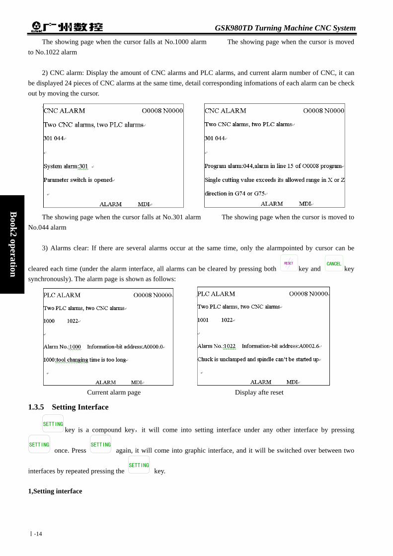
GSK980TD Turning Machine CNC System
Ⅰ-14
Book2 operation
The showing page when the cursor falls at No.1000 alarm The showing page when the cursor is moved to No.1022 alarm
2) CNC alarm: Display the amount of CNC alarms and PLC alarms, and current alarm number of CNC, it can
be displayed 24 pieces of CNC alarms at the same time, detail corresponding infomations of each alarm can be check out by moving the cursor.
The showing page when the cursor falls at No.301 alarm The showing page when the cursor is moved to No.044 alarm
3) Alarms clear: If there are several alarms occur at the same time, only the alarmpointed by cursor can be
cleared each time (under the alarm interface, all alarms can be cleared by pressing both RESET
key and CANCEL
key synchronously). The alarm page is shown as follows:
Current alarm page Display afte reset
1.3.5 Setting Interface
SETTINGkey is a compound key,it will come into setting interface under any other interface by pressing
SETTING once. Press
SETTING again, it will come into graphic interface, and it will be switched over between two
interfaces by repeated pressing the SETTING
key.
1,Setting interface

Chapter 1 Chapter 1 Operation and Display
Ⅰ-15
Book2
operation
There are three pages under setting interface, each page can be displayed by pressing the key
or key, 1) Switchs setting: Displaying parameter, program, and automatic number on/off. Parameter switch: when the parameter switch is on, the parameter can be modified; otherwise, it cannot be
modified. Program switch: when the program switch is on, the program can be edited; otherwise, it cannot be edited. Automatic number switch: when the Automatic number switch is on, the number of programs can be generated
automatically; otherwise, it only can be input manually when it is needed.
2) Datas backup: on this page, it can be backuped or resumed for CNC datas (including status parameter, data
parameter, worm offset, tool offset, etc.). Datas backup (user): for users to backup the CNC datas (preserve) Datas resume (user): for users to resume the CNC datas (read) Resume default parameter 1 (test): for users to read the original parameter datas for CNC testing. Resume default parameter 2 (step): for users to read the original parameter datas for matching step driver. Resume default parameter 3 (servo): for users to read the original parameter datas for matching servo driver.
The displaying page for users of 3,4,5 level The displaying page for users of 2 level 3) Password setting: display , setting users level There are four password levels of GSK980TD, from high to low they are machine builder (2 level), equiment
administrator (3 level), technician (4 level), operator (5 level) Machine builder level: be able to modify the status parameter, datas parameter, worm offset values, programs
editing (including variable macros), PLC ladderlike graph edit and modify, download the ladderlike graphs of CNC.
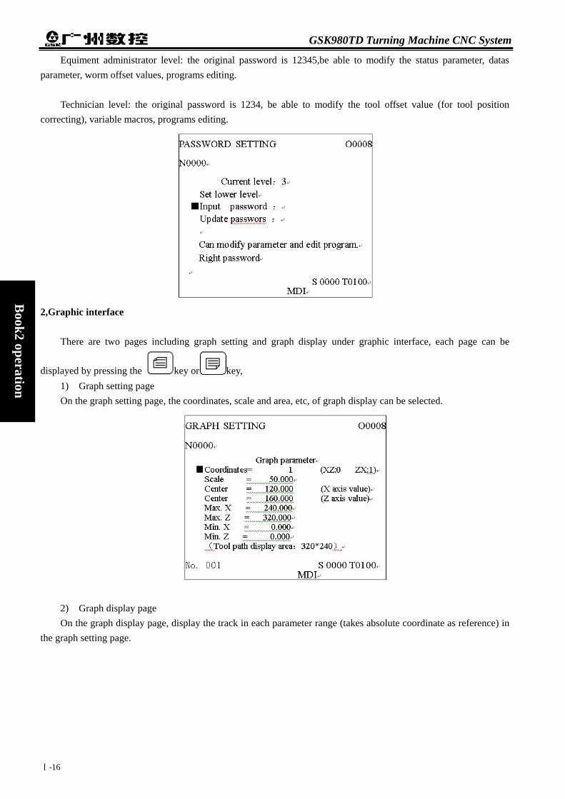
GSK980TD Turning Machine CNC System
Ⅰ-16
Book2 operation
Equiment administrator level: the original password is 12345,be able to modify the status parameter, datas parameter, worm offset values, programs editing.
Technician level: the original password is 1234, be able to modify the tool offset value (for tool position
correcting), variable macros, programs editing.
2,Graphic interface There are two pages including graph setting and graph display under graphic interface, each page can be
displayed by pressing the key or key, 1) Graph setting page On the graph setting page, the coordinates, scale and area, etc, of graph display can be selected.
2) Graph display page On the graph display page, display the track in each parameter range (takes absolute coordinate as reference) in
the graph setting page.
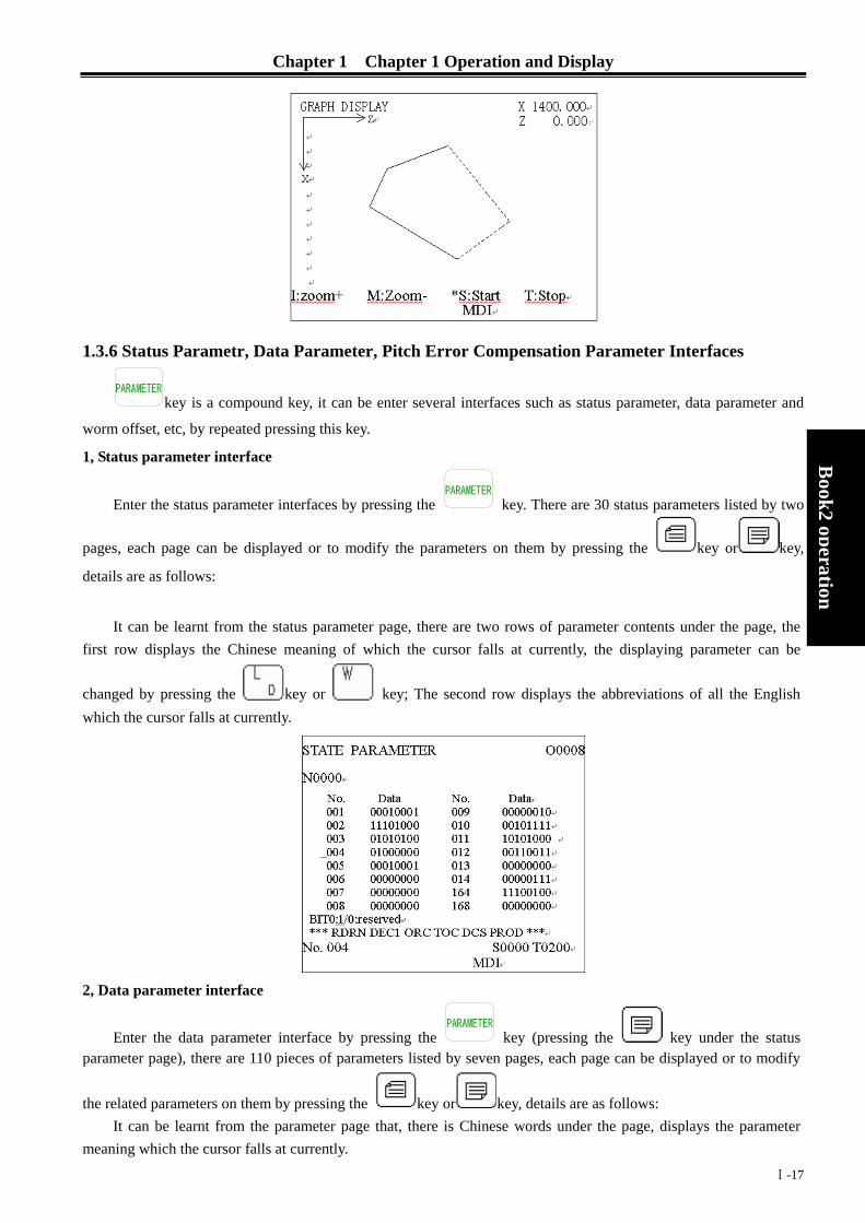
Chapter 1 Chapter 1 Operation and Display
Ⅰ-17
Book2
operation
1.3.6 Status Parametr, Data Parameter, Pitch Error Compensation Parameter Interfaces
key is a compound key, it can be enter several interfaces such as status parameter, data parameter and
worm offset, etc, by repeated pressing this key.
1, Status parameter interface
Enter the status parameter interfaces by pressing the key. There are 30 status parameters listed by two
pages, each page can be displayed or to modify the parameters on them by pressing the key or key,
details are as follows:
It can be learnt from the status parameter page, there are two rows of parameter contents under the page, the
first row displays the Chinese meaning of which the cursor falls at currently, the displaying parameter can be
changed by pressing the key or key; The second row displays the abbreviations of all the English which the cursor falls at currently.
2, Data parameter interface
Enter the data parameter interface by pressing the key (pressing the key under the status parameter page), there are 110 pieces of parameters listed by seven pages, each page can be displayed or to modify
the related parameters on them by pressing the key or key, details are as follows: It can be learnt from the parameter page that, there is Chinese words under the page, displays the parameter
meaning which the cursor falls at currently.

GSK980TD Turning Machine CNC System
Ⅰ-18
Book2 operation
3, pitch error compensation parameter interface
Enter the worm offset value interface by pressing the key, there are 256 pieces of worm offset value
parameters listed by 32 pages, each page can be displayed by pressing the key or key:
1.3.7 CNC Diagnosis, PLC Status, PLC Data, Tool Panel, Version Information Interfaces
key is a compound key, it can be enter CNC diagnosis, PLC status, PLC datas, Tool panel, version
information interfaces by repeated pressing this key.
1,CNC diagnosis interface The status of input/output between CNC and machine, the signals transmiting between CNC and PLC, the
inside datas of PLC and the inside status of CNC, all these infomations can be displayed by the diagnosis. Enter the
CNC diagnosis page by pressing the key, there are keyboad diagnosis, status diagnosis and auxiliary
parameters, etc, can be displayed.and they can be check out by pressing key or key。 On the CNC diagnosis page, there are two rows of Chinese words under the page, the first row displays the
Chinese meaning of which the cursor falls at currently, the displaying parameter can be changed by pressing the
key or key; The second row displays the abbreviations of all the English which the cursor falls at currently.

Chapter 1 Chapter 1 Operation and Display
Ⅰ-19
Book2
operation
2, PLC status interface
There displaying in turn of some address status such as X0000~X0029, Y0000~Y0019, F0000~F0255, G0000~G0255, A0000~A0024, K0000~K0039, R0000~R0999 under the PLC status interface. Enter the PLC
status interface by repeated pressing the key. The singnal status for each PLC addresses can be
checked out by pressing the key or key. On the PLC status page, there are two rows of words under the page, the first row displays the Chinese meaning
of which the cursor falls at currently, the displaying parameter can be changed by pressing the key or key; The second row displays the abbreviations of all the English which the cursor falls at currently.
3, PLC data interface There displaying in turn of some datas of register such as T0000~T0099,D0000~D0999,C0000~
C0099,DT000~DT099,DC000~DC099 under the PLC status interface. Enter the PLC status interface by repeated
pressing the key. The singnal status for each PLC addresses can be checked out by pressing the key
or key. On the PLC data page, there is a row of Chinese words under the page, shows the meaning of the parameter that
the cursor falls at currently.

GSK980TD Turning Machine CNC System
Ⅰ-20
Book2 operation
4, Tool panel
Enter the tool panel by repeated pressing the key, the machine can be controlled by the panel on this page, the page of tool panel are displayed as follows:
Manual:
By repeated pressing the key, the function of machine lock can be switched between on and off,
function the same with key.
By repeated pressing the key, the function of auxiliary lock can be switched between on and off,
function the same with
MST
key.
By repeated pressing the key, the function of single step can be switched between on and off, function
the same with SINGLE key.
By repeated pressing the key, the function of try running can be switched between on and off, function
the same with DRY key.
By repeated pressing the key, the function of block skip can be switched between on and off, function

Chapter 1 Chapter 1 Operation and Display
Ⅰ-21
Book2
operation
the same with SKIP key. 5, Version infomation
Enter the version information interface by repeated pressing the key, there are software, hard ware, PLC version infomations of current CNC system displaying on the version information page. Displaying page are as follows:
1.3.8 LCD Brightness Adjusting
Enter the relative coordinate displaying page by pressing the key(Also pressing the key or
key if necessary),pressing the key or key until the LED of the key start to glitter,and then
press the key,the contrast of LCD will be lower(darker),press the key,the contrast of LCD will be higher(brighter)。
1.4 COMMON OPERATION TABLE
Class Function Operation
Operation
modes
Displaying
page
Password
level
Program
switch
Parameter
switch
Comment

GSK980TD Turning Machine CNC System
Ⅰ-22
Book2 operation
Class Function Operation
Operation
modes
Displaying
page
Password
level
Program
switch
Parameter
switch
Comment
Relative
coordinate value
of X axis reset
,
CANCEL
Relative
coordinates
Relative
coordinate value
of Z axis reset
,
CANCEL
Relative
coordinate
Part count reset
CANCEL+
Cut time reset
CANCEL+
Relative or
absolute
coordinate
Chapter 2
1.3.1
Tool offset value
of X axis reset
,
INPUT
Tool offset
Level 2,3,4
Chapter 2
7.4.3
Reset
Tool offset value
of Z axis reset
,
INPUT
Tool offset Level 2,3,4 Chapter 2
7.4.3
Status parameter
Parameter
value,
INPUT
MDI modeStatus
parameter Level 2,3 On
Data parameter
Parameter
value,
INPUT
MDI modeData parameter
Level 2,3 On
Chapter 2
7.4.3
Data
setting
Worm offset value
of X axis input
,
offset value,
INPUT
MDI mode
Worm
offset value
parameter
Level 2 On Chapter 2
10.1.3

Chapter 1 Chapter 1 Operation and Display
Ⅰ-23
Book2
operation
Class Function Operation
Operation
modes
Displaying
page
Password
level
Program
switch
Parameter
switch
Comment
Worm offset value
of Z axis input
,
offset value,
INPUT
MDI mode
Worm offset
value
parameter
Level 2 OnChapter 2
10.1.3
Macro variable
Macro
variable
value,
INPUT
Macro variable Level 2,3,4
Tool offset
increment of X
axis input
,
Offset
increasemen
t
Tool offset Level 2,3,4 Chapter 2
7.4.2
Tool offset
increment of Z
axis input
,
offset
increasement
Tool offset Level 2,3,4 Chapter 2
7.4.2
Search down from
current cursor
position
Letter,
Edit mode Program
contents Level 2,3,4 On
Chapter 2
6.1.3
Search up from
current cursor
position
Letter,
Edit mode Program
contents Level 2, 3,4 On
Chapter 2
6.1.3
Search down from
current program ,
Level 2,3,4 Chapter 2
6.4.1
Search up from
current program ,
Level 2,3,4 Chapter 2
6.4.1
Searching
Searching for the
appointed program
,Name of
program,
Edit or
automatic
mode
Program
contents, list or
status
Level 2,3,4 Chapter 2
6.4.2
GSK980TD Turning Machine CNC System
Ⅰ-24
Book2 operation
Class Function Operation
Operation
modes
Displaying
page
Password
level
Program
switch
Parameter
switch
Comment
Searching for the
status parameter,
data parameter or
worm offset value
parameter
number of
parameter
INPUT
Related pages
of data
Chapter 2
10.1.3
Searching for the
PLC status and
data
,
address
number,
INPUT
PLC status &
data
DELETE
Edit mode Program
contents Level 2,3,4 On The letter with
cursor will be
deleted CANCEL
Edit mode Program
contents Level 2,3,4 On
Chapter 2
6.1.6
Single block
detecting
Move the
cursor to the
head of row,
DELETE
Edit mode Program
contents Level 2,3,4 On
The block
has it’s
number
Chapter 2
6.1.7
Blocks delecting
CANCEL,
,
number,
DELETE
Edit
mode
Program
contents Level 2,3,4 On
Chapter 2
6.1.8
Block delecting
CHANGE
, letter,
DELETE
Edit
mode
Program
contents Level 2,3,4 On
Chapter 2
6.1.9
Delete
Single program
delecting
,
name of
program,
DELETE
Edit
mode
Program
contents Level 2,3,4 On
Chapter 2
6.3.1
Chapter 1 Chapter 1 Operation and Display
Ⅰ-25
Book2
operation
Class Function Operation
Operation
modes
Displaying
page
Password
level
Program
switch
Parameter
switch
Comment
All programs
delecting
,
999,
DELETE
Edit
mode
Program
contents Level 2,3,4 On
Chapter 2
6.3.2
Rename Rename for
programs
,
name of
program,
INSERT
ALTER
Edit mode Program
contents Level 2,3,4 On
When the
program
number is
larger
than
9000,
password
of level 2
is needed.
Chapter 2
6.6
Copy Copy program
,
name of
program,
CHANGE
Edit mode Program
contents Level 2,3,4 On
When the
program
number is
larger
than
9000,
password
of level 2
is needed.
Chapter 2
6.7
Tool offset OUTPUT
Edit mode Tool offset Level 2,3 On
Status parameters OUTPUT
Edit mode Status
parameter Level 2,3 On
Data parameters OUTPUT
Edit mode Data
parameters Level 2,3 On
CNC →
CNC
(Send)
Worm offset value
parameter OUTPUT
Edit mode
Worm offset
value
parameter
Level 2 On
Chapter2
11.6
GSK980TD Turning Machine CNC System
Ⅰ-26
Book2 operation
Class Function Operation
Operation
modes
Displaying
page
Password
level
Program
switch
Parameter
switch
Comment
Transmitting for
single program
,
name of
program,
OUTPUT
Edit mode Program
contents Level 2,3,4 On
Transmitting for
all programs
,
999,
OUTPUT
Edit mode Program
contents Level 2,3,4 On
Tool offset Edit mode Level 2,3,4 On
Status parameter Edit mode Level 2,3 On
Data parameter Edit mode Level 2,3 On
Worm offset value
parameter Edit mode Level 2 On
CNC →
CNC
( receive
)
Program of
workpiece Edit mode Level 2,3,4 On
Chapter 2
11.6
Tool offset OUTPUT
Edit mode Tool offset Level 2,3,4 On Chapter 2
11.5.3
Status parameter OUTPUT
Edit mode Status
parameter Level 2,3,4 On
Data parameter OUTPUT
Edit mode Data parameter Level 2,3 On
Worm offset value
parameter OUTPUT
Edit mode
Worm offset
value
parameter
Level 2 On
Chapter 2
11.5.4
CNC
→PC
(upload)
Transmitting for
single program
,
name of
program,
OUTPUT
Edit mode Program
contents Level 2,3,4 On
Chapter 2
11.5.1

Chapter 1 Chapter 1 Operation and Display
Ⅰ-27
Book2
operation
Class Function Operation
Operation
modes
Displaying
page
Password
level
Program
switch
Parameter
switch
Comment
Transmitting for
all program
,
999,
OUTPUT
Edit mode Level 2,3,4 On Chapter 2
11.5.2
Tool offset Edit mode Level 2,3,4 On
Chapter
two
11.4.2
Status parameter Edit mode Level 2,3 On
Data parameter Edit mode Level 2,3 On
Chapter 2
11.4.3
Worm offset value
parameter Edit mode Level 2 On
Chapter 2
11.4.3
level 2
password
is needed
PC→CNC
(Download)
Program of
workpiece Edit mode Level 2,3,4 On
Chapter 2
11.4.1
When the
program
number is
larger
than
9000,
password
of level 2
is needed.
Chapter 2
6.7
LCD
contrast
Contrast become
higher (brighter)
( ,
)or(
,
)
Edit mode Relative
coordinate
Chapter 2
1.3.8

GSK980TD Turning Machine CNC System
Ⅰ-28
Book2 operation
Class Function Operation
Operation
modes
Displaying
page
Password
level
Program
switch
Parameter
switch
Comment
Contrast become
lower (darker)
(
,
)or(
,
)
Edit mode Relative
coordinate
Turn on the
parameter switch Switch setting Level 2,3
Turn on the
program switch Switch setting Level 2,3,4
Turn on the
automatic number Switch setting
Turn on/off the
parameter switch Switch setting Level 2,3
Turn off the
parameter switch Switch setting Level 2,3,4
Switch
setting
Turn off the
automatic number Switch setting
Chapter 2
10.1.1
Note:Symbol “,” in the operation table means there is distance between pressing the two keys, Symbol “+” in the
operation table means there is no distance between pressing two keys, the keys have to be pressed at the same time.
For example: ,CANCEL
means to press the key first,and then press the CANCEL
key ;
CANCEL+ means to press the two keys at the same time.

Chapter 2 Power on/off and safety operation
Chapter 2 POWER on/off and SAFETY OPERATION
2.1 POWER on
Before turning on the GSK980TD, Please confirm: 1、 The machine is normal. 2、 The voltage of power supply is up to the mustard. 3、 The connections are connected correctly and steadily. Below picture will turn up on the screen after the power on of GSK980TD.
Book2
operation
At the moment the system is processing the self-inspect and initialization. And after that, the screen will show the page of current position (relative coordinates).
2.2 POWER off
Before turning off the machine, please confirm: 1、 The X and Z axies of CNC are stopped.
2、 Auxiliary function (such as spindle, coolant,etc.) off.
3、 Cut off the CNC power before cutting off the machine power. Note: About cutting off the machine power please refer to the operation manual from the machine factory.
2.3 OVERRIDE PROTECTION
To avoid damage of the machine due to the overrides of X and Z axies, the machine has to take steps of override protection.
2.3.1 Override Protection for Hardware Install stroke limit inhibition switches for X and Z axies separately, and connect the wire according to below
Ⅱ-1
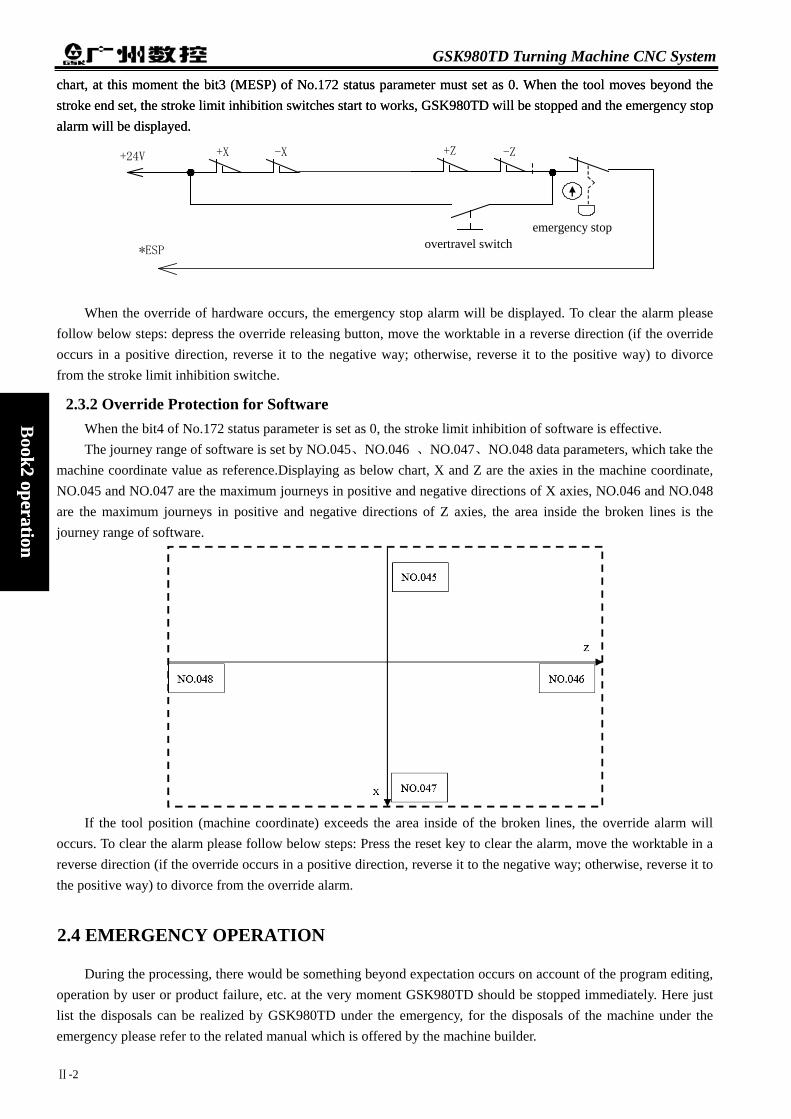
GSK980TD Turning Machine CNC System
chart, at this moment the bit3 (MESP) of No.172 status parameter must set as 0. When the tool moves beyond the stroke end set, the stroke limit inhibition switches start to works, GSK980TD will be stopped and the emergency stop alarm will be displayed.
chart, at this moment the bit3 (MESP) of No.172 status parameter must set as 0. When the tool moves beyond the stroke end set, the stroke limit inhibition switches start to works, GSK980TD will be stopped and the emergency stop alarm will be displayed.
+X -X +Z -Z
overtravel switch
+24V
*ESP
emergency stop
When the override of hardware occurs, the emergency stop alarm will be displayed. To clear the alarm please follow below steps: depress the override releasing button, move the worktable in a reverse direction (if the override occurs in a positive direction, reverse it to the negative way; otherwise, reverse it to the positive way) to divorce from the stroke limit inhibition switche.
Book2 operation
ok2 operation
2.3.2 Override Protection for Software When the bit4 of No.172 status parameter is set as 0, the stroke limit inhibition of software is effective. The journey range of software is set by NO.045、NO.046 、NO.047、NO.048 data parameters, which take the
machine coordinate value as reference.Displaying as below chart, X and Z are the axies in the machine coordinate, NO.045 and NO.047 are the maximum journeys in positive and negative directions of X axies, NO.046 and NO.048 are the maximum journeys in positive and negative directions of Z axies, the area inside the broken lines is the journey range of software.
If the tool position (machine coordinate) exceeds the area inside of the broken lines, the override alarm will
occurs. To clear the alarm please follow below steps: Press the reset key to clear the alarm, move the worktable in a reverse direction (if the override occurs in a positive direction, reverse it to the negative way; otherwise, reverse it to the positive way) to divorce from the override alarm.
2.4 EMERGENCY OPERATION
During the processing, there would be something beyond expectation occurs on account of the program editing, operation by user or product failure, etc. at the very moment GSK980TD should be stopped immediately. Here just list the disposals can be realized by GSK980TD under the emergency, for the disposals of the machine under the emergency please refer to the related manual which is offered by the machine builder.
Ⅱ-2

Chapter 2 Power on/off and safety operation
2.4.1 Reset
When the output and the axies are abnomal, GSK980TD will be reset by pressing the key.
1、 All axies are stopped. 2、 Output of M and S functions are unavailable (Whether shut down the spindle rotates forward/reverse,
lubrication, coolant signalm, or PLC ladderlike chart define automatically can be set by the parameter by
pressing the key. )
3、 Automatic running is terminated, modal status functions and status are remained.
2.4.2 Emergency Stop
Book2
operation
Pressing the emergency stop button during the processing under the dangerous or emergency situations (when
the outer emergency stop signal is available), The CNC will be turned in enmergency stop,at the very moment the
moving of machine will be stopped immediately, all output (such as rotates of the spindle, coolant, etc.) is shut down.
Clear the emergency stop alarm by releasing the emergency stop button, CNC will be turned into reset status. The
connection of the circuit is described in section 2.2.1 of this chapter.
Note1: Please confirm all failure is settled before releasing the emergency stop alarms.
Note2: Depress the emergency stop button before power on/off may reduce the electricity impact of the
equipment.
Note3: In order to ensure the correctness of coordinate position, machine zero point return needs to be
performed again after clearing the emergency stop alarm (If there is no zero point installed, please do
not perform this action). Note4: The outer emergency stop will only be in effect based on the Bit3(MESP)is set as 0 of No.172
parameter.
2.4.3 Feed Hold
Depress the key can hold the running during the process. It must be especially reminded that during the threading cutting and cycle running dictates, this function can not stop the running immediately.
2.4.4 Cutting off the Power In order to avoid any accidents happen the machine power can be cut off immediately under the dangerous or
emergency situations during the process. It must be reminded that there may be some different between the display coordinate and the actual position after the power off, so the tool adjusting and related operations have to be re-done again.
Ⅱ-3


Chapter 3 Manual operation
Ⅲ-1
Book2
operation
Chapter 3 MANUAL OPERATION
Enter the manual operation mode by pressing the JOG key, manual feed, spindle control, override adjusting, tool change, etc, can be performed under the manual operation mode.
Attention! The function of each key on the operation panel of 980TD is defined by PLC programs (ladderlike chart),
for the detail functions please refer to the manual which is offered by the machine builder. The following mentioned functions are described according to the standard PLC program of 980TD,
please take note!
3.1 MOVEMENT of AXIES
Under the manual operation mode, manual feeding, manual rapid feeding of two axies can be performed.
3.1.1 Manual Feed
Depress and hold the or of can move the X axies forward or reverse, the
axies will be stopped by releasing the keys;Depress and hold the or can move the Z axies forward or reverse, the axies will be stopped by releasing the keys. User can also depress the two keys of X and Z directions to realize the moving together. The federate override adjusting of real time is effective.
During the manual feed operation, depress the key, the LED of in the status indicating area will be turned on and the machine is on manual rapid feeding status.
3.1.2 Manual Rapid Traverse
Depress the key of and hold it until the LED of rapid traverse in the status
indicating area is turned on, then depress the or key can move the X axies rapidly forward or reverse,
the axies will be stopped by releasing the keys;Depress and hold the or can move the Z axies rapidly forward or reverse, the axies will be stopped by releasing the keys. User can also depress the two keys of X and Z directions to realize the moving together. The federate override adjusting of real time is effective.
During the manual rapid feeding operation, depress the key, the LED of in the status indicating area will be turned off, the rapid traverse is unavailable, please use manual feeding.
Note1: After the power on or release the emergency stop, if the reference point has not been returned, and
when the rapid traverse switch is on (namely,the indicating LED of rapid traverse is on),the rapid moving speed is whether manual feeding speed or rapid traverse speed is decided by the Bit0 (ISOT)

GSK980TD Turning Machine CNC System
Ⅲ-2
Book2 operation
of No.012 status parameter in GSK980TD.
Note2: is unavailable under the EDIT/MANUAL modes.
3.1.3 Speed Adjusting
Under the manual mode, the manual feed override can be modified by pressing the or key
in
FEEDRATE
OVERRIDE
, there are 16 levels. The connections between feed override and feedrate are as follows.
Feedrate override (%) Feedrate (mm/min)
0 0
10 2.0
20 3.2
30 5.0
40 7.9
50 12.6
60 20
70 32
80 50
90 79
100 126
110 200
120 320
130 500
140 790
150 1260
Note: There is about 2% error in the table.
Under the manual rapid traverse, manual rapid traverse override can be modified by pressing the or

Chapter 3 Manual operation
Ⅲ-3
Book2
operation
key in
OVERRIDE
RAPID
(it can be also modified by pressing the , , kdys,the corresponding
overrides are Fo,50%,100% ), there are four levels including Fo,25%,50%,100% of speed override of manual rapid traverse. (The speed of Fo is set by the No.032 data parameter) The selection of rapid traverse is effective under below status. (1) G00 rapid traverse (2) Rapid traverse during the fixed cycle. (3) The rapid traverse under G28 (4) Manual rapid traverse
3.1.4 Reset for Relative Coordinates Value
1) Enter the position interface by pressing the key , and then select the relative coordinate page by
pressing the or key.
2) Depress and hold the key until the LED of letter U in the page start to glitter, and then press the
CANCEL key.
3) Depress and hold the key until the LED of letter W in the page start to glitter, and then press the
CANCEL key.

GSK980TD Turning Machine CNC System
Ⅲ-4
Book2 operation
3.2 Other MANUAL OPERATIONS
3.2.1 Spindle Rotation forward/reverse and Stop Control
CW : Under the manual operation, the spindle rotates forward by pressing this key.
STOP : Under the manual operation, the spindle stops by pressing this key.
CCW : Under the manual operation, the spindle rotates reverse by pressing this key.
3.2.2 Spindle Step Feed
LUR.
JOG
: When the Bit7 of No.175 status parameter is set as 1,depress the LUR.
JOG
key to turn on the indicating LED, at this moment the spindle is under step feeding mode.
Under the spindle step feeding mode, depress the CW key, the spindle rotates forward on step feeding. The time and the speed of are set by No.108 and No.109 status parameters separately.
If the Bit7 of No.175 status parameter is set as 0 (at this moment the LUR.
JOG
dey is lubrication switch) or when
the LED of LUR.
JOG
is off, the spindle step feeding is unavailable.
3.2.3 Coolant Control
COOLANT : Under the manual operation, the coolant can be switched on/off by pressing this key.
3.2.4 Lubrication Control 1. Non-automatic lubrication DT17 =0:Non-automatic lubrication。
When the status parameter NO.175.7 =1, the LUR.
JOG
key in the panel is for spindle step feeding.
=0, the LUR.
JOG
key in the panel is for lubricating.
When the No.112 of status parameter is set as 0, it is exchangeable output of lubrication, depress the LUR.
JOG
key on the panel, the lubrication will be output, press it again the lubrication will be cancelled. When the M32 is running, the lubrication is on, and then run the M33, it will be cancelled.

Chapter 3 Manual operation
Ⅲ-5
Book2
operation
When the data parameter No.112>1, it is lubrication time-lapse output , depress the LUR.
JOG
key on the panel, the lubrication is on, when the time which is set by the data parameter No.112 pass through, the lubrication will be cancelled; When the M32 is running, lubrication is on, when the time which is set by the data parameter No.112 pass through, the lubrication will be cancelled. If the time is not yet up, if the M33 is performed, then the lubrication will be cancelled.
2. Automatic lubrication : DT17>0:Automatic lubrication, the lubrication time and interval can be set by DT17 and DT16
separately. The lubrication will be on during the time which was set by DT17 when the power on of GSK980TD,after that
the lubrication output will be stopped, and then after the interval which was set by DT16, the lubrication will be on
again, the rest may be deduced by analogy. During the automatic lubrication, the M32, M33 dictates and the LUR.
JOG
key on the panel are all unavailable.
3.2.5 Manual Tool Change
TOOL : Under the manual operation, depress this key, the tool will be changed by manual (if the current tool is the No.1, depress this key, the tool will be changed to No. 2, if the current tool is the No.4, depress this key, the tool will be changed to No. 1 ).
3.2.6 Spindle Override Adjusting Under the manual operation, when the simulative voltage output is selected to control the spindle speed, the
spindle speed can be adjusted.
Depress the spindle override key or of
OVERRIDE
SPINDE
, the speed can be changed by adjusting the spindle override, there are 8 levels of real time adjusting whose range is from 50% to 120% of spindle override can be realized.


Chapter 4 Handwheel/ Single step operation
Ⅳ-1
Book2
operation
Chapter 4 HANDWHEEL/ SINGLE STEP OPERATION Under the handwheel/single step operations, the machine moves according to the selected increasement.
Attention The function of each key on the operation panel of 980TD is defined by PLC programs (ladderlike chart),
for the detail functions please refer to the manual which is offered by the machine builder. The following mentioned functions are described according to the standard PLC program of 980TD,
please take note!
4.1 SINGLE STEP FEED
Set the Bit3 of system parameter as 0, enter the single operation mode by pressing the MPG key, the page will be shown as below:
4.1.1 Increment Selecting
Press the . or key to select the moving increment, the moving increment will be displayed on
the page. When the Bit1 (SINC) of No.173 status parameter is set as 1, the step length value of is not
effective; when the Bit1 is set as 0, . . keys are all effective。
If the key is pressed, the page will be shown as below:
Note: Under other operation modes besides from Edit and handwheel/single step, the rapid traverse can be

GSK980TD Turning Machine CNC System
Ⅳ-2
Book2 operation
modified by pressing the . . keys, the corresponding overrides are Fo,50%,100%.
4.1.2 Moving Direction Selecting
By pressing the or key, the X axis will be moved forward or reverse according to the single
increasement; By pressing the or key, the Z axis will be moved forward or reverse according to the single increasement.
4.2 HANDWHEEL FEED
Set the Bit3 of system parameter as 1, enter the handwheel operation mode by pressing the MPG key, the page will be shown as below:
The figure of handwheel are as follows:
The figure of the handwheel
4.2.1 Increasement Selecting
Select the increasement by pressing the . or key, the moving increasement will be shown on
the page. When the Bit1 (SINC)of No.173 status parameter is set as 1, the step length value of is not
effective; when the Bit1 is set as 0, . . are all effective. The page will be displayed as below if
the is pressed:
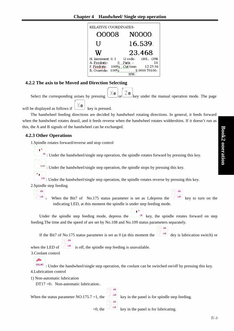
Chapter 4 Handwheel/ Single step operation
Ⅳ-3
Book2
operation
4.2.2 The axis to be Moved and Direction Selecting
Select the corresponding axises by pressing or key under the manual operation mode. The page
will be displayed as follows if key is pressed. The handwheel feeding directions are decided by handwheel rotating directions. In general, it feeds forward
when the handwheel rotates deasil, and it feeds reverse when the handwheel rotates widdershins. If it doesn’t run as this, the A and B signals of the handwheel can be exchanged.
4.2.3 Other Operations 1.Spindle rotates forward/reverse and stop control
CW : Under the handwheel/single step operation, the spindle rotates forward by pressing this key.
STOP : Under the handwheel/single step operation, the spindle stops by pressing this key.
CCW : Under the handwheel/single step operation, the spindle rotates reverse by pressing this key. 2.Spindle step feeding
LUR.
JOG
: When the Bit7 of No.175 status parameter is set as 1,depress the LUR.
JOG
key to turn on the indicating LED, at this moment the spindle is under step feeding mode.
Under the spindle step feeding mode, depress the CW key, the spindle rotates forward on step feeding.The time and the speed of are set by No.108 and No.109 status parameters separately.
If the Bit7 of No.175 status parameter is set as 0 (at this moment the LUR.
JOG
dey is lubrication switch) or
when the LED of LUR.
JOG
is off, the spindle step feeding is unavailable. 3.Coolant control
COOLANT : Under the handwheel/single step operation, the coolant can be switched on/off by pressing this key. 4.Lubrication control 1) Non-automatic lubrication
DT17 =0:Non-automatic lubrication。
When the status parameter NO.175.7 =1, the LUR.
JOG
key in the panel is for spindle step feeding.
=0, the LUR.
JOG
key in the panel is for lubricating.
GSK980TD Turning Machine CNC System
Ⅳ-4
Book2 operation
When the No.112 of status parameter is set as 0, it is exchangeable output of lubrication, depress the LUR.
JOG
key on the panel, the lubrication will be output, press it again the lubrication will be cancelled. When the M32 is running, the lubrication is on, and then run the M33, it will be cancelled.
When the data parameter No.112>1, it is lubrication time-lapse output , depress the LUR.
JOG
key on the panel, the lubrication is on, when the time which is set by the data parameter No.112 pass through, the lubrication will be cancelled; When the M32 is running, lubrication is on, when the time which is set by the data parameter No.112 pass through, the lubrication will be cancelled. If the time is not yet up, if the M33 is performed, then the lubrication will be cancelled.
2) Automatic lubrication : DT17>0:Automatic lubrication, the lubrication time and interval can be set by DT17 and DT16
separately. The lubrication will be on during the time which was set by DT17 when the power on of the CNC,after that the
lubrication output will be stopped, and then after the interval which was set by DT16, the lubrication will be on again,
the rest may be deduced by analogy. During the automatic lubrication, the M32, M33 dictates and the LUR.
JOG
key on the panel are all unavailable.
4. Manual tool change
TOOL : Under the handwheel/single step operation,, depress this key, the tool will be changed according to the sequence.
5. Spindle override adjusting Under the handwheel/single step operation, when the simulative voltage output is selected to control the
spindle speed, the spindle speed can be adjusted.
Depress the spindle override key or of
OVERRIDE
SPINDE
, the speed can be changed by adjusting the
spindle override, there are 8 levels of real time adjusting whose range is from 50% to 120% of spindle override can be realized.
4.2.4 Notes 1. The connections between the handwheel graduations and the machine moving distances are list as follows:
The moving distance per graduation of handwheel Increasement of
handwheel 0.001 0.01 0.1
The appointed coordinate value
0.001mm 0.01mm 0.1mm
2. The rotating speed of handwheel can not exceed 5 rounds per second, if it exceeds, the graduations and the
distance may not matched.
3. The and key are only effective under the handwheel operation.

Chapter 5 MDI Operation
Ⅴ-1
Book2
operation
Chapter 5 MDI OPERATION Under the MDI operation, parameter setting, dictates input and performing can be practiced.
Attention The function of each key on the operation panel of 980TD is defined by PLC programs (ladderlike chart),
for the detail functions please refer to the manual which is offered by the machine builder. The following mentioned functions are described according to the standard PLC program of 980TD,
please take note!
5.1 DICTATE INPUT
Select the MDI operation, then enter the program status page, and input a part program of G50 X50 Z100, the
operation steps are as follows:
1. Enter the MDI operation by pressing the MDI key;
2. Enter the program status page by pressing the key(and press the or key if
necessary):
3. Input the address key ,and numerical key , and INPUT
key in sequence,the page will be displayed as follows:

GSK980TD Turning Machine CNC System
Ⅴ-2
Book2 operation
4. Input the address key , and numerical key , , and INPUT
key in sequence.
5. Input the address key ,and numerical key , and INPUT
key in sequence.
After all above operations are performed the page will be displayed as follows:
5.2 DICTATE PERFORMING
After the dictates input, the MDI dictates can be performed by pressing the RUN key. During the
processingthe MDI dictates can be stopped by pressing the PAUSE key or key or emergency stop button.
Note: The transferred dictates of subprograms (M98 P___; etc.), and the compound cutting cycle dictates (such as G70, G71, G72, G73, G74, G75, G76, etc.) will not be effective under the MDI mode.
5.3 PARAMETER SETTING
Under the MDI mode, enter the parameter interface the parameter value can be modified, details please refer to Chapter 10.
5.4 DATA MODIFYING
Under the program status page of MDI mode, if there is something wrong during the dictates input before
performing the input datas, all contents can be cleared by pressing the key, and then input the correct datas again; Or input the correct one instead of the error again.Take the error input of X50 in section 5.1 of this chapter for
example, if the correct one X100 needs to be input, then please press the address key , and numeric keys
, , and INPUT
key, instead of the error input of X50, the page will be displayed as below after all set:
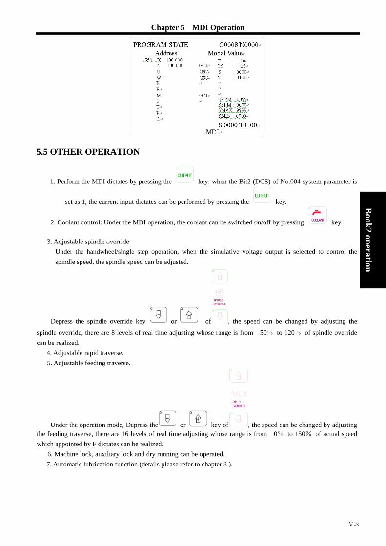
Chapter 5 MDI Operation
Ⅴ-3
Book2
operation
5.5 OTHER OPERATION
1. Perform the MDI dictates by pressing the OUTPUT
key: when the Bit2 (DCS) of No.004 system parameter is
set as 1, the current input dictates can be performed by pressing the OUTPUT
key.
2. Coolant control: Under the MDI operation, the coolant can be switched on/off by pressing COOLANT key.
3. Adjustable spindle override Under the handwheel/single step operation, when the simulative voltage output is selected to control the spindle speed, the spindle speed can be adjusted.
Depress the spindle override key or of
OVERRIDE
SPINDE
, the speed can be changed by adjusting the
spindle override, there are 8 levels of real time adjusting whose range is from 50% to 120% of spindle override can be realized.
4. Adjustable rapid traverse. 5. Adjustable feeding traverse.
Under the operation mode, Depress the or key of
OVERRIDE
RAPID
, the speed can be changed by adjusting the feeding traverse, there are 16 levels of real time adjusting whose range is from 0% to 150% of actual speed which appointed by F dictates can be realized.
6. Machine lock, auxiliary lock and dry running can be operated. 7. Automatic lubrication function (details please refer to chapter 3 ).

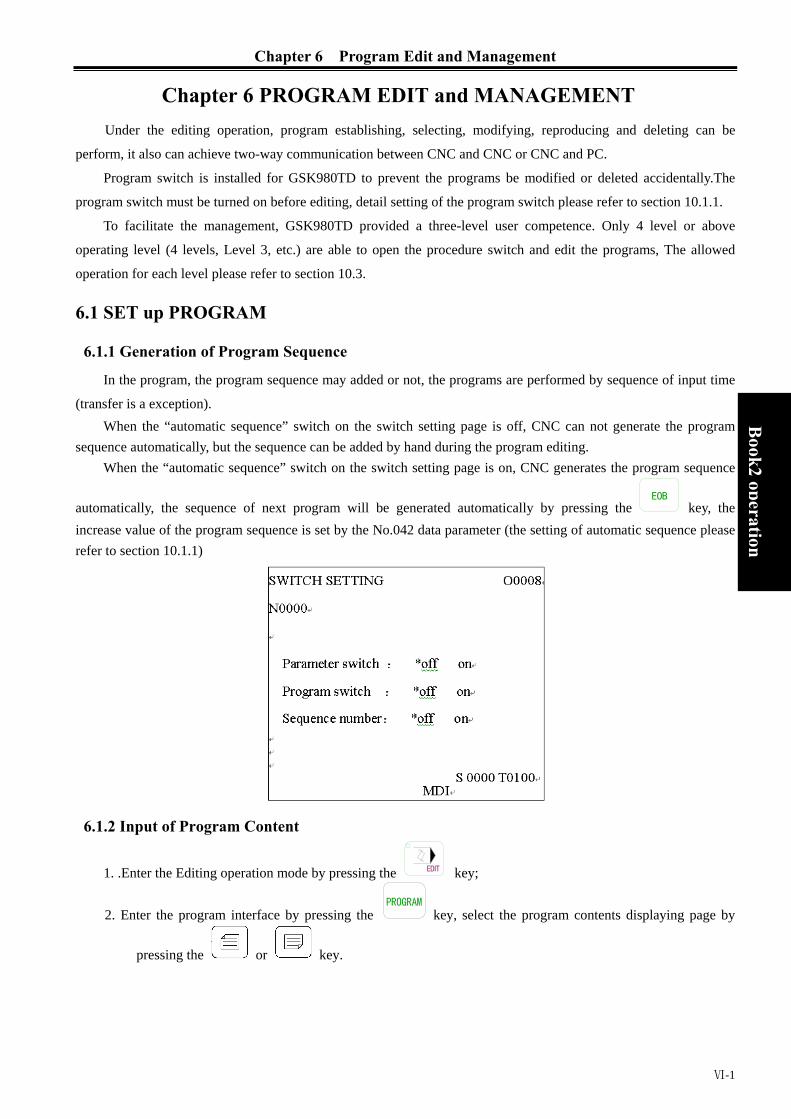
Chapter 6 Program Edit and Management
Ⅵ-1
Book2
operation
Chapter 6 PROGRAM EDIT and MANAGEMENT Under the editing operation, program establishing, selecting, modifying, reproducing and deleting can be
perform, it also can achieve two-way communication between CNC and CNC or CNC and PC.
Program switch is installed for GSK980TD to prevent the programs be modified or deleted accidentally.The
program switch must be turned on before editing, detail setting of the program switch please refer to section 10.1.1.
To facilitate the management, GSK980TD provided a three-level user competence. Only 4 level or above
operating level (4 levels, Level 3, etc.) are able to open the procedure switch and edit the programs, The allowed
operation for each level please refer to section 10.3.
6.1 SET up PROGRAM
6.1.1 Generation of Program Sequence
In the program, the program sequence may added or not, the programs are performed by sequence of input time
(transfer is a exception). When the “automatic sequence” switch on the switch setting page is off, CNC can not generate the program
sequence automatically, but the sequence can be added by hand during the program editing. When the “automatic sequence” switch on the switch setting page is on, CNC generates the program sequence
automatically, the sequence of next program will be generated automatically by pressing the EOB
key, the increase value of the program sequence is set by the No.042 data parameter (the setting of automatic sequence please refer to section 10.1.1)
6.1.2 Input of Program Content
1. .Enter the Editing operation mode by pressing the EDIT key;
2. Enter the program interface by pressing the key, select the program contents displaying page by
pressing the or key.

GSK980TD Turning Machine CNC System
Ⅵ-2
Book2 operation
3. Input the address key ,and numeric key , , , in sequence(Take the example of setting up the program O0001)。
4. Set up a new program by pressing the EOB
key.
5, Input the fixed programs one by one, the characters will be displayed on the screen immediately when they are input (For the compound key, please press it repeatedly to realize the alternate input), depress the
EOB key to terminate a part program when it is finished.
6, The input of program or other part program can be performed according to step 5.
6.1.3 Searches of Characters 1. Scan: Scan the characters one by one with the cursor
Enter the editing operation mode by pressing the EDIT key, select the program contents displaying page by
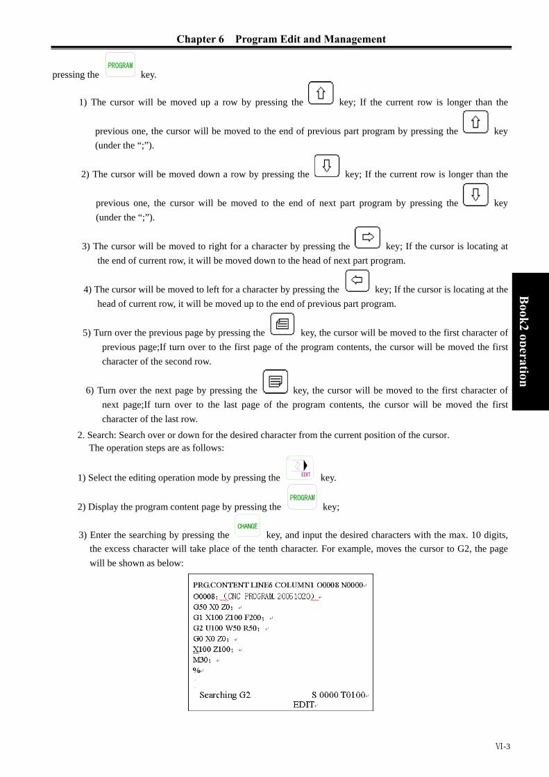
Chapter 6 Program Edit and Management
Ⅵ-3
Book2
operation
pressing the key.
1) The cursor will be moved up a row by pressing the key; If the current row is longer than the
previous one, the cursor will be moved to the end of previous part program by pressing the key (under the “;”).
2) The cursor will be moved down a row by pressing the key; If the current row is longer than the
previous one, the cursor will be moved to the end of next part program by pressing the key (under the “;”).
3) The cursor will be moved to right for a character by pressing the key; If the cursor is locating at the end of current row, it will be moved down to the head of next part program.
4) The cursor will be moved to left for a character by pressing the key; If the cursor is locating at the head of current row, it will be moved up to the end of previous part program.
5) Turn over the previous page by pressing the key, the cursor will be moved to the first character of previous page;If turn over to the first page of the program contents, the cursor will be moved the first character of the second row.
6) Turn over the next page by pressing the key, the cursor will be moved to the first character of next page;If turn over to the last page of the program contents, the cursor will be moved the first character of the last row.
2. Search: Search over or down for the desired character from the current position of the cursor. The operation steps are as follows:
1) Select the editing operation mode by pressing the EDIT key.
2) Display the program content page by pressing the key;
3) Enter the searching by pressing the CHANGE
key, and input the desired characters with the max. 10 digits, the excess character will take place of the tenth character. For example, moves the cursor to G2, the page will be shown as below:

GSK980TD Turning Machine CNC System
Ⅵ-4
Book2 operation
4) The page will be shown as below by pressing the key (according to the ubiety between the desired
character and current one to decide key or key to be pressed):
5) After the searching, the CNC is still on the seaching mode, press key or key again, it is
available to search another character, or exit the searching by pressing the . CHANGE
key. 6) “Search failure” will be displayed if there is no desired character.
Note: The character in the subprogram will not be searched during the searching. 3. Return to the head of program
1) The cursor will return to the head of program by pressing the .RESET
key on the program displaying page under the editing operation mode.
2) Look up the first character of the program according to the method which described in section 6.1.3.
6.1.4 Character insert Operation steps are as follows: 1) Select the program contents displaying page under the editing operation mode;
2) Enter the insert mode by pressing the INSERT
ALTER key (the underline is the cursor) , the page is as follows:
3) Insert the character (take above page as a example, insert the G98 dictate in front of the G2, input
, , ), the page will be shown as below;

Chapter 6 Program Edit and Management
Ⅵ-5
Book2
operation
Note1: Under the insert mode, the blank will be generated automatically when the dictate address is input provided the cursor is not at the head of the row, if the cursor is at the head of the row, the blank must be inserted by hand as it will not be generated automatically.
Note2: Under the insert mode, the “0” will be added automatically when inputing the address provided there is a decimal infront of the cursor and the cursor is not at the end of the row.
Note3: Under the insert mode, the “0” will be added automatically follows the decimal by pressing the
EOB key provided there is a decimal infront of the cursor and the cursor is not at the end of the
row.
6.1.5 Character Deleting Operation steps are as follows: 1) Select the program contents displaying page under the editing operation mode;
2) Delete the character in front of the cursor by pressing the CANCEL
key; delete the character on the cursor by
pressing the DELETE
key.
6.1.6 Character Modifying There are two ways of modifying the character
Insert modifying: Delete the character first, and then insert the desired character,details please refer to section 6.1.5.
Direct modifying: 1) Select the program contents displaying page under the editing operation mode;
2) Enter the modifying by pressing the INSERT
ALTER key (the cursor is an ashy rectangle), the page will be displayed as follows:
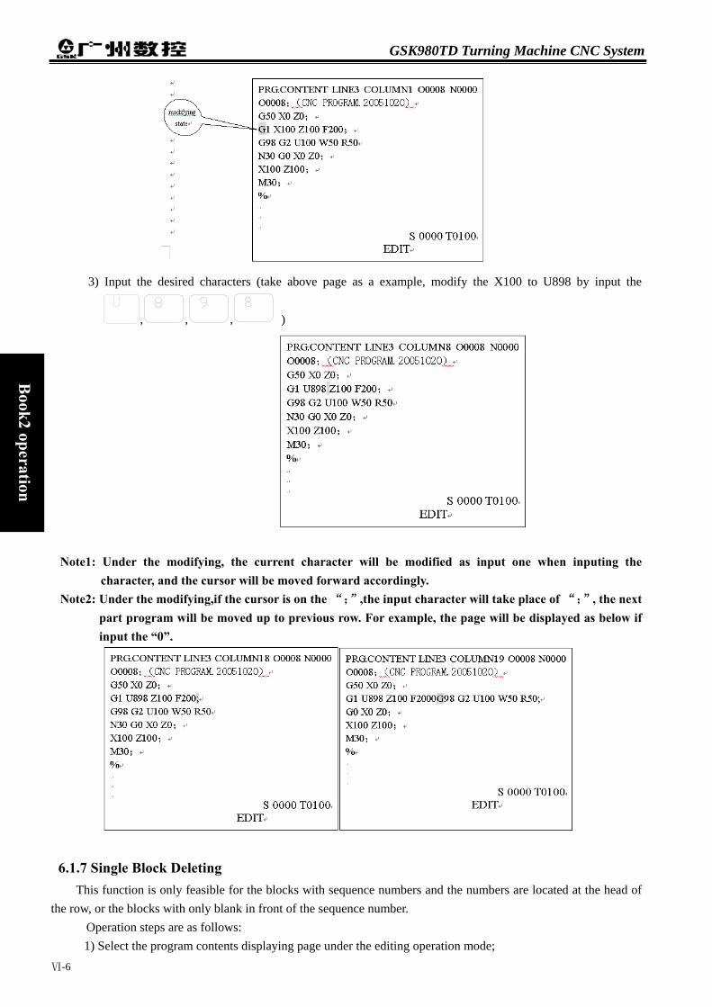
GSK980TD Turning Machine CNC System
Ⅵ-6
Book2 operation
3) Input the desired characters (take above page as a example, modify the X100 to U898 by input the
, , , )
Note1: Under the modifying, the current character will be modified as input one when inputing the character, and the cursor will be moved forward accordingly.
Note2: Under the modifying,if the cursor is on the “;”,the input character will take place of “;”, the next part program will be moved up to previous row. For example, the page will be displayed as below if input the “0”.
6.1.7 Single Block Deleting This function is only feasible for the blocks with sequence numbers and the numbers are located at the head of
the row, or the blocks with only blank in front of the sequence number. Operation steps are as follows: 1) Select the program contents displaying page under the editing operation mode;

Chapter 6 Program Edit and Management
Ⅵ-7
Book2
operation
2) Move the cursor to the head of row where the block to be deleted (the first character), and press the DELETE
key.
Note: If there is no sequence number for this block, input an “N” at the head of the row, and then move the
cursor to the N , and press the DELETE
key.
6.1.8 Part Programs Deleting From the current character with the cursor, delete the appointed part programs (search down), the appointed
block must have sequence number.
Operation steps are as follows: 1) Select the program contents displaying page under the editing operation mode;
2) Enter the searching mode by pressing the CHANGE
key, and then enter the part program sequence number;
3) The page will be displayed as below by pressing the DELETE
key:

GSK980TD Turning Machine CNC System
Ⅵ-8
Book2 operation
6.1.9 Block deleting From the current character with the cursor, delete the appointed dictates.
Operation steps are as follows: 1) Select the program contents displaying page under the editing operation mode;
2) Enter the searching mode by pressing the CHANGE
key, and then input the character;
3) The page will be displayed as below by pressing the DELETE
key.
Note1: If there is no desired character or the desired character is in front of the cursor, the “search failure”
will be displayed. If there are several the same desired character below, then the nearest one is the default.
Note2: If only input the dictate address, the following dictates will be deleted together.

Chapter 6 Program Edit and Management
Ⅵ-9
Book2
operation
6.2 PROGRAM REMARK
6.2.1 Set up the Program Remark Operation steps are as follows: 1) Select the program contents displaying page under the editing operation mode;
2) The page will be displayed as below by pressing the CHANGE
key.
3) Input the program remark (20 characters is the max.besides the brackets can be input), then the page will be displayed as below:
4) The remark is set up by pressing the INPUT
key, the page will be displayed as below:
Note1: If there is no remark added after set up the program, the default program name of CNC is the remark.

GSK980TD Turning Machine CNC System
Ⅵ-10
Book2 operation
Note2: Only English remarks can be added in CNC, but the Chinese remark is also can be displayed (Chinese decimal is an exception). Adding Chinese remark can be realized as below: Download the Chinese remark which is edited in PC from the PC via communication software.
6.2.2 Program Remark Modifying The operation steps are the same with the set up which is described in section 6.2.1.
6.3 PROGRAM DELETING
6.3.1 Single Program Deleting Operation steps are as follows: 1) Select the program contents displaying page under the editing operation mode;
2) Input the address key and numeric keys , , , in
sequence (Take program 00001 as an example);
3) The programO0001 will be deleted by pressing the DELETE
key.
6.3.2 All Programs Deleting Operation steps are as follows:
1) Select the program contents displaying page under the editing operation mode;
2) Input the address key and symbol key and numeric keys , , in
sequence;
3) All programs will be deleted by pressing the DELETE
key.
6.4 PROGRAM SELECTING
When there are several programs existing, there are three ways to select the program.
6.4.1 Searching
1) Select the editing or automatic operation mode;
2) Enter the program contents displaying page by pressing the key.
3) Press the address key , and then input the program sequence number;
4) The desired program will be displayed on the screen by pressing the key or EOB
key, if the program does not exist,CNC alarm will occurs.
Note: In the step 4, If the program does not exist, CNC will set up a new program by pressing the EOB
key.
6.4.2 Scaning
1) Select the editing or automatic operation mode;
2) Enter the program contents displaying page by pressing the key.

Chapter 6 Program Edit and Management
Ⅵ-11
Book2
operation
3) Press the address key ;
4) To display the next or previous program by pressing the key or key. 5) By repeat step 3 and step 4, the programs will be displayed one by one.
6.4.3 Cursor Confirming 1) Select the automatic operation mode (must in the non-running status)
2) Enter the program contents displaying page by pressing the key;
3) Move the cursor to the desired program name by pressing the , , or key (When the cursor is moving,”program size” and “remark” will be changed accordingly)
4) Press the EOB
key.
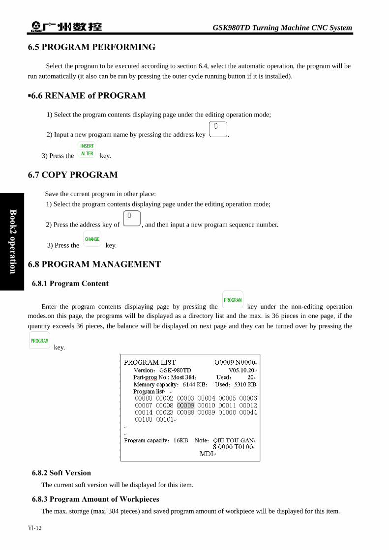
GSK980TD Turning Machine CNC System
Ⅵ-12
Book2 operation
6.5 PROGRAM PERFORMING
Select the program to be executed according to section 6.4, select the automatic operation, the program will be run automatically (it also can be run by pressing the outer cycle running button if it is installed).
▪6.6 RENAME of PROGRAM
1) Select the program contents displaying page under the editing operation mode;
2) Input a new program name by pressing the address key .
3) Press the INSERT
ALTER key.
6.7 COPY PROGRAM
Save the current program in other place: 1) Select the program contents displaying page under the editing operation mode;
2) Press the address key of , and then input a new program sequence number.
3) Press the CHANGE
key.
6.8 PROGRAM MANAGEMENT
6.8.1 Program Content
Enter the program contents displaying page by pressing the key under the non-editing operation modes.on this page, the programs will be displayed as a directory list and the max. is 36 pieces in one page, if the quantity exceeds 36 pieces, the balance will be displayed on next page and they can be turned over by pressing the
key.
6.8.2 Soft Version The current soft version will be displayed for this item.
6.8.3 Program Amount of Workpieces The max. storage (max. 384 pieces) and saved program amount of workpiece will be displayed for this item.

Chapter 6 Program Edit and Management
Ⅵ-13
Book2
operation
6.8.4 Memory Size and Used Size The total memory size of CNC (total 6144KB) and used size will be displayed for this item.
6.9 Other OPERATION under EDIT MODE
The panel operation could be defined by PLC program (Ladderlike chart) under the editing operation of GSK980TD, details please refer to the operation manual from the machine builder. Please kindly note the functions described below are only for the standard PLC program of GSK980TD.
1. Coolant control, can be switched by pressing the COOLANT key.
2. Spindle override adjusting, can be realized by pressing the or key of .
OVERRIDE
SPINDE
3. Feeding override adjusting, can be realized by pressing the or key of
OVERRIDE
RAPID
.
4. CNC reset, can be realized by pressing the RESET
key.
5. Operations switching can be realized by pressing any key of AUTO , MDI , , MPG , JOG
or .
6. Data transmission, details please refer to Chapter 11. 7. Automatic lubrication control (details please refer to Chapter 3)


Chapter 7 Tool Offset and Tool Adjusting
Ⅶ-1
Book2
operation
Chapter 7 TOOL OFFSET and TOOL ADJUSTING To simplify the program editing, the actual positions of the tools can be ignored during the editing, there are
three ways of tool adjusting including the fixed point, trial cutting and machine zero point return, the tool offset data
can be collected by tool adjustings.
7.1 TOOL OFFSET INPUT by MOVING the TOOL to a FIXED POINT
Operations are as follows:
Z a x i s
a x i s
Z axis
X axis Fig. A Fig. B
1. Please confirm if the tool offset of X and Z axises are zero, if not, please reset all of them.
2. Set the offset number as 00 (such as T0100,T0300)
3. Select a tool (normally this tool should be the first tool in process,select it as the standard tool)
4. Move the tool to a point (fixed point), please refer to chart A;
5. Set the workpiece coordinate by G50 X__ Z__ under the MDI operation,program status page;
6. Reset the related coordinate values U and W to 0;
7. Move the tool to a safe position and then select another tool, move this tool to the fixed point, Please refer to
chart B;
8. Press the OFFSET
key, and then select the corresponding tool offset number by pressing the or
key.
9. Press the key, and then press INPUT
key, the offset value of X direction will be set to the corresponding offset number;
10. Press the address key , and then press the INPUT
key, the offset value of Z direction will be set to the corresponding offset number;
11. Other tools can be adjusted by repeat the step7 to step 10.
7.2 DIRECT INPUT of TOOL OFFSET by TRAIL CUTTING
It is effective or not for the trial cutting depends on the bit5 setting of No.012 CNC parameter.
The operation steps are as follows (Set up a workpiece coordinate on the cross section) :
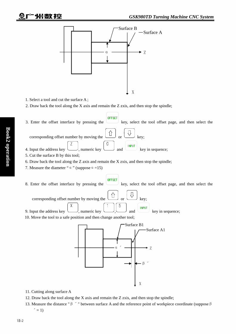
GSK980TD Turning Machine CNC System
Ⅶ-2
Book2 operation
Z
X
α
Surface A Surface B
1. Select a tool and cut the surface A ; 2. Draw back the tool along the X axis and remain the Z zxis, and then stop the spindle;
3. Enter the offset interface by pressing the OFFSET
key, select the tool offset page, and then select the
corresponding offset number by moving the or key;
4. Input the address key , numeric key and INPUT
key in sequence; 5. Cut the surface B by this tool; 6. Draw back the tool along the Z axis and remain the X zxis, and then stop the spindle; 7. Measure the diameter “α” (supposeα=15)
8. Enter the offset interface by pressing the OFFSET
key, select the tool offset page, and then select the
corresponding offset number by moving the or key;
9. Input the address key , numeric key , and INPUT
key in sequence; 10. Move the tool to a safe position and then change another tool; 11. Cutting along surface A 12. Draw back the tool along the X axis and remain the Z zxis, and then stop the spindle; 13. Measure the distance "βˊ" between surface A and the reference point of workpiece coordinate (supposeβ
ˊ= 1)
Z
X
αˊ
Surface A1Surface B1
βˊ

Chapter 7 Tool Offset and Tool Adjusting
Ⅶ-3
Book2
operation
14. Enter the offset interface by pressing the OFFSET
key, select the tool offset page, and then select the
corresponding offset number by moving the or key;
15. Input the address key , symbol key and numeric key and INPUT
key in sequence; 16. Cut along surface B; 17. Draw back the tool along the Z axis and remain the X zxis, and then stop the spindle; 18. Measure the distance "αˊ" (suppose αˊ=10)
19. Enter the offset interface by pressing the OFFSET
key, select the tool offset page, and then select the
corresponding offset number by moving the or key;
20. Input the address key , numeric key , and INPUT
key in sequence; 21. Other tools can be adjusted by repeat the step 10 to step 20.
Note: The offset value would be large by this way, so the tool compensation of CNC should be set based on the coordinate offset mode (The Bit4 of No.003 CNC parameter is set as 1), also, the tool length compensation of the first part program should be executed by dictate T, or dictate T is included in the first part program.
7.3 TOOL ADJUSTING by RETURNING to MACHINE ZERO POINT
There is no standard tool by this way, the tool can be re-adjusted when it is attrited or any tool needs to be
re-adjusted. Before the tool adjusting please retun the tool to the machine zero point. In case of power off the process
can be carried on after returning the machine zero point, it is easy to operated.
Z
X
α
surface Asurface B
1. Enter the machine zero point return mode by pressing the key, reset two axises to the machine
reference point. 2. Select a tool and set the offset number as 00 (such as T0100,T0300) 3. Cut along surface A. 4. Draw back the tool along the X axis and remain the Z zxis, and then stop the spindle;

GSK980TD Turning Machine CNC System
Ⅶ-4
Book2 operation
5. Enter the offset interface by pressing the OFFSET
key, select the tool offset page, and then select the
corresponding offset number by moving the or key;
6. Input the address key , numeric key and INPUT
key in sequence, the offset value of Z axis is set.
7. Cut along surface B. 8. Draw back the tool along the Z axis and remain the X zxis, and then stop the spindle; 9. Measure the distance "αˊ" (suppose αˊ=15)
10. Enter the offset interface by pressing the OFFSET
key, select the tool offset page, and then select the
corresponding offset number by moving the or key;
11. Input the address key , numeric key , and INPUT
key in sequence, the offset value of X axis is set.
12. Move the tool to a safe position and then change another tool; 13. Select another tool and set the offset number as 00 (such as T0100,T0300)
14. Cut along surface A1. 15. Draw back the tool along the X axis and remain the Z zxis, and then stop the spindle; Measure the distance "
β1" between surface A1 and the reference point of workpiece coordinate (supposeβ1= 1)
16. Enter the offset interface by pressing the OFFSET
key, select the tool offset page, and then select an offset
number by moving the or key;
17. Input the address key , the symbol key and numeric key and INPUT
key in sequence, the offset value of Z axis is set.
18. Cut along surface B1. 19. Draw back the tool along the Z axis and remain the X zxis, and then stop the spindle; 20. Measure the distance "α1" (suppose α1= 1)
Z
X
α1
Surface A1surface B1
β1

Chapter 7 Tool Offset and Tool Adjusting
Ⅶ-5
Book2
operation
21. Enter the offset interface by pressing the OFFSET
key, select the tool offset page, and then select an offset
number by moving the or key;
22. Input the address key and numeric key , and INPUT
key in sequence, the offset value of X axis is set.
23. Move the tool to a safe position; 24. All tools can be adjusted by repeat the step 15 to step 23.
Note1: The tool adjusting by returning to the machine zero point is only available based on the machine zero point is installed.
Note2: The workpiece coordinate could not be performed by G50 after the tool adjusting by returning to the machine zero point.
Note3: The tool compensation of CNC should be set based on the coordinate offset mode (The Bit4 of No.003 CNC parameter is set as 1), also, the tool length compensation of the first part program should be executed by dictate T, or dictate T is included in the first part program.
Note4: The corresponding parameters should be set as below: The Bit7 of No.004 CNC parameter should be set as 0; The Bit5 of No.012 CNC parameter should be set as 1; The Bit7 of No.012 CNC parameter should be set as 1;
Note45: No.049 and 050 of CNC parameter should be set similar to the absolute coordinate values in the workpiece coordinate X0Z of the machine zero point, details please find below:
For example: After the machine zero point return, the absolute coordinate value is (a, b) for the tool in the workpiece coordinate, then the No.049 of CNC parameter should be similar to “a”, and the 050 of CNC parameter should be similar to “b”.
7.4 TOOL OFFSET MODIFYING
Enter the offset interface by pressing the OFFSET
key, display the No. 000~No.032 offset number by pressing
the or key.

GSK980TD Turning Machine CNC System
Ⅶ-6
Book2 operation
7.4.1 Absolute Value Input
1. Enter the offset interface by pressing the OFFSET
key, display the desired page by pressing the or
key.
2. Move the cursor to the position where the tool offset number should be input.
Scan: Move the cursor in sequence by pressing the and key.
+offset number+ INPUT
Searching: The cursor can be move to the desired position directly by pressing below key in sequence.
+offset number+ INPUT
3. After pressing the address key or , in put the number (Decimal can also be input)
4. The tool offset value can be calculated automatically by CNC after pressing the INPUT
key, and the result will be displayed on the page.
7.4.2 Increasement Input 1. Move the cursor to the desired position of tool offset number which to be modified according to the method
described in section 7.4.1. 2. If the tool offset value of X axis has to be changed, please input U, and for Z axis, please input W. 3. Input the increasement;
4. Add the current tool offset value and the increasement by pressing the INPUT
key, the result will be displayed as a new tool offset value.
For example: The tool offset value of X axis is 5.678 Input the increasement (U 1.5) by the keyboard Then the new tool offset value of X axis is 7.178(=5.678+1.5).
7.4.3 Tool Offset Modifying under the Communication Mode Modifying and setting the tool offset value under the communication mode, detail operation please refer to
Chapter 11.
Note1: The new tool offset value will be effective when the T code is executed after the tool offset value
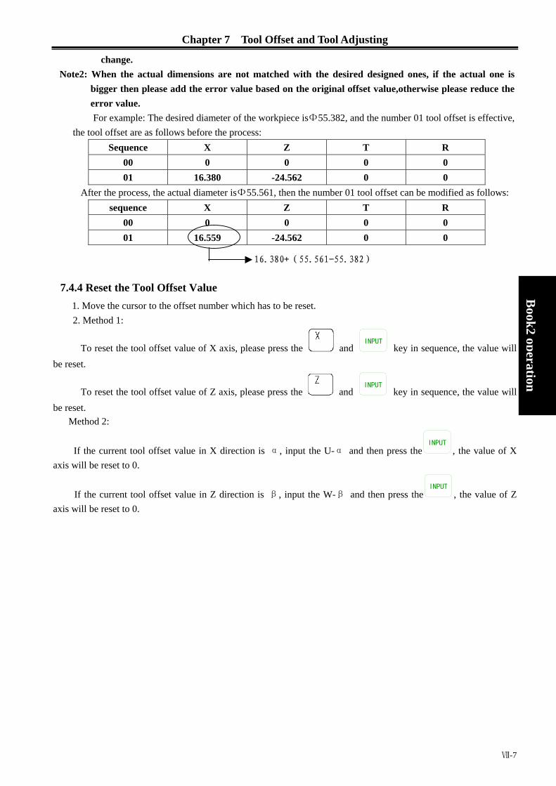
Chapter 7 Tool Offset and Tool Adjusting
change. Note2: When the actual dimensions are not matched with the desired designed ones, if the actual one is
bigger then please add the error value based on the original offset value,otherwise please reduce the error value. For example: The desired diameter of the workpiece isФ55.382, and the number 01 tool offset is effective,
the tool offset are as follows before the process: Sequence X Z T R
00 0 0 0 0 01 16.380 -24.562 0 0
After the process, the actual diameter isФ55.561, then the number 01 tool offset can be modified as follows: sequence X Z T R
00 0 0 0 0 01 16.559 -24.562 0 0
7.4.4 Reset the Tool Offset Value 1. Move the cursor to the offset number which2. Method 1:
To reset the tool offset value of X axis, pleabe reset.
To reset the tool offset value of Z axis, pleabe reset.
Method 2:
If the current tool offset value in X directionaxis will be reset to 0.
If the current tool offset value in Z direction axis will be reset to 0.
1
Ⅶ-7
Book2
operation
has to be reset.
se press the and INPUT
key in sequence, the value will
se press the and INPUT
key in sequence, the value will
is α, input the U-α and then press theINPUT
, the value of X
is β, input the W-β and then press theINPUT
, the value of Z
6.380+(55.561-55.382)


Chapter 8 Automatic Operation
Ⅷ-1
B
ook2 operation
Chapter 8 AUTOMATIC OPERATION
Attention The function of each key on the operation panel of 980TD is defined by PLC programs (ladder like chart), for the detail functions please refer to the manual which is offered by the machine builder. The following mentioned functions are described according to the standard PLC program of 980TD, please take note!
8.1 AUTOMATIC RUN
8.1.1 Automatic Run Selecting 1. Searching
1) Select the editing or automatic running operation;
2) Enter the program contents and display by pressing the key;
3) Press the address key , and then input the program number;
4) The result programs will be displayed on the screen by pressing the or EOB
key.If the program does not exist,CNC alarm will be occurred.
Note: At the step 4, if the program does not exist, a new program will be set up by CNC by pressing the
EOB key.
2. Scan
1) Select the editing or automatic running operation;
2) Enter the program contents and display by pressing the key;
3) Press the address key ;
4) To display the next or previous program by pressing the or key. 5) Display the memorized programs one by one by repeat the c and d sdteps.
3. Cursor confirming a) Select the automatic opearation (must under the non-running mode)
b) Enter the program content lisplaying page by pressing the key (Press the or key if necessary), (Details please refer to section 8.2.1)
c) Move the cursor to the desired program name by pressing the , , , key.
d) Press the EOB
key.
8.1.2 Start Automatic Run
1. Select the automatic operation by pressing the AUTO key;
2. Start the process by pressing the RUN key, the program will be run automatically.

GSK980TD Turning Machine CNC System
Ⅷ-2
Book2 operation
Note: The process will be started from the row which the cursor located in, so please check and confirm the
whether the cursor locates in the desired part program before pressing the RUN key, and if the whole program has to be run and the cursor is not in the first row please move the cursor back to the first row.
8.1.3 Stop Automatic Run Stop dictates (M00)
After the part program with M00 executed, the stop auto running, modal functions and status are all been saved.
The program will be resumed by pressing the RUN key or outer running key. Stop by pressing related keys
1, Press the the PAUSE key or outer pause key during the auto running, the machine will: 1) The machine feeding will be stop gradually;
2) When the pause dictat is executing (dictate G04), the machine will be paused after the execution.
3) Modal functions and status are saved;
4) The process will be resumed by pressing the RUN key.
2. Press the reset keyRESET
.
1) All axises are stopped.
2) M, S functions output are of no effect (whether shut off the spindle rotates forward/reverse, lubrication and
coolant signals automatically by pressing the RESET
key can be set by the the parameter);
3) When the automatic running is finished, the modal functions and status remain. 3. Emergency button
Depress the emergency button (when the outer emergency signal is effective) under the dangerous or emergency
situations during the machine running, the CNC will come into emergency stop status, the moving of machine will be
stopped immediately, all outputs (such as spindle rotates, coolant, etc.) will be shut off. CNC will come into
reposition status by releasing the emergency button to release the alarm. 4. Operations switching
When the automatic running operation is switched to machine zero point return, handwheel/single step, manual
or program zero point return, etc, the current part program will be “paused” immediately; when it is switched to
editing and MDI modes, the part program will be remain running till end and then the “pause” will be displayed. Note1: Please confirm all failures are settled before clearing the emergency stop alarm;
Note2: Depressing the emergency stop button before power on/off may reduce the power impacts to the
equipment;
Note3: The machine zero point return should be re-done after the emergency stop alarm releasing, to make
sure the correctness of the coordinate position (If the machine zero point is not installed, the operation can not
be performed) Note4: The outer emergency stop will only be effective based on the Bit3 (MESP) of No.172 status parameter is set as 0.

Chapter 8 Automatic Operation
Ⅷ-3
B
ook2 operation
8.1.4 Automatic Run from any Part Program
1. Enter the editing operation mode by pressing the EDIT key, enter the program interface by pressing the
key, then select the program content page by pressing the or key; 2. Move the cursor to the part program which is to be run (if start from row 4 then please move the cursor to the
head of row 4);
3. If the modals(Dictate G,M,T,F)are default in the part program which the cursor located at, and they are not
matched with the desire of current part program, then the related modal functions must be executed before
next step;
4. Enter the automatic operation mode by pressing the AUTO key, and then start the program by pressing the
RUN key.
8.1.5 Feed and Rapid Traverse Adjusting The running speed can be adjusted by Feeding and rapid traverse adjusting under the automatic running mode,
and there is no need to change the speed values which are set in the program or parameter. Feeding override adjusting
Depress the or key of
FEEDRATE
OVERRIDE
, there are 16 levels of real time adjusting of feeding override can
be realized.
The feeding override will be added one step by pressing the key once, until 150%;
The feeding override will be reduced one step by pressing the key once, until 0;
Note1: The appointed value by F in the feeding override adjusting program;

GSK980TD Turning Machine CNC System
Ⅷ-4
Book2 operation
Note2: Actual feeding speed =Speed appointed by F*feeding override Rapid traverse adjusting
Depress the or key of
OVERRIDE
RAPID
, there are 4 levels of real time adjusting whose range with FO, 25
%, 50%, 100% of rapid traverse can be realized.
The feeding override will be added one step by pressing the key once, until 100%
The feeding override will be reduced one step by pressing the key once, until 0. Note1:The rapid traverses of X and Z axises are set by CNC parameter No.022 and No.023 separately;
Actual rapid traverse of X axis= Value of No.022*rapid traverse Actual rapid traverse of Z axis= Value of No.023*rapid traverse
Note2: When the rapid traverse is F0, the lowest speed of the rapid traverse is set by No.032.
8.1.6 Spindle Speed Adjusting Under the automatic running, the spindle rotate speed can be adjusted when the simulated voltage output is
selected to control the spindle speed.
Depress the or key of
OVERRIDE
SPINDE
, the speed can be changed by adjusting the spindle override, there are 8 levels of real time adjusting whose range is from 50% to 120% of spindle override can be realized.
The feeding override will be added one step by pressing the key once, until 120%;
The feeding override will be reduced one step by pressing the key once, until 50%. Note1: Actual output of simulated voltage value= simulated voltage value which calculated by
parameter*spindle override For example:When the No.037 CNC parameter is set as 9999, and No.021 is set as 645, to execute the
dictate S9999, and select the spindle override 70%, then the actual output simulated voltage is 10*70%=7V approximately.
Note2: The change of spindle override will be displayed under the left corner, the rapid override and spindle
override can be switched by pressing the CHANGE
key.

Chapter 8 Automatic Operation
Ⅷ-5
B
ook2 operation
8.2 STATUS under RUN
8.2.1 Single Run To prevent the program error occurs at the first running, the single running can be selected. Under the automatic operation, the single program switch can be turned on by this way:
Method1: To light the single running indicator LED by pressing the SINGLE key in the status
indicating area, the single running is selected;
Method2: Enter the machine soft panel page by pressing the key, the symbol“*” will be turned
into the single program mode by pressing the numeric key .
During the single running, CNC will be stopped when the current part program is executed; to run the next part
program, the RUN key should be pressed again, Note1: When the dictate G28 is running, the single program will be stopped at the middle point; Note2: When the fixed cycle dictates G90,G92,G94,G70~G76 are running, the single status please refer to
the Chapter 1 of <Editing manual>; Note3: The single program will not be effective when the subprogram transferring (M98_) and subprogram
transferring return (M99) are executing. But in the program with M98 and M99, the single stop is effective excluding the address N, O and P.

GSK980TD Turning Machine CNC System
Ⅷ-6
Book2 operation
8.2.2 Dry running To prevent the program error occurs at the auto running, the dry running can be selected to test the program
before automatic running. Under the automatic operation mode, the dry running can be turned on as follows:
Method1: To light the dry running indicator LED by pressing the SINGLE key in the status indicating area, the dry running is selected;
Method2: Enter the machine soft panel page by pressing the key, the symbol“*” will be turned
into the dry running mode by pressing the numeric key .
Under the dry running, machine feeding and auxiliary functions are available (providing the machine lock and
auxiliary lock are off), namely, there is no impact to execute the machine feeding and auxiliary under the dry running, the appointed speed by the program is not effective, CNC will be run according to below table.
Program dictates Rapid traverse Cutting
Rapid traverse on Rapid traverse The highest speed of manual feeding
Rapid traverse off Manual feeding or rapid traverse (note1)
Manual feeding speed
Note1: Manual feeding speed or rapid traverse can be set by the Bit6 of No.004 CNC parameter. Note2: Under the dry running, the rapid switching would not effect the current part program, it will be
effective in next part program.
8.2.3 Machine Lock Run Under the automatic operation, the machine lock switch can be turned on as follows:
Method1: To light the machine lock running indicator LED by pressing the key in
the status indicating area, the machine lock running is selected;
Method2: Enter the machine soft panel page by pressing the key, the symbol“*” will be turned

Chapter 8 Automatic Operation
Ⅷ-7
B
ook2 operation
into the machine lock running mode by pressing the numeric key .
Usually the machine lock running is processed with the auxiliary lock to test the program. Under the machine
lock running: 1. The machine would not be moved, the “machine coordinate” in the integrated coordinate page of position
interface remains, but the relative coordinate, absolute coordinate and distance to go will change at all times just as the same with the machine lock is off.
2. Ditates M, S, and T can be performed normally.
8.2.4 Auxiliary Lock Run Under the automatic operation, the auxiliary lock switch can be turned on as follows:
Method1: To light the auxiliary lock running indicator LED
MST
by pressing the
MST
key in the
status indicating area, the auxiliary lock running is selected;
Method2: Enter the machine soft panel page by pressing the key, the symbol“*” will be turned
into the auxiliary lock running mode by pressing the numeric key .
At the moment dictates M,S and T would not be performed, the machine moves. Usually the machine lock
running is processed with the auxiliary lock to test the program.
Note: There is no impact for M00, M30, M98, M99 executing when the auxiliary

GSK980TD Turning Machine CNC System
Ⅷ-8
Book2 operation
lock is on.
8.2.5 Part Program Skipping If there is a part program won’t be executed or deleted, the part program skipping can be selected.The program
with a symbol “/” on its head will be skipped under the automatic running if the part program switch is on (when the keys of machine panel or the outer input of part program skipping is effective)
Under the automatic operation, the part program skipping switch can be turned on as follows:
Method1: To light the part program skipping indicator LED by pressing the
MST
key in the
status indicating area, the part program skipping running is selected;
Method2: Enter the machine soft panel page by pressing the key, the symbol“*” will be turned
into the auxiliary lock running mode by pressing the numeric key .
Note: When the part program skipping switch is off, the program with a symbol “/” on its head will not be skipped under the automatic running.
8.3 Other OPERATION
1. Under the automatic operation, the coolant on/off will be switched by pressing the COOLANT key.
2. By pressing any key among EDIT , MDI , , MPG , JOG or , operations can be
switched.
3. CNC can be reset by pressing the RESET
key. 4. Automatic lubrication function (details please refer to Chapter 3)

Chapter 9 Zero Point Return
Ⅸ-1
Book2
operation
Chapter 9 ZERO POINT RETURN
9.1 PROGRAM ZERO POINT RETURN
9.1.1 Program Zero Point
After the workpiece is installed on the machine, set the absolute coordinate of current tool position by dictate
G50 according to the related position between the tool and the workpiece, the workpiece is set in the CNC. The
current tool position is so-called program zero point, the tool will be return to it by perform the program zero point
return.
9.1.2 The Steps of Program Zero Point Return
1. Enter the program zero point return operation by pressing the key,
2. Select the program zero point return for X or Z zxis by pressing the or key. 3. The axis moves towards the program zero point, when it arrives, the axis will stops and the zero point return
finish indicating LET will be on.
Indicator lamp for reference point return finished
Note: After the zero point return operation, the current tool offset status would not be changed, the returned point is set by G50 and the tool offect is included if the tool offset is effective.
9.2 MACHINE ZERO POINT RETURN
9.2.1 Machine Zero Point
The machine coordinate is the standard coordinate for coordinate calculating of CNC, it is a original coordinate,
the original point of it is so-called machine zero point (or machine reference point), the machine zero point is
decided by the zero point switch or zero point return switch which is installed in the machine, usually the the zero
point switch or zero point return switch is installed at the maximum positive journey of X and Z axises.

GSK980TD Turning Machine CNC System
Ⅸ-2
Book2 operation
9.2.2 The Steps of Machine Zero Point Return
1. Enter the machine zero point return operation by pressing the key, there will be “machine zero point return ” displayed under the screen as follows:
2. Select the machine zero point return for X or Z zxis by pressing the or key. 3. The machine moves towards the machine zero point, it will be returned to the zero point after the inspectings
of slow down and zero point signal, the zxis stops at the moment, the LED of letter [X], [Z]or [U], [W] start to glitter, then the LED of zero point return is on.
Indicator lamp for machine zero return ending
Note1: The machine zero point return can not be performed if the machine zero point is not installed. Note2: The zero point return finish indicating LED will be off under below situations:
1) Moving from the zero point; 2) CNC power off;
Note3: The tool length compensation will be cancelled by CNC after the machine zero point return operation. Note4: The related parameter of machine zero point return please refer to Chapter 4 <Connection>.
9.3 Other OPERATION under ZERO POINT RETURN
1. Spindle rotates forward by pressing the CW key;
2. Spindle stops by pressing the STOP key;
3. Spindle rotates reverse by pressing the CCW key;
4. Coolant on/off can be switched by pressing the COOLANT key. 5. Lubrication control 1). Non-automatic lubrication
DT17 =0:Non-automatic lubrication.

Chapter 9 Zero Point Return
Ⅸ-3
Book2
operation
When the status parameter NO.175.7 =1, the LUR.
JOG
key in the panel is for spindle step feeding.
=0, the LUR.
JOG
key in the panel is for lubricating.
When the No.112 of status parameter is set as 0, it is exchangeable output of lubrication, depress the LUR.
JOG
key on the panel, the lubrication will be output, press it again the lubrication will be cancelled. When the M32 is running, the lubrication is on, and then run the M33, it will be cancelled.
When the data parameter No.112>1, it is lubrication time-lapse output , depress the LUR.
JOG
key on the panel, the lubrication is on, when the time which is set by the data parameter No.112 pass through, the lubrication will be cancelled; When the M32 is running, lubrication is on, when the time which is set by the data parameter No.112 pass through, the lubrication will be cancelled. If the time is not yet up, if the M33 is performed, then the lubrication will be cancelled.
2) Automatic lubrication DT17>0:Automatic lubrication, the lubrication time and interval can be set by DT17 and DT16 separately.
The lubrication will be on during the time which was set by DT17 when the power on of GSK980TD,after that the lubrication output will be stopped, and then after the interval which was set by DT16, the lubrication will be on
again, the rest may be deduced by analogy. During the automatic lubrication, the M32, M33 dictates and the LUR.
JOG
key on the panel are all unavailable.
6. The tool can be changed by hand by pressing the TOOL key; 7. Spindle override adjusting 8. Rapid traverse override adjusting; 9. Feedrate override adjusting.


Chapter 10 Setting, Backup and Resuming of Data
Ⅹ-1
Book2
operation
Chapter 10 SETTING, BACKUP and RESUMING of DATA
10.1 DATA SETTING
10.1.1 Switch Setting Under the switch setting page, the on/off status of parameter switch, program switch and auto sequence can be
displayed and set, the page are as follows:
1. Enter the setting interface by pressing the SETTING
key, then enter the switch setting page by pressing the
or key;
2. Move the cursor to the desired item by pressing the or key;
3. The swithch staus can be switched by pressing the or key, the symbol “*” will be moved to
left by pressing the key,and the switch is turned off, the symbol “*” will be moved to right by
pressing the key,and the switch is turned on, The parameter modifying is only available based on the parameter switch is on; The program editing is only
available based on the program switch is on; The auto sequence is only available based on the auto sequence switch is on;.
Note: CNC alarm will be occurred when the parameter switch is turning on, and it can be clear by pressing
the andCANCEL
simultaneously, no alarm will be occurred if the parameter is switched again. For the sake of safety, please turn off the parameter switch after modifying.
10.1.2 Graph Setting
Enter the graph interface by pressing the SETTING
key, then enter the graph parameter setting page by pressing
the or key;

GSK980TD Turning Machine CNC System
Ⅹ-2
Book2 operation
A:Graph parameter setting
1. Under the MDI operation, Move the cursor to the desired item by pressing the or key; 2. Input the value;
3. The setting will be finished by pressing the INPUT
key. B: Meaning of the graph parameter
1. Setting of coordinates: There are 8 graph tracks of GSK980TD can be displayed according to the differences of front and back toolpost coordinates. Details are as follows:
Status parameter No.175
Graph parameter
Bit1 Bit0 Coordinate selecting
Graph of graph track coordinate
0 0 0
0 0 1

Chapter 10 Setting, Backup and Resuming of Data
Ⅹ-3
Book2
operation
Status parameter No.175
Graph parameter
Bit1 Bit0 Coordinate selecting
Graph of graph track coordinate
0 1 0
0 1 1
1 0 0
1 0 1
1 1 0

GSK980TD Turning Machine CNC System
Ⅹ-4
Book2 operation
Status parameter No.175
Graph parameter
Bit1 Bit0 Coordinate selecting
Graph of graph track coordinate
1 1 1
2. Scaling: Scaling setting 3. Graph center: the corresponding workpiece coordinate value setting under the LCD center. 4. The max. and min. values: CNC auto scaling and graph center auto setting are available after the max. and
min. values of axises are set. The max. value of X axis: The max. value of X axis during the process (unit:mm) The min. value of X axis: The mIN. value of X axis during the process (unit:mm) The max. value of Z axis: The max. value of Z axis during the process (unit:mm) The min. value of Z axis: The mIN. value of Z axis during the process (unit:mm)
C: The zoom in and zoom out of the graph track
Under the graph displaying page, the real time aoom in or zoom out of graph tracks can be realized by pressing
the or .the graph will be zoom in at times by pressing key once; and .the graph
will be zoom out at times by pressing key once;
D: The starting, stop and clearing of graph track display
Under the graph displaying page, start the plot by pressing the key, the symbol “*” will be moved in
front of the character S; stop the plot by pressing the key, the symbol “*” will be moved in front of the
character T; the current graph track will be cleared by pressing the key.
10.1.3 Parameter Setting
The related characteristic of the driver, machine, etc, can be adjusted by parameter setting. Parameter details
please refer to appendix 1.
Enter the parameter interface by pressing the key, the parameter pages can be switched by pressing the
or key; details are as follows:
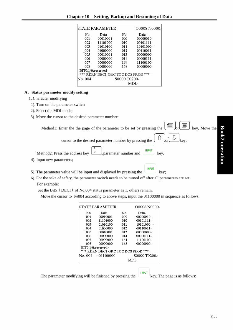
Chapter 10 Setting, Backup and Resuming of Data
Ⅹ-5
Book2
operation
A、Status parameter modify setting
1. Character modifying 1). Turn on the parameter switch 2). Select the MDI mode; 3). Move the cursor to the desired parameter number:
Method1: Enter the the page of the parameter to be set by pressing the or key, Move the
cursor to the desired parameter number by pressing the or key.
Method2: Press the address key ,parameter number and INPUT
key. 4). Input new parameters;
5). The parameter value will be input and displayed by pressing the INPUT
key; 6). For the sake of safety, the parameter switch needs to be turned off after all parameters are set.
For example: Set the Bit5(DECI)of No.004 status parameter as 1, others remain.
Move the cursor to №004 according to above steps, input the 01100000 in sequence as follows:
The parameter modifying will be finished by pressing the INPUT
key. The page is as follows:

GSK980TD Turning Machine CNC System
Ⅹ-6
Book2 operation
2. Modifying by digits:
1). Turn on the parameter switch; 2). Select the MDI mode; 3). Move the cursor to the parameter number to be set;
Method1: Enter the the page of the parameter to be set by pressing the or key, Move the
cursor to the desired parameter number by pressing the or key.
Method2: Press the address key ,parameter number and INPUT
key.
4). Press the hold the for 2 seconds or enter a parameter by pressing the CHANGE
key, the cursor will
located at the parameter, move the cursor to the one needs to be modified by pressing the or key, input 0 or 1 as requested;
5). For the sake of safety, the parameter switch needs to be turned off after all parameters are set.
Note: Enter a digit of a parameter, it is able to exit to the parameter number by pressing and holding
key for 2 seconds or by pressing the CHANGE
key.
For example: Set the Bit5(DECI)of No.004 status parameter as 1, others remain.
Move the cursor to №004 according to above steps, Press the hold the for 2 seconds or enter a
digit of parameter by pressing the CHANGE
key, detaisl are as follows:

Chapter 10 Setting, Backup and Resuming of Data
Ⅹ-7
Book2
operation
Move the cursor to Bit5 by pressing the or key, details are as follows:
Input 1, parameter modifying is done.
B. Data parameter,worm offset data modifying setting
1. Data parameter modifying 1). Turn on the parameter switch; 2). Select the MDI mode; 3). Move the cursor to the parameter number to be set; 4). Input new parameter values
5). The parameter values will be input and displayed by pressing the INPUT
key; 6). For the sake of safety, the parameter switch needs to be turned off after all parameters are set.
Example1: Set the №022 data parameter as 4000. Move the cursor to №022 according to above steps, input 4000 in sequence as follows:
The parameter modifying will be done by pressing the INPUT
key. The page is as follows:
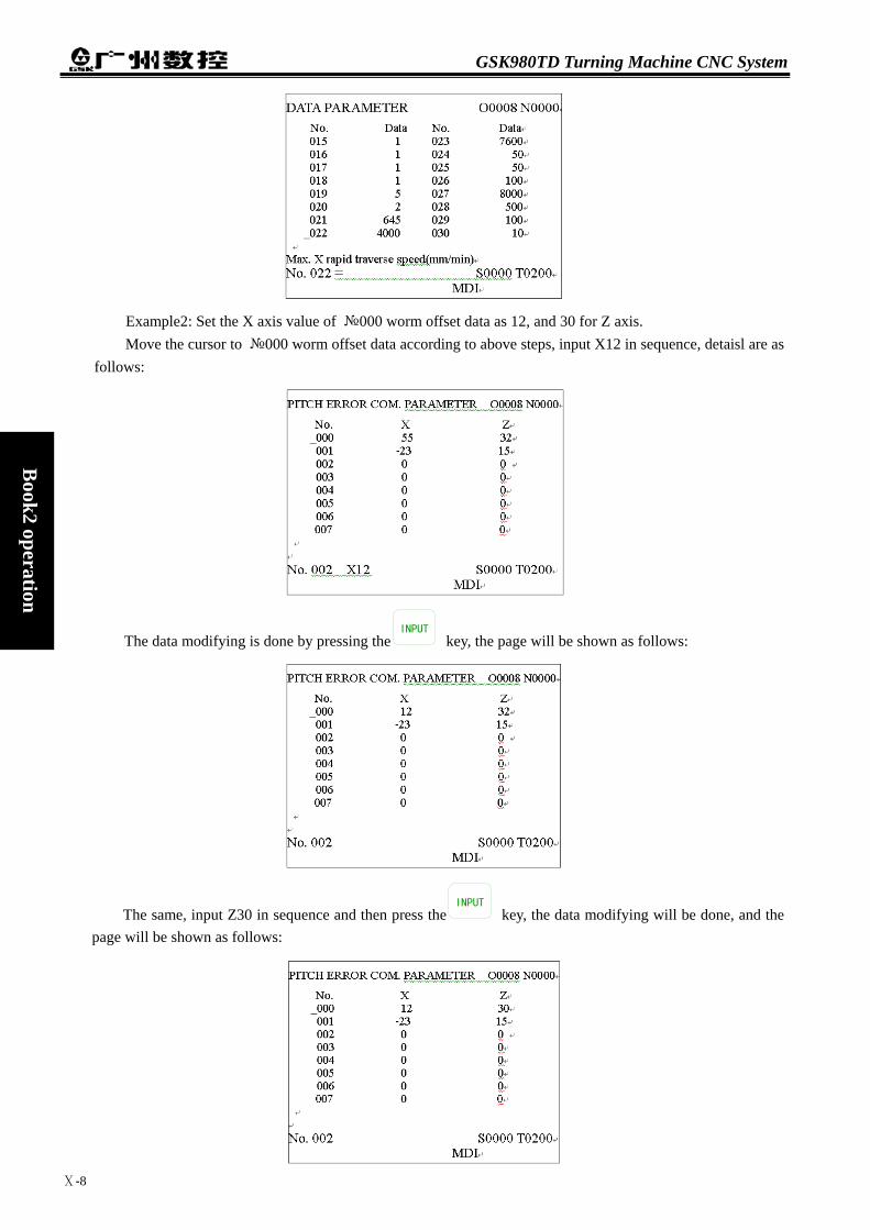
GSK980TD Turning Machine CNC System
Ⅹ-8
Book2 operation
Example2: Set the X axis value of №000 worm offset data as 12, and 30 for Z axis. Move the cursor to №000 worm offset data according to above steps, input X12 in sequence, detaisl are as
follows:
The data modifying is done by pressing theINPUT
key, the page will be shown as follows:
The same, input Z30 in sequence and then press theINPUT
key, the data modifying will be done, and the page will be shown as follows:

Chapter 10 Setting, Backup and Resuming of Data
Ⅹ-9
Book2
operation
10.2 RESUMING and BACKUP DATA
The user datas of GSK980TD (such as status parameter, data parameter, tool offset value and worm offset datas, etc. ) can be backup(storage) and resumed(read). There is no impact for the CNC programs when the datas are backup and resume. The page is as follows:
1. turn on the parameter switch;
2. Enter the MDI operation by pressing the MDI key, then enter the data backup page by pressing the
SETTING key (press the or key if necessary).
3. Move the cursor to the item bo be operated;
4. Press the INPUT
and simultaneously.
Note1: Avoid the power off during the data backup and resume, and donot proceed other operations before the operations are done;
Note2: The datas can be backuped and resumed are not the same among the current code level: user of 3,4,5 levels can proceed the status and data parameter backup and resume,but not change the worm offset parameter; User of 2 level can proceed the status,datas and worm offset parameter backup and resume. For example: To resume the CNC parameter as servo standard parameter, the operation steps are as follows: Turn on the parameter switch, and enter the MDI operation, data backup pages according to above steps,
move the cursor to “Resume Default PAR.2 (step)”,details as follows:

GSK980TD Turning Machine CNC System
Ⅹ-10
Book2 operation
Press the INPUT
and key simultaneously, “servo parameter resume successfully” will be
displayed,(please restart ).
10.3 PASSWORD SETTING and MODIFYING
To prevent the programs and parameters be modified by others, GSK980TD offers password function, there are 4 levels falls as level 2 (machine builder),level 3 (equipment administrator), level 4 (technician) and level 5 (operator), the current level can be displayed on “current operation level__” under the password setting page.
Level 2: Machine builder, CNC status parameter,data parameter, worm offset data,tool offset data,program editing and PLC ladderlike chart transmission, etc, can be modified.
Level 3: The original password is 12345, CNC status parameter, data parameter, tool offset data and program editing can be modified.
Level 4: The original password is 1234, tool offset data (tool offset operation), macro veriable and program editing can be modified, CNC status parameter, data parameter and worm offset data cannot be modified.
Level 5: No password, only machine panel can be operated, tool offset data modifying, program selecting and program editing are unavailable, and CNC status parameter, data parameter and worm offset data cannot be modified.
Enter the password setting page, the cursor will stay at the row of “input password”.Move the cursor to the
related operation by pressing the or key.
a). The cursor will moves up a row by pressing key once.If current cursor located at the row of “SET
LOW LEVE” (The first row), By pressing the key once, the cursor will be moved to “UPDATE PASSWORD” (last row).
b) The cursor will moves up a row by pressing key once. If current cursor located at the last row, By
pressing the key once, the cursor will be moved to the first row.
10.3.1 Enter Operation Level 1. Enter the password setting page, move the cursor to the row of “input password”; 2. Input password (“*” will be displayed for each input)
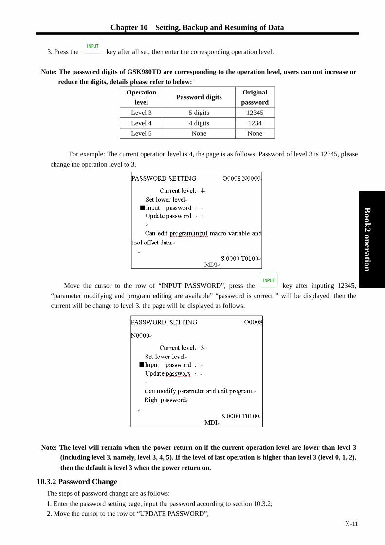
Chapter 10 Setting, Backup and Resuming of Data
Ⅹ-11
Book2
operation
3. Press the INPUT
key after all set, then enter the corresponding operation level.
Note: The password digits of GSK980TD are corresponding to the operation level, users can not increase or reduce the digits, details please refer to below:
Operation level
Password digits Original password
Level 3 5 digits 12345 Level 4 4 digits 1234 Level 5 None None
For example: The current operation level is 4, the page is as follows. Password of level 3 is 12345, please
change the operation level to 3.
Move the cursor to the row of “INPUT PASSWORD”, press the INPUT
key after inputing 12345, “parameter modifying and program editing are available” “password is correct ” will be displayed, then the current will be change to level 3. the page will be displayed as follows:
Note: The level will remain when the power return on if the current operation level are lower than level 3
(including level 3, namely, level 3, 4, 5). If the level of last operation is higher than level 3 (level 0, 1, 2), then the default is level 3 when the power return on.
10.3.2 Password Change The steps of password change are as follows: 1. Enter the password setting page, input the password according to section 10.3.2; 2. Move the cursor to the row of “UPDATE PASSWORD”;

GSK980TD Turning Machine CNC System
Ⅹ-12
Book2 operation
3. Input new password, then press the INPUT
key; 4. “Please input the new password again” will be displayed, details please find below:
5. Press the INPUT
key again after re-input the new password, if both input passwords are matched, the “password updated” will be displayed, the password is updated successfully.
6. If the input passwords are not matched, “Password unmatched, please input again” will be displayed:
10.3.3 Set Lower Level The operation is for user to set one level lower than current level, operation steps are as follows: 1. Enter the password setting page, input the password according to section 10.3.2; 2. Move the cursor to the row of “SET LOWER LEVEL”, if the current level is 3, the page is as follows:

Chapter 10 Setting, Backup and Resuming of Data
Ⅹ-13
Book2
operation
3. “Set current level to level 4, confirm?” will be displayed by pressing the INPUT
key, the page will be shown as follows:
4. The set lower level setting will be done by pressing INPUT
again, the page will be shown as follows:
Note: Set lower level can not be done if level 5 is the current level.


Chapter 11 Communication
Ⅺ-1
B
ook2 operation
Chapter 11 COMMUNICATION
11.1 Introdcution of the GSK980TD communication software, TDComm2a
TDComm2a can realize the file uploading and downloading between PC and CNC, it is easy to operate, and is efficacious in communication and relierable.
● System (PC) requirement for TDComm2a Hardware: PC with RS232 serial-port interface, serial communication cable, (3 wires) Operation System: Microsoft Windows 98/2000/XP/2003 ● Software Interface
The software interface of TDComm2a is simple, the following Fig.ture is the interface of the software when running.
Fig. 3-1 File downloading interface (PC→CNC)
Fig. 3-2 File uploading interface (CNC→PC)

GSK980TD Turning Machine CNC System
Ⅺ-2
Book2 operation
Fig. 3-2 Setting option interface
11.1.1 File Downloading(PC→CNC) When downloading the files, press the button “Add File”, select to the list box the to-transfer Files to CNC, list
the information such as file path, file name on CNC, file length, save area on CNC. You can save the list into files, so that the next time you use the programme to transfer the same file, you can open the list file, you don’t need to reselect the file.
Fig. 3-4
As shown in Fig. 3-4, on the left is the disply box of the file list, on the right are the five buttons “Load to
List”, “Save List”, “Add File”, “Check Source File”, “Start Downloading”, and the option for “overwrite the file with the same file name”
File list display box: When downloading files, it is the list box of the to-transfer file to CNC, listing the information such as file path, file name on CNC, file length, save area on CNC. You can save the list into files, so that the next time you use the programme to transfer the same file, you can open the list file, you don’t need to

Chapter 11 Communication
Ⅺ-3
B
ook2 operation
reselect the file. Load to List: Load the download list file saved on the harddisk. Save List: Save the current file list to harddisk as file. Add File Add a file to the to-transfer file list from harddisk Start Downloading: Start the file transferring after selecting the to-transfer files. Check Source File: Open the selected file in text mood. Overwrite the file with the same file name: Overwrite the file without asking if there are files with the same
names on the CNC during the file transferring. ▲ Select File Dialog Box
Press the “Add File” botton as shown at the mouse pointer in Fig.3-4, appears the dialog box “Please select the file to send…”, choose the to-transfer files in the dialog box, (can be multi-select) press botton “All CNC File”, you can select all the CNC files under the directory to the file list at a time. The default file names saved to the CNC from the file list are the same as the original file names, the file names will cut to 8 characters automatically when the file name lengths are over 8 characters.
Fig. 3-5 Annotate: The file names saved in the CNC can’t be Chinese Charactors, double click the file list item
in the file list to modify and save the file name.
When selecting a single file, we can get the preview of the file content in the bottom of the dialog box, as shown in Fig. 3-6.
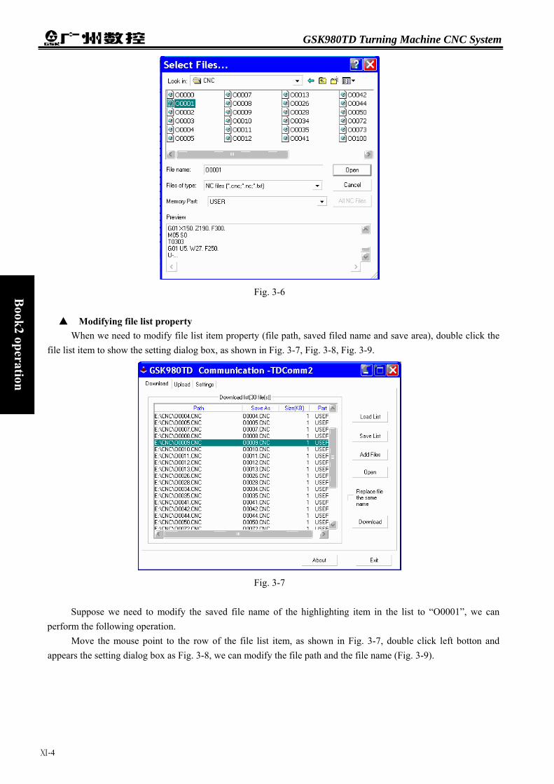
GSK980TD Turning Machine CNC System
Ⅺ-4
Book2 operation
Fig. 3-6
▲ Modifying file list property
When we need to modify file list item property (file path, saved filed name and save area), double click the file list item to show the setting dialog box, as shown in Fig. 3-7, Fig. 3-8, Fig. 3-9.
Fig. 3-7
Suppose we need to modify the saved file name of the highlighting item in the list to “O0001”, we can
perform the following operation. Move the mouse point to the row of the file list item, as shown in Fig. 3-7, double click left botton and
appears the setting dialog box as Fig. 3-8, we can modify the file path and the file name (Fig. 3-9).
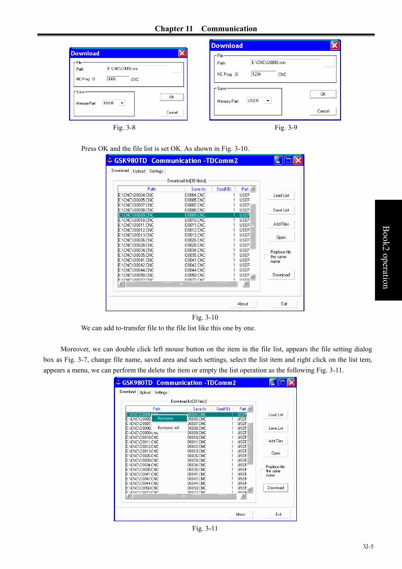
Chapter 11 Communication
Ⅺ-5
B
ook2 operation
Fig. 3-8 Fig. 3-9
Press OK and the file list is set OK. As shown in Fig. 3-10.
Fig. 3-10
We can add to-transfer file to the file list like this one by one.
Moreover, we can double click left mouse button on the item in the file list, appears the file setting dialog box as Fig. 3-7, change file name, saved area and such settings, select the list item and right click on the list tem, appears a menu, we can perform the delete the item or empty the list operation as the following Fig. 3-11.
Fig. 3-11

GSK980TD Turning Machine CNC System
Ⅺ-6
Book2 operation
When finished the file adding, we can press the “Save list” botton to save the list as a file, so that next time we can add to-transfer files by “Load list” directly, no need to set the file list one by one again, as Fig. 3-12.
Fig. 3-12 Annotation: The file name in CNC can just be 8.3 format (8 letter or digit character as file name, 3 letter or
digit character as extended name), can’t be Chinese charactors or other charactors. Obey this rule when downloading files, modifying the file names or setting CNC file names. If the file name is not accord with the rule, the item will be shown in red in the file list, modify it to this rule.
after the file list is done, we can press the “ Start Download” button, download the files and appears the dialog box of communication statues, in the dialog box, we can check the information of the transferring file, process and communication statue. ( Fig. 3-13 ).
Fig. 3-13
If there are files with the same file names on the CNC, the dialog box will shows, we can choose to overwrite the files or skip the files and transfer, and perform corresponding operation. (Fig. 3-14).
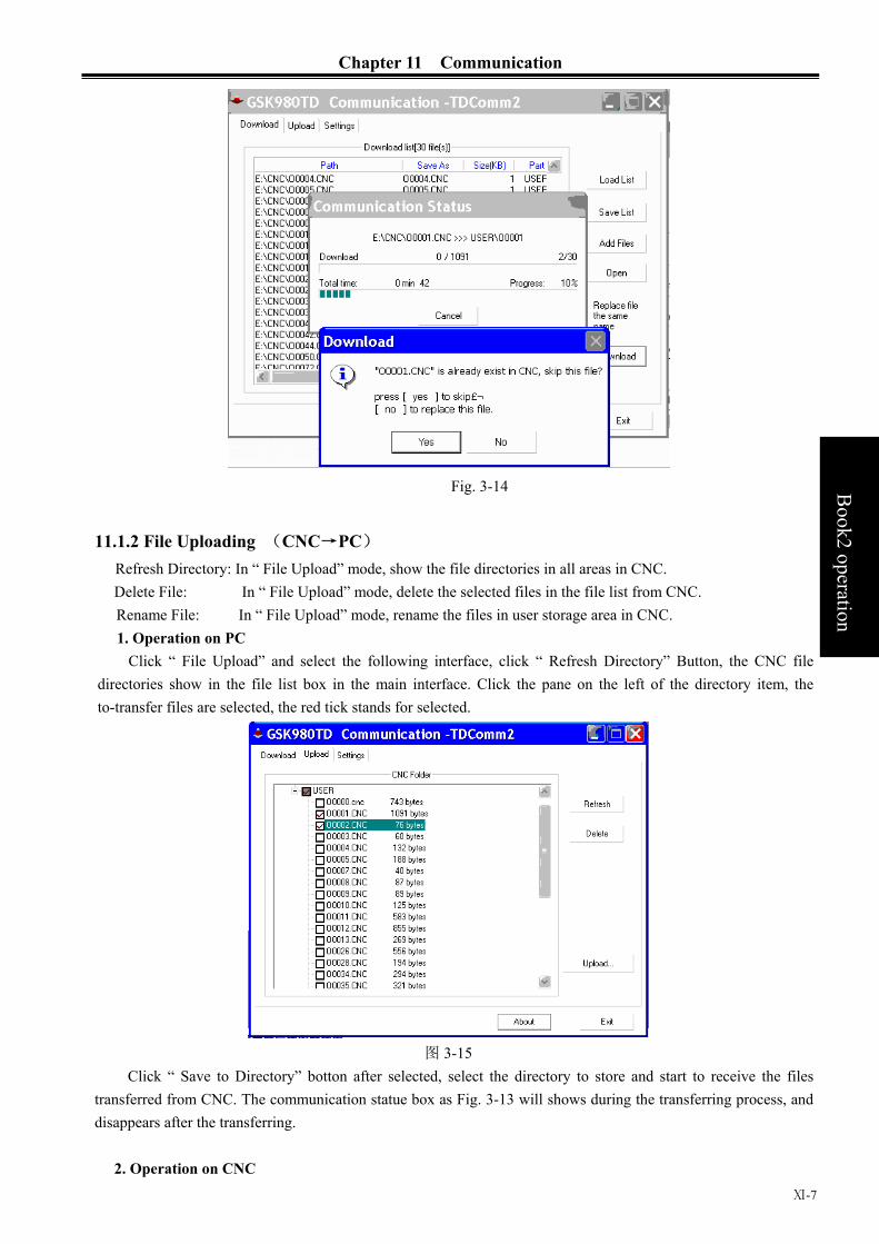
Chapter 11 Communication
Ⅺ-7
B
ook2 operation
Fig. 3-14
11.1.2 File Uploading (CNC→PC) Refresh Directory: In “ File Upload” mode, show the file directories in all areas in CNC. Delete File: In “ File Upload” mode, delete the selected files in the file list from CNC. Rename File: In “ File Upload” mode, rename the files in user storage area in CNC. 1. Operation on PC
Click “ File Upload” and select the following interface, click “ Refresh Directory” Button, the CNC file directories show in the file list box in the main interface. Click the pane on the left of the directory item, the to-transfer files are selected, the red tick stands for selected.
图 3-15
Click “ Save to Directory” botton after selected, select the directory to store and start to receive the files transferred from CNC. The communication statue box as Fig. 3-13 will shows during the transferring process, and disappears after the transferring.
2. Operation on CNC

GSK980TD Turning Machine CNC System
Ⅺ-8
Book2 operation
After connected to the CNC, in idle staute, the software can receive files sent initiatively by CNC. When the CNC starts to transfer files, the program starts to receive datas immediately, and ask the user to save the files after the receiving is finished.
Fig. 3-16
3. Delete Files on CNC When selecting “ File upload” perperty page in Dialog box, after selecting the to-delete files in the file list,
press the button “ Delete File” to delete the selected files. (select more than one file to delete at a time is OK too).
Fig. 3-17
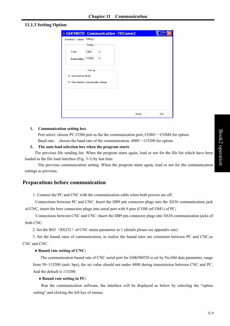
Chapter 11 Communication
Ⅺ-9
B
ook2 operation
11.1.3 Setting Option
1. Communication setting box Port select: choose PC COM port as the the communication port, COM1~COM4 for option. Baud rate: choose the baud rate of the communication, 4800~115200 for option.
2. The auto load selection box when the program starts The previous file sending list: When the progrom starts again, load or not for the file list which have been
loaded as the file load interface (Fig. 3-1) by last time. The previous communication setting: When the progrom starts again, load or not for the communication
settings as previous.
Preparations before communication
1. Connect the PC and CNC with the communication cable when both powers are off.
Connections between PC and CNC: Insert the DB9 pin connector plugs into the XS36 communication jack
of CNC, insert the bore connectore plugs into serial port with 9 pins (COM orCOM1) of PC;
Connections between CNC and CNC: Insert the DB9 pin connector plugs into XS36 communication jacks of
both CNC.
2. Set the Bit5(RS232)of CNC status parameter as 1 (details please see appendix one).
3. Set the baund rates of communication, to realize the baund rates are consistent between PC and CNC,or
CNC and CNC.
● Baund rate setting of CNC:
The communication baund rate of CNC serial port for GSK980TD is set by No.044 data parameter, range
from 50~115200 (unit: bps), the set value should not under 4800 during transmission between CNC and PC.
And the default is 115200.
● Baund rate setting in PC:
Run the communication software, the interface will be displayed as below by selecting the “option
setting” and clicking the left key of mouse.

GSK980TD Turning Machine CNC System
Ⅺ-10
Book2 operation
Port selecting: Select the port(COM1,COM2,COM3,COM4)for communication.
Baund rate selecting: Select the communication baund rate (4800,9600,19200,38400,57600,115200
(unit:bps))
Note1: Turn on the program switch if program transmission is needed; Turn on the parameter switch if parameter and tool offset,etc, transmission is needed; If alarm occurs when turning on the switch,the
alarm can be cleared by pressing the CANCEL
and RESET
key simultaneously. Note2: To ensure the steady and reliable communication, please stop processing if it is running. If data
sending from CNC is needed, please switch to the edit operation first.
Note3: It can be stopped by pressing the RESET
key; Note4: Do not shut off the power during the data transmission, or the data transmission error will be
occurred.
11.3 DATA INPUT(PC→CNC)
The appointed data file can be transferred to CNC by performing the input function, such as program,
parameter,tool offset and worm offset,etc.
11.3.1 Program Input
1. Set the operation level (level 2 is required for macro setting) and then turn on the program switch;
2. Edit the programs in PC (files with *.cnc,*.nc,*.txt postfix are supported), and then save them in the
harddisk;
3. Click the option of “file download” when the communication software is running in PC, it will be displayed
as below:

Chapter 11 Communication
Ⅺ-11
B
ook2 operation
4. Click the “Add file” button under the software interface as shown in above chart, A dialogue box for adding
file will appears, the screen will be shown as below after selecting the edited program.
5. Under the software interface as shown in above chart, the program name can be changed by double clicking it:
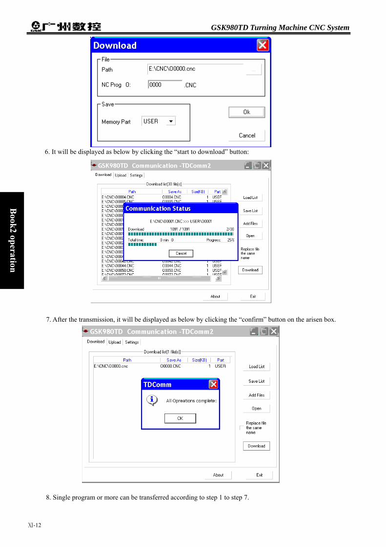
GSK980TD Turning Machine CNC System
Ⅺ-12
Book2 operation
6. It will be displayed as below by clicking the “start to download” button:
7. After the transmission, it will be displayed as below by clicking the “confirm” button on the arisen box.
8. Single program or more can be transferred according to step 1 to step 7.
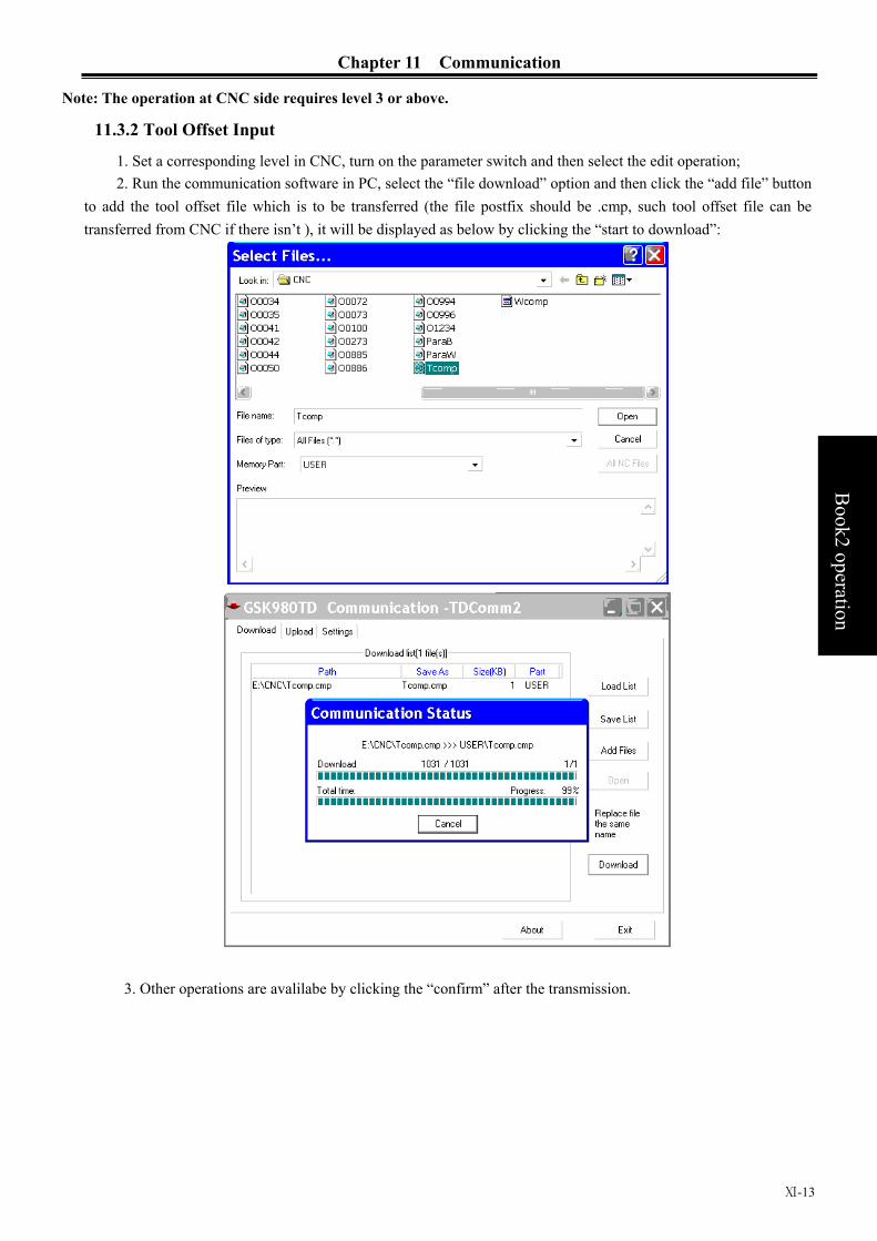
Chapter 11 Communication
Ⅺ-13
B
ook2 operation
Note: The operation at CNC side requires level 3 or above.
11.3.2 Tool Offset Input
1. Set a corresponding level in CNC, turn on the parameter switch and then select the edit operation; 2. Run the communication software in PC, select the “file download” option and then click the “add file” button
to add the tool offset file which is to be transferred (the file postfix should be .cmp, such tool offset file can be transferred from CNC if there isn’t ), it will be displayed as below by clicking the “start to download”:
3. Other operations are avalilabe by clicking the “confirm” after the transmission.

GSK980TD Turning Machine CNC System
Ⅺ-14
Book2 operation
11.3.3 Parameter Input
1. Set a corresponding level in CNC (level 2 is required for worm offset setting), turn on the parameter switch
and then select the edit operation; 2. Run the communication software in PC, select the “file download” option and then click the “add file” button
to add the parameter file which is to be transferred (the file postfix should be .par, such tool offset file can be transferred from CNC if there isn’t ), it will be displayed as below by clicking the “start to download”:
4. Other operations are avalilabe by clicking the “confirm” after the transmission.
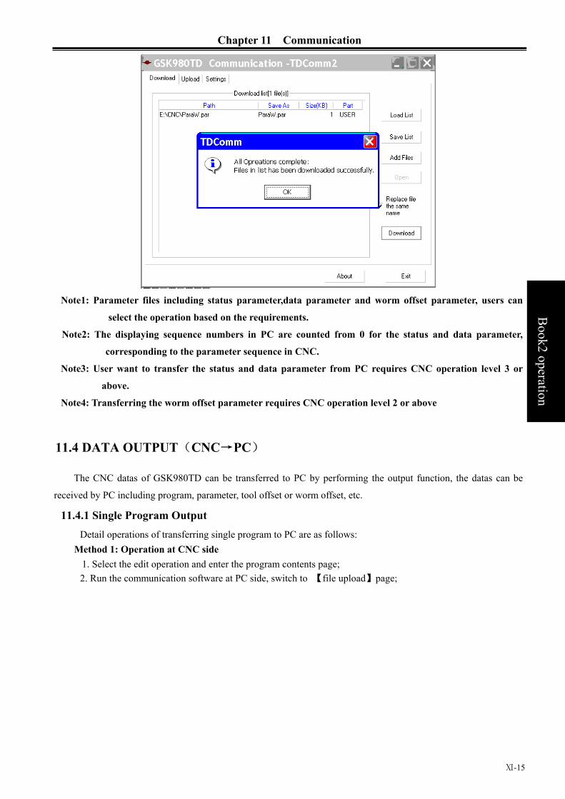
Chapter 11 Communication
Ⅺ-15
B
ook2 operation
Note1: Parameter files including status parameter,data parameter and worm offset parameter, users can
select the operation based on the requirements.
Note2: The displaying sequence numbers in PC are counted from 0 for the status and data parameter,
corresponding to the parameter sequence in CNC.
Note3: User want to transfer the status and data parameter from PC requires CNC operation level 3 or
above.
Note4: Transferring the worm offset parameter requires CNC operation level 2 or above
11.4 DATA OUTPUT(CNC→PC)
The CNC datas of GSK980TD can be transferred to PC by performing the output function, the datas can be
received by PC including program, parameter, tool offset or worm offset, etc.
11.4.1 Single Program Output Detail operations of transferring single program to PC are as follows:
Method 1: Operation at CNC side 1. Select the edit operation and enter the program contents page; 2. Run the communication software at PC side, switch to 【file upload】page;

GSK980TD Turning Machine CNC System
Ⅺ-16
Book2 operation
3. Press the key and input the program name at CNC side (this step can be omitted if transferring
current program);
4. Output starts by pressing the OUTPUT
key, The character “output” under the CNC screen will be glitter, and the screen at PC will be displayed as follows after the transmission:
5. Click the 【no save】button if no need to save; if need to save it, please click the【save】button and then select
the saving route on the save route dialogue box, the file will be saved by click the 【save】button:

Chapter 11 Communication
Ⅺ-17
B
ook2 operation
Method 2: Operations at PC side: 1. Select the edit operation and enter the program contents page; 2. Run the communication software at PC side, switch to 【file upload】page and click the 【contents refurbish】;
3. Select the program to be save, and then click the 【save to folder】, details are as follows (select the tenth
program to save):
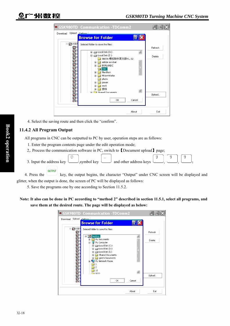
GSK980TD Turning Machine CNC System
Ⅺ-18
Book2 operation
4. Select the saving route and then click the “confirm”.
11.4.2 All Program Output
All programs in CNC can be outputted to PC by user, operation steps are as follows: 1. Enter the program contents page under the edit operation mode; 2,. Process the communication software in PC, switch to【Document upload】page;
3. Input the address key ,symbol key and other address keys , , ;
4. Press the OUTPUT
key, the output begins, the character “Output” under CNC screen will be displayed and glitter, when the output is done, the screen of PC will be displayed as follows:
5. Save the programs one by one according to Section 11.5.2.
Note: It also can be done in PC according to “method 2” described in section 11.5.1, select all programs, and save them at the desired route. The page will be displayed as below:

Chapter 11 Communication
Ⅺ-19
B
ook2 operation
11.4.3 Tool Offset Output
1. Enter the tool offset page under the edit operation mode; 2. Process the communication software in PC, switch to【Document upload】page;
3. Press the OUTPUT
key on CNC, the output begins, the character “Output” under CNC screen will be displayed, the screen of PC will be displayed as follows:
4. When the output is done, the screen of PC will be displayed as follows (default name: Tcomp.cmp):
5. Save the tool offset in desired route according to Section 11.5.2.
11.4.4 Parameter Output
1. Enter the related page of parameter interface under edit operation mode:
2. Enter the status parameter page if status parameter has to be transferred
3. Enter the data parameter page if data parameter has to be transferred
4. Enter the worm offset data page if worm offset data has to be transferred;
GSK980TD Turning Machine CNC System
Ⅺ-20
Book2 operation
5. Process the communication software in PC, switch to【Document upload】page;
6. Press the OUTPUT
key on CNC, the output begins, the character “Output” under CNC screen will be displayed, the screen of PC will be displayed as follows:
7. During the transmission, the file names dispayed in PC are different for different types of datas, detaisl are as follows (The default names are marked in ellipses):
Status parameter, displaying as follows (default file name: ParaB.par)
Data parameter, displaying as follows (default file name: ParaW.par)
Worm offset data, displaying as follows (default file name: Wcomp.wmp)

Chapter 11 Communication
Ⅺ-21
B
ook2 operation
5, Save the parameter datas to the desired rote according to section 11.5.2.
11.5 COMMUNICATION betweent CNC and CNC
To simplify the operation, transmission between two CNCs is allowed, the sending CNC is so-called sender;
and the receiving CNC is so-called receiver.Detaisl are as follows:
Sender Receiver
Please take note of below when transferring datas:
1. The communication functions are both available for sender and receiver, namely, the Bit5(RS232)of
No.002 of CNC status parameters are both set as 1;
2. The baud rates are the same between two sides, namely the No.044 CNC data parameters are the same;
3. Both side must under the edit operation;
4. The sender must under the page which is ready for data transferring (For example, it must under status
parameter page if status parameter is to be transferred)
5. The receiver must under the related levels and all related switches must have been turned on (parameter
switch, program switch)
Received datas Level Remark
Program (Program names under
9000)
Level 4,3,2
Turn on the program
switch
Macro program (Program above or
equal to 9000)
Level 2 Turn on the program
switch
Tool offset value Level 4,3,2
CNC
CNC

GSK980TD Turning Machine CNC System
Ⅺ-22
Book2 operation
Status parameter
Level 3,2
Turn on the parameter
switch
Data parameter Level 3,2 Turn on the parameter
switch
Worm offset data Level 2 Turn on the parameter
switch
6. The operation steps are the same with “Data output (CNC→PC)” on CNC which is described in Section
11.5.
Chapter 12 Process Example
Book2
operation
Chapter 12 PROCESS EXAMPLE To fabricate a workpiece as below , the dimension of roughcast isΦ136×180mm.
4 ×
×
×
轴
Z轴
workpiece
To fabricate with below four tools:
Number Tool shape Description
Tool 1
Outer rough tool
Tool 2
Tool 3
Tool 4
12.1 PROGRAM EDIT
According to the machining technic
program are as follows:
C
Ⅻ-1
Outer smooth tool
Slot cutting tool (width:3mm)
Worm cutting tool (angle of knifepoint: 60°)
s and the operation manual, set up a workpiece coordinate as chart 12-1, the
hart 12-1
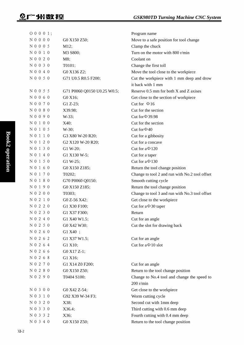
GSK980TD Turning Machine CNC System
Ⅻ-2
Book2 operation
O0001; Program name N0000 G0 X150 Z50; Move to a safe position for tool change N0005 M12; Clamp the chuck N0010 M3 S800; Turn on the motor with 800 r/min N0020 M8; Coolant on N0030 T0101; Change the first toll N0040 G0 X136 Z2; Move the tool close to the workpiece N0050 G71 U0.5 R0.5 F200; Cut the workpiece with 1 mm deep and drow
it back with 1 mm N0055 G71 P0060 Q0150 U0.25 W0.5; Reserve 0.5 mm for both X and Z axises N0060 G0 X16; Get close to the section of workpiece N0070 G1 Z-23; Cut for Φ16 N0080 X39.98; Cut for the section N0090 W-33; Cut forΦ39.98 N0100 X40; Cut for the section N0105 W-30; Cut forΦ40 N0110 G3 X80 W-20 R20; Cut for a gibbosity N0120 G2 X120 W-20 R20; Cut for a concave N0130 G1 W-20; Cut for aΦ120 N0140 G1 X130 W-5; Cut for a taper N0150 G1 W-25; Cut for aΦ130 N0160 G0 X150 Z185; Return the tool change position N0170 T0202; Change to tool 2 and run with No.2 tool offsetN0180 G70 P0060 Q0150; Smooth cutting cycle N0190 G0 X150 Z185; Return the tool change position N0200 T0303; Change to tool 3 and run with No.3 tool offsetN0210 G0 Z-56 X42; Get close to the workpiece N0220 G1 X30 F100; Cut for aΦ30 taper N0230 G1 X37 F300; Return N0240 G1 X40 W1.5; Cut for an angle N0250 G0 X42 W30; Cut the slot for drawing back N0260 G1 X40 ; N0262 G1 X37 W1.5; Cut for an angle N0264 G1 X10; Cut for aΦ10 slot N0266 G0 X17 Z-1; N0268 G1 X16; N0270 G1 X14 Z0 F200; Cut for an angle N0280 G0 X150 Z50; Return to the tool change position N0290 T0404 S100; Change to No.4 tool and change the speed to
200 r/min N0300 G0 X42 Z-54; Get close to the workpiece N0310 G92 X39 W-34 F3; Worm cutting cycle N0320 X38; Second cut with 1mm deep N0330 X36.4; Third cutting with 0.6 mm deep N0332 X36; Fourth cutting with 0.4 mm deep N0340 G0 X150 Z50; Return to the tool change position
Chapter 12 Process Example
Ⅻ-3
Book2
operation
N0350 T0100; Change back to No. 1 tool N0360 M5; Turn off the spindle N0370 M9; Coolant off N0380 M13; Release the chuck N0390 M30; Program over
12.2 PROGRAM INPUT
12.2.1 Look over the Preserve Programs
Under non-edit operation, enter the program interface by pressing the key, select the program contents
page by pressing the or key, details are as follows:
The preserve program names can be looked over on above page, then it is ready to set up a new program name.
12.2.2 Set up a New Program
Under the edit operation, enter the program contents page by pressing the key, the page will be displayed as follows:
Press the address key , select a nonexistent program (such as 0001), input the numeric keys
, , , , set up a new program by pressing the EOB
key, the page will be displayed as follows:

GSK980TD Turning Machine CNC System
Ⅻ-4
Book2 operation
Input the program as above mentioned, the program edit will be done and after that the first page will be
displayed as below:
To display other contents by pressing the or key.
12.3 PROGRAM TEST
12.3.1 Graph Setting
Enter the graph interface by pressing the SETTING
key, select the graph setting page by pressing the
or key, then enter the MDI operation by pressing the MDI key, the page will be displayed as below:

Chapter 12 Process Example
Ⅻ-5
Book2
operation
Move the cursor by pressing the or key to set the “coordinate selecting”, “max. value of X”,
“max. value of Z”, “min. value of X” and “min. value of Z” (the “scaling” and “graph center” in the graph setting will be adjusted automatically according to the “max. value of X”, “max. value of Z”, “min. value of X” and “min. value of Z” .) Here is the setting of “max. value of X” will be set as an example of graph parameter setting :
1. Move the cursor to the parameter of“max. value of X” by pressing the or key.
2. The dimension of the roughcast is 135 mm, then the input value should be bigger than 136 mm, here 150 mm
is set, input , , in sequence;
3, The page will be displayed after setting and pressing the INPUT
key:
To set other datas according above method, in this example the page will be displayed as below after setting:
12.3.2 Program Test
Enter the graph displaying page by pressing the or key, enter the automatic operation by
pressing the AUTO key, Enter the auxiliary lock, machine lock and dry running by pressing
the
MST
, , DRY keys, at the moment the LEDs of M S T
, and are turned on.Start to
plot by pressing the key, and then press the RUN key to run program automatically,the tool moving track will be displayed and the correctness of program can be tested,the page will be displayed as follows after all set.

GSK980TD Turning Machine CNC System
Ⅻ-6
Book2 operation
If there is something wrong, please analyse the error and modify the program, then test it again until there is
nothing unusual.
12.4 TOOL ADJUSTING and RUN
1. Move the tool to a safe positon, run the T0100 U0 W0 under the MDI mode, program status page, and then
cancel the tool offset; 2. Move the tool close to the workpiece and let it cut along the section.
3. Release the tool along the X axis and remain the Z axis, stop the spindle, perform the G50 Z0 under the
program status page of MDI operation, then set the coordinate of Z axis;
4. Switch to tool offset page and input Z0 into No.001 offset; 5. Move the tool close to the workpiece and cut along the outer surface;
6. Release the tool along the Z axis and remain the X axis, stop the spindle, then measure the dimension of the
outer column (suppose the value is 135 mm)
7. Perform the G50 X135 under the program status page of MDI operation, then set the coordinate of X axis
8. Switch to tool offset page and input X135 into No.001 offset;
9. Move the tool to a safe positon,select the No.2 tool by pressing the tool change key under the manual
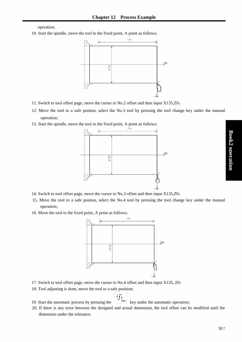
Chapter 12 Process Example
Ⅻ-7
Book2
operation
operation; 10. Start the spindle, move the tool to the fixed point, A point as follows;
11. Switch to tool offset page, move the cursor to No.2 offset and then input X135,Z0;
12. Move the tool to a safe positon, select the No.3 tool by pressing the tool change key under the manual
operation; 13. Start the spindle, move the tool to the fixed point, A point as follows;
14. Switch to tool offset page, move the cursor to No.3 offset and then input X135,Z0; 15. Move the tool to a safe positon, select the No.4 tool by pressing the tool change key under the manual
operation; 16. Move the tool to the fixed point, A point as follows;
17. Switch to tool offset page, move the cursor to No.4 offset and then input X135, Z0; 18. Tool adjusting is done, move the tool to a safe position;
19. Start the automatic process by pressing the RUN key under the automatic operation; 20. If there is any error between the designed and actual dimension, the tool offset can be modified until the
dimension under the tolerance.
GSK980TD Turning Machine CNC System
Ⅻ-8
Book2 operation
Note: Press the PAUSE to pause the automatic running if needed. If any emergency occurs, the RESET
key, emergency button can be pressed or the power can be shut off to terminate the program running.

BOOK 3
CONNECTION
Chapter 1:Fixing and Layout
Chapter 2:Definition and Connection of Interface
Chapter 3:Specification of Parameters
Chapter 4:Method and Process of Machine Tool Debugging
Chaoter 5:Diagnosis Information
Chapter 6:Function of Stored Pitch Error Compensation
Book3
connection


Contents
Chapter 1:FIXING and LAYOUT....................................................................................................Ⅰ-1
1.1 CONNECTION of GSK980TD.....................................................................................Ⅰ-11.1.1 Interface Layout of GSK980TD .............................................................................Ⅰ-11.1.2 Interface Description...............................................................................................Ⅰ-1 1.1.3 Total Connection Diagram......................................................................................Ⅰ-2
1.2 INSTALLATION of GSK980TD...................................................................................Ⅰ-3 1.2.1 Outline Dimensions of GSK980TD........................................................................Ⅰ-3 1.2.2 Outline Dimensions of GSK980TD-B....................................................................Ⅰ-4 1.2.3 Installation Requirement of the Machine Electromagnetism Cabinet ....................Ⅰ-4 1.2.4 Action Against Noise ..............................................................................................Ⅰ-4
Chapter 2:DEFINITION and CONNECTION of INTERFACE ..................................................... Ⅱ-1 2.1 CONNECTION to DRIVER...............................................................................................Ⅱ-1
2.1.1 Driver Interface.........................................................................................................Ⅱ-1 2.1.2 Pulse Signal and Direction Signal.............................................................................Ⅱ-1 2.1.3 Driver Alarm Signal nALM ...................................................................................Ⅱ-1 2.1.4 Axis Enabling Signal nEN ...................................................................................Ⅱ-2 2.1.5 Pulse Forbidden Signal nSET ............................................................................Ⅱ-2 2.1.6 Zero Signal nPC.................................................................................................Ⅱ-3 2.1.7 Connection to Driver....................................................................................................Ⅱ-4
2.2 CONNECTION to SPINDLE ENCODER .........................................................................Ⅱ-5 2.2.1 Spindle Encoder Interface.........................................................................................Ⅱ-5 2.2.2 Signal Description.....................................................................................................Ⅱ-5 2.2.3 Connection of Spindle Encoder Interface .................................................................Ⅱ-5
Book3
connection
2.3 CONNECTION to MANUAL PULSE GENERATOR ......................................................Ⅱ-6 2.3.1 Manual Pulse Generator Interface ............................................................................Ⅱ-6 2.3.2 Signal Description.....................................................................................................Ⅱ-6
2.4 CONNECTION to FREQUENCY CHANGER .................................................................Ⅱ-7 2.4.1 Analog Spindle Interface ..........................................................................................Ⅱ-7 2.4.2 Signal Description.....................................................................................................Ⅱ-7 2.4.3 Connection of Frequency Changer ...........................................................................Ⅱ-7
2.5 CONNECTION between GSK980TD and PC ...................................................................Ⅱ-8 2.5.1 Communication Interface..........................................................................................Ⅱ-8 2.5.2 Connection of Communication Interface..................................................................Ⅱ-8
2.6 POWER SUPPLY CONNECTION ....................................................................................Ⅱ-9 2.7 STANDARD and EXPANDED I/O INTERFACE ...........................................................Ⅱ-10
2.7.1 Input Signal .............................................................................................................Ⅱ-12 2.7.2 Output Signal ..........................................................................................................Ⅱ-13
2.8 FUNCTION and CONNECTION of I/O INTERFACE ...................................................Ⅱ-15 2.8.1 Overtravel and Emergency Stop .............................................................................Ⅱ-15 2.8.2 Tool Changing Control............................................................................................Ⅱ-16 2.8.3 Reference Point Return ...........................................................................................Ⅱ-19 2.8.4 Spindle Positive or Negative Rotation Control.......................................................Ⅱ-24 2.8.5 Spindle Speed Controlled by On-off Variable ........................................................Ⅱ-25 2.8.6 Automatic Gearing Control for Spindle..................................................................Ⅱ-26 2.8.7 Outside Cycle Start and Cycle Stop ........................................................................Ⅱ-27
I

GSK980TD Turning Machine CNC System
Book3 connection
2.8.8 Coolant Control .......................................................................................................Ⅱ-28 2.8.9 Lubrication Control .................................................................................................Ⅱ-29 2.8.10 Chuck Control........................................................................................................Ⅱ-31 2.8.11 Tailstock Control....................................................................................................Ⅱ-33 2.8.12 Low Pressure Detection.........................................................................................Ⅱ-34 2.8.13 Defence Gate Detection.........................................................................................Ⅱ-35 2.8.14 Spindle Rotation Permission..................................................................................Ⅱ-35 2.8.15 Program Segment Skipping ...................................................................................Ⅱ-36 2.8.16 Macro Variable.......................................................................................................Ⅱ-37
2.9 ELECTRIC CONNECTION for I/O SIGNAL.............................................................Ⅱ-38 CHAPTER3: PARAMETER SPECIFICATION.................................................................................Ⅲ-1
3.1 PARAMETER SPECIFICATION(with sequence)............................................................Ⅲ-1 3.1.1 State Parameter ..........................................................................................................Ⅲ-1 3.1.2 Data Parameter..............................................................................................................Ⅲ-6
3.2 PARAMETER SPECIFICATION(with function) ...........................................................Ⅲ-12 3.2.1 Control Logic for X and Z Axes .................................................................................Ⅲ-12 3.2.2 Acceleration and Deceleration Control.......................................................................Ⅲ-12 3.2.3 Safeguard for Machine ...............................................................................................Ⅲ-13 3.2.4 Reference Point Return...............................................................................................Ⅲ-14 3.2.5 Thread Function..........................................................................................................Ⅲ-15 3.2.6 Spindle Control ...........................................................................................................Ⅲ-16 3.2.7 Chuck Control.............................................................................................................Ⅲ-17 3.2.8 Tailstock Control.........................................................................................................Ⅲ-18 3.2.9 Tool Nose Radius Compensation................................................................................Ⅲ-18 3.2.10 Toolpost Control .......................................................................................................Ⅲ-19 3.2.11 Edit and Display........................................................................................................Ⅲ-19 3.2.12 Accuracy Compensation ...........................................................................................Ⅲ-20 3.2.13 Communication Setting ............................................................................................Ⅲ-21
Chapter 4 MACHINE DEBUGGING ..............................................................................................Ⅳ-1 4.1 EMERGENCY STOP and OVERTRAVEL ........................................................................Ⅳ-1 4.2 DRIVER SETTING.............................................................................................................Ⅳ-1 4.3 GEAR RATIO ADJUSTING...............................................................................................Ⅳ-1 4.4 ACCELERATING and DECELERATING CHARACTERISTIC ......................................Ⅳ-2 4.5 REFERENCE POINT ADJUSTING...................................................................................Ⅳ-3 4.6 SPINDLE FUNCTION ADJUSTING.................................................................................Ⅳ-4
4.6.1 Spindle Encoder............................................................................................................Ⅳ-4 4.6.2 Spindle Brake................................................................................................................Ⅳ-5 4.6.3 Spindle Speed Controlled by On-off Variable ..............................................................Ⅳ-5 4.6.4 Spindle Speed Controlled by Analog Voltage...............................................................Ⅳ-5
4.7 BACKLASH COMPENSATION........................................................................................Ⅳ-5 4.8 TOOLPOST ADJUSTING ..................................................................................................Ⅳ-6 4.9 STEP/MPG ADJUSTING ...................................................................................................Ⅳ-7 4.10 OTHER ADJUSTING .......................................................................................................Ⅳ-7
CHAPTER5: DIAGNOSIS INFORMATION.....................................................................................Ⅴ-1 5.1 DIAGNOSIS of CNC .............................................................................................................Ⅴ-1
5.1.1 Diagnosis Information from Machine ..........................................................................Ⅴ-1 5.1.2 Diagnosis Information from CNC ................................................................................Ⅴ-1

Contents
5.1.3 Diagnosis Information of Axis State............................................................................Ⅴ-2 5.1.4 Diagnosis of Keys ........................................................................................................Ⅴ-2 5.1.5 Diagnosis between PLC and CNC...............................................................................Ⅴ-4 5.1.6 Inner State of CNC.......................................................................................................Ⅴ-9
5.2 STATE of PLC .....................................................................................................................Ⅴ-10 5.2.1 Address X(machine to PLC,defined by standard PLC) .....................................Ⅴ-10 5.2.2 Address Y (machine to PLC,defined by standard PLC) ...................................Ⅴ-12 5.2.3 Address F(CNC to PLC).......................................................................................Ⅴ-15 5.2.4 Address G(PLC to CNC) ......................................................................................Ⅴ-23 5.2.5 Address A(information-asking for signal,defined by standard PLC) ................Ⅴ-28
5.3 PLC DATA...........................................................................................................................Ⅴ-28 5.3.1 Timer Address(T,defined by standard PLC)......................................................Ⅴ-28 5.3.2 Counter Address(C,defined by standard PLC) ..................................................Ⅴ-29 5.3.3 Counter Pre-setting Value Address(DT,defined by standard PLC) ...................Ⅴ-29 5.3.4 Counter Pre-setting Value Address(DC,defined by standard PLC) ...................Ⅴ-30
Chapter6: STORED PITCH ERROR COMPENSATION ................................................................. Ⅵ-1 6.1 FUNCTION DESCRIPTION ............................................................................................. Ⅵ-1 6.2 SPECIFICATION ...............................................................................................................Ⅵ-1 6.3 PARAMETER SETTING ...................................................................................................Ⅵ-1
6.3.1 Pitch Error Compensation......................................................................................... Ⅵ-1 6.3.2 Compensation Origin ................................................................................................Ⅵ-1 6.3.3 Compensation Interval ..............................................................................................Ⅵ-2 6.3.4 Compensation Value ................................................................................................. Ⅵ-2
6.4 NOTES for SETTING COMPENSATION VALUE...........................................................Ⅵ-2 6.5 EXAMPLE for SETTING COMPENSATION PARAMETERS ..........................................Ⅵ-2
Book3
connection
III


Chapter 1 Fixing and Layout
Ⅰ-1
Book3
connection
Chapter 1 FIXING and LAYOUT
1.1 CONNECTION of GSK980TD
1.1.1 Interface Layout of GSK980TD
Fig.1-1 interface layout of GSK980TD NOTE: XS41 and XS42 are optional interfaces
1.1.2 Interface Description
● Power box:Adopt GSK-PB power box and provide the voltage of +5V、+24V、+12V、-12V、GND
● Filter(optional):Input port connects to 220VAC power,PE port grounds and output port connects to L,N port of GSK-PB power box ● XS30:15-slot D-type female connector,connect to X driver ● XS31:15-slot D-type female connector,connect to Z driver ● XS32:15-slot D-type female connector,connect to spindle encoder ● XS36:9-slot D-type female connector,connect to RS232 interface of PC ● XS37:9-pin D-type male connector,connect to frequency changer. ● XS38:9-pin D-type male connector,connect to manual pulse generator(MPG) ● XS39:25-slot D-type female connector,the interface from CNC to machine ● XS40:25-pin D-type male connector,the interface from machine to CNC ● XS41:25-pin D-type male connector,the expanding input interface ● XS42:25-slot D-type female connector,the expanding output interface

GSK980TD Turning Machine CNC System
Ⅰ-2
Book3 connection
1.1.3 Total Connection Diagram
Fig.1-2 total connection diagram
to machine
MPG
encoder
to frequency changer

Chapter 1 Fixing and Layout
Ⅰ-3
Book3
connection
1.2 INSTALLATION of GSK980TD
1.2.1 Outline Dimensions of GSK980TD
MST
INSERT
ALARMOFFSET
ALTER
SETTING
EOB DELETE CANCEL
CHANGE
OUTPUT
RESET INPUT
× 10×1 × 100
SKIPSINGLE DRY
MST
ED IT AUTO MDI MPG JOG
CCW TOOL
ST OP LUR.
JOG
OV ERRIDEOVER RIDEOVER RIDE
SPINDE SPINDE SPINDE
RUN
CW COOLANT PAUSE
Fig.1-3 outline dimensions of GSK980TD
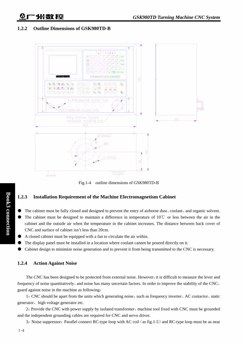
GSK980TD Turning Machine CNC System
Ⅰ-4
Book3 connection
1.2.2 Outline Dimensions of GSK980TD-B
MST
INSERT
×1 ×10 ×100
SINGLE SKIP
EDIT AUTO
MST
DRY
MDI MPG
CCW TOOL RUN
COOLANTJOG
STOP
CW
OVERRIDE
SPINDE LUR.
JOG
OVERRIDE
SPINDE SPINDE
OVERRIDE
PAUSE
ALTER
ALARMOFFSET SETTING
EOB DELETE CANCEL
RESET
CHANGE
OUTPUT
INPUT
Fig.1-4 outline dimensions of GSK980TD-B
1.2.3 Installation Requirement of the Machine Electromagnetism Cabinet
● The cabinet must be fully closed and designed to prevent the entry of airborne dust、coolant、and organic solvent. ● The cabinet must be designed to maintain a difference in temperature of 10℃ or less between the air in the
cabinet and the outside air when the temperature in the cabinet increases. The distance between back cover of CNC and surface of cabinet isn’t less than 20cm.
● A closed cabinet must be equipped with a fan to circulate the air within. ● The display panel must be installed in a location where coolant cannot be poured directly on it. ● Cabinet design to minimize noise generation and to prevent it from being transmitted to the CNC is necessary.
1.2.4 Action Against Noise
The CNC has been designed to be protected from external noise. However,it is difficult to measure the lever and frequency of noise quantitatively,and noise has many uncertain factors. In order to improve the stability of the CNC,guard against noise in the machine as following:
1:CNC should be apart from the units which generating noise,such as frequency inverter、AC contactor、static generator、high voltage generator etc.
2:Provide the CNC with power supply by isolated transformer,machine tool fixed with CNC must be grounded and the independent grounding cables are required for CNC and servo driver.
3:Noise suppressor:Parallel connect RC-type loop with AC coil(as fig.1-5)and RC-type loop must be as near

Chapter 1 Fixing and Layout
Ⅰ-5
Book3
connection
as possible to inductance load. Conversely parallel connect diode with DC coil(as fig.1-6).Parallel connect surge absorber with coil of AC motor.
4:The intertwist shielding or shielding cables as short as possible are absolutely necessary for the CNC,shielding layer of which is single-port grounding in CNC side.
5:Process the cables in each group as described in the action column. Group Signal line Action
AC power lines AC solenoid
A AC relay
Bind the cables in group A separately from groups B and C,(the groups must be 10cm or more apart from one another) or cover group A with an electromagnetic shield
DC solenoid(24VDC) DC relay(24VDC) Cable between the CNC and power magnetics cabinet
B
Cable between the CNC and machine
Bind the cables in group B separately from group A,or cover group B with an electromagnetic shield. Separate group B as far from group C as possible
Cable between the CNC and servo driver Cable for position feedback Cable for the position encoder Cable for the manual pulse generator
C
Other cables to be covered with the shield
Bind the cables in group C separately from group A,or cover group C with an electromagnetic shield. Separate group C as far from group B as possible. cables apply twisted-pair
220V~
fig.1-5
0V
+24V
fig.1-6
M 3~
Surge
absorber
KM
fig.1-7

GSK980TD Turning Machine CNC System
Cable between the CNC and servo driver Cable for position feedback Cable for the position encoder Cable for the manual pulse generator
C
Other cables to be covered with the shield
Bind the cables in group C separately from group A,or cover group C with an electromagnetic shield.Separate group C as far from group B as possible.cables apply twisted-pair
Book3 connection
Ⅰ-6

Chapter 2 Definition and Connection of Interface
Ⅱ-1
Book3
connection
Chapter 2 DEFINITION and CONNECTION of INTERFACE
2.1 CONNECTION to DRIVER
2.1.1 Driver Interface
Signal Name Description nCP+, nCP- Pulse signal
nDIR+, nDIR- Direction signal nPC Zero signal
nALM Driver alarm signal nEN Axis enabling signal nSET Pulse forbidden signal
Note:n means X or Z,the same as following.
2.1.2 Pulse Signal and Direction Signal
nCP+,nCP- are pulse signal and nDIR+,nDIR- are direction signal,which output in the difference mode(AM26LS31).Advise to receive these signal outside by AM26LS32,and the inside circuit of which as fig.2-2:
Fig.2-2 the inside circuit of nCP+/-,nDIR+/-
2.1.3 Driver Alarm Signal nALM
Driver alarm voltage can be specified to high or low level by Bit0 and Bit1 of No.009 parameter of the CNC. The inside circuit of nALM as fig.2-3:
1:nCP+ 2:nDIR+ 3:nPC 4:+24V 5:nALM 6:nSET 7:nEN 8:
9: nCP- 10:nDIR- 11:0V 12:+5V 13:+5V 14:0V 15:0V
Fig.2-1 interface of XS30、XS31 (15-slot D-type female connector)
INA Out A
Out A
INB Out B
Out B
nDIR +
nDIR – nCP +
nCP–
nDIR
nCP

GSK980TD Turning Machine CNC System
Ⅱ-2
Book3 connection
Fig.2-3 the inside circuit of nALM In such input circuit,recommend to provide driver with the signal as fig.2-4
mode1 mode2
Fig.2-4 the mode of driver providing signal
2.1.4 Axis Enabling Signal nEN
nEN is valid(being 0V)in normal operation and is invalid (not being 0V)at driver alarm or emergency stop. The inside circuit as fig.2-5:
Fig.2-5 the inside circuit of nEN
2.1.5 Pulse Forbidden Signal nSET
nSET is to control servo driver input and increase the ability of eliminating noise between the CNC and driver,which is low voltage when outputting the pulse signal and is high impedance otherwise. The inside circuit as fig.2-6:
Fig.2-6 the inside circuit of nSET
+5V
nALM
+24V
EN
ULN2803
nEN
SET
ULN2803
nSET

Chapter 2 Definition and Connection of Interface
2.1.6 Zero Signal nPC
In reference point return,zero signal is the encoder phase C signal or is the approach switch signal. The inside circuit as fig.2-7:
Fig.2-7 the inside circuit of nPC Note:nPC is valid at +24V a) User should provide nPC as fig.2-8:
+5V
PC
nPC
d
Note:In or descend b) Conne
HALL
N
irection of reference point return
*
Pencoder)
PC signal (appr
DECn signal
C signal (phase C signal of
(omitted)
Fig.2-8
reference point return,the reference point position is specified bing edge is valid)after decelerating switch coming away.
ction mode as fig.2-9 when both decelerating signal and zero sig component.
Fig.2-9 connection of NPN type HALL compo
Dn
+24VNPN型霍尔元件
PN type HALL component
nD
oaching switch)
r
Ⅱ-3
Book3
connection
y detecting skip of nPC(rising
nal are rooted in one NPN type
nent
ECnPCEC
eference point

GSK980TD Turning Machine CNC System
Ⅱ-4
Book3 connection
c) Connection mode as fig.2-9 when both decelerating signal and zero signal are rooted in one PNP type HALL component .
Fig.2-10 connection of PNP type HALL component
2.1.7 Connection to Driver
Connection between GSK980TD and the driver as fig.2-11
RSTP10
FSTP
41722
DGDG
nDIR-10
0V114 +24
35 nALM
nPC
nDIR
nCP+192
nCP-
SIGN-7
CZCOM
DG3220 COM+
CZ
15
215
SON
ALM
PULS-SIGN+
PULS+18
196
connection between GSK980TD
and DA98(A)
GSK980TD(X、Z axis)XS30、XS31
interface of DA98
metal shell
metal shell
connection between GSK980TD and DY3
nDIR-10
nALM
0V+5V
0V14
1112
5
GSK980TD(X、Z axis) XS30、XS31
nCP+nCP-nDIR+
1
29
DIR-10
metal shellEN-
RDY2EN+RDY1
11
1436
interface of DY3
DIR+CP-CP+1
29
metal shell
connection between GSK980TD and DF3 driver
GSK980TD(X、Z axis)XS30、XS31
nDIR+2
metal shell
5
14
121110
nALM0V
+5V
0VnDIR-
91
nCP-nCP+
DIR+3
ALM.COM
FREE
DIR-OUT.COM
FREEmetal shell
7
5
894
CP-CP+
interface of DF3 driver12
Fig.2-11 connection between GSK980TD and drivers
DECn nPC
PNPÐÍ»ô¶ûÔª¼þ+24V
PNP type HALL component
nDEC

Chapter 2 Definition and Connection of Interface
Ⅱ-5
Book3
connection
2.2 CONNECTION to SPINDLE ENCODER
2.2.1 Spindle Encoder Interface
Signal Name Description *PAS/PAS Encoder phase A signals *PBS/PBS Encoder phase B signals *PBS/PBS Encoder phase C signals
Fig.2-12 encoder interface of XS32 (15-slot D-type female connector)
2.2.2 Signal Description
*PCS/PCS,*PBS/PBS and *PAS/PAS are the encoder phase C,B and A difference signals separately,which are received by 26LS32. *PAS/PAS,*PBS/PBS are square wave with 90°phase difference,the highest frequency of which is less than 1MHz.Encoder lines of GSK980TD can be specified at will from 100~5000 by the parameter.
The inside circuit as fig.2-13(n=A,B,C)
Fig.2-13 the circuit of encoder signal
2.2.3 Connection of Spindle Encoder Interface
Connection between GSK980TD and spindle encoder as fig.2-14 and the twisted-pair is in need(take Changchunyiguang ZLF-12-102.4BM-C05D encoder as example ):
5 *PBS
metal shell+5V0V
PBS*PASPAS
1211
6
87
GSK980TD(XS32)
*PCSPCS
34
B6
0V+5V11
4
3 B
AA
57
1024-line encoder of Changchunyiguang
ZZ
82
Fig.2-14 connection between GSK980TD and spindle encoder
8:PAS 7:*PAS 6:PBS 5:*PBS 4:PCS 3:*PCS
15:0V 14:0V 13:+5V12:5V 11:0V
PnS
*PnSAM26LS32
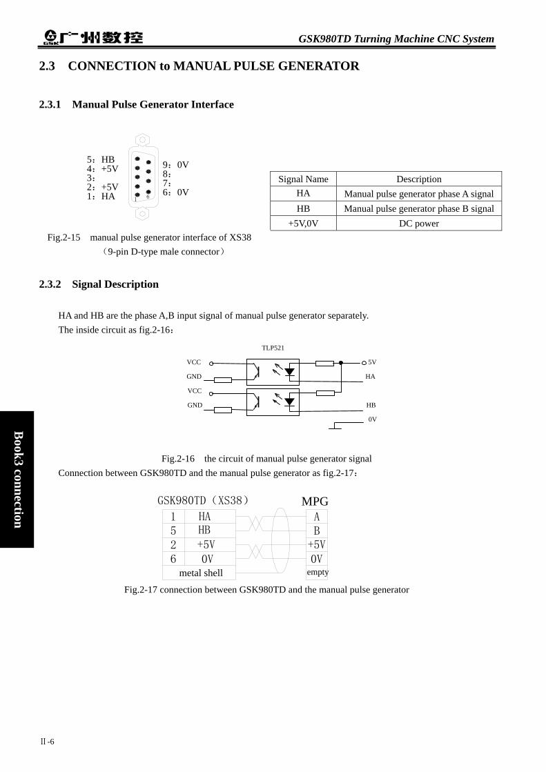
GSK980TD Turning Machine CNC System
Ⅱ-6
Book3 connection
metal shell
GSK980TD(XS38)
6251
HB
0V+5V
HA
0V+5VBA
MPG
empty
2.3 CONNECTION to MANUAL PULSE GENERATOR
2.3.1 Manual Pulse Generator Interface
Signal Name Description HA Manual pulse generator phase A signalHB Manual pulse generator phase B signal
+5V,0V DC power
2.3.2 Signal Description
HA and HB are the phase A,B input signal of manual pulse generator separately. The inside circuit as fig.2-16:
Fig.2-16 the circuit of manual pulse generator signal
Connection between GSK980TD and the manual pulse generator as fig.2-17:
Fig.2-17 connection between GSK980TD and the manual pulse generator
Fig.2-15 manual pulse generator interface of XS38 (9-pin D-type male connector)
9:0V 8: 7: 6:0V
61
5:HB 4:+5V 3: 2:+5V 1:HA
TLP521
VCC 5V
GND HA
VCC
GND HB
0V

Chapter 2 Definition and Connection of Interface
Ⅱ-7
Book3
connection
GSK980TD(XS37)
metal shell
45 input port
0V port
frequency changer0VSVC
2.4 CONNECTION to FREQUENCY CHANGER
2.4.1 Analog Spindle Interface
Signal Name Description SVC 0~10V analog voltage 0V Signal ground
2.4.2 Signal Description
SVC port can output 0~10V voltage. The inside circuit as fig.2-19:
Fig.2-19 the inside circuit of SVC
2.4.3 Connection of Frequency Changer
Connection between GSK980TD and frequency changer as fig.2-20:
Fig.2-20 connection between GSK980TD and frequency changer
Fig.2-18 analog spindle interface of XS37(9-pin D-type male connector)
5:SVC 4:0V 3: 2: 1: 61
SVC

GSK980TD Turning Machine CNC System
Ⅱ-8
Book3 connection
2.5 CONNECTION between GSK980TD and PC
2.5.1 Communication Interface
Signal Name Description
RXD Receive data TXD Send data GND Signal ground
Fig.2-21 communication interface of XS36 (9-slot D-type female connector)
2.5.2 Connection of Communication Interface
GSK980TD may communicate with PC by RS232 interface(GSK980TD communication software is in need).Connection between GSK980TD and PC as fig.2-22:
Fig.2-22 connection between GS
6: 7: 8: 9:
1: 2:RXD 3:TXD 4: 5:GND
metal shell
RS232 interface
K
980TD and PC
metal shell

Chapter 2 Definition and Connection of Interface
Ⅱ-9
Book3
connection
2.6 POWER SUPPLY CONNECTION
GSK980TD adopts GSK-PB power box,which outputs +5V(3A),+12V(1A),-12V(0.5A),+24V(0.5A),
4 groups voltage and has one common port(COM).What’s more,connection between GSK-PB power box and XS2 interface has been finished,users only connect the power box to 220VAC power.
Connection between GSK-PB power box and XS2 interface of GSK980TD as fig.2-23:
Fig.2-23
(power supply)
GSK PB power box
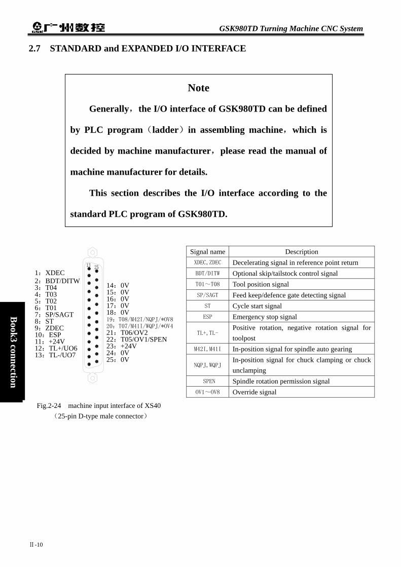
GSK980TD Turning Machine CNC System
Ⅱ-10
Book3 connection
2.7 STANDARD and EXPANDED I/O INTERFACE
Generally,the I/O inte
by PLC program(ladder)
decided by machine manufa
machine manufacturer for d
This section describes
standard PLC program of G
1:XDEC 2:BDT/DITW 3:T04 4:T03 5:T02 6:T01 7:SP/SAGT 8:ST 9:ZDEC 10:ESP 11:+24V 12:TL+/UO6 13:TL-/UO7
14:0V 15:0V 16:0V 17:0V 18:0V 19:T08/M42I/NQPJ/*OV820:T07/M41I/WQPJ/*OV421:T06/OV2 22:T05/OV1/SPEN 23:+24V 24:0V 25:0V
Fig.2-24 machine input interface of XS40 (25-pin D-type male connector)
Note
rface of GSK980TD can be defined
in assembling machine,which is
cturer,please read the manual of
etails.
the I/O interface according to the
Signal name Description XDEC,ZDEC Decelerating signal in reference point return BDT/DITW Optional skip/tailstock control signal T01~T08 Tool position signal SP/SAGT Feed keep/defence gate detecting signal
ST Cycle start signal ESP Emergency stop signal
TL+,TL- Positive rotation, negative rotation signal for toolpost
M42I,M41I In-position signal for spindle auto gearing
NQPJ,WQPJ In-position signal for chuck clamping or chuck unclamping
SPEN Spindle rotation permission signal OV1~OV8 Override signal
SK980TD.

Chapter 2 Definition and Connection of Interface
Ⅱ-11
Book3
connection
Note 1:Some I/O interface,which is figured by“/”,can be defined to multiplexer function. Note 2:Output signal is 0V when its function is valid,otherwise,output signal is high impedance. Note 3:Input signal is 24V when its function is valid,otherwise,input signal is 0V. Note 4:+24V and 0V are equivalent to the homonymy ports of power box.
XS41(extended input)and XS42(extended output)are optional interface,which contains 16 ports severally.
Signal Name Description 24V 24VDC output COM Common X2.0 Extended input X2.1 Extended input X2.2 Extended input X2.3 Extended input X2.4 Extended input X2.5 Extended input X2.6 Extended input X2.7 Extended input X3.0 Extended input X3.1 Extended input X3.2 Extended input X3.3 Extended input X3.4 Extended input X3.5 Extended input X3.6 Extended input X3.7 Extended input
Signal name Description S1~S4 Spindle gear signal
M03,M04,M05 Spindle positive rotation,negative rotation signal and spindle stop signal
M08 Coolant on signal DOTWJ,DOTWS Tailstock advancing,withdrawing signal DOQPJ,DOQPS Chuck clamping,unclamping signal
M32 Lubrication on signal PRES Pressure detecting signal SPZD Spindle brake signal
M41~M44 Spindle auto gearing signal UO1~U04 User output
24V 24VDC output 0V Common DIQP Chuck control input signal
1:S2/M42/UO1 2:DOTWJ 3:M04 4:DOQPJ 5:S1/M41/UO0 6:M32 7:M03 8:S4/M44/UO3 9:UO4/DOTWS 10:DOQPS/UO5 11:DIQP 12:PRES 13:+24V
14:S3/M43/UO215:M08 16:M05 17:SPZD 18:0V 19:0V 20:0V 21:0V 22:0V 23:0V 24:0V 25:+24V
Fig.2-25 machine output interface of XS39 (25-slot D-type female connector)
1:(X2.0) 2:(X2.7) 3:(X3.0) 4:(X3.7) 5:(X3.5) 6:(X3.6) 7:(X3.3) 8:(X3.1) 9:(X2.5) 10:(X2.3) 11:+24V 12:(X2.2) 13:(X2.1)
14:COM15:COM 16:COM 17:COM 18:COM 19:(X3.4) 20:(X3.2) 21:(X2.6) 22:(X2.4) 23:+24V 24:COM 25:COM
Fig.2-26 extended input interface of XS41 (25-pin D-type male connector)

GSK980TD Turning Machine CNC System
Ⅱ-12
Book3 connection
Signal Name Description 24V 24VDC output COM Common Y2.0 Extended output Y2.1 Extended output Y2.2 Extended output Y2.3 Extended output Y2.4 Extended output Y2.5 Extended output Y2.6 Extended output Y2.7 Extended output Y3.0 Extended output Y3.1 Extended output Y3.2 Extended output Y3.3 Extended output Y3.4 Extended output Y3.5 Extended output Y3.6 Extended output
2.7.1
InpThe sign
ConLeaDro Tw
signal coThe
The
1:(Y3.0) 2:(Y2.7) 3:(Y 2.6) 4:(Y 2.2) 5:(Y 2.0) 6:(Y 2.1) 7:(Y 3.2) 8:(Y 3.3) 9:(Y 3.4) 10:(Y 3.5) 11:(Y 3.6) 12:(Y 3.7) 13:+24V
14:(Y3.1)15:(Y2.5) 16:(Y2.4) 17:(Y2.3) 18:COM 19:COM 20:COM 21:COM 22:COM 23:COM 24:COM 25:+24V
Fig.2-27 extended output interface of XS42(25-slot D-type female connector)Y3.7 Extended output
Input Signal
ut signal is the signal from machine to CNC,which is valid when connecting to+24V,otherwise,is invalid. al conditions as following is necessary: tact capability:voltage more than 30VDC and current more than 16mA kage current between contacts in open circuit:less than 1mA p voltage between contacts at short:less than 2V(current is 8.5mA,including the drop voltage of cables)
o input modes are suitable for external input signal:one is to adopt the contact switch,in which the input mes from the key, travel-limit switch and relay contact etc. connection as fig.2-28:
Fig.2-28 other is to adopt the non-contact switch(transistor).The connection as fig.2-29,fig.2-30:
+ 5V CNC side
TLP521
machine side

Chapter 2 Definition and Connection of Interface
Ⅱ-13
Book3
connection
Fig.2-29 NPN connection
Fig.2-30 PNP connection In the standard function,input interface includes XDEC,ZDEC,ESP,ST,SP/SAGT,BDT/DITW,DIQP,OV1~
OV8,T01~T08 etc.
2.7.2 Output Signal
Output signal is to drive the relay or indicator lamp from machine side,which is valid when connecting to 0V,
otherwise,is invalid. I/O interface contains 36 digital output signal with the same circuit as fig.2-31.
Fig.2-31 the circuit structure of digital output OUTx from the main board streams into the input port of inverter(ULN2803)and nOUTx has two state of 0V
and high impedance,with the typical application as fig.2-32:
+5V
NPN型连接
+24V
输
入
信
号
CNC侧machine side CNC side
CNC侧
PNP型连接
+5V+24V
输
入
信
号
CNC sidemachine side
machine side
OUTx
ULN2803
nOUTx
CNC side
NPN type
PNP type
Input signalInput signal

GSK980TD Turning Machine CNC System
Ⅱ-14
Book3 connection
● Drive LBD A resistor in series is in need to drive LBD by ULN2803 as fig.2-32,which limits the current of LBD
(general being about 10 mA).
Fig.2-32 ● Drive filament-type indicator lamp
When driving the filament indicator lamp by ULN2803,a warm-up resistor is in need to reduce the current concussion as fig.2-33,the impedance of which is on principle that the indicator lamp isn’t light.
Fig.2-33 ● Drive inductance load
To protect the circuit and reduce noise,a diode near the coil is needed to drive the inductance load by ULN2803 as fig.2-34:
Fig.2-34 The output signals , defined by standard PLC program , includes S1 ~ S4(M41 ~
M44),M3,M4,M5,M8,M10,M11,M32,TL-,TL+,UO0~UO5,DOQPJ,DOQPS,SPZD,and the common port is +24V.
CNC side machine side
CNC side machine side +24V
ULN2803 output
CNC side machine side
+24V
ULN2803 output
relay
ULN2803 output
+24V

Chapter 2 Definition and Connection of Interface
2.8 FUNCTION and CONNECTION of I/O INTERFACE
2.8.1 Overtravel and Emergency Stop
● Relative signal ESP:emergency stop signal,ESP alarm is give ● Diagnosis data 0 0 1 Interface pins
● Control parameter
State parameter 1 7 2
ESP=0 Emergency stop function is valid =1 Emergency stop function is invalid
● Signal connection The circuit of ESP as fig.2-35:
Generally,the I/O inte
by PLC program(ladder)
decided by machine manufa
machine manufacturer for d
This section describes
standard PLC program of G
*ESP
CNC侧CNC side
ESP machine side
Note
rface of GSK980TD can be defined
in assembling machine,which is
cturer,please read the manual of
etails.
the I/O interface according to the
Ⅱ-15
Book3
connection
n when disconnecting with +24V .
ESP XS40.10
ESP
Fig.2-35
SK980TD.

GSK980TD Turning Machine CNC System
Ⅱ-16
Book3 connection
● Machine connection The connection of emergency stop switch and overtravel canceling switch as fig.2-36
Fig.2-36 ● Control logic In the standard PLC program,M03 or M04,M08,enabling signal(EN)and pulse signal are closed,and M05 is
outputted when ESP alarm,which caused by that ESP signal disconnects with +24V,is given.
2.8.2 Tool Changing Control
● Relative signal(defined by the standard PLC program) T01~T04:1 to 4 tool signals from machine to CNC T05~T08:5 to 8 tool signals from machine to CNC,in which T05,T07,T08 are the multiple ports separately
with SPEN,M41I/WQPJ,M42I/NQPJ. TCP:toolpost locking-up signal,which is the multiple port with PRES(pressure detecting signal)in the
standard PLC program. TL+,TL-:positive rotation,negative rotation signals.
● Diagnosis data 1、 input signal:T01~T08 signal 0 0 0 T04 T03 T02 T01 interface pins XS40.3 XS40.4 XS40.5 XS40.6
0 0 2 T08 T07 T06 T05 interface pins XS40.19 XS40.20 XS40.21 XS40.22
2、 output signal:TL+ positive rotation signal;TL- negative rotation signal 0 0 5 TL- TL+
interface pins XS40.13 XS40.12
● Control parameter State parameter 0 1 1 TSGN TCPS
TSGN=0:T01~T08 are valid when connecting to +24V =1:T01~T08 are valid when disconnecting with +24V
TCPS=0:TCP signal is valid when connecting to +24V =1:TCP signal is valid when disconnecting with +24V
1 8 2 PB6 PB5 PB5=0:tool changing mode A
=1:tool changing mode B
+X - X +Z -Z
overtravel canceling switch
+24V
ESP ( XS40 ) emergency stop switch
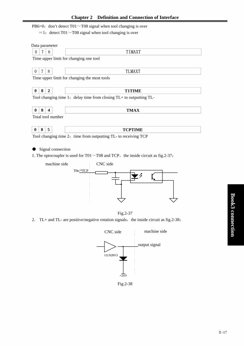
Chapter 2 Definition and Connection of Interface
T0n/*TCP
PB6=0:don’t detect T01~T08 signal when tool changing is over =1:detect T01~T08 signal when tool changing is over
Data parameter 0 7 6 TIMAXT
Time upper limit for changing one tool 0 7 8 TLMAXT
Time upper limit for changing the most tools 0 8 2 T1TIME
Tool changing time 1:delay time from closing TL+ to outputting TL- 0 8 4 TMAX
Total tool number 0 8 5 TCPTIME
Tool changing time 2:time from outputting TL- to receiving TCP ● Signal connection 1. The optocoupler is used for T01~T08 and TCP,the inside circuit as fig.2-37:
2. TL+ and TL- are positive/negat
machine side
Ⅱ-17
Book3
connection
系统侧
Fig.2-37 ive rotation signals,the inside circuit as fig.2-38:
Fig.2-38
CNC side
+24V
ULN2803
TL+/TL-
CNC侧CNC side
output signal
machine side

GSK980TD Turning Machine CNC System
Ⅱ-18
Book3 connection
3. The connection of T01~T08 as fig.2-39,in which a pull-up resistor is needed when valid T01~T08 in low voltage.
·
Fig.2-39 ● Function description(defined by standard PLC program)
In the standard PLC program,four modes for tool changing are defined as following. 1、 PB5=0,PB6=0:mode B
① During the tool changing process,CNC outputs TL+ signal firstly until the tool signal(T01~T08)being detected,then CNC outputs TL- signal after the time specified by No.82 parameter from TL+ being closed,afterwards CNC detects TCP signal and closes TL- signal after the time specified by No.85 parameter from TCP being detected,and tool changing process is over.
② CNC will give alarms and close TL- signal when not detecting TCP signal during the time specified by No.83 parameter after outputting TL- signal.
③ Set bit0(TCPS)of No.11 parameter to 0 if TCP signal doesn’t exist.
or
2. PB5=0,PB6=1:mode B(with in-position detecting) The tool changing process is same as the mode B,except for the added step of confirming tool position,in which CNC will detect the tool signal at the moment of closing TL-,if the current tool position is in accordance with the current tool number,the tool changing process is over,otherwise,CNC will give“unfinished tool changing”alarm.
CNC side machine side
HALL switch

Chapter 2 Definition and Connection of Interface
Ⅱ-19
Book3
connection
2、 PB5=1,PB6=0:mode A During the tool changing process,CNC outputs TL+ signal firstly until the tool signal(T01~T08)
being detected,then CNC outputs TL- signal when skip of the tool signal being detected,afterwards CNC detects TCP signal and closes TL- signal after the time specified by No.85 parameter from TCP being detected,and tool changing process is over.
Note 1:No.82 parameter is invalid,that is to say,CNC don’t check the delay time from closing
TL+ to outputting TL-. Note 2:Except No.82 parameter,the parameters and function for toolpost control are still valid.
3、 PB5=1,PB6=1:mode A(with in-position detecting) The tool changing process is same as the mode A,except for the added step of confirming tool
position,in which CNC will detect the tool signal at the moment of closing TL-,if the current tool position is in accordance with the current tool number,the tool changing process is over,otherwise CNC will give “unfinished tool changing”alarm.
Note:“tool changing time is too long”alarm will be given when Ta is more than the time specified by No.78 parameter.
2.8.3 Reference Point Return
● Relative signal XDEC:decelerating signal of X axis ZDEC:decelerating signal of Z axis XPC:zero signal of X axis ZPC:zero signal of Z axis
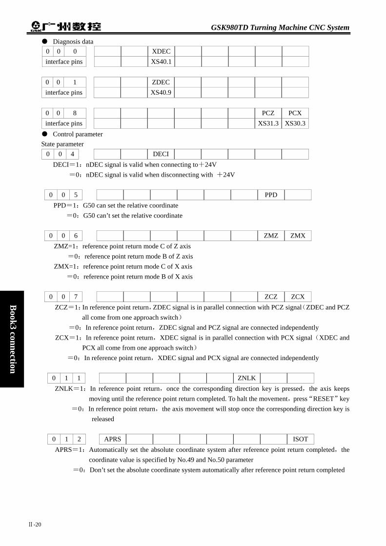
GSK980TD Turning Machine CNC System
Ⅱ-20
Book3 connection
● Diagnosis data 0 0 0 XDEC interface pins XS40.1
0 0 1 ZDEC interface pins XS40.9
0 0 8 PCZ PCX interface pins XS31.3 XS30.3
● Control parameter State parameter
0 0 4 DECI DECI=1:nDEC signal is valid when connecting to+24V
=0:nDEC signal is valid when disconnecting with +24V
0 0 5 PPD PPD=1:G50 can set the relative coordinate
=0:G50 can’t set the relative coordinate
0 0 6 ZMZ ZMX ZMZ=1:reference point return mode C of Z axis
=0:reference point return mode B of Z axis ZMX=1:reference point return mode C of X axis
=0:reference point return mode B of X axis
0 0 7 ZCZ ZCX ZCZ=1:In reference point return,ZDEC signal is in parallel connection with PCZ signal(ZDEC and PCZ
all come from one approach switch) =0:In reference point return,ZDEC signal and PCZ signal are connected independently
ZCX=1:In reference point return,XDEC signal is in parallel connection with PCX signal(XDEC and PCX all come from one approach switch)
=0:In reference point return,XDEC signal and PCX signal are connected independently
0 1 1 ZNLK ZNLK=1:In reference point return,once the corresponding direction key is pressed,the axis keeps
moving until the reference point return completed. To halt the movement,press“RESET”key =0:In reference point return,the axis movement will stop once the corresponding direction key is
released
0 1 2 APRS ISOT APRS=1:Automatically set the absolute coordinate system after reference point return completed,the
coordinate value is specified by No.49 and No.50 parameter =0:Don’t set the absolute coordinate system automatically after reference point return completed

Chapter 2 Definition and Connection of Interface
Ⅱ-21
Book3
connection
0 1 4 ZRSZ ZRSX ZRSZ,ZRSX=1:Reference point exists for Z,X axis,decelerating signal and zero signal need to be detected
in reference point return =0:Reference point doesn’t exist for Z,X axis,decelerating signal and zero signal don’t need to
be detected in reference point return
1 8 3 MZRZ MZRXMZRX,MZRZ =1:The direction of reference point return is negative for X,Z axis
=0:The direction of reference point return is positive for X,Z axis
Data parameter 0 3 3 ZRNFL
ZRNFL:The low speed in reference point return for X,Z axis 0 4 9 PRSX 0 5 0
PRSZ
PRSX,PRSZ:The absolute coordinate setting value of X,Z axis after reference point return being completed ● Signal connection
The inside circuit of nDEC signal as fig.2-40
● Reference point return of taking the phase C signal of servo motor encoder as the zero signal
① The sketch map as following:
connect to +24Vconnect to *DECn signal
the stopper fixed on machine slidder
direction of machine zero return
overtravel switch
≥
*DECn
CNC侧
Fig.2-41
CNC sidemachine side nDEC
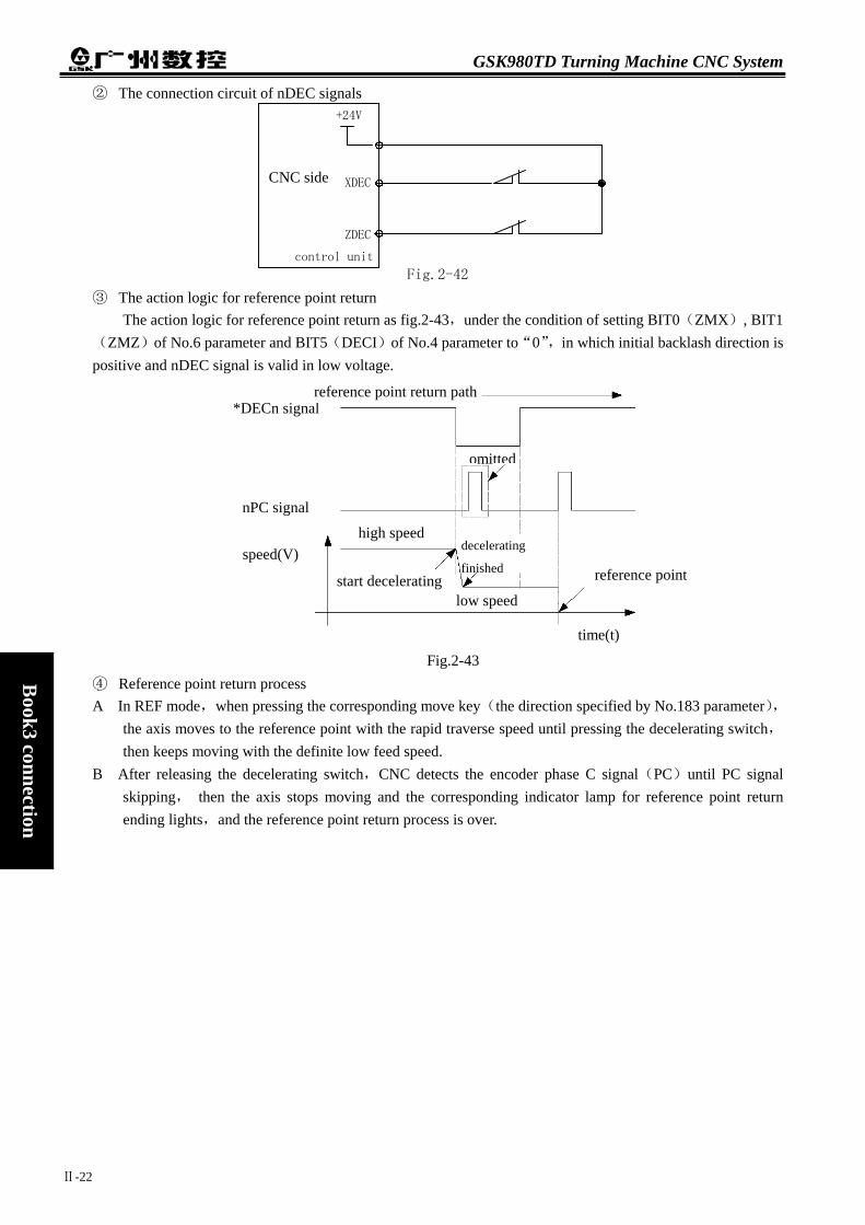
GSK980TD Turning Machine CNC System
Ⅱ-22
Book3 connection
② The connection circuit of nDEC signals
Fig.2-42
③ The action logic for reference point return The action logic for reference point return as fig.2-43,under the condition of setting BIT0(ZMX), BIT1
(ZMZ)of No.6 parameter and BIT5(DECI)of No.4 parameter to“0”,in which initial backlash direction is positive and nDEC signal is valid in low voltage.
④ Reference point return process A In REF mode,when pressing the cor
the axis moves to the reference pointthen keeps moving with the definite l
B After releasing the decelerating switcskipping, then the axis stops movending lights,and the reference poin
+24V
XDEC
ZDEC
control unit
CNC side
*DECn signal
nPC signal
speed(V)
sta
reference point return path
omitted
high speed
finished reference point
Fig.2
responding move with the rapid trow feed speed. h,CNC detects
ing and the corrt return process i
rt decelerating
-
ka
es
lo
decelerating
4
ev
tsp o
w
3
y(the direction specified by No.183 parameter),erse speed until pressing the decelerating switch,
he encoder phase C signal(PC)until PC signal onding indicator lamp for reference point return ver.
speed
time(t)

Chapter 2 Definition and Connection of Interface
Ⅱ-23
Book3
connection
● Reference point return when taking a approach switch as decelerating signal and zero signal simultaneously ① The sketch map as following:
Fig.2-44 ② The connection circuit of nDEC signals
Fig.2-45
③ The action logic for reference point return The action logic for reference point return as fig.2-46,under the condition of setting BIT0(ZMX), BIT1
(ZMZ)of No.6 parameter and BIT5(DECI)of No.4 parameter to“0”,in which initial backlash direction is positive and nDEC signal is valid in low voltage.
+24V
*DECn
nPC
nDEC
machine tool side CNC side
generally,L1 ≥ ( 1.5~2 )
approaching switch width,L2≈approaching switch width

GSK980TD Turning Machine CNC System
Ⅱ-24
Book3 connection
Fig.2-46 ④ Reference point return process
A In REF mode,the axis moves to the reference point with the rapid traverse speed when pressing the corresponding move key(the direction specified by No.183 parameter).
B The axis moves with the definited low speed and nDEC signal is valid when the approach switch inducing the stopper firstly.
C The axis keeps moving and CNC begins to detect nPC signal when the approach switch departing away from the stopper.
D The axis stops moving and the indicator lamp for reference point return ending lights when the approach switch inducing the stopper secondly,and the reference point return process is over.
2.8.4 Spindle Positive or Negative Rotation Control
● Relative signal(defined by the standard PLC program) M03:spindle positive rotation M04:spindle negative rotation M05:spindle stopping SPZD:spindle braking ● Diagnosis data
diagnosis data 0 0 4 SPZD M05 M04 M03 interface pins XS39.17 XS39.16 XS39.3 XS39.7
● Control parameter
control parameter 0 0 9 RSJG
RSJG=1:not close M03,M04,M08,M32 signals when pressing “RESET”key = 0:close M03,M04,M08,M32 signals when pressing “RESET”key
data parameter 0 8 0 MTIME
Duration for M code 0 8 7 SPDDLT
Delay time for from executing M05 to outputting SPZD
*NDEC /n PC
nDEC/nPC
reference point return path
speed(V) high speed
start decelerating
decelerating
finished
low speed reference point
time(t)
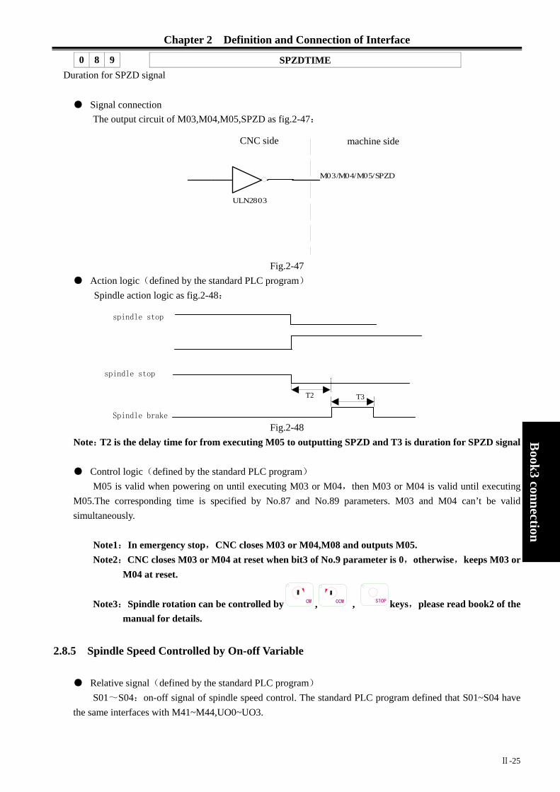
Chapter 2 Definition and Connection of Interface
Ⅱ-25
Book3
connection
0 8 9 SPZDTIME Duration for SPZD signal
● Signal connection
The output circuit of M03,M04,M05,SPZD as fig.2-47:
Fig.2-47 ● Action logic(defined by the standard PLC program)
Spindle action logic as fig.2-48:
Fig.2-48 Note:T2 is the delay time for from executing M05 to outputting SPZD and T3 is duration for SPZD signal ● Control logic(defined by the standard PLC program)
M05 is valid when powering on until executing M03 or M04,then M03 or M04 is valid until executing M05.The corresponding time is specified by No.87 and No.89 parameters. M03 and M04 can’t be valid simultaneously.
Note1:In emergency stop,CNC closes M03 or M04,M08 and outputs M05. Note2:CNC closes M03 or M04 at reset when bit3 of No.9 parameter is 0,otherwise,keeps M03 or
M04 at reset.
Note3:Spindle rotation can be controlled by CW , CCW , STOP keys,please read book2 of the manual for details.
2.8.5 Spindle Speed Controlled by On-off Variable
● Relative signal(defined by the standard PLC program) S01~S04:on-off signal of spindle speed control. The standard PLC program defined that S01~S04 have
the same interfaces with M41~M44,UO0~UO3.
+24V
ULN2803
M03/M04/M05/SPZD
CNC侧CNC side machine side
T3T2
Spindle brake
spindle stop
spindle stop
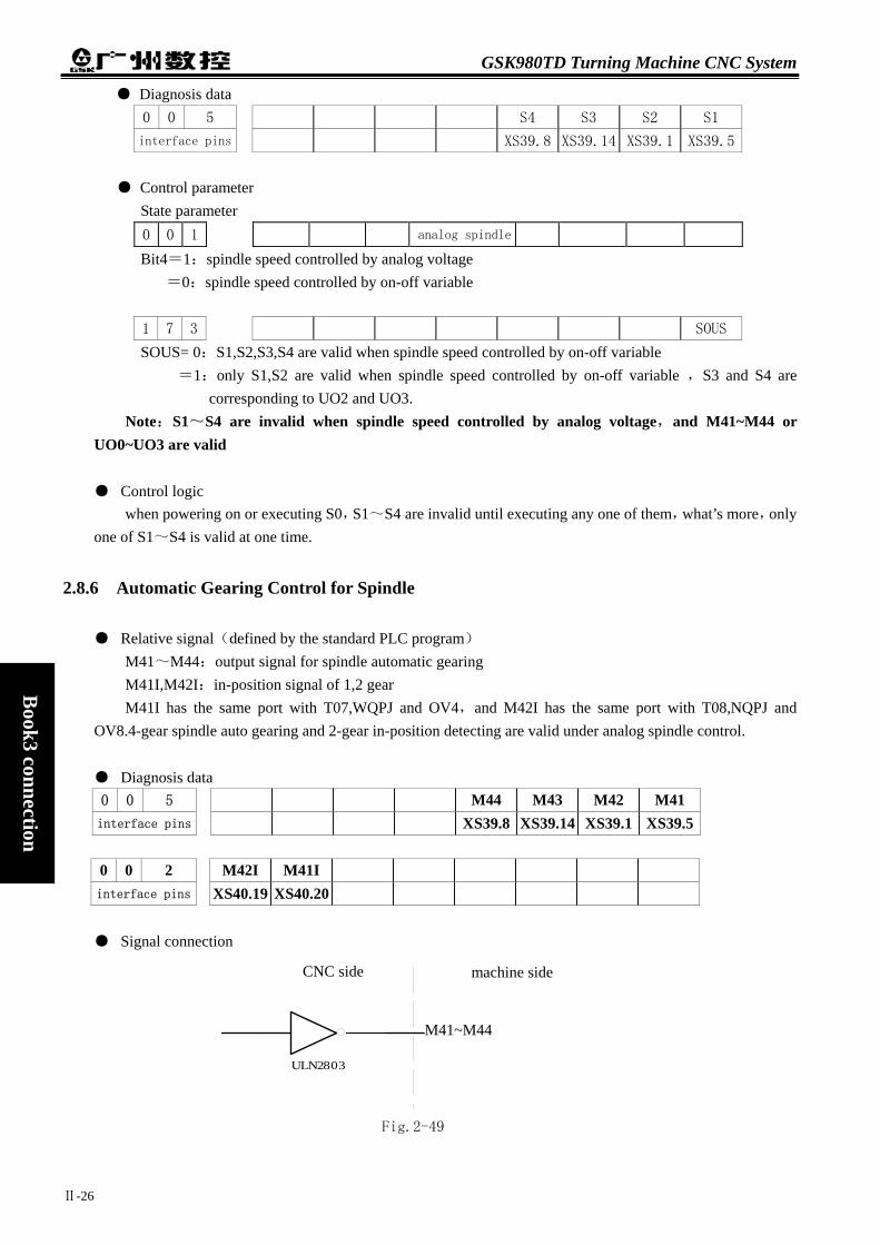
GSK980TD Turning Machine CNC System
Ⅱ-26
Book3 connection
● Diagnosis data 0 0 5 S4 S3 S2 S1
interface pins XS39.8 XS39.14 XS39.1 XS39.5
● Control parameter
State parameter 0 0 1 analog spindle
Bit4=1:spindle speed controlled by analog voltage =0:spindle speed controlled by on-off variable
1 7 3 SOUS
SOUS= 0:S1,S2,S3,S4 are valid when spindle speed controlled by on-off variable =1:only S1,S2 are valid when spindle speed controlled by on-off variable ,S3 and S4 are
corresponding to UO2 and UO3. Note:S1~S4 are invalid when spindle speed controlled by analog voltage,and M41~M44 or
UO0~UO3 are valid
● Control logic when powering on or executing S0,S1~S4 are invalid until executing any one of them,what’s more,only
one of S1~S4 is valid at one time.
2.8.6 Automatic Gearing Control for Spindle
● Relative signal(defined by the standard PLC program) M41~M44:output signal for spindle automatic gearing M41I,M42I:in-position signal of 1,2 gear M41I has the same port with T07,WQPJ and OV4,and M42I has the same port with T08,NQPJ and
OV8.4-gear spindle auto gearing and 2-gear in-position detecting are valid under analog spindle control.
● Diagnosis data 0 0 5 M44 M43 M42 M41 interface pins XS39.8 XS39.14 XS39.1 XS39.5 0 0 2 M42I M41I interface pins XS40.19 XS40.20 ● Signal connection
+24V
ULN2803
M03/M04/M05/SPZD
CNC侧CNC side machine side
M41~M44
Fig.2-49

Chapter 2 Definition and Connection of Interface
Ⅱ-27
Book3
connection
● Control parameter State parameter 0 0 1 analog spindle
Bit4=1:spindle speed controlled by analog voltage =0:spindle speed controlled by on-off variable
Bit4 must be 1 under spindle auto gearing control. 1 6 4 AGER AGIN AGIM AGER=1:spindle auto gearing control is valid
=0:spindle auto gearing control is invalid AGIN=1:detect M41I,M42I signals when gearing to 1,2 gears
=0:not detect M41I,M42I signals when gearing to 1,2 gears AGIM=1:M41I,M42I signals are valid when disconnecting with+24V
=0:M41I,M42I signals are valid when connecting to+24V
Data parameter 0 3 7 GRMAX1 0 3 8 GRMAX2 0 3 9 GRMAX3 0 4 0 GRMAX4
GRMAX1 ,GRMAX2, GRMAX3, GRMAX4:the highest speed of gear1,2,3,4 under analog spindle control or the spindle speed for M41,M42,M43,M44 respectively under spindle auto gearing control,the gear 1 speed is in default when powering on or invalid spindle auto gearing control.
0 6 5 SFT1TME
The delay time 1 for auto gearing signal outputting 0 6 6 SFT2TME
The delay time 2 for auto gearing signal outputting 0 6 7 SFTREV The output voltage(0~10000,unit:mv)under auto gearing control ● Function description(defined by the standard PLC program)
2.8.7 Outside Cycle Start and Cycle Stop
● Relative signal(defined by the standard PLC program) ST:outside cycle start signal,with the same function as CYCLE START key in operation panel SP:outside cycle stop signal,with the same function as CYCLE STOP key in operation panel and the same port with
defence gate detect signal(SAGT) ● Diagnosis data
0 0 1 SP ST interface pins XS40.7 XS40.8
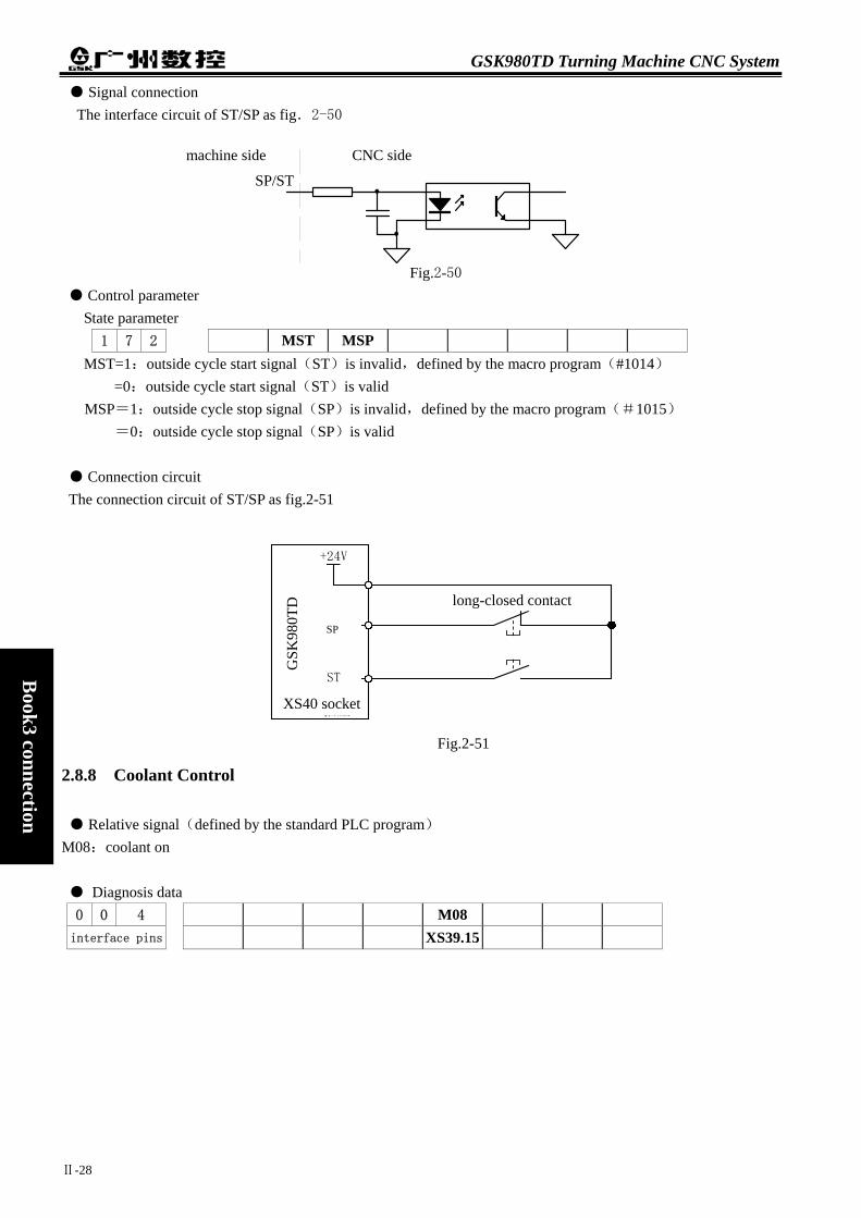
GSK980TD Turning Machine CNC System
Ⅱ-28
Book3 connection
*SP/ST
CNC侧machine side
SP/ST
CNC side
● Signal connection The interface circuit of ST/SP as fig.2-50
Fig.2-50
● Control parameter State parameter
1 7 2 MST MSP MST=1:outside cycle start signal(ST)is invalid,defined by the macro program(#1014)
=0:outside cycle start signal(ST)is valid MSP=1:outside cycle stop signal(SP)is invalid,defined by the macro program(#1015)
=0:outside cycle stop signal(SP)is valid ● Connection circuit The connection circuit of ST/SP as fig.2-51
2.8.8 Coolant Control
● Relative signal(defined by the standard PLC program) M08:coolant on ● Diagnosis data 0 0 4 M0interface pins XS39
Fig
GSK
980T
D
+24V
XS40 插座
*SP
ST
SP
XS40 socket
l
8 .15
.2-51
无锁常闭点
ong-closed contact
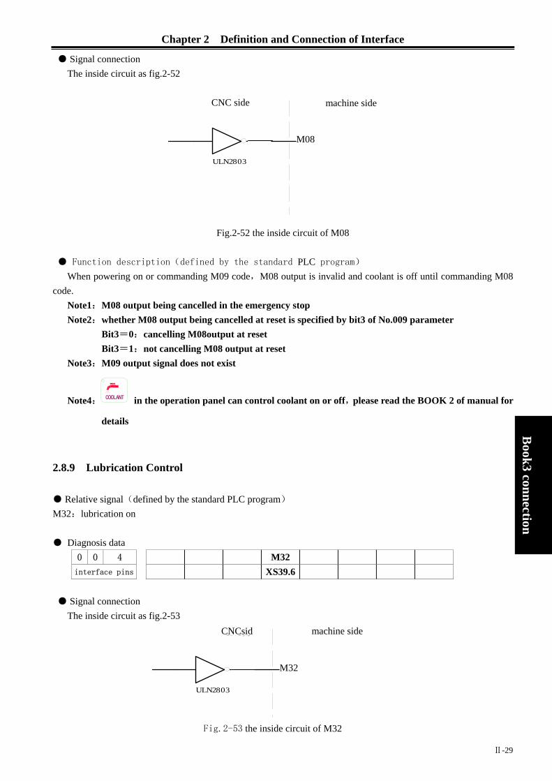
Chapter 2 Definition and Connection of Interface
Ⅱ-29
Book3
connection
● Signal connection The inside circuit as fig.2-52
Fig.2-52 the inside circuit of M08
● Function description(defined by the standard PLC program)
When powering on or commanding M09 code,M08 output is invalid and coolant is off until commanding M08 code.
Note1:M08 output being cancelled in the emergency stop Note2:whether M08 output being cancelled at reset is specified by bit3 of No.009 parameter
Bit3=0:cancelling M08output at reset Bit3=1:not cancelling M08 output at reset
Note3:M09 output signal does not exist
Note4: COOLANT in the operation panel can control coolant on or off,please read the BOOK 2 of manual for
details
2.8.9 Lubrication Control
● Relative signal(defined by the standard PLC program) M32:lubrication on ● Diagnosis data
0 0 4 M32 interface pins XS39.6
● Signal connection
The inside circuit as fig.2-53
+24V
ULN2803
M03/M04/M05/SPZD
CNC侧CNC side machine side
M08
+24V
ULN2803
M03/M04/M05/SPZD
CNC侧CNCsid machine side
M32
Fig.2-53 the inside circuit of M32

GSK980TD Turning Machine CNC System
Ⅱ-30
Book3 connection
● Control parameter State parameter 1 7 5 SPHD
SPHD=1: LUR.
JOG
on the operation panel is spindle step function
=0: LUR.
JOG
is lubrication function
Data parameter 1 1 2 Lubrication open time in non-automation mode(0~65535ms)(0:no time limit) PLC data D T 0 1 6 Lubrication time in automation mode(0~2147483647ms) D T 0 1 7 Lubrication interval time in automation mode(0~2147483647ms)
● Function description There are two mode of automatic and non-automatic lubrication for the standard PLC program,which can
be specified by the parameter. DT17=0:non-automatic lubrication(same as the former version)
>0:automatic lubrication 1 Non-automatic lubrication
No.175.7 state parameter is 1: LUR.
JOG
on the operation panel is spindle step function
No.175.7 state parameter is 0: LUR.
JOG
is lubrication function
When No.112 data parameter is 0,lubrication outputs when press LUR.
JOG
or commanding M32 code,
lubrication doesn’t output when press LUR.
JOG
again or commanding M33 code. When No.112 data parameter is more than 1,lubrication outputs for the duration time specified by
No.112 parameter when press LUR.
JOG
or commanding M32 code,lubrication output is cancelled before the
time specified by No.112 parameter when commanding M33 code.
2 Automatic lubrication

Chapter 2 Definition and Connection of Interface
Ⅱ-31
Book3
connection
With the interval time specified by D16,lubrication outputs for the duration time specified by D17
circularly,in which M32,M33 and LUR.
JOG
are invalid
2.8.10 Chuck Control
● Relative signal(defined by the standard PLC program) DIQP:chuck control input signal DOQPJ:inner chuck clamping/outer chuck unclamping output signal DOQPS:inner chuck unclamping /outer chuck clamping output signal NQPJ:in-position input signal for inner chuck clamping/outer chuck unclamping,with the same port as
T08,M42I WQPJ:in-position input signal for inner chuck unclamping/outer chuck clamping,with the same port as
T07,M41I
● Diagnosis data
0 0 0 DIQP interface pins XS39.11
0 0 2 NQPJ WQPJ interface pins XS40.19 XS40.20
0 0 4 DOQPJ interface pins XS39.4
0 0 5 DOQPS interface pins XS39.10
● Control parameter
Sate parameter 1 6 4 SLSP SLQP
SLSP=1:don’t detect whether the chuck is clamping when chuck function is valid =0:detect whether the chuck is clamping when chuck function is valid
SLQP=1:chuck function is valid =0:chuck function is invalid
1 6 8 PB2 PB1 PB1=1:outer chuck mode,in which NQPJ is outer chuck unclamping signal and WQPJ is outer chuck
clamping signal =0:inner chuck mode,in which NQPJ is inner chuck unclamping signal and WQPJ is inner chuck
clamping signal PB2=1:detect chuck in-position signal,in which bit7 of No.002 diagnosis parameter is NQPJ and bit6 is WQPJ,M41I and M42I are invalid
=0:don’t detect chuck in-position signal

GSK980TD Turning Machine CNC System
Ⅱ-32
Book3 connection
D T 0 1 8 DT18>0:chuck clamping and unclamping signals are pulse,width of which is specified by DT18
=0:chuck clamping and unclamping signals are level
● Signal connection circuit of DOQPJ/DOQPS as fig.2-54
● Action ① when SLQP is 1,SLSP is 0,PB1 is 0 and PB2 is 1(inner chuck mode and in-position detecting)
DOQPS:chuck unclamping WQPJ:in-position signal for chuck unclamping DOQPJ:chuck clamping NQPJ:in-position signal for chuck clamping When powering on,DOQPS and DOQPJ are high impedance until DIQP is valid at the first time,at which
DOQPJ connects to 0V and the chuck is clamped. After executing M12,DOQPS is high impedance and DOQPJ is 0V,in which the chuck is clamped and
CNC waits for NQPJ. After executing M13,DOQPJ is high impedance and DOQPS is 0V,in which the chuck is loosened and
CNC waits for WQPJ.
② when SLDOQPDOQP
When p
+24V
ULN2803
M03/M04/M05/SPZD
CNC侧CNC side machine side
DOQPJ/DOQPS
fig.2-54
input signal: DIQP
output signal: DOQPJ
input signal: NIQPJ
fig.2-55(DT18=0)
QP is 1,SLSP is 0,PB1 is 1 and PB2 is 1(outer chuck mode and in-position detecting) S:chuck clamping WQPJ:in-position signal for chuck clamping J:chuck unclamping NQPJ:in-position signal for chuck unclamping
owering on,DOQPS and DOQPJ are high impedance until DIQP is valid at the first time,at which
output signal: DOQPS
input signal: WIQPJ
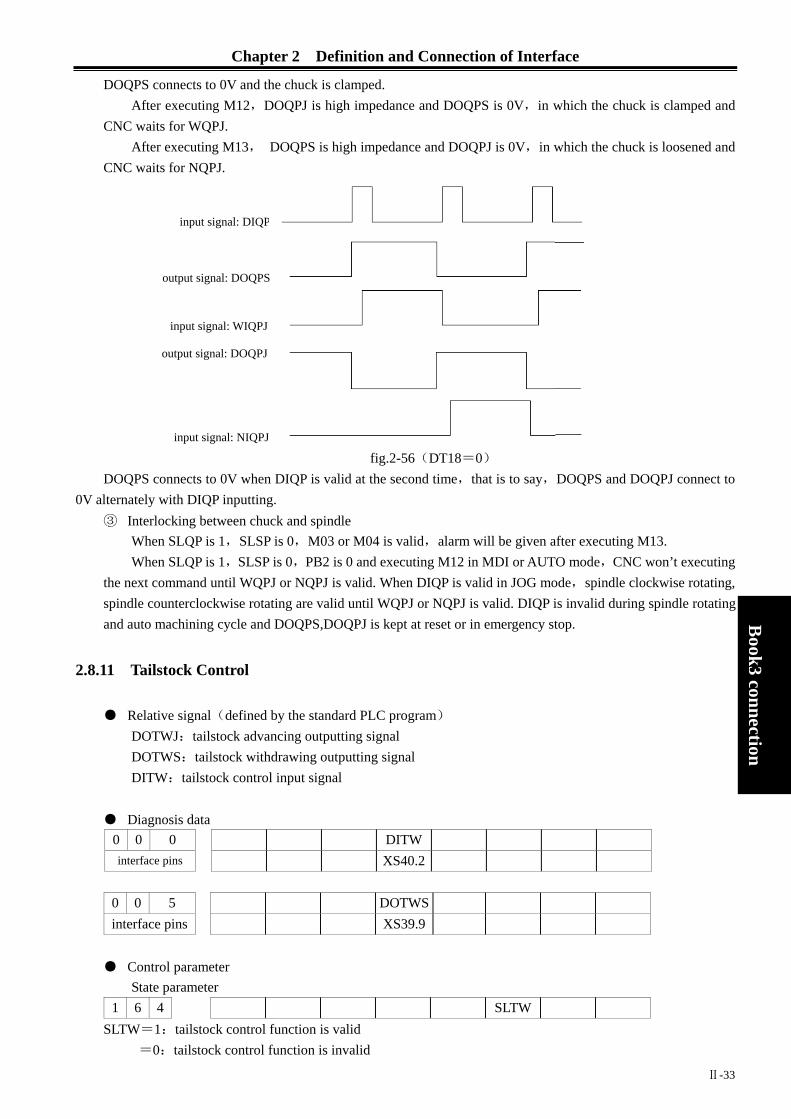
Chapter 2 Definition and Connection of Interface
DOQPS connects to 0V and the chuck is clamped. After executing M12,DOQPJ is high impedance and DOQPS is 0V,in which the chuck is clamped and
CNC waits for WQPJ. After executing M13, DOQPS is high impedance and DOQPJ is 0V,in which the chuck is loosened and
CNC wai
DOQPS co0V alternately w
③ InterloWhenWhen
the next cospindle couand auto m
2.8.11 Tailst
● RelativDOTWDOTWDITW
● Diagno0 0 interface p
0 0 interface
● Contro
State p1 6 4
SLTW=1:=0:
output signal: DOQPS
o
input signal: WIQPJ
ts for NQPJ.
input signal: DIQP
Ⅱ-33
Book3
connection
fig.2-56(DT18=0)
nnects to 0V when DIQP is valid at the second time,that is to say,DOQPS and DOQPJ connect to ith DIQP inputting.
cking between chuck and spindle SLQP is 1,SLSP is 0,M03 or M04 is valid,alarm will be given after executing M13. SLQP is 1,SLSP is 0,PB2 is 0 and executing M12 in MDI or AUTO mode,CNC won’t executing mmand until WQPJ or NQPJ is valid. When DIQP is valid in JOG mode,spindle clockwise rotating, nterclockwise rotating are valid until WQPJ or NQPJ is valid. DIQP is invalid during spindle rotating achining cycle and DOQPS,DOQPJ is kept at reset or in emergency stop.
ock Control
e signal(defined by the standard PLC program) J:tailstock advancing outputting signal S:tailstock withdrawing outputting signal :tailstock control input signal
sis data 0 DITW ins XS40.2
5 DOTWS pins XS39.9
l parameter arameter
SLTW tailstock control function is valid tailstock control function is invalid
utput signal: DOQPJ
input signal: NIQPJ

GSK980TD Turning Machine CNC System
Ⅱ-34
Book3 connection
● Signal connection Circuit of DOTWJ/ DOTWS as fig.2-57
● Action(defined by the standard PLC program)
DOTWJ and DOTWS are high impedance when powering on. DOTWJ connects to 0V(valid state) when DITW is valid at the first time or executing M10,and DOTWS connects to 0V(valid state) when DITW is valid at the second time or executing M11,that is to say,DOTWJ and DOTWS connect to 0 V alternately.
During the spindle rotating,alarm will be given after executing M11 and DITW is invalid,and DOTWS,DOTWJ are kept at reset or in emergency stop.
2.8.12 Low Pressure Detection
● Relative signal(defined by the standard PLC program) PRES:low pressure detection signal,with the same port as TCP ● Diagnosis data
0 0 5 PB3 interface pins XS39.12
● Control parameter
sate parameter 1 6 8 SPB3 PB3
PB3=0:low pressure detection function is invalid,bit7 of No.000 diagnosis data is TCP =1:low pressure detection function is valid,bit7 of No.000 diagnosis data is PRES
SPB3=0:low pressure is alarmed when PRES connecting to +24V =1:low pressure is alarmed when PRES connecting to 0V
data parameter
0 6 9 0 0 0 0 1 0 0 0
+24V
ULN2803
M03/M04/M05/SPZD
CNC侧CNC side machine side
DOTWJ/DOTWS
Fig.2-57
DITW
DOTWJ
DOTWS
fig.2-58 tailstock control logic

Chapter 2 Definition and Connection of Interface
Ⅱ-35
Book3
connection
Alarm waiting time for low pressure detection ● Function description ① when PB3 is 1 and SPB3 is 0,low pressure is alarmed when PRES connecting to 24V. ② when PB3 is 1 and SPB3 is 1,low pressure is alarmed when PRES connecting to 0V. ③ when PB3 is 1,No.14 alarm will be given when holding time of valid PRES signal exceeding the value
specified by No.069 parameter,at which feed is paused, spindle is stopped and cycle is cancelled,until pressing “RESET”key or powering off.
④ When PB3 is 1,TCP is invalid.
2.8.13 Protection Gate Detection
● Relative signal(defined by the standard PLC program)
SAGT:protection gate detection signal,with the same port as SP ● Diagnosis data
0 0 1 PB4 interface pins XS40.7 ● Control parameter
state parameter 1 6 8 SPB4 PB4
PB4=0:protection gate detection function is invalid =1:protection gate detection function is valid and SP is invalid
SPB4=0:protection gate is closed when SAGT connecting to 0V =1:protection gate is closed when SAGT connecting to +24V
● Function description ① When PB4 is 1and SPB4 is 0,protection gate is closed when SAGT connecting to 0V ② When PB4 is 1and SPB4 is 1,protection gate is closed when SAGT connecting to +24V ③ Alarms will be given at cycle start when protection gate being open ④ Feed being paused, spindle being stopped, coolant being closed and CNC alarm will appear when protection
gate is open in auto machining cycle ⑤ Protection gate detection function is valid only in AUTO mode ⑥ SAGT and SP have the same port,that is to say,MSP(bit5 of No.172 state parameter)should be 1 when
PB4 is 1 and MSP should be 0 when PB4 is 0
2.8.14 Spindle Rotation Permission
● Relative signal(defined by the standard PLC program)
SPEN:spindle rotation permission signal,with the same port as T05 ● Diagnosis data
0 0 2 SPEN interface pins XS40.22

GSK980TD Turning Machine CNC System
Ⅱ-36
Book3 connection
● Control parameter
state parameter 1 6 4 SPEN SPEN=0:spindle rotation permission signal is invalid
=1:spindle rotation permission signal is valid
● Control logic(defined by the standard program)
When SPEN parameter is 1 and SPEN signal isn’t received,alarms will be given after executing M03 or M04
2.8.15 Program Segment Skipping
Program segment skipping function is selected when one segment is embarrassed,in which the segment with “/”at head will be skipped and not be executed when PRG SEG SWITCH is on or EDT signal is valid.
● Relative signal(defined by the standard PLC program)
BDT:program segment skipping signal,with the same port as DITW ● Diagnosis data
0 0 0 BDT interface pins XS40.2
● Control parameter state parameter
0 6 4 SLTW SLTW=0:program segment skipping function is invalid
=1:program segment skipping function is valid and DITW is invalid ● Signal connection
circuit of BDT/DITW as fig.2-59
Fig.2-58 ● Function description
The segment with “/”at head will be skipped and not be executed when PRG SEG SWITCH in machine panel is on or EDT signal is valid.
BDT/DITW
CNC侧CNC side machine side

Chapter 2 Definition and Connection of Interface
Ⅱ-37
Book3
connection
2.8.16 Macro Variable
● Relative signal macro output signal:UO0~UO5 are valid when spindle speed being controlled by analog voltage and spindle auto
gearing being invalid. macro input signal:UI0~UI15 are valid when the signals with the same ports as UI0~UI15 are invalid. ● Diagnosis data
0 0 5 UO05 UO04 UO03 UO02 UO01 UO00 interfaces pins XS39.10 XS39.9 XS39.8 XS39.14 XS39.1 XS39.5
variable number #1105 #1104 #1103 #1102 #1101 #1100
0 0 0 UI07 UI06 UI05 UI04 UI03 UI02 UI01 UI00 interfaces pins XS39.12 XS39.11 XS40.1 XS40.2 XS40.3 XS40.4 XS40.5 XS40.6
variable number #1007 #1006 #1005 #1004 #1003 #1002 #1001 #1000 0 0 0 UI15 UI14 UI13 UI12 UI11 UI10 UI09 UI08 interfaces pins XS40.7 XS40.8 XS40.9 XS40.10 XS40.19 XS40.20 XS40.21 XS40.22
variable number #1015 #1014 #1013 #1012 #1011 #1010 #1009 #1008
● Function description(defined by the standard PLC program) State of UO0~UO5 can be changed by evaluating #1100~#1105,in which UO0~UO5 are 0V when
#1100~#1105 are “1”and UO0~UO5 are closed when #1100~#1105 are “0”. A variety of disposal can be carried out by evaluating #1000~#1015,detecting UI0~UI15 and using the
transfer commands.
2.9 ELECTRIC CONNECTION for I/O SIGNAL
DC24V power of GSK980TD must be separate from that of the electromagnetism valve with large current,the component symbol as following:
gr
aph
sym
bol
KM
FR
C
R
SQ
SA
FV
nam
e
cont
acto
r co
il an
d au
xilia
ry
cont
act
fuse
rel
ay
and
cont
act
capa
city
regi
ster
HA
LL
com
pone
nt
jour
ney
switc
h
vene
er ja
ck
kick
switc
h
Fuse

GSK980TD Turning Machine CNC System
Ⅱ-38
Book3 connection
grap
h
sym
bol
QF
TC
VC
M
VD
YV
KA
nam
e
air
brea
ker
tran
sfor
mer
brid
ge
rect
ifier
mot
or
diod
e
Ele
ctro
mag
net
ic v
alve
co
il
rela
y co
il an
d co
ntac
t
The following electric connection diagrams are only for reference: ● Tailstock connection

Chapter 2 Definition and Connection of Interface
Ⅱ-39
Book3
connection
L3
L1L2
QF1
FU
TC1
L+
(13),24V
(2),DOTWJ/M10G
SK980TD
(2),DITW
(9)
,DOTWS/M11
motor
U1
RC absorbor
24V
M1
3~V1W1
tailstock
going
forward
tailstock
retreat
tailstock
going
forward
tailstock
going
forward and
retreat
tailstock
ret
reat
fig.2-61
ta
ilst
ock
conn
ecti
on
● Chuck connection

GSK980TD Turning Machine CNC System
Ⅱ-40
Book3 connection
chuck
clamping
RC absorbor
(13),24V
(11),DIQP
(14),DIQPJ/M12
chuck
unclamping
chuck
clamping
and
unclamping
chuck
clamping
(10)
,DIQPS/M13 chuck
unclamping
fig.2-62 chuck connection
● Toolpost connection
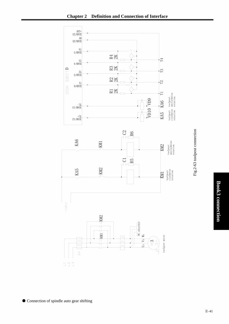
Chapter 2 Definition and Connection of Interface
Ⅱ-41
Book3
connection
● Connection of spindle auto gear shifting
Fig.
2-63
tool
post
con
nect
ion
XS40/23
XS40/3
XS40/5
XS40/6
XS40/4
XS40/13
XS40/12
KA5
KA6
XS40/25
D
KM1
KM1
KM2
KM2
RC
abso
rbor
V3
U3
W3
3
C1
R5
R3
2K
R1
2K
R2
2KR4
2K
T2
TL+
T1
TL-
+24V
0V
T3
T4
C2
R6
VD10
VD9
too
lpos
t
uncl
ockw
ise
rota
tion
KM2
tool
post
mot
or
too
lpost
cloc
kwis
e rot
atio
n
KM1
T3
KA5
T2
T1
KA6
T4
too
lpos
t
clo
ckwi
se
rota
tion
too
lpos
t
uncl
ockwi
se
rota
tion

GSK980TD Turning Machine CNC System
Ⅱ-42
Book3 connection
COM
KA9
KA10
KA9 KA10
REV
FWD
frequency
converter
spindle gear1
spindle gear2
YV5
YV6
spindle
negative
rotation
spindle
pos
itive
rot
ationKA
7KA8
frequency-
converting
motor
SQ1
SQ2
M41I
D
M4
+24VXS39/13
XS39/7M3
XS39/3
XS39/5M41
XS39/1M42
XS40/20
XS40/11
M42IXS40/19
+24V
gear1
in-position
signal
KA8
VD1
KA7
VD3
VD2
VD4
KA9
KA10
spindle
positive
rotation
spindle
negative
rotation
spindle
gear1
spindle
gear2
gear2
in-position
signal
● Connection of motor brake
Fig.
2-64
conn
ectio
n of
spin
dle
auto
gea
r shi
fting
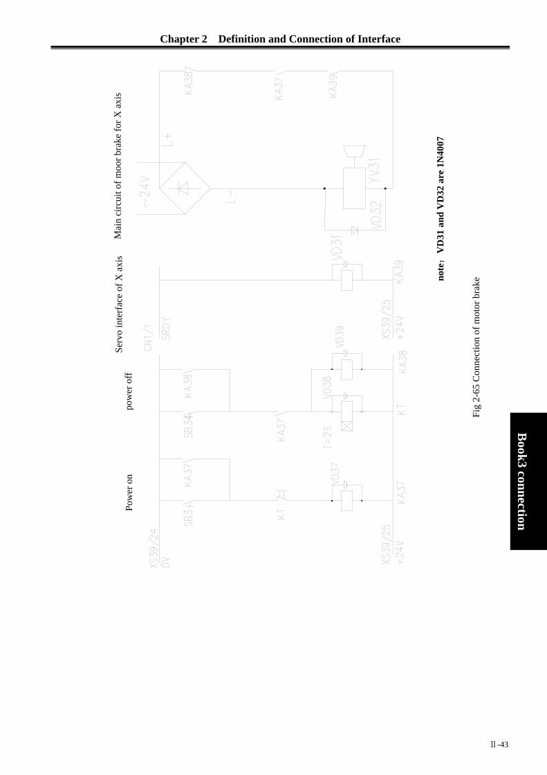
Chapter 2 Definition and Connection of Interface
Ⅱ-43
Book3
connection
Mai
n ci
rcui
t of m
oor b
rake
for X
axi
s
note:
VD
31 a
nd V
D32
are
1N
4007
Serv
o in
terf
ace
of X
axi
s
pow
er o
ff Po
wer
on
Fig
2-65
Con
nect
ion
of m
otor
bra
ke


Chapter 3 Parameter Specification
Ⅲ-1
Book3
connection
CHAPTER3 PARAMETER SPECIFICATION
In this chapter,state parameters and data parameters of CNC will be introduced.
3.1 PARAMETER SPECIFICATION(with sequence)
3.1.1 State Parameter
The show mode of state parameter as following:
Number BIT7 BIT6 BIT5 BIT4 BIT3 BIT2 BIT1 BIT0
0 0 1 *** *** *** SPIN MPG PROG *** *** Bit2 is 1:programming in radius
is 0:programming in diameter Bit3 is 1:MPG(manual pulse generator)mode
is 0:STEP mode Bit4 is 1:analog spindle
is 0:switching control spindle
0 0 2 *** *** RS232 *** *** *** TNRC *** Bit1 is 1:tool nose radius compensation is valid
is 0:tool nose radius compensation is invalid Bit5 is 1:RS232 communication is valid
is 0:RS232 communication is invalid
0 0 3 *** *** PEC TLC *** *** *** *** Bit4 is 1:compensate tool length by coordinates
is 0:compensate tool length by tool moving Bit5 is 1:pitch error compensation is valid
is 0:pitch error compensation is invalid
0 0 4 *** RDRN DECI ORC TOC DCS PROD *** Bit6 is 1:G00 in dry run at rapid traverse speed
is 0:G00 in dry run at manual feedrate Bit5 is 1:decelerating signal in high level is valid during reference point return
is 0:decelerating signal in low level is valid during reference point return Bit4 is 1:tool compensation is radius value
is 0:tool compensation is diameter value Bit3 is 1:keep tool compensation at reset
is 0:clear tool compensation at reset

GSK980TD Turning Machine CNC System
Ⅲ-2
Book3 connection
square wave,the max. frequency is 266KHz pulse,the max. frequency is 266KHz and pulsewidth is 1μs.
Bit2 is 1:OUTPUT
key can start program in MDI mode
is 0:OUTPUT
key can’t start program in MDI mode Bit1 is 1:relative coordinate display don’t include tool compensation
is 0:relative coordinate display includes tool compensation
0 0 5 *** *** SMAL M30 *** *** PPD PCMDBit5 is 1:manual gear shifting as executing S
is 0:automatic gear shifting as executing S Bit4 is 1:cursor returns after M30
is 0:cursor doesn’t return after M30 Bit1 is 1:relative coordinate is set by G50
is 0:relative coordinate isn’t set by G50 Bit0 is 1:output CP signal with square wave
is 0:output CP signal with pulse
0 0 6 *** *** *** OVRI *** *** ZMZ ZMXBit4 is 1:feedrate override in machine control panel is reversed
is 0:feedrate override in machine control panel isn’t reversed Bit1 is 1:reference point return mode C for Z axis
is 0:reference point return mode B for Z axis Bit0 is 1:reference point return mode C for X axis
is 0:reference point return mode B for X axis
0 0 7 *** *** *** *** SMZ *** ZCZ ZCX Bit3 is 1:execute next program segment after locating accurately according to the current segment
is 0:there is smoothness transition between two program segments Bit1 is 1:ZDEC connects to ZPC in parallel
is 0:ZDEC connects to ZPC independently Bit1 is 1:XDEC connects to XPC in parallel
is 0:XDEC connects to XPC independently
0 0 8 *** *** *** *** *** *** DIRZ DIRXBit1 is 1:DIRZ signal is high level when moving in positive direction
is 0:DIRZ signal is low level when moving in negative direction Bit0 is 1:DIRX signal is high level when moving in positive direction
is 0:DIRX signal is low level when moving in negative direction
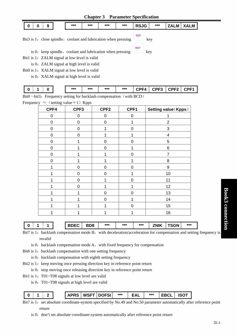
Chapter 3 Parameter Specification
Ⅲ-3
Book3
connection
0 0 9 *** *** *** *** RSJG *** ZALM XALM
Bit3 is 1:close spindle,coolant and lubrication when pressing RESET
key
is 0:keep spindle,coolant and lubrication when pressing RESET
key Bit1 is 1:ZALM signal at low level is valid
is 0:ZALM signal at high level is valid Bit0 is 1:XALM signal at low level is valid
is 0:XALM signal at high level is valid
0 1 0 *** *** *** *** CPF4 CPF3 CPF2 CPF1 Bit0~bit3:Frequency setting for backlash compensation(with BCD) Frequency =(setting value+1)Kpps
CPF4 CPF3 CPF2 CPF1 Setting value(Kpps) 0 0 0 0 1 0 0 0 1 2 0 0 1 0 3 0 0 1 1 4 0 1 0 0 5 0 1 0 1 6 0 1 1 0 7 0 1 1 1 8 1 0 0 0 9 1 0 0 1 10 1 0 1 0 11 1 0 1 1 12 1 1 0 0 13 1 1 0 1 14 1 1 1 0 15 1 1 1 1 16
0 1 1 BDEC BD8 *** *** *** ZNIK TSGN ***
Bit7 is 1:backlash compensation mode B,with deceleration/acceleration for compensation and setting frequency is invalid
is 0:backlash compensation mode A,with fixed frequency for compensation Bit6 is 1:backlash compensation with one setting frequency
is 0:backlash compensation with eighth setting frequency Bit2 is 1:keep moving once pressing direction key in reference point return
is 0:stop moving once releasing direction key in reference point return Bit1 is 1:T01~T08 signals at low level are valid
is 0:T01~T08 signals at high level are valid
0 1 2 APRS WSFT DOFSI *** EAL *** EBCL ISOT Bit7 is 1:set absolute coordinate-system specified by No.49 and No.50 parameter automatically after reference point
return is 0:don’t set absolute coordinate-system automatically after reference point return

GSK980TD Turning Machine CNC System
Ⅲ-4
Book3 connection
Bit6 is 1:workpiece coordinate-system offset specified by No.000 tool offset is valid is 0:workpiece coordinate-system offset is invalid
Bit5 is 1:toolsetting with trail cutting is valid is 0:toolsetting with trail cutting is invalid
Bit3 is 1:program can be edited at alarm is 0:program can’t be edited at alarm
Bit1 is 1:end symbol EOB in part programs is with ; is 0:end symbol EOB in part programs is with *
Bit0 is 1:rapid traverse in JOG mode is valid when powering on or before reference point return is 1:rapid traverse in JOG mode is invalid when powering on or before reference point return
0 1 4 *** *** *** *** *** *** ZRSZ ZRSXBit1 and bit0 are 1:PC signal and DEC signal are needed in reference point return
are 0:PC signal and DEC signal aren’t needed in reference point return
1 6 4 AGER AGIN AGIM *** SPEN SLTW SLSP SLQPBit7 is 1:automatic spindle gear shifting is valid
is 0:automatic spindle gear shifting is invalid Bit6 is 1:detect M41I and M42I signals at automatic spindle gear1 and gear2
is 0:don’t detect M41I and M42I signals at automatic spindle gear1 and gear2 Bit5 is 1:M41I and M42I signals are valid when disconnecting with +24V
is 0:M41I and M42I signals are valid when connecting to +24V Bit3 is 1:spindle rotation permitting input is valid
is 0:spindle rotation permitting input is invalid Bit2 is 1:tailstock control is valid
is 0:tailstock control is invalid Bit1 is 1:don’t detect whether spindle is clamped under chuck control
is 0: detect whether spindle is clamped under chuck control,otherwise,spindle can’t be started Bit0 is 1:chuck control is valid
is 0:chuck control is invalid
1 6 8 SPB4 PB4 SPB3 PB3 *** PB2 *** PB1 Bit7 is 0:safeguard is closed when SGAT signal connecting to 0V
is 1:safeguard is closed when SGAT signal connecting to +24V Bit6 is 0:safeguard is invalid
is 1:safeguard is valid and *SP signal is invalid Bit5 is 0:low pressure alarms when PRES signal connecting to 0V
is 1:low pressure alarms when PRES signal connecting to +24V Bit4 is 0:low pressure detection is invalid
is 1:low pressure detection is valid Bit2 is 0:don’t detect in-position signal of chuck
is 1:detect in-position signal of chuck Bit0 is 0:internal chuck,NQPJ is clamping signal and WQPJ is unclamping signal for internal chuck
is 1:external chuck,NQPJ is unclamping signal and WQPJ is clamping signal for external chuck
1 7 2 *** MST MSP MOT ESP *** *** SOVI
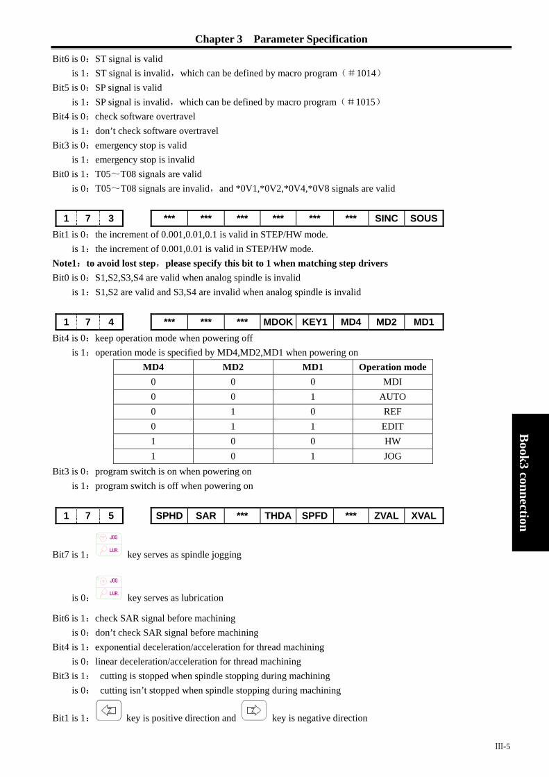
Chapter 3 Parameter Specification
Ⅲ-5
Book3
connection
Bit6 is 0:ST signal is valid is 1:ST signal is invalid,which can be defined by macro program(#1014)
Bit5 is 0:SP signal is valid is 1:SP signal is invalid,which can be defined by macro program(#1015)
Bit4 is 0:check software overtravel is 1:don’t check software overtravel
Bit3 is 0:emergency stop is valid is 1:emergency stop is invalid
Bit0 is 1:T05~T08 signals are valid is 0:T05~T08 signals are invalid,and *0V1,*0V2,*0V4,*0V8 signals are valid
1 7 3 *** *** *** *** *** *** SINC SOUS
Bit1 is 0:the increment of 0.001,0.01,0.1 is valid in STEP/HW mode. is 1:the increment of 0.001,0.01 is valid in STEP/HW mode.
Note1:to avoid lost step,please specify this bit to 1 when matching step drivers Bit0 is 0:S1,S2,S3,S4 are valid when analog spindle is invalid
is 1:S1,S2 are valid and S3,S4 are invalid when analog spindle is invalid
1 7 4 *** *** *** MDOK KEY1 MD4 MD2 MD1 Bit4 is 0:keep operation mode when powering off
is 1:operation mode is specified by MD4,MD2,MD1 when powering on MD4 MD2 MD1 Operation mode
0 0 0 MDI 0 0 1 AUTO 0 1 0 REF 0 1 1 EDIT 1 0 0 HW 1 0 1 JOG
Bit3 is 0:program switch is on when powering on is 1:program switch is off when powering on
1 7 5 SPHD SAR *** THDA SPFD *** ZVAL XVAL
Bit7 is 1: LUR.
JOG
key serves as spindle jogging
is 0: LUR.
JOG
key serves as lubrication
Bit6 is 1:check SAR signal before machining is 0:don’t check SAR signal before machining
Bit4 is 1:exponential deceleration/acceleration for thread machining is 0:linear deceleration/acceleration for thread machining
Bit3 is 1: cutting is stopped when spindle stopping during machining is 0: cutting isn’t stopped when spindle stopping during machining
Bit1 is 1: key is positive direction and key is negative direction
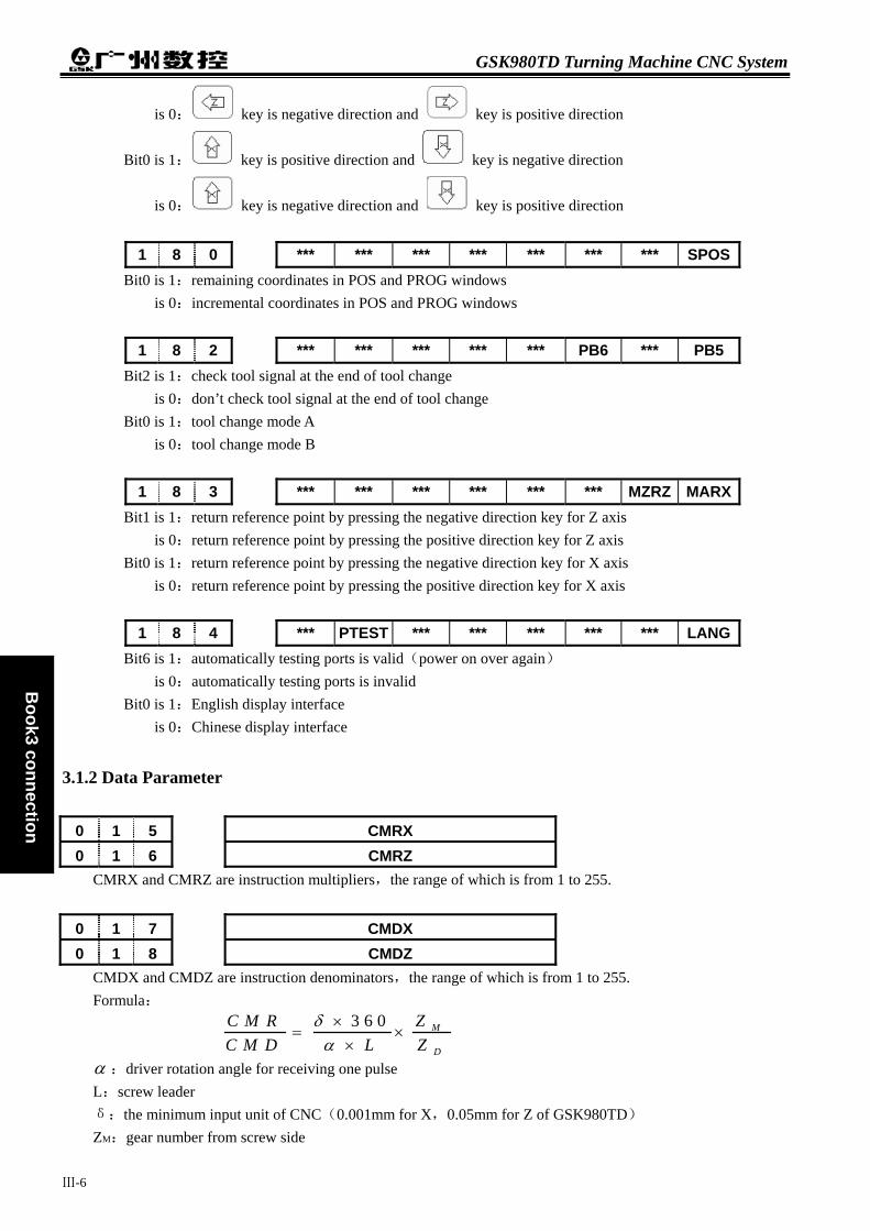
GSK980TD Turning Machine CNC System
Ⅲ-6
Book3 connection
is 0: key is negative direction and key is positive direction
Bit0 is 1: key is positive direction and key is negative direction
is 0: key is negative direction and key is positive direction
1 8 0 *** *** *** *** *** *** *** SPOSBit0 is 1:remaining coordinates in POS and PROG windows
is 0:incremental coordinates in POS and PROG windows
1 8 2 *** *** *** *** *** PB6 *** PB5 Bit2 is 1:check tool signal at the end of tool change
is 0:don’t check tool signal at the end of tool change Bit0 is 1:tool change mode A
is 0:tool change mode B
1 8 3 *** *** *** *** *** *** MZRZ MARXBit1 is 1:return reference point by pressing the negative direction key for Z axis
is 0:return reference point by pressing the positive direction key for Z axis Bit0 is 1:return reference point by pressing the negative direction key for X axis
is 0:return reference point by pressing the positive direction key for X axis
1 8 4 *** PTEST *** *** *** *** *** LANGBit6 is 1:automatically testing ports is valid(power on over again)
is 0:automatically testing ports is invalid Bit0 is 1:English display interface
is 0:Chinese display interface
3.1.2 Data Parameter
0 1 5 CMRX 0 1 6 CMRZ
CMRX and CMRZ are instruction multipliers,the range of which is from 1 to 255.
0 1 7 CMDX 0 1 8 CMDZ
CMDX and CMDZ are instruction denominators,the range of which is from 1 to 255. Formula:
α :driver rotation angle for receiving one pulse L:screw leader δ:the minimum input unit of CNC(0.001mm for X,0.05mm for Z of GSK980TD) ZM:gear number from screw side
3 6 0 M
D
ZC M RC M D L Z
δα×
= ××

Chapter 3 Parameter Specification
Ⅲ-7
Book3
connection
ZD:gear number from machine side
0 1 9 THDCH THDCH is length of thread run-out,the range of which is from 1 to 255. Width of thread run-out=THDCH×0.1×screw leader
0 2 1 VCV It’s voltage compensation value when spindle speed instruction is 10V,the range of which is from –2000 to 2000
(unit is mV)
0 2 2 RPDFX RPDFX is the max. rapid traverse speed for X axis(radius value),the range of which is from 10 to 3825000(unit is mV/min)
0 2 3 RPDFZ RPDFZ is the max. rapid traverse speed for Z axis,the range of which is from 10 to 7650000(unit is mV/min)
0 2 4 LINTX 0 2 5 LINTZ
LINTX and LINTZ are linear acceleration/deceleration time constants for X and Z axes in rapid traverse,the range of which is from 0 to 4000(unit is mS)
0 2 6 THRDT THRDT is acceleration/deceleration time constant for the short axis in thread run-out,the range of which is from 0 to 4000(unit is mS)
0 2 7 FEDMX It’s upper limit feedrate for X and Z axes,the range of which is from 10 to 8000(unit is mm/min)
0 2 8 THDFL It’s initial speed for X and Z axis in thread cutting,the range of which is from 6 to 8000(unit is mm/min)
0 2 9 FEEDT It’s exponential acceleration/deceleration time constant for X and Z axes in cutting and manual feed,the range of which is from 0 to 4000(unit is mS)
0 3 0 FEDFL It’s start speed in acceleration and end speed in deceleration in cutting,the range of which is from 0 to 8000(unit is mm/min)
0 3 2 RPDFL It’s rapid traverse speed when rapid traverse override is F0,the range of which is from 6 to 4000(unit is mm/min)
0 3 3 ZRNFL It’s low speed for X and Z axes in reference point return,the range of which is from 6 to 4000(unit is mm/min)

GSK980TD Turning Machine CNC System
Ⅲ-8
Book3 connection
0 3 4 BKLX It’s backlash compensation value of X axis,the range of which is from 0 to 2000(unit is 0.001mm)
0 3 5 BKLZ It’s backlash compensation value of Z axis,the range of which is from 0 to 2000(unit is 0.001mm)
0 3 6 SPDLC SPDLC is voltage compensation value when SVC is 10V,the range of which is from –1000 to 1000(unit is mV)
GRMAX1 ,GRMAX2, GRMAX3, GRMAX4 are the max. spindle speeds in gear 1 to 4 when SVC is 10V or for instruction M41 to M44 when automatic gear shifting is valid. Speed of gear1 is default value when powering on or automatic gear shifting is invalid. The range is from 10 to 9999(unit is rpm).
JOGFL is start speed of exponential acceleration and end speed of deceleration in JOG,the range of which is from 0 to 8000(unit is mm/min).
SEQINC is increment value of block sequence number,the range of which is from 1 to 100.
LOWSP is the min. spindle speed in G96,the range of which is from 0 to 9999(unit is rpm). BRATE0 is serial communication rate,which is valid when bit5 of No.2 parameter is 1.The range is
1200,2400,4800,9600,19200,38400 57600 115200 (unit is bit/s)
LT1X1 and LT1Z1 are software overtravel in positive direction for X and Z axes separately,LT1X2 and LT1Z2 are software overtravel in negative direction for X and Z axes separately.The range is from 0 to ±9999999(unit is mm).
Note:Value type of LT1X1 and LT1X2 is specified by bit2 of No.1 parameter.
0 5 1 MRCCD
0 3 7 GRMAX1 0 3 8 GRMAX2 0 3 9 GRMAX3 0 4 0 GRMAX4
0 4 1 JOGFL
0 4 2 SEQINC
0 4 3 LOWSP
0 4 4 BRATE0
0 4 5 LT1X1 0 4 6 LT1Z1 0 4 7 LT1X2 0 4 8 LT1Z2

Chapter 3 Parameter Specification
Ⅲ-9
Book3
connection
MRCCD is each infeed value in roughing(G71,G72),which can also be specified in program instruction. The range is from 1 to 99999(unit is 0.001mm).
0 5 2 MRCDT MRCDT is each retraction value in roughing(G71,G72),which can also be specified in program instruction. The range is from 1 to 99999(unit is 0.001mm).
0 5 3 PECSCX PECSCX is retraction value in roughing of X axis in G73,which can also be specified in program instruction. The range is from -99999 to 99999(unit is 0.001mm).
0 5 4 PECSCZ PECSCZ is retraction value in roughing of Z axis in G73,which can also be specified in program instruction. The range is from -99999 to 99999(unit is 0.001mm).
0 5 5 PATIM PATIM is cutting times of G73,which can also be specified in program instruction. The range is from 1 to 99999(unit is times).
0 5 6 GROVE GROVE is retraction value of Z axis in G74 or X axis in G75,which can also be specified in program instruction. The range is from 0 to 99999(unit is 0.001mm).
0 5 7 THRPT THRPT is finishing times in G76,which can also be specified in program instruction. The range is from 1 to 99(unit is times).
0 5 8 THANG TFANG is tool angle in G76,which can also be specified in program instruction. The range is from 0 to 99(unit is degree).
0 5 9 THCLM THCLM is least cutting depth in G76,which can also be specified in program instruction. The range is from 0 to 99999(unit is 0.001mm).
0 6 0 THDFN THDFN is remaining cutting depth of finishing in G76,which can also be specified in program instruction. The range is from 0 to 99999(unit is 0.001mm).
0 6 5 SFT1TME SFT1IME is gear shifting time 1 of spindle,the range is from 0 to 60000(unit is ms).
0 6 6 SFT2TME SFT2IME is gear shifting time 2 of spindle,the range is from 0 to 60000(unit is ms).

GSK980TD Turning Machine CNC System
Ⅲ-10
Book3 connection
0 6 7 SFTREV SFTREV is spindle voltage as gear shifting,the range is from 0 to 10000(unit is mV).
0 6 9 PEALMTIM PEALTIM is low pressure alarm time,the range is from 0 to 60000(unit is ms).
0 7 0 ENCODER_CNT ENCODER_CNT is spindle encoder line number,the range is 100 to 5000(unit is lpr).
RESET_TIME is output time for reset signal,the range is from 16 to 4080(unit is ms).
SAR_DELEY is delay time of detecting SAR signal,the range is form 0 to 4080(unit is ms).
T1MAXT is upper limit time for changing one tool,the range is form 100 to 5000(unit is ms).
TLMAXT is upper limit time for changing total tools,the range is form 1000 to 60000(unit is ms).
MTIME is duration for M code being executed,the range is form 100 to 5000(unit is ms).
STIME is duration for S code being executed,the range is form 100 to 5000(unit is ms).
T1TIME is delay time from TL+ ceased to TL- output,the range is from 0 to 4000(unit is ms).
TCPWRN is alarm time for not receiving *TCP signal,the range is from 0 to 4000(unit is ms).
TMAX is total tool number selection,the range is from 1 to 32.
TCPTIME is time .from TL- output to receive TCP,the range is from 0 to 4000(unit is ms). SPDDLT is delay time for M05 and SPZD outputting,the range is from 0 to 10000(unit is ms).
0 8 9 SPZDTIME SPZDTIME is SPZD output time,the range is from 0 to 60000(unit is ms).
0 7 1 RESET_TIME
0 7 2 SAR_DELEY
0 7 6 T1MAXT
0 7 8 TLMAXT
0 8 0 MTIME
0 8 1 STIME
0 8 2 T1TIME
0 8 3 TCPWRN
0 8 4 TMAX
0 8 5 TCPTIME
0 8 7 SPDDLT

Chapter 3 Parameter Specification
Ⅲ-11
Book3
connection
0 9 8 It’s position number of pitch error compensation for X machine reference point,the range is from 0 to 255.
0 9 9 It’s position number of pitch error compensation for Z machine reference point,the range is from 0 to 255.
1 0 2 It’s distance between each pitch error compensation of X axis,the range is from 10000 to 999999(unit is ms).
1 0 3 It’s distance between each pitch error compensation of Z axis,the range is from 10000 to 999999(unit is ms).
1 0 6 THD_SPD_VAR THD_SPD_VAR is spindle speed fluctuating limit in thread cutting,the range is from 0 to 100(unit is%).
1 0 7 THD_TAIL_SPD THD_TAIL_SPD is speed of short axis in thread tailing,the range is from 0 to 8000(unit mm/min).
1 0 8 SPL_REV_TIME SPL_REV_TIME is spindle jogging time,the range is from 0 to 60000(unit is ms).
1 0 9 SPL_REV_SPD SPL_REV_SPD is spindle jogging speed,the range is from 1 to 8000(unit is rpm).
1 1 0 MGR MGR is spindle gear teeth number in driving ratio,the range is from 1 to 255.
1 1 1 SGR SGR is encoder gear teeth number in driving ratio,the range is from 1 to 255.
1 1 2 LUBRICATE_TIME LUBRICATE_TIME is lubricating time,the range is from 0 to 60000(unit is ms).
1 1 3 REF_SPD REF_SPD is rapid traverse speed of each axis in reference point return,the range is from 10 to 7650000(unit is mm/min).
1 1 4 It’s offset in X machine reference point,the range is from –99999 to 99999(unit is 0.001mm).
1 1 5 It’s offset in Z machine reference point,the range is from –99999 to 99999(unit is 0.001mm).
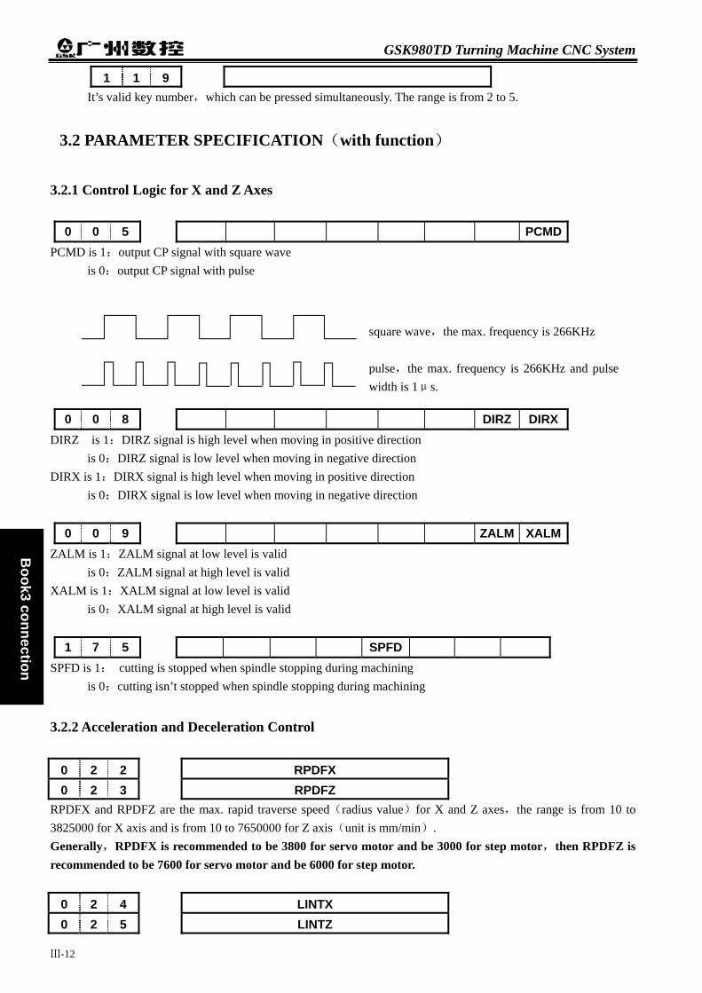
GSK980TD Turning Machine CNC System
Ⅲ-12
Book3 connection
square wave,the max. frequency is 266KHz pulse,the max. frequency is 266KHz and pulsewidth is 1μs.
1 1 9 It’s valid key number,which can be pressed simultaneously. The range is from 2 to 5.
3.2 PARAMETER SPECIFICATION(with function)
3.2.1 Control Logic for X and Z Axes
0 0 5 PCMD PCMD is 1:output CP signal with square wave
is 0:output CP signal with pulse
0 0 8 DIRZ DIRX DIRZ is 1:DIRZ signal is high level when moving in positive direction
is 0:DIRZ signal is low level when moving in negative direction DIRX is 1:DIRX signal is high level when moving in positive direction
is 0:DIRX signal is low level when moving in negative direction
0 0 9 ZALM XALM ZALM is 1:ZALM signal at low level is valid
is 0:ZALM signal at high level is valid XALM is 1:XALM signal at low level is valid
is 0:XALM signal at high level is valid
1 7 5 SPFD SPFD is 1: cutting is stopped when spindle stopping during machining
is 0:cutting isn’t stopped when spindle stopping during machining
3.2.2 Acceleration and Deceleration Control
0 2 2 RPDFX 0 2 3 RPDFZ
RPDFX and RPDFZ are the max. rapid traverse speed(radius value)for X and Z axes,the range is from 10 to 3825000 for X axis and is from 10 to 7650000 for Z axis(unit is mm/min). Generally,RPDFX is recommended to be 3800 for servo motor and be 3000 for step motor,then RPDFZ is recommended to be 7600 for servo motor and be 6000 for step motor.
0 2 4 LINTX 0 2 5 LINTZ

Chapter 3 Parameter Specification
Ⅲ-13
Book3
connection
LINTX and LINTZ are linear acceleration/deceleration time constants for X and Z axes in rapid traverse,the range of which is from 0 to 4000(unit is mS). Generally,LINTX and LINTZ are recommended to be 100 for servo motor and be 350 for step motor.
0 2 7 FEDMX FEDMX is upper limit feedrate for X and Z axes,the range of which is from 10 to 8000(unit is mm/min).
0 2 9 FEEDT FEEDT is exponential acceleration/deceleration time constant for X and Z axes in cutting and manual feed,the range of which is from 0 to 4000(unit is mS).
0 3 0 FEDFL FEDFL is start speed in acceleration and end speed in deceleration during cutting,the range of which is from 0 to 8000(unit is mm/min).
0 3 2 RPDFL RPDFL is rapid traverse speed when rapid traverse override is F0,the range of which is from 6 to 4000(unit is mm/min).
3.2.3 Safeguard for Machine
1 6 4 SPEN SPEN is 1:spindle rotation permitting input is valid
is 0:spindle rotation permitting input is invalid
1 6 8 SPB4 PB4 SPB3 PB3 *** *** *** *** SPB4 is 0:safeguard is closed when SGAT signal connecting to 0V
is 1:safeguard is closed when SGAT signal connecting to +24V PB4 is 0:safeguard is invalid
is 1:safeguard is valid and *SP signal is invalid SPB3 is 0:low pressure alarms when PRES signal connecting to 0V
is 1:low pressure alarms when PRES signal connecting to +24V PB3 is 0:low pressure detection is invalid
is 1:low pressure detection is valid
1 7 2 MST MSP MOT ESP MST is 0:ST signal is valid
is 1:ST signal is invalid,which can be defined by macro program(#1014) MSP is 0:SP signal is valid
is 1:SP signal is invalid,which can be defined by macro program(#1015) MOT is 0:check software overtravel
is 1:don’t check software overtravel ESP is 0:emergency stop is valid
is 1:emergency stop is invalid

GSK980TD Turning Machine CNC System
Ⅲ-14
Book3 connection
0 6 9 PEALMTIM PEALTIM is low pressure alarm time,the range is from 0 to 60000(unit is ms). PLC data DT021
0 2 1 It’s delay time for responding to DIQP signal after outputting M05 signal,the range is from 0 to1000(unit is ms).
3.2.4 Reference Point Return
0 0 4 RDRN DECI RDRN is 1:G00 in dry run at rapid traverse speed
is 0:G00 in dry run at feed speed DECI is 1:decelerating signal at high level is valid in reference point return
is 0:decelerating signal at low level is valid in reference point return
0 0 5 PPD PPD is 1:relative coordinate is set by G50
is 0:relative coordinate isn’t set by G50
0 0 6 ZMZ ZMXZMZ is 1:reference point return mode C for Z axis
is 0:reference point return mode B for Z axis ZMX is 1:reference point return mode C for X axis
is 0:reference point return mode B for X axis
0 0 7 ZCZ ZCX ZCZ is 1:ZDEC connects to ZPC in parallel
is 0:ZDEC connects to ZPC independently ZCX is 1:XDEC connects to XPC in parallel
is 0:XDEC connects to XPC independently
0 1 1 ZNLK ZNLK is 1:keep moving once pressing direction key in reference point return
is 0:stop moving once releasing direction key in reference point return
0 1 2 APRS ISOTAPRS is 1:set absolute coordinate-system specified by No.49 and No.50 parameter automatically after
reference point return is 0:don’t set absolute coordinate-system automatically after reference point return
ISOT is 1:rapid traverse in JOG mode is valid when powering on or before reference point return is 1:rapid traverse in JOG mode is invalid when powering on or before reference point return

Chapter 3 Parameter Specification
Ⅲ-15
Book3
connection
0 1 4 ZRSZ ZRSX ZRSZ and ZRSX are 1:PC signal and DEC signal are needed in reference point return
are 0:PC signal and DEC signal aren’t needed in reference point return
1 8 3 *** *** *** *** *** *** MZRZ MARX MZRZ is 1:return reference point by pressing the negative direction key for Z axis
is 0:return reference point by pressing the positive direction key for Z axis MZRX is 1:return reference point by pressing the negative direction key for X axis
is 0:return reference point by pressing the positive direction key for X axis
0 3 3 ZRNFL ZRNFL is low speed for X and Z axes in reference point return,the range of which is from 6 to 4000(unit is mm/min)
0 4 9 PRSX 0 5 0 PRSZ
PRSX and PRSZ are absolute coordinates value for X and Z axes after reference point return,the range is from 0 to 9999999.
1 1 3 REF_SPD REF_SPD is rapid traverse speed of each axis in reference point return,the range is from 10 to 7650000(unit is mm/min).
1 1 4 It’s offset in X machine reference point,the range is from –99999 to 99999(unit is 0.001mm).
1 1 5 It’s offset in Z machine reference point,the range is from –99999 to 99999(unit is 0.001mm).
3.2.5 Thread Function
1 7 5 THDA THDA is 1:exponential deceleration/acceleration in thread cutting
is 0:linear deceleration/acceleration in thread cutting
0 1 9 THDCH THDCH is length of thread run-out in thread cutting,the range of which is from 1 to 255. Width of thread run-out=THDCH×0.1×screw leader
0 2 6 THRDT THRDT is acceleration/deceleration time constant for the short axis in thread cutting,the range of which is from 0 to 4000(unit is mS)
0 2 8 THDFL THDFL is initial speed for X and Z axis in thread cutting,the range of which is from 6 to 8000(unit is mm/min)

GSK980TD Turning Machine CNC System
Ⅲ-16
Book3 connection
0 7 0 ENCODER_CNT ENCODER_CNT is spindle encoder line number,the range is 100 to 5000(unit is lpr).
1 1 0 MGR MGR is spindle gear teeth number in driving ratio,the range is from 1 to 255.
1 1 1 SGR SGR is encoder gear teeth number in driving ratio,the range is from 1 to 255.
3.2.6 Spindle Control
0 0 1 SPIN Bit4 is 1:analog spindle
is 0:switching control spindle
0 0 9 RSJG
RSJG is 1:close spindle,coolant and lubrication when pressing RESET
key
is 0:keep spindle,coolant and lubrication when pressing RESET
key
1 6 4 AGER AGIN AGIM AGER is 1:automatic spindle gear shifting is valid
is 0:automatic spindle gear shifting is invalid AGIN is 1:detect M41I and M42I signals in automatic spindle gear1 and gear2
is 0:don’t detect M41I and M42I signals in automatic spindle gear1 and gear2 AGIM is 1:M41I and M42I signals are valid when disconnecting with +24V
is 0:M41I and M42I signals are valid when connecting to +24V
1 7 5 SPHD
SPHD is 1: LUR.
JOG
key serves as spindle jogging
is 0: LUR.
JOG
key serves as lubrication
0 2 1 VCV It’s voltage compensation value when spindle speed instruction is 10V,the range of which is from –2000 to 2000(unit is mV)
0 3 6 SPDLC SPDLC is voltage compensation value when SVC is 10V,the range of which is from –1000 to 1000(unit is mV)
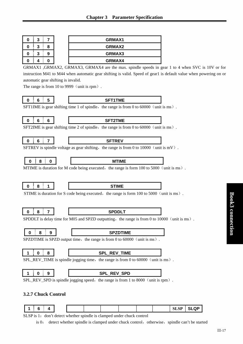
Chapter 3 Parameter Specification
Ⅲ-17
Book3
connection
0 3 7 GRMAX1 0 3 8 GRMAX2 0 3 9 GRMAX3 0 4 0 GRMAX4
GRMAX1 ,GRMAX2, GRMAX3, GRMAX4 are the max. spindle speeds in gear 1 to 4 when SVC is 10V or for instruction M41 to M44 when automatic gear shifting is valid. Speed of gear1 is default value when powering on or automatic gear shifting is invalid. The range is from 10 to 9999(unit is rpm).
0 6 5 SFT1TME SFT1IME is gear shifting time 1 of spindle,the range is from 0 to 60000(unit is ms).
0 6 6 SFT2TME SFT2IME is gear shifting time 2 of spindle,the range is from 0 to 60000(unit is ms).
0 6 7 SFTREV SFTREV is spindle voltage as gear shifting,the range is from 0 to 10000(unit is mV).
0 8 0 MTIME MTIME is duration for M code being executed,the range is form 100 to 5000(unit is ms).
STIME is duration for S code being executed,the range is form 100 to 5000(unit is ms).
SPDDLT is delay time for M05 and SPZD outputting,the range is from 0 to 10000(unit is ms).
0 8 9 SPZDTIME SPZDTIME is SPZD output time,the range is from 0 to 60000(unit is ms).
1 0 8 SPL_REV_TIME SPL_REV_TIME is spindle jogging time,the range is from 0 to 60000(unit is ms).
1 0 9 SPL_REV_SPD SPL_REV_SPD is spindle jogging speed,the range is from 1 to 8000(unit is rpm).
3.2.7 Chuck Control
1 6 4 SLSP SLQP SLSP is 1:don’t detect whether spindle is clamped under chuck control
is 0: detect whether spindle is clamped under chuck control,otherwise,spindle can’t be started
0 8 1 STIME
0 8 7 SPDDLT

GSK980TD Turning Machine CNC System
Ⅲ-18
Book3 connection
SLQP is 1:chuck control is valid is 0:chuck control is invalid
1 6 8 SPB3 PB3 PB2 PB1 SPB3 is 0:low pressure alarms when PRES signal connecting to 0V
is 1:low pressure alarms when PRES signal connecting to +24V PB3 is 0:low pressure detection is invalid
is 1:low pressure detection is valid PB2 is 0:don’t detect to-position signal of chuck
is 1:detect to-position signal of chuck PB1 is 0:internal chuck,NQPJ is clamping signal and WQPJ is unclamping signal for internal chuck
is 1:external chuck,NQPJ is unclamping signal and WQPJ is clamping signal for external chuck
0 6 9 PEALMTIM PEALTIM is low pressure alarm time,the range is from 0 to 60000(unit is ms).
PLC data DT021
0 2 1 It’s delay time for responding to DIQP signal after outputting M05 signal,the range is from 0 to1000(unit is ms).
3.2.8 Tailstock Control
1 6 4 SLTW SLTW is 1:tailstock control is valid
is 0:tailstock control is invalid
3.2.9 Tool Nose Radius Compensation
0 0 2 刀补C Bit1 is 1:tool nose radius compensation is valid
is 0:tool nose radius compensation is invalid
0 0 3 TLC Bit4 is 1:compensate tool length with coordinates
is 0:compensate tool length with tool moving
0 0 4 ORC TOC PROD ORC is 1:radius value for tool compensation
is 0:diameter value for tool compensation TOC is 1:keep tool compensation at reset
is 0:clear tool compensation at reset PROD is 1:relative coordinate display don’t include tool compensation
is 0:relative coordinate display includes tool compensation

Chapter 3 Parameter Specification
Ⅲ-19
Book3
connection
0 1 2 DOFSI DOFSL is 1:toolsetting with trail cutting is valid
is 0:toolsetting with trail cutting is invalid
3.2.10 Toolpost Control
0 1 1 TSGN TCPS TSGN is 1:T01~T08 signals are valid when disconnecting with +24V
is 0:T01~T08 signals are valid when connecting to +24V TCPS is 1:
is 0:
1 8 2 PB6 PB5 PB6 is 1:check tool signal at the end of tool change
is 0:don’t check tool signal at the end of tool change PB5 is 1:tool change mode A
is 0:tool change mode B
T1MAXT is upper limit time for changing one tool,the range is form 100 to 5000(unit is ms).
TLMAXT is upper limit time for changing total tools,the range is form 1000 to 60000(unit is ms).
T1TIME is delay time from TL+ ceased to TL- output,the range is from 0 to 4000(unit is ms).
TCPWRN is alarm time for not receiving *TCP signal,the range is from 0 to 4000(unit is ms).
TMAX is most tool number selection,the range is from 1 to 32.
TCPTIME is time .from TL- output to receive TCP,the range is from 0 to 4000(unit is ms)
3.2.11 Edit and Display
0 0 5 M30 M30 is 1:cursor returns after M30
is 0:cursor doesn’t return after M30
0 1 2 EAL EBCL EAL is 1:program can be edited at alarm
is 0:program can’t be edited at alarm
0 7 6 T1MAXT
0 7 8 TLMAXT
0 8 2 T1TIME
0 8 3 TCPWRN
0 8 4 TMAX
0 8 5 TCPTIME

GSK980TD Turning Machine CNC System
Ⅲ-20
Book3 connection
EBCL is 1:end symbol EOB in part program is with“;” is 0:end symbol EOB in part programs is with“*”
1 8 0 SPOS
SPOS is 1:remaining coordinates in POS and PROG windows is 0:incremental coordinates in POS and PROG windows
1 8 4 LANG
LANG is 1:English display interface is 0:Chinese display interface
3.2.12 Accuracy Compensation
0 0 3 PEC Bit5 is 1:pitch error compensation is valid
is 0:pitch error compensation is invalid
0 1 0 *** *** NOFC *** CPF4 CPF3 CPF2 CPF1CPF4~CPF1:frequency setting for backlash compensation(with BCD) Frequency =(setting value+1)Kpps
CPF4 CPF3 CPF2 CPF1 Setting value(Kpps) 0 0 0 0 1 0 0 0 1 2 0 0 1 0 3 0 0 1 1 4 0 1 0 0 5 0 1 0 1 6 0 1 1 0 7 0 1 1 1 8 1 0 0 0 9 1 0 0 1 10 1 0 1 0 11 1 0 1 1 12 1 1 0 0 13 1 1 0 1 14 1 1 1 0 15 1 1 1 1 16
0 1 1 BDEC BD8
BDEC is 1:backlash compensation mode B,with deceleration/acceleration for compensation and setting frequency is invalid
is 0:backlash compensation mode A,with fixed frequency for compensation BD8 is 1:compensate backlash with one setting frequency
is 0:compensate backlash with eighth setting frequency

Chapter 3 Parameter Specification
Ⅲ-21
Book3
connection
0 3 4 BKLX BKLX is backlash compensation value of X axis,the range of which is from 0 to 2000(unit is 0.001mm)
0 3 5 BKLZ BKLZ is backlash compensation value of Z axis,the range of which is from 0 to 2000(unit is 0.001mm)
0 9 8 It’s position number of pitch error compensation for X machine reference point,the range is from 0 to 255.
0 9 9 It’s position number of pitch error compensation for Z machine reference point,the range is from 0 to 255.
1 0 2 It’s distance between each pitch error compensation of X axis,the range is from 10000 to 999999(unit is ms).
1 0 3 It’s distance between each pitch error compensation of Z axis,the range is from 10000 to 999999(unit is ms). Pitch error compensation table:
Serial number X Z 0 0 0 0 0
2 5 5 0 0
3.2.13 Communication Setting
0 0 2 RS232 RS232 is 1:RS232 communication is valid
is 0:RS232 communication is invalid
0 4 4 BRATE0 BRATE0 is serial communication rate,which is valid when bit5 of No.2 parameter is 1.The range is 1200, 2400, 4800, 9600, 19200, 38400 57600 115200 (unit is bit/s).


Chapter 4 Machine Debugging
Chapter 4 MACHINE DEBUGGING
Only debugging the machine when first powering on as following method,which will be introduced in detail in this chapter,can users operate the machine.
4.1 EMERGENCY STOP and OVERTRAVEL
For safety,hardware overtravel measure is recommended for GSK980TD,in which the travel-limit switch is fixed in positive and negative direction for each axis.The connection diagram as following:
Book3
connection
+24V
emergency stop switch
Fig.4-1 In this connection,bit2 of No.172 state parameter should be specified to 0. Slowly moving for axis in MANUAL or HANDWHEEL mode can verify the validity of overtravel canceling
switch、travel-limit switch and alarm display.When overtravel in presence or pushing the emergency stop switch,ESP alarm will be given,which can be cancelled by pushing the overtravel canceling switch and moving in the negative direction.
4.2 DRIVER SETTING
Specify bit1、bit0 of No.9 state parameter according to the driver alarm voltage,which should be specified to 1 to fit our own driver.
Bit1、bit0 of No.8 state parameter can be modified when the machine moving direction isn’t consistent with the dictate desired direction.
4.3 GEAR RATIO ADJUSTING
When the machine moving distance isn’t consistent with the distance display,adjust the gear ratio by specifying No.015~No.018 parameter to fit the different machine transmission ratio.
Formula:
CMR:dictate multiple coefficient(No.15、No.16 data parameter) CMD:dictate divisor coefficient(No.17、No.18 data parameter) α :driver rotation angle for receiving one pulse L:screw leader
overtravel canceling switch ESP XS40 ) ((XS40/10)
3 6 0 M
D
ZC M RD L Z
δα×
= ××C M
Ⅳ-1

GSK980TD Turning Machine CNC System
δ:the minimum input unit of CNC(0.001mm for X,0.05mm for Z of GSK980TD) δ:the minimum input unit of CNC(0.001mm for X,0.05mm for Z of GSK980TD) ZM:gear number from screw side ZM:gear number from screw side ZD:gear number from machine side ZD:gear number from machine side
For example:ZM=50、ZD=30、For example:ZM=50、ZD=30、α =0.075°、L=4mm Gear ratio of X :
3 6 0 0 .0 00 5 3 60 5 0 10 .07 5 4 3 0 1
M
D
ZC M RC M D L Z
δα× ×
= × = ×× ×
=
Gear ratio of Z: 3 6 0 M
D
ZC M RC M D L Z
δα×
= ××
0 .001 360 50 20 .075 4 30 1
×= × =
×
From above,No.15、16、18 parameters are 1 and No.17 parameter is 2. The permitted max. Speed will descend when CMR is less than CMD.For example,the permitted max. speed of
Z is 8000mm/min when No.16 parameter is 1 and No.18 parameter is 2. The position accuracy will decline when CMR isn’t equivalent to CMD.For example,CNC only outputs one
pulse with the input increment being 0.005mm when No.16 parameter is 1 and No.18 parameter is 5. To insure the position accuracy and speed,recommend to set the gear ratio of CNC to 1:1 and set that of servo
to the calculated value. As possible as one can,choose the step driver with subdivision function and select the reasonable machine
transmission ratio to keep the gear ratio of CNC with 1:1.
4.4 ACCELERATING and DECELERATING CHARACTERISTIC
Adjust the relative parameters according to the factors of driver、motor characteristic and machine load etc:
Book3 connection
ok3 connection
No.22、No.23 data parameter:rapid traverse speed of X、Z. No.24、No.25 data parameter:linear acc./dec. time constant of X、Z in rapid traverse. No.26 data parameter:exponential acc./dec. time constant of X in thread cutting. No.28 data parameter:the start/end speed during exponential acc./dec. in thread cutting. No.29 data parameter:exponential acc./dec. time constant in cutting feed or manual feed. No.30 data parameter:the start/end speed during exponential acc./dec. in cutting feed. Bit3 of No.27 state parameter(SMZ):whether there is smooth transition between the adjacent cutting segments.
Larger the acc./dec. time constant is,the acc./dec. process is more slow,the machine strike is smaller and the cutting efficiency is lower. v.v.
When the acc./dec. time constant is same,higher the start/end speed is,the acc./dec. process is more rapid,the machine strike is greater and the cutting efficiency is higher. v.v. Acc./dec. characteristic regulating is on the principle of reducing the time constant and increasing the start/end
speed properly,and insuring no driver alarm、no lost step、no obvious machine strike. When bit3 of No.27 state parameter is 1,the cutting point of intersection is commanded position and the
efficiency is be low,otherwise,arc transition occurs in this point which will cause smooth workpiece surface,and the efficiency is high.To avoid lost step,this bit parameter should be 1 when adopting step drivers.
Recommend to specify the parameters as following when adopting step drivers(gear ratio is 1:1):
No.022≤2500 No.023≤5000
No.024≥350 No.025≥350
No.029≥150 No.028≤100 No.026≥200 No.030≤50
Ⅳ-2
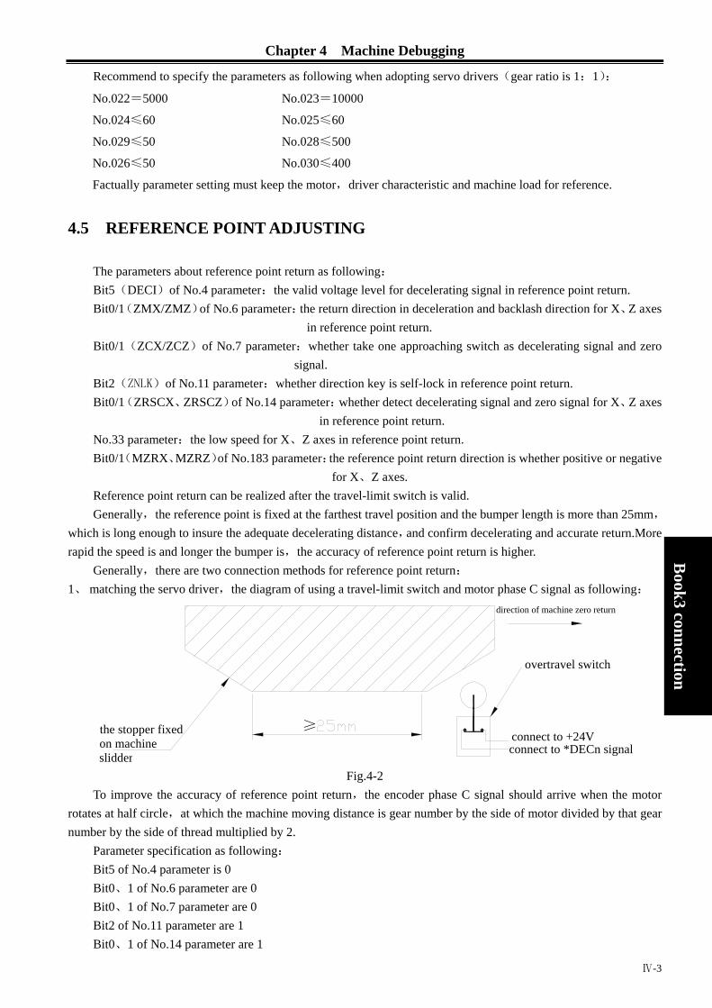
Chapter 4 Machine Debugging
Recommend to specify the parameters as following when adopting servo drivers(gear ratio is 1:1):
No.022=5000 No.023=10000
No.024≤60 No.025≤60
No.029≤50 No.028≤500
No.026≤50 No.030≤400
Factually parameter setting must keep the motor,driver characteristic and machine load for reference.
4.5 REFERENCE POINT ADJUSTING
The parameters about reference point return as following: Bit5(DECI)of No.4 parameter:the valid voltage level for decelerating signal in reference point return. Bit0/1(ZMX/ZMZ)of No.6 parameter:the return direction in deceleration and backlash direction for X、Z axes
in reference point return. Bit0/1(ZCX/ZCZ)of No.7 parameter:whether take one approaching switch as decelerating signal and zero
signal. Bit2(ZNLK)of No.11 parameter:whether direction key is self-lock in reference point return. Bit0/1(ZRSCX、ZRSCZ)of No.14 parameter:whether detect decelerating signal and zero signal for X、Z axes
in reference point return. No.33 parameter:the low speed for X、Z axes in reference point return. Bit0/1(MZRX、MZRZ)of No.183 parameter:the reference point return direction is whether positive or negative
for X、Z axes. Reference point return can be realized after the travel-limit switch is valid.
Book3
connection
Generally,the reference point is fixed at the farthest travel position and the bumper length is more than 25mm,
which is long enough to insure the adequate decelerating distance,and confirm decelerating and accurate return.More rapid the speed is and longer the bumper is,the accuracy of reference point return is higher.
Generally,there are two connection methods for reference point return: 1、 matching the servo driver,the diagram of using a travel-limit switch and motor phase C signal as following:
connect to +24Vconnect to *DECn signal
the stopper fixed on machine slidder
direction of machine zero return
overtravel switch
≥
Fig.4-2
To improve the accuracy of reference point return,the encoder phase C signal should arrive when the motor rotates at half circle,at which the machine moving distance is gear number by the side of motor divided by that gear number by the side of thread multiplied by 2.
Parameter specification as following: Bit5 of No.4 parameter is 0 Bit0、1 of No.6 parameter are 0 Bit0、1 of No.7 parameter are 0 Bit2 of No.11 parameter are 1 Bit0、1 of No.14 parameter are 1
Ⅳ-3

GSK980TD Turning Machine CNC System
No.33 parameter is 200 No.33 parameter is 200 Bit0、1 of No.183 parameter are 0 Bit0、1 of No.183 parameter are 0
Book3 connection
D
ok3 connection
2、 matching the step driver,the diagram of using one approaching switch as following: 2、 matching the step driver,the diagram of using one approaching switch as following:
To avo
following:To avo
following:Bit5 oBit5 oBit0、Bit0、Bit0、Bit0、Bit2 oBit2 oBit0、Bit0、No.33No.33Bit0、Bit0、Bit5 o
GN.008 iBit5 o
DGN.008 i
gaa
4.6 SP4.6 SP
4.6.1 Spin4.6.1 Spin
Encodparameter.Tis specifiesynchroniz
Encodparameter.Tis specifiesynchroniz
Bit2 oBit2 oDGN.DGN.
Ⅳ-4
enerally,L1 ≥ ( 1.5~2 )
pproaching switch width,L2≈
id lost step in high speed,rapid override had better be specified to 50%.The parameter specification as id lost step in high speed,rapid override had better be specified to 50%.The parameter specification as
f No.4 parameter is 0 f No.4 parameter is 0 1 of No.6 parameter are 0 1 of No.6 parameter are 0 1 of No.7 parameter are 1 1 of No.7 parameter are 1 f No.11 parameter are 0 f No.11 parameter are 0 1 of No.14 parameter are 1 1 of No.14 parameter are 1
parameter is 200 parameter is 200 1 of No.183 parameter are 0 1 of No.183 parameter are 0 f DGN.000 diagnosis indicates decelerating signal,bit5 of DGN.001 indicates zero signal and bit0、1 of ndicate PC signal. f DGN.000 diagnosis indicates decelerating signal,bit5 of DGN.001 indicates zero signal and bit0、1 of ndicate PC signal.
pproaching switch width
INDLE FUNCTION ADJUSTING INDLE FUNCTION ADJUSTING
dle Encoder dle Encoder
er is in need for thread machining,which line number is from 100 to 5000 specified by No.70 he transmission ratio between encoder and spindle is from 1/255 to 255,in which the spindle gear number
d by No.110 parameter and the encoder gear number is specified by No.111 parameter. Only ation strap transmission mode is in need(no glide transmission).
er is in need for thread machining,which line number is from 100 to 5000 specified by No.70 he transmission ratio between encoder and spindle is from 1/255 to 255,in which the spindle gear number
d by No.110 parameter and the encoder gear number is specified by No.111 parameter. Only ation strap transmission mode is in need(no glide transmission). f DGN.008 diagnosis indicates whether the encoder phase C signal is valid. f DGN.008 diagnosis indicates whether the encoder phase C signal is valid. 11 and DGN.12 diagnosis indicate whether the encoder phase A/B signal is valid. 11 and DGN.12 diagnosis indicate whether the encoder phase A/B signal is valid.

Chapter 4 Machine Debugging
4.6.2 Spindle Brake
For improving efficiency,proper spindle brake time must be specified to stop spindle rapidly,and too long brake time will cause spindle burnout.
No.87 parameter:time for from commanding M05 to spindle braking No.89 parameter:spindle brake time
4.6.3 Spindle Speed Controlled by On-off Variable
Speed dictate is S01~S04 when machine controlled by multi-speed motor,the relative parameters as following: Bit4 of No.1 parameter is 0:spindle controlled by on-off variable Bit0 of No.3 parameter is 0:four-gear spindle
4.6.4 Spindle Speed Controlled by Analog Voltage
Spindle speed controlled by analog voltage can be realized by specifying the parameters,in which 0~10V voltage will be outputted to control frequency convertor.The relative parameters as following:
Bit4 of No.1 parameter is 1:spindle speed controlled by analog voltage No.21 parameter:the compensation voltage when spindle speed dictate is 10V No.36 parameter:the compensation voltage when spindle speed dictate is 0V No.37~No.40 parameters:the highest spindle speed for gear1~gear4,gear1 is default when powering on Some parameters need to specify for the frequency convertor: Positive or negative rotation mode:decided by VF port
Book3
connection
Frequency setting mode:decided by FR mode No.37~No.40 parameters can be specified to let the commanded speed be consistent with the real speed
detected by encoder.The method is to select gear1 and command S9999 in MDI mode,then specified No.37 parameter with the real spindle speed value,which is displayed in the screen. The same methods as other gears.
The voltage should be 0V at S0 when the voltage is 10V at S9999,and the bias voltage can be cancelled by specifying No.21 and No.36 parameters(which have been adjusted correctly before leaving factory).
If the voltage is more than 10V at S9999,No.21 parameter should be diminished.If the voltage is more than 0V at S0,No.36 parameter should be diminished.
That command S9999 in MDI mode and specified No.37 parameter with the speed value,which be displayed in the speed induction instrument,is feasible without encoders.
4.7 BACKLASH COMPENSATION
Backlash compensation value,which can be measured by centi-meter、thousandth meter、laser detector,is always diameter input and has nothing to do with program mode,the input unit is 0.001mm.Recommend to measure backlash compensation value as following:
● edit program
O0001;
N10 G01 W10 F800 ;
N20 W15 ;
Ⅳ-5

GSK980TD Turning Machine CNC System
N30 W1 ; N30 W1 ;
N40 W-1 ; N40 W-1 ; N50 M30 . N50 M30 .
● set the backlash compensation value to 0 before measuring ● set the backlash compensation value to 0 before measuring ● run the program in single block,and confirm the A point after positioning two times and record the current
data,then move the distance of 1mm and move the same distance in reverse to B point,at which record the current data.
● run the program in single block,and confirm the A point after positioning two times and record the current data,then move the distance of 1mm and move the same distance in reverse to B point,at which record the current data.
Fig.4-4 sketch map for measuring backlash compensation Fig.4-4 sketch map for measuring backlash compensation
B
A
position for record data
reverse position
● backlash compensation value is the absolute value of data at A minus data at B,which multiplied by 2 can be inputted to No.34 or No.35 parameter.
● backlash compensation value is the absolute value of data at A minus data at B,which multiplied by 2 can be inputted to No.34 or No.35 parameter.
Data A is the centi-table data at A point Data A is the centi-table data at A point Data B is the centi-table data at B point Data B is the centi-table data at B point Note 1:backlash compensation mode and frequency can be specified by bit7 and bit6 of No.11 parameter. Note 1:backlash compensation mode and frequency can be specified by bit7 and bit6 of No.11 parameter. Note 2:measure the backlash compensation value every three months for machine. Note 2:measure the backlash compensation value every three months for machine.
Book3 connection
4
fo
ok3 connection
.8 TOOLPOST ADJUSTING 4.8 TOOLPOST ADJUSTING
All kinds of toolposts suit for GSK980TD,please read machine manuals for details.The relative parameters as llowings:
All kinds of toolposts suit for GSK980TD,please read machine manuals for details.The relative parameters as followings:
Bit1 of No.11 parameter:valid voltage level of tool position signal.A pull-up resistor is needed when the voltage level is low.
Bit1 of No.11 parameter:valid voltage level of tool position signal.A pull-up resistor is needed when the voltage level is low.
No.76 parameter:time for moving one tool. No.76 parameter:time for moving one tool. No.78 parameter:upper limit time for changing one tool. No.78 parameter:upper limit time for changing one tool. No.82 parameter:total tools number. No.82 parameter:total tools number. No.85 parameter: lock-up time in negative rotation direction for toolpost No.85 parameter: lock-up time in negative rotation direction for toolpost Incorrect phase sequence connection for three-phase power will lead to striking toolpost,when need to press
RESET key and check connection. Incorrect phase sequence connection for three-phase power will lead to striking toolpost,when need to press
RESET key and check connection. To avoid damaging motor or not locking toolpost up,No.85 parameter should be specified properly.The method
for inspect whether the toolpost is locked-up is that take centi-meter close to the toolpost and turn the toolpost artificially,and the index float should be less than 0.01mm.
To avoid damaging motor or not locking toolpost up,No.85 parameter should be specified properly.The method for inspect whether the toolpost is locked-up is that take centi-meter close to the toolpost and turn the toolpost artificially,and the index float should be less than 0.01mm.
Bit7 and bit6 of DGN.005 diagnosis indicate whether TL+ and TL- signals are valid. Bit7 and bit6 of DGN.005 diagnosis indicate whether TL+ and TL- signals are valid. Bit0~3 of DGN.000 diagnosis indicate whether T01~T04 signals are valid. Bit0~3 of DGN.000 diagnosis indicate whether T01~T04 signals are valid. To insure correctness of tool changing and proper time characteristic,each tool and max. tools must be changed
in adjusting. To insure correctness of tool changing and proper time characteristic,each tool and max. tools must be changed
in adjusting.
Ⅳ-6

Chapter 4 Machine Debugging
4.9 STEP/MPG ADJUSTING
whether key is STEP or MPG mode can be specified by bit3 of No.11 parameter. Bit3 is 1:STEP mode
is 0:MPG mode To avoid too rapid rotation for manual pulse generator,the increment of 0.1mm should be screened when
matching step drivers,which can be specified by bit1 of No.173 parameter. Parameter number
1 7 3 SINC SINC is 0:the increment of 0.001、0.01、0.1 is valid in STEP/MPG mode.
is 1:the increment of 0.001、0.01 is valid in STEP/MPG mode.
4.10 OTHER ADJUSTING
1 6 4 AGER AGIN AGIM SPEN SLTW SLSP SLQP AGER is 1:spindle gears automatically
is 0:spindle doesn’t gear automatically AGIN is 1:detect M41I、M42I when spindle automatically gears to 1、2 gear
is 0:don’t detect M41I、M42I when spindle automatically gears to 1、2 gear AGIM is 1:M41I and M42I are valid when connecting to 0V
is 0:M41I and M42I are valid when connecting to +24V SPEN is 1:the function of spindle rotation permission is valid
Book3
connection
is 0:the function of spindle rotation permission is invalid SLTW is 1:tailstock control is valid
is 0:tailstock control is invalid SLSP is 1:don’t detect whether the chuck is clamping
is 0:detect whether the chuck is clamping SLQP is 1:chuck control is valid
is 0:chuck control is invalid
1 6 8 SPB4 PB4 SPB3 PB3 PB2 PB1 SPB4 is 0:defence gate is closed when SGAT signal connecting to 0V
is 1:defence gate is closed when SGAT signal connecting to +24V PB4 is 0:defence gate is invalid
is 1:defence gate is valid and *SP signal is invalid SPB3 is 0:low pressure alarms when PRES signal connecting to 0V
is 1:low pressure alarms when PRES signal connecting to +24V PB3 is 0:low pressure detection is invalid
is 1:low pressure detection is valid PB2 is 0:don’t detect to-position signal of chuck
is 1:detect to-position signal of chuck PB1 is 0:inner chuck,NQPJ is clamping signal and WQPJ is loosing signal for inner chuck
is 1:outer chuck,NQPJ is loosing signal and WQPJ is clamping signal for outer chuck
Ⅳ-7

GSK980TD Turning Machine CNC System
1 7 2 MST MSP MOT SOVI MST is 0:ST signal is valid
is 1:ST signal is invalid,which can be defined by macro program(#1014) MSP is 0:SP signal is valid
is 1:SP signal is invalid,which can be defined by macro program(#1015) MOT is 0:check soft travel-limit
is 1:don’t check soft travel-limit SOVI is 1:T01~T08 signals are valid
is 0:T01~T08 signals are invalid,and *0V1、*0V2、*0V4、*0V8 signals are valid
1 7 3 SINC SOUS SINC is 0:the increment of 0.001、0.01、0.1 is valid in STEP/MPG mode.
is 1:the increment of 0.001、0.01 is valid in STEP/MPG mode. SOUS is 0:S1~S4 signals are valid when spindle controlled by on-off variable
is 1:S1、S2 signals are valid when spindle controlled by on-off variable,S3 and S4 are defined by macro program(#1102、#1103)
Book3 connection
Ⅳ-8

Chapter 5 Diagnosis Information
Ⅴ-1
Book3
connection
CHAPTER5 DIAGNOSIS INFORMATION
5.1 DIAGNOSIS of CNC
In this chapter,diagnosis of interface signals and inner states will be introduced.
5.1.1 Diagnosis Information from Machine
0 0 0 TCP DIQP XDEC BDT T04 T03 T02 T01 pins XS39.12 XS39..11 XS40.1 XS40..2 XS40.3 XS40.4 XS40.5 XS40.6
TCP:*TCP signal /low pressure detecting signal(machine to PLC) DIQP:chuck control signal(machine to PLC) XDEC:deceleration signal for reference point return in X direction(machine to PLC) BDT:optional block jumping signal(machine to PLC) T04:tool selection signal T4(machine to PLC) T03:tool selection signal T3(machine to PLC) T02:tool selection signal T2(machine to PLC) T01:tool selection signal T1(machine to PLC) 0 0 1 SP ST ZDEC ESP *** *** *** ***
pins XS40.7 XS40.8 XS40.9 XS40.10
SP:pause signal SP(machine to PLC) ST:cycle start signal ST(machine to PLC) ZDEC:deceleration signal for reference point return in Z direction(machine to PLC) ESP:ESP signal(machine to PLC) 0 0 2 T08/ M42I T07/ M41I T06 T05
pins XS40.19 XS40.20 XS40.21 XS40.22 T08/M42I:T8/gear shifting in-position signal of spindle(machine to PLC) T07/M41I:T7/gear shifting in-position signal of spindle(machine to PLC) T06:tool signal T6(machine to PLC) T05:tool signal T5(machine to PLC)
5.1.2 Diagnosis Information from CNC
0 0 4 SPZD DOQPJ M05 M32 M08 DOTWJ M04 M03 pins XS39.17 XS39.4 XS39.16 XS39.6 XS39.15 XS39.2 XS39.3 XS39.7
SPZD:spindle braked signal(PLC to machine) DOQPJ:chuck clamping signal(PLC to machine) M05:spindle stopping signal(PLC to machine) M32:lubrication ON signal(PLC to machine) M08:coolant ON signal(PLC to machine) DOTWJ:tailstock going forward signal(PLC to machine)

GSK980TD Turning Machine CNC System
Ⅴ-2
Book3 connection
M04:spindle CCW rotation signal(PLC to machine) M03:spindle CW rotation signal(PLC to machine) 0 0 5 TL- TL+
pins XS40.13 XS40.12 TL-:toolpost CCW rotation signal(PLC to machine) TL+:toolpost CW rotation signal(PLC to machine)
5.1.3 Diagnosis Information of Axis State
0 0 8 RFZ RFX MPCS ZPC XPC ZPC:reference point signal in Z direction(machine to CNC) XPC:reference point signal in X direction(machine to CNC) 0 0 9 ZALM XALM
pins XS31.5 XS30.5 ZALM:alarm signal of Z axis(machine to CNC) XALM:alarm signal of X axis(machine to CNC) 0 1 0
Handwheel speed data:relative bit will be changed under valid input 0 1 1 0 1 2
Spindle feedback data:relative bit will be changed under valid spindle encoder input 0 1 3 0 1 4
Spindle analog voltage output:relative bit will be changed under spindle analog voltage output
5.1.4 Diagnosis of Keys
DGN.016~DGN.022 is for keys on edit panel and DGN.024~DGN.029 is for keys on machine control panel,the relative bit of which is 1 for being pressed and is 0 for being released,otherwise,the panel circuit is in fault.
0 1 6 RST O N G P/Q 7 8 9
keys
RESET
0 1 7 PGU X Z U W 4 5 6
keys

Chapter 5 Diagnosis Information
Ⅴ-3
Book3
connection
0 1 8 PGD H/Y F/E R/V D/L 1 2 3
keys
0 1 9 CRU RIGHT I/A J/B K/C - 0 .
keys
0 2 0 CRD LEFT M S T EOB INS/ALT DEL
keys
EOB
INSERT
ALTER DELETE
0 2 1 *** POS RPG OFT ALM SET PAR DGN
keys
OFFSET ALARM SETTING
0 2 2 IN OUT CHG /、# CAN *** *** ***
keys
INPUT
OUTPUT
CHANGE CANCEL
0 2 4 EDT AUT MDI HOME HNDL JOG SBK BDT
keys
EDIT AUTO MDI MPG JOG SINGLE SKIP
0 2 5 MLK AFL DRN PHOME 0.001 0.01 0.1 HX
keys
MST
DRY
0 2 6 *** HZ *** X↑ *** Z← RT Z→
keys
0 2 7 *** X↓ *** SPP COOL SPS RHST SPM
keys
CW COOLANT STOP LUR.
JOG
CCW
0 2 8 JTOL SP0+ TRV+ 0V+ SP0- TRV- 0V- SP

GSK980TD Turning Machine CNC System
Ⅴ-4
Book3 connection
keys
TOOL
OVERRIDE
SPINDE OVERRIDE
RAPID FEEDRATE
OVERRIDE
OVERRIDE
SPINDE
OVERRIDE
RAPID FEEDRATE
OVERRIDE
STOP
0 2 9 ST *** *** *** *** *** *** ***
keys
RUN
5.1.5 Diagnosis between PLC and CNC
These signals between PLC and CNC are for user to check inner work state of CNC. 0 3 2 HX/RV1 *** XDEC *** -X +X *** ***
HX/RV1:X handwheel/rapid override signal(PLC to CNC) XDEC:deceleration signal of X axis -X:negative movement key for X axis(CNC to PLC) +X:positive movement key for X axis(CNC to PLC) 0 3 3 HZ/RV2 *** ZDEC *** -Z +Z *** ***
HZ/RV1:Z handwheel/rapid override signal(PLC to CNC) XDEC:deceleration signal of Z axis -Z:negative movement key for Z axis(CNC to PLC) +Z:positive movement key for Z axis(CNC to PLC) 0 3 4 DRN *** *** *** GR2 GR1 *** ***
DRN:dry run signal(PLC to CNC) GR2:gear selecting input signal 2(PLC to CNC) GR1:gear selecting input signal 1(PLC to CNC) 0 3 5 MLK MP2 MP1 *** SBK BDT *** ***
MLK:machine locked signal(PLC to CNC) MP2 :step/handwheel override signal(PLC to CNC) MP1:step/handwheel override signal(PLC to CNC) SBK:single block signal(PLC to CNC) BDT:optional block jumping signal(PLC to CNC)
0 3 6 ZNR SSTP SOR SAR FIN ST STLK *** ZNR:reference point return signal(PLC to CNC) SSTP:spindle stop signal(PLC to CNC) SOR:spindle orientation signal(PLC to CNC) SAR:spindle speed reaching signal(PLC to CNC) FIN:auxiliary function end signal(PLC to CNC)

Chapter 5 Diagnosis Information
Ⅴ-5
Book3
connection
ST:cycle start signal(PLC to CNC) STLK:startup interlocking signal(PLC to CNC) 0 3 7 ERS RT SP ESP FV03 FV02 FV01 FV00
ERS:external reset signal(PLC to CNC) RT:signal of rapid traverse in JOG mode(PLC to CNC) SP:feed holding signal(PLC to CNC) ESP:emergency stop signal(PLC to CNC) FV03:feedrate override signal *OV8(PLC to CNC) FV02:feedrate override signal *OV4(PLC to CNC) FV01:feedrate override signal *OV2(PLC to CNC) FV00:feedrate override signal *OV1(PLC to CNC) 0 3 8 PN8 PN4 PN2 PN1 KEY1 MD4 MD2 MD1
PN8:external program number selecting signal PN8(PLC to CNC) PN4:external program number selecting signal PN4(PLC to CNC) PN2:external program number selecting signal PN2(PLC to CNC) PN1:external program number selecting signal PN1(PLC to CNC) KEY1:program switch signal(PLC to CNC) MD4:mode selecting(PLC to CNC) MD2:mode selecting(PLC to CNC) MD1:mode selecting(PLC to CNC)
0 4 0 R08I R07I R06I R05I R04I R03I R02I R01I R08I:spindle speed instruction signal(PLC to CNC) R07I:spindle speed instruction signal(PLC to CNC) R06I:spindle speed instruction signal(PLC to CNC) R05I:spindle speed instruction signal(PLC to CNC) R04I:spindle speed instruction signal(PLC to CNC) R03I:spindle speed instruction signal(PLC to CNC) R02I:spindle speed instruction signal(PLC to CNC) R01I:spindle speed instruction signal(PLC to CNC) 0 4 1 SIND SGN *** *** R12I R11I R10I R09I
SIND:spindle speed instruction selecting signal(PLC to CNC) SGN:spindle instruction polarity selecting signal(PLC to CNC) R12I:spindle speed instruction signal(PLC to CNC) R11I:spindle speed instruction signal(PLC to CNC) R10I:spindle speed instruction signal(PLC to CNC) R09I:spindle speed instruction signal(PLC to CNC)
0 4 2 CDZ SMZ AFL OVC *** SOV2 SOV1 SOV0 CDZ:chamfering signal(PLC to CNC) SMZ:error detecting signal(PLC to CNC) AFL:auxiliary function locking signal(PLC to CNC) OVC:feedrate override canceling signal(PLC to CNC) SOV2:spindle override signal(PLC to CNC)
GSK980TD Turning Machine CNC System
Ⅴ-6
Book3 connection
SOV1:spindle override signal(PLC to CNC) SOV0:spindle override signal(PLC to CNC)
0 4 3 SKIP *** *** *** *** *** *** *** SKIP:jumping signal
0 4 6 UI07 UI06 UI05 UI04 UI03 UI02 UI01 UI00 UI07:macro input signal UI7(PLC to CNC) UI06:macro input signal UI6(PLC to CNC) UI05:macro input signal UI5(PLC to CNC) UI04:macro input signal UI4(PLC to CNC) UI03:macro input signal UI3(PLC to CNC) UI02:macro input signal UI2(PLC to CNC) UI01:macro input signal UI1(PLC to CNC) UI00:macro input signal UI0(PLC to CNC)
0 4 7 UI15 UI14 UI13 UI12 UI11 UI10 UI09 UI08 UI15:macro input signal UI15(PLC to CNC) UI14:macro input signal UI14(PLC to CNC) UI13:macro input signal UI13(PLC to CNC) UI12:macro input signal UI12(PLC to CNC) UI11:macro input signal UI11(PLC to CNC) UI10:macro input signal UI10(PLC to CNC) UI09:macro input signal UI9(PLC to CNC) UI08:macro input signal UI8(PLC to CNC)
0 4 8 OP SA STL SPL ENB *** ZP2 ZP1 OP:run signal(CNC to PLC) SA:servo ready signal(CNC to PLC) STL:cycle start signal(CNC to PLC) SPL:feed holding signal(CNC to PLC) ENB:spindle enabling signal(CNC to PLC) ZP2:signal for reference point return ending(CNC to PLC) ZP2:signal for reference point return ending(CNC to PLC)
0 4 9 MA *** *** *** DEN *** RST AL MA:CNC ready signal(CNC to PLC) DEN:movement ending signal(CNC to PLC) RST:reset signal(CNC to PLC) AL:alarm signal(CNC to PLC)
0 5 0 DST TF SF MF DST:start in MDI mode(CNC to PLC) TF:tool function selecting signal(CNC to PLC) SF:spindle speed selecting signal(CNC to PLC) MF:auxiliary function selecting signal(CNC to PLC)

Chapter 5 Diagnosis Information
Ⅴ-7
Book3
connection
0 5 1 M28 M24 M22 M21 M18 M14 M12 M11 M11~M28:2-bit BCD M code output
0 5 2 S28 S24 S22 S21 S18 S14 S12 S11 S11~S28:2-bit BCD S code output
0 5 3 T28 T24 T22 T21 T18 T14 T12 S11 T11~T28:2-bit BCD T code output
0 5 6 EX16 EX15 EX14 EX13 EX12 EX11 EX10 EX09 EX16~EX09:external information bit
0 5 7 EX08 EX07 EX06 EX05 EX04 EX03 EX02 EX01 EX08~EX01:external information bit
0 6 0 R08O R07O R06O R05O R04O R03O R02O R01O R08O~R01O:12-bit S code signal(CNC to PLC)
0 6 1 SFW SRV R12O R11O R10O R09O SFW:SFW=1 SRV=0 SRV:SFW=1 SRV=0 R12O~R09O:12-bit S code signal(CNC to PLC)
0 6 2 UO07 UO06 UO05 UO04 UO03 UO02 UO01 UO00 UO07~UO00:macro output signal(CNC to PLC)
0 6 3 UO15 UO14 UO13 UO12 UO11 UO10 UO09 UO08 UO15~UO08:macro output signal(CNC to PLC)
0 6 4 AGER AGIN AGIM *** SPEN SLTW SLSP SLQP AGER:spindle automatic gear shifting is valid(CNC to PLC) AGIN:detect gear shifting in-position signal(CNC to PLC) AGIM:valid level for M41,M42(CNC to PLC) SPEN:spindle rotation permitting input signal(CNC to PLC) SLTW:Tailstock control is valid/invalid(CNC to PLC) SLSP:check whether chuck is clamped or not(CNC to PLC) SLQP:chuck control is valid/invalid(CNC to PLC)
0 6 5 Bit 0~bit7 of gear shifting time 1
0 6 6 Bit 0~bit7 of gear shifting time 2
0 6 7 Bit0~bit7 of spindle gear shifting speed
GSK980TD Turning Machine CNC System
Ⅴ-8
Book3 connection
0 6 8 SPB4 PB4 SPB3 PB3 PB2 PB1
SPB4:level for closing protection gate(CNC to PLC) PB4:protection gate function is valid(CNC to PLC) SPB3:alarm level for low pressure(CNC to PLC) PB3:low pressure detection is valid(CNC to PLC) PB2:chuck in-position signal detecting(CNC to PLC) PB1:chuck mode selecting(CNC to PLC)
0 7 1 MZRZ MZRX MZRZ:direction selecting of reference point return in Z direction MZRX:direction selecting of reference point return in X direction
0 7 2 MST MSP MOT MESP SOVI MST:shield external cycle start signal MSP:shield external pause signal MOT:no detecting software overtravel MESP:shield external emergency stop signal SOVI:T05~T08 is external override switch
0 7 3 SOT MPOF ESCD SINC SUOS SOT:valid overtravel after reference point return MPOF:no detecting low voltage alarm ESCD:losing S code at emergency stop SINC:handwheel increment ×100 is invalid SUOS:S code/macro output selection
0 7 4 KY1 MD4 MD2 MD1 KY1:program switch ON as power on MD4:operating mode selecting as power on MD2:operating mode selecting as power on MD1:operating mode selecting as power on
0 7 5 T07 T06 T05 T04 T03 T02 T01 T00 T07~T00:tool signal T8~T1
0 7 6 Bit0~bit7 of the max .time of changing one tool(×16ms)
0 7 7 Bit8~bit15 of the max .time of changing one tool(×16ms)
0 7 8 Bit0~bit7 of the max .time of changing total tools(×16ms)
0 7 9 Bit8~bit15 of the max .time of changing total tools(×16ms)
Chapter 5 Diagnosis Information
Ⅴ-9
Book3
connection
0 8 0
Bit0~bit7 of M code waiting time/pulse width(×128ms)
0 8 1 Bit0~bit7 of S code waiting time/pulse width(×128ms)
0 8 2 Bit0~bit7 of time from TL+ cease to TL- output(×16ms)
0 8 3 Bit0~bit7 of alarm time for not receiving *TCP(×64ms)
0 8 4 Bit0~bit7 of total tool numbers
0 8 5 Bit0~bit7 of time from TL- output to receiving *TCP(×16ms)
0 8 7 Bit0~bit7 of time from M05 to SPZD output(×16ms)
0 8 8 Bit0~bit7 of time from M05 to SPZD output(×16ms)
0 8 9 Bit0~bit7 of SPZD output time (×16ms)
0 9 0 Bit7~bit15 of SPZD output time (×16ms)
5.1.6 Inner State of CNC
DGN.096 and DGN.097 are for user to check current work state of CNC under the condition of no alarm and no movement in AUTO mode .
0 9 6 CSCT CITL COVL CINP CDWL CMTN CFIN
CSCT:waiting for spindle gear shifting signal CITL:interlock signal is valid COVL:override is 0% CINP:detecting bit CDWL:G04 being executed CMTN:move instruction being executed CFIN:M.S.T instruction being executed
0 9 7 CRST CTRD CTPU
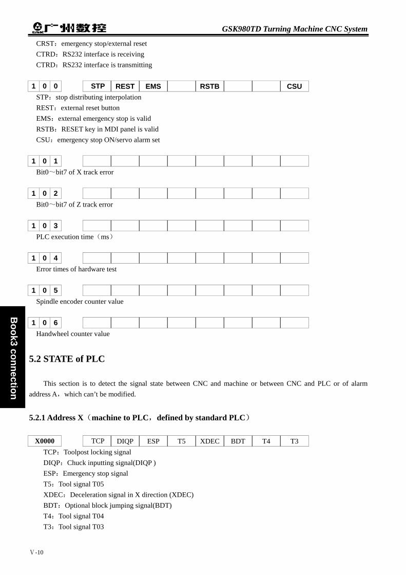
GSK980TD Turning Machine CNC System
Ⅴ-10
Book3 connection
CRST:emergency stop/external reset CTRD:RS232 interface is receiving CTRD:RS232 interface is transmitting
1 0 0 STP REST EMS RSTB CSU STP:stop distributing interpolation REST:external reset button EMS:external emergency stop is valid RSTB:RESET key in MDI panel is valid CSU:emergency stop ON/servo alarm set
1 0 1 Bit0~bit7 of X track error
1 0 2 Bit0~bit7 of Z track error
1 0 3 PLC execution time(ms)
1 0 4 Error times of hardware test
1 0 5 Spindle encoder counter value
1 0 6 Handwheel counter value
5.2 STATE of PLC
This section is to detect the signal state between CNC and machine or between CNC and PLC or of alarm address A,which can’t be modified.
5.2.1 Address X(machine to PLC,defined by standard PLC)
X0000 TCP DIQP ESP T5 XDEC BDT T4 T3 TCP:Toolpost locking signal DIQP:Chuck inputting signal(DIQP ) ESP:Emergency stop signal T5:Tool signal T05 XDEC:Deceleration signal in X direction (XDEC) BDT:Optional block jumping signal(BDT) T4:Tool signal T04 T3:Tool signal T03

Chapter 5 Diagnosis Information
Ⅴ-11
Book3
connection
X0001 T2 T1 T8 SP ZDEC T6 ST T7 T2:Tool signal T02 T1:Tool signal T01 T8:Tool signal T08 SP:External pause signal(SP)/safeguard signal ZDEC:Deceleration signal in Z direction T6:Tool signal T06 ST:External signal for cycle starting(ST) T7:Tool signal T07
X0008 ESP ESP:Emergency stop signal
X0009 ZDEC XDEC ZDEC:Deceleration signal in Z direction XDEC:Deceleration signal in X direction
X0010 XPC XALM XPC:Zero signal in X direction XALM:Driver alarm signal in X direction
X0015 ZPC ZALM ZPC:Zero signal in Z direction ZALM:Driver alarm signal in Z direction
X0020 OBJ SBK JOG HDW MRT MDI AUTO EDIT OBJ:Optional block jumping mode key SBK:Single block mode key JOG:JOG mode key HDW:Handwheel mode key MRP:Reference point return mode key MDI:MDI mode key AUTO:AUTO mode key EDIT:EDIT mode key
X0021 XHW 0.1 0.01 0.001 PRT DYR M.S.T MLK XHW:X handwheel key 0.1:0.1 increment key 0.01:0.01 increment key 0.001:0.001 increment key PRT:Program reference point return mode key DYR:Dry run mode key M.S.T:Auxiliary function locked key MLK:Machine locked key
X0022 ZRG RTR ZLF XUP ZHW YHW

GSK980TD Turning Machine CNC System
Ⅴ-12
Book3 connection
ZRG:"Z (RIGHT)" key in JOG mode RTR:Rapid traverse key in JOG mode ZLF:"Z (LEFT)" key in JOG mode XUP:"X (UP)"key in JOG mode ZHW:Z handwheel key YHW:Y handwheel key
X0023 M4 M32 M5 M8 M3 XDW
M4:M4 key
M32:M32 key
M5:M5 key
M8:M8 key
M3:M3 key
XDW:"X (DOWN)"key in JOG mode
X0024 FDH FO- RO- SO- FO+ RO+ SO+ TCH FDH:Feed hold key FO-:Feedrate override - key RO-:Rapid traverse override- key SO-:Spindle override- key FO+:Feedrate override + key RO+:Rapid traverse override+ key SO+:Spindle override+ key TCH:Manual tool change key X0025 ST ST:Cycle start key X0026 RST
RST:Reset key
5.2.2 Address Y (machine to PLC,defined by standard PLC)
Y0000 SPZD DOQPJ M5 M4 M8 M10 S3 S2
SPZD:Spindle braked signal/Y17 DOQPJ:Chuck clamping signal/Y16
M5:M05
M4:M04
M8:M08
M10:M10
S3:S3/M43/UO2
S2:S2/M42/UO1 Y0001 TL- TL+ DOQPS U4 S4 M3 M32 S1
TL-:Signal of toolpost rotating CCW

Chapter 5 Diagnosis Information
Ⅴ-13
Book3
connection
TL+:Signal of toolpost rotating CW DOQPS:Chuck unclamping signal U4:UO4 signal S4:S04 signal M3:M03 signal S1:S01 signal Y0002 *** *** *** *** *** *** *** *** Signals from PLC to machine Y0003 *** *** *** *** *** *** *** *** Signals from PLC to machine
Y0004
Lamp in machine control panel
Bit7:Lamp for machine reference point return or program reference point return ended in X direction
Bit5:Lamp for machine reference point return or program reference point return ended in Z direction
Bit4:Rapid traverse lamp
Bit3:Single block running lamp
Bit2:Optional block jumping lamp
Bit1:Lamp for machine locked
Bit0:Lamp for auxiliary function locked
Y0005
Lamp in machine control panel Bit7:EDIT mode lamp Bit6:AUTO mode lamp Bit5:MDI mode lamp Bit4:Reference point return mode lamp Bit3:Handwheel/increment mode lamp Bit2:JOG mode lamp Bit1:Spindle CW rotation lamp Bit0:Coolant lamp
Y0006
Lamp in machine control panel Bit7:Single block mode lamp
Bit6:Optional block jumping mode lamp Bit5:Lamp for machine locked Bit4:Lamp for auxiliary function locked Bit3:Dry run lamp Bit2:Program reference point return mode lamp Bit1:Rapid feed lamp Bit0:Spindle stopping lamp

GSK980TD Turning Machine CNC System
Ⅴ-14
Book3 connection
Y0007
Lamp in machine control panel Bit7:Single block mode lamp
Bit6:Optional block jumping mode lamp Bit5:Lamp for machine locked Bit4:Lamp for auxiliary function locked Bit3:Dry run lamp Bit2:Program reference point return mode lamp Bit1:Rapid feed lamp Bit0:Spindle stopping lamp
Y0008
Lamp in machine control panel Bit7:Spindle jogging lamp
Bit6:Max. spindle override lamp Bit5:Min. rapid traverse override lamp Bit4:Max. feedrate override lamp Bit3:Min. spindle override lamp Bit2:Max. rapid traverse override lamp Bit1:Min. feedrate override lamp Bit0:Cycle start lamp
Y0009 *** *** *** *** *** *** Bit1:Dry run lamp in MDI panel
Bit0:Feed pausing lamp in machine control panel
Y0010 *** *** *** *** *** *** *** XEN1 XEN1:Driver enabling signal 1 in X direction
Y0011 *** *** *** *** *** *** XSET XEN2 XSET:Driver move signal in X direction XEN2:Driver enabling signal 2 in X direction
Y0012 *** *** *** *** *** *** *** ***
Signals from PLC to machine Y0013 *** *** *** *** *** *** *** ***
Signals from PLC to machine
Y0014 *** *** *** *** *** *** *** ZEN1 ZEN1:Driver enabling signal 1 in Z direction
Y0015 *** *** *** *** *** *** ZSET ZEN2 ZSET:Driver move signal in Z direction ZEN2:Driver enabling signal 2 in Z direction

Chapter 5 Diagnosis Information
Ⅴ-15
Book3
connection
Y0016 *** *** *** *** *** *** *** *** Signals from PLC to machine
Y0017 *** *** *** *** *** *** *** ***
Signals from PLC to machine Y0018 *** *** *** *** *** *** *** ***
Signals from PLC to machine
Y0019 *** *** *** *** *** *** *** *** Reserved
5.2.3 Address F(CNC to PLC)
F0000 OP SA STL SPL *** *** *** ***
OP:Running signal in AUTO mode SA:Servo ready signal STL:Signal of cycle starting lamp SPL:Signal of feedrate pausing lamp
F0001 MA *** TAP ENB DEN *** RST AL
MA: CNC ready signal TAP:Tapping signal ENB:Spindle enabling signal DEN:Distribution ending signal RST:Reset signal AL:Alarm signal
F0002 MDRN CUT *** SRNMV THRD CSS RPDO ***
MDRN:Signal of Dry run mode detecting CUT:Cutting feed signal SRNMV:Program starting signal THRD:Thread cutting signal CSS:Constant surface speed signal RPDO:Rapid traverse signal
F0003 *** MEDT MMEM *** MMDI MJ MH MINC
MEDT:Detection signal of EDIT mode selecting MMEM:Detection signal of AUTO mode selecting MMDI:Detection signal of MDI mode selection MJ:Detection signal of JOG mode selection MH:Detection signal of Handwheel mode selection MINC:Detection signal of Increment mode selection
F0004 *** MPST MREF MAFL MSBK MABSM MMLK MBDT1
MPST:Detection signal of Program reference point return
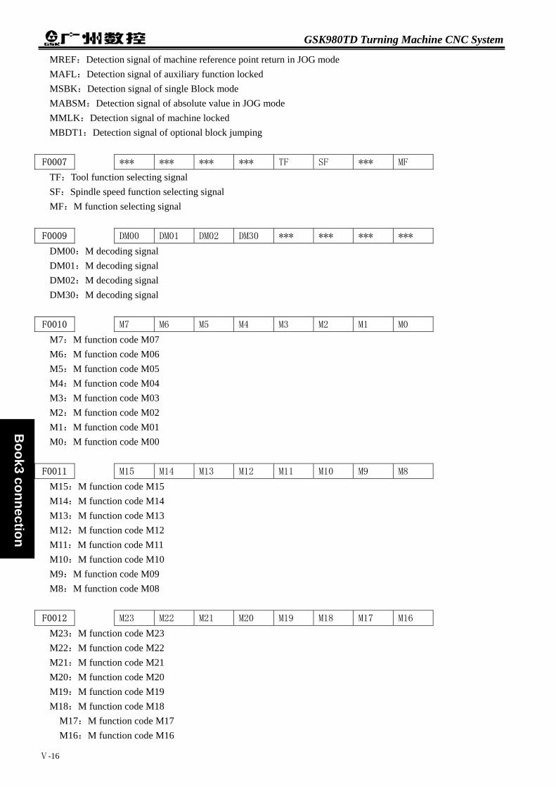
GSK980TD Turning Machine CNC System
Ⅴ-16
Book3 connection
MREF:Detection signal of machine reference point return in JOG mode MAFL:Detection signal of auxiliary function locked MSBK:Detection signal of single Block mode MABSM:Detection signal of absolute value in JOG mode MMLK:Detection signal of machine locked MBDT1:Detection signal of optional block jumping
F0007 *** *** *** *** TF SF *** MF
TF:Tool function selecting signal SF:Spindle speed function selecting signal MF:M function selecting signal
F0009 DM00 DM01 DM02 DM30 *** *** *** *** DM00:M decoding signal DM01:M decoding signal DM02:M decoding signal DM30:M decoding signal
F0010 M7 M6 M5 M4 M3 M2 M1 M0
M7:M function code M07 M6:M function code M06 M5:M function code M05 M4:M function code M04 M3:M function code M03 M2:M function code M02 M1:M function code M01 M0:M function code M00
F0011 M15 M14 M13 M12 M11 M10 M9 M8
M15:M function code M15 M14:M function code M14 M13:M function code M13 M12:M function code M12 M11:M function code M11 M10:M function code M10 M9:M function code M09 M8:M function code M08
F0012 M23 M22 M21 M20 M19 M18 M17 M16
M23:M function code M23 M22:M function code M22 M21:M function code M21 M20:M function code M20 M19:M function code M19 M18:M function code M18
M17:M function code M17 M16:M function code M16
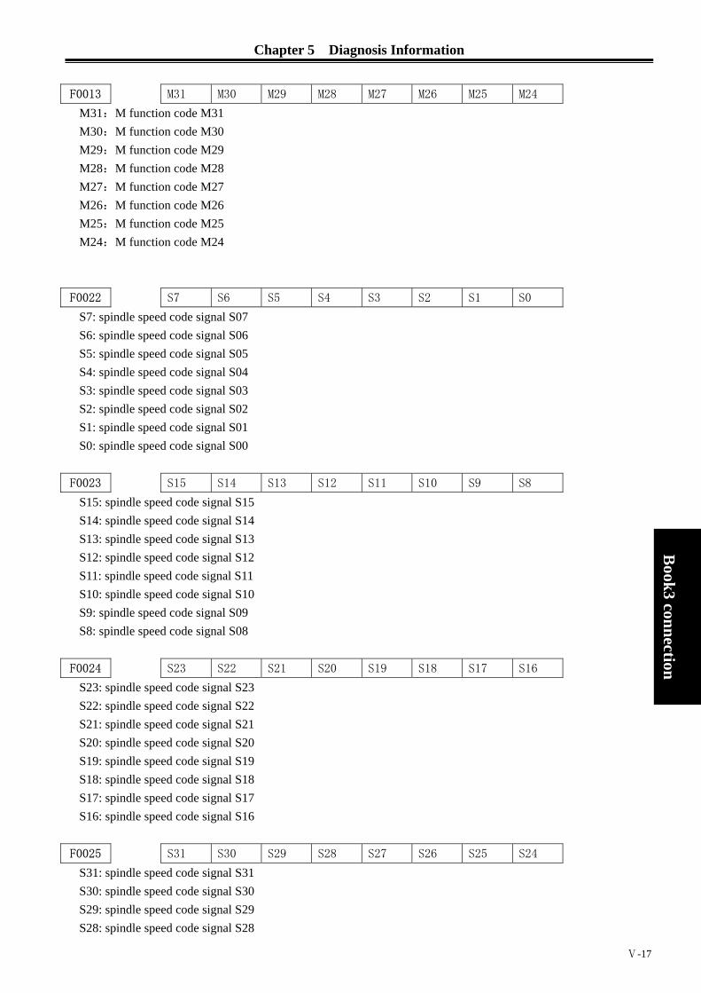
Chapter 5 Diagnosis Information
Ⅴ-17
Book3
connection
F0013 M31 M30 M29 M28 M27 M26 M25 M24
M31:M function code M31 M30:M function code M30 M29:M function code M29 M28:M function code M28 M27:M function code M27 M26:M function code M26 M25:M function code M25 M24:M function code M24
F0022 S7 S6 S5 S4 S3 S2 S1 S0
S7: spindle speed code signal S07 S6: spindle speed code signal S06 S5: spindle speed code signal S05 S4: spindle speed code signal S04 S3: spindle speed code signal S03 S2: spindle speed code signal S02 S1: spindle speed code signal S01 S0: spindle speed code signal S00
F0023 S15 S14 S13 S12 S11 S10 S9 S8
S15: spindle speed code signal S15 S14: spindle speed code signal S14 S13: spindle speed code signal S13 S12: spindle speed code signal S12 S11: spindle speed code signal S11 S10: spindle speed code signal S10 S9: spindle speed code signal S09 S8: spindle speed code signal S08
F0024 S23 S22 S21 S20 S19 S18 S17 S16
S23: spindle speed code signal S23 S22: spindle speed code signal S22 S21: spindle speed code signal S21 S20: spindle speed code signal S20 S19: spindle speed code signal S19 S18: spindle speed code signal S18 S17: spindle speed code signal S17 S16: spindle speed code signal S16
F0025 S31 S30 S29 S28 S27 S26 S25 S24
S31: spindle speed code signal S31 S30: spindle speed code signal S30 S29: spindle speed code signal S29 S28: spindle speed code signal S28

GSK980TD Turning Machine CNC System
Ⅴ-18
Book3 connection
S27: spindle speed code signal S27 S26: spindle speed code signal S26 S25: spindle speed code signal S25 S24: spindle speed code signal S24
F0026 T7 T6 T5 T4 T3 T2 T1 T0
T7: T function code T07 T6: T function code T06 T5: T function code T05 T4: T function code T04 T3: T function code T03 T2: T function code T02 T1: T function code T01 T0: T function code T00
F0027 T15 T14 T13 T12 T11 T10 T9 T8
T15: T function code T15 T14: T function code T14 T13: T function code T13 T12: T function code T12 T11: T function code T11 T10: T function code T10 T9: T function code T09 T8: T function code T08
F0028 T23 T22 T21 T20 T19 T18 T17 T16
T23: T function code T23 T22: T function code T22 T21: T function code T21 T20: T function code T20 T19: T function code T19 T18: T function code T18 T17: T function code T17 T16: T function code T16
F0029 T31 T30 T29 T28 T27 T26 T25 T24
T31: T function code T31 T30: T function code T30 T29: T function code T29 T28: T function code T28 T27: T function code T27 T26: T function code T26 T25: T function code T25 T24: T function code T24
F0036 R08O R07O R06O R05O R04O R03O R02O R01O
R08O: S 12-bit code signal R08O

Chapter 5 Diagnosis Information
Ⅴ-19
Book3
connection
R07O: S 12-bit code signal R07O R06O: S 12-bit code signal R06O R05O: S 12-bit code signal R05O R04O: S 12-bit code signal R04O R03O: S 12-bit code signal R03O R02O: S 12-bit code signal R02O R01O: S 12-bit code signal R01O
F0037 *** *** *** *** R12O R11O R10O R09O
R12O: S 12-bit code signal R12O R11O: S 12-bit code signal R11O R10O: S 12-bit code signal R10O R09O: S 12-bit code signal R09O
F0053 *** *** *** BGEACT *** *** *** *** BGEACT:Background busy signal F0054 UO7 UO6 UO5 UO4 UO3 UO2 UO1 UO0
UO7: Custom macro output signal UO07 UO6: Custom macro output signal UO06 UO5: Custom macro output signal UO05 UO4: Custom macro output signal UO04 UO3: Custom macro output signal UO03 UO2: Custom macro output signal UO02 UO1: Custom macro output signal UO01 UO0: Custom macro output signal UO00
F0055 UO15 UO14 UO13 UO12 UO11 UO10 UO9 UO8
UO15: Custom macro output signal UO15 UO14: Custom macro output signal UO14 UO13: Custom macro output signal UO13 UO12: Custom macro output signal UO12 UO11: Custom macro output signal UO11 UO10: Custom macro output signal UO10 UO9: Custom macro output signal UO09 UO8: Custom macro output signal UO08
F0056 U107 U106 U105 U104 U103 U102 U101 U100
U107: Custom macro output signal UO107 U106: Custom macro output signal UO106 U105: Custom macro output signal UO105 U104: Custom macro output signal UO104 U103: Custom macro output signal UO103 U102: Custom macro output signal UO102 U101: Custom macro output signal UO101 U100: Custom macro output signal UO100

GSK980TD Turning Machine CNC System
Ⅴ-20
Book3 connection
F0057 U115 U114 U113 U112 U111 U110 U109 U108
U115: Custom macro output signal UO115 U114: Custom macro output signal UO114 U113: Custom macro output signal UO113 U112: Custom macro output signal UO112 U111: Custom macro output signal UO111 U110: Custom macro output signal UO110 U109: Custom macro output signal UO109 U108: Custom macro output signal UO108
F0058 U123 U122 U121 U120 U119 U118 U117 U116
U123: Custom macro output signal UO123 U122: Custom macro output signal UO122 U121: Custom macro output signal UO121 U120: Custom macro output signal UO120 U119: Custom macro output signal UO119 U118: Custom macro output signal UO118 U117: Custom macro output signal UO117 U116: Custom macro output signal UO116
F0059 U131 U130 U129 U128 U127 U126 U125 U124
U131: Custom macro output signal UO131 U130: Custom macro output signal UO130 U129: Custom macro output signal UO129 U128: Custom macro output signal UO128 U127: Custom macro output signal UO127 U126: Custom macro output signal UO126 U125: Custom macro output signal UO125 U124: Custom macro output signal UO124
F0065 *** *** *** *** *** *** RGSPM RGSPP
RGSPM:Spindle rotating CCW in rigid tapping RGSPP:Spindle rotating CW in rigid tapping
F0070 PSW8 PSW7 PSW6 PSW5 PSW4 PSW3 PSW2 PSW1
PSW8: Position switch signal PSW8 PSW7: Position switch signal PSW7 PSW6: Position switch signal PSW6 PSW5: Position switch signal PSW5 PSW4: Position switch signal PSW4 PSW3: Position switch signal PSW3 PSW2: Position switch signal PSW2 PSW1:Position switch signal PSW1
F0071 *** *** *** *** *** *** PSW10 PSW9
PSW10: Position switch signal PSW10 PSW9:Position switch signal PSW9
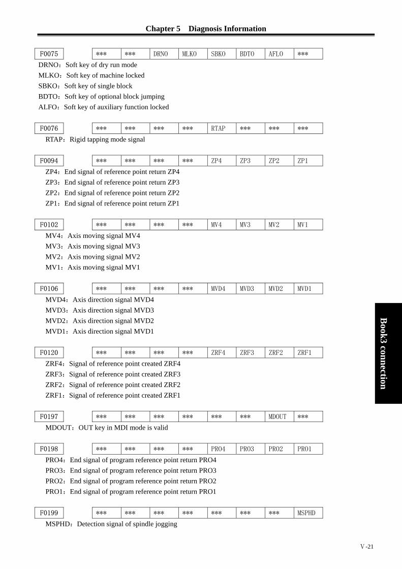
Chapter 5 Diagnosis Information
Ⅴ-21
Book3
connection
F0075 *** *** DRNO MLKO SBKO BDTO AFLO ***
DRNO:Soft key of dry run mode MLKO:Soft key of machine locked SBKO:Soft key of single block BDTO:Soft key of optional block jumping ALFO:Soft key of auxiliary function locked
F0076 *** *** *** *** RTAP *** *** ***
RTAP:Rigid tapping mode signal
F0094 *** *** *** *** ZP4 ZP3 ZP2 ZP1
ZP4:End signal of reference point return ZP4 ZP3:End signal of reference point return ZP3 ZP2:End signal of reference point return ZP2 ZP1:End signal of reference point return ZP1
F0102 *** *** *** *** MV4 MV3 MV2 MV1
MV4:Axis moving signal MV4 MV3:Axis moving signal MV3 MV2:Axis moving signal MV2 MV1:Axis moving signal MV1
F0106 *** *** *** *** MVD4 MVD3 MVD2 MVD1
MVD4:Axis direction signal MVD4 MVD3:Axis direction signal MVD3 MVD2:Axis direction signal MVD2 MVD1:Axis direction signal MVD1
F0120 *** *** *** *** ZRF4 ZRF3 ZRF2 ZRF1
ZRF4:Signal of reference point created ZRF4 ZRF3:Signal of reference point created ZRF3 ZRF2:Signal of reference point created ZRF2 ZRF1:Signal of reference point created ZRF1
F0197 *** *** *** *** *** *** MDOUT *** MDOUT:OUT key in MDI mode is valid
F0198 *** *** *** *** PRO4 PRO3 PRO2 PRO1
PRO4:End signal of program reference point return PRO4 PRO3:End signal of program reference point return PRO3 PRO2:End signal of program reference point return PRO2 PRO1:End signal of program reference point return PRO1
F0199 *** *** *** *** *** *** *** MSPHD
MSPHD:Detection signal of spindle jogging

GSK980TD Turning Machine CNC System
Ⅴ-22
Book3 connection
F0200 *** *** *** SIMSPL *** *** *** *** SIMSPL:Analog spindle is valid
F0201 *** *** DECI *** *** DCS *** *** DECI:Level selecting of DEC signal in reference point return DCS:Whether [OUT] key can start programs in MDI mode
F0203 *** *** *** OVRI *** *** *** *** OVRI:Override canceling is valid
F0204 *** *** *** *** RSJG *** *** ***
RSJG:Function selecting of [RESET] for output port
F0205 *** *** *** *** *** ZNIK TSGN TCPS
ZNIK:Axis moving key held is valid as reference point return TSGN:Level selecting of T* signal TCPS:Level selecting of *TCP signal
F0207 *** *** *** *** *** *** *** *** Total tool numbers Bit0: Bit 0 of tool number Bit1: Bit 1 of tool number Bit2: Bit 2 of tool number Bit3: Bit 3 of tool number Bit4: Bit 4 of tool number Bit5: Bit 5 of tool number Bit6: Bit 6 of tool number Bit7: Bit 7 of tool number
F0208 *** AGER AGIN AGIM *** SPEN SLTW SLSP SLQP
SLQP: Chuck control is valid/invalid SLSP: Whether chuck clamped is detected or not SLTW: Tailstock control is valid/invalid SPEN: Input signal of spindle rotation AGIM: Valid level for M41I,M42I AGIN: Detect gear shifting in-position signal AGER: Spindle gears automatically
F0209 *** SPB4 PB4 SPB3 PB3 *** PB2 *** PB1
PB1: Select chuck mode PB2: Detect chuck in-position signal PB3: Valid function of checking low pressure SPB3: Alarm level for low pressure PB4: Safeguard is valid SPB4: Level for closing safeguard
F0210 *** MST MSP *** MESP *** *** SOVI

Chapter 5 Diagnosis Information
Ⅴ-23
Book3
connection
SOVI:External feedrate override switch(T05-T08) MESP:Shield external emergency stop signal MSP: Shield external pause signal MST: Shield external start signal
F0211 *** *** *** *** *** *** SINC SUOS
SUOS:Selection for S code/macro output SINC:Selection for handwheel/increment 0.1
F0212 *** *** *** COVL CINP CDWL *** *** CDWL: G04 is being executed CINP: Bit checking is executed COVL: Override is 0%
F0213 *** *** *** *** *** *** CTRD CTPU
CTPU: RS232 interface is transmitting CTRD: RS232 interface is receiving
F0214 SPHD *** *** *** *** *** ZVAL XVAL
XVAL: Selecting X direction ZVAL: Selecting Z direction SPHD:Spindle jogging/lubrication ON
5.2.4 Address G(PLC to CNC)
G0004 FIN
FIN:Signal of auxiliary function ended
G0005 AFL
AFL:Signal of auxiliary function locked
G0006 SKIPP OVC ABSM SRN
SRN: Program restarting signal ABSM: Absolute value signal in JOG OVC: Feedrate override cancelling signal SKIPP: Jumping signal
G0007 RLSOT EXLM ST STLK
STLK: Start function locking signal ST: Cycle start signal EXLM: Stored overtravel selecting signal RLSOT: Overtravel releasing signal
G0008 ERS SP ESP IT
IT: Interlocking signal ESP: Emergency stop signal SP: Feedrate pausing signal
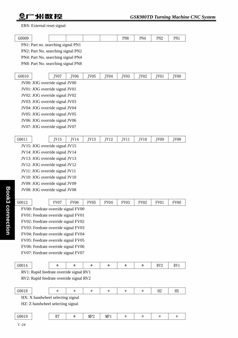
GSK980TD Turning Machine CNC System
Ⅴ-24
Book3 connection
ERS: External reset signal
G0009 PN8 PN4 PN2 PN1
PN1: Part no. searching signal PN1 PN2: Part No. searching signal PN2 PN4: Part No. searching signal PN4 PN8: Part No. searching signal PN8
G0010 JV07 JV06 JV05 JV04 JV03 JV02 JV01 JV00
JV00: JOG override signal JV00 JV01: JOG override signal JV01 JV02: JOG override signal JV02 JV03: JOG override signal JV03 JV04: JOG override signal JV04 JV05: JOG override signal JV05 JV06: JOG override signal JV06 JV07: JOG override signal JV07
G0011 JV15 JV14 JV13 JV12 JV11 JV10 JV09 JV08
JV15: JOG override signal JV15 JV14: JOG override signal JV14 JV13: JOG override signal JV13 JV12: JOG override signal JV12 JV11: JOG override signal JV11 JV10: JOG override signal JV10 JV09: JOG override signal JV09 JV08: JOG override signal JV08
G0012 FV07 FV06 FV05 FV04 FV03 FV02 FV01 FV00
FV00: Feedrate override signal FV00 FV01: Feedrate override signal FV01 FV02: Feedrate override signal FV02 FV03: Feedrate override signal FV03 FV04: Feedrate override signal FV04 FV05: Feedrate override signal FV05 FV06: Feedrate override signal FV06 FV07: Feedrate override signal FV07
G0014 * * * * * * RV2 RV1
RV1: Rapid feedrate override signal RV1 RV2: Rapid feedrate override signal RV2
G0018 * * * * * * HZ HX
HX: X handwheel selecting signal HZ: Z handwheel selecting signal
G0019 RT * MP2 MP1 * * * *

Chapter 5 Diagnosis Information
Ⅴ-25
Book3
connection
MP1: Handwheel override signal MP1 MP2: Handwheel override signal MP2 RT: Rapid feedrate selecting signal in JOG mode
G0028 * * * * * GR2 GR1 *
GR2:Gear selecting signal GR1:Gear selecting signal
G0029 *SSTP SAR
*SSTP:Spindle speed reaching signal SAR:Spindle stopping signal
G0030 SOV7 SOV6 SOV5 SOV4 SOV3 SOV2 SOV1 SOV0
SOV0: Spindle override signal SOV1: Spindle override signal SOV2: Spindle override signal SOV3: Spindle override signal SOV4: Spindle override signal SOV5: Spindle override signal SOV6: Spindle override signal SOV7: Spindle override signal
G0032 R08I R07I R06I R05I R04I R03I R02I R01I
R01I: Spindle speed instruction signal R01I R02I: Spindle speed instruction signal R02I R03I: Spindle speed instruction signal R03I R04I: Spindle speed instruction signal R04I R05I: Spindle speed instruction signal R05I R06I: Spindle speed instruction signal R06I R07I: Spindle speed instruction signal R07I R08I: Spindle speed instruction signal R08I
G0033 SIND SGN * * R12I R11I R10I R09I
R09I: Spindle speed instruction signal R09I R10I: Spindle speed instruction signal R10I R11I: Spindle speed instruction signal R11I R12I: Spindle speed instruction signal R12I SGN:Selecting signal of spindle speed instruction polarity SIND:Spindle speed instruction selecting signal
G0043 ZRN * DNC1 * * MD4 MD2 MD1
MD1: Current operating mode selection MD2: Current operating mode selection MD3: Current operating mode selection DNC1:DNC mode selecting signal ZRN: Current operating mode selection

GSK980TD Turning Machine CNC System
Ⅴ-26
Book3 connection
G0044 HDT * * * * * MLK BDT
BDT: Optional block jumping signal MLK: Machine locking signal HDT:Manual tool change signal
G0046 DRN * * * KEY1 * SBK *
SBK: Single block signal KEY1: Memory protecting signal DRN: Dry run signal
G0053 CDZ SMZ * * * * * *
SMZ: Error detection signal CDZ: Chamfering signal
G0054 UI07 UI06 UI05 UI04 UI03 UI02 UI01 UI00
UI00: Custom macro inputting signal UI00 UI01: Custom macro inputting signal UI01 UI02: Custom macro inputting signal UI02 UI03: Custom macro inputting signal UI03 UI04: Custom macro inputting signal UI04 UI05: Custom macro inputting signal UI05 UI06: Custom macro inputting signal UI06 UI07: Custom macro inputting signal UI07
G0055 UI15 UI14 UI13 UI12 UI11 UI10 UI09 UI08
UI15: Custom macro inputting signal UI15 UI14: Custom macro inputting signal UI14 UI13: Custom macro inputting signal UI13 UI12: Custom macro inputting signal UI12 UI11: Custom macro inputting signal UI11 UI10: Custom macro inputting signal UI10 UI09: Custom macro inputting signal UI09 UI08: Custom macro inputting signal UI08
G0061 * * RGTSP2 RGTSP1 * * RGTAP *
RGTAP: Rigid tapping signal RGTSP1: Spindle selecting in rigid tapping RGTSP2: Spindle selecting in rigid tapping
G0070 MRDYA * * * * * * *
MRDYA: Machine ready signal
G0074 * * SFRB SRVB * * * *
SRVB:CW rotating signal in rigid tapping SFRB:CCW rotating signal in rigid tapping

Chapter 5 Diagnosis Information
Ⅴ-27
Book3
connection
G0100 * * * * +J4 +J3 +J2 +J1
+J1:Feedrate axis and direction selecting signal (+J1) +J2:Feedrate axis and direction selecting signal (+J2) +J3:Feedrate axis and direction selecting signal (+J3) +J4:Feedrate axis and direction selecting signal (+J4)
G0102 * * * * -J4 -J3 -J2 -J1
-J1:Feedrate axis and direction selecting signal (-J1) -J2:Feedrate axis and direction selecting signal (-J2) -J3:Feedrate axis and direction selecting signal (-J3) -J4:Feedrate axis and direction selecting signal (-J4)
G0198 * * * * NPOS4 NPOS3 NPOS2 NPOS1
NPOS1:Neglecting signal NPOS1 of position display NPOS2:Neglecting signal NPOS2 of position display NPOS3:Neglecting signal NPOS3 of position display NPOS4:Neglecting signal NPOS4 of position display
G0200 * * * * * * * SPD
SPD:Spindle jogging signal
G0201 NT07 NT06 NT05 NT04 NT03 NT02 NT01 NT00
NT00: Current tool number NT00 NT01: Current tool number NT01 NT02: Current tool number NT02 NT03: Current tool number NT03 NT04: Current tool number NT04 NT05: Current tool number NT05 NT06: Current tool number NT06 NT07: Current tool number NT07
G0202 NT15 NT14 NT13 NT12 NT11 NT10 NT09 NT08
NT08: Current tool number NT08 NT09: Current tool number NT09 NT10: Current tool number NT10 NT11: Current tool number NT11 NT12: Current tool number NT12 NT13: Current tool number NT13 NT14: Current tool number NT14 NT15: Current tool number NT15
G0203 NT23 NT22 NT21 NT20 NT19 NT18 NT17 NT16
NT16: Current tool number NT16 NT17: Current tool number NT17 NT18: Current tool number NT18 NT19: Current tool number NT19

GSK980TD Turning Machine CNC System
Ⅴ-28
Book3 connection
NT20: Current tool number NT20 NT21: Current tool number NT21 NT22: Current tool number NT22 NT23: Current tool number NT23
G0204 NT31 NT30 NT29 NT28 NT27 NT26 NT25 NT24
NT24: Current tool number NT24 NT25: Current tool number NT25 NT26: Current tool number NT26 NT27: Current tool number NT27 NT28: Current tool number NT28 NT29: Current tool number NT29 NT30: Current tool number NT30 NT31: Current tool number NT31
5.2.5 Address A(information-asking for signal,defined by standard PLC)
地址 内 容 A0000.0 Tool change time is too long A0000.1 Alarm of tool being not in-position at the end of tool change A0000.2 Alarm of unfinished tool change A0001.0 Tailstock function is invalid and M10、M11 can’t be executed A0001.1 Tailstock can’t be receded under spindle rotating A0001.4 Cycle start enabling is closed and cycle can’t be started A0001.5 Spindle start enabling is closed and spindle can’t be started A0002.0 Safeguard opening alarm A0002.1 Low pressure alarm of chuck A0002.3 Chuck can’t be unclamped under spindle rotating A0002.4 Alarm of invalid clamping in-position signal under spindle
rotation A0002.5 Spindle can’t be started when clamping in-position signal of
chuck is invalid A0002.6 Spindle can’t be started when chuck is unclamped A0003.0 Chuck function is invalid and M12、M13 can’t be executed A0004.0 Illegal M code A0004.1 Spindle jogging is invalid under non-analogous spindle A0004.2 Setting error for M03 and M04 A0005.0 Setting error for No.164、168、172 parameters
5.3 PLC DATA
5.3.1 Timer Address(T,defined by standard PLC)
Address Meaning T0002 Timing for M3,4,5,8,9,10,11,32,33 executed

Chapter 5 Diagnosis Information
Ⅴ-29
Book3
connection
Address Meaning T0003 Timing for liberation/jogging output T0004 Timing for from TL+ ceased to TL- output T0005 Timing for TL- output T0006 Timing for S code executed T0007 Timing for M01,02,30executed T0020 Timing for tool change T0021 Delay for M05 output T0022 Timing for M05 ceased to SPZD output T0023 Timing for SPZD output T0025 Timing for closing former gear-shift time T0026 Timing for new gear-shift output to FIN output T0027 Timing for spindle CW jogging T0028 Timing for spindle CCW jogging T0040 Timing for low pressure alarm T0050 Timing for M12,M13 executed
5.3.2 Counter Address(C,defined by standard PLC)
Address Meaning C0001 Counting for rapid override in MDI panel decreased C0002 Counting for rapid override in MDI panel increased C0003 Counting turn for coolant input signal C0004 Counting for feedrate override in MDI panel decreased C0005 Counting for feedrate override in MDI panel increased C0006 Counting for spindle override in MDI panel decreased C0007 Counting for spindle override in MDI panel increased C0008 Counting turn for lubrication input signal C009 Counting turn for manual rapid traverse input signal
C0010 Counting turn for auxiliary function locked input signal C0011 Counting turn for machine locked input signal C0012 Counting turn for dry run input signal C0013 Counting turn for single block input signal C0014 Counting turn for optional block jumping input signal C0015 Counting turn for spindle jogging input signal C0016 Counting for manual feed in MDI panel decreased C0017 Counting for manual feed in MDI panel increased C0018 Counting turn for chuck control input signal C0019 Counting turn for tailstock control input signal C0020 Counting for two time reset under alarm of unfinished tool change
5.3.3 Counter Pre-setting Value Address(DT,defined by standard PLC)
Address Meaning DT000 Occupied by CNC and modified by No.65 data parameter

GSK980TD Turning Machine CNC System
Ⅴ-30
Book3 connection
Address Meaning DT001 Occupied by CNC and modified by No.66 data parameter DT002 Occupied by CNC and modified by No.69 data parameter DT003 Occupied by CNC and modified by No.76 data parameter DT004 Occupied by CNC and modified by No.78 data parameter DT005 Occupied by CNC and modified by No.80 data parameter DT006 Occupied by CNC and modified by No.81 data parameter DT007 Occupied by CNC and modified by No.82 data parameter DT008 Occupied by CNC and modified by No.83 data parameter DT009 Occupied by CNC and modified by No.85 data parameter DT010 Occupied by CNC and modified by No.87 data parameter DT011 Occupied by CNC and modified by No.89 data parameter DT012 Occupied by CNC and modified by No.108 data parameter DT013 Occupied by CNC and modified by No.112 data parameter DT021 Spindle stopped and chuck enabling delayed
5.3.4 Counter Pre-setting Value Address(DC,defined by standard PLC)
(unused)
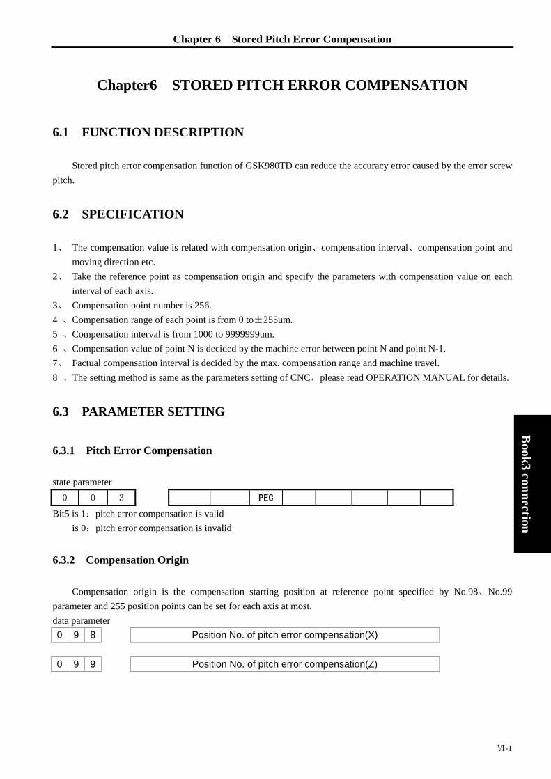
Chapter 6 Stored Pitch Error Compensation
Chapter6 STORED PITCH ERROR COMPENSATION
6.1 FUNCTION DESCRIPTION
Stored pitch error compensation function of GSK980TD can reduce the accuracy error caused by the error screw pitch.
6.2 SPECIFICATION
1、 The compensation value is related with compensation origin、compensation interval、compensation point and moving direction etc.
2、 Take the reference point as compensation origin and specify the parameters with compensation value on each interval of each axis.
3、 Compensation point number is 256. 4 、Compensation range of each point is from 0 to±255um. 5 、Compensation interval is from 1000 to 9999999um. 6 、Compensation value of point N is decided by the machine error between point N and point N-1. 7、 Factual compensation interval is decided by the max. compensation range and machine travel. 8 、The setting method is same as the parameters setting of CNC,please read OPERATION MANUAL for details.
6.3 PARAMETER SETTING
Book3
connection
6.3.1 Pitch Error Compensation
state parameter 0 0 3 PEC
Bit5 is 1:pitch error compensation is valid is 0:pitch error compensation is invalid
6.3.2 Compensation Origin
Compensation origin is the compensation starting position at reference point specified by No.98、No.99 parameter and 255 position points can be set for each axis at most. data parameter 0 9 8 Position No. of pitch error compensation(X)
0 9 9 Position No. of pitch error compensation(Z)
Ⅵ-1
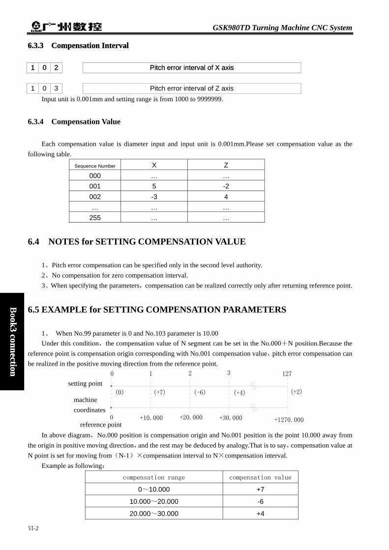
GSK980TD Turning Machine CNC System
6.3.3 Compensation Interval 6.3.3 Compensation Interval
1 1 0 0 2 2 Pitch error interval of X axis Pitch error interval of X axis 1 0 3 Pitch error interval of Z axis
Input unit is 0.001mm and setting range is from 1000 to 9999999.
6.3.4 Compensation Value
Each compensation value is diameter input and input unit is 0.001mm.Please set compensation value as the following table.
Sequence Number X Z 000 … … 001 5 -2 002 -3 4 … … …
255 … …
6.4 NOTES for SETTING COMPENSATION VALUE
1、Pitch error compensation can be specified only in the second level authority. 2、No compensation for zero compensation interval. 3、When specifying the parameters,compensation can be realized correctly only after returning reference point.
Book3 connection
ok3 connection
6.5 EXAMPLE for SETTING COMPENSATION PARAMETERS
1、 When No.99 parameter is 0 and No.103 parameter is 10.00 Under this condition,the compensation value of N segment can be set in the No.000+N position.Because the
reference point is compensation origin corresponding with No.001 compensation value,pitch error compensation can be realized in the positive moving direction from the reference point.
设定点
机床坐标系(参考点)
0 +10.000 +20.000 +30.000
0 1 2 3
(0) (+7) (-6) (+4)
127
+1270.000
(+2)
In above diagram,No.000 position is compensation origin and No.001 position is the point 10.000 away from
the origin in positive moving direction,and the rest may be deduced by analogy.That is to say,compensation value at N point is set for moving from(N-1)×compensation interval to N×compensation interval.
Example as following:
compensation range compensation value
0~10.000 +7
10.000~20.000 -6
20.000~30.000 +4
reference point
machine coordinates
setting point
Ⅵ-2

Chapter 6 Stored Pitch Error Compensation
machine
coordinates
compensation
parameter No.
compensation
value
current pulse No.
before compensation
current pulse No.
after compensation
reference
point 0
000 000 00000 00000
10.000 001 7 10000 10007
20.000 002 -6 20000 20001
30.000 003 4 30000 30005
…… 004 …
In fact,the compensation value for from the origin to +30.000 is that (+7)+(-6)+(+4).
2、 when No.099 parameter is 60 and No.103 parameter is 10.000 Under this condition,the compensation value of N segment can be set in the No.060+N position in moving
positive direction and the compensation value of N segment can be set in the No.061-N position in moving negative direction. Therefore,pitch error compensation can be realized in two directions.
设定点
机床坐标系
(参考点)
0 +10.000-20.000-60.000
58 59 60 61
(-7) (-7) (+6) (+4)
127
+670.000
(+1)(+0)
-10.000
Book3
connection
In above diagram,No.060 position is compensation origin and No.061 position is the point 10.000 away from the origin in positive moving direction,and No.059 position is the point 10.000 away from the origin in negative moving direction.That is to say,compensation value at N point is set for moving from(N-61)×compensation interval to(N-60)×compensation interval.
Example as following:
compensation range compensation value
0~10.000 +4
—10.000~0 +6
—20.000~—10.000 —7
—30.000~—20.000 —7
machine
coordinates
compensation
parameter no.
value current pulse no.
before compensation
current pulse no.
after compensation
-30.000 058 -7 -30000 -29992
-20.000 059 -7 -20000 -19999
-10.000 060 +6 -10000 -10006
reference point
0
0 0
10.000 061 +4 10000 10004
…… 062 …
reference point
machine coordinates
setting point
Ⅵ-3

GSK980TD Turning Machine CNC System
In fact,the compensation value for from –30.000 to +10.000 is that (-7)+(-7)+(+6)+(+4). In fact,the compensation value for from –30.000 to +10.000 is that (-7)+(-7)+(+6)+(+4). 3、 when No.099 parameter is 127 and No.103 parameter is 10.000 3、 when No.099 parameter is 127 and No.103 parameter is 10.000 Under this condition,the compensation value of N segment can be set in the No.128-N position.Because the
reference point is compensation origin corresponding with No.127 compensation value,pitch error compensation can be realized in the negative moving direction from the reference point.
Under this condition,the compensation value of N segment can be set in the No.128-N position.Because the reference point is compensation origin corresponding with No.127 compensation value,pitch error compensation can be realized in the negative moving direction from the reference point.
0-30.000 -20.000
124 125 126 127
(+3) (-7) (0)
Book3 connection
ok3 connection
定点
床标
系
设定点设setting point
机坐标系
机坐
床
-1270.000
(+0)
-10.000
(+2)
(参考点)(参考点)
In above diagram,No.127 position is compensation origin and No.126 position is the point 10.000 away from the origin in negative moving direction,and the rest may be deduced by analogy.That is to say,compensation value at N point is set for moving from(N-128)×compensation interval to(N-127)×compensation interval.
Example as following:
compensation range compensation value
0~—10.000 +2
—20.000~——10.000 0
—30.000~—20.000 —7
—40.000~—30.000 +3
machine coordinates compensation
parameter no.
value current pulse no.
before com.
current pulse no.
after com.
reference point 0 0 0
-10.000 127 2 10000 10002
-20.000 126 0 20000 20002
-30.000 125 -7 30000 29995
-40.000 124 3 40000 39998
machine coordinates
reference point
In fact,the compensation value for from –40.000 to the origin is that (+3)+(-7)+(0)+(+2).
Ⅵ-4

BOOK APPENDIX
APPENDIX
A
ppendix

contents
AppendixⅠ Outline Dimension of GSK980TD.....................................................................appendix -1 AppendixⅡ Outline Dimension of GSK980TD-B.................................................................appendix -2 Appendix Ⅲ Outline Dimension of Accessional Panel AP01...............................................appendix -3 Appendix Ⅳ Outline Dimension of Accessional Panel AP02...............................................appendix -3 Appendix Ⅴ Standard Parameter ..........................................................................................appendix -4 Appendix Ⅵ Alarm Table......................................................................................................appendix -7
A
ppendix
I

Appendix
AppendixⅠ Outline Dimension of GSK980TD AppendixⅠ Outline Dimension of GSK980TD
A
ppendix ppendix
刀补
换刀
点动
润滑
冷却
程序位置
程序零点单段 跳段 辅助锁机床锁 空运行
编辑 自动 机械零点录入 手轮
反转
停止
手动 正转
复位
设置 参数 诊断报警
进给倍率主轴倍率 快速倍率
运行
暂停
插入修改
换行
空格
取消删除
转换
输出
MST
输入
appendix-1
GSK980TD Turning Machine CNC System
AppendixⅡ Outline Dimension of GSK980TD-B AppendixⅡ Outline Dimension of GSK980TD-B
单段 跳段
编辑 自动
辅助锁机床锁
机械零点录入
主轴倍率空运行 程序零点
手轮 手动
反转 换刀
停止
正转
点动
润滑
冷却
刀补位置 程序 报警
快速倍率 进给倍率
运行
暂停
诊断设置 参数
删除修改
换行 插入 取消
复位
转换
空格
输出
MST
输入
,presettingbutton holes
,presetting installingholes for Dongxin MPG
,presetting button holes
distributedevenly
Appendix
pendix
appendix-2

Appendix
Appendix Ⅲ Outline Dimension of Accessional Panel AP01 Appendix Ⅲ Outline Dimension of Accessional Panel AP01 AP01:aluminum alloy 420×71(mm),can be fixed below the panel and the outline dimension as following: AP01:aluminum alloy 420×71(mm),can be fixed below the panel and the outline dimension as following:
,presettingbutton holes
, presettingbutton holes
,presetting installingholes for Dongxin MPG
distributed evenly
Appendix Ⅳ Outline Dimension of Accessional Panel AP02 AP02:aluminum alloy100×260(mm),can be fixed at the side of panel and the outline dimension as following:
A
ppendix ppendix
,presetting installing holes forChangchun MPG
,presetting botton holes
,presettingbutton holes
appendix-3
GSK980TD Turning Machine CNC System
Appendix Ⅴ Standard Parameter
Bit par. Par.1(test) Par.2(step) Par.3(servo) User par.(backup)
001 00000000 00000000 00000000
002 00100010 00100010 00100010
003 00110000 00110000 00110000
004 01000000 00000000 00000000
005 00010011 00010011 00010011
006 00000000 00000000 00000000
*007 00001000 00000000 00000000
008 00000011 00000011 00000011
009 00000000 00000011 00000011
010 00000000 00000111 00001111
011 10000110 10000010 00000010
012 01101011 10101011 10101011
013 00000000 00000000 00000000
014 00000011 00000011 00000011
164 11100101 00000000 00000000
168 00000000 00000000 00000000
172 00000000 00100000 00100000
173 00000000 00000000 00000000
174 00001000 00001000 00001000
*175 00000000 00000000 00000000
176 00000000 00000000 00000000
177 00000000 00000000 00000000
178 00000000 00000000 00000000
179 00000000 00000000 00000000
180 00000000 00000000 00000000
181 00000000 00000000 00000000
182 00000000 00000100 00000100
183 00000000 00000000 00000000
184 00000000 00000000 00000000
185 00000000 00000000 00000000
Data par. Par.1(test) Par.2(step) Par.3(servo) User par.(backup)
015 1 1 1
016 1 1 1
017 1 1 1
018 1 1 1
019 10 5 5
020 0 0 0
021 0 0 0
022 3800 2500 3800
023 7600 5000 7600
*024 200 240 100
*025 200 240 100
*026 100 200 100
*027 8000 8000 8000
*028 500 50 200
Appendix
appendix-4

Appendix
A
ppendix
Data par. Par.1(test) Par.2(step) Par.3(servo) User par.(backup)
*029 100 160 100
*030 10 10 10
031 0 0 0
032 400 400 400
033 200 200 200
034 0 0 0
035 0 0 0
036 0 0 0
037 9999 9999 9999
038 9999 9999 9999
039 9999 9999 9999
040 9999 9999 9999
*041 300 200 400
042 10 10 10
043 99 99 99
044 115200 115200 115200
045 9999999 9999999 9999999
046 9999999 9999999 9999999
047 -9999999 -9999999 -9999999
048 -9999999 -9999999 -9999999
049 0 0 0
050 0 0 0
051 0 0 0
052 0 0 0
053 0 0 0
054 0 0 0
055 0 0 0
056 0 0 0
057 0 0 0
058 0 0 0
059 0 0 0
060 0 0 0
061 0 0 0
062 0 0 0
063 0 0 0
064 0 0 0
065 1000 1000 1000
066 1000 1000 1000
067 100 100 100
068 0 0 0
069 0 0 0
070 1024 1024 1024
071 32 32 32
072 0 0 0
073 0 0 0
074 0 0 0
075 0 0 0
076 1000 1000 1000
077 0 0 0
078 15000 15000 15000
079 0 0 0
appendix-5

GSK980TD Turning Machine CNC System
Appendix
Data par. Par.1(test) Par.2(step) Par.3(servo) User par.(backup)
080 500 500 500
081 500 500 500
082 0 0 0
083 500 500 500
084 4 4 4
085 1000 1000 1000
086 0 0 0
087 0 0 0
088 0 0 0
089 50 50 50
090 0 0 0
091 0 0 0
092 0 0 0
093 0 0 0
094 0 0 0
095 0 0 0
096 0 0 0
097 0 0 0
098 0 0 0
099 0 0 0
100 0 0 0
101 0 0 0
102 10000 10000 10000
103 10000 10000 10000
104 0 0 0
105 0 0 0
106 0 0 0
107 0 0 0
108 3000 3000 3000
109 40 40 40
110 1 1 1
111 1 1 1
112 0 0 0
113 7600 5000 7600
114 0 0 0
115 0 0 0
116 0 0 0
117 0 0 0
118 0 0 0
119 3 3 3
120 0 0 0
121 0 0 0
122 0 0 0
123 0 0 0
124 0 0 0
Note: the parameters with “ *” will infect acceleration and deceleration characterist ic,
and user needs to adjust them according to system configuration and load
characterist ic .
appendix-6

Appendix
Appendix Ⅵ Alarm Table 1、CNC alarm
A
ppendix
Number Content Troubleshooting
000 Emergent stop alarm and ESP open circuit Resume ESP signal input and press【Reset】key
001 There are no part programs or cannot open part programsPress 【Reset】 key and modify programs002 G instruction values are negative or with decimals Press 【Reset】 key and modify programs003 Characters are less than 2 or more than 11 for one word Press 【Reset】 key and modify programs004 Address error (address is A~Z) Press 【Reset】 key and modify programs005 Illegal instruction value Press 【Reset】 key and modify programs
006 Block numbers are negative or with decimals Press 【Reset】 key and modify programs
007 Illegal G instructions Press 【Reset】 key and modify programs
008 Execute G96 when the spindle analog voltage control isinvalid
Press 【Reset】 key and modify programs or parameter No.001
009 Command movement distance when G instructions in 00and 01 groups are not input and there are invalidinstructions in 01 group
Press 【Reset】 key and modify programs
010 There are the same addresses in one block Press 【Reset】 key and modify programs011 There are more than 20 words in one block Press 【Reset】 key and modify programs012 Instruction values exceed their valid range Press 【Reset】 key and modify programs
013 Input S instructions except for S00~S99 when thespindle analog voltage control is invalid
Press 【Reset】 key and modify illegal S instructions
014 Input G instructions in 00 and 01 groups in one block Press 【Reset】 key and modify programs
015 Execute M instructions for spindle automatic gear shifting when the spindle analog voltage control is invalid
Press 【Reset】 key and modify programs
016 Tool offset numbers exceed their valid range(0~32) Press 【Reset】 key and modify programs or parameters
017 Tool number exceeds the range of No.084 parameter Press 【Reset】 key and modify programs or No.084 parameters
018 Data in G02 or G03 cannot form a correct arc Press 【Reset】 key and modify programs030 Movement distance in X direction isn’t zero in G33 Press 【Reset】 key and modify programs
031 G02 or G03 has changed monotony of correspondingcoordinates in G71~G73
Press 【Reset】 key and modify programs
032 Absolute value of R is more than that of U/2 in G90, G92Press 【Reset】 key and modify programs033 Absolute value of R is more than that of W in G94 Press 【Reset】 key and modify programs034 There are more than 100 blocks in G70~G73 Press 【Reset】 key and modify programs035 Ns and Nf are reversed each other in G70~G73 Press 【Reset】 key and modify programs
036 There is no Ns or Nf or they exceed their allowed range in G70~G73
Press 【Reset】 key and modify programs
037 There is no Ns or Nf in G70~G73 Press 【Reset】 key and modify programs038 Single infeed exceeds its allowed range in G71 or G72 Press 【Reset】 key and modify programs
appendix-7

GSK980TD Turning Machine CNC System
Appendix
Number Content Troubleshooting
039 Single tool retraction exceeds its allowed range in G71 orG72
Press 【Reset】 key and modify programs
040 Total cutting travel exceeds its allowed range in G73 Press 【Reset】 key and modify programs041 Cycle times is less than 1 or more than 99999 in G73 Press 【Reset】 key and modify programs
042 Single tool retraction R(e) exceeds its allowed range inG74 or G75
Press 【Reset】 key and modify programs
043 The tool retraction is negative at the end of cutting inG74 or G75
Press 【Reset】 key and modify programs
044 Single cutting value exceeds its allowed range in X or Zdirection in G74 or G75
Press 【Reset】 key and modify programs
045 Starting point of cutting taper thread is between threadstarting point and its end point in G76
Press 【Reset】 key and modify programs
046 Min. cutting value exceeds its allowed range in G76 Press 【Reset】 key and modify programs047 Finishing allowance exceeds its allowed range in G76 Press 【Reset】 key and modify programs048 Tooth height is less than finishing allowance or 0 in G76 Press 【Reset】 key and modify programs049 Cycle times exceeds its allowed range in G76 Press 【Reset】 key and modify programs050 Chamfer exceeds its allowed range in G76 Press 【Reset】 key and modify programs051 Angle of tool nose exceeds its allowed range in G76 Press 【Reset】 key and modify programs052 Movement distance in X, Z direction in G76 is zero Press 【Reset】 key and modify programs053 There is no specified tooth height P in G76 Press 【Reset】 key and modify programs
054 There is no the first cutting depth Q or Q is 0 or Q is not Press 【Reset】 key and modify programsinput
055 Call subprograms in G70~G73 Press 【Reset】 key and modify programs056 Ns does not command G00 or G01 in G70~G73 Press 【Reset】 key and modify programs
057 X value is not specified in the first block or themovement is 0 in G71
Press 【Reset】 key and modify programs
058 Z value is not specified in the first block or themovement is 0 in G72
Press 【Reset】 key and modify programs
059 Z value is not specified in G74 Press 【Reset】 key and modify programs060 Q value is 0 or is not input in G74 Press 【Reset】 key and modify programs061 X value is not specified in G75 Press 【Reset】 key and modify programs062 P value is 0 or is not input in G75 Press 【Reset】 key and modify programs
063 Initial blocks are employed with the forbidden Ginstructions in G70~G73
Press 【Reset】 key and modify programs
064 End blocks are employed with the forbidden Ginstructions in G70~G73
Press 【Reset】 key and modify programs
065 Execute G70~G73 in MDI mode G70~G73 can’t be executed in MDI mode and press 【Reset】 key
095 Subprogram numbers are not input or are illegal whenM98 calls them
Press 【Reset】 key and modify programs
096 Layers of nested subprograms are more than 4 Press 【Reset】 key and modify programs
097 Calling programs in M98 is the current one(mainprogram)
Press 【Reset】 key and modify programs
098 Use M98 or M99 in MDI mode Press 【Reset】 key and modify programs099 Use M98 or M99 in the state of tool radius compensationPress 【Reset】 key and modify programs
appendix-8

Appendix
A
ppendix
Number Content Troubleshooting
101 Operation values of H11, H12, H13, H25 are not binaryin G65
Press 【Reset】 key and modify programs
102 Operation value of H24 is more than 1023 in G65 Press 【Reset】 key and modify programs103 Denominator is 0 for division operation in G65 Press 【Reset】 key and modify programs104 G65 commands illegal H instruction Press 【Reset】 key and modify programs105 Macro variable number of G65 is illegal(error) Press 【Reset】 key and modify programs
106 Macro variable P is not commanded or P value is zero in G65
Press 【Reset】 key and modify programs
107 Variable Q is not commanded or Q value is zero when H instructions except for H80 or H99 are commanded
Press 【Reset】 key and modify programs
108 Do not command variable R or R is illegal Press 【Reset】 key and modify programs109 P instruction value isn’t variable in G65 Press 【Reset】 key and modify programs110 Number with H21 in G65 is negative Press 【Reset】 key and modify programs111 H99 user alarm number in G65 exceeds its range Press 【Reset】 key and modify programs
112 Block number of macro instruction (G65)jumping orM99 returning exceeds their range
Press 【Reset】 key and modify programs
113 There is no block number for block jumping orsubprogram returning
Press 【Reset】 key and modify programs
251 Mistake in programming causes an error of tool noseradius compensation
Press 【Reset】 key and modify programs
252 Mistake in programming causes an end point of arcmachining is not on the arc in the course of tool noseradius compensation
Press 【Reset】 key and modify programs
253 Mistake in programming causes there are the samecoordinates for two neighbouring points not to executetool nose radius compensation
Press 【Reset】 key and modify programs
254 Mistake in programming causes there are the samecoordinates between center point and starting point of arcnot to execute tool nose radius compensation
Press 【Reset】 key and modify programs
255 Mistake in programming causes there are the samecoordinates between center point and end point of arc notto execute tool nose radius compensation
Press 【Reset】 key and modify programs
256 Arc radius is less than that of tool nose to cause not to execute tool nose radius compensation
Press 【Reset】 key and modify programs
257 Mistake in programming causes there is not intersection of two arcs of current tool radius in the course of tool nose radius compensation
Press 【Reset】 key and modify programs
258 Specify one arc instruction as executing tool nose radiuscompensation
Press 【Reset】 key and modify programs
259 Specify one arc instruction as canceling tool nose radiuscompensation
Press 【Reset】 key and modify programs
appendix-9

GSK980TD Turning Machine CNC System
Appendix
Number Content Troubleshooting
260 There is excessive cutting as checking tool nose radiuscompensation
Press 【Reset】 key and modify programs
261
Mistake in programming causes there is not intersection between straight line and arc of current tool radius in the course of tool nose radius compensation
Press 【Reset】 key and modify programs
262
Mistake in programming causes there is not intersection between arc and straight line of current tool radius in the course of tool nose radius compensation
Press 【Reset】 key and modify programs
301 Parameter switch has been on Press【Reset】and【Cancel】key simultaneously or close parameter switch
302 CNC initialization is failure Power off and restart 303 Cannot open part programs Reset or power on again 304 Fail to save part programs Reset or power on again 305 Total lines of part program exceed its range(69993) Reset 306 Illegal dictates have been input Reset and input correct dictates 307 Memory capacity is not enough Reset and delete excrescent part programs 308 Program numbers exceed the range Reset or power on again
309 Editing macro program is forbidden under its currentoperation authority
Reset and modify operation password
310 Cannot open PLC programs (ladder) Download PLC programs again(ladder)
311 Edit software version of PLC programs (ladder) isinconsistent
Update software version of GSKCC
312 First-grade PLC program is too long Modify PLC programs(ladder) 313 The edit keyboard or operator panel is failure Press【Reset】or【Cancel】key
314 The memorizer is failure, check it or power on again Press【Reset】key, check it and power on again
401 The program reference point is not specified Press 【Reset】 key and set program reference point with G50
402 Max. spindle speed at some gear is not specified andcheck No.037~No.040
Press 【Reset】key and modify the parameter corresponding to the current gear
403 Run speed is too rapid Press 【Reset】 key and modify program or parameter
404 Feedrate is cancelled owing to spindle stopping Press 【Reset】 key and check the spindle
405 Spindle speed is too low when machining thread Press 【Reset】 key and change the spindle speed
406 Spindle speed is too high when machining thread Press 【Reset】 key and change the spindle speed
407 Fluctuation of spindle speed is excessive whenmachining thread
Press 【Reset】 key and modify No.106 parameter
appendix-10

Appendix
A
ppendix
Number Content Troubleshooting
411 Software overtravel in X positive direction Press 【Reset】 key and move X axis in negative direction
412 Software overtravel in X negative direction Press 【Reset】 key and move X axis in positive direction
413 Software overtravel in Z positive direction Press 【Reset】 key and move Z axis in negative direction
414 Software overtravel in Z negative direction Press 【Reset】 key and move Z axis in positive direction
421 Driver is not ready in X direction Press 【Reset】 key after fault clearance 422 Driver is not ready in Z direction Press 【Reset】 key after fault clearance 426 Driver alarms in X direction Press【Reset】 key after fault clearance 427 Driver alarms in Z direction Press【Reset】 key after fault clearance 440 Emergent stop is failure Power on again
2、Operation prompt
Content Operation with prompt Remark
Memory full Program number exceeds 384 or total memory capacity exceeds
6144KB Error data Input data is out of range
Block exceeding Input block exceeds 255 characters Unallowed input Input data includes unrecognizable characters
Serial interface not connected Doing communication under unconnected serial interface
Communication error Error data transferring Fail to delete blocks Not find object characters during deleting blocks
Fail to search Not find object characters in cursor searching up or down
Line exceeding Limit to the max. lines (69993)of part programs and forbid to add lines
Illegal G Illegal dictates have been input File not existed Not search object part program
File existed Files with same name exist when saving or renaming file Modify in parameter pageWhen modifying parameters in diagnosis page
All prompts will be displayed in bottom left corner of display interface
3、PLC alarm(defined in standard PLC)
Number Content Address 1000 Tool change time is too long A0000.0 1001 Alarm of toolpost not in-position at the end of tool change A0000.1 1002 Alarm of tool change not finished A0000.2 1008 Can’t execute M10 and M11 under invalid tailstock function A0001.0 1009 Can’t retreating tailstock when spindle rotating A0001.1 1012 Can’t start cycle when cycle start enabling is closed A0001.4 1013 Can’t start spindle when spindle start enabling is closed A0001.5
appendix-11

GSK980TD Turning Machine CNC System
Appendix
Number Content Address 1016 Alarm of protection door not closed A0002.0 1017 Chuck low pressure alarm A0002.1 1019 Can’t unclamp chuck when spindle rotating A0002.3 1020 Alarm of invalid clamping in-position signal when spindle rotating A0002.4 1021 Can’t start spindle when clamping in-position signal A0002.5 1022 Can’t start spindle when chuck is unclamped A0002.6 1024 Can’t execute M12 or M13 under invalid chuck function A0003.0 1032 Illegal M code A0004.0 1033 Spindle jogging function is invalid under invalid analog spindle A0004.1 1034 Setting error for M03 and M04 A0004.2 1040 Setting error for No.164,168,172 parameters A0005.0
appendix-12


Add: No.52, 1st . Street, Luochong North Road, Luochongwei, Guangzhou, 510165, China
Website: http://www.gsk.com.cn E-mail: [email protected] Tel: 86-20-81796410/81797922 Fax: 86-20-81993683
All specification and designs are subject to change without notice July. 2006/Edition 2
Suit for software version:V06.03.23 July. 2006/Printing 2