Avid FastServe | Ingest Setup Guide v2019.12
100
Avid® FastServe™ | Ingest Setup Guide Version 2019.12
-
Upload
khangminh22 -
Category
Documents
-
view
0 -
download
0
Transcript of Avid FastServe | Ingest Setup Guide v2019.12

Avid® FastServe™ | Ingest
Setup GuideVersion 2019.12

Legal NoticesProduct specifications are subject to change without notice and do not represent a commitment on the part of Avid Technology, Inc.
This product is subject to the terms and conditions of a software license agreement provided with the software. The product may only be used in accordance with the license agreement.
This product may be protected by one or more U.S. and non-U.S patents. Details are available at www.avid.com/patents.
This document is protected under copyright law. An authorized licensee of may reproduce this publication for the licensee’s own use in learning how to use the software. This document may not be reproduced or distributed, in whole or in part, for commercial purposes, such as selling copies of this document or providing support or educational services to others. This document is supplied as a guide for . Reasonable care has been taken in preparing the information it contains. However, this document may contain omissions, technical inaccuracies, or typographical errors. Avid Technology, Inc. does not accept responsibility of any kind for customers’ losses due to the use of this document. Product specifications are subject to change without notice.
Copyright © 2019 Avid Technology, Inc. and its licensors. All rights reserved.
Copyright 2003-2007 of MOG Solutions
The following disclaimer is required by Apple Computer, Inc.:APPLE COMPUTER, INC. MAKES NO WARRANTIES WHATSOEVER, EITHER EXPRESS OR IMPLIED, REGARDING THIS PRODUCT, INCLUDING WARRANTIES WITH RESPECT TO ITS MERCHANTABILITY OR ITS FITNESS FOR ANY PARTICULAR PURPOSE. THE EXCLUSION OF IMPLIED WARRANTIES IS NOT PERMITTED BY SOME STATES. THE ABOVE EXCLUSION MAY NOT APPLY TO YOU. THIS WARRANTY PROVIDES YOU WITH SPECIFIC LEGAL RIGHTS. THERE MAY BE OTHER RIGHTS THAT YOU MAY HAVE WHICH VARY FROM STATE TO STATE.
The following disclaimer is required by Sam Leffler and Silicon Graphics, Inc. for the use of their TIFF library:Copyright © 1988–1997 Sam Leffler Copyright © 1991–1997 Silicon Graphics, Inc.
Permission to use, copy, modify, distribute, and sell this software [i.e., the TIFF library] and its documentation for any purpose is hereby granted without fee, provided that (i) the above copyright notices and this permission notice appear in all copies of the software and related documentation, and (ii) the names of Sam Leffler and Silicon Graphics may not be used in any advertising or publicity relating to the software without the specific, prior written permission of Sam Leffler and Silicon Graphics.
THE SOFTWARE IS PROVIDED “AS-IS” AND WITHOUT WARRANTY OF ANY KIND, EXPRESS, IMPLIED OR OTHERWISE, INCLUDING WITHOUT LIMITATION, ANY WARRANTY OF MERCHANTABILITY OR FITNESS FOR A PARTICULAR PURPOSE.
IN NO EVENT SHALL SAM LEFFLER OR SILICON GRAPHICS BE LIABLE FOR ANY SPECIAL, INCIDENTAL, INDIRECT OR CONSEQUENTIAL DAMAGES OF ANY KIND, OR ANY DAMAGES WHATSOEVER RESULTING FROM LOSS OF USE, DATA OR PROFITS, WHETHER OR NOT ADVISED OF THE POSSIBILITY OF DAMAGE, AND ON ANY THEORY OF LIABILITY, ARISING OUT OF OR IN CONNECTION WITH THE USE OR PERFORMANCE OF THIS SOFTWARE.
The following disclaimer is required by the Independent JPEG Group:This software is based in part on the work of the Independent JPEG Group.
This Software may contain components licensed under the following conditions:Copyright (c) 1989 The Regents of the University of California. All rights reserved.
Redistribution and use in source and binary forms are permitted provided that the above copyright notice and this paragraph are duplicated in all such forms and that any documentation, advertising materials, and other materials related to such distribution and use acknowledge that the software was developed by the University of California, Berkeley. The name of the University may not be used to endorse or promote products derived from this software without specific prior written permission. THIS SOFTWARE IS PROVIDED ``AS IS'' AND WITHOUT ANY EXPRESS OR IMPLIED WARRANTIES, INCLUDING, WITHOUT LIMITATION, THE IMPLIED WARRANTIES OF MERCHANTABILITY AND FITNESS FOR A PARTICULAR PURPOSE.
Copyright (C) 1989, 1991 by Jef Poskanzer.
Permission to use, copy, modify, and distribute this software and its documentation for any purpose and without fee is hereby granted, provided that the above copyright notice appear in all copies and that both that copyright notice and this permission notice appear in supporting documentation. This software is provided "as is" without express or implied warranty.
Copyright 1995, Trinity College Computing Center. Written by David Chappell.
Permission to use, copy, modify, and distribute this software and its documentation for any purpose and without fee is hereby granted, provided that the above copyright notice appear in all copies and that both that copyright notice and this permission notice appear in supporting documentation. This software is provided "as is" without express or implied warranty.
Copyright 1996 Daniel Dardailler.
Permission to use, copy, modify, distribute, and sell this software for any purpose is hereby granted without fee, provided that the above copyright notice appear in all copies and that both that copyright notice and this permission notice appear in supporting documentation, and that the name of Daniel Dardailler not be used in advertising or publicity pertaining to distribution of the software without specific, written prior permission. Daniel Dardailler makes no representations about the suitability of this software for any purpose. It is provided "as is" without express or implied warranty.
Modifications Copyright 1999 Matt Koss, under the same license as above.
Copyright (c) 1991 by AT&T.
2

Permission to use, copy, modify, and distribute this software for any purpose without fee is hereby granted, provided that this entire notice is included in all copies of any software which is or includes a copy or modification of this software and in all copies of the supporting documentation for such software.
THIS SOFTWARE IS BEING PROVIDED "AS IS", WITHOUT ANY EXPRESS OR IMPLIED WARRANTY. IN PARTICULAR, NEITHER THE AUTHOR NOR AT&T MAKES ANY REPRESENTATION OR WARRANTY OF ANY KIND CONCERNING THE MERCHANTABILITY OF THIS SOFTWARE OR ITS FITNESS FOR ANY PARTICULAR PURPOSE.
This product includes software developed by the University of California, Berkeley and its contributors.
The following disclaimer is required by Nexidia Inc.:© 2010 Nexidia Inc. All rights reserved, worldwide. Nexidia and the Nexidia logo are trademarks of Nexidia Inc. All other trademarks are the property of their respective owners. All Nexidia materials regardless of form, including without limitation, software applications, documentation and any other information relating to Nexidia Inc., and its products and services are the exclusive property of Nexidia Inc. or its licensors. The Nexidia products and services described in these materials may be covered by Nexidia's United States patents: 7,231,351; 7,263,484; 7,313,521; 7,324,939; 7,406,415, 7,475,065; 7,487,086 and/or other patents pending and may be manufactured under license from the Georgia Tech Research Corporation USA.
The following disclaimer is required by Paradigm Matrix:Portions of this software licensed from Paradigm Matrix.
The following disclaimer is required by Ray Sauers Associates, Inc.:“Install-It” is licensed from Ray Sauers Associates, Inc. End-User is prohibited from taking any action to derive a source code equivalent of “Install-It,” including by reverse assembly or reverse compilation, Ray Sauers Associates, Inc. shall in no event be liable for any damages resulting from reseller’s failure to perform reseller’s obligation; or any damages arising from use or operation of reseller’s products or the software; or any other damages, including but not limited to, incidental, direct, indirect, special or consequential Damages including lost profits, or damages resulting from loss of use or inability to use reseller’s products or the software for any reason including copyright or patent infringement, or lost data, even if Ray Sauers Associates has been advised, knew or should have known of the possibility of such damages.
The following disclaimer is required by Videomedia, Inc.:“Videomedia, Inc. makes no warranties whatsoever, either express or implied, regarding this product, including warranties with respect to its merchantability or its fitness for any particular purpose.”
“This software contains V-LAN ver. 3.0 Command Protocols which communicate with V-LAN ver. 3.0 products developed by Videomedia, Inc. and V-LAN ver. 3.0 compatible products developed by third parties under license from Videomedia, Inc. Use of this software will allow “frame accurate” editing control of applicable videotape recorder decks, videodisc recorders/players and the like.”
The following disclaimer is required by Altura Software, Inc. for the use of its Mac2Win software and Sample Source Code:©1993–1998 Altura Software, Inc.
The following disclaimer is required by Ultimatte Corporation:Certain real-time compositing capabilities are provided under a license of such technology from Ultimatte Corporation and are subject to copyright protection.
The following disclaimer is required by 3Prong.com Inc.:Certain waveform and vector monitoring capabilities are provided under a license from 3Prong.com Inc.
The following disclaimer is required by Interplay Entertainment Corp.:The “Interplay” name is used with the permission of Interplay Entertainment Corp., which bears no responsibility for Avid products.
This product includes portions of the Alloy Look & Feel software from Incors GmbH.
This product includes software developed by the Apache Software Foundation (http://www.apache.org/).
© DevelopMentor
This product may include the JCifs library, for which the following notice applies:JCifs © Copyright 2004, The JCIFS Project, is licensed under LGPL (http://jcifs.samba.org/). See the LGPL.txt file in the Third Party Software directory on the installation CD.
Avid Interplay contains components licensed from LavanTech. These components may only be used as part of and in connection with Avid Interplay.
This product includes the Warlib library, for which the following notice applies:Copyright Jarle (jgaa) Aase 2000 - 2009
COPYRIGHT file which is included in the distribution:
warlib is copyright Jarle (jgaa) Aase 2000 - 2009
The warlib C++ Library is free software; you can redistribute it and/or modify it under the terms of the GNU Lesser General Public License as published by the Free Software Foundation; either version 3.0 of the License, or (at your option) any later version.
The warlib C++ Library is distributed in the hope that it will be useful, but WITHOUT ANY WARRANTY; without even the implied warranty of MERCHANTABILITY or FITNESS FOR A PARTICULAR PURPOSE. See the GNU Lesser General Public License for more details.
Portions copyright © 2012 Avid Technology, Inc.
3

Attn. Government User(s). Restricted Rights LegendU.S. GOVERNMENT RESTRICTED RIGHTS. This Software and its documentation are “commercial computer software” or “commercial computer software documentation.” In the event that such Software or documentation is acquired by or on behalf of a unit or agency of the U.S. Government, all rights with respect to this Software and documentation are subject to the terms of the License Agreement, pursuant to FAR §12.212(a) and/or DFARS §227.7202-1(a), as applicable.
Trademarks003, 192 Digital I/O, 192 I/O, 96 I/O, 96i I/O, Adrenaline, AirSpeed, ALEX, Alienbrain, AME, AniMatte, Archive, Archive II, Assistant Station, AudioPages, AudioStation, AutoLoop, AutoSync, Avid, Avid Active, Avid Advanced Response, Avid DNA, Avid DNxcel, Avid DNxHD, Avid DS Assist Station, Avid Ignite, Avid Liquid, Avid Media Engine, Avid Media Processor, Avid MEDIArray, Avid Mojo, Avid Remote Response, Avid Unity, Avid Unity ISIS, Avid VideoRAID, AvidRAID, AvidShare, AVIDstripe, AVX, Beat Detective, Beauty Without The Bandwidth, Beyond Reality, BF Essentials, Bomb Factory, Bruno, C|24, CaptureManager, ChromaCurve, ChromaWheel, Cineractive Engine, Cineractive Player, Cineractive Viewer, Color Conductor, Command|24, Command|8, Control|24, Cosmonaut Voice, CountDown, d2, d3, DAE, D-Command, D-Control, Deko, DekoCast, D-Fi, D-fx, Digi 002, Digi 003, DigiBase, Digidesign, Digidesign Audio Engine, Digidesign Development Partners, Digidesign Intelligent Noise Reduction, Digidesign TDM Bus, DigiLink, DigiMeter, DigiPanner, DigiProNet, DigiRack, DigiSerial, DigiSnake, DigiSystem, Digital Choreography, Digital Nonlinear Accelerator, DigiTest, DigiTranslator, DigiWear, DINR, DNxchange, Do More, DPP-1, D-Show, DSP Manager, DS-StorageCalc, DV Toolkit, DVD Complete, D-Verb, Eleven, EM, Euphonix, EUCON, EveryPhase, Expander, ExpertRender, Fader Pack, Fairchild, FastBreak, Fast Track, Film Cutter, FilmScribe, Flexevent, FluidMotion, Frame Chase, FXDeko, HD Core, HD Process, HDpack, Home-to-Hollywood, HYBRID, HyperSPACE, HyperSPACE HDCAM, iKnowledge, Image Independence, Impact, Improv, iNEWS, iNEWS Assign, iNEWS ControlAir, InGame, Instantwrite, Instinct, Intelligent Content Management, Intelligent Digital Actor Technology, IntelliRender, Intelli-Sat, Intelli-sat Broadcasting Recording Manager, InterFX, Interplay, inTONE, Intraframe, iS Expander, iS9, iS18, iS23, iS36, ISIS, IsoSync, LaunchPad, LeaderPlus, LFX, Lightning, Link & Sync, ListSync, LKT-200, Lo-Fi, MachineControl, Magic Mask, Make Anything Hollywood, make manage move | media, Marquee, MassivePack, Massive Pack Pro, Maxim, Mbox, Media Composer, MediaFlow, MediaLog, MediaMix, Media Reader, Media Recorder, MEDIArray, MediaServer, MediaShare, MetaFuze, MetaSync, MIDI I/O, Mix Rack, Moviestar, MultiShell, NaturalMatch, NewsCutter, NewsView, NewsVision, Nitris, NL3D, NLP, NSDOS, NSWIN, OMF, OMF Interchange, OMM, OnDVD, Open Media Framework, Open Media Management, Painterly Effects, Palladium, Personal Q, PET, Podcast Factory, PowerSwap, PRE, ProControl, ProEncode, Profiler, Pro Tools, Pro Tools|HD, Pro Tools LE, Pro Tools M-Powered, Pro Transfer, QuickPunch, QuietDrive, Realtime Motion Synthesis, Recti-Fi, Reel Tape Delay, Reel Tape Flanger, Reel Tape Saturation, Reprise, Res Rocket Surfer, Reso, RetroLoop, Reverb One, ReVibe, Revolution, rS9, rS18, RTAS, Salesview, Sci-Fi, Scorch, ScriptSync, SecureProductionEnvironment, Serv|GT, Serv|LT, Shape-to-Shape, ShuttleCase, Sibelius, SimulPlay, SimulRecord, Slightly Rude Compressor, Smack!, Soft SampleCell, Soft-Clip Limiter, SoundReplacer, SPACE, SPACEShift, SpectraGraph, SpectraMatte, SteadyGlide, Streamfactory, Streamgenie, StreamRAID, SubCap, Sundance, Sundance Digital, SurroundScope, Symphony, SYNC HD, SYNC I/O, Synchronic, SynchroScope, Syntax, TDM FlexCable, TechFlix, Tel-Ray, Thunder, TimeLiner, Titansync, Titan, TL Aggro, TL AutoPan, TL Drum Rehab, TL Everyphase, TL Fauxlder, TL In Tune, TL MasterMeter, TL Metro, TL Space, TL Utilities, tools for storytellers, Transit, TransJammer, Trillium Lane Labs, TruTouch, UnityRAID, Vari-Fi, Video the Web Way, VideoRAID, VideoSPACE, VTEM, Work-N-Play, Xdeck, X-Form, Xmon and XPAND! are either registered trademarks or trademarks of Avid Technology, Inc. in the United States and/or other countries.
Avid FastServe | Ingest Setup Guide v2019.12 • Created 12/18/19 • This document is distributed by Avid in online (electronic) form only, and is not available for purchase in printed form.
4

Contents
Using This Guide . . . . . . . . . . . . . . . . . . . . . . . . . . . . . . . . . . . . . . . . . . . . . . . . . . . . . . . . . . 9Symbols and Conventions . . . . . . . . . . . . . . . . . . . . . . . . . . . . . . . . . . . . . . . . . . . . . . . . . . . . . . . . . . . . 9
Chapter 1 Avid FastServe | Ingest Server Overview . . . . . . . . . . . . . . . . . . . . . . . . . . . . . . . . . . . . . 10Unpacking and Inspecting Your Server . . . . . . . . . . . . . . . . . . . . . . . . . . . . . . . . . . . . . . . . . . . . . . . . . 10
Unpack and Inspect Checklist . . . . . . . . . . . . . . . . . . . . . . . . . . . . . . . . . . . . . . . . . . . . . . . . . . . . 11
Unpacking Your Server . . . . . . . . . . . . . . . . . . . . . . . . . . . . . . . . . . . . . . . . . . . . . . . . . . . . . 11
Inspecting Components for Damage. . . . . . . . . . . . . . . . . . . . . . . . . . . . . . . . . . . . . . . . . . . . 11
Hardware Components. . . . . . . . . . . . . . . . . . . . . . . . . . . . . . . . . . . . . . . . . . . . . . . . . . . . . . . . . . . . . . 12
Linux CentOS 7.4 Server Hardware. . . . . . . . . . . . . . . . . . . . . . . . . . . . . . . . . . . . . . . . . . . . . . . . 12
Front Panel . . . . . . . . . . . . . . . . . . . . . . . . . . . . . . . . . . . . . . . . . . . . . . . . . . . . . . . . . . . . . . . . . . . 12
Determine Media Drive Health by Viewing LED Status . . . . . . . . . . . . . . . . . . . . . . . . . . . . 13
Server Front Panel and LED Control Panel . . . . . . . . . . . . . . . . . . . . . . . . . . . . . . . . . . . . . . 14
Drive Array . . . . . . . . . . . . . . . . . . . . . . . . . . . . . . . . . . . . . . . . . . . . . . . . . . . . . . . . . . . . . . 15
Avid FastServe | Ingest Server - Rear Panel. . . . . . . . . . . . . . . . . . . . . . . . . . . . . . . . . . . . . . . . . . 15
Power Supplies . . . . . . . . . . . . . . . . . . . . . . . . . . . . . . . . . . . . . . . . . . . . . . . . . . . . . . . . . . . . 15
Ethernet Ports . . . . . . . . . . . . . . . . . . . . . . . . . . . . . . . . . . . . . . . . . . . . . . . . . . . . . . . . . . . . . 16
USB Ports . . . . . . . . . . . . . . . . . . . . . . . . . . . . . . . . . . . . . . . . . . . . . . . . . . . . . . . . . . . . . . . . 17
VGA Port . . . . . . . . . . . . . . . . . . . . . . . . . . . . . . . . . . . . . . . . . . . . . . . . . . . . . . . . . . . . . . . . 17
LTC Input . . . . . . . . . . . . . . . . . . . . . . . . . . . . . . . . . . . . . . . . . . . . . . . . . . . . . . . . . . . . . . . . 17
Serial Port . . . . . . . . . . . . . . . . . . . . . . . . . . . . . . . . . . . . . . . . . . . . . . . . . . . . . . . . . . . . . . . . 18
Reference . . . . . . . . . . . . . . . . . . . . . . . . . . . . . . . . . . . . . . . . . . . . . . . . . . . . . . . . . . . . . . . . 18
External Audio . . . . . . . . . . . . . . . . . . . . . . . . . . . . . . . . . . . . . . . . . . . . . . . . . . . . . . . . . . . . 18
UHD Scaler Outputs . . . . . . . . . . . . . . . . . . . . . . . . . . . . . . . . . . . . . . . . . . . . . . . . . . . . . . . . 19
Video Inputs / Outputs . . . . . . . . . . . . . . . . . . . . . . . . . . . . . . . . . . . . . . . . . . . . . . . . . . . . . . 19
Chapter 2 Installing the Server Hardware . . . . . . . . . . . . . . . . . . . . . . . . . . . . . . . . . . . . . . . . . . . . . 25Electrostatic Discharge Precautions . . . . . . . . . . . . . . . . . . . . . . . . . . . . . . . . . . . . . . . . . . . . . . . . . . . . 25
Installing FastServe | Ingest Hardware in a Rack . . . . . . . . . . . . . . . . . . . . . . . . . . . . . . . . . . . . . . . . . 26
Rack-mount Requirements . . . . . . . . . . . . . . . . . . . . . . . . . . . . . . . . . . . . . . . . . . . . . . . . . . . . . . . 26
Positioning the Server in the Rack . . . . . . . . . . . . . . . . . . . . . . . . . . . . . . . . . . . . . . . . . . . . . . . . . 27
Installing the Drives in the Server . . . . . . . . . . . . . . . . . . . . . . . . . . . . . . . . . . . . . . . . . . . . . . . . . . . . . 27
Cabling the Server . . . . . . . . . . . . . . . . . . . . . . . . . . . . . . . . . . . . . . . . . . . . . . . . . . . . . . . . . . . . . . . . . 28
FastServe | Ingest Server Connection Information. . . . . . . . . . . . . . . . . . . . . . . . . . . . . . . . . . . . . 29
Connecting the Power Cords . . . . . . . . . . . . . . . . . . . . . . . . . . . . . . . . . . . . . . . . . . . . . . . . . . . . . 29
Connecting Network. . . . . . . . . . . . . . . . . . . . . . . . . . . . . . . . . . . . . . . . . . . . . . . . . . . . . . . . . . . . 30
Connecting a Keyboard, Monitor, and Mouse . . . . . . . . . . . . . . . . . . . . . . . . . . . . . . . . . . . . . . . . 30
Connecting Video Reference . . . . . . . . . . . . . . . . . . . . . . . . . . . . . . . . . . . . . . . . . . . . . . . . . . . . . 30
5

Connecting LTC - XLR . . . . . . . . . . . . . . . . . . . . . . . . . . . . . . . . . . . . . . . . . . . . . . . . . . . . . . . . . 31
Connecting AES . . . . . . . . . . . . . . . . . . . . . . . . . . . . . . . . . . . . . . . . . . . . . . . . . . . . . . . . . . . . . . . 31
Connecting SDI Video Inputs/Outputs. . . . . . . . . . . . . . . . . . . . . . . . . . . . . . . . . . . . . . . . . . . . . . 31
Turning On the Server . . . . . . . . . . . . . . . . . . . . . . . . . . . . . . . . . . . . . . . . . . . . . . . . . . . . . . . . . . . . . . 32
Setting IPMI Connection . . . . . . . . . . . . . . . . . . . . . . . . . . . . . . . . . . . . . . . . . . . . . . . . . . . . . . . . . . . . 33
Configuring the Remote Console Connection . . . . . . . . . . . . . . . . . . . . . . . . . . . . . . . . . . . . . . . . 35
Setting Up Remote Access to the Server . . . . . . . . . . . . . . . . . . . . . . . . . . . . . . . . . . . . . . . . . . . . 37
How To Use the vim Editor . . . . . . . . . . . . . . . . . . . . . . . . . . . . . . . . . . . . . . . . . . . . . . . . . . . . . . . . . . 38
Chapter 3 Upgrading The Operating System . . . . . . . . . . . . . . . . . . . . . . . . . . . . . . . . . . . . . . . . . . . 39Upgrading Checklist. . . . . . . . . . . . . . . . . . . . . . . . . . . . . . . . . . . . . . . . . . . . . . . . . . . . . . . . . . . . . . . . 39
Backing-up Your System . . . . . . . . . . . . . . . . . . . . . . . . . . . . . . . . . . . . . . . . . . . . . . . . . . . . . . . . . . . . 39
Checking BIOS Configuration . . . . . . . . . . . . . . . . . . . . . . . . . . . . . . . . . . . . . . . . . . . . . . . . . . . . . . . . 40
(Option) Preparing a Boot-able USB Drive . . . . . . . . . . . . . . . . . . . . . . . . . . . . . . . . . . . . . . . . . . . . . . 40
Loading the CentOS 7 Image on Your Server . . . . . . . . . . . . . . . . . . . . . . . . . . . . . . . . . . . . . . . . . . . . 41
Configuration Procedures. . . . . . . . . . . . . . . . . . . . . . . . . . . . . . . . . . . . . . . . . . . . . . . . . . . . . . . . . . . . 42
Assigning an IP Address. . . . . . . . . . . . . . . . . . . . . . . . . . . . . . . . . . . . . . . . . . . . . . . . . . . . . . . . . 42
Updating the Network Configuration File . . . . . . . . . . . . . . . . . . . . . . . . . . . . . . . . . . . . . . . . . . . 43
Installing Kernel . . . . . . . . . . . . . . . . . . . . . . . . . . . . . . . . . . . . . . . . . . . . . . . . . . . . . . . . . . . . . . . 44
Updating BIOS Version . . . . . . . . . . . . . . . . . . . . . . . . . . . . . . . . . . . . . . . . . . . . . . . . . . . . . . . . . 44
Configuring the GRUB File . . . . . . . . . . . . . . . . . . . . . . . . . . . . . . . . . . . . . . . . . . . . . . . . . . . . . . 45
Configuring the Root File. . . . . . . . . . . . . . . . . . . . . . . . . . . . . . . . . . . . . . . . . . . . . . . . . . . . . . . . 45
Installing the Avid OVS Software . . . . . . . . . . . . . . . . . . . . . . . . . . . . . . . . . . . . . . . . . . . . . . . . . . . . . 46
First-time Installation of OVS . . . . . . . . . . . . . . . . . . . . . . . . . . . . . . . . . . . . . . . . . . . . . . . . . . . . 46
Steps Required After OVS Installation . . . . . . . . . . . . . . . . . . . . . . . . . . . . . . . . . . . . . . . . . . . . . 47
Setting the Date, Time and Time Zone on the Server. . . . . . . . . . . . . . . . . . . . . . . . . . . . . . . 47
Setting the CPU Speed . . . . . . . . . . . . . . . . . . . . . . . . . . . . . . . . . . . . . . . . . . . . . . . . . . . . . . 48
Updating the modprobe.conf File . . . . . . . . . . . . . . . . . . . . . . . . . . . . . . . . . . . . . . . . . . . . . . 48
Editing the Codecs File . . . . . . . . . . . . . . . . . . . . . . . . . . . . . . . . . . . . . . . . . . . . . . . . . . . . . . 48
Checking the Hardware Key . . . . . . . . . . . . . . . . . . . . . . . . . . . . . . . . . . . . . . . . . . . . . . . . . . 49
Updating Firmware of DVG Boards. . . . . . . . . . . . . . . . . . . . . . . . . . . . . . . . . . . . . . . . . . . . 50
Updating Your License . . . . . . . . . . . . . . . . . . . . . . . . . . . . . . . . . . . . . . . . . . . . . . . . . . . . . . 50
Restoring the Backup Files . . . . . . . . . . . . . . . . . . . . . . . . . . . . . . . . . . . . . . . . . . . . . . . . . . . 51
Editing the user_pre_VS File . . . . . . . . . . . . . . . . . . . . . . . . . . . . . . . . . . . . . . . . . . . . . . . . . 51
Editing the vsPreferences.cfg File . . . . . . . . . . . . . . . . . . . . . . . . . . . . . . . . . . . . . . . . . . . . . 52
RAID Configuration . . . . . . . . . . . . . . . . . . . . . . . . . . . . . . . . . . . . . . . . . . . . . . . . . . . . . . . . 53
Updating the AvidRegistry . . . . . . . . . . . . . . . . . . . . . . . . . . . . . . . . . . . . . . . . . . . . . . . . . . . 54
Final Steps. . . . . . . . . . . . . . . . . . . . . . . . . . . . . . . . . . . . . . . . . . . . . . . . . . . . . . . . . . . . . . . . 54
Chapter 4 Manually Installing Individual Components. . . . . . . . . . . . . . . . . . . . . . . . . . . . . . . . . . . 55Updating Logrotate . . . . . . . . . . . . . . . . . . . . . . . . . . . . . . . . . . . . . . . . . . . . . . . . . . . . . . . . . . . . . . . . 55
Re-installing NEXIS Client . . . . . . . . . . . . . . . . . . . . . . . . . . . . . . . . . . . . . . . . . . . . . . . . . . . . . . . . . . 56
6
Installing the Latest OVS Build . . . . . . . . . . . . . . . . . . . . . . . . . . . . . . . . . . . . . . . . . . . . . . . . . . . . . . . 57
Updating VSCommander . . . . . . . . . . . . . . . . . . . . . . . . . . . . . . . . . . . . . . . . . . . . . . . . . . . . . . . . . . . . 58
Updating AirSpeedTranslator . . . . . . . . . . . . . . . . . . . . . . . . . . . . . . . . . . . . . . . . . . . . . . . . . . . . . . . . 58
(Option) Increase Log Level in VSCommander and AirSpeedTranslator. . . . . . . . . . . . . . . . . . . . . . . 59
Updating vsWrapper . . . . . . . . . . . . . . . . . . . . . . . . . . . . . . . . . . . . . . . . . . . . . . . . . . . . . . . . . . . . . . . 59
Installing the Proxy Component. . . . . . . . . . . . . . . . . . . . . . . . . . . . . . . . . . . . . . . . . . . . . . . . . . . . . . . 60
Installing the WebSettings Component . . . . . . . . . . . . . . . . . . . . . . . . . . . . . . . . . . . . . . . . . . . . . . . . . 61
Upgrading libdvg . . . . . . . . . . . . . . . . . . . . . . . . . . . . . . . . . . . . . . . . . . . . . . . . . . . . . . . . . . . . . . . . . . 61
Manually Burning DVG Boards Firmware . . . . . . . . . . . . . . . . . . . . . . . . . . . . . . . . . . . . . . . . . . . . . . 62
Chapter 5 Maintaining and Troubleshooting Your Server . . . . . . . . . . . . . . . . . . . . . . . . . . . . . . . . 65Preventative Maintenance . . . . . . . . . . . . . . . . . . . . . . . . . . . . . . . . . . . . . . . . . . . . . . . . . . . . . . . . . . . 65
Working with SNMP Monitoring. . . . . . . . . . . . . . . . . . . . . . . . . . . . . . . . . . . . . . . . . . . . . . . . . . 65
Troubleshooting Your FastServe | Ingest Server . . . . . . . . . . . . . . . . . . . . . . . . . . . . . . . . . . . . . . . . . . 66
Problems with Connecting to the WebSettings . . . . . . . . . . . . . . . . . . . . . . . . . . . . . . . . . . . . . . . 66
Troubleshooting 10GB Connection Issues . . . . . . . . . . . . . . . . . . . . . . . . . . . . . . . . . . . . . . . . . . . 66
RAID Recovery . . . . . . . . . . . . . . . . . . . . . . . . . . . . . . . . . . . . . . . . . . . . . . . . . . . . . . . . . . . . . . . 66
Changing the Timezone Manually . . . . . . . . . . . . . . . . . . . . . . . . . . . . . . . . . . . . . . . . . . . . . . . . . 68
RPM Database Recovery Procedure. . . . . . . . . . . . . . . . . . . . . . . . . . . . . . . . . . . . . . . . . . . . . . . . 69
Removing and Replacing the Server Main Cover . . . . . . . . . . . . . . . . . . . . . . . . . . . . . . . . . . . . . 69
Replacing Power Modules . . . . . . . . . . . . . . . . . . . . . . . . . . . . . . . . . . . . . . . . . . . . . . . . . . . . . . . 70
Identifying and Replacing Failed Fans. . . . . . . . . . . . . . . . . . . . . . . . . . . . . . . . . . . . . . . . . . . . . . 71
Replacing Failed DVG Boards . . . . . . . . . . . . . . . . . . . . . . . . . . . . . . . . . . . . . . . . . . . . . . . . . . . . 72
Replacing Failed PHY Boards . . . . . . . . . . . . . . . . . . . . . . . . . . . . . . . . . . . . . . . . . . . . . . . . . . . . 74
Replacing Failed RAID Controller. . . . . . . . . . . . . . . . . . . . . . . . . . . . . . . . . . . . . . . . . . . . . . . . . 76
Replacing System Drives in the Chassis . . . . . . . . . . . . . . . . . . . . . . . . . . . . . . . . . . . . . . . . . . . . 78
Accessing the Knowledge Base . . . . . . . . . . . . . . . . . . . . . . . . . . . . . . . . . . . . . . . . . . . . . . . . . . . . . . . 79
Appendix A Specifications and Notices . . . . . . . . . . . . . . . . . . . . . . . . . . . . . . . . . . . . . . . . . . . . . . . . . . 80Dimensions and Weight . . . . . . . . . . . . . . . . . . . . . . . . . . . . . . . . . . . . . . . . . . . . . . . . . . . . . . . . . . . . . 80
Environmental Specifications . . . . . . . . . . . . . . . . . . . . . . . . . . . . . . . . . . . . . . . . . . . . . . . . . . . . . . . . 81
Power Specifications . . . . . . . . . . . . . . . . . . . . . . . . . . . . . . . . . . . . . . . . . . . . . . . . . . . . . . . . . . . . . . . 81
Video Channel Specifications . . . . . . . . . . . . . . . . . . . . . . . . . . . . . . . . . . . . . . . . . . . . . . . . . . . . . . . . 81
Channel Configuration . . . . . . . . . . . . . . . . . . . . . . . . . . . . . . . . . . . . . . . . . . . . . . . . . . . . . . . . . . 81
Video Inputs . . . . . . . . . . . . . . . . . . . . . . . . . . . . . . . . . . . . . . . . . . . . . . . . . . . . . . . . . . . . . . . . . . 82
Video Outputs. . . . . . . . . . . . . . . . . . . . . . . . . . . . . . . . . . . . . . . . . . . . . . . . . . . . . . . . . . . . . . . . . 82
Audio Specifications . . . . . . . . . . . . . . . . . . . . . . . . . . . . . . . . . . . . . . . . . . . . . . . . . . . . . . . . . . . . . . . 82
Control and Synchronization Specifications . . . . . . . . . . . . . . . . . . . . . . . . . . . . . . . . . . . . . . . . . . . . . 82
Storage . . . . . . . . . . . . . . . . . . . . . . . . . . . . . . . . . . . . . . . . . . . . . . . . . . . . . . . . . . . . . . . . . . . . . . . . . . 83
Connection Specifications . . . . . . . . . . . . . . . . . . . . . . . . . . . . . . . . . . . . . . . . . . . . . . . . . . . . . . . . . . . 83
Connector Pinouts and Connections . . . . . . . . . . . . . . . . . . . . . . . . . . . . . . . . . . . . . . . . . . . . . . . . . . . 84
Ethernet Connector Specifications . . . . . . . . . . . . . . . . . . . . . . . . . . . . . . . . . . . . . . . . . . . . . . . . . 84
7

VDCP Commands Supported by OVS . . . . . . . . . . . . . . . . . . . . . . . . . . . . . . . . . . . . . . . . . . 85
LTC Timecode Connector Specifications . . . . . . . . . . . . . . . . . . . . . . . . . . . . . . . . . . . . . . . . . . . 88
USB 2 Connector Specifications . . . . . . . . . . . . . . . . . . . . . . . . . . . . . . . . . . . . . . . . . . . . . . . . . . 89
GPIO Wiring. . . . . . . . . . . . . . . . . . . . . . . . . . . . . . . . . . . . . . . . . . . . . . . . . . . . . . . . . . . . . . . . . . 89
Uninterruptible Power Supply (UPS). . . . . . . . . . . . . . . . . . . . . . . . . . . . . . . . . . . . . . . . . . . . . . . . . . . 89
Appendix B Installing Matrox S2 Board . . . . . . . . . . . . . . . . . . . . . . . . . . . . . . . . . . . . . . . . . . . . . . . . 91Prerequisites . . . . . . . . . . . . . . . . . . . . . . . . . . . . . . . . . . . . . . . . . . . . . . . . . . . . . . . . . . . . . . . . . . . . . . 91
Board Layout Before Upgrade . . . . . . . . . . . . . . . . . . . . . . . . . . . . . . . . . . . . . . . . . . . . . . . . . . . . 91
Installing the Matrox Hardware . . . . . . . . . . . . . . . . . . . . . . . . . . . . . . . . . . . . . . . . . . . . . . . . . . . . . . . 92
Board Layout After Matrox Upgrade . . . . . . . . . . . . . . . . . . . . . . . . . . . . . . . . . . . . . . . . . . . . . . . 93
Verifying the Installation . . . . . . . . . . . . . . . . . . . . . . . . . . . . . . . . . . . . . . . . . . . . . . . . . . . . . . . . 93
Installing the Matrox Software. . . . . . . . . . . . . . . . . . . . . . . . . . . . . . . . . . . . . . . . . . . . . . . . . . . . . . . . 94
Appendix C FastServe | Live Edit Controller - Technical Specification . . . . . . . . . . . . . . . . . . . . . . . 97Technical Specifications . . . . . . . . . . . . . . . . . . . . . . . . . . . . . . . . . . . . . . . . . . . . . . . . . . . . . . . . . . . . 98
Back Panel - Connections . . . . . . . . . . . . . . . . . . . . . . . . . . . . . . . . . . . . . . . . . . . . . . . . . . . . . . . . . . . 99
Appendix D Safety and Regulatory Information . . . . . . . . . . . . . . . . . . . . . . . . . . . . . . . . . . . . . . . . . 100Important Safety Instructions . . . . . . . . . . . . . . . . . . . . . . . . . . . . . . . . . . . . . . . . . . . . . . . . . . . . . . . . 100
Rack-Mount Requirements . . . . . . . . . . . . . . . . . . . . . . . . . . . . . . . . . . . . . . . . . . . . . . . . . . . . . . . . . 101
EMC (Electromagnetic Compliance) and Safety . . . . . . . . . . . . . . . . . . . . . . . . . . . . . . . . . . . . . . . . . 101
FCC Notice. . . . . . . . . . . . . . . . . . . . . . . . . . . . . . . . . . . . . . . . . . . . . . . . . . . . . . . . . . . . . . . . . . . . . . 102
Cables . . . . . . . . . . . . . . . . . . . . . . . . . . . . . . . . . . . . . . . . . . . . . . . . . . . . . . . . . . . . . . . . . . . . . . 102
Canadian ICES-003 . . . . . . . . . . . . . . . . . . . . . . . . . . . . . . . . . . . . . . . . . . . . . . . . . . . . . . . . . . . . . . . 102
Class A Equipment . . . . . . . . . . . . . . . . . . . . . . . . . . . . . . . . . . . . . . . . . . . . . . . . . . . . . . . . . . . . 102
Australian Compliance. . . . . . . . . . . . . . . . . . . . . . . . . . . . . . . . . . . . . . . . . . . . . . . . . . . . . . . . . . . . . 103
Korean EMC Compliance . . . . . . . . . . . . . . . . . . . . . . . . . . . . . . . . . . . . . . . . . . . . . . . . . . . . . . . . . . 103
Environmental Compliance . . . . . . . . . . . . . . . . . . . . . . . . . . . . . . . . . . . . . . . . . . . . . . . . . . . . . . . . . 103
Disposal of Waste Equipment by Users in the European Union . . . . . . . . . . . . . . . . . . . . . . . . . 103
Proposition 65 Warning . . . . . . . . . . . . . . . . . . . . . . . . . . . . . . . . . . . . . . . . . . . . . . . . . . . . . . . . 103
Perchlorate Notice . . . . . . . . . . . . . . . . . . . . . . . . . . . . . . . . . . . . . . . . . . . . . . . . . . . . . . . . . . . . 103
Recycling Notice . . . . . . . . . . . . . . . . . . . . . . . . . . . . . . . . . . . . . . . . . . . . . . . . . . . . . . . . . . . . . 103
8

Using This Guide
Congratulations on your purchase of an Avid ingest server. FastServe | Ingest is a multi channel, video server, that provides ingest, real-time NetStream to shared storage, E2E confidence preview channels and editing tools.
FastServe | Ingest currently supports up to four UHD channels or eight HD channels.
This guide contains all the installation, configuration, and setup instructions you need to install and setup the Avid product.
Symbols and ConventionsAvid documentation uses the following symbols and conventions:
Symbol or Convention Meaning or Action
nA note provides important related information, reminders, recommendations, and strong suggestions.
cA caution means that a specific action you take could cause harm to your computer or cause you to lose data.
wA warning describes an action that could cause you physical harm. Follow the guidelines in this document or on the unit itself when handling electrical equipment.
This symbol indicates menu commands (and subcommands) in the order you select them. For example, File > Import means to open the File menu and then select the Import command.
This symbol indicates a single-step procedure. Multiple arrows in a list indicate that you perform one of the actions listed.
This text indicates that the information applies only to the specified operating system, either Windows or Macintosh OS X.
Bold font is primarily used in task instructions to identify user interface items and keyboard sequences.
Italic font is used to emphasize certain words and to indicate variables.
>
(Windows), (Windows only), (macOS), or (macOS only)
Bold font
Italic font
Courier Bold fontCourier Bold font identifies text that you type.
Ctrl+key or mouse action Press and hold the first key while you press the last key or perform the mouse action. For example, Command+Option+C or Ctrl+drag.
| (pipe character) The pipe character is used in some Avid product names, such as Interplay | Production. In this document, the pipe is used in product names when they are in headings or at their first use in text.

1 Avid FastServe | Ingest Server Overview
This guide covers everything you need to know to unpack, install and configure your FastServe | Ingest server hardware and software.
This chapter provides an overview of the FastServe | Ingest server, starting with how to unpack and inspect your server.
Once you have unpacked and inspected your server, the features and hardware of the FastServe | Ingest server are discussed.
n Depending on your server or model configuration, your Avid FastServe | Ingest server might not contain certain features and hardware that are covered in this guide.
FastServe | Ingest is a multi channel video server, that provides ingest, real-time NetStream to shared storage, E2E confidence preview channels and editing tools.
FastServe | Ingest currently supports up to four UHD channels or eight HD channels.
FastServe | Ingest server uses a 3U chassis containing sixteen video disks, with quick access to the front panel for disk replacement.
To safeguard system integrity, FastServe | Ingest runs on two system disks, using separate RAID 1 protection, and a dual hot swap power supply. The video storage disks use RAID 60 dual parity protection.
Topics in this chapter include:
• Unpacking and Inspecting Your Server
• Hardware Components
Unpacking and Inspecting Your ServerThis topic provides information on how to unpack your server and associated components, and inspect it to verify that you have received the appropriate components for your order, and that the components are not damaged in any way.
For more information, see “Unpack and Inspect Checklist” on page 11.

Unpack and Inspect Checklist
The following table provides a checklist of tasks that must be performed when unpacking and inspecting your FastServe | Ingest server.
Unpacking Your Server
Before you unpack your server and components, make sure the location is free of clutter and dust. Also, make sure you have clean power and a VGA monitor nearby.
n The drives that were shipped with this server are pre-configured for use with this server only. Therefore, when installing the drives, make sure to use these drives only.
To unpack your server:
1. Open the box.
2. Remove the server chassis and all components from the box.
Avid recommends that you keep all packaging materials for at least 90 days. If you need to return a server to Avid Technology, Inc., the server and all components must be repackaged in its original packaging material to ensure that there is no damage during shipment.
3. Remove all of the boxes, and lay them out so you can verify that you have received all of the components that should have been shipped.
4. Once all of the components have been unpacked, visually inspect the chassis to make sure that it is free of any scratches and dents, that there are straight connectors on the back, and that the power-supply securing screws are not bent.
5. The next step is to verify that you have received all of the items particular to your order.
Related Topics
Inspecting Components for Damage
Inspecting Components for Damage
Once you have verified that all of your components have been shipped, you must verify that they are not damaged.
To inspect components for damage:
1. Visually inspect all of the hardware components listed in the previous section to make sure that none of them were damaged during shipment.
2. If you received a hardware component that was damaged, contact Avid Customer Support.
b Unpack your FastServe | Ingest server, as described in “Unpacking Your Server” on page 11.
b Verify that the components are not damaged, as described in “Inspecting Components for Damage” on page 11.
11

Hardware Components
Linux CentOS 7.4 Server Hardware
The FastServe | Ingest server ships with:
• 2x 1-Gb and 2x 10-Gb Ethernet ports,
• 4x USB ports (2 front panel / 2 back panel),
• 2x Serial interfaces,
• 1x VGA maintenance port,
• 1x XLR LTC input,
• Reference Input and Ouput,
• The FastServe | Ingest has two redundant power supply modules that set the voltage automatically in range 100 V - 240 V at 47-63Hz.
Front Panel
The front of the FastServe | Ingest server provides access to sixteen (16) media drives for UHDS model servers and contain activity LEDs, and storage error LED, two USB sockets and the Power button.
Each drive can be locked and unlocked with the use of a key that is provided with your server.
Front of the Server (front cover removed)
Regarding media drives, each media drive has a blue and red LED on the bottom front of the drive. The left LED (blue) is lit when a drive has power and flashes when the drive is in use. The right LED (red) is lit when an error is detected with the drive and the drive needs to be replaced. Details on the media drive LED indicators are in the following table.
12

Media Drive Example
• The left Power/Activity LED (blue) is solid when a drive has power and flashes when the drive is in use.
• The right Fault LED (red) is lit when an error is detected, or if the drive is rebuilding or initializing. It flashes fast when it is initializing or rebuilding an array. It flashes slow when there is a suspected problem with the drive.
Determine Media Drive Health by Viewing LED Status
This topic provides information on how to assess the health of your media drives by looking at the LEDs on the front panel of the server. The following table provides some example LED states, corresponding drive states, and required actions.
Media Drive LEDs
Power/Activity (Blue) LED
Fault (Red) LED Drive State Action Required
On solid Off On-line Inactive - Indicates a healthy online drive, with no disk I/O.
None.
Activity (flashing)
Off On-line Active - Indicates a healthy online drive, with disk I/O. Also occurs after import initialization when moving a set of configured drives to a different RAID array.
None.
On solid/Activity
Fast flashing
Online Drive in a Failed Span - Indicates the media drive is online, but another media drive in the same span may have failed.
Nothing needs to be done to the flashing online media drives. However, look for a failed (solid Red LED) indicating a failed media drive. If you find one, replace it as soon as possible.
On solid/Activity
One LED on Solid
The drive with the solid Red LED has fully failed and had been removed from the RAID array.
The failed (solid Red LED) media drive should be replaced as soon as possible.
Activity (flashing)
Fast flashing
Data Rebuilding - Indicates the media drive is rebuilding. Occurs when a drive fails.
None.
13

For information on removing media drives, see the topic “Removing and Replacing Media Drives” in the FastServe | Ingest Administrator’s Guide.
Server Front Panel and LED Control Panel
The server has one Power button on the top right part of the server. Both models contain activity LEDs, storage error LED, and two USB sockets.
Server Front View and LED Control Panels
The following table describes the LED Control Panels shown in the previous figure.
Activity (flashing)
Fast flashing
Initializing - Indicates the media drive is initializing. Occurs on initial array creation, or when rebuilding.
None.
On solid Slow flashing
Degraded drive - Can be seen on more than one drive, and on the same or different spans.
You have some time, but you should plan on replacing the suspect drive at your earliest convenience.
On solid On solid Failed Data drive - Can be seen on more than one drive, and on the same of different spans.
Replace this media drive.
On solid Off Unused disk None
None None Drives are not properly connected. Remove and reinsert the media drives properly.
Media Drive LEDs(Continued)
Power/Activity (Blue) LED
Fault (Red) LED Drive State Action Required
LED Control Panel
Letter Description Description
A Red System error LED Illuminates red when an error is detected with the server (fan, power supply, temperature, voltage).
B Power LED Illuminates green when the server is powered on.
14

Drive Array
For FastServe | Ingest server data integrity, RAID 60 configuration consisting of 16 striped disks with dual parity is created.
n The media drives have been pre-RAIDed at the factory to save time installing and configuring your server.
Avid FastServe | Ingest Server - Rear Panel
The rear panel of theFastServe | Ingest server provides access to the power supplies, video port, 1 and 10 gigabit (Gb) Ethernet ports, VGA port, serial port, two USB connectors for the keyboard, mouse, and so on. Reference IN and OUT sockets, LTC Input and Video Inputs/Outputs according to current specification.
Avid FastServe | Ingest - Rear Panel
Each of these components is described in the topics below.
Power Supplies
There are two power supplies accessible from the rear of the FastServe | Ingest server.
If a failure occurs on either one of the power supplies, you can pull the failed power supply out of the server, and install a replacement power supply without turning off the FastServe | Ingest server.
All server operations continue to run uninterrupted.
C System Drive activity LED
Power button
Indicates drive activity from the onboard SATA controller and blinks when either of the system drives is being accessed.
D_E USB Socket Two USB sockets.
LED Control Panel
Letter Description Description
15

Ethernet Ports
The FastServe | Ingest Server comes equipped with four Ethernet connectors. Although all four are functional, we currently support the use of only two of these connectors at the same time.
n The 1GB connector is essential for the IPMI BIOS Connection.
Although it is possible to use the 1Gb and 10Gb ETH ports simultaneously, it is crucial to set them in different subnets for them to work properly.
The list below presents examples of correct configurations:
• eth0 only (1 Gigabit)
• eth0 + eth1 only (2 x 1 Gigabit)
• eth0 + eth2 only (1 Gigabit + 10 Gigabit)
• eth2 only (2 x 10 Gigabit)
16

USB Ports
There are two USB ports located on the rear of the Avid FastServe | Ingest server.
VGA Port
There is one VGA port located on the rear of the Avid FastServe | Ingest server.
LTC Input
There is one LTC Input located on the rear of the Avid FastServe | Ingest server.
17

Serial Port
There is one Serial port located on the rear of the Avid FastServe | Ingest server.
Reference
There is one Reference input and one Reference loop port located on the rear of the Avid FastServe | Ingest server.
If the server is the last device in your reference loop, terminate the remaining Ref Loop through a connector with an 75 ohm-rated terminator.
External Audio
There is one AES port located on the rear of the Avid FastServe | Ingest server.
18

UHD Scaler Outputs
Scaler outputs are used when FastServe | Ingest server is in the UHD DNxHR mode.
Each scaler output provides a resolution of 1 x 1080p. Scaler outputs can also be used with OSD. In that mode, the channel name is located in the left row of the SDI outputs.
Below is the information about the scaler outputs:
OUT1
OUT1 DIRTY
OUT2
OUT2 DIRTY
OUT3
OUT3 DIRTY
OUT4
OUT4 DIRTY
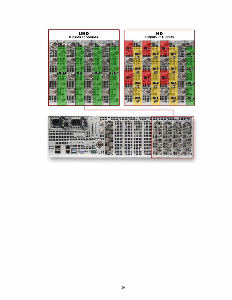
Video Inputs / Outputs
Video Inputs/Outputs are located at the right side on the rear of the FastServe | Ingest server.
The purpose of each socket varies according to the type of the currently settled video configuration.
The image below presents an example of a basis configuration:
19
20

UHD Configurations
21

HD Configurations
22

23

24

2 Installing the Server Hardware
This chapter describes how to install anFastServe | Ingest server on your site.
Topics in this chapter include:
• Electrostatic Discharge Precautions
• Installing FastServe | Ingest Hardware in a Rack
• Installing the Drives in the Server
• Cabling the Server
• Turning On the Server
• Setting IPMI Connection
Electrostatic Discharge PrecautionsElectrostatic discharge (ESD) can damage disk drives, cards, and other parts. Avid recommends that you perform all procedures in this chapter only at an ESD workstation. If one is not available, provide some ESD protection by wearing an antistatic wrist strap attached to chassis ground (any unpainted metal surface) on your server when handling parts.
ESD and handling PCIe Cards
Always handle cards carefully. They can be extremely sensitive to ESD. Hold cards only by their edges. After removing a card from its protective wrapper or from the server, place the card component side up on a grounded, static free surface. Use a conductive foam pad if available but not the card wrapper. Do not slide the card over any surface.

Installing FastServe | Ingest Hardware in a Rack The FastServe | Ingest server is designed for 19-inch racks and requires three EIA rack units (3U), or 130 mm of rack space. Dimensions of the FastServe | Ingest server are: Height 130mm; Width 443mm, Depth 790mm, Weight 48kg (approx.).
The FastServe | Ingest server includes rack mounting slide rails. The standard rail configuration is for racks with square mounting holes. The rack-mounting kit requires inner slide rails be mounted to theFastServe | Ingest server and the outer slide rails are mounted to the rack. Once both, the inner and outer rails are in place, slide the server with the inner rails attached into the outer rails. Secure the server in the rack so it does not slide forward.
c The FastServe | Ingest server is designed to be installed horizontally in a rack. Installing theFastServe | Ingest on an angle or in a sloped console causes the internal drives to wear faster than the intended life of the drive.
w To ensure the stability of the rack enclosure, start from the bottom when you install the rack components in the rack enclosure.
Rack-mount Requirements• Elevated Operating Ambient — If installed in a closed or multi-unit rack assembly, the operating
ambient temperature of the rack environment might be greater than room ambient. Therefore, consider installing the equipment in an environment compatible with the maximum ambient temperature (Tma) specified by the manufacturer.
• Reduced Air Flow — Installation of the equipment in a rack should be such that the amount of air flow required for safe operation of the equipment is not compromised.
Airflow is from the front of the server to the rear. Make allowances for cooling air to be available to the front panel surface and no restrictions at the rear.
• Mechanical Loading — Mounting of the equipment in the rack should be such that a hazardous condition is not achieved due to uneven mechanical loading.
• Circuit Overloading — Consideration should be given to the connection of the equipment to the supply circuit and the effect that overloading of the circuits might have on overcurrent protection and supply wiring. Appropriate consideration of equipment nameplate ratings should be used when addressing this concern.
• Reliable Grounding — Reliable grounding of rack-mounted equipment should be maintained. Particular attention should be given to supply connections other than direct connections to the branch circuit (for example, use of power strips).
• Inside Enclosure Access — If you want to extend the enclosure, and remove the top cover, you must allow 0.5 in (1.3 cm) clearance on top of the enclosure for cover removal.
• Ventilation is handled through the sides of the unit; incoming air from the left, and cooling fans on the right.
• If the Server is installed in a closed or multi-unit rack assembly, the operation's ambient temperature of the rack may be greater than room ambient. Verify that the temperature in the rack always stays within the 5C° to 40C° range.
c To prevent overheating, ensure there is enough room for ventilation.
26

Positioning the Server in the Rack
The following information helps you decide where to install the Avid FastServe | Ingest in the rack.
To position the server in the rack enclosure:
t Select a position in the rack where the FastServe | Ingest server is at the proper baseline position.
Positioning the Avid FastServe | Ingest
Installing the Drives in the ServerThis topic contains information on inserting drives in the FastServe | Ingest server.
n The drives that were shipped with this server are pre-configured for use with this server only. Therefore, when installing the drives, make sure to use these drives only.
To install a drive in the FastServe | Ingest server:
1. Locate the data drives that came with your FastServe | Ingest server.
2. Select one drive.
3. Push the drive carrier latch in to release the handle and pull the handle completely open to insert the drive carrier.
4. Make sure the drive LEDs are on the bottom before you begin to slide the drive into the server.
27

n When you are installing drives in the Avid FastServe | Ingest server, begin the installation at the bottom of a column of drives. Make sure the first drive you install is level and flat as you insert it into the server.
c Do not force a drive into a slot. If you are having problems installing a drive, check to make sure it is level and flat as you insert it into the server, that the drive carrier latch is open and at a 45 degree angle to the drive carrier, and that the LEDs are on the bottom of the drive carrier.
5. Slide the drive into the open drive slot in the server until it stops. Approximately 1/2 inch of the drive carrier should be outside the server.
6. Push the handle into the drive carrier. This seats the drive in the server. You’ll hear a click when the drive is fully seated and the handle latches in place.
7. Repeat steps 2 to 6 for the remaining drives.
Cabling the ServerOnce the FastServe | Ingest server is securely installed in the rack, and the drives are installed, you are now ready to connect the appropriate cables to the rear panel of the server to the external devices for your particular site. This section contains the cabling diagrams and instructions for your FastServe | Ingest server.
c Do not connect the FastServe | Ingest server to your Avid NEXIS environment until you have assigned it a new unique IP address.
28

FastServe | Ingest Server Connection Information
The rear panel of the FastServe | Ingest server provides access to the power supplies, video port, 1 and 10 gigabit (Gb) Ethernet ports, VGA port, serial port, two USB connectors for the keyboard, mouse, Reference IN and OUT sockets, LTC Input and Video Inputs/Outputs.
FastServe | Ingest Server - Rear Panel
Connecting the Power Cords
Your FastServe | Ingest server has two power supplies. If your local power distribution is not compatible with the supplied cords, you must provide your own IEC power cables that are compatible with your country's power system.
To connect/reconnect power:
1. Attach the power cords to both power receptacles on the rear of the server.
2. Connect the other end of both power cords to a properly grounded stable power source.
c For maximum power protection, Avid recommends a surge protected un-interruptible power supply (UPS).
c To avoid the risk of electrical shock and fire, inspect the system power cord and plug routinely. Ensure they are not damaged in any way.
When all necessary connections have been completed and configured, switch on the Server by pressing the POWER button on the front panel.
w This unit has two connections to the main supply. For protection against electric shock, disconnect both electric cords before service.
c Do not remove the power module without gloves. The cover of the power module serves as a heat-sink for cooling. Temperature can reach 60°C under full load condition. If removed, put aside the power module until cool, and prevent anyone from touching it until it is cooled.
c Risk of explosion if lithium battery on motherboard is replaced by an incorrect type. Dispose of used batteries according to the instructions.
29
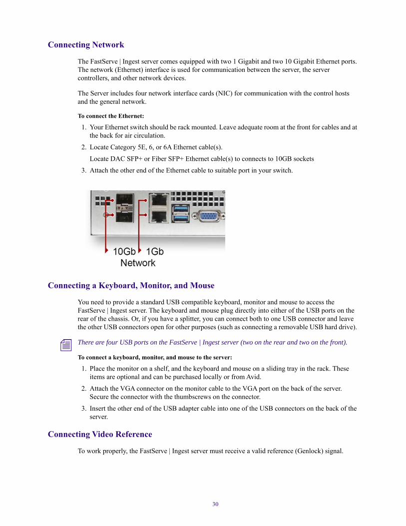
Connecting Network
The FastServe | Ingest server comes equipped with two 1 Gigabit and two 10 Gigabit Ethernet ports. The network (Ethernet) interface is used for communication between the server, the server controllers, and other network devices.
The Server includes four network interface cards (NIC) for communication with the control hosts and the general network.
To connect the Ethernet:
1. Your Ethernet switch should be rack mounted. Leave adequate room at the front for cables and at the back for air circulation.
2. Locate Category 5E, 6, or 6A Ethernet cable(s).
Locate DAC SFP+ or Fiber SFP+ Ethernet cable(s) to connects to 10GB sockets
3. Attach the other end of the Ethernet cable to suitable port in your switch.
Connecting a Keyboard, Monitor, and Mouse
You need to provide a standard USB compatible keyboard, monitor and mouse to access the FastServe | Ingest server. The keyboard and mouse plug directly into either of the USB ports on the rear of the chassis. Or, if you have a splitter, you can connect both to one USB connector and leave the other USB connectors open for other purposes (such as connecting a removable USB hard drive).
n There are four USB ports on the FastServe | Ingest server (two on the rear and two on the front).
To connect a keyboard, monitor, and mouse to the server:
1. Place the monitor on a shelf, and the keyboard and mouse on a sliding tray in the rack. These items are optional and can be purchased locally or from Avid.
2. Attach the VGA connector on the monitor cable to the VGA port on the back of the server. Secure the connector with the thumbscrews on the connector.
3. Insert the other end of the USB adapter cable into one of the USB connectors on the back of the server.
Connecting Video Reference
To work properly, the FastServe | Ingest server must receive a valid reference (Genlock) signal.
30

When using an Analog GENLOCK source, you can connect one ANALOG REF plug as the input and the other ANALOG REF plug will automatically serve as the output (Loop).
When using Analog GENLOCK, it is recommended to put a 75-OHM termination on the REF out.
Connecting LTC - XLR
The LTC signal defines the timecode that is used to manage recordings in the FastServe | Ingest server. It is recommended to use LTC whenever available.
To connect LTC to the server:
t Connect directly to the server using the Reference and LTC Breakout cable.
Connecting AES
FastServe | Ingest server can be equipped with an Analog and Digital Audio External Source (AES).
Connecting SDI Video Inputs/Outputs
The Input/Output connections vary according to the current i/o settings.
The FastServe | Ingest server currently supports up to four UHD channels or eight HD channels. For more information, see “Video Channel Specifications” on page 81.
To connect SDI video output cables on the chassis:
1. Ensure that you have proper SDI video (75 ohm-rated) interface coaxial cables available.
2. Connect the SDI output signal to an outgoing SDI output on the server.
3. Connect the other end of all SDI output cables to your devices that are receiving the output signal from the server.
To connect SDI video input cables:
1. Ensure that you have proper SDI video (75 ohm-rated) interface coaxial cables available.
2. Connect the SDI input signal to an incoming SDI input on the server.
3. 3.Connect the other end of all SDI input cables to your devices that are sending the input signal to the server.
31
Turning On the ServerWhen you turn on the power to your FastServe | Ingest server, you must do it in the following order so that it will see all of its connected components.
To turn on the power for each component:
1. Make sure you have all your network cables connected.
2. Push the power button at the top right on the front of the your server.
3. Log onto the server.
32

Setting IPMI ConnectionYour FastServe | Ingest server gives you access to the Intelligent Platform Management Interface.
Correctly configured IPMI performs power control operations or gives you remote access to a Linux console.
To configure an IPMI connection:
1. Turn on your FastServe | Ingest server.
n The server does not need to be powered on. Make sure the power supply and 1 Gb Ethernet cables are connected. You can boot the FastServe server after establishing the IPMI connection.
2. Enter BIOS by pressing the Esc button during the server startup.
3. Once the JViewer window is displayed, press Esc once again to enter boot options.
4. In the boot options, use the right arrow on your keyboard to open Advanced options.
Press Enter.
5. Use the keyboard arrows to go to H20 IMPI Configuration.
Press Enter.
6. Use the keyboard arrows to go open BMC Configuration.
Press Enter.
7. Use the keyboard arrows to go open IPV4 Source.
Press Enter.
8. Using the arrows, set the IP as <Static>.
Press Enter.
9. Put in your IPv4 address (e.g.: 10.10.31.2xx).
Press Enter.
33

10. Set IPv4 Subnet Mask according to your network settings (e.g.: 255.255.224.0).
Press Enter.
11. Set IPv4 Gateway Address according to your network configuration (Ex: 10.10.0.254).
Press Enter.
12. Save and Exit by pressing F10.
13. Restart your FastServe | Ingest server.
To connect to your FastServe | Ingest server through IPMI:
1. Make sure your FastServe | Ingest server is connected to the network through the 1 GB socket. The server does not need to be powered on.
2. Open a web browser and enter your IPv4 address in the address bar.
A login window opens.
3. Enter your credentials and click Login.
n Default username is admin, and the default password is admin. For BIOS 86 users, default credentials are: admin / Avid123.
34

Configuring the Remote Console Connection
Once you have logged on to the IPMI web service, you can now configure your Remote Console connection.
To connect to the Remote Console for the first time:
1. Log into the IPMI service as described above.
2. Move the mouse to Remote Control at the TaskBar. Left-click on it to unfold the Menu.
3. Select Console Redirection.
4. Press the Java Console button.
In the warning window, click KEEP.
5. Make Sure that proper Java is installed on your PC.
6. Add your IP to the Java Exception Site List:
a. Open the Windows Start menu.
b. Open the All Programs list.
c. Locate the Java folder and open Configure Java.
d. When the Java Control Panel appears, go to Security.
e. Click Edit Site List to add more addresses.
f. Enter your IPMI address as follows: http://10.10.X.X
35

g. Press OK to close this window.
7. Press Apply and OK to close the Java Control Panel.
8. Go to the Downloads folder and launch the jviewer.jnlp file.
9. Accept the Security Warning and press Run.
10. Your Remote Console is now available and can be used.
11. If the server is switched off, press the power button to turn it on.
Your server is booting up.
36

Setting Up Remote Access to the Server
FastServe | Ingest software supports BIOS IPMI to enable remote access to the system. For more information on how to setup an IPMI connection, see “Setting IPMI Connection” on page 33.
IPMI provides an overview of the general health of the system:
You can also power on or off your server using the Power Control and Status section:
37

How To Use the vim EditorFor the purpose of this manual, we are going to use vim to edit files.These are the most common vim operations:
• Use the keyboard arrows to find the required position in the file.
• Press Insert to enable the Editing mode.
• Press Esc to disable the Editing mode.
• To search for phrases in the file, exit the editing mode by pressing Esc, type the / key followed by the word you are looking for. Once found, you can press the n key to go directly to the next occurrence of the word.
• Type G to go to the bottom of the file.
• Type gg to move to the top of the file.
• Type :wq! to save and exit the file.
• Type :q! to exit without saving.
38

3 Upgrading The Operating System
n This topic provides information on how to upgrade your server’s operating system from CentOS5 to the CentOS7 version.
c The upgrade procedures included in this topic should be conducted by qualified Avid support personnel.
Upgrading ChecklistThe following table provides a checklist of tasks that must be performed when upgrading your FastServe | Ingest or FastServe | Live system. Some of the tasks are contained in this chapter, while others are contained in other chapters of this guide.
n Before you begin, make sure you have downloaded the latest Full version of the OVS system, you have the INST_PACK and the USB drive with CentOS 7 is ready.
Backing-up Your SystemCreate a fresh backup of your system using the procedure described below.
To create a system backup:
1. Use the following command to create a system backup:/data/VS/bin/system_re_store_cfg -c /data/public
2. Download the generated backup file (/data/public/BS_BACKUP_XXX.tgz) and copy it somewhere outside of the server.
n The backup is comprised of files which contain valuable information about the machine setup before the upgrade procedure. This can be useful when restoring the system.
b Make sure you have a valid license file for the 2019.1 version. For more information, see “Updating Your License” on page 50.
b Save your configuration settings using the Save Settings button in the WebSettings. Create a fresh backup of your system as described in the Backing-up Your System topic.
b Check your BIOS configuration, as described in the topic “Checking BIOS Configuration” on page 40.
b Prepare a bootable USB drive, as described in the topic “(Option) Preparing a Boot-able USB Drive” on page 40.
b Load the Avid CentOS7 Image v1.4.2, as described in the topic “Loading the CentOS 7 Image on Your Server” on page 41.
b Set up your FastServe server, as described in the topic “Configuration Procedures” on page 42.
b Install the FastServe OVS software, as described in the topic “Installing the Avid OVS Software” on page 46.

Checking BIOS ConfigurationIn the event that you need to re-image your FastServe | Ingest server, you should check your BIOS settings before installing the CentOS 7 software.
To check if BIOS is configured correctly:
1. Turn on or restart your FastServe | Ingest server.
2. Press the Esc button during the server start.
3. Press Esc after the initial screen appears to enter boot settings.
4. Set the following parameters:
a. Advanced > Processor Configuration > Hyper-Threading (All) = Disable.
b. Advanced > H2O IPMI Configuration > IPMI Support = Enabled
c. Advanced > H2O IPMI Configuration > BMC configuration >
- IPV4 Source <Static>
- IPv4 IP Address (Ex: 10.10.31.2xx)
- IPv4 Subnet Mask (Ex: 255.255.224.0)
- IPv4 Gateway Address (Ex: 10.10.0.254)
d. Advanced > IIO Configuration > IIO0 Configuration > IOU0 (IIO PCIe Port 2) = x8x8
e. Advanced > IIO Configuration > IIO0 Configuration > IOU1 (IIO PCIe Port 3) = x4x4x8
f. Advanced > System Event Log > IO0 Error Enable <No>
g. Advanced > System Event Log > PCI-Ex Error Enable <No>
h. Boot -> Boot Type = Legacy Boot Type
i. Boot -> USB Boot = Enabled
5. Exit -> Exit Saving Changes = Yes.
(Option) Preparing a Boot-able USB DriveThe boot-able USB drive should be delivered to you, but in case you need to prepare such drive, follow the procedure below.
This topic contains information on how to prepare a bootable USB drive to reinstall CentOS 7 on your FastServe | Ingest system.
Using Linux
Using the dd command, convert an USB drive of at least 8GB:
40

Using the Windows Win32DiskImager
Win32DiskImager is a Windows program for saving and restoring images from removable drives. It can be used to write boot images to a USB flash device, making it bootable.
Loading the CentOS 7 Image on Your ServerThis topic contains information on how to load the CentOS 7 restore image on your FastServe | Ingest system.
To load the CentOS 7 Restore image:
1. Insert the USB Flash Drive (UFD) with Avid CentOS 7 Image v1.4.2 into one of the USB ports.
2. Reboot the server while holding the Esc key on your keyboard to enter BIOS, or connect through the IPMI Console.
3. In the BIOS Boot Manager, press the right arrow on your keyboard and press Enter.
4. Select the plugged in Legacy USB portable drive, press the down arrow multiple times (mostly it is 4 times) and press Enter to install the system.
5. Wait circa 7 minutes while the CentOS 7 system is being installed. Once the installation is finished, press Enter and wait 3 minutes to fully reboot the server.
6. (Option) Change the boot order back to its original state, by going to BIOS boot options and moving the USB drive lower in the hierarchy.
7. Unplug the UFD device from the USB port.
8. Check if the system disks are in the “sync” option: cat /proc/mdstatIf the “sync” action is in progress then wait and recheck again. This action can take even 30 minutes.
41

Configuration ProceduresThe following table provides a checklist of tasks that must be performed when configuring the FastServe | Ingest before installing the OVS software.
Assigning an IP Address
Once you have the FastServe | Ingest server connected to your network, you should verify your network connection. This involves assigning a static IP address based on the requirements for your site. This enables you to communicate with your shared storage infrastructure. You should be able to get this information from your site’s Network Administrator.
To assign an IP address for eth0 (1GB):
1. Connect to your FastServe machine with PuTTY or other terminal emulator.
Or connect a keyboard and a VGA monitor directly to server.
You can also connect trough the IPMI console.
n Log on as root.
2. Edit the network file according to your network specification.vim /etc/sysconfig/network-scripts/ifcfg-eth0
3. Press Insert to enter the Editing mode.
b Verify your network connection (IP address), as described in the topic “Assigning an IP Address” on page 42.
b Change your network configuration file, as described in the topic “Updating the Network Configuration File” on page 43.
b Install the newest kernel (for servers with freshly installed Linux), as described in the topic “Installing Kernel” on page 44.
b Configure the GRUB file, as described in the topic “Configuring the GRUB File” on page 45.
b Configure the root file, as described in the topic “Configuring the Root File” on page 45.
42

4. Set the following information:ONBOOT=yes (not used Ethernet ports should have value “no”)IPADDR=HWADDR= (use data from the previous step)NETMASK=GATEWAY=10.10.0.254
n The gateway parameter is mandatory for NEXIS. Otherwise, the NEXIS client cannot find the NEXIS server by name. It needs to be the same gateway as the NEXIS server connected to it.
5. To save the file, type:wq!and press Enter.
n Assign IP addresses for the eth1, eth2, eth3 and eth4 ports in the same way.
• eth0 and eth1 are 1GB ports, while eth2 and eth4 are 10GB ports.
n When working with Avid PIVOT, it is required that the FastServe servers need to be in the same subnets, due to UDP communication.
After applying all changes to your network configuration, from a terminal emulator use the following command to restart the network configuration:
systemctl restart network
Updating the Network Configuration File
The network configuration file is used to specify information about the desired network.
To update the network configuration file:
1. Open the vim editor and type:vim /etc/sysconfig/network
2. Press Insert to enter the Editing mode.
3. Set the following parameters:
- HOSTNAME="OVS_NAME"
- GATEWAY= (enter the gateway available in your network).
- GATEWAYDEV=eth0 (write a basic network number).
4. Press Esc to exit the Editing mode.
5. To save the file, type:wq!and press Enter.
After applying all changes to your network configuration, from a terminal emulator use the following command to restart the network configuration:systemctl restart network
If you encounter any problems, see the Troubleshooting 10GB Connection Issues chapter.
43

Installing Kernel
If your Linux is freshly installed, use the newest available kernel from the INST_PACK.
To install kernel:
1. Download the following file:kernel-3.10.0-693.5.2.el7.Avid.x86_64.rpm
2. Copy the downloaded kernel to the /data/public folder.
3. Execute the following command:rpm -ivh /data/public/kernel-3.10.0-693.5.2.el7.Avid.x86_64.rpm
4. Reboot your server.
5. Check the installed version by entering the following command:uname -a
6. Check if /data/public is mounted after the reboot. If it is not properly mount it, use the following command to fix it:ls /data/public/mount -a
Updating BIOS Version
To check the BIOS version:
1. Connect to your server using a terminal emulator, such as PuTTY. Check if the BIOS version is older than version Phaev086 by entering the following command: dmidecode | grep --colour=never "Version: Phaev"
2. If the displayed version is older than Phaev086, upgrade it as described below.
To update BIOS:
1. Stop your server by entering the following command: /data/VS/bin/set_run -s all
n This step is required after the OVS engine has been installed and you need to reinstall BIOS.
2. Download the PHAEV086_fixed.tgz file to /data/public/ folder of your server.
3. Decompress the PHAEV086_fixed.tgz file to the /PHAEV086/ folder: tar -xvzf /data/public/PHAEV086_fixed.tgz -C /
4. In your IPMI Console, go to folder /PHAEV086/Linux/InsydeH2OFFT_x86_LINUX64_100.00.08.10/: cd /PHAEV086/Linux/InsydeH2OFFT_x86_LINUX64_100.00.08.10/
5. Add the following comment #!/bin/sh to the first line of the flash.sh script (without running the script).
6. Vim flash.sh and execute ./flash.sh using the IPMI panel:./flash.sh
7. When the update is complete, reboot your server.
44

Configuring the GRUB File
A GRUB (Grand Unified Bootloader) file is a boot loader package. It is responsible for loading and transferring control to an operating system kernel software.
To edit the GRUB configuration file:
1. Connect to your FastServe machine with PuTTY or other terminal emulator.
Or connect a keyboard and a VGA monitor directly to server.
You can also connect trough the IPMI console.
n Log on as root.
2. Change the bigphysarea=131072 parameter to bigphysarea=262144 in /etc/default/grub and save the new configuration. Use the following commands to initialize the change.
Edit the file using vim:vim /etc/default/grubSave changes using the :wq! command.
Execute the change:grub2-mkconfig -o /boot/grub2/grub.cfg
3. Check the new /boot/grub2/grub.cfg file if it contains the new bigphysarea parameter: cat /boot/grub2/grub.cfg | grep bigphysarea
4. Reboot of your FastServe | Ingest server is not required; it can be rebooted after the entire configuration is complete.
Configuring the Root File
A device with CentOS 7 installed requires adding the root file to /var/spool/cron/.
To configure the root file:
1. Connect to your FastServe machine with PuTTY or other terminal emulator.
Or connect a keyboard and a VGA monitor directly to server.
You can also connect trough the IPMI console.
n Log on as root.
2. Create the root file if it does not exist:vim /var/spool/cron/rootThis is the default content of the file:# DO NOT EDIT THIS FILE - edit the master and reinstall.# (/tmp/crontab.21376 installed on Mon Oct 5 11:02:15 2009)# (Cron version -- $Id: crontab.c,v 2.13 1994/01/17 03:20:37 vixie Exp $)SHELL=/bin/csh03 * * * * /usr/sbin/logrotate /etc/logrotate.conf >& /var/log/logrotate-from-cron
45

3. Check if line “dateext” is commented in /etc/logrotate.conf. If it is not, comment it with #dateext.
4. Restart the crond service and check the status:systemctl restart crondsystemctl status crond.serviceBelow is an example of the file:
Installing the Avid OVS SoftwareThe following table provides a checklist of tasks that must be performed when installing Avid OVS manually for the first time on a FastServe | Ingest server.
First-time Installation of OVS
The following procedure describes the tasks required when installing the full OVS for the first time on a given FastServe | Ingest server.
To install OVS for the first time:
1. Create the VS_INSTALLS folder:mkdir /data/VS_INSTALLS
2. Go to the VS_INSTALLS directory:cd /data/VS_INSTALLS
3. Set access permissions for the VS_INSTALLS folder:chmod 777 -Rf /data/VS_INSTALLS
4. Download the following file: VS_FULL_CS7_2018.x.x.x.tgz and copy to /data/public.
5. Extract the archive:tar -xvzf /data/public/VS_FULL_CS7_2019.1.0.xx.tgz -C /data/VS_INSTALLS/tar -xvzf /data/VS_INSTALLS/VS_FULL_CS7_2019.x.x.x/installer_0.7.tgz -C /data/VS_INSTALLS/cd /data/VS_INSTALLS/installer ./install_vs VS_FULL_CS7_2019.x.x.x
6. The server will now fully reboot.
7. When the installation is complete, proceed with actions described in the Steps Required After OVS Installation.
b How to install OVS for the first time, as described in the topic “First-time Installation of OVS” on page 46.
b Perform the steps listed in the topic “Steps Required After OVS Installation” on page 47.
46

Steps Required After OVS Installation
The following table provides a checklist of tasks that must be performed after installing Avid OVS for the first time on a FastServe | Ingest server.
Setting the Date, Time and Time Zone on the Server
You need to correctly set the date, time and time zone on each FastServe server.
To set the date, time and timezone options:
1. After installing the OVS, you need make sure to stop it before changing its parameters. Use the following command to stop it:/data/VS/bin/set_run -s all
2. To display the current time and date on your system, use the following commands:timedatectl statushwclock
3. If required, disable NTP (Network Time Protocol) and RTC (Real-time clock):timedatectl set-local-rtc 0timedatectl set-ntp 0
4. Check the current time zone: ls -l /etc/localtimetimedatectl | grep -i 'time zone'
5. Change the time zone to the one you require (we will use Europe/ Warsaw and Asia/Jerusalem as an example):timedatectl set-timezone Europe/Warsawtimedatectl set-timezone Asia/Jerusalem
6. Verify your time zone settings by typing the following commands:ls -l /etc/localtimetimedatectl | grep -i 'time zone'
b Set the date, time, and time zone settings, as described in the topic “Setting the Date, Time and Time Zone on the Server” on page 47.
b Set the CPU speed, as described in the topic “Setting the CPU Speed” on page 48.
b Update the modeprobe.conf file, as described in the topic “Updating the modprobe.conf File” on page 48.
b Edit the Codecs file, as described in the topic “Editing the Codecs File” on page 48.
b Update your license, as described in the topic “Updating Your License” on page 50.
b Edit the vsPreferences.cfg file, as described in the topic “Editing the vsPreferences.cfg File” on page 52.
b Update the firmware of DVG boards, as described in the topic “Updating Firmware of DVG Boards” on page 50.
b Update the Avid registry, as described in the topic “Updating the AvidRegistry” on page 54.
47

7. Set your local and hardware clock date and time:timedatectl set-time '2019-02-05 10:55:59'hwclock --systohc
8. Verify the new settings with the following commands:datetimedatectl
Setting the CPU Speed
The tuned.conf file is responsible for setting a correct CPU speed.
This file does not exist on a machine with freshly installed Linux.
To set the CPU speed using the tuned.conf file:
1. Verify that the CPU speed is set identically. It should be 2100 MHz for all 16 cores
- cat /proc/cpuinfo | grep MH
2. If you have a different number or a different value, check the CPU model or BIOS hyperthreading setup.
Updating the modprobe.conf File
To add DVG modules to the modprobe.conf file:
1. Check the /etc/modprobe.d/modprobe.conf file to see if the DVG module is enabled. Compare if it contains the following entry. vim /etc/modprobe.d/modprobe.confalias char-major-121 dvggoptions dvgg major=121 allow_codec=1 irq_affinity_force=1 irq_affinity=0xf
Editing the Codecs File
This is a basic FastServe | Ingest file which is responsible for proper work of your DVG graphic cards.
To stop OVS:
t Enter the following command:/data/VS/bin/set_run -s all
To edit the Codecs file:
1. Connect to your console with PuTTY or other terminal emulator.
2. Open the Codecs file in the vim editor:vim /usr/dvg/codecs.map
3. Set the following options as described below (or download to /usr/dvg/):
48

## Codec boards map## C[logical_board_num]=[physical_board_num] - Map physical boards in PCI enumeration to OVS logical boards## logical boards are enumerated internally in bottom up order by appearance## the logical_board_num is actually redundant, physical_board_num < 0 means a board not to be used## M=[logical_board_num] - Clean mixer board number (H!=M)## H=[logical_board_num] - OSD helper board number (H!=M)## A=[logical_board_num] - AES master input board number## E=[logical_board_num] - Embedded master input board number
## L=[physical_board_num] - LTC internal board numberC0=3C1=2C2=1C3=0M=0H=1A=2E=3L=2J=0#G=-1
B=44. To save and exit the file, type
:wq!and press Enter.
5. Reboot your FastServe | Ingest server.
Checking the Hardware Key
If after the installation, the /usr/bin/licdvg-getsystemid-LL is missing, download it and create a HW key (hardware identifier for existing boards).
To download the /usr/bin/licdvg-getsystemid-LL component and create the HW key:
t Enter the following commands:
Copy the file to /usr/binchmod 755 /usr/bin/licdvg-getsystemid-LL/usr/bin/licdvg-getsystemid-LL > /usr/dvg/idcat /usr/dvg/id
49

Updating Firmware of DVG Boards
Although the DVG board firmware is copied to /usr/dvg/ during OVS installation, it may not be compatible with your machine. You can burn your firmware through the FastServe | Ingest Web Settings, or using the FastServe | Live Edit Controller. After upgrading your operating system from CentOS 5 to CentOS7, the firmware is already burnt but the “burning_status” file is missing. The below procedure describes how to add it.
To add a burning status file:
1. Connect to your console with PuTTY or other terminal emulator.
2. Check what firmware is burned and create a matched /tmp/burning_status:dvgflash -board 0 -reconf -listvim /tmp/burning_statusDepending on the codec, you can receive following response: For DNX For XDCAMSUCCESS SUCCESSDNX XDCAMHD HD
3. (Option) Burn firmware for your desired format standard:/data/VS/bin/burn_dvg_flash <format_name>Example:/data/VS/bin/burn_dvg_flash XDCAM HD
n You can also easily burn the firmware for each codec in the WebSettings. It is highly recommended to use the WebSettings for this procedure.
4. Press Enter.
Updating Your License
To activate your license, note your Machine Id and send it to Avid support.
n Machine ID will change after CentOS operating system and OVS system have been upgraded. Make sure enough time is accommodated to obtain a new license from Avid Customer Support.
Avid Customer Support can provide you with a temporary license within a time frame specified in your Support Contract. This will give you enough time to provide a full license. More information on the Avid Customer response time is available at https://www.avid.com/learn-and-support/avid-advantage-support-plans.
To get the FastServe | Ingest Machine Id:
1. Connect to your console with PuTTY or other terminal emulator.
2. Get the Machine Id by typing:/usr/local/orad/getAuthoId > /usr/local/orad/autId cat /usr/local/orad/autId
3. Copy the Machine Id and send it to Avid.
50

Once you receive your license from Avid, enter the license number to the license.dat file. To create this file, use the following commands:
touch /usr/local/orad/license.datvim /usr/local/orad/license.dat
n A broken firmware can prompt the FastServe server to display error messages about an invalid license. In case you receive such error message and the license is valid, check the DVG board FW.
The table below presents an overview of the possible error messages and their short description:
Restoring the Backup Files
To restore your previously backed up files, use the following command:
./system_re_store_cfg -x /data/public VS_BACKUP
After applying this step, check your /data/VS/bin/allApps.cfg file if it contains the correct information (as listed below):
rdt ext ovs cmd vsc ast wf proxy
Editing the user_pre_VS File
Create or download the /data/VS/bin/user_pre_VS file. Compare the content of this file with the version from the latest backup.
Create the file:
Error Message Description
Broken license 6 There is no features file.
Broken license 7 There is no Key file in the /usr/dvg/ folder.
Broken license 9 • Hardware is disconnected.
• The Key file is empty.
• The Features file is empty.
License problem m The linear key (mixing) is missing in the features file.
License problem k Chroma key is missing in the features file.
License problem s No video out SD in the features file.
License problem h No video out HD in the features file.
License problem a Embedded audio.
License problem z Chroma key with zones.
License problem d Dual-channel mode (two video outputs with different content).
License problem c Specific chain mode not allowed (VR)
License problem 2 Dual-head operation (second output of graphics card enabled, like in TrackVision).
51

vim /data/VS/bin/user_pre_VS
Editing the vsPreferences.cfg File
The vsPreferences.cfg file is the most important file for the OVS engine. It keeps all of your OVS’s personal preferences.
n OVS needs to be stopped during the edition of the file. OVS overwrites the vsPreferences.cfg file every time it is stopped and your changes will be lost.
To stop OVS (in case it is running):
t Enter the following command:/data/VS/bin/set_run -s all
To edit the vsPreferences.cfg file:
1. Connect to your console with PuTTY or other terminal emulator.
n The default vsPreferences.cfg file is created when OVS is run for the first time.
2. Open the vsPreferences.cfg file in the vim editor:vim /data/VS/bin/vsPreferences.cfg
3. Edit the below settings:
t 516 CONTROL_NETWORK_INTERFACE=2 - set the eth port number which will be used to connect to the network.
n The Ethernet port number is specific to your configuration. In the example above, eth2 (10 Gb) is used as the control network interface. For more information on Ethernet ports, see “Ethernet Ports” on page 16.
t 517 DATA_NETWORK_INTERFACE=2– set the eth number which will be used for data connection.
t 24 CODEC_FORMAT - check if the codec format matches the format set in the firmware burning_status file.
t 20 ONLINE_MULTICAST_PORT=6666 – set the port number which will be used by PIVOT and the FastServe | Live Edit Controller for communication with the server.
t RAID_LEVEL=60 – set the Raid level to 60.
t RAID_DISKS=1,2,3,4,5,6,7,8,9,10,11,12,13,14,15,16 – make sure that the RAID uses all available disks.
t change TASKS_MAX_HP_EXPORT=1 to TASKS_MAX_HP_EXPORT=8 under [TASKS] line #607
t change RECORD_USE_BLACK_FILLER=0 to RECORD_USE_BLACK_FILLER=1 under [RECORD_EX] line #1361
4. To save and exit the file, type:wq!and press Enter.
52

n For OP1a workflows, set the following option in the vsPreferences.cfg file:
EXPORT_OFFSETS_PROFILE=3
RAID Configuration
The following procedure describes the steps required when you need to check the RAID.
To update the RAID:
1. Check the RAID controller version:/usr/StorMan/arcconf getconfig 1 | grep -E "BIOS|Firmware|Driver|Boot Flash" | grep -v "T907"
2. If the displayed version is older than BIOS/FW/Boot:7.11-0 / Driver: 1.2-1, update it.
a. Download the 81605z_fw_b33173.zip file and copy it to the /data/public/ folder.
b. Decompress 81605z_fw_b33173.zip file to /data/public/81605z_fw_b33173/ folder. unzip -o /data/public/81605z_fw_b33173.zip -d /data/public/81605z_fw_b33173/
c. Update the RAID:y | /usr/StorMan/arcconf romupdate 1 /data/public/81605z_fw_b33173/AS816Z01.ufi
d. Reboot the FastServe server.
e. Check the RAID controller version after update. It should be BIOS/FW/Boot: 7.11-0 (33173) / Driver: 1.2-1./usr/StorMan/arcconf getconfig 1 | grep -E "BIOS|Firmware|Driver|Boot Flash" | grep -v "T907"
f. Start your FastServe server. /data/VS/bin/set_run -a all
To check and rebuild RAID:
1. Check the status of the RAID:/usr/StorMan/arcconf getconfig 1 | grep “Group [0-9], Segment [0-9]”/data/VS/bin/detect_raid_sgs
2. If the displayed status indicates that there is no sg3 - sg18 or RAID needs to be rebuild,:
a. Stop OVS:/data/VS/bin/set_run -s all
b. /usr/StorMan/arcconf delete 1 logicaldrive allc. Confirm by pressing the “y” and Enter keys on the keyboard.
d. Shut the system down. shutdown -h now
e. Perform a power cycle and remove the power cables for about a minute. Remove all additional devices connected to your machine, such as USB devices or additional hard drives.
53

f. Turn the system back on, and after ca 3 minutes, stop the RAID and rebuild it:/data/VS/bin/setupAACRaid6
g. Check the results:/usr/StorMan/arcconf getconfig 1 | grep "Group [0-9], Segment [0-9]"/data/VS/bin/detect_raid_sgs
3. Start the FastServe server.
4. Install the appropriate NEXIS Client from the WebSettings and update the Avid Registry.
5. To make sure the current firmware is appropriate for the CentOS7 version, reburn it using the FastServe WebSettings. For more information, see the Administrator’s Guide.
Updating the AvidRegistry
Update the AvidRegistry to avoid network issues between Avid NEXIS and the FastServe | Ingest server. Follow the steps described here in the Re-installing NEXIS Client chapter.
Make sure the correct eth port is entered. The configuration entered here needs to match your current network setup. If the eth2 interface is selected for transfer is, then eth2 should be set here as well. You might encounter NEXIS export issues if this configuration does not match.
Final Steps
Now, compare the content of the newly created or updated files with the files saved in the latest backup. You can now safely start the OVS engine:
/data/VS/bin/set_run -a all
54

4 Manually Installing Individual Components
This topic describes how to manually update and configure individual components of the FastServe system.
For more information see the following sections:
• Updating Logrotate
• Re-installing NEXIS Client
• Installing the Latest OVS Build
• Updating VSCommander
• (Option) Increase Log Level in VSCommander and AirSpeedTranslator
• Updating vsWrapper
• Installing the Proxy Component
• Installing the WebSettings Component
• Upgrading libdvg
• Manually Burning DVG Boards Firmware
Updating LogrotateThis procedure describes how to manually update the logrotate to version 3.15.0.
To update logrotate to version 3.15.0:
1. Copy logrotate-3.15.0-OVS.x86_64.rpm file to /data/public.
2. Install logrotate with the following command:rpm -Uvh /data/public/logrotate-3.15.0-OVS.x86_64.rpm
3. Check the logrotate version:logrotate --version

Re-installing NEXIS ClientYou can easily upgrade the NEXIS Client using the FastServe WebSettings. But if you wish to re-install the Client manually, it is recommended to remove all associated components before installing the new version of the NEXIS Client.
To reinstall Avid NEXIS Client components:
1. Enter the following commands in PuTTY or other emulator to remove the following components:rpm -ev AvidNEXISBenchmarkAgentrpm -ev AvidNEXISClientrpm -ev afpfs-ng
2. Remove the fuse-libs component:rpm -qa | grep -i fuse-libsrpm -e fuse-libs
3. Download and install the kmod-fuse component:Copy kmod-fuse-3.10.0-693.el7.centos.avid.x86_64.rpm to /data/publicrpm -ivh /data/public/kmod-fuse-3.10.0-693.el7.centos.avid.x86_64.rpm
4. Install the Avid NEXIS Client (choose the version compatible with your NEXIS system):Copy the Avid NEXIS Client installer to /data/publicchmod 755 /data/public/AvidNEXISClient_el7.centos.x86_64_18.9.0_15.bin/data/public/AvidNEXISClient_el7.centos.x86_64_18.9.0_15.bin -f
5. Update the modules:depmod -asystemctl restart avidfos
6. Check what version of NEXIS Client is currently installed:rpm -qa | grep -i AvidNEXISClient
7. Change the AvidRegistry settings:
a. vim /etc/AvidRegistryb. Change #AvidFos\Parameters\UseIfnames eth0/AvidFos to
AvidFos\Parameters\UseIfnames eth2.
n If your server has more than one active Ethernet interface, it is important to uncomment (remove the # sign) the line for the eth interface working with NEXIS. If you are working with only one eth interface, there is no need to uncomment it because NEXIS will automatically use this one.
c. Make sure that the AvidFos\Parameters\UsrvTransport\Hires parameter is set to 4 and remove the # sign at the beginning.
n If you use the 10GB Ethernet port for NEXIS communication, make sure this line is uncommented and the Hires parameter is set to 4 for the highest performance.
d. For certain network configuration cases, add the remote system directories suitable for your network.
56

e. Start OVS:/data/VS/bin/set_run -a all
8. For version 18.9.0_15, check the current logging mask after installing:
a. Check the current logging mask:avidfos_ctrl -l
b. Change the logging mask to 0x1200024b.avidfos_ctrl -s 0x1200024b
c. Check the current logging mask after change:avidfos_ctrl -l
9. Restart the AvidNEXISClient:systemctl restart avidfos
10. (Optional) Reboot the server.
Installing the Latest OVS BuildIf you need to update the OVS build on your server, follow the steps listed in this topic.
To install a new build of the OVS component:
1. Stop the FastServe server:/data/VS/bin/set_run -s all
2. Download the latest version of the OVS component to /data/public and extract the file:Copy the OVS_CS7_2019.XX.XX.XX.tgz build to /data/publictar -xvzf /data/public/OVS_CS7_2019.XX.XX.XX.tgz -C /data/VS/bin/
3. Start the server:set_run -a all
4. Install the latest OVSCommander build:/data/VS/bin/set_run -s allCopy the OvsCommander_install_CS5_XXXX.XX.XX.XXX.tgz build to /data/publicrm -frv /data/VS/bin/OVSCommander/bin/*tar -xvzf /data/public/OvsCommander_install_CS5_2018.12.0.128.tgz -C /data/VS_INSTALLS//data/VS_INSTALLS/OvsCommander_install_CS5_2018.12.0.128/install.sh /data/VS/bin/OVSCommander/ --reinstall-firebird
57

5. Check if FireBird is running properly and if the installed version of OVSCommander is correct:pstree | grep fb_smp_server/sbin/service firebird statusll /data/VS/bin/OVSCommander/installers/currentcat /data/VS/bin/OVSCommander/installers/current/OvsCommander.version
Updating VSCommanderTo update the VSCommander to its latest version, follow the steps listed in this procedure.
To update VSCommander:
1. Copy the VSCommander installer to /data/public and install it:Copy the VSCommander-2018.XX.X.XXXX-9d3e198.el5_5.x86_64.rpm build to /data/publicrpm -e VSCommanderrpm -Uvh /data/public/VSCommander-2018.12.1.5094-9d3e198.el5_5.x86_64.rpm --force
2. Check what version of VSCommander is installed on system:rpm -qa VSCommander
3. (Option) Increase the log level to INFO or DEBUG.
Updating AirSpeedTranslatorIf you need to update the AirSpeedTranslator component, follow the steps listed in this procedure.
To update the AirSpeedTranslator component:
1. Copy the AirSpeedTranslator installer to /data/public and install it:Copy AirSpeedTranslator-2018.XX.X.XXXX-6f65b0c.el7.x86_64.rpm to /data/publicrpm -e AirSpeedTranslatorrpm -Uvh /data/public/AirSpeedTranslator-2018.11.1.430-6f65b0c.el7.x86_64.rpm --force
2. Check what version of AirSpeedTranslator is installed on your system:rpm -qa AirSpeedTranslator
3. Restart the server:/data/VS/bin/set_run -a all
58

(Option) Increase Log Level in VSCommander and AirSpeedTranslator
Optionally, you can increase the log level to INFO or DEBUG for the VSCommander and AirSpeedTranslator components. Follow the steps below.
To increase the log level:
1. (Option) Increase the log level to INFO or DEBUG for AirSpeedTranslator and VSCommander.
a. vim /data/VSCommander/commander.xmlb. change <Log Debug="No" DebugLevel="0" WriteInBackground="Yes">
to <Log Debug="Yes" DebugLevel="200" WriteInBackground="Yes">.c. change <DebugModule SQL="No" OCIPDebugLevel="1"/> to
<DebugModule SQL="No" OCIPDebugLevel="3"/>.d. vim /data/VSCommander/logrotate.conf
change rotate 50 to rotate 250.
e. vim /data/AirSpeedTranslator/AirSpeedTranslator.xmlchange <MinLevel>WARNING</MinLevel> to <MinLevel>INFO</MinLevel>
f. vim /data/AirSpeedTranslator/logrotate.confchange rotate 50 to rotate 250.
2. (Option) Increase log level to DEBUG in OVSCommander:
a. vim /data/VS/bin/OVSCommander/bin/commander.xmlb. change <Log Debug="No" DebugLevel="0" WriteInBackground="Yes">
to <Log Debug="Yes" DebugLevel="200" WriteInBackground="Yes">c. change <DebugModule SQL="No" OCIP="No" RETalk="No" Flex="No"
TimeDelay="No"/> to <DebugModule SQL="No" OCIP="Yes" RETalk="No" Flex="No" TimeDelay="No"/>.
d. vim /data/VS/bin/OVSCommander/bin/logrotate.confchange rotate 50 to rotate 250.
Updating vsWrapperTo update the vsWrapper component, follow the steps listed in this procedure.
To update vsWrapper:
1. Check the installed version in the ChangeLog:head -n 15 /data/dclib/ovslib64/ChangeLog
2. Stop the server:/data/VS/bin/set_run -s all
3. Copy the vsWrapper installer to /data/public and install the component:Copy vsWrapper-XXXX-X-X-X-gbc09730-5.tar.gz to /data/publictar -xvzf /data/public/vsWrapper-2019-2-1-6-gbc09730-5.tar.gz -C /data/dclib/ovslib64/
59

4. Start the server:/data/VS/bin/set_run -a all
Installing the Proxy ComponentTo install the proxy application, follow the steps listed in this procedure.
To install the proxy application:
1. Stop the server:/data/VS/bin/set_run -s all
2. Install the proxy component:rm -frv /data/VS/bin/vsProxy/*rm -frv /data/public/vsProxy/*Copy vsProxy-XXXX-X-X-XX-g1b5d9ae-312.tar.gz to /data/publictar -xvzf /data/public/vsProxy-2018-9-5-30-g1b5d9ae-312.tar.gz -C /data/public/cd /data/public/vsProxy/./installProxy.sh /data/VS/bin/vsProxy/
3. After the installation, open the runProxy.sh file:vim /data/VS/bin/vsProxy/bin/runProxy.shAdd the following line after LD_LIBRARY_PATH=$ if you want add a watermark to your proxy signal:export VSPROXY_GENERATE_WATERMARK=1
60

Installing the WebSettings ComponentTo install the WebSettings component, follow the steps listed in this procedure.
To update the WebSettings component:
t To install a newer version of the WebSettings (downgrade is not possible), follow the commands listed in the below example procedure.
rpm -e modSVIPrpm -e modOVSrpm -e modSystemrpm -e WebSettingsCorerpm -e AppStarterrm -frv /data/public/AppStarter-centos-7-x86_64-2018.5.1.80.gedb978f.289.rpmrm -frv /data/public/WebSettingsCore-2018.6.6.344-938fd1e-centos_7-x86_64.rpmrm -frv /data/public/modOVS-2018.6.14.324-be7fdbf-centos_7-x86_64.rpmrm -frv /data/public/modSystem-2018.6.11.324-be7fdbf-centos_7-x86_64.rpmrm -frv /data/public/modSVIP-2018.6.0.324-be7fdbf-centos_7-x86_64.rpmCopy AppStarter-centos-7-x86_64-2018.5.1.80.gedb978f.289.rpm to /data/publicCopy WebSettingsCore-2018.6.6.344-938fd1e-centos_7-x86_64.rpm to /data/publicCopy modOVS-2018.6.14.324-be7fdbf-centos_7-x86_64.rpm to /data/publicCopy modSystem-2018.6.11.324-be7fdbf-centos_7-x86_64.rpm to /data/publicCopy modSVIP-2018.6.0.324-be7fdbf-centos_7-x86_64.rpm to /data/publicrpm -Uvh /data/public/AppStarter-centos-7-x86_64-2018.5.1.80.gedb978f.289.rpmrpm -Uvh /data/public/WebSettingsCore-2018.6.6.344-938fd1e-centos_7-x86_64.
Upgrading libdvgTo upgrade the libdvg component:
1. Copy the libdvg-813.1-10.el7.centos.x86_64.rpm file to /data/public folder.
2. Install it:rpm -ivhU /data/public/libdvg-813.1-10.el7.centos.x86_64.rpm
3. Reboot the server.
61

Manually Burning DVG Boards FirmwareAlthough the DVG board firmware is copied to /usr/dvg/ during OVS installation, it may not be compatible with your machine.
g We recommend using the FastServe WebSettings for upgrading the firmware. For more information, see the Administrator’s Guide.
In some cases, it may not be possible to burn the firmware using a FastServe | Ingest user interface. Then you can attempt re-burning the firmware using a script.
To burn firmware for a format using a script:
1. Use the following command to burn firmware for the selected format:/data/VS/bin/burn_dvg_flash <format_name>Example:/data/VS/bin/burn_dvg_flash XDCAM HD
2. Make sure that the format in the burning_status (cat /tmp/burning_status) file and the vsPreferences.cfg (cat /data/VS/bin/vsPreferences.cfg | grep CODEC_FORMAT=) are the same.
n If the firmware you would like to use is different than in the release versions, you need to first change the symbolic relink of the firmware, then reburn it.
To change the symbolic link:
1. Check the current symbolic relink of the firmware (example for an XDCAM II firmware):ls -l /usr/dvg/uh2_xdcam_hd_ii.bin
2. Remove the current information: rm uh2_xdcam_hd_ii.binrm: remove symbolic link uh2_xdcam_hd_ii.bin? yyes
3. Create a new firmware file:touch /usr/dvg/uh2_xdcam_hd_ii.bin
4. Make the symbolic relink:ln -s xdcam_ii_8015.bin /usr/dvg/uh2_xdcam_hd_ii.bin
5. After changing the symbolic relink, you burn the firmware using a script (as described above).
c In extreme cases, you can attempt to re-burn the firmware manually. This method requires a lot of attention as it may possibly damage the DVG board. Please proceed with care.
To burn firmware manually:
1. Make sure that the OVS engine is closed:/data/VS/bin/set_run -s all
2. Check how many boards are present in the system:lspci | grep Orad
62

You should see four (4) boards.
3. Check the available firmware:cd /usr/dvgls
4. (Advanced users only) Replacing a single firmware. Board 0 preparation:
a. Use dvgflash to check the firmware installed on the board:dvgflash -board 0 -reconf -list
b. If required, delete the current firmware:dvgflash -board 0 -delete 2 dvgflash -board 0 -delete 1
n The XDCAM format has 5 installed firmwares. The DNx format has 3 installed firmwares.
c. Burn input/ input firmware for the DVG card:dvgflash -board 0 -write xdcam_ii_xxxx.bin
63

d. Burn input / output firmware for the DVG card (required for I/O setup 1In 7Out):dvgflash -board 0 -write xdcam_io_xxxx.bin
n It is recommended to have all required firmware for each required format burned for each board.
e. Burn output/ output firmware for the DVG card:dvgflash -board 0 -write xdcam_oo_xxxx.bin
f. Confirm burning of the listed firmware:dvgflash -board 0 -reconf -list
5. Repeat the above step for each board.
To check the status:
1. Use vim to open the burning status file:cat /tmp/burning_statusdvgflash -board 0 -reconf -list Example:SUCCESSXDCAMHD
2. To save and exit the file, type:wq!and press Enter.
3. Check the log file for any errors: /data/VS/bin/flash.log.
64

5 Maintaining and Troubleshooting Your Server
n This chapter covers procedures for the CentOS 7 operating system.
This chapter contains information on how to perform preventative maintenance on your FastServe | Ingest system, as well as how to troubleshoot your server when problems or failures occur.
For more information see the following sections:
• Preventative Maintenance
• Troubleshooting Your FastServe | Ingest Server
• Accessing the Knowledge Base
Preventative MaintenanceThis section contains information on some preventative maintenance tasks to help keep your system healthy.
Working with SNMP Monitoring
SNMP (Simple Network Management Protocol) is a standard way of monitoring hardware and software.You can use it to monitor the following events in the FastServe | Ingest system:
• status of input signals,
• status of power supplies,
• status of fans,
• system Raid condition,
• media Raid condition,
• status of the main engine (OVS),
• free storage status.
Special traps can be configured for:
• genlock sync,
• genlock lock,
• input sync,
• input lock.
The MIB (Management Information Base) file, which helps to understand SNMP responses obtained from the FastServe devices is distributed together with the installation files. For more information on how to configure SNMP, see the SNMP Settings topic in the Avid FastServe | Ingest Administrator’s Guide.

Troubleshooting Your FastServe | Ingest ServerThis section contains information on how to troubleshoot your FastServe | Ingest server, add and replace certain hardware components in case of failure, including media drives, system drives, fans, and Video I/O boards.
Problems with Connecting to the WebSettings
If you encounter any issues with connecting to the FastServe WebSettings, check if the OVS software is running on the server.
To check if the OVS software is running on the server:
1. Log onto the server using a Telnet client, such as PuTTY.
2. Check if OVS is running with the following command:top | grep OVS
3. If the OVS is up and running, open the OVS configuration file and make sure that the data network interface refers to the currently working eth DATA_NETWORK_INTERFACE: cat /data/VS/bin/vsPreferences.cfg | grep DATA_NETWORK_INTERFACE
4. If the data network interface is setup incorrectly, stop the OVS software:/data/VS/bin/set_run -s all
5. After the OVS is stopped, open the vsPreferences file: vim /data/VS/bin/vsPreferences.cfg Change the data network interface to the correct one.
6. Start the OVS software:/data/VS/bin/set_run -a all
Troubleshooting 10GB Connection Issues
If you encounter any issues connecting to the server via the 10GB interface, make sure you have configured the server as described in the Updating the Network Configuration File topic.
If you are still having problems connecting to the server using a Telnet client (such as PuTTY), try connecting to it using the IPMI console. For more information, see “Setting Up Remote Access to the Server” on page 37. Once connected, use the ifconfig utility to check the status of your network interfaces. Your working Ethernet port should have the following status: <UP,BROADCAST,RUNNING,MULTICAST>.
If only <UP,BROADCAST,MULTICAST> is displayed, check if the Ethernet cable is properly plugged in or try the second 10GB port
RAID Recovery
In case any of the RAID drives are damaged, you can recover them using the FastServe | Ingest Web Settings.
n Before you begin this procedure, make sure you have one or more spare media drives available. If not, you must obtain replacement drives before proceeding.
66

c In the event of a failed media drive, it is very important that you replace the failed media drive as soon as possible.
To recover a RAID drive:
1. Identify damaged drives:
View the LEDs on the front of the server. A solid red LED on the front of the drive indicates that the media drive has failed. If it’s flashing RED, the drive could be rebuilding the data. If a rebuild has already been initiated, other drives will be flashing RED, and the media drive you need to replace will remain solid RED.
2. Open the FastServe | Ingest WebSettings to confirm the status of your RAID drives.
Open a web browser and enter the FastServe | Ingest unit’s IP address as the URL, with the suffix 8080. For example, 192.0.2.0:8080
In the WebSettings, open the OVS tab and go to:
Maintenance > Storage > RAID > Disks
3. Replace damaged drive as described in the following steps:
a. Obtain replacement media drives
b. Locate the data drive(s) on the front of the FastServe | Ingest server that has both the blue and red LEDs on solid.
c. Remove the drives from the chassis by pushing the button, then pull the handle to unlatch the drive and slide the drive carrier out of the server.
d. Unscrew the old drive from the carrier, noting the holes used for each screw on the carrier.
e. Fasten the new drive into the carrier making sure to line up the screws with the correct holes in the carrier.
f. Push the drive carrier latch in, to release the handle and pull the handle completely open prior to inserting the drive carrier into the open slot.
g. Make sure the drive LEDs are on the bottom before you begin to slide the drive into the server.
c Do not force a drive into a slot. If you are having problems installing a drive, check to make sure it is level and flat as you insert it into the server, that the drive carrier latch is open and at a 45 degree angle to the drive carrier, and that the LEDs are on the bottom of the drive carrier.
h. Slide the drive into the open drive slot in the server until it stops. Approximately 1/2 inch of the drive carrier should be outside the server.
i. Push the handle into the drive carrier. This seats the drive in the server. You will hear a click when the drive is fully seated and the handle latches in place.
4. Go back to the FastServe | Ingest WebSetting to check the status of the newly inserted drive:
67

Click on RAID recovery for the replaced drive.
5. In the following window, select Disk recovery to rebuild one drive only. Or choose Fast Recovery to perform a quick recovery of your drive.
n The Disk recovery option rebuilds and restores the replaced drive, but it is a time-consuming process. Fast recovery is much quicker but it will erase all data from all drives during the rebuilding process.
Changing the Timezone Manually
If you encounter a situation, where you will need to manually change the timezone of your server, follow the steps listed in this procedure.
(Example) To manually change the timezone:
t Enter the following commands (changing the timezone for the one you require):
cp /usr/share/zoneinfo/Europe/Warsaw /etc/localtime
68

ln -s /usr/share/zoneinfo/Europe/Warsaw /etc/localtime
RPM Database Recovery Procedure
When you encounter a RPM DB failure, follow the steps listed in this procedure to recover it.
To recover a corrupted RPM database:
t Enter the following commands to recover the RPM database after an unexpected failure:
rm -f /var/cores/*rm -f /var/lib/rpm/__db*db_verify /var/lib/rpm/Packagesrpm --rebuilddbyum clean all
Removing and Replacing the Server Main Cover
The FastServe | Ingest server must be operated with the chassis cover in place to ensure proper cooling. However, you will need to remove the main cover to add or replace components inside of the server (Video I/O board set). Before removing the main cover, power down the server and unplug all peripheral devices and the AC power cables.
n A nonskid surface or a stop behind the server may be needed to prevent the server from sliding on your work surface.
To remove the server main cover:
1. Observe the safety precautions described in “Electrostatic Discharge Precautions” on page 25 and “Safety and Regulatory Information”.
2. Turn off all peripheral devices connected to the server. Then, turn off the server.
3. Disconnect the AC power cords.
4. Unscrew the thumbscrews at the back of the unit until they are loose.
5. Press the PUSH button on the left and right sides of the server.
6. Slide back the rear cover until it will be released. Or slide forward the front cover until it will be released.
7. Remove the main cover and set in a safe place.
69

Replacing Power Modules
The FastServe | Ingest server is designed to run with two operating power modules. A power module can be replaced if it fails. If a power module fails, the LED on the power module and the front panel LED turn red and a beeping alarm sounds. The alarm is not configurable.
c Avid recommends the use of uninterruptible power supplies, appropriately sized for your FastServe | Ingest server. This provides protection against sudden power surges or losses that could cause you to lose files or experience data corruption.
To replace a power module:
1. Observe the safety precautions described in “Electrostatic Discharge Precautions” on page 25.
2. Determine which power module needs to be replaced.
3. Make sure you have a replacement or spare power module before you continue with the procedure.
4. Power down the server and unplug all peripheral devices and the AC power cables.
c The power module must be unplugged before you remove it.
5. Push the latch towards the handle and remove the power module by pulling on the handle.A. Latch B. Handle
6. Insert the replacement power module into the power supply cage until it clicks into place.
7. Reconnect all peripheral devices and the AC power cords into the server.
n The server will automatically power up without having to turn on the Power switch.
70
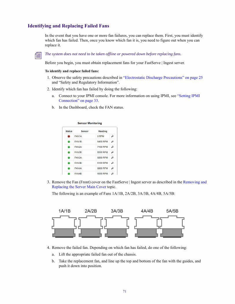
Identifying and Replacing Failed Fans
In the event that you have one or more fan failures, you can replace them. First, you must identify which fan has failed. Then, once you know which fan it is, you need to figure out when you can replace it.
n The system does not need to be taken offline or powered down before replacing fans.
Before you begin, you must obtain replacement fans for your FastServe | Ingest server.
To identify and replace failed fans:
1. Observe the safety precautions described in “Electrostatic Discharge Precautions” on page 25 and “Safety and Regulatory Information”.
2. Identify which fan has failed by doing the following:
a. Connect to your IPMI console. For more information on using IPMI, see “Setting IPMI Connection” on page 33.
b. In the Dashboard, check the FAN status.
3. Remove the Fan (Front) cover on the FastServe | Ingest server as described in the Removing and Replacing the Server Main Cover topic.
The following is an example of Fans 1A/1B, 2A/2B, 3A/3B, 4A/4B, 5A/5B:
4. Remove the failed fan. Depending on which fan has failed, do one of the following:
a. Lift the appropriate failed fan out of the chassis.
b. Take the replacement fan, and line up the top and bottom of the fan with the guides, and push it down into position.
71

5. Reconnect all peripheral devices and the AC power cords into the server.
Replacing Failed DVG Boards
In the event that you have one or more DVG board failures, you can replace them. First, you must identify which board has failed. Then, once you know which board it is, you need to figure out when you can replace it.
n The system should be taken offline and powered down before replacing boards.
Before you begin, you must obtain replacement DVG boards for your FastServe | Ingest server.
To identify and replace failed DVG boards:
1. Observe the safety precautions described in “Electrostatic Discharge Precautions” on page 25 and “Safety and Regulatory Information”.
2. Power down the server and unplug all peripheral devices and the AC power cables.
3. Remove the server cover as described in the Removing and Replacing the Server Main Cover topic.
4. Disconnect any cables that might be in danger when you are replacing board.
5. Take out screws on the back cover, and slide the cover back to remove it from the chassis.
6. Identify DVG boards in your chassis:
72

7. To remove a DVG board, do the following:
a. Remove the PHY data Harness (black cable) from the DVG board.
b. Release the Hold Down Bracket using the thumbscrews, and then slide it out of the chassis.
c. Remove the remaining cables.
n Before removing more than one card, it is recommended to observe how the cables are connected.
73

1)Power + PHY data Harness
2)REF (MCX RG179 -BNC CBL)
3)Scaller (MCX RG179 -BNC CBL)
4)AES
5)Data socket
Replacing Failed PHY Boards
In the event that you have one or more SDI PHY physical interface failures, you can replace them. First, you must identify which interface has failed. Then, once you know which interface it is, you need to figure out when you can replace it.
n The system should be taken offline and powered down before replacing boards.
Before you begin, you must obtain replacement PHY interface for your FastServe | Ingest server.
To identify and replace failed fans:
1. Observe the safety precautions described in “Electrostatic Discharge Precautions” on page 25 and “Safety and Regulatory Information”.
2. Power down the server and unplug all peripheral devices and the AC power cables.
3. Remove the server cover as described in the Removing and Replacing the Server Main Cover topic.
4. Disconnect any cables that might be in danger when you are replacing the interface.
5. Take out screws on the back cover, and slide the cover back to remove it from the chassis.
6. Identify the PHY boards in your chassis:
74

7. To remove a PHY interface, do the following:
a. Remove the PHY-DVG Mini SAS Cable (black cable) from the PHY interface.
b. Remove power socket from the PHY interface.
c. Remove the thumbscrews from the rear panel of the PHY interface.
75

8. Release the PHY interface and then slide it out of the chassis.
Replacing Failed RAID Controller
In the event that you have one or more RAID controller failures, you can replace them.
n The system should be taken offline and powered down before replacing boards.
Before you begin, you must obtain replacement RAID controller for your FastServe | Ingest server.
To replace failed RAID controller:
1. Observe the safety precautions described in “Electrostatic Discharge Precautions” on page 25 and “Safety and Regulatory Information”.
2. Power down the server and unplug all peripheral devices and the AC power cables.
3. Remove the server cover as described in the Removing and Replacing the Server Main Cover topic.
4. Disconnect any cables that might be in danger when you are replacing the RAID controller.
5. Identify the RAID controller in your chassis:
76

6. To remove a RAID controller, do the following:
a. Remove the thumbscrews from the top of the bracket.
b. Remove all Mini SAS disk cables (black cables).
c. Remove the other side of these cables from the front (disk) part of the server.
77

d. Release the RAID controller by sliding it out of the chassis.
Replacing System Drives in the Chassis
Before you begin, make sure you have replacement system drives available for your FastServe | Ingest server.
n The system should be taken offline and powered down before replacing boards.
To replace failed system drive:
1. Observe the safety precautions described in “Electrostatic Discharge Precautions” on page 25 and “Safety and Regulatory Information”.
2. Power down the server and unplug all peripheral devices and the AC power cables.
3. Remove the server cover as described in the Removing and Replacing the Server Main Cover topic.
4. Disconnect any cables that might be in danger when you are replacing the drive.
5. Identify the system drive in your chassis:
78

6. Disconnect 1) power and 2) SATA plugs from the drive:
7. Slide out the system drive.
Accessing the Knowledge BaseThe Avid Customer Support Knowledge Base (Knowledge Base) provides additional information that is frequently updated.
n Some locations on the Knowledge Base require you to log in as a registered user, but you can access most of the information in the Knowledge Base without registering and logging in.
To access the Knowledge Base:
1. Go to www.avid.com/support.
2. Click the Search Knowledge Base tab.
3. (Option) Click Sign in / Register to log in to your account.
n If you are not already a registered user of the Knowledge Base, create a Master Account, and follow the on-screen registration instructions to register now. Registered users can access more information.
4. Search for the information you need.
79

A Specifications and Notices
This section provides information on the dimensions and weight, the environmental, the electrical, acoustic, audio, video and the power cord specifications for the Avid FastServe | Ingest Server (UHDS models).
This section also provides a detailed listing of all technical system specifications and connector pinouts for the FastServe | Ingest server.
n We recommend the use of an Uninterruptible Power Supply (UPS) and supported network cabling.
The following topics are discussed:
• Dimensions and Weight
• Environmental Specifications
• Power Specifications
• Video Channel Specifications
• Audio Specifications
• Control and Synchronization Specifications
• Storage
• Connection Specifications
• Connector Pinouts and Connections
• Uninterruptible Power Supply (UPS)
Dimensions and WeightThe following table lists the dimensions and weight.
Component Dimensions and Weight
Component Height Width Depth Rack Units Weight
FastServe | Ingest Server
(UHDS model)
130 mm 443 mm 790 mm 3 48 kg (approx.)
with 16 drives installed

Environmental SpecificationsThe following table lists the environmental specifications.
Power SpecificationsThe following table lists the Power specifications.
Video Channel SpecificationsThis section describes the specifications regarding video channels.
Available I/O Configurations:
• All UHDS model servers support 4xUHD bi-directional channels or 8xHD bi-directional channels.
The following also applies:
• PAL, NTSC, 1080i 50/59.94, 720p 50/59.94, 1080p 50/59.94
Channel Configuration
The FastServe | Ingest server provides Fully Flexible I/O setup.
Environmental Specifications
ComponentOperating Temperature
Operating Humidity
Non Operating Temperature
FastServe | Ingest Server
(UHDS model)
5°C to 40°C 90% -40°C to 70°C
Power Specifications
Component Voltage Frequency Watts (max)
FastServe | Ingest Server
(UHDS model)
100 to 240 V
Dual/Redundant, hot-swap AC power supplies
47 to 63 Hz 2x 1500 W
n System Watts; running load software and 100 % CPU usage.
UHD HD
- 4in / 0out
- 2in / 2out
- 0in / 4out
- 6in / 2out
- 4in / 4out
- 2in / 6out
- 0in / 8out
81
For cabling information, see “UHD Configurations” on page 21 and “HD Configurations” on page 22.
Video Inputs
1 X SDI / HD-SDI per Video input
Loop 2 X SDI / HD-SDI per input - clean Monitoring
2 X SDI / HD-SDI per input with OSD
Video Outputs
2 X SDI / HD-SDI per Video output - clean
Monitoring 2 X SDI / HD-SDI per output
Audio SpecificationsThis section describes the audio specifications.
Control and Synchronization SpecificationsThis section describes the control and synchronization specifications.
Audio Specifications
Parameter Specification
Channels
Sampling
Embedded Audio
Up to 8 Uncompressed stereo audio tracks per video input channel.
48 KHz, 24 bit precision
PCM
Control and Synchronization Specifications
Parameter Specification
External Control • VDCP
• AirSpeed 5000API
Controllers • FastServe | Ingest Controller
• Pivot
Manual Control • Avid OCIP Open Control Interface Protocol – internal protocol.
• NetStream synchronized recording at NEXIS storage platform
• IsoSync synchronized cue, record, and stop across multiple servers through theuser interface
82

n It is crucial not to use more than one protocol at the same time.
StorageFor storage, theFastServe | Ingest is equipped with the following:
• UHDS model servers come with Sixteen (16) 3” 1 TB or 2TB SATA 2 drives RAID 60 (8 TBusable).
Connection SpecificationsThis section describes the connection specifications.
Timecode • LTC - XLR connector is available on the server back panel.
• FREE RUN - internal system timecode
Reference Analog black burst (NTSC or PAL), or tri-level reference, with loopthrough input/ output.
Closed Caption and Ancillary Data
• Ancillary data is available in XDCAM formats.
Control and Synchronization Specifications(Continued)
Parameter Specification
Connection Specifications
Parameter Specification
Serial two (2) DB-9 RS-422 connectors
LTC IN one (1) XLR connector
SATA two (2) SATA connectors
Reference IN/Loop Two (2) BNC connectors (1 In and 1 Loop Out)
Keyboard/Mouse Ports Four (4) USB 2.0 connectors, for USB compatible keyboard and mouse.
VGA 15 pin connector. To attach a Maintenance Monitor.
Ethernet Ports 10GB (2) DAC (Direct Attach Cooper) SFP+ or Fiber SFP+
(on FastServe | Ingest eth2 and eth3).
Recording capacity - 16x2TB
XDCAM HD (50 Mbps) - 282 h (approx.)
DNxHD SQ (120 Mbps) – 250h (approx.)
DNxHD HQX (440 Mbps) – 77h (approx.)
DNxHR HQX (1456 Mbps) - 25 h (approx.)
83
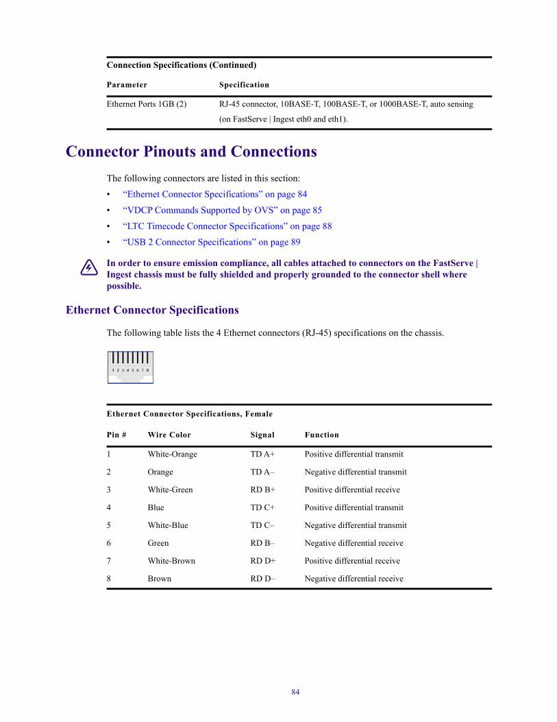
Connector Pinouts and ConnectionsThe following connectors are listed in this section:
• “Ethernet Connector Specifications” on page 84
• “VDCP Commands Supported by OVS” on page 85
• “LTC Timecode Connector Specifications” on page 88
• “USB 2 Connector Specifications” on page 89
w In order to ensure emission compliance, all cables attached to connectors on the FastServe | Ingest chassis must be fully shielded and properly grounded to the connector shell where possible.
Ethernet Connector Specifications
The following table lists the 4 Ethernet connectors (RJ-45) specifications on the chassis.
Ethernet Ports 1GB (2) RJ-45 connector, 10BASE-T, 100BASE-T, or 1000BASE-T, auto sensing
(on FastServe | Ingest eth0 and eth1).
Connection Specifications (Continued)
Parameter Specification
Ethernet Connector Specifications, Female
Pin # Wire Color Signal Function
1 White-Orange TD A+ Positive differential transmit
2 Orange TD A– Negative differential transmit
3 White-Green RD B+ Positive differential receive
4 Blue TD C+ Positive differential transmit
5 White-Blue TD C– Negative differential transmit
6 Green RD B– Negative differential receive
7 White-Brown RD D+ Positive differential receive
8 Brown RD D– Negative differential receive
84

VDCP Commands Supported by OVS
The following commands are implemented in Avid FastServe | Ingest server for the VDCP protocl.
Supported Optional VDCP Commands
Command Description
1x.00 - STOP The STOP command will return the selected port to the IDLE state.
The STOP command can be issued to a port in any state. When in IDLE, the port will output black. Any material that is playing out, CUED or cueing is aborted. No action will result if the STOP command is received when no material is PLAYing. If the port was in the RECORD state, then the system will stop recording at the next REF interval. A partial recording will have occurred and the internal database for the length of the material will be updated to reflect this reduced length. The part of the material received is kept stored on the disk and is available for play.
1x.01 - PLAY The PLAY command causes the specified ID to play out.
1x.02 - RECORD Issuing the RECORD command will cause the system to begin recording on the next REF interval. It will also clear the CUE/INIT and cueing bits in the port status.
1x.04 - STILL/PAUSE The STILL command causes the currently playing ID to pause. The last frame played prior to receiving the STILL command will continue being displayed. The output port must be in the PLAY, or in the CUED state.
1x.06 - CONTINUE The CONTINUE command causes the ID currently in the STILL state to continue playing. The output port must be in a PLAY, CUED, or STILL state or an error will be logged.
2x.21 - CLOSE PORT The CLOSE command is used to break communication to a Signal (audio/video) Port connection established by a preceding OPEN command. PORT is a number representing the available video ports as in OPEN. SEND DATA 1 contains an 8 bit signed number representing PORT.
2x.22 - SELECT PORT The SELECT PORT command selects a Signal Port from the signal ports that are currently opened by this communications port. All subsequent commands arriving at the associated RS-422 port will be routed to the assigned Signal Port until another SELECT PORT command is received. Only one signal port may be selected by a single communications port at any time. A CLOSE, or SELECT PORT command following, breaks or closes this selection. PORT is a number representing the available I/O signal ports. SEND DATA 1 contains an 8 bit signed number representing PORT.
2x.23 - RECORD INIT Issuing the RECORD INIT command with a Video Input Port selected causes the system to prepare for recording. The RECORD INIT command consists of the command itself followed by an ID, followed by a LENGTH. The ID is an 8 character identifier. The LENGTH is the duration of record in FRAMES SECONDS MINUTES HOURS (BCD) format. The RECORD INIT command may be issued when the signal port is recording, if the disk system supports back to back records. In this case every frame of video is recorded.
2x.24 - PLAY CUE The PLAY CUE command causes the selected port to prepare to play the specified ID.
2x.25 - CUE WITH DATA This command is similar to the CUE command but allows play out of just a part of the ID.
2x.26 - DELETE ID The ID DELETE command is used to remove material from the disk system.
85

2x.2C - RECORD INIT WITH DATA
This command is similar to the CUE command but allows play out of just a part of the ID.
2x.2C - RECORD INIT WITH DATA
The RECORD INIT WITH DATA command has all the features and requirements of the RECORD INIT command with the following changes: The ID may already exist on the disk (e.g. this command permits a dub over of a section of the ID).
2X.60 / AX.60 OPEN USER INFO
The OPEN_USER_INFO command will open the specified file ID for reading or writing User Data. If any file ID is already open for User Data by the communications port it will be closed.
2X.61 - CLOSE USER INFO The CLOSE_USER_INFO command will close the file ID currently open for User Data.
2X.62 - ADD USER INFO The ADD_USER_INFO command will add or replace the VALUE of the specified KEYWORD in the currently open file.
3x.01 - OPEN PORT The Signal Ports consist of audio and video channels as configured by the device. Any signal port can be controlled from any RS-422 control port with the following Port assignment commands; OPEN, CLOSE and SELECT. Only one communications port can have a given signal port open at a given time. The system commands are organized with reference to the Signal Port that they effect. The ports consist of SIP (Signal Input Ports, range –1 to -127) and SOP (Signal Output Ports range 1 to 127).
3x.02 - NEXT The NEXT command is used to transfer any remaining IDs in groups of up to ten. It has the same format as LIST commands and NEXT is called repeatedly until all IDs have been transferred. See the LIST command 3X.11 for more details.
3x.05 - PORT STATUS REQUEST
The Port Status command returns to the controller the status bytes specified for the selected video port, preceded by the bit map.
3x.06 - POSITION REQUEST The POSITION REQUEST query returns the current position ‘timecode’ or time remaining within the ID which is currently playing on the selected port. The selected port must be in PLAY, RECORD, CUED, OR STILL state or an error will be logged. An error condition will result in the appropriate bit being set in the port status error bytes. The POSITION/TIME returned is in RETURN DATA 2-5 in FRAMES, SEC, MIN, HOURS BCD format is preceded by RETURN DATA 1 the time type.
3x.07 - ACTIVE ID REQUEST This command returns information to the controller about whether a queried port is active (an active port is one that is either recording, playing, cued or cueing), and what the active ID is. This query does not affect the output of the system.
3x.08 - DEVICE TYPE REQUEST
The DEVICE TYPE REQUEST command is used to request the specifications of the Controlled Device. The response to this command is a 16-byte (maximum) data message advising of the specifications of the CONTROLLED DEVICE. The first N bytes will be the manufacturer ID followed by a colon ‘:’
3x.10 - SYSTEM STATUS REQUEST
This command returns to the controller information about the MAIN storage system.This command returns to the controller information about the MAIN storage system
3x.11 - ID LIST This command returns a list of all IDs currently stored on the system to the controller. The format will return the number of IDs remaining to be transmitted in subsequent transmissions in RETURN DATA 1 and RETURN DATA 2 (RETURN DATA 1 MSB, RETURN DATA 2 LSB), followed by ten 8 byte IDs in RETURN DATA 3 to RETURN DATA 82. The NEXT command is used to transfer any remaining IDs in groups of up to ten. NEXT is called repeatedly until all IDs have been transferred.
Supported Optional VDCP Commands(Continued)
Command Description
86

3x.14 - ID SIZE REQUEST This command returns the duration of the specified ID to the controller. The format returns the frames in RETURN DATA 1, seconds in RETURN DATA 2, minutes in RETURN DATA 3 and hours in RETURN DATA 4, in BCD. SEND DATA 1-8 contains the ID name. This command returns the duration of the specified ID to the controller. The format returns the frames in RETURN DATA 1, seconds in RETURN DATA 2, minutes in RETURN DATA 3 and hours in RETURN DATA 4, in BCD. SEND DATA 1-8 contains the ID name.
3x.16 - ID REQUEST This command tells the controller whether the ID is currently in the ‘get from archive list’ for the selected port and whether the ID is currently in the disk and the ARCHIVE. This command allows the automation controller to ask if an ID it needs for future playout is in the DISK or ARCHIVE. This command tells the controller whether the ID is currently in the ‘get from archive list’ for the selected port and whether the ID is currently in the disk and the ARCHIVE. This command allows the automation controller to ask if an ID it needs for future playout is in the DISK or ARCHIVE.
3x.18 - ID’S ADDED LIST This request allows a controller to inquire about items that were added to the disk system by another signal port. The command returns to the controller a list of the IDs that have been added to the disk system since the last ID’s ADDED request, or unreported ID’s from before the last IDs ADDED request if not all were read. The list is kept for each active communications port.
3x.19 - ID’S DELETED LIST This command returns to the controller a list of the IDs that have been deleted from the disk system since the last ID’s DELETED request, or unreported ID’s from before the last ID’s DELETED request if not all were read. This list is kept for each active communications port. This request allows a controller to find out about items added to the disk system that it may need that were deleted by another signal port.
3x.07 - ACTIVE ID REQUEST This command returns information to the controller about whether a queried port is active (an active port is one that is either recording, playing, cued or cueing), and what the active ID is. This query does not affect the output of the system.
3x.08 - DEVICE TYPE REQUEST
The DEVICE TYPE REQUEST command is used to request the specifications of the Controlled Device. The response to this command is a 16-byte (maximum) data message advising of the specifications of the CONTROLLED DEVICE. The first N bytes will be the manufacturer ID followed by a colon ‘:’
3x.10 - SYSTEM STATUS REQUEST
This command returns to the controller information about the MAIN storage system.This command returns to the controller information about the MAIN storage system
3x.11 - ID LIST This command returns a list of all IDs currently stored on the system to the controller. The format will return the number of IDs remaining to be transmitted in subsequent transmissions in RETURN DATA 1 and RETURN DATA 2 (RETURN DATA 1 MSB, RETURN DATA 2 LSB), followed by ten 8 byte IDs in RETURN DATA 3 to RETURN DATA 82. The NEXT command is used to transfer any remaining IDs in groups of up to ten. NEXT is called repeatedly until all IDs have been transferred.
3x.14 - ID SIZE REQUEST This command returns the duration of the specified ID to the controller. The format returns the frames in RETURN DATA 1, seconds in RETURN DATA 2, minutes in RETURN DATA 3 and hours in RETURN DATA 4, in BCD. SEND DATA 1-8 contains the ID name. This command returns the duration of the specified ID to the controller. The format returns the frames in RETURN DATA 1, seconds in RETURN DATA 2, minutes in RETURN DATA 3 and hours in RETURN DATA 4, in BCD. SEND DATA 1-8 contains the ID name.
Supported Optional VDCP Commands(Continued)
Command Description
87

LTC Timecode Connector Specifications
The LTC In is an AC coupled input which requires a minimum 100mV between the LTC and ground. Peak-Peak input levels cannot be lower than 1.5V. LTC voltage level: 2.5V min - 5V max
LTC Loopthrough displays Playback, Channel 2.
In the following LTC diagram:
• Pin 1 is located at the center.
• Ground is located on the outer shell.
The following table lists LTC specifications.
3x.16 - ID REQUEST This command tells the controller whether the ID is currently in the ‘get from archive list’ for the selected port and whether the ID is currently in the disk and the ARCHIVE. This command allows the automation controller to ask if an ID it needs for future playout is in the DISK or ARCHIVE. This command tells the controller whether the ID is currently in the ‘get from archive list’ for the selected port and whether the ID is currently in the disk and the ARCHIVE. This command allows the automation controller to ask if an ID it needs for future playout is in the DISK or ARCHIVE.
3x.18 - ID’S ADDED LIST This request allows a controller to inquire about items that were added to the disk system by another signal port. The command returns to the controller a list of the IDs that have been added to the disk system since the last ID’s ADDED request, or unreported ID’s from before the last IDs ADDED request if not all were read. The list is kept for each active communications port.
3x.19 - ID’S DELETED LIST This command returns to the controller a list of the IDs that have been deleted from the disk system since the last ID’s DELETED request, or unreported ID’s from before the last ID’s DELETED request if not all were read. This list is kept for each active communications port. This request allows a controller to find out about items added to the disk system that it may need that were deleted by another signal port.
3X.63 - GET USER INFO The GET_USER_INFO command will return the VALUE from the specified KEYWORD in the currently open file. The keyword supplied with the command must be an exact match for an existing keyword that is stored within the specified file. The match is case sensitive. Another GET_USER_INFO command should not be started until after the first has completed.
Supported Optional VDCP Commands(Continued)
Command Description
88
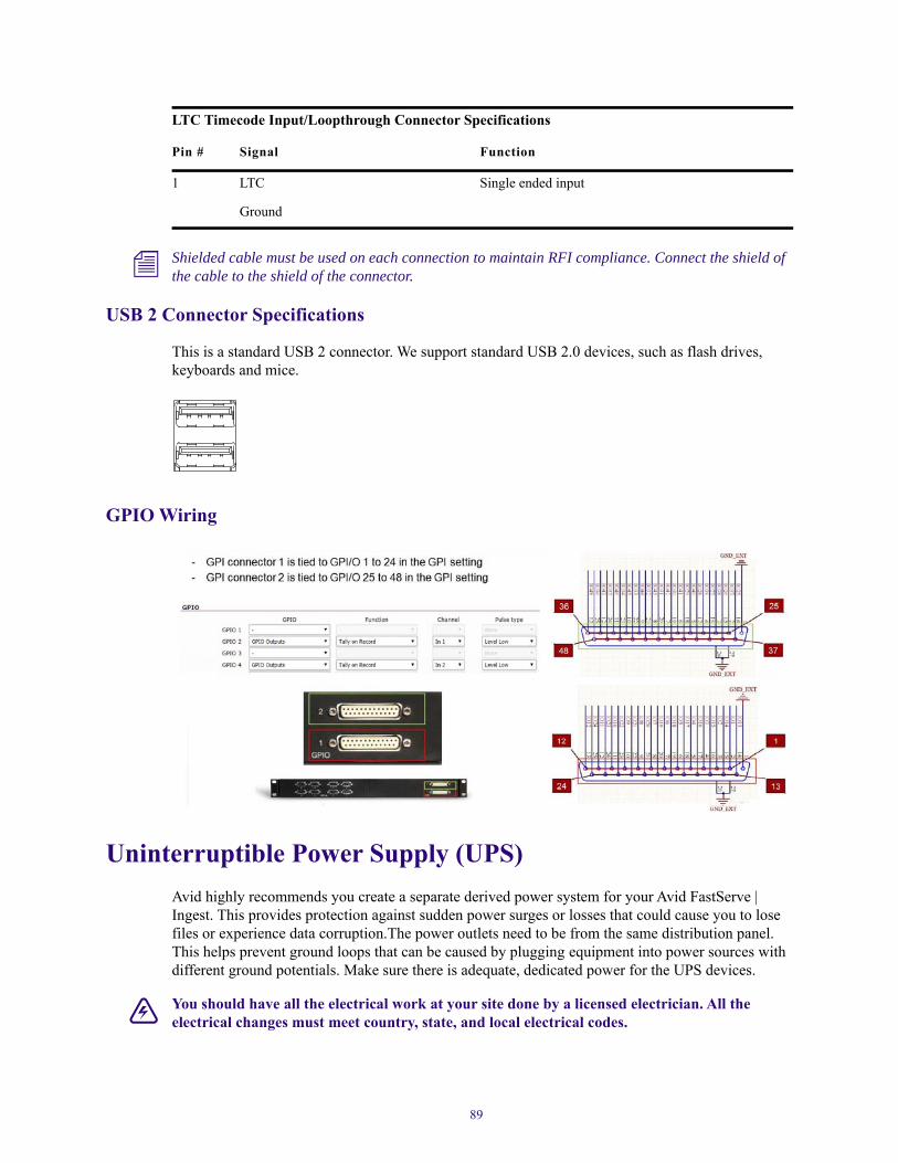
n Shielded cable must be used on each connection to maintain RFI compliance. Connect the shield of the cable to the shield of the connector.
USB 2 Connector Specifications
This is a standard USB 2 connector. We support standard USB 2.0 devices, such as flash drives, keyboards and mice.
GPIO Wiring
Uninterruptible Power Supply (UPS)Avid highly recommends you create a separate derived power system for your Avid FastServe | Ingest. This provides protection against sudden power surges or losses that could cause you to lose files or experience data corruption.The power outlets need to be from the same distribution panel. This helps prevent ground loops that can be caused by plugging equipment into power sources with different ground potentials. Make sure there is adequate, dedicated power for the UPS devices.
w You should have all the electrical work at your site done by a licensed electrician. All the electrical changes must meet country, state, and local electrical codes.
LTC Timecode Input/Loopthrough Connector Specifications
Pin # Signal Function
1 LTC Single ended input
Ground
89

FastServe | Ingest servers support UPS devices that are connected using network connections, USB connections, and serial connections. Install the software from the UPS manufacturer for advanced shutdown behavior, calibrate the UPS device. These software packages also allow for a connected Windows servers to send alerts to other Windows servers to perform actions.
Your FastServe | Ingest server is connected to a network, network policy settings might also prevent you from completing this procedure. Make sure there is adequate power and the correct receptacle type for each hardware component, the rack power strips, and the UPS devices. Do not use extension cords to plug in any of the hardware components.
90

B Installing Matrox S2 Board
Starting with the 2019.6 version of FastServe | Ingest supports the XAVC-I Class 100 HD codecs. To achieve this support, a Matrox board needs to be added to a FastServe | Ingest UHD machine.
PrerequisitesThe Matrox S2 board can only be added to a FastServe | Ingest machine which meets the following requirements:
• CentOS 7 operating system,
• OVS 2019.6 FULL (Matrox drivers are installed automatically with this version),
• minimum dnxhd_ii_9024 firmware on the codec boards.
Currently, only the ingest workflow for 8 input channels is certified.
Board Layout Before Upgrade
There is a number of possible layouts of boards. In our example, 4 codec boards are places on slots #1-4, RAID Controller on slot #7.
n Note, that the AES input cable is located on slot #4. AES cables run through the metal frame from the inside - if it is not the case, re-insert them accordingly through slot #8.

GPIO is on slot #4, LTC cables are connected to slots #3 and #2.
Installing the Matrox HardwareThe Matrox board should be physically located on slot #10.
92

Board Layout After Matrox Upgrade
Verifying the Installation
After placing the Matrox board on the slot #10, verify the installation by following the steps below.
To verify the Matrox board hardware installation:
1. Connect to your FastServe machine with PuTTY or other terminal emulator.
2. Check if the boards are installed in a correct layout:lspci | grep -e Adap -e Mat -e Eth -e OradYou should receive the following response:
00:19.0 Ethernet controller: Intel Corporation Ethernet Connection I217-LM (rev 05)02:00.0 Bridge: Orad Hi-Tec Systems Device 1980 (rev 0e)04:00.0 Bridge: Orad Hi-Tec Systems Device 1980 (rev 0e)05:00.0 Bridge: Orad Hi-Tec Systems Device 1980 (rev 0e)06:00.0 Bridge: Orad Hi-Tec Systems Device 1980 (rev 0e)
93

07:00.0 Ethernet controller: Intel Corporation I210 Gigabit Network Connection (rev 03)82:00.0 Ethernet controller: Intel Corporation 82599ES 10-Gigabit SFI/SFP+ Network Connection (rev 01)82:00.1 Ethernet controller: Intel Corporation 82599ES 10-Gigabit SFI/SFP+ Network Connection (rev 01)86:00.0 RAID bus controller: Adaptec Series 8 12G SAS/PCIe 3 (rev 01)89:00.0 Multimedia controller: Matrox Electronics Systems Ltd. SV2 (rev 01)8a:00.0 Multimedia controller: Matrox Electronics Systems Ltd. SV2 (rev 01)
Installing the Matrox SoftwareAfter successfully installing the Matrox hardware, set up the required software as described below.
To install the required software:
1. Edit the /usr/dvg/codecs.map file to match the content below:
2. The Matrox driver should be installed automatically with the FastServe | Ingest v2019.6. Verify that the M264 driver is present using the MveXinfo.exe tool. /opt/MatroxVideo/DSX.utils/bin/mveXinfo.exe
94

If the correct version of the driver is not found, install it manually.
a. Place the Matrox driver (M264_260319_23779.run) in /data/public.
b. Uninstall the previous version of the Matrox driver (if required):/opt/MatroxVideo/DSX.utils/uninstall.sh
c. Reboot the server.
d. Install the required version of the driver:/data/VS/bin/set_run -s allchmod -v 755 /data/public/M264_260319_23779.run/data/public/M264_260319_23779.run
e. Verify the installation using MveXinfo.exe: /opt/MatroxVideo/DSX.utils/bin/mveXinfo.exe
f. Start the server:/data/VS/bin/set_run -a all
3. Check the codec board and make sure the firmware is suitable for Matrox. The latest version of the firmware is dnxhd_ii_9024.bin.
4. Open the vsProxy.xml file and check if its content matches the one listed below.
a. Stop the server:/data/VS/bin/set_run -s all
b. Open the vsProxy.xml file:vi /data/VS/bin/vsProxy/bin/vsProxy.xml
c. Check the content:
<Matrox Enable="Yes" DeviceIndex="0" ProfileIndex="0" /><Buffer Name="vsProxyCommunicationChannel" /><Channels><!-- FastStart --><Channel Id="0" Type="Exporter" PresetName="Hires540p1500k" MatroxProfileIndex="0" MatroxDeviceIndex="0" /><Channel Id="1" Type="Exporter" PresetName="Hires540p1500k" MatroxProfileIndex="1" MatroxDeviceIndex="0" /><Channel Id="2" Type="Exporter" PresetName="Hires540p1500k" MatroxProfileIndex="0" MatroxDeviceIndex="0" /><Channel Id="3" Type="Exporter" PresetName="Hires540p1500k" MatroxProfileIndex="1" MatroxDeviceIndex="0" /><Channel Id="4" Type="Exporter" PresetName="Hires540p1500k" MatroxProfileIndex="0" MatroxDeviceIndex="0" /><Channel Id="5" Type="Exporter" PresetName="Hires540p1500k" MatroxProfileIndex="1" MatroxDeviceIndex="0" /><Channel Id="6" Type="Exporter" PresetName="Hires540p1500k" MatroxProfileIndex="0" MatroxDeviceIndex="0" /><Channel Id="7" Type="Exporter" PresetName="Hires540p1500k" MatroxProfileIndex="1" MatroxDeviceIndex="0" /></Channels>
95

<Presets><Preset Name="Hires1080p3000k" Description="Hires proxy,1080p, 6Mbit, audio mp2" Width="1920" Height="1080" AudioBitrate="96000" AudioCompression="mp2" VideoEncoderPreset="avc/hiresproxy/HQ" MatroxEncoder="No" ThreadPriority="60" AudioChannels="16" AudioInterleave="1" ContainerType="Mxf" /><Preset Name="Hires720p3000k" Description="Hires proxy, 720p, 3Mbit, audio mp2" Width="1280" Height="720" AudioBitrate="96000" AudioCompression="mp2" VideoEncoderPreset="avc/hiresproxy/HQ" MatroxEncoder="Yes" ThreadPriority="60" AudioChannels="16" AudioInterleave="1" ContainerType="Mxf" /><Preset Name="Hires540p1500k" Description="Hires proxy, 540p, 1.5Mbit, audio mp2" Width="960" Height="540" AudioBitrate="96000" AudioCompression="mp2" VideoEncoderPreset="avc/hiresproxy/SQ" MatroxEncoder="Yes" ThreadPriority="60" AudioChannels="16" AudioInterleave="1" ContainerType="Mxf" /><Preset Name="Hires360p800k" Description="Hires proxy, 360p, 800kbit, audio mp2" Width="640" Height="360" AudioBitrate="96000" AudioCompression="mp2" VideoEncoderPreset="avc/hiresproxy/LB" MatroxEncoder="Yes" ThreadPriority="60" AudioChannels="16" AudioInterleave="1" ContainerType="Mxf" /><Preset Name="Proxy270p800k" Description="Airspeed compatible proxy, 270p, 800kbit, audio mp2" Width="480" Height="270" AudioBitrate="96000" AudioCompression="mp2" VideoEncoderPreset="avc/proxy/1080p/800k" MatroxEncoder="Yes" ThreadPriority="60" AudioChannels="16" AudioInterleave="1" ContainerType="Mxf" /><Preset Name="Proxy180p800k" Description="Airspeed compatible proxy, 180p, 800kbit, audio mp2" Width="320" Height="180" AudioBitrate="96000" AudioCompression="mp2" VideoEncoderPreset="avc/proxy/720p/800k" MatroxEncoder="Yes" ThreadPriority="60" AudioChannels="16" AudioInterleave="1" ContainerType="Mxf" />
d. Start the server:/data/VS/bin/set_run -a all
5. Make sure you have the correct FastServe | Ingest license which includes support for XAVC XAV UHD V3G.
6. Select a XAVC-I video format in the FastServe | Ingest WebSettings > OVS > Video > Codec field.
96

D Safety and Regulatory Information
This document contains safety and regulatory information for Avid FastServe | Ingest hardware.
Important Safety Instructions1. Read these instructions.
2. Keep these instructions.
3. Heed all warnings.
4. Follow all instructions.
5. Do not use this equipment near water.
6. Clean only with dry cloth.
7. Do not block any ventilation openings. Install in accordance with the manufacturer'sinstructions.
8. Do not install near any heat sources such as radiators, heat registers, stoves, or other equipment(including amplifiers) that produce heat.
9. Protect power cords from being walked on or pinched particularly at plugs, conveniencereceptacles, and the point where they exit from the equipment.
10. Only use attachments/accessories specified by the manufacturer.
11. For products that are not rack-mountable: Use only with a cart, stand, tripod, bracket, or tablespecified by the manufacturer, or sold with the equipment. When a cart is used, use caution whenmoving the cart/equipment combination to avoid injury from tip-over.
12. Unplug this equipment during lightning storms or when unused for long periods of time.
13. Refer all servicing to qualified service personnel. Servicing is required when the equipment hasbeen damaged in any way, such as power-supply cord or plug is damaged, liquid has been spilledor objects have fallen into the equipment, the equipment has been exposed to rain or moisture,does not operate normally, or has been dropped.
14. For products that are a Mains powered device: The equipment shall not be exposed to drippingor splashing and no objects filled with liquids (such as vases) shall be placed on the equipment.
c To reduce the risk of fire or electric shock, do not expose this equipment to rain or moisture.Donot defeat the safety purpose of the polarized or grounding-type plug. A polarized plug has two blades with one wider than the other.A grounding type plug has two blades and a third grounding prong. The wide blade or the third prong are provided for your safety. If the provided plug does not fit into your outlet, consult an electrician for replacement of the obsolete outlet.
15. For products containing a lithium battery:
c Danger of explosion if battery is incorrectly replaced. Replace only with the same or equivalenttype.
16. For products with a power switch: It should remain accessible after installation.

17. The equipment shall be used at a maximum ambient temperature of 40° C.
18. This unit may be provided with a power supply cord set suitable for 120V AC input only (forU.S.A.and Canada). For other than U.S.A. and Canada, a qualified person must provide for usewith this unit, an appropriate, approved power supply cord set which is in compliance with theend use country requirements and has a minimum cross-sectional area of 1.0mm2.
19. For products with more than one power cord:
c This unit has more than one power supply cord. Disconnect two power supply cords beforeservicing to avoid electrical shock.
c Cet appareil comporte plus d'un cordon d'alimentation. Afin de prévenir les chocs électriques,débrancher les deux cordons d'alimentation avant de faire le dépannage.
20. For products with an operator-accessible fuse:
c For continued protection against risk of fire, replace only with same type and rating of fuse.
c Pour ne pas compromettre la protection contre les risques d'incendie, remplacer par un fusiblede m?me type et de m?me caractéristiques nominales.
Rack-Mount Requirements1. Elevated Operating Ambient - If installed in a closed or multi-unit rack assembly, the operating
ambient temperature of the rack environment might be greater than room ambient. Therefore,consider installing the equipment in an environment compatible with the maximum ambienttemperature (Tma) specified by the manufacturer.
2. Reduced Air Flow - Installation of the equipment in a rack should be such that the amount of airflow required for safe operation of the equipment is not compromised.
3. Mechanical Loading - Mounting of the equipment in the rack should be such that a hazardouscondition is not achieved due to uneven mechanical loading.
4. Circuit Overloading - Consideration should be given to the connection of the equipment to thesupply circuit and the effect that overloading of the circuits might have on overcurrent protectionand supply wiring. Appropriate consideration of equipment nameplate ratings should be usedwhen addressing this concern.
5. Reliable Earthing - Reliable Earthing of rack-mounted equipment should be maintained.Particular attention should be given to supply connections other than direct connections to thebranch circuit (for example, use of power strips).
EMC (Electromagnetic Compliance) and SafetyAvid declares that this product complies with the following standards regulating emissions, immunity and product safety:
• FCC Part 15 Class A
• ICES-003 Class A
• EN55032 Class A
98

• EN55103-1 E4
• EN55024
• EN55103-2 E4
• AS/NZS CISPR 32 Class A
• CISPR32 Class A
• VCCI Class A
• IEC/EN/UL60950-1
• CAN/CSA-C22.2 No. 60950-1-07
This equipment has been tested to comply with USA and Canadian safety certification in accordance with the specifications of UL Standards: IEC/UL60950-1 and Canadian CAN/CSA-C22.2 No. 60950-1-07. Avid Inc. has been authorized to apply the appropriate UL & CUL mark on its compliant equipment.
(EMC, Safety and RoHS)
Avid is authorized to apply the CE (Conformité Europénne) mark on this compliant equipment thereby declaring conformity to EMC Directive 2014/30/EU, Low Voltage Directive 2014/35/EU and RoHS Recast Directive 2011/65/EU.
FCC NoticeClass A Equipment
This equipment has been tested and found to comply with the limits for a Class A digital device, pursuant to Part 15 of the FCC rules. These limits are designed to provide reasonable protection against harmful interference when the equipment is operated in a commercial environment. This equipment generates, uses, and can radiate radio frequency energy and, if not installed and used in accordance with the instructions, may cause harmful interference to radio communications. Operation of this equipment in a residential area is likely to cause harmful interference, in which case the user will be required to correct the interference at personal expense.
Cables
Connections to Avid hardware must be made with shielded cables with metallic RFI/EMI connector hoods in order to maintain compliance with FCC Rules and Regulations.
Canadian ICES-003
Class A Equipment
This Class A digital apparatus meets all requirements of the Canadian Interference-Causing Equipment Regulations.
99

Cet appareil numérique de la classe A respecte toutes les exigences du R?glement sur le matériel brouilleur du Canada.
Australian Compliance
Korean EMC Compliance
Environmental Compliance
Disposal of Waste Equipment by Users in the European Union
This symbol on the product or its packaging indicates that this product must not be disposed of with other waste. Instead, it is your responsibility to dispose of your waste equipment by handing it over to a designated collection point for the recycling of waste electrical and electronic equipment. The separate collection and recycling of your waste equipment at the time of disposal will help conserve natural resources and ensure that it is recycled in a manner that protects human health and the environment. For more information about where you can drop off your waste equipment for recycling, please contact your local city recycling office or the dealer from whom you purchased the product.
Proposition 65 Warning
This product contains chemicals, including lead, known to the State of California to cause cancer and birth defects or other reproductive harm. Wash hands after handling.
Perchlorate Notice
This product may contain a lithium coin battery. The State of California requires the following disclosure statement: "Perchlorate Material - special handling may apply, See www.dtsc.ca.gov/hazardous waste/perchlorate "
Recycling Notice
100