VOLO SLIDING DOOR FRAME - Setup Videos
32
VOLO SLIDING DOOR FRAME Installation Manual Accompanying Installation Video: SCAN FOR VIDEO
-
Upload
khangminh22 -
Category
Documents
-
view
1 -
download
0
Transcript of VOLO SLIDING DOOR FRAME - Setup Videos

VOLO SLIDING DOOR FRAME Installation Manual
Accompanying Installation Video:
SCAN FOR VIDEO
PRE-ASSEMBLYDetailed Installation Instructions ship with every Trendway Movable Wall Products. Locate
these instructions before starting the installation. These INS Sheets are also available on
the Trendealer website. A thorough pre-installation survey is required that include: Overall
Space Dimensions, Wall Locations and Distance From Columns, Wall Runds that Terminate
Flush With Building Wall Surfaces.
2
WARNING
IMPORTANT
Ensure accurate floor plans with key dimensions and conditions are up to
date, as these factors will be crucial for proper assembly and installation.
Consult the appropriate party for floor plans and necessary details about
your property.
For Field Technical Support, contact the Trendway architectural product team for more
details. Once the designed is finalized, it’s essential to do a thorough onsite verification
of the installation drawings to actual site dimensioning prior to installation.
Please note that the assembly process will require an additional person to help with the
assembly.
PARTS & TOOLS CHECK LISTEnsure that the following parts and hardware are included with your Volo Sliding Door
Assembly.
Stiles x2
#3/8-16
Hex Coupling Nut x2Header Rail x1
#3/8-16 x 4”
Carriage Bolt GR5 x2
#6-18 x 1”
Square Drive
Screws
Header/Transom
Cover x1
10-16 x 1” Bolt
Door Guide
Assembly x1

Inline
Light Block x2
#3/8-16 x 4”
Carriage Bolt GR5 x2
Vertical
Jamb Covers x2
Panel Clips x12
Header/Transom
Cover x1
Spacer Spring
Clips x2
Door Anchor
Bracket x2
3/16” X 1 1/4”
Tapcon Screws
Pre-Drilled
Track (2 1/2” x 2” )
Valence Covers
(3 1/2” Tall)
Strike Post Cover
(2 1/2” x 1/4”) x1
Receiver
Strike Post
(2 1/2” x 1 1/2”)
3
12-11 x 1 1/4” Phillips Screw
(Used on Trolley Brackets
For Alum. Door)
#7-19 x 7/16 Screws
10-16 x 1” Bolt Wood Shims
(Only used on
4x4x4 doors)
10 Pack
WashersL Bracket x1 Acoustic Seal and
Mount Assembly x1Post Spacer x1
Hardware Kit x1
Door Guide
Assembly x1Track End Cap x1

Soft Close Mechanism x1
PARTS CHECK LIST
Standoff x1M4 x 10mm
Socket Cap Screws
M4 x 16mm
Socket Cap Screw
Plastic Drill Fixture x1
M5 x 50mm Flathead
Phillips x1
KeysNylon Spacer
Strike Plate Lock Covers
M6 x 20mm
Flat Torx Screw & Nut
Rubber BumperLock Plate Spacers Spacer Sheets
Lock Side Plates
Installation Instructions
Door Stop x1
12mm Black Spacers
M4 x 8mm
Flat Socket Cap ScrewsLock Side Plates Lock Cylinder
Safety Instructions
Lock Mechanism
4

Door Jamb x1Door StopDoor Guide x1
Door Cover
End Plate x1
Door Clamps x2 Trolley Assembly
x2
Door Cover x2
Door Cover
Screws
Door Guide
Bracket
Aluminum (Or Wood)
Framed Door x1
Frameless
Glass Door x1
Plastic Insers#6-18 x 1” Screws Anchor Bolt x1
Tapcon HXHD
Screws x4
5
Door Handle Assembly x1
Door Lock
Components x1
PARTS CHECK LIST

6
TOOLS CHECK LISTEnsure you have the following tools available for assembly. These tools are not included with the
door assembly.
Phillips Screwdriver x1Power Drill with
Square Driver Bit &
5/32” Drill Bit x1
Torx T30 Screw Driver x1 Power Drill
with 1/4” Socket x1
Knife or Box Cutter x1 Allen Wrench
2.5mm, 4mm, 1/8”Touchup Paint x1
Ladder x1 Rotto Hammer Drill
With 5/32” Drill Bit x1
Marker Or Pencil x1
2 Feet and 4 Feet
Hand Level x1
Putty Knife x1Tape Measure x1
Tape & Double
Sided Tape x1
12” Sliding
Compound Miter Saw x1
Grinder With Cutting Disk x1Quick Clamps x2
15mm Wrench x1

Tape & Double
Sided Tape x1
7
INSTRUCTIONS
Locate Part 2 Header Rail and Part 1 Stiles Adjust the part and insert
Secure the stiles to the header rail
Ensure parts are tightly placed
Begin the assembly by placing the header rail flat
on the ground & place two stiles on each end of
the Header Rail. Push the stiles into place with
the open top-end facing towards the ceiling, and
match the corner holes.
Insert the new Adjustable Foot Assembly into the Door Stiles, making sure the round side of the washer is on the tube side. Make sure the rounded section of the nut is facing away from the stile.
Place two Hex coupling nuts and two Carriage
Bolts on the open ends of each Stile. Before
inserting the bolts into place, screw the bolt into
the Hex Coupling Nut, making sure the longer Hex
part of the Coupling Nut is Facing away from the
Bolt, as shown.
Repeat these steps and tighten the remaining nut and bolt on the opposite stile and ensure it fits accordingly.
1. 4.
3. 6.
Step 1 - Assembling the Door Frame
Locate the Part 4 Nut and Part 5 Bolt
Repeat these steps on the opposite side
Push the stiles into place and secure them using eight Square Drive Screws. Insert four screws on each side into the pre drilled holes on the stilesUsing a Power Drill with a Square Drive Bit, tightly secure each screw. Repeat these steps for the opposite side.
Push up to pressure-fit the assembly into the frame. Make sure the parts tightly fit into place on the stile.
2. 5.
DO NOT OVER TIGHTEN

INSTRUCTIONS
Step 2 - Installing the Door Frame
8
Measure the area where the door frame is to be installed Locate the Part 29 Header Cover
Locate the Part 31 Door Anchor Bracket
Ensure header cover is 1-3/8” away and repeat steps
Begin Step Two by locating the bottom of the adjacent panel where the door frame is to be installed. Place a flat surface &, using a tape measure, measure 1-3/8” away from the flat surface. Place a flat piece of tape on the location
and mark the location.
Locate the Header Cover and butt it up against the door anchor bracket. This will only be used as a measuring tool in this step to determine the door anchor location on the opposite side.
Use a roto hammer with a 5/32” drill bit & drill two holes in the marked areas. Next, place the bracket into place and secure it using two Part 32 Tapcon HXHD Screws. Tighten the screws using a power drill with a 1/4” socket.
Ensure that the door brackets are tightly secured, as loose parts will affect the leveling of later steps, parts, and installation.
1. 4.
3. 6.Drill holes using a roto hammer drill and secure the bracket
Set aside the header cover and ensure the door brackets are tightly secured
Locate the Door Anchor Bracket & place it on the marked tape matching the location measured. Make sure to place the bracket where the holes will be bored. Use a knife to cut marks into the floor where the Tapcon Screws will be used to secure the bracket. Set the bracket aside for now.
Provided that the vertical panels are leveled and plumb, and is 1-3/8” away from the panels, repeat the previous steps of installing the door anchor bracket for the opposite side.
2. 5.

INSTRUCTIONS
Step 2 - Installing the Door Frame
9
Locate the previously assembled door frame Slide the panel clips upward
Adjust the foot assembly bolts Use a putty knife to slide the panel clips upward into place
With the help of another person, locate the previously assembled door frame and insert the door frame into place. Insert the frame into or
over the ceiling crown, depending on the project.
Slide the first panel clip upward about three inches, connecting the frame to the panel. Once the first panel clip is in place, take a second clip and place it on the bottom of the stile.
Locate six Panel Clips and align them so that they are positioned in between the frame and panel so that they will connect using the panel clips. Please note that the clips on the receiver side come with the adjacent panel and are not part of the door frame kit.
Using the putty knife, push the clip all the way up until it evenly attaches in place. Continue doing this process for the remaining five clips.
7. 10.
9. 12.Locate six Part 6 Panel Clips and align them
Push the panel clip all the way up to secure into place
Next, adjust the foot assembly bolts so that the top rail of the panel aligns perfectly with the panels on either side. Tighten the bolts until it reaches the door bracket. Check that the header and door frame are leveled. Repeat these steps for the opposite side.
Take a putty knife & place it in between both clips inside the stile. This process will be repeated until all six panel clips are inserted on this side of the frame.
8. 11.

INSTRUCTIONS
Step 2 - Installing the Door Frame
10
Repeat these steps for the oppo-site side Insert the Inline Light Block
Locate the Part 7 Inline Light Block and align in place
Repeat these steps for the opposite side.
Locate an additional six Panel Clips and repeat the same process until all clips are attached into place. Make sure that the header and door frame are evenly leveled.
Once verifying the type of installation the light block will need, simply inset the inline light block accordingly. Once reaching the end, fold a small portion of the end of the light block to help hold it in place
13. 15.
Please note that if the door frame is being attached directly to a panel & both are in position, install the inline light block the same you would for a direct panel-to-panel connection. If the door frame is being attached to a vertical connector, check the condition light block is installed accordingly.
If not, the condition installation must be done now. Failure to do so may damage the parts and hamper the installation process.
Finally, repeat these same steps on the opposite side, and ensuring that the type of installation matches that with the door frame accordingly.
Make sure that the parts, panel, and door frame are properly leveled and plumb, and that there is no loose parts or areas
14. 16.
11
INSTRUCTIONS
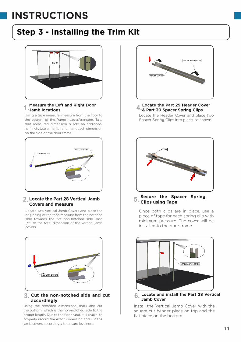
Measure the Left and Right Door Jamb locations
Locate the Part 29 Header Cover & Part 30 Spacer Spring Clips
Locate the Part 28 Vertical Jamb Covers and measure
Secure the Spacer Spring Clips using Tape
Using a tape measure, measure from the floor to
the bottom of the frame header/transom. Take
that measured dimension & add an additional
half inch. Use a marker and mark each dimension
on the side of the door frame.
Locate the Header Cover and place two Spacer Spring Clips into place, as shown.
Using the recorded dimensions, mark and cut
the bottom, which is the non-notched side to the
proper length. Due to the floor rung, it is crucial to
properly record the exact dimension and cut the
jamb covers accordingly to ensure levelness.
Install the Vertical Jamb Cover with the square cut header piece on top and the flat piece on the bottom.
1. 4.
3. 6.
Step 3 - Installing the Trim Kit
Cut the non-notched side and cut accordingly
Locate and install the Part 28 Vertical Jamb Cover
Locate two Vertical Jamb Covers and place the beginning of the tape measure from the notched side towards the flat non-notched side. Add 1/2” to the total dimension of the vertical jamb covers.
Once both clips are in place, use a piece of tape for each spring clip with minimum pressure. The cover will be installed to the door frame.
2. 5.

12
INSTRUCTIONS
Install the Vertical Jamb Cover accordingly
Measure & create a countersink hole for #6-18x1” Screw
Locate one more Vertical Jamb Cover & one Part 29 Header Cover
Secure the Vertical Jamb Cover with the #6-18x1” Screw
Align the Vertical Jamb Cover and ensure that
the cover is placed securely into position. Using a power drill with a 5/32” drill bit, drill a hole in the center of the vertical jamb cover 1/2” above the floor. Countersink the
hole for a #6-18x1” Screw.
Install the second Vertical Jamb Cover by tipping
the cover so that the notched portion of the cover
fits under the top rail. Make sure the jamb covers
fit perfectly into place.
Repeat the screw installation process for the remaining jamb cover, and ensure that the areas are properly touched up and that both covers are level.
7. 10.
9. 12.
Step 3 - Installing the Trim Kit
Install the second Vertical Jamb Cover into place
Repeat these steps for the opposite vertical jamb cover.
Next, locate the previously assembled Header Cover with Spacer Spring Clips & slip the Header Cover over the Vertical Jamb Cover, resting it into the notch of the Vertical Jamb Cover.
Secure the jamb cover using one #6-18x1” Screw. Tighten the screw using a power drill with a square driver bit. Use touch up paint to help mask the appearance of the area.
8. 11.

13
INSTRUCTIONS
Measure the Ordered Ceiling Height and record
Verify measurements if door as-sembly comes with a lock
Locate the Part 4 Receiver Post & cut accordingly
Secure the Receiver Post in place
Using a tape measure, measure from the floor
to the Ordered Ceiling Height. A ladder will be
needed to properly record this measurement.
Next, if your door assembly comes with a lock, verify that the lock hole on the receiver post is 30 5/8” from the floor to the bottom edge of the lock hole.
Make sure to place the Receiver Post about 1/4” away from the interior of the face, as shown.
Using a power drill with a 1/8” drill bit, drill five holes through the Receiver Post and through the door frame. Drill 1/2” holes, in set, from the back of the post & evenly spaced from top to bottom of the side that will mount on the door jamb.
1. 4.
3. 6.
Step 4 - Installing the Door Track
Ensure that the Receiver Post is placed accordingly
Drill five holes into the following loca-tions on the Receiver Post
Locate the Receiver Post and, using a saw, cut the height of the Receiver Post to match the recorded measurement. Place the post on either the left or right side depending on which side you want the door to open. Make sure to cut from the top part of the post.
Use two quick clamps to secure the Receiver Post. This will keep the Receiver Post secure once you begin to drill holes into it.
2. 5.

14
INSTRUCTIONS
Screw in five equally spaced Square Drive Screws
Place adhesive washers & Valence Cov-er on the back of the Pre-Drilled Track
Measure from the face of the post to the next panel joint
Place L Bracket at the end of the track & drill accordingly
Locate a minimum of five Square Drive Screws
& screw them through the back of the post,
through the post spacer, & into the door frame.
Flip the track over and place 1/8” adhesive washers over each of the pre-drilled holes. For soft stop close mechanism, please proceed to Step 6.
Locate the Pre-Drilled Track and cut to the length of the previous measurement minus 1” or to full length if aesthetics are desired.
Secure the L bracket using a #7/19 x 7/16 screw. Tighten the screw using a power drill with a Phillips head drill bit.
7. 10.
9. 12.
Step 4 - Installing the Door Track
Locate the Part 1 Pre-Drilled Track & cut accordingly
Secure the L bracket using a #7/19 x 7/16 Screw
Once the Receiver Post is secured, use a tape measure, and measure from the face of the post over to the next panel joint. A minimum panel of 36” is required to allow the door to open a minimum of 32”.
Locate the end of the track and place the L bracket, as shown. Mark the hole location on the track and drill a hole using a power drill with a 1/8” drill bit.
8. 11.

15
INSTRUCTIONS
Attach the Valence and Sliding Door Track into place
Secure the L-Bracket to the track using one #7/19 x 7/16” Screw
Ensure Door Stopper is intalled prior to attaching assembly
Check the track is leveled & secure the track onto the valence panels
With the help of another persion and using a
ladder, place the valence and sliding door track
into place, with the washers facing the door
frame & the L bracket facing downwards toward
the Receiver Post.
Secure the L-Bracket to the track using one #7/19 x 7/16” Screw. Tighten the screw using a power drill with a Phillips head drill bit.
Push the Door Stopper through the open end closest to the L bracket. Slide it through until it reaches the trolley inside the track, & attach the assembly.
Check the levelness of the track once more along with the hardware being properly secured to ensure that there are no loose parts to prevent unwanted motion, movement, and potential damage to parts in later steps.
13. 16.
18.15.
Step 4 - Installing the Door Track
Insert the Door Stopper through the track
Verify that the track is level and that all hardware is tightly secured
Verify that the Door Stopper is in place inside the track. If the Door Stopper is not installed in the track, do so before attaching the assembly to the frame.
Check that the track is level with the panels. Once verified, secure the track using six #10-16-1” screws provided with the track. Depending on the track, you may need 10 or more screws
17.14.

16
INSTRUCTIONS
Measure where you will place the Double Door Track
Repeat these steps and attach asecond Door Stopper Take the Valence Door Track and
place it on the ground
While measuring, make sure you have at least
75” on each side from the center of the door
opening. For proper clearance, panels with at
least 36”wide must be specified to the left and
right side of the Double Door.
Repeat these same steps for the opposite track and push the Door Stopper through until it reaches the trolley inside the track.
Push the Door Stopper through the open end closest to the L bracket. Slide it through until it reaches the trolley inside the track, & attach the assembly.
1.
4.
3.
Step 4a - Installing the Double Door Track
Insert the Door Stopper through the open end
With the help of another person, take the Valence Door Track and place it on the ground. Prior to attaching the Valence Door Track, ensure that the Door Stop is in place. If it is not in place, proceed to do so now.
2.

Attach and secure the second door track to the Splicer Block
Locate the Splicer Block and push into place
Level, align, and secure the Valence and Door Track to the assembly
Secure the Splicer Block to the Door Track assembly using the provided screws that came with the Splicer Block. Use a Power Drill with a Phillips Head Drill Bit.
6. Secure the Splicer Block to the Door Track using provided hardware
Once the Splicer is secured, proceed to attach the second door track. Secure the second door track to the exposed end of the splicer block using two more additional screws.
Next, locate the Splicer Block and push the Splicer Block through the open end and align the holes of the Splicer Block halfway in to align with the holes on the Door Track.
With the help of another person, level, align, and secure the Valence and Door track to the assembly using the #10-16-1” Hex Head Drill Screws. Secure the screws using a Power Drill with a 5/8” Head Socket.
5.
8.
7.
17
INSTRUCTIONSStep 4a - Installing the Double Door Track

18
INSTRUCTIONS
Install the Trailing Door Seal onto the door frame
Use the Door Guide for marking the drill hole
Secure the Trailing Door Seal & ensure it is above the guide height
Drill the anchor bolt hole and secure the Door Guide
Locate the Trailing Door Seal and install it on the
door frame, on the opposite side of the receiver
post.
Next, place the Door Guide at the bottom below the Trailing Door Seal up against the Door Frame. Use a marker and mark the hole location to be drilled. Use a blade and cut into the carpet prior to drilling.
Once the Trailing Door Seal is fully secured, locate the Plastic Insert, and push it into place inside the Trailing Door Seal.
Once the Door Guide is fully secured, locate the Aluminum Framed/Wood Door & place it on the Door Guide. Proceed to Step 6 if the Cast Bracket has not been installed on to the Door yet.
1. 4.
3. 6.
Step 5a - Installing the Aluminum Framed/Wood Door
Locate the Plastic Insert and push into the Trailing Door Seal
Locate and place the Aluminum Framed/Wood Door on the Door Guide
Secure the Trailing Door Seal to the door frame using double sided tape. Make sure that the Trailing Door Seal is above the guide height. The guide height should be an inch and will be used for the door guide later.
Use a rotary hammer with a 5/32” masonry drill bit to drill a hole in the marked location for the anchor bolt. Take one of the anchor bolts and anchor it in place.
2. 5.

19
INSTRUCTIONS
Mount the Door onto the Door Track Trolley
Install the Valence Cover, Track End Cap, & Receiver Post Cover
Slide the Door into place & tightly secure it into place
Locate the Door Handle Components & attach them
With the help of another person, lift the Door,
align and mount it to the Door Track Trolley.
Ensure that the door rests on the Door Guide.
Proceed to Step 6 if the Door Track Trolley has
not been installed.
At this point, you may install the Valence Cover, Track End Cap, & Receiver Post Cover. The installation process of these parts are shown in 5b. Please refer to Step 5b for instructions.
The Door should be 5/8” above the floor for the strike on the mortis lock to engage. Slide the Door back & forth to ensure it is working properly.
Once one Door Handle is in place, use an Allen Wrench & fully tighten both flathead bolts. Both handles will have set screws that will need to be installed, as well.
7. 10.
9. 12.
Step 5a - Installing the Aluminum Framed/Wood Door
Check the height of the door & ensure the Door properly moves
Attach one Door Handle on one side of each Door at a time
Tilt the Door & slowly slide it into place until the Cast Bracket until it fits perfectly onto the bolt of the Door Track Trolley. Once in place, use a flat 15mm wrench & tighten the nuts until the Door is fully engaged.
Locate the Door Handle Components and attach them to the Door. There are different Door Handle lengths. Check the Cut Sheets for the proper size of the Door.
8. 11.

20
INSTRUCTIONS
Install the Set Screws for the Door Handles
Repeat these steps for the remaining lock componentLocate the Lock Components of
the Door
Each side of the Door Handle will have two Set
Screws on each side, one top & one bottom. Push
the Door Handles into place and insert both Set
Screws through the bottom holes of the Door
Handle, Repeat these steps on the opposite side.
Finally, repeat the same steps for installing the lock components on the opposite side. Verify that all parts are tightly secured.
Push the ring onto the lock component, then push the newly formed component into the lock hole of the door.
13.
16.
15.
Step 5a - Installing the Aluminum Framed/Wood Door
Insert the ring on the lock sec-tion & push it into the lock hole
Locate the Lock Components of the Door and place them and align them so that the parts will line up, as shown, The ring section will be placed onto the lock section, which will be pushed towards the lock hole location on the door.
14.
To lock down the Mortise Lock, tighthen the two set screws located under the latch side of the door under the silver cover.

21
INSTRUCTIONS
Determine the proper size for the Frameless Glass Sliding Door
Tighten the fasteners on both of the clamps
Place two Door Clamps on the top of the Frameless Glass Door
Locate the Trolleys onto the Door Clamps
There are multiple sizes for the frameless glass
sliding door. Please reference the instruction
sheets for proper size ( also Page 19 ). The
previous door installation methods ( Steps 1-4 )
are the same as for Step 5a.
Next, use an Allen Wrench and tighten the fasteners on both clamps until the clamp secures the frameless glass door.
Use a tape measure and ensure that the outer edges measure 2” from the clamps, as shown.
The Slow Close Mechanism can now be attached to the Trolleys. If the Slow Close Mechanism has yet to be installed, please proceed to Step 6. The following instructions are assuming that the Slow Close Mechanism has been already installed.
1. 4.
3. 6.
Step 5b - Installing the Frameless Glass Sliding Door
Verify that the outer edges of the top of the Door are 2”
Attach the Slow Close Mechanism to the Trolleys via Door Track
After determining the proper size for your Frameless Glass Door, locate two Door Clamps & place them on the following locations on the top of the door. Check the spec sheets to verify the top location of the door.
Once the fasteners have been tightened, locate two Trolleys and align them so that the bolt section of the Trolleys are inserted into the upper gap of the Door Clamps.
2. 5.

22
FRAMELESS GLASS DOOR SIZES

23
INSTRUCTIONS
Locate the recently assembled Frameless Glass Sliding Door
Locate & install the second Door Stop into the Track
Place two Door Clamps on the top of the Frameless Glass Door
Place the Door Pull Pair over the Door Clamps
With a help of another person, align the door
into place so that the bolts of the Trolley aligns
with the open gaps of the fasteners and the base
bottom of the frameless glass door within the
Door Guide.
Locate the second Door Stop & slide it into the desired place so that the trolley will run into the spring clips first, then the bumper.
Once in place, use a 15mm flat wrench & tighten the nuts, as needed. The door should have a nominal 3/4” above the floor. Slide the door back & forth to ensure it is properly installed & plumb.
Locate the Cover End Plate and secure it to the end of the track with the provided hardware. Tighten the provided screws using a power drill with a square driver bit. Repeat these steps for the opposite end.
7. 10.
9. 12.
Step 5b - Installing the Frameless Glass Sliding Door
Tighten the Door Clamps to the Trolley Bolts
Locate the Cover End Plate and secure it to the end of the track
After determining the proper size for your Frameless Glass Door, locate two Door Clamps & place them on the following locations on the top of the door. Check the spec sheets to verify the top location of the door.
Locate the Door Pull Pair to be placed in front of and behind the door clamps until the clamps are completely covered by the Door Pull Pair.
8. 11.

24
INSTRUCTIONS
Install the Valence Cover and snap into place
Secure the Track End Cap using one #7-19 x 7/16” screw
Pre-drill & screw one #7-19 x 7/16” screw into the leg of the Valence
Locate the Receiver Post Cover & push into place
Locate the Valence Cover and snap into place
until it is tightly secured. Make sure that the
Valcene Cover is firmly attached so that it covers
the track.
Locate one #7-19 x 7/16” screw and secure it on the top of the Track End Cap, as shown. Use a power drill with a Phillips head drill bit to secure the screw.
Locate the Track End Cap and place it at the open end of the track. Slowly snap the Track End Cap into place until it firmly attaches and is in place.
Finally, verify that all parts and hardware are installed properly and that they are tightly secured. Step 6 assumes that the Door Track is already installed and is required for the Frameless Glass Sliding Door, but is optional for Aluminum/Wood Doors
13. 16.
15. 18.
Step 5b - Installing the Frameless Glass Sliding Door
Locate the Track End Cap & place it at the open end of the track
Ensure all parts & hardware are tightly secured
Locate one #7-19 x 7/16” screw & secure the valence to the track by securing the screw into place. Use a power drill with a Phillips head drill bit to tighten the screw.
Locate the Receiver Post Cover and push it into place over the Receiver Post. Snap the cover over the open area of the Receiver Post.
14. 17.

25
INSTRUCTIONS
Locate the Door Stop & loosen the set screw inside it
Locate the M4x16mm Socket Screw and secure the mechanism
Locate the Slow Close Mechanism and attach it to the Trolley
Repeat these steps for the opposite side
Locate the Door Stop inside the track and
completely loosen the set screw that is closest to
the bumper using a 2.5mm Allen wrench. Remove
the Trolley from the Track, if needed.
Next, locate one M4x16mm Socket Screw through the inner hole of the section closest to the trolley. Tighten the screw using a 2.5mm Allen wrench.
To set the lock mechanism, pull the top center handle towards the back. Snap the Slow Close mechanism to the Trolley afterwards.
The Cast Brackets are required for Framed/Wood Doors, Fasten the Cast Bracket and Wood Shims on top of the pre-drilled holes of the door. Wood Doors do not require Wood Shims. Use the provided #10-1 x 1 1/2” screws for Wood Doors, and #12-14 x 1 1/4” screws for Aluminum Doors.
1. 4.
3. 6.
Step 6 - Installing the Slow Close Mechanism
Set the lock mechanism be-fore attaching to the Trolley
For Framed/Wood Doors, install the Cast Brackets, as required
If needed, take the Trolley out from the track, and locate the Slow Close Mechanism. The Slow Close Mechanism will be attached to the Trolley. Please ensure that the lock mechanism is set.
Locate an additional Slow Close Mechanism and repeat the same steps until you have both Slow Close Mechanisms assembled. Depending on the door type, install it to the Clamps or Cast Brackets.
2. 5.

26
INSTRUCTIONS
Attach the Door to the Trolleys via Door Clamps
Drill a pilot hole through the re-corded area
Measure the underside of the track & record the measurement
Fasten the Soft Close Activation Standoff
Attach the Door to the Trolley bolts via the open
gaps in the Door Clamps if you have not done so
already. Refer to Step 5a for instructions on how
to install the door onto the track and door frame.
Use a power drill with a 1/8” drill bit & drill a
pilot hole through the fixture & into the track.
Remove the fixture afterwards and clean off
any metal shavings created from the drilling.
Align the Plastic Drill Fixture so that it is aligned
with the marked location from the measurement
previously recorded. Use the provided hardware
with the Plastic Drill Fixture to keep the fixture in
place while drilling.
Verify the Soft Close Activation Standoff works properly. Adjust the sliding door, if needed, so that the door is level and plumb.
7. 10.
9. 12.
Step 6 - Installing the Slow Close Mechanism
Locate & align the Plastic Drill Fixture
Verify the Soft Close Activation Standoff works properly.
From the rubber track stop inside the Track, measure 8-3/16” using a tape measure and pencil. This will be an indicator for installing the Drill Fixture.
Locate the Soft Close Activation Standoff and secure the standoff by using the M4x10mm screw and inserting it through the newly formed hole.
8. 11.

27
INSTRUCTIONS
Locate and inspect the Soft Close Mechanism
Locate the Soft Close Mechanism
Locate the Arm and Stop Block Secure the Soft Close Mechanism to the Trolley
Begin Step 6a by locating the Soft Close
Mechanism.
Locate the Soft Close Mechanism and place
it with the end clip piece facing the trolley. To
attach the mechanism, pivot it and attach it to
the one end of the trolley.
Locate the Trolley Assembly. Remove the bolt in
the center of the trolley by turning it counter-
clockwise to loosen the bolt.
The Trolley and Slow Close Mechanism are attached to your alunimum or wood door, and are then pushed and inserted through the track. Push and slide the door assembly all the way in.
1. 4.
3. 6.
Step 6a - Installing the Slow Close Mechanism for Double Doors
Locate the Trolley Assembly Push the attached Trolley and Slow Close Mechanism through
Next, locate the Arm and Stop Block. The Arm goes on top of the Stop Block. Slowly push the Arm on top of the Stop Block. Place the Slow Close Mechanism aside for now.
Locate the previously removed bolt and reattach it to secure the Soft Close Mechanism to the Trolley along with tightening a set screw underneath the mechanism, as shown.
2. 5.

28
INSTRUCTIONS
Ensure that the Door Assembly slides through without issue
Locate two set screws and secure the Arm and Stop Block
Locate and insert the Arm and Stop Block
Locate the Pan Head Screw
Ensure that there are no obstacles or objects
that would cause potential damage or jamming
of the door in the tracks. Failure to ensure proper
functionality and sliding of the door may result in
the Door Assembly being damaged.
Use an Allen Key to tighten the set screws into
the holes of the Arm and Stop Block, as shown,
and secure these two parts to the inner section
of the track.
7. 9.
Step 6a - Installing the Slow Close Mechanism for Double Doors
Locate the Arm and Stop Block, align it with the gap on the Slow Close Mechanism located on the top center of the mechanism and insert into place. Once in place, move the Door Assembly out of the way to secure the Arm and Stop Block.
Finally, locate the Pan Head Screw and insert it on the end slot of the Arm. Fully tighten the Pan Head Screw using a Power Drill with a Phillips Head Drill Bit. Once in place, slide the door to ensure the mechanism works properly without issue.
8. 10.

29
INSTRUCTIONS
Locate the Lock Side Plates & attach the Lock Plate Stickers
Locate the Glass Cutout on the Sliding Door
Place the Spacer Sheets on top of the Lock Mechanism
Place one Spacer Sheet & three Nylon Spacers in place
Place Lock Side Plates, flat on the ground with
the holes facing up. Next, locate two Lock Plate
Stickers. Peel the backing off & adhere one to the
back of each Lock Side Plate matching the top
hole. Slowly put them in place.
Locate the Glass Cutout of the Sliding Door. The open gap will be where the patch lock and lock mechanism will be installed.
Next, locate the Lock Side Plate and place it
directly above the Lock Mechanism assembly. Use
the 5mm Allen Wrench to thread all 3 screws. Do
not fully tighten screws until the lock engages
properly with the receiver post.
Place the Lock Side Plates on either side of the glass door through the Glass Cutout. Attach the Lock Side Plates until they are firmly attached to the Glass Cutout and Lock Mechanism.
1. 4.
3. 6.
Step 7 - Installing the Patch Lock
Place the Lock Side Plate above & secure
Place the Lock Side Plates oneither side of the glass door
Locate the Lock Mechanism and the Spacer Sheets and apply the Spacer Sheets directly above the Lock Mechanism.
Place a Spacer Sheet between the Lock Mechanism and Place three drilled Nylon Spacer into the Lock Side Plate. Combine these parts and then attach the new assembly to the Glass Cutout section.
2. 5.

30
INSTRUCTIONS
Secure the Side Plates using three M6x20mm Screws
Locate one M5x50mm Flathead Bolt & secure the lock assembly
Place one Lock Cover on each side of the Lock Assembly
Fasten the Lock Front Plate using two M4x8mm screws
To clamp the Lock Side Plates onto the door, use
three M6x20mm Flat Socket Cap Screws. Tighten
the screws using the 4mm Allen Wrench.
Locate one M5x50mm Flathead bolt &
secure through the lock body and into the
cylinder. Fully tighten the bolt using a Phillips
screwdriver.
Slide the Lock cylinder into the Keyhole. Place
the Lock Cylinder with the Key opening facing
outwards and the lock facing inwards.
Place the Flat Torx Screws through the Strike Plate then partially thread the Nuts onto the screws. Once the hardware is in place, push the assembly towards the receiver post opening, and match the slots on the receiver post.
7. 10.
9. 12.
Step 7 - Installing the Patch Lock
Locate & insert the Lock Cyl-inder in place
Locate the Flat Torx Screws, Nuts, and Strike Plate
Locate two Lock Covers, place one on each side of the door and cover the Lock Assembly. Fully tighten the screws at this point if they have not been fully tightened yet
Locate two M4x8mm screws and secure the Lock Front Plate. Tighten the screws using a 2.5mm Allen Wrench. Do not fully tighten at this time.
8. 11.

31
INSTRUCTIONS
Fully tighten the hardware on the Strike Plate
Locate one M5x50mm Flathead Bolt & secure the lock assembly
Fully tighten the hardware on the Assembled Lock
Adjust the Strike Plate & hardware accordingly
Fully tighten the hardware on the Strike Plate using a Phillips screwdriver.
Locate one M5x50mm Flathead bolt &
secure through the lock body and into the
cylinder. Fully tighten the bolt using a Phillips
screwdriver.
Finally, slide the door back and forth along with locking and unlocking the lock to ensure proper functionality and that all parts are fully secured. Installation of the Sliding Door is now complete!
Push the Assembled Lock towards the Strike Plate and make sure everything fits. Adjust any hardware needed until everything fits. Once everything fits accordingly, proceed to tighten the hardware.
16.13.
18.15.
Step 7 - Installing the Patch Lock
Slide the door back and forth and ensure proper lock function
Secure the Strike Plate & push the Assembled Lock back & forth
Fully tighten the hardware on the Assembled Lock once you have verified that all parts are properly installed, fit accordingly, and that they are secured.
Before tightening the screws, Adjust the height of the Strike Plate until the patch lock engages smoothly, then tighten the nuts down.
17.14.

Customer Support
For Customer Service Issues please contact us at:
© Trendway 2020, All Rights Reserved