
Automated assembly of hybrid PV modules - Hiperion Project
22
This project has received funding from the European Union’s Horizon 2020 research and innovation programme under grant agreement N° 857775 Automated assembly of hybrid PV modules Delphine Petri CSEM / HIPERION 1
-
Upload
khangminh22 -
Category
Documents
-
view
3 -
download
0
Transcript of Automated assembly of hybrid PV modules - Hiperion Project
This project has received funding from the European Union’s Horizon 2020 research and innovation programme under grant agreement N° 857775
Automated assembly of hybrid PV modules
Delphine Petri
CSEM / HIPERION
1
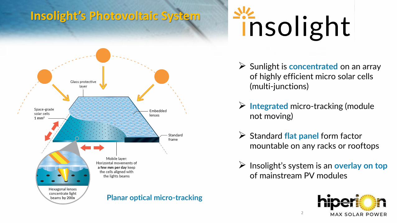
Insolight’s Photovoltaic System
2
➢ Sunlight is concentrated on an array of highly efficient micro solar cells (multi-junctions)
➢ Integrated micro-tracking (module not moving)
➢ Standard flat panel form factor mountable on any racks or rooftops
➢ Insolight’s system is an overlay on topof mainstream PV modules
Planar optical micro-tracking
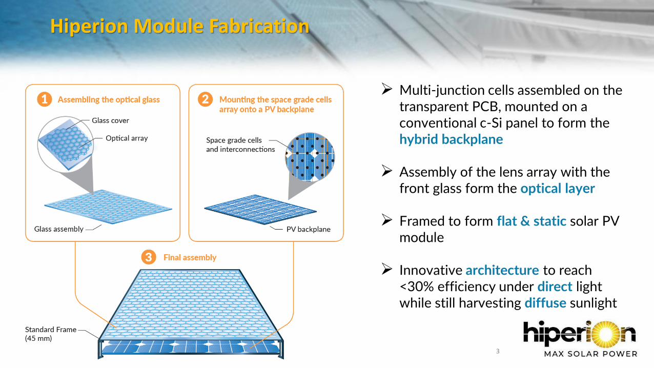
Hiperion Module Fabrication
14/09/2021 HIPERION - Meeting Type - Host - DD/MM/YYYY 3
➢ Multi-junction cells assembled on the transparent PCB, mounted on a conventional c-Si panel to form the hybrid backplane
➢ Assembly of the lens array with the front glass form the optical layer
➢ Framed to form flat & static solar PV module
➢ Innovative architecture to reach <30% efficiency under direct light while still harvesting diffuse sunlight
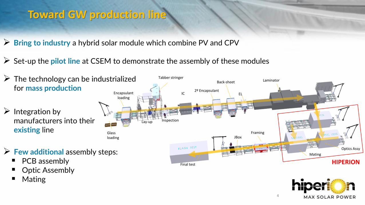
Toward GW production line
4
4
Framing
IC
Glass loading
Back-sheet
EL
LaminatorTabber stringer
Encapsulant loading
Inspection
2º Encapsulant
JBox
Lay-up
Optics Assy
Mating
Final test HIPERION
➢ The technology can be industrialized for mass production
➢ Few additional assembly steps:▪ PCB assembly▪ Optic Assembly▪ Mating
➢ Bring to industry a hybrid solar module which combine PV and CPV
➢ Set-up the pilot line at CSEM to demonstrate the assembly of these modules
➢ Integration by manufacturers into their existing line
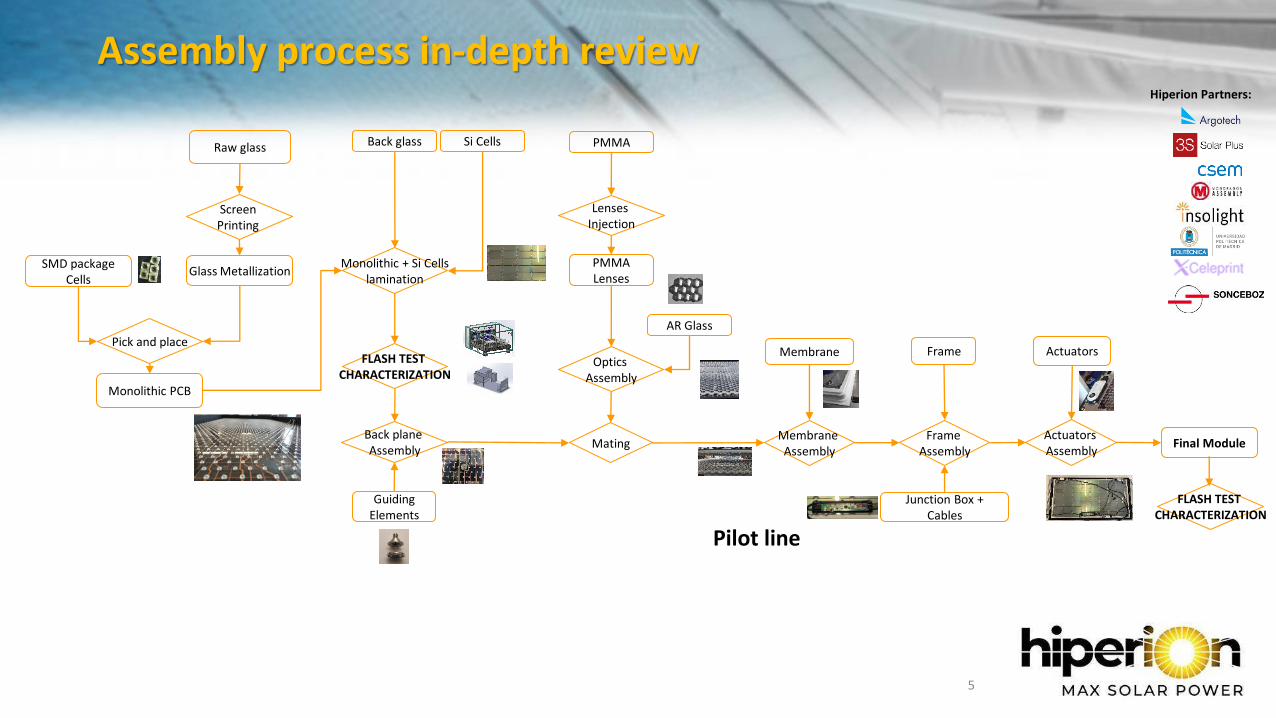
Assembly process in-depth review
5
SMD package Cells
Glass Metallization
Pick and place
Monolithic PCB
Membrane
PMMA
Lenses Injection
PMMA Lenses
Back plane Assembly
AR Glass
Optics Assembly
Si CellsBack glass
Guiding Elements
Final ModuleMatingActuators Assembly
Actuators
Junction Box + Cables
Frame
Monolithic + Si Cellslamination
Pilot line
FLASH TEST CHARACTERIZATION
Raw glass
Screen Printing
Frame Assembly
Membrane Assembly
FLASH TEST CHARACTERIZATION
Hiperion Partners:
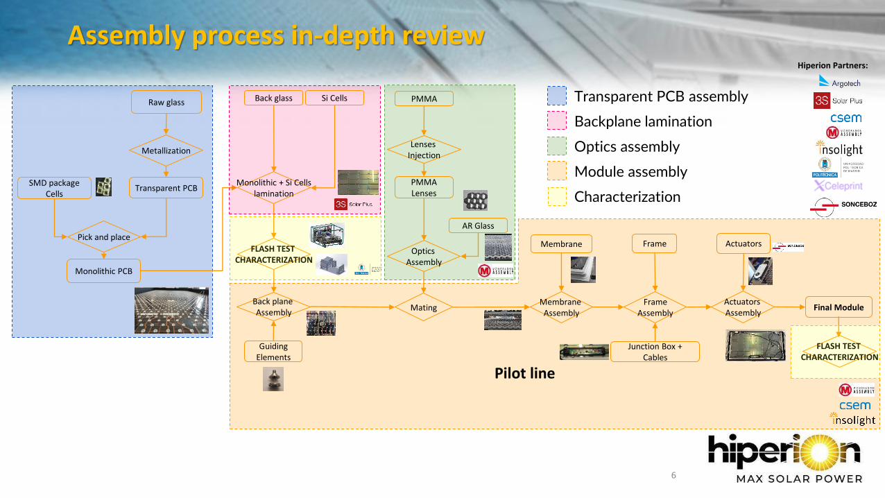
Assembly process in-depth review
6
SMD package Cells
Transparent PCB
Pick and place
Monolithic PCB
Membrane
PMMA
Lenses Injection
PMMA Lenses
Back plane Assembly
AR Glass
Optics Assembly
Si CellsBack glass
Guiding Elements
Final ModuleMatingActuators Assembly
Actuators
Junction Box + Cables
Hiperion Partners:
Frame
Monolithic + Si Cellslamination
Pilot line
FLASH TEST CHARACTERIZATION
Raw glass
Metallization
FrameAssembly
Membrane Assembly
FLASH TEST CHARACTERIZATION
Transparent PCB assembly
Backplane lamination
Optics assembly
Module assembly
Characterization
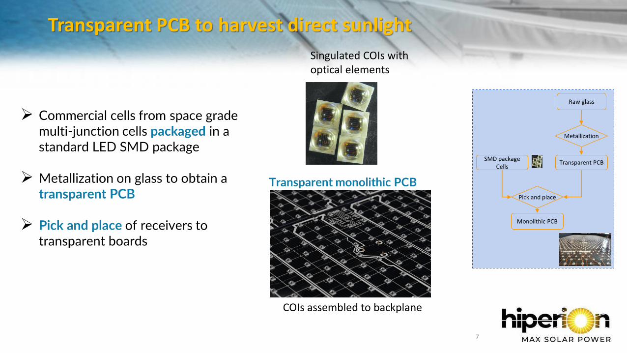
Transparent PCB to harvest direct sunlight
7
SMD package Cells
Transparent PCB
Pick and place
Monolithic PCB
Raw glass
Metallization
Singulated COIs with optical elements
COIs assembled to backplane
➢ Commercial cells from space grade multi-junction cells packaged in a standard LED SMD package
➢ Metallization on glass to obtain a transparent PCB
➢ Pick and place of receivers to transparent boards
Transparent monolithic PCB
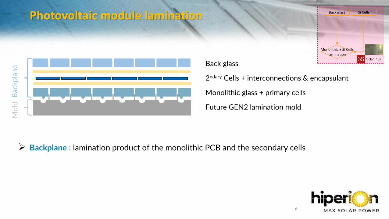
Photovoltaic module lamination
8
Si CellsBack glass
Monolithic + Si Cellslamination
Bac
kpla
neM
old
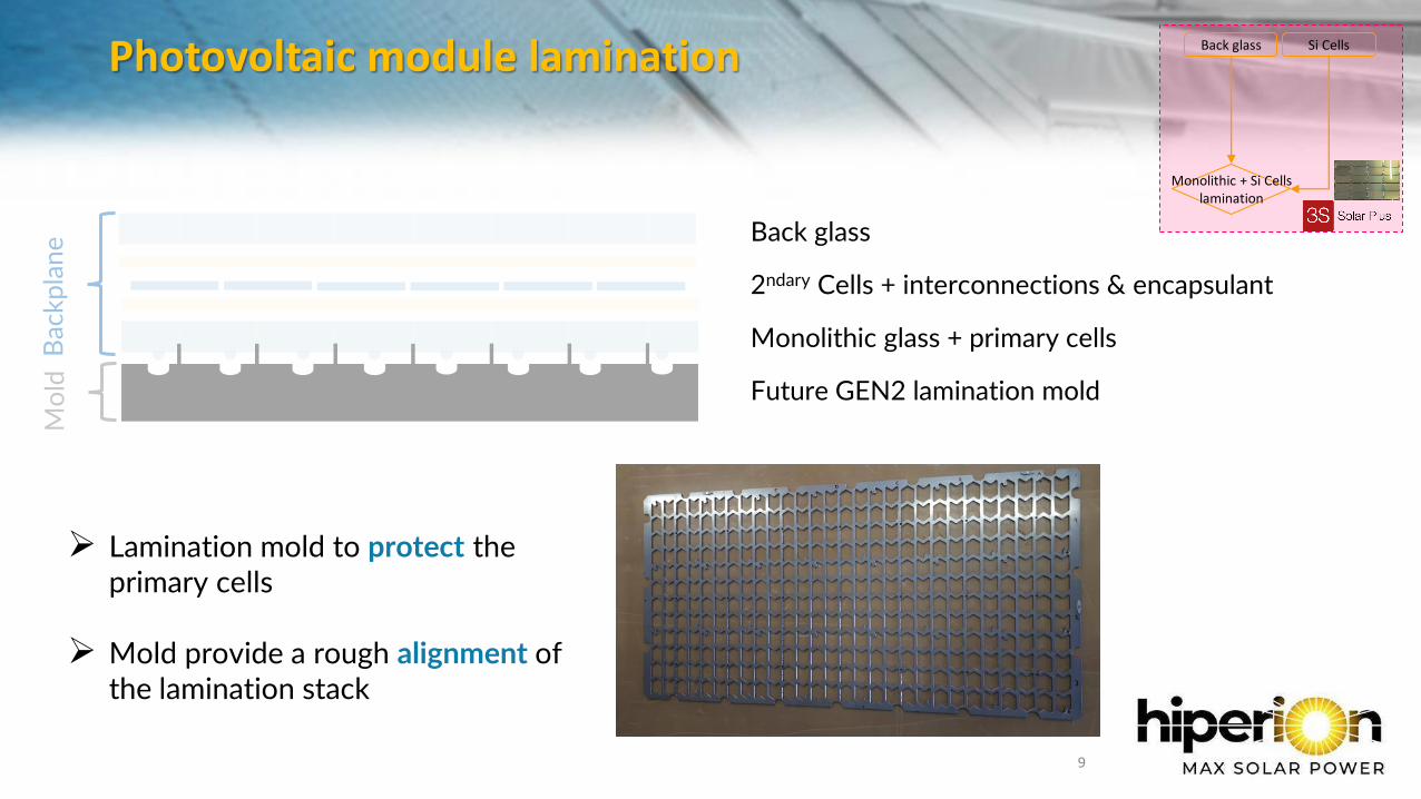
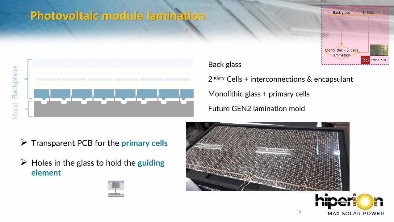
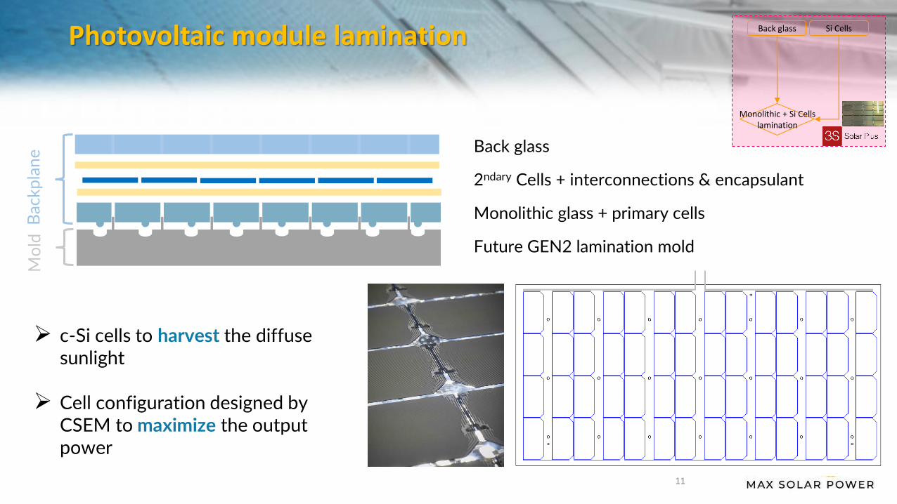
Back glass
2ndary Cells + interconnections & encapsulant
Monolithic glass + primary cells
Future GEN2 lamination mold
➢ Backplane : lamination product of the monolithic PCB and the secondary cells
Photovoltaic module lamination
9
Si CellsBack glass
Monolithic + Si Cellslamination
Bac
kpla
neM
old
Back glass
2ndary Cells + interconnections & encapsulant
Monolithic glass + primary cells
Future GEN2 lamination mold
➢ Lamination mold to protect the primary cells
➢ Mold provide a rough alignment of the lamination stack
Photovoltaic module lamination
10
Si CellsBack glass
Monolithic + Si Cellslamination
Bac
kpla
neM
old
Back glass
2ndary Cells + interconnections & encapsulant
Monolithic glass + primary cells
Future GEN2 lamination mold
➢ Transparent PCB for the primary cells
➢ Holes in the glass to hold the guiding element
Photovoltaic module lamination
11
Si CellsBack glass
Monolithic + Si Cellslamination
Bac
kpla
neM
old
Back glass
2ndary Cells + interconnections & encapsulant
Monolithic glass + primary cells
Future GEN2 lamination mold
➢ c-Si cells to harvest the diffuse sunlight
➢ Cell configuration designed by CSEM to maximize the output power
Photovoltaic module lamination
12
Si CellsBack glass
Monolithic + Si Cellslamination
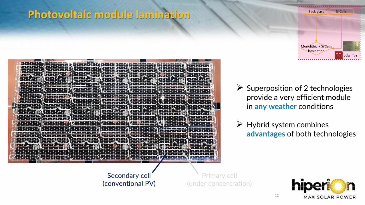
➢ Superposition of 2 technologies provide a very efficient module in any weather conditions
➢ Hybrid system combines advantages of both technologies
Primary cell (under concentration)
Secondary cell (conventional PV)
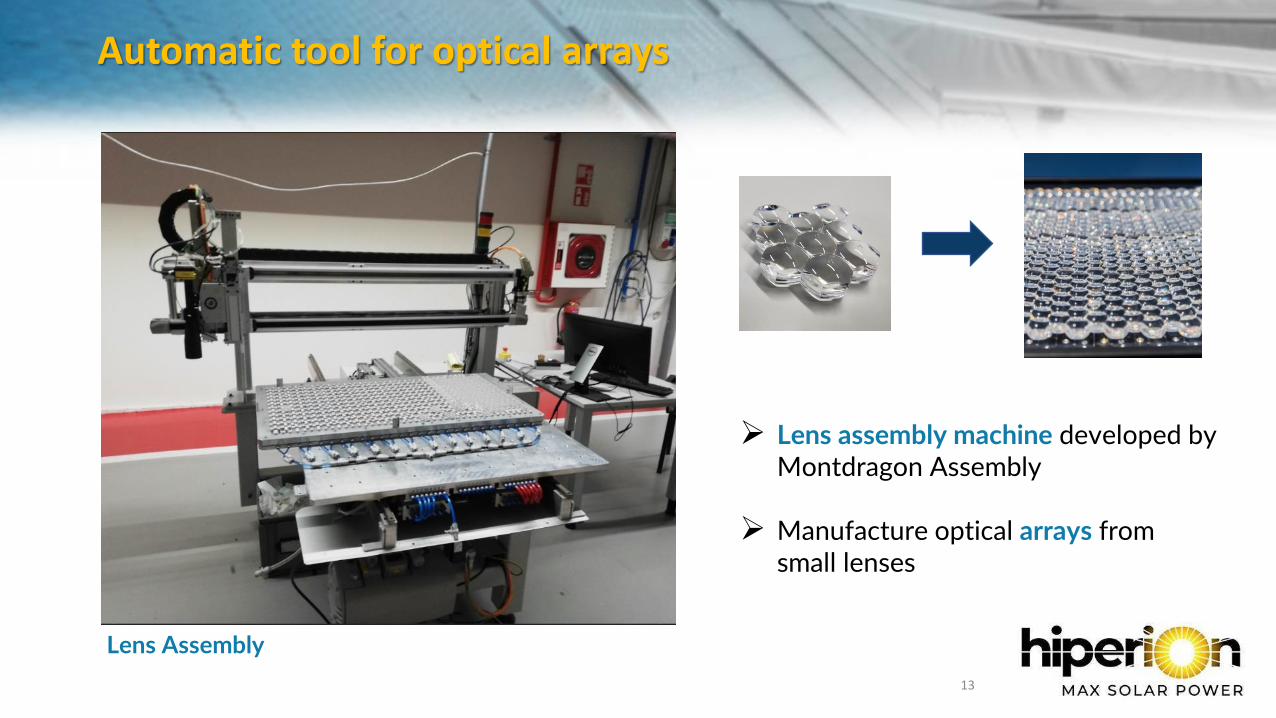
Automatic tool for optical arrays
13
➢ Lens assembly machine developed by Montdragon Assembly
➢ Manufacture optical arrays from small lenses
Lens Assembly
Automatic tool for optical arrays
14
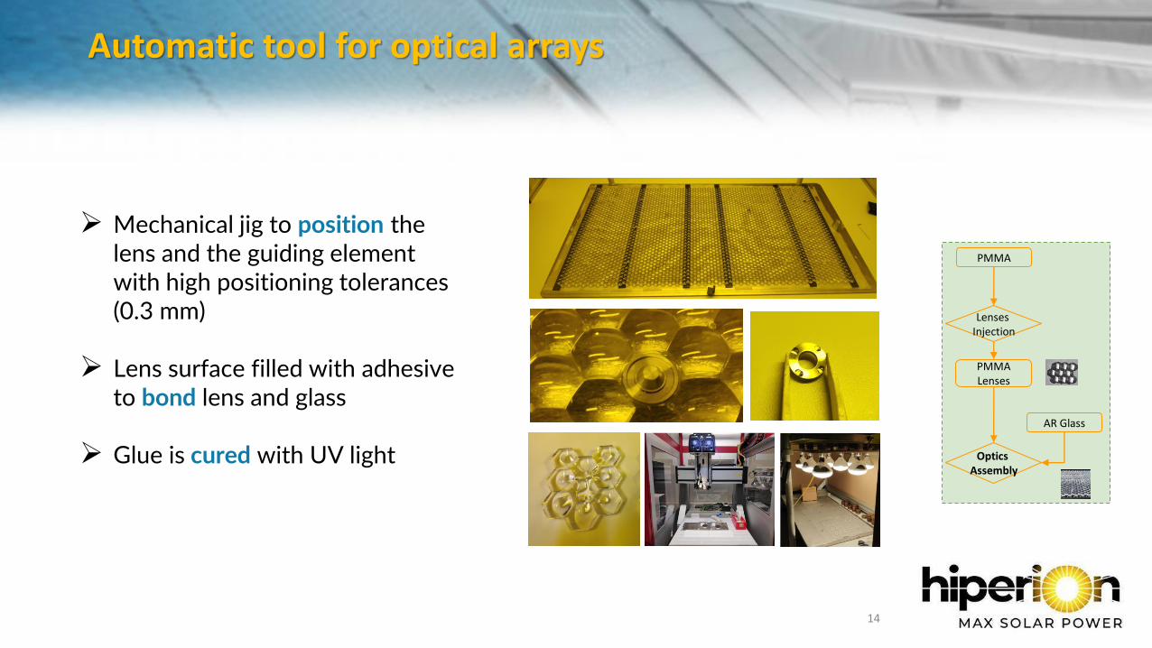
➢ Mechanical jig to position the lens and the guiding element with high positioning tolerances (0.3 mm)
➢ Lens surface filled with adhesiveto bond lens and glass
➢ Glue is cured with UV light
PMMA
Lenses Injection
PMMA Lenses
AR Glass
Optics Assembly
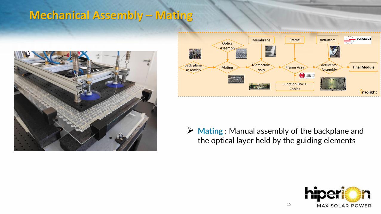
Mechanical Assembly – Mating
15
➢ Mating : Manual assembly of the backplane and the optical layer held by the guiding elements
Membrane
Final ModuleMatingActuators Assembly
Actuators
Junction Box + Cables
Frame
Frame AssyMembrane
AssyBack plane assembly
Optics Assembly
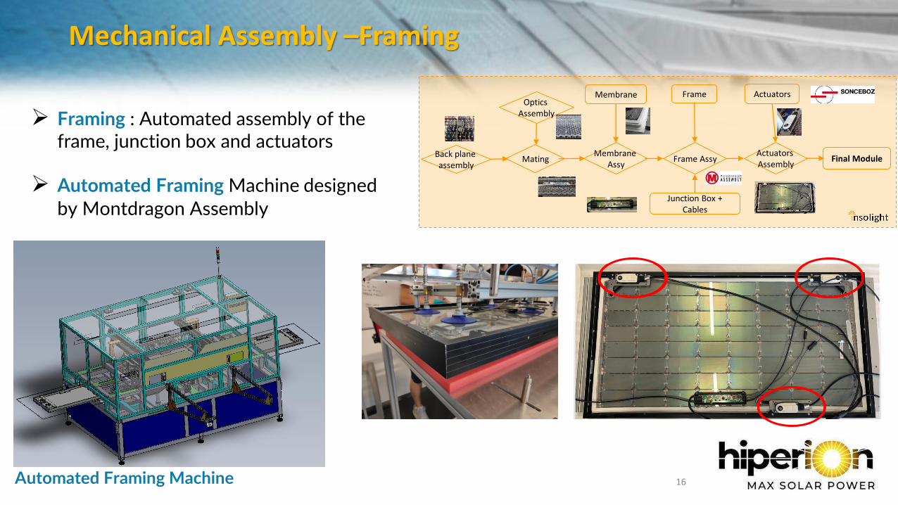
Mechanical Assembly –Framing
16
➢ Framing : Automated assembly of the frame, junction box and actuators
➢ Automated Framing Machine designed by Montdragon Assembly
Membrane
Final ModuleMatingActuators Assembly
Actuators
Junction Box + Cables
Frame
Frame AssyMembrane
AssyBack plane assembly
Optics Assembly
Automated Framing Machine
In-line and end-of-line test equipment
17
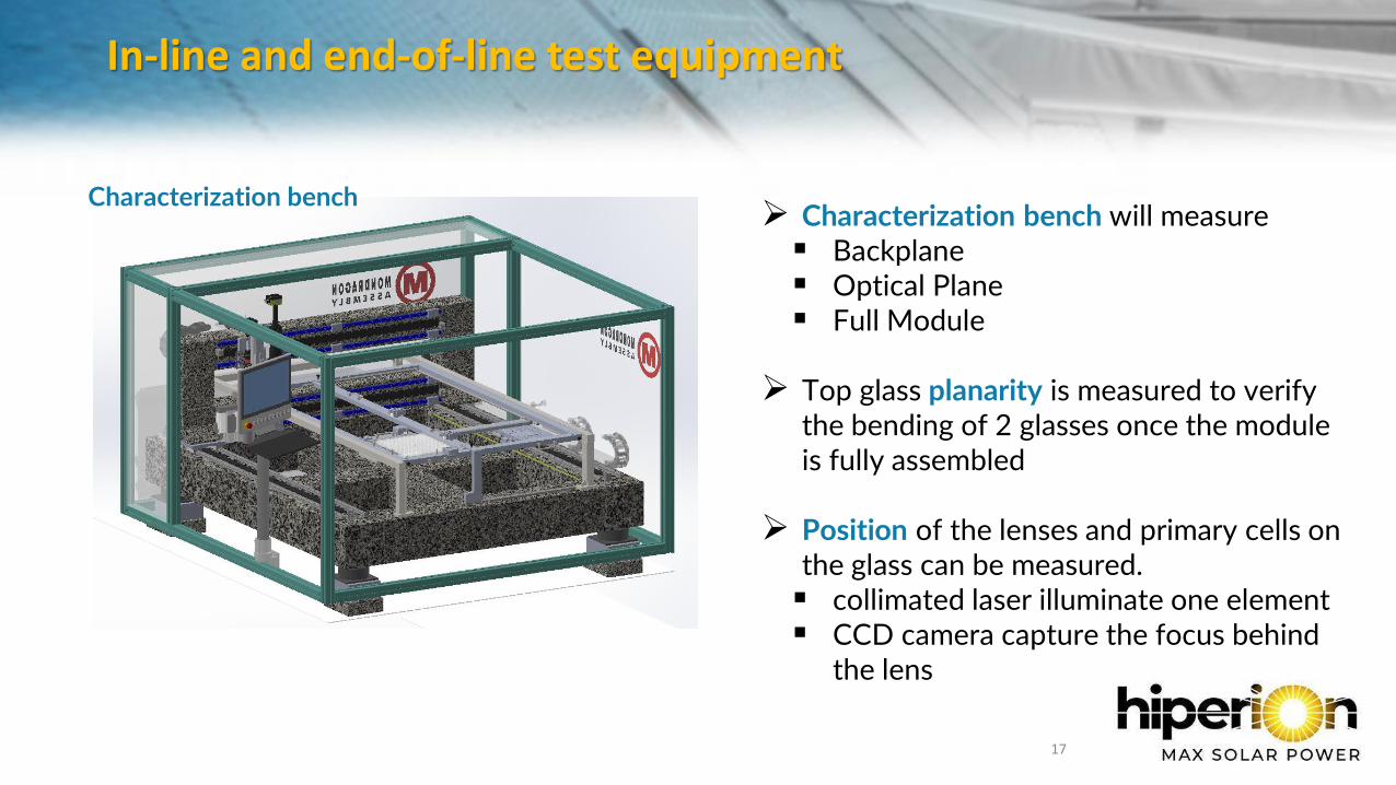
➢ Characterization bench will measure▪ Backplane▪ Optical Plane▪ Full Module
➢ Top glass planarity is measured to verify the bending of 2 glasses once the module is fully assembled
➢ Position of the lenses and primary cells on the glass can be measured.▪ collimated laser illuminate one element▪ CCD camera capture the focus behind
the lens
Characterization bench
In-line and end-of-line test equipment
18
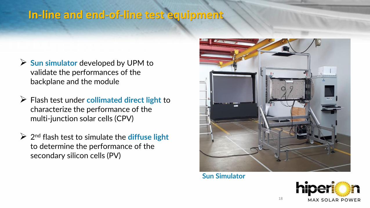
➢ Sun simulator developed by UPM to validate the performances of the backplane and the module
➢ Flash test under collimated direct light to characterize the performance of the multi-junction solar cells (CPV)
➢ 2nd flash test to simulate the diffuse lightto determine the performance of the secondary silicon cells (PV)
Sun Simulator
Deployment on pilot installations & Monitoring
19
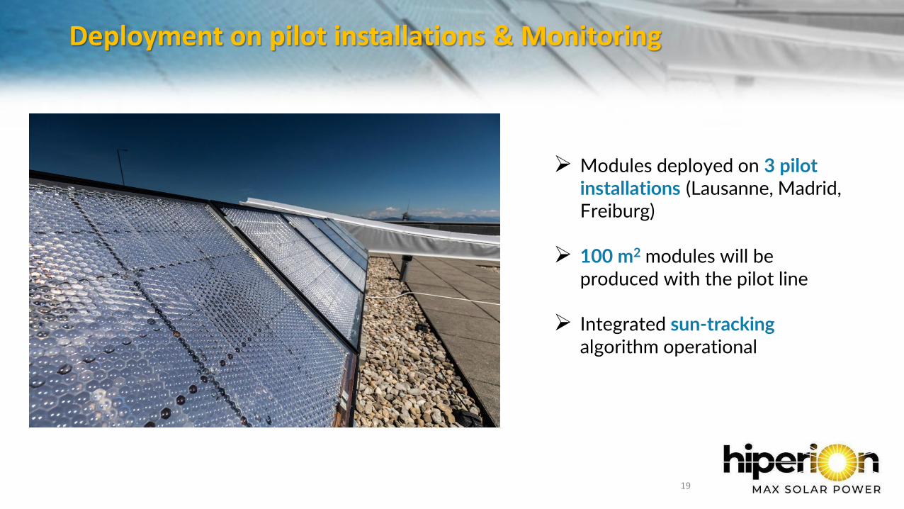
➢ Modules deployed on 3 pilot installations (Lausanne, Madrid, Freiburg)
➢ 100 m2 modules will be produced with the pilot line
➢ Integrated sun-trackingalgorithm operational
Conclusion & Achievement
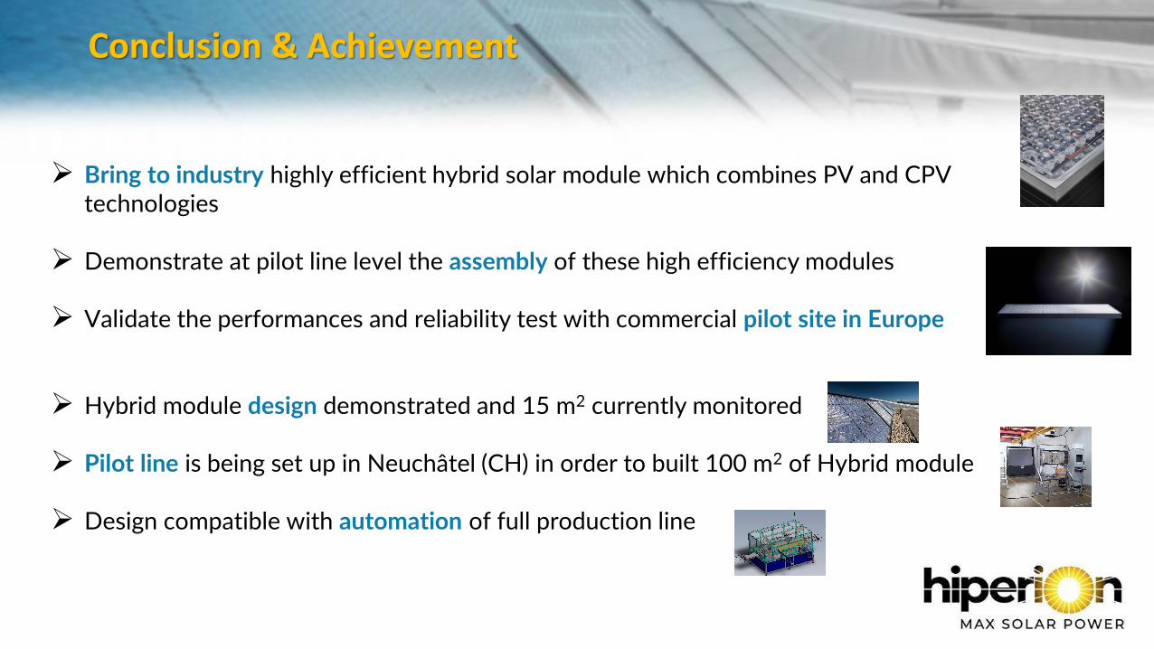
➢ Bring to industry highly efficient hybrid solar module which combines PV and CPV technologies
➢ Demonstrate at pilot line level the assembly of these high efficiency modules
➢ Validate the performances and reliability test with commercial pilot site in Europe
➢ Hybrid module design demonstrated and 15 m2 currently monitored
➢ Pilot line is being set up in Neuchâtel (CH) in order to built 100 m2 of Hybrid module
➢ Design compatible with automation of full production line
Perspectives
14/09/2021 21
➢ Key manufacturing processes will be demonstrated at industrially meaningful level
➢ Scale-up to GW production is being established based on current module by IQE
➢ Word record efficiency and above any flat module currently on the market (final modules aims to demonstrate efficiency above 30% under direct sunlight and 17% under diffuse sunlight)

Thank you!
22