Application of the object-oriented principles for hardware and embedded system design
31
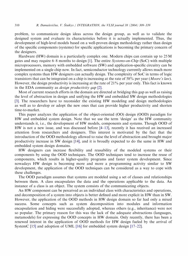
INTEGRATION, the VLSI journal 38 (2004) 309–339 Application of the object-oriented principles for hardware and embedded system design R. Damasˇevicˇius , V. S ˇ tuikys Software Engineering Department, Kaunas University of Technology, Studentu ˛ 50, 51368-Kaunas, Lithuania Received 12 February 2004; received in revised form 21 August 2004; accepted 24 August 2004 Abstract As the complexity of hardware (HW) and embedded system design is constantly increasing, the researchers are seeking to develop new more abstract and productive design methods or adapt the existing ones from other domains such as software design. This paper addresses the problem of using the object- oriented (OO) design techniques in HW domain. The main OO design techniques are as follows: abstraction, separation of concerns, composition and generalization. The application of the OO design paradigm has many aspects: high-level specification of HW models using OO formal notations such as Petri Nets and UML diagrams, HW description using OO HW description languages such as VHDL extensions and SystemC, HW design using OO HW architectures, platforms and design patterns. In this paper, we present a comprehensive overview of the application of the OO design paradigm in HW and embedded system design domains and formulate its main principles, discuss the current achievements in the area, and outline the future trends. r 2004 Elsevier B.V. All rights reserved. Keywords: Object-oriented hardware design; Embedded system design; Modeling; UML; Class diagram. 1. Introduction The usage of high-level models for specifying complex domain systems is a long-standing engineering tradition. Modeling helps to focus on the most important aspects of the design ARTICLE IN PRESS www.elsevier.com/locate/vlsi 0167-9260/$ - see front matter r 2004 Elsevier B.V. All rights reserved. doi:10.1016/j.vlsi.2004.08.005 Corresponding author. Tel.: +370-37-300-399; fax: +370-37-300-352. E-mail address: [email protected] (R. Damasˇevicˇius).
-
Upload
independent -
Category
Documents
-
view
3 -
download
0
Transcript of Application of the object-oriented principles for hardware and embedded system design
ARTICLE IN PRESS
INTEGRATION, the VLSI journal 38 (2004) 309–339
0167-9260/$ -
doi:10.1016/j.
�CorresponE-mail add
www.elsevier.com/locate/vlsi
Application of the object-oriented principles for hardwareand embedded system design
R. Damasevicius�, V. Stuikys
Software Engineering Department, Kaunas University of Technology, Studentu 50, 51368-Kaunas, Lithuania
Received 12 February 2004; received in revised form 21 August 2004; accepted 24 August 2004
Abstract
As the complexity of hardware (HW) and embedded system design is constantly increasing, theresearchers are seeking to develop new more abstract and productive design methods or adapt the existingones from other domains such as software design. This paper addresses the problem of using the object-oriented (OO) design techniques in HW domain. The main OO design techniques are as follows:abstraction, separation of concerns, composition and generalization. The application of the OO designparadigm has many aspects: high-level specification of HW models using OO formal notations such as PetriNets and UML diagrams, HW description using OO HW description languages such as VHDL extensionsand SystemC, HW design using OO HW architectures, platforms and design patterns. In this paper, wepresent a comprehensive overview of the application of the OO design paradigm in HW and embeddedsystem design domains and formulate its main principles, discuss the current achievements in the area, andoutline the future trends.r 2004 Elsevier B.V. All rights reserved.
Keywords: Object-oriented hardware design; Embedded system design; Modeling; UML; Class diagram.
1. Introduction
The usage of high-level models for specifying complex domain systems is a long-standingengineering tradition. Modeling helps to focus on the most important aspects of the design
see front matter r 2004 Elsevier B.V. All rights reserved.
vlsi.2004.08.005
ding author. Tel.: +370-37-300-399; fax: +370-37-300-352.
ress: [email protected] (R. Damasevicius).
ARTICLE IN PRESS
R. Damasevicius, V. Stuikys / INTEGRATION, the VLSI journal 38 (2004) 309–339310
problem, to communicate design ideas across the design group, as well as to validate thedesigned system and evaluate its characteristics before it is actually implemented. Thus, thedevelopment of high-level models based on a well-proven design methodology rather than designof the specific components (systems) for specific applications is becoming the primary concern ofthe designers.Hardware (HW) domain is a particularly complex one. Modern chips can contain up to 25M
gates and may require 6–8 months to design [1]. The entire Systems-on-Chip (SoC) with multiplemicroprocessors, memory with embedded software (SW) and application-specific circuitry can beimplemented on a single chip now. In fact, semiconductor technology currently allows much morecomplex systems than HW designers can actually design. The complexity of SoC in terms of logictransistors that can be integrated on a chip is increasing at the rate of 58% per year (Moore’s law).However, the design productivity is increasing at the rate of 21% per year only. This fact is knownin the EDA community as design productivity gap [2].Most of current research efforts in the domain are directed at bridging this gap as well as raising
the level of abstraction in design and unifying the HW and embedded SW design methodologies[3]. The researchers have to reconsider the existing HW modeling and design methodologiesas well as to develop or adopt the new ones that can provide higher productivity and shortentime-to-market.This paper analyzes the application of the object-oriented (OO) design (OOD) paradigm for
HW and embedded system design. Note that we use the term ‘design’ as the HW communityunderstands it, i.e., the development of HW models, components and systems. Though OOD ofHW is not a new issue, and was discussed before [4–13], recently it has received an increasedattention from researchers and designers. This interest is motivated by the fact that theintroduction of the OODmethodology allowed to raise the level of abstraction and brought majorproductivity increase in SW design [14], and it is broadly expected to do the same in HW andembedded system design domains.HW designers can increase flexibility and reusability of the modeled systems or their
components by using the OOD techniques. The OOD techniques tend to increase the reuse ofcomponents, which results in higher-quality programs and faster system development. Sincenowadays HW design is becoming more and more a programming activity similar to SWdevelopment, the application of the OOD techniques can be considered as a way to cope withthese challenges.The OOD paradigm assumes that systems are modeled using a set of classes and relationships
between them. A class encapsulates the data and the operations applicable to the data. Aninstance of a class is an object. The system consists of the communicating objects.An HW component can be perceived as an individual class with characteristics and operations,
and decomposition of a system into objects is better defined and more explicit in HW than in SW.However, the application of the OOD methods in HW design domain so far had only a mixedsuccess. Some concepts such as system decomposition into modules and informationencapsulation and hiding were successfully adopted, whereas others (e.g., inheritance) were notso popular. The primary reason for this was the lack of the adequate abstractions (languages,metamodels) for expressing the OOD concepts in HW domain. Only recently, there has been arenewed interest in the application of OOD methods for HW design fueled by the arrival ofSystemC [15] and adoption of UML [16] for embedded system design [17–22].

ARTICLE IN PRESS
R. Damasevicius, V. Stuikys / INTEGRATION, the VLSI journal 38 (2004) 309–339 311
The aim of this paper is as follows: (1) To present an extensive survey of the application of theOOD methods and techniques in HW and embedded system design, including the OO HWarchitectures, high-level specification methods, and OO HW description languages (HDLs). (2) Todiscuss the application of design patterns for HW design. (3) To formulate the main principles ofthe OOD for HW and embedded system design domain. (4) To summarize the currentachievements in the area and outline future trends.Our recent contributions to the area of the OO HW design are also presented, including the
high-level specification of HW models using UML class diagrams and the UML–VHDLmetamodel for the automatic generation of VHDL components from the UML class diagrams.The structure of the paper is as follows. Section 2 analyzes the application of the OOD
techniques in HW design. Section 3 considers the application of design patterns for HW andembedded system design. Section 4 presents the main principles of the OOD paradigm adapted forHW and embedded system design domains. Section 5 illustrates the analyzed concepts in a casestudy. Section 6 evaluates and discusses current achievements in the domain. Finally, Section 7presents the conclusions and outlines future trends.
2. Analysis of Approaches for OO HW Design
2.1. OO HW description languages
2.1.1. Extensions of VHDLHere we consider the approaches that extend an existing HW description language (HDL) for
OO HW design, only. A vast majority of these approaches uses VHDL as a base language. Thereasons why VHDL is so often selected by the researchers to include support for the OODconcepts are as follows: (1) VHDL is an industry-wide standard for HW design [23]. (2) Thelanguage already has an adequate basis mechanism to separate the component interface from itsimplementation using entity and architecture constructs. (3) There are some similarities betweenVHDL structural descriptions and objects [24].The problem is what abstractions should be used to extend VHDL in order to support the
principles of OOD, and how to solve the related problems of modeling and synthesis. Basically,there are two approaches for introducing the OOD concepts into the domain by extending thecomponent abstraction of VHDL or the type system as follows: the entity-based and type-basedones.The entity-based approaches consider a VHDL entity as an abstraction of an HW object. The
entity is extended with an additional interface for methods, or a new class construct based on theentity is introduced. The entity declaration is treated as a class definition, which specifies theinterface of the HW object. The architecture is treated as an implementation of the interface,expressed in terms of concurrent statements, processes, and component instances. A new designentity can be defined by inheriting the interface and implementation from a parent entity. The newinterface can be augmented with additional generic constants and ports, and the new architecturecan be extended with additional declarations, processes, and component instances.Thus, the entity-based approaches allow structural inheritance and can be used for writing an
initial OO specification of HW and reusing parts of old specifications. The OO specification can be
ARTICLE IN PRESS
R. Damasevicius, V. Stuikys / INTEGRATION, the VLSI journal 38 (2004) 309–339312
simulated at a high level of abstraction, but its refinement (synthesis) to the lower levels ofabstraction is complicated. The examples of the application of the entity-based approach are OO-VHDL [25], VHDL_OBJ [26], VHDL++ [27], and LaMI proposal [28].The type-based approaches provide object-orientation based on an extension of the language-
type system by a class type. Basically, such a class type is an abstract data type. It encapsulates itsstructure and models its behavior using procedures. Whereas the entity-based approaches focuson the hierarchical decomposition based on the functional units, the type-based approaches usethe data-oriented decomposition. Various proposals differ with respect to their class concepts, theway classes can be instantiated, and the details of the inheritance mechanism and polymorphism.Compared to the entity-based approach, the type-based approach is closer to the HW domain,
because it allows a more simple translation into the HW-oriented data representations. Thus, thesynthesis is simpler. However, HW components cannot be described using the types alone andshould include functional units, too. The examples of the application of the type-based approachare Objective VHDL [29], SUAVE [30]. A more extensive survey of the languages that extendVHDL with the OO features can also be found in [31–33].
2.1.2. SystemVerilog
SystemVerilog [34] is a rich set of extensions to the IEEE 1364 Verilog-2001 HDL. One of theseextensions adds the OO abstractions (classes) that are similar to C++. A class can contain datadeclarations (properties), tasks and functions for operating on the data (methods). The propertiesand methods together define the contents and capabilities of an object. Classes can haveinheritance and public or private protection, as in C++. Objects can be dynamically created,deleted and assigned values. SystemVerilog classes are dynamic by nature and can be used forverification routines, highly abstract system-level modeling and test-bench modeling. Because ofthe dynamic nature of classes, they are not synthesizable.These OO extensions address two major issues of the HDL-based design. First, the object-
orientation allows modeling very large designs with concise, accurate and intuitive code. Second,high-level OO test programs allow to efficiently and effectively verify large designs. SystemVerilogachieves the improved specification of a design by allowing the related domain functionality to bedescribed as a single object. It allows a single designer to be responsible for the specification anddevelopment of an object, rather than spreading that design knowledge diffusely throughout asystem, which can aggravate design reuse and maintenance.
2.2. Adaptation of an existing OO language to HW design
Another trend in adopting the OOD concepts to HW design domain is based on using theexisting OO programming language adopted from the SW design domain. Though approachesbased on other OO programming languages such as Java exist (e.g., JavaSynth [35]), the maintrend is focused on the adaptation of C++ (currently a de facto standard SW developmentlanguage) for HW modeling and design.Originally intended for SW design, C++ has no support required for accurately dealing with
HW models. The problem is how to adapt C++ for HW design and to solve the synthesizabilityissue. C++ provides only two levels of abstraction: algorithmic and object, whereas an HWspecification has four levels: algorithmic, modular, cycle-accurate, and register-transfer level

ARTICLE IN PRESS
R. Damasevicius, V. Stuikys / INTEGRATION, the VLSI journal 38 (2004) 309–339 313
(RTL) [36]. The algorithmic level specifies only the behavior of the system, with no specificimplementation detail. At the modular level, the system is partitioned into components thatcommunicate through a clearly (although not necessarily completely) specified protocol. The cycleaccuracy level introduces the notion of a clock and a time at which events occur. RTL specifies theimplementation of the events without relying on a particular implementation technology.Each level of abstraction requires the corresponding language support. Given that C++ is
used to describe SW algorithms, the algorithmic level requires almost no extensions (except of aprecisely sized HW-oriented data type). The object level of C++ can be used to describe themodular level of HW. The other levels of abstraction are not present in C++, and thus requireintroduction when designed for HW. According to [37], there are two approaches for building thistype of HW support:
(1)
The syntax extension approach is based on adding keywords to the C/C++ language, inorder to support HW description at a high level as a basis for synthesis (e.g., HardwareC [38],Matisse [39], SpecC [40]), and requires the development of separate compilers, simulators, andsynthesis tools to manipulate with new syntax.(2)
The class libraries approach is based on using class libraries that model the HW parts of theembedded system. This approach allows reusing the existing language development frame-work. As such, this is the most popular approach in the EDA community, now. Below, weanalyze two HDLs based on the extension of C++ with class libraries for modeling HW:SystemC and SystemC-Plus.SystemC [15,41,42] is a C++ class library and a methodology that allows to model embeddedsystems, including both HW and SW. Despite the fact that SystemC is build on top of C++,currently it does not encourage the usage of the OOD techniques for HW synthesis [43,44].The important features of SystemC are briefly discussed below. A synthesizable HW model
described in SystemC looks very similar to an equivalent VHDL model with only few syntacticdifferences. The basic block of a SystemC program is a module. A module is similar to the entity inVHDL. It is an abstract representation of a functional unit, without specifying anyimplementation details. Each module has a set of ports through which it interacts with theoutside world. The ports can be input, output, or input/output ones. Individual modulescommunicate with one another through signals that connect the ports of the modules. The codethat implements the algorithm of a module is encapsulated in one or more processes. All processesare executed concurrently, therefore a SystemC module class has in fact only one method.Fig. 1 presents two simple SystemC modules and demonstrates the application of
encapsulation, separation of data and methods, and inheritance. Fig. 1(a) shows the And gate,and (b) shows a derived class Half_adder that inherits the ports X1, X2, Y and the methodprocess1() from the And_gate.Unfortunately, the OOD paradigm cannot really be applied for HW design using SystemC [45].
Only encapsulation is fully supported by the SystemC module. Commonality can be expressedusing abstract classes such as interfaces, and variation can be implemented using multipleinheritance. Inheritance of other SystemC modules is not supported for synthesis as well aspolymorphism. Basically, SystemC partially supports the OO HW modeling, but not the OO HWdesign, because the commercially available synthesis tools for SystemC currently cannot handle

ARTICLE IN PRESS
SC_MODULE (And_gate) { public:
sc_in<sc_bit> X1, X2; sc_out<sc_bit> Y;
void process_and() { Y = X1 && X2; // and }
SC_CTOR(And_gate) { SC_METHOD(process_and);sensitive << X1 << X2;
} };
class Half_adder: public And_gate { public:
sc_out<sc_bit> Z;
SC_HAS_PROCESS(And_gate); void process_xor() {
Y = X1 ^ X2; // xor }Half_adder(const sc_module_name& name):
And_gate(name) { SC_METHOD(process_xor);sensitive << X1 << X2;
}};
(a) (b)
Fig. 1. SystemC description of And gate (a) and Half adder (b).
R. Damasevicius, V. Stuikys / INTEGRATION, the VLSI journal 38 (2004) 309–339314
the OO specifications. Thus, the designer has to manually rewrite the source code of externalobjects and translate certain high-level constructs like threads and FIFOs. However, there areefforts to extend SystemC as well, in order to provide more support for synthesizability of the OOspecifications, such as SystemC-Plus [46].SystemC-Plus is the OOD methodology based on SystemC that allows the usage of objects for
HWmodeling and synthesis. SystemC libraries are augmented with an additional class library andcoding styles giving the ability for the designer to use the OO techniques (such as polymorphism)for HW modeling without losing the possibility of synthesizing these models. The extensions tocommon SystemC were necessary to avoid the usage of the non-synthesizable language constructsand to reflect some features of the HW model in high-level simulation.SystemC-Plus supports the following OOD concepts: data encapsulation, inheritance, method-
based communication, polymorphism, and classes. SystemC-Plus supports the synthesis of thefollowing OO principles that are present in C++: class member functions, constructors, objectsand arrays as data members, and inheritance from class templates, multiple inheritance andvirtual base classes. Polymorphic objects and dynamic dispatching of virtual functions can besynthesized, too.
2.3. OO HW architectures
The implementation of the OO HW model is another subject of research. Every high-level HWspecification eventually must be mapped into low-level (RTL) implementation (gates and wires).The problem is what HW architecture should be selected for an application, how it must bespecified and implemented. Basically, there can be three approaches for implementing HWarchitectures in terms of OOD:
(1)
The behavioral model understands an object as an encapsulated data packet transported viawires (see Fig. 2) [35]. The objects are not treated as components, but rather as connectionsbetween components, which are themselves represented by the methods. A methodcorresponds to an HW component that processes the data packets and returns the result.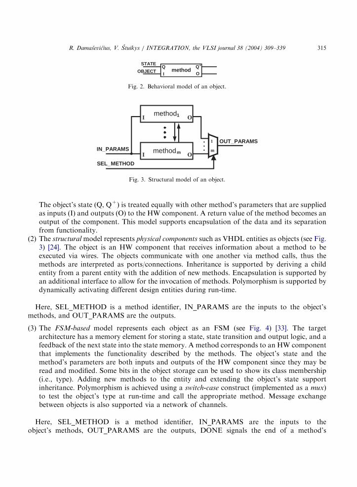
ARTICLE IN PRESS
methodSTATE
OBJECT OI
Q Q+
Fig. 2. Behavioral model of an object.
OUT_PARAMS
method1 OI
methodm OI
1
mIN_PARAMS
SEL_METHOD
Fig. 3. Structural model of an object.
R. Damasevicius, V. Stuikys / INTEGRATION, the VLSI journal 38 (2004) 309–339 315
The object’s state (Q, Q+) is treated equally with other method’s parameters that are suppliedas inputs (I) and outputs (O) to the HW component. A return value of the method becomes anoutput of the component. This model supports encapsulation of the data and its separationfrom functionality.
(2)
The structural model represents physical components such as VHDL entities as objects (see Fig.3) [24]. The object is an HW component that receives information about a method to beexecuted via wires. The objects communicate with one another via method calls, thus themethods are interpreted as ports/connections. Inheritance is supported by deriving a childentity from a parent entity with the addition of new methods. Encapsulation is supported byan additional interface to allow for the invocation of methods. Polymorphism is supported bydynamically activating different design entities during run-time.Here, SEL_METHOD is a method identifier, IN_PARAMS are the inputs to the object’smethods, and OUT_PARAMS are the outputs.
(3)
The FSM-based model represents each object as an FSM (see Fig. 4) [33]. The targetarchitecture has a memory element for storing a state, state transition and output logic, and afeedback of the next state into the state memory. A method corresponds to an HW componentthat implements the functionality described by the methods. The object’s state and themethod’s parameters are both inputs and outputs of the HW component since they may beread and modified. Some bits in the object storage can be used to show its class membership(i.e., type). Adding new methods to the entity and extending the object’s state supportinheritance. Polymorphism is achieved using a switch-case construct (implemented as a mux)to test the object’s type at run-time and call the appropriate method. Message exchangebetween objects is also supported via a network of channels.Here, SEL_METHOD is a method identifier, IN_PARAMS are the inputs to theobject’s methods, OUT_PARAMS are the outputs, DONE signals the end of a method’s

ARTICLE IN PRESS
OUT_PARAMS1
mIN_PARAMS
SEL_METHOD
O1
m
methodm OIQ+Q
method1 OIQ+Q
ob
ject
sta
tecontroller
CLKRESET
DONE
Fig. 4. FSM-based model of an object (according to [33]).
R. Damasevicius, V. Stuikys / INTEGRATION, the VLSI journal 38 (2004) 309–339316
execution, a memory element stores the object’s state, CLK is a clock signal, and RESET is areset signal.We summarize these three interpretations of objects in HW architectures as follows. The
behavioral model is the simplest one: it allows encapsulation only. The structural model allowsstateless static objects with inheritance. The FSM-based model allows static objects with supportfor inheritance, message passing and polymorphism. Dynamic objects cannot be implemented inHW directly, however, they can be emulated when HW objects are combined with SW objects in ashared memory. This approach is used in HW platforms considered in the next section.
2.4. OO HW Platforms
The OOD principles can also be applied for platform-based design [47] of embedded systems. Inthis case, platforms are modeled using a set of classes and relationships between them. We analyzethe OO-ASIP and Enodia platforms below.
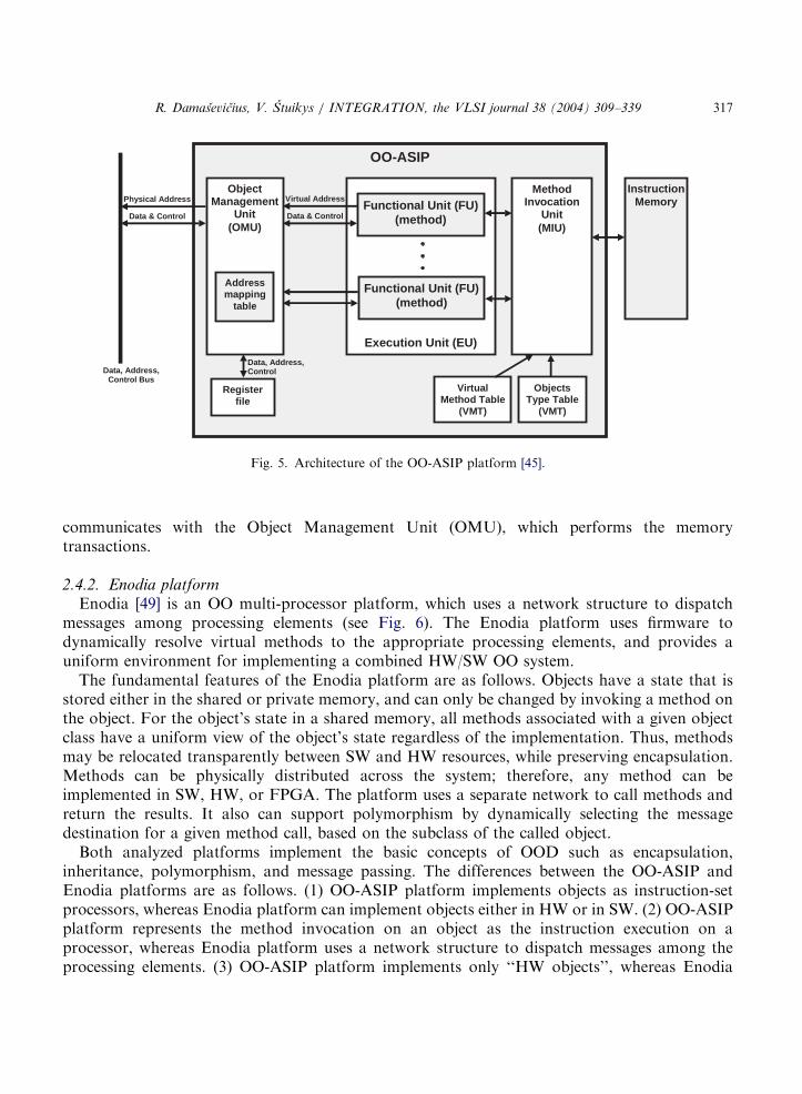
2.4.1. OO-ASIP platformIn the OO-ASIP [48] platform (see Fig. 5), the invocation of object’s methods is used as an
instruction to be executed on a processor specifying the object and additional arguments asinstruction operands. This view results in identifying public methods of the class library as theinstruction set of a corresponding processor. An OO-ASIP is a processor with its instruction setdefined by selected methods of an ‘‘HW class library’’, and with support for dynamic dispatch ofvirtual methods to both HW and SW. An embedded application is modeled using the ‘‘HW classlibrary’’ and compiled to the instructions of the corresponding OO-ASIP. ‘‘HW class library’’ canincrementally evolve to model new applications, and thus ensures reuse in future applications.Such a processor is able to execute any program comprised of objects of that class hierarchy, i.e.all applications can be modeled with that HW class library.The system designed on the OO-ASIP platform works as follows. The Method Invocation Unit
(MIU) reads method invocation commands from the instruction memory and designates amethod (opcode) and the called object (operand(s)). Based on the class membership of the calledobject, the MIU invokes the corresponding Functional Unit (FU), which implements the HWmethod, or dispatches a method call to the SW method. To access data of the object, the FU
ARTICLE IN PRESS
OO-ASIP
Execution Unit (EU)
Functional Unit (FU)(method)
Functional Unit (FU)(method)
ObjectManagement
Unit(OMU)
Address mapping
table
Virtual Address
Data & Control
Register file
Data, Address,Control
MethodInvocation
Unit(MIU)
VirtualMethod Table
(VMT)
Objects Type Table
(VMT)
InstructionMemory
Data, Address,Control Bus
Physical Address
Data & Control
Fig. 5. Architecture of the OO-ASIP platform [45].
R. Damasevicius, V. Stuikys / INTEGRATION, the VLSI journal 38 (2004) 309–339 317
communicates with the Object Management Unit (OMU), which performs the memorytransactions.
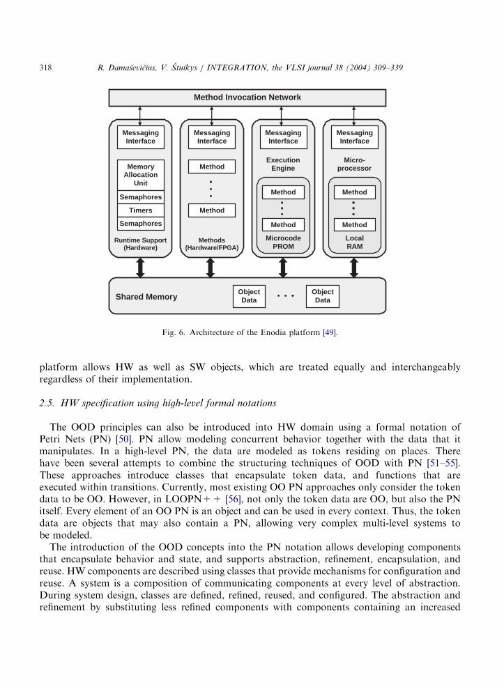
2.4.2. Enodia platformEnodia [49] is an OO multi-processor platform, which uses a network structure to dispatch
messages among processing elements (see Fig. 6). The Enodia platform uses firmware todynamically resolve virtual methods to the appropriate processing elements, and provides auniform environment for implementing a combined HW/SW OO system.The fundamental features of the Enodia platform are as follows. Objects have a state that is
stored either in the shared or private memory, and can only be changed by invoking a method onthe object. For the object’s state in a shared memory, all methods associated with a given objectclass have a uniform view of the object’s state regardless of the implementation. Thus, methodsmay be relocated transparently between SW and HW resources, while preserving encapsulation.Methods can be physically distributed across the system; therefore, any method can beimplemented in SW, HW, or FPGA. The platform uses a separate network to call methods andreturn the results. It also can support polymorphism by dynamically selecting the messagedestination for a given method call, based on the subclass of the called object.Both analyzed platforms implement the basic concepts of OOD such as encapsulation,
inheritance, polymorphism, and message passing. The differences between the OO-ASIP andEnodia platforms are as follows. (1) OO-ASIP platform implements objects as instruction-setprocessors, whereas Enodia platform can implement objects either in HW or in SW. (2) OO-ASIPplatform represents the method invocation on an object as the instruction execution on aprocessor, whereas Enodia platform uses a network structure to dispatch messages among theprocessing elements. (3) OO-ASIP platform implements only ‘‘HW objects’’, whereas Enodia
ARTICLE IN PRESS
Method Invocation Network
Runtime Support(Hardware)
MessagingInterface
MemoryAllocation
Unit
Semaphores
Timers
Semaphores
Methods(Hardware/FPGA)
MessagingInterface
Method
Method
Execution Engine
Microcode PROM
MessagingInterface
Method
Method
Micro-processor
LocalRAM
Messaging Interface
Method
Method
Shared MemoryObjectData
ObjectData
Fig. 6. Architecture of the Enodia platform [49].
R. Damasevicius, V. Stuikys / INTEGRATION, the VLSI journal 38 (2004) 309–339318
platform allows HW as well as SW objects, which are treated equally and interchangeablyregardless of their implementation.
2.5. HW specification using high-level formal notations
The OOD principles can also be introduced into HW domain using a formal notation ofPetri Nets (PN) [50]. PN allow modeling concurrent behavior together with the data that itmanipulates. In a high-level PN, the data are modeled as tokens residing on places. Therehave been several attempts to combine the structuring techniques of OOD with PN [51–55].These approaches introduce classes that encapsulate token data, and functions that areexecuted within transitions. Currently, most existing OO PN approaches only consider the tokendata to be OO. However, in LOOPN++ [56], not only the token data are OO, but also the PNitself. Every element of an OO PN is an object and can be used in every context. Thus, the tokendata are objects that may also contain a PN, allowing very complex multi-level systems tobe modeled.The introduction of the OOD concepts into the PN notation allows developing components
that encapsulate behavior and state, and supports abstraction, refinement, encapsulation, andreuse. HW components are described using classes that provide mechanisms for configuration andreuse. A system is a composition of communicating components at every level of abstraction.During system design, classes are defined, refined, reused, and configured. The abstraction andrefinement by substituting less refined components with components containing an increased

ARTICLE IN PRESS
R. Damasevicius, V. Stuikys / INTEGRATION, the VLSI journal 38 (2004) 309–339 319
amount of detail allow complex systems to be modeled and successively refined towards animplementation.Another approach [57] aims at combining PN with UML. The authors use the PN-based
behavioral specifications based on shobi-PN v1.0 metamodel [58], instead of the UML state andactivity diagrams to support the design of complex embedded systems. The metamodel presentsthe usual characteristics of the traditional synchronous and interpreted PN metamodel, but addsnew mechanisms for supporting OO modeling and hierarchical constructs. The tokens representobjects that model the data path resources. The instance variables represent the information thatis processed on the data path. The methods are the interface between the control unit and the datapath. Each token models a structure of the data path. A node (a transition or a place) invokes thetokens’ methods, when the tokens arrive at that node. Each arc is associated with one or morecolors, which indicate the types of objects that are allowed to pass through that arc. The hierarchycan be introduced by aggregation (composition) of several objects inside one single token (amacrotoken) or by using the inheritance of methods and data structures.Concurrent Object Nets (ON) [59] is a similar approach that provides a graphical semantics for
classes and objects and their interaction. An ON class is a kind of graphical template for thecreation of ON instances with a certain interface and behavior. The interface of an ON classconsists of a set of ports. Message links connect ports of different ON instances with each other.ON instances communicate via these message links (asynchronous or synchronous) by sendingsimple control messages or messages with user-defined data structure.
2.6. Application of the OO techniques for HW/SW co-design
The HW/SW co-design focuses on defining both the HW and SW parts of an embedded systemso that the given constraints are satisfied at minimal cost. The main topics are co-synthesis,partitioning, and co-simulation. The development and modeling of both HW and SW requiresraising the level of abstraction and using a unified design methodology. The OO specifications areespecially well suited for the HW/SW co-design because they provide a wealth of structuringinformation about the design from fine-grained methods to coarse-grained objects [12].In the last years, co-synthesis and co-simulation from the system specifications described in the
OO languages such as SystemC [15] and Java [35] has become possible. They allow producingexecutable specifications that can be easily and efficiently simulated. Currently, the main stream ofresearch in HW/SW co-design focuses on the application of the OOD paradigm for partitioning(e.g., [60–63]).The main advantage of having an OO system model is that it allows late binding of the
components for HW/SW partitioning, because the SWmodels can be readily substituted with HWmodels and vice versa [61]. The OO specification of a system is an important aid to automaticpartitioning, because it naturally describes a system at two levels of granularity. At the system-level, the system architecture is described as a network of objects that send messages betweenthemselves to implement tasks. At the object-level, each object is described as a collection of datavariables and methods that operate on the object’s data. Thus, the OOD paradigm allows easypartitioning of a system into objects that could be implemented in HW or SW, as well aspartitioning of objects into code and data. This gives a great opportunity for optimization anddesign space exploration.
ARTICLE IN PRESS
R. Damasevicius, V. Stuikys / INTEGRATION, the VLSI journal 38 (2004) 309–339320
The co-synthesis of the OO specifications on the algorithmic level is almost a standard today.But in order to raise the level of abstraction further, the partitioning at the system-level ofabstraction is required. The OOD techniques allow implementing such a partitioning scheme [62].It gives the designer the ability to control the partitioning process while not unnecessarilyincreasing the complexity. The designer can make partitioning decisions just by changing theinheritance of classes.The HW/SW co-design promotes the cross fertilization between the HW and the SW domains,
allows the unification of design efforts for system-level modeling, the application of the OODprinciples to HW and embedded system design and the use of executable specifications forevaluating system requirements in its initial developments steps [63].
2.7. High-level hardware and embedded system specification using UML
UML (Unified Modeling Language) [16] is a standard language that is used to design, visualize,construct, model, and document SW systems. UML graphical diagrams (class, object, state, etc.)provide support for the OOD paradigm at a high level of abstraction. The application of UML forHW design is usually focused on embedded system design [17–22]. Though integrated circuitscan be modeled using UML, too [64]. Recently, UML also was adopted for platform-baseddesign [65].An HW design can be specified in UML using three types of diagrams as follows. (1) Class
diagrams, where behavior and data are encapsulated and structured into classes that haverelationships with each other in order to implement the system functionality through interactions.(2) Object diagrams, where objects are instantiated from classes to implement system entities. (3)State diagrams, where system behavior is described in terms of an FSM. The latter, strictlyspeaking, is not OO.To refine a high-level UML specification of a system (platform) into a low-level implementation
(platform instance), we must define a mapping between the OOD concepts expressed using asubset of UML and the HDL abstractions (here we are specifically interested in VHDL). Thetarget HDL can be either OO or not an OO one. However, in both cases, the design methodologymust provide (1) a mapping between UML subset used to model HW and the HDL abstractions,and (2) a set of translation rules (and an automatic translation program, if possible) between anUML-based specification of HW and an HDL-based specification.A mapping is usually described semi-formally using an UML metamodel [66] that describes the
syntax of the UML diagrams using a small subset of UML. We have developed the UML–VHDLmetamodel [67] consisting of a class diagram, where classes describe the syntactic components ofthe used UML diagram and their semantic meaning. Such metamodel provides a homomorphicmapping between UML and VHDL. Once the mapping between UML and VHDL has beendefined, rules that describe the translation process between UML and VHDL can be formulated.The aim of the translation rules is to describe how an instance of the UML metamodel (i.e., any
UML model described using a subset of UML defined in the metamodel) can be transformed intoan instance of a target model (i.e., a concrete VHDL specification that describes theimplementation of an HW model specified using UML). Each translation-based approachusually defines its own set of rules for transformations of a metamodel. These rules can beimplemented manually by an HW designer, or automatically using a dedicated translation tool.
ARTICLE IN PRESS
R. Damasevicius, V. Stuikys / INTEGRATION, the VLSI journal 38 (2004) 309–339 321
Below, we compare two translation-based approaches: McUmber and Cheng’s approach [68]focuses on HW specification using UML state diagrams, and our approach [67] focuses on theformalization of the high-level HW design processes and HW specification using UML classdiagrams.McUmber and Cheng [68] present a framework for generating VHDL specifications from a
subset of UML, and a set of rules to map UML class and state diagrams to VHDL. Themetamodel that describes a mapping between UML state diagrams and VHDL is briefly describedbelow.Each class is represented as a VHDL entity and architecture pair. Associations between classes
are represented in VHDL with signals. The class instance variables are represented with theVHDL shared variables declared in the entity declarations. An UML simple state is represented inVHDL as a process. Processes representing states all have a similar structure: an initial waitstatement waits until the state signal contains the name of the state. At that point, the process isactivated and can perform the actions required by the state diagram.The events and messages exchanged between objects and states are carried by signal
declarations on the entity port declaration. State transitions are represented as signal assignmentswithin processes. All events within the state diagram are represented as signals that assume amomentary value. All transitions are mapped to a loop construct that contains wait and ifstatements waiting for transition events.The composite states are mapped to the entity–architecture pairs. The entity port description
contains all the signals from its instantiating state as well as other special signals required formessages between states. The concurrent state components are mapped to concurrent compositestates requiring the ‘‘thread of control’’ to be split between the concurrent states.In [67], we have proposed a framework for adapting the OOD principles and, specifically, for
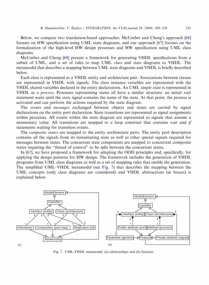
applying the design patterns for HW design. The framework includes the generation of VHDLprograms from UML class diagrams as well as a set of mapping rules that enable the generation.The simplified UML–VHDL metamodel (see Fig. 7) that describes the mapping between theUML concepts (only class diagrams are considered) and VHDL abstractions (in braces) isexplained below.
Interface (entity)
Realization (of)
1
1
1
*Inheritance
*
1
Composition (port map)
1
* *
1
Class (architecture)
Classifier
ModelElement
Relationship Feature
Method (process)
Interface (entity) Class (architecture)
Parameter (generic)
Public attribute (port)
Private attribute (signal)
1
*
1
*
1
*
1
*
ModelElement
Classifier
(a) (b)
Fig. 7. UML-VHDL metamodel: (a) relationships and (b) features.
ARTICLE IN PRESS
R. Damasevicius, V. Stuikys / INTEGRATION, the VLSI journal 38 (2004) 309–339322
The elements of UML class diagrams are classifiers, relationships, and features. The classifiers
are interfaces and classes that describe basic design blocks of an HW model. The relationships(Fig. 7(a)) describe different types of connections and associations between classifiers. Thefeatures (Fig. 7(b)) describe parameters, attributes and methods of classifiers.We map an abstract class (interface) to a VHDL entity. A class that realizes an abstract class is
mapped to the VHDL architecture. The class parameters are mapped to a VHDL generic
statement, public class attributes—to the VHDL ports and private class attributes—to the VHDLsignals. The class methods are mapped to VHDL processes (procedures). The composition
relationship describes the composition of a system from components and is mapped to a VHDLport map statement. The inheritance relationship means that an entity inherits the I/O ports from abase entity.Both approaches have similarities as well as differences. The similarities are as follows: (1) both
approaches use UML subsets as a source language and VHDL as a target language, (2) bothprovide mapping rules between UML and VHDL, (3) both generate the target VHDLspecifications automatically.The main difference is that our approach is oriented at reuse-based system design by adapting
and integrating third-party Intellectual Property (IP) components, whereas the McUmber andCheng’s approach is oriented at HW design from scratch.
3. Application of design patterns for HW design
In this section, we consider the application of UML class diagrams for describing the structureof a target system at a high level of abstraction. Class diagrams can be used to describe designpatterns [69]. Design patterns identify, document, and catalog successful design solutions tocommon design problems. Also, design patterns aid the development of reusable system modelsby expressing the structure and collaboration of components to designers at a level higher thansource code or individual objects and classes. Their use can be extended to the development ofmodels for HW components, embedded and real-time systems [70,71], too.There are two approaches for adopting the concept of design pattern to HW design. The first
approach aims at adapting the already known SW design patterns for HW design [72–74]. Thesecond approach aims at discovering new HW-specific design patterns [75,76]. Below, we describeseveral common SW design patterns [69] and their application in HW design domain.
3.1. Union Design Pattern
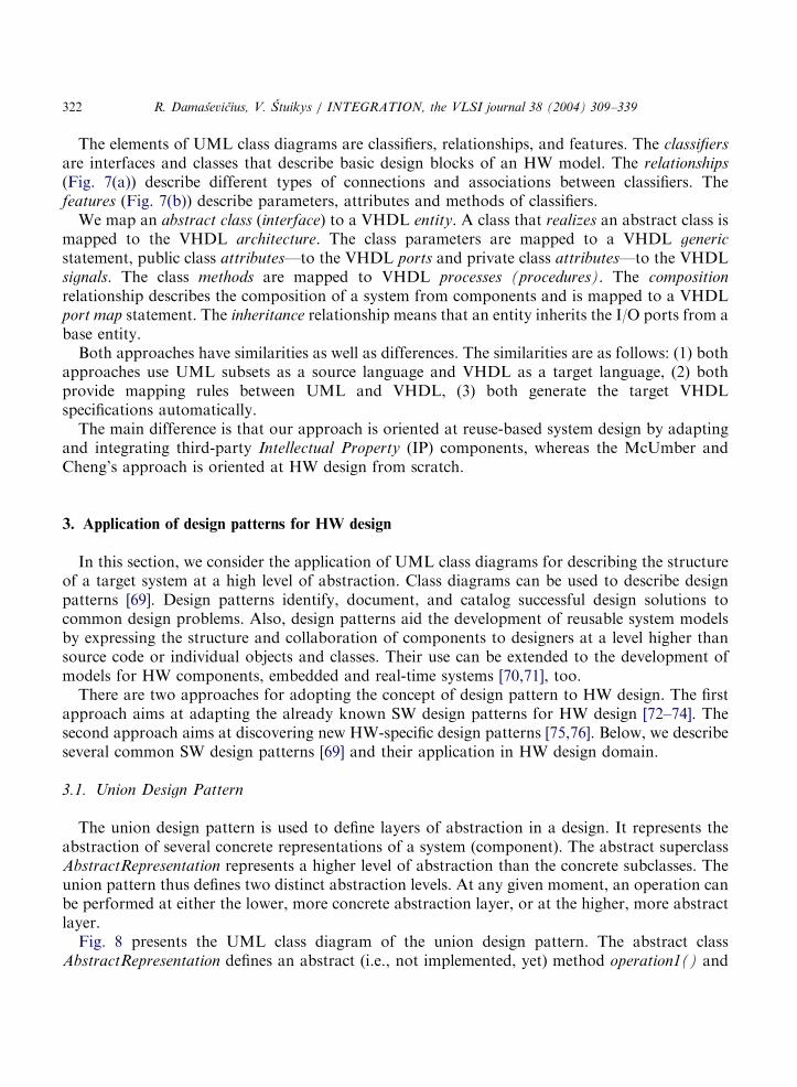
The union design pattern is used to define layers of abstraction in a design. It represents theabstraction of several concrete representations of a system (component). The abstract superclassAbstractRepresentation represents a higher level of abstraction than the concrete subclasses. Theunion pattern thus defines two distinct abstraction levels. At any given moment, an operation canbe performed at either the lower, more concrete abstraction layer, or at the higher, more abstractlayer.Fig. 8 presents the UML class diagram of the union design pattern. The abstract class
AbstractRepresentation defines an abstract (i.e., not implemented, yet) method operation1() and
ARTICLE IN PRESS
+operation1()+operation2()
AbstractRepresentation
+operation1()
ConcreteExample1
+operation1()
ConcreteExample2
+operation1()
ConcreteExample3
Fig. 8. Union design pattern.
R. Damasevicius, V. Stuikys / INTEGRATION, the VLSI journal 38 (2004) 309–339 323
implements a method operation2(). The ConcreteExample classes inherit the implementation ofthe method operation2() from AbstractRepresentation class and provide the implementation forthe method operation1().The usage of the union design pattern allows to clearly separate between the invariant
(unchanging) aspects of the design problem and the variant (changing) ones. The abstractsuperclass is a representation of the essence that is common to all possible concrete subclasses. Itthus represents the invariant aspects of all classes in the system. The concrete subclasses areequivalent at a higher, more abstract level, and differ from each other at a lower level ofabstraction. Thus, they represent the variant aspects of the design problem. The actual behaviorof the system is a composition of the invariant behavior of the superclass and the variantbehaviors provided polymorphically by the instances of the concrete subclasses used.The union design pattern can be used in HW design domain to describe the configurable HW
systems using, e.g., the configuration statement in VHDL that allows specifying a concreteimplementation of a particular design entity in a system. For example, ALU can be implementedas a composition of the decoding operation (invariant aspect of a design) and abstract designentities that represent the ALU operations (variant aspects of a design). The particularimplementations of the ALU operations can be specified independently, thus giving moreflexibility for the designer to select the optimal implementation of ALU with respect to therequired design characteristics (chip area, speed, power consumption, etc.).
3.2. State design pattern
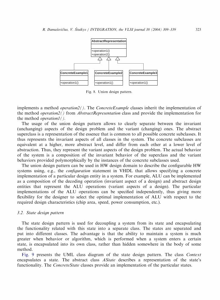
The state design pattern is used for decoupling a system from its state and encapsulatingthe functionality related with this state into a separate class. The states are separated andput into different classes. The advantage is that the ability to maintain a system is muchgreater when behavior or algorithm, which is performed when a system enters a certainstate, is encapsulated into its own class, rather than hidden somewhere in the body of somemethod.Fig. 9 presents the UML class diagram of the state design pattern. The class Context
encapsulates a state. The abstract class AState describes a representation of the state’sfunctionality. The ConcreteState classes provide an implementation of the particular states.
ARTICLE IN PRESS
+aMethod(in aParam : Object)
-aState : AState
Context
+aMethod(in aParam : Object, in context : Context)
AState
1 *
+aMethod(in aParam : Object, in context : Context)
ConcreteStateA
+aMethod(in aParam : Object, in context : Context)
ConcreteStateBaMethod()
aMethod()
Fig. 9. State design pattern.
R. Damasevicius, V. Stuikys / INTEGRATION, the VLSI journal 38 (2004) 309–339324
The state design pattern can be used in HW domain to design FSMs. Each ConcreteState classprovides an implementation of a separate FSM state and the corresponding functionality that isperformed when the FSM enters this state. This solution allows to design FSMs that can be easilyreused and extended with new states for other future applications.A disadvantage of the state design pattern is that it may result in excessive complexity of the
designed system since for every state a separate object is assigned are later implemented as aseparate component. Thus, the application of this pattern leads to worse performancecharacteristics of the designed system. The trade-off here is between faster implementation ofthe system and worse characteristics.
3.3. Diamond design pattern
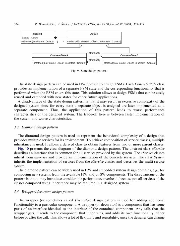
The diamond design pattern is used to represent the behavioral complexity of a design thatprovides multiple services for its environment. To achieve composition of service classes, multipleinheritance is used. It allows a derived class to obtain features from two or more parent classes.Fig. 10 presents the class diagram of the diamond design pattern. The abstract class aService
describes an interface that is common for all services provided by the system. The cService classesinherit from aService and provide an implementation of the concrete services. The class System
inherits the implementation of services from the cService classes and describes the multi-servicesystem.The diamond pattern can be widely used in HW and embedded system design domains, e.g., for
composing new systems from the available HW and/or SW components. The disadvantage of thepattern is that it may introduce considerable performance overhead, because not all services of theclasses composed using inheritance may be required in a designed system.
3.4. Wrapper/decorator design pattern
The wrapper (or sometimes called Decorator) design pattern is used for adding additionalfunctionality to a particular component. A wrapper (or decorator) is a component that has someparts of an interface identical to the interface of the contained component. Any calls that thewrapper gets, it sends to the component that it contains, and adds its own functionality, eitherbefore or after the call. This allows a lot of flexibility and reusability, since the designer can change

ARTICLE IN PRESS
+aMethod()
cComponent
+aMethod()
«interface»aComponent
«refines»
+wrapperA()
cWrapper1
1
1
+wrapperB()
cWrapper2
-component : aComponent
aWrapper
Fig. 11. Wrapper design pattern.
+serviceA()
cService1
+serviceB()
cService2
System
«interface»aService
Fig. 10. Diamond design pattern.
R. Damasevicius, V. Stuikys / INTEGRATION, the VLSI journal 38 (2004) 309–339 325
the wrapper without changing the original component it wraps. As the designer can recursivelynest wrappers, the pattern allows for almost infinite amount of customization.Fig. 11 presents the UML class diagram of the wrapper design pattern. The abstract class
aComponent specifies an interface that is common for all components and their wrappers. Theclass cComponent provides an implementation for aComponent class. The abstract class aWrapper
specifies a wrapper interface and contains an instance of aComponent class. The cWrapper classesprovide the different implementations of a wrapper.The wrapper pattern can be widely used in HW design, especially for (1) communication
control to provide an implementation of a communication protocol for an HW componentcommunicating with its environment, (2) fault-tolerant applications to implement fault-avoidance

ARTICLE IN PRESS
R. Damasevicius, V. Stuikys / INTEGRATION, the VLSI journal 38 (2004) 309–339326
and fault-discovery techniques such as TMR (Triple-Modular Redundancy) and BIST (Built-In
Self Test), (3) adaptation of the physical memory interfaces to a communication network thatmay have a different number of access ports, and (4) layered data packet processing in networkapplications.A disadvantage of the wrapper design pattern is that it may result in considerable overhead
since the complete interface of the wrapped component needs to be handled by the wrapper,including those interface elements that need not be adapted. Thus, the application of thewrapper design pattern may lead to excessive amounts of the adaptation code and performanceoverhead.
3.5. Composite design pattern
The composite pattern allows treating both single components and collections of componentsidentically. It allows building complex components by recursively composing similar componentsin a hierarchical tree-like manner. It also allows the components to be manipulated in a consistentmanner, by requiring all of the components to have a common parent. The composite designpattern is often used to represent recursive system architectures and their behavior.Fig. 12 presents the UML class diagram of the composite design pattern. The abstract class
aComponent specifies an interface that is common to all its implementations. The Leaf classesprovide the different implementations of aComponent. The class Composite is recursivelycomposed of an array of aComponent type components (which may be of Leaf or Composite type)and implements the recursive call to their operations.The composite design pattern can be widely used in HW design to rapidly implement systems
with a repetitive architecture such as multiplexer arrays, register arrays, adders, etc. Theadvantage of using the composite design pattern is scaling, i.e., a part of the system can beaddressed in the same way as the whole system. The disadvantage of this pattern is, as it is withmany other design patterns, the possibility of the considerable performance overhead introducedby the recursive composition of the components.
+operation()
«interface»aComponent
+operation()
Leaf1
+operation()
Leaf2
+operation()
-children : aComponent[]
Composite
1
*
for all c in children: c.operation();
Fig. 12. Composite design pattern.

ARTICLE IN PRESS
R. Damasevicius, V. Stuikys / INTEGRATION, the VLSI journal 38 (2004) 309–339 327
4. Principles of OOD of HW and embedded systems
In this section, we summarize our overview and formulate the basic principles of the OOD asapplied to HW and embedded system design domains.
Principle 1. OOD is based on representation of the real-world entities using a set of classes andrelationships between them.Principle 1 states that domain entities are represented as OO models. In order to represent the
domain and its systems, a higher layer of abstraction is introduced above the domain abstractionlayer. The main actors of this higher abstraction layer are classes—the highly abstract conceptsthat encapsulate the domain data and operations performed on it. The classes are related witheach other through a network of relationships. These relationships represent different types ofclassification and interaction between domain entities—the abstract ones introduced duringdomain analysis as well as the concrete ones that represent direct communication between domainentities. The decomposition of a domain system into classes and relationships between them is amatter of an OO domain analysis.
Principle 2. OOD is an evolutionary design methodology specifically oriented at design for reuse.The main concepts of the OOD are essentially the same as in other design methodologies such
as component-based design. What is the difference is the way these concepts are applied. TheOOD is essentially the evolutionary design methodology specifically aimed for implementing the‘design-for-reuse’ principle systematically, whereas other design methodologies usually supportthe design reuse only casually and ad hoc. The classes are specifically designed to evolve overtime as the designer analyzes and better understands the domain, as well as new requirementsappear in the process of system design. The classes can be extended using a powerful extensionmechanism of inheritance that allows adding new data and methods to the existing classes. As thedesigner adds new features to a system, he/she may discover that his/her previous design does notsupport easy system extension. With this new information, the designer can restructure parts ofthe designed system, very possibly adding new classes or class hierarchies to an OO model ofa system.
Principle 3. The OO model of a system is an instance of the class hierarchy that abstracts thedomain and consists of the communicating objects.The class hierarchy organizes the commonalities present in a set of domain entities into a tree
structure, where the root of any subtree contains all the attributes and behavior common to everydescendant of that root. In standard HDLs, there are no syntactical structures to express this kindof hierarchy, therefore reuse is limited to the component level, i.e. designers must use thecomponent ‘‘as is’’ or have to design a new one. In the OOD paradigm, inheritance provides thepotential for building new solutions to problems by adding incremental capability to existingproblem solutions through subclassing. This concept is one of the most fundamental OODfeatures to enable design reuse in the domain.An object is a distinct instance of a given class that encapsulates its implementation details and
is structurally identical to all other instances of that class. Multiple instantiations of a given classcan be made and each of them represents a distinct object. An object defines an interface ofservices (operations, methods) that it provides, while encapsulating the data defined in its class

ARTICLE IN PRESS
R. Damasevicius, V. Stuikys / INTEGRATION, the VLSI journal 38 (2004) 309–339328
and hiding the implementation details. In HW design domain, the notion of object corresponds toa distinct component instance that is used to create unique references to the lower-levelcomponents.
Principle 4. The functionality of the OO system model is defined by the relationships betweenobjects (classes).There are three basic types of relationships that describe the structural affinity between classes
and behavioral interaction between objects in the OO model:
(1)
Inheritance allows a subclass to incorporate the data and operations defined in a parent classand to augment it with the additional data elements and methods. In HW domain, itcorresponds to the functional classification of components.(2)
Aggregation is used when one object (container) physically or conceptually contains anotherobject (component). In HW design domain, it corresponds to the composition of componentsinto a larger module (system). The purpose of the component is to contribute in some way tothe overall functionality of its container (system).(3)
Association represents conceptual relationships between classes, and it is used for exchange ofmessages. In HW domain, it corresponds to the dependence of a particular component uponanother component for interaction or communication.Principle 5. OO models of the domain systems can have three different implementation views:structural, behavioral, and FSM-based.Depending upon the implementation on the domain layer of the abstraction, the OO HW
systems can have three distinct implementation views as follows:
(1)
The structural view to the HW system is based on the representation of physical components asobjects. It can be represented using UML class diagrams.(2)
The behavioral view to the HW system is based on the representation of abstract concepts forsolving the design problem. The objects of the design process are abstract design processes. Itcan be represented using UML object diagrams.(3)
The FSM-based view to the HW system represents each object as an FSM. It can berepresented using UML state diagrams.Principle 6. The common OO HW models can be expressed in terms of the OOD paradigm usingclass templates and polymorphism.In UML, a parameterized class (template) is used to express genericity in the OO models.
Templates allow modeling generic domain components explicitly and thus providing analternative approach for representing generalization in the domain: not only via class hierarchies,but also using class templates and their instances.
Polymorphism is another mechanism provided by the OOD methodology that provides theability to manipulate with objects of distinct classes using only knowledge of their commonproperties without regard for their exact class type. The polymorphism enables new classespossessing required properties to be handled equally with their base class. Polymorphism, whenapplied to HW design, gives an enormous potential of reuse enabling the incremental refinementof particular HW modules.

ARTICLE IN PRESS
R. Damasevicius, V. Stuikys / INTEGRATION, the VLSI journal 38 (2004) 309–339 329
Principle 7. Common domain architectures can be expressed in terms of the OOD paradigm usingdesign patterns.Common OO solutions to the HW domain problems can be expressed more abstractly and
generally using HW design patterns. The difference of the design patterns from the other OOmodels and class hierarchies is that a design pattern is a more general and abstract model thatrepresents a common and well-proven solution to a design problem rather than a specific domainsystem. Thus, design patterns represent an abstraction layer that is higher than common OOdomain models, and they allow fostering reuse of design knowledge and experience rather thanthe reuse of a specific implementation.
Principle 8. An object/domain metamodel is the conceptual framework for connecting higher andlower layers of the abstraction in system design.The OO domain models specify only abstract views of domain systems without specifying the
particular domain content. This low-level content must be introduced later in the design processwhen OO models are refined into domain entities.Thus, the introduction of the higher-level model that abstracts the domain content on the lower
layer of abstraction, requires the introduction of the object/domain metamodel that describesmapping between those layers of abstraction within the OOD framework. The OO layer of thedomain system can be described using a graphical notation such as UML diagrams or an OOlanguage. The transition to the domain layer can be performed using the traditional compilationtechniques or generation into an HDL using the generative technology. All these different choicesgreatly influence the design productivity as well as the efficiency of the designed HW system.
5. Case studies
We illustrate the application of the OOD principles discussed above by presenting two simplecase studies. The first one implements a diamond pattern for designing multi-protocolcommunication interface for HW components described in VHDL. The second one implementsa composite pattern for design of Network-on-Chip model described in SystemC. With these twocase studies, we aim to demonstrate the usage of two most popular domain languages, VHDL thatis not an OO HDL and SystemC that is an OO HDL, in the context of the OOD of HWcomponents.
5.1. Specification of communication control using Diamond pattern
In this case study, we use a diamond design pattern (see Section 3.3) to design an HWcomponent with a multi-protocol communication service provided for communication control.The services are composed of an HW component, which implements basic functionality, using awrapper design pattern [74].The main purpose of communication control is to ensure the relevant transmission of data (e.g.,
operands, commands, addresses, etc.) to and from the HW component. The transmission of datacan be described using different rules or protocols, i.e. an agreed format for transmitting databetween the HW components. We consider here two common communication protocols, namely,

ARTICLE IN PRESS
«interface»IP
IPModel
+handshake()
+Req : in std_logic+Ack : out std_logic+En_data : in std_logic+Evn_to : out std_logic
HandshakeWrapper
+fifo()
+Push : in std_logic+Full : out std_logic+Pop : in std_logic+Empty : out std_logic
FifoWrapper
System
«refines»
Fig. 13. Class diagram of a target system.
R. Damasevicius, V. Stuikys / INTEGRATION, the VLSI journal 38 (2004) 309–339330
handshake protocol that deals with an asynchronous flow of data, and FIFO protocol that dealswith sudden bursts of data in a producer–consumer model. Our aim is to include both into atarget system and let the user decide which protocol should be used to communicate with thewrapped HW component.Fig. 13 presents the UML class diagram of a target system. Abstract class IP is an interface of
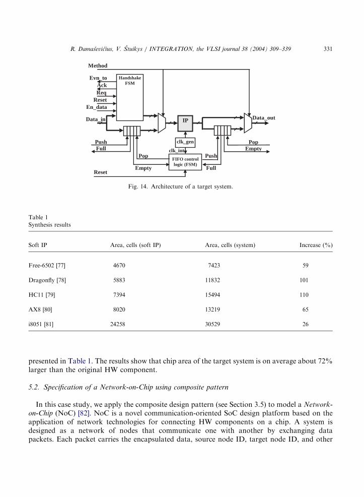
an HW component (soft IP). Class HandshakeWrapper provides an implementation of ahandshake protocol and class FIFOwrapper provides an implementation of a FIFO protocol.Class System uses multiple inheritance to inherit both protocol implementations and encapsulatesan instance of IP component.The architecture of the target system is shown in Fig. 14. The architecture implements the
FIFO-based model of an object described in Section 2.4. Note that signals Data_in and Data_out
represent the IP-specific data signals, and signal Method is used to select the required method ofthe object.
IP is an HW component (e.g., ALU, controller, processor, etc.) for which a multi-protocolcommunication interface must be implemented. The handshake wrapper wraps the IP withhandshake FSM. The data are transferred to the IP when request signal Req is set to a high leveland acknowledgement signal Ack is received from the handshake FSM. The results are returnedas soon as the IP processes the data.The FIFO wrapper wraps the IP component with two instances of FIFO buffer and additional
control logic. The internal clock signal clk_int is used to run FIFO control logic and the IP. Thedata are transferred to the IP component when Push signal is set to a high level and Full signal hasa low level. The results are returned when Pop signal is set to a high level and Empty signal has alow level.We have implemented the target system using several freely available HW components
described in VHDL as the IP. The synthesis results (Synopsys; CMOS 0.35mm technology) are
ARTICLE IN PRESS
Table 1
Synthesis results
Soft IP Area, cells (soft IP) Area, cells (system) Increase (%)
Free-6502 [77] 4670 7423 59
Dragonfly [78] 5883 11832 101
HC11 [79] 7394 15494 110
AX8 [80] 8020 13219 65
i8051 [81] 24258 30529 26
Pop Push
FullEmpty
Data_in
PushFull
IP
FIFO controllogic (FSM)
Data_out
PopEmpty
clk_gen
clk_int
Reset
Handshake FSM
ReqAck
ResetEn_data
Evn_to
Method
Fig. 14. Architecture of a target system.
R. Damasevicius, V. Stuikys / INTEGRATION, the VLSI journal 38 (2004) 309–339 331
presented in Table 1. The results show that chip area of the target system is on average about 72%larger than the original HW component.
5.2. Specification of a Network-on-Chip using composite pattern
In this case study, we apply the composite design pattern (see Section 3.5) to model a Network-on-Chip (NoC) [82]. NoC is a novel communication-oriented SoC design platform based on theapplication of network technologies for connecting HW components on a chip. A system isdesigned as a network of nodes that communicate one with another by exchanging datapackets. Each packet carries the encapsulated data, source node ID, target node ID, and other
ARTICLE IN PRESS
+north : aChannel+east : aChannel+south : aChannel+west : aChannel
aNetwork
aResource
+process(in p : Packet) : Packet
cResource
-resource : aResource
aNode11
+switch(inout north,east,south,west : aChannel)
cNode
+switch()
-nodes : aNode[]
cNetwork
for all n in nodes: n.switch(north,east,south,west);
1
*
Fig. 15. Class diagram of an NOC.
R. Damasevicius, V. Stuikys / INTEGRATION, the VLSI journal 38 (2004) 309–339332
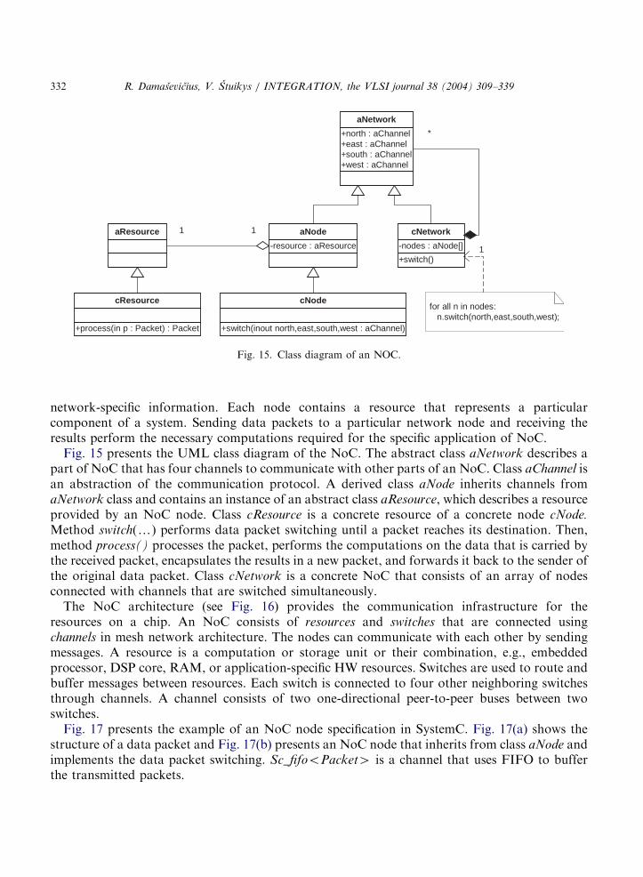
network-specific information. Each node contains a resource that represents a particularcomponent of a system. Sending data packets to a particular network node and receiving theresults perform the necessary computations required for the specific application of NoC.Fig. 15 presents the UML class diagram of the NoC. The abstract class aNetwork describes a
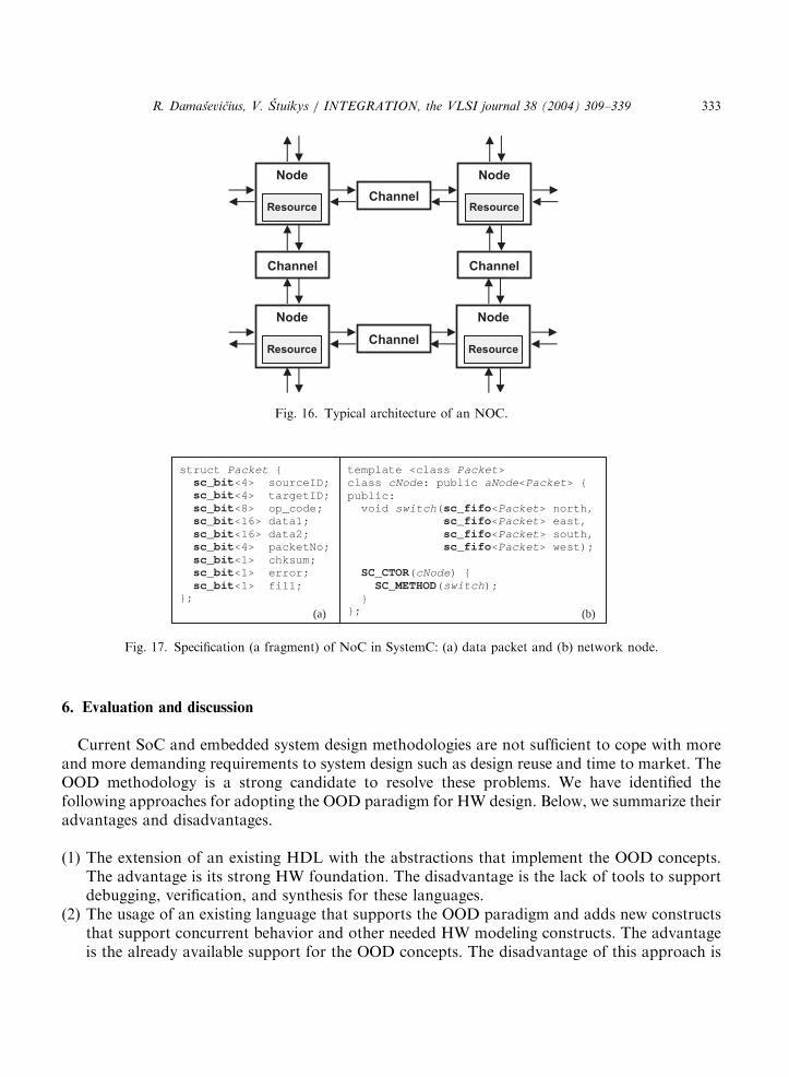
part of NoC that has four channels to communicate with other parts of an NoC. Class aChannel isan abstraction of the communication protocol. A derived class aNode inherits channels fromaNetwork class and contains an instance of an abstract class aResource, which describes a resourceprovided by an NoC node. Class cResource is a concrete resource of a concrete node cNode.Method switch(y) performs data packet switching until a packet reaches its destination. Then,method process() processes the packet, performs the computations on the data that is carried bythe received packet, encapsulates the results in a new packet, and forwards it back to the sender ofthe original data packet. Class cNetwork is a concrete NoC that consists of an array of nodesconnected with channels that are switched simultaneously.The NoC architecture (see Fig. 16) provides the communication infrastructure for the
resources on a chip. An NoC consists of resources and switches that are connected usingchannels in mesh network architecture. The nodes can communicate with each other by sendingmessages. A resource is a computation or storage unit or their combination, e.g., embeddedprocessor, DSP core, RAM, or application-specific HW resources. Switches are used to route andbuffer messages between resources. Each switch is connected to four other neighboring switchesthrough channels. A channel consists of two one-directional peer-to-peer buses between twoswitches.Fig. 17 presents the example of an NoC node specification in SystemC. Fig. 17(a) shows the
structure of a data packet and Fig. 17(b) presents an NoC node that inherits from class aNode andimplements the data packet switching. Sc_fifooPacket4 is a channel that uses FIFO to bufferthe transmitted packets.
ARTICLE IN PRESS
template <class Packet> class cNode: public aNode<Packet> {public:void switch(sc_fifo<Packet> north,
sc_fifo<Packet> east,sc_fifo<Packet> south, sc_fifo<Packet> west);
SC_CTOR(cNode) { SC_METHOD(switch);
} };
struct Packet { sc_bit<4> sourceID;sc_bit<4> targetID;sc_bit<8> op_code; sc_bit<16> data1; sc_bit<16> data2; sc_bit<4> packetNo;sc_bit<1> chksum;sc_bit<1> error; sc_bit<1> fill;
};
(a) (b)
Fig. 17. Specification (a fragment) of NoC in SystemC: (a) data packet and (b) network node.
Channel
ChannelChannel
Node
Resource
Channel
Node
Resource
Node
Resource
Node
Resource
Fig. 16. Typical architecture of an NOC.
R. Damasevicius, V. Stuikys / INTEGRATION, the VLSI journal 38 (2004) 309–339 333
6. Evaluation and discussion
Current SoC and embedded system design methodologies are not sufficient to cope with moreand more demanding requirements to system design such as design reuse and time to market. TheOOD methodology is a strong candidate to resolve these problems. We have identified thefollowing approaches for adopting the OOD paradigm for HW design. Below, we summarize theiradvantages and disadvantages.
(1)
The extension of an existing HDL with the abstractions that implement the OOD concepts.The advantage is its strong HW foundation. The disadvantage is the lack of tools to supportdebugging, verification, and synthesis for these languages.(2)
The usage of an existing language that supports the OOD paradigm and adds new constructsthat support concurrent behavior and other needed HW modeling constructs. The advantageis the already available support for the OOD concepts. The disadvantage of this approach is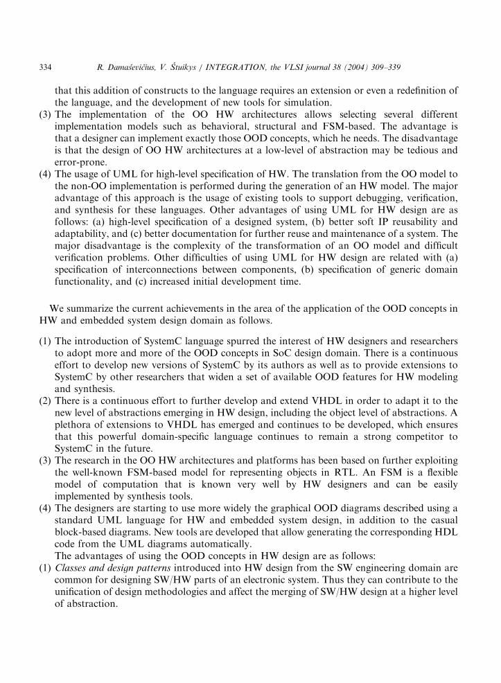
ARTICLE IN PRESS
R. Damasevicius, V. Stuikys / INTEGRATION, the VLSI journal 38 (2004) 309–339334
that this addition of constructs to the language requires an extension or even a redefinition ofthe language, and the development of new tools for simulation.
(3)
The implementation of the OO HW architectures allows selecting several differentimplementation models such as behavioral, structural and FSM-based. The advantage isthat a designer can implement exactly those OOD concepts, which he needs. The disadvantageis that the design of OO HW architectures at a low-level of abstraction may be tedious anderror-prone.(4)
The usage of UML for high-level specification of HW. The translation from the OO model tothe non-OO implementation is performed during the generation of an HW model. The majoradvantage of this approach is the usage of existing tools to support debugging, verification,and synthesis for these languages. Other advantages of using UML for HW design are asfollows: (a) high-level specification of a designed system, (b) better soft IP reusability andadaptability, and (c) better documentation for further reuse and maintenance of a system. Themajor disadvantage is the complexity of the transformation of an OO model and difficultverification problems. Other difficulties of using UML for HW design are related with (a)specification of interconnections between components, (b) specification of generic domainfunctionality, and (c) increased initial development time.We summarize the current achievements in the area of the application of the OOD concepts inHW and embedded system design domain as follows.
(1)
The introduction of SystemC language spurred the interest of HW designers and researchersto adopt more and more of the OOD concepts in SoC design domain. There is a continuouseffort to develop new versions of SystemC by its authors as well as to provide extensions toSystemC by other researchers that widen a set of available OOD features for HW modelingand synthesis.(2)
There is a continuous effort to further develop and extend VHDL in order to adapt it to thenew level of abstractions emerging in HW design, including the object level of abstractions. Aplethora of extensions to VHDL has emerged and continues to be developed, which ensuresthat this powerful domain-specific language continues to remain a strong competitor toSystemC in the future.(3)
The research in the OO HW architectures and platforms has been based on further exploitingthe well-known FSM-based model for representing objects in RTL. An FSM is a flexiblemodel of computation that is known very well by HW designers and can be easilyimplemented by synthesis tools.(4)
The designers are starting to use more widely the graphical OOD diagrams described using astandard UML language for HW and embedded system design, in addition to the casualblock-based diagrams. New tools are developed that allow generating the corresponding HDLcode from the UML diagrams automatically.The advantages of using the OOD concepts in HW design are as follows:(1)
Classes and design patterns introduced into HW design from the SW engineering domain arecommon for designing SW/HW parts of an electronic system. Thus they can contribute to theunification of design methodologies and affect the merging of SW/HW design at a higher levelof abstraction.
ARTICLE IN PRESS
R. Damasevicius, V. Stuikys / INTEGRATION, the VLSI journal 38 (2004) 309–339 335
(2)
Design patterns allow for specifying an HW design problem at a higher abstraction levelgraphically. The application of design patterns described using UML class diagrams allows forspecifying target systems using abstract representations of proven design experience. The designcontent is captured immediately and intuitively, thus increasing design comprehensibility. Thepattern-based design can be easily supported by the automated validation and code generationtools, thus increasing design reuse, quality, and productivity. The level of abstraction is raisedto the system level, which allows dealing with growing complexity of HW designs.(3)
Encapsulation allows to separate the data from functionality, thus implementing theseparation of concerns principle in HW design.(4)
Inheritance and polymorphism are powerful OOD principles that allow to increase designproductivity substantially, because they enable reuse of existing code.(5)
Message exchange is a very promising OOD concept especially when considered in the contextof a new emerging paradigm for the interconnection-based SoC design, called NoC [82].The idea of adopting the OOD principles to HW and embedded system design domain holdsgreat promises; however, there are many gaps that must be bridged before these promises could befully fulfilled and they are as follows:
(1)
Conceptual gap: SW designers think in terms of the OOD concepts (objects and messages),whereas HW designers are used to think in terms of the component-based design (componentsand wires).(2)
Physical gap: how the physical constraints (such as the timing ones) should be reflected in anOO model or a metamodel (design pattern)?(3)
Technological gap: how objects or even entire design patterns could be directly synthesized toRTL?7. Conclusions and future research
Currently, the design and implementation of HW, embedded and real-time systems hardlydiffer from traditional SW development. Despite all known problems and difficulties, the OODprinciples can be adopted for developing HW as well as embedded systems. The OOD paradigmprovides the techniques like abstraction, inheritance and polymorphism that help the designer tohandle large and complex systems. On the other hand, the OOD paradigm does not provide thedemanded code efficiency (in terms of chip area or delay) for real-time and embeddedapplications.The main task of the future research on OO HW design, therefore, should focus on reconciling
these two contradicting features of the OOD paradigm, and seeking for the best possible trade-offsolutions between faster design time provided by the application of the OOD paradigm and worsesystem characteristics introduced by the OO abstractions. We formulate the most probable futuretrends in the application of the OOD principles to HW and embedded system design as follows.
(1)
A great deal of research is performed to extend UML in order to take new domains ofapplication into account [21]. The research focuses on the UML extensions for modeling (a)real time behavior, (b) executable specifications capable to express parallelism, (c) HW/SW
ARTICLE IN PRESS
R. Damasevicius, V. Stuikys / INTEGRATION, the VLSI journal 38 (2004) 309–339336
interfaces and co-simulation, (d) behavior of analog interfaces and systems, and (e) size,weight, area, power, timing and other constraints.
(2)
The adoption of design patterns for HW design will attract more and more attention from theresearchers. The efforts will be directed at adopting the already known SW design patterns aswell as at discovering new HW-specific design patterns.(3)
The researchers are seeking for the unification of HW and SW design methodologies into asingle SoC design flow under the OOD paradigm umbrella.References
[1] H. Chang, L. Cooke, M. Hunt, G. Martin, A. McNelly, L. Todd, Surviving the SOC Revolution: A Guide to
Platform-Based Design, Kluwer Academic Publishers, Dordrecht, 1999.
[2] SEMATECH, The International Technology Roadmap for Semiconductors, 2001.
[3] F. Vahid, T. Givargis, Embedded System Design: A Unified Hardware/Software Introduction, Wiley, New York,
2002.
[4] A. Pawlak, W. Wlodzimierz, Modern object-oriented programming language as a HDL, in: Eigth IFIP
Interational Symposium on Computer Hardware Description Languages and their Applications, 1987,
Amsterdam, pp. 343–362.
[5] W.H. Wolf, How to build a hardware description and measurement system on an object-oriented programming
language, IEEE Trans. Comput. Aided Des. 8 (3) (1989) 288–301.
[6] R. Gupta, W.H. Cheng, R. Gupta, I. Hardonag, M.A. Breuer, An object-oriented VLSI CAD framework: a case
study in rapid prototyping, IEEE Comput 22 (9) (1989) 28–37.
[7] A.C. Verschueren, An object-oriented design and simulation system for VLSI’’, Microprocess. Microprogramming
30 (1–5) (1990) 241–246.
[8] D.C. Craig, Circuit description and elementary hierarchical circuit simulation using C++ and the object-oriented
programming paradigm, Ph.D. Dissertation, Department of Computer Science, Memorial University of
Newfoundland, St. John’s, Newfoundland, Canada, April 1991.
[9] S. Kumar, J.H. Aylor, B.W. Johnson, W.A. Wulf, Object-oriented techniques in hardware design, IEEE Comput.
27 (6) (1994) 64–70.
[10] K. Agsteiner, D. Monjau, S. Schulze, Object-oriented system level specification and synthesis of heterogeneous
systems, Proceedings of EURO-MICRO’95, Como, Italy, 4–7 September 1995.
[11] W. Nebel, G. Schumacher, Object-Oriented Hardware Modelling—Where to apply and what are the objects?
Proceedings of EURO-DAC with EURO-VHDL’96, Geneva, Switzerland, September 16–20, 1996, pp. 428–433.
[12] W.H. Wolf, Object-oriented cosynthesis of distributed embedded systems, ACM Trans. Des. Automati. Electron.
Systems 1 (3) (1996) 301–314.
[13] J.M. Berge, O. Levia (Eds.), Object-Oriented Modeling Current Issues in Electronic Modeling, Vol. 7, Kluwer
Academic Publishers, Dordrecht, 1996.
[14] T. Potok, M. Vouk, Development productivity for commercial software using object-oriented methods,
Proceedings of the 1995 Conference of the Centre for Advanced Studies on Collaborative Research, IBM Press,
Toronto, Ontario, Canada, 1995, p. 52.
[15] S. Swan, D. Vermeersch, P. Hardee, T. Hasegawa, A. Rose, A. Coppola, M. Jansen, T. Grotker, A. Ghosh, K.
Kranen, Functional Specification for SystemC 2.0, White paper, OSCI, 2001.
[16] G. Booch, I. Jacobson, J. Rumbaugh, J. Rumbaugh, The Unified Modeling Language User Guide, Addison-
Wesley, Reading, MA, 1998.
[17] J.M. Fernandes, R.J. Machado, H.D. Santos, Modeling Industrial Embedded Systems with UML, Proceedings of
the Eigth IEEE/IFIP/ACM Interational Workshop on Hardware/Software Co-Design (CODES’2000), San Diego,
CA, USA, May, 2000, pp. 18–23.
[18] G. de Jong, A UML-based design methodology for real-time and embedded systems, Proceedings of the Design
Automation and Test in Europe (DATE 2002), Paris, France, 4–8 March 2002, pp. 776–778.
ARTICLE IN PRESS
R. Damasevicius, V. Stuikys / INTEGRATION, the VLSI journal 38 (2004) 309–339 337
[19] Q. Zhu, A. Matsuda, S. Kuwamura, T. Nakata, M. Shoji, An object-oriented design process for system-on-chip
using UML, Proceedings of the 15th Interational Symposium on System Synthesis (ISSS 2002), Kyoto, Japan,
2002, pp. 249–254.
[20] G. Martin, UML for embedded systems specification and design: motivation and overview, Proceedings of DATE
2002, Paris, France, 4–8 March 2002, pp. 773–775.
[21] S. Gerard, F. Terrier, UML for real-time, in: L. Lavagno, G. Martin, B. Selic (Eds.), UML for Real, Kluwer
Academic Publishers, Boston, 2003, pp. 17–52.
[22] M. Edwards, P. Green, UML for hardware and software object modeling, in: L. Lavagno, G. Martin, B. Selic
(Eds.), UML for Real, Kluwer Academic Publishers, Dordrecht, 2003, pp. 127–148.
[23] IEEE. Standard VHDL Language Reference Manual, IEEE Std 1076 1993, 1994.
[24] W. Ecker, An object-oriented view of structural VHDL description, Proceedings of VHDL International Users’
Forum (VIUF Spring ‘96), Santa Clara, CA, USA, March 1996, pp. 255–264.
[25] S. Swamy, A. Molin, B. Covnot, OO–VHDL: object-oriented extensions to VHDL, IEEE Comput 28 (10) (1995)
18–26.
[26] R. Zippelius, K.D. Muller-Glaser, An object-oriented extension of VHDL, Proceedings of the VHDL-Forum
Spring’92 Meeting, Santander, Spain, April 26–28, 1992, pp. 155–163.
[27] W. Glunz, A. Pyttel, G. Venzl, System-level synthesis, in: P. Michael, U. Lauther, P. Duzy (Eds.), The Synthesis
Approach to Digital System Design, Kluwer Academic Publishers, Dordrecht, 1992, pp. 221–260.
[28] J. Benzakki, B. Djafri, Object oriented extensions to VHDL, the LaMI proposal, Proceedings of the International
Conference on Hardware Description Languages and their Applications, Toledo, Spain, 1997, pp. 334-347.
[29] M. Radetzki, W. Putzke-Roming, W. Nebel, Objective VHDL: The object-oriented approach to hardware reuse,
in: J.-Y. Roger, B. Stanford-Smith, P.T. Kidd (Eds.), Advances in Information Technologies: The Business
Challenge, IOS Press, Amsterdam, 1998, pp. 796–803.
[30] P.J. Ashenden, Overview of SUAVE language features, in: Proceedings of the Forum on Design Languages
(FDL), Lyon, France, August 30–September 3, 1999, pp. 269–278.
[31] G. Schumacher, W. Nebel, Survey on object-oriented languages for hardware design methodologies, in: High-
Level SystemModeling: Specification Languages, Current Issues in Electronic Modeling, Vol. 3, Kluwer Academic
Publishers, Dordrecht, 1995.
[32] G. Schumacher, Object-oriented hardware specification and design with a language extension to VHDL, Ph.D.
Thesis, Universitat Oldenburg, Germany, 1999.
[33] M. Radetzki, Synthesis of digital circuits from object-oriented specifications, Ph.D. Thesis, Universitat Oldenburg,
Germany, 2000.
[34] S. Sutherland, SystemVerilog For Design: A Guide to Using SystemVerilog for Hardware Design and Modeling,
Kluwer Academic Publishers, Norwell, 2004.
[35] T. Kuhn, W. Rosenstiel, U. Kebschull, Description and simulation of hardware/software systems with Java,
Proceedings of the 36th Design Automation Conference (DAC’99), New Orleans, LA, USA, 21–25 June, 1999,
pp. 790–793.
[36] R. Allen, D. Gajski, The case for C/C++ hardware design, EETimes, 2000.
[37] D. Verkest, J. Kunkel, F. Schirrmeister, System level design using C++, Proceedings of the Design, Automation
and Test in Europe (DATE 2000), Paris, France, 27–30 March 2000, pp. 74–81.
[38] D. Ku, G. De Micheli, HardwareC: a language for hardware design, Technical Report SCSL/CSL/TR-90-419,
Computer Systems Laboratory, Stanford University, Stanford, CA, USA, August 1990.
[39] J. L. da Silva, C. Ykman-Couvreur, G. de Jong, Matisse: a concurrent and object-oriented system specification
language, Proceedings of the IFIP Interational Conference on Very Large Scale Integration (VLSI’97), Gramado,
Brazil, August 26–29, 1997.
[40] A. Gerstlauer, R. Domer, J. Peng, D. Gajski, System Design—A Practical Guide with SpecC, Kluwer Academic
Publishers, Dordrecht, May 2001.
[41] T. Gro+tker, S. Liao, G. Martin, S. Swan, System Design with SystemC, Kluwer Academic Publishers, Boston,
2002.
[42] W. Mu+ ller, W. Rosenstiel, J. Ruf, SystemC: Methodologies and Applications, Kluwer Academic Publishers,
Dordrecht, 2003.

ARTICLE IN PRESS
R. Damasevicius, V. Stuikys / INTEGRATION, the VLSI journal 38 (2004) 309–339338
[43] A. Tsikhanovich, E.M. Aboulhamid, Object-oriented techniques in hardware modeling using SystemC, in:
Northeast Workshop on Circuits and Systems, Montreal, Canada, June 2003.
[44] S. Virtanen, D. Truscan, J. Lilius, SystemC based object oriented system design, in: Proceedings of the fourth
Interational Forum on Design Languages (FDL’01), Lyon, France, September 3–7, 2001.
[45] C. Schulz-Key, M.Winterholer, T. Schweizer, T. Kuhn, W. Rosenstiel, Object-oriented modeling and synthesis of
SystemC specifications, in: Proceedings of the Asia South Pacific Design Automation Conference (ASPDAC’04),
Yokohama, Japan, 2004, pp. 238–243.
[46] E. Grimpe, F. Oppenheimer, Aspects of object oriented hardware modelling with SystemC-plus, in: A. Mignotte,
E. Villar, L. Horobin (Eds.), System on Chip Design Languages, Extended Papers: Best of FDL001 and
HDLCon001, Kluwer Academic Publishers, Dordrecht, 2002, pp. 213–223.
[47] A. Sangiovanni-Vincentelli, G. Martin, A vision for embedded systems: platform-based design and software
methodology, IEEE Des. Test Comput. 18 (6) (2001) 23–33.
[48] M. Goudarzi, S. Hessabi, A. Mycroft, Object-oriented ASIP design and synthesis, in: Forum on Specification and
Design Languages (FDL’03), Frankfurt, Germany, September 23–26, 2003.
[49] Silicon Infusion Ltd., An Object Oriented Re-Configurable System on Chip, White paper, 2003.
[50] J.L. Peterson, Petri Net Theory and the Modeling of Systems, Prentice-Hall, Englewood cliffs, NJ, 1981.
[51] R. Esser, An object-oriented petri net language for embedded system design, Proceedings of the Eighth
International Workshop on Software Technology and Engineering Practice (STEP’97), London, UK, July 1997,
pp. 216–223.
[52] C. Lakos, The object orientation in object petri nets, in: Proceedings of the 16th International Conference on
Application and Theory of Petri Nets, First Workshop on Object-Oriented Programming and Models of
Concurrency, Torino, Italy, 1995 pp. 1–14.
[53] P.A.C. Verkoulen, Integrated information systems design: an approach based on object oriented concepts and
petri nets, Ph.D. Thesis, University of Technology, Eindhoven, the Netherlands, 1993.
[54] Y.K. Lee, S.J. Park, OPNETS: an object-oriented high-level Petri-net model for real-time system modeling,
J. Systems Software 1 (20) (1993) 69–86.
[55] R.J. Machado, J.M. Fernandes, A.J. Proenc-a, Specification of industrial digital controllers with object-oriented
petri nets, IEEE International Symposium on Industrial Electronics (ISIE’97), Vol. I, Guimaraes, Portugal, July,
1997, pp. 78–83.
[56] C.A. Lakos, C.D. Keen, LOOPN++: a new language for object-oriented petri nets, Proceedings of the Modelling
and Simulation (European Simulation Multiconference), Barcelona, Spain, 1994, pp. 369–374.
[57] R.J. Machado, J.M. Fernandes, H.D. Santos, a methodology for complex embedded systems design: petri nets
within a UML approach, in: B. Kleinjohann (Ed.), Architecture and Design of Distributed Embedded Systems,
Kluwer Academic Publishers, Dordrecht, 2001, pp. 1–10.
[58] R.J. Machado, J.M. Fernandes, A.J. Esteves, H.D. Santos, An evolutionary approach to the use of petri net based
models: from parallel controllers to HW/SW co-design, in: A. Yakovlev, L. Gomes, L. Lavagno (Eds.), Hardware
Design and Petri Nets, Kluwer Academic Publishers, Dordrecht, 2000, pp. 205–222.
[59] J. Nutzel, B. Dane, W. Fengler, Object nets for the design and verification of distributed and embedded
applications, in: J.D.P. Rolim (Ed.), Parallel and Distributed Processing, Proceedings of the 10th IPPS/SPDP’98
Workshops Held in Conjunction with the 12th International Parallel Processing Symposium and Ninth
Symposium on Parallel and Distributed Processing, Orlando, Florida, USA, March 30–April 3, 1998, Lecture
Notes in Computer Science, Vol. 1388, Springer, Berlin, 1998, pp. 953–962.
[60] J. Noguera, R. Badia, A HW/SW partitioning algorithm for dynamically reconfigurable architectures, in:
Proceedings of the Design, Automation and Test in Europe Conference (DATE’2001), Munich, Germany, March
12–16, 2001, pp. 729-734.
[61] P. Garg, S.K. Shukla, R.K. Gupta, Efficient usage of concurrency models in an object-oriented co-design
framework, in: Proceedings of the Design Automation and Test in Europe (DATE’01), Designers Forum, Munich,
Germany, March 2001.
[62] C. Schulz-Key, T. Kuhn, W. Rosenstiel, A framework for system-level partitioning of object-oriented
specifications, in: Workshop on Synthesis and System Integration of Mixed Technologies (SASIMI’2001), Nara,
Japan, 2001.

ARTICLE IN PRESS
R. Damasevicius, V. Stuikys / INTEGRATION, the VLSI journal 38 (2004) 309–339 339
[63] R.J. Machado, J.M. Fernandes, H.D. Santos, An object-oriented approach to the co-design of industrial control-
based information systems, in: Fourth APCA Portuguese Conference on Automatic Control (CONTROLO 2000),
Guimarces, Portugal, October, 2000.
[64] H.Hallal, X.Kong, R. Negulescu, Experiments in modeling integrated circuit blocks by UML, Proceedings of the
Interational Workshop on IP-based Circuits, 1999.
[65] R. Chen, M. Sgroi, G. Martin, L. Lavagno, A.L. Sangiovanni-Vincentelli, J. Rabaey, UML and platform-based
design, in: L. Lavagno, G. Martin, B. Selic (Eds.), UML for Real, Kluwer Academic Publishers, Dordrecht, 2003,
pp. 107–126.
[66] B. Liccardi, T. Maier-Komor, J.A. Oswald, M. Elkotob, G. Farber, A meta-modeling concept for embedded RT-
systems design, in: 14th Euromicro Conference on Real-Time Systems, Vienna, Austria, 19–21 June 2002.
[67] R. Damasevicius, V. Stuikys, Application of UML for hardware design based on design process model,
Proceedings of the Asia South Pacific Design Automation Conference (ASP-DAC 2004), Yokohama, Japan,
January 27–30, 2004, pp. 244-249.
[68] W.E. McUmber, B.H.C. Cheng, UML-based analysis of embedded systems using a mapping to VHDL,
Proceedings of the IEEE International Symposium on High Assurance Software Engineering (HASE’99),
Washington, DC, USA, November 1999, pp. 56-63.
[69] E. Gamma, R. Helm, R. Johnson, J. Vlissides, Design Patterns: Elements of Reusable Object-Oriented Software,
Addison-Wesley, Reading, MA, 1995.
[70] B.P. Douglass, Fine grained patterns for real-time systems, in: L. Lavagno, G. Martin, B. Selic (Eds.), UML for
Real, Kluwer Academic Publishers, Boston, 2003, pp. 149–170.
[71] B. Selic, Architectural Patterns for real-time systems, in: L. Lavagno, G. Martin, B. Selic (Eds.), UML for Real,
Kluwer Academic Publishers, Boston, 2003, pp. 171–188.
[72] N. Yoshida, Design patterns applied to object-oriented SoC design, in: 10th Workshop on Synthesis and System
Integration of Mixed Technologies (SASIMI 2001), Nara, Japan, October 18–19, 2001.
[73] P. Astrom, S. Johansson, P. Nilsson, Application of software design patterns to DSP library design, Proceedings
of the 14th International Symposium on System Synthesis (ISSS’01), Montreal, Canada, October 1–3, 2001,
pp. 239–243.
[74] R. Damasevicius, G. Majauskas, V. Stuikys, Application of design patterns for hardware design, Proceedings of
the 40th Design Automation Conference (DAC 2003), Anaheim, CA, USA, June 2–6, 2003, pp. 48–53.
[75] F. Doucet, R. K. Gupta, Microelectronic system-on-chip modeling using objects and their relationships, in: Online
Symposium for Electrical Engineers (OSEE 2000), 2000.
[76] G. Vanmeerbeeck, P. Schaumont, S. Vernalde, M. Engels, I. Bolsens, Hardware/software partitioning of
embedded system in OCAPI-xl, in: Proceedings of the Ninth Interational Symposium on Hardware/Software
Codesign (CODES’2001), Copenhagen, Denmark, April 25–27, 2001, pp. 30–35.
[77] D. Kessner, Free-6502 core, 1999, http://www.free-ip.com/6502/.
[78] LEOX Team, DRAGONFLY micro-core, 2001, http://www.leox.org.
[79] Green Mountain Computing Systems, Inc., HC11 CPU core, 2000, http://www.gmvhdl.com/hc11core.html.
[80] D. Wallner, AX8 core, 2001, http://hem.passagen.se/dwallner/vhdl.html.
[81] T. Givargis, Intel 8051 micro-controller, 2000, http://www.cs.ucr.edu/~dalton/i8051/i8051syn/.
[82] S. Kumar, A. Jantsch, J.-P. Soininen, M. Forsell, M. Millberg, J. Oberg, K. Tiensyrja, A. Hemani, A network on
chip architecture and design methodology, Proceedings of the IEEE Computer Society Annual Symposium on
VLSI, April 2002, pp. 117–124.