Appendix for Working Drawings Handbook
142
APPENDIX to AOPS Manual VOLUME 3 Architectural Office Practices and Standards © 2004 The JNX Group, LLC All Rights Reserved APPENDIX to AOPS Manual VOLUME 3
-
Upload
independent -
Category
Documents
-
view
0 -
download
0
Transcript of Appendix for Working Drawings Handbook
APPENDIX to AOPS ManualVOLUME 3
Architectural Office Practices and Standards
© 2004The JNX Group, LLCAll Rights Reserved
APPENDIX to AOPS ManualVOLUME 3


APPENDIX TO VOLUME 3 – TABLE OF CONTENTS
Schematic Design...........................................................................Pages 1-8Schematic Design Checklist..........................................................................1
Schematic Design Title block .................................................................6Responsibilities Matrix ............................................................................7Documentation and Deliverables Responsibilities Matrix .....................8
Design Development ......................................................................Pages 1-7Design Development Guidelines...................................................................1
Responsibilities MatricesSchematic DesignDesign DevelopmentContract DocumentsBidding/NegotiationContract Administration
Standard File Directory Tree StructureDocument and Drawing Distribution MatrixFee Budgeting ExampleDrawing Progress ReportWeekly Team and PIC Meeting Agenda24 x 36 Cartoon Set Planning Sheet30 x 42 Cartoon Set Planning SheetExample Cartooning SheetSpecifications CoordinationAbbreviationsTerminologyStandard Symbols for Working DrawingsMaterials IndicationsExample Dimensioning HierarchySample DimensioningMaster List of CSI NotationTitle Sheet ChecklistDrafting Conventions – Site Plans
Work Plan – Site PlanSite Plan Checklist
Drafting Conventions – PlansWork Plan – Plan SheetsFloor Plan ChecklistEnlarged Plan ChecklistRoof Plan ChecklistCode Plan ChecklistFinishes Plan ChecklistCD Demolition Checklist
Drafting Conventions – CeilingsWork Plan – Reflected Ceiling Plan SheetsReflected Ceiling Plan Checklist
Drafting Conventions – ElevationsWork Plan – Building ElevationsExterior Elevation ChecklistExample Elevation

Exterior FinishesFinish Materials Schedule
Drafting Conventions – Building Sections and Wall SectionsWork Plan – Building SectionsBuilding Section ChecklistWork Plan – Wall SectionsWall Section ChecklistExample Wall Section
Drafting Conventions – Stairs and ElevatorsWork Plan – Vertical CirculationStair and Elevator Checklist
Interior Elevations – Casework and MillworkWork Plan – Interior Elevations and CaseworkInterior Elevation Checklist
Finish SchedulesRoom Finish ScheduleRoom Finish LegendWork Plans – Finish Schedules
Drafting Conventions – Toilet RoomsPartitions
Partition TypesDoors
Door ReferencingWork Plan – Door SchedulesFramesDoor and Frame ChecklistExample Door Schedule
Specialties and EquipmentKitchen EquipmentExample Kitchen Equipment Schedule
Civil Engineering ChecklistLandscape Plan ChecklistStructural Engineering ChecklistHVAC ChecklistPlumbing Plan ChecklistElectrical Power Plan ChecklistElectrical Lighting Plan ChecklistArchitectural Specification Writer’s and Working Drawings Checklist

Schematic Design Standards and ChecklistA O P S© 2003
Page 1 of 8
SCHEMATIC DESIGN CHECKLIST
The following should provide a guide for determining what kinds and how muchinformation should be included in our Schematic Design and DesignDevelopment packages. It is often a very subjective decision about how muchwe should show in our drawing packages. The narrative that appears in theHandbook (not included with this handout) is a good refresher in helping tomake this decision. It is always good to be mindful of the fact that certaindecisions may be made or information gathered that does not necessarily needto be reflected in the phase documentation. As a general rule of thumb, weshould include only that information that is necessary in order to satisfy therequirements of the phase. It may seem like a good idea to go beyond thisrequirement, but it may well be that doing so alters the decision-making process.Later, as new information is discovered or developed, it may necessitatechanges to work that was done a bit prematurely.
The schematic design documentation must serve two primary purposes. Thefirst is to illustrate “the size, shape and feel” of the building for approval by theowner. However, in order for the owner to give the design his/her stamp ofapproval, we must be able to show that the design can be built for the fundsavailable. Therefore, the schematic design documentation must also be usableby a construction cost estimator so that we are able to provide our “opinion ofprobable construction cost” for the owner.
There a number of tools we can use to communicate our design ideas to theowner and the estimator. The choice of which ones to use will vary dependingon the size and complexity of the project, the sophistication of the owner, theproject type, and the requirements of the owner/architect agreement. Theminimum requirements for the schematic design package are as follows:

Schematic Design Standards and ChecklistA O P S© 2003
Page 2 of 8
Architectural
Defaults (subject to change through consultation with Partner-in-Charge):
24x36 or 30x42 sheet size
Manually-drawn or CAD
Mylar or In-house plots on bond
Freehand lettering A simple, sans serif style inAutoCAD such as Arial or Futura
Color zones of building inAutoCAD using standard AutoCADand Adobe color palettes
Color for zones of the building(from standard palette) usingmarker, colored pencil, or Pantonefilm
AIA CAD layering standards (simplified)
Title Sheet
Project name
Project number
Phase identification
Date
Client name (and logo, if available)
Firm name
Reproduction of 3D rendering or model photo
Site Plan (with optional vicinity map)
Schematic design titleblock with north arrow and graphic scale
Elements which are off-site but directly adjacent to site (such as streets,sidewalks, lighting)
Setbacks and easements
Existing topography
Show all structures and facilities to be demolished (use dashed lines)
Building footprint (with datum finish floor elevation)
Proposed topography
All sidewalks and other concrete paving (show scoring patterns)

Schematic Design Standards and ChecklistA O P S© 2003
Page 3 of 8
All parking areas (with striping and number of spaces) and other asphaltpaving
Free-standing walls, retaining walls, fences, and areaways
Show all miscellaneous architectural items such as bicycle racks,flagpoles, mail boxes, signs, etc.)
Other site appurtenances (such as trash dumpsters, transformers, gasline entrance, fire hydrants, catch basins, etc.)
Landscaping and trees
Floor Plans
Schematic design titleblock with north arrow and graphic scale
Key plan (if applicable)
Planning module
Structural grid
All structural elements (columns, bearing or foundation walls, shearwalls)
All other concrete or masonry walls
Stud partitions and chases
Doors, windows, storefront, borrow lights, and any other openings
Stairs and handrails
Plumbing fixtures
Countertops, built-in casework, vanities, partial height walls, toiletpartitions
Changes in floor materials, floor patterns, changes in floor elevations,ramps
Overall dimensions and dimensions for major building offsets
Room names and numbers
Cross-referencing symbols for building sections (and elevations, ifnecessary)
Building Elevations
Schematic design titleblock with north arrow and graphic scale
Major building components, including mechanical penthouses andscreenwalls

Schematic Design Standards and ChecklistA O P S© 2003
Page 4 of 8
All openings (glazed and unglazed)
Identify all materials
Show changes in color or texture
Indicate floor elevations
Building Sections
Schematic design titleblock with north arrow and graphic scale
Show a profile of the portions of the building exposed by the section cut
Show all major building components, including groundline, foundationwalls, footings or caissons, floors, walls, ceilings, roofs, parapets,penthouses, balconies, columns, ramps, stairs
All openings (glazed and unglazed)
Indicate floor elevations
Show structural grid and bubbles
Reflected Ceiling Plans
Schematic design titleblock with north arrow and graphic scale
Show all plan information, including walls, partitions, soffits, light coves,changes in ceiling height, etc.
Indicate fire-rated partitions and ratings
Identify ceiling types and materials
Outline Specifications provide a brief identification of significant architectural materials,
systems, and equipment include reference to quality standards adhere to CSI format, using the 16 CSI divisions, and respective
sections as needed discussion of installation requirements, ASTM standards, related
sections, and similar kinds of information necessary for the contractdocuments is generally not relevant for schematic design

Schematic Design Standards and ChecklistA O P S© 2003
Page 5 of 8
Opinion of Probable Construction Cost
Updated Project Schedule
White Model (using standard model title block)
Perspective Drawing(s)
Structural conceptual design solutions for the basic structural systems and materials
(use AIA Handbook as a guide for determining what issues should beaddressed)
Mechanical conceptual design solutions for the basic mechanical, plumbing, and fire
protection systems and materials (use AIA Handbook as a guide fordetermining what issues should be addressed)
Electrical conceptual design solutions for the basic electrical systems and materials
(power, lighting, data, and communications) (use AIA Handbook as a guidefor determining what issues should be addressed)
Civil on-site utility system locations and sizes off-site utilities work fire protection systems drainage systems paving
Landscape conceptual design solutions for the basic landscape materials and site
features, if required (use AIA Handbook as a guide for determining whatissues should be addressed)
Interior Design conceptual design solutions for the basic furniture systems and materials, if
required (use AIA Handbook as a guide for determining what issues shouldbe addressed)

Schematic Design Standards and ChecklistA O P S© 2003
Page 6 of 8
Schematic Design SubmittalAt the conclusion of the schematic design phase, the drawings and otherdeliverables should be delivered to the owner. The package should beaccompanied by the standard SD submittal letter (sample included here forreference; this documents is a template in MS Word) describing the purpose andintent of the submittal, along with a listing of the items included. The drawingsand specifications should be stamped with the standard SD sign-off stamp, anda signed copy of the submittal should be retained by the office for our permanentrecord.
Schematic Design Titleblock
PROJECT NAMESTREET ADDRESS
CITY and STATE
NAME of YOUR FIRMARCHITECTS, P.C.YOUR STREET ADDRESSYOUR CITY, STATE and ZIP CODE

Schematic Design Standards and ChecklistA O P S© 2003
Page 7 of 8
Responsibilities Matrix
Use the following worksheet idea to help define the makeup of the teamassigned to produce the work of this phase, and also to budget the timeallocated for each team member.
Meet with the design team and review this work plan with each one of them.Make sure they know how much time they can bill to this project during thisphase, how they should be spending that time, and what you expect them toaccomplish (be specific). Then, have each team member report to you at eachweekly team meeting on how much time they spent during the past week, whatthey accomplished, how much time they have remaining, and what workremains to be completed. If necessary, work together on an action plan todetermine how they are going to spend the hours remaining to complete theirwork, if they appear to be behind schedule.
Bill
ing
Rat
e
Pla
nned
Hou
rs
Des
ign
Doc
umen
tatio
n
Out
line
Spe
cific
atio
ns
Coo
rdin
atio
n
Adm
in/M
anag
emen
t
Pre
sent
atio
ns
Che
ckin
g an
d R
evie
w
Mas
sing
Mod
el
Per
spec
tive
Ske
tch
Pla
nned
Bud
gete
d
Sur
plus
/ (D
efic
it)
Bud
gete
d H
ours
Design Principal $145 16 9 5 2 $2,320 $4,300 $1,980 30
Principal in Charge $120 69 45 5 10 5 4 $8,280 $9,600 $1,320 80
Project Architect $85 184 45 18 38 24 38 5 16 $12,410 $13,600 $1,190 160
Job Captain $65 288 45 140 50 35 18 $18,720 $20,800 $2,080 320
Drafter $60 359 270 22 27 40 $19,140 $19,200 $60 320
Planned $66,500 $13,455 $26,830 $3,230 $7,210 $6,705 $3,370 $3,300 $2,400 $60,870 $67,500 $67,500
Budgeted $13,500 $27,000 $3,375 $6,750 $6,750 $3,375 $3,375 $3,375 $0 $67,500 $6,630
Surplus/Deficit 45 170 145 (460) 45 5 75 975 0 $1,000
Fee $75,000
Fee x .90 $67,500
Design 20% $13,500
Documentation 40% $27,000
Outline Specifications 5% $3,375
Coordination 10% $6,750
Admin/Management 10% $6,750
Presentations 5% $3,375
Checking and Review 5% $3,375
Massing Model 5% $3,375
Perspective Sketch 0% $0
Reimbursables *
100% $67,500* If a budget for reimbursables is established at the beginning of the project, include it here for budgeting purposes
Phase:Schematic Design
This line is the sum of (hours x billing rate) for the entire column; these #s indicate the plan for how the hours will be spent
This line is a budget number determined by applying "guestimates" for the % of the budget that each planned activity should take
These hours are your best estimate of generally how the hours will be divided
among team members (typically the hours shown on the "BOB.")

Schematic Design Standards and ChecklistA O P S© 2003
Page 8 of 8
Documentation and Deliverables Responsibilities Matrix
Use a Drawing Responsibilities Matrix to outline the drawing tasks that will berequired for this phase of the project. This matrix will also help you determinewhich of your team members will be responsible for which drawings, and it willgive you and them a budget of hours available for them to spend doing thatassigned work.
This is a further breakdown of the schematic design activities focusing on thedeliverables we are required to provide for the phase. Again, this represents aplan for who is going to be doing what, and how much time is available for themto accomplish the work. As before, this should be reviewed at the weekly teammeetings, and an action plan should be developed to address any tasks that arebehind schedule or over budget.
65 60 85 $0
% o
f Dra
win
g E
ffort
A
lloca
ted
Job
Cap
tain
Dra
fter
Pro
ject
Arc
hite
ct
Cos
t (ho
urs
x bi
lling
ra
te)
Cos
t as
a %
of T
otal
B
udge
t
Title Sheet 2 4 $240 #DIV/0!
Site Plan 8 25 $1,500 #DIV/0!
Level 1 Plan 18 70 4 9 $4,550 #DIV/0!
Level 2 Plan 18 70 4 9 $4,550 #DIV/0!
Building Elevations 12 60 $3,600 #DIV/0!
Building Sections 12 60 $3,600 #DIV/0!
Level 1 RCP 8 35 $2,100 #DIV/0!
Level 2 RCP 8 35 $2,100 #DIV/0!
Outline Specifications 8 38 $3,230 #DIV/0!
Massing Model 5 35 $2,100 #DIV/0!
Perspective Sketch 0 #DIV/0!
Presentation Graphics 1 8 $480 #DIV/0!
TOTAL 100 140 270 56 $30,060 100% Planned
Budget 140 270 56 $30,060 100% Budgeted
from "Fee Budgeting Example", "documentation" and "outline specifications" categories
From "Fee Budgeting Example", job title categories
These numbers are educated guesses about who should be spending how much time on which sheets; a certain amount of "trading" of time should be expected
These numbers are "educated guesses" based
on your knowledge of the project
Billing Rates

Design Development GuidelinesA O P S© 2003
Page 1 of 7
DESIGN DEVELOPMENT GUIDELINES
Our objective for our design development drawings is two-fold. First andforemost, we need to develop the design. Developing the design does not meanthat we continue to make schematic level proposals and decisions during designdevelopment. Those decisions are fixed upon sign-off at the conclusion of theSchematic phase. Be aware of what schematic level decisions are, and resistthe temptation to go backwards in the interest of "refinement." Developing thedesign does mean that we clarify our understanding of how the array of buildingsystems interface with each other, how the building interfaces with the site andthe earth, and how the building systems may be articulated to remain inresonance with the original design concepts established during the schematicphase.
If we are to see any benefit associated with exercising the discipline to developthe design without changing it conceptually, we must demand that ourconsultants maintain the same pace. They must provide their input at theappropriate times. Any consultant that insists on waiting until the end of DD toprovide drawings (out of fear that the design is going to change) should beidentified to the PIC and the PIC should put an immediate end to it. We can't begoing backwards during DD to add chases or increase the size of an electricalroom simply because our consultants declined to develop the designconcurrently with us.
Secondly, we need to provide additional information to the cost estimator, sothat (s)he may continue to fine tune the estimate.
These two objectives do not necessarily mandate a highly refined and visuallyimpeccable set of DD documents. In some cases, the contract or the owner willrequire that, so make certain you understand what the requirements for thedeliverables are for the project at hand. But in those cases where “presentation”drawings are not required, you should not feel obligated to produce them. If thedesign can be developed by (legible) scribbles, redmarks, free-hand sketches,bumwad overlays, scanned manual drawings, pilfered wall sections and details,and the like, consider adding this kind of information to SD drawings or early DDdrawings. Bear in mind that certain things about your drawings WILL change asyou go through the design development process. The less time you haveinvested in preparing CAD versions of drawings that have to change, the better.
Many offices begin the working drawings at the beginning of the DesignDevelopment phase in the interest of reducing drawing time and economy. Insome cases, this may make sense (buildings where we are designing only thecore and shell, for example). But this is usually a false economy. Often whathappens is that we think we know more about the design than we really know.When the unknowns are discovered, we have to redraw our base CAD drawingsto accommodate them. This process repeats itself many times during DD, and isa very inefficient way to produce the working drawings. We are much better offto measure our progress and productivity by how much we have developed thedesign, rather than by how far along the drawings are (at this stage of design).This requires great discipline, but it is a very important concept.

Design Development GuidelinesA O P S© 2003
Page 2 of 7
Here are some ideas to consider in the interest of developing the DESIGN,although not necessarily the drawings. The whole idea here is to find ways ofdocumenting the design in the fastest way possible. The emphasis in DD is notto make the prettiest drawings.1
Site PlansMany times, our drawing sets contain a civil site plan, a landscaping plan, andan architectural site plan. The architectural site plan contains much of the sameinformation contained on either or both of the other plans. In fact, frequently filesare shared in order to make sure that duplicated (some would argue redundant)information is shown the same way on all drawings. The architectural site planshows comparatively minor information such as the contractor's staging area,paving patterns, signage, or stair railings, or similar information not traditionallyshown on either civil or landscape. Consider eliminating the architectural siteplan altogether. If there is information required that goes beyond the scope forone or the other of those disciplines, consider changing their scope (and fee)and letting them do it. Any drawing we can eliminate can save us between threeand four thousand dollars, even after adding coordination time back into theequation. Yes, this means giving the consultant some of our fee, and we want tokeep as much of it as possible. But if we can pay the consultant $1000 and saveourselves $4000 by letting them do the work, it is a worthwhile tradeoff.
Floor PlansDuring schematic design, our floor plan concerns have to do primarily with roomsizes and locations, room configurations and layouts, code compliance, doorand window locations, plumbing fixture locations, casework locations, and reallynot much else. We are not too concerned about partition types or actual partitionthicknesses. Accordingly, our SD floor plans generally assume a genericpartition thickness for interior walls, and pretty much leave it at that.
Our task during DD is to hone in on the actual requirements for these walls(along with many other things, of course). We shouldn’t redraw the SD plansuntil we are well into DD, and certainly not as the first activity of the DD phase.We should take the SD plans and mark up new information all over them,wherever it applies. Color code partition types, for example, or label them byhand (on a reproducible copy, so it can be printed). Materials or special planfeatures should be noted by hand.
Verify (to the extent possible) the sizes, shapes, and locations of structuralmembers, such as columns and bearing walls. Make sure we understand thedepths of beams, and how other disciplines relate to this work (such as thelocations of roof drains and leaders, ductwork routes and depths, etc.). Confirmchase locations and sizes.
1 Our goal in presenting this information is to help find ways to simplify — simplify the process, the
documentation effort, and the building itself. Reducing the documentation effort in the interest ofeconomy or simplicity is a noble goal. This should not be confused with the temptation to leavethings out because we don’t have time for them right now. Nor should we approach this concept sodogmatically that the end result is added complexity, confusion, or a lack of clarity about our intent.If our simplification efforts lead to endless hours on the phone with the Contractor/cost estimator,then we have made a serious error in judgement somewhere along the way. That is an outcome wewant to avoid.

Design Development GuidelinesA O P S© 2003
Page 3 of 7
Make sure we understand where primary and secondary structural members are(for fireproofing), and where we have structural studs versus drywall metalframing.Prepare quick freehand elevation studies of casework on grid paper.2 Thesestudies can be reviewed with Owner groups before we commit them to CAD. Ifyou haven’t let your manual drawing skills atrophy completely, you should beable to use the freehand sketches as the final DD drawings. You may want todraw them at _” = 1’-0, and then reduce them to _” scale and tape them to full-size drawing sheets, which can be xeroxed on large sheets for distribution.
On projects where we have repetitive room types (schools would be a goodexample), we may want to develop some standardized casework designs (thesecan be done in CAD), and use them as a point of departure and go from there.
Do quick freehand elevation studies of door and borrow lite frame types, andmake sure we have all of the necessary configurations covered — before wedraw any of them in CAD. Use these sketches as the final DD drawings, as well.
Make sure wall thicknesses are adequate to accommodate recessed items suchas toilet room accessories or fire extinguisher cabinets.
Verify floor-to-floor heights for stair configurations.
Confirm floor material changes, especially where they will require slabdepressions.
Make little freehand sketches to show how the plan must change toaccommodate some of these issues as they are discovered or developed. Tapethem to the SD drawings. Prepare large scale freehand studies of areas thatrequire detailed design refinement. Don’t start redrawing CAD floor plans until afirst pass has been made at understanding the impacts of all of these issues.
Reflected Ceiling PlansMany of our projects have specially designed ceilings, with many planechanges, soffits, grid changes, and the like. When this is the case, we reallyhave to include reflected ceiling plans in our drawing sets in order to get reliablepricing. But think about whether this is a drawing type that can be eliminatedaltogether. If we are using it purely as a place to coordinate among engineeringdisciplines, perhaps we can do that work without having to do these specialdrawings. If we need to show information only for selected areas of the building,consider just showing those isolated areas, rather than the entire floor. Show
2 For those of you who have very developed and polished CAD skills, it will be difficult to resist the
temptation to do your “freehand sketching” electronically, directly on the computer. We do this, inpart, because our CAD skills are better than our hand drawing skills. We convince ourselves that acomputer sketch saves us a lot of time because anything that doesn’t have to change can becomea working drawing instantly. But the hidden costs of CAD sketching are compounded if the drawingdoes have to change (the hidden costs are things like opening AutoCAD, finding the correct file,opening the file, changing the drawing, annotating the drawing with CSI notes intended for workingdrawings, panning, zooming, and regen time, printing or plotting, going to the printer to retrieve theplot, etc.), and at DD, we must anticipate that it will change. Don’t be afraid to pull out that penciland paper to do the sketches — your sketches don’t have to be works of art… but what if theywere?

Design Development GuidelinesA O P S© 2003
Page 4 of 7
some typical areas and then don’t redraw those areas where the typicalinformation applies. Un-drawn areas might be handled by general notes.Building Sections and Wall SectionsBuilding sections do convey some of the three-dimensional aspects of ourdesigns; wall sections definitely convey some vertical information and somedetails of construction. But that doesn't mean that one or the other of thesedrawing types couldn't be eliminated. We use building sections to study thebuilding during design; their value in CDs — and even in Design Development— is much more limited. Just because we have generated these study drawingsis not necessarily a good enough reason to make them part of thedocumentation. At any rate, there is nothing about the construction of thebuilding that can be gleaned from the building sections. At best, they serve as apoint of reference for larger scale drawings drawn somewhere else. That beingthe case, draw only the outline profile. Don't draw structural members such asbar joists or beams. Consider making a “key” building section at a reduced scaleto accompany the wall sections. Don't use the building sections as a place toshow interior elevations. Interior elevations are better shown together in a logicalgrouping, since it may be purely coincidental that the building section locationsare at the same locations where we also need interior elevations. Moreover,when a building section is cut through a corridor, for example, and we use thebuilding section to show the interior elevation information for one side of thatcorridor, we may still need to draw the interior elevations for the other side of thecorridor, and we would put these on the sheets with the rest of the interiorelevations. This is non-sensical.
Use the skeleton building sections to reference wall sections drawn at a scale of3/4" = 1’-0, and eliminate scores of details in the process. 3/4" details areadequate for much of the information we have to communicate, especially inDesign Development. Drawing wall sections at 1/2" and then reiterating much ofthe same information again at 3" costs a lot of time, and the decision should bescrutinized.
Consider choosing wall sections from projects of similar construction, and thenediting them as required to adapt them for the project at hand. The goal of thesedrawings is to convey to the cost estimator a general idea of how the walls areconstructed — are they block or brick, bearing walls or veneer, aluminum wallpanels or synthetic stucco? Are the parapet copings sheet metal or limestone?Are the windows aluminum or hollow metal? Details about weep holes, flexibleflashing, window sills, and the like are not going to affect the DD pricing, in allprobability. Remember, at DD, it is important to convey general intent, and notnecessarily 100% accuracy.
Stair SectionsWe spend a lot of time drawing stair sections. Sometimes, our stairs arefeatured design elements, and when they are, we need to make sure wecommunicate the design clearly so it can be built the way we picture it in ourminds. But often times, they are simply exit stairs. When there are no specialrequirements for the design or finishes of the stairs and stairwell, we can simplifyour work dramatically. For example, in DD pricing (and often times in CD pricing,as well), the stairs will be priced by a specialty stair fabricator. They will use theirtypical fabrication methods and design details, as long as they conform to therise and run requirements of our stair. So, let’s draw just the rise and run for

Design Development GuidelinesA O P S© 2003
Page 5 of 7
each flight, and show the landing elevations. We don’t need to spend a lot oftime drawing railing configurations since the fabricator will fabricate the stairusing his own details anyway. Obviously, we’ll need to include a note ofexplanation for what we’re doing. And we should also provide performancecriteria as far as compliance with ADA, Fair Housing Act, and building coderequirements. But that will be a lot less time-consuming than what we normallyshow for stairs.
Interior ElevationsWe sometimes spend an inordinate amount of time drawing interior elevations.At DD, we need to show those kinds of things that are going to affect the DDpricing. This includes casework, obviously, and changes in finish materials.Mounting heights are not needed for DD drawings. Even though we havestandard mounting heights available in AutoCAD blocks, don’t bother with themin DD.
Cover the typical toilet room requirements for accessories in a list in the specs.Don’t worry about showing them either in plan or on interior elevations in DD.Consider showing a casework code on the floor plans, tied to typical caseworkelevations.
Consider establishing location and relationship using notation rather than aninterior elevation.
Consider showing tile patterns in some typical manner, rather than variouscustomized variations on the elevations. Consider adjusting the design so thatthese methods will work better.
Don’t draw any more interior elevations than are absolutely necessary forpricing. For the ones you do draw, don’t feel compelled to draw the entire wall —just show the portion of the wall that makes a difference, and add some breaklines.
Door Schedules and Schedules for Windows or Framed OpeningsWe typically opt for the most complete (and time consuming) method possiblefor making door schedules. While contractors prefer this because it makes theirjob so much easier, that isn’t necessarily what should determine our approach todoor schedules. Consider an alternative approach. Talk with the estimator abouthow he will price the doors and frames. It may be that he assumes that all doorsare an “average” price, along with a few special doors thrown in. identify what’sdifferent about those special doors and leave the rest alone. A hardwareschedule is probably not necessary.
Use freehand sketches of door types and frame types, or pilfer them from aprevious project of the same project type (we usually don’t have that manydifferent types, so don’t waste a lot of time looking a perfect match from previousprojects).
Room Finish SchedulesWe also typically choose the most time-consuming method of communicatinginformation about interior finishes. It's OK to choose less intensive methods, aslong as they get the message across. OPUS shows a code system that can be

Design Development GuidelinesA O P S© 2003
Page 6 of 7
very effective for simple conditions (a number for wall finishes, a letter for floorand base finishes, and another number for ceiling finishes) . This could beadapted to show a dual number or letter for walls where there is a wainscot ortile part way up the wall. Even a code method combined with the more intensiveapproach can work, as long as we make it clear what we are doing. Consider anapproach where everything is "such and such unless otherwise noted." Sinceschedules have the absolute highest density of mistakes per square inch,anything we can do to simplify or eliminate them is worth considering.
DetailsMost details that will affect DD pricing can be covered in wall sections. If thereare any special details that might affect the cost estimate, do a quick, freehandsketch and tape it to a drawing sheet (see footnote 3).
SpecificationsThe specifications need to convey our requirements about materials andproducts, level of quality, and installation requirements. For design developmentpricing, it is usually OK for the DD estimator to make assumptions — based onhis knowledge of the project type and typical quality standards — about the levelof quality and installation requirements that will be required for the project athand. We should not normally have to address these issues in DD. Further, theinformation required by the cost estimator about materials and products isgenerally covered adequately in the SD spec. This leaves the DD spec in a hugegray area as far as what we actually need to produce for design development.Some would argue that a DD spec is unnecessary and undesirable because anypreliminary work done during DD is likely to change, requiring additional reviewand editing time during CDs. We may want to identify the MasterSpec sectionsthat will be required, but even that effort will be incomplete until we have our CSInotation substantially complete, and results in a premature exercise that costsus money. If a DD spec is required, find out what we need to accomplish andconfirm that it isn’t just busy-work. Our time would best be spent at the CDphase, when the project is reasonably well-defined and no longer subject tosignificant changes.
Even though we may not be writing a DD spec, there is still considerable thoughtthat needs to occur during the DD phase. Many owners have rigorous Division 0and Division 1 requirements, and we need to make sure we understand whatthese requirements are and how they will affect either the cost of the building, orthe scope of the CD spec-writing effort. We also need to address any specialrequirements the Owner may have, if they are new or different that those thatwere conveyed during the schematic design phase. These are DD issues thatshould be addressed during the DD phase. Product specifications can probablywait until CDs.
ConclusionIf this communiqué accomplishes nothing else, it should convey the messagethat, as the Project Architect for a given project, you have some freedom inmaking decisions about how and what to document. "The way we did it on thehigh school," or "the way we have always done it" may not be the way wealways want to do it. We still need to proceed with caution, and I want toparticipate in these decisions. But, by working together, we can come up with

Design Development GuidelinesA O P S© 2003
Page 7 of 7
thoughtful, creative solutions to these difficult problems without causingourselves other problems later.

Responsibilities Mtrx.xlsSchematic Design1/28/04
Des
ign
Prin
cipa
l
Prin
cipa
l in
Cha
rge
Pro
ject
Arc
hite
ct
Doc
umen
tatio
n C
oord
inat
or
Team
Owner/Architect Agreement •Consultant Agreements •Monthly Billing •Review of Consultant Invoices •Scope Change Management •Additional Services Authorizations •Reimbursables Tracking •Staffing Projections •Fee Management •Schedule Management •Team Communications •"BOB" forms •Drawing Progress Report •Project Progress Report •File Management •Design
Consultant Coordination •Administration •Colors and Materials Selection •Client Presentations and Updates
Building Code Analysis and Compliance •Fire Department Coordination •Zoning Compliance •ADA Compliance •Program Compliance/Area Calculations •Outline Specifications •Construction Budget Compliance •Massing Model •Perspective Sketch
Documentation Oversight •CAD Captain •Reprographics Coordination and Distribution
Pro
ject
Man
agem
ent
1/28/04 Page 1 of 1 Responsibilities Mtrx.xls

Responsibilities Mtrx.xlsDesign Development1/28/04
Des
ign
Prin
cipa
l
Prin
cipa
l in
Cha
rge
Pro
ject
Arc
hite
ct
Doc
umen
tatio
n C
oord
inat
or
Team
Owner/Architect Agreement •Consultant Agreements •Monthly Billing •Review of Consultant Invoices •Scope Change Management •Additional Services Authorizations •Reimbursables Tracking •Staffing Projections •Fee Management •Schedule Management •Team Communications •"BOB" forms •Drawing Progress Report •Project Progress Report •File Management •Design
Consultant Coordination •Administration •Colors and Materials Selection •Client Presentations and Updates
Building Code Analysis and Compliance •Fire Department Coordination •Zoning Compliance •ADA Compliance •Program Compliance/Area Calculations •Outline Specifications •Construction Budget Compliance •Massing Model •Perspective Sketch
Documentation Oversight •CAD Captain •Reprographics Coordination and Distribution
Pro
ject
Man
agem
ent
1/28/04 Page 1 of 1 Responsibilities Mtrx.xls

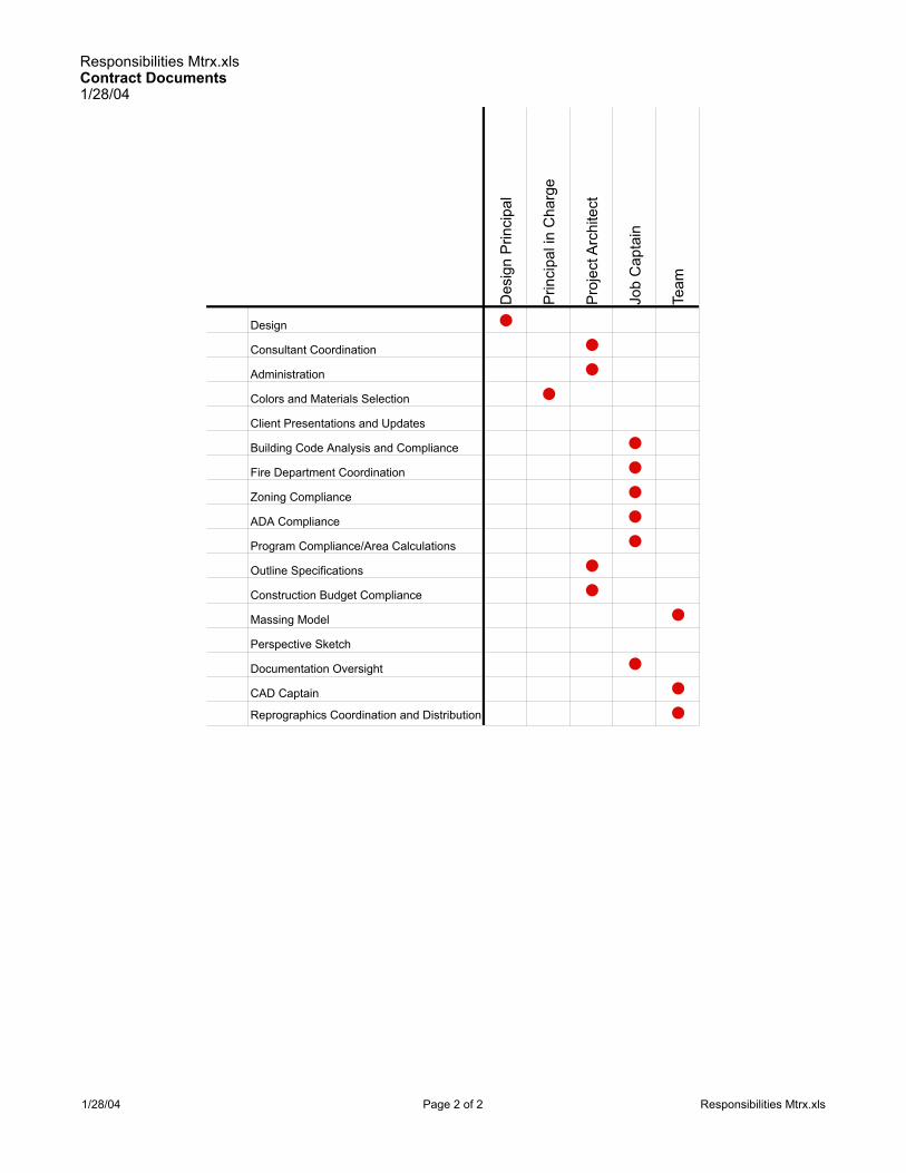
Responsibilities Mtrx.xlsContract Documents1/28/04
Des
ign
Prin
cipa
l
Prin
cipa
l in
Cha
rge
Pro
ject
Arc
hite
ct
Job
Cap
tain
Team
Owner/Architect Agreement •Consultant Agreements •Monthly Billing •Review of Consultant Invoices •Scope Change Management •Additional Services Authorizations •Reimbursables Tracking •Staffing Projections •Fee Management •Schedule Management •Team Communications •"BOB" forms •Drawing Progress Report •Project Progress Report •File Management •
Pro
ject
Man
agem
ent
1/28/04 Page 1 of 2 Responsibilities Mtrx.xls
Responsibilities Mtrx.xlsContract Documents1/28/04
Des
ign
Prin
cipa
l
Prin
cipa
l in
Cha
rge
Pro
ject
Arc
hite
ct
Job
Cap
tain
Team
Pro
ject
Man
agem
ent
Design •Consultant Coordination •Administration •Colors and Materials Selection •Client Presentations and Updates
Building Code Analysis and Compliance •Fire Department Coordination •Zoning Compliance •ADA Compliance •Program Compliance/Area Calculations •Outline Specifications •Construction Budget Compliance •Massing Model •Perspective Sketch
Documentation Oversight •CAD Captain •Reprographics Coordination and Distribution •
1/28/04 Page 2 of 2 Responsibilities Mtrx.xls

Responsibilities Mtrx.xlsBiddingNegotiation1/28/04
Des
ign
Prin
cipa
l
Prin
cipa
l in
Cha
rge
Pro
ject
Arc
hite
ct
Doc
umen
tatio
n C
oord
inat
or
Team
Owner/Architect Agreement •Consultant Agreements •Monthly Billing •Review of Consultant Invoices •Scope Change Management •Additional Services Authorizations •Reimbursables Tracking •Staffing Projections •Fee Management •Schedule Management •Team Communications •"BOB" forms •Drawing Progress Report •Project Progress Report •File Management •
Pro
ject
Man
agem
ent
1/28/04 Page 1 of 1 Responsibilities Mtrx.xls

Responsibilities Mtrx.xlsContract Administration1/28/04
Des
ign
Prin
cipa
l
Prin
cipa
l in
Cha
rge
Pro
ject
Arc
hite
ct
Doc
umen
tatio
n C
oord
inat
or
Team
Owner/Architect Agreement •Consultant Agreements •Monthly Billing •Review of Consultant Invoices •Scope Change Management •Additional Services Authorizations •Reimbursables Tracking •Staffing Projections •Fee Management •Schedule Management •Team Communications •"BOB" forms •Drawing Progress Report •Project Progress Report •File Management •
Pro
ject
Man
agem
ent
1/28/04 Page 1 of 1 Responsibilities Mtrx.xls

File Directory Tree StructureA O P S ” 2004
Page 1 of 2
STANDARD FILE DIRECTORY TREE STRUCTURE

File Directory Tree StructureA O P S ” 2004
Page 2 of 2

DOCUMENTS
DOCUMENTS DRAWINGS SPECS # Fac
sim
ile (
wh
en in
dic
ated
)
Ove
rnig
ht
Lo
cal C
ou
rier
Han
d D
eliv
er
Sn
ail M
ail
Oth
er
1/2
Siz
e
# Fac
sim
ile (
wh
en in
dic
ated
)
Ove
rnig
ht
Lo
cal C
ou
rier
Han
d D
eliv
er
Sn
ail M
ail
Oth
er
1/2
Siz
e
# Fac
sim
ile (
wh
en in
dic
ated
)
Ove
rnig
ht
Lo
cal C
ou
rier
Han
d D
eliv
er
Sn
ail M
ail
Oth
er
1/2
Siz
e
From Owner PA PA PA To Owner 1 x x 2 x 2 x
From Owner's Agent PA PA PA To Owner's Agent 1 x 1 x 1 x
From Consultants JC JC JC To Consultants 1 x 1 x 1 x
From Contractor PA PA PA To Contractor 3 x 3 x 3 x
From Government Agencies PA PA PA To Government Agencies 2 x 2* x 2* x
From Affected 3rd Parties PA PA PA To Affected 3rd Parties 1 x 1 x 1 x
From Other PA PA PA To Other 1
Flat Files — Originals — 1
Central Files Originals — Originals 1 1
INCOMINGAll incoming originals are to be filed in the flat files or
central files immediately
DRAWINGS SPECS
OUTGOINGAll outgoing items must be itemized on a transmittal (the original goes with the item; a copy goes into the central project files).
* Wet-ink stamped
x Originals
Always attach a copy of the Project Directory to facilitate routing
Project:Project #:Project Architect:
DOCUMENT AND DRAWING DISTRIBUTION MATRIX
1/28/04
Distribution MatrixO P U S© 2003
Distribution Mtrx.xls

65 60 85 $0
% o
f Dra
win
g E
ffort
A
lloca
ted
Job
Cap
tain
Dra
fter
Pro
ject
Arc
hite
ct
Cos
t (ho
urs
x bi
lling
ra
te)
Cos
t as
a %
of T
otal
B
udge
t
Title Sheet 2 4 $240 #DIV/0!
Site Plan 8 25 $1,500 #DIV/0!
Level 1 Plan 18 70 4 9 $4,550 #DIV/0!
Level 2 Plan 18 70 4 9 $4,550 #DIV/0!
Building Elevations 12 60 $3,600 #DIV/0!
Building Sections 12 60 $3,600 #DIV/0!
Level 1 RCP 8 35 $2,100 #DIV/0!
Level 2 RCP 8 35 $2,100 #DIV/0!
Outline Specifications 8 38 $3,230 #DIV/0!
Massing Model 5 35 $2,100 #DIV/0!
Perspective Sketch 0 #DIV/0!
Presentation Graphics 1 8 $480 #DIV/0!
TOTAL 100 140 270 56 $30,060 100% Planned
Budget 140 270 56 $30,060 100% Budgeted
from "Fee Budgeting Example", "documentation" and "outline specifications" categories
From "Fee Budgeting Example", job title categories
These numbers are educated guesses about who should be spending how much time on which sheets; a certain amount of "trading" of time should be expected
These numbers are "educated guesses" based
on your knowledge of the project
Billing Rates

Dwg Prog Rpt .xls1/28/04
Ava
ilabl
e H
ours
Initi
al D
raw
ing
Dim
ensi
onin
g
Cro
ss R
efer
ence
Not
atio
n
Mat
eria
ls In
dica
tions
Con
sulta
nt C
oord
inat
ion
Fin
al C
heck
ing
Pic
k-up
Fin
al R
edlin
es
TO
TALS
Rem
aini
ng H
ours
SHT, NO. DRAWING TITLE TEAM MEMBER 27% 10% 10% 10% 3% 15% 15% 10% 100.00%A0.0 Title Name 0% 0% 0% 0% 0% 0% 0% 0% 0% 0A0.0 Title Name 0% 0% 0% 0% 0% 0% 0% 0% 0% 0A0.0 Title Name 0% 0% 0% 0% 0% 0% 0% 0% 0% 0A0.0 Title Name 0% 0% 0% 0% 0% 0% 0% 0% 0% 0A0.0 Title Name 0% 0% 0% 0% 0% 0% 0% 0% 0% 0A0.0 Title Name 0% 0% 0% 0% 0% 0% 0% 0% 0% 0A0.0 Title Name 0% 0% 0% 0% 0% 0% 0% 0% 0% 0A0.0 Title Name 0% 0% 0% 0% 0% 0% 0% 0% 0% 0A0.0 Title Name 0% 0% 0% 0% 0% 0% 0% 0% 0% 0A0.0 Title Name 0% 0% 0% 0% 0% 0% 0% 0% 0% 0A0.0 Title Name 0% 0% 0% 0% 0% 0% 0% 0% 0% 0A0.0 Title Name 0% 0% 0% 0% 0% 0% 0% 0% 0% 0A0.0 Title Name 0% 0% 0% 0% 0% 0% 0% 0% 0% 0A0.0 Title Name 0% 0% 0% 0% 0% 0% 0% 0% 0% 0A0.0 Title Name 0% 0% 0% 0% 0% 0% 0% 0% 0% 0A0.0 Title Name 0% 0% 0% 0% 0% 0% 0% 0% 0% 0A0.0 Title Name 0% 0% 0% 0% 0% 0% 0% 0% 0% 0A0.0 Title Name 0% 0% 0% 0% 0% 0% 0% 0% 0% 0A0.0 Title Name 0% 0% 0% 0% 0% 0% 0% 0% 0% 0A0.0 Title Name 0% 0% 0% 0% 0% 0% 0% 0% 0% 0A0.0 Title Name 0% 0% 0% 0% 0% 0% 0% 0% 0% 0A0.0 Title Name 0% 0% 0% 0% 0% 0% 0% 0% 0% 0A0.0 Title Name 0% 0% 0% 0% 0% 0% 0% 0% 0% 0A0.0 Title Name 0% 0% 0% 0% 0% 0% 0% 0% 0% 0A0.0 Title Name 0% 0% 0% 0% 0% 0% 0% 0% 0% 0A0.0 Title Name 0% 0% 0% 0% 0% 0% 0% 0% 0% 0A0.0 Title Name 0% 0% 0% 0% 0% 0% 0% 0% 0% 0A0.0 Title Name 0% 0% 0% 0% 0% 0% 0% 0% 0% 0A0.0 Title Name 0% 0% 0% 0% 0% 0% 0% 0% 0% 0A0.0 Title Name 0% 0% 0% 0% 0% 0% 0% 0% 0% 0A0.0 Title Name 0% 0% 0% 0% 0% 0% 0% 0% 0% 0
Project Name
Project NumberDate

Dwg Prog Rpt .xls1/28/04
A0.0 Title Name 0% 0% 0% 0% 0% 0% 0% 0% 0% 0A0.0 Title Name 0% 0% 0% 0% 0% 0% 0% 0% 0% 0A0.0 Title Name 0% 0% 0% 0% 0% 0% 0% 0% 0% 0A0.0 Title Name 0% 0% 0% 0% 0% 0% 0% 0% 0% 0A0.0 Title Name 0% 0% 0% 0% 0% 0% 0% 0% 0% 0A0.0 Title Name 0% 0% 0% 0% 0% 0% 0% 0% 0% 0A0.0 Title Name 0% 0% 0% 0% 0% 0% 0% 0% 0% 0A0.0 Title Name 0% 0% 0% 0% 0% 0% 0% 0% 0% 0A0.0 Title Name 0% 0% 0% 0% 0% 0% 0% 0% 0% 0A0.0 Title Name 0% 0% 0% 0% 0% 0% 0% 0% 0% 0A0.0 Title Name 0% 0% 0% 0% 0% 0% 0% 0% 0% 0A0.0 Title Name 0% 0% 0% 0% 0% 0% 0% 0% 0% 0A0.0 Title Name 0% 0% 0% 0% 0% 0% 0% 0% 0% 0A0.0 Title Name 0% 0% 0% 0% 0% 0% 0% 0% 0% 0A0.0 Title Name 0% 0% 0% 0% 0% 0% 0% 0% 0% 0A0.0 Title Name 0% 0% 0% 0% 0% 0% 0% 0% 0% 0A0.0 Title Name 0% 0% 0% 0% 0% 0% 0% 0% 0% 0A0.0 Title Name 0% 0% 0% 0% 0% 0% 0% 0% 0% 0A0.0 Title Name 0% 0% 0% 0% 0% 0% 0% 0% 0% 0A0.0 Title Name 0% 0% 0% 0% 0% 0% 0% 0% 0% 0A0.0 Title Name 0% 0% 0% 0% 0% 0% 0% 0% 0% 0A0.0 Title Name 0% 0% 0% 0% 0% 0% 0% 0% 0% 0A0.0 Title Name 0% 0% 0% 0% 0% 0% 0% 0% 0% 0A0.0 Title Name 0% 0% 0% 0% 0% 0% 0% 0% 0% 0A0.0 Title Name 0% 0% 0% 0% 0% 0% 0% 0% 0% 0A0.0 Title Name 0% 0% 0% 0% 0% 0% 0% 0% 0% 0A0.0 Title Name 0% 0% 0% 0% 0% 0% 0% 0% 0% 0A0.0 Title Name 0% 0% 0% 0% 0% 0% 0% 0% 0% 0A0.0 Title Name 0% 0% 0% 0% 0% 0% 0% 0% 0% 0A0.0 Title Name 0% 0% 0% 0% 0% 0% 0% 0% 0% 0A0.0 Title Name 0% 0% 0% 0% 0% 0% 0% 0% 0% 0A0.0 Title Name 0% 0% 0% 0% 0% 0% 0% 0% 0% 0
SUBTOTAL 0 #DIV/0!
TOTAL PRODUCTION HOURS 0 0
TOTAL PERCENT COMPLETE

Weekly Team and PIC Meeting
AGENDAJanuary 28, 2004
R E C U R R I N G A G E N D A I T E M S
1. Staffing Projections• Review billable vs. non-billable time for each team member• Review overtime spent• Determine whether overtime needs to be authorized for the coming week
2. Progress of the Work• Review individual assignments
Æ Work completed during the past weekÆ Work completed vs. work that was plannedÆ Work planned for the upcoming week
3. Schedule Review
4. Review of expenses and progress of the work (and remedial action if necessary)
5. Consultant Performance
6. Milestone events and deadlines coming up• Submittals/deadlines/deliverables• Receipt of information from consultants
7. Additional Services Requests or Scope Changes
N E W B U S I N E S S
1. Project Management Issues
2. CA Issues
3. Continuous Quality Improvement, Drawing Standards and Procedures

24 x 36 Cartoon Set
Tit
lebl
ock
Are
a
Sheet Number
Zone forGeneral Notes
Zone forVicinity Map,Key Plan orKey Section


Show anticipated buildingsection and wall sectionlocations; orient wallsections so that exteriorof wall faces the sameend of the sheet wher-ever possible
Show drawing name andscale; show which way northshould be oriented on thesheet
Show column grid-line locations forreference
Do a quick free-hand sketch toscale (in pencil)showing buildingoutline
A2.1

Specifications CoordinationA O P S © 2004
Page 1 of 7
SPECIFICATIONS COORDINATION
In order to produce a good tight set of specifications the spec writer needs tobecome part of the project in the Schematic Design phase. They will need to bekept in the information loop and provided with product cut sheets to developsections from. Establish binder of product cut sheets for use by the spec writerand the detail drafters early in the project.
Specifications take time to write, time to coordinate, and time to check. Do notwait for the last minute, insist on receiving a few completed divisions to reviewevery other week. This goes for your engineering consultants as well, you willneed time to review and coordinate their work. Most sections can be written andfinished in the Design Development phase.
Following are some things to review:
General
Recommended Reading: AIA general conditions and contracts.
Provisions are to be included in the specifications for a mock-up of anynew feature whose final effect is not certain in the designer’s mind.
Check each division of the specifications for unnecessary:
Allowances
Unit prices
Warranty-guarantee
Shop drawings
Samples
Inspection and tests
Record drawings
Material bonds
Clean-up
New materials used should be checked with the manufacturersrepresentative; their instructions and recommendations should becarefully considered.
Electrolytic reaction should be checked where dissimilar metals are usedin contact with one another, such as aluminum and ferrous metals.
Excavation
Pay lines for earth excavation and rock excavation should be established.

Specifications CoordinationA O P S © 2004
Page 2 of 7
Site conditions and changes from the borings or contract lines should beprovided for and verified by drawings and engineer’s approval.
Sub-surface drainage
Drain lines in porous fill under concrete slab for all large areas of exteriorterrace, etc., should be specified.
Site Work
Granite or steel curbs are specified for some cities. Check other codes.
Established curb elevations, local department requirements should bechecked. Specify resetting curbs to these grades.
Landscaping
Guarantees for landscaping, other than seeding, should be established.
Maintenance contracts for planting should be considered, and if possible,provide an allowance.
Waterproofing
Check types of waterproofing required.
Provide waterproofing under all mat sinkages. Carry to exterior wall andconnect to wall dampproofing.
Concrete and Cement Finishes
Expansion strips for horizontal surfaces such as terraces should beprovided.
Concrete samples should go directly to the testing laboratory and reportsshould go directly to the Engineers. Check for other specialrequirements.
Floor hardening and sealing should be checked for drying time, specialinstallation requirements, etc.
Construction joints in slabs should not be placed within ten feet of anyexpansion joint. Contractor should prepare a plan for engineer’sapproval, locating all construction joints.

Specifications CoordinationA O P S © 2004
Page 3 of 7
Large terraced areas of concrete should be provided with minimum 6 x 6mesh reinforcement, stone base course, expansion joints and under floordrainage tile.
Rough textured surfaces should be provided on sidewalks at entrances.
Construction joints in concrete slabs should never be placed in the vicinityof mat recesses.
Masonry
Face brick cost per “M” not lump sum allowance. Quantity to be providedby general contractor.
Acoustical isolation for interior rooms should extend above suspendedceilings to the underside of the slab above.
Slate and Stonework
Sealer on interior slate floors should be specified.
Caulk all joints in copings; also flat stone surfaces where foot trafficdoesn’t occur.
Anchorage for copings and stonework shall be thoroughly described inthe specifications.
Limestone and other soft or porous stones are not to come in contact withthe earth, nor platforms or terraces where water can collect and be drawnup by capillary action.
Sidewalk surfaces: use rough textured non-slip finish.
Smooth surfaced floors should not be used in vestibules as they wearrapidly and are very slippery.
Do not use soft stones on heavily traveled stairs.
Roofing and Sheet Metal
Check for flashing under stone or masonry sills made of more than onepiece.
Furring and Lathing
Furring, lath, and plaster should enclose all pipes, ducts, etc. which wouldotherwise be exposed in finished areas regardless of whether furring isshown or indicated on architectural drawings.
Base screed (or casing bead) should be used with cement base.

Specifications CoordinationA O P S © 2004
Page 4 of 7
Casing bead should be used where plaster abuts any other surface.
Plastering
When a plaster finish is set flush with a ceramic tile wainscot, thereshould be shown on the drawings a “V” joint at their point of intersection.
Terrazzo
Rough textured non-slip surfaces should be specified on sidewalks atentrances.
Terrazzo floors are not advisable in toilet rooms and slop sink closets, asthis material is more absorbent than tile.
Ceramic Tile
Provide expansion joints for ceramic tile and setting bed for all tileexpanses exceeding 16’ vertically and/or horizontally whereverconstruction and expansion joints occur.
Resilient Flooring
In all alteration work, a paragraph should be added to the specificationsstating how work is to be done in area where floor is marked “patch andlevel floor to receive resilient tile.” It should be clearly stated that thismeans the floor of the entire room shall be patched and uniformly levelthroughout.
Miscellaneous and Ornamental work
When specifying metal or glass entrance doors remember that no matterwhat the material is, push and pull plates should be included, lettered with“push” and “pull.”
Note: specification writer should keep items in alphabetical order tofacilitate checking.
Check: area gratings, access trench covers, angle frames in woodflooring, anchorage for exterior carved stone work, astragals; frameanchors, cast iron bumper on loading platform, clean out doors, chimneycap, corner guards, catwalk in roof spaces, cupola, ceiling framing, catchbasin gratings, curb angles, supports for concealed expansion joints;driveway curb guards; exterior railings, expansion joints and covers,electric service supports; framing at floodlights, floor plates in boilerrooms; grilles; house trap pit covers, hood over kitchen ranges; interiorlintels, interior stairs; kick plates (special).

Specifications CoordinationA O P S © 2004
Page 5 of 7
Where weatherstrips are used on same doors as kickplate, detailcarefully; ladders, ladder rungs and handholds, masons ironwork, metalsaddles, manhole covers, pipe railings, pipe handrails, projection roomequipment; reinforcing steel for exterior walls; steel angle bases, steelwheel guards at overhead garage doors, step nosings, steel sidewalkdoors, supports for interior stone trim, supports for folding partitions,supports for column hung bookcases, steel angle curbs at overheadgarage doors, supports for folding doors, steel work to support electricservice cables, steel plate supports for handrail brackets; leader sleeves,wire mesh partitions, weatherstripping
Carpentry
Verify with the designers whether wood items indicated are to be veneersor solid.
Exterior wood trim should be prime coated in the shop. All cuts made inthe field which expose bare wood shall be painted in the field before beingset in place.
Carpentry specs should include the following: workmanship shall be of thehighest grade, and only mechanics especially skilled in this kind of workshall be employed. All work shall be accurately set in place plumb, true,even and in perfect alignment and be securely fastened.
Accurately and carefully fit, cut, shim, or block all work, so that adjoiningsurfaces in the same plane will finish flush, straight, and true.
Finished surfaces shall be free of all tool or machine marks and otherobjectionable features. Surfaces shall be finished equivalent to handsandpapered work.
Wood interior doors shall be 1-3/4” minimum thickness in institutional andcommercial work.
Fiberboard for cabinet doors should be limited to sizes smaller than 2’ x3’; in larger sizes the material economy doesn’t equal its lack of durability.
Weatherstripping
All exterior doors must be weather-stripped.
Glass and glazing
Glass shall be cut with proper clearance to take care of deflection ortemperature changes in wood on metal frames. This is especially criticalfor dual panes. Adhere to manufacturer’s stated clearances.

Specifications CoordinationA O P S © 2004
Page 6 of 7
Painting and Finishes
Provide protection behind drinking fountains if tile walls are not specified.
Luminous ceilings: paint all surfaces, hangers, ducts, pipes, etc., abovelight strips off-white color for good reflectance and even illumination.
Multi-colors: when used in more than a few rooms, specifications shouldstate that multi-colors are to be frequently used throughout the building.
Note that walls and base are to be painted as required behind radiators,convectors, etc. On alteration jobs it should also be noted that theseitems are to be specifically removed before painting takes place.
Allowance should be made for lettering of doors. Check if in addition tothe following, other rooms should receive door numbers and or roomnames: toilet rooms, floor numbers in stair and elevator shafts.
Base (—inches high) painted in contrasting color wherever wall materialextends down to floor.
Check whether painted dadoes of contrasting color will be wanted in anyspaces.
Convector enclosures, etc., should be painted black behind grilles to hidepipes, fins, etc.
Hardware
Specify coordinator where panic bolt is required on both leaves of doubledoor with astragal or rabbeted edge.
Whenever using door closers, avoid using closers that employ brackets.
Heating and Ventilating
If a piece of mechanical equipment such as an air conditioning unit doesnot completely fill opening in an exterior wall the remaining space shall befully insulated.
Electrical
Specify an allowance for special electrical fixtures, such as chandeliers.
Check if lighting protection is required; if so, specifications should call forthe earliest possible installation and completion of lightning arrestors.
Luminous ceilings shall be suspended and supported in strict accordancewith manufacturer’s instructions, and with all applicable codes. Checkdetails for possible conflicts in trade jurisdiction.

Specifications CoordinationA O P S © 2004
Page 7 of 7
Alterations
Existing openings to be closed or new openings to be made should bechecked for matching of existing finishes. Same for floors and bases.
Cutting and patching should be carefully noted on drawings and coveredappropriately in the specifications.
Allowances for replacement of plaster and other finishes should bechecked.
End of Section

Abbreviations.xls
(E) Existing MO Masonry Opening(N) New MAX Maximum(P) Paint MB Marker Board(R) Remove MECH Mechanical
AFF Above Finish Floor MFR ManufacturerARCH Architect(ural) MIN MinimumBLDG Building N North
CT Ceramic Tile NIC Not in ContractCG Corner Guard NOM NominalCIP cast-in-place NTS Not to ScaleCJ Control Joint OC On Center
CLG Ceiling OD Outside DiameterCMU Concrete Masonry Unit OPG Opening
CONC Concrete OPP OppositeCONT Continuous PLAM Plastic Laminate
D.S. Downspout PR PairDIA Diameter R Riser
DWG Drawing RD Roof DrainEA Each RO Rough OpeningEJ Expansion Joint RCP Reflected Ceiling PlanEL Elevation Re: Refer (to)
ELEC Electrical REQD RequiredELEV Elevator ROW Right of Way
EQUIP Equipment SAC Suspended Acoustical CeilingEWC Electric Water Cooler SC Solid Core
FD Floor Drain SS Stainless SteelFOC Face of Concrete SF Square FeetFOF Face of Finish SIM SimilarFOS Face of Stud SPEC Specifications
FR Fire-Resistive STD StandardFHC Fire Hose Cabinet STR Structural
GI Galvanized Iron T TreadGA Gauge or Gage TOB Top of Beam - SteelGB Grab Bar TOC Top of ConcreteGC General Contractor TOW Top of Wall
GYP. BD. Gypsum Board TB TackboardHC Hollow Core TYP TypicalHM Hollow Metal UNO Unless Noted Otherwise

TerminologyA O P S© 2004
Page 1 of 4
TERMINOLOGY
The following terms are provided for your convenience.
Contract DocumentsThe Contract Documents include the agreement between the owner and thecontractor, the conditions of the contract, drawings, specifications, addenda,other documents listed in the agreement, and modifications (change orders,construction change directives, and written orders for minor changes in thework issued by the architect). The invitation to bid, instructions to bidders,and bid forms are not part of the contract documents.
Owner-Contractor AgreementThe Owner-Contractor Agreement defines the terms owner, contractor, andarchitect, contract sum, contract completion date, and the contractdocuments.
Conditions of the ContractThe general and supplementary conditions of the contract define basicrelationships, rights, and responsibilities of the parties, and establish broadprovisions under which the specifications are written.
The WorkThe construction and services required by the contract documents, whethercompleted or partially completed, and including all other labor, material,equipment, and services provided or to be provided by the contractor tofulfill the contractor's obligations.
ProjectThe total construction. The work may be a whole or a part of the Project.The project may include work by other contracts or the owner.
Project ManualA bound volume which may include bidding requirements, sample forms,conditions of the contract, specifications, schedules, or details.
SpecificationsThe text portion of the contract documents that explains requiredperformance, materials, and equipment. The general requirements (Division1) provide certain performance requirements of the contract which areapplicable to all portions of the work. Product specifications (Divisions 2-16)provide a complete detailed description of each material or equipment itemand the methods for its installation.
DrawingsThe graphic and pictorial portions of the contract documents showing thedesign, dimension, and location of the work, generally including plans,sections, elevations, details, schedules, and diagrams.
Subcontractor

TerminologyA O P S© 2004
Page 2 of 4
A person or entity who has a direct contract with the general contractor toperform a portion of the work.
AddendaWritten or/and graphic instructions issued during bidding and prior toexecution of the agreement to clarify, revise, add to, or delete information inthe original bidding documents or in previous addenda.
AlternatesAlternate products, materials, equipment, systems, methods, units of work,or major elements of the work which may, at the owner's option, be selectedinstead of the corresponding requirements of the contract documents.
Indicated ("as indicated")This term is meaningless unless clarified by some measure of direction.Similarly, the terms "as noted," "as shown," "as scheduled," and "asspecified" require additional direction to be meaningful. If such phrases areused, it must also be clear whether or not any limitation on the location ofthe reference is implied.
Directed ("as directed")Terms such as "directed," "requested," "authorized," "selected," "approved,""required," "accepted," and "permitted" must be defined to mean "asdirected by the architect," "required by the architectect," and similar phrases.
InstallerThe entity engaged by the contractor (an employee, subcontractor, sub-subcontractor or other) to install a particular portion of the work at theproject site.
ApproveThe use of this word should be clarified. Approval, when given inconjunction with the architect's action on the contractor's submittals andrequests should be limited to the architect's responsibilities and duties, asspecified in the conditions of the contract. Such approval should not releasethe contractor from responsibility to fulfill requirements of the contract. "NoException Taken" is the language preferred by liability insurance carriers,and therefore should be preferred by architects as well.
Contractor's OptionWhere materials, products, systems or methods are specified to be at thecontractor's option, the choice of which shall be used is solely the choice ofthe contractor. No change in contract sum or time will be granted because ofthe choice made.
FurnishTo supply and furnish to the project site, ready for unloading, unpacking,assembly, installation, and similar operations.
Install

TerminologyA O P S© 2004
Page 3 of 4
To unload, unpack, assemble, erect, place, anchor, apply, work todimension, finish, cure, protect, clean, and perform similar operations at theproject site.
ProvideTo furnish and install
Typical/TypicallyApplying to all similar conditions
AnyChosen at random, of whatever quantity. (Use "all," or specify which, whentempted to use this word).
OmitTo leave out, to neglect to provide; usually used to describe an item thatwas never present (omitted) in the first place.
DeleteTo remove, to eliminate; usually used to describe an item that is nowpresent, but that should be taken out (deleted).
ModificationsChange orders, instructions, field orders, directives.
Record DocumentsDocuments prepared at the end of a project incorporating modificationsmade during the construction process and incorporating contractormeasured dimensions to concealed items previously shown graphically inthe contract documents. (Do not use the term "as-built drawings;" withoutbeing present at the job site at all times, and bearing personal witness to theconstruction, you are in no position to warrant anything as being "as built."Your involvement in "record drawings" suggests only that you are assistingin the documentation of the contractor's record of how things were built,provided you have defined the terms for everyone in advance).
References1. Architectural and Building Trades Dictionary, third edition, Putnam and
Carlson. Van Nostrand Reinhold Company, New York, 1974
2. Construction Dictionary, Construction Terms and Tables, fifth edition, GreaterPhoenix, Arizona Chapter #98 of The National Association of Women inConstruction, P.O. Box 6142, Phoenix, Arizona 85005, 1981.
3. Means Illustrated Construction Dictionary, first edition. R.S. Means Co., Inc.,536Construction Plaza, Kingston, Massachusetts 02364
4. Lessons in Professional Liability, A Notebook for Design Professionals,Design Professionals Insurance Company, 2959 Monterey-Salinas Highway,Monterey, California 93940, 1988

TerminologyA O P S© 2004
Page 4 of 4
5. CSI Manual of Practice MP-!-10, "Specification Language," The ConstructionSpecifications Institute, 601 Madison Street, Alexandria, Virginia 22314.
6. Uniform Drawing System, Module 5 – Terms and Abbreviations, ConstructionSpecifications Institute, 1999
Concepts:
To follow a nationally recognized industry standard for communicating thebuilding design to others in order to eliminate individual preference and tobetter defend our documents.
To establish consistent terminology throughout the Contract Documents.
Methodology:
Verify that the terminology is consistent throughout the drawings andspecifications using the UDS module as a guide.

STANDARD SYMBOLS FOR WORKING DRAWINGS
1 2
A
B
3/8" diametercircle
COLUMN GRIDLINEDESIGNATION3/8" diameter circle or hexagon with1/8" lettering;
use circles for gridlines in new con-struction and hexagons for gridlinesin existing construction
3/8" highhexagon
DRAWING TITLESCALE: 1/4" = 1'-0
0 4 8 12
1
A2.1
MATCH LINERE: 1/A3.5 (sheet reference for continuation of
drawing)
MATCH LINE DESIGNATION1/4" diameter circle
NORTH True North
NORTH ARROW1" diameter circle
NEW SPOT ELEVATION
EXISTING SPOT ELEVATION
NEW CONTOUR LINE
EXISTING CONTOUR LINE
ROOM NAME216 B 5 F 2
Ceiling FinishWall FinishBase FinishFloor Finish

STANDARD SYMBOLS FOR WORKING DRAWINGS
12
A3.6
EXTERIOR ELEVATION
B
C
D
A A7.4
INTERIOR ELEVATION REFERENCE
L2
LOUVER
12
KEYNOTE
12
A3.6
WALL SECTION
12
A3.6
BUILDING SECTION
Show section line on both sides of the buildingbut do not extend line all the way through
2
REVISION
321
FURNITURE, FIXTURES,and EQUIPMENT
12
A5.8
DETAIL CROSS REFERENCE SYMBOL5/8" diameter circle with 1/8" lettering
DETAIL CROSS REFERENCE SYMBOL5/8" diameter circle with 1/8" lettering
12
A5.8
5/8" diameter
Drawing #
Sheet #
Drawing #
Sheet #5/8" diameter
5/8" diameter
Drawing #
Sheet #
Drawing #
Sheet #
Louver #
5/16" diamond
5/16" high hexagon 5/16" high triangle
1/8" high polygon
5/8" diameter
Drawing #
Sheet #
Size as needed
Size as needed

STANDARD SYMBOLS FOR WORKING DRAWINGS
202A
DOOR IDENTIFICATION MARKUse Room Number with a letter fro each door; use theroom number from the secured side of the door.
28 PARTITION TYPE INDICATION
Door swings in direction of exittravel from the room;Door latches/locks to preventaccess to room.This is “secured” side of door.
ROOM202
25'-4
DIMENSION LINE andEXTENSION LINE
BREAK LINE
BREAK LINE(cylindrical shapes)
NEW CONSTRUCTION EXISTING CONSTRUCTION(to remain)
EXISTING CONSTRUCTION(to be demolished/removed)
1-hour fire-resistive construction
2-hour fire-resistive construction
3-hour fire-resistive construction
4-hour fire-resistive constructionx
FENCE LINE
x
18
WINDOW or FRAME TYPE
1/4" square

M AT E R I A L S I N D I C AT I O N S
GRAVEL PLASTER; MORTAR
ACOUSTICAL CEILINGPANEL OR TILE
CERAMIC TILE
FINISH WOOD
ALUMINUM
STEEL
BATT INSULATION
RIGID INSULATION
CONTINUOUS WOOD FRAMING
WOOD BLOCKING
SHEET METAL
CERAMIC TILE
SPANDREL GLASS
TOPSOIL
EARTH
ASPHALT PAVING
CONCRETE
CONCRETE MASONRY(shown as glazed)
PRECAST CONCRETE
BRICK
PARTICLE BOARD
PLYWOOD
GYPSUM BOARD
CONCRETE; PLASTER
BRICK
CONCRETE MASONRY
ELEVATION VIEW
PLAN AND SECTION VIEWS
METAL STUD PARTITION
CARPET AND PAD

OVERALL BUILDING DIMENSION
GRIDLINE DIMENSIONS
BUILDING OFFSETS
OPENINGS
Tie openingdimension togridline on oneside or the other;don’t closedimension stringat this level
Don’t show gridlines and dimen-sion lines intersecting unless youare indicating a dimension to thegridline
DIMENSION HIERARCHY

4 4846
Dimension partition thicknesseson Partition Types Schedule; don’tdimension them on the plans.
6"1"
1'-7 DIM DIM
Dimension to onesideonly of interiorpartitions
DIM DIM DIM DIM
DIM
Door openings are shownon door schedule; don’tdimension on plan
202A
SAMPLE DIMENSIONING
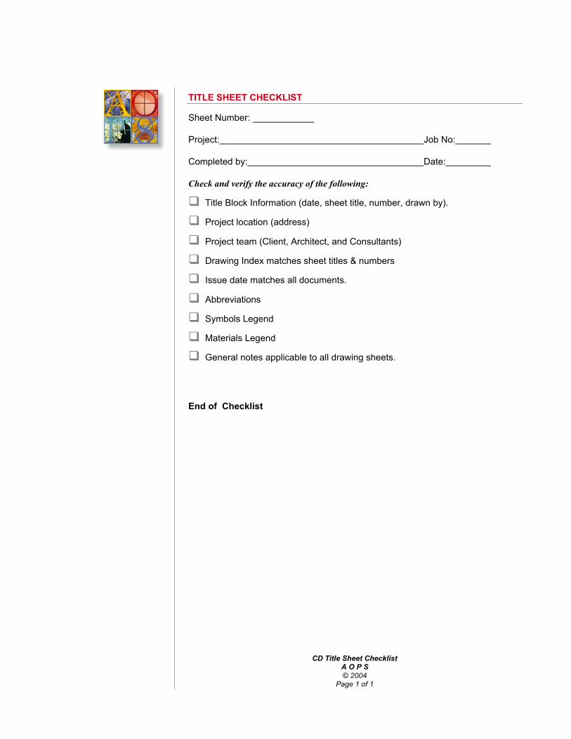
CD Title Sheet ChecklistA O P S© 2004
Page 1 of 1
TITLE SHEET CHECKLIST
Sheet Number: ____________
Project: Job No:
Completed by: Date:
Check and verify the accuracy of the following:
Title Block Information (date, sheet title, number, drawn by).
Project location (address)
Project team (Client, Architect, and Consultants)
Drawing Index matches sheet titles & numbers
Issue date matches all documents.
Abbreviations
Symbols Legend
Materials Legend
General notes applicable to all drawing sheets.
End of Checklist

Drafting Conventions — PlansA O P S© 2004
Page 1 of 4
DRAFTING CONVENTIONS – SITE PLANS
Most of the following information will show you the proper “graphic conversation”that you will need to understand in order to explain your design and reduce therisk of having it compromised through a “Value Engineering” effort or through the“Change Order” process.
It is in our best interest to follow an accepted industry standard when it comes tographic directions of this nature, so as to be able to defend our constructiondocuments and communicate our ideas with the least amount of confusion. Tothis end we recommend adopting Module 4 of the Uniform Drawing System,Drafting Conventions, as our standard for proper drafting methodology.
Concepts:
Use a plan view to explain horizontal aspects of your design.
Follow a nationally recognized industry standard for communicating thebuilding design to others in order to eliminate individual preference and tobetter defend our documents.
Methodology:
Do not show information inside the building on the site plan. Show thebuilding footprint and the ground level finish floor elevation.
Use material indications (poché) sparingly at the ends of an object or where itchanges direction. Use it to illustrate mass.

Drafting Conventions — PlansA O P S© 2004
Page 2 of 4
WORK PLAN – SITE PLAN
1. If the sheet size has not already been determined, propose a size that willallow the site plan, in its entirety, to fit on one sheet. If the sheet size hasbeen determined, propose a scale that will allow the entire site plan to fit onthe sheet for review with the project architect.
2. Determine how the title block information will be put on the sheet; confirmthe project name, number, and address.
3. Establish the drawing area on that sheet.4. Set aside space for the drawing title, the title block, general notes, and
keynotes legend.5. Develop a vicinity plan and set aside space for this drawing.6. Determine which direction will be north on the sheet.
North should be the point up on the sheet whenever possible, and to theright in most other situations.
Show a north arrow indicating true north, and any variation from truenorth that is being “assumed” for the purposes of this project.
7. Locate the plan near the center of the drawing area unless the drawing issmall enough to allow other drawings to appear on the same sheet.
8. Allow approximately 3” at the bottom of the sheet for the title, scale, andnorth arrow.
9. Layout the property lines and any elements that are off but directly adjacentto the site (such as streets, sidewalks, and lighting).
10. Show the limits of the work if only a portion of the site is to be improved.11. Show all setback lines and easements. If a civil engineer is not involved on
the project, show all utilities (including sewer, water, gas, electric, andtelephone). Locate transformer vaults, exterior lighting, public telephones,fire hydrants, and catch basins.
12. Locate the building on the site. Draw the building “footprint” on the site plan;the footprint is the plan of the building at ground level (not a roof plan). Addstructural gridlines at the extremities of the plan, for reference; interveninggridlines are not necessary.
13. Show any outbuildings, sheds, trash enclosures.14. Locate all free-standing walls, retaining walls, fences, and areaways.15. Show all temporary structures and facilities (including fences, gates,
guardhouses, signs, and trailers).16. Show all structures and facilities that are to be demolished.17. Show perimeter outline of all concrete paving, and curb and gutter18. Show perimeter outline of all concrete sidewalks.19. Show perimeter outline of all asphalt paving.
TRUE NORTHPROJECT
NORTH
SITE PLANONLY

Drafting Conventions — PlansA O P S© 2004
Page 3 of 4
20. Show drainage patterns including swales, road drainage, and sidewalkdrainage.
21. Send background to civil, mechanical, and electrical engineers andlandscape architect.
22. Show features of primary utilities, such as transformer location, gasmeter(s), fire hydrants, etc.
23. Show exterior light fixtures not attached to the building.24. Show exterior mechanical and plumbing elements not attached to the
building.25. Show grading contours only if they are not shown on a separate civil vertical
control plan.26. Show parking lot striping. Indicate accessible parking spaces and markings.27. Show signage if not shown on a separate signage plan.28. Show summaries for:
➝ Ground coverage and floor area calculations (provided versusallowable).
➝ Open space requirements (provided versus required).➝ Parking spaces provided versus required
29. Draw all miscellaneous architectural items, such as bicycle racks, flag poles,mailboxes and signs.
30. Show datum elevations at building entrances and periodically at sidewalks,curbs, and gutters. Indicate finished floor elevation for the first floor andrelate to datum elevation. If no civil engineer is involved on the project,datum elevations need to be shown at all catch basins, retaining walls,intersections of roadways, and corners of buildings.
31. Show all landscaped areas and trees. If a landscape architect is notinvolved on the project, another site plan may have to be developed whichshows the type and location of the trees, shrubs, ground cover, irrigationsystems, and other landscape features.
32. Dimension all property lines, buildings, streets, parking lots, sidewalks,walls, retaining walls, fences and lighting poles.
33. Show concrete flatwork control and expansion joints and scoring patterns. Ifintricate paving patterns exist, show them schematically and refer to anenlarged plan for further detail. Show all parking and street striping.
34. Add cross-referencing symbols and notation.35. Add identification notes.36. Add general notes.37. Add materials indications (poché).

Drafting Conventions — PlansA O P S© 2004
Page 4 of 4
SITE PLAN CHECKLIST
Sheet Number: ____________
Project: Job No:
Completed by: Date:
Check and verify the accuracy of the following:
Title Block Information (date, sheet title, number, drawn by).
Drawing titles, scales, north arrow (true & plan), and vicinity plan.
Determine if an Architectural Site Plan is needed.
Check against redundancy with Civil Engineering and LandscapeArchitecture drawings. Use this drawing to coordinate site areas directlyadjacent to the building.
Are all drawing notes consistent with specifications?
Change all references such as “See Specs”, As Indicated”, “See Structural”,etc. to specific locations in the document set.
Clarify “N.I.C.” and “by Owner” areas.
Clearly differentiate between existing and proposed construction.
Indicate minor demolition as needed.
Provide a heavy outline where the building meets the finish grade (do notshow a floor plan).
Equate USGS elevation to First Floor.
Indicate contract limits.
Verify grade slopes away from building perimeter.
Show inverts and daylighting of perimeter foundation drain (do not connectto storm sewer).
Provide parking count and show comparison to the code requirements.
Verify building foundation (footing) is located within the property lines.
Verify building does not conflict with utility easements and setbacks.
Verify requirements of Fire access road and turning radii.
Verify ADA accessible route and parking.
Check grade elevations with all building floor elevations at all exits.
Check spot elevations at each corner of the building and all exits.
Coordinate location of site equipment with building.
Complete the Civil Engineer checklist.
Complete the Landscape Architecture checklist.
Detail construction sign.
End of Checklist

Drafting Conventions — PlansA O P S© 2004
Page 1 of 10
DRAFTING CONVENTIONS – PLANS
Click here for Enlarged Plan Checklist
Click Here for Roof Plan Checklist
Click here for Code Plan Checklist
Click here for Finishes Plan Checklist
Most of the following information will show you the proper “graphic conversation”that you will need to understand in order to explain your design and reduce therisk of having it compromised through a “Value Engineering” effort or through the“Change Order” process.
It is in our best interest to follow an accepted industry standard when it comes tographic directions of this nature, so as to be able to defend our constructiondocuments and communicate our ideas with the least amount of confusion. Tothis end we recommend adopting Module 4 of the Uniform Drawing System,Drafting Conventions, as our standard for proper drafting methodology.
Concepts:
Use a plan view to explain horizontal aspects of your design.
To follow a nationally recognized industry standard for communicating thebuilding design to others in order to eliminate individual preference and tobetter defend our documents.
Methodology:
Do not repeat information from plans of different scales. Show more detailedinformation on larger plans and broadscope orientation information onsmaller plans.
Never draw two plan views when one will do. Don’t enlarge part of a planunless you have to.
Use material indications (poché) sparingly at the ends of an object or where itchanges direction. Use it to illustrate mass.
Show overhead features (balconies, soffits, overhangs, etc.) only if there is areason to coordinate it with the plan view. Add a note describing what thedashed line represents.
Do not show items that appear on another floor plan, site plan, or ceilingplan. Leave them to the appropriate area of the drawing set withoutrepeating.

Drafting Conventions — PlansA O P S© 2004
Page 2 of 10
WORK PLAN — PLAN SHEETS
The following Work Plan should be used as guide for developing the 1/8” planworking drawing sheets. While some flexibility will be necessary, follow thesequence shown as closely as possible. Complete each item of the work planbefore going on to the next; don’t complete the entire work plan in one area ofthe drawing and then go on to the same thing in another area of the drawing, forexample. Make sure you understand the CAD layering conventions that shouldbe used, to facilitate making backgrounds for consultants, as well as thearchitectural reflected ceiling plans.
1. If the sheet size has not already been determined, propose a sheet size thatwill allow the entire floor plan to fit on one sheet, if possible. If the plan mustbe divided into parts, propose a division of the plan for review by the ProjectArchitect.
2. When possible, locate match lines in corridors; draw approximately an inchof the floor plan information beyond the match line for ease of referencebetween drawings.
3. Confirm title block information; confirm the project name, number, address.
4. Establish the drawing area on the sheet.
5. Set aside space for the drawing title, scale, the title block, general notes.
6. Determine which direction will be north on the sheet.
North should point up on the sheet whenever possible, and to the rightfor most other situations.
8. Locate the plan near the center of the drawing area unless the plan is smallenough to allow other drawings (such as details) to appear on the samesheet.
Allow approximately 3” at the bottom of the sheet for the title, scale, andnorth arrow.
Allow space on the drawing in the lower right hand corner for a key plan,if applicable.
Allow a zone next to the title block for the notes legendAllow zones around the actual plan for:
Cross-referencing symbols (1” all around)
Dimensions (2” all around)
Grid identification bubbles (1” all around)
9. Draw structural grid lines and identification bubbles first.
10. Draw the structural elements, such as columns, bearing or foundation walls,shear walls.

Drafting Conventions — PlansA O P S© 2004
Page 3 of 10
11. Remember, when drawing floor plan information, show only informationinside the building; use the site plan to show exterior improvements,including sidewalks that come right up to the face of the building.
12. Exterior features shown on the floor plan will only clutter the drawing whendimensions and cross-referencing symbols are added, and could easilyconflict with site plan information.
13. Add other concrete or masonry walls.
14. Draw the stud walls. Show a change of material line between stud walls andmasonry concrete. Show a change of material line between concrete andmasonry as well. When laying out walls and partitions in CAD, use theactual (or nominal for masonry) dimensions for wall thicknesses, to the 1/8of an inch. This will allow you to use the automatic dimensioning feature ofthe CAD system when the time comes.
15. Show windows, storefront, borrow lights, and other openings. Be sure toshow mullions accurately spaced and drawn to scale.
16. Show stairs and handrails; show handrails extending 18” beyond the risersand returning to the wall to comply with code requirements; show number ofrisers. Use an arrow that begins on the first riser and ends on the last riserto show the direction of travel.
17. Add door swings and jambs. Doors should be shown open at 90 degrees,using a double line to indicate thickness. Use a thin line to indicate the doorswing arc. Use a circle of the same radius (to scale) as the door swingitself.
18. Show plumbing fixtures, such as water closets, urinals, lavatories, sinks andmop sinks.
19. Show match lines. If the project is a renovation project, show contract limits.
20. Show countertops, shelves, built-in casework, vanities, partial height walls,and toilet partitions.
21. Show changes in floor materials, floor patterns, changes in floor elevations,floor recesses, ramps, curbs, floor drains, floor outlets.Show toilet room accessories (unless a larger scale plan is provided),electrical panels, water coolers, telephones, mail boxes, refrigerators, icemakers, disposers
22. Show ceiling soffits, plane changes, or other features (such as skylights)with a dashed line.
23. Show equipment (dash in if not in contract).
24. Make a print for pre-planning the dimensions.
25. Add dimensions.
26. Add room names, numbers, and finish codes. Use “100” series of numbersfor the first floor, “200” series for the second floor, etc.
27. Add cross-referencing symbols, including section marks for buildingsections, wall sections, larger scale plans, plan details, interior elevations,door marks or numbers, partition types, frame or window marks.Information such as partition types and door numbers should be shown onlyon the 1/8” plans, so users of the plans have only one place to look for thiskind of information. Avoid the temptation to duplicate this information on the

Drafting Conventions — PlansA O P S© 2004
Page 4 of 10
larger scale versions of the plans, and do not leave it off the 1/8” plans in theareas of the plan blow-ups with the intention of showing it on larger scaleplans.
28. Indicate fire-rated partitions only on the reflected ceiling plans, using specialpattern tapes, applied to the back of the sheet (unless these patterns can bereplicated using CAD).
29. Add keyed notation, general notes.
30. Add miscellaneous items such as fire extinguisher cabinets, access doors,expansion joints, ladders, lockers, shelving, hanging rods, corner guards,roof drain leaders, chalkboards, tackboards, projection screens.Add materials indications (poché) for walls and tile or masonry floors.Concentrate poché at corners and intersections. Do not poché the entirelengths of walls.

Drafting Conventions — PlansA O P S© 2004
Page 5 of 10
FLOOR PLAN CHECKLIST
Sheet Number: ___________
Project: Job No:
Completed by: Date:
Check and verify the accuracy of the following:
Title Block Information (date, sheet title, number, drawn by).
Drawing titles, scales, north arrow, and key plan.
Structural Grid is labeled, dimensioned, and matches Structural drawings.Check all dimensions against Structural drawings.
Finish Floor elevation indicated that matches sections & elevations.
Overall building length and width are dimensioned that agrees with otherfloor plans. All changes in plane on exterior walls are dimensioned andagree with other floor plans.
Are all drawing notes consistent with specifications?
Building Sections are cross-referenced correctly.
Wall Sections are cross-referenced correctly.
Match lines are in the same location on all disciplines.
Plans are in the same location and orientation though-out.
Change all references such as “See Specs”, As Indicated”, “See Structural”,etc. to specific locations in the document set.
Room names and numbers match all Architectural and consultant drawings.
Building equipment & specialties schedule matches specifications.
Indicate all room finishes.
Clarify “N.I.C.” and “by Owner” areas.
Material indications (poché) on all partitions.
Vertical transportation routes meet code and match Structural drawings.
HVAC chase routes & size matches Mechanical and Structural drawings.
Roof drain leader routes fit within furring and match Plumbing drawings.
Electrical riser routes match electrical drawings.
Casework is scheduled correctly and will fit in space allowed. Light andpower is provided.
Masonry courses properly and is dimensioned. Masonry openings are notedas such.
All openings in walls are located and sized.
Interior partitions are dimensioned by continuous strings and tied to thestructural grid.
Partition types and head conditions are referenced correctly.
Fire rated and acoustically rated partitions are coordinated with Ceiling planand partition types.
Door references are coordinated with rated partitions and legends.

Drafting Conventions — PlansA O P S© 2004
Page 6 of 10
Partitions are of sufficient thickness for pipe chases, electrical panel boxes,toilet accessories, fire extinguisher cabinets, and specialties.
Recesses in the floor slab are indicated and match Structural drawings.
Floor drains and floor slopes are located and match Plumbing drawings.
Housekeeping pads sized and indicated at Mech. & Elec. equipment.
Plumbing fixture locations dimensioned (or on enlarged plan) and typesagree with plumbing plans.
Proper wall thickness is provided for plumbing fixtures.
Floor finish transitions (unless on Finishes plan).
Adequate drainage is provided for all wet areas.
Expansion joints are continuous, located, and referenced.
Remove any “items above” indicated unless they are required forcoordinating construction of floor or walls.
Adequate door sizes are provided for eventual replacement of equipment.
Column covering allows room for fireproofing.
Indicate Fire Extinguisher Cabinets.
End of Checklist

Drafting Conventions — PlansA O P S© 2004
Page 7 of 10
ENLARGED PLAN CHECKLIST
Sheet Number: ____________
Project: Job No:
Completed by: Date:
Enlarged PlansWhen drawing the enlarged plans, show only information that is in need of moredetail than is shown on 1/8” scale plans. Do not duplicate information which ismore appropriately shown on the 1/8” plans, such as the partition types, cross-reference symbols, door marks, and the like.
Check and verify the accuracy of the following:
Title Block Information (date, sheet title, number, drawn by).
Drawing titles, scales, north arrow, and key plan.
Determine if an enlarged plan is necessary, can the 1/8 scale explain itadequately?
Structural Grid matches Structural drawings.
Are all drawing notes consistent with specifications?
Plans are in the same location and orientation though-out.
Change all references such as “See Specs”, As Indicated”, “See Structural”,etc. to specific locations in the document set.
Room names and numbers match Floor Plan.
Check redundancy of dimensioning and other information with Floor Plan.
Show Partition types, Door types, and Window types on Floor Plan only
Dimension equipment location as required.
Provide an Equipment legend.
Dimension location of all plumbing.
Locate and indicate sloping floor to floor drains.
Verify detail cross-referencing.
HVAC chase routes & size matches Mechanical and Structural drawings.
Reference casework to details.
Verify lighting, electrical, data, security, and telephone at reception deskplan.
End of Checklist

Drafting Conventions — PlansA O P S© 2004
Page 8 of 10
ROOF PLAN CHECKLIST
Sheet Number: ____________
Project: Job No:
Completed by: Date:
Check and verify the accuracy of the following:
Title Block Information (date, sheet title, number, drawn by).
Drawing titles, scales, north arrow, and key plan.
Structural Grid matches Structural drawings and stops short of plan view(roof slopes are easier to read without the column grid in the way).
Dimension structural bays and building overalls.
Are all drawing notes consistent with specifications?
Match lines are in the same location on all disciplines.
Plans are in the same location and orientation though-out.
Change all references such as “See Specs”, As Indicated”, “See Structural”,etc. to specific locations in the document set.
Indicate roof slope with spot elevations.
Indicate wind load.
Provide a Ballast Type key plan if necessary.
Provide a Roof Type key plan and legend if necessary.
Eliminate excessive poché (poché along edges only).
Check and indicate roof slope of _”/ft min.
Check cricket valley for minimum of 1/8”/ft slope. Indicate cricket slope.
Check to see that roof drains and scuppers do not conflict with Structure.
Check roof deflection along parapets and provide for movement as required.
Reference wall and building sections.
Coordinate skylight locations with the Reflected Ceiling Plan and Structuraldrawings.
Check to see that RTU locations match Mechanical and Structural drawings.Verify exact size.
Dimension roof hatch location and coordinate with Structural.
Provide splashblocks at all downspouts and spitters.
Indicate walkway pavers.
Indicate extent of water & ice shield if required.
Dimension window washing equipment locations.
Dimension extent of RTU screen wall.
Detail roof access ladder.
Detail and dimension location of roof ladders.
Indicate parapet railings if required.

Drafting Conventions — PlansA O P S© 2004
Page 9 of 10
CODE PLAN CHECKLIST
Sheet Number: _____________
Project: Job No:
Completed by: Date:
Check and verify the accuracy of the following:
Title Block Information (date, sheet title, number, drawn by).
Drawing titles, scales, north arrow, and key plan.
Basic Floor Plans w/o grid, dimensions, poche, or notes.
A clear egress path is shown.
Egress capacity is labeled at each exterior door.
Egress width of stairs checked.
Occupancy load is labeled in each room
Sq. Ft. of each occupancy listed per floor.
Dead end corridor check.
Occupancy and/or Area separation walls shown.
List applicable codes and issues dates.
List local code amendments.
Zoning code and date.
Fire zone.
Occupancy types
Building Height
Allowable square footage calculations
Construction Type
Fire protection (sprinkled)
Fire ratings (UL listing)
Plumbing fixture count.
ADA door swing check.
ADA route check
ADA toilet room check
Verify allowable % of openings in rated exterior walls.
End of Checklist

Drafting Conventions — PlansA O P S© 2004
Page 10 of 10
FINISHES PLAN CHECKLIST
Sheet Number: ____________
Project: Job No:
Completed by: Date:
Check and verify the accuracy of the following:
Title Block Information (date, sheet title, number, drawn by).
Drawing titles, scales, north arrow, and key plan.
Structural Grid matches Structural drawings and stops short of plan view.
Are all drawing notes consistent with specifications?
Match lines are in the same location on all disciplines.
Plans are in the same location and orientation though-out.
Change all references such as “See Specs”, As Indicated”, “See Structural”,etc. to specific locations in the document set.
Room names and numbers match all Architectural and consultant drawings.
Clarify any “N.I.C.” and “by Owner” areas.
Indicate only the finishes whose extents cannot be clearly explained by theFinish Schedule or Legend.
Eliminate unnecessary poché.
Indicate transition strips.
Indicate window treatment and provide legend if necessary.
Indicate extent of paint or wallcovering on parts of walls and columns.
Check against redundant information on plans, schedules, and interiorelevations.
Indicate a starting point for the layout of floor or wall graphics.
Provide a finish (color & texture) legend if needed to explain patterns andgraphics.
Coordination check all finishes with the Specifications.
Dimension equipment location if required to coordinate with finishes.
Check cross-references to details.
Verify the relationship of light fixtures to floor and wall with Electrical.
Verify locations of exit signs and fire protection alarms with Electrical.
Verify locations of grilles and access panels with Mechanical drawings.
Verify finishes and equipment locations with FF&E plan.
End of Checklist

CD Demolition ChecklistA O P S© 2004
Page 1 of 2
CD DEMOLITION CHECKLIST
Sheet Number: __________
Project: Job No:
Completed by: Date:
Check and verify the accuracy of the following:
Title Block Information (date, sheet title, number, drawn by).
Drawing titles, scales, north arrow, and key plan.
Small areas of demolition can be shown on the site or floor plan.
Structural Grid is labeled, dimensioned, and matches Structural drawings.Check all dimensions against Structural drawings.
Existing structural grid is differentiated from proposed grid.
Are all drawing notes consistent with specifications?
Match lines are in the same location on all disciplines.
Plans are in the same location and orientation though-out.
Change all references such as “See Specs”, As Indicated”, “See Structural”,etc. to specific locations in the document set.
Clarify “N.I.C.” and “by Owner” areas.
If needed develop an example of a phasing plan to be submitted by GeneralContractor.
Existing room names and numbers match all consultant demolition drawingsand are not mixed with room names and numbers of proposed construction.
Indicate all pertinent existing finishes to be removed or restored.
Indicate types of all existing partitions & ceilings to be removed.
Do not dwell on items having nothing to do with proposed construction.
Note to “remove in its’ entirety” and not to “abandon in place.”
Note to provide acceptable substrate for proposed finishes.
Do not poché existing construction.
Indicate items to be relocated.
Indicate items for Owner salvage.

CD Demolition ChecklistA O P S© 2004
Page 2 of 2
Dust partition construction.
Show elevation views as necessary for demo of some items.
End of Checklist

Reflected CeilingsA O P S© 2004
Page 1 of 4
DRAFTING CONVENTIONS — CEILINGS
Concepts:
Easy to check: The reflected ceiling type can be readily checked against thegraphic indication without referring to a schedule.
Easy to Check: Indicate the height of the ceilings and soffits on the drawingitself instead of referring the reader to a schedule.
Reduce drafting time: Label height of only those ceilings that are not baselineconditions.
Define your potential errors: Develop a baseline type such as “Unlabeledceilings shall be type…. at …. AFF”
A flexible system that will adapt to a variety of building types.
Methodology:
Create a single source of information. Indicate all ceiling types and heights inone place only, on the Reflected Ceiling Plan, not on details, sections,enlarged plans, or schedules. Show the ceiling type identifier in the FinishLegend next to the room name (outside of the reflected ceiling plan proper).
Create a single source of information. Indicate fire rated partitions on theReflected Ceiling Plans only.
Create a single source of information. Indicate starting points for grid ceilingson the Reflected Ceiling Plans only.
Create a single source of information. Define the soffit type and height on theReflected Ceiling Plan only, using the ceiling type material indications andspot elevations. Dimension soffit sizes and skylight locations on theReflected Ceiling Plans.
Do not run structural column line through the Reflected Ceiling Plan. Indicatethe column grid outside of the plan only so as to avoid the graphic confusionof centerlines running through the suspended ceiling grid and dimensions.

Reflected CeilingsA O P S© 2004
Page 2 of 4
WORK PLAN — REFLETED CEILING PLAN SHEETS
The following Work Plan should be used as guide for developing the 1/8” planworking drawing sheets. While some flexibility will be necessary, follow thesequence shown as closely as possible. Complete each item of the work planbefore going on to the next; don’t complete the entire work plan in one area ofthe drawing and then go on to the same thing in another area of the drawing, forexample. Make sure you understand the CAD layering conventions that shouldbe used, to facilitate making backgrounds for consultants, as well as thearchitectural reflected ceiling plans.
1. Use the floor plan sheet with selected layers turned off. Show all walls thatpenetrate the ceiling plane. Retain the north arrow and sale; update thesheet identification number, the drawing number, and the drawing name.
2. Show the ceiling grid in areas where there is a suspended acoustical ceilingassembly. Generally, enter the grid within rooms.
3. Show:
light fixture locations
mechanical diffusers
sprinkler heads
4. Show walls that penetrate the ceiling plane as outlines only (no materialsindications)
5. Show ceiling soffits, plane changes, or other features (such as skylights)with a dashed line.
6. Make a plot for pre-planning the dimensions.
7. Add dimensions.
8. Show room names, numbers, and finish codes from the floor plan.
9. Add cross-referencing symbols, including section marks for buildingsections, wall sections, larger scale plans, plan details. Indicate doorlocations, but do not show door swings.
10. Indicate fire-rated partitions only on the reflected ceiling plans, using specialpatterned linetypes.
11. Add keyed notation, general notes and identification notes.
12. Add miscellaneous items such as expansion joints, roof hatches, roof drainleaders, projection screens.
13. Add materials indications (poché) for gypsum board soffits and ceilings.Concentrate poché at corners.

Reflected CeilingsA O P S© 2004
Page 3 of 4
REFLECTED CEILING PLAN CHECKLIST
Sheet Number: ____________
Project: Job No:
Completed by: Date:
Check and verify the accuracy of the following:
Title Block Information (date, sheet title, number, drawn by).
Drawing titles, scales, north arrow, and key plan.
Structural Grid matches Structural drawings and stops short of plan view.
Are all drawing notes consistent with specifications?
Match lines are in the same location on all disciplines.
Plans are in the same location and orientation though-out.
Change all references such as “See Specs”, As Indicated”, “See Structural”,etc. to specific locations in the document set.
Room names and numbers match all Architectural and consultant drawingsand are located outside of gridded spaces. Linework does not pass throughthe room name and number indication.
Clarify “N.I.C.” and “by Owner” areas.
Indicate all ceiling finishes and show structure where exposed.
Indicate ceiling and soffit heights other than 9’-0” AFF.
Show all control joints.
Dimension starting point for all grid ceilings.
Dimension soffits and refer to details.
Do not show partial height partitions.
Partitions that touch but do not penetrate ceiling plane are shown withhidden line type.
Delete excessive poché (partial poché at edges only).
Indicate and dimension all access panels, coordinate with Mechanical.
Dimension all penetrations in partitions that occur above the ceiling plane.
Check all detail references.
Dimension light locations as required.
Do not show lighting that has no relation to ceiling. Dimension wall sconcesand under counter lights on electrical drawings.
Check mounting heights of all electrical equipment with electrical drawings.
Dimension skylight locations and coordinate with structural, HVAC,plumbing, and electrical.
Show all exposed HVAC chase routes & coordinate with Mechanical andStructural drawings.
Verify required plenum space for structure, HVAC, plumbing, fireprotection, and lighting.
Verify slopes and clearances required for roof drain leaders.

Reflected CeilingsA O P S© 2004
Page 4 of 4
Indicate fire rated partitions.
Indicate acoustically rated partitions.
Indicate all HVAC supply and return grilles.
Coordinate ceiling mounted equipment with HVAC, structural, and electricallighting.
Show roof hatch and coordinate with structural. Dimension soffit ventlocations.
End of Checklist

Drafting Conventions — ElevationsA O P S© 2004
Page 1 of 5
DRAFTING CONVENTIONS – ELEVATIONS
Most of the following information will show you the proper “graphic conversation”that you will need to understand in order to explain your design and reduce therisk of having it compromised through a “Value Engineering” effort or through the“Change Order” process.
It is in our best interest to follow an accepted industry standard when it comes tographic directions of this nature, so as to be able to defend our constructiondocuments and communicate our ideas with the least amount of confusion. Tothis end KCJD has adopted Module 4 of the Uniform Drawing System, DraftingConventions, as our standard for proper drafting methodology.
Concepts:
Use an elevation view to explain the vertical aspects of your design.
To follow a nationally recognized industry standard for communicating thebuilding design to others in order to eliminate individual preference and tobetter defend our documents.
Methodology:
Do not repeat information from elevations of different scales. Show detailedinformation on large scales and broadscope orientation information on smallscales.
Never draw two elevation views when one will do. Don’t enlarge part of anelevation unless you have to.
Use material indications (poché) sparingly at the edges of the area to clarifylimits. Use it to illustrate patterns or to emphasize important aspects of theview.
Delete all design graphics such as people, cars, horses, shadows, etc.
Tie dimensioning to the column grid and to the floor elevations.
Click here for a link to a sampleDimensioned and Annotated Building Elevation

Drafting Conventions — ElevationsA O P S© 2004
Page 2 of 5
WORK PLANS — BUILDING ELEVATIONS
If the sheet size has not already been determined, propose a sheet size that willallow all of the elevations in their entirety, to fit on one sheet, if possible. If theelevations must be divided into parts, propose a division of the plan for reviewwith the Project Architect.
1. Determine how the title block information will be put on the sheet; confirmthe project name, number, address.
2. Establish the drawing area on the sheet.
3. Set aside space for the drawing title, the title block, general notes, andkeynotes legend.
4. Locate the elevations in the drawing area. Most sheets are large enough toaccommodate several rows of elevations; elevations should be arranged sothat equal amounts of white space lay between each row of elevations.
5. Allow enough space between each row of elevations for the title and scale.
6. Allow zones around the actual building elevation for:
a) Elevation markersb) Vertical dimensionsc) Grid identification bubblesd) Cross-referencing symbols
7. Draw structural grid lines and identification bubbles first.
8. Block out massing of the building. Draw the major building components,including the ground line, corners, cornices, ridges, dormers, parapets,chimneys, roof lines, setback lines, penthouses, balconies, ramps, stairs,columns, pilasters, and beams.
9. Show footings, foundation walls, grade beams, and drilled piers; use adashed line for any work below grade. Show steps in footings and brickledges. Brick ledge elevations should be shown only on the structuraldrawings.
10. Draw all of the glazed and unglazed openings, including windows, doors,skylights, barrel vaults, ridged vaults, roof scuttles, colonnades, andarcades.
11. Show all waterproofing items, such as coping, gutters, leaders, scuppers,conductor heads, splash blocks, and flashing.
12. Draw all mechanical equipment, such as cooling towers, vents, louvers,grilles, flues, hose bibs, and siamese connections.
13. Locate all electrical equipment, such as lighting, meters, transformers, andalarm panels.

Drafting Conventions — ElevationsA O P S© 2004
Page 3 of 5
14. Show all elements that allow for structural movement, such as expansion,seismic, and control joints and reveals.
15. Show all directional elements, including signs, plaques, clocks, and streetnames and numbers.
16. Draw all miscellaneous architectural items, such as bicycle racks, flag poles,ladders, railings and mailboxes.
17. Draw elevation markers to the left or right side of the elevation. Theseelevation markers should mark elements, such as floor lines, roof lines,parapets, top and bottom of windows, break lines, and tops of arches,lintels, or any major horizontal elements.
18. Add vertical elevations of major elements that are not marked by elevationmarkers (see Chapter on Dimensioning).
19. Add cross-references symbols, including section marks for building sectionsand wall sections, elevation marks, and detail marks.
20. Add notation. Note each material or item at least once on each buildingsection.
21. Poché all materials. Show major horizontal and vertical materials, includingbrick coursing and horizontal and vertical siding. Do not over-poché!

Drafting Conventions — ElevationsA O P S© 2004
Page 4 of 5
EXTERIOR ELEVATION CHECKLIST
Sheet Number: _____________
Project: Job No:
Completed by: Date:
Check and verify the accuracy of the following:
Title Block Information (date, sheet title, number, drawn by).
Drawing titles, scales, and key plan.
Column grid centerlines stop short of elevation view and match structuraldrawings. Check all dimensions against Structural drawings.
Are all drawing notes consistent with specifications?
Change all references such as “See Specs”, As Indicated”, “See Structural”,etc. to specific locations in the document set.
Check that exterior elevations match floor plans (openings and offsets).
Floor elevations indicated.
Eliminate excessive poché (poché at change of plane locations).
Eliminate landscaping, cars, and people.
Complete the Exterior Materials Schedule & indicate finishes.
Check finish grade at building face against Civil Engineering drawings.
Check below grade foundation steps & info against Structural.
Wall and Building Sections cross-referenced.
Control joints labeled.
Expansion joints labeled.
Roof scuppers, gutters, and downspouts indicated.
Building-mounted electrical equipment (lights & outlets) indicated.
Building-mounted mechanical equipment (Roof Top Units) indicated.
Building-mounted plumbing (hose bibs, Siamese connection) indicated.
Check roof slopes with Structural.
Indicate special finishing details.
Indicate sign locations and check electrical as required.

Drafting Conventions — ElevationsA O P S© 2004
Page 5 of 5
Dimension door, window, louver head and sill.
Dimension vertical wall breaks or heights and changes in materials.
Show ladders and railings.
End of Checklist

123456
TOP OF PARAPETEL. 112'-6
TOP OF STEELEL. 112'-4STEEL LINTEL BEARINGEL. 116'-8
LEVEL 1 FIN. FLR.EL. 100'-0
BRICK LEDGEREL. 99'-93/8
LOWER LEVEL FIN. FLR.EL. 91'-0
TOP OF FOOTINGEL. 90'-4
1251/2
03400 -- PRECAST CONCRETEPIER CAP
07600 -- SHEET METAL COPING
04200 -- BRICK MASONRY
04200 -- BRICK SOLDIER COURSE
04200 -- DOUBLE BRICK SOLDIERCOURSE
05500 -- STEEL ANGLE BRICKBEARING LEDGER
03300 -- CONCRETE FOUNDATIONWALL AND FOOTING
04200 -- BRICK SOLDIER COURSE
07700 -- LOUVERED VENT
07600 -- METAL COPING
04200 -- SOLDIERARCH
08500 -- ALUMINUMWINDOW
03300 -- CONCRETESTOOP
07600 -- METALGUTTER
8"6'
-42'
-41'
-4
NORTH ELEVATIONSCALE: 1/8" = 1'-0
0 1 2 3 4 5
07600 -- METAL GUTTER
07400 -- STANDING SEAM METAL ROOF

Drafting Conventions — Exterior FinishesA O P S© 2004
Page 1 of 2
EXTERIOR FINISHES
Some projects involve a number of different materials, in a number of differentpatterns, in addition to the usual miscellaneous metals found on the exterior ofthe building. An Exterior Finish Schedule creates a place to coordinate thefinished appearance of all these materials.
Concepts:
Easy to check: X-ref the Schedule adjacent to the Exterior Elevation on eachsheet.
Reduce drafting time: Legend is kept small and convenient. Codes markedon the elevations can be readily identified.
Define your potential errors: Include a note such as “All brick shall be type …unless otherwise noted.”
A flexible system that will adapt to a variety of building types and could beexpanded upon in special circumstances.
Methodology:
Create a single source of information. Keep the schedule simple and placeall product information in the Finish Materials Schedule and specifications.
Indicate materials on the exterior elevations and define their extent.
Indicate finish type and colors for miscellaneous items such as handrails,louvers, and flashing.

Drafting Conventions — Exterior FinishesA O P S© 2004
Page 2 of 2
FINISH MATERIALS SCHEDULE
Sometimes known as a “Color Schedule” this form is intended to serve as acomprehensive listing of all the materials and variety of each material, that thecontractor will need to include in their bid to complete the project. If colors haveyet not been approved for bid, the schedule will serve as a quantity listing forhow many types of tile, carpet, ceilings, wall fabric, etc. the contractor will needto include.
Concepts:
Develop a single source of information: A complete listing of all finishesproposed for the project.
Able to start construction with or without final color selections.
A checklist for the specification consultant. Able to issue specs with orwithout final color selections.
Works with different types of Room Finish Schedules.
A flexible system that will adapt to a variety of building types.
Methodology:
Keep the schedule simple and place extensive product type information inthe specifications.
When creating this schedule, understand that some finishes will be added &deleted depending on product availability and budget (VE). Structure yournumbering system accordingly so that the “iffy” choices are at the end of thelist, in order to make the schedule easy to edit without a lot of renumbering.
Produce Finish Materials Schedule in 8 _ x 11 format and bind into thespecifications at the end of Division 9 - Finishes (following the Room FinishSchedule if one is used).
Reference this schedule from the Interior Finishes Plan (if one was needed).
Reference this schedule from the Interior Elevations (if they were needed).
Finish MaterialsSchedule

FINISH MATERIAL SCHEDULE
Finish Materials Schedule — Page 1 of 2
SPECDIVISION
MATERIALFINISHCODE
MANUFACTURER DESCRIPTION COLOR TEXTURE NOTES

Drafting Conventions — SectionsA O P S© 2004
Page 1 of 8
DRAFTING CONVENTIONS – Building Sections and Wall Sections
Most of the following information will show you the proper “graphic conversation”that you will need to understand in order to explain your design and reduce therisk of having it compromised through a “Value Engineering” effort or through the“Change Order” process.
It is in our best interest to follow an accepted industry standard when it comes tographic directions of this nature, so as to be able to defend our constructiondocuments and communicate our ideas with the least amount of confusion. Tothis end KCJD has adopted Module 4 of the Uniform Drawing System, DraftingConventions, as our standard for proper drafting methodology.
Concepts:
Use a section view to explain the vertical aspects of your design.
To follow a nationally recognized industry standard for communicating thebuilding design to others in order to eliminate individual preference and tobetter defend our documents.
Methodology:
Do not show interior elevation information on building or wall sections.Eliminate potential conflicting information.
Do not repeat information from sections of different scales. Show detailedinformation on large scales and broadscope orientation information on smallscales.
Do not repeat information shown in elevations, plans, or schedules (such asceiling heights).
Never draw two section views when one will do. Don’t enlarge part of asection unless you have to.
Use material indications (poché) sparingly at the edges of the area to clarifylimits. Use it to illustrate mass or to emphasize important aspects of the view.
Delete all design graphics such as people, cars, horses, shadows, etc.
Tie dimensioning to the column grid and to the floor elevations.
Click here for a sampleDimensioned and Annotated Wall Section

Drafting Conventions — SectionsA O P S© 2004
Page 2 of 8
WORK PLANS — BUILDING SECTIONS
Building sections should be diagrammatic; their intent is to convey a generalsense of the vertical dimensions and forms of the building, and to provide aplace to cross-reference larger scale wall sections, which show the detail. Showas little detail as possible in building sections. Do not use building sections toshow interior elevations of walls beyond; show room names and numbers onlywhen necessary for clarity. Show a profile of the portions of the buildingexposed by the section cut. Do not show joists, beams, insulation, etc. that isbetter shown in a wall section or a detail. Use building sections to revealportions of the building that need to be shown in elevation (such as the wallssurrounding an interior courtyard) that do not appear in the normal buildingelevations.
1. If the sheet size has not already been determined, propose a size that willallow the sections, in their entirety, to fit on one sheet.
2. Determine how the title block information will be put on the sheet; confirmthe project name, number, address.
3. Establish the drawing area on the sheet.
4. Set aside space for the drawing title, the title block, and keynotes.
5. Locate the sections in the drawing area. Most sheets are large enough toaccommodate several rows of sections; sections should be arranged so thatequal amounts of white space lay between each column.
6. Allow enough space between each column of sections for the title and scale.
7. Allow zones around the actual section drawing for:
a) Elevation markersb) Vertical dimensionsc) Grid identification bubblesd) Cross-referencing symbols
8. Draw structural grid lines and identification bubbles first.
9. Block out all building sections. Draw the major building components of thesection, including the ground line, footings, foundations, floors, walls,ceilings, roofs, parapets, penthouses, balconies, columns, beams, ramps,and stairs.
a) Draw all of the glazed and unglazed openings in section and inelevation, including windows, doors, skylights, barrel vaults, roofscuttles, colonnades, and arcades.
b) Show members, such as copings, gutters, leaders, scuppers, conductorheads, splash blocks, and flashing in section and elevation, whereapplicable.

Drafting Conventions — SectionsA O P S© 2004
Page 3 of 8
c) Draw all mechanical and electrical equipment
10. Draw elevation markers to the left or right side of the elevation. Theseelevation markers should mark major building elements, such as floors,ceilings, roofs, parapets, top and bottom of windows, arch break lines andtop of arches, lintels, or any major horizontal elements.
11. Add vertical elevations of major elements that are not marked by elevationmarkers (see Chapter on Dimensioning).
12. Add cross-references symbols for wall section locations.
13. Add notation. Notation should be minimal; materials indications andnotations should generally be shown on the wall sections. Materials shownin elevation should be noted in the same way as the building elevations.
14. Poché all materials. Show major horizontal and vertical materials, includingbrick coursing and horizontal and vertical siding. Do not over-poché!

Drafting Conventions — SectionsA O P S© 2004
Page 4 of 8
Building Section Checklist
Sheet Number: _____________
Project: Job No:
Completed by: Date:
Check and verify the accuracy of the following:
Title Block Information (date, sheet title, number, drawn by).
Drawing titles, scales, and key plan indicating section locations.
Column lines match Structural and extend thru section. Check alldimensions against Structural drawings.
Are all drawing notes consistent with specifications?
Match lines are in the same location on all disciplines.
Change all references such as “See Specs”, As Indicated”, “See Structural”,etc. to specific locations in the document set.
Floor Elevations indicated.
Room Names & Numbers.
Check detail references.
Roof slope and type matches Roof plan & Structural.
Ceiling type & soffits match Reflected Ceiling plan.
Foundation system matches Structural.
Dimensions are tied to column line or floor elevation.
Check for unnecessary redundancy in notes and dimensions.
Check for excessive poché.
Eliminate “Interior Elevation” information.
Indicate fire resistive assemblies meeting code requirements (structuralframe, floor/ceiling, roof/ceiling, and walls).
Indicate Insulated assemblies (walls, foundation, crawl space, roof).
End of Checklist

Drafting Conventions — SectionsA O P S© 2004
Page 5 of 8
WORK PLAN — WALL SECTIONS
1. If the sheet size has not already been determined, propose a size that willallow the sections, in their entirety, to fit on one sheet. If the sections mustbe divided into parts, propose a division of the sections for review with theproject architect.
2. Determine the appropriate scale (1/2” or 3/4” = 1’-0); frequently, wallsections drawn at 3/4” will reduce the need for details later.
3. Determine how the title block information will be put on the sheet; confirmthe project name, number, address.
4. Establish the drawing area on the sheet.
5. Set aside space for the drawing title, the title block, and keynotes.
6. Locate the sections in the drawing area. Sections should be arranged sothat equal amounts of white space lay between sections.
7. If the wall sections are stacked to allow two rows to appear on the sheet,line up the outside of the wall for all sections, above and below.
8. All wall sections should be cut so that the outside of the building is orientedthe same way on each drawing.
9. Draw structural grid lines and identification bubbles first.
10. Block out the portion of the building that is to be cut.
d) Draw the major building components, including the ground line, footings,foundations, brick ledges, floors, walls, ceilings, roofs, parapets,penthouses, balconies, ramps, and stairs.
e) Wall sections should generally be cut through door or/and windowopenings; this will allow the maximum number of conditions to beaddressed in one drawing; if the scale is large enough, additionaldetails may not be necessary.
f) Draw all of the glazed and unglazed openings in section and inelevation, including windows, doors, skylights, barrel vaults, roofscuttles, colonnades, and arcades.
g) Show all room names and numbers in rooms that have been cut.
h) Show all waterproofing members, such as coping, gutters, leaders,scuppers, conductor heads, splash blocks, and flashing in section andelevation.

Drafting Conventions — SectionsA O P S© 2004
Page 6 of 8
i) Draw all mechanical equipment, such as cooling towers, ducts, boilersand chillers, vents, louvers, grilles, flues, drinking fountains, toilet roomfixtures, and siamese connections in elevation.
j) Draw all electrical equipment, such as lighting, meters, service panels,transformers, thermostats, and alarm panels in elevation.
k) Draw all miscellaneous architectural items, such as casework, counters,shelves, chalkboards, and tackboards, display cases, fire extinguishercabinets, mirrors, toilet partitions, and accessories, ladders, railings andmailboxes in section and elevation.
11. Draw elevation markers to the left or right side of the elevation. Theseelevation markers should mark elements, such as floors, ceilings, roofs,parapets, top and bottom of windows, arch break lines and top of arches,lintels, or any major horizontal elements.
a) Show (and dimension) vertical masonry coursing, including specialcoursing, such as rowlocks, headers, belt courses, stone sills oraccents, etc.
b) Add vertical elevations of major elements that are not marked byelevation markers (see Chapter on Dimensioning).
13. Add cross-references symbols, including section marks for wall sections anddetails.
14. Add notation. Note materials on a typical section at the lower right portion ofthe drawing sheet. Do not repeat typical materials notes or dimensionsunless clarity is suffering. Add a note indicating that materials anddimensions are similar on other sections, unless noted otherwise.
Notation on wall sections should identify the basic systems in a general way;specific materials can be itemized on the details.
15. Poché all materials. Show major horizontal and vertical materials, includingbrick coursing and horizontal and vertical siding. Do not over-poché!

Drafting Conventions — SectionsA O P S© 2004
Page 7 of 8
Wall Section Checklist
Sheet Number: ____________
Project: Job No:
Completed by: Date:
Check and verify the accuracy of the following:
Title Block Information (date, sheet title, number, drawn by).
Drawing titles, scales, and key plan indicating section locations.
Create a master wall section (other sections to highlight differences frommaster).
Column line extends thru section. Check all dimensions against Structuraldrawings.
Are all drawing notes consistent with specifications?
Change all references such as “See Specs”, As Indicated”, “See Structural”,etc. to specific locations in the document set.
Floor Elevations indicated and checked against Structural.
Room Names & Numbers agree with floor plans.
Check detail references.
Roof slope and type matches Roof plan, Specifications, & Structural.
Ceiling type & soffits match Reflected Ceiling plan.
Foundation system matches Structural.
Dimensions are tied to column line or floor elevation.
Dimension materials from column line to outside face of wall, or includematerial thickness in notation but not both. Coordinate overall thickness withfloor plan dimension.
Check for unnecessary redundancy in notes and dimensions.
Dimension rough openings of windows and check against frame typesallowing for shim space.
Check for excessive poché.
Eliminate “Interior Elevation” information.
Show vertical slip joints.
Note dampproofing, insulation, and foundation drainage system.

Drafting Conventions — SectionsA O P S© 2004
Page 8 of 8
Note lintels above windows, flashings, weeps, and drips.
Note insulation, vapor barrier, soffit vents, and fire safing.
Check underslab gravel, vapor barrier, and sand with Structural.
Check parapet and roof against roof plan.
End of Checklist

3'-4
15C
4'-2
2 /3
19C
5'-8
21C
PLU
S2
ROW
LOCK
LOWER LEVEL FINISH FLOOREL. 91'-0
TOP OF FOOTINGEL. 90'-4
BRICK LEDGER BEARINGEL. 99'-13/8
LEVEL 1 FINISH FLOOREL. 100'-0
TOP OF BRICKEL. 103'-4
STEEL LINTEL BEARINGEL. 106'-8
TOP OF STEELEL. 109'-6 3/4
TOP OF STEELEL. 112'-4
TOP OF PARAPETEL. 112'-6
02600 -- FOUNDATIONDRAIN SYSTEM
06100 -- 2X NAILER07500 -- MEMBRANE COUNTER-FLASHING07500 -- SINGLE-PLY MEMBRANEROOF ASSEMBLY
07500 -- RIGIDINSULATION; R30 MIN
05300 -- METAL DECK
05200 -- STEEL JOIST
09500 -- SUSPENDEDACOUSTICAL CEILINGASSEMBLY
07200 -- BATT INSULATION; R11 MIN
09200 -- GYPSUM BOARD; 5/8" TYPE X
06200 -- HARDWOOD TRIM
09200 -- METAL STUD SUPPORT SYSTEM
03300 -- CONCRETE TOPPING
05300 -- METAL DECK
03300 -- JOIST BEARING POCKET;SEE STRUCTURAL
05200 -- STEEL JOIST
03300 -- CONCRETE SLAB W/ WIREMESH REINFORCING07900 -- SEALANT
07100 -- MOISTURE BARRIER02300 -- GRAVEL FILL
WALL SECTIONSCALE: 1/2" = 1'-0
0 1 2 34
07600 -- SHEET METALCOPING
04200 -- BRICK MASONRYSOLDIER COURSE
04200 -- BRICK MASONRY
04200 -- BRICK MASONRYSOLDIER COURSE
05500 -- METAL ANGLELINTEL
08400 -- ALUMINUMSTOREFRONT
03400 -- PRECASTCONCRETE SILL
04200 -- BRICK MASONRYSOLDIER COURSE
07600 -- FLEXIBLEFLASHING
& WEEP HOLES
05500 -- STEEL ANGLEBRICK BEARING LEDGER
07100 -- BITUMINOUSDAMPPROOFING
04000 -- GROUT

Drafting Conventions — StairsA O P S© 2004
Page 1 of 4
DRAFTING CONVENTIONS – STAIRS AND ELEVATORS
When explaining metal pan egress stairs to the contractor it is best to base yourdesign on a manufactured product and refer to it in the specifications. Limit yourdetailing to only those areas that explain size or materials not furnished by thestair manufacturer. This approach is similar to what we already do withaluminum curtain walls and elevators.
Concepts:
Use a manufactured product to explain your stair system.
To follow a nationally recognized industry standard for communicating thebuilding design to others in order to eliminate individual preference and tobetter defend our documents.
References:
Uniform Drawing System, Module 4 – Drafting Conventions, ConstructionSpecifications Institute, 1999
Methodology:
Do not show building construction information previously indicated on plans& sections. Keep your focus on the stair & railing issues.
Do not repeat information from sections of different scales. Show detailedinformation on large scales and broadscope orientation information on smallscales.
Do not repeat information shown in elevations, plans, or schedules (such asceiling heights).
Never draw the entire stair section if it is able to be compressed. Don’tenlarge part of a section unless you have to.
Use material indications (poché) sparingly at the edges of the area to clarifylimits. Use it to illustrate mass or to emphasize important aspects of the view.
Delete all design graphics such as people, cars, horses, shadows, etc.
Tie dimensioning to the column grid and to the floor elevations.

Drafting Conventions — StairsA O P S© 2004
Page 2 of 4
WORK PLANS — VERTICAL CIRCULATION
1. Detail elevators, stairs, dumbwaiters, chutes.Draw stair sections through near run looking at opposite run.
2. Draw elevator section through front and back elevator walls.
3. Detail elevator sill and special elevator cab features.
4. Detail architectural features including special features, nosings, guardrails,handrails.
5. Detail ladders, ramps
6. Verify building code and handicap code (ADA) compliance.

Drafting Conventions — StairsA O P S© 2004
Page 3 of 4
STAIR & ELEVATOR CHECKLIST
Sheet Number: ____________
Project: Job No:
Completed by: Date:
Check and verify the accuracy of the following:
Title Block Information (date, sheet title, number, drawn by).
Drawing titles, scales, north arrow, and key plan.
Column grid matches Structural.
Are all drawing notes consistent with specifications?
Plans are in the same location and orientation though-out.
Change all references such as “See Specs”, As Indicated”, “See Structural”,etc. to specific locations in the document set.
Check stair width and landing for code compliance.
Verify size and location of stair shafts with all floors and structural.
Verify stair will fit in shaft size.
Area of refuge provided.
Landing elevations match floor elevations.
Door swings and special requirements at landings.
Dimension treads on plan and risers on section.
Check handrail details for ADA and code compliance.
Check Guardrail elevation and details for size and attachment.
Eliminate redundancy of dimensioning with floor plan (dimension stairs onstair plan, partitions on floor plan).
Check all detail and section references.
Check break-line location and direction arrows.
Check threshold detail at roof level.
Eliminate unnecessary poché and drafting (break-line stair section).
Verify size and location of elevator shafts with all floor plans and structural.
Show sloping floor, sump, and access ladder on elevator pit plan.

Drafting Conventions — StairsA O P S© 2004
Page 4 of 4
Check electrical for power and light in elevator pit.
Check shaft wall fireproofing and construction at all floor levels.
Show hoist beam and dimension elevator over run.
Check size and fire rating of elevator machine room.
Verify acoustical rating of elevator shaft and machine room.
Detail access ladder for elevator pit.
Check elevator door head, jamb, and sill details against partition type.
Elevator electrical requirements match electrical documents.
End of Checklist

Casework and MillworkA O P S© 2004
Page 1 of 6
INTERIOR ELEVATIONS -- CASEWORK & MILLWORK
Casework on a project must be located for the contractor to show its type and toidentify the number of pieces required. It can be located in plan or elevation, aswell as on a casework schedule, to help communicate the necessaryinformation. Casework can be either manufactured or custom-made, and theinformation required for the contractor depends upon which type it is. As aminimum, dimensions for casework should be shown, as well as its arrangementof doors, drawers, and shelves. A numeric identifier used to reference the pieceof casework may be a model number, a reference indicating its dimensions, or itmay be another generic reference.
The approach to identifying casework types and quantities for a smaller job canbe simple, while a larger job requires an approach that clearly organizesadditional information. Smaller jobs can use an identifier to call out casework inplan or section. Other jobs can use an identifier that refers to a schedule whereadditional information is provided.
Æ An approach to identifying casework for a simple job should be briefand straightforward. For example, when the owner is already familiarwith the elevations of the casework, it may not be necessary to drawthe elevations of the casework in order to communicate the intent tothe owner. In this case, if the floor plans allow for it, an identifier canbe placed adjacent to each piece of casework in plan. The identifiershould note either base or upper cabinets when both are being used.If space is not provided in plan, a larger-scale plan may be desirable,or casework can be shown in elevation.
Æ Casework can be shown in elevation by itself or in other interiorelevations already required for the project. We use interiorelevations (that is, we “elevate” a wall or pieces of casework) if thecasework must relate to something else vertically or the owner wouldlike to see how multiple pieces of casework relate to each other. If acasework schedule is not necessary, an identifier can give thecontractor the information he needs to determine the piece to beused. For larger or more complicated jobs, additional caseworkinformation may be necessary.
Æ When the depth of the casework or the manufacturer varies, it maybe difficult to communicate this information so it is easily understood.In this case, we use a casework schedule. The schedule mayconsist of one or more sheets showing a graphic representation ofeach piece of casework, with a matrix or table adjacent to eachpiece. The table combines spaces for dimensions and themanufacturer’s information.
Æ The casework schedule might work like this:
Æ Casework is shown on the interior elevations.
Æ For each piece, a diamond, divided into a top and bottom half,references the casework schedule.
Æ The top half contains a number which refers to a casework model.

Casework and MillworkA O P S© 2004
Page 2 of 6
Æ The bottom half of the diamond contains a letter for a casework stylewithin its model.
Æ Tables adjacent to each piece of casework list the styles used foreach model within the project.
Æ Each style then is given dimensions for length, depth, and height, aswell as a manufacturer.
Æ When all pieces are available from a single manufacturer, a generalnote can indicate this. When graphics are used for models that comefrom a single manufacturer, it should be verified that competitorshave acceptable units available.
When casework is custom-built for a particular job, a different approach isrequired. Custom casework should be identified sufficiently in plan, elevation,and section so that the builder has enough information to build it. Details mayalso be necessary, even at full scale. Their extent is determined by the type andcomplexity of the casework desired. Use the Architectural Woodwork Institute(AWI) standards to control the quality of workmanship. However, keep in mindthat the actual details of construction may vary from one casework fabricator tothe next. It may be possible to show only the desired profiles, dimensions andmaterials, and let the fabricator show the intended details of construction on theshop drawings.
Æ Specifications should be used to establish the level of quality desiredfor the materials and finishes of the casework. If several types ofcasework are used, drawings can clarify where each occurs.Countertop materials can also be covered in the specifications, butthe dimensions of splashes should be noted on the drawings. Ratherthan dimensioning filler pieces, note that they’re equal to each other(when they are).
We are using a format for casework that defines a baseline condition and thenoffers a way to indicate modifications. Millwork on the other hand must bedimensioned in plan, elevated, and the profiles detailed out on a custom basis.
Concepts:
Common casework can be numbered and identified by schedule, thuseliminating countless hours of drawing Interior Elevations. Keep in mindhowever that in special cases of millwork, or in special interior relationships,they must still be shown in Elevation.
Reduced Drafting: For instance all baseline casework is referenced to LSICorporation of America reference numbers (or other casework manufacturerdepending on job location) as the standard of quality to meet or exceed. It isthen no longer necessary to draw cabinet sections.
Easy to Check by referring to casework type elevations types, similar tochecking doors, frames, and partitions.
Define your potential errors. “Unlabeled base casework shall be type…. ”

Casework and MillworkA O P S© 2004
Page 3 of 6
Define your potential errors. “All casework shall meet or exceed thestandards of quality established by the LSI Corporation of America and theAmerican Woodworking Institute (AWI).”
A graphic illustration of a casework type is easier to understand and retainedlonger than a written description or LSI number would have been.
A flexible system that will adapt to a variety of building types.
Methodology:
Create a single source of information. Indicate all casework types in oneplace only, on the Floor Plan or on the enlarged plans but not both.
Indicate special details as required for the particulars of your job. Thesecould be listed with the modifications. Keep it simple.
In the event that you need to coordinate casework with equipment or interiorfinishes you will need to draw an interior elevation. Be sure to include fillerstrips on each side of the casework unless you have a finish end panel.

Casework and MillworkA O P S© 2004
Page 4 of 6
WORK PLAN -- Interior Elevations and Casework
1. Draw interior elevations for all walls not clearly understandable from planinformation.
2. Show materials if there is more than one or if colors or textures vary.
3. Show special tile patterns or paneling patterns.
4. Show wall mounted equipment such as chalkboards, tackboards, clocks, firehose cabinets, and fire extinguishers.
5. Show doors and windows.
6. Show mechanical diffusers and louvers.
7. Show electrical fixtures and outlets.
8. Show casework and furnishings that are in the contract.
9. Reference casework details or keynote casework by type.
10. Show toilet accessories and toilet partitions.
11. Show plumbing fixtures.
12. Show mirrors.
13. Show ceiling height changes and soffits viewed in elevation.
14. Show thermostats, light switches, outlets, controls.
15. Detail special trim conditions.
16. Detail custom millwork showing specifics of construction and specialcomponents.
17. Dimension wall items from the finish floor. Dimension wall items horizontallyif plan Dimensions have not been identified else where.

Casework and MillworkA O P S© 2004
Page 5 of 6
INTERIOR ELEVATION CHECKLIST
Sheet Number: __________
Project: Job No:
Completed by: Date:
Check and verify the accuracy of the following:
Title Block Information (date, sheet title, number, drawn by).
Drawing titles, scales and compass direction of elevation.
Check for unnecessary elevations and redundancy with plans.
Delete any column grids.
Are all drawing notes consistent with specifications?
Change all references such as “See Specs”, As Indicated”, “See Structural”,etc. to specific locations in the document set.
Check doors and windows against Floor Plans.
Room Names and Numbers match floor plans.
Show door frame but not door type or swing.
Check heights and soffits against Reflected Ceiling Plans.
Check casework and shelving against plans.
Check against typical mounting heights legend.
Check for redundancy of dimensioning with plans.
Dimension vertical limits of finishes and equipment.
Indicate graphics and transition point of finishes.
Indicate control joints in gypsum board.
Indicate expansion joint.
Include casework in room elevation or as a separate elevation but not both.Dimension and indicate finishes.
Check against redundancy labeling of finishes with Finish Schedule orLegend.
Verify all detail references.
Indicate pertinent electrical, mechanical, and fire protection equipment.
Indicate pertinent exposed structure and equipment mounting methods.

Room Finish ScheduleA O P S© 2004
Page 1 of 5
FINISH SCHEDULES
The finishes selected for a given project are likely to be fairly limited–a few kindsof carpet, several paint colors, some plastic laminates. Communicating thelocations of each of these finishes is when it gets complicated. Just as for doorschedules, this information must be organized and presented in a logical,coherent manner.
Finish Schedules must identify the finish materials applied to each surface in agiven room (the walls, the floor, the ceiling) and, in some cases, the substrate towhich these finishes are applied as well. The complexity of the finish schedulingmethod should match the complexity of finishing requirements. Three types ofschedules are most commonly used:
Written Written with symbols Keyed to the plan
The written schedule provides probably the most effective method of managinglarge amounts of information when many different finishes are required, or whenthe locations where these finishes are required are highly variable. It is arguablythe most direct and clear method of organizing the information which can beread directly with little chance of error. It consists of rows for rooms andcolumns for each finished surface. Abbreviations are commonly used to indicatedifferent selections (such as CPT1 for one carpet selection, CPT2 for another,etc.) Each abbreviation and material selection should be identified in theappropriate section in the specifications.
A variation of the written schedule can be created which lists all of the finishesalong the top row. The matrix is then completed by marking the appropriatefinish and room intersection. This can lead to long schedules since they maycontain many finishes, but it requires less time to complete than the moreconventional type of written schedule. A further variation of this type of scheduleis to indicate specifically which walls of a given room are to receive specificfinishes.
The symbol method is probably the simplest, because it avoids “schedules” andprovides symbols on the plan of each room to denote finishes. This is useful forsimple projects where each wall, floor, and ceiling in a given space is finishedusing a single material, and where there is extra room on the plan. This methodis not recommended where walls may have some paint and some wall fabric, orwhere floors may have some carpet and some tile. The symbol method can beachieved using a box divided into two parts. The room number occupies the leftpart, with an alphanumeric symbol for floor and base, wall, and ceiling finishes inthe right part. This method also requires a legend to identify the room finishcodes being used.

Room Finish ScheduleA O P S© 2004
Page 2 of 5
ROOM NAME
Remodeling and renovation adds an additional layer of complexity to the task ofcommunicating finishes. This can be addressed by giving each room two linesof the written form of the schedule. The first line may be used to show newfinishes intended for existing surfaces, while the second line may be used in thetypical manner to show new finishes for new surfaces.
ROOM # 2 A 4
Ceiling finishes code
Floor and base finishes code
Wall finishes code

Room Finish ScheduleA O P S© 2004
Page 3 of 5
ROOM FINISH SCHEDULE
In special circumstances where the interior finishes are to include extensivespecialized colors and textures, the use of a Room Finish Schedule may bedesired. This use of a schedule requires the utmost care to ensure it’s accuracyand must be verified by the Project Architect and Interior Designer personally(Refer to following format). Produce in 8 _ x 11 format and bind into thespecifications at the end of Division 9 – Finishes.
Concepts:
Define your potential errors: Include a note such as “All rooms shall receivepaint & VCT unless otherwise noted.”
A system for use with specialized finishes.
Methodology:
Create a single source of information. Keep the Room Finish Schedulesimple and place all descriptive information in the Finish Materials Scheduleand specifications.
Indicate textures, patterns, and colors in the Finish Materials Schedule, foundin the specifications.
An Interior Finishes Plan may be created in certain circumstances wherewalls in the same room require several different finishes. Refer to specialsituations by using the “Wall Notes” column on the legend.
As a last resort, Interior Elevations may be created if the wall finishes need tobe defined vertically.
Room Finish Schedule

Room Finish ScheduleA O P S© 2004
Page 4 of 5
ROOM FINISH LEGEND
Concepts:
Easy to check: X-ref the Legend adjacent to the Floor Plan on each sheet.
Reduce drafting time: Legend is kept small and convenient.
Define your potential errors: Include a note such as “All rooms shall receivepaint & VCT unless otherwise noted.”
A flexible system that will adapt to a variety of building types and could beexpanded upon in special circumstances.
Methodology:
Create a single source of information. Keep the legend simple and place alldescriptive information in the Finish Materials Schedule and specifications.
Indicate textures, patterns, and colors in the Finish Materials Schedule,found in the specifications.
An Interior Finishes Plan may be created in certain circumstances wherewalls in the same room require several different finishes. Refer to specialsituations by using the “Wall Notes” column on the legend.
As a last resort, Interior Elevations may be created if the wall finishes needto be defined vertically.

Room Finish ScheduleA O P S© 2004
Page 5 of 5
WORK PLANS — FINISH SCHEDULES
Consider alternative methods for scheduling room finishes, and for handlinginterior elevations. Toilet room accessories may be better handled using a fewtypical elevations (of just the accessories), showing typical mounting heights,rather than drawing elevations of all the toilet room walls. Casework types withtypical dimensions may make many interior elevations unnecessary. Thinkabout the most appropriate way to communicate the information, and thenchoose the simplest and least time-consuming method that gets the job done.
Room Finishes
1. Schedule room finishes to identify the substrate and the finish material foreach room surface.
2. Schedule room number, room name, materials and finishes for floors, base,walls, and ceilings.
3. Indicate paint, paint sheen, wall coverings, paneling, tile, and material colorsor product numbers.

Casework and MillworkA O P S© 2004
Page 6 of 6
Include a materials (color & texture) legend if needed.

ROOM FINISH SCHEDULE
Room Finish Schedule — Page 1 of 2
WALLROOMNO.
ROOM NAME FLOOR BASENORTH EAST SOUTH WEST
CEILING NOTES

Drafting Conventions — Toilet RoomsA O P S© 2004
Page 1 of 2
DRAFTING CONVENTIONS – TOILET ROOMS
Toilet and bath accessories compose one of many systems that are critical to abuilding’s performance and, if improperly referenced and organized via drawingsand/or schedules, can mean confusion and lost time for the architect andcontractor.
When explaining Toilet Rooms to a contractor keep in mind that the partitionshave already been dimensioned on the Floor Plan and that the emphasis is onthe equipment contained within the room.
The complexity of the project will dictate how the accessories are described.For those projects that do not demand a set of technical specifications, theinformation will necessarily be limited to the drawing set.
There are four common ways to communicate the necessary information aboutaccessories:
Typical elevations of the accessories showing appearance and typicallocations and mounting heights
A code system on the drawing plans (floor plans or enlarged scale plans)referring to information in the specifications
Accessories schedule Interior elevations as part of the drawing set
Accessory schedules may be categorized as either “Quantitative” or “Non-quantitative” types. For complex or smaller customized projects the“quantitative” system uses room names and numbers for accessory locations,indications of quantities of each accessory (in the respective column of eachitem or group of items); and specifications to identify various accessory types.
The “non-quantitative” schedule system locates each accessory via the typicalplumbing fixture location. This system seems particularly applicable for largerepetitive projects with little or no variation in accessory type.
Finally, accessory schedules should be used in conjunction with specificinformation in the drawings, the specifications, or the “remarks” column, whichdesignates locations and mounting heights.
Limit your detailing to only those areas that explain the relationship between theequipment and the room. This approach is similar to what we already do withstairs and elevators.
Concepts:
Use an enlarged plan to coordinate finishes, equipment, and plumbing.
To follow a nationally recognized industry standard for communicating thebuilding design to others in order to eliminate individual preference and tobetter defend our documents.

Drafting Conventions — Toilet RoomsA O P S© 2004
Page 2 of 2
Methodology:
Do not show building construction information previously indicated on plans& sections. Keep your focus on the equipment and finish issues.
Do not repeat information from sections of different scales. Show detailedinformation on large scales and broadscope orientation information on smallscales.
Do not repeat information shown in elevations, plans, or sections (such assoffit heights).
Never draw the toilet room plan unless you have to. Indicate accessories onthe Floor Plan if space permits.
Use material indications (poché) sparingly at the edges of the area to clarifylimits. Use it to illustrate mass or to emphasize important aspects of the view.
Tie dimensioning to the column grid and room partitions.

Drafting Conventions — DetailsA O P S© 2004
Page 1 of 2
PARTITIONS
The Partition Type indications uses a format that defines a baseline conditionand then offers a way to indicate modifications.
Concepts:
Easy to check the floor plans without continual reference to the PartitionType Sections. For instance all head conditions are suffixed A & B. Also, allpartition types with an “S” modification indicate “sound batt”. Other “mentalcrutches” could be developed as long as they are kept simple.
Define your potential errors. “Unlabeled partitions shall be type….”
Define your potential errors. “All partitions shall run structure to structureunless otherwise noted.”
A graphic illustration of a partition type is easier to understand and retainedlonger than a written description would have been.
A flexible system that will adapt to a variety of building types.
Methodology:
Create a single source of information. Indicate all partition types in one placeonly, on the Floor Plan, not on details or enlarged plans.
Create a single source of information. Define and dimension your partitionson the partition types sections only.
Create a single source of information. Indicate extent of fire rated partitionson the Reflected Ceiling Plans only. UL ratings need not become a specialpartition type as long as the baseline partition section meets the ULrequirements for the required rating. Label, “1 hour as indicated”, and rely onyour line symbol.
Include fire rated partition indications with your engineering background tothe Mechanical and Electrical Engineers.
Develop and detail Partition Head Types as required for the particulars ofyour job. A slip anchorage should be referenced from the baseline sectionand not become a Head type. Keep it simple.

Drafting Conventions — DetailsA O P S© 2004
Page 2 of 2
PARTITION TYPES
1. List each wall type to be designated.
2. Group wall types by construction type (frame, masonry, concrete), anddesignate wall types within each group using the same letter designation(A!1, A2, A3...)
3. List the components for each wall assembly in sequence from exterior tointerior.
4. Coordinate with specification language for the proper nomenclature toidentify component materials.
5. Indicate fire assembly ratings, sound transmission coefficients, and testinglaboratory design designations.
6. Indicate walls that extend vertically to structure above, walls which extendjust a few inches above the ceiling plane, and walls which terminate at theceiling.
7. Indicate special wall construction for acoustics.
8. Indicate HVAC fire damper requirements for fire-rated walls.

Drafting Conventions — DoorsA O P S© 2004
Page 1 of 6
DOORS
Each door on a project requires making many decisions and documenting themfor the contractor. The size, material, hardware, frame and finish, among otherthings, must all be determined and communicated. On a large project you mayhave to communicate this information for scores, even hundreds, of doors. It isessential that this information be organized in a logical, coherent manner. Adoor schedule seems to be the best way to accomplish this kind of organization.
The purpose of door schedules is to convey detailed information that is oftencopious, repetitious, tedious, and arduous. The schedule organizes salientinformation about a door and frame for easy and accurate reference. Theinformation provided should be adequate to describe all the necessaryrequirements to enable the contractor to supply the correct doors and frames.
Scheduling is a matter of setting up tables or matrices and filling in the properdata. Each door is given a reference number. These numbers are aligned in acolumn and a row is allocated for each door. Additional columns provide a placeto indicate other kinds of information about each door.
Door schedules need to fit the complexity of the project. As a minimumrequirement, door schedules should describe size, material, finish, and physicalproperties of both door and frame. The schedule referenced here (at the link)includes a column for each of the features matched to a row for each door. Theschedule may be expanded to include a column for veneers, gauge, etc. foritems which differ from door to door. Hardware and frame suppliers seem toprefer a separate row for each door, rather than generic door types which repeat(such as door “A” for all offices). This allows the suppliers to indicate the handof the door as well as provide an accurate quantitative takeoff. The scheduleshould be accompanied by drawings which graphically depict the variety of doorand frame types included in the project, usually drawn at 1/4” scale. A sample iscontained in the appendix. The doors shown are standard choices with theappropriate symbols used by the Steel Door Institute. Add necessary door andframe types to fit the particular project.
A complete schedule will be generated by the door and or hardware supplier.This schedule may show location of door (“from and to”), clearances required,hinge location, opening sizes and locations. The more complete and accuratethe initial door schedule, the easier it should be to check the shop drawingversions.
Our research on door scheduling and door numbering revealed several time-tested and proven techniques for numbering doors. For a smaller residentialproject, it may be adequate to indicate “3068HC” along the face of the door, andeliminate the need for a door schedule. For larger projects, you may find it moredesirable to number each door consecutively, starting with 100 for level 1 doors,200 for level 2 doors, and so forth. But the system we have come to favorbegins with the room number, such as 315. Then, every door which swingsfrom that room into an adjacent room is designated with a letter (315A). Thisnumber is then indicated along the face of the door. This system makes it mucheasier to find specific doors because they are always associated with room

Drafting Conventions — DoorsA O P S© 2004
Page 2 of 6
numbers. We have also seen shortcuts which use only a letter to identify eachdoor; its relationship to a specific room is assumed. If you should choose thissystem, be sure to provide an explanation for the contractor and the door, frame,and hardware suppliers of how to be absolutely certain which door is which.
Make sure you are familiar with the fire-resistive requirements of various walls,and be certain that the door types and hardware match the fire rating required.For example, don’t schedule a full glass door with a B label or use untestedhardware in a fire door. Be aware of maximum glass sizes, where mullions arerequired, and stop sizes.
Also be aware that many standard sizes, styles, and types of construction havebeen developed by the door industry and they should be used whereverpossible. Deviation from these standards should be well defined and as preciseas possible.
A sample door schedule, a “starting point” drawing that includes some typicaldoor types, and a sample hardware schedule are included here for your use.These samples should be suitable for most projects.
Use this Door Schedule in the rare case where there doesn’t seemto be any two doors that are alike. If you feel that your project maybe such a case, discuss your documentation strategy with yourProject Architect.
Concepts:
Comprehensive: Includes all special finishes and color information.
Comprehensive: Includes all Head / Jamb / Sill detail references.
Define your potential errors: Include a note such as “All doors shall receivehardware type … unless otherwise noted.”
A system for use with very specialized construction in certain circumstances.
Methodology:
Create a single source of information. Indicate finish materials, textures,patterns, and colors.
Note circumstances where a frame requires several different finishes.
Use the Room Number as the Door Number with an alphabetical suffixshould there be more than one door in a room.
Produce in 8.5 x 11 format and bind into the specifications at the end ofDivision 8 – Door & Windows.
DoorSchedule

Drafting Conventions — DoorsA O P S© 2004
Page 3 of 6
DOOR REFERENCING
Concepts:
Easy to check the floor plans without continual reference to a Door Schedule.For instance all door types with an “S” modification indicate “sound rated”.Other “mental crutches” could be developed as long as they are kept simple.
Easy to Check door hardware against room function by specific doorlocation.
Define your potential errors. “Unlabeled doors shall be type….”
Define your potential errors. “All doors shall be 1_” thick unless otherwisenoted.”
A graphic illustration of a door type is easier to understand and retainedlonger than a written description would have been.
A flexible system that will adapt to a variety of building types.
References:
Department of Veterans Affairs Construction Document Procedures.
Methodology:
Create a single source of information. Indicate all door and hardware types inone place only, on the Floor Plan, not on details, enlarged plans, orschedules.
Create a single source of information. Indicate fire rated doors on the DoorTypes elevations only.
Create a single source of information. Indicate glazing type and size on theDoor Type Elevation only.
Define the door size on the Door Type only. Indicate rough openingrequirements on the Head and Jamb sections only. Locate door openings tocenterline on the floor plans only. The combination of this information willenable the contractor to size the rough opening and position the doorcorrectly.
Develop a Glazing Types Legend as required for the particulars of your job.Use this schedule to label frame type glazing as well.

Drafting Conventions — DoorsA O P S© 2004
Page 4 of 6
WORK PLAN — DOOR SCHEDULES
Consider alternative methods for scheduling doors, room finishes, and forhandling interior elevations. Projects with only a few different kinds of doors thatrepeat many times throughout the project should have a numbering andscheduling system showing only those few types, rather than having a uniquenumber for each door. Toilet room accessories may be better handled using afew typical elevations (of just the accessories), showing typical mountingheights, rather than drawing elevations of all the toilet room walls. Caseworktypes with typical dimensions may make many interior elevations unnecessary.Think about the most appropriate way to communicate the information, and thenchoose the simplest and least time-consuming method that gets the job done.
Openings
1. Schedule door and window openings indicating door and frame elevations,materials, sizes, finishes, hardware, fire ratings, glazing, and detailreferences.
2. Detail heads, jambs, and sills.
3. Identify screens and window coverings.
4. Coordinate specified hardware with details.
5. Provide identification of latches/locks, exit devices, push/pull plates, hinges,closers, door operators, stops, kickplates, weatherstripping, smoke seals,thresholds, and mail slots.
6. Coordinate all electrical documents for electronic locks, magnetic holds, andfor door operators including overhead door operators and gates.

Drafting Conventions — DoorsA O P S© 2004
Page 5 of 6
FRAMES
Just as with the Partition Types, we are using a format that defines a baselinecondition and then offers a way to indicate modifications.
Concepts:
A Frame is a Frame is a Frame regardless of whether it contains a Door, aWindow, a Louver, or is just an opening.
Easy to check the floor plans without continual reference to the Frame TypeElevations. For instance all frames could be “Hollow Metal” or your mostcommon condition. Wood frames could have a “W” suffix, Aluminum framesan “A” suffix. Other “mental crutches” could be developed as long as theyare kept simple.
Easy to Check your tempered glass locations and glazing types.
Define your potential errors. “Unlabeled frames shall be type….”
Define your potential errors. “… fire rated partitions shall contain …. ratedframes.”
A flexible system that will adapt to a variety of building types.
Methodology:
Create a single source of information. Indicate all frame types in one placeonly, on the Floor Plan, not on details, elevations, or enlarged plans.
Create a single source of information. Define and dimension your frame sizeon the frame types elevations only. Define and dimension your roughopening size on the floor plans by coordinating with Head and Jamb details.They should be different (unless you are using nominal masonrydimensions).
Indicate Head/Jamb/Sill details as required for the particulars of your job.These could be combined into a single reference number and listed with themodifications. Keep it simple.
Develop a Glazing Types Legend as required for the particulars of your job.Use this schedule to label your door glazing as well (Know your temperedglass requirements).

Drafting Conventions — DoorsA O P S© 2004
Page 6 of 6
DOOR & FRAME CHECKLIST
Sheet Number: ____________
Project: Job No:
Completed by: Date:
Check and verify the accuracy of the following:
Title Block Information (date, sheet title, number, drawn by).
Drawing titles and scales.
Are all drawing notes consistent with specifications?
Change all references such as “See Specs”, As Indicated”, “See Structural”,etc. to specific locations in the document set.
Determine if a Door Schedule is necessary.
Verify maximum glazing span with frame manufacturer.
Indicate required wind load.
Coordinate hardware types and finishes with design team.
Check for redundancy of mounting height information (specs).
Check fire rated door requirements with RCP and Code sheets.
Verify references to all head, jamb, and sill sections.
Verify frame size against opening size (allow for shim space).
Check requirements for using slip anchors at frame head.
Check for redundancy of notation and dimensioning with wall sections.
Indicate field and factory finishes of doors & frame types.
Verify tempered glazing requirements with code.
Verify glazing types with Glazing Legend.
Check electrical with automatic or security door requirements.
Check mounting system of overhead and coiling doors.
Verify sill condition & weather-stripping of exterior doors.
End of Checklist

DOOR SCHEDULE
Door Schedule — Page 1 of 2
DOOR FRAME DETAILNO.
SIZE (w h t) TYPE MAT FIN TYPE MAT FIN HEAD JAMB SILLFIRE HDWR NOTES
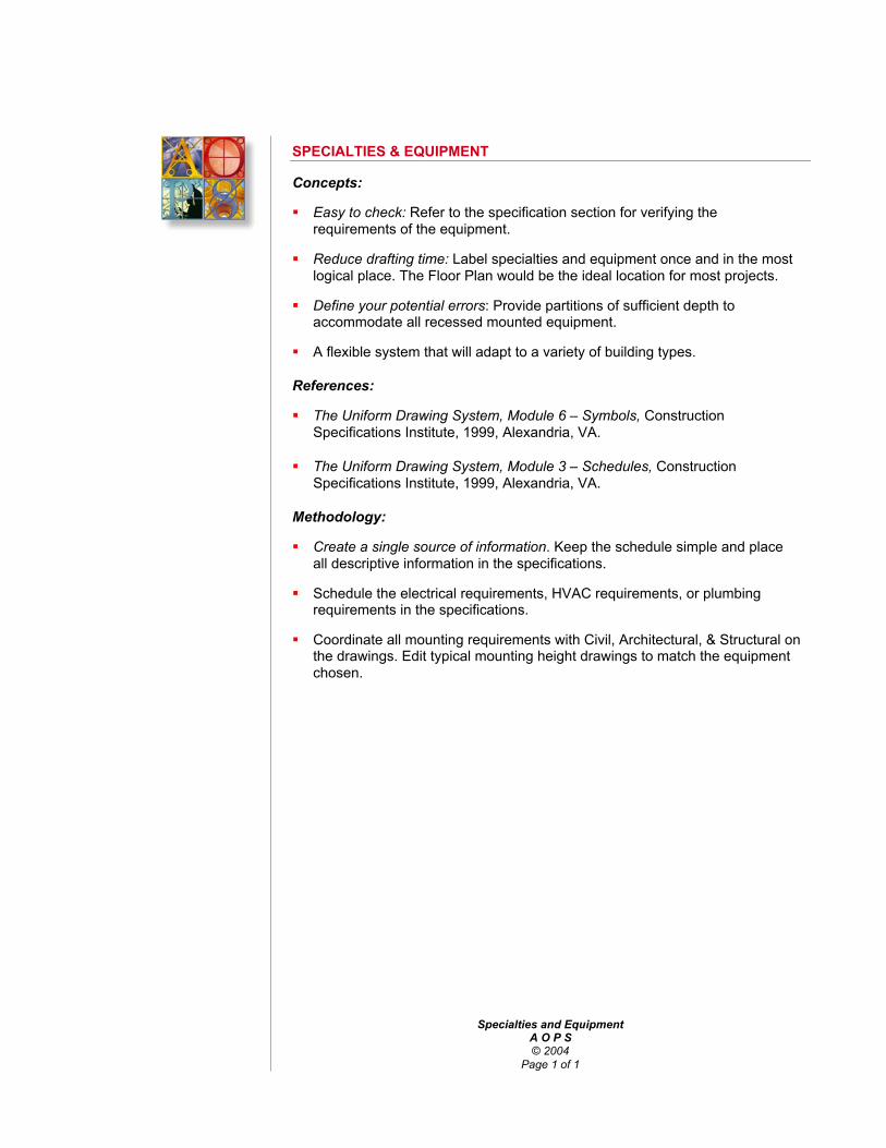
Specialties and EquipmentA O P S© 2004
Page 1 of 1
SPECIALTIES & EQUIPMENT
Concepts:
Easy to check: Refer to the specification section for verifying therequirements of the equipment.
Reduce drafting time: Label specialties and equipment once and in the mostlogical place. The Floor Plan would be the ideal location for most projects.
Define your potential errors: Provide partitions of sufficient depth toaccommodate all recessed mounted equipment.
A flexible system that will adapt to a variety of building types.
References:
The Uniform Drawing System, Module 6 – Symbols, ConstructionSpecifications Institute, 1999, Alexandria, VA.
The Uniform Drawing System, Module 3 – Schedules, ConstructionSpecifications Institute, 1999, Alexandria, VA.
Methodology:
Create a single source of information. Keep the schedule simple and placeall descriptive information in the specifications.
Schedule the electrical requirements, HVAC requirements, or plumbingrequirements in the specifications.
Coordinate all mounting requirements with Civil, Architectural, & Structural onthe drawings. Edit typical mounting height drawings to match the equipmentchosen.

Kitchen EquipmentA O P S© 2004
Page 1 of 1
Kitchen EquipmentSchedule
KITCHEN EQUIPMENT
Kitchen equipment requires the coordination of work between a number ofconsultants and construction trades. This schedule can serve as a focal point forthat coordination. Locate next to the kitchen equipment plan.
Concepts:
Easy to check: Refer to the specification section for verifying therequirements of the equipment.
Reduce drafting time: Label kitchen equipment once and in the most logicalplace. An enlarged Floor Plan would be the ideal location for most projects.
Define your potential errors: Provide blocking in partitions for all wallmounted equipment.
A flexible system that will adapt to a variety of building types.
References:
The Uniform Drawing System, Module 6 – Symbols, ConstructionSpecifications Institute, 1999, Alexandria, VA.
The Uniform Drawing System, Module 3 – Schedules, ConstructionSpecifications Institute, 1999, Alexandria, VA.
Methodology:
Create a single source of information. Keep the schedule simple and placeall other product information in the specifications.
Schedule the electrical requirements, HVAC requirements, or plumbingrequirements.
Coordinate all mounting requirements with Architectural, & Structural on thedrawings.

KITCHEN EQUIPMENT SCHEDULE
Kitchen Equipment Schedule — Page 1 of 2
MECHANICAL ELECTRICALNO. DESCRIPTION MFG & MODEL
CW HWDIR
WASTEINDIR
WASTEVOLTS AMPS PHASE KW HP DIRECT PLUG
NOTES

Civil Engineering CoordinationA O P S© 2004
Page 1 of 2
CIVIL ENGINEERING CHECKLIST
Project: Job No:
Completed by: Date:
Title Block conforms to drawing set.
Sheet numbering conforms to drawing set.
Plan orientation, and scale conforms to drawing set
Verify the following:
Building outline matches Architectural (do not show a floor plan).
Building entry & exit locations match Architectural.
Survey datum equates to first floor elevation.
Show and label property line.
Location of building from property line.
Indicate staging area and site access.
Locate and detail the project sign.
Indicate all exterior signage locations.
Dimension parking striping.
Indicate existing and proposed topography.
Slope finish grade away from building.
Indicate retention basin location.
Label all catch basin locations.
Water line route is free of conflicts and building entry matches Mech.
Water meter location with Arch, Mech, and Landscaping.
Fire protection route is free of conflicts and building entry matches Mech.
Gas line route is free of conflicts and building entry matches Mech.
Gas meter location with Mech. and pad construction is detailed.
Sanitary sewer route, slope, and building exit with Mech. and Structural.
Storm sewer route, slope, and building exits with Mech. and Structural.

Civil Engineering CoordinationA O P S© 2004
Page 2 of 2
Electrical power route and building entry with Elec.
Transformer location and pad construction with Arch, Elec. and Landscape.
Telephone service route and building entry with Elec.
Cable TV route and building entry with Elec.
Foundation perimeter drain and daylight with Arch.
Site lighting locations with Arch, Elec. and Landscape.
Security equipment locations with Arch.
Specialties & Equipment locations with Arch, Mech, and Elec.
Sand & Oil interceptor location with Arch and Mech.
Grease interceptor location with Arch, and Mech.
Irrigation system conflicts with Arch, Elec., and Mech.
Water feature system with Arch, Mech. Elec., and Landscape.
Dumpster size will fit in trash enclosure.
Heavy-duty pavement areas.
Patios & Pavers with Arch and Landscape.
Concrete walks and control joints with Arch and Landscape.
Colored concrete areas with Arch and Landscape.
Swales and drainage pan slope.
Handicapped access issues (ramps, parking, and signage) with Arch.
Ice melt system with Mech and Elec.

Landscape CoordinationA O P S© 2004
Page 1 of 1
LANDSCAPE PLAN CHECKLIST
Project: Job No:
Completed by: Date:
Title Block conforms to drawing set.
Sheet numbering is conforms to drawing set.
Plan orientation and scale conforms to drawing set
Verify the following with Architectural and Civil:
Current building outline (not floor plan).
Current site plan background.
Planting in snow removal accumulation areas.
Retention basin location.
Utility routes and easements (underground & overhead).
Water meter location.
Gas meter location.
Site lighting locations.
Signage locations.
Tree locations.
Fire protection hydrants.
Shrub locations.
Irrigation system route (away from building).
Irrigation system controls.
Check for excessive slopes.
Check for hard surface runoff points.
Roof drip line.
Splashblock locations.
Concrete mow strip or gravel at building perimeter.
Planting legend.
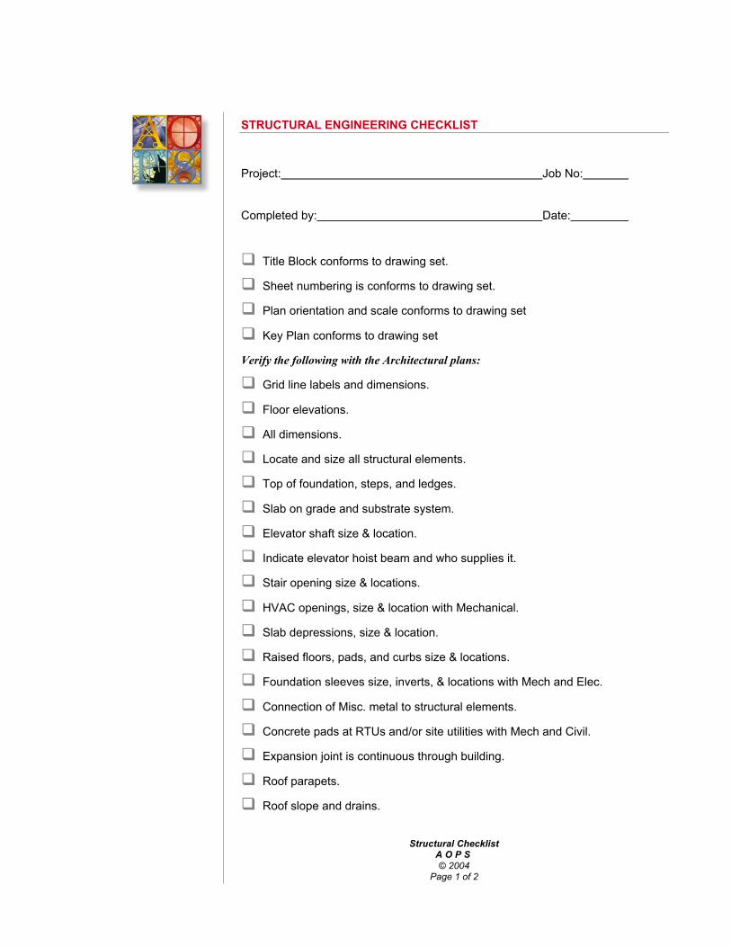
Structural ChecklistA O P S © 2004
Page 1 of 2
STRUCTURAL ENGINEERING CHECKLIST
Project: Job No:
Completed by: Date:
Title Block conforms to drawing set.
Sheet numbering is conforms to drawing set.
Plan orientation and scale conforms to drawing set
Key Plan conforms to drawing set
Verify the following with the Architectural plans:
Grid line labels and dimensions.
Floor elevations.
All dimensions.
Locate and size all structural elements.
Top of foundation, steps, and ledges.
Slab on grade and substrate system.
Elevator shaft size & location.
Indicate elevator hoist beam and who supplies it.
Stair opening size & locations.
HVAC openings, size & location with Mechanical.
Slab depressions, size & location.
Raised floors, pads, and curbs size & locations.
Foundation sleeves size, inverts, & locations with Mech and Elec.
Connection of Misc. metal to structural elements.
Concrete pads at RTUs and/or site utilities with Mech and Civil.
Expansion joint is continuous through building.
Roof parapets.
Roof slope and drains.

Structural ChecklistA O P S © 2004
Page 2 of 2
Rooftop Utility Screen.
Roof access hatch location & framing.
Skylight location & construction.
Show connections of all misc. metal to structural elements.
Specialties & Equipment mounting systems.

HVAC ChecklistA O P S© 2004
Page 1 of 2
HVAC CHECKLIST
Project: Job No:
Completed by: Date:
Title Block conforms to drawing set.
Sheet numbering is conforms to drawing set.
Plan orientation and scale conforms to drawing set.
Key Plan conforms to the drawing set.
Verify the following with Architectural:
Current plan background.
Current grid line labels.
Current room names and numbers.
HVAC chase, size & location.
Housekeeping pads & locations.
Foundation penetration size, & locations.
Louver size and locations.
Fire damper locations.
Fire rated partitions.
RTU weight, clearances, & locations.
RTU gas line route.
RTU screen conflicts.
Control locations & mounting heights.
Exposed duct shape, route, & mounting.
Roof hatch and utility conflicts.
Skylight and utility conflicts.
Plenum space evaluation.
Duct route and structural conflicts.
Lighting conflicts.

HVAC ChecklistA O P S© 2004
Page 2 of 2
Plumbing & drainage conflicts.
Fire protection conflicts.
Specialties & Equipment conflicts.
Stair & elevator conflicts.
HVAC supply & return locations.
Kitchen or Lab hoods.
Access panel size & locations.
Rooftop equipment mounting details.

Plumbing ChecklistA O P S© 2004
Page 1 of 2
PLUMBING PLAN CHECKLIST
Project: Job No:
Completed by: Date:
Title Block conforms to drawing set.
Sheet numbering is conforms to drawing set.
Plan orientation and scale conforms to drawing set
Key Plan conforms with the drawing set.
Verify the following with Architectural:
Current plan background.
Current grid line labels.
Current room names and numbers.
Plumbing chase, size & location.
Foundation penetration size, & locations.
Fire protection connection, controls, and locations.
Water line entry and meter location.
Gas line entry and meter location.
Sanitary sewer exit & invert.
Roof Drain leader exits & inverts.
Fire rated partitions.
Fire protection piping route.
RTU gas line route.
Plumbing fixture locations & mounting heights.
Chase partition width between Toilets.
Partition width at piping.
Exposed piping route, & mounting.
Roof hatch conflicts.

Plumbing ChecklistA O P S© 2004
Page 2 of 2
Skylight conflicts.
Plenum space evaluation.
Pipe route and structural conflicts.
Lighting conflicts.
HVAC duct conflicts.
Fire protection conflicts.
Specialties & Equipment conflicts.
Stair & elevator conflicts.
Drinking fountain supply & return.
Kitchen equipment coordination.
Laboratory equipment coordination.
Access panel size & locations.
Floor drain & floor sink locations.
Shower & mop sink locations.
Clean out locations vs. floor finishes.

Electrical Power Plan ChecklistA O P S© 2004
Page 1 of 2
ELECTRICAL POWER PLAN CHECKLIST
Project: Job No:
Completed by: Date:
Title Block conforms to drawing set.
Sheet numbering is conforms to drawing set.
Plan orientation and scale conforms to drawing set.
Key plan conforms to drawing set.
Verify the following with Architectural:
Current plan background.
Current grid line labels.
Current room names and numbers.
Electrical chase, size & location.
Foundation penetration size, & locations.
Electrical panels, wall thickness, and locations.
Electrical line entry and meter location.
Telephone line entry and board location.
Transformer location and pad construction.
Lightning protection.
Dedicated lines (copier, equipment, etc.).
Grommets in countertops.
Outlet at electric water coolers.
GFI outlet locations.
WP outlet locations.
Data jacks (computers).
Exposed conduit route, & mounting.
Roof hatch conflicts.
Skylight conflicts.

Electrical Power Plan ChecklistA O P S© 2004
Page 2 of 2
Plenum space evaluation.
Conduit route and structural conflicts.
Lighting conflicts.
Plumbing conflicts.
HVAC duct conflicts.
Fire protection conflicts.
Specialties & Equipment supply & conflicts.
Stair & elevator conflicts.
Security - control & monitoring location.
Security - camera power.
Kitchen equipment coordination.
Laboratory equipment coordination.
Electrical Room clearances.
Signage power, interior & exterior.
Dimension floor outlets and under-floor ducts.
Coordinate mounting heights with finishes and equipment.
A/V system supply.

Electrical Lighting Plan ChecklistA O P S© 2004
Page 1 of 2
ELECTRICAL LIGHTING PLAN CHECKLIST
Project: Job No:
Completed by: Date:
Title Block conforms to drawing set.
Sheet numbering is conforms to drawing set.
Plan orientation and scale conforms to drawing set.
Key plan conforms to drawing set.
Verify the following with Architectural:
Current plan background.
Current grid line labels.
Current room names and numbers.
Clearance for downlights in soffits.
Dimension wall sconce locations & mounting heights.
Dimension exterior lighting locations.
Dimension illuminated signage locations.
Security lighting.
Emergency lighting locations.
Under-counter lighting
Coordinate mounting heights of pendant fixtures.
Cove lighting.
Dimension wall washer locations & distance from wall.
Dimension decorative & specialty lighting.
Roof hatch conflicts.
Skylight conflicts & lighting.
Plenum space evaluation.
Structural conflicts.
HVAC duct conflicts.
Conduit route conflicts.

Electrical Lighting Plan ChecklistA O P S© 2004
Page 2 of 2
Plumbing conflicts.
Fire protection conflicts.
Specialties & Equipment conflicts.
Stair & elevator lighting.
Kitchen equipment coordination.
Laboratory equipment coordination.
Exit light locations
Smoke & heat detector locations.
Speaker locations.
A/V equipment locations.
Security equipment locations.

ARCHITECTURAL SPECIFICATION WRITER’S AND WORKING DRAWINGS CHECKLIST
” 2004 JNX Group, LLC – All Rights ReservedPage 1 of 7
SPECIFICATION WRITER’S CHECKLISTA. General1. Recommended reading: AIA general conditions and
contracts.
2. Provisions should be included in the specifications for amockup of any feature whose final affect is not certain in thedesigner’s mind.
3. check each division of the specifications for:a. allowancesb. unit pricesc. warranty/guaranteed. shop drawingse. samplesf. inspections and testsg. record drawingsh. material bondsi. clean-up
4. New materials should be checked with the manufacturer’srepresentative; their instructions and recommendationsshould be carefully considered.
5. Electrolytic reaction should be checked where dissimilarmetals are used in contact with one another, such asaluminum and ferrous metals.
B. Excavation1. Pay lines for earth excavation and rock excavation should be
established.
2. Site conditions and changes from borings or contract linesshould be provided for and verified by drawings and engineer’sapproval.
3. Sub-surface drainagea. Drain lines in porous fill under concrete slab for all large
areas of exterior terraces, etc. should be specified.
C. Site Work1. Check local requirements for curb materials.
2. Check local requirements for replacement of existing curbswhere new sidewalks are provided.
3. Check local requirements for re-setting existing curbs toestablished curb elevations.
D. Landscaping1. Guarantees for landscaping, other than trees, should be
established.
2. Maintenance contracts for plant materials should beconsidered; if possible, provide an allowance.
E. Waterproofing1. Check types of waterproofing required.
2. Provide waterproofing under all mat recesses, and carry toexterior wall and connect to wall dampproofing.
F. Concrete and Cement Finishes1. Exp[ansion strips for horizontal surfaces such as terraces
should be provided.
2. Concrete samples should go directly to the testing laboratory,and test reports should go directly to the engineers. Checklocal jurisdictions for special local requirements.
3. Floor hardening and sealing should be checked for dryingtime, any special installation requirements, etc.
4. Construction joints in slabs should not be placed within 10feet of any expansion joint. Contractor should prepare a planfor engineer’s approval showing locations of all constructionjoints.
5. Large terraced areas of concrete should be provided withminimum 6x6 mesh reinforcement, stone base course,expansion joints, and an under-floor drainage system.
6. Rough textured surfaces should be provided on sidewalks atentrances.
7. Construction joints in concrete slabs should never be placednear mat recesses.
G. Masonry1. Face brick cost per “M,” not lump sum allowance. Quantity to
be provided by general contractor.
2. Acoustical isolation for interior rooms should etend abovesuspended ceilings to underside of slab above.
H. Slate and Stonework1. Sealer on interior slate or other stone floors should be
specified.
2. Caulk all joints in copings; also flat surfaces where foot trafficdoesn’t occur.
3. Anchorage for copings and stonework should be thoroughlydescribed in the specifications.
4. Limestone and other soft or porous stones are not to come incontact with the earth, nor terraces or platforms where watercan collect and be drawn up by capillary action.
5. Sidewalk surfaces; use rough, textured non-slip surface.
6. Smooth surfaced floors should not be used in vestibules, asthey wear rapidly and are very slippery.
7. Do not use soft stones on heavily traveled stairs.
I. Roofing and Sheet Metal1. Check for flashing under stone or masonry sills made of more
than one piece.
J. Furring and Lathing(if plaster is used on the project in lieu of gypsum board)
1. Furring, lath, and plaster should enclose all pipes, ducts, etc.which would otherwise be exposed in finish areas, regardlessof whether furring is shown or indicated on the architecturaldrawings.
2. Base screed (or casing bead) should be used with cementbase.
3. Casing bead should be used where plaster abuts any othersurface.
K. Plastering(if plaster is used on the project in lieu of gypsum board)
1. When a plaster finish is set flush with a ceramic tile wainscot,a v-joint or other reveal should be shown on the drawings attheir point of intersection.
L. Terrazzo1. Rough textured, non-slip surfaces should be specified on
sidewalks at entrances.
2. Terrazzo floors are not advisable in toilet rooms or slop sinkclosets, as this material is more absorbent than tile.

ARCHITECTURAL SPECIFICATION WRITER’S AND WORKING DRAWINGS CHECKLIST
” 2004 JNX Group, LLC – All Rights ReservedPage 2 of 7
M. Ceramic Tile1. Provide expansion joints for ceramic tile and setting bed for
all tile expanses exceeding 16’ vertically and/or horizontally,wherever construction and expansion joints occur.
N. Resilient Flooring1. In all alteration work, a paragraph should be added to the
specifications stating how work is to be done in areas wherefloor is marked “patch and level floor to receive resilient tile.”It should be clearly stated that this means the floor of theentire room shall be patched and uniformly level throughout.
O. Miscellaneous and Ornamental Work1. When specifying metal or glass entrance doors, remember
that no matter what the material is, push and pull platesshould be included, lettered with the words “push” and “pull.”
2. Note: Specifications writer should keep items in alphabeticalto facilitate checking.
3. Check: area gratings, access trench covers, angle frames inwood flooring, anchorage for exterior carved stonework,astragals, frame anchors, cast iron bumper on loadingplatform, cleanout doors, chimney caps, corner guards,catwalk in roof spaces, cupola, ceiling framing, catch basingratings, curb angles, supports for concealed expansionjoints, driveway curb guards, exterior railings, expansionjoints and covers, electrical service supports, framing atfloodlights, floor plates in boiler rooms, grilles, house trap pitcovers, hoods over kitchen ranges, interior lintels, interiorstairs, interior kickplates (special).
4. Where weatherstripping is used on the same doors askickplates, detail carefully; ladders, ladder rungs andhandholds, mason’s ironwork, metal saddles, manholecovers, pipe railings, pipe handrails, projection roomequipment, reinforcing steel for exterior walls, steel anglebases, steel wheel guards at overhead garage doors, stepnosings, steel sidewalk doors, supports for interior stone trim,supports for folding partitions, supports for column-hungbookcases, steel angle curbs at overhead garage doors,supports for folding doors, steel work to support electricalservice cables, steel plate supports for handrail brackets,leader sleeves, wire mesh partitions, weatherstripping.
P. Carpentry1. Verify with the designers whether wood items indicated are to
be veneers or solid.
2. Exterior wood trim should be prime coated in the shop. Allcuts made in the field which expose bare wood shall bepainted in the field before setting in place.
3. Carpentry specs should include the following: workmanshipshall be of the highest grade, and only mechanics especiallyskilled in this kind of work shall be employed. All work shall beaccurately set in place plumb, true, even and in perfectalignment, and shall be securely fastened.
4. Accurately and carefully fit, cut, shim, or block all work so thatadjoining surfaces in the same plane will finish flush, straight,and true.
5. Finished surfaces shall be free of all tool or machine marksand other objectionable features. Surfaces shall be finishedequivalent to hand sandpapered work.
6. Wood interior doors shall be 1-3/4” minimum thickness ininstitutional and commercial work.
Q. Weatherstripping1. All exterior doors must be weatherstripped.
R. Glass and Glazing1. Glass shall be cut with proper clearances to accommodate
deflection or temperature changes in wood or metal frames.This is especially critical for double panes. Adhere tomanufacturer’s stated clearance requirements.
S. Painting and Finishes1. Provide protection behind drinking fountains if tile walls are
not specified.
2. Luminous ceilings: paint all surfaces, hangers, ducts, pipes,etc. above light strips an off-white color for good reflectanceand even illumination.
3. Multi-colors: when used in more than a few rooms,specifications should state that multi-colors will be usedfrequently throughout the building.
4. Note that walls and base are to be painted behind radiators,convectors, etc. where exposed to view. On alteration jobs, itshould also be noted that these items are specifically to beremoved before painting takes place.
5. Allowance should be made for lettering of doors. Check, if inaddition to the following, other rooms should receive doornumbers and/or room names: toilet rooms, floor numbers instair or elevator shafts.
6. Base (_____inches high) painted in contrasting colorwherever wall material extends down to floor.
7. Check whether painted dadoes of contrasting color will bewanted in any spaces.
8. Convector enclosures, etc.. should be painted black behindgrilles to hide pipes, fins, etc.
T. Hardware1. Specify coordinator where panic bolt is required on both
leaves of double door with astragal or rabetted edge.
2. Whenever using door closers, avoid using closers thatemploy brackets.
U. Heating and Ventilating1. If a piece of mechanical equipment, such as an air
conditioning unit, does not completely fill the opening in theexterior wall, the remaining space shall be fully insulated.
V. Electrical1. Specify an allowance for special electrical fixtures, such as
chandeliers.
2. Check if lightning protection is required; if so, specificationsshould call for the earliest possible installation and completionof lightning arrestors.
3. Luminous ceilings shall be suspended and supported in strictaccordance with manufacturer’s instructions, and with allapplicable codes. Check details for possible conflicts in tradejurisdictions.
W. Alterations1. Existing openings to be closed, or new openings to be made
should be checked for matching of existing finishes. Same forfloors and bases.
2. Cutting and patching should be carefully noted on drawingsand covered appropriately in specifications.
3. Allowances for replacement of plaster and other finishesshould be checked.

ARCHITECTURAL SPECIFICATION WRITER’S AND WORKING DRAWINGS CHECKLIST
” 2004 JNX Group, LLC – All Rights ReservedPage 3 of 7
WORKING DRAWINGS CHECKLISTA. All Drawings1. Title2. Scale3. North arrow on plans
B. Site or Plot Plan1. Property lines, property location, city, street names, lot and
block number, property line angles and dimensions, markers.
2. Building location, setbacks, zoning and clearances, groundfloor elevations, future additions, grades at buildings,dimensions, dimensions of all projections beyond buildingline, such as steps, corners, copings, canopies, window sills,etc.
3. Easements (electrical, water, gas, sewers).
4. Paving: show existing and contract paving, parking plan,parking bumpers, walks, platforms, steps, drives, paths,terraces, signs, flagpoles, playfields, playground equipment,drinking fountains.
5. Fences and stone walls, retaining walls, areaways, pools.
6. Existing structures, cellars, trees, shrubs, etc. to remain or tobe removed, structures to be relocated, underground voids tobe filled.
7. Storm drainage and catch basins, road drainage.
8. Contract limits.
9. Work not included in contract (NIC).
10. Footing drains.
11. Legend; show all indications and materials used on site plan.
12. Contours; existing and new. Contour elevations.
13. Datum benchmarks, monuments, etc.
14. Utilities: sewer, water, electricity, telephone, gas hydrants,sewage disposal.
15. Survey date, name and address of surveyor.
16. Details of construction of site contract items.
17. Curbs: check that elevations conform to those established byauthorities having jurisdiction; also, that materials comply withsuch requirements.
18. Landscaping: show unless covered by a separate landscapeplan; indicate existing to be protected; show new trees andsignificant plants.
19. Temporary fences and gates, temporary toilets and shanties.
20. Material storage area(s).
21. Orientation: true north and reference (project) north symbol.
22. Project sign location.
23. Protection of existing work.
24. Paving patterns: scoring and parking markings, trafficmarkings, expansion joints, striping, wheel stops.
25. Curb and gutter elevations, unless covered on separate civilengineering drawing.
26. If required, show required sequencing or phasing of parts ofproject.
27. Demolition: show extents.
C. Architectural Floor Plans1. Dimensions: overall, column centers, building breaks and
setbacks, masonry dimensions. Tie room dimensions tocolumn centers if practicable.
2. Rooms: name and number, finish codes, references to largerscale plans, sections and details.
3. Floors: floor elevations, floor patterns, joint patterns in tile,stone or other floor finishes, mat recesses, changes inmaterials, ramps, curbs, bases, gutters.
4. Walls: material indications, fire ratings, pipe and duct spaces,recessed convectors, electrical panels.
5. Ceilings: ceiling breaks, change in height or material,skylights, ceiling grid or tile patterns showing lights anddiffusers.
6. Door swings and numbers. Show thresholds if required. Noteall fire-rated, self-closing openings.
7. Windows: indicate mullions; schedule window types whereapplicable.
8. Toilet rooms: plumbing fixtures, compartments, floor drains,references to larger scale plans.
9. Stairs: dimensions to stairwell; show traffic direction; indicatenumber of risers; handrails. References to larger scale plans,sections, and details.
10. Miscellaneous items: casework, fire extinguisher cabinets,access doors, drinking fountains, expansion joints, foldingpartitions, gratings and pit covers, ladders, lockers, shelving,special trenches, corner guards, special convectorenclosures, telephone booths, roof drain leaders, low walls,chalkboards, tackboards, folding gates, wardrobes, railings.
11. Finishes: clearly indicate extents of finishes, showing wherethey start and stop. Confirm that they are clearly indicated inschedules, plans, interior elevations, details, andspecifications.
D. Architectural Roof Plan1. Dimensions: indicate overall dimensions of building and roof
surface; indicate and dimension overhangs. Show canopies.
2. Drainage: indicate roof drains or gutters and leaders. Showpitch to drains. Show pitch and expansion joints in gutters.Show high points and low points on flat roofs.
3. Materials: indicate type(s) of roofing and cornice materials.Note when face brick is required.
4. General: label high and low roofs where they occur; showcopings and indicate joints and materials. Indicate columncenters, chimneys and crickets, skylights and scuttles,hatches and bulkheads, fans, and other equipment located onroof. Indicate expansion joints and references to typicaldetails. Indicate railings or other guards, 3’ minimum railingsat roofs accessible by the public.
5. Miscellaneous: ladders, steel stairs to bulkheads,splashblocks, ridges, eaves, decks, roof walkways, parapets,special lighting fixtures, ventilators, flagpoles, lightningarrestors, special flashing conditions, snow guards, snow

ARCHITECTURAL SPECIFICATION WRITER’S AND WORKING DRAWINGS CHECKLIST
” 2004 JNX Group, LLC – All Rights ReservedPage 4 of 7
melting equipment, ice guard, check verification of headroomin roof spaces.
E. Exterior Elevations1. Key plan: indicate elevations, locations; show north arrow.
2. Materials: note and indicate; show joint patterns.
3. Windows and doors: show all window and door openings.dimension heights only, and relate to finish floor elevations.Indicate type for each opening. Indicate operating sash onoperable windows.
4. Dimensions: indicate column centers. Show only verticaldimensions and planes. Indicate floor levels. Indicate brickcourses, and brick (or other masonry) bearing ledge locationsand elevations. Show finish grade elevations.
5. Miscellaneous items: ladders, louvers or other openings,railings, vents, roof slopes, access openings, leaders andsizes, leader boots, conductor heads, splashblocks, guttersand size, leader straps, chimneys, sidewalk levels, curbs,ramps, ridges, eaves, decks, penthouses, parapets, trenches,beams, footings, low points, water outlets, fire plugs, hosebibbs, siamese connections, fresh air intakes, meter boxes,section lines, projections and setbacks (sunken and raised),panels, pilasters, awnings, electrical outlets, cornerstones,dormers, gables, hoods, entrances, balconies, flashing,counter flashing, roof scuttles, fleches, skylights, ventilators,snow guards, flagpoles and holders, lightning rods, gates,bumper blocks at loading platforms, clocks, plaques.
6. Check dimensions.
7. Check finish grades with site plan.
8. Check detail references with details.
9. Check elevations, column references, etc.
10. Check for penthouse, cooling towers, large fans, and othersuch roof structures which should be shown on elevations.Also check for exterior ladders or stairs to penthouses.
11. Check for unusual footing conditions which should be shownon the plans.
12. Check plaster and masonry control joints, including fasciasand soffits.
F. Wall and Roof Sections1. Dimensions: show vertical dimensions relating floor, ceiling,
and roof to top of steel (or steel bearing elevation), or top ofconcrete slab. Relate foundation building face and columncenters to each other.
2. Section identification: in addition to identifying numbers andkey plan, describe typical sections or details by titles.
3. Materials: indicate and note all materials.
4. Technique: limit details to show different conditions only.Avoid repetition; use outlines and refer to typical details. Useadequate scale to show what must be shown, but don’t uselarge scale details just to fill up a sheet.
G. Longitudinal and Cross Sections, Interior Elevations1. Dimensions: show vertical dimensions relating floor, ceiling,
and roof to top of steel (or steel bearing elevation), or top ofconcrete slab.
2. Section identification: in addition to identifying numbers andkey plan, describe typical sections or details by titles.
3. Materials: note and indicate all materials. Use general termssuch as metal, hardwood, softwood, plywood, beam joint,brick, concrete unit masonry, etc. when material or item isdescribed in greater detail in specifications or schedules, orshown on structural or mechanical drawings.
4. Interior elevations: include special rooms, such as chapels,lobbies, typical classrooms, typical bedrooms, corridors,auditoriums, gymnasiums, etc.
5. Miscellaneous items: cabinets (base and wall), doors,drawers, shelves, stock numbers. Chalkboards: sizes, joints,map hooks, trim, chalk tray. Closets: doors, clothes poles,mirrors, shelves. Display cases: sizes, shelves, brackets andstandards. Lockers: height and standards. Shelving: shelvingwidths, standards and brackets, Skylights: note locations andsizes. Tackboards: sizes, surface material, trim. Telephonerecesses: acoustical materials, shelves. Wardrobes: doors,base, coat hooks, dividers, shelves, overhead bracing.
6. Mechanical items: note, indicate, and locate: access doors,bells, chimes, clocks, convector enclosures and covers,drinking fountains, fire extinguishers, light fixtures, louversand grilles, speakers, switches, telephones, thermostats,electrical outlets and switches, unit ventilators/heaters.
7. Check finishes with Finishes Schedule.
H. Interior Details1. Concrete masonry, concrete bases: height, width, sleepers,
facing. Concrete stairs: risers, treads, nosings, finishes.Fireplace: size, hearth, damper, lintel, facing. Mat recesses:size, depth, edge strip.
2. Millwork: detail the following except stock items: cabinets,counters, doors, drawers, shelves, stock numbers.Chalkboards: sizes, chalk tray, map hooks, trim, blocking.Closets: doors, hardware, clothes poles, mirrors, shelves.Display cases: size. Shelves, doors, brackets and standards.Lockers (built-in): height, width, base, trim. Tackboards: size,surface material, trim, back-up blocking. Telephone recesses:surface materials, trim, shelves, acoustical treatments andinsulation. Wardrobes: doors, hardware, base, coat hooks,dividers, shelving.
3. Miscellaneous metals: Catwalks: width, railing, suspension.Ladders: spiral, vertical, 60 degree. Pass windows: stockitem, relate to counter. Railings: size, method of anchoring.Stairs: balustrade, handrail, tread and riser materials, landing,stairs to floors, stair soffit.
I. Detail Plans1. paces: make 1/4” scale plans of the following: kitchen, serving
and dishwashing. Typical classrooms: show only equipmentin contract. Home arts, science, etc.: detail these only ifequipment is in contract. Lobbies and stairs: detail plans asrequired. Toiulets and locker rooms: generally, 1/4” scaleplans are adequate.
2. Check details for practicability of fabrication and installation.
3. Check finishes against finish schedule.
4. Check materials against specifications. Make sure materialsare properly identified (refer to CSI Library of StandardNotation).
5. Where structural members are shown, do not indicate sizes.
6. Note any details needed for further clarification, windowdetails (usually show), materials, sizes, frames, glazing,transoms, sills, stools, rough blocks, caulking, etc.

ARCHITECTURAL SPECIFICATION WRITER’S AND WORKING DRAWINGS CHECKLIST
” 2004 JNX Group, LLC – All Rights ReservedPage 5 of 7
J. Windows and Framed Openings1. Window and framed opening sizes and types: refer to interior
and exterior elevations, or make 1/4” scale elevation drawingsof all windows and frame types. Dimension window and frametypes. Note when some types have several sizes.
2. Window details: when practical, to save drafting, show on wallsections. Otherwise, make detail drawings of all conditions.Relate windows/frames to masonry or porcelain panels. Showmethod of securing windows/frames to building. Providereinforcing for large windows. Check method of operatingvents. Brace heads of openings back to structure aboveceiling.
3. Consider the following: screens, reinforcing for attachment,washing of windows. Check for clearances/conflicts ofwindow coverings and operating window hardware. Interiorvenetian blinds. Square head sash for circular headedwindows. Arrangement of stools for grilles, convectors, etc.consider height of sills for safety: 3’0 AFF above first floor.Consider hospital type bottom rails for double hung windowsin bedrooms, etc. window operators for high windows. Wiremesh guards in gymnasiums, etc. coordinate windowcoverings operation with window hardware, such ascasement levers. Confirm sufficient stacking space fordraperies. Drapery recesses in ceilings.
4. Weatherstripping, types of glass: schedule.
5. Check the following:a. Window size to provide the equivalent of 10% of floor
area of roomb. Cover strips at mullions where marble stools are used.c. Window stops, caulking.d. Painting of screens when frames are non-ferrous.e. Punching of inlets for angles for securing metal lath at
heads of windows.f. Blocking or solid construction at heads of windows for
securing venetian blinds, shades, drapery tracks, etc.,window sizes and types against details, and againstplans and elevations.
g. Proper glazing indications.h. Lateral bracing for strip windows.
K. StairsNote: in offices where a similarity of work so warrants, standarddetails of stairs may be used. It is important that adequate stairplans and sections be prepared to check headroom, structuralclearances, code requirements, and dimensions.
1. Check the following: materials, width of treads, number ofrisers and heights. Stair numbers and direction of travelagainst floor plans. Newels: show caps and drops. Handrails:provide intermediate brackets that may be required; checkminimum finger clearances. Elevations of floor landings andplatform. Safety treads for concrete stairs. Check details ofrailing anchorage.
2. Exterior steps:a. Width of treadsb. Pitchc. Ends of buttresses or rampsd. Checks of buttressese. Anchoring or railings and handrailsf. Stagger joints for stone stepsg. Cast iron or other inset nosings on concrete steps where
requiredh. Materialsi. Verify stone thickness with specificationsj. Dimensionsk. Number and dimensions of treads and risersl. Headroom clearances
L. Ceilings1. Show reflected ceiling plans of principal rooms. Consider
soffits of beams, locations of lights, grilles, drapery tracks,access openings to mechanical equipment. Consider accessopenings, catwalks, etc. for re-lamping from above, access todampers, mechanical equipment scuttles, skylights, and forinspection of roof and plumbing leaks.
2. Check the following:a. Clearances of structure and ducts where light fixtures
are recessedb. Coordination of mechanical equipmentc. Acoustical treatments, plaster or gypsum board borders,
cornices, control joints, cove lightingd. Arched ceiling supports,e. Furring of bathroom ceilings to conceal plumbing pipesf. Low ceilings, furred soffits to conceal piping, ducts, etc.g. Structural supports for special ceilings, catwalks, folding
doors, testers, special lighting fixtures, equipment, etc.h. Relationship to partitions, piers, columns, etc. to ceiling
beams, features such as coves, skylights, etc.i. Finish schedulej. Mechanical and electrical plans for correct locations of
ceiling diffusers, light fixtures, sprinkler heads, andaccess panels
k. Ceiling patterns and design; check whether designrelates to window mullions or other wall features norpatterns.
3. Show control joints in gypsum board ceilings and soffits.Show expansion joints.
4. Show: paging annunciators, smoke detectors, fire alarms, exitsigns, corridor mirrors, lights, diffusers, returns, sprinklerheads, curtain tracks. Confirm compliance of projectingappurtenances with ADA requirements.
M. Schedules1. Doors are usually covered by schedules. It should be noted
that in offices where the similarity of work so warrants,standard details of doors and frames may be used. Thispermits the various types to be clearly delineated forreference. Where a door schedule is used, it should show:size, type, opening, location, material, frame, glazing, louvers,transoms, panels, thresholds, under cuts, fire resistiverequirements, and special features.
2. Hardware requirements are usually considered separately,but consideration should be given to space for door checkclearances, and electric strikes with panic hardware.
3. Check trim clearances where doors are close to each other atright angles. Consider electric switch locations.
4. Note when hatchway doors and frames are part of a separateelevator or dumbwaiter contract. Note and specify thatgeneral contractor shall leave openings in masonry asrequired for setting frames.
5. Check building code and multiple dwelling laws on sizes ofglass and louvers in various types of fire rated doorassemblies.
6. Where fire-resistive structures are built in areas not governedby building code, the recommended practice is to providedoors in accordance with the National Board of FireUnderwriters.
7. Check exterior doors for weatherstripping and caulking;confirm with specifications.

ARCHITECTURAL SPECIFICATION WRITER’S AND WORKING DRAWINGS CHECKLIST
” 2004 JNX Group, LLC – All Rights ReservedPage 6 of 7
8. Also check threshold types whether interlocking or not (bemindful of accessibility requirements.
9. Check weatherstrip detail where kickplates are used.
10. Meeting stiles of doors should be checked as to whether theyare bull-nosed or beveled. Exterior doors should be preppedfor astragals and hardware.
11. Check codes for:a. Actual widths required for 36”, 42” and 48” compartment
doorsb. All interior doors such as fire prevention self-closing
doors to public halls should be 7’-0 high to allowclearance below closer brackets.
c. All exterior doors should be 7’-0 high where they swingout and they require closer brackets
12. Door schedule should show types of glass required.
13. Provide weatherstripping at plenum room doors.
14. See that transoms above doors are covered in drawings andspecifications. If hinges are used, check stone and concretefloors for cutouts for box and saddle – coordinate. Detail doorhead condition where carrying partition.
15. Check the following:a. Door numbers and all items in schedules against door
numbers on plansb. Door types against graphic schedulec. Mechanical for under-cut or louvered doorsd. Proper labeling of fire doors
16. Finish schedules: interior finishes are usually covered byschedules. It should be noted that in some offices where asimilarity of the work so warrants, typical details of floorconstruction, base, and other features may be covered bydetails from a standard detail library. This permits variousdetails to be drawn and referenced in the schedules.
17. Schedule of interior finishes usually shows materials, heights,types, etc. particular care should be taken to ensure that allnotes on plans, details, schedules, and specifications areconsistent from one to another.
18. Schedule or indicate on details the following: floor trim,plinths, base (type in schedule). Check screeds. Notepaneling in schedule, and drawing to be referred to. Scheduletypes and heights of chair rails. Check window stools.Wainscots: painted or otherwise for flush type wainscots.
19. Note on drawings: covers, cornices, plaster reveals, floorborders and patterns (note thickness and locate terrazzostrips), slopes and pitches of floors. Consider drainage, markhigh and low points and elevations of porches, areas,terraces, and saddles.
20. Note on schedule rooms such as toilets, showers, kitchens,etc. where membrane waterproofing is required.
21. Marble graining, thickness, quirks, anchors, reinforcementshould be shown on details.
22. Where marble stools are used, check convector heights.
23. Show plaster corner guards on plans.
24. Ceilings: reflected ceiling plan should show beam soffits,cornices, panels, etc. lighting layout should be studied,especially where flush mounted light fixtures may be inconflict with structural members or piping.
25. Check structural and mechanical work for all furred orsuspended ceiling requirements.
26. Determine accurate heights of tile and structural facing tilewainscots.
27. Schedule or note window stools: marble, slate, wood, tile, etc.
28. Prepare interior finish studies, name and color of materials.Use samples in office and get client approval information thatneeds to be incorporated into the specifications.
29. Check the following:a. Room names and numbers in the finish schedule against
room names and numbers indicated on the floor plansb. Finish schedule against interior elevations
c. Finish schedule with design and graphics coordinator
N. Procedure for Job Captain Checking of CompletedWorking Drawings
Architectural Drawings
1. The architectural job captain should make a line for line checkof the architectural working drawings, and do a cross-check ofthe structural, mechanical, electrical, and civil drawings withrespect to dimensions, clearances, conflicts or interferences,and conformance with architectural requirements. This checkis to be made after the completion of all working drawings,and before issuing for bidding.
2. Refer to this manual or the firm’s drafting room manual fordrawing standards.
3. Review the working drawings checklist which has beenmaintained during progress of the work.
4. Check the following:a. Sheet index against sheet titles, and against sheet index
in specificationsb. Title blocks and revision blocksc. North arrowsd. General notes on all drawings for spelling, clarity, and
general usagee. All dimensions on architectural plansf. Cross-references between small scale drawings and
larger scale drawings and details
Structural, Mechanical, and Electrical Plans
1. Check the architectural plans against the structural plans for:a. Column identificationb. All dimensionsc. Slab openingsd. Slab depressions
2. Compare architectural, structural, mechanical, plumbing, andelectrical plans for agreement on locations and sizes ofopenings.
3. Compare the architectural and structural drawings with themechanical drawings for possible conflicts and impairedheadroom. Use an overlay checking approach.
4. Check the architectural, mechanical, and electrical plans forproper locations of motors, fans, pumps, compressors, andother equipment.
5. Check the architectural plans and the mechanical plans withthe electrical plans:
ARCHITECTURAL SPECIFICATION WRITER’S AND WORKING DRAWINGS CHECKLIST
” 2004 JNX Group, LLC – All Rights ReservedPage 7 of 7
a. Locations and sizes of switches, panel guards,telephone equipment
b. Locate water heaters and drinking fountains onarchitectural plans.
6. Check the architectural, mechanical, and electrical plansto make sure wall and furred spaces have sufficientclearances and depths for pipes, ducts, recesseddrinking fountains, etc. make sure that fire ratings aremaintained.
7. Check the architectural drawings with the plumbingdrawings for locations and number of roof drains,downspouts, sprinkler risers, vents through roof, toiletfixtures, etc. Use an overlay checking approach. Accesspanels must be noted. Check number of toilet fixtureswith code requirements.
8. Check the architectural and structural drawings with themechanical drawings for locations of equipment, ducts,air inlets, exhausts, etc. check for proximity of exhaustsand intakes to wall openings. Check that any largeequipment has proper structural support. Look forpossible conflicts and interferences with beams.