A0 Bonelle TCG Drawings - baixardoc
10
Acknowledgement The set of drawings has been verified by the construction of a grinder from them. Any mistakes or omissions being corrected when found. This grinder is illustrated below and I would like to thank Laurie Clarke ( Melbourne Australia ) who made it and kept me informed. The drawings should be reliable but I take full responsibility if this proves not to be the case. Don Willis
-
Upload
khangminh22 -
Category
Documents
-
view
1 -
download
0
Transcript of A0 Bonelle TCG Drawings - baixardoc

Acknowledgement
The set of drawings has been verified by the construction of a grinder from them. Any
mistakes or omissions being corrected when found. This grinder is illustrated below and I
would like to thank Laurie Clarke ( Melbourne Australia ) who made it and kept me
informed. The drawings should be reliable but I take full responsibility if this proves not
to be the case.
Don Willis

Bonelle TCG Drawing Revisions
20/2/04 G4 rev 1 dim 2 ½ was 2 3/8, G3 rev 2 notch added 21/02/04 L1 minor changes principally to clarify ‘where used’ 23/02/04 C7 Sketch added to show positioning of components. 24/02/04 L2/2 13/13” was 7/8” Rearranged to show slots more clearly. 25/02/04 Cross references to keys & clamps ( Drgs L1 & L2) corrected on drawings :- B2, B4, D1, G1, G2, G10, H1, H3, K4. 26/02/04 B2 Shape corrected to correspond with B3 28/02/04 C10/2 scale added 01/03/04 C2/4 added 06/03/04 G11 dim 4 7/16" was 4 5/16" 06/03/04 H2 missing dims added 06/03/04 G5 dim1 5/8" was 1 11/16" 30/03/04 H1 assembly clarified31/03/04 H7 & H8 added 22/05/04 D1 dim 2 1/2" added 00/00/00 00/00/00 00/00/00 00/00/00
James B Willis
Left click on a green link to go to the drawing in question. To return to this page right click and choose 'go back' or use toolbar 'first page'
Bonelle TCG
© J.B.D.Willis
Drawings
A. General Arrangement
B. Base
C. Wheel head
D. Wheel Guard
E. Dust Containment
F. Spindle
G.Workhead
H.Toolholder
J. Front Bar
K.Tooth Rest
L.Miscellaneous
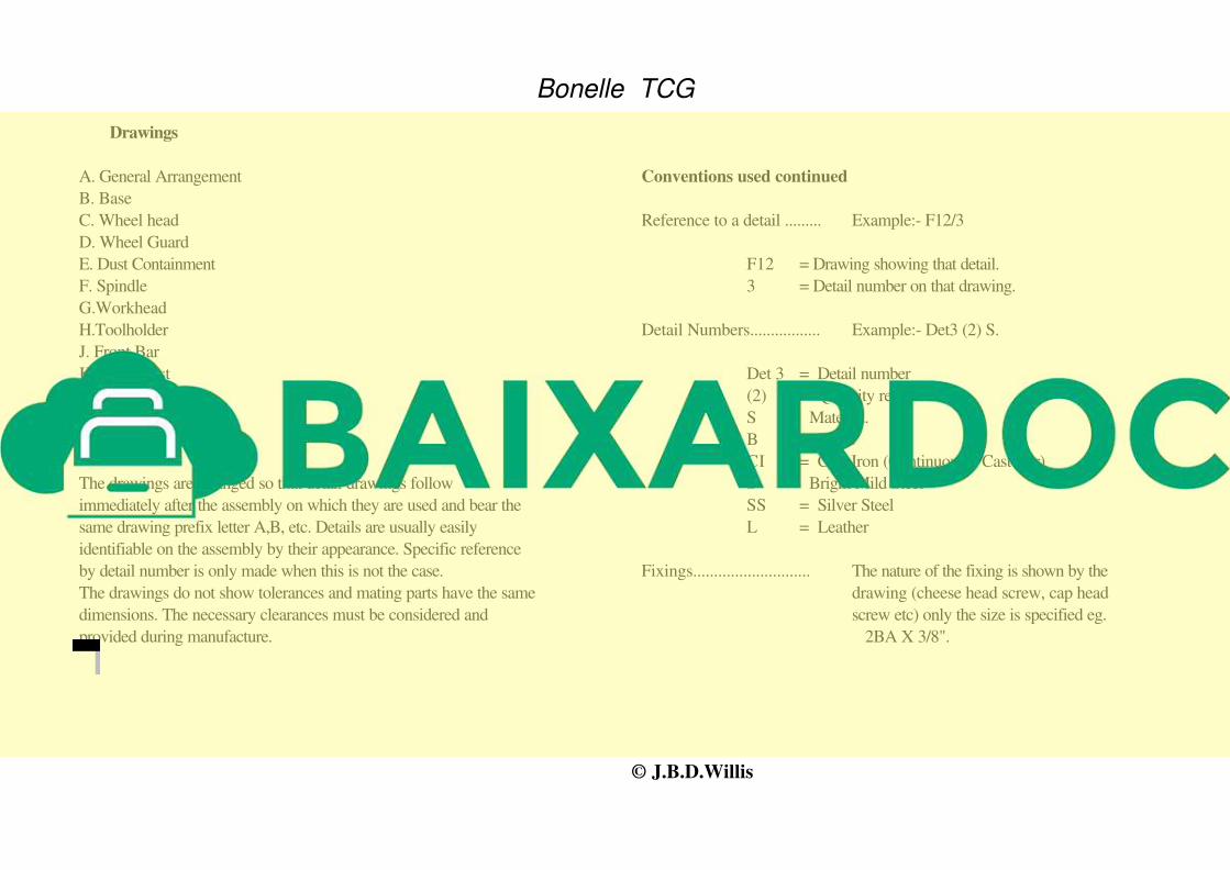
Conventions used.
The drawings are arranged so that detail drawings follow
immediately after the assembly on which they are used and bear the
same drawing prefix letter A,B, etc. Details are usually easily
identifiable on the assembly by their appearance. Specific reference
by detail number is only made when this is not the case.
The drawings do not show tolerances and mating parts have the same
dimensions. The necessary clearances must be considered and
provided during manufacture.
Conventions used continued
Reference to a detail ......... Example:- F12/3
F12 = Drawing showing that detail.
3 = Detail number on that drawing.
Detail Numbers................. Example:- Det3 (2) S.
Det 3 = Detail number
(2) = Quantity required
S = Material.
B = Brass
CI = Cast Iron (Continuously Cast Bar)
S = Bright Mild Steel
SS = Silver Steel
L = Leather
Fixings............................ The nature of the fixing is shown by the
drawing (cheese head screw, cap head
screw etc) only the size is specified eg.
2BA X 3/8".
James Willis
See also Bookmarks to find main assembly drawings. Where text has a green frame around it click to view a relevant illustration. Right click illustration and choose 'back' to return to drawing.

Bonelle TCG
Drg NoDateRevision
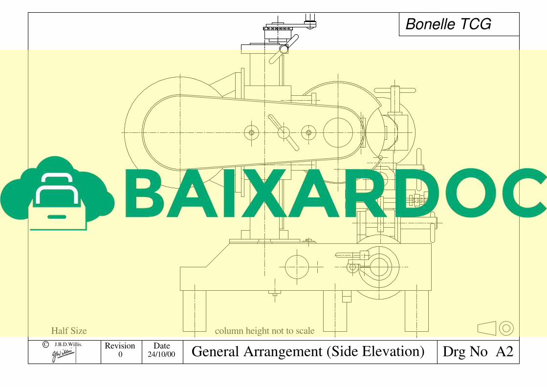
column height not to scale
010
20
10
20
30 30
C J.B.D.Willis.
0 22/10/00 General Arrangement (Front Elevation) A1
Half Size
Bonelle TCG
Drg NoDateRevisionC J.B.D.Willis.
General Arrangement (Side Elevation) A2
Half Size column height not to scale
0 24/10/00

Bonelle TCG
Drg NoC J.B.D.Willis.DateRevision
A A
Section A - A
0
10
20
30
40
10
20
30
40
Base Assembly B12 17/03/03

Bonelle TCG
Drg NoC J.B.D.Willis.DateRevision
12"
B6/3
1/16
B6/1
B6/2
B4/5
B4/6
Base Sub Assembly
Ensure that B6/1 & B6/2 are in thesame plane then secure B6/2 with Loctite.
secure with Loctite
secure with Loctite( see note on C7 regarding levelling screws)
B22 26/02/04

Bonelle TCG
Drg NoC J.B.D.Willis.DateRevision
2 1/4 " 3 1/2 " 1 1/8 " 3 1/2 "1 3/8
1 5/8 "
11 "
1 1/2 "
3 1/2"
Tap M4 10mm deep on 1 1/2 " pcd
Tap M4 10mm deep
120°
1/4 "
1 "
Tap M8 3/4 " deep
1 7/8 "
60°
A BA
on 1 1/2 " pcd
C C C C
D
B
retain offcut to make K2/1
1 1/2
1 1/2
41/64"
1 1/4 in
5/8"
1 1/4 in
2in
8 mm
2 BA3 1/4 in
15/16 in
3/8
in
1 3/8 in 1 3/8 in
1/2
in E
E
E
ECL
1
1 3/81 1/2
Ø1 1/4
1 1/2
4BA X 3/8
1 7/8
1 3/16 1 7/16
15/16
3/8
9/16 1 1/8
1 3/16 1 7/16
1 1/4 " Notes
2. Bolt together using holes C.
3. Bore holes A to give close slide fit to bar
4. Holes B to be .003" larger than A
5. Hole D to be a push fit on vertical bar
Det 1 (1) CI
Det 2 (1) CI
Base Details (A)
1. Lightly machine faces check that they
6. Holes E (on underside ) 2BA X 3/8"
7. Holes F 9/32" C'Bore 1/2" X 1/2"
at 90deg to each other.
F
F
F
F F
B35 20/03/03
see note on C4 40mm see note on C4 (cleans up to 1.54" typically)

1 1/8" 1/2"
1 1/2"
1/2"
1/4"
1/2" 1/4"
1/4"
1 1/4"
5/8"
1/4" 1/4"
5/8" 1"
7/8"
5/8"
3/8"
2 BA"
1/2"
Ø3/16"
1/4"
1" 1/2"
A"
9/32" dia
3/8"
2 B
A"
Bonelle TCG
Drg NoC J.B.D.Willis.DateRevision
knurl knurl
Det 1 (1) S
Det 3 (1) S
Base Details (B)
Det 2 (1) S
Det 4 (1) S
Det 5 (2) S A = 1 3/4"*
*
B4
Det 6 (1) S A = 2"
* adjust these dimensions to suite actual sizes of B3/1 & B3/2
1 17/03/03
If levelling screws are to be incorporated as shown in Z2 or Z3 then det 5 and 6to be modified accordingly.

5/8" 1"
1 3/16 "
1/4"
1 1/2"
3/8"
1/2" 3/4"
1/8"
1"
13 1/4""
13 3/4""
1 1/2" 11/16" "
5/8"
3 3/8"
3/8"
3/8"
1/2"
1/8"
3/16" dia
3/16" dia
2 BA
5/8" 3/16"
5/8"
11 3/4""
12 7/8""
1/4"
3/8"
5/8"
1/16"
Bonelle TCG
Drg NoC J.B.D.Willis.DateRevision
Det 2 (1) S
Det 1 (1) S
Det 3 (1) S
Tap 2 BA 3/8" deep
3 Holes
Det 4 (1) S
Base Details (C) B51 16/12/03
knurl