004 Drawings - Fort Lupton
10
-
Upload
khangminh22 -
Category
Documents
-
view
0 -
download
0
Transcript of 004 Drawings - Fort Lupton

Open Office103 Office
102
Hall105
Wom.108
Mech.107 Men's
106
Reception101
Office119
Office118
Office117
Open Office116
Conference111
Office110
Office115
Office114
Open Office109
Break Rm104
Shop126
Hall120Hall
113
Office121
Entry100
19' -
0"
18' -
4"
18' -
4"
19' -
0"
8"
Office122
Unisex123
D4A40
Tools124
Parts125
A3A40
E4A41
A2A40
1 2 3 4 5 6 7 8
A
B
C
D
E
A4A40
1' - 0" 19' - 3 1/2" 18' - 11" 19' - 4" 19' - 1 1/4" 1' - 0" 19' - 11 3/4" 21' - 0" 21' - 4 1/2" 1' - 0" 8' - 2" 5' - 4" 1' - 6"
Office112
77' - 11 3/4" 64' - 0 1/4" 15' - 0"
102.1
104.1
110.1
108.1 107.1
112.1
111.2
126.2
121.1
126.3126.4126.1
122.1
123.1
124.1
125.1
126.5
126.8126.7126.6
100.2 100.1
111.3
103.1105.1
114.1
115.1 117.1
118.1
119.1
106.1
111.1
113.1
116.1
109.1
126.9
103.2
C
B
A
A
A
A
AAAAAA
A A A A A
A
A
D1A42
6" dia. painted steel pipe bollard filled with conc., typ. ea. side of O.H. door openings per Dtl. B3/A01
12' concrete apron in thicknesses to match adjacent interior floor slab, slope to drain, typ. @O.H. Doors
B
See Sheet A11 for Enlarged Office Plan with Dimensions
D.S.D.S.D.S. D.S.D.S.D.S.
14' -
0"
18' -
4"
1' -
6"
12' -
0"
1' -
6"
17
' - 1
0"
100' - 0"
100' - 0"
100' - 0" 100' - 0"
100' - 0"
Provide concrete pad for A/C units per Mech.
6" dia. painted steel pipe bollard filled with conc., typ. ea. side of A/C units per Dtl. B3/A01
6" dia. painted steel pipe bollard filled with conc., typ. ea. side of steel columns in Shop per Dtl. B3/A01
1/8" = 1'-0"A10A1 Main Floor Plan
SHEET NUMBER
SHEET TITLE
REVISIONS
DATE
© 2016 HALCYON DESIGN LLC EXPRESSLY RESERVES ITS COMMON LAW COPYRIGHT AND OTHER PROPERTY RIGHTS IN THESE PLANS. THESE PLANS ARE NOT TO BE REPRODUCED, CHANGED OR COPIED IN ANY FORM OR MANNER WHATSOEVER, NOR ARE THEY TO BE ASSIGNED TO ANY THIRD PARTY WITHOUT FIRST OBTAINING THE EXPRESSED WRITTEN PERMISSION AND CONSENT OF HALCYON DESIGN LLC.
ALL CONSTRUCTION SHALL CONFORM TO CURRENT INTERNATIONAL BUILDING CODE AND AND ALL OTHER APPLICABLE CODES.
DO NOT SCALE DRAWINGS FOR DIMENSIONS.
PO Box 30Frederick, CO 80530
303.906.2617
Project No.
Main Floor Plan & Notes
A10
DE
I Sho
p &
Offi
ce33
55 C
ount
y Rd
27
Fort
Lupt
on, C
O 8
0621
2.8.17
1607
1 - 2.21.172 - 5.5.17
General Plan Notes:1. Contact Geotechnical Engineer after excavation, and prior to forming footings, for open
hole inspection to confirm analysis findings as noted in Geotechnical Engineering Report #12.245.16, dated September 7, 2016.
2. Provide minimum 2" void space at bottom of non-bearing stud walls. Geotechnical Engineer to provide bottom of wall detail.
3. Provide isolation joints between slabs and all foundations and column piers to allow independent movement.
4. Field verify all rough openings and wall widths prior to ordering windows, doors and other materials. Provide rough openings for windows and doors so that trim aligns.
5. Run a continuous bead of sealant around all doors, windows and other openings and joints. Leave adjacent surfaces clean and provide backer rod where necessary.
6. Provide solid blocking in walls as required for accessories, fixtures, cabinets, shelves, equipment, etc. at locations indicated on Floor Plan and Enlarged Plans.
7. Provide vapor barrier at exterior walls and roof-ceilings, at warm (inside) face of construction, immediately behind finish.
8. Align inside face of girt system and stud framing with inside face of foundation stem wall at exterior walls, typ.
9. Dimensions at interior partitions are to face of stud.10. Provide sound attenuation insulation at all interior partitions.11. Provide Knox Box adjacent to East building entry doors, keyed to Fire Dept. standards,
coordinate knox box model and location with Fire Marshal.12. Provide concrete splash blocks for downspouts, typical.13. Install interior metal studs @16" o.c., in gauge as recommended by stud manufacturer
for required height. Brace per mfgr. recommendation. Provide studs in widths greater than shown on plan, if required by mfgr. for height.
1
1
1
2

D4A40
A3A40
E4A41
A2A40
5 6 7 8
A
B
C
D
E
A4A40
3' - 4" 5' - 0 11/16" 3' - 0" 5' - 5 1/16" 2' - 0 1/4" 3' - 0" 9' - 8" 3' - 4" 5' - 0" 3' - 0" 2' - 0" 3' - 0" 16' - 0" 3' - 0" 2' - 0" 3' - 0" 7' - 8" 8"
Office102Open Office
103Break Rm104
Office122
Unisex123
Tools124
Parts125
Office114
Office115
Open Office109
Open Office116
Office117
Office118
Office119
Office121
Conference111
Office112
Office110
Mech.107
Wom.108
Men's106
Reception101
Entry100
Hall105
Shop126
3 1/8" 11' - 4 3/4" 3 5/8" 2' - 0 3/8" 3 5/8" 36' - 8 3/4" 3 5/8" 11' - 4 1/2"1 1/2"
3 5/8" 11' - 8 1/4"
3 5/8" 7' - 8"1 1/2"
28' -
4"
3 5
/8"
20' -
4"
3 5
/8"
7' -
0"
3 5
/8"
6' -
4"
3 5
/8"
11
' - 5
1/2
"
11' - 4 3/4" 3 5/8" 5' - 0" 3 5/8" 8' - 6" 3 5/8" 10' - 10 1/4" 3 5/8" 8' - 6"3 5/8"
5' - 0" 3 5/8" 11' - 4 1/2" 1 1/2"
11' - 5" 3 5/8" 27' - 6 7/8" 3 5/8" 11' - 2" 3 5/8" 11' - 4 1/2"
1 1
/2"
1' -
0"
1 1
/2"
17' -
7"
3 5
/8"
12' -
8"
3 5
/8"
11' -
9"
3 5
/8"
15
' - 1
1 5
/8"
3 5
/8"
14
' - 1
3/8
"1 1
/2"
2' - 8 1/4" 3' - 0" 2' - 0" 3' - 0" 12' - 4" 3' - 0" 2' - 0" 3' - 0" 4' - 8" 3' - 4" 8' - 0" 3' - 0" 2' - 0" 3' - 0" 7' - 8"
13
' - 1
0 1
/2"
3 5
/8"
14' -
0"
3 5
/8"
26' -
0"
3 5
/8"
19
' - 7
5/8
"
3 5
/8"
11' -
0"
3 5
/8"
10' -
6"
3 5
/8"
11
' - 8
5/8
"3 5
/8"
5' -
8"
3' -
0"
2' -
0"
3' -
0"
2' -
8"
4' -
8"
3' -
0"
2' -
0"
3' -
0"
8' -
2"
3' -
0"
2' -
0"
3' -
0"
1 1
/2"
13
' - 1
0 1
/2"
3 5
/8"
Stained conc.
Carpet
B4A41
A4A41
102.1
104.1
110.1
108.1 107.1
112.1
111.2
116.1
121.1
109.1
126.1
122.1
123.1
124.1
125.1
126.9
100.2 100.1
111.3
103.2
103.1
105.1
114.1
115.1
117.1
118.1
119.1
106.1
111.1
113.1
A A A A A
A
A
A
A
A
A
AAAAAA
B
B
C
D
Proposed gas meter location
Proposed elec. meter location
4' - 1 1/16" 4' - 1"
A50B2
A50D1
A50
C3108 South Elev
C2
108
Wes
t Ele
v
B3108 North Elev
C1
108
East
Ele
v
A50
E2123 North El
D2123 South El
E1
123
East
El
1' -
9"
10' -
6"
1' -
9"
A50
A1Conf. 111 NorthElev
A50 2
Brea
k R
m 1
04Ea
st E
lev
Chase as req'd for gas piping
Provide blocking as required for Owner-provided signage
E
SHEET NUMBER
SHEET TITLE
REVISIONS
DATE
© 2016 HALCYON DESIGN LLC EXPRESSLY RESERVES ITS COMMON LAW COPYRIGHT AND OTHER PROPERTY RIGHTS IN THESE PLANS. THESE PLANS ARE NOT TO BE REPRODUCED, CHANGED OR COPIED IN ANY FORM OR MANNER WHATSOEVER, NOR ARE THEY TO BE ASSIGNED TO ANY THIRD PARTY WITHOUT FIRST OBTAINING THE EXPRESSED WRITTEN PERMISSION AND CONSENT OF HALCYON DESIGN LLC.
ALL CONSTRUCTION SHALL CONFORM TO CURRENT INTERNATIONAL BUILDING CODE AND AND ALL OTHER APPLICABLE CODES.
DO NOT SCALE DRAWINGS FOR DIMENSIONS.
PO Box 30Frederick, CO 80530
303.906.2617
Project No.
Enlarged Office Plan
A11
DE
I Sho
p &
Offi
ce33
55 C
ount
y Rd
27
Fort
Lupt
on, C
O 8
0621
2.8.17
1607
1 - 2.21.172 - 5.5.17
1/4" = 1'-0"A11A4 Enlarged Office Plan
1
1
1

1 2 3 4 5 6 7 8
A
B
C
D
E
Open Office103 Office
102
Hall105
Wom.108 Mech.
107
Men's106
Reception101
Office119
Office118
Office117
Open Office116
Conference111
Office110
Office115
Office114
Open Office109
Break Rm104
Shop126
Hall120
Hall113
Office121
Entry100
Office122
Unisex123
Tools124
Parts125
Office112
Proposed F.E. location
Proposed F.E. location
Proposed F.E. location
Proposed F.E. location
Proposed F.E. location
Proposed F.E. location
1
13
1
1
1
11 1
1
1
1
3
3
6
9
2
8
3
2
2
Typical exit door width = 32" clear
Worst case hallway width = 4'-10"
Worst case exit path = 87'-3"
Worst case exit path = 56'-3"
1 2 3 4 5 6 7 8
A
B
C
D
ESlo
pe D
own
1:1
2
Slo
pe D
own
1:1
2
Slo
pe D
own
1:1
2
Provide continuous prefinished gutter and downspout system at South roof edge
Provide continuous prefinished gutter and downspout system
Upper Roof Lower Roof
Snowguards at door openings, typ.
Vent per Plumb., typ.
Exhaust vent per Mech., typ.
Door Clearance Legend
60"Push
Sid
e
Pull
Sid
e5
4"
48"
60"
Push
Sid
e
Pull
Sid
e
36
"42"
FrontApproaches
HingeApproaches
Add 12" if doorhas closer & latch
22
"
Clearances shownare clear minimums
Push
Sid
e
Pull
Sid
e
42"
LatchApproaches
48"
24
"
Add 6" if door hascloser & latch
24
"
Add 6" if doorhas closer & latch
Add 6" if door hascloser & latch
36
"
36
"
36
"
36
"
36
"
SHEET NUMBER
SHEET TITLE
REVISIONS
DATE
© 2016 HALCYON DESIGN LLC EXPRESSLY RESERVES ITS COMMON LAW COPYRIGHT AND OTHER PROPERTY RIGHTS IN THESE PLANS. THESE PLANS ARE NOT TO BE REPRODUCED, CHANGED OR COPIED IN ANY FORM OR MANNER WHATSOEVER, NOR ARE THEY TO BE ASSIGNED TO ANY THIRD PARTY WITHOUT FIRST OBTAINING THE EXPRESSED WRITTEN PERMISSION AND CONSENT OF HALCYON DESIGN LLC.
ALL CONSTRUCTION SHALL CONFORM TO CURRENT INTERNATIONAL BUILDING CODE AND AND ALL OTHER APPLICABLE CODES.
DO NOT SCALE DRAWINGS FOR DIMENSIONS.
PO Box 30Frederick, CO 80530
303.906.2617
Project No.
Code Compliance andRoof Plans
A12
DE
I Sho
p &
Offi
ce33
55 C
ount
y Rd
27
Fort
Lupt
on, C
O 8
0621
2.8.17
1607
3/32" = 1'-0"A12C2 Exiting Plan
3/32" = 1'-0"A12C4 Roof Plan
General Roof Notes:1. All roof penetrations shall be completed prior to roof installation &
sealed watertight.2. Coordinate locations of all vents, exhaust & roof window openings
minimum 3'-0" from valleys or ridges.3. All roof flashing, gutters & downspouts shall be 24 ga. galvanized
metal.4. Proposed roof insulation system is unvented.5. Install snow guards South side of building above exterior door
locations, typ..
Code Analysis2012 International Building Code2009 International Energy Code
Chapter 3 Occupancy ClassificationOccupancy Groups:
B Business = 3,621 s.f. (net) 39% of building areaS-1 Moderate Hazard Storage (allows for welding) =
5,735 s.f. (net) 61% of building areaTotal Building Footprint 10,780 s.f.
Chapter 5 Building Height & AreaAllowable Area Type IIB
Group B = 3 stories, 23,000 s.f.Group S-1 = 2 stories, 17,500
Maximum Allowed Height 55’Proposed Building Height 26’ +/-Frontage increase not taken
Proposed unseparated, mixed occupancyMixed Area Ratio/Unity Formula:(3,621/23,000) + (5,735/17,500) = .157 + .328 = .485 < 1
Chapter 6 Construction TypeConstruction Type II-BBuilding Element Protection for Type IIB (all categories) = 0New Building Distance to Property Lines (approx.):
North – 81’-4”South – 69’-0”East – 99’-9”West – 815’-4”
Chapter 7 Fire & Smoke ProtectionPermitted Exterior Wall Openings (Table 705.8) not limitedParapets not required per 705.11 Exception #1Fire barriers not required per 706/707Fireblock at 10' horizontal spacing for concealed wall spacesDraftstop every 3,000 s.f. attic area, not required for non-
combustible exterior walls
Chapter 8 Interior FinishesRating B for exitways both Groups:
Flame spread 26-75, Smoke 0-450Rating C for rooms, both Groups:
Flame spread 76-200, Smoke 0-450Exposed insulation shall have flame spread index <25,
smoke index <450 per Section 720.3
Chapter 9 Fire Protection SystemsNot required for Occupancy Group S-1 repair garages per 903.2.9
1. Fire area does not exceed 12,000 s.f.2. Fire area is not located > 3 stories above grade3. Combined areas are not > than 24,000 s.f.4. Storage of commercial trucks or buses is not a proposed use5. Storage of upholstered furniture or mattresses is not a
proposed useProvide either 10-B fire extinguishers at 30' max. travel distance, or
20-B fire extinguishers at 50' max. travel distance, preferredlocations near exits
Fire alarm not required per 907.2
Chapter 10 Means of EgressBuilding Occupant Load (see exiting plan):
Group B = 20Group S-1 = 6
Exits required Group B = 1Exits provided Group B = 3Exits required Group S-1 = 1Exits provided Group S-1 = 3Maximum exit access travel distance:
Group B = 200'Group S-1 = 300’
Minimum corridor width <50 occupants = 36”Minimum proposed corridor width = 56"Maximum dead end corridor length = 20’½ Diagonal distance of floor area, Group B = 53’Actual distance between exits 100.2 and 116.1 = 56’
Chapter 11 AccessibilityOne accessible entrance with an accessible path to parkingTwo accessible parking spaces provided as required by
City of Ft LuptonAccessible restrooms providedSignage for accessible features and paths of travel will be
provided
Chapter 29 Plumbing SystemsDrinking Fountain requirement met with kitchen facilitiesService Sink provided in ShopBuilding Occupancy
Group B = 10/10Group S-1 = 3/3
Fixture CountUrinals = 1Water closets = 4Lavatories = 3Showers = 0Utility Sink = 1
Energy Requirements (Zone 5) 2009 IECC:A ComCheck Report is included in the project submittal, Contractor provide products with minimum insulative values as noted in the Report.
General Code Compliance and Accessibility Notes:1. Fire Marshall to verify locations of six (6) fire extinguishers - see
Plan this sheet for proposed locations. Provide fire extinguishers in semi-recessed cabinets in office areas and wall hung fire extinguishers in Shop.
2. Fire blocking and draftstopping shall be provided per IBC Section 718. Install fire blocking at 10' intervals horizontally, in concealed vertical wall spaces.
3. Occupant Load based on actual proposed occupancy, and not tabular area, as permitted by code review agency.
4. Provide accessibility complying with the Americans with Disabilities Act "ADA," ANSI 117.A and all local accessibility codes.
5. Plan illustrates accessible floor clearances required at doors as well as other required accessibility features of the building.
6. Some doors have both a closer and a latch requiring additional clearance - refer to Door Clearance Legend, this Sheet.
7. Restroom signage shall comply with Section 4.30 of the A.D.A. with regard to character, size, proportion, stroke, color, relief, sign construction, location and height. Unisex restroom signs shall have the international symbol of accessibility.
8. All signage shall have raised character and grade 2 braille per Section 4.30 of the A.D.A.. All rooms shall have identifying signage, mounted 5'-0" a.f.f. adjacent to the doors, and have color contrasting the surrounding wall. See Spec. for additional criteria.
1/4" = 1'-0"A12A4 Door Clearance Legend

D4A40
A3A40
E4A41
A2A40
1 2 3 4 5 6 7 8
A
B
C
D
E
A4A40
Open Office103 Office
102
Hall105
Wom.108
Mech.107
Men's106 Reception
101
Office119
Office118
Office117
Open Office116
Conference111
Office110
Office115
Office114
Open Office109
Break Rm104
Shop126
Hall120Hall
113
Office121
Entry100
Office122
Unisex123
Tools124
Parts125
Office112
Frame walls full height to underside of deck, at perimeter of spaces with no ceiling, typ.
Frame walls full height to underside of deck, at perimeter of spaces with no ceiling, typ.
1A42
Painted spiral duct where exposed, typ.
4' extended roof overhang at South office area only
Center lights North-South in space, coordinate ductwork to miss lights
2x10 pergola framing @2'-0" o.c. across Hall 105 & Hall 120, set on wood top plate at top of light ga. stud wall, solid blocking between members in stud cavity
Stain pergola framing, typ.
Painted structure above where exposed, typ.
SHEET NUMBER
SHEET TITLE
REVISIONS
DATE
© 2016 HALCYON DESIGN LLC EXPRESSLY RESERVES ITS COMMON LAW COPYRIGHT AND OTHER PROPERTY RIGHTS IN THESE PLANS. THESE PLANS ARE NOT TO BE REPRODUCED, CHANGED OR COPIED IN ANY FORM OR MANNER WHATSOEVER, NOR ARE THEY TO BE ASSIGNED TO ANY THIRD PARTY WITHOUT FIRST OBTAINING THE EXPRESSED WRITTEN PERMISSION AND CONSENT OF HALCYON DESIGN LLC.
ALL CONSTRUCTION SHALL CONFORM TO CURRENT INTERNATIONAL BUILDING CODE AND AND ALL OTHER APPLICABLE CODES.
DO NOT SCALE DRAWINGS FOR DIMENSIONS.
PO Box 30Frederick, CO 80530
303.906.2617
Project No.
Reflected Ceiling Plan
A13
DE
I Sho
p &
Offi
ce33
55 C
ount
y Rd
27
Fort
Lupt
on, C
O 8
0621
2.8.17
1607
1 - 2.21.172 - 5.5.17
1/8" = 1'-0"A131 Reflected Ceiling Plan
General Notes:1. Ceiling heights are as noted in the Room Schedule on Sheet A10.
Generally, offices shall have a 10'-0" high ceiling, and restrooms shall have an 8'-0" high ceiling, unless noted otherwise.
2. Suspended Acoustical Tile (SAT) ceilings shall be 2'x4' white grid with white tile, USG "F" Fissured acoustical panels with Shadowline edge profile, or similar.
3. See corresponding Mechanical, Plumbing and Electrical drawings for additional info.
4. Per Geotechnical Report, isolate ceiling grid from non-bearing partitions, typ.
2
2

5' - 2"
Type 'A' Type 'B' Type 'C' Type 'D' Type 'E' Type 'F'
14' -
0"
14' - 0"
Type 'G'
2' -
8"
Type 'A' Type 'B'
Type 'C'
Type 'D'
3' -
2"
6' -
10"
10' -
0"
3' - 0" 6' - 0"
3' -
2"
10' -
0"
7' -
0"
3' -
2"
7' -
0"10' -
0"
2' - 3" 6' - 0" 2' - 3"
10' - 6"
3' -
2"
7' -
2"
16' - 0"
2" 3' - 0" 2" 3' - 0" 2" 3' - 0" 2" 3' - 0" 2" 3' - 0" 2"
Type 'E'
4' -
0"
3' -
2"
7' -
2"
3' - 0"
Type 'F'
7' -
8"
2' -
4"
10' -
0"
3' - 4"
SHEET NUMBER
SHEET TITLE
REVISIONS
DATE
© 2016 HALCYON DESIGN LLC EXPRESSLY RESERVES ITS COMMON LAW COPYRIGHT AND OTHER PROPERTY RIGHTS IN THESE PLANS. THESE PLANS ARE NOT TO BE REPRODUCED, CHANGED OR COPIED IN ANY FORM OR MANNER WHATSOEVER, NOR ARE THEY TO BE ASSIGNED TO ANY THIRD PARTY WITHOUT FIRST OBTAINING THE EXPRESSED WRITTEN PERMISSION AND CONSENT OF HALCYON DESIGN LLC.
ALL CONSTRUCTION SHALL CONFORM TO CURRENT INTERNATIONAL BUILDING CODE AND AND ALL OTHER APPLICABLE CODES.
DO NOT SCALE DRAWINGS FOR DIMENSIONS.
PO Box 30Frederick, CO 80530
303.906.2617
Project No.
Door, Window & FinishSchedules
A20
DE
I Sho
p &
Offi
ce33
55 C
ount
y Rd
27
Fort
Lupt
on, C
O 8
0621
2.8.17
1607
Room Schedule
Number Name AreaOccup
ant Floor FinishBaseFinish Wall Finish Ceiling Finish
ClgHeight
100 Entry 92 SF 0 Stained conc. Rubber Painted Gyp. Bd White SAT Grid/Tile 10' - 0"101 Reception 288 SF 1 Stained conc. Rubber Painted Gyp. Bd none 10' - 0"102 Office 157 SF 1 Carpet Rubber Painted Gyp. Bd White SAT Grid/Tile 10' - 0"103 Open Office 522 SF 3 Carpet Rubber Painted Gyp. Bd White SAT Grid/Tile 10' - 0"104 Break Rm 242 SF 0 Stained conc. Rubber Painted Gyp. Bd White SAT Grid/Tile 10' - 0"105 Hall 160 SF 0 Stained conc. Rubber Painted Gyp. Bd none 10' - 0"106 Men's 98 SF 0 Stained conc. Rubber Porcelain Tile/Gyp. Bd. White SAT Grid/Tile 8' - 0"107 Mech. 125 SF 0 Sealed conc. Rubber Painted Gyp. Bd White SAT Grid/Tile 10' - 0"108 Wom. 98 SF 0 Stained conc. Rubber Porcelain Tile/Gyp. Bd. White SAT Grid/Tile 8' - 0"109 Open Office 457 SF 3 Stained conc. Rubber Painted Gyp. Bd White SAT Grid/Tile 10' - 0"110 Office 109 SF 1 Carpet Rubber Painted Gyp. Bd White SAT Grid/Tile 10' - 0"111 Conference 378 SF 0 Carpet Rubber Painted Gyp. Bd White SAT Grid/Tile 10' - 0"112 Office 115 SF 1 Carpet Rubber Painted Gyp. Bd White SAT Grid/Tile 10' - 0"113 Hall 40 SF 0 Stained conc. Rubber Painted Gyp. Bd White SAT Grid/Tile 10' - 0"114 Office 157 SF 1 Stained conc. Rubber Painted Gyp. Bd White SAT Grid/Tile 10' - 0"115 Office 156 SF 1 Stained conc. Rubber Painted Gyp. Bd White SAT Grid/Tile 10' - 0"116 Open Office 543 SF 3 Carpet Rubber Painted Gyp. Bd none 10' - 0"117 Office 150 SF 1 Carpet Rubber Painted Gyp. Bd White SAT Grid/Tile 10' - 0"118 Office 208 SF 1 Carpet Rubber Painted Gyp. Bd White SAT Grid/Tile 10' - 0"119 Office 141 SF 1 Carpet Rubber Painted Gyp. Bd White SAT Grid/Tile 10' - 0"120 Hall 155 SF 0 Stained conc. Rubber Painted Gyp. Bd none 10' - 0"121 Office 129 SF 1 Carpet Rubber Painted Gyp. Bd White SAT Grid/Tile 10' - 0"122 Office 129 SF 1 Carpet Rubber Painted Gyp. Bd White SAT Grid/Tile 10' - 0"123 Unisex 47 SF 0 Sealed conc. Rubber FRP White SAT Grid/Tile 8' - 0"124 Tools 235 SF 0 Sealed conc. Rubber Painted Gyp. Bd White SAT Grid/Tile 10' - 0"125 Parts 329 SF 0 Sealed conc. Rubber Painted Gyp. Bd White SAT Grid/Tile 10' - 0"126 Shop 4974 SF 6 Sealed conc. Rubber Painted Gyp. Bd White SAT Grid/Tile 10' - 0"
Door Schedule
Mark FunctionTypeMark Width Height Thickness Material Finish Glazing
FrameType
FrameMaterial Frame Finish Closer Notes
100.1 Exterior A 6' - 0" 7' - 0" 0' - 1 3/4" Aluminum ClearAnodized
Tempered Storefront Aluminum Clear Anodized Yes
100.2 Exterior A 6' - 0" 7' - 0" 0' - 1 3/4" Aluminum ClearAnodized
Tempered Storefront Aluminum Clear Anodized Yes
102.1 Interior B 3' - 0" 7' - 0" 0' - 1 3/4" Wood Prefinished Sidelight, Tempered Welded Steel Prefinished103.1 Interior B 3' - 0" 7' - 0" 0' - 1 3/4" Wood Prefinished Sidelight, Tempered Welded Steel Prefinished103.2 Exterior C 3' - 0" 7' - 0" 0' - 1 3/4" Insulated Steel Painted N/A Welded Steel Painted Yes104.1 Interior D 3' - 0" 7' - 0" 0' - 1 3/4" Wood Prefinished 1/2 Lite, Tempered Welded Steel Prefinished105.1 Interior B 3' - 0" 7' - 0" 0' - 1 3/4" Wood Prefinished Sidelight, Tempered Welded Steel Prefinished106.1 Interior C 3' - 0" 7' - 0" 0' - 1 3/4" Wood Prefinished N/A Welded Steel Prefinished107.1 Interior C 3' - 0" 7' - 0" 0' - 1 3/4" Wood Prefinished N/A Welded Steel Prefinished108.1 Interior C 3' - 0" 7' - 0" 0' - 1 3/4" Wood Prefinished N/A Welded Steel Prefinished109.1 Interior D 3' - 0" 7' - 0" 0' - 1 3/4" Wood Prefinished 1/2 Lite, Tempered Welded Steel Prefinished Yes110.1 Interior B 3' - 0" 7' - 0" 0' - 1 3/4" Wood Prefinished Sidelight, Tempered Welded Steel Prefinished111.1 Interior E 3' - 0" 7' - 0" 0' - 1 3/4" Aluminum Clear
AnodizedTempered Storefront Aluminum Clear Anodized
111.2 Interior C 3' - 0" 7' - 0" 0' - 1 3/4" Wood Prefinished N/A Welded Steel Prefinished111.3 Interior F 8' - 0" 7' - 0" 0' - 1 3/4" Aluminum Clear
AnodizedTempered N/A O.H. Door
112.1 Interior B 3' - 0" 7' - 0" 0' - 1 3/4" Wood Prefinished Sidelight, Tempered Welded Steel Prefinished113.1 Interior C 3' - 0" 7' - 0" 0' - 1 3/4" Wood Prefinished N/A Welded Steel Prefinished114.1 Interior B 3' - 0" 7' - 0" 0' - 1 3/4" Wood Prefinished Sidelight, Tempered Welded Steel Prefinished115.1 Interior B 3' - 0" 7' - 0" 0' - 1 3/4" Wood Prefinished Sidelight, Tempered Welded Steel Prefinished116.1 Exterior C 3' - 0" 7' - 0" 0' - 1 3/4" Insulated Steel Painted N/A Welded Steel Painted Yes117.1 Interior B 3' - 0" 7' - 0" 0' - 1 3/4" Wood Prefinished Sidelight, Tempered Welded Steel Prefinished118.1 Interior C 3' - 0" 7' - 0" 0' - 1 3/4" Wood Prefinished N/A Welded Steel Prefinished119.1 Interior B 3' - 0" 7' - 0" 0' - 1 3/4" Wood Prefinished Sidelight, Tempered Welded Steel Prefinished121.1 Interior B 3' - 0" 7' - 0" 0' - 1 3/4" Wood Prefinished Sidelight, Tempered Welded Steel Prefinished122.1 Interior C 3' - 0" 7' - 0" 0' - 1 3/4" Wood Prefinished N/A Welded Steel Prefinished123.1 Interior C 3' - 0" 7' - 0" 0' - 1 3/4" Wood Prefinished N/A Welded Steel Prefinished124.1 Interior C 3' - 0" 7' - 0" 0' - 1 3/4" Wood Prefinished N/A Welded Steel Prefinished125.1 Interior C 3' - 0" 7' - 0" 0' - 1 3/4" Wood Prefinished N/A Welded Steel Prefinished126.1 Exterior C 3' - 0" 7' - 0" 0' - 1 3/4" Insulated Steel Painted N/A Welded Steel Painted Yes126.2 Exterior G 14' - 0" 14' - 0" 0' - 2" Insulated Steel Prefinished N/A N/A O.H. Door126.3 Exterior G 14' - 0" 14' - 0" 0' - 2" Insulated Steel Prefinished N/A N/A O.H. Door126.4 Exterior G 14' - 0" 14' - 0" 0' - 2" Insulated Steel Prefinished N/A N/A O.H. Door126.5 Exterior C 3' - 0" 7' - 0" 0' - 1 3/4" Insulated Steel Painted N/A Welded Steel Painted Yes O.H. Door126.6 Exterior G 14' - 0" 14' - 0" 0' - 2" Insulated Steel Prefinished N/A N/A O.H. Door126.7 Exterior G 14' - 0" 14' - 0" 0' - 2" Insulated Steel Prefinished N/A N/A O.H. Door126.8 Exterior G 14' - 0" 14' - 0" 0' - 2" Insulated Steel Prefinished N/A N/A O.H. Door126.9 Exterior O 3' - 0" 7' - 0" 0' - 1 3/4" Insulated Steel Painted N/A Welded Steel Painted Yes O.H. Door
1/4" = 1'-0"
Door Types
General Finish Notes:1. Electrical panels, grills, etc, on finished walls and
ceilings are to be painted to match adjacent wall surfaces.
2. All interior finishes to be verified and approved by Owner prior to ordering. Provide samples of products in colors and finishes as noted.
3. Verify that new concrete flooring has reached moisture levels in accordance with floor finish manufacturer's criteria prior to sealing/finishing.
4. All flooring transitions shall be centered under doors in closed position unless noted/shown otherwise.
5. Provide bead of caulk around all grilles and fire extinguisher cabinets, around interior door and window frames, wood wall base, and where countertops meet drywall.
6. All interior and exterior exposed metal fabrications, shall be painted in color as selected by Owner.
7. Interior partitions shall have Level 4 finish. Painted partitions shall have medium orange peel texture. Provide sample for Owner approval prior to commencing work.
Door & Window General Notes:1. Field verify all rough openings and wall widths prior to ordering doors,
windows and hardware.2. Door & window suppliers shall be responsible for bidding & supplying
tempered and fire-rated units as required by code, including but not limited to those scheduled and/or illustrated.
3. All exit doors to be operable from inside without the use of a key or special knowledge or effort. Use of flush bolts or surface bolts on exit doors is prohibited.
4. Caulk all around window and door frames, typ.5. See Floor Plan for wall thickness and frame throat widths, G.C.
coordinate.6. Windows shall have a max. U-value of 0.29, and maximum SHGC value of
0.6.7. Rough openings measured from inside face of framing, typ.8. Exterior storefront framing wider than 4'-0" and higher than 7'-2" shall be
engineered by manufacturer to withstand lateral loads as defined by Structural Engineer.
9. All exterior doors shall be insulated. See ComCheck report for minimum insulative values of doors and proposed for this project. Values indicated in report may exceed requirements indicated in adopted Energy Code.
10. All exterior windows shall be thermally broken storefront framing, Oldcastle Series 3000 Thermal MultiPlane, with center set 1" glazing, or similar.
11. Interior door frames shall be Timely GalXC 'C-Series' (18 ga.) metal frames, with TA-23 casing, or sim.. Provide samples of standard finish colors for Owner selection.
12. Interior doors shall be solid core, 5-ply wood veneer, flush style, as provided by Assa Abloy, or sim., in natural birch. Wood doors shall be finished with clear natural stain.
Hardware General Notes:1. Hardware finish shall be US26D Satin Chrome for interior application, and
US32D Stainless Steel for exterior applications.2. Provide three (3) hinges for swing doors 4 1/2" x 4 1/2" ball bearing, with
non-removable pins for outswinging exterior doors. Install heavy weight hinges at restroom and exterior doors, medium weight hinges for other doors.
3. All doors shall have locksets with lever handles, except for Break Room and Restroom doors, which shall have passage sets. Locksets to have Best 7-pin interchangeable cores. Keying shall be as directed by Owner.
4. Lever locksets and passage sets shall be Grade 1 mortise locks for exterior applications, and cylidrical locks for interior applications. Provide Corbin Russwin MS2000 Series mortise locks, and CL3800 Series standard duty cylindrical locks, or similar.
5. Install adjustable closers on interior side of doors as scheduled, with heavy duty arms for parallel applications. Provide closers with stop function to limit swing to either 90 degree or 170 degree opening based on location.
6. Provide wall stops adjacent to interior doors without closers, Hager 251W concave style, or similar.
7. Install exit devices on all swinging exterior doors with lever handles on opposite side.
8. Provide silicone weatherstripping, thresholds and automatic door bottoms on all exterior swinging doors. Door bottoms shall be Pemko 412CPKL surface applied, or similar.
9. Install silencer buttons on all interior doors.10. All overhead doors shall have motor-operators and standard overhead track.
G.C. coordinate location of motor operators and track relative to head height and metal building framing. Use of low-headroom track is not anticipated on this project.
Window ScheduleType Count Width2 Height Head Ht. Function
A 17 3' - 0" 6' - 10" 10' - 0" ExteriorB 2 6' - 0" 10' - 0" 10' - 0" ExteriorC 1 10' - 6" 10' - 0" 10' - 0" ExteriorD 1 16' - 0" 7' - 2" 7' - 2" InteriorE 3 3' - 0" 3' - 2" 7' - 2" ExteriorF 3 3' - 4" 2' - 4" 10' - 0" Exterior
1/4" = 1'-0"A20C3 Window Types
8. Carpet shall be Interface carpet tile, "The Standard" series, in color as selected by Owner, or similar.
9. Wall tile shall be porcelain Florida Tile, "Soul" series, 13" x 13" or similar, on wet walls only, color as selected by Owner. Non-wet walls in restrooms shall be painted gyp. bd. finish. Grout shall be Tec AccuColor Epoxy grout, or similar.
10. Stained concrete floors shall be either Bomanite Chemical Stain or Micro-top Dye or similar. Provide comparison pricing and color samples for Owner selection.
11. Rubber wall base shall be either Roppe or Johnsonite, in color as selected by Owner.
1
1
Main Floor Level100' - 0"
Upper Roof Bm Brg116' - 0"
A3A40
A2A40
Lower Roof Bm Brg111' - 0"
Prefinished standing seam metal roofing w/ prefinished metal fascia in matching color
Prefinished sunshade, typ. @East & South windows
Painted steel supports for extended South roof overhang
Thermally broken storefront windows, typ.
Line of footing and foundation belowSynthetic stone veneer
Prefinished metal siding panels, typ.
4'-0" roof overhang at South Office
ABCDE
Wainscot104' - 0"
A42C4
1A42
App
rox.
Bld
g. H
t.
26' -
0"
Approx. location of knox box, verify with Fire Dept.
121
M1
M1
M1 M1M1
Light sconce per Elec., centered in accent trim band over entry doors
S2S2
AAAA AA
100.1
C
Main Floor Level100' - 0"
Upper Roof Bm Brg116' - 0"
D4A40
E4A41
Prefinished standing seam metal roofing w/ prefinished metal fascia in matching color
1'-6" high continuousaccent color band
Prefinished 14'x14' overhead doors, typ.
Painted steel insulateddoors at Shop, typ.
Thermally broken storefrontwindows & doors
Painted steel supports forextended South roof overhang as provide with metal bldg. package and spaced as req'd
Painted steel posts and kickers at entry canopy
Prefinished standing seammetal roofing w/ prefinished metal fascia in matching color
Storefront framing at entry vestibule
Synthetic stone post base w/ stone cap, typ.
Line of foundation and footing below, typ.
1 2 3 4 5 6 7 8A4A40
Wainscot104' - 0"
Elec. meter, CT & disconnect per Elec.
Prefinished gutter and downspouts, typ.
Provide concrete pad for A/C units as required
Prefinished metal siding panels, typ.
Split-faced cmu to 4'-0" a.f.f. at shop, typ.
Synthetic stone veneer wainscot, typ. @Office
M1
S2S2
M1
M1
M1
S1 S1 S1
R1
R1R1
R1R1
M1
Light sconce per Elec., centered in accent trim band, typ.
AAAAAA116.1
126.8126.7126.6
126.9
B
F
Exhaust fan per Mech. G.C. coord. location
Gutters & downspouts in "Cool Zinc Grey"
Main Floor Level100' - 0"
Upper Roof Bm Brg116' - 0"
A3A40
A2A40
Prefinished standing seammetal roofing w/ prefinished metal fascia in matching color
Prefinished sunshade , typ. @ East & West windows
1'-6" high continuous accent color band
Prefinished metal siding panels, typ.
1'-0" roof overhangs u.n.o.
Painted steel supports for extended South roof overhang beyond
A B C D E
Wainscot104' - 0"
1A42
Control joint at mid-point
121
M1
S1S1
M1
M1
126.5
E E
Split-faced cmu to 4'-0" a.f.f. at shop, typ.
Main Floor Level100' - 0"
Upper Roof Bm Brg116' - 0"
D4A40
E4A41
Lower Roof Bm Brg111' - 0"
Prefinished standing seammetal roofing w/ prefinished metal fascia in matching color
1'-6" high continuousaccent color band
Prefinished 14'x14'overhead doors, typ.
Painted steel insulateddoors at Shop, typ.
Thermally broken storefrontwindows, typ.
Synthetic stone veneer
Prefinished metal siding panels, typ.
Line of sunshade beyond
Prefinished standing seammetal roofing w/ prefinished metal fascia in matching color
Painted steel posts and kickers at entry canopy
Synthetic stone postbase w/ stone cap, typ.
Storefront framing atentry vestibule
12345678
A4A40
Wainscot104' - 0"
M1
S1S1
M1
M1
M1
M1
M1M1
S2 S2
Light sconce per Elec., centered in accent trim band, typ.
AAAAA
126.2 126.3 126.4
126.1103.2
B F
E
F
Exhaust louvers per Mech, G.C. coord. location
Split-faced cmu to 4'-0" a.f.f. at shop, typ.
SHEET NUMBER
SHEET TITLE
REVISIONS
DATE
© 2016 HALCYON DESIGN LLC EXPRESSLY RESERVES ITS COMMON LAW COPYRIGHT AND OTHER PROPERTY RIGHTS IN THESE PLANS. THESE PLANS ARE NOT TO BE REPRODUCED, CHANGED OR COPIED IN ANY FORM OR MANNER WHATSOEVER, NOR ARE THEY TO BE ASSIGNED TO ANY THIRD PARTY WITHOUT FIRST OBTAINING THE EXPRESSED WRITTEN PERMISSION AND CONSENT OF HALCYON DESIGN LLC.
ALL CONSTRUCTION SHALL CONFORM TO CURRENT INTERNATIONAL BUILDING CODE AND AND ALL OTHER APPLICABLE CODES.
DO NOT SCALE DRAWINGS FOR DIMENSIONS.
PO Box 30Frederick, CO 80530
303.906.2617
Project No.
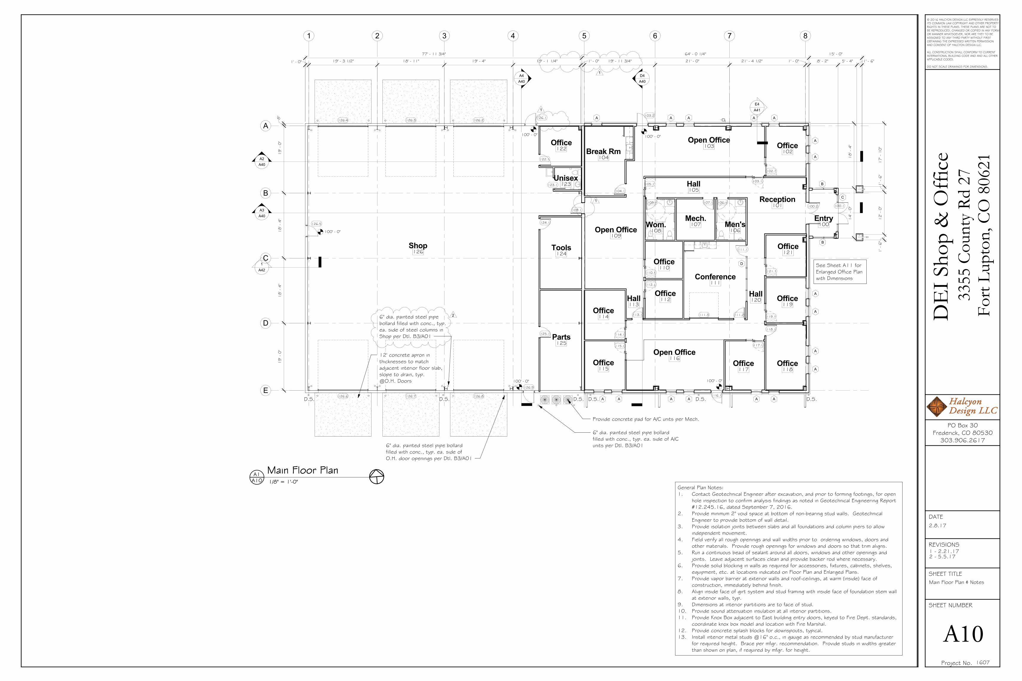
Building Elevations
A30
DE
I Sho
p &
Offi
ce33
55 C
ount
y Rd
27
Fort
Lupt
on, C
O 8
0621
2.8.17
1607
1/8" = 1'-0"A30A1 East Elevation
1/8" = 1'-0"A30A3 South Elevation
1/8" = 1'-0"A30C1 West Elevation
1/8" = 1'-0"A30A4 North Elevation
Metal Building Notes:1. Metal building products are based on products manufactured
by Varco Pruden Buildings.2. Building insulation package shall be provided by metal building
supplier, and shall meet the 2009 Edition of the International Energy Conservation Code. See also ComCheck Envelope Report.
3. Exterior metal roofing shall consist of 24 ga. SSR-Standing Seam Roof panels in "Cool Arctic White" prefinished color.
4. Exterior metal wall panels above stone and cmu wainscot as shown, shall consist of 24 ga. Vee Rib panels in "Cool Zinc Grey" prefinished color. Install with self-drilling color-matched fasteners. Provide termination flashing at transition to other materials, to make joints weather-tight.
5. Provide bid alternate for interior application of 28 ga. LPR-36 liner panels in standard pre-finished color, in shop area above concrete wainscot only. Provide panels in standard prefinished white color.
6. Gutters and downspouts shall be in "Cool Zinc Grey" finish.7. Provide 1'-6" high accent band as shown in "Cool Bright Red."
Exterior Finish Notes:1. Exterior synthetic stone wainscot shall be Quarry style in
"New Castle" color, as manufactured by Signature Stone in Greeley, CO. Synthetic stone shall be installed over drain wrap air/weather barrier, sealed per manufacturer's instructions. Provide breathable, non-film forming masonry sealer, Craftshield or similar.
2. Shop wainscot to consist of 4'-0" high split-faced cmu, color as selected by Owner.
General Notes:1. Install galvanized metal flashing around all window and door
openings, and below window sill caps for positive drainage away from wall systems. Lap and seal joints per mfgr's installation instructions.
2. Provide gutters and downspouts as shown, with splashblocks and leaders min. 5' away from foundation at landscaped areas.
3. Provide joint sealants at movement joints and at junction of all dissimilar materials. Caulk around perimeter of all doors and windows. Sealant shall be color of adjacent materials. Where colors of two materials differ, Owner or Architect shall select color based on cured sealant samples provided.
4. Provide solid backing @ exterior soffits & walls as required for light fixtures, equipment, etc.
5. See Roof Plan for roofing and venting requirements.6. Install exhaust grilles for equipment as indicated on
Mechanical Drawings.
Finish Key
Prefinished metal siding
Composite stucco
Siding accent band
Synthetic stone
Standing seam roofing
M1
S1
M2
S2
R1
1

FEEDER SCHEDULE
SWITCHES
LEGENDOUTLETS
DESIGNATIONS
SOUND and SIGNALCIRCUITRY and RACEWAYS
CONTROL
DEVICE MOUNTING HEIGHT DETAIL
© 2015 HALCYON DESIGN LLC EXPRESSLY RESERVESITS COMMON LAW COPYRIGHT AND OTHER PROPERTYRIGHTS IN THESE PLANS. THESE PLANS ARE NOT TOBE REPRODUCED, CHANGED OR COPIED IN ANY FORMOR MANNER WHATSOEVER, NOR ARE THEY TO BEASSIGNED TO ANY THIRD PARTY WITHOUT FIRSTOBTAINING THE EXPRESSED WRITTEN PERMISSIONAND CONSENT OF HALCYON DESIGN LLC.
ALL CONSTRUCTION SHALL CONFORM TO CURRENTINTERNATIONAL RESIDENTIAL CODE AND ALL OTHERAPPLICABLE CODES
DO NOT SCALE DRAWINGS FOR DIMENSIONS
SHEET NUMBER
SHEET TITLE
REVISIONS
DATE
02/08/17
PO Box 30Frederick, CO 80530
303.906.2617
MECHANICAL ELECTRICAL PLUMBING
37127 Cullison Ridge RoadSeverance, CO 80550
Ph: 970.686.1004Email: [email protected]
Dav
e'sE
arth
wor
ksSh
op&
Off
ice
3355
Coun
tyRd
27Fo
rtLu
pton
,CO
8062
1
03/27/17
LEGEND, NOTES, INDEXSCHEDULES & ONE-LINE
DIAGRAM

216'
48'
192'
270'
48'
200'
36'
© 2015 HALCYON DESIGN LLC EXPRESSLY RESERVESITS COMMON LAW COPYRIGHT AND OTHER PROPERTYRIGHTS IN THESE PLANS. THESE PLANS ARE NOT TOBE REPRODUCED, CHANGED OR COPIED IN ANY FORMOR MANNER WHATSOEVER, NOR ARE THEY TO BEASSIGNED TO ANY THIRD PARTY WITHOUT FIRSTOBTAINING THE EXPRESSED WRITTEN PERMISSIONAND CONSENT OF HALCYON DESIGN LLC.
ALL CONSTRUCTION SHALL CONFORM TO CURRENTINTERNATIONAL RESIDENTIAL CODE AND ALL OTHERAPPLICABLE CODES
DO NOT SCALE DRAWINGS FOR DIMENSIONS
SHEET NUMBER
SHEET TITLE
REVISIONS
DATE
02/08/17
PO Box 30Frederick, CO 80530
303.906.2617
MECHANICAL ELECTRICAL PLUMBING
37127 Cullison Ridge RoadSeverance, CO 80550
Ph: 970.686.1004Email: [email protected]
Dav
e'sE
arth
wor
ksSh
op&
Off
ice
3355
Coun
tyRd
27Fo
rtLu
pton
,CO
8062
1
GENERAL SITE NOTES:
SITE ELECTRICAL PLAN