Analytical Solution of Two-Layer Beam Taking into Account Nonlinear Interlayer Slip
43
Jamova 2 1000 Ljubljana, Slovenija http://www3.fgg.uni-lj.si/ DRUGG – Digitalni repozitorij UL FGG http://drugg.fgg.uni-lj.si/ Ta članek je avtorjeva zadnja recenzirana različica, kot je bila sprejeta po opravljeni recenziji. Prosimo, da se pri navajanju sklicujete na bibliografske podatke, kot je navedeno: University of Ljubljana Faculty of Civil and Geodetic Engineering Jamova 2 SI – 1000 Ljubljana, Slovenia http://www3.fgg.uni-lj.si/en/ DRUGG – The Digital Repository http://drugg.fgg.uni-lj.si/ This version of the article is author's manuscript as accepted for publishing after the review process. When citing, please refer to the publisher's bibliographic information as follows: Schnabl, S., Saje, M., Turk, G. in Planinc, I. 2007. Analytical solution of two-layer beam taking into account interlayer slip and shear deformation. Journal of Structural Engineering – ASCE 133, 6: 886–894. DOI: 10.1061/(ASCE)0733-9445(2007)133:6(886). Univerza v Ljubljani Fakulteta za gradbeništvo in geodezijo
Transcript of Analytical Solution of Two-Layer Beam Taking into Account Nonlinear Interlayer Slip

Jamova 2 1000 Ljubljana, Slovenija http://www3.fgg.uni-lj.si/
DRUGG – Digitalni repozitorij UL FGG http://drugg.fgg.uni-lj.si/
Ta članek je avtorjeva zadnja recenzirana različica, kot je bila sprejeta po opravljeni recenziji. Prosimo, da se pri navajanju sklicujete na bibliografske podatke, kot je navedeno:
University of Ljubljana Faculty of Civil and Geodetic Engineering
Jamova 2 SI – 1000 Ljubljana, Slovenia http://www3.fgg.uni-lj.si/en/
DRUGG – The Digital Repository http://drugg.fgg.uni-lj.si/
This version of the article is author's manuscript as accepted for publishing after the review process. When citing, please refer to the publisher's bibliographic information as follows:
Schnabl, S., Saje, M., Turk, G. in Planinc, I. 2007. Analytical solution of two-layer beam taking into account interlayer slip and shear deformation. Journal of Structural Engineering – ASCE 133, 6: 886–894. DOI: 10.1061/(ASCE)0733-9445(2007)133:6(886).
Univerza v Ljubljani
Fakulteta za gradbeništvo in geodezijo

Analytical solution of two-layer beam taking into account
interlayer slip and shear deformation
Simon Schnabl1, Miran Saje2, Goran Turk3 and Igor Planinc4
Abstract
A mathematical model is proposed and its analytical solution derived for the
analysis of the geometrically and materially linear two-layer beams with different
material and geometric characteristics of an individual layer. The model takes
into account the effect of the transverse shear deformation on displacements in
each layer. The analytical study is carried out to evaluate the influence of the
transverse shear deformation on the static and kinematic quantities. We study a
simply supported two-layer planar beam subjected to the uniformly distributed
load. Parametric studies have been performed to investigate the influence of shear
by varying material and geometric parameters, such as interlayer slip modulus
(K), flexural-to-shear moduli ratios (E/G) and span-to-depth ratios (L/h). The
1graduate student, University of Ljubljana, Faculty of Civil and Geodetic Engineering,
Jamova 2, 1000 Ljubljana, Slovenia, email: [email protected], tel. +386 1 4768 615, fax.
+386 1 4768 629
2Professor, University of Ljubljana, Faculty of Civil and Geodetic Engineering, Jamova 2,
1000 Ljubljana, Slovenia, email: [email protected], tel. +386 1 4768 613
3Associate Professor, University of Ljubljana, Faculty of Civil and Geodetic Engineering,
Jamova 2, 1000 Ljubljana, Slovenia, email: [email protected], tel. +386 1 4768 614
4Associate Professor, University of Ljubljana, Faculty of Civil and Geodetic Engineering,
Jamova 2, 1000 Ljubljana, Slovenia, email: [email protected], tel. +386 1 4768 616
1

comparison of the results for vertical deflections shows that shear deformations
are more important for high slip modulus, for “short” beams with small L/h
ratios, and beams with high E/G ratios. In these cases the effect of the shear
deformations becomes significant and has to be addressed in design. It also
becomes apparent that models, which consider the partial interaction between
the layers, should be employed if beams have very flexible connections
Keywords: Timoshenko beam model, multi-layered planar beam, composite
structures, shear deformation, interlayer slip, exact solution, elasticity.
1 Introduction
Due to their economy of construction and high bearing capacity, layered sys-
tems are widely used to optimize the performance of components in structural
engineering. Classic cases are steel-concrete composite beams in buildings and
bridges, wood-concrete floor systems, coupled shear walls, concrete beams ex-
ternally reinforced with laminates, sandwich beams, and many more. The be-
haviour of these structures largely depends on the type of the connection between
the layers. Mechanical shear connectors are usually employed to provide a de-
sired composite action. With the use of the rigid shear connectors, a full shear
connection and, consequently, a full composite action between the individual
components can be achieved. The result is that conventional principles of the
solid beam analysis can be employed. Unfortunately, the rigid shear connectors
can hardly be realized in practice. Therefore, most of shear connections result
2

in only a partial composite action. As a result, an interlayer slip often develops;
if it has a sufficient magnitude, it significantly effects the deformation and the
stress distribution of the composite system.
The first appreciation of a composite construction probably originated from
observations of highway bridges in service. After the experimental studies had
indicated the absence of full composite interaction between the layers in com-
posite beams, new theories were presented accounting for the slip between the
layers. These early theories of incomplete or partial interaction between the
layers of a composite beam were developed independently during the 1940s in
Switzerland, Sweden and the United States of America [Leon and Viest 1998].
These theories were based on the assumptions of linear elastic material mod-
els and the Euler-Bernoulli hypothesis of plane sections. Perhaps the first but
certainly the most quoted partial action theory was developed by Newmark et
al. [Newmark et al. 1951]. The subsequent theories differ in one or more as-
pects regarding the additional assumptions and resulted in similar second-order
differential equations. Up to now, a number of elastic theories with fewer sim-
plifying assumptions and of greater sophistication have been developed. Sev-
eral exact analytical solutions of simply supported, layered planar beams for
different combinations of simple loading cases and simple boundary conditions
have been presented in professional literature, e.g. [Girhammar and Gopu 1993,
Goodman and Popov 1968, Goodman and Popov 1969, Jasim 1997, Jasim and Ali 1997,
Ranzi et al. 2003]. With the development of computational tools and computers
3

over the last decades, these elastic theories have been refined to incorporate nu-
merous aspects of non-linear geometric and material behaviour, as well as time
dependent effects, fatigue and load reversals, e.g. [Ayoub 2001, Cas et al. 2004,
Cas et al. 2004 b, Cas 2004, Fabbrocino et al. 2002, Faella et al. 2002, Gatessco 1999,
Smith and Teng 2001].
One of the basic assumptions of all the above mentioned exact analytical mod-
els with partial interaction theory of composite beams was the Euler-Bernoulli
hypothesis of plane sections of each individual layer. It is well known that the
classical Euler-Bernoulli theory of beam bending, also known as the elementary
theory of bending, disregards the effects of the shear deformation. The theory
is based on the assumption that the cross-section remains perpendicular to the
deformed centroidal axis of the beam during bending. This assumption implies
a zero shear strain and an infinite shear stiffness. In reality, no material exists
that possesses such a property. Since the Euler-Bernoulli theory neglects the
transverse shear deformation, its suitability for composite beams can be ques-
tioned. This is particularly true in circumstances where shear effects can be
significant, as in thick and short composite beams, where flexural-to-shear rigid-
ity ratio parameters are large and the span-to-depth ratio is small. Timoshenko
[Timoshenko 1921] was the pioneering investigator to include refined effects such
as the shear deformation in the beam theory. In the literature, this theory is now
widely referred to as the Timoshenko beam theory. The effect of shear deforma-
tion in Timoshenko’s theory is accounted for by an additional rotation angle of
4

transverse cross-sections. Consequently, the distribution of the transverse shear
deformation is assumed to be constant through the beam thickness. In the begin-
ning of 1970s, Reissner [Reissner 1972] has introduced a similar shear distortion
in his one-dimensional finite-strain beam model.
To improve the accuracy of the transverse stress prediction, non-classical
higher-order shear-deformable iterative models have been proposed [Gorik 2003,
Matsunaga 2002, Piskunov and Grinevitskii 2004, Soldatos and Watson 1997]. Ac-
cording to these propositions, a zero-iteration model corresponds to the classi-
cal Euler-Bernoulli theory, while the above mentioned non-classical Timoshenko
theory corresponds to the first-iteration model. Higher-order iteration models
introduce further deformation modes such as cross-sectional bulging and warp-
ing, which are important in the modelling of thin-walled composites structures,
employed in the aerospace industry. It is not the goal of the present paper to
model the higher-order deformations. Only the first-iteration model will be con-
sidered and the Reissner one-dimensional finite-strain beam model used in the
present analytical model. To the best of the authors’ knowledge, there seems
to exist no report on the exact analytical solution of the Timoshenko composite
beams with the partial interaction between the layers. In the present paper,
we aim to fill this gap, and present an exact analytical model of the composite
beam, which takes into account the effect of the shear deformation. Then we
make the parametric studies on the influence of shear deformation effects on the
mechanical behaviour of composite beams with the partial interaction between
5

the layers. This way we show, when the effect of the shear deformation in the
individual layer can be neglected.
2 Analytical model
2.1 Assumptions
Our formulation of the planar Timoshenko two-layer composite beam model
uses the following assumptions: (1) material is linear elastic; (2) displacements,
strains and rotations are small; (3) shear deformations are taken into account
(the ‘Timoshenko beam’); (4) strains vary linearly over each layer (the ‘Bernoulli
hypothesis’); (5) the layers are continuously connected and slip modulus of the
connection is constant; (6) friction between the layers is not considered; (7)
the shapes of the cross-sections are symmetrical with respect to the plane of
deformation and remain unchanged in the form and size during deformation.
Our further assumption (8) is that an interlayer tangential slip can occur at the
interface between the layers but no delamination or the transverse separation
between them is possible.
2.2 Governing system of equations
We consider an initially straight, planar, two-layer composite beam element of
undeformed length L. Layers are marked by letters a and b (see Fig. 1). The
beam element is placed in the (x, z)-plane of a spatial Cartesian coordinate sys-
6

tem with coordinates (x, y, z) and unit base vectors Ex,Ey,Ez. The undeformed
reference axis of the layered beam element is common to both layers and lies
in their contact plane. The layered beam element is subjected to the action of
the conservative distributed load p = pxEx + pzEz and the distributed moment
m = myEy along the span, and to external point forces and moments Sai and Sb
i
(i = 1, 2, . . . , 6) at its ends, respectively; see e.g. [Cas et al. 2004].
The deformed configurations of both layers are defined by vector-valued func-
tions
Ra(x, z) =(x + ua(x) + z ϕa(x)
)Ex +
(z + wa(x)
)Ez,
Rb(x∗, z) =(x∗ + ub(x∗) + z ϕb(x∗)
)Ex +
(z + wb(x∗)
)Ez,
(1)
where x∗ represents a material, undeformed coordinate of that point of layer
b which, in the deformed state, gets in contact with the point of layer a with
coordinate x (see Fig. 1. In Eqs. (1) and in all further expressions, the notations
(•)a and (•)b refer to layers a and b. Functions ua, wa, ϕa denote the components
of the displacement vector and the rotation angle of layer a at the reference axis
with respect to the base vectors Ex, Ez and Ey, respectively. Variables ub, wb, ϕb
are related to layer b.
The system of governing equations of the two-layer composite beam consists
of kinematic, equilibrium and constitutive equations with accompanying bound-
ary conditions for each of the two layers, and the constraining equations that
assemble each layer into a two-layer composite beam. Since deformations, dis-
placements and rotations are assumed to be small quantities, the generalized
equilibrium equations can be simplified using the following two assumptions (see,
7

e.g. [Cas et al. 2004 b]: (i) dx ≈ dx∗; (ii) vertical deflections of the reference axis
of individual layers are equal wa(x) = wb(x∗) = w(x) and Ia ≈ Ib = [0, L]. Thus,
(•)b(x∗) = (•)b(x) holds true for any quantity of layer b, e.g. ub(x∗) = ub(x).
Kinematic, equilibrium and constraining equations can now be considerably sim-
plified. After considering the assumptions mentioned above, we can decompose
the basic equations of the two-layer beam with an interlayer slip into two separate
systems of differential and algebraic equations:
ua ′ − εa = 0, ub ′ − εb = 0,
wa ′ + ϕa − γa = 0, wb ′ + ϕb − γb = 0,
ϕa ′ − κa = 0, ϕb ′ − κb = 0,
(2)
wa − wb = 0, (3)
N a ′ − pt = 0, N b ′ + pt + px = 0,
Qa ′ + pn = 0, Qb ′ − pn + pz = 0,
Ma ′ −Qa = 0, Mb ′ −Qb + my = 0,
(4)
N a −N aC = 0, N b −N b
C = 0,
Qa −QaC = 0, Qb −Qb
C = 0,
Ma −MaC = 0, Mb −Mb
C = 0,
(5)
∆ = ua − ub, (6)
pt = F(∆) = K∆, (7)
and
x + ua = x∗ + ub → x∗ = x + ∆ , (8)
N = N a + N b ,
8

Q = Qa + Qb , (9)
M = Ma + Mb . (10)
In Eqs. (2–7), εa and εb are extensional strains of the reference axes of layers a and
b, κa and κb are pseudocurvatures, while γa and γb are transverse shear strains of
the corresponding cross-sections of layers a and b, respectively. N a,N b,Qa,Qb
and Ma,Mb represent equilibrium axial forces, equilibrium shear forces and
equilibrium bending moments of both layers. pt and pn denote the tangential
and the normal interlayer contact tractions in the contact plane between the
layers. N aC,N b
C, QaC,Qb
C, and MaC,Mb
C are constitutive axial forces, constitutive
shear forces and constitutive bending moments of layers a and b, respectively. In
the case of linear elastic material, the constitutive forces are assumed to be given
by the linear relations with respect to εa, εb, κa, κb, γa and γb and, therefore,
take the following notation:
N aC = EaAaεa + EaSaκa = Ca
11εa + Ca
12κa,
QaC = kyG
aAaγa = Ca33γ
a,
MaC = EaSaεa + EaJaκa = Ca
21εa + Ca
22κa,
N bC = EbAbεb + EbSbκb = Cb
11εb + Cb
12κb,
QbC = kyG
bAbγb = Cb33γ
b,
MbC = EbSbεb + EbJ bκb = Cb
21εb + Cb
22κb,
(11)
where Ea,Eb are elastic and Ga, Gb are shear moduli of layers a and b, Aa, Ab
denote the areas of the cross-sections of layers a and b, Sa, Sb are the static
moments and Ja, J b are the moments of inertia of layers a and b with respect
9

to the interlayer contact line. ky is shear coefficient of the cross-section of the
layer. In the case of a rectangular cross-section and isotropic material, the shear
coefficient is 5/6 [Cowper 1966].
The system of equations (2–7) consists of 21 equations for 21 unknown func-
tions ua, ub, wa, wb, ϕa, ϕb, εa, εb, κa, κb, γa, γb, N a, N b, Qa, Qb, Ma, Mb,
∆, pt, pn, whereas Eqs. (8–10) constitute a system of three equations for three
unknown functions x∗, Q, M. In Eqs. (7), K denotes the slip modulus at the
interlayer surface.
3 Solution algorithm
If the slip ∆ and normal traction pn between the layers is a known function of x,
the solution of the system of Eqs. (2–7) can easily be obtained with the following
sequence of steps.
In the first step, we differentiate Eqs. (6) and (3) twice with respect to x and
insert Eqs. (2). The following differential equations for the interlayer slip and
the pseudocurvatures are derived
∆ ′′ = εa ′ − εb ′, (12)
κb = κa + γb ′ − γa ′. (13)
The derivatives εa ′, εb ′, γa ′ and γb ′ are obtained from Eqs. (5), if differentiated
with respect to x. Solving the differentiated Eqs. (5) for εa ′, εb ′, γa ′, γb ′, κa ′
10

and κb ′ gives
⎧⎪⎪⎪⎪⎪⎪⎪⎪⎪⎪⎪⎪⎪⎪⎨⎪⎪⎪⎪⎪⎪⎪⎪⎪⎪⎪⎪⎪⎪⎩
εa ′
γa ′
κa ′
εb ′
γb ′
κb ′
⎫⎪⎪⎪⎪⎪⎪⎪⎪⎪⎪⎪⎪⎪⎪⎬⎪⎪⎪⎪⎪⎪⎪⎪⎪⎪⎪⎪⎪⎪⎭
= C−1
⎧⎪⎪⎪⎪⎪⎪⎪⎪⎪⎪⎪⎪⎪⎪⎨⎪⎪⎪⎪⎪⎪⎪⎪⎪⎪⎪⎪⎪⎪⎩
N a ′
Qa ′
Ma ′
N b ′
Qb ′
Mb ′
⎫⎪⎪⎪⎪⎪⎪⎪⎪⎪⎪⎪⎪⎪⎪⎬⎪⎪⎪⎪⎪⎪⎪⎪⎪⎪⎪⎪⎪⎪⎭
. (14)
C is the matrix of constitutive constants (see Eqs. (11)), and C−1 is its inverse:
C−1=
⎡⎢⎢⎢⎢⎢⎢⎢⎢⎢⎢⎢⎢⎢⎢⎣
Ca11 0 Ca
12 0 0 0
0 Ca33 0 0 0 0
Ca21 0 Ca
22 0 0 0
0 0 0 Cb11 0 Cb
12
0 0 0 0 Cb33 0
0 0 0 Cb21 0 Cb
22
⎤⎥⎥⎥⎥⎥⎥⎥⎥⎥⎥⎥⎥⎥⎥⎦
−1
=
⎡⎢⎢⎢⎢⎢⎢⎢⎢⎢⎢⎢⎢⎢⎢⎣
Da11 0 Da
12 0 0 0
0 Da33 0 0 0 0
Da21 0 Da
22 0 0 0
0 0 0 Db11 0 Db
12
0 0 0 0 Db33 0
0 0 0 Db21 0 Db
22
⎤⎥⎥⎥⎥⎥⎥⎥⎥⎥⎥⎥⎥⎥⎥⎦(15)
Furthermore, we differentiate Eq. (13) twice with respect to x. By insertion of
Eqs. (4) into Eq. (14), the second and third derivatives of strains are obtained by
differentiation of Eq. (14) twice and three times with respect to x. Introducing
εa ′, εb ′, κa ′′, κb ′′, γa ′′′ and γb ′′′ in Eq. (12) and differentiated Eq. (13), results in
a coupled system of two higher-order linear differential equations with constant
coefficients for the slip and the normal interlayer traction between layers a and b
∆ ′′′ + K1 ∆ ′ + K2 pn = Db12 pz,
K5 p ′′n + K4 pn + K3 ∆ ′ = −Db
22 pz,
(16)
11

with K1, K2, K3, K4, K5 being constants
K1 = −K(Da11 + Db
11), K2 = Da12 + Db
12, K3 = K(Da21 + Db
21),
K4 = −(Da22 + Db
22), K5 = Da33 + Db
33.
(17)
Boundary conditions associated with Eqs. (16) are the values of the interlayer
slip and its first two derivatives, and the values of the normal interlayer traction
and its first derivative at the edge x = 0 of the beam element. An exact solution
of Eqs. (16) was easily obtained by Mathematica [Wolfram 2003]. Due to its
length and complexity the closed form expressions are not shown throughout the
paper. When the slip and the normal interlayer traction have been obtained,
the remaining equations of the system (2–7) can simply be solved. We first
determine the boundary rotations and displacements from the system of linear
equations
KT u = g (18)
for the composite structure. In Eq. (18), KT denotes the tangent stiffness matrix,
u is the vector of end-point displacements , and g is the load vector. Once u
is known, the values of the end forces can easily be computed. By integrating
the Eqs. (2) and (4) and considering the Eqs. (3), (6) and (7) the solution for
unknown functions ua, ub, wa, wb, ϕa, ϕb, εa, εb, κa, κb, γa, γb, N a, N b, Qa, Qb,
Ma, Mb, ∆, pt, pn can easily be obtained. Finally, the unknown functions x∗,
Q, M are obtained from Eqs. (8–10).
12

4 Parametric studies
This section presents parametric studies performed on a simply supported two-
layer planar beam subjected to uniformly distributed load (see Fig. 2) with the
aim to investigate the influence of the shear deformation in an individual layer
and a variety of other material and geometric parameters, such as flexural-to-
shear and span-to-depth ratios, interlayer slip modulus, etc., on the mechanical
behaviour of the Timoshenko composite beams.
The main interest was focused on the assessment of the contribution effect of
the transverse shear deformation to the deformation and stresses in composite
beams with partial interaction between the layers. To this end, the vertical
deflections were calculated for different values of parameters (K,E/G,L/h) and
compared to those obtained by the analytical model of Euler-Bernoulli composite
beams with partial interaction between the individual components. Results are
given in Figs. 3, 4 and Table 1.
In Fig. 3 the vertical deflections (wT ) of the Timoshenko composite beam with
the partial interlayer interaction are compared to the vertical deflections (wB)
obtained by the Euler-Bernoulli composite beam model with the same partial
interlayer interaction (here also called the classical composite beam model), for
different L/h ratios and various interlayer slip moduli K. It can be observed in
Fig. 3 that decreasing the L/h ratios and increasing interlayer slip modulus K,
increases the influence of the transverse shear deformation on vertical deflections.
This influence is considerable in the case of timber composite beams (E/G = 16)
13

even for relatively slender beams (L/h = 10), as can be seen from Fig. 4 and
Table 1. The effect is even more pronounced for timber composite beams with
L/h = 5, where the shear deformations increase the vertical deflections for the
values in the range from 19.2 % to 59.5 %.
The effect of shear deformation on the vertical deflections at the mid-span of
a composite beam has been investigated for various E/G and L/h ratios and
different interlayer slip moduli K. Here we present (see Table 1) only the results
for beams with E/G = 2.68 (the ratio, typical for isotropic materials such as
steel, aluminium and copper) and beams with E/G = 8.67 (transversely isotropic
glass-fiber-reinforced unidirectional composite beams) and for anisotropic wood
beams with E/G = 16÷ 20. The results for beam with E/G = 100, which is not
a realistic value for material, have been added in Fig. 4 as well.
A comparative analysis of the analytical results for the vertical deflections at
the mid-span of a simply supported composite beam with the partial interlayer
interaction shows that the influence of shear effects is significant for composite
beams where E/G ≥ 16, particularly in the case of rather stiff connections with
very high interlayer slip moduli K, where the influence of shear effects on the
increase of deflections can be as high as 15.4 % for L/h = 10, and more than
250 % for short beams with L/h = 3.
The contribution of the shear effects to the vertical deflections ranges, in the
case of steel, aluminium and copper composite beams with E/G = 2.86, from
0.3 % to 8.3 % for 5 ≤ L/h ≤ 15. Therefore, for such composite beams, the shear
14
effects are insignificant, except for “short” beams with L/h ≤ 3 and high K’s.
In the case of glass-fiber-reinforced composite beams with E/G = 8.67, the
influence for beams with L/h ≥ 10 is still beyond 8.4 % and thus less significant,
while the influence on beams with L/h ≤ 5 becomes important (it ranges from
10.4 % to 32.9 %).
It is illustrative to study the influence of the shear deformation in an individual
layer on the static and kinematic quantities rather than w, such as ∆, pn, εa, N a
etc.
These quantities have been calculated for timber composite beams with E/G
= 16 and for various values of parameters L/h and K. The results are pre-
sented in Fig. 5 and in Table 2, where the notations (•)T and (•)B mark that
the quantities have been calculated by different beam models. Thus, (•)B rep-
resents quantities calculated by the Euler-Bernoulli composite beam model with
the partial interlayer interaction, and (•)T represents quantities obtained by the
Timoshenko composite beam model.
The examination of analytical results in Table 2 and in Fig. 5 reveals, that the
shear deformation has an important influence not only on the vertical deflections,
but also on other mechanical quantities of composite beams with the partial
interlayer interaction.
An interesting detail at this point is, that the influence of the shear deforma-
tion has different effects on different quantities. Some quantities, like w, ϕb, κb,
N a, increase due to the shear deformation, while the others, like pn, εa, ϕa, de-
15

crease when compared to the quantities calculated by the classical beam model.
E.g., an increasing influence of shear effects on ϕb(0) for interlayer slip modulus
K = 0.1 kN/cm2 and L/h = 3 is found to be 25.0 %, while for L/h = 15 it is only
1.2 %. On the other hand, a decreasing influence of shear effects on εa(L/2) is
found (−10.3 %) for K = 100 kN/cm2 and L/h = 3, and −2.2 % for L/h = 10 it
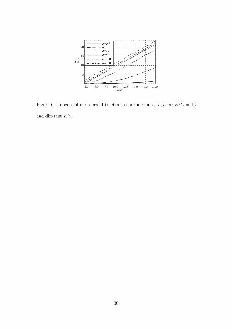
is . It is clear from the results depicted in Fig. 6 that, in addition to the increase
in the L/h, the increase of K leads to a significant enlargement of tangential
interlayer tractions with respect to normal interlayer tractions in the contact
plane between the layers. For example, in the case of relatively slender two-layer
composite beams (L/h ≥ 10) with K ≥ 10 kN/cm2, the tangential interlayer
tractions may be as high as about 20-times of the normal interlayer tractions.
Although it has been shown that the influence of shear effects on the interlayer
tractions is negligible, it is apparent from the graphs in Fig. 7, that the shear
deformation has an important impact on the ratio of the interlayer tractions,
especially for the two-layer beams with L/h ≤ 10, where the influence of shear
effects is more than 29.0 %.
A parametric study has also been conducted to assess the effects of different
parameters such as ha/hb and K on the vertical deflections and shear forces. For
this purpose, the vertical deflections at the mid-span and the shear forces at the
edge x = 0 of the two-layer composite beam have been calculated for various
ha/hb and K. In the case of relatively slender timber beams with L/h = 10
and E/G = 16, the parametric study reveals, that minimum shear effects occur
16

when layers have approximately equal depths. In Fig. 8 it is shown, that the
corresponding discrepancies are higher for smaller values of K and can be, in the
case of a rather flexible connection (K ≤ 1 kN/cm2), as much as about 4-times
smaller than in the case of stiff interaction between the layers.
Figs. 9 and 10 show that the contribution to the shear forces due to shear
effects can be considerable, especially when the depth of one layer is very small
compared to the depth of the other one and for small values of K.
It is observed, that for a very thin bottom layer a (ha/hb ≤ 0.1) and the
non-stiff interlayer contact (K = 0.1 kN/cm2), the shear force Qa can be due to
shear effects about 2.8-times bigger than the one obtained by the Euler-Bernoulli
model. By contrast, for high values of K, the shear force Qa may be about twice
as small as in the case of the Euler-Bernoulli beam. It is also apparent from
Fig. 10, that the value of the shear force Qb in Timoshenko’s theory is in the
non-stiff connection about 2.5-times bigger if the top layer is very thin compared
to the bottom one. Thus, it has been shown, that the shear deformations have
considerable influence on static shear forces of individual layers of the two-layer
composite beam and hence should not be neglected in the analysis of such struc-
tures.
In addition, the vertical deflections have been calculated for timber compos-
ite beams with E/G = 16 and L/h = 10 by different beam models: (i) using
empirical formulas given in the European code for timber structures Eurocode 5
[Eurocode 5 1993], (ii) with the classical Euler-Bernoulli beam model with and
17

without considering the interlayer slip, (iii) with the Timoshenko beam model
for beams without the interlayer slip, and finally (iv) with the present analyt-
ical Timoshenko composite beam model with the consideration of the partial
interaction between the layers.
In Table 3 the results of different beam models and for a wide range of slip
modulus from 0.001 to 1000 kN/cm2 are presented and compared. Observe
that the influence of the interlayer slip modulus on the vertical deflections is
negligible for the range of the slip modulus from 0.001 to 0.1 kN/cm2, and that
the influence of solely slip modulus on the deflections due to the interlayer slip
(wB/w∗B) decreases with the increase of the slip modulus. On the other hand, the
combined influence of the shear deformation and slip (wT /wB) on the deflections
increases with the increase of the slip modulus between the layers. Thus, for
high values of K, deflections obtained by both Euler-Bernoulli and Timoshenko
models with the consideration of the partial interaction differ from deflections
obtained by the complete-interaction models by less than 1.2 %. Note that the
deflections, obtained by the formulae given in Eurocode [Eurocode 5 1993] for
composite beams with interlayer slip between the layers, agree with the present
results for Euler-Bernoulli beam for 0.001 < K < 10 kN/m2 and 100 < K < 1000
kN/m2, but not for 10 < K < 100 kN/m2, where the maximum difference is
22.5 %. The comparison with the Timoshenko beam is more promising.
Fig. 11 shows comparisons of vertical deflections obtained by different beam
models. It can be seen from the results in Table 3 and Fig. 11 that the models
18

with the partial interaction are essential for the accurate prediction of vertical
deflections, especially for more flexible connections between the layers, i.e. for the
range of slip moduli from 0.001 to 1 kN/cm2, since the comparisons of wB/w∗B
and wT /w∗T show, that the deflections may be as high as about 3.5-times of
the deflections of a rigidly connected layered beam. Furthermore, based on the
comparisons between the analytical results for vertical deflections shown in Table
3 and Fig. 11, it is clear, that the proposed model needs to be employed even
for the range of the slip modulus K > 50 kN/cm2. The comparison of vertical
deflections wT /wB shows, that the effect of the shear deformation on the increase
of vertical deflections can be about 15.4 %.
Next, let us inspect the stress distributions over the depth of the two-layer
composite beam. The longitudinal normal stresses σxx have been evaluated at the
mid-span section, and the tangential stresses σxz at the edge section of the beam
shown in Fig. 2. From Fig. 12 it can be seen that the distributions and the values
of the normal and the tangential stresses in the layers are very much affected by
the stiffness of the contact. The effect is depicted for various stiffnesses and
the ‘zig-zag’ linear variation of normal stresses and the quadratic distribution of
tangential stresses is obtained. Note that for small K’s the maximum tangential
stresses considerably exceed the stresses obtained from the classical solid beam
model. It is apparent that the classical beam theory underestimates both the
normal and the tangential stresses in layered beams. In the case of the non-stiff
connection between the layers, the tangential stresses σxz may increase up to
19

25 % compared to the stresses in the ‘solid beam’.
5 Conclusions
A mathematical model is proposed and its analytical solution is found for the
analysis of the geometrically and materially linear layered beams with different
material and geometric characteristics of each layer. The proposed analytical
model takes into account the transverse shear deformation of each layer of a
multi-layer beam. The analytical study is carried out for evaluating the influ-
ence of the transverse shear deformation on the static and kinematic quantities.
Particular emphasis is given to the vertical deflections at the mid-span of a sim-
ply supported two-layer planar beam subjected to the uniformly distributed load.
For this purpose, several parametric studies have been performed to investigate
the influence of shear effects and various material and geometric parameters, such
as flexural-to-shear rigidity ratios and span-to-depth ratios, on the mechanical
behaviour of the layered Timoshenko beams.
Based on the results of this analytical study and the parametric evaluations
undertaken, the following conclusions can be drawn:
1. The present mathematical model is general and relatively easy to compre-
hend.
2. The influence of the shear deformation on vertical deflections is increasing
with decreasing L/h ratios and increasing K. In the case of a timber
20

composite beam (E/G = 16), the contribution of shear deformations to
vertical deflections can be about 15 % for ratios L/h = 10. The effect is
even more pronounced for beams with L/h = 5, where the effect of shear
deformation on vertical deflections ranges between 19 % and 60 %.
3. The influence of shear effects is significant for composite beams with E/G ≥
16, particularly in the case of very high interlayer slip moduli, where the
influence is about 15 % for L/h = 10, and about 250 % for “short” beams
with L/h = 3.
4. In the case of steel, aluminium and copper composite beams with E/G =
2.86, the extra contribution to the vertical deflections due to shear effects
ranges from 0.3 % to 8 % for 5 ≤ L/h ≤ 15. Therefore, for such composite
beams, shear effects are insignificant, except possibly for “short” beams
with L/h ≤ 3 and higher values of K.
5. In the case of glass-fiber reinforced unidirectional composite beams with
E/G = 8.67, the influence of shear effects on vertical deflections increases
with an increase in K and a decrease in L/h. Thus, the influence for beams
with L/h ≥ 10 is still beyond 8 % and hence insignificant, in contrast to
beams with L/h = 5, where the increase of the deflection ranges from 10 %
to 33 %, and particularly for very “short” and rigidly connected composite
beams, where the influence of shear effects can reach values up to 85 %.
6. In the case of relatively slender two-layer composite beams (L/h ≥ 10)
21

with K ≥ 10 kN/cm2, the tangential interlayer tractions are about 20-times
bigger than the related normal interlayer tractions. The shear deformation
has an important impact on the actual ratio of the interlayer tractions. For
the two-layer beams with L/h ≤ 10, the influence of shear effects is more
than 29 %.
7. In the case of one very thin layer and a rather flexible connection (K =
0.1 kN/cm2), the corresponding shear force in the thin layer can be consid-
erably bigger than in the classical theory. This is, QT is about 2.8-times
larger for non-stiff and about twice smaller than QB obtained by the clas-
sical Euler-Bernoulli beam model. Similarly, the shear force QT of a very
thin top layer is 2.5-times larger than that of the classical theory. Thus,
we have shown, that the shear has a considerable impact on the values of
the shear forces in the layers, and therefore should not be neglected.
8. The influence of shear deformation on vertical deflections is negligible, if
0.001 ≤ K ≤ 0.1 kN/cm2, E/G = 16 and L/h = 10.
9. The results of the deflection formulae given in Eurocode 5 [Eurocode 5 1993]
agree completely with the present results if 0.001 ≤ K ≤ 0.1 kN/cm2, while
discrepancies may occur for other values of K.
10. The comparison of the results wB/w∗B and wT /w∗
T shows that larger shear
deformations develop for large slip moduli K, for “short” beams with small
L/h ratios and for materials with high E/G ratios. In all these cases, the
22

role of shear deformations is significant and they have to be addressed in
design. It also becomes clear that the beam models should consider the
partial interaction between the layers if K takes small values.
11. The ‘zig-zag’ linear variation of the normal stresses and the piece-wise
quadratic distribution of the tangential stresses over the composite cross-
section has been obtained. For K ≤ 0.1 kN/cm2, the maximum tangential
stresses σxz may exceed the values obtained from the classical solid beam
model for about 25 %. It is apparent then, that the classical solid beam
model provides non-conservative estimates for the tangential and normal
stresses in layered beams.
Acknowledgment
The work of S. Schnabl was financially supported by the Ministry of Education,
Science and Sport of the Republic of Slovenia under contract 3311-02-831625.
The support is gratefully acknowledged.
References
Ayoub, A. (2001). “A two-field mixed variational principle for partially connected
composite beams”, Finite Elements in Analysis and Design, 37, 929–959.
Cas, B., Saje, M., Planinc, I. (2004). “Nonlinear finite element analysis of com-
posite planar frames with inter-layer slip”, Computers and Structures, 82, 1901–
1912.
23

B. Cas, S. Bratina, M. Saje, I. Planinc. (2004) “Non-linear analysis of composite
steel-concrete beams with incomplete interaction”, Steel and Composite Struc-
tures, 4(6), 489–507.
Cas, B. (2004). Non-linear analysis of composite beams with inter-layer slip, PhD
Thesis (in Slovene), University of Ljubljana, Faculty of Civil and Geodetic En-
gineering.
Cowper, G. R. (1966). “The shear coefficient in Timoshenko’s beam theory, Jour-
nal of Applied Mechanics, 33(2), 335–340.
Eurocode 5 (1993). “Design of timber structures, Part 1-1: General rules and
rules for buildings”, ENV 1995-1-1.
Fabbrocino, G., Manfredi, G., Cosenza, E. (2002). “Modelling of continuous steel-
concrete composite beams: computational aspects”, Computers and Structures,
80, 2241–2251.
Faella, C., Martinelli, E., Nigro, E. (2002). “Steel and concrete composite beams
with flexible shear connection: ‘exact’ analytical expression of the stiffness matrix
and applications”, Computers and Structures, 80, 1001–1009.
Gattesco, N. (1999). “Analytical modeling of nonlinear behavior of composite
beams with deformable connection”, Journal of Constructional Steel Research,
52, 195–218.
Girhammar, U. A., Gopu, V. K. A. (1993). “Composite beam-columns with
inter-layer slip–exact analysis”, Journal of Structural Engineering, ASCE, 199(4),
24

1265–1282.
Goodman, J. R., Popov, E. P. (1968). “Layered beam systems with inter-layer
slip”, Journal of Structural Division, ASCE, 94(11), 2535–2547.
Goodman, J. R., Popov, E. P. (1969). “Layered wood systems with inter-layer
slip”, Wood Science, 1(3), 148–158.
Gorik, A. V. (2003). “Theoretical and experimental deformation parameters of
composite beams with account of deplanation of cross sections in bending”, Me-
chanics of Composite Materials, 39(1), 57–64.
Jasim, N. A. (1997). “Computation of deflections for continuous composite beams
with partial interaction”, Proceedings of the Institution of Civil Engineers, Struc-
tures and Buildings, 122, 347–354.
Jasim, N. A., Ali, A. A. M. (1997). “Deflections of composite beams with partial
shear connection”, Structural Engineer, 75, 58–61.
Leon, R. T., Viest, I. M. (1998). “Theories of incomplete interaction in composite
beams”, Composite construction in steel and concrete III, ASCE, 858–870.
Matsunaga, H. (2002). “Interlaminar stress analysis of laminated composite
beams according to global higher-order deformation theories”, Composite Struc-
tures, 34, 105–114.
Newmark, N. M., Siest, C. P., Viest, C. P. (1951). “Test and analysis of composite
beams with incomplete interaction”, Proceedings of the Society for Experimental
25

Stress Analysis, 1, 75–92.
Piskunov, V. G., Grinevitskii, B. V. (2004). “Variant of an analytical shear model
for the stress-strain state of heterogeneous composite beams”, Mechanics of Com-
posite Materials, 40(5), 409–417.
Ranzi, G., Bradford, M. A., Uy, B. (2003). “A general method of analysis of
composite beams with partial interaction”, Steel and Composite Structures, 3(3),
169–184.
Reissner, E. (1972). “On one-dimensional finite-strain beam theory: The plane
problem”, Journal of Applied Mechanics and Physics (ZAMP), 23, 795–804.
Smith, S. T., Teng, J. G. (2001). “Interfacial stresses in plated beams”, Engi-
neering Structures, 23, 857–871.
Soldatos, K. P., Watson, P. (1997). “A general theory for accurate stress analysis
of homogeneous and laminated composite beams”, International journal of Solids
and Structures, 34(22), 2857–2885.
Timoshenko, S. P. (1921). “On the correction for shear of the differential equation
for transverse vibrations of prismatic bars”, Philosophical Magazine, Series 6,
41(245), 744–746.
Wolfram, S. (2003). Mathematica, Addison-Wesley Publishing Company.
26

Table 1: Influence of K,E/G and L/h on vertical deflections (wT /wB).
E/G=2.68 E/G=8.67 E/G=16
K [kN/cm2] I II III I II III I II III
0.001 1.090 1.032 1.008 1.287 1.104 1.026 1.524 1.192 1.048
0.01 1.090 1.032 1.008 1.287 1.104 1.026 1.524 1.192 1.048
0.1 1.090 1.032 1.008 1.288 1.105 1.027 1.524 1.192 1.049
1 1.091 1.033 1.008 1.293 1.110 1.032 1.529 1.197 1.054
10 1.092 1.034 1.010 1.341 1.152 1.056 1.581 1.244 1.087
50 1.098 1.040 1.014 1.494 1.237 1.075 1.767 1.370 1.128
100 1.105 1.046 1.017 1.603 1.274 1.080 1.931 1.445 1.139
1000 1.182 1.083 1.024 1.875 1.329 1.084 2.534 1.595 1.154
Note: I: L/h= 3 II: L/h= 5 III: L/h= 10
27

Table 2: Static and kinematic quantities as functions of K and L/h for E/G = 16.
K = 0.1 kN/cm2 K = 100 kN/cm2
(•)T /(•)B I II III I II III
w(L/2) 1.524 1.192 1.049 1.931 1.445 1.139
∆(0) 1.046 1.020 1.006 1.026 1.012 1.005
ϕa(0) 0.939 0.973 0.992 0.919 0.960 0.988
ϕb(0) 1.250 1.092 1.026 1.185 1.083 1.030
κa(L/2) 0.944 0.977 0.994 0.927 0.969 0.992
κb(L/2) 1.188 1.077 1.020 1.156 1.059 1.015
N a(L/2) 1.044 1.019 1.005 1.022 1.007 1.001
εa(L/2) 0.944 0.977 0.994 0.897 0.942 0.978
pn(L/2) 0.968 0.994 1.000 1.993 1.004 1.001
Note: I: L/h= 3 II: L/h = 5 III: L/h = 10
28

Table 3: Vertical deflections calculated by different beam models for different
K’s with L/h = 10 and E/G = 16.
K EC 5 w∗B wB w∗
T wTEC5wB
wT
wB
wB
w∗B
wT
w∗T
wT
w∗B[
kNcm2
][cm] [cm] [cm] [cm] [cm]
0.001 3.875 1.085 3.875 1.252 4.062 1.000 1.048 3.571 3.243 3.743
0.01 3.872 1.085 3.869 1.252 4.057 1.000 1.048 3.566 3.239 3.738
0.1 3.845 1.085 3.818 1.252 4.005 1.007 1.049 3.518 3.197 3.691
1 3.602 1.085 3.391 1.252 3.573 1.062 1.054 3.125 2.853 3.293
10 2.427 1.085 1.982 1.252 2.154 1.225 1.087 1.826 1.720 1.985
50 1.526 1.085 1.325 1.252 1.494 1.153 1.128 1.221 1.193 1.377
100 1.326 1.085 1.230 1.252 1.379 1.096 1.139 1.115 1.101 1.270
1000 1.111 1.085 1.098 1.252 1.267 1.012 1.154 1.012 1.012 1.168
Note: * without interlayer slip
29

List of figures
Fig. 1: Undeformed and deformed configuration of the two-layer beam.
Fig. 2: Simply supported two-layer beam.
Fig. 3: Influence of slip modulus and L/h ratios on vertical deflections for E/G = 16.
Fig. 4: Influence of E/G and L/h ratios on vertical deflections for K = 100.
Fig. 5: Static and kinematic quantities as a function of L/h for E/G = 16 and K =
100 kN/cm2.
Fig. 6: Tangential and normal tractions as a function of L/h for E/G = 16 and dif-
ferent K’s.
Fig. 7: Ratio of tangential and normal tractions as a function of L/h for E/G = 16
and different K’s.
Fig. 8: Vertical deflections as a function of ha/hb for L/h = 10 and E/G = 16 and
different K’s.
Fig. 9: Shear force Qa as a function of ha/hb for L/h = 10, E/G = 16 and different
K’s.
Fig. 10: Shear force Qb as a function of ha/hb for L/h = 10, E/G = 16 and different
K’s.
Fig. 11: Comparisons of vertical deflections calculated by different beam models, for
different K’s with L/h = 10 and E/G = 16.
Fig. 12: The distribution of normal and tangential stresses over the cross-section for
different K’s.
30

R *=a( )x,z R
b( )x ,z
deformed configuration
undeformed configuration
z
xx L=x 0=
x 0= x L=
Ez
*x
x
z
y
Ey
L
Ex
Ez
Figure 1: Undeformed and deformed configuration of the two-layer beam.
31

I
I
Section I-I:
zp
ba bb=
hb
ha
x y
zz
Figure 2: Simply supported two-layer beam.
32

2 4 6 8 10 12
1.0
1.5
2.0
2.5
3.0
3.5
4.0
L /h
wB
wT
Figure 3: Influence of slip modulus and L/h ratios on vertical deflections for
E/G = 16.
33

wB
wT
1.0
1.2
1.4
1.6
1.8
2.0
L /h2.5 5.0 7.5 10.0 12.5 15.0 17.5 20.0
Figure 4: Influence of E/G and L/h ratios on vertical deflections for K = 100.
34

( )B
( )T
L /h42 6 8 10 12
1.0
0.8
1.2
1.4
1.6
1.8
2.0
2.2
0.95
1.00
1.05
1.10
1.15
8 9 10 11 127
1.20
�
f
f
w
Figure 5: Static and kinematic quantities as a function of L/h for E/G = 16 and
K = 100 kN/cm2.
35
5
10
15
20
2.5 5.0 7.5 10.0 12.5 15.0 17.5 20.0L /h
T
T
Figure 6: Tangential and normal tractions as a function of L/h for E/G = 16
and different K’s.
36

T
T
3 4 5 6 7 8 9 10
1.30
1.32
1.34
1.36
2L /h
B
B
Figure 7: Ratio of tangential and normal tractions as a function of L/h for
E/G = 16 and different K’s.
37

1.04
1.06
1.08
1.10
1.12
1.14
1.16
/h
2.5 5.0 7.5 10.0 12.5 15.0 17.5 20.0
wB
wT
h
0
Figure 8: Vertical deflections as a function of ha/hb for L/h = 10 and E/G = 16
and different K’s.
38

0.1 0.2 0.3 0.4 0.5 0.6 0.7 0.8
0.5
1.0
1.5
2.0
2.5
3.0
/hh
�T
�B
Figure 9: Shear force Qa as a function of ha/hb for L/h = 10, E/G = 16 and
different K’s.
39

2 4 6 8 10
1.00
1.25
1.50
1.75
2.00
2.25
2.50
/hh
�T
�B
0
Figure 10: Shear force Qb as a function of ha/hb for L/h = 10, E/G = 16 and
different K’s.
40

-7.5 -5.0 -2.5 0.0 2.5 5.0 7.5 10.0
1.0
1.5
2.0
2.5
3.0
3.5
-10.0
wB
EC 5
Log K
wB
wB
wB
wT
wB
wT
�
�
EC 5
wB
wT
wB
wT�
wB
wB�
wB
Figure 11: Comparisons of vertical deflections calculated by different beam mod-
els, for different K’s with L/h = 10 and E/G = 16.
41

0 0.025 0.050 0.075 0.100 0.125 0.150 -2 -1 0 1 2�xx [kN/cm ]2
�xz [kN/cm ]2
layer ‘ ’
layer ‘ ’
Ez
Ex
Figure 12: The distribution of normal and tangential stresses over the cross-
section for different K’s.
42