Friction rolling with lateral slip in rail vehicles
19
JOURNAL OF THEORETICAL AND APPLIED MECHANICS 47, 2, pp. 275-293, Warsaw 2009 FRICTION ROLLING WITH LATERAL SLIP IN RAIL VEHICLES Robert Konowrocki Czesław Bajer Institute of Fundamental Technological Research, Plish Academy of Sciences, Warsaw, Poland e-mail: [email protected] The paper deals with the dynamic phenomena accompanying the wheel rolling over a road (rail, track), with lateral slip effects. They occur in rol- ling of a wheel and wheelset on a straight track in the case of lateral load and especially on curves. Different curvature radii and rotary oscillations of wheelsets result in skew rolling and, in turn, in lateral slip oscillation in the contact zone between the wheel and rail. It significantly increases noise and wear in real structures. Double periodicity of motion was de- tected in an underground train. Hitherto, this phenomenon has not been reported in the literature. Experimental investigation was performed on a test stand for various parameters: the angle of skew rolling, velocity and contact pressure. Results were related to a two degree-of-freedom the- oretical system. In the case of steel/polyester and polyamide/polyester friction pair, qualitatively similar results were obtained. Key words: rolling, friction, lateral slip, wheel-rail interaction 1. Introduction Rolling contact has been investigated intensively during the last two decades (Kalker, 1990; Knothe, 1983). However, full and correct simulation of the rol- ling process with all phenomena that occur in the railway transport is complex. The generation of corrugations (Bajer, 1998; Hempelmann et al., 1991; Kalker, 1994; Sato et al., 2002) and resulting vibrations, the essential problem of rolling in railway transportation, has not been completely explained yet. Burdensome vibration transmission to the environment is in focus of researches. Different hypotheses were assumed as a base of the analysis of wheel rol- ling. Some of them have minor importance and the postulated phenomena do not result in the final effect significantly, others are still being intensively
Transcript of Friction rolling with lateral slip in rail vehicles
JOURNAL OF THEORETICAL
AND APPLIED MECHANICS
47, 2, pp. 275-293, Warsaw 2009
FRICTION ROLLING WITH LATERAL SLIP IN RAILVEHICLES
Robert Konowrocki
Czesław Bajer
Institute of Fundamental Technological Research, Plish Academy of Sciences, Warsaw, Poland
e-mail: [email protected]
The paper deals with the dynamic phenomena accompanying the wheelrolling over a road (rail, track), with lateral slip effects. They occur in rol-ling of a wheel and wheelset on a straight track in the case of lateral loadand especially on curves. Different curvature radii and rotary oscillationsof wheelsets result in skew rolling and, in turn, in lateral slip oscillationin the contact zone between the wheel and rail. It significantly increasesnoise and wear in real structures. Double periodicity of motion was de-tected in an underground train. Hitherto, this phenomenon has not beenreported in the literature. Experimental investigation was performed ona test stand for various parameters: the angle of skew rolling, velocity andcontact pressure. Results were related to a two degree-of-freedom the-oretical system. In the case of steel/polyester and polyamide/polyesterfriction pair, qualitatively similar results were obtained.
Key words: rolling, friction, lateral slip, wheel-rail interaction
1. Introduction
Rolling contact has been investigated intensively during the last two decades(Kalker, 1990; Knothe, 1983). However, full and correct simulation of the rol-ling process with all phenomena that occur in the railway transport is complex.The generation of corrugations (Bajer, 1998; Hempelmann et al., 1991; Kalker,1994; Sato et al., 2002) and resulting vibrations, the essential problem of rollingin railway transportation, has not been completely explained yet. Burdensomevibration transmission to the environment is in focus of researches.Different hypotheses were assumed as a base of the analysis of wheel rol-
ling. Some of them have minor importance and the postulated phenomenado not result in the final effect significantly, others are still being intensively
276 R. Konowrocki, C. Bajer
investigated. In the literature, the following cases are pointed out as a sourceof generation of vibrations and corrugations: imperfections in rail joints andwheel geometry (Dżuła, 1995), cone form of wheels which results in differentlinear speeds of the left and right wheel and snaking of trains, periodical struc-ture of rails with sleepers and the instability of motion over periodically placedsupports (Bajer and Bogacz, 2005; Bogacz et al., 1995), contact problems be-tween wheels and rails, stick and slip zones varying with a high frequency andgenerating waves which deform elastically or plastically both contact surfa-ces (Bogacz et al., 1987; Brzozowski et al., 1990), residual stresses caused bymanufacturing and maintenance of rails and wheels (Bogacz, 1995), non-linearfriction in the stick zone (Bogacz and Ryczek, 1997), influence of material har-dening (Bajer, 1997), deformation of wheel/axle system as a result of impactsduring rolling motion, instability of wheelset motion (Meinke and Szolc, 1996;Bogacz and Dżuła, 1993), strong hits of a perfectly round wheel rolling on animperfect rail (Kowalska, 2008), wave phenomena in circumferential direction(Bajer, 1998), etc.
The important contribution to the problem was published by Bogacz andDżuła (1993), Dżuła (1989, 1995). The physical continuous model was tre-ated analytically. The wheel tire was modeled as an elastic curved Rayleigh’sbeam joined with the axle by means of the continuous elastic Winkler typefoundation. The elastic foundation constituting the wheel disk carries out theload in three directions: circumferential, radial and perpendicular to the planeof the wheel. The curved beam theory allows one to assume the real shapeof the cross-section. Frequency response functions for forced vibrations of therailway wheel prove a significant amplitude increase for the frequency 100Hzat the velocity 200 km/h. There is no doubt that the wave propagation ana-lysis is essential. In Bajer (1998) it was proved that steady rolling of the discresults in oscillations of contact forces. Surface waves on the circumferenceperiodically reflect from the contact zone. The number of oscillations that suitthe circumference decreases with the increase of the travelling speed while theamplitudes of contact forces increase in the same case.
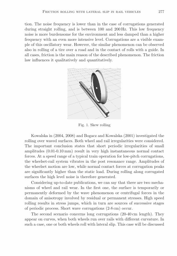
In this paper, we consider a dynamic phenomenon, which occurs in rollingof the wheel over a rail with lateral slip. Such a case is involved by wind blows(both on curved and straight tracks), lateral deformation of wheels, wheelsetsand rails, different linear velocity of wheels on curves and rotary oscillationsof wheelsets. The skew wheel plane related to the direction of rolling results inlateral slip in the rail-wheel contact zone (Fig. 1). The rail-wheel system oscil-lates and generates noise. In the same time, wear considerably increases andnegatively influences the environment and decreases the safety of transporta-
Friction rolling with lateral slip in rail vehicles 277
tion. The noise frequency is lower than in the case of corrugations generatedduring straight rolling, and is between 100 and 200Hz. This low frequencynoise is more burdensome for the environment and less damped than a higherfrequency with an even more intensive level. Corrugations are a visible exam-ple of this oscillatory wear. However, the similar phenomenon can be observedalso in rolling of a tire over a road and in the contact of rolls with a guide. Inall cases, friction is the main reason of the described phenomenon. The frictionlaw influences it qualitatively and quantitatively.
Fig. 1. Skew rolling
Kowalska in (2004, 2008) and Bogacz and Kowalska (2001) investigated therolling over waved surfaces. Both wheel and rail irregularities were considered.The important conclusion states that short periodic irregularities of smallamplitudes (0.01-0.10 mm) result in very high instantaneous normal contactforces. At a speed range of a typical train operation for low-pitch corrugations,the wheelset-rail system vibrates in the post resonance range. Amplitudes ofthe wheelset motion are low, while normal contact forces at corrugation peaksare significantly higher than the static load. During rolling along corrugatedsurfaces the high level noise is therefore generated.
Considering up-to-date publications, we can say that there are two mecha-nisms of wheel and rail wear. In the first one, the surface is temporarily orpermanently deformed by the wave phenomenon or centrifugal forces in thedomain of anisotropy involved by residual or permanent stresses. High speedrolling results in stress jumps, which in turn are sources of successive stagesof periodic process. Short wave corrugations (2-8 cm) occur.
The second scenario concerns long corrugations (20-40 cm length). Theyappear on curves, when both wheels run over rails with different curvature. Insuch a case, one or both wheels roll with lateral slip. This case will be discussed
278 R. Konowrocki, C. Bajer
in the paper. We take here into account the elasticity of the wheelset, especiallyrotary flexibility of the axle and the lateral bending of the wheel disc.
Skew rolling with lateral stick and slip results in another phenomenonimportant in practice. Vertical stresses in contact are augmented by a signifi-cant value of residual and permanent stresses in the circumferential direction.Lateral motion in the direction of the third coordinate contributes to tangen-tial stresses. Then the plasticity limit can be locally achieved. The oscillatorylateral motion can result in consolidation of a waved pattern.
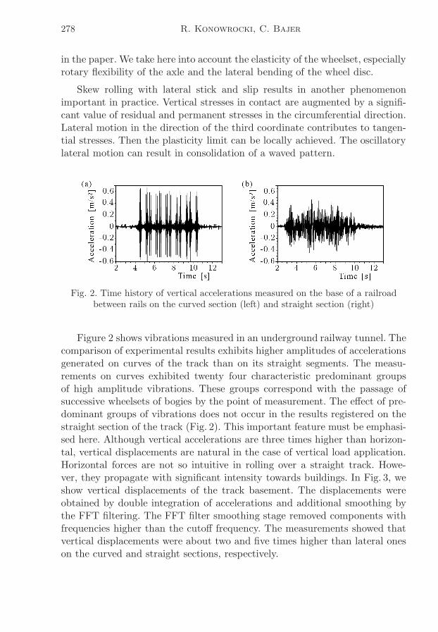
Fig. 2. Time history of vertical accelerations measured on the base of a railroadbetween rails on the curved section (left) and straight section (right)
Figure 2 shows vibrations measured in an underground railway tunnel. Thecomparison of experimental results exhibits higher amplitudes of accelerationsgenerated on curves of the track than on its straight segments. The measu-rements on curves exhibited twenty four characteristic predominant groupsof high amplitude vibrations. These groups correspond with the passage ofsuccessive wheelsets of bogies by the point of measurement. The effect of pre-dominant groups of vibrations does not occur in the results registered on thestraight section of the track (Fig. 2). This important feature must be emphasi-sed here. Although vertical accelerations are three times higher than horizon-tal, vertical displacements are natural in the case of vertical load application.Horizontal forces are not so intuitive in rolling over a straight track. Howe-ver, they propagate with significant intensity towards buildings. In Fig. 3, weshow vertical displacements of the track basement. The displacements wereobtained by double integration of accelerations and additional smoothing bythe FFT filtering. The FFT filter smoothing stage removed components withfrequencies higher than the cutoff frequency. The measurements showed thatvertical displacements were about two and five times higher than lateral oneson the curved and straight sections, respectively.
Friction rolling with lateral slip in rail vehicles 279
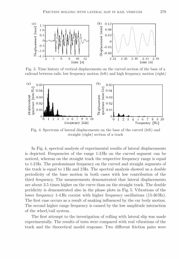
Fig. 3. Time history of vertical displacements on the curved section of the base of arailroad between rails: low frequency motion (left) and high frequency motion (right)
Fig. 4. Spectrum of lateral displacements on the base of the curved (left) andstraight (right) section of a track
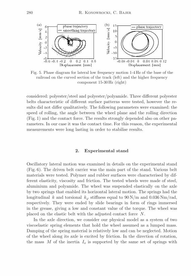
In Fig. 4, spectral analysis of experimental results of lateral displacementsis depicted. Frequencies of the range 1-3Hz on the curved segment can benoticed, whereas on the straight track the respective frequency range is equalto 1-2Hz. The predominant frequency on the curved and straight segments ofthe track is equal to 1Hz and 2Hz. The spectral analysis showed us a doubleperiodicity of the base motion in both cases with low contribution of thethird frequency. The measurements demonstrated that lateral displacementsare about 3.5 times higher on the curve than on the straight track. The doubleperidicity is demonstrated also in the phase plots in Fig. 5. Vibrations of thelower frequency 1-4 Hz coexist with higher frequency oscillations (15-30 Hz).The first case occurs as a result of snaking influenced by the car body motion.The second higher range frequency is caused by the low amplitude interactionof the wheel/rail system.
The first attempt to the investigation of rolling with lateral slip was madeexperimentally. The results of tests were compared with real vibrations of thetrack and the theoretical model response. Two different friction pairs were
280 R. Konowrocki, C. Bajer
Fig. 5. Phase diagram for lateral low frequency motion 1-4Hz of the base of therailroad on the curved section of the track (left) and the higher frequency
component 15-30Hz (right)
considered: polyester/steel and polyester/polyamide. Three different polyesterbelts characteristic of different surface patterns were tested, however the re-sults did not differ qualitatively. The following parameters were examined: thespeed of rolling, the angle between the wheel plane and the rolling direction(Fig. 1) and the contact force. The results strongly depended also on other pa-rameters. In our case it was the contact time. For this reason, the experimentalmeasurements were long lasting in order to stabilise results.
2. Experimental stand
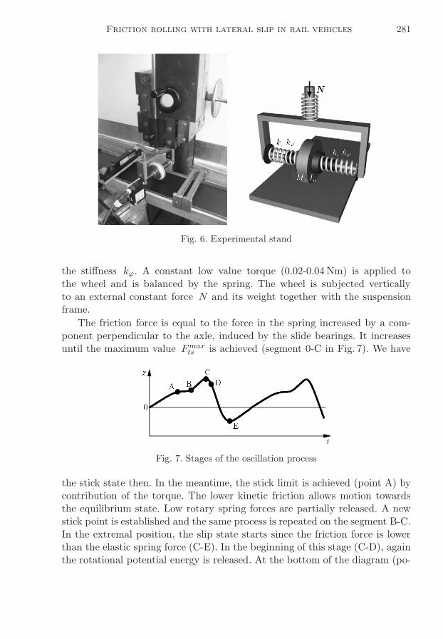
Oscillatory lateral motion was examined in details on the experimental stand(Fig. 6). The driven belt carrier was the main part of the stand. Various beltmaterials were tested. Polymer and rubber surfaces were characterised by dif-ferent elasticity, viscosity and friction. The tested wheels were made of steel,aluminium and polyamide. The wheel was suspended elastically on the axleby two springs that enabled its horizontal lateral motion. The springs had thelongitudinal k and torsional kϕ stiffness equal to 90N/m and 0.036 Nm/rad,respectively. They were ended by slide bearings in form of rings immersedin the grease, giving a low and constant value of the torque. The wheel wasplaced on the elastic belt with the adjusted contact force N .
In the axle direction, we consider our physical model as a system of twoviscoelastic spring elements that hold the wheel assumed as a lumped mass.Damping of the spring material is relatively low and can be neglected. Motionof the wheel along its axle is excited by friction. In the direction of rotation,the mass M of the inertia Io is supported by the same set of springs with
Friction rolling with lateral slip in rail vehicles 281
Fig. 6. Experimental stand
the stiffness kϕ. A constant low value torque (0.02-0.04 Nm) is applied tothe wheel and is balanced by the spring. The wheel is subjected verticallyto an external constant force N and its weight together with the suspensionframe.
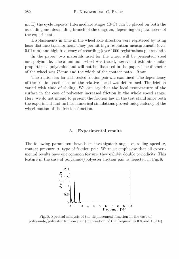
The friction force is equal to the force in the spring increased by a com-ponent perpendicular to the axle, induced by the slide bearings. It increasesuntil the maximum value Fmaxts is achieved (segment 0-C in Fig. 7). We have
Fig. 7. Stages of the oscillation process
the stick state then. In the meantime, the stick limit is achieved (point A) bycontribution of the torque. The lower kinetic friction allows motion towardsthe equilibrium state. Low rotary spring forces are partially released. A newstick point is established and the same process is repeated on the segment B-C.In the extremal position, the slip state starts since the friction force is lowerthan the elastic spring force (C-E). In the beginning of this stage (C-D), againthe rotational potential energy is released. At the bottom of the diagram (po-
282 R. Konowrocki, C. Bajer
int E) the cycle repeats. Intermediate stages (B-C) can be placed on both theascending and descending branch of the diagram, depending on parameters ofthe experiment.
Displacements in time in the wheel axle direction were registered by usinglaser distance transformers. They permit high resolution measurements (over0.01mm) and high frequency of recording (over 1000 registrations per second).
In the paper. two materials used for the wheel will be presented: steeland polyamide. The aluminium wheel was tested, however it exhibits similarproperties as polyamide and will not be discussed in the paper. The diameterof the wheel was 75mm and the width of the contact path – 9mm.
The friction law for each tested friction pair was examined. The dependencyof the friction coefficient on the relative speed was determined. The frictionvaried with time of sliding. We can say that the local temperature of thesurface in the case of polyester increased friction in the whole speed range.Here, we do not intend to present the friction law in the test stand since boththe experiment and further numerical simulations proved independency of thewheel motion of the friction function.
3. Experimental results
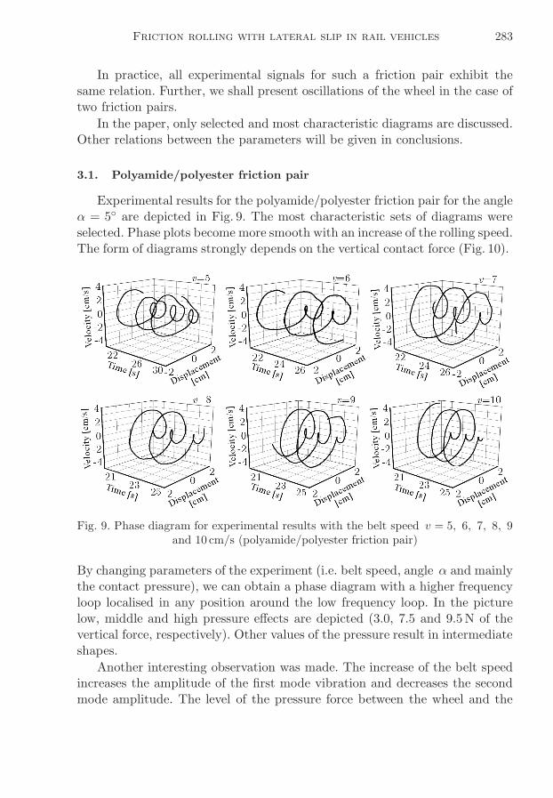
The following parameters have been investigated: angle α, rolling speed v,contact pressure σ, type of friction pair. We must emphasise that all experi-mental results have one common feature: they exhibit double periodicity. Thisfeature in the case of polyamide/polyester friction pair is depicted in Fig. 8.
Fig. 8. Spectral analysis of the displacement function in the case ofpolyamide/polyester friction pair (domination of the frequencies 0.8 and 1.6Hz)
Friction rolling with lateral slip in rail vehicles 283
In practice, all experimental signals for such a friction pair exhibit thesame relation. Further, we shall present oscillations of the wheel in the case oftwo friction pairs.
In the paper, only selected and most characteristic diagrams are discussed.Other relations between the parameters will be given in conclusions.
3.1. Polyamide/polyester friction pair
Experimental results for the polyamide/polyester friction pair for the angleα = 5◦ are depicted in Fig. 9. The most characteristic sets of diagrams wereselected. Phase plots become more smooth with an increase of the rolling speed.The form of diagrams strongly depends on the vertical contact force (Fig. 10).
Fig. 9. Phase diagram for experimental results with the belt speed v = 5, 6, 7, 8, 9and 10 cm/s (polyamide/polyester friction pair)
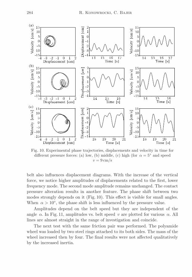
By changing parameters of the experiment (i.e. belt speed, angle α and mainlythe contact pressure), we can obtain a phase diagram with a higher frequencyloop localised in any position around the low frequency loop. In the picturelow, middle and high pressure effects are depicted (3.0, 7.5 and 9.5N of thevertical force, respectively). Other values of the pressure result in intermediateshapes.
Another interesting observation was made. The increase of the belt speedincreases the amplitude of the first mode vibration and decreases the secondmode amplitude. The level of the pressure force between the wheel and the
284 R. Konowrocki, C. Bajer
Fig. 10. Experimental phase trajectories, displacements and velocity in time fordifferent pressure forces: (a) low, (b) middle, (c) high (for α = 5◦ and speed
v = 9 cm/s
belt also influences displacement diagrams. With the increase of the verticalforce, we notice higher amplitudes of displacements related to the first, lowerfrequency mode. The second mode amplitude remains unchanged. The contactpressure alteration results in another feature. The phase shift between twomodes strongly depends on it (Fig. 10). This effect is visible for small angles.When α > 10◦, the phase shift is less influenced by the pressure value.
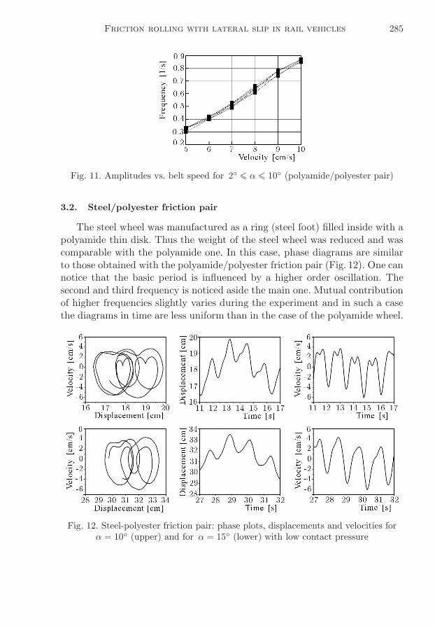
Amplitudes depend on the belt speed but they are independent of theangle α. In Fig. 11, amplitudes vs. belt speed v are plotted for various α. Alllines are almost straight in the range of investigation and coincide.
The next test with the same friction pair was performed. The polyamidewheel was loaded by two steel rings attached to its both sides. The mass of thewheel increased then by four. The final results were not affected qualitativelyby the increased inertia.
Friction rolling with lateral slip in rail vehicles 285
Fig. 11. Amplitudes vs. belt speed for 2◦ ¬ α ¬ 10◦ (polyamide/polyester pair)
3.2. Steel/polyester friction pair
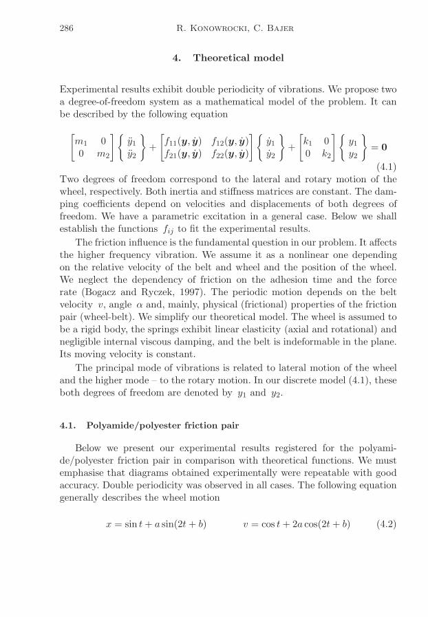
The steel wheel was manufactured as a ring (steel foot) filled inside with apolyamide thin disk. Thus the weight of the steel wheel was reduced and wascomparable with the polyamide one. In this case, phase diagrams are similarto those obtained with the polyamide/polyester friction pair (Fig. 12). One cannotice that the basic period is influenced by a higher order oscillation. Thesecond and third frequency is noticed aside the main one. Mutual contributionof higher frequencies slightly varies during the experiment and in such a casethe diagrams in time are less uniform than in the case of the polyamide wheel.
Fig. 12. Steel-polyester friction pair: phase plots, displacements and velocities forα = 10◦ (upper) and for α = 15◦ (lower) with low contact pressure
286 R. Konowrocki, C. Bajer
4. Theoretical model
Experimental results exhibit double periodicity of vibrations. We propose twoa degree-of-freedom system as a mathematical model of the problem. It canbe described by the following equation
[
m1 00 m2
]{
y1y2
}
+
[
f11(y, y) f12(y, y)f21(y, y) f22(y, y)
]{
y1y2
}
+
[
k1 00 k2
]{
y1y2
}
= 0
(4.1)Two degrees of freedom correspond to the lateral and rotary motion of thewheel, respectively. Both inertia and stiffness matrices are constant. The dam-ping coefficients depend on velocities and displacements of both degrees offreedom. We have a parametric excitation in a general case. Below we shallestablish the functions fij to fit the experimental results.
The friction influence is the fundamental question in our problem. It affectsthe higher frequency vibration. We assume it as a nonlinear one dependingon the relative velocity of the belt and wheel and the position of the wheel.We neglect the dependency of friction on the adhesion time and the forcerate (Bogacz and Ryczek, 1997). The periodic motion depends on the beltvelocity v, angle α and, mainly, physical (frictional) properties of the frictionpair (wheel-belt). We simplify our theoretical model. The wheel is assumed tobe a rigid body, the springs exhibit linear elasticity (axial and rotational) andnegligible internal viscous damping, and the belt is indeformable in the plane.Its moving velocity is constant.
The principal mode of vibrations is related to lateral motion of the wheeland the higher mode – to the rotary motion. In our discrete model (4.1), theseboth degrees of freedom are denoted by y1 and y2.
4.1. Polyamide/polyester friction pair
Below we present our experimental results registered for the polyami-de/polyester friction pair in comparison with theoretical functions. We mustemphasise that diagrams obtained experimentally were repeatable with goodaccuracy. Double periodicity was observed in all cases. The following equationgenerally describes the wheel motion
x = sin t+ a sin(2t+ b) v = cos t+ 2a cos(2t+ b) (4.2)
Friction rolling with lateral slip in rail vehicles 287
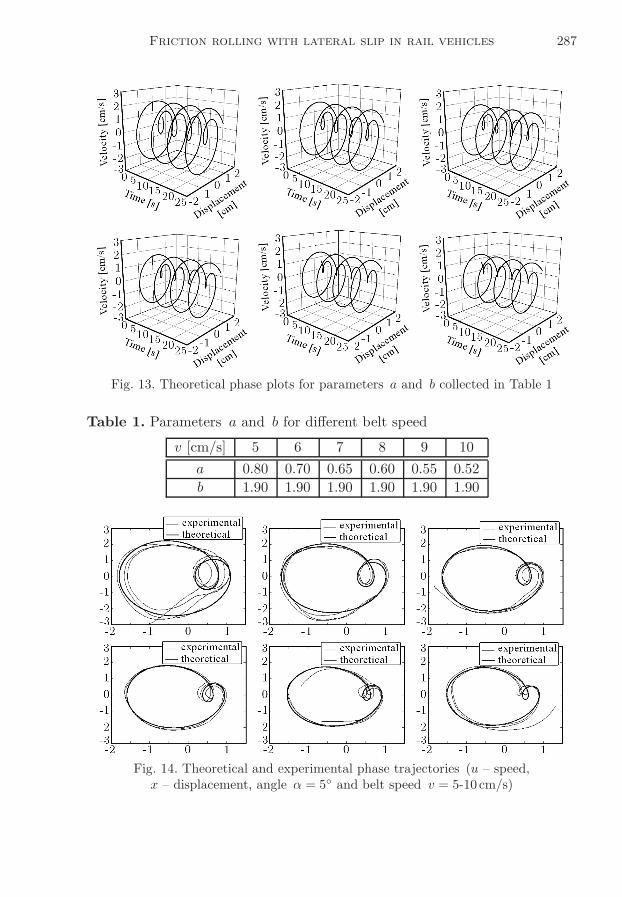
Fig. 13. Theoretical phase plots for parameters a and b collected in Table 1
Table 1. Parameters a and b for different belt speed
v [cm/s] 5 6 7 8 9 10
a 0.80 0.70 0.65 0.60 0.55 0.52
b 1.90 1.90 1.90 1.90 1.90 1.90
Fig. 14. Theoretical and experimental phase trajectories (u – speed,x – displacement, angle α = 5◦ and belt speed v = 5-10 cm/s)
288 R. Konowrocki, C. Bajer
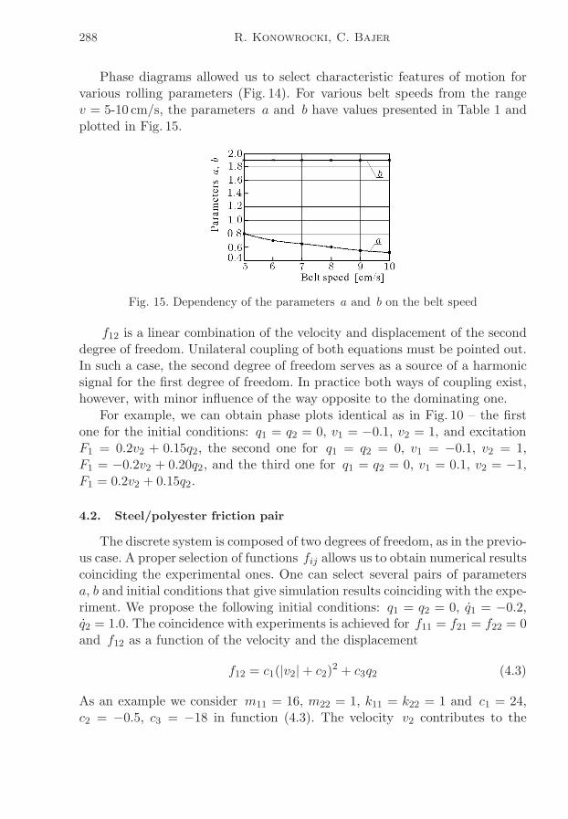
Phase diagrams allowed us to select characteristic features of motion forvarious rolling parameters (Fig. 14). For various belt speeds from the rangev = 5-10 cm/s, the parameters a and b have values presented in Table 1 andplotted in Fig. 15.
Fig. 15. Dependency of the parameters a and b on the belt speed
f12 is a linear combination of the velocity and displacement of the seconddegree of freedom. Unilateral coupling of both equations must be pointed out.In such a case, the second degree of freedom serves as a source of a harmonicsignal for the first degree of freedom. In practice both ways of coupling exist,however, with minor influence of the way opposite to the dominating one.
For example, we can obtain phase plots identical as in Fig. 10 – the firstone for the initial conditions: q1 = q2 = 0, v1 = −0.1, v2 = 1, and excitationF1 = 0.2v2 + 0.15q2, the second one for q1 = q2 = 0, v1 = −0.1, v2 = 1,F1 = −0.2v2 + 0.20q2, and the third one for q1 = q2 = 0, v1 = 0.1, v2 = −1,F1 = 0.2v2 + 0.15q2.
4.2. Steel/polyester friction pair
The discrete system is composed of two degrees of freedom, as in the previo-us case. A proper selection of functions fij allows us to obtain numerical resultscoinciding the experimental ones. One can select several pairs of parametersa, b and initial conditions that give simulation results coinciding with the expe-riment. We propose the following initial conditions: q1 = q2 = 0, q1 = −0.2,q2 = 1.0. The coincidence with experiments is achieved for f11 = f21 = f22 = 0and f12 as a function of the velocity and the displacement
f12 = c1(|v2|+ c2)2 + c3q2 (4.3)
As an example we consider m11 = 16, m22 = 1, k11 = k22 = 1 and c1 = 24,c2 = −0.5, c3 = −18 in function (4.3). The velocity v2 contributes to the
Friction rolling with lateral slip in rail vehicles 289
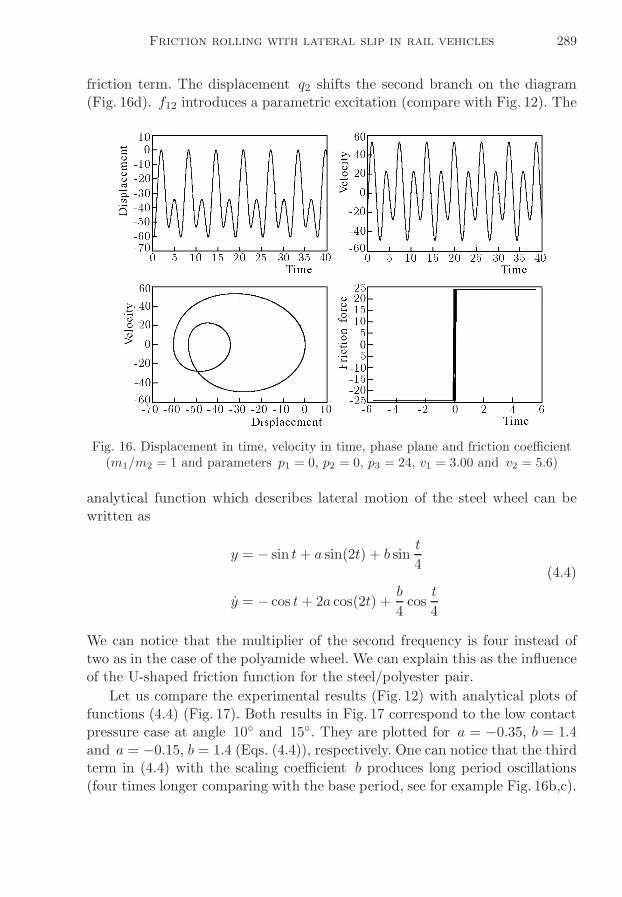
friction term. The displacement q2 shifts the second branch on the diagram(Fig. 16d). f12 introduces a parametric excitation (compare with Fig. 12). The
Fig. 16. Displacement in time, velocity in time, phase plane and friction coefficient(m1/m2 = 1 and parameters p1 = 0, p2 = 0, p3 = 24, v1 = 3.00 and v2 = 5.6)
analytical function which describes lateral motion of the steel wheel can bewritten as
y = − sin t+ a sin(2t) + b sint
4(4.4)
y = − cos t+ 2a cos(2t) +b
4cost
4
We can notice that the multiplier of the second frequency is four instead oftwo as in the case of the polyamide wheel. We can explain this as the influenceof the U-shaped friction function for the steel/polyester pair.
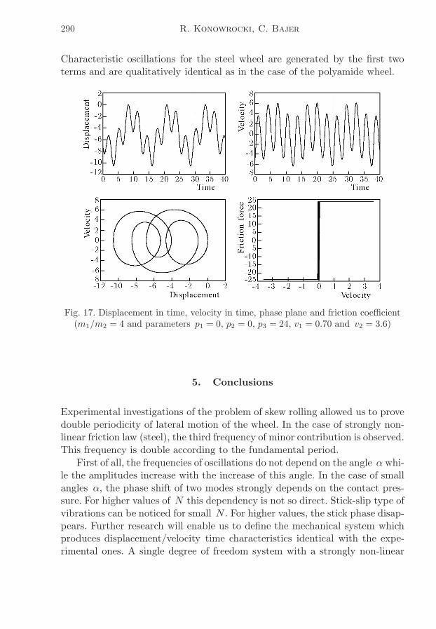
Let us compare the experimental results (Fig. 12) with analytical plots offunctions (4.4) (Fig. 17). Both results in Fig. 17 correspond to the low contactpressure case at angle 10◦ and 15◦. They are plotted for a = −0.35, b = 1.4and a = −0.15, b = 1.4 (Eqs. (4.4)), respectively. One can notice that the thirdterm in (4.4) with the scaling coefficient b produces long period oscillations(four times longer comparing with the base period, see for example Fig. 16b,c).
290 R. Konowrocki, C. Bajer
Characteristic oscillations for the steel wheel are generated by the first twoterms and are qualitatively identical as in the case of the polyamide wheel.
Fig. 17. Displacement in time, velocity in time, phase plane and friction coefficient(m1/m2 = 4 and parameters p1 = 0, p2 = 0, p3 = 24, v1 = 0.70 and v2 = 3.6)
5. Conclusions
Experimental investigations of the problem of skew rolling allowed us to provedouble periodicity of lateral motion of the wheel. In the case of strongly non-linear friction law (steel), the third frequency of minor contribution is observed.This frequency is double according to the fundamental period.
First of all, the frequencies of oscillations do not depend on the angle α whi-le the amplitudes increase with the increase of this angle. In the case of smallangles α, the phase shift of two modes strongly depends on the contact pres-sure. For higher values of N this dependency is not so direct. Stick-slip type ofvibrations can be noticed for small N . For higher values, the stick phase disap-pears. Further research will enable us to define the mechanical system whichproduces displacement/velocity time characteristics identical with the expe-rimental ones. A single degree of freedom system with a strongly non-linear
Friction rolling with lateral slip in rail vehicles 291
friction law applied to the vibrating mass does not allow obtaining satisfactoryresults, since it requires a harmonic excitation. In our experiment, the rotarydegree of freedom supplies this mode. That is why the two degree-of-freedomsystem seems to be appropriate to result in double periodic vibrations. Thisalso concerns the rolling of the steel wheel which exhibits an increase of thefriction coefficient with the velocity. Theoretical results coincide with the re-sponse of our physical model with the first degree of freedom related to lateralmotion of the wheel and the second one corresponding to wheel rotations. Asoft coupling is promising in investigation of the self-excited response.
Intuitively, we expect faster lateral motion and spring compression in thecase of higher angles. Thus, one oscillation could be performed in a shortertime. The experiment proves the independency of the main frequency of theangle. In turn, the angle influences the amplitude level.
The experimental investigation will be continued for other friction pairs.The dependence of the friction coefficient on the rolling speed, the angle andcontact pressure in a full form will be established. The experiment preformedin a real scale should be the final stage of the research.
References
1. Bajer C., 1997, Numerical space-time modelling of dynamic contact problems,IFTR Reports, Warsaw, 5 [in Polish]
2. Bajer C.I., 1998, The space-time approach to rail/wheel contact and corru-gations problem, Comp. Ass. Mech. Eng. Sci., 5, 2, 267-283
3. Bajer C., Bogacz R., 2005, Propagation of perturbances generated in classictrack, and track with Y-type sleepers, Arch. Appl. Mech., 74, 754-761
4. Bogacz R., 1995, Residual stresses in high-speed wheel/rail system; Shake-down and corrugations, In: Proc. of the 1-st European Conference on SteelStructures EUROSTEEL’95, A.N. Koanadis (Edit.), Athens, A.A. Balkema,331-343
5. Bogacz R., Brzozowski M., Mahrenholtz O., Rońda J., 1987, Dynamiceffects in a rolling contact problem, ZAMM, 67, 4, T176-T179
6. Bogacz R., Dżuła S., 1993, Dynamics and stability of a wheelset in rol-ling contact motion on rails, Proc. of ITTG International Symposium on theTechnological Innovation in Guided Transports, Lille, France, 871-883
7. Bogacz R., Kowalska Z., 2001, Computer simulation of the interaction be-tween a wheel and a corrugated rail, Eur. J. Mech A/Solids, 20, 637-684
292 R. Konowrocki, C. Bajer
8. Bogacz R., Krzyżyński T., Popp K., 1995, Application of floquet’s the-orem high-speed train/track dynamics, In: Advanced Automotive Technologies,ASME Congress, 55-61
9. Bogacz R., Ryczek B., 1997, Dry friction self-excited vibrations analysis andexperoment, Eng. Transactions, 45, 3/4, 487-504
10. Brzozowski M., Bogacz R., Popp K., 1990, Zur reibungsmodellierung beimrollkontakt (on the modelling of wear in rolling contact), ZAMM, T678-T680
11. Dżuła S., 1989, Free vibration of wheelset wheel, Arch. Mech. Engng., 2/3,97-124
12. Dżuła S., 1995, Forced vibrations of the rotating railway wheel, Cracow Univ.of Technology, Selected Problems, 3, 307-323
13. Hempelmann K., Hiss F., Knothe K., Ripke B., 1991, The formation ofwear patterns on rail tread, Wear, 179-195
14. Kalker J.J., 1990, Three-Dimensional Elastic Bodies in Rolling Contact, Klu-wer Academic Pablisbers
15. Kalker J.J., 1994, Considerations on rail corrugation, Vehicle System Dyna-mics, 23, 3-28
16. Knothe K., 1983, Rail Corrugations, ILR Bericht 56, Berlin
17. Kowalska Z., 2004, Vibro-impact motion of heavily loaded compact hardbodies, Engng. Trans., 52, 1/2, 37-55
18. Kowalska Z., 2008, Vibro-impacts induced by irregular rolling surfaces ofrailway rails and wheels, J. Theor. Appl. Mech., 46, 1, 205-221
19. Meinke P., Szolc T., 1996, On discrete-continuous modelling in the railwaywheelsets for non-linear dynamic analysis in the medium frequency range, Proc.2 Europ. Nonlinear Oscillation Conf., Euromech, Praque, 135-138
20. Sato Y., Matsumoto A., Knothe K., 2002, Review on rail corrugationstudies, Wear, 253, 1/2, 130-139
Tarcie toczne z poślizgiem bocznym w pojazdach szynowych
Streszczenie
W pracy omówiono zjawiska dynamiczne związane z toczniem się koła z poślizgiembocznym po drodze (szynie, torze). Mają one miejsce przy toczeniu się kół lub zesta-wów kołowych po torze prostym, w przypadku bocznego obciążenia oraz na łukach.Różne promienie krzywizn oraz drgania skrętne zestawów kołowych powodują ukośne
Friction rolling with lateral slip in rail vehicles 293
toczenie i boczne poślizgi w strefie kontaktu koła z szyną. Zjawisko to znacząco zwięk-sza hałas oraz zużycie elementów konstrukcji. W kolei podziemnej wykryto dwuokre-sowość drgań. Zjawisko to dotąd nie było opisywane w literaturze. Przeprowadzonostanowiskowe badania eksperymantalne z uwzględnieniem następujących parametrów:kąta ukośnego toczenia, prędkości oraz siły nacisku w strefie kontaktu. Wyniki odnie-siono do ruchu teoretycznego układu o dwóch stopniach swobody. W przypadku parciernych stal-poliester i poliamid-poliester uzyskano zbliżone jakościowo rezultaty.
Manuscript received July 11, 2008; accepted for print November 12, 2008