
Analytical Armature Reaction Field Prediction in Field-Excited Flux-Switching Machines Using an...
15
IEEE TRANSACTIONS ON MAGNETICS, VOL. X, NO. X, X 2012 1 Analytical Armature Reaction Field Prediction in Field-Excited Flux-Switching Machines using an Exact Relative Permeance Function Benjamin Gaussens 12 , Student Member, IEEE, Emmanuel Hoang 1 , Olivier de la Barri` ere 1 , Jacques Saint-Michel 2 , Philippe Manfe 2 , Michel L´ ecrivain 1 , and Mohamed Gabsi 1 , Member, IEEE 1 SATIE, ENS Cachan, CNRS, UniverSud, 61 av. du President Wilson, Cachan F-94230, France 2 Leroy Somer, Emerson, EPG Division, Sillac, Bd Marcellin Leroy - 16015 Angoulˆ eme Cedex, France In this paper, an analytical approach for the prediction of the armature reaction field of field-excited flux-switching (FE-FS) machines is presented. The analytical method is based on the Magnetomotive Force (MMF)-permeance theory. The doubly-salient air-gap permeance, developed here, is derived from an exact solution of the slot permeance. Indeed, the relative slot permeance is obtained by solving Maxwell’s equations in a subdomain model and applying boundary and continuity conditions. In addition, during a no-load study, we found that, regarding the stator-rotor teeth combination, phase distributions were modified. Hence, in this paper, phase MMF distributions, for q phases, several stator-rotor combinations and also phase winding distribution (single or double-layers) are proposed. We compare extensively magnetic field distributions calculated by the analytical model with those obtained from finite-element analyses. Futhermore, the model is used to predict the machine inductances. Once again, FE results validate the analytical prediction, showing that the developed model can be advantageously used as a design tool of FE-FS machine. Index Terms—Analytical model, armature reaction field, flux-switching, switched flux, slotting effect. I. I NTRODUCTION I N recent years, there has been an increasing interest in Flux-Switching (FS) machines, notably Permanent-Magnet excited (PM-FS) topologies [1]. Industrial demands are in- creasing for electromagnetic topologies combining high torque density, high efficiency and robustness. Hence, the PM-FS machine appears to be an excellent candidate. Indeed, this machine combines advantages of brushless PM machines having a high torque density, and those of switched reluctance machine, i.e. rugged rotor suitable for high-speed operation. Also, since all active parts (windings and PM) are located in the stator, which will simplify the cooling system and make the PM-FS machine a suitable alternative for high operating temperature applications [2][3]. The first electromagnetic actuator based on flux-switching principle can be traced back to the 50’s [4]. Since, many works have investigated performances of FS machine to reveal the interest of a bipolar flux-linkage [5][6], and propose refinements in the design of those structures, especially for PM excited topologies [7][8][9][10][11]. Nevertheless, the high flux control capability, required for variable speed applications, led designers to propose Hybrid- Excited Flux-Switching (HE-FS) machines. An additional wound exciter is combined with the PM to allow a good flux regulation. The various topologies of HE-FS machines found in the literature can be sorted into series flux path [12][13] or parallel flux path [14] HE-FS machines, depending on the location of the DC coil. Recent developments on those structures show promising future for Hybrid Electric Vehicles (HEV) applications, with an extended flux-weakening range and a higher efficiency [9][15]. Manuscript received .. However, the current increase in rare-earth PM prices, combined with risks of shortages, pose great issues of cost and supply delays. To overcome these problems the Field-Excited Flux-Switching (FE-FS) machine was proposed. So far, how- ever, there has been little discussion about electromagnetic performances of FE-FS machines despite a general agreement on their attractive low-cost topology [16][17][18]. In the litera- ture, two topologies of FE-FS machines are listed, the classical structures having overlapping windings and also, a modular rotor topology with non-overlapping windings [19][20]. In this paper, only classical topologies are investigated. Regarding the modeling of FS machines, mainly Finite Element (FE) methods are considered because of the inherent doubly-salient air-gap and the non-linear behavior of magnetic material, particularly in PM-FS machines with a high flux- focusing effect. Despite their proven accuracy, FE simulations suffer from severe computational time requirements and offer limited ability to explore numerous designs. To overcome this problem, some authors proposed models of PM-FS and HE- FS topologies in a more analytical manner, using Magnetic Equivalent Circuit (MEC) [21][22] or Fourier analysis meth- ods [23]. No references in the literature addressing the issue of an analytical model for FE-FS machines were found, while it meets a real design requirement, especially in an industrial context. Therefore, in this paper, an analytical method is developed to predict the armature reaction field in FE-FS machines. An accurate calculation of self- and mutual-inductances is of primary interest to improve the analysis and the design of this class of machines. This article has been organized in the following way. Firstly, the armature reaction field model, based on MMF-permeance theory, is described. An exact solution of the slot permeance, by solving the field’s governing equation
-
Upload
ens-cachan -
Category
Documents
-
view
3 -
download
0
Transcript of Analytical Armature Reaction Field Prediction in Field-Excited Flux-Switching Machines Using an...

IEEE TRANSACTIONS ON MAGNETICS, VOL. X, NO. X, X 2012 1
Analytical Armature Reaction Field Prediction in Field-ExcitedFlux-Switching Machines using an Exact Relative Permeance
Function
Benjamin Gaussens12, Student Member, IEEE, Emmanuel Hoang1, Olivier de la Barriere1,Jacques Saint-Michel2, Philippe Manfe2, Michel Lecrivain1, and Mohamed Gabsi1, Member, IEEE
1 SATIE, ENS Cachan, CNRS, UniverSud, 61 av. du President Wilson, Cachan F-94230, France2Leroy Somer, Emerson, EPG Division, Sillac, Bd Marcellin Leroy - 16015 Angouleme Cedex, France
In this paper, an analytical approach for the prediction of the armature reaction field of field-excited flux-switching (FE-FS)machines is presented. The analytical method is based on theMagnetomotive Force (MMF)-permeance theory. The doubly-salientair-gap permeance, developed here, is derived from an exactsolution of the slot permeance. Indeed, the relative slot permeanceis obtained by solving Maxwell’s equations in a subdomain model and applying boundary and continuity conditions. In addition,during a no-load study, we found that, regarding the stator-rotor teeth combination, phase distributions were modified. Hence, inthis paper, phase MMF distributions, for q phases, several stator-rotor combinations and also phase winding distribution (singleor double-layers) are proposed. We compare extensively magnetic field distributions calculated by the analytical model with thoseobtained from finite-element analyses. Futhermore, the model is used to predict the machine inductances. Once again, FEresultsvalidate the analytical prediction, showing that the developed model can be advantageously used as a design tool of FE-FS machine.
Index Terms—Analytical model, armature reaction field, flux-switching, switched flux, slotting effect.
I. I NTRODUCTION
I N recent years, there has been an increasing interest inFlux-Switching (FS) machines, notably Permanent-Magnet
excited (PM-FS) topologies [1]. Industrial demands are in-creasing for electromagnetic topologies combining high torquedensity, high efficiency and robustness. Hence, the PM-FSmachine appears to be an excellent candidate. Indeed, thismachine combines advantages of brushless PM machineshaving a high torque density, and those of switched reluctancemachine,i.e. rugged rotor suitable for high-speed operation.Also, since all active parts (windings and PM) are located inthe stator, which will simplify the cooling system and makethe PM-FS machine a suitable alternative for high operatingtemperature applications [2][3].
The first electromagnetic actuator based on flux-switchingprinciple can be traced back to the 50’s [4]. Since, manyworks have investigated performances of FS machine to revealthe interest of a bipolar flux-linkage [5][6], and proposerefinements in the design of those structures, especially forPM excited topologies [7][8][9][10][11].
Nevertheless, the high flux control capability, required forvariable speed applications, led designers to propose Hybrid-Excited Flux-Switching (HE-FS) machines. An additionalwound exciter is combined with the PM to allow a good fluxregulation. The various topologies of HE-FS machines foundin the literature can be sorted into series flux path [12][13]or parallel flux path [14] HE-FS machines, depending onthe location of the DC coil. Recent developments on thosestructures show promising future for Hybrid Electric Vehicles(HEV) applications, with an extended flux-weakening rangeand a higher efficiency [9][15].
Manuscript received ..
However, the current increase in rare-earth PM prices,combined with risks of shortages, pose great issues of cost andsupply delays. To overcome these problems the Field-ExcitedFlux-Switching (FE-FS) machine was proposed. So far, how-ever, there has been little discussion about electromagneticperformances of FE-FS machines despite a general agreementon their attractive low-cost topology [16][17][18]. In thelitera-ture, two topologies of FE-FS machines are listed, the classicalstructures having overlapping windings and also, a modularrotor topology with non-overlapping windings [19][20]. Inthispaper, only classical topologies are investigated.
Regarding the modeling of FS machines, mainly FiniteElement (FE) methods are considered because of the inherentdoubly-salient air-gap and the non-linear behavior of magneticmaterial, particularly in PM-FS machines with a high flux-focusing effect. Despite their proven accuracy, FE simulationssuffer from severe computational time requirements and offerlimited ability to explore numerous designs. To overcome thisproblem, some authors proposed models of PM-FS and HE-FS topologies in a more analytical manner, using MagneticEquivalent Circuit (MEC) [21][22] or Fourier analysis meth-ods [23]. No references in the literature addressing the issueof an analytical model for FE-FS machines were found, whileit meets a real design requirement, especially in an industrialcontext.
Therefore, in this paper, an analytical method is developedto predict the armature reaction field in FE-FS machines.An accurate calculation of self- and mutual-inductances isofprimary interest to improve the analysis and the design ofthis class of machines. This article has been organized in thefollowing way. Firstly, the armature reaction field model, basedon MMF-permeance theory, is described. An exact solution ofthe slot permeance, by solving the field’s governing equation

2 IEEE TRANSACTIONS ON MAGNETICS, VOL. X, NO. X, X 2012
in a subdomain model, is derived and validated with 2DFE software. In addition, stator phase MMF distributions areproposed, regarding the stator-rotor combination, the numberof phases (q) and also, the winding configurations (singleor double-layers). Once again, extensive comparisons withflux-density distributions obtained by FE simulations cometovalidate the model. Analytical expressions of the self- andmutual inductance are presented, and analytical results arecompared to the corresponding FE analyses.
II. A RMATURE REACTION FIELD ANALYTICAL SOLUTION
Literature has widely addressed the analytical calculationof the armature reaction field distribution for both PM orelectrically excited machines. Some authors solved directlyfield’s governing equations in a subdomain model to accountfor directly the mutual influence of slot openings [24][25][26].In others papers, the Magnetomotive Force MMF-permeancetheory was used to derive the flux-density distribution createdby phase coils [27][28][29].
As mentioned previously, the analytical approach is basedon MMF-permeance theory. Some assumptions are made inorder to simplify the problem:
• Infinite permeability of rotor and stator core, hence, no-magnetic saturation of iron regions is considered.
• Non-conductive materials (No eddy currents) and 2Dproblem (end effects are neglected).
The doubly-slotted air-gap of FE-FS machine is shown inFig. 1. Stator and rotor slots opening areβsθs and βrθrrespectively. The angular position in the air-gap is definedwithν, andθ corresponds to the rotor position.
m®¥
Rsi
Re
Rre
q
m®¥
n
b qr r
qr
qs
b qs s
Fig. 1. Doubly-salient geometry of FS machine withNs = 10 andNr = 8
A. General expression of Armature Reaction Field in theair-gap
By considering the hypothesis of infinite permeability ofstator and rotor teeth and yokes, the air-gap flux-densitycreated by a currentIq flowing in a phaseq is defined as
Barm (ν, θ) = µ0MMFq (ν, θ) Λ (ν, θ) (1)
whereMMFq is the magnetomotive force of phaseq andΛ denotes the doubly-salient air-gap permeance of the FSmachine. Considering that the air-gap is split into two parts atits mean radii (r = Re), with stator slots on one side and rotorteeth on the other, the air-gap permeance can be expressed as
Λ(ν, θ) =2
e
(
Λrs (ν) Λrr (ν, θ)
Λrs (ν) + Λrr (ν, θ)
)
(2)
with Λrs (ν) andΛrr (ν, θ), respectively, the relative air-gappermeance of stator and rotor slots ande the effective air-gap length (e = Rsi − Rre). In the next paragraph, an exactexpression of the relative air-gap permeance is derived.
B. Exact Solution of Slot Permeance solving Maxwell’sequations
Literature about slotting effect is rich, and usually, methodsto assess the slotting influence on the air-gap flux density fallinto two groups.
The first approach uses a relative permeance function tomodulate the field in a slotless air-gap. Some authors, likeZhu [30][31], used exact approaches based on conformal trans-formation to evaluate a relative permeance function. Zarko[32][33]proposed also a complex relative permeance functioncapable of accounting for the influence of slotting on thetangential air-gap flux density. In other papers, permeancefunction is derived from idealized flux lines under infinitelydeep slot [28][34][29][35].
The second approach is generally denominated as sub-domain models [36][37][38][39][40]. It consists of solvingdirectly the field governing equations (Laplacian and/or quasi-Poissonian equations) in different domains to obtain the overallfield distribution by applying boundary conditions on theinterfaces between each subdomains.
In this paper, we propose an original and exact expressionof the air-gap relative permeance under a slot to account forall the geometric parameters of the slot. To this end, wecombine the previous mentioned approches. Indeed, the exactexpression of the relative permeance is derived considering asubdomain model to be described in the next sections.
Furthermore, this relative permeance function could beapplied to configuration having a higher effective air-gap,like flux-reversal machines [41] or PM-FS machines withsegmented rotor [42].
1) Problem description and assumptionsThe geometric representation of the problem to be solved is
depicted in Fig. 2. To simplify the analytical calculation,weconsider that slots have radial sides.Re denotes the middleair-gap radius,Rsi the inner stator radius and finallyRei thebottom of the stator slot. As shown in Fig. 2, the geometry isdivided into two regions: the air-gap domain (Region I) andthe slot (Region II). A scalar magnetic potential formulationis used in 2D polar coordinates to solve the problem.
The absence of source terms (PM or current density), in theair-gap domain and in the slot, means that the field behavioris governed in both regions by the Laplace’s equation
∆ψ(I) = 0 , in Region I
∆ψ(II) = 0 , in Region II(3)

GAUSSENSet al.: ANALYTICAL ARMATURE REACTION FIELD PREDICTION IN FE-FS MACHINES USING AN EXACT RELATIVE PERMEANCE FUNCTION 3
SlotRegion II
Air-gapRegion I
∂Ψ∂ν =0
Rsi
Re
Rei
r
ν
θs
β θs s
SmoothSurface
Stator
Fig. 2. Slot domain with its boundary conditions
The scalar magnetic potentialψ is forced to unity on therotor bore and is zero on the stator edges (Fig. 2). So that, thefollowing boundary conditions can be defined
ψ(I) (Re, ν) = 1 for ν ∈
[
−θs2,θs2
]
(4)
ψ(I) (Rsi, ν) = 0 for ν ∈
[
−θs2,−
βsθs2
]
∪
[
βsθs2
,θs2
]
(5)
ψ(II) (Rei, ν) = 0 for ν ∈
[
−βsθs2
,βsθs2
]
(6)
ψ(II)
(
r,±βsθs2
)
= 0 for r ∈ [Rsi, Rei] (7)
Neumann boundary conditions are also considered in eachsides of air-gap domain
∂ψ(I)(
r,± θs2
)
∂ν= 0 for r ∈ [Re, Rsi] (8)
2) General solution of the Laplace’s equation in the air-gap
The Laplace’s equation (3) governing the field in the air-gapdomain, can be rewritten in polar coordinates as
∂2ψ(I)
∂r2+
1
r
∂ψ(I)
∂r+
1
r2∂2ψ(I)
∂ν2= 0 (9)
with ψ(I) = ψ(I)(r, ν).The general solution of (9) can be found by separating the
variabler andν, so that the solution can be written as
ψ(I)(r, ν) = ρ(r)Θ(ν) (10)
Considering the Neumann boundary condition (8), we lookinto solutions of the form
ψ(I) (r, ν) = a(I)0 (r) +
∑
k≥1
a(I)k (r) cos
[
kπ
θs
(
ν +θs2
)]
(11)
Substituting (11) into (9), we obtain a set of two ordinarydifferential equations
d2a0
dr2+ 1
rda0
dr= 0
d2ak
dr2+ 1
rdak
dr−(
k πθs
)2ak
r2= 0 , ∀k ≥ 1
(12)
The general solutions of (12) are found to be
a0 (r) = C0 ln (r) + C′
0
ak (r) = C(1)
k rkπθs + C
(2)
k r−k πθs , ∀k ≥ 1
(13)
Finally, considering the boundary condition (4), the generalsolution of the scalar magnetic potential in the air-gap domainis given by
ψ(I) (r, ν) = 1 + C0 ln
(
r
Re
)
+
∑
k≥1
Ck
[
(
r
Rsi
)k πθs
− λ1
(
r
Re
)−k πθs
]
cos
[
kπ
θs
(
ν +θs2
)]
(14)
with
λ1 =
(
Rsi
Re
)−k πθs
(15)
and whereC0 and Ck are the Fourier coefficients to bedetermined.
3) General solution of the Laplace’s equation in the slotregion
In a similar manner to the air-gap region, the scalar magneticpotential in Region II is governed by the Laplace’s equationgiven in (3). By using the method of the separation of variablesand considering the boundary condition (7), the solution’sformthat we look into are
ψ(II) (r, ν) =∑
q≥1
b(II)q (r) sin
[
qπ
βsθs
(
ν +βsθs2
)]
(16)
Substituting (16) into (3), and considering the boundarycondition (6) inr = Rei, the general expression of the scalarmagnetic potential in the slot is given by
ψ(II) (r, ν) =∑
q≥1
Dq
[
λ2
(
r
Rei
)q πβsθs
−
(
r
Rsi
)−q πβsθs
]
sin
[
qπ
βsθs
(
ν +βsθs2
)]
(17)
with
λ2 =
(
Rsi
Rei
)
q πβsθs
(18)
and whereDq are the Fourier coefficient to be determined.

4 IEEE TRANSACTIONS ON MAGNETICS, VOL. X, NO. X, X 2012
4) Boundary ConditionsIn what follows, the boundary conditions are discussed to
determine the unknown coefficients defined in (14) and (17).First, the continuity condition of the scalar magnetic poten-
tial at r = Rsi leads to
ψ(I) (Rsi, ν) =
0 , ∀ν ∈[
− θs2 ,−
αθs2
]
∪[
αθs2 , θs2
]
ψ(II) (Rsi, ν) , ∀ν ∈[
−αθs2 , αθs2
](19)
Expanding (19) into Fourier series over[
− θs2 ,
θs2
]
, it yields
ψ(II) (Rsi, ν) = E0 +∑
k≥1
Ek cos
[
kπ
θs
(
ν +θs2
)]
(20)
with
E0 =1
θs
θs2
∫
−θs2
ψ(II) (Rsi, ν) dν
=1
θs
∑
q≥1
Dq
[
λ2
(
Rsi
Rei
)q πβsθs
− 1
]
αq (21)
and
Ek =2
θs
θs2
∫
−θs2
ψ(II) (Rsi, ν) cos
[
kπ
θs
(
ν +θs2
)]
dν
=2
θs
∑
q≥1
Dq
[
λ2
(
Rsi
Rei
)q πβsθs
− 1
]
αq,k (22)
whereαq andαq,k are defined by (23) and (24).
αq =
βsθs2
∫
−βsθs
2
sin
[
qπ
βsθs
(
ν +βsθs2
)]
dν
=βsθsqπ
(1− (−1)q) (23)
From (14) and (20), it gives
1 + C0 ln
(
Rsi
Re
)
= E0 (25)
and, for∀k ≥ 1,
Ck
[
1− λ1
(
Rsi
Re
)−k πθs
]
= Ek (26)
Then, regarding the continuity of the normal component offlux density at the interface between both regions (r = Rsi),we can write
∂ψ(I)
∂r
∣
∣
∣
∣
r=Rsi
=∂ψ(II)
∂r
∣
∣
∣
∣
r=Rsi
∀ν ∈
[
−βsθs2
,βsθs2
]
(27)
since Region I and II have the same relative permeability (bothare air).
Hence, for∀q ≥ 1, it gives
π
βsθsqDq
[
λ5
(
Rsi
Rei
)q πβsθs
−1
+ λ3
]
=2
βsθs
βsθs2
∫
−βsθs
2
C0
Rsi
+π
θs
∑
k≥1
kCk
[
λ3 + λ4
(
Rsi
Re
)−k πθs
−1]
cos
(
kπ
θs
(
ν +θs2
))
sin
(
qπ
βsθs
(
ν +βsθs2
))
dν
(28)
with
λ3 =1
Rsi
(29)
λ4 =λ1Re
(30)
λ5 =λ2Rei
(31)
Expanding (28) yields to
π
βsθsqDq
[
λ5
(
Rsi
Rei
)q πβsθs
−1
+ λ3
]
=2C0
βsθsRsi
αq
+2π
βsθ2s
∑
k≥1
kCk
[
λ3 + λ4
(
Rsi
Re
)−k πθs
−1]
αq,k (32)
Consequently, from (25), (26) and (32), all the Fouriercoefficients can be determined. The linear equation systemto solve is rewritten in matrix and vectors form, so that anumerical solution can be found. Once, the scalar magneticpotential in each region is obtained, the magnetic field can bededuced by
Hν = −1
r
∂ψ
∂ν(33)
Hr = −∂ψ
∂r(34)
whereHν andHr represent the radial and tangential compo-nents of the magnetic field.
Finally, the relative permeance under the slot is obtained bynormalizing the magnetic field on the rotor boreHr(Re, ν)by the magnetic field on the side on the air-gap domainHr(Re,
θs2 ) = 2
e. Considering (14) and (34), the general
expression on the relative permeance under the slot is foundto be
Λrs(ν)=e
2
−C0
Re
−π
θs
∑
k≥1
kCk
[
λ3
(
Re
Rsi
)k πθs
−1
+ λ4
]
cos
[
kπ
θs
(
ν +θs2
)]
(35)

GAUSSENSet al.: ANALYTICAL ARMATURE REACTION FIELD PREDICTION IN FE-FS MACHINES USING AN EXACT RELATIVE PERMEANCE FUNCTION 5
The same procedure is applied to determine the expressionof the rotor relative permeanceΛrr . For reasons of simplicityand clarity, this is not developed in the paper.
5) Comparisons with Finite ElementTo validate the approach outlined in the preceding section
and also confirm the expression of the relative slot permeanceΛrs , the analytical results have been compared with 2D FEsimulations (using the free-of-charge sotfware Femm).
Thereafter, results for different slot configurations are given.Figs. 3.(a) and (b) present respectively the equipotentiallines of the scalar magnetic potential obtained analytically(with (14) and (17)) and with FE simulations. An excellentagreement between both distributions is observed. In Fig.3.(c), analytical computation and FE simulation of the relativepermeance under the slotΛrs are shown. Again, excellentagreement is observed between analytical and FE results.Particularly, the decrease of the relative permanence in thevicinity of the slot opening,i.e. for ν = ±βsπ
Ns, is well
accounted for.Also, the influence of the slot opening on the relative
permeance function is presented in Appendix A (Fig. 18).We consider here a quite small effective air-gap length (e =0.5mm), which is likely the case in FE-FS machines. Onceagain, an accurate prediction of the relative permeanceΛrs isobserved in comparison with FE simulation, especially in thebottom of the slot. It is interesting to note that when the slotopening reduces, the magnetic field penetrates less deeply inthe slot. That observation can corroborate the assumption of aninfinitely deep slot in some specific configurations. However, aformal expression of the slot permeance is far more convenientand more reliable for automated analysis.
C. Magnetomotive Force created by phase winding
In this section, to ease sorting of structures and configu-rations, we introduce some parameters .γ = gcd(Ns, Nr)denotes the periodicity of the air-gap flux-density andnc
corresponds to the number of coils of the same phase havingdifferent flux-linkage waveforms. Indeed, depending on thestator-rotor teeth configuration, the distribution of phase coilsis modified, and consequently, phase coil MMF.
In the next paragraphs, the MMF created by current-carryingphase conductors distributed in the stator slots are given,and their Fourier series expansions are detailed. For the sakeof clarity, only configurations havingNr = Ns/2 ± γ areinvestigated. Also, single or double-layers configurations areconsidered. As a reminder, the main difference between singleand double-layer configurations is that each stator slot contains
coils from only one phase in single-layer configuration, whilestator slots share two different phase coils for double-layerconfigurations. In Figs. 4 and 5, a linearized view of statorslots, for both phase winding configurations with the asso-ciated MMF, is depicted. The following list of phase MMFdistribution is by no means exhaustive, however the mostpromising configurations, in terms of power capability, areembraced.
1) Single-layer configurationAccording to Fig. 4.(a), the MMF of one phase for single-
layer configurations havingγ ≥ 2 andnc = Ns/4qγ coils canbe defined as a function by parts over[0, 4qθs]
MMFq(ν) =
NsqIq2 − δ0 , ∀ν ∈
[
0,(
1− βs
2
)
θs
]
−NsqIq(ν−θs)βsθs
− δ0 , ∀ν ∈[(
1− βs
2
)
θs,(
1 + βs
2
)
θs
]
−NsqIq2 − δ0 , ∀ν ∈
[(
1 + βs
2
)
θs,(
η1 −βs
2
)
θs
]
NsqIq(ν−η1θs)βsθs
− δ0 , ∀ν ∈[(
η1 −βs
2
)
θs,(
η1 +βs
2
)
θs
]
NsqIq2 − δ0 , ∀ν ∈
[(
η1 +βs
2
)
θs, 4qθs
]
(36)
whereη1 = 4q − 1 and
δ0 =1
T
4qθs∫
0
MMFq (ν, δo = 0) dν
=NsqIq2
(
1− q
q
)
(37)
Expanding (36) into Fourier series over[0, 4qθs], it yields to
MMFq (ν) ∼
+∞∑
n=1
an cos
(
nNs
4qν
)
(38)
with
an =2
T
4qθs∫
0
MMFq (ν) cos
(
nNs
4qν
)
dν
=8qNsqIq
βs (nπ)2
sin
(
n2π
q
)
sin
(
nπβs4q
)
(39)
Regarding configurations havingγ = 1 with nc = 2, thephase MMF can be defined as
αq,k =
βsθs2
∫
−βsθs
2
cos
(
kπ
θs
(
ν +θs2
))
sin
(
qπ
βsθs
(
ν +βsθs2
))
dν
=
βsθsq(cos( kπ2 (1−βs))−cos( kπ
2 (1+βs))(−1)q)π(q2−β2
sk2) , ∀q 6= βsk
βsθs2
sin(
kπ2 (βs − 1)
)
+ 12πkβs
(
cos(
kπ2 (1− βs)
)
− cos(
kπ2 (1 + 3βs)
))
, ∀q = βsk(24)

6 IEEE TRANSACTIONS ON MAGNETICS, VOL. X, NO. X, X 2012
−π/Ns
−πβs/N
s0 πβ
s/N
sπ/N
s
Position ν (rad)
Radiu
sr
(mm
)
0.125
0.13
0.135
0.14
0.145
0
0.2
0.4
0.6
0.8
1
(a) (b)
0.2
0.4
0.6
0.8
1
Position ν (rad)
Rela
tive
perm
eance
Λr
s(ν
)
−π/Ns
−πβs/N
s0 πβ
s/N
sπ/N
s
Analytical
2D FE
(c)
Fig. 3. Distribution of equipotential lines of scalar magnetic potential in air-gap and slot regions with the analytical model (a) and the FE simulation (b).Comparison between analytical and FE calculated relative permeance functionΛrs for a 24 stator slots structure (withβs = 0.5, e = 4mm, Rsi = 126.6mmandHs = 20mm)
DC field coils
ν
MMFq
0
β θs s
θs2θs-N Isq q
2
Phase q coils
+ +- -- -
-θs-2θs4qθs(4q-2)θs (4q+2)θs
N Isq q
2
N Isq q
2-δ0
-δ0
(a)
DC field coils
ν
MMFq
0
β θs s
-N Isq q
Phase q coils
+ +- -- -
6qθs(6q-2)θs (6q+2)θs
N Isq q
2qθs(2q-1)θs (2q+1)θs
(b)
Fig. 4. The Magnetomotive Force created by phase coils for a single-layer configuration having:γ ≥ 2 (a) andγ = 1 (with nc = 2) (b)
MMFq (ν) =
NsqIq(ν−σ2θs)βsθs
, ∀ν ∈ [σ2θs, χ2θs]
NsqIq , ∀ν ∈ [χ2θs, σ3θs]
−NsqIq(ν−χ3θs)βsθs
, ∀ν ∈ [σ3θs, χ4θs]
−NsqIq(ν−σ4θs)βsθs
, ∀ν ∈ [σ4θs, χ4θs]
−NsqIq , ∀ν ∈ [χ4θs, σ5θs]
NsqIq(ν−χ5θs)βsθs
, ∀ν ∈ [σ5θs, χ5θs]
0 , elsewhere
(40)
with σi = ηi −βs
2 , χi = ηi +βs
2 , η2 = 2q − 1, η3 = 2q + 1,η4 = 6q − 1 andη5 = 6q + 1. Finally, (40) can be expandedinto Fourier series over[0, 2π] as
MMFq (ν) ∼
+∞∑
n=1
bn sin (nν) (41)
with
bn =2
T
2π∫
0
MMFq (ν) sin (nν) dν
=2NsqIqβsθsπn2
sin(
n(
η3 +βs
2
)
θs
)
− sin (nη3θs)
+ sin(
n(
η4 +βs
2
)
θs
)
− sin (nη4θs)
(42)
2) Double-layer configurationIn Fig. 5 are depicted the MMF created by one stator phase
for double-layers configurations regarding the value ofγ. Inthe particular case ofγ ≥ 2 with nc = Ns/2qγ (and also

GAUSSENSet al.: ANALYTICAL ARMATURE REACTION FIELD PREDICTION IN FE-FS MACHINES USING AN EXACT RELATIVE PERMEANCE FUNCTION 7
+ -
ν
MMFq
β θs s
Phase q coils DC field coils
-θs θs 2qθs 3qθs0-N Isq q
22-δ1
N Isq q
22-δ1
(a)
+ +- -
ν
MMFq
β θs s
-N Isq q
N Isq q
Phase q coils DC field coils
qθs(q-1)θs (q+1)θs 3qθs 5qθs 7qθs(7q-1)θs (7q+1)θs
(b)
Fig. 5. The Magnetomotive Force created by phase coils for a double-layer configuration having:γ ≥ 2 or γ = 1 (with nc = 2) (a) andγ = 1 (withnc = 4) (b)
γ = 1 andnc = 2), the phase MMF (Fig. 5.(a)) can be definedover [0, 2qθs] by
MMFq(ν) =
NsqIq2 − δ1 , ∀ν ∈
[
0,(
1− βs
2
)
θs
]
−2NsqIq(ν−θs(1− βs4 ))
βsθs− δ1 , ∀ν ∈
[(
1− βs
2
)
θs, θs
]
−NsqIq2 − δ1 , ∀ν ∈ [θs, η2θs]
2NsqIq(ν−θs(η2+βs4 ))
βsθs− δ1 , ∀ν ∈
[
η2θs,(
η2 +βs
2
)
θs
]
NsqIq2 − δ1 , ∀ν ∈
[(
η2 +βs
2
)
θs, 2qθs
]
(43)
where
δ1 =1
T
2qθs∫
0
MMFq (ν, δ1 = 0)dν
=NsqIqq
(
1−βs4
−q
2
)
(44)
Fourier series expansion of (43) is found to be
MMFq (ν) ∼
+∞∑
n=1
an cos
(
nNs
2qν
)
(45)
with
an =2
T
2qθs∫
0
MMFq (ν) cos
(
nNs
2qν
)
dν
=4qNsqIq
βs (nπ)2
cos
(
nπ
q
(
1−βs2
))
− cos
(
nπ
q
)
(46)
In a similar manner, the phase MMF of double-layer con-figurations havingγ = 1 andnc = 4 is depicted in Fig. 5.(b)and can be defined over[0, π] as
MMFq(ν) =
2NsqIqβsθs
(ν − η6θs) , ∀ν ∈[
η6θs,(
η6 +βs
2
)
θs
]
NsqIq , ∀ν ∈[(
η6 +βs
2
)
θs,(
η7 −βs
2
)
θs
]
−2NsqIqβsθs
(ν − η7θs) , ∀ν ∈[(
η7 −βs
2
)
θs, η7θs
]
−2NsqIqβsθs
(ν − η8θs) , ∀ν ∈[
η8θs,(
η8 +βs
2
)
θs
]
−NsqIq , ∀ν ∈[(
η8 +βs
2
)
θs,(
η9 −βs
2
)
θs
]
2NsqIqβsθs
(θ − η9θs) , ∀ν ∈[(
η9 −βs
2
)
θs, η9θs
]
0 , elsewhere(47)
whereη6 = q − 1, η7 = q + 1, η8 = 3q − 1 andη9 = 3q + 1.The Fourier series development of (47) gives
MMFq (ν) ∼
+∞∑
n=1
an cos (nν) (48)

8 IEEE TRANSACTIONS ON MAGNETICS, VOL. X, NO. X, X 2012
with
an =2
T
2π∫
0
MMFq (ν) cos (nν) dν
=4NsqIqβsθsπn2
cos(
n(
η6 +βs
2
)
θs
)
− cos (nη6θs)
+ cos(
n(
η7 +βs
2
)
θs
)
− cos (nη7θs)
+ cos (nη8θs)− cos(
n(
η8 +βs
2
)
θs
)
+cos (nη9θs)− cos(
n(
η9 −βs
2
)
θs
)
(49)
3) Modified Magnetomotive Force in the doubly-slotted air-gap
In previous sections, the rotor scalar magnetic potentialwas assumed to be zero, and only the stator scalar magneticpotential was defined in the expression of the magnetomotiveforce given in (38), (41), (45) or (48). However, because ofthe doubly-slotted air-gap, it can be demonstrated that themagnetomotive force has to be modified. Hence, satisfyingthe Gauss’s law for magnetism, that statesdiv ~B = 0, we candefine a coefficientκc as
κc (ν, θ) = −
∫ 2π
0 MMFq (ν) Λ (ν, θ) dν∫ 2π
0Λ (ν, θ) dν
(50)
Finally, from (50), the magnetomotive force is defined as
MMFq(ν, θ) =MMFq(ν) + κc(ν, θ) (51)
Now that phase MMFs have been defined for differentwinding configurations,q phases and also the rotor-statorcombination, the armature reaction field can be predicted using(1), (2), (35) and (51).
III. A RMATURE REACTION FIELD PREDICTION AND
COMPARISON WITHFINITE ELEMENT SIMULATIONS
TABLE ICOMMUN PARAMETERS OF THE MODEL
Description Symbol Numerical value
Inner radius of stator Rsi 126.6mm
Middle air-gap radius Re 126.35mm
Outer radius of rotor Rre 126.1mm
Active axial length La 45mm
q phase MMF NsqIq 600A.turn
Speed Ω 1300rpm
In this section, 2D FE results serve to validate the afore-mentioned armature reaction field model. As in the analyticalsolution, FE results were obtained by considering that statorand rotor cores are made of an infinitely permeable magneticmaterial (µr = 1000). Furthermore, in the FE simulations, weconsider that stator and rotor teeth have straight parallelsides,which is the case in any prototype. As a reminder, radial slotswere considered in the analytical model.
Although the model is dedicated to multiphase structures,only flux-density distributions of 3-phase topologies are pre-sented in the paper due to space limit. Common parameters ofboth analytical predictions and 2D FE simulations are givenin Table I.
A. Single-layer configurations
−0.5
0
0.5
1
1.5
Position ν (rad)
Flu
x-d
ensi
tyB
arm
(T)
−π −π/2 0 π/2 π
Analytical2D FE
(a)
(b)
Fig. 6. Magnetic flux density in middle of air-gapBr (ν, θ) |r=Refor a
24 stator slots single-layer configuration (3 phase) (withγ = 2, βs = 0.6,Lds = Ldr andNsqIa = 600A.turn): (a) Br distribution for 24-10 slotsconfiguration and (b) the magnetic flux lines with FE software
We first consider single-layer configurations. Figs .6 and 7present the evolution of the armature reaction field distributionat the mean air-gap (r = Re) and the magnetic flux lines, for a24 stator slots (3 phase and single-layer) configurations havingrespectively 10 and 14 rotor teeth. Only phasea is poweredwith NsqIa = 600A.tr, while Ib andIc are set to zero. Bothcombinations correspond to configuration havingγ = 2. Wecan indeed observe that the flux-density isπ-periodic overthe whole air-gap. Both analytical and FE simulations are inclose agreement. The field distribution has an extremely highharmonic content, which is usual for FS machines because ofthe doubly-slotted airgap, and is asymmetric because of anasymmetrical phase MMF distribution (Fig. 4.(a)). However,the analytical model predicted really well this phenomenonwith a relative error less than2% for the peak of flux-density.
Single-layer configurations havingγ = 1 were also in-vestigated. In Figs. 8 and 9 are depicted the flux-densitydistribution and the magnetic field equipotential lines of 24stator slots having, respectively, 11 and 13 rotor teeth. Hereagain, only phasea is supplied withNsqIa = 600A.turn(Ib = Ic = 0). A good agreement is observed betweenanalytical and FE simulations, despite some leakage flux linesthat cannot be accounted for with the analytical model. The
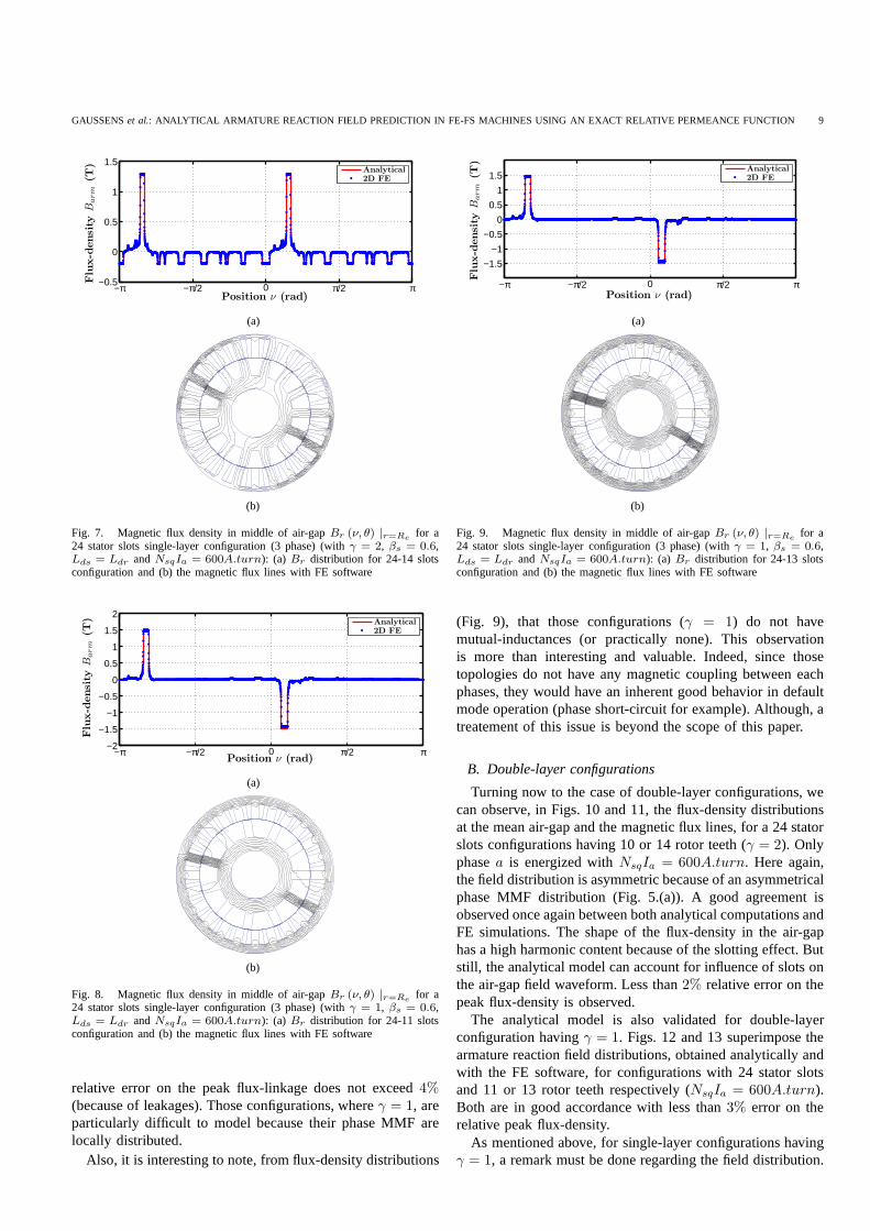
GAUSSENSet al.: ANALYTICAL ARMATURE REACTION FIELD PREDICTION IN FE-FS MACHINES USING AN EXACT RELATIVE PERMEANCE FUNCTION 9
−0.5
0
0.5
1
1.5
Position ν (rad)
Flu
x-d
ensi
tyB
arm
(T)
−π −π/2 0 π/2 π
Analytical2D FE
(a)
(b)
Fig. 7. Magnetic flux density in middle of air-gapBr (ν, θ) |r=Refor a
24 stator slots single-layer configuration (3 phase) (withγ = 2, βs = 0.6,Lds = Ldr andNsqIa = 600A.turn): (a) Br distribution for 24-14 slotsconfiguration and (b) the magnetic flux lines with FE software
−2
−1.5
−1
−0.5
0
0.5
1
1.5
2
Position ν (rad)
Flu
x-d
ensi
tyB
arm
(T)
−π −π/2 0 π/2 π
Analytical2D FE
(a)
(b)
Fig. 8. Magnetic flux density in middle of air-gapBr (ν, θ) |r=Refor a
24 stator slots single-layer configuration (3 phase) (withγ = 1, βs = 0.6,Lds = Ldr andNsqIa = 600A.turn): (a) Br distribution for 24-11 slotsconfiguration and (b) the magnetic flux lines with FE software
relative error on the peak flux-linkage does not exceed4%(because of leakages). Those configurations, whereγ = 1, areparticularly difficult to model because their phase MMF arelocally distributed.
Also, it is interesting to note, from flux-density distributions
−1.5
−1
−0.5
0
0.5
1
1.5
Position ν (rad)
Flu
x-d
ensi
tyB
arm
(T)
−π −π/2 0 π/2 π
Analytical2D FE
(a)
(b)
Fig. 9. Magnetic flux density in middle of air-gapBr (ν, θ) |r=Refor a
24 stator slots single-layer configuration (3 phase) (withγ = 1, βs = 0.6,Lds = Ldr andNsqIa = 600A.turn): (a) Br distribution for 24-13 slotsconfiguration and (b) the magnetic flux lines with FE software
(Fig. 9), that those configurations (γ = 1) do not havemutual-inductances (or practically none). This observationis more than interesting and valuable. Indeed, since thosetopologies do not have any magnetic coupling between eachphases, they would have an inherent good behavior in defaultmode operation (phase short-circuit for example). Although, atreatement of this issue is beyond the scope of this paper.
B. Double-layer configurations
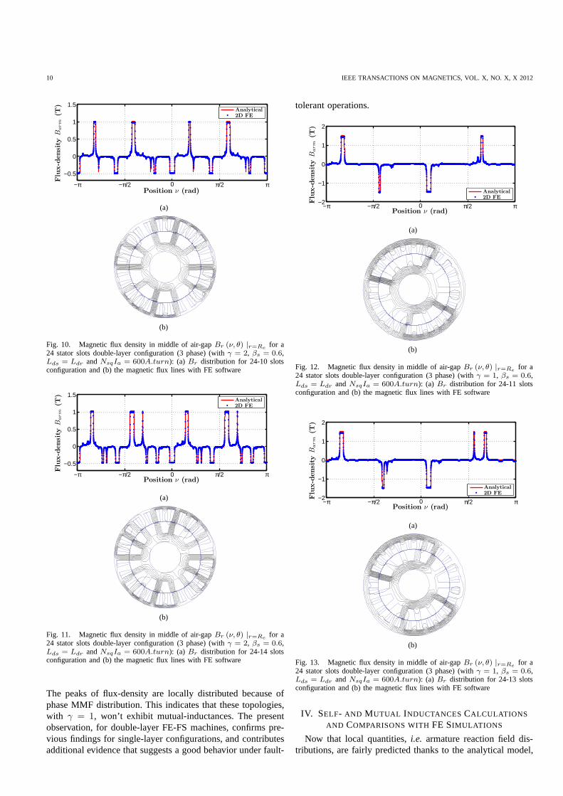
Turning now to the case of double-layer configurations, wecan observe, in Figs. 10 and 11, the flux-density distributionsat the mean air-gap and the magnetic flux lines, for a 24 statorslots configurations having 10 or 14 rotor teeth (γ = 2). Onlyphasea is energized withNsqIa = 600A.turn. Here again,the field distribution is asymmetric because of an asymmetricalphase MMF distribution (Fig. 5.(a)). A good agreement isobserved once again between both analytical computations andFE simulations. The shape of the flux-density in the air-gaphas a high harmonic content because of the slotting effect. Butstill, the analytical model can account for influence of slots onthe air-gap field waveform. Less than2% relative error on thepeak flux-density is observed.
The analytical model is also validated for double-layerconfiguration havingγ = 1. Figs. 12 and 13 superimpose thearmature reaction field distributions, obtained analytically andwith the FE software, for configurations with 24 stator slotsand 11 or 13 rotor teeth respectively (NsqIa = 600A.turn).Both are in good accordance with less than3% error on therelative peak flux-density.
As mentioned above, for single-layer configurations havingγ = 1, a remark must be done regarding the field distribution.
10 IEEE TRANSACTIONS ON MAGNETICS, VOL. X, NO. X, X 2012
−0.5
0
0.5
1
1.5
Position ν (rad)
Flu
x-d
ensi
tyB
arm
(T)
−π −π/2 0 π/2 π
Analytical2D FE
(a)
(b)
Fig. 10. Magnetic flux density in middle of air-gapBr (ν, θ) |r=Refor a
24 stator slots double-layer configuration (3 phase) (withγ = 2, βs = 0.6,Lds = Ldr andNsqIa = 600A.turn): (a) Br distribution for 24-10 slotsconfiguration and (b) the magnetic flux lines with FE software
−0.5
0
0.5
1
1.5
Position ν (rad)
Flu
x-d
ensi
tyB
arm
(T)
−π −π/2 0 π/2 π
Analytical2D FE
(a)
(b)
Fig. 11. Magnetic flux density in middle of air-gapBr (ν, θ) |r=Refor a
24 stator slots double-layer configuration (3 phase) (withγ = 2, βs = 0.6,Lds = Ldr andNsqIa = 600A.turn): (a) Br distribution for 24-14 slotsconfiguration and (b) the magnetic flux lines with FE software
The peaks of flux-density are locally distributed because ofphase MMF distribution. This indicates that these topologies,with γ = 1, won’t exhibit mutual-inductances. The presentobservation, for double-layer FE-FS machines, confirms pre-vious findings for single-layer configurations, and contributesadditional evidence that suggests a good behavior under fault-
tolerant operations.
−2
−1
0
1
2
Position ν (rad)
Flu
x-d
ensi
tyB
arm
(T)
−π −π/2 0 π/2 π
Analytical2D FE
(a)
(b)
Fig. 12. Magnetic flux density in middle of air-gapBr (ν, θ) |r=Refor a
24 stator slots double-layer configuration (3 phase) (withγ = 1, βs = 0.6,Lds = Ldr andNsqIa = 600A.turn): (a) Br distribution for 24-11 slotsconfiguration and (b) the magnetic flux lines with FE software
−2
−1
0
1
2
Position ν (rad)
Flu
x-d
ensi
tyB
arm
(T)
−π −π/2 0 π/2 π
Analytical2D FE
(a)
(b)
Fig. 13. Magnetic flux density in middle of air-gapBr (ν, θ) |r=Refor a
24 stator slots double-layer configuration (3 phase) (withγ = 1, βs = 0.6,Lds = Ldr andNsqIa = 600A.turn): (a) Br distribution for 24-13 slotsconfiguration and (b) the magnetic flux lines with FE software
IV. SELF- AND MUTUAL INDUCTANCESCALCULATIONS
AND COMPARISONS WITHFE SIMULATIONS
Now that local quantities,i.e. armature reaction field dis-tributions, are fairly predicted thanks to the analytical model,
GAUSSENSet al.: ANALYTICAL ARMATURE REACTION FIELD PREDICTION IN FE-FS MACHINES USING AN EXACT RELATIVE PERMEANCE FUNCTION 11
self- and mutual inductances can be derived also analytically.Also, Finite Element simulations come to validate the analyt-ical results and demonstrate the utility and accuracy of thedeveloped model.
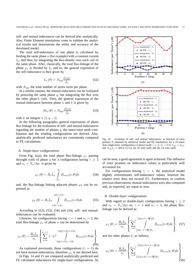
The total self-inductance of one phase is calculated byfeeding the same phasea (for example) with a constant currentIa, and then, by integrating the flux-density over each coil ofthe same phase. After, classically, the total flux-linkage of thephaseϕs is divided byIa and so, the general expression ofthe self-inductance is then given by
Ls (θ) = Ntpp
ϕs(θ)
Ia(52)
with Ntpp the total number of series turns per phase.In a similar manner, the mutual-inductance can be evaluated
by powering the same phaseq, but integrating the flux overthe other phase’s coils. Then, the general expression of themutual-inductance between phasea andk is given by
Mk (θ) = Ntpp
ϕk(θ)
Ia(53)
with k an integrer∈ [1, q − 1].In the following paragraphs, general expressions of phase
flux-linkage for the evaluation of self- and mutual-inductancesregarding the number of phasesq, the stator-rotor teeth com-bination and the winding configurations are derived. Also,analytically predicted inductances are consistently comparedto FE calculations.
A. Single-layer configurations
From Fig. 4.(a), the total phase flux-linkageϕs passingthrought coils of phaseq for a configuration havingγ ≥ 2andnc = Ns/4qγ is given by
ϕs (θ) = ReLa
θs∫
−θs
Barm(ν, θ)dν (54)
and, the flux-linkage linking adjacent phasesϕk can be ex-pressed as
ϕk (θ) = ReLa
(4k+1)θs∫
(4k−1)θs
Barm(ν, θ)dν (55)
According to (52), (53), (54) and (54), self- and mutual-inductances can be evaluated.
Likewise, for configurations havingγ = 1 andnc = 2, thetotal flux-linkageϕs of phasea can be determined by
ϕs (θ) =ReLa
nc
nc−1∑
i=0
(−1)i
(2q(1+2i)+1)θs∫
(2q(1+2i)−1)θs
Barm(ν, θ)dν
(56)As explained previously, those configurations (γ = 1) do
not have mutual-inductances, thereforeϕs is not derived here.In Figs. 14 and 15 are compared analytically predicted and
FE calculated inductances for single-layer configurations. As
0 5 10 15 20 25 30 35−2
0
2
4
6
Position θ (deg)
Inducta
nces
(per
Turn
s2)
(µH
)
Analytical - Ls
2D FE - Ls
Analytical - M1
2D FE - M1
Analytical - M2
2D FE - M2
(a)
0 5 10 15 20 25−2
0
2
4
6
8
Position θ (deg)
Inducta
nces
(per
Turn
s2)
(µH
)
Analytical - Ls
2D FE - Ls
Analytical - M1
2D FE - M1
Analytical - M2
2D FE - M2
(b)
Fig. 14. Evolution of self- and mutual inductances, as fonction of rotorposition θ, obtained by analytical model and FE simulations, for a 24 statorslots single-layer configuration (3 phase) (withγ = 2, βs = 0.6, Lds = Ldr
andNsqIa = 600A.turn): (a) 10 rotor teeth and (b) 14 rotor teeth
can be seen, a good agreement is again achieved. The influenceof rotor position on inductance values is particularly wellaccounted for.
For configurations havingγ = 1, the analytical modelslightly overestimates self-inductance values, however therelative error does not exceed3%. Furthermore, to confirmprevious observations, mutual-inductances were also computedand, as expected, are equal to zero.
B. Double-layer configurations
With regard to double-layer configurations havingγ ≥ 2and nc = Ns/2qγ or, γ = 1 and nc = 2, the phase flux-linkage can be derived as
ϕs (θ) =ReLa
nc
nc−1∑
i=0
(2qi+1− βs4 )θs
∫
(2qi−1+ βs4 )θs
Barm(ν, θ)dν
(57)
and for other phasesk, as follows,
ϕk (θ) =ReLa
nc
nc−1∑
i=0
(2(qi+k)+1− βs4 )θs
∫
(2(qi+k)−1+ βs4 )θs
Barm(ν, θ)dν
(58)

12 IEEE TRANSACTIONS ON MAGNETICS, VOL. X, NO. X, X 2012
0 5 10 15 20 25 30
0
2
4
6
8
Position θ (deg)
Inducta
nces
(per
Turn
s2)
(µH
)
Analytical - Ls
2D FE - Ls
Analytical - M1
2D FE - M1
Analytical - M2
2D FE - M2
(a)
0 5 10 15 20 25−2
0
2
4
6
8
Position θ (deg)
Inducta
nces
(per
Turn
s2)
(µH
)
Analytical - Ls
2D FE - Ls
Analytical - M1
2D FE - M1
Analytical - M2
2D FE - M2
(b)
Fig. 15. Evolution of self- and mutual inductances, as fonction of rotorposition θ, obtained by analytical model and FE simulations, for a 24 statorslots single-layer configuration (3 phase) (withγ = 1, βs = 0.6, Lds = Ldr
andNsqIa = 600A.turn): (a) 11 rotor teeth and (b) 13 rotor teeth
For configurations withγ = 1 andnc = 4, we can derivethe total phase flux-linkage as
ϕs (θ) =ReLa
nc
nc2 −1∑
i=0
(−1)i
(2(qi+k)+1− βs4 )θs
∫
(2(qi+k)−1+ βs4 )θs
Barm(ν, θ)dν
−
nc−1∑
i=nc2
(−1)i
(2(qi+k)+1− βs4 )θs
∫
(2(qi+k)−1+ βs4 )θs
Barm(ν, θ)dν
(59)
The analytically predicted inductances for double-layer con-figurations are compared with FE predictions in Figs. 16 and17. It shows that predicted inductances by the analytical modelalmost completely match FE simulations. Here again, theinfluence of the salient moving rotor is well taken into account.A slight difference due to additional leakage is observed forconfigurations havingγ = 1 (Fig. 17). Nevertheless, therelative error on the inductance does not exceed3%.
V. CONCLUSION
The present work paves the way to a precise prediction ofarmature reaction field for multiphase FE-FS machines, andhence, along with an open circuit analytical model (previouswork), the proposed model can be used for prediction of onload field distribution.
0 5 10 15 20 25 30 35−3
−2
−1
0
1
2
3
4
5
Position θ (deg)
Inducta
nces
(per
Turn
s2)
(µH
)
Analytical - Ls
2D FE - Ls
Analytical - M1
2D FE - M1
Analytical - M2
2D FE - M2
(a)
0 5 10 15 20 25−4
−2
0
2
4
6
Position θ (deg)
Inducta
nces
(per
Turn
s2)
(µH
)
Analytical - Ls
2D FE - Ls
Analytical - M1
2D FE - M1
Analytical - M2
2D FE - M2
(b)
Fig. 16. Evolution of self- and mutual inductances, as fonction of rotorposition θ, obtained by analytical model and FE simulations for a 24 statorslots double-layer configuration (3 phase) (withγ = 2, βs = 0.6, Lds = Ldr
andNsqIa = 600A.turn): (a) 10 rotor teeth and (b) 14 rotor teeth
In the first part of the paper, an exact expression of the slotrelative permeance is derived by solving the field governingequations in each subdomain,i.e., stator slot and air-gap, andapplying the boundary conditions to the interface between bothsubdomain. In so doing, a general expression of the air-gappermeance is obtained, accounting for the moving salient rotor.
Because of flux-switching principle, armature winding dis-tributions depend directly on the stator-rotor teeth configura-tion. We propose in this paper, a way to sort the different fea-sible combinations, and also, general expressions, as Fourierseries, of phase MMF distributions are derived, accountingforthe phase numberq, the stator-rotor teeth configuration and thephase winding configuration (single or double-layers).
Extensive comparisons with 2D FE results have been pro-vided. Those results have shown a good accuracy in theprediction of the armature reaction field for several topologies.Moreover, a striking observation has emerged from this study.Some stator-rotor configurations (generally whenγ = 1)do not have mutual-inductances. Those machines could benamed ”Non-Mutually Coupled Flux-Switching Machines”. Atreatement of these topologies is beyond the scope of thispaper. Although, this is an important issue for future research,and especially for fault-tolerant machines.
Finally, the last section focused on the evaluation of self-and mutual-inductance. Here again, general analytical expres-

GAUSSENSet al.: ANALYTICAL ARMATURE REACTION FIELD PREDICTION IN FE-FS MACHINES USING AN EXACT RELATIVE PERMEANCE FUNCTION 13
0 5 10 15 20 25 30−0.5
0
0.5
1
1.5
2
2.5
3
3.5
4
Position θ (deg)
Inducta
nces
(per
Turn
s2)
(µH
)
Analytical - Ls
2D FE - Ls
Analytical - M1
2D FE - M1
Analytical - M2
2D FE - M2
(a)
0 5 10 15 20 25
0
1
2
3
4
5
Position θ (deg)
Inducta
nces
(per
Turn
s2)
(µH
)
Analytical - Ls
2D FE - Ls
Analytical - M1
2D FE - M1
Analytical - M2
2D FE - M2
(b)
Fig. 17. Evolution of self- and mutual inductances, as fonction of rotorposition θ, obtained by analytical model and FE simulations for a 24 statorslots double-layer configuration (3 phase) (withγ = 1, βs = 0.6, Lds = Ldr
andNsqIa = 600A.turn): (a) 11 rotor teeth and (b) 13 rotor teeth
sions regarding, the stator-rotor teeth combination, forq phasemachines and the winding configuration have been presented.Close agreements with FE analysis have been demonstrated,illustrating the gain in terms of computation time.
APPENDIX AINFLUENCE OF VARIATION OF THE SLOT OPENINGβs ON
THE RELATIVE PERMEANCE FUNCTION
The influence of the slot opening on the distribution ofthe scalar magnetic potential in the air-gap and the slot, byboth analytical model and FE software, are presented in Fig.18. Also, the relative permeance function obtained by bothmethods are compared, and we can observe a good agreementwith regard to different slot opening values.
ACKNOWLEDGMENT
The authors would like to thank Leroy Somer (who are partof Emerson) and Agence Nationale de la Recherche (ANR)for their support.
REFERENCES
[1] Z. Zhu and J. Chen, “Advanced flux-switching permanent magnetbrushless machines,”IEEE Trans. Magn., vol. 46, no. 6, pp. 1447 –1453, june 2010.
[2] G. Li, J. Ojeda, E. Hoang, and M. Gabsi, “Thermal-electromagneticanalysis of a fault-tolerant dual-star flux-switching permanent magnetmotor for critical applications,”Electric Power Applications, IET, vol. 5,no. 6, pp. 503 –513, july 2011.
[3] G. Li, J. Ojeda, E. Hoang, M. Gabsi, and M. Lecrivain, “Thermal-electromagnetic analysis for driving cycles of embedded flux-switchingpermanent-magnet motors,”IEEE Trans. Veh. Technol., vol. 61, no. 1,pp. 140 –151, jan. 2012.
[4] S. E. Rauch and L. J. Johnson, “Design principles of flux-switchalternators,”Power Apparatus and Systems, Part III. Transactions ofthe American Institute of Electrical Engineers, vol. 74, no. 3, pp. 1261–1268, jan. 1955.
[5] B. Sarlioglu, Y. Zhao, and T. Lipo, “A novel doubly salient single phasepermanent magnet generator,” inIndustry Applications Society AnnualMeeting, 1994., Conference Record of the 1994 IEEE, oct 1994, pp. 9–15 vol.1.
[6] E. Hoang, A. H. Ben-Ahmed, and J. Lucidarme, “Switching fluxpermanent magnet polyphased synchronous machines,” in7th EuropeanConference on Power Electronics and Applications, vol. 3, 1997, pp.903–908.
[7] Z. Zhu, A. Thomas, J. Chen, and G. Jewell, “Cogging torquein flux-switching permanent magnet machines,”IEEE Trans. Magn., vol. 45,no. 10, pp. 4708 –4711, oct. 2009.
[8] Y. Cheng, C. Pollock, and H. Pollock, “A permanent magnetfluxswitching motor for low energy axial fans,” inIndustry ApplicationsConference, 2005. Fourtieth IAS Annual Meeting. Conference Record ofthe 2005, vol. 3, oct. 2005, pp. 2168 – 2175 Vol. 3.
[9] E. Hoang, M. Lecrivain, S. Hlioui, and M. Gabsi, “Hybrid excitationsynchronous permanent magnets synchronous machines optimally de-signed for hybrid and full electrical vehicle,” inPower Electronics andECCE Asia (ICPE ECCE), 2011 IEEE 8th International Conference on,30 2011-june 3 2011, pp. 153 –160.
[10] E. Hoang, M. Gabsi, M. Lecrivain, and B. Multon, “Influence ofmagnetic losses on maximum power limits of synchronous permanentmagnet drives in flux-weakening mode,” inIndustry Applications Con-ference, 2000. Conference Record of the 2000 IEEE, vol. 1, 2000, pp.299 –303 vol.1.
[11] Y. Amara, E. Hoang, M. Gabsi, M. Lcrivain, and S. Allano,“Designand comparison of different flux-switch synchronous machines for anaircraft oil breather application,”European Transactions on ElectricalPower, vol. 15, pp. 497–511, 2005.
[12] R. Owen, Z. Zhu, and G. Jewell, “Hybrid-excited flux-switchingpermanent-magnet machines with iron flux bridges,”IEEE Trans. Magn.,vol. 46, no. 6, pp. 1726 –1729, june 2010.
[13] W. Hua, M. Cheng, and G. Zhang, “A novel hybrid excitation flux-switching motor for hybrid vehicles,”IEEE Trans. Magn., vol. 45,no. 10, pp. 4728 –4731, oct. 2009.
[14] E. Hoang, M. Lecrivain, and M. Gabsi, “A new structure ofa switchingflux synchronous polyphased machine with hybrid excitation,” in PowerElectronics and Applications, 2007 European Conference on, sept. 2007,pp. 1 –8.
[15] E. Sulaiman, T. Kosaka, and N. Matsui, “High power density designof 6-slot 8-pole hybrid excitation flux switching machine for hybridelectric vehicles,”IEEE Trans. Magn., vol. 47, no. 10, pp. 4453 –4456,oct. 2011.
[16] C. Pollock and M. Wallace, “The flux switching motor, a dcmotorwithout magnets or brushes,” inIndustry Applications Conference, 1999.Thirty-Fourth IAS Annual Meeting. Conference Record of the1999 IEEE,vol. 3, 1999, pp. 1980 –1987 vol.3.
[17] H. Pollock, C. Pollock, R. Walter, and B. Gorti, “Low cost, high powerdensity, flux switching machines and drives for power tools,” in IndustryApplications Conference, 2003. 38th IAS Annual Meeting. ConferenceRecord of the, vol. 3, oct. 2003, pp. 1451 – 1457 vol.3.
[18] J. Chen, Z. Zhu, S. Iwasaki, and R. Deodhar, “Low cost flux-switchingbrushless ac machines,” inVehicle Power and Propulsion Conference(VPPC), 2010 IEEE, sept. 2010, pp. 1 –6.
[19] A. Zulu, B. Mecrow, and M. Armstrong, “A wound-field three-phaseflux-switching synchronous motor with all excitation sources on thestator,” IEEE Trans. Ind. Appl., vol. 46, no. 6, pp. 2363 –2371, nov.-dec.2010.
[20] ——, “Topologies for wound-field three-phase segmented-rotor flux-switching machines,” inPower Electronics, Machines and Drives(PEMD 2010), 5th IET International Conference on, april 2010, pp.1 –6.
[21] Z. Zhu, Y. Pang, D. Howe, S. Iwasaki, R. Deodhar, and A. Pride,“Analysis of electromagnetic performance of flux-switching permanent-magnet machines by nonlinear adaptive lumped parameter magnetic

14 IEEE TRANSACTIONS ON MAGNETICS, VOL. X, NO. X, X 2012
−π/Ns
−πβs/N
s0 πβ
s/N
sπ/N
sPosition ν (rad)
Radiu
sr
(mm
)
0.13
0.135
0.14
0.145
0
0.2
0.4
0.6
0.8
1
(a) (b)
0
0.2
0.4
0.6
0.8
1
Position ν (rad)
Rela
tive
perm
eance
Λr
s(ν
)
−π/Ns
−πβs/N
s0 πβ
s/N
sπ/N
s
Analytical2D FE
(c)
−π/Ns
−πβs/N
s0 πβ
s/N
sπ/N
s
Position ν (rad)
Radiu
sr
(mm
)
0,13
0,135
0,14
0,145
0
0.2
0.4
0.6
0.8
1
(d) (e)
0
0.2
0.4
0.6
0.8
1
Position ν (rad)
Rela
tive
perm
eance
Λr
s(ν
)
−π/Ns
−πβs/N
s0 πβ
s/N
sπ/N
s
Analytical
2D FE
(f)
−π/Ns−πβ
s/N
s0 πβ
s/N
sπ/N
sPosition ν (rad)
Radiu
sr
(mm
)
0.13
0.135
0.14
0.145
0
0.2
0.4
0.6
0.8
1
(g) (h)
0
0.2
0.4
0.6
0.8
1
Position ν (rad)
Rela
tive
perm
eance
Λr
s(ν
)
−π/Ns
−πβs/N
s0 πβ
s/N
sπ/N
s
Analytical
2D FE
(i)
Fig. 18. Distribution of equipotential lines of scalar magnetic potential in air-gap and slot regions with the analytical model and the FE simulation. Comparisonbetween analytical and FE calculated relative permeance functionΛrs for a 24 stator slots structure (withe = 0.5mm, Rsi = 126.6mm andHs = 20mm).(a)(b)(c)βs = 0.2, (d)(e)(f) βs = 0.5 and (g)(h)(i)βs = 0.8
circuit model,” IEEE Trans. Magn., vol. 41, no. 11, pp. 4277 – 4287,nov. 2005.
[22] J. Chen and Z. Zhu, “Influence of the rotor pole number on optimalparameters in flux-switching pm brushless ac machines by thelumped-parameter magnetic circuit model,”IEEE Trans. Ind. Appl., vol. 46,no. 4, pp. 1381 –1388, july-aug. 2010.
[23] B. Gysen, E. Ilhan, K. Meessen, J. Paulides, and E. Lomonova, “Model-ing of flux switching permanent magnet machines with fourieranalysis,”IEEE Trans. Magn., vol. 46, no. 6, pp. 1499 –1502, june 2010.
[24] L. Wu, Z. Zhu, D. Staton, M. Popescu, and D. Hawkins, “Subdo-main model for predicting armature reaction field of surface-mountedpermanent-magnet machines accounting for tooth-tips,”IEEE Trans.Magn., vol. 47, no. 4, pp. 812 –822, april 2011.
[25] Y. Amara, G. Barakat, and P. Reghem, “Armature reactionmagneticfield of tubular linear surface-inset permanent-magnet machines,” IEEETrans. Magn., vol. 47, no. 4, pp. 805 –811, april 2011.
[26] A. Bellara, Y. Amara, G. Barakat, and B. Dakyo, “Two-dimensionalexact analytical solution of armature reaction field in slotted surfacemounted pm radial flux synchronous machines,”IEEE Trans. Magn.,vol. 45, no. 10, pp. 4534 –4538, oct. 2009.
[27] A. Chiba, F. Nakamura, T. Fukao, and M. Rahman, “Inductances ofcageless reluctance-synchronous machines having nonsinusoidal spacedistributions,” Industry Applications, IEEE Transactions on, vol. 27,no. 1, pp. 44 –51, jan/feb 1991.
[28] T. Lubin, T. Hamiti, H. Razik, and A. Rezzoug, “Comparison betweenfinite-element analysis and winding function theory for inductances andtorque calculation of a synchronous reluctance machine,”IEEE Trans.Magn., vol. 43, no. 8, pp. 3406 –3410, aug. 2007.
[29] G. Dajaku and D. Gerling, “Stator slotting effect on themagnetic field
distribution of salient pole synchronous permanent-magnet machines,”IEEE Trans. Magn., vol. 46, no. 9, pp. 3676 –3683, sept. 2010.
[30] Z. Zhu and D. Howe, “Instantaneous magnetic field distribution inbrushless permanent magnet dc motors. iii. effect of statorslotting,”IEEE Trans. Magn., vol. 29, no. 1, pp. 143 –151, jan 1993.
[31] ——, “Instantaneous magnetic field distribution in permanent magnetbrushless dc motors. iv. magnetic field on load,”IEEE Trans. Magn.,vol. 29, no. 1, pp. 152 –158, jan 1993.
[32] D. Zarko, D. Ban, and T. Lipo, “Analytical calculation of magnetic fielddistribution in the slotted air gap of a surface permanent-magnet motorusing complex relative air-gap permeance,”IEEE Trans. Magn., vol. 42,no. 7, pp. 1828 – 1837, july 2006.
[33] ——, “Analytical solution for cogging torque in surfacepermanent-magnet motors using conformal mapping,”IEEE Trans. Magn., vol. 44,no. 1, pp. 52 –65, jan. 2008.
[34] U. Kim and D. Lieu, “Magnetic field calculation in permanent magnetmotors with rotor eccentricity: with slotting effect considered,” IEEETrans. Magn., vol. 34, no. 4, pp. 2253 –2266, jul 1998.
[35] S. Sadeghi and L. Parsa, “Multiobjective design optimization of five-phase halbach array permanent-magnet machine,”IEEE Trans. Magn.,vol. 47, no. 6, pp. 1658 –1666, june 2011.
[36] Z. Zhu, L. Wu, and Z. Xia, “An accurate subdomain model for mag-netic field computation in slotted surface-mounted permanent-magnetmachines,”IEEE Trans. Magn., vol. 46, no. 4, pp. 1100 –1115, april2010.
[37] T. Lubin, S. Mezani, and A. Rezzoug, “Exact analytical method formagnetic field computation in the air gap of cylindrical electricalmachines considering slotting effects,”IEEE Trans. Magn., vol. 46,no. 4, pp. 1092 –1099, april 2010.

GAUSSENSet al.: ANALYTICAL ARMATURE REACTION FIELD PREDICTION IN FE-FS MACHINES USING AN EXACT RELATIVE PERMEANCE FUNCTION 15
[38] Z. Liu and J. Li, “Analytical solution of air-gap field inpermanent-magnet motors taking into account the effect of pole transition overslots,” IEEE Trans. Magn., vol. 43, no. 10, pp. 3872 –3883, oct. 2007.
[39] F. Dubas and C. Espanet, “Analytical solution of the magnetic fieldin permanent-magnet motors taking into account slotting effect: No-load vector potential and flux density calculation,”IEEE Trans. Magn.,vol. 45, no. 5, pp. 2097 –2109, may 2009.
[40] H. Tiegna, A. Bellara, Y. Amara, and G. Barakat, “Analytical modelingof the open-circuit magnetic field in axial flux permanent magnetmachines with semi-closed slots,”IEEE Trans. Magn., vol. PP, no. 99,p. 1, 2011.
[41] R. Deodhar, S. Andersson, I. Boldea, and T. Miller, “Theflux-reversalmachine: a new brushless doubly-salient permanent-magnetmachine,”Industry Applications, IEEE Transactions on, vol. 33, no. 4, pp. 925–934, jul/aug 1997.
[42] A. Zulu, B. Mecrow, and M. Armstrong, “Investigation ofthe dq-equivalent model for performance prediction of flux-switching syn-chronous motors with segmented-rotors,”IEEE Trans. Ind. Electron.,vol. PP, no. 99, p. 1, 2011.
Gaussens Benjaminwas born in Toulouse, France, in 1987. He received theM.Sc. degree in electrical engineering from the Institut National Polytechnique(ENSEEIHT), Toulouse, France. He is currently working toward the Ph.D.degree still in electrical engineering at SATIE, ENS Cachan, CNRS, Univer-Sud. His current research interests include design of innovative topology ofelectromagnetic actuators and their modeling.
Hoang Emmanuel was born in Antibes, France, in 1966. He received the”agregation” in electrical engineering in 1990 and the Ph.D. degree from theEcole Normale Superieure de Cachan in 1995. Since 1990, he has worked withthe electrical machine team in the SATIE laboratory. His research interestsinclude the modeling of the iron losses in SRMs and the design, modeling,optimization, and control of novel topologies of PM machines.
De la Barri ere Olivier was born in Paris, France, in 1982. He receivedthe M.Sc. degree in electronics from the Ecole Nationale Superieure del’Electronique et de ses Applications (ENSEA), and the Ph.D. degree inelectrical engineering from the Ecole Normale Superieurede Cachan. He isnow a Reseacher at SATIE, ENS Cachan, CNRS, UniverSud. His researchtopics include analytical modelling of electrical actuators, and also the studyof new magnetic materials for electrical engineering applications.
Saint-Michel Jacques was born in 1949. He received the degree in engi-neering from Ecole Centrale de Paris, Paris, France, in 1972, and the Ph.D.degree from the University of Paris VI, Paris. From 1972 to 1982, he waswith the French National Scientific Research Center (CNRS).In 1982, hejoined Jeumont Schneider as the Head of the Design and Planning Departmentand remained with them until 1990. In 1990, he joined Leroy-Somer Motor,Angouleme, France, as a Technical Manager, becoming Scientific Director in1998.
Manfe Philippe was born in 1957. He received the degree in engineeringfrom Ecole Nationale Superieure d’Electricite et de Mecanique, and the Ph.D.degree from the Institut National Polytechnique de Lorraine, Nancy, France.From 1981 to 1984, he was with the French National Scientific ResearchCenter (CNRS). In 1985, he joined Leroy Somer Motors and Drive Division,Angouleme, France to Design and Develop high performance motors anddrives for industrial and automotive markets. In 1997 he joined the AlternatorsDivision as Electrical Engineering Manager, and is currently Engineering Di-rector for LV Generators in Emerson/LS Electric Power Generation Division.
Lecrivain Michel was born in Barneville, France. He received the degreein electrical engineering from the Conservatoire Nationaldes Arts et Metiers(CNAM, Paris, France) in 1981. In 1997 he joined SATIE laboratory as aResearch Engineer. His research interests include the design and control ofnew hybrid machines and novel permanent-magnet machines for automotiveapplications.
Gabsi Mohamed received the Ph.D. degree in electrical engineering fromUniversity of Paris-VI in 1987 and the HDR in 1999 from Universityof Paris-XI (Orsay, France). Since 1990, he has been workingwith theelectrical machine team (SETE, Systemes d’Energies pour le Transport etl’Environnement) of SATIE laboratory where he is currentlya Full Professorand the Director of the Electrical Engineering Department.His researchinterests include SRM, vibrations and acoustic noise, and PM machines.