Voltage Control of Self-Excited Induction Generator using ...
11
Turk J Elec Eng & Comp Sci, Vol.17, No.1, 2009, c T ¨ UB ˙ ITAK doi:10.3906/elk-0610-1 Voltage Control of Self-Excited Induction Generator using Genetic Algorithm Dheeraj JOSHI, Kanwarjit Singh SANDHU, Mahender Kumar SONI Department of Electrical Engineering, National Institute of Technology, Kurukshetra-136119, Haryana-INDIA e-mail: dheeraj [email protected], [email protected], [email protected] Abstract Self-excited induction generators (SEIG) are found to be most suitable candidate for wind energy conver- sion application required at remote windy locations. Such generators are not able to maintain the terminal voltage with load as, a literature survey reveals, the voltage profile falls sharply with load. In this paper an attempt has been made to improve the voltage profile of a self-excited induction generator. A new method- ology based upon Genetic Algorithm (GA) is proposed to compute the steady state performance of the model including core loss branch. Further efforts are made to control the terminal voltage under loaded conditions. Simulated results using proposed modeling have been compared with experimental results. A close agreement between the computed and experimentalresults confirms the validity of the approach adopted. Key Words: Asychronous generators, Genetic Algorithm, Self-excited induction generator, Voltage regula- tion. 1. Introduction The self-excited induction generators (SEIG) have been found suitable for energy conversion for remote locations. Such generators may be commonly used in the remote rural areas where it is not possible to draw from transmission lines. These machines can be used to meet the local demand of remote areas in the absence of a grid. SEIG has many advantages such as simple construction (especially in squirrel-cage rotor), absence of DC power supply for excitation, reduced maintenance cost, good overspeed capability, self short-circuit protection capability and no synchronizing problem. To compute the steady state performance of SEIG, researchers [1–8] adopted loop impedance or nodal admittance with iterative models. [7–8] proposed a new equivalent circuit model which includes a power source on rotor side. Irrespective of analytical technique or representation, it has been found that the major drawback of the SEIG is its poor voltage regulation. The terminal voltage varies with load and operating speed and fixed capacitor alone cannot provide the adequate amount of reactive power needed by the induction generator [9]. Reference [10] has presented a controller architecture with three phase, four-wire shunt active filter for a stand alone SEIG under varying wind speed conditions. A mathematical model has been developed for voltage control 87
-
Upload
khangminh22 -
Category
Documents
-
view
6 -
download
0
Transcript of Voltage Control of Self-Excited Induction Generator using ...
Turk J Elec Eng & Comp Sci,Vol.17, No.1, 2009, c© TUBITAKdoi:10.3906/elk-0610-1
Voltage Control of Self-Excited Induction Generator
using Genetic Algorithm
Dheeraj JOSHI, Kanwarjit Singh SANDHU, Mahender Kumar SONIDepartment of Electrical Engineering, National Institute of Technology,
Kurukshetra-136119, Haryana-INDIAe-mail: dheeraj [email protected], [email protected], [email protected]
Abstract
Self-excited induction generators (SEIG) are found to be most suitable candidate for wind energy conver-
sion application required at remote windy locations. Such generators are not able to maintain the terminal
voltage with load as, a literature survey reveals, the voltage profile falls sharply with load. In this paper an
attempt has been made to improve the voltage profile of a self-excited induction generator. A new method-
ology based upon Genetic Algorithm (GA) is proposed to compute the steady state performance of the model
including core loss branch. Further efforts are made to control the terminal voltage under loaded conditions.
Simulated results using proposed modeling have been compared with experimental results. A close agreement
between the computed and experimental results confirms the validity of the approach adopted.
Key Words: Asychronous generators, Genetic Algorithm, Self-excited induction generator, Voltage regula-
tion.
1. Introduction
The self-excited induction generators (SEIG) have been found suitable for energy conversion for remote locations.Such generators may be commonly used in the remote rural areas where it is not possible to draw fromtransmission lines. These machines can be used to meet the local demand of remote areas in the absenceof a grid. SEIG has many advantages such as simple construction (especially in squirrel-cage rotor), absenceof DC power supply for excitation, reduced maintenance cost, good overspeed capability, self short-circuitprotection capability and no synchronizing problem.
To compute the steady state performance of SEIG, researchers [1–8] adopted loop impedance or nodal
admittance with iterative models. [7–8] proposed a new equivalent circuit model which includes a power sourceon rotor side. Irrespective of analytical technique or representation, it has been found that the major drawbackof the SEIG is its poor voltage regulation. The terminal voltage varies with load and operating speed and fixedcapacitor alone cannot provide the adequate amount of reactive power needed by the induction generator [9].
Reference [10] has presented a controller architecture with three phase, four-wire shunt active filter for a standalone SEIG under varying wind speed conditions. A mathematical model has been developed for voltage control
87
Turk J Elec Eng & Comp Sci, Vol.17, No.1, 2009
purpose by [11] with STATCOM for SEIG. It has been shown that STATCOM acts as voltage regulator, loadbalancer and harmonic eliminator.
The variation in voltage may be controlled through excitation capacitance, as the load or speed varies.Reference [12] proposed a regulating scheme using constant frequency model with proper control of operatingspeed and excitation capacitance.
In the present study, a new and unique genetic algorithm-based modeling approach has been adopted tocompute the unknown generated frequency, magnetizing reactance and excitation capacitance, simultaneously,for self-excited induction generators. The proposed modeling approach may be used to predict and controlthe excitation capacitance to maintain a constant terminal voltage for changing load conditions. This makesthe analysis simple and effective. In addition, iron/core losses of the induction generator have taken intoconsideration during analysis and such inclusion makes analysis more realistic.
2. Genetic Algorithm
The genetic algorithm (GA) [13] is an optimization technique that performs a parallel, stochastic and directed
search to evolve the fittest (best) solution. Different from conventional optimization methods, GA employs theprinciples of evolution, natural selection and genetics, as inspired by natural biological systems, in a computeralgorithm to simulate evolution.
Performance evaluation variables aand C in SEIG may take any real number. Thus following the manyresearchers who have been paying attention to real-coded evolutionary algorithms, particularly for solving real-world optimization problems (as is SEIG), we use a real-coded GA [14-15] to investigate performance parameterspace. Three main operators comprising GAs are: reproduction, crossover, and mutation.
Reproduction: - Evolution is, in effect, a method of searching among an enormous number of possibilitiesfor solutions. For the analysis and control of SEIG, tournament selection is used for reproduction. A string ispermitted reproduction based on fitness for productivity, where productivity of an individual is defined as thevalue of a string’s non-negative objective function.
Crossover: - The crossover operator exchanges genetic information between strings. There are a number ofcommonly used crossover operators: such as blend crossover (BLX), simulated binary crossover (SBX), unimodal
normal distribution crossover (UNDX) and simplex crossover (SPX) and parent centric recombination operator
(PCX) [14]. In the present paper PCX operator has been used because this particular operator assigns moreprobability keeping an offspring closer to the parents than away from parents.
Mutation: - Real coded mutation (RCM) operator [15] has been used to protect the irrecoverable orpremature loss of important notions. Since continuous variables are coded directly, RCM is flexible in nature.PCX and RCM operator have been used in conjunction and attain search power similar to the individualmethodologies, yet the overall algorithm performs better than binary-coded GAs.
3. Steady-State Analysis
Steady-state operation of the self-excited generator with shunt capacitors may be analyzed using the equivalentcircuit representation shown in Figure 1. In this circuit model, all parameters are assumed to be independentof saturation, except for magnetizing reactance. However, core loss branch has been accounted for, using the
88

JOSHI, SANDHU, SONI: Voltage Control of Self-Excited Induction Generator...,
algorithm as shown in the Figure 2.
��
��� ���
�
� ��
���
����
��
� ��
�
�� �
����
���
��
Figure 1. Per phase equivalent circuit representation for capacitor self-excited induction generator.
�����
���������� ������������������������������������
���������
�������� ��������������
������������������������
������������
��������������������� �!��������"����
����������#��������
���������#��������
$������%�������
&���������'%
��������(���)�
���*��+���,���������-
��������!��������!��&��
&��
&�������,�./&������"��01�� ����������ε
/� 2��
����(��
/�
2��
Figure 2. Flow Chart.
As Figure 1 contains neither e.m.f. nor current source, nodal analysis of the equivalent circuit results inthe following equations:
∑Y = 0 (1)
where−Y =
−Yr +
−Ymc +
−Ys
89
Turk J Elec Eng & Comp Sci, Vol.17, No.1, 2009
Here subscript r , mc and s represents the rotor branch, magnetizing/ core loss branch and stator branchin the equivalent circuit of machine. Further these can be defined as;
−Ys =
(RL + R1
a
)
(X1 − XL)2 +(RL + R1
a
)2 − j(X1 − XL)
(X1 − XL)2 +(RL + R1
a
)2
−Ymc =
a
Rc− j
1Xm
−Yr =
R2a−b
X22 +
(R2a−b
)2 − jX2
X22 +
(R2a−b
)2
where,
RL =RX2
sh
a2R2 + (a2X − Xsh)2
and
XL =aR2Xsh + a3X2Xsh − aXX2
sh
a2R2 + (a2X − Xsh)2
Equation (2) must be satisfied to ensure the phenomenon of self-excitation. The SEIG voltage regulationproblem may easily be handled by using the objective function
OF = Y + Verr , (2)
whereVerr = (1 − Vpu)2
Here ‘V ′pu is the per unit generated voltage. This objective function may be minimized using GA to maintain
power quality. Suitable ranges of a and C are given in Appendix I. Such approach gives a new and uniquemethodology to compute the values of a and C simultaneously for controlled voltage operation of SEIG.
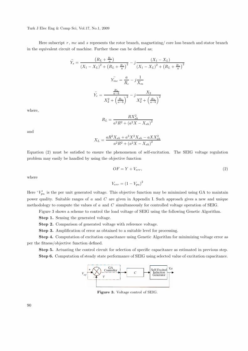
Figure 3 shows a scheme to control the load voltage of SEIG using the following Genetic Algorithm.Step 1. Sensing the generated voltage.
Step 2. Comparison of generated voltage with reference voltage.
Step 3. Amplification of error as obtained to a suitable level for processing.Step 4. Computation of excitation capacitance using Genetic Algorithm for minimizing voltage error as
per the fitness/objective function defined.
Step 5. Actuating the control circuit for selection of specific capacitance as estimated in previous step.
Step 6. Computation of steady state performance of SEIG using selected value of excitation capacitance.
����
) �3��������
��
��!4&+�����������������������
���
4
Figure 3. Voltage control of SEIG.
90
JOSHI, SANDHU, SONI: Voltage Control of Self-Excited Induction Generator...,
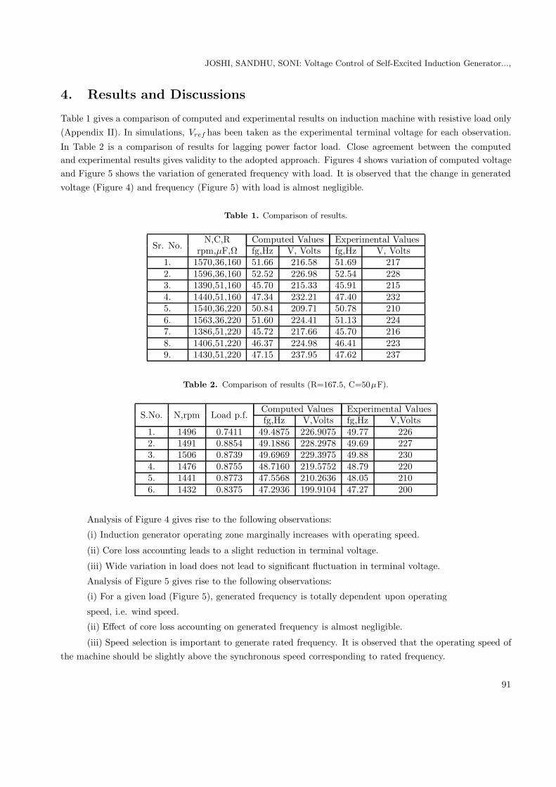
4. Results and Discussions
Table 1 gives a comparison of computed and experimental results on induction machine with resistive load only(Appendix II). In simulations, Vref has been taken as the experimental terminal voltage for each observation.
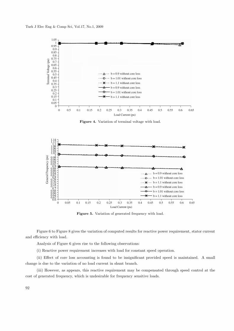
In Table 2 is a comparison of results for lagging power factor load. Close agreement between the computedand experimental results gives validity to the adopted approach. Figures 4 shows variation of computed voltageand Figure 5 shows the variation of generated frequency with load. It is observed that the change in generatedvoltage (Figure 4) and frequency (Figure 5) with load is almost negligible.
Table 1. Comparison of results.
Sr. No.N,C,R Computed Values Experimental Values
rpm,μF,Ω fg,Hz V, Volts fg,Hz V, Volts1. 1570,36,160 51.66 216.58 51.69 2172. 1596,36,160 52.52 226.98 52.54 2283. 1390,51,160 45.70 215.33 45.91 2154. 1440,51,160 47.34 232.21 47.40 2325. 1540,36,220 50.84 209.71 50.78 2106. 1563,36,220 51.60 224.41 51.13 2247. 1386,51,220 45.72 217.66 45.70 2168. 1406,51,220 46.37 224.98 46.41 2239. 1430,51,220 47.15 237.95 47.62 237
Table 2. Comparison of results (R=167.5, C=50μF).
S.No. N,rpm Load p.f.Computed Values Experimental Valuesfg,Hz V,Volts fg,Hz V,Volts
1. 1496 0.7411 49.4875 226.9075 49.77 2262. 1491 0.8854 49.1886 228.2978 49.69 2273. 1506 0.8739 49.6969 229.3975 49.88 2304. 1476 0.8755 48.7160 219.5752 48.79 2205. 1441 0.8773 47.5568 210.2636 48.05 2106. 1432 0.8375 47.2936 199.9104 47.27 200
Analysis of Figure 4 gives rise to the following observations:
(i) Induction generator operating zone marginally increases with operating speed.
(ii) Core loss accounting leads to a slight reduction in terminal voltage.
(iii) Wide variation in load does not lead to significant fluctuation in terminal voltage.
Analysis of Figure 5 gives rise to the following observations:
(i) For a given load (Figure 5), generated frequency is totally dependent upon operating
speed, i.e. wind speed.
(ii) Effect of core loss accounting on generated frequency is almost negligible.
(iii) Speed selection is important to generate rated frequency. It is observed that the operating speed ofthe machine should be slightly above the synchronous speed corresponding to rated frequency.
91
Turk J Elec Eng & Comp Sci, Vol.17, No.1, 2009
�156�
51765175186518519651951:651:516651651;651;51<651<51 651 51�651�5156
5
.���
����%���"����
��
��(�517�=�� ������������
��(��15��=�� ������������
��(��1��=�� ������������
��(�517�=�� ������������
��(��15��=�� ������������
��(��1��=�� ������������
5 516 51� 51�6 51 51 6 51< 51<6 51; 51;6 516 5166 51: 51:6
>����������������
Figure 4. Variation of terminal voltage with load.
�1�;�1� �1��158�15:�15;�15
�5178517:517;517 5175188518:518;518 5185198519:519;519 51951:851::51:;51: 51:
�������,��0����-���
��
��(�517�=�� ������������
��(��15��=�� ������������
��(��1��=�� ������������
��(�517�=�� ������������
��(��15��=�� ������������
��(��1��=�� ������������
5 5156 51� 51�6 51 51 6 51< 51<6 51; 51;6 516 5166 51: 51:6>����������������
Figure 5. Variation of generated frequency with load.
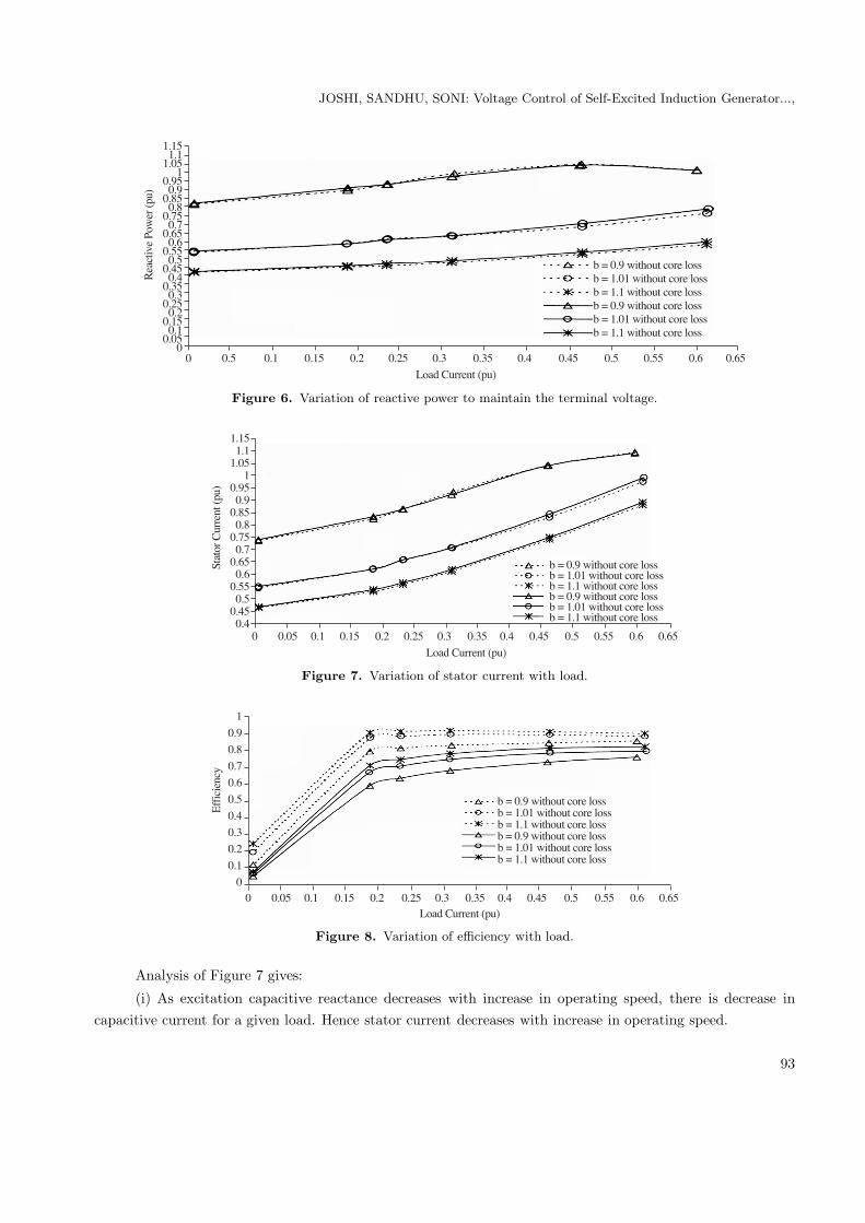
Figure 6 to Figure 8 gives the variation of computed results for reactive power requirement, stator currentand efficiency with load.
Analysis of Figure 6 gives rise to the following observations:
(i) Reactive power requirement increases with load for constant speed operation.
(ii) Effect of core loss accounting is found to be insignificant provided speed is maintained. A smallchange is due to the variation of no load current in shunt branch.
(iii) However, as appears, this reactive requirement may be compensated through speed control at thecost of generated frequency, which is undesirable for frequency sensitive loads.
92
JOSHI, SANDHU, SONI: Voltage Control of Self-Excited Induction Generator...,
�1�6�1��156
�51765175186518519651951:651:516651651;651;51<651<51 651 51�651�5156
5
�����������
=�����
��
��(�517�=�� ��������������(��15��=�� ��������������(��1��=�� ��������������(�517�=�� ��������������(��15��=�� ��������������(��1��=�� ������������
5 516 51� 51�6 51 51 6 51< 51<6 51; 51;6 516 5166 51: 51:6
>����������������
Figure 6. Variation of reactive power to maintain the terminal voltage.
�1�6�1��156
�51765175186518519651951:651:516651651;651;
�����������������
��
��(�517�=�� ��������������(��15��=�� ��������������(��1��=�� ��������������(�517�=�� ��������������(��15��=�� ��������������(��1��=�� ������������
5 5156 51� 51�6 51 51 6 51< 51<6 51; 51;6 516 5166 51: 51:6
>����������������
Figure 7. Variation of stator current with load.
�
517
518
519
51:
516
51;
51<
51
51�
5
&!!������-
��(�517�=�� ��������������(��15��=�� ��������������(��1��=�� ��������������(�517�=�� ��������������(��15��=�� ��������������(��1��=�� ������������
5 5156 51� 51�6 51 51 6 51< 51<6 51; 51;6 516 5166 51: 51:6>����������������
Figure 8. Variation of efficiency with load.
Analysis of Figure 7 gives:
(i) As excitation capacitive reactance decreases with increase in operating speed, there is decrease incapacitive current for a given load. Hence stator current decreases with increase in operating speed.
93

Turk J Elec Eng & Comp Sci, Vol.17, No.1, 2009
(ii) For constant speed operation, stator current increases with load due to increase in reactive and activepower.
Analysis of Figure 8 gives:
(i) For the same load, efficiency increases with an increase in operating speed. It is due to reduction instator current or copper losses.
(ii) Effect of core loss accounting is clearly visible from plot. Therefore it is essential to account core losscomponent for the analysis of SEIG.
(iii) Nature of plot comes out to be same as for induction motor.
Finally, Figure 9 gives the control of excitation capacitance to achieve constant terminal voltage; speedis maintained constant and kept slightly greater then synchronous speed corresponding to rated frequency.
:5
65
;5
<5
5
�5
5
&+����������������������
��
5 5156 51� 51�6 51 51 6 51< 51<6 51; 51;6 516 5166 51: 51:6>����������������
��(��15�
Figure 9. Variation of excitation capacitance with load to maintain the terminal voltage (including core losses).
Figure 10 shows the effect of load power factor on the excitation requirements of the systems. Valueof excitation capacitance for any load varies with load power factor. As evident, reactive power requirementincreases as power factor shifts from unity power factor to lagging. This results in the need for more shuntcapacitance for lagging power factor load. Therefore operation of such generators is generally recommendedonly for unity power factor load.
518
519
51:
516
51;
51<
51
51�
5
&+�������������������������
5 5156 51� 51�6 51 51 6 51< 51<6 51; 51;6 516>����������������
��(��15
&+��������������������������=�� ��!�(��15
&+��������������������������=�� ��!�(�517
Figure 10. Effect of power factor on excitation capacitance(including core losses).
94
JOSHI, SANDHU, SONI: Voltage Control of Self-Excited Induction Generator...,
5. Conclusion
Self excited induction generators seems to be the right choice for remote windy locations provided terminalvoltage is maintained with load. In this paper a new and unique GA based modeling has been proposedto improve the voltage profile of SEIG. Genetic Algorithm is proposed for estimation and selection of shuntcapacitance. It is found that proposed methodology results in to a simultaneous estimation for generatedfrequency, magnetizing reactance and excitation capacitance. A control strategy has been worked out toachieve the required performance of SEIG. Simulated results as obtained are compared with experimentalresults on a test machine. Comparison for unity power factor and lagging power factor load indicates that theproposed modeling is effective and accurate for real world applications. A close agreement between computed andexperimental results proves the validity and accuracy of proposed modeling. Analysis proposed may be helpfulfor researchers to think over the implementation of such generators successfully in windy remote locations.
List of symbols
a per unit frequencyb per unit speedC excitation capacitance per phase, μFE1 air gap voltage per phase, at rated frequency, Vf rated frequency, Hzfg generated frequency, HzI1 stator current per phase, AI2 rotor current per phase, referred to stator, AIL load current per phase, AN speed, rpmpf power factorR load resistance per phase, ΩRc core resistance per phase, ΩR1 stator resistance per phase, ΩR2 rotor resistance per phase, referred to stator, ΩRL equivalent series resistance per phase, across stator terminals, ΩXL equivalent series reactance per phase, across stator terminals, ΩV load voltage per phase, VVb base voltage per phase, VX1 stator reactance per phase, ΩX2 rotor reactance per phase, referred to stator, ΩXsh excitation capacitive reactance due to C at rated frequency, ΩXm magnetizing reactance per phase, at rated frequency, ΩX load reactance per phase, at rated frequency, Ω
References
[1] S. S. Murthy, O. P. Malik, and A.K.Tandon, “Analysis of self -excited induction generators,” Proc. IEE,vol. 129,pt.
C, no. 6,pp. 260-265, 1982.
[2] L. Quazene and G. McPherson, “Analysis of the isolated induction generator,” IEEE Trans. Power Apparatus and
Systems, vol. PAS-102, no. 8, pp. 2793-2798, 1983.
95
Turk J Elec Eng & Comp Sci, Vol.17, No.1, 2009
[3] G. Raina and O. P. Malik, “Wind energy conversion using a self-excited induction generator,” IEEE Trans. Power
Apparatus and Systems, vol. PAS-102, no. 12,pp. 3933-3936,1983.
[4] A. K. Tandon, S. S. Murthy and C. S. Jha, “New method of computing steady-state response of capacitor self-excited
induction generator,” IE (I) Journal-EL, vol. 65, pp. 196-201,1985.
[5] N. H. Malik and S. E. Haque, “Steady-state analysis and performance of an isolated self-excited induction generator,”
IEEE Trans. Energy Conversion, vol. EC-1, no.3, pp.134-139, 1986.
[6] T. F. Chan, “Analysis of self-excited induction generators using an iterative method,” IEEE Trans. Energy Con-
version, vol. 10, no. 3,pp. 502-507,1995.
[7] K. S. Sandhu and S. K. Jain, “Operational aspects of self-excited induction generator using a new model,” Electric
Machines and Power Systems, vol. 27, no. 2, pp. 169-180,1999.
[8] K. S. Sandhu, “Iterative model for the analysis of self-excited induction generators,” Electric Power Components
and Systems, vol. 31, no. 10, pp. 925-939, 2003.
[9] S.M. Alghuwainem, “Steady state analysis of induction generator self excited by a capacitor in parallel with a
saturable reactor,” Electric Machines and Power Systems, vol 26, pp. 617-625, 1998.
[10] J. A. Barrado and R. Grino, “Voltage and frequency control for a self excited induction generator using a three phase
four wire electronic converter,” Proc. Power Electronics and Motion Control Conference, ISBN:1-4224-0121-6,2006.
[11] B. Singh, S. S. Murthy and S. Gupta, “STATCOM based voltage regulator for self excited induction generator
feeding non linear loads,” Industrial Electronics Society, IECON, pp. 709-714, 2003.
[12] D. Joshi, K. S. Sandhu and M. K. Soni, “Constant voltage constant frequency operation for a self-excited induction
generator”, IEEE Trans. Energy Conversion, vol. 21, no. 1, pp. 228-234, 2006.
[13] D. E. Goldberg, Genetic Algorithms in Search, Optimization, and Machine Learning, Asia: Pearson Education,
2001.
[14] H. G. Beyer and K. Deb, “On self-adaptive features in real-parameter evolutionary algorithms”, IEEE Transactions
on Evolutionary Computation, 5 (3). 250-270, 2001
[15] K. Deb, A. Anand, and D. Joshi, “A computationally efficient evolutionary algorithm for real-parameter optimiza-
tion,” Evolutionary Computation Journal, 10(4), pp. 371-395, 2002.
96
JOSHI, SANDHU, SONI: Voltage Control of Self-Excited Induction Generator...,
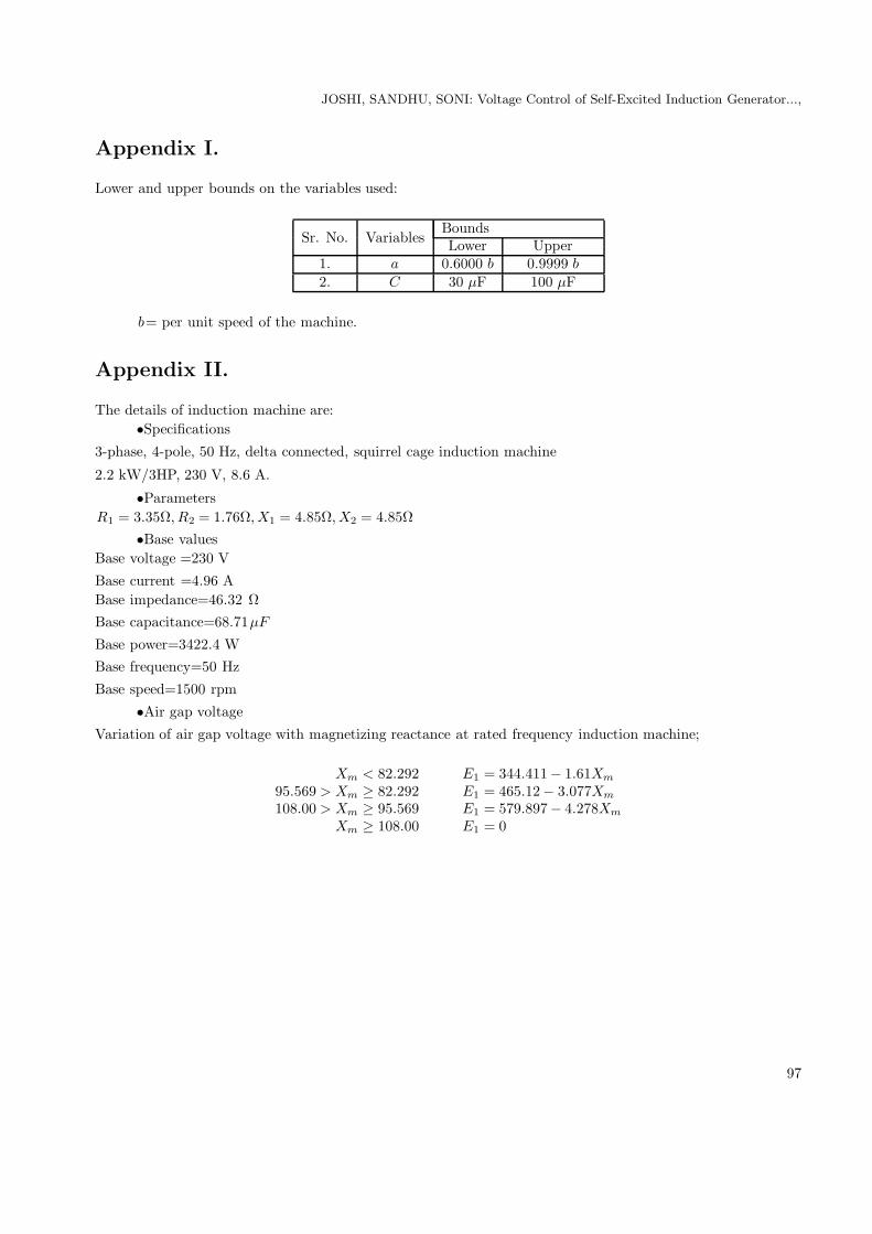
Appendix I.
Lower and upper bounds on the variables used:
Sr. No. VariablesBoundsLower Upper
1. a 0.6000 b 0.9999 b
2. C 30 μF 100 μF
b= per unit speed of the machine.
Appendix II.
The details of induction machine are:•Specifications
3-phase, 4-pole, 50 Hz, delta connected, squirrel cage induction machine
2.2 kW/3HP, 230 V, 8.6 A.
•ParametersR1 = 3.35Ω, R2 = 1.76Ω, X1 = 4.85Ω, X2 = 4.85Ω
•Base valuesBase voltage =230 V
Base current =4.96 ABase impedance=46.32 ΩBase capacitance=68.71μF
Base power=3422.4 WBase frequency=50 Hz
Base speed=1500 rpm
•Air gap voltage
Variation of air gap voltage with magnetizing reactance at rated frequency induction machine;
Xm < 82.292 E1 = 344.411− 1.61Xm
95.569 > Xm ≥ 82.292 E1 = 465.12− 3.077Xm
108.00 > Xm ≥ 95.569 E1 = 579.897− 4.278Xm
Xm ≥ 108.00 E1 = 0
97