
A pulsed power generator merging inductive voltage and current adders and its switch trigger...
6
A pulsed-power generator merging inductive voltage and current adders and its switch trigger application example Lee Li, Ge Yafeng, Zhong Heqin, Yu Bin, and Xie Longjun Citation: Rev. Sci. Instrum. 84, 075108 (2013); doi: 10.1063/1.4812694 View online: http://dx.doi.org/10.1063/1.4812694 View Table of Contents: http://rsi.aip.org/resource/1/RSINAK/v84/i7 Published by the AIP Publishing LLC. Additional information on Rev. Sci. Instrum. Journal Homepage: http://rsi.aip.org Journal Information: http://rsi.aip.org/about/about_the_journal Top downloads: http://rsi.aip.org/features/most_downloaded Information for Authors: http://rsi.aip.org/authors
Transcript of A pulsed power generator merging inductive voltage and current adders and its switch trigger...

A pulsed-power generator merging inductive voltage and current addersand its switch trigger application exampleLee Li, Ge Yafeng, Zhong Heqin, Yu Bin, and Xie Longjun Citation: Rev. Sci. Instrum. 84, 075108 (2013); doi: 10.1063/1.4812694 View online: http://dx.doi.org/10.1063/1.4812694 View Table of Contents: http://rsi.aip.org/resource/1/RSINAK/v84/i7 Published by the AIP Publishing LLC. Additional information on Rev. Sci. Instrum.Journal Homepage: http://rsi.aip.org Journal Information: http://rsi.aip.org/about/about_the_journal Top downloads: http://rsi.aip.org/features/most_downloaded Information for Authors: http://rsi.aip.org/authors

REVIEW OF SCIENTIFIC INSTRUMENTS 84, 075108 (2013)
A pulsed-power generator merging inductive voltage and current addersand its switch trigger application example
Lee Li,a) Ge Yafeng, Zhong Heqin, Yu Bin, and Xie LongjunState Key Laboratory of Advanced Electromagnetic Engineering and Technology, College of Electric andElectronic Engineering, Huazhong University of Science and Technology (HUST), Wuhan 430074, China
(Received 3 March 2013; accepted 18 June 2013; published online 17 July 2013)
A pulsed-power generator using inductive adder technology is proposed for the case of a dischargegap. The merit of this generator is to merge the pulsed-voltage and pulsed-current adders via thedual secondary windings with special circuit. For the nonlinear impedance in any discharge gap,the standalone voltage-pulse and current-pulse can be outputted successively by this generator. Theproposed generator is especially useful for the common resolution of implementing pulse dischargeat less cost. As an application example, a compact trigger prototype was developed to compatiblyuse in the gas-insulated and vacuum switches. Experiments achieved good results that the triggeredswitches showed stable performance and long life. If the basic circuit of this proposed generator isregarded as a pulsed-generating unit, a certain number of such units connected in parallel can beexpected to form a general device with generating greater breakdown-voltage and sustained-currentpulses for discharge gaps. © 2013 AIP Publishing LLC. [http://dx.doi.org/10.1063/1.4812694]
I. INTRODUCTION
Pulsed power is a certain amount of electrical energy re-leased in a very short time. It has applications in many indus-trial and defense-related fields.1, 2 Traditional electrical triggerpulse is usually generated by the method of pulse compressionvia a transformer core. In the meantime, it has been realizedthat a high-power pulse can be obtained by inductive addertechnology (IAT). The typical example is the so-called lineartransformer driver (LTD) first proposed by Russians.3 As forthis device, a required peak pulse can be obtained by addingup enough numbers of small pulses if they are synchronized.Until now, most of the reported IAT-based devices with highoutput-voltage or great output-current are gigantic for appli-cations on gigawatt-to-terawatt power levels used in accelera-tors and beams.4–7 But it is worth noting that solid-state LTDshave been proposed and studied for compact pulsed-powerapplications in recent years.8, 9 And many applications requirenot high transient power but proper coordination of voltage-pulse and/or current-pulse.
Moreover, a universal or multifunction pulsed-power de-vice is always of intense interest. For example, a trigger pulseis indispensable for spark gap switches. The injected energy,peak voltage, and rise time of the trigger pulse are as de-cisive for the switching characteristics as the spark gap ar-rangement. When a spark gap requires greater injected en-ergy/voltage/current to improve switching performance, thetrigger device only relying on a hulking transformer core maybe uneconomical and inefficient. As one of the two switch so-lutions, existing commercial solid-state switches cannot oper-ate at tens of kilovolts. And spark gaps are very forgiving toa one-time over-current or over-voltage.1, 2 Therefore, a sparkgap for high voltage or great current switch is still a cheap andreliable solution for high power/coulomb transfer. If a general
a)Author to whom correspondence should be addressed. Electronic mail:[email protected]. Tel.: 86-27-87559348. FAX: 86-27-87559349.
trigger can be developed, this will be cheering for spark gapapplication.
With the background, this paper will represent a de-sign philosophy of the IAT-based pulsed-power generator.This generator can supply the standalone voltage-pulse andcurrent-pulse for nonlinear impedance of a discharge gap, ofwhich the impedance is high before the discharge happensand is low when a discharge channel is formed. A small, drytype transformer and solid-state components make the gener-ator quite compact. As an example application, this generatoris employed in the general trigger of the three-electrode triga-tron switches. The first prototype will be reported and testedtoo. In principle, this pulsed-power generator and its designidea can be used in the pulsed-driven applications which needthe voltage breakdown and the followed current physics.
II. DESIGN IDEA
The simple circuit of a pulse generator based on IAT con-cept is shown in Fig. 1.9 Each pulse-generating unit must atleast consist of a capacitor and a switch. A certain number ofsuch units are connected in parallel to form a module, and acertain number of such modules are added up inductively toform a stack. Such stacks can be connected in different ways.In principle, arbitrary output voltage and current can be re-alized by using appropriate combinations of units, modules,and stacks. Since pulsed-power generation by IAT is virtuallyno physical limit on the output parameters, the device can beconstructed by using pre-manufactured modules, which allowcontrolled time variation of output voltage and current.
Going back to the basic pulse-generating unit, its prac-tical circuit is just like shown in Fig. 2. In theory, this is aresonant circuit with a magnetic core. After the primary ca-pacitor C0 is charged to a defined voltage by the DC supply,through a controllable switch S1, C0 discharges through theprimary winding of the pulse transformer T. Accordingly, theoscillating high-voltage will be generated in the secondary
0034-6748/2013/84(7)/075108/5/$30.00 © 2013 AIP Publishing LLC84, 075108-1
075108-2 Li et al. Rev. Sci. Instrum. 84, 075108 (2013)
FIG. 1. Equivalent circuit of an IAT-based pulse generator.
side. In a single resonant mode, the voltage reaches the peakvalue within only half a primary oscillation period. The mainmerit of a resonant circuit is that the low-voltage components,e.g., C0 and S1, can generate high voltage via electromagnetinduction.
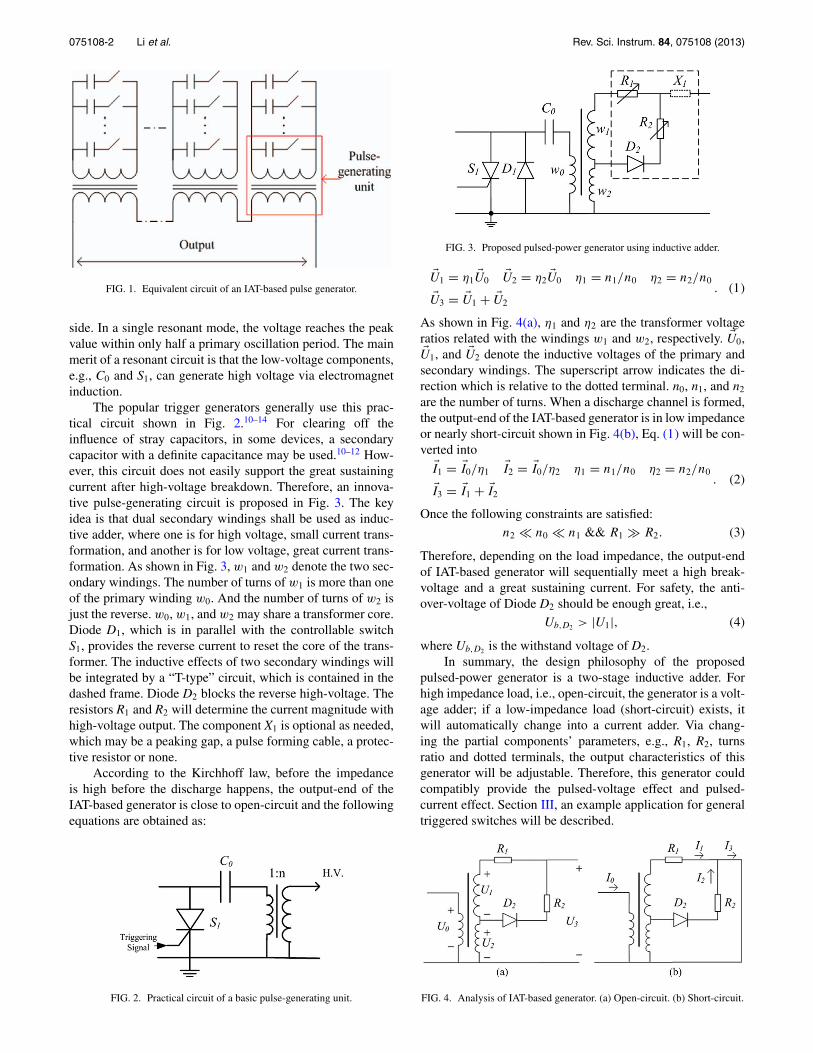
The popular trigger generators generally use this prac-tical circuit shown in Fig. 2.10–14 For clearing off theinfluence of stray capacitors, in some devices, a secondarycapacitor with a definite capacitance may be used.10–12 How-ever, this circuit does not easily support the great sustainingcurrent after high-voltage breakdown. Therefore, an innova-tive pulse-generating circuit is proposed in Fig. 3. The keyidea is that dual secondary windings shall be used as induc-tive adder, where one is for high voltage, small current trans-formation, and another is for low voltage, great current trans-formation. As shown in Fig. 3, w1 and w2 denote the two sec-ondary windings. The number of turns of w1 is more than oneof the primary winding w0. And the number of turns of w2 isjust the reverse. w0, w1, and w2 may share a transformer core.Diode D1, which is in parallel with the controllable switchS1, provides the reverse current to reset the core of the trans-former. The inductive effects of two secondary windings willbe integrated by a “T-type” circuit, which is contained in thedashed frame. Diode D2 blocks the reverse high-voltage. Theresistors R1 and R2 will determine the current magnitude withhigh-voltage output. The component X1 is optional as needed,which may be a peaking gap, a pulse forming cable, a protec-tive resistor or none.
According to the Kirchhoff law, before the impedanceis high before the discharge happens, the output-end of theIAT-based generator is close to open-circuit and the followingequations are obtained as:
FIG. 2. Practical circuit of a basic pulse-generating unit.
FIG. 3. Proposed pulsed-power generator using inductive adder.
�U1 = η1 �U0 �U2 = η2 �U0 η1 = n1/n0 η2 = n2/n0
�U3 = �U1 + �U2
. (1)
As shown in Fig. 4(a), η1 and η2 are the transformer voltageratios related with the windings w1 and w2, respectively. �U0,�U1, and �U2 denote the inductive voltages of the primary andsecondary windings. The superscript arrow indicates the di-rection which is relative to the dotted terminal. n0, n1, and n2
are the number of turns. When a discharge channel is formed,the output-end of the IAT-based generator is in low impedanceor nearly short-circuit shown in Fig. 4(b), Eq. (1) will be con-verted into
�I1 = �I0/η1 �I2 = �I0/η2 η1 = n1/n0 η2 = n2/n0
�I3 = �I1 + �I2
. (2)
Once the following constraints are satisfied:n2 � n0 � n1 && R1 � R2. (3)
Therefore, depending on the load impedance, the output-endof IAT-based generator will sequentially meet a high break-voltage and a great sustaining current. For safety, the anti-over-voltage of Diode D2 should be enough great, i.e.,
Ub,D2 > |U1|, (4)
where Ub,D2 is the withstand voltage of D2.In summary, the design philosophy of the proposed
pulsed-power generator is a two-stage inductive adder. Forhigh impedance load, i.e., open-circuit, the generator is a volt-age adder; if a low-impedance load (short-circuit) exists, itwill automatically change into a current adder. Via chang-ing the partial components’ parameters, e.g., R1, R2, turnsratio and dotted terminals, the output characteristics of thisgenerator will be adjustable. Therefore, this generator couldcompatibly provide the pulsed-voltage effect and pulsed-current effect. Section III, an example application for generaltriggered switches will be described.
FIG. 4. Analysis of IAT-based generator. (a) Open-circuit. (b) Short-circuit.

075108-3 Li et al. Rev. Sci. Instrum. 84, 075108 (2013)
FIG. 5. Schematic of a prototypical IAT-based trigger generator.
III. PROTOTYPE
A compact IAT-based trigger generator used for trig-gered trigatron switches was prototyped. Its schematic is rep-resented in Fig. 5. The controllable switch S1 and diode D1
listed in the principle circuit, are achieved with an insulatedgate bipolar transistor (IGBT) S.
The tower structure is selected as represented in Fig. 6.The top layer, taken in Fig. 7, involves the self-made trans-former T and the secondary components. Through adding atap, the transformer is easy to complete the dual secondarywindings. Many low-cost, in-series semiconductor diodes canwithstand the high-voltage from the winding w1. The sec-ondary resistors, i.e., R1 and R2, are achieved by a lots ofcheap color ring resistances.
As shown in Fig. 8, the inter-layer includes the IGBTmodule, the primary capacitor which is made up of severalparallel film-capacitors, and the subsidiary circuits of IGBT.
At the bottom layer, the 0.8 kV DC supply, which is gen-erated by a multiple voltage rectifier, is used for charging theparallel film-capacitors of the inter-layer (Fig. 9). The AC/DCand photoelectric converters are arranged in this layer too.
Overall, the trigger generator is fiber-optically coupledto an external trigger input, eliminating ground coupled noisesources. The small printed circuit boards, the cheap electroniccomponents, and the dry-type transformer occupy a compactspace.
The main parameters of this device are listed in Table I.If this trigger uses AC-powered, an isolation transformer-fed
FIG. 6. Tower structure of the trigger prototype.
TABLE I. Main operating parameters of the trigger generator.
Output voltage peak 18 kV open circuitOutput current peaka 600 A short circuitPeak time of voltage ≈1.0 μsPeak time of current ≈3.0 μsFiber optic trigger input 820 nm, 2–20 dBm typ.Overall weight 2.8 kgOverall size 200 × 200 × 240 mm3
aThe output current is affected by the load impedance in use.
FIG. 7. Photograph of the top layer.
FIG. 8. Photograph of the inter-layer.
FIG. 9. Photograph of the bottom layer.

075108-4 Li et al. Rev. Sci. Instrum. 84, 075108 (2013)
FIG. 10. Application for two kinds of trigatron switches. (a) Gas-insulatedspark switch. (b) Vacuum-insulated switch.
installation should be considered. And the version with theexternal or internal rechargeable battery powered is still indevelopment.
IV. APPLICATION
The trigger generator is designed to be compatibly usedfor the gas-insulated and vacuum trigatron gaps. The machineconstruction was inspired by the vertical water dispenser. Agap switch is just like a bucket which is replaceable. Inspiredby traditional Chinese wood structure architecture, a specialmortise-tenon joint is used for the assembly structure. Thisjoint does not need to use additional tools or accessories, andcan assure proper fastening even if a great mechanical vibra-tion happens. Fig. 10 represents the photographs which thesame trigger serves two kinds of trigatron switches.
Test circuit is shown in Fig. 11. The closure or break-down of the trigatron switches involves two gaps: The triggergap and the main gap. Fig. 12 represents the typical outputwaveforms of the trigger. It is seen clearly that the triggercan generate a rapidly rising voltage pulse applied to the trig-ger pin in the earthen electrode at first. Once the trigger gapbreaks down, the trigger voltage will fall and a hundreds ofcurrent pulse will follow. The closure of the main gap lieson the physical process caused by trigger pulse. In this appli-cation illustrated by this paper, the trigger gap is for surfaceflashover.
FIG. 11. Test circuit.
FIG. 12. Typical output waveforms of the trigger.
Known reports have found the gas-insulated thevacuum-insulated trigatron gaps have different breakdowncharacteristics.15–17 Therefore, in order to pursue the goodelectrical performance, such as small switching delay, low de-lay jitter, and long useful life, the trigger generators of the twokinds of switches need to be designed in practice. For gas-insulated, the distorted E-field related to a triggering sparkis primary.16 However, the initial plasma relies on the field-emission for triggered vacuum switches.17, 18
The compatibility of the proposed trigger generator canbe described in the following:
(1) As for gas-insulated trigatron spark gaps, the trigger canprovide an enough triggering current. On the one hand,this will promote the electron avalanche and streamerdevelopment; on the other hand, both main E-field anddistorted E-field in trigatron gap will be enhanced bymore charged particles. Therefore, the switching de-lay would be shortened, and the delay jitter wouldbe smaller.16 The operation of gas-insulated trigatronswitches will be expected to more stable.
(2) If a vacuum-insulated trigatron gap is used, the highertrigger voltage generated from the trigger will benefitthe field-emission. Accordingly, the initial plasmas pro-duced by the thermionic emission or explosive emis-sion will be enhanced.17 On the other side, the greattriggering current can erase the material particle depositin trigatron gap, which is especially helpful to surface-breakdown vacuum switches.19 Thus, the useful lifetimeof the vacuum-insulated switches will be lengthened.
The test switches intentionally chose the relatively severearrangements listed in Table II. The 50% under-voltage ratioof the gas switch and 30 mm main gap of the vacuum switch
TABLE II. Key parameters of test switches.
Parameters Gas-insulated switch Vacuum switch
Main gap distance 8 mm 30 mmTrigger gap (surface) distance 2.3 mm 0.5 mmUnder-voltage ratio 50% . . .Discharge current peak per shot 45 kA 50 kA

075108-5 Li et al. Rev. Sci. Instrum. 84, 075108 (2013)
FIG. 13. Typical voltage waveforms related to gas-insulated spark switch.
are likely to bring about a great delay and jitter, even switch-ing failure.17, 18, 20 The 0.5 mm trigger surface will likely beshorted out by the metal particle deposit.
Through using two probes to monitor the main voltageacross the main capacitor and the trigger voltage at the triggerpin, the switching delay can be observed. Fig. 13 gives thetypical voltage waveforms of the gas-insulated switch. Fig. 14is for the vacuum switches. The statistical results demonstratethat the delay values were in several microseconds (μs) andthe jitters were very small. Even if the main voltage was low,the vacuum switches still can work normally. As for the usefullifetime, two kinds of switches can still work after successive5000 shots without failure.
To sum up, the proposed trigger supports two relevantpulsed-outputs through the voltage and current adders. Thissuperiority makes the pulse-accepter meet the requirementsof both the break-voltage and sustained-current effect. Thismeans compatibility or versatility.
FIG. 14. Typical voltage waveforms related to vacuum-insulated switch.
For a large part of pulsed-power application, the mecha-nism is generally a physics effect related to voltage or current.This prototype approves the feasibility of the proposed gen-erator. If possible, the applications of this pulsed-power gen-erator using IAT may expand into many new fields such asmaterial modification, environment protection, and biologicaland medical developments.
V. CONCLUSIONS
A pulsed-power generator using inductive adder technol-ogy is proposed in this paper. The merit of this generator is tomerge the pulsed-voltage and pulsed-current adders via dualsecondary windings and a secondary circuit with particulardesign. As an application example, a compact trigger proto-type is developed to compatibly use in the gas-insulated andvacuum switches. If the basic circuit of this proposed gener-ator is regarded as a pulse-generating unit, a certain numberof such units connected in parallel can be expected to form ageneral device with greater voltage and current for the case ofa discharge gap.
ACKNOWLEDGMENTS
The authors gratefully acknowledge the support of theNational Natural Science Fund, China, Grant No. 51107049.
1E. Schamiloglu and R. J. Barker, Proc. IEEE 92(7), 1011 (2004).2E. Schamiloglu, R. J. Barker, M. Gundersen, and A. Neuber, Proc. IEEE92(7), 1014 (2004).
3B. M. Koval’chuk, V. A. Vizir’, A. A. Kim et al., Russ. Phys. J. 40(12),1142 (1997).
4M. G. Mazarakis, W. E. Fowler, A. A. Kim et al., Phys. Rev. ST Accel.Beams 12(5), 050401 (2009).
5A. A. Kim, M. G. Mazarakis, V. A. Sinebryukhov et al., Phys. Rev. STAccel. Beams 12(5), 050402 (2009).
6W. A. Stygar, W. E. Fowler, and K. R. LeChien, Phys. Rev. ST Accel.Beams 12(3), 030402 (2009).
7M. G. Mazarakis, W. E. Fowler, and K. L. LeChien, IEEE Trans. PlasmaSci. 38(4), 704 (2010).
8W. H. Jiang, K. Yatsui, K. Takayama et al., Proc. IEEE 92(7), 1180 (2004).9W. Jiang, IEEE Trans. Plasma Sci. 38(10), 2730 (2010).
10L. Li, C. B. Bao, X. B. Feng et al., Rev. Sci. Instrum. 84(2), 024703 (2013).11Z. Y. Zhou, X. Y. Duan, M. F. Liao, H. J. Dong, and J. Y. Zou, IEEE Trans.
Magn. 45(1), 564 (2009).12Y. Liu, F. C. Lin, X. B. Feng et al., IEEE Trans. Plasma Sci. 39(12), 3378
(2011).13J. L. Liu, Y. Zhang, Z. Chen, and J. H. Feng, IEEE Trans. Electron Devices
57(7), 1680 (2010).14J. Chatzakis, S. M. Hassan, E. L. Clark et al., Rev. Sci. Instrum. 79(8),
086103 (2008).15P. Osmokrovi, N. Arsi, and Z. Lazarevi, IEEE Trans. Power Deliv. 11(2),
858 (1996).16L. Li, L. Cai, X. D. Qi et al., J. Appl. Phys. 111(5), 053306 (2012).17G. Raju, R. Hackam, and F. A. Benson, J. Appl. Phys. 47(4), 1310 (1976).18R. L. Boxman, IEEE Trans. Electron Devices 24(2), 122 (1977).19A. Hiroshi, S. Kouji, and K. Yukio, IEEE Trans. Plasma Sci. 20(2), 76
(1992).20L. Cai, L. Li, F. C. Lin et al., IEEE Trans. Plasma Sci. 40(6), 1634 (2012).


