Performance Enhancement for Inductive Coupling Wireless ...
13
Research Journal of Applied Sciences, Engineering and Technology 16(4): 140-152, 2019 DOI:10.19026/rjaset.16.6018 ISSN: 2040-7459; e-ISSN: 2040-7467 © 2019 Maxwell Scientific Publication Corp. Submitted: January 15, 2019 Accepted: March 11, 2019 Published: September 15, 2019 Corresponding Author: Mohamed El Rayes, Senior Software and Simulation Engineer at Valeo, Giza, Egypt This work is licensed under a Creative Commons Attribution 4.0 International License (URL: http://creativecommons.org/licenses/by/4.0/). 140 Research Article Performance Enhancement for Inductive Coupling Wireless Power Transfer 1 Mohamed El Rayes, 2 Gihan Nagib and 3, 4 Wahied G. Ali Abdelaal 1 Senior Software and Simulation Engineer at Valeo, Giza, 2 Associate Professor at Electrical Engineering Department, Fayoum University, 3 Dean of Egyptian Academy for Engineering and Advanced Technology, 4 Computer and Systems Engineering Department, Ain Shams University, Cairo, Egypt Abstract: This study focuses on enhancing WPT efficiency by optimizing the physical parameters of the system. The overall efficiency in wireless power transfer is dominated by the transmitter and receiver coil parameters. This study investigates the effect of coil parameters on system performance. The coupling coefficient between the transmitter and the receiver coils is the main characteristic of the inductive coupling link that defines power transfer efficiency between both coils. System physical parameters determine the coupling coefficient such as distance between coils, coils inner and outer diameter, wire thickness and inductance. These parameters are connected to each other by non-linear relationships and there is no closed-form that relates these parameters. To enhance power transfer efficiency, tradeoffs should be done among the ranges of those parameters. Physical coils parameters are investigated using the finite element analysis method with a parametric 3D-model. The goal is to define the best conditions and ranges for the design parameters and deduce guidelines for designers to enhance power transfer efficiency. Keywords: 3D modeling, coils, computer aided design, digital simulation, mutual coupling, wireless power transfer INTRODUCTION This study investigates the relation between transmitter/receiver coil parameters and wireless power transfer efficiency. These parameters affect the coil inductances and mutual inductance between both coils, which in turns determine the coupling coefficient. The coupling coefficient represents the fraction of magnetic flux generated by the transmitter coil, which penetrates the receiver coil causing induced current to flow in it. So, for efficient power transfer, more flux has to reach the receiver coil, which means higher coupling coefficient (Wireless Power Consortium, 2019). This means that coupling coefficient can be used as a metric for inductive coupling efficiency. Calculation of inductance for complex structures usually involves solving complicated equations using simulation tools like MATLAB or using Finite Element Analysis (FEA) based simulators (Thompson, 1999). There is no easy closed form formula for inductance of different shapes; only approximated formulas can be found except for some simple structures such as straight wires and one-turn wire loop. In this section, a brief illustration is presented for the inductance calculation of one-turn wire loop coil and the mutual inductance between two loop coils which is the main factor that affects the power transfer efficiency. Loop coil in Wireless Power Transfer (WPT) has many benefits such as: • The omni-directional flux pattern of the loop coil imposes fewer constrains on the designer and improve the system performance in certain situations. • The loop coil is primarily inductive even with small dimensions. This makes it suitable for magnetic resonant systems; as the coil can be used in the tank circuit and transmit or receive power at the same time (Wireless Power Consortium, 2019). The mutual inductance between two circular filaments (Fig. 1) carrying current can be calculated using Neumann’s formula: = # $ %& ∬( )* + + + + .)*. + + + + + + / ) (1) where, ds and ds' = Incremental sections of the current filaments
-
Upload
khangminh22 -
Category
Documents
-
view
2 -
download
0
Transcript of Performance Enhancement for Inductive Coupling Wireless ...

Research Journal of Applied Sciences, Engineering and Technology 16(4): 140-152, 2019 DOI:10.19026/rjaset.16.6018 ISSN: 2040-7459; e-ISSN: 2040-7467 © 2019 Maxwell Scientific Publication Corp. Submitted: January 15, 2019 Accepted: March 11, 2019 Published: September 15, 2019
Corresponding Author: Mohamed El Rayes, Senior Software and Simulation Engineer at Valeo, Giza, Egypt This work is licensed under a Creative Commons Attribution 4.0 International License (URL: http://creativecommons.org/licenses/by/4.0/).
140
Research Article
Performance Enhancement for Inductive Coupling Wireless Power Transfer
1Mohamed El Rayes, 2Gihan Nagib and 3, 4Wahied G. Ali Abdelaal 1Senior Software and Simulation Engineer at Valeo, Giza,
2Associate Professor at Electrical Engineering Department, Fayoum University, 3Dean of Egyptian Academy for Engineering and Advanced Technology,
4Computer and Systems Engineering Department, Ain Shams University, Cairo, Egypt
Abstract: This study focuses on enhancing WPT efficiency by optimizing the physical parameters of the system. The overall efficiency in wireless power transfer is dominated by the transmitter and receiver coil parameters. This study investigates the effect of coil parameters on system performance. The coupling coefficient between the transmitter and the receiver coils is the main characteristic of the inductive coupling link that defines power transfer efficiency between both coils. System physical parameters determine the coupling coefficient such as distance between coils, coils inner and outer diameter, wire thickness and inductance. These parameters are connected to each other by non-linear relationships and there is no closed-form that relates these parameters. To enhance power transfer efficiency, tradeoffs should be done among the ranges of those parameters. Physical coils parameters are investigated using the finite element analysis method with a parametric 3D-model. The goal is to define the best conditions and ranges for the design parameters and deduce guidelines for designers to enhance power transfer efficiency. Keywords: 3D modeling, coils, computer aided design, digital simulation, mutual coupling, wireless power transfer
INTRODUCTION
This study investigates the relation between
transmitter/receiver coil parameters and wireless power transfer efficiency. These parameters affect the coil inductances and mutual inductance between both coils, which in turns determine the coupling coefficient. The coupling coefficient represents the fraction of magnetic flux generated by the transmitter coil, which penetrates the receiver coil causing induced current to flow in it. So, for efficient power transfer, more flux has to reach the receiver coil, which means higher coupling coefficient (Wireless Power Consortium, 2019). This means that coupling coefficient can be used as a metric for inductive coupling efficiency.
Calculation of inductance for complex structures usually involves solving complicated equations using simulation tools like MATLAB or using Finite Element Analysis (FEA) based simulators (Thompson, 1999). There is no easy closed form formula for inductance of different shapes; only approximated formulas can be found except for some simple structures such as straight wires and one-turn wire loop. In this section, a brief illustration is presented for the inductance calculation of one-turn wire loop coil and the mutual inductance
between two loop coils which is the main factor that affects the power transfer efficiency.
Loop coil in Wireless Power Transfer (WPT) has many benefits such as:
• The omni-directional flux pattern of the loop coil
imposes fewer constrains on the designer and improve the system performance in certain situations.
• The loop coil is primarily inductive even with small dimensions. This makes it suitable for magnetic resonant systems; as the coil can be used in the tank circuit and transmit or receive power at the same time (Wireless Power Consortium, 2019). The mutual inductance between two circular
filaments (Fig. 1) carrying current can be calculated using Neumann’s formula:
𝑀 = #$%&∬(
)*++++⃗ .)*.++++++⃗
/) (1)
where, ds and ds' = Incremental sections of the current
filaments
Res. J. Appl. Sci. Eng. Technol., 16(4): 140-152, 2019
141
Fig. 1: Two current filaments separated by distance r r = The distance between them µ0 = The vacuum permeability
So, the formula shows that mutual inductance is proportional to the length of the filaments, but inversely proportional to the distance between them.
If the coils are considered as current sheets, the mutual inductance can be used to calculate the coupling coefficient as follows (Gutiérrez-Lázaro, 2013):
𝑘 = 234546
(2)
The coupling coefficient is a value between 0 and
1. Negative values for coupling coefficient means that magnetic flux reaches the receiver coil from the reverse direction.
So, many coils and system parameters affect the coupling coefficient and the WPT system efficiency. This study aims to reveal the relation between coils physical parameters and the power transfer efficiency for the goal of getting the optimal design parameters
that achieve the highest wireless power transfer efficiency.
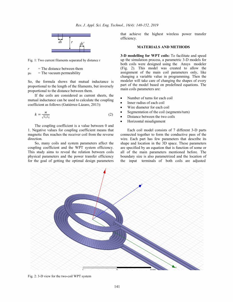
MATERIALS AND METHODS 3-D modelling for WPT coils: To facilitate and speed up the simulation process, a parametric 3-D models for both coils were designed using the Ansys modeler (Fig. 2). This model was created to allow the assignment of the main coil parameters only, like changing a variable value in programming. Then the modeler will take care of changing the shapes of every part of the model based on predefined equations. The main coils parameters are: • Number of turns for each coil • Inner radius of each coil • Wire diameter for each coil • Segmentation of the coil (segments/turn) • Distance between the two coils • Horizontal misalignment
Each coil model consists of 7 different 3-D parts connected together to form the conductive pass of the wire. Each part has few parameters that describe its shape and location in the 3D space. These parameters are specified by an equation that is function of some or all of the main parameters mentioned before. The boundary size is also parametrized and the location of the input terminals of both coils are adjusted
Fig. 2: 3-D view for the two-coil WPT system

Res. J. Appl. Sci. Eng. Technol., 16(4): 140-152, 2019
142
Fig. 3: System model with current input terminals on the boundary edge automatically with the change of boundary size (Fig. 3). The reason for this is that all terminals must be on the side of the boundary box. The coils material is copper and the boundary box material is air.
RESULTS AND DISCUSSION EFFECT OF COIL RADIUS ON THE
INDUCTIVE LINK From the approximated formula for the inductance
of single turn coil (Thompson, 1999):
𝐿 = 𝜇:𝐴 <𝑙𝑛 ?@ABC − 1.75H (3)
where, 𝜇: : The vacuum permeability A : The loop radius R : The wire radius one can notice that increasing the loop radius leads to an increase in the coil inductance, which in turns increases the coupling from (2). But to what extend this fact will hold true? In this section, the effect of the transmitter coil size on the coupling coefficient is investigated for various number of turns and over distance. All other parameters are held constant. For these simulations, parameters in Table 1 were used.
First, the situation where the two coils are very close to each other, is discussed to remove the distance effect. Getting results for different coil sizes will help in validating the results. Then, the distance is changed to see how the best transmitter coil size changes with the distance.
Table 1: Model parameters used in studying Tx radius effect Parameter Value Receiver inner radius 10 mm Receiver number of turns 3 Receiver wire radius 0.5 mm Transmitter inner radius Swept from 1 to 20 mm with
1 mm step Transmitter number of turns Swept from 1 to 9 Transmitter wire radius 0.5 mm Distance between the Tx and Rx coils
0.1 to 20 mm with 1 mm step
Misalignment 0 mm When the separation distance is very small: From Eq. (1), the highest mutual inductance and therefor the highest coupling coefficient, can be realized when the distance between the Tx and Rx coils is very small. But the question is which coil size will result in highest possible coupling. To find an answer, simulations were done using different values for the radius of the Tx coil over various number-of-turns values. The results are used to analyze the effect of the coil size on the maximum achievable coupling coefficient value.
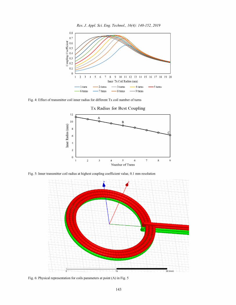
From Fig. 4, it can be observed that the maximum coupling coefficient is reached at a certain radius. This proves that increasing the radius of the transmitter coil will result in higher coupling coefficient until a certain limit, after which the coupling coefficient will decrease. This can be explained as large transmitter coil size will result in more magnetic flux lines loop around the coil without penetrating the receiver coil, leading to lower coupling. However, the best radius tends to be smaller with the increase of the number of turns as in Fig. 5.
For cases A, B and C in Fig. 5, physical coils arrangements are shown in Fig. 6 to 8 respectively, to
Res. J. Appl. Sci. Eng. Technol., 16(4): 140-152, 2019
143
Fig. 4: Effect of transmitter coil inner radius for different Tx coil number of turns
Fig. 5: Inner transmitter coil radius at highest coupling coefficient value, 0.1 mm resolution
Fig. 6: Physical representation for coils parameters at point (A) in Fig. 5
Res. J. Appl. Sci. Eng. Technol., 16(4): 140-152, 2019
144
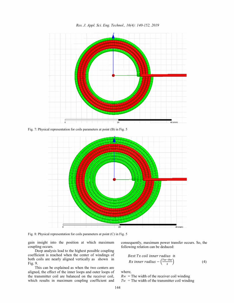
Fig. 7: Physical representation for coils parameters at point (B) in Fig. 5
Fig. 8: Physical representation for coils parameters at point (C) in Fig. 5 gain insight into the position at which maximum coupling occurs.
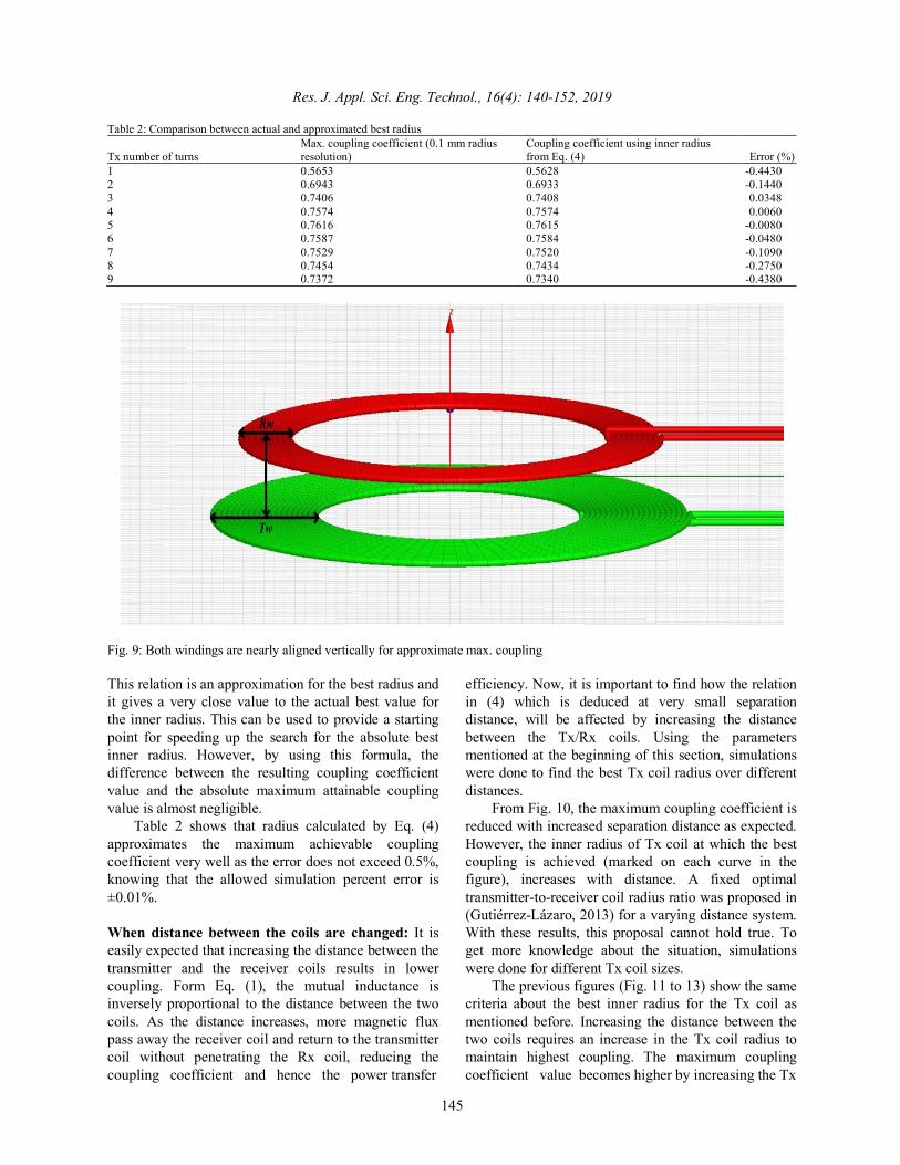
Deep analysis lead to the highest possible coupling coefficient is reached when the center of windings of both coils are nearly aligned vertically as shown in Fig. 9.
This can be explained as when the two centers are aligned, the effect of the inner loops and outer loops of the transmitter coil are balanced on the receiver coil, which results in maximum coupling coefficient and
consequently, maximum power transfer occurs. So, the following relation can be deduced:
𝐵𝑒𝑠𝑡𝑇𝑥𝑐𝑜𝑖𝑙𝑖𝑛𝑛𝑒𝑟𝑟𝑎𝑑𝑖𝑢𝑠 ≅𝑅𝑥𝑖𝑛𝑛𝑒𝑟𝑟𝑎𝑑𝑖𝑢𝑠 − ?XYZBY
[C (4)
where, Rw = The width of the receiver coil winding Tw = The width of the transmitter coil winding
Res. J. Appl. Sci. Eng. Technol., 16(4): 140-152, 2019
145
Table 2: Comparison between actual and approximated best radius
Tx number of turns Max. coupling coefficient (0.1 mm radius resolution)
Coupling coefficient using inner radius from Eq. (4) Error (%)
1 0.5653 0.5628 -0.4430 2 0.6943 0.6933 -0.1440 3 0.7406 0.7408 0.0348 4 0.7574 0.7574 0.0060 5 0.7616 0.7615 -0.0080 6 0.7587 0.7584 -0.0480 7 0.7529 0.7520 -0.1090 8 0.7454 0.7434 -0.2750 9 0.7372 0.7340 -0.4380
Fig. 9: Both windings are nearly aligned vertically for approximate max. coupling This relation is an approximation for the best radius and it gives a very close value to the actual best value for the inner radius. This can be used to provide a starting point for speeding up the search for the absolute best inner radius. However, by using this formula, the difference between the resulting coupling coefficient value and the absolute maximum attainable coupling value is almost negligible.
Table 2 shows that radius calculated by Eq. (4) approximates the maximum achievable coupling coefficient very well as the error does not exceed 0.5%, knowing that the allowed simulation percent error is ±0.01%. When distance between the coils are changed: It is easily expected that increasing the distance between the transmitter and the receiver coils results in lower coupling. Form Eq. (1), the mutual inductance is inversely proportional to the distance between the two coils. As the distance increases, more magnetic flux pass away the receiver coil and return to the transmitter coil without penetrating the Rx coil, reducing the coupling coefficient and hence the power transfer
efficiency. Now, it is important to find how the relation in (4) which is deduced at very small separation distance, will be affected by increasing the distance between the Tx/Rx coils. Using the parameters mentioned at the beginning of this section, simulations were done to find the best Tx coil radius over different distances.
From Fig. 10, the maximum coupling coefficient is reduced with increased separation distance as expected. However, the inner radius of Tx coil at which the best coupling is achieved (marked on each curve in the figure), increases with distance. A fixed optimal transmitter-to-receiver coil radius ratio was proposed in (Gutiérrez-Lázaro, 2013) for a varying distance system. With these results, this proposal cannot hold true. To get more knowledge about the situation, simulations were done for different Tx coil sizes.
The previous figures (Fig. 11 to 13) show the same criteria about the best inner radius for the Tx coil as mentioned before. Increasing the distance between the two coils requires an increase in the Tx coil radius to maintain highest coupling. The maximum coupling coefficient value becomes higher by increasing the Tx

Res. J. Appl. Sci. Eng. Technol., 16(4): 140-152, 2019
146
Fig. 10: Effect of separation distance on the best Tx inner radius for Tn = 1, Rn = 3
Fig. 11: Effect of separation distance on the best Tx inner radius for Tn = 3, Rn = 3
Fig. 12: Effect of separation distance on best Tx inner radius for Tn = 5, Rn = 3

Res. J. Appl. Sci. Eng. Technol., 16(4): 140-152, 2019
147
Fig. 13: Effect of separation distance on best Tx inner radius for Tn = 7, Rn = 3
Fig. 14: Effect of distance on best Tx inner radius (mm) at
max. coupling coefficient coil turns at any given distance. The reason for this is that coil inductance becomes higher and from Eq. (1) and (2) one can see that will lead to increased mutual inductance and therefore higher coupling coefficient. Also, it can be noticed that as the distance increases, the Tx coil sizes curve becomes nearly flat around the highest value. So, the coupling coefficient value is less sensitive to radius change at longer separation distances.
Analyzing the above four figures, it is clear that the increase in best Tx inner radius is non-linear over distance. This is further noticeable in Fig. 14.
Despite of the non-linearity of the radius increase with distance, the best Tx coil radius curves for different coil sizes, have approximately the same increase trend. The value of the best Tx coil radius at 20 mm distance is nearly double its value at very close coils for all transmitter coil sizes. This means that the
receiver coil size is the effective parameter in determining the best transmitter radius at a given distance. EFFECT OF TRANSMITTER COIL NUMBER OF
TURNS ON THE INDUCTIVE LINK Increasing the transmitter number of turns means
increasing the flux lines that cut the receiver coil, improving the coupling coefficient and power transfer efficiency (Imura and Hori, 2011). The question is by how much and to what extend increasing the transmitter coil number of turns will increase the coupling coefficient. For this reason, the receiver coil parameters are fixed and the transmitter coil radius value is swept to find the maximum coupling coefficient for each number of turns. For simulations, parameters in Table 3 were used.
From Fig. 15, the coupling coefficient increases with higher transmitter number of turns, but the increase value becomes negligible when adding more turns.
Figure 16 shows that the improvement in coupling coefficient is small beyond transmitter-to-receiver turns ratio of 3. Increasing turns ratio from 3 to 4 only adds 3% higher coupling coefficient from its value at 1-turn
Table 3: Model parameters used in studying the effect of Tx/Rx
number of turns Parameter Value Receiver inner radius 10 mm Receiver number of turns 3 Receiver wire radius 0.5 mm Transmitter inner radius Swept from 2 to 20 mm, 2 mm
step Transmitter number of turns Swept from 1 to 12 Transmitter wire radius 0.5 mm Distance between the Tx and Rx coils
5 mm
Misalignment 0 mm

Res. J. Appl. Sci. Eng. Technol., 16(4): 140-152, 2019
148
Fig. 15: Effect of increasing the transmitter coil number of
turns on the highest achievable coupling coefficient value
Tx coil. Thus, doubling the Tx coil size does not double the coupling coefficient and that is not economical and may add more limits due to higher resistance and capacitance, in addition to larger space. It can be recommended that transmitter to receiver turns ratio should be in the range of 2 to 3.
EFFECT OF DISTANCE BETWEEN THE TWO COILS AND THEIR SIZE ON THE
INDUCTIVE LINK
Allowed operating distance for any WPT system is of great importance. From Eq. (1), the mutual inductance is inversely proportional to the distance between the transmitter and the receiver coils (Shin et al., 2014). However, we want to study the effect of coil size (number of turns) on the rate at which mutual inductance and consequently the coupling coefficient,
decreases. For simulations, the coupling coefficient at 2 mm distance was taken as the reference value, then the decrease of the coupling coefficient with distance was calculated as a percentage of the reference value. When the transmitter coil is identical to the receiver one: Coils of 20 mm inner diameter were used for these simulations and the number of turns is swept to discover its effect on the inductive link. Parameters in Table 4 were used in simulations.
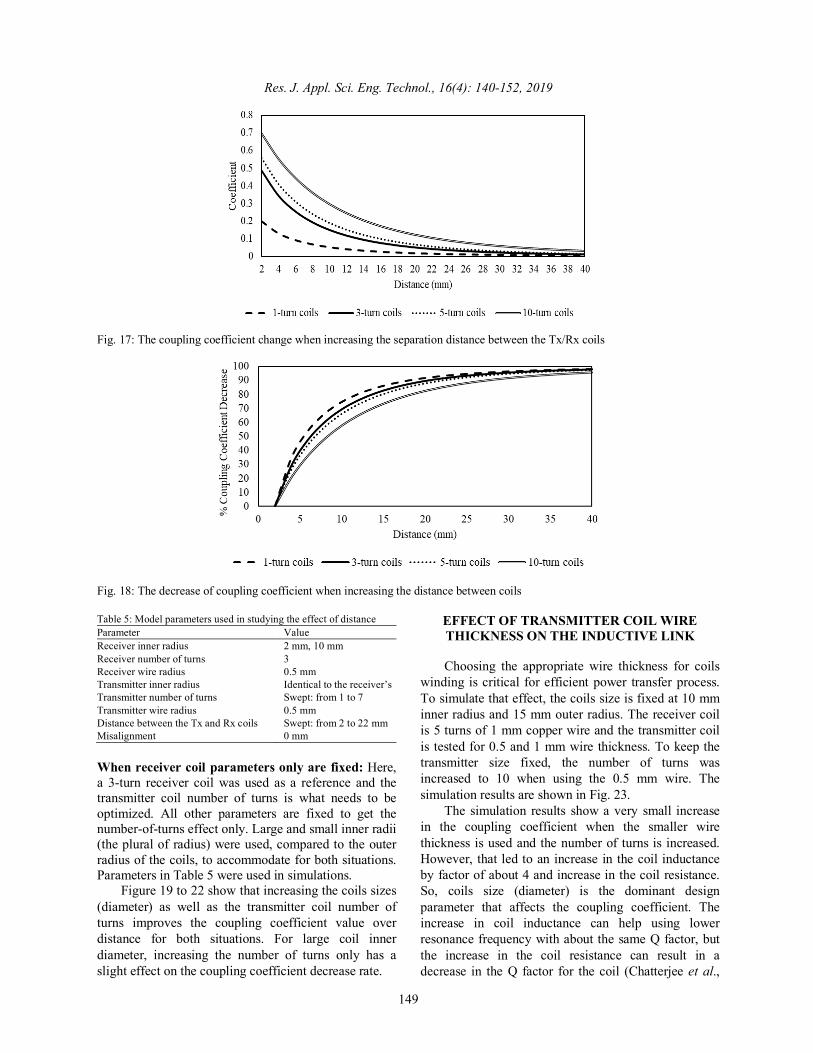
From Fig. 17 and 18, two important conclusions can be extracted. The first one is that larger coils allow longer range for WPT systems to deliver the same performance, e.g., the coupling coefficient for 1-turn coils at 2 mm distance is approximately equal to the coupling coefficient value for 10-turn coils at 14 mm distance. This result is expected but the enhancement comes at the expense of larger coil space, higher cost and increased resistance.
The second conclusion is that as the coils size increases, the decrease rate of coupling coefficient over distance also decreases which represents an improvement in performance. This can be explained by Eq. (1) which shows that the mutual inductance is proportional to the total length of the conductor for both coils. However, the increase in wire length leads to an increase in inductance of both coils and from Eq. (2), the coupling coefficient is inversely proportional to the square root of the multiplication of both inductances. This nonlinear relation between coupling coefficient and both mutual inductance and coils inductance limits the enhancement of increasing coils size.
Fig. 16: Improvement coming from increasing the transmitter coil turns over that of the receiver coil Table 4: Model parameters used in studying the effect of distance Parameter Value Receiver inner radius 10 mm Receiver number of turns Swept: 1, 3, 5, 10 Receiver wire radius 0.5 mm Transmitter inner radius 10 mm Transmitter number of turns Identical to the receiver’s Transmitter wire radius 0.5 mm Distance between the Tx and Rx coils Swept: 2 to 40 mm (about double coil inner diameter for 1 turn coil) Misalignment 0 mm
Res. J. Appl. Sci. Eng. Technol., 16(4): 140-152, 2019
149
Fig. 17: The coupling coefficient change when increasing the separation distance between the Tx/Rx coils
Fig. 18: The decrease of coupling coefficient when increasing the distance between coils Table 5: Model parameters used in studying the effect of distance Parameter Value Receiver inner radius 2 mm, 10 mm Receiver number of turns 3 Receiver wire radius 0.5 mm Transmitter inner radius Identical to the receiver’s Transmitter number of turns Swept: from 1 to 7 Transmitter wire radius 0.5 mm Distance between the Tx and Rx coils Swept: from 2 to 22 mm Misalignment 0 mm When receiver coil parameters only are fixed: Here, a 3-turn receiver coil was used as a reference and the transmitter coil number of turns is what needs to be optimized. All other parameters are fixed to get the number-of-turns effect only. Large and small inner radii (the plural of radius) were used, compared to the outer radius of the coils, to accommodate for both situations. Parameters in Table 5 were used in simulations.
Figure 19 to 22 show that increasing the coils sizes (diameter) as well as the transmitter coil number of turns improves the coupling coefficient value over distance for both situations. For large coil inner diameter, increasing the number of turns only has a slight effect on the coupling coefficient decrease rate.
EFFECT OF TRANSMITTER COIL WIRE THICKNESS ON THE INDUCTIVE LINK Choosing the appropriate wire thickness for coils
winding is critical for efficient power transfer process. To simulate that effect, the coils size is fixed at 10 mm inner radius and 15 mm outer radius. The receiver coil is 5 turns of 1 mm copper wire and the transmitter coil is tested for 0.5 and 1 mm wire thickness. To keep the transmitter size fixed, the number of turns was increased to 10 when using the 0.5 mm wire. The simulation results are shown in Fig. 23.
The simulation results show a very small increase in the coupling coefficient when the smaller wire thickness is used and the number of turns is increased. However, that led to an increase in the coil inductance by factor of about 4 and increase in the coil resistance. So, coils size (diameter) is the dominant design parameter that affects the coupling coefficient. The increase in coil inductance can help using lower resonance frequency with about the same Q factor, but the increase in the coil resistance can result in a decrease in the Q factor for the coil (Chatterjee et al.,

Res. J. Appl. Sci. Eng. Technol., 16(4): 140-152, 2019
150
Fig. 19: The coupling coefficient change when increasing the separation distance between the Tx/Rx coils
Fig. 20: The decrease of coupling coefficient when increasing the distance between coils
Fig. 21: The coupling coefficient change when increasing the separation distance between the Tx/Rx coils

Res. J. Appl. Sci. Eng. Technol., 16(4): 140-152, 2019
151
Fig. 22: The decrease of coupling coefficient when increasing the distance between coils
Fig. 23: The effect of transmitter coil wire thickness on WPT system performance 2017) and an increase in heat losses which can limit the maximum power that can be transferred.
EFFECT OF COILS NUMBER OF TURNS ON THE INDUCTIVE LINK WITH
MISALIGNED COILS Misalignment is one of the main problems of WPT
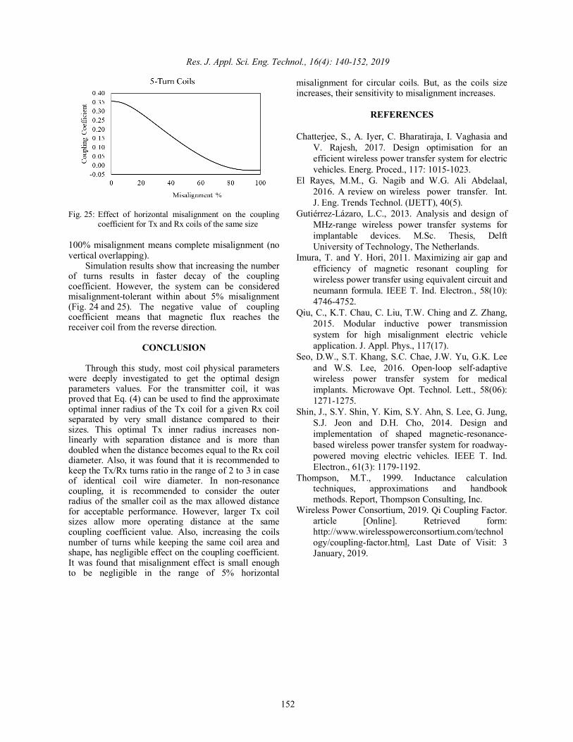
that is hard to be avoided and can cause a significant decrease in the power transfer efficiency. Solutions for enhancing the power transfer efficiency under coils misalignment condition involve using a matrix of transmitting coils (El Rayes et al., 2016), a self-adaptive Tx coil (Seo et al., 2016) or uniform Tx magnetic field (Qiu et al., 2015). The design of the transmitter coil needs to be investigated to discover the best size that can make the system misalignment-tolerant. Simulations were done on two identical coils (10 mm radius and 1 mm wire thickness) for 1-turn
coils and 5-turn coils (Fig. 24 and 25). Misalignment is calculated as a percentage of the outer coil diameter, so
Fig. 24: Effect of horizontal misalignment on the coupling
coefficient for Tx and Rx coils of the same size
Res. J. Appl. Sci. Eng. Technol., 16(4): 140-152, 2019
152
Fig. 25: Effect of horizontal misalignment on the coupling
coefficient for Tx and Rx coils of the same size 100% misalignment means complete misalignment (no vertical overlapping).
Simulation results show that increasing the number of turns results in faster decay of the coupling coefficient. However, the system can be considered misalignment-tolerant within about 5% misalignment (Fig. 24 and 25). The negative value of coupling coefficient means that magnetic flux reaches the receiver coil from the reverse direction.
CONCLUSION
Through this study, most coil physical parameters were deeply investigated to get the optimal design parameters values. For the transmitter coil, it was proved that Eq. (4) can be used to find the approximate optimal inner radius of the Tx coil for a given Rx coil separated by very small distance compared to their sizes. This optimal Tx inner radius increases non-linearly with separation distance and is more than doubled when the distance becomes equal to the Rx coil diameter. Also, it was found that it is recommended to keep the Tx/Rx turns ratio in the range of 2 to 3 in case of identical coil wire diameter. In non-resonance coupling, it is recommended to consider the outer radius of the smaller coil as the max allowed distance for acceptable performance. However, larger Tx coil sizes allow more operating distance at the same coupling coefficient value. Also, increasing the coils number of turns while keeping the same coil area and shape, has negligible effect on the coupling coefficient. It was found that misalignment effect is small enough to be negligible in the range of 5% horizontal
misalignment for circular coils. But, as the coils size increases, their sensitivity to misalignment increases.
REFERENCES Chatterjee, S., A. Iyer, C. Bharatiraja, I. Vaghasia and
V. Rajesh, 2017. Design optimisation for an efficient wireless power transfer system for electric vehicles. Energ. Proced., 117: 1015-1023.
El Rayes, M.M., G. Nagib and W.G. Ali Abdelaal, 2016. A review on wireless power transfer. Int. J. Eng. Trends Technol. (IJETT), 40(5).
Gutiérrez-Lázaro, L.C., 2013. Analysis and design of MHz-range wireless power transfer systems for implantable devices. M.Sc. Thesis, Delft University of Technology, The Netherlands.
Imura, T. and Y. Hori, 2011. Maximizing air gap and efficiency of magnetic resonant coupling for wireless power transfer using equivalent circuit and neumann formula. IEEE T. Ind. Electron., 58(10): 4746-4752.
Qiu, C., K.T. Chau, C. Liu, T.W. Ching and Z. Zhang, 2015. Modular inductive power transmission system for high misalignment electric vehicle application. J. Appl. Phys., 117(17).
Seo, D.W., S.T. Khang, S.C. Chae, J.W. Yu, G.K. Lee and W.S. Lee, 2016. Open-loop self-adaptive wireless power transfer system for medical implants. Microwave Opt. Technol. Lett., 58(06): 1271-1275.
Shin, J., S.Y. Shin, Y. Kim, S.Y. Ahn, S. Lee, G. Jung, S.J. Jeon and D.H. Cho, 2014. Design and implementation of shaped magnetic-resonance-based wireless power transfer system for roadway-powered moving electric vehicles. IEEE T. Ind. Electron., 61(3): 1179-1192.
Thompson, M.T., 1999. Inductance calculation techniques, approximations and handbook methods. Report, Thompson Consulting, Inc.
Wireless Power Consortium, 2019. Qi Coupling Factor. article [Online]. Retrieved form: http://www.wirelesspowerconsortium.com/technology/coupling-factor.html, Last Date of Visit: 3 January, 2019.