Analytical formulas for interfacial transition zone properties
Int. J. Multiphase Flow Vol. 10, No. 3, pp. 371-383, 1984 0301-9322/84 $3.00 + .00 Printed in Great Britain. Pergamon/Ehevier
A N I N V E S T I G A T I O N I N T O T H E I N T E R F A C I A L S H E A R S T R E S S C O N T R I B U T I O N I N T W O - P H A S E
S T R A T I F I E D F L O W
A. J. JOHNSTON Department of Civil and Mining Engineering, University of WoUongong, New South Wales,
Australia 2500
(Received 5 May 1983; m revised form 1 September 1983)
Abstract--This paper provides a combined theoretical and experimental investigation into the contribution of interfacial shear stress in certain co and counter-current flows in circular pipes. Based on momentum balance two equations were developed for such flows then two fluid systems of significantly different density ratio were experimentally tested to quantify these equations.
1. I N T R O D U C T I O N
Most of the material which has been published on stratified two phase flow has concentrated on situations where the gas and liquid phases are in the same direction (i.e. co-current) where the velocity of the gas is considerably greater than the liquid. Such situations are manifested in certain boiler pipes, refrigerator tubes and natural gas pipelines. In contrast to this the amount of published material on co-current flow where the velocities of the gas and liquid phases are similar in magnitude and, on counter-current flow where the liquid and gas phases travel in different directions, has been relatively small.
A practical example where such counter-current flow situations are possible is in the inlet bottles (or pipes) of a parallel bottle slugeatcher which is an installation often located at the terminal of a two phase natural gas pipeline. Its principal function is to separate the liquid and gas phases and in doing so, counter-current flow is facilitated in the inlet bottles. The flow characteristics in these bottles are closely related to the capacity and controlled operation of the slugcatcher.
Hence, to improve the general understanding of these stratified two ,phase flows a combined theoretical and experimental investigation was completed.
2. T H E O R E T I C A L A N A L Y S I S
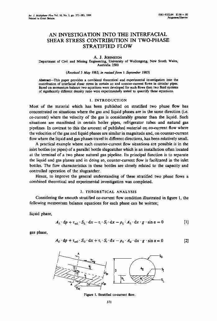
Considering the smooth stratified co-current flow condition illustrated in figure 1, the following momentum balance equations for each phase can be written;
liquid phase,
A L " d e + "[oL " S L " d x - z~ " Si " d x - P L " A L " d x • g • s in ,t = 0 [1]
gas phase,
AG " d p + % r e ' S a" d x + xi " S~ " d x - p~ " A ~ " d x " g • s in , t= 0 [2]
y sL
Figure 1. Stratified co-current flow.
371
372 A.J. JOHNSTON
eliminating dp,
S~ SL+ ( 1 1 ) z ~ " - - - Z ~ L " Zi " S i + (PL - P t ; ) g " s i n ~ = 0
At; A L -ALL+-~a [3]
where A is the phase cross sectional area, p is the density, Si is the interfacial width, S is the perimeter over which the stress acts, z is the shear stress, g is the acceleration due to gravity, at is the angle between the pipe axis and the horizontal; subscripts G and L are for gas and liquid, i for interfacial, tog for wall gas and ~oL for wall liquid.
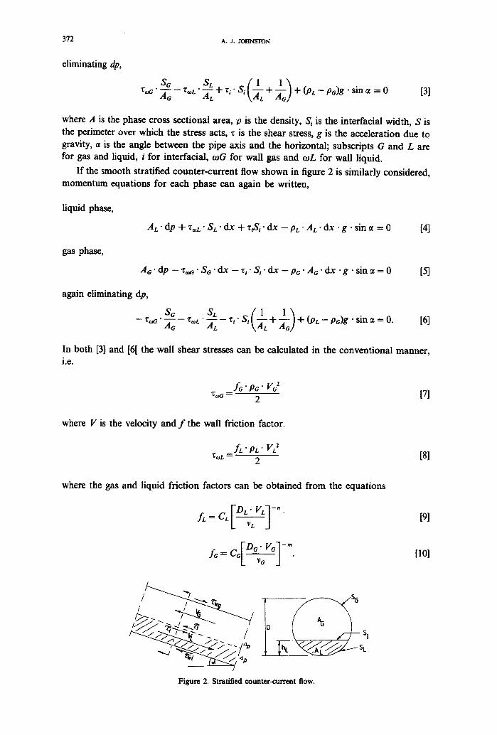
If the smooth stratified counter-current flow shown in figure 2 is similarly considered, momentum equations for each phase can again be written,
liquid phase,
A t " d e -~- "co~ L • S L • d x + "ciS i • d x - PL " A L " d x " g " s i n ~ = 0 [4]
gas phase,
At;" dp - zoo" S~" dx - zi" S~" dx - Pc" At;' dx "g" sin ~t = 0 [5]
again eliminating dp,
St; SL ( 1 1 ) - - % ~ " -~C - - Xo, L " -~L - - Z, " S , -~L + - ~ + (pL - - p t ; )g " s i n ~ = O. [6]
In both [3] and [6[ the wall shear stresses can be calculated in the conventional manner, i .e .
ft;" pt;" Vt; 2 z,ot; = 2 [7]
where V is the velocity and f the wall friction factor.
f L " PL" VL2 Z~L = 2 [8]
where the gas and liquid friction factors can be obtained from the equations
L VL d [9]
A= c~D~" Vt;] -m. L y e a
[10]
/ "7
/
Figure 2. Stratified counter-current flow.
AN INVESTIGATION INTO SHEAR ~ IN TWO..PHASE STRATIFIED FLOW 373
In these relationships the hydraulic diameter parameters (DL and Do) can be evaluated using the procedure suggested by Agrawal et al. (1973),
4AL and Do= 4Ao [11] D , = s , (so +------~,)"
Furthermore, the coefficients CL, n, Co and m used in [9] and [10] are those used by Taitel and Dukler (1976) in their co-current studies,
in turbulent flows Co = CL = 0.046 and n = m = 0.2
in laminar flows Co-~'C L = 16.000 and n = m = 1.0.
Turbulent or laminar flow conditions in each phase are identified by calculating the Reynolds number for each phase using the actual velocity and hydraulic diameter of each phase, i.e.
and FV°' °l =L v--T_l L v-'--o--j"
The interfacial shear stress evaluation is normally accepted to be equal to,
f,. vo(vo- 4.)" [131 Zi = 2
wheref~ is the interracial friction factor, R, is the Reynolds number and v is the kinematic viscosity.
Gazley (1949) established that f~ =fo for smooth co-current flows and in situations where Vo >> Vl the interracial shear stress evaluation can be evaluated with the same equation as is used to calculate the gas wall shear stress[7].
However, in the present work where Vo and Vt are of the same magnitude this equality of inteffacial and gas friction factors cannot be made. The velocity at the interface between the gas and the liquid phases would be expected to vary between 0 and VL, therefore it is assumed that V~ = VL. Under these conditions the interfacial shear stress can be expressed as,
Pc " f~VG + VJ 2 [14] Zi = 2
Therefore, considering [3] and [6] the one parameter which cannot readily be evaluated is the interfacial friction factor (f~. Clearly, this evaluation cannot be achieved from theoretical arguments consequently an experimental investigation was required for this purpose and to gain an understanding of the interfacial shear stress contribution.
3. EXPERIMENTAL ANALYSIS
The object of the experimental study was to examine two separate fluid systems exhibiting stratified co and counter-current flows to evaluate the interfadal friction factors and interfacial shear stresses over a range of flowrates, pipe diameters and gradients of the pipe. The evaluation of these, and other parameters, would allow the developed equations to be quantified and verified, implying their acceptance for general use.
Two experimental testing rigs as shown in figures 3 and 4 were constructed to allow two fluid systems to be studied. The first rig (figure 3) was used to examine a water/air
374 A.J. Jorr~sroN
oir I~ower
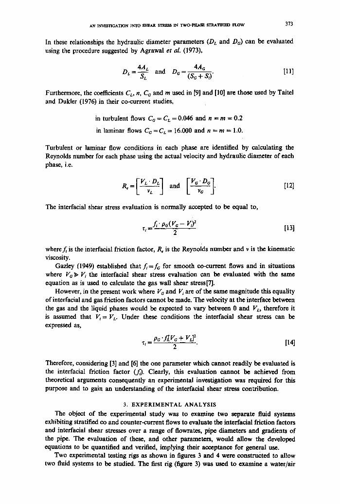
Figure 3. Apparatus used to study the water air system.
(W/A) fluid system and incorporated separate water and air circuits which could combine to instigate co and counter-current flows in the acrylic pipe (dia.=0.121m, length = 8.0 m).
The water was pumped by a centrifugal pump through a control valve to the entry of the perspex pipe where it travelled down towards the weighbridge mechanism which was used to accurately determine the water flowrate. To instigate countercurrent flow conditions in the pipe, air was sucked from the connection close to the liquid entry, by attaching it to the suction side of a large air centrifugal blower. A water strainer and a vaned anemometer were installed in this line which ensured that no liquid entered the air blower and recorded the air flowrates respectively. The total length of the perspex pipe was supported on screwjacks which allowed the flow characteristics to be recorded for a range of pipe slopes from level to 1/10.
It was believed that the fluid density ratio (Pa/PL) is one of the controlling parameters in two phase flow. This ratio in the air/water case is approx. 1/800 which is significantly different to the ratio in the slugcatcher case; viz. 1/13. In order to monitor this ratio's effect on the flow characteristics two fluids (kerosene and aqueous zinc chloride) were chosen since a density ratio of 1/4 was possible using them. Z, C12 was selected because it has the particular property that it can be dissolved in water to ultimately give a mixture which has a density of four times that of the original water. Kerosene was selected because it is a relatively light fluid which does not interact with the Z,CI2 solution.
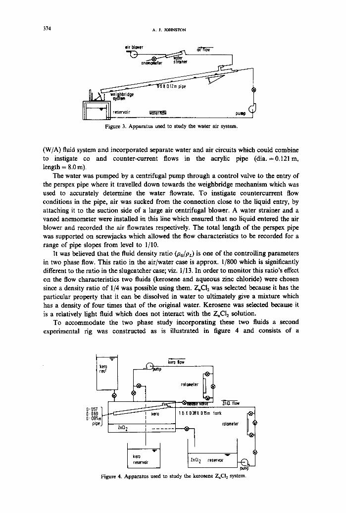
To accommodate the two phase study incorporating these two fluids a second experimental rig was constructed as is illustrated in figure 4 and consists of a
l~Jm p kero 1tow
rotameter
"-(~neeme volve- J " ~ flow
t6XO38XO15m tonk o.o,,1 I 0"069 ~ ! kero O" O95mr t I
I "v -
kem reservoir
cotometer
CI 2 reservoir
Figure 4. Apparatus used to study the kerosene ZnCI 2 system.
AN INVESTIGATION INTO SHEAR STRESS IN TWO-PHASE S T R A T I r ~ FLOW 375
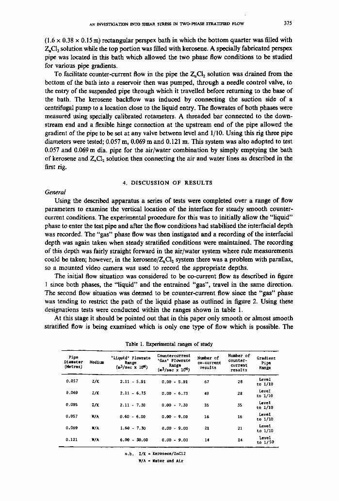
(1.6 x 0.38 x 0.15 m) rectangular perspex bath in which the bottom quarter was filled with Z,CI2 solution while the top portion was filled with kerosene. A specially fabricated perspex pipe was located in this bath which allowed the two phase flow conditions to be studied for various pipe gradients.
To facilitate counter-current flow in the pipe the Z~CI2 solution was drained from the bottom of the bath into a reservoir then was pumped, through a needle control valve, to the entry of the suspended pipe through which it travelled before returning to the base of the bath. The kerosene backflow was induced by connecting the suction side of a centrifugal pump to a location close to the liquid entry. The flowrates of both phases were measured using specially calibrated rotameters. A threaded bar connected to the down- stream end and a flexible hinge connection at the upstream end of the pipe allowed the gradient of the pipe to be set at any valve between level and 1/10. Using this rig three pipe diameters were tested; 0.057 m, 0.069 m and 0.121 m. This system was also adopted to test 0.057 and 0.069 m dia. pipe for the air/water combination by simply emptying the bath of kerosene and Z, CI2 solution then connecting the air and water lines as described in the first rig.
4 . D I S C U S S I O N O F R E S U L T S
General Using the described apparatus a series of tests were completed over a range of flow
parameters to examine the vertical location of the interface for steady smooth counter- current conditions. The experimental procedure for this was to initially allow the "liquid" phase to enter the test pipe and after the flow conditions had stabilised the interfacial depth was recorded. The "gas" phase flow was then instigated and a recording of the interfacial depth was again taken when steady stratified conditions were maintained. The recording of this depth was fairly straight forward in the air/water system where rule measurements could be taken; however, in the kerosene/Z, Cl2 system there was a problem with parallax, so a mounted video camera was used to record the appropriate depths.
The initial flow situation was considered to be co-current flow as described in figure 1 since both phases, the "liquid" and the entrained "gas", travel in the same direction. The second flow situation was deemed to be counter-current flow since the "gas" phase was tending to restrict the path of the liquid phase as outlined in figure 2. Using these designations tests were conducted within the ranges shown in table 1.
At this stage it should be pointed out that in this paper only smooth or almost smooth stratified flow is being examined which is only one type of flow which is possible. The
T a b l e I. E x p e r i m e n t a l r a n g e s o f study
Pipe ' L i q u i d ' F1owrate C o u n t e r c u r r e n t Number o f Number o f Grad ien t Diameter Medium Range ' G a s ' F lowra te c o u n t e r - c o - c u r r e n t Pipe Range c u r r e n t ( H e t r e s ) (mS/sec x 10 ~) (m3/sec x 1~ 4) r e s u l t s r e s u l t s Range
Leve l 0 .057 Z/K 2 .11 - 5 .91 0 . 0 0 - 5 .91 67 28 t o 1 /10
L e v e l 0 .069 Z/K 2 .11 - 6 .73 0 .00 - 6 . 7 3 49 28 t o 1 /10
L e v e l 0 .095 Z/K 2 .11 - 7.30 0 .00 - 7 .30 3S 55 t o 1 /10
L e v e l 0 .057 W/A 0 .60 - 6 .00 0 .00 - 9 . 0 0 16 16 t o 1 /10
Level 0 .069 W/A 1.60 - 7 .50 0 .00 - 9 . 0 0 21 21 t o ! / 1 0
L e v e l 0 .121 W/A 6 ,00 - 30.00 0 .00 - 9 .00 14 14 t o 1 / 5 0
n . b . Z/K = Kerosene/ZnC12
W/A = Water and Ai r
376 A.J. JOHNSTON
others, as described by Baker (1954), such as slug and annular flow cannot be analysed at this stage by the aforementioned derived relationships. This is the reason why there are many more results in the co-current mode at the 0.057 and 0.06 m dia. of pipe because in these pipes as the counter-current gas flow was applied to the liquid phase slugging of the liquid began to occur.
Rearranging [3] and [6] the unknown interfaciat shear stress can be expressed in terms of the parameters described in [7]-[14] and the geometrical properties of the pipe. All these geometric properties can be evaluated in a dimensionless form from the interfacial depth. A computer program was used to evaluate the particular intcrfacial shear stress value (~i) from the known; geometric properties, fluid properties and the phase flowrates.
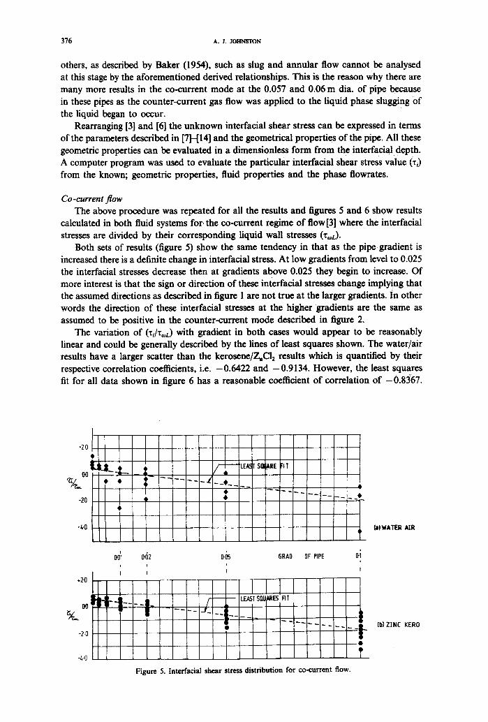
Co-current flow The above procedure was repeated for all the results and figures 5 and 6 show results
calculated in both fluid systems for, the co-current regime of flow [3] where the interracial stresses are divided by their corresponding liquid wall stresses (Z~L).
Both sets of results (figure 5) show the same tendency in that as the pipe gradient is increased there is a definite change in interfacial stress. At low gradients from level to 0.025 the inteffacial stresses decrease then at gradients above 0.025 they begin to increase. Of more interest is that the sign or direction of these interfacial stresses change implying that the assumed directions as described in figure 1 are not true at the larger gradients, in other words the direction of these inteffacial stresses at the higher gradients are the same as assumed to be positive in the counter-current mode described in figure 2.
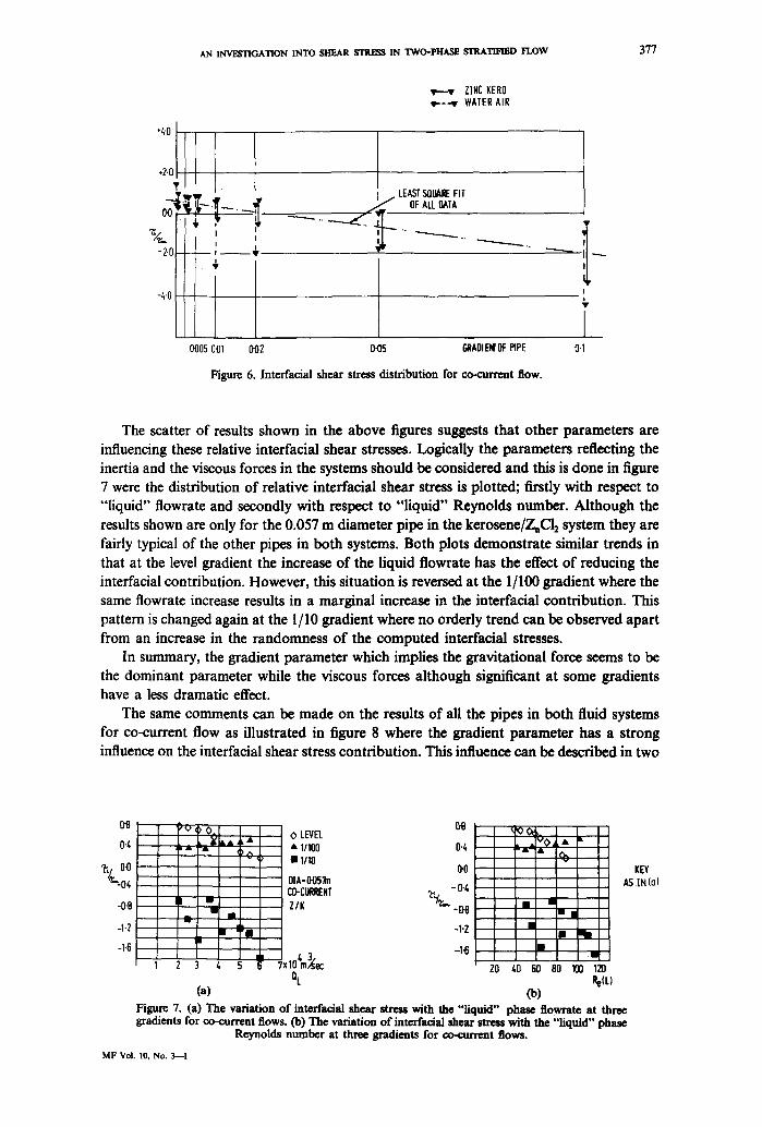
The variation of (~l/To, L) with gradient in both cases would appear to be reasonably linear and could be generally described by the lines of least squares shown. The water/air results have a larger scatter than the kerosene/Z, Cl2 results which is quantified by their respective correlation coefficients, i.e. -0.6422 and -0.9134. However, the least squares fit for all data shown in figure 6 has a reasonable coefficient of correlation of -0.8367.
-2.0
DO
-~0
-4"0
, i
I i
I I o+ H . . . . L f "
" I . . . . - ' -
*2.0
-2,0
0'05 BRAD OF PIPE &i +
i
I 1
l [ l [ LEAST SIIU M~ES FII
-.L- I
-4-0
Figure 5. Interracial shear stress distr ibution for co-current flow.
(a) WATER AIR
(b) ZINC KERO
AN INVESTIGATION INTO SHEAR STRESS IN TWO-PHASE STRATIFIED FLOW 377
.2.0
,
-2.0~- f •
-4.0
0005 0"01 002
v,---v ZINC KER0 w.--.-v WATER AIR
LEAST SQUARE FIT " ~ . t " ~ OF ALL DATA
---..._.._
0-05 ~OIEMOF RPE
Figure 6. Interfacial shear stress distribution for co-current flow.
"------...._.......
0.1
The scatter of results shown in the above figures suggests that other parameters are influencing these relative interracial shear stresses. Logically the parameters reflecting the inertia and the viscous forces in the systems should be considered and this is done in figure 7 were the distribution of relative interfacial shear stress is plotted; firstly with respect to "liquid" flowrate and secondly with respect to "liquid" Reynolds number. Although the results shown are only for the 0.057 m diameter pipe in the kerosene/ZnCl2 system they are fairly typical of the other pipes in both systems. Both plots demonstrate similar trends in that at the level gradient the increase of the liquid flowrate has the effect of reducing the interracial contribution. However, this situation is reversed at the 1/100 gradient where the same flowrate increase results in a marginal increase in the interracial contribution. This pattern is changed again at the 1/10 gradient where no orderly trend can be observed apart from an increase in the randomness of the computed interracial stresses.
In summary, the gradient parameter which implies the gravitational force seems to be the dominant parameter while the viscous forces although significant at some gradients have a less dramatic effect.
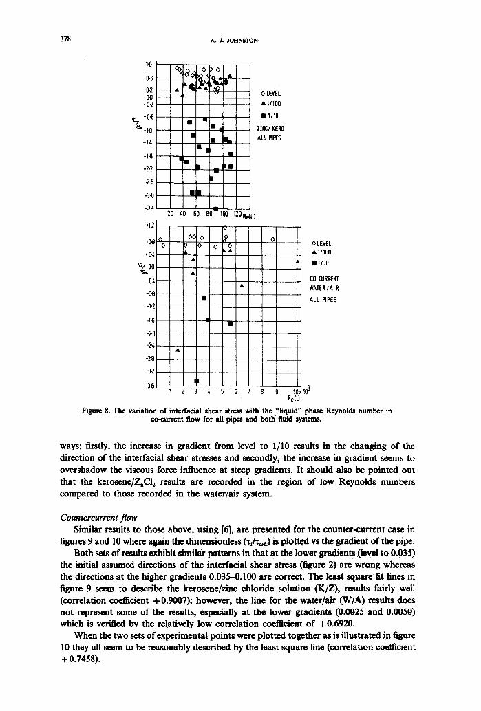
The same comments can be made on the results of all the pipes in both fluid systems for co-current flow as illustrated in figure 8 where the gradient parameter has a strong influence on the interracial shear stress contribution. This influence can be described in two
0'8
0.4
~-,/. o-o '~-o~
-0.8
-1.2
-1.6
0'8 'O , O. O LEVEL
A,t , • • 11100 0"4 hm, -,it, ~A • 1/10
0"0 0]A'OOS~ CO-CURRENT ,~, - 0.4
- - a
• " . • -1"2
-1"6 3 4 5 ~104m,~ec
QL ( a )
i 1 2
~ , , t m l I l i ~ w t , ~ l l r - m m l n i m : - J a
I n • i
m 20 40 60 80 100 120
(b) Figure 7. (a) The variation of interfacial shear stress with the "liquid" phase flowrate at three gradients for co-current flows. (b) The variation of interfaoial shear stress with the "liquid" phase
Reynolds number at three gradients for oo-current flows.
KEY AS IN (a}
MF Vol. I0, No. 3--1
378 A.J. JOHNSTON
1.0
0.6
0.2 0.0
-0.2
~ -0'6
7"=..1. 0
-1"4
-1"8
-2-2
-2.6
-3.0
-3-4
.1.2
-1.2
-1.6
-2.0 -N
-2.8
-3.2
o 0
• "1 l ,
• ' h
m ¸
l •
II
mm
m
2O /,0 60 8( 100
v
~> 0 o & k&
"- •
0 LEVEL
• 1/100
• 1/10
ZINC/KERO ALL PIPES
120 R.fi.}
0 CLEVEL • 1/100
ml / lO
CO CURRENT WAIERIAIR
ALL ~PES
l
l 2 3 4 5 6 7 8 9 fox lO 3 Re(L)
Figure 8. The variation of int©rfacial shear stress with the " l iquid" phase Reynolds number in co-current flow for all pipes and bo th fluid systems.
ways; firstly, the increase in gradient from level to 1/10 results in the changing of the direction of the interracial shear stresses and secondly, the increase in gradient seems to overshadow the viscous force influence at steep gradients. It should also be pointed out that the kerosene/Z,Cl2 results are recorded in the region of low Reynolds numbers compared to those recorded in the water/air system.
Countercurrent flow Similar results to those above, using [6], are presented for the counter-current case in
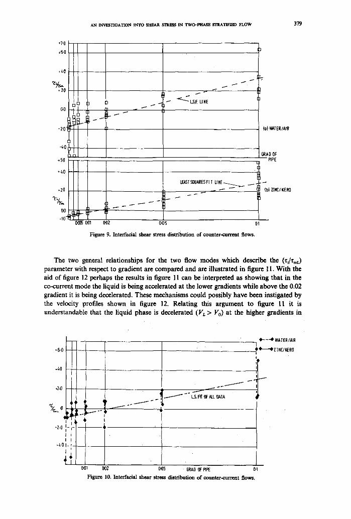
figures 9 and 10 where again the dimensionless (z~/%a.) is plotted vs the gradient of the pipe. Both sets of results exhibit similar patterns in that at the lower gradients (level to 0.035)
the initial assumed directions of the interracial shear stress (figure 2) are wrong whereas the directions at the higher gradients 0.035-0.100 are correct. The least square fit fines in figure 9 seem to describe the kerosene/zinc chloride solution (K/Z), results fairly well (correlation coefficient + 0.9007); however, the line for the water/air (W/A) results does not represent some of the results, especially at the lower gradients (0.0025 and 0.0050) which is verified by the relatively low correlation coefficient of +0.6920.
When the two sets of experimental points were plotted together as is illustrated in figure 10 they all seem to be reasonably described by the least square line (correlation coefficient +0.7458).
AN INVESTIGATION I N T O S H E A R S ~ I N T W O - - P H , / u ~ STRATI~ F L O W 379
*7.0
~-fi.O
4.0
• 2.0
.,...,,.
I
...... ~ 0.0
- 2 .
-4"0
[ - 1 / - 1
+5-0
÷~0
.7.0
I
LS.F. LI NE
I
I /
LEAST SQUARES FI T LI NE ~ ...._.. - - . . - - - -
. . . . . -
0 ~ 0~1 0'02 0.05 0.1
Figure 9. Interfacial shear stress distribution of counter-current flows.
(o) WATER/AIR
GRAO OF PiPE
I
(b} Z [ H C / K E R O
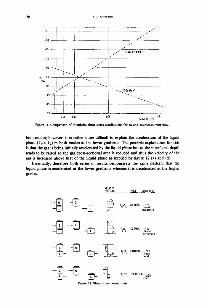
The two general relationships for the two flow modes which describe the (%/z0oL) parameter with respect to gradient are compared and are illustrated in figure 11. With the aid of figure 12 perhaps the results in figure 11 can be interpreted as showing that in the co-current mode the liquid is being accelerated at the lower gradients while above the 0.02 gradient it is being decelerated. These mechanisms could possibly have been instigated by the velocity profiles shown in figure 12. Relating this argument to figure 1[ it is understandable that the liquid phase is decelerated (VL > Vo) at the higher gradients in
-6"0
+2.0
m I I - I-
-2-0 I I
I I -4'0 I- t_
I
I i
t L
I
--,t,
J J
- " L.S. Fff OF ALL OATA
0'0'~ 002 0"05 6RAO OF PIPE
O-. - -.4~ WATER/AIR
O 41"~4'Z INE/KERO
I
4
m
O4
Figure 10. Inteffacial shear stress distribution of counter-current flows.
380 A.J. JOHNSTON
",2.5
"2.0
.1.5
-1"0
*05 "" ~
~,,,..00
-0~
-1-0
-1-5
-2.0
I " "
001 0.02
J
I I
J J COUNTER-CURRENT
i f ' :
"-~RENT
0.05 0.1 5RAO OF RPE
Figure I l. Comparison of interracial shear stress distributions for co and counter-current flow.
both modes; however, it is rather more difficult to explain the acceleration of the liquid phase (V~ > VL) in both modes at the lower gradients. The possible explanation for this is that the gas is being initially accelerated by the liquid phase but as the interracial depth tends to be raised so the gas cross-sectional area is reduced and thus the velocity of the gas is increased above that of the liquid phase as implied by figure 12 (a) and (d).
Essentially, therefore both series of results demonstrate the same pattern, that the liquid phase is accelerated at the lower gradients whereas it is decelerated at the higher grades.
VELOCITY PROFILES NOOE CONVENTION
liquid occeiemted
- ~ _ _ ~ VG, V L CO CURR. - re liquid
~ d eceleroted
VG~V L CI]JNTCURP,. '.-re liquid
deceL
Figure 12. Shear stress conventions.
COUNT CURE ..-,~ uqpta Qccel.
AN INVESTIGATION INTO SHEAR EI'RE~ IN TWO-PHASE STRATHq]~ FLOW 38l
-70
,5'0
.50
,30
.Z.O
.1.0 "c'7~ O. 0
-10
-2-0
-3.0
,.GO
.5.0
-t.O
,ry~3'o
,2.o
ol.O
oo
-1.o
-2.o
-3-o
-4.o
I ml
i m
• I
a,J i
'Ik Iz ,d • •
O LEVEL A I1100
• 1/10
COUNTER CURR.
ZINC/KERO
20 40 60 80 10~ 120 eetL)
- " i m
I l
OLEVEL •I1100
li110
COUNTER CURR.
W,6.TERIAIR
• ~ O¢.A V
0 0 0
<
1 2 3 4 5 6 7 B 9 1 "~ ~(L)
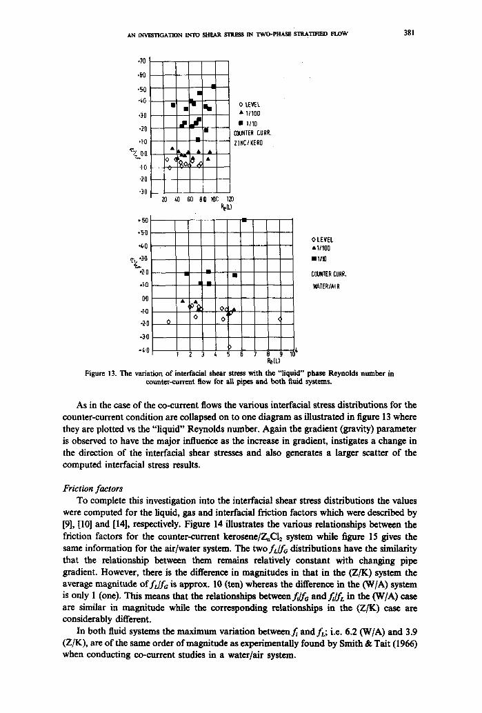
Figure 13. The variation of interfacial shear stress with the " l iquid" phase Reynolds number in counter-current flow for all pipes and bo th fluid systems.
As in the case of the co-current flows the various interracial stress distributions for the counter-current condition are collapsed on to one diagram as illustrated in figure 13 where they are plotted vs the "liquid" Reynolds number. Again the gradient (gravity) parameter is observed to have the major influence as the increase in gradient, instigates a change in the direction of the interfacial shear stresses and also generates a larger scatter of the computed interfacial stress results.
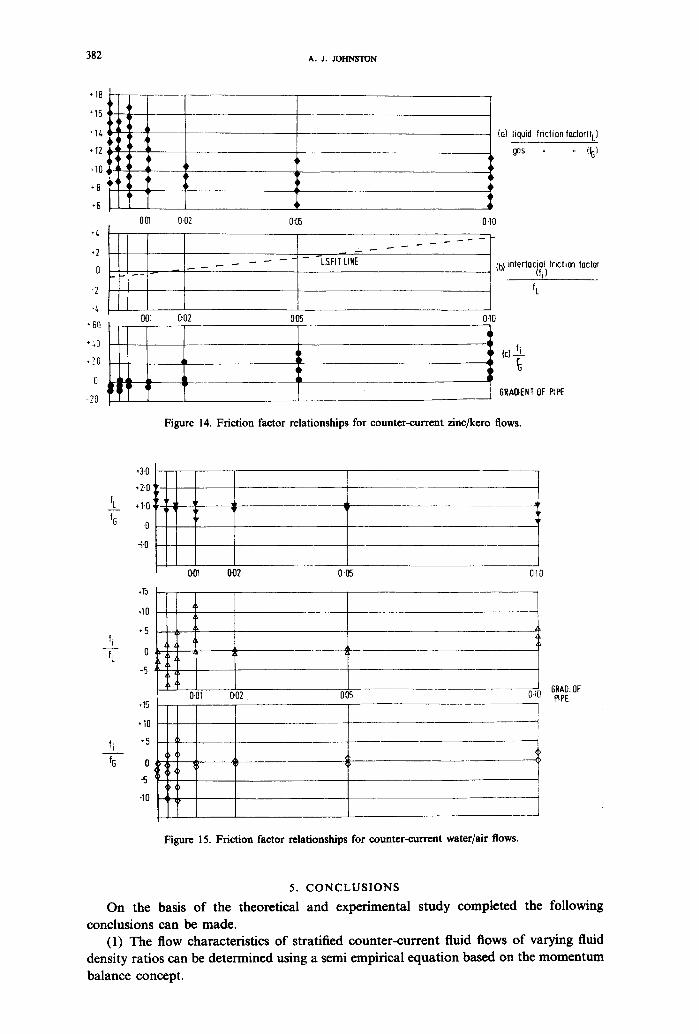
Friction factors To complete this investigation into the interfacial shear stress distributions the values
were computed for the liquid, gas and interfacial friction factors which were described by [9], [10] and [14], respectively. Figure 14 illustrates the various relationships between the friction factors for the counter-current kerosene/Z~Cl2 system while figure 15 gives the same information for the air/water system. The twofL/fo distributions have the similarity that the relationship between them remains relatively constant with changing pipe gradient. However, there is the difference in magnitudes in that in the (Z/K) system the average magnitude of fdfo is approx. 10 (ten) whereas the difference in the (W/A) system is only 1 (one). This means that the relationships between f , lfo and fi/fL in the (W/A) case are similar in magnitude while the corresponding relationships in the (Z/K) case are considerably different.
In both fluid systems the maximum variation betweenf~ andfL; i.e. 6.2 (W/A) and 3.9 (Z/K), are of the same order of magnitude as experimentally found by Smith & Tait (1966) when conducting co-current studies in a water/air system.
382 A . J . JOHNSTON
,t,
0 .... F
-2
-4 001
• 60 1 • :,0 [
,?0
-ZO
0.02
002
4
"-4
0"05
-- - "-'L.S, FI T~INE
O05
I D i
(a) liquid friction foctor(f L] ms %)
0.10
- [,b, 'nte'f°ci~t'fL 1,,c,,o~ fo~,o~
0"I0
GRAOIENT OF PIPE
Figure 14. Friction factor relationships for counter-current zinc/kero flows.
fL fG
fi fL
fi fG
,3-0
,2.0
+I.0
.0
-I.0
.15
.10
"5
,,q
001 0'02 0.05 0t0
0
-5
.15
.1oll . , l i °Tl! -5
0"01
I I 1
T
GRAO. OF 0'02 005 0.10 RPE
Figure 15. Friction factor relationships for counter-current water/air flows.
5. C O N C L U S I O N S
On the basis of the theoretical and experimental study completed the following conclusions can be made.
(1) The flow characteristics of stratified counter-current fluid flows of varying fluid density ratios can be determined using a semi empirical equation based on the momentum balance concept.
AN INVESTIGATION INTO SHEAR STRESS IN T W O = ~ $'rRATIFIED FLOW 383
(2) A similar equation can be used to analyse co-current flows where the velocity of both phases are of the same order of magnitude.
(3) The direction and magnitude of interracial shear stresses in both modes appear to be strongly influenced by the gradient of the pipes. At low gradients the interface between the fluids tends to be attracted towards the top of the pipe causing an increase in gas velocity which results, it is proposed, in the interfacial shear stresses being opposite to those expected. At higher gradients (above 0.02) the interfacial shear stresses act to decelerate the liquid phase and increase in magnitude with respective gradient increases.
(4) It is considered that the two main reasons for the large scatter of results are; that viscous forces have significant effects at certain gradients and, that at some flow conditions examined the stratified regime was on the verge of changing to the slug regime which affects the basic assumptions and thus the evaluation of the developed equations.
(5) It is suggested that this verified momentum balance equation has a number of practical applications and that it can readily be incorporated in a computer package which can quickly give the required design curves for almost any stratified counter-current situation.
REFERENCES
AORAWAL, S. S., G~C, ORY, G. A. & GOVmR, G. W. 1973 An analysis of horizontal stratified two phase flow in pipes. Can. J. Chem. Engng 51, 280-286.
BAKER, O. 1954 Simultaneous flow of oil and gas. Oil Gas 53, 185-195. CAMP, T. R. 1946 Design of sewers to fa~litate flow. Sewage Works J. 18, 1-16. GAZLEY, C. 1949 Interracial shear and stability in two-phase flow. Ph.D. Thesis, University
of Delaware. SMITH, T. N. & TAIT, R. W. F. 1966 Interfadal shear stress and momentum transfer in
horizontal gas-liquid flow. Chem. Engng Sci. 21, 63-75. TAITEL, Y. & DUKL~, A. E. 1976 A model for predicting flow regime transitions in
horizontal and near horizontal gas-liquid flow. AIChE J. 22, 47-55.
Copyright © 2022 FDOKUMEN