An ANN based Rotor Flux Estimator for Vector Controlled ...
10
International Journal of Electrical Engineering. ISSN 0974-2158 Volume 5, Number 4 (2012), pp. 427-436 © International Research Publication House http://www.irphouse.com An ANN based Rotor Flux Estimator for Vector Controlled Induction Motor Drive 1* Dr. D.D. Neema and 2 P.K. Choudhary 1 Dept. of Electrical & Electronics, CIT, Rajnandgoan, C.G., India 2 Dept. of Electrical Engineering, RCET, Bhilai, C.G., India E-mail: [email protected], [email protected] Abstract Field Oriented Control (FOC), also known as vector control of induction motor drives is very useful technique to obtain high performance speed response. Implementation of field oriented control requires the value of the instantaneous magnitude and position of the rotor flux. The magnitude and position of the rotor flux is approximated based on flux measurements in the direct FOC scheme and estimated in the indirect FOC scheme. In this paper a novel flux estimator, in the form of a two stage neural network flux estimator, is presented. The neural network is able to accurately estimate the rotor flux magnitude and position for line-start operation of an induction motor. Its ability to estimate flux response that lies outside of the neural network training data set is one of its strengths. Our preliminary work indicates that neural network flux estimation may be a feasible alternative to other flux estimation methods like programmable DSP kit. The comparative performance of both has been presented in this work. Keywords: FOC, Vector Control, Induction Drive, Neural Network, Back Propagation. Introduction In order to control an induction motor requiring high dynamic performance, an accurate knowledge of the magnitude and position of the rotor flux of the induction motor is necessary, irrespective of the operating point. Both direct Field Oriented Control (FOC), and indirect FOC, has been successfully established in theory and practice. In both control strategies the stator current components, responsible for the flux and torque production, are decoupled. This achieves independent control of
-
Upload
khangminh22 -
Category
Documents
-
view
2 -
download
0
Transcript of An ANN based Rotor Flux Estimator for Vector Controlled ...
International Journal of Electrical Engineering. ISSN 0974-2158 Volume 5, Number 4 (2012), pp. 427-436 © International Research Publication House http://www.irphouse.com
An ANN based Rotor Flux Estimator for Vector Controlled Induction Motor Drive
1*Dr. D.D. Neema and 2P.K. Choudhary
1Dept. of Electrical & Electronics, CIT, Rajnandgoan, C.G., India 2Dept. of Electrical Engineering, RCET, Bhilai, C.G., India
E-mail: [email protected], [email protected]
Abstract
Field Oriented Control (FOC), also known as vector control of induction motor drives is very useful technique to obtain high performance speed response. Implementation of field oriented control requires the value of the instantaneous magnitude and position of the rotor flux. The magnitude and position of the rotor flux is approximated based on flux measurements in the direct FOC scheme and estimated in the indirect FOC scheme. In this paper a novel flux estimator, in the form of a two stage neural network flux estimator, is presented. The neural network is able to accurately estimate the rotor flux magnitude and position for line-start operation of an induction motor. Its ability to estimate flux response that lies outside of the neural network training data set is one of its strengths. Our preliminary work indicates that neural network flux estimation may be a feasible alternative to other flux estimation methods like programmable DSP kit. The comparative performance of both has been presented in this work. Keywords: FOC, Vector Control, Induction Drive, Neural Network, Back Propagation.
Introduction In order to control an induction motor requiring high dynamic performance, an accurate knowledge of the magnitude and position of the rotor flux of the induction motor is necessary, irrespective of the operating point. Both direct Field Oriented Control (FOC), and indirect FOC, has been successfully established in theory and practice. In both control strategies the stator current components, responsible for the flux and torque production, are decoupled. This achieves independent control of

428 Dr. D.D. Neema and P.K. Choudhary
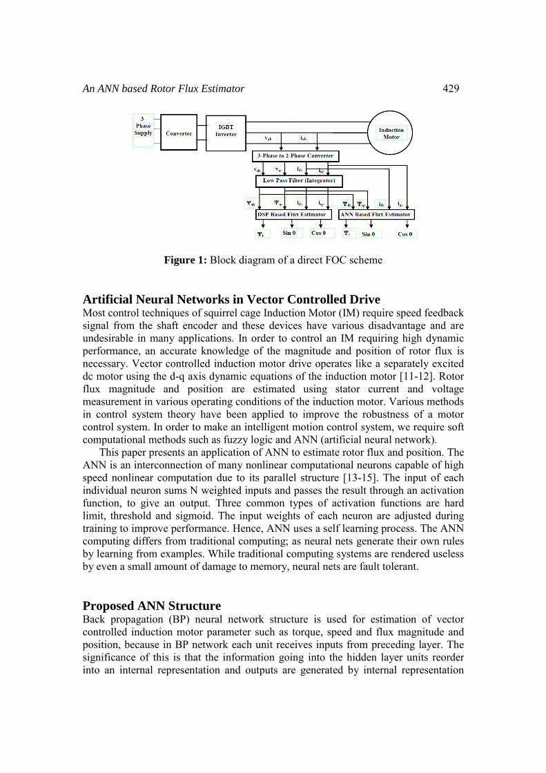
torque and flux. Since its introduction in the early 70's the direct FOC scheme has been regarded as less practical[1], because sensors are needed to obtain information about the machine variables. The sensors include the search coils, coil taps, or Hall effect sensors. Sensors often impose limitations on the machine's operating range (particularly at the low speed end) and also increase the overall cost of the machine. However, with the introduction of indirect FOC, the hardware requirements are much simpler, resulting in better overall performance. In order for such a scheme to work, the accurate estimation of rotor flux magnitude and position is vital. There are a few schemes available today [2-8]; most of which are based on adaptive control while others use digital signal processing (DSP) for the estimator implementation. In this paper an artificial neural network is described, as used for the estimation of the instantaneous magnitude or position of rotor flux during line-start operation of an induction motor. The design of a two hidden layer neural network is discussed. The learning requirements of the design are evaluated by developing the back-propagation learning technique for the flux estimator. In balanced three-phase systems, the two axis (d-axis and q-axis) model is used for dynamic modeling of an induction motor [9-12]. The d-q model of an induction motor can be expressed in either a stationary or a rotating reference frame. In stationary reference frame [10], the reference d and q axes are fixed on the stator. In synchronously rotating reference frame, the d-q axes rotate at the synchronous speed. Fig. 1 shows the block diagram of a FOC Scheme in stationary reference frame for the estimation of feedback signals such as rotor flux Ψr, and unit vectors (Sinθ, Cosθ), using DSP as well as ANN. The feedback signals can be calculated using the machine voltages and currents by using the following equations. Ψds = ⌠(vds – Rs ids)dt (1) Ψqs = ⌠(vqs – Rs iqs)dt (2) Ψqm = Ψqs – Ls iqs (3) Ψdm = Ψds – Ls ids (4) Ψqr = (Lr / Lm)Ψqm – Lr iqs (5) Ψdr = (Lr / Lm)Ψdm – Lr iqs (6) Ψr = √[(Ψqr )2 + (Ψdr )2] (7) Cosθ = (Ψdr / Ψr ) (8) Sinθ = (Ψqr / Ψr ) (9) All signals indicate that they are in stationary reference frame. The integrations in equation (1) & (2) can be merged with low corner frequency Low Pass Filter [1] as represented in Fig. 1. Both DSP and ANN receive voltage and current magnitude signals vds, vqs, ids and iqs and then estimate rotor flux using equations (1 to 9). The DSP based estimator output is used for comparison of the ANN based estimator performance.
An ANN based Rotor Flux Estimator 429
Figure 1: Block diagram of a direct FOC scheme Artificial Neural Networks in Vector Controlled Drive Most control techniques of squirrel cage Induction Motor (IM) require speed feedback signal from the shaft encoder and these devices have various disadvantage and are undesirable in many applications. In order to control an IM requiring high dynamic performance, an accurate knowledge of the magnitude and position of rotor flux is necessary. Vector controlled induction motor drive operates like a separately excited dc motor using the d-q axis dynamic equations of the induction motor [11-12]. Rotor flux magnitude and position are estimated using stator current and voltage measurement in various operating conditions of the induction motor. Various methods in control system theory have been applied to improve the robustness of a motor control system. In order to make an intelligent motion control system, we require soft computational methods such as fuzzy logic and ANN (artificial neural network). This paper presents an application of ANN to estimate rotor flux and position. The ANN is an interconnection of many nonlinear computational neurons capable of high speed nonlinear computation due to its parallel structure [13-15]. The input of each individual neuron sums N weighted inputs and passes the result through an activation function, to give an output. Three common types of activation functions are hard limit, threshold and sigmoid. The input weights of each neuron are adjusted during training to improve performance. Hence, ANN uses a self learning process. The ANN computing differs from traditional computing; as neural nets generate their own rules by learning from examples. While traditional computing systems are rendered useless by even a small amount of damage to memory, neural nets are fault tolerant. Proposed ANN Structure Back propagation (BP) neural network structure is used for estimation of vector controlled induction motor parameter such as torque, speed and flux magnitude and position, because in BP network each unit receives inputs from preceding layer. The significance of this is that the information going into the hidden layer units reorder into an internal representation and outputs are generated by internal representation
430
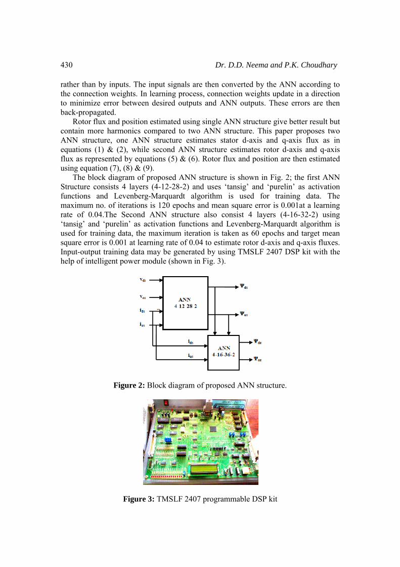
rather than by inputs. Thethe connection weights. Into minimize error betweeback-propagated. Rotor flux and positioncontain more harmonics cANN structure, one ANNequations (1) & (2), whilflux as represented by equusing equation (7), (8) & ( The block diagram of Structure consists 4 layerfunctions and Levenbergmaximum no. of iterationrate of 0.04.The Second‘tansig’ and ‘purelin’ as aused for training data, thesquare error is 0.001 at leaInput-output training data help of intelligent power m
Figure 2:
Figure
Dr. D.D. Neema and P
e input signals are then converted by the ANn learning process, connection weights updatn desired outputs and ANN outputs. These
n estimated using single ANN structure give bcompared to two ANN structure. This papeN structure estimates stator d-axis and q-ale second ANN structure estimates rotor d-auations (5) & (6). Rotor flux and position are(9). f proposed ANN structure is shown in Fig. 2rs (4-12-28-2) and uses ‘tansig’ and ‘pureling-Marquardt algorithm is used for trains is 120 epochs and mean square error is 0.0
d ANN structure also consist 4 layers (4-activation functions and Levenberg-Marquare maximum iteration is taken as 60 epochs aarning rate of 0.04 to estimate rotor d-axis anmay be generated by using TMSLF 2407 D
module (shown in Fig. 3).
Block diagram of proposed ANN structure.
e 3: TMSLF 2407 programmable DSP kit
P.K. Choudhary
NN according to te in a direction errors are then
better result but er proposes two axis flux as in axis and q-axis
e then estimated
; the first ANN n’ as activation
ning data. The 001at a learning 16-32-2) using rdt algorithm is and target mean nd q-axis fluxes. DSP kit with the

An ANN based Rotor Flux Estimator 431
Results and Discussions In this paper, application of ANN for the estimation of rotor flux and rotor position is suggested for vector control of an induction motor drive. Various layers of BP ANN structure have been trained with help of Neural Network Toolbox for Matlab-Simulink program. The real system data in the form of three-phase voltage and current were obtained for a 1 hp, 50 Hz, 3-phase squirrel cage induction motor drive and processed with the help of the programmable DSP kit (TMSLF 2407). The preliminary measured parameters were Vd, Vq, id and iq; the DSP kit is capable of converting the three phase voltage and current data obtained from the practical drive system into corresponding d-q components by using Park’s Transformation [9]. These d-q data for voltages and currents are in turn used to estimate the other parameters with the help of the programming features of the kit with the help of equations (1) to (9). The values obtained thus for a known set of inputs (Vd, Vq, id and iq) give the known output values for flux, which serve as target values in training the Neural Network of Fig. 2. A comparative study was then conducted between the DSP estimator and the proposed ANN estimator. Fig. 4 shows, estimated value of stator d-axis flux at 3-N-m load torque. The ANN based d-axis flux and DSP based d-axis flux reach peak value of 2.4 Wb at the same time of 0.01sec. In the case of ANN based estimator, the peak value of flux is maintained constant throughout the operation, and its value is slightly higher as compared to DSP based peak flux of 2.38 Wb. As load torque is increased from 3-Nm to 5-Nm, ANN estimated d-axis flux as well as DSP estimated d-axis flux match more closely as shown in Fig. 5. In ANN based estimator, the peak value of flux is 2.4 Wb and has a constant peak while in DSP based estimator the peak value of flux has some harmonics.
Figure 4: Stator d‐ axis flux at torque 3‐Nm
Figure 5: Stator d‐ axis flux at torque 5‐Nm
0 0.05 0.1 0.15 0.2-3
-2
-1
0
1
2
3
TIME (Sec.)
FLU
X (
Wb)
ANNDSP
0 0.05 0.1 0.15 0.2-3
-2
-1
0
1
2
3
TIME (Sec.)
FLU
X (
Wb)
ANNDSP

432 Dr. D.D. Neema and P.K. Choudhary
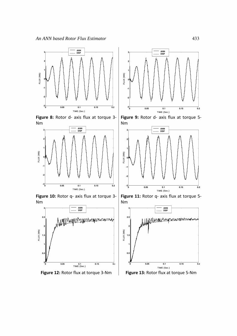
Fig. 6 shows the stator q-axis flux at load torque of 3-Nm. ANN based estimation of stator q-axis flux and DSP based estimation of flux reach the peak value of 2.8 Wb after 0.02 sec. Both the estimated values have close resemblance but ANN based peak flux is slightly higher than DSP based peak flux. As the load torque is increased from 3-Nm to 5-Nm, ANN based stator q-axis flux as well as DSP based q-axis flux responses track very closely as shown in Fig. 7. Both ANN and DSP based stator d-axis flux have the peak value as 2.8 Wb and remains constant for complete operation. Rotor d-axis and q-axis flux and position are estimated using above estimated d-axis and q-axis stator flux. Fig. 8 shows rotor d-axis flux at load torque of 3-Nm as estimated by both ANN and DSP; which produce nearly same results. In the case of ANN based estimator, rotor d-axis peak flux (2.4 Wb) is reached after 0.05 sec and remains constant. On the other hand, for the DSP based rotor d-axis flux, the peak flux is slightly lower (2.35 Wb) in the beginning. After 0.17 sec. its value is same as ANN based estimator. As load torque is increased from 3-Nm to 5-Nm, both ANN and DSP based rotor d-axis flux match quite closely, as shown in Fig. 9. In case of ANN based estimator at load torque 5-Nm, rotor d-axis flux reaches its steady state value (with peak of 2.4 Wb) after 0.05 sec. In case of DSP based estimator, rotor d-axis flux is slightly lower (with peak as 2.33 Wb) in magnitude in the beginning. After 0.17 sec its value is same as ANN based estimator (2.4 Wb).
Figure 6: Stator q‐ axis flux at torque 3‐Nm.
Figure 7: Stator q‐ axis flux at torque 5‐Nm
0 0.05 0.1 0.15 0.2-3
-2
-1
0
1
2
3
TIME (Sec.)
FLU
X (
Wb)
ANNDSP
0 0.05 0.1 0.15 0.2-3
-2
-1
0
1
2
3
TIME (Sec.)
FLU
X (
Wb)
ANNDSP
An ANN based Rotor Flux Estimator 433
Figure 8: Rotor d‐ axis flux at torque 3‐Nm
Figure 9: Rotor d‐ axis flux at torque 5‐Nm
Figure 10: Rotor q‐ axis flux at torque 3‐Nm
Figure 11: Rotor q‐ axis flux at torque 5‐Nm
Figure 12: Rotor flux at torque 3‐Nm Figure 13: Rotor flux at torque 5‐Nm
0 0.05 0.1 0.15 0.2-3
-2
-1
0
1
2
3
TIME (Sec.)
FLU
X (
Wb)
ANNDSP
0 0.05 0.1 0.15 0.2-3
-2
-1
0
1
2
3
TIME (Sec.)
FLU
X (
Wb)
ANNDSP
0 0.05 0.1 0.15 0.2-3
-2
-1
0
1
2
3
TIME (Sec.)
FLU
X (
Wb)
ANNDSP
0 0.05 0.1 0.15 0.2-3
-2
-1
0
1
2
3
TIME (Sec.)
FLU
X (
Wb)
ANNDSP
0 0.05 0.1 0.15 0.20
0.5
1
1.5
2
2.5
3
TIME (Sec.)
FLU
X (
Wb)
ANNDSP
0 0.05 0.1 0.15 0.20
0.5
1
1.5
2
2.5
3
TIME (Sec.)
FLU
X (
Wb)
ANNDSP
434 Dr. D.D. Neema and P.K. Choudhary
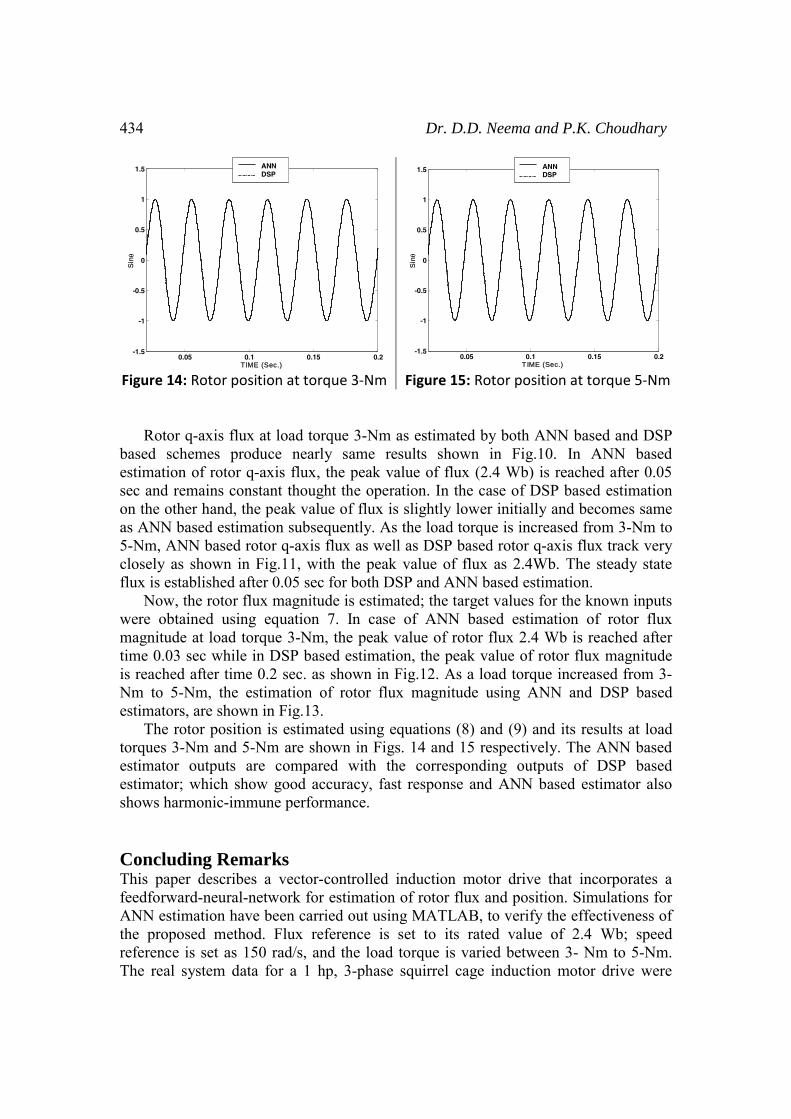
Figure 14: Rotor position at torque 3‐Nm Figure 15: Rotor position at torque 5‐Nm Rotor q-axis flux at load torque 3-Nm as estimated by both ANN based and DSP based schemes produce nearly same results shown in Fig.10. In ANN based estimation of rotor q-axis flux, the peak value of flux (2.4 Wb) is reached after 0.05 sec and remains constant thought the operation. In the case of DSP based estimation on the other hand, the peak value of flux is slightly lower initially and becomes same as ANN based estimation subsequently. As the load torque is increased from 3-Nm to 5-Nm, ANN based rotor q-axis flux as well as DSP based rotor q-axis flux track very closely as shown in Fig.11, with the peak value of flux as 2.4Wb. The steady state flux is established after 0.05 sec for both DSP and ANN based estimation. Now, the rotor flux magnitude is estimated; the target values for the known inputs were obtained using equation 7. In case of ANN based estimation of rotor flux magnitude at load torque 3-Nm, the peak value of rotor flux 2.4 Wb is reached after time 0.03 sec while in DSP based estimation, the peak value of rotor flux magnitude is reached after time 0.2 sec. as shown in Fig.12. As a load torque increased from 3-Nm to 5-Nm, the estimation of rotor flux magnitude using ANN and DSP based estimators, are shown in Fig.13. The rotor position is estimated using equations (8) and (9) and its results at load torques 3-Nm and 5-Nm are shown in Figs. 14 and 15 respectively. The ANN based estimator outputs are compared with the corresponding outputs of DSP based estimator; which show good accuracy, fast response and ANN based estimator also shows harmonic-immune performance. Concluding Remarks This paper describes a vector-controlled induction motor drive that incorporates a feedforward-neural-network for estimation of rotor flux and position. Simulations for ANN estimation have been carried out using MATLAB, to verify the effectiveness of the proposed method. Flux reference is set to its rated value of 2.4 Wb; speed reference is set as 150 rad/s, and the load torque is varied between 3- Nm to 5-Nm. The real system data for a 1 hp, 3-phase squirrel cage induction motor drive were
0.05 0.1 0.15 0.2-1.5
-1
-0.5
0
0.5
1
1.5
TIME (Sec.)
Sinθ
ANNDSP
0.05 0.1 0.15 0.2-1.5
-1
-0.5
0
0.5
1
1.5
TIME (Sec.)
Sinθ
ANNDSP
An ANN based Rotor Flux Estimator 435
obtained and processed with the help of the DSP kit (TMSLF 2407) and a comparative study was conducted with the proposed ANN estimator. The results obtained demonstrate the successful application of ANN in the estimation of rotor flux and position for a vector controlled induction motor drive system. A four-layer feedforward neural network has been trained for estimation of stator d-axis and q- axis flux, which are supplied as inputs to another neural network of similar structure (with different number of neurons) in order to estimate the rotor d-q axis flux. This two stage ANN structure is found to give very efficient and accurate results with comparatively less computation burden in training of neurons. The performance of the proposed neural net estimator is found to be very good as compared to programmable DSP based estimator. Appendix
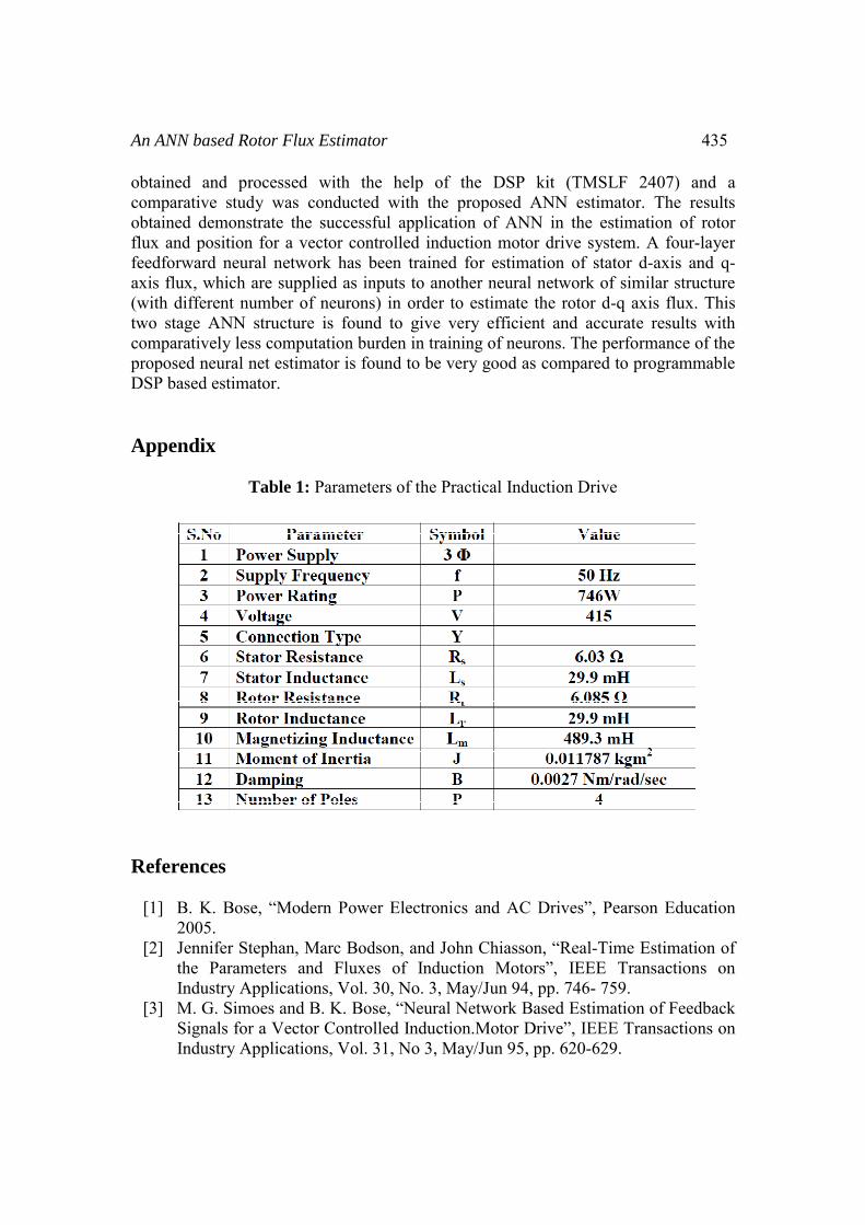
Table 1: Parameters of the Practical Induction Drive
References
[1] B. K. Bose, “Modern Power Electronics and AC Drives”, Pearson Education 2005.
[2] Jennifer Stephan, Marc Bodson, and John Chiasson, “Real-Time Estimation of the Parameters and Fluxes of Induction Motors”, IEEE Transactions on Industry Applications, Vol. 30, No. 3, May/Jun 94, pp. 746- 759.
[3] M. G. Simoes and B. K. Bose, “Neural Network Based Estimation of Feedback Signals for a Vector Controlled Induction.Motor Drive”, IEEE Transactions on Industry Applications, Vol. 31, No 3, May/Jun 95, pp. 620-629.

436 Dr. D.D. Neema and P.K. Choudhary
[4] M. N. Cirstea, A. Dinu, J.G. Khor and M. McCormick, “Neural and Fuzzy Logic Control of Drives and Power Systems”, Newnes Pub., ISBN 7506 55585, 2006.
[5] K. P. Allan, P. N. Edwin and A. Farhad, “A Flux Estimator for Field oriented Control of Induction Motor Using Artificial Neural Network”, IEEE Transactions on Industry Applications, Vol. 1, 1994, pp. 585-592.
[6] P. Alexei, and Z. Alex, “Direct Torque and Flux Regulation in Sensorless Control of an Induction Motor”, Proc. of the American Control Conference, Arlington, VA, Jun. 25-27, 2001, pp. 137-142.
[7] P. P. Cruz and Jaime J. Rodriguez Rivas, “A Small Neural Network Structure Application in Speed Estimation of an Induction Motor using Direct Torque Control”, IEEE Transactions on Industry Applications, 2001.
[8] P. Vas, A. F. Stronach and M. Neuroth, “DSP-Based Speed-Sensorless Vector Controlled Induction Motor Drives Using AI Based Speed Estimator and Two Current Sensors”, Proc. of the Power Electronics and Variable Speed Drives, 21-23 September 1998 (Conference Publication No. 456 0 IEE 1998), pp. 442-446.
[9] D. D. Neema and Dr. A. S. Zadgaonkar, “Matlab Simulation of Three Phase to Two Phase Transformation and Vice-Versa”, Proc. of the National Conference on Innovation in Engineering and Technology – INVENT – 2007 held at MIET Gondia (M.S.) on 14th -15th March, 2007.
[10] P. C. Sen, “Principles of Electric Machines and Power Electronics”, New York: Wiley, 1988.
[11] W. Leonhard, “Control of Electric Drives”, New York: Springer- 3rd Edition, 2001.
[12] R. Krishnan, “Electric Motor Drives, Modeling, Analysis and Control”, Pearson Education, 2005.
[13] Simon Haykin, “Neural Networks: A Comprehensive Foundation”, 2nd Edition, Pearson Publication, 2004.
[14] Ben Krose and Patrick Van Der, “Smart Introduction to Neural Networks”, 8th
Edition, November 1996. [15] O. K. Teresa and T. K. Czeslaw, “Neural Network Application for Flux and
Speed Estimation in the Sensorless Induction Motor Drive”, Proc. of ISIE’97, Guimaraes, Portugal, (IEEE Cat. No. 97TH8280), 1997, pp. 1253-1258.