modelling and analysis of disc brake rotor
72
MODELLING AND ANALYSIS OF DISC BRAKE ROTOR A Thesis Submitted to JAWAHARLAL NEHRU TECHNOLOGICAL UNIVERSITY ANANTAPUR, ANANTAPURAMU In partial fulfillment of the requirements for the award of the Degree of BACHELOR OF TECHNOLOGY In MECHANICAL ENGINEERING Academic Batch 2011-15 By G.SUDHEER (114M1A0328) L.SAI PRATAP (114M1A0323) Y.ASHOK (114M1A0302) G.GURU PRASAD (114M1A0310) Under the Guidance of Mrs. K.BALAJI M.Tech Assistant Professor, VEMU INSTITUTE OF TECHNOLOGY – Chittoor
-
Upload
independent -
Category
Documents
-
view
4 -
download
0
Transcript of modelling and analysis of disc brake rotor

MODELLING AND ANALYSIS OF DISC BRAKE ROTOR
A Thesis
Submitted to
JAWAHARLAL NEHRU TECHNOLOGICAL UNIVERSITY ANANTAPUR, ANANTAPURAMU
In partial fulfillment of the requirements for the award of the Degree
of
BACHELOR OF TECHNOLOGY
In
MECHANICAL ENGINEERING
Academic Batch 2011-15
By
G.SUDHEER (114M1A0328) L.SAI PRATAP (114M1A0323)
Y.ASHOK (114M1A0302)G.GURU PRASAD (114M1A0310)
Under the Guidance of
Mrs. K.BALAJI M.Tech
Assistant Professor, VEMU INSTITUTE OF TECHNOLOGY – Chittoor

DEPARTMENT OF MECHANICAL ENGINEERINGVEMU INSTITUTE OF TECHNOLOGY
(Approved by AICTE, New Delhi & Affiliated to JNTU,Anantapur)
P. K o t h a k o t a (P), P u t h a l a p a t t u (M), C h I t t o o rDist. - 517112
VEMU INSTITUTE OF TECHNOLOGY(Approved by AICTE, New Delhi & Affiliated to JNTU,
Anantapur)P. K o t h a k o t a (P), P u t h a l a p a t t u (M), C h I t t o o r
Dist. - 517112DEPARTMENT OF MECHANICAL ENGINEERING
CERTIFICATE
This is to certify that the Project report entitled “MODELLING AND
ANALYSIS OF DISC BRAKE ROTOR” is a bonafide work carried out by
G.SUDHEER(114M1A0328)
L.SAI PRATAP(114M1A0323) Y.ASHOK(114M1A0302) G.GURU PRASAD
(114M1A0310)

during the academic batch 2011-15 is submitted to the department of
Mechanical Engineering, in partial fulfillment of the requirements
for the award of degree of BACHELOR OF TECHNOLOGY in MECHANICAL
ENGINEERING from Jawaharlal Nehru Technological University Anantapur,
Ananthapuramu.This is a record of bonafide work carried out by the
above student on his own and the results embodied in this project have
not been reproduced or copied from any source. The results embodied in
this project report have not been submitted to any other university or
institute for the award of any other degree or diploma.
Signature of the Supervisor Signature of the Head of the Department
Mr.K.Balaji, Mr.S.P.Bhanu murthy,Assistant Professor Professor& HODDepartment of Mechanical Engineering, Department of Mechanical Engineering,VIT, Chittoor. VIT, Chittoor. External Viva-Voce held on: ____________
Signature of the Internal Examiner Signature of the
External Examiner
VEMU INSTITUTE OF TECHNOLOGY(Approved by AICTE, New Delhi & Affiliated to JNTU,
Anantapur)P. K o t h a k o t a (P), P u t h a l a p a t t u (M), C h I t t o o r
Dist. - 517112

DEPARTMENT OF MECHANICAL ENGINEERING
DECLARATION
We,G.Sudheer (114M1A0328)
L.Sai pratap (114M1A0323)
Y.Ashok (114M1A0302)
G.Guru Prasad (114M1A0310)
Here by declare that the Project report entitled “MODELLING AND
ANALYSIS OF DISC BRAKE ROTOR”” under the guidance of Mrs.K.Balaji,
Assistant Professor, Vemu Institute of Technology,, Chittoor is
submitted in partial fulfillment of the requirements for the award of
the degree of BACHELOR OF TECHNOLOGY in MECHANICAL ENGINEERING.This is
a record of bonafide work carried out by me and the results embodied
in this project have not been reproduced or copied from any source.
The results embodied in this project report have not been submitted to
any other university or institute for the award of any other any
degree or diploma
other degree or diploma.

Signature of the student
ACKNOWLEDGEMENT
This project has been successful with the encouragement, guidance
and support attributed from many patrons along with the hard work that
has been put into it by myself. I would like to take this opportunity
to express my gratitude and sincere thanks to all those who made this
project a successful one.
It is my great pleasure to express my sincere thanks to
Mr.S.P.Bhanu murthy, M.Tech HOD – Mechanical Engineering Department for
his valuable suggestions related to the different aspects of this
project.
I am extremely thankful and immensely grateful to my guide
Mr.K.Balaji, M.Tech VIT for granting me this golden opportunity to
complete my project work under her esteemed guidance. Her keen
interest, continuous encouragement and regular supervision at every
stage of this project have ensured the best out of me and the best

possible results from the project. Finally, yet importantly, I would
like to express my sincere thanks to all my respectable faculties,
respected parents, dear friends and classmates for their support,
blessings, help and continuous encouragement for the successful
completion of this project.
,G.Sudheer (114M1A0328)
L.Sai pratap (114M1A0323)
Y.Ashok (114M1A0302)
G.Guru Prasad (114m1a0310)

ABSTRACT
The disc brake is a device for slowing or stopping the rotation of a
wheel. Breaks convert friction into heat if brake get to hot they will
expose to large thermal stress during the rotation of breaking. Break
is a mechanical device is used stop are slowing of vehicle during the
motion. The main aim of this project is to minimize the temperature
and thermal stress with best suited Material Analysis is done on both
ventilated and normal disc Actual disc brake has no holes design is
changed by giving holes in the disc brake for more heat dissipation.
Modeling is done in catia v5 and analysis is done in analysis is
done ansys 2012 (finite element Analysis software) thermal and
structural analysis is done by providing materials gray cast iron And
stain less steel and comparing both results and providing best suited
material.

Table of Contents
ACKNOWLEDGEMENT…………………………………………………………….i
ABSTRACT................................................i
Table of Contents.....................................iii
List of Tables.........................................vi
List of Figures.......................................vii
1 INTRODUCTION...................................1
1.1 BRAKEING SYSTEM ...............................1
1.1.1 PRINCIPLE OF BRAKEING SYSTEM.................1
2 LITERATURE REVIEW..............................4
2.1 HISTORY OF BREAKING SYSTEM.....................4
2.1.1 TYPICAL MODERN AUTOMOTIVE BRAKE SYSTEM.........5
2.2.2 TYPES OF DISC BRAKE ROTORS.....................6
2.2.3 USES OF ROTOR..................................9
2.2.4 FUNCTIONS OF DISC BRAKE ROTOR..................9
2.3 MANUFACTURING PROCESS OF LEAF SPRING..........14
2.3.1 STEPS IN MANUFACTURING PROCESS OF LEAF SPRING. 15
2.4 SPRING MATERIALS..............................19
2.4.1 HIGH CARBON STEELS............................20
2.4.2 ALLOY STEELS..................................20
2.4.3 STAINLESS STEELS..............................20
2.4.4 COPPER-BASED ALLOYS...........................21
2.4.5 NICKEL-BASED ALLOYS...........................21
2.4.6 COMPOSITE MATERIALS...........................21
2.4.7 ADVANTAGES OF COMPOSITE MATERIALS.............22
2.4.8 DISADVANTAGES OF COMPOSITE MATERIALS..........23
2.4.9 STEEL VS COMPOSITE MATERIALS..................23
2.5 ADVANTAGES OF LEAF SPRING.....................24
2.6 DISADVANTAGES OF LEAF SPRING..................25
3 METHODOLOGY...................................28
3.1 INTRODUCTION..................................28
3.2 SPECIFICATION OF PROBLEM......................29
3.3 GEOMETRY IN SOLID WORKS.......................30
3.3.1 STEPS TO DRAW THE LEAF SPRING ASSEMBLY IN SOLID WORKS 14
..............................................30
3.3.2 SPECIFICATIONS OF SEMIELLIPTICAL LEAF SPRING ASSEMBLY 31
3.3.3 MODEL OF THE MASTER LEAF SPRING...............32
3.3.4 ASSEMBLY VIEW OF LEAF SPRING ASSEMBLY.........32
3.3.5 BOTTOM VIEW OF LEAF SPRING ASSEMBLY...........33
3.3.6 ISOMETRIC VIEW OF LEAF SPRING ASSEMBLY........33
3.4 IMPORT OF CAD MODELS IN ANSYS.................33
3.5 MESHING OF GEOMETRY...........................34

3.6 BOUNDARY CONDITIONS...........................36
3.7 MATERIAL PROPERTIES...........................36
4 RESULTS AND DISCUSSION........................37
4.1 DEFORMATION RESULTS...........................37
4.1.1 STAINLESS STEEL...............................37
4.1.2 CARBON FIBRE..................................38
4.1.3 BORON FIBRE...................................38
4.2 STRESS RESULTS................................39
4.2.1 STAINLESS STEEL...............................39
4.2.2 CARBON FIBRE..................................40
4.2.3 BORON FIBRE...................................40
4.3 STRAIN RESULTS................................41
4.3.1 STAINLESS STEEL...............................41
4.3.2 CARBON FIBRE..................................42
4.3.3 BORON FIBRE...................................42
4.4 RESULTS OF INDIVIDUAL LEAVES..................43
4.5 FEA RESULTS...................................44
4.6 ANALYTICAL CALCULATIONS.......................45
4.6.1 STAINLESS STEEL...............................45
4.6.2 CARBON FIBRE..................................45
4.6.3 BORON FIBRE...................................46

4.7 ANALYTICAL RESULTS............................47
5 CONCLUSION....................................48
6 FUTURE SCOPE..................................49
7 REFERENCES………………………………………………………..50
8 PAPER PUBLISHED……………………………………………………...51

List of Tables
Table 3-1: Specifications of semielliptical leaf spring assembly 31
Table 3-2: Mechanical properties of materials..........36
Table 4-1: FEA results.................................44
Table 4-2: Analytical results..........................47

List of Figures
Figure 3-1: Flowchart for methodology..................29
Figure 3-2: Model of the master leaf spring............32
Figure 3-3: Assembly view of leaf spring assembly......32
Figure 3-4: Bottom view of leaf spring assembly........33
Figure 3-5: Isometric view of leaf spring assembly.....33
Figure 3-6: Importing model of leaf spring.............34
Figure 3-7: Meshing of leaf spring assembly............35
Figure 3-8: Detailed view of meshing...................35
Figure 3-9: Boundary condition of leaf spring..........36
Figure 4-1: Deformation in stainless steel.............37
Figure 4-2: Deformation in carbon fibre................38
Figure 4-3: Deformation in boron fibre.................38
Figure 4-4: Stress in stainless steel..................39
Figure 3-5: Stress in carbon fibre.....................40
Figure 4-6: Stress in boron fibre......................40
Figure 4-7: Strain in stainless steel..................41
Figure 4-8: Stress in carbon fiber.....................42
Figure 4-9: Strain in boron fibre......................42


CHAPTER IINTRODUCTION
1.1 BREAKING SYSTEM Brakes are the most important safety parts
in the vehicles. Generally all of the vehicles have their own safety
devices to stop their car. Function of brakes to slow and stop the
rotation of the wheel. To stop the wheel, breaking pads are forced
mechanically against rotor disc on both surfaces .they compulsory for
all of the modern vehicles and the safe operation of vehicles. Brakes
transform the kinetic energy of the car into heat energy.
Brakes have been retuned and improved ever since their invention.
Brakes increases in the travelling speeds. An effective braking system
is needed to accomplish this task with challenging term where material
need to be lighter than before and performance of the brakes must be
improved. Today’s cars often use a combination of disc brakes and drum
brakes.
Disc brakes are located on front two wheels and drum brakes on
the back two wheels. Clearly show that together with steering
components and tiers represent the most important accident avoidance
systems present on motor vehicles.
In order to understand the behavior of braking system have to
satisfied following three function
1 The braking system must be permitted the vehicle to maintain a
constant speed when travelling

2 Break should control the vehicle in repeatable fashion and cause
the vehicle stop
3 The break should must hold the vehicle stationary when on the
flat or on a gradient
1.1.1 PRINCIPLE OF BRAKING SYSTEM
A brake is a device by means of which artificial frictional
resistance is applied to moving machine member, in order to stop the
motion of a machine. Break play major role in moving auto motive
vehicles
A disk brake consists of a cast iron disc bolted to the wheel hub
and a stationary hosing called caliper the caliper is connected to
some stationary part of the vehicle like the axle casing or stub axle
as in two parts each part containing a piston. in between each piston
and the disc there is a friction pad held in position by retaining
pins, spring plates etc. passages are drilled in the caliper for the
fluid enter or leave each housing the passages are also connected to
another one for bleeding . Each cylinder and piston.
When the brakes are applied, hydraulically actuated pistons move
the friction pads in to contact with the rotating disc, applying equal
and opposite forces on the disc. Due to the friction between disc and
pad surfaces the kinetic energy of the rotating wheel is converted
into heat, by which vehicle is to stop after a certain distance. On
releasing the brakes the brakes rubber-sealing ring acts as return
spring and retract the pistons and the friction pads away from the
disc. In the course of brake operation, frictional heat is dissipated

mostly pad and disc causes uneven temperature distribution on the
components could induce severe thermo elastic distortion of the disc.
The thermal distortion of a normally flat surface into highly deformed
state called thermo elastic transition. It sometimes occurs in the
sequence of stable continuously related states operating conditions
change. At the other times, however the stable evolution behavior of
the sliding system crosses threshold where upon a sudden change of
contact conditions occurs in a sequence of stable continuously related
states s operating conditions change.
When this process leads to an accelerated change of contact
pressure distribution, the unexpected hot roughness of thermal
distortion may grow unstably under some conditions, resulting in local
hot spots and leaving thermal cracks on the disc. This is known as
thermo elastic in stability. The thermo elastic instability phenomenon
occurs more easily as the rotating speed of the disk increases. This
region where the contact load is concentrated reaches very high
temperatures, which cause deterioration in braking performance.
Moreover, in the course of their presence on the disk, the passage of
thermally distorted hot spots moving under the brake pads causes low-
frequency brake vibration.

Figure 1.1; hydraulic disc brake
CHAPTER 2
2 LITERATURE REVIEW
2.1 INTRODUCTIONNormally, thermal stress analysis has been performed to any of
material related to thermal process in order to oversee the behavior
and character of material. Any abnormality regards to thermal input
will give the high values on the stress magnitude of the studied
materials.
The high values of stress magnitude will shows deformation on
certain areas which load has been applied on it. Design and analysis
of certain parts or component will took much time and it is costly.
Therefore, without any analysis or design tools, it would be

limitations on repeated analysis. For decades, finite element analysis
(FEA) has been a preferred method to address some of the above
concerns. It can be used to compare the design alternatives and hence,
optimize the brake rotor design prior to production of prototype
components.
A literature review was conducted to investigate the past
research that has been done in many areas related to this work. In
addition, description, histories, functions and theory of disc brake
rotor will be discussed in this chapter. Furthermore, theory of finite
element method related to thermal analysis will be presented as well
in this chapter
2.1.1 Some Brake History
The first known vehicular brake, the Locked Wheel

Figure 2-1; first know vehicular brake locked wheel
It is believed that the Romans used a chariot brake. One end of
chain was attached to a chariot chassis, while the other end was held
by the driver. The major advance of this brake was that it allowed the
amount of braking force to be varied.
Figure 2-2; chariot brake by using chain

Another advance was in the 1800’s. The typical wagon used a
wooden brake shoe that was pressed against the wheel rim by lever-
operated linkages.
Figure 2-3; wagon with wooden brake shoe
The first automobiles were little more than wagons or carriages
fitted with engines and drive trains. With the invention of rubber
tires, the rim-contact wagon brake became impractical. To solve the
problem, a metal brake drum was attached to the inside of the wheel to
provide a rubbing surface for the brake shoe.

Figure 2-4; rim contact wagon brake with metal brake drum
As time went by, the speeds attained by the newer models exceeded
the ability of the brakes to stop them safely and reliably (too much
energy into heat raising temperatures causing brake power loss and
quick wear out). Initial solution was to increase the surface area of
the lining material led to the band brake.
Figure 2-5; advance breaking system with brake lining

The solution for the problems of the band brake was the hydraulic
actuated internal expanding shoe brake.
Figure 2-6; hydraulic actuated internal expanding shoe brake
As highway speeds and the size and weight of vehicles continued
to increase, it became apparent that even the largest practical drum
brakes were unable to adequately transfer the heat generated during
repeated braking. Hence disc brakes became more in use.

Figure 2-7; drum brake
2.1.2 Typical Modern Automotive Brake System
Figure 2-8; typical modern automotive brake system
2.1.3 Basic Brake Operation

An automobile’s brake system must be able to slow or stop the vehicle
when in motion and it must be able to hold the car in position when
stopped on an incline.
Automotive brakes have two interrelated systems:1) Service Brakes
2) Parking Brakes
Basic Brake OperationAll break systems work in accordance with the physical “laws” or
principles that describe the relationships between elements of our
physical world such as
Energy
Inertia
Hydraulics
Mechanics
Friction
Energy:
Can be defined as the ability to do work
Work:
Transfer of energy from one physical system to another –
especially the transfer of energy to an object through the application
of force. Formula: Work = Force x Distance
Automotive Brakes:
The force input by the driver is multiplied by the actuation
system and enables the energy of the vehicle’s motion to be
transferred to the brake drums or rotors where friction converts it
into heat energy and stops the vehicle.

Kinetic Energy:
the energy of mass in motion the amount of that energy is
determined by the object’s mass and speed. Kinetic Energy is based on
speed and mass, not weight. Weight is the mass of an object acted upon
by the force of gravity. Since the force of gravity is relatively
constant on Earth, we can use the terms weight and mass
interchangeably in this tutorial. Weight and speed contribute to
kinetic energy – they do not affect it to the same degree – speed has
a much greater effect.
WEIGHT TRANSFER INCREASES THE LOAD ON THE FRONT WHEELS WHILE THE LOAD
ON THE RARE WHEELS REDUCED
For the foundation brakes to convert kinetic energy into heat
they must be applied with great force. The force required to stop a
vehicle is so great that leverage and hydraulics are used to
facilitate a person to apply it (We’ll not consider boosters in this
tutorial). The primary mechanical principle used to increase the
application force in every brake system is leverage. Lever: a simple
machine that consists of a rigid object that pivots about a fixed
point called a fulcrum.

In addition to mechanical advantage, hydraulic principles are
used to increase the brake application force. Hydraulic systems are
very efficient at transmitting motion and force. Hydraulic systems use
liquids to transmit motion (by moving a volume of the liquid). For all
practical purposes, a liquid cannot be compressed. A gas, such as air,
will compress and a hydraulic system MUST be free from air to work
properly.
Figure 2-9; hydraulic brake system with cylinder
Brake hydraulic systems not only transmit motion they also
transmit force in the form of pressure. Pressure in a brake system is
primarily determined by 2 factors (Not including the booster’s power
assist):
1) Force on the brake pedal multiplied by the mechanical advantage of
the pedal ratio.
2) Surface area of the master cylinder piston.
The differences in force are obtained by using different sized
pistons in the wheel cylinders and/or calipers. The ability of a

hydraulic system to increase and decrease forces appears to be a
convenient thing. However, there is another side to the process that
must be considered.
Brake linings having a coefficient of friction of less than 1.0
are not a deficiency. They have to be easily controlled as not being
“grabby” and not wear out too quickly while managing the heat
generated. The amount of contact width may not greatly affect the
coefficient of friction, but it does offer considerable effects on
lining life and the dissipation of heat converted from the vehicle’s
kinetic energy.
2.1.4 WHY DISC BRAKE NEED The higher levels of braking performance specified in the 1976
revision of FMVSS 105 virtually guaranteed that manufactures would use
only disc brakes on front axles of new vehicles.
The main performance advantages are:
Fade resistance (Both for high temperature and water soaking) Reduced tendency for pull (stay within 12 ft. lane requirement).
Lining Fade:
The lining material overheats, its friction coefficient drops and
lining fade occurs. Primary symptom is a hard pedal and requires the
driver to apply greater force to maintain stopping power. Point at
which it occurs in disc brakes is much later than in drum brakes and
recovery is faster.
Fade Resistance:

A disc brake compared to a drum brake of similar diameter has a
greater ability to resist fade. One reason for this is the cooling
ability since all the major parts are usually exposed to air flowing
over them. Also, many rotors have cooling passages cast into them to
help reduce operating temperatures. However, with the demands for high
number of multiple stops temperature requirements on today’s vehicles,
this is an area where the OEM’s need more R&D for improved heat
transfer (air flow) to transfer the heat into the atmosphere.
2.1.5 DISC BRAKE TYPES AND CALIPER BODYThere are many different designs but all contain the following basic
parts:
Caliper body Bleed Screw Pistons Piston seals Dust boots Pads
Fixed Caliper:
Body usually manufactured in two halves; has two, three or four
pistons Gets its name from the fact that it is rigidly mounted to the
knuckle; no part of the caliper body moves when the brakes are
applied.
Advantages:
Size and rigid mounting does not flex much. Strong and provides a firm and linear brake pedal feel. Strength and heat dissipating ability ideal for heavy duty use.
Disadvantages:
Weight, cost and complexity usually cannot be justified for the lower speeds and more moderate braking in U.S.
More difficult to service with more opportunity for leaks.

Fixed Caliper Alignment:
Must be centered over the rotor and aligned for pistons to
contact the pads parallel to the rotor If not properly aligned,
pistons will be at an angle and cause taper wear of the linings and if
too much misalignment, pistons could cock in their bores causing wear
and possibly cracking.
Figure 2-10; fixed caliper alignment
Floating / Sliding Calipers:
Not rigidly mounted, are free to move within a limited range on
an anchor that is solidly mounted to the vehicle Anchor may be cast
into the knuckle or it can be a separate piece that bolts on

Figure 2-11; floating/sliding caliper
When floating / sliding disc brakes are applied the caliper
piston moves out of its bore and forces the inner pad against the
rotor while the pressure on the closed end of the bore moves the
caliper body in the opposite direction forcing the outer pad against
the rotor at the same time. The caliper body moves every time the
brakes are applied
Floating / Sliding Calipers Advantages:
Biggest advantages are lower cost, simple construction and
compact size.

Fewer pieces: cost effective to build and service with fewer
potential leak points.
Smaller size usually allows better packaging on the vehicle (less
room required on the outboard side at the wheel).
Better suited for parking brake role. Can be mechanically
actuated by applying a single inboard piston with a cable and
lever mechanism.
Floating / Sliding Calipers Disadvantages:
Allows a degree of flex in the caliper suspension which may
contribute to a slight spongy pedal feel.
Caliper suspension flex also allows the body to twist slightly
when brakes are applied which cause taper lining can wear.
Do not have the mass of fixed calipers and the flexible mounting
systems slow the transfer of heat from the caliper body to the
anchor plate and other vehicle components that aid the cooling
Process.
2.1.6 DISC BRAKE PADS
Brake Pads:
Contact the rotor to create the friction that converts kinetic
energy into heat when stopping the vehicle Two pads are used in a disc
brake: one on each side of the rotor Designed and manufactured in all
sorts of various shapes and sizes usually to fit the package space
available while maximizing lining area and volume for optimum lining
life All have a metal backing plate (usually steel) to which lining is
molded or riveted.

Disc brake pads operate under the most extreme conditions in the
entire brake system and are subject to a great deal of temperature
variations and contaminants. Although they appear to be simple parts,
modern disc brake pads are the result of years of engineering and
development.
Friction Material:
The most important part of disc brake pads from an overall brake
performance perspective. Different brake designs require different
kinds of friction material. Disc brakes routinely operate at much
higher temperature than drum brakes and require pad friction material
to have a greater
resistance to this high temperature.

2.1.7 DISC BRAKE ROTORRotors are the largest and heaviest parts of the disc brake assembly.
They provide friction surfaces for the linings to rub against and
together these parts create the “friction couple” that converts
kinetic energy into heat and stops the vehicle. They absorb and
dissipate most of the heat generated in breaking Made of cast iron
because of its relative low cost good wear and friction properties and
ease of machining.
Figure 4-2; disc brake rotor
2.1.8 TYPES OF DISC ROTORSSolid Rotor:
One whose friction surfaces are on the opposite sides of a solid piece
of metal (usually used on lighter, less powerful vehicles)
Vented Rotor:
Has cooling passages cast between its friction surfaces allowing
cooling air to enter the center portion and exit at the outer edges
intended to provide lower operating temperature for better rotor and
lining life and improved fade resistance

Figure 4-2; solid and vented disc brake
2.1.9 FUNCTIONS OF DISC BRAKEThe main functional requirement for the brake system is "to provide a
controllable reduction of speed". The following function applies to
the brake rotor
Transmit braking power: The primary function is that the brake rotor
is ableto transmit power from the caliper to the rim.
Function
Transmit braking power Requirements
Withstand stress Ample space must be provided for steering, suspension, knuckle
assembly, stabilization and driveshaft Working temperature Recycling possible Design tolerances must coincide with other tolerances! Satisfy
test requirementsWithstand stress: It must be capable of withstanding the dynamic
stress and strain caused by retardation, steering and rough road.

Ample space must be provided: for the steering (front), the
suspensions, the stabilisers, the driveshafts, the caliper and the
knuckle assembly. The brake rotor has to be adapted to the dimensions
and tolerances that apply.
The rotor must satisfy the test requirements: for the retardation of
the vehicle (requirements from the authority), lifetime, and
reliability and safety requirements made by the car makers.
Working temperature: must be under the melting temperature for the
specified material.
Recycling possible: The material selected must be recyclable.
Design tolerances must coincide with the rest of the wheel parts.
Properties of the brake rotor Low noise level Low life cycle cost Low pollution rates Low energy consumption Low material consumption Provide safety & reliability
2.2.0 DAMAGE OF DISC BRAKE ROTOR DUE FRICTIONDamage to the friction surface usually is the result of extremes
in brake operation, extremes of wear, stress, temperature or
temperature variation. Various things can and will happen to the rotor
in the real world Extreme form of wear consisting of scratches, deep
grooves and a rough finish on the friction surface. Most common cause

is when linings have worn to the point where rivets, table or pad
backing plate contacts the drum or rotor.
Cracking:
Caused by stress of severe braking or an impact during a crash. Can appear anywhere on a rotor, usually at the edges of the
friction surface
Figure 4-2; crack formation of disc brake
Heat Checking Many small interlaced cracks on the friction surface. Typically
penetrate only a few thousandths of an inch and do not go into the
structure of the drum or rotor. Can cause rapid lining wear and slight
pedal noise.

Figure 4-2; heat checks on disc brake drum
2.2.1 MATERIAL PROPERTIES REQUIRED FOR DISC BRAKE 1. Provide homogenous friction coefficient
2. Low density
3. High corrosion resistance
4. High modulus of elasticity
5. High wear resistance
6. High heat conductivity
7. Low thermal expansion coefficient
8. High specific strength
2.2.2 MANUFACTURING PROCESS OF DISC BRAKE ROTAR
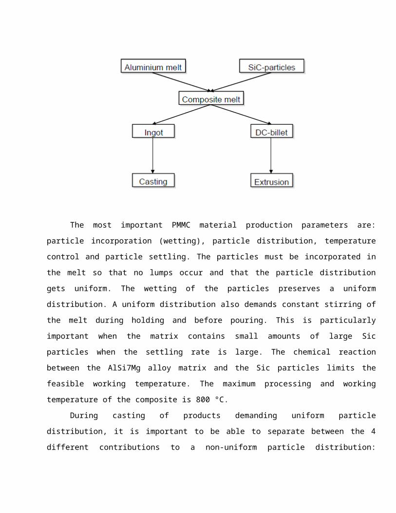
The most important PMMC material production parameters are:
particle incorporation (wetting), particle distribution, temperature
control and particle settling. The particles must be incorporated in
the melt so that no lumps occur and that the particle distribution
gets uniform. The wetting of the particles preserves a uniform
distribution. A uniform distribution also demands constant stirring of
the melt during holding and before pouring. This is particularly
important when the matrix contains small amounts of large Sic
particles when the settling rate is large. The chemical reaction
between the AlSi7Mg alloy matrix and the Sic particles limits the
feasible working temperature. The maximum processing and working
temperature of the composite is 800 °C.
During casting of products demanding uniform particle
distribution, it is important to be able to separate between the 4
different contributions to a non-uniform particle distribution:

settling, solidification rate, flow length and grain size, in order to
control the production process and reduce process variations. The
solidification conditions largely influence the particle distribution
in a casting, and the choice of casting method is dependent of this
relation. Short solidification time gives the best particle
distribution, and if uniform particle distribution is demanded the
choice of casting method is limited to permanent mould casting
processes. The settling rate is also dependent on the choice of
casting method, and, for instance, with high pressure die-casting ,the
particle settling during mould filling is almost negligible.
Figure 4-2; casting process
AFTER CASTING

Figure 4-2; casting process
CHAPTER-3
METHODOLOGY
3.1 STATEMENT OF PROBLEM
If looking on the overall automotive parts, besides engines,
there are more crucial parts that engineers need to look into
consideration. Suspension, brake, electrical, hydraulic and gear are
all the crucial systems in the automotive areas. Each of all system
has their own functionality which brings life to the automation
industries. Brakes is such a crucial system in stopping the vehicle on
all moving stages including braking during high speed, sharp
cornering, traffic jam and downhill. All of those braking moments give
a different value of temperature distribution and thermal stress. Good
performance of disc brake rotor comes from good material with better

mechanical and thermal properties. Good designs of disc brake rotor
are varying across the range of the vehicles. There are different
design and performance of disc brake rotor if compared between
passenger, commercial and heavy duty vehicle. There are also other
constraints such as cost, weight, manufacturing capability, robustness
and reliability, packaging, maintenance and servicing.
For example, heavy duty vehicle need large size of disc brake
rotor if compared to passenger vehicle. Due to that, it will increased
total weight of vehicle as well as fuel consumption and reduces
performances of the vehicle. Moreover, high weight of vehicle induces
to high temperature increased during braking where the higher value of
temperature during braking could lead to braking failure and cracking
of disc brake rotor.
This project concerns of the temperature distribution and
constraint of the disc brake rotor. Most of the passenger cars today
have disc brake rotors that are made of grey cast iron. Grey cast iron
is chosen for its relatively high thermal conductivity, high thermal
diffusivity and low cost. In this project, the author will investigate
on the thermal issues of normal passenger vehicle disc brake rotor,
where the investigation are to determine the temperature behavior of
the disc brake rotor due to severe braking of the disc brake rotor by
using Finite Element Analysis (FEA).
3.2 RESEARCH METHODOLOGY

Begin with a literature review, alot of paper and journal has
been read up and a part of it has been considered in this project.
Meanwhile, Coordinate Measuring Machine (CMM) has been used to measure
the major coordinate of real disc brake rotor. CMM has been used in
order to get accurate dimension of disc brake rotor. Later, the
precise dimensions have been used to translate in 2D and 3D drawing by
using CATIA.
In the second stage, load analysis has been done where the heat
flux and convectional heat transfer coefficients has been calculated.
Load analysis calculated based on full load of passenger in the normal
passenger vehicle. Later, value of load analysis has been applied on
finite element analysis.
Next, the fractional 3D model of disc brake rotor has been
transfer to finite element software which is ANSYS. Thermal analysis
has been done on steady state and transient responses. Assigning
material properties, load and meshing of the model has been done in
this stages. Then, completed meshing model has been submitted for
analysis. Finally an expected result from the steady state and
transient responses of thermal analysis has been obtained. A flow
chart below shows a better understanding of overall contents of this
project.

CHAPTER-4
MODELL
ING
4.1 MODELLING SOFTWARE There are different software’s available for modeling some of them
are:
1. Solid works
2. Pro-E
3. Ideas
4. Inventor

5. Mechanical desktop
6. Unigraphics
7. Catia v5
IN THIS PROJECT THE DESIGN IS DEVELOPED BY USING CATIA V5
SOFTWARE
4.1.1 INTRODUCTION TO CATIA V5
CATIA V5 provides the power of parametric design. With parametric, we
define the modal according to the size and positional relationship of
its parts.
PART MODELLING Many technical designs consist of complex assemblies made from
angular shaped parts. This type of design work can be made ashier by
part and assembly modeling capabilities that are well integrated. The
CATIA V5 is a 3-D parametric solid modeler with both part and assembly
modeling capabilities. You can see the CATIA V5 to model piece parts
and then combine them into more complex assemblies. With CATIA V5 a
part is designed by sketching its components shapes and defining their
size shape and inters relationships. By successfully creating these
features you construct the part in a building block fashion. Since
CATIA V5 has parametric features, you can change one feature and all
related features are automatically updated to reflect the change and
its effects throughout the part. It can be used to create angular

shaped part, to which 3D surface can be applied to create hybrid parts
consisting of mixture of angular and curved shapes.
CATIA V5 employs two operating modes for part modeling, model made
for modeling 3Dparametric parts and drawing mode for creating 2D drawings
of them. These modes operate independently but share the same design
data. Part modeling requires beginning the design work in model mode
where a model of the part is immediately built. Then the drawing mode can
be used at any point to document the design. In traditional CUMPUTER
AIDED DESIGN, a 2D drawing is created at the beginning and then 3D model
is built to analyze, and verify the initial concept.
4.1.2 DIMENSIONS OF DISC BREAK ROTAR
SOLID TYPE
Figure 4-2; solid disc dimensions

4.1.3 MODELLING OF SOLID DISC BRAKE USING CATIA V5
Figure 4-2; modeling of solid disc brake modelling

4.1.4 DIMENSIONS OF VENTEAD TYPE DISC BREAK
4.1.5 MODELLING OF VENTD DISC BREAK

4.1.6 INTRODUCTION OF FINITE ELEMENT ANALYSIS

The finite element method is numerical analysis technique for
obtaining approximate solutions to a wide variety of engineering
problems. Because of its diversity and flexibility as an analysis
tool, it is receiving much attention in almost every industry. In more
and more engineering situations today, we find that it is necessary to
obtain approximate solutions to problem rather than exact closed form
solution.
It is not possible to obtain analytical mathematical solutions
for many engineering problems. An analytical solutions is a
mathematical expression that gives the values of the desired unknown
quantity at any location in the body, as consequence it is valid for
infinite number of location in the body. For problems involving
complex material properties and boundary conditions, the engineer
resorts to numerical methods that provide approximate, but acceptable
solutions.
The finite element method has become a powerful tool for the
numerical solutions of a wide range of engineering problems. It has
been developed simultaneously with the increasing use of the high-
speed electronic digital computers and with the growing emphasis on
numerical methods for engineering analysis. This method started as a
generalization of the structural idea to some problems of elastic
continuum problem, started in terms of different equations
4.1.7 BRIEF INTRODUCTION OF ANASYS

4.18 PROCEDURE FOR ANSYS

Static analysis is used to determine the displacements stresses,
stains and forces in structures or components due to loads that do not
induce significant inertia and damping effects. Steady loading in
response conditions are assumed. The kinds of loading that can be
applied in a static analysis include externally applied forces and
pressures, steady state inertial forces such as gravity or rotational
velocity imposed (non-zero) displacements, temperaturesThe procedure for static analysis consists of these main steps
Building the mode
Obtaining the solution
Reviewing the results.
4.1.9 BUILD THE MODELIn this step we specify the job name and analysis title use PREP7
to define the element types, element real constants, material
properties and model geometry element type both linear and non- linear
structural elements are allowed. The ANSYS elements library contains
over 80 different element types. A unique number and prefix identify
each element type.
E.g. BEAM 94, PLAN 71, SOLID 96 and PIPE 16E

4.2.0MATERIAL PROPERTIES
Young’s modulus (EX) must be defined for a static analysis. If we plan
to apply inertia loads (such as gravity) we define mass properties
such as density (DENS). Similarly if we plan to apply thermal loads
(temperatures) we define coefficient of thermal expansion

S.NO MATERIAL PROPERTIES STAIN LESS STEEL GRAY CAST IRON1 Thermal conductivity, k(W/m_C) 36 57
2
Density (kg/m3) 710
0
7250
3
Specific heat, c (J/Kg. _C) 320 460
4
Poisson’s ratio 0.1
2
0.2
8
5
Thermal expansion 10 10-
85
6
Elastic modulus E 210 13
8
7
Coefficient of friction 0.5 0
.2

4.2.1 IMPORTING OF CATIA MODEL I N TO ANSYS
4.2.2 MESHING OF DISC BRAKE ROTAR

4.2.3 MESHAING DETAILS
DISC TYPE ELEMENTS NODES
SOLID DISC 35011 43733
VENTED DISC 14463 24832
4.2.4 SOLUTION
In this step we define the analysis type and options, apply loads
and initiate the finite element solution. This involves three phases:
Pre-processor phase
Solution phase
Post-processor phase

CHAPTER-5
5.1.1 RESULTS AND DISCUSSION
5.1.2 STAIN LESS STEEL SOLID DISC RESULTS

Figure 4-1: Deformation in stainless steel
Figure 4-2; displacement sum in stain less steel
Figure 4-2; von misses stress stain less steel
5.1.3 STAIN LESS STEEL VENTED DISC RESULTS

Figure 4-2: Deformation in stainless steel
Figure 4-2; displacement sum in stain less steel

Figure 4-2; von misses stress stain less steel
5.1.4 GRAY CAST IRON SOLID DISC RESULTS

Figure 4-3: Deformation in gray cast iron
Figure 4-2; displacement sum in gray cast iron

Figure 4-2 von misses in gray cast iron
5.1.5 GRAY CAST IRON VENTED DISC RESULTS
Figure 4-2 deformation in gray cast iron

Figure 4-2; displacement sum in gray cast iron
Figure 4-2; von misses in gray cast iron

5.1.6 Table of Result Analysis (Gray Cast Iron)
s.no Parameters Solid type Ventilated
type
1 Deformation 0.01833 0.01740
2 Displacement 0.00561 0.00488
3 Von misses stress 0.01833 0.01740
5.1.7 Table of Result Analysis (stain less steel)
s.no Parameters Solid type Ventilated
type
1 Deformation 0.02142 0.019606
2 Displacement 0.02107 0.017400
3 Von misses stress 0.021426 0.017405

6 CONCLUSION
Total Deflection (in mm.) is less in vented type disc brake and
best suited material is Grey Cast Iron.
Von-mises stases (in MPa) are very less in Grey Cast Iron, so
best suited material is Grey Cast Iron.
Total displacement is less in ventilated disc and best suited
material is Gray cast iron
It is observed that the vented type disk brakes can provide
better heat dissipation than the solid ones; present study can be
provide a useful design tools and improvement of the brake
performance in disk brake system. We can say that from all the
values obtained from the analysis i.e. the Total Deformation, Von
misses Stress exhibit that the vented disc is best suited design.
Comparing the different results obtained from analysis, it is
concluded that disk brake with vents and of material Grey Cast Iron
is observed best possible combination for present application

7 FUTURE SCOPE
The automobile industry has shown greater interest in the use of
ventilated gray cat iron disc brake rotors in the place of solid disc
brake rotors due to its high strength and heat dissipation.
Gray cast iron materials are light, strong and are being used in
a wide variety of products. Gray cast iron material give better heat
dispassion and less deformation compare with stain less steel
So the gray cast iron disc brake rotors have a bright future in
automobiles. In the present days high standard cars are using these

ventilated disc brake rotors because of its high strength to weight
ratio. In future when its usage becomes feasible gray cast iron disc
brake rotors will play an important role in automobiles because of its
best features.
8 REFERENCES

1.ENNEDY, F. E., COLIN, F. FLOQUET, A. AND GLOVSKY, R. Improved
Techniques for Finite Element Analysis of Sliding Surface
Temperatures. Westbury House page 138-150, (1984).
2. LIN , J. -Y. AND CHEN, H. -T. Radial Axis symmetric Transient Heat
Conduction in Composite Hollow Cylinders with Variable Thermal
Conductivity, vol. 10, page 2- 33, (1992).
3. BRILLA, J. Laplace Transform and New Mathematical Theory of Visco
elasticity, vol. 32, page 187- 195, (1997).
4. TSINOPOULOS, S. V, AGNANTIARIS, J. P. AND POLYZOS, D. An Advanced
Boundary Element/Fast Fourier Transform Axis symmetric Formulation for
Acoustic Radiation and Wave Scattering Problems, J.ACOUST. SOC. AMER.,
vol 105, page 1517-1526, (1999).
5. WANG, H. -C. AND BANERJEE, P. K.. Generalized Axis symmetric
Elastodynamic Analysis by Boundary Element Method, vol. 30, page 115-
131, (1990).
6. FLOQUET, A. AND DUBOURG, M.-C. Non axis symmetric effects for three
dimensional Analyses of a Brake, ASME J. Tribology, vol. 116, page
401-407, (1994).
7. BURTON, R. A. Thermal Deformation in Frictionally Heated Contact,
Wear, vol. 59, page 1- 20, (1980).
8. ANDERSON, A. E. AND KNAPP, R. A. Hot Spotting in Automotive
Friction System Wear, vol. 135, page 319-337, (1990).
9. COMNINOU, M. AND DUNDURS, J. On the Barber Boundary Conditions for
Thermo elastic Contact, ASME J, vol. 46, page 849-853, (1979).
10. BARBER, J. R. Contact Problems Involving a Cooled Punch, J.
Elasticity, vol. 8, page 409- 423, (1978).