
Aeronautical Information Manual - Miami Gliders
784
Aeronautical Information Manual Official Guide to Basic Flight Information and ATC Procedures Effective: February 21, 2002 Includes Change 1 Effective August 8, 2002, Change 2 Effective February 20, 2003, and Change 3 Effective August 7, 2003 Table of Contents Explanation of Changes Explanation of Changes Preface Subscription Information, Comments/Corrections Form, Publication Schedule, General Information Chapter 1 Navigation Aids Chapter 2 Aeronautical Lighting and Other Airport Visual Aids Chapter 3 Airspace Chapter 4 Air Traffic Control Chapter 5 Air Traffic Procedures
-
Upload
khangminh22 -
Category
Documents
-
view
0 -
download
0
Transcript of Aeronautical Information Manual - Miami Gliders

Aeronautical Information ManualOfficial Guide to Basic Flight Information and ATC Procedures
Effective: February 21, 2002Includes Change 1 Effective August 8, 2002,
Change 2 Effective February 20, 2003,and Change 3 Effective August 7, 2003
Table of ContentsExplanationof Changes Explanation of Changes
Preface Subscription Information, Comments/Corrections Form, PublicationSchedule, General Information
Chapter 1 Navigation Aids
Chapter 2 Aeronautical Lighting and Other Airport Visual Aids
Chapter 3 Airspace
Chapter 4 Air Traffic Control
Chapter 5 Air Traffic Procedures

Chapter 6 Emergency Procedures
Chapter 7 Safety of Flight
Chapter 8 Medical Facts for Pilots
Chapter 9 Aeronautical Charts and Related Publications
Chapter 10 Helicopter Operations
Appendices Bird/Other Wildlife Strike Report, Volcanic Activity Reporting Form,Abbreviations/Acronyms
Return to Air Traffic PublicationsLibrary Home Page
Link to Pilot/Controller Glossary

Aeronautical Information ManualExplanation of Changes
Change 3
Effective: August 7, 2003
a. 1-1-18. Inertial Navigation System (INS).
Adds a description of Inertial Reference Unit (IRU) and Attitude Heading Reference System (AHRS) tothe description of the Inertial Navigation System.
b. 1-1-20. Flight Management System (FMS).
Revises paragraph and incorporates into new paragraph 1-2-1, Area Navigation (RNAV).
c. Chapter 1 Section 2. Area Navigation (RNAV) and Required Navigation Performance (RNP).
Adds a new Section 2 to explain the RNAV and RNP operational concepts and procedures.
d. 1-3-5. Traffic Information Service (TIS).
Adds new paragraph adding information concerning the Traffic Information System.
e. 3-2-4. Class C Airspace. TBL 3-2-1 Class C Airspace Areas by State.
Removes Sacramento, McClellan AFB, and revises Austin, Robert Mueller Municipal, to Austin-Bergstrom International.
f. 4-1-20. Hazardous Area Reporting Service.
Updates frequencies for South Bend.
g. 4-1-21. Airport Reservations Operations and Procedures.
Updates procedures and other information on applicable airports. Replaces most current AIM informationwith a notice of availability of an Advisory Circular detailing reservation procedures and additionalinformation. Changes title of paragraph to Airport Reservation Operations and Special TrafficManagement Programs.
h. 4-3-9. Runway Friction Reports and Advisories.
Deletes the last two words in this paragraph (upon request) making MU reports mandatory briefing items.
i. 4-4-16. Traffic Information Service (TIS).
Adds new paragraph adding information on limitations of the Traffic Information System.

j. 5-1-3. Notice to Airmen (NOTAM) System.
Removes airport rotating beacon outages from the "Local (L)" NOTAM status.
k. 5-1-7. Flight Plan - IFR Flights.
Removes references to the TCAS indicators B, L, and T. Also, clarifies RNAV requirements.
l. 5-1-14. RNAV and RNP Operations.
Adds new paragraph to explain pre-flight actions required by the pilot.
m. 5-2-6. Instrument Departures.
Makes changes to state that RNAV SID's must be retrievable by the procedure name from the aircraftdatabase and conform to charted procedures. Also, explains RNAV Departure Procedures.
n. 5-3-4. Airways and Route Systems.
Makes changes to address the use of published and unpublished RNAV routes.
o. 5-3-7. Holding.
Adds information concerning use of GPS Along Track Distance in holding patterns.
p. 5-4-1. Standard Terminal Arrival (STAR), Flight Management System Procedures (FMSP) forArrivals.
Makes changes to state that RNAV STAR's must be retrievable by the procedure name from the aircraftdatabase and conform to charted procedures. Also, explains the criteria used in designing a RNAV STAR.
q. 5-4-5. Instrument Approach Procedure Charts.
Adds information concerning use of military instrument approach procedures at civil airports. Also, addsnew text to address charting issues related to RNP.
r. 5-5-16. Area Navigation (RNAV) and Required Navigation Performance (RNP) Operations.
Adds new paragraph to explain RNP operational procedures.
s. Entire manual. Editorial/format changes made throughout the manual.
Back to AIMHome Page
Back toTop of this Page

Chapter 1. Navigation Aids
Section 1. Air Navigation Aids
1-1-1. General
a. Various types of air navigation aids are in use today, each serving a special purpose. Theseaids have varied owners and operators, namely: the Federal Aviation Administration (FAA),the military services, private organizations, individual states and foreign governments. TheFAA has the statutory authority to establish, operate, maintain air navigation facilities and toprescribe standards for the operation of any of these aids which are used for instrument flightin federally controlled airspace. These aids are tabulated in the Airport/Facility Directory(A/FD).
b. Pilots should be aware of the possibility of momentary erroneous indications on cockpitdisplays when the primary signal generator for a ground-based navigational transmitter (forexample, a glideslope, VOR, or nondirectional beacon) is inoperative. Pilots should disregardany navigation indication, regardless of its apparent validity, if the particular transmitter wasidentified by NOTAM or otherwise as unusable or inoperative.
1-1-2. Nondirectional Radio Beacon (NDB)
a. A low or medium frequency radio beacon transmits nondirectional signals whereby thepilot of an aircraft properly equipped can determine bearings and "home" on the station.These facilities normally operate in the frequency band of 190 to 535 kilohertz (kHz) andtransmit a continuous carrier with either 400 or 1020 hertz (Hz) modulation. All radiobeacons except the compass locators transmit a continuous three-letter identification in codeexcept during voice transmissions.
b. When a radio beacon is used in conjunction with the Instrument Landing System markers,it is called a Compass Locator.
c. Voice transmissions are made on radio beacons unless the letter "W" (without voice) isincluded in the class designator (HW).
d. Radio beacons are subject to disturbances that may result in erroneous bearinginformation. Such disturbances result from such factors as lightning, precipitation static, etc.At night, radio beacons are vulnerable to interference from distant stations. Nearly alldisturbances which affect the Automatic Direction Finder (ADF) bearing also affect thefacility's identification. Noisy identification usually occurs when the ADF needle is erratic.Voice, music or erroneous identification may be heard when a steady false bearing is beingdisplayed. Since ADF receivers do not have a "flag" to warn the pilot when erroneousbearing information is being displayed, the pilot should continuously monitor the NDB'sidentification.
1-1-3. VHF Omni-directional Range (VOR)

a. VOR's operate within the 108.0 to 117.95 MHz frequency band and have a power outputnecessary to provide coverage within their assigned operational service volume. They aresubject to line-of-sight restrictions, and the range varies proportionally to the altitude of thereceiving equipment.
NOTE-Normal service ranges for the various classes of VOR's are given in Navigational Aid(NAVAID) Service Volumes, paragraph 1-1-8.
b. Most VOR's are equipped for voice transmission on the VOR frequency. VOR's withoutvoice capability are indicated by the letter "W" (without voice) included in the classdesignator (VORW).
c. The only positive method of identifying a VOR is by its Morse Code identification or bythe recorded automatic voice identification which is always indicated by use of the word"VOR" following the range's name. Reliance on determining the identification of anomnirange should never be placed on listening to voice transmissions by the Flight ServiceStation (FSS) (or approach control facility) involved. Many FSS's remotely operate severalomniranges with different names. In some cases, none of the VOR's have the name of the"parent" FSS. During periods of maintenance, the facility may radiate a T-E-S-T code (− l l
l l −) or the code may be removed.
d. Voice identification has been added to numerous VOR's. The transmission consists of avoice announcement, "AIRVILLE VOR" alternating with the usual Morse Codeidentification.
e. The effectiveness of the VOR depends upon proper use and adjustment of both ground andairborne equipment.
1. Accuracy. The accuracy of course alignment of the VOR is excellent, beinggenerally plus or minus 1 degree.
2. Roughness. On some VOR's, minor course roughness may be observed,evidenced by course needle or brief flag alarm activity (some receivers are moresusceptible to these irregularities than others). At a few stations, usually inmountainous terrain, the pilot may occasionally observe a brief course needleoscillation, similar to the indication of "approaching station." Pilots flying overunfamiliar routes are cautioned to be on the alert for these vagaries, and inparticular, to use the "to/from" indicator to determine positive station passage.
(a) Certain propeller revolutions per minute (RPM) settings orhelicopter rotor speeds can cause the VOR Course DeviationIndicator to fluctuate as much as plus or minus six degrees. Slightchanges to the RPM setting will normally smooth out thisroughness. Pilots are urged to check for this modulationphenomenon prior to reporting a VOR station or aircraft equipmentfor unsatisfactory operation.
1-1-4. VOR Receiver Check

a. The FAA VOR test facility (VOT) transmits a test signal which provides users aconvenient means to determine the operational status and accuracy of a VOR receiver whileon the ground where a VOT is located. The airborne use of VOT is permitted; however, itsuse is strictly limited to those areas/altitudes specifically authorized in the A/FD orappropriate supplement.
b. To use the VOT service, tune in the VOT frequency on your VOR receiver. With theCourse Deviation Indicator (CDI) centered, the omni-bearing selector should read 0 degreeswith the to/from indication showing "from" or the omni-bearing selector should read 180degrees with the to/from indication showing "to." Should the VOR receiver operate an RMI(Radio Magnetic Indicator), it will indicate 180 degrees on any omni-bearing selector (OBS)setting. Two means of identification are used. One is a series of dots and the other is acontinuous tone. Information concerning an individual test signal can be obtained from thelocal FSS.
c. Periodic VOR receiver calibration is most important. If a receiver's Automatic GainControl or modulation circuit deteriorates, it is possible for it to display acceptable accuracyand sensitivity close into the VOR or VOT and display out-of-tolerance readings whenlocated at greater distances where weaker signal areas exist. The likelihood of thisdeterioration varies between receivers, and is generally considered a function of time. Thebest assurance of having an accurate receiver is periodic calibration. Yearly intervals arerecommended at which time an authorized repair facility should recalibrate the receiver tothe manufacturer's specifications.
d. Federal Aviation Regulations (14 CFR Section 91.171) provides for certain VORequipment accuracy checks prior to flight under instrument flight rules. To comply with thisrequirement and to ensure satisfactory operation of the airborne system, the FAA hasprovided pilots with the following means of checking VOR receiver accuracy:
1. VOT or a radiated test signal from an appropriately rated radio repair station.
2. Certified airborne check points.
3. Certified check points on the airport surface.
e. A radiated VOT from an appropriately rated radio repair station serves the same purposeas an FAA VOR signal and the check is made in much the same manner as a VOT with thefollowing differences:
1. The frequency normally approved by the Federal CommunicationsCommission is 108.0 MHz.
2. Repair stations are not permitted to radiate the VOR test signal continuously;consequently, the owner or operator must make arrangements with the repairstation to have the test signal transmitted. This service is not provided by allradio repair stations. The aircraft owner or operator must determine which repairstation in the local area provides this service. A representative of the repairstation must make an entry into the aircraft logbook or other permanent recordcertifying to the radial accuracy and the date of transmission. The owner,operator or representative of the repair station may accomplish the necessary

checks in the aircraft and make a logbook entry stating the results. It isnecessary to verify which test radial is being transmitted and whether youshould get a "to" or "from" indication.
f. Airborne and ground check points consist of certified radials that should be received atspecific points on the airport surface or over specific landmarks while airborne in theimmediate vicinity of the airport.
1. Should an error in excess of plus or minus 4 degrees be indicated through useof a ground check, or plus or minus 6 degrees using the airborne check,Instrument Flight Rules (IFR) flight shall not be attempted without firstcorrecting the source of the error.
CAUTION-No correction other than the correction card figures supplied by themanufacturer should be applied in making these VOR receiver checks.
2. Locations of airborne check points, ground check points and VOT's arepublished in the A/FD and are depicted on the A/G voice communicationspanels on the FAA IFR area chart and IFR enroute low altitude chart.
3. If a dual system VOR (units independent of each other except for theantenna) is installed in the aircraft, one system may be checked against theother. Turn both systems to the same VOR ground facility and note theindicated bearing to that station. The maximum permissible variations betweenthe two indicated bearings is 4 degrees.
1-1-5. Tactical Air Navigation (TACAN)
a. For reasons peculiar to military or naval operations (unusual siting conditions, the pitchingand rolling of a naval vessel, etc.) the civil VOR/Distance Measuring Equipment (DME)system of air navigation was considered unsuitable for military or naval use. A newnavigational system, TACAN, was therefore developed by the military and naval forces tomore readily lend itself to military and naval requirements. As a result, the FAA has been inthe process of integrating TACAN facilities with the civil VOR/DME program. Although thetheoretical, or technical principles of operation of TACAN equipment are quite differentfrom those of VOR/DME facilities, the end result, as far as the navigating pilot is concerned,is the same. These integrated facilities are called VORTAC's.
b. TACAN ground equipment consists of either a fixed or mobile transmitting unit. Theairborne unit in conjunction with the ground unit reduces the transmitted signal to a visualpresentation of both azimuth and distance information. TACAN is a pulse system andoperates in the Ultrahigh Frequency (UHF) band of frequencies. Its use requires TACANairborne equipment and does not operate through conventional VOR equipment.
1-1-6. VHF Omni-directional Range/Tactical Air Navigation (VORTAC)
a. A VORTAC is a facility consisting of two components, VOR and TACAN, whichprovides three individual services: VOR azimuth, TACAN azimuth and TACAN distance(DME) at one site. Although consisting of more than one component, incorporating more

than one operating frequency, and using more than one antenna system, a VORTAC isconsidered to be a unified navigational aid. Both components of a VORTAC are envisionedas operating simultaneously and providing the three services at all times.
b. Transmitted signals of VOR and TACAN are each identified by three-letter codetransmission and are interlocked so that pilots using VOR azimuth with TACAN distancecan be assured that both signals being received are definitely from the same ground station.The frequency channels of the VOR and the TACAN at each VORTAC facility are "paired"in accordance with a national plan to simplify airborne operation.
1-1-7. Distance Measuring Equipment (DME)
a. In the operation of DME, paired pulses at a specific spacing are sent out from the aircraft(this is the interrogation) and are received at the ground station. The ground station(transponder) then transmits paired pulses back to the aircraft at the same pulse spacing buton a different frequency. The time required for the round trip of this signal exchange ismeasured in the airborne DME unit and is translated into distance (nautical miles) from theaircraft to the ground station.
b. Operating on the line-of-sight principle, DME furnishes distance information with a veryhigh degree of accuracy. Reliable signals may be received at distances up to 199 NM atline-of-sight altitude with an accuracy of better than 1/2 mile or 3 percent of the distance,whichever is greater. Distance information received from DME equipment is SLANTRANGE distance and not actual horizontal distance.
c. DME operates on frequencies in the UHF spectrum between 962 MHz and 1213 MHz.Aircraft equipped with TACAN equipment will receive distance information from aVORTAC automatically, while aircraft equipped with VOR must have a separate DMEairborne unit.
d. VOR/DME, VORTAC, Instrument Landing System (ILS)/DME, and localizer(LOC)/DME navigation facilities established by the FAA provide course and distanceinformation from collocated components under a frequency pairing plan. Aircraft receivingequipment which provides for automatic DME selection assures reception of azimuth anddistance information from a common source when designated VOR/DME, VORTAC,ILS/DME, and LOC/DME are selected.
e. Due to the limited number of available frequencies, assignment of paired frequencies isrequired for certain military noncollocated VOR and TACAN facilities which serve the samearea but which may be separated by distances up to a few miles. The military is presentlyundergoing a program to collocate VOR and TACAN facilities or to assign nonpairedfrequencies to those that cannot be collocated.
f. VOR/DME, VORTAC, ILS/DME, and LOC/DME facilities are identified by synchronizedidentifications which are transmitted on a time share basis. The VOR or localizer portion ofthe facility is identified by a coded tone modulated at 1020 Hz or a combination of code andvoice. The TACAN or DME is identified by a coded tone modulated at 1350 Hz. The DMEor TACAN coded identification is transmitted one time for each three or four times that theVOR or localizer coded identification is transmitted. When either the VOR or the DME is

inoperative, it is important to recognize which identifier is retained for the operative facility.A single coded identification with a repetition interval of approximately 30 seconds indicatesthat the DME is operative.
g. Aircraft equipment which provides for automatic DME selection assures reception ofazimuth and distance information from a common source when designated VOR/DME,VORTAC and ILS/DME navigation facilities are selected. Pilots are cautioned to disregardany distance displays from automatically selected DME equipment when VOR or ILSfacilities, which do not have the DME feature installed, are being used for positiondetermination.
1-1-8. Navigational Aid (NAVAID) Service Volumes
a. Most air navigation radio aids which provide positive course guidance have a designatedstandard service volume (SSV). The SSV defines the reception limits of unrestrictedNAVAID's which are usable for random/unpublished route navigation.
b. A NAVAID will be classified as restricted if it does not conform to flight inspection signalstrength and course quality standards throughout the published SSV. However, the NAVAIDshould not be considered usable at altitudes below that which could be flown while operatingunder random route IFR conditions (14 CFR Section 91.177), even though these altitudesmay lie within the designated SSV. Service volume restrictions are first published in Noticesto Airmen (NOTAM's) and then with the alphabetical listing of the NAVAID's in the A/FD.
c. Standard Service Volume limitations do not apply to published IFR routes or procedures.
d. VOR/DME/TACAN Standard Service Volumes (SSV).
1. Standard service volumes (SSV's) are graphically shown in FIG 1-1-1, FIG1-1-2, FIG 1-1-3, FIG 1-1-4, and FIG 1-1-5. The SSV of a station is indicatedby using the class designator as a prefix to the station type designation.
EXAMPLE-TVOR, LDME, and HVORTAC.
FIG 1-1-1
Standard High Altitude Service Volume(See FIG 1-1-5 for altitudes below 1,000 feet).
FIG 1-1-2
Standard Low Altitude Service Volume

(See FIG 1-1-5 for altitudes below 1,000 feet).
FIG 1-1-3
Standard Terminal Service Volume(See FIG 1-1-4 for altitudes below 1,000 feet).
2. Within 25 NM, the bottom of the T service volume is defined by the curve inFIG 1-1-4. Within 40 NM, the bottoms of the L and H service volumes aredefined by the curve in FIG 1-1-5. (See TBL 1-1-1.)
TBL 1-1-1
VOR/DME/TACAN Standard Service VolumesSSV Class Designator Altitude and Range BoundariesT (Terminal) From 1,000 feet above ground level (AGL) up to and including 12,000 feet AGL
at radial distances out to 25 NM.
L (Low Altitude) From 1,000 feet AGL up to and including 18,000 feet AGL at radial distances outto 40 NM.
H (High Altitude) From 1,000 feet AGL up to and including 14,500 feet AGL at radial distances outto 40 NM. From 14,500 AGL up to and including 60,000 feet at radial distancesout to 100 NM. From 18,000 feet AGL up to and including 45,000 feet AGL atradial distances out to 130 NM.
e. Nondirectional Radio Beacon (NDB)
1. NDB's are classified according to their intended use.
2. The ranges of NDB service volumes are shown in TBL 1-1-2. The distances(radius) are the same at all altitudes.
TBL 1-1-2

NDB Service VolumesClass Distance (Radius)
Compass Locator 15 NM
MH 25 NM
H 50 NM*
HH 75 NM
* Service ranges of individual facilities may be less than 50 nautical miles (NM). Restrictions toservice volumes are first published as a Notice to Airmen and then with the alphabetical listing of theNAVAID in the A/FD.
FIG 1-1-4
Service Volume Lower EdgeTerminal
FIG 1-1-5
Service Volume Lower EdgeStandard High and Low
1-1-9. Instrument Landing System (ILS)
a. General
1. The ILS is designed to provide an approach path for exact alignment anddescent of an aircraft on final approach to a runway.
2. The ground equipment consists of two highly directional transmitting systemsand, along the approach, three (or fewer) marker beacons. The directionaltransmitters are known as the localizer and glide slope transmitters.
3. The system may be divided functionally into three parts:
(a) Guidance information: localizer, glide slope;
(b) Range information: marker beacon, DME; and
(c) Visual information: approach lights, touchdown and centerlinelights, runway lights.
4. Compass locators located at the Outer Marker (OM) or Middle Marker (MM)

may be substituted for marker beacons. DME, when specified in the procedure,may be substituted for the OM.
5. Where a complete ILS system is installed on each end of a runway; (i.e., theapproach end of Runway 4 and the approach end of Runway 22) the ILSsystems are not in service simultaneously.
b. Localizer
1. The localizer transmitter operates on one of 40 ILS channels within thefrequency range of 108.10 to 111.95 MHz. Signals provide the pilot with courseguidance to the runway centerline.
2. The approach course of the localizer is called the front course and is usedwith other functional parts, e.g., glide slope, marker beacons, etc. The localizersignal is transmitted at the far end of the runway. It is adjusted for a coursewidth of (full scale fly-left to a full scale fly-right) of 700 feet at the runwaythreshold.
3. The course line along the extended centerline of a runway, in the oppositedirection to the front course is called the back course.
CAUTION-Unless the aircraft's ILS equipment includes reverse sensing capability, whenflying inbound on the back course it is necessary to steer the aircraft in thedirection opposite the needle deflection when making corrections fromoff-course to on-course. This "flying away from the needle" is also requiredwhen flying outbound on the front course of the localizer. Do not use backcourse signals for approach unless a back course approach procedure ispublished for that particular runway and the approach is authorized by ATC.
4. Identification is in International Morse Code and consists of a three-letteridentifier preceded by the letter I (ll) transmitted on the localizer frequency.
EXAMPLE-I-DIA
5. The localizer provides course guidance throughout the descent path to therunway threshold from a distance of 18 NM from the antenna between analtitude of 1,000 feet above the highest terrain along the course line and 4,500feet above the elevation of the antenna site. Proper off-course indications areprovided throughout the following angular areas of the operational servicevolume:
(a) To 10 degrees either side of the course along a radius of 18 NMfrom the antenna; and
(b) From 10 to 35 degrees either side of the course along a radiusof 10 NM. (See FIG 1-1-6.)
FIG 1-1-6

Limits of Localizer Coverage
6. Unreliable signals may be received outside these areas.
c. Localizer Type Directional Aid (LDA)
1. The LDA is of comparable use and accuracy to a localizer but is not part of acomplete ILS. The LDA course usually provides a more precise approachcourse than the similar Simplified Directional Facility (SDF) installation, whichmay have a course width of 6 or 12 degrees.
2. The LDA is not aligned with the runway. Straight-in minimums may bepublished where alignment does not exceed 30 degrees between the course andrunway. Circling minimums only are published where this alignment exceeds 30degrees.
3. A very limited number of LDA approaches also incorporate a glideslope.These are annotated in the plan view of the instrument approach chart with anote, "LDA/Glideslope." These procedures fall under a newly defined categoryof approaches called Approach with Vertical Guidance (APV) described inparagraph 5-4-5, Instrument Approach Procedure Charts, subparagraph a7(b),Approach with Vertical Guidance (APV). LDA minima for with and withoutglideslope is provided and annotated on the minima lines of the approach chartas S-LDA/GS and S-LDA. Because the final approach course is not alignedwith the runway centerline, additional maneuvering will be required comparedto an ILS approach.
d. Glide Slope/Glide Path
1. The UHF glide slope transmitter, operating on one of the 40 ILS channelswithin the frequency range 329.15 MHz, to 335.00 MHz radiates its signals inthe direction of the localizer front course. The term "glide path" means thatportion of the glide slope that intersects the localizer.
CAUTION-False glide slope signals may exist in the area of the localizer back courseapproach which can cause the glide slope flag alarm to disappear and presentunreliable glide slope information. Disregard all glide slope signal indicationswhen making a localizer back course approach unless a glide slope isspecified on the approach and landing chart.
2. The glide slope transmitter is located between 750 feet and 1,250 feet fromthe approach end of the runway (down the runway) and offset 250 to 650 feet

from the runway centerline. It transmits a glide path beam 1.4 degrees wide(vertically). The signal provides descent information for navigation down to thelowest authorized decision height (DH) specified in the approved ILS approachprocedure. The glidepath may not be suitable for navigation below the lowestauthorized DH and any reference to glidepath indications below that heightmust be supplemented by visual reference to the runway environment.Glidepaths with no published DH are usable to runway threshold.
3. The glide path projection angle is normally adjusted to 3 degrees abovehorizontal so that it intersects the MM at about 200 feet and the OM at about1,400 feet above the runway elevation. The glide slope is normally usable to thedistance of 10 NM. However, at some locations, the glide slope has beencertified for an extended service volume which exceeds 10 NM.
4. Pilots must be alert when approaching the glidepath interception. Falsecourses and reverse sensing will occur at angles considerably greater than thepublished path.
5. Make every effort to remain on the indicated glide path.
CAUTION-Avoid flying below the glide path to assure obstacle/terrain clearance ismaintained.
6. The published glide slope threshold crossing height (TCH) DOES NOTrepresent the height of the actual glide path on-course indication above therunway threshold. It is used as a reference for planning purposes whichrepresents the height above the runway threshold that an aircraft's glide slopeantenna should be, if that aircraft remains on a trajectory formed by thefour-mile-to-middle marker glidepath segment.
7. Pilots must be aware of the vertical height between the aircraft's glide slopeantenna and the main gear in the landing configuration and, at the DH, plan toadjust the descent angle accordingly if the published TCH indicates the wheelcrossing height over the runway threshold may not be satisfactory. Testsindicate a comfortable wheel crossing height is approximately 20 to 30 feet,depending on the type of aircraft.
e. Distance Measuring Equipment (DME)
1. When installed with the ILS and specified in the approach procedure, DMEmay be used:
(a) In lieu of the OM;
(b) As a back course (BC) final approach fix (FAF); and
(c) To establish other fixes on the localizer course.
2. In some cases, DME from a separate facility may be used within TerminalInstrument Procedures (TERPS) limitations:

(a) To provide ARC initial approach segments;
(b) As a FAF for BC approaches; and
(c) As a substitute for the OM.
f. Marker Beacon
1. ILS marker beacons have a rated power output of 3 watts or less and anantenna array designed to produce an elliptical pattern with dimensions, at 1,000feet above the antenna, of approximately 2,400 feet in width and 4,200 feet inlength. Airborne marker beacon receivers with a selective sensitivity featureshould always be operated in the "low" sensitivity position for proper receptionof ILS marker beacons.
2. Ordinarily, there are two marker beacons associated with an ILS, the OM andMM. Locations with a Category II ILS also have an Inner Marker (IM). Whenan aircraft passes over a marker, the pilot will receive the indications shown inTBL 1-1-3.
(a) The OM normally indicates a position at which an aircraft at theappropriate altitude on the localizer course will intercept the ILSglide path.
(b) The MM indicates a position approximately 3,500 feet from thelanding threshold. This is also the position where an aircraft on theglide path will be at an altitude of approximately 200 feet above theelevation of the touchdown zone.
(c) The IM will indicate a point at which an aircraft is at adesignated decision height (DH) on the glide path between the MMand landing threshold.
TBL 1-1-3
Marker PassageIndications
Marker Code Light
OM − − − BLUE
MM l − l − AMBER
IM l l l l WHITE
BC l l l l WHITE
3. A back course marker normally indicates the ILS back course final approachfix where approach descent is commenced.

g. Compass Locator
1. Compass locator transmitters are often situated at the MM and OM sites. Thetransmitters have a power of less than 25 watts, a range of at least 15 miles andoperate between 190 and 535 kHz. At some locations, higher powered radiobeacons, up to 400 watts, are used as OM compass locators. These generallycarry Transcribed Weather Broadcast (TWEB) information.
2. Compass locators transmit two letter identification groups. The outer locatortransmits the first two letters of the localizer identification group, and themiddle locator transmits the last two letters of the localizer identification group.
h. ILS Frequency (See TBL 1-1-4.)
TBL 1-1-4
Frequency PairsAllocated for ILS
Localizer MHz Glide Slope108.10 334.70
108.15 334.55
108.3 334.10
108.35 333.95
108.5 329.90
108.55 329.75
108.7 330.50
108.75 330.35
108.9 329.30
108.95 329.15
109.1 331.40
109.15 331.25
109.3 332.00
109.35 331.85
109.50 332.60
109.55 332.45
109.70 333.20
109.75 333.05
109.90 333.80
109.95 333.65
110.1 334.40
110.15 334.25
110.3 335.00
110.35 334.85
110.5 329.60
110.55 329.45
110.70 330.20

110.75 330.05
110.90 330.80
110.95 330.65
111.10 331.70
111.15 331.55
111.30 332.30
111.35 332.15
111.50 332.9
111.55 332.75
111.70 333.5
111.75 333.35
111.90 331.1
111.95 330.95
i. ILS Minimums
1. The lowest authorized ILS minimums, with all required ground and airbornesystems components operative, are:
(a) Category I. Decision Height (DH) 200 feet and Runway VisualRange (RVR) 2,400 feet (with touchdown zone and centerlinelighting, RVR 1,800 feet);
(b) Category II. DH 100 feet and RVR 1,200 feet;
(c) Category IIIa. No DH or DH below 100 feet and RVR not lessthan 700 feet;
(d) Category IIIb. No DH or DH below 50 feet and RVR less than700 feet but not less than 150 feet; and
(e) Category IIIc. No DH and no RVR limitation.
NOTE-Special authorization and equipment required for Categories IIand III.
j. Inoperative ILS Components
1. Inoperative localizer. When the localizer fails, an ILS approach is notauthorized.
2. Inoperative glide slope. When the glide slope fails, the ILS reverts to anonprecision localizer approach.
REFERENCE-See the inoperative component table in the U.S. Government Terminal Procedures Publication (TPP), for adjustments tominimums due to inoperative airborne or ground system equipment.
k. ILS Course Distortion

1. All pilots should be aware that disturbances to ILS localizer and glide slopecourses may occur when surface vehicles or aircraft are operated near thelocalizer or glide slope antennas. Most ILS installations are subject to signalinterference by either surface vehicles, aircraft or both. ILS CRITICAL AREASare established near each localizer and glide slope antenna.
2. ATC issues control instructions to avoid interfering operations within ILScritical areas at controlled airports during the hours the Airport Traffic ControlTower (ATCT) is in operation as follows:
(a) Weather Conditions. Less than ceiling 800 feet and/orvisibility 2 miles.
(1) Localizer Critical Area. Except for aircraft thatland, exit a runway, depart or miss approach, vehiclesand aircraft are not authorized in or over the criticalarea when an arriving aircraft is between the ILS finalapproach fix and the airport. Additionally, when theceiling is less than 200 feet and/or the visibility isRVR 2,000 or less, vehicle and aircraft operations inor over the area are not authorized when an arrivingaircraft is inside the ILS MM.
(2) Glide Slope Critical Area. Vehicles and aircraftare not authorized in the area when an arriving aircraftis between the ILS final approach fix and the airportunless the aircraft has reported the airport in sight andis circling or side stepping to land on a runway otherthan the ILS runway.
(b) Weather Conditions. At or above ceiling 800 feet and/orvisibility 2 miles.
(1) No critical area protective action is provided underthese conditions.
(2) A flight crew, under these conditions, shouldadvise the tower that it will conduct an AUTOLANDor COUPLED approach to ensure that the ILS criticalareas are protected when the aircraft is inside the ILSMM.
EXAMPLE-Glide slope signal not protected.
3. Aircraft holding below 5,000 feet between the outer marker and the airportmay cause localizer signal variations for aircraft conducting the ILS approach.Accordingly, such holding is not authorized when weather or visibilityconditions are less than ceiling 800 feet and/or visibility 2 miles.

4. Pilots are cautioned that vehicular traffic not subject to ATC may causemomentary deviation to ILS course or glide slope signals. Also, critical areasare not protected at uncontrolled airports or at airports with an operating controltower when weather or visibility conditions are above those requiring protectivemeasures. Aircraft conducting coupled or autoland operations should beespecially alert in monitoring automatic flight control systems. (See FIG 1-1-7.)
NOTE-Unless otherwise coordinated through Flight Standards, ILS signals toCategory I runways are not flight inspected below 100 feet AGL. Guidancesignal anomalies may be encountered below this altitude.
FIG 1-1-7
FAA Instrument Landing Systems
1-1-10. Simplified Directional Facility (SDF)
a. The SDF provides a final approach course similar to that of the ILS localizer. It does notprovide glide slope information. A clear understanding of the ILS localizer and the additionalfactors listed below completely describe the operational characteristics and use of the SDF.
b. The SDF transmits signals within the range of 108.10 to 111.95 MHz.
c. The approach techniques and procedures used in an SDF instrument approach areessentially the same as those employed in executing a standard localizer approach except theSDF course may not be aligned with the runway and the course may be wider, resulting inless precision.
d. Usable off-course indications are limited to 35 degrees either side of the course centerline.Instrument indications received beyond 35 degrees should be disregarded.
e. The SDF antenna may be offset from the runway centerline. Because of this, the angle ofconvergence between the final approach course and the runway bearing should bedetermined by reference to the instrument approach procedure chart. This angle is generallynot more than 3 degrees. However, it should be noted that inasmuch as the approach courseoriginates at the antenna site, an approach which is continued beyond the runway thresholdwill lead the aircraft to the SDF offset position rather than along the runway centerline.
f. The SDF signal is fixed at either 6 degrees or 12 degrees as necessary to provide maximumflyability and optimum course quality.
g. Identification consists of a three-letter identifier transmitted in Morse Code on the SDFfrequency. The appropriate instrument approach chart will indicate the identifier used at a

particular airport.
1-1-11. Microwave Landing System (MLS)
a. General
1. The MLS provides precision navigation guidance for exact alignment anddescent of aircraft on approach to a runway. It provides azimuth, elevation, anddistance.
2. Both lateral and vertical guidance may be displayed on conventional coursedeviation indicators or incorporated into multipurpose cockpit displays. Rangeinformation can be displayed by conventional DME indicators and alsoincorporated into multipurpose displays.
3. The MLS supplements the ILS as the standard landing system in the U.S. forcivil, military, and international civil aviation. At international airports, ILSservice is protected to 2010.
4. The system may be divided into five functions:
(a) Approach azimuth;
(b) Back azimuth;
(c) Approach elevation;
(d) Range; and
(e) Data communications.
5. The standard configuration of MLS ground equipment includes:
(a) An azimuth station to perform functions (a) and (e) above. Inaddition to providing azimuth navigation guidance, the stationtransmits basic data which consists of information associateddirectly with the operation of the landing system, as well asadvisory data on the performance of the ground equipment.
(b) An elevation station to perform function (c).
(c) Distance Measuring Equipment (DME) to perform rangeguidance, both standard DME (DME/N) and precision DME(DME/P).
6. MLS Expansion Capabilities. The standard configuration can be expandedby adding one or more of the following functions or characteristics.
(a) Back azimuth. Provides lateral guidance for missed approachand departure navigation.
(b) Auxiliary data transmissions. Provides additional data,including refined airborne positioning, meteorological information,

runway status, and other supplementary information.
(c) Expanded Service Volume (ESV) proportional guidance to 60degrees.
7. MLS identification is a four-letter designation starting with the letter M. It istransmitted in International Morse Code at least six times per minute by theapproach azimuth (and back azimuth) ground equipment.
b. Approach Azimuth Guidance
1. The azimuth station transmits MLS angle and data on one of 200 channelswithin the frequency range of 5031 to 5091 MHz.
2. The equipment is normally located about 1,000 feet beyond the stop end ofthe runway, but there is considerable flexibility in selecting sites. For example,for heliport operations the azimuth transmitter can be collocated with theelevation transmitter.
3. The azimuth coverage extends: (See FIG 1-1-8.)
(a) Laterally, at least 40 degrees on either side of the runwaycenterline in a standard configuration,
(b) In elevation, up to an angle of 15 degrees and to at least 20,000feet, and
(c) In range, to at least 20 NM.
FIG 1-1-8
Coverage VolumeAzimuth
c. Elevation Guidance
1. The elevation station transmits signals on the same frequency as the azimuthstation. A single frequency is time-shared between angle and data functions.
2. The elevation transmitter is normally located about 400 feet from the side ofthe runway between runway threshold and the touchdown zone.
3. Elevation coverage is provided in the same airspace as the azimuth guidance

signals:
(a) In elevation, to at least +15 degrees;
(b) Laterally, to fill the Azimuth lateral coverage; and
(c) In range, to at least 20 NM. (See FIG 1-1-9.)
FIG 1-1-9
Coverage VolumesElevation
d. Range Guidance
1. The MLS Precision Distance Measuring Equipment (DME/P) functions thesame as the navigation DME described in paragraph 1-1-7, Distance MeasuringEquipment (DME), but there are some technical differences. The beacontransponder operates in the frequency band 962 to 1105 MHz and responds toan aircraft interrogator. The MLS DME/P accuracy is improved to be consistentwith the accuracy provided by the MLS azimuth and elevation stations.
2. A DME/P channel is paired with the azimuth and elevation channel. Acomplete listing of the 200 paired channels of the DME/P with the anglefunctions is contained in FAA Standard 022 (MLS Interoperability andPerformance Requirements).
3. The DME/N or DME/P is an integral part of the MLS and is installed at allMLS facilities unless a waiver is obtained. This occurs infrequently and only atoutlying, low density airports where marker beacons or compass locators arealready in place.
e. Data Communications
1. The data transmission can include both the basic and auxiliary data words.All MLS facilities transmit basic data. Where needed, auxiliary data can betransmitted.
2. Coverage limits. MLS data are transmitted throughout the azimuth (and backazimuth when provided) coverage sectors.
3. Basic data content. Representative data include:
(a) Station identification;
(b) Exact locations of azimuth, elevation and DME/P stations (forMLS receiver processing functions);

(c) Ground equipment performance level; and
(d) DME/P channel and status.
4. Auxiliary data content: Representative data include:
(a) 3-D locations of MLS equipment;
(b) Waypoint coordinates;
(c) Runway conditions; and
(d) Weather (e.g., RVR, ceiling, altimeter setting, wind, wakevortex, wind shear).
f. Operational Flexibility
1. The MLS has the capability to fulfill a variety of needs in the approach,landing, missed approach and departure phases of flight. For example:
(a) Curved and segmented approaches;
(b) Selectable glide path angles;
(c) Accurate 3-D positioning of the aircraft in space; and
(d) The establishment of boundaries to ensure clearance fromobstructions in the terminal area.
2. While many of these capabilities are available to any MLS-equipped aircraft,the more sophisticated capabilities (such as curved and segmented approaches)are dependent upon the particular capabilities of the airborne equipment.
g. Summary
1. Accuracy. The MLS provides precision three-dimensional navigationguidance accurate enough for all approach and landing maneuvers.
2. Coverage. Accuracy is consistent throughout the coverage volumes. (SeeFIG 1-1-10.)
FIG 1-1-10
Coverage Volumes3-D Representation

3. Environment. The system has low susceptibility to interference fromweather conditions and airport ground traffic.
4. Channels. MLS has 200 channels- enough for any foreseeable need.
5. Data. The MLS transmits ground-air data messages associated with thesystems operation.
6. Range information. Continuous range information is provided with anaccuracy of about 100 feet.
1-1-12. NAVAID Identifier Removal During Maintenance
During periods of routine or emergency maintenance, coded identification (or code and voice, whereapplicable) is removed from certain FAA NAVAID's. Removal of identification serves as a warning topilots that the facility is officially off the air for tune-up or repair and may be unreliable even thoughintermittent or constant signals are received.
NOTE-During periods of maintenance VHF ranges may radiate a T-E-S-T code (−llll− ).
NOTE-DO NOT attempt to fly a procedure that is NOTAMed out of service even if the identification is present.In certain cases, the identification may be transmitted for short periods as part of the testing.
1-1-13. NAVAID's with Voice
a. Voice equipped en route radio navigational aids are under the operational control of eitheran FAA Automated Flight Service Station (AFSS) or an approach control facility. The voicecommunication is available on some facilities. The Hazardous Inflight Weather AdvisoryService (HIWAS) broadcast capability on selected VOR sites is in the process of beingimplemented throughout the conterminous U.S. and does not provide voice communication.The availability of two-way voice communication and HIWAS is indicated in the A/FD andaeronautical charts.
b. Unless otherwise noted on the chart, all radio navigation aids operate continuously exceptduring shutdowns for maintenance. Hours of operation of facilities not operatingcontinuously are annotated on charts and in the A/FD.
1-1-14. User Reports on NAVAID Performance
a. Users of the National Airspace System (NAS) can render valuable assistance in the earlycorrection of NAVAID malfunctions by reporting their observations of undesirableNAVAID performance. Although NAVAID's are monitored by electronic detectors, adverseeffects of electronic interference, new obstructions or changes in terrain near the NAVAIDcan exist without detection by the ground monitors. Some of the characteristics ofmalfunction or deteriorating performance which should be reported are: erratic course orbearing indications; intermittent, or full, flag alarm; garbled, missing or obviously impropercoded identification; poor quality communications reception; or, in the case of frequency

interference, an audible hum or tone accompanying radio communications or NAVAIDidentification.
b. Reporters should identify the NAVAID, location of the aircraft, time of the observation,type of aircraft and describe the condition observed; the type of receivers in use is also usefulinformation. Reports can be made in any of the following ways:
1. Immediate report by direct radio communication to the controlling Air RouteTraffic Control Center (ARTCC), Control Tower, or FSS. This method providesthe quickest result.
2. By telephone to the nearest FAA facility.
3. By FAA Form 8000-7, Safety Improvement Report, a postage-paid carddesigned for this purpose. These cards may be obtained at FAA FSS's, FlightStandards District Offices, and General Aviation Fixed Base Operations.
c. In aircraft that have more than one receiver, there are many combinations of possibleinterference between units. This can cause either erroneous navigation indications or,complete or partial blanking out of the communications. Pilots should be familiar enoughwith the radio installation of the particular airplanes they fly to recognize this type ofinterference.
1-1-15. LORAN
a. Introduction
1. LORAN, which uses a network of land-based radio transmitters, wasdeveloped to provide an accurate system for LOng RAnge Navigation. Thesystem was configured to provide reliable, all weather navigation for marineusers along the U.S. coasts and in the Great Lakes. The current system, knownas LORAN-C, was the third version of four developed since World War II.
2. With an expanding user group in the general aviation community, theLORAN coastal facilities were augmented in 1991 to provide signal coverageover the entire continental U.S. The FAA and the U.S. Coast Guard (USCG) areincorporating LORAN into the NAS for supplemental en route and nonprecisionapproach operations. LORAN-C is also supported in the Canadian airspacesystem. This guide is intended to provide an introduction to the LORAN system,LORAN avionics, the use of LORAN for aircraft navigation, and to examine thepossible future of LORAN in aviation.
b. LORAN Chain
1. The 27 U.S. LORAN transmitters that provide signal coverage for thecontinental U.S. and the southern half of Alaska are distributed from Caribou,ME, to Attu Island in the Aleutians. Station operations are organized intosub-groups of four to six stations called "chains." One station in the chain isdesignated the "Master" and the others are "secondary" stations.
2. The LORAN navigation signal is a carefully structured sequence of brief

radio frequency pulses centered at 100 kHz. The sequence of signaltransmissions consists of a pulse group from the Master (M) station followed atprecise time intervals by groups from the secondary stations which aredesignated by the U.S. Coast Guard with the letters V, W, X, Y and Z. Allsecondary stations radiate pulses in groups of eight, but the Master signal foridentification has an additional ninth pulse.
3. The time interval between the reoccurrence of the Master pulse group is theGroup Repetition Interval (GRI). The GRI is the same for all stations in a chainand each LORAN chain has a unique GRI. Since all stations in a particularchain operate on the same radio frequency, the GRI is the key by which aLORAN receiver can identify and isolate signal groups from a specific chain.
EXAMPLE-Transmitters in the northeast U.S. chain operate with a GRI of 99,600microseconds which is shortened to 9960 for convenience. The master station(m) at Sseneca, NY, controls: secondary stations (w) at Caribou, ME; (x) atNantucket, MA; (y) at Carolina Beach, NC; and (z) at Dana, IN. In order tokeep chain operations precise, the system uses monitor receivers at CapeElizabeth, ME, Sandy Hook, NJ and Plumbrook, OH. Monitor receiverscontinuously measure various aspects of the quality and accuracy of LORANsignals and report system status to a control station where chain timing ismaintained.
4. The line between the Master and each secondary station is the "baseline" for apair of stations. Typical baselines are from 600 to 1,000 nautical miles in length.The continuation of the baseline in either direction is a "baseline extension."
5. LORAN transmitter stations have time and control equipment, a transmitter,auxiliary power equipment, a building about 100 by 30 feet in size and anantenna that is about 700 feet tall. A station generally requires approximately100 or more acres of land to accommodate guy lines that keep the antenna inposition. Each LORAN station transmits from 400 to 1,600 kilowatts of signalpower.
6. The USCG operates 27 stations, comprising eight chains, in the U.S. NAS.Four control stations, which monitor chain performance, have personnel on dutyfull time. The Canadian east and west coast chains also provide signal coverageover small areas of the NAS.
7. When a control station detects a signal problem that could affect navigationaccuracy, an alert signal called "Blink" is activated. Blink is a distinctive changein the group of eight pulses that can be recognized automatically by a receiverso the user is notified instantly that the LORAN system should not be used fornavigation. In addition, other problems can cause signal transmissions from astation to be halted.
8. Each individual LORAN chain provides navigation-quality signal coverageover an identified area as shown for the West Coast chain, GRI 9940. The chain

Master station is at Fallon, NV, and secondary stations are at George, WA;Middletown, CA; and Searchlight, NV. In a signal coverage area the signalstrength relative to the normal ambient radio noise must be adequate to assuresuccessful reception.
FIG 1-1-11
LORAN CPulse
FIG 1-1-12
LORAN CNortheast U.S. Chain
c. The LORAN Receiver
1. Before a LORAN receiver can provide navigation information for a pilot, itmust successfully receive, or "acquire," signals from three or more stations in achain. Acquisition involves the time synchronization of the receiver with thechain GRI, identification of the Master station signals from among thosechecked, identification of secondary station signals, and the proper selection ofthe point in each signal at which measurements should be made.
2. Signal reception at any site will require a pilot to provide location informationsuch as approximate latitude and longitude, or the GRI to be used, to the

receiver. Once activated, most receivers will store present location informationfor later use.
3. The basic measurements made by LORAN receivers are the differences intime-of-arrival between the Master signal and the signals from each of thesecondary stations of a chain. Each "time difference" (TD) value is measured toa precision of about 0.1 microseconds. As a rule of thumb, 0.1 microsecond isequal to about 100 feet.
4. An aircraft's LORAN receiver must recognize three signal conditions:
(a) Usable signals;
(b) Absence of signals; and
(c) Signal blink.
5. The most critical phase of flight is during the approach to landing at anairport. During the approach phase the receiver must detect a lost signal, or asignal Blink, within 10 seconds of the occurrence and warn the pilot of theevent.
6. Most receivers have various internal tests for estimating the probableaccuracy of the current TD values and consequent navigation solutions. Testsmay include verification of the timing alignment of the receiver clock with theLORAN pulse, or a continuous measurement of the signal-to-noise ratio (SNR).SNR is the relative strength of the LORAN signals compared to the localambient noise level. If any of the tests fail, or if the quantities measured are outof the limits set for reliable navigation, then an alarm will be activated to alertthe pilot.
7. LORAN signals operate in the low frequency band around (100 kHz) that hasbeen reserved for LORAN use. Adjacent to the band, however, are numerouslow frequency communications transmitters. Nearby signals can distort theLORAN signals and must be eliminated by the receiver to assure properoperation. To eliminate interfering signals, LORAN receivers have selectiveinternal filters. These filters, commonly known as "notch filters" reduce theeffect of interfering signals.
8. Careful installation of antennas, good metal-to-metal electrical bonding, andprovisions for precipitation noise discharge on the aircraft are essential for thesuccessful operation of LORAN receivers. A LORAN antenna should beinstalled on an aircraft in accordance with the manufacturer's instructions.Corroded bonding straps should be replaced, and static discharge devicesinstalled at points indicated by the aircraft manufacturer.
FIG 1-1-13
LORAN- CWest Coast Chain

d. LORAN Navigation
1. An airborne LORAN receiver has four major parts:
(a) Signal processor;
(b) Navigation computer;
(c) Control/display; and
(d) Antenna.
2. The signal processor acquires LORAN signals and measures the differencebetween the time-of-arrival of each secondary station pulse group and theMaster station pulse group. The measured TD's depend on the location of thereceiver in relation to the three or more transmitters.
FIG 1-1-14
First Line-of-Position
(a) The first TD will locate an aircraft somewhere on aline-of-position (LOP) on which the receiver will measure the sameTD value.
(b) A second LOP is defined by a TD measurement between theMaster station signal and the signal from another secondary station.
FIG 1-1-15

Second Line-of-Position
FIG 1-1-16
Intersection of Lines-of-Position
(c) The intersection of the measured LOP's is the position of theaircraft.
3. The navigation computer converts TD values to corresponding latitude andlongitude. Once the time and position of the aircraft is established at two points,distance to destination, cross track error, ground speed, estimated time ofarrival, etc., can be determined. Cross track error can be displayed as thevertical needle of a course deviation indicator, or digitally, as decimal parts of amile left or right of course. During a nonprecision approach, course guidancemust be displayed to the pilot with a full scale deviation of ±0.30 nautical milesor greater.
4. LORAN navigation for nonprecision approaches requires accurate andreliable information. During an approach the occurrence of signal Blink or lossof signal must be detected within 10 seconds and the pilot must be notified.LORAN signal accuracy for approaches is 0.25 nautical miles, well within therequired accuracy of 0.30 nautical miles. LORAN signal accuracy can beimproved by applying correction values.
5. Flying a LORAN nonprecision approach is different from flying a VORapproach. A VOR approach is on a radial of the VOR station, with guidancesensitivity increasing as the aircraft nears the airport. The LORAN systemprovides a linear grid, so there is constant guidance sensitivity everywhere in

the approach procedure. Consequently, inaccuracies and ambiguities that occurduring operations in close proximity to VOR's (station passage, for example) donot occur in LORAN approaches.
6. The navigation computer also provides storage for data entered by pilot orprovided by the receiver manufacturer. The receiver's database is updated atlocal maintenance facilities every 60 days to include all changes made by theFAA.
7. The FAA is currently canceling all LORAN nonprecision approaches with theadvent of Global Positioning System (GPS).
e. Notices to Airmen (NOTAM's) are issued for LORAN-C chain or station outages.Domestic NOTAM (D)'s are issued under the identifier "LRN." International NOTAM's areissued under the KNMH series. Pilots may obtain these NOTAM's from FSS briefers uponrequest.
FIG 1-1-17
North Pacific Chain
FIG 1-1-18
Coverage Over Alaska
FIG 1-1-19
Canadian West Coast Chain

FIG 1-1-20
U.S. West Coast Chain
FIG 1-1-21
North Central U.S. Chain
FIG 1-1-22
South Central U.S. Chain

FIG 1-1-23
U.S. Great Lakes Chain
FIG 1-1-24
U.S. Southeast Chain
FIG 1-1-25
Northeast U.S. Chain

FIG 1-1-26
Canadian East Coast Chain
f. LORAN-C status information
Prerecorded telephone answering service messages pertaining to LORAN-C are available inTBL 1-1-5 and TBL 1-1-6.
g. The U.S. will continue to operate the LORAN-C system in the short term beyond thepreviously planned December 31, 2000, termination date while continuing to evaluate thelong-term need for continuation of the system. Users will be given reasonable notice if it isconcluded that LORAN-C is not needed or is not cost effective, so that they will have theopportunity to transition to alternative navigation aids.
TBL 1-1-5
Prerecorded LORAN-C Status InformationRate Chain Telephone5930 Canadian East Coast (709) 454-3261*
7980 Southeast U.S. (904) 569-5241
8970 Great Lakes (607) 869-5395
9960 Northeast U.S. (607) 869-5395
*St. Anthony, Newfoundland, Canada.Information can also be obtained directly from the office of the Coordinator of Chain Operations (COCO)for each chain. The following telephone numbers are for each COCO office.
TBL 1-1-6

LORAN-C Coordinator of Chain Operations Telephone NumbersRate Chain Telephone Location4990 Central Pacific 808-247-5591 Kaneohe, HI
5930 Canadian East Coast 709-454-2392 St. Antony, NF
5990 Canadian West Coast 604-666-0472 Vancover, BC
7930 North Atlantic 011-44-1-409-4758 London, UK
7960 Gulf of Alaska 907-487-5583 Kodiak, AK
7970 Norwegian Sea 011-44-1-409-4758 London, UK
7980 Southeast U.S. 205-899-5225 Malone, FL
7990 Mediterranean Sea 011-44-1-409-4758 London, UK
8290 North Central U.S. 707-987-2911 Middletown, CA
8970 Great Lakes 607-869-5393 Seneca, NY
9610 South Central U.S. 205-899-5225 Malone, FL
9940 West Coast U.S. 707-987-2911 Middletown, CA
9960 Northeast U.S. 607-869-5393 Seneca, NY
9970 Northwest Pacific 415-437-3224 San Francisco, CA
9990 North Pacific 907-487-5583 Kodiak, AK
1-1-16. OMEGA and OMEGA/Very Low Frequency (VLF) Navigation Systems
OMEGA operations were terminated on September 30, 1997.
1-1-17. VHF Direction Finder
a. The VHF Direction Finder (VHF/DF) is one of the common systems that helps pilotswithout their being aware of its operation. It is a ground-based radio receiver used by theoperator of the ground station. FAA facilities that provide VHF/DF service are identified inthe A/FD.
b. The equipment consists of a directional antenna system and a VHF radio receiver.
c. The VHF/DF receiver display indicates the magnetic direction of the aircraft from theground station each time the aircraft transmits.
d. DF equipment is of particular value in locating lost aircraft and in helping to identifyaircraft on radar.
REFERENCE-AIM, Direction Finding Instrument Approach Procedure, Paragraph 6-2-3.
1-1-18. Inertial Reference Unit (IRU), Inertial Navigation System (INS), and Attitude HeadingReference System (AHRS)
a. IRU's are self-contained systems comprised of gyros and accelerometers that provideaircraft attitude (pitch, roll, and heading), position, and velocity information in response tosignals resulting from inertial effects on system components. Once aligned with a knownposition, IRU's continuously calculate position and velocity. IRU position accuracy decays

with time. This degradation is known as "drift."
b. INS's combine the components of an IRU with an internal navigation computer. Byprogramming a series of waypoints, these systems will navigate along a predetermined track.
c. AHRS's are electronic devices that provide attitude information to aircraft systems such asweather radar and autopilot, but do not directly compute position information.
1-1-19. Doppler Radar
Doppler Radar is a semiautomatic self-contained dead reckoning navigation system (radar sensor pluscomputer) which is not continuously dependent on information derived from ground based or externalaids. The system employs radar signals to detect and measure ground speed and drift angle, using theaircraft compass system as its directional reference. Doppler is less accurate than INS or OMEGAhowever, and the use of an external reference is required for periodic updates if acceptable positionaccuracy is to be achieved on long range flights.
1-1-20. Global Positioning System (GPS)
a. System Overview
1. GPS is a U.S. satellite-based radio navigational, positioning, and time transfersystem operated by the Department of Defense (DOD). The system provideshighly accurate position and velocity information and precise time on acontinuous global basis to an unlimited number of properly-equipped users. Thesystem is unaffected by weather and provides a worldwide common gridreference system based on the earth-fixed coordinate system. For its earthmodel, GPS uses the World Geodetic System of 1984 (WGS-84) datum.
2. GPS provides two levels of service: Standard Positioning Service (SPS) andPrecise Positioning Service (PPS). SPS provides, to all users, horizontalpositioning accuracy of 100 meters, or less, with a probability of 95 percent and300 meters with a probability of 99.99 percent. PPS is more accurate than SPS;however, this is limited to authorized U.S. and allied military, federalgovernment, and civil users who can satisfy specific U.S. requirements.
3. GPS operation is based on the concept of ranging and triangulation from agroup of satellites in space which act as precise reference points. A GPSreceiver measures distance from a satellite using the travel time of a radiosignal. Each satellite transmits a specific code, called a coarse acquisition (C/A)code, which contains information on the satellite's position, the GPS systemtime, and the health and accuracy of the transmitted data. Knowing the speed atwhich the signal traveled (approximately 186,000 miles per second) and theexact broadcast time, the distance traveled by the signal can be computed fromthe arrival time.
4. The GPS receiver matches each satellite's C/A code with an identical copy ofthe code contained in the receiver's database. By shifting its copy of thesatellite's code in a matching process, and by comparing this shift with itsinternal clock, the receiver can calculate how long it took the signal to travel

from the satellite to the receiver. The distance derived from this method ofcomputing distance is called a pseudo-range because it is not a directmeasurement of distance, but a measurement based on time. Pseudo-range issubject to several error sources; for example: ionospheric and troposphericdelays and multipath.
5. In addition to knowing the distance to a satellite, a receiver needs to know thesatellite's exact position in space; this is known as its ephemeris. Each satellitetransmits information about its exact orbital location. The GPS receiver uses thisinformation to precisely establish the position of the satellite.
6. Using the calculated pseudo-range and position information supplied by thesatellite, the GPS receiver mathematically determines its position bytriangulation. The GPS receiver needs at least four satellites to yield athree-dimensional position (latitude, longitude, and altitude) and time solution.The GPS receiver computes navigational values such as distance and bearing toa waypoint, ground speed, etc., by using the aircraft's known latitude/longitudeand referencing these to a database built into the receiver.
7. The GPS constellation of 24 satellites is designed so that a minimum of fiveare always observable by a user anywhere on earth. The receiver uses data froma minimum of four satellites above the mask angle (the lowest angle above thehorizon at which it can use a satellite).
8. The GPS receiver verifies the integrity (usability) of the signals received fromthe GPS constellation through receiver autonomous integrity monitoring(RAIM) to determine if a satellite is providing corrupted information. At leastone satellite, in addition to those required for navigation, must be in view for thereceiver to perform the RAIM function; thus, RAIM needs a minimum of 5satellites in view, or 4 satellites and a barometric altimeter (baro-aiding) todetect an integrity anomaly. For receivers capable of doing so, RAIM needs 6satellites in view (or 5 satellites with baro-aiding) to isolate the corrupt satellitesignal and remove it from the navigation solution. Baro-aiding is a method ofaugmenting the GPS integrity solution by using a nonsatellite input source. GPSderived altitude should not be relied upon to determine aircraft altitude since thevertical error can be quite large. To ensure that baro-aiding is available, thecurrent altimeter setting must be entered into the receiver as described in theoperating manual.
9. RAIM messages vary somewhat between receivers; however, generally thereare two types. One type indicates that there are not enough satellites available toprovide RAIM integrity monitoring and another type indicates that the RAIMintegrity monitor has detected a potential error that exceeds the limit for thecurrent phase of flight. Without RAIM capability, the pilot has no assuranceof the accuracy of the GPS position.
10. The DOD declared initial operational capability (IOC) of the U.S. GPS onDecember 8, 1993. The FAA has granted approval for U.S. civil operators to

use properly certified GPS equipment as a primary means of navigation inoceanic airspace and certain remote areas. Properly certified GPS equipmentmay be used as a supplemental means of IFR navigation for domestic en route,terminal operations, and certain instrument approach procedures (IAP's). Thisapproval permits the use of GPS in a manner that is consistent with currentnavigation requirements as well as approved air carrier operationsspecifications.
b. VFR Use of GPS
1. GPS navigation has become a great asset to VFR pilots, providing increasednavigation capability and enhanced situational awareness, while reducingoperating costs due to greater ease in flying direct routes. While GPS has manybenefits to the VFR pilot, care must be exercised to ensure that systemcapabilities are not exceeded.
2. Types of receivers used for GPS navigation under VFR are varied, from a fullIFR installation being used to support a VFR flight, to a VFR only installation(in either a VFR or IFR capable aircraft) to a hand-held receiver. The limitationsof each type of receiver installation or use must be understood by the pilot toavoid misusing navigation information. (See TBL 1-1-8.) In all cases, VFRpilots should never rely solely on one system of navigation. GPS navigationmust be integrated with other forms of electronic navigation (when possible), aswell as pilotage and dead reckoning. Only through the integration of thesetechniques can the VFR pilot ensure accuracy in navigation.
3. Some critical concerns in VFR use of GPS include RAIM capability, databasecurrency and antenna location.
(a) RAIM Capability. Many VFR GPS receivers and all hand-heldunits have no RAIM alerting capability. Loss of the requirednumber of satellites in view, or the detection of a position error,cannot be displayed to the pilot by such receivers. In receivers withno RAIM capability, no alert would be provided to the pilot that thenavigation solution had deteriorated, and an undetected navigationerror could occur. A systematic cross-check with other navigationtechniques would identify this failure, and prevent a seriousdeviation. See subparagraphs a8 and a9 for more information onRAIM.
(b) Database Currency
(1) In many receivers, an up-datable database is usedfor navigation fixes, airports, and instrumentprocedures. These databases must be maintained to thecurrent update for IFR operation, but no suchrequirement exists for VFR use.
(2) However, in many cases, the database drives a

moving map display which indicates Special UseAirspace and the various classes of airspace, inaddition to other operational information. Without acurrent database the moving map display may beoutdated and offer erroneous information to VFRpilots wishing to fly around critical airspace areas,such as a Restricted Area or a Class B airspacesegment. Numerous pilots have ventured into airspacethey were trying to avoid by using an outdateddatabase. If you don't have a current database in thereceiver, disregard the moving map display for criticalnavigation decisions.
(3) In addition, waypoints are added, removed,relocated, or re-named as required to meet operationalneeds. When using GPS to navigate relative to anamed fix, a current database must be used to properlylocate a named waypoint. Without the update, it is thepilot's responsibility to verify the waypoint locationreferencing to an official current source, such as theAirport/Facility Directory, Sectional Chart, or EnRoute Chart.
(c) Antenna Location
(1) In many VFR installations of GPS receivers,antenna location is more a matter of convenience thanperformance. In IFR installations, care is exercised toensure that an adequate clear view is provided for theantenna to see satellites. If an alternate location isused, some portion of the aircraft may block the viewof the antenna, causing a greater opportunity to losenavigation signal.
(2) This is especially true in the case of hand-helds.The use of hand-held receivers for VFR operations is agrowing trend, especially among rental pilots.Typically, suction cups are used to place the GPSantennas on the inside of cockpit windows. While thismethod has great utility, the antenna location islimited to the cockpit or cabin only and is rarelyoptimized to provide a clear view of availablesatellites. Consequently, signal losses may occur incertain situations of aircraft-satellite geometry,causing a loss of navigation signal. These losses,coupled with a lack of RAIM capability, could presenterroneous position and navigation information with nowarning to the pilot.

(3) While the use of a hand-held GPS for VFR operations is notlimited by regulation, modification of the aircraft, such as installinga panel- or yoke-mounted holder, is governed by 14 CFR Part 43.Consult with your mechanic to ensure compliance with theregulation, and a safe installation.
4. As a result of these and other concerns, here are some tips for using GPS forVFR operations:
(a) Always check to see if your unit has RAIM capability. If noRAIM capability exists, be suspicious of your GPS position whenany disagreement exists with the position derived from other radionavigation systems, pilotage, or dead reckoning.
(b) Check the currency of the database, if any. If expired, updatethe database using the current revision. If an update of an expireddatabase is not possible, disregard any moving map display ofairspace for critical navigation decisions. Be aware that namedwaypoints may no longer exist or may have been relocated sincethe database expired. At a minimum, the waypoints planned to beused should be checked against a current official source, such asthe Airport/Facility Directory, or a Sectional Aeronautical Chart.
(c) While hand-helds can provide excellent navigation capability toVFR pilots, be prepared for intermittent loss of navigation signal,possibly with no RAIM warning to the pilot. If mounting thereceiver in the aircraft, be sure to comply with 14 CFR Part 43.
(d) Plan flights carefully before taking off. If you wish to navigateto user-defined waypoints, enter them before flight, not on-the-fly.Verify your planned flight against a current source, such as acurrent sectional chart. There have been cases in which one pilotused waypoints created by another pilot that were not where thepilot flying was expecting. This generally resulted in a navigationerror. Minimize head-down time in the aircraft and keep a sharplookout for traffic, terrain, and obstacles. Just a few minutes ofpreparation and planning on the ground will make a greatdifference in the air.
(e) Another way to minimize head-down time is to become veryfamiliar with your receiver's operation. Most receivers are notintuitive. The pilot must take the time to learn the variouskeystrokes, knob functions, and displays that are used in theoperation of the receiver. Some manufacturers providecomputer-based tutorials or simulations of their receivers. Take thetime to learn about your particular unit before you try to use it inflight.

5. In summary, be careful not to rely on GPS to solve all your VFR navigationalproblems. Unless an IFR receiver is installed in accordance with IFRrequirements, no standard of accuracy or integrity has been assured. While thepracticality of GPS is compelling, the fact remains that only the pilot cannavigate the aircraft, and GPS is just one of the pilot's tools to do the job.
c. VFR Waypoints
1. VFR waypoints provide VFR pilots with a supplementary tool to assist withposition awareness while navigating visually in aircraft equipped with areanavigation receivers. VFR waypoints should be used as a tool to supplementcurrent navigation procedures. The uses of VFR waypoints include providingnavigational aids for pilots unfamiliar with an area, waypoint definition ofexisting reporting points, enhanced navigation in and around Class B and ClassC airspace, and enhanced navigation around Special Use Airspace. VFR pilotsshould rely on appropriate and current aeronautical charts published specificallyfor visual navigation. If operating in a terminal area, pilots should takeadvantage of the Terminal Area Chart available for that area, if published. Theuse of VFR waypoints does not relieve the pilot of any responsibility to complywith the operational requirements of 14 CFR Part 91.
2. VFR waypoint names (for computer-entry and flight plans) consist of fiveletters beginning with the letters "VP" and are retrievable from navigationdatabases. NOTICE: Effective on 6/15/00 VFR waypoint names shall consistof five letters beginning with the letters "VP." The change is effective forall GPS databases and aviation publications. The Los Angeles HelicopterRoute Chart depicts VFR waypoint names beginning with "VV." The chartwill be updated to the "VP" naming convention at the next publication ofthe chart. The VFR waypoint names are not intended to be pronounceable, andthey are not for use in ATC communications. On VFR charts, stand-alone VFRwaypoints will be portrayed using the same four-point star symbol used for IFRwaypoints. VFR waypoints collocated with visual check points on the chart willbe identified by small magenta flag symbols. VFR waypoints collocated withvisual check points will be pronounceable based on the name of the visual checkpoint and may be used for ATC communications. Each VFR waypoint namewill appear in parentheses adjacent to the geographic location on the chart.Latitude/longitude data for all established VFR waypoints may be found in theappropriate regional Airport/Facility Directory (A/FD).
3. VFR waypoints shall not be used to plan flights under IFR. VFR waypointswill not be recognized by the IFR system and will be rejected for IFR routingpurposes.
4. When filing VFR flight plans, pilots may use the five letter identifier as awaypoint in the route of flight section if there is an intended course change atthat point or if used to describe the planned route of flight. This VFR filingwould be similar to how a VOR would be used in a route of flight. Pilots mustuse the VFR waypoints only when operating under VFR conditions.

5. Any VFR waypoints intended for use during a flight should be loaded into thereceiver while on the ground and prior to departure. Once airborne, pilots shouldavoid programming routes or VFR waypoint chains into their receivers.
6. Pilots should be especially vigilant for other traffic while operating near VFRwaypoints. The same effort to see and avoid other aircraft near VFR waypointswill be necessary, as was the case with VOR's and NDB's in the past. In fact, theincreased accuracy of navigation through the use of GPS will demand evengreater vigilance, as off-course deviations among different pilots and receiverswill be less. When operating near a VFR waypoint, use whatever ATC servicesare available, even if outside a class of airspace where communications arerequired. Regardless of the class of airspace, monitor the available ATCfrequency closely for information on other aircraft operating in the vicinity. It isalso a good idea to turn on your landing light(s) when operating near a VFRwaypoint to make your aircraft more conspicuous to other pilots, especiallywhen visibility is reduced. See paragraph 7-5-2, VFR in Congested Areas, formore information.
d. The Gulf of Mexico Grid System
1. On October 8, 1998, the Southwest Region of the FAA, with assistance fromthe Helicopter Safety Advisory Conference (HSAC), implemented the world'sfirst Instrument Flight Rules (IFR) Grid System in the Gulf of Mexico. Thisnavigational route structure is completely independent of ground-basednavigation aids (NAVAID's) and was designed to facilitate helicopter IFRoperations to offshore destinations. The Grid System is defined by over 300offshore waypoints located 20 minutes apart (latitude and longitude). Flight planroutes are routinely defined by just 4 segments; departure point (lat/long), firsten route grid waypoint, last en route grid waypoint prior to approach procedure,and destination point (lat/long). There are over 4,000 possible offshore landingsites. Upon reaching the waypoint prior to the destination, the pilot may executean Offshore Standard Approach Procedure (OSAP), a Helicopter En RouteDescent Areas (HEDA) approach, or an Airborne Radar Approach (ARA). Formore information on these helicopter instrument procedures, refer to FAA AC90-80B, Approval of Offshore Standard Approach Procedure (OSAP), AirborneRadar Approaches (ARA), and Helicopter En Route Areas (HEDA) Criteria, onthe Flight Standards web site http://av-info.faa.gov/terps. The return flightplan is just the reverse with the requested stand-alone GPS approach containedin the remarks section.
2. The large number (over 300) of waypoints in the grid system makes itdifficult to assign phonetically pronounceable names to the waypoints thatwould be meaningful to pilots and controllers. A unique naming system wasadopted that enables pilots and controllers to derive the fix position from thename. The five-letter names are derived as follows:
(a) The waypoints are divided into sets of 3 columns each. Athree-letter identifier, identifying a geographical area or a

NAVAID to the north, represents each set.
(b) Each column in a set is named after its position, i.e., left (L),center (C), and right (R).
(c) The rows of the grid are named alphabetically from north tosouth, starting with A for the northern most row.
EXAMPLE-LCHRC would be pronounced "Lake Charles Romeo Charlie." Thewaypoint is in the right-hand column of the Lake Charles VOR set,in row C (third south from the northern most row).
3. Since the grid system's implementation, IFR delays (frequently over 1 hour inlength) for operations in this environment have been effectively eliminated. Thecomfort level of the pilots, knowing that they will be given a clearance quickly,plus the mileage savings in this near free-flight environment, is allowing theoperators to carry less fuel. Less fuel means they can transport additionalpassengers, which is a substantial fiscal and operational benefit, considering thelimited seating on board helicopters.
4. There are 3 requirements for operators to meet before filing IFR flight plansutilizing the grid:
(a) The helicopter must be IFR certified and equipped with IFRcertified TSO C-129 GPS navigational units.
(b) The operator must obtain prior written approval from theappropriate Flight Standards District Office through a Certificate ofAuthorization or revision to their Operations Specifications, asappropriate.
(c) The operator must be a signatory to the Houston ARTCC Letterof Agreement.
5. FAA/NACO publishes the grid system waypoints on the IFR Gulf of MexicoVertical Flight Reference Chart. A commercial equivalent is also available. Thechart is updated annually and is available from a FAA chart agent or FAAdirectly, website address: http://naco.faa.gov.
e. General Requirements
1. Authorization to conduct any GPS operation under IFR requires that:
(a) GPS navigation equipment used must be approved inaccordance with the requirements specified in Technical StandardOrder (TSO) C-129, or equivalent, and the installation must bedone in accordance with Advisory Circular AC 20-138,Airworthiness Approval of Global Positioning System (GPS)Navigation Equipment for Use as a VFR and IFR Supplemental

Navigation System, or Advisory Circular AC 20-130A,Airworthiness Approval of Navigation or Flight ManagementSystems Integrating Multiple Navigation Sensors, or equivalent.Equipment approved in accordance with TSO C-115a does notmeet the requirements of TSO C-129. Visual flight rules (VFR) andhand-held GPS systems are not authorized for IFR navigation,instrument approaches, or as a principal instrument flight reference.During IFR operations they may be considered only an aid tosituational awareness.
(b) Aircraft using GPS navigation equipment under IFR must beequipped with an approved and operational alternate means ofnavigation appropriate to the flight. Active monitoring ofalternative navigation equipment is not required if the GPS receiveruses RAIM for integrity monitoring. Active monitoring of analternate means of navigation is required when the RAIMcapability of the GPS equipment is lost.
(c) Procedures must be established for use in the event that the lossof RAIM capability is predicted to occur. In situations where this isencountered, the flight must rely on other approved equipment,delay departure, or cancel the flight.
(d) The GPS operation must be conducted in accordance with theFAA-approved aircraft flight manual (AFM) or flight manualsupplement. Flight crew members must be thoroughly familiar withthe particular GPS equipment installed in the aircraft, the receiveroperation manual, and the AFM or flight manual supplement.Unlike ILS and VOR, the basic operation, receiver presentation tothe pilot, and some capabilities of the equipment can vary greatly.Due to these differences, operation of different brands, or evenmodels of the same brand, of GPS receiver under IFR should not beattempted without thorough study of the operation of that particularreceiver and installation. Most receivers have a built-in simulatormode which will allow the pilot to become familiar with operationprior to attempting operation in the aircraft. Using the equipment inflight under VFR conditions prior to attempting IFR operation willallow further familiarization.
(e) Aircraft navigating by IFR approved GPS are considered to bearea navigation (RNAV) aircraft and have special equipmentsuffixes. File the appropriate equipment suffix in accordance withTBL 5-1-2, on the ATC flight plan. If GPS avionics becomeinoperative, the pilot should advise ATC and amend the equipmentsuffix.
(f) Prior to any GPS IFR operation, the pilot must reviewappropriate NOTAM's and aeronautical information. (See GPS

NOTAM's/Aeronautical Information.)
(g) Air carrier and commercial operators must meet the appropriateprovisions of their approved operations specifications.
f. Use of GPS for IFR Oceanic, Domestic En Route, and Terminal Area Operations
1. GPS IFR operations in oceanic areas can be conducted as soon as the properavionics systems are installed, provided all general requirements are met. AGPS installation with TSO C-129 authorization in class A1, A2, B1, B2, C1, orC2 may be used to replace one of the other approved means of long-rangenavigation, such as dual INS or dual Omega. (See TBL 1-1-7 and TBL 1-1-8.)A single GPS installation with these classes of equipment which provide RAIMfor integrity monitoring may also be used on short oceanic routes which haveonly required one means of long-range navigation.
TBL 1-1-7
GPS IFR Equipment Classes/CategoriesTSO-C129
Equipment Class RAIM
Int. Nav Sys.to Prov.RAIMEquiv.
Oceanic En Route Terminal Nonprecision ApproachCapable
Class A - GPS sensor and navigation capability.
A1 yes yes yes yes yes
A2 yes yes yes yes no
Class B - GPS sensor data to an integrated navigation system (i.e. FMS, multi-sensor navigation system, etc.).
B1 yes yes yes yes yes
B2 yes yes yes yes no
B3 yes yes yes yes yes
B4 yes yes yes yes no
Class C - GPS sensor data to an integrated navigation system (as in Class B) which provides enhanced guidanceto an autopilot, or flight director, to reduce flight tech. errors. Limited to 14 CFR Part 121 or equivalent criteria.
C1 yes yes yes yes yes
C2 yes yes yes yes no
C3 yes yes yes yes yes
C4 yes yes yes yes no
TBL 1-1-8
GPS Approval Required/Authorized Use

EquipmentType1
InstallationApprovalRequired
OperationalApprovalRequired
IFREn
Route2
IFRTerminal2
IFRApproach3
OceanicRemote
In Lieuof ADFand/orDME3
Hand held4 X5 VFR Panel
Mount4X
IFR En Routeand Terminal
X X X X X
IFR Oceanic/Remote
X X X X X X
IFR En Route,Terminal, and
Approach
X X X X X X
NOTE-1To determine equipment approvals and limitations, refer to the AFM, AFMsupplements, or pilot guides.2Requires verification of data for correctness if database is expired.3Requires current database.4VFR and hand-held GPS systems are not authorized for IFR navigation,instrument approaches, or as a primary instrument flight reference. During IFRoperations they may be considered only an aid to situational awareness.5Hand-held receivers require no approval. However, any aircraft modificationto support the hand-held receiver; i.e., installation of an external antenna or apermanent mounting bracket, does require approval.
2. GPS domestic en route and terminal IFR operations can be conducted as soonas proper avionics systems are installed, provided all general requirements aremet. The avionics necessary to receive all of the ground-based facilitiesappropriate for the route to the destination airport and any required alternateairport must be installed and operational. Ground-based facilities necessary forthese routes must also be operational.
(a) GPS en route IFR RNAV operations may be conducted inAlaska outside the operational service volume of ground-basednavigation aids when a TSO-C145a or TSO-C146a GPS/WAASsystem is installed and operating. Ground-based navigationequipment is not required to be installed and operating for en routeIFR RNAV operations when using GPS WAAS navigationsystems. All operators should ensure that an alternate means ofnavigation is available in the unlikely event the GPS WAASnavigation system becomes inoperative.
3. The GPS Approach Overlay Program is an authorization for pilots to use GPSavionics under IFR for flying designated nonprecision instrument approachprocedures, except LOC, LDA, and simplified directional facility (SDF)procedures. These procedures are now identified by the name of the procedure

and "or GPS" (e.g., VOR/DME or GPS RWY 15). Other previous types ofoverlays have either been converted to this format or replaced with stand-aloneprocedures. Only approaches contained in the current onboard navigationdatabase are authorized. The navigation database may contain information aboutnonoverlay approach procedures that is intended to be used to enhance positionorientation, generally by providing a map, while flying these approaches usingconventional NAVAID's. This approach information should not be confusedwith a GPS overlay approach (see the receiver operating manual, AFM, or AFMSupplement for details on how to identify these approaches in the navigationdatabase).
NOTE-Overlay approaches are predicated upon the design criteria of theground-based NAVAID used as the basis of the approach. As such, they do notadhere to the design criteria described in paragraph 5-4-5i, Area Navigation(RNAV) Instrument Approach Charts, for stand-alone GPS approaches.
4. GPS IFR approach operations can be conducted as soon as proper avionicssystems are installed and the following requirements are met:
(a) The authorization to use GPS to fly instrument approaches islimited to U.S. airspace.
(b) The use of GPS in any other airspace must be expresslyauthorized by the FAA Administrator.
(c) GPS instrument approach operations outside the U.S. must beauthorized by the appropriate sovereign authority.
5. Subject to the restrictions below, operators in the U.S. NAS are authorized touse GPS equipment certified for IFR operations in place of ADF and/or DMEequipment for en route and terminal operations. For some operations there is norequirement for the aircraft to be equipped with an ADF or DME receiver, seesubparagraphs f6(g) and (h) below. The ground-based NDB or DME facilitymay be temporarily out of service during these operations. Charting will notchange to support these operations.
(a) Determining the aircraft position over a DME fix. GPS satisfiesthe 14 CFR Section 91.205(e) requirement for DME at and above24,000 feet mean sea level (MSL) (FL 240).
(b) Flying a DME arc.
(c) Navigating to/from an NDB/compass locator.
(d) Determining the aircraft position over an NDB/compasslocator.
(e) Determining the aircraft position over a fix defined by anNDB/compass locator bearing crossing a VOR/LOC course.

(f) Holding over an NDB/compass locator.
NOTE-This approval does not alter the conditions and requirements foruse of GPS to fly existing nonprecision instrument approachprocedures as defined in the GPS approach overlay program.
6. Restrictions
(a) GPS avionics approved for terminal IFR operations may beused in lieu of ADF and/or DME. Included in this approval areboth stand-alone and multi-sensor systems actively employing GPSas a sensor. This equipment must be installed in accordance withappropriate airworthiness installation requirements and theprovisions of the applicable FAA approved AFM, AFMsupplement, or pilot's guide must be met. The required integrity forthese operations must be provided by at least en route RAIM, or anequivalent method; i.e., Wide Area Augmentation System(WAAS).
(b) For air carriers and operators for compensation or hire,Principal Operations Inspector (POI) and operations specificationapproval is required for any use of GPS.
(c) Waypoints, fixes, intersections, and facility locations to be usedfor these operations must be retrieved from the GPS airbornedatabase. The database must be current. If the required positionscannot be retrieved from the airborne database, the substitution ofGPS for ADF and/or DME is not authorized.
(d) The aircraft GPS system must be operated within the guidelinescontained in the AFM, AFM supplement, or pilot's guide.
(e) The CDI must be set to terminal sensitivity (normally 1 or 1 1/4NM) when tracking GPS course guidance in the terminal area. Thisis to ensure that small deviations from course are displayed to thepilot in order to keep the aircraft within the smaller terminalprotected areas.
(f) Charted requirements for ADF and/or DME can be met usingthe GPS system, except for use as the principal instrumentapproach navigation source.
(g) Procedures must be established for use in the event that GPSintegrity outages are predicted or occur (RAIM annunciation). Inthese situations, the flight must rely on other approved equipment;this may require the aircraft to be equipped with operational NDBand/or DME receivers. Otherwise, the flight must be rerouted,delayed, canceled or conducted VFR.

(h) A non-GPS approach procedure must exist at the alternateairport when one is required. If the non-GPS approaches on whichthe pilot must rely require DME or ADF, the aircraft must beequipped with DME or ADF avionics as appropriate.
7. Guidance. The following provides general guidance which is not specific toany particular aircraft GPS system. For specific system guidance refer to theAFM, AFM supplement, pilot's guide, or contact the manufacturer of yoursystem.
(a) To determine the aircraft position over a DME fix:
(1) Verify aircraft GPS system integrity monitoring isfunctioning properly and indicates satisfactoryintegrity.
(2) If the fix is identified by a five letter name which iscontained in the GPS airborne database, you mayselect either the named fix as the active GPS waypoint(WP) or the facility establishing the DME fix as theactive GPS WP.
NOTE-When using a facility as the active WP, the onlyacceptable facility is the DME facility which ischarted as the one used to establish the DME fix. Ifthis facility is not in your airborne database, you arenot authorized to use a facility WP for this operation.
(3) If the fix is identified by a five letter name which isnot contained in the GPS airborne database, or if thefix is not named, you must select the facilityestablishing the DME fix or another named DME fixas the active GPS WP.
NOTE-An alternative, until all DME sources are in thedatabase, is using a named DME fix as the activewaypoint to identify unnamed DME fixes on the samecourse and from the same DME source as the activewaypoint.
CAUTION-Pilots should be extremely careful to ensure thatcorrect distance measurements are used whenutilizing this interim method. It is stronglyrecommended that pilots review distances for DMEfixing during preflight preparation.

(4) If you select the named fix as your active GPS WP,you are over the fix when the GPS system indicatesyou are at the active WP.
(5) If you select the DME providing facility as theactive GPS WP, you are over the fix when the GPSdistance from the active WP equals the charted DMEvalue and you are on the appropriate bearing orcourse.
(b) To fly a DME arc:
(1) Verify aircraft GPS system integrity monitoring isfunctioning properly and indicates satisfactoryintegrity.
(2) You must select, from the airborne database, thefacility providing the DME arc as the active GPS WP.
NOTE-The only acceptable facility is the DME facility onwhich the arc is based. If this facility is not in yourairborne database, you are not authorized to performthis operation.
(3) Maintain position on the arc by reference to theGPS distance in lieu of a DME readout.
(c) To navigate to or from an NDB/compass locator:
NOTE-If the chart depicts the compass locator collocated with a fix of thesame name, use of that fix as the active WP in place of the compasslocator facility is authorized.
(1) Verify aircraft GPS system integrity monitoring isfunctioning properly and indicates satisfactoryintegrity.
(2) Select terminal CDI sensitivity in accordance withthe AFM, AFM supplement, or pilot's guide if in theterminal area.
(3) Select the NDB/compass locator facility from theairborne database as the active WP.
(4) Select and navigate on the appropriate course to orfrom the active WP.
(d) To determine the aircraft position over an NDB/compasslocator:

(1) Verify aircraft GPS system integrity monitoring isfunctioning properly and indicates satisfactoryintegrity.
(2) Select the NDB/compass locator facility from theairborne database as the active WP.
NOTE-When using an NDB/compass locator, that facilitymust be charted and be in the airborne database. Ifthis facility is not in your airborne database, you arenot authorized to use a facility WP for this operation.
(3) You are over the NDB/compass locator when theGPS system indicates you are at the active WP.
(e) To determine the aircraft position over a fix made up of anNDB/compass locator bearing crossing a VOR/LOC course:
(1) Verify aircraft GPS system integrity monitoring isfunctioning properly and indicates satisfactoryintegrity.
(2) A fix made up by a crossing NDB/compass locatorbearing will be identified by a five letter fix name.You may select either the named fix or theNDB/compass locator facility providing the crossingbearing to establish the fix as the active GPS WP.
NOTE-When using an NDB/compass locator, that facilitymust be charted and be in the airborne database. Ifthis facility is not in your airborne database, you arenot authorized to use a facility WP for this operation.
(3) If you select the named fix as your active GPS WP,you are over the fix when the GPS system indicatesyou are at the WP as you fly the prescribed track fromthe non-GPS navigation source.
(4) If you select the NDB/compass locator facility asthe active GPS WP, you are over the fix when the GPSbearing to the active WP is the same as the chartedNDB/compass locator bearing for the fix as you flythe prescribed track from the non-GPS navigationsource.
(f) To hold over an NDB/compass locator:
(1) Verify aircraft GPS system integrity monitoring is

functioning properly and indicates satisfactoryintegrity.
(2) Select terminal CDI sensitivity in accordance withthe AFM, AFM supplement, or pilot's guide if in theterminal area.
(3) Select the NDB/compass locator facility from theairborne database as the active WP.
NOTE-When using a facility as the active WP, the onlyacceptable facility is the NDB/compass locator facilitywhich is charted. If this facility is not in your airbornedatabase, you are not authorized to use a facility WPfor this operation.
(4) Select nonsequencing (e.g. "HOLD" or "OBS")mode and the appropriate course in accordance withthe AFM, AFM supplement, or pilot's guide.
(5) Hold using the GPS system in accordance with theAFM, AFM supplement, or pilot's guide.
8. Planning. Good advance planning and intimate knowledge of yournavigational systems are vital to safe and successful use of GPS in lieu of ADFand/or DME.
(a) You should plan ahead before using GPS systems as asubstitute for ADF and/or DME. You will have several alternativesin selecting waypoints and system configuration. After you arecleared for the approach is not the time to begin programming yourGPS. In the flight planning process you should determine whetheryou will use the equipment in the automatic sequencing mode or inthe nonsequencing mode and select the waypoints you will use.
(b) When you are using your aircraft GPS system to supplementother navigation systems, you may need to bring your GPS controlpanel into your navigation scan to see the GPS information. SomeGPS aircraft installations will present localizer information on theCDI whenever a localizer frequency is tuned, removing the GPSinformation from the CDI display. Good advance planning andintimate knowledge of your navigation systems are vital to safe andsuccessful use of GPS.
(c) The following are some factors to consider when preparing toinstall a GPS receiver in an aircraft. Installation of the equipmentcan determine how easy or how difficult it will be to use thesystem.

(1) Consideration should be given to installing thereceiver within the primary instrument scan tofacilitate using the GPS in lieu of ADF and/or DME.This will preclude breaking the primary instrumentscan while flying the aircraft and tuning, andidentifying waypoints. This becomes increasinglyimportant on approaches, and missed approaches.
(2) Many GPS receivers can drive an ADF typebearing pointer. Such an installation will provide thepilot with an enhanced level of situational awarenessby providing GPS navigation information while theCDI is set to VOR or ILS.
(3) The GPS receiver may be installed so that when anILS frequency is tuned, the navigation display defaultsto the VOR/ILS mode, preempting the GPS mode.However, if the receiver installation requires a manualselection from GPS to ILS, it allows the ILS to betuned and identified while navigating on the GPS.Additionally, this prevents the navigation display fromautomatically switching back to GPS when a VORfrequency is selected. If the navigation displayautomatically switches to GPS mode when a VOR isselected, the change may go unnoticed and couldresult in erroneous navigation and departingobstruction protected airspace.
(4) GPS is a supplemental navigation system in partdue to signal availability. There will be times whenyour system will not receive enough satellites withproper geometry to provide accurate positioning orsufficient integrity. Procedures should be establishedby the pilot in the event that GPS outages occur. Inthese situations, the pilot should rely on otherapproved equipment, delay departure, reroute, ordiscontinue IFR operations.
g. Equipment and Database Requirements
1. Authorization to fly approaches under IFR using GPS avionics systemsrequires that:
(a) A pilot use GPS avionics with TSO C-129, or equivalent,authorization in class A1, B1, B3, C1, or C3; and
(b) All approach procedures to be flown must be retrievable fromthe current airborne navigation database supplied by the TSOC-129 equipment manufacturer or other FAA approved source.

h. GPS Approach Procedures
As the production of stand-alone GPS approaches has progressed, many of the originaloverlay approaches have been replaced with stand-alone procedures specifically designed foruse by GPS systems. The title of the remaining GPS overlay procedures has been revised onthe approach chart to "or GPS" (e.g., VOR or GPS RWY 24). Therefore, all the approachesthat can be used by GPS now contain "GPS" in the title (e.g., "VOR or GPS RWY 24," "GPSRWY 24," or "RNAV (GPS) RWY 24"). During these GPS approaches, underlyingground-based NAVAID's are not required to be operational and associated aircraft avionicsneed not be installed, operational, turned on or monitored (monitoring of the underlyingapproach is suggested when equipment is available and functional). Existing overlayapproaches may be requested using the GPS title, such as "GPS RWY 24" for the VOR orGPS RWY 24.
NOTE-Any required alternate airport must have an approved instrument approach procedure otherthan GPS that is anticipated to be operational and available at the estimated time of arrival,and which the aircraft is equipped to fly.
i. GPS NOTAM's/Aeronautical Information
1. GPS satellite outages are issued as GPS NOTAM's both domestically andinternationally. However, the effect of an outage on the intended operationcannot be determined unless the pilot has a RAIM availability predictionprogram which allows excluding a satellite which is predicted to be out ofservice based on the NOTAM information.
2. Civilian pilots may obtain GPS RAIM availability information fornonprecision approach procedures by specifically requesting GPS aeronauticalinformation from an Automated Flight Service Station during preflightbriefings. GPS RAIM aeronautical information can be obtained for a period of 3hours (ETA hour and 1 hour before to 1 hour after the ETA hour) or a 24 hourtime frame at a particular airport. FAA briefers will provide RAIM informationfor a period of 1 hour before to 1 hour after the ETA, unless a specific timeframe is requested by the pilot. If flying a published GPS departure, a RAIMprediction should also be requested for the departure airport.
3. The military provides airfield specific GPS RAIM NOTAM's fornonprecision approach procedures at military airfields. The RAIM outages areissued as M-series NOTAM's and may be obtained for up to 24 hours from thetime of request.
4. Receiver manufacturers and/or database suppliers may supply "NOTAM"type information concerning database errors. Pilots should check these sources,when available, to ensure that they have the most current informationconcerning their electronic database.
j. Receiver Autonomous Integrity Monitoring (RAIM)

1. RAIM outages may occur due to an insufficient number of satellites or due tounsuitable satellite geometry which causes the error in the position solution tobecome too large. Loss of satellite reception and RAIM warnings may occurdue to aircraft dynamics (changes in pitch or bank angle). Antenna location onthe aircraft, satellite position relative to the horizon, and aircraft attitude mayaffect reception of one or more satellites. Since the relative positions of thesatellites are constantly changing, prior experience with the airport does notguarantee reception at all times, and RAIM availability should always bechecked.
2. If RAIM is not available, another type of navigation and approach systemmust be used, another destination selected, or the trip delayed until RAIM ispredicted to be available on arrival. On longer flights, pilots should considerrechecking the RAIM prediction for the destination during the flight. This mayprovide early indications that an unscheduled satellite outage has occurred sincetakeoff.
3. If a RAIM failure/status annunciation occurs prior to the final approachwaypoint (FAWP), the approach should not be completed since GPS mayno longer provide the required accuracy. The receiver performs a RAIMprediction by 2 NM prior to the FAWP to ensure that RAIM is available at theFAWP as a condition for entering the approach mode. The pilot should ensurethat the receiver has sequenced from "Armed" to "Approach" prior to theFAWP (normally occurs 2 NM prior). Failure to sequence may be an indicationof the detection of a satellite anomaly, failure to arm the receiver (if required),or other problems which preclude completing the approach.
4. If the receiver does not sequence into the approach mode or a RAIMfailure/status annunciation occurs prior to the FAWP, the pilot should notdescend to Minimum Descent Altitude (MDA), but should proceed to themissed approach waypoint (MAWP) via the FAWP, perform a missed approach,and contact ATC as soon as practical. Refer to the receiver operating manual forspecific indications and instructions associated with loss of RAIM prior to theFAF.
5. If a RAIM failure occurs after the FAWP, the receiver is allowed to continueoperating without an annunciation for up to 5 minutes to allow completion ofthe approach (see receiver operating manual). If the RAIM flag/statusannunciation appears after the FAWP, the missed approach should beexecuted immediately.
k. Waypoints
1. GPS approaches make use of both fly-over and fly-by waypoints. Fly-bywaypoints are used when an aircraft should begin a turn to the next course priorto reaching the waypoint separating the two route segments. This is known asturn anticipation and is compensated for in the airspace and terrain clearances.Approach waypoints, except for the MAWP and the missed approach holding

waypoint (MAHWP), are normally fly-by waypoints. Fly-over waypoints areused when the aircraft must fly over the point prior to starting a turn. Newapproach charts depict fly-over waypoints as a circled waypoint symbol.Overlay approach charts and some early stand alone GPS approach charts maynot reflect this convention.
2. Since GPS receivers are basically "To-To" navigators, they must always benavigating to a defined point. On overlay approaches, if no pronounceablefive-character name is published for an approach waypoint or fix, it was given adatabase identifier consisting of letters and numbers. These points will appear inthe list of waypoints in the approach procedure database, but may not appear onthe approach chart. A point used for the purpose of defining the navigation trackfor an airborne computer system (i.e., GPS or FMS) is called a ComputerNavigation Fix (CNF). CNF's include unnamed DME fixes, beginning andending points of DME arcs and sensor final approach fixes (FAF's) on someGPS overlay approaches. To aid in the approach chart/database correlationprocess, the FAA has begun a program to assign five-letter names to CNF's andto chart CNF's on various National Oceanic Service aeronautical products.These CNF's are not to be used for any air traffic control (ATC) application,such as holding for which the fix has not already been assessed. CNF's will becharted to distinguish them from conventional reporting points, fixes,intersections, and waypoints. The CNF name will be enclosed in parenthesis,e.g., (MABEE), and the name will be placed next to the CNF it defines. If theCNF is not at an existing point defined by means such as crossing radials orradial/DME, the point will be indicated by an "X." The CNF name will not beused in filing a flight plan or in aircraft/ATC communications. Use currentphraseology, e.g., facility name, radial, distance, to describe these fixes.
3. Unnamed waypoints in the database will be uniquely identified for eachairport but may be repeated for another airport (e.g., RW36 will be used at eachairport with a runway 36 but will be at the same location for all approaches at agiven airport).
4. The runway threshold waypoint, which is normally the MAWP, may have afive letter identifier (e.g., SNEEZ) or be coded as RW## (e.g., RW36, RW36L).Those thresholds which are coded as five letter identifiers are being changed tothe RW## designation. This may cause the approach chart and database to differuntil all changes are complete. The runway threshold waypoint is also used asthe center of the Minimum Safe Altitude (MSA) on most GPS approaches.MAWP's not located at the threshold will have a five letter identifier.
l. Position Orientation
As with most RNAV systems, pilots should pay particular attention to position orientationwhile using GPS. Distance and track information are provided to the next active waypoint,not to a fixed navigation aid. Receivers may sequence when the pilot is not flying along anactive route, such as when being vectored or deviating for weather, due to the proximity toanother waypoint in the route. This can be prevented by placing the receiver in the

nonsequencing mode. When the receiver is in the nonsequencing mode, bearing and distanceare provided to the selected waypoint and the receiver will not sequence to the next waypointin the route until placed back in the auto sequence mode or the pilot selects a differentwaypoint. On overlay approaches, the pilot may have to compute the along track distance tostepdown fixes and other points due to the receiver showing along track distance to the nextwaypoint rather than DME to the VOR or ILS ground station.
m. Conventional Versus GPS Navigation Data
There may be slight differences between the heading information portrayed on navigationalcharts and the GPS navigation display when flying an overlay approach or along an airway.All magnetic tracks defined by a VOR radial are determined by the application of magneticvariation at the VOR; however, GPS operations may use an algorithm to apply the magneticvariation at the current position, which may produce small differences in the displayedcourse. Both operations should produce the same desired ground track. Due to the use ofgreat circle courses, and the variations in magnetic variation, the bearing to the nextwaypoint and the course from the last waypoint (if available) may not be exactly 180° apartwhen long distances are involved. Variations in distances will occur since GPSdistance-to-waypoint values are along track (straight-line) distances (ATD) computed to thenext waypoint and the DME values published on underlying procedures are slant rangedistances measured to the station. This difference increases with aircraft altitude andproximity to the NAVAID.
n. Departures and Instrument Departure Procedures (DP's)
The GPS receiver must be set to terminal (±1 NM) CDI sensitivity and the navigation routescontained in the database in order to fly published IFR charted departures and DP's. TerminalRAIM should be automatically provided by the receiver. (Terminal RAIM for departure maynot be available unless the waypoints are part of the active flight plan rather than proceedingdirect to the first destination.) Certain segments of a DP may require some manualintervention by the pilot, especially when radar vectored to a course or required to intercept aspecific course to a waypoint. The database may not contain all of the transitions ordepartures from all runways and some GPS receivers do not contain DP's in the database. Itis necessary that helicopter procedures be flown at 70 knots or less since helicopter departureprocedures and missed approaches use a 20:1 obstacle clearance surface (OCS), which isdouble the fixed-wing OCS, and turning areas are based on this speed as well.
o. Flying GPS Approaches
1. Determining which area of the TAA the aircraft will enter when flying a "T"with a TAA must be accomplished using the bearing and distance to theIF(IAF). This is most critical when entering the TAA in the vicinity of theextended runway centerline and determining whether you will be entering theright or left base area. Once inside the TAA, all sectors and stepdowns are basedon the bearing and distance to the IAF for that area, which the aircraft should beproceeding direct to at that time, unless on vectors. (See FIG 5-4-3 and FIG5-4-4.)
2. Pilots should fly the full approach from an Initial Approach Waypoint

(IAWP) or feeder fix unless specifically cleared otherwise. Randomly joining anapproach at an intermediate fix does not assure terrain clearance.
3. When an approach has been loaded in the flight plan, GPS receivers will givean "arm" annunciation 30 NM straight line distance from the airport/heliportreference point. Pilots should arm the approach mode at this time, if it has notalready been armed (some receivers arm automatically). Without arming, thereceiver will not change from en route CDI and RAIM sensitivity of ±5 NMeither side of centerline to ±1 NM terminal sensitivity. Where the IAWP isinside this 30 mile point, a CDI sensitivity change will occur once the approachmode is armed and the aircraft is inside 30 NM. Where the IAWP is beyond 30NM from the airport/heliport reference point, CDI sensitivity will not changeuntil the aircraft is within 30 miles of the airport/heliport reference point even ifthe approach is armed earlier. Feeder route obstacle clearance is predicated onthe receiver being in terminal (±1 NM) CDI sensitivity and RAIM within 30NM of the airport/heliport reference point, therefore, the receiver should alwaysbe armed (if required) not later than the 30 NM annunciation.
4. The pilot must be aware of what bank angle/turn rate the particular receiveruses to compute turn anticipation, and whether wind and airspeed are includedin the receiver's calculations. This information should be in the receiveroperating manual. Over or under banking the turn onto the final approach coursemay significantly delay getting on course and may result in high descent rates toachieve the next segment altitude.
5. When within 2 NM of the FAWP with the approach mode armed, theapproach mode will switch to active, which results in RAIM changing toapproach sensitivity and a change in CDI sensitivity. Beginning 2 NM prior tothe FAWP, the full scale CDI sensitivity will smoothly change from ±1 NM to±0.3 NM at the FAWP. As sensitivity changes from ±1 NM to ±0.3 NMapproaching the FAWP, with the CDI not centered, the corresponding increasein CDI displacement may give the impression that the aircraft is moving furtheraway from the intended course even though it is on an acceptable interceptheading. Referencing the digital track displacement information (cross trackerror), if it is available in the approach mode, may help the pilot remain positionoriented in this situation. Being established on the final approach course prior tothe beginning of the sensitivity change at 2 NM will help prevent problems ininterpreting the CDI display during ramp down. Therefore, requesting oraccepting vectors which will cause the aircraft to intercept the final approachcourse within 2 NM of the FAWP is not recommended.
6. When receiving vectors to final, most receiver operating manuals suggestplacing the receiver in the nonsequencing mode on the FAWP and manuallysetting the course. This provides an extended final approach course in caseswhere the aircraft is vectored onto the final approach course outside of anyexisting segment which is aligned with the runway. Assigned altitudes must bemaintained until established on a published segment of the approach. Requiredaltitudes at waypoints outside the FAWP or stepdown fixes must be considered.

Calculating the distance to the FAWP may be required in order to descend at theproper location.
7. Overriding an automatically selected sensitivity during an approach willcancel the approach mode annunciation. If the approach mode is not armed by 2NM prior to the FAWP, the approach mode will not become active at 2 NMprior to the FAWP, and the equipment will flag. In these conditions, the RAIMand CDI sensitivity will not ramp down, and the pilot should not descend toMDA, but fly to the MAWP and execute a missed approach. The approachactive annunciator and/or the receiver should be checked to ensure the approachmode is active prior to the FAWP.
8. Do not attempt to fly an approach unless the procedure is contained in thecurrent, on-board navigation database and identified as "GPS" on the approachchart. The navigation database may contain information about nonoverlayapproach procedures that is intended to be used to enhance position orientation,generally by providing a map, while flying these approaches using conventionalNAVAID's. This approach information should not be confused with a GPSoverlay approach (see the receiver operating manual, AFM, or AFMSupplement for details on how to identify these procedures in the navigationdatabase). Flying point to point on the approach does not assure compliancewith the published approach procedure. The proper RAIM sensitivity will not beavailable and the CDI sensitivity will not automatically change to ±0.3 NM.Manually setting CDI sensitivity does not automatically change the RAIMsensitivity on some receivers. Some existing nonprecision approach procedurescannot be coded for use with GPS and will not be available as overlays.
9. Pilots should pay particular attention to the exact operation of their GPSreceivers for performing holding patterns and in the case of overlay approaches,operations such as procedure turns. These procedures may require manualintervention by the pilot to stop the sequencing of waypoints by the receiver andto resume automatic GPS navigation sequencing once the maneuver iscomplete. The same waypoint may appear in the route of flight more than onceconsecutively (e.g., IAWP, FAWP, MAHWP on a procedure turn). Care mustbe exercised to ensure that the receiver is sequenced to the appropriate waypointfor the segment of the procedure being flown, especially if one or morefly-overs are skipped (e.g., FAWP rather than IAWP if the procedure turn is notflown). The pilot may have to sequence past one or more fly-overs of the samewaypoint in order to start GPS automatic sequencing at the proper place in thesequence of waypoints.
10. Incorrect inputs into the GPS receiver are especially critical duringapproaches. In some cases, an incorrect entry can cause the receiver to leave theapproach mode.
11. A fix on an overlay approach identified by a DME fix will not be in thewaypoint sequence on the GPS receiver unless there is a published nameassigned to it. When a name is assigned, the along track to the waypoint may be

zero rather than the DME stated on the approach chart. The pilot should be alertfor this on any overlay procedure where the original approach used DME.
12. If a visual descent point (VDP) is published, it will not be included in thesequence of waypoints. Pilots are expected to use normal piloting techniques forbeginning the visual descent, such as ATD.
13. Unnamed stepdown fixes in the final approach segment will not be coded inthe waypoint sequence of the aircraft's navigation database and must beidentified using ATD. Stepdown fixes in the final approach segment of RNAV(GPS) approaches are being named, in addition to being identified by ATD.However, since most GPS avionics do not accommodate waypoints between theFAF and MAP, even when the waypoint is named, the waypoints for thesestepdown fixes may not appear in the sequence of waypoints in the navigationdatabase. Pilots must continue to identify these stepdown fixes using ATD.
p. Missed Approach
1. A GPS missed approach requires pilot action to sequence the receiver pastthe MAWP to the missed approach portion of the procedure. The pilot must bethoroughly familiar with the activation procedure for the particular GPS receiverinstalled in the aircraft and must initiate appropriate action after the MAWP.Activating the missed approach prior to the MAWP will cause CDI sensitivityto immediately change to terminal (±1NM) sensitivity and the receiver willcontinue to navigate to the MAWP. The receiver will not sequence past theMAWP. Turns should not begin prior to the MAWP. If the missed approach isnot activated, the GPS receiver will display an extension of the inbound finalapproach course and the ATD will increase from the MAWP until it is manuallysequenced after crossing the MAWP.
2. Missed approach routings in which the first track is via a course rather thandirect to the next waypoint require additional action by the pilot to set thecourse. Being familiar with all of the inputs required is especially critical duringthis phase of flight.
q. GPS Familiarization
Pilots should practice GPS approaches under visual meteorological conditions (VMC) untilthoroughly proficient with all aspects of their equipment (receiver and installation) prior toattempting flight by IFR in instrument meteorological conditions (IMC). Some of the areaswhich the pilot should practice are:
1. Utilizing the receiver autonomous integrity monitoring (RAIM) predictionfunction;
2. Inserting a DP into the flight plan, including setting terminal CDI sensitivity,if required, and the conditions under which terminal RAIM is available fordeparture (some receivers are not DP or STAR capable);
3. Programming the destination airport;

4. Programming and flying the overlay approaches (especially procedure turnsand arcs);
5. Changing to another approach after selecting an approach;
6. Programming and flying "direct" missed approaches;
7. Programming and flying "routed" missed approaches;
8. Entering, flying, and exiting holding patterns, particularly on overlayapproaches with a second waypoint in the holding pattern;
9. Programming and flying a "route" from a holding pattern;
10. Programming and flying an approach with radar vectors to the intermediatesegment;
11. Indication of the actions required for RAIM failure both before and after theFAWP; and
12. Programming a radial and distance from a VOR (often used in departureinstructions).
1-1-21. Wide Area Augmentation System (WAAS)
a. General
1. The FAA developed the Wide Area Augmentation System (WAAS) toimprove the accuracy, integrity and availability of GPS signals. WAAS willallow GPS to be used, as the aviation navigation system, from takeoff throughCategory I precision approach when it is complete. WAAS is a criticalcomponent of the FAA's strategic objective for a seamless satellite navigationsystem for civil aviation, improving capacity and safety.
2. The International Civil Aviation Organization (ICAO) has defined Standardsand Recommended Practices (SARP's) for satellite-based augmentation systems(SBAS) such as WAAS. Japan and Europe are building similar systems that areplanned to be interoperable with WAAS: EGNOS, the European GeostationaryNavigation Overlay System, and MSAS, the Japan Multifunctional TransportSatellite (MTSAT) Satellite-based Augmentation System. The merging of thesesystems will create a worldwide seamless navigation capability similar to GPSbut with greater accuracy, availability and integrity.
3. Unlike traditional ground-based navigation aids, WAAS will cover a moreextensive service area. Precisely surveyed wide-area ground reference stations(WRS) are linked to form the U.S. WAAS network. Signals from the GPSsatellites are monitored by these WRS's to determine satellite clock andephemeris corrections and to model the propagation effects of the ionosphere.Each station in the network relays the data to a wide-area master station (WMS)where the correction information is computed. A correction message is preparedand uplinked to a geostationary satellite (GEO) via a ground uplink station

(GUS). The message is then broadcast on the same frequency as GPS (L1,1575.42 MHz) to WAAS receivers within the broadcast coverage area of theWAAS GEO.
4. In addition to providing the correction signal, the WAAS GEO provides anadditional pseudorange measurement to the aircraft receiver, improving theavailability of GPS by providing, in effect, an additional GPS satellite in view.The integrity of GPS is improved through real-time monitoring, and theaccuracy is improved by providing differential corrections to reduce errors. Theperformance improvement is sufficient to enable approach procedures withGPS/WAAS glide paths (vertical guidance).
5. The FAA has completed installation of 25 WRS's, 2 WMS's, 4 GUS's, and therequired terrestrial communications to support the WAAS network. Prior to thecommissioning of the WAAS for public use, the FAA has been conducting aseries of test and validation activities. Enhancements to the initial phase ofWAAS will include additional master and reference stations, communicationsatellites, and transmission frequencies as needed.
6. GNSS navigation, including GPS and WAAS, is referenced to the WGS-84coordinate system. It should only be used where the Aeronautical InformationPublications (including electronic data and aeronautical charts) conform toWGS-84 or equivalent. Other countries civil aviation authorities may imposeadditional limitations on the use of their SBAS systems.
b. Instrument Approach Capabilities
1. A new class of approach procedures which provide vertical guidance, butwhich do not meet the ICAO Annex 10 requirements for precision approacheshas been developed to support satellite navigation use for aviation applicationsworldwide. These new procedures called Approach with Vertical Guidance(APV), are defined in ICAO Annex 6, and include approaches such as theLNAV/VNAV procedures presently being flown with barometric verticalnavigation (Baro-VNAV). These approaches provide vertical guidance, but donot meet the more stringent standards of a precision approach. Properly certifiedWAAS receivers will be able to fly these LNAV/VNAV procedures using aWAAS electronic glide path, which eliminates the errors that can be introducedby using Barometric altimetery.
2. A new type of APV approach procedure, in addition to LNAV/VNAV, isbeing implemented to take advantage of the lateral precision provided byWAAS. This lateral precision, combined with an electronic glidepath allows theuse of TERPS approach criteria very similar to that used for present precisionapproaches, with adjustments for the larger vertical containment limit. Theresulting approach procedure minima, titled LPV, may have decision altitudesas low as 250 feet height above touchdown with visibility minimums as low as1/2 mile, when the terrain and airport infrastructure support the lowest minima.LPV will be published on the RNAV (GPS) approach charts (see paragraph

5-4-5, Instrument Approach Procedure Charts).
3. WAAS initial operating capability provides a level of service that supports allphases of flight including LNAV, LNAV/VNAV and LPV approaches. In thelong term, WAAS will provide Category I precision approach services inconjunction with modernized GPS.
c. General Requirements
1. WAAS navigation equipment used must be approved in accordance with therequirements specified in Technical Standard Order (TSO) C145A or C146Aand installed in accordance with Advisory Circular AC 20-138A, AirworthinessApproval of Global Navigation Satellite System (GNSS) Equipment.
2. GPS/WAAS operation must be conducted in accordance with theFAA-approved aircraft flight manual (AFM) and flight manual supplements.Flight manual supplements will state the level of approach procedure that thereceiver supports. IFR approved WAAS receivers support all GPS onlyoperations as long as lateral capability at the appropriate level is functional.WAAS monitors both GPS and WAAS satellites and provides integrity.
3. GPS/WAAS equipment is inherently capable of supporting oceanic andremote operations if the operator obtains a fault detection and exclusion (FDE)prediction program.
4. Air carrier and commercial operators must meet the appropriate provisions oftheir approved operations specifications.
5. Prior to GPS/WAAS IFR operation, the pilot must review appropriate Noticesto Airmen (NOTAM's) and aeronautical information. The FAA will provideNOTAM's to advise pilots of the status of the WAAS. This will also includeNOTAM's advising if the operational capability of GPS/WAAS equipment isdegraded.
6. GPS/WAAS was developed to be used within SBAS GEO coverage (WAASor other interoperable system) without the need for other radio navigationequipment appropriate to the route of flight to be flown. Outside the SBAScoverage or in the event of a WAAS failure, GPS/WAAS equipment reverts toGPS-only operation and satisfies the requirements for basic GPS equipment.
d. Flying Procedures with WAAS
1. WAAS receivers support all basic GPS approach functions and will provideadditional capabilities. One of the major improvements is the ability to generatean electronic glide path, independent of ground equipment or barometric aiding.This eliminates several problems such as cold temperature effects, incorrectaltimeter setting or lack of a local altimeter source and allows approachprocedures to be built without the cost of installing ground stations at eachairport. Some approach certified receivers will only support a glide path withperformance similar to Baro-VNAV, and are authorized to fly the

LNAV/VNAV line of minima on the RNAV (GPS) approach charts. Receiverswith additional capability which support the performance requirements forprecision approaches (including update rates and integrity limits) will beauthorized to fly the LPV line of minima. The lateral integrity changesdramatically from the 0.3 NM (556 meter) limit for GPS, LNAV andLNAV/VNAV approach mode, to 40 meters for LPV. It also adds verticalintegrity monitoring, which for LNAV/VNAV and LPV approaches bounds thevertical error to 50 meters.
2. When an approach procedure is selected and active, the receiver will notifythe pilot of the most accurate level of service supported by the combination ofthe WAAS signal, the receiver, and the selected approach, using the namingconventions on the minima lines of the selected approach procedure. Forexample, if an approach is published with LPV minima and the receiver is onlycertified for LNAV/VNAV, the equipment would indicate "LPV not available -use LNAV/VNAV minima," even though the WAAS signal would supportLPV. If flying an existing LNAV/VNAV procedure, the receiver will notify thepilot "LNAV/VNAV available" even if the receiver is certified for LPV and theWAAS signal supports LPV. If the WAAS signal does not support publishedminima lines which the receiver is certified to fly, the receiver will notify thepilot with a message such as "LPV not available - use LNAV/VNAV minima"or "LPV not available - use LNAV minima." Once this notification has beengiven, the receiver will operate in this mode for the duration of that approachprocedure. The receiver cannot change back to a more accurate level of serviceuntil the next time an approach is activated.
3. Another additional feature of WAAS receivers is the ability to exclude a badGPS signal and continue operating normally. This is normally accomplished bythe WAAS correction information. Outside WAAS coverage or when WAAS isnot available, it is accomplished through a receiver algorithm called FDE. Inmost cases this operation will be invisible to the pilot since the receiver willcontinue to operate with other available satellites after excluding the "bad"signal. This capability increases the reliability of navigation.
4. Both lateral and vertical scaling for the LNAV/VNAV and LPV approachprocedures are different than the linear scaling of basic GPS. When thecomplete published procedure is flown, +/-1 NM linear scaling is provided untiltwo (2) NM prior to the FAF, where the sensitivity increases to be similar to theangular scaling of an ILS. There are two differences in the WAAS scaling andILS: 1) on long final approach segments, the initial scaling will be +/-0.3 NM toachieve equivalent performance to GPS (and better than ILS, which is lesssensitive far from the runway); 2) close to the runway threshold, the scalingchanges to linear instead of continuing to become more sensitive. The width ofthe final approach course is tailored so that it is usually 350 feet wide at therunway threshold, unlike ILS where the width varies with runway length. Whenthe complete published procedure is not flown, and instead the aircraft needs tocapture the extended final approach course similar to ILS, the vector to final

(VTF) mode is used. Under VTF the scaling is linear at +/-1 NM until the pointwhere the ILS angular splay reaches a width of +/-1 NM regardless of thedistance from the FAWP.
5. The WAAS scaling is also different than GPS TSO-C129 in the initial portionof the missed approach. Two differences occur here. First, the scaling abruptlychanges from the approach scaling to the missed approach scaling, atapproximately the departure end of the runway or when the pilot requestsmissed approach guidance rather than ramping as GPS does. Second, when thefirst leg of the missed approach is a Track to Fix (TF) leg aligned within 3degrees of the inbound course, the receiver will change to 0.3 NM linearsensitivity until the turn initiation point for the first waypoint in the missedapproach procedure, at which time it will abruptly change to terminal (+/-1 NM)sensitivity. This allows the elimination of close in obstacles in the early part ofthe missed approach that may cause the DA to be raised.
6. A new method has been added for selecting the final approach segment of aninstrument approach. Along with the current method used by most receiversusing menus where the pilot selects the airport, the runway, the specificapproach procedure and finally the IAF, there is also a channel number selectionmethod. The pilot enters a unique 5-digit number provided on the approachchart, and the receiver recalls the matching final approach segment from theaircraft database. A list of information including the available IAF's is displayedand the pilot selects the appropriate IAF. The pilot should confirm that thecorrect final approach segment was loaded by cross checking the Approach ID,which is also provided on the approach chart.
7. The Along Track Distance (ATD) during the final approach segment of anLNAV procedure (with a minimum descent altitude) will be to the MAWP. OnLNAV/VNAV and LPV approaches to a decision altitude, there is no missedapproach waypoint so the along-track distance is displayed to a point normallylocated at the runway threshold. In most cases the MAWP for the LNAVapproach is located on the runway threshold at the centerline, so these distanceswill be the same. This distance will always vary slightly from any ILS DMEthat may be present, since the ILS DME is located further down the runway.Initiation of the missed approach on the LNAV/VNAV and LPV approaches isstill based on reaching the decision altitude without any of the items listed in 14CFR Section 91.175 being visible, and must not be delayed until the ATDreaches zero. The WAAS receiver, unlike a GPS receiver, will automaticallysequence past the MAWP if the missed approach procedure has been designedfor RNAV. The pilot may also select missed approach prior to the MAWP,however, navigation will continue to the MAWP prior to waypoint sequencingtaking place.
1-1-22. GNSS Landing System (GLS)
a. General

1. The GLS provides precision navigation guidance for exact alignment anddescent of aircraft on approach to a runway. It provides differentialaugmentation to the Global Navigation Satellite System (GNSS).
2. The U.S. plans to provide augmentation services to the GPS for the firstphase of GNSS. This section will be revised and updated to reflect internationalstandards and GLS services as they are provided.
1-1-23. Precision Approach Systems other than ILS, GLS, and MLS
a. General
Approval and use of precision approach systems other than ILS, GLS and MLS require theissuance of special instrument approach procedures.
b. Special Instrument Approach Procedure
1. Special instrument approach procedures must be issued to the aircraftoperator if pilot training, aircraft equipment, and/or aircraft performance isdifferent than published procedures. Special instrument approach procedures arenot distributed for general public use. These procedures are issued to an aircraftoperator when the conditions for operations approval are satisfied.
2. General aviation operators requesting approval for special procedures shouldcontact the local Flight Standards District Office to obtain a letter ofauthorization. Air carrier operators requesting approval for use of specialprocedures should contact their Certificate Holding District Office forauthorization through their Operations Specification.
c. Transponder Landing System (TLS)
1. The TLS is designed to provide approach guidance utilizing existing airborneILS localizer, glide slope, and transponder equipment.
2. Ground equipment consists of a transponder interrogator, sensor arrays todetect lateral and vertical position, and ILS frequency transmitters. The TLSdetects the aircraft's position by interrogating its transponder. It then broadcastsILS frequency signals to guide the aircraft along the desired approach path.
3. TLS instrument approach procedures are designated Special InstrumentApproach Procedures. Special aircrew training is required. TLS groundequipment provides approach guidance for only one aircraft at a time. Eventhough the TLS signal is received using the ILS receiver, no fixed course orglidepath is generated. The concept of operation is very similar to an air trafficcontroller providing radar vectors, and just as with radar vectors, the guidance isvalid only for the intended aircraft. The TLS ground equipment tracks oneaircraft, based on its transponder code, and provides correction signals to courseand glidepath based on the position of the tracked aircraft. Flying the TLScorrections computed for another aircraft will not provide guidance relative tothe approach; therefore, aircrews must not use the TLS signal for navigation

unless they have received approach clearance and completed the requiredcoordination with the TLS ground equipment operator. Navigation fixes basedon conventional NAVAID's or GPS are provided in the special instrumentapproach procedure to allow aircrews to verify the TLS guidance.
d. Special Category I Differential GPS (SCAT-I DGPS)
1. The SCAT-I DGPS is designed to provide approach guidance by broadcastingdifferential correction to GPS.
2. SCAT-I DGPS procedures require aircraft equipment and pilot training.
3. Ground equipment consists of GPS receivers and a VHF digital radiotransmitter. The SCAT-I DGPS detects the position of GPS satellites relative toGPS receiver equipment and broadcasts differential corrections over the VHFdigital radio.
4. Category I Ground Based Augmentation System (GBAS) will displaceSCAT-I DGPS as the public use service.
REFERENCE-AIM, Instrument Approach Procedures, Paragraph 5-4-7f.
1-1-24. Area Navigation
a. General
Area Navigation (RNAV) provides enhanced navigational capability to the pilot. RNAVequipment can compute the airplane position, actual track and ground speed and then providemeaningful information relative to a route of flight selected by the pilot. Typical equipmentwill provide the pilot with distance, time, bearing and crosstrack error relative to the selected"TO" or "active" waypoint and the selected route. Several navigational systems withdifferent navigational performance characteristics are capable of providing area navigationalfunctions. Present day RNAV includes INS, LORAN, VOR/DME, and GPS systems.Modern multi-sensor systems can integrate one or more of the above systems to provide amore accurate and reliable navigational system. Due to the different levels of performance,area navigational capabilities can satisfy different levels of required navigation performance(RNP).
b. RNAV Operations Incorporating RNP
1. During the past four decades domestic and international air navigation hasbeen conducted using a system of airways and instrument procedures basedupon ground-based navigational systems such as NDB, VOR, and ILS. Relianceon ground-based navigational systems has served the aviation community well,but often results in less than optimal routes or instrument procedures and aninefficient use of airspace. With the widespread deployment of RNAV systemsand the advent of GPS-based navigation, greater flexibility in defining routes,procedures, and airspace design is now possible with an associated increase inflight safety. To capitalize on the potential of RNAV systems, both the FAA andInternational Civil Aviation Organization (ICAO) are affecting a shift toward a

new standard of navigation and airspace management called RNP.
2. Navigational systems are typically described as being sensor specific, such asa VOR or ILS system. By specifying airspace requirements as RNP, variousnavigation systems or combination of systems may be used as long as theaircraft can achieve the RNP. RNP is intended to provide a single performancestandard that can be used and applied by aircraft and aircraft equipmentmanufacturers, airspace planners, aircraft certification and operations, pilots andcontrollers, and international aviation authorities. RNP can be applied toobstacle clearance or aircraft separation requirements to ensure a consistentapplication level.
3. ICAO has defined RNP values for the four typical navigation phases of flight:oceanic, en route, terminal and approach. The RNP applicable to a selectedairspace, route, procedure is designated by it's RNP Level or Type. As definedin the Pilot/Controller Glossary (P/CG), the RNP Level or Type is a valuetypically expressed as a distance, in nautical miles, from the procedure, route orpath within which an aircraft would typically operate. RNP applications alsoprovide performance to protect against larger errors at some multiple of RNPlevel (e.g., twice the RNP level).
c. Standard RNP Levels
U.S. standard values supporting typical RNP airspace are as specified in TBL 1-1-9 below.Other RNP levels as identified by ICAO, other states and the FAA may also be used.
TBL 1-1-9
U.S. Standard RNP LevelsRNP Level Typical Application
.3 Approach
1 Departure, Terminal
2 En Route
1. Application of Standard RNP Levels. U.S. Standard Levels of RNPtypically used for various routes and procedures supporting RNAV operationsmay be based on use of a specific navigational system or sensor such as GPS, oron multi-sensor RNAV systems having suitable performance. New RNAVroutes and procedures will be FAA's first public use procedures to include aspecified RNP level. These procedures are being developed based on earthreferenced navigation and do not rely on conventional ground-basednavigational aids. Unless otherwise noted on affected charts or procedures,depiction of a specified RNP level will not preclude the use of other airborneRNAV navigational systems.
2. Depiction of Standard RNP Levels. The applicable RNP level will bedepicted on affected charts and procedures. For example, an RNAV departureprocedure may contain a notation referring to eligible aircraft by equipment

suffix and a phrase "or RNP-1.0." A typical RNAV approach procedure mayinclude a notation referring to eligible aircraft by specific navigation sensor(s),equipment suffix and a phrase "or RNP-0.3." Specific guidelines for thedepiction of RNP levels will be provided through chart bulletins and accompanyaffected charting changes.
d. Aircraft and Airborne Equipment Eligibility for RNP Operations. Aircraft meetingRNP criteria will have an appropriate entry including special conditions and limitations, ifany, in its Aircraft/Rotorcraft Flight Manual (AFM), or supplement. RNAV installations withAFM-RNP certification based on GPS or systems integrating GPS are considered to meetU.S. standard RNP levels for all phases of flight. Aircraft with AFM-RNP certificationwithout GPS may be limited to certain RNP levels, or phases of flight. For example, RNPbased on DME/DME without other augmentation may not be appropriate for phases of flightoutside the certified DME service volume. Operators of aircraft not having specificAFM-RNP certification may be issued operational approval including special conditions andlimitations, if any, for specific RNP levels. Aircraft navigation systems eligible for RNPairspace will be indicated on charts, or announced through other FAA media such asNOTAM's and chart bulletins.
e. Understanding RNP Operations. Pilots should have a clear understanding of the aircraftrequirements for operation in a given RNP environment, and advise ATC if an equipmentfailure or other malfunction causes the aircraft to lose its ability to continue operating in thedesignated RNP airspace. When a pilot determines a specified RNP level cannot be achieved,he/she should be prepared to revise the route, or delay the operation until appropriate RNPlevel can be ensured. Some airborne systems use terms other than RNP to indicate thecurrent level of performance. Depending on the airborne system implementation, this may bedisplayed, and referred to, as actual navigation performance (ANP), estimate of positionerror (EPE), or other.
f. Other RNP Applications Outside the U.S. The FAA, in cooperation with ICAO memberstates has led initiatives in implementing the RNP concept to oceanic operations. Forexample, RNP-10 routes have been established in the northern Pacific (NOPAC) which hasincreased capacity and efficiency by reducing the distance between tracks to 50 NM.Additionally, the FAA has assisted those U.S. air carriers operating in Europe where theroutes have been designated as RNP-5. TBL 1-1-10 below, shows examples of current andfuture RNP levels of airspace.
TBL 1-1-10
RNP Levels Supported for International OperationsRNP Level Typical Application
4 Projected for oceanic/remote areas where 30 NM horizontal separation is applied
5 European Basic RNAV (B-RNAV)
10 Oceanic/remote areas where 50 NM horizontal separation is applied

Back to AIMHome Page
Go toChapter 1 Section 2
Back toTop of this Page

Section 2. Area Navigation (RNAV) andRequired Navigation Performance (RNP)
1-2-1. Area Navigation (RNAV)
a. General. RNAV is a method of navigation that permits aircraft operation on any desiredflight path within the coverage of station-referenced navigation aids or within the limits of thecapability of self-contained aids, or a combination of these. In the future, there will be anincreased dependence on the use of RNAV in lieu of routes defined by ground-basednavigation aids.
RNAV systems were originally used within the en route environment as a tool for flyingconventional ground-based routes including departure procedures (DP's) and standardterminal arrivals (STAR's). RNAV terminal procedures are being designed with RNAVsystems in mind. There are several potential advantages to this including:
1. Routings which save both time and fuel,
2. Reduced dependence on radar vectoring, altitude, and speed assignmentsallowing a reduction in required ATC radio transmissions, and
3. More efficient use of airspace.
b. RNAV Operations. RNAV procedures, such as DP's and STAR's, demand strict pilotawareness and maintenance of the RNAV procedure course centerline. Pilots should possess aworking knowledge of their aircraft navigation system to ensure RNAV procedures are flownin an appropriate manner. Additionally, pilots should have an understanding of the variouswaypoint and leg types used in RNAV procedures, these are discussed in more detail below.
1. Waypoints. A waypoint is a predetermined geographical position that isdefined in terms of latitude/longitude coordinates. Waypoints may be a simplenamed point in space or associated with existing navaids, intersections, or fixes.A waypoint is most often used to indicate a change in direction, speed, oraltitude along the desired path. RNAV procedures make use of both fly-over andfly-by waypoints.
(a) Fly-by waypoints. Fly-by waypoints are used when an aircraftshould begin a turn to the next course prior to reaching the waypointseparating the two route segments. This is known as turnanticipation.
(b) Fly-over waypoints. Fly-over waypoints are used when theaircraft must fly over the point prior to starting a turn.
NOTE-FIG 1-2-1 illustrates several differences between a fly-by and afly-over waypoint.

FIG 1-2-1
Fly-by and Fly-over Waypoints
2. RNAV Leg Types. A leg type describes the desired path proceeding,following, or between waypoints on an RNAV procedure. Leg types areidentified by a two-letter code that describes the path (e.g., heading, course,track, etc.) and the termination point (e.g., the path terminates at an altitude,distance, fix, etc.). Leg types used for procedure design are included in theaircraft navigation database, but not normally provided on the procedure chart.The narrative depiction of the RNAV chart describes how a procedure is flown.The "path and terminator concept" defines that every leg of a procedure has atermination point and some kind of path into that termination point. Some of theavailable leg types are described below.
(a) Track to Fix. A Track to Fix (TF) leg is intercepted andacquired as the flight track to the following waypoint. Track to a Fixlegs are sometimes called point-to-point legs for this reason.Narrative: "via 087° track to CHEZZ WP." See FIG 1-2-2.
(b) Direct to Fix. A Direct to Fix (DF) leg is a path described by anaircraft's track from an initial area direct to the next waypoint.Narrative: "left turn direct BARGN WP." See FIG 1-2-3.
FIG 1-2-2
Track to Fix Leg Type
FIG 1-2-3
Direct to Fix Leg Type

(c) Course to Fix. A Course to Fix (CF) leg is a path that terminatesat a fix with a specified course at that fix. Narrative: "via 078°course to PRIMY WP."See FIG 1-2-4.
FIG 1-2-4
Course to Fix Leg Type
(d) Radius to Fix. A Radius to Fix (RF) leg is defined as a constantradius circular path around a defined turn center that terminates at afix. See FIG 1-2-5.
FIG 1-2-5
Radius to Fix Leg Type
(e) Heading. A Heading leg may be defined as, but not limited to, aHeading to Altitude (VA), Heading to DME range (VD), andHeading to Manual Termination, i.e., Vector (VM). Narrative:"climb runway heading to 1500", "heading 265°, at 9 DME west ofPXR VORTAC, right turn heading 360°", "fly heading 090°, expectradar vectors to DRYHT INT."
3. Navigation Issues. Pilots should be aware of their navigation system inputs,alerts, and annunciations in order to make better-informed decisions. In addition,

the availability and suitability of particular sensors/systems should beconsidered.
(a) GPS. Operators using TSO-C129 systems should ensuredeparture and arrival airports are entered to ensure proper RAIMavailability and CDI sensitivity.
(b) DME/DME. Operators should be aware that DME/DMEposition updating is dependent on FMS logic and DME facilityproximity, availability, and signal masking. The available numberand geometry of facilities influences DME/DME performance.
(c) VOR/DME. Unique VOR characteristics may result in lessaccurate values from VOR/DME position updating than from GPSor DME/DME position updating.
(d) Inertial Navigation. Inertial reference units and inertialnavigation systems are often coupled with other types of navigationinputs, e.g., DME/DME or GPS, to improve overall navigationsystem performance.
NOTE-Specific inertial position updating requirements may apply.
4. Flight Management System (FMS). A flight management system is anintegrated system consisting of airborne sensors, receivers, computers, and anavigation database. These systems may also provide performance and RNAVguidance to displays and automatic flight control systems.
Inputs can be accepted from multiple sources such as the GPS, DME, VOR,LOC and IRU. These inputs may be applied to a navigation solution one at atime or in combination. Some FMS's provide for the detection and isolation offaulty navigation information.
When appropriate navigation signals are available, FMS's will normally rely onGPS and/or DME/DME for position updates. Other inputs may be incorporatedbased on FMS system architecture and navigation source geometry.
1-2-2. Required Navigation Performance (RNP)
a. General. RNP is intended to provide a single performance standard for aircraftmanufacturers, airspace designers, pilots, controllers, and international aviation authorities.Some RNP procedures will take advantage of improved navigation capabilities and will resultin increased flight path predictability and repeatability.
Typically, various sensor inputs are processed by an RNAV system to arrive at a positionestimate having a high-statistical degree of accuracy and confidence. When RNP is specified,a combination of systems may be used, provided the aircraft can achieve the requirednavigation performance.
While it has been a goal for RNP to be sensor-generic, this goal is unachievable as long as the

aircraft capability is in any way dependent on external signals. The aircraft navigation systemalways consists of specific sensors or sensor combinations and the navigation infrastructureconsists of specific systems.
The RNP capability of an aircraft will vary depending upon the aircraft equipment and thenavigation infrastructure. For example, an aircraft may be equipped and certified for RNP 1.0,but may not be capable of RNP 1.0 operations due to limited navaid coverage.
b. RNP Operations
1. RNP Levels. An RNP "level" or "type" is applicable to a selected airspace,route, or procedure. ICAO has defined RNP values for the four typicalnavigation phases of flight: oceanic, en route, terminal, and approach. As definedin the Pilot/Controller Glossary, the RNP Level or Type is a value typicallyexpressed as a distance in nautical miles from the intended centerline of aprocedure, route, or path. RNP applications also account for potential errors atsome multiple of RNP level (e.g., twice the RNP level).
(a) Standard RNP Levels. U.S. standard values supporting typicalRNP airspace are as specified inTBL 1-2-1 below. Other RNP levels as identified by ICAO, otherstates and the FAA may also be used.
TBL 1-2-1
U.S. Standard RNP Levels
RNP Level Typical Application Primary Route Width (NM) -Centerline to Boundary
0.3 Approach 0.31 Terminal 1.02 Terminal and
En Route2.0
NOTE-1. The "performance" of the navigation equipment in RNP refers not only to the level ofaccuracy of a particular sensor or aircraft navigation system, but also to the degree ofprecision with which the aircraft will be flown.
2. Specific required flight procedures may vary for different RNP levels.
(b) Application of Standard RNP Levels. U.S. standard levels ofRNP typically used for various routes and procedures supportingRNAV operations may be based on use of a specific navigationalsystem or sensor such as GPS, or on multi-sensor RNAV systemshaving suitable performance.
(c) Depiction of Standard RNP Levels. The applicable RNP levelwill be depicted on affected charts and procedures. For example, anRNAV departure procedure may contain a notation referring to

eligible aircraft by equipment suffix and a phrase "or RNP-1.0." Atypical RNAV approach procedure may include a notation referringto eligible aircraft by specific navigation sensor(s), equipmentsuffix, and a phrase "or RNP-0.3." Specific guidelines for thedepiction of RNP levels will be provided through chart bulletins andaccompany affected charting changes.
c. Other RNP Applications Outside the U.S. The FAA and ICAO member states have ledinitiatives in implementing the RNP concept to oceanic operations. For example, RNP-10routes have been established in the northern Pacific (NOPAC) which has increased capacityand efficiency by reducing the distance between tracks to 50 NM. Additionally, the FAA hasassisted those U.S. air carriers operating in Europe where the routes have been designated asRNP-5. TBL 1-2-2 below, shows examples of current and future RNP levels of airspace.
d. Aircraft and Airborne Equipment Eligibility for RNP Operations. Aircraft meetingRNP criteria will have an appropriate entry including special conditions and limitations in itsAircraft Flight Manual (AFM), or supplement. RNAV installations with AFM-RNPcertification based on GPS or systems integrating GPS are considered to meet U.S. standardRNP levels for all phases of flight. Aircraft with AFM-RNP certification without GPS may belimited to certain RNP levels, or phases of flight. For example, RNP based on DME/DMEwithout other augmentation may not be appropriate for phases of flight outside the certifiedDME service volume. Operators of aircraft not having specific AFM-RNP certification maybe issued operational approval including special conditions and limitations for specific RNPlevels. Aircraft navigation systems eligible for RNP airspace will be indicated on charts orannounced through other FAA media such as NOTAM's and chart bulletins.
NOTE-Some airborne systems use Estimated Position Uncertainty (EPU) as a measure of thecurrent estimated navigational performance. EPU may also be referred to as ActualNavigation Performance (ANP) or Estimated Position Error (EPE).
TBL 1-2-2
RNP Levels Supported for International Operations
RNP Level Typical Application1 European Precision RNAV (P-RNAV)
4 Projected for oceanic/remote areas where 30 NM horizontal separation is applied
5 European Basic RNAV (B-RNAV)
10 Oceanic/remote areas where 50 NM lateral separation is applied
NOTE-Specific operational and equipment performance requirements apply for P-RNAV andB-RNAV.
Back to AIMHome Page
Go back toChapter 1 Section 1
Go to Chapter 1Section 3
Back toTop of this Page


Section 3. Radar Services and Procedures
1-3-1. Radar
a. Capabilities
1. Radar is a method whereby radio waves are transmitted into the air and arethen received when they have been reflected by an object in the path of thebeam. Range is determined by measuring the time it takes (at the speed of light)for the radio wave to go out to the object and then return to the receivingantenna. The direction of a detected object from a radar site is determined by theposition of the rotating antenna when the reflected portion of the radio wave isreceived.
2. More reliable maintenance and improved equipment have reduced radarsystem failures to a negligible factor. Most facilities actually have somecomponents duplicated, one operating and another which immediately takes overwhen a malfunction occurs to the primary component.
b. Limitations
1. It is very important for the aviation community to recognize the fact that thereare limitations to radar service and that ATC controllers may not always be ableto issue traffic advisories concerning aircraft which are not under ATC controland cannot be seen on radar. (See FIG 1-3-1.)
FIG 1-3-1
Limitations to Radar Service
(a) The characteristics of radio waves are such that they normallytravel in a continuous straight line unless they are:
(1) "Bent" by abnormal atmospheric phenomena suchas temperature inversions;
(2) Reflected or attenuated by dense objects such as

heavy clouds, precipitation, ground obstacles,mountains, etc.; or
(3) Screened by high terrain features.
(b) The bending of radar pulses, often called anomalouspropagation or ducting, may cause many extraneous blips to appearon the radar operator's display if the beam has been bent toward theground or may decrease the detection range if the wave is bentupward. It is difficult to solve the effects of anomalous propagation,but using beacon radar and electronically eliminating stationary andslow moving targets by a method called moving target indicator(MTI) usually negate the problem.
(c) Radar energy that strikes dense objects will be reflected anddisplayed on the operator's scope thereby blocking out aircraft at thesame range and greatly weakening or completely eliminating thedisplay of targets at a greater range. Again, radar beacon and MTIare very effectively used to combat ground clutter and weatherphenomena, and a method of circularly polarizing the radar beamwill eliminate some weather returns. A negative characteristic ofMTI is that an aircraft flying a speed that coincides with thecanceling signal of the MTI (tangential or "blind" speed) may not bedisplayed to the radar controller.
(d) Relatively low altitude aircraft will not be seen if they arescreened by mountains or are below the radar beam due to earthcurvature. The only solution to screening is the installation ofstrategically placed multiple radars which has been done in someareas.
(e) There are several other factors which affect radar control. Theamount of reflective surface of an aircraft will determine the size ofthe radar return. Therefore, a small light airplane or a sleek jetfighter will be more difficult to see on radar than a largecommercial jet or military bomber. Here again, the use of radarbeacon is invaluable if the aircraft is equipped with an airbornetransponder. All ARTCCs' radars in the conterminous U.S. andmany airport surveillance radars have the capability to interrogateMode C and display altitude information to the controller fromappropriately equipped aircraft. However, there are a number ofairport surveillance radars that don't have Mode C display capabilityand; therefore, altitude information must be obtained from the pilot.
(f) At some locations within the ATC en route environment,secondary-radar-only (no primary radar) gap filler radar systems areused to give lower altitude radar coverage between two larger radarsystems, each of which provides both primary and secondary radar

coverage. In those geographical areas served by secondary-radaronly, aircraft without transponders cannot be provided with radarservice. Additionally, transponder equipped aircraft cannot beprovided with radar advisories concerning primary targets andweather.
REFERENCE-Pilot/Controller Glossary Term- Radar.
(g) The controller's ability to advise a pilot flying on instruments orin visual conditions of the aircraft's proximity to another aircraftwill be limited if the unknown aircraft is not observed on radar, ifno flight plan information is available, or if the volume of trafficand workload prevent issuing traffic information. The controller'sfirst priority is given to establishing vertical, lateral, or longitudinalseparation between aircraft flying IFR under the control of ATC.
c. FAA radar units operate continuously at the locations shown in the Airport/FacilityDirectory, and their services are available to all pilots, both civil and military. Contact theassociated FAA control tower or ARTCC on any frequency guarded for initial instructions, orin an emergency, any FAA facility for information on the nearest radar service.
1-3-2. Air Traffic Control Radar Beacon System (ATCRBS)
a. The ATCRBS, sometimes referred to as secondary surveillance radar, consists of threemain components:
1. Interrogator. Primary radar relies on a signal being transmitted from theradar antenna site and for this signal to be reflected or "bounced back" from anobject (such as an aircraft). This reflected signal is then displayed as a "target"on the controller's radarscope. In the ATCRBS, the Interrogator, a ground basedradar beacon transmitter-receiver, scans in synchronism with the primary radarand transmits discrete radio signals which repetitiously request all transponders,on the mode being used, to reply. The replies received are then mixed with theprimary returns and both are displayed on the same radarscope.
2. Transponder. This airborne radar beacon transmitter-receiver automaticallyreceives the signals from the interrogator and selectively replies with a specificpulse group (code) only to those interrogations being received on the mode towhich it is set. These replies are independent of, and much stronger than aprimary radar return.
3. Radarscope. The radarscope used by the controller displays returns from boththe primary radar system and the ATCRBS. These returns, called targets, arewhat the controller refers to in the control and separation of traffic.
b. The job of identifying and maintaining identification of primary radar targets is a long andtedious task for the controller. Some of the advantages of ATCRBS over primary radar are:
1. Reinforcement of radar targets.

2. Rapid target identification.
3. Unique display of selected codes.
c. A part of the ATCRBS ground equipment is the decoder. This equipment enables acontroller to assign discrete transponder codes to each aircraft under his/her control. Normallyonly one code will be assigned for the entire flight. Assignments are made by the ARTCCcomputer on the basis of the National Beacon Code Allocation Plan. The equipment is alsodesigned to receive Mode C altitude information from the aircraft.
NOTE-Refer to figures with explanatory legends for an illustration of the target symbology depictedon radar scopes in the NAS Stage A (en route), the ARTS III (terminal) Systems, and othernonautomated (broadband) radar systems. (See FIG 1-3-2 and FIG 1-3-3.)
d. It should be emphasized that aircraft transponders greatly improve the effectiveness ofradar systems.
REFERENCE-AIM, Transponder Operation, Paragraph 4-1-19.
FIG 1-3-2
ARTS III Radar Scope With Alphanumeric Data
NOTE-A number of radar terminals do not have ARTS equipment. Those facilities and certainARTCC's outside the contiguous U.S. would have radar displays similar to the lower righthand subset. ARTS facilities and NAS Stage A ARTCC's, when operating in thenonautomation mode, would also have similar displays and certain services based onautomation may not be available.
EXAMPLE-
1. Areas of precipitation (can be reduced by CP)2. Arrival/departure tabular list3. Trackball (control) position symbol (A)4. Airway (lines are sometimes deleted in part)5. Radar limit line for control6. Obstruction (video map)7. Primary radar returns of obstacles or terrain (can be removed by MTI)8. Satellite airports9. Runway centerlines (marks and spaces indicate miles)

10. Primary airport with parallel runways11. Approach gates12. Tracked target (primary and beacon target)13. Control position symbol14. Untracked target select code (monitored) with Mode C readout of 5,000'15. Untracked target without Mode C16. Primary target17. Beacon target only (secondary radar) (transponder)18. Primary and beacon target19. Leader line20. Altitude Mode C readout is 6,000'(Note: readouts may not be displayed because of nonreceipt of beacon information,garbled beacon signals, and flight plan data which is displayed alternately with thealtitude readout)21. Ground speed readout is 240 knots(Note: readouts may not be displayed because of a loss of beacon signal, a controlleralert that a pilot was squawking emergency, radio failure, etc.)22. Aircraft ID23. Asterisk indicates a controller entry in Mode C block. In this case 5,000' is enteredand "05" would alternate with Mode C readout.24. Indicates heavy25. "Low ALT" flashes to indicate when an aircraft's predicted descent places theaircraft in an unsafe proximity to terrain.(Note: this feature does not function if the aircraft is not squawking Mode C. When ahelicopter or aircraft is known to be operating below the lower safe limit, the "low ALT"can be changed to "inhibit" and flashing ceases.)26. NAVAID's27. Airways28. Primary target only29. Nonmonitored. No Mode C (an asterisk would indicate nonmonitored with Mode C)30. Beacon target only (secondary radar based on aircraft transponder)31. Tracked target (primary and beacon target) control position A32. Aircraft is squawking emergency Code 7700 and is nonmonitored, untracked, ModeC33. Controller assigned runway 36 right alternates with Mode C readout(Note: a three letter identifier could also indicate the arrival is at specific airport)34. Ident flashes35. Identing target blossoms36. Untracked target identing on a selected code37. Range marks (10 and 15 miles) (can be changed/offset)38. Aircraft controlled by center39. Targets in suspend status40. Coast/suspend list (aircraft holding, temporary loss of beacon/target, etc.)41. Radio failure (emergency information)42. Select beacon codes (being monitored)43. General information (ATIS, runway, approach in use)44. Altimeter setting45. Time46. System data area

FIG 1-3-3
NAS Stage A Controllers View Plan Display
This figure illustrates the controller's radar scope (PVD) when operating in the fullautomation (RDP) mode, which is normally 20 hours per day.
(When not in automation mode, the display is similar to the broadband mode shown in theARTS III radar scope figure. Certain ARTCC's outside the contiguous U.S. also operate in"broadband" mode.)
EXAMPLE-Target symbols:
1. Uncorrelated primary radar target [o] [+]
2. Correlated primary radar target *See note below.
3. Uncorrelated beacon target [ / ]
4. Correlated beacon target [ \ ]
5. Identing beacon target [=]
*Note: in Number 2 correlated means the association of radar data with the computerprojected track of an identified aircraft.
Position symbols:
6. Free track (no flight plan tracking)
7. Flat track (flight plan tracking)
8. Coast (beacon target lost) [#]
9. Present position hold

Data block information:
10. Aircraft ident*See note below.
11. Assigned altitude FL 280, Mode C altitude same or within 200' of assigned altitude.*See note below.
12. Computer ID #191, handoff is to sector 33(0-33 would mean handoff accepted) *See note below.
13. Assigned altitude 17,000', aircraft is climbing, Mode C readout was 14,300 when lastbeacon interrogation was received.
14. Leader line connecting target symbol and data block
15. Track velocity and direction vector line (projected ahead of target)
16. Assigned altitude 7,000, aircraft is descending, last Mode C readout (or last reportedaltitude) was 100' above FL 230
17. Transponder code shows in full data block only when different than assigned code
18. Aircraft is 300' above assigned altitude
19. Reported altitude (no Mode C readout) same as assigned. (An "n" would indicate noreported altitude.)
20. Transponder set on emergency Code 7700 (EMRG flashes to attract attention)
21. Transponder Code 1200 (VFR) with no Mode C
22. Code 1200 (VFR) with Mode C and last altitude readout
23. Transponder set on radio failure Code 7600 (RDOF flashes)
24. Computer ID #228, CST indicates target is in coast status
25. Assigned altitude FL 290, transponder code (these two items constitute a "limited datablock")
*Note: numbers 10, 11, and 12 constitute a "full data block"
Other symbols:

26. Navigational aid
27. Airway or jet route
28. Outline of weather returns based on primary radar. "H" represents areas of high densityprecipitation which might be thunderstorms. Radial lines indicated lower densityprecipitation.
29. Obstruction
30. Airports
1-3-3. Surveillance Radar
a. Surveillance radars are divided into two general categories: Airport Surveillance Radar(ASR) and Air Route Surveillance Radar (ARSR).
1. ASR is designed to provide relatively short-range coverage in the generalvicinity of an airport and to serve as an expeditious means of handling terminalarea traffic through observation of precise aircraft locations on a radarscope. TheASR can also be used as an instrument approach aid.
2. ARSR is a long-range radar system designed primarily to provide a display ofaircraft locations over large areas.
3. Center Radar Automated Radar Terminal Systems (ARTS) Processing(CENRAP) was developed to provide an alternative to a nonradar environmentat terminal facilities should an ASR fail or malfunction. CENRAP sends aircraftradar beacon target information to the ASR terminal facility equipped withARTS. Procedures used for the separation of aircraft may increase under certainconditions when a facility is utilizing CENRAP because radar target informationupdates at a slower rate than the normal ASR radar. Radar services for VFRaircraft are also limited during CENRAP operations because of the additionalworkload required to provide services to IFR aircraft.
b. Surveillance radars scan through 360 degrees of azimuth and present target information ona radar display located in a tower or center. This information is used independently or inconjunction with other navigational aids in the control of air traffic.
1-3-4. Precision Approach Radar (PAR)
a. PAR is designed to be used as a landing aid, rather than an aid for sequencing and spacingaircraft. PAR equipment may be used as a primary landing aid, or it may be used to monitorother types of approaches. It is designed to display range, azimuth and elevation information.
b. Two antennas are used in the PAR array, one scanning a vertical plane, and the other

scanning horizontally. Since the range is limited to 10 miles, azimuth to 20 degrees, andelevation to 7 degrees, only the final approach area is covered. Each scope is divided into twoparts. The upper half presents altitude and distance information, and the lower half presentsazimuth and distance.
1-3-5. Traffic Information Service (TIS)
a. Introduction
The Traffic Information Service (TIS) provides information to the cockpit via data link, thatis similar to VFR radar traffic advisories normally received over voice radio. Among the firstFAA-provided data services, TIS is intended to improve the safety and efficiency of "see andavoid" flight through an automatic display that informs the pilot of nearby traffic andpotential conflict situations. This traffic display is intended to assist the pilot in visualacquisition of these aircraft. TIS employs an enhanced capability of the terminal Mode Sradar system, which contains the surveillance data, as well as the data link required to"uplink" this information to suitably-equipped aircraft (known as a TIS "client"). TISprovides estimated position, altitude, altitude trend, and ground track information for up to 8intruder aircraft within 7 NM horizontally, +3,500 and -3,000 feet vertically of the clientaircraft (see FIG 1-3-4, TIS Proximity Coverage Volume). The range of a target reported at adistance greater than 7 NM only indicates that this target will be a threat within 34 secondsand does not display an precise distance. TIS will alert the pilot to aircraft (under surveillanceof the Mode S radar) that are estimated to be within 34 seconds of potential collision,regardless of distance of altitude. TIS surveillance data is derived from the same radar usedby ATC; this data is uplinked to the client aircraft on each radar scan (nominally every 5seconds).
b. Requirements
1. In order to use TIS, the client and any intruder aircraft must be equipped withthe appropriate cockpit equipment and fly within the radar coverage of a Mode Sradar capable of providing TIS. Typically, this will be within 55 NM of the sitesdepicted in FIG 1-3-5, Terminal Mode S Radar Sites. ATC communication is nota requirement to receive TIS, although it may be required by the particularairspace or flight operations in which TIS is being used.
2. The cockpit equipment functionality required by a TIS client aircraft toreceive the service consists of the following (refer to FIG 1-3-6):
FIG 1-3-4
TIS Proximity Coverage Volume

FIG 1-3-5
Terminal Mode S Radar Sites
FIG 1-3-6
Traffic Information Service (TIS)Avionics Block Diagram
(a) Mode S data link transponder with altitude encoder.
(b) Data link applications processor with TIS software installed.
(c) Control-display unit.
(d) Optional equipment includes a digital heading source to correct displayerrors caused by "crab angle" and turning maneuvers.
NOTE-Some of the above functions will likely be combined into single pieces ofavionics, such as (a) and (b).
3. To be visible to the TIS client, the intruder aircraft must, at a minimum, have an operatingtransponder (Mode A, C or S). All altitude information provided by TIS from intruder aircraftis derived from Mode C reports, if appropriately equipped.
4. TIS will initially be provided by the terminal Mode S systems that are paired with ASR-9digital primary radars. These systems are in locations with the greatest traffic densities, thuswill provide the greatest initial benefit. The remaining terminal Mode S sensors, which arepaired with ASR-7 or ASR-8 analog primary radars, will provide TIS pending modificationor relocation of these sites. See FIG 1-3-5, Terminal Mode S Radar Sites, for site locations.There is no mechanism in place, such as NOTAM's, to provide status update on individualradar sites since TIS is a nonessential, supplemental information service.

The FAA also operates en route Mode S radars (not illustrated) that rotate once every 12seconds. These sites will require additional development of TIS before any possibleimplementation. There are no plans to implement TIS in the en route Mode S radars at thepresent time.
c. Capabilities
1. TIS provides ground-based surveillance information over the Mode S data link to properlyequipped client aircraft to aid in visual acquisition of proximate air traffic. The actualavionics capability of each installation will vary and the supplemental handbook materialmust be consulted prior to using TIS. A maximum of eight (8) intruder aircraft may bedisplayed; if more than eight aircraft match intruder parameters, the eight "most significant"intruders are uplinked. These "most significant" intruders are usually the ones in closestproximity and/or the greatest threat to the TIS client.
2. TIS, through the Mode S ground sensor, provides the following data on each intruderaircraft:
(a) Relative bearing information in 6-degree increments.
(b) Relative range information in 1/8 NM to 1 NM increments (depending onrange).
(c) Relative altitude in 100-foot increments (within 1,000 feet) or500-foot increments (from 1,000-3,500 feet) if the intruder aircraft has operatingaltitude reporting capability.
(d) Estimated intruder ground track in 45-degree increments.
(e) Altitude trend data (level within 500 fpm or climbing/descending >500 fpm)if the intruder aircraft has operating altitude reporting capability.
(f) Intruder priority as either an "traffic advisory" or "proximate" intruder.
3. When flying from surveillance coverage of one Mode S sensor to another, the transfer ofTIS is an automatic function of the avionics system and requires no action from the pilot.
4. There are a variety of status messages that are provided by either the airborne system orground equipment to alert the pilot of high priority intruders and data link system status.These messages include the following:
(a) Alert. Identifies a potential collision hazard within 34 seconds. This alertmay be visual and/or audible, such as a flashing display symbol or a headsettone. A target is a threat if the time to the closest approach in vertical andhorizontal coordinates is less than 30 seconds and the closest approach isexpected to be within 500 feet vertically and 0.5 nautical miles laterally.
(b) TIS Traffic. TIS traffic data is displayed.
(c) Coasting. The TIS display is more than 6 seconds old. This indicates amissing uplink from the ground system. When the TIS display information is

more than 12 seconds old, the "No Traffic" status will be indicated.
(d) No Traffic. No intruders meet proximate or alert criteria. This condition mayexist when the TIS system is fully functional or may indicate "coasting" between12 and 59 seconds old (see (c) above).
(e) TIS Unavailable. The pilot has requested TIS, but no ground system isavailable. This condition will also be displayed when TIS uplinks are missing for60 seconds or more.
(f) TIS Disabled. The pilot has not requested TIS or has disconnected from TIS.
(g) Goodbye. The client aircraft has flown outside of TIS coverage.
NOTE-Depending on the avionics manufacturer implementation, it is possible that someof these messages will not be directly available to the pilot.
5. Depending on avionics system design, TIS may be presented to the pilot in a variety ofdifferent displays, including text and/or graphics. Voice annunciation may also be used, eitheralone or in combination with a visual display. FIG 1-3-6, Traffic Information Service (TIS),Avionics Block Diagram, shows an example of a TIS display using symbology similar to theTraffic Alert and Collision Avoidance System (TCAS) installed on most passenger aircarrier/commuter aircraft in the U.S. The small symbol in the center represents the clientaircraft and the display is oriented "track up," with the 12 o'clock position at the top. Therange rings indicate 2 and 5 NM. Each intruder is depicted by a symbol positioned at theapproximate relative bearing and range from the client aircraft. The circular symbol near thecenter indicates an "alert" intruder and the diamond symbols indicate "proximate" intruders.
6. The inset in the lower right corner of FIG 1-3-6, Traffic Information Service (TIS),Avionics Block Diagram, shows a possible TIS data block display. The following informationis contained in this data block:
(a) The intruder, located approximately four o'clock, three miles, is a"proximate" aircraft and currently not a collision threat to the client aircraft. Thisis indicated by the diamond symbol used in this example.
(b) The intruder ground track diverges to the right of the client aircraft, indicatedby the small arrow.
(c) The intruder altitude is 700 feet less than or below the client aircraft,indicated by the "-07" located under the symbol.
(d) The intruder is descending >500 fpm, indicated by the downward arrow nextto the "-07" relative altitude information. The absence of this arrow when analtitude tag is present indicates level flight or a climb/descent rate less than 500fpm.
NOTE-If the intruder did not have an operating altitude encoder (Mode C), the altitude

and altitude trend "tags" would have been omitted.
d. Limitations
1. TIS is NOT intended to be used as a collision avoidance system and does not relieve thepilot responsibility to "see and avoid" other aircraft (see paragraph 5-5-8, See and Avoid).TIS shall not be for avoidance maneuvers during IMC or other times when there is no visualcontact with the intruder aircraft. TIS is intended only to assist in visual acquisition of otheraircraft in VMC. No recommended avoidance maneuvers are provided for, norauthorized, as a direct result of a TIS intruder display or TIS alert.
2. While TIS is a useful aid to visual traffic avoidance, it has some system limitations thatmust be fully understood to ensure proper use. Many of these limitations are inherent insecondary radar surveillance. In other words, the information provided by TIS will be nobetter than that provided to ATC. Other limitations and anomalies are associated with the TISpredictive algorithm.
(a) Intruder Display Limitations. TIS will only display aircraft with operatingtransponders installed. TIS relies on surveillance of the Mode S radar, which is a"secondary surveillance" radar similar to the ATCRBS described in paragraph1-3-2.
(b) TIS Client Altitude Reporting Requirement. Altitude reporting is requiredby the TIS client aircraft in order to receive TIS. If the altitude encoder isinoperative or disabled, TIS will be unavailable, as TIS requests will not behonored by the ground system. As such, TIS requires altitude reporting todetermine the Proximity Coverage Volume as indicated in FIG 1-3-4. TIS usersmust be alert to altitude encoder malfunctions, as TIS has no mechanism todetermine if client altitude reporting is correct. A failure of this nature will causeerroneous and possibly unpredictable TIS operation. If this malfunction issuspected, confirmation of altitude reporting with ATC is suggested.
(c) Intruder Altitude Reporting. Intruders without altitude reporting capabilitywill be displayed without the accompanying altitude tag. Additionally,nonaltitude reporting intruders are assumed to be at the same altitude as the TISclient for alert computations. This helps to ensure that the pilot will be alerted toall traffic under radar coverage, but the actual altitude difference may besubstantial. Therefore, visual acquisition may be difficult in this instance.
(d) Coverage Limitations. Since TIS is provided by ground-based, secondarysurveillance radar, it is subject to all limitations of that radar. If an aircraft is notdetected by the radar, it cannot be displayed on TIS. Examples of theselimitations are as follows:
(1) TIS will typically be provided within 55 NM of the radarsdepicted in FIG 1-3-5, Terminal Mode S Radar Sites. Thismaximum range can vary by radar site and is always subject to "lineof sight" limitations; the radar and data link signals will be blockedby obstructions, terrain, and curvature of the earth.

(2) TIS will be unavailable at low altitudes in many areas of thecountry, particularly in mountainous regions. Also, when flyingnear the "floor" of radar coverage in a particular area, intrudersbelow the client aircraft may not be detected by TIS.
(3) TIS will be temporarily disrupted when flying directly over theradar site providing coverage if no adjacent site assumes the service.A ground-based radar, like a VOR or NDB, has a zenith cone,sometimes referred to as the cone of confusion or cone of silence.This is the area of ambiguity directly above the station wherebearing information is unreliable. The zenith cone setting for TIS is34 degrees: Any aircraft above that angle with respect to the radarhorizon will lose TIS coverage from that radar until it is below this34 degree angle. The aircraft may not actually lose service in areasof multiple radar coverage since an adjacent radar will provide TIS.If no other TIS-capable radar is available, the "Goodbye" messagewill be received and TIS terminated until coverage is resumed.
(e) Intermittent Operations. TIS operation may be intermittent during turns orother maneuvering, particularly if the transponder system does not includeantenna diversity (antenna mounted on the top and bottom of the aircraft). As in(d) above, TIS is dependent on two-way, "line of sight" communicationsbetween the aircraft and the Mode S radar. Whenever the structure of the clientaircraft comes between the transponder antenna (usually located on the undersideof the aircraft) and the ground-based radar antenna, the signal may betemporarily interrupted.
(f) TIS Predictive Algorithm. TIS information is collected one radar scan priorto the scan during which the uplink occurs. Therefore, the surveillanceinformation is approximately 5 seconds old. In order to present the intruders in a"real time" position, TIS uses a "predictive algorithm" in its tracking software.This algorithm uses track history data to extrapolate intruders to their expectedpositions consistent with the time of display in the cockpit. Occasionally, aircraftmaneuvering will cause this algorithm to induce errors in the TIS display. Theseerrors primarily affect relative bearing information; intruder distance and altitudewill remain relatively accurate and may be used to assist in "see and avoid."Some of the more common examples of these errors are as follows:
(1) When client or intruder aircraft maneuver excessively orabruptly, the tracking algorithm will report incorrect horizontalposition until the maneuvering aircraft stabilizes.
(2) When a rapidly closing intruder is on a course that crosses theclient at a shallow angle (either overtaking or head on) and eitheraircraft abruptly changes course within ¼ NM, TIS will display theintruder on the opposite side of the client than it actually is.
These are relatively rare occurrences and will be corrected in a few

radar scans once the course has stabilized.
(g) Heading/Course Reference. Not all TIS aircraft installations will haveonboard heading reference information. In these installations, aircraft coursereference to the TIS display is provided by the Mode S radar. The radar onlydetermines ground track information and has no indication of the client aircraftheading. In these installations, all intruder bearing information is referenced toground track and does not account for wind correction. Additionally, sinceground-based radar will require several scans to determine aircraft coursefollowing a course change, a lag in TIS display orientation (intruder aircraftbearing) will occur. As in (f) above, intruder distance and altitude are still usable.
(h) Closely-Spaced Intruder Errors. When operating more than 30 NM fromthe Mode S sensor, TIS forces any intruder within 3/8 NM of the TIS client toappear at the same horizontal position as the client aircraft. Without this feature,TIS could display intruders in a manner confusing to the pilot in criticalsituations (e.g. a closely-spaced intruder that is actually to the right of the clientmay appear on the TIS display to the left). At longer distances from the radar,TIS cannot accurately determine relative bearing/distance information onintruder aircraft that are in close proximity to the client.
Because TIS uses a ground-based, rotating radar for surveillance information, theaccuracy of TIS data is dependent on the distance from the sensor (radar)providing the service. This is much the same phenomenon as experienced withground-based navigational aids, such as VOR or NDB. As distance from theradar increases, the accuracy of surveillance decreases. Since TIS does notinform the pilot of distance from the Mode S radar, the pilot must assume thatany intruder appearing at the same position as the client aircraft may actually beup to 3/8 NM away in any direction. Consistent with the operation of TIS, analert on the display (regardless of distance from the radar) should stimulate anoutside visual scan, intruder acquisition, and traffic avoidance based on outsidereference.
e. Reports of TIS Malfunctions
1. Users of TIS can render valuable assistance in the early correction of malfunctions byreporting their observations of undesirable performance. Reporters should identify the time ofobservation, location, type and identity of aircraft, and describe the condition observed; thetype of transponder processor, and software in use can also be useful information. Since TISperformance is monitored by maintenance personnel rather than ATC, it is suggested thatmalfunctions be reported in the following ways:
(a) By radio or telephone to the nearest Flight Service Station (FSS) facility.
(b) By FAA Form 8000-7, Safety Improvement Report, a postage-paid carddesigned for this purpose. These cards may be obtained at FAA FSS's, GeneralAviation District Offices, Flight Standards District Offices, and GeneralAviation Fixed Based Operations.

Back to AIMHome Page
Go back toChapter 1 Section 2
Go to Chapter 2Table of Contents
Back toTop of this Page

Section 2. Controlled Airspace
3-2-1. General
a. Controlled Airspace. A generic term that covers the different classification of airspace(Class A, Class B, Class C, Class D, and Class E airspace) and defined dimensions withinwhich air traffic control service is provided to IFR flights and to VFR flights in accordancewith the airspace classification. (See FIG 3-2-1.)
b. IFR Requirements. IFR operations in any class of controlled airspace requires that a pilotmust file an IFR flight plan and receive an appropriate ATC clearance.
c. IFR Separation. Standard IFR separation is provided to all aircraft operating under IFR incontrolled airspace.
d. VFR Requirements. It is the responsibility of the pilot to insure that ATC clearance orradio communication requirements are met prior to entry into Class B, Class C, or Class Dairspace. The pilot retains this responsibility when receiving ATC radar advisories. (See 14CFR Part 91.)
e. Traffic Advisories. Traffic advisories will be provided to all aircraft as the controller'swork situation permits.
f. Safety Alerts. Safety Alerts are mandatory services and are provided to ALL aircraft.There are two types of Safety Alerts:
1. Terrain/Obstruction Alert. A Terrain/Obstruction Alert is issued when, inthe controller's judgment, an aircraft's altitude places it in unsafe proximity toterrain and/or obstructions; and
2. Aircraft Conflict/Mode C Intruder Alert. An Aircraft Conflict/Mode CIntruder Alert is issued if the controller observes another aircraft which places itin an unsafe proximity. When feasible, the controller will offer the pilot analternative course of action.
FIG 3-2-1
Airspace Classes
g. Ultralight Vehicles. No person may operate an ultralight vehicle within Class A, Class B,Class C, or Class D airspace or within the lateral boundaries of the surface area of Class Eairspace designated for an airport unless that person has prior authorization from the ATC

facility having jurisdiction over that airspace. (See 14 CFR Part 103.)
h. Unmanned Free Balloons. Unless otherwise authorized by ATC, no person may operatean unmanned free balloon below 2,000 feet above the surface within the lateral boundaries ofClass B, Class C, Class D, or Class E airspace designated for an airport. (See 14 CFR Part101.)
i. Parachute Jumps. No person may make a parachute jump, and no pilot-in-command mayallow a parachute jump to be made from that aircraft, in or into Class A, Class B, Class C, orClass D airspace without, or in violation of, the terms of an ATC authorization issued by theATC facility having jurisdiction over the airspace. (See 14 CFR Part 105.)
3-2-2. Class A Airspace
a. Definition. Generally, that airspace from 18,000 feet MSL up to and including FL 600,including the airspace overlying the waters within 12 nautical miles of the coast of the 48contiguous States and Alaska; and designated international airspace beyond 12 nautical milesof the coast of the 48 contiguous States and Alaska within areas of domestic radionavigational signal or ATC radar coverage, and within which domestic procedures areapplied.
b. Operating Rules and Pilot/Equipment Requirements. Unless otherwise authorized, allpersons must operate their aircraft under IFR. (See 14 CFR Section 71.33 and 14 CFRSection 91.167 through 14 CFR Section 91.193.)
c. Charts. Class A airspace is not specifically charted.
3-2-3. Class B Airspace
a. Definition. Generally, that airspace from the surface to 10,000 feet MSL surrounding thenation's busiest airports in terms of IFR operations or passenger enplanements. Theconfiguration of each Class B airspace area is individually tailored and consists of a surfacearea and two or more layers (some Class B airspace areas resemble upside-down weddingcakes), and is designed to contain all published instrument procedures once an aircraft entersthe airspace. An ATC clearance is required for all aircraft to operate in the area, and allaircraft that are so cleared receive separation services within the airspace. The cloudclearance requirement for VFR operations is "clear of clouds."
b. Operating Rules and Pilot/Equipment Requirements for VFR Operations. Regardlessof weather conditions, an ATC clearance is required prior to operating within Class Bairspace. Pilots should not request a clearance to operate within Class B airspace unless therequirements of 14 CFR Section 91.215 and 14 CFR Section 91.131 are met. Includedamong these requirements are:
1. Unless otherwise authorized by ATC, aircraft must be equipped with anoperable two-way radio capable of communicating with ATC on appropriatefrequencies for that Class B airspace.
2. No person may take off or land a civil aircraft at the following primaryairports within Class B airspace unless the pilot-in-command holds at least a

private pilot certificate:
(a) Andrews Air Force Base, MD
(b) Atlanta Hartsfield Airport, GA
(c) Boston Logan Airport, MA
(d) Chicago O'Hare Intl. Airport, IL
(e) Dallas/Fort Worth Intl. Airport, TX
(f) Los Angeles Intl. Airport, CA
(g) Miami Intl. Airport, FL
(h) Newark Intl. Airport, NJ
(i) New York Kennedy Airport, NY
(j) New York La Guardia Airport, NY
(k) Ronald Reagan Washington National Airport, DC
(l) San Francisco Intl. Airport, CA
3. No person may take off or land a civil aircraft at an airport within Class Bairspace or operate a civil aircraft within Class B airspace unless:
(a) The pilot-in-command holds at least a private pilot certificate;or
(b) The aircraft is operated by a student pilot or recreational pilotwho seeks private pilot certification and has met the requirementsof 14 CFR Section 61.95.
4. Unless otherwise authorized by ATC, each person operating a large turbineengine-powered airplane to or from a primary airport shall operate at or abovethe designated floors while within the lateral limits of Class B airspace.
5. Unless otherwise authorized by ATC, each aircraft must be equipped asfollows:
(a) For IFR operations, an operable VOR or TACAN receiver; and
(b) For all operations, a two-way radio capable of communicationswith ATC on appropriate frequencies for that area; and
(c) Unless otherwise authorized by ATC, an operable radar beacontransponder with automatic altitude reporting equipment.
NOTE-ATC may, upon notification, immediately authorize a deviationfrom the altitude reporting equipment requirement; however, a

request for a deviation from the 4096 transponder equipmentrequirement must be submitted to the controlling ATC facility atleast one hour before the proposed operation.
REFERENCE-AIM, Transponder Operation, Paragraph 4-1-19.
6. Mode C Veil. The airspace within 30 nautical miles of an airport listed inAppendix D, Section 1 of 14 CFR Part 91 (generally primary airports withinClass B airspace areas), from the surface upward to 10,000 feet MSL. Unlessotherwise authorized by ATC, aircraft operating within this airspace must beequipped with automatic pressure altitude reporting equipment having Mode Ccapability.
However, an aircraft that was not originally certificated with an engine-drivenelectrical system or which has not subsequently been certified with a systeminstalled may conduct operations within a Mode C veil provided the aircraftremains outside Class A, B or C airspace; and below the altitude of the ceilingof a Class B or Class C airspace area designated for an airport or 10,000 feetMSL, whichever is lower.
c. Charts. Class B airspace is charted on Sectional Charts, IFR En Route Low Altitude, andTerminal Area Charts.
d. Flight Procedures.
1. Flights. Aircraft within Class B airspace are required to operate inaccordance with current IFR procedures. A clearance for a visual approach to aprimary airport is not authorization for turbine- powered airplanes to operatebelow the designated floors of the Class B airspace.
2. VFR Flights.
(a) Arriving aircraft must obtain an ATC clearance prior toentering Class B airspace and must contact ATC on the appropriatefrequency, and in relation to geographical fixes shown on localcharts. Although a pilot may be operating beneath the floor of theClass B airspace on initial contact, communications with ATCshould be established in relation to the points indicated for spacingand sequencing purposes.
(b) Departing aircraft require a clearance to depart Class B airspaceand should advise the clearance delivery position of their intendedaltitude and route of flight. ATC will normally advise VFR aircraftwhen leaving the geographical limits of the Class B airspace. Radarservice is not automatically terminated with this advisory unlessspecifically stated by the controller.
(c) Aircraft not landing or departing the primary airport may obtainan ATC clearance to transit the Class B airspace when traffic

conditions permit and provided the requirements of 14 CFRSection 91.131 are met. Such VFR aircraft are encouraged, to theextent possible, to operate at altitudes above or below the Class Bairspace or transit through established VFR corridors. Pilotsoperating in VFR corridors are urged to use frequency 122.750MHz for the exchange of aircraft position information.
e. ATC Clearances and Separation. An ATC clearance is required to enter and operatewithin Class B airspace. VFR pilots are provided sequencing and separation from otheraircraft while operating within Class B airspace.
REFERENCE-AIM, Terminal Radar Services for VFR Aircraft, Paragraph 4-1-17.
NOTE-1. Separation and sequencing of VFR aircraft will be suspended in the event of a radaroutage as this service is dependent on radar. The pilot will be advised that the service is notavailable and issued wind, runway information and the time or place to contact the tower.
2. Separation of VFR aircraft will be suspended during CENRAP operations. Trafficadvisories and sequencing to the primary airport will be provided on a workload permittingbasis. The pilot will be advised when center radar presentation (CENRAP) is in use.
1. VFR aircraft are separated from all VFR/IFR aircraft which weigh 19,000pounds or less by a minimum of:
(a) Target resolution, or
(b) 500 feet vertical separation, or
(c) Visual separation.
2. VFR aircraft are separated from all VFR/IFR aircraft which weigh more than19,000 and turbojets by no less than:
(a) 1 1/2 miles lateral separation, or
(b) 500 feet vertical separation, or
(c) Visual separation.
3. This program is not to be interpreted as relieving pilots of theirresponsibilities to see and avoid other traffic operating in basic VFR weatherconditions, to adjust their operations and flight path as necessary to precludeserious wake encounters, to maintain appropriate terrain and obstructionclearance or to remain in weather conditions equal to or better than theminimums required by 14 CFR Section 91.155. Approach control should beadvised and a revised clearance or instruction obtained when compliance withan assigned route, heading and/or altitude is likely to compromise pilotresponsibility with respect to terrain and obstruction clearance, vortex exposure,and weather minimums.

4. ATC may assign altitudes to VFR aircraft that do not conform to 14 CFRSection 91.159. "RESUME APPROPRIATE VFR ALTITUDES" will bebroadcast when the altitude assignment is no longer needed for separation orwhen leaving Class B airspace. Pilots must return to an altitude that conforms to14 CFR Section 91.159.
f. Proximity operations. VFR aircraft operating in proximity to Class B airspace arecautioned against operating too closely to the boundaries, especially where the floor of theClass B airspace is 3,000 feet or less or where VFR cruise altitudes are at or near the floor ofhigher levels. Observance of this precaution will reduce the potential for encountering anaircraft operating at the altitudes of Class B floors. Additionally, VFR aircraft areencouraged to utilize the VFR Planning Chart as a tool for planning flight in proximity toClass B airspace. Charted VFR Flyway Planning Charts are published on the back of theexisting VFR Terminal Area Charts.
3-2-4. Class C Airspace
a. Definition. Generally, that airspace from the surface to 4,000 feet above the airportelevation (charted in MSL) surrounding those airports that have an operational control tower,are serviced by a radar approach control, and that have a certain number of IFR operations orpassenger enplanements. Although the configuration of each Class C airspace area isindividually tailored, the airspace usually consists of a 5 NM radius core surface area thatextends from the surface up to 4,000 feet above the airport elevation, and a 10 NM radiusshelf area that extends from 1,200 feet to 4,000 feet above the airport elevation.
b. Outer Area. The normal radius will be 20NM, with some variations based on site specificrequirements. The outer area extends outward from the primary airport and extends from thelower limits of radar/radio coverage up to the ceiling of the approach control's delegatedairspace, excluding the Class C airspace and other airspace as appropriate.
c. Charts. Class C airspace is charted on Sectional Charts, IFR En Route Low Altitude, andTerminal Area Charts where appropriate.
d. Operating Rules and Pilot/Equipment Requirements:
1. Pilot Certification. No specific certification required.
2. Equipment.
(a) Two-way radio; and
(b) Unless otherwise authorized by ATC, an operable radar beacontransponder with automatic altitude reporting equipment.
NOTE-See paragraph 4-1-19, Transponder Operation, subparagraphf2(c) for Mode C transponder requirements for operating aboveClass C airspace.
3. Arrival or Through Flight Entry Requirements. Two-way radio

communication must be established with the ATC facility providing ATCservices prior to entry and thereafter maintain those communications while inClass C airspace. Pilots of arriving aircraft should contact the Class C airspaceATC facility on the publicized frequency and give their position, altitude, radarbeacon code, destination, and request Class C service. Radio contact should beinitiated far enough from the Class C airspace boundary to preclude enteringClass C airspace before two-way radio communications are established.
NOTE-1. If the controller responds to a radio call with, "(aircraft callsign) standby,"radio communications have been established and the pilot can enter the Class Cairspace.
2. If workload or traffic conditions prevent immediate provision of Class Cservices, the controller will inform the pilot to remain outside the Class Cairspace until conditions permit the services to be provided.
3. It is important to understand that if the controller responds to the initial radiocall without using the aircraft identification, radio communications have notbeen established and the pilot may not enter the Class C airspace.
EXAMPLE-1. [Aircraft callsign] "remain outside the Class Charlie airspace and standby."
2. "Aircraft calling Dulles approach control, standby."
4. Departures from:
(a) A primary or satellite airport with an operating control tower.Two-way radio communications must be established andmaintained with the control tower, and thereafter as instructed byATC while operating in Class C airspace.
(b) A satellite airport without an operating control tower. Two-wayradio communications must be established as soon as practicableafter departing with the ATC facility having jurisdiction over theClass C airspace.
5. Aircraft Speed. Unless otherwise authorized or required by ATC, no personmay operate an aircraft at or below 2,500 feet above the surface within 4nautical miles of the primary airport of a Class C airspace area at an indicatedairspeed of more than 200 knots (230 mph).
e. Air Traffic Services. When two-way radio communications and radar contact areestablished, all participating VFR aircraft are:
1. Sequenced to the primary airport.
2. Provided Class C services within the Class C airspace and the outer area.

3. Provided basic radar services beyond the outer area on a workload permittingbasis. This can be terminated by the controller if workload dictates.
f. Aircraft Separation. Separation is provided within the Class C airspace and the outer areaafter two-way radio communications and radar contact are established. VFR aircraft areseparated from IFR aircraft within the Class C airspace by any of the following:
1. Visual separation.
2. 500 feet vertical; except when operating beneath a heavy jet.
3. Target resolution.
NOTE-1. Separation and sequencing of VFR aircraft will be suspended in the event ofa radar outage as this service is dependent on radar. The pilot will be advisedthat the service is not available and issued wind, runway information and thetime or place to contact the tower.
2. Separation of VFR aircraft will be suspended during CENRAP operations.Traffic advisories and sequencing to the primary airport will be provided on aworkload permitting basis. The pilot will be advised when CENRAP is in use.
3. Pilot participation is voluntary within the outer area and can bediscontinued, within the outer area, at the pilot's request. Class C services willbe provided in the outer area unless the pilot requests termination of theservice.
4. Some facilities provide Class C services only during published hours. Atother times, terminal IFR radar service will be provided. It is important to notethat the communications and transponder requirements are dependent of theclass of airspace established outside of the published hours.
g. Secondary Airports
1. In some locations Class C airspace may overlie the Class D surface area of asecondary airport. In order to allow that control tower to provide service toaircraft, portions of the overlapping Class C airspace may be procedurallyexcluded when the secondary airport tower is in operation. Aircraft operating inthese procedurally excluded areas will only be provided airport traffic controlservices when in communication with the secondary airport tower.
2. Aircraft proceeding inbound to a satellite airport will be terminated at asufficient distance to allow time to change to the appropriate tower or advisoryfrequency. Class C services to these aircraft will be discontinued when theaircraft is instructed to contact the tower or change to advisory frequency.
3. Aircraft departing secondary controlled airports will not receive Class Cservices until they have been radar identified and two-way communicationshave been established with the Class C airspace facility.

4. This program is not to be interpreted as relieving pilots of their responsibilities to see andavoid other traffic operating in basic VFR weather conditions, to adjust their operations andflight path as necessary to preclude serious wake encounters, to maintain appropriate terrainand obstruction clearance or to remain in weather conditions equal to or better than theminimums required by 14 CFR Section 91.155. Approach control should be advised and arevised clearance or instruction obtained when compliance with an assigned route, headingand/or altitude is likely to compromise pilot responsibility with respect to terrain andobstruction clearance, vortex exposure, and weather minimums. (See TBL 3-2-1.)
Class C Airspace Areas by StateThese states currently have designated Class C airspace areas that are depicted on sectional charts. Pilotsshould consult current sectional charts and NOTAM's for the latest information on services available.Pilots should be aware that some Class C airspace underlies or is adjacent to Class B airspace.
TBL 3-2-1
Class C Airspace Areas by StateState/City Airport
ALABAMA Birmingham International
Huntsville International-Carl T Jones Fld
Mobile Regional
ALASKA Anchorage International
ARIZONA Davis-Monthan AFB
Tucson International
ARKANSAS Little Rock Adams Field
CALIFORNIA Beale AFB
Burbank Burbank-Glendale-Pasadena
Fresno Air Terminal
Monterey Peninsula
Oakland Metropolitan OaklandInternational
Ontario International
Riverside March AFB
Sacramento International
San Jose International
Santa Ana El Toro MCAS,John Wayne/Orange County
Santa Barbara Municipal
COLORADO

Colorado Springs Municipal
CONNECTICUT Windsor Locks Bradley International
FLORIDA Daytona Beach Regional
Fort Lauderdale Hollywood International
Fort Myers SW Florida Regional
Jacksonville International
Palm Beach International
Pensacola NAS
Pensacola Regional
Sarasota Bradenton
Tallahassee Regional
Whiting NAS
GEORGIA Columbus Metropolitan
Savannah International
HAWAII Kahului Kahului
IDAHO Boise Air Terminal
ILLINOIS Champaign U of Illinois-Willard
Chicago Midway
Moline Quad City
Peoria Greater Peoria
Springfield Capital
INDIANA Evansville Regional
Fort Wayne International
Indianapolis International
South Bend Michiana Regional
IOWA Cedar Rapids The Eastern Iowa
Des Moines International
KANSAS Wichita Mid-Continent
KENTUCKY Lexington Blue Grass
Louisville Standiford Field
LOUISIANA Baton Rouge BTR Metro, Ryan Field

Lafayette Regional
Shreveport Barksdale AFB
Shreveport Regional
MAINE Bangor International
Portland International Jetport
MICHIGAN Flint Bishop International
Grand Rapids Kent County International
Lansing Capital City
MISSISSIPPI Columbus AFB
Jackson International
MISSOURI Springfield Springfield-Branson Regional
MONTANA Billings Logan International
NEBRASKA Lincoln Municipal
Omaha Eppley Airfield
Offutt AFB
NEVADA Reno Cannon International
NEW HAMPSHIRE Manchester Manchester
NEW JERSEY Atlantic City International
NEW MEXICO Albuquerque International
NEW YORK Albany County
Buffalo Greater Buffalo International
Islip Long Island MacArthur
Rochester Greater Rochester International
Syracuse Hancock International
NORTH CAROLINA Asheville Regional
Fayetteville Regional/Grannis Field
Greensboro Piedmont Triad International
Pope AFB
Raleigh Raleigh-Durham International
OHIO

Akron Akron-Canton Regional
Columbus Port Columbus International
Dayton James M. Cox International
Toledo Express
OKLAHOMA Oklahoma City Will Rogers World
Tinker AFB
Tulsa International
OREGON Portland International
PENNSYLVANIA Allentown Allentown Bethlehem-Easton
PUERTO RICO San Juan Luis Munoz Marin International
RHODE ISLAND Providence Theodore Francis Green State
SOUTH CAROLINA Charleston AFB/International
Columbia Metropolitan
Greer Greenville-Spartanburg
Myrtle Beach Myrtle Beach International
Shaw AFB
TENNESSEE Chattanooga Lovell Field
Knoxville McGhee Tyson
Nashville International
TEXAS Abilene Regional
Amarillo International
Austin Austin-Bergstrom International
Corpus Christi International
Dyess AFB
El Paso International
Harlingen Rio Grande Valley International
Laughlin AFB
Lubbock International
Midland International
San Antonio International
VERMONT Burlington International
VIRGIN ISLANDS St. Thomas Charlotte Amalie Cyril E. King

VIRGINIA Richmond Richard Evelyn Byrd International
Norfolk International
Roanoke Regional/Woodrum Field
WASHINGTON Point Roberts Vancouver International
Spokane Fairchild AFB
Spokane International
Whidbey Island NAS, Ault Field
WEST VIRGINIA Charleston Yeager
WISCONSIN Green Bay Austin Straubel International
Madison Dane County Regional-Traux Field
Milwaukee General Mitchell International
3-2-5. Class D Airspace
a. Definition. Generally, that airspace from the surface to 2,500 feet above the airportelevation (charted in MSL) surrounding those airports that have an operational control tower.The configuration of each Class D airspace area is individually tailored and when instrumentprocedures are published, the airspace will normally be designed to contain the procedures.
b. Operating Rules and Pilot/Equipment Requirements:
1. Pilot Certification. No specific certification required.
2. Equipment. Unless otherwise authorized by ATC, an operable two-wayradio is required.
3. Arrival or Through Flight Entry Requirements. Two-way radiocommunication must be established with the ATC facility providing ATCservices prior to entry and thereafter maintain those communications while inthe Class D airspace. Pilots of arriving aircraft should contact the control toweron the publicized frequency and give their position, altitude, destination, andany request(s). Radio contact should be initiated far enough from the Class Dairspace boundary to preclude entering the Class D airspace before two-wayradio communications are established.
NOTE-1. If the controller responds to a radio call with, "[aircraft callsign] standby,"radio communications have been established and the pilot can enter the Class Dairspace.
2. If workload or traffic conditions prevent immediate entry into Class Dairspace, the controller will inform the pilot to remain outside the Class D

airspace until conditions permit entry.
EXAMPLE-1. "[Aircraft callsign] remain outside the Class Delta airspace and standby."It is important to understand that if the controller responds to the initial radiocall without using the aircraft callsign, radio communications have not beenestablished and the pilot may not enter the Class D airspace.
2. "Aircraft calling Manassas tower standby."
At those airports where the control tower does not operate 24 hours a day, theoperating hours of the tower will be listed on the appropriate charts and in theA/FD. During the hours the tower is not in operation, the Class E surface arearules or a combination of Class E rules to 700 feet above ground level andClass G rules to the surface will become applicable. Check the A/FD forspecifics.
4. Departures from:
(a) A primary or satellite airport with an operating control tower.Two-way radio communications must be established andmaintained with the control tower, and thereafter as instructed byATC while operating in the Class D airspace.
(b) A satellite airport without an operating control tower. Two-wayradio communications must be established as soon as practicableafter departing with the ATC facility having jurisdiction over theClass D airspace as soon as practicable after departing.
5. Aircraft Speed. Unless otherwise authorized or required by ATC, no personmay operate an aircraft at or below 2,500 feet above the surface within 4nautical miles of the primary airport of a Class D airspace area at an indicatedairspeed of more than 200 knots (230 mph).
c. Class D airspace areas are depicted on Sectional and Terminal charts with blue segmentedlines, and on IFR En Route Lows with a boxed [D].
d. Arrival extensions for instrument approach procedures may be Class D or Class Eairspace. As a general rule, if all extensions are 2 miles or less, they remain part of the ClassD surface area. However, if any one extension is greater than 2 miles, then all extensionsbecome Class E.
e. Separation for VFR Aircraft. No separation services are provided to VFR aircraft.
3-2-6. Class E Airspace
a. Definition. Generally, if the airspace is not Class A, Class B, Class C, or Class D, and it iscontrolled airspace, it is Class E airspace.
b. Operating Rules and Pilot/Equipment Requirements:

1. Pilot Certification. No specific certification required.
2. Equipment. No specific equipment required by the airspace.
3. Arrival or Through Flight Entry Requirements. No specific requirements.
c. Charts. Class E airspace below 14,500 feet MSL is charted on Sectional, Terminal, andIFR Enroute Low Altitude charts.
d. Vertical limits. Except for 18,000 feet MSL, Class E airspace has no defined vertical limitbut rather it extends upward from either the surface or a designated altitude to the overlyingor adjacent controlled airspace.
e. Types of Class E Airspace:
1. Surface area designated for an airport. When designated as a surface areafor an airport, the airspace will be configured to contain all instrumentprocedures.
2. Extension to a surface area. There are Class E airspace areas that serve asextensions to Class B, Class C, and Class D surface areas designated for anairport. Such airspace provides controlled airspace to contain standardinstrument approach procedures without imposing a communicationsrequirement on pilots operating under VFR.
3. Airspace used for transition. There are Class E airspace areas beginning ateither 700 or 1,200 feet AGL used to transition to/from the terminal or en routeenvironment.
4. En Route Domestic Areas. There are Class E airspace areas that extendupward from a specified altitude and are en route domestic airspace areas thatprovide controlled airspace in those areas where there is a requirement toprovide IFR en route ATC services but the Federal airway system is inadequate.
5. Federal Airways. The Federal airways are Class E airspace areas and, unlessotherwise specified, extend upward from 1,200 feet to, but not including, 18,000feet MSL. The colored airways are green, red, amber, and blue. The VORairways are classified as Domestic, Alaskan, and Hawaiian.
6. Offshore Airspace Areas. There are Class E airspace areas that extendupward from a specified altitude to, but not including, 18,000 feet MSL and aredesignated as offshore airspace areas. These areas provide controlled airspacebeyond 12 miles from the coast of the U.S. in those areas where there is arequirement to provide IFR en route ATC services and within which the U.S. isapplying domestic procedures.
7. Unless designated at a lower altitude, Class E airspace begins at 14,500 feetMSL to, but not including, 18,000 feet MSL overlying: the 48 contiguous Statesincluding the waters within 12 miles from the coast of the 48 contiguous States;the District of Columbia; Alaska, including the waters within 12 miles from the

coast of Alaska, and that airspace above FL 600; excluding the Alaska peninsulawest of long. 160°00'00''W, and the airspace below 1,500 feet above the surfaceof the earth unless specifically so designated.
f. Separation for VFR Aircraft. No separation services are provided to VFR aircraft.
Back to AIMHome Page
Go back to Chapter 3Section 1
Go to Chapter 3Section 3
Back toTop of this Page

Chapter 4. Air Traffic Control
Section 1. Services Available to Pilots
4-1-1. Air Route Traffic Control Centers
Centers are established primarily to provide air traffic service to aircraft operating on IFR flight planswithin controlled airspace, and principally during the en route phase of flight.
4-1-2. Control Towers
Towers have been established to provide for a safe, orderly and expeditious flow of traffic on and in thevicinity of an airport. When the responsibility has been so delegated, towers also provide for theseparation of IFR aircraft in the terminal areas.
REFERENCE-AIM, Approach Control, Paragraph 5-4-3.
4-1-3. Flight Service Stations
a. Flight Service Stations (FSS's) are air traffic facilities which provide pilot briefings, enroute communications and VFR search and rescue services, assist lost aircraft and aircraft inemergency situations, relay ATC clearances, originate Notices to Airmen, broadcast aviationweather and National Airspace System (NAS) information, receive and process IFR flightplans, and monitor navigational aids (NAVAID's). In addition, at selected locations FSS'sprovide En Route Flight Advisory Service (Flight Watch), take weather observations, issueairport advisories, and advise Customs and Immigration of transborder flights.
b. Supplemental Weather Service Locations (SWSL's) are airport facilities staffed withcontract personnel who take weather observations and provide current local weather to pilotsvia telephone or radio. All other services are provided by the parent FSS.
4-1-4. Recording and Monitoring
a. Calls to air traffic control (ATC) facilities (ARTCC's, Towers, FSS's, Central Flow, andOperations Centers) over radio and ATC operational telephone lines (lines used foroperational purposes such as controller instructions, briefings, opening and closing flightplans, issuance of IFR clearances and amendments, counter hijacking activities, etc.) may bemonitored and recorded for operational uses such as accident investigations, accidentprevention, search and rescue purposes, specialist training and evaluation, and technicalevaluation and repair of control and communications systems.
b. Where the public access telephone is recorded, a beeper tone is not required. In place of

the "beep" tone the FCC has substituted a mandatory requirement that persons to be recordedbe given notice they are to be recorded and give consent. Notice is given by this entry,consent to record is assumed by the individual placing a call to the operational facility.
4-1-5. Communications Release of IFR Aircraft Landing at an Airport Without an OperatingControl Tower
Aircraft operating on an IFR flight plan, landing at an airport without an operating control tower will beadvised to change to the airport advisory frequency when direct communications with ATC are no longerrequired. Towers and centers do not have nontower airport traffic and runway in use information. Theinstrument approach may not be aligned with the runway in use; therefore, if the information has notalready been obtained, pilots should make an expeditious change to the airport advisory frequency whenauthorized.
REFERENCE-AIM, Advance Information on Instrument Approach, Paragraph 5-4-4.
4-1-6. Pilot Visits to Air Traffic Facilities
Pilots are encouraged to visit air traffic facilities (Towers, Centers and FSS's) and familiarize themselveswith the ATC system. On rare occasions, facilities may not be able to approve a visit because of ATCworkload or other reasons. It is, therefore, requested that pilots contact the facility prior to the visit andadvise of the number of persons in the group, the time and date of the proposed visit and the primaryinterest of the group. With this information available, the facility can prepare an itinerary and havesomeone available to guide the group through the facility.
4-1-7. Operation Take-off and Operation Raincheck
Operation Take-off is a program that educates pilots in how best to utilize the FSS modernization effortsand services available in Automated Flight Service Stations (AFSS), as stated in FAA Order 7230.17,Pilot Education Program - Operation Takeoff. Operation Raincheck is a program designed to familiarizepilots with the ATC system, its functions, responsibilities and benefits.
4-1-8. Approach Control Service for VFR Arriving Aircraft
a. Numerous approach control facilities have established programs for arriving VFR aircraftto contact approach control for landing information. This information includes: wind,runway, and altimeter setting at the airport of intended landing. This information may beomitted if contained in the Automatic Terminal Information Service (ATIS) broadcast andthe pilot states the appropriate ATIS code.
NOTE-Pilot use of "have numbers" does not indicate receipt of the ATIS broadcast. In addition, thecontroller will provide traffic advisories on a workload permitting basis.
b. Such information will be furnished upon initial contact with concerned approach controlfacility. The pilot will be requested to change to the tower frequency at a predetermined timeor point, to receive further landing information.
c. Where available, use of this procedure will not hinder the operation of VFR flights byrequiring excessive spacing between aircraft or devious routing.

d. Compliance with this procedure is not mandatory but pilot participation is encouraged.
REFERENCE-AIM, Terminal Radar Services for VFR Aircraft, Paragraph 4-1-17.
NOTE-Approach control services for VFR aircraft are normally dependent on ATC radar. Theseservices are not available during periods of a radar outage. Approach control services forVFR aircraft are limited when CENRAP is in use.
4-1-9. Traffic Advisory Practices at Airports Without Operating Control Towers(See TBL 4-1-1.)
a. Airport Operations Without Operating Control Tower
1. There is no substitute for alertness while in the vicinity of an airport. It isessential that pilots be alert and look for other traffic and exchange trafficinformation when approaching or departing an airport without an operatingcontrol tower. This is of particular importance since other aircraft may not havecommunication capability or, in some cases, pilots may not communicate theirpresence or intentions when operating into or out of such airports. To achievethe greatest degree of safety, it is essential that all radio-equipped aircrafttransmit/receive on a common frequency identified for the purpose of airportadvisories.
2. An airport may have a full or part-time tower or FSS located on the airport, afull or part-time UNICOM station or no aeronautical station at all. There arethree ways for pilots to communicate their intention and obtain airport/trafficinformation when operating at an airport that does not have an operating tower:by communicating with an FSS, a UNICOM operator, or by making aself-announce broadcast.
3. Many airports are now providing completely automated weather, radio checkcapability and airport advisory information on an automated UNICOM system.These systems offer a variety of features, typically selectable by microphoneclicks, on the UNICOM frequency. Availability of the automated UNICOM willbe published in the Airport/Facility Directory and approach charts.
b. Communicating on a Common Frequency
1. The key to communicating at an airport without an operating control tower isselection of the correct common frequency. The acronym CTAF which standsfor Common Traffic Advisory Frequency, is synonymous with this program. ACTAF is a frequency designated for the purpose of carrying out airport advisorypractices while operating to or from an airport without an operating controltower. The CTAF may be a UNICOM, MULTICOM, FSS, or tower frequencyand is identified in appropriate aeronautical publications.
TBL 4-1-1
Summary of Recommended Communication Procedures

Communication/Broadcast Procedures
Facility at
AirportFrequency Use Outbound Inbound
Practice InstrumentApproach
1. UNICOM (NoTower or FSS)
Communicate withUNICOM station onpublished CTAFfrequency (122.7; 122.8;122.725; 122.975; or123.0). If unable tocontact UNICOM station,use self-announceprocedures on CTAF.
Before taxiing andbefore taxiing onthe runway fordeparture.
10 miles out.Enteringdownwind, base,and final. Leavingthe runway.
2. No Tower, FSS,or UNICOM
Self-announce onMULTICOM frequency122.9.
Before taxiing andbefore taxiing onthe runway fordeparture.
10 miles out.Enteringdownwind, base,and final. Leavingthe runway.
Departing finalapproach fix (name)or on final approachsegment inbound.
3. No Tower inoperation, FSSopen
Communicate with FSSon CTAF frequency.
Before taxiing andbefore taxiing onthe runway fordeparture.
10 miles out.Enteringdownwind, base,and final. Leavingthe runway.
Approach completed/terminated.
4. FSS Closed (NoTower)
Self-announce on CTAF. Before taxiing andbefore taxiing onthe runway fordeparture.
10 miles out.Enteringdownwind, base,and final. Leavingthe runway.
5. Tower or FSS notin operation
Self-announce on CTAF. Before taxiing andbefore taxiing onthe runway fordeparture.
10 miles out.Enteringdownwind, base,and final. Leavingthe runway.
2. The CTAF frequency for a particular airport is contained in the A/FD, AlaskaSupplement, Alaska Terminal Publication, Instrument Approach ProcedureCharts, and Instrument Departure Procedure (DP) Charts. Also, the CTAFfrequency can be obtained by contacting any FSS. Use of the appropriate CTAF,combined with a visual alertness and application of the following recommendedgood operating practices, will enhance safety of flight into and out of alluncontrolled airports.
c. Recommended Traffic Advisory Practices
1. Pilots of inbound traffic should monitor and communicate as appropriate onthe designated CTAF from 10 miles to landing. Pilots of departing aircraftshould monitor/communicate on the appropriate frequency from start-up, duringtaxi, and until 10 miles from the airport unless the CFR's or local proceduresrequire otherwise.

2. Pilots of aircraft conducting other than arriving or departing operations ataltitudes normally used by arriving and departing aircraft shouldmonitor/communicate on the appropriate frequency while within 10 miles of theairport unless required to do otherwise by the CFR's or local procedures. Suchoperations include parachute jumping/dropping, en route, practicing maneuvers,etc.
REFERENCE-AIM, Parachute Jump Aircraft Operations, Paragraph 3-5-4.
d. Airport Advisory/Information Services Provided by a FSS
1. There are three advisory type services provided at selected airports.
(a) Local Airport Advisory (LAA) is provided at airports that havea FSS physically located on the airport, which does not have acontrol tower or where the tower is operated on a part-time basis.The CTAF for LAA airports is disseminated in the appropriateaeronautical publications.
(b) Remote Airport Advisory (RAA) is provided at selected verybusy GA airports, which do not have an operating control tower.The CTAF for RAA airports is disseminated in the appropriateaeronautical publications.
(c) Remote Airport Information Service (RAIS) is provided insupport of special events at nontowered airports by request fromthe airport authority.
2. In communicating with a CTAF FSS, check the airport's automated weatherand establish two-way communications before transmitting outbound/inboundintentions or information. An inbound aircraft should initiate contactapproximately 10 miles from the airport, reporting aircraft identification andtype, altitude, location relative to the airport, intentions (landing or over flight),possession of the automated weather, and request airport advisory or airportinformation service. A departing aircraft should initiate contact before taxiing,reporting aircraft identification and type, VFR or IFR, location on the airport,intentions, direction of take-off, possession of the automated weather, andrequest airport advisory or information service. Also, report intentions beforetaxiing onto the active runway for departure. If you must change frequencies forother service after initial report to FSS, return to FSS frequency for trafficupdate.
(a) Inbound
EXAMPLE-Vero Beach radio, Centurion Six Niner Delta Delta is ten milessouth, two thousand, landing Vero Beach. I have the automatedweather, request airport advisory.

(b) Outbound
EXAMPLE-Vero Beach radio, Centurion Six Niner Delta Delta, ready to taxito runway 22, VFR, departing to the southwest. I have theautomated weather, request airport advisory.
3. Airport advisory service includes wind direction and velocity, favored ordesignated runway, altimeter setting, known airborne and ground traffic,NOTAM's, airport taxi routes, airport traffic pattern information, and instrumentapproach procedures. These elements are varied so as to best serve the currenttraffic situation. Some airport managers have specified that under certain windor other conditions designated runways be used. Pilots should advise the FSS ofthe runway they intend to use.
CAUTION-All aircraft in the vicinity of an airport may not be in communication with theFSS.
e. Information Provided by Aeronautical Advisory Stations (UNICOM)
1. UNICOM is a nongovernment air/ground radio communication station whichmay provide airport information at public use airports where there is no tower orFSS.
2. On pilot request, UNICOM stations may provide pilots with weatherinformation, wind direction, the recommended runway, or other necessaryinformation. If the UNICOM frequency is designated as the CTAF, it will beidentified in appropriate aeronautical publications.
f. Unavailability of Information from FSS or UNICOM
Should LAA by an FSS or Aeronautical Advisory Station UNICOM be unavailable, windand weather information may be obtainable from nearby controlled airports via AutomaticTerminal Information Service (ATIS) or Automated Weather Observing System (AWOS)frequency.
g. Self-Announce Position and/or Intentions
1. General. Self-announce is a procedure whereby pilots broadcast theirposition or intended flight activity or ground operation on the designated CTAF.This procedure is used primarily at airports which do not have an FSS on theairport. The self-announce procedure should also be used if a pilot is unable tocommunicate with the FSS on the designated CTAF.
2. If an airport has a tower and it is temporarily closed, or operated on apart-time basis and there is no FSS on the airport or the FSS is closed, use theCTAF to self-announce your position or intentions.
3. Where there is no tower, FSS, or UNICOM station on the airport, useMULTICOM frequency 122.9 for self-announce procedures. Such airports will

be identified in appropriate aeronautical information publications.
4. Practice Approaches. Pilots conducting practice instrument approachesshould be particularly alert for other aircraft that may be departing in theopposite direction. When conducting any practice approach, regardless of itsdirection relative to other airport operations, pilots should make announcementson the CTAF as follows:
(a) Departing the final approach fix, inbound (nonprecisionapproach) or departing the outer marker or fix used in lieu of theouter marker, inbound (precision approach);
(b) Established on the final approach segment or immediately uponbeing released by ATC;
(c) Upon completion or termination of the approach; and
(d) Upon executing the missed approach procedure.
5. Departing aircraft should always be alert for arrival aircraft coming from theopposite direction.
6. Recommended self-announce phraseologies: It should be noted that aircraftoperating to or from another nearby airport may be making self-announcebroadcasts on the same UNICOM or MULTICOM frequency. To help identifyone airport from another, the airport name should be spoken at the beginningand end of each self-announce transmission.
(a) Inbound
EXAMPLE-Strawn traffic, Apache Two Two Five Zulu, (position), (altitude),(descending) or entering downwind/base/final (as appropriate)runway one seven full stop, touch-and-go, Strawn.Strawn traffic Apache Two Two Five Zulu clear of runway oneseven Strawn.
(b) Outbound
EXAMPLE-Strawn traffic, Queen Air Seven One Five Five Bravo (location onairport) taxiing to runway two six Strawn.Strawn traffic, Queen Air Seven One Five Five Bravo departingrunway two six. Departing the pattern to the (direction), climbingto (altitude) Strawn.
(c) Practice Instrument Approach
EXAMPLE-Strawn traffic, Cessna Two One Four Three Quebec (position fromairport) inbound descending through (altitude) practice (name of

approach) approach runway three five Strawn.Strawn traffic, Cessna Two One Four Three Quebec practice (type)approach completed or terminated runway three five Strawn.
h. UNICOM Communications Procedures
1. In communicating with a UNICOM station, the following practices will helpreduce frequency congestion, facilitate a better understanding of pilot intentions,help identify the location of aircraft in the traffic pattern, and enhance safety offlight:
(a) Select the correct UNICOM frequency.
(b) State the identification of the UNICOM station you are callingin each transmission.
(c) Speak slowly and distinctly.
(d) Report approximately 10 miles from the airport, reportingaltitude, and state your aircraft type, aircraft identification, locationrelative to the airport, state whether landing or overflight, andrequest wind information and runway in use.
(e) Report on downwind, base, and final approach.
(f) Report leaving the runway.
2. Recommended UNICOM phraseologies:
(a) Inbound
PHRASEOLOGY-FREDERICK UNICOM CESSNA EIGHT ZERO ONE TANGOFOXTROT 10 MILES SOUTHEAST DESCENDING THROUGH(altitude) LANDING FREDERICK, REQUEST WIND ANDRUNWAY INFORMATION FREDERICK.FREDERICK TRAFFIC CESSNA EIGHT ZERO ONE TANGOFOXTROT ENTERING DOWNWIND/BASE/ FINAL (asappropriate) FOR RUNWAY ONE NINER (full stop/touch-and-go)FREDERICK.FREDERICK TRAFFIC CESSNA EIGHT ZERO ONE TANGOFOXTROT CLEAR OF RUNWAY ONE NINER FREDERICK.
(b) Outbound
PHRASEOLOGY-FREDERICK UNICOM CESSNA EIGHT ZERO ONE TANGOFOXTROT (location on airport) TAXIING TO RUNWAY ONENINER, REQUEST WIND AND TRAFFIC INFORMATIONFREDERICK.FREDERICK TRAFFIC CESSNA EIGHT ZERO ONE TANGO

FOXTROT DEPARTING RUNWAY ONE NINER. "REMAININGIN THE PATTERN" OR "DEPARTING THE PATTERN TO THE(direction) (as appropriate)" FREDERICK.
4-1-10. IFR Approaches/Ground Vehicle Operations
a. IFR Approaches. When operating in accordance with an IFR clearance and ATCapproves a change to the advisory frequency, make an expeditious change to the CTAF andemploy the recommended traffic advisory procedures.
b. Ground Vehicle Operation. Airport ground vehicles equipped with radios shouldmonitor the CTAF frequency when operating on the airport movement area and remain clearof runways/taxiways being used by aircraft. Radio transmissions from ground vehiclesshould be confined to safety-related matters.
c. Radio Control of Airport Lighting Systems. Whenever possible, the CTAF will be usedto control airport lighting systems at airports without operating control towers. Thiseliminates the need for pilots to change frequencies to turn the lights on and allows acontinuous listening watch on a single frequency. The CTAF is published on the instrumentapproach chart and in other appropriate aeronautical information publications. For furtherdetails concerning radio controlled lights, see AC 150/5340-27, Air-to-Ground RadioControl of Airport Lighting Systems.
4-1-11. Designated UNICOM/MULTICOM Frequencies
a. Communications between aircraft
CAUTION-The Federal Communications Commission (FCC) requires an aircraft station license tooperate on UNICOM/MULTICOM frequencies and usage must be in accordance withPart 87 of the FCC rules (see Section 87.29 regarding license applications). Misuse ofthese frequencies may result in either the imposition of fines and/or revocation/suspensionof FCC aircraft station license.
b. Frequency use
1. The following listing depicts UNICOM and MULTICOM frequency uses asdesignated by the Federal Communications Commission (FCC). (See TBL4-1-2.)
TBL 4-1-2
Unicom/Multicom Frequency UsageUse Frequency
Airports without an operating control tower. 122.700122.725122.800122.975123.000123.050123.075

(MULTICOM FREQUENCY) Activities of a temporary,seasonal, emergency nature or search and rescue, as well as,airports with no tower, FSS, or UNICOM.
122.900
(MULTICOM FREQUENCY) Forestry management and firesuppression, fish and game management and protection, andenvironmental monitoring and protection.
122.925
Airports with a control tower or FSS on airport. 122.950
NOTE-1. In some areas of the country, frequency interference may be encounteredfrom nearby airports using the same UNICOM frequency. Where there is aproblem, UNICOM operators are encouraged to develop a "least interference"frequency assignment plan for airports concerned using the frequenciesdesignated for airports without operating control towers. UNICOM licenseesare encouraged to apply for UNICOM 25 kHz spaced channel frequencies. Dueto the extremely limited number of frequencies with 50 kHz channel spacing, 25kHz channel spacing should be implemented. UNICOM licensees may thenrequest FCC to assign frequencies in accordance with the plan, which FCC willreview and consider for approval.
2. Wind direction and runway information may not be available on UNICOMfrequency 122.950.
2. The following listing depicts other frequency uses as designated by theFederal Communications Commission (FCC). (See TBL 4-1-3.)
TBL 4-1-3
Other Frequency Usage Designated by FCCUse Frequency
Air-to-air communications & private airports (not open to thepublic).
122.750122.850
Air-to-air communications (general aviation helicopters). 123.025
Aviation instruction, Glider, Hot Air Balloon (not to be used foradvisory service).
123.300123.500
4-1-12. Use of UNICOM for ATC Purposes
UNICOM service may be used for ATC purposes, only under the following circumstances:
1. Revision to proposed departure time.
2. Takeoff, arrival, or flight plan cancellation time.
3. ATC clearance, provided arrangements are made between the ATC facility and theUNICOM licensee to handle such messages.
4-1-13. Automatic Terminal Information Service (ATIS)
a. ATIS is the continuous broadcast of recorded noncontrol information in selected high

activity terminal areas. Its purpose is to improve controller effectiveness and to relievefrequency congestion by automating the repetitive transmission of essential but routineinformation. The information is continuously broadcast over a discrete VHF radio frequencyor the voice portion of a local NAVAID. ATIS transmissions on a discrete VHF radiofrequency are engineered to be receivable to a maximum of 60 NM from the ATIS site and amaximum altitude of 25,000 feet AGL. At most locations, ATIS signals may be received onthe surface of the airport, but local conditions may limit the maximum ATIS receptiondistance and/or altitude. Pilots are urged to cooperate in the ATIS program as it relievesfrequency congestion on approach control, ground control, and local control frequencies. TheA/FD indicates airports for which ATIS is provided.
b. ATIS information includes the time of the latest weather sequence, ceiling, visibility,obstructions to visibility, temperature, dew point (if available), wind direction (magnetic),and velocity, altimeter, other pertinent remarks, instrument approach and runway in use. Theceiling/sky condition, visibility, and obstructions to vision may be omitted from the ATISbroadcast if the ceiling is above 5,000 feet and the visibility is more than 5 miles. Thedeparture runway will only be given if different from the landing runway except at locationshaving a separate ATIS for departure. The broadcast may include the appropriate frequencyand instructions for VFR arrivals to make initial contact with approach control. Pilots ofaircraft arriving or departing the terminal area can receive the continuous ATIS broadcast attimes when cockpit duties are least pressing and listen to as many repeats as desired. ATISbroadcast shall be updated upon the receipt of any official hourly and special weather. A newrecording will also be made when there is a change in other pertinent data such as runwaychange, instrument approach in use, etc.
EXAMPLE-Dulles International information Sierra. 1300 zulu weather. Measured ceiling threethousand overcast. Visibility three, smoke. Temperature six eight. Wind three five zero ateight. Altimeter two niner niner two. ILS runway one right approach in use. Landing runwayone right and left. Departure runway three zero. Armel VORTAC out of service. Advise youhave Sierra.
c. Pilots should listen to ATIS broadcasts whenever ATIS is in operation.
d. Pilots should notify controllers on initial contact that they have received the ATISbroadcast by repeating the alphabetical code word appended to the broadcast.
EXAMPLE-"Information Sierra received."
e. When a pilot acknowledges receipt of the ATIS broadcast, controllers may omit thoseitems contained in the broadcast if they are current. Rapidly changing conditions will beissued by ATC and the ATIS will contain words as follows:
EXAMPLE-"Latest ceiling/visibility/altimeter/wind/(other conditions) will be issued by approachcontrol/tower."
NOTE-

The absence of a sky condition or ceiling and/or visibility on ATIS indicates a sky conditionor ceiling of 5,000 feet or above and visibility of 5 miles or more. A remark may be made onthe broadcast, "the weather is better than 5000 and 5," or the existing weather may bebroadcast.
f. Controllers will issue pertinent information to pilots who do not acknowledge receipt of abroadcast or who acknowledge receipt of a broadcast which is not current.
g. To serve frequency limited aircraft, FSS's are equipped to transmit on the omnirangefrequency at most en route VOR's used as ATIS voice outlets. Such communicationinterrupts the ATIS broadcast. Pilots of aircraft equipped to receive on other FSS frequenciesare encouraged to do so in order that these override transmissions may be kept to an absoluteminimum.
h. While it is a good operating practice for pilots to make use of the ATIS broadcast where itis available, some pilots use the phrase "have numbers" in communications with the controltower. Use of this phrase means that the pilot has received wind, runway, and altimeterinformation ONLY and the tower does not have to repeat this information. It does notindicate receipt of the ATIS broadcast and should never be used for this purpose.
4-1-14. Radar Traffic Information Service
This is a service provided by radar ATC facilities. Pilots receiving this service are advised of any radartarget observed on the radar display which may be in such proximity to the position of their aircraft or itsintended route of flight that it warrants their attention. This service is not intended to relieve the pilot ofthe responsibility for continual vigilance to see and avoid other aircraft.
a. Purpose of the Service
1. The issuance of traffic information as observed on a radar display is based onthe principle of assisting and advising a pilot that a particular radar target'sposition and track indicates it may intersect or pass in such proximity to thatpilot's intended flight path that it warrants attention. This is to alert the pilot tothe traffic, to be on the lookout for it, and thereby be in a better position to takeappropriate action should the need arise.
2. Pilots are reminded that the surveillance radar used by ATC does not providealtitude information unless the aircraft is equipped with Mode C and the radarfacility is capable of displaying altitude information.
b. Provisions of the Service
1. Many factors, such as limitations of the radar, volume of traffic, controllerworkload and communications frequency congestion, could prevent thecontroller from providing this service. Controllers possess complete discretionfor determining whether they are able to provide or continue to provide thisservice in a specific case. The controller's reason against providing orcontinuing to provide the service in a particular case is not subject to questionnor need it be communicated to the pilot. In other words, the provision of thisservice is entirely dependent upon whether controllers believe they are in a

position to provide it. Traffic information is routinely provided to all aircraftoperating on IFR flight plans except when the pilot declines the service, or thepilot is operating within Class A airspace. Traffic information may be providedto flights not operating on IFR flight plans when requested by pilots of suchflights.
NOTE-Radar ATC facilities normally display and monitor both primary and secondaryradar when it is available, except that secondary radar may be used as the soledisplay source in Class A airspace, and under some circumstances outside ofClass A airspace (beyond primary coverage and in en route areas where onlysecondary is available). Secondary radar may also be used outside Class Aairspace as the sole display source when the primary radar is temporarilyunusable or out of service. Pilots in contact with the affected ATC facility arenormally advised when a temporary outage occurs; i.e., "primary radar out ofservice; traffic advisories available on transponder aircraft only." This meanssimply that only the aircraft which have transponders installed and in use willbe depicted on ATC radar indicators when the primary radar is temporarily outof service.
2. When receiving VFR radar advisory service, pilots should monitor theassigned frequency at all times. This is to preclude controllers' concern for radiofailure or emergency assistance to aircraft under the controller's jurisdiction.VFR radar advisory service does not include vectors away from conflictingtraffic unless requested by the pilot. When advisory service is no longer desired,advise the controller before changing frequencies and then change yourtransponder code to 1200, if applicable. Pilots should also inform the controllerwhen changing VFR cruising altitude. Except in programs where radar serviceis automatically terminated, the controller will advise the aircraft when radar isterminated.
NOTE-Participation by VFR pilots in formal programs implemented at certain terminallocations constitutes pilot request. This also applies to participating pilots atthose locations where arriving VFR flights are encouraged to make their firstcontact with the tower on the approach control frequency.
c. Issuance of Traffic Information. Traffic information will include the followingconcerning a target which may constitute traffic for an aircraft that is:
1. Radar identified
(a) Azimuth from the aircraft in terms of the 12 hour clock, or
(b) When rapidly maneuvering civil test or military aircraft preventaccurate issuance of traffic as in (a) above, specify the directionfrom an aircraft's position in terms of the eight cardinal compasspoints (N, NE, E, SE, S, SW, W, NW). This method shall beterminated at the pilot's request.

(c) Distance from the aircraft in nautical miles;
(d) Direction in which the target is proceeding; and
(e) Type of aircraft and altitude if known.
EXAMPLE-Traffic 10 o'clock, 3 miles, west-bound (type aircraft and altitude,if known, of the observed traffic). The altitude may be known, bymeans of Mode C, but not verified with the pilot for accuracy. (Tobe valid for separation purposes by ATC, the accuracy of Mode Creadouts must be verified. This is usually accomplished upon initialentry into the radar system by a comparison of the readout to pilotstated altitude, or the field elevation in the case of continuousreadout being received from an aircraft on the airport.) Whennecessary to issue traffic advisories containing unverified altitudeinformation, the controller will issue the advisory in the samemanner as if it were verified due to the accuracy of these readouts.The pilot may upon receipt of traffic information, request a vector(heading) to avoid such traffic. The vector will be provided to theextent possible as determined by the controller provided theaircraft to be vectored is within the airspace under the jurisdictionof the controller.
2. Not radar identified
(a) Distance and direction with respect to a fix;
(b) Direction in which the target is proceeding; and
(c) Type of aircraft and altitude if known.
EXAMPLE-Traffic 8 miles south of the airport northeastbound, (type aircraftand altitude if known).
d. The examples depicted in the following figures point out the possible error in the positionof this traffic when it is necessary for a pilot to apply drift correction to maintain this track.This error could also occur in the event a change in course is made at the time radar trafficinformation is issued.
FIG 4-1-1
Induced Error in Position of Traffic
EXAMPLE-In FIG 4-1-1 traffic information would be issued to the pilot of aircraft "A" as 12 o'clock.The actual position of the traffic as seen by the pilot of aircraft "A" would be 2 o'clock.

Traffic information issued to aircraft "B" would also be given as 12 o'clock, but in this case,the pilot of "B" would see the traffic at 10 o'clock.
FIG 4-1-2
Induced Error in Position of Traffic
EXAMPLE-In FIG 4-1-2 traffic information would be issued to the pilot of aircraft "C" as 2 o'clock. Theactual position of the traffic as seen by the pilot of aircraft "C" would be 3 o'clock. Trafficinformation issued to aircraft "D" would be at an 11 o'clock position. Since it is notnecessary for the pilot of aircraft "D" to apply wind correction (crab) to remain on track, theactual position of the traffic issued would be correct. Since the radar controller can onlyobserve aircraft track (course) on the radar display, traffic advisories are issuedaccordingly, and pilots should give due consideration to this fact when looking for reportedtraffic.
4-1-15. Safety Alert
A safety alert will be issued to pilots of aircraft being controlled by ATC if the controller is aware theaircraft is at an altitude which, in the controller's judgment, places the aircraft in unsafe proximity toterrain, obstructions or other aircraft. The provision of this service is contingent upon the capability of thecontroller to have an awareness of a situation involving unsafe proximity to terrain, obstructions anduncontrolled aircraft. The issuance of a safety alert cannot be mandated, but it can be expected on areasonable, though intermittent basis. Once the alert is issued, it is solely the pilot's prerogative todetermine what course of action, if any, to take. This procedure is intended for use in time criticalsituations where aircraft safety is in question. Noncritical situations should be handled via the normaltraffic alert procedures.
a. Terrain or Obstruction Alert
1. Controllers will immediately issue an alert to the pilot of an aircraft undertheir control when they recognize that the aircraft is at an altitude which, in theirjudgment, may be in an unsafe proximity to terrain/obstructions. The primarymethod of detecting unsafe proximity is through Mode C automatic altitudereports.
EXAMPLE-Low altitude alert, check your altitude immediately. The, as appropriate,MEA/MVA/MOCA in your area is (altitude) or, if past the final approach fix(nonprecision approach) or the outer marker or fix used in lieu of the outermarker (precision approach), the, as appropriate, MDA/DH (if known) is(altitude).
2. Terminal ARTS IIA, III, AND IIIA facilities have an automated functionwhich, if operating, alerts controllers when a tracked Mode C equipped aircraftunder their control is below or is predicted to be below a predetermined

minimum safe altitude. This function, called Minimum Safe Altitude Warning(MSAW), is designed solely as a controller aid in detecting potentially unsafeaircraft proximity to terrain/obstructions. The ARTS IIA, III, and IIIA facilitywill, when MSAW is operating, provide MSAW monitoring for all aircraft withan operating Mode C altitude encoding transponder that are tracked by thesystem and are:
(a) Operating on an IFR flight plan; or
(b) Operating VFR and have requested MSAW monitoring.
3. Terminal AN/TPX-42A (number beacon decoder system) facilities have anautomated function called Low Altitude Alert System (LAAS). Although not assophisticated as MSAW, LAAS alerts the controller when a Mode Ctransponder equipped aircraft operating on an IFR flight plan is below apredetermined minimum safe altitude.
NOTE-Pilots operating VFR may request MSAW or LAAS monitoring if their aircraftare equipped with Mode C transponders.
EXAMPLE-Apache Three Three Papa request MSAW/LAAS.
b. Aircraft Conflict Alert.
1. Controllers will immediately issue an alert to the pilot of an aircraft undertheir control if they are aware of another aircraft which is not under theircontrol, at an altitude which, in the controller's judgment, places both aircraft inunsafe proximity to each other. With the alert, when feasible, the controller willoffer the pilot the position of the traffic if time permits and an alternatecourse(s) of action. Any alternate course(s) of action the controller mayrecommend to the pilot will be predicated only on other traffic being worked bythe controller.
EXAMPLE-American Three, traffic alert, (position of traffic, if time permits), advise youturn right/left heading (degrees) and/or climb/descend to (altitude) immediately.
4-1-16. Radar Assistance to VFR Aircraft
a. Radar equipped FAA ATC facilities provide radar assistance and navigation service(vectors) to VFR aircraft provided the aircraft can communicate with the facility, are withinradar coverage, and can be radar identified.
b. Pilots should clearly understand that authorization to proceed in accordance with suchradar navigational assistance does not constitute authorization for the pilot to violate CFR's.In effect, assistance provided is on the basis that navigational guidance information issued isadvisory in nature and the job of flying the aircraft safely, remains with the pilot.
c. In many cases, controllers will be unable to determine if flight into instrument conditions

will result from their instructions. To avoid possible hazards resulting from being vectoredinto IFR conditions, pilots should keep controllers advised of the weather conditions inwhich they are operating and along the course ahead.
d. Radar navigation assistance (vectors) may be initiated by the controller when one of thefollowing conditions exist:
1. The controller suggests the vector and the pilot concurs.
2. A special program has been established and vectoring service has beenadvertised.
3. In the controller's judgment the vector is necessary for air safety.
e. Radar navigation assistance (vectors) and other radar derived information may be providedin response to pilot requests. Many factors, such as limitations of radar, volume of traffic,communications frequency, congestion, and controller workload could prevent the controllerfrom providing it. Controllers have complete discretion for determining if they are able toprovide the service in a particular case. Their decision not to provide the service in aparticular case is not subject to question.
4-1-17. Terminal Radar Services for VFR Aircraft
a. Basic Radar Service:
1. In addition to the use of radar for the control of IFR aircraft, allcommissioned radar facilities provide the following basic radar services forVFR aircraft:
(a) Safety alerts.
(b) Traffic advisories.
(c) Limited radar vectoring (on a workload permitting basis).
(d) Sequencing at locations where procedures have beenestablished for this purpose and/or when covered by a Letter ofAgreement.
NOTE-When the stage services were developed, two basic radar services(traffic advisories and limited vectoring) were identified as "StageI." This definition became unnecessary and the term "Stage I" waseliminated from use. The term "Stage II" has been eliminated inconjunction with the airspace reclassification, and sequencingservices to locations with local procedures and/or letters ofagreement to provide this service have been included in basicservices to VFR aircraft. These basic services will still be providedby all terminal radar facilities whether they include Class B, ClassC, Class D or Class E airspace. "Stage III" services have beenreplaced with "Class B" and "TRSA" service where applicable.

2. Vectoring service may be provided when requested by the pilot or with pilotconcurrence when suggested by ATC.
3. Pilots of arriving aircraft should contact approach control on the publicizedfrequency and give their position, altitude, aircraft call sign, type aircraft, radarbeacon code (if transponder equipped), destination, and request trafficinformation.
4. Approach control will issue wind and runway, except when the pilot states"have numbers" or this information is contained in the ATIS broadcast and thepilot states that the current ATIS information has been received. Trafficinformation is provided on a workload permitting basis. Approach control willspecify the time or place at which the pilot is to contact the tower on localcontrol frequency for further landing information. Radar service is automaticallyterminated upon being advised to contact the tower.
5. Sequencing for VFR aircraft is available at certain terminal locations (seelocations listed in the Airport/Facility Directory). The purpose of the service isto adjust the flow of arriving VFR and IFR aircraft into the traffic pattern in asafe and orderly manner and to provide radar traffic information to departingVFR aircraft. Pilot participation is urged but is not mandatory. Trafficinformation is provided on a workload permitting basis. Standard radarseparation between VFR or between VFR and IFR aircraft is not provided.
(a) Pilots of arriving VFR aircraft should initiate radio contact onthe publicized frequency with approach control whenapproximately 25 miles from the airport at which sequencingservices are being provided. On initial contact by VFR aircraft,approach control will assume that sequencing service is requested.After radar contact is established, the pilot may use pilot navigationto enter the traffic pattern or, depending on traffic conditions,approach control may provide the pilot with routings or vectorsnecessary for proper sequencing with other participating VFR andIFR traffic en route to the airport. When a flight is positionedbehind a preceding aircraft and the pilot reports having that aircraftin sight, the pilot will be instructed to follow the preceding aircraft.THE ATC INSTRUCTION TO FOLLOW THE PRECEDINGAIRCRAFT DOES NOT AUTHORIZE THE PILOT TOCOMPLY WITH ANY ATC CLEARANCE OR INSTRUCTIONISSUED TO THE PRECEDING AIRCRAFT. If other"nonparticipating" or "local" aircraft are in the traffic pattern, thetower will issue a landing sequence. Radar service will becontinued to the runway. If an arriving aircraft does not want theservice, the pilot should state "NEGATIVE RADAR SERVICE" ormake a similar comment, on initial contact with approach control.
(b) Pilots of departing VFR aircraft are encouraged to request radartraffic information by notifying ground control on initial contact

with their request and proposed direction of flight.
EXAMPLE-Xray ground control, November One Eight Six, Cessna OneSeventy Two, ready to taxi, VFR southbound at 2,500, haveinformation bravo and request radar traffic information.
NOTE-Following takeoff, the tower will advise when to contact departurecontrol.
(c) Pilots of aircraft transiting the area and in radarcontact/communication with approach control will receive trafficinformation on a controller workload permitting basis. Pilots ofsuch aircraft should give their position, altitude, aircraft call sign,aircraft type, radar beacon code (if transponder equipped),destination, and/or route of flight.
b. TRSA Service (Radar Sequencing and Separation Service for VFR Aircraft in aTRSA).
1. This service has been implemented at certain terminal locations. The serviceis advertised in the Airport/Facility Directory. The purpose of this service is toprovide separation between all participating VFR aircraft and all IFR aircraftoperating within the airspace defined as the Terminal Radar Service Area(TRSA). Pilot participation is urged but is not mandatory.
2. If any aircraft does not want the service, the pilot should state "NEGATIVETRSA SERVICE" or make a similar comment, on initial contact with approachcontrol or ground control, as appropriate.
3. TRSA's are depicted on sectional aeronautical charts and listed in theAirport/Facility Directory.
4. While operating within a TRSA, pilots are provided TRSA service andseparation as prescribed in this paragraph. In the event of a radar outage,separation and sequencing of VFR aircraft will be suspended as this service isdependent on radar. The pilot will be advised that the service is not availableand issued wind, runway information, and the time or place to contact the tower.Traffic information will be provided on a workload permitting basis.
5. Visual separation is used when prevailing conditions permit and it will beapplied as follows:
(a) When a VFR flight is positioned behind a preceding aircraft andthe pilot reports having that aircraft in sight, the pilot will beinstructed by ATC to follow the preceding aircraft. Radar servicewill be continued to the runway. THE ATC INSTRUCTION TOFOLLOW THE PRECEDING AIRCRAFT DOES NOTAUTHORIZE THE PILOT TO COMPLY WITH ANY ATC

CLEARANCE OR INSTRUCTION ISSUED TO THEPRECEDING AIRCRAFT.
(b) If other "nonparticipating" or "local" aircraft are in the trafficpattern, the tower will issue a landing sequence.
(c) Departing VFR aircraft may be asked if they can visually followa preceding departure out of the TRSA. The pilot will be instructedto follow the other aircraft provided that the pilot can maintainvisual contact with that aircraft.
6. VFR aircraft will be separated from VFR/IFR aircraft by one of thefollowing:
(a) 500 feet vertical separation.
(b) Visual separation.
(c) Target resolution (a process to ensure that correlated radartargets do not touch) when using broadband radar systems.
7. Participating pilots operating VFR in a TRSA:
(a) Must maintain an altitude when assigned by ATC unless thealtitude assignment is to maintain at or below a specified altitude.ATC may assign altitudes for separation that do not conform to 14CFR Section 91.159. When the altitude assignment is no longerneeded for separation or when leaving the TRSA, the instructionwill be broadcast, "RESUME APPROPRIATE VFRALTITUDES." Pilots must then return to an altitude that conformsto 14 CFR Section 91.159 as soon as practicable.
(b) When not assigned an altitude, the pilot should coordinate withATC prior to any altitude change.
8. Within the TRSA, traffic information on observed but unidentified targetswill, to the extent possible, be provided to all IFR and participating VFRaircraft. The pilot will be vectored upon request to avoid the observed traffic,provided the aircraft to be vectored is within the airspace under the jurisdictionof the controller.
9. Departing aircraft should inform ATC of their intended destination and/orroute of flight and proposed cruising altitude.
10. ATC will normally advise participating VFR aircraft when leaving thegeographical limits of the TRSA. Radar service is not automatically terminatedwith this advisory unless specifically stated by the controller.
c. Class C Service. This service provides, in addition to basic radar service, approvedseparation between IFR and VFR aircraft, and sequencing of VFR arrivals to the primaryairport.

d. Class B Service. This service provides, in addition to basic radar service, approvedseparation of aircraft based on IFR, VFR, and/or weight, and sequencing of VFR arrivals tothe primary airport(s).
e. PILOT RESPONSIBILITY. THESE SERVICES ARE NOT TO BE INTERPRETEDAS RELIEVING PILOTS OF THEIR RESPONSIBILITIES TO SEE AND AVOID OTHERTRAFFIC OPERATING IN BASIC VFR WEATHER CONDITIONS, TO ADJUST THEIROPERATIONS AND FLIGHT PATH AS NECESSARY TO PRECLUDE SERIOUSWAKE ENCOUNTERS, TO MAINTAIN APPROPRIATE TERRAIN ANDOBSTRUCTION CLEARANCE, OR TO REMAIN IN WEATHER CONDITIONS EQUALTO OR BETTER THAN THE MINIMUMS REQUIRED BY 14 CFR SECTION 91.155.WHENEVER COMPLIANCE WITH AN ASSIGNED ROUTE, HEADING AND/ORALTITUDE IS LIKELY TO COMPROMISE PILOT RESPONSIBILITY RESPECTINGTERRAIN AND OBSTRUCTION CLEARANCE, VORTEX EXPOSURE, ANDWEATHER MINIMUMS, APPROACH CONTROL SHOULD BE SO ADVISED AND AREVISED CLEARANCE OR INSTRUCTION OBTAINED.
f. ATC services for VFR aircraft participating in terminal radar services are dependent onATC radar. Services for VFR aircraft are not available during periods of a radar outage andare limited during CENRAP operations. The pilot will be advised when VFR services arelimited or not available.
NOTE-Class B and Class C airspace are areas of regulated airspace. The absence of ATC radardoes not negate the requirement of an ATC clearance to enter Class B airspace or two wayradio contact with ATC to enter Class C airspace.
4-1-18. Tower En Route Control (TEC)
a. TEC is an ATC program to provide a service to aircraft proceeding to and frommetropolitan areas. It links designated Approach Control Areas by a network of identifiedroutes made up of the existing airway structure of the National Airspace System. The FAAinitiated an expanded TEC program to include as many facilities as possible. The program'sintent is to provide an overflow resource in the low altitude system which would enhanceATC services. A few facilities have historically allowed turbojets to proceed between certaincity pairs, such as Milwaukee and Chicago, via tower en route and these locations maycontinue this service. However, the expanded TEC program will be applied, generally, fornonturbojet aircraft operating at and below 10,000 feet. The program is entirely within theapproach control airspace of multiple terminal facilities. Essentially, it is for relatively shortflights. Participating pilots are encouraged to use TEC for flights of two hours duration orless. If longer flights are planned, extensive coordination may be required within the multiplecomplex which could result in unanticipated delays.
b. Pilots requesting TEC are subject to the same delay factor at the destination airport asother aircraft in the ATC system. In addition, departure and en route delays may occurdepending upon individual facility workload. When a major metropolitan airport is incurringsignificant delays, pilots in the TEC program may want to consider an alternative airportexperiencing no delay.

c. There are no unique requirements upon pilots to use the TEC program. Normal flight planfiling procedures will ensure proper flight plan processing. Pilots should include the acronym"TEC" in the remarks section of the flight plan when requesting tower en route control.
d. All approach controls in the system may not operate up to the maximum TEC altitude of10,000 feet. IFR flight may be planned to any satellite airport in proximity to the majorprimary airport via the same routing.
4-1-19. Transponder Operation
a. General
1. Pilots should be aware that proper application of transponder operatingprocedures will provide both VFR and IFR aircraft with a higher degree ofsafety in the environment where high-speed closure rates are possible.Transponders substantially increase the capability of radar to see an aircraft andthe Mode C feature enables the controller to quickly determine where potentialtraffic conflicts may exist. Even VFR pilots who are not in contact with ATCwill be afforded greater protection from IFR aircraft and VFR aircraft which arereceiving traffic advisories. Nevertheless, pilots should never relax their visualscanning vigilance for other aircraft.
2. Air Traffic Control Radar Beacon System (ATCRBS) is similar to andcompatible with military coded radar beacon equipment. Civil Mode A isidentical to military Mode 3.
3. Civil and military transponders should be adjusted to the "on" or normaloperating position as late as practicable prior to takeoff and to "off" or "standby"as soon as practicable after completing landing roll, unless the change to"standby" has been accomplished previously at the request of ATC. IN ALLCASES, WHILE IN CONTROLLED AIRSPACE EACH PILOT OPERATINGAN AIRCRAFT EQUIPPED WITH AN OPERABLE ATC TRANSPONDERMAINTAINED IN ACCORDANCE WITH 14 CFR SECTION 91.413 SHALLOPERATE THE TRANSPONDER, INCLUDING MODE C IF INSTALLED,ON THE APPROPRIATE CODE OR AS ASSIGNED BY ATC. IN CLASS GAIRSPACE, THE TRANSPONDER SHOULD BE OPERATING WHILEAIRBORNE UNLESS OTHERWISE REQUESTED BY ATC.
4. A pilot on an IFR flight who elects to cancel the IFR flight plan prior toreaching destination, should adjust the transponder according to VFRoperations.
5. If entering a U.S. OFFSHORE AIRSPACE AREA from outside the U.S., thepilot should advise on first radio contact with a U.S. radar ATC facility thatsuch equipment is available by adding "transponder" to the aircraftidentification.
6. It should be noted by all users of ATC transponders that the coverage theycan expect is limited to "line of sight." Low altitude or aircraft antenna shielding

by the aircraft itself may result in reduced range. Range can be improved byclimbing to a higher altitude. It may be possible to minimize antenna shieldingby locating the antenna where dead spots are only noticed during abnormalflight attitudes.
b. Transponder Code Designation
1. For ATC to utilize one or a combination of the 4096 discrete codes FOURDIGIT CODE DESIGNATION will be used, e.g., code 2100 will be expressedas TWO ONE ZERO ZERO. Due to the operational characteristics of therapidly expanding automated ATC system, THE LAST TWO DIGITS OF THESELECTED TRANSPONDER CODE SHOULD ALWAYS READ "00"UNLESS SPECIFICALLY REQUESTED BY ATC TO BE OTHERWISE.
c. Automatic Altitude Reporting (Mode C)
1. Some transponders are equipped with a Mode C automatic altitude reportingcapability. This system converts aircraft altitude in 100 foot increments to codeddigital information which is transmitted together with Mode C framing pulses tothe interrogating radar facility. The manner in which transponder panels aredesigned differs, therefore, a pilot should be thoroughly familiar with theoperation of the transponder so that ATC may realize its full capabilities.
2. Adjust transponder to reply on the Mode A/3 code specified by ATC and, ifequipped, to reply on Mode C with altitude reporting capability activated unlessdeactivation is directed by ATC or unless the installed aircraft equipment hasnot been tested and calibrated as required by 14 CFR Section 91.217. Ifdeactivation is required by ATC, turn off the altitude reporting feature of yourtransponder. An instruction by ATC to "STOP ALTITUDE SQUAWK,ALTITUDE DIFFERS (number of feet) FEET," may be an indication that yourtransponder is transmitting incorrect altitude information or that you have anincorrect altimeter setting. While an incorrect altimeter setting has no effect onthe Mode C altitude information transmitted by your transponder (transpondersare preset at 29.92), it would cause you to fly at an actual altitude different fromyour assigned altitude. When a controller indicates that an altitude readout isinvalid, the pilot should initiate a check to verify that the aircraft altimeter is setcorrectly.
3. Pilots of aircraft with operating Mode C altitude reporting transpondersshould report exact altitude or flight level to the nearest hundred foot incrementwhen establishing initial contact with an ATC facility. Exact altitude or flightlevel reports on initial contact provide ATC with information that is requiredprior to using Mode C altitude information for separation purposes. This willsignificantly reduce altitude verification requests.
d. Transponder IDENT Feature
1. The transponder shall be operated only as specified by ATC. Activate the"IDENT" feature only upon request of the ATC controller.

e. Code Changes
1. When making routine code changes, pilots should avoid inadvertent selectionof Codes 7500, 7600 or 7700 thereby causing momentary false alarms atautomated ground facilities. For example, when switching from Code 2700 toCode 7200, switch first to 2200 then to 7200, NOT to 7700 and then 7200. Thisprocedure applies to nondiscrete Code 7500 and all discrete codes in the 7600and 7700 series (i.e. 7600-7677, 7700-7777) which will trigger specialindicators in automated facilities. Only nondiscrete Code 7500 will be decodedas the hijack code.
2. Under no circumstances should a pilot of a civil aircraft operate thetransponder on Code 7777. This code is reserved for military interceptoroperations.
3. Military pilots operating VFR or IFR within restricted/warning areas shouldadjust their transponders to Code 4000 unless another code has been assigned byATC.
f. Mode C Transponder Requirements
1. Specific details concerning requirements to carry and operate Mode Ctransponders, as well as exceptions and ATC authorized deviations from therequirements are found in 14 CFR Section 91.215 and 14 CFR Section 99.12.
2. In general, the CFR's require aircraft to be equipped with Mode Ctransponders when operating:
(a) At or above 10,000 feet MSL over the 48 contiguous states orthe District of Columbia, excluding that airspace below 2,500 feetAGL;
(b) Within 30 miles of a Class B airspace primary airport, below10,000 feet MSL. Balloons, gliders, and aircraft not equipped withan engine driven electrical system are excepted from the aboverequirements when operating below the floor of Class A airspaceand/or; outside of a Class B airspace and below the ceiling of theClass B airspace (or 10,000 feet MSL, whichever is lower);
(c) Within and above all Class C airspace, up to 10,000 feet MSL;
(d) Within 10 miles of certain designated airports, excluding thatairspace which is both outside the Class D surface area and below1,200 feet AGL. Balloons, gliders and aircraft not equipped with anengine driven electrical system are excepted from this requirement.
3. 14 CFR Section 99.12 requires all aircraft flying into, within, or across thecontiguous U.S. ADIZ be equipped with a Mode C or Mode S transponder.Balloons, gliders and aircraft not equipped with an engine driven electricalsystem are excepted from this requirement.

4. Pilots shall ensure that their aircraft transponder is operating on anappropriate ATC assigned VFR/IFR code and Mode C when operating in suchairspace. If in doubt about the operational status of either feature of yourtransponder while airborne, contact the nearest ATC facility or FSS and theywill advise you what facility you should contact for determining the status ofyour equipment.
5. In-flight requests for "immediate" deviation from the transponder requirementmay be approved by controllers only when the flight will continue IFR or whenweather conditions prevent VFR descent and continued VFR flight in airspacenot affected by the CFR's. All other requests for deviation should be made bycontacting the nearest Flight Service or Air Traffic facility in person or bytelephone. The nearest ARTCC will normally be the controlling agency and isresponsible for coordinating requests involving deviations in other ARTCCareas.
g. Transponder Operation Under Visual Flight Rules (VFR)
1. Unless otherwise instructed by an ATC facility, adjust transponder to reply onMode 3/A Code 1200 regardless of altitude.
2. Adjust transponder to reply on Mode C, with altitude reporting capabilityactivated if the aircraft is so equipped, unless deactivation is directed by ATC orunless the installed equipment has not been tested and calibrated as required by14 CFR Section 91.217. If deactivation is required and your transponder is sodesigned, turn off the altitude reporting switch and continue to transmit Mode Cframing pulses. If this capability does not exist, turn off Mode C.
h. Radar Beacon Phraseology
Air traffic controllers, both civil and military, will use the following phraseology whenreferring to operation of the Air Traffic Control Radar Beacon System (ATCRBS).Instructions by ATC refer only to Mode A/3 or Mode C operation and do not affect theoperation of the transponder on other Mode's.
1. SQUAWK (number). Operate radar beacon transponder on designated codein Mode A/3.
2. IDENT. Engage the "IDENT" feature (military I/P) of the transponder.
3. SQUAWK (number) and IDENT. Operate transponder on specified code inMode A/3 and engage the "IDENT" (military I/P) feature.
4. SQUAWK STANDBY. Switch transponder to standby position.
5. SQUAWK LOW/NORMAL. Operate transponder on low or normalsensitivity as specified. Transponder is operated in "NORMAL" position unlessATC specifies "LOW" ("ON" is used instead of "NORMAL" as a master controllabel on some types of transponders.)
6. SQUAWK ALTITUDE. Activate Mode C with automatic altitude reporting.

7. STOP ALTITUDE SQUAWK. Turn off altitude reporting switch andcontinue transmitting Mode C framing pulses. If your equipment does not havethis capability, turn off Mode C.
8. STOP SQUAWK (mode in use). Switch off specified mode. (Used formilitary aircraft when the controller is unaware of military service requirementsfor the aircraft to continue operation on another Mode.)
9. STOP SQUAWK. Switch off transponder.
10. SQUAWK MAYDAY. Operate transponder in the emergency position(Mode A Code 7700 for civil transponder. Mode 3 Code 7700 and emergencyfeature for military transponder.)
11. SQUAWK VFR. Operate radar beacon transponder on Code 1200 in theMode A/3, or other appropriate VFR code.
FIG 4-1-3
Hazardous Area Reporting Service
4-1-20. Hazardous Area Reporting Service
a. Selected FSS's provide flight monitoring where regularly traveled VFR routes cross largebodies of water, swamps, and mountains. This service is provided for the purpose ofexpeditiously alerting Search and Rescue facilities when required.(See FIG 4-1-3.)
1. When requesting the service either in person, by telephone or by radio, pilotsshould be prepared to give the following information: type of aircraft, altitude,indicated airspeed, present position, route of flight, heading.
2. Radio contacts are desired at least every 10 minutes. If contact is lost formore than 15 minutes, Search and Rescue will be alerted. Pilots are responsiblefor canceling their request for service when they are outside the service areaboundary. Pilots experiencing two-way radio failure are expected to land assoon as practicable and cancel their request for the service. FIG 4-1-3 depictsthe areas and the FSS facilities involved in this program.
b. Long Island Sound Reporting Service.
The New York and Bridgeport AFSS's provide Long Island Sound Reporting service onrequest for aircraft traversing Long Island Sound.

1. When requesting the service, pilots should ask for SOUND REPORTINGSERVICE and should be prepared to provide the following appropriateinformation:
(a) Type and color of aircraft;
(b) The specific route and altitude across the sound including theshore crossing point;
(c) The overwater crossing time;
(d) Number of persons on board; and
(e) True air speed.
2. Radio contacts are desired at least every 10 minutes; however, for flights ofshorter duration a midsound report is requested. If contact is lost for more than15 minutes Search and Rescue will be alerted. Pilots are responsible forcanceling their request for the Long Island Sound Reporting Service whenoutside the service area boundary. Aircraft experiencing radio failure will beexpected to land as soon as practicable and cancel their request for the service.
3. Communications. Primary communications - pilots are to transmit on 122.1MHz and listen on one of the following VOR frequencies:
(a) New York AFSS Controls:
(1) Hampton RCO (FSS transmits and receives on122.6 MHz).
(2) Calverton VORTAC (FSS transmits on 117.2 andreceives on standard FSS frequencies).
(3) Kennedy VORTAC (FSS transmits on 115.9 andreceives on 122.1 MHz).
(b) Bridgeport AFSS Controls:
(1) Madison VORTAC (FSS transmits on 110.4 andreceives on 122.15 MHz).
(2) Groton VOR (FSS transmits on 110.85 andreceives on 122.15 MHz).
(3) Bridgeport VOR (FSS transmits on 108.8 andreceives on 122.1 MHz).
c. Block Island Reporting Service.
Within the Long Island Reporting Service, the New York FSS also provides an additionalservice for aircraft operating between Montauk Point and Block Island. When requesting thisservice, pilots should ask for BLOCK ISLAND REPORTING SERVICE and should beprepared to provide the same flight information as required for the Long Island Sound

Reporting Service.
1. A minimum of three position reports are mandatory for this service; these are:
(a) Reporting leaving either Montauk Point or Block Island.
(b) Midway report.
(c) Report when over either Montauk Point or Block Island. At thistime, the overwater service is canceled.
2. Communications. Pilots are to transmit and receive on 122.6 MHz.
NOTE-Pilots are advised that 122.6 MHz is a remote receiver located at the HamptonVORTAC site and designed to provide radio coverage between Hampton andBlock Island. Flights proceeding beyond Block Island may contact theBridgeport AFSS by transmitting on 122.1 MHz and listening on Groton VOR(TMU) frequency 111.8 MHz.
d. Cape Cod and Islands Radar Overwater Flight Following.
In addition to normal VFR radar advisory services, traffic permitting, Cape ApproachControl provides a radar overwater flight following service for aircraft traversing the CapeCod and adjacent Island area. Pilots desiring this service may contact Cape RAPCON on118.2 MHz.
1. Pilots requesting this service should be prepared to give the followinginformation:
(a) Type and color of aircraft;
(b) Altitude;
(c) Position and heading;
(d) Route of flight; and
(e) True airspeed.
2. For best radar coverage, pilots are encouraged to fly at 1,500 feet MSL orabove.
3. Pilots are responsible for canceling their request for overwater flightfollowing when they are over the mainland and/or outside the service areaboundary.
e. Lake Reporting Service.
Cleveland and Lansing AFSS's provide Lake Reporting Service on request for aircrafttraversing the western half of Lake Erie; Green Bay, Kankakee, Lansing, and Terre HauteAFSS's provide Lake Reporting Service on request for aircraft traversing Lake Michigan.

1. When requesting the service, pilots should ask for LAKE REPORTINGSERVICE.
2. Pilots not on a VFR flight plan should be prepared to provide all informationthat is normally provided for a complete VFR flight plan.
3. Pilots already on a VFR flight plan should be prepared to provide thefollowing information:
(a) Aircraft or flight identification.
(b) Type of aircraft.
(c) Near-shore crossing point or last fix before crossing.
(d) Proposed time over near-shore crossing point or last fix beforecrossing.
(e) Proposed altitude.
(f) Proposed route of flight.
(g) Estimated time over water.
(h) Next landing point.
(i) AFSS/FSS having complete VFR flight plan information.
4. Radio contacts must not exceed 10 minutes when pilots fly at an altitude thataffords continuous communications. If radio contact is lost for more than 15minutes (5 minutes after a scheduled reporting time), Search and Rescue (SAR)will be alerted.
5. The estimated time for crossing the far shore will be the scheduled reportingtime for aircraft that fly at an altitude that does not afford continuouscommunication coverage while crossing the lake. If radio contact is notestablished within 5 minutes of that time, SAR will be alerted.
6. Pilots are responsible for canceling their request for Lake Reporting Servicewhen outside the service area boundary. Aircraft experiencing radio failure willbe expected to land as soon as practicable and cancel their Lake ReportingService flight plan.
7. Communications. Primary communications - Pilots should communicatewith the following facilities on the indicated frequencies:
(a) Cleveland AFSS Controls:
(1) Cleveland RCO (FSS transmits and receives on122.35 or 122.55 MHz).
(2) Sandusky VOR (FSS transmits on 109.2 andreceives on 122.1 MHz).

(b) Green Bay AFSS Controls:
(1) Escanaba VORTAC (FSS transmits on 110.8 andreceives on 122.1 MHz).
(2) Green Bay RCO (FSS transmits and receives on122.55 MHz).
(3) Manistique RCO (FSS transmits and receives on122.25 MHz).
(4) Manitowoc VOR (FSS transmits on 111.0 andreceives on 122.1 MHz).
(5) Menominee VOR (FSS transmits on 109.6 andreceives on 122.1 MHz).
(6) Milwaukee RCO (FSS transmits and receives on122.65 MHz).
(7) Falls VOR (FSS transmits on 110.0 and receiveson 122.1 MHz).
(c) Kankakee AFSS Controls:
(1) Chicago Heights VORTAC (FSS transmits on114.2 and receives on 122.1 MHz).
(2) Meigs RCO (FSS transmits and receives on 122.15MHz).
(3) Waukegan RCO (FSS transmits and receives on122.55 MHz).
(d) Lansing AFSS Controls:
(1) Lake Erie. Detroit City RCO (FSS transmits andreceives on 122.55 MHz).
(2) Lake Michigan:
[a] Keeler VORTAC (FSS transmits on116.6 and receives on 122.1 MHz).
[b] Ludington RCO (FSS transmits andreceives on 122.45 MHz).
[c] Manistee VORTAC (FSS transmits on111.4 and receives on 122.1 MHz).
[d] Muskegon RCO (FSS transmits andreceives on 122.5 MHz).

[e] Pellston RCO (FSS transmits andreceives on 122.3 MHz).
[f] Pullman VORTAC (FSS transmits on112.1 and receives on 122.1 MHz).
[g] Traverse City RCO (FSS transmitsand receives on 122.65 MHz).
(e) Terre Haute AFSS Controls. South Bend RCO (FSS transmitsand receives on 122.6 MHz).
f. Everglades Reporting Service.
This service is offered by Miami Automated International Flight Service Station (MIAAIFSS), in extreme southern Florida. The service is provided to aircraft crossing the FloridaEverglades, between Lee County (Ft. Myers, FL) VORTAC (RSW) on the northwest side,and Dolphin (Miami, FL) VOR (DHP) on the southeast side.
1. The pilot must request the service from Miami AIFSS.
2. MIA AIFSS frequency information, 122.2, 122.3, and 122.65.
3. The pilot must file a VFR flight plan with the remark: ERS.
4. The pilot must maintain 2000 feet of altitude.
5. The pilot must make position reports every ten (10) minutes. SAR beginsfifteen (15) minutes after position report is not made on time.
6. The pilot is expected to land as soon as is practical, in the event of two-wayradio failure, and advise MIA AIFSS that the service is terminated.
7. The pilot must notify Miami AIFSS when the flight plan is cancelled or theservice is suspended.
4-1-21. Airport Reservation Operations and Special Traffic Management Programs
This section describes procedures for obtaining required airport reservations at high density trafficairports and for airports operating under Special Traffic Management Programs.
a. High Density Traffic Airports (HDTA).
1. The FAA, by 14 CFR Part 93, Subpart K, has designated the John F. KennedyInternational (JFK), LaGuardia (LGA), Ronald Reagan Washington National(DCA), and Newark International (EWR) Airports as high density airports andhas prescribed air traffic rules and requirements for operating aircraft to andfrom these airports. (The quota for EWR has been suspended indefinitely.Effective July 2, 2002, the slot requirements at ORD were eliminated.)Reservations for JFK are required between 3:00 p.m. and 7:59 p.m. local time.Reservations for LGA and DCA are required between 6:00 a.m. and 11:59 p.m.local time. Helicopter operations are excluded from the requirement for a

reservation.
2. The FAA has established an Airport Reservations Office (ARO) to receiveand process all Instrument Flight Rules (IFR) requests for nonscheduledoperations at the designated HDTA's. This office monitors operation of the highdensity rule and allocates reservations on a "first-come-first-served" basisdetermined by the time the request is received at the reservation office. Standbylists are not maintained. The ARO utilizes the Enhanced Computer VoiceReservation System (e-CVRS) to make all reservations. Users may access thecomputer system using a touch-tone telephone or via the Internet. Requests forIFR reservations will be accepted starting 72 hours prior to the proposed time ofoperation at the affected airport.
3. The toll-free telephone number for obtaining IFR reservations throughe-CVRS at HDTA's is 1-800-875-9694. This number is valid for callsoriginating within the United States, Canada, and the Caribbean. The tollnumber for other areas is (703) 707-0568. The Internet address for the e-CVRSWeb interface is: http://www.fly.faa.gov/ecvrs.
For more detailed information on operations and reservation procedures at anHDTA, please see Advisory Circular 93-1, Reservations for UnscheduledOperations at High Density Traffic Airports. A copy of the Advisory Circularmay be obtained via the Internet at: http://www.faa.gov.
b. Special Traffic Management Programs (STMP).
1. Special procedures may be established when a location requires special traffichandling to accommodate above normal traffic demand (e.g., the Indianapolis500, Super Bowl, etc.) or reduced airport capacity (e.g., airport runway/taxiwayclosures for airport construction). The special procedures may remain in effectuntil the problem has been resolved or until local traffic managementprocedures can handle the situation and a need for special handling no longerexists.
2. There will be two methods available for obtaining slot reservations at theATCSCC: the web interface and the touch-tone interface. If these methods areused, a NOTAM will be issued relaying the web site address and toll-freetelephone number. Be sure to check current NOTAM's to determine: whatairports are included in the STMP; the dates and times reservations are required;the time limits for reservation requests; the point of contact for reservations; andany other instructions.
c. Users may contact the ARO at 703-904-4452 if they have a problem making a reservationor have a question concerning the HDTA/STMP regulations or procedures.
d. Making Reservations.
1. Internet Users. Detailed information and User Instruction Guides for usingthe Web Interface to the reservation systems are available on the websites for

the HDTA (e-CVRS) and STMP's (e-STMP).
2. Telephone users. When using the telephone to make a reservation, you areprompted for input of information about what you wish to do. All input isaccomplished using the keypad on the telephone. The only problem with atelephone is that most keys have a letter and number associated with them.When the system asks for a date or time, it is expecting an input of numbers. Aproblem arises when entering an aircraft call sign or tail number. The systemdoes not detect if you are entering a letter (alpha character) or a number.Therefore, when entering an aircraft call sign or tail number two keys are usedto represent each letter or number. When entering a number, precede the numberyou wish by the number 0 (zero) i.e. 01, 02, 03, 04, . . .. If you wish to enter aletter, first press the key on which the letter appears and then press 1, 2, or 3,depending upon whether the letter you desire is the first, second, or third letteron that key. For example to enter the letter "N" first press the "6" key because"N" is on that key, then press the "2" key because the letter "N" is the secondletter on the "6" key. Since there are no keys for the letters "Q" and "Z" e-CVRSpretends they are on the number "1" key. Therefore, to enter the letter "Q", press11, and to enter the letter "Z" press 12.
NOTE-Users are reminded to enter the "N" character with their tail numbers.(See TBL 4-1-4.)
TBL 4-1-4
Codes for Call Sign/Tail Number Input
Codes for Call Sign/Tail Number Input OnlyA-21 J-51 S-73 1-01B-22 K-52 T-81 2-02C-23 L-53 U-82 3-03D-31 M-61 V-83 4-04E-32 N-62 W-91 5-05F-33 O-63 X-92 6-06G-41 P-71 Y-93 7-07H-42 Q-11 Z-12 8-08I-43 R-72 0-00 9-09
3. Additional helpful key entries: (See TBL 4-1-5.)
TBL 4-1-5
Helpful Key Entries
# After entering a call sign/tail number, depressing the "pound key" (#) twice will indicate theend of the entry.
*2 Will take the user back to the start of the process.*3 Will repeat the call sign/tail number used in a previous reservation.*5 Will repeat the previous question.

*8 Tutorial Mode: In the tutorial mode each prompt for input includes a more detaileddescription of what is expected as input. *8 is a toggle on/off switch. If you are in tutorialmode and enter *8, you will return to the normal mode.
*0 Expert Mode: In the expert mode each prompt for input is brief with little or noexplanation. Expert mode is also on/off toggle.
4-1-22. Requests for Waivers and Authorizations from Title 14, Code of Federal Regulations (14CFR)
a. Requests for a Certificate of Waiver or Authorization (FAA Form 7711-2), or requests forrenewal of a waiver or authorization, may be accepted by any FAA facility and will beforwarded, if necessary, to the appropriate office having waiver authority.
b. The grant of a Certificate of Waiver or Authorization from 14 CFR constitutes relief fromspecific regulations, to the degree and for the period of time specified in the certificate, anddoes not waive any state law or local ordinance. Should the proposed operations conflict withany state law or local ordinance, or require permission of local authorities or propertyowners, it is the applicant's responsibility to resolve the matter. The holder of a waiver isresponsible for compliance with the terms of the waiver and its provisions.
c. A waiver may be canceled at any time by the Administrator, the person authorized to grantthe waiver, or the representative designated to monitor a specific operation. In such caseeither written notice of cancellation, or written confirmation of a verbal cancellation will beprovided to the holder.
Back to AIMHome Page
Go back to Chapter 3Section 5
Go to Chapter 4Section 2
Back toTop of this Page

Section 3. Airport Operations
4-3-1. General
Increased traffic congestion, aircraft in climb and descent attitudes, and pilot preoccupation with cockpitduties are some factors that increase the hazardous accident potential near the airport. The situation isfurther compounded when the weather is marginal, that is, just meeting VFR requirements. Pilots must beparticularly alert when operating in the vicinity of an airport. This section defines some rules, practices,and procedures that pilots should be familiar with and adhere to for safe airport operations.
4-3-2. Airports with an Operating Control Tower
a. When operating at an airport where traffic control is being exercised by a control tower,pilots are required to maintain two-way radio contact with the tower while operating withinthe Class B, Class C, and Class D surface area unless the tower authorizes otherwise. Initialcallup should be made about 15 miles from the airport. Unless there is a good reason to leavethe tower frequency before exiting the Class B, Class C, and Class D surface areas, it is agood operating practice to remain on the tower frequency for the purpose of receiving trafficinformation. In the interest of reducing tower frequency congestion, pilots are reminded thatit is not necessary to request permission to leave the tower frequency once outside of ClassB, Class C, and Class D surface areas. Not all airports with an operating control tower willhave Class D airspace. These airports do not have weather reporting which is a requirementfor surface based controlled airspace, previously known as a control zone. The controlledairspace over these airports will normally begin at 700 feet or 1,200 feet above ground leveland can be determined from the visual aeronautical charts. Pilots are expected to use goodoperating practices and communicate with the control tower as described in this section.
b. When necessary, the tower controller will issue clearances or other information for aircraftto generally follow the desired flight path (traffic patterns) when flying in Class B, Class C,and Class D surface areas and the proper taxi routes when operating on the ground. If not

otherwise authorized or directed by the tower, pilots of fixed-wing aircraft approaching toland must circle the airport to the left. Pilots approaching to land in a helicopter must avoidthe flow of fixed-wing traffic. However, in all instances, an appropriate clearance must bereceived from the tower before landing.
FIG 4-3-1
Components of a Traffic Pattern
NOTE-This diagram is intended only to illustrate terminology used in identifying variouscomponents of a traffic pattern. It should not be used as a reference or guide on how to entera traffic pattern.
c. The following terminology for the various components of a traffic pattern has beenadopted as standard for use by control towers and pilots (See FIG 4-3-1):
1. Upwind leg. A flight path parallel to the landing runway in the direction oflanding.
2. Crosswind leg. A flight path at right angles to the landing runway off itstakeoff end.
3. Downwind leg. A flight path parallel to the landing runway in the oppositedirection of landing.
4. Base leg. A flight path at right angles to the landing runway off its approachend and extending from the downwind leg to the intersection of the extendedrunway centerline.
5. Final approach. A flight path in the direction of landing along the extendedrunway centerline from the base leg to the runway.
6. Departure leg. The flight path which begins after takeoff and continuesstraight ahead along the extended runway centerline. The departure climbcontinues until reaching a point at least 1/2 mile beyond the departure end of therunway and within 300 feet of the traffic pattern altitude.
d. Many towers are equipped with a tower radar display. The radar uses are intended toenhance the effectiveness and efficiency of the local control, or tower, position. They are notintended to provide radar services or benefits to pilots except as they may accrue through amore efficient tower operation. The four basic uses are:
1. To determine an aircraft's exact location. This is accomplished by radaridentifying the VFR aircraft through any of the techniques available to a radarposition, such as having the aircraft squawk ident. Once identified, the aircraft'sposition and spatial relationship to other aircraft can be quickly determined, and

standard instructions regarding VFR operation in Class B, Class C, and Class Dsurface areas will be issued. Once initial radar identification of a VFR aircrafthas been established and the appropriate instructions have been issued, radarmonitoring may be discontinued; the reason being that the local controller'sprimary means of surveillance in VFR conditions is visually scanning theairport and local area.
2. To provide radar traffic advisories. Radar traffic advisories may beprovided to the extent that the local controller is able to monitor the radardisplay. Local control has primary control responsibilities to the aircraftoperating on the runways, which will normally supersede radar monitoringduties.
3. To provide a direction or suggested heading. The local controller mayprovide pilots flying VFR with generalized instructions which will facilitateoperations; e.g., "PROCEED SOUTHWESTBOUND, ENTER A RIGHTDOWNWIND RUNWAY THREE ZERO," or provide a suggested heading toestablish radar identification or as an advisory aid to navigation; e.g.,"SUGGESTED HEADING TWO TWO ZERO, FOR RADARIDENTIFICATION." In both cases, the instructions are advisory aids to thepilot flying VFR and are not radar vectors.
NOTE-Pilots have complete discretion regarding acceptance of the suggested headingsor directions and have sole responsibility for seeing and avoiding otheraircraft.
4. To provide information and instructions to aircraft operating withinClass B, Class C, and Class D surface areas. In an example of this situation,the local controller would use the radar to advise a pilot on an extendeddownwind when to turn base leg.
NOTE-The above tower radar applications are intended to augment the standardfunctions of the local control position. There is no controller requirement tomaintain constant radar identification. In fact, such a requirement couldcompromise the local controller's ability to visually scan the airport and localarea to meet FAA responsibilities to the aircraft operating on the runways andwithin the Class B, Class C, and Class D surface areas. Normally, pilots willnot be advised of being in radar contact since that continued status cannot beguaranteed and since the purpose of the radar identification is not to establish alink for the provision of radar services.
e. A few of the radar equipped towers are authorized to use the radar to ensure separationbetween aircraft in specific situations, while still others may function as limited radarapproach controls. The various radar uses are strictly a function of FAA operational need.The facilities may be indistinguishable to pilots since they are all referred to as tower and nopublication lists the degree of radar use. Therefore, when in communication with a tower

controller who may have radar available, do not assume that constant radarmonitoring and complete ATC radar services are being provided.
4-3-3. Traffic Patterns
At most airports and military air bases, traffic pattern altitudes for propeller-driven aircraft generallyextend from 600 feet to as high as 1,500 feet above the ground. Also, traffic pattern altitudes for militaryturbojet aircraft sometimes extend up to 2,500 feet above the ground. Therefore, pilots of en route aircraftshould be constantly on the alert for other aircraft in traffic patterns and avoid these areas wheneverpossible. Traffic pattern altitudes should be maintained unless otherwise required by the applicabledistance from cloud criteria (14 CFR Section 91.155). (See FIG 4-3-2 and FIG 4-3-3.)
FIG 4-3-2
Traffic Pattern OperationsSingle Runway
NOTE-See Key to Traffic Pattern Operations under FIG 4-3-3.
FIG 4-3-3
Traffic Pattern OperationsParallel Runways
EXAMPLE-Key to traffic pattern operations
1. Enter pattern in level flight, abeam the midpoint of the runway, at patternaltitude. (1,000' AGL is recommended pattern altitude unless establishedotherwise. . .)
2. Maintain pattern altitude until abeam approach end of the landing runway ondownwind leg.
3. Complete turn to final at least 1/4 mile from the runway.

4. Continue straight ahead until beyond departure end of runway.
5. If remaining in the traffic pattern, commence turn to crosswind leg beyondthe departure end of the runway within 300 feet of pattern altitude.
6. If departing the traffic pattern, continue straight out, or exit with a 45 degreeturn (to the left when in a left-hand traffic pattern; to the right when in aright-hand traffic pattern) beyond the departure end of the runway, afterreaching pattern altitude.
7. Do not overshoot final or continue on a track which will penetrate the finalapproach of the parallel runway.
8. Do not continue on a track which will penetrate the departure path of theparallel runway.
4-3-4. Visual Indicators at Airports Without an Operating Control Tower
a. At those airports without an operating control tower, a segmented circle visual indicatorsystem, if installed, is designed to provide traffic pattern information.
REFERENCE-AIM, Traffic Advisory Practices at Airports Without Operating Control Towers, Paragraph 4-1-9.
b. The segmented circle system consists of the following components:
1. The segmented circle. Located in a position affording maximum visibility topilots in the air and on the ground and providing a centralized location for otherelements of the system.
2. The wind direction indicator. A wind cone, wind sock, or wind tee installednear the operational runway to indicate wind direction. The large end of thewind cone/wind sock points into the wind as does the large end (cross bar) ofthe wind tee. In lieu of a tetrahedron and where a wind sock or wind cone iscollocated with a wind tee, the wind tee may be manually aligned with therunway in use to indicate landing direction. These signaling devices may belocated in the center of the segmented circle and may be lighted for night use.Pilots are cautioned against using a tetrahedron to indicate wind direction.
3. The landing direction indicator. A tetrahedron is installed when conditionsat the airport warrant its use. It may be used to indicate the direction of landingsand takeoffs. A tetrahedron may be located at the center of a segmented circleand may be lighted for night operations. The small end of the tetrahedron pointsin the direction of landing. Pilots are cautioned against using a tetrahedron forany purpose other than as an indicator of landing direction. Further, pilotsshould use extreme caution when making runway selection by use of atetrahedron in very light or calm wind conditions as the tetrahedron may not bealigned with the designated calm-wind runway. At airports with control towers,the tetrahedron should only be referenced when the control tower is not inoperation. Tower instructions supersede tetrahedron indications.

4. Landing strip indicators. Installed in pairs as shown in the segmented circlediagram and used to show the alignment of landing strips.
5. Traffic pattern indicators. Arranged in pairs in conjunction with landingstrip indicators and used to indicate the direction of turns when there is avariation from the normal left traffic pattern. (If there is no segmented circleinstalled at the airport, traffic pattern indicators may be installed on or near theend of the runway.)
c. Preparatory to landing at an airport without a control tower, or when the control tower isnot in operation, pilots should concern themselves with the indicator for the approach end ofthe runway to be used. When approaching for landing, all turns must be made to the leftunless a traffic pattern indicator indicates that turns should be made to the right. If the pilotwill mentally enlarge the indicator for the runway to be used, the base and final approachlegs of the traffic pattern to be flown immediately become apparent. Similar treatment of theindicator at the departure end of the runway will clearly indicate the direction of turn aftertakeoff.
d. When two or more aircraft are approaching an airport for the purpose of landing, the pilotof the aircraft at the lower altitude has the right-of-way over the pilot of the aircraft at thehigher altitude. However, the pilot operating at the lower altitude should not take advantageof another aircraft, which is on final approach to land, by cutting in front of, or overtakingthat aircraft.
4-3-5. Unexpected Maneuvers in the Airport Traffic Pattern
There have been several incidents in the vicinity of controlled airports that were caused primarily byaircraft executing unexpected maneuvers. ATC service is based upon observed or known traffic andairport conditions. Controllers establish the sequence of arriving and departing aircraft by requiring themto adjust flight as necessary to achieve proper spacing. These adjustments can only be based on observedtraffic, accurate pilot reports, and anticipated aircraft maneuvers. Pilots are expected to cooperate so as topreclude disrupting traffic flows or creating conflicting patterns. The pilot-in-command of an aircraft isdirectly responsible for and is the final authority as to the operation of the aircraft. On occasion it may benecessary for pilots to maneuver their aircraft to maintain spacing with the traffic they have beensequenced to follow. The controller can anticipate minor maneuvering such as shallow "S" turns. Thecontroller cannot, however, anticipate a major maneuver such as a 360 degree turn. If a pilot makes a 360degree turn after obtaining a landing sequence, the result is usually a gap in the landing interval and, moreimportantly, it causes a chain reaction which may result in a conflict with following traffic and aninterruption of the sequence established by the tower or approach controller. Should a pilot decide tomake maneuvering turns to maintain spacing behind a preceding aircraft, the pilot should always advisethe controller if at all possible. Except when requested by the controller or in emergency situations, a 360degree turn should never be executed in the traffic pattern or when receiving radar service without firstadvising the controller.
4-3-6. Use of Runways/Declared Distances
a. Runways are identified by numbers which indicate the nearest 10-degree increment of theazimuth of the runway centerline. For example, where the magnetic azimuth is 183 degrees,

the runway designation would be 18; for a magnetic azimuth of 87 degrees, the runwaydesignation would be 9. For a magnetic azimuth ending in the number 5, such as 185, therunway designation could be either 18 or 19. Wind direction issued by the tower is alsomagnetic and wind velocity is in knots.
b. Airport proprietors are responsible for taking the lead in local aviation noise control.Accordingly, they may propose specific noise abatement plans to the FAA. If approved,these plans are applied in the form of Formal or Informal Runway Use Programs for noiseabatement purposes.
REFERENCE-Pilot/Controller Glossary Term- Runway Use Program.
1. At airports where no runway use program is established, ATC clearancesmay specify:
(a) The runway most nearly aligned with the wind when it is 5knots or more;
(b) The "calm wind" runway when wind is less than 5 knots; or
(c) Another runway if operationally advantageous.
NOTE-It is not necessary for a controller to specifically inquire if the pilotwill use a specific runway or to offer a choice of runways. If a pilotprefers to use a different runway from that specified or the onemost nearly aligned with the wind, the pilot is expected to informATC accordingly.
2. At airports where a runway use program is established, ATC will assignrunways deemed to have the least noise impact. If in the interest of safety arunway different from that specified is preferred, the pilot is expected to adviseATC accordingly. ATC will honor such requests and advise pilots when therequested runway is noise sensitive. When use of a runway other than the oneassigned is requested, pilot cooperation is encouraged to preclude disruption oftraffic flows or the creation of conflicting patterns.
c. At some airports, the airport proprietor may declare that sections of a runway at one orboth ends are not available for landing or takeoff. For these airports, the declared distance ofrunway length available for a particular operation is published in the Airport/FacilityDirectory. Declared distances (TORA, TODA, ASDA, and LDA) are defined in thePilot/Controller Glossary. These distances are calculated by adding to the full length ofpaved runway any applicable clearway or stopway and subtracting from that sum thesections of the runway unsuitable for satisfying the required takeoff run, takeoff,accelerate/stop, or landing distance.
4-3-7. Low Level Wind Shear Alert System (LLWAS) and Terminal Doppler Weather Radar(TDWR)

LLWAS and TDWR are systems designed to provide pilots with information on hazardous wind shearand microburst activity in the vicinity of an airport. Not all airports will have this capability, but morethan half of the towered airports will have the capability to provide some level of alert.
a. At airports equipped with LLWAS, controllers are provided with gust front wind shearinformation. Controllers will provide this information to pilots by giving the pilot the airportwind followed by the boundary wind.
EXAMPLE-Wind shear alert, airport wind 230 at 8, south boundary wind 170 at 20.
NOTE-The LLWAS is designed to detect low level wind shear conditions around the periphery of anairport. It does not detect wind shear beyond that limitation.
b. Airports equipped with LLWAS "network expansion," LLWAS systems integrated withTDWR and TDWR systems provide the capability of detecting microburst alerts and windshear alerts. Controllers will issue the appropriate wind shear alerts or microburst alerts. Insome of these systems controllers also have the ability to issue wind information oriented tothe threshold or departure end of the runway.
EXAMPLE-Runway 17 arrival microburst alert, 40 knot loss 3 mile final.
REFERENCE-AIM, Microbursts, Paragraph 7-1-24.
c. An airport equipped with the LLWAS is so indicated in the Airport/Facility Directoryunder Weather Data Sources for that particular airport.
4-3-8. Braking Action Reports and Advisories
a. When available, ATC furnishes pilots the quality of braking action received from pilots orairport management. The quality of braking action is described by the terms "good," "fair,""poor," and "nil," or a combination of these terms. When pilots report the quality of brakingaction by using the terms noted above, they should use descriptive terms that are easilyunderstood, such as, "braking action poor the first/last half of the runway," together with theparticular type of aircraft.
b. For NOTAM purposes, braking action reports are classified according to the most criticalterm ("fair," "poor," or "nil") used and issued as a NOTAM(D).
c. When tower controllers have received runway braking action reports which include theterms poor or nil, or whenever weather conditions are conducive to deteriorating or rapidlychanging runway braking conditions, the tower will include on the ATIS broadcast thestatement, "BRAKING ACTION ADVISORIES ARE IN EFFECT."
d. During the time that braking action advisories are in effect, ATC will issue the latestbraking action report for the runway in use to each arriving and departing aircraft. Pilotsshould be prepared for deteriorating braking conditions and should request current runwaycondition information if not volunteered by controllers. Pilots should also be prepared to

provide a descriptive runway condition report to controllers after landing.
4-3-9. Runway Friction Reports and Advisories
a. Friction is defined as the ratio of the tangential force needed to maintain uniform relativemotion between two contacting surfaces (aircraft tires to the pavement surface) to theperpendicular force holding them in contact (distributed aircraft weight to the aircraft tirearea). Simply stated, friction quantifies slipperiness of pavement surfaces.
b. The greek letter MU (pronounced "myew"), is used to designate a friction valuerepresenting runway surface conditions.
c. MU (friction) values range from 0 to 100 where zero is the lowest friction value and 100 isthe maximum friction value obtainable. For frozen contaminants on runway surfaces, a MUvalue of 40 or less is the level when the aircraft braking performance starts to deteriorate anddirectional control begins to be less responsive. The lower the MU value, the less effectivebraking performance becomes and the more difficult directional control becomes.
d. At airports with friction measuring devices, airport management should conduct frictionmeasurements on runways covered with compacted snow and/or ice.
1. Numerical readings may be obtained by using any FAA approved frictionmeasuring device. As these devices do not provide equal numerical readings oncontaminated surfaces, it is necessary to designate the type of frictionmeasuring device used.
2. When the MU value for any one-third zone of an active runway is 40 or less,a report should be given to ATC by airport management for dissemination topilots. The report will identify the runway, the time of measurement, the type offriction measuring device used, MU values for each zone, and the contaminantconditions, e.g., wet snow, dry snow, slush, deicing chemicals, etc.Measurements for each one-third zone will be given in the direction of takeoffand landing on the runway. A report should also be given when MU values riseabove 40 in all zones of a runway previously reporting a MU below 40.
3. Airport management should initiate a NOTAM(D) when the frictionmeasuring device is out of service.
e. When MU reports are provided by airport management, the ATC facility providingapproach control or local airport advisory will provide the report to any pilot.
f. Pilots should use MU information with other knowledge including aircraft performancecharacteristics, type, and weight, previous experience, wind conditions, and aircraft tire type(i.e., bias ply vs. radial constructed) to determine runway suitability.
g. No correlation has been established between MU values and the descriptive terms "good,""fair," "poor," and "nil" used in braking action reports.
4-3-10. Intersection Takeoffs
a. In order to enhance airport capacities, reduce taxiing distances, minimize departure delays,

and provide for more efficient movement of air traffic, controllers may initiate intersectiontakeoffs as well as approve them when the pilot requests. If for ANY reason a pilot prefers touse a different intersection or the full length of the runway or desires to obtain the distancebetween the intersection and the runway end, THE PILOT IS EXPECTED TO INFORMATC ACCORDINGLY.
b. An aircraft is expected to taxi to (but not onto) the end of the assigned runway unless priorapproval for an intersection departure is received from ground control.
c. Pilots should state their position on the airport when calling the tower for takeoff from arunway intersection.
EXAMPLE-Cleveland Tower, Apache Three Seven Two Two Papa, at the intersection of taxiway Oscarand runway two three right, ready for departure.
d. Controllers are required to separate small aircraft (12,500 pounds or less, maximumcertificated takeoff weight) departing (same or opposite direction) from an intersectionbehind a large nonheavy aircraft on the same runway, by ensuring that at least a 3-minuteinterval exists between the time the preceding large aircraft has taken off and the succeedingsmall aircraft begins takeoff roll. To inform the pilot of the required 3-minute hold, thecontroller will state, "Hold for wake turbulence." If after considering wake turbulencehazards, the pilot feels that a lesser time interval is appropriate, the pilot may request awaiver to the 3-minute interval. To initiate such a request, simply say "Request waiver to3-minute interval," or a similar statement. Controllers may then issue a takeoff clearance ifother traffic permits, since the pilot has accepted the responsibility for wake turbulenceseparation.
e. The 3-minute interval is not required when the intersection is 500 feet or less from thedeparture point of the preceding aircraft and both aircraft are taking off in the same direction.Controllers may permit the small aircraft to alter course after takeoff to avoid the flight pathof the preceding departure.
f. The 3-minute interval is mandatory behind a heavy aircraft in all cases.
4-3-11. Pilot Responsibilities When Conducting Land and Hold Short Operations (LAHSO)
a. LAHSO is an acronym for "Land and Hold Short Operations." These operations includelanding and holding short of an intersecting runway, an intersecting taxiway, or someother designated point on a runway other than an intersecting runway or taxiway. (See FIG4-3-4, FIG 4-3-5, FIG 4-3-6.)
b. Pilot Responsibilities and Basic Procedures.
1. LAHSO is an air traffic control procedure that requires pilot participation tobalance the needs for increased airport capacity and system efficiency,consistent with safety. This procedure can be done safely provided pilots andcontrollers are knowledgeable and understand their responsibilities. Thefollowing paragraphs outline specific pilot/operator responsibilities whenconducting LAHSO.

2. At controlled airports, air traffic may clear a pilot to land and hold short.Pilots may accept such a clearance provided that the pilot-in-commanddetermines that the aircraft can safely land and stop within the AvailableLanding Distance (ALD). ALD data are published in the special notices sectionof the Airport/Facility Directory (A/FD) and in the U.S. Terminal ProceduresPublications. Controllers will also provide ALD data upon request. Studentpilots or pilots not familiar with LAHSO should not participate in the program.
3. The pilot-in-command has the final authority to accept or decline anyland and hold short clearance. The safety and operation of the aircraftremain the responsibility of the pilot. Pilots are expected to decline aLAHSO clearance if they determine it will compromise safety.
4. To conduct LAHSO, pilots should become familiar with all availableinformation concerning LAHSO at their destination airport. Pilots should have,readily available, the published ALD and runway slope information for allLAHSO runway combinations at each airport of intended landing. Additionally,knowledge about landing performance data permits the pilot to readilydetermine that the ALD for the assigned runway is sufficient for safe LAHSO.As part of a pilot's preflight planning process, pilots should determine if theirdestination airport has LAHSO. If so, their preflight planning process shouldinclude an assessment of which LAHSO combinations would work for themgiven their aircraft's required landing distance. Good pilot decision making isknowing in advance whether one can accept a LAHSO clearance if offered.
FIG 4-3-4
Land and Hold Short of an Intersecting Runway
EXAMPLE-FIG 4-3-6 - holding short at a designated point may be required to avoidconflicts with the runway safety area/flight path of a nearby runway.
NOTE-Each figure shows the approximate location of LAHSO markings, signage, andin-pavement lighting when installed.
REFERENCE-AIM, Chapter 2, Aeronautical Lighting and Other Airport Visual Aids.
FIG 4-3-5
Land and Hold Short of an Intersecting Taxiway

FIG 4-3-6
Land and Hold Short of a Designated Point on a RunwayOther Than an Intersecting Runway or Taxiway
5. If, for any reason, such as difficulty in discerning the location of a LAHSOintersection, wind conditions, aircraft condition, etc., the pilot elects to requestto land on the full length of the runway, to land on another runway, or to declineLAHSO, a pilot is expected to promptly inform air traffic, ideally even beforethe clearance is issued. A LAHSO clearance, once accepted, must beadhered to, just as any other ATC clearance, unless an amended clearanceis obtained or an emergency occurs. A LAHSO clearance does not precludea rejected landing.
6. A pilot who accepts a LAHSO clearance should land and exit the runway atthe first convenient taxiway (unless directed otherwise) before reaching the holdshort point. Otherwise, the pilot must stop and hold at the hold short point. If arejected landing becomes necessary after accepting a LAHSO clearance,the pilot should maintain safe separation from other aircraft or vehicles,and should promptly notify the controller.
7. Controllers need a full read back of all LAHSO clearances. Pilots should readback their LAHSO clearance and include the words, "HOLD SHORT OF(RUNWAY/TAXIWAY/OR POINT)" in their acknowledgment of all LAHSOclearances. In order to reduce frequency congestion, pilots are encouraged toread back the LAHSO clearance without prompting. Don't make the controllerhave to ask for a read back!
c. LAHSO Situational Awareness
1. Situational awareness is vital to the success of LAHSO. Situationalawareness starts with having current airport information in the cockpit, readilyaccessible to the pilot. (An airport diagram assists pilots in identifying theirlocation on the airport, thus reducing requests for "progressive taxi instructions"from controllers.)

2. Situational awareness includes effective pilot-controller radiocommunication. ATC expects pilots to specifically acknowledge and read backall LAHSO clearances as follows:
EXAMPLE-ATC: "(Aircraft ID) cleared to land runway six right, hold short of taxiwaybravo for crossing traffic (type aircraft)."Aircraft: "(Aircraft ID), wilco, cleared to land runway six right to hold short oftaxiway bravo."ATC: "(Aircraft ID) cross runway six right at taxiway bravo, landing aircraftwill hold short."Aircraft: "(Aircraft ID), wilco, cross runway six right at bravo, landing traffic(type aircraft) to hold."
3. For those airplanes flown with two crewmembers, effective intra-cockpitcommunication between cockpit crewmembers is also critical. There have beenseveral instances where the pilot working the radios accepted a LAHSOclearance but then simply forgot to tell the pilot flying the aircraft.
4. Situational awareness also includes a thorough understanding of the airportmarkings, signage, and lighting associated with LAHSO. These visual aidsconsist of a three-part system of yellow hold-short markings, red and whitesignage and, in certain cases, in-pavement lighting. Visual aids assist the pilotin determining where to hold short. FIG 4-3-4, FIG 4-3-5, FIG 4-3-6 depict howthese markings, signage, and lighting combinations will appear once installed.Pilots are cautioned that not all airports conducting LAHSO have installed anyor all of the above markings, signage, or lighting.
5. Pilots should only receive a LAHSO clearance when there is a minimumceiling of 1,000 feet and 3 statute miles visibility. The intent of having "basic"VFR weather conditions is to allow pilots to maintain visual contact with otheraircraft and ground vehicle operations. Pilots should consider the effects ofprevailing inflight visibility (such as landing into the sun) and how it may affectoverall situational awareness. Additionally, surface vehicles and aircraft beingtaxied by maintenance personnel may also be participating in LAHSO,especially in those operations that involve crossing an active runway.
4-3-12. Low Approach
a. A low approach (sometimes referred to as a low pass) is the go-around maneuverfollowing an approach. Instead of landing or making a touch-and- go, a pilot may wish to goaround (low approach) in order to expedite a particular operation (a series of practiceinstrument approaches is an example of such an operation). Unless otherwise authorized byATC, the low approach should be made straight ahead, with no turns or climb made until thepilot has made a thorough visual check for other aircraft in the area.
b. When operating within a Class B, Class C, and Class D surface area, a pilot intending tomake a low approach should contact the tower for approval. This request should be madeprior to starting the final approach.

c. When operating to an airport, not within a Class B, Class C, and Class D surface area, apilot intending to make a low approach should, prior to leaving the final approach fixinbound (nonprecision approach) or the outer marker or fix used in lieu of the outer markerinbound (precision approach), so advise the FSS, UNICOM, or make a broadcast asappropriate.
REFERENCE-AIM, Traffic Advisory Practices at Airports Without Operating Control Towers, Paragraph 4-1-9.
4-3-13. Traffic Control Light Signals
a. The following procedures are used by ATCT's in the control of aircraft, ground vehicles,equipment, and personnel not equipped with radio. These same procedures will be used tocontrol aircraft, ground vehicles, equipment, and personnel equipped with radio if radiocontact cannot be established. ATC personnel use a directive traffic control signal whichemits an intense narrow light beam of a selected color (either red, white, or green) whencontrolling traffic by light signals.
b. Although the traffic signal light offers the advantage that some control may be exercisedover nonradio equipped aircraft, pilots should be cognizant of the disadvantages which are:
1. Pilots may not be looking at the control tower at the time a signal is directedtoward their aircraft.
2. The directions transmitted by a light signal are very limited since onlyapproval or disapproval of a pilot's anticipated actions may be transmitted. Nosupplement or explanatory information may be transmitted except by the use ofthe "General Warning Signal" which advises the pilot to be on the alert.
c. Between sunset and sunrise, a pilot wishing to attract the attention of the control towershould turn on a landing light and taxi the aircraft into a position, clear of the active runway,so that light is visible to the tower. The landing light should remain on until appropriatesignals are received from the tower.
d. Air Traffic Control Tower Light Gun Signals. (See TBL 4-3-1.)
TBL 4-3-1
Meaning
Color and Type of Signal Movement of Vehicles, Equipmentand Personnel
Aircraft on theGround
Aircraft in Flight
Steady green Cleared to cross, proceed or go Cleared for takeoff Cleared to land
Flashing green Not applicable Cleared for taxi Return for landing (tobe followed by steadygreen at the propertime)

Steady red STOP STOP Give way to otheraircraft and continuecircling
Flashing red Clear the taxiway/runway Taxi clear of therunway in use
Airport unsafe, do notland
Flashing white Return to starting point on airport Return to startingpoint on airport
Not applicable
Alternating red and green Exercise extreme caution Exercise extremecaution
Exercise extremecaution
e. During daylight hours, acknowledge tower transmissions or light signals by moving theailerons or rudder. At night, acknowledge by blinking the landing or navigation lights. Ifradio malfunction occurs after departing the parking area, watch the tower for light signals ormonitor tower frequency.
4-3-14. Communications
a. Pilots of departing aircraft should communicate with the control tower on the appropriateground control/clearance delivery frequency prior to starting engines to receive engine starttime, taxi and/or clearance information. Unless otherwise advised by the tower, remain onthat frequency during taxiing and runup, then change to local control frequency when readyto request takeoff clearance.
NOTE-Pilots are encouraged to monitor the local tower frequency as soon as practical consistentwith other ATC requirements.
REFERENCE-AIM, Automatic Terminal Information Service (ATIS), Paragraph 4-1-13.
b. The majority of ground control frequencies are in the 121.6-121.9 MHz bandwidth.Ground control frequencies are provided to eliminate frequency congestion on the tower(local control) frequency and are limited to communications between the tower and aircrafton the ground and between the tower and utility vehicles on the airport, provide a clear VHFchannel for arriving and departing aircraft. They are used for issuance of taxi information,clearances, and other necessary contacts between the tower and aircraft or other vehiclesoperated on the airport. A pilot who has just landed should not change from the towerfrequency to the ground control frequency until directed to do so by the controller. Normally,only one ground control frequency is assigned at an airport; however, at locations where theamount of traffic so warrants, a second ground control frequency and/or another frequencydesignated as a clearance delivery frequency, may be assigned.
c. A controller may omit the ground or local control frequency if the controller believes thepilot knows which frequency is in use. If the ground control frequency is in the 121 MHzbandwidth the controller may omit the numbers preceding the decimal point; e.g., 121.7,"CONTACT GROUND POINT SEVEN." However, if any doubt exists as to what frequency

is in use, the pilot should promptly request the controller to provide that information.
d. Controllers will normally avoid issuing a radio frequency change to helicopters, known tobe single-piloted, which are hovering, air taxiing, or flying near the ground. At times, it maybe necessary for pilots to alert ATC regarding single pilot operations to minimize delay ofessential ATC communications. Whenever possible, ATC instructions will be relayedthrough the frequency being monitored until a frequency change can be accomplished. Youmust promptly advise ATC if you are unable to comply with a frequency change. Also, youshould advise ATC if you must land to accomplish the frequency change unless it is clear thelanding will have no impact on other air traffic; e.g., on a taxiway or in a helicopteroperating area.
4-3-15. Gate Holding Due to Departure Delays
a. Pilots should contact ground control or clearance delivery prior to starting engines as gatehold procedures will be in effect whenever departure delays exceed or are anticipated toexceed 15 minutes. The sequence for departure will be maintained in accordance with initialcall up unless modified by flow control restrictions. Pilots should monitor the ground controlor clearance delivery frequency for engine startup advisories or new proposed start time ifthe delay changes.
b. The tower controller will consider that pilots of turbine-powered aircraft are ready fortakeoff when they reach the runway or warm-up block unless advised otherwise.
4-3-16. VFR Flights in Terminal Areas
Use reasonable restraint in exercising the prerogative of VFR flight, especially in terminal areas. Theweather minimums and distances from clouds are minimums. Giving yourself a greater margin in specificinstances is just good judgment.
a. Approach Area. Conducting a VFR operation in a Class B, Class C, Class D, and Class Esurface area when the official visibility is 3 or 4 miles is not prohibited, but good judgmentwould dictate that you keep out of the approach area.
b. Reduced Visibility. It has always been recognized that precipitation reduces forwardvisibility. Consequently, although again it may be perfectly legal to cancel your IFR flightplan at any time you can proceed VFR, it is good practice, when precipitation is occurring, tocontinue IFR operation into a terminal area until you are reasonably close to yourdestination.
c. Simulated Instrument Flights. In conducting simulated instrument flights, be sure thatthe weather is good enough to compensate for the restricted visibility of the safety pilot andyour greater concentration on your flight instruments. Give yourself a little greater marginwhen your flight plan lies in or near a busy airway or close to an airport.
4-3-17. VFR Helicopter Operations at Controlled Airports
a. General.
1. The following ATC procedures and phraseologies recognize the uniquecapabilities of helicopters and were developed to improve service to all users.

Helicopter design characteristics and user needs often require operations frommovement areas and nonmovement areas within the airport boundary. In orderfor ATC to properly apply these procedures, it is essential that pilots familiarizethemselves with the local operations and make it known to controllers whenadditional instructions are necessary.
2. Insofar as possible, helicopter operations will be instructed to avoid the flowof fixed-wing aircraft to minimize overall delays; however, there will be manysituations where faster/larger helicopters may be integrated with fixed-wingaircraft for the benefit of all concerned. Examples would include IFR flights,avoidance of noise sensitive areas, or use of runways/taxiways to minimize thehazardous effects of rotor downwash in congested areas.
3. Because helicopter pilots are intimately familiar with the effects of rotordownwash, they are best qualified to determine if a given operation can beconducted safely. Accordingly, the pilot has the final authority with respect tothe specific airspeed/altitude combinations. ATC clearances are in no wayintended to place the helicopter in a hazardous position. It is expected that pilotswill advise ATC if a specific clearance will cause undue hazards to persons orproperty.
b. Controllers normally limit ATC ground service and instruction to movement areas;therefore, operations from nonmovement areas are conducted at pilot discretion and shouldbe based on local policies, procedures, or letters of agreement. In order to maximize theflexibility of helicopter operations, it is necessary to rely heavily on sound pilot judgment.For example, hazards such as debris, obstructions, vehicles, or personnel must be recognizedby the pilot, and action should be taken as necessary to avoid such hazards. Taxi, hover taxi,and air taxi operations are considered to be ground movements. Helicopters conducting suchoperations are expected to adhere to the same conditions, requirements, and practices asapply to other ground taxiing and ATC procedures in the AIM.
1. The phraseology taxi is used when it is intended or expected that thehelicopter will taxi on the airport surface, either via taxiways or other prescribedroutes. Taxi is used primarily for helicopters equipped with wheels or inresponse to a pilot request. Preference should be given to this procedurewhenever it is necessary to minimize effects of rotor downwash.
2. Pilots may request a hover taxi when slow forward movement is desired orwhen it may be appropriate to move very short distances. Pilots should avoidthis procedure if rotor downwash is likely to cause damage to parked aircraft orif blowing dust/snow could obscure visibility. If it is necessary to operate above25 feet AGL when hover taxiing, the pilot should initiate a request to ATC.
3. Air taxi is the preferred method for helicopter ground movements on airportsprovided ground operations and conditions permit. Unless otherwise requestedor instructed, pilots are expected to remain below 100 feet AGL. However, if ahigher than normal airspeed or altitude is desired, the request should be madeprior to lift-off. The pilot is solely responsible for selecting a safe airspeed for

the altitude/operation being conducted. Use of air taxi enables the pilot toproceed at an optimum airspeed/altitude, minimize downwash effect, conservefuel, and expedite movement from one point to another. Helicopters shouldavoid overflight of other aircraft, vehicles, and personnel during air-taxioperations. Caution must be exercised concerning active runways and pilotsmust be certain that air taxi instructions are understood. Special precautionsmay be necessary at unfamiliar airports or airports with multiple/intersectingactive runways. The taxi procedures given in paragraph 4-3-18, Taxiing,paragraph 4-3-19, Taxi During Low Visibility, and paragraph 4-3-20, Exitingthe Runway After Landing, also apply.
REFERENCE-Pilot/Controller Glossary Term- Taxi.Pilot/Controller Glossary Term- Hover Taxi.Pilot/Controller Glossary Term- Air Taxi.
c. Takeoff and Landing Procedures.
1. Helicopter operations may be conducted from a runway, taxiway, portion of alanding strip, or any clear area which could be used as a landing site such as thescene of an accident, a construction site, or the roof of a building. The termsused to describe designated areas from which helicopters operate are: movementarea, landing/takeoff area, apron/ramp, heliport and helipad (SeePilot/Controller Glossary). These areas may be improved or unimproved andmay be separate from or located on an airport/heliport. ATC will issue takeoffclearances from movement areas other than active runways, or in diversedirections from active runways, with additional instructions as necessary.Whenever possible, takeoff clearance will be issued in lieu of extendedhover/air taxi operations. Phraseology will be "CLEARED FOR TAKEOFFFROM (taxiway, helipad, runway number, etc.), MAKE RIGHT/LEFT TURNFOR (direction, heading, NAVAID radial) DEPARTURE/DEPARTUREROUTE (number, name, etc.)." Unless requested by the pilot, downwindtakeoffs will not be issued if the tailwind exceeds 5 knots.
2. Pilots should be alert to wind information as well as to wind indications inthe vicinity of the helicopter. ATC should be advised of the intended method ofdeparting. A pilot request to takeoff in a given direction indicates that the pilotis willing to accept the wind condition and controllers will honor the request iftraffic permits. Departure points could be a significant distance from the controltower and it may be difficult or impossible for the controller to determine thehelicopter's relative position to the wind.
3. If takeoff is requested from nonmovement areas, the phraseology "PROCEEDAS REQUESTED" will be used. Additional instructions will be issued asnecessary. The pilot is responsible for operating in a safe manner and shouldexercise due caution. When other known traffic is not a factor and takeoff isrequested from an area not visible from the tower, an area not authorized forhelicopter use, an unlighted area at night, or an area not on the airport, thephraseology "DEPARTURE FROM (location) WILL BE AT YOUR OWN

RISK (with reason, and additional instructions as necessary)."
4. Similar phraseology is used for helicopter landing operations. Every effortwill be made to permit helicopters to proceed direct and land as near as possibleto their final destination on the airport. Traffic density, the need for detailedtaxiing instructions, frequency congestion, or other factors may affect the extentto which service can be expedited. As with ground movement operations, a highdegree of pilot/controller cooperation and communication is necessary toachieve safe and efficient operations.
4-3-18. Taxiing
a. General. Approval must be obtained prior to moving an aircraft or vehicle onto themovement area during the hours an Airport Traffic Control Tower is in operation.
1. Always state your position on the airport when calling the tower for taxiinstructions.
2. The movement area is normally described in local bulletins issued by theairport manager or control tower. These bulletins may be found in FSS's, fixedbase operators offices, air carrier offices, and operations offices.
3. The control tower also issues bulletins describing areas where they cannotprovide ATC service due to nonvisibility or other reasons.
4. A clearance must be obtained prior to taxiing on a runway, taking off, orlanding during the hours an Airport Traffic Control Tower is in operation.
5. When ATC clears an aircraft to "taxi to" an assigned takeoff runway, theabsence of holding instructions authorizes the aircraft to "cross" all runwayswhich the taxi route intersects except the assigned takeoff runway. It does notinclude authorization to "taxi onto" or "cross" the assigned takeoff runway atany point. In order to preclude misunderstandings in radio communications,ATC will not use the word "cleared" in conjunction with authorization foraircraft to taxi.
6. In the absence of holding instructions, a clearance to "taxi to" any point otherthan an assigned takeoff runway is a clearance to cross all runways that intersectthe taxi route to that point.
7. Air traffic control will first specify the runway, issue taxi instructions, andthen state any required hold short instructions, when authorizing an aircraft totaxi for departure. This does not authorize the aircraft to "enter" or "cross" theassigned departure runway at any point.
NOTE-Air traffic controllers are required to obtain from the pilot a readback of allrunway hold short instructions.
8. If a pilot is expected to hold short of a runway approach ("APPCH") area or

ILS holding position (see FIG 2-3-15, Taxiways Located in Runway ApproachArea), ATC will issue instructions.
9. Pilots should always read back the runway assignment and runway hold shortinstructions when taxi instructions are received from the controller. Controllersare required to request a readback of runway hold short assignment when it isnot received from the pilot/vehicle.
b. ATC clearances or instructions pertaining to taxiing are predicated on known traffic andknown physical airport conditions. Therefore, it is important that pilots clearly understandthe clearance or instruction. Although an ATC clearance is issued for taxiing purposes, whenoperating in accordance with the CFR's, it is the responsibility of the pilot to avoid collisionwith other aircraft. Since "the pilot-in-command of an aircraft is directly responsible for, andis the final authority as to, the operation of that aircraft" the pilot should obtain clarificationof any clearance or instruction which is not understood.
REFERENCE-AIM, General, Paragraph 7-3-1.
1. Good operating practice dictates that pilots acknowledge all runway crossing,hold short, or takeoff clearances unless there is some misunderstanding, atwhich time the pilot should query the controller until the clearance isunderstood.
NOTE-Air traffic controllers are required to obtain from the pilot a readback of allrunway hold short instructions.
2. Pilots operating a single pilot aircraft should monitor only assigned ATCcommunications after being cleared onto the active runway for departure. Singlepilot aircraft should not monitor other than ATC communications until flightfrom Class B, Class C, or Class D surface area is completed. This sameprocedure should be practiced from after receipt of the clearance for landinguntil the landing and taxi activities are complete. Proper effective scanning forother aircraft, surface vehicles, or other objects should be continuouslyexercised in all cases.
3. If the pilot is unfamiliar with the airport or for any reason confusion exists asto the correct taxi routing, a request may be made for progressive taxiinstructions which include step-by-step routing directions. Progressiveinstructions may also be issued if the controller deems it necessary due to trafficor field conditions; i.e., construction or closed taxiways.
c. At those airports where the U.S. Government operates the control tower and ATC hasauthorized noncompliance with the requirement for two-way radio communications whileoperating within the Class B, Class C, or Class D surface area, or at those airports where theU.S. Government does not operate the control tower and radio communications cannot beestablished, pilots shall obtain a clearance by visual light signal prior to taxiing on a runwayand prior to takeoff and landing.

d. The following phraseologies and procedures are used in radiotelephone communicationswith aeronautical ground stations.
1. Request for taxi instructions prior to departure. State your aircraftidentification, location, type of operation planned (VFR or IFR), and the pointof first intended landing.
EXAMPLE-Aircraft: "Washington ground, Beechcraft One Three One Five Niner at hangareight, ready to taxi, I-F-R to Chicago."
Tower: "Beechcraft One Three One Five Niner, Washington ground, taxi torunway three six, wind zero three zero at two five, altimeter three zero zerofour."
or
Tower: "Beechcraft one three one five niner, Washington ground, runway twoseven, taxi via taxiways Charlie and Delta, hold short of runway three threeleft."
Aircraft: "Beechcraft One Three One Five Niner, hold short of runway threethree left."
2. Receipt of ATC clearance. ARTCC clearances are relayed to pilots byairport traffic controllers in the following manner.
EXAMPLE-Tower: "Beechcraft One Three One Five Niner, cleared to the Chicago MidwayAirport via Victor Eight, maintain eight thousand."
Aircraft: "Beechcraft One Three One Five Niner, cleared to the ChicagoMidway Airport via Victor Eight, maintain eight thousand."
NOTE-Normally, an ATC IFR clearance is relayed to a pilot by the ground controller.At busy locations, however, pilots may be instructed by the ground controller to"contact clearance delivery" on a frequency designated for this purpose. Nosurveillance or control over the movement of traffic is exercised by this positionof operation.
3. Request for taxi instructions after landing. State your aircraftidentification, location, and that you request taxi instructions.
EXAMPLE-Aircraft: "Dulles ground, Beechcraft One Four Two Six One clearing runwayone right on taxiway echo three, request clearance to Page."
Tower: "Beechcraft One Four Two Six One, Dulles ground, taxi to Page via

taxiways echo three, echo one, and echo niner."
or
Aircraft: "Orlando ground, Beechcraft One Four Two Six One clearing runwayone eight left at taxiway bravo three, request clearance to Page."
Tower: "Beechcraft One Four Two Six One, Orlando ground, hold short ofrunway one eight right."
Aircraft: "Beechcraft One Four Two Six One, hold short of runway one eightright."
4-3-19. Taxi During Low Visibility
a. Pilots and aircraft operators should be constantly aware that during certain low visibilityconditions the movement of aircraft and vehicles on airports may not be visible to the towercontroller. This may prevent visual confirmation of an aircraft's adherence to taxiinstructions.
b. Of vital importance is the need for pilots to notify the controller when difficulties areencountered or at the first indication of becoming disoriented. Pilots should proceed withextreme caution when taxiing toward the sun. When vision difficulties are encountered pilotsshould immediately inform the controller.
c. Advisory Circular 120-57, Surface Movement Guidance and Control System, commonlyknown as SMGCS (pronounced "SMIGS") requires a low visibility taxi plan for any airportwhich has takeoff or landing operations in less than 1,200 feet runway visual range (RVR)visibility conditions. These plans, which affect aircrew and vehicle operators, mayincorporate additional lighting, markings, and procedures to control airport surface traffic.They will be addressed at two levels; operations less than 1,200 feet RVR to 600 feet RVRand operations less than 600 feet RVR.
NOTE-Specific lighting systems and surface markings may be found in paragraph 2-1-9, TaxiwayLights, and paragraph 2-3-4, Taxiway Markings.
d. When low visibility conditions exist, pilots should focus their entire attention on the safeoperation of the aircraft while it is moving. Checklists and nonessential communicationshould be withheld until the aircraft is stopped and the brakes set.
4-3-20. Exiting the Runway After Landing
The following procedures should be followed after landing and reaching taxi speed.
a. Exit the runway without delay at the first available taxiway or on a taxiway as instructedby ATC. Pilots shall not exit the landing runway onto another runway unless authorized byATC. At airports with an operating control tower, pilots should not stop or reverse course onthe runway without first obtaining ATC approval.

b. Taxi clear of the runway unless otherwise directed by ATC. In the absence of ATCinstructions the pilot is expected to taxi clear of the landing runway by clearing the holdposition marking associated with the landing runway even if that requires the aircraft toprotrude into or cross another taxiway or ramp area. This does not authorize an aircraft tocross a subsequent taxiway/runway/ramp after clearing the landing runway.
NOTE-The tower will issue the pilot with instructions which will normally permit the aircraft toenter another taxiway, runway, or ramp area when required to taxi clear of the runway byclearing the hold position marking associated with the landing runway.
c. Stop the aircraft after clearing the runway if instructions have not been received fromATC.
d. Immediately change to ground control frequency when advised by the tower and obtain ataxi clearance.
NOTE-1. The tower will issue instructions required to resolve any potential conflictions with otherground traffic prior to advising the pilot to contact ground control.
2. A clearance from ATC to taxi to the ramp authorizes the aircraft to cross all runways andtaxiway intersections. Pilots not familiar with the taxi route should request specific taxiinstructions from ATC.
4-3-21. Practice Instrument Approaches
a. Various air traffic incidents have indicated the necessity for adoption of measures toachieve more organized and controlled operations where practice instrument approaches areconducted. Practice instrument approaches are considered to be instrument approaches madeby either a VFR aircraft not on an IFR flight plan or an aircraft on an IFR flight plan. Toachieve this and thereby enhance air safety, it is Air Traffic's policy to provide for separationof such operations at locations where approach control facilities are located and, as resourcespermit, at certain other locations served by ARTCC's or parent approach control facilities.Pilot requests to practice instrument approaches may be approved by ATC subject to trafficand workload conditions. Pilots should anticipate that in some instances the controller mayfind it necessary to deny approval or withdraw previous approval when traffic conditionswarrant. It must be clearly understood, however, that even though the controller may beproviding separation, pilots on VFR flight plans are required to comply with basic VFRweather minimums (14 CFR Section 91.155). Application of ATC procedures or any actiontaken by the controller to avoid traffic conflictions does not relieve IFR and VFR pilots oftheir responsibility to see-and-avoid other traffic while operating in VFR conditions (14 CFRSection 91.113). In addition to the normal IFR separation minimums (which includes visualseparation) during VFR conditions, 500 feet vertical separation may be applied betweenVFR aircraft and between a VFR aircraft and the IFR aircraft. Pilots not on IFR flight plansdesiring practice instrument approaches should always state `practice' when making requeststo ATC. Controllers will instruct VFR aircraft requesting an instrument approach to maintainVFR. This is to preclude misunderstandings between the pilot and controller as to the status

of the aircraft. If pilots wish to proceed in accordance with instrument flight rules, they mustspecifically request and obtain, an IFR clearance.
b. Before practicing an instrument approach, pilots should inform the approach controlfacility or the tower of the type of practice approach they desire to make and how they intendto terminate it, i.e., full-stop landing, touch-and-go, or missed or low approach maneuver.This information may be furnished progressively when conducting a series of approaches.Pilots on an IFR flight plan, who have made a series of instrument approaches to full stoplandings should inform ATC when they make their final landing. The controller will controlflights practicing instrument approaches so as to ensure that they do not disrupt the flow ofarriving and departing itinerant IFR or VFR aircraft. The priority afforded itinerant aircraftover practice instrument approaches is not intended to be so rigidly applied that it causesgrossly inefficient application of services. A minimum delay to itinerant traffic may beappropriate to allow an aircraft practicing an approach to complete that approach.
NOTE-A clearance to land means that appropriate separation on the landing runway will beensured. A landing clearance does not relieve the pilot from compliance with any previouslyissued restriction.
c. At airports without a tower, pilots wishing to make practice instrument approaches shouldnotify the facility having control jurisdiction of the desired approach as indicated on theapproach chart. All approach control facilities and ARTCC's are required to publish a Letterto Airmen depicting those airports where they provide standard separation to both VFR andIFR aircraft conducting practice instrument approaches.
d. The controller will provide approved separation between both VFR and IFR aircraft whenauthorization is granted to make practice approaches to airports where an approach controlfacility is located and to certain other airports served by approach control or an ARTCC.Controller responsibility for separation of VFR aircraft begins at the point where theapproach clearance becomes effective, or when the aircraft enters Class B or Class Cairspace, or a TRSA, whichever comes first.
e. VFR aircraft practicing instrument approaches are not automatically authorized to executethe missed approach procedure. This authorization must be specifically requested by the pilotand approved by the controller. Separation will not be provided unless the missed approachhas been approved by ATC.
f. Except in an emergency, aircraft cleared to practice instrument approaches must notdeviate from the approved procedure until cleared to do so by the controller.
g. At radar approach control locations when a full approach procedure (procedure turn, etc.,)cannot be approved, pilots should expect to be vectored to a final approach course for apractice instrument approach which is compatible with the general direction of traffic at thatairport.
h. When granting approval for a practice instrument approach, the controller will usually askthe pilot to report to the tower prior to or over the final approach fix inbound (nonprecisionapproaches) or over the outer marker or fix used in lieu of the outer marker inbound

(precision approaches).
i. When authorization is granted to conduct practice instrument approaches to an airport witha tower, but where approved standard separation is not provided to aircraft conductingpractice instrument approaches, the tower will approve the practice approach, instruct theaircraft to maintain VFR and issue traffic information, as required.
j. When an aircraft notifies a FSS providing Local Airport Advisory to the airport concernedof the intent to conduct a practice instrument approach and whether or not separation is to beprovided, the pilot will be instructed to contact the appropriate facility on a specifiedfrequency prior to initiating the approach. At airports where separation is not provided, theFSS will acknowledge the message and issue known traffic information but will neitherapprove or disapprove the approach.
k. Pilots conducting practice instrument approaches should be particularly alert for otheraircraft operating in the local traffic pattern or in proximity to the airport.
4-3-22. Option Approach
The "Cleared for the Option" procedure will permit an instructor, flight examiner or pilot the option tomake a touch-and-go, low approach, missed approach, stop-and-go, or full stop landing. This procedurecan be very beneficial in a training situation in that neither the student pilot nor examinee would knowwhat maneuver would be accomplished. The pilot should make a request for this procedure passing thefinal approach fix inbound on an instrument approach or entering downwind for a VFR traffic pattern.The advantages of this procedure as a training aid are that it enables an instructor or examiner to obtainthe reaction of a trainee or examinee under changing conditions, the pilot would not have to discontinuean approach in the middle of the procedure due to student error or pilot proficiency requirements, andfinally it allows more flexibility and economy in training programs. This procedure will only be used atthose locations with an operational control tower and will be subject to ATC approval.
4-3-23. Use of Aircraft Lights
a. Aircraft position lights are required to be lighted on aircraft operated on the surface and inflight from sunset to sunrise. In addition, aircraft equipped with an anti-collision light systemare required to be operated during all types of operations (day and night) except when thepilot-in-command determines that the anti-collision lights should be turned off when theirlight output during adverse meteorological conditions would constitute a hazard to safety (14CFR Section 91.209). Supplementary strobe lights should be turned off on the ground whenthey adversely affect ground personnel or other pilots, and in flight when there are adversereflection from clouds.
b. An aircraft anti-collision light system can use one or more rotating beacons and/or strobelights, be colored either red or white, and have different (higher than minimum) intensitieswhen compared to other aircraft. Many aircraft have both a rotating beacon and a strobe lightsystem.
c. The FAA has a voluntary pilot safety program, Operation Lights On, to enhance thesee-and-avoid concept. Pilots are encouraged to turn on their landing lights during takeoff;i.e., either after takeoff clearance has been received or when beginning takeoff roll. Pilots are

further encouraged to turn on their landing lights when operating below 10,000 feet, day ornight, especially when operating within 10 miles of any airport, or in conditions of reducedvisibility and in areas where flocks of birds may be expected, i.e., coastal areas, lake areas,around refuse dumps, etc. Although turning on aircraft lights does enhance the see-and-avoidconcept, pilots should not become complacent about keeping a sharp lookout for otheraircraft. Not all aircraft are equipped with lights and some pilots may not have their lightsturned on. Aircraft manufacturer's recommendations for operation of landing lights andelectrical systems should be observed.
d. Prop and jet blast forces generated by large aircraft have overturned or damaged severalsmaller aircraft taxiing behind them. To avoid similar results, and in the interest ofpreventing upsets and injuries to ground personnel from such forces, the FAA recommendsthat air carriers and commercial operators turn on their rotating beacons anytime theiraircraft engines are in operation. General aviation pilots using rotating beacon equippedaircraft are also encouraged to participate in this program which is designed to alert others tothe potential hazard. Since this is a voluntary program, exercise caution and do not relysolely on the rotating beacon as an indication that aircraft engines are in operation.
e. At the discretion of the pilot-in-command turn on all external illumination, includinglanding lights, when taxiing on, across, or holding in position on any runway. This increasesthe conspicuity of the aircraft to controllers and other pilots approaching to land, taxiing, orcrossing the runway. Pilots should comply with any equipment operating limitations andconsider the effects of landing and strobe lights on other aircraft in their vicinity. Whencleared for takeoff pilots should turn on any remaining exterior lights.
4-3-24. Flight Inspection/`Flight Check' Aircraft in Terminal Areas
a. Flight check is a call sign used to alert pilots and air traffic controllers when a FAAaircraft is engaged in flight inspection/certification of NAVAID's and flight procedures.Flight check aircraft fly preplanned high/low altitude flight patterns such as grids, orbits,DME arcs, and tracks, including low passes along the full length of the runway to verifyNAVAID performance. In most instances, these flight checks are being automaticallyrecorded and/or flown in an automated mode.
b. Pilots should be especially watchful and avoid the flight paths of any aircraft using the callsign "Flight Check" or "Flight Check Recorded." The latter call sign; e.g. "Flight Check 47Recorded" indicates that automated flight inspections are in progress in terminal areas. Theseflights will normally receive special handling from ATC. Pilot patience and cooperation inallowing uninterrupted recordings can significantly help expedite flight inspections,minimize costly, repetitive runs, and reduce the burden on the U.S. taxpayer.
4-3-25. Hand Signals
FIG 4-3-7
Signalman Directs Towing

FIG 4-3-8
Signalman's Position
FIG 4-3-9
All Clear(O.K.)
FIG 4-3-10
Start Engine

FIG 4-3-11
Pull Chocks
FIG 4-3-12
Proceed Straight Ahead
FIG 4-3-13
Left Turn

FIG 4-3-14
Right Turn
FIG 4-3-15
Slow Down
FIG 4-3-16
Flagman Directs Pilot

FIG 4-3-17
Insert Chocks
FIG 4-3-18
Cut Engines
FIG 4-3-19
Night Operation

FIG 4-3-20
Stop
4-3-26. Operations at Uncontrolled Airports With Automated Surface Observing System(ASOS)/Automated Weather Observing System (AWOS)
a. Many airports throughout the National Airspace System are equipped with either ASOS orAWOS. At most airports with an operating control tower or human observer, the weatherwill be available to you in an Aviation Routine Weather Report (METAR) hourly or specialobservation format on the Automatic Terminal Information Service (ATIS) or directlytransmitted from the controller/observer.
b. At uncontrolled airports that are equipped with ASOS/AWOS with ground-to-airbroadcast capability, the one-minute updated airport weather should be available to youwithin approximately 25 NM of the airport below 10,000 feet. The frequency for the weatherbroadcast will be published on sectional charts and in the Airport/Facility Directory. Somepart-time towered airports may also broadcast the automated weather on their ATIS

frequency during the hours that the tower is closed.
c. Controllers issue SVFR or IFR clearances based on pilot request, known traffic andreported weather, i.e., METAR/Nonroutine (Special) Aviation Weather Report (SPECI)observations, when they are available. Pilots have access to more current weather atuncontrolled ASOS/AWOS airports than do the controllers who may be located severalmiles away. Controllers will rely on the pilot to determine the current airport weather fromthe ASOS/AWOS. All aircraft arriving or departing an ASOS/AWOS equipped uncontrolledairport should monitor the airport weather frequency to ascertain the status of the airspace.Pilots in Class E airspace must be alert for changing weather conditions which may effect thestatus of the airspace from IFR/VFR. If ATC service is required for IFR/SVFRapproach/departure or requested for VFR service, the pilot should advise the controller thathe/she has received the one-minute weather and state his/her intentions.
EXAMPLE-"I have the (airport) one-minute weather, request an ILS Runway 14 approach."
REFERENCE-AIM, Weather Observing Programs, Paragraph 7-1-12.
Back to AIMHome Page
Go back to Chapter 4Section 2
Go to Chapter 4Section 4
Back toTop of this Page

Section 4. ATC Clearances/Separations
4-4-1. Clearance
a. A clearance issued by ATC is predicated on known traffic and known physical airportconditions. An ATC clearance means an authorization by ATC, for the purpose of preventingcollision between known aircraft, for an aircraft to proceed under specified conditions withincontrolled airspace. IT IS NOT AUTHORIZATION FOR A PILOT TO DEVIATE FROMANY RULE, REGULATION, OR MINIMUM ALTITUDE NOR TO CONDUCT UNSAFEOPERATION OF THE AIRCRAFT.
b. 14 CFR Section 91.3(a) states: "The pilot-in- command of an aircraft is directlyresponsible for, and is the final authority as to, the operation of that aircraft." If ATC issues aclearance that would cause a pilot to deviate from a rule or regulation, or in the pilot'sopinion, would place the aircraft in jeopardy, IT IS THE PILOT'S RESPONSIBILITY TOREQUEST AN AMENDED CLEARANCE. Similarly, if a pilot prefers to follow a differentcourse of action, such as make a 360 degree turn for spacing to follow traffic whenestablished in a landing or approach sequence, land on a different runway, takeoff from adifferent intersection, takeoff from the threshold instead of an intersection, or delayoperation, THE PILOT IS EXPECTED TO INFORM ATC ACCORDINGLY. When thepilot requests a different course of action, however, the pilot is expected to cooperate so as topreclude disruption of traffic flow or creation of conflicting patterns. The pilot is alsoexpected to use the appropriate aircraft call sign to acknowledge all ATC clearances,frequency changes, or advisory information.
c. Each pilot who deviates from an ATC clearance in response to a Traffic Alert andCollision Avoidance System resolution advisory shall notify ATC of that deviation as soonas possible.
REFERENCE-Pilot/Controller Glossary Term- Traffic Alert and Collision Avoidance System.
d. When weather conditions permit, during the time an IFR flight is operating, it is the directresponsibility of the pilot to avoid other aircraft since VFR flights may be operating in thesame area without the knowledge of ATC. Traffic clearances provide standard separationonly between IFR flights.
4-4-2. Clearance Prefix
A clearance, control information, or a response to a request for information originated by an ATC facilityand relayed to the pilot through an air-to-ground communication station will be prefixed by "ATC clears,""ATC advises," or "ATC requests."
4-4-3. Clearance Items
ATC clearances normally contain the following:

a. Clearance Limit. The traffic clearance issued prior to departure will normally authorizeflight to the airport of intended landing. Under certain conditions, at some locations ashort-range clearance procedure is utilized whereby a clearance is issued to a fix within orjust outside of the terminal area and pilots are advised of the frequency on which they willreceive the long-range clearance direct from the center controller.
b. Departure Procedure. Headings to fly and altitude restrictions may be issued to separatea departure from other air traffic in the terminal area. Where the volume of traffic warrants,DP's have been developed.
REFERENCE-AIM, Abbreviated IFR Departure Clearance (Cleared...as Filed) Procedures, Paragraph 5-2-3.AIM, Instrument Departures, Paragraph 5-2-6.
c. Route of Flight.
1. Clearances are normally issued for the altitude or flight level and route filedby the pilot. However, due to traffic conditions, it is frequently necessary forATC to specify an altitude or flight level or route different from that requestedby the pilot. In addition, flow patterns have been established in certaincongested areas or between congested areas whereby traffic capacity isincreased by routing all traffic on preferred routes. Information on these flowpatterns is available in offices where preflight briefing is furnished or whereflight plans are accepted.
2. When required, air traffic clearances include data to assist pilots inidentifying radio reporting points. It is the responsibility of pilots to notify ATCimmediately if their radio equipment cannot receive the type of signals theymust utilize to comply with their clearance.
d. Altitude Data.
1. The altitude or flight level instructions in an ATC clearance normally requirethat a pilot "MAINTAIN" the altitude or flight level at which the flight willoperate when in controlled airspace. Altitude or flight level changes while enroute should be requested prior to the time the change is desired.
2. When possible, if the altitude assigned is different from the altitude requestedby the pilot, ATC will inform the pilot when to expect climb or descentclearance or to request altitude change from another facility. If this has not beenreceived prior to crossing the boundary of the ATC facility's area andassignment at a different altitude is still desired, the pilot should reinitiate therequest with the next facility.
3. The term "cruise" may be used instead of "MAINTAIN" to assign a block ofairspace to a pilot from the minimum IFR altitude up to and including thealtitude specified in the cruise clearance. The pilot may level off at anyintermediate altitude within this block of airspace. Climb/descent within theblock is to be made at the discretion of the pilot. However, once the pilot startsdescent and verbally reports leaving an altitude in the block, the pilot may not

return to that altitude without additional ATC clearance.
REFERENCE-Pilot/Controller Glossary Term- Cruise.
e. Holding Instructions.
1. Whenever an aircraft has been cleared to a fix other than the destinationairport and delay is expected, it is the responsibility of the ATC controller toissue complete holding instructions (unless the pattern is charted), an EFC time,and a best estimate of any additional en route/terminal delay.
2. If the holding pattern is charted and the controller doesn't issue completeholding instructions, the pilot is expected to hold as depicted on the appropriatechart. When the pattern is charted, the controller may omit all holdinginstructions except the charted holding direction and the statement ASPUBLISHED, e.g., "HOLD EAST AS PUBLISHED." Controllers shall alwaysissue complete holding instructions when pilots request them.
NOTE-Only those holding patterns depicted on U.S. government or commerciallyproduced charts which meet FAA requirements should be used.
3. If no holding pattern is charted and holding instructions have not been issued,the pilot should ask ATC for holding instructions prior to reaching the fix. Thisprocedure will eliminate the possibility of an aircraft entering a holding patternother than that desired by ATC. If unable to obtain holding instructions prior toreaching the fix (due to frequency congestion, stuck microphone, etc.), hold in astandard pattern on the course on which you approached the fix and requestfurther clearance as soon as possible. In this event, the altitude/flight level of theaircraft at the clearance limit will be protected so that separation will beprovided as required.
4. When an aircraft is 3 minutes or less from a clearance limit and a clearancebeyond the fix has not been received, the pilot is expected to start a speedreduction so that the aircraft will cross the fix, initially, at or below themaximum holding airspeed.
5. When no delay is expected, the controller should issue a clearance beyond thefix as soon as possible and, whenever possible, at least 5 minutes before theaircraft reaches the clearance limit.
6. Pilots should report to ATC the time and altitude/flight level at which theaircraft reaches the clearance limit and report leaving the clearance limit.
NOTE-In the event of two-way communications failure, pilots are required to complywith 14 CFR Section 91.185.
4-4-4. Amended Clearances

a. Amendments to the initial clearance will be issued at any time an air traffic controllerdeems such action necessary to avoid possible confliction between aircraft. Clearances willrequire that a flight "hold" or change altitude prior to reaching the point where standardseparation from other IFR traffic would no longer exist.
NOTE-Some pilots have questioned this action and requested "traffic information" and were at aloss when the reply indicated "no traffic report." In such cases the controller has takenaction to prevent a traffic confliction which would have occurred at a distant point.
b. A pilot may wish an explanation of the handling of the flight at the time of occurrence;however, controllers are not able to take time from their immediate control duties nor canthey afford to overload the ATC communications channels to furnish explanations. Pilotsmay obtain an explanation by directing a letter or telephone call to the chief controller of thefacility involved.
c. Pilots have the privilege of requesting a different clearance from that which has beenissued by ATC if they feel that they have information which would make another course ofaction more practicable or if aircraft equipment limitations or company procedures forbidcompliance with the clearance issued.
4-4-5. Special VFR Clearances
a. An ATC clearance must be obtained prior to operating within a Class B, Class C, Class D,or Class E surface area when the weather is less than that required for VFR flight. A VFRpilot may request and be given a clearance to enter, leave, or operate within most Class Dand Class E surface areas and some Class B and Class C surface areas in special VFRconditions, traffic permitting, and providing such flight will not delay IFR operations. Allspecial VFR flights must remain clear of clouds. The visibility requirements for special VFRaircraft (other than helicopters) are:
1. At least 1 statute mile flight visibility for operations within Class B, Class C,Class D, and Class E surface areas.
2. At least 1 statute mile ground visibility if taking off or landing. If groundvisibility is not reported at that airport, the flight visibility must be at least 1statute mile.
3. The restrictions in subparagraphs 1 and 2 do not apply to helicopters.Helicopters must remain clear of clouds and may operate in Class B, Class C,Class D, and Class E surface areas with less than 1 statute mile visibility.
b. When a control tower is located within the Class B, Class C, or Class D surface area,requests for clearances should be to the tower. In a Class E surface area, a clearance may beobtained from the nearest tower, FSS, or center.
c. It is not necessary to file a complete flight plan with the request for clearance, but pilotsshould state their intentions in sufficient detail to permit ATC to fit their flight into the trafficflow. The clearance will not contain a specific altitude as the pilot must remain clear ofclouds. The controller may require the pilot to fly at or below a certain altitude due to other

traffic, but the altitude specified will permit flight at or above the minimum safe altitude. Inaddition, at radar locations, flights may be vectored if necessary for control purposes or onpilot request.
NOTE-The pilot is responsible for obstacle or terrain clearance.
REFERENCE-14 CFR Section 91.119, Minimum safe altitudes: General..
d. Special VFR clearances are effective within Class B, Class C, Class D, and Class Esurface areas only. ATC does not provide separation after an aircraft leaves the Class B,Class C, Class D, or Class E surface area on a special VFR clearance.
e. Special VFR operations by fixed-wing aircraft are prohibited in some Class B and Class Csurface areas due to the volume of IFR traffic. A list of these Class B and Class C surfaceareas is contained in 14 CFR Part 91, Appendix D, Section 3. They are also depicted onsectional aeronautical charts.
f. ATC provides separation between Special VFR flights and between these flights and otherIFR flights.
g. Special VFR operations by fixed-wing aircraft are prohibited between sunset and sunriseunless the pilot is instrument rated and the aircraft is equipped for IFR flight.
h. Pilots arriving or departing an uncontrolled airport that has automated weather broadcastcapability (ASOS/AWOS) should monitor the broadcast frequency, advise the controller thatthey have the "one-minute weather" and state intentions prior to operating within the ClassB, Class C, Class D, or Class E surface areas.
REFERENCE-Pilot/Controller Glossary Term- One-minute Weather.
4-4-6. Pilot Responsibility upon Clearance Issuance
a. Record ATC clearance. When conducting an IFR operation, make a written record ofyour clearance. The specified conditions which are a part of your air traffic clearance may besomewhat different from those included in your flight plan. Additionally, ATC may find itnecessary to ADD conditions, such as particular departure route. The very fact that ATCspecifies different or additional conditions means that other aircraft are involved in the trafficsituation.
b. ATC Clearance/Instruction Readback. Pilots of airborne aircraft should read back thoseparts of ATC clearances and instructions containing altitude assignments or vectors as ameans of mutual verification. The readback of the "numbers" serves as a double checkbetween pilots and controllers and reduces the kinds of communications errors that occurwhen a number is either "misheard" or is incorrect.
1. Include the aircraft identification in all readbacks and acknowledgments. Thisaids controllers in determining that the correct aircraft received the clearance orinstruction. The requirement to include aircraft identification in all readbacksand acknowledgements becomes more important as frequency congestion

increases and when aircraft with similar call signs are on the same frequency.
EXAMPLE-"Climbing to Flight Level three three zero, United Twelve" or "November FiveCharlie Tango, roger, cleared to land."
2. Read back altitudes, altitude restrictions, and vectors in the same sequence asthey are given in the clearance or instruction.
3. Altitudes contained in charted procedures, such as DP's, instrumentapproaches, etc., should not be read back unless they are specifically stated bythe controller.
c. It is the responsibility of the pilot to accept or refuse the clearance issued.
4-4-7. IFR Clearance VFR-on-top
a. A pilot on an IFR flight plan operating in VFR weather conditions, may requestVFR-on-top in lieu of an assigned altitude. This permits a pilot to select an altitude or flightlevel of their choice (subject to any ATC restrictions.)
b. Pilots desiring to climb through a cloud, haze, smoke, or other meteorological formationand then either cancel their IFR flight plan or operate VFR-on-top may request a climb toVFR-on-top. The ATC authorization shall contain either a top report or a statement that notop report is available, and a request to report reaching VFR-on-top. Additionally, the ATCauthorization may contain a clearance limit, routing and an alternative clearance ifVFR-on-top is not reached by a specified altitude.
c. A pilot on an IFR flight plan, operating in VFR conditions, may request to climb/descendin VFR conditions.
d. ATC may not authorize VFR-on-top/VFR conditions operations unless the pilot requeststhe VFR operation or a clearance to operate in VFR conditions will result in noise abatementbenefits where part of the IFR departure route does not conform to an FAA approved noiseabatement route or altitude.
e. When operating in VFR conditions with an ATC authorization to "maintainVFR-on-top/maintain VFR conditions" pilots on IFR flight plans must:
1. Fly at the appropriate VFR altitude as prescribed in 14 CFR Section 91.159.
2. Comply with the VFR visibility and distance from cloud criteria in 14 CFRSection 91.155 (Basic VFR Weather Minimums).
3. Comply with instrument flight rules that are applicable to this flight; i.e.,minimum IFR altitudes, position reporting, radio communications, course to beflown, adherence to ATC clearance, etc.
NOTE-Pilots should advise ATC prior to any altitude change to insure the exchange ofaccurate traffic information.

f. ATC authorization to "maintain VFR-on-top" is not intended to restrict pilots so that theymust operate only above an obscuring meteorological formation (layer). Instead, it permitsoperation above, below, between layers, or in areas where there is no meteorologicalobscuration. It is imperative, however, that pilots understand that clearance to operate"VFR-on-top/VFR conditions" does not imply cancellation of the IFR flight plan.
g. Pilots operating VFR-on-top/VFR conditions may receive traffic information from ATCon other pertinent IFR or VFR aircraft. However, aircraft operating in Class Bairspace/TRSA's shall be separated as required by FAA Order 7110.65, Air Traffic Control.
NOTE-When operating in VFR weather conditions, it is the pilot's responsibility to be vigilant so asto see-and-avoid other aircraft.
h. ATC will not authorize VFR or VFR-on-top operations in Class A airspace.
REFERENCE-AIM, Class A Airspace, Paragraph 3-2-2.
4-4-8. VFR/IFR Flights
A pilot departing VFR, either intending to or needing to obtain an IFR clearance en route, must be awareof the position of the aircraft and the relative terrain/obstructions. When accepting a clearance below theMEA/MIA/MVA/OROCA, pilots are responsible for their own terrain/obstruction clearance untilreaching the MEA/MIA/MVA/OROCA. If pilots are unable to maintain terrain/obstruction clearance, thecontroller should be advised and pilots should state their intentions.
NOTE-OROCA is an off-route altitude which provides obstruction clearance with a 1,000 foot buffer innonmountainous terrain areas and a 2,000 foot buffer in designated mountainous areas within the U.S.This altitude may not provide signal coverage from ground-based navigational aids, air traffic controlradar, or communications coverage.
4-4-9. Adherence to Clearance
a. When air traffic clearance has been obtained under either visual or instrument flight rules,the pilot-in-command of the aircraft shall not deviate from the provisions thereof unless anamended clearance is obtained. When ATC issues a clearance or instruction, pilots areexpected to execute its provisions upon receipt. ATC, in certain situations, will include theword "IMMEDIATELY" in a clearance or instruction to impress urgency of an imminentsituation and expeditious compliance by the pilot is expected and necessary for safety. Theaddition of a VFR or other restriction; i.e., climb or descent point or time, crossing altitude,etc., does not authorize a pilot to deviate from the route of flight or any other provision of theATC clearance.
b. When a heading is assigned or a turn is requested by ATC, pilots are expected to promptlyinitiate the turn, to complete the turn, and maintain the new heading unless issued additionalinstructions.
c. The term "AT PILOT'S DISCRETION" included in the altitude information of an ATCclearance means that ATC has offered the pilot the option to start climb or descent when the

pilot wishes, is authorized to conduct the climb or descent at any rate, and to temporarilylevel off at any intermediate altitude as desired. However, once the aircraft has vacated analtitude, it may not return to that altitude.
d. When ATC has not used the term "AT PILOT'S DISCRETION" nor imposed any climb ordescent restrictions, pilots should initiate climb or descent promptly on acknowledgement ofthe clearance. Descend or climb at an optimum rate consistent with the operatingcharacteristics of the aircraft to 1,000 feet above or below the assigned altitude, and thenattempt to descend or climb at a rate of between 500 and 1,500 fpm until the assignedaltitude is reached. If at anytime the pilot is unable to climb or descend at a rate of at least500 feet a minute, advise ATC. If it is necessary to level off at an intermediate altitudeduring climb or descent, advise ATC, except when leveling off at 10,000 feet MSL ondescent, or 2,500 feet above airport elevation (prior to entering a Class B, Class C, or ClassD surface area), when required for speed reduction.
REFERENCE-14 CFR Section 91.117.
NOTE-Leveling off at 10,000 feet MSL on descent or 2,500 feet above airport elevation (prior toentering a Class B, Class C, or Class D surface area) to comply with 14 CFR Section 91.117airspeed restrictions is commonplace. Controllers anticipate this action and planaccordingly. Leveling off at any other time on climb or descent may seriously affect airtraffic handling by ATC. Consequently, it is imperative that pilots make every effort to fulfillthe above expected actions to aid ATC in safely handling and expediting traffic.
e. If the altitude information of an ATC DESCENT clearance includes a provision to"CROSS (fix) AT" or "AT OR ABOVE/BELOW (altitude)," the manner in which thedescent is executed to comply with the crossing altitude is at the pilot's discretion. Thisauthorization to descend at pilot's discretion is only applicable to that portion of the flight towhich the crossing altitude restriction applies, and the pilot is expected to comply with thecrossing altitude as a provision of the clearance. Any other clearance in which pilotexecution is optional will so state "AT PILOT'S DISCRETION."
EXAMPLE-1. "United Four Seventeen, descend and maintain six thousand."
NOTE-1. The pilot is expected to commence descent upon receipt of the clearance and to descend atthe suggested rates until reaching the assigned altitude of 6,000 feet.
EXAMPLE-2. "United Four Seventeen, descend at pilot's discretion, maintain six thousand."
NOTE-2. The pilot is authorized to conduct descent within the context of the term at pilot'sdiscretion as described above.
EXAMPLE-3. "United Four Seventeen, cross Lakeview V-O-R at or above Flight Level two zero zero,

descend and maintain six thousand."
NOTE-3. The pilot is authorized to conduct descent at pilot's discretion until reaching LakeviewVOR and must comply with the clearance provision to cross the Lakeview VOR at or aboveFL 200. After passing Lakeview VOR, the pilot is expected to descend at the suggested ratesuntil reaching the assigned altitude of 6,000 feet.
EXAMPLE-4. "United Four Seventeen, cross Lakeview V-O-R at six thousand, maintain six thousand."
NOTE-4. The pilot is authorized to conduct descent at pilot's discretion, however, must comply withthe clearance provision to cross the Lakeview VOR at 6,000 feet.
EXAMPLE-5. "United Four Seventeen, descend now to Flight Level two seven zero, cross LakeviewV-O-R at or below one zero thousand, descend and maintain six thousand."
NOTE-5. The pilot is expected to promptly execute and complete descent to FL 270 upon receipt ofthe clearance. After reaching FL 270 the pilot is authorized to descend "at pilot's discretion"until reaching Lakeview VOR. The pilot must comply with the clearance provision to crossLakeview VOR at or below 10,000 feet. After Lakeview VOR the pilot is expected to descendat the suggested rates until reaching 6,000 feet.
EXAMPLE-6. "United Three Ten, descend now and maintain Flight Level two four zero, pilot'sdiscretion after reaching Flight Level two eight zero."
NOTE-6. The pilot is expected to commence descent upon receipt of the clearance and to descend atthe suggested rates until reaching FL 280. At that point, the pilot is authorized to continuedescent to FL 240 within the context of the term "at pilot's discretion" as described above.
f. In case emergency authority is used to deviate from provisions of an ATC clearance, thepilot-in-command shall notify ATC as soon as possible and obtain an amended clearance. Inan emergency situation which does not result in a deviation from the rules prescribed in 14CFR Part 91 but which requires ATC to give priority to an aircraft, the pilot of such aircraftshall, when requested by ATC, make a report within 48 hours of such emergency situation tothe manager of that ATC facility.
g. The guiding principle is that the last ATC clearance has precedence over the previousATC clearance. When the route or altitude in a previously issued clearance is amended, thecontroller will restate applicable altitude restrictions. If altitude to maintain is changed orrestated, whether prior to departure or while airborne, and previously issued altituderestrictions are omitted, those altitude restrictions are canceled, including departureprocedures and STAR altitude restrictions.
EXAMPLE-

1. A departure flight receives a clearance to destination airport to maintain FL 290. Theclearance incorporates a DP which has certain altitude crossing restrictions. Shortly aftertakeoff, the flight receives a new clearance changing the maintaining FL from 290 to 250. Ifthe altitude restrictions are still applicable, the controller restates them.
2. A departing aircraft is cleared to cross Fluky Intersection at or above 3,000 feet,Gordonville VOR at or above 12,000 feet, maintain FL 200. Shortly after departure, thealtitude to be maintained is changed to FL 240. If the altitude restrictions are stillapplicable, the controller issues an amended clearance as follows: "cross Fluky Intersectionat or above three thousand, cross Gordonville V-O-R at or above one two thousand,maintain Flight Level two four zero."
3. An arriving aircraft is cleared to the destination airport via V45 Delta VOR direct; theaircraft is cleared to cross Delta VOR at 10,000 feet, and then to maintain 6,000 feet. Priorto Delta VOR, the controller issues an amended clearance as follows: "turn right headingone eight zero for vector to runway three six I-L-S approach, maintain six thousand."
NOTE-Because the altitude restriction "cross Delta V-O-R at 10,000 feet" was omitted from theamended clearance, it is no longer in effect.
h. Pilots of turbojet aircraft equipped with afterburner engines should advise ATC prior totakeoff if they intend to use afterburning during their climb to the en route altitude. Often,the controller may be able to plan traffic to accommodate a high performance climb andallow the aircraft to climb to the planned altitude without restriction.
i. If an "expedite" climb or descent clearance is issued by ATC, and the altitude to maintainis subsequently changed or restated without an expedite instruction, the expedite instructionis canceled. Expedite climb/descent normally indicates to the pilot that the approximate bestrate of climb/descent should be used without requiring an exceptional change in aircrafthandling characteristics. Normally controllers will inform pilots of the reason for aninstruction to expedite.
4-4-10. IFR Separation Standards
a. ATC effects separation of aircraft vertically by assigning different altitudes; longitudinallyby providing an interval expressed in time or distance between aircraft on the same,converging, or crossing courses, and laterally by assigning different flight paths.
b. Separation will be provided between all aircraft operating on IFR flight plans exceptduring that part of the flight (outside Class B airspace or a TRSA) being conducted on aVFR-on-top/VFR conditions clearance. Under these conditions, ATC may issue trafficadvisories, but it is the sole responsibility of the pilot to be vigilant so as to see and avoidother aircraft.
c. When radar is employed in the separation of aircraft at the same altitude, a minimum of 3miles separation is provided between aircraft operating within 40 miles of the radar antennasite, and 5 miles between aircraft operating beyond 40 miles from the antenna site. Theseminima may be increased or decreased in certain specific situations.

NOTE-Certain separation standards are increased in the terminal environment when CENRAP isbeing utilized.
4-4-11. Speed Adjustments
a. ATC will issue speed adjustments to pilots of radar-controlled aircraft to achieve ormaintain required or desire spacing.
b. ATC will express all speed adjustments in terms of knots based on indicated airspeed(IAS) in 10 knot increments except that at or above FL 240 speeds may be expressed interms of Mach numbers in 0.01 increments. The use of Mach numbers is restricted to turbojetaircraft with Mach meters.
c. Pilots complying with speed adjustments are expected to maintain a speed within plus orminus 10 knots or 0.02 Mach number of the specified speed.
d. Unless pilot concurrence is obtained, ATC requests for speed adjustments will be inaccordance with the following minimums:
1. To aircraft operating between FL 280 and 10,000 feet, a speed not less than250 knots or the equivalent Mach number.
2. To turbine-powered aircraft operating below 10,000 feet:
(a) A speed not less than 210 knots, except;
(b) Within 20 flying miles of the airport of intended landing, aspeed not less than 170 knots.
3. Reciprocating engine or turboprop aircraft within 20 flying miles of therunway threshold of the airport of intended landing, a speed not less than 150knots.
4. To departing aircraft:
(a) Turbine-powered aircraft, a speed not less than 230 knots.
(b) Reciprocating engine aircraft, a speed not less than 150 knots.
e. When ATC combines a speed adjustment with a descent clearance, the sequence ofdelivery, with the word "then" between, indicates the expected order of execution.
EXAMPLE-1. Descend and maintain (altitude); then, reduce speed to (speed).2. Reduce speed to (speed); then, descend and maintain (altitude).
NOTE-The maximum speeds below 10,000 feet as established in 14 CFR Section 91.117 still apply.If there is any doubt concerning the manner in which such a clearance is to be executed,request clarification from ATC.

f. If ATC determines (before an approach clearance is issued) that it is no longer necessary toapply speed adjustment procedures, they will inform the pilot to resume normal speed.Approach clearances supersede any prior speed adjustment assignments, and pilots areexpected to make their own speed adjustments, as necessary, to complete the approach.Under certain circumstances, however, it may be necessary for ATC to issue further speedadjustments after approach clearance is issued to maintain separation between successivearrivals. Under such circumstances, previously issued speed adjustments will be restated ifthat speed is to be maintained or additional speed adjustments are requested. ATC mustobtain pilot concurrence for speed adjustments after approach clearances are issued. Speedadjustments should not be assigned inside the final approach fix on final or a point 5 milesfrom the runway, whichever is closer to the runway.
NOTE-An instruction to "resume normal speed" does not delete speed restrictions that arecontained in a published procedure, unless specifically stated by ATC, nor does it relieve thepilot of those speed restrictions which are applicable to 14 CFR Section 91.117.
g. The pilots retain the prerogative of rejecting the application of speed adjustment by ATCif the minimum safe airspeed for any particular operation is greater than the speedadjustment.
NOTE-In such cases, pilots are expected to advise ATC of the speed that will be used.
h. Pilots are reminded that they are responsible for rejecting the application of speedadjustment by ATC if, in their opinion, it will cause them to exceed the maximum indicatedairspeed prescribed by 14 CFR Section 91.117(a), (c) and (d). IN SUCH CASES, THE PILOTIS EXPECTED TO SO INFORM ATC. Pilots operating at or above 10,000 feet MSL who areissued speed adjustments which exceed 250 knots IAS and are subsequently cleared below10,000 feet MSL are expected to comply with 14 CFR Section 91.117(a).
i. Speed restrictions of 250 knots do not apply to U.S. registered aircraft operating beyond 12nautical miles from the coastline within the U.S. Flight Information Region, in Class Eairspace below 10,000 feet MSL. However, in airspace underlying a Class B airspace areadesignated for an airport, or in a VFR corridor designated through such as a Class B airspacearea, pilots are expected to comply with the 200 knot speed limit specified in 14 CFR Section91.117(c).
j. For operations in a Class C and Class D surface area, ATC is authorized to request orapprove a speed greater than the maximum indicated airspeeds prescribed for operationwithin that airspace (14 CFR Section 91.117(b)).
NOTE-Pilots are expected to comply with the maximum speed of 200 knots when operating beneathClass B airspace or in a Class B VFR corridor (14 CFR Section 91.117(c) and (d)).
k. When in communications with the ARTCC or approach control facility, pilots should, as agood operating practice, state any ATC assigned speed restriction on initial radio contactassociated with an ATC communications frequency change.

4-4-12. Runway Separation
Tower controllers establish the sequence of arriving and departing aircraft by requiring them to adjustflight or ground operation as necessary to achieve proper spacing. They may "HOLD" an aircraft short ofthe runway to achieve spacing between it and an arriving aircraft; the controller may instruct a pilot to"EXTEND DOWNWIND" in order to establish spacing from an arriving or departing aircraft. At times aclearance may include the word "IMMEDIATE." For example: "CLEARED FOR IMMEDIATETAKEOFF." In such cases "IMMEDIATE" is used for purposes of air traffic separation. It is up to thepilot to refuse the clearance if, in the pilot's opinion, compliance would adversely affect the operation.
REFERENCE-AIM, Gate Holding due to Departure Delays, Paragraph 4-3-15.
4-4-13. Visual Separation
a. Visual separation is a means employed by ATC to separate aircraft in terminal areas anden route airspace in the NAS. There are two methods employed to effect this separation:
1. The tower controller sees the aircraft involved and issues instructions, asnecessary, to ensure that the aircraft avoid each other.
2. A pilot sees the other aircraft involved and upon instructions from thecontroller provides separation by maneuvering the aircraft to avoid it. Whenpilots accept responsibility to maintain visual separation, they must maintainconstant visual surveillance and not pass the other aircraft until it is no longer afactor.
NOTE-Traffic is no longer a factor when during approach phase the other aircraft is inthe landing phase of flight or executes a missed approach; and during departureor en route, when the other aircraft turns away or is on a diverging course.
b. A pilot's acceptance of instructions to follow another aircraft or provide visual separationfrom it is an acknowledgment that the pilot will maneuver the aircraft as necessary to avoidthe other aircraft or to maintain in-trail separation. In operations conducted behind heavy jetaircraft, it is also an acknowledgment that the pilot accepts the responsibility for waketurbulence separation.
NOTE-When a pilot has been told to follow another aircraft or to provide visual separation from it,the pilot should promptly notify the controller if visual contact with the other aircraft is lostor cannot be maintained or if the pilot cannot accept the responsibility for the separation forany reason.
c. Scanning the sky for other aircraft is a key factor in collision avoidance. Pilots andcopilots (or the right seat passenger) should continuously scan to cover all areas of the skyvisible from the cockpit. Pilots must develop an effective scanning technique whichmaximizes one's visual capabilities. Spotting a potential collision threat increases directly asmore time is spent looking outside the aircraft. One must use timesharing techniques toeffectively scan the surrounding airspace while monitoring instruments as well.

d. Since the eye can focus only on a narrow viewing area, effective scanning is accomplishedwith a series of short, regularly spaced eye movements that bring successive areas of the skyinto the central visual field. Each movement should not exceed ten degrees, and each areashould be observed for at least one second to enable collision detection. Although manypilots seem to prefer the method of horizontal back-and-forth scanning every pilot shoulddevelop a scanning pattern that is not only comfortable but assures optimum effectiveness.Pilots should remember, however, that they have a regulatory responsibility (14 CFR Section91.113(a)) to see and avoid other aircraft when weather conditions permit.
4-4-14. Use of Visual Clearing Procedures
a. Before Takeoff. Prior to taxiing onto a runway or landing area in preparation for takeoff,pilots should scan the approach areas for possible landing traffic and execute the appropriateclearing maneuvers to provide them a clear view of the approach areas.
b. Climbs and Descents. During climbs and descents in flight conditions which permitvisual detection of other traffic, pilots should execute gentle banks, left and right at afrequency which permits continuous visual scanning of the airspace about them.
c. Straight and Level. Sustained periods of straight and level flight in conditions whichpermit visual detection of other traffic should be broken at intervals with appropriate clearingprocedures to provide effective visual scanning.
d. Traffic Pattern. Entries into traffic patterns while descending create specific collisionhazards and should be avoided.
e. Traffic at VOR Sites. All operators should emphasize the need for sustained vigilance inthe vicinity of VOR's and airway intersections due to the convergence of traffic.
f. Training Operations. Operators of pilot training programs are urged to adopt thefollowing practices:
1. Pilots undergoing flight instruction at all levels should be requested toverbalize clearing procedures (call out "clear" left, right, above, or below) toinstill and sustain the habit of vigilance during maneuvering.
2. High-wing airplane. Momentarily raise the wing in the direction of theintended turn and look.
3. Low-wing airplane. Momentarily lower the wing in the direction of theintended turn and look.
4. Appropriate clearing procedures should precede the execution of all turnsincluding chandelles, lazy eights, stalls, slow flight, climbs, straight and level,spins, and other combination maneuvers.
4-4-15. Traffic Alert and Collision Avoidance System (TCAS I & II)
a. TCAS I provides proximity warning only, to assist the pilot in the visual acquisition ofintruder aircraft. No recommended avoidance maneuvers are provided nor authorized as adirect result of a TCAS I warning. It is intended for use by smaller commuter aircraft holding

10 to 30 passenger seats, and general aviation aircraft.
b. TCAS II provides traffic advisories (TA's) and resolution advisories (RA's). Resolutionadvisories provide recommended maneuvers in a vertical direction (climb or descend only)to avoid conflicting traffic. Airline aircraft, and larger commuter and business aircraftholding 31 passenger seats or more, use TCAS II equipment.
1. Each pilot who deviates from an ATC clearance in response to a TCAS II RAshall notify ATC of that deviation as soon as practicable and expeditiouslyreturn to the current ATC clearance when the traffic conflict is resolved.
2. Deviations from rules, policies, or clearances should be kept to the minimumnecessary to satisfy a TCAS II RA.
3. The serving IFR air traffic facility is not responsible to provide approvedstandard IFR separation to an aircraft after a TCAS II RA maneuver until one ofthe following conditions exists:
(a) The aircraft has returned to its assigned altitude and course.
(b) Alternate ATC instructions have been issued.
c. TCAS does not alter or diminish the pilot's basic authority and responsibility to ensure safeflight. Since TCAS does not respond to aircraft which are not transponder equipped oraircraft with a transponder failure, TCAS alone does not ensure safe separation in every case.
d. At this time, no air traffic service nor handling is predicated on the availability of TCASequipment in the aircraft.
4-4-16. Traffic Information Service (TIS)
a. TIS provides proximity warning only, to assist the pilot in the visual acquisition ofintruder aircraft. No recommended avoidance maneuvers are provided nor authorized as adirect result of a TIS intruder display or TIS alert. It is intended for use by aircraft in whichTCAS is not required.
b. TIS does not alter or diminish the pilot's basic authority and responsibility to ensure safeflight. Since TIS does not respond to aircraft which are not transponder equipped, aircraftwith a transponder failure, or aircraft out of radar coverage, TIS alone does not ensure safeseparation in every case.
c. At this time, no air traffic service nor handling is predicated on the availability of TISequipment in the aircraft.
Back to AIMHome Page
Go back to Chapter 4Section 3
Go to Chapter 5Section 1
Back toTop of this Page

Chapter 5. Air Traffic Procedures
Section 1. Preflight
5-1-1. Preflight Preparation
a. Every pilot is urged to receive a preflight briefing and to file a flight plan. This briefingshould consist of the latest or most current weather, airport, and en route NAVAIDinformation. Briefing service may be obtained from an FSS either by telephone orinterphone, by radio when airborne, or by a personal visit to the station. Pilots with a currentmedical certificate in the 48 contiguous States may access toll-free the Direct User AccessTerminal System (DUATS) through a personal computer. DUATS will providealpha-numeric preflight weather data and allow pilots to file domestic VFR or IFR flightplans.
REFERENCE-AIM, FAA Weather Services, Paragraph 7-1-2, Lists DUATS Vendors.
NOTE-Pilots filing flight plans via "fast file" who desire to have their briefing recorded, shouldinclude a statement at the end of the recording as to the source of their weather briefing.
b. The information required by the FAA to process flight plans is contained on FAA Form7233-1, Flight Plan. The forms are available at all flight service stations. Additional copieswill be provided on request.
REFERENCE-AIM, Flight Plan- VFR Flights, Paragraph 5-1-4.AIM, Flight Plan- IFR Flights, Paragraph 5-1-7.
c. Consult an FSS or a Weather Service Office (WSO) for preflight weather briefing.Supplemental Weather Service Locations (SWSL's) do not provide weather briefings.
d. FSS's are required to advise of pertinent NOTAM's if a standard briefing is requested, butif they are overlooked, don't hesitate to remind the specialist that you have not receivedNOTAM information.
NOTE-NOTAM's which are known in sufficient time for publication and are of 7 days duration orlonger are normally incorporated into the Notices to Airmen Publication and carried there

until cancellation time. FDC NOTAM's, which apply to instrument flight procedures, arealso included in the Notices to Airmen Publication up to and including the number indicatedin the FDC NOTAM legend. Printed NOTAM's are not provided during a briefing unlessspecifically requested by the pilot since the FSS specialist has no way of knowing whetherthe pilot has already checked the Notices to Airmen Publication prior to calling. Rememberto ask for NOTAM's in the Notices to Airmen Publication. This information is not normallyfurnished during your briefing.
REFERENCE-AIM, Notice to Airmen (NOTAM) System, Paragraph 5-1-3.
e. Pilots are urged to use only the latest issue of aeronautical charts in planning andconducting flight operations. Aeronautical charts are revised and reissued on a regularscheduled basis to ensure that depicted data are current and reliable. In the conterminousU.S., Sectional Charts are updated every 6 months, IFR En Route Charts every 56 days, andamendments to civil IFR Approach Charts are accomplished on a 56-day cycle with a changenotice volume issued on the 28-day midcycle. Charts that have been superseded by those of amore recent date may contain obsolete or incomplete flight information.
REFERENCE-AIM, General Description of Each Chart Series, Paragraph 9-1-4.
f. When requesting a preflight briefing, identify yourself as a pilot and provide the following:
1. Type of flight planned; e.g., VFR or IFR.
2. Aircraft's number or pilot's name.
3. Aircraft type.
4. Departure Airport.
5. Route of flight.
6. Destination.
7. Flight altitude(s).
8. ETD and ETE.
g. Prior to conducting a briefing, briefers are required to have the background informationlisted above so that they may tailor the briefing to the needs of the proposed flight. Theobjective is to communicate a "picture" of meteorological and aeronautical informationnecessary for the conduct of a safe and efficient flight. Briefers use all available weather andaeronautical information to summarize data applicable to the proposed flight. They do notread weather reports and forecasts verbatim unless specifically requested by the pilot.
REFERENCE-AIM, Preflight Briefings, Paragraph 7-1-3, contains those items of a weather briefing that should be expected or requested.
h. FAA by 14 CFR Part 93, Subpart K, has designated High Density Traffic Airports(HDTA's) and has prescribed air traffic rules and requirements for operating aircraft(excluding helicopter operations) to and from these airports.

REFERENCE-Airport/Facility Directory, Special Notices Section.AIM, Airport Reservations Operations and Procedures, Paragraph 4-1-21.
i. In addition to the filing of a flight plan, if the flight will traverse or land in one or moreforeign countries, it is particularly important that pilots leave a complete itinerary withsomeone directly concerned and keep that person advised of the flight's progress. If seriousdoubt arises as to the safety of the flight, that person should first contact the FSS.
REFERENCE-AIM, Flights Outside the U.S. and U.S. Territories, Paragraph 5-1-9.
j. Pilots operating under provisions of 14 CFR Part 135 and not having an FAA assigned3-letter designator, are urged to prefix the normal registration (N) number with the letter "T"on flight plan filing; e.g., TN1234B.
REFERENCE-AIM, Aircraft Call Signs, Paragraph 4-2-4.
5-1-2. Follow IFR Procedures Even When Operating VFR
a. To maintain IFR proficiency, pilots are urged to practice IFR procedures wheneverpossible, even when operating VFR. Some suggested practices include:
1. Obtain a complete preflight and weather briefing. Check the NOTAM's.
2. File a flight plan. This is an excellent low cost insurance policy. The cost isthe time it takes to fill it out. The insurance includes the knowledge thatsomeone will be looking for you if you become overdue at your destination.
3. Use current charts.
4. Use the navigation aids. Practice maintaining a good course-keep the needlecentered.
5. Maintain a constant altitude which is appropriate for the direction of flight.
6. Estimate en route position times.
7. Make accurate and frequent position reports to the FSS's along your route offlight.
b. Simulated IFR flight is recommended (under the hood); however, pilots are cautioned toreview and adhere to the requirements specified in 14 CFR Section 91.109 before and duringsuch flight.
c. When flying VFR at night, in addition to the altitude appropriate for the direction of flight,pilots should maintain an altitude which is at or above the minimum en route altitude asshown on charts. This is especially true in mountainous terrain, where there is usually verylittle ground reference. Do not depend on your eyes alone to avoid rising unlighted terrain, oreven lighted obstructions such as TV towers.
5-1-3. Notice to Airmen (NOTAM) System
a. Time-critical aeronautical information which is of either a temporary nature or not

sufficiently known in advance to permit publication on aeronautical charts or in otheroperational publications receives immediate dissemination via the National NOTAMSystem.
NOTE-1. NOTAM information is that aeronautical information that could affect a pilot's decision tomake a flight. It includes such information as airport or primary runway closures, changesin the status of navigational aids, ILS's, radar service availability, and other informationessential to planned en route, terminal, or landing operations.
2. NOTAM information is transmitted using standard contractions to reduce transmissiontime. See TBL 5-1-1 for a listing of the most commonly used contractions.
b. NOTAM information is classified into three categories. These are NOTAM (D) or distant,NOTAM (L) or local, and Flight Data Center (FDC) NOTAM's.
1. NOTAM (D) information is disseminated for all navigational facilities thatare part of the National Airspace System (NAS), all public use airports, seaplanebases, and heliports listed in the Airport/Facility Directory (A/FD). Thecomplete file of all NOTAM (D) information is maintained in a computerdatabase at the Weather Message Switching Center (WMSC), located inAtlanta, Georgia. This category of information is distributed automatically viaService A telecommunications system. Air traffic facilities, primarily FSS's,with Service A capability have access to the entire WMSC database ofNOTAM's. These NOTAM's remain available via Service A for the duration oftheir validity or until published. Once published, the NOTAM data is deletedfrom the system.
2. NOTAM (L)
(a) NOTAM (L) information includes such data as taxiwayclosures, personnel and equipment near or crossing runways, andairport lighting aids that do not affect instrument approach criteria,such as VASI.
(b) NOTAM (L) information is distributed locally only and is notattached to the hourly weather reports. A separate file of localNOTAM's is maintained at each FSS for facilities in their areaonly. NOTAM (L) information for other FSS areas must bespecifically requested directly from the FSS that has responsibilityfor the airport concerned.
3. FDC NOTAM's
(a) On those occasions when it becomes necessary to disseminateinformation which is regulatory in nature, the National Flight DataCenter (NFDC), in Washington, DC, will issue an FDC NOTAM.FDC NOTAM's contain such things as amendments to publishedIAP's and other current aeronautical charts. They are also used to

advertise temporary flight restrictions caused by such things asnatural disasters or large-scale public events that may generate acongestion of air traffic over a site.
(b) FDC NOTAM's are transmitted via Service A only once andare kept on file at the FSS until published or canceled. FSS's areresponsible for maintaining a file of current, unpublished FDCNOTAM's concerning conditions within 400 miles of theirfacilities. FDC information concerning conditions that are morethan 400 miles from the FSS, or that is already published, is givento a pilot only on request.
NOTE-1. DUATS vendors will provide FDC NOTAM's only uponsite-specific requests using a location identifier.
2. NOTAM data may not always be current due to the changeablenature of national airspace system components, delays inherent inprocessing information, and occasional temporary outages of theU.S. NOTAM system. While en route, pilots should contact FSS'sand obtain updated information for their route of flight anddestination.
c. An integral part of the NOTAM System is the Notices to Airmen Publication (NTAP)published every four weeks. Data is included in this publication to reduce congestion on thetelecommunications circuits and, therefore, is not available via Service A. Once published,the information is not provided during pilot weather briefings unless specifically requestedby the pilot. This publication contains two sections.
1. The first section consists of notices that meet the criteria for NOTAM (D) andare expected to remain in effect for an extended period and FDC NOTAM's thatare current at the time of publication. Occasionally, some NOTAM (L) andother unique information is included in this section when it will contribute toflight safety.
2. The second section contains special notices that are either too long or concerna wide or unspecified geographic area and are not suitable for inclusion in thefirst section. The content of these notices vary widely and there are no specificcriteria for their inclusion, other than their enhancement of flight safety.
3. The number of the last FDC NOTAM included in the publication is noted onthe first page to aid the user in updating the listing with any FDC NOTAM'swhich may have been issued between the cut-off date and the date thepublication is received. All information contained will be carried until theinformation expires, is canceled, or in the case of permanent conditions, ispublished in other publications, such as the A/FD.
4. All new notices entered, excluding FDC NOTAM's, will be published only ifthe information is expected to remain in effect for at least 7 days after the

effective date of the publication.
d. NOTAM information is not available from a Supplemental Weather Service Locations(SWSL).
TBL 5-1-1
NOTAM CONTRACTIONS
A
AADC Approach and Departure Control
ABV Above
A/C Approach Control
ACCUM Accumulate
ACFT Aircraft
ACR Air Carrier
ACTV/ACTVT Active/Activate
ADF Automatic Direction Finder
AFSS Automated Flight Service Station
ADJ Adjacent
ADZ/ADZD Advise/Advised
AFD Airport/Facility Directory
ALS Approach Light System
ALTM Altimeter
ALTN/ALTNLY Alternate/Alternately
ALSTG Altimeter Setting
AMDT Amendment
APCH Approach
APL Airport Lights
ARFF Aircraft Rescue & Fire Fighting
ARPT Airport
ARSR Air Route Surveillance Radar
ASDE Airport Surface Detection Equipment
ASOS Automated Surface Observing System
ASPH Asphalt
ASR Airport Surveillance Radar
ATC Air Traffic Control
ATCT Airport Traffic Control Tower
ATIS Automated Terminal Information Service
AVBL Available
AWOS Automatic Weather Observing System
AZM Azimuth
B
BC Back Course
BCN Beacon
BERM Snowbank/s Containing Earth/Gravel

BLO Below
BND Bound
BRAF Braking Action Fair
BRAG Braking Action Good
BRAN Braking Action Nil
BRAP Braking Action Poor
BYD Beyond
C
CAAS Class A Airspace
CAT Category
CBAS Class B Airspace
CBSA Class B Surface Area
CCAS Class C Airspace
CCLKWS Counterclockwise
CCSA Class C Surface Area
CD Clearance Delivery
CDAS Class D Airspace
CDSA Class D Surface Area
CEAS Class E Airspace
CESA Class E Surface Area
CFA Controlled Firing Area
CGAS Class G Airspace
CHG Change
CLKWS Clockwise
CLNC Clearance
CLSD Closed
CMSN/CMSND Commission/Commissioned
CNCL/CNCLD/CNL Cancel/Canceled/Cancel
CNTRLN Centerline
CONC Concrete
CONT Continue/Continuously
CRS Course
CTAF Common Traffic Advisory Frequency
CTLZ Control Zone
D
DALGT Daylight
DCMS/DCMSND Decommission/Decommissioned
DCT Direct
DEP Depart/Departure
DEPT Department
DH Decision Height
DISABLD Disabled
DLA/DLAD Delay/Delayed

DLT/DLTD Delete/Deleted
DLY Daily
DME Distance Measuring Equipment
DMSTN Demonstration
DP Instrument Departure Procedure
DPCR Departure Procedure
DRCT Direct
DRFT/DRFTD Drift/Drifted Snowbank/s Caused By Wind Action
DSPLCD Displaced
DSTC Distance
DWPNT Dew Point
E
E East
EBND Eastbound
EFAS En Route Flight Advisory Service
EFF Effective
ELEV Elevate/Elevation
ENG Engine
ENTR Entire
EXCP Except
F
FA Final Approach
FAC Facility
FAF Final Approach Fix
FDC Flight Data Center
FM Fan Marker
FREQ Frequency
FRH Fly Runway Heading
FRZN Frozen
FRNZ SLR Frozen Slush on Runway/s
FSS Flight Service Station
G
GC Ground Control
GCA Ground Controlled Approach
GOVT Government
GP Glide Path
GPS Global Positioning System
GRVL Gravel
GS Glide Slope
H
HAA Height Above Airport
HAT Height Above Touchdown
HAZ Hazard

HEL Helicopter
HELI Heliport
HF High Frequency
HIRL High Intensity Runway Lights
HIWAS Hazardous Inflight Weather Advisory Service
HOL Holiday
HP Holding Pattern
I
IAP Instrument Approach Procedure
IBND Inbound
ID Identification
IDENT Identify/Identifier/Identification
IFR Instrument Flight Rules
ILS Instrument Landing System
IM Inner Marker
IN Inch/Inches
INDEFLY Indefinitely
INOP Inoperative
INST Instrument
INT Intersection
INTST Intensity
IR Ice On Runway/s
L
L Left
LAA Local Airport Advisory
LAT Latitude
LAWRS Limited Aviation Weather Reporting Station
LB Pound/Pounds
LC Local Control
LCL Local
LCTD Located
LDA Localizer Type Directional Aid
LDIN Lead In Lighting System
LGT/LGTD/LGTS Light/Lighted/Lights
LIRL Low Intensity Runway Edge Lights
LLWAS Low Level Wind Shear Alert System
LMM Compass Locator at ILS Middle Marker
LNDG Landing
LOC Localizer
LOM Compass Locator at ILS Outer Marker
LONG Longitude
LRN LORAN
LSR Loose Snow on Runway/s

LT Left Turn After Take-off
M
MALS Medium Intensity Approach Lighting System
MALSF Medium Intensity Approach Lighting System withSequenced Flashers
MALSR Medium Intensity Approach Lighting System withRunway Alignment Indicator Lights
MAP Missed Approach Point
MCA Minimum Crossing Altitude
MDA Minimum Descent Altitude
MEA Minimum En Route Altitude
MED Medium
MIN Minute
MIRL Medium Intensity Runway Edge Lights
MLS Microwave Landing System
MM Middle Marker
MNM Minimum
MOCA Minimum Obstruction Clearance Altitude
MONTR Monitor
MSA Minimum Safe Altitude/Minimum Sector Altitude
MSAW Minimum Safe Altitude Warning
MSL Mean Sea Level
MU Designate a Friction Value Representing Runway SurfaceConditions
MUD Mud
MUNI Municipal
N
N North
NA Not Authorized
NBND Northbound
NDB Nondirectional Radio Beacon
NE Northeast
NGT Night
NM Nautical Mile/s
NMR Nautical Mile Radius
NOPT No Procedure Turn Required
NTAP Notice To Airmen Publication
NW Northwest
O
OBSC Obscured
OBSTN Obstruction
OM Outer Marker
OPER Operate
OPN Operation
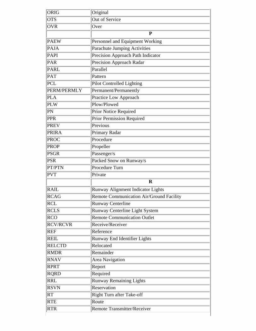
ORIG Original
OTS Out of Service
OVR Over
P
PAEW Personnel and Equipment Working
PAJA Parachute Jumping Activities
PAPI Precision Approach Path Indicator
PAR Precision Approach Radar
PARL Parallel
PAT Pattern
PCL Pilot Controlled Lighting
PERM/PERMLY Permanent/Permanently
PLA Practice Low Approach
PLW Plow/Plowed
PN Prior Notice Required
PPR Prior Permission Required
PREV Previous
PRIRA Primary Radar
PROC Procedure
PROP Propeller
PSGR Passenger/s
PSR Packed Snow on Runway/s
PT/PTN Procedure Turn
PVT Private
R
RAIL Runway Alignment Indicator Lights
RCAG Remote Communication Air/Ground Facility
RCL Runway Centerline
RCLS Runway Centerline Light System
RCO Remote Communication Outlet
RCV/RCVR Receive/Receiver
REF Reference
REIL Runway End Identifier Lights
RELCTD Relocated
RMDR Remainder
RNAV Area Navigation
RPRT Report
RQRD Required
RRL Runway Remaining Lights
RSVN Reservation
RT Right Turn after Take-off
RTE Route
RTR Remote Transmitter/Receiver

RTS Return to Service
RUF Rough
RVR Runway Visual Range
RVRM RVR Midpoint
RVRR RVR Rollout
RVRT RVR Touchdown
RVV Runway Visibility Value
RY/RWY Runway
S
S South
SBND Southbound
SDF Simplified Directional Facility
SE Southeast
SECRA Secondary Radar
SFL Sequenced Flashing Lights
SI Straight-In Approach
SIR Packed or Compacted Snow and Ice on Runway/s
SKED Scheduled
SLR Slush on Runway/s
SNBNK Snowbank/s Caused by Plowing
SND Sand/Sanded
SNGL Single
SNW Snow
SPD Speed
SR Sunrise
SS Sunset
SSALF Simplified Short Approach Lighting System withSequenced Flashers
SSALR Simplified Short Approach Lighting System with RunwayAlignment Indicator Lights
SSALS Simplified Short Approach Lighting System
STAR Standard Terminal Arrival
SVC Service
SW Southwest
SWEPT Swept or Broom/Broomed
T
TACAN Tactical Air Navigational Aid
TDZ/TDZL Touchdown Zone/Touchdown Zone Lights
TFC Traffic
TFR Temporary Flight Restriction
TGL Touch and Go Landings
THN Thin
THR Threshold
THRU Through

TIL Until
TKOF Takeoff
TMPRY Temporary
TRML Terminal
TRNG Training
TRSA Terminal Radar Service Area
TRSN Transition
TSNT Transient
TWEB Transcribed Weather Broadcast
TWR Tower
TWY Taxiway
U
UNAVBL Unavailable
UNLGTD Unlighted
UNMKD Unmarked
UNMON Unmonitored
UNRELBL Unreliable
UNUSBL Unusable
V
VASI Visual Approach Slope Indicator
VDP Visual Descent Point
VFR Visual Flight Rules
VIA By Way Of
VICE Instead/Versus
VIS/VSBY Visibility
VMC Visual Meteorological Conditions
VOL Volume
VOLMET Meteorlogical Information for Aircraft in Flight
VOR VHF Omni-Directional Radio Range
VORTAC VOR and TACAN (collocated)
VOT VOR Test Signal
W
W West
WBND Westbound
WEA/WX Weather
WI Within
WKDAYS Monday through Friday
WKEND Saturday and Sunday
WND Wind
WP Waypoint
WSR Wet Snow on Runway/s
WTR Water on Runway/s
WX Weather

/ And
+ In Addition/Also
5-1-4. Flight Plan - VFR Flights
a. Except for operations in or penetrating a Coastal or Domestic ADIZ or DEWIZ a flightplan is not required for VFR flight.
REFERENCE-AIM, National Security, Paragraph 5-6-1.
b. It is strongly recommended that a flight plan (for a VFR flight) be filed with an FAA FSS.This will ensure that you receive VFR Search and Rescue Protection.
REFERENCE-AIM, Search and Rescue, Paragraph 6-2-7 gives the proper method of filing a VFR flight plan.
c. To obtain maximum benefits from the flight plan program, flight plans should be fileddirectly with the nearest FSS. For your convenience, FSS's provide aeronautical andmeteorological briefings while accepting flight plans. Radio may be used to file if no othermeans are available.
NOTE-Some states operate aeronautical communications facilities which will accept and forwardflight plans to the FSS for further handling.
d. When a "stopover" flight is anticipated, it is recommended that a separate flight plan befiled for each "leg" when the stop is expected to be more than 1 hour duration.
e. Pilots are encouraged to give their departure times directly to the FSS serving thedeparture airport or as otherwise indicated by the FSS when the flight plan is filed. This willensure more efficient flight plan service and permit the FSS to advise you of significantchanges in aeronautical facilities or meteorological conditions. When a VFR flight plan isfiled, it will be held by the FSS until 1 hour after the proposed departure time unless:
1. The actual departure time is received.
2. A revised proposed departure time is received.
3. At a time of filing, the FSS is informed that the proposed departure time willbe met, but actual time cannot be given because of inadequate communications(assumed departures).
f. On pilot's request, at a location having an active tower, the aircraft identification will beforwarded by the tower to the FSS for reporting the actual departure time. This procedureshould be avoided at busy airports.
g. Although position reports are not required for VFR flight plans, periodic reports to FAAFSS's along the route are good practice. Such contacts permit significant information to bepassed to the transiting aircraft and also serve to check the progress of the flight should it benecessary for any reason to locate the aircraft.

EXAMPLE-1. Bonanza 314K, over Kingfisher at (time), VFR flight plan, Tulsa to Amarillo.
2. Cherokee 5133J, over Oklahoma City at (time), Shreveport to Denver, no flight plan.
h. Pilots not operating on an IFR flight plan and when in level cruising flight, are cautionedto conform with VFR cruising altitudes appropriate to the direction of flight.
i. When filing VFR flight plans, indicate aircraft equipment capabilities by appending theappropriate suffix to aircraft type in the same manner as that prescribed for IFR flight.
REFERENCE-AIM, Flight Plan- IFR Flights, Paragraph 5-1-7.
j. Under some circumstances, ATC computer tapes can be useful in constructing the radarhistory of a downed or crashed aircraft. In each case, knowledge of the aircraft's transponderequipment is necessary in determining whether or not such computer tapes might proveeffective.
k. Flight Plan Form - (See FIG 5-1-1).
FIG 5-1-1
FAA Flight PlanForm 7233-1 (8-82)
l. Explanation of VFR Flight Plan Items.
1. Block 1. Check the type flight plan. Check both the VFR and IFR blocks ifcomposite VFR/IFR.
2. Block 2. Enter your complete aircraft identification including the prefix "N"if applicable.
3. Block 3. Enter the designator for the aircraft, or if unknown, consult an FSSbriefer.
4. Block 4. Enter your true airspeed (TAS).
5. Block 5. Enter the departure airport identifier code, or if unknown, the nameof the airport.
6. Block 6. Enter the proposed departure time in Coordinated Universal Time(UTC) (Z). If airborne, specify the actual or proposed departure time asappropriate.
7. Block 7. Enter the appropriate VFR altitude (to assist the briefer in providing

weather and wind information).
8. Block 8. Define the route of flight by using NAVAID identifier codes andairways.
9. Block 9. Enter the destination airport identifier code, or if unknown, theairport name.
NOTE-Include the city name (or even the state name) if needed for clarity.
10. Block 10. Enter your estimated time en route in hours and minutes.
11. Block 11. Enter only those remarks pertinent to ATC or to the clarificationof other flight plan information, such as the appropriate radiotelephony (callsign) associated with the designator filed in Block 2. Items of a personal natureare not accepted.
12. Block 12. Specify the fuel on board in hours and minutes.
13. Block 13. Specify an alternate airport if desired.
14. Block 14. Enter your complete name, address, and telephone number. Entersufficient information to identify home base, airport, or operator.
NOTE-This information is essential in the event of search and rescue operations.
15. Block 15. Enter total number of persons on board (POB) including crew.
16. Block 16. Enter the predominant colors.
17. Block 17. Record the FSS name for closing the flight plan. If the flight planis closed with a different FSS or facility, state the recorded FSS name thatwould normally have closed your flight plan.
NOTE-1. Optional- record a destination telephone number to assist search and rescuecontact should you fail to report or cancel your flight plan within 1/2 hour afteryour estimated time of arrival (ETA).
2. The information transmitted to the destination FSS will consist only of flightplan blocks 2, 3, 9, and 10. Estimated time en route (ETE) will be converted tothe correct ETA.
5-1-5. Flight Plan- Defense VFR (DVFR) Flights
VFR flights into a Coastal or Domestic ADIZ/DEWIZ are required to file DVFR flight plans for securitypurposes. Detailed ADIZ procedures are found in Section 6, National Security and InterceptionProcedures, of this chapter. (See 14 CFR Part 99.)
5-1-6. Composite Flight Plan (VFR/IFR Flights)

a. Flight plans which specify VFR operation for one portion of a flight, and IFR for anotherportion, will be accepted by the FSS at the point of departure. If VFR flight is conducted forthe first portion of the flight, pilots should report their departure time to the FSS with whomthe VFR/IFR flight plan was filed; and, subsequently, close the VFR portion and requestATC clearance from the FSS nearest the point at which change from VFR to IFR isproposed. Regardless of the type facility you are communicating with (FSS, center, ortower), it is the pilot's responsibility to request that facility to "CLOSE VFR FLIGHTPLAN." The pilot must remain in VFR weather conditions until operating in accordance withthe IFR clearance.
b. When a flight plan indicates IFR for the first portion of flight and VFR for the latterportion, the pilot will normally be cleared to the point at which the change is proposed. Afterreporting over the clearance limit and not desiring further IFR clearance, the pilot shouldadvise ATC to cancel the IFR portion of the flight plan. Then, the pilot should contact thenearest FSS to activate the VFR portion of the flight plan. If the pilot desires to continue theIFR flight plan beyond the clearance limit, the pilot should contact ATC at least 5 minutesprior to the clearance limit and request further IFR clearance. If the requested clearance isnot received prior to reaching the clearance limit fix, the pilot will be expected to enter into astandard holding pattern on the radial or course to the fix unless a holding pattern for theclearance limit fix is depicted on a U.S. Government or commercially produced (meetingFAA requirements) low or high altitude enroute, area or STAR chart. In this case the pilotwill hold according to the depicted pattern.
5-1-7. Flight Plan- IFR Flights
a. General
1. Prior to departure from within, or prior to entering controlled airspace, a pilotmust submit a complete flight plan and receive an air traffic clearance, ifweather conditions are below VFR minimums. Instrument flight plans may besubmitted to the nearest FSS or ATCT either in person or by telephone (or byradio if no other means are available). Pilots should file IFR flight plans at least30 minutes prior to estimated time of departure to preclude possible delay inreceiving a departure clearance from ATC. In order to provide FAA trafficmanagement units strategic route planning capabilities, nonscheduled operatorsconducting IFR operations above FL 230 are requested to voluntarily file IFRflight plans at least 4 hours prior to estimated time of departure (ETD). Tominimize your delay in entering Class B, Class C, Class D, and Class E surfaceareas at destination when IFR weather conditions exist or are forecast at thatairport, an IFR flight plan should be filed before departure. Otherwise, a 30minute delay is not unusual in receiving an ATC clearance because of timespent in processing flight plan data. Traffic saturation frequently preventscontrol personnel from accepting flight plans by radio. In such cases, the pilot isadvised to contact the nearest FSS for the purpose of filing the flight plan.
NOTE-There are several methods of obtaining IFR clearances at nontower, non-FSS,and outlying airports. The procedure may vary due to geographical features,

weather conditions, and the complexity of the ATC system. To determine themost effective means of receiving an IFR clearance, pilots should ask thenearest FSS the most appropriate means of obtaining the IFR clearance.
2. When filing an IFR flight plan for flight in an aircraft equipped with a radarbeacon transponder, DME equipment, TACAN-only equipment, GlobalNavigation Satellite System (GNSS), or a combination of any of these types ofequipment, identify the equipment capability by adding a suffix, preceded by aslant, to the AIRCRAFT TYPE, as shown inTBL 5-1-2.
3. It is recommended that pilots file the maximum transponder or navigationcapability of their aircraft in the equipment suffix. This will provide ATC withthe necessary information to utilize all facets of navigational equipment andtransponder capabilities available.
NOTE-The suffix is not to be added to the aircraft identification or be transmitted byradio as part of the aircraft identification.
b. Airways and Jet Routes Depiction on Flight Plan
1. It is vitally important that the route of flight be accurately and completelydescribed in the flight plan. To simplify definition of the proposed route, and tofacilitate ATC, pilots are requested to file via airways or jet routes establishedfor use at the altitude or flight level planned.
2. If flight is to be conducted via designated airways or jet routes, describe theroute by indicating the type and number designators of the airway(s) or jetroute(s) requested. If more than one airway or jet route is to be used, clearlyindicate points of transition. If the transition is made at an unnamed intersection,show the next succeeding NAVAID or named intersection on the intended routeand the complete route from that point. Reporting points may be identified byusing authorized name/code as depicted on appropriate aeronautical charts. Thefollowing two examples illustrate the need to specify the transition point whentwo routes share more than one transition fix.
EXAMPLE-1. ALB J37 BUMPY J14 BHMSpelled out: from Albany, New York, via Jet Route 37 transitioning to Jet Route14 at BUMPY intersection, thence via Jet Route 14 to Birmingham, Alabama.2. ALB J37 ENO J14 BHMSpelled out: from Albany, New York, via Jet Route 37 transitioning to Jet Route14 at Kenton VORTAC (ENO) thence via Jet Route 14 to Birmingham,Alabama.
3. The route of flight may also be described by naming the reporting points orNAVAID's over which the flight will pass, provided the points named areestablished for use at the altitude or flight level planned.

EXAMPLE-BWI V44 SWANN V433 DQOSpelled out: from Baltimore-Washington International, via Victor 44 to Swannintersection, transitioning to Victor 433 at Swann, thence via Victor 433 toDupont.
4. When the route of flight is defined by named reporting points, whether aloneor in combination with airways or jet routes, and the navigational aids (VOR,VORTAC, TACAN, NDB) to be used for the flight are a combination ofdifferent types of aids, enough information should be included to clearlyindicate the route requested.
EXAMPLE-LAX J5 LKV J3 GEG YXC FL 330 J500 VLR J515 YWGSpelled out: from Los Angeles International via Jet Route 5 Lakeview, Jet Route3 Spokane, direct Cranbrook, British Columbia VOR/DME, Flight Level 330 JetRoute 500 to Langruth, Manitoba VORTAC, Jet Route 515 to Winnepeg,Manitoba.
5. When filing IFR, it is to the pilot's advantage to file a preferred route.
REFERENCE-Preferred IFR Routes are described and tabulated in the Airport/Facility Directory.
TBL 5-1-2
Aircraft Equipment SuffixesSuffix Aircraft Equipment Suffixes
NO DME
/X No transponder
/T Transponder with no Mode C
/U Transponder with Mode C
DME
/D No transponder
/B Transponder with no Mode C
/A Transponder with Mode C
TACAN ONLY
/M No transponder
/N Transponder with no Mode C
/P Transponder with Mode C
AREA NAVIGATION (RNAV)
/Y LORAN, VOR/DME, or INS with no transponder
/C LORAN, VOR/DME, or INS, transponder with no Mode C
/I LORAN, VOR/DME, or INS, transponder with Mode C
ADVANCED RNAV WITH TRANSPONDER AND MODE C (If an aircraft is unable tooperate with a transponder and/or Mode C, it will revert to the appropriate code listed aboveunder Area Navigation.)

/E Flight Management System (FMS) with en route, terminal, and approach capability.Equipment requirements are:(a) Dual FMS which meets the specifications of AC 25-15, Approval of Flight ManagementSystems in Transport Category Airplanes; AC 20-129, Airworthiness Approval of VerticalNavigation (VNAV) Systems for use in the U.S. NAS and Alaska; AC 20-130A,Airworthiness Approval of Navigation or Flight Management Systems Integrating MultipleNavigation Sensors; or equivalent criteria as approved by Flight Standards.(b) A flight director and autopilot control system capable of following the lateral and verticalFMS flight path.(c) At least dual inertial reference units (IRU's).(d) A database containing the waypoints and speed/altitude constraints for the route and/orprocedure to be flown that is automatically loaded into the FMS flight plan.(e) An electronic map.(U.S. and U.S. territories only unless otherwise authorized.)
/F FMS with en route, terminal, and approach capability. Unless otherwise authorized by theAdministrator, equipment requirements are:(a) Single FMS which meets the specifications of AC 25-15, Approval of Flight ManagementSystems in Transport Category Airplanes; AC 20-129, Airworthiness Approval of VerticalNavigation (VNAV) Systems for use in the U.S. NAS and Alaska; AC 20-130A,Airworthiness Approval of Navigation or Flight Management Systems Integrating MultipleNavigation Sensors; or equivalent criteria as approved by Flight Standards.(b) A demonstrated capability of depicting and following the lateral and vertical path.(c) An FMS with DME/DME updating and one or more of the following: Single GlobalPositioning System (GPS) - Single inertial reference unit (IRU).(d) A database containing the waypoints and speed/altitude constraints for the route and/orprocedure to be flown that is automatically loaded into the FMS flight plan.(U.S. and U.S. territories only unless otherwise authorized.)
/G Global Positioning System (GPS)/Global Navigation Satellite System (GNSS) equippedaircraft with en route and terminal capability
/R Required Navigational Performance (Denotes capability to operate in RNP designated airspaceand routes)
/W Reduced Vertical Separation Minima (RVSM)
/Q Required Navigation Performance (RNP) and Reduced Vertical Separation Minima (RVSM)(Indicate approval for application of RNP and RVSM separation standards.) It should be notedthat /Q is for automation purposes only and will not be filed by system users. FAA processorswill convert the combination of /R+/W to =/Q.
6. ATC may issue a DP or a STAR, as appropriate.
REFERENCE-AIM, Instrument Departures, Paragraph 5-2-6.AIM, Standard Terminal Arrival (STAR), Flight Management System Procedures (FMSP) for Arrivals, Paragraph 5-4-1.
NOTE-Pilots not desiring a DP or STAR should so indicate in the remarks section ofthe flight plan as "no DP" or "no STAR."
c. Direct Flights
1. All or any portions of the route which will not be flown on the radials orcourses of established airways or routes, such as direct route flights, must bedefined by indicating the radio fixes over which the flight will pass. Fixesselected to define the route shall be those over which the position of the aircraftcan be accurately determined. Such fixes automatically become compulsory

reporting points for the flight, unless advised otherwise by ATC. Only thosenavigational aids established for use in a particular structure; i.e., in the low orhigh structures, may be used to define the en route phase of a direct flight withinthat altitude structure.
2. The azimuth feature of VOR aids and that azimuth and distance (DME)features of VORTAC and TACAN aids are assigned certain frequency protectedareas of airspace which are intended for application to established airway androute use, and to provide guidance for planning flights outside of establishedairways or routes. These areas of airspace are expressed in terms of cylindricalservice volumes of specified dimensions called "class limits" or "categories."
REFERENCE-AIM, Navigational Aid (NAVAID) Service Volumes, Paragraph 1-1-8.
3. An operational service volume has been established for each class in whichadequate signal coverage and frequency protection can be assured. To facilitateuse of VOR, VORTAC, or TACAN aids, consistent with their operationalservice volume limits, pilot use of such aids for defining a direct route of flightin controlled airspace should not exceed the following:
(a) Operations above FL 450 - Use aids not more than 200 NMapart. These aids are depicted on enroute high altitude charts.
(b) Operation off established routes from 18,000 feet MSL to FL450 - Use aids not more than 260 NM apart. These aids aredepicted on enroute high altitude charts.
(c) Operation off established airways below 18,000 feet MSL - Useaids not more than 80 NM apart. These aids are depicted on enroutelow altitude charts.
(d) Operation off established airways between 14,500 feet MSLand 17,999 feet MSL in the conterminous U.S. - (H) facilities notmore than 200 NM apart may be used.
4. Increasing use of self-contained airborne navigational systems which do notrely on the VOR/VORTAC/TACAN system has resulted in pilot requests fordirect routes which exceed NAVAID service volume limits. These direct routerequests will be approved only in a radar environment, with approval based onpilot responsibility for navigation on the authorized direct route. Radar flightfollowing will be provided by ATC for ATC purposes.
5. At times, ATC will initiate a direct route in a radar environment whichexceeds NAVAID service volume limits. In such cases ATC will provide radarmonitoring and navigational assistance as necessary.
6. Airway or jet route numbers, appropriate to the stratum in which operationwill be conducted, may also be included to describe portions of the route to beflown.

EXAMPLE-MDW V262 BDF V10 BRL STJ SLN GCKSpelled out: from Chicago Midway Airport via Victor 262 to Bradford, Victor10 to Burlington, Iowa, direct St. Joseph, Missouri, direct Salina, Kansas, directGarden City, Kansas.
NOTE-When route of flight is described by radio fixes, the pilot will be expected to flya direct course between the points named.
7. Pilots are reminded that they are responsible for adhering to obstructionclearance requirements on those segments of direct routes that are outside ofcontrolled airspace. The MEA's and other altitudes shown on low altitude IFRenroute charts pertain to those route segments within controlled airspace, andthose altitudes may not meet obstruction clearance criteria when operating offthose routes.
d. Area Navigation (RNAV)
1. Random RNAV routes can only be approved in a radar environment. Factorsthat will be considered by ATC in approving random RNAV routes include thecapability to provide radar monitoring and compatibility with traffic volume andflow. ATC will radar monitor each flight, however, navigation on the randomRNAV route is the responsibility of the pilot.
2. Pilots of aircraft equipped with approved area navigation equipment may filefor RNAV routes throughout the National Airspace System and may be filed forin accordance with the following procedures.
(a) File airport-to-airport flight plans.
(b) File the appropriate RNAV capability certification suffix in theflight plan.
(c) Plan the random route portion of the flight plan to begin andend over appropriate arrival and departure transition fixes orappropriate navigation aids for the altitude stratum within whichthe flight will be conducted. The use of normal preferred departureand arrival routes (DP/STAR), where established, is recommended.
(d) File route structure transitions to and from the random routeportion of the flight.
(e) Define the random route by waypoints. File route descriptionwaypoints by using degree-distance fixes based on navigationalaids which are appropriate for the altitude stratum.
(f) File a minimum of one route description waypoint for eachARTCC through whose area the random route will be flown. Thesewaypoints must be located within 200 NM of the preceding center's

boundary.
(g) File an additional route description waypoint for each turnpointin the route.
(h) Plan additional route description waypoints as required toensure accurate navigation via the filed route of flight. Navigationis the pilot's responsibility unless ATC assistance is requested.
(i) Plan the route of flight so as to avoid prohibited and restrictedairspace by 3 NM unless permission has been obtained to operatein that airspace and the appropriate ATC facilities are advised.
NOTE-To be approved for use in the National Airspace System, RNAVequipment must meet the appropriate system availability, accuracy,and airworthiness standards. For additional guidance onequipment requirements see AC 20-130, Airworthiness Approval ofVertical Navigation (VNAV) Systems for use in the U.S. NAS andAlaska, or AC 20-138, Airworthiness Approval of GlobalPositioning System (GPS) Navigation Equipment for Use as a VFRand IFR Supplemental Navigation System. For airborne navigationdatabase, see AC 90-94, Guidelines for Using GPS Equipment forIFR En Route and Terminal Operations and for NonprecisionInstrument Approaches in the U.S. National Airspace System,Section 2.
3. Pilots of aircraft equipped with latitude/longitude coordinate navigationcapability, independent of VOR/TACAN references, may file for randomRNAV routes at and above FL 390 within the conterminous U.S. using thefollowing procedures.
(a) File airport-to-airport flight plans prior to departure.
(b) File the appropriate RNAV capability certification suffix in theflight plan.
(c) Plan the random route portion of the flight to begin and endover published departure/arrival transition fixes or appropriatenavigation aids for airports without published transitionprocedures. The use of preferred departure and arrival routes, suchas DP and STAR where established, is recommended.
(d) Plan the route of flight so as to avoid prohibited and restrictedairspace by 3 NM unless permission has been obtained to operatein that airspace and the appropriate ATC facility is advised.
(e) Define the route of flight after the departure fix, including eachintermediate fix (turnpoint) and the arrival fix for the destinationairport in terms of latitude/longitude coordinates plotted to the

nearest minute. The arrival fix must be identified by both thelatitude/longitude coordinates and a fix identifier.
EXAMPLE-MIA1 SRQ2 3407/106153 3407/11546 TNP4 LAX 5
1 Departure airport.2 Departure fix.3 Intermediate fix (turning point).4 Arrival fix.5 Destination airport.
(f) Record latitude/longitude coordinates by four figures describinglatitude in degrees and minutes followed by a solidus and fivefigures describing longitude in degrees and minutes.
(g) File at FL 390 or above for the random RNAV portion of theflight.
(h) Fly all routes/route segments on Great Circle tracks.
(i) Make any inflight requests for random RNAV clearances orroute amendments to an en route ATC facility.
e. Flight Plan Form- See FIG 5-1-2.
f. Explanation of IFR Flight Plan Items.
1. Block 1. Check the type flight plan. Check both the VFR and IFR blocks ifcomposite VFR/IFR.
2. Block 2. Enter your complete aircraft identification including the prefix "N"if applicable.
3. Block 3. Enter the designator for the aircraft, followed by a slant(/), and thetransponder or DME equipment code letter; e.g., C-182/U. Heavy aircraft, addprefix "H" to aircraft type; example: H/DC10/U. Consult an FSS briefer for anyunknown elements.
4. Block 4. Enter your computed true airspeed (TAS).
NOTE-If the average TAS changes plus or minus 5 percent or 10 knots, whichever isgreater, advise ATC.
5. Block 5. Enter the departure airport identifier code (or the name if theidentifier is unknown).
NOTE-Use of identifier codes will expedite the processing of your flight plan.

6. Block 6. Enter the proposed departure time in Coordinated Universal Time(UTC) (Z). If airborne, specify the actual or proposed departure time asappropriate.
7. Block 7. Enter the requested en route altitude or flight level.
NOTE-Enter only the initial requested altitude in this block. When more than one IFRaltitude or flight level is desired along the route of flight, it is best to make asubsequent request direct to the controller.
8. Block 8. Define the route of flight by using NAVAID identifier codes (ornames if the code is unknown), airways, jet routes, and waypoints (for RNAV).
NOTE-Use NAVAID's or waypoint's to define direct routes and radials/bearings todefine other unpublished routes.
9. Block 9. Enter the destination airport identifier code (or name if the identifieris unknown).
10. Block 10. Enter your estimated time en route based on latest forecast winds.
11. Block 11. Enter only those remarks pertinent to ATC or to the clarificationof other flight plan information, such as the appropriate radiotelephony (callsign) associated with the designator filed in Block 2. Items of a personal natureare not accepted. Do not assume that remarks will be automatically transmittedto every controller. Specific ATC or en route requests should be made directlyto the appropriate controller.
NOTE-"DVRSN" should be placed in Block 11 only if the pilot/company is requestingpriority handling to their original destination from ATC as a result of adiversion as defined in the Pilot/Controller Glossary.
12. Block 12. Specify the fuel on board, computed from the departure point.
13. Block 13. Specify an alternate airport if desired or required, but do notinclude routing to the alternate airport.
14. Block 14. Enter the complete name, address, and telephone number ofpilot-in-command, or in the case of a formation flight, the formationcommander. Enter sufficient information to identify home base, airport, oroperator.
NOTE-This information would be essential in the event of search and rescue operation.
15. Block 15. Enter the total number of persons on board including crew.
16. Block 16. Enter the predominant colors.

NOTE-Close IFR flight plans with tower, approach control, or ARTCC, or if unable,with FSS. When landing at an airport with a functioning control tower, IFRflight plans are automatically canceled.
g. The information transmitted to the ARTCC for IFR flight plans will consist of only flightplan blocks 2, 3, 4, 5, 6, 7, 8, 9, 10, and 11.
h. A description of the International Flight Plan Form is contained in the International FlightInformation Manual (IFIM).
FIG 5-1-2
FAA Flight PlanForm 7233-1 (8-82)
5-1-8. IFR Operations to High Altitude Destinations
a. Pilots planning IFR flights to airports located in mountainous terrain are cautioned toconsider the necessity for an alternate airport even when the forecast weather conditionswould technically relieve them from the requirement to file one.
REFERENCE-14 CFR Section 91.167.AIM, Tower En Route Control (TEC), Paragraph 4-1-18.
b. The FAA has identified three possible situations where the failure to plan for an alternateairport when flying IFR to such a destination airport could result in a critical situation if theweather is less than forecast and sufficient fuel is not available to proceed to a suitableairport.
1. An IFR flight to an airport where the Minimum Descent Altitudes (MDA's)or landing visibility minimums for all instrument approaches are higher thanthe forecast weather minimums specified in 14 CFR Section 91.167(b). Forexample, there are 3 high altitude airports in the U.S. with approved instrumentapproach procedures where all of the MDA's are greater than 2,000 feet and/orthe landing visibility minimums are greater than 3 miles (Bishop, California;South Lake Tahoe, California; and Aspen-Pitkin Co./Sardy Field, Colorado). Inthe case of these airports, it is possible for a pilot to elect, on the basis offorecasts, not to carry sufficient fuel to get to an alternate when the ceilingand/or visibility is actually lower than that necessary to complete the approach.
2. A small number of other airports in mountainous terrain have MDA's whichare slightly (100 to 300 feet) below 2,000 feet AGL. In situations where there isan option as to whether to plan for an alternate, pilots should bear in mind thatjust a slight worsening of the weather conditions from those forecast could placethe airport below the published IFR landing minimums.

3. An IFR flight to an airport which requires special equipment; i.e., DME, glideslope, etc., in order to make the available approaches to the lowest minimums.Pilots should be aware that all other minimums on the approach charts mayrequire weather conditions better than those specified in 14 CFR Section91.167(b). An inflight equipment malfunction could result in the inability tocomply with the published approach procedures or, again, in the position ofhaving the airport below the published IFR landing minimums for all remaininginstrument approach alternatives.
5-1-9. Flights Outside the U.S. and U.S. Territories
a. When conducting flights, particularly extended flights, outside the U.S. and its territories,full account should be taken of the amount and quality of air navigation services available inthe airspace to be traversed. Every effort should be made to secure information on thelocation and range of navigational aids, availability of communications and meteorologicalservices, the provision of air traffic services, including alerting service, and the existence ofsearch and rescue services.
b. Pilots should remember that there is a need to continuously guard the VHF emergencyfrequency 121.5 MHz when on long over-water flights, except when communications onother VHF channels, equipment limitations, or cockpit duties prevent simultaneous guardingof two channels. Guarding of 121.5 MHz is particularly critical when operating in proximityto Flight Information Region (FIR) boundaries, for example, operations on Route R220between Anchorage and Tokyo, since it serves to facilitate communications with regard toaircraft which may experience in-flight emergencies, communications, or navigationaldifficulties.
REFERENCE-ICAO Annex 10, Vol II, Paras 5.2.2.1.1.1 and 5.2.2.1.1.2.
c. The filing of a flight plan, always good practice, takes on added significance for extendedflights outside U.S. airspace and is, in fact, usually required by the laws of the countriesbeing visited or overflown. It is also particularly important in the case of such flights thatpilots leave a complete itinerary and schedule of the flight with someone directly concernedand keep that person advised of the flight's progress. If serious doubt arises as to the safety ofthe flight, that person should first contact the appropriate FSS. Round Robin Flight Plans toMexico are not accepted.
d. All pilots should review the foreign airspace and entry restrictions published in the IFIMduring the flight planning process. Foreign airspace penetration without official authorizationcan involve both danger to the aircraft and the imposition of severe penalties andinconvenience to both passengers and crew. A flight plan on file with ATC authorities doesnot necessarily constitute the prior permission required by certain other authorities. Thepossibility of fatal consequences cannot be ignored in some areas of the world.
e. Current NOTAM's for foreign locations must also be reviewed. The publication Notices toAirmen, Domestic/International, published biweekly, contains considerable informationpertinent to foreign flight. Current foreign NOTAM's are also available from the U.S.International NOTAM Office in Washington, D.C., through any local FSS.

f. When customs notification is required, it is the responsibility of the pilot to arrange forcustoms notification in a timely manner. The following guidelines are applicable:
1. When customs notification is required on flights to Canada and Mexico and apredeparture flight plan cannot be filed or an advise customs message (ADCUS)cannot be included in a predeparture flight plan, call the nearest en routedomestic or International FSS as soon as radio communication can beestablished and file a VFR or DVFR flight plan, as required, and include as thelast item the advise customs information. The station with which such a flightplan is filed will forward it to the appropriate FSS who will notify the customsoffice responsible for the destination airport.
2. If the pilot fails to include ADCUS in the radioed flight plan, it will beassumed that other arrangements have been made and FAA will not advisecustoms.
3. The FAA assumes no responsibility for any delays in advising customs if theflight plan is given too late for delivery to customs before arrival of the aircraft.It is still the pilot's responsibility to give timely notice even though a flightplan is given to FAA.
4. Air Commerce Regulations of the Treasury Department's Customs Servicerequire all private aircraft arriving in the U.S. via:
(a) The U.S./Mexican border or the Pacific Coast from a foreignplace in the Western Hemisphere south of 33 degrees north latitudeand between 97 degrees and 120 degrees west longitude; or
(b) The Gulf of Mexico and Atlantic Coasts from a foreign place inthe Western Hemisphere south of 30 degrees north latitude, shallfurnish a notice of arrival to the Customs service at the nearestdesignated airport. This notice may be furnished directly toCustoms by:
(1) Radio through the appropriate FAA Flight ServiceStation.
(2) Normal FAA flight plan notification procedures (aflight plan filed in Mexico does not meet thisrequirement due to unreliable relay of data); or
(3) Directly to the district Director of Customs orother Customs officer at place of first intended landingbut must be furnished at least 1 hour prior to crossingthe U.S./Mexican border or the U.S. coastline.
(c) This notice will be valid as long as actual arrival is within 15minutes of the original ETA, otherwise a new notice must be givento Customs. Notices will be accepted up to 23 hours in advance.Unless an exemption has been granted by Customs, private aircraft

are required to make first landing in the U.S. at one of thefollowing designated airports nearest to the point of border ofcoastline crossing:
Designated Airports
ARIZONABisbee Douglas Intl AirportDouglas Municipal AirportNogales Intl AirportTucson Intl AirportYuma MCAS-Yuma Intl Airport
CALIFORNIA
Calexico Intl Airport
Brown Field Municipal Airport (San Diego)
FLORIDAFort Lauderdale Executive AirportFort Lauderdale/Hollywood Intl AirportKey West Intl Airport (Miami Intl Airport)Opa Locka Airport (Miami)Kendall-Tamiami Executive Airport (Miami)St. Lucie County Intl Airport (Fort Pierce)Tampa Intl AirportPalm Beach Intl Airport (West Palm Beach)
LOUISANANew Orleans Intl Airport (Moisant Field)New Orleans Lakefront Airport
NEW MEXICO
Las Cruces Intl Airport
NORTH CAROLINANew Hanover Intl Airport (Wilmington)
TEXASBrownsville/South Padre Island Intl AirportCorpus Christi Intl AirportDel Rio Intl AirportEagle Pass Municipal AirportEl Paso Intl AirportWilliam P. Hobby Airport (Houston)Laredo Intl Airport

McAllen Miller Intl AirportPresidio Lely Intl Airport
5-1-10. Change in Flight Plan
In addition to altitude or flight level, destination and/or route changes, increasing or decreasing the speedof an aircraft constitutes a change in a flight plan. Therefore, at any time the average true airspeed atcruising altitude between reporting points varies or is expected to vary from that given in the flight planby plus or minus 5 percent, or 10 knots, whichever is greater, ATC should be advised.
5-1-11. Change in Proposed Departure Time
a. To prevent computer saturation in the en route environment, parameters have beenestablished to delete proposed departure flight plans which have not been activated. Mostcenters have this parameter set so as to delete these flight plans a minimum of 1 hour afterthe proposed departure time. To ensure that a flight plan remains active, pilots whose actualdeparture time will be delayed 1 hour or more beyond their filed departure time, arerequested to notify ATC of their departure time.
b. Due to traffic saturation, control personnel frequently will be unable to accept theserevisions via radio. It is recommended that you forward these revisions to the nearest FSS.
5-1-12. Closing VFR/DVFR Flight Plans
A pilot is responsible for ensuring that his/her VFR or DVFR flight plan is canceled. You should closeyour flight plan with the nearest FSS, or if one is not available, you may request any ATC facility to relayyour cancellation to the FSS. Control towers do not automatically close VFR or DVFR flight plans sincethey do not know if a particular VFR aircraft is on a flight plan. If you fail to report or cancel your flightplan within 1/2 hour after your ETA, search and rescue procedures are started.
REFERENCE-14 CFR Section 91.153.14 CFR Section 91.169.
5-1-13. Canceling IFR Flight Plan
a. 14 CFR Sections 91.153 and 91.169 include the statement "When a flight plan has beenactivated, the pilot-in-command, upon canceling or completing the flight under the flightplan, shall notify an FAA Flight Service Station or ATC facility."
b. An IFR flight plan may be canceled at any time the flight is operating in VFR conditionsoutside Class A airspace by pilots stating "CANCEL MY IFR FLIGHT PLAN" to thecontroller or air/ground station with which they are communicating. Immediately aftercanceling an IFR flight plan, a pilot should take the necessary action to change to theappropriate air/ground frequency, VFR radar beacon code and VFR altitude or flight level.
c. ATC separation and information services will be discontinued, including radar services(where applicable). Consequently, if the canceling flight desires VFR radar advisory service,the pilot must specifically request it.

NOTE-Pilots must be aware that other procedures may be applicable to a flight that cancels an IFRflight plan within an area where a special program, such as a designated TRSA, Class Cairspace, or Class B airspace, has been established.
d. If a DVFR flight plan requirement exists, the pilot is responsible for filing this flight planto replace the canceled IFR flight plan. If a subsequent IFR operation becomes necessary, anew IFR flight plan must be filed and an ATC clearance obtained before operating in IFRconditions.
e. If operating on an IFR flight plan to an airport with a functioning control tower, the flightplan is automatically closed upon landing.
f. If operating on an IFR flight plan to an airport where there is no functioning control tower,the pilot must initiate cancellation of the IFR flight plan. This can be done after landing ifthere is a functioning FSS or other means of direct communications with ATC. In the eventthere is no FSS and/or air/ground communications with ATC is not possible below a certainaltitude, the pilot should, weather conditions permitting, cancel the IFR flight plan while stillairborne and able to communicate with ATC by radio. This will not only save the time andexpense of canceling the flight plan by telephone but will quickly release the airspace for useby other aircraft.
5-1-14. RNAV and RNP Operations
a. During the pre-flight planning phase the availability of the navigation infrastructurerequired for the intended operation, including any non-RNAV contingencies, must beconfirmed for the period of intended operation. Availability of the onboard navigationequipment necessary for the route to be flown must be confirmed.
b. If a pilot determines a specified RNP level cannot be achieved, revise the route or delaythe operation until appropriate RNP level can be ensured.
c. The onboard navigation database must be appropriate for the region of intended operationand must include the navigation aids, waypoints, and coded terminal airspace procedures forthe departure, arrival and alternate airfields.
d. During system initialization, pilots of aircraft equipped with a Flight Management Systemor other RNAV-certified system, must confirm that the navigation database is current, andverify that the aircraft position has been entered correctly. Flight crews should crosscheckthe cleared flight plan against charts or other applicable resources, as well as the navigationsystem textual display and the aircraft map display. This process includes confirmation of thewaypoints sequence, reasonableness of track angles and distances, any altitude or speedconstraints, and identification of fly-by or fly-over waypoints. A procedure shall not be usedif validity of the navigation database is in doubt.
e. Prior to commencing takeoff, the flight crew must verify that the RNAV system isoperating correctly and the correct airport and runway data have been loaded.

Back to AIMHome Page
Go back to Chapter 4Section 4
Go to Chapter 5Section 2
Back toTop of this Page

Section 2. Departure Procedures
5-2-1. Pre-taxi Clearance Procedures
a. Certain airports have established pre-taxi clearance programs whereby pilots of departinginstrument flight rules (IFR) aircraft may elect to receive their IFR clearances before theystart taxiing for takeoff. The following provisions are included in such procedures:
1. Pilot participation is not mandatory.
2. Participating pilots call clearance delivery or ground control not more than 10minutes before proposed taxi time.
3. IFR clearance (or delay information, if clearance cannot be obtained) isissued at the time of this initial call-up.
4. When the IFR clearance is received on clearance delivery frequency, pilotscall ground control when ready to taxi.
5. Normally, pilots need not inform ground control that they have received IFRclearance on clearance delivery frequency. Certain locations may, however,require that the pilot inform ground control of a portion of the routing or that theIFR clearance has been received.
6. If a pilot cannot establish contact on clearance delivery frequency or has notreceived an IFR clearance before ready to taxi, the pilot should contact groundcontrol and inform the controller accordingly.
b. Locations where these procedures are in effect are indicated in the Airport/FacilityDirectory.
5-2-2. Taxi Clearance
Pilots on IFR flight plans should communicate with the control tower on the appropriate ground control orclearance delivery frequency, prior to starting engines, to receive engine start time, taxi and/or clearanceinformation.
5-2-3. Abbreviated IFR Departure Clearance (Cleared. . .as Filed) Procedures
a. ATC facilities will issue an abbreviated IFR departure clearance based on the ROUTE offlight filed in the IFR flight plan, provided the filed route can be approved with little or norevision. These abbreviated clearance procedures are based on the following conditions:
1. The aircraft is on the ground or it has departed visual flight rules (VFR) andthe pilot is requesting IFR clearance while airborne.
2. That a pilot will not accept an abbreviated clearance if the route or destinationof a flight plan filed with ATC has been changed by the pilot or the company orthe operations officer before departure.

3. That it is the responsibility of the company or operations office to inform thepilot when they make a change to the filed flight plan.
4. That it is the responsibility of the pilot to inform ATC in the initial call-up(for clearance) when the filed flight plan has been either:
(a) Amended, or
(b) Canceled and replaced with a new filed flight plan.
NOTE-The facility issuing a clearance may not have received the revisedroute or the revised flight plan by the time a pilot requestsclearance.
b. Controllers will issue a detailed clearance when they know that the original filed flightplan has been changed or when the pilot requests a full route clearance.
c. The clearance as issued will include the destination airport filed in the flight plan.
d. ATC procedures now require the controller to state the DP name, the current number andthe DP transition name after the phrase "Cleared to (destination) airport" and prior to thephrase, "then as filed," for ALL departure clearances when the DP or DP transition is to beflown. The procedures apply whether or not the DP is filed in the flight plan.
e. STAR's, when filed in a flight plan, are considered a part of the filed route of flight andwill not normally be stated in an initial departure clearance. If the ARTCC's jurisdictionalairspace includes both the departure airport and the fix where a STAR or STAR transitionbegins, the STAR name, the current number and the STAR transition name MAY be statedin the initial clearance.
f. "Cleared to (destination) airport as filed" does NOT include the en route altitude filed in aflight plan. An en route altitude will be stated in the clearance or the pilot will be advised toexpect an assigned or filed altitude within a given time frame or at a certain point afterdeparture. This may be done verbally in the departure instructions or stated in the DP.
g. In both radar and nonradar environments, the controller will state "Cleared to (destination)airport as filed" or:
1. If a DP or DP transition is to be flown, specify the DP name, the current DPnumber, the DP transition name, the assigned altitude/flight level, and anyadditional instructions (departure control frequency, beacon code assignment,etc.) necessary to clear a departing aircraft via the DP or DP transition and theroute filed.
EXAMPLE-National Seven Twenty cleared to Miami Airport Intercontinental onedeparture, Lake Charles transition then as filed, maintain Flight Level twoseven zero.
2. When there is no DP or when the pilot cannot accept a DP, the controller will

specify the assigned altitude or flight level, and any additional instructionsnecessary to clear a departing aircraft via an appropriate departure routing andthe route filed.
NOTE-A detailed departure route description or a radar vector may be used to achievethe desired departure routing.
3. If it is necessary to make a minor revision to the filed route, the controllerwill specify the assigned DP or DP transition (or departure routing), the revisionto the filed route, the assigned altitude or flight level and any additionalinstructions necessary to clear a departing aircraft.
EXAMPLE-Jet Star One Four Two Four cleared to Atlanta Airport, South Boston twodeparture then as filed except change route to read South Boston Victor 20Greensboro, maintain one seven thousand.
4. Additionally, in a nonradar environment, the controller will specify one ormore fixes, as necessary, to identify the initial route of flight.
EXAMPLE-Cessna Three One Six Zero Foxtrot cleared to Charlotte Airport as filed viaBrooke, maintain seven thousand.
h. To ensure success of the program, pilots should:
1. Avoid making changes to a filed flight plan just prior to departure.
2. State the following information in the initial call-up to the facility when nochange has been made to the filed flight plan: Aircraft call sign, location, typeoperation (IFR) and the name of the airport (or fix) to which you expectclearance.
EXAMPLE-"Washington clearance delivery (or ground control if appropriate) AmericanSeventy Six at gate one, IFR Los Angeles."
3. If the flight plan has been changed, state the change and request a full routeclearance.
EXAMPLE-"Washington clearance delivery, American Seventy Six at gate one. IFR SanFrancisco. My flight plan route has been amended (or destination changed).Request full route clearance."
4. Request verification or clarification from ATC if ANY portion of theclearance is not clearly understood.
5. When requesting clearance for the IFR portion of a VFR/IFR flight, requestsuch clearance prior to the fix where IFR operation is proposed to commence in

sufficient time to avoid delay. Use the following phraseology:
EXAMPLE-"Los Angeles center, Apache Six One Papa, VFR estimating Paso Robles VORat three two, one thousand five hundred, request IFR to Bakersfield."
5-2-4. Departure Restrictions, Clearance Void Times, Hold for Release, and Release Times
a. ATC may assign departure restrictions, clearance void times, hold for release, and releasetimes, when necessary, to separate departures from other traffic or to restrict or regulate thedeparture flow.
1. CLEARANCE VOID TIMES. A pilot may receive a clearance, whenoperating from an airport without a control tower, which contains a provisionfor the clearance to be void if not airborne by a specific time. A pilot who doesnot depart prior to the clearance void time must advise ATC as soon as possibleof their intentions. ATC will normally advise the pilot of the time allotted tonotify ATC that the aircraft did not depart prior to the clearance void time. Thistime cannot exceed 30 minutes. Failure of an aircraft to contact ATC within 30minutes after the clearance void time will result in the aircraft being consideredoverdue and search and rescue procedures initiated.
NOTE-1. Other IFR traffic for the airport where the clearance is issued is suspendeduntil the aircraft has contacted ATC or until 30 minutes after the clearance voidtime or 30 minutes after the clearance release time if no clearance void time isissued.
2. Pilots who depart at or after their clearance void time are not afforded IFRseparation and may be in violation of 14 CFR Section 91.173 which requiresthat pilots receive an appropriate ATC clearance before operating IFR incontrolled airspace.
EXAMPLE-Clearance void if not off by (clearance void time) and, if required, if not off by(clearance void time) advise (facility) not later than (time) of intentions.
2. HOLD FOR RELEASE. ATC may issue "hold for release" instructions in aclearance to delay an aircraft's departure for traffic management reasons (i.e.,weather, traffic volume, etc.). When ATC states in the clearance, "hold forrelease," the pilot may not depart utilizing that IFR clearance until a release timeor additional instructions are issued by ATC. In addition, ATC will includedeparture delay information in conjunction with "hold for release" instructions.The ATC instruction, "hold for release," applies to the IFR clearance and doesnot prevent the pilot from departing under VFR. However, prior to takeoff thepilot should cancel the IFR flight plan and operate the transponder on theappropriate VFR code. An IFR clearance may not be available after departure.
EXAMPLE-

(Aircraft identification) cleared to (destination) airport as filed, maintain(altitude), and, if required (additional instructions or information), hold forrelease, expect (time in hours and/or minutes) departure delay.
3. RELEASE TIMES. A "release time" is a departure restriction issued to apilot by ATC, specifying the earliest time an aircraft may depart. ATC will use"release times" in conjunction with traffic management procedures and/or toseparate a departing aircraft from other traffic.
EXAMPLE-(Aircraft identification) released for departure at (time in hours and/orminutes).
b. If practical, pilots departing uncontrolled airports should obtain IFR clearances prior tobecoming airborne when two-way communications with the controlling ATC facility isavailable.
5-2-5. Departure Control
a. Departure Control is an approach control function responsible for ensuring separationbetween departures. So as to expedite the handling of departures, Departure Control maysuggest a take off direction other than that which may normally have been used under VFRhandling. Many times it is preferred to offer the pilot a runway that will require the fewestturns after take off to place the pilot on course or selected departure route as quickly aspossible. At many locations particular attention is paid to the use of preferential runways forlocal noise abatement programs, and route departures away from congested areas.
b. Departure Control utilizing radar will normally clear aircraft out of the terminal area usingDP's via radio navigation aids. When a departure is to be vectored immediately followingtake off, the pilot will be advised prior to take off of the initial heading to be flown but maynot be advised of the purpose of the heading. Pilots operating in a radar environment areexpected to associate departure headings with vectors to their planned route or flight. Whengiven a vector taking the aircraft off a previously assigned nonradar route, the pilot will beadvised briefly what the vector is to achieve. Thereafter, radar service will be provided untilthe aircraft has been reestablished "on-course" using an appropriate navigation aid and thepilot has been advised of the aircraft's position or a handoff is made to another radarcontroller with further surveillance capabilities.
c. Controllers will inform pilots of the departure control frequencies and, if appropriate, thetransponder code before takeoff. Pilots should not operate their transponder until ready tostart the takeoff roll or change to the departure control frequency until requested. Controllersmay omit the departure control frequency if a DP has or will be assigned and the departurecontrol frequency is published on the DP.
5-2-6. Instrument Departure Procedure (DP)
Instrument departure procedures are preplanned instrument flight rule (IFR) procedures which provideobstruction clearance from the terminal area to the appropriate en route structure. There are two types ofDP's, Obstacle Departure Procedures (ODP's), printed either textually or graphically, and StandardInstrument Departures (SID's), always printed graphically. ODP's provide obstruction clearance via the

least onerous route from the terminal area to the appropriate en route structure. ODP's are recommendedfor obstruction clearance and may be flown without ATC clearance unless an alternate departureprocedure (SID or radar vector) has been specifically assigned by ATC. Standard Instrument Departuresare air traffic control (ATC) procedures printed for pilot/controller use in graphic form to provideobstruction clearance and a transition from the terminal area to the appropriate en route structure. SID'sare primarily designed for system enhancement and to reduce pilot/controller workload. ATC clearancemust be received prior to flying a SID. All DP's provide the pilot with a way to depart the airport andtransition to the en route structure safely. Pilots operating under 14 CFR Part 91 are strongly encouragedto file and fly a DP at night, during marginal Visual Meteorological Conditions (VMC) and InstrumentMeteorological Conditions (IMC), when one is available. The following paragraphs will provide anoverview of the DP program, why DP's are developed, what criteria are used, where to find them, howthey are to be flown, and finally pilot and ATC responsibilities.
a. Why are DP's necessary? The primary reason is to provide obstacle clearance protectioninformation to pilots. A secondary reason, at busier airports, is to increase efficiency andreduce communications and departure delays through the use of SID's. When an instrumentapproach is initially developed for an airport, the need for DP's is assessed. The proceduredesigner conducts an obstacle analysis to support departure operations. If an aircraft mayturn in any direction from a runway, and remain clear of obstacles, that runway passes whatis called a diverse departure assessment and no ODP will be published. A SID may bepublished if needed for air traffic control purposes. However, if an obstacle penetrates whatis called the 40:1 obstacle identification surface, then the procedure designer chooseswhether to:
1. Establish a steeper than normal climb gradient; or
2. Establish a steeper than normal climb gradient with an alternative thatincreases takeoff minima to allow the pilot to visually remain clear of theobstacle(s); or
3. Design and publish a specific departure route; or
4. A combination or all of the above.
b. What criteria is used to provide obstruction clearance during departure?
1. Unless specified otherwise, required obstacle clearance for all departures,including diverse, is based on the pilot crossing the departure end of the runwayat least 35 feet above the departure end of runway elevation, climbing to 400feet above the departure end of runway elevation before making the initial turn,and maintaining a minimum climb gradient of 200 feet per nautical mile(FPNM), unless required to level off by a crossing restriction, until theminimum IFR altitude. A greater climb gradient may be specified in the DP toclear obstacles or to achieve an ATC crossing restriction. If an initial turn higherthan 400 feet above the departure end of runway elevation is specified in theDP, the turn should be commenced at the higher altitude. If a turn is specified ata fix, the turn must be made at that fix. Fixes may have minimum and/ormaximum crossing altitudes that must be adhered to prior to passing the fix. Inrare instances, obstacles that exist on the extended runway centerline may make

an "early turn" more desirable than proceeding straight ahead. In these cases, thepublished departure instructions will include the language "turn left(right) assoon as practicable." These departures will also include a ceiling and visibilityminimum of at least 300 and 1. Pilots encountering one of these DP's shouldpreplan the climb out to gain altitude and begin the turn as quickly as possiblewithin the bounds of safe operating practices and operating limitations. Thistype of departure procedure is being phased out.
NOTE-"Practical" or "feasible" may exist in some existing departure text instead of"practicable."
2. The 40:1 obstacle identification surface begins at the departure end of the runway andslopes upward at 152 FPNM until reaching the minimum IFR altitude or entering the enroute structure.
3. Climb gradients greater than 200 FPNM are specified when required for obstacleclearance and/or ATC required crossing restrictions.
EXAMPLE-"Cross ALPHA intersection at or below 4000; maintain 6000." The pilot climbs at least 200FPNM to 6000. If 4000 is reached before ALPHA, the pilot levels off at 4000 until passingALPHA; then immediately resumes at least 200 FPNM climb.
4. Climb gradients may be specified only to an altitude/fix, above which the normal gradientapplies.
EXAMPLE-"Minimum climb 340 FPNM to ALPHA." The pilot climbs at least 340 FPNM to ALPHA,then at least 200 FPNM to MIA.
5. Some DP's established solely for obstacle avoidance require a climb in visual conditions tocross the airport or an on-airport NAVAID in a specified direction, at or above a specifiedaltitude.
EXAMPLE-"Climb in visual conditions so as to cross the McElory Airport southbound, at or above6000, then climb via Keemmling radial zero three three to Keemmling VORTAC."
c. Who is responsible for obstacle clearance? DP's are designed so that adherence to theprocedure by the pilot will ensure obstacle protection. Additionally:
1. Obstacle clearance responsibility also rests with the pilot when he/shechooses to climb in visual conditions in lieu of flying a DP and/or depart underincreased takeoff minima rather than fly the DP. Standard takeoff minima areone statute mile for aircraft having two engines or less and one-half statute milefor aircraft having more than two engines. Specified ceiling and visibilityminima will allow visual avoidance of obstacles until the pilot enters thestandard obstacle protection area. Obstacle avoidance is not guaranteed if thepilot maneuvers farther from the airport than the specified visibility minimum.

That segment of the procedure which requires the pilot to see and avoidobstacles ends when the aircraft crosses the specified point at the requiredaltitude. Thereafter, standard obstacle protection is provided and the standardclimb gradient is required unless a higher gradient is specified.
2. ATC may assume responsibility for obstacle clearance by vectoring theaircraft prior to reaching the minimum vectoring altitude by using a DiverseVector Area (DVA). The DVA has been assessed for departures which do notfollow a specific ground track. ATC may also vector an aircraft off a previouslyassigned DP. In all cases, the 200 FPNM climb gradient is assumed and obstacleclearance is not provided by ATC until the controller begins to providenavigational guidance in the form of radar vectors.
NOTE-When used by the controller during departure, the term "radar contact" shouldnot be interpreted as relieving pilots of their responsibility to maintainappropriate terrain and obstruction clearance which may include flying theobstacle DP.
d. Where are DP's located? DP's will be listed by airport in the IFR Takeoff Minimums and(Obstacle) Departure Procedures Section, Section C, of the Terminal Procedures Publications(TPP's). If the DP is textual, it will be described in TPP Section C. SID's and complex ODP'swill be published graphically and named. The name will be listed by airport name andrunway in Section C. Graphic ODP's will also have the term "(OBSTACLE)" printed in thecharted procedure title, differentiating them from SID's.
1. An ODP that has been developed solely for obstacle avoidance will beindicated with the symbol "T" on appropriate Instrument Approach Procedure(IAP) charts and DP charts for that airport. The "T" symbol will continue torefer users to TPP Section C. In the case of a graphic ODP, the TPP Section Cwill only contain the name of the ODP. Since there may be both a textual and agraphic DP, Section C should still be checked for additional information. Thenonstandard takeoff minimums and minimum climb gradients found in TPPSection C also apply to charted DP's and radar vector departures unless differentminimums are specified on the charted DP. Takeoff minimums and departureprocedures apply to all runways unless otherwise specified. New graphic DP'swill have all the information printed on the graphic depiction. As a general rule,ATC will only assign an ODP from a nontowered airport when compliance withthe ODP is necessary for aircraft to aircraft separation. Pilots may use the ODPto help ensure separation from terrain and obstacles.
e. Responsibilities.
1. Each pilot, prior to departing an airport on an IFR flight should consider thetype of terrain and other obstacles on or in the vicinity of the departure airport;and:
2. Determine whether an ODP is available; and

3. Determine if obstacle avoidance can be maintained visually or if the ODPshould be flown; and
4. Consider the effect of degraded climb performance and the actions to take inthe event of an engine loss during the departure.
5. After an aircraft is established on an ODP/SID and subsequently vectored orcleared off of the ODP or SID transition, pilots shall consider the ODP/SIDcanceled, unless the controller adds "expect to resume ODP/SID."
6. Aircraft instructed to resume a procedure which contains restrictions, such asa DP, shall be issued/reissued all applicable restrictions or shall be advised tocomply with those restrictions.
7. If an altitude to "maintain" is restated, whether prior to departure or whileairborne, previously issued altitude restrictions are canceled, including any DPaltitude restrictions if any.
8. Pilots of civil aircraft operating from locations where SID's are establishedmay expect ATC clearances containing a SID. Use of a DP requires pilotpossession of the textual description or graphic depiction of the approvedcurrent DP, as appropriate. RNAV SID's must be retrievable by the procedurename from the aircraft database and conform to charted procedure. ATC mustbe immediately advised if the pilot does not possess the assigned SID, or theaircraft is not capable of flying the SID. Notification may be accomplished byfiling "NO SID" in the remarks section of the filed flight plan or by the lessdesirable method of verbally advising ATC. Adherence to all restrictions on theDP is required unless clearance to deviate is received.
9. Controllers may omit the departure control frequency if a SID clearance isissued and the departure control frequency is published on the SID.
f. RNAV Departure Procedures. There are two levels of public DP: Level 1 and Level 2.While these levels are not the same as RNP levels, these procedures share many RNP designand operational characteristics.
1. Procedure Identification.
(a) Pilots may determine the level of an RNAV DP by referring tothe RNP value charted for /R aircraft. Level 2 procedures have a /Raircraft RNP requirement of 2.0. Level 1 procedures have a /Raircraft RNP requirement of 1.0.
(b) "Level 1" or "Level 2" may also be indicated on the procedure.
2. Procedure Design. The FAA provides criteria for the design of RNAV DP inFAA Order 8260.44, Civil Utilization of Area Navigation (RNAV) DepartureProcedures. The two levels of procedure design provide for obstacle clearance.Level 1 criteria, with the narrower linear obstacle clearance areas, is applied inprocedure design only if Level 2 criteria would not provide a usable procedure.

Level 1 procedures require a higher level of overall navigation performance, asthe protected obstacle clearance areas are smaller.
Back to AIMHome Page
Go back to Chapter 5Section 1
Go to Chapter 5Section 3
Back toTop of this Page

Section 3. En Route Procedures
5-3-1. ARTCC Communications
a. Direct Communications, Controllers and Pilots.
1. ARTCC's are capable of direct communications with IFR air traffic on certainfrequencies. Maximum communications coverage is possible through the use ofRemote Center Air/Ground (RCAG) sites comprised of both VHF and UHFtransmitters and receivers. These sites are located throughout the U.S. Althoughthey may be several hundred miles away from the ARTCC, they are remoted tothe various ARTCC's by land lines or microwave links. Since IFR operationsare expedited through the use of direct communications, pilots are requested touse these frequencies strictly for communications pertinent to the control of IFRaircraft. Flight plan filing, en route weather, weather forecasts, and similar datashould be requested through FSS's, company radio, or appropriate militaryfacilities capable of performing these services.
2. An ARTCC is divided into sectors. Each sector is handled by one or a team ofcontrollers and has its own sector discrete frequency. As a flight progressesfrom one sector to another, the pilot is requested to change to the appropriatesector discrete frequency.
3. Controller Pilot Data Link Communications (CPDLC) is a system thatsupplements air/ground voice communications. As a result, it expands two-wayair traffic control air/ground communications capabilities. Consequently, the airtraffic system's operational capacity is increased and any associated air trafficdelays become minimized. A related safety benefit is that pilot/controllerread-back and hear-back errors will be significantly reduced. The CPDLC'sprincipal operating criteria are:
(a) Voice remains the primary and controlling air/groundcommunications means.
(b) Participating aircraft will need to have the appropriate CPDLCavionics equipment in order to receive uplink or transmit downlinkmessages.
(c) CPDLC Build 1 offers four ATC data link services. These arealtimeter setting (AS), transfer of communications (TC), initialcontact (IC), and menu text messages (MT).
(1) Altimeter settings are usually transmittedautomatically when a CPDLC session and eligibilityhas been established with an aircraft. A controller may

also manually send an altimeter setting message.
NOTE-When conducting instrument approach procedures,pilots are responsible to obtain and use theappropriate altimeter setting in accordance with 14CFR Section 97.20. CPDLC issued altimeter settingsare excluded for this purpose.
(2) Initial contact is a safety validation transaction thatcompares a pilot's initiated altitude downlink messagewith an aircraft's ATC host computer stored altitude. Ifan altitude mismatch is detected, the controller willverbally provide corrective action.
(3) Transfer of communications automaticallyestablishes data link contact with a succeeding sector.
(4) Menu text transmissions are scripted nontrajectoryaltering uplink messages.
NOTE-Initial use of CPDLC will be at the Miami Air RouteTraffic Control Center (ARTCC). Air carriers will bethe first users. Subsequently, CPDLC will be madeavailable to all NAS users. Later versions will includetrajectory altering services and expanded clearanceand advisory message capabilities.
b. ATC Frequency Change Procedures.
1. The following phraseology will be used by controllers to effect a frequencychange:
EXAMPLE-(Aircraft identification) contact (facility name or location name and terminalfunction) (frequency) at (time, fix, or altitude).
NOTE-Pilots are expected to maintain a listening watch on the transferring controller'sfrequency until the time, fix, or altitude specified. ATC will omit frequencychange restrictions whenever pilot compliance is expected upon receipt.
2. The following phraseology should be utilized by pilots for establishingcontact with the designated facility:
(a) When operating in a radar environment: On initial contact, thepilot should inform the controller of the aircraft's assigned altitudepreceded by the words "level," or "climbing to," or "descendingto," as appropriate; and the aircraft's present vacating altitude, if

applicable.
EXAMPLE-1. (Name) CENTER, (aircraft identification), LEVEL (altitude orflight level).2. (Name) CENTER, (aircraft identification), LEAVING (exactaltitude or flight level), CLIMBING TO OR DESCENDING TO(altitude of flight level).
NOTE-Exact altitude or flight level means to the nearest 100 footincrement. Exact altitude or flight level reports on initial contactprovide ATC with information required prior to using Mode Caltitude information for separation purposes.
(b) When operating in a nonradar environment:
(1) On initial contact, the pilot should inform thecontroller of the aircraft's present position, altitude andtime estimate for the next reporting point.
EXAMPLE-(Name) CENTER, (aircraft identification), (position),(altitude), ESTIMATING (reporting point) AT (time).
(2) After initial contact, when a position report will bemade, the pilot should give the controller a completeposition report.
EXAMPLE-(Name) CENTER, (aircraft identification), (position),(time), (altitude), (type of flight plan), (ETA and nameof next reporting point), (the name of the nextsucceeding reporting point), AND (remarks).
REFERENCE-AIM, Position Reporting, Paragraph 5-3-2.
3. At times controllers will ask pilots to verify that they are at a particularaltitude. The phraseology used will be: "VERIFY AT (altitude)." In climbing ordescending situations, controllers may ask pilots to "VERIFY ASSIGNEDALTITUDE AS (altitude)." Pilots should confirm that they are at the altitudestated by the controller or that the assigned altitude is correct as stated. If this isnot the case, they should inform the controller of the actual altitude beingmaintained or the different assigned altitude.
CAUTION-Pilots should not take action to change their actual altitude or differentassigned altitude to the altitude stated in the controllers verification requestunless the controller specifically authorizes a change.

c. ARTCC Radio Frequency Outage. ARTCC's normally have at least one back-up radioreceiver and transmitter system for each frequency, which can usually be placed into servicequickly with little or no disruption of ATC service. Occasionally, technical problems maycause a delay but switchover seldom takes more than 60 seconds. When it appears that theoutage will not be quickly remedied, the ARTCC will usually request a nearby aircraft, ifthere is one, to switch to the affected frequency to broadcast communications instructions. Itis important, therefore, that the pilot wait at least 1 minute before deciding that the ARTCChas actually experienced a radio frequency failure. When such an outage does occur, the pilotshould, if workload and equipment capability permit, maintain a listening watch on theaffected frequency while attempting to comply with the following recommendedcommunications procedures:
1. If two-way communications cannot be established with the ARTCC afterchanging frequencies, a pilot should attempt to recontact the transferringcontroller for the assignment of an alternative frequency or other instructions.
2. When an ARTCC radio frequency failure occurs after two-waycommunications have been established, the pilot should attempt to reestablishcontact with the center on any other known ARTCC frequency, preferably thatof the next responsible sector when practicable, and ask for instructions.However, when the next normal frequency change along the route is known toinvolve another ATC facility, the pilot should contact that facility, if feasible,for instructions. If communications cannot be reestablished by either method,the pilot is expected to request communications instructions from the FSSappropriate to the route of flight.
NOTE-The exchange of information between an aircraft and an ARTCC through anFSS is quicker than relay via company radio because the FSS has directinterphone lines to the responsible ARTCC sector. Accordingly, whencircumstances dictate a choice between the two, during an ARTCC frequencyoutage, relay via FSS radio is recommended.
5-3-2. Position Reporting
The safety and effectiveness of traffic control depends to a large extent on accurate position reporting. Inorder to provide the proper separation and expedite aircraft movements, ATC must be able to makeaccurate estimates of the progress of every aircraft operating on an IFR flight plan.
a. Position Identification.
1. When a position report is to be made passing a VOR radio facility, the timereported should be the time at which the first complete reversal of the "to/from"indicator is accomplished.
2. When a position report is made passing a facility by means of an airborneADF, the time reported should be the time at which the indicator makes acomplete reversal.
3. When an aural or a light panel indication is used to determine the time

passing a reporting point, such as a fan marker, Z marker, cone of silence orintersection of range courses, the time should be noted when the signal is firstreceived and again when it ceases. The mean of these two times should then betaken as the actual time over the fix.
4. If a position is given with respect to distance and direction from a reportingpoint, the distance and direction should be computed as accurately as possible.
5. Except for terminal area transition purposes, position reports or navigationwith reference to aids not established for use in the structure in which flight isbeing conducted will not normally be required by ATC.
b. Position Reporting Points. CFR's require pilots to maintain a listening watch on theappropriate frequency and, unless operating under the provisions of subparagraph c, tofurnish position reports passing certain reporting points. Reporting points are indicated bysymbols on en route charts. The designated compulsory reporting point symbol is a solid
triangle and the "on request" reporting point symbol is the open triangle . Reportspassing an "on request" reporting point are only necessary when requested by ATC.
c. Position Reporting Requirements.
1. Flights along airways or routes. A position report is required by all flightsregardless of altitude, including those operating in accordance with an ATCclearance specifying "VFR-on-top," over each designated compulsory reportingpoint along the route being flown.
2. Flights Along a Direct Route. Regardless of the altitude or flight level beingflown, including flights operating in accordance with an ATC clearancespecifying "VFR-on-top," pilots shall report over each reporting point used inthe flight plan to define the route of flight.
3. Flights in a Radar Environment. When informed by ATC that their aircraftare in "Radar Contact," pilots should discontinue position reports overdesignated reporting points. They should resume normal position reportingwhen ATC advises "RADAR CONTACT LOST" or "RADAR SERVICETERMINATED."
NOTE-ATC will inform pilots that they are in "radar contact":(a) when their aircraft is initially identified in the ATC system; and(b) when radar identification is reestablished after radar service has beenterminated or radar contact lost.Subsequent to being advised that the controller has established radar contact,this fact will not be repeated to the pilot when handed off to another controller.At times, the aircraft identity will be confirmed by the receiving controller;however, this should not be construed to mean that radar contact has been lost.The identity of transponder equipped aircraft will be confirmed by asking thepilot to "ident," "squawk standby," or to change codes. Aircraft withouttransponders will be advised of their position to confirm identity. In this case,

the pilot is expected to advise the controller if in disagreement with the positiongiven. Any pilot who cannot confirm the accuracy of the position given becauseof not being tuned to the NAVAID referenced by the controller, should ask foranother radar position relative to the tuned in NAVAID.
d. Position Report Items:
1. Position reports should include the following items:
(a) Identification;
(b) Position;
(c) Time;
(d) Altitude or flight level (include actual altitude or flight levelwhen operating on a clearance specifying VFR-on-top);
(e) Type of flight plan (not required in IFR position reports madedirectly to ARTCC's or approach control);
(f) ETA and name of next reporting point;
(g) The name only of the next succeeding reporting point along theroute of flight; and
(h) Pertinent remarks.
5-3-3. Additional Reports
a. The following reports should be made to ATC or FSS facilities without a specificATC request:
1. At all times.
(a) When vacating any previously assigned altitude or flight levelfor a newly assigned altitude or flight level.
(b) When an altitude change will be made if operating on aclearance specifying VFR-on-top.
(c) When unable to climb/descend at a rate of a least 500 feet perminute.
(d) When approach has been missed. (Request clearance forspecific action; i.e., to alternative airport, another approach, etc.)
(e) Change in the average true airspeed (at cruising altitude) whenit varies by 5 percent or 10 knots (whichever is greater) from thatfiled in the flight plan.
(f) The time and altitude or flight level upon reaching a holding fixor point to which cleared.

(g) When leaving any assigned holding fix or point.
NOTE-The reports in subparagraphs (f) and (g) may be omitted by pilotsof aircraft involved in instrument training at military terminal areafacilities when radar service is being provided.
(h) Any loss, in controlled airspace, of VOR, TACAN, ADF, lowfrequency navigation receiver capability, GPS anomalies whileusing installed IFR-certified GPS/GNSS receivers, complete orpartial loss of ILS receiver capability or impairment of air/groundcommunications capability. Reports should include aircraftidentification, equipment affected, degree to which the capability tooperate under IFR in the ATC system is impaired, and the natureand extent of assistance desired from ATC.
NOTE-1. Other equipment installed in an aircraft may effectively impairsafety and/or the ability to operate under IFR. If such equipment(e.g. airborne weather radar) malfunctions and in the pilot'sjudgment either safety or IFR capabilities are affected, reportsshould be made as above.
2. When reporting GPS anomalies, include the location andaltitude of the anomaly. Be specific when describing the locationand include duration of the anomaly if necessary.
(i) Any information relating to the safety of flight.
2. When not in radar contact.
(a) When leaving final approach fix inbound on final approach(nonprecision approach) or when leaving the outer marker or fixused in lieu of the outer marker inbound on final approach(precision approach).
(b) A corrected estimate at anytime it becomes apparent that anestimate as previously submitted is in error in excess of 3 minutes.
b. Pilots encountering weather conditions which have not been forecast, or hazardousconditions which have been forecast, are expected to forward a report of such weather toATC.
REFERENCE-AIM, Pilot Weather Reports (PIREP's), Paragraph 7-1-19.14 CFR Section 91.183(B) and (C).
5-3-4. Airways and Route Systems
a. Two fixed route systems are established for air navigation purposes. They are the VORand L/MF system, and the jet route system. To the extent possible, these route systems are

aligned in an overlying manner to facilitate transition between each.
1. The VOR and L/MF Airway System consists of airways designated from1,200 feet above the surface (or in some instances higher) up to but notincluding 18,000 feet MSL. These airways are depicted on Enroute LowAltitude Charts.
NOTE-The altitude limits of a victor airway should not be exceeded except to effecttransition within or between route structures.
(a) Except in Alaska and coastal North Carolina, the VOR airwaysare predicated solely on VOR or VORTAC navigation aids; aredepicted in blue on aeronautical charts; and are identified by a "V"(Victor) followed by the airway number (e.g., V12).
NOTE-Segments of VOR airways in Alaska and North Carolina (V56,V290) are based on L/MF navigation aids and charted in browninstead of blue on en route charts.
(1) A segment of an airway which is common to twoor more routes carries the numbers of all the airwayswhich coincide for that segment. When such is thecase, pilots filing a flight plan need to indicate onlythat airway number for the route filed.
NOTE-A pilot who intends to make an airway flight, usingVOR facilities, will simply specify the appropriate"victor" airways(s) in the flight plan. For example, if aflight is to be made from Chicago to New Orleans at8,000 feet, using omniranges only, the route may beindicated as "departing from Chicago-Midway,cruising 8,000 feet via Victor 9 to MoisantInternational." If flight is to be conducted in part bymeans of L/MF navigation aids and in part onomniranges, specifications of the appropriate airwaysin the flight plan will indicate which types of facilitieswill be used along the described routes, and, for IFRflight, permit ATC to issue a traffic clearanceaccordingly. A route may also be described byspecifying the station over which the flight will pass,but in this case since many VOR's and L/MF aids havethe same name, the pilot must be careful to indicatewhich aid will be used at a particular location. Thiswill be indicated in the route of flight portion of theflight plan by specifying the type of facility to be used

after the location name in the following manner:Newark L/MF, Allentown VOR.
(2) With respect to position reporting, reporting pointsare designated for VOR Airway Systems. Flightsusing Victor Airways will report over these pointsunless advised otherwise by ATC.
(b) The L/MF airways (colored airways) are predicated solely onL/MF navigation aids and are depicted in brown on aeronauticalcharts and are identified by color name and number (e.g., AmberOne). Green and Red airways are plotted east and west. Amber andBlue airways are plotted north and south.
NOTE-Except for G13 in North Carolina, the colored airway system existsonly in the state of Alaska. All other such airways formerly sodesignated in the conterminous U.S. have been rescinded.
(c) The use of TSO-C145a or TSO-C146a GPS/WAAS navigationsystems is allowed in Alaska as the only means of navigation onpublished air traffic routes including those Victor and coloredairway segments designated with a second minimum en routealtitude (MEA) depicted in blue and followed by the letter G atthose lower altitudes. The altitudes so depicted are below theminimum reception altitude (MRA) of the land-based navigationfacility defining the route segment, and guarantee standard en routeobstacle clearance and two-way communications. Air carrieroperators requiring operations specifications are authorized toconduct operations on those routes in accordance with FAAoperations specifications.
2. The jet route system consists of jet routes established from 18,000 feet MSLto FL 450 inclusive.
(a) These routes are depicted on Enroute High Altitude Charts. Jetroutes are depicted in black on aeronautical charts and areidentified by a "J" (Jet) followed by the airway number (e.g., J12).Jet routes, as VOR airways, are predicated solely on VOR orVORTAC navigation facilities (except in Alaska).
NOTE-Segments of jet routes in Alaska are based on L/MF navigationaids and are charted in brown color instead of black on en routecharts.
(b) With respect to position reporting, reporting points aredesignated for jet route systems. Flights using jet routes will reportover these points unless otherwise advised by ATC.

3. Area Navigation (RNAV) Routes.
(a) Published RNAV routes can be flight planned for use byaircraft with RNAV capability.
(b) Unpublished RNAV routes are direct routes, based on areanavigation capability, between waypoints defined in terms oflatitude/longitude coordinates, degree-distance fixes, or offsetsfrom established routes/airways at a specified distance anddirection. Radar monitoring by ATC is required on all unpublishedRNAV routes.
b. Operation above FL 450 may be conducted on a point-to-point basis. Navigationalguidance is provided on an area basis utilizing those facilities depicted on the enroute highaltitude charts.
c. Radar Vectors. Controllers may vector aircraft within controlled airspace for separationpurposes, noise abatement considerations, when an operational advantage will be realized bythe pilot or the controller, or when requested by the pilot. Vectors outside of controlledairspace will be provided only on pilot request. Pilots will be advised as to what the vector isto achieve when the vector is controller initiated and will take the aircraft off a previouslyassigned nonradar route. To the extent possible, aircraft operating on RNAV routes will beallowed to remain on their own navigation.
d. When flying in Canadian airspace, pilots are cautioned to review Canadian AirRegulations.
1. Special attention should be given to the parts which differ from U.S. CFR's.
(a) The Canadian Airways Class B airspace restriction is anexample. Class B airspace is all controlled low level airspace above12,500 feet MSL or the MEA, whichever is higher, within whichonly IFR and controlled VFR flights are permitted. (Low levelairspace means an airspace designated and defined as such in theDesignated Airspace Handbook.)
(b) Regardless of the weather conditions or the height of theterrain, no person shall operate an aircraft under VFR conditionswithin Class B airspace except in accordance with a clearance forVFR flight issued by ATC.
(c) The requirement for entry into Class B airspace is a studentpilot permit (under the guidance or control of a flight instructor).
(d) VFR flight requires visual contact with the ground or water atall times.
2. Segments of VOR airways and high level routes in Canada are based onL/MF navigation aids and are charted in brown color instead of blue on en routecharts.

FIG 5-3-1
Adhering to Airways or Routes
5-3-5. Airway or Route Course Changes
a. Pilots of aircraft are required to adhere to airways or routes being flown. Special attentionmust be given to this requirement during course changes. Each course change consists ofvariables that make the technique applicable in each case a matter only the pilot can resolve.Some variables which must be considered are turn radius, wind effect, airspeed, degree ofturn, and cockpit instrumentation. An early turn, as illustrated below, is one method ofadhering to airways or routes. The use of any available cockpit instrumentation, such asDistance Measuring Equipment, may be used by the pilot to lead the turn when makingcourse changes. This is consistent with the intent of 14 CFR Section 91.181, which requirespilots to operate along the centerline of an airway and along the direct course betweennavigational aids or fixes.
b. Turns which begin at or after fix passage may exceed airway or route boundaries. FIG5-3-1 contains an example flight track depicting this, together with an example of an earlyturn.
c. Without such actions as leading a turn, aircraft operating in excess of 290 knots true airspeed (TAS) can exceed the normal airway or route boundaries depending on the amount ofcourse change required, wind direction and velocity, the character of the turn fix (DME,overhead navigation aid, or intersection), and the pilot's technique in making a coursechange. For example, a flight operating at 17,000 feet MSL with a TAS of 400 knots, a 25degree bank, and a course change of more than 40 degrees would exceed the width of theairway or route; i.e., 4 nautical miles each side of centerline. However, in the airspace below18,000 feet MSL, operations in excess of 290 knots TAS are not prevalent and the provisionof additional IFR separation in all course change situations for the occasional aircraft makinga turn in excess of 290 knots TAS creates an unacceptable waste of airspace and imposes apenalty upon the preponderance of traffic which operate at low speeds. Consequently, theFAA expects pilots to lead turns and take other actions they consider necessary during coursechanges to adhere as closely as possible to the airways or route being flown.
5-3-6. Changeover Points (COP's)
a. COP's are prescribed for Federal airways, jet routes, area navigation routes, or other directroutes for which an MEA is designated under 14 CFR Part 95. The COP is a point along theroute or airway segment between two adjacent navigation facilities or waypoints wherechangeover in navigation guidance should occur. At this point, the pilot should changenavigation receiver frequency from the station behind the aircraft to the station ahead.
b. The COP is normally located midway between the navigation facilities for straight route

segments, or at the intersection of radials or courses forming a dogleg in the case of doglegroute segments. When the COP is NOT located at the midway point, aeronautical charts willdepict the COP location and give the mileage to the radio aids.
c. COP's are established for the purpose of preventing loss of navigation guidance, to preventfrequency interference from other facilities, and to prevent use of different facilities bydifferent aircraft in the same airspace. Pilots are urged to observe COP's to the fullest extent.
5-3-7. Holding
a. Whenever an aircraft is cleared to a fix other than the destination airport and delay isexpected, it is the responsibility of the ATC controller to issue complete holding instructions(unless the pattern is charted), an EFC time and best estimate of any additional enroute/terminal delay.
NOTE-Only those holding patterns depicted on U.S. government or commercially produced(meeting FAA requirements) low/high altitude enroute, and area or STAR charts should beused.
b. If the holding pattern is charted and the controller doesn't issue complete holdinginstructions, the pilot is expected to hold as depicted on the appropriate chart. When thepattern is charted, the controller may omit all holding instructions except the charted holdingdirection and the statement AS PUBLISHED; e.g., HOLD EAST AS PUBLISHED.Controllers shall always issue complete holding instructions when pilots request them.
c. If no holding pattern is charted and holding instructions have not been issued, the pilotshould ask ATC for holding instructions prior to reaching the fix. This procedure willeliminate the possibility of an aircraft entering a holding pattern other than that desired byATC. If unable to obtain holding instructions prior to reaching the fix (due to frequencycongestion, stuck microphone, etc.), then enter a standard pattern on the course on which theaircraft approached the fix and request further clearance as soon as possible. In this event, thealtitude/flight level of the aircraft at the clearance limit will be protected so that separationwill be provided as required.
d. When an aircraft is 3 minutes or less from a clearance limit and a clearance beyond the fixhas not been received, the pilot is expected to start a speed reduction so that the aircraft willcross the fix, initially, at or below the maximum holding airspeed.
e. When no delay is expected, the controller should issue a clearance beyond the fix as soonas possible and, whenever possible, at least 5 minutes before the aircraft reaches theclearance limit.
f. Pilots should report to ATC the time and altitude/flight level at which the aircraft reachesthe clearance limit and report leaving the clearance limit.
NOTE-In the event of two-way communications failure, pilots are required to comply with 14 CFRSection 91.185.

g. When holding at a VOR station, pilots should begin the turn to the outbound leg at thetime of the first complete reversal of the to/from indicator.
h. Patterns at the most generally used holding fixes are depicted (charted) on U.S.Government or commercially produced (meeting FAA requirements) Low or High AltitudeEnroute, Area and STAR Charts. Pilots are expected to hold in the pattern depicted unlessspecifically advised otherwise by ATC.
NOTE-Holding patterns that protect for a maximum holding airspeed other than the standard maybe depicted by an icon, unless otherwise depicted. The icon is a standard holding patternsymbol (racetrack) with the airspeed restriction shown in the center. In other cases, theairspeed restriction will be depicted next to the standard holding pattern symbol.
REFERENCE-AIM, Holding, Paragraph 5-3-7j2.
i. An ATC clearance requiring an aircraft to hold at a fix where the pattern is not charted willinclude the following information: (See FIG 5-3-2.)
1. Direction of holding from the fix in terms of the eight cardinal compasspoints (i.e., N, NE, E, SE, etc.).
2. Holding fix (the fix may be omitted if included at the beginning of thetransmission as the clearance limit).
3. Radial, course, bearing, airway or route on which the aircraft is to hold.
4. Leg length in miles if DME or RNAV is to be used (leg length will bespecified in minutes on pilot request or if the controller considers it necessary).
5. Direction of turn if left turns are to be made, the pilot requests, or thecontroller considers it necessary.
6. Time to expect further clearance and any pertinent additional delayinformation.
FIG 5-3-2
Holding Patterns
FIG 5-3-3

Holding Pattern Descriptive Terms
j. Holding pattern airspace protection is based on the following procedures.
1. Descriptive Terms.
(a) Standard Pattern. Right turns(See FIG 5-3-3.)
(b) Nonstandard Pattern. Left turns
2. Airspeeds.
(a) All aircraft may hold at the following altitudes and maximumholding airspeeds:
TBL 5-3-1
Altitude (MSL) Airspeed (KIAS)MHA - 6,000' 200
6,001' - 14,000' 230
14,001' and above 265
(b) The following are exceptions to the maximum holdingairspeeds:
(1) Holding patterns from 6,001' to 14,000' may berestricted to a maximum airspeed of 210 KIAS. Thisnonstandard pattern will be depicted by an icon.
(2) Holding patterns may be restricted to a maximumairspeed of 175 KIAS. An icon will depict thisnonstandard pattern. Pilots of aircraft unable tocomply with the maximum airspeed restriction shouldnotify ATC.
(3) Holding patterns at USAF airfields only - 310KIAS maximum, unless otherwise depicted.
(4) Holding patterns at Navy fields only - 230 KIASmaximum, unless otherwise depicted.
(5) When a climb-in hold is specified by a publishedprocedure (e.g., "Climb-in holding pattern to departXYZ VORTAC at or above 10,000." or "All aircraftclimb-in TRUCK holding pattern to cross TRUCK Intat or above 11,500 before proceeding on course."),

additional obstacle protection area has been providedto allow for greater airspeeds in the climb for thoseaircraft requiring them. The holding pattern templatefor a maximum airspeed of 310 KIAS has been usedfor the holding pattern if there are no airspeedrestrictions on the holding pattern as specified insubparagraph j2(b)(2) of this paragraph. Where theholding pattern is restricted to a maximum airspeed of175 KIAS, the 200 KIAS holding pattern template hasbeen applied for published climb-in hold proceduresfor altitudes 6,000 feet and below and the 230 KIASholding pattern template has been applied for altitudesabove 6,000 feet. The airspeed limitations in 14 CFRSection 91.117, Aircraft Speed, still apply.
(c) The following phraseology may be used by an ATCS to advisea pilot of the maximum holding airspeed for a holding patternairspace area.
PHRASEOLOGY-(AIRCRAFT IDENTIFICATION) (holding instructions, whenneeded) MAXIMUM HOLDING AIRSPEED IS (speed in knots).
FIG 5-3-4
Holding Pattern Entry Procedures
3. Entry Procedures. (See FIG 5-3-4.)
(a) Parallel Procedure. When approaching the holding fix fromanywhere in sector (a), the parallel entry procedure would be toturn to a heading to parallel the holding course outbound on thenonholding side for one minute, turn in the direction of the holdingpattern through more than 180 degrees, and return to the holdingfix or intercept the holding course inbound.
(b) Teardrop Procedure. When approaching the holding fix fromanywhere in sector (b), the teardrop entry procedure would be tofly to the fix, turn outbound to a heading for a 30 degree teardropentry within the pattern (on the holding side) for a period of oneminute, then turn in the direction of the holding pattern to interceptthe inbound holding course.
(c) Direct Entry Procedure. When approaching the holding fix

from anywhere in sector (c), the direct entry procedure would be tofly directly to the fix and turn to follow the holding pattern.
(d) While other entry procedures may enable the aircraft to enterthe holding pattern and remain within protected airspace, theparallel, teardrop and direct entries are the procedures for entry andholding recommended by the FAA.
4. Timing.
(a) Inbound Leg.
(1) At or below 14,000 feet MSL: 1 minute.
(2) Above 14,000 feet MSL: 11/2 minutes.
NOTE-The initial outbound leg should be flown for 1 minuteor 1 1/2 minutes (appropriate to altitude). Timing forsubsequent outbound legs should be adjusted, asnecessary, to achieve proper inbound leg time. Pilotsmay use any navigational means available; i.e. DME,RNAV, etc., to insure the appropriate inbound legtimes.
(b) Outbound leg timing begins over/abeam the fix, whicheveroccurs later. If the abeam position cannot be determined, starttiming when turn to outbound is completed.
5. Distance Measuring Equipment (DME)/GPS Along Track Distance(ATD). DME/GPS holding is subject to the same entry and holding proceduresexcept that distances (nautical miles) are used in lieu of time values. Theoutbound course of the DME/GPS holding pattern is called the outbound leg ofthe pattern. The length of the outbound leg will be specified by the controller orthe instrument approach procedure chart. The end of the outbound leg isdetermined by the DME or ATD readout. See paragraph 1-1-20, GlobalPositioning System (GPS), for requirements and restrictions on using GPS forIFR operations. (See FIG 5-3-5 and FIG 5-3-6.)
FIG 5-3-5
Inbound Leg Toward NAVAID
NOTE-When the inbound course is toward the NAVAID/Waypoint, and the fix distance

is 10 NM, and the leg length is 5 NM, then the end of the outbound leg will bereached when the DME/ATD reads 15 NM.
FIG 5-3-6
Inbound Leg Away from NAVAID
NOTE-When the inbound course is away from the NAVAID/Waypoint and the fixdistance is 28 NM, and the leg length is 8 NM, then the end of the outbound legwill be reached when the DME/ATD reads 20 NM.
6. Pilot Action.
(a) Start speed reduction when 3 minutes or less from the holdingfix. Cross the holding fix, initially, at or below the maximumholding airspeed.
(b) Make all turns during entry and while holding at:
(1) 3 degrees per second; or
(2) 30 degree bank angle; or
(3) 25 degree bank provided a flight director system isused.
NOTE-Use whichever requires the least bank angle.
(c) Compensate for wind effect primarily by drift correction on theinbound and outbound legs. When outbound, triple the inbounddrift correction to avoid major turning adjustments; e.g., ifcorrecting left by 8 degrees when inbound, correct right by 24degrees when outbound.
(d) Determine entry turn from aircraft heading upon arrival at theholding fix; +/-5 degrees in heading is considered to be withinallowable good operating limits for determining entry.
(e) Advise ATC immediately what increased airspeed is necessary,if any, due to turbulence, icing, etc., or if unable to accomplish anypart of the holding procedures. When such higher speeds becomeno longer necessary, operate according to the appropriate publishedholding speed and notify ATC.

7. Nonstandard Holding Pattern. Fix end and outbound end turns are made tothe left. Entry procedures to a nonstandard pattern are oriented in relation to the70 degree line on the holding side just as in the standard pattern.
k. When holding at a fix and instructions are received specifying the time of departure fromthe fix, the pilot should adjust the aircraft's flight path within the limits of the establishedholding pattern in order to leave the fix at the exact time specified. After departing theholding fix, normal speed is to be resumed with respect to other governing speedrequirements, such as terminal area speed limits, specific ATC requests, etc. Where the fix isassociated with an instrument approach and timed approaches are in effect, a procedure turnshall not be executed unless the pilot advises ATC, since aircraft holding are expected toproceed inbound on final approach directly from the holding pattern when approachclearance is received.
l. Radar surveillance of outer fix holding pattern airspace areas.
1. Whenever aircraft are holding at an outer fix, ATC will usually provide radarsurveillance of the outer fix holding pattern airspace area, or any portion of it, ifit is shown on the controller's radar scope.
2. The controller will attempt to detect any holding aircraft that stray outside theholding pattern airspace area and will assist any detected aircraft to return to theassigned airspace area.
NOTE-Many factors could prevent ATC from providing this additional service, such asworkload, number of targets, precipitation, ground clutter, and radar systemcapability. These circumstances may make it unfeasible to maintain radaridentification of aircraft to detect aircraft straying from the holding pattern. Theprovision of this service depends entirely upon whether controllers believe theyare in a position to provide it and does not relieve a pilot of their responsibilityto adhere to an accepted ATC clearance.
3. If an aircraft is established in a published holding pattern at an assignedaltitude above the published minimum holding altitude and subsequently clearedfor the approach, the pilot may descend to the published minimum holdingaltitude. The holding pattern would only be a segment of the IAP if it ispublished on the instrument procedure chart and is used in lieu of a procedureturn.
m. For those holding patterns where there are no published minimum holding altitudes, thepilot, upon receiving an approach clearance, must maintain the last assigned altitude untilleaving the holding pattern and established on the inbound course. Thereafter, the publishedminimum altitude of the route segment being flown will apply. It is expected that the pilotwill be assigned a holding altitude that will permit a normal descent on the inbound course.
Back to AIMHome Page
Go back to Chapter 5Section 2
Go to Chapter 5Section 4
Back toTop of this Page

Section 4. Arrival Procedures
5-4-1. Standard Terminal Arrival (STAR), Flight Management System Procedures (FMSP) forArrivals
a. A STAR is an ATC coded IFR arrival route established for application to arriving IFRaircraft destined for certain airports. FMSP's for arrivals serve the same purpose but are onlyused by aircraft equipped with FMS. The purpose of both is to simplify clearance deliveryprocedures and facilitate transition between en route and instrument approach procedures.
1. STAR's/FMSP's may have mandatory speeds and/or crossing altitudespublished. Other STAR's may have planning information depicted to informpilots what clearances or restrictions to "expect." "Expect" altitudes/speeds arenot considered STAR/FMSP crossing restrictions until verbally issued by ATC.
NOTE-The "expect" altitudes/speeds are published so that pilots may have theinformation for planning purposes. These altitudes/speeds should not be used inthe event of lost communications unless ATC has specifically advised the pilot toexpect these altitudes/speeds as part of a further clearance.
REFERENCE-14 CFR Section 91.185(c)(2)(iii).
2. Pilots navigating on a STAR/FMSD shall maintain last assigned altitude untilreceiving authorization to descend so as to comply with all published/issuedrestrictions. This authorization will contain the phraseology "DESCEND VIA."
(a) A "descend via" clearance authorizes pilots to vertically andlaterally navigate, in accordance with the depicted procedure, tomeet published restrictions. Vertical navigation is at pilot'sdiscretion, however, adherence to published altitude crossingrestrictions and speeds is mandatory unless otherwise cleared.(Minimum En Route Altitudes [MEA's] are not consideredrestrictions; however, pilots are expected to remain above MEA's).
EXAMPLE-1. Lateral/routing clearance only."Cleared Hadly One arrival."2. Routing with assigned altitude."Cleared Hadly One arrival, descend and maintain Flight Leveltwo four zero.""Cleared Hadly One arrival, descend at pilot's discretion, maintainFlight Level two four zero."3. Lateral/routing and vertical navigation clearance."Descend via the Civit One arrival.""Descend via the Civit One arrival, except, cross Arnes at or aboveone one thousand."

NOTE-In Example 2, pilots are expected to descend to FL 240 as directed,and maintain FL 240 until cleared for further vertical navigationwith a newly assigned altitude or a "descend via" clearance.
(b) Pilots cleared for vertical navigation using the phraseology"descend via" shall inform ATC upon initial contact with a newfrequency.
EXAMPLE-"Delta One Twenty One descending via the Civit One arrival."
b. Pilots of IFR aircraft destined to locations for which STAR's have been published may beissued a clearance containing a STAR whenever ATC deems it appropriate.
c. Use of STAR's requires pilot possession of at least the approved chart. RNAV STAR'smust be retrievable by the procedure name from the aircraft database and conform to chartedprocedure. As with any ATC clearance or portion thereof, it is the responsibility of each pilotto accept or refuse an issued STAR. Pilots should notify ATC if they do not wish to use aSTAR by placing "NO STAR" in the remarks section of the flight plan or by the lessdesirable method of verbally stating the same to ATC.
d. STAR charts are published in the Terminal Procedures Publications (TPP) and areavailable on subscription from the National Aeronautical Charting Office, AVN-500.
e. RNAV STAR.
Procedure Design. An RNAV STAR is designed using criteria similar to Level2 DP.
5-4-2. Local Flow Traffic Management Program
a. This program is a continuing effort by the FAA to enhance safety, minimize the impact ofaircraft noise and conserve aviation fuel. The enhancement of safety and reduction of noise isachieved in this program by minimizing low altitude maneuvering of arriving turbojet andturboprop aircraft weighing more than 12,500 pounds and, by permitting departure aircraft toclimb to higher altitudes sooner, as arrivals are operating at higher altitudes at the pointswhere their flight paths cross. The application of these procedures also reduces exposuretime between controlled aircraft and uncontrolled aircraft at the lower altitudes in and aroundthe terminal environment. Fuel conservation is accomplished by absorbing any necessaryarrival delays for aircraft included in this program operating at the higher and more fuelefficient altitudes.
b. A fuel efficient descent is basically an uninterrupted descent (except where level flight isrequired for speed adjustment) from cruising altitude to the point when level flight isnecessary for the pilot to stabilize the aircraft on final approach. The procedure for a fuelefficient descent is based on an altitude loss which is most efficient for the majority ofaircraft being served. This will generally result in a descent gradient window of 250-350 feetper nautical mile.

c. When crossing altitudes and speed restrictions are issued verbally or are depicted on achart, ATC will expect the pilot to descend first to the crossing altitude and then reducespeed. Verbal clearances for descent will normally permit an uninterrupted descent inaccordance with the procedure as described in paragraph b above. Acceptance of a chartedfuel efficient descent (Runway Profile Descent) clearance requires the pilot to adhere to thealtitudes, speeds, and headings depicted on the charts unless otherwise instructed by ATC.PILOTS RECEIVING A CLEARANCE FOR A FUEL EFFICIENT DESCENT AREEXPECTED TO ADVISE ATC IF THEY DO NOT HAVE RUNWAY PROFILEDESCENT CHARTS PUBLISHED FOR THAT AIRPORT OR ARE UNABLE TOCOMPLY WITH THE CLEARANCE.
5-4-3. Approach Control
a. Approach control is responsible for controlling all instrument flight operating within itsarea of responsibility. Approach control may serve one or more airfields, and control isexercised primarily by direct pilot and controller communications. Prior to arriving at thedestination radio facility, instructions will be received from ARTCC to contact approachcontrol on a specified frequency.
b. Radar Approach Control.
1. Where radar is approved for approach control service, it is used not only forradar approaches (Airport Surveillance Radar [ASR] and Precision ApproachRadar [PAR]) but is also used to provide vectors in conjunction with publishednonradar approaches based on radio NAVAID's (ILS, MLS, VOR, NDB,TACAN). Radar vectors can provide course guidance and expedite traffic to thefinal approach course of any established IAP or to the traffic pattern for a visualapproach. Approach control facilities that provide this radar service will operatein the following manner:
(a) Arriving aircraft are either cleared to an outer fix mostappropriate to the route being flown with vertical separation and, ifrequired, given holding information or, when radar handoffs areeffected between the ARTCC and approach control, or betweentwo approach control facilities, aircraft are cleared to the airport orto a fix so located that the handoff will be completed prior to thetime the aircraft reaches the fix. When radar handoffs are utilized,successive arriving flights may be handed off to approach controlwith radar separation in lieu of vertical separation.
(b) After release to approach control, aircraft are vectored to thefinal approach course (ILS, MLS, VOR, ADF, etc.). Radar vectorsand altitude or flight levels will be issued as required for spacingand separating aircraft. Therefore, pilots must not deviate from theheadings issued by approach control. Aircraft will normally beinformed when it is necessary to vector across the final approachcourse for spacing or other reasons. If approach course crossing isimminent and the pilot has not been informed that the aircraft will

be vectored across the final approach course, the pilot should querythe controller.
(c) The pilot is not expected to turn inbound on the final approachcourse unless an approach clearance has been issued. Thisclearance will normally be issued with the final vector forinterception of the final approach course, and the vector will besuch as to enable the pilot to establish the aircraft on the finalapproach course prior to reaching the final approach fix.
(d) In the case of aircraft already inbound on the final approachcourse, approach clearance will be issued prior to the aircraftreaching the final approach fix. When established inbound on thefinal approach course, radar separation will be maintained and thepilot will be expected to complete the approach utilizing theapproach aid designated in the clearance (ILS, MLS, VOR, radiobeacons, etc.) as the primary means of navigation. Therefore, onceestablished on the final approach course, pilots must not deviatefrom it unless a clearance to do so is received from ATC.
(e) After passing the final approach fix on final approach, aircraftare expected to continue inbound on the final approach course andcomplete the approach or effect the missed approach procedurepublished for that airport.
2. ARTCC's are approved for and may provide approach control services tospecific airports. The radar systems used by these centers do not provide thesame precision as an ASR/PAR used by approach control facilities and towers,and the update rate is not as fast. Therefore, pilots may be requested to reportestablished on the final approach course.
3. Whether aircraft are vectored to the appropriate final approach course orprovide their own navigation on published routes to it, radar service isautomatically terminated when the landing is completed or when instructed tochange to advisory frequency at uncontrolled airports, whichever occurs first.
5-4-4. Advance Information on Instrument Approach
a. When landing at airports with approach control services and where two or more IAP's arepublished, pilots will be provided in advance of their arrival with the type of approach toexpect or that they may be vectored for a visual approach. This information will be broadcasteither by a controller or on ATIS. It will not be furnished when the visibility is three miles orbetter and the ceiling is at or above the highest initial approach altitude established for anylow altitude IAP for the airport.
b. The purpose of this information is to aid the pilot in planning arrival actions; however, it isnot an ATC clearance or commitment and is subject to change. Pilots should bear in mindthat fluctuating weather, shifting winds, blocked runway, etc., are conditions which mayresult in changes to approach information previously received. It is important that pilots

advise ATC immediately they are unable to execute the approach ATC advised will be used,or if they prefer another type of approach.
c. Aircraft destined to uncontrolled airports, which have automated weather data withbroadcast capability, should monitor the ASOS/AWOS frequency to ascertain the currentweather for the airport. The pilot shall advise ATC when he/she has received the broadcastweather and state his/her intentions.
NOTE-1. ASOS/AWOS should be set to provide one-minute broadcast weather updates atuncontrolled airports that are without weather broadcast capability by a human observer.
2. Controllers will consider the long line disseminated weather from an automated weathersystem at an uncontrolled airport as trend and planning information only and will rely on thepilot for current weather information for the airport. If the pilot is unable to receive thecurrent broadcast weather, the last long line disseminated weather will be issued to the pilot.When receiving IFR services, the pilot/aircraft operator is responsible for determining ifweather/visibility is adequate for approach/landing.
d. When making an IFR approach to an airport not served by a tower or FSS, after ATCadvises "CHANGE TO ADVISORY FREQUENCY APPROVED" you should broadcastyour intentions, including the type of approach being executed, your position, and when overthe final approach fix inbound (nonprecision approach) or when over the outer marker or fixused in lieu of the outer marker inbound (precision approach). Continue to monitor theappropriate frequency (UNICOM, etc.) for reports from other pilots.
5-4-5. Instrument Approach Procedure Charts
a. 14 CFR Section 91.175(a), Instrument approaches to civil airports, requires the use ofSIAP's prescribed for the airport in 14 CFR Part 97 unless otherwise authorized by theAdministrator (including ATC). If there are military procedures published at a civil airport,aircraft operating under 14 CFR Section 91 must use the civil procedure(s). Civil proceduresare defined with "FAA" in parenthesis; e.g., (FAA), at the top, center of the procedure chart.If a civil procedure does not exist to the required runway and a DOD procedure is published,civil aircraft may use the DOD procedure. DOD procedures are defined using theabbreviation of the applicable military service in parenthesis; e.g., (USAF), (USN), (USA).14 CFR Section 91.175(g), Military airports, requires civil pilots flying into or out of militaryairports to comply with the IAP's and takeoff and landing minimums prescribed by theauthority having jurisdiction at those airports. Unless an emergency exists, civil aircraftoperating at military airports normally require advance authorization, commonly referred toas "Prior Permission Required" or "PPR." Information on obtaining a PPR for a particularmilitary airport can be found in the Airport Facility Directory.
NOTE-Civil aircraft may conduct practice VFR approaches using DOD instrument approachprocedures when approved by the air traffic controller.
1. IAP's (standard and special, civil and military) are based on joint civil andmilitary criteria contained in the U.S. Standard for TERPS. The design of IAP's

based on criteria contained in TERPS, takes into account the interrelationshipbetween airports, facilities, and the surrounding environment, terrain, obstacles,noise sensitivity, etc. Appropriate altitudes, courses, headings, distances, andother limitations are specified and, once approved, the procedures are publishedand distributed by government and commercial cartographers as instrumentapproach charts.
2. Not all IAP's are published in chart form. Radar IAP's are established whererequirements and facilities exist but they are printed in tabular form inappropriate U.S. Government Flight Information Publications.
3. Straight-in IAP's are identified by the navigational system providing the finalapproach guidance and the runway to which the approach is aligned (e.g. VORRWY 13). Circling only approaches are identified by the navigational systemproviding final approach guidance and a letter (e.g., VOR A). More than onenavigational system separated by a slash indicates that more than one type ofequipment must be used to execute the final approach (e.g., VOR/DME RWY31). More than one navigational system separated by the word "or" indicateseither type of equipment may be used to execute the final approach (e.g., VORor GPS RWY 15). In some cases, other types of navigation systems may berequired to execute other portions of the approach (e.g., an NDB procedure turnto an ILS or an NDB in the missed approach). Pilots should ensure that theaircraft is equipped with the required NAVAID(s) in order to execute theapproach, including the missed approach. The FAA has initiated a program toprovide a new notation for LOC approaches when charted on an ILS approachrequiring other navigational aids to fly the final approach course. The LOCminimums will be annotated with the NAVAID required e.g., "DME Required"or "RADAR Required." During the transition period, ILS approaches will stillexist without the annotation. The naming of multiple approaches of the sametype to the same runway is also changing. Multiple approaches with the sameguidance will be annotated with an alphabetical suffix beginning at the end ofthe alphabet and working backwards for subsequent procedures (ILS Z RWY28, ILS Y RWY 28, etc.). The existing annotations such as ILS 2 RWY 28 orSilver ILS RWY 28 will be phased out and replaced with the new designation.The Cat II and Cat III designations are used to differentiate between multipleILS's to the same runway unless there are multiples of the same type. WAAS(LPV and LNAV/VNAV), and GPS (LNAV) approach procedures will becharted as RNAV (GPS) RWY (Number); e.g., RNAV (GPS) RWY 21.VOR/DME RNAV approaches will continue to be identified as VOR/DMERNAV RWY (Number); e.g., VOR/DME RNAV RWY 21. VOR/DME RNAVprocedures which can be flown by GPS will be annotated with "or GPS" e.g.,VOR/DME RNAV or GPS RWY 31.
4. Approach minimums are based on the local altimeter setting for that airport,unless annotated otherwise; e.g., Oklahoma City/Will Rogers World approachesare based on having a Will Rogers World altimeter setting. When a differentaltimeter source is required, or more than one source is authorized, it will be

annotated on the approach chart; e.g., use Sidney altimeter setting, if notreceived, use Scottsbluff altimeter setting. Approach minimums may be raisedwhen a nonlocal altimeter source is authorized. When more than one altimetersource is authorized, and the minima are different, they will be shown byseparate lines in the approach minima box or a note; e.g., use Manhattanaltimeter setting; when not available use Salina altimeter setting and increase allMDA's 40 feet. When the altimeter must be obtained from a source other thanair traffic a note will indicate the source; e.g., Obtain local altimeter setting onCTAF. When the altimeter setting(s) on which the approach is based is notavailable, the approach is not authorized. Baro-VNAV must be flown using thelocal altimeter setting only. Where no local altimeter is available, theLNAV/VNAV line will still be published for use by WAAS receivers with anote that Baro-VNAV is not authorized. When a local and at least one otheraltimeter setting source is authorized and the local altimeter is not availableBaro-VNAV is not authorized; however, the LNAV/VNAV minima can still beused by WAAS receivers using the alternate altimeter setting source.
5. A pilot adhering to the altitudes, flight paths, and weather minimums depictedon the IAP chart or vectors and altitudes issued by the radar controller, isassured of terrain and obstruction clearance and runway or airport alignmentduring approach for landing.
6. IAP's are designed to provide an IFR descent from the en route environmentto a point where a safe landing can be made. They are prescribed and approvedby appropriate civil or military authority to ensure a safe descent duringinstrument flight conditions at a specific airport. It is important that pilotsunderstand these procedures and their use prior to attempting to fly instrumentapproaches.
7. TERPS criteria are provided for the following types of instrument approachprocedures:
(a) Precision Approach (PA). An instrument approach based on anavigation system that provides course and glidepath deviationinformation meeting the precision standards of ICAO Annex 10.For example, PAR, ILS, and GLS are precision approaches.
(b) Approach with Vertical Guidance (APV). An instrumentapproach based on a navigation system that is not required to meetthe precision approach standards of ICAO Annex 10 but providescourse and glidepath deviation information. For example,Baro-VNAV, LDA with glidepath, LNAV/VNAV and LPV areAPV approaches.
(c) Nonprecision Approach (NPA). An instrument approach basedon a navigation system which provides course deviationinformation, but no glidepath deviation information. For example,VOR, NDB and LNAV. As noted in subparagraph h, Vertical

Descent Angle (VDA) on Nonprecision Approaches, someapproach procedures may provide a Vertical Descent Angle as anaid in flying a stabilized approach, without requiring its use inorder to fly the procedure. This does not make the approach anAPV procedure, since it must still be flown to an MDA and has notbeen evaluated with a glidepath.
b. The method used to depict prescribed altitudes on instrument approach charts differsaccording to techniques employed by different chart publishers. Prescribed altitudes may bedepicted in three different configurations: minimum, maximum, and mandatory. The U.S.Government distributes charts produced by National Imagery and Mapping Agency (NIMA)and FAA. Altitudes are depicted on these charts in the profile view with underscore,overscore, or both to identify them as minimum, maximum, or mandatory.
1. Minimum altitude will be depicted with the altitude value underscored.Aircraft are required to maintain altitude at or above the depicted value.
2. Maximum altitude will be depicted with the altitude value overscored.Aircraft are required to maintain altitude at or below the depicted value.
3. Mandatory altitude will be depicted with the altitude value both underscoredand overscored. Aircraft are required to maintain altitude at the depicted value.
NOTE-The underscore and overscore to identify mandatory altitudes and the overscoreto identify maximum altitudes are used almost exclusively by NIMA for militarycharts. With very few exceptions, civil approach charts produced by FAA utilizeonly the underscore to identify minimum altitudes. Pilots are cautioned toadhere to altitudes as prescribed because, in certain instances, they may beused as the basis for vertical separation of aircraft by ATC. When a depictedaltitude is specified in the ATC clearance, that altitude becomes mandatory asdefined above.
c. Minimum Safe/Sector Altitudes (MSA) are published for emergency use on IAP charts.For conventional navigation systems, the MSA is normally based on the primaryomnidirectional facility on which the IAP is predicated. The MSA depiction on the approachchart contains the facility identifier of the NAVAID used to determine the MSA altitudes.For RNAV approaches, the MSA is based on the runway waypoint (RWY WP) forstraight-in approaches, or the airport waypoint (APT WP) for circling approaches. For GPSapproaches, the MSA center will be the missed approach waypoint (MAWP). MSA's areexpressed in feet above mean sea level and normally have a 25 NM radius; however, thisradius may be expanded to 30 NM if necessary to encompass the airport landing surfaces.Ideally, a single sector altitude is established and depicted on the plan view of approachcharts; however, when necessary to obtain relief from obstructions, the area may be furthersectored and as many as four MSA's established. When established, sectors may be no lessthan 90° in spread. MSA's provide 1,000 feet clearance over all obstructions but do notnecessarily assure acceptable navigation signal coverage.
d. Terminal Arrival Area (TAA)

1. The objective of the TAA is to provide a seamless transition from the en routestructure to the terminal environment for arriving aircraft equipped with FlightManagement System (FMS) and/or Global Positioning System (GPS)navigational equipment. The underlying instrument approach procedure is anarea navigation (RNAV) procedure described in this section. The TAA providesthe pilot and air traffic controller with a very efficient method for routing trafficinto the terminal environment with little required air traffic control interface,and with minimum altitudes depicted that provide standard obstacle clearancecompatible with the instrument procedure associated with it. The TAA will notbe found on all RNAV procedures, particularly in areas of heavy concentrationof air traffic. When the TAA is published, it replaces the MSA for that approachprocedure. See FIG 5-4-9 for a depiction of a RNAV approach chart with aTAA.
2. The RNAV procedure underlying the TAA will be the "T" design (also calledthe "Basic T"), or a modification of the "T." The "T" design incorporates fromone to three IAF's; an intermediate fix (IF) that serves as a dual purpose IF(IAF); a final approach fix (FAF), and a missed approach point (MAP) usuallylocated at the runway threshold. The three IAF's are normally aligned in astraight line perpendicular to the intermediate course, which is an extension ofthe final course leading to the runway, forming a "T." The initial segment isnormally from 3-6 NM in length; the intermediate 5-7 NM, and the finalsegment 5 NM. Specific segment length may be varied to accommodate specificaircraft categories for which the procedure is designed. However, the publishedsegment lengths will reflect the highest category of aircraft normally expectedto use the procedure.
(a) A standard racetrack holding pattern may be provided at thecenter IAF, and if present may be necessary for course reversal andfor altitude adjustment for entry into the procedure. In the lattercase, the pattern provides an extended distance for the descentrequired by the procedure. Depiction of this pattern in U.S.Government publications will utilize the "hold-in-lieu-of-PT"holding pattern symbol.
(b) The published procedure will be annotated to indicate when thecourse reversal is not necessary when flying within a particularTAA area; e.g., "NoPT." Otherwise, the pilot is expected to executethe course reversal under the provisions of 14 CFR Section 91.175.The pilot may elect to use the course reversal pattern when it is notrequired by the procedure, but must inform air traffic control andreceive clearance to do so. (See FIG 5-4-1 andFIG 5-4-2).
FIG 5-4-1
Basic "T" Design

FIG 5-4-2
Basic "T" Design
FIG 5-4-3
Modified Basic "T"
3. The "T" design may be modified by the procedure designers where requiredby terrain or air traffic control considerations. For instance, the "T" design mayappear more like a regularly or irregularly shaped "Y", or may even have one orboth outboard IAF's eliminated resulting in an upside down "L" or an "I"configuration. (See FIG 5-4-3 and FIG 5-4-10). Further, the leg lengthsassociated with the outboard IAF's may differ. (See FIG 5-4-5 and FIG 5-4-6).
4. Another modification of the "T" design may be found at airports with parallelrunway configurations. Each parallel runway may be served by its own "T" IAF,IF (IAF), and FAF combination, resulting in parallel final approach courses.(See FIG 5-4-4). Common IAF's may serve both runways; however, only theintermediate and final approach segments for the landing runway will be shownon the approach chart. (See FIG 5-4-5 and FIG 5-4-6).
FIG 5-4-4

Modified "T" Approach to Parallel Runways
FIG 5-4-5
"T" Approach with Common IAF's to Parallel Runways
FIG 5-4-6
"T" Approach with Common IAF's to Parallel Runways
FIG 5-4-7
TAA Area
5. The standard TAA consists of three areas defined by the extension of the IAFlegs and the intermediate segment course. These areas are called the straight-in,left-base, and right-base areas. (See FIG 5-4-7). TAA area lateral boundaries areidentified by magnetic courses TO the IF (IAF). The straight-in area can be

further divided into pie-shaped sectors with the boundaries identified bymagnetic courses TO the IF (IAF), and may contain stepdown sections definedby arcs based on RNAV distances (DME or ATD) from the IF (IAF). Theright/left-base areas can only be subdivided using arcs based on RNAVdistances from the IAF's for those areas. Minimum MSL altitudes are chartedwithin each of these defined areas/subdivisions that provide at least 1,000 feetof obstacle clearance, or more as necessary in mountainous areas.
(a) Prior to arriving at the TAA boundary, the pilot can determinewhich area of the TAA the aircraft will enter by selecting the IF(IAF) to determine the magnetic bearing TO the center IF (IAF).That bearing should then be compared with the published bearingsthat define the lateral boundaries of the TAA areas. Using the endIAF's may give a false indication of which area the aircraft willenter. This is critical when approaching the TAA near the extendedboundary between the left and right-base areas, especially wherethese areas contain different minimum altitude requirements.
(b) Pilots entering the TAA and cleared by air traffic control, areexpected to proceed directly to the IAF associated with that area ofthe TAA at the altitude depicted, unless otherwise cleared by airtraffic control. Pilots entering the TAA with two-way radiocommunications failure (14 CFR Section 91.185, IFR Operations:Two-way Radio Communications Failure), must maintain thehighest altitude prescribed by Section 91.185(c)(2) until arriving atthe appropriate IAF.
FIG 5-4-8
Sectored TAA Areas
(c) Depiction of the TAA on U.S. Government charts will bethrough the use of icons located in the plan view outside thedepiction of the actual approach procedure. (See FIG 5-4-9). Use oficons is necessary to avoid obscuring any portion of the "T"procedure (altitudes, courses, minimum altitudes, etc.). The iconfor each TAA area will be located and oriented on the plan viewwith respect to the direction of arrival to the approach procedure,and will show all TAA minimum altitudes and sector/radiussubdivisions for that area. The IAF for each area of the TAA isincluded on the icon where it appears on the approach, to help the

pilot orient the icon to the approach procedure. The IAF name andthe distance of the TAA area boundary from the IAF are includedon the outside arc of the TAA area icon. Examples here are shownwith the TAA around the approach to aid pilots in visualizing howthe TAA corresponds to the approach and should not be confusedwith the actual approach chart depiction.
(d) Each waypoint on the "T", except the missed approachwaypoint, is assigned a pronounceable 5-character name used in airtraffic control communications, and which is found in the RNAVdatabases for the procedure. The missed approach waypoint isassigned a pronounceable name when it is not located at therunway threshold.
6. Once cleared to fly the TAA, pilots are expected to obey minimum altitudesdepicted within the TAA icons, unless instructed otherwise by air traffic control.In FIG 5-4-8, pilots within the left or right-base areas are expected to maintain aminimum altitude of 6,000 feet until within 17 NM of the associated IAF. Aftercrossing the 17 NM arc, descent is authorized to the lower charted altitudes.Pilots approaching from the northwest are expected to maintain a minimumaltitude of 6,000 feet, and when within 22 NM of the IF (IAF), descend to aminimum altitude of 2,000 feet MSL until reaching the IF (IAF).
FIG 5-4-9
RNAV Approach Chart
NOTE-This chart has been modified to depict new concepts and may notreflect actual approach minima.
FIG 5-4-10
TAA with Left and Right Base Areas Eliminated

7. Just as the underlying "T" approach procedure may be modified in shape, theTAA may contain modifications to the defined area shapes and sizes. Someareas may even be eliminated, with other areas expanded as needed. FIG 5-4-10is an example of a design limitation where a course reversal is necessary whenapproaching the IF (IAF) from certain directions due to the amount of turnrequired at the IF (IAF). Design criteria require a course reversal whenever thisturn exceeds 120 degrees. In this generalized example, pilots approaching on abearing TO the IF (IAF) from 300° clockwise through 060° are expected toexecute a course reversal. The term "NoPT" will be annotated on the boundaryof the TAA icon for the other portion of the TAA.
FIG 5-4-11
TAA with Right Base Eliminated
8. FIG 5-4-11 depicts another TAA modification that pilots may encounter. Inthis generalized example, the right-base area has been eliminated. Pilotsoperating within the TAA between 360° clockwise to 060° bearing TO the IF(IAF) are expected to execute the course reversal in order to properly align theaircraft for entry onto the intermediate segment. Aircraft operating in all otherareas from 060° clockwise to 360° bearing TO the IF (IAF) need not performthe course reversal, and the term "NoPT" will be annotated on the TAAboundary of the icon in these areas. TAA's are no longer being produced withsections removed; however, some may still exist on previously publishedprocedures.
FIG 5-4-12
Examples of a TAA with Feeders from an Airway

9. When an airway does not cross the lateral TAA boundaries, a feeder routewill be established to provide a transition from the en route structure to theappropriate IAF. Each feeder route will terminate at the TAA boundary, andwill be aligned along a path pointing to the associated IAF. Pilots shoulddescend to the TAA altitude after crossing the TAA boundary and cleared by airtraffic control. (See FIG 5-4-12).
FIG 5-4-13
Minimum Vectoring Altitude Charts
e. Minimum Vectoring Altitudes (MVA's) are established for use by ATCwhen radar ATC is exercised. MVA charts are prepared by air traffic facilities atlocations where there are numerous different minimum IFR altitudes. EachMVA chart has sectors large enough to accommodate vectoring of aircraftwithin the sector at the MVA. Each sector boundary is at least 3 miles from theobstruction determining the MVA. To avoid a large sector with an excessivelyhigh MVA due to an isolated prominent obstruction, the obstruction may beenclosed in a buffer area whose boundaries are at least 3 miles from theobstruction. This is done to facilitate vectoring around the obstruction.(See FIG 5-4-13.)
1. The minimum vectoring altitude in each sector provides 1,000feet above the highest obstacle in nonmountainous areas and 2,000feet above the highest obstacle in designated mountainous areas.Where lower MVA's are required in designated mountainous areasto achieve compatibility with terminal routes or to permit vectoringto an IAP, 1,000 feet of obstacle clearance may be authorized withthe use of Airport Surveillance Radar (ASR). The minimumvectoring altitude will provide at least 300 feet above the floor ofcontrolled airspace.

NOTE-OROCA is an off-route altitude which provides obstructionclearance with a 1,000 foot buffer in nonmountainous terrain areasand a 2,000 foot buffer in designated mountainous areas within theU.S. This altitude may not provide signal coverage fromground-based navigational aids, air traffic control radar, orcommunications coverage.
2. Because of differences in the areas considered for MVA, andthose applied to other minimum altitudes, and the ability to isolatespecific obstacles, some MVA's may be lower than the nonradarMinimum En Route Altitudes (MEA's), Minimum ObstructionClearance Altitudes (MOCA's) or other minimum altitudesdepicted on charts for a given location. While being radar vectored,IFR altitude assignments by ATC will be at or above MVA.
f. Visual Descent Points (VDP's) are being incorporated in nonprecision approachprocedures. The VDP is a defined point on the final approach course of a nonprecisionstraight-in approach procedure from which normal descent from the MDA to the runwaytouchdown point may be commenced, provided visual reference required by 14 CFR Section91.175(c)(3) is established. The VDP will normally be identified by DME on VOR and LOCprocedures and by along track distance to the next waypoint for RNAV procedures. TheVDP is identified on the profile view of the approach chart by the symbol: V.
1. VDP's are intended to provide additional guidance where they areimplemented. No special technique is required to fly a procedure with a VDP.The pilot should not descend below the MDA prior to reaching the VDP andacquiring the necessary visual reference.
2. Pilots not equipped to receive the VDP should fly the approach procedure asthough no VDP had been provided.
g. Visual Portion of the Final Segment. Instrument procedures designers perform a visualarea obstruction evaluation off the approach end of each runway authorized for instrumentlanding, straight-in, or circling. Restrictions to instrument operations are imposed ifpenetrations of the obstruction clearance surfaces exist. These restrictions vary based on theseverity of the penetrations, and may include increasing required visibility, denying VDP'sand prohibiting night instrument operations to the runway.
h. Vertical Descent Angle (VDA) on Nonprecision Approaches. The FAA intends toeventually publish VDA's on all nonprecision approaches. Published along with the VDA isthe threshold crossing height (TCH); i.e., the height of the descent angle above the landingthreshold. The descent angle describes a computed path from the final approach fix (FAF)and altitude to the runway threshold at the published TCH. The optimum descent angle is3.00 degrees; and whenever possible the approach will be designed to accommodate thisangle.
1. The VDA provides the pilot with information not previously available on

nonprecision approaches. It provides the means for the pilot to establish astabilized approach descent from the FAF or stepdown fix to the TCH.Stabilized descent along this path is a key factor in the reduction of controlledflight into terrain (CFIT) incidents. Pilots can use the published angle andestimated/actual groundspeed to find a target rate of descent from a rate ofdescent table published in the back of the U.S. Terminal Procedures Publication.
2. Normally, the VDA will first appear on the nonprecision approach chart asthe procedure is amended through the normal process. However, in some cases,pilots may see this data provided via a D-NOTAM.
EXAMPLE-GPS RWY 9L, AMDT 2. . .ADD: AWZAC WP TO RW09L: 2.96 DEGREES, TCH 50.THIS IS GPS RWY 9L, AMDT 2A
Translated, this means that the currently published GPS RWY 9L procedure,Amendment 2, is changed by the addition of a 2.96-degree descent angle fromAWZAC WP to a point 50 feet above the RWY 9L threshold. This constitutesAmendment 2A to the published procedure.
3. Pilots should be aware that the published angle is for information only - itis strictly advisory in nature. There is no implicit additional obstacle protectionbelow the MDA. Pilots must still respect the published minimum descentaltitude (MDA) unless the visual cues stated in 14 CFR Section 91.175 arepresent. In rare cases, the published procedure descent angle will not coincidewith the Visual Glide Slope Indicator (VGSI); VASI or PAPI. In these cases,the procedure will be annotated: "VGSI and descent angle not coincident."
i. Pilot Operational Considerations When Flying Nonprecision Approaches. The missedapproach point (MAP) on a nonprecision approach is not designed with any consideration towhere the aircraft must begin descent to execute a safe landing. It is developed based onterrain, obstructions, NAVAID location and possibly air traffic considerations. Because theMAP may be located anywhere from well prior to the runway threshold to past the oppositeend of the runway, the descent from the Minimum Descent Altitude (MDA) to the runwaythreshold cannot be determined based on the MAP location. Descent from MDA at the MAPwhen the MAP is located close to the threshold would require an excessively steep descentgradient to land in the normal touchdown zone. Any turn from the final approach course tothe runway heading may also be a factor in when to begin the descent.
1. Pilots are cautioned that descent to a straight-in landing from the MDA at theMAP may be inadvisable or impossible, on a nonprecision approach, even ifcurrent weather conditions meet the published ceiling and visibility. Aircraftspeed, height above the runway, descent rate, amount of turn and runway lengthare some of the factors which must be considered by the pilot to determine if alanding can be accomplished.
2. Visual descent points (VDP's) provide pilots with a reference for the optimallocation to begin descent from the MDA, based on the designed vertical descent

angle (VDA) for the approach procedure, assuming required visual referencesare available. Approaches without VDP's have not been assessed for terrainclearance below the MDA, and may not provide a clear vertical path to therunway at the normally expected descent angle. Therefore, pilots must beespecially vigilant when descending below the MDA at locations withoutVDP's. This does not necessarily prevent flying the normal angle; it only meansthat obstacle clearance in the visual segment could be less and greater careshould be exercised in looking for obstacles in the visual segment. Use of visualglide slope indicator (VGSI) systems can aid the pilot in determining if theaircraft is in a position to make the descent from the MDA. However, when thevisibility is close to minimums, the VGSI may not be visible at the start descentpoint for a "normal" glide path, due to its location down the runway.
3. Accordingly, pilots are advised to carefully review approach procedures,prior to initiating the approach, to identify the optimum position(s), and anyunacceptable positions, from which a descent to landing can be initiated (inaccordance with 14 CFR Section 91.175(c)).
j. Area Navigation (RNAV) Instrument Approach Charts. Reliance on RNAV systemsfor instrument approach operations is becoming more commonplace as new systems such asGPS, Wide Area Augmentation System (WAAS) and Local Area Augmentation System(LAAS) are developed and deployed. In order to foster and support full integration of RNAVinto the National Airspace System (NAS), the FAA has developed a new charting format forIAP's. (See FIG 5-4-9). This format avoids unnecessary duplication and proliferation ofinstrument approach charts. The approach minimums for unaugmented GPS (the presentGPS approaches) and WAAS augmented GPS will be published on the same approach chart.The approach chart will be titled "RNAV (GPS) RWY XX." The first new RNAV approachcharts appeared as stand alone "GPS" procedures, prior to WAAS becoming operational,with only a LNAV minima line. The follow-on charts contained as many as four lines ofapproach minimums: GLS (Global Navigation Satellite System [GNSS] Landing System);LNAV/VNAV (lateral navigation/vertical navigation); LNAV; and CIRCLING. GLS was aplaceholder for WAAS and LAAS when they became available and is marked N/A.LNAV/VNAV is a new type of instrument approach called APV, with lateral and verticalnavigation. The vertical portion can be flown by approach certified Baro-VNAV and byWAAS electronic VNAV as well. A new line will be added to these charts titled LPV. Thiswill replace the GLS N/A line. The decision of whether the WAAS and LAAS precisionlines of minima will remain on this chart or be moved to a precision only chart will bedetermined later. RNAV procedures which incorporate a final approach stepdown fix may bepublished without vertical navigation, on a separate chart, titled RNAV (GPS) RWY XX andthen Z, Y, X, etc., as indicated in subparagraph 5-4-5a3. During a transition period until allGPS procedures are retitled both "RNAV (GPS)" and "GPS" approach charts and formatswill be published. ATC clearance for the RNAV procedure authorizes a properly certifiedpilot to utilize any landing minimums for which the aircraft is certified. The RNAV chartincludes formatted information required for quick pilot or flight crew reference located at thetop of the chart. This portion of the chart, developed based on a study by the Department ofTransportation, Volpe National Transportation Systems Center, is commonly referred to asthe pilot briefing.

1. The minima lines are:
(a) GLS. "GLS" is the acronym for GNSS Landing System; GNSSis the acronym for Global Navigation Satellite System. Theminimums line labeled GLS will accommodate aircraft equippedwith precision approach certified WAAS receivers operating totheir fullest capability or LAAS and may support precision (GLS)approach minimums as low as 200-foot height above touchdown(HAT) and 1/2 statute mile (SM) visibility. This line has beenpublished as N/A as a place holder for the minima when published.The WAAS and LAAS precision minima may be moved to adifferent chart in the future.
(b) LPV identifies APV minimums with electronic lateral andvertical guidance. The lateral guidance is equivalent to localizer,and the protected area is considerably smaller than the protectedarea for the present LNAV and LNAV/VNAV lateral protection.This minima line can be flown by aircraft with a statement in theAircraft Flight Manual that the installed equipment supports LPVapproach procedures. This includes Class 3 and 4 TSO-C146WAAS equipment. Depending on the location of the obstaclesaround an airport this may result in lower minima than aLNAV/VNAV procedure. The vertical performance accommodatesequipment with integrity limits larger than required for precision,but with precision approach 5 Hz update rates to help control flighttechnical error. The minima will be published as a DA. Thisprocedure takes advantage of the precise lateral guidance availablefrom the WAAS system at initial operational capability, allowinglower minimums at a large number of airports while the verticalintegrity limits of WAAS are being further improved. This minimacan also be used as a fail down mode if the WAAS verticalintegrity does not meet the requirement for a precision approach.
(c) LNAV/VNAV identifies APV minimums developed toaccommodate an RNAV IAP with vertical guidance, usuallyprovided by approach certified Baro-VNAV, but with lateral andvertical integrity limits larger than a precision approach or LPV.LNAV stands for Lateral Navigation; VNAV stands for VerticalNavigation. This minima line can be flown by aircraft with astatement in the Aircraft Flight Manual that the installed equipmentsupports GPS approaches and has an approach-approvedbarometric VNAV, or if the aircraft has been demonstrated tosupport LNAV/VNAV approaches. This includes Class 2, 3 and 4TSO-C146 WAAS equipment. Aircraft using LNAV/VNAVminimums will descend to landing via an internally generateddescent path based on satellite or other approach approved VNAV

systems. WAAS equipment may revert to this mode of operationwhen the signal does not support precision or LPV integrity. Sinceelectronic vertical guidance is provided, the minima will bepublished as a DA. Other navigation systems may be specificallyauthorized to use this line of minima, see Section A,Terms/Landing Minima Data, of the U.S. Terminal Proceduresbooks.
(d) LNAV. This minima is for lateral navigation only, and theapproach minimum altitude will be published as a minimumdescent altitude (MDA). LNAV provides the same level of serviceas the present GPS stand alone approaches. LNAV minimumssupport the following navigation systems: WAAS, when thenavigation solution will not support vertical navigation; and, GPSnavigation systems which are presently authorized to conduct GPSapproaches. Existing GPS approaches continue to be converted tothe RNAV (GPS) format as they are revised or reviewed.
NOTE-GPS receivers approved for approach operations in accordancewith: AC 20-138, Airworthiness Approval of Global PositioningSystem (GPS) Navigation Equipment for Use as a VFR and IFRSupplemental Navigation System, for stand-alone TechnicalStandard Order (TSO) TSO-C129 Class A(1) systems; or AC20-130A, Airworthiness Approval of Navigation or FlightManagement Systems Integrating Multiple Navigation Sensors, forGPS as part of a multi-sensor system, qualify for this minima.WAAS navigation equipment must be approved in accordance withthe requirements specified in TSO-C145 or TSO-C146 andinstalled in accordance with Advisory Circular AC 20-138A,Airworthiness Approval of Global Navigation Satellite System(GNSS) Equipment.
2. Other systems may be authorized to utilize these approaches. See thedescription in Section A of the U.S. Terminal Procedures books for details.These systems may include aircraft equipped with an FMS that can file /E or /F.Operational approval must also be obtained for Baro-VNAV systems to operateto the LNAV/VNAV minimums. Baro-VNAV may not be authorized on someapproaches due to other factors, such as no local altimeter source beingavailable. Baro-VNAV is not authorized on LPV procedures. Pilots are directedto their local Flight Standards District Office (FSDO) for additionalinformation.
NOTE-RNAV and Baro-VNAV systems must have a manufacturer supplied electronicdatabase which shall include the waypoints, altitudes, and vertical data for theprocedure to be flown. The system shall also be able to extract the procedure inits entirety, not just as a manually entered series of waypoints.

3. Required Navigation Performance (RNP)
(a) Pilots are advised to refer to the "TERMS/LANDINGMINIMUMS DATA" (Section A) of the U.S. GovernmentTerminal Procedures books for aircraft approach eligibilityrequirements by specific RNP level requirements.
(b) Some aircraft have RNP approval in their AFM without a GPSsensor. The lowest level of sensors that the FAA will support forRNP service is DME/DME. However, necessary DME signal maynot be available at the airport of intended operations. For thoselocations having an RNAV chart published with LNAV/VNAVminimums, a procedure note may be provided such as "DME/DMERNP-0.3 NA." This means that RNP aircraft dependent onDME/DME to achieve RNP-0.3 are not authorized to conduct thisapproach. Where DME facility availability is a factor, the note mayread "DME/DME RNP-0.3 Authorized; ABC and XYZ Required."This means that ABC and XYZ facilities have been determined byflight inspection to be required in the navigation solution to assureRNP-0.3. VOR/DME updating must not be used for approachprocedures.
4. Chart Terminology
(a) Decision Altitude (DA) replaces the familiar term DecisionHeight (DH). DA conforms to the international convention wherealtitudes relate to MSL and heights relate to AGL. DA willeventually be published for other types of instrument approachprocedures with vertical guidance, as well. DA indicates to thepilot that the published descent profile is flown to the DA (MSL),where a missed approach will be initiated if visual references forlanding are not established. Obstacle clearance is provided to allowa momentary descent below DA while transitioning from the finalapproach to the missed approach. The aircraft is expected to followthe missed instructions while continuing along the published finalapproach course to at least the published runway thresholdwaypoint or MAP (if not at the threshold) before executing anyturns.
(b) Minimum Descent Altitude (MDA) has been in use for manyyears, and will continue to be used for the LNAV only and circlingprocedures.
(c) Threshold Crossing Height (TCH) has been traditionally used in"precision" approaches as the height of the glide slope abovethreshold. With publication of LNAV/VNAV minimums andRNAV descent angles, including graphically depicted descentprofiles, TCH also applies to the height of the "descent angle," or

glidepath, at the threshold. Unless otherwise required for largertype aircraft which may be using the IAP, the typical TCH is 30 to50 feet.
5. The MINIMA FORMAT will also change slightly.
(a) Each line of minima on the RNAV IAP is titled to reflect thelevel of service available; e.g., GLS, LPV, LNAV/VNAV, andLNAV. CIRCLING minima will also be provided.
(b) The minima title box indicates the nature of the minimumaltitude for the IAP. For example:
(1) DA will be published next to the minima line titlefor minimums supporting vertical guidance such as forGLS, LPV or LNAV/VNAV.
(2) MDA will be published where the minima line wasdesigned to support aircraft with only lateral guidanceavailable, such as LNAV. Descent below the MDA,including during the missed approach, is notauthorized unless the visual conditions stated in 14CFR Section 91.175 exist.
(3) Where two or more systems, such as LPV andLNAV/VNAV, share the same minima, each line ofminima will be displayed separately.
6. Chart Symbology changed slightly to include:
(a) Descent Profile. The published descent profile and a graphicaldepiction of the vertical path to the runway will be shown.Graphical depiction of the RNAV vertical guidance will differ fromthe traditional depiction of an ILS glide slope (feather) through theuse of a shorter vertical track beginning at the decision altitude.
(1) It is FAA policy to design IAP's with minimumaltitudes established at fixes/waypoints to achieveoptimum stabilized (constant rate) descents withineach procedure segment. This design can enhance thesafety of the operations and contribute towardreduction in the occurrence of controlled flight intoterrain (CFIT) accidents. Additionally, the NationalTransportation Safety Board (NTSB) recentlyemphasized that pilots could benefit from publicationof the appropriate IAP descent angle for a stabilizeddescent on final approach. The RNAV IAP formatincludes the descent angle to the hundredth of adegree; e.g., 3.00 degrees. The angle will be providedin the graphically depicted descent profile.

(2) The stabilized approach may be performed byreference to vertical navigation information providedby WAAS or LNAV/VNAV systems; or forLNAV-only systems, by the pilot determining theappropriate aircraft attitude/groundspeed combinationto attain a constant rate descent which best emulatesthe published angle. To aid the pilot, U.S. GovernmentTerminal Procedures Publication charts publish anexpanded Rate of Descent Table on the inside of theback hard cover for use in planning and executingprecision descents under known or approximategroundspeed conditions.
(b) Visual Descent Point (VDP). A VDP will be published onmost RNAV IAP's. VDP's apply only to aircraft utilizing LNAVminima, not LPV or LNAV/VNAV minimums.
(c) Missed Approach Symbology. In order to make missedapproach guidance more readily understood, a method has beendeveloped to display missed approach guidance in the profile viewthrough the use of quick reference icons. Due to limited space inthe profile area, only four or fewer icons can be shown. However,the icons may not provide representation of the entire missedapproach procedure. The entire set of textual missed approachinstructions are provided at the top of the approach chart in thepilot briefing. (See FIG 5-4-9).
(d) Waypoints. All RNAV or GPS stand-alone IAP's are flownusing data pertaining to the particular IAP obtained from anonboard database, including the sequence of all WP's used for theapproach and missed approach, except that step down waypointsmay not be included in some TSO C-129 receiver databases.Included in the database, in most receivers, is coding that informsthe navigation system of which WP's are fly-over (FO) or fly-by(FB). The navigation system may provide guidance appropriately -including leading the turn prior to a fly-by WP; or causingoverflight of a fly-over WP. Where the navigation system does notprovide such guidance, the pilot must accomplish the turn lead orwaypoint overflight manually. Chart symbology for the FB WPprovides pilot awareness of expected actions. Refer to the legend ofthe U.S. Terminal Procedures books.
(e) TAA's are described in paragraph 5-4-5d, Terminal ArrivalArea (TAA). When published, the RNAV chart depicts the TAAareas through the use of "icons" representing each TAA areaassociated with the RNAV procedure (See FIG 5-4-9). These iconsare depicted in the plan view of the approach chart, generally

arranged on the chart in accordance with their position relative tothe aircraft's arrival from the en route structure. The WP, to whichnavigation is appropriate and expected within each specific TAAarea, will be named and depicted on the associated TAA icon. Eachdepicted named WP is the IAF for arrivals from within that area.TAA's may not be used on all RNAV procedures because ofairspace congestion or other reasons.
(f) Cold Temperature Limitations. A minimum temperaturelimitation is published on procedures which authorize Baro-VNAVoperation. This temperature represents the airport temperaturebelow which use of the Baro-VNAV is not authorized to theLNAV/VNAV minimums. An example limitation will read:"Baro-VNAV NA below -20°C(-4°F)." This information will befound in the upper left hand box of the pilot briefing.
NOTE-Temperature limitations do not apply to flying the LNAV/VNAVline of minima using approach certified WAAS receivers.
(g) WAAS Channel Number/Approach ID. The WAAS ChannelNumber is an equipment optional capability that allows the use of a5-digit number to select a specific final approach segment. TheApproach ID is an airport unique 4-letter combination for verifyingselection of the correct final approach segment, e.g. W-35L, whereW stands for WAAS and 35L is runway 35 left. The WAASChannel Number and Approach ID will be displayed in the upperleft corner of the approach procedure pilot briefing.
5-4-6. Approach Clearance
a. An aircraft which has been cleared to a holding fix and subsequently "cleared . . .approach" has not received new routing. Even though clearance for the approach may havebeen issued prior to the aircraft reaching the holding fix, ATC would expect the pilot toproceed via the holding fix (his/her last assigned route), and the feeder route associated withthat fix (if a feeder route is published on the approach chart) to the initial approach fix (IAF)to commence the approach. WHEN CLEARED FOR THE APPROACH, THE PUBLISHEDOFF AIRWAY (FEEDER) ROUTES THAT LEAD FROM THE EN ROUTE STRUCTURE TOTHE IAF ARE PART OF THE APPROACH CLEARANCE.
b. If a feeder route to an IAF begins at a fix located along the route of flight prior to reachingthe holding fix, and clearance for an approach is issued, a pilot should commence theapproach via the published feeder route; i.e., the aircraft would not be expected to overfly thefeeder route and return to it. The pilot is expected to commence the approach in a similarmanner at the IAF, if the IAF for the procedure is located along the route of flight to theholding fix.
c. If a route of flight directly to the initial approach fix is desired, it should be so stated bythe controller with phraseology to include the words "direct . . . ," "proceed direct" or a

similar phrase which the pilot can interpret without question. When uncertain of theclearance, immediately query ATC as to what route of flight is desired.
d. The name of an instrument approach, as published, is used to identify the approach, eventhough a component of the approach aid, such as the glideslope on an Instrument LandingSystem, is inoperative or unreliable. The controller will use the name of the approach aspublished, but must advise the aircraft at the time an approach clearance is issued that theinoperative or unreliable approach aid component is unusable.
5-4-7. Instrument Approach Procedures
a. Minimums are specified for various aircraft approach categories based upon a value 1.3times the stalling speed of the aircraft in the landing configuration at maximum certifiedgross landing weight. In 14 CFR Section 97.3(b) categories are listed as follows:
1. Category A: Speed less than 91 knots.
2. Category B: Speed 91 knots or more but less than 121 knots.
3. Category C: Speed 121 knots or more but less than 141 knots.
4. Category D: Speed 141 knots or more but less than 166 knots.
5. Category E: Speed 166 knots or more.
b. Aircraft approach categories are also discussed in the U.S. Terminal Procedures(commonly called approach plates), which states, among other things, that "An aircraft shallfit in only one category. If it is necessary to maneuver at speeds in excess of the upper limitof a speed range for a category, the minimums for the next higher category should be used."If it is necessary, while circling-to-land, to maneuver at speeds in excess of the upper limit ofthe speed range for each category, due to the possibility of extending the circling maneuverbeyond the area for which obstruction clearance is provided, the circling minimum for thenext higher approach category should be used. For example, an aircraft which falls inCategory C, but is circling to land at a speed of 141 knots or higher should use the approachcategory "D" minimum when circling to land.
c. When operating on an unpublished route or while being radar vectored, the pilot, when anapproach clearance is received, shall, in addition to complying with the minimum altitudesfor IFR operations (14 CFR Section 91.177), maintain the last assigned altitude unless adifferent altitude is assigned by ATC, or until the aircraft is established on a segment of apublished route or IAP. After the aircraft is so established, published altitudes apply todescent within each succeeding route or approach segment unless a different altitude isassigned by ATC. Notwithstanding this pilot responsibility, for aircraft operating onunpublished routes or while being radar vectored, ATC will, except when conducting a radarapproach, issue an IFR approach clearance only after the aircraft is established on a segmentof a published route or IAP, or assign an altitude to maintain until the aircraft is establishedon a segment of a published route or instrument approach procedure. For this purpose, theprocedure turn of a published IAP shall not be considered a segment of that IAP until theaircraft reaches the initial fix or navigation facility upon which the procedure turn ispredicated.

EXAMPLE-Cross Redding VOR at or above five thousand, cleared VOR runway three four approach.orFive miles from outer marker, turn right heading three three zero, maintain two thousanduntil established on the localizer, cleared ILS runway three six approach.
NOTE-The altitude assigned will assure IFR obstruction clearance from the point at which theapproach clearance is issued until established on a segment of a published route or IAP. Ifuncertain of the meaning of the clearance, immediately request clarification from ATC.
d. Several IAP's, using various navigation and approach aids may be authorized for anairport. ATC may advise that a particular approach procedure is being used, primarily toexpedite traffic. If issued a clearance that specifies a particular approach procedure, notifyATC immediately if a different one is desired. In this event it may be necessary for ATC towithhold clearance for the different approach until such time as traffic conditions permit.However, a pilot involved in an emergency situation will be given priority. If the pilot is notfamiliar with the specific approach procedure, ATC should be advised and they will providedetailed information on the execution of the procedure.
REFERENCE-AIM, Advance Information on Instrument Approach, Paragraph 5-4-4.
e. At times ATC may not specify a particular approach procedure in the clearance, but willstate "CLEARED APPROACH." Such clearance indicates that the pilot may execute any oneof the authorized IAP's for that airport. This clearance does not constitute approval for thepilot to execute a contact approach or a visual approach.
f. Except when being radar vectored to the final approach course, when cleared for aspecifically prescribed IAP; i.e., "cleared ILS runway one niner approach" or when "clearedapproach" i.e., execution of any procedure prescribed for the airport, pilots shall execute theentire procedure commencing at an IAF or an associated feeder route as described on the IAPchart unless an appropriate new or revised ATC clearance is received, or the IFR flight planis canceled.
g. Pilots planning flights to locations served by special IAP's should obtain advance approvalfrom the owner of the procedure. Approval by the owner is necessary because specialprocedures are for the exclusive use of the single interest unless otherwise authorized by theowner. Additionally, some special approach procedures require certain crew qualificationstraining, or other special considerations in order to execute the approach. Also, some of theseapproach procedures are based on privately owned navigational aids. Owners of aids that arenot for public use may elect to turn off the aid for whatever reason they may have; i.e.,maintenance, conservation, etc. Air traffic controllers are not required to question pilots todetermine if they have permission to use the procedure. Controllers presume a pilot hasobtained approval and is aware of any details of the procedure if an IFR flight plan was filedto that airport.
h. When executing an instrument approach and in radio contact with an FAA facility, unlessin "radar contact," report passing the final approach fix inbound (nonprecision approach) or

the outer marker or fix used in lieu of the outer marker inbound (precision approach).
i. Pilots should not rely on radar to identify a fix unless the fix is indicated as "RADAR" onthe IAP. Pilots may request radar identification of an OM, but the controller may not be ableto provide the service due either to workload or not having the fix on the video map.
j. If a missed approach is required, advise ATC and include the reason (unless initiated byATC). Comply with the missed approach instructions for the instrument approach procedurebeing executed, unless otherwise directed by ATC.
REFERENCE-AIM, Missed Approach, Paragraph 5-4-19.AIM, Missed Approach, Paragraph 5-5-5.
5-4-8. Procedure Turn
a. A procedure turn is the maneuver prescribed when it is necessary to perform a coursereversal to establish the aircraft inbound on an intermediate or final approach course. Theprocedure turn or hold in lieu of procedure turn is a required maneuver. The procedure turn isnot required when the symbol "No PT" is shown, when RADAR VECTORING to the finalapproach course is provided, when conducting a timed approach, or when the procedure turnis not authorized. The hold in lieu of procedure turn is not required when RADARVECTORING to the final approach course is provided or when "No PT" is shown. Thealtitude prescribed for the procedure turn is a minimum altitude until the aircraft isestablished on the inbound course. The maneuver must be completed within the distancespecified in the profile view.
1. On U.S. Government charts, a barbed arrow indicates the direction or side ofthe outbound course on which the procedure turn is made. Headings areprovided for course reversal using the 45 degree type procedure turn. However,the point at which the turn may be commenced and the type and rate of turn isleft to the discretion of the pilot. Some of the options are the 45 degreeprocedure turn, the racetrack pattern, the tear-drop procedure turn, or the 80degree ↔ 260 degree course reversal. Some procedure turns are specified byprocedural track. These turns must be flown exactly as depicted.
2. When the approach procedure involves a procedure turn, a maximum speedof not greater than 200 knots (IAS) should be observed from first overheadingthe course reversal IAF through the procedure turn maneuver to ensurecontainment within the obstruction clearance area. Pilots should begin theoutbound turn immediately after passing the procedure turn fix. The procedureturn maneuver must be executed within the distance specified in the profileview. The normal procedure turn distance is 10 miles. This may be reduced to aminimum of 5 miles where only Category A or helicopter aircraft are to beoperated or increased to as much as 15 miles to accommodate high performanceaircraft.
3. A teardrop procedure or penetration turn may be specified in someprocedures for a required course reversal. The teardrop procedure consists ofdeparture from an initial approach fix on an outbound course followed by a turn

toward and intercepting the inbound course at or prior to the intermediate fix orpoint. Its purpose is to permit an aircraft to reverse direction and loseconsiderable altitude within reasonably limited airspace. Where no fix isavailable to mark the beginning of the intermediate segment, it shall be assumedto commence at a point 10 miles prior to the final approach fix. When thefacility is located on the airport, an aircraft is considered to be on final approachupon completion of the penetration turn. However, the final approach segmentbegins on the final approach course 10 miles from the facility.
4. A holding pattern in lieu of procedure turn may be specified for coursereversal in some procedures. In such cases, the holding pattern is establishedover an intermediate fix or a final approach fix. The holding pattern distance ortime specified in the profile view must be observed. Maximum holding airspeedlimitations as set forth for all holding patterns apply. The holding patternmaneuver is completed when the aircraft is established on the inbound courseafter executing the appropriate entry. If cleared for the approach prior toreturning to the holding fix, and the aircraft is at the prescribed altitude,additional circuits of the holding pattern are not necessary nor expected byATC. If pilots elect to make additional circuits to lose excessive altitude or tobecome better established on course, it is their responsibility to so advise ATCupon receipt of their approach clearance.
5. A procedure turn is not required when an approach can be made directly froma specified intermediate fix to the final approach fix. In such cases, the term"NoPT" is used with the appropriate course and altitude to denote that theprocedure turn is not required. If a procedure turn is desired, and when clearedto do so by ATC, descent below the procedure turn altitude should not be madeuntil the aircraft is established on the inbound course, since some NoPTaltitudes may be lower than the procedure turn altitudes.
b. Limitations on Procedure Turns.
1. In the case of a radar initial approach to a final approach fix or position, or atimed approach from a holding fix, or where the procedure specifies NoPT, nopilot may make a procedure turn unless, when final approach clearance isreceived, the pilot so advises ATC and a clearance is received to execute aprocedure turn.
2. When a teardrop procedure turn is depicted and a course reversal is required,this type turn must be executed.
3. When a holding pattern replaces a procedure turn, the holding pattern must befollowed, except when RADAR VECTORING is provided or when NoPT isshown on the approach course. The recommended entry procedures will ensurethe aircraft remains within the holding pattern's protected airspace. As in theprocedure turn, the descent from the minimum holding pattern altitude to thefinal approach fix altitude (when lower) may not commence until the aircraft isestablished on the inbound course. Where a holding pattern is established

in-lieu-of a procedure turn, the maximum holding pattern airspeeds apply.
REFERENCE-AIM, Holding, Paragraph 5-3-7j2.
4. The absence of the procedure turn barb in the plan view indicates that aprocedure turn is not authorized for that procedure.
5-4-9. Timed Approaches from a Holding Fix
a. TIMED APPROACHES may be conducted when the following conditions are met:
1. A control tower is in operation at the airport where the approaches areconducted.
2. Direct communications are maintained between the pilot and the center orapproach controller until the pilot is instructed to contact the tower.
3. If more than one missed approach procedure is available, none require acourse reversal.
4. If only one missed approach procedure is available, the following conditionsare met:
(a) Course reversal is not required; and,
(b) Reported ceiling and visibility are equal to or greater than thehighest prescribed circling minimums for the IAP.
5. When cleared for the approach, pilots shall not execute a procedure turn. (14CFR Section 91.175.)
b. Although the controller will not specifically state that "timed approaches are in progress,"the assigning of a time to depart the final approach fix inbound (nonprecision approach) orthe outer marker or fix used in lieu of the outer marker inbound (precision approach) isindicative that timed approach procedures are being utilized, or in lieu of holding, thecontroller may use radar vectors to the Final Approach Course to establish a mileage intervalbetween aircraft that will insure the appropriate time sequence between the final approachfix/outer marker or fix used in lieu of the outer marker and the airport.
c. Each pilot in an approach sequence will be given advance notice as to the time they shouldleave the holding point on approach to the airport. When a time to leave the holding pointhas been received, the pilot should adjust the flight path to leave the fix as closely as possibleto the designated time. (See FIG 5-4-14.)
FIG 5-4-14
Timed Approaches from a Holding Fix

EXAMPLE-At 12:03 local time, in the example shown, a pilot holding, receives instructions to leave thefix inbound at 12:07. These instructions are received just as the pilot has completed turn atthe outbound end of the holding pattern and is proceeding inbound towards the fix. Arrivingback over the fix, the pilot notes that the time is 12:04 and that there are 3 minutes to lose inorder to leave the fix at the assigned time. Since the time remaining is more than twominutes, the pilot plans to fly a race track pattern rather than a 360 degree turn, whichwould use up 2 minutes. The turns at the ends of the race track pattern will consumeapproximately 2 minutes. Three minutes to go, minus 2 minutes required for the turns, leaves1 minute for level flight. Since two portions of level flight will be required to get back to thefix inbound, the pilot halves the 1 minute remaining and plans to fly level for 30 secondsoutbound before starting the turn back to the fix on final approach. If the winds werenegligible at flight altitude, this procedure would bring the pilot inbound across the fixprecisely at the specified time of 12:07. However, if expecting headwind on final approach,the pilot should shorten the 30 second outbound course somewhat, knowing that the windwill carry the aircraft away from the fix faster while outbound and decrease the groundspeed while returning to the fix. On the other hand, compensating for a tailwind on finalapproach, the pilot should lengthen the calculated 30 second outbound heading somewhat,knowing that the wind would tend to hold the aircraft closer to the fix while outbound andincrease the ground speed while returning to the fix.
5-4-10. Radar Approaches
a. The only airborne radio equipment required for radar approaches is a functioning radiotransmitter and receiver. The radar controller vectors the aircraft to align it with the runwaycenterline. The controller continues the vectors to keep the aircraft on course until the pilotcan complete the approach and landing by visual reference to the surface. There are twotypes of radar approaches: Precision (PAR) and Surveillance (ASR).
b. A radar approach may be given to any aircraft upon request and may be offered to pilotsof aircraft in distress or to expedite traffic, however, an ASR might not be approved unlessthere is an ATC operational requirement, or in an unusual or emergency situation.Acceptance of a PAR or ASR by a pilot does not waive the prescribed weather minimumsfor the airport or for the particular aircraft operator concerned. The decision to make a radarapproach when the reported weather is below the established minimums rests with the pilot.
c. PAR and ASR minimums are published on separate pages in the FAA TerminalProcedures Publication (TPP).
1. A PRECISION APPROACH (PAR) is one in which a controller provides

highly accurate navigational guidance in azimuth and elevation to a pilot. Pilotsare given headings to fly, to direct them to, and keep their aircraft aligned withthe extended centerline of the landing runway. They are told to anticipate glidepath interception approximately 10 to 30 seconds before it occurs and when tostart descent. The published Decision Height will be given only if the pilotrequests it. If the aircraft is observed to deviate above or below the glide path,the pilot is given the relative amount of deviation by use of terms "slightly" or"well" and is expected to adjust the aircraft's rate of descent/ascent to return tothe glide path. Trend information is also issued with respect to the elevation ofthe aircraft and may be modified by the terms "rapidly" and "slowly"; e.g., "wellabove glide path, coming down rapidly." Range from touchdown is given atleast once each mile. If an aircraft is observed by the controller to proceedoutside of specified safety zone limits in azimuth and/or elevation and continueto operate outside these prescribed limits, the pilot will be directed to execute amissed approach or to fly a specified course unless the pilot has the runwayenvironment (runway, approach lights, etc.) in sight. Navigational guidance inazimuth and elevation is provided the pilot until the aircraft reaches thepublished Decision Height (DH). Advisory course and glidepath information isfurnished by the controller until the aircraft passes over the landing threshold, atwhich point the pilot is advised of any deviation from the runway centerline.Radar service is automatically terminated upon completion of the approach.
2. A SURVEILLANCE APPROACH (ASR) is one in which a controllerprovides navigational guidance in azimuth only. The pilot is furnished headingsto fly to align the aircraft with the extended centerline of the landing runway.Since the radar information used for a surveillance approach is considerably lessprecise than that used for a precision approach, the accuracy of the approachwill not be as great and higher minimums will apply. Guidance in elevation isnot possible but the pilot will be advised when to commence descent to theMinimum Descent Altitude (MDA) or, if appropriate, to an intermediatestep-down fix Minimum Crossing Altitude and subsequently to the prescribedMDA. In addition, the pilot will be advised of the location of the MissedApproach Point (MAP) prescribed for the procedure and the aircraft's positioneach mile on final from the runway, airport or heliport or MAP, as appropriate.If requested by the pilot, recommended altitudes will be issued at each mile,based on the descent gradient established for the procedure, down to the lastmile that is at or above the MDA. Normally, navigational guidance will beprovided until the aircraft reaches the MAP. Controllers will terminate guidanceand instruct the pilot to execute a missed approach unless at the MAP the pilothas the runway, airport or heliport in sight or, for a helicopter point-in-spaceapproach, the prescribed visual reference with the surface is established. Also,if, at any time during the approach the controller considers that safe guidancefor the remainder of the approach cannot be provided, the controller willterminate guidance and instruct the pilot to execute a missed approach.Similarly, guidance termination and missed approach will be effected upon pilotrequest and, for civil aircraft only, controllers may terminate guidance when thepilot reports the runway, airport/heliport or visual surface route (point-in-space

approach) in sight or otherwise indicates that continued guidance is notrequired. Radar service is automatically terminated at the completion of a radarapproach.
NOTE-1. The published MDA for straight-in approaches will be issued to the pilotbefore beginning descent. When a surveillance approach will terminate in acircle-to-land maneuver, the pilot must furnish the aircraft approach categoryto the controller. The controller will then provide the pilot with the appropriateMDA.
2. ASR APPROACHES ARE NOT AVAILABLE WHEN AN ATC FACILITY ISUSING CENRAP.
3. A NO-GYRO APPROACH is available to a pilot under radar control whoexperiences circumstances wherein the directional gyro or other stabilizedcompass is inoperative or inaccurate. When this occurs, the pilot should soadvise ATC and request a No-Gyro vector or approach. Pilots of aircraft notequipped with a directional gyro or other stabilized compass who desire radarhandling may also request a No-Gyro vector or approach. The pilot should makeall turns at standard rate and should execute the turn immediately upon receiptof instructions. For example, "TURN RIGHT," "STOP TURN." When asurveillance or precision approach is made, the pilot will be advised after theaircraft has been turned onto final approach to make turns at half standard rate.
5-4-11. Radar Monitoring of Instrument Approaches
a. PAR facilities operated by the FAA and the military services at some joint-use (civil andmilitary) and military installations monitor aircraft on instrument approaches and issue radaradvisories to the pilot when weather is below VFR minimums (1,000 and 3), at night, orwhen requested by a pilot. This service is provided only when the PAR Final ApproachCourse coincides with the final approach of the navigational aid and only during theoperational hours of the PAR. The radar advisories serve only as a secondary aid since thepilot has selected the navigational aid as the primary aid for the approach.
b. Prior to starting final approach, the pilot will be advised of the frequency on which theadvisories will be transmitted. If, for any reason, radar advisories cannot be furnished, thepilot will be so advised.
c. Advisory information, derived from radar observations, includes information on:
1. Passing the final approach fix inbound (nonprecision approach) or passing theouter marker or fix used in lieu of the outer marker inbound (precisionapproach).
NOTE-At this point, the pilot may be requested to report sighting the approach lightsor the runway.

2. Trend advisories with respect to elevation and/or azimuth radar position andmovement will be provided.
NOTE-Whenever the aircraft nears the PAR safety limit, the pilot will be advised thatthe aircraft is well above or below the glidepath or well left or right of course.Glidepath information is given only to those aircraft executing a precisionapproach, such as ILS or MLS. Altitude information is not transmitted toaircraft executing other than precision approaches because the descent portionsof these approaches generally do not coincide with the depicted PAR glidepath.At locations where the MLS glidepath and PAR glidepath are not coincidental,only azimuth monitoring will be provided.
3. If, after repeated advisories, the aircraft proceeds outside the PAR safety limitor if a radical deviation is observed, the pilot will be advised to execute a missedapproach unless the prescribed visual reference with the surface is established.
d. Radar service is automatically terminated upon completion of the approach.
5-4-12. ILS/MLS Approaches to Parallel Runways
a. ATC procedures permit ILS instrument approach operations to dual or triple parallelrunway configurations. ILS/MLS approaches to parallel runways are grouped into threeclasses: Parallel (dependent) ILS/MLS Approaches; Simultaneous Parallel (independent)ILS/MLS Approaches; and Simultaneous Close Parallel (independent) ILS PrecisionRunway Monitor (PRM) Approaches. (See FIG 5-4-15.) The classification of a parallelrunway approach procedure is dependent on adjacent parallel runway centerline separation,ATC procedures, and airport ATC radar monitoring and communications capabilities. Atsome airports one or more parallel localizer courses may be offset up to 3 degrees. Offsetlocalizer configurations result in loss of Category II capabilities and an increase in decisionheight (50').
b. Parallel approach operations demand heightened pilot situational awareness. A thoroughApproach Procedure Chart review should be conducted with, as a minimum, emphasis on thefollowing approach chart information: name and number of the approach, localizerfrequency, inbound localizer/azimuth course, glide slope intercept altitude, decision height,missed approach instructions, special notes/procedures, and the assigned runwaylocation/proximity to adjacent runways. Pilots will be advised that simultaneous ILS/MLS orsimultaneous close parallel ILS PRM approaches are in use. This information may beprovided through the ATIS.
c. The close proximity of adjacent aircraft conducting simultaneous parallel ILS/MLS andsimultaneous close parallel ILS PRM approaches mandates strict pilot compliance with allATC clearances. ATC assigned airspeeds, altitudes, and headings must be complied with in atimely manner. Autopilot coupled ILS/MLS approaches require pilot knowledge ofprocedures necessary to comply with ATC instructions. Simultaneous parallel ILS/MLS andsimultaneous close parallel ILS PRM approaches necessitate precise localizer tracking tominimize final monitor controller intervention, and unwanted No Transgression Zone (NTZ)penetration. In the unlikely event of a breakout, ATC will not assign altitudes lower than the

minimum vectoring altitude. Pilots should notify ATC immediately if there is a degradationof aircraft or navigation systems.
d. Strict radio discipline is mandatory during parallel ILS/MLS approach operations. Thisincludes an alert listening watch and the avoidance of lengthy, unnecessary radiotransmissions. Attention must be given to proper call sign usage to prevent the inadvertentexecution of clearances intended for another aircraft. Use of abbreviated call signs must beavoided to preclude confusion of aircraft with similar sounding call signs. Pilots must bealert to unusually long periods of silence or any unusual background sounds in their radioreceiver. A stuck microphone may block the issuance of ATC instructions by the finalmonitor controller during simultaneous parallel ILS/MLS and simultaneous close parallelILS PRM approaches.
REFERENCE-AIM, Chapter 4, Section 2, Radio Communications Phraseology and Techniques, gives additional communications information.
e. Use of Traffic Collision Avoidance Systems (TCAS) provides an additional element ofsafety to parallel approach operations. Pilots should follow recommended TCAS operatingprocedures presented in approved flight manuals, original equipment manufacturerrecommendations, professional newsletters, and FAA publications.
FIG 5-4-15
Parallel ILS Approaches
5-4-13. Parallel ILS/MLS Approaches (Dependent)(See FIG 5-4-16.)
FIG 5-4-16
Staggered ILS Approaches
a. Parallel approaches are an ATC procedure permitting parallel ILS/MLS approaches toairports having parallel runways separated by at least 2,500 feet between centerlines. Integralparts of a total system are ILS/MLS, radar, communications, ATC procedures, and requiredairborne equipment.

b. A parallel (dependent) approach differs from a simultaneous (independent) approach inthat, the minimum distance between parallel runway centerlines is reduced; there is norequirement for radar monitoring or advisories; and a staggered separation of aircraft on theadjacent localizer/azimuth course is required.
c. Aircraft are afforded a minimum of 1.5 miles radar separation diagonally betweensuccessive aircraft on the adjacent localizer/azimuth course when runway centerlines are atleast 2,500 feet but no more than 4,300 feet apart. When runway centerlines are more than4,300 feet but no more than 9,000 feet apart a minimum of 2 miles diagonal radar separationis provided. Aircraft on the same localizer/azimuth course within 10 miles of the runway endare provided a minimum of 2.5 miles radar separation. In addition, a minimum of 1,000 feetvertical or a minimum of three miles radar separation is provided between aircraft duringturn on to the parallel final approach course.
d. Whenever parallel ILS/MLS approaches are in progress, pilots are informed thatapproaches to both runways are in use. In addition, the radar controller will have theinterphone capability of communicating with the tower controller where separationresponsibility has not been delegated to the tower.
5-4-14. Simultaneous Parallel ILS/MLS Approaches (Independent)(See FIG 5-4-17.)
FIG 5-4-17
Simultaneous Parallel ILS Approaches
a. System. An approach system permitting simultaneous ILS/MLS approaches to parallelrunways with centerlines separated by 4,300 to 9,000 feet, and equipped with final monitorcontrollers. Simultaneous parallel ILS/MLS approaches require radar monitoring to ensureseparation between aircraft on the adjacent parallel approach course. Aircraft position istracked by final monitor controllers who will issue instructions to aircraft observed deviatingfrom the assigned localizer course. Staggered radar separation procedures are not utilized.Integral parts of a total system are ILS/MLS, radar, communications, ATC procedures, andrequired airborne equipment. The Approach Procedure Chart permitting simultaneousparallel ILS/MLS approaches will contain the note "simultaneous approaches authorizedRWYS 14L and 14R," identifying the appropriate runways as the case may be. Whenadvised that simultaneous parallel ILS/MLS approaches are in progress, pilots shall adviseapproach control immediately of malfunctioning or inoperative receivers, or if asimultaneous parallel ILS/MLS approach is not desired.
b. Radar Monitoring. This service is provided for each simultaneous parallel ILS/MLSapproach to ensure aircraft do not deviate from the final approach course. Radar monitoring

includes instructions if an aircraft nears or penetrates the prescribed NTZ (an area 2,000 feetwide located equidistant between parallel final approach courses). This service will beprovided as follows:
1. During turn on to parallel final approach, aircraft will be provided 3 milesradar separation or a minimum of 1,000 feet vertical separation. Aircraft will notbe vectored to intercept the final approach course at an angle greater than thirtydegrees.
2. The final monitor controller will have the capability of overriding the towercontroller on the tower frequency.
3. Pilots will be instructed to monitor the tower frequency to receive advisoriesand instructions.
4. Aircraft observed to overshoot the turn-on or to continue on a track whichwill penetrate the NTZ will be instructed to return to the correct final approachcourse immediately. The final monitor controller may also issue missedapproach or breakout instructions to the deviating aircraft.
PHRASEOLOGY-"(Aircraft call sign) YOU HAVE CROSSED THE FINAL APPROACHCOURSE. TURN (left/right) IMMEDIATELY AND RETURN TO THELOCALIZER/AZIMUTH COURSE,"
or
"(aircraft call sign) TURN (left/right) AND RETURN TO THELOCALIZER/AZIMUTH COURSE."
5. If a deviating aircraft fails to respond to such instructions or is observedpenetrating the NTZ, the aircraft on the adjacent final approach course may beinstructed to alter course.
PHRASEOLOGY-"TRAFFIC ALERT (aircraft call sign) TURN (left/right) IMMEDIATELYHEADING (degrees), (climb/descend) AND MAINTAIN (altitude)."
6. Radar monitoring will automatically be terminated when visual separation isapplied, the aircraft reports the approach lights or runway in sight, or the aircraftis 1 mile or less from the runway threshold (for runway centerlines spaced 4,300feet or greater). Final monitor controllers will not advise pilots when radarmonitoring is terminated.
5-4-15. Simultaneous Close Parallel ILS PRM Approaches (Independent)(See FIG 5-4-18.)
FIG 5-4-18
ILS PRM Approaches(Simultaneous Close Parallel)

a. System. An approach system permitting simultaneous ILS PRM approaches to dualrunways with centerlines separated by less than 4,300 feet, and equipped with final monitorcontrollers. To qualify for reduced lateral runway separation, final monitor controllers mustbe equipped with high update radar and high resolution ATC radar displays, collectivelycalled a PRM system. The PRM system displays almost instantaneous radar information.Automated tracking software provides monitor controllers with aircraft identification,position, a ten-second projected position, as well as visual and aural controller alerts. ThePRM system is a supplemental requirement for simultaneous close parallel approaches inaddition to the system requirements for simultaneous parallel ILS/MLS approaches describedin paragraph 5-4-14, Simultaneous Parallel ILS/MLS Approaches (Independent).Simultaneous close parallel ILS PRM approaches are identified by a separate ApproachProcedure Chart named ILS PRM (Simultaneous Close Parallel). The name ILS PRM isderived from the Precision Runway Monitor System which provides a means for simplifyingthe name of the simultaneous close parallel ILS approach.
b. Requirements. The following requirements must be met in order to fly an ILS PRMapproach:
1. Air carrier pilots (including Part 121 and Part 135) must complete ILS PRMtraining which includes viewing one of the FAA videos, RDU PrecisionRunway Monitor: A Pilot's Approach or ILS PRM Approaches, Information forPilots. Watching one of these videos is strongly recommended for all pilots whowish to fly these approaches.
2. All ATC directed "breakouts," a vector off the ILS prior to the decisionaltitude (DA), must be hand-flown.
3. If the airport has two tower frequencies operating for each runway, theaircraft flying the ILS PRM approach must have the capability of enabling thepilot/s to listen to two frequencies simultaneously. Pilots shall advise air trafficcontrol within 200 miles of the airport of intended landing if the pilot(s) are notqualified and/or the aircraft is not equipped to fly the approach.
c. Radar Monitoring. Simultaneous close parallel ILS/MLS approaches require finalmonitor controllers utilize the Precision Runway Monitor system to ensure prescribedseparation standards are met. Procedures and communications phraseology are described inparagraph 5-4-14, Simultaneous Parallel ILS/MLS Approaches (Independent). To ensureseparation is maintained, and in order to avoid an imminent situation during simultaneousclose parallel ILS/MLS approaches, pilots must immediately comply with final monitorcontroller instructions to avoid an imminent situation. A minimum of 3 miles radarseparation or 1,000 feet vertical separation will be provided during the turn on to close

parallel final approach courses. In the event of a missed approach, radar monitoring isprovided to one-half mile beyond the departure end of the runway. Final monitor controllerswill not notify pilots when radar monitoring is terminated.
d. Differences between ILS and ILS PRM approaches of importance to the pilot.
1. Runway Spacing. Prior to ILS PRM approaches, most ATC directedbreakouts were the result of two aircraft in trail getting too close together. Twoaircraft going in the same direction did not mandate quick reaction times, buttwo aircraft along side each other separated by less than 4,300 feet and closingat 135 feet per second, does constitute the need for quick action. A blunder hasto be recognized by one controller, the information passed on to anothercontroller and breakout instructions issued to the endangered aircraft. The pilotwill not have any warning that a breakout is eminent because the blunderingaircraft will probably be on another frequency. It is important that when a pilotreceives breakout instructions, he/she assumes that a blundering aircraft isheading into his/her approach course and begins the breakout as soon as safetyallows.
2. Communications. To help in avoiding communication problems caused bystuck mikes and two parties talking at the same time, two tower frequencies foreach runway will be in use during ILS PRM approach operations. The towercontroller and the monitor controller will be broadcasting on both of theassigned frequencies. The monitor controller has the capability of overriding thetower controller. The pilots flying the approach will listen to both frequenciesand only broadcast on the primary tower frequency. If a breakout is initiated bythe monitor controller and the primary frequency is blocked by anothertransmission, the breakout instruction will be able to be heard on the secondfrequency. Anti-blocking technology installed in VHF radios might remove therequirement for the second VHF communications frequency in the near future.
3. Hand-flown Breakouts. The use of the autopilot is encouraged while flyingan ILS PRM approach, but the autopilot must be disengaged in the rare eventthat a breakout is issued. Simulation studies of breakouts have shown that ahandflown breakout is initiated consistently faster than a breakout performedusing the autopilot.
4. TCAS. TCAS II equipped aircraft will fly the ILS PRM approach with theTCAS set to the Traffic Advisory (TA) only mode. If the TCAS is set to theTA/Resolution Advisory (RA) mode there is a chance that the TCAS resolutionadvisory will be in conflict with the breakout instruction and result in aconfusing situation during a critical time. Pilots must remember to switch backto the TA/RA mode after completing the breakout maneuver.
5. Descending Breakouts. In the past, breakout descents were rarely given topilots when flying on the lLS localizer and glideslope. A greater chance existsfor the controller to issue a descending breakout when there is a blunderingaircraft from an adjacent approach course crossing an aircraft's path. Pilots must

be aware that a descending breakout is a possibility. In no case will thecontroller descend an aircraft below the Minimum Vectoring Altitude (MVA)which will provide at least 1,000 feet clearance above obstacles. The pilot is notexpected to exceed 1,000 feet per minute rate of descent in the event adescending breakout is issued.
5-4-16. Simultaneous Converging Instrument Approaches
a. ATC may conduct instrument approaches simultaneously to converging runways; i.e.,runways having an included angle from 15 to 100 degrees, at airports where a program hasbeen specifically approved to do so.
b. The basic concept requires that dedicated, separate standard instrument approachprocedures be developed for each converging runway included. Missed Approach Pointsmust be at least 3 miles apart and missed approach procedures ensure that missed approachprotected airspace does not overlap.
c. Other requirements are: radar availability, nonintersecting final approach courses,precision (ILS/MLS) approach systems on each runway and, if runways intersect, controllersmust be able to apply visual separation as well as intersecting runway separation criteria.Intersecting runways also require minimums of at least 700 foot ceilings and 2 milesvisibility. Straight in approaches and landings must be made.
d. Whenever simultaneous converging approaches are in progress, aircraft will be informedby the controller as soon as feasible after initial contact or via ATIS. Additionally, the radarcontroller will have direct communications capability with the tower controller whereseparation responsibility has not been delegated to the tower.
5-4-17. Side-step Maneuver
a. ATC may authorize a nonprecision approach procedure which serves either one of parallelrunways that are separated by 1,200 feet or less followed by a straight-in landing on theadjacent runway.
b. Aircraft that will execute a side-step maneuver will be cleared for a specified nonprecisionapproach and landing on the adjacent parallel runway. Example, "cleared ILS runway 7 leftapproach, side-step to runway 7 right." Pilots are expected to commence the side-stepmaneuver as soon as possible after the runway or runway environment is in sight.
c. Landing minimums to the adjacent runway will be based on nonprecision criteria andtherefore higher than the precision minimums to the primary runway, but will normally belower than the published circling minimums.
5-4-18. Approach and Landing Minimums
a. Landing Minimums. The rules applicable to landing minimums are contained in 14 CFRSection 91.175.
b. Published Approach Minimums. Approach minimums are published for differentaircraft categories and consist of a minimum altitude (DA, DH, MDA) and requiredvisibility. These minimums are determined by applying the appropriate TERPS criteria.

When a fix is incorporated in a nonprecision final segment, two sets of minimums may bepublished: one for the pilot that is able to identify the fix, and a second for the pilot thatcannot. Two sets of minimums may also be published when a second altimeter source is usedin the procedure. When a nonprecision procedure incorporates both a stepdown fix in thefinal segment and a second altimeter source, two sets of minimums are published to accountfor the stepdown fix and a note addresses minimums for the second altimeter source.
FIG 5-4-19
Final Approach Obstacle Clearance
c. Obstacle Clearance. Final approach obstacle clearance is provided from the start of thefinal segment to the runway or missed approach point, whichever occurs last. Side-stepobstacle protection is provided by increasing the width of the final approach obstacleclearance area. Circling approach protected areas are defined by the tangential connection ofarcs drawn from each runway end. The arc radii distance differs by aircraft approachcategory. Because of obstacles near the airport, a portion of the circling area may berestricted by a procedural note: e.g., "Circling NA E of RWY 17-35." Obstacle clearance isprovided at the published minimums for the pilot that makes a straight-in approach,side-steps, circles, or executes the missed approach. Missed approach obstacle clearancerequirements may dictate the published minimums for the approach. (See FIG 5-4-19.)
d. Straight-in Minimums are shown on the IAP when the final approach course is within 30degrees of the runway alignment (15 degrees for GPS IAP's) and a normal descent can bemade from the IFR altitude shown on the IAP to the runway surface. When either the normalrate of descent or the runway alignment factor of 30 degrees (15 degrees for GPS IAP's) isexceeded, a straight-in minimum is not published and a circling minimum applies. The factthat a straight-in minimum is not published does not preclude pilots from landing straight-inif they have the active runway in sight and have sufficient time to make a normal approachfor landing. Under such conditions and when ATC has cleared them for landing on thatrunway, pilots are not expected to circle even though only circling minimums are published.If they desire to circle, they should advise ATC.
e. Side-Step Maneuver Minimums. Landing minimums for a side-step maneuver to theadjacent runway will normally be higher than the minimums to the primary runway.
f. Circling Minimums. In some busy terminal areas, ATC may not allow circling andcircling minimums will not be published. Published circling minimums provide obstacle

clearance when pilots remain within the appropriate area of protection. Pilots should remainat or above the circling altitude until the aircraft is continuously in a position from which adescent to a landing on the intended runway can be made at a normal rate of descent usingnormal maneuvers. Circling may require maneuvers at low altitude, at low airspeed, and inmarginal weather conditions. Pilots must use sound judgment, have an indepth knowledge oftheir capabilities, and fully understand the aircraft performance to determine the exactcircling maneuver since weather, unique airport design, and the aircraft position, altitude,and airspeed must all be considered. The following basic rules apply:
1. Maneuver the shortest path to the base or downwind leg, as appropriate,considering existing weather conditions. There is no restriction from passingover the airport or other runways.
2. It should be recognized that circling maneuvers may be made while VFR orother flying is in progress at the airport. Standard left turns or specificinstruction from the controller for maneuvering must be considered whencircling to land.
3. At airports without a control tower, it may be desirable to fly over the airportto observe wind and turn indicators and other traffic which may be on therunway or flying in the vicinity of the airport.
g. Instrument Approach at a Military Field. When instrument approaches are conductedby civil aircraft at military airports, they shall be conducted in accordance with theprocedures and minimums approved by the military agency having jurisdiction over theairport.
5-4-19. Missed Approach
a. When a landing cannot be accomplished, advise ATC and, upon reaching the missedapproach point defined on the approach procedure chart, the pilot must comply with themissed approach instructions for the procedure being used or with an alternate missedapproach procedure specified by ATC.
b. Protected obstacle clearance areas for missed approach are predicated on the assumptionthat the missed approach is initiated at the decision height (DH) or at the missed approachpoint and not lower than minimum descent altitude (MDA). A climb of at least 200 feet pernautical mile is required, (except for Copter approaches, where a climb of at least 400 feetper nautical mile is required), unless a higher climb gradient is published on the approachchart. Reasonable buffers are provided for normal maneuvers. However, no consideration isgiven to an abnormally early turn. Therefore, when an early missed approach is executed,pilots should, unless otherwise cleared by ATC, fly the IAP as specified on the approachplate to the missed approach point at or above the MDA or DH before executing a turningmaneuver.
c. If visual reference is lost while circling-to-land from an instrument approach, the missedapproach specified for that particular procedure must be followed (unless an alternate missedapproach procedure is specified by ATC). To become established on the prescribed missedapproach course, the pilot should make an initial climbing turn toward the landing runway

and continue the turn until established on the missed approach course. Inasmuch as thecircling maneuver may be accomplished in more than one direction, different patterns will berequired to become established on the prescribed missed approach course, depending on theaircraft position at the time visual reference is lost. Adherence to the procedure will assurethat an aircraft will remain within the circling and missed approach obstruction clearanceareas.(See FIG 5-4-20.)
d. At locations where ATC radar service is provided, the pilot should conform to radarvectors when provided by ATC in lieu of the published missed approach procedure. (See FIG5-4-21.)
e. When approach has been missed, request clearance for specific action; i.e., to alternativeairport, another approach, etc.
f. Pilots must ensure that they have climbed to a safe altitude prior to proceeding off thepublished missed approach, especially in nonradar environments. Abandoning the missedapproach prior to reaching the published altitude may not provide adequate terrain clearance.Additional climb may be required after reaching the holding pattern before proceeding backto the IAF or to an alternate.
FIG 5-4-20
Circling and Missed Approach Obstruction Clearance Areas
FIG 5-4-21
Missed Approach
5-4-20. Visual Approach
a. A visual approach is conducted on an IFR flight plan and authorizes a pilot to proceed

visually and clear of clouds to the airport. The pilot must have either the airport or thepreceding identified aircraft in sight. This approach must be authorized and controlled by theappropriate air traffic control facility. Reported weather at the airport must have a ceiling ator above 1,000 feet and visibility 3 miles or greater. ATC may authorize this type approachwhen it will be operationally beneficial. Visual approaches are an IFR procedure conductedunder IFR in visual meteorological conditions. Cloud clearance requirements of 14 CFRSection 91.155 are not applicable, unless required by operation specifications.
b. Operating to an Airport Without Weather Reporting Service. ATC will advise thepilot when weather is not available at the destination airport. ATC may initiate a visualapproach provided there is a reasonable assurance that weather at the airport is a ceiling at orabove 1,000 feet and visibility 3 miles or greater (e.g. area weather reports, PIREP's, etc.).
c. Operating to an Airport With an Operating Control Tower. Aircraft may beauthorized to conduct a visual approach to one runway while other aircraft are conductingIFR or VFR approaches to another parallel, intersecting, or converging runway. Whenoperating to airports with parallel runways separated by less than 2,500 feet, the succeedingaircraft must report sighting the preceding aircraft unless standard separation is beingprovided by ATC. When operating to parallel runways separated by at least 2,500 feet butless than 4,300 feet, controllers will clear/vector aircraft to the final at an angle not greaterthan 30 degrees unless radar, vertical, or visual separation is provided during the turn-on.The purpose of the 30 degree intercept angle is to reduce the potential for overshoots of thefinal and to preclude side-by-side operations with one or both aircraft in a belly-upconfiguration during the turn-on. Once the aircraft are established within 30 degrees of final,or on the final, these operations may be conducted simultaneously. When the parallelrunways are separated by 4,300 feet or more, or intersecting/converging runways are in use,ATC may authorize a visual approach after advising all aircraft involved that other aircraftare conducting operations to the other runway. This may be accomplished through use of theATIS.
d. Separation Responsibilities. If the pilot has the airport in sight but cannot see the aircraftto be followed, ATC may clear the aircraft for a visual approach; however, ATC retains bothseparation and wake vortex separation responsibility. When visually following a precedingaircraft, acceptance of the visual approach clearance constitutes acceptance of pilotresponsibility for maintaining a safe approach interval and adequate wake turbulenceseparation.
e. A visual approach is not an IAP and therefore has no missed approach segment. If a goaround is necessary for any reason, aircraft operating at controlled airports will be issued anappropriate advisory/clearance/instruction by the tower. At uncontrolled airports, aircraft areexpected to remain clear of clouds and complete a landing as soon as possible. If a landingcannot be accomplished, the aircraft is expected to remain clear of clouds and contact ATCas soon as possible for further clearance. Separation from other IFR aircraft will bemaintained under these circumstances.
f. Visual approaches reduce pilot/controller workload and expedite traffic by shorteningflight paths to the airport. It is the pilot's responsibility to advise ATC as soon as possible if avisual approach is not desired.

g. Authorization to conduct a visual approach is an IFR authorization and does not alter IFRflight plan cancellation responsibility.
REFERENCE-AIM, Canceling IFR Flight Plan, Paragraph 5-1-13.
h. Radar service is automatically terminated, without advising the pilot, when the aircraft isinstructed to change to advisory frequency.
5-4-21. Charted Visual Flight Procedure (CVFP)
a. CVFP's are charted visual approaches established for environmental/noise considerations,and/or when necessary for the safety and efficiency of air traffic operations. The approachcharts depict prominent landmarks, courses, and recommended altitudes to specific runways.CVFP's are designed to be used primarily for turbojet aircraft.
b. These procedures will be used only at airports with an operating control tower.
c. Most approach charts will depict some NAVAID information which is for supplementalnavigational guidance only.
d. Unless indicating a Class B airspace floor, all depicted altitudes are for noise abatementpurposes and are recommended only. Pilots are not prohibited from flying other thanrecommended altitudes if operational requirements dictate.
e. When landmarks used for navigation are not visible at night, the approach will beannotated "PROCEDURE NOT AUTHORIZED AT NIGHT."
f. CVFP's usually begin within 20 flying miles from the airport.
g. Published weather minimums for CVFP's are based on minimum vectoring altitudes ratherthan the recommended altitudes depicted on charts.
h. CVFP's are not instrument approaches and do not have missed approach segments.
i. ATC will not issue clearances for CVFP's when the weather is less than the publishedminimum.
j. ATC will clear aircraft for a CVFP after the pilot reports siting a charted landmark or apreceding aircraft. If instructed to follow a preceding aircraft, pilots are responsible formaintaining a safe approach interval and wake turbulence separation.
k. Pilots should advise ATC if at any point they are unable to continue an approach or losesight of a preceding aircraft. Missed approaches will be handled as a go-around.
5-4-22. Contact Approach
a. Pilots operating in accordance with an IFR flight plan, provided they are clear of cloudsand have at least 1 mile flight visibility and can reasonably expect to continue to thedestination airport in those conditions, may request ATC authorization for a contactapproach.
b. Controllers may authorize a contact approach provided:

1. The contact approach is specifically requested by the pilot. ATC cannotinitiate this approach.
EXAMPLE-Request contact approach.
2. The reported ground visibility at the destination airport is at least 1 statutemile.
3. The contact approach will be made to an airport having a standard or specialinstrument approach procedure.
4. Approved separation is applied between aircraft so cleared and between theseaircraft and other IFR or special VFR aircraft.
EXAMPLE-Cleared contact approach (and, if required) at or below (altitude) (routing) ifnot possible (alternative procedures) and advise.
c. A contact approach is an approach procedure that may be used by a pilot (with priorauthorization from ATC) in lieu of conducting a standard or special IAP to an airport. It isnot intended for use by a pilot on an IFR flight clearance to operate to an airport not having apublished and functioning IAP. Nor is it intended for an aircraft to conduct an instrumentapproach to one airport and then, when "in the clear," discontinue that approach and proceedto another airport. In the execution of a contact approach, the pilot assumes the responsibilityfor obstruction clearance. If radar service is being received, it will automatically terminatewhen the pilot is instructed to change to advisory frequency.
5-4-23. Landing Priority
A clearance for a specific type of approach (ILS, MLS, ADF, VOR or Straight-in Approach) to an aircraftoperating on an IFR flight plan does not mean that landing priority will be given over other traffic.ATCT's handle all aircraft, regardless of the type of flight plan, on a "first-come, first-served" basis.Therefore, because of local traffic or runway in use, it may be necessary for the controller in the interestof safety, to provide a different landing sequence. In any case, a landing sequence will be issued to eachaircraft as soon as possible to enable the pilot to properly adjust the aircraft's flight path.
FIG 5-4-22
Overhead Maneuver
aim0504new_Auto0
5-4-24. Overhead Approach Maneuver
a. Pilots operating in accordance with an IFR flight plan in Visual Meteorological Conditions(VMC) may request ATC authorization for an overhead maneuver. An overhead maneuver isnot an instrument approach procedure. Overhead maneuver patterns are developed at airports

where aircraft have an operational need to conduct the maneuver. An aircraft conducting anoverhead maneuver is considered to be VFR and the IFR flight plan is cancelled when theaircraft reaches the initial point on the initial approach portion of the maneuver. (See FIG5-4-22.) The existence of a standard overhead maneuver pattern does not eliminate thepossible requirement for an aircraft to conform to conventional rectangular patterns if anoverhead maneuver cannot be approved. Aircraft operating to an airport without afunctioning control tower must initiate cancellation of an IFR flight plan prior to executingthe overhead maneuver. Cancellation of the IFR flight plan must be accomplished aftercrossing the landing threshold on the initial portion of the maneuver or after landing.Controllers may authorize an overhead maneuver and issue the following to arriving aircraft:
1. Pattern altitude and direction of traffic. This information may be omitted ifeither is standard.
PHRASEOLOGY-PATTERN ALTITUDE (altitude). RIGHT TURNS.
2. Request for a report on initial approach.
PHRASEOLOGY-REPORT INITIAL.
3. "Break" information and a request for the pilot to report. The "Break Point"will be specified if nonstandard. Pilots may be requested to report "break" ifrequired for traffic or other reasons.
PHRASEOLOGY-BREAK AT (specified point).REPORT BREAK.
Back to AIMHome Page
Go back to Chapter 5Section 3
Go to Chapter 5Section 5
Back toTop of this Page

Section 5. Pilot/Controller Rolesand Responsibilities
5-5-1. General
a. The roles and responsibilities of the pilot and controller for effective participation in theATC system are contained in several documents. Pilot responsibilities are in the CFR's andthe air traffic controller's are in the FAA Order 7110.65, Air Traffic Control, andsupplemental FAA directives. Additional and supplemental information for pilots can befound in the current Aeronautical Information Manual (AIM), Notices to Airmen, AdvisoryCirculars and aeronautical charts. Since there are many other excellent publications producedby nongovernment organizations, as well as other government organizations, with variousupdating cycles, questions concerning the latest or most current material can be resolved bycross-checking with the above mentioned documents.
b. The pilot-in-command of an aircraft is directly responsible for, and is the final authority asto the safe operation of that aircraft. In an emergency requiring immediate action, thepilot-in-command may deviate from any rule in the General Subpart A and Flight RulesSubpart B in accordance with 14 CFR Section 91.3.
c. The air traffic controller is responsible to give first priority to the separation of aircraft andto the issuance of radar safety alerts, second priority to other services that are required, butdo not involve separation of aircraft and third priority to additional services to the extentpossible.
d. In order to maintain a safe and efficient air traffic system, it is necessary that each partyfulfill their responsibilities to the fullest.
e. The responsibilities of the pilot and the controller intentionally overlap in many areasproviding a degree of redundancy. Should one or the other fail in any manner, thisoverlapping responsibility is expected to compensate, in many cases, for failures that mayaffect safety.
f. The following, while not intended to be all inclusive, is a brief listing of pilot andcontroller responsibilities for some commonly used procedures or phases of flight. Moredetailed explanations are contained in other portions of this publication, the appropriateCFR's, AC's and similar publications. The information provided is an overview of theprinciples involved and is not meant as an interpretation of the rules nor is it intended toextend or diminish responsibilities.
5-5-2. Air Traffic Clearance
a. Pilot.
1. Acknowledges receipt and understanding of an ATC clearance.
2. Reads back any hold short of runway instructions issued by ATC.

3. Requests clarification or amendment, as appropriate, any time a clearance isnot fully understood or considered unacceptable from a safety standpoint.
4. Promptly complies with an air traffic clearance upon receipt except asnecessary to cope with an emergency. Advises ATC as soon as possible andobtains an amended clearance, if deviation is necessary.
NOTE-A clearance to land means that appropriate separation on the landing runwaywill be ensured. A landing clearance does not relieve the pilot from compliancewith any previously issued altitude crossing restriction.
b. Controller.
1. Issues appropriate clearances for the operation to be conducted, or beingconducted, in accordance with established criteria.
2. Assigns altitudes in IFR clearances that are at or above the minimum IFRaltitudes in controlled airspace.
3. Ensures acknowledgement by the pilot for issued information, clearances, orinstructions.
4. Ensures that readbacks by the pilot of altitude, heading, or other items arecorrect. If incorrect, distorted, or incomplete, makes corrections as appropriate.
5-5-3. Contact Approach
a. Pilot.
1. Must request a contact approach and makes it in lieu of a standard or specialinstrument approach.
2. By requesting the contact approach, indicates that the flight is operating clearof clouds, has at least one mile flight visibility, and reasonably expects tocontinue to the destination airport in those conditions.
3. Assumes responsibility for obstruction clearance while conducting a contactapproach.
4. Advises ATC immediately if unable to continue the contact approach or ifencounters less than 1 mile flight visibility.
5. Is aware that if radar service is being received, it may be automaticallyterminated when told to contact the tower.
REFERENCE-Pilot/Controller Glossary Term- Radar Service Terminated.
b. Controller.
1. Issues clearance for a contact approach only when requested by the pilot.Does not solicit the use of this procedure.

2. Before issuing the clearance, ascertains that reported ground visibility atdestination airport is at least 1 mile.
3. Provides approved separation between the aircraft cleared for a contactapproach and other IFR or special VFR aircraft. When using vertical separation,does not assign a fixed altitude, but clears the aircraft at or below an altitudewhich is at least 1,000 feet below any IFR traffic but not below Minimum SafeAltitudes prescribed in 14 CFR Section 91.119.
4. Issues alternative instructions if, in their judgment, weather conditions maymake completion of the approach impracticable.
5-5-4. Instrument Approach
a. Pilot.
1. Be aware that the controller issues clearance for approach based only onknown traffic.
2. Follows the procedure as shown on the IAP, including all restrictivenotations, such as:
(a) Procedure not authorized at night;
(b) Approach not authorized when local area altimeter notavailable;
(c) Procedure not authorized when control tower not in operation;
(d) Procedure not authorized when glide slope not used;
(e) Straight-in minimums not authorized at night; etc.
(f) Radar required; or
(g) The circling minimums published on the instrument approachchart provide adequate obstruction clearance and pilots should notdescend below the circling altitude until the aircraft is in a positionto make final descent for landing. Sound judgment and knowledgeof the pilot's and the aircraft's capabilities are the criteria fordetermining the exact maneuver in each instance since airportdesign and the aircraft position, altitude and airspeed must all beconsidered.
REFERENCE-AIM, Approach and Landing Minimums, Paragraph 5-4-18.
3. Upon receipt of an approach clearance while on an unpublished route orbeing radar vectored:
(a) Complies with the minimum altitude for IFR; and
(b) Maintains the last assigned altitude until established on a

segment of a published route or IAP, at which time publishedaltitudes apply.
b. Controller.
1. Issues an approach clearance based on known traffic.
2. Issues an IFR approach clearance only after the aircraft is established on asegment of published route or IAP, or assigns an appropriate altitude for theaircraft to maintain until so established.
5-5-5. Missed Approach
a. Pilot.
1. Executes a missed approach when one of the following conditions exist:
(a) Arrival at the Missed Approach Point (MAP) or the DecisionHeight (DH) and visual reference to the runway environment isinsufficient to complete the landing.
(b) Determined that a safe landing is not possible.
(c) Instructed to do so by ATC.
2. Advises ATC that a missed approach will be made. Include the reason for themissed approach unless the missed approach is initiated by ATC.
3. Complies with the missed approach instructions for the IAP being executedunless other missed approach instructions are specified by ATC.
4. If executing a missed approach prior to reaching the MAP or DH, flies theinstrument procedure to the MAP at an altitude at or above the MinimumDescent Altitude (MDA) or DH before executing a turning maneuver.
5. Radar vectors issued by ATC when informed that a missed approach is beingexecuted supersedes the previous missed approach procedure.
6. If making a missed approach from a radar approach, executes the missedapproach procedure previously given or climbs to the altitude and flies theheading specified by the controller.
7. Following a missed approach, requests clearance for specific action; i.e.,another approach, hold for improved conditions, proceed to an alternate airport,etc.
b. Controller.
1. Issues an approved alternate missed approach procedure if it is desired thatthe pilot execute a procedure other than as depicted on the instrument approachchart.
2. May vector a radar identified aircraft executing a missed approach when

operationally advantageous to the pilot or the controller.
3. In response to the pilot's stated intentions, issues a clearance to an alternateairport, to a holding fix, or for reentry into the approach sequence, as trafficconditions permit.
5-5-6. Radar Vectors
a. Pilot.
1. Promptly complies with headings and altitudes assigned to you by thecontroller.
2. Questions any assigned heading or altitude believed to be incorrect.
3. If operating VFR and compliance with any radar vector or altitude wouldcause a violation of any CFR, advises ATC and obtains a revised clearance orinstructions.
b. Controller.
1. Vectors aircraft in Class A, Class B, Class C, Class D, and Class E airspace:
(a) For separation.
(b) For noise abatement.
(c) To obtain an operational advantage for the pilot or controller.
2. Vectors aircraft in Class A, Class B, Class C, Class D, Class E, and Class Gairspace when requested by the pilot.
3. Vectors IFR aircraft at or above minimum vectoring altitudes.
4. May vector VFR aircraft, not at an ATC assigned altitude, at any altitude. Inthese cases, terrain separation is the pilot's responsibility.
5-5-7. Safety Alert
a. Pilot.
1. Initiates appropriate action if a safety alert is received from ATC.
2. Be aware that this service is not always available and that many factors affectthe ability of the controller to be aware of a situation in which unsafe proximityto terrain, obstructions, or another aircraft may be developing.
b. Controller.
1. Issues a safety alert if aware an aircraft under their control is at an altitudewhich, in the controller's judgment, places the aircraft in unsafe proximity toterrain, obstructions or another aircraft. Types of safety alerts are:
(a) Terrain or Obstruction Alert. Immediately issued to an

aircraft under their control if aware the aircraft is at an altitudebelieved to place the aircraft in unsafe proximity to terrain orobstructions.
(b) Aircraft Conflict Alert. Immediately issued to an aircraftunder their control if aware of an aircraft not under their control atan altitude believed to place the aircraft in unsafe proximity to eachother. With the alert, they offer the pilot an alternative, if feasible.
2. Discontinue further alerts if informed by the pilot action is being taken tocorrect the situation or that the other aircraft is in sight.
5-5-8. See and Avoid
a. Pilot. When meteorological conditions permit, regardless of type of flight plan or whetheror not under control of a radar facility, the pilot is responsible to see and avoid other traffic,terrain, or obstacles.
b. Controller.
1. Provides radar traffic information to radar identified aircraft operating outsidepositive control airspace on a workload permitting basis.
2. Issues safety alerts to aircraft under their control if aware the aircraft is at analtitude believed to place the aircraft in unsafe proximity to terrain, obstructions,or other aircraft.
5-5-9. Speed Adjustments
a. Pilot.
1. Advises ATC any time cruising airspeed varies plus or minus 5 percent or 10knots, whichever is greater, from that given in the flight plan.
2. Complies with speed adjustments from ATC unless:
(a) The minimum or maximum safe airspeed for any particularoperation is greater or less than the requested airspeed. In suchcases, advises ATC.
NOTE-It is the pilot's responsibility and prerogative to refuse speedadjustments considered excessive or contrary to the aircraft'soperating specifications.
(b) Operating at or above 10,000 feet MSL on an ATC assignedSPEED ADJUSTMENT of more than 250 knots IAS andsubsequent clearance is received for descent below 10,000 feetMSL. In such cases, pilots are expected to comply with 14 CFRSection 91.117(a).
3. When complying with speed adjustment assignments, maintains an indicated

airspeed within plus or minus 10 knots or 0.02 Mach number of the specifiedspeed.
b. Controller.
1. Assigns speed adjustments to aircraft when necessary but not as a substitutefor good vectoring technique.
2. Adheres to the restrictions published in the FAA Order 7110.65, Air TrafficControl, as to when speed adjustment procedures may be applied.
3. Avoids speed adjustments requiring alternate decreases and increases.
4. Assigns speed adjustments to a specified IAS (KNOTS)/Mach number or toincrease or decrease speed using increments of 10 knots or multiples thereof.
5. Advises pilots to resume normal speed when speed adjustments are no longerrequired.
6. Gives due consideration to aircraft capabilities to reduce speed whiledescending.
7. Does not assign speed adjustments to aircraft at or above FL 390 withoutpilot consent.
5-5-10. Traffic Advisories (Traffic Information)
a. Pilot.
1. Acknowledges receipt of traffic advisories.
2. Informs controller if traffic in sight.
3. Advises ATC if a vector to avoid traffic is desired.
4. Does not expect to receive radar traffic advisories on all traffic. Some aircraftmay not appear on the radar display. Be aware that the controller may beoccupied with higher priority duties and unable to issue traffic information for avariety of reasons.
5. Advises controller if service is not desired.
b. Controller.
1. Issues radar traffic to the maximum extent consistent with higher priorityduties except in Class A airspace.
2. Provides vectors to assist aircraft to avoid observed traffic when requested bythe pilot.
3. Issues traffic information to aircraft in the Class B, Class C, and Class Dsurface areas for sequencing purposes.
5-5-11. Visual Approach

a. Pilot.
1. If a visual approach is not desired, advises ATC.
2. Complies with controller's instructions for vectors toward the airport ofintended landing or to a visual position behind a preceding aircraft.
3. The pilot must, at all times, have either the airport or the preceding aircraft insight. After being cleared for a visual approach, proceed to the airport in anormal manner or follow the preceding aircraft. Remain clear of clouds whileconducting a visual approach.
4. If the pilot accepts a visual approach clearance to visually follow a precedingaircraft, you are required to establish a safe landing interval behind the aircraftyou were instructed to follow. You are responsible for wake turbulenceseparation.
5. Advise ATC immediately if the pilot is unable to continue following thepreceding aircraft, cannot remain clear of clouds, or lose sight of the airport.
6. Be aware that radar service is automatically terminated, without beingadvised by ATC, when the pilot is instructed to change to advisory frequency.
7. Be aware that there may be other traffic in the traffic pattern and the landingsequence may differ from the traffic sequence assigned by approach control orARTCC.
b. Controller.
1. Do not clear an aircraft for a visual approach unless reported weather at theairport is ceiling at or above 1,000 feet and visibility is 3 miles or greater. Whenweather is not available for the destination airport, inform the pilot and do notinitiate a visual approach to that airport unless there is reasonable assurance thatdescent and flight to the airport can be made visually.
2. Issue visual approach clearance when the pilot reports sighting either theairport or a preceding aircraft which is to be followed.
3. Provide separation except when visual separation is being applied by thepilot.
4. Continue flight following and traffic information until the aircraft has landedor has been instructed to change to advisory frequency.
5. Inform the pilot when the preceding aircraft is a heavy.
6. When weather is available for the destination airport, do not initiate a vectorfor a visual approach unless the reported ceiling at the airport is 500 feet ormore above the MVA and visibility is 3 miles or more. If vectoring weatherminima are not available but weather at the airport is ceiling at or above 1,000feet and visibility of 3 miles or greater, visual approaches may still be

conducted.
7. Informs the pilot conducting the visual approach of the aircraft class whenpertinent traffic is known to be a heavy aircraft.
5-5-12. Visual Separation
a. Pilot.
1. Acceptance of instructions to follow another aircraft or to provide visualseparation from it is an acknowledgment that the pilot will maneuver the aircraftas necessary to avoid the other aircraft or to maintain in-trail separation. Pilotsare responsible to maintain visual separation until flight paths (altitudes and/orcourses) diverge.
2. If instructed by ATC to follow another aircraft or to provide visual separationfrom it, promptly notify the controller if you lose sight of that aircraft, areunable to maintain continued visual contact with it, or cannot accept theresponsibility for your own separation for any reason.
3. The pilot also accepts responsibility for wake turbulence separation underthese conditions.
b. Controller. Applies visual separation only:
1. Within the terminal area when a controller has both aircraft in sight or byinstructing a pilot who sees the other aircraft to maintain visual separation fromit.
2. Pilots are responsible to maintain visual separation until flight paths (altitudesand/or courses) diverge.
3. Within en route airspace when aircraft are on opposite courses and one pilotreports having seen the other aircraft and that the aircraft have passed eachother.
5-5-13. VFR-on-top
a. Pilot.
1. This clearance must be requested by the pilot on an IFR flight plan, and ifapproved, allows the pilot the choice (subject to any ATC restrictions) to selectan altitude or flight level in lieu of an assigned altitude.
NOTE-VFR-on-top is not permitted in certain airspace areas, such as Class Aairspace, certain restricted areas, etc. Consequently, IFR flights operatingVFR-on-top will avoid such airspace.
REFERENCE-AIM, IFR Clearance VFR-on-top, Paragraph 4-4-7.AIM, IFR Separation Standards, Paragraph 4-4-10.AIM, Position Reporting, Paragraph 5-3-2.

AIM, Additional Reports, Paragraph 5-3-3.
2. By requesting a VFR-on-top clearance, the pilot assumes the soleresponsibility to be vigilant so as to see and avoid other aircraft and to:
(a) Fly at the appropriate VFR altitude as prescribed in 14 CFRSection 91.159.
(b) Comply with the VFR visibility and distance from cloudscriteria in 14 CFR Section 91.155, Basic VFR weather minimums.
(c) Comply with instrument flight rules that are applicable to thisflight; i.e., minimum IFR altitudes, position reporting, radiocommunications, course to be flown, adherence to ATC clearance,etc.
3. Should advise ATC prior to any altitude change to ensure the exchange ofaccurate traffic information.
b. Controller.
1. May clear an aircraft to maintain VFR-on-top if the pilot of an aircraft on anIFR flight plan requests the clearance.
2. Informs the pilot of an aircraft cleared to climb to VFR-on-top the reportedheight of the tops or that no top report is available; issues an alternate clearanceif necessary; and once the aircraft reports reaching VFR-on-top, reclears theaircraft to maintain VFR-on- top.
3. Before issuing clearance, ascertain that the aircraft is not in or will not enterClass A airspace.
5-5-14. Instrument Departures
a. Pilot.
1. Prior to departure considers the type of terrain and other obstructions on or inthe vicinity of the departure airport.
2. Determines if obstruction avoidance can be maintained visually or that thedeparture procedure should be followed.
3. Determines whether a departure procedure and/or DP is available forobstruction avoidance.
4. At airports where IAP's have not been published, hence no publisheddeparture procedure, determines what action will be necessary and takes suchaction that will assure a safe departure.
b. Controller.
1. At locations with airport traffic control service, when necessary, specifiesdirection of takeoff, turn, or initial heading to be flown after takeoff.

2. At locations without airport traffic control service but within Class E surfacearea when necessary to specify direction of takeoff, turn, or initial heading to beflown, obtains pilot's concurrence that the procedure will allow the pilot tocomply with local traffic patterns, terrain, and obstruction avoidance.
3. Includes established departure procedures as part of the ATC clearance whenpilot compliance is necessary to ensure separation.
5-5-15. Minimum Fuel Advisory
a. Pilot.
1. Advise ATC of your minimum fuel status when your fuel supply has reacheda state where, upon reaching destination, you cannot accept any undue delay.
2. Be aware this is not an emergency situation, but merely an advisory thatindicates an emergency situation is possible should any undue delay occur.
3. On initial contact the term "minimum fuel" should be used after stating callsign.
EXAMPLE-Salt Lake Approach, United 621, "minimum fuel."
4. Be aware a minimum fuel advisory does not imply a need for traffic priority.
5. If the remaining usable fuel supply suggests the need for traffic priority toensure a safe landing, you should declare an emergency due to low fuel andreport fuel remaining in minutes.
REFERENCE-Pilot/Controller Glossary Item- Fuel Remaining.
b. Controller.
1. When an aircraft declares a state of minimum fuel, relay this information tothe facility to whom control jurisdiction is transferred.
2. Be alert for any occurrence which might delay the aircraft.
5-5-16. RNAV and RNP Operations
a. Pilot.
1. If unable to comply with the requirements of an RNAV or RNP procedure,pilots shall advise air traffic control as soon as possible. For example, ". ..N1234, failure of GPS system, unable RNAV, request amended clearance."
2. Pilots are not authorized to fly a published RNAV or RNP procedure unless itis retrievable by the procedure name from the aircraft navigation database andconforms to the charted procedure.
3. Pilots shall not change any database waypoint type from a fly-by to fly-over,

or vice versa. In addition, the creation of user-defined waypoints for use onpublished RNAV or RNP procedures is not permitted.
4. Pilots of aircraft utilizing DME/DME for primary radio updating shall ensureany published required DME stations are in service as determined by NOTAM,ATIS, or ATC advisory. No pilot monitoring of FMS navigation source(s) isrequired.
5. Pilots of FMS-equipped aircraft, who are assigned an RNAV DP or STARprocedure and subsequently receive a change of runway, transition or procedure,shall verify that the appropriate changes are loaded and available for navigation.
6. While operating on RNAV segments, pilots are encouraged to use flightdirector, in at least a lateral navigation mode.
7. When on a Level 1 DP, indicated by an RNP value of 1.0 for /R aircraft,pilots of /E, /F and /G shall comply with the following:
(a) In aircraft with selectable course deviation indicator (CDI) -pilots shall operate in 1.0 NM sensitivity.
(b) In aircraft without selectable CDI - pilots shall use flightdirector in at least a lateral navigation mode.
8. RNAV terminal procedures may be amended by ATC issuing radar vectorsand/or clearances direct to a waypoint. Pilots should avoid premature manualdeletion of waypoints from their active "legs" page to allow for rejoiningprocedures.
9. While operating on RNAV segments, pilots operating /R aircraft shall adhereto any flight manual limitation or operating procedure required to maintain theRNP value specified for the procedure.
Back to AIMHome Page
Go back to Chapter 5Section 4
Go to Chapter 5Section 6
Back toTop of this Page

Preface
Subscription InformationSuperintendent of Documents Order FormComments/CorrectionsFederal Aviation Administration (FAA)Aeronautical Information Manual (AIM) Basic Flight Information and ATC ProceduresFlight Information Publication PolicyAeronautical Information Manual (AIM) Code of Federal Regulations and Advisory Circulars
Back to AIM Home Page

Subscription Information
This manual is offered for sale on a subscription basis. Order forms are provided at the beginning of thismanual, and should be sent to:
Superintendent of DocumentsU.S. Government Printing OfficeP.O. Box 371954Pittsburgh, PA 15250-7954
Remittance must be included with all subscription orders. Factors such as postal/freight delivery, printingschedules, and weather conditions may cause shipment delays. If the next issue has not been received atleast ten (10) days prior to its effective date (see Publication Schedule on Basic Flight Information page),notify the Superintendent of Documents by telephone (202) 512-1806, or by FAX (202) 512-2168.
Information about the Superintendent of Documents' Subscription Service
You can expect to receive a renewal notice approximately 90 days prior to the end of your currentsubscription. If you wish to renew your subscription, use the form on the renewal notice.
Subscription renewals: To be sure that your service continues without interruption, please return yourrenewal notice promptly. If your service is discontinued, return your mailing label (from a previous issue)and the proper remittance to: Superintendent of Documents, Washington, DC 20402-9372, and yourservice will be reinstated.
To change your address: Return your mailing label along with your new address to: Superintendent ofDocuments, Attn: Chief, Mail List Branch, Mail Stop: SSOM, Washington, DC 20402-9373.
To inquire about your subscription service: Send your mailing label along with your correspondenceto: Superintendent of Documents, Attn: Chief, Mail List Branch, Mail Stop: SSOM, Washington, DC20402-9375.
To Obtain a Copy of this PeriodicalGeneral Public Department of Defense and
U.S. Coast Guard OrganizationsFederal AviationAdministration
Employees

Price and Availability,Call:
Superintendent ofDocuments(202) 512-1800
Contact :
Richmond Map FacilityDefense Supply Center Richmond8000 Jefferson Davis HighwayRichmond, VA 23297-5335
Customer Service:DSN: 695-6500Tel: (804) 279-65001-800-826-0342
http://www.dscr.dla.mil/pc9
Contact:
Appropriate FAA sources(Distribution Officers)
Do not send change of address information or subscription orders to theFederal Aviation Administration.
It will only delay service.
Back to AIMHome Page
Back to PrefaceTable of Contents

Superintendent of Documents Order Form

Back to AIMHome Page
Back to PrefaceTable of Contents

Comments/Corrections
Comments, suggested changes, or corrections concerning this publication may be submitted on this formand mailed to:
Federal Aviation Administration,Air Traffic Publications (ATA-10),Attn: AIM Editor,800 Independence Avenue, S.W.,Washington, DC 20591.
Fax: 202-267-9291
Notice to Editor
The following comments/corrections are submitted concerning the information contained in:
Paragraph number Title Page Dated
Name Street City State Zip
NOTE:DO NOT SEND CHANGE OF ADDRESS INFORMATION OR SUBSCRIPTION ORDERS FORTHE AIM TO THE FAA. It will only delay service. These should be directed to:
Superintendent of Documents,Attn: Chief, Mail List Branch,

Mail Stop: SSOM,Washington, DC 20402-9373.
Back to AIMHome Page
Back to PrefaceTable of Contents
Back to Topof this Page

Federal Aviation Administration (FAA)
The Federal Aviation Administration is responsible for insuring the safe, efficient, and secure use of theNation's airspace, by military as well as civil aviation, for promoting safety in air commerce, forencouraging and developing civil aeronautics, including new aviation technology, and for supporting therequirements of national defense.
The activities required to carry out these responsibilities include: safety regulations; airspace managementand the establishment, operation, and maintenance of a civil-military common system of air traffic control(ATC) and navigation facilities; research and development in support of the fostering of a national systemof airports, promulgation of standards and specifications for civil airports, and administration of Federalgrants-in-aid for developing public airports; various joint and cooperative activities with the Departmentof Defense; and technical assistance (under State Department auspices) to other countries.
Aeronautical Information Manual (AIM)Basic Flight Information and ATC Procedures
This manual is designed to provide the aviation community with basic flight information and ATCprocedures for use in the National Airspace System (NAS) of the United States. An international versioncalled the Aeronautical Information Publication contains parallel information, as well as specificinformation on the international airports for use by the international community.
This manual contains the fundamentals required in order to fly in the United States NAS. It also containsitems of interest to pilots concerning health and medical facts, factors affecting flight safety, apilot/controller glossary of terms used in the ATC System, and information on safety, accident, andhazard reporting.
This manual is complemented by other operational publications which are available via separatesubscriptions. These publications are:
Notices to Airmen publication - A publication containing current Notices to Airmen (NOTAM's) whichare considered essential to the safety of flight as well as supplemental data affecting the other operationalpublications listed here. It also includes current Flight Data Center NOTAM's, which are regulatory innature, issued to establish restrictions to flight or to amend charts or published Instrument ApproachProcedures. This publication is issued every four weeks and is available through subscription from theSuperintendent of Documents.
The Airport/Facility Directory, the Alaska Supplement, and the Pacific Chart Supplement - Thesepublications contain information on airports, communications, navigation aids, instrument landingsystems, VOR receiver check points, preferred routes, Flight Service Station/Weather Service telephonenumbers, Air Route Traffic Control Center (ARTCC) frequencies, part-time surface areas, and variousother pertinent special notices essential to air navigation. These publications are available uponsubscription from the NACO Distribution Division (AVN-530), Federal Aviation Administration,Riverdale, Maryland 20737.
Publication Schedule

Basic or Change Cutoff Datefor Submission
Effective Dateof Publication
Basic Manual 7/12/01 2/21/02Change 1 2/21/02 8/8/02Change 2 8/8/02 2/20/03Change 3 2/20/03 8/7/03
Basic Manual 8/7/03 2/19/04
Back to AIMHome Page
Back to PrefaceTable of Contents
Back to Topof this Page

Flight Information Publication Policy
The following is in essence, the statement issued by the FAA Administrator and published in theDecember 10, 1964, issue of the Federal Register, concerning the FAA policy as pertaining to the type ofinformation that will be published as NOTAM's and in the Aeronautical Information Manual.
a. It is a pilot's inherent responsibility to be alert at all times for and in anticipation of allcircumstances, situations, and conditions affecting the safe operation of the aircraft. Forexample, a pilot should expect to find air traffic at any time or place. At or near both civiland military airports and in the vicinity of known training areas, a pilot should expectconcentrated air traffic and realize concentrations of air traffic are not limited to these places.
b. It is the general practice of the agency to advertise by NOTAM or other flight informationpublications such information it may deem appropriate; information which the agency mayfrom time to time make available to pilots is solely for the purpose of assisting them inexecuting their regulatory responsibilities. Such information serves the aviation communityas a whole and not pilots individually.
c. The fact that the agency under one particular situation or another may or may not furnishinformation does not serve as a precedent of the agency's responsibility to the aviationcommunity; neither does it give assurance that other information of the same or similarnature will be advertised, nor, does it guarantee that any and all information known to theagency will be advertised.
d. This publication, while not regulatory, provides information which reflects examples ofoperating techniques and procedures which may be requirements in other federalpublications or regulations. It is made available solely to assist pilots in executing theirresponsibilities required by other publications.
Consistent with the foregoing, it shall be the policy of the Federal Aviation Administration to furnishinformation only when, in the opinion of the agency, a unique situation should be advertised and not tofurnish routine information such as concentrations of air traffic, either civil or military. The AeronauticalInformation Manual will not contain informative items concerning everyday circumstances that pilotsshould, either by good practices or regulation, expect to encounter or avoid.
Back to AIMHome Page
Back to PrefaceTable of Contents

Aeronautical Information Manual (AIM)Code of Federal Regulations and Advisory Circulars
Code of Federal Regulations - The FAA publishes the Code of Federal Regulations (CFR's) to makereadily available to the aviation community the regulatory requirements placed upon them. Theseregulations are sold as individual parts by the Superintendent of Documents.
The more frequently amended parts are sold on subscription service with subscribers receiving changesautomatically as issued. Less active parts are sold on a single-sale basis. Changes to single-sale parts willbe sold separately as issued. Information concerning these changes will be furnished by the FAA throughits Status of Federal Aviation Regulations, AC 00-44.
Advisory Circulars - The FAA issues Advisory Circulars (AC's) to inform the aviation public in asystematic way of nonregulatory material. Unless incorporated into a regulation by reference, the contentsof an advisory circular are not binding on the public. Advisory Circulars are issued in a numbered subjectsystem corresponding to the subject areas of the Code of Federal Regulations (CFR's) (Title 14, Chapter1, FAA).
AC 00-2, Advisory Circular Checklist and Status of Other FAA Publications, contains advisory circularsthat are for sale as well as those distributed free-of-charge by the FAA.
NOTE-The above information relating to CFR's and AC's is extracted from AC 00-2. Many of the CFR's andAC's listed in AC 00-2 are cross-referenced in the AIM. These regulatory and nonregulatory referencescover a wide range of subjects and are a source of detailed information of value to the aviationcommunity. AC 00-2 is issued annually and can be obtained free-of-charge from:
U.S. Department of TransportationSubsequent Distribution Office, SVC-121.23Ardmore East Business Center3341 Q 75th AvenueLandover, MD 20785Telephone: 301-322-4961
AC 00-2 is also available at:http://www.faa.gov/aba/html_policies/ac00_2.html
External References - All references to Advisory Circulars and other FAA publications in theAeronautical Information Manual include the FAA Advisory Circular or Order identification numbers(when available). However, due to varied publication dates, the basic publication letter is not included.
EXAMPLE-Order 7110.65M, Air Traffic Control, is referenced as Order 7110.65.
Back to AIMHome Page
Back to PrefaceTable of Contents
Back toTop of this Page

Chapter 1. Navigation Aids
Section 1. Air Navigation Aids
1-1-1. General 1-1-13. NAVAID's with Voice
1-1-2. Nondirectional Radio Beacon(NDB)
1-1-14. User Reports on NAVAIDPerformance
1-1-3. VHF Omni-directional Range(VOR)
1-1-15. LORAN
1-1-4. VOR Receiver Check 1-1-16.OMEGA and OMEGA/Very LowFrequency (VLF) NavigationSystems
1-1-5. Tactical Air Navigation(TACAN)
1-1-17. VHF Direction Finder
1-1-6.VHF Omni-directionalRange/Tactical Air Navigation(VORTAC)
1-1-18.
Inertial Reference Unit (IRU),Inertial Navigation System (INS),and Attitude Heading ReferenceSystem (AHRS)
1-1-7. Distance Measuring Equipment(DME)
1-1-19. Doppler Radar
1-1-8. Navigational Aid (NAVAID)Service Volumes
1-1-20. Global Positioning System (GPS)
1-1-9. Instrument Landing System (ILS) 1-1-21. Wide Area Augmentation System(WAAS)
1-1-10. Simplified Directional Facility(SDF)
1-1-22. GNSS Landing System (GLS)
1-1-11. Microwave Landing System(MLS)
1-1-23. Precision Approach Systemsother than ILS, GLS, and MLS
1-1-12. NAVAID Identifier RemovalDuring Maintenance
1-1-24. Area Navigation
Section 2. Area Navigation (RNAV) and Required Navigation Performance (RNP)
1-2-1. Area Navigation (RNAV) 1-2-2. Required Navigation Performance (RNP)
Section 3. Radar Services and Procedures
1-3-1. Radar 1-3-4. Precision Approach Radar (PAR)
1-3-2. Air Traffic Control Radar BeaconSystem (ATCRBS)
1-3-5. Traffic Information Service (TIS)
1-3-3. Surveillance Radar

Back to AIM Home PageGo to Chapter 2
Table of ContentsBack to Top of this Page

Chapter 2. Aeronautical Lightingand Other Airport Visual Aids
Section 1. Airport Lighting Aids
2-1-1. Approach Light Systems (ALS) 2-1-6. Control of Lighting Systems2-1-2. Visual Glideslope Indicators 2-1-7. Pilot Control of Airport Lighting
2-1-3. Runway End Identifier Lights(REIL)
2-1-8. Airport/Heliport Beacons
2-1-4. Runway Edge Light Systems 2-1-9. Taxiway Lights2-1-5. In-runway Lighting
Section 2. Air Navigation and Obstruction Lighting
2-2-1. Aeronautical Light Beacons2-2-2. Code Beacons and Course Lights2-2-3. Obstruction Lights
Section 3. Airport Marking Aids and Signs
2-3-1. General 2-3-8. Mandatory Instruction Signs
2-3-2. Airport Pavement Markings 2-3-9. Location Signs
2-3-3. Runway Markings 2-3-10. Direction Signs
2-3-4. Taxiway Markings 2-3-11. Destination Signs
2-3-5. Holding Position Markings 2-3-12. Information Signs
2-3-6. Other Markings 2-3-13. Runway Distance RemainingSigns
2-3-7. Airport Signs 2-3-14. Aircraft Arresting Devices
Back to AIMHome Page
Back to Chapter 1Table of Contents
Go to Chapter 3Table of Contents
Back toTop of this Page

Chapter 2. Aeronautical Lighting andOther Airport Visual Aids
Section 1. Airport Lighting Aids
2-1-1. Approach Light Systems (ALS)
a. ALS provide the basic means to transition from instrument flight to visual flight forlanding. Operational requirements dictate the sophistication and configuration of theapproach light system for a particular runway.
b. ALS are a configuration of signal lights starting at the landing threshold and extendinginto the approach area a distance of 2400-3000 feet for precision instrument runways and1400-1500 feet for nonprecision instrument runways. Some systems include sequencedflashing lights which appear to the pilot as a ball of light traveling towards the runway athigh speed (twice a second). (See FIG 2-1-1.)
FIG 2-1-1
Precision & Nonprecision Configurations
2-1-2. Visual Glideslope Indicators
a. Visual Approach Slope Indicator (VASI)
1. The VASI is a system of lights so arranged to provide visual descentguidance information during the approach to a runway. These lights are visiblefrom 3-5 miles during the day and up to 20 miles or more at night. The visualglide path of the VASI provides safe obstruction clearance within plus or minus10 degrees of the extended runway centerline and to 4 NM from the runwaythreshold. Descent, using the VASI, should not be initiated until the aircraft isvisually aligned with the runway. Lateral course guidance is provided by therunway or runway lights.
2. VASI installations may consist of either 2, 4, 6, 12, or 16 light units arrangedin bars referred to as near, middle, and far bars. Most VASI installations consistof 2 bars, near and far, and may consist of 2, 4, or 12 light units. Some VASI'sconsist of three bars, near, middle, and far, which provide an additional visual

glide path to accommodate high cockpit aircraft. This installation may consist ofeither 6 or 16 light units. VASI installations consisting of 2, 4, or 6 light unitsare located on one side of the runway, usually the left. Where the installationconsists of 12 or 16 light units, the units are located on both sides of the runway.
3. Two-bar VASI installations provide one visual glide path which is normallyset at 3 degrees. Three-bar VASI installations provide two visual glide paths.The lower glide path is provided by the near and middle bars and is normally setat 3 degrees while the upper glide path, provided by the middle and far bars, isnormally 1/4 degree higher. This higher glide path is intended for use only byhigh cockpit aircraft to provide a sufficient threshold crossing height. Althoughnormal glide path angles are three degrees, angles at some locations may be ashigh as 4.5 degrees to give proper obstacle clearance. Pilots of high performanceaircraft are cautioned that use of VASI angles in excess of 3.5 degrees maycause an increase in runway length required for landing and rollout.
4. The basic principle of the VASI is that of color differentiation between redand white. Each light unit projects a beam of light having a white segment in theupper part of the beam and red segment in the lower part of the beam. The lightunits are arranged so that the pilot using the VASI's during an approach will seethe combination of lights shown below.
5. For 2-bar VASI (4 light units) see FIG 2-1-2.
FIG 2-1-2
2-Bar VASI
6. For 3-bar VASI (6 light units) see FIG 2-1-3.
FIG 2-1-3
3-Bar VASI
7. For other VASI configurations see FIG 2-1-4.
FIG 2-1-4
VASI Variations

b. Precision Approach Path Indicator (PAPI). The precision approach path indicator(PAPI) uses light units similar to the VASI but are installed in a single row of either two orfour light units. These systems have an effective visual range of about 5 miles during the dayand up to 20 miles at night. The row of light units is normally installed on the left side of therunway and the glide path indications are as depicted. (See FIG 2-1-5.)
FIG 2-1-5
Precision Approach Path Indicator (PAPI)
c. Tri-color Systems. Tri-color visual approach slope indicators normally consist of a singlelight unit projecting a three-color visual approach path into the final approach area of therunway upon which the indicator is installed. The below glide path indication is red, theabove glide path indication is amber, and the on glide path indication is green. These types ofindicators have a useful range of approximately one-half to one mile during the day and up tofive miles at night depending upon the visibility conditions. (See FIG 2-1-6.)
FIG 2-1-6
Tri-Color Visual Approach Slope Indicator
NOTE-1. Since the tri-color VASI consists of a single light source which could possibly be confusedwith other light sources, pilots should exercise care to properly locate and identify the lightsignal.2. When the aircraft descends from green to red, the pilot may see a dark amber color duringthe transition from green to red.
d. Pulsating Systems. Pulsating visual approach slope indicators normally consist of a singlelight unit projecting a two-color visual approach path into the final approach area of therunway upon which the indicator is installed. The on glide path indication is a steady whitelight. The slightly below glide path indication is a steady red light. If the aircraft descendsfurther below the glide path, the red light starts to pulsate. The above glide path indication isa pulsating white light. The pulsating rate increases as the aircraft gets further above orbelow the desired glide slope. The useful range of the system is about four miles during theday and up to ten miles at night.(See FIG 2-1-7.)
FIG 2-1-7
Pulsating Visual Approach Slope Indicator

NOTE-Since the PVASI consists of a single light source which could possibly be confused with otherlight sources, pilots should exercise care to properly locate and identify the light signal.
e. Alignment of Elements Systems. Alignment of elements systems are installed on somesmall general aviation airports and are a low-cost system consisting of painted plywoodpanels, normally black and white or fluorescent orange. Some of these systems are lightedfor night use. The useful range of these systems is approximately three-quarter miles. To usethe system the pilot positions the aircraft so the elements are in alignment. The glide pathindications are shown in FIG 2-1-8.
FIG 2-1-8
Alignment of Elements
2-1-3. Runway End Identifier Lights (REIL)
REIL's are installed at many airfields to provide rapid and positive identification of the approach end of aparticular runway. The system consists of a pair of synchronized flashing lights located laterally on eachside of the runway threshold. REIL's may be either omnidirectional or unidirectional facing the approacharea. They are effective for:
a. Identification of a runway surrounded by a preponderance of other lighting.
b. Identification of a runway which lacks contrast with surrounding terrain.
c. Identification of a runway during reduced visibility.
2-1-4. Runway Edge Light Systems
a. Runway edge lights are used to outline the edges of runways during periods of darkness orrestricted visibility conditions. These light systems are classified according to the intensity orbrightness they are capable of producing: they are the High Intensity Runway Lights (HIRL),Medium Intensity Runway Lights (MIRL), and the Low Intensity Runway Lights (LIRL).The HIRL and MIRL systems have variable intensity controls, whereas the LIRL's normallyhave one intensity setting.
b. The runway edge lights are white, except on instrument runways yellow replaces white onthe last 2,000 feet or half the runway length, whichever is less, to form a caution zone forlandings.
c. The lights marking the ends of the runway emit red light toward the runway to indicate theend of runway to a departing aircraft and emit green outward from the runway end toindicate the threshold to landing aircraft.
2-1-5. In-runway Lighting
a. Runway Centerline Lighting System (RCLS). Runway centerline lights are installed on

some precision approach runways to facilitate landing under adverse visibility conditions.They are located along the runway centerline and are spaced at 50-foot intervals. Whenviewed from the landing threshold, the runway centerline lights are white until the last 3,000feet of the runway. The white lights begin to alternate with red for the next 2,000 feet, andfor the last 1,000 feet of the runway, all centerline lights are red.
b. Touchdown Zone Lights (TDZL). Touchdown zone lights are installed on someprecision approach runways to indicate the touchdown zone when landing under adversevisibility conditions. They consist of two rows of transverse light bars disposedsymmetrically about the runway centerline. The system consists of steady-burning whitelights which start 100 feet beyond the landing threshold and extend to 3,000 feet beyond thelanding threshold or to the midpoint of the runway, whichever is less.
c. Taxiway Lead-Off Lights. Taxiway lead-off lights extend from the runway centerline to apoint on an exit taxiway to expedite movement of aircraft from the runway. These lightsalternate green and yellow from the runway centerline to the runway holding position or theILS/MLS critical area, as appropriate.
d. Land and Hold Short Lights. Land and hold short lights are used to indicate the holdshort point on certain runways which are approved for Land and Hold Short Operations(LAHSO). Land and hold short lights consist of a row of pulsing white lights installed acrossthe runway at the hold short point. Where installed, the lights will be on anytime LAHSO isin effect. These lights will be off when LAHSO is not in effect.
REFERENCE-AIM, Pilot Responsibilities When Conducting Land and Hold Short Operations (LAHSO), Paragraph 4-3-11.
2-1-6. Control of Lighting Systems
a. Operation of approach light systems and runway lighting is controlled by the control tower(ATCT). At some locations the FSS may control the lights where there is no control tower inoperation.
b. Pilots may request that lights be turned on or off. Runway edge lights, in-pavement lightsand approach lights also have intensity controls which may be varied to meet the pilotsrequest. Sequenced flashing lights (SFL) may be turned on and off. Some sequenced flashinglight systems also have intensity control.
TBL 2-1-1
Runways With Approach Lights
Lighting System No. of Int.Steps
Status DuringNonuse Period
Intensity Step Selected Per No. of MikeClicks
3 Clicks 5 Clicks 7 Clicks
Approach Lights(Med. Int.)
2 Off Low Low High
Approach Lights(Med. Int.)
3 Off Low Med High
MIRL 3 Off or Low u u uHIRL 5 Off or Low u u u

VASI 2 Off * * *NOTES: uPredetermined intensity step.*Low intensity for night use. High intensity for day use as determined by photocell control.
TBL 2-1-2
Runways Without Approach Lights
Lighting System No. of Int.Steps
Status DuringNonuse Period
Intensity Step Selected Per No. of MikeClicks
3 Clicks 5 Clicks 7 Clicks
MIRL 3 Off or Low Low Med. High
HIRL 5 Off or Low Step 1 or 2 Step 3 Step 5
LIRL 1 Off On On On
VASIL* 2 Off u u u
REILL* 1 Off Off On /Off On
REILL* 3 Off Low Med. High
NOTES: uLow intensity for night use. High intensity for day use as determined by photocell control.*The control of VASI and/or REIL may be independent of other lighting systems.
2-1-7. Pilot Control of Airport Lighting
Radio control of lighting is available at selected airports to provide airborne control of lights by keyingthe aircraft's microphone. Control of lighting systems is often available at locations without specifiedhours for lighting and where there is no control tower or FSS or when the tower or FSS is closed(locations with a part-time tower or FSS) or specified hours. All lighting systems which are radiocontrolled at an airport, whether on a single runway or multiple runways, operate on the same radiofrequency. (See TBL 2-1-1 and TBL 2-1-2.)
a. With FAA approved systems, various combinations of medium intensity approach lights,runway lights, taxiway lights, VASI and/or REIL may be activated by radio control. Onrunways with both approach lighting and runway lighting (runway edge lights, taxiwaylights, etc.) systems, the approach lighting system takes precedence for air-to-ground radiocontrol over the runway lighting system which is set at a predetermined intensity step, basedon expected visibility conditions. Runways without approach lighting may provide radiocontrolled intensity adjustments of runway edge lights. Other lighting systems, includingVASI, REIL, and taxiway lights may be either controlled with the runway edge lights orcontrolled independently of the runway edge lights.
b. The control system consists of a 3-step control responsive to 7, 5, and/or 3 microphoneclicks. This 3-step control will turn on lighting facilities capable of either 3-step, 2-step or1-step operation. The 3-step and 2-step lighting facilities can be altered in intensity, while the1-step cannot. All lighting is illuminated for a period of 15 minutes from the most recenttime of activation and may not be extinguished prior to end of the 15 minute period (exceptfor 1-step and 2-step REIL's which may be turned off when desired by keying the mike 5 or

3 times respectively).
c. Suggested use is to always initially key the mike 7 times; this assures that all controlledlights are turned on to the maximum available intensity. If desired, adjustment can then bemade, where the capability is provided, to a lower intensity (or the REIL turned off) bykeying 5 and/or 3 times. Due to the close proximity of airports using the same frequency,radio controlled lighting receivers may be set at a low sensitivity requiring the aircraft to berelatively close to activate the system. Consequently, even when lights are on, always keymike as directed when overflying an airport of intended landing or just prior to entering thefinal segment of an approach. This will assure the aircraft is close enough to activate thesystem and a full 15 minutes lighting duration is available. Approved lighting systems maybe activated by keying the mike (within 5 seconds) as indicated in TBL 2-1-3.
TBL 2-1-3
Radio Control SystemKey Mike Function
7 times within 5 seconds Highest intensity available
5 times within 5 seconds Medium or lower intensity (Lower REIL orREIL-off)
3 times within 5 seconds Lowest intensity available (Lower REIL orREIL-off)
d. For all public use airports with FAA standard systems the Airport/Facility Directorycontains the types of lighting, runway and the frequency that is used to activate the system.Airports with IAP's include data on the approach chart identifying the light system, therunway on which they are installed, and the frequency that is used to activate the system.
NOTE-Although the CTAF is used to activate the lights at many airports, other frequencies mayalso be used. The appropriate frequency for activating the lights on the airport is provided inthe Airport/Facility Directory and the standard instrument approach procedurespublications. It is not identified on the sectional charts.
e. Where the airport is not served by an IAP, it may have either the standard FAA approvedcontrol system or an independent type system of different specification installed by theairport sponsor. The Airport/Facility Directory contains descriptions of pilot controlledlighting systems for each airport having other than FAA approved systems, and explains thetype lights, method of control, and operating frequency in clear text.
2-1-8. Airport/Heliport Beacons
a. Airport and heliport beacons have a vertical light distribution to make them most effectivefrom one to ten degrees above the horizon; however, they can be seen well above and belowthis peak spread. The beacon may be an omnidirectional capacitor-discharge device, or itmay rotate at a constant speed which produces the visual effect of flashes at regular intervals.Flashes may be one or two colors alternately. The total number of flashes are:
1. 24 to 30 per minute for beacons marking airports, landmarks, and points on

Federal airways.
2. 30 to 45 per minute for beacons marking heliports.
b. The colors and color combinations of beacons are:
1. White and Green- Lighted land airport.
2. *Green alone- Lighted land airport.
3. White and Yellow- Lighted water airport.
4. *Yellow alone- Lighted water airport.
5. Green, Yellow, and White- Lighted heliport.
NOTE-*Green alone or yellow alone is used only in connection with a white-and-greenor white-and-yellow beacon display, respectively.
c. Military airport beacons flash alternately white and green, but are differentiated from civilbeacons by dualpeaked (two quick) white flashes between the green flashes.
d. In Class B, Class C, Class D and Class E surface areas, operation of the airport beaconduring the hours of daylight often indicates that the ground visibility is less than 3 milesand/or the ceiling is less than 1,000 feet. ATC clearance in accordance with 14 CFR Part 91is required for landing, takeoff and flight in the traffic pattern. Pilots should not rely solelyon the operation of the airport beacon to indicate if weather conditions are IFR or VFR. Atsome locations with operating control towers, ATC personnel turn the beacon on or off whencontrols are in the tower. At many airports the airport beacon is turned on by a photoelectriccell or time clocks and ATC personnel can not control them. There is no regulatoryrequirement for daylight operation and it is the pilot's responsibility to comply with properpreflight planning as required by 14 CFR Section 91.103.
2-1-9. Taxiway Lights
a. Taxiway Edge Lights. Taxiway edge lights are used to outline the edges of taxiwaysduring periods of darkness or restricted visibility conditions. These fixtures emit blue light.
NOTE-At most major airports these lights have variable intensity settings and may be adjusted atpilot request or when deemed necessary by the controller.
b. Taxiway Centerline Lights. Taxiway centerline lights are used to facilitate ground trafficunder low visibility conditions. They are located along the taxiway centerline in a straightline on straight portions, on the centerline of curved portions, and along designated taxiingpaths in portions of runways, ramp, and apron areas. Taxiway centerline lights are steadyburning and emit green light.
c. Clearance Bar Lights. Clearance bar lights are installed at holding positions on taxiwaysin order to increase the conspicuity of the holding position in low visibility conditions. Theymay also be installed to indicate the location of an intersecting taxiway during periods of

darkness. Clearance bars consist of three in-pavement steady-burning yellow lights.
d. Runway Guard Lights. Runway guard lights are installed at taxiway/runwayintersections. They are primarily used to enhance the conspicuity of taxiway/runwayintersections during low visibility conditions, but may be used in all weather conditions.Runway guard lights consist of either a pair of elevated flashing yellow lights installed oneither side of the taxiway, or a row of in-pavement yellow lights installed across the entiretaxiway, at the runway holding position marking.
NOTE-Some airports may have a row of three or five in-pavement yellow lights installed attaxiway/runway intersections. They should not be confused with clearance bar lightsdescribed in paragraph 2-1-9c, Clearance Bar Lights.
e. Stop Bar Lights. Stop bar lights, when installed, are used to confirm the ATC clearance toenter or cross the active runway in low visibility conditions (below 1,200 ft Runway VisualRange). A stop bar consists of a row of red, unidirectional, steady-burning in-pavementlights installed across the entire taxiway at the runway holding position, and elevatedsteady-burning red lights on each side. A controlled stop bar is operated in conjunction withthe taxiway centerline lead-on lights which extend from the stop bar toward the runway.Following the ATC clearance to proceed, the stop bar is turned off and the lead-on lights areturned on. The stop bar and lead-on lights are automatically reset by a sensor or backuptimer.
CAUTION-Pilots should never cross a red illuminated stop bar, even if an ATC clearance has beengiven to proceed onto or across the runway.
NOTE-If after crossing a stop bar, the taxiway centerline lead-on lights inadvertently extinguish,pilots should hold their position and contact ATC for further instructions.
Back to AIMHome Page
Go back toChapter 1 Section 2
Go to Chapter 2Section 2
Back toTop of this Page

Section 2. Air Navigation and Obstruction Lighting
2-2-1. Aeronautical Light Beacons
a. An aeronautical light beacon is a visual NAVAID displaying flashes of white and/orcolored light to indicate the location of an airport, a heliport, a landmark, a certain point of aFederal airway in mountainous terrain, or an obstruction. The light used may be a rotatingbeacon or one or more flashing lights. The flashing lights may be supplemented by steadyburning lights of lesser intensity.
b. The color or color combination displayed by a particular beacon and/or its auxiliary lightstell whether the beacon is indicating a landing place, landmark, point of the Federal airways,or an obstruction. Coded flashes of the auxiliary lights, if employed, further identify thebeacon site.
2-2-2. Code Beacons and Course Lights
a. Code Beacons. The code beacon, which can be seen from all directions, is used to identifyairports and landmarks. The code beacon flashes the three or four character airport identifierin International Morse Code six to eight times per minute. Green flashes are displayed forland airports while yellow flashes indicate water airports.
b. Course Lights. The course light, which can be seen clearly from only one direction, isused only with rotating beacons of the Federal Airway System: two course lights, back toback, direct coded flashing beams of light in either direction along the course of airway.
NOTE-Airway beacons are remnants of the "lighted" airways which antedated the presentelectronically equipped federal airways system. Only a few of these beacons exist today tomark airway segments in remote mountain areas. Flashes in Morse code identify the beaconsite.
2-2-3. Obstruction Lights
a. Obstructions are marked/lighted to warn airmen of their presence during daytime andnighttime conditions. They may be marked/lighted in any of the following combinations:
1. Aviation Red Obstruction Lights. Flashing aviation red beacons (20 to 40flashes per minute) and steady burning aviation red lights during nighttimeoperation. Aviation orange and white paint is used for daytime marking.
2. Medium Intensity Flashing White Obstruction Lights. Medium intensityflashing white obstruction lights may be used during daytime and twilight withautomatically selected reduced intensity for nighttime operation. When thissystem is used on structures 500 feet (153m) AGL or less in height, othermethods of marking and lighting the structure may be omitted. Aviation orangeand white paint is always required for daytime marking on structures exceeding500 feet (153m) AGL. This system is not normally installed on structures lessthan 200 feet (61m) AGL.

3. High Intensity White Obstruction Lights. Flashing high intensity whitelights during daytime with reduced intensity for twilight and nighttimeoperation. When this type system is used, the marking of structures with redobstruction lights and aviation orange and white paint may be omitted.
4. Dual Lighting. A combination of flashing aviation red beacons and steadyburning aviation red lights for nighttime operation and flashing high intensitywhite lights for daytime operation. Aviation orange and white paint may beomitted.
5. Catenary Lighting. Lighted markers are available for increased nightconspicuity of high-voltage (69KV or higher) transmission line catenary wires.Lighted markers provide conspicuity both day and night.
b. Medium intensity omnidirectional flashing white lighting system provides conspicuityboth day and night on catenary support structures. The unique sequential/simultaneousflashing light system alerts pilots of the associated catenary wires.
c. High intensity flashing white lights are being used to identify some supporting structuresof overhead transmission lines located across rivers, chasms, gorges, etc. These lights flashin a middle, top, lower light sequence at approximately 60 flashes per minute. The top lightis normally installed near the top of the supporting structure, while the lower light indicatesthe approximate lower portion of the wire span. The lights are beamed towards thecompanion structure and identify the area of the wire span.
d. High intensity flashing white lights are also employed to identify tall structures, such aschimneys and towers, as obstructions to air navigation. The lights provide a 360 degreecoverage about the structure at 40 flashes per minute and consist of from one to seven levelsof lights depending upon the height of the structure. Where more than one level is used thevertical banks flash simultaneously.
Back to AIMHome Page
Go back to Chapter 2Section 1
Go to Chapter 2Section 3
Back toTop of this Page

Section 3. Airport Marking Aids and Signs
2-3-1. General
a. Airport pavement markings and signs provide information that is useful to a pilot duringtakeoff, landing, and taxiing.
b. Uniformity in airport markings and signs from one airport to another enhances safety andimproves efficiency. Pilots are encouraged to work with the operators of the airports they useto achieve the marking and sign standards described in this section.
c. Pilots who encounter ineffective, incorrect, or confusing markings or signs on an airportshould make the operator of the airport aware of the problem. These situations may also bereported under the Aviation Safety Reporting Program as described in paragraph 7-6-1,Aviation Safety Reporting Program. Pilots may also report these situations to the FAAregional airports division.
d. The markings and signs described in this section of the AIM reflect the current FAArecommended standards.
REFERENCE-AC 150/5340-1, Standards for Airport Markings.AC 150/5340-18, Standards for Airport Sign Systems.
2-3-2. Airport Pavement Markings
a. General. For the purpose of this presentation the Airport Pavement Markings have beengrouped into four areas:
1. Runway Markings.
2. Taxiway Markings.
3. Holding Position Markings.
4. Other Markings.
b. Marking Colors. Markings for runways are white. Markings defining the landing area ona heliport are also white except for hospital heliports which use a red "H" on a white cross.Markings for taxiways, areas not intended for use by aircraft (closed and hazardous areas),and holding positions (even if they are on a runway) are yellow.
2-3-3. Runway Markings

a. General. There are three types of markings for runways: visual, nonprecision instrument,and precision instrument. TBL 2-3-1 identifies the marking elements for each type of runwayand TBL 2-3-2 identifies runway threshold markings.
TBL 2-3-1
Runway Marking Elements
Marking Element Visual Runway Nonprecision InstrumentRunway
Precision InstrumentRunway
Designation X X X
Centerline X X X
Threshold X1 X X
Aiming Point X2 X X
Touchdown Zone X
Side Stripes X
1 On runways used, or intended to be used, by international commercial transports.2 On runways 4,000 feet (1200 m) or longer used by jet aircraft.
FIG 2-3-1
Precision Instrument Runway Markings
b. Runway Designators. Runway numbers and letters are determined from the approachdirection. The runway number is the whole number nearest one-tenth the magnetic azimuthof the centerline of the runway, measured clockwise from the magnetic north. The letters,differentiate between left (L), right (R), or center (C), parallel runways, as applicable:
1. For two parallel runways "L" "R."
2. For three parallel runways "L" "C" "R."
c. Runway Centerline Marking. The runway centerline identifies the center of the runwayand provides alignment guidance during takeoff and landings. The centerline consists of aline of uniformly spaced stripes and gaps.
d. Runway Aiming Point Marking. The aiming point marking serves as a visual aimingpoint for a landing aircraft. These two rectangular markings consist of a broad white stripelocated on each side of the runway centerline and approximately 1,000 feet from the landingthreshold, as shown in FIG 2-3-1, Precision Instrument Runway Markings.
e. Runway Touchdown Zone Markers. The touchdown zone markings identify thetouchdown zone for landing operations and are coded to provide distance information in 500

feet (150m) increments. These markings consist of groups of one, two, and three rectangularbars symmetrically arranged in pairs about the runway centerline, as shown in FIG 2-3-1,Precision Instrument Runway Markings. For runways having touchdown zone markings onboth ends, those pairs of markings which extend to within 900 feet (270m) of the midpointbetween the thresholds are eliminated.
FIG 2-3-2
Nonprecision Instrument Runway andVisual Runway Markings
f. Runway Side Stripe Marking. Runway side stripes delineate the edges of the runway.They provide a visual contrast between runway and the abutting terrain or shoulders. Sidestripes consist of continuous white stripes located, on each side of the runway as shown inFIG 2-3-4.
g. Runway Shoulder Markings. Runway shoulder stripes may be used to supplementrunway side stripes to identify pavement areas contiguous to the runway sides that are notintended for use by aircraft. Runway Shoulder stripes are Yellow.(See FIG 2-3-5.)
h. Runway Threshold Markings. Runway threshold markings come in two configurations.They either consist of eight longitudinal stripes of uniform dimensions disposedsymmetrically about the runway centerline, as shown in FIG 2-3-1, or the number of stripesis related to the runway width as indicated in TBL 2-3-2. A threshold marking helps identifythe beginning of the runway that is available for landing. In some instances the landingthreshold may be relocated or displaced.
1. Relocation of a Threshold. Sometimes construction, maintenance, or otheractivities require the threshold to be relocated towards the rollout end of therunway. (See FIG 2-3-3.) When a threshold is relocated, it closes not only a setportion of the approach end of a runway, but also shortens the length of theopposite direction runway. In these cases, a NOTAM should be issued by theairport operator identifying the portion of the runway that is closed, e.g., 10/28W 900 CLSD. Because the duration of the relocation can vary from a few hoursto several months, methods identifying the new threshold may vary. Onecommon practice is to use a ten feet wide white threshold bar across the widthof the runway. Although the runway lights in the area between the old thresholdand new threshold will not be illuminated, the runway markings in this area mayor may not be obliterated, removed, or covered.

2. Displaced Threshold. A displaced threshold is a threshold located at a pointon the runway other than the designated beginning of the runway. Displacementof a threshold reduces the length of runway available for landings. The portionof runway behind a displaced threshold is available for takeoffs in eitherdirection and landings from the opposite direction. A ten feet wide whitethreshold bar is located across the width of the runway at the displacedthreshold. White arrows are located along the centerline in the area between thebeginning of the runway and displaced threshold. White arrow heads are locatedacross the width of the runway just prior to the threshold bar, as shown in FIG2-3-4.
NOTE-Airport operator. When reporting the relocation or displacement of a threshold,the airport operator should avoid language which confuses the two.
TBL 2-3-2
Number of Runway Threshold StripesRunway Width Number of Stripes60 feet (18 m) 4
75 feet (23 m) 6
100 feet (30 m) 8
150 feet (45 m) 12
200 feet (60 m) 16
FIG 2-3-3
Relocation of a Threshold with Markings forTaxiway Aligned with Runway
FIG 2-3-4
Displaced Threshold Markings

i. Demarcation Bar. A demarcation bar delineates a runway with a displaced threshold froma blast pad, stopway or taxiway that precedes the runway. A demarcation bar is 3 feet (1m)wide and yellow, since it is not located on the runway as shown in FIG 2-3-6.
1. Chevrons. These markings are used to show pavement areas aligned with therunway that are unusable for landing, takeoff, and taxiing. Chevrons are yellow.(See FIG 2-3-7.)
j. Runway Threshold Bar. A threshold bar delineates the beginning of the runway that isavailable for landing when the threshold has been relocated or displaced. A threshold bar is10 feet (3m) in width and extends across the width of the runway, as shown in FIG 2-3-4.
FIG 2-3-5
Runway Shoulder Markings
2-3-4. Taxiway Markings
a. General. All taxiways should have centerline markings and runway holding positionmarkings whenever they intersect a runway. Taxiway edge markings are present wheneverthere is a need to separate the taxiway from a pavement that is not intended for aircraft use orto delineate the edge of the taxiway. Taxiways may also have shoulder markings and holdingposition markings for Instrument Landing System/Microwave Landing System (ILS/MLS)critical areas, and taxiway/taxiway intersection markings.

REFERENCE-AIM, Holding Position Markings, Paragraph 2-3-5.
b. Taxiway Centerline. The taxiway centerline is a single continuous yellow line, 6 inches(15 cm) to 12 inches (30 cm) in width. This provides a visual cue to permit taxiing along adesignated path. Ideally the aircraft should be kept centered over this line during taxi toensure wing-tip clearance.(See FIG 2-3-8.)
c. Taxiway Edge Markings. Taxiway edge markings are used to define the edge of thetaxiway. They are primarily used when the taxiway edge does not correspond with the edgeof the pavement. There are two types of markings depending upon whether the aircraft issuppose to cross the taxiway edge:
1. Continuous Markings. These consist of a continuous double yellow line,with each line being at least 6 inches (15 cm) in width spaced 6 inches (15 cm)apart. They are used to define the taxiway edge from the shoulder or some otherabutting paved surface not intended for use by aircraft.
2. Dashed Markings. These markings are used when there is an operationalneed to define the edge of a taxiway or taxilane on a paved surface where theadjoining pavement to the taxiway edge is intended for use by aircraft. e.g., anapron. Dashed taxiway edge markings consist of a broken double yellow line,with each line being at least 6 inches (15 cm) in width, spaced 6 inches (15 cm)apart (edge to edge). These lines are 15 feet (4.5 m) in length with 25 foot (7.5m) gaps. (See FIG 2-3-9.)
d. Taxi Shoulder Markings. Taxiways, holding bays, and aprons are sometimes providedwith paved shoulders to prevent blast and water erosion. Although shoulders may have theappearance of full strength pavement they are not intended for use by aircraft, and may beunable to support an aircraft. Usually the taxiway edge marking will define this area. Whereconditions exist such as islands or taxiway curves that may cause confusion as to which sideof the edge stripe is for use by aircraft, taxiway shoulder markings may be used to indicatethe pavement is unusable. Taxiway shoulder markings are yellow. (See FIG 2-3-10.)
FIG 2-3-6
Markings for Blast Pad or Stopway or TaxiwayPreceding a Displaced Threshold

FIG 2-3-7
Markings for Blast Pads and Stopways
FIG 2-3-8
Taxiway Centerline
FIG 2-3-9
Dashed Markings
e. Surface Painted Taxiway Direction Signs. Surface painted taxiway direction signs havea yellow background with a black inscription, and are provided when it is not possible toprovide taxiway direction signs at intersections, or when necessary to supplement such signs.These markings are located adjacent to the centerline with signs indicating turns to the leftbeing on the left side of the taxiway centerline and signs indicating turns to the right being onthe right side of the centerline. (See FIG 2-3-11.)
FIG 2-3-10

Taxi Shoulder Markings
f. Surface Painted Location Signs. Surface painted location signs have a black backgroundwith a yellow inscription. When necessary, these markings are used to supplement locationsigns located along side the taxiway and assist the pilot in confirming the designation of thetaxiway on which the aircraft is located. These markings are located on the right side of thecenterline. (See FIG 2-3-11.)
g. Geographic Position Markings. These markings are located at points along low visibilitytaxi routes designated in the airport's Surface Movement Guidance Control System(SMGCS) plan. They are used to identify the location of taxiing aircraft during low visibilityoperations. Low visibility operations are those that occur when the runway visible range(RVR) is below 1200 feet(360m). They are positioned to the left of the taxiway centerline inthe direction of taxiing. (See FIG 2-3-12.) The geographic position marking is a circlecomprised of an outer black ring contiguous to a white ring with a pink circle in the middle.When installed on asphalt or other dark-colored pavements, the white ring and the black ringare reversed, i.e., the white ring becomes the outer ring and the black ring becomes the innerring. It is designated with either a number or a number and letter. The number corresponds tothe consecutive position of the marking on the route.
FIG 2-3-11
Surface Painted Signs
2-3-5. Holding Position Markings
a. Runway Holding Position Markings. For runways these markings indicate where anaircraft is supposed to stop. They consist of four yellow lines two solid, and two dashed,

spaced six or twelve inches apart and extending across the width of the taxiway or runway.The solid lines are always on the side where the aircraft is to hold. There are three locationswhere runway holding position markings are encountered.
1. Runway Holding Position Markings on Taxiways. These markings identifythe locations on a taxiway where an aircraft is supposed to stop when it does nothave clearance to proceed onto the runway. The runway holding positionmarkings are shown in FIG 2-3-13 and FIG 2-3-16. When instructed by ATC"Hold short of (runway "xx")" the pilot should stop so no part of the aircraftextends beyond the holding position marking. When approaching the holdingposition marking, a pilot should not cross the marking without ATC clearance ata controlled airport or without making sure of adequate separation from otheraircraft at uncontrolled airports. An aircraft exiting a runway is not clear of therunway until all parts of the aircraft have crossed the applicable holding positionmarking.
2. Runway Holding Position Markings on Runways. These markings areinstalled on runways only if the runway is normally used by air traffic controlfor "land, hold short" operations or taxiing operations and have operationalsignificance only for those two types of operations. A sign with a whiteinscription on a red background is installed adjacent to these holding positionmarkings. (See FIG 2-3-14.) The holding position markings are placed onrunways prior to the intersection with another runway, or some designatedpoint. Pilots receiving instructions "cleared to land, runway "xx"" from airtraffic control are authorized to use the entire landing length of the runway andshould disregard any holding position markings located on the runway. Pilotsreceiving and accepting instructions "cleared to land runway "xx," hold short ofrunway "yy"" from air traffic control must either exit runway "xx," or stop at theholding position prior to runway "yy."
3. Taxiways Located in Runway Approach Areas. These markings are usedat some airports where it is necessary to hold an aircraft on a taxiway located inthe approach or departure area of a runway so that the aircraft does not interferewith the operations on that runway. This marking is collocated with the runwayapproach area holding position sign. (See subparagraph 2-3-8b2, RunwayApproach Area Holding Position Sign, and FIG 2-3-15.)
b. Holding Position Markings for Instrument Landing System (ILS). Holding positionmarkings for ILS/MLS critical areas consist of two yellow solid lines spaced two feet apartconnected by pairs of solid lines spaced ten feet apart extending across the width of thetaxiway as shown. (See FIG 2-3-16.) A sign with an inscription in white on a red backgroundis installed adjacent to these hold position markings. When the ILS critical area is beingprotected, the pilot should stop so no part of the aircraft extends beyond the holding positionmarking. When approaching the holding position marking, a pilot should not cross themarking without ATC clearance. ILS critical area is not clear until all parts of the aircrafthave crossed the applicable holding position marking.
REFERENCE-

AIM, Instrument Landing System (ILS), Paragraph 1-1-9.
c. Holding Position Markings for Taxiway/ Taxiway Intersections. Holding positionmarkings for taxiway/taxiway intersections consist of a single dashed line extending acrossthe width of the taxiway as shown. (See FIG 2-3-17.) They are installed on taxiways whereair traffic control normally holds aircraft short of a taxiway intersection. When instructed byATC "hold short of (taxiway)" the pilot should stop so no part of the aircraft extends beyondthe holding position marking. When the marking is not present the pilot should stop theaircraft at a point which provides adequate clearance from an aircraft on the intersectingtaxiway.
d. Surface Painted Holding Position Signs. Surface painted holding position signs have ared background with a white inscription and supplement the signs located at the holdingposition. This type of marking is normally used where the width of the holding position onthe taxiway is greater than 200 feet(60m). It is located to the left side of the taxiwaycenterline on the holding side and prior to the holding position marking. (See FIG 2-3-11.)
FIG 2-3-12
Geographic Position Markings
FIG 2-3-13
Runway Holding Position Markings on Taxiway
FIG 2-3-14
Runway Holding Position Markings on Runways

FIG 2-3-15
Taxiways Located in Runway Approach Area
FIG 2-3-16
Holding Position Markings: ILS Critical Area
2-3-6. Other Markings
a. Vehicle Roadway Markings. The vehicle roadway markings are used when necessary todefine a pathway for vehicle operations on or crossing areas that are also intended foraircraft. These markings consist of a white solid line to delineate each edge of the roadwayand a dashed line to separate lanes within the edges of the roadway. In lieu of the solid lines,zipper markings may be used to delineate the edges of the vehicle roadway. (See FIG2-3-18.) Details of the zipper markings are shown in FIG 2-3-19.
b. VOR Receiver Checkpoint Markings. The VOR receiver checkpoint marking allows thepilot to check aircraft instruments with navigational aid signals. It consists of a painted circlewith an arrow in the middle; the arrow is aligned in the direction of the checkpoint azimuth.This marking, and an associated sign, is located on the airport apron or taxiway at a pointselected for easy access by aircraft but where other airport traffic is not to be undulyobstructed. (See FIG 2-3-20.)
NOTE-The associated sign contains the VOR station identification letter and course selected(published) for the check, the words "VOR check course," and DME data (when applicable).The color of the letters and numerals are black on a yellow background.
EXAMPLE-DCA 176-356

VOR check courseDME XXX
FIG 2-3-17
Holding Position Markings:Taxiway/Taxiway Intersections
FIG 2-3-18
Vehicle Roadway Markings
FIG 2-3-19
Roadway Edge Stripes, White, Zipper Style
c. Nonmovement Area Boundary Markings. These markings delineate the movement area,i.e., area under air traffic control. These markings are yellow and located on the boundarybetween the movement and nonmovement area. The nonmovement area boundary markingsconsist of two yellow lines (one solid and one dashed) 6 inches (15cm) in width. The solidline is located on the nonmovement area side while the dashed yellow line is located on themovement area side. The nonmovement boundary marking area is shown in FIG 2-3-21.
FIG 2-3-20

Ground Receiver Checkpoint Markings
FIG 2-3-21
Nonmovement Area Boundary Markings
FIG 2-3-22
Closed or Temporarily Closed Runwayand Taxiway Markings
d. Marking and Lighting of Permanently Closed Runways and Taxiways. For runwaysand taxiways which are permanently closed, the lighting circuits will be disconnected. Therunway threshold, runway designation, and touchdown markings are obliterated and yellowcrosses are placed at each end of the runway and at 1,000 foot intervals. (See FIG 2-3-22.)
FIG 2-3-23
Helicopter Landing Areas
e. Temporarily Closed Runways and Taxiways. To provide a visual indication to pilotsthat a runway is temporarily closed, crosses are placed on the runway only at each end of therunway. The crosses are yellow in color. (See FIG 2-3-22.)
1. A raised lighted yellow cross may be placed on each runway end in lieu ofthe markings described in subparagraph e,Temporarily Closed Runways andTaxiways, to indicate the runway is closed.
2. A visual indication may not be present depending on the reason for the
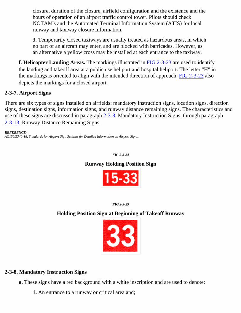
closure, duration of the closure, airfield configuration and the existence and thehours of operation of an airport traffic control tower. Pilots should checkNOTAM's and the Automated Terminal Information System (ATIS) for localrunway and taxiway closure information.
3. Temporarily closed taxiways are usually treated as hazardous areas, in whichno part of an aircraft may enter, and are blocked with barricades. However, asan alternative a yellow cross may be installed at each entrance to the taxiway.
f. Helicopter Landing Areas. The markings illustrated in FIG 2-3-23 are used to identifythe landing and takeoff area at a public use heliport and hospital heliport. The letter "H" inthe markings is oriented to align with the intended direction of approach. FIG 2-3-23 alsodepicts the markings for a closed airport.
2-3-7. Airport Signs
There are six types of signs installed on airfields: mandatory instruction signs, location signs, directionsigns, destination signs, information signs, and runway distance remaining signs. The characteristics anduse of these signs are discussed in paragraph 2-3-8, Mandatory Instruction Signs, through paragraph2-3-13, Runway Distance Remaining Signs.
REFERENCE-AC150/5340-18, Standards for Airport Sign Systems for Detailed Information on Airport Signs.
FIG 2-3-24
Runway Holding Position Sign
FIG 2-3-25
Holding Position Sign at Beginning of Takeoff Runway
2-3-8. Mandatory Instruction Signs
a. These signs have a red background with a white inscription and are used to denote:
1. An entrance to a runway or critical area and;

2. Areas where an aircraft is prohibited from entering.
b. Typical mandatory signs and applications are:
1. Runway Holding Position Sign. This sign is located at the holding positionon taxiways that intersect a runway or on runways that intersect other runways.The inscription on the sign contains the designation of the intersecting runwayas shown in FIG 2-3-24. The runway numbers on the sign are arranged tocorrespond to the respective runway threshold. For example, "15-33" indicatesthat the threshold for Runway 15 is to the left and the threshold for Runway 33is to the right.
(a) On taxiways that intersect the beginning of the takeoff runway,only the designation of the takeoff runway may appear on the signas shown in FIG 2-3-25, while all other signs will have thedesignation of both runway directions.
FIG 2-3-26
Holding Position Sign for a Taxiway that Intersectsthe Intersection of Two Runways
FIG 2-3-27
Holding Position Sign for a Runway Approach Area
(b) If the sign is located on a taxiway that intersects the intersectionof two runways, the designations for both runways will be shownon the sign along with arrows showing the approximate alignmentof each runway as shown in FIG 2-3-26. In addition to showing theapproximate runway alignment, the arrow indicates the direction tothe threshold of the runway whose designation is immediately nextto the arrow.
(c) A runway holding position sign on a taxiway will be installedadjacent to holding position markings on the taxiway pavement. Onrunways, holding position markings will be located only on therunway pavement adjacent to the sign, if the runway is normallyused by air traffic control for "Land, Hold Short" operations or as ataxiway. The holding position markings are described in paragraph2-3-5, Holding Position Markings.

2. Runway Approach Area Holding Position Sign. At some airports, it isnecessary to hold an aircraft on a taxiway located in the approach or departurearea for a runway so that the aircraft does not interfere with operations on thatrunway. In these situations, a sign with the designation of the approach end ofthe runway followed by a "dash" (-) and letters "APCH" will be located at theholding position on the taxiway. Holding position markings in accordance withparagraph 2-3-5, Holding Position Markings, will be located on the taxiwaypavement. An example of this sign is shown in FIG 2-3-27. In this example, thesign may protect the approach to Runway 15 and/or the departure for Runway33.
FIG 2-3-28
Holding Position Sign for ILS Critical Area
FIG 2-3-29
Sign Prohibiting Aircraft Entry into an Area
3. ILS Critical Area Holding Position Sign. At some airports, when theinstrument landing system is being used, it is necessary to hold an aircraft on ataxiway at a location other than the holding position described in paragraph2-3-5, Holding Position Markings. In these situations the holding position signfor these operations will have the inscription "ILS" and be located adjacent tothe holding position marking on the taxiway described in paragraph 2-3-5. Anexample of this sign is shown in FIG 2-3-28.
4. No Entry Sign. This sign, shown in FIG 2-3-29, prohibits an aircraft fromentering an area. Typically, this sign would be located on a taxiway intended tobe used in only one direction or at the intersection of vehicle roadways withrunways, taxiways or aprons where the roadway may be mistaken as a taxiwayor other aircraft movement surface.

NOTE-The holding position sign provides the pilot with a visual cue as to the locationof the holding position marking. The operational significance of holdingposition markings are described in the notes for paragraph 2-3-5, HoldingPosition Markings.
FIG 2-3-30
Taxiway Location Sign
FIG 2-3-31
Taxiway Location Sign Collocated withRunway Holding Position Sign
2-3-9. Location Signs
a. Location signs are used to identify either a taxiway or runway on which the aircraft islocated. Other location signs provide a visual cue to pilots to assist them in determiningwhen they have exited an area. The various location signs are described below.
1. Taxiway Location Sign. This sign has a black background with a yellowinscription and yellow border as shown in FIG 2-3-30. The inscription is thedesignation of the taxiway on which the aircraft is located. These signs areinstalled along taxiways either by themselves or in conjunction with directionsigns or runway holding position signs.(See FIG 2-3-35 and FIG 2-3-31.)
FIG 2-3-32
Runway Location Sign

FIG 2-3-33
Runway Boundary Sign
|
2. Runway Location Sign. This sign has a black background with a yellowinscription and yellow border as shown in FIG 2-3-32. The inscription is thedesignation of the runway on which the aircraft is located. These signs areintended to complement the information available to pilots through theirmagnetic compass and typically are installed where the proximity of two ormore runways to one another could cause pilots to be confused as to whichrunway they are on.
3. Runway Boundary Sign. This sign has a yellow background with a blackinscription with a graphic depicting the pavement holding position marking asshown in FIG 2-3-33. This sign, which faces the runway and is visible to thepilot exiting the runway, is located adjacent to the holding position marking onthe pavement. The sign is intended to provide pilots with another visual cuewhich they can use as a guide in deciding when they are "clear of the runway."
FIG 2-3-34
ILS Critical Area Boundary Sign
4. ILS Critical Area Boundary Sign. This sign has a yellow background witha black inscription with a graphic depicting the ILS pavement holding positionmarking as shown in FIG 2-3-34. This sign is located adjacent to the ILSholding position marking on the pavement and can be seen by pilots leaving thecritical area. The sign is intended to provide pilots with another visual cuewhich they can use as a guide in deciding when they are "clear of the ILScritical area."
2-3-10. Direction Signs
a. Direction signs have a yellow background with a black inscription. The inscriptionidentifies the designation(s) of the intersecting taxiway(s) leading out of the intersection thata pilot would normally be expected to turn onto or hold short of. Each designation is

accompanied by an arrow indicating the direction of the turn.
b. Except as noted in subparagraph e, each taxiway designation shown on the sign isaccompanied by only one arrow. When more than one taxiway designation is shown on thesign each designation and its associated arrow is separated from the other taxiwaydesignations by either a vertical message divider or a taxiway location sign as shown in FIG2-3-35.
c. Direction signs are normally located on the left prior to the intersection. When used on arunway to indicate an exit, the sign is located on the same side of the runway as the exit. FIG2-3-36 shows a direction sign used to indicate a runway exit.
d. The taxiway designations and their associated arrows on the sign are arranged clockwisestarting from the first taxiway on the pilot's left.(See FIG 2-3-35.)
e. If a location sign is located with the direction signs, it is placed so that the designations forall turns to the left will be to the left of the location sign; the designations for continuingstraight ahead or for all turns to the right would be located to the right of the location sign.(See FIG 2-3-35.)
f. When the intersection is comprised of only one crossing taxiway, it is permissible to havetwo arrows associated with the crossing taxiway as shown in FIG 2-3-37. In this case, thelocation sign is located to the left of the direction sign.
FIG 2-3-35
Direction Sign Array with Location Signon Far Side of Intersection
FIG 2-3-36
Direction Sign for Runway Exit
FIG 2-3-37

Direction Sign Array for Simple Intersection
FIG 2-3-38
Destination Sign for Military Area
FIG 2-3-39
Destination Sign for Common Taxiing Routeto Two Runways
2-3-11. Destination Signs
a. Destination signs also have a yellow background with a black inscription indicating adestination on the airport. These signs always have an arrow showing the direction of thetaxiing route to that destination. FIG 2-3-38 is an example of a typical destination sign.When the arrow on the destination sign indicates a turn, the sign is located prior to theintersection.
b. Destinations commonly shown on these types of signs include runways, aprons, terminals,military areas, civil aviation areas, cargo areas, international areas, and fixed base operators.An abbreviation may be used as the inscription on the sign for some of these destinations.
c. When the inscription for two or more destinations having a common taxiing route areplaced on a sign, the destinations are separated by a "dot" (·) and one arrow would be used asshown in FIG 2-3-39. When the inscription on a sign contains two or more destinationshaving different taxiing routes, each destination will be accompanied by an arrow and will beseparated from the other destinations on the sign with a vertical black message divider asshown in FIG 2-3-40.
FIG 2-3-40
Destination Sign for Different Taxiing Routes

to Two Runways
2-3-12. Information Signs
Information signs have a yellow background with a black inscription. They are used to provide the pilotwith information on such things as areas that cannot be seen from the control tower, applicable radiofrequencies, and noise abatement procedures. The airport operator determines the need, size, and locationfor these signs.
2-3-13. Runway Distance Remaining Signs
Runway distance remaining signs have a black background with a white numeral inscription and may beinstalled along one or both side(s) of the runway. The number on the signs indicates the distance (inthousands of feet) of landing runway remaining. The last sign, i.e., the sign with the numeral "1," will belocated at least 950 feet from the runway end. FIG 2-3-41 shows an example of a runway distanceremaining sign.
FIG 2-3-41
Runway Distance Remaining Sign Indicating3,000 feet of Runway Remaining
2-3-14. Aircraft Arresting Devices
a. Certain airports are equipped with a means of rapidly stopping military aircraft on arunway. This equipment, normally referred to as EMERGENCY ARRESTING GEAR,generally consists of pendant cables supported over the runway surface by rubber "donuts."Although most devices are located in the overrun areas, a few of these arresting systems havecables stretched over the operational areas near the ends of a runway.
b. Arresting cables which cross over a runway require special markings on the runway toidentify the cable location. These markings consist of 10 feet diameter solid circles painted"identification yellow," 30 feet on center, perpendicular to the runway centerline across theentire runway width. Additional details are contained in AC 150/5220-9, Aircraft ArrestingSystems for Joint Civil/Military Airports.
NOTE-

Aircraft operations on the runway are not restricted by the installation of aircraft arrestingdevices.
Back to AIMHome Page
Go back to Chapter 2Section 2
Go to Chapter 3Table of Contents
Back toTop of this Page

Chapter 3. Airspace
Section 1. General
3-1-1. General 3-1-3. Hierarchy of OverlappingAirspace Designations
3-1-2. General Dimensions of AirspaceSegments
3-1-4. Basic VFR Weather Minimums
3-1-5. VFR Cruising Altitudes andFlight Levels
Section 2. Controlled Airspace
3-2-1. General 3-2-4. Class C Airspace3-2-2. Class A Airspace 3-2-5. Class D Airspace3-2-3. Class B Airspace 3-2-6. Class E Airspace
Section 3. Class G Airspace
3-3-1. General3-3-2. VFR Requirements3-3-3. IFR Requirements
Section 4. Special Use Airspace
3-4-1. General 3-4-5. Military Operations Areas3-4-2. Prohibited Areas 3-4-6. Alert Areas
3-4-3. Restricted Areas 3-4-7. Controlled Firing Areas
3-4-4. Warning Areas
Section 5. Other Airspace Areas
3-5-1. Airport Advisory/InformationServices
3-5-5. Published VFR Routes
3-5-2. Military Training Routes 3-5-6. Terminal Radar Service Area(TRSA)
3-5-3. Temporary Flight Restrictions 3-5-7. National Security Areas
3-5-4. Parachute Jump AircraftOperations

Back to AIMHome Page
Back to Chapter 2Table of Contents
Go to Chapter 4Table of Contents
Back toTop of this Page

Chapter 3. Airspace
Section 1. General
3-1-1. General
a. There are two categories of airspace or airspace areas:
1. Regulatory (Class A, B, C, D and E airspace areas, restricted and prohibitedareas); and
2. Nonregulatory (military operations areas (MOA's), warning areas, alert areas,and controlled firing areas).
NOTE-Additional information on special use airspace (prohibited areas, restrictedareas, warning areas, MOA's, alert areas and controlled firing areas) may befound in Chapter 3, Airspace, Section 4, Special Use Airspace, paragraphs3-4-1 through 3-4-7.
b. Within these two categories, there are four types:
1. Controlled;
2. Uncontrolled;
3. Special use; and
4. Other airspace.
c. The categories and types of airspace are dictated by:
1. The complexity or density of aircraft movements;
2. The nature of the operations conducted within the airspace;
3. The level of safety required; and
4. The national and public interest.
d. It is important that pilots be familiar with the operational requirements for each of thevarious types or classes of airspace. Subsequent sections will cover each class in sufficientdetail to facilitate understanding.
3-1-2. General Dimensions of Airspace Segments
Refer to Code of Federal Regulations (CFR's) for specific dimensions, exceptions, geographical areascovered, exclusions, specific transponder or equipment requirements, and flight operations.
3-1-3. Hierarchy of Overlapping Airspace Designations

a. When overlapping airspace designations apply to the same airspace, the operating rulesassociated with the more restrictive airspace designation apply.
b. For the purpose of clarification:
1. Class A airspace is more restrictive than Class B, Class C, Class D, Class E,or Class G airspace;
2. Class B airspace is more restrictive than Class C, Class D, Class E, or Class Gairspace;
3. Class C airspace is more restrictive than Class D, Class E, or Class Gairspace;
4. Class D airspace is more restrictive than Class E or Class G airspace; and
5. Class E is more restrictive than Class G airspace.
3-1-4. Basic VFR Weather Minimums
a. No person may operate an aircraft under basic VFR when the flight visibility is less, or ata distance from clouds that is less, than that prescribed for the corresponding altitude andclass of airspace.(See TBL 3-1-1.)
NOTE-Student pilots must comply with 14 CFR Section 61.89(a) (6) and (7).
b. Except as provided in 14 CFR Section 91.157, Special VFR Weather Minimums, noperson may operate an aircraft beneath the ceiling under VFR within the lateral boundariesof controlled airspace designated to the surface for an airport when the ceiling is less than1,000 feet. (See 14 CFR Section 91.155(c).)
TBL 3-1-1
Basic VFR Weather MinimumsAirspace Flight Visibility Distance from Clouds
Class A Not Applicable Not Applicable
Class B 3 statute miles Clear of Clouds
Class C 3 statute miles 500 feet below1,000 feet above2,000 feet horizontal
Class D 3 statute miles 500 feet below1,000 feet above2,000 feet horizontal
Class ELess than 10,000 feet MSL
3 statute miles 500 feet below1,000 feet above2,000 feet horizontal
At or above 10,000 feet MSL 5 statute miles 1,000 feet below1,000 feet above1 statute mile horizontal

Class G1,200 feet or less above the surface (regardless ofMSL altitude).
Day, except as provided in section 91.155(b) 1 statute mile Clear of clouds
Night, except as provided in section 91.155(b) 3 statute miles 500 feet below1,000 feet above2,000 feet horizontal
More than 1,200 feet above the surface but less than10,000 feet MSL.
Day 1 statute mile 500 feet below1,000 feet above2,000 feet horizontal
Night 3 statute miles 500 feet below1,000 feet above2,000 feet horizontal
More than 1,200 feet above the surface and at orabove 10,000 feet MSL.
5 statute miles 1,000 feet below1,000 feet above1 statute mile horizontal
3-1-5. VFR Cruising Altitudes and Flight Levels
(See TBL 3-1-2.)
TBL 3-1-2
VFR Cruising Altitudes and Flight Levels
If your magneticcourse
(ground track) is:
And you are more than 3,000 feet above thesurface but below 18,000 feet MSL, fly:
And you are above 18,000 feet MSL to FL290, fly:
0° to 179° Odd thousands MSL, plus 500 feet(3,500; 5,500; 7,500, etc.)
Odd Flight Levels plus 500 feet(FL 195; FL 215; FL 235, etc.)
180° to 359° Even thousands MSL, plus 500 feet(4,500; 6,500; 8,500, etc.)
Even Flight Levels plus 500 feet(FL 185; FL 205; FL 225, etc.)
Back to AIMHome Page
Go back toChapter 2 Section 3
Go to Chapter 3Section 2
Back toTop of this Page

Section 3. Class G Airspace
3-3-1. General
Class G airspace (uncontrolled) is that portion of the airspace that has not been designated as Class A,Class B, Class C, Class D, or Class E airspace.
3-3-2. VFR Requirements
Rules governing VFR flight have been adopted to assist the pilot in meeting the responsibility to see andavoid other aircraft. Minimum flight visibility and distance from clouds required for VFR flight arecontained in 14 CFR Section 91.155. (See TBL 3-3-1.)
3-3-3. IFR Requirements
a. The CFR's specify the pilot and aircraft equipment requirements for IFR flight. Pilots arereminded that in addition to altitude or flight level requirements, 14 CFR Section 91.177includes a requirement to remain at least 1,000 feet (2,000 feet in designated mountainousterrain) above the highest obstacle within a horizontal distance of 4 nautical miles from thecourse to be flown.
b. IFR Altitudes and Flight Levels. (See TBL 3-3-1.)
TBL 3-3-1
IFR Altitudes and Flight LevelsClass G Airspace
If your magnetic course(ground track) is:
And you are below18,000 feet MSL, fly:
And you are at orabove 18,000 feet
MSL but below FL290, fly:
And you are at or above FL290, fly 4,000 foot intervals:
0°to 179° Odd thousands MSL, (3,000;5,000; 7,000, etc.)
Odd Flight Levels(FL 190; 210; 230,etc.)
Beginning at FL 290;(FL 290; 330; 370, etc.)
180° to 359° Even thousands MSL,(2,000; 4,000; 6,000, etc.)
Even Flight Levels(FL 180; 200; 220,etc.)
Beginning at FL 310;(FL 310; 350; 390, etc.)
Back to AIMHome Page
Go back to Chapter 3Section 2
Go to Chapter 3Section 4
Back toTop of this Page

Section 4. Special Use Airspace
3-4-1. General
a. Special use airspace consists of that airspace wherein activities must be confined becauseof their nature, or wherein limitations are imposed upon aircraft operations that are not a partof those activities, or both. Except for controlled firing areas, special use airspace areas aredepicted on aeronautical charts.
b. Prohibited and restricted areas are regulatory special use airspace and are established in 14CFR Part 73 through the rulemaking process.
c. Warning areas, military operations areas (MOA's), alert areas, and controlled firing areas(CFA's) are nonregulatory special use airspace.
d. Special use airspace descriptions (except CFA's) are contained in FAA Order 7400.8,Special Use Airspace.
e. Special use airspace (except CFA's) are charted on IFR or visual charts and include thehours of operation, altitudes, and the controlling agency.
3-4-2. Prohibited Areas
Prohibited areas contain airspace of defined dimensions identified by an area on the surface of the earthwithin which the flight of aircraft is prohibited. Such areas are established for security or other reasonsassociated with the national welfare. These areas are published in the Federal Register and are depicted onaeronautical charts.
3-4-3. Restricted Areas
a. Restricted areas contain airspace identified by an area on the surface of the earth withinwhich the flight of aircraft, while not wholly prohibited, is subject to restrictions. Activitieswithin these areas must be confined because of their nature or limitations imposed uponaircraft operations that are not a part of those activities or both. Restricted areas denote theexistence of unusual, often invisible, hazards to aircraft such as artillery firing, aerialgunnery, or guided missiles. Penetration of restricted areas without authorization from theusing or controlling agency may be extremely hazardous to the aircraft and its occupants.Restricted areas are published in the Federal Register and constitute 14 CFR Part 73.
b. ATC facilities apply the following procedures when aircraft are operating on an IFRclearance (including those cleared by ATC to maintain VFR-on-top) via a route which lieswithin joint-use restricted airspace.
1. If the restricted area is not active and has been released to the controllingagency (FAA), the ATC facility will allow the aircraft to operate in therestricted airspace without issuing specific clearance for it to do so.
2. If the restricted area is active and has not been released to the controllingagency (FAA), the ATC facility will issue a clearance which will ensure the

aircraft avoids the restricted airspace unless it is on an approved altitudereservation mission or has obtained its own permission to operate in the airspaceand so informs the controlling facility.
NOTE-The above apply only to joint-use restricted airspace and not to prohibited andnonjoint-use airspace. For the latter categories, the ATC facility will issue aclearance so the aircraft will avoid the restricted airspace unless it is on anapproved altitude reservation mission or has obtained its own permission tooperate in the airspace and so informs the controlling facility.
c. Restricted airspace is depicted on the en route chart appropriate for use at the altitude orflight level being flown. For joint-use restricted areas, the name of the controlling agency isshown on these charts. For all prohibited areas and nonjoint-use restricted areas, unlessotherwise requested by the using agency, the phrase "NO A/G" is shown.
3-4-4. Warning Areas
A warning area is airspace of defined dimensions, extending from three nautical miles outward from thecoast of the U.S., that contains activity that may be hazardous to nonparticipating aircraft. The purpose ofsuch warning areas is to warn nonparticipating pilots of the potential danger. A warning area may belocated over domestic or international waters or both.
3-4-5. Military Operations Areas
a. MOA's consist of airspace of defined vertical and lateral limits established for the purposeof separating certain military training activities from IFR traffic. Whenever a MOA is beingused, nonparticipating IFR traffic may be cleared through a MOA if IFR separation can beprovided by ATC. Otherwise, ATC will reroute or restrict nonparticipating IFR traffic.
b. Examples of activities conducted in MOA's include, but are not limited to: air combattactics, air intercepts, aerobatics, formation training, and low-altitude tactics. Military pilotsflying in an active MOA are exempted from the provisions of 14 CFR Section 91.303(c) and(d) which prohibits aerobatic flight within Class D and Class E surface areas, and withinFederal airways. Additionally, the Department of Defense has been issued an authorizationto operate aircraft at indicated airspeeds in excess of 250 knots below 10,000 feet MSLwithin active MOA's.
c. Pilots operating under VFR should exercise extreme caution while flying within a MOAwhen military activity is being conducted. The activity status (active/inactive) of MOA's maychange frequently. Therefore, pilots should contact any FSS within 100 miles of the area toobtain accurate real-time information concerning the MOA hours of operation. Prior toentering an active MOA, pilots should contact the controlling agency for traffic advisories.
d. MOA's are depicted on sectional, VFR Terminal Area, and Enroute Low Altitude charts.
3-4-6. Alert Areas
Alert areas are depicted on aeronautical charts to inform nonparticipating pilots of areas that may containa high volume of pilot training or an unusual type of aerial activity. Pilots should be particularly alert

when flying in these areas. All activity within an alert area shall be conducted in accordance with CFR's,without waiver, and pilots of participating aircraft as well as pilots transiting the area shall be equallyresponsible for collision avoidance.
3-4-7. Controlled Firing Areas
CFA's contain activities which, if not conducted in a controlled environment, could be hazardous tononparticipating aircraft. The distinguishing feature of the CFA, as compared to other special useairspace, is that its activities are suspended immediately when spotter aircraft, radar, or ground lookoutpositions indicate an aircraft might be approaching the area. There is no need to chart CFA's since they donot cause a nonparticipating aircraft to change its flight path.
Back to AIMHome Page
Go back to Chapter 3Section 3
Go to Chapter 3
Section 5 Back to
Top of this Page

Section 5. Other Airspace Areas
3-5-1. Airport Advisory/Information Services
a. There are three advisory type services available at selected airports.
1. Local Airport Advisory (LAA) service is operated within 10 statute miles ofan airport where a control tower is not operating but where a FSS is located onthe airport. At such locations, the FSS provides a complete local airportadvisory service to arriving and departing aircraft. During periods of fastchanging weather the FSS will automatically provide Final Guard as part of theservice from the time the aircraft reports "on-final" or"taking-the-active-runway" until the aircraft reports "on-the-ground" or"airborne."
NOTE-Current policy, when requesting remote ATC services, requires that a pilotmonitor the automated weather broadcast at the landing airport prior torequesting ATC services. The FSS automatically provides Final Guard, whenappropriate, during LAA/Remote Airport Advisory (RAA) operations. FinalGuard is a value added wind/altimeter monitoring service, which provides anautomatic wind and altimeter check during active weather situations when thepilot reports on-final or taking the active runway. During the landing or take-offoperation when the winds or altimeter are actively changing the FSS will blindbroadcast significant changes when the specialist believes the change mightaffect the operation. Pilots should acknowledge the first wind/altimeter checkbut due to cockpit activity no acknowledgement is expected for the blindbroadcasts. It is prudent for a pilot to report on-the-ground or airborne to endthe service.
2. RAA service is operated within 10 statute miles of specified high activity GAairports where a control tower is not operating. Airports offering this service arelisted in the A/FD and the published service hours may be changed by NOTAMD. Final Guard is automatically provided with RAA.
3. Remote Airport Information Service (RAIS) is provided in support of shortterm special events like small to medium fly-in's. The service is advertised byNOTAM D only. The FSS will not have access to a continuous readout of thecurrent winds and altimeter; therefore, RAIS does not include weather and/orFinal Guard service. However, known traffic, special event instructions, and allother services are provided.
NOTE-The airport authority and/or manager should request RAIS support on officialletterhead directly with the manager of the FSS that will provide the service atleast 60 days in advance. Approval authority rests with the FSS manager and is

based on workload and resource availability.
REFERENCE-AIM, Traffic Advisory Practices at Airports Without Operating Control Towers, Paragraph 4-1-9.
b. It is not mandatory that pilots participate in the Airport Advisory programs. Participationenhances safety for everyone operating around busy GA airports; therefore, everyone isencouraged to participate and provide feedback that will help improve the program.
3-5-2. Military Training Routes
a. National security depends largely on the deterrent effect of our airborne military forces.To be proficient, the military services must train in a wide range of airborne tactics. Onephase of this training involves "low level" combat tactics. The required maneuvers and highspeeds are such that they may occasionally make the see-and-avoid aspect of VFR flightmore difficult without increased vigilance in areas containing such operations. In an effort toensure the greatest practical level of safety for all flight operations, the Military TrainingRoute (MTR) program was conceived.
b. The MTR program is a joint venture by the FAA and the Department of Defense (DOD).MTR's are mutually developed for use by the military for the purpose of conductinglow-altitude, high-speed training. The routes above 1,500 feet AGL are developed to beflown, to the maximum extent possible, under IFR. The routes at 1,500 feet AGL and beloware generally developed to be flown under VFR.
c. Generally, MTR's are established below 10,000 feet MSL for operations at speeds inexcess of 250 knots. However, route segments may be defined at higher altitudes forpurposes of route continuity. For example, route segments may be defined for descent,climbout, and mountainous terrain. There are IFR and VFR routes as follows:
1. IFR Military Training Routes-(IR). Operations on these routes areconducted in accordance with IFR regardless of weather conditions.
2. VFR Military Training Routes-(VR). Operations on these routes areconducted in accordance with VFR except flight visibility shall be 5 miles ormore; and flights shall not be conducted below a ceiling of less than 3,000 feetAGL.
d. Military training routes will be identified and charted as follows:
1. Route identification.
(a) MTR's with no segment above 1,500 feet AGL shall beidentified by four number characters; e.g., IR1206, VR1207.
(b) MTR's that include one or more segments above 1,500 feetAGL shall be identified by three number characters; e.g., IR206,VR207.
(c) Alternate IR/VR routes or route segments are identified byusing the basic/principal route designation followed by a lettersuffix, e.g., IR008A, VR1007B, etc.

2. Route charting.
(a) IFR Low Altitude En Route Chart. This chart will depict allIR routes and all VR routes that accommodate operations above1,500 feet AGL.
(b) VFR Sectional Charts. These charts will depict militarytraining activities such as IR, VR, MOA, Restricted Area, WarningArea, and Alert Area information.
(c) Area Planning (AP/1B) Chart (DOD Flight InformationPublication-FLIP). This chart is published by the DOD primarilyfor military users and contains detailed information on both IR andVR routes.
REFERENCE-AIM, National Imagery and Mapping Agency (NIMA), Paragraph 9-1-5, Subparagraph a.
e. The FLIP contains charts and narrative descriptions of these routes. This publication isavailable to the general public by single copy or annual subscription from:
NACO Distribution Division, AVN-530Federal Aviation Administration6501 Lafayette AvenueRiverdale, MD 20737-1199Toll free phone: 1-800-638-8972Commercial: 301-436-8301
This DOD FLIP is available for pilot briefings at FSS and many airports.
f. Nonparticipating aircraft are not prohibited from flying within an MTR; however, extremevigilance should be exercised when conducting flight through or near these routes. Pilotsshould contact FSS's within 100 NM of a particular MTR to obtain current information orroute usage in their vicinity. Information available includes times of scheduled activity,altitudes in use on each route segment, and actual route width. Route width varies for eachMTR and can extend several miles on either side of the charted MTR centerline. Route widthinformation for IR and VR MTR's is also available in the FLIP AP/1B along with additionalMTR (slow routes/air refueling routes) information. When requesting MTR information,pilots should give the FSS their position, route of flight, and destination in order to reducefrequency congestion and permit the FSS specialist to identify the MTR which could be afactor.
3-5-3. Temporary Flight Restrictions
a. General. This paragraph describes the types of conditions under which the FAA mayimpose temporary flight restrictions. It also explains which FAA elements have beendelegated authority to issue a temporary flight restrictions NOTAM and lists the types ofresponsible agencies/offices from which the FAA will accept requests to establish temporaryflight restrictions. The 14 CFR is explicit as to what operations are prohibited, restricted, orallowed in a temporary flight restrictions area. Pilots are responsible to comply with 14 CFR

Sections 91.137, 91.138, 91.141 and 91.143 when conducting flight in an area where atemporary flight restrictions area is in effect, and should check appropriate NOTAM's duringflight planning.
b. The purpose for establishing a temporary flight restrictions area is to:
1. Protect persons and property in the air or on the surface from an existing orimminent hazard associated with an incident on the surface when the presenceof low flying aircraft would magnify, alter, spread, or compound that hazard (14CFR Section 91.137(a)(1));
2. Provide a safe environment for the operation of disaster relief aircraft (14CFR Section 91.137(a)(2)); or
3. Prevent an unsafe congestion of sightseeing aircraft above an incident orevent which may generate a high degree of public interest (14 CFR Section91.137(a)(3)).
4. Protect declared national disasters for humanitarian reasons in the State ofHawaii (14 CFR Section 91.138).
5. Protect the President, Vice President, or other public figures (14 CFR Section91.141).
6. Provide a safe environment for space agency operations (14 CFR Section91.143).
c. Except for hijacking situations, when the provisions of 14 CFR Section 91.137(a)(1) or(a)(2) are necessary, a temporary flight restrictions area will only be established by orthrough the area manager at the Air Route Traffic Control Center (ARTCC) havingjurisdiction over the area concerned. A temporary flight restrictions NOTAM involving theconditions of 14 CFR Section 91.137(a)(3) will be issued at the direction of the regional airtraffic division manager having oversight of the airspace concerned. When hijackingsituations are involved, a temporary flight restrictions area will be implemented through theFAA Washington Headquarters Office of Civil Aviation Security. The appropriate FAA airtraffic element, upon receipt of such a request, will establish a temporary flight restrictionsarea under 14 CFR Section 91.137(a)(1).
d. The FAA accepts recommendations for the establishment of a temporary flight restrictionsarea under 14 CFR Section 91.137(a)(1) from military major command headquarters,regional directors of the Office of Emergency Planning, Civil Defense State Directors, StateGovernors, or other similar authority. For the situations involving 14 CFR Section91.137(a)(2), the FAA accepts recommendations from military commanders serving asregional, subregional, or Search and Rescue (SAR) coordinators; by military commandersdirecting or coordinating air operations associated with disaster relief; or by civil authoritiesdirecting or coordinating organized relief air operations (includes representatives of theOffice of Emergency Planning, U.S. Forest Service, and State aeronautical agencies).Appropriate authorities for a temporary flight restrictions establishment under 14 CFRSection 91.137(a)(3) are any of those listed above or by State, county, or city governmententities.

e. The type of restrictions issued will be kept to a minimum by the FAA consistent withachievement of the necessary objective. Situations which warrant the extreme restrictions of14 CFR Section 91.137(a)(1) include, but are not limited to: toxic gas leaks or spills,flammable agents, or fumes which if fanned by rotor or propeller wash could endangerpersons or property on the surface, or if entered by an aircraft could endanger persons orproperty in the air; imminent volcano eruptions which could endanger airborne aircraft andoccupants; nuclear accident or incident; and hijackings. Situations which warrant therestrictions associated with 14 CFR Section 91.137(a)(2) include: forest fires which are beingfought by releasing fire retardants from aircraft; and aircraft relief activities following adisaster (earthquake, tidal wave, flood, etc.). 14 CFR Section 91.137(a)(3) restrictions areestablished for events and incidents that would attract an unsafe congestion of sightseeingaircraft.
f. The amount of airspace needed to protect persons and property or provide a safeenvironment for rescue/relief aircraft operations is normally limited to within 2,000 feetabove the surface and within a 3-nautical-mile radius. Incidents occurring within Class B,Class C, or Class D airspace will normally be handled through existing procedures andshould not require the issuance of a temporary flight restrictions NOTAM. Temporary flightrestrictions affecting airspace outside of the U.S. and its territories and possessions are issuedwith verbiage excluding that airspace outside of the 12-mile coastal limits.
g. The FSS nearest the incident site is normally the "coordination facility." When FAAcommunications assistance is required, the designated FSS will function as the primarycommunications facility for coordination between emergency control authorities and affectedaircraft. The ARTCC may act as liaison for the emergency control authorities if adequatecommunications cannot be established between the designated FSS and the relieforganization. For example, the coordination facility may relay authorizations from theon-scene emergency response official in cases where news media aircraft operations areapproved at the altitudes used by relief aircraft.
h. ATC may authorize operations in a temporary flight restrictions area under its ownauthority only when flight restrictions are established under 14 CFR Section 91.137(a)(2)and (a)(3). The appropriate ARTCC/airport traffic control tower manager will, however,ensure that such authorized flights do not hamper activities or interfere with the event forwhich restrictions were implemented. However, ATC will not authorize local IFR flights intothe temporary flight restrictions area.
i. To preclude misunderstanding, the implementing NOTAM will contain specific andformatted information. The facility establishing a temporary flight restrictions area willformat a NOTAM beginning with the phrase "FLIGHT RESTRICTIONS" followed by: thelocation of the temporary flight restrictions area; the effective period; the area defined instatute miles; the altitudes affected; the FAA coordination facility and commercial telephonenumber; the reason for the temporary flight restrictions; the agency directing any reliefactivities and its commercial telephone number; and other information consideredappropriate by the issuing authority.
EXAMPLE-

1. 14 CFR Section 91.137(a)(1):The following NOTAM prohibits all aircraft operations except those specified in theNOTAM.Flight restrictions Matthews, Virginia, effective immediately until 9610211200. Pursuant to14 CFR Section 91.137(a)(1) temporary flight restrictions are in effect. Rescue operations inprogress. Only relief aircraft operations under the direction of the Department of Defenseare authorized in the airspace at and below 5,000 feet MSL within a 2-nautical-mile radiusof Laser AFB, Matthews, Virginia. Commander, Laser AFB, in charge (897) 946-5543(122.4). Steenson FSS (792) 555-6141 (123.1) is the FAA coordination facility.
2. 14 CFR Section 91.137(a)(2):The following NOTAM permits flight operations in accordance with 14 CFR Section91.137(a)(2). The on-site emergency response official to authorize media aircraft operationsbelow the altitudes used by the relief aircraft.Flight restrictions 25 miles east of Bransome, Idaho, effective immediately until 9601202359UTC. Pursuant to 14 CFR Section 91.137(a)(2) temporary flight restrictions are in effectwithin a 4-nautical-mile radius of the intersection of county roads 564 and 315 at and below3,500 feet MSL to provide a safe environment for fire fighting aircraft operations. DavisCounty sheriff's department (792) 555-8122 (122.9) is in charge of on-scene emergencyresponse activities. Glivings FSS (792) 555-1618 (122.2) is the FAA coordination facility.
3. 14 CFR Section 91.137(a)(3):The following NOTAM prohibits sightseeing aircraft operations.Flight restrictions Brown, Tennessee, due to olympic activity. Effective 9606181100 UTCuntil 9607190200 UTC. Pursuant to 14 CFR Section 91.137(a)(3) temporary flightrestrictions are in effect within a 3-nautical-mile radius of N355783/W835242 and VolunteerVORTAC 019 degree radial 3.7 DME fix at and below 2,500 feet MSL. Norton FSS (423)555-6742 (126.6) is the FAA coordination facility.
4. 14 CFR Section 91.138:The following NOTAM prohibits all aircraft except those operating under the authorizationof the official in charge of associated emergency or disaster relief response activities,aircraft carrying law enforcement officials, aircraft carrying personnel involved in anemergency or legitimate scientific purposes, carrying properly accredited news media, andaircraft operating in accordance with an ATC clearance or instruction.Flight restrictions Kapalua, Hawaii, effective 9605101200 UTC until 9605151500 UTC.Pursuant to 14 CFR Section 91.138 temporary flight restrictions are in effect within a3-nautical-mile radius of N205778/W1564038 and Maui/OGG/VORTAC 275 degree radialat 14.1 nautical miles. John Doe 808-757-4469 or 122.4 is in charge of the operation.Honolulu/HNL 808-757-4470 (123.6) AFSS is the FAA coordination facility.
5. 14 CFR Section 91.141:The following NOTAM prohibits all aircraft.Flight restrictions Stillwater, Oklahoma, June 21, 1996. Pursuant to 14 CFR Section 91.141aircraft flight operations are prohibited within a 3-nautical-mile radius, below 2000 feetAGL of N360962/W970515 and the Stillwater/SWO/VOR/DME 176 degree radial 3.8-

nautical-mile fix from 1400 local time to 1700 local time June 21, 1996, unless otherwiseauthorized by ATC.
6. 14 CFR Section 91.143:The following NOTAM prohibits any aircraft of U.S. registry, or pilot any aircraft under theauthority of an airman certificate issued by the FAA.Kennedy space center space operations area effective immediately until 9610152100 UTC.Pursuant to 14 CFR Section 91.143, flight operations conducted by FAA certificated pilotsor conducted in aircraft of U.S. registry are prohibited at any altitude from surface tounlimited, within the following area 30-nautical-mile radius of theMelbourne/MLB/VORTAC 010 degree radial 21-nautical-mile fix. St. Petersburg,Florida/PIE/AFSS 813-545-1645 (122.2) is the FAA coordination facility and should becontacted for the current status of any airspace associated with the space shuttle operations.This airspace encompasses R2933, R2932, R2931, R2934, R2935, W497A and W158A.Additional warning and restricted areas will be active in conjunction with the operations.Pilots shall consult all NOTAM's regarding this operation.
3-5-4. Parachute Jump Aircraft Operations
a. Procedures relating to parachute jump areas are contained in 14 CFR Part 105. Tabulationsof parachute jump areas in the U.S. are contained in the A/FD.
b. Pilots of aircraft engaged in parachute jump operations are reminded that all reportedaltitudes must be with reference to mean sea level, or flight level, as appropriate, to enableATC to provide meaningful traffic information.
c. Parachute operations in the vicinity of an airport without an operating control tower - thereis no substitute for alertness while in the vicinity of an airport. It is essential that pilotsconducting parachute operations be alert, look for other traffic, and exchange trafficinformation as recommended in paragraph 4-1-9, Traffic Advisory Practices at AirportsWithout Operating Control Towers. In addition, pilots should avoid releasing parachuteswhile in an airport traffic pattern when there are other aircraft in that pattern. Pilots shouldmake appropriate broadcasts on the designated Common Traffic Advisory Frequency(CTAF), and monitor that CTAF until all parachute activity has terminated or the aircraft hasleft the area. Prior to commencing a jump operation, the pilot should broadcast the aircraft'saltitude and position in relation to the airport, the approximate relative time when the jumpwill commence and terminate, and listen to the position reports of other aircraft in the area.
3-5-5. Published VFR Routes
Published VFR routes for transitioning around, under and through complex airspace such as Class Bairspace were developed through a number of FAA and industry initiatives. All of the following terms,i.e., "VFR Flyway" "VFR Corridor" and "Class B Airspace VFR Transition Route" have been used whenreferring to the same or different types of routes or airspace. The following paragraphs identify andclarify the functionality of each type of route, and specify where and when an ATC clearance is required.
a. VFR Flyways:
1. VFR Flyways and their associated Flyway Planning Charts were developed

from the recommendations of a National Airspace Review Task Group. A VFRFlyway is defined as a general flight path not defined as a specific course, foruse by pilots in planning flights into, out of, through or near complex terminalairspace to avoid Class B airspace. An ATC clearance is NOT required to flythese routes.
FIG 3-5-1
VFR Flyway Planning Chart
2. VFR Flyways are depicted on the reverse side of some of the VFR TerminalArea Charts (TAC), commonly referred to as Class B airspace charts. (See FIG3-5-1.) Eventually all TAC's will include a VFR Flyway Planning Chart. Thesecharts identify VFR flyways designed to help VFR pilots avoid major controlledtraffic flows. They may further depict multiple VFR routings throughout thearea which may be used as an alternative to flight within Class B airspace. Theground references provide a guide for improved visual navigation. These routesare not intended to discourage requests for VFR operations within Class Bairspace but are designed solely to assist pilots in planning for flights under andaround busy Class B airspace without actually entering Class B airspace.
3. It is very important to remember that these suggested routes are not sterile ofother traffic. The entire Class B airspace, and the airspace underneath it, may beheavily congested with many different types of aircraft. Pilot adherence to VFRrules must be exercised at all times. Further, when operating beneath Class Bairspace, communications must be established and maintained between youraircraft and any control tower while transiting the Class B, Class C, and Class Dsurface areas of those airports under Class B Airspace.
b. VFR Corridors.
1. The design of a few of the first Class B airspace areas provided a corridor forthe passage of uncontrolled traffic. A VFR corridor is defined as airspacethrough Class B airspace, with defined vertical and lateral boundaries, in whichaircraft may operate without an ATC clearance or communication with airtraffic control.
2. These corridors are, in effect, a "hole" through Class B airspace. (See FIG3-5-2.) A classic example would be the corridor through the Los Angeles ClassB airspace, which has been subsequently changed to Special Flight Rulesairspace (SFR). A corridor is surrounded on all sides by Class B airspace anddoes not extend down to the surface like a VFR Flyway. Because of their finitelateral and vertical limits, and the volume of VFR traffic using a corridor,

extreme caution and vigilance must be exercised.
FIG 3-5-2
Class B Airspace
3. Because of the heavy traffic volume and the procedures necessary toefficiently manage the flow of traffic, it has not been possible to incorporateVFR corridors in the development or modifications of Class B airspace in recentyears.
c. Class B Airspace VFR Transition Routes.
1. To accommodate VFR traffic through certain Class B airspace, such asSeattle, Phoenix and Los Angeles, Class B Airspace VFR Transition Routeswere developed. A Class B Airspace VFR Transition Route is defined as aspecific flight course depicted on a TAC for transiting a specific Class Bairspace. These routes include specific ATC-assigned altitudes, and pilots mustobtain an ATC clearance prior to entering Class B airspace on the route.
2. These routes, as depicted in FIG 3-5-3, are designed to show the pilot whereto position the aircraft outside of, or clear of, the Class B airspace where anATC clearance can normally be expected with minimal or no delay. Until ATCauthorization is received, pilots must remain clear of Class B airspace. On initialcontact, pilots should advise ATC of their position, altitude, route name desired,and direction of flight. After a clearance is received, pilots must fly the route asdepicted and, most importantly, adhere to ATC instructions.
FIG 3-5-3
VFR Transition Route

3-5-6. Terminal Radar Service Area (TRSA)
a. Background. TRSA's were originally established as part of the Terminal Radar Programat selected airports. TRSA's were never controlled airspace from a regulatory standpointbecause the establishment of TRSA's was never subject to the rulemaking process;consequently, TRSA's are not contained in 14 CFR Part 71 nor are there any TRSA operatingrules in 14 CFR Part 91. Part of the Airport Radar Service Area (ARSA) program was toeventually replace all TRSA's. However, the ARSA requirements became relatively stringentand it was subsequently decided that TRSA's would have to meet ARSA criteria before theywould be converted. TRSA's do not fit into any of the U.S. airspace classes; therefore, theywill continue to be non-Part 71 airspace areas where participating pilots can receiveadditional radar services which have been redefined as TRSA Service.
b. TRSA's. The primary airport(s) within the TRSA become(s) Class D airspace. Theremaining portion of the TRSA overlies other controlled airspace which is normally Class Eairspace beginning at 700 or 1,200 feet and established to transition to/from the enroute/terminal environment.
c. Participation. Pilots operating under VFR are encouraged to contact the radar approachcontrol and avail themselves of the TRSA Services. However, participation is voluntary onthe part of the pilot. See Chapter 4, Air Traffic Control, for details and procedures.
d. Charts. TRSA's are depicted on VFR sectional and terminal area charts with a solid blackline and altitudes for each segment. The Class D portion is charted with a blue segmentedline.
3-5-7. National Security Areas
National Security Areas consist of airspace of defined vertical and lateral dimensions established atlocations where there is a requirement for increased security and safety of ground facilities. Pilots arerequested to voluntarily avoid flying through the depicted NSA. When it is necessary to provide a greaterlevel of security and safety, flight in NSA's may be temporarily prohibited by regulation under theprovisions of 14 CFR Section 99.7. Regulatory prohibitions will be issued by ATA-400 and disseminatedvia NOTAM. Inquiries about NSA's should be directed to the Airspace and Rules Division, ATA-400.
Back to AIMHome Page
Go back to Chapter 3Section 4
Go to Chapter 4
Section 1 Back to
Top of this Page

Chapter 4. Air Traffic Control
Section 1. Services Available to Pilots
4-1-1. Air Route Traffic Control Centers 4-1-12. Use of UNICOM for ATCPurposes
4-1-2. Control Towers 4-1-13. Automatic Terminal InformationService (ATIS)
4-1-3. Flight Service Stations 4-1-14. Radar Traffic Information Service4-1-4. Recording and Monitoring 4-1-15. Safety Alert
4-1-5.
Communications Release of IFRAircraft Landing at an AirportWithout an Operating ControlTower
4-1-16. Radar Assistance to VFR Aircraft
4-1-6. Pilot Visits to Air TrafficFacilities
4-1-17. Terminal Radar Services for VFRAircraft
4-1-7. Operation Take-off and OperationRaincheck
4-1-18. Tower En Route Control (TEC)
4-1-8. Approach Control Service forVFR Arriving Aircraft
4-1-19. Transponder Operation
4-1-9.Traffic Advisory Practices atAirports Without OperatingControl Towers
4-1-20. Hazardous Area ReportingService
4-1-10. IFR Approaches/Ground VehicleOperations
4-1-21.Airport Reservation Operationsand Special Traffic ManagementPrograms
4-1-11.DesignatedUNICOM/MULTICOMFrequencies
4-1-22.
Requests for Waivers andAuthorizations from Title 14,Code of Federal Regulations (14CFR)
Section 2. Radio Communications Phraseology and Techniques
4-2-1. General 4-2-8. Figures4-2-2. Radio Technique 4-2-9. Altitudes and Flight Levels4-2-3. Contact Procedures 4-2-10. Directions4-2-4. Aircraft Call Signs 4-2-11. Speeds
4-2-5. Description of Interchange orLeased Aircraft
4-2-12. Time
4-2-6. Ground Station Call Signs 4-2-13.Communications with Towerwhen Aircraft Transmitter orReceiver or Both are Inoperative
4-2-7. Phonetic Alphabet 4-2-14. Communications for VFR Flights

Section 3. Airport Operations
4-3-1. General 4-3-14. Communications
4-3-2. Airports with an OperatingControl Tower
4-3-15. Gate Holding Due to DepartureDelays
4-3-3. Traffic Patterns 4-3-16. VFR Flights in Terminal Areas
4-3-4.Visual Indicators at AirportsWithout an Operating ControlTower
4-3-17. VFR Helicopter Operations atControlled Airports
4-3-5. Unexpected Maneuvers in theAirport Traffic Pattern
4-3-18. Taxiing
4-3-6. Use of Runways/DeclaredDistances
4-3-19. Taxi During Low Visibility
4-3-7.Low Level Wind Shear AlertSystem (LLWAS) and TerminalDoppler Weather Radar (TDWR)
4-3-20. Exiting the Runway AfterLanding
4-3-8. Braking Action Reports andAdvisories
4-3-21. Practice Instrument Approaches
4-3-9. Runway Friction Reports andAdvisories
4-3-22. Option Approach
4-3-10. Intersection Takeoffs 4-3-23. Use of Aircraft Lights
4-3-11.Pilot Responsibilities WhenConducting Land and Hold ShortOperations (LAHSO)
4-3-24. Flight Inspection/`Flight Check'Aircraft in Terminal Areas
4-3-12. Low Approach 4-3-25. Hand Signals
4-3-13. Traffic Control Light Signals 4-3-26.
Operations at UncontrolledAirports With Automated SurfaceObserving System(ASOS)/Automated WeatherObserving System (AWOS)
Section 4. ATC Clearances/Separations
4-4-1. Clearance 4-4-9. Adherence to Clearance4-4-2. Clearance Prefix 4-4-10. IFR Separation Standards4-4-3. Clearance Items 4-4-11. Speed Adjustments4-4-4. Amended Clearances 4-4-12. Runway Separation4-4-5. Special VFR Clearances 4-4-13. Visual Separation
4-4-6. Pilot Responsibility uponClearance Issuance
4-4-14. Use of Visual ClearingProcedures
4-4-7. IFR Clearance VFR-on-top 4-4-15.Traffic Alert and CollisionAvoidance System(TCAS I & II)
4-4-8. VFR/IFR Flights 4-4-16. Traffic Information Service (TIS)

Back to AIMHome Page
Back to Chapter 3Table of Contents
Go to Chapter 5Table of Contents
Back toTop of this Page

Section 2. Radio Communications Phraseologyand Techniques
4-2-1. General
a. Radio communications are a critical link in the ATC system. The link can be a strong bondbetween pilot and controller or it can be broken with surprising speed and disastrous results.Discussion herein provides basic procedures for new pilots and also highlights safe operatingconcepts for all pilots.
b. The single, most important thought in pilot-controller communications is understanding. Itis essential, therefore, that pilots acknowledge each radio communication with ATC by usingthe appropriate aircraft call sign. Brevity is important, and contacts should be kept as brief aspossible, but controllers must know what you want to do before they can properly carry outtheir control duties. And you, the pilot, must know exactly what the controller wants you todo. Since concise phraseology may not always be adequate, use whatever words arenecessary to get your message across. Pilots are to maintain vigilance in monitoring airtraffic control radio communications frequencies for potential traffic conflicts with theiraircraft especially when operating on an active runway and/or when conducting a finalapproach to landing.
c. All pilots will find the Pilot/Controller Glossary very helpful in learning what certainwords or phrases mean. Good phraseology enhances safety and is the mark of a professionalpilot. Jargon, chatter, and "CB" slang have no place in ATC communications. ThePilot/Controller Glossary is the same glossary used in FAA Order 7110.65, Air TrafficControl. We recommend that it be studied and reviewed from time to time to sharpen yourcommunication skills.
4-2-2. Radio Technique
a. Listen before you transmit. Many times you can get the information you want throughATIS or by monitoring the frequency. Except for a few situations where some frequencyoverlap occurs, if you hear someone else talking, the keying of your transmitter will be futileand you will probably jam their receivers causing them to repeat their call. If you have justchanged frequencies, pause, listen, and make sure the frequency is clear.
b. Think before keying your transmitter. Know what you want to say and if it is lengthy;e.g., a flight plan or IFR position report, jot it down.
c. The microphone should be very close to your lips and after pressing the mike button, aslight pause may be necessary to be sure the first word is transmitted. Speak in a normal,conversational tone.
d. When you release the button, wait a few seconds before calling again. The controller orFSS specialist may be jotting down your number, looking for your flight plan, transmittingon a different frequency, or selecting the transmitter for your frequency.

e. Be alert to the sounds or the lack of sounds in your receiver. Check your volume, recheckyour frequency, and make sure that your microphone is not stuck in the transmit position.Frequency blockage can, and has, occurred for extended periods of time due to unintentionaltransmitter operation. This type of interference is commonly referred to as a "stuck mike,"and controllers may refer to it in this manner when attempting to assign an alternatefrequency. If the assigned frequency is completely blocked by this type of interference, usethe procedures described for en route IFR radio frequency outage to establish or reestablishcommunications with ATC.
f. Be sure that you are within the performance range of your radio equipment and the groundstation equipment. Remote radio sites do not always transmit and receive on all of a facility'savailable frequencies, particularly with regard to VOR sites where you can hear but not reacha ground station's receiver. Remember that higher altitudes increase the range of VHF "lineof sight" communications.
4-2-3. Contact Procedures
a. Initial Contact.
1. The terms initial contact or initial callup means the first radio call you maketo a given facility or the first call to a different controller or FSS specialistwithin a facility. Use the following format:
(a) Name of the facility being called;
(b) Your full aircraft identification as filed in the flight plan or asdiscussed in paragraph 4-2-4, Aircraft Call Signs;
(c) When operating on an airport surface, state your position.
(d) The type of message to follow or your request if it is short; and
(e) The word "Over" if required.
EXAMPLE-1. "New York Radio, Mooney Three One One Echo."2. "Columbia Ground, Cessna Three One Six Zero Foxtrot, southramp, I-F-R Memphis."3. "Miami Center, Baron Five Six Three Hotel, request V-F-Rtraffic advisories."
2. Many FSS's are equipped with Remote Communications Outlets (RCO's) andcan transmit on the same frequency at more than one location. The frequenciesavailable at specific locations are indicated on charts above FSScommunications boxes. To enable the specialist to utilize the correct transmitter,advise the location and the frequency on which you expect a reply.
EXAMPLE-St. Louis FSS can transmit on frequency 122.3 at either Farmington, Missouri,or Decatur, Illinois, if you are in the vicinity of Decatur, your callup should be"Saint Louis radio, Piper Six Niner Six Yankee, receiving Decatur One Two

Two Point Three."
3. If radio reception is reasonably assured, inclusion of your request, yourposition or altitude, and the phrase "(ATIS) Information Charlie received" in theinitial contact helps decrease radio frequency congestion. Use discretion; do notoverload the controller with information unneeded or superfluous. If you do notget a response from the ground station, recheck your radios or use anothertransmitter, but keep the next contact short.
EXAMPLE-"Atlanta Center, Duke Four One Romeo, request V-F-R traffic advisories,Twenty Northwest Rome, seven thousand five hundred, over."
b. Initial Contact When Your Transmitting and Receiving Frequencies are Different.
1. If you are attempting to establish contact with a ground station and you arereceiving on a different frequency than that transmitted, indicate the VOR nameor the frequency on which you expect a reply. Most FSS's and control facilitiescan transmit on several VOR stations in the area. Use the appropriate FSS callsign as indicated on charts.
EXAMPLE-New York FSS transmits on the Kennedy, the Hampton, and the CalvertonVORTAC's. If you are in the Calverton area, your callup should be "New Yorkradio, Cessna Three One Six Zero Foxtrot, receiving Calverton V-O-R, over."
2. If the chart indicates FSS frequencies above the VORTAC or in the FSScommunications boxes, transmit or receive on those frequencies nearest yourlocation.
3. When unable to establish contact and you wish to call any ground station, usethe phrase "ANY RADIO (tower) (station), GIVE CESSNA THREE ONE SIXZERO FOXTROT A CALL ON (frequency) OR (V-O-R)." If an emergencyexists or you need assistance, so state.
c. Subsequent Contacts and Responses to Callup from a Ground Facility.
Use the same format as used for the initial contact except you should state your message orrequest with the callup in one transmission. The ground station name and the word "Over"may be omitted if the message requires an obvious reply and there is no possibility formisunderstandings. You should acknowledge all callups or clearances unless the controlleror FSS specialist advises otherwise. There are some occasions when controllers must issuetime-critical instructions to other aircraft, and they may be in a position to observe yourresponse, either visually or on radar. If the situation demands your response, take appropriateaction or immediately advise the facility of any problem. Acknowledge with your aircraftidentification, either at the beginning or at the end of your transmission, and one of the words"Wilco," "Roger," "Affirmative," "Negative," or other appropriate remarks; e.g., "PIPERTWO ONE FOUR LIMA, ROGER." If you have been receiving services; e.g., VFR trafficadvisories and you are leaving the area or changing frequencies, advise the ATC facility and

terminate contact.
d. Acknowledgement of Frequency Changes.
1. When advised by ATC to change frequencies, acknowledge the instruction. Ifyou select the new frequency without an acknowledgement, the controller'sworkload is increased because there is no way of knowing whether you receivedthe instruction or have had radio communications failure.
2. At times, a controller/specialist may be working a sector with multiplefrequency assignments. In order to eliminate unnecessary verbiage and to freethe controller/specialist for higher priority transmissions, thecontroller/specialist may request the pilot "(Identification), change to myfrequency 123.4." This phrase should alert the pilot that the controller/specialistis only changing frequencies, not controller/specialist, and that initial callupphraseology may be abbreviated.
EXAMPLE-"United Two Twenty-Two on one two three point four" or "one two three pointfour, United Two Twenty-Two."
e. Compliance with Frequency Changes.
When instructed by ATC to change frequencies, select the new frequency as soon as possibleunless instructed to make the change at a specific time, fix, or altitude. A delay in making thechange could result in an untimely receipt of important information. If you are instructed tomake the frequency change at a specific time, fix, or altitude, monitor the frequency you areon until reaching the specified time, fix, or altitudes unless instructed otherwise by ATC.
REFERENCE-AIM, ARTCC Communications, Paragraph 5-3-1.
4-2-4. Aircraft Call Signs
a. Precautions in the Use of Call Signs.
1. Improper use of call signs can result in pilots executing a clearance intendedfor another aircraft. Call signs should never be abbreviated on an initial contactor at any time when other aircraft call signs have similar numbers/sounds oridentical letters/number; e.g., Cessna 6132F, Cessna 1622F, Baron 123F,Cherokee 7732F, etc.
EXAMPLE-Assume that a controller issues an approach clearance to an aircraft at thebottom of a holding stack and an aircraft with a similar call sign (at the top ofthe stack) acknowledges the clearance with the last two or three numbers of theaircraft's call sign. If the aircraft at the bottom of the stack did not hear theclearance and intervene, flight safety would be affected, and there would be noreason for either the controller or pilot to suspect that anything is wrong. Thiskind of "human factors" error can strike swiftly and is extremely difficult torectify.

2. Pilots, therefore, must be certain that aircraft identification is complete andclearly identified before taking action on an ATC clearance. ATC specialistswill not abbreviate call signs of air carrier or other civil aircraft havingauthorized call signs. ATC specialists may initiate abbreviated call signs ofother aircraft by using the prefix and the last three digits/letters of the aircraftidentification after communications are established. The pilot may use theabbreviated call sign in subsequent contacts with the ATC specialist. Whenaware of similar/identical call signs, ATC specialists will take action tominimize errors by emphasizing certain numbers/letters, by repeating the entirecall sign, by repeating the prefix, or by asking pilots to use a different call signtemporarily. Pilots should use the phrase "VERIFY CLEARANCE FOR (yourcomplete call sign)" if doubt exists concerning proper identity.
3. Civil aircraft pilots should state the aircraft type, model or manufacturer'sname, followed by the digits/letters of the registration number. When theaircraft manufacturer's name or model is stated, the prefix "N" is dropped; e.g.,Aztec Two Four Six Four Alpha.
EXAMPLE-1. Bonanza Six Five Five Golf.
2. Breezy Six One Three Romeo Experimental (omit "Experimental" after initialcontact).
4. Air Taxi or other commercial operators not having FAA authorized call signsshould prefix their normal identification with the phonetic word "Tango."
EXAMPLE-Tango Aztec Two Four Six Four Alpha.
5. Air carriers and commuter air carriers having FAA authorized call signsshould identify themselves by stating the complete call sign (using group formfor the numbers) and the word "heavy" if appropriate.
EXAMPLE-1. United Twenty-Five Heavy.
2. Midwest Commuter Seven Eleven.
6. Military aircraft use a variety of systems including serial numbers, word callsigns, and combinations of letters/numbers. Examples include Army Copter48931; Air Force 61782; REACH 31792; Pat 157; Air Evac 17652; Navy GolfAlfa Kilo 21; Marine 4 Charlie 36, etc.
b. Air Ambulance Flights.
Because of the priority afforded air ambulance flights in the ATC system, extreme discretionis necessary when using the term "LIFEGUARD." It is only intended for those missions ofan urgent medical nature and to be utilized only for that portion of the flight requiring

expeditious handling. When requested by the pilot, necessary notification to expedite groundhandling of patients, etc., is provided by ATC; however, when possible, this informationshould be passed in advance through non-ATC communications systems.
1. Civilian air ambulance flights responding to medical emergencies (first call toan accident scene, carrying patients, organ donors, organs, or other urgentlyneeded lifesaving medical material) will be expedited by ATC when necessary.When expeditious handling is necessary, add the word "LIFEGUARD" in theremarks section of the flight plan. In radio communications, use the call sign"LIFEGUARD" followed by the aircraft registration letters/numbers.
2. Similar provisions have been made for the use of "AIR EVAC" and "MEDEVAC" by military air ambulance flights, except that these military flights willreceive priority handling only when specifically requested.
EXAMPLE-Lifeguard Two Six Four Six.
3. Air carrier and Air Taxi flights responding to medical emergencies will alsobe expedited by ATC when necessary. The nature of these medical emergencyflights usually concerns the transportation of urgently needed lifesaving medicalmaterials or vital organs. IT IS IMPERATIVE THAT THE COMPANY/PILOTDETERMINE, BY THE NATURE/URGENCY OF THE SPECIFICMEDICAL CARGO, IF PRIORITY ATC ASSISTANCE IS REQUIRED.Pilots shall ensure that the word "LIFEGUARD" is included in the remarkssection of the flight plan and use the call sign "LIFEGUARD" followed by thecompany name and flight number for all transmissions when expeditioushandling is required. It is important for ATC to be aware of "LIFEGUARD"status, and it is the pilot's responsibility to ensure that this information isprovided to ATC.
EXAMPLE-Lifeguard Delta Thirty-Seven.
c. Student Pilots Radio Identification.
1. The FAA desires to help student pilots in acquiring sufficient practicalexperience in the environment in which they will be required to operate. Toreceive additional assistance while operating in areas of concentrated air traffic,student pilots need only identify themselves as a student pilot during their initialcall to an FAA radio facility.
EXAMPLE-Dayton tower, this is Fleetwing One Two Three Four, student pilot.
2. This special identification will alert FAA ATC personnel and enable them toprovide student pilots with such extra assistance and consideration as they mayneed. It is recommended that student pilots identify themselves as such, oninitial contact with each clearance delivery prior to taxiing, ground control,tower, approach and departure control frequency, or FSS contact.

4-2-5. Description of Interchange or Leased Aircraft
a. Controllers issue traffic information based on familiarity with airline equipment andcolor/markings. When an air carrier dispatches a flight using another company's equipmentand the pilot does not advise the terminal ATC facility, the possible confusion in aircraftidentification can compromise safety.
b. Pilots flying an "interchange" or "leased" aircraft not bearing the colors/markings of thecompany operating the aircraft should inform the terminal ATC facility on first contact thename of the operating company and trip number, followed by the company name asdisplayed on the aircraft, and aircraft type.
EXAMPLE-Air Cal Three Eleven, United (interchange/lease), Boeing Seven Two Seven.
4-2-6. Ground Station Call Signs
Pilots, when calling a ground station, should begin with the name of the facility being called followed bythe type of the facility being called as indicated in TBL 4-2-1.
TBL 4-2-1
Calling a Ground StationFacility Call Sign
Airport UNICOM "Shannon UNICOM"
FAA Flight Service Station "Chicago Radio"
FAA Flight Service Station (En Route Flight Advisory Service(Weather))
"Seattle Flight Watch"
Airport Traffic Control Tower "Augusta Tower"
Clearance Delivery Position (IFR) "Dallas Clearance Delivery"
Ground Control Position in Tower "Miami Ground"
Radar or Nonradar Approach Control Position "Oklahoma City Approach"
Radar Departure Control Position "St. Louis Departure"
FAA Air Route Traffic Control Center "Washington Center"
4-2-7. Phonetic Alphabet
The International Civil Aviation Organization (ICAO) phonetic alphabet is used by FAA personnel whencommunications conditions are such that the information cannot be readily received without their use.ATC facilities may also request pilots to use phonetic letter equivalents when aircraft with similarsounding identifications are receiving communications on the same frequency. Pilots should use thephonetic alphabet when identifying their aircraft during initial contact with air traffic control facilities.Additionally, use the phonetic equivalents for single letters and to spell out groups of letters or difficultwords during adverse communications conditions. (See TBL 4-2-2.)
TBL 4-2-2
Phonetic Alphabet/Morse Code

4-2-8. Figures
a. Figures indicating hundreds and thousands in round number, as for ceiling heights, andupper wind levels up to 9,900 shall be spoken in accordance with the following.
EXAMPLE-1. 500 five hundred
2. 4,500 four thousand five hundred
b. Numbers above 9,900 shall be spoken by separating the digits preceding the word"thousand."
EXAMPLE-1. 10,000 one zero thousand
2. 13,500 one three thousand five hundred
c. Transmit airway or jet route numbers as follows.
EXAMPLE-1. V12 Victor Twelve
2. J533 J Five Thirty-Three
d. All other numbers shall be transmitted by pronouncing each digit.
EXAMPLE-10 one zero
e. When a radio frequency contains a decimal point, the decimal point is spoken as "POINT."
EXAMPLE-122.1 one two two point one
NOTE-

ICAO procedures require the decimal point be spoken as "DECIMAL." The FAA will honorsuch usage by military aircraft and all other aircraft required to use ICAO procedures.
4-2-9. Altitudes and Flight Levels
a. Up to but not including 18,000 feet MSL, state the separate digits of the thousands plus thehundreds if appropriate.
EXAMPLE-1. 12,000 one two thousand2. 12,500 one two thousand five hundred
b. At and above 18,000 feet MSL (FL 180), state the words "flight level" followed by theseparate digits of the flight level.
EXAMPLE-1. 190 Flight Level One Niner Zero2. 275 Flight Level Two Seven Five
4-2-10. Directions
The three digits of bearing, course, heading, or wind direction should always be magnetic. The word"true" must be added when it applies.
EXAMPLE-1. (Magnetic course) 005 zero zero five2. (True course) 050 zero five zero true3. (Magnetic bearing) 360 three six zero4. (Magnetic heading) 100 heading one zerozero5. (Wind direction) 220 wind two two zero
4-2-11. Speeds
The separate digits of the speed followed by the word "KNOTS." Except, controllers may omit the word"KNOTS" when using speed adjustment procedures; e.g., "REDUCE/INCREASE SPEED TO TWOFIVE ZERO."
EXAMPLE-(Speed) 250 two five zero knots(Speed) 190 one niner zero knots
The separate digits of the Mach Number preceded by "Mach."
EXAMPLE-(Mach number) 1.5 Mach one point five(Mach number) 0.64 Mach point six four(Mach number) 0.7 Mach point seven
4-2-12. Time
a. FAA uses Coordinated Universal Time (UTC) for all operations. The word "local" or the

time zone equivalent shall be used to denote local when local time is given during radio andtelephone communications. The term "Zulu" may be used to denote UTC.
EXAMPLE-0920 UTC zero niner two zero,zero one two zero pacific or local,or one twenty AM
b. To convert from Standard Time to Coordinated Universal Time:
TBL 4-2-3
Standard Time to Coordinated UniversalTime
Eastern Standard Time
Central Standard Time
Mountain Standard Time
Pacific Standard Time
Alaska Standard Time
Hawaii Standard Time
Add 5 hours
Add 6 hours
Add 7 hours
Add 8 hours
Add 9 hours
Add 10 hours
NOTE-For daylight time, subtract 1 hour.
c. A reference may be made to local daylight or standard time utilizing the 24-hour clocksystem. The hour is indicated by the first two figures and the minutes by the last two figures.
EXAMPLE-0000 zero zero zero zero0920 zero niner two zero
d. Time may be stated in minutes only (two figures) in radiotelephone communications whenno misunderstanding is likely to occur.
e. Current time in use at a station is stated in the nearest quarter minute in order that pilotsmay use this information for time checks. Fractions of a quarter minute less than 8 secondsare stated as the preceding quarter minute; fractions of a quarter minute of 8 seconds or moreare stated as the succeeding quarter minute.
EXAMPLE-0929:05 time, zero niner two niner0929:10 time, zero niner two niner andone-quarter
4-2-13. Communications with Tower when Aircraft Transmitter or Receiver or Both areInoperative

a. Arriving Aircraft.
1. Receiver inoperative.
(a) If you have reason to believe your receiver is inoperative,remain outside or above the Class D surface area until the directionand flow of traffic has been determined; then, advise the tower ofyour type aircraft, position, altitude, intention to land, and requestthat you be controlled with light signals.
REFERENCE-AIM, Traffic Control Light Signals, Paragraph 4-3-13.
(b) When you are approximately 3 to 5 miles from the airport,advise the tower of your position and join the airport traffic pattern.From this point on, watch the tower for light signals. Thereafter, ifa complete pattern is made, transmit your position downwindand/or turning base leg.
2. Transmitter inoperative. Remain outside or above the Class D surface areauntil the direction and flow of traffic has been determined; then, join the airporttraffic pattern. Monitor the primary local control frequency as depicted onSectional Charts for landing or traffic information, and look for a light signalwhich may be addressed to your aircraft. During hours of daylight, acknowledgetower transmissions or light signals by rocking your wings. At night,acknowledge by blinking the landing or navigation lights. To acknowledgetower transmissions during daylight hours, hovering helicopters will turn in thedirection of the controlling facility and flash the landing light. While in flight,helicopters should show their acknowledgement of receiving a transmission bymaking shallow banks in opposite directions. At night, helicopters willacknowledge receipt of transmissions by flashing either the landing or thesearch light.
3. Transmitter and receiver inoperative. Remain outside or above the Class Dsurface area until the direction and flow of traffic has been determined; then,join the airport traffic pattern and maintain visual contact with the tower toreceive light signals. Acknowledge light signals as noted above.
b. Departing Aircraft. If you experience radio failure prior to leaving the parking area,make every effort to have the equipment repaired. If you are unable to have the malfunctionrepaired, call the tower by telephone and request authorization to depart without two-wayradio communications. If tower authorization is granted, you will be given departureinformation and requested to monitor the tower frequency or watch for light signals asappropriate. During daylight hours, acknowledge tower transmissions or light signals bymoving the ailerons or rudder. At night, acknowledge by blinking the landing or navigationlights. If radio malfunction occurs after departing the parking area, watch the tower for lightsignals or monitor tower frequency.
REFERENCE-14 CFR Section 91.125 and 14 CFR Section 91.129.

4-2-14. Communications for VFR Flights
a. FSS's and Supplemental Weather Service Locations (SWSL's) are allocated frequenciesfor different functions; for example, 122.0 MHz is assigned as the En Route Flight AdvisoryService frequency at selected FSS's. In addition, certain FSS's provide Local AirportAdvisory on 123.6 MHz. Frequencies are listed in the A/FD. If you are in doubt as to whatfrequency to use, 122.2 MHz is assigned to the majority of FSS's as a common en routesimplex frequency.
NOTE-In order to expedite communications, state the frequency being used and the aircraft locationduring initial callup.
EXAMPLE-Dayton radio, this is November One Two Three Four Five on one two two point two, overSpringfield V-O-R, over.
b. Certain VOR voice channels are being utilized for recorded broadcasts; i.e., ATIS,HIWAS, etc. These services and appropriate frequencies are listed in the A/FD. On VFRflights, pilots are urged to monitor these frequencies. When in contact with a control facility,notify the controller if you plan to leave the frequency to monitor these broadcasts.
Back to AIMHome Page
Go back to Chapter 4Section 1
Go to Chapter 4Section 3
Back toTop of this Page

Chapter 5. Air Traffic Procedures
Section 1. Preflight
5-1-1. Preflight Preparation 5-1-8. IFR Operations to High AltitudeDestinations
5-1-2. Follow IFR Procedures EvenWhen Operating VFR
5-1-9. Flights Outside the U.S. and U.S.Territories
5-1-3. Notices to Airmen (NOTAM)System
5-1-10. Change in Flight Plan
5-1-4. Flight Plan - VFR Flights 5-1-11. Change in Proposed DepartureTime
5-1-5. Flight Plan- Defense VFR(DVFR) Flights
5-1-12. Closing VFR/DVFR Flight Plans
5-1-6. Composite Flight Plan (VFR/IFRFlights)
5-1-13. Canceling IFR Flight Plan
5-1-7. Flight Plan- IFR Flights 5-1-14. RNAV and RNP Operations
Section 2. Departure Procedures
5-2-1. Pre-taxi Clearance Procedures 5-2-4.Departure Restrictions, ClearanceVoid Times, Hold for Release,and Release Times
5-2-2. Taxi Clearance 5-2-5. Departure Control
5-2-3.Abbreviated IFR DepartureClearance (Cleared...as Filed)Procedures
5-2-6. Instrument Departure Procedure(DP)
Section 3. En Route Procedures
5-3-1. ARTCC Communications 5-3-5. Airway or Route Course Changes5-3-2. Position Reporting 5-3-6. Changeover Points (COP'S)5-3-3. Additional Reports 5-3-7. Holding5-3-4. Airways and Route Systems
Section 4. Arrival Procedures
5-4-1.
Standard Terminal Arrival(STAR), Flight ManagementSystem Procedures (FMSP) forArrivals
5-4-13. Parallel ILS/MLS Approaches(Dependent)
5-4-2. Local Flow Traffic ManagementProgram
5-4-14.Simultaneous Parallel ILS/MLSApproaches(Independent)

5-4-3. Approach Control 5-4-15.Simultaneous Close Parallel ILSPRM Approaches(Independent)
5-4-4. Advance Information onInstrument Approach
5-4-16. Simultaneous ConvergingInstrument Approaches
5-4-5. Instrument Approach ProcedureCharts
5-4-17. Side-step Maneuver
5-4-6. Approach Clearance 5-4-18. Approach and LandingMinimums
5-4-7. Instrument Approach Procedures 5-4-19. Missed Approach5-4-8. Procedure Turn 5-4-20. Visual Approach
5-4-9. Timed Approaches from aHolding Fix
5-4-21. Charted Visual Flight Procedure(CVFP)
5-4-10. Radar Approaches 5-4-22. Contact Approach
5-4-11. Radar Monitoring of InstrumentApproaches
5-4-23. Landing Priority
5-4-12. ILS/MLS Approaches to ParallelRunways
5-4-24. Overhead Approach Maneuver
Section 5. Pilot/Controller Roles and Responsibilities
5-5-1. General 5-5-9. Speed Adjustments
5-5-2. Air Traffic Clearance 5-5-10. Traffic Advisories (TrafficInformation)
5-5-3. Contact Approach 5-5-11. Visual Approach
5-5-4. Instrument Approach 5-5-12. Visual Separation
5-5-5. Missed Approach 5-5-13. VFR-on-top
5-5-6. Radar Vectors 5-5-14. Instrument Departures
5-5-7. Safety Alert 5-5-15. Minimum Fuel Advisory
5-5-8. See and Avoid 5-5-16. RNAV and RNP Operations
Section 6. National Security and Interception Procedures
5-6-1. National Security 5-6-4. Interception Signals
5-6-2. Interception Procedures 5-6-5. ADIZ Boundaries and DesignatedMountainous Areas
5-6-3. Law Enforcement Operations byCivil and Military Organizations

Back to AIMHome Page
Back to Chapter 4Table of Contents
Go to Chapter 6Table of Contents
Back toTop of this Page

Section 6. National Security andInterception Procedures
5-6-1. National Security
a. National security in the control of air traffic is governed by 14 CFR Part 99.
b. All aircraft entering domestic U.S. airspace from points outside must provide foridentification prior to entry. To facilitate early aircraft identification of all aircraft in thevicinity of U.S. and international airspace boundaries, Air Defense Identification Zones(ADIZ) have been established.
REFERENCE-AIM, ADIZ Boundaries and Designated Mountainous Areas, Paragraph 5-6-5.
c. Operational requirements for aircraft operations associated with an ADIZ are asfollows:
1. Flight Plan. Except as specified in subparagraphs d and e below, an IFR orDVFR flight plan must be filed with an appropriate aeronautical facility asfollows:
(a) Generally, for all operations that enter an ADIZ.
(b) For operations that will enter or exit the U.S. and which willoperate into, within or across the Contiguous U.S. ADIZ regardlessof true airspeed.
(c) The flight plan must be filed before departure except foroperations associated with the Alaskan ADIZ when the airport ofdeparture has no facility for filing a flight plan, in which case theflight plan may be filed immediately after takeoff or when withinrange of the aeronautical facility.
2. Two-way Radio. For the majority of operations associated with an ADIZ, anoperating two-way radio is required. See 14 CFR Section 99.1 for exceptions.
3. Transponder Requirements. Unless otherwise authorized by ATC, eachaircraft conducting operations into, within, or across the Contiguous U.S. ADIZmust be equipped with an operable radar beacon transponder having altitudereporting capability (Mode C), and that transponder must be turned on and set toreply on the appropriate code or as assigned by ATC.
4. Position Reporting.
(a) For IFR flight. Normal IFR position reporting.

(b) For DVFR flights. The estimated time of ADIZ penetrationmust be filed with the aeronautical facility at least 15 minutes priorto penetration except for flight in the Alaskan ADIZ, in which casereport prior to penetration.
(c) For inbound aircraft of foreign registry. The pilot mustreport to the aeronautical facility at least one hour prior to ADIZpenetration.
5. Aircraft Position Tolerances.
(a) Over land, the tolerance is within plus or minus five minutesfrom the estimated time over a reporting point or point ofpenetration and within 10 NM from the centerline of an intendedtrack over an estimated reporting point or penetration point.
(b) Over water, the tolerance is plus or minus five minutes from theestimated time over a reporting point or point of penetration andwithin 20 NM from the centerline of the intended track over anestimated reporting point or point of penetration (to include theAleutian Islands).
d. Except when applicable under 14 CFR Section 99.7, 14 CFR Part 99 does not applyto aircraft operations:
1. Within the 48 contiguous states and the District of Columbia, or within theState of Alaska, and remains within 10 miles of the point of departure;
2. Over any island, or within three nautical miles of the coastline of any island,in the Hawaii ADIZ; or
3. Associated with any ADIZ other than the Contiguous U.S. ADIZ, when theaircraft true airspeed is less than 180 knots.
e. Authorizations to deviate from the requirements of Part 99 may also be granted by theARTCC, on a local basis, for some operations associated with an ADIZ.
f. An airfiled VFR Flight Plan makes an aircraft subject to interception for positiveidentification when entering an ADIZ. Pilots are, therefore, urged to file the required DVFRflight plan either in person or by telephone prior to departure.
g. Special Security Instructions.
1. During defense emergency or air defense emergency conditions, additionalspecial security instructions may be issued in accordance with the SecurityControl of Air Traffic and Air Navigation Aids (SCATANA) Plan.
2. Under the provisions of the SCATANA Plan, the military will direct theaction to be taken-in regard to landing, grounding, diversion, or dispersal ofaircraft and the control of air navigation aids in the defense of the U.S. duringemergency conditions.

3. At the time a portion or all of SCATANA is implemented, ATC facilities willbroadcast appropriate instructions received from the military over availableATC frequencies. Depending on instructions received from the military, VFRflights may be directed to land at the nearest available airport, and IFR flightswill be expected to proceed as directed by ATC.
4. Pilots on the ground may be required to file a flight plan and obtain anapproval (through FAA) prior to conducting flight operation.
5. In view of the above, all pilots should guard an ATC or FSS frequency at alltimes while conducting flight operations.
5-6-2. Interception Procedures
a. General.
1. Identification intercepts during peacetime operations are vastly different thanthose conducted under increased states of readiness. Unless otherwise directedby the control agency, intercepted aircraft will be identified by type only. Whenspecific information is required (i.e. markings, serial numbers, etc.) theinterceptor aircrew will respond only if the request can be conducted in a safemanner. During hours of darkness or Instrument Meteorological Conditions(IMC), identification of unknown aircraft will be by type only. The interceptionpattern described below is the typical peacetime method used by air interceptoraircrews. In all situations, the interceptor aircrew will use caution to avoidstartling the intercepted aircrew and/or passengers.
b. Intercept phases (See FIG 5-6-1).
1. Phase One- Approach Phase.During peacetime, intercepted aircraft will be approached from the stern.Generally two interceptor aircraft will be employed to accomplish theidentification. The flight leader and wingman will coordinate their individualpositions in conjunction with the ground controlling agency. Their relationshipwill resemble a line abreast formation. At night or in IMC, a comfortable radartrail tactic will be used. Safe vertical separation between interceptor aircraft andunknown aircraft will be maintained at all times.
2. Phase Two- Identification Phase.The intercepted aircraft should expect to visually acquire the lead interceptorand possibly the wingman during this phase in visual meteorological conditions(VMC). The wingman will assume a surveillance position while the flight leaderapproaches the unknown aircraft. Intercepted aircraft personnel may observe theuse of different drag devices to allow for speed and position stabilization duringthis phase. The flight leader will then initiate a gentle closure toward theintercepted aircraft, stopping at a distance no closer than absolutely necessary toobtain the information needed. The interceptor aircraft will use every possibleprecaution to avoid startling intercepted aircrew or passengers. Additionally, theinterceptor aircrews will constantly keep in mind that maneuvers considered

normal to a fighter aircraft may be considered hazardous to passengers andcrews of nonfighter aircraft. When interceptor aircrews know or believe that anunsafe condition exists, the identification phase will be terminated. Aspreviously stated, during darkness or IMC identification of unknown aircraftwill be by type only. Positive vertical separation will be maintained byinterceptor aircraft throughout this phase.
3. Phase Three- Post Intercept Phase.Upon identification phase completion, the flight leader will turn away from theintercepted aircraft. The wingman will remain well clear and accomplish arejoin with the leader.
FIG 5-6-1
Interception Procedures
c. Communication interface between interceptor aircrews and the ground controlling agencyis essential to ensure successful intercept completion. Flight Safety is paramount. An aircraftwhich is intercepted by another aircraft shall immediately:
1. Follow the instructions given by the intercepting aircraft, interpreting andresponding to the visual signals.
2. Notify, if possible, the appropriate air traffic services unit.
3. Attempt to establish radio communication with the intercepting aircraft orwith the appropriate intercept control unit, by making a general call on theemergency frequency 243.0 MHz and repeating this call on the emergencyfrequency 121.5 MHz, if practicable, giving the identity and position of theaircraft and the nature of the flight.
4. If equipped with SSR transponder, select Mode 3/A Code 7700, unlessotherwise instructed by the appropriate air traffic services unit. If anyinstructions received by radio from any sources conflict with those given by theintercepting aircraft by visual or radio signals, the intercepted aircraft shallrequest immediate clarification while continuing to comply with the instructionsgiven by the intercepting aircraft.
5-6-3. Law Enforcement Operations by Civil and Military Organizations
a. Special law enforcement operations.
1. Special law enforcement operations include in-flight identification,surveillance, interdiction, and pursuit activities performed in accordance with

official civil and/or military mission responsibilities.
2. To facilitate accomplishment of these special missions, exemptions fromspecified sections of the CFR's have been granted to designated departments andagencies. However, it is each organization's responsibility to apprise ATC oftheir intent to operate under an authorized exemption before initiating actualoperations.
3. Additionally, some departments and agencies that perform special missionshave been assigned coded identifiers to permit them to apprise ATC of ongoingmission activities and solicit special air traffic assistance.
5-6-4. Interception Signals
TBL 5-6-1 and TBL 5-6-2.
TBL 5-6-1
Intercepting SignalsINTERCEPTING SIGNALS
Signals initiated by intercepting aircraft and responses by intercepted aircraft(as set forth in ICAO Annex 2-Appendix A, 2.1)
Series INTERCEPTING AircraftSignals
Meaning INTERCEPTED AircraftResponds
Meaning
1 DAY-Rocking wings from aposition slightly above andahead of, and normally to theleft of, the intercepted aircraftand, after acknowledgement, aslow level turn, normally to theleft, on to the desired heading.
NIGHT-Same and, in addition,flashing navigational lights atirregular intervals.
NOTE 1-Meteorologicalconditions or terrain mayrequire the interceptingaircraft to take up a positionslightly above and ahead of,and to the right of, theintercepted aircraft and tomake the subsequent turn to theright.
NOTE 2-If the interceptedaircraft is not able to keeppace with the interceptingaircraft, the latter is expectedto fly a series of race-trackpatterns and to rock its wingseach time it passes theintercepted aircraft.
You have beenintercepted.Follow me.
AEROPLANES:DAY-Rocking wings andfollowing.
NIGHT-Same and, in addition,flashingnavigational lights at irregularintervals.
HELICOPTERS:DAY or NIGHT-Rockingaircraft, flashing navigationallights at irregular intervals andfollowing.
Understood, willcomply.

2 DAY or NIGHT-An abruptbreak-away maneuver from theintercepted aircraft consistingof a climbing turn of 90degrees or more withoutcrossing the line of flight of theintercepted aircraft.
You mayproceed.
AEROPLANES:DAY or NIGHT-Rockingwings.
HELICOPTERS:DAY or NIGHT-Rockingaircraft.
Understood, willcomply.
3 DAY-Circling aerodrome,lowering landing gear andoverflying runway in directionof landing or, if the interceptedaircraft is a helicopter,overflying the helicopterlanding area.
NIGHT-Same and, in addition,showing steady landing lights.
Land at thisaerodrome.
AEROPLANES:DAY-Lowering landing gear,following the interceptingaircraft and, if after overflyingthe runway landing isconsidered safe, proceeding toland.
NIGHT-Same and, in addition,showing steady landing lights(if carried).
HELICOPTERS:DAY or NIGHT-Followingthe intercepting aircraft andproceeding to land, showing asteady landing light (ifcarried).
Understood, willcomply.
TBL 5-6-2
Intercepting SignalsINTERCEPTING SIGNALS
Signals and Responses During Aircraft InterceptSignals initiated by intercepted aircraft and responses by intercepting aircraft
(as set forth in ICAO Annex 2-Appendix A, 2.2)Series INTERCEPTED Aircraft
SignalsMeaning INTERCEPTING Aircraft
RespondsMeaning
4 DAY or NIGHT-Raisinglanding gear (if fitted) andflashing landing lights whilepassing over runway in use orhelicopter landing area at aheight exceeding 300m(1,000 ft) but not exceeding600m (2,000 ft) (in the caseof a helicopter, at a heightexceeding 50m (170 ft) butnot exceeding 100m (330 ft)above the aerodrome level,and continuing to circlerunway in use or helicopterlanding area. If unable toflash landing lights, flash anyother lights available.
Aerodrome youhave designated isinadequate.
DAY or NIGHT-If it is desiredthat the intercepted aircraftfollow the intercepting aircraftto an alternate aerodrome, theintercepting aircraft raises itslanding gear (if fitted) and usesthe Series 1 signals prescribedfor intercepting aircraft.
If it is decided to release theintercepted aircraft, theintercepting aircraft uses theSeries 2 signals prescribed forintercepting aircraft.
Understood, followme.
Understood, youmayproceed.

5 DAY or NIGHT-Regularswitching on and off of allavailable lights but in such amanner as to be distinct fromflashing lights.
Cannot comply. DAY or NIGHT-Use Series 2signals prescribed forintercepting aircraft.
Understood.
6 DAY or NIGHT-Irregularflashing of all availablelights.
In distress. DAY or NIGHT-Use Series 2signals prescribed forintercepting aircraft.
Understood.
5-6-5. ADIZ Boundaries and Designated Mountainous Areas(See FIG 5-6-2.)
FIG 5-6-2
Air Defense Identification Zone BoundariesDesignated Mountainous Areas
Back to AIMHome Page
Go back to Chapter 5Section 5
Go to Chapter 6Section 1
Back toTop of this Page

Chapter 6. Emergency Procedures
Section 1. General
6-1-1. Pilot Responsibility and Authority6-1-2. Emergency Condition- Request Assistance Immediately
Section 2. Emergency Services Available to Pilots
6-2-1. Radar Service for VFR Aircraft inDifficulty
6-2-5. Emergency Locator Transmitter(ELT)
6-2-2. Transponder EmergencyOperation
6-2-6. FAA K-9 Explosives DetectionTeam Program
6-2-3. Direction Finding InstrumentApproach Procedure
6-2-7. Search and Rescue
6-2-4. Intercept and Escort
Section 3. Distress and Urgency Procedures
6-3-1. Distress and UrgencyCommunications
6-3-4. Special Emergency(Air Piracy)
6-3-2. Obtaining Emergency Assistance 6-3-5. Fuel Dumping6-3-3. Ditching Procedures
Section 4. Two-way Radio Communications Failure
6-4-1. Two-way Radio Communications Failure6-4-2. Transponder Operation During Two-way Communications Failure6-4-3. Reestablishing Radio Contact
Section 5. Aircraft Rescue and Fire Fighting Communications
6-5-1. Discrete Emergency Frequency6-5-2. Radio Call Signs6-5-3. ARFF Emergency Hand Signals

Back to AIMHome Page
Back to Chapter 5Table of Contents
Go to Chapter 7Table of Contents
Back toTop of this Page

Chapter 6. Emergency Procedures
Section 1. General
6-1-1. Pilot Responsibility and Authority
a. The pilot-in-command of an aircraft is directly responsible for and is the final authority asto the operation of that aircraft. In an emergency requiring immediate action, thepilot-in-command may deviate from any rule in 14 CFR Part 91, Subpart A, General, andSubpart B, Flight Rules, to the extent required to meet that emergency.
REFERENCE-14 CFR Section 91.3(b).
b. If the emergency authority of 14 CFR Section 91.3(b) is used to deviate from theprovisions of an ATC clearance, the pilot-in-command must notify ATC as soon as possibleand obtain an amended clearance.
c. Unless deviation is necessary under the emergency authority of 14 CFR Section 91.3,pilots of IFR flights experiencing two-way radio communications failure are expected toadhere to the procedures prescribed under "IFR operations, two-way radio communicationsfailure."
REFERENCE-14 CFR Section 91.185.
6-1-2. Emergency Condition- Request Assistance Immediately
a. An emergency can be either a distress or urgency condition as defined in thePilot/Controller Glossary. Pilots do not hesitate to declare an emergency when they are facedwith distress conditions such as fire, mechanical failure, or structural damage. However,some are reluctant to report an urgency condition when they encounter situations which maynot be immediately perilous, but are potentially catastrophic. An aircraft is in at least anurgency condition the moment the pilot becomes doubtful about position, fuel endurance,weather, or any other condition that could adversely affect flight safety. This is the time toask for help, not after the situation has developed into a distress condition.
b. Pilots who become apprehensive for their safety for any reason should request assistanceimmediately. Ready and willing help is available in the form of radio, radar, direction findingstations and other aircraft. Delay has caused accidents and cost lives. Safety is not a luxury!Take action!
Back to AIMHome Page
Go back to Chapter 5Section 6
Go to Chapter 6Section 2
Back toTop of this Page

Section 2. Emergency ServicesAvailable to Pilots
6-2-1. Radar Service for VFR Aircraft in Difficulty
a. Radar equipped ATC facilities can provide radar assistance and navigation service(vectors) to VFR aircraft in difficulty when the pilot can talk with the controller, and theaircraft is within radar coverage. Pilots should clearly understand that authorization toproceed in accordance with such radar navigational assistance does not constituteauthorization for the pilot to violate CFR's. In effect, assistance is provided on the basis thatnavigational guidance information is advisory in nature, and the responsibility for flying theaircraft safely remains with the pilot.
b. Experience has shown that many pilots who are not qualified for instrument flight cannotmaintain control of their aircraft when they encounter clouds or other reduced visibilityconditions. In many cases, the controller will not know whether flight into instrumentconditions will result from ATC instructions. To avoid possible hazards resulting from beingvectored into IFR conditions, a pilot in difficulty should keep the controller advised of thecurrent weather conditions being encountered and the weather along the course ahead andobserve the following:
1. If a course of action is available which will permit flight and a safe landing inVFR weather conditions, noninstrument rated pilots should choose the VFRcondition rather than requesting a vector or approach that will take them intoIFR weather conditions; or
2. If continued flight in VFR conditions is not possible, the noninstrument ratedpilot should so advise the controller and indicating the lack of an instrumentrating, declare a distress condition; or
3. If the pilot is instrument rated and current, and the aircraft is instrumentequipped, the pilot should so indicate by requesting an IFR flight clearance.Assistance will then be provided on the basis that the aircraft can operate safelyin IFR weather conditions.
6-2-2. Transponder Emergency Operation
a. When a distress or urgency condition is encountered, the pilot of an aircraft with a coded

radar beacon transponder, who desires to alert a ground radar facility, should squawk Mode3/A, Code 7700/Emergency and Mode C altitude reporting and then immediately establishcommunications with the ATC facility.
b. Radar facilities are equipped so that Code 7700 normally triggers an alarm or specialindicator at all control positions. Pilots should understand that they might not be within aradar coverage area. Therefore, they should continue squawking Code 7700 and establishradio communications as soon as possible.
6-2-3. Direction Finding Instrument Approach Procedure
a. Direction Finder (DF) equipment has long been used to locate lost aircraft and to guideaircraft to areas of good weather or to airports. Now at most DF equipped airports, DFinstrument approaches may be given to aircraft in a distress or urgency condition.
b. Experience has shown that most emergencies requiring DF assistance involve pilots withlittle flight experience. With this in mind, DF approach procedures provide maximum flightstability in the approach by using small turns, and wings-level descents. The DF specialistwill give the pilot headings to fly and tell the pilot when to begin descent.
c. DF IAP's are for emergency use only and will not be used in IFR weather conditionsunless the pilot has declared a distress or urgency condition.
d. To become familiar with the procedures and other benefits of DF, pilots are urged torequest practice DF guidance and approaches in VFR weather conditions. DF specialistswelcome the practice and will honor such requests, workload permitting.
6-2-4. Intercept and Escort
a. The concept of airborne intercept and escort is based on the Search and Rescue (SAR)aircraft establishing visual and/or electronic contact with an aircraft in difficulty, providingin-flight assistance, and escorting it to a safe landing. If bailout, crash landing or ditchingbecomes necessary, SAR operations can be conducted without delay. For most incidents,particularly those occurring at night and/or during instrument flight conditions, theavailability of intercept and escort services will depend on the proximity of SAR units withsuitable aircraft on alert for immediate dispatch. In limited circumstances, other aircraftflying in the vicinity of an aircraft in difficulty can provide these services.
b. If specifically requested by a pilot in difficulty or if a distress condition is declared, SARcoordinators will take steps to intercept and escort an aircraft. Steps may be initiated forintercept and escort if an urgency condition is declared and unusual circumstances make suchaction advisable.
c. It is the pilot's prerogative to refuse intercept and escort services. Escort services willnormally be provided to the nearest adequate airport. Should the pilot receiving escortservices continue onto another location after reaching a safe airport, or decide not to divert tothe nearest safe airport, the escort aircraft is not obligated to continue and further escort isdiscretionary. The decision will depend on the circumstances of the individual incident.
6-2-5. Emergency Locator Transmitter (ELT)

a. General.
1. ELT's are required for most General Aviation airplanes.
REFERENCE-14 CFR SECTION 91.207.
2. ELT's of various types were developed as a means of locating downedaircraft. These electronic, battery operated transmitters operate on one of threefrequencies. These operating frequencies are 121.5 MHz, 243.0 MHz, and thenewer 406 MHz. ELT's operating on 121.5 MHz and 243.0 MHz are analogdevices. The newer 406 MHz ELT is a digital transmitter that can be encodedwith the owner's contact information or aircraft data. The latest 406 MHz ELTmodels can also be encoded with the aircraft's position data which can help SARforces locate the aircraft much more quickly after a crash. The 406 MHz ELT'salso transmits a stronger signal when activated than the older 121.5 MHz ELT's.
(a) The Federal Communications Commission (FCC) requires 406MHz ELT's be registered with the National Oceanic andAtmospheric Administration (NOAA) as outlined in the ELT'sdocumentation. The FAA's 406 MHz ELT Technical StandardOrder (TSO) TSO-C126 also requires that each 406 MHz ELT beregistered with NOAA. The reason is NOAA maintains the ownerregistration database for U.S. registered 406 MHz alerting devices,which includes ELT's. NOAA also operates the United States'portion of the Cospas-Sarsat satellite distress alerting systemdesigned to detect activated ELT's and other distress alertingdevices.
(b) In the event that a properly registered 406 MHz ELT activates,the Cospas-Sarsat satellite system can decode the owner'sinformation and provide that data to the appropriate search andrescue (SAR) center. In the United States, NOAA provides the alertdata to the appropriate U.S. Air Force Rescue Coordination Center(RCC) or U.S. Coast Guard Rescue Coordination Center. ThatRCC can then telephone or contact the owner to verify the status ofthe aircraft. If the aircraft is safely secured in a hangar, a costlyground or airborne search is avoided. In the case of an inadvertent406 MHz ELT activation, the owner can deactivate the 406 MHzELT. If the 406 MHz ELT equipped aircraft is being flown, theRCC can quickly activate a search. 406 MHz ELT's permit theCospas-Sarsat satellite system to narrow the search area to a moreconfined area compared to that of a 121.5 MHz or 243.0 MHzELT. 406 MHz ELT's also include a low-power 121.5 MHzhoming transmitter to aid searchers in finding the aircraft in theterminal search phase.
(c) Each analog ELT emits a distinctive downward swept audiotone on 121.5 MHz and 243.0 MHz.

(d) If "armed" and when subject to crash-generated forces, ELT'sare designed to automatically activate and continuously emit theirrespective signals, analog or digital. The transmitters will operatecontinuously for at least 48 hours over a wide temperature range. Aproperly installed, maintained, and functioning ELT can expeditesearch and rescue operations and save lives if it survives the crashand is activated.
(e) Pilots and their passengers should know how to activate theaircraft's ELT if manual activation is required. They should also beable to verify the aircraft's ELT is functioning and transmitting analert after a crash or manual activation.
(f) Because of the large number of 121.5 MHz ELT false alerts andthe lack of a quick means of verifying the actual status of anactivated 121.5 MHz or 243.0 MHz analog ELT through an ownerregistration database, U.S. SAR forces do not respond as quickly toinitial 121.5/243.0 MHz ELT alerts as the SAR forces do to 406MHz ELT alerts. Compared to the almost instantaneous detectionof a 406 MHz ELT, SAR forces' normal practice is to wait foreither a confirmation of a 121.5/243.0 MHz alert by additionalsatellite passes or through confirmation of an overdue aircraft orsimilar notification. In some cases, this confirmation process cantake hours. SAR forces can initiate a response to 406 MHz alerts inminutes compared to the potential delay of hours for a 121.5/243.0MHz ELT.
3. The Cospas-Sarsat system has announced the termination of satellitemonitoring and reception of the 121.5 MHz and 243.0 MHz frequencies in2009. The Cospas-Sarsat system will continue to monitor the 406 MHzfrequency. What this means for pilots is that after the termination date, thoseaircraft with only 121.5 MHz or 243.0 MHz ELT's onboard will have to dependupon either a nearby Air Traffic Control facility receiving the alert signal or anoverflying aircraft monitoring 121.5 MHz or 243.0 MHz detecting the alert. Toensure adequate monitoring of these frequencies and timely alerts after 2009, allairborne pilots should periodically monitor these frequencies to try and detect anactivated 121.5/243.0 MHz ELT.
b. Testing.
1. ELT's should be tested in accordance with the manufacturer's instructions,preferably in a shielded or screened room or specially designed test container toprevent the broadcast of signals which could trigger a false alert.
2. When this cannot be done, aircraft operational testing is authorized asfollows:
(a) Analog 121.5/243 MHz ELT's should only be tested during thefirst 5 minutes after any hour. If operational tests must be made

outside of this period, they should be coordinated with the nearestFAA Control Tower or FSS. Tests should be no longer than threeaudible sweeps. If the antenna is removable, a dummy load shouldbe substituted during test procedures.
(b) Digital 406 MHz ELT's should only be tested in accordancewith the unit's manufacturer's instructions.
(c) Airborne tests are not authorized.
c. False Alarms.
1. Caution should be exercised to prevent the inadvertent activation of ELT's inthe air or while they are being handled on the ground. Accidental orunauthorized activation will generate an emergency signal that cannot bedistinguished from the real thing, leading to expensive and frustrating searches.A false ELT signal could also interfere with genuine emergency transmissionsand hinder or prevent the timely location of crash sites. Frequent false alarmscould also result in complacency and decrease the vigorous reaction that mustbe attached to all ELT signals.
2. Numerous cases of inadvertent activation have occurred as a result ofaerobatics, hard landings, movement by ground crews and aircraft maintenance.These false alarms can be minimized by monitoring 121.5 MHz and/or 243.0MHz as follows:
(a) In flight when a receiver is available.
(b) Before engine shut down at the end of each flight.
(c) When the ELT is handled during installation or maintenance.
(d) When maintenance is being performed near the ELT.
(e) When a ground crew moves the aircraft.
(f) If an ELT signal is heard, turn off the aircraft's ELT todetermine if it is transmitting. If it has been activated, maintenancemight be required before the unit is returned to the "ARMED"position. You should contact the nearest Air Traffic facility andnotify it of the inadvertent activation.
d. Inflight Monitoring and Reporting.
1. Pilots are encouraged to monitor 121.5 MHz and/or 243.0 MHz while inflightto assist in identifying possible emergency ELT transmissions. On receiving asignal, report the following information to the nearest air traffic facility:
(a) Your position at the time the signal was first heard.
(b) Your position at the time the signal was last heard.

(c) Your position at maximum signal strength.
(d) Your flight altitudes and frequency on which the emergencysignal was heard: 121.5 MHz or 243.0 MHz. If possible, positionsshould be given relative to a navigation aid. If the aircraft hashoming equipment, provide the bearing to the emergency signalwith each reported position.
6-2-6. FAA K-9 Explosives Detection Team Program
a. The FAA's Office of Civil Aviation Security Operations manages the FAA K-9 ExplosivesDetection Team Program which was established in 1972. Through a unique agreement withlaw enforcement agencies and airport authorities, the FAA has strategically placedFAA-certified K-9 teams (a team is one handler and one dog) at airports throughout thecountry. If a bomb threat is received while an aircraft is in flight, the aircraft can be directedto an airport with this capability. The FAA provides initial and refresher training for allhandlers, provides single purpose explosive detector dogs, and requires that each team isannually evaluated in five areas for FAA certification: aircraft (widebody and narrowbody),vehicles, terminal, freight (cargo), and luggage. If you desire this service, notify yourcompany or an FAA air traffic control facility.
b. The following list shows the locations of current FAA K-9 teams:
TBL 6-2-1
FAA Sponsored Explosives DetectionDog/Handler Team Locations
Airport Symbol LocationATL Atlanta, Georgia
BHM Birmingham, Alabama
BOS Boston, Massachusetts
BUF Buffalo, New York
CLT Charlotte, North Carolina
ORD Chicago, Illinois
CVG Cincinnati, Ohio
DFW Dallas, Texas
DEN Denver, Colorado
DTW Detroit, Michigan
IAH Houston, Texas
JAX Jacksonville, Florida
MCI Kansas City, Missouri
LAX Los Angeles, California
MEM Memphis, Tennessee
MIA Miami, Florida
MKE Milwaukee, Wisconsin
MSY New Orleans, Louisiana
MCO Orlando, Florida

PHX Phoenix, Arizona
PIT Pittsburgh, Pennsylvania
PDX Portland, Oregon
SLC Salt Lake City, Utah
SFO San Francisco, California
SJU San Juan, Puerto Rico
SEA Seattle, Washington
STL St. Louis, Missouri
TUS Tucson, Arizona
TUL Tulsa, Oklahoma
c. If due to weather or other considerations an aircraft with a suspected hidden explosiveproblem were to land or intended to land at an airport other than those listed in b above, it isrecommended that they call the FAA's Washington Operations Center (telephone202-267-3333, if appropriate) or have an air traffic facility with which you can communicatecontact the above center requesting assistance.
6-2-7. Search and Rescue
a. General. SAR is a lifesaving service provided through the combined efforts of the federalagencies signatory to the National SAR Plan, and the agencies responsible for SAR withineach state. Operational resources are provided by the U.S. Coast Guard, DOD components,the Civil Air Patrol, the Coast Guard Auxiliary, state, county and local law enforcement andother public safety agencies, and private volunteer organizations. Services include search formissing aircraft, survival aid, rescue, and emergency medical help for the occupants after anaccident site is located.
b. National Search and Rescue Plan. By federal interagency agreement, the NationalSearch and Rescue Plan provides for the effective use of all available facilities in all types ofSAR missions. These facilities include aircraft, vessels, pararescue and ground rescue teams,and emergency radio fixing. Under the plan, the U.S. Coast Guard is responsible for thecoordination of SAR in the Maritime Region, and the USAF is responsible in the InlandRegion. To carry out these responsibilities, the Coast Guard and the Air Force haveestablished Rescue Coordination Centers (RCC's) to direct SAR activities within theirregions. For aircraft emergencies, distress, and urgency, information normally will be passedto the appropriate RCC through an ARTCC or FSS.
c. Coast Guard Rescue Coordination Centers. (See TBL 6-2-2.)
TBL 6-2-2
Coast Guard Rescue Coordination CentersCoast Guard Rescue Coordination Centers
Alameda, CA510-437-3701
Miami, FL305-415-6800
Boston, MA617-223-8555
New York, NY212-668-7055

Cleveland, OH216-902-6117
New Orleans, LA504-589-6225
Honolulu, HI808-541-2500
Portsmouth, VA757-398-6390
Juneau, AK907-463-2000
Seattle, WA206-220-7001
San Juan, PR809-729-6770
d. Air Force Rescue Coordination Centers.(See TBL 6-2-3 and TBL 6-2-4.)
TBL 6-2-3
Air Force Rescue Coordination Center48 Contiguous States
Air Force Rescue Coordination CenterLangley AFB, Virginia Phone
Commercial 804-764-8112
WATS 800-851-3051
DSN 574-8112
TBL 6-2-4
Air Command Rescue Coordination CenterAlaska
Alaskan Air Command RescueCoordination Center
Fort Richardson, Alaska PhoneCommercial 907-428-7230
800-420-7230(outside Anchorage)
DSN 317-384-6726
e. Joint Rescue Coordination Center.(See TBL 6-2-5.)
TBL 6-2-5
Joint Rescue Coordination CenterHawaii
Honolulu Joint Rescue Coordination CenterHQ 14th CG District
Honolulu Phone
Commercial 808-541-2500
DSN 448-0301

f. Emergency and Overdue Aircraft.
1. ARTCC's and FSS's will alert the SAR system when information is receivedfrom any source that an aircraft is in difficulty, overdue, or missing.
(a) Radar facilities providing radar flight following or advisoriesconsider the loss of radar and radios, without service terminationnotice, to be a possible emergency. Pilots receiving VFR servicesfrom radar facilities should be aware that SAR may be initiatedunder these circumstances.
(b) A filed flight plan is the most timely and effective indicator thatan aircraft is overdue. Flight plan information is invaluable to SARforces for search planning and executing search efforts.
2. Prior to departure on every flight, local or otherwise, someone at thedeparture point should be advised of your destination and route of flight if otherthan direct. Search efforts are often wasted and rescue is often delayed becauseof pilots who thoughtlessly takeoff without telling anyone where they are going.File a flight plan for your safety.
3. According to the National Search and Rescue Plan, "The life expectancy ofan injured survivor decreases as much as 80 percent during the first 24 hours,while the chances of survival of uninjured survivors rapidly diminishes after thefirst 3 days."
4. An Air Force Review of 325 SAR missions conducted during a 23-monthperiod revealed that "Time works against people who experience a distress butare not on a flight plan, since 36 hours normally pass before family concerninitiates an (alert)."
g. VFR Search and Rescue Protection.
1. To receive this valuable protection, file a VFR or DVFR Flight Plan with anFAA FSS. For maximum protection, file only to the point of first intendedlanding, and refile for each leg to final destination. When a lengthy flight plan isfiled, with several stops en route and an ETE to final destination, a mishap couldoccur on any leg, and unless other information is received, it is probable that noone would start looking for you until 30 minutes after your ETA at your finaldestination.
2. If you land at a location other than the intended destination, report the landingto the nearest FAA FSS and advise them of your original destination.
3. If you land en route and are delayed more than 30 minutes, report thisinformation to the nearest FSS and give them your original destination.
4. If your ETE changes by 30 minutes or more, report a new ETA to the nearestFSS and give them your original destination. Remember that if you fail to

respond within one-half hour after your ETA at final destination, a search willbe started to locate you.
5. It is important that you close your flight plan IMMEDIATELY AFTERARRIVAL AT YOUR FINAL DESTINATION WITH THE FSS DESIGNATEDWHEN YOUR FLIGHT PLAN WAS FILED. The pilot is responsible for closureof a VFR or DVFR flight plan; they are not closed automatically. This willprevent needless search efforts.
6. The rapidity of rescue on land or water will depend on how accurately yourposition may be determined. If a flight plan has been followed and your positionis on course, rescue will be expedited.
h. Survival Equipment.
1. For flight over uninhabited land areas, it is wise to take and know how to usesurvival equipment for the type of climate and terrain.
2. If a forced landing occurs at sea, chances for survival are governed by thedegree of crew proficiency in emergency procedures and by the availability andeffectiveness of water survival equipment.
i. Body Signal Illustrations.
1. If you are forced down and are able to attract the attention of the pilot of arescue airplane, the body signals illustrated on these pages can be used totransmit messages to the pilot circling over your location.
2. Stand in the open when you make the signals.
3. Be sure the background, as seen from the air, is not confusing.
4. Go through the motions slowly and repeat each signal until you are positivethat the pilot understands you.
j. Observance of Downed Aircraft.
1. Determine if crash is marked with a yellow cross; if so, the crash has alreadybeen reported and identified.
2. If possible, determine type and number of aircraft and whether there isevidence of survivors.
3. Fix the position of the crash as accurately as possible with reference to anavigational aid. If possible, provide geographic or physical description of thearea to aid ground search parties.
4. Transmit the information to the nearest FAA or other appropriate radiofacility.
5. If circumstances permit, orbit the scene to guide in other assisting units untiltheir arrival or until you are relieved by another aircraft.

6. Immediately after landing, make a complete report to the nearest FAAfacility, or Air Force or Coast Guard Rescue Coordination Center. The reportcan be made by a long distance collect telephone call.
FIG 6-2-1
Ground-Air Visual Code for Use by Survivors
FIG 6-2-2
Ground-Air Visual Code for use by Ground Search Parties
FIG 6-2-3
Urgent Medical Assistance
FIG 6-2-4
All OK

FIG 6-2-5
Short Delay
FIG 6-2-6
Long Delay
FIG 6-2-7

Drop Message
FIG 6-2-8
Receiver Operates
FIG 6-2-9
Do Not Land Here

FIG 6-2-10
Land Here
FIG 6-2-11
Negative (Ground)
FIG 6-2-12

Affirmative (Ground)
FIG 6-2-13
Pick Us Up
FIG 6-2-14
Affirmative (Aircraft)

FIG 6-2-15
Negative (Aircraft)
FIG 6-2-16
Message received and understood (Aircraft)
FIG 6-2-17
Message received and NOT understood (Aircraft)
Back to AIMHome Page
Go back to Chapter 6Section 1
Go to Chapter 6Section 3
Back toTop of this Page

Section 3. Distress and Urgency Procedures
6-3-1. Distress and Urgency Communications
a. A pilot who encounters a distress or urgency condition can obtain assistance simply bycontacting the air traffic facility or other agency in whose area of responsibility the aircraft isoperating, stating the nature of the difficulty, pilot's intentions and assistance desired.Distress and urgency communications procedures are prescribed by the International CivilAviation Organization (ICAO), however, and have decided advantages over the informalprocedure described above.
b. Distress and urgency communications procedures discussed in the following paragraphsrelate to the use of air ground voice communications.
c. The initial communication, and if considered necessary, any subsequent transmissions byan aircraft in distress should begin with the signal MAYDAY, preferably repeated threetimes. The signal PAN-PAN should be used in the same manner for an urgency condition.
d. Distress communications have absolute priority over all other communications, and theword MAYDAY commands radio silence on the frequency in use. Urgency communicationshave priority over all other communications except distress, and the word PAN-PAN warnsother stations not to interfere with urgency transmissions.
e. Normally, the station addressed will be the air traffic facility or other agency providing airtraffic services, on the frequency in use at the time. If the pilot is not communicating andreceiving services, the station to be called will normally be the air traffic facility or otheragency in whose area of responsibility the aircraft is operating, on the appropriate assignedfrequency. If the station addressed does not respond, or if time or the situation dictates, thedistress or urgency message may be broadcast, or a collect call may be used, addressing"Any Station (Tower)(Radio)(Radar)."
f. The station addressed should immediately acknowledge a distress or urgency message,provide assistance, coordinate and direct the activities of assisting facilities, and alert theappropriate search and rescue coordinator if warranted. Responsibility will be transferred toanother station only if better handling will result.
g. All other stations, aircraft and ground, will continue to listen until it is evident thatassistance is being provided. If any station becomes aware that the station being called eitherhas not received a distress or urgency message, or cannot communicate with the aircraft indifficulty, it will attempt to contact the aircraft and provide assistance.
h. Although the frequency in use or other frequencies assigned by ATC are preferable, thefollowing emergency frequencies can be used for distress or urgency communications, ifnecessary or desirable:
1. 121.5 MHz and 243.0 MHz. Both have a range generally limited to line of

sight. 121.5 MHz is guarded by direction finding stations and some military andcivil aircraft. 243.0 MHz is guarded by military aircraft. Both 121.5 MHz and243.0 MHz are guarded by military towers, most civil towers, FSS's, and radarfacilities. Normally ARTCC emergency frequency capability does not extend toradar coverage limits. If an ARTCC does not respond when called on 121.5MHz or 243.0 MHz, call the nearest tower or FSS.
2. 2182 kHz. The range is generally less than 300 miles for the average aircraftinstallation. It can be used to request assistance from stations in the maritimeservice. 2182 kHz is guarded by major radio stations serving Coast GuardRescue Coordination Centers, and Coast Guard units along the sea coasts of theU.S. and shores of the Great Lakes. The call "Coast Guard" will alert all CoastGuard Radio Stations within range. 2182 kHz is also guarded by mostcommercial coast stations and some ships and boats.
6-3-2. Obtaining Emergency Assistance
a. A pilot in any distress or urgency condition should immediately take the following action,not necessarily in the order listed, to obtain assistance:
1. Climb, if possible, for improved communications, and better radar anddirection finding detection. However, it must be understood that unauthorizedclimb or descent under IFR conditions within controlled airspace is prohibited,except as permitted by 14 CFR Section 91.3(b).
2. If equipped with a radar beacon transponder (civil) or IFF/SIF (military):
(a) Continue squawking assigned Mode A/3 discrete code/VFRcode and Mode C altitude encoding when in radio contact with anair traffic facility or other agency providing air traffic services,unless instructed to do otherwise.
(b) If unable to immediately establish communications with an airtraffic facility/agency, squawk Mode A/3, Code 7700/Emergencyand Mode C.
3. Transmit a distress or urgency message consisting of as many as necessary ofthe following elements, preferably in the order listed:
(a) If distress, MAYDAY, MAYDAY, MAY-DAY; if urgency,PAN-PAN, PAN-PAN, PAN-PAN.
(b) Name of station addressed.
(c) Aircraft identification and type.
(d) Nature of distress or urgency.
(e) Weather.
(f) Pilots intentions and request.

(g) Present position, and heading; or if lost, last known position,time, and heading since that position.
(h) Altitude or flight level.
(i) Fuel remaining in minutes.
(j) Number of people on board.
(k) Any other useful information.
REFERENCE-Pilot/Controller Glossary Term- Fuel Remaining.
b. After establishing radio contact, comply with advice and instructions received. Cooperate.Do not hesitate to ask questions or clarify instructions when you do not understand or if youcannot comply with clearance. Assist the ground station to control communications on thefrequency in use. Silence interfering radio stations. Do not change frequency or change toanother ground station unless absolutely necessary. If you do, advise the ground station ofthe new frequency and station name prior to the change, transmitting in the blind ifnecessary. If two-way communications cannot be established on the new frequency, returnimmediately to the frequency or station where two-way communications last existed.
c. When in a distress condition with bailout, crash landing or ditching imminent, take thefollowing additional actions to assist search and rescue units:
1. Time and circumstances permitting, transmit as many as necessary of themessage elements in subparagraph a3 above, and any of the following that youthink might be helpful:
(a) ELT status.
(b) Visible landmarks.
(c) Aircraft color.
(d) Number of persons on board.
(e) Emergency equipment on board.
2. Actuate your ELT if the installation permits.
3. For bailout, and for crash landing or ditching if risk of fire is not aconsideration, set your radio for continuous transmission.
4. If it becomes necessary to ditch, make every effort to ditch near a surfacevessel. If time permits, an FAA facility should be able to get the position of thenearest commercial or Coast Guard vessel from a Coast Guard RescueCoordination Center.
5. After a crash landing, unless you have good reason to believe that you willnot be located by search aircraft or ground teams, it is best to remain with youraircraft and prepare means for signaling search aircraft.

6-3-3. Ditching Procedures
FIG 6-3-1
Single Swell (15 knot wind)
FIG 6-3-2
Double Swell (15 knot wind)
FIG 6-3-3
Double Swell (30 knot wind)
FIG 6-3-4
(50 knot wind)
FIG 6-3-5
Wind-Swell-Ditch Heading

a. A successful aircraft ditching is dependent on three primary factors. In order ofimportance they are:
1. Sea conditions and wind.
2. Type of aircraft.
3. Skill and technique of pilot.
b. Common oceanographic terminology.
1. Sea. The condition of the surface that is the result of both waves and swells.
2. Wave (or Chop). The condition of the surface caused by the local winds.
3. Swell. The condition of the surface which has been caused by a distancedisturbance.
4. Swell Face. The side of the swell toward the observer. The backside is theside away from the observer. These definitions apply regardless of the directionof swell movement.
5. Primary Swell. The swell system having the greatest height from trough tocrest.
6. Secondary Swells. Those swell systems of less height than the primary swell.
7. Fetch. The distance the waves have been driven by a wind blowing in aconstant direction, without obstruction.
8. Swell Period. The time interval between the passage of two successive crestsat the same spot in the water, measured in seconds.
9. Swell Velocity. The speed and direction of the swell with relation to a fixedreference point, measured in knots. There is little movement of water in thehorizontal direction. Swells move primarily in a vertical motion, similar to themotion observed when shaking out a carpet.
10. Swell Direction. The direction from which a swell is moving. This directionis not necessarily the result of the wind present at the scene. The swell may bemoving into or across the local wind. Swells, once set in motion, tend tomaintain their original direction for as long as they continue in deep water,regardless of changes in wind direction.
11. Swell Height. The height between crest and trough, measured in feet. Thevast majority of ocean swells are lower than 12 to 15 feet, and swells over 25

feet are not common at any spot on the oceans. Successive swells may differconsiderably in height.
c. In order to select a good heading when ditching an aircraft, a basic evaluation of the sea isrequired. Selection of a good ditching heading may well minimize damage and could saveyour life. It can be extremely dangerous to land into the wind without regard to seaconditions; the swell system, or systems, must be taken into consideration. Remember oneaxiom- AVOID THE FACE OF A SWELL.
1. In ditching parallel to the swell, it makes little difference whether touchdownis on the top of the crest or in the trough. It is preferable, however, to land onthe top or back side of the swell, if possible. After determining which heading(and its reciprocal) will parallel the swell, select the heading with the most intothe wind component.
2. If only one swell system exists, the problem is relatively simple-even with ahigh, fast system. Unfortunately, most cases involve two or more swell systemsrunning in different directions. With more than one system present, the seapresents a confused appearance. One of the most difficult situations occurswhen two swell systems are at right angles. For example, if one system is eightfeet high, and the other three feet, plan to land parallel to the primary system,and on the down swell of the secondary system. If both systems are of equalheight, a compromise may be advisable-select an intermediate heading at 45degrees down swell to both systems. When landing down a secondary swell,attempt to touch down on the back side, not on the face of the swell.
3. If the swell system is formidable, it is considered advisable, in landplanes, toaccept more crosswind in order to avoid landing directly into the swell.
4. The secondary swell system is often from the same direction as the wind.Here, the landing may be made parallel to the primary system, with the windand secondary system at an angle. There is a choice to two directions parallelingthe primary system. One direction is downwind and down the secondary swell,and the other is into the wind and into the secondary swell, the choice willdepend on the velocity of the wind versus the velocity and height of thesecondary swell.
d. The simplest method of estimating the wind direction and velocity is to examine thewindstreaks on the water. These appear as long streaks up and down wind. Some personsmay have difficulty determining wind direction after seeing the streaks on the water.Whitecaps fall forward with the wind but are overrun by the waves thus producing theillusion that the foam is sliding backward. Knowing this, and by observing the direction ofthe streaks, the wind direction is easily determined. Wind velocity can be estimated bynoting the appearance of the whitecaps, foam and wind streaks.
1. The behavior of the aircraft on making contact with the water will vary withinwide limits according to the state of the sea. If landed parallel to a single swellsystem, the behavior of the aircraft may approximate that to be expected on asmooth sea. If landed into a heavy swell or into a confused sea, the deceleration

forces may be extremely great-resulting in breaking up of the aircraft. Withincertain limits, the pilot is able to minimize these forces by proper sea evaluationand selection of ditching heading.
2. When on final approach the pilot should look ahead and observe the surfaceof the sea. There may be shadows and whitecaps-signs of large seas. Shadowsand whitecaps close together indicate short and rough seas. Touchdown in theseareas is to be avoided. Select and touchdown in any area (only about 500 feet isneeded) where the shadows and whitecaps are not so numerous.
3. Touchdown should be at the lowest speed and rate of descent which permitsafe handling and optimum nose up attitude on impact. Once first impact hasbeen made, there is often little the pilot can do to control a landplane.
e. Once preditching preparations are completed, the pilot should turn to the ditching headingand commence let-down. The aircraft should be flown low over the water, and slowed downuntil ten knots or so above stall. At this point, additional power should be used to overcomethe increased drag caused by the nose up attitude. When a smooth stretch of water appearsahead, cut power, and touchdown at the best recommended speed as fully stalled as possible.By cutting power when approaching a relatively smooth area, the pilot will preventovershooting and will touchdown with less chance of planing off into a second uncontrolledlanding. Most experienced seaplane pilots prefer to make contact with the water in asemi-stalled attitude, cutting power as the tail makes contact. This technique eliminates thechance of misjudging altitude with a resultant heavy drop in a fully stalled condition. Caremust be taken not to drop the aircraft from too high altitude or to balloon due to excessivespeed. The altitude above water depends on the aircraft. Over glassy smooth water, or atnight without sufficient light, it is very easy, for even the most experienced pilots tomisjudge altitude by 50 feet or more. Under such conditions, carry enough power to maintainnine to twelve degrees nose up attitude, and 10 to 20 percent over stalling speed until contactis made with the water. The proper use of power on the approach is of great importance. Ifpower is available on one side only, a little power should be used to flatten the approach;however, the engine should not be used to such an extent that the aircraft cannot be turnedagainst the good engines right down to the stall with a margin of rudder movement available.When near the stall, sudden application of excessive unbalanced power may result in loss ofdirectional control. If power is available on one side only, a slightly higher than normal glideapproach speed should be used. This will insure good control and some margin of speed afterleveling off without excessive use of power. The use of power in ditching is so important thatwhen it is certain that the coast cannot be reached, the pilot should, if possible, ditch beforefuel is exhausted. The use of power in a night or instrument ditching is far more essentialthan under daylight contact conditions.
1. If no power is available, a greater than normal approach speed should be useddown to the flare-out. This speed margin will allow the glide to be broken earlyand more gradually, thereby giving the pilot time and distance to feel for thesurface - decreasing the possibility of stalling high or flying into the water.When landing parallel to a swell system, little difference is noted betweenlanding on top of a crest or in the trough. If the wings of aircraft are trimmed tothe surface of the sea rather than the horizon, there is little need to worry about a

wing hitting a swell crest. The actual slope of a swell is very gradual. If forcedto land into a swell, touchdown should be made just after passage of the crest. Ifcontact is made on the face of the swell, the aircraft may be swamped or thrownviolently into the air, dropping heavily into the next swell. If control surfacesremain intact, the pilot should attempt to maintain the proper nose above thehorizon attitude by rapid and positive use of the controls.
f. After Touchdown. In most cases drift, caused by crosswind can be ignored; the forcesacting on the aircraft after touchdown are of such magnitude that drift will be only asecondary consideration. If the aircraft is under good control, the "crab" may be kicked outwith rudder just prior to touchdown. This is more important with high wing aircraft, for theyare laterally unstable on the water in a crosswind and may roll to the side in ditching.
REFERENCE-This information has been extracted from Appendix H of the "National Search and Rescue Manual."
6-3-4. Special Emergency (Air Piracy)
a. A special emergency is a condition of air piracy, or other hostile act by a person(s) aboardan aircraft, which threatens the safety of the aircraft or its passengers.
b. The pilot of an aircraft reporting a special emergency condition should:
1. If circumstances permit, apply distress or urgency radio-telephonyprocedures. Include the details of the special emergency.
REFERENCE-AIM, Distress and Urgency Communications, Paragraph 6-3-1.
2. If circumstances do not permit the use of prescribed distress or urgencyprocedures, transmit:
(a) On the air/ground frequency in use at the time.
(b) As many as possible of the following elements spokendistinctly and in the following order:
(1) Name of the station addressed (time andcircumstances permitting).
(2) The identification of the aircraft and presentposition.
(3) The nature of the special emergency condition andpilot intentions (circumstances permitting).
(4) If unable to provide this information, use codewords and/or transponder as follows:
Spoken WordsTRANSPONDER SEVEN FIVE ZERO ZERO
MeaningI am being hijacked/forced to a new destination

Transponder SettingMode 3/A, Code 7500
NOTE-Code 7500 will never be assigned by ATC withoutprior notification from the pilot that the aircraft isbeing subjected to unlawful interference. The pilotshould refuse the assignment of Code 7500 in anyother situation and inform the controller accordingly.Code 7500 will trigger the special emergencyindicator in all radar ATC facilities.
c. Air traffic controllers will acknowledge and confirm receipt of transponder Code 7500 byasking the pilot to verify it. If the aircraft is not being subjected to unlawful interference, thepilot should respond to the query by broadcasting in the clear that the aircraft is not beingsubjected to unlawful interference. Upon receipt of this information, the controller willrequest the pilot to verify the code selection depicted in the code selector windows in thetransponder control panel and change the code to the appropriate setting. If the pilot repliesin the affirmative or does not reply, the controller will not ask further questions but willflight follow, respond to pilot requests and notify appropriate authorities.
d. If it is possible to do so without jeopardizing the safety of the flight, the pilot of a hijackedpassenger aircraft, after departing from the cleared routing over which the aircraft wasoperating, will attempt to do one or more of the following things, insofar as circumstancesmay permit:
1. Maintain a true airspeed of no more than 400 knots, and preferably an altitudeof between 10,000 and 25,000 feet.
2. Fly a course toward the destination which the hijacker has announced.
e. If these procedures result in either radio contact or air intercept, the pilot will attempt tocomply with any instructions received which may direct the aircraft to an appropriate landingfield.
6-3-5. Fuel Dumping
a. Should it become necessary to dump fuel, the pilot should immediately advise ATC. Uponreceipt of information that an aircraft will dump fuel, ATC will broadcast or cause to bebroadcast immediately and every 3 minutes thereafter the following on appropriate ATC andFSS radio frequencies:
EXAMPLE-Attention all aircraft-fuel dumping in progress over-(location) at (altitude) by (type aircraft)(flight direction).
b. Upon receipt of such a broadcast, pilots of aircraft affected, which are not on IFR flightplans or special VFR clearances, should clear the area specified in the advisory. Aircraft onIFR flight plans or special VFR clearances will be provided specific separation by ATC. Atthe termination of the fuel dumping operation, pilots should advise ATC. Upon receipt of

such information, ATC will issue, on the appropriate frequencies, the following:
EXAMPLE-ATTENTION ALL AIRCRAFT-FUEL DUMPING BY-(type aircraft)-TERMINATED.
Back to AIMHome Page
Go back to Chapter 6Section 2
Go to Chapter 6Section 4
Back toTop of this Page

Section 4. Two-way Radio Communications Failure
6-4-1. Two-way Radio Communications Failure
a. It is virtually impossible to provide regulations and procedures applicable to all possiblesituations associated with two-way radio communications failure. During two-way radiocommunications failure, when confronted by a situation not covered in the regulation, pilotsare expected to exercise good judgment in whatever action they elect to take. Should thesituation so dictate they should not be reluctant to use the emergency action contained in 14CFR Section 91.3(b).
b. Whether two-way communications failure constitutes an emergency depends on thecircumstances, and in any event, it is a determination made by the pilot. 14 CFR Section91.3(b) authorizes a pilot to deviate from any rule in Subparts A and B to the extent requiredto meet an emergency.
c. In the event of two-way radio communications failure, ATC service will be provided onthe basis that the pilot is operating in accordance with 14 CFR Section 91.185. A pilotexperiencing two-way communications failure should (unless emergency authority isexercised) comply with 14 CFR Section 91.185 quoted below:
NOTE-Capitalization, print and examples changed/added for emphasis.
1. General. Unless otherwise authorized by ATC, each pilot who has two-wayradio communications failure when operating under IFR shall comply with therules of this section.
2. VFR conditions. If the failure occurs in VFR conditions, or if VFRconditions are encountered after the failure, each pilot shall continue the flightunder VFR and land as soon as practicable.
NOTE-This procedure also applies when two-way radio failure occurs while operatingin Class A airspace. The primary objective of this provision in 14 CFR Section91.185 is to preclude extended IFR operation by these aircraft within the ATCsystem. Pilots should recognize that operation under these conditions mayunnecessarily as well as adversely affect other users of the airspace, since ATCmay be required to reroute or delay other users in order to protect the failureaircraft. However, it is not intended that the requirement to "land as soon aspracticable" be construed to mean "as soon as possible." Pilots retain theprerogative of exercising their best judgment and are not required to land at anunauthorized airport, at an airport unsuitable for the type of aircraft flown, orto land only minutes short of their intended destination.
3. IFR conditions. If the failure occurs in IFR conditions, or if subparagraph 2above cannot be complied with, each pilot shall continue the flight according tothe following:

(a) Route.
(1) By the route assigned in the last ATC clearancereceived;
(2) If being radar vectored, by the direct route fromthe point of radio failure to the fix, route, or airwayspecified in the vector clearance;
(3) In the absence of an assigned route, by the routethat ATC has advised may be expected in a furtherclearance; or
(4) In the absence of an assigned route or a route thatATC has advised may be expected in a furtherclearance by the route filed in the flight plan.
(b) Altitude. At the HIGHEST of the following altitudes or flightlevels FOR THE ROUTE SEGMENT BEING FLOWN:
(1) The altitude or flight level assigned in the last ATCclearance received;
(2) The minimum altitude (converted, if appropriate,to minimum flight level as prescribed in 14 CFRSection 91.121(c)) for IFR operations; or
(3) The altitude or flight level ATC has advised maybe expected in a further clearance.
NOTE-The intent of the rule is that a pilot who hasexperienced two-way radio failure should select theappropriate altitude for the particular route segmentbeing flown and make the necessary altitudeadjustments for subsequent route segments. If the pilotreceived an "expect further clearance" containing ahigher altitude to expect at a specified time or fix,maintain the highest of the following altitudes untilthat time/fix:
(1) the last assigned altitude; or(2) the minimum altitude/flight level for IFRoperations.
Upon reaching the time/fix specified, the pilot shouldcommence climbing to the altitude advised to expect.If the radio failure occurs after the time/fix specified,the altitude to be expected is not applicable and the

pilot should maintain an altitude consistent with 1 or 2above. If the pilot receives an "expect furtherclearance" containing a lower altitude, the pilotshould maintain the highest of 1 or 2 above until thattime/fix specified in subparagraph (c) Leave clearancelimit, below.
EXAMPLE-1. A pilot experiencing two-way radio failure at anassigned altitude of 7,000 feet is cleared along adirect route which will require a climb to a minimumIFR altitude of 9,000 feet, should climb to reach 9,000feet at the time or place where it becomes necessary(see 14 CFR Section 91.177(b)). Later whileproceeding along an airway with an MEA of 5,000feet, the pilot would descend to 7,000 feet (the lastassigned altitude), because that altitude is higher thanthe MEA.
2. A pilot experiencing two-way radio failure whilebeing progressively descended to lower altitudes tobegin an approach is assigned 2,700 feet untilcrossing the VOR and then cleared for the approach.The MOCA along the airway is 2,700 feet and MEA is4,000 feet. The aircraft is within 22 NM of the VOR.The pilot should remain at 2,700 feet until crossingthe VOR because that altitude is the minimum IFRaltitude for the route segment being flown.
3. The MEA between a and b: 5,000 feet. The MEAbetween b and c: 5,000 feet. The MEA between c andd: 11,000 feet. The MEA between d and e: 7,000 feet.A pilot had been cleared via a, b, c, d, to e. Whileflying between a and b the assigned altitude was 6,000feet and the pilot was told to expect a clearance to8,000 feet at b. Prior to receiving the higher altitudeassignment, the pilot experienced two-way failure. Thepilot would maintain 6,000 to b, then climb to 8,000feet (the altitude advised to expect). The pilot wouldmaintain 8,000 feet, then climb to 11,000 at c, or priorto c if necessary to comply with an MCA at c. (14 CFRSection 91.177(b).) Upon reaching d, the pilot woulddescend to 8,000 feet (even though the MEA was 7,000feet), as 8,000 was the highest of the altitudesituations stated in the rule (14 CFR Section 91.185).
(c) Leave clearance limit.

(1) When the clearance limit is a fix from which anapproach begins, commence descent or descent andapproach as close as possible to the expect furtherclearance time if one has been received, or if one hasnot been received, as close as possible to theEstimated Time of Arrival (ETA) as calculated fromthe filed or amended (with ATC) Estimated Time EnRoute (ETE).
(2) If the clearance limit is not a fix from which anapproach begins, leave the clearance limit at theexpect further clearance time if one has been received,or if none has been received, upon arrival over theclearance limit, and proceed to a fix from which anapproach begins and commence descent or descentand approach as close as possible to the estimated timeof arrival as calculated from the filed or amended(with ATC) estimated time en route.
6-4-2. Transponder Operation During Two-way Communications Failure
a. If an aircraft with a coded radar beacon transponder experiences a loss of two-way radiocapability, the pilot should adjust the transponder to reply on Mode A/3, Code 7600.
b. The pilot should understand that the aircraft may not be in an area of radar coverage.
6-4-3. Reestablishing Radio Contact
a. In addition to monitoring the NAVAID voice feature, the pilot should attempt toreestablish communications by attempting contact:
1. On the previously assigned frequency; or
2. With an FSS or *ARINC.
b. If communications are established with an FSS or ARINC, the pilot should advise thatradio communications on the previously assigned frequency has been lost giving theaircraft's position, altitude, last assigned frequency and then request further clearance fromthe controlling facility. The preceding does not preclude the use of 121.5 MHz. There is nopriority on which action should be attempted first. If the capability exists, do all at the sametime.
NOTE-*Aeronautical Radio/Incorporated (ARINC) is a commercial communications corporationwhich designs, constructs, operates, leases or otherwise engages in radio activities servingthe aviation community. ARINC has the capability of relaying information to/from ATCfacilities throughout the country.

Back to AIMHome Page
Go back to Chapter 6Section 3
Go to Chapter 6Section 5
Back toTop of this Page

Section 5. Aircraft Rescue andFire Fighting Communications
6-5-1. Discrete Emergency Frequency
a. Direct contact between an emergency aircraft flight crew, Aircraft Rescue and FireFighting Incident Commander (ARFF IC), and the Airport Traffic Control Tower (ATCT), ispossible on an aeronautical radio frequency (Discrete Emergency Frequency [DEF]),designated by Air Traffic Control (ATC) from the operational frequencies assigned to thatfacility.
b. Emergency aircraft at airports without an ATCT, (or when the ATCT is closed), maycontact the ARFF IC (if ARFF service is provided), on the Common Traffic AdvisoryFrequency (CTAF) published for the airport or the civil emergency frequency 121.5 MHz.
6-5-2. Radio Call Signs
Preferred radio call sign for the ARFF IC is "(location/facility) Command" when communicating withthe flight crew and the FAA ATCT.
EXAMPLE-LAX Command.Washington Command.
6-5-3. ARFF Emergency Hand Signals
In the event that electronic communications cannot be maintained between the ARFF IC and the flightcrew, standard emergency hand signals as depicted in FIG 6-5-1 through FIG 6-5-3 should be used. Thesehand signals should be known and understood by all cockpit and cabin aircrew, and all ARFF firefighters.
FIG 6-5-1
Recommend Evacuation
FIG 6-5-2
Recommend Stop
FIG 6-5-3
Emergency Contained

Back to AIMHome Page
Go back to Chapter 6Section 4
Go to Chapter 7Section 1
Back toTop of this Page

Chapter 7. Safety of Flight
Section 1. Meteorology
7-1-1. National Weather ServiceAviation Products
7-1-17. Reporting of Cloud Heights
7-1-2. FAA Weather Services 7-1-18. Reporting Prevailing Visibility
7-1-3. Use of Aviation Weather Products 7-1-19. Estimating Intensity of Rain andIce Pellets
7-1-4. Preflight Briefing 7-1-20. Estimating Intensity of Snow orDrizzle (Based on Visibility)
7-1-5. En Route Flight Advisory Service(EFAS)
7-1-21. Pilot Weather Reports (PIREP's)
7-1-6. Inflight Aviation WeatherAdvisories
7-1-22. PIREP's Relating to AirframeIcing
7-1-7. Categorical Outlooks 7-1-23. PIREP's Relating to Turbulence
7-1-8. Telephone Information BriefingService (TIBS)
7-1-24. Wind Shear PIREP's
7-1-9. Transcribed Weather Broadcast(TWEB)
7-1-25. Clear Air Turbulence (CAT)PIREP's
7-1-10. Inflight Weather Broadcasts 7-1-26. Microbursts
7-1-11. Flight Information Services DataLink (FISDL)
7-1-27. PIREP's Relating to Volcanic AshActivity
7-1-12. Weather Observing Programs 7-1-28. Thunderstorms7-1-13. Weather Radar Services 7-1-29. Thunderstorm Flying
7-1-14. National Convective WeatherForecast (NCWF)
7-1-30.
Key to Aerodrome Forecast(TAF) and AviationRoutine Weather Report(METAR)
7-1-15. ATC Inflight Weather AvoidanceAssistance
7-1-31.International Civil AviationOrganization (ICAO)Weather Formats
7-1-16. Runway Visual Range (RVR)
Section 2. Altimeter Setting Procedures
7-2-1. General 7-2-4. High Barometric Pressure7-2-2. Procedures 7-2-5. Low Barometric Pressure7-2-3. Altimeter Errors
Section 3. Wake Turbulence
7-3-1. General 7-3-6. Vortex Avoidance Procedures

7-3-2. Vortex Generation 7-3-7. Helicopters7-3-3. Vortex Strength 7-3-8. Pilot Responsibility
7-3-4. Vortex Behavior 7-3-9. Air Traffic Wake TurbulenceSeparations
7-3-5. Operations Problem Areas
Section 4. Bird Hazards and FlightOver National Refuges, Parks, and Forests
7-4-1. Migratory Bird Activity 7-4-4. Reporting Bird and OtherWildlife Activities
7-4-2. Reducing Bird Strike Risks 7-4-5. Pilot Advisories on Bird andOther Wildlife Hazards
7-4-3. Reporting Bird Strikes 7-4-6.Flights Over Charted U.S.Wildlife Refuges, Parks, andForest Service Areas
Section 5. Potential Flight Hazards
7-5-1. Accident Cause Factors 7-5-7. Seaplane Safety7-5-2. VFR in Congested Areas 7-5-8. Flight Operations in Volcanic Ash
7-5-3. Obstructions to Flight 7-5-9. Emergency Airborne Inspectionof Other Aircraft
7-5-4. Avoid Flight Beneath UnmannedBalloons
7-5-10. Precipitation Static
7-5-5. Mountain Flying 7-5-11.Light Amplification byStimulated Emission of Radiation(Laser) Operations
7-5-6. Use of Runway Half-way Signs atUnimproved Airports
Section 6. Safety, Accident, and Hazard Reports
7-6-1. Aviation Safety Reporting Program7-6-2. Aircraft Accident and Incident Reporting7-6-3. Near Midair Collision Reporting7-6-4. Unidentified Flying Object (UFO) Reports
Back to AIMHome Page
Back to Chapter 6Table of Contents
Go to Chapter 8Table of Contents
Back toTop of this Page


Chapter 7. Safety of Flight
Section 1. Meteorology
7-1-1. National Weather Service Aviation Products
a. Weather service to aviation is a joint effort of the National Weather Service (NWS), theFederal Aviation Administration (FAA), the military weather services, and other aviationoriented groups and individuals. The NWS maintains an extensive surface, upper air, andradar weather observing program; a nationwide aviation weather forecasting service; andprovides limited pilot briefing service (interpretational). The majority of pilot weatherbriefings are provided by FAA personnel at Flight Service Stations (AFSS's/FSS's). Aviationroutine weather reports (METAR) are taken manually by NWS, FAA, contractors, orsupplemental observers. METAR reports are also provided by Automated WeatherObserving System (AWOS) and Automated Surface Observing System (ASOS).
REFERENCE-AIM, Weather Observing Programs, Paragraph 7-1-12.
b. Aerodrome forecasts are prepared by approximately 100 Weather Forecast Offices(WFO's). These offices prepare and distribute approximately 525 aerodrome forecasts 4times daily for specific airports in the 50 States, Puerto Rico, the Caribbean and PacificIslands. These forecasts are valid for 24 hours and amended as required. WFO's prepare over300 route forecasts and 39 synopses for Transcribed Weather Broadcasts (TWEB), andbriefing purposes. The route forecasts are issued 3 times daily, each forecast is valid for 15hours. A centralized aviation forecast program originating from the Aviation Weather Center(AWC) in Kansas City was implemented in October 1995. In the conterminous U.S., allInflight Advisories Significant Meteorological Information (SIGMET's), ConvectiveSIGMET's, and Airmen's Meteorological Information (AIRMET's) and all Area Forecasts(FA's) (6 areas) are now issued by AWC. FA's are prepared 3 times a day in theconterminous U.S. and Alaska (4 times in Hawaii), and amended as required. InflightAdvisories are issued only when conditions warrant. Winds aloft forecasts are provided for176 locations in the 48 contiguous States and 21 locations in Alaska for flight planningpurposes. (Winds aloft forecasts for Hawaii are prepared locally.) All the aviation weatherforecasts are given wide distribution through the Weather Message Switching CenterReplacement (WMSCR) in Atlanta, Georgia, and Salt Lake City, Utah.
REFERENCE-AIM, Inflight Aviation Weather Advisories, Paragraph 7-1-6.
c. Weather element values may be expressed by using different measurement systemsdepending on several factors, such as whether the weather products will be used by thegeneral public, aviation interests, international services, or a combination of these users. FIG7-1-1 provides conversion tables for the most used weather elements that will be encounteredby pilots.
7-1-2. FAA Weather Services

a. The FAA maintains a nationwide network of Automated Flight Service Stations(AFSS's/FSS's) to serve the weather needs of pilots. In addition, NWS meteorologists areassigned to most ARTCC's as part of the Center Weather Service Unit (CWSU). Theyprovide Center Weather Advisories (CWA's) and gather weather information to support theneeds of the FAA and other users of the system.
b. The primary source of preflight weather briefings is an individual briefing obtained from abriefer at the AFSS/FSS. These briefings, which are tailored to your specific flight, areavailable 24 hours a day through the use of the toll free number (1-800-WX BRIEF).Numbers for these services can be found in the Airport/Facility Directory (A/FD) under"FAA and NWS Telephone Numbers" section. They may also be listed in the U.S.Government section of your local telephone directory under Department of Transportation,Federal Aviation Administration, or Department of Commerce, National Weather Service.NWS pilot weather briefers do not provide aeronautical information (NOTAM's, flowcontrol advisories, etc.) nor do they accept flight plans.
REFERENCE-AIM, Preflight Briefing, Paragraph 7-1-4, explains the types of preflight briefings available and the information contained in each.
FIG 7-1-1
Weather Elements Conversion Tables
c. Other sources of weather information are as follows:
1. Telephone Information Briefing Service (TIBS) (AFSS), a small number ofTranscribed Weather Broadcast (TWEB) locations, and telephone access to theTWEB (TEL-TWEB) provide continuously updated recorded weatherinformation for short or local flights. Separate paragraphs in this section giveadditional information regarding these services.
REFERENCE-AIM, Telephone Information Briefing Service (TIBS), Paragraph 7-1-8.AIM, Transcribed Weather Broadcast (TWEB), Paragraph 7-1-9.
2. Weather and aeronautical information are also available from numerousprivate industry sources on an individual or contract pay basis. Information onhow to obtain this service should be available from local pilot organizations.
3. The Direct User Access Terminal System (DUATS) can be accessed by pilotswith a current medical certificate toll-free in the 48 contiguous States viapersonal computer. Pilots can receive alpha-numeric preflight weather data andfile domestic VFR and IFR flight plans. The following are the contract DUATS

vendors:
GTE Federal Systems15000 Conference Center DriveChantilly, VA 22021-3808Computer Modem Access Number: For filing flight plans and obtaining weatherbriefings: (800) 767-9989For customer service: (800) 345-3828
Data Transformation Corporation108-D Greentree RoadTurnersville, NJ 08012Computer Modem Access Number: For filing flight plans and obtaining weatherbriefings: (800) 245-3828For customer service: (800) 243-3828
d. Inflight weather information is available from any FSS within radio range. The commonfrequency for all AFSS's is 122.2. Discrete frequencies for individual stations are listed in theA/FD.
1. Information on In-Flight Weather broadcasts.
REFERENCE-AIM, Inflight Weather Broadcasts, Paragraph 7-1-10.
2. En Route Flight Advisory Service (EFAS) is provided to serve the nonroutineweather needs of pilots in flight.
REFERENCE-AIM, En Route Flight Advisory Service (EFAS), Paragraph 7-1-5, gives details on this service.
7-1-3. Use of Aviation Weather Products
a. Air carriers and operators certificated under the provisions of 14 CFR Part 119 arerequired to use the aeronautical weather information systems defined in the OperationsSpecifications issued to that certificate holder by the FAA. These systems may utilize basicFAA/National Weather Service (NWS) weather services, contractor- or operator-proprietaryweather services and/or Enhanced Weather Information System (EWINS) when approved inthe Operations Specifications. As an integral part of this system approval, the procedures forcollecting, producing and disseminating aeronautical weather information, as well as thecrew member and dispatcher training to support the use of system weather products, must beaccepted or approved.
b. Operators not certificated under the provisions of 14 CFR Part 119 are encouraged to useFAA/NWS products through Flight Service Stations, Direct User Access Terminal System(DUATS), and/or Flight Information Services Data Link (FISDL).
c. The suite of available aviation weather product types is expanding, with the developmentof new sensor systems, algorithms and forecast models. The FAA and NWS, supported bythe National Center for Atmospheric Research and the Forecast Systems Laboratory, developand implement new aviation weather product types through a comprehensive process known

as the Aviation Weather Technology Transfer process. This process ensures that user needs,and technical and operational readiness requirements are met as experimental product typesmature to operational application.
d. The development of enhanced communications capabilities, most notably the Internet, hasallowed pilots access to an ever increasing range of weather service providers andproprietary products. It is not the intent of the FAA to limit operator use of this weatherinformation. However, pilots and operators should be aware that weather services providedby entities other than the FAA, NWS or their contractors (such as the DUATS and FISDLproviders) may not meet FAA/NWS quality control standards. Hence, operators and pilotscontemplating using such services should consider the following in determining thesuitability of that service or product. In many cases, this may be accomplished by providerdisclosure or description of services or products:
1. Is the service or product applicable for aviation use?
(a) Does the product or service provide information which is usablein aeronautical weather decision-making?
(b) Does the product or service fail to provide data necessary tomake critical aeronautical weather decisions?
2. Does the service provide data/products produced by approved aviationweather information sources?
(a) Is this data or product modified?
(b) If so, is the modification process described, and is the finalproduct in a configuration which supports aeronautical weatherdecision-making?
3. Are the weather products professionally developed and produced and/orquality-controlled by a qualified aviation meteorologist?
4. Does the provider's quality assurance plan include the capability to monitorgenerated products and contain a procedure to correct deficiencies as they arediscovered?
5. Is the product output consistent with original data sources?
6. Is the product compliant with applicable RTCA, Inc., Society of AutomotiveEngineers (SAE) and International Civil Aviation Organization (ICAO)standards?
7. Are education and training materials sufficient to enable users to use the newproduct effectively?
8. Are the following key elements of the product intuitive and easy for the userto interpret:
(a) Type of data/product.

(b) Currency or age of data/product.
(c) Method for displaying and decoding the data/product.
(d) Location/mapping of the data.
9. Is the product suitable for use, considering potential pilot misunderstandingsdue to:
(a) Complexity of the product.
(b) Nonstandard display (colors, labels).
(c) Incorrect mapping/display of data.
(d) Incorrect overlay of weather data with other data (terrain,NAVAID's, waypoints, etc.).
(e) Inappropriate display of missing data.
(f) Missing/inaccurate time/date stamp on product.
e. Pilots and operators should be cautious when using unfamiliar products, or products notsupported by technical specifications which satisfy the considerations noted above.
NOTE-When in doubt, use FAA/NWS products with the consultation of an FAA Flight ServiceStation Specialist.
7-1-4. Preflight Briefing
a. Flight Service Stations (AFSS's/FSS's) are the primary source for obtaining preflightbriefings and inflight weather information. Flight Service Specialists are qualified andcertificated by the NWS as Pilot Weather Briefers. They are not authorized to make originalforecasts, but are authorized to translate and interpret available forecasts and reports directlyinto terms describing the weather conditions which you can expect along your flight routeand at your destination. Available aviation weather reports, forecasts and aviation weathercharts are displayed at each AFSS/FSS, for pilot use. Pilots should feel free to use these selfbriefing displays where available, or to ask for a briefing or assistance from the specialist onduty. Three basic types of preflight briefings are available to serve your specific needs.These are: Standard Briefing, Abbreviated Briefing, and Outlook Briefing. You shouldspecify to the briefer the type of briefing you want, along with your appropriate backgroundinformation. This will enable the briefer to tailor the information to your intended flight. Thefollowing paragraphs describe the types of briefings available and the information providedin each briefing.
REFERENCE-AIM, Preflight Preparation, Paragraph 5-1-1, for items that are required.
b. Standard Briefing. You should request a Standard Briefing any time you are planning aflight and you have not received a previous briefing or have not received preliminaryinformation through mass dissemination media; e.g., TIBS, TWEB, etc. International data

may be inaccurate or incomplete. If you are planning a flight outside of U.S. controlledairspace, the briefer will advise you to check data as soon as practical after entering foreignairspace, unless you advise that you have the international cautionary advisory. The brieferwill automatically provide the following information in the sequence listed, except as noted,when it is applicable to your proposed flight.
1. Adverse Conditions. Significant meteorological and aeronauticalinformation that might influence the pilot to alter the proposed flight; e.g.,hazardous weather conditions, airport closures, air traffic delays, etc.
2. VFR Flight Not Recommended. When VFR flight is proposed and skyconditions or visibilities are present or forecast, surface or aloft, that in thebriefer's judgment would make flight under visual flight rules doubtful, thebriefer will describe the conditions, affected locations, and use the phrase "VFRflight not recommended." This recommendation is advisory in nature. The finaldecision as to whether the flight can be conducted safely rests solely with thepilot.
3. Synopsis. A brief statement describing the type, location and movement ofweather systems and/or air masses which might affect the proposed flight.
NOTE-These first 3 elements of a briefing may be combined in any order when thebriefer believes it will help to more clearly describe conditions.
4. Current Conditions. Reported weather conditions applicable to the flightwill be summarized from all available sources; e.g., METAR's/SPECI's,PIREP's, RAREP's. This element will be omitted if the proposed time ofdeparture is beyond 2 hours, unless the information is specifically requested bythe pilot.
5. En Route Forecast. Forecast en route conditions for the proposed route aresummarized in logical order; i.e., departure/climbout, en route, and descent.(Heights are MSL, unless the contractions "AGL" or "CIG" are denotedindicating that heights are above ground.)
6. Destination Forecast. The destination forecast for the planned ETA. Anysignificant changes within 1 hour before and after the planned arrival areincluded.
7. Winds Aloft. Forecast winds aloft will be provided using degrees of thecompass. The briefer will interpolate wind directions and speeds between levelsand stations as necessary to provide expected conditions at planned altitudes.(Heights are MSL.) Temperature information will be provided on request.
8. Notices to Airmen (NOTAM's).
(a) Available NOTAM (D) information pertinent to the proposedflight.

(b) NOTAM (L) information pertinent to the departure and/or localarea, if available, and pertinent FDC NOTAM's withinapproximately 400 miles of the FSS providing the briefing. AFSSfacilities will provide FDC NOTAM's for the entire route of flight.
NOTE-NOTAM information may be combined with current conditionswhen the briefer believes it is logical to do so.
NOTE-NOTAM (D) information and FDC NOTAM's which have beenpublished in the Notices to Airmen Publication are not included inpilot briefings unless a review of this publication is specificallyrequested by the pilot. For complete flight information you areurged to review the printed NOTAM's in the Notices to AirmenPublication and the A/FD in addition to obtaining a briefing.
9. ATC Delays. Any known ATC delays and flow control advisories whichmight affect the proposed flight.
10. Pilots may obtain the following from AFSS/FSS briefers upon request:
(a) Information on Military Training Routes (MTR's) and MilitaryOperations Area (MOA's) activity within the flight plan area and a100 NM extension around the flight plan area.
NOTE-Pilots are encouraged to request updated information from enroute AFSS's.
(b) A review of the Notices to Airmen Publication for pertinentNOTAM's and Special Notices.
(c) Approximate density altitude data.
(d) Information regarding such items as air traffic services andrules, customs/immigration procedures, ADIZ rules, search andrescue, etc.
(e) LORAN-C NOTAM's, available military NOTAM's, andrunway friction measurement value NOTAM's.
(f) GPS RAIM availability for 1 hour before to 1 hour after ETA ora time specified by the pilot.
(g) Other assistance as required.
c. Abbreviated Briefing. Request an Abbreviated Briefing when you need information tosupplement mass disseminated data, update a previous briefing, or when you need only oneor two specific items. Provide the briefer with appropriate background information, the timeyou received the previous information, and/or the specific items needed. You should indicate

the source of the information already received so that the briefer can limit the briefing to theinformation that you have not received, and/or appreciable changes inmeteorological/aeronautical conditions since your previous briefing. To the extent possible,the briefer will provide the information in the sequence shown for a Standard Briefing. If yourequest only one or two specific items, the briefer will advise you if adverse conditions arepresent or forecast. (Adverse conditions contain both meteorological and/or aeronauticalinformation.) Details on these conditions will be provided at your request. International datamay be inaccurate or incomplete. If you are planning a flight outside of U.S. controlledairspace, the briefer will advise you to check data as soon as practical after entering foreignairspace, unless you advise that you have the international cautionary advisory.
d. Outlook Briefing. You should request an Outlook Briefing whenever your proposed timeof departure is six or more hours from the time of the briefing. The briefer will provideavailable forecast data applicable to the proposed flight. This type of briefing is provided forplanning purposes only. You should obtain a Standard or Abbreviated Briefing prior todeparture in order to obtain such items as adverse conditions, current conditions, updatedforecasts, winds aloft and NOTAM's, etc.
e. When filing a flight plan only, you will be asked if you require the latest information onadverse conditions pertinent to the route of flight.
f. Inflight Briefing. You are encouraged to obtain your preflight briefing by telephone or inperson before departure. In those cases where you need to obtain a preflight briefing or anupdate to a previous briefing by radio, you should contact the nearest AFSS/FSS to obtainthis information. After communications have been established, advise the specialist of thetype briefing you require and provide appropriate background information. You will beprovided information as specified in the above paragraphs, depending on the type briefingrequested. In addition, the specialist will recommend shifting to the Flight Watch frequencywhen conditions along the intended route indicate that it would be advantageous to do so.
g. Following any briefing, feel free to ask for any information that you or the briefer mayhave missed or are not understood. This way, the briefer is able to present the information ina logical sequence, and lessens the chance of important items being overlooked.
7-1-5. En Route Flight Advisory Service (EFAS)
a. EFAS is a service specifically designed to provide en route aircraft with timely andmeaningful weather advisories pertinent to the type of flight intended, route of flight, andaltitude. In conjunction with this service, EFAS is also a central collection and distributionpoint for pilot reported weather information. EFAS is provided by specially trainedspecialists in selected AFSS's controlling multiple Remote Communications Outlets coveringa large geographical area and is normally available throughout the conterminous U.S. andPuerto Rico from 6 a.m. to 10 p.m. EFAS provides communications capabilities for aircraftflying at 5,000 feet above ground level to 17,500 feet MSL on a common frequency of 122.0MHz. Discrete EFAS frequencies have been established to ensure communications coveragefrom 18,000 through 45,000 MSL serving in each specific ARTCC area. These discretefrequencies may be used below 18,000 feet when coverage permits reliable communication.
NOTE-

When an EFAS outlet is located in a time zone different from the zone in which the flightwatch control station is located, the availability of service may be plus or minus one hourfrom the normal operating hours.
b. Contact flight watch by using the name of the ARTCC facility identification serving thearea of your location, followed by your aircraft identification, and the name of the nearestVOR to your position. The specialist needs to know this approximate location to select themost appropriate transmitter/receiver outlet for communications coverage.
EXAMPLE-Cleveland Flight Watch, Cessna One Two Three Four Kilo, Mansfield V-O-R, over.
c. Charts depicting the location of the flight watch control stations (parent facility) and theoutlets they use are contained in the A/FD. If you do not know in which flight watch areayou are flying, initiate contact by using the words "Flight Watch," your aircraftidentification, and the name of the nearest VOR. The facility will respond using the name ofthe flight watch facility.
EXAMPLE-Flight Watch, Cessna One Two Three Four Kilo, Mansfield V-O-R, over.
d. AFSS's that provide En Route Flight Advisory Service are listed regionally in the A/FD's.
e. EFAS is not intended to be used for filing or closing flight plans, position reporting,getting complete preflight briefings, or obtaining random weather reports and forecasts. Enroute flight advisories are tailored to the phase of flight that begins after climb-out and endswith descent to land. Immediate destination weather and terminal aerodrome forecasts willbe provided on request. Pilots requesting information not within the scope of flight watchwill be advised of the appropriate AFSS/FSS frequency to obtain the information. Pilotparticipation is essential to the success of EFAS by providing a continuous exchange ofinformation on weather, winds, turbulence, flight visibility, icing, etc., between pilots andflight watch specialists. Pilots are encouraged to report good weather as well as bad, and toconfirm expected conditions as well as unexpected to EFAS facilities.
7-1-6. Inflight Aviation Weather Advisories
a. Background
1. Inflight Aviation Weather Advisories are forecasts to advise en route aircraftof development of potentially hazardous weather. All inflight aviation weatheradvisories in the conterminous U.S. are issued by the Aviation Weather Center(AWC) in Kansas City, Missouri. The Weather Forecast Office (WFO) inHonolulu issues advisories for the Hawaiian Islands. In Alaska, the AlaskaAviation Weather Unit (AAWU) issues inflight aviation weather advisories. Allheights are referenced MSL, except in the case of ceilings (CIG) which indicateAGL.
2. There are three types of inflight aviation weather advisories: the SignificantMeteorological Information (SIGMET), the Convective SIGMET and theAirmen's Meteorological Information (AIRMET). All of these advisories use the

same location identifiers (either VOR's, airports, or well-known geographicareas) to describe the hazardous weather areas. See FIG 7-1-2 and FIG 7-1-3.Graphics with improved clarity can be found in Advisory Circular AC 00-45E,Aviation Weather Services, which is available on the following web site:http://www.faa.gov/avr/afs/afs400.
3. Two other weather products supplement these Inflight Aviation WeatherAdvisories:
(a) The Severe Weather Watch Bulletins (WW's), (with associatedAlert Messages) (AWW), and
(b) The Center Weather Advisories (CWA's).
FIG 7-1-2
Inflight Advisory Plotting Chart
FIG 7-1-3
Geographical Areas and Terrain Features
FIG 7-1-4
Aviation Area ForecastsFA Locations - Contiguous United States

b. SIGMET (WS)/AIRMET (WA)
SIGMET's/AIRMET's are issued corresponding to the Area Forecast (FA) areas described inFIG 7-1-4, FIG 7-1-5 and FIG 7-1-6. The maximum forecast period is 4 hours for SIGMET'sand 6 hours for AIRMET's. Both advisories are considered "widespread" because they mustbe either affecting or be forecasted to affect an area of at least 3,000 square miles at any onetime. However, if the total area to be affected during the forecast period is very large, itcould be that in actuality only a small portion of this total area would be affected at any onetime.
FIG 7-1-5
Alaska Area Forecast Sectors
FIG 7-1-6
Hawaii Area Forecast Locations
c. SIGMET (WS)
1. A SIGMET advises of nonconvective weather that is potentially hazardous toall aircraft. SIGMET's are unscheduled products that are valid for 4 hours.However, conditions that are associated with hurricanes are valid for 6 hours.Unscheduled updates and corrections are issued as necessary. In theconterminous U.S., SIGMET's are issued when the following phenomena occuror are expected to occur:
(a) Severe icing not associated with thunderstorms.
(b) Severe or extreme turbulence or clear air turbulence (CAT) notassociated with thunderstorms.
(c) Dust storms or sandstorms lowering surface or inflightvisibilities to below 3 miles.
(d) Volcanic ash.
2. In Alaska and Hawaii, SIGMET's are also issued for:

(a) Tornadoes.
(b) Lines of thunderstorms.
(c) Embedded thunderstorms.
(d) Hail greater than or equal to 3/4 inch in diameter.
3. SIGMET's are identified by an alphabetic designator from November throughYankee excluding Sierra and Tango. (Sierra, Tango, and Zulu are reserved forAIRMET's.) The first issuance of a SIGMET will be labeled as UWS (UrgentWeather SIGMET). Subsequent issuances are at the forecaster's discretion.Issuance for the same phenomenon will be sequentially numbered, using theoriginal designator until the phenomenon ends. For example, the first issuancein the Chicago (CHI) FA area for phenomenon moving from the Salt Lake City(SLC) FA area will be SIGMET Papa 3, if the previous two issuances, Papa 1and Papa 2, had been in the SLC FA area. Note that no two different phenomenaacross the country can have the same alphabetic designator at the same time.
EXAMPLE-Example of a SIGMET:BOSR WS 050600SIGMET ROMEO 2 VALID UNTIL 051000ME NH VTFROM CAR TO YSJ TO CON TO MPV TO CARMOD TO OCNL SEV TURB BLW 080 EXP DUE TO STG NWLY FLOW.CONDS CONTG BYD1000Z.
d. Convective SIGMET (WST)
1. Convective SIGMET's are issued in the conterminous U.S. for any of thefollowing:
(a) Severe thunderstorm due to:
(1) Surface winds greater than or equal to 50 knots.
(2) Hail at the surface greater than or equal to 3/4inches in diameter.
(3) Tornadoes.
(b) Embedded thunderstorms.
(c) A line of thunderstorms.
(d) Thunderstorms producing precipitation greater than or equal toheavy precipitation affecting 40 percent or more of an area at least3,000 square miles.
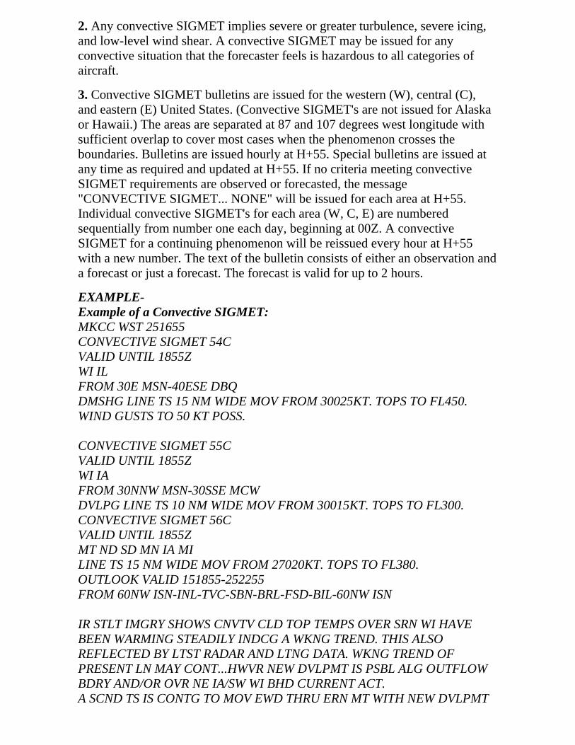
2. Any convective SIGMET implies severe or greater turbulence, severe icing,and low-level wind shear. A convective SIGMET may be issued for anyconvective situation that the forecaster feels is hazardous to all categories ofaircraft.
3. Convective SIGMET bulletins are issued for the western (W), central (C),and eastern (E) United States. (Convective SIGMET's are not issued for Alaskaor Hawaii.) The areas are separated at 87 and 107 degrees west longitude withsufficient overlap to cover most cases when the phenomenon crosses theboundaries. Bulletins are issued hourly at H+55. Special bulletins are issued atany time as required and updated at H+55. If no criteria meeting convectiveSIGMET requirements are observed or forecasted, the message"CONVECTIVE SIGMET... NONE" will be issued for each area at H+55.Individual convective SIGMET's for each area (W, C, E) are numberedsequentially from number one each day, beginning at 00Z. A convectiveSIGMET for a continuing phenomenon will be reissued every hour at H+55with a new number. The text of the bulletin consists of either an observation anda forecast or just a forecast. The forecast is valid for up to 2 hours.
EXAMPLE-Example of a Convective SIGMET:MKCC WST 251655CONVECTIVE SIGMET 54CVALID UNTIL 1855ZWI ILFROM 30E MSN-40ESE DBQDMSHG LINE TS 15 NM WIDE MOV FROM 30025KT. TOPS TO FL450.WIND GUSTS TO 50 KT POSS.
CONVECTIVE SIGMET 55CVALID UNTIL 1855ZWI IAFROM 30NNW MSN-30SSE MCWDVLPG LINE TS 10 NM WIDE MOV FROM 30015KT. TOPS TO FL300.CONVECTIVE SIGMET 56CVALID UNTIL 1855ZMT ND SD MN IA MILINE TS 15 NM WIDE MOV FROM 27020KT. TOPS TO FL380.OUTLOOK VALID 151855-252255FROM 60NW ISN-INL-TVC-SBN-BRL-FSD-BIL-60NW ISN
IR STLT IMGRY SHOWS CNVTV CLD TOP TEMPS OVER SRN WI HAVEBEEN WARMING STEADILY INDCG A WKNG TREND. THIS ALSOREFLECTED BY LTST RADAR AND LTNG DATA. WKNG TREND OFPRESENT LN MAY CONT...HWVR NEW DVLPMT IS PSBL ALG OUTFLOWBDRY AND/OR OVR NE IA/SW WI BHD CURRENT ACT.A SCND TS IS CONTG TO MOV EWD THRU ERN MT WITH NEW DVLPMT

OCRG OVR CNTRL ND. MT ACT IS MOVG TWD MORE FVRBL AMS OVRTHE WRN DAKS WHERE DWPTS ARE IN THE UPR 60S WITH LIFTEDINDEX VALUES TO MS 6. TS EXPD TO INCR IN COVERAGE AND INTSTYDURG AFTN HRS.WST ISSUANCES EXPD TO BE RQRD THRUT AFTN HRS WITH INCRGPTNTL FOR STGR CELLS TO CONTAIN LRG HAIL AND PSBLY DMGG SFCWNDS.
e. International SIGMET
1. Some NWS offices have been designated by the ICAO as MeteorologicalWatch Offices (MWO's). These offices are responsible for issuing InternationalSIGMET's for designated areas that include Alaska, Hawaii, portions of theAtlantic and Pacific Oceans, and the Gulf of Mexico.
2. The offices which issue International SIGMET's are:
(a) The AWC in Kansas City, Missouri.
(b) The AAWU in Anchorage, Alaska.
(c) The WFO in Honolulu, Hawaii.
(d) The WFO on Guam Island in the Pacific Ocean.
3. These SIGMET's are considered "widespread" because they must be eitheraffecting or be forecasted to affect an area of at least 3,000 square miles at anyone time. The International SIGMET is issued for 12 hours for volcanic ashevents, 6 hours for hurricanes and tropical storms, and 4 hours for all otherevents. Like the domestic SIGMET's, International SIGMET's are alsoidentified by an alphabetic designator from Alpha through Mike and arenumbered sequentially until that weather phenomenon ends. The criteria for anInternational SIGMET are:
(a) Thunderstorms occurring in lines, embedded in clouds, or inlarge areas producing tornadoes or large hail.
(b) Tropical cyclones.
(c) Severe icing.
(d) Severe or extreme turbulence.
(e) Dust storms and sandstorms lowering visibilities to less than 3miles.
(f) Volcanic ash.
EXAMPLE-Example of an International SIGMET:WSNT06 KKCI 022014SIGA0F

KZMA KZNY TJZS SIGMET FOXTROT 3 VALID 022015/030015KKCI- MIAMI OCEANIC FIR NEW YORK OCEANIC FIR SANJUAN FIR FRQ TS WI AREA BOUNDED BY 2711N6807W2156N6654W 2220N7040W 2602N7208W 2711N6807W. TOPSTO FL470. MOV NE 15KT. WKN. BASED ON SAT AND LTGOBS.MOSHER
f. AIRMET (WA)
1. AIRMET's (WA's) are advisories of significant weather phenomena butdescribe conditions at intensities lower than those which require the issuance ofSIGMET's. AIRMET's are intended for dissemination to all pilots in thepreflight and en route phase of flight to enhance safety. AIRMET Bulletins areissued on a scheduled basis every 6 hours beginning at 0145 UTC duringCentral Daylight Time and at 0245 UTC during Central Standard Time.Unscheduled updates and corrections are issued as necessary. Each AIRMETBulletin contains any current AIRMET's in effect and an outlook for conditionsexpected after the AIRMET valid period. AIRMET's contain details about IFR,extensive mountain obscuration, turbulence, strong surface winds, icing, andfreezing levels.
2. There are three AIRMET's: Sierra, Tango, and Zulu. After the first issuanceeach day, scheduled or unscheduled bulletins are numbered sequentially foreasier identification.
(a) AIRMET Sierra describes IFR conditions and/or extensivemountain obscurations.
(b) AIRMET Tango describes moderate turbulence, sustainedsurface winds of 30 knots or greater, and/or nonconvectivelow-level wind shear.
(c) AIRMET Zulu describes moderate icing and provides freezinglevel heights.
EXAMPLE-Example of AIRMET Sierra issued for the Chicago FA area:CHIS WA 121345AIRMET SIERRA UPDT 3 FOR IFR AND MTN OBSCN VALIDUNTIL 122000.AIRMET IFR...SD NE MN IA MO WI LM MI IL IN KYFROM 70NW RAP TO 50W RWF TO 50W MSN TO GRB TO MBSTO FWA TO CVG TO HNN TO TRI TO ARG TO 40SSW BRL TOOMA TO BFF TO 70NW RAPOCNL CIG BLW 010/VIS BLW 3SM FG/BR. CONDS ENDG15Z-17Z.
AIRMET MTN OBSCN...KY TN

FROM HNN TO TRI TO CHA TO LOZ TO HNNMTNS OCNL OBSC CLDS/PCPN/BR. CONDS ENDG TN PTNAREA 18Z- 20Z..CONTG KY BYD 20Z..ENDG 02Z.
EXAMPLE-Example of AIRMET Tango issued for the Salt Lake City FAarea:SLCT WA 121345AIRMET TANGO UPDT 2 FOR TURB VALID UNTIL 122000.AIRMET TURB...NV UT CO AZ NMFROM LKV TO CHE TO ELP TO 60S TUS TO YUM TO EED TORNO TO LKV OCNL MOD TURB BLW FL180 DUE TO MODSWLY/WLY WNDS. CONDS CONTG BYD 20Z THRU 02Z.
AIRMET TURB...NV WA OR CA CSTL WTRSFROM BLI TO REO TO BTY TO DAG TO SBA TO 120W FOT TO120W TOU TO BLIOCNL MOD TURB BTWN FL180 AND FL400 DUE TO WNDSHRASSOCD WITH JTSTR. CONDS CONTG BYD 20Z THRU 02Z.
EXAMPLE-Example of AIRMET Zulu issued for the San Francisco FAarea:SFOZ WA 121345AIRMET ZULU UPDT 2 FOR ICE AND FRZLVL VALID UNTIL122000.AIRMET ICE...WA OR ID MT NV UTFROM YQL TO SLC TO WMC TO LKV TO PDT TO YDC TO YQLLGT OCNL MOD RIME/MXD ICGICIP BTWN FRZLVL ANDFL220. FRZLVL 080-120. CONDS CONTG BYD 20Z THRU 02Z.
AIRMET ICE...WA ORFROM YDC TO PDT TO LKV TO 80W MFR TO ONP TO TOUTO YDCLGT OCNL MOD RIME/MXD ICGICIP BTWN FRZLVL ANDFL180. FRZLVL 060-080. CONDS CONTG BYD 20Z THRU 02Z.
FRZLVL...WA...060 CSTLN SLPG 100 XTRM E.OR...060-070 CASCDS WWD. 070-095 RMNDR.NRN CA...060-100 N OF A 30N FOT-40N RNO LN SLPG 100-110RMNDR.
g. Severe Weather Watch Bulletins (WW's) and Alert Messages (AWW's)
1. WW's define areas of possible severe thunderstorms or tornado activity. Thebulletins are issued by the Storm Prediction Center (SPC) in Norman, OK.WW's are unscheduled and are issued as required.

2. A severe thunderstorm watch describes areas of expected severethunderstorms. (Severe thunderstorm criteria are 3/4-inch hail or larger and/orwind gusts of 50 knots [58 mph] or greater.)
3. A tornado watch describes areas where the threat of tornadoes exists.
4. In order to alert the WFO's, CWSU's, FSS's, and other users, a preliminarynotification of a watch called the Alert Severe Weather Watch bulletin (AWW)is sent before the WW. (WFO's know this product as a SAW).
EXAMPLE-Example of an AWW:MKC AWW 011734WW 75 TORNADO TX OK AR 011800Z-020000ZAXIS..80 STATUTE MILES EAST AND WEST OF A LINE..60ESEDAL/DALLAS TX/ - 30 NW ARG/ WALNUT RIDGE AR/..AVIATION COORDS.. 70NM E/W /58W GGG - 25NW ARG/HAIL SURFACE AND ALOFT..1 3/4 INCHES. WIND GUSTS..70 KNOTS. MAXTOPS TO 450. MEAN WIND VECTOR 24045.
5. Soon after the AWW goes out, the actual watch bulletin itself is issued. AWW is in the following format:
(a) Type of severe weather watch, watch area, valid time period,type of severe weather possible, watch axis, meaning of a watch,and a statement that persons should be on the lookout for severeweather.
(b) Other watch information; i.e., references to previous watches.
(c) Phenomena, intensities, hail size, wind speed (knots), maximumcumulonimbus (CB) tops, and estimated cell movement (meanwind vector).
(d) Cause of severe weather.
(e) Information on updating Convective Outlook (CA) products.
EXAMPLE-Example of a WW:BULLETIN - IMMEDIATE BROADCAST REQUESTEDTORNADO WATCH NUMBER 381STORM PREDICTION CENTER NORMAN OK556 PM CDT MON JUN 2 1997THE STORM PREDICTON CENTER HAS ISSUED A TORNADOWATCH FOR PORTIONS OF NORTHEAST NEW MEXICOTEXAS PANHANDLEEFFECTIVE THIS MONDAY NIGHT AND TUESDAY MORNINGFROM 630 PM UNTIL MIDNIGHT CDT.

TORNADOES...HAIL TO 2 3/4 INCHES INDIAMETER...THUNDERSTORM WIND GUSTS TO 80MPH...AND DANGEROUS LIGHTNING ARE POSSIBLE INTHESE AREAS.THE TORNADO WATCH AREA IS ALONG AND 60 STATUTEMILES NORTH AND SOUTH OF A LINE FROM 50 MILESSOUTHWEST OF RATON NEW MEXICO TO 50 MILES EAST OFAMARILLO TEXAS.REMEMBER...A TORNADO WATCH MEANS CONDITIONS AREFAVORABLE FOR TORNADOES AND SEVERETHUNDERSTORMS IN AND CLOSE TO THE WATCH AREA.PERSONS IN THESE AREAS SHOULD BE ON THE LOOKOUTFOR THREATENING WEATHER CONDITIONS AND LISTENFOR LATER STATEMENTS AND POSSIBLE WARNINGS.OTHER WATCH INFORMATION...CONTINUE... WW 378...WW379...WW 380
DISCUSSION...THUNDERSTORMS ARE INCREASING OVER NENM IN MOIST SOUTHEASTERLY UPSLOPE FLOW. OUTFLOWBOUNDARY EXTENDS EASTWARD INTO THE TEXASPANHANDLE AND EXPECT STORMS TO MOVE ESE ALONGAND NORTH OF THE BOUNDARY ON THE N EDGE OF THECAP. VEERING WINDS WITH HEIGHT ALONG WITHINCREASGING MID LVL FLOW INDICATE A THREAT FORSUPERCELLS.
AVIATION...TORNADOES AND A FEW SEVERETHUNDERSTORMS WITH HAIL SURFACE AND ALOFT TO 23/4 INCHES. EXTREME TURBULENCE AND SURFACE WINDGUSTS TO 70 KNOTS. A FEW CUMULONIMBI WITHMAXIMUM TOPS TO 550. MEAN STORM MOTION VECTOR28025.
6. Status reports are issued as needed to show progress of storms and todelineate areas no longer under the threat of severe storm activity. Cancellationbulletins are issued when it becomes evident that no severe weather will developor that storms have subsided and are no longer severe.
7. When tornadoes or severe thunderstorms have developed, the local WFOoffice will issue the warnings covering those areas.
h. Center Weather Advisories (CWA's)
1. CWA's are unscheduled inflight, flow control, air traffic, and air crewadvisory. By nature of its short lead time, the CWA is not a flight planningproduct. It is generally a nowcast for conditions beginning within the next twohours. CWA's will be issued:

(a) As a supplement to an existing SIGMET, Convective SIGMETor AIRMET.
(b) When an Inflight Advisory has not been issued but observed orexpected weather conditions meet SIGMET/AIRMET criteriabased on current pilot reports and reinforced by other sources ofinformation about existing meteorological conditions.
(c) When observed or developing weather conditions do not meetSIGMET, Convective SIGMET, or AIRMET criteria; e.g., in termsof intensity or area coverage, but current pilot reports or otherweather information sources indicate that existing or anticipatedmeteorological phenomena will adversely affect the safe flow of airtraffic within the ARTCC area of responsibility.
2. The following example is a CWA issued from the Kansas City, Missouri,ARTCC. The "3" after ZKC in the first line denotes this CWA has been issuedfor the third weather phenomena to occur for the day. The "301" in the secondline denotes the phenomena number again (3) and the issuance number (01) forthis phenomena. The CWA was issued at 2140Z and is valid until 2340Z.
EXAMPLE-ZKC3 CWA 032140ZKC CWA 301 VALID UNTIL 032340ISOLD SVR TSTM over KCOU MOVG SWWD 10 KTS ETC.
7-1-7. Categorical Outlooks
a. Categorical outlook terms, describing general ceiling and visibility conditions foradvanced planning purposes are used only in area forecasts and are defined as follows:
1. LIFR (Low IFR). Ceiling less than 500 feet and/or visibility less than 1 mile.
2. IFR. Ceiling 500 to less than 1,000 feet and/or visibility 1 to less than 3miles.
3. MVFR (Marginal VFR). Ceiling 1,000 to 3,000 feet and/or visibility 3 to 5miles inclusive.
4. VFR. Ceiling greater than 3,000 feet and visibility greater than 5 miles;includes sky clear.
b. The cause of LIFR, IFR, or MVFR is indicated by either ceilingor visibility restrictions or both. The contraction "CIG" and/orweather and obstruction to vision symbols are used. If winds orgusts of 25 knots or greater are forecast for the outlook period, theword "WIND" is also included for all categories including VFR.
EXAMPLE-1. LIFR CIG-low IFR due to low ceiling.2. IFR FG-IFR due to visibility restricted by fog.

3. MVFR CIG HZ FU-marginal VFR due to both ceiling andvisibility restricted by haze and smoke.4. IFR CIG RA WIND-IFR due to both low ceiling and visibilityrestricted by rain; wind expected to be 25 knots or greater.
7-1-8. Telephone Information Briefing Service (TIBS)
a. TIBS, provided by automated flight service stations (AFSS's) is a continuous recording ofmeteorological and aeronautical information, available by telephone. Each AFSS provides atleast four route and/or area briefings. In addition, airspace procedures and specialannouncements (if applicable) concerning aviation interests may also be available.Depending on user demand, other items may be provided; i.e., METAR observations,terminal aerodrome forecasts, wind/temperatures aloft forecasts, etc.
b. TIBS is not intended to substitute for specialist-provided preflight briefings. It is,however, recommended for use as a preliminary briefing, and often will be valuable inhelping you to make a "go or no go" decision.
c. TIBS is provided by Automated Flight Service Stations (AFSS's) and provides continuoustelephone recordings of meteorological and/or aeronautical information. Specifically, TIBSprovides area and/or route briefings, airspace procedures, and special announcements (ifapplicable) concerning aviation interests.
d. Depending on user demand, other items may be provided; i.e., surface observations,terminal forecasts, winds/temperatures aloft forecasts, etc. A TOUCH-TONETM telephoneis necessary to fully utilize the TIBS program.
e. Pilots are encouraged to avail themselves of this service. TIBS locations are found atAFSS sites and can be accessed by use of 1-800-WX BRIEF toll free number.
7-1-9. Transcribed Weather Broadcast (TWEB)
Equipment is provided at three AFSS/FSS locations in the lower 48 States (Arcata, California;Bridgeport, CT; Princeton, Minnesota) and all of Alaska, by which meteorological and aeronautical dataare recorded on tapes and broadcast continuously over selected low-frequency (190-535 kHz)navigational aids (L/MF ranges or H facilities) and/or VOR's. Broadcasts are made from a series ofindividual tape recordings, and changes, as they occur, are transcribed onto the tapes. The informationprovided varies depending on the type equipment available. Generally, the broadcast containsroute-oriented data with specially prepared NWS forecasts, Inflight Advisories, and winds aloft pluspreselected current information, such as weather reports (METAR/SPECI), NOTAM's, and specialnotices. In some locations, the information is broadcast over the local VOR only and is limited to suchitems as the hourly weather for the parent station and up to 5 immediately adjacent stations, localNOTAM information, aerodrome forecast (TAF) for the parent station, adverse conditions extracted fromInflight Advisories, and other potentially hazardous conditions. At selected locations, telephone access tothe TWEB has been provided (TEL-TWEB). Telephone numbers for this service are found in the FSS andNational Weather Service Telephone Numbers section of the A/FD. These broadcasts are made availableprimarily for preflight and inflight planning, and as such, should not be considered as a substitute forspecialist-provided preflight briefings.

7-1-10. Inflight Weather Broadcasts
a. Weather Advisory Broadcasts. ARTCC's broadcast a Severe Weather Forecast Alert(AWW), Convective SIGMET, SIGMET, or CWA alert once on all frequencies, exceptemergency, when any part of the area described is within 150 miles of the airspace undertheir jurisdiction. These broadcasts contain SIGMET or CWA (identification) and a briefdescription of the weather activity and general area affected.
EXAMPLE-1. Attention all aircraft, SIGMET Delta Three, from Myton to Tuba City to Milford, severeturbulence and severe clear icing below one zero thousand feet. Expected to continue beyondzero three zero zero zulu.2. Attention all aircraft, convective SIGMET Two Seven Eastern. From the vicinity of Elmirato Phillipsburg. Scattered embedded thunderstorms moving east at one zero knots. A fewintense level five cells, maximum tops four five zero.3. Attention all aircraft, Kansas City Center weather advisory one zero three. Numerousreports of moderate to severe icing from eight to niner thousand feet in a three zero mileradius of St. Louis. Light or negative icing reported from four thousand to one two thousandfeet remainder of Kansas City Center area.
NOTE-Terminal control facilities have the option to limit the AWW, convective SIGMET, SIGMET,or CWA broadcast as follows: local control and approach control positions may opt tobroadcast SIGMET or CWA alerts only when any part of the area described is within 50miles of the airspace under their jurisdiction.
b. Hazardous InFlight Weather Advisory Service (HIWAS). This is a continuousbroadcast of inflight weather advisories including summarized AWW, SIGMET's,Convective SIGMET's, CWA's, AIRMET's, and urgent PIREP's. HIWAS has been adoptedas a national program and will be implemented throughout the conterminous U.S. asresources permit. In those areas where HIWAS is commissioned, ARTCC, Terminal ATC,and AFSS/FSS facilities have discontinued the broadcast of inflight advisories as describedin the preceding paragraph. HIWAS is an additional source of hazardous weatherinformation which makes these data available on a continuous basis. It is not, however, areplacement for preflight or inflight briefings or real-time weather updates from FlightWatch (EFAS). As HIWAS is implemented in individual center areas, the commissioningwill be advertised in the Notices to Airmen Publication.
1. Where HIWAS has been implemented, a HIWAS alert will be broadcast onall except emergency frequencies once upon receipt by ARTCC and terminalfacilities, which will include an alert announcement, frequency instruction,number, and type of advisory updated; e.g., AWW, SIGMET, ConvectiveSIGMET, or CWA.
EXAMPLE-Attention all aircraft. Hazardous weather information (SIGMET, ConvectiveSIGMET, AIRMET, Urgent Pilot Weather Report (UUA), or Center WeatherAdvisory (CWA), Number or Numbers) for (geographical area) available on

HIWAS, Flight Watch, or Flight Service frequencies.
2. In HIWAS ARTCC areas, AFSS/FSS's will broadcast a HIWAS updateannouncement once on all except emergency frequencies upon completion ofrecording an update to the HIWAS broadcast. Included in the broadcast will bethe type of advisory updated; e.g. AWW, SIGMET, Convective SIGMET,CWA, etc.
EXAMPLE-Attention all aircraft. Hazardous weather information for (geographical area)available from Flight Watch or Flight Service.
3. HIWAS availability is shown on IFR Enroute Low Altitude Charts and VFRSectional Charts. The symbol depiction is identified in the chart legend.
7-1-11. Flight Information Services Data Link (FISDL)
a. FISDL. Aeronautical weather and operational information may be displayed in the cockpitthrough the use of FISDL. FISDL systems are comprised of two basic types: broadcastsystems and two-way systems. Broadcast system components include a terrestrial orpace-based transmitter, an aircraft receiver, and a cockpit display device. Two-way systemsutilize transmitter/receivers at both the terrestrial or space-based site and the aircraft.
1. Broadcast FISDL allows the pilot to passively collect weather and operationaldata and to call up that data for review at the appropriate time. In addition totext weather products, such as METAR's and TAF's, graphical weatherproducts, such as radar composite/mosaic images may be provided to thecockpit. Two-way FISDL services permit the pilot to make specific weather andoperational information requests for cockpit display.
2. FISDL services are available from three types of service providers.
(a) Through vendors operating under a service agreement with theFAA using broadcast data link on VHF aeronautical spectrum(products and services are defined under subparagraph c).
(b) Through vendors operating under customer contract onaeronautical spectrum.
(c) Through vendors operating under customer contract on otherthan aeronautical spectrum.
3. FISDL is a method of disseminating aeronautical weather and operationaldata which augments pilot voice communication with Flight Service Stations(FSS's), other Air Traffic Control (ATC) facilities or Airline Operations ControlCenters (AOCC's). FISDL does not replace pilot and controller/flight servicespecialist/aircraft dispatcher voice communication for critical weather oroperational information interpretation. FISDL, however, can provide thebackground information which can abbreviate and greatly improve theusefulness of such communications. As such, FISDL serves to enhance pilot

situational awareness and improve safety.
b. Operational Use of FISDL. Regardless of the type of FISDL system being used, eitherunder FAA service agreement or by an independent provider, several factors must beconsidered when using FISDL.
1. Before using FISDL in flight operations, pilots and other flight crew membersshould become completely familiar with the operation of the FISDL system tobe used, airborne equipment to be used, including system architecture, airbornesystem components, service volume and other limitations of the particularsystem, modes of operation and the indications of various system failures. Usersshould also be familiar with the content and format of the services availablefrom the FISDL provider(s). Sources of information which may provide thisguidance include manufacturer's manuals, training programs and referenceguides.
2. FISDL does not serve as the sole source of aeronautical weather andoperational information. ATC, FSS, and, if applicable, AOCC VHF/HF voice isthe basic method of communicating aeronautical weather, special use airspace,NOTAM and other operational information to aircraft in flight. FISDLaugments ATC/FSS/AOCC services, and, in some applications, offers theadvantage of graphical data. By using FISDL for orientation, the usefulness ofany information received from conventional voice sources may be greatlyenhanced. FISDL may alert the pilot to specific areas of concern which willmore accurately focus requests made to FSS or AOCC for inflight briefings orqueries made to ATC.
3. The aeronautical environment is constantly changing; often these changesoccur quickly, and without warning. It is important that critical decisions bebased on the most timely and appropriate data available. Consequently, whendifferences exist between FISDL and information obtained by voicecommunication with ATC, FSS, and/or AOCC (if applicable), pilots arecautioned to use the most recent data from the most authoritative source.
4. FISDL products, such as ground-based radar precipitation maps, are notappropriate for use in tactical severe weather avoidance, such as negotiating apath through a weather hazard area (an area where a pilot cannot reliably divertaround hazardous weather, such as a broken line of thunderstorms). FISDLsupports strategic weather decision making such as route selection to avoid aweather hazard area in its entirety. The misuse of information beyond it'sapplicability may place the pilot and his/her aircraft in great jeopardy. Inaddition, FISDL should never be used in lieu of an individual pre-flight weatherand flight planning briefing.
5. FISDL supports better pilot decision making by increasing situationalawareness. The best decision making is based on using information from avariety of sources. In addition to FISDL, pilots should take advantage of otherweather/NAS status sources, including, but not limited to, Flight Service

Stations, Flight Watch, other air traffic control facilities, airline operationcontrol centers, pilot reports, and their own personal observations.
c. FAA FISDL. The FAA's FISDL system provides flight crews of properly equippedaircraft with a cockpit display of certain aeronautical weather and flight operationalinformation. This information is displayed using both text and graphic format. This system isscheduled for initial operational capability (IOC) in the first quarter of calendar year 2000.The system is operated by vendors under a service agreement with the FAA, using broadcastdata link on aeronautical spectrum on four 25 KHz spaced frequencies from 136.425 through136.500 MHz. FISDL is designed to provide coverage throughout the continental U.S. from5,000 feet AGL to 17,500 feet MSL, except in those areas where this is unfeasible due tomountainous terrain. Aircraft operating near transmitter sites will receive useable FISDLsignals at altitudes lower than 5000 feet AGL, including on the surface in some locations,depending on transmitter/aircraft line of sight geometry. Aircraft operating above 17,500MSL may also receive useable FISDL signals under certain circumstances.
1. FAA FISDL provides, free of charge, the following basic products:
(a) Aviation Routine Weather Reports (METAR's).
(b) Special Aviation Reports (SPECI's).
(c) Terminal Area Forecasts (TAF's), and their amendments.
(d) Significant Meteorological Information (SIGMET's).
(e) Convective SIGMET's.
(f) Airman's Meteorological Information (AIRMET's).
(g) Pilot Reports (both urgent and routine) (PIREP's); and,
(h) Severe Weather Forecast Alerts (AWW's) issued by the FAA orNWS.
2. The format and coding of these products are described in Advisory CircularAC-00-45, Aviation Weather Services, and paragraph 7-1-30, Key toAerodrome Forecast (TAF) and Aviation Routine Weather Report (METAR).
3. Additional products, called Value-Added Products, are available from thevendors on a paid subscription basis. Details concerning the content, format,symbology and cost of these products may be obtained from the followingvendors:
(a) BENDIX/KING WxSIGHTAllied Signal, Inc.One Technology Center23500 West 105th StreetOlathe, KS 66061(913) 712-2613www.bendixking.com

(b) ARNAV Systems, Inc.16923 Meridian EastP. O. Box 73730Puyallup, WA 98373(253) 848-6060www.arnav.com
d. Non-FAA FISDL Systems. In addition to FAA FISDL, several commercial vendorsprovide customers with FISDL on both the aeronautical spectrum and other frequenciesusing a variety of data link protocols. In some cases, the vendors provide only thecommunications system which carries customer messages, such as the AircraftCommunications Addressing and Reporting System (ACARS) used by many air carrier andother operators.
1. Operators using non-FAA FISDL for inflight weather and operationalinformation should ensure that the products used conform to the FAA/NWSstandards. Specifically, aviation weather information should meet the followingcriteria:
(a) The products should be either FAA/NWS accepted aviationweather reports or products, or based on FAA/NWS acceptedaviation weather reports or products. If products are used which donot meet this criteria, they should be so identified. The operatormust determine the applicability of such products to flightoperations.
(b) In the case of a weather product which is the result of theapplication of a process which alters the form, function or contentof the base FAA/NWS accepted weather product(s), that process,and any limitations to the application of the resultant productshould be described in the vendor's user guidance material.
2. An example would be a NEXRAD radar composite/mosaic map, which hasbeen modified by changing the scaling resolution. The methodology ofassigning reflectivity values to the resultant image components should bedescribed in the vendor's guidance material to ensure that the user canaccurately interpret the displayed data.
3. To ensure airman compliance with Federal Aviation Regulations, NationalAirspace System (NAS) status products (such as NOTAM's, Special UseAirspace Status, etc.) and other government flight information should includeverbatim transmissions of FAA products. If these products are modified, themodification process, and any limitations of the resultant product should bedescribed in the vendor's user guidance.
7-1-12. Weather Observing Programs
a. Manual Observations. With only a few exceptions, these reports are from airportlocations staffed by FAA or NWS personnel who manually observe, perform calculations,

and enter these observations into the (WMSCR) communication system. The format andcoding of these observations are contained in paragraph 7-1-30, Key to Aviation RoutineWeather Report (METAR) and Aerodrome Forecasts (TAF).
b. Automated Weather Observing System (AWOS).
1. Automated weather reporting systems are increasingly being installed atairports. These systems consist of various sensors, a processor, acomputer-generated voice subsystem, and a transmitter to broadcast local,minute-by-minute weather data directly to the pilot.
NOTE-When the barometric pressure exceeds 31.00 inches Hg., see paragraph 7-2-2,Procedures, for the altimeter setting procedures.
2. The AWOS observations will include the prefix "AUTO" to indicate that thedata are derived from an automated system. Some AWOS locations will beaugmented by certified observers who will provide weather and obstruction tovision information in the remarks of the report when the reported visibility isless than 7 miles. These sites, along with the hours of augmentation, are to bepublished in the A/FD. Augmentation is identified in the observation as"OBSERVER WEATHER." The AWOS wind speed, direction and gusts,temperature, dew point, and altimeter setting are exactly the same as for manualobservations. The AWOS will also report density altitude when it exceeds thefield elevation by more than 1,000 feet. The reported visibility is derived from asensor near the touchdown of the primary instrument runway. The visibilitysensor output is converted to a visibility value using a 10-minute harmonicaverage. The reported sky condition/ceiling is derived from the ceilometerlocated next to the visibility sensor. The AWOS algorithm integrates the last 30minutes of ceilometer data to derive cloud layers and heights. This output mayalso differ from the observer sky condition in that the AWOS is totallydependent upon the cloud advection over the sensor site.
3. These real-time systems are operationally classified into four basic levels:
(a) AWOS-A only reports altimeter setting;
(b) AWOS-l usually reports altimeter setting, wind data,temperature, dew point, and density altitude;
(c) AWOS-2 provides the information provided by AWOS-l plusvisibility; and
(d) AWOS-3 provides the information provided by AWOS-2 pluscloud/ceiling data.
4. The information is transmitted over a discrete VHF radio frequency or thevoice portion of a local NAVAID. AWOS transmissions on a discrete VHFradio frequency are engineered to be receivable to a maximum of 25 NM fromthe AWOS site and a maximum altitude of 10,000 feet AGL. At many locations,

AWOS signals may be received on the surface of the airport, but localconditions may limit the maximum AWOS reception distance and/or altitude.The system transmits a 20 to 30 second weather message updated each minute.Pilots should monitor the designated frequency for the automated weatherbroadcast. A description of the broadcast is contained in subparagraph c. Thereis no two-way communication capability. Most AWOS sites also have a dial-upcapability so that the minute-by-minute weather messages can be accessed viatelephone.
5. AWOS information (system level, frequency, phone number, etc.) concerningspecific locations is published, as the systems become operational, in the A/FD,and where applicable, on published Instrument Approach Procedures. Selectedindividual systems may be incorporated into nationwide data collection anddissemination networks in the future.
c. AWOS Broadcasts. Computer-generated voice is used in AWOS to automate thebroadcast of the minute-by-minute weather observations. In addition, some systems areconfigured to permit the addition of an operator-generated voice message; e.g., weatherremarks following the automated parameters. The phraseology used generally follows thatused for other weather broadcasts. Following are explanations and examples of theexceptions.
1. Location and Time. The location/name and the phrase "AUTOMATEDWEATHER OBSERVATION," followed by the time are announced.
(a) If the airport's specific location is included in the airport's name,the airport's name is announced.
EXAMPLE-"Bremerton National Airport automated weather observation, onefour five six zulu;""Ravenswood Jackson County Airport automated weatherobservation, one four five six zulu."
(b) If the airport's specific location is not included in the airport'sname, the location is announced followed by the airport's name.
EXAMPLE-"Sault Ste. Marie, Chippewa County International Airportautomated weather observation;""Sandusky, Cowley Field automated weather observation."
(c) The word "TEST" is added following "OBSERVATION" whenthe system is not in commissioned status.
EXAMPLE-"Bremerton National Airport automated weather observation test,one four five six zulu."
(d) The phrase "TEMPORARILY INOPERATIVE" is added when

the system is inoperative.
EXAMPLE-"Bremerton National Airport automated weather observing systemtemporarily inoperative."
2. Visibility.
(a) The lowest reportable visibility value in AWOS is "less than1/4." It is announced as "VISIBILITY LESS THAN ONEQUARTER."
(b) A sensor for determining visibility is not included in someAWOS. In these systems, visibility is not announced."VISIBILITY MISSING" is announced only if the system isconfigured with a visibility sensor and visibility information is notavailable.
3. Weather. In the future, some AWOS's are to be configured to determine theoccurrence of precipitation. However, the type and intensity may not always bedetermined. In these systems, the word "PRECIPITATION" will be announcedif precipitation is occurring, but the type and intensity are not determined.
4. Ceiling and Sky Cover.
(a) Ceiling is announced as either "CEILING" or "INDEFINITECEILING." With the exception of indefinite ceilings, all automatedceiling heights are measured.
EXAMPLE-"Bremerton National Airport automated weather observation, onefour five six zulu. Ceiling two thousand overcast;"
"Bremerton National Airport automated weather observation, onefour five six zulu. Indefinite ceiling two hundred, sky obscured."
(b) The word "Clear" is not used in AWOS due to limitations in theheight ranges of the sensors. No clouds detected is announced as"NO CLOUDS BELOW XXX" or, in newer systems as "CLEARBELOW XXX" (where XXX is the range limit of the sensor).
EXAMPLE-"No clouds below one two thousand.""Clear below one two thousand."
(c) A sensor for determining ceiling and sky cover is not includedin some AWOS. In these systems, ceiling and sky cover are notannounced. "SKY CONDITION MISSING" is announced only ifthe system is configured with a ceilometer and the ceiling and skycover information is not available.

5. Remarks. If remarks are included in the observation, the word "REMARKS"is announced following the altimeter setting.
(a) Automated "Remarks."
(1) Density Altitude.
(2) Variable Visibility.
(3) Variable Wind Direction.
(b) Manual Input Remarks. Manual input remarks are prefacedwith the phrase "OBSERVER WEATHER." As a general rule themanual remarks are limited to:
(1) Type and intensity of precipitation.
(2) Thunderstorms and direction; and
(3) Obstructions to vision when the visibility is 3miles or less.
EXAMPLE-"Remarks ... density altitude, two thousand fivehundred ... visibility variable between one and two ...wind direction variable between two four zero andthree one zero ...observed weather ... thunderstormmoderate rain showers and fog ... thunderstormoverhead."
(c) If an automated parameter is "missing" and no manual input forthat parameter is available, the parameter is announced as"MISSING." For example, a report with the dew point "missing"and no manual input available, would be announced as follows:
EXAMPLE-"Ceiling one thousand overcast ... visibility three ... precipitation ...temperature three zero, dew point missing ... wind calm ... altimeterthree zero zero one."
(d) "REMARKS" are announced in the following order of priority:
(1) Automated "REMARKS."
[a] Density Altitude.
[b] Variable Visibility.
[c] Variable Wind Direction.
(2) Manual Input "REMARKS."
[a] Sky Condition.

[b] Visibility.
[c] Weather and Obstructions to Vision.
[d] Temperature.
[e] Dew Point.
[f] Wind; and
[g] Altimeter Setting.
EXAMPLE-"Remarks ... density altitude, twothousand five hundred ... visibilityvariable between one and two ... winddirection variable between two four zeroand three one zero ... observer ceilingestimated two thousand broken ...observer temperature two, dew pointminus five."
d. Automated Surface Observing System (ASOS). The ASOS is the primary surfaceweather observing system of the U.S. (See Key to Decode an ASOS (METAR) Observation,FIG 7-1-7 and FIG 7-1-8.) The program to install and operate up to 993 systems throughoutthe U.S. is a joint effort of the NWS, the FAA and the Department of Defense. ASOS isdesigned to support aviation operations and weather forecast activities. The ASOS willprovide continuous minute-by-minute observations and perform the basic observingfunctions necessary to generate an aviation routine weather report (METAR) and otheraviation weather information. The information may be transmitted over a discrete VHF radiofrequency or the voice portion of a local NAVAID. ASOS transmissions on a discrete VHFradio frequency are engineered to be receivable to a maximum of 25 NM from the ASOS siteand a maximum altitude of 10,000 feet AGL. At many locations, ASOS signals may bereceived on the surface of the airport, but local conditions may limit the maximum receptiondistance and/or altitude. While the automated system and the human may differ in theirmethods of data collection and interpretation, both produce an observation quite similar inform and content. For the "objective" elements such as pressure, ambient temperature, dewpoint temperature, wind, and precipitation accumulation, both the automated system and theobserver use a fixed location and time-averaging technique. The quantitative differencesbetween the observer and the automated observation of these elements are negligible. For the"subjective" elements, however, observers use a fixed time, spatial averaging technique todescribe the visual elements (sky condition, visibility and present weather), while theautomated systems use a fixed location, time averaging technique. Although this is afundamental change, the manual and automated techniques yield remarkably similar resultswithin the limits of their respective capabilities.
1. System Description.
(a) The ASOS at each airport location consists of four main

components:
(1) Individual weather sensors.
(2) Data collection package(s) (DCP).
(3) The acquisition control unit.
(4) Peripherals and displays.
(b) The ASOS sensors perform the basic function of dataacquisition. They continuously sample and measure the ambientenvironment, derive raw sensor data and make them available tothe collocated DCP.
2. Every ASOS will contain the following basic set of sensors:
(a) Cloud height indicator (one or possibly three).
(b) Visibility sensor (one or possibly three).
(c) Precipitation identification sensor.
(d) Freezing rain sensor (at select sites).
(e) Pressure sensors (two sensors at small airports; three sensors atlarge airports).
(f) Ambient temperature/Dew point temperature sensor.
(g) Anemometer (wind direction and speed sensor).
(h) Rainfall accumulation sensor.
3. The ASOS data outlets include:
(a) Those necessary for on-site airport users.
(b) National communications networks.
(c) Computer-generated voice (available through FAA radiobroadcast to pilots, and dial-in telephone line).
NOTE-Wind direction broadcast over FAA radios is in reference tomagnetic north.
4. An ASOS/AWOS report without human intervention will contain only thatweather data capable of being reported automatically. The modifier for thisMETAR report is "AUTO." When an observer augments or backs-up anASOS/AWOS site, the "AUTO" modifier disappears.
5. There are two types of automated stations, AO1 for automated weatherreporting stations without a precipitation discriminator, and AO2 for automated

stations with a precipitation discriminator. As appropriate, "AO1" and "AO2"shall appear in remarks. (A precipitation discriminator can determine thedifference between liquid and frozen/freezing precipitation).
NOTE-To decode an ASOS report, refer to FIG 7-1-7 and FIG 7-1-8.
REFERENCE-A complete explanation of METAR terminology is located in AIM, Paragraph 7-1-30, Key to Aerodrome Forecast (TAF) andAviation Routine Weather Report (METAR).
FIG 7-1-7
Key to Decode an ASOS (METAR) Observation (Front)
FIG 7-1-8
Key to Decode an ASOS (METAR) Observation (Back)
e. TBL 7-1-1 contains a comparison of weather observing programs and the elementsreported.
f. Service Standards. During 1995, a government/industry team worked to comprehensivelyreassess the requirements for surface observations at the nation's airports. That work resultedin agreement on a set of service standards, and the FAA and NWS ASOS sites to which thestandards would apply. The term "Service Standards" refers to the level of detail in weatherobservation. The service standards consist of four different levels of service (A, B, C, and D)as described below. Specific observational elements included in each service level are listedin TBL 7-1-2.
1. Service Level D defines the minimum acceptable level of service. It is acompletely automated service in which the ASOS observation will constitute theentire observation, i.e., no additional weather information is added by a humanobserver. This service is referred to as a stand alone D site.
2. Service Level C is a service in which the human observer, usually an airtraffic controller, augments or adds information to the automated observation.Service Level C also includes backup of ASOS elements in the event of anASOS malfunction or an unrepresentative ASOS report. In backup, the human

observer inserts the correct or missing value for the automated ASOS elements.This service is provided by air traffic controllers under the Limited AviationWeather Reporting Station (LAWRS) process, FSS and NWS observers, and, atselected sites, Non-Federal Observation Program observers.
Two categories of airports require detail beyond Service Level C in order toenhance air traffic control efficiency and increase system capacity. Services atthese airports are typically provided by contract weather observers, NWSobservers, and, at some locations, FSS observers.
3. Service Level B is a service in which weather observations consist of allelements provided under Service Level C, plus augmentation of additional databeyond the capability of the ASOS. This category of airports includes smallerhubs or special airports in other ways that have worse than average bad weatheroperations for thunderstorms and/or freezing/frozen precipitation, and/or thatare remote airports.
4. Service Level A, the highest and most demanding category, includes all thedata reported in Service Standard B, plus additional requirements as specified.Service Level A covers major aviation hubs and/or high volume traffic airportswith average or worse weather.
TBL 7-1-1
Weather Observing ProgramsElement Reported AWOS-A AWOS-1 AWOS-2 AWOS-3 ASOS Manual
Altimeter X X X X X X
Wind X X X X X
Temperature/Dew Point
X X X X X
Density Altitude X X X X Visibility X X X X
Clouds/Ceiling X X X
Precipitation X X
Remarks X X
TBL 7-1-2
SERVICE LEVEL A Service Level A consists of all the
elements of Service Levels B, Cand D plus the elements listed tothe right, if observed.
10 minute longline RVR at precedented sites oradditional visibility increments of 1/8, 1/16 and 0 SectorvisibilityVariable sky conditionCloud layers above 12,000 feet and cloud typesWidespread dust, sand and other obscurationsVolcanic eruptions
SERVICE LEVEL B

Service Level B consists of all theelements of Service Levels C and Dplus the elements listed to the right,if observed.
Longline RVR at precedented sites(may be instantaneous readout)Freezing drizzle versus freezing rainIce pelletsSnow depth & snow increasing rapidly remarksThunderstorm and lightning location remarksObserved significant weather not at the stationremarks
SERVICE LEVEL C Service Level C consists of all the
elements of Service Level D plusaugmentation and backup by a humanobserver or an air traffic controlspecialist on location nearby. Backupconsists of inserting the correct valueif the system malfunctions or isunrepresentative. Augmentationconsists of adding the elements listedto the right, if observed. During hoursthat the observing facility is closed,the site reverts to Service Level D.
ThunderstormsTornadoesHailVirgaVolcanic ashTower visibilityOperationally significant remarks as deemedappropriate by the observer
SERVICE LEVEL D This level of service consists of an
ASOS continually measuring theatmosphere at a point near the runway.The ASOS senses and measures theweather parameters listed to the right.
WindVisibilityPrecipitation/Obstruction to visionCloud heightSky coverTemperatureDew pointAltimeter
7-1-13. Weather Radar Services
a. The National Weather Service operates a network of radar sites for detecting coverage,intensity, and movement of precipitation. The network is supplemented by FAA and DODradar sites in the western sections of the country. Local warning radar sites augment thenetwork by operating on an as needed basis to support warning and forecast programs.
b. Scheduled radar observations are taken hourly and transmitted in alpha-numeric format onweather telecommunications circuits for flight planning purposes. Under certain conditions,special radar reports are issued in addition to the hourly transmittals. Data contained in thereports are also collected by the National Center for Environmental Prediction and used toprepare national radar summary charts for dissemination on facsimile circuits.
c. A clear radar display (no echoes) does not mean that there is no significant weather withinthe coverage of the radar site. Clouds and fog are not detected by the radar. However, whenechoes are present, turbulence can be implied by the intensity of the precipitation, and icingis implied by the presence of the precipitation at temperatures at or below zero degreesCelsius. Used in conjunction with other weather products, radar provides invaluable

information for weather avoidance and flight planning.
FIG 7-1-9
NEXRAD Coverage
FIG 7-1-10
NEXRAD Coverage
FIG 7-1-11
NEXRAD Coverage
d. All En Route Flight Advisory Service facilities and AFSS's have equipment to directlyaccess the radar displays from the individual weather radar sites. Specialists at theselocations are trained to interpret the display for pilot briefing and inflight advisory services.The Center Weather Service Units located in ARTCC's also have access to weather radardisplays and provide support to all air traffic facilities within their center's area.
e. Additional information on weather radar products and services can be found in AC 00-45,Aviation Weather Services.
REFERENCE-Pilot/Controller Glossary, Radar Weather Echo Intensity Levels.AIM, Thunderstorms, Paragraph 7-1-28.A/FD, Charts, NWS Upper Air Observing Stations and Weather Network for the location of specific radar sites.
7-1-14. National Convective Weather Forecast (NCWF)
a. Description.
1. The NCWF is an automatically generated depiction of: (1) current convectionand (2) extrapolated significant current convection. It is a supplement to, but

does NOT substitute for, the report and forecast information contained inConvective SIGMET's (see paragraph 7-1-6d). Convection, particularlysignificant convection, is typically associated with thunderstorm activity.
2. The National Weather Service Aviation Weather Center (AWC) updates theNCWF based on input from the Next Generation Weather Radar (NEXRAD)and cloud-to-ground lightning data.
3. The NCWF is most accurate for long-lived mature multi-storm systems suchas organized line storms. NCWF does not forecast initiation, growth or decay ofthunderstorms. Therefore, NCWF tends to under-warn on new and growingstorms and over-warn on dying storms. Forecast positions of small, isolated orweaker thunderstorms are not displayed.
4. The NCWF area of coverage is limited to the 48 contiguous states.
b. Attributes.
1. The NCWF is updated frequently (every 5 minutes) using the most currentavailable data.
2. The NCWF is able to detect the existence of convective storm locations thatagree very well with concurrent radar and lightning observations.
3. The NCWF is a high-resolution forecast impacting a relatively small volumeof airspace rather than covering large boxed areas. The location, speeds anddirections of movement of multiple convective storms are depicted individually.
4. The NCWF extrapolation forecasts are more accurate when predicting thelocation and size of well organized, unchanging convective storms moving atuniform speeds. The NCWF does not work well with sporadic, explosive cellsdeveloping and dissipating in minutes.
5. In displaying forecast cell locations, the NCWF does NOT distinguish amonglevel 3 through level 6 on the NCWF hazard scale (see TBL 7-1-3).
6. The NCWF may not detect or forecast:
(a) Some embedded convection.
(b) Low-topped convection containing little or no cloud-to-groundlightning (such as may occur in cool air masses).
(c) Rapidly evolving convection.
7. The NCWF cannot provide information on specific storm hazards such ashail, high winds or tornadoes.
c. Availability and Use.
1. The NCWF is available primarily via the Internet from the AWC AviationDigital Data Service (ADDS) at http://adds.aviationweather.noaa.gov. Used in

conjunction with other weather products such as Convective SIGMET's, theNCWF provides additional information for convective weather avoidance andflight planning.
2. The NCWF access by Automated Flight Service Stations and their associatedEn Route Flight Advisory Service Facilities, Air Route Traffic Control Centers(ARTCC's) or Terminal Radar Approach Controls is planned but NOT currentlyavailable.
NOTE-See AIM, paragraph 7-1-15, ATC Inflight Weather Avoidance Assistance, forfurther information.
d. Display Summary.
1. Existing convective hazards (based on NEXRAD and lightning data) aredepicted using the color-coded 6-level NCWF hazard scale shown in TBL7-1-3. In displaying forecast cell locations, the NCWF does NOT distinguishamong level 3 through level 6.
TBL 7-1-3
NCWF Hazard ScaleLevel Color Effect5-6 Red Thunderstorms may contain any or all of the following:
severe turbulence, severe icing, hail, frequent lightning,tornadoes and low-level wind shear. The risk ofhazardous weather generally increases with levels on theNCWF hazard scale.
3-4 Yellow Orange
1-2 Green
NOTE-Although similar, the NCWF hazard scale levels are NOT identical to VIPlevels.
REFERENCE-Pilot/Controller Glossary Term- Radar Weather Echo Intensity Levels.
2. One-hour forecast locations of signification convection (NCWF hazard scalelevels of 3 or greater) are depicted with blue polygons. Their directions ofmovement and storm tops are also shown.
3. The Java display permits some degree of customization. Other means ofviewing the NCWF may not offer these display options. Java display optionsinclude the following (see FIG 7-1-12):
(a) "Current Convective Interest Grid."
(b) "One-Hour Extrapolation Polygons."
(c) "Previous Performance Polygons."

(d) Storm speed and altitude of tops.
(e) Overlays of:
(1) Airport locations.
(2) County boundaries.
(3) ARTCC boundaries.
(f) Aviation Routine Weather Reports (METAR's).
(g) Unlimited customized zooms (by holding down the left mousebutton and dragging to select the rectangle of coverage desired).
4. The JavaScript display options include the following (see FIG 7-1-13):
(a) Current convective hazard "Detection" field.
(b) 1-hour extrapolation "Forecast" polygons.
(c) Previous hour "Performance" polygons.
(d) "2 hr Movie" loops of convective hazard detection fields (withforecast polygons included on the last frame).
(e) "24 hr Movie" loops of convective hazard detection fields.
(f) Zoomed views of:
(1) ARTCC boundaries.
(2) Certain major airports.
(3) Seven geographical regions: Northwest, NorthCentral, Northeast, Southwest, South Central,Southwest, the 48 contiguous states.
5. Additional information is available via the "FYI/Help" or "i" links on the Javaand JavaScript displays, respectively.
FIG 7-1-12
Example NCWF Java Display

FIG 7-1-13
Example NCWF JavaScript Display
7-1-15. ATC Inflight Weather Avoidance Assistance
a. ATC Radar Weather Display.
1. Areas of radar weather clutter result from rain or moisture. Radars cannotdetect turbulence. The determination of the intensity of the weather displayed isbased on its precipitation density. Generally, the turbulence associated with avery heavy rate of rainfall will normally be more severe than any associatedwith a very light rainfall rate.
2. ARTCC's use Narrowband Radar which provides the controller with twodistinct levels of weather intensity by assigning radar display symbols forspecific precipitation densities measured by the narrowband system.
b. Weather Avoidance Assistance.
1. To the extent possible, controllers will issue pertinent information on weatheror chaff areas and assist pilots in avoiding such areas when requested. Pilotsshould respond to a weather advisory by either acknowledging the advisory orby acknowledging the advisory and requesting an alternative course of action asfollows:
(a) Request to deviate off course by stating the number of milesand the direction of the requested deviation. In this case, when therequested deviation is approved, navigation is at the pilot'sprerogative, but must maintain the altitude assigned by ATC and toremain within the specified mileage of the original course.
(b) Request a new route to avoid the affected area.
(c) Request a change of altitude.
(d) Request radar vectors around the affected areas.
2. For obvious reasons of safety, an IFR pilot must not deviate from the courseor altitude or flight level without a proper ATC clearance. When weatherconditions encountered are so severe that an immediate deviation is determinedto be necessary and time will not permit approval by ATC, the pilot's

emergency authority may be exercised.
3. When the pilot requests clearance for a route deviation or for an ATC radarvector, the controller must evaluate the air traffic picture in the affected area,and coordinate with other controllers (if ATC jurisdictional boundaries may becrossed) before replying to the request.
4. It should be remembered that the controller's primary function is to providesafe separation between aircraft. Any additional service, such as weatheravoidance assistance, can only be provided to the extent that it does not derogatethe primary function. It's also worth noting that the separation workload isgenerally greater than normal when weather disrupts the usual flow of traffic.ATC radar limitations and frequency congestion may also be a factor in limitingthe controller's capability to provide additional service.
5. It is very important, therefore, that the request for deviation or radar vector beforwarded to ATC as far in advance as possible. Delay in submitting it maydelay or even preclude ATC approval or require that additional restrictions beplaced on the clearance. Insofar as possible the following information should befurnished to ATC when requesting clearance to detour around weather activity:
(a) Proposed point where detour will commence.
(b) Proposed route and extent of detour (direction and distance).
(c) Point where original route will be resumed.
(d) Flight conditions (IFR or VFR).
(e) Any further deviation that may become necessary as the flightprogresses.
(f) Advise if the aircraft is equipped with functioning airborneradar.
6. To a large degree, the assistance that might be rendered by ATC will dependupon the weather information available to controllers. Due to the extremelytransitory nature of severe weather situations, the controller's weatherinformation may be of only limited value if based on weather observed on radaronly. Frequent updates by pilots giving specific information as to the areaaffected, altitudes, intensity and nature of the severe weather can be ofconsiderable value. Such reports are relayed by radio or phone to other pilotsand controllers and also receive widespread teletypewriter dissemination.
7. Obtaining IFR clearance or an ATC radar vector to circumnavigate severeweather can often be accommodated more readily in the en route areas awayfrom terminals because there is usually less congestion and, therefore, offergreater freedom of action. In terminal areas, the problem is more acute becauseof traffic density, ATC coordination requirements, complex departure andarrival routes, adjacent airports, etc. As a consequence, controllers are less

likely to be able to accommodate all requests for weather detours in a terminalarea or be in a position to volunteer such routing to the pilot. Nevertheless,pilots should not hesitate to advise controllers of any observed severe weatherand should specifically advise controllers if they desire circumnavigation ofobserved weather.
c. Procedures for Weather Deviations and Other Contingencies in Oceanic ControlledAirspace.
1. When the pilot initiates communications with ATC, rapid response may beobtained by stating "WEATHER DEVIATION REQUIRED" to indicatepriority is desired on the frequency and for ATC response.
2. The pilot still retains the option of initiating the communications using theurgency call "PAN-PAN" 3 times to alert all listening parties of a specialhandling condition which will receive ATC priority for issuance of a clearanceor assistance.
3. ATC will:
(a) Approve the deviation.
(b) Provide vertical separation and then approve the deviation; or
(c) If ATC is unable to establish vertical separation, ATC shalladvise the pilot that standard separation cannot be applied; provideessential traffic information for all affected aircraft, to the extentpracticable; and if possible, suggest a course of action. ATC maysuggest that the pilot climb or descend to a contingency altitude(1,000 feet above or below that assigned if operating above FL290; 500 feet above or below that assigned if operating at or belowFL 290).
PHRASEOLOGY-STANDARD SEPARATION NOT AVAILABLE, DEVIATE ATPILOT'S DISCRETION; SUGGEST CLIMB (or descent) TO(appropriate altitude); TRAFFIC (position and altitude); REPORTDEVIATION COMPLETE.
4. The pilot will follow the ATC advisory altitude when approximately 10 NMfrom track as well as execute the procedures detailed in paragraph 7-1-15c5.
5. If contact cannot be established or revised ATC clearance or advisory is notavailable and deviation from track is required, the pilot shall take the followingactions:
(a) If possible, deviate away from an organized track or routesystem.
(b) Broadcast aircraft position and intentions on the frequency inuse, as well as on frequency 121.5 MHz at suitable intervals

stating: flight identification (operator call sign), flight level, trackcode or ATS route designator, and extent of deviation expected.
(c) Watch for conflicting traffic both visually and by reference toTCAS (if equipped).
(d) Turn on aircraft exterior lights.
(e) Deviations of less than 10 NM or operations withinCOMPOSITE (NOPAC and CEPAC) Airspace, should REMAINat ASSIGNED altitude. Otherwise, when the aircraft isapproximately 10 NM from track, initiate an altitude change basedon the following criteria:
TBL 7-1-4
RouteCenterline/Track
Deviations >10 NM Altitude Change
East000 - 179°M
LeftRight
Descend 500 FeetClimb 500 Feet
West180-359°M
LeftRight
Climb 500 Feet Descend 500 Feet
Pilot Memory Slogan: "East right up,West right down."
(f) When returning to track, be at assigned flight level when theaircraft is within approximately 10 NM of centerline.
(g) If contact was not established prior to deviating, continue toattempt to contact ATC to obtain a clearance. If contact wasestablished, continue to keep ATC advised of intentions and obtainessential traffic information.
7-1-16. Runway Visual Range (RVR)
There are currently two configurations of RVR in the NAS commonly identified as Taskers and NewGeneration RVR. The Taskers are the existing configuration which uses transmissometer technology. TheNew Generation RVR's were deployed in November 1994 and use forward scatter technology. The NewGeneration RVR's are currently being deployed in the NAS to replace the existing Taskers.
a. RVR values are measured by transmissometers mounted on 14-foot towers along therunway. A full RVR system consists of:
1. Transmissometer projector and related items.
2. Transmissometer receiver (detector) and related items.
3. Analogue recorder.
4. Signal data converter and related items.
5. Remote digital or remote display programmer.

b. The transmissometer projector and receiver are mounted on towers 250 feet apart. Aknown intensity of light is emitted from the projector and is measured by the receiver. Anyobscuring matter such as rain, snow, dust, fog, haze or smoke reduces the light intensityarriving at the receiver. The resultant intensity measurement is then converted to an RVRvalue by the signal data converter. These values are displayed by readout equipment in theassociated air traffic facility and updated approximately once every minute for controllerissuance to pilots.
c. The signal data converter receives information on the high intensity runway edge lightsetting in use (step 3, 4, or 5); transmission values from the transmissometer and the sensingof day or night conditions. From the three data sources, the system will compute appropriateRVR values.
d. An RVR transmissometer established on a 250 foot baseline provides digital readouts to aminimum of 600 feet, which are displayed in 200 foot increments to 3,000 feet and in 500foot increments from 3,000 feet to a maximum value of 6,000 feet.
e. RVR values for Category IIIa operations extend down to 700 feet RVR; however, only600 and 800 feet are reportable RVR increments. The 800 RVR reportable value covers arange of 701 feet to 900 feet and is therefore a valid minimum indication of Category IIIaoperations.
f. Approach categories with the corresponding minimum RVR values. (See TBL 7-1-5.)
TBL 7-1-5
Approach Category/Minimum RVR TableCategory Visibility (RVR)
Nonprecision 2,400 feet
Category I 1,800 feet
Category II 1,200 feet
Category IIIa 700 feet
Category IIIb 150 feet
Category IIIc 0 feet
g. Ten minute maximum and minimum RVR values for the designated RVR runway arereported in the body of the aviation weather report when the prevailing visibility is less thanone mile and/or the RVR is 6,000 feet or less. ATCT's report RVR when the prevailingvisibility is 1 mile or less and/or the RVR is 6,000 feet or less.
h. Details on the requirements for the operational use of RVR are contained in FAA AC97-1, "Runway Visual Range (RVR)." Pilots are responsible for compliance with minimumsprescribed for their class of operations in the appropriate CFR's and/or operationsspecifications.
i. RVR values are also measured by forward scatter meters mounted on 14-foot frangiblefiberglass poles. A full RVR system consists of:

1. Forward scatter meter with a transmitter, receiver and associated items.
2. A runway light intensity monitor (RLIM).
3. An ambient light sensor (ALS).
4. A data processor unit (DPU).
5. Controller display (CD).
j. The forward scatter meter is mounted on a 14-foot frangible pole. Infrared light is emittedfrom the transmitter and received by the receiver. Any obscuring matter such as rain, snow,dust, fog, haze or smoke increases the amount of scattered light reaching the receiver. Theresulting measurement along with inputs from the runway light intensity monitor and theambient light sensor are forwarded to the DPU which calculates the proper RVR value. TheRVR values are displayed locally and remotely on controller displays.
k. The runway light intensity monitors both the runway edge and centerline light stepsettings (steps 1 through 5). Centerline light step settings are used for CAT IIIb operations.Edge Light step settings are used for CAT I, II, and IIIa operations.
l. New Generation RVR's can measure and display RVR values down to the lowest limits ofCategory IIIb operations (150 feet RVR). RVR values are displayed in 100 feet incrementsand are reported as follows:
1. 100-feet increments for products below 800 feet.
2. 200-feet increments for products between 800 feet and 3,000 feet.
3. 500-feet increments for products between 3,000 feet and 6,500 feet.
4. 25-meter increments for products below 150 meters.
5. 50-meter increments for products between 150 meters and 800 meters.
6. 100-meter increments for products between 800 meters and 1,200 meters.
7. 200-meter increments for products between 1,200 meters and 2,000 meters.
7-1-17. Reporting of Cloud Heights
a. Ceiling, by definition in the CFR's and as used in aviation weather reports and forecasts, isthe height above ground (or water) level of the lowest layer of clouds or obscuringphenomenon that is reported as "broken," "overcast," or "obscuration," e.g., an aerodromeforecast (TAF) which reads "BKN030" refers to height above ground level. An area forecastwhich reads "BKN030" indicates that the height is above mean sea level.
REFERENCE-AIM, Key to Aerodrome Forecast (TAF) and Aviation Routine Weather Report (METAR), Paragraph 7-1-30, defines "broken," "overcast," and"obscuration."
b. Pilots usually report height values above MSL, since they determine heights by thealtimeter. This is taken in account when disseminating and otherwise applying informationreceived from pilots. ("Ceiling" heights are always above ground level.) In reports

disseminated as PIREP's, height references are given the same as received from pilots, thatis, above MSL.
c. In area forecasts or inflight advisories, ceilings are denoted by the contraction "CIG" whenused with sky cover symbols as in "LWRG TO CIG OVC005," or the contraction "AGL"after, the forecast cloud height value. When the cloud base is given in height above MSL, itis so indicated by the contraction "MSL" or "ASL" following the height value. The heights ofclouds tops, freezing level, icing, and turbulence are always given in heights above ASL orMSL.
7-1-18. Reporting Prevailing Visibility
a. Surface (horizontal) visibility is reported in METAR reports in terms of statute miles andincrements thereof; e.g., 1/16, 1/8, 3/
16, 1/4, 5/16, 3/
8, 1/2, 5/
8, 3/4, 7/8, 1, 1 1/8, etc. (Visibilityreported by an unaugmented automated site is reported differently than in a manual report,i.e., ASOS: 0, 1/16, 1/
8, 1/4, 1/2, 3/4, 1, 1 1/4, 1 1/
2, 1 3/4, 2, 2 1/
2, 3, 4, 5, etc., AWOS: M1/4, 1/4,1/
2, 3/4, 1, 1 1/4, 1 1/2, 1 3/
4, 2, 2 1/2, 3, 4, 5, etc.) Visibility is determined through the ability to
see and identify preselected and prominent objects at a known distance from the usual pointof observation. Visibilities which are determined to be less than 7 miles, identify theobscuring atmospheric condition; e.g., fog, haze, smoke, etc., or combinations thereof.
b. Prevailing visibility is the greatest visibility equalled or exceeded throughout at least onehalf of the horizon circle, not necessarily contiguous. Segments of the horizon circle whichmay have a significantly different visibility may be reported in the remarks section of theweather report; i.e., the southeastern quadrant of the horizon circle may be determined to be2 miles in mist while the remaining quadrants are determined to be 3 miles in mist.
c. When the prevailing visibility at the usual point of observation, or at the tower level, isless than 4 miles, certificated tower personnel will take visibility observations in addition tothose taken at the usual point of observation. The lower of these two values will be used asthe prevailing visibility for aircraft operations.
7-1-19. Estimating Intensity of Rain and Ice Pellets
a. Rain
1. Light. From scattered drops that, regardless of duration, do not completelywet an exposed surface up to a condition where individual drops are easily seen.
2. Moderate. Individual drops are not clearly identifiable; spray is observablejust above pavements and other hard surfaces.
3. Heavy. Rain seemingly falls in sheets; individual drops are not identifiable;heavy spray to height of several inches is observed over hard surfaces.
b. Ice Pellets
1. Light. Scattered pellets that do not completely cover an exposed surfaceregardless of duration. Visibility is not affected.

2. Moderate. Slow accumulation on ground. Visibility reduced by ice pellets toless than 7 statute miles.
3. Heavy. Rapid accumulation on ground. Visibility reduced by ice pellets toless than 3 statute miles.
7-1-20. Estimating Intensity of Snow or Drizzle (Based on Visibility)
a. Light. Visibility more than 1/2 statute mile.
b. Moderate. Visibility from more than 1/4 statute mile to 1/2 statute mile.
c. Heavy. Visibility 1/4 statute mile or less.
7-1-21. Pilot Weather Reports (PIREP's)
a. FAA air traffic facilities are required to solicit PIREP's when the following conditions arereported or forecast: ceilings at or below 5,000 feet; visibility at or below 5 miles (surface oraloft); thunderstorms and related phenomena; icing of light degree or greater; turbulence ofmoderate degree or greater; wind shear and reported or forecast volcanic ash clouds.
b. Pilots are urged to cooperate and promptly volunteer reports of these conditions and otheratmospheric data such as: cloud bases, tops and layers; flight visibility; precipitation;visibility restrictions such as haze, smoke and dust; wind at altitude; and temperature aloft.
c. PIREP's should be given to the ground facility with which communications areestablished; i.e., EFAS, AFSS/FSS, ARTCC, or terminal ATC. One of the primary duties ofEFAS facilities, radio call "FLIGHT WATCH," is to serve as a collection point for theexchange of PIREP's with en route aircraft.
d. If pilots are not able to make PIREP's by radio, reporting upon landing of the inflightconditions encountered to the nearest AFSS/FSS or Weather Forecast Office will be helpful.Some of the uses made of the reports are:
1. The ATCT uses the reports to expedite the flow of air traffic in the vicinity ofthe field and for hazardous weather avoidance procedures.
2. The AFSS/FSS uses the reports to brief other pilots, to provide inflightadvisories, and weather avoidance information to en route aircraft.
3. The ARTCC uses the reports to expedite the flow of en route traffic, todetermine most favorable altitudes, and to issue hazardous weather informationwithin the center's area.
4. The NWS uses the reports to verify or amend conditions contained in aviationforecast and advisories. In some cases, pilot reports of hazardous conditions arethe triggering mechanism for the issuance of advisories. They also use thereports for pilot weather briefings.
5. The NWS, other government organizations, the military, and private industrygroups use PIREP's for research activities in the study of meteorological

phenomena.
6. All air traffic facilities and the NWS forward the reports received from pilotsinto the weather distribution system to assure the information is made availableto all pilots and other interested parties.
TBL 7-1-6
PIREP Element Code Chart
PIREP ELEMENT PIREP CODE CONTENTS
1. 3-letter station identifier XXX Nearest weather reporting location to the reportedphenomenon
2. Report type UA or UUA Routine or Urgent PIREP
3. Location /OV In relation to a VOR
4. Time /TM Coordinated Universal Time
5. Altitude /FL Essential for turbulence and icing reports
6. Type Aircraft /TP Essential for turbulence and icing reports
7. Sky cover /SK Cloud height and coverage (sky clear, few, scattered,broken, or overcast)
8. Weather /WX Flight visibility, precipitation, restrictions to visibility,etc.
9. Temperature /TA Degrees Celsius
10. Wind /WV Direction in degrees magnetic north and speed in knots
11. Turbulence /TB See AIM paragraph 7-1-23
12. Icing /IC See AIM paragraph 7-1-22
13. Remarks /RM For reporting elements not included or to clarifypreviously reported items
e. The FAA, NWS, and other organizations that enter PIREP's into the weather reportingsystem use the format listed in TBL 7-1-6. Items 1 through 6 are included in all transmittedPIREP's along with one or more of items 7 through 13. Although the PIREP should be ascomplete and concise as possible, pilots should not be overly concerned with strict format orphraseology. The important thing is that the information is relayed so other pilots maybenefit from your observation. If a portion of the report needs clarification, the groundstation will request the information. Completed PIREP's will be transmitted to weathercircuits as in the following examples:
EXAMPLE-1. KCMH UA /OV APE 230010/TM 1516/FL085/TP BE20/SK BKN065/WX FV03SM HZFU/TA 20/TB LGT
NOTE-1. One zero miles southwest of Appleton VOR; time 1516 UTC; altitude eight thousand fivehundred; aircraft type BE200; bases of the broken cloud layer is six thousand five hundred;flight visibility 3 miles with haze and smoke; air temperature 20 degrees Celsius; lightturbulence.

EXAMPLE-2. KCRW UV /OV KBKW 360015-KCRW/TM 1815/FL120//TP BE99/SK IMC/WX RA/TAM08 /WV 290030/TB LGT-MDT/IC LGT RIME/RM MDT MXD ICG DURGC KROANWBND FL080-100 1750Z
NOTE-2. From 15 miles north of Beckley VOR to Charleston VOR; time 1815 UTC; altitude 12,000feet; type aircraft, BE-99; in clouds; rain; temperature minus 8 Celsius; wind 290 degreesmagnetic at 30 knots; light to moderate turbulence; light rime icing during climbnorthwestbound from Roanoke, VA, between 8,000 and 10,000 feet at 1750 UTC.
7-1-22. PIREP's Relating to Airframe Icing
a. The effects of ice on aircraft are cumulative- thrust is reduced, drag increases, lift lessens,and weight increases. The results are an increase in stall speed and a deterioration of aircraftperformance. In extreme cases, 2 to 3 inches of ice can form on the leading edge of theairfoil in less than 5 minutes. It takes but 1/2 inch of ice to reduce the lifting power of someaircraft by 50 percent and increases the frictional drag by an equal percentage.
b. A pilot can expect icing when flying in visible precipitation, such as rain or cloud droplets,and the temperature is between +02 and -10 degrees Celsius. When icing is detected, a pilotshould do one of two things, particularly if the aircraft is not equipped with deicingequipment; get out of the area of precipitation; or go to an altitude where the temperature isabove freezing. This "warmer" altitude may not always be a lower altitude. Proper preflightaction includes obtaining information on the freezing level and the above freezing levels inprecipitation areas. Report icing to ATC, and if operating IFR, request new routing oraltitude if icing will be a hazard. Be sure to give the type of aircraft to ATC when reportingicing. The following describes how to report icing conditions.
1. Trace. Ice becomes perceptible. Rate of accumulation slightly greater thansublimation. Deicing/anti-icing equipment is not utilized unless encountered foran extended period of time (over 1 hour).
2. Light. The rate of accumulation may create a problem if flight is prolonged inthis environment (over 1 hour). Occasional use of deicing/anti-icing equipmentremoves/prevents accumulation. It does not present a problem if thedeicing/anti-icing equipment is used.
3. Moderate. The rate of accumulation is such that even short encountersbecome potentially hazardous and use of deicing/anti-icing equipment or flightdiversion is necessary.
4. Severe. The rate of accumulation is such that deicing/anti-icing equipmentfails to reduce or control the hazard. Immediate flight diversion is necessary.
EXAMPLE-Pilot report: give aircraft identification, location, time (UTC), intensity of type,altitude/FL, aircraft type, indicated air speed (IAS), and outside air temperature(OAT).

NOTE-1. Rime ice. Rough, milky, opaque ice formed by the instantaneous freezing ofsmall supercooled water droplets.2. Clear ice. A glossy, clear, or translucent ice formed by the relatively slowfreezing of large supercooled water droplets.3. The OAT should be requested by the AFSS/FSS or ATC if not included in thePIREP.
7-1-23. PIREP's Relating to Turbulence
a. When encountering turbulence, pilots are urgently requested to report such conditions toATC as soon as practicable. PIREP's relating to turbulence should state:
1. Aircraft location.
2. Time of occurrence in UTC.
3. Turbulence intensity.
4. Whether the turbulence occurred in or near clouds.
5. Aircraft altitude or flight level.
6. Type of aircraft.
7. Duration of turbulence.
EXAMPLE-1. Over Omaha, 1232Z, moderate turbulence in clouds at Flight Level three onezero, Boeing 707.2. From five zero miles south of Albuquerque to three zero miles north ofPhoenix, 1250Z, occasional moderate chop at Flight Level three three zero,DC8.
b. Duration and classification of intensity should be made using TBL 7-1-7.
TBL 7-1-7
Turbulence Reporting Criteria TableIntensity Aircraft Reaction Reaction Inside
AircraftReporting Term-Definition

Light Turbulence thatmomentarily causes slight,erratic changes in altitudeand/or attitude (pitch, roll,yaw). Report as LightTurbulence; 1
or
Turbulence that causesslight, rapid and somewhatrhythmic bumpinesswithout appreciablechanges in altitude orattitude. Report as LightChop.
Occupants may feel aslight strain against seatbelts or shoulder straps.Unsecured objects maybe displaced slightly.Food service may beconducted and little orno difficulty isencountered in walking.
Occasional-Less than 1/3 of the time.
Intermittent-1/3 to 2/3.
Continuous-More than 2/3.
Moderate Turbulence that is similarto Light Turbulence but ofgreater intensity. Changesin altitude and/or attitudeoccur but the aircraftremains in positive controlat all times. It usuallycauses variations inindicated airspeed. Reportas Moderate Turbulence;1orTurbulence that is similarto Light Chop but ofgreater intensity. It causesrapid bumps or joltswithout appreciablechanges in aircraft altitudeor attitude. Report asModerate Chop.1
Occupants feel definitestrains against seat beltsor shoulder straps.Unsecured objects aredislodged. Food serviceand walking are difficult.
NOTE
1. Pilots should report location(s),time (UTC), intensity, whether in ornear clouds, altitude, type of aircraftand, when applicable, duration ofturbulence.
2. Duration may be based on timebetween two locations or over asingle location. All locations shouldbe readily identifiable.
Severe Turbulence that causeslarge, abrupt changes inaltitude and/or attitude. Itusually causes largevariations in indicatedairspeed. Aircraft may bemomentarily out ofcontrol. Report as SevereTurbulence. 1
Occupants are forcedviolently against seatbelts or shoulder straps.Unsecured objects aretossed about. FoodService and walking areimpossible.
EXAMPLES:
a. Over Omaha. 1232Z, ModerateTurbulence, in cloud, Flight Level310, B707.
Extreme Turbulence in which theaircraft is violently tossedabout and is practicallyimpossible to control. Itmay cause structuraldamage. Report asExtreme Turbulence. 1
b. From 50 miles south ofAlbuquerque to 30 miles north ofPhoenix, 1210Z to 1250Z,occasional Moderate Chop, FlightLevel 330, DC8.
1 High level turbulence (normally above 15,000 feet ASL) not associated with cumuliform cloudiness,including thunderstorms, should be reported as CAT (clear air turbulence) preceded by theappropriate intensity, or light or moderate chop.

7-1-24. Wind Shear PIREP's
a. Because unexpected changes in wind speed and direction can be hazardous to aircraftoperations at low altitudes on approach to and departing from airports, pilots are urged topromptly volunteer reports to controllers of wind shear conditions they encounter. Anadvance warning of this information will assist other pilots in avoiding or coping with a windshear on approach or departure.
b. When describing conditions, use of the terms "negative" or "positive" wind shear shouldbe avoided. PIREP's of "negative wind shear on final," intended to describe loss of airspeedand lift, have been interpreted to mean that no wind shear was encountered. Therecommended method for wind shear reporting is to state the loss or gain of airspeed and thealtitudes at which it was encountered.
EXAMPLE-1. Denver Tower, Cessna 1234 encountered wind shear, loss of 20 knots at 400.2. Tulsa Tower, American 721 encountered wind shear on final, gained 25 knots between600 and 400 feet followed by loss of 40 knots between 400 feet and surface.
1. Pilots who are not able to report wind shear in these specific terms areencouraged to make reports in terms of the effect upon their aircraft.
EXAMPLE-Miami Tower, Gulfstream 403 Charlie encountered an abrupt wind shear at 800feet on final, max thrust required.
2. Pilots using Inertial Navigation Systems (INS's) should report the wind andaltitude both above and below the shear level.
7-1-25. Clear Air Turbulence (CAT) PIREP's
CAT has become a very serious operational factor to flight operations at all levels and especially to jettraffic flying in excess of 15,000 feet. The best available information on this phenomenon must comefrom pilots via the PIREP reporting procedures. All pilots encountering CAT conditions are urgentlyrequested to report time, location, and intensity (light, moderate, severe, or extreme) of the element to theFAA facility with which they are maintaining radio contact. If time and conditions permit, elementsshould be reported according to the standards for other PIREP's and position reports.
REFERENCE-AIM, PIREP's Relating to Turbulence, Paragraph 7-1-23.
FIG 7-1-14
Evolution of a Microburst

7-1-26. Microbursts
a. Relatively recent meteorological studies have confirmed the existence of microburstphenomenon. Microbursts are small scale intense downdrafts which, on reaching the surface,spread outward in all directions from the downdraft center. This causes the presence of bothvertical and horizontal wind shears that can be extremely hazardous to all types andcategories of aircraft, especially at low altitudes. Due to their small size, short life span, andthe fact that they can occur over areas without surface precipitation, microbursts are noteasily detectable using conventional weather radar or wind shear alert systems.
b. Parent clouds producing microburst activity can be any of the low or middle layerconvective cloud types. Note, however, that microbursts commonly occur within the heavyrain portion of thunderstorms, and in much weaker, benign appearing convective cells thathave little or no precipitation reaching the ground.
c. The life cycle of a microburst as it descends in a convective rain shaft is seen in FIG7-1-14. An important consideration for pilots is the fact that the microburst intensifies forabout 5 minutes after it strikes the ground.
d. Characteristics of microbursts include:
1. Size. The microburst downdraft is typically less than 1 mile in diameter as itdescends from the cloud base to about 1,000-3,000 feet above the ground. In thetransition zone near the ground, the downdraft changes to a horizontal outflowthat can extend to approximately 2 1/2 miles in diameter.
2. Intensity. The downdrafts can be as strong as 6,000 feet per minute.Horizontal winds near the surface can be as strong as 45 knots resulting in a 90knot shear (headwind to tailwind change for a traversing aircraft) across themicroburst. These strong horizontal winds occur within a few hundred feet ofthe ground.
FIG 7-1-15
Microburst Encounter During Takeoff
3. Visual Signs. Microbursts can be found almost anywhere that there isconvective activity. They may be embedded in heavy rain associated with athunderstorm or in light rain in benign appearing virga. When there is little orno precipitation at the surface accompanying the microburst, a ring of blowingdust may be the only visual clue of its existence.

4. Duration. An individual microburst will seldom last longer than 15 minutesfrom the time it strikes the ground until dissipation. The horizontal windscontinue to increase during the first 5 minutes with the maximum intensitywinds lasting approximately 2-4 minutes. Sometimes microbursts areconcentrated into a line structure, and under these conditions, activity maycontinue for as long as an hour. Once microburst activity starts, multiplemicrobursts in the same general area are not uncommon and should be expected.
e. Microburst wind shear may create a severe hazard for aircraft within 1,000 feet of theground, particularly during the approach to landing and landing and take-off phases. Theimpact of a microburst on aircraft which have the unfortunate experience of penetrating oneis characterized in FIG 7-1-15. The aircraft may encounter a headwind (performanceincreasing) followed by a downdraft and tailwind (both performance decreasing), possiblyresulting in terrain impact.
FIG 7-1-16
NAS Wind Shear Product Systems
f. Detection of Microbursts, Wind Shear and Gust Fronts.
1. FAA's Integrated Wind Shear Detection Plan.
(a) The FAA currently employs an integrated plan for wind sheardetection that will significantly improve both the safety andcapacity of the majority of the airports currently served by the aircarriers. This plan integrates several programs, such as theIntegrated Terminal Weather System (ITWS), Terminal DopplerWeather Radar (TDWR), Weather System Processor (WSP), andLow Level Wind Shear Alert Systems (LLWAS) into a singlestrategic concept that significantly improves the aviation weatherinformation in the terminal area. (See FIG 7-1-16.)
(b) The wind shear/microburst information and warnings aredisplayed on the ribbon display terminals (RBDT) located in thetower cabs. They are identical (and standardized) in the LLWAS,TDWR and WSP systems, and so designed that the controller doesnot need to interpret the data, but simply read the displayedinformation to the pilot. The RBDT's are constantly monitored bythe controller to ensure the rapid and timely dissemination of anyhazardous event(s) to the pilot.
FIG 7-1-17

LLWAS Siting Criteria
(c) The early detection of a wind shear/micro-burst event, and thesubsequent warning(s) issued to an aircraft on approach ordeparture, will alert the pilot/crew to the potential of, and to beprepared for, a situation that could become very dangerous!Without these warnings, the aircraft may NOT be able to climb outof, or safely transition, the event, resulting in a catastrophe. The aircarriers, working with the FAA, have developed specializedtraining programs using their simulators to train and prepare theirpilots on the demanding aircraft procedures required to escapethese very dangerous wind shear and/or microburst encounters.
2. Low Level Wind Shear Alert System (LLWAS).
(a) The LLWAS provides wind data and software processes todetect the presence of hazardous wind shear and microbursts in thevicinity of an airport. Wind sensors, mounted on poles sometimesas high as 150 feet, are (ideally) located 2,000 - 3,500 feet, but notmore than 5,000 feet, from the centerline of the runway. (See FIG7-1-17.)
FIG 7-1-18
Warning Boxes
(b) LLWAS was fielded in 1988 at 110 airports across the nation.Many of these systems have been replaced by new TDWR andWSP technology. Eventually all LLWAS systems will be phasedout; however, 39 airports will be upgraded to the LLWAS-NE(Network Expansion) system, which employs the very latestsoftware and sensor technology. The new LLWAS-NE systemswill not only provide the controller with wind shear warnings andalerts, including wind shear/microburst detection at the airportwind sensor location, but will also provide the location of thehazards relative to the airport runway(s). It will also have theflexibility and capability to grow with the airport as new runways

are built. As many as 32 sensors, strategically located around theairport and in relationship to its runway configuration, can beaccommodated by the LLWAS-NE network.
3. Terminal Doppler Weather Radar (TDWR).
(a) TDWR's are being deployed at 45 locations across the U.S.Optimum locations for TDWR's are 8 to 12 miles off of the airportproper, and designed to look at the airspace around and over theairport to detect microbursts, gust fronts, wind shifts andprecipitation intensities. TDWR products advise the controller ofwind shear and microburst events impacting all runways and theareas 1/2 mile on either side of the extended centerline of therunways out to 3 miles on final approach and 2 miles out ondeparture. (FIG 7-1-18 is a theoretical view of the warning boxes,including the runway, that the software uses in determining thelocation(s) of wind shear or microbursts). These warnings aredisplayed (as depicted in the examples in subparagraph 5) on theRBDT.
(b) It is very important to understand what TDWR does NOT DO:
(1) It DOES NOT warn of wind shear outside of thealert boxes (on the arrival and departure ends of therunways);
(2) It DOES NOT detect wind shear that is NOT amicroburst or a gust front;
(3) It DOES NOT detect gusty or cross windconditions; and
(4) It DOES NOT detect turbulence.
However, research and development is continuing onthese systems. Future improvements may include suchareas as storm motion (movement), improved gustfront detection, storm growth and decay, microburstprediction, and turbulence detection.
(c) TDWR also provides a geographical situation display (GSD) forsupervisors and traffic management specialists for planningpurposes. The GSD displays (in color) 6 levels of weather(precipitation), gust fronts and predicted storm movement(s). SeeFIG 7-1-19 for a sample of what that display looks like. This datais used by the tower supervisor(s), traffic management specialistsand controllers to plan for runway changes and arrival/departureroute changes in order to both reduce aircraft delays and increaseairport capacity.

4. Weather System Processor (WSP).
(a) The WSP provides the controller, supervisor, trafficmanagement specialist, and ultimately the pilot, with the sameproducts as the terminal doppler weather radar (TDWR) at afraction of the cost of a TDWR. This is accomplished by utilizingnew technologies to access the weather channel capabilities of theexisting ASR-9 radar located on or near the airport, thuseliminating the requirements for a separate radar location, landacquisition, support facilities and the associated communicationlandlines and expenses.
(b) The WSP utilizes the same RBDT display as the TDWR andLLWAS, and, just like TDWR, also has a GSD for planningpurposes by supervisors, traffic management specialists andcontrollers. The WSP GSD emulates the TDWR display, i.e., it alsodepicts 6 levels of precipitation, gust fronts and predicted stormmovement, and like the TDWR GSD, is used to plan for runwaychanges and arrival/departure route changes in order to reduceaircraft delays and to increase airport capacity.
(c) This system is currently under development and is operating ina developmental test status at the Albuquerque, New Mexico,airport. When fielded, the WSP is expected to be installed at 34airports across the nation, substantially increasing the safety of theAmerican flying public.
5. Operational aspects of LLWAS, TDWR and WSP.
To demonstrate how this data is used by both the controller and the pilot, 3ribbon display examples and their explanations are presented:
(a) MICROBURST ALERTS
EXAMPLE-This is what the controller sees on his/her ribbon display in thetower cab.
27A MBA 35K- 2MF 250 20
NOTE-(See FIG 7-1-20 to see how the TDWR/WSP determines themicroburst location).
This is what the controller will say when issuing the alert.
PHRASEOLOGY-RUNWAY 27 ARRIVAL, MICROBURST ALERT, 35 KT LOSS 2MILE FINAL, THRESHOLD WIND 250 AT 20.

In plain language, the controller is telling the pilot that on approachto runway 27, there is a microburst alert on the approach lane to therunway, and to anticipate or expect a 35 knot loss of airspeed atapproximately 2 miles out on final approach (where it will firstencounter the phenomena). With that information, the aircrew isforewarned, and should be prepared to apply wind shear/microburstescape procedures should they decide to continue the approach.Additionally, the surface winds at the airport for landing runway 27are reported as 250 degrees at 20 knots.
NOTE-Threshold wind is at pilot's request or as deemed appropriate bythe controller.
REFERENCE-FAA Order 7110.65, Air Traffic Control, Low Level Wind Shear Advisories, Paragraph 3-1-8b2(a).
FIG 7-1-19
Geographical Situation Display (GSD)
FIG 7-1-20
Microburst Alert
(b) WIND SHEAR ALERTS
EXAMPLE-This is what the controller sees on his/her ribbon display in thetower cab.
27A WSA 20K- 3MF 200 15
NOTE-(See FIG 7-1-21 to see how the TDWR/WSP determines the windshear location).
This is what the controller will say when issuing the alert.

PHRASEOLOGY-RUNWAY 27 ARRIVAL, WIND SHEAR ALERT, 20 KT LOSS 3MILE FINAL, THRESHOLD WIND 200 AT 15.
In plain language, the controller is advising the aircraft arriving onrunway 27 that at about 3 miles out they can expect to encounter awind shear condition that will decrease their airspeed by 20 knotsand possibly encounter turbulence. Additionally, the airport surfacewinds for landing runway 27 are reported as 200 degrees at 15knots.
NOTE-Threshold wind is at pilot's request or as deemed appropriate bythe controller.
REFERENCE-FAA Order 7110.65, Air Traffic Control, Low Level Wind Shear Advisories, Paragraph 3-1-8b2(a).
FIG 7-1-21
Weak Microburst Alert
FIG 7-1-22
Gust Front Alert
(c) MULTIPLE WIND SHEAR ALERTS
EXAMPLE-This is what the controller sees on his/her ribbon display in thetower cab.
27A WSA 20K+ RWY 250 2027D WSA 20K+ RWY 250 20
NOTE-(See FIG 7-1-22 to see how the TDWR/WSP determines the gustfront/wind shear location.)
This is what the controller will say when issuing the alert.

PHRASEOLOGY-MULTIPLE WIND SHEAR ALERTS. RUNWAY 27 ARRIVAL,WIND SHEAR ALERT, 20 KT GAIN ON RUNWAY; RUNWAY 27DEPARTURE, WIND SHEAR ALERT, 20 KT GAIN ON RUNWAY,WIND 250 AT 20.
EXAMPLE-In this example, the controller is advising arriving and departingaircraft that they could encounter a wind shear condition right onthe runway due to a gust front (significant change of winddirection) with the possibility of a 20 knot gain in airspeedassociated with the gust front. Additionally, the airport surfacewinds (for the runway in use) are reported as 250 degrees at 20knots.
REFERENCE-FAA Order 7110.65, Air Traffic Control, Low Level Wind Shear Advisories, Paragraph 3-1-8b2(d).
6. The Terminal Weather Information for Pilots System (TWIP).
(a) With the increase in the quantity and quality of terminalweather information available through TDWR, the next step is toprovide this information directly to pilots rather than relying onvoice communications from ATC. The National Airspace Systemhas long been in need of a means of delivering terminal weatherinformation to the cockpit more efficiently in terms of both speedand accuracy to enhance pilot awareness of weather hazards andreduce air traffic controller workload. With the TWIP capability,terminal weather information, both alphanumerically andgraphically, is now available directly to the cockpit on a test basisat 9 locations.
(b) TWIP products are generated using weather data from theTDWR or the Integrated Terminal Weather System (ITWS)testbed. TWIP products are generated and stored in the form of textand character graphic messages. Software has been developed toallow TDWR or ITWS to format the data and send the TWIPproducts to a database resident at Aeronautical Radio, Inc.(ARINC). These products can then be accessed by pilots using theARINC Aircraft Communications Addressing and ReportingSystem (ACARS) data link services. Airline dispatchers can alsoaccess this database and send messages to specific aircraftwhenever wind shear activity begins or ends at an airport.
(c) TWIP products include descriptions and character graphics ofmicroburst alerts, wind shear alerts, significant precipitation,convective activity within 30 NM surrounding the terminal area,and expected weather that will impact airport operations. Duringinclement weather, i.e., whenever a predetermined level of

precipitation or wind shear is detected within 15 miles of theterminal area, TWIP products are updated once each minute fortext messages and once every five minutes for character graphicmessages. During good weather (below the predeterminedprecipitation or wind shear parameters) each message is updatedevery 10 minutes. These products are intended to improve thesituational awareness of the pilot/flight crew, and to aid in flightplanning prior to arriving or departing the terminal area. It isimportant to understand that, in the context of TWIP, thepredetermined levels for inclement versus good weather hasnothing to do with the criteria for VFR/MVFR/IFR/LIFR; it onlydeals with precipitation, wind shears and microbursts.
7-1-27. PIREP's Relating to Volcanic Ash Activity
a. Volcanic eruptions which send ash into the upper atmosphere occur somewhere around theworld several times each year. Flying into a volcanic ash cloud can be extremely dangerous.At least two B747's have lost all power in all four engines after such an encounter.Regardless of the type aircraft, some damage is almost certain to ensue after an encounterwith a volcanic ash cloud.
b. While some volcanoes in the U.S. are monitored, many in remote areas are not. Theseunmonitored volcanoes may erupt without prior warning to the aviation community. A pilotobserving a volcanic eruption who has not had previous notification of it may be the onlywitness to the eruption. Pilots are strongly encouraged to transmit a PIREP regardingvolcanic eruptions and any observed volcanic ash clouds.
c. Pilots should submit PIREP's regarding volcanic activity using the Volcanic ActivityReporting (VAR) form as illustrated in Appendix 2. If a VAR form is not immediatelyavailable, relay enough information to identify the position and type of volcanic activity.
d. Pilots should verbally transmit the data required in items 1 through 8 of the VAR as soonas possible. The data required in items 9 through 16 of the VAR should be relayed afterlanding if possible.
7-1-28. Thunderstorms
a. Turbulence, hail, rain, snow, lightning, sustained updrafts and downdrafts, icingconditions-all are present in thunderstorms. While there is some evidence that maximumturbulence exists at the middle level of a thunderstorm, recent studies show little variation ofturbulence intensity with altitude.
b. There is no useful correlation between the external visual appearance of thunderstormsand the severity or amount of turbulence or hail within them. The visible thunderstorm cloudis only a portion of a turbulent system whose updrafts and downdrafts often extend farbeyond the visible storm cloud. Severe turbulence can be expected up to 20 miles fromsevere thunderstorms. This distance decreases to about 10 miles in less severe storms.
c. Weather radar, airborne or ground based, will normally reflect the areas of moderate toheavy precipitation (radar does not detect turbulence). The frequency and severity of

turbulence generally increases with the radar reflectivity which is closely associated with theareas of highest liquid water content of the storm. NO FLIGHT PATH THROUGH ANAREA OF STRONG OR VERY STRONG RADAR ECHOES SEPARATED BY 20-30MILES OR LESS MAY BE CONSIDERED FREE OF SEVERE TURBULENCE.
d. Turbulence beneath a thunderstorm should not be minimized. This is especially true whenthe relative humidity is low in any layer between the surface and 15,000 feet. Then the loweraltitudes may be characterized by strong out flowing winds and severe turbulence.
e. The probability of lightning strikes occurring to aircraft is greatest when operating ataltitudes where temperatures are between minus 5 degrees Celsius and plus 5 degreesCelsius. Lightning can strike aircraft flying in the clear in the vicinity of a thunderstorm.
f. METAR reports do not include a descriptor for severe thunderstorms. However, byunderstanding severe thunderstorm criteria, i.e., 50 knot winds or 3/4 inch hail, theinformation is available in the report to know that one is occurring.
g. NWS radar systems are able to objectively determine radar weather echo intensity levelsby use of Video Integrator Processor (VIP) equipment. These thunderstorm intensity levelsare on a scale of one to six.
REFERENCE-Pilot/Controller Glossary, Radar Weather Echo Intensity Levels.
EXAMPLE-1. Alert provided by an ATC facility to an aircraft:(aircraft identification) level five intense weather echo between ten o'clock and two o'clock,one zero miles, moving east at two zero knots, tops Flight Level three nine zero.2. Alert provided by an AFSS/FSS:(aircraft identification) level five intense weather echo, two zero miles west of AtlantaV-O-R, two five miles wide, moving east at two zero knots, tops Flight Level three nine zero.
7-1-29. Thunderstorm Flying
a. Above all, remember this: never regard any thunderstorm "lightly" even when radarobservers report the echoes are of light intensity. Avoiding thunderstorms is the best policy.Following are some Do's and Don'ts of thunderstorm avoidance:
1. Don't land or takeoff in the face of an approaching thunderstorm. A suddengust front of low level turbulence could cause loss of control.
2. Don't attempt to fly under a thunderstorm even if you can see through to theother side. Turbulence and wind shear under the storm could be disastrous.
3. Don't fly without airborne radar into a cloud mass containing scatteredembedded thunderstorms. Scattered thunderstorms not embedded usually can bevisually circumnavigated.
4. Don't trust the visual appearance to be a reliable indicator of the turbulenceinside a thunderstorm.

5. Do avoid by at least 20 miles any thunderstorm identified as severe or givingan intense radar echo. This is especially true under the anvil of a largecumulonimbus.
6. Do clear the top of a known or suspected severe thunderstorm by at least1,000 feet altitude for each 10 knots of wind speed at the cloud top. This shouldexceed the altitude capability of most aircraft.
7. Do circumnavigate the entire area if the area has 6/10 thunderstorm coverage.
8. Do remember that vivid and frequent lightning indicates the probability of astrong thunderstorm.
9. Do regard as extremely hazardous any thunderstorm with tops 35,000 feet orhigher whether the top is visually sighted or determined by radar.
b. If you cannot avoid penetrating a thunderstorm, following are some Do's before enteringthe storm:
1. Tighten your safety belt, put on your shoulder harness if you have one andsecure all loose objects.
2. Plan and hold your course to take you through the storm in a minimum time.
3. To avoid the most critical icing, establish a penetration altitude below thefreezing level or above the level of minus 15 degrees Celsius.
4. Verify that pitot heat is on and turn on carburetor heat or jet engine anti-ice.Icing can be rapid at any altitude and cause almost instantaneous power failureand/or loss of airspeed indication.
5. Establish power settings for turbulence penetration airspeed recommended inyour aircraft manual.
6. Turn up cockpit lights to highest intensity to lessen temporary blindness fromlightning.
7. If using automatic pilot, disengage altitude hold mode and speed hold mode.The automatic altitude and speed controls will increase maneuvers of theaircraft thus increasing structural stress.
8. If using airborne radar, tilt the antenna up and down occasionally. This willpermit you to detect other thunderstorm activity at altitudes other than the onebeing flown.
c. Following are some Do's and Don'ts during the thunderstorm penetration:
1. Do keep your eyes on your instruments. Looking outside the cockpit canincrease danger of temporary blindness from lightning.
2. Don't change power settings; maintain settings for the recommendedturbulence penetration airspeed.

3. Do maintain constant attitude; let the aircraft "ride the waves." Maneuvers intrying to maintain constant altitude increase stress on the aircraft.
4. Don't turn back once you are in the thunderstorm. A straight course throughthe storm most likely will get you out of the hazards most quickly. In addition,turning maneuvers increase stress on the aircraft.
7-1-30. Key to Aerodrome Forecast (TAF) and Aviation Routine Weather Report (METAR)
FIG 7-1-23
Key to Aerodrome Forecast (TAF) andAviation Routine Weather Report (METAR) (Front)
FIG 7-1-24
Key to Aerodrome Forecast (TAF) andAviation Routine Weather Report (METAR) (Back)
7-1-31. International Civil Aviation Organization (ICAO) Weather Formats
The U.S. uses the ICAO world standard for aviation weather reporting and forecasting. The utilization ofterminal forecasts affirms our commitment to a single global format for aviation weather. The WorldMeteorological Organization's (WMO) publication No. 782 "Aerodrome Reports and Forecasts" containsthe base METAR and TAF code as adopted by the WMO member countries.
a. Although the METAR code is adopted worldwide, each country is allowed to makemodifications or exceptions to the code for use in their particular country, e.g., the U.S. willcontinue to use statute miles for visibility, feet for RVR values, knots for wind speed, and

inches of mercury for altimetry. However, temperature and dew point will be reported indegrees Celsius. The U.S. will continue reporting prevailing visibility rather than lowestsector visibility. Most of the current U.S. observing procedures and policies will continueafter the METAR conversion date, with the information disseminated in the METAR codeand format. The elements in the body of a METAR report are separated with a space. Theonly exceptions are RVR, temperature and dew point, which are separated with a solidus (/).When an element does not occur, or cannot be observed, the preceding space and thatelement are omitted from that particular report. A METAR report contains the followingsequence of elements in the following order:
1. Type of report.
2. ICAO Station Identifier.
3. Date and time of report.
4. Modifier (as required).
5. Wind.
6. Visibility.
7. Runway Visual Range (RVR).
8. Weather phenomena.
9. Sky conditions.
10. Temperature/dew point group.
11. Altimeter.
12. Remarks (RMK).
b. The following paragraphs describe the elements in a METAR report.
1. Type of report. There are two types of report:
(a) Aviation Routine Weather Report (METAR); and
(b) Nonroutine (Special) Aviation Weather Report (SPECI).
The type of report (METAR or SPECI) will always appear as thelead element of the report.
2. ICAO Station Identifier. The METAR code uses ICAO 4-letter stationidentifiers. In the contiguous 48 States, the 3-letter domestic station identifier isprefixed with a "K;" i.e., the domestic identifier for Seattle is SEA while theICAO identifier is KSEA. Elsewhere, the first two letters of the ICAO identifierindicate what region of the world and country (or state) the station is in. ForAlaska, all station identifiers start with "PA;" for Hawaii, all station identifiersstart with "PH." Canadian station identifiers start with "CU," "CW," "CY," and"CZ." Mexican station identifiers start with "MM." The identifier for the

western Caribbean is "M" followed by the individual country's letter; i.e., Cubais "MU;" Dominican Republic "MD;" the Bahamas "MY." The identifier for theeastern Caribbean is "T" followed by the individual country's letter; i.e., PuertoRico is "TJ." For a complete worldwide listing see ICAO Document 7910,Location Indicators.
3. Date and Time of Report. The date and time the observation is taken aretransmitted as a six-digit date/time group appended with Z to denoteCoordinated Universal Time (UTC). The first two digits are the date followedwith two digits for hour and two digits for minutes.
EXAMPLE-172345Z (the 17th day of the month at 2345Z)
4. Modifier (As Required). "AUTO" identifies a METAR/SPECI report as anautomated weather report with no human intervention. If "AUTO" is shown inthe body of the report, the type of sensor equipment used at the station will beencoded in the remarks section of the report. The absence of "AUTO" indicatesthat a report was made manually by an observer or that an automated report hadhuman augmentation/backup. The modifier "COR" indicates a corrected reportthat is sent out to replace an earlier report with an error.
NOTE-There are two types of automated stations, AO1 for automated weatherreporting stations without a precipitation discriminator, and AO2 for automatedstations with a precipitation discriminator. (A precipitation discriminator candetermine the difference between liquid and frozen/freezing precipitation). Thisinformation appears in the remarks section of an automated report.
5. Wind. The wind is reported as a five digit group (six digits if speed is over 99knots). The first three digits are the direction the wind is blowing from, in tensof degrees referenced to true north, or "VRB" if the direction is variable. Thenext two digits is the wind speed in knots, or if over 99 knots, the next threedigits. If the wind is gusty, it is reported as a "G" after the speed followed by thehighest gust reported. The abbreviation "KT" is appended to denote the use ofknots for wind speed.
EXAMPLE-13008KT - wind from 130 degrees at 8 knots08032G45KT - wind from 080 degrees at 32 knots with gusts to 45 knotsVRB04KT - wind variable in direction at 4 knots00000KT - wind calm210103G130KT - wind from 210 degrees at 103 knots with gusts to 130 knotsIf the wind direction is variable by 60 degrees or more and the speed is greaterthan 6 knots, a variable group consisting of the extremes of the wind directionseparated by a "v" will follow the prevailing wind group.32012G22KT 280V350
(a) Peak Wind. Whenever the peak wind exceeds 25 knots "PK

WND" will be included in Remarks, e.g., PK WND 28045/1955"Peak wind two eight zero at four five occurred at one niner fivefive." If the hour can be inferred from the report time, only theminutes will be appended, e.g., PK WND 34050/38 "Peak windthree four zero at five zero occurred at three eight past the hour."
(b) Wind shift. Whenever a wind shift occurs, "WSHFT" will beincluded in remarks followed by the time the wind shift began, e.g.,WSHFT 30 FROPA "Wind shift at three zero due to frontalpassage."
6. Visibility. Prevailing visibility is reported in statute miles with "SM"appended to it.
EXAMPLE-7SM - seven statute miles15SM - fifteen statute miles1/2SM - one-half statute mile
(a) Tower/surface visibility. If either visibility (tower or surface)is below four statute miles, the lesser of the two will be reported inthe body of the report; the greater will be reported in remarks.
(b) Automated visibility. ASOS visibility stations will showvisibility ten or greater than ten miles as "10SM." AWOS visibilitystations will show visibility less than 1/4 statute mile as "M1/4SM"and visibility ten or greater than ten miles as "10SM."
(c) Variable visibility. Variable visibility is shown in remarks(when rapid increase or decrease by 1/2 statute mile or more and theaverage prevailing visibility is less than three miles) e.g., VIS 1V2"visibility variable between one and two."
(d) Sector visibility. Sector visibility is shown in remarks when itdiffers from the prevailing visibility, and either the prevailing orsector visibility is less than three miles.
EXAMPLE-VIS N2 - visibility north two
7. Runway Visual Range (When Reported). "R" identifies the group followedby the runway heading (and parallel runway designator, if needed) "/" and thevisual range in feet (meters in other countries) followed with "FT" (feet is notspoken).
(a) Variability Values. When RVR varies (by more than onreportable value), the lowest and highest values are shown with"V" between them.

(b) Maximum/Minimum Range. "P" indicates an observed RVRis above the maximum value for this system (spoken as "morethan"). "M" indicates an observed RVR is below the minimumvalue which can be determined by the system (spoken as "lessthan").
EXAMPLE-R32L/1200FT - runway three two left R-V-R one thousand twohundred.R27R/M1000V4000FT - runway two seven right R-V-R variablefrom less than one thousand to four thousand.
8. Weather Phenomena. The weather as reported in the METAR coderepresents a significant change in the way weather is currently reported. InMETAR, weather is reported in the format:
Intensity/Proximity/Descriptor/Precipitation/Obstruction to visibility/Other
NOTE-The "/" above and in the following descriptions (except as the separatorbetween the temperature and dew point) are for separation purposes in thispublication and do not appear in the actual METAR's.
(a) Intensity applies only to the first type of precipitation reported.A "-" denotes light, no symbol denotes moderate, and a "+" denotesheavy.
(b) Proximity applies to and reported only for weather occurring inthe vicinity of the airport (between 5 and 10 miles of the point(s) ofobservation). It is denoted by the letters "VC." (Intensity and "VC"will not appear together in the weather group).
(c) Descriptor. These eight descriptors apply to the precipitation orobstructions to visibility:TS thunderstormDR low driftingSH showersMI shallowFZ freezingBC patchesBL blowingPR partial
NOTE-Although "TS" and "SH" are used with precipitation and may bepreceded with an intensity symbol, the intensity still applies to theprecipitation, not the descriptor.
(d) Precipitation. There are nine types of precipitation in theMETAR code:

RA rainDZ drizzleSN snowGR hail (1/4" or greater)GS small hail/snow pelletsPL ice pelletsSG snow grainsIC ice crystals (diamond dust)UP unknown precipitation(automated stations only)
(e) Obstructions to visibility. There are eight types of obscurationphenomena in the METAR code (obscurations are any phenomenain the atmosphere, other than precipitation, that reduce horizontalvisibility):FG fog (vsby less than 5/8 mile)HZ hazeFU smokePY sprayBR mist (vsby 5/8 - 6 miles)SA sandDU dustVA volcanic ash
NOTE-Fog (FG) is observed or forecast only when the visibility is lessthan five-eighths of mile, otherwise mist (BR) is observed orforecast.
(f) Other. There are five categories of other weather phenomenawhich are reported when they occur:SQ squallSS sandstormDS duststormPO dust/sand whirlsFC funnel cloud+FC tornado/waterspout
Examples:
TSRA thunderstorm with moderaterain+SN heavy snow-RA FG light rain and fogBRHZ mist and haze (visibility5/8 mile or greater)FZDZ freezing drizzle

VCSH rain shower in the vicinity+SHRASNPL heavy rain showers, snow, icepellets (intensity indicatorrefers to the predominant rain)
9. Sky Condition. The sky condition as reported in METAR represents asignificant change from the way sky condition is currently reported. In METAR,sky condition is reported in the format:
Amount/Height/(Type) or Indefinite Ceiling/Height
(a) Amount. The amount of sky cover is reported in eighths of skycover, using the contractions:SKC clear (no clouds)FEW >0 to 2/8SCT scattered (3/8's to 4/8's ofclouds)BKN broken (5/8's to 7/8's of clouds)
OVC overcast (8/8's clouds)CB Cumulonimbus when presentTCU Towering cumulus whenpresent
NOTE-1. "SKC" will be reported at manual stations. "CLR" will be usedat automated stations when no clouds below 12,000 feet arereported.2. A ceiling layer is not designated in the METAR code. Foraviation purposes, the ceiling is the lowest broken or overcastlayer, or vertical visibility into an obscuration. Also there is noprovision for reporting thin layers in the METAR code. Whenclouds are thin, that layer shall be reported as if it were opaque.
(b) Height. Cloud bases are reported with three digits in hundredsof feet. (Clouds above 12,000 feet cannot be reported by anautomated station).
(c) (Type). If Towering Cumulus Clouds (TCU) or CumulonimbusClouds (CB) are present, they are reported after the height whichrepresents their base.
EXAMPLE-(Reported as) SCT025TCU BKN080 BKN250 (spoken as) "TWOTHOUSAND FIVE HUNDRED SCATTERED TOWERINGCUMULUS, CEILING EIGHT THOUSAND BROKEN, TWO FIVETHOUSAND BROKEN."(Reported as) SCT008 OVC012CB (spoken as) "EIGHT

HUNDRED SCATTERED CEILING ONE THOUSAND TWOHUNDRED OVERCAST CUMULONIMBUS CLOUDS."
(d) Vertical Visibility (indefinite ceiling height). The height intoan indefinite ceiling is preceded by "VV" and followed by threedigits indicating the vertical visibility in hundreds of feet. Thislayer indicates total obscuration.
EXAMPLE-1/8 SM FG VV006 - visibility one eighth, fog, indefinite ceiling sixhundred.
(e) Obscurations are reported when the sky is partially obscuredby a ground-based phenomena by indicating the amount ofobscuration as FEW, SCT, BKN followed by three zeros (000). Inremarks, the obscuring phenomenon precedes the amount ofobscuration and three zeros.
EXAMPLE-BKN000 (in body) "sky partially obscured"FU BKN000 (in remarks) "smoke obscuring five-to seven-eighths of thesky"
(f) When sky conditions include a layer aloft, other than clouds,such as smoke or haze the type of phenomena, sky cover and heightare shown in remarks.
EXAMPLE-BKN020 (in body) "ceiling two thousandbroken"RMK FU BKN020 "broken layer of smokealoft, based at twothousand"
(g) Variable ceiling. When a ceiling is below three thousand and isvariable, the remark "CIG" will be shown followed with the lowestand highest ceiling heights separated by a "V."
EXAMPLE-CIG 005V010 "ceiling variable betweenfive hundred and onethousand"
(h) Second site sensor. When an automated station usesmeteorological discontinuity sensors, remarks will be shown toidentify site specific sky conditions which differ and are lower thanconditions reported in the body.
EXAMPLE-

CIG 020 RY11 "ceiling two thousand at runwayone one"
(i) Variable cloud layer. When a layer is varying in sky cover,remarks will show the variability range. If there is more than onecloud layer, the variable layer will be identified by including thelayer height.
EXAMPLE-SCT V BKN "scattered layer variable tobroken"BKN025 V OVC "broken layer at two thousandfive hundred variable toovercast"
(j) Significant clouds. When significant clouds are observed, theyare shown in remarks, along with the specified information asshown below:
(1) Cumulonimbus (CB), or CumulonimbusMammatus (CBMAM), distance (if known), directionfrom the station, and direction of movement, if known.If the clouds are beyond 10 miles from the airport,DSNT will indicate distance.
EXAMPLE-CB W MOV E "cumulonimbus west movingeast"CBMAM DSNT S "cumulonimbus mammatusdistant south"
(2) Towering Cumulus (TCU), location, (if known), ordirection from the station.
EXAMPLE-TCU OHD "towering cumulusoverhead"TCU W "towering cumulus west"
(3) Altocumulus Castellanus (ACC), StratocumulusStanding Lenticular (SCSL), Altocumulus StandingLenticular (ACSL), Cirrocumulus Standing Lenticular(CCSL) or rotor clouds, describing the clouds (ifneeded) and the direction from the station.
EXAMPLE-ACC W "altocumulus castellanuswest"ACSL SW-S "standing lenticularaltocumulus southwest

through south"APRNT ROTOR CLD S "apparent rotor cloud south"CCSL OVR MT E "standing lenticularcirrocumulus over themountains east"
10. Temperature/Dew Point. Temperature and dew point are reported in two,two-digit groups in degrees Celsius, separated by a solidus ("/"). Temperaturesbelow zero are prefixed with an "M." If the temperature is available but the dewpoint is missing, the temperature is shown followed by a solidus. If thetemperature is missing, the group is omitted from the report.
EXAMPLE-15/08 "temperature one five,dew point 8"00/M02 "temperature zero,dew point minus 2"M05/ "temperature minus five,dew point missing"
11. Altimeter. Altimeter settings are reported in a four-digit format in inches ofmercury prefixed with an "A" to denote the units of pressure.
EXAMPLE-A2995 - "Altimeter two niner niner five"
12. Remarks. Remarks will be included in all observations, when appropriate.The contraction "RMK" denotes the start of the remarks section of a METARreport.
Except for precipitation, phenomena located within 5 statute miles of the pointof observation will be reported as at the station. Phenomena between 5 and 10statute miles will be reported in the vicinity, "VC." Precipitation not occurringat the point of observation but within 10 statute miles is also reported as in thevicinity, "VC." Phenomena beyond 10 statute miles will be shown as distant,"DSNT." Distances are in statute miles except for automated lightning remarkswhich are in nautical miles. Movement of clouds or weather will be indicated bythe direction toward which the phenomena is moving.
(a) There are two categories of remarks:
(1) Automated, manual, and plain language.
(2) Additive and automated maintenance data.
(b) Automated, Manual, and Plain Language. This group ofremarks may be generated from either manual or automatedweather reporting stations and generally elaborate on parametersreported in the body of the report. (Plain language remarks are onlyprovided by manual stations).

(1) Volcanic eruptions.
(2) Tornado, Funnel Cloud, Waterspout.
(3) Station Type (AO1 or AO2).
(4) PK WND.
(5) WSHFT (FROPA).
(6) TWR VIS or SFC VIS.
(7) VRB VIS.
(8) Sector VIS.
(9) VIS @ 2nd Site.
(10) (freq) LTG (type) (loc).
(11) Beginning/Ending of Precipitation/TSTMS.
(12) TSTM Location MVMT.
(13) Hailstone Size (GR).
(14) Virga.
(15) VRB CIG (height).
(16) Obscuration.
(17) VRB Sky Condition.
(18) Significant Cloud Types.
(19) Ceiling Height 2nd Location.
(20) PRESFR PRESRR.
(21) Sea-Level Pressure.
(22) ACFT Mishap (not transmitted).
(23) NOSPECI.
(24) SNINCR.
(25) Other SIG Info.
(c) Additive and Automated Maintenance Data.
(1) Hourly Precipitation.
(2) 3- and 6-Hour Precipitation Amount.

(3) 24-Hour Precipitation.
(4) Snow Depth on Ground.
(5) Water Equivalent of Snow.
(6) Cloud Type.
(7) Duration of Sunshine.
(8) Hourly Temperature/Dew Point(Tenths).
(9) 6-Hour Maximum Temperature.
(10) 6-Hour Minimum Temperature.
(11) 24-Hour Maximum/MinimumTemperature.
(12) Pressure Tendency.
(13) Sensor Status.PWINOFZRANOTSNORVRNOPNOVISNO
Examples of METAR reports and explanation:
METAR KBNA 281250Z 33018KT 290V360 1/2SMR31/2700FT SN BLSN FG VV008 00/M03 A2991RMK RAE42SNB42
METAR aviation routine weather reportKBNA Nashville, TN281250Z date 28th, time 1250 UTC(no modifier) This is a manually generatedreport, due to the absence of"AUTO" and "AO1 or AO2"in remarks33018KT wind three three zero at oneeight290V360 wind variable betweentwo nine zero and three six zero1/2SM visibility one halfR31/2700FT Runway three one RVR twothousand seven hundred

SN moderate snowBLSN FG visibility obscured by blowingsnow and fogVV008 indefinite ceiling eighthundred00/M03 temperature zero, dew pointminus threeA2991 altimeter two niner niner oneRMK remarksRAE42 rain ended at four twoSNB42 snow began at four two
METAR KSFO 041453Z AUTO VRB02KT 3SM BRCLR 15/12 A3012 RMK AO2
METAR aviation routine weather reportKSFO San Francisco, CA041453Z date 4th, time 1453 UTCAUTO fully automated; no humaninterventionVRB02KT wind variable at two3SM visibility threeBR visibility obscured by mistCLR no clouds below one twothousand15/12 temperature one five, dewpoint one twoA3012 altimeter three zero one twoRMK remarksAO2 this automated station has aweather discriminator (forprecipitation)
SPECI KCVG 152224Z 28024G36KT 3/4SM +TSRABKN008 OVC020CB 28/23 A3000 RMK TSRAB24TS W MOV E
SPECI (nonroutine) aviation specialweather reportKCVG Cincinnati, OH152228Z date 15th, time 2228 UTC(no modifier) This is a manually generatedreport due to the absence of"AUTO" and "AO1 or AO2"in remarks28024G36KT wind two eight zero at two four

gusts three six3/4SM visibility three fourths+TSRA thunderstorms, heavy rainBKN008 ceiling eight hundred brokenOVC020CB two thousand overcastcumulonimbus clouds28/23 temperature two eight, dewpoint two threeA3000 altimeter three zero zero zeroRMK remarksTSRAB24 thunderstorm and rain began attwo fourTS W MOV E thunderstorm west movingeast
c. Aerodrome Forecast (TAF). A concise statement of the expected meteorologicalconditions at an airport during a specified period (usually 24 hours). TAF's use the samecodes as METAR weather reports. They are scheduled four times daily for 24-hour periodsbeginning at 0000Z, 0600Z, 1200Z, and 1800Z. TAF's are issued in the following format:
TYPE OF REPORT/ICAO STATION IDENTIFIER/DATE AND TIME OFORIGIN/VALID PERIOD DATE AND TIME/FORECAST METEOROLOGICALCONDITIONS
NOTE-The "/" above and in the following descriptions are for separation purposes in thispublication and do not appear in the actual TAF's.
TAFKOKC 051130Z 051212 14008KT 5SM BR BKN030 TEMPO 1316 1 1/2SM BRFM1600 16010KT P6SM SKCFM2300 20013G20KT 4SM SHRA OVC020PROB40 0006 2SM TSRA OVC008CB BECMG 0608 21015KT P6SM NSW SCT040
TAF format observed in the above example:
TAF = type of report
KOKC = ICAO station identifier
051130Z = date and time of origin
051212 = valid period date and times
14008KT 5SM BR BKN030 = forecast meteorological conditions
Explanation of TAF elements:
1. Type of Report. There are two types of TAF issuances, a routine forecastissuance (TAF) and an amended forecast (TAF AMD). An amended TAF is

issued when the current TAF no longer adequately describes the on-goingweather or the forecaster feels the TAF is not representative of the current orexpected weather. Corrected (COR) or delayed (RTD) TAF's are identified onlyin the communications header which precedes the actual forecasts.
2. ICAO Station Identifier. The TAF code uses ICAO 4-letter locationidentifiers as described in the METAR section.
3. Date and Time of Origin. This element is the date and time the forecast isactually prepared. The format is a two-digit date and four-digit time followed,without a space, by the letter "Z."
4. Valid Period Date and Time. The UTC valid period of the forecast is atwo-digit date followed by the two-digit beginning hour and two-digit endinghour. In the case of an amended forecast, or a forecast which is corrected ordelayed, the valid period may be for less than 24 hours. Where an airport orterminal operates on a part-time basis (less than 24 hours/day), the TAF's issuedfor those locations will have the abbreviated statement "NIL AMD SKED AFT(closing time) Z" added to the end of the forecasts. For the TAF's issued whilethese locations are closed, the word "NIL" will appear in place of the forecasttext. A delayed (RTD) forecast will then be issued for these locations after twocomplete observations are received.
5. Forecast Meteorological Conditions. This is the body of the TAF. The basicformat is:
WIND/VISIBILITY/WEATHER/SKY CONDITION/OPTIONAL DATA(WIND SHEAR)
The wind, visibility, and sky condition elements are always included in theinitial time group of the forecast. Weather is included only if significant toaviation. If a significant, lasting change in any of the elements is expectedduring the valid period, a new time period with the changes is included. Itshould be noted that with the exception of a "FM" group the new time periodwill include only those elements which are expected to change, i.e., if alowering of the visibility is expected but the wind is expected to remain thesame, the new time period reflecting the lower visibility would not include aforecast wind. The forecast wind would remain the same as in the previous timeperiod.
Any temporary conditions expected during a specific time period are includedwith that time period. The following describes the elements in the above format.
(a) Wind. This five (or six) digit group includes the expected winddirection (first 3 digits) and speed (last 2 digits or 3 digits if 100knots or greater). The contraction "KT" follows to denote the unitsof wind speed. Wind gusts are noted by the letter "G" appended tothe wind speed followed by the highest expected gust.
A variable wind direction is noted by "VRB" where the three digit

direction usually appears. A calm wind (3 knots or less) is forecastas "00000KT."
EXAMPLE-18010KT wind one eight zero at one zero (wind isblowing from 180).35012G20KT wind three five zero at one two gust twozero.
(b) Visibility. The expected prevailing visibility up to andincluding 6 miles is forecast in statute miles, including fractions ofmiles, followed by "SM" to note the units of measure. Expectedvisibilities greater than 6 miles are forecast as P6SM (plus sixstatute miles).
EXAMPLE-1/2SM - visibility one-half4SM - visibility fourP6SM - visibility more than six
(c) Weather Phenomena. The expected weather phenomena iscoded in TAF reports using the same format, qualifiers, andphenomena contractions as METAR reports (except UP).
Obscurations to vision will be forecast whenever the prevailingvisibility is forecast to be 6 statute miles or less.
If no significant weather is expected to occur during a specific timeperiod in the forecast, the weather phenomena group is omitted forthat time period. If, after a time period in which significant weatherphenomena has been forecast, a change to a forecast of nosignificant weather phenomena occurs, the contraction NSW (NoSignificant Weather) will appear as the weather group in the newtime period. (NSW is included only in BECMG or TEMPOgroups).
NOTE-It is very important that pilots understand that NSW only refers toweather phenomena, i.e., rain, snow, drizzle, etc. Omittedconditions, such as sky conditions, visibility, winds, etc., arecarried over from the previous time group.
(d) Sky Condition. TAF sky condition forecasts use the METARformat described in the METAR section. Cumulonimbus clouds(CB) are the only cloud type forecast in TAF's.
When clear skies are forecast, the contraction "SKC" will alwaysbe used. The contraction "CLR" is never used in the TAF.
When the sky is obscured due to a surface-based phenomenon,

vertical visibility (VV) into the obscuration is forecast. The formatfor vertical visibility is "VV" followed by a three-digit height inhundreds of feet.
NOTE-As in METAR, ceiling layers are not designated in the TAF code.For aviation purposes, the ceiling is the lowest broken or overcastlayer or vertical visibility into a complete obscuration.
SKC "sky clear"SCT005 BKN025CB "five hundred scattered,ceiling two thousandfive hundred brokencumulonimbus clouds"VV008 "indefinite ceilingeight hundred"
(e) Optional Data (Wind Shear). Wind shear is the forecast ofnonconvective low level winds (up to 2,000 feet). The forecastincludes the letters "WS" followed by the height of the wind shear,the wind direction and wind speed at the indicated height and theending letters "KT" (knots). Height is given in hundreds of feet(AGL) up to and including 2,000 feet. Wind shear is encoded withthe contraction "WS," followed by a three-digit height, slantcharacter "/," and winds at the height indicated in the same formatas surface winds. The wind shear element is omitted if not expectedto occur.
WS010/18040KT - "LOW LEVEL WIND SHEAR AT ONETHOUSAND, WIND ONE EIGHT ZERO AT FOUR ZERO"
d. Probability Forecast. The probability or chance of thunderstorms or other precipitationevents occurring, along with associated weather conditions (wind, visibility, and skyconditions).
The PROB30 group is used when the occurrence of thunderstorms or precipitation is 30-39%and the PROB40 group is used when the occurrence of thunderstorms or precipitation is40-49%. This is followed by a four-digit group giving the beginning hour and ending hour ofthe time period during which the thunderstorms or precipitation are expected.
NOTE-Neither PROB30 nor PROB40 will be shown during the first six hours of a forecast.
EXAMPLE-PROB40 2102 1/2SM +TSRA "chance between2100Z and 0200Z ofvisibility one-halfstatute mile inthunderstorms and

heavy rain."PROB30 1014 1SM RASN "chance between1000Z and 1400Z ofvisibility one statutemile in mixed rainand snow."
e. Forecast Change Indicators. The following change indicators are used when either arapid, gradual, or temporary change is expected in some or all of the forecast meteorologicalconditions. Each change indicator marks a time group within the TAF report.
1. From (FM) group. The FM group is used when a rapid change, usuallyoccurring in less than one hour, in prevailing conditions is expected. Typically,a rapid change of prevailing conditions to more or less a completely new set ofprevailing conditions is associated with a synoptic feature passing through theterminal area (cold or warm frontal passage). Appended to the "FM" indicator isthe four-digit hour and minute the change is expected to begin and continuesuntil the next change group or until the end of the current forecast.
A "FM" group will mark the beginning of a new line in a TAF report (indented5 spaces). Each "FM" group contains all the required elements-wind, visibility,weather, and sky condition. Weather will be omitted in "FM" groups when it isnot significant to aviation. FM groups will not include the contraction NSW.
EXAMPLE-FM0100 14010KT P6SM SKC - "after 0100Z, wind one four zero at one zero,visibility more than six, sky clear."
2. Becoming (BECMG) group. The BECMG group is used when a gradualchange in conditions is expected over a longer time period, usually two hours.The time period when the change is expected is a four-digit group with thebeginning hour and ending hour of the change period which follows theBECMG indicator. The gradual change will occur at an unspecified time withinthis time period. Only the changing forecast meteorological conditions areincluded in BECMG groups. The omitted conditions are carried over from theprevious time group.
EXAMPLE-OVC012 BECMG 1416 BKN020 - "ceiling one thousand two hundred overcast.Then a gradual change to ceiling two thousand broken between 1400Z and1600Z."
3. Temporary (TEMPO) group. The TEMPO group is used for any conditions inwind, visibility, weather, or sky condition which are expected to last forgenerally less than an hour at a time (occasional), and are expected to occurduring less than half the time period. The TEMPO indicator is followed by afour-digit group giving the beginning hour and ending hour of the time periodduring which the temporary conditions are expected. Only the changing forecastmeteorological conditions are included in TEMPO groups. The omitted

conditions are carried over from the previous time group.
EXAMPLE-1. SCT030 TEMPO 1923 BKN030 - "three thousand scattered with occasionalceilings three thousand broken between 1900Z and 2300Z."2. 4SM HZ TEMPO 0006 2SM BR HZ - "visibility four in haze with occasionalvisibility two in mist and haze between 0000Z and 0600Z."
Back to AIMHome Page
Go back to Chapter 6Section 5
Go to Chapter 7Section 2
Back toTop of this Page

Section 2. Altimeter Setting Procedures
7-2-1. General
a. The accuracy of aircraft altimeters is subject to the following factors:
1. Nonstandard temperatures of the atmosphere.
2. Nonstandard atmospheric pressure.
3. Aircraft static pressure systems (position error); and
4. Instrument error.
b. EXTREME CAUTION SHOULD BE EXERCISED WHEN FLYING IN PROXIMITYTO OBSTRUCTIONS OR TERRAIN IN LOW TEMPERATURES AND PRESSURES.This is especially true in extremely cold temperatures that cause a large differential betweenthe Standard Day temperature and actual temperature. This circumstance can cause seriouserrors that result in the aircraft being significantly lower than the indicated altitude.
NOTE-Standard temperature at sea level is 15 degrees Celsius (59 degrees Fahrenheit). Thetemperature gradient from sea level is minus 2 degrees Celsius (3.6 degrees Fahrenheit) per1,000 feet. Pilots should apply corrections for static pressure systems and/or instruments, ifappreciable errors exist.
c. The adoption of a standard altimeter setting at the higher altitudes eliminates stationbarometer errors, some altimeter instrument errors, and errors caused by altimeter settingsderived from different geographical sources.
7-2-2. Procedures
The cruising altitude or flight level of aircraft shall be maintained by reference to an altimeter which shallbe set, when operating:
a. Below 18,000 feet MSL.
1. When the barometric pressure is 31.00 inches Hg. or less. To the currentreported altimeter setting of a station along the route and within 100 NM of theaircraft, or if there is no station within this area, the current reported altimetersetting of an appropriate available station. When an aircraft is en route on aninstrument flight plan, air traffic controllers will furnish this information to thepilot at least once while the aircraft is in the controllers area of jurisdiction. Inthe case of an aircraft not equipped with a radio, set to the elevation of thedeparture airport or use an appropriate altimeter setting available prior todeparture.
2. When the barometric pressure exceeds 31.00 inches Hg. The followingprocedures will be placed in effect by NOTAM defining the geographic area

affected:
(a) For all aircraft. Set 31.00 inches for en route operations below18,000 feet MSL. Maintain this setting until beyond the affectedarea or until reaching final approach segment. At the beginning ofthe final approach segment, the current altimeter setting will be set,if possible. If not possible, 31.00 inches will remain set throughoutthe approach. Aircraft on departure or missed approach will set31.00 inches prior to reaching any mandatory/crossing altitude or1,500 feet AGL, whichever is lower. (Air traffic control will issueactual altimeter settings and advise pilots to set 31.00 inches intheir altimeters for en route operations below 18,000 feet MSL inaffected areas.)
(b) During preflight, barometric altimeters shall be checked fornormal operation to the extent possible.
(c) For aircraft with the capability of setting the current altimetersetting and operating into airports with the capability of measuringthe current altimeter setting, no additional restrictions apply.
(d) For aircraft operating VFR, there are no additional restrictions,however, extra diligence in flight planning and in operating in theseconditions is essential.
(e) Airports unable to accurately measure barometric pressuresabove 31.00 inches of Hg. will report the barometric pressure as"missing" or "in excess of 31.00 inches of Hg." Flight operations toand from those airports are restricted to VFR weather conditions.
(f) For aircraft operating IFR and unable to set the current altimetersetting, the following restrictions apply:
(1) To determine the suitability of departure alternateairports, destination airports, and destination alternateairports, increase ceiling requirements by 100 feet andvisibility requirements by 1/4 statute mile for each 1/10of an inch of Hg., or any portion thereof, over 31.00inches. These adjusted values are then applied inaccordance with the requirements of the applicableoperating regulations and operations specifications.
EXAMPLE-Destination altimeter is 31.28 inches, ILS DH 250 feet(200-1/2). When flight planning, add 300-3/4 to the
weather requirements which would become 500-11/4.
(2) On approach, 31.00 inches will remain set.Decision height (DH) or minimum descent altitude

shall be deemed to have been reached when thepublished altitude is displayed on the altimeter.
NOTE-Although visibility is normally the limiting factor onan approach, pilots should be aware that whenreaching DH the aircraft will be higher thanindicated. Using the example above the aircraft wouldbe approximately 300 feet higher.
(3) These restrictions do not apply to authorizedCategory II and III ILS operations nor do they apply tocertificate holders using approved QFE altimetrysystems.
(g) The FAA Regional Flight Standards Division Manager of theaffected area is authorized to approve temporary waivers to permitemergency resupply or emergency medical service operation.
b. At or above 18,000 feet MSL. To 29.92 inches of mercury (standard setting). The lowestusable flight level is determined by the atmospheric pressure in the area of operation asshown in TBL 7-2-1.
TBL 7-2-1
Lowest Usable Flight LevelAltimeter Setting
(Current Reported)Lowest Usable
Flight Level29.92 or higher 180
29.91 to 29.42 185
29.41 to 28.92 190
28.91 to 28.42 195
28.41 to 27.92 200
c. Where the minimum altitude, as prescribed in 14 CFR Section 91.159 and 14 CFR Section91.177, is above 18,000 feet MSL, the lowest usable flight level shall be the flight levelequivalent of the minimum altitude plus the number of feet specified in TBL 7-2-2.
TBL 7-2-2
Lowest Flight Level Correction FactorAltimeter Setting Correction Factor
29.92 or higher none
29.91 to 29.42 500 feet
29.41 to 28.92 1000 feet
28.91 to 28.42 1500 feet
28.41 to 27.92 2000 feet
27.91 to 27.42 2500 feet

EXAMPLE-The minimum safe altitude of a route is 19,000 feet MSL and the altimeter setting is reportedbetween 29.92 and 29.42 inches of mercury, the lowest usable flight level will be 195, whichis the flight level equivalent of 19,500 feet MSL (minimum altitude plus 500 feet).
7-2-3. Altimeter Errors
a. Most pressure altimeters are subject to mechanical, elastic, temperature, and installationerrors. (Detailed information regarding the use of pressure altimeters is found in theInstrument Flying Handbook, Chapter IV.) Although manufacturing and installationspecifications, as well as the periodic test and inspections required by regulations (14 CFRPart 43, Appendix E), act to reduce these errors, any scale error may be observed in thefollowing manner:
1. Set the current reported altimeter setting on the altimeter setting scale.
2. Altimeter should now read field elevation if you are located on the samereference level used to establish the altimeter setting.
3. Note the variation between the known field elevation and the altimeterindication. If this variation is in the order of plus or minus 75 feet, the accuracyof the altimeter is questionable and the problem should be referred to anappropriately rated repair station for evaluation and possible correction.
b. Once in flight, it is very important to obtain frequently current altimeter settings en route.If you do not reset your altimeter when flying from an area of high pressure into an area oflow pressure, your aircraft will be closer to the surface than your altimeter indicates. Aninch error in the altimeter setting equals 1,000 feet of altitude. To quote an old saying:"GOING FROM A HIGH TO A LOW, LOOK OUT BELOW."
c. Temperature also has an effect on the accuracy of altimeters and your altitude. The crucialvalues to consider are standard temperature versus the ambient (at altitude) temperature. It isthis "difference" that causes the error in indicated altitude. When the air is warmer thanstandard, you are higher than your altimeter indicates. Subsequently, when the air is colderthan standard you are lower than indicated. It is the magnitude of this "difference" thatdetermines the magnitude of the error. When flying into a cooler air mass while maintaininga constant indicated altitude, you are losing true altitude. However, flying into a cooler airmass does not necessarily mean you will be lower than indicated if the difference is still onthe plus side. For example, while flying at 10,000 feet (where STANDARD temperature is-5 degrees Celsius (C)), the outside air temperature cools from +5 degrees C to 0 degrees C,the temperature error will nevertheless cause the aircraft to be HIGHER than indicated. It isthe extreme "cold" difference that normally would be of concern to the pilot. Also, whenflying in cold conditions over mountainous country, the pilot should exercise caution inflight planning both in regard to route and altitude to ensure adequate en route and terminalarea terrain clearance.
d. TBL 7-2-3, derived from ICAO formulas, indicates how much error can exist when thetemperature is extremely cold. To use the table, find the reported temperature in the leftcolumn, then read across the top row to locate the height above the airport/reporting station

(i.e., subtract the airport/reporting elevation from the intended flight altitude). Theintersection of the column and row is how much lower the aircraft may actually be as a resultof the possible cold temperature induced error.
e. The possible result of the above example should be obvious, particularly if operating at theminimum altitude or when conducting an instrument approach. When operating in extremecold temperatures, pilots may wish to compensate for the reduction in terrain clearance byadding a cold temperature correction.
TBL 7-2-3
ICAO Cold Temperature Error Table
ICAO COLD TEMPERATURE ERROR TABLEHeight Above Airport in Feet
200 300 400 500 600 700 800 900 1000 1500 2000 3000 4000 5000
+10 10 10 10 10 20 20 20 20 20 30 40 60 80 90
0 20 20 30 30 40 40 50 50 60 90 120 170 230 280
-10 20 30 40 50 60 70 80 90 100 150 200 290 390 490
-20 30 50 60 70 90 100 120 130 140 210 280 420 570 710
-30 40 60 80 100 120 140 150 170 190 280 380 570 760 950
-40 50 80 100 120 150 170 190 220 240 360 480 720 970 1210
-50 60 90 120 150 180 210 240 270 300 450 590 890 1190 1500
EXAMPLE-Temperature-10 degrees Celsius, and the aircraft altitude is 1,000 feet above the airportelevation. The chart shows that the reported current altimeter setting may place the aircraftas much as 100 feet below the altitude indicated by the altimeter.
7-2-4. High Barometric Pressure
a. Cold, dry air masses may produce barometric pressures in excess of 31.00 inches ofMercury, and many altimeters do not have an accurate means of being adjusted for settingsof these levels. When the altimeter cannot be set to the higher pressure setting, the aircraftactual altitude will be higher than the altimeter indicates.
REFERENCE-AIM, Altimeter Errors, Paragraph 7-2-3.
b. When the barometric pressure exceeds 31.00 inches, air traffic controllers will issue theactual altimeter setting, and:
1. En Route/Arrivals. Advise pilots to remain set on 31.00 inches until

reaching the final approach segment.
2. Departures. Advise pilots to set 31.00 inches prior to reaching anymandatory/crossing altitude or 1,500 feet, whichever is lower.
c. The altimeter error caused by the high pressure will be in the opposite direction to theerror caused by the cold temperature.
7-2-5. Low Barometric Pressure
When abnormally low barometric pressure conditions occur (below 28.00), flight operations by aircraftunable to set the actual altimeter setting are not recommended.
NOTE-The true altitude of the aircraft is lower than the indicated altitude if the pilot is unable to set the actualaltimeter setting.
Back to AIMHome Page
Go back to Chapter 7Section 1
Go to Chapter 7Section 3
Back toTop of this Page

Section 3. Wake Turbulence
7-3-1. General
a. Every aircraft generates a wake while in flight. Initially, when pilots encountered thiswake in flight, the disturbance was attributed to "prop wash." It is known, however, that thisdisturbance is caused by a pair of counter-rotating vortices trailing from the wing tips. Thevortices from larger aircraft pose problems to encountering aircraft. For instance, the wake ofthese aircraft can impose rolling moments exceeding the roll-control authority of theencountering aircraft. Further, turbulence generated within the vortices can damage aircraftcomponents and equipment if encountered at close range. The pilot must learn to envisionthe location of the vortex wake generated by larger (transport category) aircraft and adjustthe flight path accordingly.
b. During ground operations and during takeoff, jet engine blast (thrust stream turbulence)can cause damage and upsets if encountered at close range. Exhaust velocity versus distancestudies at various thrust levels have shown a need for light aircraft to maintain an adequateseparation behind large turbojet aircraft. Pilots of larger aircraft should be particularly carefulto consider the effects of their "jet blast" on other aircraft, vehicles, and maintenanceequipment during ground operations.
7-3-2. Vortex Generation
Lift is generated by the creation of a pressure differential over the wing surface. The lowest pressureoccurs over the upper wing surface and the highest pressure under the wing. This pressure differentialtriggers the roll up of the airflow aft of the wing resulting in swirling air masses trailing downstream ofthe wing tips. After the roll up is completed, the wake consists of two counter-rotating cylindricalvortices. (See FIG 7-3-1.) Most of the energy is within a few feet of the center of each vortex, but pilotsshould avoid a region within about 100 feet of the vortex core.
FIG 7-3-1
Wake Vortex Generation
7-3-3. Vortex Strength
a. The strength of the vortex is governed by the weight, speed, and shape of the wing of thegenerating aircraft. The vortex characteristics of any given aircraft can also be changed byextension of flaps or other wing configuring devices as well as by change in speed. However,as the basic factor is weight, the vortex strength increases proportionately. Peak vortextangential speeds exceeding 300 feet per second have been recorded. The greatest vortexstrength occurs when the generating aircraft is HEAVY, CLEAN, and SLOW.

b. Induced Roll
1. In rare instances a wake encounter could cause inflight structural damage ofcatastrophic proportions. However, the usual hazard is associated with inducedrolling moments which can exceed the roll-control authority of the encounteringaircraft. In flight experiments, aircraft have been intentionally flown directly uptrailing vortex cores of larger aircraft. It was shown that the capability of anaircraft to counteract the roll imposed by the wake vortex primarily depends onthe wingspan and counter-control responsiveness of the encountering aircraft.
2. Counter control is usually effective and induced roll minimal in cases wherethe wingspan and ailerons of the encountering aircraft extend beyond therotational flow field of the vortex. It is more difficult for aircraft with shortwingspan (relative to the generating aircraft) to counter the imposed rollinduced by vortex flow. Pilots of short span aircraft, even of the highperformance type, must be especially alert to vortex encounters. (See FIG7-3-2.)
3. The wake of larger aircraft requires the respect of all pilots.
FIG 7-3-2
Wake Encounter Counter Control
7-3-4. Vortex Behavior
a. Trailing vortices have certain behavioral characteristics which can help a pilot visualizethe wake location and thereby take avoidance precautions.
1. Vortices are generated from the moment aircraft leave the ground, sincetrailing vortices are a by-product of wing lift. Prior to takeoff or touchdownpilots should note the rotation or touchdown point of the preceding aircraft. (SeeFIG 7-3-4.)
2. The vortex circulation is outward, upward and around the wing tips whenviewed from either ahead or behind the aircraft. Tests with large aircraft haveshown that the vortices remain spaced a bit less than a wingspan apart, driftingwith the wind, at altitudes greater than a wingspan from the ground. In view ofthis, if persistent vortex turbulence is encountered, a slight change of altitudeand lateral position (preferably upwind) will provide a flight path clear of theturbulence.
3. Flight tests have shown that the vortices from larger (transport category)aircraft sink at a rate of several hundred feet per minute, slowing their descentand diminishing in strength with time and distance behind the generating

aircraft. Atmospheric turbulence hastens breakup. Pilots should fly at or abovethe preceding aircraft's flight path, altering course as necessary to avoid the areabehind and below the generating aircraft. (See FIG 7-3-3.) However, verticalseparation of 1,000 feet may be considered safe.
4. When the vortices of larger aircraft sink close to the ground (within 100 to200 feet), they tend to move laterally over the ground at a speed of 2 or 3 knots.(See FIG 7-3-5.)
FIG 7-3-3
Wake Ends/Wake Begins
FIG 7-3-4
Vortex Flow Field
FIG 7-3-5
Vortex Movement Near Ground - No Wind
FIG 7-3-6
Vortex Movement Near Ground - with Cross Winds
5. There is a small segment of the aviation community that have becomeconvinced that wake vortices may "bounce" up to twice their nominal steadystate height. With a 200-foot span aircraft, the "bounce" height could reachapproximately 200 feet AGL. This conviction is based on a singleunsubstantiated report of an apparent coherent vortical flow that was seen in thevolume scan of a research sensor. No one can say what conditions cause vortexbouncing, how high they bounce, at what angle they bounce, or how many timesa vortex may bounce. On the other hand, no one can say for certain that vorticesnever "bounce." Test data have shown that vortices can rise with the air mass inwhich they are embedded. Wind shear, particularly, can cause vortex flow field

"tilting." Also, ambient thermal lifting and orographic effects (rising terrain ortree lines) can cause a vortex flow field to rise. Notwithstanding the foregoing,pilots are reminded that they should be alert at all times for possible wakevortex encounters when conducting approach and landing operations. The pilothas the ultimate responsibility for ensuring appropriate separations andpositioning of the aircraft in the terminal area to avoid the wake turbulencecreated by a preceding aircraft.
b. A crosswind will decrease the lateral movement of the upwind vortex and increase themovement of the downwind vortex. Thus a light wind with a cross runway component of 1 to5 knots could result in the upwind vortex remaining in the touchdown zone for a period oftime and hasten the drift of the downwind vortex toward another runway. (See FIG 7-3-6.)Similarly, a tailwind condition can move the vortices of the preceding aircraft forward intothe touchdown zone. THE LIGHT QUARTERING TAILWIND REQUIRES MAXIMUMCAUTION. Pilots should be alert to large aircraft upwind from their approach and takeoffflight paths. (See FIG 7-3-7.)
FIG 7-3-7
Vortex Movement in Ground Effect - Tailwind
7-3-5. Operations Problem Areas
a. A wake encounter can be catastrophic. In 1972 at Fort Worth a DC-9 got too close to aDC-10 (two miles back), rolled, caught a wingtip, and cartwheeled coming to rest in aninverted position on the runway. All aboard were killed. Serious and even fatal GA accidentsinduced by wake vortices are not uncommon. However, a wake encounter is not necessarilyhazardous. It can be one or more jolts with varying severity depending upon the direction ofthe encounter, weight of the generating aircraft, size of the encountering aircraft, distancefrom the generating aircraft, and point of vortex encounter. The probability of induced rollincreases when the encountering aircraft's heading is generally aligned with the flight path ofthe generating aircraft.
b. AVOID THE AREA BELOW AND BEHIND THE GENERATING AIRCRAFT,ESPECIALLY AT LOW ALTITUDE WHERE EVEN A MOMENTARY WAKEENCOUNTER COULD BE HAZARDOUS. This is not easy to do. Some accidents haveoccurred even though the pilot of the trailing aircraft had carefully noted that the aircraft infront was at a considerably lower altitude. Unfortunately, this does not ensure that the flightpath of the lead aircraft will be below that of the trailing aircraft.
c. Pilots should be particularly alert in calm wind conditions and situations where thevortices could:
1. Remain in the touchdown area.

2. Drift from aircraft operating on a nearby runway.
3. Sink into the takeoff or landing path from a crossing runway.
4. Sink into the traffic pattern from other airport operations.
5. Sink into the flight path of VFR aircraft operating on the hemispheric altitude500 feet below.
d. Pilots of all aircraft should visualize the location of the vortex trail behind larger aircraftand use proper vortex avoidance procedures to achieve safe operation. It is equally importantthat pilots of larger aircraft plan or adjust their flight paths to minimize vortex exposure toother aircraft.
7-3-6. Vortex Avoidance Procedures
a. Under certain conditions, airport traffic controllers apply procedures for separating IFRaircraft. If a pilot accepts a clearance to visually follow a preceding aircraft, the pilot acceptsresponsibility for separation and wake turbulence avoidance. The controllers will alsoprovide to VFR aircraft, with whom they are in communication and which in the tower'sopinion may be adversely affected by wake turbulence from a larger aircraft, the position,altitude and direction of flight of larger aircraft followed by the phrase "CAUTION - WAKETURBULENCE." After issuing the caution for wake turbulence, the airport trafficcontrollers generally do not provide additional information to the following aircraft unlessthe airport traffic controllers know the following aircraft is overtaking the preceding aircraft.WHETHER OR NOT A WARNING OR INFORMATION HAS BEEN GIVEN,HOWEVER, THE PILOT IS EXPECTED TO ADJUST AIRCRAFT OPERATIONS ANDFLIGHT PATH AS NECESSARY TO PRECLUDE SERIOUS WAKE ENCOUNTERS.When any doubt exists about maintaining safe separation distances between aircraft duringapproaches, pilots should ask the control tower for updates on separation distance andaircraft groundspeed.
b. The following vortex avoidance procedures are recommended for the various situations:
1. Landing behind a larger aircraft- same runway. Stay at or above the largeraircraft's final approach flight path-note its touchdown point-land beyond it.
2. Landing behind a larger aircraft- when parallel runway is closer than2,500 feet. Consider possible drift to your runway. Stay at or above the largeraircraft's final approach flight path- note its touchdown point.
3. Landing behind a larger aircraft- crossing runway. Cross above the largeraircraft's flight path.
4. Landing behind a departing larger aircraft- same runway. Note the largeraircraft's rotation point- land well prior to rotation point.
5. Landing behind a departing larger aircraft- crossing runway. Note thelarger aircraft's rotation point- if past the intersection- continue the approach-land prior to the intersection. If larger aircraft rotates prior to the intersection,

avoid flight below the larger aircraft's flight path. Abandon the approach unlessa landing is ensured well before reaching the intersection.
6. Departing behind a larger aircraft. Note the larger aircraft's rotation pointand rotate prior to the larger aircraft's rotation point. Continue climbing abovethe larger aircraft's climb path until turning clear of the larger aircraft's wake.Avoid subsequent headings which will cross below and behind a larger aircraft.Be alert for any critical takeoff situation which could lead to a vortex encounter.
7. Intersection takeoffs- same runway. Be alert to adjacent larger aircraftoperations, particularly upwind of your runway. If intersection takeoff clearanceis received, avoid subsequent heading which will cross below a larger aircraft'spath.
8. Departing or landing after a larger aircraft executing a low approach,missed approach, or touch-and-go landing. Because vortices settle and movelaterally near the ground, the vortex hazard may exist along the runway and inyour flight path after a larger aircraft has executed a low approach, missedapproach, or a touch-and-go landing, particular in light quartering windconditions. You should ensure that an interval of at least 2 minutes has elapsedbefore your takeoff or landing.
9. En route VFR (thousand-foot altitude plus 500 feet). Avoid flight belowand behind a large aircraft's path. If a larger aircraft is observed above on thesame track (meeting or overtaking) adjust your position laterally, preferablyupwind.
7-3-7. Helicopters
In a slow hover taxi or stationary hover near the surface, helicopter main rotor(s) generate downwashproducing high velocity outwash vortices to a distance approximately three times the diameter of therotor. When rotor downwash hits the surface, the resulting outwash vortices have behavioralcharacteristics similar to wing tip vortices produced by fixed wing aircraft. However, the vortexcirculation is outward, upward, around, and away from the main rotor(s) in all directions. Pilots of smallaircraft should avoid operating within three rotor diameters of any helicopter in a slow hover taxi orstationary hover. In forward flight, departing or landing helicopters produce a pair of strong, high-speedtrailing vortices similar to wing tip vortices of larger fixed wing aircraft. Pilots of small aircraft shoulduse caution when operating behind or crossing behind landing and departing helicopters.
7-3-8. Pilot Responsibility
a. Government and industry groups are making concerted efforts to minimize or eliminatethe hazards of trailing vortices. However, the flight disciplines necessary to ensure vortexavoidance during VFR operations must be exercised by the pilot. Vortex visualization andavoidance procedures should be exercised by the pilot using the same degree of concern as incollision avoidance.
b. Wake turbulence may be encountered by aircraft in flight as well as when operating on theairport movement area.

REFERENCE-Pilot/Controller Glossary Term- Wake Turbulence.
c. Pilots are reminded that in operations conducted behind all aircraft, acceptance ofinstructions from ATC in the following situations is an acknowledgment that the pilot willensure safe takeoff and landing intervals and accepts the responsibility for providing waketurbulence separation.
1. Traffic information.
2. Instructions to follow an aircraft; and
3. The acceptance of a visual approach clearance.
d. For operations conducted behind heavy aircraft, ATC will specify the word "heavy" whenthis information is known. Pilots of heavy aircraft should always use the word "heavy" inradio communications.
e. Heavy and large jet aircraft operators should use the following procedures during anapproach to landing. These procedures establish a dependable baseline from which pilots ofin-trail, lighter aircraft may reasonably expect to make effective flight path adjustments toavoid serious wake vortex turbulence.
1. Pilots of aircraft that produce strong wake vortices should make everyattempt to fly on the established glidepath, not above it; or, if glidepathguidance is not available, to fly as closely as possible to a "3-1" glidepath, notabove it.
EXAMPLE-Fly 3,000 feet at 10 miles from touchdown, 1,500 feet at 5 miles, 1,200 feet at 4miles, and so on to touchdown.
2. Pilots of aircraft that produce strong wake vortices should fly as closely aspossible to the approach course centerline or to the extended centerline of therunway of intended landing as appropriate to conditions.
f. Pilots operating lighter aircraft on visual approaches in-trail to aircraft producing strongwake vortices should use the following procedures to assist in avoiding wake turbulence.These procedures apply only to those aircraft that are on visual approaches.
1. Pilots of lighter aircraft should fly on or above the glidepath. Glidepathreference may be furnished by an ILS, by a visual approach slope system, byother ground-based approach slope guidance systems, or by other means. In theabsence of visible glidepath guidance, pilots may very nearly duplicate a3-degree glideslope by adhering to the "3 to 1" glidepath principle.
EXAMPLE-Fly 3,000 feet at 10 miles from touchdown, 1,500 feet at 5 miles, 1,200 feet at 4miles, and so on to touchdown.
2. If the pilot of the lighter following aircraft has visual contact with thepreceding heavier aircraft and also with the runway, the pilot may further adjust

for possible wake vortex turbulence by the following practices:
(a) Pick a point of landing no less than 1,000 feet from the arrivalend of the runway.
(b) Establish a line-of-sight to that landing point that is above andin front of the heavier preceding aircraft.
(c) When possible, note the point of landing of the heavierpreceding aircraft and adjust point of intended landing asnecessary.
EXAMPLE-A puff of smoke may appear at the 1,000-foot markings of therunway, showing that touchdown was that point; therefore, adjustpoint of intended landing to the 1,500-foot markings.
(d) Maintain the line-of-sight to the point of intended landingabove and ahead of the heavier preceding aircraft; maintain it totouchdown.
(e) Land beyond the point of landing of the preceding heavieraircraft.
3. During visual approaches pilots may ask ATC for updates on separation andgroundspeed with respect to heavier preceding aircraft, especially when there isany question of safe separation from wake turbulence.
7-3-9. Air Traffic Wake Turbulence Separations
a. Because of the possible effects of wake turbulence, controllers are required to apply noless than specified minimum separation for aircraft operating behind a heavy jet and, incertain instances, behind large nonheavy aircraft (i.e., B757 aircraft).
1. Separation is applied to aircraft operating directly behind a heavy/B757 jet atthe same altitude or less than 1,000 feet below:
(a) Heavy jet behind heavy jet-4 miles.
(b) Large/heavy behind B757 - 4 miles.
(c) Small behind B757 - 5 miles.
(d) Small/large aircraft behind heavy jet - 5 miles.
2. Also, separation, measured at the time the preceding aircraft is over thelanding threshold, is provided to small aircraft:
(a) Small aircraft landing behind heavy jet - 6 miles.
(b) Small aircraft landing behind B757 - 5 miles.
(c) Small aircraft landing behind large aircraft- 4 miles.

REFERENCE-Pilot/Controller Glossary Term- Aircraft Classes.
3. Additionally, appropriate time or distance intervals are provided to departingaircraft:
(a) Two minutes or the appropriate 4 or 5 mile radar separationwhen takeoff behind a heavy/B757 jet will be:
(1) From the same threshold.
(2) On a crossing runway and projected flight pathswill cross.
(3) From the threshold of a parallel runway whenstaggered ahead of that of the adjacent runway by lessthan 500 feet and when the runways are separated byless than 2,500 feet.
NOTE-Controllers may not reduce or waive these intervals.
b. A 3-minute interval will be provided when a small aircraft will takeoff:
1. From an intersection on the same runway (same or opposite direction) behinda departing large aircraft,
2. In the opposite direction on the same runway behind a large aircraft takeoff orlow/missed approach.
NOTE-This 3-minute interval may be waived upon specific pilot request.
c. A 3-minute interval will be provided for all aircraft taking off when the operations are asdescribed in subparagraph b1 and 2 above, the preceding aircraft is a heavy/B757 jet, and theoperations are on either the same runway or parallel runways separated by less than 2,500feet. Controllers may not reduce or waive this interval.
d. Pilots may request additional separation i.e., 2 minutes instead of 4 or 5 miles for waketurbulence avoidance. This request should be made as soon as practical on ground controland at least before taxiing onto the runway.
NOTE-14 CFR Section 91.3(a) states: "The pilot-in-command of an aircraft is directly responsiblefor and is the final authority as to the operation of that aircraft."
e. Controllers may anticipate separation and need not withhold a takeoff clearance for anaircraft departing behind a large/heavy aircraft if there is reasonable assurance the requiredseparation will exist when the departing aircraft starts takeoff roll.

Back to AIMHome Page
Go back to Chapter 7Section 2
Go to Chapter 7Section 4
Back toTop of this Page

Section 4. Bird Hazards and Flight Over NationalRefuges, Parks, and Forests
7-4-1. Migratory Bird Activity
a. Bird strike risk increases because of bird migration during the months of March throughApril, and August through November.
b. The altitudes of migrating birds vary with winds aloft, weather fronts, terrain elevations,cloud conditions, and other environmental variables. While over 90 percent of the reportedbird strikes occur at or below 3,000 feet AGL, strikes at higher altitudes are common duringmigration. Ducks and geese are frequently observed up to 7,000 feet AGL and pilots arecautioned to minimize en route flying at lower altitudes during migration.
c. Considered the greatest potential hazard to aircraft because of their size, abundance, orhabit of flying in dense flocks are gulls, waterfowl, vultures, hawks, owls, egrets, blackbirds,and starlings. Four major migratory flyways exist in the U.S. The Atlantic flyway parallelsthe Atlantic Coast. The Mississippi Flyway stretches from Canada through the Great Lakesand follows the Mississippi River. The Central Flyway represents a broad area east of theRockies, stretching from Canada through Central America. The Pacific Flyway follows thewest coast and overflies major parts of Washington, Oregon, and California. There are alsonumerous smaller flyways which cross these major north-south migratory routes.
7-4-2. Reducing Bird Strike Risks
a. The most serious strikes are those involving ingestion into an engine (turboprops andturbine jet engines) or windshield strikes. These strikes can result in emergency situationsrequiring prompt action by the pilot.
b. Engine ingestions may result in sudden loss of power or engine failure. Review engine outprocedures, especially when operating from airports with known bird hazards or whenoperating near high bird concentrations.
c. Windshield strikes have resulted in pilots experiencing confusion, disorientation, loss ofcommunications, and aircraft control problems. Pilots are encouraged to review theiremergency procedures before flying in these areas.
d. When encountering birds en route, climb to avoid collision, because birds in flocksgenerally distribute themselves downward, with lead birds being at the highest altitude.
e. Avoid overflight of known areas of bird concentration and flying at low altitudes duringbird migration. Charted wildlife refuges and other natural areas contain unusually high localconcentration of birds which may create a hazard to aircraft.
7-4-3. Reporting Bird Strikes
Pilots are urged to report any bird or other wildlife strike using FAA Form 5200-7, Bird/Other WildlifeStrike Report (Appendix 1). Additional forms are available at any FSS; at any FAA Regional Office or athttp://wildlife-mitigation.tc.faa.gov. The data derived from these reports are used to develop standards to

cope with this potential hazard to aircraft and for documentation of necessary habitat control on airports.
7-4-4. Reporting Bird and Other Wildlife Activities
If you observe birds or other animals on or near the runway, request airport management to disperse thewildlife before taking off. Also contact the nearest FAA ARTCC, FSS, or tower (including non-Federaltowers) regarding large flocks of birds and report the:
1. Geographic location.
2. Bird type (geese, ducks, gulls, etc.).
3. Approximate numbers.
4. Altitude.
5. Direction of bird flight path.
7-4-5. Pilot Advisories on Bird and Other Wildlife Hazards
Many airports advise pilots of other wildlife hazards caused by large animals on the runway through theA/FD and the NOTAM system. Collisions of landing and departing aircraft and animals on the runwayare increasing and are not limited to rural airports. These accidents have also occurred at several majorairports. Pilots should exercise extreme caution when warned of the presence of wildlife on and in thevicinity of airports. If you observe deer or other large animals in close proximity to movement areas,advise the FSS, tower, or airport management.
7-4-6. Flights Over Charted U.S. Wildlife Refuges, Parks, and Forest Service Areas
a. The landing of aircraft is prohibited on lands or waters administered by the National ParkService, U.S. Fish and Wildlife Service, or U.S. Forest Service without authorization fromthe respective agency. Exceptions include:
1. When forced to land due to an emergency beyond the control of the operator;
2. At officially designated landing sites; or
3. An approved official business of the Federal Government.
b. Pilots are requested to maintain a minimum altitude of 2,000 feet above the surface of thefollowing: National Parks, Monuments, Seashores, Lakeshores, Recreation Areas and ScenicRiverways administered by the National Park Service, National Wildlife Refuges, Big GameRefuges, Game Ranges and Wildlife Ranges administered by the U.S. Fish and WildlifeService, and Wilderness and Primitive areas administered by the U.S. Forest Service.
NOTE-FAA Advisory Circular AC 91-36, Visual Flight Rules (VFR) Flight Near Noise-SensitiveAreas, defines the surface of a national park area (including parks, forests, primitive areas,wilderness areas, recreational areas, national seashores, national monuments, nationallakeshores, and national wildlife refuge and range areas) as: the highest terrain within 2,000feet laterally of the route of flight, or the upper-most rim of a canyon or valley.
c. Federal statutes prohibit certain types of flight activity and/or provide altitude restrictions

over designated U.S. Wildlife Refuges, Parks, and Forest Service Areas. These designatedareas, for example: Boundary Waters Canoe Wilderness Areas, Minnesota; HaleakalaNational Park, Hawaii; Yosemite National Park, California; and Grand Canyon NationalPark, Arizona, are charted on Sectional Charts.
d. Federal regulations also prohibit airdrops by parachute or other means of persons, cargo,or objects from aircraft on lands administered by the three agencies without authorizationfrom the respective agency. Exceptions include:
1. Emergencies involving the safety of human life; or
2. Threat of serious property loss.
Back to AIMHome Page
Go back to Chapter 7Section 3
Go to Chapter 7Section 5
Back toTop of this Page

Section 5. Potential Flight Hazards
7-5-1. Accident Cause Factors
a. The 10 most frequent cause factors for general aviation accidents that involve thepilot-in-command are:
1. Inadequate preflight preparation and/or planning.
2. Failure to obtain and/or maintain flying speed.
3. Failure to maintain direction control.
4. Improper level off.
5. Failure to see and avoid objects or obstructions.
6. Mismanagement of fuel.
7. Improper inflight decisions or planning.
8. Misjudgment of distance and speed.
9. Selection of unsuitable terrain.
10. Improper operation of flight controls.
b. This list remains relatively stable and points out the need for continued refresher trainingto establish a higher level of flight proficiency for all pilots. A part of the FAA's continuingeffort to promote increased aviation safety is the Aviation Safety Program. For informationon Aviation Safety Program activities contact your nearest Flight Standards District Office.
c. Alertness. Be alert at all times, especially when the weather is good. Most pilots payattention to business when they are operating in full IFR weather conditions, but strangely,air collisions almost invariably have occurred under ideal weather conditions. Unlimitedvisibility appears to encourage a sense of security which is not at all justified. Considerableinformation of value may be obtained by listening to advisories being issued in the terminalarea, even though controller workload may prevent a pilot from obtaining individual service.
d. Giving Way. If you think another aircraft is too close to you, give way instead of waitingfor the other pilot to respect the right-of-way to which you may be entitled. It is a lot safer topursue the right-of-way angle after you have completed your flight.
7-5-2. VFR in Congested Areas
A high percentage of near midair collisions occur below 8,000 feet AGL and within 30 miles of anairport. When operating VFR in these highly congested areas, whether you intend to land at an airportwithin the area or are just flying through, it is recommended that extra vigilance be maintained and thatyou monitor an appropriate control frequency. Normally the appropriate frequency is an approach control

frequency. By such monitoring action you can "get the picture" of the traffic in your area. When theapproach controller has radar, radar traffic advisories may be given to VFR pilots upon request.
REFERENCE-AIM, Radar Traffic Information Service, Paragraph 4-1-14.
7-5-3. Obstructions To Flight
a. General. Many structures exist that could significantly affect the safety of your flightwhen operating below 500 feet AGL, and particularly below 200 feet AGL. While 14 CFRPart 91.119 allows flight below 500 AGL when over sparsely populated areas or open water,such operations are very dangerous. At and below 200 feet AGL there are numerous powerlines, antenna towers, etc., that are not marked and lighted as obstructions and; therefore,may not be seen in time to avoid a collision. Notices to Airmen (NOTAM's) are issued onthose lighted structures experiencing temporary light outages. However, some time may passbefore the FAA is notified of these outages, and the NOTAM issued, thus pilot vigilance isimperative.
b. Antenna Towers. Extreme caution should be exercised when flying less than 2,000 feetAGL because of numerous skeletal structures, such as radio and television antenna towers,that exceed 1,000 feet AGL with some extending higher than 2,000 feet AGL. Most skeletalstructures are supported by guy wires which are very difficult to see in good weather and canbe invisible at dusk or during periods of reduced visibility. These wires can extend about1,500 feet horizontally from a structure; therefore, all skeletal structures should be avoidedhorizontally by at least 2,000 feet. Additionally, new towers may not be on your current chartbecause the information was not received prior to the printing of the chart.
c. Overhead Wires. Overhead transmission and utility lines often span approaches torunways, natural flyways such as lakes, rivers, gorges, and canyons, and cross otherlandmarks pilots frequently follow such as highways, railroad tracks, etc. As with antennatowers, these high voltage/power lines or the supporting structures of these lines may notalways be readily visible and the wires may be virtually impossible to see under certainconditions. In some locations, the supporting structures of overhead transmission lines areequipped with unique sequence flashing white strobe light systems to indicate that there arewires between the structures. However, many power lines do not require notice to the FAAand, therefore, are not marked and/or lighted. Many of those that do require notice do notexceed 200 feet AGL or meet the Obstruction Standard of 14 CFR Part 77 and, therefore, arenot marked and/or lighted. All pilots are cautioned to remain extremely vigilant for thesepower lines or their supporting structures when following natural flyways or during theapproach and landing phase. This is particularly important for seaplane and/or float equippedaircraft when landing on, or departing from, unfamiliar lakes or rivers.
d. Other Objects/Structures. There are other objects or structures that could adverselyaffect your flight such as construction cranes near an airport, newly constructed buildings,new towers, etc. Many of these structures do not meet charting requirements or may not yetbe charted because of the charting cycle. Some structures do not require obstruction markingand/or lighting and some may not be marked and lighted even though the FAArecommended it.

7-5-4. Avoid Flight Beneath Unmanned Balloons
a. The majority of unmanned free balloons currently being operated have, extending belowthem, either a suspension device to which the payload or instrument package is attached, or atrailing wire antenna, or both. In many instances these balloon subsystems may be invisibleto the pilot until the aircraft is close to the balloon, thereby creating a potentially dangeroussituation. Therefore, good judgment on the part of the pilot dictates that aircraft shouldremain well clear of all unmanned free balloons and flight below them should be avoided atall times.
b. Pilots are urged to report any unmanned free balloons sighted to the nearest FAA groundfacility with which communication is established. Such information will assist FAA ATCfacilities to identify and flight follow unmanned free balloons operating in the airspace.
7-5-5. Mountain Flying
a. Your first experience of flying over mountainous terrain (particularly if most of your flighttime has been over the flatlands of the midwest) could be a never-to-be-forgotten nightmareif proper planning is not done and if you are not aware of the potential hazards awaiting.Those familiar section lines are not present in the mountains; those flat, level fields forforced landings are practically nonexistent; abrupt changes in wind direction and velocityoccur; severe updrafts and downdrafts are common, particularly near or above abruptchanges of terrain such as cliffs or rugged areas; even the clouds look different and can buildup with startling rapidity. Mountain flying need not be hazardous if you follow therecommendations below.
b. File a Flight Plan. Plan your route to avoid topography which would prevent a safeforced landing. The route should be over populated areas and well known mountain passes.Sufficient altitude should be maintained to permit gliding to a safe landing in the event ofengine failure.
c. Don't fly a light aircraft when the winds aloft, at your proposed altitude, exceed 35 milesper hour. Expect the winds to be of much greater velocity over mountain passes thanreported a few miles from them. Approach mountain passes with as much altitude aspossible. Downdrafts of from 1,500 to 2,000 feet per minute are not uncommon on theleeward side.
d. Don't fly near or above abrupt changes in terrain. Severe turbulence can be expected,especially in high wind conditions.
e. Understand Mountain Obscuration. The term Mountain Obscuration (MTOS) is used todescribe a visibility condition that is distinguished from IFR because ceilings, by definition,are described as "above ground level" (AGL). In mountainous terrain clouds can form ataltitudes significantly higher than the weather reporting station and at the same time nearbymountaintops may be obscured by low visibility. In these areas the ground level can alsovary greatly over a small area. Beware if operating VFR-on-top. You could be operatingcloser to the terrain than you think because the tops of mountains are hidden in a cloud deckbelow. MTOS areas are identified daily on The Aviation Weather Center located atwww.awc-kc.noaa.gov under Official Forecast Products, AIRMET's (WA), IFR/Mountain

Obscuration.
f. Some canyons run into a dead end. Don't fly so far up a canyon that you get trapped.ALWAYS BE ABLE TO MAKE A 180 DEGREE TURN!
g. VFR flight operations may be conducted at night in mountainous terrain with theapplication of sound judgment and common sense. Proper pre-flight planning, giving ampleconsideration to winds and weather, knowledge of the terrain and pilot experience inmountain flying are prerequisites for safety of flight. Continuous visual contact with thesurface and obstructions is a major concern and flight operations under an overcast or in thevicinity of clouds should be approached with extreme caution.
h. When landing at a high altitude field, the same indicated airspeed should be used as at lowelevation fields. Remember: that due to the less dense air at altitude, this same indicatedairspeed actually results in higher true airspeed, a faster landing speed, and more important, alonger landing distance. During gusty wind conditions which often prevail at high altitudefields, a power approach and power landing is recommended. Additionally, due to the fastergroundspeed, your takeoff distance will increase considerably over that required at lowaltitudes.
i. Effects of Density Altitude. Performance figures in the aircraft owner's handbook forlength of takeoff run, horsepower, rate of climb, etc., are generally based on standardatmosphere conditions (59 degrees Fahrenheit (15 degrees Celsius), pressure 29.92 inches ofmercury) at sea level. However, inexperienced pilots, as well as experienced pilots, may runinto trouble when they encounter an altogether different set of conditions. This is particularlytrue in hot weather and at higher elevations. Aircraft operations at altitudes above sea leveland at higher than standard temperatures are commonplace in mountainous areas. Suchoperations quite often result in a drastic reduction of aircraft performance capabilitiesbecause of the changing air density. Density altitude is a measure of air density. It is not tobe confused with pressure altitude, true altitude or absolute altitude. It is not to be used as aheight reference, but as a determining criteria in the performance capability of an aircraft.Air density decreases with altitude. As air density decreases, density altitude increases. Thefurther effects of high temperature and high humidity are cumulative, resulting in anincreasing high density altitude condition. High density altitude reduces all aircraftperformance parameters. To the pilot, this means that the normal horsepower output isreduced, propeller efficiency is reduced and a higher true airspeed is required to sustain theaircraft throughout its operating parameters. It means an increase in runway lengthrequirements for takeoff and landings, and decreased rate of climb. An average smallairplane, for example, requiring 1,000 feet for takeoff at sea level under standardatmospheric conditions will require a takeoff run of approximately 2,000 feet at anoperational altitude of 5,000 feet.
NOTE-A turbo-charged aircraft engine provides some slight advantage in that it provides sea levelhorsepower up to a specified altitude above sea level.
1. Density Altitude Advisories. At airports with elevations of 2,000 feet andhigher, control towers and FSS's will broadcast the advisory "Check Density

Altitude" when the temperature reaches a predetermined level. These advisorieswill be broadcast on appropriate tower frequencies or, where available, ATIS.FSS's will broadcast these advisories as a part of Local Airport Advisory, andon TWEB.
2. These advisories are provided by air traffic facilities, as a reminder to pilotsthat high temperatures and high field elevations will cause significant changesin aircraft characteristics. The pilot retains the responsibility to compute densityaltitude, when appropriate, as a part of preflight duties.
NOTE-All FSS's will compute the current density altitude upon request.
j. Mountain Wave. Many pilots go all their lives without understanding what a mountainwave is. Quite a few have lost their lives because of this lack of understanding. One need notbe a licensed meteorologist to understand the mountain wave phenomenon.
1. Mountain waves occur when air is being blown over a mountain range oreven the ridge of a sharp bluff area. As the air hits the upwind side of the range,it starts to climb, thus creating what is generally a smooth updraft which turnsinto a turbulent downdraft as the air passes the crest of the ridge. From thispoint, for many miles downwind, there will be a series of downdrafts andupdrafts. Satellite photos of the Rockies have shown mountain waves extendingas far as 700 miles downwind of the range. Along the east coast area, suchphotos of the Appalachian chain have picked up the mountain wavephenomenon over a hundred miles eastward. All it takes to form a mountainwave is wind blowing across the range at 15 knots or better at an intersectionangle of not less than 30 degrees.
2. Pilots from flatland areas should understand a few things about mountainwaves in order to stay out of trouble. When approaching a mountain range fromthe upwind side (generally the west), there will usually be a smooth updraft;therefore, it is not quite as dangerous an area as the lee of the range. From theleeward side, it is always a good idea to add an extra thousand feet or so ofaltitude because downdrafts can exceed the climb capability of the aircraft.Never expect an updraft when approaching a mountain chain from the leeward.Always be prepared to cope with a downdraft and turbulence.
3. When approaching a mountain ridge from the downwind side, it isrecommended that the ridge be approached at approximately a 45 degree angleto the horizontal direction of the ridge. This permits a safer retreat from theridge with less stress on the aircraft should severe turbulence and downdraft beexperienced. If severe turbulence is encountered, simultaneously reduce powerand adjust pitch until aircraft approaches maneuvering speed, then adjust powerand trim to maintain maneuvering speed and fly away from the turbulent area.
7-5-6. Use of Runway Half-way Signs at Unimproved Airports
When installed, runway half-way signs provide the pilot with a reference point to judge takeoff

acceleration trends. Assuming that the runway length is appropriate for takeoff (considering runwaycondition and slope, elevation, aircraft weight, wind, and temperature), typical takeoff acceleration shouldallow the airplane to reach 70 percent of lift-off airspeed by the midpoint of the runway. The "rule ofthumb" is that should airplane acceleration not allow the airspeed to reach this value by the midpoint, thetakeoff should be aborted, as it may not be possible to liftoff in the remaining runway.
Several points are important when considering using this "rule of thumb":
a. Airspeed indicators in small airplanes are not required to be evaluated at speeds belowstalling, and may not be usable at 70 percent of liftoff airspeed.
b. This "rule of thumb" is based on a uniform surface condition. Puddles, soft spots, areas oftall and/or wet grass, loose gravel, etc., may impede acceleration or even cause deceleration.Even if the airplane achieves 70 percent of liftoff airspeed by the midpoint, the condition ofthe remainder of the runway may not allow further acceleration. The entire length of therunway should be inspected prior to takeoff to ensure a usable surface.
c. This "rule of thumb" applies only to runway required for actual liftoff. In the event thatobstacles affect the takeoff climb path, appropriate distance must be available after liftoff toaccelerate to best angle of climb speed and to clear the obstacles. This will, in effect, requirethe airplane to accelerate to a higher speed by midpoint, particularly if the obstacles are closeto the end of the runway. In addition, this technique does not take into account the effects ofupslope or tailwinds on takeoff performance. These factors will also require greateracceleration than normal and, under some circumstances, prevent takeoff entirely.
d. Use of this "rule of thumb" does not alleviate the pilot's responsibility to comply withapplicable Federal Aviation Regulations, the limitations and performance data provided inthe FAA approved Airplane Flight Manual (AFM), or, in the absence of an FAA approvedAFM, other data provided by the aircraft manufacturer.
In addition to their use during takeoff, runway half-way signs offer the pilot increasedawareness of his or her position along the runway during landing operations.
7-5-7. Seaplane Safety
a. Acquiring a seaplane class rating affords access to many areas not available to landplanepilots. Adding a seaplane class rating to your pilot certificate can be relatively uncomplicatedand inexpensive. However, more effort is required to become a safe, efficient, competent"bush" pilot. The natural hazards of the backwoods have given way to modern man-madehazards. Except for the far north, the available bodies of water are no longer the exclusivedomain of the airman. Seaplane pilots must be vigilant for hazards such as electric powerlines, power, sail and rowboats, rafts, mooring lines, water skiers, swimmers, etc.
b. Seaplane pilots must have a thorough understanding of the right-of-way rules as theyapply to aircraft versus other vessels. Seaplane pilots are expected to know and adhere toboth the U.S. Coast Guard's (USCG) Navigation Rules, International-Inland, and 14 CFRSection 91.115, Right-of-Way Rules; Water Operations. The navigation rules of the road area set of collision avoidance rules as they apply to aircraft on the water. A seaplane isconsidered a vessel when on the water for the purposes of these collision avoidance rules. Ingeneral, a seaplane on the water shall keep well clear of all vessels and avoid impeding their

navigation. The CFR requires, in part, that aircraft operating on the water ". . . shall, insofaras possible, keep clear of all vessels and avoid impeding their navigation, and shall give wayto any vessel or other aircraft that is given the right-of-way . . . ." This means that a seaplaneshould avoid boats and commercial shipping when on the water. If on a collision course, theseaplane should slow, stop, or maneuver to the right, away from the bow of the oncomingvessel. Also, while on the surface with an engine running, an aircraft must give way to allnonpowered vessels. Since a seaplane in the water may not be as maneuverable as one in theair, the aircraft on the water has right-of-way over one in the air, and one taking off hasright-of-way over one landing. A seaplane is exempt from the USCG safety equipmentrequirements, including the requirements for Personal Flotation Devices (PFD). Requiringseaplanes on the water to comply with USCG equipment requirements in addition to theFAA equipment requirements would be an unnecessary burden on seaplane owners andoperators.
c. Unless they are under Federal jurisdiction, navigable bodies of water are under thejurisdiction of the state, or in a few cases, privately owned. Unless they are specificallyrestricted, aircraft have as much right to operate on these bodies of water as other vessels. Toavoid problems, check with Federal or local officials in advance of operating on unfamiliarwaters. In addition to the agencies listed in TBL 7-5-1, the nearest Flight Standards DistrictOffice can usually offer some practical suggestions as well as regulatory information. If youland on a restricted body of water because of an inflight emergency, or in ignorance of therestrictions you have violated, report as quickly as practical to the nearest local officialhaving jurisdiction and explain your situation.
d. When operating a seaplane over or into remote areas, appropriate attention should begiven to survival gear. Minimum kits are recommended for summer and winter, and arerequired by law for flight into sparsely settled areas of Canada and Alaska. Alaska StateDepartment of Transportation and Canadian Ministry of Transport officials can providespecific information on survival gear requirements. The kit should be assembled in onecontainer and be easily reachable and preferably floatable.
e. The FAA recommends that each seaplane owner or operator provide flotation gear foroccupants any time a seaplane operates on or near water. 14 CFR Section 91.205(b)(12)requires approved flotation gear for aircraft operated for hire over water and beyondpower-off gliding distance from shore. FAA-approved gear differs from that required fornavigable waterways under USCG rules. FAA-approved life vests are inflatable designs ascompared to the USCG's noninflatable PFD's that may consist of solid, bulky material. SuchUSCG PFD's are impractical for seaplanes and other aircraft because they may block passagethrough the relatively narrow exits available to pilots and passengers. Life vests approvedunder Technical Standard Order (TSO) C13E contain fully inflatable compartments. Thewearer inflates the compartments (AFTER exiting the aircraft) primarily by independentCO2 cartridges, with an oral inflation tube as a backup. The flotation gear also contains awater-activated, self-illuminating signal light. The fact that pilots and passengers can easilydon and wear inflatable life vests (when not inflated) provides maximum effectiveness andallows for unrestricted movement. It is imperative that passengers are briefed on the locationand proper use of available PFD's prior to leaving the dock.
TBL 7-5-1

Jurisdictions Controlling Navigable Bodies of WaterAuthority to Consult For Use of a Body of Water
Location Authority ContactWilderness Area U.S. Department of
Agriculture, Forest ServiceLocal forest ranger
National Forest USDA Forest Service Local forest ranger
National Park U.S. Department of theInterior, National Park Service
Local park ranger
Indian Reservation USDI, Bureau of Indian Affairs Local Bureau office
State Park State government or stateforestry or park service
Local state aviation office for furtherinformation
Canadian National andProvincial Parks
Supervised and restricted on anindividual basis from provinceto province and by differentdepartments of the Canadiangovernment; consult CanadianFlight Information Manualand/or Water AerodromeSupplement
Park Superintendent in an emergency
f. The FAA recommends that seaplane owners and operators obtain Advisory Circular (AC)91-69, Seaplane Safety for 14 CFR Part 91 Operations, free from the U.S. Department ofTransportation, Subsequent Distribution Office, SVC-121.23, Ardmore East BusinessCenter, 3341 Q 75th Avenue, Landover, MD 20785; fax: (301) 386-5394. The USCGNavigation Rules International-Inland (COMDTINSTM 16672.2B) is available for a feefrom the Government Printing Office by facsimile request to (202) 512-2250, and can beordered using Mastercard or Visa.
7-5-8. Flight Operations in Volcanic Ash
a. Severe volcanic eruptions which send ash into the upper atmosphere occur somewherearound the world several times each year. Flying into a volcanic ash cloud can beexceedingly dangerous. A B747-200 lost all four engines after such an encounter and aB747-400 had the same nearly catastrophic experience. Piston-powered aircraft are lesslikely to lose power but severe damage is almost certain to ensue after an encounter with avolcanic ash cloud which is only a few hours old.
b. Most important is to avoid any encounter with volcanic ash. The ash plume may not bevisible, especially in instrument conditions or at night; and even if visible, it is difficult todistinguish visually between an ash cloud and an ordinary weather cloud. Volcanic ashclouds are not displayed on airborne or ATC radar. The pilot must rely on reports from airtraffic controllers and other pilots to determine the location of the ash cloud and use thatinformation to remain well clear of the area. Every attempt should be made to remain on theupwind side of the volcano.
c. It is recommended that pilots encountering an ash cloud should immediately reduce thrustto idle (altitude permitting), and reverse course in order to escape from the cloud. Ash clouds

may extend for hundreds of miles and pilots should not attempt to fly through or climb out ofthe cloud. In addition, the following procedures are recommended:
1. Disengage the autothrottle if engaged. This will prevent the autothrottle fromincreasing engine thrust;
2. Turn on continuous ignition;
3. Turn on all accessory airbleeds including all air conditioning packs, nacelles,and wing anti-ice. This will provide an additional engine stall margin byreducing engine pressure.
d. The following has been reported by flightcrews who have experienced encounters withvolcanic dust clouds:
1. Smoke or dust appearing in the cockpit.
2. An acrid odor similar to electrical smoke.
3. Multiple engine malfunctions, such as compressor stalls, increasing EGT,torching from tailpipe, and flameouts.
4. At night, St. Elmo's fire or other static discharges accompanied by a brightorange glow in the engine inlets.
5. A fire warning in the forward cargo area.
e. It may become necessary to shut down and then restart engines to prevent exceeding EGTlimits. Volcanic ash may block the pitot system and result in unreliable airspeed indications.
f. If you see a volcanic eruption and have not been previously notified of it, you may havebeen the first person to observe it. In this case, immediately contact ATC and alert them tothe existence of the eruption. If possible, use the Volcanic Activity Reporting form (VAR)depicted in Appendix 2 of this manual. Items 1 through 8 of the VAR should be transmittedimmediately. The information requested in items 9 through 16 should be passed afterlanding. If a VAR form is not immediately available, relay enough information to identifythe position and nature of the volcanic activity. Do not become unnecessarily alarmed ifthere is merely steam or very low-level eruptions of ash.
g. When landing at airports where volcanic ash has been deposited on the runway, be awarethat even a thin layer of dry ash can be detrimental to braking action. Wet ash on the runwaymay also reduce effectiveness of braking. It is recommended that reverse thrust be limited tominimum practical to reduce the possibility of reduced visibility and engine ingestion ofairborne ash.
h. When departing from airports where volcanic ash has been deposited, it is recommendedthat pilots avoid operating in visible airborne ash. Allow ash to settle before initiating takeoffroll. It is also recommended that flap extension be delayed until initiating the before takeoffchecklist and that a rolling takeoff be executed to avoid blowing ash back into the air.
7-5-9. Emergency Airborne Inspection of Other Aircraft

a. Providing airborne assistance to another aircraft may involve flying in very closeproximity to that aircraft. Most pilots receive little, if any, formal training or instruction inthis type of flying activity. Close proximity flying without sufficient time to plan (i.e., in anemergency situation), coupled with the stress involved in a perceived emergency can behazardous.
b. The pilot in the best position to assess the situation should take the responsibility ofcoordinating the airborne intercept and inspection, and take into account the unique flightcharacteristics and differences of the category(s) of aircraft involved.
c. Some of the safety considerations are:
1. Area, direction and speed of the intercept;
2. Aerodynamic effects (i.e., rotorcraft downwash);
3. Minimum safe separation distances;
4. Communications requirements, lost communications procedures,coordination with ATC;
5. Suitability of diverting the distressed aircraft to the nearest safe airport; and
6. Emergency actions to terminate the intercept.
d. Close proximity, inflight inspection of another aircraft is uniquely hazardous. Thepilot-in-command of the aircraft experiencing the problem/emergency must not relinquishcontrol of the situation and/or jeopardize the safety of their aircraft. The maneuver must beaccomplished with minimum risk to both aircraft.
7-5-10. Precipitation Static
a. Precipitation static is caused by aircraft in flight coming in contact with unchargedparticles. These particles can be rain, snow, fog, sleet, hail, volcanic ash, dust; any solid orliquid particles. When the aircraft strikes these neutral particles the positive element of theparticle is reflected away from the aircraft and the negative particle adheres to the skin of theaircraft. In a very short period of time a substantial negative charge will develop on the skinof the aircraft. If the aircraft is not equipped with static dischargers, or has an ineffectivestatic discharger system, when a sufficient negative voltage level is reached, the aircraft maygo into "CORONA." That is, it will discharge the static electricity from the extremities of theaircraft, such as the wing tips, horizontal stabilizer, vertical stabilizer, antenna, propeller tips,etc. This discharge of static electricity is what you will hear in your headphones and is whatwe call P-static.
b. A review of pilot reports often shows different symptoms with each problem that isencountered. The following list of problems is a summary of many pilot reports from manydifferent aircraft. Each problem was caused by P-static:
1. Complete loss of VHF communications.
2. Erroneous magnetic compass readings (30 percent in error).

3. High pitched squeal on audio.
4. Motor boat sound on audio.
5. Loss of all avionics in clouds.
6. VLF navigation system inoperative most of the time.
7. Erratic instrument readouts.
8. Weak transmissions and poor receptivity of radios.
9. "St. Elmo's Fire" on windshield.
c. Each of these symptoms is caused by one general problem on the airframe. This problemis the inability of the accumulated charge to flow easily to the wing tips and tail of theairframe, and properly discharge to the airstream.
d. Static dischargers work on the principal of creating a relatively easy path for dischargingnegative charges that develop on the aircraft by using a discharger with fine metal points,carbon coated rods, or carbon wicks rather than wait until a large charge is developed anddischarged off the trailing edges of the aircraft that will interfere with avionics equipment.This process offers approximately 50 decibels (dB) static noise reduction which is adequatein most cases to be below the threshold of noise that would cause interference in avionicsequipment.
e. It is important to remember that precipitation static problems can only be corrected withthe proper number of quality static dischargers, properly installed on a properly bondedaircraft. P-static is indeed a problem in the all weather operation of the aircraft, but there areeffective ways to combat it. All possible methods of reducing the effects of P-static shouldbe considered so as to provide the best possible performance in the flight environment.
f. A wide variety of discharger designs is available on the commercial market. The inclusionof well-designed dischargers may be expected to improve airframe noise in P-staticconditions by as much as 50 dB. Essentially, the discharger provides a path by whichaccumulated charge may leave the airframe quietly. This is generally accomplished byproviding a group of tiny corona points to permit onset of corona-current flow at a lowaircraft potential. Additionally, aerodynamic design of dischargers to permit corona to occurat the lowest possible atmospheric pressure also lowers the corona threshold. In addition topermitting a low-potential discharge, the discharger will minimize the radiation of radiofrequency (RF) energy which accompanies the corona discharge, in order to minimize effectsof RF components at communications and navigation frequencies on avionics performance.These effects are reduced through resistive attachment of the corona point(s) to the airframe,preserving direct current connection but attenuating the higher-frequency components of thedischarge.
g. Each manufacturer of static dischargers offers information concerning appropriatedischarger location on specific airframes. Such locations emphasize the trailing outboardsurfaces of wings and horizontal tail surfaces, plus the tip of the vertical stabilizer, wherecharge tends to accumulate on the airframe. Sufficient dischargers must be provided to allow

for current-carrying capacity which will maintain airframe potential below the coronathreshold of the trailing edges.
h. In order to achieve full performance of avionic equipment, the static discharge system willrequire periodic maintenance. A pilot knowledgeable of P-static causes and effects is animportant element in assuring optimum performance by early recognition of these types ofproblems.
7-5-11. Light Amplification by Stimulated Emission of Radiation (Laser) Operations
a. Lasers have many applications. Of concern to users of the National Airspace System arethose laser events that may affect pilots, e.g., outdoor laser light shows or demonstrations forentertainment and advertisements at special events and theme parks. Generally, the beamsfrom these events appear as bright blue-green in color; however, they may be red, yellow, orwhite. However, some laser systems produce light which is invisible to the human eye.
b. Currently, there are no FAA regulations that specifically address the above-mentionedlaser activities. However, FAA regulations prohibit the disruption of aviation activity by anyperson on the ground or in the air. The FAA and the Food and Drug Administration (theFederal agency that has the responsibility to enforce compliance with Federal requirementsfor laser systems and laser light show products) are working together to ensure that operatorsof these devices do not pose a hazard to aircraft operators.
c. Pilots should be aware that illumination from these laser operations are able to createtemporary vision impairment miles from the actual location. In addition, these operations canproduce permanent eye damage. Pilots should make themselves aware of where theseactivities are being conducted and avoid these areas if possible.
d. When these activities become known to the FAA, Notices to Airmen (NOTAM's) areissued to inform the aviation community of the events. Pilots should consult NOTAM's orthe Special Notices section of the Airport/Facility Directory for information regarding theseactivities.
Back to AIMHome Page
Go back to Chapter 7Section 4
Go to Chapter 7Section 6
Back toTop of this Page

Section 6. Safety, Accident, and Hazard Reports
7-6-1. Aviation Safety Reporting Program
a. The FAA has established a voluntary Aviation Safety Reporting Program designed tostimulate the free and unrestricted flow of information concerning deficiencies anddiscrepancies in the aviation system. This is a positive program intended to ensure the safestpossible system by identifying and correcting unsafe conditions before they lead to accidents.The primary objective of the program is to obtain information to evaluate and enhance thesafety and efficiency of the present system.
b. This cooperative safety reporting program invites pilots, controllers, flight attendants,maintenance personnel and other users of the airspace system, or any other person, to filewritten reports of actual or potential discrepancies and deficiencies involving the safety ofaviation operations. The operations covered by the program include departure, en route,approach, and landing operations and procedures, air traffic control procedures andequipment, crew and air traffic control communications, aircraft cabin operations, aircraftmovement on the airport, near midair collisions, aircraft maintenance and record keeping andairport conditions or services.
c. The report should give the date, time, location, persons and aircraft involved (ifapplicable), nature of the event, and all pertinent details.
d. To ensure receipt of this information, the program provides for the waiver of certaindisciplinary actions against persons, including pilots and air traffic controllers, who filetimely written reports concerning potentially unsafe incidents. To be considered timely,reports must be delivered or postmarked within 10 days of the incident unless that period isextended for good cause. Reports should be submitted on NASA ARC Forms 277, which areavailable free of charge, postage prepaid, at FAA Flight Standards District Offices and FlightService Stations, and from NASA, ASRS, PO Box 189, Moffet Field, CA 94035.
e. The FAA utilizes the National Aeronautics and Space Administration (NASA) to act as anindependent third party to receive and analyze reports submitted under the program. Thisprogram is described in AC 00-46, Aviation Safety Reporting Program.
7-6-2. Aircraft Accident and Incident Reporting
a. Occurrences Requiring Notification. The operator of an aircraft shall immediately, andby the most expeditious means available, notify the nearest National Transportation SafetyBoard (NTSB) Field Office when:
1. An aircraft accident or any of the following listed incidents occur:
(a) Flight control system malfunction or failure.
(b) Inability of any required flight crew member to perform theirnormal flight duties as a result of injury or illness.
(c) Failure of structural components of a turbine engine excluding

compressor and turbine blades and vanes.
(d) Inflight fire.
(e) Aircraft collide in flight.
(f) Damage to property, other than the aircraft, estimated to exceed$25,000 for repair (including materials and labor) or fair marketvalue in the event of total loss, whichever is less.
(g) For large multi-engine aircraft (more than 12,500 poundsmaximum certificated takeoff weight):
(1) Inflight failure of electrical systems which requiresthe sustained use of an emergency bus powered by aback-up source such as a battery, auxiliary power unit,or air-driven generator to retain flight control oressential instruments;
(2) Inflight failure of hydraulic systems that results insustained reliance on the sole remaining hydraulic ormechanical system for movement of flight controlsurfaces;
(3) Sustained loss of the power or thrust produced bytwo or more engines; and
(4) An evacuation of aircraft in which an emergencyegress system is utilized.
2. An aircraft is overdue and is believed to have been involved in an accident.
b. Manner of Notification.
1. The most expeditious method of notification to the NTSB by the operator willbe determined by the circumstances existing at that time. The NTSB has advisedthat any of the following would be considered examples of the type ofnotification that would be acceptable:
(a) Direct telephone notification.
(b) Telegraphic notification.
(c) Notification to the FAA who would in turn notify the NTSB bydirect communication; i.e., dispatch or telephone.
c. Items to be Included in Notification. The notification required above shall contain thefollowing information, if available:
1. Type, nationality, and registration marks of the aircraft.
2. Name of owner and operator of the aircraft.

3. Name of the pilot-in-command.
4. Date and time of the accident, or incident.
5. Last point of departure, and point of intended landing of the aircraft.
6. Position of the aircraft with reference to some easily defined geographicalpoint.
7. Number of persons aboard, number killed, and number seriously injured.
8. Nature of the accident, or incident, the weather, and the extent of damage tothe aircraft so far as is known; and
9. A description of any explosives, radioactive materials, or other dangerousarticles carried.
d. Follow-up Reports.
1. The operator shall file a report on NTSB Form 6120.1 or 6120.2, availablefrom NTSB Field Offices or from the NTSB, Washington, DC, 20594:
(a) Within 10 days after an accident;
(b) When, after 7 days, an overdue aircraft is still missing;
(c) A report on an incident for which notification is required asdescribed in subparagraph a(1) shall be filed only as requested byan authorized representative of the NTSB.
2. Each crewmember, if physically able at the time the report is submitted, shallattach a statement setting forth the facts, conditions, and circumstances relatingto the accident or incident as they appeared. If the crewmember is incapacitated,a statement shall be submitted as soon as physically possible.
e. Where to File the Reports.
1. The operator of an aircraft shall file with the NTSB Field Office nearest theaccident or incident any report required by this section.
2. The NTSB Field Offices are listed under U.S. Government in the telephonedirectories in the following cities: Anchorage, AK; Atlanta, GA; Chicago, IL;Denver, CO; Forth Worth, TX; Los Angeles, CA; Miami, FL; Parsippany, NJ;Seattle, WA.
7-6-3. Near Midair Collision Reporting
a. Purpose and Data Uses. The primary purpose of the Near Midair Collision (NMAC)Reporting Program is to provide information for use in enhancing the safety and efficiencyof the National Airspace System. Data obtained from NMAC reports are used by the FAA toimprove the quality of FAA services to users and to develop programs, policies, andprocedures aimed at the reduction of NMAC occurrences. All NMAC reports are thoroughlyinvestigated by Flight Standards Facilities in coordination with Air Traffic Facilities. Data

from these investigations are transmitted to FAA Headquarters in Washington, DC, wherethey are compiled and analyzed, and where safety programs and recommendations aredeveloped.
b. Definition. A near midair collision is defined as an incident associated with the operationof an aircraft in which a possibility of collision occurs as a result of proximity of less than500 feet to another aircraft, or a report is received from a pilot or a flight crew memberstating that a collision hazard existed between two or more aircraft.
c. Reporting Responsibility. It is the responsibility of the pilot and/or flight crew todetermine whether a near midair collision did actually occur and, if so, to initiate a NMACreport. Be specific, as ATC will not interpret a casual remark to mean that a NMAC is beingreported. The pilot should state "I wish to report a near midair collision."
d. Where to File Reports. Pilots and/or flight crew members involved in NMACoccurrences are urged to report each incident immediately:
1. By radio or telephone to the nearest FAA ATC facility or FSS.
2. In writing, in lieu of the above, to the nearest Flight Standards District Office(FSDO).
e. Items to be Reported.
1. Date and time (UTC) of incident.
2. Location of incident and altitude.
3. Identification and type of reporting aircraft, aircrew destination, name andhome base of pilot.
4. Identification and type of other aircraft, aircrew destination, name and homebase of pilot.
5. Type of flight plans; station altimeter setting used.
6. Detailed weather conditions at altitude or flight level.
7. Approximate courses of both aircraft: indicate if one or both aircraft wereclimbing or descending.
8. Reported separation in distance at first sighting, proximity at closest pointhorizontally and vertically, and length of time in sight prior to evasive action.
9. Degree of evasive action taken, if any (from both aircraft, if possible).
10. Injuries, if any.
f. Investigation. The FSDO in whose area the incident occurred is responsible for theinvestigation and reporting of NMAC's.
g. Existing radar, communication, and weather data will be examined in the conduct of theinvestigation. When possible, all cockpit crew members will be interviewed regarding factors

involving the NMAC incident. Air traffic controllers will be interviewed in cases where oneor more of the involved aircraft was provided ATC service. Both flight and ATC procedureswill be evaluated. When the investigation reveals a violation of an FAA regulation,enforcement action will be pursued.
7-6-4. Unidentified Flying Object (UFO) Reports
a. Persons wanting to report UFO/Unexplained Phenomena activity should contact an UFO/Unexplained Phenomena Reporting Data Collection Center, such as the National Institute forDiscovery Sciences (NIDS), the National UFO Reporting Center, etc.
b. If concern is expressed that life or property might be endangered, report the activity to thelocal law enforcement department.
Back to AIMHome Page
Go back to Chapter 7Section 5
Go to Chapter 8Section 1
Back toTop of this Page

Chapter 8. Medical Facts for Pilots
Section 1. Fitness for Flight
8-1-1. Fitness For Flight 8-1-5. Illusions in Flight8-1-2. Effects of Altitude 8-1-6. Vision in Flight8-1-3. Hyperventilation in Flight 8-1-7. Aerobatic Flight
8-1-4. Carbon Monoxide Poisoning inFlight
8-1-8. Judgment Aspects of CollisionAvoidance
Back to AIM Home PageBack to Chapter 7Table of Contents
Go to Chapter 9Table of Contents

Chapter 8. Medical Facts for Pilots
Section 1. Fitness for Flight
8-1-1. Fitness For Flight
a. Medical Certification.
1. All pilots except those flying gliders and free air balloons must possess validmedical certificates in order to exercise the privileges of their airmancertificates. The periodic medical examinations required for medicalcertification are conducted by designated Aviation Medical Examiners, who arephysicians with a special interest in aviation safety and training in aviationmedicine.
2. The standards for medical certification are contained in 14 CFR Part 67.Pilots who have a history of certain medical conditions described in thesestandards are mandatorily disqualified from flying. These medical conditionsinclude a personality disorder manifested by overt acts, a psychosis, alcoholism,drug dependence, epilepsy, an unexplained disturbance of consciousness,myocardial infarction, angina pectoris and diabetes requiring medication for itscontrol. Other medical conditions may be temporarily disqualifying, such asacute infections, anemia, and peptic ulcer. Pilots who do not meet medicalstandards may still be qualified under special issuance provisions or theexemption process. This may require that either additional medical informationbe provided or practical flight tests be conducted.
3. Student pilots should visit an Aviation Medical Examiner as soon as possiblein their flight training in order to avoid unnecessary training expenses shouldthey not meet the medical standards. For the same reason, the student pilot whoplans to enter commercial aviation should apply for the highest class of medicalcertificate that might be necessary in the pilot's career.
CAUTION-The CFR's prohibit a pilot who possesses a current medical certificate fromperforming crewmember duties while the pilot has a known medical conditionor increase of a known medical condition that would make the pilot unable tomeet the standards for the medical certificate.
b. Illness.
1. Even a minor illness suffered in day-to-day living can seriously degradeperformance of many piloting tasks vital to safe flight. Illness can produce fever

and distracting symptoms that can impair judgment, memory, alertness, and theability to make calculations. Although symptoms from an illness may be underadequate control with a medication, the medication itself may decrease pilotperformance.
2. The safest rule is not to fly while suffering from any illness. If this rule isconsidered too stringent for a particular illness, the pilot should contact anAviation Medical Examiner for advice.
c. Medication.
1. Pilot performance can be seriously degraded by both prescribed andover-the-counter medications, as well as by the medical conditions for whichthey are taken. Many medications, such as tranquilizers, sedatives, strong painrelievers, and cough-suppressant preparations, have primary effects that mayimpair judgment, memory, alertness, coordination, vision, and the ability tomake calculations. Others, such as antihistamines, blood pressure drugs, musclerelaxants, and agents to control diarrhea and motion sickness, have side effectsthat may impair the same critical functions. Any medication that depresses thenervous system, such as a sedative, tranquilizer or antihistamine, can make apilot much more susceptible to hypoxia.
2. The CFR's prohibit pilots from performing crewmember duties while usingany medication that affects the faculties in any way contrary to safety. Thesafest rule is not to fly as a crewmember while taking any medication, unlessapproved to do so by the FAA.
d. Alcohol.
1. Extensive research has provided a number of facts about the hazards ofalcohol consumption and flying. As little as one ounce of liquor, one bottle ofbeer or four ounces of wine can impair flying skills, with the alcohol consumedin these drinks being detectable in the breath and blood for at least 3 hours.Even after the body completely destroys a moderate amount of alcohol, a pilotcan still be severely impaired for many hours by hangover. There is simply noway of increasing the destruction of alcohol or alleviating a hangover. Alcoholalso renders a pilot much more susceptible to disorientation and hypoxia.
2. A consistently high alcohol related fatal aircraft accident rate serves toemphasize that alcohol and flying are a potentially lethal combination. TheCFR's prohibit pilots from performing crewmember duties within 8 hours afterdrinking any alcoholic beverage or while under the influence of alcohol.However, due to the slow destruction of alcohol, a pilot may still be underinfluence 8 hours after drinking a moderate amount of alcohol. Therefore, anexcellent rule is to allow at least 12 to 24 hours between "bottle and throttle,"depending on the amount of alcoholic beverage consumed.
e. Fatigue.
1. Fatigue continues to be one of the most treacherous hazards to flight safety,

as it may not be apparent to a pilot until serious errors are made. Fatigue is bestdescribed as either acute (short-term) or chronic (long-term).
2. A normal occurrence of everyday living, acute fatigue is the tiredness feltafter long periods of physical and mental strain, including strenuous musculareffort, immobility, heavy mental workload, strong emotional pressure,monotony, and lack of sleep. Consequently, coordination and alertness, so vitalto safe pilot performance, can be reduced. Acute fatigue is prevented byadequate rest and sleep, as well as by regular exercise and proper nutrition.
3. Chronic fatigue occurs when there is not enough time for full recoverybetween episodes of acute fatigue. Performance continues to fall off, andjudgment becomes impaired so that unwarranted risks may be taken. Recoveryfrom chronic fatigue requires a prolonged period of rest.
f. Stress.
1. Stress from the pressures of everyday living can impair pilot performance,often in very subtle ways. Difficulties, particularly at work, can occupy thoughtprocesses enough to markedly decrease alertness. Distraction can so interferewith judgment that unwarranted risks are taken, such as flying into deterioratingweather conditions to keep on schedule. Stress and fatigue (see above) can be anextremely hazardous combination.
2. Most pilots do not leave stress "on the ground." Therefore, when more thanusual difficulties are being experienced, a pilot should consider delaying flightuntil these difficulties are satisfactorily resolved.
g. Emotion.
Certain emotionally upsetting events, including a serious argument, death of a familymember, separation or divorce, loss of job, and financial catastrophe, can render a pilotunable to fly an aircraft safely. The emotions of anger, depression, and anxiety from suchevents not only decrease alertness but also may lead to taking risks that border onself-destruction. Any pilot who experiences an emotionally upsetting event should not flyuntil satisfactorily recovered from it.
h. Personal Checklist. Aircraft accident statistics show that pilots should be conductingpreflight checklists on themselves as well as their aircraft for pilot impairment contributes tomany more accidents than failures of aircraft systems. A personal checklist, which includesall of the categories of pilot impairment as discussed in this section, that can be easilycommitted to memory is being distributed by the FAA in the form of a wallet-sized card.
i. PERSONAL CHECKLIST. I'm physically and mentally safe to fly; not being impairedby:
Illness
Medication

Stress
Alcohol
Fatigue
Emotion
8-1-2. Effects of Altitude
a. Hypoxia.
1. Hypoxia is a state of oxygen deficiency in the body sufficient to impairfunctions of the brain and other organs. Hypoxia from exposure to altitude isdue only to the reduced barometric pressures encountered at altitude, for theconcentration of oxygen in the atmosphere remains about 21 percent from theground out to space.
2. Although a deterioration in night vision occurs at a cabin pressure altitude aslow as 5,000 feet, other significant effects of altitude hypoxia usually do notoccur in the normal healthy pilot below 12,000 feet. From 12,000 to 15,000 feetof altitude, judgment, memory, alertness, coordination and ability to makecalculations are impaired, and headache, drowsiness, dizziness and either asense of well-being (euphoria) or belligerence occur. The effects appearfollowing increasingly shorter periods of exposure to increasing altitude. In fact,pilot performance can seriously deteriorate within 15 minutes at 15,000 feet.
3. At cabin pressure altitudes above 15,000 feet, the periphery of the visual fieldgrays out to a point where only central vision remains (tunnel vision). A bluecoloration (cyanosis) of the fingernails and lips develops. The ability to takecorrective and protective action is lost in 20 to 30 minutes at 18,000 feet and 5to 12 minutes at 20,000 feet, followed soon thereafter by unconsciousness.
4. The altitude at which significant effects of hypoxia occur can be lowered by anumber of factors. Carbon monoxide inhaled in smoking or from exhaust fumes,lowered hemoglobin (anemia), and certain medications can reduce theoxygen-carrying capacity of the blood to the degree that the amount of oxygenprovided to body tissues will already be equivalent to the oxygen provided tothe tissues when exposed to a cabin pressure altitude of several thousand feet.Small amounts of alcohol and low doses of certain drugs, such asantihistamines, tranquilizers, sedatives and analgesics can, through theirdepressant action, render the brain much more susceptible to hypoxia. Extremeheat and cold, fever, and anxiety increase the body's demand for oxygen, andhence its susceptibility to hypoxia.
5. The effects of hypoxia are usually quite difficult to recognize, especially

when they occur gradually. Since symptoms of hypoxia do not vary in anindividual, the ability to recognize hypoxia can be greatly improved byexperiencing and witnessing the effects of hypoxia during an altitude chamber"flight." The FAA provides this opportunity through aviation physiologytraining, which is conducted at the FAA Civil Aeromedical Institute and atmany military facilities across the U.S. To attend the Physiological TrainingProgram at the Civil Aeromedical Institute, Mike Monroney AeronauticalCenter, Oklahoma City, OK, contact by telephone (405) 954-6212, or by writingAirmen Education Program Branch, AAM-420, CAMI, Mike MonroneyAeronautical Center, P.O. Box 25082, Oklahoma City, OK 73125.
NOTE-To attend the physiological training program at one of the military installationshaving the training capability, an application form and a fee must be submitted.Full particulars about location, fees, scheduling procedures, course content,individual requirements, etc., are contained in the Physiological TrainingApplication, Form Number AC 3150-7, which is obtained by contacting theaccident prevention specialist or the office forms manager in the nearest FAAoffice.
6. Hypoxia is prevented by heeding factors that reduce tolerance to altitude, byenriching the inspired air with oxygen from an appropriate oxygen system, andby maintaining a comfortable, safe cabin pressure altitude. For optimumprotection, pilots are encouraged to use supplemental oxygen above 10,000 feetduring the day, and above 5,000 feet at night. The CFR's require that at theminimum, flight crew be provided with and use supplemental oxygen after 30minutes of exposure to cabin pressure altitudes between 12,500 and 14,000 feetand immediately on exposure to cabin pressure altitudes above 14,000 feet.Every occupant of the aircraft must be provided with supplemental oxygen atcabin pressure altitudes above 15,000 feet.
b. Ear Block.
1. As the aircraft cabin pressure decreases during ascent, the expanding air inthe middle ear pushes the eustachian tube open, and by escaping down it to thenasal passages, equalizes in pressure with the cabin pressure. But duringdescent, the pilot must periodically open the eustachian tube to equalizepressure. This can be accomplished by swallowing, yawning, tensing muscles inthe throat, or if these do not work, by a combination of closing the mouth,pinching the nose closed, and attempting to blow through the nostrils (Valsalvamaneuver).
2. Either an upper respiratory infection, such as a cold or sore throat, or a nasalallergic condition can produce enough congestion around the eustachian tube tomake equalization difficult. Consequently, the difference in pressure betweenthe middle ear and aircraft cabin can build up to a level that will hold theeustachian tube closed, making equalization difficult if not impossible. Theproblem is commonly referred to as an "ear block."

3. An ear block produces severe ear pain and loss of hearing that can last fromseveral hours to several days. Rupture of the ear drum can occur in flight orafter landing. Fluid can accumulate in the middle ear and become infected.
4. An ear block is prevented by not flying with an upper respiratory infection ornasal allergic condition. Adequate protection is usually not provided bydecongestant sprays or drops to reduce congestion around the eustachian tubes.Oral decongestants have side effects that can significantly impair pilotperformance.
5. If an ear block does not clear shortly after landing, a physician should beconsulted.
c. Sinus Block.
1. During ascent and descent, air pressure in the sinuses equalizes with theaircraft cabin pressure through small openings that connect the sinuses to thenasal passages. Either an upper respiratory infection, such as a cold or sinusitis,or a nasal allergic condition can produce enough congestion around an openingto slow equalization, and as the difference in pressure between the sinus andcabin mounts, eventually plug the opening. This "sinus block" occurs mostfrequently during descent.
2. A sinus block can occur in the frontal sinuses, located above each eyebrow,or in the maxillary sinuses, located in each upper cheek. It will usually produceexcruciating pain over the sinus area. A maxillary sinus block can also make theupper teeth ache. Bloody mucus may discharge from the nasal passages.
3. A sinus block is prevented by not flying with an upper respiratory infection ornasal allergic condition. Adequate protection is usually not provided bydecongestant sprays or drops to reduce congestion around the sinus openings.Oral decongestants have side effects that can impair pilot performance.
4. If a sinus block does not clear shortly after landing, a physician should beconsulted.
d. Decompression Sickness After Scuba Diving.
1. A pilot or passenger who intends to fly after scuba diving should allow thebody sufficient time to rid itself of excess nitrogen absorbed during diving. Ifnot, decompression sickness due to evolved gas can occur during exposure tolow altitude and create a serious inflight emergency.
2. The recommended waiting time before going to flight altitudes of up to 8,000feet is at least 12 hours after diving which has not required controlled ascent(nondecompression stop diving), and at least 24 hours after diving which hasrequired controlled ascent (decompression stop diving). The waiting time beforegoing to flight altitudes above 8,000 feet should be at least 24 hours after anySCUBA dive. These recommended altitudes are actual flight altitudes abovemean sea level (AMSL) and not pressurized cabin altitudes. This takes into

consideration the risk of decompression of the aircraft during flight.
8-1-3. Hyperventilation in Flight
a. Hyperventilation, or an abnormal increase in the volume of air breathed in and out of thelungs, can occur subconsciously when a stressful situation is encountered in flight. Ashyperventilation "blows off" excessive carbon dioxide from the body, a pilot can experiencesymptoms of lightheadedness, suffocation, drowsiness, tingling in the extremities, andcoolness and react to them with even greater hyperventilation. Incapacitation can eventuallyresult from incoordination, disorientation, and painful muscle spasms. Finally,unconsciousness can occur.
b. The symptoms of hyperventilation subside within a few minutes after the rate and depth ofbreathing are consciously brought back under control. The buildup of carbon dioxide in thebody can be hastened by controlled breathing in and out of a paper bag held over the noseand mouth.
c. Early symptoms of hyperventilation and hypoxia are similar. Moreover, hyperventilationand hypoxia can occur at the same time. Therefore, if a pilot is using an oxygen system whensymptoms are experienced, the oxygen regulator should immediately be set to deliver 100percent oxygen, and then the system checked to assure that it has been functioningeffectively before giving attention to rate and depth of breathing.
8-1-4. Carbon Monoxide Poisoning in Flight
a. Carbon monoxide is a colorless, odorless, and tasteless gas contained in exhaust fumes.When breathed even in minute quantities over a period of time, it can significantly reduce theability of the blood to carry oxygen. Consequently, effects of hypoxia occur.
b. Most heaters in light aircraft work by air flowing over the manifold. Use of these heaterswhile exhaust fumes are escaping through manifold cracks and seals is responsible everyyear for several nonfatal and fatal aircraft accidents from carbon monoxide poisoning.
c. A pilot who detects the odor of exhaust or experiences symptoms of headache, drowsiness,or dizziness while using the heater should suspect carbon monoxide poisoning, andimmediately shut off the heater and open air vents. If symptoms are severe or continue afterlanding, medical treatment should be sought.
8-1-5. Illusions in Flight
a. Introduction. Many different illusions can be experienced in flight. Some can lead tospatial disorientation. Others can lead to landing errors. Illusions rank among the mostcommon factors cited as contributing to fatal aircraft accidents.
b. Illusions Leading to Spatial Disorientation.
1. Various complex motions and forces and certain visual scenes encountered inflight can create illusions of motion and position. Spatial disorientation fromthese illusions can be prevented only by visual reference to reliable, fixed pointson the ground or to flight instruments.

2. The leans. An abrupt correction of a banked attitude, which has been enteredtoo slowly to stimulate the motion sensing system in the inner ear, can create theillusion of banking in the opposite direction. The disoriented pilot will roll theaircraft back into its original dangerous attitude, or if level flight is maintained,will feel compelled to lean in the perceived vertical plane until this illusionsubsides.
(a) Coriolis illusion. An abrupt head movement in a prolongedconstant-rate turn that has ceased stimulating the motion sensingsystem can create the illusion of rotation or movement in anentirely different axis. The disoriented pilot will maneuver theaircraft into a dangerous attitude in an attempt to stop rotation. Thismost overwhelming of all illusions in flight may be prevented bynot making sudden, extreme head movements, particularly whilemaking prolonged constant-rate turns under IFR conditions.
(b) Graveyard spin. A proper recovery from a spin that has ceasedstimulating the motion sensing system can create the illusion ofspinning in the opposite direction. The disoriented pilot will returnthe aircraft to its original spin.
(c) Graveyard spiral. An observed loss of altitude during acoordinated constant-rate turn that has ceased stimulating themotion sensing system can create the illusion of being in a descentwith the wings level. The disoriented pilot will pull back on thecontrols, tightening the spiral and increasing the loss of altitude.
(d) Somatogravic illusion. A rapid acceleration during takeoff cancreate the illusion of being in a nose up attitude. The disorientedpilot will push the aircraft into a nose low, or dive attitude. A rapiddeceleration by a quick reduction of the throttles can have theopposite effect, with the disoriented pilot pulling the aircraft into anose up, or stall attitude.
(e) Inversion illusion. An abrupt change from climb to straight andlevel flight can create the illusion of tumbling backwards. Thedisoriented pilot will push the aircraft abruptly into a nose lowattitude, possibly intensifying this illusion.
(f) Elevator illusion. An abrupt upward vertical acceleration,usually by an updraft, can create the illusion of being in a climb.The disoriented pilot will push the aircraft into a nose low attitude.An abrupt downward vertical acceleration, usually by a downdraft,has the opposite effect, with the disoriented pilot pulling theaircraft into a nose up attitude.
(g) False horizon. Sloping cloud formations, an obscured horizon,a dark scene spread with ground lights and stars, and certaingeometric patterns of ground light can create illusions of not being

aligned correctly with the actual horizon. The disoriented pilot willplace the aircraft in a dangerous attitude.
(h) Autokinesis. In the dark, a static light will appear to moveabout when stared at for many seconds. The disoriented pilot willlose control of the aircraft in attempting to align it with the light.
3. Illusions Leading to Landing Errors.
(a) Various surface features and atmospheric conditionsencountered in landing can create illusions of incorrect heightabove and distance from the runway threshold. Landing errors fromthese illusions can be prevented by anticipating them duringapproaches, aerial visual inspection of unfamiliar airports beforelanding, using electronic glide slope or VASI systems whenavailable, and maintaining optimum proficiency in landingprocedures.
(b) Runway width illusion. A narrower- than-usual runway cancreate the illusion that the aircraft is at a higher altitude than itactually is. The pilot who does not recognize this illusion will fly alower approach, with the risk of striking objects along the approachpath or landing short. A wider-than-usual runway can have theopposite effect, with the risk of leveling out high and landing hardor overshooting the runway.
(c) Runway and terrain slopes illusion. An upsloping runway,upsloping terrain, or both, can create the illusion that the aircraft isat a higher altitude than it actually is. The pilot who does notrecognize this illusion will fly a lower approach. A downslopingrunway, downsloping approach terrain, or both, can have theopposite effect.
(d) Featureless terrain illusion. An absence of ground features, aswhen landing over water, darkened areas, and terrain madefeatureless by snow, can create the illusion that the aircraft is at ahigher altitude than it actually is. The pilot who does not recognizethis illusion will fly a lower approach
(e) Atmospheric illusions. Rain on the windscreen can create theillusion of greater height, and atmospheric haze the illusion ofbeing at a greater distance from the runway. The pilot who does notrecognize these illusions will fly a lower approach. Penetration offog can create the illusion of pitching up. The pilot who does notrecognize this illusion will steepen the approach, often quiteabruptly.
(f) Ground lighting illusions. Lights along a straight path, such asa road, and even lights on moving trains can be mistaken for

runway and approach lights. Bright runway and approach lightingsystems, especially where few lights illuminate the surroundingterrain, may create the illusion of less distance to the runway. Thepilot who does not recognize this illusion will fly a higherapproach. Conversely, the pilot overflying terrain which has fewlights to provide height cues may make a lower than normalapproach.
8-1-6. Vision in Flight
a. Introduction. Of the body senses, vision is the most important for safe flight. Majorfactors that determine how effectively vision can be used are the level of illumination and thetechnique of scanning the sky for other aircraft.
b. Vision Under Dim and Bright Illumination.
1. Under conditions of dim illumination, small print and colors on aeronauticalcharts and aircraft instruments become unreadable unless adequate cockpitlighting is available. Moreover, another aircraft must be much closer to be seenunless its navigation lights are on.
2. In darkness, vision becomes more sensitive to light, a process called darkadaptation. Although exposure to total darkness for at least 30 minutes isrequired for complete dark adaptation, a pilot can achieve a moderate degree ofdark adaptation within 20 minutes under dim red cockpit lighting. Since redlight severely distorts colors, especially on aeronautical charts, and can causeserious difficulty in focusing the eyes on objects inside the aircraft, its use isadvisable only where optimum outside night vision capability is necessary.Even so, white cockpit lighting must be available when needed for map andinstrument reading, especially under IFR conditions. Dark adaptation isimpaired by exposure to cabin pressure altitudes above 5,000 feet, carbonmonoxide inhaled in smoking and from exhaust fumes, deficiency of Vitamin Ain the diet, and by prolonged exposure to bright sunlight. Since any degree ofdark adaptation is lost within a few seconds of viewing a bright light, a pilotshould close one eye when using a light to preserve some degree of night vision.
3. Excessive illumination, especially from light reflected off the canopy,surfaces inside the aircraft, clouds, water, snow, and desert terrain, can produceglare, with uncomfortable squinting, watering of the eyes, and even temporaryblindness. Sunglasses for protection from glare should absorb at least 85 percentof visible light (15 percent transmittance) and all colors equally (neutraltransmittance), with negligible image distortion from refractive and prismaticerrors.
c. Scanning for Other Aircraft.
1. Scanning the sky for other aircraft is a key factor in collision avoidance. Itshould be used continuously by the pilot and copilot (or right seat passenger) tocover all areas of the sky visible from the cockpit. Although pilots must meet

specific visual acuity requirements, the ability to read an eye chart does notensure that one will be able to efficiently spot other aircraft. Pilots must developan effective scanning technique which maximizes one's visual capabilities. Theprobability of spotting a potential collision threat obviously increases with thetime spent looking outside the cockpit. Thus, one must use timesharingtechniques to efficiently scan the surrounding airspace while monitoringinstruments as well.
2. While the eyes can observe an approximate 200 degree arc of the horizon atone glance, only a very small center area called the fovea, in the rear of the eye,has the ability to send clear, sharply focused messages to the brain. All othervisual information that is not processed directly through the fovea will be of lessdetail. An aircraft at a distance of 7 miles which appears in sharp focus withinthe foveal center of vision would have to be as close as 7/10 of a mile in order tobe recognized if it were outside of foveal vision. Because the eyes can focusonly on this narrow viewing area, effective scanning is accomplished with aseries of short, regularly spaced eye movements that bring successive areas ofthe sky into the central visual field. Each movement should not exceed 10degrees, and each area should be observed for at least 1 second to enabledetection. Although horizontal back-and-forth eye movements seem preferredby most pilots, each pilot should develop a scanning pattern that is mostcomfortable and then adhere to it to assure optimum scanning.
3. Studies show that the time a pilot spends on visual tasks inside the cabinshould represent no more that 1/4 to 1/3 of the scan time outside, or no more than4 to 5 seconds on the instrument panel for every 16 seconds outside. Since thebrain is already trained to process sight information that is presented from left toright, one may find it easier to start scanning over the left shoulder and proceedacross the windshield to the right.
4. Pilots should realize that their eyes may require several seconds to refocuswhen switching views between items in the cockpit and distant objects. Theeyes will also tire more quickly when forced to adjust to distances immediatelyafter close-up focus, as required for scanning the instrument panel. Eye fatiguecan be reduced by looking from the instrument panel to the left wing past thewing tip to the center of the first scan quadrant when beginning the exteriorscan. After having scanned from left to right, allow the eyes to return to thecabin along the right wing from its tip inward. Once back inside, one shouldautomatically commence the panel scan.
5. Effective scanning also helps avoid "empty- field myopia." This conditionusually occurs when flying above the clouds or in a haze layer that providesnothing specific to focus on outside the aircraft. This causes the eyes to relaxand seek a comfortable focal distance which may range from 10 to 30 feet. Forthe pilot, this means looking without seeing, which is dangerous.
8-1-7. Aerobatic Flight

a. Pilots planning to engage in aerobatics should be aware of the physiological stressesassociated with accelerative forces during aerobatic maneuvers. Many prospective aerobatictrainees enthusiastically enter aerobatic instruction but find their first experiences with Gforces to be unanticipated and very uncomfortable. To minimize or avoid potential adverseeffects, the aerobatic instructor and trainee must have a basic understanding of thephysiology of G force adaptation.
b. Forces experienced with a rapid push-over maneuver result in the blood and body organsbeing displaced toward the head. Depending on forces involved and individual tolerance, apilot may experience discomfort, headache, "red-out," and even unconsciousness.
c. Forces experienced with a rapid pull-up maneuver result in the blood and body organdisplacement toward the lower part of the body away from the head. Since the brain requirescontinuous blood circulation for an adequate oxygen supply, there is a physiologic limit tothe time the pilot can tolerate higher forces before losing consciousness. As the bloodcirculation to the brain decreases as a result of forces involved, a pilot will experience"narrowing" of visual fields, "gray-out," "black- out," and unconsciousness. Even a brief lossof consciousness in a maneuver can lead to improper control movement causing structuralfailure of the aircraft or collision with another object or terrain.
d. In steep turns, the centrifugal forces tend to push the pilot into the seat, thereby resultingin blood and body organ displacement toward the lower part of the body as in the case ofrapid pull-up maneuvers and with the same physiologic effects and symptoms.
e. Physiologically, humans progressively adapt to imposed strains and stress, and withpractice, any maneuver will have decreasing effect. Tolerance to G forces is dependent onhuman physiology and the individual pilot. These factors include the skeletal anatomy, thecardiovascular architecture, the nervous system, the quality of the blood, the general physicalstate, and experience and recency of exposure. The pilot should consult an Aviation MedicalExaminer prior to aerobatic training and be aware that poor physical condition can reducetolerance to accelerative forces.
f. The above information provides pilots with a brief summary of the physiologic effects ofG forces. It does not address methods of "counteracting" these effects. There are numerousreferences on the subject of G forces during aerobatics available to pilots. Among these are"G Effects on the Pilot During Aerobatics," FAA-AM-72-28, and "G Incapacitation inAerobatic Pilots: A Flight Hazard" FAA-AM-82-13. These are available from the NationalTechnical Information Service, Springfield, Virginia 22161.
REFERENCE-FAA AC 91-61, A Hazard in Aerobatics: Effects of G-forces on Pilots.
8-1-8. Judgment Aspects of Collision Avoidance
a. Introduction. The most important aspects of vision and the techniques to scan for otheraircraft are described in paragraph 8-1-6, Vision in Flight. Pilots should also be familiar withthe following information to reduce the possibility of mid-air collisions.
b. Determining Relative Altitude. Use the horizon as a reference point. If the other aircraftis above the horizon, it is probably on a higher flight path. If the aircraft appears to be below

the horizon, it is probably flying at a lower altitude.
c. Taking Appropriate Action. Pilots should be familiar with rules on right-of-way, so if anaircraft is on an obvious collision course, one can take immediate evasive action, preferablyin compliance with applicable Federal Aviation Regulations.
d. Consider Multiple Threats. The decision to climb, descend, or turn is a matter ofpersonal judgment, but one should anticipate that the other pilot may also be making a quickmaneuver. Watch the other aircraft during the maneuver and begin your scanning againimmediately since there may be other aircraft in the area.
e. Collision Course Targets. Any aircraft that appears to have no relative motion and staysin one scan quadrant is likely to be on a collision course. Also, if a target shows no lateral orvertical motion, but increases in size, take evasive action.
f. Recognize High Hazard Areas.
1. Airways, especially near VOR's, and Class B, Class C, Class D, and Class Esurface areas are places where aircraft tend to cluster.
2. Remember, most collisions occur during days when the weather is good.Being in a "radar environment" still requires vigilance to avoid collisions.
g. Cockpit Management. Studying maps, checklists, and manuals before flight, with otherproper preflight planning; e.g., noting necessary radio frequencies and organizing cockpitmaterials, can reduce the amount of time required to look at these items during flight,permitting more scan time.
h. Windshield Conditions. Dirty or bug- smeared windshields can greatly reduce the abilityof pilots to see other aircraft. Keep a clean windshield.
i. Visibility Conditions. Smoke, haze, dust, rain, and flying towards the sun can also greatlyreduce the ability to detect targets.
j. Visual Obstructions in the Cockpit.
1. Pilots need to move their heads to see around blind spots caused by fixedaircraft structures, such as door posts, wings, etc. It will be necessary at times tomaneuver the aircraft; e.g., lift a wing, to facilitate seeing.
2. Pilots must insure curtains and other cockpit objects; e.g., maps on glareshield, are removed and stowed during flight.
k. Lights On.
1. Day or night, use of exterior lights can greatly increase the conspicuity of anyaircraft.
2. Keep interior lights low at night.
l. ATC Support. ATC facilities often provide radar traffic advisories on aworkload-permitting basis. Flight through Class C and Class D airspace requires

communication with ATC. Use this support whenever possible or when required.
Back to AIMHome Page
Go back to Chapter 7Section 6
Go to Chapter 9Section 1
Back toTop of this Page

Chapter 9. Aeronautical Charts and Related Publications
Section 1. Types of Charts Available
9-1-1. General9-1-2. Obtaining Aeronautical Charts9-1-3. Selected Charts and Products Available9-1-4. General Description of each Chart Series9-1-5. Where and How to Get Charts of Foreign Areas
Back to AIMHome Page
Back to Chapter 8Table of Contents
Go to Chapter 10Table of Contents

Chapter 9. Aeronautical Charts andRelated Publications
Section 1. Types of Charts Available
9-1-1. General
Civil aeronautical charts for the U.S. and its territories, and possessions are produced by the NationalAeronautical Charting Office (NACO), which is part of FAA's Office of Aviation Systems Standards(AVN).
9-1-2. Obtaining Aeronautical Charts
a. Most charts and publications described in this Chapter can be obtained by subscription orone-time sales from:
NACO Distribution Division, AVN-530Federal Aviation AdministrationRiverdale, MD 20737-1199Telephone: 1-800-638-8972 (Toll free within U.S.)301-436-8301/6990301-436-6829 (FAX)
b. Public sales of charts and publications are also available through a network of FAA chartagents primarily located at or near major civil airports. A listing of products and agents isprinted in the free FAA catalog, Aeronautical Charts and Related Products. (FAA Stock No.ACATSET). A free quarterly bulletin, Dates of Latest Editions, VFR Aeronautical Charts(FAA Stock No. 5318), is also available from NACO.
9-1-3. Selected Charts and Products Available
VFR Navigation ChartsIFR Navigation ChartsPlanning ChartsSupplementary Charts and PublicationsDigital Products
9-1-4. General Description of each Chart Series
a. VFR Navigation Charts.
1. Sectional Aeronautical Charts. Sectional Charts are designed for visualnavigation of slow to medium speed aircraft. The topographic informationconsists of contour lines, shaded relief, drainage patterns, and an extensive

selection of visual checkpoints and landmarks used for flight under VFR.Cultural features include cities and towns, roads, railroads, and other distinctlandmarks. The aeronautical information includes visual and radio aids tonavigation, airports, controlled airspace, special-use airspace, obstructions, andrelated data. Scale 1 inch = 6.86nm/1:500,000. 60 x 20 inches folded to 5 x 10inches. Revised semiannually, except most Alaskan charts are revised annually.(See FIG 9-1-1 and FIG 9-1-11.)
2. VFR Terminal Area Charts (TAC). TAC's depict the airspace designated asClass B airspace. While similar to sectional charts, TAC's have more detailbecause the scale is larger. The TAC should be used by pilots intending tooperate to or from airfields within or near Class B or Class C airspace. Areaswith TAC coverage are indicated by a · on the Sectional Chart indexes. Scale 1inch = 3.43nm/1:250,000. Charts are revised semiannually, except PuertoRico-Virgin Islands revised annually. (See FIG 9-1-1 and FIG 9-1-11.)
3. World Aeronautical Chart (WAC).WAC's cover land areas for navigation by moderate speed aircraft operating athigh altitudes. Included are city tints, principal roads, railroads, distinctivelandmarks, drainage patterns, and relief. Aeronautical information includesvisual and radio aids to navigation, airports, airways, special-use airspace, andobstructions. Because of a smaller scale, WAC's do not show as much detail assectional or TAC's, and; therefore, are not recommended for exclusive use bypilots of low speed, low altitude aircraft. Scale 1 inch = 13.7nm/1:1,000,000. 60x 20 inches folded to 5 x 10 inches. WAC's are revised annually, except for afew in Alaska and the Caribbean, which are revised biennially. (See FIG 9-1-12and FIG 9-1-13.)
FIG 9-1-1
Sectional and VFR Terminal Area Charts for the Conterminous U.S.,Hawaii, Puerto Rico, and Virgin Islands
4. U.S. Gulf Coast VFR Aeronautical Chart. The Gulf Coast Chart isdesigned primarily for helicopter operation in the Gulf of Mexico area.Information depicted includes offshore mineral leasing areas and blocks, oildrilling platforms, and high density helicopter activity areas. Scale 1 inch =13.7nm/1:1,000,000. 55 x 27 inches folded to 5 x 10 inches. Revised annually.
5. Grand Canyon VFR Aeronautical Chart. Covers the Grand CanyonNational Park area and is designed to promote aviation safety, flight free zones,and facilitate VFR navigation in this popular area. The chart contains

aeronautical information for general aviation VFR pilots on one side andcommercial VFR air tour operators on the other side.
6. Helicopter Route Charts. A three-color chart series which shows currentaeronautical information useful to helicopter pilots navigating in areas with highconcentrations of helicopter activity. Information depicted includes helicopterroutes, four classes of heliports with associated frequency and lightingcapabilities, NAVAID's, and obstructions. In addition, pictorial symbols, roads,and easily identified geographical features are portrayed. Helicopter charts havea longer life span than other chart products and may be current for several years.All new editions of these charts are printed on a durable plastic material.Helicopter Route Charts are updated as requested by the FAA. Scale 1 inch =1.71nm/1:125,000. 34 x 30 inches folded to 5 x 10 inches.
b. IFR Navigation Charts.
1. IFR Enroute Low Altitude Charts (Conterminous U.S. and Alaska).Enroute low altitude charts provide aeronautical information for navigationunder IFR conditions below 18,000 feet MSL. This four-color chart seriesincludes airways; limits of controlled airspace; VHF NAVAID's with frequency,identification, channel, geographic coordinates; airports with terminalair/ground communications; minimum en route and obstruction clearancealtitudes; airway distances; reporting points; special use airspace; and militarytraining routes. Scales vary from 1 inch = 5nm to 1 inch = 20nm. 50 x 20 inchesfolded to 5 x 10 inches. Charts revised every 56 days. Area charts showcongested terminal areas at a large scale. They are included with subscriptionsto any conterminous U.S. Set Low (Full set, East or West sets). (See FIG 9-1-2and FIG 9-1-4.)
FIG 9-1-2
Enroute Low Altitude Instrument Charts forthe Conterminous U.S. (Includes Area Charts)
FIG 9-1-3
Enroute High Altitude Charts for the Conterminous U.S.

2. IFR Enroute High Altitude Charts (Conterminous U.S. and Alaska).Enroute high altitude charts are designed for navigation at or above 18,000 feetMSL. This four-color chart series includes the jet route structure; VHFNAVAID's with frequency, identification, channel, geographic coordinates;selected airports; reporting points. Scales vary from 1 inch = 45nm to 1 inch =18nm. 55 x 20 inches folded to 5 x 10 inches. Revised every 56 days. (See FIG9-1-3 and FIG 9-1-5.)
FIG 9-1-4
Alaska Enroute Low Altitude Chart
FIG 9-1-5
Alaskan Enroute High Altitude Chart
3. U.S. Terminal Procedures Publication (TPP). TPP's are published in 20loose-leaf or perfect bound volumes covering the conterminous U.S., PuertoRico and the Virgin Islands. A Change Notice is published at the midpointbetween revisions in bound volume format. (See FIG 9-1-9.) The TPP's include:
(a) Instrument Approach Procedure (IAP) Charts. IAP chartsportray the aeronautical data that is required to execute instrumentapproaches to airports. Each chart depicts the IAP, all relatednavigation data, communications information, and an airportsketch. Each procedure is designated for use with a specificelectronic navigational aid, such as ILS, VOR, NDB, RNAV, etc.
(b) Instrument Departure Procedure (DP) Charts. DP charts aredesigned to expedite clearance delivery and to facilitate transitionbetween takeoff and en route operations. They furnish pilots'departure routing clearance information in graphic and textualform.
(c) Standard Terminal Arrival (STAR) Charts. STAR charts aredesigned to expedite ATC arrival procedures and to facilitatetransition between en route and instrument approach operations.They depict preplanned IFR ATC arrival procedures in graphic and

textual form. Each STAR procedure is presented as a separate chartand may serve either a single airport or more than one airport in agiven geographic area.
(d) Airport Diagrams. Full page airport diagrams are designed toassist in the movement of ground traffic at locations with complexrunway/taxiway configurations and provide information forupdating geodetic position navigational systems aboard aircraft.
4. Alaska Terminal Procedures Publication. This publication contains allterminal flight procedures for civil and military aviation in Alaska. Included areIAP charts, DP charts, STAR charts, airport diagrams, radar minimums, andsupplementary support data such as IFR alternate minimums, take-offminimums, rate of descent tables, rate of climb tables and inoperativecomponents tables. Volume is 5-3/8 x 8-1/4 inch top bound. Publication revisedevery 56 days with provisions for a Terminal Change Notice, as required.
c. Planning Charts.
1. U.S. IFR/VFR Low Altitude Planning Chart. This chart is designed forprefight and en route flight planning for IFR/VFR flights. Depiction includeslow altitude airways and mileage, NAVAID's, airports, special use airspace,cities, times zones, major drainage, a directory of airports with their airspaceclassification, and a mileage table showing great circle distances between majorairports. Scale 1 inch = 47nm/1:3,400,000. Chart revised annually, and isavailable either folded or unfolded for wall mounting. (See FIG 9-1-6.)
2. Gulf of Mexico and Caribbean Planning Chart. This is a VFR planningchart on the reverse side of the Puerto Rico - Virgin Islands VFR Terminal AreaChart. Information shown includes mileage between airports of entry, aselection of special use airspace and a directory of airports with their availableservices. Scale 1 inch = 85nm/1:6,192,178. 60 x 20 inches folded to 5 x 10inches. Chart revised annually. (See FIG 9-1-6.)
FIG 9-1-6
Planning Charts
3. Charted VFR Flyway Planning Charts.This chart is printed on the reverse side of selected TAC charts. The coverage isthe same as the associated TAC. Flyway planning charts depict flight paths andaltitudes recommended for use to bypass high traffic areas. Ground references

are provided as a guide for visual orientation. Flyway planning charts aredesigned for use in conjunction with TAC's and sectional charts and are not tobe used for navigation. Chart scale 1 inch = 3.43nm/1:250,000.
d. Supplementary Charts and Publications.
1. Airport/Facility Directory (A/FD). This 7-volume booklet series containsdata on airports, seaplane bases, heliports, NAVAID's, communications data,weather data sources, airspace, special notices, and operational procedures.Coverage includes the conterminous U.S., Puerto Rico, and the Virgin Islands.The A/FD shows data that cannot be readily depicted in graphic form; e.g.airport hours of operations, types of fuel available, runway widths, lightingcodes, etc. The A/FD also provides a means for pilots to update visual chartsbetween edition dates (A/FD is published every 56 days while sectional andTerminal Area Charts are generally revised every six months). Volumes areside-bound 5-3/8 x 8-1/4 inches. (See FIG 9-1-10.)
2. Supplement Alaska. This is a civil/military flight information publicationissued by FAA every 56 days. It is a single volume booklet designed for usewith appropriate IFR or VFR charts. The Supplement Alaska contains an A/FD,airport sketches, communications data, weather data sources, airspace, listing ofnavigational facilities, and special notices and procedures. Volume isside-bound 5-3/8 x 8-1/4 inches.
3. Chart Supplement Pacific. This supplement is designed for use withappropriate VFR or IFR enroute charts. Included in this one-volume booklet arethe A/FD, communications data, weather data sources, airspace, navigationalfacilities, special notices, and Pacific area procedures. IAP charts, DP charts,STAR charts, airport diagrams, radar minimums, and supporting data for theHawaiian and Pacific Islands are included. The manual is published every 56days. Volume is side-bound 5-3/8 x 8-1/4 inches.
4. North Pacific Route Charts. These charts are designed for FAA controllersto monitor transoceanic flights. They show established intercontinental airroutes, including reporting points with geographic positions. Composite Chart:Scale 1 inch = 164nm/1:12,000,000. 48 x 41-1/2 inches. Area Charts: Scale 1inch = 95.9nm/1:7,000,000. 52 x 40-1/2 inches. All charts shipped unfolded.Charts revised every 56 days. (See FIG 9-1-8.)
5. North Atlantic Route Chart. Designed for FAA controllers to monitortransatlantic flights, this 5-color chart shows oceanic control areas, coastalnavigation aids, oceanic reporting points, and NAVAID geographic coordinates.Full Size Chart: Scale 1 inch = 113.1nm/1:8,250,000. Chart is shipped flat only.Half Size Chart: Scale 1 inch = 150.8nm/1:11,000,000. Chart is 29-3/4 x 20-1/2inches, shipped folded to 5 x 10 inches only. Chart revised every 56 weeks. (SeeFIG 9-1-7.)
FIG 9-1-7

North Atlantic Route Charts
FIG 9-1-8
North Pacific Oceanic Route Charts
6. Airport Obstruction Charts (OC). The OC is a 1:12,000 scale graphicdepicting 14 CFR Part 77, Objects Affecting Navigable Airspace, surfaces, arepresentation of objects that penetrate these surfaces, aircraft movement andapron areas, navigational aids, prominent airport buildings, and a selection ofroads and other planimetric detail in the airport vicinity. Also included aretabulations of runway and other operational data.
7. FAA Aeronautical Chart User's Guide. A booklet designed to be used as ateaching aid and reference document. It describes the substantial amount ofinformation provided on FAA's aeronautical charts and publications. It includesexplanations and illustrations of chart terms and symbols organized by charttype.
e. Digital Products.
1. The NAVAID Digital Data File. This file contains a current listing ofNAVAID's that is compatible with the National Airspace System. Updatedevery 56 days, the file contains all NAVAID's including ILS and itscomponents, in the U.S., Puerto Rico, and the Virgin Islands plus borderingfacilities in Canada, Mexico, and the Atlantic and Pacific areas. The file isavailable by subscription only, on 3.5-inch, 1.4 megabyte diskette.
2. The Digital Obstacle File. This file describes all obstacles of interest toaviation users in the U.S., with limited coverage of the Pacific, Caribbean,Canada, and Mexico. The obstacles are assigned unique numerical identifiers,accuracy codes, and listed in order of ascending latitude within each state orarea. The file is updated every 56 days. File is available on 3.5-inch, 1.4

megabyte diskettes.
3. The Digital Aeronautical Chart Supplement (DACS). The DACS is asubset of the data provided to FAA controllers every 56 days. It reflects digitallywhat is shown on the enroute high and low charts. The DACS is designed to beused with aeronautical charts for flight planning purposes only. It should not beused as a substitute for a chart. The DACS is available on two 3.5-inchdiskettes, compressed format. The supplement is divided into nine individualsections.
Section 1: High altitude airways, conterminous U.S.Section 2: Low altitude airways, conterminous U.S.Section 3: Selected instrument approach procedureNAVAID and fix dataSection 4: Military training routesSection 5: Alaska, Hawaii, Puerto Rico, Bahamasand selected oceanic routesSection 6: STAR's - Standard Terminal ArrivalsSection 7: DP's - Instrument Departure ProceduresSection 8: Preferred IFR routes (low and highaltitude)Section 9: Air route and airport surveillance radarfacilities
FIG 9-1-9
U.S. Terminal Publication Volumes
FIG 9-1-10
Airport/Facility Directory Geographic Areas
FIG 9-1-11
Sectional and VFR Terminal Area Charts for Alaska

FIG 9-1-12
World Aeronautical Charts for Alaska
FIG 9-1-13
World Aeronautical Charts for the Conterminous U.S.Mexico, and the Caribbean Areas
9-1-5. Where and How to Get Charts of Foreign Areas
a. National Imagery and Mapping Agency (NIMA) Products. An FAA catalog of NIMAPublic Sale Aeronautical Charts and Publications (FAA Stock No. DMAACATSET), isavailable from the NACO Distribution Division. The catalog describes available charts andpublications primarily covering areas outside the U.S. A free quarterly bulletin, Dates ofLatest Editions - NIMA Aeronautical Charts and Publications (FAA Stock No. DADOLE),is also available from NACO.
1. Flight Information Publication (FLIP) Planning Documents.
General Planning (GP)Area PlanningArea Planning - Special Use Airspace -Planning Charts
2. FLIP Enroute Charts and Chart Supplements.
Pacific, Australasia, and AntarcticaU.S. - IFR and VFR SupplementsFlight Information HandbookCaribbean and South America - Low Altitude

Caribbean and South America - High AltitudeEurope, North Africa, and Middle East -Low AltitudeEurope, North Africa, and Middle East -High AltitudeAfricaEastern Europe and AsiaArea Arrival Charts
3. FLIP Instrument Approach Procedures (IAP's).
AfricaCanada and North AtlanticCaribbean and South AmericaEastern Europe and AsiaEurope, North Africa, and Middle EastPacific, Australasia, and AntarcticaVFR Arrival/Departure Routes - Europe and KoreaU.S.
4. Miscellaneous DoD Charts and Products.
Aeronautical Chart Updating Manual (CHUM)DoD Weather Plotting Charts (WPC)Tactical Pilotage Charts (TPC)Operational Navigation Charts (ONC)Global Navigation and Planning Charts (GNC)Global LORAN-C Navigation Charts (GLCC)LORAN-C Coastal Navigation Charts (LCNC)Jet Navigation Charts (JNC) and Universal JetNavigation Charts (JNU)Jet Navigation Charts (JNCA)Aerospace Planning Charts (ASC)Oceanic Planning Charts (OPC)Joint Operations Graphics - Air (JOG-A)Standard Index Charts (SIC)Universal Plotting Sheet (VP-OS)Sight Reduction Tables for Air Navigation (PUB249)Plotting Sheets (VP-30)Dial-Up Electronic CHUM
b. Canadian Charts. Information on available Canadian charts and publications may beobtained from designated FAA chart agents or by contacting the:
Canada Map OfficeDepartment of Natural Resources130 Bentley AveNepean, Ontario

K1A 0E9, CanadaTelephone: (613) 952-7000 or1-800-465-6277Fax: (613) 957-8861 or1-800-661-6277
c. Mexican Charts. Information on available Mexican charts and publications may beobtained by contacting:
Dirección de Navigacion AereoBlvd. Puerto Aereo 485Zona Federal Del Aeropuerto Int'l15620 Mexico D.F.Mexico
d. International Civil Aviation Organization (ICAO). A free ICAO Publications andAudio-Visual Training Aids Catalogue is available from:
International Civil Aviation OrganizationATTN: Document Sales Unit999 University StreetMontreal, QuebecH3C 5H7, CanadaTelephone: (514) 954-8022Fax: (514) 954-6769E-mail: [email protected]: http://www.icao.org/cgi/goto.pl?icao/en/sales.htmSitatex: YULCAYATelex: 05-24513
Back to AIMHome Page
Go back to Chapter 8Section 1
Go to Chapter 10Section 1
Back toTop of this Page

Chapter 10. Helicopter Operations
Section 1. Helicopter IFR Operations
10-1-1. Helicopter Flight Control Systems10-1-2. Helicopter Instrument Approaches10-1-3. Helicopter Point-in-Space (PinS) Approach Procedures
Section 2. Special Operations
10-2-1. Offshore Helicopter Operations
Back to AIM Home PageBack to Chapter 9Table of Contents
Go to Appendices

Chapter 10. Helicopter Operations
Section 1. Helicopter IFR Operations
10-1-1. Helicopter Flight Control Systems
a. The certification requirements for helicopters to operate under Instrument Flight Rules(IFR) are contained in 14 CFR Part 27, Airworthiness Standards: Normal CategoryRotorcraft, and 14 CFR Part 29, Airworthiness Standards: Transport Category Rotorcraft. Tomeet these requirements, helicopter manufacturers usually utilize a set of stabilization and/orAutomatic Flight Control Systems (AFCS's).
b. Typically, these systems fall into the following categories:
1. Aerodynamic surfaces, which impart some stability or control capability notfound in the basic VFR configuration.
2. Trim systems, which provide a cyclic centering effect. These systemstypically involve a magnetic brake/spring device, and may also be controlled bya four-way switch on the cyclic. This is a system that supports "hands on" flyingof the helicopter by the pilot.
3. Stability Augmentation Systems (SAS's), which provide short-term ratedamping control inputs to increase helicopter stability. Like trim systems, SASsupports "hands on" flying.
4. Attitude Retention Systems (ATT's), which return the helicopter to a selectedattitude after a disturbance. Changes in desired attitude can be accomplishedusually through a four-way "beep" switch, or by actuating a "force trim" switchon the cyclic, setting the attitude manually, and releasing. Attitude retentionmay be a SAS function, or may be the basic "hands off" autopilot function.
5. Autopilot Systems (AP's), which provide for "hands off" flight alongspecified lateral and vertical paths, including heading, altitude, vertical speed,navigation tracking, and approach. These systems typically have a control panelfor mode selection, and system for indication of mode status. Autopilots may ormay not be installed with an associated Flight Director System (FD). Autopilotstypically control the helicopter about the roll and pitch axes (cyclic control) butmay also include yaw axis (pedal control) and collective control servos.
6. FD's, which provide visual guidance to the pilot to fly specific selected lateraland vertical modes of operation. The visual guidance is typically provided aseither a "dual cue" (commonly known as a "cross-pointer") or "single cue"(commonly known as a "vee-bar") presentation superimposed over the attitudeindicator. Some FD's also include a collective cue. The pilot manipulates thehelicopter's controls to satisfy these commands, yielding the desired flight path,

or may couple the flight director to the autopilot to perform automatic flightalong the desired flight path. Typically, flight director mode control andindication is shared with the autopilot.
c. In order to be certificated for IFR operation, a specific helicopter may require the use ofone or more of these systems, in any combination.
d. In many cases, helicopters are certificated for IFR operations with either one or two pilots.Certain equipment is required to be installed and functional for two pilot operations, andtypically, additional equipment is required for single pilot operation. These requirements areusually described in the limitations section of the Rotorcraft Flight Manual.
e. In addition, the Rotorcraft Flight Manual also typically defines systems and functions thatare required to be in operation or engaged for IFR flight in either the single or two pilotconfiguration. Often, particularly in two pilot operation, this level of augmentation is lessthan the full capability of the installed systems. Likewise, single pilot operation may requirea higher level of augmentation.
f. The Rotorcraft Flight Manual also identifies other specific limitations associated with IFRflight. Typically, these limitations include, but are not limited to:
1. Minimum equipment required for IFR flight (in some cases, for both singlepilot and two pilot operations).
2. Vmini (minimum speed - IFR).
NOTE-The manufacturer may also recommend a minimum IFR airspeed duringinstrument approach.
3. Vnei (never exceed speed - IFR).
4. Maximum approach angle.
5. Weight and center of gravity limits.
6. Aircraft configuration limitations (such as aircraft door positions and externalloads).
7. Aircraft system limitations (generators, inverters, etc.).
8. System testing requirements (many avionics and AFCS/AP/FD systemsincorporate a self-test feature).
9. Pilot action requirements (such as the pilot must have his/her hands and feeton the controls during certain operations, such as during instrument approachbelow certain altitudes).
g. It is very important that pilots be familiar with the IFR requirements for their particularhelicopter. Within the same make, model and series of helicopter, variations in the installedavionics may change the required equipment or the level of augmentation for a particularoperation.

h. During flight operations, pilots must be aware of the mode of operation of theaugmentation systems, and the control logic and functions employed. For example, during anILS approach using a particular system in the three-cue mode (lateral, vertical and collectivecues), the flight director collective cue responds to glideslope deviation, while the horizontalbar of the "cross-pointer" responds to airspeed deviations. The same system, while flying anILS in the two-cue mode, provides for the horizontal bar to respond to glideslope deviations.This concern is particularly significant when operating using two pilots. Pilots should havean established set of procedures and responsibilities for the control of flight director/autopilotmodes for the various phases of flight. Not only does a full understanding of the systemmodes provide for a higher degree of accuracy in control of the helicopter, it is the basis forcrew identification of a faulty system.
i. Relief from the prohibition to takeoff with any inoperative instruments or equipment maybe provided through a Minimum Equipment List (see 14 CFR Section 91.213 and 14 CFRSection 135.179, Inoperative Instruments and Equipment). In many cases, a helicopterconfigured for single pilot IFR may depart IFR with certain equipment inoperative, provideda crew of two pilots is used. Pilots are cautioned to ensure the pilot-in-command andsecond-in-command meet the requirements of 14 CFR Section 61.58, Pilot-in-CommandProficiency Check: Operation of Aircraft Requiring More Than One Pilot FlightCrewmember, and 14 CFR Section 61.55, Second-in-Command Qualifications, or 14 CFRPart 135, Operating Requirements: Commuter and On-Demand Operations, Subpart E, FlightCrewmember Requirements, and Subpart G, Crewmember Testing Requirements, asappropriate.
j. Experience has shown that modern AFCS/AP/FD equipment installed in IFR helicopterscan, in some cases, be very complex. This complexity requires the pilot(s) to obtain andmaintain a high level of knowledge of system operation, limitations, failure indications andreversionary modes. In some cases, this may only be reliably accomplished through formaltraining.
10-1-2. Helicopter Instrument Approaches
a. Helicopters are capable of flying any published 14 CFR Part 97, Standard InstrumentApproach Procedures (SIAP's), for which they are properly equipped, subject to thefollowing limitations and conditions:
1. Helicopters flying conventional (non-Copter) SIAP's may reduce thevisibility minima to not less than one half the published Category A landingvisibility minima, or 1/4 statue mile visibility/1200 RVR, whichever is greater.No reduction in MDA/DA is permitted. The reference for this is 14 CFR Section97.3, Symbols and Terms used in Procedures, (d-1). The helicopter may initiatethe final approach segment at speeds up to the upper limit of the highestapproach category authorized by the procedure, but must be slowed to no morethan 90 KIAS at the missed approach point (MAP) in order to apply thevisibility reduction. Pilots are cautioned that such a decelerating approach maymake early identification of wind shear on the approach path difficult orimpossible. If required, use the Inoperative Components and Visual Aids Table

provided in the front cover of the U.S. Terminal Procedures Volume to derivethe Category A minima before applying the 14 CFR Section 97.3(d-1) rule.
2. Helicopters flying Copter SIAP's may use the published minima, with noreductions allowed. The maximum airspeed is 90 KIAS on any segment of theapproach or missed approach.
3. Helicopters flying GPS Copter SIAP's must limit airspeed to 90 KIAS or lesswhen flying any segment of the procedure, except speeds must be limited to nomore than 70 KIAS on the final and missed approach segments. Military GPSCopter SIAP's are limited to no more than 90 KIAS throughout the procedure. Ifannotated, holding may also be limited to no more than 70 KIAS. Use thepublished minima, no reductions allowed.
NOTE-Obstruction clearance surfaces are based on the aircraft speed and have beendesigned on these approaches for 70 knots. If the helicopter is flown at higherspeeds, it may fly outside of protected airspace. Some helicopters have a VMINIgreater than 70 knots; therefore, they can not meet the 70 knot limitation toconduct this type of procedure. Some helicopter autopilots, when used in the"go-around" mode, are programmed with a VYI greater than 70 knots, thereforewhen using the autopilot "go-around" mode, they can not meet the 70 knotlimitation to conduct this type of approach. It may be possible to use theautopilot for the missed approach in the other than the "go-around" mode andmeet the 70 knot limitation to conduct this type of approach. When operating atspeeds other than VYI or VY, performance data may not be available in the RFMto predict compliance with climb gradient requirements. Pilots may useobserved performance in similar weight/altitude/temperature/speed conditionsto evaluate the suitability of performance. Pilots are cautioned to monitor climbperformance to ensure compliance with procedure requirements.
4. TBL 10-1-1 summarizes these requirements.
5. Even with weather conditions reported at or above landing minima, somecombinations of reduced cockpit cutoff angle, minimal approach/runwaylighting, and high MDA/DH coupled with a low visibility minima, the pilot maynot be able to identify the required visual reference(s) during the approach, orthose references may only be visible in a very small portion of the pilot'savailable field of view. Even if identified by the pilot, these visual referencesmay not support normal maneuvering and normal rates of descent to landing.The effect of such a combination may be exacerbated by other conditions suchas rain on the windshield, or incomplete windshield defogging coverage.
6. Pilots are cautioned to be prepared to execute a missed approach even thoughweather conditions may be reported at or above landing minima.
NOTE-See paragraph 5-4-19, Missed Approach, for additional information on missed

approach procedures.
TBL 10-1-1
Helicopter Use of Standard Instrument Approach ProceduresProcedure Helicopter Visibility
MinimaHelicopter MDA/DA Maximum Speed
LimitationsConventional (non-Copter) The greater of: one half
the Category A visibilityminima, 1/4 statute milevisibility, or 1200 RVR
As published forCategory A
The helicopter may initiatethe final approach segmentat speeds up to the upperlimit of the highestApproach Categoryauthorized by the procedure,but must be slowed to nomore than 90 KIAS at theMAP in order to apply thevisibility reduction.
Copter Procedure As published As published 90 KIAS when on apublished route/track.
GPS Copter Procedure As published As published 90 KIAS when on apublished route or track,EXCEPT 70 KIAS when onthe final approach or missedapproach segment and, ifannotated, in holding.Military procedures arelimited to 90 KIAS for allsegments.
NOTE-Several factors effect the ability of the pilot to acquire and maintain the visualreferences specified in 14 CFR Section 91.175(c), even in cases where the flightvisibility may be at the minimum derived by TBL 10-1-1. These factors include,but are not limited to:1. Cockpit cutoff angle (the angle at which the cockpit or other airframestructure limits downward visibility below the horizon).2. Combinations of high MDA/DH and low visibility minimum, such as aconventional nonprecision approach with a reduced helicopter visibility minima(per 14 CFR Section 97.3).3. Type, configuration, and intensity of approach and runway lighting systems.4. Type of obscuring phenomenon and/or windshield contamination.
10-1-3. Helicopter Point-in-Space (PinS) Approach Procedures
a. PinS nonprecision approaches are normally developed for heliports that do not meet thedesign standards for an IFR heliport or the heliport is not located within 2,600 feet of theMAP. A helicopter PinS approach can be developed from conventional NAVAID's or areanavigation systems (including GPS). These procedures involve a visual segment between theMAP and the landing area. There are two types of notes associated with a PinS approach:
1. To a location 10,500 feet or less from the MAP: "PROCEED VISUALLYFROM (NAMED MAP) OR CONDUCT THE SPECIFIED MISSED

APPROACH."
(a) This phrase requires the pilot to acquire and maintain visualcontact with the landing site at or prior to the MAP, or execute amissed approach. The visibility minimum is based on the distancefrom the MAP to the landing site, among other factors.
(b) The pilot is required to maintain the published minimumvisibility throughout the visual segment.
(c) IFR obstruction clearance areas are not applied to the visualsegment of the approach and missed approach segment protectionis not provided between the MAP and the landing site.
(d) Obstacle or terrain avoidance from the MAP to the landing siteis the responsibility of the pilot.
(e) Upon reaching the MAP defined on the approach procedure, oras soon as practicable after reaching the MAP, the pilot advisesATC whether proceeding visually and canceling IFR or complyingwith the missed approach instructions. See paragraph 5-1-13,Canceling IFR Flight Plan.
(f) In those cases where proceed visually cannot be approved, theprocedure will be annotated proceed VFR. The visual requirementsare contained in subpara 2(b) below.
2. To a location greater than 10,500 feet from the MAP: "PROCEED VFRFROM (NAMED MAP) OR CONDUCT THE SPECIFIED MISSEDAPPROACH."
(a) This phrase requires the pilot, at or prior to the MAP, todetermine if the published minimum visibility, or the visibilityrequired by the operating rule, or operations specifications(whichever is higher) is available to safely transition from IFR toVFR flight. If not, the pilot must execute a missed approach.
(b) Visual contact with the landing site is not required; however,the pilot must maintain VFR weather minimums throughout thevisual segment (as required by the class of airspace, operating ruleand/or operations specifications), provided the visibility is limitedto no lower than that published in the procedure, until cancelingIFR.
(c) IFR obstruction clearance areas are not applied to the VFRsegment between the MAP and the landing site. Obstacle or terrainavoidance from the MAP to the landing site is the responsibility ofthe pilot.
(d) Upon reaching the MAP defined on the approach procedure, or

as soon as practicable after reaching the MAP, the pilot advisesATC whether proceeding VFR and canceling IFR, or complyingwith the missed approach instructions. See paragraph 5-1-13,Canceling IFR Flight Plan.
(e) If the visual segment penetrates Class B, C, or D airspace, pilotsare responsible for obtaining a Special VFR clearance, whenrequired.
NOTE-In both cases, a substantial visual segment may exist. Pilots arecautioned to reduce ground speed during the approach so as toarrive at the MAP at a ground speed which will promote a safetransition from IFR to VFR flight.
Back to AIMHome Page
Go back to Chapter 9Section 1
Go to Appendix 1Back to
Top of this Page

Section 2. Special Operations
10-2-1. Offshore Helicopter Operations
a. Introduction
The offshore environment offers unique applications and challenges for helicopter pilots.The mission demands, the nature of oil and gas exploration and production facilities, and theflight environment (weather, terrain, obstacles, traffic), demand special practices, techniquesand procedures not found in other flight operations. Several industry organizations have risento the task of reducing risks in offshore operations, including the Helicopter Safety AdvisoryConference (HSAC) (www.hsac.org), and the Offshore Committee of the HelicopterAssociation International (HAI) (www.rotor.com). The following recommended practices foroffshore helicopter operations are based on guidance developed by HSAC for use in the Gulfof Mexico, and provided here with their permission. While not regulatory, theserecommended practices provide aviation and oil and gas industry operators with usefulinformation in developing procedures to avoid certain hazards of offshore helicopteroperations.
NOTE-Like all aviation practices, these recommended practices are under constant review. Inaddition to normal procedures for comments, suggested changes, or corrections to the AIM(contained in the Preface), any questions or feedback concerning these recommendedprocedures may also be directed to the HSAC through the feedback feature of the HSAC website (www.hsac.org).
b. Passenger Management on and about Heliport Facilities
1. Background. Several incidents involving offshore helicopter passengers havehighlighted the potential for incidents and accidents on and about the heliportarea. The following practices will minimize risks to passengers and othersinvolved in heliport operations.
2. Recommended Practices
(a) Heliport facilities should have a designated and postedpassenger waiting area which is clear of the heliport, heliportaccess points, and stairways.
(b) Arriving passengers and cargo should be unloaded and clearedfrom the heliport and access route prior to loading departingpassengers and cargo.
(c) Where a flight crew consists of more than one pilot, onecrewmember should supervise the unloading/loading process from

outside the aircraft.
(d) Where practical, a designated facility employee should assistwith loading/unloading, etc.
c. Crane-Helicopter Operational Procedures
1. Background. Historical experience has shown that catastrophicconsequences can occur when industry safe practices for crane/helicopteroperations are not observed. The following recommended practices are designedto minimize risks during crane and helicopter operations.
2. Recommended Practices
(a) Personnel awareness
(1) Crane operators and pilots should develop a mutualunderstanding and respect of the others' operationallimitations and cooperate in the spirit of safety;
(2) Pilots need to be aware that crane operatorssometimes cannot release the load to cradle the craneboom, such as when attached to wire line lubricatorsor supporting diving bells; and
(3) Crane operators need to be aware that helicoptersrequire warm up before takeoff, a two-minute cooldown before shutdown, and cannot circle for extendedlengths of time because of fuel consumption.
(b) It is recommended that when helicopters are approaching,maneuvering, taking off, or running on the heliport, cranes beshutdown and the operator leave the cab. Cranes not in use shallhave their booms cradled, if feasible. If in use, the crane's boom(s)are to be pointed away from the heliport and the crane shutdownfor helicopter operations.
(c) Pilots will not approach, land on, takeoff, or have rotor bladesturning on heliports of structures not complying with the abovepractice.
(d) It is recommended that cranes on offshore platforms, rigs,vessels, or any other facility, which could interfere with helicopteroperations (including approach/departure paths):
(1) Be equipped with a red rotating beacon or red highintensity strobe light connected to the systempowering the crane, indicating the crane is underpower;
(2) Be designed to allow the operator a maximum

view of the helideck area and should be equipped withwide-angle mirrors to eliminate blind spots; and
(3) Have their boom tips, headache balls, and hookspainted with high visibility international orange.
d. Helicopter/Tanker Operations
1. Background. The interface of helicopters and tankers during shipboardhelicopter operations is complex and may be hazardous unless appropriateprocedures are coordinated among all parties. The following recommendedpractices are designed to minimize risks during helicopter/tanker operations:
2. Recommended Practices
(a) Management, flight operations personnel, and pilots should befamiliar with and apply the operating safety standards set forth in"Guide to Helicopter/Ship Operations", International Chamber ofShipping, Third Edition, 5-89 (as amended), establishingoperational guidelines/standards and safe practices sufficient tosafeguard helicopter/tanker operations.
(b) Appropriate plans, approvals, and communications must beaccomplished prior to reaching the vessel, allowing tanker crewssufficient time to perform required safety preparations and positioncrew members to receive or dispatch a helicopter safely.
(c) Appropriate approvals and direct communications with thebridge of the tanker must be maintained throughout allhelicopter/tanker operations.
(d) Helicopter/tanker operations, including landings/departures,shall not be conducted until the helicopter pilot-in-command hasreceived and acknowledged permission from the bridge of thetanker.
(e) Helicopter/tanker operations shall not be conducted duringproduct/cargo transfer.
(f) Generally, permission will not be granted to land on tankersduring mooring operations or while maneuvering alongside anothertanker.
e. Helideck/Heliport Operational Hazard Warning(s) Procedures
1. Background
(a) A number of operational hazards can develop on or nearoffshore helidecks or onshore heliports that can be minimizedthrough procedures for proper notification or visual warning topilots. Examples of hazards include but are not limited to:

(1) Perforating operations: subparagraph f.
(2) H2S gas presence: subparagraph g.
(3) Gas venting: subparagraph h; or,
(4) Closed helidecks or heliports: subparagraph i(unspecified cause).
(b) These and other operational hazards are currently minimizedthrough timely dissemination of a written Notice to Airmen(NOTAM) for pilots by helicopter companies and operators. ANOTAM provides a written description of the hazard, time andduration of occurrence, and other pertinent information. ANYPOTENTIAL HAZARD should be communicated to helicopteroperators or company aviation departments as early as possible toallow the NOTAM to be activated.
(c) To supplement the existing NOTAM procedure and furtherassist in reducing these hazards, a standardized visual signal(s) onthe helideck/heliport will provide a positive indication to anapproaching helicopter of the status of the landing area.Recommended Practice(s) have been developed to reinforce theNOTAM procedures and standardize visual signals.
f. Drilling Rig Perforating Operations: Helideck/Heliport Operational HazardWarning(s)/Procedure(s)
1. Background. A critical step in the oil well completion process is perforation,which involves the use of explosive charges in the drill pipe to open the pipe tooil or gas deposits. Explosive charges used in conjunction with perforationoperations offshore can potentially be prematurely detonated by radiotransmissions, including those from helicopters. The following practices arerecommended.
2. Recommended Practices
(a) Personnel Conducting Perforating Operations. Wheneverperforating operations are scheduled and operators are concernedthat radio transmissions from helicopters in the vicinity mayjeopardize the operation, personnel conducting perforatingoperations should take the following precautionary measures:
(1) Notify company aviation departments, helicopteroperators or bases, and nearby manned platforms ofthe pending perforation operation so the Notice toAirmen (NOTAM) system can be activated for theperforation operation and the temporary helideckclosure.

(2) Close the deck and make the radio warning clearlyvisible to passing pilots, install a temporary marking(described in subparagraph 10-2-1i1(b)) with thewords "NO RADIO" stenciled in red on the legs of thediagonals. The letters should be 24 inches high and 12inches wide. (See FIG 10-2-1.)
(3) The marker should be installed during the time thatcharges may be affected by radio transmissions.
(b) Pilots
(1) Pilots when operating within 1,000 feet of a knownperforation operation or observing the white X withred "NO RADIO" warning indicating perforationoperations are underway will avoid radiotransmissions from or near the helideck (within 1,000feet) and will not land on the deck if the X is present.In addition to communications radios, radiotransmissions are also emitted by aircraft radar,transponders, radar altimeters, and DME equipment,and ELT's.
(2) Whenever possible, make radio calls to theplatform being approached or to the Flight FollowingCommunications Center at least one mile out onapproach. Ensure all communications are completeoutside the 1,000 foot hazard distance. If no responseis received, or if the platform is not radio equipped,further radio transmissions should not be made untilvisual contact with the deck indicates it is open foroperation (no white "X").
g. Hydrogen Sulfide Gas Helideck/Heliport Operational HazardWarning(s)/Procedures
1. Background. Hydrogen sulfide (H2S) gas: Hydrogen sulfide gas in higherconcentrations (300-500 ppm) can cause loss of consciousness within a fewseconds and presents a hazard to pilots on/near offshore helidecks. Whenoperating in offshore areas that have been identified to have concentrations ofhydrogen sulfide gas, the following practices are recommended.
2. Recommended Practices
(a) Pilots
(1) Ensure approved protective air packs are availablefor emergency use by the crew on the helicopter.

(2) If shutdown on a helideck, request the supervisorin charge provide a briefing on location of protectiveequipment and safety procedures.
(3) If while flying near a helideck and the visual redbeacon alarm is observed or an unusually strong odorof "rotten eggs" is detected, immediately don theprotective air pack, exit to an area upwind, and notifythe suspected source field of the hazard.
FIG 10-2-1
Closed Helideck Marking - No Radio
(b) Oil Field Supervisors
(1) If presence of hydrogen sulfide is detected, a redrotating beacon or red high intensity strobe lightadjacent to the primary helideck stairwell or windindicator on the structure should be turned on toprovide visual warning of hazard. If the beacon is tobe located near the stairwell, the State of Louisiana"Offshore Heliport Design Guide" and FAA AdvisoryCircular AC 150/5390-2A, "Heliport Design Guide,"should be reviewed to ensure proper clearance on thehelideck.
(2) Notify nearby helicopter operators and bases of thehazard and advise when hazard is cleared.
(3) Provide a safety briefing to include location ofprotective equipment to all arriving personnel.
(4) Wind socks or indicator should be clearly visibleto provide upwind indication for the pilot.
h. Gas Venting Helideck/Heliport Operational Hazard Warning(s)/Procedures -Operations Near Gas Vent Booms
1. Background. Ignited flare booms can release a large volume of natural gasand create a hot fire and intense heat with little time for the pilot to react.Likewise, unignited gas vents can release reasonably large volumes of methanegas under certain conditions. Thus, operations conducted very near unignitedgas vents require precautions to prevent inadvertent ingestion of combustiblegases by the helicopter engine(s). The following practices are recommended.
2. Pilots

(a) Gas will drift upwards and downwind of the vent. Plan theapproach and takeoff to observe and avoid the area downwind ofthe vent, remaining as far away as practicable from the open end ofthe vent boom.
(b) Do not attempt to start or land on an offshore helideck when thedeck is downwind of a gas vent unless properly trained personnelverify conditions are safe.
3. Oil Field Supervisors
(a) During venting of large amounts of unignited raw gas, a redrotating beacon or red high intensity strobe light adjacent to theprimary helideck stairwell or wind indicator should be turned on toprovide visible warning of hazard. If the beacon is to be locatednear the stairwell, the State of Louisiana "Offshore Heliport DesignGuide" and FAA Advisory Circular AC 150/5390-2A, HeliportDesign Guide, should be reviewed to ensure proper clearance fromthe helideck.
(b) Notify nearby helicopter operators and bases of the hazard forplanned operations.
(c) Wind socks or indicator should be clearly visible to provideupward indication for the pilot.
i. Helideck/Heliport Operational Warning(s)/ Procedure(s) - Closed Helidecks orHeliports
1. Background. A white "X" marked diagonally from corner to corner across ahelideck or heliport touchdown area is the universally accepted visual indicatorthat the landing area is closed for safety of other reasons and that helicopteroperations are not permitted. The following practices are recommended.
(a) Permanent Closing. If a helideck or heliport is to bepermanently closed, X diagonals of the same size and location asindicated above should be used, but the markings should be paintedon the landing area.
NOTE-White Decks: If a helideck is painted white, then internationalorange or yellow markings can be used for the temporary orpermanent diagonals.
(b) Temporary Closing. A temporary marker can be used forhazards of an interim nature. This marker could be made fromvinyl or other durable material in the shape of a diagonal "X." Themarker should be white with legs at least 20 feet long and 3 feet inwidth. This marker is designed to be quickly secured and removedfrom the deck using grommets and rope ties. The duration, time,

location, and nature of these temporary closings should be providedto and coordinated with company aviation departments, nearbyhelicopter bases, and helicopter operators supporting the area.These markers MUST be removed when the hazard no longerexists.(See FIG 10-2-2.)
FIG 10-2-2
Closed Helideck Marking
j. Offshore (VFR) Operating Altitudes for Helicopters
1. Background. Mid-air collisions constitute a significant percentage of totalfatal offshore helicopter accidents. A method of reducing this risk is the use ofcoordinated VFR cruising altitudes. To enhance safety through standardizedvertical separation of helicopters when flying in the offshore environment, it isrecommended that helicopter operators flying in a particular area establish acooperatively developed Standard Operating Procedure (SOP) for VFRoperating altitudes. An example of such an SOP is contained in this example.
2. Recommended Practice Example
(a) Field Operations. Without compromising minimum safeoperating altitudes, helicopters working within an offshore field"constituting a cluster" should use altitudes not to exceed 500 feet.
(b) En Route Operations
(1) Helicopters operating below 750' AGL shouldavoid transitioning through offshore fields.
(2) Helicopters en route to and from offshorelocations, below 3,000 feet, weather permitting,should use en route altitudes as outlined in TBL10-2-1.
TBL 10-2-1
Magnetic Heading Altitude0° to 179° 750'
1750'
2750'
180° 359° 1250'
2250'

(c) Area Agreements. See HSAC Area Agreement Maps foroperating procedures for onshore high density traffic locations.
NOTE-Pilots of helicopters operating VFR above 3,000 feet above thesurface should refer to the current Federal Aviation Regulations(14 CFR Part 91), and Paragraph 3-1-4, Basic VFR WeatherMinimums, of the AIM.
(d) Landing Lights. Aircraft landing lights should be on toenhance aircraft identification:
(1) During takeoff and landings;
(2) In congested helicopter or fixed wing traffic areas;
(3) During reduced visibility; or,
(4) Anytime safety could be enhanced.
k. Offshore Helidecks/Landing Communications
1. Background. To enhance safety, and provide appropriate time to prepare forhelicopter operations, the following is recommended when anticipating alanding on an offshore helideck.
2. Recommended Practices
(a) Before landing on an offshore helideck, pilots are encouraged toestablish communications with the company owning or operatingthe helideck if frequencies exist for that purpose.
(b) When impracticable, or if frequencies do not exist, pilots oroperations personnel should attempt to contact the companyowning or operating the helideck by telephone. Contact should bemade before the pilot departs home base/point of departure toadvise of intentions and obtain landing permission if necessary.
NOTE-It is recommended that communications be established a minimumof 10 minutes prior to planned arrival time. This practice may be arequirement of some offshore owner/operators.
NOTE-1. See subparagraph 10-2-1d for Tanker Operations.
2. Private use Heliport. Offshore heliports are privatelyowned/operated facilities and their use is limited to persons havingprior authorization to utilize the facility.

l. Two (2) Helicopter Operations on Offshore Helidecks
1. Background. Standardized procedures can enhance the safety of operating asecond helicopter on an offshore helideck, enabling pilots to determine/maintainminimum operational parameters. Orientation of the parked helicopter on thehelideck, wind and other factors may prohibit multi-helicopter operations. Moreconservative Rotor Diameter (RD) clearances may be required under differingcondition, i.e. temperature, wet deck, wind (velocity/direction/gusts), obstacles,approach/departure angles, etc. Operations are at the pilot's discretion.
2. Recommended Practice. Helideck size, structural weight capability, andtype of main rotor on the parked and operating helicopter will aid indetermining accessibility by a second helicopter. Pilots should determine thatmulti-helicopter deck operations are permitted by the helideck owner/operator.
3. Recommended Criteria
(a) Minimum one-third rotor diameter clearance (1/3 RD). The
landing helicopter maintains a minimum 1/3 RD clearance betweenthe tips of its turning rotor and the closest part of a parked andsecured helicopter (rotors stopped and tied down).
(b) Three foot parking distance from deck edge (3'). Helicoptersoperating on an offshore helideck land or park the helicopter with askid/wheel assembly no closer than 3 feet from helideck edge.
(c) Tiedowns. Main rotors on all helicopters that are shut down beproperly secured (tied down) to prevent the rotor blades fromturning.
(d) Medium (transport) and larger helicopters should not land onany offshore helideck where a light helicopter is parked unless thelight helicopter is property secured to the helideck and has mainrotor tied down.
(e) Helideck owners/operators should ensure that the helideck has aserviceable anti-skid surface.
4. Weight and limitations markings on helideck. The helideck weightlimitations should be displayed by markings visible to the pilot (see State ofLouisiana "Offshore Heliport Design Guide" and FAA Advisory Circular AC150/5390-2A, Heliport Design Guide).
NOTE-Some offshore helideck owners/operators have restrictions on the number ofhelicopters allowed on a helideck. When helideck size permits, multiple (morethan two) helicopter operations are permitted by some operators.
m. Helicopter Rapid Refueling Procedures (HRR)

1. Background. Helicopter Rapid Refueling (HRR), engine(s)/rotors operating,can be conducted safely when utilizing trained personnel and observing safepractices. This recommended practice provides minimum guidance for HRR asoutlined in National Fire Protection Association (NFPA) and industry practices.For detailed guidance, please refer to National Fire Protection Association(NFPA) Document 407, "Standard for Aircraft Fuel Servicing," 1990 edition,including 1993 HRR Amendment.
NOTE-Certain operators prohibit HRR, or "hot refueling," or may have specificprocedures for certain aircraft or refueling locations. See the GeneralOperations Manual and/or Operations Specifications to determine theapplicable procedures or limitations.
2. Recommended Practices
(a) Only turbine-engine helicopters fueled with JET A or JET A-1with fueling ports located below any engine exhausts may befueled while an onboard engine(s) is (are) operating.
(b) Helicopter fueling while an onboard engine(s) is (are) operatingshould only be conducted under the following conditions:
(1) A properly certificated and current pilot is at thecontrols and a trained refueler attending the fuelnozzle during the entire fuel servicing process. Thepilot monitors the fuel quantity and signals the refuelerwhen quantity is reached.
(2) No electrical storms (thunderstorms) are presentwithin 10 nautical miles. Lightning can travel greatdistances beyond the actual thunderstorm.
(3) Passengers disembark the helicopter and move to asafe location prior to HRR operations. When thepilot-in-command deems it necessary for passengersafety that they remain onboard, passengers should bebriefed on the evacuation route to follow to clear thearea.
(4) Passengers not board or disembark during HRRoperations nor should cargo be loaded or unloaded.
(5) Only designated personnel, trained in HRRoperations should conduct HRR written authorizationto include safe handling of the fuel and equipment.(See your Company Operations/Safety Manual fordetailed instructions.)
(6) All doors, windows, and access points allowing

entry to the interior of the helicopter that are adjacentto or in the immediate vicinity of the fuel inlet portskept closed during HRR operations.
(7) Pilots insure that appropriate electrical/electronicequipment is placed in standby-off position, topreclude the possibility of electrical discharge or otherfire hazard, such as [i.e., weather radar is on standbyand no radio transmissions are made (keying of themicrophone/transmitter)]. Remember, in addition tocommunications radios, radio transmissions are alsoemitted by aircraft radar, transponders, radaraltimeters, DME equipment, and ELT's.
(8) Smoking be prohibited in and around thehelicopter during all HRR operations.
The HRR procedures are critical and present associated hazards requiring attention to detailregarding quality control, weather conditions, static electricity, bonding, and spill/firespotential.
Any activity associated with rotors turning (i.e.; refueling embarking/disembarking,loading/unloading baggage/freight; etc.) personnel should only approach the aircraft whenauthorized to do so. Approach should be made via safe approach path/walkway or "arc"-remain clear of all rotors.
NOTE-1. Marine vessels, barges etc.: Vessel motion presents additional potential hazards tohelicopter operations (blade flex, aircraft movement).
2. See National Fire Protection Association (NFPA) Document 407, "Standard for AircraftFuel Servicing" for specifics regarding non-HRR (routine refueling operations).
Back to AIMHome Page
Go back to Chapter 10Section 1
Go to Appendix 1Back to
Top of this Page

Appendices
Appendix 1. Bird/Other Wildlife Strike ReportAppendix 2. Volcanic Activity Reporting FormAppendix 3. Abbreviations/Acronyms
Back to AIM Home Page Back to Chapter 9 Table of Contents

Appendix 1.
Bird/Other Wildlife Strike Report

Back to AIM Home Page Go to Appendix 2 Back to Top of this Page


Appendix 2.
Volcanic Activity Reporting Form (VAR)

Back to AIM Home Page Go to Appendix 3 Back to Top of this Page

Appendix 3.
Abbreviations/AcronymsAs used in this manual, the following abbreviations/acronyms have the meanings indicated.
Abbreviation/Acronym MeaningAAWU Alaskan Aviation Weather Unit
AC Advisory Circular
ACAR Aircraft Communications Addressing and Reporting System
ADDS Aviation Digital Data Service
ADCUS Advise Customs
ADF Automatic Direction Finder
AFB Air Force Base
AFCS Automatic Flight Control System
A/FD Airport/Facility Directory
AFM Aircraft Flight Manual
AFSS Automated Flight Service Station
AHRS Attitude Heading Reference System
AIM Aeronautical Information Manual
AIRMET Airmen's Meteorological Information
ALD Available Landing Distance
ALS Approach Light Systems
AMSL Above Mean Sea Level
ANP Actual Navigation Performance
AOCC Airline Operations Control Center
AP Autopilot System
APV Approach with Vertical Guidance
ARFF IC Aircraft Rescue and Fire Fighting Incident Commander
ARINC Aeronautical Radio Incorporated
ARO Airport Reservations Office
ARSA Airport Radar Service Area
ARSR Air Route Surveillance Radar
ARTCC Air Route Traffic Control Center
ARTS Automated Radar Terminal System
ASOS Automated Surface Observing System
ASR Airport Surveillance Radar
ATC Air Traffic Control
ATCRBS Air Traffic Control Radar Beacon System
ATCT Airport Traffic Control Tower
ATD Along Track (Straight-line) Distance
ATIS Automatic Terminal Information Service
ATT Attitude Retention System
AWC Aviation Weather Center

AWOS Automated Weather Observing System
AWW Severe Weather Forecast Alert
BBS Bulletin Board System
BC Back Course
C/A Coarse Acquisition
CAT Clear Air Turbulence
CD Controller Display
CDI Course Deviation Indicator
CERAP Combined Center/RAPCON
CFA Controlled Firing Area
CFR Code of Federal Regulations
CPDLC Controller Pilot Data Link Communications
CTAF Common Traffic Advisory Frequency
CVFP Charted Visual Flight Procedure
CVRS Computerized Voice Reservation System
CWA Center Weather Advisory
CWSU Center Weather Service Unit
DA Decision Altitude
DCA Ronald Reagan Washington National Airport
DCP Data Collection Package
DF Direction Finder
DH Decision Height
DME Distance Measuring Equipment
DME/N Standard DME
DME/P Precision DME
DOD Department of Defense
DP Instrument Departure Procedure
DPU Data Processor Unit
DRT Diversion Recovery Tool
DUATS Direct User Access Terminal System
DVA Diverse Vector Area
DVFR Defense Visual Flight Rules
DVRSN Diversion
EFAS En Route Flight Advisory Service
ELT Emergency Locator Transmitter
EPE Estimate of Position Error
ESV Expanded Service Volume
ETA Estimated Time of Arrival
ETD Estimated Time of Departure
ETE Estimated Time En Route
EWINS Enhanced Weather Information System
EWR Newark International Airport
FA Area Forecast

FAA Federal Aviation Administration
FAF Final Approach Fix
FAWP Final Approach Waypoint
FB Fly-by
FCC Federal Communications Commission
FD Flight Director System
FDC Flight Data Center
FDE Fault Detection and Exclusion
FIR Flight Information Region
FISDL Flight Information Services Data Link
FLIP Flight Information Publication
FMS Flight Management System
FMSP Flight Management System Procedure
FO Fly-over
FPNM Feet Per Nautical Mile
FSDO Flight Standards District Office
FSS Flight Service Station
GBAS Ground Based Augmentation System
GEO Geostationary Satellite
GLS GNSS Landing System
GNSS Global Navigation Satellite System
GNSSP Global Navigation Satellite System Panel
GPS Global Positioning System
GRI Group Repetition Interval
GSD Geographical Situation Display
GUS Ground Uplink Station
HAT Height Above Touchdown
HDTA High Density Traffic Airports
HIRL High Intensity Runway Lights
HIWAS Hazardous Inflight Weather Advisory Service
HRR Helicopter Rapid Refueling Procedures
Hz Hertz
IAF Initial Approach Fix
IAP Instrument Approach Procedure
IAS Indicated Air Speed
IAWP Initial Approach Waypoint
ICAO International Civil Aviation Organization
IF Intermediate Fix
IFIM International Flight Information Manual
IFR Instrument Flight Rules
ILS Instrument Landing System
IM Inner Marker
IMC Instrument Meteorological Conditions

INS Inertial Navigation System
IOC Initial Operational Capability
IR IFR Military Training Route
IRU Inertial Reference Unit
ITWS Integrated Terminal Weather System
JFK John F. Kennedy International Airport
kHz Kilohertz
LAA Local Airport Advisory
LAAS Local Area Augmentation System
LAHSO Land and Hold Short Operations
LAWRS Limited Aviation Weather Reporting Station
LDA Localizer Type Directional Aid
LGA LaGuardia Airport
LIRL Low Intensity Runway Lights
LLWAS Low Level Wind Shear Alert System
LNAV Lateral Navigation
LOC Localizer
LOP Line-of-position
LORAN Long Range Navigation System
MAHWP Missed Approach Holding Waypoint
MAP Missed Approach Point
MAWP Missed Approach Waypoint
MDA Minimum Descent Altitude
MEA Minimum En Route Altitude
METAR Aviation Routine Weather Report
MHz Megahertz
MIRL Medium Intensity Runway Lights
MLS Microwave Landing System
MM Middle Marker
MOA Military Operations Area
MOCA Minimum Obstruction Clearance Altitude
MRA Minimum Reception Altitude
MSA Minimum Safe Altitude
MSAW Minimum Safe Altitude Warning
MSL Mean Sea Level
MTI Moving Target Indicator
MTOS Mountain Obscuration
MTR Military Training Route
MVA Minimum Vectoring Altitude
MWO Meteorological Watch Office
NACO National Aeronautical Charting Office
NAS National Airspace System
NASA National Aeronautics and Space Administration

NAVAID Navigational Aid
NCWF National Convective Weather Forecast
NDB Nondirectional Radio Beacon
NEXRAD Next Generation Weather Radar
NFDC National Flight Data Center
NIDS National Institute for Discovery Sciences
NIMA National Imagery and Mapping Agency
NM Nautical Mile
NMAC Near Midair Collision
NOAA National Oceanic and Atmospheric Administration
NOPAC North Pacific
NoPT No Procedure Turn Required
NOTAM Notice to Airmen
NPA Nonprecision Approach
NSA National Security Area
NSW No Significant Weather
NTAP Notices to Airmen Publication
NTSB National Transportation Safety Board
NTZ No Transgression Zone
NWS National Weather Service
OAT Outside Air Temperature
OBS Omni-bearing Selector
ODP Obstacle Departure Procedure
OM Outer Marker
ORD Chicago O'Hare International Airport
PA Precision Approach
PAPI Precision Approach Path Indicator
PAR Precision Approach Radar
PAR Preferred Arrival Route
PC Personal Computer
P/CG Pilot/Controller Glossary
PFD Personal Flotation Device
PinS Point-in-Space
PIREP Pilot Weather Report
POB Persons on Board
POI Principal Operations Inspector
PPS Precise Positioning Service
PRM Precision Runway Monitor
PT Procedure Turn
RA Resolution Advisory
RAA Remote Advisory Airport
RAIM Receiver Autonomous Integrity Monitoring
RAIS Remote Airport Information Service

RBDT Ribbon Display Terminals
RCAG Remote Center Air/Ground
RCC Rescue Coordination Center
RCLS Runway Centerline Lighting System
RCO Remote Communications Outlet
RD Rotor Diameter
REIL Runway End Identifier Lights
RFM Rotorcraft Flight Manual
RLIM Runway Light Intensity Monitor
RMI Radio Magnetic Indicator
RNAV Area Navigation
RNP Required Navigation Performance
RVR Runway Visual Range
SAR Search and Rescue
SAS Stability Augmentation System
SBAS Satellite-based Augmentation System
SCAT-1 DGPS Special Category I Differential GPS
SDF Simplified Directional Facility
SFL Sequenced Flashing Lights
SFR Special Flight Rules
SIAP Standard Instrument Approach Procedure
SID Standard Instrument Departure
SIGMET Significant Meteorological Information
SM Statute Mile
SMGCS Surface Movement Guidance Control System
SNR Signal-to-noise Ratio
SOP Standard Operating Procedure
SPC Storm Prediction Center
SPS Standard Positioning Service
STAR Standard Terminal Arrival
STMP Special Traffic Management Program
SWSL Supplemental Weather Service Locations
TA Traffic Advisory
TAA Terminal Arrival Area
TAC Terminal Area Chart
TACAN Tactical Air Navigation
TAF Aerodrome Forecast
TAS True Air Speed
TCAS Traffic Alert and Collision Avoidance System
TCH Threshold Crossing Height
TD Time Difference
TDWR Terminal Doppler Weather Radar
TDZL Touchdown Zone Lights

TEC Tower En Route Control
TIBS Telephone Information Briefing Service
TIS Traffic Information Service
TLS Transponder Landing System
TPP Terminal Procedures Publications
TRSA Terminal Radar Service Area
TSO Technical Standard Order
TWEB Transcribed Weather Broadcast
TWIB Terminal Weather Information for Pilots System
UFO Unidentified Flying Object
UHF Ultrahigh Frequency
U.S. United States
USCG United States Coast Guard
UTC Coordinated Universal Time
UWS Urgent Weather SIGMET
VAR Volcanic Activity Reporting
VASI Visual Approach Slope Indicator
VDA Vertical Descent Angle
VDP Visual Descent Point
VFR Visual Flight Rules
VGSI Visual Glide Slope Indicator
VHF Very High Frequency
VIP Video Integrator Processor
VMC Visual Meteorological Conditions
VMINI Instrument flight mimum speed, utilized in complying with minimum limit speedrequirements for instrument flight
VNAV Vertical Navigation
VNE Never exceed speed
VNEI Instrument flight never exceed speed, utilized instead of VNE for compliance withmaximum limit speed requirements for instrument flight
VOR Very High Frequency Omni-directional Range
VORTAC VHF Omni-directional Range/Tactical Air Navigation
VOT VOR Test Facility
VR VFR Military Training Route
VTF Vector to Final
VV Vertical Visibility
VY Speed for best rate of climb
VYI Instrument climb speed, utilized instead of VY for compliance with the climbrequirements for instrument flight
WA AIRMET
WAAS Wide Area Augmentation System
WAC World Aeronautical Chart
WFO Weather Forecast Office
WGS-84 World Geodetic System of 1984

WMO World Meteorological Organization
WMS Wide-Area Master Station
WMSC Weather Message Switching Center
WMSCR Weather Message Switching Center Replacement
WP Waypoint
WRS Wide-Area Ground Reference Station
WS SIGMET
WSO Weather Service Office
WSP Weather System Processor
WST Convective Significant Meteorological Information
WW Severe Weather Watch Bulletin
Back to AIM Home Page Back to Top of this Page

8/7/03
Pilot/Controller Glossary
Pilot/Controller Glossary (P/CG)Effective 2/21/02
(Includes Change 1 dated 8/8/02)
(Includes Change 2 dated 2/20/03)(Includes Change 3 dated 8/7/03)
The P/CG is an addendum to:
Aeronautical Information ManualOrder 7110.10, Flight Services
Order 7110.65, Air Traffic Control
The navigator below can be found at the bottom of every page in the glossary.
Find Terms:
A/B/C/D/E/F/G/H/I/J/K/L/M/N/O/P/Q/R/S/T/U/V/W
P/CG IntroductionGo to:
P/CG Home Page Air Traffic Publications Library
Aeronautical InformationManual
FAA Order 7110.10Flight Services
FAA Order 7110.65Air Traffic Control

8/7/03
Pilot/Controller Glossary
AAAI-
(See ARRIVAL AIRCRAFT INTERVAL.)
AAR-
(See AIRPORT ARRIVAL RATE.)
ABBREVIATED IFR FLIGHT PLANS- An authorization by ATC requiring pilots to submit only thatinformation needed for the purpose of ATC. It includes only a small portion of the usual IFR flight planinformation. In certain instances, this may be only aircraft identification, location, and pilot request. Otherinformation may be requested if needed by ATC for separation/control purposes. It is frequently used byaircraft which are airborne and desire an instrument approach or by aircraft which are on the ground anddesire a climb to VFR-on-top.
(See VFR-ON-TOP.)
(Refer to AIM.)
ABEAM- An aircraft is "abeam" a fix, point, or object when that fix, point, or object is approximately 90degrees to the right or left of the aircraft track. Abeam indicates a general position rather than a precisepoint.
ABORT- To terminate a preplanned aircraft maneuver; e.g., an aborted takeoff.
ACC [ICAO]-
(See ICAO term AREA CONTROL CENTER.)
ACCELERATE-STOP DISTANCE AVAILABLE- The runway plus stopway length declared availableand suitable for the acceleration and deceleration of an airplane aborting a takeoff.
ACCELERATE-STOP DISTANCE AVAILABLE [ICAO]- The length of the take-off run available plusthe length of the stopway if provided.
ACDO-
(See AIR CARRIER DISTRICT OFFICE.)

ACKNOWLEDGE- Let me know that you have received my message.
(See ICAO term ACKNOWLEDGE.)
ACKNOWLEDGE [ICAO]- Let me know that you have received and understood this message.
ACL-
(See AIRCRAFT LIST.)
ACLS-
(See AUTOMATIC CARRIER LANDING SYSTEM.)
ACLT-
(See ACTUAL CALCULATED LANDING TIME.)
ACROBATIC FLIGHT- An intentional maneuver involving an abrupt change in an aircraft's attitude, anabnormal attitude, or abnormal acceleration not necessary for normal flight.
(See ICAO term ACROBATIC FLIGHT.)
(Refer to 14 CFR Part 91.)
ACROBATIC FLIGHT [ICAO]- Maneuvers intentionally performed by an aircraft involving an abruptchange in its attitude, an abnormal attitude, or an abnormal variation in speed.
ACTIVE RUNWAY-
(See RUNWAY IN USE/ACTIVE RUNWAY/DUTY RUNWAY.)
ACTUAL CALCULATED LANDING TIME- ACLT is a flight's frozen calculated landing time. Anactual time determined at freeze calculated landing time (FCLT) or meter list display interval (MLDI) forthe adapted vertex for each arrival aircraft based upon runway configuration, airport acceptance rate,airport arrival delay period, and other metered arrival aircraft. This time is either the vertex time of arrival(VTA) of the aircraft or the tentative calculated landing time (TCLT)/ACLT of the previous aircraft plusthe arrival aircraft interval (AAI), whichever is later. This time will not be updated in response to theaircraft's progress.
ACTUAL NAVIGATION PERFORMANCE (ANP)-
(See REQUIRED NAVIGATION PERFORMANCE.)
ADDITIONAL SERVICES- Advisory information provided by ATC which includes but is not limited tothe following:
a. Traffic advisories.
b. Vectors, when requested by the pilot, to assist aircraft receiving traffic advisories to avoidobserved traffic.
c. Altitude deviation information of 300 feet or more from an assigned altitude as observed on

a verified (reading correctly) automatic altitude readout (Mode C).
d. Advisories that traffic is no longer a factor.
e. Weather and chaff information.
f. Weather assistance.
g. Bird activity information.
h. Holding pattern surveillance. Additional services are provided to the extent possiblecontingent only upon the controller's capability to fit them into the performance of higherpriority duties and on the basis of limitations of the radar, volume of traffic, frequencycongestion, and controller workload. The controller has complete discretion for determining ifhe/she is able to provide or continue to provide a service in a particular case. The controller'sreason not to provide or continue to provide a service in a particular case is not subject toquestion by the pilot and need not be made known to him/her.
(See TRAFFIC ADVISORIES.)
(Refer to AIM.)
ADF-
(See AUTOMATIC DIRECTION FINDER.)
ADIZ-
(See AIR DEFENSE IDENTIFICATION ZONE.)
ADLY-
(See ARRIVAL DELAY.)
ADMINISTRATOR- The Federal Aviation Administrator or any person to whom he/she has delegatedhis/her authority in the matter concerned.
ADR-
(See AIRPORT DEPARTURE RATE.)
ADVISE INTENTIONS- Tell me what you plan to do.
ADVISORY- Advice and information provided to assist pilots in the safe conduct of flight and aircraftmovement.
(See ADVISORY SERVICE.)
ADVISORY FREQUENCY- The appropriate frequency to be used for Airport Advisory Service.
(See LOCAL AIRPORT ADVISORY.)
(See UNICOM.)

(Refer to ADVISORY CIRCULAR NO. 90-42.)
(Refer to AIM.)
ADVISORY SERVICE- Advice and information provided by a facility to assist pilots in the safe conductof flight and aircraft movement.
(See ADDITIONAL SERVICES.)
(See EN ROUTE FLIGHT ADVISORY SERVICE.)
(See LOCAL AIRPORT ADVISORY.)
(See RADAR ADVISORY.)
(See SAFETY ALERT.)
(See TRAFFIC ADVISORIES.)
(Refer to AIM.)
AERIAL REFUELING- A procedure used by the military to transfer fuel from one aircraft to anotherduring flight.
(Refer to VFR/IFR Wall Planning Charts.)
AERODROME- A defined area on land or water (including any buildings, installations and equipment)intended to be used either wholly or in part for the arrival, departure, and movement of aircraft.
AERODROME BEACON [ICAO]- Aeronautical beacon used to indicate the location of an aerodromefrom the air.
AERODROME CONTROL SERVICE [ICAO]- Air traffic control service for aerodrome traffic.
AERODROME CONTROL TOWER [ICAO]- A unit established to provide air traffic control service toaerodrome traffic.
AERODROME ELEVATION [ICAO]- The elevation of the highest point of the landing area.
AERODROME TRAFFIC CIRCUIT [ICAO]- The specified path to be flown by aircraft operating in thevicinity of an aerodrome.
AERONAUTICAL BEACON- A visual NAVAID displaying flashes of white and/or colored light toindicate the location of an airport, a heliport, a landmark, a certain point of a Federal airway inmountainous terrain, or an obstruction.
(See AIRPORT ROTATING BEACON.)
(Refer to AIM.)
AERONAUTICAL CHART- A map used in air navigation containing all or part of the following:topographic features, hazards and obstructions, navigation aids, navigation routes, designated airspace, andairports. Commonly used aeronautical charts are:

a. Sectional Aeronautical Charts (1:500,000)- Designed for visual navigation of slow ormedium speed aircraft. Topographic information on these charts features the portrayal ofrelief and a judicious selection of visual check points for VFR flight. Aeronauticalinformation includes visual and radio aids to navigation, airports, controlled airspace,restricted areas, obstructions, and related data.
b. VFR Terminal Area Charts (1:250,000)- Depict Class B airspace which provides for thecontrol or segregation of all the aircraft within Class B airspace. The chart depictstopographic information and aeronautical information which includes visual and radio aids tonavigation, airports, controlled airspace, restricted areas, obstructions, and related data.
c. World Aeronautical Charts (WAC) (1:1,000,000)- Provide a standard series of aeronauticalcharts covering land areas of the world at a size and scale convenient for navigation bymoderate speed aircraft. Topographic information includes cities and towns, principal roads,railroads, distinctive landmarks, drainage, and relief. Aeronautical information includes visualand radio aids to navigation, airports, airways, restricted areas, obstructions, and otherpertinent data.
d. En Route Low Altitude Charts- Provide aeronautical information for en route instrumentnavigation (IFR) in the low altitude stratum. Information includes the portrayal of airways,limits of controlled airspace, position identification and frequencies of radio aids, selectedairports, minimum en route and minimum obstruction clearance altitudes, airway distances,reporting points, restricted areas, and related data. Area charts, which are a part of this series,furnish terminal data at a larger scale in congested areas.
e. En Route High Altitude Charts- Provide aeronautical information for en route instrumentnavigation (IFR) in the high altitude stratum. Information includes the portrayal of jet routes,identification and frequencies of radio aids, selected airports, distances, time zones, specialuse airspace, and related information.
f. Instrument Approach Procedures (IAP) Charts- Portray the aeronautical data which isrequired to execute an instrument approach to an airport. These charts depict the procedures,including all related data, and the airport diagram. Each procedure is designated for use with aspecific type of electronic navigation system including NDB, TACAN, VOR, ILS/MLS, andRNAV. These charts are identified by the type of navigational aid(s) which provide finalapproach guidance.
g. Instrument Departure Procedure (DP) Charts- Designed to expedite clearance delivery andto facilitate transition between takeoff and en route operations. Each DP is presented as aseparate chart and may serve a single airport or more than one airport in a given geographicallocation.
h. Standard Terminal Arrival (STAR) Charts- Designed to expedite air traffic control arrivalprocedures and to facilitate transition between en route and instrument approach operations.Each STAR procedure is presented as a separate chart and may serve a single airport or morethan one airport in a given geographical location.
i. Airport Taxi Charts- Designed to expedite the efficient and safe flow of ground traffic at anairport. These charts are identified by the official airport name; e.g., Ronald Reagan

Washington National Airport.
(See ICAO term AERONAUTICAL CHART.)
AERONAUTICAL CHART [ICAO]- A representation of a portion of the earth, its culture and relief,specifically designated to meet the requirements of air navigation.
AERONAUTICAL INFORMATION MANUAL (AIM)- A primary FAA publication whose purpose is toinstruct airmen about operating in the National Airspace System of the U.S. It provides basic flightinformation, ATC Procedures and general instructional information concerning health, medical facts,factors affecting flight safety, accident and hazard reporting, and types of aeronautical charts and their use.
AERONAUTICAL INFORMATION PUBLICATION (AIP) [ICAO]- A publication issued by or with theauthority of a State and containing aeronautical information of a lasting character essential to airnavigation.
A/FD-
(See AIRPORT/FACILITY DIRECTORY.)
AFFIRMATIVE- Yes.
AIM-
(See AERONAUTICAL INFORMATION MANUAL.)
AIP [ICAO]-
(See ICAO term AERONAUTICAL INFORMATION PUBLICATION.)
AIR CARRIER DISTRICT OFFICE- An FAA field office serving an assigned geographical area, staffedwith Flight Standards personnel serving the aviation industry and the general public on matters related tothe certification and operation of scheduled air carriers and other large aircraft operations.
AIR DEFENSE EMERGENCY- A military emergency condition declared by a designated authority. Thiscondition exists when an attack upon the continental U.S., Alaska, Canada, or U.S. installations inGreenland by hostile aircraft or missiles is considered probable, is imminent, or is taking place.
(Refer to AIM.)
AIR DEFENSE IDENTIFICATION ZONE- The area of airspace over land or water, extending upwardfrom the surface, within which the ready identification, the location, and the control of aircraft are requiredin the interest of national security.
a. Domestic Air Defense Identification Zone. An ADIZ within the United States along aninternational boundary of the United States.
b. Coastal Air Defense Identification Zone. An ADIZ over the coastal waters of the UnitedStates.
c. Distant Early Warning Identification Zone (DEWIZ). An ADIZ over the coastal waters ofthe State of Alaska.

Note: ADIZ locations and operating and flight plan requirements for civil aircraft operations are specifiedin 14 CFR Part 99.
(Refer to AIM.)
AIR NAVIGATION FACILITY- Any facility used in, available for use in, or designed for use in, aid ofair navigation, including landing areas, lights, any apparatus or equipment for disseminating weatherinformation, for signaling, for radio-directional finding, or for radio or other electrical communication, andany other structure or mechanism having a similar purpose for guiding or controlling flight in the air or thelanding and takeoff of aircraft.
(See NAVIGATIONAL AID.)
AIR ROUTE SURVEILLANCE RADAR- Air route traffic control center (ARTCC) radar used primarilyto detect and display an aircraft's position while en route between terminal areas. The ARSR enablescontrollers to provide radar air traffic control service when aircraft are within the ARSR coverage. In someinstances, ARSR may enable an ARTCC to provide terminal radar services similar to but usually morelimited than those provided by a radar approach control.
AIR ROUTE TRAFFIC CONTROL CENTER- A facility established to provide air traffic control serviceto aircraft operating on IFR flight plans within controlled airspace and principally during the en routephase of flight. When equipment capabilities and controller workload permit, certain advisory/assistanceservices may be provided to VFR aircraft.
(See EN ROUTE AIR TRAFFIC CONTROL SERVICES.)
(See NAS STAGE A.)
(Refer to AIM.)
AIR TAXI- Used to describe a helicopter/VTOL aircraft movement conducted above the surface butnormally not above 100 feet AGL. The aircraft may proceed either via hover taxi or flight at speeds morethan 20 knots. The pilot is solely responsible for selecting a safe airspeed/altitude for the operation beingconducted.
(See HOVER TAXI.)
(Refer to AIM.)
AIR TRAFFIC- Aircraft operating in the air or on an airport surface, exclusive of loading ramps andparking areas.
(See ICAO term AIR TRAFFIC.)
AIR TRAFFIC [ICAO]- All aircraft in flight or operating on the maneuvering area of an aerodrome.
AIR TRAFFIC CLEARANCE- An authorization by air traffic control for the purpose of preventingcollision between known aircraft, for an aircraft to proceed under specified traffic conditions withincontrolled airspace. The pilot-in-command of an aircraft may not deviate from the provisions of a visualflight rules (VFR) or instrument flight rules (IFR) air traffic clearance except in an emergency or unless anamended clearance has been obtained. Additionally, the pilot may request a different clearance from that

which has been issued by air traffic control (ATC) if information available to the pilot makes anothercourse of action more practicable or if aircraft equipment limitations or company procedures forbidcompliance with the clearance issued. Pilots may also request clarification or amendment, as appropriate,any time a clearance is not fully understood, or considered unacceptable because of safety of flight.Controllers should, in such instances and to the extent of operational practicality and safety, honor thepilot's request. 14 CFR Part 91.3(a) states: "The pilot in command of an aircraft is directly responsible for,and is the final authority as to, the operation of that aircraft." THE PILOT IS RESPONSIBLE TOREQUEST AN AMENDED CLEARANCE if ATC issues a clearance that would cause a pilot to deviatefrom a rule or regulation, or in the pilot's opinion, would place the aircraft in jeopardy.
(See ATC INSTRUCTIONS.)
(See ICAO term AIR TRAFFIC CONTROL CLEARANCE.)
AIR TRAFFIC CONTROL- A service operated by appropriate authority to promote the safe, orderly andexpeditious flow of air traffic.
(See ICAO term AIR TRAFFIC CONTROL SERVICE.)
AIR TRAFFIC CONTROL CLEARANCE [ICAO]- Authorization for an aircraft to proceed underconditions specified by an air traffic control unit.
Note 1: For convenience, the term air traffic control clearance is frequently abbreviated to clearance whenused in appropriate contexts.
Note 2: The abbreviated term clearance may be prefixed by the words taxi, takeoff, departure, en route,approach or landing to indicate the particular portion of flight to which the air traffic control clearancerelates.
AIR TRAFFIC CONTROL SERVICE-
(See AIR TRAFFIC CONTROL.)
AIR TRAFFIC CONTROL SERVICE [ICAO]- A service provided for the purpose of:
a. Preventing collisions:
1. Between aircraft; and
2. On the maneuvering area between aircraft and obstructions.
b. Expediting and maintaining an orderly flow of air traffic.
AIR TRAFFIC CONTROL SPECIALIST- A person authorized to provide air traffic control service.
(See AIR TRAFFIC CONTROL.)
(See FLIGHT SERVICE STATION.)
(See ICAO term CONTROLLER.)
AIR TRAFFIC CONTROL SYSTEM COMMAND CENTER- An Air Traffic Tactical Operations facility

consisting of four operational units.
a. Central Flow Control Function (CFCF). Responsible for coordination and approval of allmajor intercenter flow control restrictions on a system basis in order to obtain maximumutilization of the airspace.
(See QUOTA FLOW CONTROL.)
b. Central Altitude Reservation Function (CARF). Responsible for coordinating, planning,and approving special user requirements under the Altitude Reservation (ALTRV) concept.
(See ALTITUDE RESERVATION.)
c. Airport Reservation Office (ARO). Responsible for approving IFR flights at designatedhigh density traffic airports (John F. Kennedy, LaGuardia, O'Hare, and Ronald ReaganWashington National) during specified hours.
(Refer to 14 CFR Part 93.)
(Refer to AIRPORT/FACILITY DIRECTORY.)
d. ATC Contingency Command Post. A facility which enables the FAA to manage the ATCsystem when significant portions of the system's capabilities have been lost or are threatened.
AIR TRAFFIC SERVICE- A generic term meaning:
a. Flight Information Service.
b. Alerting Service.
c. Air Traffic Advisory Service.
d. Air Traffic Control Service:
1. Area Control Service,
2. Approach Control Service, or
3. Airport Control Service.
AIRBORNE DELAY- Amount of delay to be encountered in airborne holding.
AIRCRAFT- Device(s) that are used or intended to be used for flight in the air, and when used in airtraffic control terminology, may include the flight crew.
(See ICAO term AIRCRAFT.)
AIRCRAFT [ICAO]- Any machine that can derive support in the atmosphere from the reactions of the airother than the reactions of the air against the earth's surface.
AIRCRAFT APPROACH CATEGORY- A grouping of aircraft based on a speed of 1.3 times the stallspeed in the landing configuration at maximum gross landing weight. An aircraft shall fit in only onecategory. If it is necessary to maneuver at speeds in excess of the upper limit of a speed range for acategory, the minimums for the next higher category should be used. For example, an aircraft which falls

in Category A, but is circling to land at a speed in excess of 91 knots, should use the approach Category Bminimums when circling to land. The categories are as follows:
a. Category A- Speed less than 91 knots.
b. Category B- Speed 91 knots or more but less than 121 knots.
c. Category C- Speed 121 knots or more but less than 141 knots.
d. Category D- Speed 141 knots or more but less than 166 knots.
e. Category E- Speed 166 knots or more.
(Refer to 14 CFR Part 97.)
AIRCRAFT CLASSES- For the purposes of Wake Turbulence Separation Minima, ATC classifies aircraftas Heavy, Large, and Small as follows:
a. Heavy- Aircraft capable of takeoff weights of more than 255,000 pounds whether or notthey are operating at this weight during a particular phase of flight.
b. Large- Aircraft of more than 41,000 pounds, maximum certificated takeoff weight, up to255,000 pounds.
c. Small- Aircraft of 41,000 pounds or less maximum certificated takeoff weight.
(Refer to AIM.)
AIRCRAFT CONFLICT- Predicted conflict, within URET, of two aircraft, or between aircraft andairspace. A Red alert is used for conflicts when the predicted minimum separation is 5 nautical miles orless. A Yellow alert is used when the predicted minimum separation is between 5 and approximately 12nautical miles. A Blue alert is used for conflicts between an aircraft and predefined airspace.
(See USER REQUEST EVALUATION TOOL.)
AIRCRAFT LIST (ACL)- A view available with URET that lists aircraft currently in or predicted to be ina particular sector's airspace. The view contains textual flight data information in line format and may besorted into various orders based on the specific needs of the sector team.
(See USER REQUEST EVALUATION TOOL.)
AIRCRAFT SURGE LAUNCH AND RECOVERY- Procedures used at USAF bases to provide increasedlaunch and recovery rates in instrument flight rules conditions. ASLAR is based on:
a. Reduced separation between aircraft which is based on time or distance. Standard arrivalseparation applies between participants including multiple flights until the DRAG point. TheDRAG point is a published location on an ASLAR approach where aircraft landing second ina formation slows to a predetermined airspeed. The DRAG point is the reference point atwhich MARSA applies as expanding elements effect separation within a flight or betweensubsequent participating flights.
b. ASLAR procedures shall be covered in a Letter of Agreement between the responsibleUSAF military ATC facility and the concerned Federal Aviation Administration facility.

Initial Approach Fix spacing requirements are normally addressed as a minimum.
AIRMEN'S METEOROLOGICAL INFORMATION-
(See AIRMET.)
AIRMET- In-flight weather advisories issued only to amend the area forecast concerning weatherphenomena which are of operational interest to all aircraft and potentially hazardous to aircraft havinglimited capability because of lack of equipment, instrumentation, or pilot qualifications. AIRMETsconcern weather of less severity than that covered by SIGMETs or Convective SIGMETs. AIRMETscover moderate icing, moderate turbulence, sustained winds of 30 knots or more at the surface, widespreadareas of ceilings less than 1,000 feet and/or visibility less than 3 miles, and extensive mountainobscurement.
(See AWW.)
(See CONVECTIVE SIGMET.)
(See CWA.)
(See SIGMET.)
(Refer to AIM.)
AIRPORT- An area on land or water that is used or intended to be used for the landing and takeoff ofaircraft and includes its buildings and facilities, if any.
AIRPORT ADVISORY AREA- The area within ten miles of an airport without a control tower or wherethe tower is not in operation, and on which a Flight Service Station is located.
(See LOCAL AIRPORT ADVISORY.)
(Refer to AIM.)
AIRPORT ARRIVAL RATE (AAR)- A dynamic input parameter specifying the number of arrivingaircraft which an airport or airspace can accept from the ARTCC per hour. The AAR is used to calculatethe desired interval between successive arrival aircraft.
AIRPORT DEPARTURE RATE (ADR)- A dynamic parameter specifying the number of aircraft whichcan depart an airport and the airspace can accept per hour.
AIRPORT ELEVATION- The highest point of an airport's usable runways measured in feet from meansea level.
(See TOUCHDOWN ZONE ELEVATION.)
(See ICAO term AERODROME ELEVATION.)
AIRPORT/FACILITY DIRECTORY- A publication designed primarily as a pilot's operational manualcontaining all airports, seaplane bases, and heliports open to the public including communications data,navigational facilities, and certain special notices and procedures. This publication is issued in sevenvolumes according to geographical area.

AIRPORT LIGHTING- Various lighting aids that may be installed on an airport. Types of airport lightinginclude:
a. Approach Light System (ALS)- An airport lighting facility which provides visual guidanceto landing aircraft by radiating light beams in a directional pattern by which the pilot alignsthe aircraft with the extended centerline of the runway on his/her final approach for landing.Condenser-Discharge Sequential Flashing Lights/Sequenced Flashing Lights may be installedin conjunction with the ALS at some airports. Types of Approach Light Systems are:
1. ALSF-1- Approach Light System with Sequenced Flashing Lights in ILSCat-I configuration.
2. ALSF-2- Approach Light System with Sequenced Flashing Lights in ILSCat-II configuration. The ALSF-2 may operate as an SSALR when weatherconditions permit.
3. SSALF- Simplified Short Approach Light System with Sequenced FlashingLights.
4. SSALR- Simplified Short Approach Light System with Runway AlignmentIndicator Lights.
5. MALSF- Medium Intensity Approach Light System with Sequenced FlashingLights.
6. MALSR- Medium Intensity Approach Light System with Runway AlignmentIndicator Lights.
7. LDIN- Lead-in-light system- Consists of one or more series of flashing lightsinstalled at or near ground level that provides positive visual guidance along anapproach path, either curving or straight, where special problems exist withhazardous terrain, obstructions, or noise abatement procedures.
8. RAIL- Runway Alignment Indicator Lights- Sequenced Flashing Lights whichare installed only in combination with other light systems.
9. ODALS- Omnidirectional Approach Lighting System consists of sevenomnidirectional flashing lights located in the approach area of a nonprecisionrunway. Five lights are located on the runway centerline extended with the firstlight located 300 feet from the threshold and extending at equal intervals up to1,500 feet from the threshold. The other two lights are located, one on each sideof the runway threshold, at a lateral distance of 40 feet from the runway edge, or75 feet from the runway edge when installed on a runway equipped with a VASI.
(Refer to FAAO 6850.2, VISUAL GUIDANCE LIGHTING SYSTEMS.)
b. Runway Lights/Runway Edge Lights- Lights having a prescribed angle of emission used todefine the lateral limits of a runway. Runway lights are uniformly spaced at intervals ofapproximately 200 feet, and the intensity may be controlled or preset.

c. Touchdown Zone Lighting- Two rows of transverse light bars located symmetrically aboutthe runway centerline normally at 100 foot intervals. The basic system extends 3,000 feetalong the runway.
d. Runway Centerline Lighting- Flush centerline lights spaced at 50-foot intervals beginning75 feet from the landing threshold and extending to within 75 feet of the opposite end of therunway.
e. Threshold Lights- Fixed green lights arranged symmetrically left and right of the runwaycenterline, identifying the runway threshold.
f. Runway End Identifier Lights (REIL)- Two synchronized flashing lights, one on each sideof the runway threshold, which provide rapid and positive identification of the approach endof a particular runway.
g. Visual Approach Slope Indicator (VASI)- An airport lighting facility providing verticalvisual approach slope guidance to aircraft during approach to landing by radiating adirectional pattern of high intensity red and white focused light beams which indicate to thepilot that he/she is "on path" if he/she sees red/white, "above path" if white/white, and "belowpath" if red/red. Some airports serving large aircraft have three-bar VASIs which provide twovisual glide paths to the same runway.
h. Boundary Lights- Lights defining the perimeter of an airport or landing area.
(Refer to AIM.)
AIRPORT MARKING AIDS- Markings used on runway and taxiway surfaces to identify a specificrunway, a runway threshold, a centerline, a hold line, etc. A runway should be marked in accordance withits present usage such as:
a. Visual.
b. Nonprecision instrument.
c. Precision instrument.
(Refer to AIM.)
AIRPORT MOVEMENT AREA SAFETY SYSTEM (AMASS)- A software enhancement to ASDE radarwhich provides logic predicting the path of aircraft landing and/or departing, and aircraft and/or vehicularmovements on runways. Visual and aural alarms are activated when logic projects a potential collision.
AIRPORT REFERENCE POINT (ARP)- The approximate geometric center of all usable runway surfaces.
AIRPORT RESERVATION OFFICE- Office responsible for monitoring the operation of the high densityrule. Receives and processes requests for IFR operations at high density traffic airports.
AIRPORT ROTATING BEACON- A visual NAVAID operated at many airports. At civil airports,alternating white and green flashes indicate the location of the airport. At military airports, the beaconsflash alternately white and green, but are differentiated from civil beacons by dualpeaked (two quick)white flashes between the green flashes.

(See INSTRUMENT FLIGHT RULES.)
(See SPECIAL VFR OPERATIONS.)
(See ICAO term AERODROME BEACON.)
(Refer to AIM.)
AIRPORT SURFACE DETECTION EQUIPMENT- Radar equipment specifically designed to detect allprincipal features on the surface of an airport, including aircraft and vehicular traffic, and to present theentire image on a radar indicator console in the control tower. Used to augment visual observation bytower personnel of aircraft and/or vehicular movements on runways and taxiways.
AIRPORT SURVEILLANCE RADAR- Approach control radar used to detect and display an aircraft'sposition in the terminal area. ASR provides range and azimuth information but does not provide elevationdata. Coverage of the ASR can extend up to 60 miles.
AIRPORT TAXI CHARTS-
(See AERONAUTICAL CHART.)
AIRPORT TRAFFIC CONTROL SERVICE- A service provided by a control tower for aircraft operatingon the movement area and in the vicinity of an airport.
(See MOVEMENT AREA.)
(See TOWER.)
(See ICAO term AERODROME CONTROL SERVICE.)
AIRPORT TRAFFIC CONTROL TOWER-
(See TOWER.)
AIRSPACE CONFLICT- Predicted conflict of an aircraft and active Special Activity Airspace (SAA).
AIRSPACE HIERARCHY- Within the airspace classes, there is a hierarchy and, in the event of an overlapof airspace: Class A preempts Class B, Class B preempts Class C, Class C preempts Class D, Class Dpreempts Class E, and Class E preempts Class G.
AIRSPEED- The speed of an aircraft relative to its surrounding air mass. The unqualified term "airspeed"means one of the following:
a. Indicated Airspeed- The speed shown on the aircraft airspeed indicator. This is the speedused in pilot/controller communications under the general term "airspeed."
(Refer to 14 CFR Part 1.)
b. True Airspeed- The airspeed of an aircraft relative to undisturbed air. Used primarily inflight planning and en route portion of flight. When used in pilot/controller communications,it is referred to as "true airspeed" and not shortened to "airspeed."
AIRSTART- The starting of an aircraft engine while the aircraft is airborne, preceded by engine shutdown

during training flights or by actual engine failure.
AIRWAY- A Class E airspace area established in the form of a corridor, the centerline of which is definedby radio navigational aids.
(See FEDERAL AIRWAYS.)
(See ICAO term AIRWAY.)
(Refer to 14 CFR Part 71.)
(Refer to AIM.)
AIRWAY [ICAO]- A control area or portion thereof established in the form of corridor equipped withradio navigational aids.
AIRWAY BEACON- Used to mark airway segments in remote mountain areas. The light flashes MorseCode to identify the beacon site.
(Refer to AIM.)
AIT-
(See AUTOMATED INFORMATION TRANSFER.)
ALERFA (Alert Phase) [ICAO]- A situation wherein apprehension exists as to the safety of an aircraft andits occupants.
ALERT- A notification to a position that there is an aircraft-to-aircraft or aircraft-to-airspace conflict, asdetected by Automated Problem Detection (APD).
ALERT AREA-
(See SPECIAL USE AIRSPACE.)
ALERT NOTICE- A request originated by a flight service station (FSS) or an air route traffic controlcenter (ARTCC) for an extensive communication search for overdue, unreported, or missing aircraft.
ALERTING SERVICE- A service provided to notify appropriate organizations regarding aircraft in needof search and rescue aid and assist such organizations as required.
ALNOT-
(See ALERT NOTICE.)
ALONG TRACK DISTANCE (LTD)- The distance measured from a point-in-space by systems using areanavigation reference capabilities that are not subject to slant range errors.
ALPHANUMERIC DISPLAY- Letters and numerals used to show identification, altitude, beacon code,and other information concerning a target on a radar display.
(See AUTOMATED RADAR TERMINAL SYSTEMS.)

(See NAS STAGE A.)
ALTERNATE AERODROME [ICAO]- An aerodrome to which an aircraft may proceed when it becomeseither impossible or inadvisable to proceed to or to land at the aerodrome of intended landing.
Note: The aerodrome from which a flight departs may also be an en-route or a destination alternateaerodrome for the flight.
ALTERNATE AIRPORT- An airport at which an aircraft may land if a landing at the intended airportbecomes inadvisable.
(See ICAO term ALTERNATE AERODROME.)
ALTIMETER SETTING- The barometric pressure reading used to adjust a pressure altimeter forvariations in existing atmospheric pressure or to the standard altimeter setting (29.92).
(Refer to 14 CFR Part 91.)
(Refer to AIM.)
ALTITUDE- The height of a level, point, or object measured in feet Above Ground Level (AGL) or fromMean Sea Level (MSL).
(See FLIGHT LEVEL.)
a. MSL Altitude- Altitude expressed in feet measured from mean sea level.
b. AGL Altitude- Altitude expressed in feet measured above ground level.
c. Indicated Altitude- The altitude as shown by an altimeter. On a pressure or barometricaltimeter it is altitude as shown uncorrected for instrument error and uncompensated forvariation from standard atmospheric conditions.
(See ICAO term ALTITUDE.)
ALTITUDE [ICAO]- The vertical distance of a level, a point or an object considered as a point, measuredfrom mean sea level (MSL).
ALTITUDE READOUT- An aircraft's altitude, transmitted via the Mode C transponder feature, that isvisually displayed in 100-foot increments on a radar scope having readout capability.
(See ALPHANUMERIC DISPLAY.)
(See AUTOMATED RADAR TERMINAL SYSTEMS.)
(See NAS STAGE A.)
(Refer to AIM.)
ALTITUDE RESERVATION- Airspace utilization under prescribed conditions normally employed forthe mass movement of aircraft or other special user requirements which cannot otherwise beaccomplished. ALTRVs are approved by the appropriate FAA facility.

(See AIR TRAFFIC CONTROL SYSTEM COMMAND CENTER.)
ALTITUDE RESTRICTION- An altitude or altitudes, stated in the order flown, which are to bemaintained until reaching a specific point or time. Altitude restrictions may be issued by ATC due totraffic, terrain, or other airspace considerations.
ALTITUDE RESTRICTIONS ARE CANCELED- Adherence to previously imposed altitude restrictionsis no longer required during a climb or descent.
ALTRV-
(See ALTITUDE RESERVATION.)
AMASS-
(See AIRPORT MOVEMENT AREA SAFETY SYSTEM.)
AMVER-
(See AUTOMATED MUTUAL-ASSISTANCE VESSEL RESCUE SYSTEM.)
APB-
(See AUTOMATED PROBLEM DETECTION BOUNDARY.)
APD-
(See AUTOMATED PROBLEM DETECTION.)
APDIA-
(See AUTOMATED PROBLEM DETECTION INHIBITED AREA.)
APPROACH CLEARANCE- Authorization by ATC for a pilot to conduct an instrument approach. Thetype of instrument approach for which a clearance and other pertinent information is provided in theapproach clearance when required.
(See CLEARED APPROACH.)
(See INSTRUMENT APPROACH PROCEDURE.)
(Refer to AIM.)
(Refer to 14 CFR Part 91.)
APPROACH CONTROL FACILITY- A terminal ATC facility that provides approach control service in aterminal area.
(See APPROACH CONTROL SERVICE.)
(See RADAR APPROACH CONTROL FACILITY.)
APPROACH CONTROL SERVICE- Air traffic control service provided by an approach control facility

for arriving and departing VFR/IFR aircraft and, on occasion, en route aircraft. At some airports not servedby an approach control facility, the ARTCC provides limited approach control service.
(See ICAO term APPROACH CONTROL SERVICE.)
(Refer to AIM.)
APPROACH CONTROL SERVICE [ICAO]- Air traffic control service for arriving or departingcontrolled flights.
APPROACH GATE- An imaginary point used within ATC as a basis for vectoring aircraft to the finalapproach course. The gate will be established along the final approach course 1 mile from the finalapproach fix on the side away from the airport and will be no closer than 5 miles from the landingthreshold.
APPROACH LIGHT SYSTEM-
(See AIRPORT LIGHTING.)
APPROACH SEQUENCE- The order in which aircraft are positioned while on approach or awaitingapproach clearance.
(See LANDING SEQUENCE.)
(See ICAO term APPROACH SEQUENCE.)
APPROACH SEQUENCE [ICAO]- The order in which two or more aircraft are cleared to approach toland at the aerodrome.
APPROACH SPEED- The recommended speed contained in aircraft manuals used by pilots when makingan approach to landing. This speed will vary for different segments of an approach as well as for aircraftweight and configuration.
APPROPRIATE ATS AUTHORITY [ICAO]- The relevant authority designated by the State responsiblefor providing air traffic services in the airspace concerned. In the United States, the "appropriate ATSauthority" is the Program Director for Air Traffic Planning and Procedures, ATP-1.
APPROPRIATE AUTHORITY-
a. Regarding flight over the high seas: the relevant authority is the State of Registry.
b. Regarding flight over other than the high seas: the relevant authority is the State havingsovereignty over the territory being overflown.
APPROPRIATE OBSTACLE CLEARANCE MINIMUM ALTITUDE- Any of the following:
(See Minimum En Route Altitude- MEA.)
(See Minimum IFR Altitude- MIA.)
(See Minimum Obstruction Clearance Altitude- MOCA.)
(See Minimum Vectoring Altitude- MVA.)

APPROPRIATE TERRAIN CLEARANCE MINIMUM ALTITUDE- Any of the following:
(See Minimum En Route Altitude- MEA.)
(See Minimum IFR Altitude- MIA.)
(See Minimum Obstruction Clearance Altitude- MOCA.)
(See Minimum Vectoring Altitude- MVA.)
APRON- A defined area on an airport or heliport intended to accommodate aircraft for purposes ofloading or unloading passengers or cargo, refueling, parking, or maintenance. With regard to seaplanes, aramp is used for access to the apron from the water.
(See ICAO term APRON.)
APRON [ICAO]- A defined area, on a land aerodrome, intended to accommodate aircraft for purposes ofloading or unloading passengers, mail or cargo, refueling, parking or maintenance.
ARC- The track over the ground of an aircraft flying at a constant distance from a navigational aid byreference to distance measuring equipment (DME).
AREA CONTROL CENTER [ICAO]- An air traffic control facility primarily responsible for ATCservices being provided IFR aircraft during the en route phase of flight. The U.S. equivalent facility is anair route traffic control center (ARTCC).
AREA NAVIGATION- Area Navigation (RNAV) provides enhanced navigational capability to the pilot.RNAV equipment can compute the airplane position, actual track and ground speed and then providemeaningful information relative to a route of flight selected by the pilot. Typical equipment will providethe pilot with distance, time, bearing and crosstrack error relative to the selected "TO" or "active"waypoint and the selected route. Several distinctly different navigational systems with differentnavigational performance characteristics are capable of providing area navigational functions. Present dayRNAV includes INS, LORAN, VOR/DME, and GPS systems. Modern multi-sensor systems can integrateone or more of the above systems to provide a more accurate and reliable navigational system. Due to thedifferent levels of performance, area navigational capabilities can satisfy different levels of requirednavigational performance (RNP). The major types of equipment are:
a. VORTAC referenced or Course Line Computer (CLC) systems, which account for thegreatest number of RNAV units in use. To function, the CLC must be within the servicerange of a VORTAC.
b. OMEGA/VLF, although two separate systems, can be considered as one operationally. Along-range navigation system based upon Very Low Frequency radio signals transmitted froma total of 17 stations worldwide.
c. Inertial (INS) systems, which are totally self- contained and require no information fromexternal references. They provide aircraft position and navigation information in response tosignals resulting from inertial effects on components within the system.
d. MLS Area Navigation (MLS/RNAV), which provides area navigation with reference to an

MLS ground facility.
e. LORAN-C is a long-range radio navigation system that uses ground waves transmitted atlow frequency to provide user position information at ranges of up to 600 to 1,200 nauticalmiles at both en route and approach altitudes. The usable signal coverage areas aredetermined by the signal-to-noise ratio, the envelope-to-cycle difference, and the geometricrelationship between the positions of the user and the transmitting stations.
f. GPS is a space-base radio positioning, navigation, and time-transfer system. The systemprovides highly accurate position and velocity information, and precise time, on a continuousglobal basis, to an unlimited number of properly equipped users. The system is unaffected byweather, and provides a worldwide common grid reference system.
(See ICAO term AREA NAVIGATION.)
AREA NAVIGATION [ICAO]- A method of navigation which permits aircraft operation on any desiredflight path within the coverage of station-referenced navigation aids or within the limits of the capabilityof self-contained aids, or a combination of these.
AREA NAVIGATION (RNAV) APPROACH CONFIGURATION:
a. STANDARD T- An RNAV approach whose design allows direct flight to any one of threeinitial approach fixes (IAF) and eliminates the need for procedure turns. The standard designis to align the procedure on the extended centerline with the missed approach point (MAP) atthe runway threshold, the final approach fix (FAF), and the initial approach/intermediate fix(IAF/IF). The other two IAFs will be established perpendicular to the IF.
b. MODIFIED T- An RNAV approach design for single or multiple runways where terrain oroperational constraints do not allow for the standard T. The "T" may be modified byincreasing or decreasing the angle from the corner IAF(s) to the IF or by eliminating one orboth corner IAFs.
c. STANDARD I- An RNAV approach design for a single runway with both corner IAFseliminated. Course reversal or radar vectoring may be required at busy terminals withmultiple runways.
d. TERMINAL ARRIVAL AREA (TAA)- The TAA is controlled airspace established inconjunction with the Standard or Modified T and I RNAV approach configurations. In thestandard TAA, there are three areas: straight-in, left base, and right base. The arc boundariesof the three areas of the TAA are published portions of the approach and allow aircraft totransition from the en route structure direct to the nearest IAF. TAAs will also eliminate orreduce feeder routes, departure extensions, and procedure turns or course reversal.
1. STRAIGHT-IN AREA- A 30NM arc centered on the IF bounded by a straightline extending through the IF perpendicular to the intermediate course.
2. LEFT BASE AREA- A 30NM arc centered on the right corner IAF. The areashares a boundary with the straight-in area except that it extends out for 30NMfrom the IAF and is bounded on the other side by a line extending from the IFthrough the FAF to the arc.

3. RIGHT BASE AREA- A 30NM arc centered on the left corner IAF. The areashares a boundary with the straight-in area except that it extends out for 30NMfrom the IAF and is bounded on the other side by a line extending from the IFthrough the FAF to the arc.
ARINC- An acronym for Aeronautical Radio, Inc., a corporation largely owned by a group of airlines.ARINC is licensed by the FCC as an aeronautical station and contracted by the FAA to providecommunications support for air traffic control and meteorological services in portions of internationalairspace.
ARMY AVIATION FLIGHT INFORMATION BULLETIN- A bulletin that provides air operation datacovering Army, National Guard, and Army Reserve aviation activities.
ARO-
(See AIRPORT RESERVATION OFFICE.)
ARRESTING SYSTEM- A safety device consisting of two major components, namely, engaging orcatching devices and energy absorption devices for the purpose of arresting both tailhook and/ornontailhook-equipped aircraft. It is used to prevent aircraft from overrunning runways when the aircraftcannot be stopped after landing or during aborted takeoff. Arresting systems have various names; e.g.,arresting gear, hook device, wire barrier cable.
(See ABORT.)
(Refer to AIM.)
ARRIVAL AIRCRAFT INTERVAL- An internally generated program in hundredths of minutes basedupon the AAR. AAI is the desired optimum interval between successive arrival aircraft over the vertex.
ARRIVAL CENTER- The ARTCC having jurisdiction for the impacted airport.
ARRIVAL DELAY- A parameter which specifies a period of time in which no aircraft will be metered forarrival at the specified airport.
ARRIVAL SECTOR- An operational control sector containing one or more meter fixes.
ARRIVAL SECTOR ADVISORY LIST- An ordered list of data on arrivals displayed at the PVD/MDMof the sector which controls the meter fix.
ARRIVAL SEQUENCING PROGRAM- The automated program designed to assist in sequencing aircraftdestined for the same airport.
ARRIVAL STREAM FILTER (ASF)- An on/off filter that allows the conflict notification function to beinhibited for arrival streams into single or multiple airports to prevent nuisance alerts.
ARRIVAL TIME- The time an aircraft touches down on arrival.
ARSR-
(See AIR ROUTE SURVEILLANCE RADAR.)

ARTCC-
(See AIR ROUTE TRAFFIC CONTROL CENTER.)
ARTS-
(See AUTOMATED RADAR TERMINAL SYSTEMS.)
ASDA-
(See ACCELERATE-STOP DISTANCE AVAILABLE.)
ASDA [ICAO]-
(See ICAO Term ACCELERATE-STOP DISTANCE AVAILABLE.)
ASDE-
(See AIRPORT SURFACE DETECTION EQUIPMENT.)
ASF-
(See ARRIVAL STREAM FILTER.)
ASLAR-
(See AIRCRAFT SURGE LAUNCH AND RECOVERY.)
ASP-
(See ARRIVAL SEQUENCING PROGRAM.)
ASR-
(See AIRPORT SURVEILLANCE RADAR.)
ASR APPROACH-
(See SURVEILLANCE APPROACH.)
ATC-
(See AIR TRAFFIC CONTROL.)
ATC ADVISES- Used to prefix a message of noncontrol information when it is relayed to an aircraft byother than an air traffic controller.
(See ADVISORY.)
ATC ASSIGNED AIRSPACE- Airspace of defined vertical/lateral limits, assigned by ATC, for thepurpose of providing air traffic segregation between the specified activities being conducted within theassigned airspace and other IFR air traffic.
(See SPECIAL USE AIRSPACE.)

ATC CLEARANCE-
(See AIR TRAFFIC CLEARANCE.)
ATC CLEARS- Used to prefix an ATC clearance when it is relayed to an aircraft by other than an airtraffic controller.
ATC INSTRUCTIONS- Directives issued by air traffic control for the purpose of requiring a pilot to takespecific actions; e.g., "Turn left heading two five zero," "Go around," "Clear the runway."
(Refer to 14 CFR Part 91.)
ATC PREFERRED ROUTE NOTIFICATION- URET notification to the appropriate controller of theneed to determine if an ATC preferred route needs to be applied, based on destination airport.
(See ROUTE ACTION NOTIFICATION.)
(See USER REQUEST EVALUATION TOOL.)
ATC PREFERRED ROUTES- Preferred routes that are not automatically applied by Host.
ATC REQUESTS- Used to prefix an ATC request when it is relayed to an aircraft by other than an airtraffic controller.
ATCAA-
(See ATC ASSIGNED AIRSPACE.)
ATCRBS-
(See RADAR.)
ATCSCC-
(See AIR TRAFFIC CONTROL SYSTEM COMMAND CENTER.)
ATCSCC DELAY FACTOR- The amount of delay calculated to be assigned prior to departure.
ATCT-
(See TOWER.)
ATIS-
(See AUTOMATIC TERMINAL INFORMATION SERVICE.)
ATIS [ICAO]-
(See ICAO Term AUTOMATIC TERMINAL INFORMATION SERVICE.)
ATS Route [ICAO]- A specified route designed for channelling the flow of traffic as necessary for theprovision of air traffic services.
Note: The term "ATS Route" is used to mean variously, airway, advisory route, controlled or uncontrolled

route, arrival or departure, etc.
ATTS-
(See AUTOMATED TERMINAL TRACKING SYSTEM.)
AUTOLAND APPROACH- An autoland approach is a precision instrument approach to touchdown and,in some cases, through the landing rollout. An autoland approach is performed by the aircraft autopilotwhich is receiving position information and/or steering commands from onboard navigation equipment.
Note: Autoland and coupled approaches are flown in VFR and IFR. It is common for carriers to requiretheir crews to fly coupled approaches and autoland approaches (if certified) when the weather conditionsare less than approximately 4,000 RVR.
(See COUPLED APPROACH.)
AUTOMATED INFORMATION TRANSFER- A precoordinated process, specifically defined in facilitydirectives, during which a transfer of altitude control and/or radar identification is accomplished withoutverbal coordination between controllers using information communicated in a full data block.
AUTOMATED MUTUAL-ASSISTANCE VESSEL RESCUE SYSTEM- A facility which can deliver, ina matter of minutes, a surface picture (SURPIC) of vessels in the area of a potential or actual search andrescue incident, including their predicted positions and their characteristics.
(See FAAO 7110.65, Para 10-6-4, INFLIGHT CONTINGENCIES.)
AUTOMATED PROBLEM DETECTION (APD)- An Automation Processing capability that comparestrajectories in order to predict conflicts.
AUTOMATED PROBLEM DETECTION BOUNDARY (APB)- The adapted distance beyond a facilitiesboundary defining the airspace within which URET performs conflict detection.
(See USER REQUEST EVALUATION TOOL.)
AUTOMATED PROBLEM DETECTION INHIBITED AREA (APDIA)- Airspace surrounding aterminal area within which APD is inhibited for all flights within that airspace.
AUTOMATED RADAR TERMINAL SYSTEMS- The generic term for the ultimate in functionalcapability afforded by several automation systems. Each differs in functional capabilities and equipment.ARTS plus a suffix roman numeral denotes a specific system. A following letter indicates a majormodification to that system. In general, an ARTS displays for the terminal controller aircraft identification,flight plan data, other flight associated information; e.g., altitude, speed, and aircraft position symbols inconjunction with his/her radar presentation. Normal radar co-exists with the alphanumeric display. Inaddition to enhancing visualization of the air traffic situation, ARTS facilitate intra/inter-facility transferand coordination of flight information. These capabilities are enabled by specially designed computers andsubsystems tailored to the radar and communications equipments and operational requirements of eachautomated facility. Modular design permits adoption of improvements in computer software and electronictechnologies as they become available while retaining the characteristics unique to each system.
a. ARTS II. A programmable nontracking, computer-aided display subsystem capable ofmodular expansion. ARTS II systems provide a level of automated air traffic control

capability at terminals having low to medium activity. Flight identification and altitude maybe associated with the display of secondary radar targets. The system has the capability ofcommunicating with ARTCCs and other ARTS II, IIA, III, and IIIA facilities.
b. ARTS IIA. A programmable radar-tracking computer subsystem capable of modularexpansion. The ARTS IIA detects, tracks, and predicts secondary radar targets. The targetsare displayed by means of computer-generated symbols, ground speed, and flight plan data.Although it does not track primary radar targets, they are displayed coincident with thesecondary radar as well as the symbols and alphanumerics. The system has the capability ofcommunicating with ARTCCs and other ARTS II, IIA, III, and IIIA facilities.
c. ARTS III. The Beacon Tracking Level of the modular programmable automated radarterminal system in use at medium to high activity terminals. ARTS III detects, tracks, andpredicts secondary radar-derived aircraft targets. These are displayed by means ofcomputer-generated symbols and alphanumeric characters depicting flight identification,aircraft altitude, ground speed, and flight plan data. Although it does not track primarytargets, they are displayed coincident with the secondary radar as well as the symbols andalphanumerics. The system has the capability of communicating with ARTCCs and otherARTS III facilities.
d. ARTS IIIA. The Radar Tracking and Beacon Tracking Level (RT&BTL) of the modular,programmable automated radar terminal system. ARTS IIIA detects, tracks, and predictsprimary as well as secondary radar-derived aircraft targets. This more sophisticatedcomputer-driven system upgrades the existing ARTS III system by providing improvedtracking, continuous data recording, and fail-soft capabilities.
AUTOMATED TERMINAL TRACKING SYSTEM (ATTS)- ATTS is used to identify the numeroustracking systems including ARTS IIA, ARTS IIE, ARTS IIIA, ARTS IIIE, STARS, and M-EARTS.
AUTOMATED UNICOM- Provides completely automated weather, radio check capability and airportadvisory information on an Automated UNICOM system. These systems offer a variety of features,typically selectable by microphone clicks, on the UNICOM frequency. Availability will be published inthe Airport/Facility Directory and approach charts.
AUTOMATIC ALTITUDE REPORT-
(See ALTITUDE READOUT.)
AUTOMATIC ALTITUDE REPORTING- That function of a transponder which responds to Mode Cinterrogations by transmitting the aircraft's altitude in 100-foot increments.
AUTOMATIC CARRIER LANDING SYSTEM- U.S. Navy final approach equipment consisting ofprecision tracking radar coupled to a computer data link to provide continuous information to the aircraft,monitoring capability to the pilot, and a backup approach system.
AUTOMATIC DIRECTION FINDER- An aircraft radio navigation system which senses and indicates thedirection to a L/MF nondirectional radio beacon (NDB) ground transmitter. Direction is indicated to thepilot as a magnetic bearing or as a relative bearing to the longitudinal axis of the aircraft depending on thetype of indicator installed in the aircraft. In certain applications, such as military, ADF operations may bebased on airborne and ground transmitters in the VHF/UHF frequency spectrum.

(See BEARING.)
(See NONDIRECTIONAL BEACON.)
AUTOMATIC TERMINAL INFORMATION SERVICE- The continuous broadcast of recordednoncontrol information in selected terminal areas. Its purpose is to improve controller effectiveness and torelieve frequency congestion by automating the repetitive transmission of essential but routineinformation; e.g., "Los Angeles information Alfa. One three zero zero Coordinated Universal Time.Weather, measured ceiling two thousand overcast, visibility three, haze, smoke, temperature seven one,dew point five seven, wind two five zero at five, altimeter two niner niner six. I-L-S Runway Two FiveLeft approach in use, Runway Two Five Right closed, advise you have Alfa."
(See ICAO term AUTOMATIC TERMINAL INFORMATION SERVICE.)
(Refer to AIM.)
AUTOMATIC TERMINAL INFORMATION SERVICE [ICAO]- The provision of current, routineinformation to arriving and departing aircraft by means of continuous and repetitive broadcasts throughoutthe day or a specified portion of the day.
AUTOROTATION- A rotorcraft flight condition in which the lifting rotor is driven entirely by action ofthe air when the rotorcraft is in motion.
a. Autorotative Landing/Touchdown Autorotation. Used by a pilot to indicate that the landingwill be made without applying power to the rotor.
b. Low Level Autorotation. Commences at an altitude well below the traffic pattern, usuallybelow 100 feet AGL and is used primarily for tactical military training.
c. 180 degrees Autorotation. Initiated from a downwind heading and is commenced wellinside the normal traffic pattern. "Go around" may not be possible during the latter part of thismaneuver.
AVAILABLE LANDING DISTANCE (ALD)- The portion of a runway available for landing and roll-outfor aircraft cleared for LAHSO. This distance is measured from the landing threshold to the hold- shortpoint.
AVIATION WEATHER SERVICE- A service provided by the National Weather Service (NWS) andFAA which collects and disseminates pertinent weather information for pilots, aircraft operators, andATC. Available aviation weather reports and forecasts are displayed at each NWS office and FAA FSS.
(See EN ROUTE FLIGHT ADVISORY SERVICE.)
(See TRANSCRIBED WEATHER BROADCAST.)
(See WEATHER ADVISORY.)
(Refer to AIM.)
AWW-

(See SEVERE WEATHER FORECAST ALERTS.)
AZIMUTH (MLS)- A magnetic bearing extending from an MLS navigation facility.
Note: Azimuth bearings are described as magnetic and are referred to as "azimuth" in radio telephonecommunications.
Find Terms:
A/B/C/D/E/F/G/H/I/J/K/L/M/N/O/P/Q/R/S/T/U/V/W
P/CG IntroductionGo to:
P/CG Home Page Air Traffic Publications Library
Aeronautical InformationManual
FAA Order 7110.10Flight Services
FAA Order 7110.65Air Traffic Control

8/7/03
Pilot/Controller Glossary
BBACK-TAXI- A term used by air traffic controllers to taxi an aircraft on the runway opposite to the trafficflow. The aircraft may be instructed to back-taxi to the beginning of the runway or at some point beforereaching the runway end for the purpose of departure or to exit the runway.
BASE LEG-
(See TRAFFIC PATTERN.)
BEACON-
(See AERONAUTICAL BEACON.)
(See AIRPORT ROTATING BEACON.)
(See AIRWAY BEACON.)
(See MARKER BEACON.)
(See NONDIRECTIONAL BEACON.)
(See RADAR.)
BEARING- The horizontal direction to or from any point, usually measured clockwise from true north,magnetic north, or some other reference point through 360 degrees.
(See NONDIRECTIONAL BEACON.)
BELOW MINIMUMS- Weather conditions below the minimums prescribed by regulation for theparticular action involved; e.g., landing minimums, takeoff minimums.
BLAST FENCE- A barrier that is used to divert or dissipate jet or propeller blast.
BLIND SPEED- The rate of departure or closing of a target relative to the radar antenna at whichcancellation of the primary radar target by moving target indicator (MTI) circuits in the radar equipmentcauses a reduction or complete loss of signal.
(See ICAO term BLIND VELOCITY.)
BLIND SPOT- An area from which radio transmissions and/or radar echoes cannot be received. The termis also used to describe portions of the airport not visible from the control tower.
BLIND TRANSMISSION-
(See TRANSMITTING IN THE BLIND.)
BLIND VELOCITY [ICAO]- The radial velocity of a moving target such that the target is not seen on

primary radars fitted with certain forms of fixed echo suppression.
BLIND ZONE-
(See BLIND SPOT.)
BLOCKED- Phraseology used to indicate that a radio transmission has been distorted or interrupted due tomultiple simultaneous radio transmissions.
BOUNDARY LIGHTS-
(See AIRPORT LIGHTING.)
BRAKING ACTION (GOOD, FAIR, POOR, OR NIL)- A report of conditions on the airport movementarea providing a pilot with a degree/quality of braking that he/she might expect. Braking action is reportedin terms of good, fair, poor, or nil.
(See RUNWAY CONDITION READING.)
BRAKING ACTION ADVISORIES- When tower controllers have received runway braking action reportswhich include the terms "poor" or "nil," or whenever weather conditions are conducive to deteriorating orrapidly changing runway braking conditions, the tower will include on the ATIS broadcast the statement,"BRAKING ACTION ADVISORIES ARE IN EFFECT." During the time Braking Action Advisories arein effect, ATC will issue the latest braking action report for the runway in use to each arriving anddeparting aircraft. Pilots should be prepared for deteriorating braking conditions and should requestcurrent runway condition information if not volunteered by controllers. Pilots should also be prepared toprovide a descriptive runway condition report to controllers after landing.
BREAKOUT- A technique to direct aircraft out of the approach stream. In the context of close paralleloperations, a breakout is used to direct threatened aircraft away from a deviating aircraft.
BROADCAST- Transmission of information for which an acknowledgement is not expected.
(See ICAO term BROADCAST.)
BROADCAST [ICAO]- A transmission of information relating to air navigation that is not addressed to aspecific station or stations.
Find Terms:
A/B/C/D/E/F/G/H/I/J/K/L/M/N/O/P/Q/R/S/T/U/V/W
P/CG IntroductionGo to:
P/CG Home Page Air Traffic Publications Library
Aeronautical InformationManual
FAA Order 7110.10Flight Services
FAA Order 7110.65Air Traffic Control

8/7/03
Pilot/Controller Glossary
CCALCULATED LANDING TIME- A term that may be used in place of tentative or actual calculatedlanding time, whichever applies.
CALL FOR RELEASE- Wherein the overlying ARTCC requires a terminal facility to initiate verbalcoordination to secure ARTCC approval for release of a departure into the en route environment.
CALL UP- Initial voice contact between a facility and an aircraft, using the identification of the unit beingcalled and the unit initiating the call.
(Refer to AIM.)
CANADIAN MINIMUM NAVIGATION PERFORMANCE SPECIFICATION AIRSPACE- Thatportion of Canadian domestic airspace within which MNPS separation may be applied.
CARDINAL ALTITUDES- "Odd" or "Even" thousand-foot altitudes or flight levels; e.g., 5,000, 6,000,7,000, FL 250, FL 260, FL 270.
(See ALTITUDE.)
(See FLIGHT LEVEL.)
CARDINAL FLIGHT LEVELS-
(See CARDINAL ALTITUDES.)
CAT-
(See CLEAR-AIR TURBULENCE.)
CDT PROGRAMS-
(See CONTROLLED DEPARTURE TIME PROGRAMS.)
CEILING- The heights above the earth's surface of the lowest layer of clouds or obscuring phenomena thatis reported as "broken," "overcast," or "obscuration," and not classified as "thin" or "partial."
(See ICAO term CEILING.)
CEILING [ICAO]- The height above the ground or water of the base of the lowest layer of cloud below6,000 meters (20,000 feet) covering more than half the sky.
CENRAP-
(See CENTER RADAR ARTS PRESENTATION/PROCESSING.)
CENRAP-PLUS-
(See CENTER RADAR ARTS PRESENTATION/PROCESSING-PLUS.)
CENTER-
(See AIR ROUTE TRAFFIC CONTROL CENTER.)
CENTER'S AREA- The specified airspace within which an air route traffic control center (ARTCC)provides air traffic control and advisory service.
(See AIR ROUTE TRAFFIC CONTROL CENTER.)
(Refer to AIM.)
CENTER RADAR ARTS PRESENTATION/PROCESSING- A computer program developed to providea back-up system for airport surveillance radar in the event of a failure or malfunction. The program usesair route traffic control center radar for the processing and presentation of data on the ARTS IIA or IIIAdisplays.
CENTER RADAR ARTS PRESENTATION/PROCESSING-PLUS- A computer program developed toprovide a back-up system for airport surveillance radar in the event of a terminal secondary radar systemfailure. The program uses a combination of Air Route Traffic Control Center Radar and terminal airportsurveillance radar primary targets displayed simultaneously for the processing and presentation of data onthe ARTS IIA or IIIA displays.
CENTER TRACON AUTOMATION SYSTEM (CTAS)- A computerized set of programs designed to aidAir Route Traffic Control Centers and TRACONs in the management and control of air traffic.
CENTER WEATHER ADVISORY- An unscheduled weather advisory issued by Center Weather ServiceUnit meteorologists for ATC use to alert pilots of existing or anticipated adverse weather conditions withinthe next 2 hours. A CWA may modify or redefine a SIGMET.
(See AWW.)
(See AIRMET.)
(See CONVECTIVE SIGMET.)
(See SIGMET.)
(Refer to AIM.)
CENTRAL EAST PACIFIC- An organized route system between the U.S. West Coast and Hawaii.
CEP-
(See CENTRAL EAST PACIFIC.)
CERAP-

(See COMBINED CENTER-RAPCON.)
CERTIFIED TOWER RADAR DISPLAY (CTRD)- A radar display that provides a presentation ofprimary, beacon radar videos, and alphanumeric data from an Air Traffic Control radar system, which iscertified by the FAA to provide radar services. Examples include Digital Bright Radar Indicator TowerEquipment (DBRITE), Tower Display Workstation (TDW) and BRITE.
CFR-
(See CALL FOR RELEASE.)
CHAFF- Thin, narrow metallic reflectors of various lengths and frequency responses, used to reflect radarenergy. These reflectors when dropped from aircraft and allowed to drift downward result in large targetson the radar display.
CHARTED VFR FLYWAYS- Charted VFR Flyways are flight paths recommended for use to bypassareas heavily traversed by large turbine-powered aircraft. Pilot compliance with recommended flywaysand associated altitudes is strictly voluntary. VFR Flyway Planning charts are published on the back ofexisting VFR Terminal Area charts.
CHARTED VISUAL FLIGHT PROCEDURE APPROACH- An approach conducted while operating onan instrument flight rules (IFR) flight plan which authorizes the pilot of an aircraft to proceed visually andclear of clouds to the airport via visual landmarks and other information depicted on a charted visual flightprocedure. This approach must be authorized and under the control of the appropriate air traffic controlfacility. Weather minimums required are depicted on the chart.
CHASE- An aircraft flown in proximity to another aircraft normally to observe its performance duringtraining or testing.
CHASE AIRCRAFT-
(See CHASE.)
CIRCLE-TO-LAND MANEUVER- A maneuver initiated by the pilot to align the aircraft with a runwayfor landing when a straight-in landing from an instrument approach is not possible or is not desirable. Attower controlled airports, this maneuver is made only after ATC authorization has been obtained and thepilot has established required visual reference to the airport.
(See CIRCLE TO RUNWAY.)
(See LANDING MINIMUMS.)
(Refer to AIM.)
CIRCLE TO RUNWAY (RUNWAY NUMBER)- Used by ATC to inform the pilot that he/she must circleto land because the runway in use is other than the runway aligned with the instrument approachprocedure. When the direction of the circling maneuver in relation to the airport/runway is required, thecontroller will state the direction (eight cardinal compass points) and specify a left or right downwind orbase leg as appropriate; e.g., "Cleared VOR Runway Three Six Approach circle to Runway Two Two," or"Circle northwest of the airport for a right downwind to Runway Two Two."

(See CIRCLE-TO-LAND MANEUVER.)
(See LANDING MINIMUMS.)
(Refer to AIM.)
CIRCLING APPROACH-
(See CIRCLE-TO-LAND MANEUVER.)
CIRCLING MANEUVER-
(See CIRCLE-TO-LAND MANEUVER.)
CIRCLING MINIMA-
(See LANDING MINIMUMS.)
CLASS A AIRSPACE-
(See CONTROLLED AIRSPACE.)
CLASS B AIRSPACE-
(See CONTROLLED AIRSPACE.)
CLASS C AIRSPACE-
(See CONTROLLED AIRSPACE.)
CLASS D AIRSPACE-
(See CONTROLLED AIRSPACE.)
CLASS E AIRSPACE-
(See CONTROLLED AIRSPACE.)
CLASS G AIRSPACE- That airspace not designated as Class A, B, C, D or E.
CLEAR AIR TURBULENCE (CAT)- Turbulence encountered in air where no clouds are present. Thisterm is commonly applied to high-level turbulence associated with wind shear. CAT is often encounteredin the vicinity of the jet stream.
(See WIND SHEAR.)
(See JET STREAM.)
CLEAR OF THE RUNWAY-
a. A taxiing aircraft, which is approaching a runway, is clear of the runway when all parts ofthe aircraft are held short of the applicable holding position marking.
b. A pilot or controller may consider an aircraft, which is exiting or crossing a runway, to be

clear of the runway when all parts of the aircraft are beyond the runway edge and there is noATC restriction to its continued movement beyond the applicable holding position marking.
c. Pilots and controllers shall exercise good judgement to ensure that adequate separationexists between all aircraft on runways and taxiways at airports with inadequate runway edgelines or holding position markings.
CLEARANCE-
(See AIR TRAFFIC CLEARANCE.)
CLEARANCE LIMIT- The fix, point, or location to which an aircraft is cleared when issued an air trafficclearance.
(See ICAO term CLEARANCE LIMIT.)
CLEARANCE LIMIT [ICAO]- The point of which an aircraft is granted an air traffic control clearance.
CLEARANCE VOID IF NOT OFF BY (TIME)- Used by ATC to advise an aircraft that the departureclearance is automatically canceled if takeoff is not made prior to a specified time. The pilot must obtain anew clearance or cancel his/her IFR flight plan if not off by the specified time.
(See ICAO term CLEARANCE VOID TIME.)
CLEARANCE VOID TIME [ICAO]- A time specified by an air traffic control unit at which a clearanceceases to be valid unless the aircraft concerned has already taken action to comply therewith.
CLEARED APPROACH- ATC authorization for an aircraft to execute any standard or special instrumentapproach procedure for that airport. Normally, an aircraft will be cleared for a specific instrumentapproach procedure.
(See CLEARED (Type of) APPROACH.)
(See INSTRUMENT APPROACH PROCEDURE.)
(Refer to 14 CFR Part 91.)
(Refer to AIM.)
CLEARED (Type of) APPROACH- ATC authorization for an aircraft to execute a specific instrumentapproach procedure to an airport; e.g., "Cleared ILS Runway Three Six Approach."
(See APPROACH CLEARANCE.)
(See INSTRUMENT APPROACH PROCEDURE.)
(Refer to 14 CFR Part 91.)
(Refer to AIM.)
CLEARED AS FILED- Means the aircraft is cleared to proceed in accordance with the route of flightfiled in the flight plan. This clearance does not include the altitude, DP, or DP Transition.

(See REQUEST FULL ROUTE CLEARANCE.)
(Refer to AIM.)
CLEARED FOR TAKEOFF- ATC authorization for an aircraft to depart. It is predicated on knowntraffic and known physical airport conditions.
CLEARED FOR THE OPTION- ATC authorization for an aircraft to make a touch-and-go, lowapproach, missed approach, stop and go, or full stop landing at the discretion of the pilot. It is normallyused in training so that an instructor can evaluate a student's performance under changing situations.
(See OPTION APPROACH.)
(Refer to AIM.)
CLEARED THROUGH- ATC authorization for an aircraft to make intermediate stops at specifiedairports without refiling a flight plan while en route to the clearance limit.
CLEARED TO LAND- ATC authorization for an aircraft to land. It is predicated on known traffic andknown physical airport conditions.
CLEARWAY- An area beyond the takeoff runway under the control of airport authorities within whichterrain or fixed obstacles may not extend above specified limits. These areas may be required for certainturbine-powered operations and the size and upward slope of the clearway will differ depending on whenthe aircraft was certificated.
(Refer to 14 CFR Part 1.)
CLIMB TO VFR- ATC authorization for an aircraft to climb to VFR conditions within Class B, C, D, andE surface areas when the only weather limitation is restricted visibility. The aircraft must remain clear ofclouds while climbing to VFR.
(See SPECIAL VFR CONDITIONS.)
(Refer to AIM.)
CLIMBOUT- That portion of flight operation between takeoff and the initial cruising altitude.
CLOSE PARALLEL RUNWAYS- Two parallel runways whose extended centerlines are separated byless than 4,300 feet, having a Precision Runway Monitoring (PRM) system that permits simultaneousindependent ILS approaches.
CLOSED RUNWAY- A runway that is unusable for aircraft operations. Only the airportmanagement/military operations office can close a runway.
CLOSED TRAFFIC- Successive operations involving takeoffs and landings or low approaches where theaircraft does not exit the traffic pattern.
CLOUD- A cloud is a visible accumulation of minute water droplets and/or ice particles in the atmosphereabove the Earth's surface. Cloud differs from ground fog, fog, or ice fog only in that the latter are, bydefinition, in contact with the Earth's surface.

CLT-
(See CALCULATED LANDING TIME.)
CLUTTER- In radar operations, clutter refers to the reception and visual display of radar returns caused byprecipitation, chaff, terrain, numerous aircraft targets, or other phenomena. Such returns may limit orpreclude ATC from providing services based on radar.
(See CHAFF.)
(See GROUND CLUTTER.)
(See PRECIPITATION.)
(See TARGET.)
(See ICAO term RADAR CLUTTER.)
CMNPS-
(See CANADIAN MINIMUM NAVIGATION PERFORMANCE SPECIFICATION AIRSPACE.)
COASTAL FIX- A navigation aid or intersection where an aircraft transitions between the domestic routestructure and the oceanic route structure.
CODES- The number assigned to a particular multiple pulse reply signal transmitted by a transponder.
(See DISCRETE CODE.)
COMBINED CENTER-RAPCON- An air traffic facility which combines the functions of an ARTCC anda radar approach control facility.
(See AIR ROUTE TRAFFIC CONTROL CENTER.)
(See RADAR APPROACH CONTROL FACILITY.)
COMMON POINT- A significant point over which two or more aircraft will report passing or havereported passing before proceeding on the same or diverging tracks. To establish/maintain longitudinalseparation, a controller may determine a common point not originally in the aircraft's flight plan and thenclear the aircraft to fly over the point.
(See SIGNIFICANT POINT.)
COMMON PORTION-
(See COMMON ROUTE.)
COMMON ROUTE- That segment of a North American Route between the inland navigation facility andthe coastal fix.
COMMON TRAFFIC ADVISORY FREQUENCY (CTAF)- A frequency designed for the purpose ofcarrying out airport advisory practices while operating to or from an airport without an operating controltower. The CTAF may be a UNICOM, Multicom, FSS, or tower frequency and is identified in appropriate

aeronautical publications.
(Refer to AC 90-42, Traffic Advisory Practices at Airports Without Operating Control Towers.)
COMPASS LOCATOR- A low power, low or medium frequency (L/MF) radio beacon installed at the siteof the outer or middle marker of an instrument landing system (ILS). It can be used for navigation atdistances of approximately 15 miles or as authorized in the approach procedure.
a. Outer Compass Locator (LOM)- A compass locator installed at the site of the outer markerof an instrument landing system.
(See OUTER MARKER.)
b. Middle Compass Locator (LMM)- A compass locator installed at the site of the middlemarker of an instrument landing system.
(See MIDDLE MARKER.)
(See ICAO term LOCATOR.)
COMPASS ROSE- A circle, graduated in degrees, printed on some charts or marked on the ground at anairport. It is used as a reference to either true or magnetic direction.
COMPOSITE FLIGHT PLAN- A flight plan which specifies VFR operation for one portion of flight andIFR for another portion. It is used primarily in military operations.
(Refer to AIM.)
COMPOSITE ROUTE SYSTEM- An organized oceanic route structure, incorporating reduced lateralspacing between routes, in which composite separation is authorized.
COMPOSITE SEPARATION- A method of separating aircraft in a composite route system where, bymanagement of route and altitude assignments, a combination of half the lateral minimum specified for thearea concerned and half the vertical minimum is applied.
COMPULSORY REPORTING POINTS- Reporting points which must be reported to ATC. They aredesignated on aeronautical charts by solid triangles or filed in a flight plan as fixes selected to define directroutes. These points are geographical locations which are defined by navigation aids/fixes. Pilots shoulddiscontinue position reporting over compulsory reporting points when informed by ATC that their aircraftis in "radar contact."
CONFLICT ALERT- A function of certain air traffic control automated systems designed to alert radarcontrollers to existing or pending situations between tracked targets (known IFR or VFR aircraft) thatrequire his/her immediate attention/action.
(See MODE C INTRUDER ALERT.)
CONFLICT RESOLUTION- The resolution of potential conflictions between aircraft that are radaridentified and in communication with ATC by ensuring that radar targets do not touch. Pertinent trafficadvisories shall be issued when this procedure is applied.
Note: This procedure shall not be provided utilizing mosaic radar systems.

CONFORMANCE- The condition established when an aircraft's actual position is within the conformanceregion constructed around that aircraft at its position, according to the trajectory associated with theaircraft's Current Plan.
CONFORMANCE REGION- A volume, bounded laterally, vertically, and longitudinally, within which anaircraft must be at a given time in order to be in conformance with the Current Plan Trajectory for thataircraft. At a given time, the conformance region is determined by the simultaneous application of thelateral, vertical, and longitudinal conformance bounds for the aircraft at the position defined by time andaircraft's trajectory.
CONSOLAN- A low frequency, long-distance NAVAID used principally for transoceanic navigations.
CONTACT-
a. Establish communication with (followed by the name of the facility and, if appropriate, thefrequency to be used).
b. A flight condition wherein the pilot ascertains the attitude of his/her aircraft and navigatesby visual reference to the surface.
(See CONTACT APPROACH.)
(See RADAR CONTACT.)
CONTACT APPROACH- An approach wherein an aircraft on an IFR flight plan, having an air trafficcontrol authorization, operating clear of clouds with at least 1 mile flight visibility and a reasonableexpectation of continuing to the destination airport in those conditions, may deviate from the instrumentapproach procedure and proceed to the destination airport by visual reference to the surface. This approachwill only be authorized when requested by the pilot and the reported ground visibility at the destinationairport is at least 1 statute mile.
(Refer to AIM.)
CONTAMINATED RUNWAY- A runway is considered contaminated whenever standing water, ice,snow, slush, frost in any form, heavy rubber, or other substances are present. A runway is contaminatedwith respect to rubber deposits or other friction-degrading substances when the average friction value forany 500-foot segment of the runway within the ALD fails below the recommended minimum friction leveland the average friction value in the adjacent 500-foot segments falls below the maintenance planningfriction level.
CONTERMINOUS U.S.- The 48 adjoining States and the District of Columbia.
CONTINENTAL UNITED STATES- The 49 States located on the continent of North America and theDistrict of Columbia.
CONTINUE- When used as a control instruction should be followed by another word or words clarifyingwhat is expected of the pilot. Example: "continue taxi", "continue descent", "continue inbound" etc.
CONTROL AREA [ICAO]- A controlled airspace extending upwards from a specified limit above theearth.

CONTROL SECTOR- An airspace area of defined horizontal and vertical dimensions for which acontroller or group of controllers has air traffic control responsibility, normally within an air route trafficcontrol center or an approach control facility. Sectors are established based on predominant traffic flows,altitude strata, and controller workload. Pilot- communications during operations within a sector arenormally maintained on discrete frequencies assigned to the sector.
(See DISCRETE FREQUENCY.)
CONTROL SLASH- A radar beacon slash representing the actual position of the associated aircraft.Normally, the control slash is the one closest to the interrogating radar beacon site. When ARTCC radar isoperating in narrowband (digitized) mode, the control slash is converted to a target symbol.
CONTROLLED AIRSPACE- An airspace of defined dimensions within which air traffic control service isprovided to IFR flights and to VFR flights in accordance with the airspace classification.
a. Controlled airspace is a generic term that covers Class A, Class B, Class C, Class D, andClass E airspace.
b. Controlled airspace is also that airspace within which all aircraft operators are subject tocertain pilot qualifications, operating rules, and equipment requirements in 14 CFR Part 91(for specific operating requirements, please refer to 14 CFR Part 91). For IFR operations inany class of controlled airspace, a pilot must file an IFR flight plan and receive an appropriateATC clearance. Each Class B, Class C, and Class D airspace area designated for an airportcontains at least one primary airport around which the airspace is designated (for specificdesignations and descriptions of the airspace classes, please refer to 14 CFR Part 71).
c. Controlled airspace in the United States is designated as follows:
1. CLASS A- Generally, that airspace from 18,000 feet MSL up to and includingFL 600, including the airspace overlying the waters within 12 nautical miles ofthe coast of the 48 contiguous States and Alaska. Unless otherwise authorized,all persons must operate their aircraft under IFR.
2. CLASS B- Generally, that airspace from the surface to 10,000 feet MSLsurrounding the nation's busiest airports in terms of airport operations orpassenger enplanements. The configuration of each Class B airspace area isindividually tailored and consists of a surface area and two or more layers (someClass B airspaces areas resemble upside-down wedding cakes), and is designedto contain all published instrument procedures once an aircraft enters theairspace. An ATC clearance is required for all aircraft to operate in the area, andall aircraft that are so cleared receive separation services within the airspace. Thecloud clearance requirement for VFR operations is "clear of clouds."
3. CLASS C- Generally, that airspace from the surface to 4,000 feet above theairport elevation (charted in MSL) surrounding those airports that have anoperational control tower, are serviced by a radar approach control, and that havea certain number of IFR operations or passenger enplanements. Although theconfiguration of each Class C area is individually tailored, the airspace usuallyconsists of a surface area with a 5 nautical mile (NM) radius, an outer circle with

a 10NM radius that extends from 1,200 feet to 4,000 feet above the airportelevation and an outer area. Each person must establish two-way radiocommunications with the ATC facility providing air traffic services prior toentering the airspace and thereafter maintain those communications while withinthe airspace. VFR aircraft are only separated from IFR aircraft within theairspace.
(See OUTER AREA.)
4. CLASS D- Generally, that airspace from the surface to 2,500 feet above theairport elevation (charted in MSL) surrounding those airports that have anoperational control tower. The configuration of each Class D airspace area isindividually tailored and when instrument procedures are published, the airspacewill normally be designed to contain the procedures. Arrival extensions forinstrument approach procedures may be Class D or Class E airspace. Unlessotherwise authorized, each person must establish two-way radio communicationswith the ATC facility providing air traffic services prior to entering the airspaceand thereafter maintain those communications while in the airspace. Noseparation services are provided to VFR aircraft.
5. CLASS E- Generally, if the airspace is not Class A, Class B, Class C, or ClassD, and it is controlled airspace, it is Class E airspace. Class E airspace extendsupward from either the surface or a designated altitude to the overlying oradjacent controlled airspace. When designated as a surface area, the airspace willbe configured to contain all instrument procedures. Also in this class are Federalairways, airspace beginning at either 700 or 1,200 feet AGL used to transitionto/from the terminal or en route environment, en route domestic, and offshoreairspace areas designated below 18,000 feet MSL. Unless designated at a loweraltitude, Class E airspace begins at 14,500 MSL over the United States,including that airspace overlying the waters within 12 nautical miles of the coastof the 48 contiguous States and Alaska, up to, but not including 18,000 feetMSL, and the airspace above FL 600.
CONTROLLED AIRSPACE [ICAO]- An airspace of defined dimensions within which air traffic controlservice is provided to IFR flights and to VFR flights in accordance with the airspace classification.
Note: Controlled airspace is a generic term which covers ATS airspace Classes A, B, C, D, and E.
CONTROLLED DEPARTURE TIME PROGRAMS- These programs are the flow control processwhereby aircraft are held on the ground at the departure airport when delays are projected to occur ineither the en route system or the terminal of intended landing. The purpose of these programs is to reducecongestion in the air traffic system or to limit the duration of airborne holding in the arrival center orterminal area. A CDT is a specific departure slot shown on the flight plan as an expect departure clearancetime (EDCT).
CONTROLLED TIME OF ARRIVAL- The original estimated time of arrival adjusted by the ATCSCCground delay factor.
CONTROLLER-

(See AIR TRAFFIC CONTROL SPECIALIST.)
CONTROLLER [ICAO]- A person authorized to provide air traffic control services.
CONTROLLER PILOT DATA LINK COMMUNICATIONS (CPDLC)- A two-way digital very highfrequency (VHF) air/ground communications system that conveys textual air traffic control messagesbetween controllers and pilots.
CONVECTIVE SIGMET- A weather advisory concerning convective weather significant to the safety ofall aircraft. Convective SIGMETs are issued for tornadoes, lines of thunderstorms, embeddedthunderstorms of any intensity level, areas of thunderstorms greater than or equal to VIP level 4 with anarea coverage of 4/10 (40%) or more, and hail 3/4 inch or greater.
(See AIRMET.)
(See AWW.)
(See CWA.)
(See SIGMET.)
(Refer to AIM.)
CONVECTIVE SIGNIFICANT METEOROLOGICAL INFORMATION-
(See CONVECTIVE SIGMET.)
COORDINATES- The intersection of lines of reference, usually expressed in degrees/minutes/seconds oflatitude and longitude, used to determine position or location.
COORDINATION FIX- The fix in relation to which facilities will handoff, transfer control of an aircraft,or coordinate flight progress data. For terminal facilities, it may also serve as a clearance for arrivingaircraft.
COPTER-
(See HELICOPTER.)
CORRECTION- An error has been made in the transmission and the correct version follows.
COUPLED APPROACH- A coupled approach is an instrument approach performed by the aircraftautopilot which is receiving position information and/or steering commands from onboard navigationequipment. In general, coupled nonprecision approaches must be discontinued and flown manually ataltitudes lower than 50 feet below the minimum descent altitude, and coupled precision approaches mustbe flown manually below 50 feet AGL.
Note: Coupled and autoland approaches are flown in VFR and IFR. It is common for carriers to requiretheir crews to fly coupled approaches and autoland approaches (if certified) when the weather conditionsare less than approximately 4,000 RVR.
(See AUTOLAND APPROACH.)

COURSE-
a. The intended direction of flight in the horizontal plane measured in degrees from north.
b. The ILS localizer signal pattern usually specified as the front course or the back course.
c. The intended track along a straight, curved, or segmented MLS path.
(See BEARING.)
(See INSTRUMENT LANDING SYSTEM.)
(See MICROWAVE LANDING SYSTEM.)
(See RADIAL.)
CPDLC-
(See CONTROLLER PILOT DATA LINK COMMUNICATONS.)
CPL [ICAO]-
(See ICAO term CURRENT FLIGHT PLAN.)
CRITICAL ENGINE- The engine which, upon failure, would most adversely affect the performance orhandling qualities of an aircraft.
CROSS (FIX) AT (ALTITUDE)- Used by ATC when a specific altitude restriction at a specified fix isrequired.
CROSS (FIX) AT OR ABOVE (ALTITUDE)- Used by ATC when an altitude restriction at a specified fixis required. It does not prohibit the aircraft from crossing the fix at a higher altitude than specified;however, the higher altitude may not be one that will violate a succeeding altitude restriction or altitudeassignment.
(See ALTITUDE RESTRICTION.)
(Refer to AIM.)
CROSS (FIX) AT OR BELOW (ALTITUDE)- Used by ATC when a maximum crossing altitude at aspecific fix is required. It does not prohibit the aircraft from crossing the fix at a lower altitude; however, itmust be at or above the minimum IFR altitude.
(See ALTITUDE RESTRICTION.)
(See MINIMUM IFR ALTITUDES.)
(Refer to 14 CFR Part 91.)
CROSSWIND-
a. When used concerning the traffic pattern, the word means "crosswind leg."

(See TRAFFIC PATTERN.)
b. When used concerning wind conditions, the word means a wind not parallel to the runwayor the path of an aircraft.
(See CROSSWIND COMPONENT.)
CROSSWIND COMPONENT- The wind component measured in knots at 90 degrees to the longitudinalaxis of the runway.
CRUISE- Used in an ATC clearance to authorize a pilot to conduct flight at any altitude from theminimum IFR altitude up to and including the altitude specified in the clearance. The pilot may level off atany intermediate altitude within this block of airspace. Climb/descent within the block is to be made at thediscretion of the pilot. However, once the pilot starts descent and verbally reports leaving an altitude in theblock, he/she may not return to that altitude without additional ATC clearance. Further, it is approval forthe pilot to proceed to and make an approach at destination airport and can be used in conjunction with:
a. An airport clearance limit at locations with a standard/special instrument approachprocedure. The CFRs require that if an instrument letdown to an airport is necessary, the pilotshall make the letdown in accordance with a standard/special instrument approach procedurefor that airport, or
b. An airport clearance limit at locations that are within/below/outside controlled airspace andwithout a standard/special instrument approach procedure. Such a clearance is NOTAUTHORIZATION for the pilot to descend under IFR conditions below the applicableminimum IFR altitude nor does it imply that ATC is exercising control over aircraft in ClassG airspace; however, it provides a means for the aircraft to proceed to destination airport,descend, and land in accordance with applicable CFRs governing VFR flight operations.Also, this provides search and rescue protection until such time as the IFR flight plan isclosed.
(See INSTRUMENT APPROACH PROCEDURE.)
CRUISE CLIMB- A climb technique employed by aircraft, usually at a constant power setting, resulting inan increase of altitude as the aircraft weight decreases.
CRUISING ALTITUDE- An altitude or flight level maintained during en route level flight. This is aconstant altitude and should not be confused with a cruise clearance.
(See ALTITUDE.)
(See ICAO term CRUISING LEVEL.)
CRUISING LEVEL-
(See CRUISING ALTITUDE.)
CRUISING LEVEL [ICAO]- A level maintained during a significant portion of a flight.
CT MESSAGE- An EDCT time generated by the ATCSCC to regulate traffic at arrival airports. Normally,a CT message is automatically transferred from the Traffic Management System computer to the NAS en

route computer and appears as an EDCT. In the event of a communication failure between the TMS andthe NAS, the CT message can be manually entered by the TMC at the en route facility.
CTA-
(See CONTROLLED TIME OF ARRIVAL.)
(See ICAO term CONTROL AREA.)
CTAF-
(See COMMON TRAFFIC ADVISORY FREQUENCY.)
CTAS-
(See CENTER TRACON AUTOMATION SYSTEM.)
CTRD-
(See CERTIFIED TOWER RADAR DISPLAY.)
CURRENT FLIGHT PLAN [ICAO]- The flight plan, including changes, if any, brought about bysubsequent clearances.
CURRENT PLAN- The ATC clearance the aircraft has received and is expected to fly.
CVFP APPROACH-
(See CHARTED VISUAL FLIGHT PROCEDURE APPROACH.)
CWA-
(See CENTER WEATHER ADVISORY and WEATHER ADVISORY.)
Find Terms:
A/B/C/D/E/F/G/H/I/J/K/L/M/N/O/P/Q/R/S/T/U/V/W
P/CG IntroductionGo to:
P/CG Home Page Air Traffic Publications Library
Aeronautical InformationManual
FAA Order 7110.10Flight Services
FAA Order 7110.65Air Traffic Control

8/7/03
Pilot/Controller Glossary
DDA [ICAO]-
(See ICAO Term DECISION ALTITUDE/DECISION HEIGHT.)
DAIR-
(See DIRECT ALTITUDE AND IDENTITY READOUT.)
DANGER AREA [ICAO]- An airspace of defined dimensions within which activities dangerous to theflight of aircraft may exist at specified times.
Note: The term "Danger Area" is not used in reference to areas within the United States or any of itspossessions or territories.
DATA BLOCK-
(See ALPHANUMERIC DISPLAY.)
DEAD RECKONING- Dead reckoning, as applied to flying, is the navigation of an airplane solely bymeans of computations based on airspeed, course, heading, wind direction, and speed, groundspeed, andelapsed time.
DECISION ALTITUDE/DECISION HEIGHT [ICAO]- A specified altitude or height (A/H) in theprecision approach at which a missed approach must be initiated if the required visual reference tocontinue the approach has not been established.
Note 1: Decision altitude [DA] is referenced to mean sea level [MSL] and decision height [DH] isreferenced to the threshold elevation.
Note 2: The required visual reference means that section of the visual aids or of the approach area whichshould have been in view for sufficient time for the pilot to have made an assessment of the aircraftposition and rate of change of position, in relation to the desired flight path.
DECISION HEIGHT- With respect to the operation of aircraft, means the height at which a decision mustbe made during an ILS, MLS, or PAR instrument approach to either continue the approach or to execute amissed approach.
(See ICAO term DECISION ALTITUDE/DECISION HEIGHT.)
DECODER- The device used to decipher signals received from ATCRBS transponders to effect theirdisplay as select codes.
(See CODES.)

(See RADAR.)
DEFENSE VISUAL FLIGHT RULES- Rules applicable to flights within an ADIZ conducted under thevisual flight rules in 14 CFR Part 91.
(See AIR DEFENSE IDENTIFICATION ZONE.)
(Refer to 14 CFR Part 91.)
(Refer to 14 CFR Part 99.)
DELAY INDEFINITE (REASON IF KNOWN) EXPECT FURTHER CLEARANCE (TIME)- Used byATC to inform a pilot when an accurate estimate of the delay time and the reason for the delay cannotimmediately be determined; e.g., a disabled aircraft on the runway, terminal or center area saturation,weather below landing minimums, etc.
(See EXPECT FURTHER CLEARANCE (TIME).)
DELAY TIME- The amount of time that the arrival must lose to cross the meter fix at the assigned meterfix time. This is the difference between ACLT and VTA.
DEPARTURE CENTER- The ARTCC having jurisdiction for the airspace that generates a flight to theimpacted airport.
DEPARTURE CONTROL- A function of an approach control facility providing air traffic control servicefor departing IFR and, under certain conditions, VFR aircraft.
(See APPROACH CONTROL FACILITY.)
(Refer to AIM.)
DEPARTURE SEQUENCING PROGRAM- A program designed to assist in achieving a specifiedinterval over a common point for departures.
DEPARTURE TIME- The time an aircraft becomes airborne.
DESCENT SPEED ADJUSTMENTS- Speed deceleration calculations made to determine an accurateVTA. These calculations start at the transition point and use arrival speed segments to the vertex.
DESIRED COURSE-
a. True- A predetermined desired course direction to be followed (measured in degrees fromtrue north).
b. Magnetic- A predetermined desired course direction to be followed (measured in degreesfrom local magnetic north).
DESIRED TRACK- The planned or intended track between two waypoints. It is measured in degrees fromeither magnetic or true north. The instantaneous angle may change from point to point along the greatcircle track between waypoints.
DETRESFA (DISTRESS PHASE) [ICAO]- The code word used to designate an emergency phasewherein there is reasonable certainty that an aircraft and its occupants are threatened by grave and

imminent danger or require immediate assistance.
DEVIATIONS-
a. A departure from a current clearance, such as an off course maneuver to avoid weather orturbulence.
b. Where specifically authorized in the CFRs and requested by the pilot, ATC may permitpilots to deviate from certain regulations.
(Refer to AIM.)
DF-
(See DIRECTION FINDER.)
DF APPROACH PROCEDURE- Used under emergency conditions where another instrument approachprocedure cannot be executed. DF guidance for an instrument approach is given by ATC facilities with DFcapability.
(See DF GUIDANCE.)
(See DIRECTION FINDER.)
(Refer to AIM.)
DF FIX- The geographical location of an aircraft obtained by one or more direction finders.
(See DIRECTION FINDER.)
DF GUIDANCE- Headings provided to aircraft by facilities equipped with direction finding equipment.These headings, if followed, will lead the aircraft to a predetermined point such as the DF station or anairport. DF guidance is given to aircraft in distress or to other aircraft which request the service. PracticeDF guidance is provided when workload permits.
(See DIRECTION FINDER.)
(See DF FIX.)
(Refer to AIM.)
DF STEER-
(See DF GUIDANCE.)
DH-
(See DECISION HEIGHT.)
DH [ICAO]-
(See ICAO Term DECISION ALTITUDE/ DECISION HEIGHT.)

DIRECT- Straight line flight between two navigational aids, fixes, points, or any combination thereof.When used by pilots in describing off-airway routes, points defining direct route segments becomecompulsory reporting points unless the aircraft is under radar contact.
DIRECT ALTITUDE AND IDENTITY READOUT- The DAIR System is a modification to theAN/TPX-42 Interrogator System. The Navy has two adaptations of the DAIR System-Carrier Air TrafficControl Direct Altitude and Identification Readout System for Aircraft Carriers and Radar Air TrafficControl Facility Direct Altitude and Identity Readout System for land-based terminal operations. TheDAIR detects, tracks, and predicts secondary radar aircraft targets. Targets are displayed by means ofcomputer-generated symbols and alphanumeric characters depicting flight identification, altitude, groundspeed, and flight plan data. The DAIR System is capable of interfacing with ARTCCs.
DIRECTION FINDER- A radio receiver equipped with a directional sensing antenna used to take bearingson a radio transmitter. Specialized radio direction finders are used in aircraft as air navigation aids. Othersare ground-based, primarily to obtain a "fix" on a pilot requesting orientation assistance or to locatedowned aircraft. A location "fix" is established by the intersection of two or more bearing lines plotted ona navigational chart using either two separately located Direction Finders to obtain a fix on an aircraft orby a pilot plotting the bearing indications of his/her DF on two separately located ground-basedtransmitters, both of which can be identified on his/her chart. UDFs receive signals in the ultra highfrequency radio broadcast band; VDFs in the very high frequency band; and UVDFs in both bands. ATCprovides DF service at those air traffic control towers and flight service stations listed in theAirport/Facility Directory and the DOD FLIP IFR En Route Supplement.
(See DF FIX.)
(See DF GUIDANCE.)
DISCRETE BEACON CODE-
(See DISCRETE CODE.)
DISCRETE CODE- As used in the Air Traffic Control Radar Beacon System (ATCRBS), any one of the4096 selectable Mode 3/A aircraft transponder codes except those ending in zero zero; e.g., discrete codes:0010, 1201, 2317, 7777; nondiscrete codes: 0100, 1200, 7700. Nondiscrete codes are normally reservedfor radar facilities that are not equipped with discrete decoding capability and for other purposes such asemergencies (7700), VFR aircraft (1200), etc.
(See RADAR.)
(Refer to AIM.)
DISCRETE FREQUENCY- A separate radio frequency for use in direct pilot-controller communicationsin air traffic control which reduces frequency congestion by controlling the number of aircraft operating ona particular frequency at one time. Discrete frequencies are normally designated for each control sector inen route/terminal ATC facilities. Discrete frequencies are listed in the Airport/Facility Directory and theDOD FLIP IFR En Route Supplement.
(See CONTROL SECTOR.)
DISPLACED THRESHOLD- A threshold that is located at a point on the runway other than the

designated beginning of the runway.
(See THRESHOLD.)
(Refer to AIM.)
DISTANCE MEASURING EQUIPMENT- Equipment (airborne and ground) used to measure, in nauticalmiles, the slant range distance of an aircraft from the DME navigational aid.
(See MICROWAVE LANDING SYSTEM.)
(See TACAN.)
(See VORTAC.)
DISTRESS- A condition of being threatened by serious and/or imminent danger and of requiringimmediate assistance.
DIVE BRAKES-
(See SPEED BRAKES.)
DIVERSE VECTOR AREA- In a radar environment, that area in which a prescribed departure route is notrequired as the only suitable route to avoid obstacles. The area in which random radar vectors below theMVA/MIA, established in accordance with the TERPS criteria for diverse departures, obstacles and terrainavoidance, may be issued to departing aircraft.
DIVERSION (DVRSN)- Flights that are required to land at other than their original destination for reasonsbeyond the control of the pilot/company, e.g. periods of significant weather.
DME-
(See DISTANCE MEASURING EQUIPMENT.)
DME FIX- A geographical position determined by reference to a navigational aid which provides distanceand azimuth information. It is defined by a specific distance in nautical miles and a radial, azimuth, orcourse (i.e., localizer) in degrees magnetic from that aid.
(See DISTANCE MEASURING EQUIPMENT.)
(See FIX.)
(See MICROWAVE LANDING SYSTEM.)
DME SEPARATION- Spacing of aircraft in terms of distances (nautical miles) determined by reference todistance measuring equipment (DME).
(See DISTANCE MEASURING EQUIPMENT.)
DOD FLIP- Department of Defense Flight Information Publications used for flight planning, en route, andterminal operations. FLIP is produced by the National Imagery and Mapping Agency (NIMA) forworld-wide use. United States Government Flight Information Publications (en route charts and instrument

approach procedure charts) are incorporated in DOD FLIP for use in the National Airspace System (NAS).
DOMESTIC AIRSPACE- Airspace which overlies the continental land mass of the United States plusHawaii and U.S. possessions. Domestic airspace extends to 12 miles offshore.
DOWNBURST- A strong downdraft which induces an outburst of damaging winds on or near the ground.Damaging winds, either straight or curved, are highly divergent. The sizes of downbursts vary from 1/2mile or less to more than 10 miles. An intense downburst often causes widespread damage. Damagingwinds, lasting 5 to 30 minutes, could reach speeds as high as 120 knots.
DOWNWIND LEG-
(See TRAFFIC PATTERN.)
DP-
(See INSTRUMENT DEPARTURE PROCEDURE.)
DRAG CHUTE- A parachute device installed on certain aircraft which is deployed on landing roll to assistin deceleration of the aircraft.
DSP-
(See DEPARTURE SEQUENCING PROGRAM.)
DT-
(See DELAY TIME.)
DUE REGARD- A phase of flight wherein an aircraft commander of a State-operated aircraft assumesresponsibility to separate his/her aircraft from all other aircraft.
(See also FAAO 7110.65, Para 1-2-1, WORD MEANINGS.)
DUTY RUNWAY-
(See RUNWAY IN USE/ACTIVE RUNWAY/DUTY RUNWAY.)
DVA-
(See DIVERSE VECTOR AREA.)
DVFR-
(See DEFENSE VISUAL FLIGHT RULES.)
DVRSN-
(See DIVERSION.)
DVFR FLIGHT PLAN- A flight plan filed for a VFR aircraft which intends to operate in airspace withinwhich the ready identification, location, and control of aircraft are required in the interest of nationalsecurity.

DYNAMIC- Continuous review, evaluation, and change to meet demands.
DYNAMIC RESTRICTIONS- Those restrictions imposed by the local facility on an "as needed" basis tomanage unpredictable fluctuations in traffic demands.
Find Terms:
A/B/C/D/E/F/G/H/I/J/K/L/M/N/O/P/Q/R/S/T/U/V/W
P/CG IntroductionGo to:
P/CG Home Page Air Traffic Publications Library
Aeronautical InformationManual
FAA Order 7110.10Flight Services
FAA Order 7110.65Air Traffic Control

EEDCT-
(See EXPECT DEPARTURE CLEARANCE TIME.)
EFC-
(See EXPECT FURTHER CLEARANCE (TIME).)
ELT-
(See EMERGENCY LOCATOR TRANSMITTER.)
EMERGENCY- A distress or an urgency condition.
EMERGENCY LOCATOR TRANSMITTER- A radio transmitter attached to the aircraft structure whichoperates from its own power source on 121.5 MHz and 243.0 MHz. It aids in locating downed aircraft byradiating a downward sweeping audio tone, 2-4 times per second. It is designed to function without humanaction after an accident.
(Refer to 14 CFR Part 91.)
(Refer to AIM.)
E-MSAW-
(See EN ROUTE MINIMUM SAFE ALTITUDE WARNING.)
ENGINEERED PERFORMANCE STANDARDS- A mathematically derived runway capacity standard.EPSs are calculated for each airport on an individual basis and reflect that airport's aircraft mix, operatingprocedures, runway layout, and specific weather conditions. EPSs do not give consideration to staffing,experience levels, equipment outages, and in-trail restrictions as does the AAR.
EN ROUTE AIR TRAFFIC CONTROL SERVICES- Air traffic control service provided aircraft on IFRflight plans, generally by centers, when these aircraft are operating between departure and destinationterminal areas. When equipment, capabilities, and controller workload permit, certain advisory/assistanceservices may be provided to VFR aircraft.
(See AIR ROUTE TRAFFIC CONTROL CENTER.)
(See NAS STAGE A.)
(Refer to AIM.)
EN ROUTE CHARTS-
(See AERONAUTICAL CHART.)
EN ROUTE DESCENT- Descent from the en route cruising altitude which takes place along the route of

flight.
EN ROUTE FLIGHT ADVISORY SERVICE- A service specifically designed to provide, upon pilotrequest, timely weather information pertinent to his/her type of flight, intended route of flight, and altitude.The FSSs providing this service are listed in the Airport/Facility Directory.
(See FLIGHT WATCH.)
(Refer to AIM.)
EN ROUTE HIGH ALTITUDE CHARTS-
(See AERONAUTICAL CHART.)
EN ROUTE LOW ALTITUDE CHARTS-
(See AERONAUTICAL CHART.)
EN ROUTE MINIMUM SAFE ALTITUDE WARNING- A function of the NAS Stage A en routecomputer that aids the controller by alerting him when a tracked aircraft is below or predicted by thecomputer to go below a predetermined minimum IFR altitude (MIA).
EN ROUTE SPACING PROGRAM- A program designed to assist the exit sector in achieving therequired in-trail spacing.
EPS-
(See ENGINEERED PERFORMANCE STANDARDS.)
ESP-
(See EN ROUTE SPACING PROGRAM.)
ESTABLISHED-To be stable or fixed on a route, route segment, altitude, heading, etc.
ESTIMATED ELAPSED TIME [ICAO]- The estimated time required to proceed from one significantpoint to another.
(See ICAO Term TOTAL ESTIMATED ELAPSED TIME.)
ESTIMATED OFF-BLOCK TIME [ICAO]- The estimated time at which the aircraft will commencemovement associated with departure.
ESTIMATED POSITION ERROR (EPE)-
(See Required Navigation Performance)
ESTIMATED TIME OF ARRIVAL- The time the flight is estimated to arrive at the gate (scheduledoperators) or the actual runway on times for nonscheduled operators.
ESTIMATED TIME EN ROUTE- The estimated flying time from departure point to destination (lift-offto touchdown).
ETA-

(See ESTIMATED TIME OF ARRIVAL.)
ETE-
(See ESTIMATED TIME EN ROUTE.)
EXECUTE MISSED APPROACH- Instructions issued to a pilot making an instrument approach whichmeans continue inbound to the missed approach point and execute the missed approach procedure asdescribed on the Instrument Approach Procedure Chart or as previously assigned by ATC. The pilot mayclimb immediately to the altitude specified in the missed approach procedure upon making a missedapproach. No turns should be initiated prior to reaching the missed approach point. When conducting anASR or PAR approach, execute the assigned missed approach procedure immediately upon receivinginstructions to "execute missed approach."
(Refer to AIM.)
EXPECT (ALTITUDE) AT (TIME) or (FIX)- Used under certain conditions to provide a pilot with analtitude to be used in the event of two-way communications failure. It also provides altitude information toassist the pilot in planning.
(Refer to AIM.)
EXPECT DEPARTURE CLEARANCE TIME- The runway release time assigned to an aircraft in acontrolled departure time program and shown on the flight progress strip as an EDCT.
EXPECT FURTHER CLEARANCE (TIME)- The time a pilot can expect to receive clearance beyond aclearance limit.
EXPECT FURTHER CLEARANCE VIA (AIRWAYS, ROUTES OR FIXES)- Used to inform a pilot ofthe routing he/she can expect if any part of the route beyond a short range clearance limit differs from thatfiled.
EXPEDITE- Used by ATC when prompt compliance is required to avoid the development of an imminentsituation. Expedite climb/descent normally indicates to a pilot that the approximate best rate ofclimb/descent should be used without requiring an exceptional change in aircraft handling characteristics.

FFAF-
(See FINAL APPROACH FIX.)
FAST FILE- A system whereby a pilot files a flight plan via telephone that is tape recorded and thentranscribed for transmission to the appropriate air traffic facility. Locations having a fast file capability arecontained in the Airport/Facility Directory.
(Refer to AIM.)
FAWP- Final Approach Waypoint
FCLT-
(See FREEZE CALCULATED LANDING TIME.)
FEATHERED PROPELLER- A propeller whose blades have been rotated so that the leading and trailingedges are nearly parallel with the aircraft flight path to stop or minimize drag and engine rotation.Normally used to indicate shutdown of a reciprocating or turboprop engine due to malfunction.
FEDERAL AIRWAYS-
(See LOW ALTITUDE AIRWAY STRUCTURE.)
FEEDER FIX- The fix depicted on Instrument Approach Procedure Charts which establishes the startingpoint of the feeder route.
FEEDER ROUTE- A route depicted on instrument approach procedure charts to designate routes foraircraft to proceed from the en route structure to the initial approach fix (IAF).
(See INSTRUMENT APPROACH PROCEDURE.)
FERRY FLIGHT- A flight for the purpose of:
a. Returning an aircraft to base.
b. Delivering an aircraft from one location to another.
c. Moving an aircraft to and from a maintenance base.- Ferry flights, under certain conditions,may be conducted under terms of a special flight permit.
FIELD ELEVATION-
(See AIRPORT ELEVATION.)
FILED- Normally used in conjunction with flight plans, meaning a flight plan has been submitted to ATC.
FILED EN ROUTE DELAY- Any of the following preplanned delays at points/areas along the route of

flight which require special flight plan filing and handling techniques.
a. Terminal Area Delay. A delay within a terminal area for touch-and-go, low approach, orother terminal area activity.
b. Special Use Airspace Delay. A delay within a Military Operations Area, Restricted Area,Warning Area, or ATC Assigned Airspace.
c. Aerial Refueling Delay. A delay within an Aerial Refueling Track or Anchor.
FILED FLIGHT PLAN- The flight plan as filed with an ATS unit by the pilot or his/her designatedrepresentative without any subsequent changes or clearances.
FINAL- Commonly used to mean that an aircraft is on the final approach course or is aligned with alanding area.
(See FINAL APPROACH COURSE.)
(See FINAL APPROACH-IFR.)
(See SEGMENTS OF AN INSTRUMENT APPROACH PROCEDURE.)
FINAL APPROACH [ICAO]- That part of an instrument approach procedure which commences at thespecified final approach fix or point, or where such a fix or point is not specified.
a. At the end of the last procedure turn, base turn or inbound turn of a racetrack procedure, ifspecified; or
b. At the point of interception of the last track specified in the approach procedure; and endsat a point in the vicinity of an aerodrome from which:
1. A landing can be made; or
2. A missed approach procedure is initiated.
FINAL APPROACH COURSE- A bearing/radial/track of an instrument approach leading to a runway oran extended runway centerline all without regard to distance.
FINAL APPROACH FIX- The fix from which the final approach (IFR) to an airport is executed andwhich identifies the beginning of the final approach segment. It is designated on Government charts by theMaltese Cross symbol for nonprecision approaches and the lightning bolt symbol for precision approaches;or when ATC directs a lower-than- published glideslope/path intercept altitude, it is the resultant actualpoint of the glideslope/path intercept.
(See FINAL APPROACH POINT.)
(See GLIDESLOPE INTERCEPT ALTITUDE.)
(See SEGMENTS OF AN INSTRUMENT APPROACH PROCEDURE.)
FINAL APPROACH-IFR- The flight path of an aircraft which is inbound to an airport on a finalinstrument approach course, beginning at the final approach fix or point and extending to the airport or thepoint where a circle-to-land maneuver or a missed approach is executed.

(See FINAL APPROACH COURSE.)
(See FINAL APPROACH FIX.)
(See FINAL APPROACH POINT.)
(See SEGMENTS OF AN INSTRUMENT APPROACH PROCEDURE.)
(See ICAO term FINAL APPROACH.)
FINAL APPROACH POINT- The point, applicable only to a nonprecision approach with no depicted FAF(such as an on airport VOR), where the aircraft is established inbound on the final approach course fromthe procedure turn and where the final approach descent may be commenced. The FAP serves as the FAFand identifies the beginning of the final approach segment.
(See FINAL APPROACH FIX.)
(See SEGMENTS OF AN INSTRUMENT APPROACH PROCEDURE.)
FINAL APPROACH SEGMENT-
(See SEGMENTS OF AN INSTRUMENT APPROACH PROCEDURE.)
FINAL APPROACH SEGMENT [ICAO]- That segment of an instrument approach procedure in whichalignment and descent for landing are accomplished.
FINAL CONTROLLER- The controller providing information and final approach guidance during PARand ASR approaches utilizing radar equipment.
(See RADAR APPROACH.)
FINAL MONITOR AID- A high resolution color display that is equipped with the controller alert systemhardware/software which is used in the precision runway monitor (PRM) system. The display includesalert algorithms providing the target predictors, a color change alert when a target penetrates or ispredicted to penetrate the no transgression zone (NTZ), a color change alert if the aircraft transponderbecomes inoperative, synthesized voice alerts, digital mapping, and like features contained in the PRMsystem.
(See RADAR APPROACH.)
FINAL MONITOR CONTROLLER- Air Traffic Control Specialist assigned to radar monitor the flightpath of aircraft during simultaneous parallel and simultaneous close parallel ILS approach operations.Each runway is assigned a final monitor controller during simultaneous parallel and simultaneous closeparallel ILS approaches. Final monitor controllers shall utilize the Precision Runway Monitor (PRM)system during simultaneous close parallel ILS approaches.
FIR-
(See FLIGHT INFORMATION REGION.)
FIRST TIER CENTER- The ARTCC immediately adjacent to the impacted center.

FIX- A geographical position determined by visual reference to the surface, by reference to one or moreradio NAVAIDs, by celestial plotting, or by another navigational device.
FIX BALANCING- A process whereby aircraft are evenly distributed over several available arrival fixesreducing delays and controller workload.
FLAG- A warning device incorporated in certain airborne navigation and flight instruments indicatingthat:
a. Instruments are inoperative or otherwise not operating satisfactorily, or
b. Signal strength or quality of the received signal falls below acceptable values.
FLAG ALARM-
(See FLAG.)
FLAMEOUT- An emergency condition caused by a loss of engine power.
FLAMEOUT PATTERN- An approach normally conducted by a single-engine military aircraftexperiencing loss or anticipating loss of engine power or control. The standard overhead approach starts ata relatively high altitude over a runway ("high key") followed by a continuous 180 degree turn to a high,wide position ("low key") followed by a continuous 180 degree turn final. The standard straight-in patternstarts at a point that results in a straight-in approach with a high rate of descent to the runway. Flameoutapproaches terminate in the type approach requested by the pilot (normally fullstop).
FLIGHT CHECK- A call-sign prefix used by FAA aircraft engaged in flight inspection/certification ofnavigational aids and flight procedures. The word "recorded" may be added as a suffix; e.g., "Flight Check320 recorded" to indicate that an automated flight inspection is in progress in terminal areas.
(See FLIGHT INSPECTION.)
(Refer to AIM.)
FLIGHT FOLLOWING-
(See TRAFFIC ADVISORIES.)
FLIGHT INFORMATION REGION- An airspace of defined dimensions within which Flight InformationService and Alerting Service are provided.
a. Flight Information Service. A service provided for the purpose of giving advice andinformation useful for the safe and efficient conduct of flights.
b. Alerting Service. A service provided to notify appropriate organizations regarding aircraftin need of search and rescue aid and to assist such organizations as required.
FLIGHT INFORMATION SERVICE- A service provided for the purpose of giving advice andinformation useful for the safe and efficient conduct of flights.
FLIGHT INSPECTION- Inflight investigation and evaluation of a navigational aid to determine whether itmeets established tolerances.

(See FLIGHT CHECK.)
(See NAVIGATIONAL AID.)
FLIGHT LEVEL- A level of constant atmospheric pressure related to a reference datum of 29.92 inchesof mercury. Each is stated in three digits that represent hundreds of feet. For example, flight level (FL) 250represents a barometric altimeter indication of 25,000 feet; FL 255, an indication of 25,500 feet.
(See ICAO term FLIGHT LEVEL.)
FLIGHT LEVEL [ICAO]- A surface of constant atmospheric pressure which is related to a specificpressure datum, 1013.2 hPa (1013.2 mb), and is separated from other such surfaces by specific pressureintervals.
Note 1: A pressure type altimeter calibrated in accordance with the standard atmosphere:a. When set to a QNH altimeter setting, will indicate altitude;b. When set to a QFE altimeter setting, will indicate height above the QFE reference datum; andc. When set to a pressure of 1013.2 hPa(1013.2 mb), may be used to indicate flight levels.
Note 2: The terms 'height' and 'altitude,' used in Note 1 above, indicate altimetric rather than geometricheights and altitudes.
FLIGHT LINE- A term used to describe the precise movement of a civil photogrammetric aircraft along apredetermined course(s) at a predetermined altitude during the actual photographic run.
FLIGHT MANAGEMENT SYSTEMS- A computer system that uses a large data base to allow routes tobe preprogrammed and fed into the system by means of a data loader. The system is constantly updatedwith respect to position accuracy by reference to conventional navigation aids. The sophisticated programand its associated data base insures that the most appropriate aids are automatically selected during theinformation update cycle.
FLIGHT MANAGEMENT SYSTEM PROCEDURE- An arrival, departure, or approach proceduredeveloped for use by aircraft with a slant (/) E or slant (/) F equipment suffix.
FLIGHT PATH- A line, course, or track along which an aircraft is flying or intended to be flown.
(See COURSE.)
(See TRACK.)
FLIGHT PLAN- Specified information relating to the intended flight of an aircraft that is filed orally or inwriting with an FSS or an ATC facility.
(See FAST FILE.)
(See FILED.)
(Refer to AIM.)
FLIGHT PLAN AREA- The geographical area assigned by regional air traffic divisions to a flight service

station for the purpose of search and rescue for VFR aircraft, issuance of NOTAMs, pilot briefing,in-flight services, broadcast, emergency services, flight data processing, international operations, andaviation weather services. Three letter identifiers are assigned to every flight service station and areannotated in AFDs and FAAO 7350.7, LOCATION IDENTIFIERS, as tie-in facilities.
(See FAST FILE.)
(See FILED.)
(Refer to AIM.)
FLIGHT RECORDER- A general term applied to any instrument or device that records information aboutthe performance of an aircraft in flight or about conditions encountered in flight. Flight recorders maymake records of airspeed, outside air temperature, vertical acceleration, engine RPM, manifold pressure,and other pertinent variables for a given flight.
(See ICAO term FLIGHT RECORDER.)
FLIGHT RECORDER [ICAO]- Any type of recorder installed in the aircraft for the purpose ofcomplementing accident/incident investigation.
Note: See Annex 6 Part I, for specifications relating to flight recorders.
FLIGHT SERVICE STATION- Air traffic facilities which provide pilot briefing, en routecommunications and VFR search and rescue services, assist lost aircraft and aircraft in emergencysituations, relay ATC clearances, originate Notices to Airmen, broadcast aviation weather and NASinformation, receive and process IFR flight plans, and monitor NAVAIDs. In addition, at selectedlocations, FSSs provide En Route Flight Advisory Service (Flight Watch), take weather observations,issue airport advisories, and advise Customs and Immigration of transborder flights.
(Refer to AIM.)
FLIGHT STANDARDS DISTRICT OFFICE- An FAA field office serving an assigned geographical areaand staffed with Flight Standards personnel who serve the aviation industry and the general public onmatters relating to the certification and operation of air carrier and general aviation aircraft. Activitiesinclude general surveillance of operational safety, certification of airmen and aircraft, accident prevention,investigation, enforcement, etc.
FLIGHT TEST- A flight for the purpose of:
a. Investigating the operation/flight characteristics of an aircraft or aircraft component.
b. Evaluating an applicant for a pilot certificate or rating.
FLIGHT VISIBILITY-
(See VISIBILITY.)
FLIGHT WATCH- A shortened term for use in air-ground contacts to identify the flight service stationproviding En Route Flight Advisory Service; e.g., "Oakland Flight Watch."
(See EN ROUTE FLIGHT ADVISORY SERVICE.)

FLIP-
(See DOD FLIP.)
FLOW CONTROL- Measures designed to adjust the flow of traffic into a given airspace, along a givenroute, or bound for a given aerodrome (airport) so as to ensure the most effective utilization of theairspace.
(See QUOTA FLOW CONTROL.)
(Refer to AIRPORT/FACILITY DIRECTORY.)
FLY HEADING (DEGREES)- Informs the pilot of the heading he/she should fly. The pilot may have toturn to, or continue on, a specific compass direction in order to comply with the instructions. The pilot isexpected to turn in the shorter direction to the heading unless otherwise instructed by ATC.
FLY-BY WAYPOINT- A fly-by waypoint requires the use of turn anticipation to avoid overshoot of thenext flight segment.
FLY-OVER WAYPOINT- A fly-over waypoint precludes any turn until the waypoint is overflown and isfollowed by an intercept maneuver of the next flight segment.
FMA-
(See FINAL MONITOR AID.)
FMS-
(See FLIGHT MANAGEMENT SYSTEM.)
FMSP-
(See FLIGHT MANAGEMENT SYSTEM PROCEDURE.)
FORMATION FLIGHT- More than one aircraft which, by prior arrangement between the pilots, operateas a single aircraft with regard to navigation and position reporting. Separation between aircraft within theformation is the responsibility of the flight leader and the pilots of the other aircraft in the flight. Thisincludes transition periods when aircraft within the formation are maneuvering to attain separation fromeach other to effect individual control and during join-up and breakaway.
a. A standard formation is one in which a proximity of no more than 1 mile laterally orlongitudinally and within 100 feet vertically from the flight leader is maintained by eachwingman.
b. Nonstandard formations are those operating under any of the following conditions:
1. When the flight leader has requested and ATC has approved other thanstandard formation dimensions.
2. When operating within an authorized altitude reservation (ALTRV) or underthe provisions of a letter of agreement.

3. When the operations are conducted in airspace specifically designed for aspecial activity.
(See ALTITUDE RESERVATION.)
(Refer to 14 CFR Part 91.)
FRC-
(See REQUEST FULL ROUTE CLEARANCE.)
FREEZE/FROZEN- Terms used in referring to arrivals which have been assigned ACLTs and to the listsin which they are displayed.
FREEZE CALCULATED LANDING TIME- A dynamic parameter number of minutes prior to the meterfix calculated time of arrival for each aircraft when the TCLT is frozen and becomes an ACLT (i.e., theVTA is updated and consequently the TCLT is modified as appropriate until FCLT minutes prior to meterfix calculated time of arrival, at which time updating is suspended and an ACLT and a frozen meter fixcrossing time (MFT) is assigned).
FREEZE HORIZON- The time or point at which an aircraft's STA becomes fixed and no longer fluctuateswith each radar update. This setting insures a constant time for each aircraft, necessary for the meteringcontroller to plan his/her delay technique. This setting can be either in distance from the meter fix or aprescribed flying time to the meter fix.
FREEZE SPEED PARAMETER- A speed adapted for each aircraft to determine fast and slow aircraft.Fast aircraft freeze on parameter FCLT and slow aircraft freeze on parameter MLDI.
FRICTION MEASUREMENT- A measurement of the friction characteristics of the runway pavementsurface using continuous self-watering friction measurement equipment in accordance with thespecifications, procedures and schedules contained in AC 150/5320-12, Measurement, Construction, andMaintenance of Skid Resistant Airport Pavement Surfaces.
FSDO-
(See FLIGHT STANDARDS DISTRICT OFFICE.)
FSPD-
(See FREEZE SPEED PARAMETER.)
FSS-
(See FLIGHT SERVICE STATION.)
FUEL DUMPING- Airborne release of usable fuel. This does not include the dropping of fuel tanks.
(See JETTISONING OF EXTERNAL STORES.)
FUEL REMAINING- A phrase used by either pilots or controllers when relating to the fuel remaining onboard until actual fuel exhaustion. When transmitting such information in response to either a controllerquestion or pilot initiated cautionary advisory to air traffic control, pilots will state the APPROXIMATE

NUMBER OF MINUTES the flight can continue with the fuel remaining. All reserve fuel SHOULD BEINCLUDED in the time stated, as should an allowance for established fuel gauge system error.
FUEL SIPHONING- Unintentional release of fuel caused by overflow, puncture, loose cap, etc.
FUEL VENTING-
(See FUEL SIPHONING.)

8/7/03
Pilot/Controller Glossary
GGATE HOLD PROCEDURES- Procedures at selected airports to hold aircraft at the gate or other groundlocation whenever departure delays exceed or are anticipated to exceed 15 minutes. The sequence fordeparture will be maintained in accordance with initial call-up unless modified by flow control restrictions.Pilots should monitor the ground control/clearance delivery frequency for engine start/taxi advisories ornew proposed start/taxi time if the delay changes.
(See FLOW CONTROL.)
GCA-
(See GROUND CONTROLLED APPROACH.)
GENERAL AVIATION- That portion of civil aviation which encompasses all facets of aviation except aircarriers holding a certificate of public convenience and necessity from the Civil Aeronautics Board andlarge aircraft commercial operators.
(See ICAO term GENERAL AVIATION.)
GENERAL AVIATION [ICAO]- All civil aviation operations other than scheduled air services andnonscheduled air transport operations for remuneration or hire.
GEO MAP- The digitized map markings associated with the ASR-9 Radar System.
GLIDEPATH-
(See GLIDESLOPE.)
GLIDEPATH [ICAO]- A descent profile determined for vertical guidance during a final approach.
GLIDEPATH INTERCEPT ALTITUDE-
(See GLIDESLOPE INTERCEPT ALTITUDE.)
GLIDESLOPE- Provides vertical guidance for aircraft during approach and landing. Theglideslope/glidepath is based on the following:
a. Electronic components emitting signals which provide vertical guidance by reference toairborne instruments during instrument approaches such as ILS/MLS, or
b. Visual ground aids, such as VASI, which provide vertical guidance for a VFR approach orfor the visual portion of an instrument approach and landing.
c. PAR. Used by ATC to inform an aircraft making a PAR approach of its vertical position(elevation) relative to the descent profile.
(See ICAO term GLIDEPATH.)

GLIDESLOPE INTERCEPT ALTITUDE- The minimum altitude to intercept the glideslope/path on aprecision approach. The intersection of the published intercept altitude with the glideslope/path,designated on Government charts by the lightning bolt symbol, is the precision FAF; however, when theapproach chart shows an alternative lower glideslope intercept altitude, and ATC directs a lower altitude,the resultant lower intercept position is then the FAF.
(See FINAL APPROACH FIX.)
(See SEGMENTS OF AN INSTRUMENT APPROACH PROCEDURE.)
GLOBAL POSITIONING SYSTEM (GPS)- A space-base radio positioning, navigation, and time- transfersystem. The system provides highly accurate position and velocity information, and precise time, on acontinuous global basis, to an unlimited number of properly equipped users. The system is unaffected byweather, and provides a worldwide common grid reference system. The GPS concept is predicated uponaccurate and continuous knowledge of the spatial position of each satellite in the system with respect totime and distance from a transmitting satellite to the user. The GPS receiver automatically selectsappropriate signals from the satellites in view and translates these into three-dimensional position,velocity, and time. System accuracy for civil users is normally 100 meters horizontally.
GO AHEAD- Proceed with your message. Not to be used for any other purpose.
GO AROUND- Instructions for a pilot to abandon his/her approach to landing. Additional instructionsmay follow. Unless otherwise advised by ATC, a VFR aircraft or an aircraft conducting visual approachshould overfly the runway while climbing to traffic pattern altitude and enter the traffic pattern via thecrosswind leg. A pilot on an IFR flight plan making an instrument approach should execute the publishedmissed approach procedure or proceed as instructed by ATC; e.g., "Go around" (additional instructions ifrequired).
(See LOW APPROACH.)
(See MISSED APPROACH.)
GPD-
(See GRAPHIC PLAN DISPLAY.)
GPS-
(See GLOBAL POSITIONING SYSTEM.)
GRAPHIC PLAN DISPLAY (GPD)- A view available with URET that provides a graphic display ofaircraft, traffic, and notification of predicted conflicts. Graphic routes for Current Plans and Trial Plans aredisplayed upon controller request.
(See USER REQUEST EVALUATION TOOL.)
GROUND CLUTTER- A pattern produced on the radar scope by ground returns which may degrade otherradar returns in the affected area. The effect of ground clutter is minimized by the use of moving targetindicator (MTI) circuits in the radar equipment resulting in a radar presentation which displays only targetswhich are in motion.

(See CLUTTER.)
GROUND COMMUNICATION OUTLET (GCO)- An unstaffed, remotely controlled, ground/groundcommunications facility. Pilots at uncontrolled airports may contact ATC and FSS via VHF to a telephoneconnection to obtain an instrument clearance or close a VFR or IFR flight plan. They may also get anupdated weather briefing prior to takeoff. Pilots will use four "key clicks" on the VHF radio to contact theappropriate ATC facility or six "key clicks" to contact the FSS. The GCO system is intended to be usedonly on the ground.
GROUND CONTROLLED APPROACH- A radar approach system operated from the ground by airtraffic control personnel transmitting instructions to the pilot by radio. The approach may be conductedwith surveillance radar (ASR) only or with both surveillance and precision approach radar (PAR). Usageof the term "GCA" by pilots is discouraged except when referring to a GCA facility. Pilots shouldspecifically request a "PAR" approach when a precision radar approach is desired or request an "ASR" or"surveillance" approach when a nonprecision radar approach is desired.
(See RADAR APPROACH.)
GROUND DELAY- The amount of delay attributed to ATC, encountered prior to departure, usuallyassociated with a CDT program.
GROUND SPEED- The speed of an aircraft relative to the surface of the earth.
GROUND STOP- Normally, the last initiative to be utilized; this method mandates that the terminalfacility will not allow any departures to enter the ARTCC airspace until further notified.
GROUND VISIBILITY-
(See VISIBILITY.)
Find Terms:
A/B/C/D/E/F/G/H/I/J/K/L/M/N/O/P/Q/R/S/T/U/V/W
P/CG IntroductionGo to:
P/CG Home Page Air Traffic Publications Library
Aeronautical InformationManual
FAA Order 7110.10Flight Services
FAA Order 7110.65Air Traffic Control

8/7/03
Pilot/Controller Glossary
HHAA-
(See HEIGHT ABOVE AIRPORT.)
HAL-
(See HEIGHT ABOVE LANDING.)
HANDOFF- An action taken to transfer the radar identification of an aircraft from one controller toanother if the aircraft will enter the receiving controller's airspace and radio communications with theaircraft will be transferred.
HAT-
(See HEIGHT ABOVE TOUCHDOWN.)
HAVE NUMBERS- Used by pilots to inform ATC that they have received runway, wind, and altimeterinformation only.
HAZARDOUS INFLIGHT WEATHER ADVISORY SERVICE- Continuous recorded hazardous inflightweather forecasts broadcasted to airborne pilots over selected VOR outlets defined as an HIWASBROADCAST AREA.
HAZARDOUS WEATHER INFORMATION- Summary of significant meteorological information(SIGMET/WS), convective significant meteorological information (convective SIGMET/WST), urgentpilot weather reports (urgent PIREP/UUA), center weather advisories (CWA), airmen's meteorologicalinformation (AIRMET/WA) and any other weather such as isolated thunderstorms that are rapidlydeveloping and increasing in intensity, or low ceilings and visibilities that are becoming widespread whichis considered significant and are not included in a current hazardous weather advisory.
HEAVY (AIRCRAFT)-
(See AIRCRAFT CLASSES.)
HEIGHT ABOVE AIRPORT- The height of the Minimum Descent Altitude above the published airportelevation. This is published in conjunction with circling minimums.
(See MINIMUM DESCENT ALTITUDE.)
HEIGHT ABOVE LANDING- The height above a designated helicopter landing area used for helicopterinstrument approach procedures.
(Refer to 14 CFR Part 97.)
HEIGHT ABOVE TOUCHDOWN- The height of the Decision Height or Minimum Descent Altitude

above the highest runway elevation in the touchdown zone (first 3,000 feet of the runway). HAT ispublished on instrument approach charts in conjunction with all straight-in minimums.
(See DECISION HEIGHT.)
(See MINIMUM DESCENT ALTITUDE.)
HELICOPTER- Rotorcraft that, for its horizontal motion, depends principally on its engine-driven rotors.
(See ICAO term HELICOPTER.)
HELICOPTER [ICAO]- A heavier-than-air aircraft supported in flight chiefly by the reactions of the airon one or more power-driven rotors on substantially vertical axes.
HELIPAD- A small, designated area, usually with a prepared surface, on a heliport, airport,landing/takeoff area, apron/ramp, or movement area used for takeoff, landing, or parking of helicopters.
HELIPORT- An area of land, water, or structure used or intended to be used for the landing and takeoff ofhelicopters and includes its buildings and facilities if any.
HELIPORT REFERENCE POINT (HRP)- The geographic center of a heliport.
HERTZ- The standard radio equivalent of frequency in cycles per second of an electromagnetic wave.Kilohertz (KHz) is a frequency of one thousand cycles per second. Megahertz (MHz) is a frequency of onemillion cycles per second.
HF-
(See HIGH FREQUENCY.)
HF COMMUNICATIONS-
(See HIGH FREQUENCY COMMUNICATIONS.)
HIGH FREQUENCY- The frequency band between 3 and 30 MHz.
(See HIGH FREQUENCY COMMUNICATIONS.)
HIGH FREQUENCY COMMUNICATIONS- High radio frequencies (HF) between 3 and 30 MHz usedfor air-to-ground voice communication in overseas operations.
HIGH SPEED EXIT-
(See HIGH SPEED TAXIWAY.)
HIGH SPEED TAXIWAY- A long radius taxiway designed and provided with lighting or marking todefine the path of aircraft, traveling at high speed (up to 60 knots), from the runway center to a point onthe center of a taxiway. Also referred to as long radius exit or turn-off taxiway. The high speed taxiway isdesigned to expedite aircraft turning off the runway after landing, thus reducing runway occupancy time.
HIGH SPEED TURNOFF-
(See HIGH SPEED TAXIWAY.)

HIWAS-
(See HAZARDOUS INFLIGHT WEATHER ADVISORY SERVICE.)
HIWAS AREA-
(See HAZARDOUS INFLIGHT WEATHER ADVISORY SERVICE.)
HIWAS BROADCAST AREA- A geographical area of responsibility including one or more HIWASoutlet areas assigned to an AFSS/FSS for hazardous weather advisory broadcasting.
HIWAS OUTLET AREA- An area defined as a 150 NM radius of a HIWAS outlet, expanded as necessaryto provide coverage.
HOLD FOR RELEASE- Used by ATC to delay an aircraft for traffic management reasons; i.e., weather,traffic volume, etc. Hold for release instructions (including departure delay information) are used toinform a pilot or a controller (either directly or through an authorized relay) that an IFR departureclearance is not valid until a release time or additional instructions have been received.
(See ICAO term HOLDING POINT.)
HOLD PROCEDURE- A predetermined maneuver which keeps aircraft within a specified airspace whileawaiting further clearance from air traffic control. Also used during ground operations to keep aircraftwithin a specified area or at a specified point while awaiting further clearance from air traffic control.
(See HOLDING FIX.)
(Refer to AIM.)
HOLDING FIX- A specified fix identifiable to a pilot by NAVAIDs or visual reference to the ground usedas a reference point in establishing and maintaining the position of an aircraft while holding.
(See FIX.)
(See VISUAL HOLDING.)
(Refer to AIM.)
HOLDING POINT [ICAO]- A specified location, identified by visual or other means, in the vicinity ofwhich the position of an aircraft in flight is maintained in accordance with air traffic control clearances.
HOLDING PROCEDURE-
(See HOLD PROCEDURE.)
HOLD-SHORT POINT- A point on the runway beyond which a landing aircraft with a LAHSO clearanceis not authorized to proceed. This point may be located prior to an intersecting runway, taxiway,predetermined point, or approach/departure flight path.
HOLD-SHORT POSITION LIGHTS- Flashing in- pavement white lights located at specified hold-shortpoints.

HOLD-SHORT POSITION MARKING- The painted runway marking located at the hold-short point onall LAHSO runways.
HOLD-SHORT POSITION SIGNS- Red and white holding position signs located alongside the hold-short point.
HOMING- Flight toward a NAVAID, without correcting for wind, by adjusting the aircraft heading tomaintain a relative bearing of zero degrees.
(See BEARING.)
(See ICAO term HOMING.)
HOMING [ICAO]- The procedure of using the direction-finding equipment of one radio station with theemission of another radio station, where at least one of the stations is mobile, and whereby the mobilestation proceeds continuously towards the other station.
HOVER CHECK- Used to describe when a helicopter/VTOL aircraft requires a stabilized hover toconduct a performance/power check prior to hover taxi, air taxi, or takeoff. Altitude of the hover will varybased on the purpose of the check.
HOVER TAXI- Used to describe a helicopter/VTOL aircraft movement conducted above the surface andin ground effect at airspeeds less than approximately 20 knots. The actual height may vary, and somehelicopters may require hover taxi above 25 feet AGL to reduce ground effect turbulence or provideclearance for cargo slingloads.
(See AIR TAXI.)
(See HOVER CHECK.)
(Refer to AIM.)
HOW DO YOU HEAR ME?- A question relating to the quality of the transmission or to determine howwell the transmission is being received.
HZ-
(See HERTZ.)
Find Terms:
A/B/C/D/E/F/G/H/I/J/K/L/M/N/O/P/Q/R/S/T/U/V/W
P/CG IntroductionGo to:
P/CG Home Page Air Traffic Publications Library
Aeronautical InformationManual
FAA Order 7110.10Flight Services
FAA Order 7110.65Air Traffic Control

8/7/03
Pilot/Controller Glossary
II SAY AGAIN- The message will be repeated.
IAF-
(See INITIAL APPROACH FIX.)
IAP-
(See INSTRUMENT APPROACH PROCEDURE.)
IAWP- Initial Approach Waypoint
ICAO-
(See ICAO Term INTERNATIONAL CIVIL AVIATION ORGANIZATION.)
ICING- The accumulation of airframe ice.
Types of icing are:
a. Rime Ice- Rough, milky, opaque ice formed by the instantaneous freezing of smallsupercooled water droplets.
b. Clear Ice- A glossy, clear, or translucent ice formed by the relatively slow freezing or largesupercooled water droplets.
c. Mixed- A mixture of clear ice and rime ice.
Intensity of icing:
a. Trace- Ice becomes perceptible. Rate of accumulation is slightly greater than the rate ofsublimation. Deicing/anti-icing equipment is not utilized unless encountered for an extendedperiod of time (over 1 hour).
b. Light- The rate of accumulation may create a problem if flight is prolonged in thisenvironment (over 1 hour). Occasional use of deicing/anti-icing equipment removes/preventsaccumulation. It does not present a problem if the deicing/anti-icing equipment is used.
c. Moderate- The rate of accumulation is such that even short encounters become potentiallyhazardous and use of deicing/anti-icing equipment or flight diversion is necessary.
d. Severe- The rate of accumulation is such that deicing/anti-icing equipment fails to reduceor control the hazard. Immediate flight diversion is necessary.

IDENT- A request for a pilot to activate the aircraft transponder identification feature. This will help thecontroller to confirm an aircraft identity or to identify an aircraft.
(Refer to AIM.)
IDENT FEATURE- The special feature in the Air Traffic Control Radar Beacon System (ATCRBS)equipment. It is used to immediately distinguish one displayed beacon target from other beacon targets.
(See IDENT.)
IF-
(See INTERMEDIATE FIX.)
IFIM-
(See INTERNATIONAL FLIGHT INFORMATION MANUAL.)
IF NO TRANSMISSION RECEIVED FOR (TIME)- Used by ATC in radar approaches to prefixprocedures which should be followed by the pilot in event of lost communications.
(See LOST COMMUNICATIONS.)
IFR-
(See INSTRUMENT FLIGHT RULES.)
IFR AIRCRAFT- An aircraft conducting flight in accordance with instrument flight rules.
IFR CONDITIONS- Weather conditions below the minimum for flight under visual flight rules.
(See INSTRUMENT METEOROLOGICAL CONDITIONS.)
IFR DEPARTURE PROCEDURE-
(See IFR TAKEOFF MINIMUMS AND DEPARTURE PROCEDURES.)
(Refer to AIM.)
IFR FLIGHT-
(See IFR AIRCRAFT.)
IFR LANDING MINIMUMS-
(See LANDING MINIMUMS.)
IFR MILITARY TRAINING ROUTES (IR)- Routes used by the Department of Defense and associatedReserve and Air Guard units for the purpose of conducting low-altitude navigation and tactical training inboth IFR and VFR weather conditions below 10,000 feet MSL at airspeeds in excess of 250 knots IAS.
IFR TAKEOFF MINIMUMS AND DEPARTURE PROCEDURES- Title 14 Code of Federal RegulationsPart 91, prescribes standard takeoff rules for certain civil users. At some airports, obstructions or other

factors require the establishment of nonstandard takeoff minimums, departure procedures, or both to assistpilots in avoiding obstacles during climb to the minimum en route altitude. Those airports are listed inFAA/DOD Instrument Approach Procedures (IAPs) Charts under a section entitled "IFR TakeoffMinimums and Departure Procedures." The FAA/DOD IAP chart legend illustrates the symbol used toalert the pilot to nonstandard takeoff minimums and departure procedures. When departing IFR from suchairports or from any airports where there are no departure procedures, DPs, or ATC facilities available,pilots should advise ATC of any departure limitations. Controllers may query a pilot to determineacceptable departure directions, turns, or headings after takeoff. Pilots should be familiar with thedeparture procedures and must assure that their aircraft can meet or exceed any specified climb gradients.
IF/IAWP- Intermediate Fix/Initial Approach Waypoint. The waypoint where the final approach course of aT approach meets the crossbar of the T. When designated (in conjunction with a TAA) this waypoint willbe used as an IAWP when approaching the airport from certain directions, and as an IFWP whenbeginning the approach from another IAWP.
IFWP- Intermediate Fix Waypoint
ILS-
(See INSTRUMENT LANDING SYSTEM.)
ILS CATEGORIES- 1. ILS Category I. An ILS approach procedure which provides for approach to aheight above touchdown of not less than 200 feet and with runway visual range of not less than 1,800feet.- 2. ILS Category II. An ILS approach procedure which provides for approach to a height abovetouchdown of not less than 100 feet and with runway visual range of not less than 1,200 feet.- 3. ILSCategory III:
a. IIIA.-An ILS approach procedure which provides for approach without a decision heightminimum and with runway visual range of not less than 700 feet.
b. IIIB.-An ILS approach procedure which provides for approach without a decision heightminimum and with runway visual range of not less than 150 feet.
c. IIIC.-An ILS approach procedure which provides for approach without a decision heightminimum and without runway visual range minimum.
ILS PRM APPROACH- An instrument landing system (ILS) approach conducted to parallel runwayswhose extended centerlines are separated by less than 4,300 feet and the parallel runways have a PrecisionRunway Monitoring (PRM) system that permits simultaneous independent ILS approaches.
IM-
(See INNER MARKER.)
IMC-
(See INSTRUMENT METEOROLOGICAL CONDITIONS.)
IMMEDIATELY- Used by ATC or pilots when such action compliance is required to avoid an imminentsituation.

INCERFA (Uncertainty Phase) [ICAO]- A situation wherein uncertainty exists as to the safety of anaircraft and its occupants.
INCREASE SPEED TO (SPEED)-
(See SPEED ADJUSTMENT.)
INERTIAL NAVIGATION SYSTEM- An RNAV system which is a form of self-contained navigation.
(See AREA NAVIGATION (RNAV.)
INFLIGHT REFUELING-
(See AERIAL REFUELING.)
INFLIGHT WEATHER ADVISORY-
(See WEATHER ADVISORY.)
INFORMATION REQUEST- A request originated by an FSS for information concerning an overdue VFRaircraft.
INITIAL APPROACH FIX- The fixes depicted on instrument approach procedure charts that identify thebeginning of the initial approach segment(s).
(See FIX.)
(See SEGMENTS OF AN INSTRUMENT APPROACH PROCEDURE.)
INITIAL APPROACH SEGMENT-
(See SEGMENTS OF AN INSTRUMENT APPROACH PROCEDURE.)
INITIAL APPROACH SEGMENT [ICAO]- That segment of an instrument approach procedure betweenthe initial approach fix and the intermediate approach fix or, where applicable, the final approach fix orpoint.
INLAND NAVIGATION FACILITY- A navigation aid on a North American Route at which the commonroute and/or the noncommon route begins or ends.
INNER MARKER- A marker beacon used with an ILS (CAT II) precision approach located between themiddle marker and the end of the ILS runway, transmitting a radiation pattern keyed at six dots per secondand indicating to the pilot, both aurally and visually, that he/she is at the designated decision height (DH),normally 100 feet above the touchdown zone elevation, on the ILS CAT II approach. It also marksprogress during a CAT III approach.
(See INSTRUMENT LANDING SYSTEM.)
(Refer to AIM.)
INNER MARKER BEACON-
(See INNER MARKER.)

INREQ-
(See INFORMATION REQUEST.)
INS-
(See INERTIAL NAVIGATION SYSTEM.)
INSTRUMENT APPROACH-
(See INSTRUMENT APPROACH PROCEDURE.)
INSTRUMENT APPROACH PROCEDURE- A series of predetermined maneuvers for the orderlytransfer of an aircraft under instrument flight conditions from the beginning of the initial approach to alanding or to a point from which a landing may be made visually. It is prescribed and approved for aspecific airport by competent authority.
(See SEGMENTS OF AN INSTRUMENT APPROACH PROCEDURE.)
(Refer to 14 CFR Part 91.)
(Refer to AIM.)
a. U.S. civil standard instrument approach procedures are approved by the FAA as prescribedunder 14 CFR Part 97 and are available for public use.
b. U.S. military standard instrument approach procedures are approved and published by theDepartment of Defense.
c. Special instrument approach procedures are approved by the FAA for individual operatorsbut are not published in 14 CFR Part 97 for public use.
(See ICAO term INSTRUMENT APPROACH PROCEDURE.)
INSTRUMENT APPROACH PROCEDURE [ICAO]- A series of predetermined maneuvers by referenceto flight instruments with specified protection from obstacles from the initial approach fix, or whereapplicable, from the beginning of a defined arrival route to a point from which a landing can be completedand thereafter, if a landing is not completed, to a position at which holding or en route obstacle clearancecriteria apply.
INSTRUMENT APPROACH PROCEDURES CHARTS-
(See AERONAUTICAL CHART.)
INSTRUMENT DEPARTURE PROCEDURE (DP)- A preplanned instrument flight rule (IFR) air trafficcontrol departure procedure printed for pilot use in graphic and/or textual form. DPs provide transitionfrom the terminal to the appropriate en route structure.
(See IFR TAKEOFF MINIMUMS AND DEPARTURE PROCEDURES.)
(Refer to AIM.)

INSTRUMENT DEPARTURE PROCEDURE (DP) CHARTS-
(See AERONAUTICAL CHART.)
INSTRUMENT FLIGHT RULES- Rules governing the procedures for conducting instrument flight. Alsoa term used by pilots and controllers to indicate type of flight plan.
(See INSTRUMENT METEOROLOGICAL CONDITIONS.)
(See VISUAL FLIGHT RULES.)
(See VISUAL METEOROLOGICAL CONDITIONS.)
(See ICAO term INSTRUMENT FLIGHT RULES.)
(Refer to AIM.)
INSTRUMENT FLIGHT RULES [ICAO]- A set of rules governing the conduct of flight under instrumentmeteorological conditions.
INSTRUMENT LANDING SYSTEM- A precision instrument approach system which normally consistsof the following electronic components and visual aids:
a. Localizer.
(See LOCALIZER.)
b. Glideslope.
(See GLIDESLOPE.)
c. Outer Marker.
(See OUTER MARKER.)
d. Middle Marker.
(See MIDDLE MARKER.)
e. Approach Lights.
(See AIRPORT LIGHTING.)
(Refer to 14 CFR Part 91.)
(Refer to AIM.)
INSTRUMENT METEOROLOGICAL CONDITIONS- Meteorological conditions expressed in terms ofvisibility, distance from cloud, and ceiling less than the minima specified for visual meteorologicalconditions.
(See INSTRUMENT FLIGHT RULES.)

(See VISUAL FLIGHT RULES.)
(See VISUAL METEOROLOGICAL CONDITIONS.)
INSTRUMENT RUNWAY- A runway equipped with electronic and visual navigation aids for which aprecision or nonprecision approach procedure having straight-in landing minimums has been approved.
(See ICAO term INSTRUMENT RUNWAY.)
INSTRUMENT RUNWAY [ICAO]- One of the following types of runways intended for the operation ofaircraft using instrument approach procedures:
a. Nonprecision Approach Runway-An instrument runway served by visual aids and anonvisual aid providing at least directional guidance adequate for a straight-in approach.
b. Precision Approach Runway, Category I-An instrument runway served by ILS and visualaids intended for operations down to 60 m (200 feet) decision height and down to an RVR ofthe order of 800 m.
c. Precision Approach Runway, Category II-An instrument runway served by ILS and visualaids intended for operations down to 30 m (100 feet) decision height and down to an RVR ofthe order of 400 m.
d. Precision Approach Runway, Category III-An instrument runway served by ILS to andalong the surface of the runway and:
1. Intended for operations down to an RVR of the order of 200 m (no decisionheight being applicable) using visual aids during the final phase of landing;
2. Intended for operations down to an RVR of the order of 50 m (no decisionheight being applicable) using visual aids for taxiing;
3. Intended for operations without reliance on visual reference for landing ortaxiing.
Note 1: See Annex 10 Volume I, Part I, Chapter 3, for related ILS specifications.
Note 2: Visual aids need not necessarily be matched to the scale of nonvisual aids provided. The criterionfor the selection of visual aids is the conditions in which operations are intended to be conducted.
INTEGRITY- The ability of a system to provide timely warnings to users when the system should not beused for navigation.
INTERMEDIATE APPROACH SEGMENT-
(See SEGMENTS OF AN INSTRUMENT APPROACH PROCEDURE.)
INTERMEDIATE APPROACH SEGMENT [ICAO]- That segment of an instrument approach procedurebetween either the intermediate approach fix and the final approach fix or point, or between the end of areversal, race track or dead reckoning track procedure and the final approach fix or point, as appropriate.
INTERMEDIATE FIX- The fix that identifies the beginning of the intermediate approach segment of an

instrument approach procedure. The fix is not normally identified on the instrument approach chart as anintermediate fix (IF).
(See SEGMENTS OF AN INSTRUMENT APPROACH PROCEDURE.)
INTERMEDIATE LANDING- On the rare occasion that this option is requested, it should be approved.The departure center, however, must advise the ATCSCC so that the appropriate delay is carried over andassigned at the intermediate airport. An intermediate landing airport within the arrival center will not beaccepted without coordination with and the approval of the ATCSCC.
INTERNATIONAL AIRPORT- Relating to international flight, it means:
a. An airport of entry which has been designated by the Secretary of Treasury orCommissioner of Customs as an international airport for customs service.
b. A landing rights airport at which specific permission to land must be obtained fromcustoms authorities in advance of contemplated use.
c. Airports designated under the Convention on International Civil Aviation as an airport foruse by international commercial air transport and/or international general aviation.
(See ICAO term INTERNATIONAL AIRPORT.)
(Refer to AIRPORT/FACILITY DIRECTORY.)
(Refer to IFIM.)
INTERNATIONAL AIRPORT [ICAO]- Any airport designated by the Contracting State in whoseterritory it is situated as an airport of entry and departure for international air traffic, where the formalitiesincident to customs, immigration, public health, animal and plant quarantine and similar procedures arecarried out.
INTERNATIONAL CIVIL AVIATION ORGANIZATION [ICAO]- A specialized agency of the UnitedNations whose objective is to develop the principles and techniques of international air navigation and tofoster planning and development of international civil air transport.
a. Regions include:
1. African-Indian Ocean Region
2. Caribbean Region
3. European Region
4. Middle East/Asia Region
5. North American Region
6. North Atlantic Region
7. Pacific Region
8. South American Region

INTERNATIONAL FLIGHT INFORMATION MANUAL- A publication designed primarily as a pilot'spreflight planning guide for flights into foreign airspace and for flights returning to the U.S. from foreignlocations.
INTERROGATOR- The ground-based surveillance radar beacon transmitter-receiver, which normallyscans in synchronism with a primary radar, transmitting discrete radio signals which repetitiously requestall transponders on the mode being used to reply. The replies received are mixed with the primary radarreturns and displayed on the same plan position indicator (radar scope). Also, applied to the airborneelement of the TACAN/DME system.
(See TRANSPONDER.)
(Refer to AIM.)
INTERSECTING RUNWAYS- Two or more runways which cross or meet within their lengths.
(See INTERSECTION.)
INTERSECTION-
a. A point defined by any combination of courses, radials, or bearings of two or morenavigational aids.
b. Used to describe the point where two runways, a runway and a taxiway, or two taxiwayscross or meet.
INTERSECTION DEPARTURE- A departure from any runway intersection except the end of the runway.
(See INTERSECTION.)
INTERSECTION TAKEOFF-
(See INTERSECTION DEPARTURE.)
IR-
(See IFR MILITARY TRAINING ROUTES.)
Find Terms:
A/B/C/D/E/F/G/H/I/J/K/L/M/N/O/P/Q/R/S/T/U/V/W
P/CG IntroductionGo to:
P/CG Home Page Air Traffic Publications Library
Aeronautical InformationManual
FAA Order 7110.10Flight Services
FAA Order 7110.65Air Traffic Control

8/7/03
Pilot/Controller Glossary
JJAMMING- Electronic or mechanical interference which may disrupt the display of aircraft on radar orthe transmission/reception of radio communications/navigation.
JET BLAST- Jet engine exhaust (thrust stream turbulence).
(See WAKE TURBULENCE.)
JET ROUTE- A route designed to serve aircraft operations from 18,000 feet MSL up to and includingflight level 450. The routes are referred to as "J" routes with numbering to identify the designated route;e.g., J105.
(See Class A AIRSPACE.)
(Refer to 14 CFR Part 71.)
JET STREAM- A migrating stream of high-speed winds present at high altitudes.
JETTISONING OF EXTERNAL STORES- Airborne release of external stores; e.g., tiptanks, ordnance.
(See FUEL DUMPING.)
(Refer to 14 CFR Part 91.)
JOINT USE RESTRICTED AREA-
(See RESTRICTED AREA.)
Find Terms:
A/B/C/D/E/F/G/H/I/J/K/L/M/N/O/P/Q/R/S/T/U/V/W
P/CG IntroductionGo to:
P/CG Home Page Air Traffic Publications Library
Aeronautical InformationManual
FAA Order 7110.10Flight Services
FAA Order 7110.65Air Traffic Control

8/7/03
Pilot/Controller Glossary
KKNOWN TRAFFIC- With respect to ATC clearances, means aircraft whose altitude, position, andintentions are known to ATC.
Find Terms:
A/B/C/D/E/F/G/H/I/J/K/L/M/N/O/P/Q/R/S/T/U/V/W
P/CG IntroductionGo to:
P/CG Home Page Air Traffic Publications Library
Aeronautical InformationManual
FAA Order 7110.10Flight Services
FAA Order 7110.65Air Traffic Control

8/7/03
Pilot/Controller Glossary
LLAA-
(See LOCAL AIRPORT ADVISORY.)
LAAS-
(See LOW ALTITUDE ALERT SYSTEM.)
LAHSO- An acronym for "Land and Hold Short Operation." These operations include landing and holdingshort of an intersecting runway, a taxiway, a predetermined point, or an approach/departure flightpath.
LAHSO-DRY- Land and hold short operations on runways that are dry.
LAHSO-WET- Land and hold short operations on runways that are wet (but not contaminated).
LAND AND HOLD SHORT OPERATIONS- Operations which include simultaneous takeoffs andlandings and/or simultaneous landings when a landing aircraft is able and is instructed by the controller tohold-short of the intersecting runway/taxiway or designated hold-short point. Pilots are expected topromptly inform the controller if the hold short clearance cannot be accepted.
(See PARALLEL RUNWAYS.)
(Refer to AIM.)
LANDING AREA- Any locality either on land, water, or structures, including airports/heliports andintermediate landing fields, which is used, or intended to be used, for the landing and takeoff of aircraftwhether or not facilities are provided for the shelter, servicing, or for receiving or discharging passengersor cargo.
(See ICAO term LANDING AREA.)
LANDING AREA [ICAO]- That part of a movement area intended for the landing or take-off of aircraft.
LANDING DIRECTION INDICATOR- A device which visually indicates the direction in which landingsand takeoffs should be made.
(See TETRAHEDRON.)
(Refer to AIM.)
LANDING DISTANCE AVAILABLE [ICAO]- The length of runway which is declared available andsuitable for the ground run of an aeroplane landing.
LANDING MINIMUMS- The minimum visibility prescribed for landing a civil aircraft while using aninstrument approach procedure. The minimum applies with other limitations set forth in 14 CFR Part 91

with respect to the Minimum Descent Altitude (MDA) or Decision Height (DH) prescribed in theinstrument approach procedures as follows:
a. Straight-in landing minimums. A statement of MDA and visibility, or DH and visibility,required for a straight-in landing on a specified runway, or
b. Circling minimums. A statement of MDA and visibility required for the circle-to-landmaneuver.
Note: Descent below the established MDA or DH is not authorized during an approach unless the aircraftis in a position from which a normal approach to the runway of intended landing can be made andadequate visual reference to required visual cues is maintained.
(See CIRCLE-TO-LAND MANEUVER.)
(See DECISION HEIGHT.)
(See INSTRUMENT APPROACH PROCEDURE.)
(See MINIMUM DESCENT ALTITUDE.)
(See STRAIGHT-IN LANDING.)
(See VISIBILITY.)
(Refer to 14 CFR Part 91.)
LANDING ROLL- The distance from the point of touchdown to the point where the aircraft can bebrought to a stop or exit the runway.
LANDING SEQUENCE- The order in which aircraft are positioned for landing.
(See APPROACH SEQUENCE.)
LAST ASSIGNED ALTITUDE- The last altitude/flight level assigned by ATC and acknowledged by thepilot.
(See MAINTAIN.)
(Refer to 14 CFR Part 91.)
LATERAL NAVIGATION (LNAV)- A function of area navigation (RNAV) equipment which calculates,displays, and provides lateral guidance to a profile or path.
LATERAL SEPARATION- The lateral spacing of aircraft at the same altitude by requiring operation ondifferent routes or in different geographical locations.
(See SEPARATION.)
LDA-
(See LOCALIZER TYPE DIRECTIONAL AID.)

(See ICAO Term LANDING DISTANCE AVAILABLE.)
LF-
(See LOW FREQUENCY.)
LIGHTED AIRPORT- An airport where runway and obstruction lighting is available.
(See AIRPORT LIGHTING.)
(Refer to AIM.)
LIGHT GUN- A handheld directional light signaling device which emits a brilliant narrow beam of white,green, or red light as selected by the tower controller. The color and type of light transmitted can be usedto approve or disapprove anticipated pilot actions where radio communication is not available. The lightgun is used for controlling traffic operating in the vicinity of the airport and on the airport movement area.
(Refer to AIM.)
LOCAL AIRPORT ADVISORY [LAA]- A service provided by flight service stations or the military atairports not serviced by an operating control tower. This service consists of providing information toarriving and departing aircraft concerning wind direction and speed, favored runway, altimeter setting,pertinent known traffic, pertinent known field conditions, airport taxi routes and traffic patterns, andauthorized instrument approach procedures. This information is advisory in nature and does not constitutean ATC clearance.
(See AIRPORT ADVISORY AREA.)
LOCAL TRAFFIC- Aircraft operating in the traffic pattern or within sight of the tower, or aircraft knownto be departing or arriving from flight in local practice areas, or aircraft executing practice instrumentapproaches at the airport.
(See TRAFFIC PATTERN.)
LOCALIZER- The component of an ILS which provides course guidance to the runway.
(See INSTRUMENT LANDING SYSTEM.)
(See ICAO term LOCALIZER COURSE.)
(Refer to AIM.)
LOCALIZER COURSE [ICAO]- The locus of points, in any given horizontal plane, at which the DDM(difference in depth of modulation) is zero.
LOCALIZER OFFSET- An angular offset of the localizer from the runway extended centerline in adirection away from the no transgression zone (NTZ) that increases the normal operating zone (NOZ)width. An offset requires a 50 foot increase in DH and is not authorized for CAT II and CAT IIIapproaches.
LOCALIZER TYPE DIRECTIONAL AID- A NAVAID used for nonprecision instrument approacheswith utility and accuracy comparable to a localizer but which is not a part of a complete ILS and is not

aligned with the runway.
(Refer to AIM.)
LOCALIZER USABLE DISTANCE- The maximum distance from the localizer transmitter at a specifiedaltitude, as verified by flight inspection, at which reliable course information is continuously received.
(Refer to AIM.)
LOCATOR [ICAO]- An LM/MF NDB used as an aid to final approach.
Note: A locator usually has an average radius of rated coverage of between 18.5 and 46.3 km (10 and 25NM).
LONG RANGE NAVIGATION-
(See LORAN.)
LONGITUDINAL SEPARATION- The longitudinal spacing of aircraft at the same altitude by a minimumdistance expressed in units of time or miles.
(See SEPARATION.)
(Refer to AIM.)
LORAN- An electronic navigational system by which hyperbolic lines of position are determined bymeasuring the difference in the time of reception of synchronized pulse signals from two fixedtransmitters. Loran A operates in the 1750-1950 KHz frequency band. Loran C and D operate in the100-110 KHz frequency band.
(Refer to AIM.)
LOST COMMUNICATIONS- Loss of the ability to communicate by radio. Aircraft are sometimesreferred to as NORDO (No Radio). Standard pilot procedures are specified in 14 CFR Part 91. Radarcontrollers issue procedures for pilots to follow in the event of lost communications during a radarapproach when weather reports indicate that an aircraft will likely encounter IFR weather conditionsduring the approach.
(Refer to 14 CFR Part 91.)
(Refer AIM.)
LOW ALTITUDE AIRWAY STRUCTURE- The network of airways serving aircraft operations up to butnot including 18,000 feet MSL.
(See AIRWAY.)
(Refer to AIM.)
LOW ALTITUDE ALERT, CHECK YOUR ALTITUDE IMMEDIATELY-
(See SAFETY ALERT.)

LOW ALTITUDE ALERT SYSTEM- An automated function of the TPX-42 that alerts the controllerwhen a Mode C transponder equipped aircraft on an IFR flight plan is below a predetermined minimumsafe altitude. If requested by the pilot, Low Altitude Alert System monitoring is also available to VFRMode C transponder equipped aircraft.
LOW APPROACH- An approach over an airport or runway following an instrument approach or a VFRapproach including the go-around maneuver where the pilot intentionally does not make contact with therunway.
(Refer to AIM.)
LOW FREQUENCY- The frequency band between 30 and 300 KHz.
(Refer to AIM.)
Find Terms:
A/B/C/D/E/F/G/H/I/J/K/L/M/N/O/P/Q/R/S/T/U/V/W
P/CG IntroductionGo to:
P/CG Home Page Air Traffic Publications Library
Aeronautical InformationManual
FAA Order 7110.10Flight Services
FAA Order 7110.65Air Traffic Control

8/7/03
Pilot/Controller Glossary
MM-EARTS-
(See MICRO-EN ROUTE AUTOMATED RADAR TRACKING SYSTEM.)
MAA-
(See MAXIMUM AUTHORIZED ALTITUDE.)
MACH NUMBER- The ratio of true airspeed to the speed of sound; e.g., MACH .82, MACH 1.6.
(See AIRSPEED.)
MACH TECHNIQUE [ICAO]- Describes a control technique used by air traffic control whereby turbojetaircraft operating successively along suitable routes are cleared to maintain appropriate MACH numbersfor a relevant portion of the en route phase of flight. The principle objective is to achieve improvedutilization of the airspace and to ensure that separation between successive aircraft does not decreasebelow the established minima.
MAHWP- Missed Approach Holding Waypoint
MAINTAIN-
a. Concerning altitude/flight level, the term means to remain at the altitude/flight levelspecified. The phrase "climb and" or "descend and" normally precedes "maintain" and thealtitude assignment; e.g., "descend and maintain 5,000."
b. Concerning other ATC instructions, the term is used in its literal sense; e.g., maintain VFR.
MAINTENANCE PLANNING FRICTION LEVEL- The friction level specified in AC 150/5320-12,Measurement, Construction, and Maintenance of Skid Resistant Airport Pavement Surfaces, whichrepresents the friction value below which the runway pavement surface remains acceptable for anycategory or class of aircraft operations but which is beginning to show signs of deterioration. This valuewill vary depending on the particular friction measurement equipment used.
MAKE SHORT APPROACH- Used by ATC to inform a pilot to alter his/her traffic pattern so as to makea short final approach.
(See TRAFFIC PATTERN.)
MANDATORY ALTITUDE- An altitude depicted on an instrument Approach Procedure Chart requiringthe aircraft to maintain altitude at the depicted value.
MAP-

(See MISSED APPROACH POINT.)
MARKER BEACON- An electronic navigation facility transmitting a 75 MHz vertical fan or boneshapedradiation pattern. Marker beacons are identified by their modulation frequency and keying code, and whenreceived by compatible airborne equipment, indicate to the pilot, both aurally and visually, that he/she ispassing over the facility.
(See INNER MARKER.)
(See MIDDLE MARKER.)
(See OUTER MARKER.)
(Refer to AIM.)
MARSA-
(See MILITARY AUTHORITY ASSUMES RESPONSIBILITY FOR SEPARATION OF AIRCRAFT.)
MAWP- Missed Approach Waypoint
MAXIMUM AUTHORIZED ALTITUDE- A published altitude representing the maximum usable altitudeor flight level for an airspace structure or route segment. It is the highest altitude on a Federal airway, jetroute, area navigation low or high route, or other direct route for which an MEA is designated in 14 CFRPart 95 at which adequate reception of navigation aid signals is assured.
MAYDAY- The international radiotelephony distress signal. When repeated three times, it indicatesimminent and grave danger and that immediate assistance is requested.
(See PAN-PAN.)
(Refer to AIM.)
MCA-
(See MINIMUM CROSSING ALTITUDE.)
MDA-
(See MINIMUM DESCENT ALTITUDE.)
MEA-
(See MINIMUM EN ROUTE IFR ALTITUDE.)
METEOROLOGICAL IMPACT STATEMENT- An unscheduled planning forecast describing conditionsexpected to begin within 4 to 12 hours which may impact the flow of air traffic in a specific center's(ARTCC) area.
METER FIX ARC- A semicircle, equidistant from a meter fix, usually in low altitude relatively close tothe meter fix, used to help CTAS/HOST calculate a meter time, and determine appropriate sector meter listassignments for aircraft not on an established arrival route or assigned a meter fix.

METER FIX TIME/SLOT TIME- A calculated time to depart the meter fix in order to cross the vertex atthe ACLT. This time reflects descent speed adjustment and any applicable time that must be absorbedprior to crossing the meter fix.
METER LIST-
(See ARRIVAL SECTOR ADVISORY LIST.)
METER LIST DISPLAY INTERVAL- A dynamic parameter which controls the number of minutes priorto the flight plan calculated time of arrival at the meter fix for each aircraft, at which time the TCLT isfrozen and becomes an ACLT; i.e., the VTA is updated and consequently the TCLT modified asappropriate until frozen at which time updating is suspended and an ACLT is assigned. When frozen, theflight entry is inserted into the arrival sector's meter list for display on the sector PVD/MDM. MLDI isused if filed true airspeed is less than or equal to freeze speed parameters (FSPD).
METERING- A method of time-regulating arrival traffic flow into a terminal area so as not to exceed apredetermined terminal acceptance rate.
METERING AIRPORTS- Airports adapted for metering and for which optimum flight paths are defined.A maximum of 15 airports may be adapted.
METERING FIX- A fix along an established route from over which aircraft will be metered prior toentering terminal airspace. Normally, this fix should be established at a distance from the airport whichwill facilitate a profile descent 10,000 feet above airport elevation (AAE) or above.
METERING POSITION(S)- Adapted PVDs/MDMs and associated "D" positions eligible for display of ametering position list. A maximum of four PVDs/MDMs may be adapted.
METERING POSITION LIST- An ordered list of data on arrivals for a selected metering airport displayedon a metering position PVD/MDM.
MFT-
(See METER FIX TIME/SLOT TIME.)
MHA-
(See MINIMUM HOLDING ALTITUDE.)
MIA-
(See MINIMUM IFR ALTITUDES.)
MICROBURST- A small downburst with outbursts of damaging winds extending 2.5 miles or less. Inspite of its small horizontal scale, an intense microburst could induce wind speeds as high as 150 knots
(Refer to AIM.)
MICRO-EN ROUTE AUTOMATED RADAR TRACKING SYSTEM (M-EARTS)- An automated radarand radar beacon tracking system capable of employing both short-range (ASR) and long-range (ARSR)radars. This microcomputer driven system provides improved tracking, continuous data recording, and useof full digital radar displays.

MICROWAVE LANDING SYSTEM- A precision instrument approach system operating in themicrowave spectrum which normally consists of the following components:
a. Azimuth Station.
b. Elevation Station.
c. Precision Distance Measuring Equipment.
(See MLS CATEGORIES.)
MID RVR-
(See VISIBILITY.)
MIDDLE COMPASS LOCATOR-
(See COMPASS LOCATOR.)
MIDDLE MARKER- A marker beacon that defines a point along the glideslope of an ILS normallylocated at or near the point of decision height (ILS Category I). It is keyed to transmit alternate dots anddashes, with the alternate dots and dashes keyed at the rate of 95 dot/dash combinations per minute on a1300 Hz tone, which is received aurally and visually by compatible airborne equipment.
(See INSTRUMENT LANDING SYSTEM.)
(See MARKER BEACON.)
(Refer to AIM.)
MILES-IN-TRAIL- A specified distance between aircraft, normally, in the same stratum associated withthe same destination or route of flight.
MILITARY AUTHORITY ASSUMES RESPONSIBILITY FOR SEPARATION OF AIRCRAFT- Acondition whereby the military services involved assume responsibility for separation betweenparticipating military aircraft in the ATC system. It is used only for required IFR operations which arespecified in letters of agreement or other appropriate FAA or military documents.
MILITARY LANDING ZONE- A landing strip used exclusively by the military for training. A militarylanding zone does not carry a runway designation.
MILITARY OPERATIONS AREA-
(See SPECIAL USE AIRSPACE.)
MILITARY TRAINING ROUTES- Airspace of defined vertical and lateral dimensions established for theconduct of military flight training at airspeeds in excess of 250 knots IAS.
(See IFR MILITARY TRAINING ROUTES.)
(See VFR MILITARY TRAINING ROUTES.)
MINIMA-

(See MINIMUMS.)
MINIMUM CROSSING ALTITUDE- The lowest altitude at certain fixes at which an aircraft must crosswhen proceeding in the direction of a higher minimum en route IFR altitude (MEA).
(See MINIMUM EN ROUTE IFR ALTITUDE.)
MINIMUM DESCENT ALTITUDE- The lowest altitude, expressed in feet above mean sea level, towhich descent is authorized on final approach or during circle-to-land maneuvering in execution of astandard instrument approach procedure where no electronic glideslope is provided.
(See NONPRECISION APPROACH PROCEDURE.)
MINIMUM EN ROUTE IFR ALTITUDE- The lowest published altitude between radio fixes whichassures acceptable navigational signal coverage and meets obstacle clearance requirements between thosefixes. The MEA prescribed for a Federal airway or segment thereof, area navigation low or high route, orother direct route applies to the entire width of the airway, segment, or route between the radio fixesdefining the airway, segment, or route.
(Refer to 14 CFR Part 91.)
(Refer to 14 CFR Part 95.)
(Refer to AIM.)
MINIMUM FRICTION LEVEL- The friction level specified in AC 150/5320-12, Measurement,Construction, and Maintenance of Skid Resistant Airport Pavement Surfaces, that represents the minimumrecommended wet pavement surface friction value for any turbojet aircraft engaged in LAHSO. This valuewill vary with the particular friction measurement equipment used.
MINIMUM FUEL- Indicates that an aircraft's fuel supply has reached a state where, upon reaching thedestination, it can accept little or no delay. This is not an emergency situation but merely indicates anemergency situation is possible should any undue delay occur.
(Refer to AIM.)
MINIMUM HOLDING ALTITUDE- The lowest altitude prescribed for a holding pattern which assuresnavigational signal coverage, communications, and meets obstacle clearance requirements.
MINIMUM IFR ALTITUDES- Minimum altitudes for IFR operations as prescribed in 14 CFR Part 91.These altitudes are published on aeronautical charts and prescribed in 14 CFR Part 95 for airways androutes, and in 14 CFR Part 97 for standard instrument approach procedures. If no applicable minimumaltitude is prescribed in 14 CFR Part 95 or 14 CFR Part 97, the following minimum IFR altitude applies:
a. In designated mountainous areas, 2,000 feet above the highest obstacle within a horizontaldistance of 4 nautical miles from the course to be flown; or
b. Other than mountainous areas, 1,000 feet above the highest obstacle within a horizontaldistance of 4 nautical miles from the course to be flown; or
c. As otherwise authorized by the Administrator or assigned by ATC.

(See MINIMUM CROSSING ALTITUDE.)
(See MINIMUM EN ROUTE IFR ALTITUDE.)
(See MINIMUM OBSTRUCTION CLEARANCE ALTITUDE.)
(See MINIMUM SAFE ALTITUDE.)
(See MINIMUM VECTORING ALTITUDE.)
(Refer to 14 CFR Part 91.)
MINIMUM NAVIGATION PERFORMANCE SPECIFICATION- A set of standards which requireaircraft to have a minimum navigation performance capability in order to operate in MNPS designatedairspace. In addition, aircraft must be certified by their State of Registry for MNPS operation.
MINIMUM NAVIGATION PERFORMANCE SPECIFICATION AIRSPACE- Designated airspace inwhich MNPS procedures are applied between MNPS certified and equipped aircraft. Under certainconditions, non-MNPS aircraft can operate in MNPSA. However, standard oceanic separation minima isprovided between the non-MNPS aircraft and other traffic. Currently, the only designated MNPSA isdescribed as follows:
a. Between FL 285 and FL 420;
b. Between latitudes 27°N and the North Pole;
c. In the east, the eastern boundaries of the CTAs Santa Maria Oceanic, Shanwick Oceanic,and Reykjavik;
d. In the west, the western boundaries of CTAs Reykjavik and Gander Oceanic and NewYork Oceanic excluding the area west of 60°W and south of 38°30'N.
MINIMUM OBSTRUCTION CLEARANCE ALTITUDE- The lowest published altitude in effectbetween radio fixes on VOR airways, off-airway routes, or route segments which meets obstacle clearancerequirements for the entire route segment and which assures acceptable navigational signal coverage onlywithin 25 statute (22 nautical) miles of a VOR.
(Refer to 14 CFR Part 91.)
(Refer to 14 CFR Part 95.)
MINIMUM RECEPTION ALTITUDE- The lowest altitude at which an intersection can be determined.
(Refer to 14 CFR Part 95.)
MINIMUM SAFE ALTITUDE-
a. The minimum altitude specified in 14 CFR Part 91 for various aircraft operations.
b. Altitudes depicted on approach charts which provide at least 1,000 feet of obstacleclearance for emergency use within a specified distance from the navigation facility uponwhich a procedure is predicated. These altitudes will be identified as Minimum Sector

Altitudes or Emergency Safe Altitudes and are established as follows:
1. Minimum Sector Altitudes. Altitudes depicted on approach charts whichprovide at least 1,000 feet of obstacle clearance within a 25-mile radius of thenavigation facility upon which the procedure is predicated. Sectors depicted onapproach charts must be at least 90 degrees in scope. These altitudes are foremergency use only and do not necessarily assure acceptable navigational signalcoverage.
(See ICAO term Minimum Sector Altitude.)
2. Emergency Safe Altitudes. Altitudes depicted on approach charts whichprovide at least 1,000 feet of obstacle clearance in nonmountainous areas and2,000 feet of obstacle clearance in designated mountainous areas within a100-mile radius of the navigation facility upon which the procedure is predicatedand normally used only in military procedures. These altitudes are identified onpublished procedures as "Emergency Safe Altitudes."
MINIMUM SAFE ALTITUDE WARNING- A function of the ARTS III computer that aids the controllerby alerting him/her when a tracked Mode C equipped aircraft is below or is predicted by the computer togo below a predetermined minimum safe altitude.
(Refer to AIM.)
MINIMUM SECTOR ALTITUDE [ICAO]- The lowest altitude which may be used under emergencyconditions which will provide a minimum clearance of 300 m (1,000 feet) above all obstacles located in anarea contained within a sector of a circle of 46 km (25 NM) radius centered on a radio aid to navigation.
MINIMUMS- Weather condition requirements established for a particular operation or type of operation;e.g., IFR takeoff or landing, alternate airport for IFR flight plans, VFR flight, etc.
(See IFR CONDITIONS.)
(See IFR TAKEOFF MINIMUMS AND DEPARTURE PROCEDURES.)
(See LANDING MINIMUMS.)
(See VFR CONDITIONS.)
(Refer to 14 CFR Part 91.)
(Refer to AIM.)
MINIMUM VECTORING ALTITUDE- The lowest MSL altitude at which an IFR aircraft will bevectored by a radar controller, except as otherwise authorized for radar approaches, departures, and missedapproaches. The altitude meets IFR obstacle clearance criteria. It may be lower than the published MEAalong an airway or J-route segment. It may be utilized for radar vectoring only upon the controller'sdetermination that an adequate radar return is being received from the aircraft being controlled. Chartsdepicting minimum vectoring altitudes are normally available only to the controllers and not to pilots.
(Refer to AIM.)

MINUTES-IN-TRAIL- A specified interval between aircraft expressed in time. This method would morelikely be utilized regardless of altitude.
MIS-
(See METEOROLOGICAL IMPACT STATEMENT.)
MISSED APPROACH-
a. A maneuver conducted by a pilot when an instrument approach cannot be completed to alanding. The route of flight and altitude are shown on instrument approach procedure charts.A pilot executing a missed approach prior to the Missed Approach Point (MAP) mustcontinue along the final approach to the MAP. The pilot may climb immediately to thealtitude specified in the missed approach procedure.
b. A term used by the pilot to inform ATC that he/she is executing the missed approach.
c. At locations where ATC radar service is provided, the pilot should conform to radar vectorswhen provided by ATC in lieu of the published missed approach procedure.
(See MISSED APPROACH POINT.)
(Refer to AIM.)
MISSED APPROACH POINT- A point prescribed in each instrument approach procedure at which amissed approach procedure shall be executed if the required visual reference does not exist.
(See MISSED APPROACH.)
(See SEGMENTS OF AN INSTRUMENT APPROACH PROCEDURE.)
MISSED APPROACH PROCEDURE [ICAO]- The procedure to be followed if the approach cannot becontinued.
MISSED APPROACH SEGMENT-
(See SEGMENTS OF AN INSTRUMENT APPROACH PROCEDURE.)
MLDI-
(See METER LIST DISPLAY INTERVAL.)
MLS-
(See MICROWAVE LANDING SYSTEM.)
MLS CATEGORIES-
a. MLS Category I. An MLS approach procedure which provides for an approach to a heightabove touchdown of not less than 200 feet and a runway visual range of not less than 1,800feet.
b. MLS Category II. Undefined until data gathering/analysis completion.

c. MLS Category III. Undefined until data gathering/analysis completion.
MM-
(See MIDDLE MARKER.)
MNPS-
(See MINIMUM NAVIGATION PERFORMANCE SPECIFICATION.)
MNPSA-
(See MINIMUM NAVIGATION PERFORMANCE- SPECIFICATION AIRSPACE.)
MOA-
(See MILITARY OPERATIONS AREA.)
MOCA-
(See MINIMUM OBSTRUCTION CLEARANCE ALTITUDE.)
MODE- The letter or number assigned to a specific pulse spacing of radio signals transmitted or receivedby ground interrogator or airborne transponder components of the Air Traffic Control Radar BeaconSystem (ATCRBS). Mode A (military Mode 3) and Mode C (altitude reporting) are used in air trafficcontrol.
(See INTERROGATOR.)
(See RADAR.)
(See TRANSPONDER.)
(See ICAO term MODE.)
(Refer to AIM.)
MODE (SSR MODE) [ICAO]- The letter or number assigned to a specific pulse spacing of theinterrogation signals transmitted by an interrogator. There are 4 modes, A, B, C and D specified in Annex10, corresponding to four different interrogation pulse spacings.
MODE C INTRUDER ALERT- A function of certain air traffic control automated systems designed toalert radar controllers to existing or pending situations between a tracked target (known IFR or VFRaircraft) and an untracked target (unknown IFR or VFR aircraft) that requires immediate attention/action.
(See CONFLICT ALERT.)
MONITOR- (When used with communication transfer) listen on a specific frequency and stand by forinstructions. Under normal circumstances do not establish communications.
MONITOR ALERT (MA)- A function of the ETMS that provides traffic management personnel with atool for predicting potential capacity problems in individual operational sectors. The MA is an indication

that traffic management personnel need to analyze a particular sector for actual activity and to determinethe required action(s), if any, needed to control the demand.
MONITOR ALERT PARAMETER (MAP)- The number designated for use in monitor alert processing bythe ETMS. The MAP is designated for each operational sector for increments of 15 minutes.
MOVEMENT AREA- The runways, taxiways, and other areas of an airport/heliport which are utilized fortaxiing/hover taxiing, air taxiing, takeoff, and landing of aircraft, exclusive of loading ramps and parkingareas. At those airports/heliports with a tower, specific approval for entry onto the movement area must beobtained from ATC.
(See ICAO term MOVEMENT AREA.)
MOVEMENT AREA [ICAO]- That part of an aerodrome to be used for the takeoff, landing and taxiing ofaircraft, consisting of the maneuvering area and the apron(s).
MOVING TARGET INDICATOR- An electronic device which will permit radar scope presentation onlyfrom targets which are in motion. A partial remedy for ground clutter.
MRA-
(See MINIMUM RECEPTION ALTITUDE.)
MSA-
(See MINIMUM SAFE ALTITUDE.)
MSAW-
(See MINIMUM SAFE ALTITUDE WARNING.)
MTI-
(See MOVING TARGET INDICATOR.)
MTR-
(See MILITARY TRAINING ROUTES.)
MULTICOM- A mobile service not open to public correspondence used to provide communicationsessential to conduct the activities being performed by or directed from private aircraft.
MULTIPLE RUNWAYS- The utilization of a dedicated arrival runway(s) for departures and a dedicateddeparture runway(s) for arrivals when feasible to reduce delays and enhance capacity.
MVA-
(See MINIMUM VECTORING ALTITUDE.)

Find Terms:
A/B/C/D/E/F/G/H/I/J/K/L/M/N/O/P/Q/R/S/T/U/V/W
P/CG IntroductionGo to:
P/CG Home Page Air Traffic Publications Library
Aeronautical InformationManual
FAA Order 7110.10Flight Services
FAA Order 7110.65Air Traffic Control

8/7/03
Pilot/Controller Glossary
NNAS-
(See NATIONAL AIRSPACE SYSTEM.)
NAS STAGE A- The en route ATC system's radar, computers and computer programs, controller planview displays (PVDs/Radar Scopes), input/output devices, and the related communications equipmentwhich are integrated to form the heart of the automated IFR air traffic control system. This equipmentperforms Flight Data Processing (FDP) and Radar Data Processing (RDP). It interfaces with automatedterminal systems and is used in the control of en route IFR aircraft.
(Refer to AIM.)
NATIONAL AIRSPACE SYSTEM- The common network of U.S. airspace; air navigation facilities,equipment and services, airports or landing areas; aeronautical charts, information and services; rules,regulations and procedures, technical information, and manpower and material. Included are systemcomponents shared jointly with the military.
NATIONAL BEACON CODE ALLOCATION PLAN AIRSPACE- Airspace over United States territorylocated within the North American continent between Canada and Mexico, including adjacent territorialwaters outward to about boundaries of oceanic control areas (CTA)/Flight Information Regions (FIR).
(See FLIGHT INFORMATION REGION.)
NATIONAL FLIGHT DATA CENTER- A facility in Washington D.C., established by FAA to operate acentral aeronautical information service for the collection, validation, and dissemination of aeronauticaldata in support of the activities of government, industry, and the aviation community. The information ispublished in the National Flight Data Digest.
(See NATIONAL FLIGHT DATA DIGEST.)
NATIONAL FLIGHT DATA DIGEST- A daily (except weekends and Federal holidays) publication offlight information appropriate to aeronautical charts, aeronautical publications, Notices to Airmen, or othermedia serving the purpose of providing operational flight data essential to safe and efficient aircraftoperations.
NATIONAL SEARCH AND RESCUE PLAN- An interagency agreement which provides for theeffective utilization of all available facilities in all types of search and rescue missions.
NAVAID-
(See NAVIGATIONAL AID.)
NAVAID CLASSES- VOR, VORTAC, and TACAN aids are classed according to their operational use.

The three classes of NAVAIDs are:
a. T- Terminal.
b. L- Low altitude.
c. H- High altitude.
Note: The normal service range for T, L, and H class aids is found in the AIM. Certain operationalrequirements make it necessary to use some of these aids at greater service ranges than specified. Extendedrange is made possible through flight inspection determinations. Some aids also have lesser service rangedue to location, terrain, frequency protection, etc. Restrictions to service range are listed in Airport/FacilityDirectory.
NAVIGABLE AIRSPACE- Airspace at and above the minimum flight altitudes prescribed in the CFRsincluding airspace needed for safe takeoff and landing.
(Refer to 14 CFR Part 91.)
NAVIGATIONAL AID- Any visual or electronic device airborne or on the surface which providespoint-to-point guidance information or position data to aircraft in flight.
(See AIR NAVIGATION FACILITY.)
NBCAP AIRSPACE-
(See NATIONAL BEACON CODE ALLOCATION PLAN AIRSPACE.)
NDB-
(See NONDIRECTIONAL BEACON.)
NEGATIVE- "No," or "permission not granted," or "that is not correct."
NEGATIVE CONTACT- Used by pilots to inform ATC that:
a. Previously issued traffic is not in sight. It may be followed by the pilot's request for thecontroller to provide assistance in avoiding the traffic.
b. They were unable to contact ATC on a particular frequency.
NFDC-
(See NATIONAL FLIGHT DATA CENTER.)
NFDD-
(See NATIONAL FLIGHT DATA DIGEST.)
NIGHT- The time between the end of evening civil twilight and the beginning of morning civil twilight, aspublished in the American Air Almanac, converted to local time.
(See ICAO term NIGHT.)

NIGHT [ICAO]- The hours between the end of evening civil twilight and the beginning of morning civiltwilight or such other period between sunset and sunrise as may be specified by the appropriate authority.
Note: Civil twilight ends in the evening when the center of the sun's disk is 6 degrees below the horizonand begins in the morning when the center of the sun's disk is 6 degrees below the horizon.
NO GYRO APPROACH- A radar approach/vector provided in case of a malfunctioning gyro-compass ordirectional gyro. Instead of providing the pilot with headings to be flown, the controller observes the radartrack and issues control instructions "turn right/left" or "stop turn" as appropriate.
(Refer to AIM.)
NO GYRO VECTOR-
(See NO GYRO APPROACH.)
NO TRANSGRESSION ZONE (NTZ)- The NTZ is a 2,000 foot wide zone, located equidistant betweenparallel runway final approach courses in which flight is not allowed.
NONAPPROACH CONTROL TOWER- Author- izes aircraft to land or takeoff at the airport controlledby the tower or to transit the Class D airspace. The primary function of a nonapproach control tower is thesequencing of aircraft in the traffic pattern and on the landing area. Nonapproach control towers alsoseparate aircraft operating under instrument flight rules clearances from approach controls and centers.They provide ground control services to aircraft, vehicles, personnel, and equipment on the airportmovement area.
NONCOMMON ROUTE/PORTION- That segment of a North American Route between the inlandnavigation facility and a designated North American terminal.
NONCOMPOSITE SEPARATION- Separation in accordance with minima other than the compositeseparation minimum specified for the area concerned.
NONDIRECTIONAL BEACON- An L/MF or UHF radio beacon transmitting nondirectional signalswhereby the pilot of an aircraft equipped with direction finding equipment can determine his/her bearingto or from the radio beacon and "home" on or track to or from the station. When the radio beacon isinstalled in conjunction with the Instrument Landing System marker, it is normally called a CompassLocator.
(See AUTOMATIC DIRECTION FINDER.)
(See COMPASS LOCATOR.)
NONMOVEMENT AREAS- Taxiways and apron (ramp) areas not under the control of air traffic.
NONPRECISION APPROACH-
(See NONPRECISION APPROACH PROCEDURE.)
NONPRECISION APPROACH PROCEDURE- A standard instrument approach procedure in which noelectronic glideslope is provided; e.g., VOR, TACAN, NDB, LOC, ASR, LDA, or SDF approaches.
NONRADAR- Precedes other terms and generally means without the use of radar, such as:

a. Nonradar Approach. Used to describe instrument approaches for which course guidance onfinal approach is not provided by ground-based precision or surveillance radar. Radar vectorsto the final approach course may or may not be provided by ATC. Examples of nonradarapproaches are VOR, NDB, TACAN, and ILS/MLS approaches.
(See FINAL APPROACH COURSE.)
(See FINAL APPROACH-IFR.)
(See INSTRUMENT APPROACH PROCEDURE.)
(See RADAR APPROACH.)
b. Nonradar Approach Control. An ATC facility providing approach control service withoutthe use of radar.
(See APPROACH CONTROL FACILITY.)
(See APPROACH CONTROL SERVICE.)
c. Nonradar Arrival. An aircraft arriving at an airport without radar service or at an airportserved by a radar facility and radar contact has not been established or has been terminateddue to a lack of radar service to the airport.
(See RADAR ARRIVAL.)
(See RADAR SERVICE.)
d. Nonradar Route. A flight path or route over which the pilot is performing his/her ownnavigation. The pilot may be receiving radar separation, radar monitoring, or other ATCservices while on a nonradar route.
(See RADAR ROUTE.)
e. Nonradar Separation. The spacing of aircraft in accordance with established minimawithout the use of radar; e.g., vertical, lateral, or longitudinal separation.
(See RADAR SEPARATION.)
(See ICAO term NONRADAR SEPARATION.)
NONRADAR SEPARATION [ICAO]- The separation used when aircraft position information is derivedfrom sources other than radar.
NOPAC-
(See NORTH PACIFIC.)
NORDO-
(See LOST COMMUNICATIONS.)

NORMAL OPERATING ZONE (NOZ)- The NOZ is the operating zone within which aircraft flightremains during normal independent simultaneous parallel ILS approaches.
NORTH AMERICAN ROUTE- A numerically coded route preplanned over existing airway and routesystems to and from specific coastal fixes serving the North Atlantic. North American Routes consist ofthe following:
a. Common Route/Portion. That segment of a North American Route between the inlandnavigation facility and the coastal fix.
b. Noncommon Route/Portion. That segment of a North American Route between the inlandnavigation facility and a designated North American terminal.
c. Inland Navigation Facility. A navigation aid on a North American Route at which thecommon route and/or the noncommon route begins or ends.
d. Coastal Fix. A navigation aid or intersection where an aircraft transitions between thedomestic route structure and the oceanic route structure.
NORTH AMERICAN ROUTE PROGRAM (NRP)- The NRP is a set of rules and procedures which aredesigned to increase the flexibility of user flight planning within published guidelines.
NORTH MARK- A beacon data block sent by the host computer to be displayed by the ARTS on a 360degree bearing at a locally selected radar azimuth and distance. The North Mark is used to ensure correctrange/azimuth orientation during periods of CENRAP.
NORTH PACIFIC- An organized route system between the Alaskan west coast and Japan.
NOTAM-
(See NOTICE TO AIRMEN.)
NOTAM [ICAO]- A notice containing information concerning the establishment, condition or change inany aeronautical facility, service, procedure or hazard, the timely knowledge of which is essential topersonnel concerned with flight operations.
a. I Distribution- Distribution by means of telecommunication.
b. II Distribution- Distribution by means other than telecommunications.
NOTICE TO AIRMEN- A notice containing information (not known sufficiently in advance to publicizeby other means) concerning the establishment, condition, or change in any component (facility, service, orprocedure of, or hazard in the National Airspace System) the timely knowledge of which is essential topersonnel concerned with flight operations.
a. NOTAM(D)- A NOTAM given (in addition to local dissemination) distant disseminationbeyond the area of responsibility of the Flight Service Station. These NOTAMs will be storedand available until canceled.
b. NOTAM(L)- A NOTAM given local dissemination by voice and other means, such astelautograph and telephone, to satisfy local user requirements.

c. FDC NOTAM- A NOTAM regulatory in nature, transmitted by USNOF and given systemwide dissemination.
(See ICAO term NOTAM.)
NOTICES TO AIRMEN PUBLICATION- A publication issued every 28 days, designed primarily for thepilot, which contains current NOTAM information considered essential to the safety of flight as well assupplemental data to other aeronautical publications. The contraction NTAP is used in NOTAM text.
(See NOTICE TO AIRMEN.)
NTAP-
(See NOTICES TO AIRMEN PUBLICATION.)
NUMEROUS TARGETS VICINITY (LOCATION)- A traffic advisory issued by ATC to advise pilotsthat targets on the radar scope are too numerous to issue individually.
(See TRAFFIC ADVISORIES.)
Find Terms:
A/B/C/D/E/F/G/H/I/J/K/L/M/N/O/P/Q/R/S/T/U/V/W
P/CG IntroductionGo to:
P/CG Home Page Air Traffic Publications Library
Aeronautical InformationManual
FAA Order 7110.10Flight Services
FAA Order 7110.65Air Traffic Control

8/7/03
Pilot/Controller Glossary
OOBSTACLE- An existing object, object of natural growth, or terrain at a fixed geographical location orwhich may be expected at a fixed location within a prescribed area with reference to which verticalclearance is or must be provided during flight operation.
OBSTACLE FREE ZONE- The OFZ is a three dimensional volume of airspace which protects for thetransition of aircraft to and from the runway. The OFZ clearing standard precludes taxiing and parkedairplanes and object penetrations, except for frangible NAVAID locations that are fixed by function.Additionally, vehicles, equipment, and personnel may be authorized by air traffic control to enter the areausing the provisions of FAAO 7110.65, Para 3-1-5, VEHICLES/EQUIPMENT/PERSONNEL ONRUNWAYS. The runway OFZ and when applicable, the inner-approach OFZ, and the inner-transitionalOFZ, comprise the OFZ.
a. Runway OFZ. The runway OFZ is a defined volume of airspace centered above therunway. The runway OFZ is the airspace above a surface whose elevation at any point is thesame as the elevation of the nearest point on the runway centerline. The runway OFZ extends200 feet beyond each end of the runway. The width is as follows:
1. For runways serving large airplanes, the greater of:
(a) 400 feet, or
(b) 180 feet, plus the wingspan of the most demanding airplane,plus 20 feet per 1,000 feet of airport elevation.
2. For runways serving only small airplanes:
(a) 300 feet for precision instrument runways.
(b) 250 feet for other runways serving small airplanes withapproach speeds of 50 knots, or more.
(c) 120 feet for other runways serving small airplanes with approachspeeds of less than 50 knots.
b. Inner-approach OFZ. The inner-approach OFZ is a defined volume of airspace centered onthe approach area. The inner-approach OFZ applies only to runways with an approachlighting system. The inner-approach OFZ begins 200 feet from the runway threshold at thesame elevation as the runway threshold and extends 200 feet beyond the last light unit in theapproach lighting system. The width of the inner-approach OFZ is the same as the runwayOFZ and rises at a slope of 50 (horizontal) to 1 (vertical) from the beginning.
c. Inner-transitional OFZ. The inner transitional surface OFZ is a defined volume of airspacealong the sides of the runway and inner-approach OFZ and applies only to precisioninstrument runways. The inner-transitional surface OFZ slopes 3 (horizontal) to 1 (vertical)

out from the edges of the runway OFZ and inner-approach OFZ to a height of 150 feet abovethe established airport elevation.
(Refer to AC 150/5300-13, Chapter 3.)
(Refer to FAAO 7110.65, Para 3-1-5, VEHICLES/EQUIPMENT/PERSONNEL ON RUNWAYS.)
OBSTRUCTION- Any object/obstacle exceeding the obstruction standards specified by 14 CFR Part 77,Subpart C.
OBSTRUCTION LIGHT- A light or one of a group of lights, usually red or white, frequently mounted ona surface structure or natural terrain to warn pilots of the presence of an obstruction.
OCEANIC AIRSPACE- Airspace over the oceans of the world, considered international airspace, whereoceanic separation and procedures per the International Civil Aviation Organization are applied.Responsibility for the provisions of air traffic control service in this airspace is delegated to variouscountries, based generally upon geographic proximity and the availability of the required resources.
OCEANIC DISPLAY AND PLANNING SYSTEM- An automated digital display system which providesflight data processing, conflict probe, and situation display for oceanic air traffic control.
OCEANIC NAVIGATIONAL ERROR REPORT- A report filed when an aircraft exiting oceanic airspacehas been observed by radar to be off course. ONER reporting parameters and procedures are contained inFAAO 7110.82, Monitoring of Navigational Performance In Oceanic Areas.
OCEANIC PUBLISHED ROUTE- A route established in international airspace and charted or describedin flight information publications, such as Route Charts, DOD Enroute Charts, Chart Supplements,NOTAMs, and Track Messages.
OCEANIC TRANSITION ROUTE- An ATS route established for the purpose of transitioning aircraftto/from an organized track system.
ODAPS-
(See OCEANIC DISPLAY AND PLANNING SYSTEM.)
OFF COURSE- A term used to describe a situation where an aircraft has reported a position fix or isobserved on radar at a point not on the ATC-approved route of flight.
OFF-ROUTE VECTOR- A vector by ATC which takes an aircraft off a previously assigned route.Altitudes assigned by ATC during such vectors provide required obstacle clearance.
OFFSET PARALLEL RUNWAYS- Staggered runways having centerlines which are parallel.
OFFSHORE/CONTROL AIRSPACE AREA- That portion of airspace between the U.S. 12 NM limit andthe oceanic CTA/FIR boundary within which air traffic control is exercised. These areas are established toprovide air traffic control services. Offshore/Control Airspace Areas may be classified as either Class Aairspace or Class E airspace.
OFT-
(See OUTER FIX TIME.)

OM-
(See OUTER MARKER.)
OMEGA- An RNAV system designed for long-range navigation based upon ground-based electronicnavigational aid signals.
ON COURSE-
a. Used to indicate that an aircraft is established on the route centerline.
b. Used by ATC to advise a pilot making a radar approach that his/her aircraft is lined up onthe final approach course.
(See ON-COURSE INDICATION.)
ON-COURSE INDICATION- An indication on an instrument, which provides the pilot a visual means ofdetermining that the aircraft is located on the centerline of a given navigational track, or an indication on aradar scope that an aircraft is on a given track.
ONE-MINUTE WEATHER- The most recent one minute updated weather broadcast received by a pilotfrom an uncontrolled airport ASOS/AWOS.
ONER-
(See OCEANIC NAVIGATIONAL ERROR REPORT.)
OPERATIONAL-
(See DUE REGARD.)
OPPOSITE DIRECTION AIRCRAFT- Aircraft are operating in opposite directions when:
a. They are following the same track in reciprocal directions; or
b. Their tracks are parallel and the aircraft are flying in reciprocal directions; or
c. Their tracks intersect at an angle of more than 135°.
OPTION APPROACH- An approach requested and conducted by a pilot which will result in either atouch-and-go, missed approach, low approach, stop- and-go, or full stop landing.
(See CLEARED FOR THE OPTION.)
(Refer to AIM.)
ORGANIZED TRACK SYSTEM- A series of ATS routes which are fixed and charted; i.e., CEP,NOPAC, or flexible and described by NOTAM; i.e., NAT TRACK MESSAGE.
OROCA- An off-route altitude which provides obstruction clearance with a 1,000 foot buffer innonmountainous terrain areas and a 2,000 foot buffer in designated mountainous areas within the UnitedStates. This altitude may not provide signal coverage from ground-based navigational aids, air trafficcontrol radar, or communications coverage.

OTR-
(See OCEANIC TRANSITION ROUTE.)
OTS-
(See ORGANIZED TRACK SYSTEM.)
OUT- The conversation is ended and no response is expected.
OUTER AREA (associated with Class C airspace)- Nonregulatory airspace surrounding designated ClassC airspace airports wherein ATC provides radar vectoring and sequencing on a full-time basis for all IFRand participating VFR aircraft. The service provided in the outer area is called Class C service whichincludes: IFR/IFR-standard IFR separation; IFR/VFR-traffic advisories and conflict resolution; andVFR/VFR-traffic advisories and, as appropriate, safety alerts. The normal radius will be 20 nautical mileswith some variations based on site-specific requirements. The outer area extends outward from the primaryClass C airspace airport and extends from the lower limits of radar/radio coverage up to the ceiling of theapproach control's delegated airspace excluding the Class C charted area and other airspace as appropriate.
(See CONFLICT RESOLUTION.)
(See CONTROLLED AIRSPACE.)
OUTER COMPASS LOCATOR-
(See COMPASS LOCATOR.)
OUTER FIX- A general term used within ATC to describe fixes in the terminal area, other than the finalapproach fix. Aircraft are normally cleared to these fixes by an Air Route Traffic Control Center or anApproach Control Facility. Aircraft are normally cleared from these fixes to the final approach fix or finalapproach course.
OUTER FIX- An adapted fix along the converted route of flight, prior to the meter fix, for which crossingtimes are calculated and displayed in the metering position list.
OUTER FIX ARC- A semicircle, usually about a 50-70 mile radius from a meter fix, usually in highaltitude, which is used by CTAS/HOST to calculate outer fix times and determine appropriate sector meterlist assignments for aircraft on an established arrival route that will traverse the arc.
OUTER FIX TIME- A calculated time to depart the outer fix in order to cross the vertex at the ACLT. Thetime reflects descent speed adjustments and any applicable delay time that must be absorbed prior tocrossing the meter fix.
OUTER MARKER- A marker beacon at or near the glideslope intercept altitude of an ILS approach. It iskeyed to transmit two dashes per second on a 400 Hz tone, which is received aurally and visually bycompatible airborne equipment. The OM is normally located four to seven miles from the runwaythreshold on the extended centerline of the runway.
(See INSTRUMENT LANDING SYSTEM.)
(See MARKER BEACON.)

(Refer to AIM.)
OVER- My transmission is ended; I expect a response.
OVERHEAD MANEUVER- A series of predetermined maneuvers prescribed for aircraft (often information) for entry into the visual flight rules (VFR) traffic pattern and to proceed to a landing. Anoverhead maneuver is not an instrument flight rules (IFR) approach procedure. An aircraft executing anoverhead maneuver is considered VFR and the IFR flight plan is cancelled when the aircraft reaches the"initial point" on the initial approach portion of the maneuver. The pattern usually specifies the following:
a. The radio contact required of the pilot.
b. The speed to be maintained.
c. An initial approach 3 to 5 miles in length.
d. An elliptical pattern consisting of two 180 degree turns.
e. A break point at which the first 180 degree turn is started.
f. The direction of turns.
g. Altitude (at least 500 feet above the conventional pattern).
h. A "Roll-out" on final approach not less than 1/4 mile from the landing threshold and notless than 300 feet above the ground.
OVERLYING CENTER- The ARTCC facility that is responsible for arrival/departure operations at aspecific terminal.
Find Terms:
A/B/C/D/E/F/G/H/I/J/K/L/M/N/O/P/Q/R/S/T/U/V/W
P/CG IntroductionGo to:
P/CG Home Page Air Traffic Publications Library
Aeronautical InformationManual
FAA Order 7110.10Flight Services
FAA Order 7110.65Air Traffic Control

8/7/03
Pilot/Controller Glossary
PP TIME-
(See PROPOSED DEPARTURE TIME.)
P-ACP-
(See PREARRANGED COORDINATION PROCEDURES.)
PAN-PAN- The international radio-telephony urgency signal. When repeated three times, indicatesuncertainty or alert followed by the nature of the urgency.
(See MAYDAY.)
(Refer to AIM.)
PAR-
(See PRECISION APPROACH RADAR.)
PAR [ICAO]-
(See ICAO Term PRECISION APPROACH RADAR.)
PARALLEL ILS APPROACHES- Approaches to parallel runways by IFR aircraft which, whenestablished inbound toward the airport on the adjacent final approach courses, are radar-separated by atleast 2 miles.
(See FINAL APPROACH COURSE.)
(See SIMULTANEOUS ILS APPROACHES.)
PARALLEL MLS APPROACHES-
(See PARALLEL ILS APPROACHES.)
PARALLEL OFFSET ROUTE- A parallel track to the left or right of the designated or establishedairway/route. Normally associated with Area Navigation (RNAV) operations.
(See AREA NAVIGATION.)
PARALLEL RUNWAYS- Two or more runways at the same airport whose centerlines are parallel. Inaddition to runway number, parallel runways are designated as L (left) and R (right) or, if three parallelrunways exist, L (left), C (center), and R (right).
PBCT-

(See PROPOSED BOUNDARY CROSSING TIME.)
PERMANENT ECHO- Radar signals reflected from fixed objects on the earth's surface; e.g., buildings,towers, terrain. Permanent echoes are distinguished from "ground clutter" by being definable locationsrather than large areas. Under certain conditions they may be used to check radar alignment.
PHOTO RECONNAISSANCE- Military activity that requires locating individual photo targets andnavigating to the targets at a preplanned angle and altitude. The activity normally requires a lateral routewidth of 16 NM and altitude range of 1,500 feet to 10,000 feet AGL.
PIDP-
(See PROGRAMMABLE INDICATOR DATA PROCESSOR.)
PILOT BRIEFING- A service provided by the FSS to assist pilots in flight planning. Briefing items mayinclude weather information, NOTAMS, military activities, flow control information, and other items asrequested.
(Refer to AIM.)
PILOT IN COMMAND- The pilot responsible for the operation and safety of an aircraft during flighttime.
(Refer to 14 CFR Part 91.)
PILOT WEATHER REPORT- A report of meteorological phenomena encountered by aircraft in flight.
(Refer to AIM.)
PILOT'S DISCRETION- When used in conjunction with altitude assignments, means that ATC hasoffered the pilot the option of starting climb or descent whenever he/she wishes and conducting the climbor descent at any rate he/she wishes. He/she may temporarily level off at any intermediate altitude.However, once he/she has vacated an altitude, he/she may not return to that altitude.
PIREP-
(See PILOT WEATHER REPORT.)
PLANS DISPLAY- A display available in URET that provides detailed flight plan and predicted conflictinformation in textual format for requested Current Plans and all Trial Plans.
(See USER REQUEST EVALUATION TOOL.)
POINT OUT-
(See RADAR POINT OUT.)
POLAR TRACK STRUCTURE- A system of organized routes between Iceland and Alaska which overlieCanadian MNPS Airspace.
POSITION REPORT- A report over a known location as transmitted by an aircraft to ATC.

(Refer to AIM.)
POSITION SYMBOL- A computer-generated indication shown on a radar display to indicate the mode oftracking.
POSITIVE CONTROL- The separation of all air traffic within designated airspace by air traffic control.
PRACTICE INSTRUMENT APPROACH- An instrument approach procedure conducted by a VFR or anIFR aircraft for the purpose of pilot training or proficiency demonstrations.
PREARRANGED COORDINATION- A standardized procedure which permits an air traffic controller toenter the airspace assigned to another air traffic controller without verbal coordination. The procedures aredefined in a facility directive which ensures standard separation between aircraft.
PREARRANGED COORDINATION PROCEDURES- A facility's standardized procedure that describesthe process by which one controller shall allow an aircraft to penetrate or transit another controller'sairspace in a manner that assures standard separation without individual coordination for each aircraft.
PRECIPITATION- Any or all forms of water particles (rain, sleet, hail, or snow) that fall from theatmosphere and reach the surface.
PRECISION APPROACH-
(See PRECISION APPROACH PROCEDURE.)
PRECISION APPROACH PROCEDURE- A standard instrument approach procedure in which anelectronic glideslope/glidepath is provided; e.g., ILS, MLS, and PAR.
(See INSTRUMENT LANDING SYSTEM.)
(See MICROWAVE LANDING SYSTEM.)
(See PRECISION APPROACH RADAR.)
PRECISION APPROACH RADAR- Radar equipment in some ATC facilities operated by the FAA and/orthe military services at joint-use civil/military locations and separate military installations to detect anddisplay azimuth, elevation, and range of aircraft on the final approach course to a runway. This equipmentmay be used to monitor certain nonradar approaches, but is primarily used to conduct a precisioninstrument approach (PAR) wherein the controller issues guidance instructions to the pilot based on theaircraft's position in relation to the final approach course (azimuth), the glidepath (elevation), and thedistance (range) from the touchdown point on the runway as displayed on the radar scope.
Note: The abbreviation "PAR" is also used to denote preferential arrival routes in ARTCC computers.
(See GLIDEPATH.)
(See PAR.)
(See PREFERENTIAL ROUTES.)
(See ICAO term PRECISION APPROACH RADAR.)

(Refer to AIM.)
PRECISION APPROACH RADAR [ICAO]- Primary radar equipment used to determine the position ofan aircraft during final approach, in terms of lateral and vertical deviations relative to a nominal approachpath, and in range relative to touchdown.
Note: Precision approach radars are designed to enable pilots of aircraft to be given guidance by radiocommunication during the final stages of the approach to land.
PRECISION RUNWAY MONITOR (PRM)- Provides air traffic controllers with high precision secondarysurveillance data for aircraft on final approach to parallel runways that have extended centerlines separatedby less than 4,300 feet. High resolution color monitoring displays (FMA) are required to presentsurveillance track data to controllers along with detailed maps depicting approaches and no transgressionzone.
PREFERENTIAL ROUTES- Preferential routes (PDRs, PARs, and PDARs) are adapted in ARTCCcomputers to accomplish inter/intrafacility controller coordination and to assure that flight data is posted atthe proper control positions. Locations having a need for these specific inbound and outbound routesnormally publish such routes in local facility bulletins, and their use by pilots minimizes flight plan routeamendments. When the workload or traffic situation permits, controllers normally provide radar vectors orassign requested routes to minimize circuitous routing. Preferential routes are usually confined to oneARTCC's area and are referred to by the following names or acronyms:
a. Preferential Departure Route (PDR). A specific departure route from an airport or terminalarea to an en route point where there is no further need for flow control. It may be included inan Instrument Departure Procedure (DP) or a Preferred IFR Route.
b. Preferential Arrival Route (PAR). A specific arrival route from an appropriate en routepoint to an airport or terminal area. It may be included in a Standard Terminal Arrival(STAR) or a Preferred IFR Route. The abbreviation "PAR" is used primarily within theARTCC and should not be confused with the abbreviation for Precision Approach Radar.
c. Preferential Departure and Arrival Route (PDAR). A route between two terminals whichare within or immediately adjacent to one ARTCC's area. PDARs are not synonymous withPreferred IFR Routes but may be listed as such as they do accomplish essentially the samepurpose.
(See NAS STAGE A.)
(See PREFERRED IFR ROUTES.)
PREFERRED IFR ROUTES- Routes established between busier airports to increase system efficiency andcapacity. They normally extend through one or more ARTCC areas and are designed to achieve balancedtraffic flows among high density terminals. IFR clearances are issued on the basis of these routes exceptwhen severe weather avoidance procedures or other factors dictate otherwise. Preferred IFR Routes arelisted in the Airport/Facility Directory. If a flight is planned to or from an area having such routes but thedeparture or arrival point is not listed in the Airport/Facility Directory, pilots may use that part of aPreferred IFR Route which is appropriate for the departure or arrival point that is listed. Preferred IFRRoutes are correlated with DPs and STARs and may be defined by airways, jet routes, direct routesbetween NAVAIDs, Waypoints, NAVAID radials/DME, or any combinations thereof.

(See CENTER'S AREA.)
(See INSTRUMENT DEPARTURE PROCEDURE.)
(See PREFERENTIAL ROUTES.)
(See STANDARD TERMINAL ARRIVAL.)
(Refer to AIRPORT/FACILITY DIRECTORY.)
(Refer to NOTICES TO AIRMEN PUBLICATION.)
PRE-FLIGHT PILOT BRIEFING-
(See PILOT BRIEFING.)
PREVAILING VISIBILITY-
(See VISIBILITY.)
PRM-
(See ILS PRM APPROACH.)
(See PRECISION RUNWAY MONITOR.)
PROCEDURE TURN- The maneuver prescribed when it is necessary to reverse direction to establish anaircraft on the intermediate approach segment or final approach course. The outbound course, direction ofturn, distance within which the turn must be completed, and minimum altitude are specified in theprocedure. However, unless otherwise restricted, the point at which the turn may be commenced and thetype and rate of turn are left to the discretion of the pilot.
(See ICAO term PROCEDURE TURN.)
PROCEDURE TURN [ICAO]- A maneuver in which a turn is made away from a designated trackfollowed by a turn in the opposite direction to permit the aircraft to intercept and proceed along thereciprocal of the designated track.
Note 1: Procedure turns are designated "left" or "right" according to the direction of the initial turn.
Note 2: Procedure turns may be designated as being made either in level flight or while descending,according to the circumstances of each individual approach procedure.
PROCEDURE TURN INBOUND- That point of a procedure turn maneuver where course reversal hasbeen completed and an aircraft is established inbound on the intermediate approach segment or finalapproach course. A report of "procedure turn inbound" is normally used by ATC as a position report forseparation purposes.
(See FINAL APPROACH COURSE.)
(See PROCEDURE TURN.)

(See SEGMENTS OF AN INSTRUMENT APPROACH PROCEDURE.)
PROFILE DESCENT- An uninterrupted descent (except where level flight is required for speedadjustment; e.g., 250 knots at 10,000 feet MSL) from cruising altitude/level to interception of a glideslopeor to a minimum altitude specified for the initial or intermediate approach segment of a nonprecisioninstrument approach. The profile descent normally terminates at the approach gate or where the glideslopeor other appropriate minimum altitude is intercepted.
PROGRAMMABLE INDICATOR DATA PROCESSOR- The PIDP is a modification to the AN/TPX-42interrogator system currently installed in fixed RAPCONs. The PIDP detects, tracks, and predictssecondary radar aircraft targets. These are displayed by means of computer-generated symbols andalphanumeric characters depicting flight identification, aircraft altitude, ground speed, and flight plan data.Although primary radar targets are not tracked, they are displayed coincident with the secondary radartargets as well as with the other symbols and alphanumerics. The system has the capability of interfacingwith ARTCCs.
PROGRESS REPORT-
(See POSITION REPORT.)
PROGRESSIVE TAXI- Precise taxi instructions given to a pilot unfamiliar with the airport or issued instages as the aircraft proceeds along the taxi route.
PROHIBITED AREA-
(See SPECIAL USE AIRSPACE.)
(See ICAO term PROHIBITED AREA.)
PROHIBITED AREA [ICAO]- An airspace of defined dimensions, above the land areas or territorialwaters of a State, within which the flight of aircraft is prohibited.
PROPOSED BOUNDARY CROSSING TIME- Each center has a PBCT parameter for each internalairport. Proposed internal flight plans are transmitted to the adjacent center if the flight time along theproposed route from the departure airport to the center boundary is less than or equal to the value of PBCTor if airport adaptation specifies transmission regardless of PBCT.
PROPOSED DEPARTURE TIME- The time that the aircraft expects to become airborne.
PROTECTED AIRSPACE- The airspace on either side of an oceanic route/track that is equal to one-halfthe lateral separation minimum except where reduction of protected airspace has been authorized.
PT-
(See PROCEDURE TURN.)
PTS-
(See POLAR TRACK STRUCTURE.)
PUBLISHED ROUTE- A route for which an IFR altitude has been established and published; e.g., FederalAirways, Jet Routes, Area Navigation Routes, Specified Direct Routes.

Find Terms:
A/B/C/D/E/F/G/H/I/J/K/L/M/N/O/P/Q/R/S/T/U/V/W
P/CG IntroductionGo to:
P/CG Home Page Air Traffic Publications Library
Aeronautical InformationManual
FAA Order 7110.10Flight Services
FAA Order 7110.65Air Traffic Control

8/7/03
Pilot/Controller Glossary
QQUEUING-
(See STAGING/QUEUING.)
QNE- The barometric pressure used for the standard altimeter setting (29.92 inches Hg.).
QNH- The barometric pressure as reported by a particular station.
QUADRANT- A quarter part of a circle, centered on a NAVAID, oriented clockwise from magnetic northas follows: NE quadrant 000-089, SE quadrant 090-179, SW quadrant 180-269, NW quadrant 270-359.
QUICK LOOK- A feature of NAS Stage A and ARTS which provides the controller the capability todisplay full data blocks of tracked aircraft from other control positions.
QUOTA FLOW CONTROL- A flow control procedure by which the Central Flow Control Function(CFCF) restricts traffic to the ARTC Center area having an impacted airport, thereby avoiding sector/areasaturation.
(See AIR TRAFFIC CONTROL SYSTEM COMMAND CENTER.)
(Refer to AIRPORT/FACILITY DIRECTORY.)
Find Terms:
A/B/C/D/E/F/G/H/I/J/K/L/M/N/O/P/Q/R/S/T/U/V/W
P/CG IntroductionGo to:
P/CG Home Page Air Traffic Publications Library
Aeronautical InformationManual
FAA Order 7110.10Flight Services
FAA Order 7110.65Air Traffic Control

8/7/03
Pilot/Controller Glossary
RRADAR- A device which, by measuring the time interval between transmission and reception of radiopulses and correlating the angular orientation of the radiated antenna beam or beams in azimuth and/orelevation, provides information on range, azimuth, and/or elevation of objects in the path of thetransmitted pulses.
a. Primary Radar- A radar system in which a minute portion of a radio pulse transmitted froma site is reflected by an object and then received back at that site for processing and display atan air traffic control facility.
b. Secondary Radar/Radar Beacon (ATCRBS)- A radar system in which the object to bedetected is fitted with cooperative equipment in the form of a radio receiver/transmitter(transponder). Radar pulses transmitted from the searching transmitter/receiver (interrogator)site are received in the cooperative equipment and used to trigger a distinctive transmissionfrom the transponder. This reply transmission, rather than a reflected signal, is then receivedback at the transmitter/receiver site for processing and display at an air traffic control facility.
(See INTERROGATOR.)
(See TRANSPONDER.)
(See ICAO term RADAR.)
(Refer to AIM.)
RADAR [ICAO]- A radio detection device which provides information on range, azimuth and/or elevationof objects.
a. Primary Radar- Radar system which uses reflected radio signals.
b. Secondary Radar- Radar system wherein a radio signal transmitted from a radar stationinitiates the transmission of a radio signal from another station.
RADAR ADVISORY- The provision of advice and information based on radar observations.
(See ADVISORY SERVICE.)
RADAR ALTIMETER-
(See RADIO ALTIMETER.)
RADAR APPROACH- An instrument approach procedure which utilizes Precision Approach Radar(PAR) or Airport Surveillance Radar (ASR).

(See AIRPORT SURVEILLANCE RADAR.)
(See INSTRUMENT APPROACH PROCEDURE.)
(See PRECISION APPROACH RADAR.)
(See SURVEILLANCE APPROACH.)
(See ICAO term RADAR APPROACH.)
(Refer to AIM.)
RADAR APPROACH [ICAO]- An approach, executed by an aircraft, under the direction of a radarcontroller.
RADAR APPROACH CONTROL FACILITY- A terminal ATC facility that uses radar and nonradarcapabilities to provide approach control services to aircraft arriving, departing, or transiting airspacecontrolled by the facility.
(See APPROACH CONTROL SERVICE.)
a. Provides radar ATC services to aircraft operating in the vicinity of one or more civil and/ormilitary airports in a terminal area. The facility may provide services of a ground controlledapproach (GCA); i.e., ASR and PAR approaches. A radar approach control facility may beoperated by FAA, USAF, US Army, USN, USMC, or jointly by FAA and a military service.Specific facility nomenclatures are used for administrative purposes only and are related tothe physical location of the facility and the operating service generally as follows:
1. Army Radar Approach Control (ARAC) (Army).
2. Radar Air Traffic Control Facility (RATCF) (Navy/FAA).
3. Radar Approach Control (RAPCON) (Air Force/FAA).
4. Terminal Radar Approach Control (TRACON) (FAA).
5. Air Traffic Control Tower (ATCT) (FAA). (Only those towers delegatedapproach control authority).
RADAR ARRIVAL- An aircraft arriving at an airport served by a radar facility and in radar contact withthe facility.
(See NONRADAR.)
RADAR BEACON-
(See RADAR.)
RADAR CLUTTER [ICAO]- The visual indication on a radar display of unwanted signals.
RADAR CONTACT-
a. Used by ATC to inform an aircraft that it is identified on the radar display and radar flight

following will be provided until radar identification is terminated. Radar service may also beprovided within the limits of necessity and capability. When a pilot is informed of "radarcontact," he/she automatically discontinues reporting over compulsory reporting points.
(See RADAR CONTACT LOST.)
(See RADAR FLIGHT FOLLOWING.)
(See RADAR SERVICE.)
(See RADAR SERVICE TERMINATED.)
(Refer to AIM.)
b. The term used to inform the controller that the aircraft is identified and approval is grantedfor the aircraft to enter the receiving controllers airspace.
(See ICAO term RADAR CONTACT.)
RADAR CONTACT [ICAO]- The situation which exists when the radar blip or radar position symbol of aparticular aircraft is seen and identified on a radar display.
RADAR CONTACT LOST- Used by ATC to inform a pilot that radar data used to determine the aircraft'sposition is no longer being received, or is no longer reliable and radar service is no longer being provided.The loss may be attributed to several factors including the aircraft merging with weather or ground clutter,the aircraft operating below radar line of sight coverage, the aircraft entering an area of poor radar return,failure of the aircraft transponder, or failure of the ground radar equipment.
(See CLUTTER.)
(See RADAR CONTACT.)
RADAR ENVIRONMENT- An area in which radar service may be provided.
(See ADDITIONAL SERVICES.)
(See RADAR CONTACT.)
(See RADAR SERVICE.)
(See TRAFFIC ADVISORIES.)
RADAR FLIGHT FOLLOWING- The observation of the progress of radar identified aircraft, whoseprimary navigation is being provided by the pilot, wherein the controller retains and correlates the aircraftidentity with the appropriate target or target symbol displayed on the radar scope.
(See RADAR CONTACT.)
(See RADAR SERVICE.)
(Refer to AIM.)

RADAR IDENTIFICATION- The process of ascertaining that an observed radar target is the radar returnfrom a particular aircraft.
(See RADAR CONTACT.)
(See RADAR SERVICE.)
(See ICAO term RADAR IDENTIFICATION.)
RADAR IDENTIFICATION [ICAO]- The process of correlating a particular radar blip or radar positionsymbol with a specific aircraft.
RADAR IDENTIFIED AIRCRAFT- An aircraft, the position of which has been correlated with anobserved target or symbol on the radar display.
(See RADAR CONTACT.)
(See RADAR CONTACT LOST.)
RADAR MONITORING-
(See RADAR SERVICE.)
RADAR NAVIGATIONAL GUIDANCE-
(See RADAR SERVICE.)
RADAR POINT OUT- An action taken by a controller to transfer the radar identification of an aircraft toanother controller if the aircraft will or may enter the airspace or protected airspace of another controllerand radio communications will not be transferred.
RADAR REQUIRED- A term displayed on charts and approach plates and included in FDC NOTAMs toalert pilots that segments of either an instrument approach procedure or a route are not navigable becauseof either the absence or unusability of a NAVAID. The pilot can expect to be provided radar navigationalguidance while transiting segments labeled with this term.
(See RADAR ROUTE.)
(See RADAR SERVICE.)
RADAR ROUTE- A flight path or route over which an aircraft is vectored. Navigational guidance andaltitude assignments are provided by ATC.
(See FLIGHT PATH.)
(See ROUTE.)
RADAR SEPARATION-
(See RADAR SERVICE.)
RADAR SERVICE- A term which encompasses one or more of the following services based on the use ofradar which can be provided by a controller to a pilot of a radar identified aircraft.

a. Radar Monitoring- The radar flight-following of aircraft, whose primary navigation isbeing performed by the pilot, to observe and note deviations from its authorized flight path,airway, or route. When being applied specifically to radar monitoring of instrumentapproaches; i.e., with precision approach radar (PAR) or radar monitoring of simultaneousILS/MLS approaches, it includes advice and instructions whenever an aircraft nears orexceeds the prescribed PAR safety limit or simultaneous ILS/MLS no transgression zone.
(See ADDITIONAL SERVICES.)
(See TRAFFIC ADVISORIES.)
b. Radar Navigational Guidance- Vectoring aircraft to provide course guidance.
c. Radar Separation- Radar spacing of aircraft in accordance with established minima.
(See ICAO term RADAR SERVICE.)
RADAR SERVICE [ICAO]- Term used to indicate a service provided directly by means of radar.
a. Monitoring- The use of radar for the purpose of providing aircraft with information andadvice relative to significant deviations from nominal flight path.
b. Separation- The separation used when aircraft position information is derived from radarsources.
RADAR SERVICE TERMINATED- Used by ATC to inform a pilot that he/she will no longer beprovided any of the services that could be received while in radar contact. Radar service is automaticallyterminated, and the pilot is not advised in the following cases:
a. An aircraft cancels its IFR flight plan, except within Class B airspace, Class C airspace, aTRSA, or where Basic Radar service is provided.
b. An aircraft conducting an instrument, visual, or contact approach has landed or has beeninstructed to change to advisory frequency.
c. An arriving VFR aircraft, receiving radar service to a tower-controlled airport within ClassB airspace, Class C airspace, a TRSA, or where sequencing service is provided, has landed;or to all other airports, is instructed to change to tower or advisory frequency.
d. An aircraft completes a radar approach.
RADAR SURVEILLANCE- The radar observation of a given geographical area for the purpose ofperforming some radar function.
RADAR TRAFFIC ADVISORIES- Advisories issued to alert pilots to known or observed radar trafficwhich may affect the intended route of flight of their aircraft.
(See TRAFFIC ADVISORIES.)
RADAR TRAFFIC INFORMATION SERVICE-
(See TRAFFIC ADVISORIES.)

RADAR VECTORING [ICAO]- Provision of navigational guidance to aircraft in the form of specificheadings, based on the use of radar.
RADAR WEATHER ECHO INTENSITY LEVELS- Existing radar systems cannot detect turbulence.However, there is a direct correlation between the degree of turbulence and other weather featuresassociated with thunderstorms and the radar weather echo intensity. The National Weather Service hascategorized radar weather echo intensity for precipitation into six levels. These levels are sometimesexpressed during communications as "VIP LEVEL" 1 through 6 (derived from the component of the radarthat produces the information- Video Integrator and Processor). The following list gives the "VIPLEVELS" in relation to the precipitation intensity within a thunderstorm:
a. Level 1. WEAK
b. Level 2. MODERATE
c. Level 3. STRONG
d. Level 4. VERY STRONG
e. Level 5. INTENSE
f. Level 6. EXTREME
(Refer to AC 00-45, Aviation Weather Services.)
RADIAL- A magnetic bearing extending from a VOR/VORTAC/TACAN navigation facility.
RADIO-
a. A device used for communication.
b. Used to refer to a flight service station; e.g., "Seattle Radio" is used to call Seattle FSS.
RADIO ALTIMETER- Aircraft equipment which makes use of the reflection of radio waves from theground to determine the height of the aircraft above the surface.
RADIO BEACON-
(See NONDIRECTIONAL BEACON.)
RADIO DETECTION AND RANGING-
(See RADAR.)
RADIO MAGNETIC INDICATOR- An aircraft navigational instrument coupled with a gyro compass orsimilar compass that indicates the direction of a selected NAVAID and indicates bearing with respect tothe heading of the aircraft.
RAMP-
(See APRON.)
RANDOM ALTITUDE- An altitude inappropriate for direction of flight and/or not in accordance with

FAAO 7110.65, Para 4-5-1, VERTICAL SEPARATION MINIMA.
RANDOM ROUTE- Any route not established or charted/published or not otherwise available to all users.
RC-
(See ROAD RECONNAISSANCE.)
RCAG-
(See REMOTE COMMUNICATIONS AIR/GROUND FACILITY.)
RCC-
(See RESCUE COORDINATION CENTER.)
RCO-
(See REMOTE COMMUNICATIONS OUTLET.)
RCR-
(See RUNWAY CONDITION READING.)
READ BACK- Repeat my message back to me.
RECEIVER AUTONOMOUS INTEGRITY MONITORING (RAIM)- A technique whereby a civil GNSSreceiver/processor determines the integrity of the GNSS navigation signals without reference to sensors ornon-DoD integrity systems other than the receiver itself. This determination is achieved by a consistencycheck among redundant pseudorange measurements.
RECEIVING CONTROLLER- A controller/facility receiving control of an aircraft from anothercontroller/facility.
RECEIVING FACILITY-
(See RECEIVING CONTROLLER.)
RECONFORMANCE- The automated process of bringing an aircraft's Current Plan Trajectory intoconformance with its track.
REDUCE SPEED TO (SPEED)-
(See SPEED ADJUSTMENT.)
REIL-
(See RUNWAY END IDENTIFIER LIGHTS.)
RELEASE TIME- A departure time restriction issued to a pilot by ATC (either directly or through anauthorized relay) when necessary to separate a departing aircraft from other traffic.
(See ICAO term RELEASE TIME.)

RELEASE TIME [ICAO]- Time prior to which an aircraft should be given further clearance or prior towhich it should not proceed in case of radio failure.
REMOTE COMMUNICATIONS AIR/GROUND FACILITY- An unmanned VHF/UHFtransmitter/receiver facility which is used to expand ARTCC air/ground communications coverage and tofacilitate direct contact between pilots and controllers. RCAG facilities are sometimes not equipped withemergency frequencies 121.5 MHz and 243.0 MHz.
(Refer to AIM.)
REMOTE COMMUNICATIONS OUTLET- An unmanned communications facility remotely controlledby air traffic personnel. RCOs serve FSSs. RTRs serve terminal ATC facilities. An RCO or RTR may beUHF or VHF and will extend the communication range of the air traffic facility. There are several classesof RCOs and RTRs. The class is determined by the number of transmitters or receivers. Classes A throughG are used primarily for air/ground purposes. RCO and RTR class O facilities are nonprotected outletssubject to undetected and prolonged outages. RCO (O's) and RTR (O's) were established for the expresspurpose of providing ground-to-ground communications between air traffic control specialists and pilotslocated at a satellite airport for delivering en route clearances, issuing departure authorizations, andacknowledging instrument flight rules cancellations or departure/landing times. As a secondary function,they may be used for advisory purposes whenever the aircraft is below the coverage of the primaryair/ground frequency.
REMOTE TRANSMITTER/RECEIVER-
(See REMOTE COMMUNICATIONS OUTLET.)
REPORT- Used to instruct pilots to advise ATC of specified information; e.g., "Report passing HamiltonVOR."
REPORTING POINT- A geographical location in relation to which the position of an aircraft is reported.
(See COMPULSORY REPORTING POINTS.)
(See ICAO term REPORTING POINT.)
(Refer to AIM.)
REPORTING POINT [ICAO]- A specified geographical location in relation to which the position of anaircraft can be reported.
REQUEST FULL ROUTE CLEARANCE- Used by pilots to request that the entire route of flight be readverbatim in an ATC clearance. Such request should be made to preclude receiving an ATC clearancebased on the original filed flight plan when a filed IFR flight plan has been revised by the pilot, company,or operations prior to departure.
REQUIRED NAVIGATION PERFORMANCE (RNP)- A statement of the navigational performancenecessary for operation within a defined airspace. The following terms are commonly associated withRNP:
a. Required Navigation Performance Level or Type (RNP-X). A value, in nautical miles(NM), from the intended horizontal position within which an aircraft would be at least

95-percent of the total flying time.
b. Required Navigation Performance (RNP) Airspace. A generic term designating airspace,route (s), leg (s), operation (s), or procedure (s) where minimum required navigationalperformance (RNP) have been established.
c. Actual Navigation Performance (ANP). A measure of the current estimated navigationalperformance. Also referred to as Estimated Position Error (EPE).
d. Estimated Position Error (EPE). A measure of the current estimated navigationalperformance. Also referred to as Actual Navigation Performance (ANP).
e. Lateral Navigation (LNAV). A function of area navigation (RNAV) equipment whichcalculates, displays, and provides lateral guidance to a profile or path.
f. Vertical Navigation (VNAV). A function of area navigation (RNAV) equipment whichcalculates, displays, and provides vertical guidance to a profile or path.
RESCUE COORDINATION CENTER- A search and rescue (SAR) facility equipped and manned tocoordinate and control SAR operations in an area designated by the SAR plan. The U.S. Coast Guard andthe U.S. Air Force have responsibility for the operation of RCCs.
(See ICAO term RESCUE CO-ORDINATION CENTRE.)
RESCUE CO-ORDINATION CENTRE [ICAO]- A unit responsible for promoting efficient organizationof search and rescue service and for coordinating the conduct of search and rescue operations within asearch and rescue region.
RESOLUTION ADVISORY-A display indication given to the pilot by the traffic alert and collisionavoidance systems (TCAS II) recommending a maneuver to increase vertical separation relative to anintruding aircraft. Positive, negative, and vertical speed limit (VSL) advisories constitute the resolutionadvisories. A resolution advisory is also classified as corrective or preventive
RESTRICTED AREA-
(See SPECIAL USE AIRSPACE.)
(See ICAO term RESTRICTED AREA.)
RESTRICTED AREA [ICAO]- An airspace of defined dimensions, above the land areas or territorialwaters of a State, within which the flight of aircraft is restricted in accordance with certain specifiedconditions.
RESUME NORMAL SPEED- Used by ATC to advise a pilot that previously issued speed controlrestrictions are deleted. An instruction to "resume normal speed" does not delete speed restrictions that areapplicable to published procedures of upcoming segments of flight, unless specifically stated by ATC.This does not relieve the pilot of those speed restrictions which are applicable to 14 CFR Section 91.117.
RESUME OWN NAVIGATION- Used by ATC to advise a pilot to resume his/her own navigationalresponsibility. It is issued after completion of a radar vector or when radar contact is lost while the aircraftis being radar vectored.

(See RADAR CONTACT LOST.)
(See RADAR SERVICE TERMINATED.)
RMI-
(See RADIO MAGNETIC INDICATOR.)
RNAV-
(See AREA NAVIGATION.)
(See ICAO Term AREA NAVIGATION.)
RNAV APPROACH- An instrument approach procedure which relies on aircraft area navigationequipment for navigational guidance.
(See AREA NAVIGATION.)
(See INSTRUMENT APPROACH PROCEDURE.)
ROAD RECONNAISSANCE- Military activity requiring navigation along roads, railroads, and rivers.Reconnaissance route/route segments are seldom along a straight line and normally require a lateral routewidth of 10 NM to 30 NM and an altitude range of 500 feet to 10,000 feet AGL.
ROGER- I have received all of your last transmission. It should not be used to answer a question requiringa yes or a no answer.
(See AFFIRMATIVE.)
(See NEGATIVE.)
ROLLOUT RVR-
(See VISIBILITY.)
ROUTE- A defined path, consisting of one or more courses in a horizontal plane, which aircraft traverseover the surface of the earth.
(See AIRWAY.)
(See JET ROUTE.)
(See PUBLISHED ROUTE.)
(See UNPUBLISHED ROUTE.)
ROUTE ACTION NOTIFICATION- URET notification that a PAR/PDR/PDAR has been applied to theflight plan.
(See ATC PREFERRED ROUTE NOTIFICATION.)
(See USER REQUEST EVALUATION TOOL.)

ROUTE SEGMENT- As used in Air Traffic Control, a part of a route that can be defined by twonavigational fixes, two NAVAIDs, or a fix and a NAVAID.
(See FIX.)
(See ROUTE.)
(See ICAO term ROUTE SEGMENT.)
ROUTE SEGMENT [ICAO]- A portion of a route to be flown, as defined by two consecutive significantpoints specified in a flight plan.
RSA-
(See RUNWAY SAFETY AREA.)
RTR-
(See REMOTE TRANSMITTER/RECEIVER.)
RUNWAY- A defined rectangular area on a land airport prepared for the landing and takeoff run ofaircraft along its length. Runways are normally numbered in relation to their magnetic direction roundedoff to the nearest 10 degrees; e.g., Runway 1, Runway 25.
(See PARALLEL RUNWAYS.)
(See ICAO term RUNWAY.)
RUNWAY [ICAO]- A defined rectangular area on a land aerodrome prepared for the landing and take-offof aircraft.
RUNWAY CENTERLINE LIGHTING-
(See AIRPORT LIGHTING.)
RUNWAY CONDITION READING- Numerical decelerometer readings relayed by air traffic controllersat USAF and certain civil bases for use by the pilot in determining runway braking action. These readingsare routinely relayed only to USAF and Air National Guard Aircraft.
(See BRAKING ACTION.)
RUNWAY END IDENTIFIER LIGHTS-
(See AIRPORT LIGHTING.)
RUNWAY GRADIENT- The average slope, measured in percent, between two ends or points on arunway. Runway gradient is depicted on Government aerodrome sketches when total runway gradientexceeds 0.3%.
RUNWAY HEADING- The magnetic direction that corresponds with the runway centerline extended, notthe painted runway number. When cleared to "fly or maintain runway heading," pilots are expected to flyor maintain the heading that corresponds with the extended centerline of the departure runway. Drift

correction shall not be applied; e.g., Runway 4, actual magnetic heading of the runway centerline 044, fly044.
RUNWAY IN USE/ACTIVE RUNWAY/DUTY RUNWAY- Any runway or runways currently beingused for takeoff or landing. When multiple runways are used, they are all considered active runways. Inthe metering sense, a selectable adapted item which specifies the landing runway configuration ordirection of traffic flow. The adapted optimum flight plan from each transition fix to the vertex isdetermined by the runway configuration for arrival metering processing purposes.
RUNWAY LIGHTS-
(See AIRPORT LIGHTING.)
RUNWAY MARKINGS-
(See AIRPORT MARKING AIDS.)
RUNWAY OVERRUN- In military aviation exclusively, a stabilized or paved area beyond the end of arunway, of the same width as the runway plus shoulders, centered on the extended runway centerline.
RUNWAY PROFILE DESCENT- An instrument flight rules (IFR) air traffic control arrival procedure toa runway published for pilot use in graphic and/or textual form and may be associated with a STAR.Runway Profile Descents provide routing and may depict crossing altitudes, speed restrictions, andheadings to be flown from the en route structure to the point where the pilot will receive clearance for andexecute an instrument approach procedure. A Runway Profile Descent may apply to more than onerunway if so stated on the chart.
(Refer to AIM.)
RUNWAY SAFETY AREA- A defined surface surrounding the runway prepared, or suitable, for reducingthe risk of damage to airplanes in the event of an undershoot, overshoot, or excursion from the runway.The dimensions of the RSA vary and can be determined by using the criteria contained within AC150/5300-13, Airport Design, Chapter 3. Figure 3-1 in AC 150/5300-13 depicts the RSA. The designstandards dictate that the RSA shall be:
a. Cleared, graded, and have no potentially hazardous ruts, humps, depressions, or othersurface variations;
b. Drained by grading or storm sewers to prevent water accumulation;
c. Capable, under dry conditions, of supporting snow removal equipment, aircraft rescue andfirefighting equipment, and the occasional passage of aircraft without causing structuraldamage to the aircraft; and,
d. Free of objects, except for objects that need to be located in the runway safety area becauseof their function. These objects shall be constructed on low impact resistant supports(frangible mounted structures) to the lowest practical height with the frangible point no higherthan 3 inches above grade.
(Refer to AC 150/5300-13, Airport Design, Chapter 3.)

RUNWAY USE PROGRAM- A noise abatement runway selection plan designed to enhance noiseabatement efforts with regard to airport communities for arriving and departing aircraft. These plans aredeveloped into runway use programs and apply to all turbojet aircraft 12,500 pounds or heavier; turbojetaircraft less than 12,500 pounds are included only if the airport proprietor determines that the aircraftcreates a noise problem. Runway use programs are coordinated with FAA offices, and safety criteria usedin these programs are developed by the Office of Flight Operations. Runway use programs areadministered by the Air Traffic Service as "Formal" or "Informal" programs.
a. Formal Runway Use Program- An approved noise abatement program which is defined andacknowledged in a Letter of Understanding between Flight Operations, Air Traffic Service,the airport proprietor, and the users. Once established, participation in the program ismandatory for aircraft operators and pilots as provided for in 14 CFR Section 91.129.
b. Informal Runway Use Program- An approved noise abatement program which does notrequire a Letter of Understanding, and participation in the program is voluntary for aircraftoperators/pilots.
RUNWAY VISIBILITY VALUE-
(See VISIBILITY.)
RUNWAY VISUAL RANGE-
(See VISIBILITY.)
Find Terms:
A/B/C/D/E/F/G/H/I/J/K/L/M/N/O/P/Q/R/S/T/U/V/W
P/CG IntroductionGo to:
P/CG Home Page Air Traffic Publications Library
Aeronautical InformationManual
FAA Order 7110.10Flight Services
FAA Order 7110.65Air Traffic Control

8/7/03
Pilot/Controller Glossary
SSAA-
(See SPECIAL ACTIVITY AIRSPACE.)
SAFETY ALERT- A safety alert issued by ATC to aircraft under their control if ATC is aware the aircraftis at an altitude which, in the controller's judgment, places the aircraft in unsafe proximity to terrain,obstructions, or other aircraft. The controller may discontinue the issuance of further alerts if the pilotadvises he/she is taking action to correct the situation or has the other aircraft in sight.
a. Terrain/Obstruction Alert- A safety alert issued by ATC to aircraft under their control ifATC is aware the aircraft is at an altitude which, in the controller's judgment, places theaircraft in unsafe proximity to terrain/obstructions; e.g., "Low Altitude Alert, check youraltitude immediately."
b. Aircraft Conflict Alert- A safety alert issued by ATC to aircraft under their control if ATCis aware of an aircraft that is not under their control at an altitude which, in the controller'sjudgment, places both aircraft in unsafe proximity to each other. With the alert, ATC willoffer the pilot an alternate course of action when feasible; e.g., "Traffic Alert, advise you turnright heading zero niner zero or climb to eight thousand immediately."
Note: The issuance of a safety alert is contingent upon the capability of the controller to have an awarenessof an unsafe condition. The course of action provided will be predicated on other traffic under ATCcontrol. Once the alert is issued, it is solely the pilot's prerogative to determine what course of action, ifany, he/she will take.
SAIL BACK- A maneuver during high wind conditions (usually with power off) where float planemovement is controlled by water rudders/opening and closing cabin doors.
SAME DIRECTION AIRCRAFT- Aircraft are operating in the same direction when:
a. They are following the same track in the same direction; or
b. Their tracks are parallel and the aircraft are flying in the same direction; or
c. Their tracks intersect at an angle of less than 45 degrees.
SAR-
(See SEARCH AND RESCUE.)
SAY AGAIN- Used to request a repeat of the last transmission. Usually specifies transmission or portionthereof not understood or received; e.g., "Say again all after ABRAM VOR."

SAY ALTITUDE- Used by ATC to ascertain an aircraft's specific altitude/flight level. When the aircraft isclimbing or descending, the pilot should state the indicated altitude rounded to the nearest 100 feet.
SAY HEADING- Used by ATC to request an aircraft heading. The pilot should state the actual heading ofthe aircraft.
SCHEDULED TIME OF ARRIVAL (STA)- A STA is the desired time that an aircraft should cross acertain point (landing or metering fix). It takes other traffic and airspace configuration into account. ASTA time shows the results of the TMA scheduler that has calculated an arrival time according toparameters such as optimized spacing, aircraft performance, and weather.
SDF-
(See SIMPLIFIED DIRECTIONAL FACILITY.)
SEA LANE- A designated portion of water outlined by visual surface markers for and intended to be usedby aircraft designed to operate on water.
SEARCH AND RESCUE- A service which seeks missing aircraft and assists those found to be in need ofassistance. It is a cooperative effort using the facilities and services of available Federal, state and localagencies. The U.S. Coast Guard is responsible for coordination of search and rescue for the MaritimeRegion, and the U.S. Air Force is responsible for search and rescue for the Inland Region. Informationpertinent to search and rescue should be passed through any air traffic facility or be transmitted directly tothe Rescue Coordination Center by telephone.
(See FLIGHT SERVICE STATION.)
(See RESCUE COORDINATION CENTER.)
(Refer to AIM.)
SEARCH AND RESCUE FACILITY- A facility responsible for maintaining and operating a search andrescue (SAR) service to render aid to persons and property in distress. It is any SAR unit, station, NET, orother operational activity which can be usefully employed during an SAR Mission; e.g., a Civil Air PatrolWing, or a Coast Guard Station.
(See SEARCH AND RESCUE.)
SECTIONAL AERONAUTICAL CHARTS-
(See AERONAUTICAL CHART.)
SECTOR LIST DROP INTERVAL- A parameter number of minutes after the meter fix time when arrivalaircraft will be deleted from the arrival sector list.
SEE AND AVOID- When weather conditions permit, pilots operating IFR or VFR are required to observeand maneuver to avoid other aircraft. Right- of-way rules are contained in 14 CFR Part 91.
SEGMENTED CIRCLE- A system of visual indicators designed to provide traffic pattern information atairports without operating control towers.
(Refer to AIM.)

SEGMENTS OF AN INSTRUMENT APPROACH PROCEDURE- An instrument approach proceduremay have as many as four separate segments depending on how the approach procedure is structured.
a. Initial Approach- The segment between the initial approach fix and the intermediate fix orthe point where the aircraft is established on the intermediate course or final approach course.
(See ICAO term INITIAL APPROACH SEGMENT.)
b. Intermediate Approach- The segment between the intermediate fix or point and the finalapproach fix.
(See ICAO term INTERMEDIATE APPROACH SEGMENT.)
c. Final Approach- The segment between the final approach fix or point and the runway,airport, or missed approach point.
(See ICAO term FINAL APPROACH SEGMENT.)
d. Missed Approach- The segment between the missed approach point or the point of arrivalat decision height and the missed approach fix at the prescribed altitude.
(Refer to 14 CFR Part 97.)
(See ICAO term MISSED APPROACH PROCEDURE.)
SELECTED GROUND DELAYS- A traffic management procedure whereby selected flights are issuedground delays to better regulate traffic flows over a particular fix or area.
SEPARATION- In air traffic control, the spacing of aircraft to achieve their safe and orderly movement inflight and while landing and taking off.
(See SEPARATION MINIMA.)
(See ICAO term SEPARATION.)
SEPARATION [ICAO]- Spacing between aircraft, levels or tracks.
SEPARATION MINIMA- The minimum longitudinal, lateral, or vertical distances by which aircraft arespaced through the application of air traffic control procedures.
(See SEPARATION.)
SERVICE- A generic term that designates functions or assistance available from or rendered by air trafficcontrol. For example, Class C service would denote the ATC services provided within a Class C airspacearea.
SEVERE WEATHER AVOIDANCE PLAN- An approved plan to minimize the affect of severe weatheron traffic flows in impacted terminal and/or ARTCC areas. SWAP is normally implemented to provide theleast disruption to the ATC system when flight through portions of airspace is difficult or impossible dueto severe weather.
SEVERE WEATHER FORECAST ALERTS- Preliminary messages issued in order to alert users that a

Severe Weather Watch Bulletin (WW) is being issued. These messages define areas of possible severethunderstorms or tornado activity. The messages are unscheduled and issued as required by the NationalSevere Storm Forecast Center at Kansas City, Missouri.
(See AIRMET.)
(See CONVECTIVE SIGMET.)
(See CWA.)
(See SIGMET.)
SFA-
(See SINGLE FREQUENCY APPROACH.)
SFO-
(See SIMULATED FLAMEOUT.)
SHF-
(See SUPER HIGH FREQUENCY.)
SHORT RANGE CLEARANCE- A clearance issued to a departing IFR flight which authorizes IFR flightto a specific fix short of the destination while air traffic control facilities are coordinating and obtaining thecomplete clearance.
SHORT TAKEOFF AND LANDING AIRCRAFT- An aircraft which, at some weight within its approvedoperating weight, is capable of operating from a STOL runway in compliance with the applicable STOLcharacteristics, airworthiness, operations, noise, and pollution standards.
(See VERTICAL TAKEOFF AND LANDING AIRCRAFT.)
SIAP-
(See STANDARD INSTRUMENT APPROACH PROCEDURE.)
SIDESTEP MANEUVER- A visual maneuver accomplished by a pilot at the completion of an instrumentapproach to permit a straight-in landing on a parallel runway not more than 1,200 feet to either side of therunway to which the instrument approach was conducted.
(Refer to AIM.)
SIGMET- A weather advisory issued concerning weather significant to the safety of all aircraft. SIGMETadvisories cover severe and extreme turbulence, severe icing, and widespread dust or sandstorms thatreduce visibility to less than 3 miles.
(See AIRMET.)
(See AWW.)

(See CONVECTIVE SIGMET.)
(See CWA.)
(See ICAO term SIGMET INFORMATION.)
(Refer to AIM.)
SIGMET INFORMATION [ICAO]- Information issued by a meteorological watch office concerning theoccurrence or expected occurrence of specified en-route weather phenomena which may affect the safetyof aircraft operations.
SIGNIFICANT METEOROLOGICAL INFORMATION-
(See SIGMET.)
SIGNIFICANT POINT- A point, whether a named intersection, a NAVAID, a fix derived from aNAVAID(s), or geographical coordinate expressed in degrees of latitude and longitude, which isestablished for the purpose of providing separation, as a reporting point, or to delineate a route of flight.
SIMPLIFIED DIRECTIONAL FACILITY- A NAVAID used for nonprecision instrument approaches.The final approach course is similar to that of an ILS localizer except that the SDF course may be offsetfrom the runway, generally not more than 3 degrees, and the course may be wider than the localizer,resulting in a lower degree of accuracy.
(Refer to AIM.)
SIMULATED FLAMEOUT- A practice approach by a jet aircraft (normally military) at idle thrust to arunway. The approach may start at a runway (high key) and may continue on a relatively high and widedownwind leg with a continuous turn to final. It terminates in landing or low approach. The purpose of thisapproach is to simulate a flameout.
(See FLAMEOUT.)
SIMULTANEOUS ILS APPROACHES- An approach system permitting simultaneous ILS/MLSapproaches to airports having parallel runways separated by at least 4,300 feet between centerlines.Integral parts of a total system are ILS/MLS, radar, communications, ATC procedures, and appropriateairborne equipment.
(See PARALLEL RUNWAYS.)
(Refer to AIM.)
SIMULTANEOUS MLS APPROACHES-
(See SIMULTANEOUS ILS APPROACHES.)
SINGLE DIRECTION ROUTES- Preferred IFR Routes which are sometimes depicted on high altitude enroute charts and which are normally flown in one direction only.
(See PREFERRED IFR ROUTES.)

(Refer to AIRPORT/FACILITY DIRECTORY.)
SINGLE FREQUENCY APPROACH- A service provided under a letter of agreement to militarysingle-piloted turbojet aircraft which permits use of a single UHF frequency during approach for landing.Pilots will not normally be required to change frequency from the beginning of the approach to touchdownexcept that pilots conducting an en route descent are required to change frequency when control istransferred from the air route traffic control center to the terminal facility. The abbreviation "SFA" in theDOD FLIP IFR Supplement under "Communications" indicates this service is available at an aerodrome.
SINGLE-PILOTED AIRCRAFT- A military turbojet aircraft possessing one set of flight controls, tandemcockpits, or two sets of flight controls but operated by one pilot is considered single-piloted by ATC whendetermining the appropriate air traffic service to be applied.
(See SINGLE FREQUENCY APPROACH.)
SLASH- A radar beacon reply displayed as an elongated target.
SLDI-
(See SECTOR LIST DROP INTERVAL.)
SLOT TIME-
(See METER FIX TIME/SLOT TIME.)
SLOW TAXI- To taxi a float plane at low power or low RPM.
SN-
(See SYSTEM STRATEGIC NAVIGATION.)
SPEAK SLOWER- Used in verbal communications as a request to reduce speech rate.
SPECIAL ACTIVITY AIRSPACE (SAA)- Any airspace with defined dimensions within the NationalAirspace System wherein limitations may be imposed upon aircraft operations. This airspace may berestricted areas, prohibited areas, military operations areas, air ATC assigned airspace, and any otherdesignated airspace areas. The dimensions of this airspace are programmed into URET and can bedesignated as either active or inactive by screen entry. Aircraft trajectories are constantly tested against thedimensions of active areas and alerts issued to the applicable sectors when violations are predicted.
(See USER REQUEST EVALUATION TOOL.)
SPECIAL EMERGENCY- A condition of air piracy or other hostile act by a person(s) aboard an aircraftwhich threatens the safety of the aircraft or its passengers.
SPECIAL INSTRUMENT APPROACH PROCEDURE-
(See INSTRUMENT APPROACH PROCEDURE.)
SPECIAL USE AIRSPACE- Airspace of defined dimensions identified by an area on the surface of theearth wherein activities must be confined because of their nature and/or wherein limitations may beimposed upon aircraft operations that are not a part of those activities. Types of special use airspace are:

a. Alert Area- Airspace which may contain a high volume of pilot training activities or anunusual type of aerial activity, neither of which is hazardous to aircraft. Alert Areas aredepicted on aeronautical charts for the information of nonparticipating pilots. All activitieswithin an Alert Area are conducted in accordance with Federal Aviation Regulations, andpilots of participating aircraft as well as pilots transiting the area are equally responsible forcollision avoidance.
b. Controlled Firing Area- Airspace wherein activities are conducted under conditions socontrolled as to eliminate hazards to nonparticipating aircraft and to ensure the safety ofpersons and property on the ground.
c. Military Operations Area (MOA)- A MOA is airspace established outside of Class Aairspace area to separate or segregate certain nonhazardous military activities from IFR trafficand to identify for VFR traffic where these activities are conducted.
(Refer to AIM.)
d. Prohibited Area- Airspace designated under 14 CFR Part 73 within which no person mayoperate an aircraft without the permission of the using agency.
(Refer to AIM.)
(Refer to En Route Charts.)
e. Restricted Area- Airspace designated under 14 CFR Part 73, within which the flight ofaircraft, while not wholly prohibited, is subject to restriction. Most restricted areas aredesignated joint use and IFR/VFR operations in the area may be authorized by the controllingATC facility when it is not being utilized by the using agency. Restricted areas are depictedon en route charts. Where joint use is authorized, the name of the ATC controlling facility isalso shown.
(Refer to 14 CFR Part 73.)
(Refer to AIM.)
f. Warning Area- A warning area is airspace of defined dimensions extending from 3 nauticalmiles outward from the coast of the United States, that contains activity that may behazardous to nonparticipating aircraft. The purpose of such warning area is to warnnonparticipating pilots of the potential danger. A warning area may be located over domesticor international waters or both.
SPECIAL VFR CONDITIONS- Meteorological conditions that are less than those required for basic VFRflight in Class B, C, D, or E surface areas and in which some aircraft are permitted flight under visualflight rules.
(See SPECIAL VFR OPERATIONS.)
(Refer to 14 CFR Part 91.)
SPECIAL VFR FLIGHT [ICAO]- A VFR flight cleared by air traffic control to operate within Class B, C,D, and E surface areas in metrological conditions below VMC.

SPECIAL VFR OPERATIONS- Aircraft operating in accordance with clearances within Class B, C, D,and E surface areas in weather conditions less than the basic VFR weather minima. Such operations mustbe requested by the pilot and approved by ATC.
(See SPECIAL VFR CONDITIONS.)
(See ICAO term SPECIAL VFR FLIGHT.)
SPEED-
(See AIRSPEED.)
(See GROUND SPEED.)
SPEED ADJUSTMENT- An ATC procedure used to request pilots to adjust aircraft speed to a specificvalue for the purpose of providing desired spacing. Pilots are expected to maintain a speed of plus orminus 10 knots or 0.02 Mach number of the specified speed. Examples of speed adjustments are:
a. "Increase/reduce speed to Mach point (number.)"
b. "Increase/reduce speed to (speed in knots)" or "Increase/reduce speed (number of knots)knots."
SPEED BRAKES- Moveable aerodynamic devices on aircraft that reduce airspeed during descent andlanding.
SPEED SEGMENTS- Portions of the arrival route between the transition point and the vertex along theoptimum flight path for which speeds and altitudes are specified. There is one set of arrival speedsegments adapted from each transition point to each vertex. Each set may contain up to six segments.
SQUAWK (Mode, Code, Function)- Activate specific modes/codes/functions on the aircraft transponder;e.g., "Squawk three/alpha, two one zero five, low."
(See TRANSPONDER.)
STA-
(See SCHEDULED TIME OF ARRIVAL.)
STAGING/QUEUING- The placement, integration, and segregation of departure aircraft in designatedmovement areas of an airport by departure fix, EDCT, and/or restriction.
STAND BY- Means the controller or pilot must pause for a few seconds, usually to attend to other dutiesof a higher priority. Also means to wait as in "stand by for clearance." The caller should reestablishcontact if a delay is lengthy. "Stand by" is not an approval or denial.
STANDARD INSTRUMENT APPROACH PROCEDURE-
(See INSTRUMENT APPROACH PROCEDURE.)
STANDARD RATE TURN- A turn of three degrees per second.

STANDARD TERMINAL ARRIVAL- A preplanned instrument flight rule (IFR) air traffic control arrivalprocedure published for pilot use in graphic and/or textual form. STARs provide transition from the enroute structure to an outer fix or an instrument approach fix/arrival waypoint in the terminal area.
STANDARD TERMINAL ARRIVAL CHARTS-
(See AERONAUTICAL CHART.)
STAR-
(See STANDARD TERMINAL ARRIVAL.)
STATE AIRCRAFT- Aircraft used in military, customs and police service, in the exclusive service of anygovernment, or of any political subdivision, thereof including the government of any state, territory, orpossession of the United States or the District of Columbia, but not including any government-ownedaircraft engaged in carrying persons or property for commercial purposes.
STATIC RESTRICTIONS- Those restrictions that are usually not subject to change, fixed, in place, and/orpublished.
STATIONARY RESERVATIONS- Altitude reservations which encompass activities in a fixed area.Stationary reservations may include activities, such as special tests of weapons systems or equipment,certain U.S. Navy carrier, fleet, and anti-submarine operations, rocket, missile and drone operations, andcertain aerial refueling or similar operations.
STEP TAXI- To taxi a float plane at full power or high RPM.
STEP TURN- A maneuver used to put a float plane in a planing configuration prior to entering an
STEPDOWN FIX- A fix permitting additional descent within a segment of an instrument approachprocedure by identifying a point at which a controlling obstacle has been safely overflown.
active sea lane for takeoff. The STEP TURN maneuver should only be used upon pilot request.
STEREO ROUTE- A routinely used route of flight established by users and ARTCCs identified by acoded name; e.g., ALPHA 2. These routes minimize flight plan handling and communications.
STOL AIRCRAFT-
(See SHORT TAKEOFF AND LANDING AIRCRAFT.)
STOP ALTITUDE SQUAWK- Used by ATC to inform an aircraft to turn-off the automatic altitudereporting feature of its transponder. It is issued when the verbally reported altitude varies 300 feet or morefrom the automatic altitude report.
(See ALTITUDE READOUT.)
(See TRANSPONDER.)
STOP AND GO- A procedure wherein an aircraft will land, make a complete stop on the runway, and thencommence a takeoff from that point.
(See LOW APPROACH.)

(See OPTION APPROACH.)
STOP BURST-
(See STOP STREAM.)
STOP BUZZER-
(See STOP STREAM.)
STOP SQUAWK (Mode or Code)- Used by ATC to tell the pilot to turn specified functions of the aircrafttransponder off.
(See STOP ALTITUDE SQUAWK.)
(See TRANSPONDER.)
STOP STREAM- Used by ATC to request a pilot to suspend electronic countermeasure activity.
(See JAMMING.)
STOPOVER FLIGHT PLAN- A flight plan format which permits in a single submission the filing of asequence of flight plans through interim full-stop destinations to a final destination.
STOPWAY- An area beyond the takeoff runway no less wide than the runway and centered upon theextended centerline of the runway, able to support the airplane during an aborted takeoff, without causingstructural damage to the airplane, and designated by the airport authorities for use in decelerating theairplane during an aborted takeoff.
STRAIGHT-IN APPROACH IFR- An instrument approach wherein final approach is begun without firsthaving executed a procedure turn, not necessarily completed with a straight-in landing or made tostraight-in landing minimums.
(See LANDING MINIMUMS.)
(See STRAIGHT-IN APPROACH VFR.)
(See STRAIGHT-IN LANDING.)
STRAIGHT-IN APPROACH VFR- Entry into the traffic pattern by interception of the extended runwaycenterline (final approach course) without executing any other portion of the traffic pattern.
(See TRAFFIC PATTERN.)
STRAIGHT-IN LANDING- A landing made on a runway aligned within 30° of the final approach coursefollowing completion of an instrument approach.
(See STRAIGHT-IN APPROACH IFR.)
STRAIGHT-IN LANDING MINIMUMS-
(See LANDING MINIMUMS.)

STRAIGHT-IN MINIMUMS-
(See STRAIGHT-IN LANDING MINIMUMS.)
STRATEGIC PLANNING- Planning whereby solutions are sought to resolve potential conflicts.
SUBSTITUTIONS- Users are permitted to exchange CTAs. Normally, the airline dispatcher will contactthe ATCSCC with this request. The ATCSCC shall forward approved substitutions to the TMUs who willnotify the appropriate terminals. Permissible swapping must not change the traffic load for any given hourof an EQF program.
SUBSTITUTE ROUTE- A route assigned to pilots when any part of an airway or route is unusablebecause of NAVAID status. These routes consist of:
a. Substitute routes which are shown on U.S. Government charts.
b. Routes defined by ATC as specific NAVAID radials or courses.
c. Routes defined by ATC as direct to or between NAVAIDs.
SUNSET AND SUNRISE- The mean solar times of sunset and sunrise as published in the NauticalAlmanac, converted to local standard time for the locality concerned. Within Alaska, the end of eveningcivil twilight and the beginning of morning civil twilight, as defined for each locality.
SUPER HIGH FREQUENCY- The frequency band between 3 and 30 gigahertz (GHz). The elevation andazimuth stations of the microwave landing system operate from 5031 MHz to 5091 MHz in this spectrum.
SUPPLEMENTAL WEATHER SERVICE LOCATION- Airport facilities staffed with contract personnelwho take weather observations and provide current local weather to pilots via telephone or radio. (Allother services are provided by the parent FSS.)
SUPPS- Refers to ICAO Document 7030 Regional Supplementary Procedures. SUPPS contain proceduresfor each ICAO Region which are unique to that Region and are not covered in the worldwide provisionsidentified in the ICAO Air Navigation Plan. Procedures contained in Chapter 8 are based in part on thosepublished in SUPPS.
SURFACE AREA- The airspace contained by the lateral boundary of the Class B, C, D, or E airspacedesignated for an airport that begins at the surface and extends upward.
SURPIC- A description of surface vessels in the area of a Search and Rescue incident including theirpredicted positions and their characteristics.
(Refer to FAAO 7110.65, Para 10-6-4, INFLIGHT CONTINGENCIES.)
SURVEILLANCE APPROACH- An instrument approach wherein the air traffic controller issuesinstructions, for pilot compliance, based on aircraft position in relation to the final approach course(azimuth), and the distance (range) from the end of the runway as displayed on the controller's radar scope.The controller will provide recommended altitudes on final approach if requested by the pilot.
(Refer to AIM.)
SWAP-

(See SEVERE WEATHER AVOIDANCE PLAN.)
SWSL-
(See SUPPLEMENTAL WEATHER SERVICE LOCATION.)
SYSTEM STRATEGIC NAVIGATION- Military activity accomplished by navigating along a preplannedroute using internal aircraft systems to maintain a desired track. This activity normally requires a lateralroute width of 10 NM and altitude range of 1,000 feet to 6,000 feet AGL with some route segments thatpermit terrain following.
Find Terms:
A/B/C/D/E/F/G/H/I/J/K/L/M/N/O/P/Q/R/S/T/U/V/W
P/CG IntroductionGo to:
P/CG Home Page Air Traffic Publications Library
Aeronautical InformationManual
FAA Order 7110.10Flight Services
FAA Order 7110.65Air Traffic Control

8/7/03
Pilot/Controller Glossary
TTACAN-
(See TACTICAL AIR NAVIGATION.)
TACAN-ONLY AIRCRAFT- An aircraft, normally military, possessing TACAN with DME but no VORnavigational system capability. Clearances must specify TACAN or VORTAC fixes and approaches.
TACTICAL AIR NAVIGATION- An ultra-high frequency electronic rho-theta air navigation aid whichprovides suitably equipped aircraft a continuous indication of bearing and distance to the TACAN station.
(See VORTAC.)
(Refer to AIM.)
TAILWIND- Any wind more than 90 degrees to the longitudinal axis of the runway. The magneticdirection of the runway shall be used as the basis for determining the longitudinal axis.
TAKEOFF AREA-
(See LANDING AREA.)
TAKE-OFF DISTANCE AVAILABLE [ICAO]- The length of the take-off run available plus the lengthof the clearway, if provided.
TAKE-OFF RUN AVAILABLE [ICAO]- The length of runway declared available and suitable for theground run of an aeroplane take-off.
TARGET- The indication shown on a radar display resulting from a primary radar return or a radar beaconreply.
(See RADAR.)
(See TARGET SYMBOL.)
(See ICAO term TARGET.)
TARGET [ICAO]- In radar:
a. Generally, any discrete object which reflects or retransmits energy back to the radarequipment.
b. Specifically, an object of radar search or surveillance.

TARGET RESOLUTION- A process to ensure that correlated radar targets do not touch. Target resolutionshall be applied as follows:
a. Between the edges of two primary targets or the edges of the ASR-9 primary targetsymbol.
b. Between the end of the beacon control slash and the edge of a primary target.
c. Between the ends of two beacon control slashes.
Note 1: MANDATORY TRAFFIC ADVISORIES AND SAFETY ALERTS SHALL BE ISSUED WHENTHIS PROCEDURE IS USED.
Note 2: This procedure shall not be provided utilizing mosaic radar systems.
TARGET SYMBOL- A computer-generated indication shown on a radar display resulting from a primaryradar return or a radar beacon reply.
TAXI- The movement of an airplane under its own power on the surface of an airport (14 CFR Section135.100 [Note]). Also, it describes the surface movement of helicopters equipped with wheels.
(See AIR TAXI.)
(See HOVER TAXI.)
(Refer to 14 CFR Section 135.100.)
(Refer to AIM.)
TAXI INTO POSITION AND HOLD- Used by ATC to inform a pilot to taxi onto the departure runwayin takeoff position and hold. It is not authorization for takeoff. It is used when takeoff clearance cannotimmediately be issued because of traffic or other reasons.
(See CLEARED FOR TAKEOFF.)
TAXI PATTERNS- Patterns established to illustrate the desired flow of ground traffic for the differentrunways or airport areas available for use.
TCAS-
(See TRAFFIC ALERT AND COLLISION AVOIDANCE SYSTEM.)
TCH-
(See THRESHOLD CROSSING HEIGHT.)
TCLT-
(See TENTATIVE CALCULATED LANDING TIME.)
TDZE-
(See TOUCHDOWN ZONE ELEVATION.)

TELEPHONE INFORMATION BRIEFING SERVICE- A continuous telephone recording ofmeteorological and/or aeronautical information.
(Refer to AIM.)
TENTATIVE CALCULATED LANDING TIME- A projected time calculated for adapted vertex for eacharrival aircraft based upon runway configuration, airport acceptance rate, airport arrival delay period, andother metered arrival aircraft. This time is either the VTA of the aircraft or the TCLT/ACLT of theprevious aircraft plus the AAI, whichever is later. This time will be updated in response to an aircraft'sprogress and its current relationship to other arrivals.
TERMINAL AREA- A general term used to describe airspace in which approach control service or airporttraffic control service is provided.
TERMINAL AREA FACILITY- A facility providing air traffic control service for arriving and departingIFR, VFR, Special VFR, and on occasion en route aircraft.
(See APPROACH CONTROL FACILITY.)
(See TOWER.)
TERMINAL RADAR SERVICE AREA- Airspace surrounding designated airports wherein ATC providesradar vectoring, sequencing, and separation on a full-time basis for all IFR and participating VFR aircraft.The AIM contains an explanation of TRSA. TRSAs are depicted on VFR aeronautical charts. Pilotparticipation is urged but is not mandatory.
TERMINAL VFR RADAR SERVICE- A national program instituted to extend the terminal radar servicesprovided instrument flight rules (IFR) aircraft to visual flight rules (VFR) aircraft. The program is dividedinto four types service referred to as basic radar service, terminal radar service area (TRSA) service, ClassB service and Class C service. The type of service provided at a particular location is contained in theAirport/Facility Directory.
a. Basic Radar Service- These services are provided for VFR aircraft by all commissionedterminal radar facilities. Basic radar service includes safety alerts, traffic advisories, limitedradar vectoring when requested by the pilot, and sequencing at locations where procedureshave been established for this purpose and/or when covered by a letter of agreement. Thepurpose of this service is to adjust the flow of arriving IFR and VFR aircraft into the trafficpattern in a safe and orderly manner and to provide traffic advisories to departing VFRaircraft.
b. TRSA Service- This service provides, in addition to basic radar service, sequencing of allIFR and participating VFR aircraft to the primary airport and separation between allparticipating VFR aircraft. The purpose of this service is to provide separation between allparticipating VFR aircraft and all IFR aircraft operating within the area defined as a TRSA.
c. Class C Service- This service provides, in addition to basic radar service, approvedseparation between IFR and VFR aircraft, and sequencing of VFR aircraft, and sequencing ofVFR arrivals to the primary airport.
d. Class B Service- This service provides, in addition to basic radar service, approved

separation of aircraft based on IFR, VFR, and/or weight, and sequencing of VFR arrivals tothe primary airport(s).
(See CONTROLLED AIRSPACE.)
(See TERMINAL RADAR SERVICE AREA.)
(Refer to AIM.)
(Refer to AIRPORT/FACILITY DIRECTORY.)
TERMINAL-VERY HIGH FREQUENCY OMNIDIRECTIONAL RANGE STATION- A very highfrequency terminal omnirange station located on or near an airport and used as an approach aid.
(See NAVIGATIONAL AID.)
(See VOR.)
TERRAIN FOLLOWING- The flight of a military aircraft maintaining a constant AGL altitude above theterrain or the highest obstruction. The altitude of the aircraft will constantly change with the varyingterrain and/or obstruction.
TETRAHEDRON- A device normally located on uncontrolled airports and used as a landing directionindicator. The small end of a tetrahedron points in the direction of landing. At controlled airports, thetetrahedron, if installed, should be disregarded because tower instructions supersede the indicator.
(See SEGMENTED CIRCLE.)
(Refer to AIM.)
TF-
(See TERRAIN FOLLOWING.)
THAT IS CORRECT- The understanding you have is right.
360 OVERHEAD-
(See OVERHEAD MANEUVER.)
THRESHOLD- The beginning of that portion of the runway usable for landing.
(See AIRPORT LIGHTING.)
(See DISPLACED THRESHOLD.)
THRESHOLD CROSSING HEIGHT- The theoretical height above the runway threshold at which theaircraft's glideslope antenna would be if the aircraft maintains the trajectory established by the mean ILSglideslope or MLS glidepath.
(See GLIDESLOPE.)
(See THRESHOLD.)

THRESHOLD LIGHTS-
(See AIRPORT LIGHTING.)
TIBS-
(See TELEPHONE INFORMATION BRIEFING SERVICE.)
TIME GROUP- Four digits representing the hour and minutes from the Coordinated Universal Time(UTC) clock. FAA uses UTC for all operations. The term "ZULU" may be used to denote UTC. The word"local" or the time zone equivalent shall be used to denote local when local time is given during radio andtelephone communications. When written, a time zone designator is used to indicate local time; e.g."0205M" (Mountain). The local time may be based on the 24-hour clock system. The day begins at 0000and ends at 2359.
TMA-
(See TRAFFIC MANAGEMENT ADVISOR.)
TMPA-
(See TRAFFIC MANAGEMENT PROGRAM ALERT.)
TMU-
(See TRAFFIC MANAGEMENT UNIT.)
TODA [ICAO]-
(See ICAO Term TAKE-OFF DISTANCE AVAILABLE.)
TORA [ICAO]-
(See ICAO Term TAKE-OFF RUN AVAILABLE.)
TORCHING- The burning of fuel at the end of an exhaust pipe or stack of a reciprocating aircraft engine,the result of an excessive richness in the fuel air mixture.
TOTAL ESTIMATED ELAPSED TIME [ICAO]- For IFR flights, the estimated time required fromtake-off to arrive over that designated point, defined by reference to navigation aids, from which it isintended that an instrument approach procedure will be commenced, or, if no navigation aid is associatedwith the destination aerodrome, to arrive over the destination aerodrome. For VFR flights, the estimatedtime required from take-off to arrive over the destination aerodrome.
(See ICAO term ESTIMATED ELAPSED TIME.)
TOUCH-AND-GO- An operation by an aircraft that lands and departs on a runway without stopping orexiting the runway.
TOUCH-AND-GO LANDING-
(See TOUCH-AND-GO.)

TOUCHDOWN-
a. The point at which an aircraft first makes contact with the landing surface.
b. Concerning a precision radar approach (PAR), it is the point where the glide path interceptsthe landing surface.
(See ICAO term TOUCHDOWN.)
TOUCHDOWN [ICAO]- The point where the nominal glide path intercepts the runway.
Note: Touchdown as defined above is only a datum and is not necessarily the actual point at which theaircraft will touch the runway.
TOUCHDOWN RVR-
(See VISIBILITY.)
TOUCHDOWN ZONE- The first 3,000 feet of the runway beginning at the threshold. The area is used fordetermination of Touchdown Zone Elevation in the development of straight-in landing minimums forinstrument approaches.
(See ICAO term TOUCHDOWN ZONE.)
TOUCHDOWN ZONE [ICAO]- The portion of a runway, beyond the threshold, where it is intendedlanding aircraft first contact the runway.
TOUCHDOWN ZONE ELEVATION- The highest elevation in the first 3,000 feet of the landing surface.TDZE is indicated on the instrument approach procedure chart when straight-in landing minimums areauthorized.
(See TOUCHDOWN ZONE.)
TOUCHDOWN ZONE LIGHTING-
(See AIRPORT LIGHTING.)
TOWER- A terminal facility that uses air/ground communications, visual signaling, and other devices toprovide ATC services to aircraft operating in the vicinity of an airport or on the movement area.Authorizes aircraft to land or takeoff at the airport controlled by the tower or to transit the Class D airspacearea regardless of flight plan or weather conditions (IFR or VFR). A tower may also provide approachcontrol services (radar or nonradar).
(See AIRPORT TRAFFIC CONTROL SERVICE.)
(See APPROACH CONTROL FACILITY.)
(See APPROACH CONTROL SERVICE.)
(See MOVEMENT AREA.)
(See TOWER EN ROUTE CONTROL SERVICE.)

(See ICAO term AERODROME CONTROL TOWER.)
(Refer to AIM.)
TOWER EN ROUTE CONTROL SERVICE- The control of IFR en route traffic within delegated airspacebetween two or more adjacent approach control facilities. This service is designed to expedite traffic andreduce control and pilot communication requirements.
TOWER TO TOWER-
(See TOWER EN ROUTE CONTROL SERVICE.)
TPX-42- A numeric beacon decoder equipment/system. It is designed to be added to terminal radarsystems for beacon decoding. It provides rapid target identification, reinforcement of the primary radartarget, and altitude information from Mode C.
(See AUTOMATED RADAR TERMINAL SYSTEMS.)
(See TRANSPONDER.)
TRACEABLE PRESSURE STANDARD- The facility station pressure instrument, withcertification/calibration traceable to the National Institute of Standards and Technology. Traceablepressure standards may be mercurial barometers, commissioned ASOS or dual transducer AWOS, orportable pressure standards or DASI.
TRACK- The actual flight path of an aircraft over the surface of the earth.
(See COURSE.)
(See FLIGHT PATH.)
(See ROUTE.)
(See ICAO term TRACK.)
TRACK [ICAO]- The projection on the earth's surface of the path of an aircraft, the direction of whichpath at any point is usually expressed in degrees from North (True, Magnetic, or Grid).
TRAFFIC-
a. A term used by a controller to transfer radar identification of an aircraft to anothercontroller for the purpose of coordinating separation action. Traffic is normally issued:
1. In response to a handoff or point out,
2. In anticipation of a handoff or point out, or
3. In conjunction with a request for control of an aircraft.
b. A term used by ATC to refer to one or more aircraft.
TRAFFIC ADVISORIES- Advisories issued to alert pilots to other known or observed air traffic whichmay be in such proximity to the position or intended route of flight of their aircraft to warrant their

attention. Such advisories may be based on:
a. Visual observation.
b. Observation of radar identified and nonidentified aircraft targets on an ATC radar display,or
c. Verbal reports from pilots or other facilities.
Note 1: The word "traffic" followed by additional information, if known, is used to provide suchadvisories; e.g., "Traffic, 2 o'clock, one zero miles, southbound, eight thousand."
Note 2: Traffic advisory service will be provided to the extent possible depending on higher priority dutiesof the controller or other limitations; e.g., radar limitations, volume of traffic, frequency congestion, orcontroller workload. Radar/nonradar traffic advisories do not relieve the pilot of his/her responsibility tosee and avoid other aircraft. Pilots are cautioned that there are many times when the controller is not ableto give traffic advisories concerning all traffic in the aircraft's proximity; in other words, when a pilotrequests or is receiving traffic advisories, he/she should not assume that all traffic will be issued.
(Refer to AIM.)
TRAFFIC ALERT (aircraft call sign), TURN (left/right) IMMEDIATELY, (climb/descend) ANDMAINTAIN (altitude).
(See SAFETY ALERT.)
TRAFFIC ALERT AND COLLISION AVOIDANCE SYSTEM- An airborne collision avoidance systembased on radar beacon signals which operates independent of ground-based equipment. TCAS-I generatestraffic advisories only. TCAS-II generates traffic advisories, and resolution (collision avoidance)advisories in the vertical plane.
TRAFFIC INFORMATION-
(See TRAFFIC ADVISORIES.)
TRAFFIC IN SIGHT- Used by pilots to inform a controller that previously issued traffic is in sight.
(See NEGATIVE CONTACT.)
(See TRAFFIC ADVISORIES.)
TRAFFIC MANAGEMENT ADVISOR (TMA)- A computerized tool which assists Traffic ManagementCoordinators to efficiently schedule arrival traffic to a metered airport, by calculating meter fix times anddelays then sending that information to the sector controllers.
TRAFFIC MANAGEMENT PROGRAM ALERT- A term used in a Notice to Airmen (NOTAM) issuedin conjunction with a special traffic management program to alert pilots to the existence of the programand to refer them to either the Notices to Airmen publication or a special traffic management programadvisory message for program details. The contraction TMPA is used in NOTAM text.
TRAFFIC MANAGEMENT UNIT- The entity in ARTCCs and designated terminals responsible for directinvolvement in the active management of facility traffic. Usually under the direct supervision of an

assistant manager for traffic management.
TRAFFIC NO FACTOR- Indicates that the traffic described in a previously issued traffic advisory is nofactor.
TRAFFIC NO LONGER OBSERVED- Indicates that the traffic described in a previously issued trafficadvisory is no longer depicted on radar, but may still be a factor.
TRAFFIC PATTERN- The traffic flow that is prescribed for aircraft landing at, taxiing on, or taking offfrom an airport. The components of a typical traffic pattern are upwind leg, crosswind leg, downwind leg,base leg, and final approach.
a. Upwind Leg- A flight path parallel to the landing runway in the direction of landing.
b. Crosswind Leg- A flight path at right angles to the landing runway off its upwind end.
c. Downwind Leg- A flight path parallel to the landing runway in the direction opposite tolanding. The downwind leg normally extends between the crosswind leg and the base leg.
d. Base Leg- A flight path at right angles to the landing runway off its approach end. Thebase leg normally extends from the downwind leg to the intersection of the extended runwaycenterline.
e. Final Approach. A flight path in the direction of landing along the extended runwaycenterline. The final approach normally extends from the base leg to the runway. An aircraftmaking a straight-in approach VFR is also considered to be on final approach.
(See STRAIGHT-IN APPROACH VFR.)
(See TAXI PATTERNS.)
(See ICAO term AERODROME TRAFFIC CIRCUIT.)
(Refer to 14 CFR Part 91.)
(Refer to AIM.)
TRAFFIC SITUATION DISPLAY (TSD)- TSD is a computer system that receives radar track data fromall 20 CONUS ARTCCs, organizes this data into a mosaic display, and presents it on a computer screen.The display allows the traffic management coordinator multiple methods of selection and highlighting ofindividual aircraft or groups of aircraft. The user has the option of superimposing these aircraft positionsover any number of background displays. These background options include ARTCC boundaries, anystratum of en route sector boundaries, fixes, airways, military and other special use airspace, airports, andgeopolitical boundaries. By using the TSD, a coordinator can monitor any number of traffic situations orthe entire systemwide traffic flows.
TRAJECTORY- A URET representation of the path an aircraft is predicted to fly based upon a CurrentPlan or Trial Plan.
(See USER REQUEST EVALUATION TOOL.)
TRAJECTORY MODELING- The automated process of calculating a trajectory.

TRANSCRIBED WEATHER BROADCAST- A continuous recording of meteorological and aeronauticalinformation that is broadcast on L/MF and VOR facilities for pilots.
(Refer to AIM.)
TRANSFER OF CONTROL- That action whereby the responsibility for the separation of an aircraft istransferred from one controller to another.
(See ICAO term TRANSFER OF CONTROL.)
TRANSFER OF CONTROL [ICAO]- Transfer of responsibility for providing air traffic control service.
TRANSFERRING CONTROLLER- A controller/facility transferring control of an aircraft to anothercontroller/facility.
(See ICAO term TRANSFERRING UNIT/CONTROLLER.)
TRANSFERRING FACILITY-
(See TRANSFERRING CONTROLLER.)
TRANSFERRING UNIT/CONTROLLER [ICAO]- Air traffic control unit/air traffic controller in theprocess of transferring the responsibility for providing air traffic control service to an aircraft to the nextair traffic control unit/air traffic controller along the route of flight.
Note: See definition of accepting unit/controller.
TRANSITION-
a. The general term that describes the change from one phase of flight or flight condition toanother; e.g., transition from en route flight to the approach or transition from instrumentflight to visual flight.
b. A published procedure (DP Transition) used to connect the basic DP to one of several enroute airways/jet routes, or a published procedure (STAR Transition) used to connect one ofseveral en route airways/jet routes to the basic STAR.
(Refer to DP/STAR Charts.)
TRANSITION POINT- A point at an adapted number of miles from the vertex at which an arrival aircraftwould normally commence descent from its en route altitude. This is the first fix adapted on the arrivalspeed segments.
TRANSITIONAL AIRSPACE- That portion of controlled airspace wherein aircraft change from onephase of flight or flight condition to another.
TRANSMISSOMETER- An apparatus used to determine visibility by measuring the transmission of lightthrough the atmosphere. It is the measurement source for determining runway visual range (RVR) andrunway visibility value (RVV).
(See VISIBILITY.)

TRANSMITTING IN THE BLIND- A transmission from one station to other stations in circumstanceswhere two-way communication cannot be established, but where it is believed that the called stations maybe able to receive the transmission.
TRANSPONDER- The airborne radar beacon receiver/transmitter portion of the Air Traffic Control RadarBeacon System (ATCRBS) which automatically receives radio signals from interrogators on the ground,and selectively replies with a specific reply pulse or pulse group only to those interrogations beingreceived on the mode to which it is set to respond.
(See INTERROGATOR.)
(See ICAO term TRANSPONDER.)
(Refer to AIM.)
TRANSPONDER [ICAO]- A receiver/transmitter which will generate a reply signal upon properinterrogation; the interrogation and reply being on different frequencies.
TRANSPONDER CODES-
(See CODES.)
TRIAL PLAN- A proposed amendment which utilizes automation to analyze and display potentialconflicts along the predicted trajectory of the selected aircraft.
TRSA-
(See TERMINAL RADAR SERVICE AREA.)
TSD-
(See TRAFFIC SITUATION DISPLAY.)
TURBOJET AIRCRAFT- An aircraft having a jet engine in which the energy of the jet operates a turbinewhich in turn operates the air compressor.
TURBOPROP AIRCRAFT- An aircraft having a jet engine in which the energy of the jet operates aturbine which drives the propeller.
TURN ANTICIPATION- (maneuver anticipation).
TVOR-
(See TERMINAL-VERY HIGH FREQUENCY OMNIDIRECTIONAL RANGE STATION.)
TWEB-
(See TRANSCRIBED WEATHER BROADCAST.)
TWO-WAY RADIO COMMUNICATIONS FAILURE-
(See LOST COMMUNICATIONS.)

Find Terms:
A/B/C/D/E/F/G/H/I/J/K/L/M/N/O/P/Q/R/S/T/U/V/W
P/CG IntroductionGo to:
P/CG Home Page Air Traffic Publications Library
Aeronautical InformationManual
FAA Order 7110.10Flight Services
FAA Order 7110.65Air Traffic Control

UUDF-
(See DIRECTION FINDER.)
UHF-
(See ULTRAHIGH FREQUENCY.)
ULTRAHIGH FREQUENCY- The frequency band between 300 and 3,000 MHz. The bank of radiofrequencies used for military air/ground voice communications. In some instances this may go as low as225 MHz and still be referred to as UHF.
ULTRALIGHT VEHICLE- An aeronautical vehicle operated for sport or recreational purposes whichdoes not require FAA registration, an airworthiness certificate, nor pilot certification. They are primarilysingle occupant vehicles, although some two-place vehicles are authorized for training purposes.Operation of an ultralight vehicle in certain airspace requires authorization from ATC.
(Refer to 14 CFR Part 103.)
UNABLE- Indicates inability to comply with a specific instruction, request, or clearance.
UNDER THE HOOD- Indicates that the pilot is using a hood to restrict visibility outside the cockpit whilesimulating instrument flight. An appropriately rated pilot is required in the other control seat while thisoperation is being conducted.
(Refer to 14 CFR Part 91.)
UNFROZEN- The Scheduled Time of Arrival (STA) tags, which are still being rescheduled by trafficmanagement advisor (TMA) calculations. The aircraft will remain unfrozen until the time thecorresponding estimated time of arrival (ETA) tag passes the preset freeze horizon for that aircraft's streamclass. At this point the automatic rescheduling will stop, and the STA becomes "frozen."
UNICOM- A nongovernment communication facility which may provide airport information at certainairports. Locations and frequencies of UNICOMs are shown on aeronautical charts and publications.
(See AIRPORT/FACILITY DIRECTORY.)
(Refer to AIM.)
UNPUBLISHED ROUTE- A route for which no minimum altitude is published or charted for pilot use. Itmay include a direct route between NAVAIDs, a radial, a radar vector, or a final approach course beyondthe segments of an instrument approach procedure.
(See PUBLISHED ROUTE.)
(See ROUTE.)
UPWIND LEG-

(See TRAFFIC PATTERN.)
URET-
(See USER REQUEST EVALUATION TOOL.)
URGENCY- A condition of being concerned about safety and of requiring timely but not immediateassistance; a potential distress condition.
(See ICAO term URGENCY.)
URGENCY [ICAO]- A condition concerning the safety of an aircraft or other vehicle, or of person onboard or in sight, but which does not require immediate assistance.
USAFIB-
(See ARMY AVIATION FLIGHT INFORMATION BULLETIN.)
USER REQUEST EVALUATION TOOL (URET)- User Request Evaluation Tool is an automated toolprovided at each Radar Associate position in selected En Route facilities. This tool utilizes flight and radardata to determine present and future trajectories for all active and proposal aircraft and provides enhanced,automated flight data management.
UVDF-
(See DIRECTION FINDER.)

8/7/03
Pilot/Controller Glossary
VVASI-
(See VISUAL APPROACH SLOPE INDICATOR.)
VDF-
(See DIRECTION FINDER.)
VDP-
(See VISUAL DESCENT POINT.)
VECTOR- A heading issued to an aircraft to provide navigational guidance by radar.
(See ICAO term RADAR VECTORING.)
VERIFY- Request confirmation of information; e.g., "verify assigned altitude."
VERIFY SPECIFIC DIRECTION OF TAKEOFF (OR TURNS AFTER TAKEOFF)- Used by ATC toascertain an aircraft's direction of takeoff and/or direction of turn after takeoff. It is normally used for IFRdepartures from an airport not having a control tower. When direct communication with the pilot is notpossible, the request and information may be relayed through an FSS, dispatcher, or by other means.
(See IFR TAKEOFF MINIMUMS AND DEPARTURE PROCEDURES.)
VERTEX- The last fix adapted on the arrival speed segments. Normally, it will be the outer marker of therunway in use. However, it may be the actual threshold or other suitable common point on the approachpath for the particular runway configuration.
VERTEX TIME OF ARRIVAL- A calculated time of aircraft arrival over the adapted vertex for therunway configuration in use. The time is calculated via the optimum flight path using adapted speedsegments.
VERTICAL NAVIGATION (VNAV)- A function of area navigation (RNAV) equipment whichcalculates, displays, and provides vertical guidance to a profile or path.
VERTICAL SEPARATION- Separation established by assignment of different altitudes or flight levels.
(See SEPARATION.)
(See ICAO term VERTICAL SEPARATION.)
VERTICAL SEPARATION [ICAO]- Separation between aircraft expressed in units of vertical distance.

VERTICAL TAKEOFF AND LANDING AIRCRAFT- Aircraft capable of vertical climbs and/or descentsand of using very short runways or small areas for takeoff and landings. These aircraft include, but are notlimited to, helicopters.
(See SHORT TAKEOFF AND LANDING AIRCRAFT.)
VERY HIGH FREQUENCY- The frequency band between 30 and 300 MHz. Portions of this band, 108 to118 MHz, are used for certain NAVAIDs; 118 to 136 MHz are used for civil air/ground voicecommunications. Other frequencies in this band are used for purposes not related to air traffic control.
VERY HIGH FREQUENCY OMNIDIRECTIONAL RANGE STATION-
(See VOR.)
VERY LOW FREQUENCY- The frequency band between 3 and 30 KHz.
VFR-
(See VISUAL FLIGHT RULES.)
VFR AIRCRAFT- An aircraft conducting flight in accordance with visual flight rules.
(See VISUAL FLIGHT RULES.)
VFR CONDITIONS- Weather conditions equal to or better than the minimum for flight under visualflight rules. The term may be used as an ATC clearance/instruction only when:
a. An IFR aircraft requests a climb/descent in VFR conditions.
b. The clearance will result in noise abatement benefits where part of the IFR departure routedoes not conform to an FAA approved noise abatement route or altitude.
c. A pilot has requested a practice instrument approach and is not on an IFR flight plan.
Note: All pilots receiving this authorization must comply with the VFR visibility and distance from cloudcriteria in 14 CFR Part 91. Use of the term does not relieve controllers of their responsibility to separateaircraft in Class B and Class C airspace or TRSAs as required by FAAO 7110.65. When used as an ATCclearance/instruction, the term may be abbreviated "VFR;" e.g., "MAINTAIN VFR," "CLIMB/DESCENDVFR," etc.
VFR FLIGHT-
(See VFR AIRCRAFT.)
VFR MILITARY TRAINING ROUTES- Routes used by the Department of Defense and associatedReserve and Air Guard units for the purpose of conducting low-altitude navigation and tactical trainingunder VFR below 10,000 feet MSL at airspeeds in excess of 250 knots IAS.
VFR NOT RECOMMENDED- An advisory provided by a flight service station to a pilot during apreflight or inflight weather briefing that flight under visual flight rules is not recommended. To be givenwhen the current and/or forecast weather conditions are at or below VFR minimums. It does not abrogatethe pilot's authority to make his/her own decision.

VFR-ON-TOP- ATC authorization for an IFR aircraft to operate in VFR conditions at any appropriateVFR altitude (as specified in 14 CFR and as restricted by ATC). A pilot receiving this authorization mustcomply with the VFR visibility, distance from cloud criteria, and the minimum IFR altitudes specified in14 CFR Part 91. The use of this term does not relieve controllers of their responsibility to separate aircraftin Class B and Class C airspace or TRSAs as required by FAAO 7110.65.
VFR TERMINAL AREA CHARTS-
(See AERONAUTICAL CHART.)
VFR WAYPOINT-
(See WAYPOINT.)
VHF-
(See VERY HIGH FREQUENCY.)
VHF OMNIDIRECTIONAL RANGE/TACTICAL AIR NAVIGATION-
(See VORTAC.)
VIDEO MAP- An electronically displayed map on the radar display that may depict data such as airports,heliports, runway centerline extensions, hospital emergency landing areas, NAVAIDs and fixes, reportingpoints, airway/route centerlines, boundaries, handoff points, special use tracks, obstructions, prominentgeographic features, map alignment indicators, range accuracy marks, minimum vectoring altitudes.
VISIBILITY- The ability, as determined by atmospheric conditions and expressed in units of distance, tosee and identify prominent unlighted objects by day and prominent lighted objects by night. Visibility isreported as statute miles, hundreds of feet or meters.
(Refer to 14 CFR Part 91.)
(Refer to AIM.)
a. Flight Visibility- The average forward horizontal distance, from the cockpit of an aircraftin flight, at which prominent unlighted objects may be seen and identified by day andprominent lighted objects may be seen and identified by night.
b. Ground Visibility- Prevailing horizontal visibility near the earth's surface as reported bythe United States National Weather Service or an accredited observer.
c. Prevailing Visibility- The greatest horizontal visibility equaled or exceeded throughout atleast half the horizon circle which need not necessarily be continuous.
d. Runway Visibility Value (RVV)- The visibility determined for a particular runway by atransmissometer. A meter provides a continuous indication of the visibility (reported in milesor fractions of miles) for the runway. RVV is used in lieu of prevailing visibility indetermining minimums for a particular runway.
e. Runway Visual Range (RVR)- An instrumentally derived value, based on standardcalibrations, that represents the horizontal distance a pilot will see down the runway from the

approach end. It is based on the sighting of either high intensity runway lights or on the visualcontrast of other targets whichever yields the greater visual range. RVR, in contrast toprevailing or runway visibility, is based on what a pilot in a moving aircraft should seelooking down the runway. RVR is horizontal visual range, not slant visual range. It is basedon the measurement of a transmissometer made near the touchdown point of the instrumentrunway and is reported in hundreds of feet. RVR is used in lieu of RVV and/or prevailingvisibility in determining minimums for a particular runway.
1. Touchdown RVR- The RVR visibility readout values obtained from RVRequipment serving the runway touchdown zone.
2. Mid-RVR- The RVR readout values obtained from RVR equipment locatedmidfield of the runway.
3. Rollout RVR- The RVR readout values obtained from RVR equipmentlocated nearest the rollout end of the runway.
(See ICAO term VISIBILITY.)
VISIBILITY [ICAO]- The ability, as determined by atmospheric conditions and expressed in units ofdistance, to see and identify prominent unlighted objects by day and prominent lighted objects by night.
a. Flight Visibility-The visibility forward from the cockpit of an aircraft in flight.
b. Ground Visibility-The visibility at an aerodrome as reported by an accredited observer.
c. Runway Visual Range [RVR]-The range over which the pilot of an aircraft on thecenterline of a runway can see the runway surface markings or the lights delineating therunway or identifying its centerline.
VISUAL APPROACH- An approach conducted on an instrument flight rules (IFR) flight plan whichauthorizes the pilot to proceed visually and clear of clouds to the airport. The pilot must, at all times, haveeither the airport or the preceding aircraft in sight. This approach must be authorized and under the controlof the appropriate air traffic control facility. Reported weather at the airport must be ceiling at or above1,000 feet and visibility of 3 miles or greater.
(See ICAO term VISUAL APPROACH.)
VISUAL APPROACH [ICAO]- An approach by an IFR flight when either part or all of an instrumentapproach procedure is not completed and the approach is executed in visual reference to terrain.
VISUAL APPROACH SLOPE INDICATOR-
(See AIRPORT LIGHTING.)
VISUAL DESCENT POINT- A defined point on the final approach course of a nonprecision straight-inapproach procedure from which normal descent from the MDA to the runway touchdown point may becommenced, provided the approach threshold of that runway, or approach lights, or other markingsidentifiable with the approach end of that runway are clearly visible to the pilot.
VISUAL FLIGHT RULES- Rules that govern the procedures for conducting flight under visual

conditions. The term "VFR" is also used in the United States to indicate weather conditions that are equalto or greater than minimum VFR requirements. In addition, it is used by pilots and controllers to indicatetype of flight plan.
(See INSTRUMENT FLIGHT RULES.)
(See INSTRUMENT METEOROLOGICAL CONDITIONS.)
(See VISUAL METEOROLOGICAL CONDITIONS.)
(Refer to 14 CFR Part 91.)
(Refer to AIM.)
VISUAL HOLDING- The holding of aircraft at selected, prominent geographical fixes which can beeasily recognized from the air.
(See HOLDING FIX.)
VISUAL METEOROLOGICAL CONDITIONS- Meteorological conditions expressed in terms ofvisibility, distance from cloud, and ceiling equal to or better than specified minima.
(See INSTRUMENT FLIGHT RULES.)
(See INSTRUMENT METEOROLOGICAL CONDITIONS.)
(See VISUAL FLIGHT RULES.)
VISUAL SEPARATION- A means employed by ATC to separate aircraft in terminal areas and en routeairspace in the NAS. There are two ways to effect this separation:
a. The tower controller sees the aircraft involved and issues instructions, as necessary, toensure that the aircraft avoid each other.
b. A pilot sees the other aircraft involved and upon instructions from the controller provideshis/her own separation by maneuvering his/her aircraft as necessary to avoid it. This mayinvolve following another aircraft or keeping it in sight until it is no longer a factor.
(See SEE AND AVOID.)
(Refer to 14 CFR Part 91.)
VLF-
(See VERY LOW FREQUENCY.)
VMC-
(See VISUAL METEOROLOGICAL CONDITIONS.)
VOICE SWITCHING AND CONTROL SYSTEM- The VSCS is a computer controlled switching systemthat provides air traffic controllers with all voice circuits (air to ground and ground to ground) necessaryfor air traffic control.

(See VOICE SWITCHING AND CONTROL SYSTEM.)
(Refer to AIM.)
VOR- A ground-based electronic navigation aid transmitting very high frequency navigation signals, 360degrees in azimuth, oriented from magnetic north. Used as the basis for navigation in the NationalAirspace System. The VOR periodically identifies itself by Morse Code and may have an additional voiceidentification feature. Voice features may be used by ATC or FSS for transmitting instructions/informationto pilots.
(See NAVIGATIONAL AID.)
(Refer to AIM.)
VOR TEST SIGNAL-
(See VOT.)
VORTAC- A navigation aid providing VOR azimuth, TACAN azimuth, and TACAN distance measuringequipment (DME) at one site.
(See DISTANCE MEASURING EQUIPMENT.)
(See NAVIGATIONAL AID.)
(See TACAN.)
(See VOR.)
(Refer to AIM.)
VORTICES- Circular patterns of air created by the movement of an airfoil through the air whengenerating lift. As an airfoil moves through the atmosphere in sustained flight, an area of area of lowpressure is created above it. The air flowing from the high pressure area to the low pressure area aroundand about the tips of the airfoil tends to roll up into two rapidly rotating vortices, cylindrical in shape.These vortices are the most predominant parts of aircraft wake turbulence and their rotational force isdependent upon the wing loading, gross weight, and speed of the generating aircraft. The vortices frommedium to heavy aircraft can be of extremely high velocity and hazardous to smaller aircraft.
(See AIRCRAFT CLASSES.)
(See WAKE TURBULENCE.)
(Refer to AIM.)
VOT- A ground facility which emits a test signal to check VOR receiver accuracy. Some VOTs areavailable to the user while airborne, and others are limited to ground use only.
(See AIRPORT/FACILITY DIRECTORY.)
(Refer to 14 CFR Part 91.)

(Refer to AIM.)
VR-
(See VFR MILITARY TRAINING ROUTES.)
VSCS-
(See VOICE SWITCHING AND CONTROL SYSTEM.)
VTA-
(See VERTEX TIME OF ARRIVAL.)
VTOL AIRCRAFT-
(See VERTICAL TAKEOFF AND LANDING AIRCRAFT.)
Find Terms:
A/B/C/D/E/F/G/H/I/J/K/L/M/N/O/P/Q/R/S/T/U/V/W
P/CG IntroductionGo to:
P/CG Home Page Air Traffic Publications Library
Aeronautical InformationManual
FAA Order 7110.10Flight Services
FAA Order 7110.65Air Traffic Control

WWA-
(See AIRMET.)
(See WEATHER ADVISORY.)
WAAS-
(See WIDE-AREA AUGMENTATION SYSTEM.)
WAKE TURBULENCE- Phenomena resulting from the passage of an aircraft through the atmosphere.The term includes vortices, thrust stream turbulence, jet blast, jet wash, propeller wash, and rotor washboth on the ground and in the air.
(See AIRCRAFT CLASSES.)
(See JET BLAST.)
(See VORTICES.)
(Refer to AIM.)
WARNING AREA-
(See SPECIAL USE AIRSPACE.)
WAYPOINT- A predetermined geographical position used for route/instrument approach definition,progress reports, published VFR routes, visual reporting points or points for transitioning and/orcircumnavigating controlled and/or special use airspace, that is defined relative to a VORTAC station or interms of latitude/longitude coordinates.
WEATHER ADVISORY- In aviation weather forecast practice, an expression of hazardous weatherconditions not predicted in the area forecast, as they affect the operation of air traffic and as prepared bythe NWS.
(See AIRMET.)
(See SIGMET.)
WHEN ABLE- When used in conjunction with ATC instructions, gives the pilot the latitude to delaycompliance until a condition or event has been reconciled. Unlike "pilot discretion," when instructions areprefaced "when able," the pilot is expected to seek the first opportunity to comply. Once a maneuver hasbeen initiated, the pilot is expected to continue until the specifications of the instructions have been met."When able," should not be used when expeditious compliance is required.
WIDE-AREA AUGMENTATION SYSTEM (WAAS)- The WAAS is a satellite navigation systemconsisting of the equipment and software which augments the GPS Standard Positioning Service (SPS).The WAAS provides enhanced integrity, accuracy, availability, and continuity over and above GPS SPS.

The differential correction function provides improved accuracy required for precision approach.
WILCO- I have received your message, understand it, and will comply with it.
WIND GRID DISPLAY- A display that presents the latest forecasted wind data overlaid on a map of theARTCC area. Wind data is automatically entered and updated periodically by transmissions from theNational Weather Service. Winds at specific altitudes, along with temperatures and air pressure can beviewed.
WIND SHEAR- A change in wind speed and/or wind direction in a short distance resulting in a tearing orshearing effect. It can exist in a horizontal or vertical direction and occasionally in both.
WING TIP VORTICES-
(See VORTICES.)
WORDS TWICE-
a. As a request: "Communication is difficult. Please say every phrase twice."
b. As information: "Since communications are difficult, every phrase in this message will bespoken twice."
WORLD AERONAUTICAL CHARTS-
(See AERONAUTICAL CHART.)
WS-
(See SIGMET.)
(See WEATHER ADVISORY.)
WST-
(See CONVECTIVE SIGMET.)
(See WEATHER ADVISORY.)

8/7/03
Pilot/Controller Glossary
PILOT/CONTROLLERGLOSSARY
PURPOSE
a. This Glossary was compiled to promote a common understanding of the terms used in the Air TrafficControl system. It includes those terms which are intended for pilot/controller communications. Thoseterms most frequently used in pilot/controller communications are printed in bold italics. The definitionsare primarily defined in an operational sense applicable to both users and operators of the NationalAirspace System. Use of the Glossary will preclude any misunderstandings concerning the system'sdesign, function, and purpose.
b. Because of the international nature of flying, terms used in the Lexicon, published by the InternationalCivil Aviation Organization (ICAO), are included when they differ from FAA definitions. These terms arefollowed by "[ICAO]." For the reader's convenience, there are also cross references to related terms inother parts of the Glossary and to other documents, such as the Code of Federal Regulations (CFR) and theAeronautical Information Manual (AIM).
c. This Glossary will be revised, as necessary, to maintain a common understanding of the system.
EXPLANATION OF CHANGES
a. Terms Added:
PREARRANGED COORDINATION PROCEDURES (P-ACP) (ATP-120)
b. Terms Modified:
NATIONAL ROUTE PROGRAM (NRP)
to read NORTH AMERICAN ROUTE PROGRAM (NRP) (ATT-232)
USER REQUEST EVALUATION TOOL CORE CAPABILITY LIMITED DEPLOYMENT (URETCCLD)
to read USER REQUEST EVALUATION TOOL (URET) (ATP-110)
c. Editorial/format changes were made where necessary. Revision bars were not used due to theinsignificant nature of the changes. (ATA-10)

Find Terms:
A/B/C/D/E/F/G/H/I/J/K/L/M/N/O/P/Q/R/S/T/U/V/W
P/CG IntroductionGo to:
P/CG Home Page Air Traffic Publications Library
Aeronautical InformationManual
FAA Order 7110.10Flight Services
FAA Order 7110.65Air Traffic Control