
AERONAUTICAL INFORMATION MANUAL - TFM Learning
198
U.S. Department of Transportation Federal Aviation Administration FEBRUARY 11, 2010 AERONAUTICAL INFORMATION MANUAL Change 2 March 10, 2011 DO NOT DESTROY BASIC DATED
-
Upload
khangminh22 -
Category
Documents
-
view
1 -
download
0
Transcript of AERONAUTICAL INFORMATION MANUAL - TFM Learning

U.S. Departmentof Transportation
Federal Aviation
Administration
FEBRUARY 11, 2010
AERONAUTICAL
INFORMATION
MANUAL
Change 2March 10, 2011
DO NOT DESTROYBASIC DATED


AIM3/10/11
Explanation of Changes E of Chg−1
Aeronautical Information ManualExplanation of Changes
Effective: March 10, 2011
a. 1−1−15. LORAN
This change explains the termination of the transmission ofall U.S. LORAN−C signals and the continuation ofinternational operation.
b. 1−1−19. Global Positioning System (GPS)
This change clarifies the time period for a RAIM check.
c. 1−2−3. Use of Suitable Area Navigation (RNAV)Systems on Conventional Procedures and Routes
This change reflects the new policies and proceduresrelated to RNAV operations.
d. 2−1−1. Approach Light Systems (ALS)
This change updates the graphic illustration to showcorrect color and proper light alignment.
e. 2−1−6. Runway Status Light (RWSL) System
This change explains the new implementation of RWSLequipment and procedures, specifically Runway Intersec-tion Lights (RIL) and Final Approach Runway OccupancySignal (FAROS).
f. 2−1−6. Runway Status Light (RWSL) System4−3−18. Taxiing5−2−4. Line Up and Wait (LUAW)Appendix 4. Acronyms/Abbreviations
In accordance with the Runway Safety Call−to−ActionCommittee Recommendations and the SRM Document,dated May 19, 2009, this change replaces all references of“Taxi Into Position and Hold (TIPH)” with “Line Up andWait (LUAW).”
g. 2−3−15. Security Identification Display Area (Airport Ramp Area)
This change adds information regarding the use of securityidentification display areas at certain airports as requiredby Code of Federal Regulations 49 part 1542.
h. 4−1−18. Terminal Radar Services for VFRAircraft
This change removes the condition requiring a broadbandradar system.
i. 4−1−20. Transponder Operation
This change explains how to operate transponders on theairport surface in the presence of ASDE−X equipment, andhow to operate ADS−B equipment on the airport surface.
j. 4−3−6. Use of Runways/Declared Distances
This change is added to improve pilots’ knowledge ofdeclared distances.
k. 4−3−10. Intersection Takeoffs
This change clarifies the fact that the concept of “declareddistances” used by the Airport Service has no bearing onair traffic control operations. This provides symmetry toFAA Order JO 7210.3, Facility Operation andAdministration.
l. 4−4−18. Automatic Dependent Surveillance−Broadcast (ADS−B)
4−4−19. Traffic Information Service−Broadcast (TIS−B)
These paragraphs are deleted because the description ofADS−B and TIS−B is provided in paragraphs 4−5−7 and4−5−8 of this manual.
m. 4−5−5. Airport Surface Detection Equipment−Model X (ASDE−X)
This change is added to reflect the implementation ofASDE−X.
n. 4−5−7. Automatic Dependent Surveillance−Broadcast (ADS−B) Services
4−5−8. Traffic Information Service−Broadcast (TIS−B)
This change is added to clarify system description,describe changes resulting from the ADS−B Out rule,describe system enhancements resulting from nationwideADS−B implementation, and provide an update to newterminology. The graphic illustration is also updated toreflect that TIS−B is now available on 1090ES atoperational sites (see FIG 4−5−7).
o. 4−5−10. Automatic Dependent Surveillance−Rebroadcast (ADS−R)
This change is added to explain the ADS−R system inUnited States airspace.
p. 5−1−3. Notice to Airmen (NOTAM) System
This change is added to describe the issuance of SpecialUse Airspace (SUA) NOTAMs and their published times.

AIM 3/10/11
Explanation of ChangesE of Chg−2
It also describes pilots’ and other users’ responsibilitiesconcerning SUA NOTAMs.
q. 5−3−4. Airways and Route Systems
This change clarifies guidance regarding enroute charting.
r. 5−4−5. Instrument Approach Procedure Charts
This change explains glide slope intercept altitudes on ILSparallel approaches.
s. 5−4−20. Approach and Landing Minimums
This change explains how to execute a circling to landapproach without an MDA.
t. 5−4−21. Missed Approach
This change provides more details on using an ODP in lieuof the published missed approach procedure.
u. 5−4−22. Use of Enhanced Flight Vision Systems(EFVS) on Instrument Approaches
This change introduces EFVS to pilots and brings thismanual in line with the EFVS Advisory Circular.
v. 5−5−10. Traffic Advisories (Traffic Information)
This change adds the controller requirement to issue trafficinformation to each aircraft operating on convergingrunways where projected flight paths will cross.
w. 7−1−12. Weather Observing Programs
This change adds a ninth classification level. It also addsAWSS, the new AWOS types, and additional “elementreported” categories to TBL 7−1−2. The table has beenreorganized to match the order of reported elements in theMETAR order.
x. 9−1−4. General Description of each Chart Series
This change updates the graphic illustration for the U.S.Terminal Publication Volumes.
y. 10−1−4. The Gulf of Mexico Grid System
This change explains how the introduction of ADS−B inthe Gulf of Mexico has improved operations in the gridsystem and lays out the requirements for operators toparticipate.
z. Appendix 4. Abbreviations/Acronyms
This change was added to support the material updated inthis manual.
aa. Entire publication.
Editorial/format changes were made where necessary.Revision bars were not used because of the insignificantnature of these changes.

AIM3/10/11
1Page Control Chart
AIM Change 2Page Control Chart
March 10, 2011
REMOVE PAGES DATED INSERT PAGES DATED
Checklist of Pages CK−1 through CK−6 . . . . 2/11/10 Checklist of Pages CK−1 through CK−6 . . . . 3/10/11
i and ii . . . . . . . . . . . . . . . . . . . . . . . . . . . . . . 8/26/10 i and ii . . . . . . . . . . . . . . . . . . . . . . . . . . . . . . 3/10/11
iii . . . . . . . . . . . . . . . . . . . . . . . . . . . . . . . . . . 8/26/10 iii . . . . . . . . . . . . . . . . . . . . . . . . . . . . . . . . . . 8/26/10
iv through vii . . . . . . . . . . . . . . . . . . . . . . . . . 8/26/10 iv through vii . . . . . . . . . . . . . . . . . . . . . . . . . 3/10/11
viii . . . . . . . . . . . . . . . . . . . . . . . . . . . . . . . . . 8/26/10 viii . . . . . . . . . . . . . . . . . . . . . . . . . . . . . . . . . 8/26/10
1−1−17 through 1−1−20 . . . . . . . . . . . . . . . . . 2/11/10 1−1−17 through 1−1−20 . . . . . . . . . . . . . . . . . 3/10/11
1−1−23 . . . . . . . . . . . . . . . . . . . . . . . . . . . . . . 2/11/10 1−1−23 . . . . . . . . . . . . . . . . . . . . . . . . . . . . . . 2/11/10
1−1−24 and 1−1−25 . . . . . . . . . . . . . . . . . . . . 2/11/10 1−1−24 and 1−1−25 . . . . . . . . . . . . . . . . . . . . 3/10/11
1−1−26 and 1−1−27 . . . . . . . . . . . . . . . . . . . . 8/26/10 1−1−26 and 1−1−27 . . . . . . . . . . . . . . . . . . . . 3/10/11
1−1−28 through 1−1−30 . . . . . . . . . . . . . . . . . 2/11/10 1−1−28 through 1−1−30 . . . . . . . . . . . . . . . . . 3/10/11
1−1−33 and 1−1−34 . . . . . . . . . . . . . . . . . . . . 8/26/10 1−1−33 and 1−1−34 . . . . . . . . . . . . . . . . . . . . 3/10/11
1−2−5 and 1−2−6 . . . . . . . . . . . . . . . . . . . . . . 8/26/10 1−2−5 through 1−2−7 . . . . . . . . . . . . . . . . . . . 3/10/11
2−1−1 . . . . . . . . . . . . . . . . . . . . . . . . . . . . . . . 2/11/10 2−1−1 . . . . . . . . . . . . . . . . . . . . . . . . . . . . . . . 3/10/11
2−1−2 and 2−1−3 . . . . . . . . . . . . . . . . . . . . . . 8/26/10 2−1−2 and 2−1−3 . . . . . . . . . . . . . . . . . . . . . . 3/10/11
2−1−4 . . . . . . . . . . . . . . . . . . . . . . . . . . . . . . . 8/26/10 2−1−4 . . . . . . . . . . . . . . . . . . . . . . . . . . . . . . . 8/26/10
2−1−7 through 2−1−12 . . . . . . . . . . . . . . . . . . 8/26/10 2−1−7 through 2−1−14 . . . . . . . . . . . . . . . . . . 3/10/11
2−3−15 . . . . . . . . . . . . . . . . . . . . . . . . . . . . . . 8/26/10 2−3−15 . . . . . . . . . . . . . . . . . . . . . . . . . . . . . . 8/26/10
2−3−16 . . . . . . . . . . . . . . . . . . . . . . . . . . . . . . 2/11/10 2−3−16 . . . . . . . . . . . . . . . . . . . . . . . . . . . . . . 3/10/11
. . . . . . . . . . . . . . . . . . . . . . . . . . . . . . . . . . . . . . . . . . . 2−3−31 . . . . . . . . . . . . . . . . . . . . . . . . . . . . . . 3/10/11
4−1−13 through 4−1−17 . . . . . . . . . . . . . . . . . 2/11/10 4−1−13 through 4−1−17 . . . . . . . . . . . . . . . . . 3/10/11
4−1−18 . . . . . . . . . . . . . . . . . . . . . . . . . . . . . . 2/11/10 4−1−18 . . . . . . . . . . . . . . . . . . . . . . . . . . . . . . 2/11/10
4−3−5 . . . . . . . . . . . . . . . . . . . . . . . . . . . . . . . 2/11/10 4−3−5 . . . . . . . . . . . . . . . . . . . . . . . . . . . . . . . 2/11/10
4−3−6 through 4−3−14 . . . . . . . . . . . . . . . . . . 2/11/10 4−3−6 through 4−3−14 . . . . . . . . . . . . . . . . . . 3/10/11
4−3−15 and 4−3−16 . . . . . . . . . . . . . . . . . . . . 8/26/10 4−3−15 and 4−3−16 . . . . . . . . . . . . . . . . . . . . 3/10/11
4−3−17 through 4−3−23 . . . . . . . . . . . . . . . . . 2/11/10 4−3−17 through 4−3−23 . . . . . . . . . . . . . . . . . 3/10/11
4−3−24 . . . . . . . . . . . . . . . . . . . . . . . . . . . . . . 8/26/10 4−3−24 through 4−3−28 . . . . . . . . . . . . . . . . 3/10/11
4−4−11 . . . . . . . . . . . . . . . . . . . . . . . . . . . . . . 2/11/10 4−4−11 . . . . . . . . . . . . . . . . . . . . . . . . . . . . . . 3/10/11
4−5−7 . . . . . . . . . . . . . . . . . . . . . . . . . . . . . . . 2/11/10 4−5−7 . . . . . . . . . . . . . . . . . . . . . . . . . . . . . . . 2/11/10
4−5−8 . . . . . . . . . . . . . . . . . . . . . . . . . . . . . . . 2/11/10 4−5−8 . . . . . . . . . . . . . . . . . . . . . . . . . . . . . . . 3/10/11
4−5−13 . . . . . . . . . . . . . . . . . . . . . . . . . . . . . . 2/11/10 4−5−13 . . . . . . . . . . . . . . . . . . . . . . . . . . . . . . 2/11/10
4−5−14 through 4−5−20 . . . . . . . . . . . . . . . . . 2/11/10 4−5−14 through 4−5−20 . . . . . . . . . . . . . . . . . 3/10/11
5−1−3 . . . . . . . . . . . . . . . . . . . . . . . . . . . . . . . 8/26/10 5−1−3 . . . . . . . . . . . . . . . . . . . . . . . . . . . . . . . 8/26/10
5−1−4 through 5−1−8 . . . . . . . . . . . . . . . . . . . 8/26/10 5−1−4 through 5−1−8 . . . . . . . . . . . . . . . . . . . 3/10/11
5−2−1 through 5−2−3 . . . . . . . . . . . . . . . . . . . 2/11/10 5−2−1 through 5−2−3 . . . . . . . . . . . . . . . . . . . 3/10/11
5−2−4 . . . . . . . . . . . . . . . . . . . . . . . . . . . . . . . 2/11/10 5−2−4 . . . . . . . . . . . . . . . . . . . . . . . . . . . . . . . 2/11/10
5−3−5 . . . . . . . . . . . . . . . . . . . . . . . . . . . . . . . 2/11/10 5−3−5 . . . . . . . . . . . . . . . . . . . . . . . . . . . . . . . 3/10/11
5−3−6 . . . . . . . . . . . . . . . . . . . . . . . . . . . . . . . 2/11/10 5−3−6 . . . . . . . . . . . . . . . . . . . . . . . . . . . . . . . 2/11/10
5−4−5 . . . . . . . . . . . . . . . . . . . . . . . . . . . . . . . 8/26/10 5−4−5 . . . . . . . . . . . . . . . . . . . . . . . . . . . . . . . 8/26/10
5−4−6 through 5−4−8 . . . . . . . . . . . . . . . . . . . 8/26/10 5−4−6 through 5−4−8 . . . . . . . . . . . . . . . . . . . 3/10/11
5−4−27 . . . . . . . . . . . . . . . . . . . . . . . . . . . . . . 8/26/10 5−4−27 . . . . . . . . . . . . . . . . . . . . . . . . . . . . . . 8/26/10

AIM 3/10/11
2 Page Control Chart
REMOVE PAGES DATED INSERT PAGES DATED
5−4−28 . . . . . . . . . . . . . . . . . . . . . . . . . . . . . . 8/26/10 5−4−28 . . . . . . . . . . . . . . . . . . . . . . . . . . . . . . 3/10/11
5−4−51 . . . . . . . . . . . . . . . . . . . . . . . . . . . . . . 8/26/10 5−4−51 . . . . . . . . . . . . . . . . . . . . . . . . . . . . . . 8/26/10
5−4−52 through 5−4−57 . . . . . . . . . . . . . . . . . 8/26/10 5−4−52 through 5−4−60 . . . . . . . . . . . . . . . . . 3/10/11
5−5−3 . . . . . . . . . . . . . . . . . . . . . . . . . . . . . . . 2/11/10 5−5−3 . . . . . . . . . . . . . . . . . . . . . . . . . . . . . . . 2/11/10
5−5−4 . . . . . . . . . . . . . . . . . . . . . . . . . . . . . . . 2/11/10 5−5−4 . . . . . . . . . . . . . . . . . . . . . . . . . . . . . . . 3/10/11
7−1−27 through 7−1−30 . . . . . . . . . . . . . . . . . 8/26/10 7−1−27 through 7−1−30 . . . . . . . . . . . . . . . . . 3/10/11
7−1−33 . . . . . . . . . . . . . . . . . . . . . . . . . . . . . . 8/26/10 7−1−33 . . . . . . . . . . . . . . . . . . . . . . . . . . . . . . 3/10/11
7−1−34 . . . . . . . . . . . . . . . . . . . . . . . . . . . . . . 8/26/10 7−1−34 . . . . . . . . . . . . . . . . . . . . . . . . . . . . . . 8/26/10
9−1−9 . . . . . . . . . . . . . . . . . . . . . . . . . . . . . . . 2/11/10 9−1−9 . . . . . . . . . . . . . . . . . . . . . . . . . . . . . . . 3/10/11
9−1−10 . . . . . . . . . . . . . . . . . . . . . . . . . . . . . . 2/11/10 9−1−10 . . . . . . . . . . . . . . . . . . . . . . . . . . . . . . 2/11/10
10−1−6 and 10−1−7 . . . . . . . . . . . . . . . . . . . . 8/26/10 10−1−5 through 10−1−7 . . . . . . . . . . . . . . . . . 3/10/11
Appendix 4−1 . . . . . . . . . . . . . . . . . . . . . . . . . 2/11/10 Appendix 4−1 . . . . . . . . . . . . . . . . . . . . . . . . . 2/11/10
Appendix 4−2 through 4−5 . . . . . . . . . . . . . . 2/11/10 Appendix 4−2 through 4−5 . . . . . . . . . . . . . . 3/10/11
PCG−1 . . . . . . . . . . . . . . . . . . . . . . . . . . . . . . 8/26/10 PCG−1 . . . . . . . . . . . . . . . . . . . . . . . . . . . . . . 3/10/11
PCG A−5 . . . . . . . . . . . . . . . . . . . . . . . . . . . . 2/11/10 PCG A−5 . . . . . . . . . . . . . . . . . . . . . . . . . . . . 2/11/10
PCG A−6 . . . . . . . . . . . . . . . . . . . . . . . . . . . . 2/11/10 PCG A−6 . . . . . . . . . . . . . . . . . . . . . . . . . . . . 3/10/11
PCG A−11 . . . . . . . . . . . . . . . . . . . . . . . . . . . 2/11/10 PCG A−11 . . . . . . . . . . . . . . . . . . . . . . . . . . . 2/11/10
PCG A−12 through A−15 . . . . . . . . . . . . . . . 2/11/10 PCG A−12 through A−15 . . . . . . . . . . . . . . . 3/10/11
PCG A−16 . . . . . . . . . . . . . . . . . . . . . . . . . . . 8/26/10 PCG A−16 . . . . . . . . . . . . . . . . . . . . . . . . . . . 3/10/11
PCG A−17 . . . . . . . . . . . . . . . . . . . . . . . . . . . 2/11/10 . . . . . . . . . . . . . . . . . . . . . . . . . . . . . . . . . . . . . . . . . .
PCG C−5 through C−9 . . . . . . . . . . . . . . . . . . 2/11/10 PCG C−5 through C−9 . . . . . . . . . . . . . . . . . . 3/10/11
PCG L−1 . . . . . . . . . . . . . . . . . . . . . . . . . . . . 2/11/10 PCG L−1 . . . . . . . . . . . . . . . . . . . . . . . . . . . . 3/10/11
PCG L−2 . . . . . . . . . . . . . . . . . . . . . . . . . . . . 8/26/10 PCG L−2 . . . . . . . . . . . . . . . . . . . . . . . . . . . . 3/10/11
PCG L−3 . . . . . . . . . . . . . . . . . . . . . . . . . . . . 2/11/10 PCG L−3 . . . . . . . . . . . . . . . . . . . . . . . . . . . . 3/10/11
PCG N−3 and N−4 . . . . . . . . . . . . . . . . . . . . . 2/11/10 PCG N−3 and N−4 . . . . . . . . . . . . . . . . . . . . . 3/10/11
PCG P−1 . . . . . . . . . . . . . . . . . . . . . . . . . . . . . 2/11/10 PCG P−1 . . . . . . . . . . . . . . . . . . . . . . . . . . . . . 2/11/10
PCG P−2 . . . . . . . . . . . . . . . . . . . . . . . . . . . . . 2/11/10 PCG P−2 . . . . . . . . . . . . . . . . . . . . . . . . . . . . . 3/10/11
PCG P−3 . . . . . . . . . . . . . . . . . . . . . . . . . . . . . 8/26/10 PCG P−3 . . . . . . . . . . . . . . . . . . . . . . . . . . . . . 8/26/10
PCG P−4 and P−5 . . . . . . . . . . . . . . . . . . . . . 8/26/10 PCG P−4 and P−5 . . . . . . . . . . . . . . . . . . . . . 3/10/11
PCG R−5 . . . . . . . . . . . . . . . . . . . . . . . . . . . . 2/11/10 PCG R−5 . . . . . . . . . . . . . . . . . . . . . . . . . . . . 2/11/10
PCG R−6 and R−7 . . . . . . . . . . . . . . . . . . . . . 2/11/10 PCG R−6 and R−7 . . . . . . . . . . . . . . . . . . . . . 3/10/11
PCG R−8 . . . . . . . . . . . . . . . . . . . . . . . . . . . . 2/11/10 PCG R−8 . . . . . . . . . . . . . . . . . . . . . . . . . . . . 2/11/10
PCG T−1 through T−3 . . . . . . . . . . . . . . . . . . 2/11/10 PCG T−1 through T−3 . . . . . . . . . . . . . . . . . . 3/10/11
PCG T−4 . . . . . . . . . . . . . . . . . . . . . . . . . . . . 8/26/10 PCG T−4 . . . . . . . . . . . . . . . . . . . . . . . . . . . . 3/10/11
PCG T−5 through T−7 . . . . . . . . . . . . . . . . . . 2/11/10 PCG T−5 through T−8 . . . . . . . . . . . . . . . . . . 3/10/11
Index I−1 through I−13 . . . . . . . . . . . . . . . . . 8/26/10 Index I−1 through I−13 . . . . . . . . . . . . . . . . . 3/10/11

3/10/11
Checklist of PagesAIM
Checklist of Pages CK−1
PAGE DATE
Cover 2/11/10
Record of Changes N/A
E of Chg−1 3/10/11
E of Chg−2 3/10/11
Checklist of PagesCK−1 3/10/11
CK−2 3/10/11
CK−3 3/10/11
CK−4 3/10/11
CK−5 3/10/11
CK−6 3/10/11
Subscription Info 2/11/10
Comments/Corr 2/11/10
Comments/Corr 2/11/10
Basic Flight Info 2/11/10
Publication Policy 2/11/10
Reg & Advis Cir 2/11/10
Table of Contentsi 3/10/11
ii 3/10/11
iii 8/26/10
iv 3/10/11
v 3/10/11
vi 3/10/11
vii 3/10/11
viii 8/26/10
ix 8/26/10
x 8/26/10
xi 8/26/10
Chapter 1. Air Navigation
Section 1. Navigation Aids1−1−1 2/11/10
1−1−2 2/11/10
1−1−3 2/11/10
1−1−4 2/11/10
1−1−5 2/11/10
1−1−6 2/11/10
1−1−7 2/11/10
1−1−8 2/11/10
1−1−9 2/11/10
1−1−10 2/11/10
1−1−11 2/11/10
1−1−12 2/11/10
PAGE DATE
1−1−13 2/11/10
1−1−14 2/11/10
1−1−15 2/11/10
1−1−16 2/11/10
1−1−17 3/10/11
1−1−18 3/10/11
1−1−19 3/10/11
1−1−20 3/10/11
1−1−21 2/11/10
1−1−22 2/11/10
1−1−23 2/11/10
1−1−24 3/10/11
1−1−25 3/10/11
1−1−26 3/10/11
1−1−27 3/10/11
1−1−28 3/10/11
1−1−29 3/10/11
1−1−30 3/10/11
1−1−31 8/26/10
1−1−32 8/26/10
1−1−33 3/10/11
1−1−34 3/10/11
1−1−35 8/26/10
1−1−36 8/26/10
1−1−37 8/26/10
1−1−38 8/26/10
1−1−39 2/11/10
1−1−40 2/11/10
1−1−41 8/26/10
1−1−42 8/26/10
Section 2. Area Navigation(RNAV) and Required
Navigation Performance(RNP)
1−2−1 2/11/10
1−2−2 2/11/10
1−2−3 2/11/10
1−2−4 2/11/10
1−2−5 3/10/11
1−2−6 3/10/11
1−2−7 3/10/11
PAGE DATE
Chapter 2. AeronauticalLighting and Other Airport
Visual AidsSection 1. Airport Lighting
Aids2−1−1 3/10/11
2−1−2 3/10/11
2−1−3 3/10/11
2−1−4 8/26/10
2−1−5 8/26/10
2−1−6 8/26/10
2−1−7 3/10/11
2−1−8 3/10/11
2−1−9 3/10/11
2−1−10 3/10/11
2−1−11 3/10/11
2−1−12 3/10/11
2−1−13 3/10/11
2−1−14 3/10/11
Section 2. Air Navigation andObstruction Lighting2−2−1 2/11/10
2−2−2 2/11/10
Section 3. Airport MarkingAids and Signs
2−3−1 2/11/10
2−3−2 2/11/10
2−3−3 2/11/10
2−3−4 2/11/10
2−3−5 2/11/10
2−3−6 2/11/10
2−3−7 2/11/10
2−3−8 2/11/10
2−3−9 2/11/10
2−3−10 2/11/10
2−3−11 2/11/10
2−3−12 2/11/10
2−3−13 2/11/10
2−3−14 2/11/10
2−3−15 8/26/10
2−3−16 3/10/11
2−3−17 2/11/10
2−3−18 2/11/10
2−3−19 2/11/10
2−3−20 2/11/10
2−3−21 2/11/10
2−3−22 2/11/10

3/10/11AIM
Checklist of Pages
Checklist of PagesCK−2
PAGE DATE
2−3−23 2/11/10
2−3−24 2/11/10
2−3−25 2/11/10
2−3−26 2/11/10
2−3−27 2/11/10
2−3−28 2/11/10
2−3−29 2/11/10
2−3−30 2/11/10
2−3−31 3/10/11
Chapter 3. AirspaceSection 1. General
3−1−1 2/11/10
3−1−2 2/11/10
Section 2. Controlled Airspace3−2−1 2/11/10
3−2−2 2/11/10
3−2−3 2/11/10
3−2−4 2/11/10
3−2−5 2/11/10
3−2−6 2/11/10
3−2−7 2/11/10
3−2−8 2/11/10
3−2−9 2/11/10
Section 3. Class G Airspace3−3−1 2/11/10
Section 4. Special Use Airspace
3−4−1 2/11/10
3−4−2 2/11/10
Section 5. Other AirspaceAreas
3−5−1 2/11/10
3−5−2 2/11/10
3−5−3 2/11/10
3−5−4 2/11/10
3−5−5 2/11/10
3−5−6 2/11/10
3−5−7 2/11/10
3−5−8 2/11/10
3−5−9 2/11/10
PAGE DATE
Chapter 4. Air Traffic ControlSection 1. Services Available
to Pilots
4−1−1 2/11/10
4−1−2 2/11/10
4−1−3 2/11/10
4−1−4 2/11/10
4−1−5 2/11/10
4−1−6 2/11/10
4−1−7 2/11/10
4−1−8 2/11/10
4−1−9 2/11/10
4−1−10 2/11/10
4−1−11 2/11/10
4−1−12 2/11/10
4−1−13 3/10/11
4−1−14 3/10/11
4−1−15 3/10/11
4−1−16 3/10/11
4−1−17 3/10/11
4−1−18 2/11/10
4−1−19 2/11/10
4−1−20 2/11/10
4−1−21 2/11/10
4−1−22 2/11/10
4−1−23 2/11/10
Section 2. RadioCommunications Phraseology
and Techniques4−2−1 2/11/10
4−2−2 2/11/10
4−2−3 2/11/10
4−2−4 2/11/10
4−2−5 2/11/10
4−2−6 2/11/10
4−2−7 2/11/10
4−2−8 2/11/10
Section 3. Airport Operations4−3−1 2/11/10
4−3−2 2/11/10
4−3−3 2/11/10
4−3−4 2/11/10
4−3−5 2/11/10
4−3−6 3/10/11
4−3−7 3/10/11
4−3−8 3/10/11
PAGE DATE
4−3−9 3/10/11
4−3−10 3/10/11
4−3−11 3/10/11
4−3−13 3/10/11
4−3−14 3/10/11
4−3−15 3/10/11
4−3−16 3/10/11
4−3−17 3/10/11
4−3−18 3/10/11
4−3−19 3/10/11
4−3−20 3/10/11
4−3−21 3/10/11
4−3−22 3/10/11
4−3−23 3/10/11
4−3−24 3/10/11
4−3−25 3/10/11
4−3−26 3/10/11
4−3−27 3/10/11
4−3−28 3/10/11
Section 4. ATC Clearancesand Aircraft Separation
4−4−1 2/11/10
4−4−2 2/11/10
4−4−3 2/11/10
4−4−4 8/26/10
4−4−5 2/11/10
4−4−6 2/11/10
4−4−7 2/11/10
4−4−8 2/11/10
4−4−9 2/11/10
4−4−10 2/11/10
4−4−11 3/10/11
Section 5. Surveillance Systems
4−5−1 2/11/10
4−5−2 2/11/10
4−5−3 2/11/10
4−5−4 2/11/10
4−5−5 2/11/10
4−5−6 2/11/10
4−5−7 2/11/10
4−5−8 3/10/11
4−5−9 2/11/10
4−5−10 2/11/10
4−5−11 2/11/10
4−5−12 2/11/10
4−5−13 3/10/11

3/10/11
Checklist of PagesAIM
Checklist of Pages CK−3
PAGE DATE
4−5−14 3/10/11
4−5−15 3/10/11
4−5−16 3/10/11
4−5−17 3/10/11
4−5−18 3/10/11
4−5−19 3/10/11
4−5−20 3/10/11
Section 6. Operational Policy/Procedures for Reduced VerticalSeparation Minimum (RVSM) in
the Domestic U.S., Alaska,Offshore Airspace and the
San Juan FIR4−6−1 2/11/10
4−6−2 2/11/10
4−6−3 2/11/10
4−6−4 2/11/10
4−6−5 2/11/10
4−6−6 2/11/10
4−6−7 2/11/10
4−6−8 2/11/10
4−6−9 2/11/10
4−6−10 2/11/10
4−6−11 2/11/10
Chapter 5. Air Traffic Procedures
Section 1. Preflight5−1−1 8/26/10
5−1−2 8/26/10
5−1−3 3/10/11
5−1−4 3/10/11
5−1−5 3/10/11
5−1−6 3/10/11
5−1−7 3/10/11
5−1−8 3/10/11
5−1−9 2/11/10
5−1−10 2/11/10
5−1−11 8/26/10
5−1−12 8/26/10
5−1−13 2/11/10
5−1−14 2/11/10
5−1−15 2/11/10
5−1−16 2/11/10
5−1−17 8/26/10
5−1−18 8/26/10
5−1−19 8/26/10
5−1−20 8/26/10
5−1−21 8/26/10
PAGE DATE
5−1−22 8/26/10
5−1−23 8/26/10
5−1−24 8/26/10
5−1−25 8/26/10
5−1−26 8/26/10
5−1−27 8/26/10
5−1−28 8/26/10
5−1−29 8/26/10
Section 2. DepartureProcedures
5−2−1 3/10/11
5−2−2 3/10/11
5−2−3 3/10/11
5−2−4 2/11/10
5−2−5 2/11/10
5−2−6 2/11/10
5−2−7 2/11/10
5−2−8 2/11/10
5−2−9 8/26/10
Section 3. En RouteProcedures
5−3−1 2/11/10
5−3−2 2/11/10
5−3−3 2/11/10
5−3−4 2/11/10
5−3−5 3/10/11
5−3−6 2/11/10
5−3−7 2/11/10
5−3−8 2/11/10
5−3−9 2/11/10
5−3−10 2/11/10
5−3−11 2/11/10
5−3−12 2/11/10
5−3−13 2/11/10
5−3−14 2/11/10
Section 4. Arrival Procedures5−4−1 2/11/10
5−4−2 2/11/10
5−4−3 2/11/10
5−4−4 8/26/10
5−4−5 8/26/10
5−4−6 3/10/11
5−4−7 3/10/11
5−4−8 3/10/11
PAGE DATE
5−4−9 8/26/10
5−4−10 8/26/10
5−4−11 8/26/10
5−4−12 8/26/10
5−4−13 8/26/10
5−4−14 8/26/10
5−4−15 8/26/10
5−4−16 8/26/10
5−4−17 8/26/10
5−4−18 8/26/10
5−4−19 8/26/10
5−4−20 8/26/10
5−4−21 8/26/10
5−4−22 8/26/10
5−4−23 8/26/10
5−4−24 8/26/10
5−4−25 8/26/10
5−4−26 8/26/10
5−4−27 8/26/10
5−4−28 3/10/11
5−4−29 8/26/10
5−4−30 8/26/10
5−4−31 8/26/10
5−4−32 8/26/10
5−4−33 8/26/10
5−4−34 8/26/10
5−4−35 8/26/10
5−4−36 8/26/10
5−4−37 8/26/10
5−4−38 8/26/10
5−4−39 8/26/10
5−4−40 8/26/10
5−4−41 8/26/10
5−4−42 8/26/10
5−4−43 8/26/10
5−4−44 8/26/10
5−4−45 8/26/10
5−4−46 8/26/10
5−4−47 8/26/10
5−4−48 8/26/10
5−4−49 8/26/10
5−4−50 8/26/10
5−4−51 8/26/10
5−4−52 3/10/11
5−4−53 3/10/11
5−4−54 3/10/11
5−4−55 3/10/11
5−4−56 3/10/11

3/10/11AIM
Checklist of Pages
Checklist of PagesCK−4
PAGE DATE
5−4−57 3/10/11
5−4−58 3/10/11
5−4−59 3/10/11
5−4−60 3/10/11
Section 5. Pilot/ControllerRoles and Responsibilities
5−5−1 2/11/10
5−5−2 2/11/10
5−5−3 2/11/10
5−5−4 3/10/11
5−5−5 2/11/10
5−5−6 2/11/10
5−5−7 8/26/10
Section 6. National Securityand Interception Procedures
5−6−1 2/11/10
5−6−2 2/11/10
5−6−3 2/11/10
5−6−4 2/11/10
5−6−5 2/11/10
5−6−6 2/11/10
5−6−7 2/11/10
Chapter 6. Emergency Procedures
Section 1. General6−1−1 2/11/10
Section 2. Emergency ServicesAvailable to Pilots
6−2−1 2/11/10
6−2−2 2/11/10
6−2−3 2/11/10
6−2−4 2/11/10
6−2−5 2/11/10
6−2−6 2/11/10
6−2−7 2/11/10
6−2−8 2/11/10
6−2−9 2/11/10
6−2−10 2/11/10
6−2−11 2/11/10
6−2−12 2/11/10
Section 3. Distress andUrgency Procedures6−3−1 2/11/10
6−3−2 2/11/10
6−3−3 2/11/10
PAGE DATE
6−3−4 2/11/10
6−3−5 2/11/10
6−3−6 2/11/10
6−3−7 2/11/10
Section 4. Two−way RadioCommunications Failure
6−4−1 2/11/10
6−4−2 2/11/10
Section 5. Aircraft Rescueand Fire FightingCommunications
6−5−1 2/11/10
6−5−2 2/11/10
Chapter 7. Safety of FlightSection 1. Meteorology7−1−1 8/26/10
7−1−2 2/11/10
7−1−3 2/11/10
7−1−4 2/11/10
7−1−5 2/11/10
7−1−6 2/11/10
7−1−7 2/11/10
7−1−8 2/11/10
7−1−9 8/26/10
7−1−10 2/11/10
7−1−11 2/11/10
7−1−12 2/11/10
7−1−13 8/26/10
7−1−14 2/11/10
7−1−15 8/26/10
7−1−16 8/26/10
7−1−17 8/26/10
7−1−18 8/26/10
7−1−19 8/26/10
7−1−20 8/26/10
7−1−21 8/26/10
7−1−22 8/26/10
7−1−23 8/26/10
7−1−24 8/26/10
7−1−25 8/26/10
7−1−26 8/26/10
7−1−27 3/10/11
7−1−28 3/10/11
7−1−29 3/10/11
7−1−30 3/10/11
PAGE DATE
7−1−31 8/26/10
7−1−32 8/26/10
7−1−33 3/10/11
7−1−34 8/26/10
7−1−35 8/26/10
7−1−36 8/26/10
7−1−37 8/26/10
7−1−38 8/26/10
7−1−39 8/26/10
7−1−40 8/26/10
7−1−41 8/26/10
7−1−42 8/26/10
7−1−43 8/26/10
7−1−44 8/26/10
7−1−45 8/26/10
7−1−46 8/26/10
7−1−47 8/26/10
7−1−48 8/26/10
7−1−49 8/26/10
7−1−50 8/26/10
7−1−51 8/26/10
7−1−52 8/26/10
7−1−53 8/26/10
7−1−54 8/26/10
7−1−55 8/26/10
7−1−56 8/26/10
7−1−57 8/26/10
7−1−58 8/26/10
7−1−59 8/26/10
7−1−60 8/26/10
7−1−61 8/26/10
7−1−62 8/26/10
7−1−63 8/26/10
7−1−64 8/26/10
7−1−65 8/26/10
7−1−66 8/26/10
7−1−67 8/26/10
7−1−68 8/26/10
7−1−69 8/26/10
7−1−70 8/26/10
7−1−71 8/26/10
7−1−72 8/26/10
Section 2. Altimeter Setting Procedures
7−2−1 2/11/10
7−2−2 2/11/10
7−2−3 2/11/10
7−2−4 2/11/10

3/10/11
Checklist of PagesAIM
Checklist of Pages CK−5
PAGE DATE
Section 3. Wake Turbulence7−3−1 2/11/10
7−3−2 2/11/10
7−3−3 2/11/10
7−3−4 2/11/10
7−3−5 2/11/10
7−3−6 2/11/10
7−3−7 2/11/10
7−3−8 2/11/10
Section 4. Bird Hazards andFlight Over National Refuges,
Parks, and Forests7−4−1 2/11/10
7−4−2 2/11/10
Section 5. Potential FlightHazards
7−5−1 2/11/10
7−5−2 2/11/10
7−5−3 2/11/10
7−5−4 2/11/10
7−5−5 2/11/10
7−5−6 2/11/10
7−5−7 2/11/10
7−5−8 2/11/10
7−5−9 2/11/10
7−5−10 8/26/10
7−5−11 2/11/10
7−5−12 2/11/10
7−5−13 8/26/10
7−5−14 8/26/10
Section 6. Safety, Accident,and Hazard Reports7−6−1 2/11/10
7−6−2 2/11/10
7−6−3 2/11/10
Chapter 8. Medical Facts for Pilots
Section 1. Fitness for Flight8−1−1 2/11/10
8−1−2 2/11/10
8−1−3 2/11/10
8−1−4 2/11/10
8−1−5 2/11/10
8−1−6 2/11/10
PAGE DATE
8−1−7 2/11/10
8−1−8 2/11/10
8−1−9 2/11/10
Chapter 9. AeronauticalCharts and Related
Publications
Section 1. Types of ChartsAvailable
9−1−1 2/11/10
9−1−2 2/11/10
9−1−3 2/11/10
9−1−4 2/11/10
9−1−5 2/11/10
9−1−6 2/11/10
9−1−7 2/11/10
9−1−8 2/11/10
9−1−9 3/10/11
9−1−10 2/11/10
9−1−11 2/11/10
9−1−12 2/11/10
9−1−13 2/11/10
Chapter 10. HelicopterOperations
Section 1. Helicopter IFROperations
10−1−1 2/11/10
10−1−2 2/11/10
10−1−3 2/11/10
10−1−4 2/11/10
10−1−5 8/26/10
10−1−6 3/10/11
10−1−7 3/10/11
Section 2. Special Operations10−2−1 2/11/10
10−2−2 2/11/10
10−2−3 2/11/10
10−2−4 2/11/10
10−2−5 2/11/10
10−2−6 2/11/10
10−2−7 2/11/10
10−2−8 2/11/10
10−2−9 2/11/10
10−2−10 2/11/10
10−2−11 2/11/10
10−2−12 2/11/10
PAGE DATE
10−2−13 2/11/10
10−2−14 2/11/10
10−2−15 2/11/10
10−2−16 2/11/10
10−2−17 2/11/10
AppendicesAppendix 1−1 2/11/10
Env N/A
Appendix 2−1 2/11/10
Appendix 3−1 8/26/10
Appendix 4−1 2/11/10
Appendix 4−2 3/10/11
Appendix 4−3 3/10/11
Appendix 4−4 3/10/11
Appendix 4−5 3/10/11
Pilot/Controller GlossaryPCG−1 3/10/11
PCG A−1 2/11/10
PCG A−2 2/11/10
PCG A−3 2/11/10
PCG A−4 2/11/10
PCG A−5 2/11/10
PGC A−6 3/10/11
PCG A−7 2/11/10
PCG A−8 2/11/10
PCG A−9 2/11/10
PCG A−10 2/11/10
PCG A−11 2/11/10
PCG A−12 3/10/11
PCG A−13 3/10/11
PCG A−14 3/10/11
PCG A−15 3/10/11
PCG A−16 3/10/11
PCG B−1 8/26/10
PCG C−1 2/11/10
PCG C−2 2/11/10
PCG C−3 2/11/10
PCG C−4 2/11/10
PCG C−5 3/10/11
PCG C−6 3/10/11
PCG C−7 3/10/11
PCG C−8 3/10/11
PCG C−9 3/10/11
PCG D−1 2/11/10
PCG D−2 2/11/10
PCG D−3 2/11/10
PCG D−4 2/11/10

3/10/11AIM
Checklist of Pages
Checklist of PagesCK−6
PAGE DATE
PCG E−1 2/11/10
PCG E−2 2/11/10
PCG F−1 2/11/10
PCG F−2 2/11/10
PCG F−3 2/11/10
PCG F−4 2/11/10
PCG F−5 2/11/10
PCG G−1 2/11/10
PCG G−2 2/11/10
PCG H−1 2/11/10
PCG H−2 2/11/10
PCG H−3 2/11/10
PCG I−1 2/11/10
PCG I−2 2/11/10
PCG I−3 2/11/10
PCG I−4 2/11/10
PCG I−5 2/11/10
PCG J−1 2/11/10
PCG K−1 2/11/10
PCG L−1 3/10/11
PCG L−2 3/10/11
PCG L−3 3/10/11
PCG M−1 2/11/10
PCG M−2 2/11/10
PCG M−3 2/11/10
PCG M−4 2/11/10
PCG M−5 2/11/10
PCG M−6 2/11/10
PCG N−1 2/11/10
PCG N−2 2/11/10
PCG N−3 3/10/11
PCG N−4 3/10/11
PAGE DATE
PCG O−1 2/11/10
PCG O−2 8/26/10
PCG O−3 2/11/10
PCG O−4 2/11/10
PCG P−1 2/11/10
PCG P−2 3/10/11
PCG P−3 8/26/10
PCG P−4 3/10/11
PCG P−5 3/10/11
PCG Q−1 2/11/10
PCG R−1 2/11/10
PCG R−2 2/11/10
PCG R−3 2/11/10
PCG R−4 8/26/10
PCG R−5 2/11/10
PCG R−6 3/10/11
PCG R−7 3/10/11
PCG R−8 2/11/10
PCG S−1 8/26/10
PCG S−2 8/26/10
PCG S−3 8/26/10
PCG S−4 8/26/10
PCG S−5 8/26/10
PCG S−6 8/26/10
PCG S−7 8/26/10
PCG S−8 8/26/10
PCG T−1 3/10/11
PCG T−2 3/10/11
PCG T−3 3/10/11
PCG T−4 3/10/11
PCG T−5 3/10/11
PAGE DATE
PCG T−6 3/10/11
PCG T−7 3/10/11
PCG T−8 3/10/11
PCG U−1 2/11/10
PCG V−1 2/11/10
PCG V−2 2/11/10
PCG V−3 2/11/10
PCG V−4 2/11/10
PCG W−1 2/11/10
IndexI−1 3/10/11
I−2 3/10/11
I−3 3/10/11
I−4 3/10/11
I−5 3/10/11
I−6 3/10/11
I−7 3/10/11
I−8 3/10/11
I−9 3/10/11
I−10 3/10/11
I−11 3/10/11
I−12 3/10/11
I−13 3/10/11
Back Cover N/A

AIM2/11/10
iTable of Contents
Table of Contents
Chapter 1. Air Navigation
Section 1. Navigation Aids
1-1-1. General 1-1-1. . . . . . . . . . . . . . . . . . . . . . . . . . . . . . . . . . . . . . . . . . . . . . . . . . . . . . . . . . . .
1-1-2. Nondirectional Radio Beacon (NDB) 1-1-1. . . . . . . . . . . . . . . . . . . . . . . . . . . . . . . . . .
1-1-3. VHF Omni-directional Range (VOR) 1-1-1. . . . . . . . . . . . . . . . . . . . . . . . . . . . . . . . .
1-1-4. VOR Receiver Check 1-1-2. . . . . . . . . . . . . . . . . . . . . . . . . . . . . . . . . . . . . . . . . . . . . . . .
1-1-5. Tactical Air Navigation (TACAN) 1-1-3. . . . . . . . . . . . . . . . . . . . . . . . . . . . . . . . . . . . . .
1-1-6. VHF Omni-directional Range/Tactical Air Navigation (VORTAC) 1-1-3. . . . . . . . .
1-1-7. Distance Measuring Equipment (DME) 1-1-3. . . . . . . . . . . . . . . . . . . . . . . . . . . . . . . .
1-1-8. Navigational Aid (NAVAID) Service Volumes 1-1-4. . . . . . . . . . . . . . . . . . . . . . . . . . .
1-1-9. Instrument Landing System (ILS) 1-1-7. . . . . . . . . . . . . . . . . . . . . . . . . . . . . . . . . . . . . .
1-1-10. Simplified Directional Facility (SDF) 1-1-11. . . . . . . . . . . . . . . . . . . . . . . . . . . . . . . . . .
1-1-11. Microwave Landing System (MLS) 1-1-14. . . . . . . . . . . . . . . . . . . . . . . . . . . . . . . . . . . .
1-1-12. NAVAID Identifier Removal During Maintenance 1-1-16. . . . . . . . . . . . . . . . . . . . . .
1-1-13. NAVAIDs with Voice 1-1-17. . . . . . . . . . . . . . . . . . . . . . . . . . . . . . . . . . . . . . . . . . . . . . .
1-1-14. User Reports on NAVAID Performance 1-1-17. . . . . . . . . . . . . . . . . . . . . . . . . . . . . . .
1-1-15. LORAN 1-1-17. . . . . . . . . . . . . . . . . . . . . . . . . . . . . . . . . . . . . . . . . . . . . . . . . . . . . . . . . .
1-1-16. VHF Direction Finder 1-1-25. . . . . . . . . . . . . . . . . . . . . . . . . . . . . . . . . . . . . . . . . . . . . .
1-1-17. Inertial Reference Unit (IRU), Inertial Navigation System (INS), and Attitude Heading Reference System (AHRS) 1-1-25. . . . . . . . . . . . . . . . . . . . . . . .
1-1-18. Doppler Radar 1-1-25. . . . . . . . . . . . . . . . . . . . . . . . . . . . . . . . . . . . . . . . . . . . . . . . . . . . .
1-1-19. Global Positioning System (GPS) 1-1-25. . . . . . . . . . . . . . . . . . . . . . . . . . . . . . . . . . . . .
1-1-20. Wide Area Augmentation System (WAAS) 1-1-37. . . . . . . . . . . . . . . . . . . . . . . . . . . . .
1-1-21. Ground Based Augmentation System (GBAS) Landing System (GLS) 1-1-41. . . . . .
1-1-22. Precision Approach Systems other than ILS, GLS, and MLS 1-1-42. . . . . . . . . . . . . .
Section 2. Area Navigation (RNAV) and Required NavigationPerformance (RNP)
1-2-1. Area Navigation (RNAV) 1-2-1. . . . . . . . . . . . . . . . . . . . . . . . . . . . . . . . . . . . . . . . . . . .
1-2-2. Required Navigation Performance (RNP) 1-2-4. . . . . . . . . . . . . . . . . . . . . . . . . . . . . . .
1-2-3. Use of Suitable Area Navigation (RNAV) Systems on Conventional Procedures and Routes 1-2-5. . . . . . . . . . . . . . . . . . . . . . . . . . . . . . .
Chapter 2. Aeronautical Lighting and Other Airport Visual Aids
Section 1. Airport Lighting Aids
2-1-1. Approach Light Systems (ALS) 2-1-1. . . . . . . . . . . . . . . . . . . . . . . . . . . . . . . . . . . . . . . .
2-1-2. Visual Glideslope Indicators 2-1-1. . . . . . . . . . . . . . . . . . . . . . . . . . . . . . . . . . . . . . . . . .
2-1-3. Runway End Identifier Lights (REIL) 2-1-6. . . . . . . . . . . . . . . . . . . . . . . . . . . . . . . . . .
2-1-4. Runway Edge Light Systems 2-1-6. . . . . . . . . . . . . . . . . . . . . . . . . . . . . . . . . . . . . . . . . .
2-1-5. In‐runway Lighting 2-1-6. . . . . . . . . . . . . . . . . . . . . . . . . . . . . . . . . . . . . . . . . . . . . . . . . .
2-1-6. Runway Status Light (RWSL) System 2-1-7. . . . . . . . . . . . . . . . . . . . . . . . . . . . . . . . . . .
2-1-7. Control of Lighting Systems 2-1-10. . . . . . . . . . . . . . . . . . . . . . . . . . . . . . . . . . . . . . . . . . .
2-1-8. Pilot Control of Airport Lighting 2-1-10. . . . . . . . . . . . . . . . . . . . . . . . . . . . . . . . . . . . . .
3/10/11 AIM

AIM 2/11/10
ii Table of Contents
Paragraph Page
2-1-9. Airport/Heliport Beacons 2-1-13. . . . . . . . . . . . . . . . . . . . . . . . . . . . . . . . . . . . . . . . . . . . .
2-1-10. Taxiway Lights 2-1-13. . . . . . . . . . . . . . . . . . . . . . . . . . . . . . . . . . . . . . . . . . . . . . . . . . . . .
Section 2. Air Navigation and Obstruction Lighting
2-2-1. Aeronautical Light Beacons 2-2-1. . . . . . . . . . . . . . . . . . . . . . . . . . . . . . . . . . . . . . . . . . .
2-2-2. Code Beacons and Course Lights 2-2-1. . . . . . . . . . . . . . . . . . . . . . . . . . . . . . . . . . . . . .
2-2-3. Obstruction Lights 2-2-1. . . . . . . . . . . . . . . . . . . . . . . . . . . . . . . . . . . . . . . . . . . . . . . . . .
Section 3. Airport Marking Aids and Signs
2-3-1. General 2-3-1. . . . . . . . . . . . . . . . . . . . . . . . . . . . . . . . . . . . . . . . . . . . . . . . . . . . . . . . . . . .
2-3-2. Airport Pavement Markings 2-3-1. . . . . . . . . . . . . . . . . . . . . . . . . . . . . . . . . . . . . . . . . . .
2-3-3. Runway Markings 2-3-1. . . . . . . . . . . . . . . . . . . . . . . . . . . . . . . . . . . . . . . . . . . . . . . . . . .
2-3-4. Taxiway Markings 2-3-7. . . . . . . . . . . . . . . . . . . . . . . . . . . . . . . . . . . . . . . . . . . . . . . . . . .
2-3-5. Holding Position Markings 2-3-12. . . . . . . . . . . . . . . . . . . . . . . . . . . . . . . . . . . . . . . . . . . .
2-3-6. Other Markings 2-3-16. . . . . . . . . . . . . . . . . . . . . . . . . . . . . . . . . . . . . . . . . . . . . . . . . . . . .
2-3-7. Airport Signs 2-3-20. . . . . . . . . . . . . . . . . . . . . . . . . . . . . . . . . . . . . . . . . . . . . . . . . . . . . . .
2-3-8. Mandatory Instruction Signs 2-3-21. . . . . . . . . . . . . . . . . . . . . . . . . . . . . . . . . . . . . . . . . .
2-3-9. Location Signs 2-3-24. . . . . . . . . . . . . . . . . . . . . . . . . . . . . . . . . . . . . . . . . . . . . . . . . . . . . .
2-3-10. Direction Signs 2-3-26. . . . . . . . . . . . . . . . . . . . . . . . . . . . . . . . . . . . . . . . . . . . . . . . . . . .
2-3-11. Destination Signs 2-3-29. . . . . . . . . . . . . . . . . . . . . . . . . . . . . . . . . . . . . . . . . . . . . . . . . .
2-3-12. Information Signs 2-3-30. . . . . . . . . . . . . . . . . . . . . . . . . . . . . . . . . . . . . . . . . . . . . . . . . .
2-3-13. Runway Distance Remaining Signs 2-3-30. . . . . . . . . . . . . . . . . . . . . . . . . . . . . . . . . . . .
2-3-14. Aircraft Arresting Systems 2-3-31. . . . . . . . . . . . . . . . . . . . . . . . . . . . . . . . . . . . . . . . . . .
2-3-15. Security Identifications Display Area (Airport Ramp Area) 2-3-32. . . . . . . . . . . . . . .
Chapter 3. Airspace
Section 1. General
3-1-1. General 3-1-1. . . . . . . . . . . . . . . . . . . . . . . . . . . . . . . . . . . . . . . . . . . . . . . . . . . . . . . . . . . .
3-1-2. General Dimensions of Airspace Segments 3-1-1. . . . . . . . . . . . . . . . . . . . . . . . . . . . . .
3-1-3. Hierarchy of Overlapping Airspace Designations 3-1-1. . . . . . . . . . . . . . . . . . . . . . . . .
3-1-4. Basic VFR Weather Minimums 3-1-1. . . . . . . . . . . . . . . . . . . . . . . . . . . . . . . . . . . . . . . .
3-1-5. VFR Cruising Altitudes and Flight Levels 3-1-2. . . . . . . . . . . . . . . . . . . . . . . . . . . . . . .
Section 2. Controlled Airspace
3-2-1. General 3-2-1. . . . . . . . . . . . . . . . . . . . . . . . . . . . . . . . . . . . . . . . . . . . . . . . . . . . . . . . . . . .
3-2-2. Class A Airspace 3-2-2. . . . . . . . . . . . . . . . . . . . . . . . . . . . . . . . . . . . . . . . . . . . . . . . . . . .
3-2-3. Class B Airspace 3-2-2. . . . . . . . . . . . . . . . . . . . . . . . . . . . . . . . . . . . . . . . . . . . . . . . . . . .
3-2-4. Class C Airspace 3-2-4. . . . . . . . . . . . . . . . . . . . . . . . . . . . . . . . . . . . . . . . . . . . . . . . . . . .
3-2-5. Class D Airspace 3-2-8. . . . . . . . . . . . . . . . . . . . . . . . . . . . . . . . . . . . . . . . . . . . . . . . . . . .
3-2-6. Class E Airspace 3-2-9. . . . . . . . . . . . . . . . . . . . . . . . . . . . . . . . . . . . . . . . . . . . . . . . . . . .
Section 3. Class G Airspace
3-3-1. General 3-3-1. . . . . . . . . . . . . . . . . . . . . . . . . . . . . . . . . . . . . . . . . . . . . . . . . . . . . . . . . . . .
3-3-2. VFR Requirements 3-3-1. . . . . . . . . . . . . . . . . . . . . . . . . . . . . . . . . . . . . . . . . . . . . . . . . .
3-3-3. IFR Requirements 3-3-1. . . . . . . . . . . . . . . . . . . . . . . . . . . . . . . . . . . . . . . . . . . . . . . . . .
3/15/077110.65R CHG 2AIM 3/10/11

AIM2/11/10
iiiTable of Contents
Section 4. Special Use Airspace
Paragraph Page3-4-1. General 3-4-1. . . . . . . . . . . . . . . . . . . . . . . . . . . . . . . . . . . . . . . . . . . . . . . . . . . . . . . . . . . .
3-4-2. Prohibited Areas 3-4-1. . . . . . . . . . . . . . . . . . . . . . . . . . . . . . . . . . . . . . . . . . . . . . . . . . . .
3-4-3. Restricted Areas 3-4-1. . . . . . . . . . . . . . . . . . . . . . . . . . . . . . . . . . . . . . . . . . . . . . . . . . . .
3-4-4. Warning Areas 3-4-1. . . . . . . . . . . . . . . . . . . . . . . . . . . . . . . . . . . . . . . . . . . . . . . . . . . . . .
3-4-5. Military Operations Areas 3-4-2. . . . . . . . . . . . . . . . . . . . . . . . . . . . . . . . . . . . . . . . . . . .
3-4-6. Alert Areas 3-4-2. . . . . . . . . . . . . . . . . . . . . . . . . . . . . . . . . . . . . . . . . . . . . . . . . . . . . . . . .
3-4-7. Controlled Firing Areas 3-4-2. . . . . . . . . . . . . . . . . . . . . . . . . . . . . . . . . . . . . . . . . . . . . .
Section 5. Other Airspace Areas
3-5-1. Airport Advisory/Information Services 3-5-1. . . . . . . . . . . . . . . . . . . . . . . . . . . . . . . . . .
3-5-2. Military Training Routes 3-5-1. . . . . . . . . . . . . . . . . . . . . . . . . . . . . . . . . . . . . . . . . . . . .
3-5-3. Temporary Flight Restrictions 3-5-2. . . . . . . . . . . . . . . . . . . . . . . . . . . . . . . . . . . . . . . . .
3-5-4. Parachute Jump Aircraft Operations 3-5-5. . . . . . . . . . . . . . . . . . . . . . . . . . . . . . . . . . .
3-5-5. Published VFR Routes 3-5-5. . . . . . . . . . . . . . . . . . . . . . . . . . . . . . . . . . . . . . . . . . . . . . .
3-5-6. Terminal Radar Service Area (TRSA) 3-5-9. . . . . . . . . . . . . . . . . . . . . . . . . . . . . . . . . .
3-5-7. National Security Areas 3-5-9. . . . . . . . . . . . . . . . . . . . . . . . . . . . . . . . . . . . . . . . . . . . . .
Chapter 4. Air Traffic Control
Section 1. Services Available to Pilots
4-1-1. Air Route Traffic Control Centers 4-1-1. . . . . . . . . . . . . . . . . . . . . . . . . . . . . . . . . . . . .
4-1-2. Control Towers 4-1-1. . . . . . . . . . . . . . . . . . . . . . . . . . . . . . . . . . . . . . . . . . . . . . . . . . . . .
4-1-3. Flight Service Stations 4-1-1. . . . . . . . . . . . . . . . . . . . . . . . . . . . . . . . . . . . . . . . . . . . . . .
4-1-4. Recording and Monitoring 4-1-1. . . . . . . . . . . . . . . . . . . . . . . . . . . . . . . . . . . . . . . . . . . .
4-1-5. Communications Release of IFR Aircraft Landing at an Airport Without an Operating Control Tower 4-1-1. . . . . . . . . . . . . . . . . . .
4-1-6. Pilot Visits to Air Traffic Facilities 4-1-1. . . . . . . . . . . . . . . . . . . . . . . . . . . . . . . . . . . . .
4-1-7. Operation Take‐off and Operation Raincheck 4-1-2. . . . . . . . . . . . . . . . . . . . . . . . . . .
4-1-8. Approach Control Service for VFR Arriving Aircraft 4-1-2. . . . . . . . . . . . . . . . . . . . .
4-1-9. Traffic Advisory Practices at Airports Without Operating Control Towers 4-1-2. . . .
4-1-10. IFR Approaches/Ground Vehicle Operations 4-1-6. . . . . . . . . . . . . . . . . . . . . . . . . . .
4-1-11. Designated UNICOM/MULTICOM Frequencies 4-1-6. . . . . . . . . . . . . . . . . . . . . . .
4-1-12. Use of UNICOM for ATC Purposes 4-1-7. . . . . . . . . . . . . . . . . . . . . . . . . . . . . . . . . . .
4-1-13. Automatic Terminal Information Service (ATIS) 4-1-7. . . . . . . . . . . . . . . . . . . . . . . .
4-1-14. Automatic Flight Information Service (AFIS) - Alaska FSSs Only 4-1-8. . . . . . . . .
4-1-15. Radar Traffic Information Service 4-1-8. . . . . . . . . . . . . . . . . . . . . . . . . . . . . . . . . . . .
4-1-16. Safety Alert 4-1-10. . . . . . . . . . . . . . . . . . . . . . . . . . . . . . . . . . . . . . . . . . . . . . . . . . . . . . .
4-1-17. Radar Assistance to VFR Aircraft 4-1-11. . . . . . . . . . . . . . . . . . . . . . . . . . . . . . . . . . . .
4-1-18. Terminal Radar Services for VFR Aircraft 4-1-12. . . . . . . . . . . . . . . . . . . . . . . . . . . . .
4-1-19. Tower En Route Control (TEC) 4-1-14. . . . . . . . . . . . . . . . . . . . . . . . . . . . . . . . . . . . . .
4-1-20. Transponder Operation 4-1-15. . . . . . . . . . . . . . . . . . . . . . . . . . . . . . . . . . . . . . . . . . . . .
4-1-21. Hazardous Area Reporting Service 4-1-18. . . . . . . . . . . . . . . . . . . . . . . . . . . . . . . . . . . .
4-1-22. Airport Reservation Operations and Special Traffic Management Programs 4-1-21. . . . . . . . . . . . . . . . . . . . . . . . . . . . . .
4-1-23. Requests for Waivers and Authorizations from Title 14, Code of Federal Regulations (14 CFR) 4-1-23. . . . . . . . . . . . . . . . . . . . . .
4-1-24. Weather System Processor 4-1-23. . . . . . . . . . . . . . . . . . . . . . . . . . . . . . . . . . . . . . . . . . .
8/26/10 AIM
AIM 2/11/10
iv Table of Contents
Section 2. Radio Communications Phraseology and Techniques
Paragraph Page
4-2-1. General 4-2-1. . . . . . . . . . . . . . . . . . . . . . . . . . . . . . . . . . . . . . . . . . . . . . . . . . . . . . . . . . . .
4-2-2. Radio Technique 4-2-1. . . . . . . . . . . . . . . . . . . . . . . . . . . . . . . . . . . . . . . . . . . . . . . . . . . .
4-2-3. Contact Procedures 4-2-1. . . . . . . . . . . . . . . . . . . . . . . . . . . . . . . . . . . . . . . . . . . . . . . . . .
4-2-4. Aircraft Call Signs 4-2-3. . . . . . . . . . . . . . . . . . . . . . . . . . . . . . . . . . . . . . . . . . . . . . . . . . .
4-2-5. Description of Interchange or Leased Aircraft 4-2-4. . . . . . . . . . . . . . . . . . . . . . . . . . .
4-2-6. Ground Station Call Signs 4-2-4. . . . . . . . . . . . . . . . . . . . . . . . . . . . . . . . . . . . . . . . . . . .
4-2-7. Phonetic Alphabet 4-2-5. . . . . . . . . . . . . . . . . . . . . . . . . . . . . . . . . . . . . . . . . . . . . . . . . . .
4-2-8. Figures 4-2-6. . . . . . . . . . . . . . . . . . . . . . . . . . . . . . . . . . . . . . . . . . . . . . . . . . . . . . . . . . . .
4-2-9. Altitudes and Flight Levels 4-2-6. . . . . . . . . . . . . . . . . . . . . . . . . . . . . . . . . . . . . . . . . . .
4-2-10. Directions 4-2-6. . . . . . . . . . . . . . . . . . . . . . . . . . . . . . . . . . . . . . . . . . . . . . . . . . . . . . . . .
4-2-11. Speeds 4-2-6. . . . . . . . . . . . . . . . . . . . . . . . . . . . . . . . . . . . . . . . . . . . . . . . . . . . . . . . . . . .
4-2-12. Time 4-2-6. . . . . . . . . . . . . . . . . . . . . . . . . . . . . . . . . . . . . . . . . . . . . . . . . . . . . . . . . . . . .
4-2-13. Communications with Tower when Aircraft Transmitter or Receiver or Both are Inoperative 4-2-7. . . . . . . . . . . . . . . . . . . . . . . . . . . . . . . . . . .
4-2-14. Communications for VFR Flights 4-2-8. . . . . . . . . . . . . . . . . . . . . . . . . . . . . . . . . . . . .
Section 3. Airport Operations
4-3-1. General 4-3-1. . . . . . . . . . . . . . . . . . . . . . . . . . . . . . . . . . . . . . . . . . . . . . . . . . . . . . . . . . . .
4-3-2. Airports with an Operating Control Tower 4-3-1. . . . . . . . . . . . . . . . . . . . . . . . . . . . . .
4-3-3. Traffic Patterns 4-3-2. . . . . . . . . . . . . . . . . . . . . . . . . . . . . . . . . . . . . . . . . . . . . . . . . . . . .
4-3-4. Visual Indicators at Airports Without an Operating Control Tower 4-3-5. . . . . . . . . .
4-3-5. Unexpected Maneuvers in the Airport Traffic Pattern 4-3-6. . . . . . . . . . . . . . . . . . . . .
4-3-6. Use of Runways/Declared Distances 4-3-6. . . . . . . . . . . . . . . . . . . . . . . . . . . . . . . . . . . .
4-3-7. Low Level Wind Shear/Microburst Detection Systems 4-3-11. . . . . . . . . . . . . . . . . . . .
4-3-8. Braking Action Reports and Advisories 4-3-11. . . . . . . . . . . . . . . . . . . . . . . . . . . . . . . . .
4-3-9. Runway Friction Reports and Advisories 4-3-11. . . . . . . . . . . . . . . . . . . . . . . . . . . . . . . .
4-3-10. Intersection Takeoffs 4-3-12. . . . . . . . . . . . . . . . . . . . . . . . . . . . . . . . . . . . . . . . . . . . . . .
4-3-11. Pilot Responsibilities When Conducting Land and Hold Short Operations (LAHSO) 4-3-13. . . . . . . . . . . . . . . . . . . . . . . . . . . . . . . . . .
4-3-12. Low Approach 4-3-15. . . . . . . . . . . . . . . . . . . . . . . . . . . . . . . . . . . . . . . . . . . . . . . . . . . . .
4-3-13. Traffic Control Light Signals 4-3-15. . . . . . . . . . . . . . . . . . . . . . . . . . . . . . . . . . . . . . . . .
4-3-14. Communications 4-3-16. . . . . . . . . . . . . . . . . . . . . . . . . . . . . . . . . . . . . . . . . . . . . . . . . . .
4-3-15. Gate Holding Due to Departure Delays 4-3-17. . . . . . . . . . . . . . . . . . . . . . . . . . . . . . .
4-3-16. VFR Flights in Terminal Areas 4-3-17. . . . . . . . . . . . . . . . . . . . . . . . . . . . . . . . . . . . . . .
4-3-17. VFR Helicopter Operations at Controlled Airports 4-3-17. . . . . . . . . . . . . . . . . . . . . .
4-3-18. Taxiing 4-3-19. . . . . . . . . . . . . . . . . . . . . . . . . . . . . . . . . . . . . . . . . . . . . . . . . . . . . . . . . . .
4-3-19. Taxi During Low Visibility 4-3-20. . . . . . . . . . . . . . . . . . . . . . . . . . . . . . . . . . . . . . . . . . .
4-3-20. Exiting the Runway After Landing 4-3-21. . . . . . . . . . . . . . . . . . . . . . . . . . . . . . . . . . . .
4-3-21. Practice Instrument Approaches 4-3-21. . . . . . . . . . . . . . . . . . . . . . . . . . . . . . . . . . . . . .
4-3-22. Option Approach 4-3-23. . . . . . . . . . . . . . . . . . . . . . . . . . . . . . . . . . . . . . . . . . . . . . . . . .
4-3-23. Use of Aircraft Lights 4-3-23. . . . . . . . . . . . . . . . . . . . . . . . . . . . . . . . . . . . . . . . . . . . . . .
4-3-24. Flight Inspection/`Flight Check' Aircraft in Terminal Areas 4-3-24. . . . . . . . . . . . . . .
4-3-25. Hand Signals 4-3-24. . . . . . . . . . . . . . . . . . . . . . . . . . . . . . . . . . . . . . . . . . . . . . . . . . . . . .
4-3-26. Operations at Uncontrolled Airports With Automated Surface Observing System (ASOS)/Automated Weather Sensor System(AWSS)/Automated Weather Observing System (AWOS) 4-3-28. . . . . . . . . . . . . . . . . . . . . .
3/15/077110.65R CHG 2AIM 3/10/11

AIM2/11/10
vTable of Contents
Section 4. ATC Clearances and Aircraft Separation
Paragraph Page
4-4-1. Clearance 4-4-1. . . . . . . . . . . . . . . . . . . . . . . . . . . . . . . . . . . . . . . . . . . . . . . . . . . . . . . . . .
4-4-2. Clearance Prefix 4-4-1. . . . . . . . . . . . . . . . . . . . . . . . . . . . . . . . . . . . . . . . . . . . . . . . . . . .
4-4-3. Clearance Items 4-4-1. . . . . . . . . . . . . . . . . . . . . . . . . . . . . . . . . . . . . . . . . . . . . . . . . . . . .
4-4-4. Amended Clearances 4-4-2. . . . . . . . . . . . . . . . . . . . . . . . . . . . . . . . . . . . . . . . . . . . . . . .
4-4-5. Coded Departure Route (CDR) 4-4-3. . . . . . . . . . . . . . . . . . . . . . . . . . . . . . . . . . . . . . .
4-4-6. Special VFR Clearances 4-4-3. . . . . . . . . . . . . . . . . . . . . . . . . . . . . . . . . . . . . . . . . . . . . .
4-4-7. Pilot Responsibility upon Clearance Issuance 4-4-4. . . . . . . . . . . . . . . . . . . . . . . . . . . .
4-4-8. IFR Clearance VFR‐on‐top 4-4-4. . . . . . . . . . . . . . . . . . . . . . . . . . . . . . . . . . . . . . . . . . .
4-4-9. VFR/IFR Flights 4-4-5. . . . . . . . . . . . . . . . . . . . . . . . . . . . . . . . . . . . . . . . . . . . . . . . . . . .
4-4-10. Adherence to Clearance 4-4-5. . . . . . . . . . . . . . . . . . . . . . . . . . . . . . . . . . . . . . . . . . . . .
4-4-11. IFR Separation Standards 4-4-7. . . . . . . . . . . . . . . . . . . . . . . . . . . . . . . . . . . . . . . . . . .
4-4-12. Speed Adjustments 4-4-7. . . . . . . . . . . . . . . . . . . . . . . . . . . . . . . . . . . . . . . . . . . . . . . . .
4-4-13. Runway Separation 4-4-9. . . . . . . . . . . . . . . . . . . . . . . . . . . . . . . . . . . . . . . . . . . . . . . . .
4-4-14. Visual Separation 4-4-9. . . . . . . . . . . . . . . . . . . . . . . . . . . . . . . . . . . . . . . . . . . . . . . . . .
4-4-15. Use of Visual Clearing Procedures 4-4-10. . . . . . . . . . . . . . . . . . . . . . . . . . . . . . . . . . . .
4-4-16. Traffic Alert and Collision Avoidance System (TCAS I & II) 4-4-10. . . . . . . . . . . . . .
4-4-17. Traffic Information Service (TIS) 4-4-11. . . . . . . . . . . . . . . . . . . . . . . . . . . . . . . . . . . . .
Section 5. Surveillance Systems
4-5-1. Radar 4-5-1. . . . . . . . . . . . . . . . . . . . . . . . . . . . . . . . . . . . . . . . . . . . . . . . . . . . . . . . . . . . .
4-5-2. Air Traffic Control Radar Beacon System (ATCRBS) 4-5-2. . . . . . . . . . . . . . . . . . . . .
4-5-3. Surveillance Radar 4-5-7. . . . . . . . . . . . . . . . . . . . . . . . . . . . . . . . . . . . . . . . . . . . . . . . . .
4-5-4. Precision Approach Radar (PAR) 4-5-7. . . . . . . . . . . . . . . . . . . . . . . . . . . . . . . . . . . . . .
4-5-5. Airport Surface Detection Equipment - Model X (ASDE-X) 4-5-7. . . . . . . . . . . .
4-5-6. Traffic Information Service (TIS) 4-5-8. . . . . . . . . . . . . . . . . . . . . . . . . . . . . . . . . . . . . .
4-5-7. Automatic Dependent Surveillance-Broadcast (ADS-B) Services 4-5-14. . . . . . . . .
4-5-8. Traffic Information Service- Broadcast (TIS-B) 4-5-17. . . . . . . . . . . . . . . . . . . . . . . .
4-5-9. Flight Information Service- Broadcast (FIS-B) 4-5-18. . . . . . . . . . . . . . . . . . . . . . . . .
4-5-10. Automatic Dependent Surveillance-Rebroadcast (ADS-R) 4-5-20. . . . . . . . . . . . . .
Section 6. Operational Policy/Procedures for Reduced VerticalSeparation Minimum (RVSM) in the Domestic U.S., Alaska, Offshore
Airspace and the San Juan FIR
4-6-1. Applicability and RVSM Mandate (Date/Time and Area) 4-6-1. . . . . . . . . . . . . . . . .
4-6-2. Flight Level Orientation Scheme 4-6-1. . . . . . . . . . . . . . . . . . . . . . . . . . . . . . . . . . . . . .
4-6-3. Aircraft and Operator Approval Policy/Procedures, RVSM Monitoring and Databases for Aircraft and Operator Approval 4-6-2. . . . . . . . . . . . . . . . . . . . . . .
4-6-4. Flight Planning into RVSM Airspace 4-6-3. . . . . . . . . . . . . . . . . . . . . . . . . . . . . . . . . . .
4-6-5. Pilot RVSM Operating Practices and Procedures 4-6-3. . . . . . . . . . . . . . . . . . . . . . . . .
4-6-6. Guidance on Severe Turbulence and Mountain Wave Activity (MWA) 4-6-4. . . . . . .
4-6-7. Guidance on Wake Turbulence 4-6-5. . . . . . . . . . . . . . . . . . . . . . . . . . . . . . . . . . . . . . . .
4-6-8. Pilot/Controller Phraseology 4-6-6. . . . . . . . . . . . . . . . . . . . . . . . . . . . . . . . . . . . . . . . . .
4-6-9. Contingency Actions: Weather Encounters and Aircraft System Failures 4-6-8. . . . .
4-6-10. Procedures for Accommodation of Non-RVSM Aircraft 4-6-10. . . . . . . . . . . . . . . . .
4-6-11. Non-RVSM Aircraft Requesting Climb to and Descent from Flight Levels Above RVSM Airspace Without Intermediate Level Off 4-6-11. . .
3/10/11 AIM

AIM 2/11/10
vi Table of Contents
Chapter 5. Air Traffic Procedures
Section 1. Preflight
Paragraph Page5-1-1. Preflight Preparation 5-1-1. . . . . . . . . . . . . . . . . . . . . . . . . . . . . . . . . . . . . . . . . . . . . . . .
5-1-2. Follow IFR Procedures Even When Operating VFR 5-1-2. . . . . . . . . . . . . . . . . . . . . .
5-1-3. Notice to Airmen (NOTAM) System 5-1-2. . . . . . . . . . . . . . . . . . . . . . . . . . . . . . . . . . .
5-1-4. Flight Plan - VFR Flights 5-1-8. . . . . . . . . . . . . . . . . . . . . . . . . . . . . . . . . . . . . . . . . . . .
5-1-5. Operational Information System (OIS) 5-1-10. . . . . . . . . . . . . . . . . . . . . . . . . . . . . . . . .
5-1-6. Flight Plan- Defense VFR (DVFR) Flights 5-1-10. . . . . . . . . . . . . . . . . . . . . . . . . . . . .
5-1-7. Composite Flight Plan (VFR/IFR Flights) 5-1-10. . . . . . . . . . . . . . . . . . . . . . . . . . . . . . .
5-1-8. Flight Plan (FAA Form 7233-1)- Domestic IFR Flights 5-1-11. . . . . . . . . . . . . . . . . .
5-1-9. International Flight Plan (FAA Form 7233-4)- IFR Flights (For Domestic or International Flights) 5-1-17. . . . . . . . . . . . . . . . . . . . . . . . . . . . .
5-1-10. IFR Operations to High Altitude Destinations 5-1-25. . . . . . . . . . . . . . . . . . . . . . . . . .
5-1-11. Flights Outside the U.S. and U.S. Territories 5-1-26. . . . . . . . . . . . . . . . . . . . . . . . . . .
5-1-12. Change in Flight Plan 5-1-27. . . . . . . . . . . . . . . . . . . . . . . . . . . . . . . . . . . . . . . . . . . . . . .
5-1-13. Change in Proposed Departure Time 5-1-28. . . . . . . . . . . . . . . . . . . . . . . . . . . . . . . . . .
5-1-14. Closing VFR/DVFR Flight Plans 5-1-28. . . . . . . . . . . . . . . . . . . . . . . . . . . . . . . . . . . . .
5-1-15. Canceling IFR Flight Plan 5-1-28. . . . . . . . . . . . . . . . . . . . . . . . . . . . . . . . . . . . . . . . . . .
5-1-16. RNAV and RNP Operations 5-1-28. . . . . . . . . . . . . . . . . . . . . . . . . . . . . . . . . . . . . . . . .
Section 2. Departure Procedures
5-2-1. Pre‐taxi Clearance Procedures 5-2-1. . . . . . . . . . . . . . . . . . . . . . . . . . . . . . . . . . . . . . . . .
5-2-2. Pre-departure Clearance Procedures 5-2-1. . . . . . . . . . . . . . . . . . . . . . . . . . . . . . . . . .
5-2-3. Taxi Clearance 5-2-1. . . . . . . . . . . . . . . . . . . . . . . . . . . . . . . . . . . . . . . . . . . . . . . . . . . . . .
5-2-4. Line Up and Wait (LUAW) 5-2-1. . . . . . . . . . . . . . . . . . . . . . . . . . . . . . . . . . . . . . . . . . .
5-2-5. Abbreviated IFR Departure Clearance (Cleared. . .as Filed) Procedures 5-2-2. . . . .
5-2-6. Departure Restrictions, Clearance Void Times, Hold for Release, and Release Times 5-2-4. . . . . . . . . . . . . . . . . . . . . . . . . . . . . . .
5-2-7. Departure Control 5-2-5. . . . . . . . . . . . . . . . . . . . . . . . . . . . . . . . . . . . . . . . . . . . . . . . . .
5-2-8. Instrument Departure Procedures (DP) - Obstacle Departure Procedures (ODP) and Standard Instrument Departures (SID) 5-2-5. . . . . . . . .
Section 3. En Route Procedures
5-3-1. ARTCC Communications 5-3-1. . . . . . . . . . . . . . . . . . . . . . . . . . . . . . . . . . . . . . . . . . . .
5-3-2. Position Reporting 5-3-3. . . . . . . . . . . . . . . . . . . . . . . . . . . . . . . . . . . . . . . . . . . . . . . . . .
5-3-3. Additional Reports 5-3-4. . . . . . . . . . . . . . . . . . . . . . . . . . . . . . . . . . . . . . . . . . . . . . . . . .
5-3-4. Airways and Route Systems 5-3-5. . . . . . . . . . . . . . . . . . . . . . . . . . . . . . . . . . . . . . . . . . .
5-3-5. Airway or Route Course Changes 5-3-7. . . . . . . . . . . . . . . . . . . . . . . . . . . . . . . . . . . . . .
5-3-6. Changeover Points (COPs) 5-3-8. . . . . . . . . . . . . . . . . . . . . . . . . . . . . . . . . . . . . . . . . . .
5-3-7. Holding 5-3-8. . . . . . . . . . . . . . . . . . . . . . . . . . . . . . . . . . . . . . . . . . . . . . . . . . . . . . . . . . . .
Section 4. Arrival Procedures
5-4-1. Standard Terminal Arrival (STAR), Area Navigation (RNAV) STAR, and Flight Management System Procedures (FMSP) for Arrivals 5-4-1. . . . . . . .
5-4-2. Local Flow Traffic Management Program 5-4-2. . . . . . . . . . . . . . . . . . . . . . . . . . . . . . .
5-4-3. Approach Control 5-4-2. . . . . . . . . . . . . . . . . . . . . . . . . . . . . . . . . . . . . . . . . . . . . . . . . . .
5-4-4. Advance Information on Instrument Approach 5-4-3. . . . . . . . . . . . . . . . . . . . . . . . . .
5-4-5. Instrument Approach Procedure Charts 5-4-4. . . . . . . . . . . . . . . . . . . . . . . . . . . . . . . .
3/15/077110.65R CHG 2AIM 3/10/11

AIM2/11/10
viiTable of Contents
Paragraph Page
5-4-6. Approach Clearance 5-4-25. . . . . . . . . . . . . . . . . . . . . . . . . . . . . . . . . . . . . . . . . . . . . . . . .
5-4-7. Instrument Approach Procedures 5-4-26. . . . . . . . . . . . . . . . . . . . . . . . . . . . . . . . . . . . . .
5-4-8. Special Instrument Approach Procedures 5-4-27. . . . . . . . . . . . . . . . . . . . . . . . . . . . . . .
5-4-9. Procedure Turn and Hold-in-lieu of Procedure Turn 5-4-28. . . . . . . . . . . . . . . . . . . .
5-4-10. Timed Approaches from a Holding Fix 5-4-31. . . . . . . . . . . . . . . . . . . . . . . . . . . . . . . .
5-4-11. Radar Approaches 5-4-34. . . . . . . . . . . . . . . . . . . . . . . . . . . . . . . . . . . . . . . . . . . . . . . . .
5-4-12. Radar Monitoring of Instrument Approaches 5-4-35. . . . . . . . . . . . . . . . . . . . . . . . . . .
5-4-13. ILS/MLS Approaches to Parallel Runways 5-4-36. . . . . . . . . . . . . . . . . . . . . . . . . . . . .
5-4-14. Parallel ILS/MLS Approaches (Dependent) 5-4-38. . . . . . . . . . . . . . . . . . . . . . . . . . . .
5-4-15. Simultaneous Parallel ILS/MLS Approaches (Independent) 5-4-39. . . . . . . . . . . . . . .
5-4-16. Simultaneous Close Parallel ILS PRM Approaches (Independent) and Simultaneous Offset Instrument Approaches (SOIA) 5-4-41. . . . . . . . . . . . . . . . . .
5-4-17. Simultaneous Converging Instrument Approaches 5-4-47. . . . . . . . . . . . . . . . . . . . . . .
5-4-18. RNP SAAAR Instrument Approach Procedures 5-4-47. . . . . . . . . . . . . . . . . . . . . . . . .
5-4-19. Side‐step Maneuver 5-4-49. . . . . . . . . . . . . . . . . . . . . . . . . . . . . . . . . . . . . . . . . . . . . . . .
5-4-20. Approach and Landing Minimums 5-4-49. . . . . . . . . . . . . . . . . . . . . . . . . . . . . . . . . . . .
5-4-21. Missed Approach 5-4-52. . . . . . . . . . . . . . . . . . . . . . . . . . . . . . . . . . . . . . . . . . . . . . . . . .
5-4-22. Use of Enhanced Flight Vision Systems (EFVS) on Instrument Approaches 5-4-55.
5-4-23. Visual Approach 5-4-57. . . . . . . . . . . . . . . . . . . . . . . . . . . . . . . . . . . . . . . . . . . . . . . . . . .
5-4-24. Charted Visual Flight Procedure (CVFP) 5-4-58. . . . . . . . . . . . . . . . . . . . . . . . . . . . . .
5-4-25. Contact Approach 5-4-59. . . . . . . . . . . . . . . . . . . . . . . . . . . . . . . . . . . . . . . . . . . . . . . . . .
5-4-26. Landing Priority 5-4-59. . . . . . . . . . . . . . . . . . . . . . . . . . . . . . . . . . . . . . . . . . . . . . . . . . .
5-4-27. Overhead Approach Maneuver 5-4-59. . . . . . . . . . . . . . . . . . . . . . . . . . . . . . . . . . . . . . .
Section 5. Pilot/Controller Roles and Responsibilities
5-5-1. General 5-5-1. . . . . . . . . . . . . . . . . . . . . . . . . . . . . . . . . . . . . . . . . . . . . . . . . . . . . . . . . . . .
5-5-2. Air Traffic Clearance 5-5-1. . . . . . . . . . . . . . . . . . . . . . . . . . . . . . . . . . . . . . . . . . . . . . . .
5-5-3. Contact Approach 5-5-2. . . . . . . . . . . . . . . . . . . . . . . . . . . . . . . . . . . . . . . . . . . . . . . . . . .
5-5-4. Instrument Approach 5-5-2. . . . . . . . . . . . . . . . . . . . . . . . . . . . . . . . . . . . . . . . . . . . . . . .
5-5-5. Missed Approach 5-5-2. . . . . . . . . . . . . . . . . . . . . . . . . . . . . . . . . . . . . . . . . . . . . . . . . . .
5-5-6. Radar Vectors 5-5-3. . . . . . . . . . . . . . . . . . . . . . . . . . . . . . . . . . . . . . . . . . . . . . . . . . . . . .
5-5-7. Safety Alert 5-5-3. . . . . . . . . . . . . . . . . . . . . . . . . . . . . . . . . . . . . . . . . . . . . . . . . . . . . . . .
5-5-8. See and Avoid 5-5-4. . . . . . . . . . . . . . . . . . . . . . . . . . . . . . . . . . . . . . . . . . . . . . . . . . . . . .
5-5-9. Speed Adjustments 5-5-4. . . . . . . . . . . . . . . . . . . . . . . . . . . . . . . . . . . . . . . . . . . . . . . . . .
5-5-10. Traffic Advisories (Traffic Information) 5-5-4. . . . . . . . . . . . . . . . . . . . . . . . . . . . . . . .
5-5-11. Visual Approach 5-5-5. . . . . . . . . . . . . . . . . . . . . . . . . . . . . . . . . . . . . . . . . . . . . . . . . . .
5-5-12. Visual Separation 5-5-5. . . . . . . . . . . . . . . . . . . . . . . . . . . . . . . . . . . . . . . . . . . . . . . . . .
5-5-13. VFR‐on‐top 5-5-6. . . . . . . . . . . . . . . . . . . . . . . . . . . . . . . . . . . . . . . . . . . . . . . . . . . . . . .
5-5-14. Instrument Departures 5-5-6. . . . . . . . . . . . . . . . . . . . . . . . . . . . . . . . . . . . . . . . . . . . . .
5-5-15. Minimum Fuel Advisory 5-5-6. . . . . . . . . . . . . . . . . . . . . . . . . . . . . . . . . . . . . . . . . . . . .
5-5-16. RNAV and RNP Operations 5-5-7. . . . . . . . . . . . . . . . . . . . . . . . . . . . . . . . . . . . . . . . .
Section 6. National Security and Interception Procedures
5-6-1. National Security 5-6-1. . . . . . . . . . . . . . . . . . . . . . . . . . . . . . . . . . . . . . . . . . . . . . . . . . . .
5-6-2. Interception Procedures 5-6-2. . . . . . . . . . . . . . . . . . . . . . . . . . . . . . . . . . . . . . . . . . . . . .
5-6-3. Law Enforcement Operations by Civil and Military Organizations 5-6-4. . . . . . . . . .
5-6-4. Interception Signals 5-6-5. . . . . . . . . . . . . . . . . . . . . . . . . . . . . . . . . . . . . . . . . . . . . . . . .
5-6-5. ADIZ Boundaries and Designated Mountainous Areas 5-6-7. . . . . . . . . . . . . . . . . . .
3/10/11 AIM

AIM 2/11/10
viii Table of Contents
Chapter 6. Emergency Procedures
Section 1. General
6-1-1. Pilot Responsibility and Authority 6-1-1. . . . . . . . . . . . . . . . . . . . . . . . . . . . . . . . . . . . .
6-1-2. Emergency Condition- Request Assistance Immediately 6-1-1. . . . . . . . . . . . . . . . . .
Section 2. Emergency Services Available to Pilots
6-2-1. Radar Service for VFR Aircraft in Difficulty 6-2-1. . . . . . . . . . . . . . . . . . . . . . . . . . . .
6-2-2. Transponder Emergency Operation 6-2-1. . . . . . . . . . . . . . . . . . . . . . . . . . . . . . . . . . . .
6-2-3. Direction Finding Instrument Approach Procedure 6-2-1. . . . . . . . . . . . . . . . . . . . . . .
6-2-4. Intercept and Escort 6-2-2. . . . . . . . . . . . . . . . . . . . . . . . . . . . . . . . . . . . . . . . . . . . . . . . .
6-2-5. Emergency Locator Transmitter (ELT) 6-2-2. . . . . . . . . . . . . . . . . . . . . . . . . . . . . . . . .
6-2-6. FAA K-9 Explosives Detection Team Program 6-2-4. . . . . . . . . . . . . . . . . . . . . . . . . .
6-2-7. Search and Rescue 6-2-5. . . . . . . . . . . . . . . . . . . . . . . . . . . . . . . . . . . . . . . . . . . . . . . . . .
Section 3. Distress and Urgency Procedures
6-3-1. Distress and Urgency Communications 6-3-1. . . . . . . . . . . . . . . . . . . . . . . . . . . . . . . . .
6-3-2. Obtaining Emergency Assistance 6-3-2. . . . . . . . . . . . . . . . . . . . . . . . . . . . . . . . . . . . . .
6-3-3. Ditching Procedures 6-3-3. . . . . . . . . . . . . . . . . . . . . . . . . . . . . . . . . . . . . . . . . . . . . . . . .
6-3-4. Special Emergency (Air Piracy) 6-3-6. . . . . . . . . . . . . . . . . . . . . . . . . . . . . . . . . . . . . . . .
6-3-5. Fuel Dumping 6-3-7. . . . . . . . . . . . . . . . . . . . . . . . . . . . . . . . . . . . . . . . . . . . . . . . . . . . . .
Section 4. Two‐way Radio Communications Failure
6-4-1. Two‐way Radio Communications Failure 6-4-1. . . . . . . . . . . . . . . . . . . . . . . . . . . . . . . .
6-4-2. Transponder Operation During Two‐way Communications Failure 6-4-2. . . . . . . . . .
6-4-3. Reestablishing Radio Contact 6-4-2. . . . . . . . . . . . . . . . . . . . . . . . . . . . . . . . . . . . . . . . .
Section 5. Aircraft Rescue and Fire Fighting Communications
6-5-1. Discrete Emergency Frequency 6-5-1. . . . . . . . . . . . . . . . . . . . . . . . . . . . . . . . . . . . . . . .
6-5-2. Radio Call Signs 6-5-1. . . . . . . . . . . . . . . . . . . . . . . . . . . . . . . . . . . . . . . . . . . . . . . . . . . .
6-5-3. ARFF Emergency Hand Signals 6-5-1. . . . . . . . . . . . . . . . . . . . . . . . . . . . . . . . . . . . . . .
Chapter 7. Safety of Flight
Section 1. Meteorology
7-1-1. National Weather Service Aviation Products 7-1-1. . . . . . . . . . . . . . . . . . . . . . . . . . . . .
7-1-2. FAA Weather Services 7-1-1. . . . . . . . . . . . . . . . . . . . . . . . . . . . . . . . . . . . . . . . . . . . . . .
7-1-3. Use of Aviation Weather Products 7-1-3. . . . . . . . . . . . . . . . . . . . . . . . . . . . . . . . . . . . .
7-1-4. Preflight Briefing 7-1-6. . . . . . . . . . . . . . . . . . . . . . . . . . . . . . . . . . . . . . . . . . . . . . . . . . . .
7-1-5. En Route Flight Advisory Service (EFAS) 7-1-8. . . . . . . . . . . . . . . . . . . . . . . . . . . . . . .
7-1-6. Inflight Aviation Weather Advisories 7-1-9. . . . . . . . . . . . . . . . . . . . . . . . . . . . . . . . . . .
7-1-7. Categorical Outlooks 7-1-19. . . . . . . . . . . . . . . . . . . . . . . . . . . . . . . . . . . . . . . . . . . . . . . .
7-1-8. Telephone Information Briefing Service (TIBS) 7-1-20. . . . . . . . . . . . . . . . . . . . . . . . . .
7-1-9. Transcribed Weather Broadcast (TWEB) (Alaska Only) 7-1-20. . . . . . . . . . . . . . . . . . .
7-1-10. Inflight Weather Broadcasts 7-1-20. . . . . . . . . . . . . . . . . . . . . . . . . . . . . . . . . . . . . . . . .
7-1-11. Flight Information Services (FIS) 7-1-23. . . . . . . . . . . . . . . . . . . . . . . . . . . . . . . . . . . . .
7-1-12. Weather Observing Programs 7-1-27. . . . . . . . . . . . . . . . . . . . . . . . . . . . . . . . . . . . . . . .
7-1-13. Weather Radar Services 7-1-34. . . . . . . . . . . . . . . . . . . . . . . . . . . . . . . . . . . . . . . . . . . . .
3/15/077110.65R CHG 2AIM 8/26/10

AIM2/11/10
1−1−17Navigation Aids
NOTE−DO NOT attempt to fly a procedure that is NOTAMed outof service even if the identification is present. In certaincases, the identification may be transmitted for shortperiods as part of the testing.
1−1−13. NAVAIDs with Voice
a. Voice equipped en route radio navigational aidsare under the operational control of either an FAAAutomated Flight Service Station (AFSS) or anapproach control facility. The voice communicationis available on some facilities. Hazardous InflightWeather Advisory Service (HIWAS) broadcastcapability is available on selected VOR sitesthroughout the conterminous U.S. and does notprovide two-way voice communication. The avail-ability of two-way voice communication and HIWASis indicated in the A/FD and aeronautical charts.
b. Unless otherwise noted on the chart, all radionavigation aids operate continuously except duringshutdowns for maintenance. Hours of operation offacilities not operating continuously are annotated oncharts and in the A/FD.
1−1−14. User Reports on NAVAIDPerformance
a. Users of the National Airspace System (NAS)can render valuable assistance in the early correctionof NAVAID malfunctions by reporting theirobservations of undesirable NAVAID performance.Although NAVAIDs are monitored by electronicdetectors, adverse effects of electronic interference,new obstructions or changes in terrain near theNAVAID can exist without detection by the groundmonitors. Some of the characteristics of malfunctionor deteriorating performance which should bereported are: erratic course or bearing indications;intermittent, or full, flag alarm; garbled, missing orobviously improper coded identification; poorquality communications reception; or, in the case offrequency interference, an audible hum or toneaccompanying radio communications or NAVAIDidentification.
b. Reporters should identify the NAVAID, loca-tion of the aircraft, time of the observation, type ofaircraft and describe the condition observed; the typeof receivers in use is also useful information. Reportscan be made in any of the following ways:
1. Immediate report by direct radio communica-tion to the controlling Air Route Traffic ControlCenter (ARTCC), Control Tower, or FSS. Thismethod provides the quickest result.
2. By telephone to the nearest FAA facility.
3. By FAA Form 8740−5, Safety ImprovementReport, a postage−paid card designed for thispurpose. These cards may be obtained at FAA FSSs,Flight Standards District Offices, and GeneralAviation Fixed Base Operations.
c. In aircraft that have more than one receiver,there are many combinations of possible interferencebetween units. This can cause either erroneousnavigation indications or, complete or partialblanking out of the communications. Pilots should befamiliar enough with the radio installation of theparticular airplanes they fly to recognize this type ofinterference.
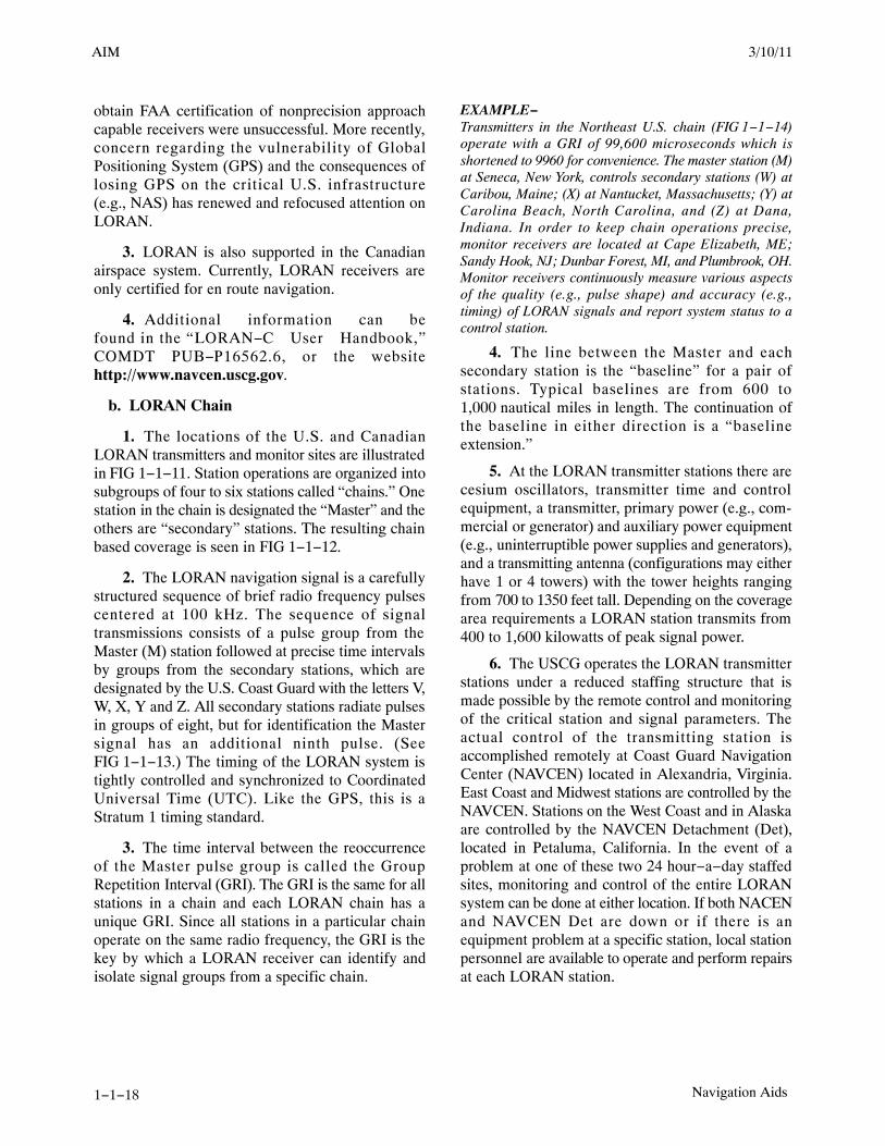
1−1−15. LORAN
a. Introduction
NOTE−In accordance with the 2010 DHS Appropriations Act, theU.S. Coast Guard (USCG) terminated the transmission ofall U.S. LORAN−C signals on 08 Feb 2010. The USCGalso terminated the transmission of the Russian Americansignals on 01 Aug 2010, and the Canadian LORAN−Csignals on 03 Aug 2010. For more information, visithttp://www.navcen.uscg.gov. Operators should also notethat TSO−C60b, AIRBORNE AREA NAVIGATIONEQUIPMENT USING LORAN−C INPUTS, has beencanceled by the FAA.
1. The LOng RAnge Navigation−C (LORAN)system is a hyperbolic, terrestrial−based navigationsystem operating in the 90−110 kHz frequency band.LORAN, operated by the U.S. Coast Guard (USCG),has been in service for over 50 years and is used fornavigation by the various transportation modes, aswell as, for precise time and frequency applications.The system is configured to provide reliable, allweather navigation for marine users along theU.S. coasts and in the Great Lakes.
2. In the 1980’s, responding to aviation user andindustry requests, the USCG and FAA expandedLORAN coverage to include the entire continentalU.S. This work was completed in late 1990, but theLORAN system failed to gain significant useracceptance and primarily due to transmitter and userequipment performance limitations, attempts to
3/10/11 AIM
AIM 2/11/10
1−1−18 Navigation Aids
obtain FAA certification of nonprecision approachcapable receivers were unsuccessful. More recently,concern regarding the vulnerability of GlobalPositioning System (GPS) and the consequences oflosing GPS on the critical U.S. infrastructure(e.g., NAS) has renewed and refocused attention onLORAN.
3. LORAN is also supported in the Canadianairspace system. Currently, LORAN receivers areonly certified for en route navigation.
4. Additional information can befound in the “LORAN−C User Handbook,”COMDT PUB−P16562.6, or the websitehttp://www.navcen.uscg.gov.
b. LORAN Chain
1. The locations of the U.S. and CanadianLORAN transmitters and monitor sites are illustratedin FIG 1−1−11. Station operations are organized intosubgroups of four to six stations called “chains.” Onestation in the chain is designated the “Master” and theothers are “secondary” stations. The resulting chainbased coverage is seen in FIG 1−1−12.
2. The LORAN navigation signal is a carefullystructured sequence of brief radio frequency pulsescentered at 100 kHz. The sequence of signaltransmissions consists of a pulse group from theMaster (M) station followed at precise time intervalsby groups from the secondary stations, which aredesignated by the U.S. Coast Guard with the letters V,W, X, Y and Z. All secondary stations radiate pulsesin groups of eight, but for identification the Mastersignal has an additional ninth pulse. (SeeFIG 1−1−13.) The timing of the LORAN system istightly controlled and synchronized to CoordinatedUniversal Time (UTC). Like the GPS, this is aStratum 1 timing standard.
3. The time interval between the reoccurrenceof the Master pulse group is called the GroupRepetition Interval (GRI). The GRI is the same for allstations in a chain and each LORAN chain has aunique GRI. Since all stations in a particular chainoperate on the same radio frequency, the GRI is thekey by which a LORAN receiver can identify andisolate signal groups from a specific chain.
EXAMPLE−Transmitters in the Northeast U.S. chain (FIG 1−1−14)operate with a GRI of 99,600 microseconds which isshortened to 9960 for convenience. The master station (M)at Seneca, New York, controls secondary stations (W) atCaribou, Maine; (X) at Nantucket, Massachusetts; (Y) atCarolina Beach, North Carolina, and (Z) at Dana,Indiana. In order to keep chain operations precise,monitor receivers are located at Cape Elizabeth, ME;Sandy Hook, NJ; Dunbar Forest, MI, and Plumbrook, OH.Monitor receivers continuously measure various aspectsof the quality (e.g., pulse shape) and accuracy (e.g.,timing) of LORAN signals and report system status to acontrol station.
4. The line between the Master and eachsecondary station is the “baseline” for a pair ofstations. Typical baselines are from 600 to1,000 nautical miles in length. The continuation ofthe baseline in either direction is a “baselineextension.”
5. At the LORAN transmitter stations there arecesium oscillators, transmitter time and controlequipment, a transmitter, primary power (e.g., com-mercial or generator) and auxiliary power equipment(e.g., uninterruptible power supplies and generators),and a transmitting antenna (configurations may eitherhave 1 or 4 towers) with the tower heights rangingfrom 700 to 1350 feet tall. Depending on the coveragearea requirements a LORAN station transmits from400 to 1,600 kilowatts of peak signal power.
6. The USCG operates the LORAN transmitterstations under a reduced staffing structure that ismade possible by the remote control and monitoringof the critical station and signal parameters. Theactual control of the transmitting station isaccomplished remotely at Coast Guard NavigationCenter (NAVCEN) located in Alexandria, Virginia.East Coast and Midwest stations are controlled by theNAVCEN. Stations on the West Coast and in Alaskaare controlled by the NAVCEN Detachment (Det),located in Petaluma, California. In the event of aproblem at one of these two 24 hour−a−day staffedsites, monitoring and control of the entire LORANsystem can be done at either location. If both NACENand NAVCEN Det are down or if there is anequipment problem at a specific station, local stationpersonnel are available to operate and perform repairsat each LORAN station.
3/15/077110.65R CHG 2AIM 3/10/11

AIM2/11/10
1−1−19Navigation Aids
FIG 1−1−11
U.S. and Canadian LORAN System Architecture
FIG 1−1−12
LORAN Chain Based Coverage
7. The transmitted signal is also monitored inthe service areas (i.e., area of published LORANcoverage) and its status provided to NAVCEN andNAVCEN Det. The System Area Monitor (SAM) isa single site used to observe the transmitted signal(signal strength, time difference, and pulse shape). Ifan out−of−tolerance situation that could affectnavigation accuracy is detected, an alert signal called
“Blink” is activated. Blink is a distinctive change inthe group of eight pulses that can be recognizedautomatically by a receiver so the user is notifiedinstantly that the LORAN system should not be usedfor navigation. Out−of−tolerance situations whichonly the local station can detect are also monitored.These situations when detected cause signaltransmissions from a station to be halted.
3/10/11 AIM

AIM 2/11/10
1−1−20 Navigation Aids
8. Each individual LORAN chain providesnavigation-quality signal coverage over an identifiedarea as shown in FIG 1−1−15 for the West Coastchain, GRI 9940. The chain Master station is atFallon, Nevada, and secondary stations are at George,Washington; Middletown, California, and Search-
light, Nevada. In a signal coverage area the signalstrength relative to the normal ambient radio noisemust be adequate to assure successful reception.Similar coverage area charts are available for allchains.
FIG 1−1−13
The LORAN Pulse and Pulse Group
3/15/077110.65R CHG 2AIM 3/10/11

AIM2/11/10
1−1−23Navigation Aids
c. The LORAN Receiver
1. For a currently certified LORAN aviationreceiver to provide navigation information for a pilot,it must successfully receive, or “acquire,” signalsfrom three or more stations in a chain. Acquisitioninvolves the time synchronization of the receiver withthe chain GRI, identification of the Master stationsignals from among those checked, identification ofsecondary station signals, and the proper selection ofthe tracking point on each signal at whichmeasurements are made. However, a new generationof receivers has been developed that use pulses fromall stations that can be received at the pilot’s location.Use of “all−in−view” stations by a receiver is madepossible due to the synchronization of LORANstations signals to UTC. This new generation ofreceivers, along with improvements at the transmit-ting stations and changes in system policy andoperations doctrine may allow for LORAN’s use innonprecision approaches. At this time these receiversare available for purchase, but none have beencertified for aviation use.
2. The basic measurements made by certifiedLORAN receivers are the differences in time−of−arrival between the Master signal and the signals fromeach of the secondary stations of a chain. Each “timedifference” (TD) value is measured to a precision ofabout 0.1 microseconds. As a rule of thumb,0.1 microsecond is equal to about 100 feet.
3. An aircraft’s LORAN receiver must recog-nize three signal conditions:
(a) Usable signals;
(b) Absence of signals, and
(c) Signal blink.
4. The most critical phase of flight is during theapproach to landing at an airport. During theapproach phase the receiver must detect a lost signal,or a signal Blink, within 10 seconds of the occurrenceand warn the pilot of the event. At this time there areno receivers that are certified for nonprecisionapproaches.
5. Most certified receivers have various internaltests for estimating the probable accuracy of thecurrent TD values and consequent navigationsolutions. Tests may include verification of the timingalignment of the receiver clock with the LORANpulse, or a continuous measurement of thesignal−to−noise ratio (SNR). SNR is the relativestrength of the LORAN signals compared to the localambient noise level. If any of the tests fail, or if thequantities measured are out of the limits set forreliable navigation, then an alarm will be activated toalert the pilot.
6. LORAN signals operate in the low frequencyband (90−110 kHz) that has been reserved for marinenavigation signals. Adjacent to the band, however,are numerous low frequency communicationstransmitters. Nearby signals can distort the LORANsignals and must be eliminated by the receiver toassure proper operation. To eliminate interferingsignals, LORAN receivers have selective internalfilters. These filters, commonly known as “notchfilters,” reduce the effect of interfering signals.
7. Careful installation of antennas, good metal−to−metal electrical bonding, and provisions forprecipitation noise discharge on the aircraft areessential for the successful operation of LORANreceivers. A LORAN antenna should be installed onan aircraft in accordance with the manufacturer’sinstructions. Corroded bonding straps should bereplaced, and static discharge devices installed atpoints indicated by the aircraft manufacturer.
d. LORAN Navigation
1. An airborne LORAN receiver has four majorparts:
(a) Signal processor;
(b) Navigation computer;
(c) Control/display, and
(d) Antenna.
2. The signal processor acquires LORANsignals and measures the difference between thetime−of−arrival of each secondary station pulsegroup and the Master station pulse group. Themeasured TDs depend on the location of the receiverin relation to the three or more transmitters.

AIM 2/11/10
1−1−24 Navigation Aids
FIG 1−1−16
First Line−of−Position
(a) The first TD will locate an aircraftsomewhere on a line−of−position (LOP) on which thereceiver will measure the same TD value.
(b) A second LOP is defined by a TDmeasurement between the Master station signal andthe signal from another secondary station.
FIG 1−1−17
Second Line−of−Position
(c) The intersection of the measured LOPs isthe position of the aircraft.
FIG 1−1−18
Intersection of Lines−of−Position
3. The navigation computer converts TD valuesto corresponding latitude and longitude. Once thetime and position of the aircraft are established attwo points, distance to destination, cross track error,ground speed, estimated time of arrival, etc., can bedetermined. Cross track error can be displayed as thevertical needle of a course deviation indicator, ordigitally, as decimal parts of a mile left or right ofcourse.
e. Notices to Airmen (NOTAMs) are issued forLORAN chain or station outages. DomesticNOTAM (D)s are issued under the identifier “LRN.”International NOTAMs are issued under the KNMHseries. Pilots may obtain these NOTAMs from FSSbriefers upon request.
f. LORAN status information. To findout more information on the LORAN systemand its operational status you can visithttp://www.navcen.uscg.gov/loran/default.htmor contact NAVCEN’s Navigation InformationService (NIS) watchstander, phone (703) 313−5900,fax (703) 313−5920.
NOTE−In accordance with the 2010 DHS Appropriations Act, theU.S. Coast Guard (USCG) terminated the transmission ofall U.S. LORAN−C signals on 08 Feb 2010. The USCG
3/15/077110.65R CHG 2AIM 3/10/11

AIM2/11/10
1−1−25Navigation Aids
also terminated the transmission of the Russian Americansignals on 01 Aug 2010, and the Canadian LORAN−Csignals on 03 Aug 2010. For more information, visithttp://www.navcen.uscg.gov. Operators should also notethat TSO−C60b, AIRBORNE AREA NAVIGATIONEQUIPMENT USING LORAN−C INPUTS, has beencanceled by the FAA.
g. LORAN’s future. The U.S. will continue tooperate the LORAN system in the short term. Duringthis time, the FAA LORAN evaluation program,being conducted with the support of a teamcomprising government, academia, and industry, willidentify and assess LORAN’s potential contributionsto required navigation services for the NationalAirspace System (NAS), and support decisionsregarding continued operation of the system. If thegovernment concludes LORAN should not be kept aspart of the mix of federally provided radio navigationsystems, it will give the users of LORAN reasonablenotice so that they will have the opportunity totransition to alternative navigation aids.
1−1−16. VHF Direction Finder
a. The VHF Direction Finder (VHF/DF) is one ofthe common systems that helps pilots without theirbeing aware of its operation. It is a ground−basedradio receiver used by the operator of the groundstation. FAA facilities that provide VHF/DF serviceare identified in the A/FD.
b. The equipment consists of a directional antennasystem and a VHF radio receiver.
c. The VHF/DF receiver display indicates themagnetic direction of the aircraft from the groundstation each time the aircraft transmits.
d. DF equipment is of particular value in locatinglost aircraft and in helping to identify aircraft onradar.
REFERENCE−AIM, Direction Finding Instrument Approach Procedure,Paragraph 6−2−3.
1−1−17. Inertial Reference Unit (IRU),Inertial Navigation System (INS), andAttitude Heading Reference System (AHRS)
a. IRUs are self−contained systems comprised ofgyros and accelerometers that provide aircraftattitude (pitch, roll, and heading), position, andvelocity information in response to signals resulting
from inertial effects on system components. Oncealigned with a known position, IRUs continuouslycalculate position and velocity. IRU positionaccuracy decays with time. This degradation isknown as “drift.”
b. INSs combine the components of an IRU withan internal navigation computer. By programming aseries of waypoints, these systems will navigate alonga predetermined track.
c. AHRSs are electronic devices that provideattitude information to aircraft systems such asweather radar and autopilot, but do not directlycompute position information.
1−1−18. Doppler Radar
Doppler Radar is a semiautomatic self−containeddead reckoning navigation system (radar sensor pluscomputer) which is not continuously dependent oninformation derived from ground based or externalaids. The system employs radar signals to detect andmeasure ground speed and drift angle, using theaircraft compass system as its directional reference.Doppler is less accurate than INS, however, and theuse of an external reference is required for periodicupdates if acceptable position accuracy is to beachieved on long range flights.
1−1−19. Global Positioning System (GPS)
a. System Overview
1. System Description. The Global PositioningSystem is a satellite−based radio navigation system,which broadcasts a signal that is used by receivers todetermine precise position anywhere in the world.The receiver tracks multiple satellites and determinesa pseudorange measurement that is then used todetermine the user location. A minimum of foursatellites is necessary to establish an accuratethree−dimensional position. The Department ofDefense (DOD) is responsible for operating the GPSsatellite constellation and monitors the GPS satellitesto ensure proper operation. Every satellite’s orbitalparameters (ephemeris data) are sent to each satellitefor broadcast as part of the data message embeddedin the GPS signal. The GPS coordinate system is theCartesian earth−centered earth−fixed coordinates asspecified in the World Geodetic System 1984(WGS−84).
3/10/11 AIM

AIM 2/11/10
1−1−26 Navigation Aids
2. System Availability and Reliability
(a) The status of GPS satellites is broadcast aspart of the data message transmitted by the GPSsatellites. GPS status information is also available bymeans of the U.S. Coast Guard navigationinformation service: (703) 313−5907, Internet:http://www.navcen.uscg.gov/. Additionally, satel-lite status is available through the Notice to Airmen(NOTAM) system.
(b) The operational status of GNSS opera-tions depends upon the type of equipment being used.For GPS−only equipment TSO−C129(a), the opera-tional status of nonprecision approach capability forflight planning purposes is provided through aprediction program that is embedded in the receiveror provided separately.
3. Receiver Autonomous Integrity Monitoring(RAIM). When GNSS equipment is not usingintegrity information from WAAS or LAAS, the GPSnavigation receiver using RAIM provides GPS signalintegrity monitoring. RAIM is necessary since delaysof up to two hours can occur before an erroneoussatellite transmission can be detected and correctedby the satellite control segment. The RAIM functionis also referred to as fault detection. Anothercapability, fault exclusion, refers to the ability of thereceiver to exclude a failed satellite from the positionsolution and is provided by some GPS receivers andby WAAS receivers.
4. The GPS receiver verifies the integrity(usability) of the signals received from the GPSconstellation through receiver autonomous integritymonitoring (RAIM) to determine if a satellite isproviding corrupted information. At least onesatellite, in addition to those required for navigation,must be in view for the receiver to perform the RAIMfunction; thus, RAIM needs a minimum of 5 satellitesin view, or 4 satellites and a barometric altimeter(baro−aiding) to detect an integrity anomaly.[Baro−aiding satisfies the RAIM requirement in lieuof a fifth satellite.] For receivers capable of doing so,RAIM needs 6 satellites in view (or 5 satellites withbaro−aiding) to isolate the corrupt satellite signal andremove it from the navigation solution. Baro−aidingis a method of augmenting the GPS integrity solutionby using a nonsatellite input source. GPS derivedaltitude should not be relied upon to determineaircraft altitude since the vertical error can be quitelarge and no integrity is provided. To ensure that
baro−aiding is available, the current altimeter settingmust be entered into the receiver as described in theoperating manual.
5. RAIM messages vary somewhat betweenreceivers; however, generally there are two types.One type indicates that there are not enough satellitesavailable to provide RAIM integrity monitoring andanother type indicates that the RAIM integritymonitor has detected a potential error that exceeds thelimit for the current phase of flight. Without RAIMcapability, the pilot has no assurance of the accuracyof the GPS position.
6. Selective Availability. Selective Availability(SA) is a method by which the accuracy of GPS isintentionally degraded. This feature is designed todeny hostile use of precise GPS positioning data. SAwas discontinued on May 1, 2000, but many GPSreceivers are designed to assume that SA is stillactive. New receivers may take advantage of thediscontinuance of SA based on the performancevalues in ICAO Annex 10, and do not need to bedesigned to operate outside of that performance.
7. The GPS constellation of 24 satellites isdesigned so that a minimum of five is alwaysobservable by a user anywhere on earth. The receiveruses data from a minimum of four satellites above themask angle (the lowest angle above the horizon atwhich it can use a satellite).
8. The DOD declared initial operational capa-bility (IOC) of the U.S. GPS on December 8, 1993.The FAA has granted approval for U.S. civiloperators to use properly certified GPS equipment asa primary means of navigation in oceanic airspaceand certain remote areas. Properly certified GPSequipment may be used as a supplemental means ofIFR navigation for domestic en route, terminaloperations, and certain instrument approach proce-dures (IAPs). This approval permits the use of GPS ina manner that is consistent with current navigationrequirements as well as approved air carrieroperations specifications.
b. VFR Use of GPS
1. GPS navigation has become a great asset toVFR pilots, providing increased navigation capabili-ty and enhanced situational awareness, whilereducing operating costs due to greater ease in flyingdirect routes. While GPS has many benefits to theVFR pilot, care must be exercised to ensure thatsystem capabilities are not exceeded.
3/15/077110.65R CHG 2AIM 3/10/11

AIM2/11/10
1−1−27Navigation Aids
2. Types of receivers used for GPS navigationunder VFR are varied, from a full IFR installationbeing used to support a VFR flight, to a VFR onlyinstallation (in either a VFR or IFR capable aircraft)to a hand−held receiver. The limitations of each typeof receiver installation or use must be understood bythe pilot to avoid misusing navigation information.(See TBL 1−1−6.) In all cases, VFR pilots shouldnever rely solely on one system of navigation. GPSnavigation must be integrated with other forms ofelectronic navigation (when possible), as well aspilotage and dead reckoning. Only through theintegration of these techniques can the VFR pilotensure accuracy in navigation.
3. Some critical concerns in VFR use of GPSinclude RAIM capability, database currency andantenna location.
(a) RAIM Capability. Many VFR GPS re-ceivers and all hand−held units have no RAIMalerting capability. Loss of the required number ofsatellites in view, or the detection of a position error,cannot be displayed to the pilot by such receivers. Inreceivers with no RAIM capability, no alert would beprovided to the pilot that the navigation solution haddeteriorated, and an undetected navigation errorcould occur. A systematic cross−check with othernavigation techniques would identify this failure, andprevent a serious deviation. See subparagraphs a4 anda5 for more information on RAIM.
(b) Database Currency
(1) In many receivers, an up−databledatabase is used for navigation fixes, airports, andinstrument procedures. These databases must bemaintained to the current update for IFR operation,but no such requirement exists for VFR use.
(2) However, in many cases, the databasedrives a moving map display which indicates SpecialUse Airspace and the various classes of airspace, inaddition to other operational information. Without acurrent database the moving map display may beoutdated and offer erroneous information to VFRpilots wishing to fly around critical airspace areas,such as a Restricted Area or a Class B airspacesegment. Numerous pilots have ventured intoairspace they were trying to avoid by using anoutdated database. If you don’t have a currentdatabase in the receiver, disregard the moving mapdisplay for critical navigation decisions.
(3) In addition, waypoints are added,removed, relocated, or re−named as required to meetoperational needs. When using GPS to navigaterelative to a named fix, a current database must beused to properly locate a named waypoint. Withoutthe update, it is the pilot’s responsibility to verify thewaypoint location referencing to an official currentsource, such as the Airport/Facility Directory,Sectional Chart, or En Route Chart.
(c) Antenna Location
(1) In many VFR installations of GPSreceivers, antenna location is more a matter ofconvenience than performance. In IFR installations,care is exercised to ensure that an adequate clear viewis provided for the antenna to see satellites. If analternate location is used, some portion of the aircraftmay block the view of the antenna, causing a greateropportunity to lose navigation signal.
(2) This is especially true in the case ofhand−helds. The use of hand−held receivers for VFRoperations is a growing trend, especially amongrental pilots. Typically, suction cups are used to placethe GPS antennas on the inside of cockpit windows.While this method has great utility, the antennalocation is limited to the cockpit or cabin only and israrely optimized to provide a clear view of availablesatellites. Consequently, signal losses may occur incertain situations of aircraft−satellite geometry,causing a loss of navigation signal. These losses,coupled with a lack of RAIM capability, couldpresent erroneous position and navigation informa-tion with no warning to the pilot.
(3) While the use of a hand−held GPS forVFR operations is not limited by regulation,modification of the aircraft, such as installing apanel− or yoke−mounted holder, is governed by14 CFR Part 43. Consult with your mechanic toensure compliance with the regulation, and a safeinstallation.
4. As a result of these and other concerns, hereare some tips for using GPS for VFR operations:
(a) Always check to see if your unit hasRAIM capability. If no RAIM capability exists, besuspicious of your GPS position when anydisagreement exists with the position derived fromother radio navigation systems, pilotage, or deadreckoning.
(b) Check the currency of the database, if any.If expired, update the database using the current
3/10/11 AIM

AIM 2/11/10
1−1−28 Navigation Aids
revision. If an update of an expired database is notpossible, disregard any moving map display ofairspace for critical navigation decisions. Be awarethat named waypoints may no longer exist or mayhave been relocated since the database expired. At aminimum, the waypoints planned to be used shouldbe checked against a current official source, such asthe Airport/Facility Directory, or a SectionalAeronautical Chart.
(c) While hand−helds can provide excellentnavigation capability to VFR pilots, be prepared forintermittent loss of navigation signal, possibly withno RAIM warning to the pilot. If mounting thereceiver in the aircraft, be sure to comply with14 CFR Part 43.
(d) Plan flights carefully before taking off. Ifyou wish to navigate to user−defined waypoints, enterthem before flight, not on−the−fly. Verify yourplanned flight against a current source, such as acurrent sectional chart. There have been cases inwhich one pilot used waypoints created by anotherpilot that were not where the pilot flying wasexpecting. This generally resulted in a navigationerror. Minimize head−down time in the aircraft andkeep a sharp lookout for traffic, terrain, and obstacles.Just a few minutes of preparation and planning on theground will make a great difference in the air.
(e) Another way to minimize head−downtime is to become very familiar with your receiver’soperation. Most receivers are not intuitive. The pilotmust take the time to learn the various keystrokes,knob functions, and displays that are used in theoperation of the receiver. Some manufacturersprovide computer−based tutorials or simulations oftheir receivers. Take the time to learn about yourparticular unit before you try to use it in flight.
5. In summary, be careful not to rely on GPS tosolve all your VFR navigational problems. Unless anIFR receiver is installed in accordance with IFRrequirements, no standard of accuracy or integrity hasbeen assured. While the practicality of GPS iscompelling, the fact remains that only the pilot cannavigate the aircraft, and GPS is just one of the pilot’stools to do the job.
c. VFR Waypoints
1. VFR waypoints provide VFR pilots with asupplementary tool to assist with position awarenesswhile navigating visually in aircraft equipped with
area navigation receivers. VFR waypoints should beused as a tool to supplement current navigationprocedures. The uses of VFR waypoints includeproviding navigational aids for pilots unfamiliar withan area, waypoint definition of existing reportingpoints, enhanced navigation in and around Class Band Class C airspace, and enhanced navigationaround Special Use Airspace. VFR pilots should relyon appropriate and current aeronautical chartspublished specifically for visual navigation. Ifoperating in a terminal area, pilots should takeadvantage of the Terminal Area Chart available forthat area, if published. The use of VFR waypointsdoes not relieve the pilot of any responsibility tocomply with the operational requirements of 14 CFRPart 91.
2. VFR waypoint names (for computer−entryand flight plans) consist of five letters beginning withthe letters “VP” and are retrievable from navigationdatabases. The VFR waypoint names are not intendedto be pronounceable, and they are not for use in ATCcommunications. On VFR charts, stand−alone VFRwaypoints will be portrayed using the samefour−point star symbol used for IFR waypoints. VFRwaypoints collocated with visual check points on thechart will be identified by small magenta flagsymbols. VFR waypoints collocated with visualcheck points will be pronounceable based on thename of the visual check point and may be used forATC communications. Each VFR waypoint namewill appear in parentheses adjacent to the geographiclocation on the chart. Latitude/longitude data for allestablished VFR waypoints may be found in theappropriate regional Airport/Facility Directory(A/FD).
3. VFR waypoints shall not be used to planflights under IFR. VFR waypoints will not berecognized by the IFR system and will be rejected forIFR routing purposes.
4. When filing VFR flight plans, pilots may usethe five letter identifier as a waypoint in the route offlight section if there is an intended course change atthat point or if used to describe the planned route offlight. This VFR filing would be similar to how aVOR would be used in a route of flight. Pilots mustuse the VFR waypoints only when operating underVFR conditions.
5. Any VFR waypoints intended for use duringa flight should be loaded into the receiver while on theground and prior to departure. Once airborne, pilots
3/15/077110.65R CHG 2AIM 3/10/11

AIM2/11/10
1−1−29Navigation Aids
should avoid programming routes or VFR waypointchains into their receivers.
6. Pilots should be especially vigilant for othertraffic while operating near VFR waypoints. Thesame effort to see and avoid other aircraft near VFRwaypoints will be necessary, as was the case withVORs and NDBs in the past. In fact, the increasedaccuracy of navigation through the use of GPS willdemand even greater vigilance, as off−coursedeviations among different pilots and receivers willbe less. When operating near a VFR waypoint, usewhatever ATC services are available, even if outsidea class of airspace where communications arerequired. Regardless of the class of airspace, monitorthe available ATC frequency closely for informationon other aircraft operating in the vicinity. It is also agood idea to turn on your landing light(s) whenoperating near a VFR waypoint to make your aircraftmore conspicuous to other pilots, especially whenvisibility is reduced. See paragraph 7−5−2, VFR inCongested Areas, for more information.
d. General Requirements
1. Authorization to conduct any GPS operationunder IFR requires that:
(a) GPS navigation equipment used must beapproved in accordance with the requirementsspecified in Technical Standard Order (TSO)TSO−C129, or equivalent, and the installation mustbe done in accordance with Advisory CircularAC 20−138, Airworthiness Approval of GlobalPositioning System (GPS) Navigation Equipment forUse as a VFR and IFR Supplemental NavigationSystem, or Advisory Circular AC 20−130A, Airwor-thiness Approval of Navigation or FlightManagement Systems Integrating Multiple Naviga-tion Sensors, or equivalent. Equipment approved inaccordance with TSO−C115a does not meet therequirements of TSO−C129. Visual flight rules(VFR) and hand−held GPS systems are notauthorized for IFR navigation, instrument ap-proaches, or as a principal instrument flightreference. During IFR operations they may beconsidered only an aid to situational awareness.
(b) Aircraft using GPS navigation equipmentunder IFR must be equipped with an approved andoperational alternate means of navigation appropriateto the flight. Active monitoring of alternativenavigation equipment is not required if the GPS
receiver uses RAIM for integrity monitoring. Activemonitoring of an alternate means of navigation isrequired when the RAIM capability of the GPSequipment is lost.
(c) Procedures must be established for use inthe event that the loss of RAIM capability is predictedto occur. In situations where this is encountered, theflight must rely on other approved equipment, delaydeparture, or cancel the flight.
(d) The GPS operation must be conducted inaccordance with the FAA−approved aircraft flightmanual (AFM) or flight manual supplement. Flightcrew members must be thoroughly familiar with theparticular GPS equipment installed in the aircraft, thereceiver operation manual, and the AFM or flightmanual supplement. Unlike ILS and VOR, the basicoperation, receiver presentation to the pilot, and somecapabilities of the equipment can vary greatly. Due tothese differences, operation of different brands, oreven models of the same brand, of GPS receiverunder IFR should not be attempted without thoroughstudy of the operation of that particular receiver andinstallation. Most receivers have a built−in simulatormode which will allow the pilot to become familiarwith operation prior to attempting operation in theaircraft. Using the equipment in flight under VFRconditions prior to attempting IFR operation willallow further familiarization.
(e) Aircraft navigating by IFR approved GPSare considered to be area navigation (RNAV) aircraftand have special equipment suffixes. File theappropriate equipment suffix in accordance withTBL 5−1−2, on the ATC flight plan. If GPS avionicsbecome inoperative, the pilot should advise ATC andamend the equipment suffix.
(f) Prior to any GPS IFR operation, the pilotmust review appropriate NOTAMs and aeronauticalinformation. (See GPS NOTAMs/AeronauticalInformation.)
(g) Air carrier and commercial operatorsmust meet the appropriate provisions of theirapproved operations specifications.
e. Use of GPS for IFR Oceanic, DomesticEn Route, and Terminal Area Operations
1. GPS IFR operations in oceanic areas can beconducted as soon as the proper avionics systems areinstalled, provided all general requirements are met.A GPS installation with TSO−C129 authorization in
3/10/11 AIM

AIM 2/11/10
1−1−30 Navigation Aids
class A1, A2, B1, B2, C1, or C2 may be used toreplace one of the other approved means oflong−range navigation, such as dual INS. (SeeTBL 1−1−5 and TBL 1−1−6.) A single GPS installa-tion with these classes of equipment which provideRAIM for integrity monitoring may also be used onshort oceanic routes which have only required onemeans of long−range navigation.
2. GPS domestic en route and terminal IFRoperations can be conducted as soon as properavionics systems are installed, provided all generalrequirements are met. The avionics necessary toreceive all of the ground−based facilities appropriatefor the route to the destination airport and any
required alternate airport must be installed andoperational. Ground−based facilities necessary forthese routes must also be operational.
(a) GPS en route IFR RNAV operations maybe conducted in Alaska outside the operationalservice volume of ground−based navigation aidswhen a TSO−C145a or TSO−C146a GPS/WAASsystem is installed and operating. Ground−basednavigation equipment is not required to be installedand operating for en route IFR RNAV operationswhen using GPS WAAS navigation systems. Alloperators should ensure that an alternate means ofnavigation is available in the unlikely event the GPSWAAS navigation system becomes inoperative.
TBL 1−1−5
GPS IFR Equipment Classes/Categories
TSO−C129
EquipmentClass RAIM
Int. Nav. Sys. toProv. RAIM
Equiv.Oceanic En Route Terminal
NonprecisionApproachCapable
Class A − GPS sensor and navigation capability.
A1 yes yes yes yes yes
A2 yes yes yes yes no
Class B − GPS sensor data to an integrated navigation system (i.e., FMS, multi−sensor navigation system, etc.).
B1 yes yes yes yes yes
B2 yes yes yes yes no
B3 yes yes yes yes yes
B4 yes yes yes yes no
Class C − GPS sensor data to an integrated navigation system (as in Class B) which provides enhanced guidance to an autopilot, orflight director, to reduce flight tech. errors. Limited to 14 CFR Part 121 or equivalent criteria.
C1 yes yes yes yes yes
C2 yes yes yes yes no
C3 yes yes yes yes yes
C4 yes yes yes yes no
3/15/077110.65R CHG 2AIM 3/10/11

AIM2/11/10
1−1−33Navigation Aids
3. Civilian pilots may obtain GPS RAIMavailability information for nonprecision approachprocedures by specifically requesting GPSaeronautical information from an Automated FlightService Station during preflight briefings. GPSRAIM aeronautical information can be obtained fora period of 3 hours (for example, if you arescheduled to arrive at 1215 hours, then the GPSRAIM information is available from 1100 to1400 hours) or a 24 hour time frame at a particularairport. FAA briefers will provide RAIM informationfor a period of 1 hour before to 1 hour after the ETAhour, unless a specific time frame is requested by thepilot. If flying a published GPS departure, a RAIMprediction should also be requested for the departureairport.
4. The military provides airfield specific GPSRAIM NOTAMs for nonprecision approach proce-dures at military airfields. The RAIM outages areissued as M−series NOTAMs and may be obtained forup to 24 hours from the time of request.
5. Receiver manufacturers and/or databasesuppliers may supply “NOTAM” type informationconcerning database errors. Pilots should check thesesources, when available, to ensure that they have themost current information concerning their electronicdatabase.
i. Receiver Autonomous Integrity Monitoring(RAIM)
1. RAIM outages may occur due to aninsufficient number of satellites or due to unsuitablesatellite geometry which causes the error in theposition solution to become too large. Loss of satellitereception and RAIM warnings may occur due toaircraft dynamics (changes in pitch or bank angle).Antenna location on the aircraft, satellite positionrelative to the horizon, and aircraft attitude may affectreception of one or more satellites. Since the relativepositions of the satellites are constantly changing,prior experience with the airport does not guaranteereception at all times, and RAIM availability shouldalways be checked.
2. If RAIM is not available, another type ofnavigation and approach system must be used,another destination selected, or the trip delayed untilRAIM is predicted to be available on arrival. Onlonger flights, pilots should consider rechecking theRAIM prediction for the destination during the flight.
This may provide early indications that anunscheduled satellite outage has occurred sincetakeoff.
3. If a RAIM failure/status annunciationoccurs prior to the final approach waypoint(FAWP), the approach should not be completedsince GPS may no longer provide the requiredaccuracy. The receiver performs a RAIM predictionby 2 NM prior to the FAWP to ensure that RAIM isavailable at the FAWP as a condition for entering theapproach mode. The pilot should ensure that thereceiver has sequenced from “Armed” to“Approach” prior to the FAWP (normally occurs2 NM prior). Failure to sequence may be anindication of the detection of a satellite anomaly,failure to arm the receiver (if required), or otherproblems which preclude completing the approach.
4. If the receiver does not sequence into theapproach mode or a RAIM failure/status annunci-ation occurs prior to the FAWP, the pilot should notdescend to Minimum Descent Altitude (MDA), butshould proceed to the missed approach way-point (MAWP) via the FAWP, perform a missedapproach, and contact ATC as soon as practical. Referto the receiver operating manual for specificindications and instructions associated with loss ofRAIM prior to the FAF.
5. If a RAIM failure occurs after the FAWP, thereceiver is allowed to continue operating without anannunciation for up to 5 minutes to allow completionof the approach (see receiver operating manual). Ifthe RAIM flag/status annunciation appears afterthe FAWP, the missed approach should beexecuted immediately.
j. Waypoints
1. GPS approaches make use of both fly−overand fly−by waypoints. Fly−by waypoints are usedwhen an aircraft should begin a turn to the next courseprior to reaching the waypoint separating the tworoute segments. This is known as turn anticipationand is compensated for in the airspace and terrainclearances. Approach waypoints, except for theMAWP and the missed approach holding waypoint(MAHWP), are normally fly−by waypoints. Fly−over waypoints are used when the aircraft must flyover the point prior to starting a turn. New approachcharts depict fly−over waypoints as a circledwaypoint symbol. Overlay approach charts and someearly stand alone GPS approach charts may not
3/10/11 AIM

AIM 2/11/10
1−1−34 Navigation Aids
reflect this convention.
2. Since GPS receivers are basically “To−To”navigators, they must always be navigating to adefined point. On overlay approaches, if nopronounceable five−character name is published foran approach waypoint or fix, it was given a databaseidentifier consisting of letters and numbers. Thesepoints will appear in the list of waypoints in theapproach procedure database, but may not appear onthe approach chart. A point used for the purpose ofdefining the navigation track for an airbornecomputer system (i.e., GPS or FMS) is called aComputer Navigation Fix (CNF). CNFs includeunnamed DME fixes, beginning and ending points ofDME arcs and sensor final approach fixes (FAFs) onsome GPS overlay approaches. To aid in the approachchart/database correlation process, the FAA hasbegun a program to assign five−letter names to CNFsand to chart CNFs on various National OceanicService aeronautical products. These CNFs are not tobe used for any air traffic control (ATC) application,such as holding for which the fix has not already beenassessed. CNFs will be charted to distinguish themfrom conventional reporting points, fixes, intersec-tions, and waypoints. The CNF name will be enclosedin parenthesis, e.g., (MABEE), and the name will beplaced next to the CNF it defines. If the CNF is not atan existing point defined by means such as crossingradials or radial/DME, the point will be indicated byan “X.” The CNF name will not be used in filing aflight plan or in aircraft/ATC communications. Usecurrent phraseology, e.g., facility name, radial,distance, to describe these fixes.
3. Unnamed waypoints in the database will beuniquely identified for each airport but may berepeated for another airport (e.g., RW36 will be usedat each airport with a runway 36 but will be at thesame location for all approaches at a given airport).
4. The runway threshold waypoint, which isnormally the MAWP, may have a five letter identifier(e.g., SNEEZ) or be coded as RW## (e.g., RW36,RW36L). Those thresholds which are coded as fiveletter identifiers are being changed to the RW##designation. This may cause the approach chart anddatabase to differ until all changes are complete. Therunway threshold waypoint is also used as the centerof the Minimum Safe Altitude (MSA) on most GPSapproaches. MAWPs not located at the threshold willhave a five letter identifier.
k. Position Orientation
As with most RNAV systems, pilots should payparticular attention to position orientation whileusing GPS. Distance and track information areprovided to the next active waypoint, not to a fixednavigation aid. Receivers may sequence when thepilot is not flying along an active route, such as whenbeing vectored or deviating for weather, due to theproximity to another waypoint in the route. This canbe prevented by placing the receiver in thenonsequencing mode. When the receiver is in thenonsequencing mode, bearing and distance areprovided to the selected waypoint and the receiverwill not sequence to the next waypoint in the routeuntil placed back in the auto sequence mode or thepilot selects a different waypoint. On overlayapproaches, the pilot may have to compute thealong−track distance to stepdown fixes and otherpoints due to the receiver showing along−trackdistance to the next waypoint rather than DME to theVOR or ILS ground station.
l. Conventional Versus GPS Navigation Data
There may be slight differences between the courseinformation portrayed on navigational charts and aGPS navigation display when flying authorized GPSinstrument procedures or along an airway. Allmagnetic tracks defined by any conventionalnavigation aids are determined by the application ofthe station magnetic variation. In contrast, GPSRNAV systems may use an algorithm, which appliesthe local magnetic variation and may produce smalldifferences in the displayed course. However, bothmethods of navigation should produce the samedesired ground track when using approved, IFRnavigation system. Should significant differencesbetween the approach chart and the GPS avionics’application of the navigation database arise, thepublished approach chart, supplemented byNOTAMs, holds precedence.
Due to the GPS avionics’ computation of great circlecourses, and the variations in magnetic variation, thebearing to the next waypoint and the course from thelast waypoint (if available) may not be exactly 180�apart when long distances are involved. Variations indistances will occur since GPS distance−to−waypointvalues are along−track distances (ATD) computed tothe next waypoint and the DME values published onunderlying procedures are slant−range distances
3/15/077110.65R CHG 2AIM 3/10/11

AIM2/11/10
1−2−5Area Navigation (RNAV) and Required Navigation Performance (RNP)
TBL 1−2−2
RNP Levels Supported for International Operations
RNP Level Typical Application
4 Projected for oceanic/remote areas where 30 NM horizontal separation is applied
10 Oceanic/remote areas where 50 NM lateral separation is applied
c. Other RNP Applications Outside the U.S.The FAA and ICAO member states have ledinitiatives in implementing the RNP concept tooceanic operations. For example, RNP−10 routeshave been established in the northern Pacific(NOPAC) which has increased capacity andefficiency by reducing the distance between tracksto 50 NM. (See TBL 1−2−2.)
d. Aircraft and Airborne Equipment Eligibilityfor RNP Operations. Aircraft meeting RNP criteriawill have an appropriate entry including specialconditions and limitations in its Aircraft FlightManual (AFM), or supplement. Operators of aircraftnot having specific AFM−RNP certification may beissued operational approval including special condi-tions and limitations for specific RNP levels.
NOTE−Some airborne systems use Estimated Position Uncer-tainty (EPU) as a measure of the current estimatednavigational performance. EPU may also be referred to asActual Navigation Performance (ANP) or EstimatedPosition Error (EPE).
1−2−3. Use of Suitable Area Navigation(RNAV) Systems on ConventionalProcedures and Routes
a. Discussion. This paragraph sets forth policy,while providing operational and airworthinessguidance regarding the suitability and use of RNAVsystems when operating on, or transitioning to,conventional, non−RNAV routes and procedureswithin the U.S. National Airspace System (NAS):
1. Use of a suitable RNAV system as aSubstitute Means of Navigation when a Very−HighFrequency (VHF) Omni−directional Range (VOR),Distance Measuring Equipment (DME), Tactical AirNavigation (TACAN), VOR/TACAN (VORTAC),VOR/DME, Non−directional Beacon (NDB), orcompass locator facility including locator outermarker and locator middle marker is out−of−service(that is, the navigation aid (NAVAID) information is
not available); an aircraft is not equipped with anAutomatic Direction Finder (ADF) or DME; or theinstalled ADF or DME on an aircraft is notoperational. For example, if equipped with a suitableRNAV system, a pilot may hold over an out−of−service NDB.
2. Use of a suitable RNAV system as anAlternate Means of Navigation when a VOR, DME,VORTAC, VOR/DME, TACAN, NDB, or compasslocator facility including locator outer marker andlocator middle marker is operational and therespective aircraft is equipped with operationalnavigation equipment that is compatible withconventional navaids. For example, if equipped witha suitable RNAV system, a pilot may fly a procedureor route based on operational VOR using that RNAVsystem without monitoring the VOR.
NOTE−1. Additional information and associated requirementsare available via a 90−series Advisory Circular titled “Useof Suitable RNAV Systems on Conventional Routes andProcedures.”
2. Good planning and knowledge of your RNAV system arecritical for safe and successful operations.
3. Pilots planning to use their RNAV system as a substitutemeans of navigation guidance in lieu of an out−of−serviceNAVAID may need to advise ATC of this intent andcapability.
4. The navigation database should be current for theduration of the flight. If the AIRAC cycle will changeduring flight, operators and pilots should establishprocedures to ensure the accuracy of navigation data,including suitability of navigation facilities used to definethe routes and procedures for flight. To facilitate validatingdatabase currency, the FAA has developed procedures forpublishing the amendment date that instrument approachprocedures were last revised. The amendment date followsthe amendment number, e.g., Amdt 4 14Jan10. Currency ofgraphic departure procedures and STARs may beascertained by the numerical designation in the proceduretitle. If an amended chart is published for the procedure, orthe procedure amendment date shown on the chart is on or
3/10/11 AIM

AIM 2/11/10
1−2−6 Area Navigation (RNAV) and Required Navigation Performance (RNP)
after the expiration date of the database, the operator mustnot use the database to conduct the operation.
b. Types of RNAV Systems that Qualify as aSuitable RNAV System. When installed in accord-ance with appropriate airworthiness installationrequirements and operated in accordance withapplicable operational guidance (e.g., aircraft flightmanual and Advisory Circular material), thefollowing systems qualify as a suitable RNAVsystem:
1. An RNAV system with TSO−C129/−C145/−C146 equipment, installed in accordancewith AC 20−138, Airworthiness Approval of GlobalPositioning System (GPS) Navigation Equipment forUse as a VFR and IFR Supplemental NavigationSystem, or AC 20−130A, Airworthiness Approval ofNavigation or Flight Management Systems Integrat-ing Multiple Navigation Sensors, and authorized forinstrument flight rules (IFR) en route and terminaloperations (including those systems previouslyqualified for “GPS in lieu of ADF or DME”operations), or
2. An RNAV system with DME/DME/IRUinputs that is compliant with the equipmentprovisions of AC 90−100A, U.S. Terminal andEn Route Area Navigation (RNAV) Operations, forRNAV routes. A table of compliant equipment isavailable at the following website:h t t p : / / w w w. f a a . g o v / a b o u t / o f f i c e _ o r g /headquarters_offices/avs/offices/afs/afs400/afs470/policy_guidance/
NOTE−Approved RNAV systems using DME/DME/IRU, withoutGPS/WAAS position input, may only be used as a substitutemeans of navigation when specifically authorized by aNotice to Airmen (NOTAM) or other FAA guidance for aspecific procedure. The NOTAM or other FAA guidanceauthorizing the use of DME/DME/IRU systems will alsoidentify any required DME facilities based on an FAAassessment of the DME navigation infrastructure.
c. Uses of Suitable RNAV Systems. Subject tothe operating requirements, operators may use asuitable RNAV system in the following ways.
1. Determine aircraft position relative to, ordistance from a VOR (see NOTE 5 below), TACAN,NDB, compass locator, DME fix; or a named fixdefined by a VOR radial, TACAN course, NDBbearing, or compass locator bearing intersecting aVOR or localizer course.
2. Navigate to or from a VOR, TACAN, NDB,or compass locator.
3. Hold over a VOR, TACAN, NDB, compasslocator, or DME fix.
4. Fly an arc based upon DME.
NOTE−1. The allowances described in this section apply evenwhen a facility is identified as required on a procedure (forexample, “Note ADF required”).
2. These operations do not include lateral navigation onlocalizer−based courses (including localizer back−courseguidance) without reference to raw localizer data.
3. Unless otherwise specified, a suitable RNAV systemcannot be used for navigation on procedures that areidentified as not authorized (“NA”) without exception bya NOTAM. For example, an operator may not use a RNAVsystem to navigate on a procedure affected by an expired orunsatisfactory flight inspection, or a procedure that isbased upon a recently decommissioned NAVAID.
4. Pilots may not substitute for the NAVAID (for example,a VOR or NDB) providing lateral guidance for the finalapproach segment. This restriction does not refer toinstrument approach procedures with “or GPS” in the titlewhen using GPS or WAAS. These allowances do not applyto procedures that are identified as not authorized (NA)without exception by a NOTAM, as other conditions maystill exist and result in a procedure not being available. Forexample, these allowances do not apply to a procedureassociated with an expired or unsatisfactory flightinspection, or is based upon a recently decommissionedNAVAID.
5. For the purpose of paragraph c, “VOR” includes VOR,VOR/DME, and VORTAC facilities and “compasslocator” includes locator outer marker and locator middlemarker.
3/15/077110.65R CHG 2AIM 3/10/11

AIM2/11/10
1−2−7Area Navigation (RNAV) and Required Navigation Performance (RNP)
d. Alternate Airport Considerations. For thepurposes of flight planning, any required alternateairport must have an available instrument approachprocedure that does not require the use of GPS. Thisrestriction includes conducting a conventionalapproach at the alternate airport using a substitutemeans of navigation that is based upon the use ofGPS. For example, these restrictions would apply
when planning to use GPS equipment as a substitutemeans of navigation for an out−of−service VOR thatsupports an ILS missed approach procedure at analternate airport. In this case, some other approachnot reliant upon the use of GPS must be available.This restriction does not apply to RNAV systemsusing TSO−C145/−C146 WAAS equipment. Forfurther WAAS guidance see AIM 1−1−20.
3/10/11 AIM

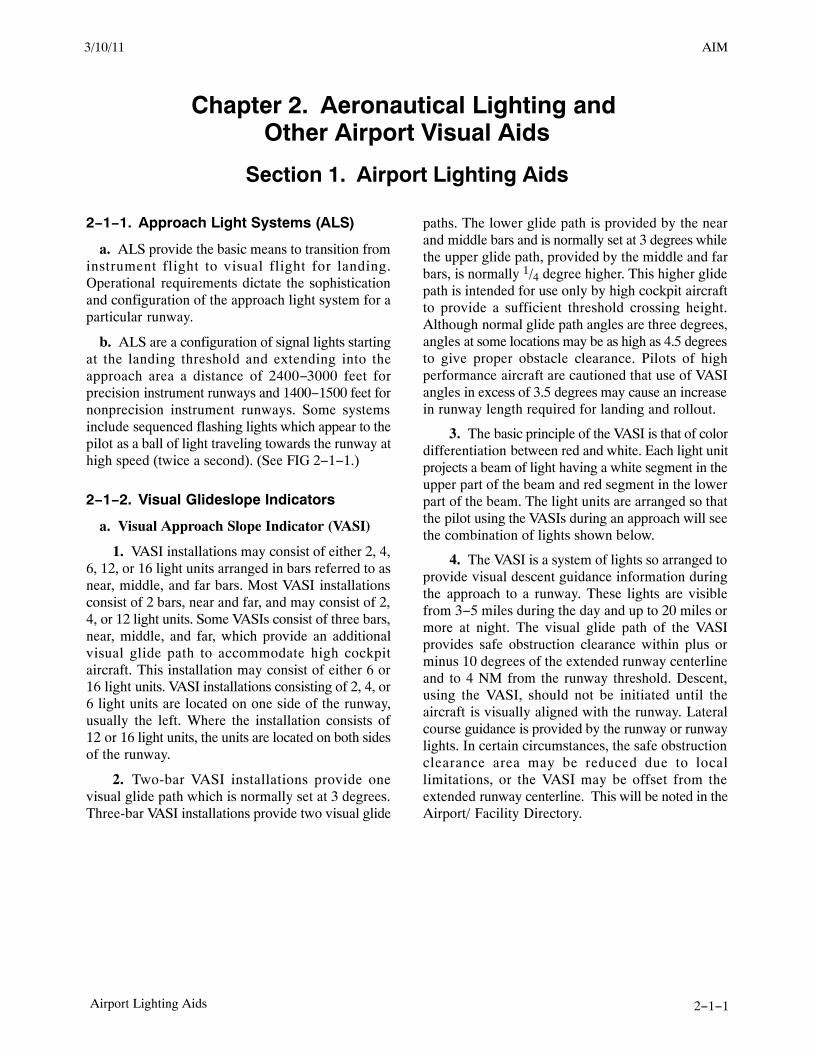
AIM2/11/10
2−1−1Airport Lighting Aids
Chapter 2. Aeronautical Lighting and Other Airport Visual Aids
Section 1. Airport Lighting Aids
2−1−1. Approach Light Systems (ALS)
a. ALS provide the basic means to transition frominstrument flight to visual flight for landing.Operational requirements dictate the sophisticationand configuration of the approach light system for aparticular runway.
b. ALS are a configuration of signal lights startingat the landing threshold and extending into theapproach area a distance of 2400−3000 feet forprecision instrument runways and 1400−1500 feet fornonprecision instrument runways. Some systemsinclude sequenced flashing lights which appear to thepilot as a ball of light traveling towards the runway athigh speed (twice a second). (See FIG 2−1−1.)
2−1−2. Visual Glideslope Indicators
a. Visual Approach Slope Indicator (VASI)
1. VASI installations may consist of either 2, 4,6, 12, or 16 light units arranged in bars referred to asnear, middle, and far bars. Most VASI installationsconsist of 2 bars, near and far, and may consist of 2,4, or 12 light units. Some VASIs consist of three bars,near, middle, and far, which provide an additionalvisual glide path to accommodate high cockpitaircraft. This installation may consist of either 6 or16 light units. VASI installations consisting of 2, 4, or6 light units are located on one side of the runway,usually the left. Where the installation consists of12 or 16 light units, the units are located on both sidesof the runway.
2. Two-bar VASI installations provide onevisual glide path which is normally set at 3 degrees.Three-bar VASI installations provide two visual glide
paths. The lower glide path is provided by the nearand middle bars and is normally set at 3 degrees whilethe upper glide path, provided by the middle and farbars, is normally 1/4 degree higher. This higher glidepath is intended for use only by high cockpit aircraftto provide a sufficient threshold crossing height.Although normal glide path angles are three degrees,angles at some locations may be as high as 4.5 degreesto give proper obstacle clearance. Pilots of highperformance aircraft are cautioned that use of VASIangles in excess of 3.5 degrees may cause an increasein runway length required for landing and rollout.
3. The basic principle of the VASI is that of colordifferentiation between red and white. Each light unitprojects a beam of light having a white segment in theupper part of the beam and red segment in the lowerpart of the beam. The light units are arranged so thatthe pilot using the VASIs during an approach will seethe combination of lights shown below.
4. The VASI is a system of lights so arranged toprovide visual descent guidance information duringthe approach to a runway. These lights are visiblefrom 3−5 miles during the day and up to 20 miles ormore at night. The visual glide path of the VASIprovides safe obstruction clearance within plus orminus 10 degrees of the extended runway centerlineand to 4 NM from the runway threshold. Descent,using the VASI, should not be initiated until theaircraft is visually aligned with the runway. Lateralcourse guidance is provided by the runway or runwaylights. In certain circumstances, the safe obstructionclearance area may be reduced due to locallimitations, or the VASI may be offset from theextended runway centerline. This will be noted in theAirport/ Facility Directory.
3/10/11 AIM
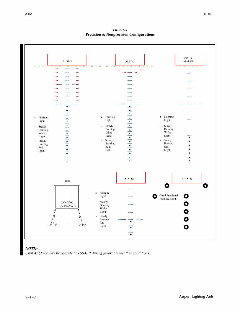
AIM 2/11/10
2−1−2 Airport Lighting Aids
FIG 2−1−1
Precision & Nonprecision Configurations
NOTE−Civil ALSF−2 may be operated as SSALR during favorable weather conditions.
3/15/077110.65R CHG 2AIM 3/10/11

AIM2/11/10
2−1−3Airport Lighting Aids
5. For 2-bar VASI (4 light units) see FIG 2−1−2.
FIG 2−1−2
2-Bar VASI
Far Bar
= Red
= WhiteNear Bar
Below Glide Path On Glide Path Above Glide Path
6. For 3-bar VASI (6 light units) see FIG 2−1−3.
FIG 2−1−3
3-Bar VASI
Far Bar
Middle Bar
Near Bar
Below BothGlide Paths
On LowerGlide Path
On UpperGlide Path
Above BothGlide Paths
7. For other VASI configurations see FIG 2−1−4.
FIG 2−1−4
VASI Variations
2 Bar2 Light Units
On Glide Path
2 Bar12 Light UnitsOn Glide Path
3 Bar16 Light Units
on Lower Glide Path
3/10/11 AIM

AIM 2/11/10
2−1−4 Airport Lighting Aids
b. Precision Approach Path Indicator (PAPI).The precision approach path indicator (PAPI) useslight units similar to the VASI but are installed in asingle row of either two or four light units. Theselights are visible from about 5 miles during the dayand up to 20 miles at night. The visual glide path ofthe PAPI typically provides safe obstructionclearance within plus or minus 10 degrees of theextended runway centerline and to 4 SM from therunway threshold. Descent, using the PAPI, should
not be initiated until the aircraft is visually alignedwith the runway. The row of light units is normallyinstalled on the left side of the runway and the glidepath indications are as depicted. Lateral courseguidance is provided by the runway or runway lights.In certain circumstances, the safe obstructionclearance area may be reduced due to locallimitations, or the PAPI may be offset from theextended runway centerline. This will be noted in theAirport/ Facility Directory. (See FIG 2−1−5.)
FIG 2−1−5
Precision Approach Path Indicator (PAPI)
Slightly High(3.2 Degrees)
White
Red
High(More Than
3,5 Degrees)
On Glide Path(3 Degrees)
Slightly Low(2.8 Degrees)
Low(Less Than
2.5 Degrees)
c. Tri-color Systems. Tri-color visual approachslope indicators normally consist of a single light unitprojecting a three-color visual approach path into thefinal approach area of the runway upon which theindicator is installed. The below glide path indicationis red, the above glide path indication is amber, and
the on glide path indication is green. These types ofindicators have a useful range of approximatelyone-half to one mile during the day and up tofive miles at night depending upon the visibilityconditions. (See FIG 2−1−6.)
FIG 2−1−6
Tri-Color Visual Approach Slope Indicator
Amber
Above Glide Path
On Glide Path
Below Glide Path
Amber
Green
Red
NOTE−1. Since the tri-color VASI consists of a single light source which could possibly be confused with other light sources, pilotsshould exercise care to properly locate and identify the light signal.
2. When the aircraft descends from green to red, the pilot may see a dark amber color during the transition from green tored.
3/15/077110.65R CHG 2AIM 8/26/10

AIM2/11/10
2−1−7Airport Lighting Aids
LAHSO is in effect. These lights will be off whenLAHSO is not in effect.REFERENCE−AIM, Pilot Responsibilities When Conducting Land and Hold ShortOperations (LAHSO), Paragraph 4−3−11.
2−1−6. Runway Status Light (RWSL)System
a. Introduction.
RWSL is a fully automated system that providesrunway status information to pilots and surfacevehicle operators to clearly indicate when it is unsafeto enter, cross, takeoff from, or land on a runway. TheRWSL system processes information from surveil-lance systems and activates Runway Entrance Lights(REL), Takeoff Hold Lights (THL), RunwayIntersection Lights (RIL), and Final ApproachRunway Occupancy Signal (FAROS) in accordancewith the position and velocity of the detected traffic.REL, THL, and RIL are in-pavement light fixturesthat are directly visible to pilots and surface vehicleoperators. The FAROS annunciation is by means offlashing the Precision Approach Path Indicator(PAPI). RWSL is an independent safety enhance-ment that does not substitute for an ATC clearance.Clearance to enter, cross, takeoff from, land on, oroperate on a runway must be issued by ATC.Although ATC has limited control over the system,personnel do not directly use, and may not be ableto view, light fixture output in their operations.
b. Runway Entrance Lights (REL): The RELsystem is composed of flush mounted, in-pavement,unidirectional fixtures that are parallel to and focusedalong the taxiway centerline and directed toward thepilot at the hold line. An array of REL lights includethe first light at the hold line followed by a series ofevenly spaced lights to the runway edge; oneadditional light at the runway centerline is in line withthe last two lights before the runway edge (seeFIG 2−1−9 and FIG 2−1−10). When activated, thered lights indicate that there is high speed traffic onthe runway or there is an aircraft on final approachwithin the activation area.
1. Operating Characteristics − Departing Air-craft:
When a departing aircraft reaches 30 knots, alltaxiway intersections with REL arrays along the
runway ahead of the aircraft will illuminate (seeFIG 2−1−9). As the aircraft approaches an RELequipped taxiway intersection, the lights at thatintersection extinguish approximately 3 to 4 secondsbefore the aircraft reaches it. This allows controllersto apply “anticipated separation” to permit ATC tomove traffic more expeditiously without comprom-ising safety. After the aircraft is declared “airborne”by the system, all REL lights associated with thisrunway will extinguish.
2. Operating Characteristics − Arriving Air-craft:
When an aircraft on final approach is approximately1 mile from the runway threshold, all sets of RELlight arrays along the runway illuminate. Thedistance is adjustable and can be configured forspecific operations at particular airports. Lightsextinguish at each equipped taxiway intersectionapproximately 3 to 4 seconds before the aircraftreaches it to apply anticipated separation until theaircraft has slowed to approximately 80 knots (siteadjustable parameter). Below 80 knots, all arrays thatare not within 30 seconds of the aircraft’s forwardpath are extinguished. Once the arriving aircraftslows to approximately 34 knots (site adjustableparameter), it is declared to be in a taxi state, and alllights extinguish.
3. What a pilot would observe: A pilot at orapproaching the hold line to a runway will observeREL illumination and extinguishing in reaction to anaircraft or vehicle operating on the runway, or anarriving aircraft operating less than 1 mile from therunway threshold.
4. Whenever a pilot observes the red lights ofthe REL, that pilot will stop at the hold line orremain stopped. The pilot will then contact ATC forresolution if the clearance is in conflict with thelights. Should pilots note illuminated lights undercircumstances when remaining clear of the runway isimpractical for safety reasons (for example, aircraft isalready on the runway), the crew should proceedaccording to their best judgment while understandingthe illuminated lights indicate the runway is unsafe toenter or cross. Contact ATC at the earliest possibleopportunity.
3/10/11 AIM

AIM 2/11/10
2−1−8 Airport Lighting Aids
FIG 2−1−9
Runway Status Light System
c. Takeoff Hold Lights (THL): The THL systemis composed of flush mounted, in−pavement,unidirectional fixtures in a double longitudinalrow aligned either side of the runway centerlinelighting. Fixtures are focused toward the arrival endof the runway at the “line up and wait” point, and theyextend for 1,500 feet in front of the holding aircraftstarting at a point 375 feet from the departurethreshold (see FIG 2−1−11). Illuminated red lightsprovide a signal, to an aircraft in position for takeoffor rolling, that it is unsafe to takeoff because therunway is occupied or about to be occupied byanother aircraft or ground vehicle. Two aircraft, or asurface vehicle and an aircraft, are required for thelights to illuminate. The departing aircraft must be inposition for takeoff or beginning takeoff roll. Anotheraircraft or a surface vehicle must be on or about tocross the runway.
1. Operating Characteristics − Departing Air-craft:
THLs will illuminate for an aircraft in position fordeparture or departing when there is another aircraftor vehicle on the runway or about to enter the runway(see FIG 2−1−9.) Once that aircraft or vehicle exitsthe runway, the THLs extinguish. A pilot may notice
lights extinguish prior to the downfield aircraft orvehicle being completely clear of the runway but stillmoving. Like RELs, THLs have an “anticipatedseparation” feature.
NOTE−When the THLs extinguish, this is not clearance to begina takeoff roll. All takeoff clearances will be issued by ATC.
2. What a pilot would observe: A pilot inposition to depart from a runway, or has begun takeoffroll, will observe THLs illuminate in reaction to anaircraft or vehicle on the runway or entering orcrossing it. Lights will extinguish when the runway isclear. A pilot may observe several cycles ofillumination and extinguishing depending on theamount of crossing traffic.
3. Whenever a pilot observes the red light ofthe THLs, the pilot will stop or remain stopped. Thepilot will contact ATC for resolution if any clearanceis in conflict with the lights. Should pilots noteilluminated lights while in takeoff roll and undercircumstances when stopping is impractical for safetyreasons, the crew should proceed according to theirbest judgment while understanding the illuminatedlights indicate that continuing the takeoff is unsafe.Contact ATC at the earliest possible opportunity.
3/15/077110.65R CHG 2AIM 3/10/11

AIM2/11/10
2−1−9Airport Lighting Aids
d. Runway Intersection Lights (RIL): The RILsystem is composed of flush mounted, in−pavement,unidirectional fixtures in a double longitudinal rowaligned either side of the runway centerline lightingin the same manner as THLs. Their appearance to apilot is similar to that of THLs. Fixtures are focusedtoward the arrival end of the runway, and they extendfor 3,000 feet in front of an aircraft that is approachingan intersecting runway. They end at the Land andHold Short Operation (LASHO) light bar or the holdshort line for the intersecting runway.
1. Operating Characteristics − Departing Air-craft:
RILs will illuminate for an aircraft departing or inposition to depart when there is high speed trafficoperating on the intersecting runway (seeFIG 2−1−9). Note that there must be an aircraft orvehicle in a position to observe the RILs for them toilluminate. Once that traffic passes through theintersection, the RILs extinguish.
2. Operating Characteristics − Arriving Air-craft:
RILs will illuminate for an aircraft that has landed andis rolling out when there is high speed traffic on theintersecting runway that is �5 seconds of meeting atthe intersection. Once that traffic passes through theintersection, the RILs extinguish.
3. What a pilot would observe: A pilot departingor arriving will observe RILs illuminate in reaction tothe high speed traffic operation on the intersectingrunway. The lights will extinguish when that traffichas passed through the runway intersection.
4. Whenever a pilot observes the red light of theRIL array, the pilot will stop before the LAHSO stopbar or the hold line for the intersecting runway. If adeparting aircraft is already at high speed in thetakeoff roll when the RILs illuminate, it may beimpractical to stop for safety reasons. The crewshould safely operate according to their bestjudgment while understanding the illuminated lightsindicate that continuing the takeoff is unsafe. ContactATC at the earliest possible opportunity.
e. The Final Approach Runway Occupancy Signal(FAROS) is activated by flashing of the PrecisionApproach Path Indicator (PAPI) (see FIG 2-1-9).When activated, the light fixtures of the PAPI flash or
pulse to indicate to the pilot on an approach that therunway is occupied and that it may be unsafe to land.
1. Operating Characteristics:
If an aircraft or surface vehicle occupies a FAROSequipped runway, the PAPI(s) on that runway willflash or pulse. The glide path indication will not beaffected, and the allotment of red and white PAPIlights observed by the pilot on approach will notchange. Some FAROS systems will flash or pulse thePAPI when traffic enters the runway whether or notthere is an aircraft on approach. Others will flash thePAPI only if there is an aircraft on approach andwithin 1.5 nautical miles of the landing threshold.
2. What a pilot would observe: A pilot onapproach to the runway will observe the PAPI flash orpulse if there is traffic on the runway and will noticethe PAPI ceases to flash or pulse when the trafficmoves outside the hold short lines for the runway.
3. Whenever a pilot observes a flashing orpulsing PAPI, the pilot will verify the FAROSactivation. At 500 feet above ground level (AGL), thecontact height, the pilot must look for and acquire thetraffic on the runway. At 300 feet AGL, the pilot mustcontact ATC for resolution if the clearance is inconflict with the FAROS indication. If the PAPIcontinues to flash or pulse, the pilot must execute animmediate “go around” and contact ATC at theearliest possible opportunity.
f. Pilot Actions:
1. When operating at airports with RWSL, pilotswill operate with the transponder “On” whendeparting the gate or parking area until it is shutdownupon arrival at the gate or parking area. This ensuresinteraction with the FAA surveillance systems whichprovide information to the RWSL system.
2. Pilots must always inform the ATCT whenthey have either stopped, are verifying a landingclearance, or are executing a missed approach due toRWSL or FAROS indication that are in conflict withATC instructions. Pilots must request clarification ofthe taxi, takeoff, or landing clearance.
3. Never cross over illuminated red lights.Under normal circumstances, RWSL will confirm thepilot’s taxi or takeoff clearance. If RWSL indicatesthat it is unsafe to takeoff from, land on, cross, or entera runway, immediately notify ATC of the conflict andconfirm your clearance. Never land if PAPI continuesto flash or pulse. Execute a go around and notify ATC.
3/10/11 AIM

AIM 2/11/10
2−1−10 Airport Lighting Aids
4. Do not proceed when lights have extin-guished without an ATC clearance. RWSL verifies anATC clearance; it does not substitute for an ATCclearance.
g. ATC Control of RWSL System:
1. Controllers can set in−pavement lights to oneof five (5) brightness levels to assure maximumconspicuity under all visibility and lighting condi-tions. REL, THL, and RIL subsystems may beindependently set.
2. The system can be shutdown should RWSLoperations impact the efficient movement of airtraffic or contribute, in the opinion of the ATCSupervisor, to unsafe operations. REL, THL, RIL,and FAROS subsystems may be shutdown separately.Shutdown of the FAROS subsystem will notextinguish PAPI lights or impact its glide pathfunction. Whenever the system or a component isshutdown, a NOTAM must be issued, and theAutomatic Terminal Information System (ATIS)must be updated.
2−1−7. Control of Lighting Systems
a. Operation of approach light systems and
runway lighting is controlled by the control tower(ATCT). At some locations the FSS may control thelights where there is no control tower in operation.
b. Pilots may request that lights be turned on oroff. Runway edge lights, in-pavement lights andapproach lights also have intensity controls whichmay be varied to meet the pilots request. Sequencedflashing lights (SFL) may be turned on and off. Somesequenced flashing light systems also have intens-ity control.
2−1−8. Pilot Control of Airport Lighting
Radio control of lighting is available at selectedairports to provide airborne control of lights bykeying the aircraft’s microphone. Control of lightingsystems is often available at locations withoutspecified hours for lighting and where there is nocontrol tower or FSS or when the tower or FSS isclosed (locations with a part-time tower or FSS) orspecified hours. All lighting systems which are radiocontrolled at an airport, whether on a single runwayor multiple runways, operate on the same radiofrequency. (See TBL 2−1−1 and TBL 2−1−2.)
FIG 2−1−10
Runway Entrance Lights
3/15/077110.65R CHG 2AIM 3/10/11

AIM2/11/10
2−1−11Airport Lighting Aids
FIG 2−1−11
Takeoff Hold Lights
FIG 2−1−12
Taxiway Lead−On Light Configuration
3/10/11 AIM

AIM 2/11/10
2−1−12 Airport Lighting Aids
TBL 2−1−1
Runways With Approach Lights
Lighting SystemNo. of Int.
StepsStatus During Nonuse Period
Intensity Step Selected Per No. of Mike Clicks
3 Clicks 5 Clicks 7 Clicks
Approach Lights (Med. Int.) 2 Off Low Low High
Approach Lights (Med. Int.) 3 Off Low Med High
MIRL 3 Off or Low � � �
HIRL 5 Off or Low � � �
VASI 2 Off � � �
NOTES: � Predetermined intensity step.� Low intensity for night use. High intensity for day use as determined by photocell control.
TBL 2−1−2
Runways Without Approach Lights
Lighting SystemNo. of Int.
StepsStatus DuringNonuse Period
Intensity Step Selected Per No. of Mike Clicks
3 Clicks 5 Clicks 7 Clicks
MIRL 3 Off or Low Low Med. High
HIRL 5 Off or Low Step 1 or 2 Step 3 Step 5
LIRL 1 Off On On On
VASI� 2 Off � � �
REIL� 1 Off Off On/Off On
REIL� 3 Off Low Med. High
NOTES: � Low intensity for night use. High intensity for day use as determined by photocell control.� The control of VASI and/or REIL may be independent of other lighting systems.
a. With FAA approved systems, various combina-tions of medium intensity approach lights, runwaylights, taxiway lights, VASI and/or REIL may beactivated by radio control. On runways with bothapproach lighting and runway lighting (runway edgelights, taxiway lights, etc.) systems, the approachlighting system takes precedence for air-to-groundradio control over the runway lighting system whichis set at a predetermined intensity step, based onexpected visibility conditions. Runways withoutapproach lighting may provide radio controlledintensity adjustments of runway edge lights. Otherlighting systems, including VASI, REIL, and taxiwaylights may be either controlled with the runway edgelights or controlled independently of the runway edgelights.
b. The control system consists of a 3−step controlresponsive to 7, 5, and/or 3 microphone clicks. This3−step control will turn on lighting facilities capableof either 3−step, 2−step or 1−step operation. The3−step and 2−step lighting facilities can be altered inintensity, while the 1−step cannot. All lighting isilluminated for a period of 15 minutes from the most
recent time of activation and may not be extinguishedprior to end of the 15 minute period (except for 1−stepand 2−step REILs which may be turned off whendesired by keying the mike 5 or 3 times respectively).
c. Suggested use is to always initially key the mike7 times; this assures that all controlled lights areturned on to the maximum available intensity. Ifdesired, adjustment can then be made, where thecapability is provided, to a lower intensity (or theREIL turned off) by keying 5 and/or 3 times. Due tothe close proximity of airports using the samefrequency, radio controlled lighting receivers may beset at a low sensitivity requiring the aircraft to berelatively close to activate the system. Consequently,even when lights are on, always key mike as directedwhen overflying an airport of intended landing or justprior to entering the final segment of an approach.This will assure the aircraft is close enough to activatethe system and a full 15 minutes lighting duration isavailable. Approved lighting systems may beactivated by keying the mike (within 5 seconds) asindicated in TBL 2−1−3.
3/15/077110.65R CHG 2AIM 3/10/11

AIM2/11/10
2−1−13Airport Lighting Aids
TBL 2−1−3
Radio Control System
Key Mike Function
7 times within 5 seconds Highest intensity available
5 times within 5 seconds Medium or lower intensity(Lower REIL or REIL-off)
3 times within 5 seconds Lowest intensity available(Lower REIL or REIL-off)
d. For all public use airports with FAA standardsystems the Airport/Facility Directory contains thetypes of lighting, runway and the frequency that isused to activate the system. Airports with IAPsinclude data on the approach chart identifying thelight system, the runway on which they are installed,and the frequency that is used to activate the system.
NOTE−Although the CTAF is used to activate the lights at manyairports, other frequencies may also be used. Theappropriate frequency for activating the lights on theairport is provided in the Airport/Facility Directory andthe standard instrument approach procedures publica-tions. It is not identified on the sectional charts.
e. Where the airport is not served by an IAP, it mayhave either the standard FAA approved controlsystem or an independent type system of differentspecification installed by the airport sponsor. TheAirport/Facility Directory contains descriptions ofpilot controlled lighting systems for each airporthaving other than FAA approved systems, andexplains the type lights, method of control, andoperating frequency in clear text.
2−1−9. Airport/Heliport Beacons
a. Airport and heliport beacons have a verticallight distribution to make them most effective fromone to ten degrees above the horizon; however, theycan be seen well above and below this peak spread.The beacon may be an omnidirectional capacitor-dis-charge device, or it may rotate at a constant speedwhich produces the visual effect of flashes at regularintervals. Flashes may be one or two colorsalternately. The total number of flashes are:
1. 24 to 30 per minute for beacons markingairports, landmarks, and points on Federal airways.
2. 30 to 45 per minute for beacons markingheliports.
b. The colors and color combinations of beaconsare:
1. White and Green− Lighted land airport.
2. *Green alone− Lighted land airport.
3. White and Yellow− Lighted water airport.
4. *Yellow alone− Lighted water airport.
5. Green, Yellow, and White− Lighted heliport.
NOTE−*Green alone or yellow alone is used only in connectionwith a white-and-green or white-and-yellow beacondisplay, respectively.
c. Military airport beacons flash alternately whiteand green, but are differentiated from civil beaconsby dualpeaked (two quick) white flashes between thegreen flashes.
d. In Class B, Class C, Class D and Class E surfaceareas, operation of the airport beacon during the hoursof daylight often indicates that the ground visibility isless than 3 miles and/or the ceiling is less than1,000 feet. ATC clearance in accordance with14 CFR Part 91 is required for landing, takeoff andflight in the traffic pattern. Pilots should not relysolely on the operation of the airport beacon toindicate if weather conditions are IFR or VFR. Atsome locations with operating control towers, ATCpersonnel turn the beacon on or off when controls arein the tower. At many airports the airport beacon isturned on by a photoelectric cell or time clocks andATC personnel cannot control them. There is noregulatory requirement for daylight operation and itis the pilot’s responsibility to comply with properpreflight planning as required by 14 CFRSection 91.103.
2−1−10. Taxiway Lights
a. Taxiway Edge Lights. Taxiway edge lightsare used to outline the edges of taxiways duringperiods of darkness or restricted visibility conditions.These fixtures emit blue light.
NOTE−At most major airports these lights have variable intensitysettings and may be adjusted at pilot request or whendeemed necessary by the controller.
b. Taxiway Centerline Lights. Taxiway center-line lights are used to facilitate ground traffic underlow visibility conditions. They are located along thetaxiway centerline in a straight line on straight
3/10/11 AIM

AIM 2/11/10
2−1−14 Airport Lighting Aids
portions, on the centerline of curved portions, andalong designated taxiing paths in portions ofrunways, ramp, and apron areas. Taxiway centerlinelights are steady burning and emit green light.
c. Clearance Bar Lights. Clearance bar lightsare installed at holding positions on taxiways in orderto increase the conspicuity of the holding position inlow visibility conditions. They may also be installedto indicate the location of an intersecting taxiwayduring periods of darkness. Clearance bars consist ofthree in-pavement steady-burning yellow lights.
d. Runway Guard Lights. Runway guard lightsare installed at taxiway/runway intersections. Theyare primarily used to enhance the conspicuity oftaxiway/runway intersections during low visibilityconditions, but may be used in all weather conditions.Runway guard lights consist of either a pair ofelevated flashing yellow lights installed on either sideof the taxiway, or a row of in-pavement yellow lightsinstalled across the entire taxiway, at the runwayholding position marking.NOTE−Some airports may have a row of three or five in-pavementyellow lights installed at taxiway/runway intersections.They should not be confused with clearance bar lightsdescribed in paragraph 2−1−10 c, Clearance Bar Lights.
e. Stop Bar Lights. Stop bar lights, wheninstalled, are used to confirm the ATC clearance toenter or cross the active runway in low visibilityconditions (below 1,200 ft Runway Visual Range). Astop bar consists of a row of red, unidirectional,steady−burning in-pavement lights installed acrossthe entire taxiway at the runway holding position, andelevated steady−burning red lights on each side. Acontrolled stop bar is operated in conjunction with thetaxiway centerline lead-on lights which extend fromthe stop bar toward the runway. Following the ATCclearance to proceed, the stop bar is turned off and thelead-on lights are turned on. The stop bar and lead-onlights are automatically reset by a sensor or backuptimer.
CAUTION−Pilots should never cross a red illuminated stop bar, evenif an ATC clearance has been given to proceed onto oracross the runway.
NOTE−If after crossing a stop bar, the taxiway centerline lead-onlights inadvertently extinguish, pilots should hold theirposition and contact ATC for further instructions.
3/15/077110.65R CHG 2AIM 3/10/11

AIM2/11/10
2−3−15Airport Marking Aids and Signs
FIG 2−3−15
Taxiways Located in Runway Approach Area
8/26/10 AIM

AIM 2/11/10
2−3−16 Airport Marking Aids and Signs
FIG 2−3−16
Holding Position Markings: ILS Critical Area
15
DETAIL 2
DETAIL 1RUNWAY HOLDINGPOSITION MARKINGS,YELLOW, SEEDETAIL 1
ILS HOLDINGPOSITION MARKINGS,YELLOW, SEEDETAIL 2
ILS CRITICALAREA
2−3−6. Other Markings
a. Vehicle Roadway Markings. The vehicleroadway markings are used when necessary to definea pathway for vehicle operations on or crossing areasthat are also intended for aircraft. These markingsconsist of a white solid line to delineate each edge ofthe roadway and a dashed line to separate lanes withinthe edges of the roadway. In lieu of the solid lines,zipper markings may be used to delineate the edgesof the vehicle roadway. (See FIG 2−3−18.) Details ofthe zipper markings are shown in FIG 2−3−19.
b. VOR Receiver Checkpoint Markings. TheVOR receiver checkpoint marking allows the pilot tocheck aircraft instruments with navigational aidsignals. It consists of a painted circle with an arrow in
the middle; the arrow is aligned in the direction of thecheckpoint azimuth. This marking, and an associatedsign, is located on the airport apron or taxiway at apoint selected for easy access by aircraft but whereother airport traffic is not to be unduly obstructed.(See FIG 2−3−20.)
NOTE−The associated sign contains the VOR station identifica-tion letter and course selected (published) for the check,the words “VOR check course,” and DME data (whenapplicable). The color of the letters and numerals are blackon a yellow background.
EXAMPLE−DCA 176−356VOR check courseDME XXX
3/15/077110.65R CHG 2AIM 3/10/11

AIM2/11/10
2−3−31Airport Marking Aids and Signs
2−3−15. Security Identifications DisplayArea (Airport Ramp Area)
a. Security Identification Display Areas (SIDA)are limited access areas that require a badge issued inaccordance with procedures in CFR 49 Part 1542.Movement through or into these areas is prohibitedwithout proper identification being displayed. If youare unsure of the location of a SIDA, contact theairport authority for additional information. Airportsthat have a SIDA must have the followinginformation available:
1. A description and map detailing boundariesand pertinent features;
2. Measures used to perform the access controlfunctions required under CFR 49 Part1542.201(b)(1);
3. Procedures to control movement within thesecured area, including identification media requiredunder CFR 49 Part 1542.201(b)(3); and
4. A description of the notification signsrequired under CFR 49 Part 1542.201(b)(6).
b. Pilots or passengers without proper identifica-tion that are observed entering a SIDA (ramp area)may be reported to TSA or airport security. Pilots areadvised to brief passengers accordingly.
3/15/077110.65R CHG 2AIM 3/10/11


AIM2/11/10
4−1−13Services Available to Pilots
EXAMPLE−Xray ground control, November One Eight Six, CessnaOne Seventy Two, ready to taxi, VFR southbound at 2,500,have information bravo and request radar trafficinformation.
NOTE−Following takeoff, the tower will advise when to contactdeparture control.
(c) Pilots of aircraft transiting the area and inradar contact/communication with approach controlwill receive traffic information on a controllerworkload permitting basis. Pilots of such aircraftshould give their position, altitude, aircraft call sign,aircraft type, radar beacon code (if transponderequipped), destination, and/or route of flight.
b. TRSA Service (Radar Sequencing andSeparation Service for VFR Aircraft in a TRSA).
1. This service has been implemented at certainterminal locations. The service is advertised in theAirport/Facility Directory. The purpose of thisservice is to provide separation between allparticipating VFR aircraft and all IFR aircraftoperating within the airspace defined as the TerminalRadar Service Area (TRSA). Pilot participation isurged but is not mandatory.
2. If any aircraft does not want the service, thepilot should state “NEGATIVE TRSA SERVICE” ormake a similar comment, on initial contact withapproach control or ground control, as appropriate.
3. TRSAs are depicted on sectional aeronauticalcharts and listed in the Airport/Facility Directory.
4. While operating within a TRSA, pilots areprovided TRSA service and separation as prescribedin this paragraph. In the event of a radar outage,separation and sequencing of VFR aircraft will besuspended as this service is dependent on radar. Thepilot will be advised that the service is not availableand issued wind, runway information, and the time orplace to contact the tower. Traffic information will beprovided on a workload permitting basis.
5. Visual separation is used when prevailingconditions permit and it will be applied as follows:
(a) When a VFR flight is positioned behind apreceding aircraft and the pilot reports having thataircraft in sight, the pilot will be instructed by ATC tofollow the preceding aircraft. Radar service will becontinued to the runway. THE ATC INSTRUCTION
TO FOLLOW THE PRECEDING AIRCRAFTDOES NOT AUTHORIZE THE PILOT TOCOMPLY WITH ANY ATC CLEARANCE ORINSTRUCTION ISSUED TO THE PRECEDINGAIRCRAFT.
(b) If other “nonparticipating” or “local”aircraft are in the traffic pattern, the tower will issuea landing sequence.
(c) Departing VFR aircraft may be asked ifthey can visually follow a preceding departure out ofthe TRSA. The pilot will be instructed to follow theother aircraft provided that the pilot can maintainvisual contact with that aircraft.
6. VFR aircraft will be separated from VFR/IFRaircraft by one of the following:
(a) 500 feet vertical separation.
(b) Visual separation.
(c) Target resolution (a process to ensure thatcorrelated radar targets do not touch).
7. Participating pilots operating VFR in aTRSA:
(a) Must maintain an altitude when assignedby ATC unless the altitude assignment is to maintainat or below a specified altitude. ATC may assignaltitudes for separation that do not conform to14 CFR Section 91.159. When the altitude assign-ment is no longer needed for separation or whenleaving the TRSA, the instruction will be broadcast,“RESUME APPROPRIATE VFR ALTITUDES.”Pilots must then return to an altitude that conforms to14 CFR Section 91.159 as soon as practicable.
(b) When not assigned an altitude, the pilotshould coordinate with ATC prior to any altitudechange.
8. Within the TRSA, traffic information onobserved but unidentified targets will, to the extentpossible, be provided to all IFR and participatingVFR aircraft. The pilot will be vectored upon requestto avoid the observed traffic, provided the aircraft tobe vectored is within the airspace under thejurisdiction of the controller.
9. Departing aircraft should inform ATC of theirintended destination and/or route of flight andproposed cruising altitude.
10. ATC will normally advise participatingVFR aircraft when leaving the geographical limits of
3/10/11 AIM

AIM 2/11/10
4−1−14 Services Available to Pilots
the TRSA. Radar service is not automaticallyterminated with this advisory unless specificallystated by the controller.
c. Class C Service. This service provides, inaddition to basic radar service, approved separationbetween IFR and VFR aircraft, and sequencing ofVFR arrivals to the primary airport.
d. Class B Service. This service provides, inaddition to basic radar service, approved separationof aircraft based on IFR, VFR, and/or weight, andsequencing of VFR arrivals to the primary airport(s).
e. PILOT RESPONSIBILITY. THESE SER-VICES ARE NOT TO BE INTERPRETED ASRELIEVING PILOTS OF THEIR RESPONSIBILI-TIES TO SEE AND AVOID OTHER TRAFFICOPERATING IN BASIC VFR WEATHER CONDI-TIONS, TO ADJUST THEIR OPERATIONS ANDFLIGHT PATH AS NECESSARY TO PRECLUDESERIOUS WAKE ENCOUNTERS, TO MAINTAINAPPROPRIATE TERRAIN AND OBSTRUCTIONCLEARANCE, OR TO REMAIN IN WEATHERCONDITIONS EQUAL TO OR BETTER THANTHE MINIMUMS REQUIRED BY 14 CFRSECTION 91.155. WHENEVER COMPLIANCEWITH AN ASSIGNED ROUTE, HEADINGAND/OR ALTITUDE IS LIKELY TO COMPRO-MISE PILOT RESPONSIBILITY RESPECTINGTERRAIN AND OBSTRUCTION CLEARANCE,VORTEX EXPOSURE, AND WEATHER MINI-MUMS, APPROACH CONTROL SHOULD BE SOADVISED AND A REVISED CLEARANCE ORINSTRUCTION OBTAINED.
f. ATC services for VFR aircraft participating interminal radar services are dependent on ATC radar.Services for VFR aircraft are not available duringperiods of a radar outage and are limited duringCENRAP operations. The pilot will be advised whenVFR services are limited or not available.
NOTE−Class B and Class C airspace are areas of regulatedairspace. The absence of ATC radar does not negate therequirement of an ATC clearance to enter Class B airspaceor two way radio contact with ATC to enter Class Cairspace.
4−1−19. Tower En Route Control (TEC)
a. TEC is an ATC program to provide a service toaircraft proceeding to and from metropolitan areas. Itlinks designated Approach Control Areas by anetwork of identified routes made up of the existingairway structure of the National Airspace System.The FAA initiated an expanded TEC program toinclude as many facilities as possible. The program’sintent is to provide an overflow resource in the lowaltitude system which would enhance ATC services.A few facilities have historically allowed turbojets toproceed between certain city pairs, such asMilwaukee and Chicago, via tower en route and theselocations may continue this service. However, theexpanded TEC program will be applied, generally,for nonturbojet aircraft operating at and below10,000 feet. The program is entirely within theapproach control airspace of multiple terminalfacilities. Essentially, it is for relatively short flights.Participating pilots are encouraged to use TEC forflights of two hours duration or less. If longer flightsare planned, extensive coordination may be requiredwithin the multiple complex which could result inunanticipated delays.
b. Pilots requesting TEC are subject to the samedelay factor at the destination airport as other aircraftin the ATC system. In addition, departure and en routedelays may occur depending upon individual facilityworkload. When a major metropolitan airport isincurring significant delays, pilots in the TECprogram may want to consider an alternative airportexperiencing no delay.
c. There are no unique requirements upon pilots touse the TEC program. Normal flight plan filingprocedures will ensure proper flight plan processing.Pilots should include the acronym “TEC” in theremarks section of the flight plan when requestingtower en route control.
d. All approach controls in the system may notoperate up to the maximum TEC altitude of10,000 feet. IFR flight may be planned to anysatellite airport in proximity to the major primaryairport via the same routing.
3/15/077110.65R CHG 2AIM 3/10/11

AIM2/11/10
4−1−15Services Available to Pilots
4−1−20. Transponder Operation
a. General
1. Pilots should be aware that proper applicationof transponder operating procedures will provideboth VFR and IFR aircraft with a higher degree ofsafety in the environment where high-speed closurerates are possible. Transponders substantially in-crease the capability of radar to see an aircraft and theMode C feature enables the controller to quicklydetermine where potential traffic conflicts may exist.Even VFR pilots who are not in contact with ATC willbe afforded greater protection from IFR aircraft andVFR aircraft which are receiving traffic advisories.Nevertheless, pilots should never relax their visualscanning vigilance for other aircraft.
2. Air Traffic Control Radar Beacon System(ATCRBS) is similar to and compatible with militarycoded radar beacon equipment. Civil Mode A isidentical to military Mode 3.
3. Civil and military transponders should beadjusted to the “on” or normal operating position aslate as practicable prior to takeoff and to “off” or“standby” as soon as practicable after completinglanding roll, unless the change to “standby” has beenaccomplished previously at the request of ATC. INALL CASES, WHILE IN CONTROLLED AIR-SPACE EACH PILOT OPERATING ANAIRCRAFT EQUIPPED WITH AN OPERABLEATC TRANSPONDER MAINTAINED IN AC-CORDANCE WITH 14 CFR SECTION 91.413SHALL OPERATE THE TRANSPONDER, IN-CLUDING MODE C IF INSTALLED, ON THEAPPROPRIATE CODE OR AS ASSIGNED BYATC. IN CLASS G AIRSPACE, THE TRANS-PONDER SHOULD BE OPERATING WHILEAIRBORNE UNLESS OTHERWISE RE-QUESTED BY ATC.
4. A pilot on an IFR flight who elects to cancelthe IFR flight plan prior to reaching destination,should adjust the transponder according to VFRoperations.
5. If entering a U.S. OFFSHORE AIRSPACEAREA from outside the U.S., the pilot should adviseon first radio contact with a U.S. radar ATC facilitythat such equipment is available by adding“transponder” to the aircraft identification.
6. It should be noted by all users of ATCtransponders that the coverage they can expect islimited to “line of sight.” Low altitude or aircraftantenna shielding by the aircraft itself may result inreduced range. Range can be improved by climbingto a higher altitude. It may be possible to minimizeantenna shielding by locating the antenna where deadspots are only noticed during abnormal flightattitudes.
7. If operating at an airport with Airport SurfaceDetection Equipment − Model X (ASDE−X), trans-ponders should be transmitting (on position)continuously with altitude reporting while movingon the airport surface.
8. Aircraft equipped with ADS−B (1090 ES orUAT) must operate the equipment in the transmitmode (on position) at all times while on any airportsurface.
NOTE−Pilots of aircraft equipped with ADS−B should refer toAIM, Automatic Dependant Surveillance − BroadcastServices, Paragraph 4−5−7, for a complete description ofoperating limitations and procedures.
b. Transponder Code Designation
1. For ATC to utilize one or a combination of the4096 discrete codes FOUR DIGIT CODE DES-IGNATION will be used, e.g., code 2100 will beexpressed as TWO ONE ZERO ZERO. Due to theoperational characteristics of the rapidly expandingautomated ATC system, THE LAST TWO DIGITSOF THE SELECTED TRANSPONDER CODESHOULD ALWAYS READ “00” UNLESS SPECIF-ICALLY REQUESTED BY ATC TO BEOTHERWISE.
c. Automatic Altitude Reporting (Mode C)
1. Some transponders are equipped with aMode C automatic altitude reporting capability. Thissystem converts aircraft altitude in 100 footincrements to coded digital information which istransmitted together with Mode C framing pulses tothe interrogating radar facility. The manner in whichtransponder panels are designed differs, therefore, apilot should be thoroughly familiar with the operationof the transponder so that ATC may realize its fullcapabilities.
2. Adjust transponder to reply on the Mode A/3code specified by ATC and, if equipped, to reply onMode C with altitude reporting capability activated
3/10/11 AIM

AIM 2/11/10
4−1−16 Services Available to Pilots
unless deactivation is directed by ATC or unless theinstalled aircraft equipment has not been tested andcalibrated as required by 14 CFR Section 91.217. Ifdeactivation is required by ATC, turn off the altitudereporting feature of your transponder. An instructionby ATC to “STOP ALTITUDE SQUAWK, ALTI-TUDE DIFFERS (number of feet) FEET,” may be anindication that your transponder is transmittingincorrect altitude information or that you have anincorrect altimeter setting. While an incorrectaltimeter setting has no effect on the Mode C altitudeinformation transmitted by your transponder (trans-ponders are preset at 29.92), it would cause you to flyat an actual altitude different from your assignedaltitude. When a controller indicates that an altitudereadout is invalid, the pilot should initiate a check toverify that the aircraft altimeter is set correctly.
3. Pilots of aircraft with operating Mode Caltitude reporting transponders should report exactaltitude or flight level to the nearest hundred footincrement when establishing initial contact with anATC facility. Exact altitude or flight level reports oninitial contact provide ATC with information that isrequired prior to using Mode C altitude informationfor separation purposes. This will significantlyreduce altitude verification requests.
d. Transponder IDENT Feature
1. The transponder shall be operated only asspecified by ATC. Activate the “IDENT” feature onlyupon request of the ATC controller.
e. Code Changes
1. When making routine code changes, pilotsshould avoid inadvertent selection of Codes 7500,7600 or 7700 thereby causing momentary falsealarms at automated ground facilities. For example,when switching from Code 2700 to Code 7200,switch first to 2200 then to 7200, NOT to 7700 andthen 7200. This procedure applies to nondiscreteCode 7500 and all discrete codes in the 7600 and 7700series (i.e., 7600−7677, 7700−7777) which willtrigger special indicators in automated facilities.Only nondiscrete Code 7500 will be decoded as thehijack code.
2. Under no circumstances should a pilot of acivil aircraft operate the transponder on Code 7777.This code is reserved for military interceptoroperations.
3. Military pilots operating VFR or IFR withinrestricted/warning areas should adjust their trans-ponders to Code 4000 unless another code has beenassigned by ATC.
f. Mode C Transponder Requirements
1. Specific details concerning requirements tocarry and operate Mode C transponders, as well asexceptions and ATC authorized deviations from therequirements are found in 14 CFR Section 91.215 and14 CFR Section 99.12.
2. In general, the CFRs require aircraft to beequipped with Mode C transponders when operating:
(a) At or above 10,000 feet MSL over the48 contiguous states or the District of Columbia,excluding that airspace below 2,500 feet AGL;
(b) Within 30 miles of a Class B airspaceprimary airport, below 10,000 feet MSL. Balloons,gliders, and aircraft not equipped with an enginedriven electrical system are excepted from the aboverequirements when operating below the floor ofClass A airspace and/or; outside of a Class B airspaceand below the ceiling of the Class B airspace (or10,000 feet MSL, whichever is lower);
(c) Within and above all Class C airspace, upto 10,000 feet MSL;
(d) Within 10 miles of certain designatedairports, excluding that airspace which is both outsidethe Class D surface area and below 1,200 feet AGL.Balloons, gliders and aircraft not equipped with anengine driven electrical system are excepted from thisrequirement.
3. 14 CFR Section 99.12 requires all aircraftflying into, within, or across the contiguous U.S.ADIZ be equipped with a Mode C or Mode Stransponder. Balloons, gliders and aircraft notequipped with an engine driven electrical system areexcepted from this requirement.
4. Pilots shall ensure that their aircraft trans-ponder is operating on an appropriate ATC assignedVFR/IFR code and Mode C when operating in suchairspace. If in doubt about the operational status ofeither feature of your transponder while airborne,contact the nearest ATC facility or FSS and they willadvise you what facility you should contact fordetermining the status of your equipment.
5. In-flight requests for “immediate” deviationfrom the transponder requirement may be approved
3/15/077110.65R CHG 2AIM 3/10/11

AIM2/11/10
4−1−17Services Available to Pilots
by controllers only when the flight will continue IFRor when weather conditions prevent VFR descent andcontinued VFR flight in airspace not affected by theCFRs. All other requests for deviation should bemade by contacting the nearest Flight Service orAir Traffic facility in person or by telephone. Thenearest ARTCC will normally be the controllingagency and is responsible for coordinating requestsinvolving deviations in other ARTCC areas.
g. Transponder Operation Under Visual FlightRules (VFR)
1. Unless otherwise instructed by an ATCfacility, adjust transponder to reply on Mode 3/ACode 1200 regardless of altitude.
2. Adjust transponder to reply on Mode C, withaltitude reporting capability activated if the aircraftis so equipped, unless deactivation is directed by ATCor unless the installed equipment has not been testedand calibrated as required by 14 CFR Section 91.217.If deactivation is required and your transponder is sodesigned, turn off the altitude reporting switch andcontinue to transmit Mode C framing pulses. If thiscapability does not exist, turn off Mode C.
h. Radar Beacon Phraseology
Air traffic controllers, both civil and military, will usethe following phraseology when referring tooperation of the Air Traffic Control Radar BeaconSystem (ATCRBS). Instructions by ATC refer only toMode A/3 or Mode C operation and do not affect theoperation of the transponder on other Modes.
1. SQUAWK (number). Operate radar beacontransponder on designated code in Mode A/3.
2. IDENT. Engage the “IDENT” feature (mili-tary I/P) of the transponder.
3. SQUAWK (number) and IDENT. Operatetransponder on specified code in Mode A/3 andengage the “IDENT” (military I/P) feature.
4. SQUAWK STANDBY. Switch transponderto standby position.
5. SQUAWK LOW/NORMAL. Operatetransponder on low or normal sensitivity as specified.Transponder is operated in “NORMAL” positionunless ATC specifies “LOW” (“ON” is used insteadof “NORMAL” as a master control label on sometypes of transponders.)
6. SQUAWK ALTITUDE. Activate Mode Cwith automatic altitude reporting.
7. STOP ALTITUDE SQUAWK. Turn offaltitude reporting switch and continue transmittingMode C framing pulses. If your equipment does nothave this capability, turn off Mode C.
8. STOP SQUAWK (mode in use). Switch offspecified mode. (Used for military aircraft when thecontroller is unaware of military service requirementsfor the aircraft to continue operation on anotherMode.)
9. STOP SQUAWK. Switch off transponder.
10. SQUAWK MAYDAY. Operate transpond-er in the emergency position (Mode A Code 7700 forcivil transponder. Mode 3 Code 7700 and emergencyfeature for military transponder.)
11. SQUAWK VFR. Operate radar beacontransponder on Code 1200 in the Mode A/3, or otherappropriate VFR code.
3/10/11 AIM

AIM 2/11/10
4−1−18 Services Available to Pilots
FIG 4−1−3
Hazardous Area Reporting Service
4−1−21. Hazardous Area Reporting Service
a. Selected FSSs provide flight monitoring whereregularly traveled VFR routes cross large bodies ofwater, swamps, and mountains. This service isprovided for the purpose of expeditiously alertingSearch and Rescue facilities when required. (See FIG 4−1−3.)
1. When requesting the service either in person,by telephone or by radio, pilots should be prepared togive the following information: type of aircraft,altitude, indicated airspeed, present position, route offlight, heading.
2. Radio contacts are desired at least every10 minutes. If contact is lost for more than15 minutes, Search and Rescue will be alerted. Pilotsare responsible for canceling their request for servicewhen they are outside the service area boundary.Pilots experiencing two-way radio failure are
expected to land as soon as practicable and canceltheir request for the service. FIG 4−1−3 depicts theareas and the FSS facilities involved in this program.
b. Long Island Sound Reporting Service.
New York and Bridgeport FSS Radio Sectorsprovide Long Island Sound Reporting service onrequest for aircraft traversing Long Island Sound.
1. When requesting the service, pilots shouldask for SOUND REPORTING SERVICE and shouldbe prepared to provide the following appropriateinformation:
(a) Type and color of aircraft;
(b) The specific route and altitude across thesound including the shore crossing point;
(c) The overwater crossing time;
(d) Number of persons on board; and
(e) True air speed.

AIM2/11/10
4−3−5Airport Operations
4−3−4. Visual Indicators at AirportsWithout an Operating Control Tower
a. At those airports without an operating controltower, a segmented circle visual indicator system, ifinstalled, is designed to provide traffic patterninformation.
REFERENCE−AIM, Traffic Advisory Practices at Airports Without Operating ControlTowers, Paragraph 4−1−9.
b. The segmented circle system consists of thefollowing components:
1. The segmented circle. Located in a positionaffording maximum visibility to pilots in the air andon the ground and providing a centralized location forother elements of the system.
2. The wind direction indicator. A wind cone,wind sock, or wind tee installed near the operationalrunway to indicate wind direction. The large end ofthe wind cone/wind sock points into the wind as doesthe large end (cross bar) of the wind tee. In lieu of atetrahedron and where a wind sock or wind cone iscollocated with a wind tee, the wind tee may bemanually aligned with the runway in use to indicatelanding direction. These signaling devices may belocated in the center of the segmented circle and maybe lighted for night use. Pilots are cautioned againstusing a tetrahedron to indicate wind direction.
3. The landing direction indicator. A tetrahe-dron is installed when conditions at the airportwarrant its use. It may be used to indicate the directionof landings and takeoffs. A tetrahedron may belocated at the center of a segmented circle and may belighted for night operations. The small end of thetetrahedron points in the direction of landing. Pilotsare cautioned against using a tetrahedron for anypurpose other than as an indicator of landingdirection. Further, pilots should use extreme cautionwhen making runway selection by use of a
tetrahedron in very light or calm wind conditions asthe tetrahedron may not be aligned with thedesignated calm-wind runway. At airports withcontrol towers, the tetrahedron should only bereferenced when the control tower is not in operation.Tower instructions supersede tetrahedron indica-tions.
4. Landing strip indicators. Installed in pairsas shown in the segmented circle diagram and used toshow the alignment of landing strips.
5. Traffic pattern indicators. Arranged inpairs in conjunction with landing strip indicators andused to indicate the direction of turns when there is avariation from the normal left traffic pattern. (If thereis no segmented circle installed at the airport, trafficpattern indicators may be installed on or near the endof the runway.)
c. Preparatory to landing at an airport without acontrol tower, or when the control tower is not inoperation, pilots should concern themselves with theindicator for the approach end of the runway to beused. When approaching for landing, all turns mustbe made to the left unless a traffic pattern indicatorindicates that turns should be made to the right. If thepilot will mentally enlarge the indicator for therunway to be used, the base and final approach legsof the traffic pattern to be flown immediately becomeapparent. Similar treatment of the indicator at thedeparture end of the runway will clearly indicate thedirection of turn after takeoff.
d. When two or more aircraft are approaching anairport for the purpose of landing, the pilot of theaircraft at the lower altitude has the right−of−wayover the pilot of the aircraft at the higher altitude.However, the pilot operating at the lower altitudeshould not take advantage of another aircraft, whichis on final approach to land, by cutting in front of, orovertaking that aircraft.

AIM 2/11/10
4−3−6 Airport Operations
4−3−5. Unexpected Maneuvers in theAirport Traffic Pattern
There have been several incidents in the vicinity ofcontrolled airports that were caused primarily byaircraft executing unexpected maneuvers. ATCservice is based upon observed or known traffic andairport conditions. Controllers establish the sequenceof arriving and departing aircraft by requiring them toadjust flight as necessary to achieve proper spacing.These adjustments can only be based on observedtraffic, accurate pilot reports, and anticipated aircraftmaneuvers. Pilots are expected to cooperate so as topreclude disrupting traffic flows or creating conflict-ing patterns. The pilot-in-command of an aircraft isdirectly responsible for and is the final authority as tothe operation of the aircraft. On occasion it may benecessary for pilots to maneuver their aircraft tomaintain spacing with the traffic they have beensequenced to follow. The controller can anticipateminor maneuvering such as shallow “S” turns. Thecontroller cannot, however, anticipate a majormaneuver such as a 360 degree turn. If a pilot makesa 360 degree turn after obtaining a landing sequence,the result is usually a gap in the landing interval and,more importantly, it causes a chain reaction whichmay result in a conflict with following traffic and aninterruption of the sequence established by the toweror approach controller. Should a pilot decide to makemaneuvering turns to maintain spacing behind apreceding aircraft, the pilot should always advise thecontroller if at all possible. Except when requested bythe controller or in emergency situations, a 360degree turn should never be executed in the trafficpattern or when receiving radar service without firstadvising the controller.
4−3−6. Use of Runways/Declared Distances
a. Runways are identified by numbers whichindicate the nearest 10−degree increment of theazimuth of the runway centerline. For example,where the magnetic azimuth is 183 degrees, therunway designation would be 18; for a magneticazimuth of 87 degrees, the runway designation wouldbe 9. For a magnetic azimuth ending in the number 5,such as 185, the runway designation could be either18 or 19. Wind direction issued by the tower is alsomagnetic and wind velocity is in knots.
b. Airport proprietors are responsible for takingthe lead in local aviation noise control. Accordingly,
they may propose specific noise abatement plans tothe FAA. If approved, these plans are applied in theform of Formal or Informal Runway Use Programsfor noise abatement purposes.REFERENCE−Pilot/Controller Glossary Term− “Runway Use Program”
1. At airports where no runway use program isestablished, ATC clearances may specify:
(a) The runway most nearly aligned with thewind when it is 5 knots or more;
(b) The “calm wind” runway when wind isless than 5 knots; or
(c) Another runway if operationally advanta-geous.
NOTE−It is not necessary for a controller to specifically inquire ifthe pilot will use a specific runway or to offer a choice ofrunways. If a pilot prefers to use a different runway fromthat specified, or the one most nearly aligned with the wind,the pilot is expected to inform ATC accordingly.
2. At airports where a runway use program isestablished, ATC will assign runways deemed to havethe least noise impact. If in the interest of safety arunway different from that specified is preferred, thepilot is expected to advise ATC accordingly. ATC willhonor such requests and advise pilots when therequested runway is noise sensitive. When use of arunway other than the one assigned is requested, pilotcooperation is encouraged to preclude disruption oftraffic flows or the creation of conflicting patterns.
c. Declared Distances.
1. Declared distances for a runway representthe maximum distances available and suitable formeeting takeoff and landing distance performancerequirements. These distances are determined inaccordance with FAA runway design standards byadding to the physical length of paved runway anyclearway or stopway and subtracting from that sumany lengths necessary to obtain the standard runwaysafety areas, runway object free areas, or runwayprotection zones. As a result of these additions andsubtractions, the declared distances for a runway maybe more or less than the physical length of the runwayas depicted on aeronautical charts and relatedpublications, or available in electronic navigationdatabases provided by either the U.S. Government orcommercial companies.
2. All 14 CFR Part 139 airports report declareddistances for each runway. Other airports may also
3/15/077110.65R CHG 2AIM 3/10/11

AIM2/11/10
4−3−7Airport Operations
report declared distances for a runway if necessaryto meet runway design standards or to indicate thepresence of a clearway or stopway. Where reported,declared distances for each runway end arepublished in the Airport/Facility Directory (A/FD).For runways without published declared distances,the declared distances may be assumed to be equal tothe physical length of the runway unless there is adisplaced landing threshold, in which case theLanding Distance Available (LDA) is shortened bythe amount of the threshold displacement.
NOTE−A symbol is shown on U.S. Government charts toindicate that runway declared distance information isavailable (See appropriate A/FD, Alaska, or PacificSupplement).
(a) The FAA uses the following definitionsfor runway declared distances (See FIG 4−3−4):
REFERENCE−Pilot/Controller Glossary Terms: “Accelerate−Stop DistanceAvailable,” “Landing Distance Available,” “Takeoff DistanceAvailable,” “Takeoff Run Available,” ” Stopway,” and “Clearway.”
(1) Takeoff Run Available (TORA) – Therunway length declared available and suitable forthe ground run of an airplane taking off.
The TORA is typically the physical length of therunway, but it may be shorter than the runway lengthif necessary to satisfy runway design standards. Forexample, the TORA may be shorter than the runwaylength if a portion of the runway must be used tosatisfy runway protection zone requirements.
(2) Takeoff Distance Available (TODA) –The takeoff run available plus the length of anyremaining runway or clearway beyond the far end ofthe takeoff run available.
The TODA is the distance declared available forsatisfying takeoff distance requirements for airplaneswhere the certification and operating rules andavailable performance data allow for the considera-tion of a clearway in takeoff performancecomputations.
NOTE−The length of any available clearway will be included in theTODA published in the A/FD’s entry for that runway end.
(3) Accelerate−Stop Distance Available(ASDA) – The runway plus stopway length declaredavailable and suitable for the acceleration anddeceleration of an airplane aborting a takeoff.
The ASDA may be longer than the physical length ofthe runway when a stopway has been designatedavailable by the airport operator, or it may be shorterthan the physical length of the runway if necessary touse a portion of the runway to satisfy runway designstandards; for example, where the airport operatoruses a portion of the runway to achieve the runwaysafety area requirement. ASDA is the distance usedto satisfy the airplane accelerate−stop distanceperformance requirements where the certificationand operating rules require accelerate−stop distancecomputations.
NOTE−The length of any available stopway will be included in theASDA published in the A/FD’s entry for that runway end.
(4) Landing Distance Available (LDA) −The runway length declared available and suitablefor a landing airplane.
The LDA may be less than the physical length of therunway or the length of the runway remaining beyonda displaced threshold if necessary to satisfy runwaydesign standards;for example, where the airportoperator uses a portion of the runway to achieve therunway safety area requirement.
Although some runway elements (such as stopwaylength and clearway length) may be availableinformation, pilots must use the declared distancesdetermined by the airport operator and not attempt toindependently calculate declared distances byadding those elements to the reported physicallength of the runway.
(b) The airplane operating rules and/or theairplane operating limitations establish minimumdistance requirements for takeoff and landing andare based on performance data supplied in theAirplane Flight Manual or Pilot’s OperatingHandbook. The minimum distances required fortakeoff and landing obtained either in planningprior to takeoff or in performance assessmentsconducted at the time of landing must fall within theapplicable declared distances before the pilot canaccept that runway for takeoff or landing.
(c) Runway design standards may imposerestrictions on the amount of runway available foruse in takeoff and landing that are not apparentfrom the reported physical length of the runway orfrom runway markings and lighting. The runwayelements of Runway Safety Area (RSA), RunwayObject Free Area (ROFA), and Runway Protection
3/10/11 AIM

AIM 2/11/10
4−3−8 Airport Operations
Zone (RPZ) may reduce a runway’s declareddistances to less than the physical length of therunway at geographically constrained airports (SeeFIG 4−3−5). When considering the amount ofrunway available for use in takeoff or landingperformance calculations, the declared distancespublished for a runway must always be used in lieuof the runway’s physical length.REFERENCE−AC 150/5300−13, Airport Design.
(d) While some runway elements associatedwith declared distances may be identifiable throughrunway markings or lighting (for example, adisplaced threshold or a stopway), the individualdeclared distance limits are not marked or otherwiseidentified on the runway. An aircraft is notprohibited from operating beyond a declareddistance limit during the takeoff, landing, or taxioperation provided the runway surface is appropri-ately marked as usable runway (See FIG 4−3−5). Thefollowing examples clarify the intent of thisparagraph.
REFERENCE−AIM, Runway Markings, Paragraph 2−3−3.AC 150/5340−1, Standards for Airport Markings.
EXAMPLE−1. The declared LDA for runway 9 must be used whenshowing compliance with the landing distance require-ments of the applicable airplane operating rules and/orairplane operating limitations or when making a beforelanding performance assessment. The LDA is less than thephysical runway length, not only because of the displacedthreshold, but also because of the subtractions necessaryto meet the RSA beyond the far end of the runway. However,during the actual landing operation, it is permissible forthe airplane to roll beyond the unmarked end of the LDA.
2. The declared ASDA for runway 9 must be used whenshowing compliance with the accelerate−stop distancerequirements of the applicable airplane operating rulesand/or airplane operating limitations. The ASDA is lessthan the physical length of the runway due to subtractionsnecessary to achieve the full RSA requirement. However, inthe event of an aborted takeoff, it is permissible for theairplane to roll beyond the unmarked end of the ASDA asit is brought to a full−stop on the remaining usable runway.
3/15/077110.65R CHG 2AIM 3/10/11

AIM2/11/10
4−3−9Airport Operations
FIG 4−3−4
Declared Distances with Full−Standard Runway Safety Areas, Runway Object Free Areas, and RunwayProtection Zones
3/10/11 AIM

AIM 2/11/10
4−3−10 Airport Operations
FIG 4−3−5
Effects of a Geographical Constraint on a Runway’s Declared Distances
NOTE−A runway’s RSA begins a set distance prior to the threshold and will extend a set distance beyond the end of the runwaydepending on the runway’s design criteria. If these required lengths cannot be achieved, the ASDA and/or LDA will bereduced as necessary to obtain the required lengths to the extent practicable.
3/15/077110.65R CHG 2AIM 3/10/11

AIM2/11/10
4−3−11Airport Operations
4−3−7. Low Level Wind Shear/MicroburstDetection Systems
Low Level Wind Shear Alert System (LLWAS),Terminal Doppler Weather Radar (TDWR), WeatherSystem Processor (WSP), and Integrated TerminalWeather System (ITWS) display information onhazardous wind shear and microburst activity in thevicinity of an airport to air traffic controllers whorelay this information to pilots.
a. LLWAS provides wind shear alert and gust frontinformation but does not provide microburst alerts.The LLWAS is designed to detect low level windshear conditions around the periphery of an airport. Itdoes not detect wind shear beyond that limitation.Controllers will provide this information to pilots bygiving the pilot the airport wind followed by theboundary wind.
EXAMPLE−Wind shear alert, airport wind 230 at 8, south boundarywind 170 at 20.
b. LLWAS “network expansion,” (LLWAS NE)and LLWAS Relocation/Sustainment (LLWAS−RS)are systems integrated with TDWR. These systemsprovide the capability of detecting microburst alertsand wind shear alerts. Controllers will issue theappropriate wind shear alerts or microburst alerts. Insome of these systems controllers also have the abilityto issue wind information oriented to the threshold ordeparture end of the runway.
EXAMPLE−Runway 17 arrival microburst alert, 40 knot loss 3 milefinal.
REFERENCE−AIM, Microbursts, Paragraph 7−1−26.
c. More advanced systems are in the field or beingdeveloped such as ITWS. ITWS provides alerts formicrobursts, wind shear, and significant thunder-storm activity. ITWS displays wind informationoriented to the threshold or departure end of therunway.
d. The WSP provides weather processor enhance-ments to selected Airport Surveillance Radar(ASR)−9 facilities. The WSP provides Air Trafficwith detection and alerting of hazardous weather suchas wind shear, microbursts, and significant thunder-storm activity. The WSP displays terminal area6 level weather, storm cell locations and movement,as well as the location and predicted future position
and intensity of wind shifts that may affect airportoperations. Controllers will receive and issue alertsbased on Areas Noted for Attention (ARENA). AnARENA extends on the runway center line from a3 mile final to the runway to a 2 mile departure.
e. An airport equipped with the LLWAS, ITWS, orWSP is so indicated in the Airport/Facility Directoryunder Weather Data Sources for that particularairport.
4−3−8. Braking Action Reports andAdvisories
a. When available, ATC furnishes pilots thequality of braking action received from pilots orairport management. The quality of braking action isdescribed by the terms “good,” “fair,” “poor,” and“nil,” or a combination of these terms. When pilotsreport the quality of braking action by using the termsnoted above, they should use descriptive terms thatare easily understood, such as, “braking action poorthe first/last half of the runway,” together with theparticular type of aircraft.
b. For NOTAM purposes, braking action reportsare classified according to the most critical term(“fair,” “poor,” or “nil”) used and issued as aNOTAM(D).
c. When tower controllers have received runwaybraking action reports which include the terms pooror nil, or whenever weather conditions are conduciveto deteriorating or rapidly changing runway brakingconditions, the tower will include on the ATISbroadcast the statement, “BRAKING ACTIONADVISORIES ARE IN EFFECT.”
d. During the time that braking action advisoriesare in effect, ATC will issue the latest braking actionreport for the runway in use to each arriving anddeparting aircraft. Pilots should be prepared fordeteriorating braking conditions and should requestcurrent runway condition information if not volun-teered by controllers. Pilots should also be preparedto provide a descriptive runway condition report tocontrollers after landing.
4−3−9. Runway Friction Reports andAdvisories
a. Friction is defined as the ratio of the tangentialforce needed to maintain uniform relative motionbetween two contacting surfaces (aircraft tires to the
3/10/11 AIM

AIM 2/11/10
4−3−12 Airport Operations
pavement surface) to the perpendicular force holdingthem in contact (distributed aircraft weight to theaircraft tire area). Simply stated, friction quantifiesslipperiness of pavement surfaces.
b. The greek letter MU (pronounced “myew”), isused to designate a friction value representingrunway surface conditions.
c. MU (friction) values range from 0 to 100 wherezero is the lowest friction value and 100 is themaximum friction value obtainable. For frozencontaminants on runway surfaces, a MU value of40 or less is the level when the aircraft brakingperformance starts to deteriorate and directionalcontrol begins to be less responsive. The lower theMU value, the less effective braking performancebecomes and the more difficult directional controlbecomes.
d. At airports with friction measuring devices,airport management should conduct friction mea-surements on runways covered with compacted snowand/or ice.
1. Numerical readings may be obtained by usingany FAA approved friction measuring device. Asthese devices do not provide equal numericalreadings on contaminated surfaces, it is necessary todesignate the type of friction measuring device used.
2. When the MU value for any one-third zone ofan active runway is 40 or less, a report should be givento ATC by airport management for dissemination topilots. The report will identify the runway, the time ofmeasurement, the type of friction measuring deviceused, MU values for each zone, and the contaminantconditions, e.g., wet snow, dry snow, slush, deicingchemicals, etc. Measurements for each one-thirdzone will be given in the direction of takeoff andlanding on the runway. A report should also be givenwhen MU values rise above 40 in all zones of arunway previously reporting a MU below 40.
3. Airport management should initiate aNOTAM(D) when the friction measuring device isout of service.
e. When MU reports are provided by airportmanagement, the ATC facility providing approachcontrol or local airport advisory will provide thereport to any pilot upon request.
f. Pilots should use MU information with otherknowledge including aircraft performance character-
istics, type, and weight, previous experience, windconditions, and aircraft tire type (i.e., bias ply vs.radial constructed) to determine runway suitability.
g. No correlation has been established betweenMU values and the descriptive terms “good,” “fair,”“poor,” and “nil” used in braking action reports.
4−3−10. Intersection Takeoffs
a. In order to enhance airport capacities, reducetaxiing distances, minimize departure delays, andprovide for more efficient movement of air traffic,controllers may initiate intersection takeoffs as wellas approve them when the pilot requests. If for ANYreason a pilot prefers to use a different intersection orthe full length of the runway or desires to obtain thedistance between the intersection and the runway end,THE PILOT IS EXPECTED TO INFORM ATCACCORDINGLY.
b. Pilots are expected to assess the suitability of anintersection for use at takeoff during their preflightplanning. They must consider the resultant lengthreduction to the published runway length and to thepublished declared distances from the intersectionintended to be used for takeoff. The minimum runwayrequired for takeoff must fall within the reducedrunway length and the reduced declared distancesbefore the intersection can be accepted for takeoff.REFERENCE−AIM, Use of Runways/Declared Distances, Paragraph 4−3−6.
c. Controllers will issue the measured distancefrom the intersection to the runway end rounded“down” to the nearest 50 feet to any pilot whorequests and to all military aircraft, unless use of theintersection is covered in appropriate directives.Controllers, however, will not be able to inform pilotsof the distance from the intersection to the end of anyof the published declared distances.REFERENCE−FAAO JO 7110.65, Ground Traffic Movement, Paragraph 3−7−1.
d. An aircraft is expected to taxi to (but not onto)the end of the assigned runway unless prior approvalfor an intersection departure is received from groundcontrol.
e. Pilots should state their position on the airportwhen calling the tower for takeoff from a runwayintersection.
EXAMPLE−Cleveland Tower, Apache Three Seven Two Two Papa, atthe intersection of taxiway Oscar and runway two threeright, ready for departure.
3/15/077110.65R CHG 2AIM 3/10/11

AIM2/11/10
4−3−13Airport Operations
f. Controllers are required to separate smallaircraft (12,500 pounds or less, maximum certifi-cated takeoff weight) departing (same or oppositedirection) from an intersection behind a largenonheavy aircraft on the same runway, by ensuringthat at least a 3−minute interval exists between thetime the preceding large aircraft has taken off and thesucceeding small aircraft begins takeoff roll. Toinform the pilot of the required 3−minute hold, thecontroller will state, “Hold for wake turbulence.” Ifafter considering wake turbulence hazards, the pilotfeels that a lesser time interval is appropriate, the pilotmay request a waiver to the 3−minute interval. Toinitiate such a request, simply say “Request waiver to3−minute interval,” or a similar statement. Control-lers may then issue a takeoff clearance if other trafficpermits, since the pilot has accepted the responsibilityfor wake turbulence separation.
g. The 3−minute interval is not required when theintersection is 500 feet or less from the departurepoint of the preceding aircraft and both aircraft aretaking off in the same direction. Controllers maypermit the small aircraft to alter course after takeoffto avoid the flight path of the preceding departure.
h. The 3−minute interval is mandatory behind aheavy aircraft in all cases.
4−3−11. Pilot Responsibilities WhenConducting Land and Hold ShortOperations (LAHSO)
a. LAHSO is an acronym for “Land and HoldShort Operations.” These operations include landingand holding short of an intersecting runway, anintersecting taxiway, or some other designatedpoint on a runway other than an intersecting runwayor taxiway. (See FIG 4−3−6, FIG 4−3−7,FIG 4−3−8.)
b. Pilot Responsibilities and Basic Procedures.
1. LAHSO is an air traffic control procedure thatrequires pilot participation to balance the needs for
increased airport capacity and system efficiency,consistent with safety. This procedure can be donesafely provided pilots and controllers are knowl-edgeable and understand their responsibilities. Thefollowing paragraphs outline specific pilot/operatorresponsibilities when conducting LAHSO.
2. At controlled airports, air traffic may clear apilot to land and hold short. Pilots may accept such aclearance provided that the pilot−in−commanddetermines that the aircraft can safely land and stopwithin the Available Landing Distance (ALD). ALDdata are published in the special notices section of theAirport/Facility Directory (A/FD) and in the U.S.Terminal Procedures Publications. Controllers willalso provide ALD data upon request. Student pilots orpilots not familiar with LAHSO should notparticipate in the program.
3. The pilot−in−command has the finalauthority to accept or decline any land and holdshort clearance. The safety and operation of theaircraft remain the responsibility of the pilot.Pilots are expected to decline a LAHSO clearanceif they determine it will compromise safety.
4. To conduct LAHSO, pilots should becomefamiliar with all available information concerningLAHSO at their destination airport. Pilots shouldhave, readily available, the published ALD andrunway slope information for all LAHSO runwaycombinations at each airport of intended landing.Additionally, knowledge about landing performancedata permits the pilot to readily determine that theALD for the assigned runway is sufficient for safeLAHSO. As part of a pilot’s preflight planningprocess, pilots should determine if their destinationairport has LAHSO. If so, their preflight planningprocess should include an assessment of whichLAHSO combinations would work for them giventheir aircraft’s required landing distance. Good pilotdecision making is knowing in advance whether onecan accept a LAHSO clearance if offered.
3/10/11 AIM

AIM 2/11/10
4−3−14 Airport Operations
FIG 4−3−6
Land and Hold Short of an Intersecting Runway
EXAMPLE−FIG 4−3−8 − holding short at a designated point may berequired to avoid conflicts with the runway safetyarea/flight path of a nearby runway.
NOTE−Each figure shows the approximate location of LAHSOmarkings, signage, and in−pavement lighting wheninstalled.
REFERENCE−AIM, Chapter 2, Aeronautical Lighting and Other Airport Visual Aids.
FIG 4−3−7
Land and Hold Short of an Intersecting Taxiway
FIG 4−3−8
Land and Hold Short of a Designated Pointon a Runway Other Than an Intersecting
Runway or Taxiway
5. If, for any reason, such as difficulty indiscerning the location of a LAHSO intersection,wind conditions, aircraft condition, etc., the pilotelects to request to land on the full length of therunway, to land on another runway, or to declineLAHSO, a pilot is expected to promptly inform airtraffic, ideally even before the clearance is issued. ALAHSO clearance, once accepted, must beadhered to, just as any other ATC clearance,unless an amended clearance is obtained or anemergency occurs. A LAHSO clearance does notpreclude a rejected landing.
6. A pilot who accepts a LAHSO clearanceshould land and exit the runway at the first convenienttaxiway (unless directed otherwise) before reachingthe hold short point. Otherwise, the pilot must stopand hold at the hold short point. If a rejected landingbecomes necessary after accepting a LAHSOclearance, the pilot should maintain safe separa-tion from other aircraft or vehicles, and shouldpromptly notify the controller.
7. Controllers need a full read back of allLAHSO clearances. Pilots should read back theirLAHSO clearance and include the words, “HOLDSHORT OF (RUNWAY/TAXIWAY/OR POINT)” intheir acknowledgment of all LAHSO clearances. Inorder to reduce frequency congestion, pilots areencouraged to read back the LAHSO clearance
3/15/077110.65R CHG 2AIM 3/10/11

AIM2/11/10
4−3−15Airport Operations
without prompting. Don’t make the controller have toask for a read back!
c. LAHSO Situational Awareness
1. Situational awareness is vital to the successof LAHSO. Situational awareness starts with havingcurrent airport information in the cockpit, readilyaccessible to the pilot. (An airport diagram assistspilots in identifying their location on the airport, thusreducing requests for “progressive taxi instructions”from controllers.)
2. Situational awareness includes effectivepilot−controller radio communication. ATC expectspilots to specifically acknowledge and read back allLAHSO clearances as follows:
EXAMPLE−ATC: “(Aircraft ID) cleared to land runway six right, holdshort of taxiway bravo for crossing traffic (type aircraft).”Aircraft: “(Aircraft ID), wilco, cleared to land runway sixright to hold short of taxiway bravo.”ATC: “(Aircraft ID) cross runway six right at taxiwaybravo, landing aircraft will hold short.”Aircraft: “(Aircraft ID), wilco, cross runway six right atbravo, landing traffic (type aircraft) to hold.”
3. For those airplanes flown with two crew-members, effective intra−cockpit communicationbetween cockpit crewmembers is also critical. Therehave been several instances where the pilot workingthe radios accepted a LAHSO clearance but thensimply forgot to tell the pilot flying the aircraft.
4. Situational awareness also includes a thor-ough understanding of the airport markings, signage,and lighting associated with LAHSO. These visualaids consist of a three−part system of yellowhold−short markings, red and white signage and,in certain cases, in−pavement lighting. Visual aidsassist the pilot in determining where to hold short.FIG 4−3−6, FIG 4−3−7, FIG 4−3−8 depict how thesemarkings, signage, and lighting combinations willappear once installed. Pilots are cautioned that not allairports conducting LAHSO have installed any or allof the above markings, signage, or lighting.
5. Pilots should only receive a LAHSOclearance when there is a minimum ceiling of1,000 feet and 3 statute miles visibility. The intent ofhaving “basic” VFR weather conditions is to allowpilots to maintain visual contact with other aircraftand ground vehicle operations. Pilots should consider
the effects of prevailing inflight visibility (such aslanding into the sun) and how it may affect overallsituational awareness. Additionally, surface vehiclesand aircraft being taxied by maintenance personnelmay also be participating in LAHSO, especially inthose operations that involve crossing an activerunway.
4−3−12. Low Approach
a. A low approach (sometimes referred to as a lowpass) is the go-around maneuver following anapproach. Instead of landing or making a touch-and-go, a pilot may wish to go around (low approach) inorder to expedite a particular operation (a series ofpractice instrument approaches is an example of suchan operation). Unless otherwise authorized by ATC,the low approach should be made straight ahead, withno turns or climb made until the pilot has made athorough visual check for other aircraft in the area.
b. When operating within a Class B, Class C, andClass D surface area, a pilot intending to make a lowapproach should contact the tower for approval. Thisrequest should be made prior to starting the finalapproach.
c. When operating to an airport, not within aClass B, Class C, and Class D surface area, a pilotintending to make a low approach should, prior toleaving the final approach fix inbound (nonprecisionapproach) or the outer marker or fix used in lieu of theouter marker inbound (precision approach), so advisethe FSS, UNICOM, or make a broadcast asappropriate.
REFERENCE−AIM, Traffic Advisory Practices at Airports Without Operating ControlTowers, Paragraph 4−1−9.
4−3−13. Traffic Control Light Signals
a. The following procedures are used by ATCTs inthe control of aircraft, ground vehicles, equipment,and personnel not equipped with radio. These sameprocedures will be used to control aircraft, groundvehicles, equipment, and personnel equipped withradio if radio contact cannot be established. ATCpersonnel use a directive traffic control signal whichemits an intense narrow light beam of a selected color(either red, white, or green) when controlling trafficby light signals.
3/10/11 AIM

AIM 2/11/10
4−3−16 Airport Operations
b. Although the traffic signal light offers theadvantage that some control may be exercised overnonradio equipped aircraft, pilots should be cogni-zant of the disadvantages which are:
1. Pilots may not be looking at the control towerat the time a signal is directed toward their aircraft.
2. The directions transmitted by a light signalare very limited since only approval or disapproval ofa pilot’s anticipated actions may be transmitted. Nosupplement or explanatory information may betransmitted except by the use of the “GeneralWarning Signal” which advises the pilot to be on thealert.
c. Between sunset and sunrise, a pilot wishing toattract the attention of the control tower should turnon a landing light and taxi the aircraft into a position,clear of the active runway, so that light is visible to thetower. The landing light should remain on untilappropriate signals are received from the tower.
d. Air Traffic Control Tower Light Gun Signals.(See TBL 4−3−1.)
e. During daylight hours, acknowledge towertransmissions or light signals by moving the aileronsor rudder. At night, acknowledge by blinking thelanding or navigation lights. If radio malfunctionoccurs after departing the parking area, watch thetower for light signals or monitor tower frequency.
TBL 4−3−1
Air Traffic Control Tower Light Gun Signals
Meaning
Color and Type of SignalMovement of Vehicles,
Equipment and Personnel Aircraft on the Ground Aircraft in Flight
Steady green Cleared to cross, proceed or go Cleared for takeoff Cleared to land
Flashing green Not applicable Cleared for taxi Return for landing (to befollowed by steady green at theproper time)
Steady red STOP STOP Give way to other aircraft andcontinue circling
Flashing red Clear the taxiway/runway Taxi clear of the runway in use Airport unsafe, do not land
Flashing white Return to starting point on airport Return to starting point on airport Not applicable
Alternating red and green Exercise extreme caution Exercise extreme caution Exercise extreme caution
4−3−14. Communications
a. Pilots of departing aircraft should communicatewith the control tower on the appropriate groundcontrol/clearance delivery frequency prior to startingengines to receive engine start time, taxi and/orclearance information. Unless otherwise advised bythe tower, remain on that frequency during taxiingand runup, then change to local control frequencywhen ready to request takeoff clearance.NOTE−Pilots are encouraged to monitor the local tower frequencyas soon as practical consistent with other ATCrequirements.REFERENCE−AIM, Automatic Terminal Information Service (ATIS),Paragraph 4−1−13.
b. The tower controller will consider that pilots ofturbine−powered aircraft are ready for takeoff whenthey reach the runway or warm−up block unlessadvised otherwise.
c. The majority of ground control frequencies arein the 121.6−121.9 MHz bandwidth. Ground controlfrequencies are provided to eliminate frequencycongestion on the tower (local control) frequency andare limited to communications between the tower andaircraft on the ground and between the tower andutility vehicles on the airport, provide a clear VHFchannel for arriving and departing aircraft. They areused for issuance of taxi information, clearances, andother necessary contacts between the tower andaircraft or other vehicles operated on the airport. Apilot who has just landed should not change from thetower frequency to the ground control frequency untildirected to do so by the controller. Normally, only oneground control frequency is assigned at an airport;however, at locations where the amount of traffic sowarrants, a second ground control frequency and/oranother frequency designated as a clearance deliveryfrequency, may be assigned.
3/15/077110.65R CHG 2AIM 3/10/113/15/077110.65R CHG 2AIM 3/10/11

AIM2/11/10
4−3−17Airport Operations
d. A controller may omit the ground or localcontrol frequency if the controller believes the pilotknows which frequency is in use. If the groundcontrol frequency is in the 121 MHz bandwidth thecontroller may omit the numbers preceding thedecimal point; e.g., 121.7, “CONTACT GROUNDPOINT SEVEN.” However, if any doubt exists as towhat frequency is in use, the pilot should promptlyrequest the controller to provide that information.
e. Controllers will normally avoid issuing a radiofrequency change to helicopters, known to besingle-piloted, which are hovering, air taxiing, orflying near the ground. At times, it may be necessaryfor pilots to alert ATC regarding single pilotoperations to minimize delay of essential ATCcommunications. Whenever possible, ATC instruc-tions will be relayed through the frequency beingmonitored until a frequency change can beaccomplished. You must promptly advise ATC if youare unable to comply with a frequency change. Also,you should advise ATC if you must land toaccomplish the frequency change unless it is clear thelanding will have no impact on other air traffic;e.g., on a taxiway or in a helicopter operating area.
4−3−15. Gate Holding Due to DepartureDelays
a. Pilots should contact ground control orclearance delivery prior to starting engines as gatehold procedures will be in effect whenever departuredelays exceed or are anticipated to exceed 15 min-utes. The sequence for departure will be maintainedin accordance with initial call up unless modified byflow control restrictions. Pilots should monitor theground control or clearance delivery frequency forengine startup advisories or new proposed start timeif the delay changes.
b. The tower controller will consider that pilots ofturbine-powered aircraft are ready for takeoff whenthey reach the runway or warm-up block unlessadvised otherwise.
4−3−16. VFR Flights in Terminal Areas
Use reasonable restraint in exercising the prerogativeof VFR flight, especially in terminal areas. Theweather minimums and distances from clouds areminimums. Giving yourself a greater margin inspecific instances is just good judgment.
a. Approach Area. Conducting a VFR operationin a Class B, Class C, Class D, and Class E surfacearea when the official visibility is 3 or 4 miles is notprohibited, but good judgment would dictate that youkeep out of the approach area.
b. Reduced Visibility. It has always been recog-nized that precipitation reduces forward visibility.Consequently, although again it may be perfectlylegal to cancel your IFR flight plan at any time youcan proceed VFR, it is good practice, whenprecipitation is occurring, to continue IFR operationinto a terminal area until you are reasonably close toyour destination.
c. Simulated Instrument Flights. In conductingsimulated instrument flights, be sure that the weatheris good enough to compensate for the restrictedvisibility of the safety pilot and your greaterconcentration on your flight instruments. Giveyourself a little greater margin when your flight planlies in or near a busy airway or close to an airport.
4−3−17. VFR Helicopter Operations atControlled Airports
a. General.
1. The following ATC procedures and phraseol-ogies recognize the unique capabilities of helicoptersand were developed to improve service to all users.Helicopter design characteristics and user needs oftenrequire operations from movement areas andnonmovement areas within the airport boundary. Inorder for ATC to properly apply these procedures, itis essential that pilots familiarize themselves with thelocal operations and make it known to controllerswhen additional instructions are necessary.
2. Insofar as possible, helicopter operations willbe instructed to avoid the flow of fixed-wing aircraftto minimize overall delays; however, there will bemany situations where faster/larger helicopters maybe integrated with fixed-wing aircraft for the benefitof all concerned. Examples would include IFRflights, avoidance of noise sensitive areas, or use ofrunways/taxiways to minimize the hazardous effectsof rotor downwash in congested areas.
3. Because helicopter pilots are intimatelyfamiliar with the effects of rotor downwash, they arebest qualified to determine if a given operation can beconducted safely. Accordingly, the pilot has the finalauthority with respect to the specific airspeed/altitude
3/10/11 AIM

AIM 2/11/10
4−3−18 Airport Operations
combinations. ATC clearances are in no way intendedto place the helicopter in a hazardous position. It isexpected that pilots will advise ATC if a specificclearance will cause undue hazards to persons orproperty.
b. Controllers normally limit ATC ground serviceand instruction to movement areas; therefore,operations from nonmovement areas are conducted atpilot discretion and should be based on local policies,procedures, or letters of agreement. In order tomaximize the flexibility of helicopter operations, it isnecessary to rely heavily on sound pilot judgment.For example, hazards such as debris, obstructions,vehicles, or personnel must be recognized by thepilot, and action should be taken as necessary to avoidsuch hazards. Taxi, hover taxi, and air taxi operationsare considered to be ground movements. Helicoptersconducting such operations are expected to adhere tothe same conditions, requirements, and practices asapply to other ground taxiing and ATC procedures inthe AIM.
1. The phraseology taxi is used when it isintended or expected that the helicopter will taxi onthe airport surface, either via taxiways or otherprescribed routes. Taxi is used primarily forhelicopters equipped with wheels or in response to apilot request. Preference should be given to thisprocedure whenever it is necessary to minimizeeffects of rotor downwash.
2. Pilots may request a hover taxi when slowforward movement is desired or when it may beappropriate to move very short distances. Pilotsshould avoid this procedure if rotor downwash islikely to cause damage to parked aircraft or if blowingdust/snow could obscure visibility. If it is necessaryto operate above 25 feet AGL when hover taxiing, thepilot should initiate a request to ATC.
3. Air taxi is the preferred method for helicopterground movements on airports provided groundoperations and conditions permit. Unless otherwiserequested or instructed, pilots are expected to remainbelow 100 feet AGL. However, if a higher thannormal airspeed or altitude is desired, the requestshould be made prior to lift-off. The pilot is solelyresponsible for selecting a safe airspeed for thealtitude/operation being conducted. Use of air taxienables the pilot to proceed at an optimumairspeed/altitude, minimize downwash effect, con-serve fuel, and expedite movement from one point to
another. Helicopters should avoid overflight of otheraircraft, vehicles, and personnel during air-taxioperations. Caution must be exercised concerningactive runways and pilots must be certain that air taxiinstructions are understood. Special precautions maybe necessary at unfamiliar airports or airports withmultiple/intersecting active runways. The taxiprocedures given in Paragraph 4−3−18, Taxiing,Paragraph 4−3−19, Taxi During Low Visibility, andParagraph 4−3−20, Exiting the Runway AfterLanding, also apply.
REFERENCE−Pilot/Controller Glossary Term− Taxi.Pilot/Controller Glossary Term− Hover Taxi.Pilot/Controller Glossary Term− Air Taxi.
c. Takeoff and Landing Procedures.
1. Helicopter operations may be conductedfrom a runway, taxiway, portion of a landing strip, orany clear area which could be used as a landing sitesuch as the scene of an accident, a construction site,or the roof of a building. The terms used to describedesignated areas from which helicopters operate are:movement area, landing/takeoff area, apron/ramp,heliport and helipad (See Pilot/Controller Glossary).These areas may be improved or unimproved andmay be separate from or located on an airport/heliport. ATC will issue takeoff clearances frommovement areas other than active runways, or indiverse directions from active runways, withadditional instructions as necessary. Wheneverpossible, takeoff clearance will be issued in lieu ofextended hover/air taxi operations. Phraseology willbe “CLEARED FOR TAKEOFF FROM (taxiway,helipad, runway number, etc.), MAKE RIGHT/LEFT TURN FOR (direction, heading, NAVAIDradial) DEPARTURE/DEPARTURE ROUTE (num-ber, name, etc.).” Unless requested by the pilot,downwind takeoffs will not be issued if the tailwindexceeds 5 knots.
2. Pilots should be alert to wind information aswell as to wind indications in the vicinity of thehelicopter. ATC should be advised of the intendedmethod of departing. A pilot request to takeoff in agiven direction indicates that the pilot is willing toaccept the wind condition and controllers will honorthe request if traffic permits. Departure points couldbe a significant distance from the control tower andit may be difficult or impossible for the controller todetermine the helicopter’s relative position to thewind.
3/15/077110.65R CHG 2AIM 3/10/11

AIM2/11/10
4−3−19Airport Operations
3. If takeoff is requested from nonmovementareas, the phraseology “PROCEED AS RE-QUESTED” will be used. Additional instructionswill be issued as necessary. The pilot is responsiblefor operating in a safe manner and should exercisedue caution. When other known traffic is not a factorand takeoff is requested from an area not visible fromthe tower, an area not authorized for helicopter use, anunlighted area at night, or an area not on the airport,the phraseology “DEPARTURE FROM (location)WILL BE AT YOUR OWN RISK (with reason, andadditional instructions as necessary).”
4. Similar phraseology is used for helicopterlanding operations. Every effort will be made topermit helicopters to proceed direct and land as nearas possible to their final destination on the airport.Traffic density, the need for detailed taxiinginstructions, frequency congestion, or other factorsmay affect the extent to which service can beexpedited. As with ground movement operations, ahigh degree of pilot/controller cooperation andcommunication is necessary to achieve safe andefficient operations.
4−3−18. Taxiing
a. General. Approval must be obtained prior tomoving an aircraft or vehicle onto the movement areaduring the hours an Airport Traffic Control Tower isin operation.
1. Always state your position on the airportwhen calling the tower for taxi instructions.
2. The movement area is normally described inlocal bulletins issued by the airport manager orcontrol tower. These bulletins may be found in FSSs,fixed base operators offices, air carrier offices, andoperations offices.
3. The control tower also issues bulletinsdescribing areas where they cannot provide ATCservice due to nonvisibility or other reasons.
4. A clearance must be obtained prior to taxiingon a runway, taking off, or landing during the hoursan Airport Traffic Control Tower is in operation.
5. A clearance must be obtained prior tocrossing any runway. ATC will issue an explicitclearance for all runway crossings.
6. When assigned a takeoff runway, ATC willfirst specify the runway, issue taxi instructions, and
state any hold short instructions or runway crossingclearances if the taxi route will cross a runway. Thisdoes not authorize the aircraft to “enter” or “cross”the assigned departure runway at any point. In orderto preclude misunderstandings in radio communica-tions, ATC will not use the word “cleared” inconjunction with authorization for aircraft to taxi.
7. When issuing taxi instructions to any pointother than an assigned takeoff runway, ATC willspecify the point to taxi to, issue taxi instructions, andstate any hold short instructions or runway crossingclearances if the taxi route will cross a runway.
NOTE−ATC is required to obtain a readback from the pilot of allrunway hold short instructions.
8. If a pilot is expected to hold short of a runwayapproach (“APPCH”) area or ILS holding position(see FIG 2−3−15, Taxiways Located in RunwayApproach Area), ATC will issue instructions.
9. When taxi instructions are received from thecontroller, pilots should always read back:
(a) The runway assignment.
(b) Any clearance to enter a specific runway.
(c) Any instruction to hold short of a specificrunway or line up and wait.
Controllers are required to request a readback ofrunway hold short assignment when it is not receivedfrom the pilot/vehicle.
b. ATC clearances or instructions pertaining totaxiing are predicated on known traffic and knownphysical airport conditions. Therefore, it is importantthat pilots clearly understand the clearance orinstruction. Although an ATC clearance is issued fortaxiing purposes, when operating in accordance withthe CFRs, it is the responsibility of the pilot to avoidcollision with other aircraft. Since “the pilot-in-com-mand of an aircraft is directly responsible for, and isthe final authority as to, the operation of that aircraft”the pilot should obtain clarification of any clearanceor instruction which is not understood.
REFERENCE−AIM, General, Paragraph 7−3−1.
1. Good operating practice dictates that pilotsacknowledge all runway crossing, hold short, ortakeoff clearances unless there is some misunder-standing, at which time the pilot should query thecontroller until the clearance is understood.
3/10/11 AIM

AIM 2/11/10
4−3−20 Airport Operations
NOTE−Air traffic controllers are required to obtain from the pilota readback of all runway hold short instructions.
2. Pilots operating a single pilot aircraft shouldmonitor only assigned ATC communications afterbeing cleared onto the active runway for departure.Single pilot aircraft should not monitor other thanATC communications until flight from Class B,Class C, or Class D surface area is completed. Thissame procedure should be practiced from after receiptof the clearance for landing until the landing and taxiactivities are complete. Proper effective scanning forother aircraft, surface vehicles, or other objectsshould be continuously exercised in all cases.
3. If the pilot is unfamiliar with the airport or forany reason confusion exists as to the correct taxirouting, a request may be made for progressive taxiinstructions which include step-by-step routingdirections. Progressive instructions may also beissued if the controller deems it necessary due totraffic or field conditions (for example, constructionor closed taxiways).
c. At those airports where the U.S. Governmentoperates the control tower and ATC has authorizednoncompliance with the requirement for two-wayradio communications while operating within theClass B, Class C, or Class D surface area, or at thoseairports where the U.S. Government does not operatethe control tower and radio communications cannotbe established, pilots shall obtain a clearance byvisual light signal prior to taxiing on a runway andprior to takeoff and landing.
d. The following phraseologies and proceduresare used in radiotelephone communications withaeronautical ground stations.
1. Request for taxi instructions prior todeparture. State your aircraft identification, loca-tion, type of operation planned (VFR or IFR), and thepoint of first intended landing.
EXAMPLE−Aircraft: “Washington ground, Beechcraft One Three OneFive Niner at hangar eight, ready to taxi, I−F−R toChicago.” Tower: “Beechcraft one three one five niner, Washingtonground, runway two seven, taxi via taxiways Charlie andDelta, hold short of runway three three left.”
Aircraft: “Beechcraft One Three One Five Niner, holdshort of runway three three left.”
2. Receipt of ATC clearance. ARTCC clear-ances are relayed to pilots by airport trafficcontrollers in the following manner.
EXAMPLE−Tower: “Beechcraft One Three One Five Niner, cleared tothe Chicago Midway Airport via Victor Eight, maintaineight thousand.”
Aircraft: “Beechcraft One Three One Five Niner, clearedto the Chicago Midway Airport via Victor Eight, maintaineight thousand.”
NOTE−Normally, an ATC IFR clearance is relayed to a pilot by theground controller. At busy locations, however, pilots maybe instructed by the ground controller to “contactclearance delivery” on a frequency designated for thispurpose. No surveillance or control over the movement oftraffic is exercised by this position of operation.
3. Request for taxi instructions after landing.State your aircraft identification, location, and thatyou request taxi instructions.
EXAMPLE−Aircraft: “Dulles ground, Beechcraft One Four Two SixOne clearing runway one right on taxiway echo three,request clearance to Page.”
Tower: “Beechcraft One Four Two Six One, Dullesground, taxi to Page via taxiways echo three, echo one, andecho niner.”
or
Aircraft: “Orlando ground, Beechcraft One Four Two SixOne clearing runway one eight left at taxiway bravo three,request clearance to Page.”
Tower: “Beechcraft One Four Two Six One, Orlandoground, hold short of runway one eight right.”
Aircraft: “Beechcraft One Four Two Six One, hold shortof runway one eight right.”
4−3−19. Taxi During Low Visibility
a. Pilots and aircraft operators should be constant-ly aware that during certain low visibility conditionsthe movement of aircraft and vehicles on airports maynot be visible to the tower controller. This mayprevent visual confirmation of an aircraft’s adherenceto taxi instructions.
3/15/077110.65R CHG 2AIM 3/10/11

AIM2/11/10
4−3−21Airport Operations
b. Of vital importance is the need for pilots tonotify the controller when difficulties are encoun-tered or at the first indication of becomingdisoriented. Pilots should proceed with extremecaution when taxiing toward the sun. When visiondifficulties are encountered pilots shouldimmediately inform the controller.
c. Advisory Circular 120−57, Surface MovementGuidance and Control System, commonly known asSMGCS (pronounced “SMIGS”) requires a lowvisibility taxi plan for any airport which has takeoffor landing operations in less than 1,200 feet runwayvisual range (RVR) visibility conditions. These plans,which affect aircrew and vehicle operators, mayincorporate additional lighting, markings, andprocedures to control airport surface traffic. They willbe addressed at two levels; operations less than 1,200feet RVR to 600 feet RVR and operations less than600 feet RVR.
NOTE−Specific lighting systems and surface markings may befound in paragraph 2−1−10, Taxiway Lights, andparagraph 2−3−4, Taxiway Markings.
d. When low visibility conditions exist, pilotsshould focus their entire attention on the safeoperation of the aircraft while it is moving. Checklistsand nonessential communication should be withhelduntil the aircraft is stopped and the brakes set.
4−3−20. Exiting the Runway After Landing
The following procedures must be followed afterlanding and reaching taxi speed.
a. Exit the runway without delay at the firstavailable taxiway or on a taxiway as instructed byATC. Pilots shall not exit the landing runway ontoanother runway unless authorized by ATC. Atairports with an operating control tower, pilots shouldnot stop or reverse course on the runway without firstobtaining ATC approval.
b. Taxi clear of the runway unless otherwisedirected by ATC. An aircraft is considered clear of therunway when all parts of the aircraft are past therunway edge and there are no restrictions to itscontinued movement beyond the runway holdingposition markings. In the absence of ATC instruc-tions, the pilot is expected to taxi clear of the landingrunway by taxiing beyond the runway holdingposition markings associated with the landing
runway, even if that requires the aircraft to protrudeinto or cross another taxiway or ramp area. Once allparts of the aircraft have crossed the runway holdingposition markings, the pilot must hold unless furtherinstructions have been issued by ATC.
NOTE−1. The tower will issue the pilot instructions which willpermit the aircraft to enter another taxiway, runway, orramp area when required.
2. Guidance contained in subparagraphs a and b above isconsidered an integral part of the landing clearance andsatisfies the requirement of 14 CFR Section 91.129.
c. Immediately change to ground control fre-quency when advised by the tower and obtain a taxiclearance.
NOTE−1. The tower will issue instructions required to resolve anypotential conflictions with other ground traffic prior toadvising the pilot to contact ground control.
2. A clearance from ATC to taxi to the ramp authorizes theaircraft to cross all runways and taxiway intersections.Pilots not familiar with the taxi route should requestspecific taxi instructions from ATC.
4−3−21. Practice Instrument Approaches
a. Various air traffic incidents have indicated thenecessity for adoption of measures to achieve moreorganized and controlled operations where practiceinstrument approaches are conducted. Practiceinstrument approaches are considered to be instru-ment approaches made by either a VFR aircraft not onan IFR flight plan or an aircraft on an IFR flight plan.To achieve this and thereby enhance air safety, it isAir Traffic’s policy to provide for separation of suchoperations at locations where approach controlfacilities are located and, as resources permit, atcertain other locations served by ARTCCs or parentapproach control facilities. Pilot requests to practiceinstrument approaches may be approved by ATCsubject to traffic and workload conditions. Pilotsshould anticipate that in some instances the controllermay find it necessary to deny approval or withdrawprevious approval when traffic conditions warrant. Itmust be clearly understood, however, that eventhough the controller may be providing separation,pilots on VFR flight plans are required to comply withbasic VFR weather minimums (14 CFR Sec-tion 91.155). Application of ATC procedures or anyaction taken by the controller to avoid trafficconflictions does not relieve IFR and VFR pilots of
3/10/11 AIM3/10/11 AIM

AIM 2/11/10
4−3−22 Airport Operations
their responsibility to see-and-avoid other trafficwhile operating in VFR conditions (14 CFRSection 91.113). In addition to the normal IFRseparation minimums (which includes visual separa-tion) during VFR conditions, 500 feet verticalseparation may be applied between VFR aircraft andbetween a VFR aircraft and the IFR aircraft. Pilots noton IFR flight plans desiring practice instrumentapproaches should always state ‘practice’ whenmaking requests to ATC. Controllers will instructVFR aircraft requesting an instrument approach tomaintain VFR. This is to preclude misunderstandingsbetween the pilot and controller as to the status of theaircraft. If pilots wish to proceed in accordance withinstrument flight rules, they must specifically requestand obtain, an IFR clearance.
b. Before practicing an instrument approach,pilots should inform the approach control facility orthe tower of the type of practice approach they desireto make and how they intend to terminate it,i.e., full-stop landing, touch-and-go, or missed or lowapproach maneuver. This information may befurnished progressively when conducting a series ofapproaches. Pilots on an IFR flight plan, who havemade a series of instrument approaches to full stoplandings should inform ATC when they make theirfinal landing. The controller will control flightspracticing instrument approaches so as to ensure thatthey do not disrupt the flow of arriving and departingitinerant IFR or VFR aircraft. The priority affordeditinerant aircraft over practice instrument approachesis not intended to be so rigidly applied that it causesgrossly inefficient application of services. Aminimum delay to itinerant traffic may be appropriateto allow an aircraft practicing an approach tocomplete that approach.
NOTE−A clearance to land means that appropriate separation onthe landing runway will be ensured. A landing clearancedoes not relieve the pilot from compliance with anypreviously issued restriction.
c. At airports without a tower, pilots wishing tomake practice instrument approaches should notifythe facility having control jurisdiction of the desiredapproach as indicated on the approach chart. Allapproach control facilities and ARTCCs are requiredto publish a Letter to Airmen depicting those airportswhere they provide standard separation to both VFRand IFR aircraft conducting practice instrumentapproaches.
d. The controller will provide approved separationbetween both VFR and IFR aircraft when authoriza-tion is granted to make practice approaches to airportswhere an approach control facility is located and tocertain other airports served by approach control oran ARTCC. Controller responsibility for separationof VFR aircraft begins at the point where theapproach clearance becomes effective, or when theaircraft enters Class B or Class C airspace, or a TRSA,whichever comes first.
e. VFR aircraft practicing instrument approachesare not automatically authorized to execute themissed approach procedure. This authorization mustbe specifically requested by the pilot and approved bythe controller. Separation will not be provided unlessthe missed approach has been approved by ATC.
f. Except in an emergency, aircraft cleared topractice instrument approaches must not deviate fromthe approved procedure until cleared to do so by thecontroller.
g. At radar approach control locations when a fullapproach procedure (procedure turn, etc.,) cannot beapproved, pilots should expect to be vectored to afinal approach course for a practice instrumentapproach which is compatible with the generaldirection of traffic at that airport.
h. When granting approval for a practice instru-ment approach, the controller will usually ask thepilot to report to the tower prior to or over the finalapproach fix inbound (nonprecision approaches) orover the outer marker or fix used in lieu of the outermarker inbound (precision approaches).
i. When authorization is granted to conductpractice instrument approaches to an airport with atower, but where approved standard separation is notprovided to aircraft conducting practice instrumentapproaches, the tower will approve the practiceapproach, instruct the aircraft to maintain VFR andissue traffic information, as required.
j. When an aircraft notifies a FSS providing LocalAirport Advisory to the airport concerned of theintent to conduct a practice instrument approach andwhether or not separation is to be provided, the pilotwill be instructed to contact the appropriate facilityon a specified frequency prior to initiating theapproach. At airports where separation is notprovided, the FSS will acknowledge the message andissue known traffic information but will neitherapprove or disapprove the approach.
3/15/077110.65R CHG 2AIM 3/10/11
AIM2/11/10
4−3−23Airport Operations
k. Pilots conducting practice instrumentapproaches should be particularly alert for otheraircraft operating in the local traffic pattern or inproximity to the airport.
4−3−22. Option Approach
The “Cleared for the Option” procedure will permitan instructor, flight examiner or pilot the option tomake a touch-and-go, low approach, missedapproach, stop-and-go, or full stop landing. Thisprocedure can be very beneficial in a trainingsituation in that neither the student pilot nor examineewould know what maneuver would be accomplished.The pilot should make a request for this procedurepassing the final approach fix inbound on aninstrument approach or entering downwind for a VFRtraffic pattern. The advantages of this procedure as atraining aid are that it enables an instructor orexaminer to obtain the reaction of a trainee orexaminee under changing conditions, the pilot wouldnot have to discontinue an approach in the middle ofthe procedure due to student error or pilot proficiencyrequirements, and finally it allows more flexibilityand economy in training programs. This procedurewill only be used at those locations with anoperational control tower and will be subject to ATCapproval.
4−3−23. Use of Aircraft Lights
a. Aircraft position lights are required to be lightedon aircraft operated on the surface and in flight fromsunset to sunrise. In addition, aircraft equipped withan anti−collision light system are required to operatethat light system during all types of operations (dayand night). However, during any adverse meteorolog-ical conditions, the pilot−in−command maydetermine that the anti−collision lights should beturned off when their light output would constitute ahazard to safety (14 CFR Section 91.209).Supplementary strobe lights should be turned off onthe ground when they adversely affect groundpersonnel or other pilots, and in flight when there areadverse reflection from clouds.
b. An aircraft anti−collision light system can useone or more rotating beacons and/or strobe lights, becolored either red or white, and have different (higher
than minimum) intensities when compared to otheraircraft. Many aircraft have both a rotating beaconand a strobe light system.
c. The FAA has a voluntary pilot safety program,Operation Lights On, to enhance the see-and-avoidconcept. Pilots are encouraged to turn on their landinglights during takeoff; i.e., either after takeoffclearance has been received or when beginningtakeoff roll. Pilots are further encouraged to turn ontheir landing lights when operating below10,000 feet, day or night, especially when operatingwithin 10 miles of any airport, or in conditions ofreduced visibility and in areas where flocks of birdsmay be expected, i.e., coastal areas, lake areas,around refuse dumps, etc. Although turning onaircraft lights does enhance the see-and-avoidconcept, pilots should not become complacent aboutkeeping a sharp lookout for other aircraft. Not allaircraft are equipped with lights and some pilots maynot have their lights turned on. Aircraft manufactur-er’s recommendations for operation of landing lightsand electrical systems should be observed.
d. Prop and jet blast forces generated by largeaircraft have overturned or damaged several smalleraircraft taxiing behind them. To avoid similar results,and in the interest of preventing upsets and injuries toground personnel from such forces, the FAArecommends that air carriers and commercialoperators turn on their rotating beacons anytime theiraircraft engines are in operation. General aviationpilots using rotating beacon equipped aircraft are alsoencouraged to participate in this program which isdesigned to alert others to the potential hazard. Sincethis is a voluntary program, exercise caution and donot rely solely on the rotating beacon as an indicationthat aircraft engines are in operation.
e. At the discretion of the pilot−in−command turnon all external illumination, including landing lights,when taxiing on, across, or holding in position on anyrunway. This increases the conspicuity of the aircraftto controllers and other pilots approaching to land,taxiing, or crossing the runway. Pilots should complywith any equipment operating limitations andconsider the effects of landing and strobe lights onother aircraft in their vicinity. When cleared fortakeoff pilots should turn on any remaining exteriorlights.
3/10/11 AIM

AIM 2/11/10
4−3−24 Airport Operations
4−3−24. Flight Inspection/‘Flight Check’Aircraft in Terminal Areas
a. Flight check is a call sign used to alert pilots andair traffic controllers when a FAA aircraft is engagedin flight inspection/certification of NAVAIDs andflight procedures. Flight check aircraft fly preplannedhigh/low altitude flight patterns such as grids, orbits,DME arcs, and tracks, including low passes along thefull length of the runway to verify NAVAIDperformance.
b. Pilots should be especially watchful and avoidthe flight paths of any aircraft using the call sign“Flight Check.” These flights will normally receivespecial handling from ATC. Pilot patience andcooperation in allowing uninterrupted recordings cansignificantly help expedite flight inspections, mini-mize costly, repetitive runs, and reduce the burden onthe U.S. taxpayer.
4−3−25. Hand Signals
FIG 4−3−9
Signalman Directs Towing
SIGNALMANSIGNALMAN
FIG 4−3−10
Signalman’s Position
SIGNALMANSIGNALMAN
FIG 4−3−11
All Clear(O.K.)
3/15/077110.65R CHG 2AIM 3/10/11

AIM2/11/10
4−3−25Airport Operations
FIG 4−3−12
Start Engine
POINTTOENGINETO BESTARTED
FIG 4−3−13
Pull Chocks
FIG 4−3−14
Proceed Straight Ahead
FIG 4−3−15
Left Turn
3/10/11 AIM

AIM 2/11/10
4−3−26 Airport Operations
FIG 4−3−16
Right Turn
FIG 4−3−17
Slow Down
FIG 4−3−18
Flagman Directs Pilot
FIG 4−3−19
Insert Chocks
3/15/077110.65R CHG 2AIM 3/10/11

AIM2/11/10
4−3−27Airport Operations
FIG 4−3−20
Cut Engines
FIG 4−3−21
Night Operation
Use same hand movementsas day operation
FIG 4−3−22
Stop
3/10/11 AIM

AIM 2/11/10
4−3−28 Airport Operations
4−3−26. Operations at UncontrolledAirports With Automated SurfaceObserving System (ASOS)/AutomatedWeather Sensor System(AWSS)/AutomatedWeather Observing System (AWOS)
a. Many airports throughout the National Air-space System are equipped with either ASOS,AWSS, or AWOS. At most airports with an operatingcontrol tower or human observer, the weather will beavailable to you in an Aviation Routine WeatherReport (METAR) hourly or special observationformat on the Automatic Terminal InformationService (ATIS) or directly transmitted from thecontroller/observer.
b. At uncontrolled airports that are equipped withASOS/AWSS/AWOS with ground−to−air broadcastcapability, the one−minute updated airport weathershould be available to you within approximately 25NM of the airport below 10,000 feet. The frequencyfor the weather broadcast will be published onsectional charts and in the Airport/Facility Directory.Some part−time towered airports may also broadcastthe automated weather on their ATIS frequencyduring the hours that the tower is closed.
c. Controllers issue SVFR or IFR clearancesbased on pilot request, known traffic and reportedweather, i.e., METAR/Nonroutine (Special) AviationWeather Report (SPECI) observations, when they areavailable. Pilots have access to more current weatherat uncontrolled ASOS/AWSS/AWOS airports thando the controllers who may be located several milesaway. Controllers will rely on the pilot to determinethe current airport weather from the ASOS/AWSS/AWOS. All aircraft arriving or departing anASOS/AWSS/AWOS equipped uncontrolled airportshould monitor the airport weather frequency toascertain the status of the airspace. Pilots in Class Eairspace must be alert for changing weatherconditions which may effect the status of the airspacefrom IFR/VFR. If ATC service is required forIFR/SVFR approach/departure or requested for VFRservice, the pilot should advise the controller thathe/she has received the one−minute weather and statehis/her intentions.
EXAMPLE−“I have the (airport) one−minute weather, request an ILSRunway 14 approach.”
REFERENCE−AIM, Weather Observing Programs, Paragraph 7−1−12.
3/15/077110.65R CHG 2AIM 3/10/11
AIM2/11/10
4−4−11ATC Clearances and Aircraft Separation
4−4−17. Traffic Information Service (TIS)
a. TIS provides proximity warning only, to assistthe pilot in the visual acquisition of intruder aircraft.No recommended avoidance maneuvers are providednor authorized as a direct result of a TIS intruderdisplay or TIS alert. It is intended for use by aircraftin which TCAS is not required.
b. TIS does not alter or diminish the pilot’s basicauthority and responsibility to ensure safe flight.Since TIS does not respond to aircraft which are not
transponder equipped, aircraft with a transponderfailure, or aircraft out of radar coverage, TIS alonedoes not ensure safe separation in every case.
c. At this time, no air traffic service nor handlingis predicated on the availability of TIS equipment inthe aircraft.
d. Presently, no air traffic services or handling ispredicated on the availability of an ADS−B cockpitdisplay. A “traffic−in−sight” reply to ATC must bebased on seeing an aircraft out−the−window, NOT onthe cockpit display.
3/10/11 AIM

AIM2/11/10
4−5−7Surveillance Systems
4−5−3. Surveillance Radar
a. Surveillance radars are divided into two generalcategories: Airport Surveillance Radar (ASR) andAir Route Surveillance Radar (ARSR).
1. ASR is designed to provide relativelyshort-range coverage in the general vicinity of anairport and to serve as an expeditious means ofhandling terminal area traffic through observation ofprecise aircraft locations on a radarscope. The ASRcan also be used as an instrument approach aid.
2. ARSR is a long-range radar system designedprimarily to provide a display of aircraft locationsover large areas.
3. Center Radar Automated Radar TerminalSystems (ARTS) Processing (CENRAP) was devel-oped to provide an alternative to a nonradarenvironment at terminal facilities should an ASR failor malfunction. CENRAP sends aircraft radar beacontarget information to the ASR terminal facilityequipped with ARTS. Procedures used for theseparation of aircraft may increase under certainconditions when a facility is utilizing CENRAPbecause radar target information updates at a slowerrate than the normal ASR radar. Radar services forVFR aircraft are also limited during CENRAPoperations because of the additional workloadrequired to provide services to IFR aircraft.
b. Surveillance radars scan through 360 degrees ofazimuth and present target information on a radardisplay located in a tower or center. This informationis used independently or in conjunction with othernavigational aids in the control of air traffic.
4−5−4. Precision Approach Radar (PAR)
a. PAR is designed for use as a landing aid ratherthan an aid for sequencing and spacing aircraft. PARequipment may be used as a primary landing aid (SeeChapter 5, Air Traffic Procedures, for additionalinformation), or it may be used to monitor other typesof approaches. It is designed to display range,azimuth, and elevation information.
b. Two antennas are used in the PAR array, onescanning a vertical plane, and the other scanning
horizontally. Since the range is limited to 10 miles,azimuth to 20 degrees, and elevation to 7 degrees,only the final approach area is covered. Each scope isdivided into two parts. The upper half presentsaltitude and distance information, and the lower halfpresents azimuth and distance.
4−5−5. Airport Surface DetectionEquipment − Model X (ASDE−X)
a. The Airport Surface Detection Equipment −Model X (ASDE−X) is a multi−sensor surfacesurveillance system the FAA is acquiring for airportsin the United States. This system will provide highresolution, short−range, clutter free surveillanceinformation about aircraft and vehicles, both movingand fixed, located on or near the surface of theairport’s runways and taxiways under all weather andvisibility conditions. The system consists of:
1. A Primary Radar System. ASDE−X sys-tem coverage includes the airport surface and theairspace up to 200 feet above the surface. Typicallylocated on the control tower or other strategiclocation on the airport, the Primary Radar antenna isable to detect and display aircraft that are notequipped with or have malfunctioning transponders.
2. Interfaces. ASDE−X contains an automa-tion interface for flight identification via allautomation platforms and interfaces with theterminal radar for position information.
3. ASDE−X Automation. A Multi−sensorData Processor (MSDP) combines all sensor reportsinto a single target which is displayed to the air trafficcontroller.
4. Air Traffic Control Tower Display. A highresolution, color monitor in the control tower cabprovides controllers with a seamless picture of airportoperations on the airport surface.
b. The combination of data collected from themultiple sensors ensures that the most accurateinformation about aircraft location is received in thetower, thereby increasing surface safety andefficiency.

AIM 2/11/10
4−5−8 Surveillance Systems
c. The following facilities have been projected toreceive ASDE−X:
TBL 4−5−1
STL Lambert−St. Louis International
CLT Charlotte Douglas International
SDF Louisville International Standiford
DFW Dallas/Ft. Worth International
ORD Chicago O’Hare International
LAX Los Angeles International
ATL Hartsfield Atlanta International
IAD Washington Dulles International
SEA Seattle−Tacoma International
MKE General Mitchell International
MCO Orlando International
PVD Theodore Francis Green State
PHX Phoenix Sky Harbor International
MEM Memphis International
RDU Raleigh−Durham International
HOU William P. Hobby (Houston, TX)
BDL Bradley International
SJC San Jose International
SAT San Antonio International
SMF Sacramento International
FLL Ft. Lauderdale/Hollywood
HNL Honolulu International − Hickam AFB
OAK Metropolitan Oakland International
IND Indianapolis International
TPA Tampa International
BUR Burbank−Glendale−Pasadena
CMH Port Columbus International
MDW Chicago Midway
COS Colorado Springs Municipal
SNA John Wayne − Orange County
ONT Ontario International
AUS Austin−Bergstrom International
RNO Reno/Tahoe International
ABQ Albuquerque International Sunport
SJU San Juan International
4−5−6. Traffic Information Service (TIS)
a. Introduction
The Traffic Information Service (TIS) providesinformation to the cockpit via data link, that is similarto VFR radar traffic advisories normally receivedover voice radio. Among the first FAA−provided dataservices, TIS is intended to improve the safety andefficiency of “see and avoid” flight through anautomatic display that informs the pilot of nearbytraffic and potential conflict situations. This trafficdisplay is intended to assist the pilot in visualacquisition of these aircraft. TIS employs anenhanced capability of the terminal Mode S radarsystem, which contains the surveillance data, as wellas the data link required to “uplink” this informationto suitably−equipped aircraft (known as a TIS“client”). TIS provides estimated position, altitude,altitude trend, and ground track information for up to8 intruder aircraft within 7 NM horizontally,+3,500 and −3,000 feet vertically of the client aircraft(see FIG 4−5−4, TIS Proximity Coverage Volume).The range of a target reported at a distance greaterthan 7 NM only indicates that this target will be athreat within 34 seconds and does not display anprecise distance. TIS will alert the pilot to aircraft(under surveillance of the Mode S radar) that areestimated to be within 34 seconds of potentialcollision, regardless of distance of altitude. TISsurveillance data is derived from the same radar usedby ATC; this data is uplinked to the client aircraft oneach radar scan (nominally every 5 seconds).
b. Requirements
1. In order to use TIS, the client and any intruderaircraft must be equipped with the appropriatecockpit equipment and fly within the radar coverageof a Mode S radar capable of providing TIS.Typically, this will be within 55 NM of the sitesdepicted in FIG 4−5−5, Terminal Mode S Radar Sites.ATC communication is not a requirement to receiveTIS, although it may be required by the particularairspace or flight operations in which TIS is beingused.
3/15/077110.65R CHG 2AIM 3/10/11

AIM2/11/10
4−5−13Surveillance Systems
indicated in FIG 4−5−4. TIS users must be alert toaltitude encoder malfunctions, as TIS has nomechanism to determine if client altitude reporting iscorrect. A failure of this nature will cause erroneousand possibly unpredictable TIS operation. If thismalfunction is suspected, confirmation of altitudereporting with ATC is suggested.
(c) Intruder Altitude Reporting. Intruderswithout altitude reporting capability will be dis-played without the accompanying altitude tag.Additionally, nonaltitude reporting intruders areassumed to be at the same altitude as the TIS client foralert computations. This helps to ensure that the pilotwill be alerted to all traffic under radar coverage, butthe actual altitude difference may be substantial.Therefore, visual acquisition may be difficult in thisinstance.
(d) Coverage Limitations. Since TIS isprovided by ground−based, secondary surveillanceradar, it is subject to all limitations of that radar. If anaircraft is not detected by the radar, it cannot bedisplayed on TIS. Examples of these limitations areas follows:
(1) TIS will typically be provided within55 NM of the radars depicted in FIG 4−5−5, TerminalMode S Radar Sites. This maximum range can varyby radar site and is always subject to “line of sight”limitations; the radar and data link signals will beblocked by obstructions, terrain, and curvature of theearth.
(2) TIS will be unavailable at low altitudesin many areas of the country, particularly inmountainous regions. Also, when flying near the“floor” of radar coverage in a particular area,intruders below the client aircraft may not be detectedby TIS.
(3) TIS will be temporarily disrupted whenflying directly over the radar site providing coverageif no adjacent site assumes the service. Aground−based radar, like a VOR or NDB, has a zenithcone, sometimes referred to as the cone of confusionor cone of silence. This is the area of ambiguitydirectly above the station where bearing informationis unreliable. The zenith cone setting for TIS is34 degrees: Any aircraft above that angle withrespect to the radar horizon will lose TIS coveragefrom that radar until it is below this 34 degree angle.The aircraft may not actually lose service in areas of
multiple radar coverage since an adjacent radar willprovide TIS. If no other TIS−capable radar isavailable, the “Good−bye” message will be receivedand TIS terminated until coverage is resumed.
(e) Intermittent Operations. TIS operationmay be intermittent during turns or other maneuver-ing, particularly if the transponder system does notinclude antenna diversity (antenna mounted on thetop and bottom of the aircraft). As in (d) above, TISis dependent on two−way, “line of sight” communica-tions between the aircraft and the Mode S radar.Whenever the structure of the client aircraft comesbetween the transponder antenna (usually located onthe underside of the aircraft) and the ground−basedradar antenna, the signal may be temporarilyinterrupted.
(f) TIS Predictive Algorithm. TIS informa-tion is collected one radar scan prior to the scanduring which the uplink occurs. Therefore, thesurveillance information is approximately 5 secondsold. In order to present the intruders in a “real time”position, TIS uses a “predictive algorithm” in itstracking software. This algorithm uses track historydata to extrapolate intruders to their expectedpositions consistent with the time of display in thecockpit. Occasionally, aircraft maneuvering willcause this algorithm to induce errors in the TISdisplay. These errors primarily affect relative bearinginformation; intruder distance and altitude willremain relatively accurate and may be used to assistin “see and avoid.” Some of the more commonexamples of these errors are as follows:
(1) When client or intruder aircraft maneu-ver excessively or abruptly, the tracking algorithmwill report incorrect horizontal position until themaneuvering aircraft stabilizes.
(2) When a rapidly closing intruder is on acourse that crosses the client at a shallow angle (eitherovertaking or head on) and either aircraft abruptlychanges course within ¼ NM, TIS will display theintruder on the opposite side of the client than itactually is.
These are relatively rare occurrences and will becorrected in a few radar scans once the course hasstabilized.
(g) Heading/Course Reference. Not all TISaircraft installations will have onboard headingreference information. In these installations, aircraftcourse reference to the TIS display is provided by the

AIM 2/11/10
4−5−14 Surveillance Systems
Mode S radar. The radar only determines groundtrack information and has no indication of the clientaircraft heading. In these installations, all intruderbearing information is referenced to ground track anddoes not account for wind correction. Additionally,since ground−based radar will require several scansto determine aircraft course following a coursechange, a lag in TIS display orientation (intruderaircraft bearing) will occur. As in (f) above, intruderdistance and altitude are still usable.
(h) Closely−Spaced Intruder Errors.When operating more than 30 NM from the Mode Ssensor, TIS forces any intruder within 3/8 NM of theTIS client to appear at the same horizontal position asthe client aircraft. Without this feature, TIS coulddisplay intruders in a manner confusing to the pilot incritical situations (e.g., a closely−spaced intruder thatis actually to the right of the client may appear on theTIS display to the left). At longer distances from theradar, TIS cannot accurately determine relativebearing/distance information on intruder aircraft thatare in close proximity to the client.
Because TIS uses a ground−based, rotating radar forsurveillance information, the accuracy of TIS data isdependent on the distance from the sensor (radar)providing the service. This is much the samephenomenon as experienced with ground−basednavigational aids, such as VOR or NDB. As distancefrom the radar increases, the accuracy of surveillancedecreases. Since TIS does not inform the pilot ofdistance from the Mode S radar, the pilot must assumethat any intruder appearing at the same position as theclient aircraft may actually be up to 3/8 NM away inany direction. Consistent with the operation of TIS,an alert on the display (regardless of distance from theradar) should stimulate an outside visual scan,intruder acquisition, and traffic avoidance based onoutside reference.
e. Reports of TIS Malfunctions
1. Users of TIS can render valuable assistance inthe early correction of malfunctions by reporting theirobservations of undesirable performance. Reporters
should identify the time of observation, location, typeand identity of aircraft, and describe the conditionobserved; the type of transponder processor, andsoftware in use can also be useful information. SinceTIS performance is monitored by maintenancepersonnel rather than ATC, it is suggested thatmalfunctions be reported in the following ways:
(a) By radio or telephone to the nearest FlightService Station (FSS) facility.
(b) By FAA Form 8740−5, Safety Improve-ment Report, a postage−paid card designed for thispurpose. These cards may be obtained at FAA FSSs,General Aviation District Offices, Flight StandardsDistrict Offices, and General Aviation Fixed BasedOperations.
4−5−7. Automatic DependentSurveillance−Broadcast (ADS−B) Services
a. Introduction
1. Automatic Dependent Surveillance−Broad-cast (ADS−B) is a surveillance technology beingdeployed throughout the NAS (see FIG 4−5−7). TheADS−B system is composed of aircraft avionics anda ground infrastructure. Onboard avionics determinethe position of the aircraft by using the GNSS andtransmit its position along with additional informa-tion about the aircraft to ground stations for use byATC and other ADS−B services. This information istransmitted at a rate of approximately once persecond.
2. In the United States, ADS−B equippedaircraft exchange information is on one of twofrequencies: 978 or 1090 MHz. The 1090 MHzfrequency is associated with Mode A, C, and Stransponder operations. 1090 MHz transponderswith integrated ADS−B functionality extend thetransponder message sets with additional ADS−Binformation. This additional information is knownas an “extended squitter” message and referred to as1090ES. ADS−B equipment operating on 978 MHzis known as the Universal Access Transceiver (UAT).
3/15/077110.65R CHG 2AIM 3/10/11

AIM2/11/10
4−5−15Surveillance Systems
FIG 4−5−7
ADS−B, TIS−B, and FIS−B:Broadcast Services Architecture
3. ADS B avionics can have the ability to bothtransmit and receive information. The transmissionof ADS−B information from an aircraft is known asADS−B Out. The receipt of ADS−B information byan aircraft is known as ADS−B In. On January 1,2020, all aircraft operating within the airspacedefined in 14 CFR part 91, § 91.225 will be requiredto transmit the information defined in § 91.227using ADS−B Out avionics.
4. In general, operators flying at 18,000 feet andabove will require equipment which uses 1090 ES.Those that do not fly above 18,000 may use eitherUAT or 1090ES equipment. (Refer to 14 CFR 91.225and 91.227.) While the regulation will not require it,operators equipped with ADS−B In will realizeadditional benefits from ADS−B broadcast services:Traffic Information Service – Broadcast (TIS−B)(paragraph 4−5−8) and Flight Information Service −Broadcast (FIS−B) (paragraph 4−5−9).
b. ADS−B Certification and PerformanceRequirements
ADS−B equipment may be certified as a surveillancesource for air traffic separation services using
ADS−B Out. ADS−B equipment may also becertified for use with ADS−B In advisory servicesthat enable appropriately equipped aircraft todisplay traffic and flight information. Refer to theaircraft’s flight manual supplement or PilotOperating Handbook for the capabilities of a specificaircraft installation.
c. ADS−B Capabilities
1. ADS−B enables improved surveillance ser-vices, both air−to−air and air−to−ground, especiallyin areas where radar is ineffective due to terrain orwhere it is impractical or cost prohibitive. Initial NASapplications of air−to−air ADS−B are for “advisory”use only, enhancing a pilot’s visual acquisition ofother nearby equipped aircraft either when airborneor on the airport surface. Additionally, ADS−B willenable ATC and fleet operators to monitor aircraftthroughout the available ground station coveragearea.
2. ADS−B avionics typically allow pilots toenter the aircraft’s call sign and Air Traffic Control(ATC)−assigned transponder code, which will betransmitted to other aircraft and ground receivers.Pilots are cautioned to use care when selecting and
3/10/11 AIM

AIM 2/11/10
4−5−16 Surveillance Systems
entering the aircraft’s identification and transpondercodes. Some installations may require separateentries of this information into both the ADS−Bsystem and the transponder. Therefore, it isextremely important to ensure that thetransponder and ADS−B codes being transmittedare identical to avoid false conflict alerts withinthe ATC system.
3. ADS B systems integrated with the transpon-der will automatically set the applicable emergencystatus when 7500, 7600, or 7700 are entered into thetransponder. ADS B systems not integrated with thetransponder, or systems with optional emergencycodes, will require that the appropriate emergencycode is entered through a pilot interface. ADS−B isintended for in−flight and airport surface use.ADS−B systems should be turned “on” −− andremain “on” −− whenever operating in the air andmoving on the airport surface. Civil and militaryMode A/C transponders and ADS−B systemsshould be adjusted to the “on” or normaloperating position as soon as practical, unless thechange to “standby” has been accomplishedpreviously at the request of ATC. Mode S transpon-ders should be left on whenever power is applied tothe aircraft.
d. ATC Surveillance Services using ADS−B −Procedures and Recommended Phraseology −For Use In Alaska Only
Radar procedures, with the exceptions found in thisparagraph, are identical to those procedures pre-scribed for radar in AIM Chapter 4 and Chapter 5.
1. Preflight:
If a request for ATC services is predicated on ADS−Band such services are anticipated when either a VFRor IFR flight plan is filed, the aircraft’s “N” numberor call−sign as filed in “Block 2” of the Flight Planshall be entered in the ADS−B avionics as theaircraft’s flight ID.
2. Inflight:
When requesting ADS−B services while airborne,pilots should ensure that their ADS−B equipment istransmitting their aircraft’s “N” number or call signprior to contacting ATC. To accomplish this, the pilotmust select the ADS−B “broadcast flight ID”function.
NOTE−The broadcast “VFR” or “Standby” mode built into someADS−B systems will not provide ATC with the appropriateaircraft identification information. This function shouldfirst be disabled before contacting ATC.
3. Aircraft with an Inoperative/MalfunctioningADS−B Transmitter or in the Event of an InoperativeGround Broadcast Transceiver (GBT).
(a) ATC will inform the flight crew when theaircraft’s ADS−B transmitter appears to be inopera-tive or malfunctioning:
PHRASEOLOGY−YOUR ADS−B TRANSMITTER APPEARS TO BEINOPERATIVE/MALFUNCTIONING. STOP ADS−BTRANSMISSIONS.
(b) ATC will inform the flight crew when theGBT transceiver becomes inoperative or malfunc-tioning, as follows:
PHRASEOLOGY−(Name of facility) GROUND BASED TRANSCEIVERINOPERATIVE/MALFUNCTIONING.(And if appropriate) RADAR CONTACT LOST.
NOTE−An inoperative or malfunctioning GBT may also cause aloss of ATC surveillance services.
(c) ATC will inform the flight crew if itbecomes necessary to turn off the aircraft’s ADS−Btransmitter.
PHRASEOLOGY−STOP ADS−B TRANSMISSIONS.
(d) Other malfunctions and considerations:
Loss of automatic altitude reporting capabilities(encoder failure) will result in loss of ATC altitudeadvisory services.
e. ADS−B Limitations
1. The ADS−B cockpit display of traffic is NOTintended to be used as a collision avoidance systemand does not relieve the pilot’s responsibility to “seeand avoid” other aircraft. (See paragraph 5−5−8, Seeand Avoid). ADS−B shall not be used for avoidancemaneuvers during IMC or other times when there isno visual contact with the intruder aircraft. ADS−B isintended only to assist in visual acquisition of otheraircraft. No avoidance maneuvers are provided norauthorized, as a direct result of an ADS−B targetbeing displayed in the cockpit.
3/15/077110.65R CHG 2AIM 3/10/11

AIM2/11/10
4−5−17Surveillance Systems
2. Use of ADS−B radar services is limited to theservice volume of the GBT.
NOTE−The coverage volume of GBTs are limited to line−of−sight.
f. Reports of ADS−B Malfunctions
Users of ADS−B can provide valuable assistance inthe correction of malfunctions by reporting instancesof undesirable system performance. Reports shouldidentify the time of observation, location, type andidentity of aircraft, and describe the conditionobserved; the type of avionics system and its softwareversion in use should also be included. Since ADS−Bperformance is monitored by maintenance personnelrather than ATC, it is suggested that malfunctions bereported in any one of the following ways:
1. By radio or telephone to the nearest FlightService Station (FSS) facility.
2. By FAA Form 8740−5, Safety ImprovementReport, a postage−paid card is designed for thispurpose. These cards may be obtained from FAAFSSs, Flight Standards District Offices, and generalaviation fixed−based operators.
3. By reporting the failure directly to the FAASafe Flight 21 program at 1−877−FLYADSB orhttp://www.adsb.gov.
4−5−8. Traffic Information Service−Broadcast (TIS−B)
TIS−B is the broadcast of ATC derived trafficinformation to ADS−B equipped (1090ES or UAT)aircraft from ground radio stations. The source of thistraffic information is derived from ground−based airtraffic surveillance radar sensors. TIS−B servicewill be available throughout the NAS where there areboth adequate surveillance coverage (radar) fromground sensors and adequate broadcast coveragefrom ADS−B ground radio stations. The quality levelof traffic information provided by TIS−B isdependent upon the number and type of groundsensors available as TIS−B sources and thetimeliness of the reported data.
a. TIS−B Requirements.
In order to receive TIS−B service, the followingconditions must exist:
1. Aircraft must be equipped with an ADS−Btransmitter/receiver or transceiver, and a cockpitdisplay of traffic information (CDTI).
2. Aircraft must fly within the coverage volumeof a compatible ground radio station that isconfigured for TIS−B uplinks. (Not all ground radiostations provide TIS−B due to a lack of radarcoverage or because a radar feed is not available).
3. Aircraft must be within the coverage of anddetected by at least one ATC radar serving the groundradio station in use.
b. TIS−B Capabilities.
1. TIS−B is intended to provide ADS−Bequipped aircraft with a more complete traffic picturein situations where not all nearby aircraft areequipped with ADS−B Out. This advisory−onlyapplication is intended to enhance a pilot’s visualacquisition of other traffic.
2. Only transponder−equipped targets(i.e., Mode A/C or Mode S transponders) aretransmitted through the ATC ground systemarchitecture. Current radar siting may result inlimited radar surveillance coverage at loweraltitudes near some airports, with subsequentlylimited TIS−B service volume coverage. If there isno radar coverage in a given area, then there will beno TIS−B coverage in that area.
c. TIS−B Limitations.
1. TIS−B is NOT intended to be used as acollision avoidance system and does not relieve thepilot’s responsibility to “see and avoid” other aircraft,in accordance with 14CFR §91.113b. TIS−B mustnot be used for avoidance maneuvers during timeswhen there is no visual contact with the intruderaircraft. TIS−B is intended only to assist in the visualacquisition of other aircraft.
NOTE−No aircraft avoidance maneuvers are authorized as adirect result of a TIS−B target being displayed in thecockpit.
2. While TIS−B is a useful aid to visual trafficavoidance, its inherent system limitations must beunderstood to ensure proper use.
(a) A pilot may receive an intermittent TIS−Btarget of themselves, typically when maneuvering(e.g., climbing turns) due to the radar not trackingthe aircraft as quickly as ADS−B.
3/10/11 AIM

AIM 2/11/10
4−5−18 Surveillance Systems
(b) The ADS−B−to−radar association pro-cess within the ground system may at times havedifficulty correlating an ADS−B report withcorresponding radar returns from the same aircraft.When this happens the pilot may see duplicate trafficsymbols (i.e., “TIS−B shadows”) on the cockpitdisplay.
(c) Updates of TIS−B traffic reports willoccur less often than ADS−B traffic updates. TIS−Bposition updates will occur approximately onceevery 3−13 seconds depending on the type of radarsystem in use within the coverage area. Incomparison, the update rate for ADS−B is nominallyonce per second.
(d) The TIS−B system only uplinks datapertaining to transponder−equipped aircraft. Aircraftwithout a transponder will not be displayed as TIS−Btraffic.
(e) There is no indication provided when anyaircraft is operating inside or outside the TIS−Bservice volume, therefore it is difficult to know if oneis receiving uplinked TIS−B traffic information.
3. Pilots and operators are reminded that theairborne equipment that displays TIS−B targets is forpilot situational awareness only and is not approvedas a collision avoidance tool. Unless there is animminent emergency requiring immediate action,any deviation from an air traffic control clearance inresponse to perceived converging traffic appearingon a TIS−B display must be approved by thecontrolling ATC facility before commencing themaneuver, except as permitted under certainconditions in 14CFR §91.123. Uncoordinateddeviations may place an aircraft in close proximity toother aircraft under ATC control not seen on theairborne equipment and may result in a pilotdeviation or other incident.
d. Reports of TIS−B Malfunctions
Users of TIS−B can provide valuable assistance in thecorrection of malfunctions by reporting instances ofundesirable system performance. Reporters shouldidentify the time of observation, location, type andidentity of the aircraft, and describe the conditionobserved; the type of avionics system and its softwareversion used. Since TIS−B performance is monitoredby maintenance personnel rather than ATC, it is
suggested that malfunctions be reported in anyone ofthe following ways:
1. By radio or telephone to the nearest FlightService Station (FSS) facility.
2. By FAA Form 8740−5, Safety ImprovementReport, a postage−paid card is designed for thispurpose. These cards may be obtained from FAAFSSs, Flight Standards District Offices, and generalaviation fixed−based operators.
3. By reporting the failure directly to the FAASurveillance and Broadcast Services Program Officeat 1−877−FLYADSB or http://www.adsb.gov.
4−5−9. Flight Information Service−Broadcast (FIS−B)
a. FIS−B is a ground broadcast service providedthrough the ADS−B Services network over the978 MHz UAT data link. The FAA FIS−B systemprovides pilots and flight crews of properly equippedaircraft with a cockpit display of certain aviationweather and aeronautical information. FIS−B serviceavailability is expected across the NAS in 2013 andis currently available within certain regions.
b. The weather products provided by FIS−B arefor information only. Therefore, these products donot meet the safety and regulatory requirements ofofficial weather products. The weather productsdisplayed on FIS−B should not be used as primaryweather products, i.e., aviation weather to meetoperational and safety requirements. Officialweather products (primary products) can be obtainedfrom a variety of sources including ATC, AFSSs, and,if applicable, AOCC VHF/HF voice, which cantransmit aviation weather, NOTAMS, and otheroperational aeronautical information to aircraft inflight. FIS−B augments the traditional ATC/FSS/AOCC services by providing additional informationand, for some products, offers the advantage of beingdisplayed graphically. By using FIS−B for orientationand information, the usefulness of informationreceived from official sources may be enhanced, butthe user should be alert and understand anylimitations associated with individual products.FIS−B provides the initial basic products listed belowat no−charge to the user. Additional products areenvisioned, but may incur subscription charges to theuser. FIS−B reception is line−of−sight within theservice volume of the ground infrastructure.
3/15/077110.65R CHG 2AIM 3/10/11

AIM2/11/10
4−5−19Surveillance Systems
1. Airmen’s Meteorological Conditions(AIRMET) − Text/graphical report − A concisedescription of expected occurrence of specifieden route weather phenomena.
REFERENCE−Advisory Circular AC−00−45, “Aviation Weather Services.”
2. Convective Significant MeteorologicalConditions (SIGMET) − Text report/graphical−Convective SIGMETs (also known internationallyas SIGMET for Convection) are issued for thecontiguous U.S. Each bulletin includes one or moreConvective SIGMETs for a specific region of theCONUS. Convective SIGMETs issued for thunder-storms and related phenomena do not includereferences to all weather associated with thunder-storms such as turbulence, icing, low−level windshear and IFR conditions.
REFERENCE−Advisory Circular AC−00−45, “Aviation Weather Services.”
3. Aviation Routine Weather Reports (METAR)− Text reports − Surface meteorological data. Thebody of the report includes airport identifier, time ofobservation, wind, visibility, runway visual range,present weather phenomena, sky conditions, temper-ature, dew point, and altimeter setting. Remarks maybe appended to the end.
REFERENCE−Advisory Circular AC−00−45, “Aviation Weather Services.”
4. Special Aviation Reports (SPECI) − Textreports − Non− routine, unscheduled report when anyof SPECI criteria have been met.Contains all dataelements found in METAR plus additional informa-tion which elaborates on data.
REFERENCE−Reference Advisory Circular AC−00−45, “Aviation Weather Services.”
5. Next Generation Radar (NEXRAD)(CONUS and Regional) − Derived from NextGeneration Weather Radar (WSR−88D). Radarmosaic consists of multiple single site radar imagescombined to produce a graphical image on a regionalor national scale. Regional and national radarmosaics can be found at the National Weather Service(NWS) Doppler Radar Images web site:http://radar.weather.gov/ridge/.
REFERENCE−Advisory Circular AC−00−45, “AviationWeather Services.”
6. Notice to Airmen (NOTAM) Distant andFlight Data Center (D/FDC) − Text/graphical reports− includes Temporary Flight Restrictions (TFRs) −
TFR text and graphic reports, prescribes proceduresused to obtain, format, and disseminate informationon unanticipated or temporary changes to compon-ents of or hazards in the NAS until the associatedaeronautical charts and related publications havebeen amended.
REFERENCE−FAA Order JO 7930.2, Notices to Airmen (NOTAM).
7. Pilot Weather Reports (PIREP) − Text report− Pilots report observations to assist other pilots withflight planning and preparation, help NWS verifyforecast products, and create more accurate productsfor aviation community.
REFERENCE−Advisory Circular AC−00−45, “Aviation Weather Services.”
8. Significant Meteorological Information(SIGMET) − Text/graphical report − Potentiallyhazardous en route phenomena such as thunder-storms and hail, turbulence, icing, sand and duststorms, tropical cyclones, and volcanic ash in an areaaffecting 3,000 square miles or an area deemed tohave a significant effect on safety of aircraftoperations.
REFERENCE−Advisory Circular AC−00−45, “AviationWeather Services.”
9. Special Use Airspace (SUA) Status −Text/graphical report − Establishes/designatesairspace in the interest of National Defense, securityand/or welfare. Charted SUA identifies to otherairspace users where these activities occur. SUA isairspace of defined dimensions wherein activitiesmust be confined because of their nature, or whereinlimitations may be imposed upon aircraft operationsthat are not a part of those activities.
REFERENCE−FAA Order JO 7400.2G, Procedures for Handling Airspace Matters.
10. Terminal Aerodrome Forecast (TAF) andtheir amendments (AMEND) − Text report − Routineforecast that gives a concise statement of expectedmeteorological conditions for a specified time periodwithin five statute miles (SM) of the center of theairport’s runway complex (terminal). TAFs areamended whenever they become, in the forecaster’sjudgment, unrepresentative of existing or expectedconditions, particularly regarding those elements andevents significant to aircraft and airports. Anamended forecast is identified by TAF AMD (in placeof TAF) on the first line of the forecast text.
REFERENCE−Advisory Circular AC−00−45, “Aviation Weather Services.”
3/10/11 AIM

AIM 2/11/10
4−5−20 Surveillance Systems
11. Temperature Aloft − Text report − Computerprepared forecasts, based on North AmericanMesoscale (NAM) forecast model run, of temperat-ure at specified times, altitudes, and locations.REFERENCE− Advisory Circular AC−00−45, “Aviation Weather Services.”
12. Winds Aloft − Text report − Computer-
prepared forecasts, based on North AmericanMesoscale (NAM) forecast model run, of winddirection and wind speed at specified times, altitudes,and locations.REFERENCE−Advisory Circular AC−00−45, “Aviation Weather Services.”
TBL 4−5−2
FIS−B Basic Product Update and Transmission Intervals
ProductFIS−B Service
Update Interval1FIS−B Service
Transmission Interval2
AIRMET As available 5 minutes
Convective SIGMET As available 5 minutes
METAR/SPECI Hourly/as available 5 minutes
NEXRAD Reflectivity (CONUS) 5 minutes 15 minutes
NEXRAD Reflectivity (Regional) 5 minutes 2.5 minutes
NOTAM−D/FDC As available 10 minutes
PIREP As available 10 minutes
SIGMET As available 5 minutes
SUA Status As available 10 minutes
TAF/AMEND 8 hours/as available 10 minutes
Temperature Aloft 6 hours 10 minutes
Winds Aloft 6 hours 10 minutes
1 The Update Interval is the rate at which the product data is available from the source.2 The Transmission Interval is the amount of time within which a new or updated product transmission must becompleted and the rate or repetition interval at which the product is rebroadcast.
NOTE−Details concerning the content, format, and symbols of the various data link products provided should be obtained fromthe specific avionics manufacturer.
4−5−10. Automatic DependentSurveillance−Rebroadcast (ADS−R)
ADS−R is a datalink translation function of the ADS−Bground system required to accommodate the two separateoperating frequencies (978 MHz and 1090 ES). TheADS−B system receives the ADS−B messages transmittedon one frequency and ADS−R translates and reformats the
information for rebroadcast and use on the other frequency.This allows ADS−B In equipped aircraft to see nearbyADS−B Out traffic regardless of the operating link of theother aircraft. Aircraft operating on the same ADS−Bfrequency exchange information directly and do notrequire the ADS−R translation function.
3/15/077110.65R CHG 2AIM 3/10/11

AIM2/11/10
5−1−3Preflight
Data Center (FDC) NOTAMs, Pointer NOTAMs, andMilitary NOTAMs.
1. NOTAM (D) information is disseminated forall navigational facilities that are part of the NationalAirspace System (NAS), all public use airports,seaplane bases, and heliports listed in the Airport/Facility Directory (A/FD). The complete file of allNOTAM (D) information is maintained in a computerdatabase at the Weather Message Switching Center(WMSC), located in Atlanta, Georgia. This categoryof information is distributed automatically viaService A telecommunications system. Air trafficfacilities, primarily FSSs, with Service A capabilityhave access to the entire WMSC database ofNOTAMs. These NOTAMs remain available viaService A for the duration of their validity or untilpublished. Once published, the NOTAM data isdeleted from the system. NOTAM (D) informationincludes such data as taxiway closures, personneland equipment near or crossing runways, and airportlighting aids that do not affect instrument approachcriteria, such as VASI.
All NOTAM Ds must have one of the followingkeywords as the first part of the text after the locationidentifier:
Keyword Definition
RWY . . . . . . . Example
RunwayABC XX/XXX ABC RWY 3/21 CLSD
TWY . . . . . . . Example
TaxiwayABC XX/XXX ABC TWY F LGTS OTS
RAMP . . . . . . Example
RampABC XX/XXX ABC RAMP TERMINALEAST SIDE CONSTRUCTION
APRON . . . . . Example
ApronABC XX/XXX ABC APRON SW TWYC NEAR HANGARS CLSD
AD . . . . . . . . . Example
AerodromeABC XX/XXX ABC AD ABN OTS
OBST . . . . . . . Example
ObstructionABC XX/XXX ABC OBST TOWER 283(246 AGL) 2.2 S LGTS OTS (ASR1065881) TIL 1003282300
NAV . . . . . . . . Example
NavigationABC XX/XXX ABC NAV VOR OTS
COM . . . . . . . Example
CommunicationsABC XX/XXX ABC COM ATIS OTS
SVC . . . . . . . . Example
ServicesXX/XXX ABC SVC JET FUELUNAVBL TIL 1003291600
Keyword Definition
AIRSPACE . . Example
AirspaceABC XX/XXX ABC AIRSPACEAIRSHOW ACFT 5000/BLW 5 NMRAIRPORT AVOIDANCE ADZD TIL1003152200
U . . . . . . . . . . . Unverified Aeronautical Information (for use only where authorized by Letterof Agreement)*
O . . . . . . . . . . Other Aeronautical Information**
* Unverified Aeronauticatical Information can bemovement area or other information received thatmeets NOTAM criteria and has not been confirmedby the Airport Manager (AMGR) or their designee. IfFlight Service is unable to contact airport manage-ment, Flight Service shall forward (U) NOTAMinformation to the United States NOTAM System(USNS). Subsequent to USNS distribution of a (U)NOTAM, Flight Service will inform airport manage-ment of the action taken as soon as practical. Anysuch NOTAM will be prefaced with “(U)” as thekeyword and followed by the appropriate keywordcontraction, following the location identifier.
** Other Aeronautical Information is that whichis received from any authorized source that may bebeneficial to aircraft operations and does not meetdefined NOTAM criteria. Any such NOTAM will beprefaced with “(O)” as the keyword following thelocation identifier.
2. FDC NOTAMs
(a) On those occasions when it becomesnecessary to disseminate information which isregulatory in nature, the National Flight Data Center(NFDC), in Washington, DC, will issue an FDCNOTAM. FDC NOTAMs contain such things asamendments to published IAPs and other currentaeronautical charts. They are also used to advertisetemporary flight restrictions caused by such things asnatural disasters or large-scale public events that maygenerate a congestion of air traffic over a site.
(b) FDC NOTAMs are transmitted viaService A only once and are kept on file at the FSSuntil published or canceled. FSSs are responsible formaintaining a file of current, unpublished FDCNOTAMs concerning conditions within 400 miles oftheir facilities. FDC information concerning condi-tions that are more than 400 miles from the FSS, orthat is already published, is given to a pilot only onrequest.
8/26/10 AIM

AIM 2/11/10
5−1−4 Preflight
NOTE−1. DUATS vendors will provide FDC NOTAMs only uponsite-specific requests using a location identifier.
2. NOTAM data may not always be current due to thechangeable nature of national airspace system compo-nents, delays inherent in processing information, andoccasional temporary outages of the U.S. NOTAM system.While en route, pilots should contact FSSs and obtainupdated information for their route of flight anddestination.
3. Pointer NOTAMs. NOTAMs issued by aflight service station to highlight or point out anotherNOTAM, such as an FDC or NOTAM (D) NOTAM.This type of NOTAM will assist users incross−referencing important information that maynot be found under an airport or NAVAID identifier.Keywords in pointer NOTAMs must match thekeywords in the NOTAM that is being pointed out.The keyword in pointer NOTAMs related toTemporary Flight Restrictions (TFR) must beAIRSPACE.
4. Special Use Airspace (SUA) NOTAMs.SUA NOTAMs are issued when Special UseAirspace will be active outside the publishedschedule times and when required by the publishedschedule. Pilots and other users are still responsibleto check published schedule times for Special UseAirspace as well as any NOTAMs for that airspace.
5. Military NOTAMs. NOTAMs pertainingto U.S. Air Force, Army, Marine, and Navynavigational aids/airports that are part of the NAS.
c. An integral part of the NOTAM System is theNotices to Airmen Publication (NTAP) publishedevery four weeks. Data is included in this publicationto reduce congestion on the telecommunicationscircuits and, therefore, is not available via Service A.Once published, the information is not providedduring pilot weather briefings unless specificallyrequested by the pilot. This publication contains twosections.
1. The first section consists of notices that meetthe criteria for NOTAM (D) and are expected toremain in effect for an extended period and FDCNOTAMs that are current at the time of publication.Occasionally, unique information is included in thissection when it will contribute to flight safety.
2. The second section contains special noticesthat are either too long or concern a wide or
unspecified geographic area and are not suitable forinclusion in the first section. The content of thesenotices vary widely and there are no specific criteriafor their inclusion, other than their enhancement offlight safety.
3. The number of the last FDC NOTAMincluded in the publication is noted on the first pageto aid the user in updating the listing with any FDCNOTAMs which may have been issued between thecut-off date and the date the publication is received.All information contained will be carried until theinformation expires, is canceled, or in the case ofpermanent conditions, is published in other publica-tions, such as the A/FD.
4. All new notices entered, excluding FDCNOTAMs, will be published only if the informationis expected to remain in effect for at least 7 days afterthe effective date of the publication.
d. NOTAM information is not available from aSupplemental Weather Service Locations (SWSL).
TBL 5−1−1
NOTAM CONTRACTIONS
AAADC . . . . . . . . Approach and Departure ControlABV . . . . . . . . . . AboveA/C . . . . . . . . . . . Approach ControlACCUM . . . . . . . AccumulateACFT . . . . . . . . . AircraftACR . . . . . . . . . . Air CarrierACTV/ACTVT . . Active/ActivateADF . . . . . . . . . . Automatic Direction FinderADJ . . . . . . . . . . AdjacentADZ/ADZD . . . . Advise/AdvisedAFD . . . . . . . . . . Airport/Facility DirectoryAFSS . . . . . . . . . Automated Flight Service StationALS . . . . . . . . . . Approach Light SystemALTM . . . . . . . . . AltimeterALTN/ALTNLY . Alternate/AlternatelyALSTG . . . . . . . . Altimeter SettingAMDT . . . . . . . . AmendmentAPCH . . . . . . . . . ApproachAPL . . . . . . . . . . Airport LightsARFF . . . . . . . . . Aircraft Rescue & Fire FightingARPT . . . . . . . . . AirportARSR . . . . . . . . . Air Route Surveillance RadarASDE . . . . . . . . . Airport Surface Detection EquipmentASOS . . . . . . . . . Automated Surface Observing SystemASPH . . . . . . . . . AsphaltASR . . . . . . . . . . Airport Surveillance RadarATC . . . . . . . . . . Air Traffic ControlATCT . . . . . . . . . Airport Traffic Control TowerATIS . . . . . . . . . . Automated Terminal Information
Service
3/15/077110.65R CHG 2AIM 3/10/11

AIM2/11/10
5−1−5Preflight
AVBL . . . . . . . . . AvailableAWOS . . . . . . . . Automatic Weather Observing SystemAWSS . . . . . . . . . Automated Weather Sensor SystemAZM . . . . . . . . . . Azimuth
BBC . . . . . . . . . . . Back CourseBCN . . . . . . . . . . BeaconBERM . . . . . . . . Snowbank/s Containing Earth/GravelBLO . . . . . . . . . . BelowBND . . . . . . . . . . BoundBRAF . . . . . . . . . Braking Action FairBRAG . . . . . . . . Braking Action GoodBRAN . . . . . . . . Braking Action NilBRAP . . . . . . . . . Braking Action PoorBYD . . . . . . . . . . Beyond
CCAAS . . . . . . . . . Class A AirspaceCAT . . . . . . . . . . CategoryCBAS . . . . . . . . . Class B AirspaceCBSA . . . . . . . . . Class B Surface AreaCCAS . . . . . . . . . Class C AirspaceCCLKWS . . . . . . CounterclockwiseCCSA . . . . . . . . . Class C Surface AreaCD . . . . . . . . . . . Clearance DeliveryCDAS . . . . . . . . . Class D AirspaceCDSA . . . . . . . . . Class D Surface AreaCEAS . . . . . . . . . Class E AirspaceCESA . . . . . . . . . Class E Surface AreaCFA . . . . . . . . . . Controlled Firing AreaCGAS . . . . . . . . . Class G AirspaceCHG . . . . . . . . . . ChangeCLKWS . . . . . . . ClockwiseCLNC . . . . . . . . . ClearanceCLSD . . . . . . . . . ClosedCMSN/CMSND . Commission/CommissionedCNCL/CNCLD/CNL . . . . . . . . . .
Cancel/Canceled/Cancel
CNTRLN . . . . . . CenterlineCONC . . . . . . . . ConcreteCONT . . . . . . . . . Continue/ContinuouslyCRS . . . . . . . . . . CourseCTAF . . . . . . . . . Common Traffic Advisory FrequencyCTLZ . . . . . . . . . Control Zone
DDALGT . . . . . . . DaylightDCMS/DCMSND Decommission/DecommissionedDCT . . . . . . . . . . DirectDEP . . . . . . . . . . Depart/DepartureDEPT . . . . . . . . . DepartmentDH . . . . . . . . . . . Decision HeightDISABLD . . . . . DisabledDLA/DLAD . . . . Delay/DelayedDLT/DLTD . . . . . Delete/DeletedDLY . . . . . . . . . . DailyDME . . . . . . . . . . Distance Measuring EquipmentDMSTN . . . . . . . DemonstrationDP . . . . . . . . . . . Instrument Departure Procedure
DPCR . . . . . . . . . Departure ProcedureDRCT . . . . . . . . . DirectDRFT/DRFTD . . Drift/Drifted Snowbank/s Caused By
Wind ActionDSPLCD . . . . . . DisplacedDSTC . . . . . . . . . DistanceDWPNT . . . . . . . Dew Point
E
E . . . . . . . . . . . . . EastEBND . . . . . . . . . EastboundEFAS . . . . . . . . . En Route Flight Advisory ServiceEFF . . . . . . . . . . . EffectiveELEV . . . . . . . . . Elevate/ElevationENG . . . . . . . . . . EngineENTR . . . . . . . . . EntireEXCP . . . . . . . . . Except
F
FA . . . . . . . . . . . . Final ApproachFAC . . . . . . . . . . FacilityFAF . . . . . . . . . . . Final Approach FixFDC . . . . . . . . . . Flight Data CenterFM . . . . . . . . . . . Fan MarkerFREQ . . . . . . . . . FrequencyFRH . . . . . . . . . . Fly Runway HeadingFRZN . . . . . . . . . FrozenFRNZ SLR . . . . . Frozen Slush on Runway/sFSS . . . . . . . . . . . Flight Service Station
GGC . . . . . . . . . . . Ground ControlGCA . . . . . . . . . . Ground Controlled ApproachGOVT . . . . . . . . GovernmentGP . . . . . . . . . . . Glide PathGPS . . . . . . . . . . Global Positioning SystemGRVL . . . . . . . . . GravelGS . . . . . . . . . . . Glide Slope
H
HAA . . . . . . . . . . Height Above AirportHAT . . . . . . . . . . Height Above TouchdownHAZ . . . . . . . . . . HazardHEL . . . . . . . . . . HelicopterHELI . . . . . . . . . HeliportHF . . . . . . . . . . . High FrequencyHIRL . . . . . . . . . High Intensity Runway LightsHIWAS . . . . . . . . Hazardous Inflight Weather Advisory
ServiceHOL . . . . . . . . . . HolidayHP . . . . . . . . . . . Holding Pattern
IIAP . . . . . . . . . . . Instrument Approach ProcedureIBND . . . . . . . . . InboundID . . . . . . . . . . . . IdentificationIDENT . . . . . . . . Identify/Identifier/IdentificationIFR . . . . . . . . . . . Instrument Flight RulesILS . . . . . . . . . . . Instrument Landing SystemIM . . . . . . . . . . . . Inner MarkerIN . . . . . . . . . . . . Inch/Inches
3/10/11 AIM

AIM 2/11/10
5−1−6 Preflight
INDEFLY . . . . . . IndefinitelyINOP . . . . . . . . . InoperativeINST . . . . . . . . . . InstrumentINT . . . . . . . . . . . IntersectionINTST . . . . . . . . IntensityIR . . . . . . . . . . . . Ice On Runway/s
LL . . . . . . . . . . . . . LeftLAA . . . . . . . . . . Local Airport AdvisoryLAT . . . . . . . . . . LatitudeLAWRS . . . . . . . Limited Aviation Weather Reporting
StationLB . . . . . . . . . . . Pound/PoundsLC . . . . . . . . . . . Local ControlLCL . . . . . . . . . . LocalLCTD . . . . . . . . . LocatedLDA . . . . . . . . . . Localizer Type Directional AidLDIN . . . . . . . . . Lead In Lighting SystemLGT/LGTD/LGTS . .
Light/Lighted/Lights
LIRL . . . . . . . . . . Low Intensity Runway Edge LightsLLWAS . . . . . . . . Low Level Wind Shear Alert SystemLMM . . . . . . . . . Compass Locator at ILS Middle MarkerLNDG . . . . . . . . LandingLOC . . . . . . . . . . LocalizerLOM . . . . . . . . . . Compass Locator at ILS Outer MarkerLONG . . . . . . . . LongitudeLRN . . . . . . . . . . LORANLSR . . . . . . . . . . Loose Snow on Runway/sLT . . . . . . . . . . . . Left Turn After Take-off
MMALS . . . . . . . . Medium Intensity Approach Lighting
SystemMALSF . . . . . . . Medium Intensity Approach Lighting
System with Sequenced FlashersMALSR . . . . . . . Medium Intensity Approach Lighting
System with Runway AlignmentIndicator Lights
MAP . . . . . . . . . . Missed Approach PointMCA . . . . . . . . . Minimum Crossing AltitudeMDA . . . . . . . . . Minimum Descent AltitudeMEA . . . . . . . . . . Minimum En Route AltitudeMED . . . . . . . . . . MediumMIN . . . . . . . . . . MinuteMIRL . . . . . . . . . Medium Intensity Runway Edge LightsMLS . . . . . . . . . . Microwave Landing SystemMM . . . . . . . . . . Middle MarkerMNM . . . . . . . . . MinimumMOCA . . . . . . . . Minimum Obstruction Clearance
AltitudeMONTR . . . . . . . MonitorMSA . . . . . . . . . . Minimum Safe Altitude/Minimum
Sector AltitudeMSAW . . . . . . . . Minimum Safe Altitude WarningMSL . . . . . . . . . . Mean Sea LevelMU . . . . . . . . . . . Designate a Friction Value Representing
Runway Surface ConditionsMUD . . . . . . . . . Mud
MUNI . . . . . . . . . Municipal
NN . . . . . . . . . . . . . NorthNA . . . . . . . . . . . Not AuthorizedNBND . . . . . . . . NorthboundNDB . . . . . . . . . . Nondirectional Radio BeaconNE . . . . . . . . . . . NortheastNGT . . . . . . . . . . NightNM . . . . . . . . . . . Nautical Mile/sNMR . . . . . . . . . Nautical Mile RadiusNOPT . . . . . . . . . No Procedure Turn RequiredNTAP . . . . . . . . . Notice To Airmen PublicationNW . . . . . . . . . . . Northwest
OOBSC . . . . . . . . . ObscuredOBSTN . . . . . . . ObstructionOM . . . . . . . . . . . Outer MarkerOPER . . . . . . . . . OperateOPN . . . . . . . . . . OperationORIG . . . . . . . . . OriginalOTS . . . . . . . . . . Out of ServiceOVR . . . . . . . . . . Over
PPAEW . . . . . . . . . Personnel and Equipment WorkingPAJA . . . . . . . . . Parachute Jumping ActivitiesPAPI . . . . . . . . . . Precision Approach Path IndicatorPAR . . . . . . . . . . Precision Approach RadarPARL . . . . . . . . . ParallelPAT . . . . . . . . . . . PatternPCL . . . . . . . . . . Pilot Controlled LightingPERM/PERMLY Permanent/PermanentlyPLA . . . . . . . . . . Practice Low ApproachPLW . . . . . . . . . . Plow/PlowedPN . . . . . . . . . . . Prior Notice RequiredPPR . . . . . . . . . . Prior Permission RequiredPREV . . . . . . . . . PreviousPRIRA . . . . . . . . Primary RadarPROC . . . . . . . . . ProcedurePROP . . . . . . . . . PropellerPSGR . . . . . . . . . Passenger/sPSR . . . . . . . . . . Packed Snow on Runway/sPT/PTN . . . . . . . Procedure TurnPVT . . . . . . . . . . Private
RRAIL . . . . . . . . . Runway Alignment Indicator LightsRCAG . . . . . . . . Remote Communication Air/Ground
FacilityRCL . . . . . . . . . . Runway CenterlineRCLS . . . . . . . . . Runway Centerline Light SystemRCO . . . . . . . . . . Remote Communication OutletRCV/RCVR . . . . Receive/ReceiverREF . . . . . . . . . . ReferenceREIL . . . . . . . . . . Runway End Identifier LightsRELCTD . . . . . . RelocatedRMDR . . . . . . . . RemainderRNAV . . . . . . . . . Area NavigationRPRT . . . . . . . . . Report
3/15/077110.65R CHG 2AIM 3/10/11

AIM2/11/10
5−1−7Preflight
RQRD . . . . . . . . RequiredRRL . . . . . . . . . . Runway Remaining LightsRSVN . . . . . . . . . ReservationRT . . . . . . . . . . . . Right Turn after Take-offRTE . . . . . . . . . . RouteRTR . . . . . . . . . . Remote Transmitter/ReceiverRTS . . . . . . . . . . Return to ServiceRUF . . . . . . . . . . RoughRVR . . . . . . . . . . Runway Visual RangeRVRM . . . . . . . . RVR MidpointRVRR . . . . . . . . . RVR RolloutRVRT . . . . . . . . . RVR TouchdownRVV . . . . . . . . . . Runway Visibility ValueRY/RWY . . . . . . Runway
SS . . . . . . . . . . . . . SouthSAA . . . . . . . . . . Special Activity AirspaceSBND . . . . . . . . . SouthboundSDF . . . . . . . . . . Simplified Directional FacilitySE . . . . . . . . . . . . SoutheastSECRA . . . . . . . . Secondary RadarSFL . . . . . . . . . . . Sequenced Flashing LightsSI . . . . . . . . . . . . Straight-In ApproachSIR . . . . . . . . . . . Packed or Compacted Snow and Ice on
Runway/sSKED . . . . . . . . . ScheduledSLR . . . . . . . . . . Slush on Runway/sSNBNK . . . . . . . Snowbank/s Caused by PlowingSND . . . . . . . . . . Sand/SandedSNGL . . . . . . . . . SingleSNW . . . . . . . . . . SnowSPD . . . . . . . . . . SpeedSR . . . . . . . . . . . . SunriseSS . . . . . . . . . . . . SunsetSSALF . . . . . . . . Simplified Short Approach Lighting
System with Sequenced FlashersSSALR . . . . . . . . Simplified Short Approach Lighting
System with Runway AlignmentIndicator Lights
SSALS . . . . . . . . Simplified Short Approach LightingSystem
STAR . . . . . . . . . Standard Terminal ArrivalSUA . . . . . . . . . . Special Use AirspaceSVC . . . . . . . . . . ServiceSW . . . . . . . . . . . SouthwestSWEPT . . . . . . . . Swept or Broom/Broomed
TTACAN . . . . . . . Tactical Air Navigational AidTDZ/TDZL . . . . . Touchdown Zone/Touchdown Zone
LightsTFC . . . . . . . . . . Traffic
TFR . . . . . . . . . . Temporary Flight RestrictionTGL . . . . . . . . . . Touch and Go LandingsTHN . . . . . . . . . . ThinTHR . . . . . . . . . . ThresholdTHRU . . . . . . . . . ThroughTIL . . . . . . . . . . . UntilTKOF . . . . . . . . . TakeoffTMPRY . . . . . . . TemporaryTRML . . . . . . . . TerminalTRNG . . . . . . . . . TrainingTRSA . . . . . . . . . Terminal Radar Service AreaTRSN . . . . . . . . . TransitionTSNT . . . . . . . . . TransientTWEB . . . . . . . . Transcribed Weather BroadcastTWR . . . . . . . . . . TowerTWY . . . . . . . . . Taxiway
UUNAVBL . . . . . . UnavailableUNLGTD . . . . . . UnlightedUNMKD . . . . . . UnmarkedUNMON . . . . . . UnmonitoredUNRELBL . . . . . UnreliableUNUSBL . . . . . . Unusable
VVASI . . . . . . . . . . Visual Approach Slope IndicatorVDP . . . . . . . . . . Visual Descent PointVFR . . . . . . . . . . Visual Flight RulesVIA . . . . . . . . . . By Way OfVICE . . . . . . . . . Instead/VersusVIS/VSBY . . . . . VisibilityVMC . . . . . . . . . Visual Meteorological ConditionsVOL . . . . . . . . . . VolumeVOLMET . . . . . . Meteorlogical Information for Aircraft
in FlightVOR . . . . . . . . . . VHF Omni-Directional Radio RangeVORTAC . . . . . . VOR and TACAN (collocated)VOT . . . . . . . . . . VOR Test Signal
WW . . . . . . . . . . . . WestWBND . . . . . . . . WestboundWEA/WX . . . . . . WeatherWI . . . . . . . . . . . WithinWKDAYS . . . . . Monday through FridayWKEND . . . . . . . Saturday and SundayWND . . . . . . . . . WindWP . . . . . . . . . . . WaypointWSR . . . . . . . . . . Wet Snow on Runway/sWTR . . . . . . . . . . Water on Runway/sWX . . . . . . . . . . . Weather/ . . . . . . . . . . . . . And+ . . . . . . . . . . . . . In Addition/Also
3/10/11 AIM
AIM 2/11/10
5−1−8 Preflight
5−1−4. Flight Plan − VFR Flights
a. Except for operations in or penetrating a Coastalor Domestic ADIZ or DEWIZ a flight plan is notrequired for VFR flight.REFERENCE−AIM, National Security, Paragraph 5−6−1.
b. It is strongly recommended that a flight plan(for a VFR flight) be filed with an FAA FSS. This willensure that you receive VFR Search and RescueProtection.REFERENCE−AIM, Search and Rescue, Paragraph 6−2−7 gives the proper method offiling a VFR flight plan.
c. To obtain maximum benefits from the flightplan program, flight plans should be filed directlywith the nearest FSS. For your convenience, FSSsprovide aeronautical and meteorological briefingswhile accepting flight plans. Radio may be used tofile if no other means are available.
NOTE−Some states operate aeronautical communications facili-ties which will accept and forward flight plans to the FSSfor further handling.
d. When a “stopover” flight is anticipated, it isrecommended that a separate flight plan be filed foreach “leg” when the stop is expected to be more than1 hour duration.
e. Pilots are encouraged to give their departuretimes directly to the FSS serving the departure airportor as otherwise indicated by the FSS when the flightplan is filed. This will ensure more efficient flightplan service and permit the FSS to advise you ofsignificant changes in aeronautical facilities ormeteorological conditions. When a VFR flight planis filed, it will be held by the FSS until 1 hour after theproposed departure time unless:
1. The actual departure time is received.
2. A revised proposed departure time isreceived.
3. At a time of filing, the FSS is informed thatthe proposed departure time will be met, but actualtime cannot be given because of inadequatecommunications (assumed departures).
f. On pilot’s request, at a location having an activetower, the aircraft identification will be forwarded bythe tower to the FSS for reporting the actual departuretime. This procedure should be avoided at busyairports.
g. Although position reports are not required forVFR flight plans, periodic reports to FAA FSSs alongthe route are good practice. Such contacts permitsignificant information to be passed to the transitingaircraft and also serve to check the progress of theflight should it be necessary for any reason to locatethe aircraft.
EXAMPLE−1. Bonanza 314K, over Kingfisher at (time), VFR flightplan, Tulsa to Amarillo.
2. Cherokee 5133J, over Oklahoma City at (time),Shreveport to Denver, no flight plan.
h. Pilots not operating on an IFR flight plan andwhen in level cruising flight, are cautioned toconform with VFR cruising altitudes appropriate tothe direction of flight.
i. When filing VFR flight plans, indicate aircraftequipment capabilities by appending the appropriatesuffix to aircraft type in the same manner as thatprescribed for IFR flight.
REFERENCE−AIM, Flight Plan− Domestic IFR Flights, Paragraph 5−1−8.
j. Under some circumstances, ATC computertapes can be useful in constructing the radar historyof a downed or crashed aircraft. In each case,knowledge of the aircraft’s transponder equipment isnecessary in determining whether or not suchcomputer tapes might prove effective.
3/15/077110.65R CHG 2AIM 3/10/11

AIM2/11/10
5−2−1Departure Procedures
Section 2. Departure Procedures
5−2−1. Pre-taxi Clearance Procedures
a. Certain airports have established pre-taxi clear-ance programs whereby pilots of departinginstrument flight rules (IFR) aircraft may elect to re-ceive their IFR clearances before they start taxiing fortakeoff. The following provisions are included insuch procedures:
1. Pilot participation is not mandatory.
2. Participating pilots call clearance delivery orground control not more than 10 minutes before pro-posed taxi time.
3. IFR clearance (or delay information, if clear-ance cannot be obtained) is issued at the time of thisinitial call-up.
4. When the IFR clearance is received on clear-ance delivery frequency, pilots call ground controlwhen ready to taxi.
5. Normally, pilots need not inform ground con-trol that they have received IFR clearance onclearance delivery frequency. Certain locations may,however, require that the pilot inform ground controlof a portion of the routing or that the IFR clearancehas been received.
6. If a pilot cannot establish contact on clearancedelivery frequency or has not received an IFR clear-ance before ready to taxi, the pilot should contactground control and inform the controller accordingly.
b. Locations where these procedures are in effectare indicated in the Airport/Facility Directory.
5−2−2. Pre−departure Clearance Proce-dures
a. Many airports in the National Airspace Systemare equipped with the Tower Data Link System(TDLS) that includes the Pre−departure Clearance(PDC) function. The PDC function automates theClearance Delivery operations in the ATCT for par-ticipating users. The PDC function displays IFRclearances from the ARTCC to the ATCT. The Clear-ance Delivery controller in the ATCT can appendlocal departure information and transmit the clear-ance via data link to participating airline/serviceprovider computers. The airline/service provider will
then deliver the clearance via the Aircraft Commu-nications Addressing and Reporting System(ACARS) or a similar data link system or, for nondatalink equipped aircraft, via a printer located at the de-parture gate. PDC reduces frequency congestion,controller workload and is intended to mitigate deliv-ery/readback errors. Also, information fromparticipating users indicates a reduction in pilotworkload.
b. PDC is available only to participating aircraftthat have subscribed to the service through an ap-proved service provider.
c. Due to technical reasons, the following limita-tions currently exist in the PDC program:
1. Aircraft filing multiple flight plans are limit-ed to one PDC clearance per departure airport withina 24−hour period. Additional clearances will be de-livered verbally.
2. If the clearance is revised or modified prior todelivery, it will be rejected from PDC and the clear-ance will need to be delivered verbally.
d. No acknowledgment of receipt or readback isrequired for a PDC.
e. In all situations, the pilot is encouraged to con-tact clearance delivery if a question or concern existsregarding an automated clearance.
5−2−3. Taxi Clearance
Pilots on IFR flight plans should communicate withthe control tower on the appropriate ground control orclearance delivery frequency, prior to starting en-gines, to receive engine start time, taxi and/orclearance information.
5−2−4. Line Up and Wait (LUAW)
a. Line up and wait is an air traffic control (ATC)procedure designed to position an aircraft onto therunway for an imminent departure. The ATCinstruction “LINE UP AND WAIT” is used to instructa pilot to taxi onto the departure runway and line upand wait.
EXAMPLE−Tower: “N234AR Runway 24L, line up and wait.”
b. This ATC instruction is not an authorization totakeoff. In instances where the pilot has been
3/10/11 AIM

AIM 2/11/10
5−2−2 Departure Procedures
instructed to line up and wait and has been advised ofa reason/condition (wake turbulence, traffic on anintersecting runway, etc.) or the reason/condition isclearly visible (another aircraft that has landed on oris taking off on the same runway), and the reason/condition is satisfied, the pilot should expect animminent takeoff clearance, unless advised of adelay. If you are uncertain about any ATC instructionor clearance, contact ATC immediately.
c. If a takeoff clearance is not received within areasonable amount of time after clearance to line upand wait, ATC should be contacted.
EXAMPLE−Aircraft: Cessna 234AR holding in position Runway 24L. Aircraft: Cessna 234AR holding in position Runway 24Lat Bravo.
NOTE−FAA analysis of accidents and incidents involving aircraftholding in position indicate that two minutes or moreelapsed between the time the instruction was issued to lineup and wait and the resulting event (for example, land−overor go−around). Pilots should consider the length of timethat they have been holding in position whenever theyHAVE NOT been advised of any expected delay todetermine when it is appropriate to query the controller.
REFERENCE−Advisory Circulars 91−73A, Part 91 and Part 135 Single−Pilot Proced-ures during Taxi Operations, and 120−74A, Parts 91, 121, 125, and 135Flightcrew Procedures during Taxi Operations
d. Situational awareness during line up and waitoperations is enhanced by monitoring ATCinstructions/clearances issued to other aircraft. Pilotsshould listen carefully if another aircraft is onfrequency that has a similar call sign and pay closeattention to communications between ATC and otheraircraft. If you are uncertain of an ATC instruction orclearance, query ATC immediately. Care should betaken to not inadvertently execute a clearance/instruction for another aircraft.
e. Pilots should be especially vigilant whenconducting line up and wait operations at night orduring reduced visibility conditions. They shouldscan the full length of the runway and look for aircrafton final approach or landing roll out when taxiingonto a runway. ATC should be contacted anytimethere is a concern about a potential conflict.
f. When two or more runways are active, aircraftmay be instructed to “LINE UP AND WAIT” on twoor more runways. When multiple runway operations
are being conducted, it is important to listen closelyfor your call sign and runway. Be alert for similarsounding call signs and acknowledge all instructionswith your call sign. When you are holding in positionand are not sure if the takeoff clearance was for you,ask ATC before you begin takeoff roll. ATC prefersthat you confirm a takeoff clearance rather thanmistake another aircraft’s clearance for your own.
g. When ATC issues intersection “line up andwait” and takeoff clearances, the intersectiondesignator will be used. If ATC omits the intersectiondesignator, call ATC for clarification.EXAMPLE−Aircraft: “Cherokee 234AR, Runway 24L at November 4,line up and wait.”
h. If landing traffic is a factor during line up andwait operations, ATC will inform the aircraft inposition of the closest traffic that has requested a full−stop, touch−and−go, stop−and−go, or an unrestrictedlow approach to the same runway. Pilots should takecare to note the position of landing traffic. ATC willalso advise the landing traffic when an aircraft isauthorized to “line up and wait” on the same runway.EXAMPLE−Tower: “Cessna 234AR, Runway 24L, line up and wait.Traffic a Boeing 737, six mile final.”Tower: “Delta 1011, continue, traffic a Cessna 210holding in position Runway 24L.”
NOTE−ATC will normally withhold landing clearance to arrivalaircraft when another aircraft is in position and holding onthe runway.
i. Never land on a runway that is occupied byanother aircraft, even if a landing clearance wasissued. Do not hesitate to ask the controller about thetraffic on the runway and be prepared to execute a go−around.NOTE−Always clarify any misunderstanding or confusionconcerning ATC instructions or clearances. ATC should beadvised immediately if there is any uncertainty about theability to comply with any of their instructions.
5−2−5. Abbreviated IFR Departure Clear-ance (Cleared. . .as Filed) Procedures
a. ATC facilities will issue an abbreviated IFR de-parture clearance based on the ROUTE of flight filedin the IFR flight plan, provided the filed route can beapproved with little or no revision. These abbreviatedclearance procedures are based on the followingconditions:
3/15/077110.65R CHG 2AIM 3/10/11

AIM2/11/10
5−2−3Departure Procedures
1. The aircraft is on the ground or it has departedvisual flight rules (VFR) and the pilot is requestingIFR clearance while airborne.
2. That a pilot will not accept an abbreviatedclearance if the route or destination of a flight planfiled with ATC has been changed by the pilot or thecompany or the operations officer before departure.
3. That it is the responsibility of the company oroperations office to inform the pilot when they makea change to the filed flight plan.
4. That it is the responsibility of the pilot to in-form ATC in the initial call-up (for clearance) whenthe filed flight plan has been either:
(a) Amended, or
(b) Canceled and replaced with a new filedflight plan.
NOTE−The facility issuing a clearance may not have received therevised route or the revised flight plan by the time a pilot re-quests clearance.
b. Controllers will issue a detailed clearance whenthey know that the original filed flight plan has beenchanged or when the pilot requests a full route clear-ance.
c. The clearance as issued will include the destina-tion airport filed in the flight plan.
d. ATC procedures now require the controller tostate the DP name, the current number and the DPtransition name after the phrase “Cleared to (destina-tion) airport” and prior to the phrase, “then as filed,”for ALL departure clearances when the DP or DPtransition is to be flown. The procedures apply wheth-er or not the DP is filed in the flight plan.
e. STARs, when filed in a flight plan, are consid-ered a part of the filed route of flight and will notnormally be stated in an initial departure clearance. Ifthe ARTCC’s jurisdictional airspace includes boththe departure airport and the fix where a STAR orSTAR transition begins, the STAR name, the currentnumber and the STAR transition name MAY be statedin the initial clearance.
f. “Cleared to (destination) airport as filed” doesNOT include the en route altitude filed in a flight plan.
An en route altitude will be stated in the clearance orthe pilot will be advised to expect an assigned or filedaltitude within a given time frame or at a certain pointafter departure. This may be done verbally in the de-parture instructions or stated in the DP.
g. In both radar and nonradar environments, thecontroller will state “Cleared to (destination) airportas filed” or:
1. If a DP or DP transition is to be flown, specifythe DP name, the current DP number, the DP transi-tion name, the assigned altitude/flight level, and anyadditional instructions (departure control frequency,beacon code assignment, etc.) necessary to clear a de-parting aircraft via the DP or DP transition and theroute filed.
EXAMPLE−National Seven Twenty cleared to Miami Airport Intercon-tinental one departure, Lake Charles transition then asfiled, maintain Flight Level two seven zero.
2. When there is no DP or when the pilot cannotaccept a DP, the controller will specify the assignedaltitude or flight level, and any additional instructionsnecessary to clear a departing aircraft via an appropri-ate departure routing and the route filed.
NOTE−A detailed departure route description or a radar vectormay be used to achieve the desired departure routing.
3. If it is necessary to make a minor revision tothe filed route, the controller will specify the assignedDP or DP transition (or departure routing), the revi-sion to the filed route, the assigned altitude or flightlevel and any additional instructions necessary toclear a departing aircraft.
EXAMPLE−Jet Star One Four Two Four cleared to Atlanta Airport,South Boston two departure then as filed except changeroute to read South Boston Victor 20 Greensboro, maintainone seven thousand.
4. Additionally, in a nonradar environment, thecontroller will specify one or more fixes, as neces-sary, to identify the initial route of flight.
EXAMPLE−Cessna Three One Six Zero Foxtrot cleared to CharlotteAirport as filed via Brooke, maintain seven thousand.
3/10/11 AIM

AIM 2/11/10
5−2−4 Departure Procedures
h. To ensure success of the program, pilots should:
1. Avoid making changes to a filed flight planjust prior to departure.
2. State the following information in the initialcall-up to the facility when no change has been madeto the filed flight plan: Aircraft call sign, location,type operation (IFR) and the name of the airport (orfix) to which you expect clearance.
EXAMPLE−“Washington clearance delivery (or ground control if ap-propriate) American Seventy Six at gate one, IFRLos Angeles.”
3. If the flight plan has been changed, state thechange and request a full route clearance.
EXAMPLE−“Washington clearance delivery, American Seventy Six atgate one. IFR San Francisco. My flight plan route has beenamended (or destination changed). Request full routeclearance.”
4. Request verification or clarification fromATC if ANY portion of the clearance is not clearly un-derstood.
5. When requesting clearance for the IFR por-tion of a VFR/IFR flight, request such clearance priorto the fix where IFR operation is proposed to com-mence in sufficient time to avoid delay. Use thefollowing phraseology:
EXAMPLE−“Los Angeles center, Apache Six One Papa, VFR estimat-ing Paso Robles VOR at three two, one thousand fivehundred, request IFR to Bakersfield.”
5−2−6. Departure Restrictions, ClearanceVoid Times, Hold for Release, and ReleaseTimes
a. ATC may assign departure restrictions, clear-ance void times, hold for release, and release times,when necessary, to separate departures from othertraffic or to restrict or regulate the departure flow.
1. Clearance Void Times. A pilot may receivea clearance, when operating from an airport withouta control tower, which contains a provision for theclearance to be void if not airborne by a specific time.A pilot who does not depart prior to the clearance voidtime must advise ATC as soon as possible of theirintentions. ATC will normally advise the pilot of thetime allotted to notify ATC that the aircraft did not de-
part prior to the clearance void time. This time cannotexceed 30 minutes. Failure of an aircraft to contactATC within 30 minutes after the clearance void timewill result in the aircraft being considered overdueand search and rescue procedures initiated.
NOTE−1. Other IFR traffic for the airport where the clearance isissued is suspended until the aircraft has contacted ATC oruntil 30 minutes after the clearance void time or 30 minutesafter the clearance release time if no clearance void timeis issued.
2. Pilots who depart at or after their clearance void timeare not afforded IFR separation and may be in violation of14 CFR Section 91.173 which requires that pilots receivean appropriate ATC clearance before operating IFR incontrolled airspace.
EXAMPLE−Clearance void if not off by (clearance void time) and, if re-quired, if not off by (clearance void time) advise (facility)not later than (time) of intentions.
2. Hold for Release. ATC may issue “hold forrelease” instructions in a clearance to delay an air-craft’s departure for traffic management reasons (i.e.,weather, traffic volume, etc.). When ATC states in theclearance, “hold for release,” the pilot may not departutilizing that IFR clearance until a release time oradditional instructions are issued by ATC. In addi-tion, ATC will include departure delay information inconjunction with “hold for release” instructions. TheATC instruction, “hold for release,” applies to the IFRclearance and does not prevent the pilot from depart-ing under VFR. However, prior to takeoff the pilotshould cancel the IFR flight plan and operate thetransponder on the appropriate VFR code. An IFRclearance may not be available after departure.
EXAMPLE−(Aircraft identification) cleared to (destination) airport asfiled, maintain (altitude), and, if required (additional in-structions or information), hold for release, expect (time inhours and/or minutes) departure delay.
3. Release Times. A “release time” is a depar-ture restriction issued to a pilot by ATC, specifyingthe earliest time an aircraft may depart. ATC will use“release times” in conjunction with traffic manage-ment procedures and/or to separate a departingaircraft from other traffic.
EXAMPLE−(Aircraft identification) released for departure at (time inhours and/or minutes).

AIM2/11/10
5−3−5En Route Procedures
5−3−4. Airways and Route Systems
a. Three fixed route systems are established for airnavigation purposes. They are the Federal airwaysystem (consisting of VOR and L/MF routes), the jetroute system, and the RNAV route system. To theextent possible, these route systems are aligned in anoverlying manner to facilitate transition betweeneach.
1. The VOR and L/MF (nondirectional radiobeacons) Airway System consists of airwaysdesignated from 1,200 feet above the surface (or insome instances higher) up to but not including 18,000feet MSL. These airways are depicted on IFR EnrouteLow Altitude Charts.
NOTE−The altitude limits of a victor airway should not beexceeded except to effect transition within or between routestructures.
(a) Except in Alaska, the VOR airways are:predicated solely on VOR or VORTAC navigationaids; depicted in black on aeronautical charts; andidentified by a “V” (Victor) followed by the airwaynumber (for example, V12).
NOTE−Segments of VOR airways in Alaska are based on L/MFnavigation aids and charted in brown instead of black onen route charts.
(1) A segment of an airway which iscommon to two or more routes carries the numbers ofall the airways which coincide for that segment.When such is the case, pilots filing a flight plan needto indicate only that airway number for the route filed.
NOTE−A pilot who intends to make an airway flight, using VORfacilities, will simply specify the appropriate “victor”airway(s) in the flight plan. For example, if a flight is to bemade from Chicago to New Orleans at 8,000 feet, usingomniranges only, the route may be indicated as “departingfrom Chicago−Midway, cruising 8,000 feet via Victor 9 toMoisant International.” If flight is to be conducted in partby means of L/MF navigation aids and in part onomniranges, specifications of the appropriate airways inthe flight plan will indicate which types of facilities will beused along the described routes, and, for IFR flight, permitATC to issue a traffic clearance accordingly. A route mayalso be described by specifying the station over which theflight will pass, but in this case since many VORs and L/MFaids have the same name, the pilot must be careful toindicate which aid will be used at a particular location.This will be indicated in the route of flight portion of the
flight plan by specifying the type of facility to be used afterthe location name in the following manner: Newark L/MF,Allentown VOR.
(2) With respect to position reporting,reporting points are designated for VOR AirwaySystems. Flights using Victor Airways will reportover these points unless advised otherwise by ATC.
(b) The L/MF airways (colored airways) arepredicated solely on L/MF navigation aids and aredepicted in brown on aeronautical charts and areidentified by color name and number (e.g., AmberOne). Green and Red airways are plotted east andwest. Amber and Blue airways are plotted north andsouth.
NOTE−Except for G13 in North Carolina, the colored airwaysystem exists only in the state of Alaska. All other suchairways formerly so designated in the conterminous U.S.have been rescinded.
(c) The use of TSO−C145a or TSO−C146aGPS/WAAS navigation systems is allowed in Alaskaas the only means of navigation on published airtraffic routes including those Victor and coloredairway segments designated with a second minimumen route altitude (MEA) depicted in blue andfollowed by the letter G at those lower altitudes. Thealtitudes so depicted are below the minimumreception altitude (MRA) of the land−basednavigation facility defining the route segment, andguarantee standard en route obstacle clearance andtwo−way communications. Air carrier operatorsrequiring operations specifications are authorized toconduct operations on those routes in accordancewith FAA operations specifications.
2. The jet route system consists of jet routesestablished from 18,000 feet MSL to FL 450inclusive.
(a) These routes are depicted on EnrouteHigh Altitude Charts. Jet routes are depicted in blackon aeronautical charts and are identified by a “J” (Jet)followed by the airway number (e.g., J12). Jet routes,as VOR airways, are predicated solely on VOR orVORTAC navigation facilities (except in Alaska).
NOTE−Segments of jet routes in Alaska are based on L/MFnavigation aids and are charted in brown color instead ofblack on en route charts.
(b) With respect to position reporting,reporting points are designated for jet route systems.
3/10/11 AIM

AIM 2/11/10
5−3−6 En Route Procedures
Flights using jet routes will report over these pointsunless otherwise advised by ATC.
3. Area Navigation (RNAV) Routes.
(a) Published RNAV routes, includingQ−Routes and T−Routes, can be flight planned foruse by aircraft with RNAV capability, subject to anylimitations or requirements noted on en route charts,in applicable Advisory Circulars, or by NOTAM.RNAV routes are depicted in blue on aeronauticalcharts and are identified by the letter “Q” or “T”followed by the airway number (e.g., Q−13, T−205).Published RNAV routes are RNAV−2 except whenspecifically charted as RNAV−1. These routesrequire system performance currently met by GPS orDME/DME/IRU RNAV systems that satisfy thecriteria discussed in AC 90−100A, U.S. Terminal andEn Route Area Navigation (RNAV) Operations.
NOTE−AC 90−100A does not apply to over water RNAV routes(reference 14 CFR 91.511, including the Q−routes in theGulf of Mexico and the Atlantic routes) or AlaskaVOR/DME RNAV routes (“JxxxR”). The AC does not applyto off−route RNAV operations, Alaska GPS routes orCaribbean routes.
(1) Q−routes are available for use by RNAVequipped aircraft between 18,000 feet MSL andFL 450 inclusive. Q−routes are depicted on EnrouteHigh Altitude Charts.
(2) T−routes are available for use by RNAVequipped aircraft from 1,200 feet above the surface(or in some instances higher) up to but not including18,000 feet MSL. T−routes are depicted on EnrouteLow Altitude Charts.
(b) Unpublished RNAV routes are directroutes, based on area navigation capability, betweenwaypoints defined in terms of latitude/longitudecoordinates, degree−distance fixes, or offsets fromestablished routes/airways at a specified distance anddirection. Radar monitoring by ATC is required on allunpublished RNAV routes.
(c) Magnetic Reference Bearing (MRB) is thepublished bearing between two waypoints on anRNAV/GPS/GNSS route. The MRB is calculated byapplying magnetic variation at the waypoint to thecalculated true course between two waypoints. TheMRB enhances situational awareness by indicating areference bearing (no−wind heading) that a pilotshould see on the compass/HSI/RMI etc., when
turning prior to/over a waypoint en route to anotherwaypoint. Pilots should use this bearing as a referenceonly, because their RNAV/GPS/GNSS navigationsystem will fly the true course between thewaypoints.
b. Operation above FL 450 may be conducted ona point-to-point basis. Navigational guidance isprovided on an area basis utilizing those facilitiesdepicted on the enroute high altitude charts.
c. Radar Vectors. Controllers may vector air-craft within controlled airspace for separationpurposes, noise abatement considerations, when anoperational advantage will be realized by the pilot orthe controller, or when requested by the pilot. Vectorsoutside of controlled airspace will be provided onlyon pilot request. Pilots will be advised as to what thevector is to achieve when the vector is controllerinitiated and will take the aircraft off a previouslyassigned nonradar route. To the extent possible,aircraft operating on RNAV routes will be allowed toremain on their own navigation.
d. When flying in Canadian airspace, pilots arecautioned to review Canadian Air Regulations.
1. Special attention should be given to the partswhich differ from U.S. CFRs.
(a) The Canadian Airways Class B airspacerestriction is an example. Class B airspace is allcontrolled low level airspace above 12,500 feet MSLor the MEA, whichever is higher, within which onlyIFR and controlled VFR flights are permitted. (Lowlevel airspace means an airspace designated anddefined as such in the Designated AirspaceHandbook.)
(b) Regardless of the weather conditions orthe height of the terrain, no person shall operate anaircraft under VFR conditions within Class Bairspace except in accordance with a clearance forVFR flight issued by ATC.
(c) The requirement for entry into Class Bairspace is a student pilot permit (under the guidanceor control of a flight instructor).
(d) VFR flight requires visual contact withthe ground or water at all times.
2. Segments of VOR airways and high levelroutes in Canada are based on L/MF navigation aidsand are charted in brown color instead of blue onen route charts.

AIM2/11/10
5−4−5Arrival Procedures
execute the final approach (e.g., VOR or GPSRWY 15).
(b) In some cases, other types of navigationsystems including radar may be required to executeother portions of the approach or to navigate to theIAF (e.g., an NDB procedure turn to an ILS, an NDBin the missed approach, or radar required to join theprocedure or identify a fix). When radar or otherequipment is required for procedure entry from theen route environment, a note will be charted in theplanview of the approach procedure chart(e.g., RADAR REQUIRED or ADF REQUIRED).When radar or other equipment is required onportions of the procedure outside the final approachsegment, including the missed approach, a note willbe charted in the notes box of the pilot briefingportion of the approach chart (e.g., RADARREQUIRED or DME REQUIRED). Notes are notcharted when VOR is required outside the finalapproach segment. Pilots should ensure that theaircraft is equipped with the required NAVAID(s) inorder to execute the approach, including the missedapproach.
NOTE−Some military (i.e., U.S. Air Force and U.S. Navy)IAPs have these “additional equipment required”notes charted only in the planview of the approachprocedure and do not conform to the same applicationstandards used by the FAA.
(c) The FAA has initiated a program toprovide a new notation for LOC approaches whencharted on an ILS approach requiring othernavigational aids to fly the final approach course. TheLOC minimums will be annotated with the NAVAIDrequired (e.g., “DME Required” or “RADARRequired”). During the transition period, ILSapproaches will still exist without the annotation.
(d) Many ILS approaches having minimabased on RVR are eligible for a landing minimum ofRVR 1800. Some of these approaches are to runwaysthat have touchdown zone and centerline lights. Formany runways that do not have touchdown andcenterline lights, it is still possible to allow a landingminimum of RVR 1800. For these runways, thenormal ILS minimum of RVR 2400 can be annotatedwith a single or double asterisk or the dagger symbol“†”; for example “** 696/24 200 (200/1/2).” A noteis included on the chart stating “**RVR 1800authorized with use of FD or AP or HUD to DA.” The
pilot must use the flight director, or autopilot with anapproved approach coupler, or head up display todecision altitude or to the initiation of a missedapproach. In the interest of safety, single pilotoperators should not fly approaches to 1800 RVRminimums on runways without touchdown andcenterline lights using only a flight director, unlessaccompanied by the use of an autopilot with anapproach coupler.
(e) The naming of multiple approaches of thesame type to the same runway is also changing.Multiple approaches with the same guidance will beannotated with an alphabetical suffix beginning at theend of the alphabet and working backwards forsubsequent procedures (e.g., ILS Z RWY 28, ILS YRWY 28, etc.). The existing annotations such asILS 2 RWY 28 or Silver ILS RWY 28 will be phasedout and replaced with the new designation. The Cat IIand Cat III designations are used to differentiatebetween multiple ILSs to the same runway unlessthere are multiples of the same type.
(f) RNAV (GPS) approaches to LNAV, LP,LNAV/VNAV and LPV lines of minima using WAASand RNAV (GPS) approaches to LNAV andLNAV/VNAV lines of minima using GPS are chartedas RNAV (GPS) RWY (Number) (e.g., RNAV (GPS)RWY 21). VOR/DME RNAV approaches willcontinue to be identified as VOR/DME RNAV RWY(Number) (e.g., VOR/DME RNAV RWY 21).VOR/DME RNAV procedures which can be flown byGPS will be annotated with “or GPS”(e.g., VOR/DME RNAV or GPS RWY 31).
4. Approach minimums are based on the localaltimeter setting for that airport, unless annotatedotherwise; e.g., Oklahoma City/Will Rogers Worldapproaches are based on having a Will Rogers Worldaltimeter setting. When a different altimeter source isrequired, or more than one source is authorized, it willbe annotated on the approach chart; e.g., use Sidneyaltimeter setting, if not received, use Scottsbluffaltimeter setting. Approach minimums may be raisedwhen a nonlocal altimeter source is authorized. Whenmore than one altimeter source is authorized, and theminima are different, they will be shown by separatelines in the approach minima box or a note; e.g., useManhattan altimeter setting; when not available useSalina altimeter setting and increase all MDAs40 feet. When the altimeter must be obtained from asource other than air traffic a note will indicate thesource; e.g., Obtain local altimeter setting on CTAF.
8/26/10 AIM

AIM 2/11/10
5−4−6 Arrival Procedures
When the altimeter setting(s) on which the approachis based is not available, the approach is notauthorized. Baro−VNAV must be flown using thelocal altimeter setting only. Where no local altimeteris available, the LNAV/VNAV line will still bepublished for use by WAAS receivers with a note thatBaro−VNAV is not authorized. When a local and atleast one other altimeter setting source is authorizedand the local altimeter is not available Baro−VNAVis not authorized; however, the LNAV/VNAVminima can still be used by WAAS receivers using thealternate altimeter setting source.
NOTE−Barometric Vertical Navigation (baro−VNAV). An RNAVsystem function which uses barometric altitude informa-tion from the aircraft’s altimeter to compute and presenta vertical guidance path to the pilot. The specified verticalpath is computed as a geometric path, typically computedbetween two waypoints or an angle based computationfrom a single waypoint. Further guidance may be found inAdvisory Circular 90−105.
5. A pilot adhering to the altitudes, flight paths,and weather minimums depicted on the IAP chart orvectors and altitudes issued by the radar controller, isassured of terrain and obstruction clearance andrunway or airport alignment during approach forlanding.
6. IAPs are designed to provide an IFR descentfrom the en route environment to a point where a safelanding can be made. They are prescribed andapproved by appropriate civil or military authority toensure a safe descent during instrument flightconditions at a specific airport. It is important thatpilots understand these procedures and their use priorto attempting to fly instrument approaches.
7. TERPS criteria are provided for the followingtypes of instrument approach procedures:
(a) Precision Approach (PA). An instrumentapproach based on a navigation system that providescourse and glidepath deviation information meetingthe precision standards of ICAO Annex 10. Forexample, PAR, ILS, and GLS are precisionapproaches.
(b) Approach with Vertical Guidance (APV).An instrument approach based on a navigationsystem that is not required to meet the precisionapproach standards of ICAO Annex 10 but providescourse and glidepath deviation information. For
example, Baro−VNAV, LDA with glidepath,LNAV/VNAV and LPV are APV approaches.
(c) Nonprecision Approach (NPA). An in-strument approach based on a navigation systemwhich provides course deviation information, but noglidepath deviation information. For example, VOR,NDB and LNAV. As noted in subparagraph i, VerticalDescent Angle (VDA) on Nonprecision Approaches,some approach procedures may provide a VerticalDescent Angle as an aid in flying a stabilizedapproach, without requiring its use in order to fly theprocedure. This does not make the approach an APVprocedure, since it must still be flown to an MDA andhas not been evaluated with a glidepath.
b. The method used to depict prescribed altitudeson instrument approach charts differs according totechniques employed by different chart publishers.Prescribed altitudes may be depicted in four differentconfigurations: minimum, maximum, mandatory,and recommended. The U.S. Government distributescharts produced by National Geospatial−IntelligenceAgency (NGA) and FAA. Altitudes are depicted onthese charts in the profile view with underscore,overscore, both or none to identify them as minimum,maximum, mandatory or recommended.
1. Minimum altitude will be depicted with thealtitude value underscored. Aircraft are required tomaintain altitude at or above the depicted value,e.g., 3000.
2. Maximum altitude will be depicted with thealtitude value overscored. Aircraft are required tomaintain altitude at or below the depicted value,e.g., 4000.
3. Mandatory altitude will be depicted with thealtitude value both underscored and overscored.Aircraft are required to maintain altitude at thedepicted value, e.g., 5000.
4. Recommended altitude will be depicted withno overscore or underscore. These altitudes aredepicted for descent planning, e.g., 6000.
NOTE−1. Pilots are cautioned to adhere to altitudes as prescribedbecause, in certain instances, they may be used as the basisfor vertical separation of aircraft by ATC. When a depictedaltitude is specified in the ATC clearance, that altitude be-comes mandatory as defined above.
2. The ILS glide slope is intended to be intercepted at thepublished glide slope intercept altitude. This point marksthe PFAF and is depicted by the ”lightning bolt” symbol
3/15/077110.65R CHG 2AIM 3/10/11

AIM2/11/10
5−4−7Arrival Procedures
on U.S. Government charts. Intercepting the glide slopeat this altitude marks the beginning of the finalapproach segment and ensures required obstacleclearance during descent from the glide slope interceptaltitude to the lowest published decision altitude forthe approach. Interception and tracking of the glide slopeprior to the published glide slope interception altitudedoes not necessarily ensure that minimum, maximum,and/or mandatory altitudes published for any precedingfixes will be complied with during the descent. If the pilotchooses to track the glide slope prior to the glide slopeinterception altitude, they remain responsible forcomplying with published altitudes for any precedingstepdown fixes encountered during the subsequentdescent.
c. Minimum Safe/Sector Altitudes (MSA) arepublished for emergency use on IAP charts. Forconventional navigation systems, the MSA isnormally based on the primary omnidirectionalfacility on which the IAP is predicated. The MSAdepiction on the approach chart contains the facilityidentifier of the NAVAID used to determine the MSAaltitudes. For RNAV approaches, the MSA is basedon the runway waypoint (RWY WP) for straight−inapproaches, or the airport waypoint (APT WP) forcircling approaches. For GPS approaches, the MSAcenter will be the missed approach waypoint(MAWP). MSAs are expressed in feet above meansea level and normally have a 25 NM radius;however, this radius may be expanded to 30 NM ifnecessary to encompass the airport landing surfaces.Ideally, a single sector altitude is established anddepicted on the plan view of approach charts;however, when necessary to obtain relief fromobstructions, the area may be further sectored and asmany as four MSAs established. When established,sectors may be no less than 90� in spread. MSAsprovide 1,000 feet clearance over all obstructions butdo not necessarily assure acceptable navigationsignal coverage.
d. Terminal Arrival Area (TAA)
1. The objective of the TAA is to provide aseamless transition from the en route structure to theterminal environment for arriving aircraft equippedwith Flight Management System (FMS) and/orGlobal Positioning System (GPS) navigationalequipment. The underlying instrument approachprocedure is an area navigation (RNAV) proceduredescribed in this section. The TAA provides the pilot
and air traffic controller with a very efficient methodfor routing traffic into the terminal environment withlittle required air traffic control interface, and withminimum altitudes depicted that provide standardobstacle clearance compatible with the instrumentprocedure associated with it. The TAA will not befound on all RNAV procedures, particularly in areasof heavy concentration of air traffic. When the TAAis published, it replaces the MSA for that approachprocedure. See FIG 5−4−9 for a depiction of a RNAVapproach chart with a TAA.
2. The RNAV procedure underlying the TAAwill be the “T” design (also called the “Basic T”), ora modification of the “T.” The “T” designincorporates from one to three IAFs; an intermediatefix (IF) that serves as a dual purpose IF (IAF); a finalapproach fix (FAF), and a missed approach point(MAP) usually located at the runway threshold. Thethree IAFs are normally aligned in a straight lineperpendicular to the intermediate course, which is anextension of the final course leading to the runway,forming a “T.” The initial segment is normally from3−6 NM in length; the intermediate 5−7 NM, and thefinal segment 5 NM. Specific segment length may bevaried to accommodate specific aircraft categoriesfor which the procedure is designed. However, thepublished segment lengths will reflect the highestcategory of aircraft normally expected to use theprocedure.
(a) A standard racetrack holding pattern maybe provided at the center IAF, and if present may benecessary for course reversal and for altitudeadjustment for entry into the procedure. In the lattercase, the pattern provides an extended distance for thedescent required by the procedure. Depiction of thispattern in U.S. Government publications will utilizethe “hold−in−lieu−of−PT” holding pattern symbol.
(b) The published procedure will be anno-tated to indicate when the course reversal is notnecessary when flying within a particular TAA area;e.g., “NoPT.” Otherwise, the pilot is expected toexecute the course reversal under the provisions of14 CFR Section 91.175. The pilot may elect to usethe course reversal pattern when it is not required bythe procedure, but must inform air traffic control andreceive clearance to do so. (See FIG 5−4−1,FIG 5−4−2, FIG 5−4−9, and paragraph 5−4−9,Procedure Turn and Hold−in−lieu of ProcedureTurn).
3/10/11 AIM
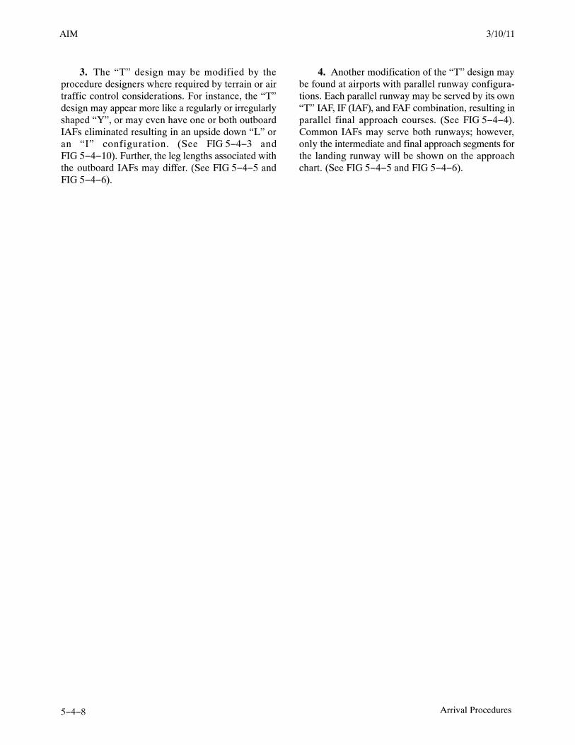
AIM 2/11/10
5−4−8 Arrival Procedures
3. The “T” design may be modified by theprocedure designers where required by terrain or airtraffic control considerations. For instance, the “T”design may appear more like a regularly or irregularlyshaped “Y”, or may even have one or both outboardIAFs eliminated resulting in an upside down “L” oran “I” configuration. (See FIG 5−4−3 andFIG 5−4−10). Further, the leg lengths associated withthe outboard IAFs may differ. (See FIG 5−4−5 andFIG 5−4−6).
4. Another modification of the “T” design maybe found at airports with parallel runway configura-tions. Each parallel runway may be served by its own“T” IAF, IF (IAF), and FAF combination, resulting inparallel final approach courses. (See FIG 5−4−4).Common IAFs may serve both runways; however,only the intermediate and final approach segments forthe landing runway will be shown on the approachchart. (See FIG 5−4−5 and FIG 5−4−6).
3/15/077110.65R CHG 2AIM 3/10/11

AIM2/11/10
5−4−27Arrival Procedures
such time as traffic conditions permit. However, apilot involved in an emergency situation will be givenpriority. If the pilot is not familiar with the specificapproach procedure, ATC should be advised and theywill provide detailed information on the execution ofthe procedure.
REFERENCE−AIM, Advance Information on Instrument Approach, Paragraph 5−4−4.
d. At times ATC may not specify a particularapproach procedure in the clearance, but will state“CLEARED APPROACH.” Such clearanceindicates that the pilot may execute any one of theauthorized IAPs for that airport. This clearance doesnot constitute approval for the pilot to execute acontact approach or a visual approach.
e. Except when being radar vectored to the finalapproach course, when cleared for a specificallyprescribed IAP; i.e., “cleared ILS runway one ninerapproach” or when “cleared approach” i.e., executionof any procedure prescribed for the airport, pilotsshall execute the entire procedure commencing at anIAF or an associated feeder route as described on theIAP chart unless an appropriate new or revised ATCclearance is received, or the IFR flight plan iscanceled.
f. Pilots planning flights to locations which areprivate airfields or which have instrument approachprocedures based on private navigation aids shouldobtain approval from the owner. In addition, the pilotmust be authorized by the FAA to fly specialinstrument approach procedures associated withprivate navigation aids (see paragraph 5−4−8).Owners of navigation aids that are not for public usemay elect to turn off the signal for whatever reasonthey may have; e.g., maintenance, energyconservation, etc. Air traffic controllers are notrequired to question pilots to determine if they havepermission to land at a private airfield or to useprocedures based on privately owned navigation aids,and they may not know the status of the navigationaid. Controllers presume a pilot has obtainedapproval from the owner and the FAA for use ofspecial instrument approach procedures and is awareof any details of the procedure if an IFR flight planwas filed to that airport.
g. Pilots should not rely on radar to identify a fixunless the fix is indicated as “RADAR” on the IAP.Pilots may request radar identification of an OM, butthe controller may not be able to provide the service
due either to workload or not having the fix on thevideo map.
h. If a missed approach is required, advise ATCand include the reason (unless initiated by ATC).Comply with the missed approach instructions for theinstrument approach procedure being executed,unless otherwise directed by ATC.REFERENCE−AIM, Missed Approach, Paragraph 5−4−21.AIM, Missed Approach, Paragraph 5−5−5.
i. ATC may clear aircraft that have filed anAdvanced RNAV equipment suffix to theintermediate fix when clearing aircraft for aninstrument approach procedure. ATC will take thefollowing actions when clearing Advanced RNAVaircraft to the intermediate fix:
1. Provide radar monitoring to the intermediatefix.
2. Advise the pilot to expect clearance direct tothe intermediate fix at least 5 miles from the fix.
NOTE−This is to allow the pilot to program the RNAV equipmentto allow the aircraft to fly to the intermediate fix whencleared by ATC.
3. Assign an altitude to maintain until theintermediate fix.
4. Insure the aircraft is on a course that willintercept the intermediate segment at an angle notgreater than 90 degrees and is at an altitude that willpermit normal descent from the intermediate fix tothe final approach fix.
5−4−8. Special Instrument ApproachProcedures
Instrument Approach Procedure (IAP) charts reflectthe criteria associated with the U.S. Standard forTerminal Instrument [Approach] Procedures(TERPs), which prescribes standardized methods foruse in developing IAPs. Standard IAPs are publishedin the Federal Register (FR) in accordance withTitle 14 of the Code of Federal Regulations, Part 97,and are available for use by appropriately qualifiedpilots operating properly equipped and airworthyaircraft in accordance with operating rules andprocedures acceptable to the FAA. Special IAPs arealso developed using TERPS but are not given publicnotice in the FR. The FAA authorizes only certainindividual pilots and/or pilots in individualorganizations to use special IAPs, and may require
8/26/10 AIM

AIM 2/11/10
5−4−28 Arrival Procedures
additional crew training and/or aircraft equipment orperformance, and may also require the use of landingaids, communications, or weather services notavailable for public use. Additionally, IAPs thatservice private use airports or heliports are generallyspecial IAPs.
5−4−9. Procedure Turn and Hold−in−lieu ofProcedure Turn
a. A procedure turn is the maneuver prescribedwhen it is necessary to reverse direction to establishthe aircraft inbound on an intermediate or finalapproach course. The procedure turn orhold−in−lieu−of−PT is a required maneuver when itis depicted on the approach chart, unless cleared byATC for a straight−in approach. Additionally, theprocedure turn or hold−in−lieu−of−PT is notpermitted when the symbol “No PT” is depicted onthe initial segment being used, when a RADARVECTOR to the final approach course is provided,or when conducting a timed approach from a holdingfix. The altitude prescribed for the procedure turn isa minimum altitude until the aircraft is established onthe inbound course. The maneuver must becompleted within the distance specified in theprofile view. For a hold−in−lieu−of−PT, the holdingpattern direction must be flown as depicted and thespecified leg length/timing must not be exceeded.
NOTE−The pilot may elect to use the procedure turn orhold−in−lieu−of−PT when it is not required by theprocedure, but must first receive an amended clearancefrom ATC. If the pilot is uncertain whether the ATCclearance intends for a procedure turn to be conducted orto allow for a straight−in approach, the pilot mustimmediately request clarification from ATC (14 CFRSection 91.123).
1. On U.S. Government charts, a barbed arrowindicates the maneuvering side of the outboundcourse on which the procedure turn is made.Headings are provided for course reversal using the45 degree type procedure turn. However, the point atwhich the turn may be commenced and the type andrate of turn is left to the discretion of the pilot (limitedby the charted remain within xx NM distance). Someof the options are the 45 degree procedure turn, theracetrack pattern, the teardrop procedure turn, or the80 degree � 260 degree course reversal. Racetrackentries should be conducted on the maneuvering sidewhere the majority of protected airspace resides. If anentry places the pilot on the non−maneuvering side ofthe PT, correction to intercept the outbound courseensures remaining within protected airspace. Someprocedure turns are specified by procedural track.These turns must be flown exactly as depicted.
2. Descent to the procedure turn (PT)completion altitude from the PT fix altitude (whenone has been published or assigned by ATC) must notbegin until crossing over the PT fix or abeam andproceeding outbound. Some procedures contain anote in the chart profile view that says “Maintain(altitude) or above until established outbound forprocedure turn” (See FIG 5−4−14). Newerprocedures will simply depict an “at or above”altitude at the PT fix without a chart note (SeeFIG 5−4−15). Both are there to ensure requiredobstacle clearance is provided in the procedure turnentry zone (See FIG 5−4−16). Absence of a chart noteor specified minimum altitude adjacent to the PT fixis an indication that descent to the procedure turnaltitude can commence immediately upon crossingover the PT fix, regardless of the direction of flight.This is because the minimum altitudes in the PT entryzone and the PT maneuvering zone are the same.
3/15/077110.65R CHG 2AIM 3/10/11

AIM2/11/10
5−4−51Arrival Procedures
FIG 5−4−27
c. Straight-in Minimums are shown on the IAPwhen the final approach course is within 30 degreesof the runway alignment (15 degrees for GPS IAPs)and a normal descent can be made from the IFRaltitude shown on the IAP to the runway surface.When either the normal rate of descent or the runwayalignment factor of 30 degrees (15 degrees for GPSIAPs) is exceeded, a straight-in minimum is notpublished and a circling minimum applies. The factthat a straight-in minimum is not published does notpreclude pilots from landing straight-in if they havethe active runway in sight and have sufficient time tomake a normal approach for landing. Under suchconditions and when ATC has cleared them forlanding on that runway, pilots are not expected tocircle even though only circling minimums arepublished. If they desire to circle, they should adviseATC.
d. Side-Step Maneuver Minimums. Landingminimums for a side-step maneuver to the adjacentrunway will normally be higher than the minimumsto the primary runway.
e. Published Approach Minimums. Approachminimums are published for different aircraftcategories and consist of a minimum altitude (DA,DH, MDA) and required visibility. These minimumsare determined by applying the appropriate TERPScriteria. When a fix is incorporated in a nonprecisionfinal segment, two sets of minimums may bepublished: one for the pilot that is able to identify thefix, and a second for the pilot that cannot. Two sets ofminimums may also be published when a secondaltimeter source is used in the procedure. When anonprecision procedure incorporates both astepdown fix in the final segment and a second
8/26/10 AIM

AIM 2/11/10
5−4−52 Arrival Procedures
altimeter source, two sets of minimums are publishedto account for the stepdown fix and a note addressesminimums for the second altimeter source.
f. Circling Minimums. In some busy terminalareas, ATC may not allow circling and circlingminimums will not be published. Published circlingminimums provide obstacle clearance when pilotsremain within the appropriate area of protection.Pilots should remain at or above the circling altitudeuntil the aircraft is continuously in a position fromwhich a descent to a landing on the intended runwaycan be made at a normal rate of descent using normalmaneuvers. Circling may require maneuvers at lowaltitude, at low airspeed, and in marginal weatherconditions. Pilots must use sound judgment, have anindepth knowledge of their capabilities, and fullyunderstand the aircraft performance to determine theexact circling maneuver since weather, unique airportdesign, and the aircraft position, altitude, andairspeed must all be considered. The following basicrules apply:
1. Maneuver the shortest path to the base ordownwind leg, as appropriate, considering existingweather conditions. There is no restriction frompassing over the airport or other runways.
2. It should be recognized that circlingmaneuvers may be made while VFR or other flyingis in progress at the airport. Standard left turns orspecific instruction from the controller formaneuvering must be considered when circling toland.
3. At airports without a control tower, it may bedesirable to fly over the airport to observe wind andturn indicators and other traffic which may be on therunway or flying in the vicinity of the airport.
REFERENCE−AC 90−66A, Recommended Standards Traffic patterns for AeronauticalOperations at Airports without Operating Control Towers.
4. The missed approach point (MAP) variesdepending upon the approach flown. For verticallyguided approaches, the MAP is at the decisionaltitude/decision height. Non−vertically guided andcircling procedures share the same MAP and the pilotdetermines this MAP by timing from the finalapproach fix, by a fix, a NAVAID, or a waypoint.Circling from a GLS, an ILS without a localizer lineof minima or an RNAV (GPS) approach without anLNAV line of minima is prohibited.
g. Instrument Approach at a Military Field.When instrument approaches are conducted by civilaircraft at military airports, they shall be conducted inaccordance with the procedures and minimumsapproved by the military agency having jurisdictionover the airport.
5−4−21. Missed Approach
a. When a landing cannot be accomplished, adviseATC and, upon reaching the missed approach pointdefined on the approach procedure chart, the pilotmust comply with the missed approach instructionsfor the procedure being used or with an alternatemissed approach procedure specified by ATC.
b. Obstacle protection for missed approach ispredicated on the missed approach being initiated atthe decision altitude/height (DA/H) or at the missedapproach point and not lower than minimum descentaltitude (MDA). A climb gradient of at least 200 feetper nautical mile is required, (except for Copterapproaches, where a climb of at least 400 feet pernautical mile is required), unless a higher climbgradient is published in the notes section of theapproach procedure chart. When higher than standardclimb gradients are specified, the end point of thenon−standard climb will be specified at either analtitude or a fix. Pilots must preplan to ensure that theaircraft can meet the climb gradient (expressed in feetper nautical mile) required by the procedure in theevent of a missed approach, and be aware that flyingat a higher than anticipated ground speed increasesthe climb rate requirement (feet per minute). Tablesfor the conversion of climb gradients (feet pernautical mile) to climb rate (feet per minute), basedon ground speed, are included on page D1 of the U.S.Terminal Procedures booklets. Reasonable buffersare provided for normal maneuvers. However, noconsideration is given to an abnormally early turn.Therefore, when an early missed approach isexecuted, pilots should, unless otherwise cleared byATC, fly the IAP as specified on the approach plateto the missed approach point at or above the MDA orDH before executing a turning maneuver.
c. If visual reference is lost while circling-to-landfrom an instrument approach, the missed approachspecified for that particular procedure must befollowed (unless an alternate missed approachprocedure is specified by ATC). To becomeestablished on the prescribed missed approachcourse, the pilot should make an initial climbing turn
3/15/077110.65R CHG 2AIM 3/10/11

AIM2/11/10
5−4−53Arrival Procedures
toward the landing runway and continue the turn untilestablished on the missed approach course. Inasmuchas the circling maneuver may be accomplished inmore than one direction, different patterns will berequired to become established on the prescribedmissed approach course, depending on the aircraftposition at the time visual reference is lost.Adherence to the procedure will help assure that anaircraft will remain laterally within the circling andmissed approach obstruction clearance areas. Referto paragraph h concerning vertical obstructionclearance when starting a missed approach at otherthan the MAP. (See FIG 5−4−28.)
d. At locations where ATC radar service isprovided, the pilot should conform to radar vectorswhen provided by ATC in lieu of the publishedmissed approach procedure. (See FIG 5−4−29.)
e. Some locations may have a preplanned alternatemissed approach procedure for use in the event theprimary NAVAID used for the missed approachprocedure is unavailable. To avoid confusion, thealternate missed approach instructions are notpublished on the chart. However, the alternate missedapproach holding pattern will be depicted on theinstrument approach chart for pilot situationalawareness and to assist ATC by not having to issuedetailed holding instructions. The alternate missedapproach may be based on NAVAIDs not used in theapproach procedure or the primary missed approach.When the alternate missed approach procedure is
implemented by NOTAM, it becomes a mandatorypart of the procedure. The NOTAM will specify boththe textual instructions and any additional equipmentrequirements necessary to complete the procedure.Air traffic may also issue instructions for the alternatemissed approach when necessary, such as when theprimary missed approach NAVAID fails during theapproach. Pilots may reject an ATC clearance for analternate missed approach that requires equipmentnot necessary for the published approach procedurewhen the alternate missed approach is issued afterbeginning the approach. However, when the alternatemissed approach is issued prior to beginning theapproach the pilot must either accept the entireprocedure (including the alternate missed approach),request a different approach procedure, or coordinatewith ATC for alternative action to be taken, i.e.,proceed to an alternate airport, etc.
f. When approach has been missed, requestclearance for specific action; i.e., to alternativeairport, another approach, etc.
g. Pilots must ensure that they have climbed to asafe altitude prior to proceeding off the publishedmissed approach, especially in nonradarenvironments. Abandoning the missed approachprior to reaching the published altitude may notprovide adequate terrain clearance. Additional climbmay be required after reaching the holding patternbefore proceeding back to the IAF or to an alternate.
3/10/11 AIM

AIM 2/11/10
5−4−54 Arrival Procedures
FIG 5−4−28
Circling and Missed Approach ObstructionClearance Areas
X
X
CLIMBING TURN
CLIMBING TURN
DECISION TO MISSHERE
DECISIONTO MISS HERE
VOR
VORCIRCLINGMANEUVER
(WHENCLEARED INRIGHT HANDTRAFFICPATTERN)
FIG 5−4−29
Missed Approach
x
CHANUTE
109.2 CNU
090°
1450 12651581
11801172
Portion of a Published ProcedureRemain within
10 NMVOR
MISSED APPROACHClimbing right turn to2600 direct to VOR2600
236°
056°
2500
5.7 NM
R236
056°
011°
191°
h. A clearance for an instrument approachprocedure includes a clearance to fly the publishedmissed approach procedure, unless otherwiseinstructed by ATC. The published missed approachprocedure provides obstacle clearance only when themissed approach is conducted on the missedapproach segment from or above the missed approachpoint, and assumes a climb rate of 200 feet/NM orhigher, as published. If the aircraft initiates a missedapproach at a point other than the missed approachpoint (see paragraph 5−4−5b), from below MDA orDA (H), or on a circling approach, obstacle clearanceis not necessarily provided by following thepublished missed approach procedure, nor isseparation assured from other air traffic in thevicinity.
In the event a balked (rejected) landing occurs at a po-sition other than the published missed approach point,the pilot should contact ATC as soon as possible to ob-tain an amended clearance. If unable to contact ATCfor any reason, the pilot should attempt to re−inter-cept a published segment of the missed approach andcomply with route and altitude instructions. If unableto contact ATC, and in the pilot’s judgment it is nolonger appropriate to fly the published missed ap-proach procedure, then consider either maintainingvisual conditions if practicable and reattempt a land-ing, or a circle−climb over the airport. Should amissed approach become necessary when operatingto an airport that is not served by an operating controltower, continuous contact with an air traffic facilitymay not be possible. In this case, the pilot should ex-ecute the appropriate go−around/missed approachprocedure without delay and contact ATC when ableto do so.
Prior to initiating an instrument approach procedure,the pilot should assess the actions to be taken in theevent of a balked (rejected) landing beyond themissed approach point or below the MDA or DA (H)considering the anticipated weather conditions andavailable aircraft performance. 14 CFR 91.175(e)authorizes the pilot to fly an appropriate missedapproach procedure that ensures obstruction clear-ance, but it does not necessarily consider separationfrom other air traffic. The pilot must consider otherfactors such as the aircraft’s geographical locationwith respect to the prescribed missed approach point,direction of flight, and/or minimum turning altitudesin the prescribed missed approach procedure. Thepilot must also consider aircraft performance, visual
3/15/077110.65R CHG 2AIM 3/10/11

AIM2/11/10
5−4−55Arrival Procedures
climb restrictions, charted obstacles, publishedobstacle departure procedure, takeoff visual climbrequirements as expressed by nonstandard takeoffminima, other traffic expected to be in the vicinity, orother factors not specifically expressed by the ap-proach procedures.
5−4−22. Use of Enhanced Flight VisionSystems (EFVS) on Instrument Approaches
An EFVS is an installed airborne system which usesan electronic means to provide a display of theforward external scene topography (the applicablenatural or manmade features of a place or regionespecially in a way to show their relative positionsand elevation) through the use of imaging sensors,such as forward looking infrared, millimeter waveradiometry, millimeter wave radar, and/or low lightlevel image intensifying. The EFVS imagery isdisplayed along with the additional flight informationand aircraft flight symbology required by 14 CFR91.175 (m) on a head−up display (HUD), or anequivalent display, in the same scale and alignment asthe external view and includes the display element,sensors, computers and power supplies, indications,and controls. The display is typically presented to thepilot by means of an approved HUD.
a. Basic Strategy Using EFVS. When flying aninstrument approach procedure (IAP), if the runwayenvironment cannot be visually acquired at decisionaltitude (DA) or minimum descent altitude (MDA)using natural vision, then a pilot may use an EFVS tocontinue descending down to 100 feet above theTouchdown Zone Elevation (TDZE), provided all ofthe visibility requirements of 14 CFR part 91.175 (l)are met. The primary reference for maneuvering theaircraft is based on what the pilot sees through theEFVS. At 100 feet above the TDZE, a pilot can con-tinue to descend only when the visual referencerequirements for descent below 100 feet can be seenusing natural vision (without the aid of the EFVS). Inother words, a pilot may not continue to rely on theEFVS sensor image to identify the required visualreferences below 100 feet above the TDZE. Support-ing information is provided by the flight path vector(FPV), flight path angle (FPA) reference cue, on-board navigation system, and other imagery andflight symbology displayed on the EFVS. The FPVand FPA reference cue, along with the EFVS imageryof the Touchdown Zone (TDZ), provide the primary
vertical path reference for the pilot when verticalguidance from a precision approach or approach withvertical guidance is not available.
1. Straight−In Instrument ApproachProcedures. An EFVS may be used to descendbelow DA or MDA from any straight−in IAP, otherthan Category II or Category III approaches,provided all of the requirements of 14 CFR part91.175 (l) are met. This includes straight−in precisionapproaches, approaches with vertical guidance (forexample, LPV or LNAV/VNAV), and non−precisionapproaches (for example, VOR, NDB, LOC, RNAV,GPS, LDA, SDF, etc.).
2. Circling Approach Procedure. An IAPwith a circle−to−land maneuver or circle−to−landminimums does not meet criteria for straight−inlanding minimums. While the regulations do notprohibit EFVS from being used during any phase offlight, they do prohibit it from being used foroperational credit on anything but a straight−in IAPwith straight−in landing minima. EFVS shall only beused during a circle−to−land maneuver provided thevisual references required throughout the circlingmaneuver are distinctly visible using natural vision.An EFVS cannot be used to satisfy the requirementthat an identifiable part of the airport be distinctlyvisible to the pilot during a circling maneuver at orabove MDA or while descending below MDA froma circling maneuver.
3. Enhanced Flight Visibility. Flight visibilityis determined by using natural vision, and enhancedflight visibility (EFV) is determined by using anEFVS. 14 CFR part 91.175 (l) requires that the EFVobserved by using an EFVS cannot be less than thevisibility prescribed in the IAP to be used in order tocontinue to descend below the DA or MDA.
b. EFVS Operations At or Below DA or MDADown to 100 Feet Above the TDZE. The visualsegment of an IAP begins at DA or MDA and contin-ues to the runway. There are two means of operatingin the visual segment−−one is by using natural visionand the other is by using an EFVS. If the pilot determ-ines that the EFV observed by using the EFVS is notless than the minimum visibility prescribed in the IAPbeing flown, and the pilot acquires the required visualreferences prescribed in 14 CFR part 91.175 (l)(3) us-ing the EFVS, then the pilot can continue theapproach to 100 feet above the TDZE. To continuethe approach, the pilot uses the EFVS image to visu-ally acquire the runway environment (the approach
3/10/11 AIM

AIM 2/11/10
5−4−56 Arrival Procedures
light system (ALS), if installed, or both the runwaythreshold and the TDZ), confirm lateral alignment,maneuver to the extended runway centerline earlierthan would otherwise be possible, and continue a nor-mal descent from the DA or MDA to 100 feet abovethe TDZE.
1. Required Visual References. In order todescend below DA or MDA, the following visualreferences (specified in 14 CFR part 91.175 (l)(3)) forthe runway of intended landing must be distinctlyvisible and identifiable to the pilot using the EFVS:
(a) The ALS (if installed), or
(b) The following visual references in both(b)(1) and (b)(2) below:
(1) The runway threshold, identified by atleast one of the following: the beginning of the run-way landing surface, the threshold lights, or therunway end identifier lights (REIL).
(2) The TDZ, identified by at least one ofthe following: the runway TDZ landing surface, theTDZ lights, the TDZ markings, or the runway lights.
2. Comparison of Visual Reference Require-ments for EFVS and Natural Vision. The EFVSvisual reference requirements of 14 CFR part 91.175(l)(3) comprise a more stringent standard than thevisual reference requirements prescribed under 14CFR part 91.175 (c)(3) when using natural vision.The more stringent standard is needed because anEFVS might not display the color of the lights usedto identify specific portions of the runway or mightnot be able to consistently display the runway mark-ings. The main differences for EFVS operations arethat the visual glide slope indicator (VGSI) lightscannot be used as a visual reference, and specificvisual references from both the threshold and TDZmust be distinctly visible and identifiable. However,when using natural vision, only one of the specifiedvisual references must be visible and identifiable.
3. Visual References and OffsetApproaches. Pilots must be especially knowledge-able of the approach conditions and approach coursealignment when considering whether to rely on EFVSduring a non−precision approach with an offset finalapproach course. Depending upon the combination ofcrosswind correction and the lateral field of viewprovided by a particular EFVS, the required visualreferences may or may not be within the pilot’s view
looking through the EFVS display. Pilots conductingany non−precision approach must verify lateral align-ment with the runway centerline when determiningwhen to descend from MDA.
4. When to Go Around. Any pilot operatingan aircraft with an EFVS installed should be awarethat the requirements of 14 CFR part 91.175 (c) forusing natural vision and the requirements of 14 CFRpart 91.175 (l) for using an EFVS are different. Apilot would, therefore, first have to determinewhether an approach will be commenced usingnatural vision or using an EFVS. While these two setsof requirements provide a parallel decisionmakingprocess, the requirements for when a missedapproach must be executed differ. Using EFVS, amissed approach must be initiated at or below DA orMDA down to 100 feet above TDZE whenever thepilot determines that:
(a) The EFV is less than the visibility minimaprescribed for the IAP being used;
(b) The required visual references for the run-way of intended landing are no longer distinctlyvisible and identifiable to the pilot using the EFVSimagery;
(c) The aircraft is not continuously in a posi-tion from which a descent to a landing can be madeon the intended runway, at a normal rate of descent,using normal maneuvers; or
(d) For operations under 14 CFR parts 121and 135, the descent rate of the aircraft would notallow touchdown to occur within the TDZ of therunway of intended landing.
5. Missed Approach Considerations. Itshould be noted that a missed approach after passingthe DA, or beyond the missed approach point (MAP),involves additional risk until established on the pub-lished missed approach segment. Initiating ago−around after passing the published MAP may res-ult in loss of obstacle clearance. As with anyapproach, pilot planning should include contingen-cies between the published MAP and touchdown withreference to obstacle clearance, aircraft performance,and alternate escape plans.
c. EFVS Operations At and Below 100 FeetAbove the TDZE. At and below 100 feet above theTDZE, the regulations do not require the EFVS to beturned off or the display to be stowed in order to con-tinue to a landing. A pilot may continue the approach
3/15/077110.65R CHG 2AIM 3/10/11

AIM2/11/10
5−4−57Arrival Procedures
below this altitude using an EFVS as long as the re-quired visual references can be seen through thedisplay using natural vision. An operator may notcontinue to descend beyond this point by relyingsolely on the sensor image displayed on the EFVS.
1. Required Visual References. In order todescend below 100 feet above the TDZE, the flightvisibility−−assessed using natural vision−−must besufficient for the following visual references to bedistinctly visible and identifiable to the pilot withoutreliance on the EFVS to continue to a landing:
(a) The lights or markings of the threshold, or
(b) The lights or markings of the TDZ.
It is important to note that from 100 feet above theTDZE and below, the flight visibility does not haveto be equal to or greater than the visibility prescribedfor the IAP in order to continue descending. It onlyhas to be sufficient for the visual references requiredby 14 CFR part 91.175 (l)(4) to be distinctly visibleand identifiable to the pilot without reliance on theEFVS.
2. Comparison of Visual Reference Require-ments for EFVS and Natural Vision. Again, thevisual reference requirements for EFVS in 14 CFRpart 91.175 (l)(4) are more stringent than those re-quired for natural vision in 14 CFR part 91.175 (c)(3).The main differences for EFVS operations are thatthe ALS and red terminating bars or red side row bars,the REIL, and the VASI cannot be used as visual ref-erences. Only very specific visual references from thethreshold or the TDZ can be used (that is, the lightsor markings of the threshold or the lights or markingsof the TDZ).
3. When to Go Around. A missed approachmust be initiated when the pilot determines that:
(a) The flight visibility is no longer sufficientto distinctly see and identify the required visual refer-ences listed in 14 CFR part 91.175 (l)(4) using naturalvision;
(b) The aircraft is not continuously in a posi-tion from which a descent to a landing can be madeon the intended runway, at a normal rate of descent,using normal maneuvers; or
(c) For operations under 14 CFR parts 121and 135, the descent rate of the aircraft would not al-low touchdown to occur within the TDZ of therunway of intended landing.
While touchdown within the TDZ is not specificallyaddressed in the regulations for operators other than14 CFR parts 121 and 135 operators, continued oper-ations below DA or MDA where touchdown in theTDZ is not assured, where a high sink rate occurs, orwhere the decision to conduct a missed approach pro-cedure is not executed in a timely manner, all createa significant risk to the operation.
4. Missed Approach Considerations. Asnoted earlier, a missed approach initiated after the DAor MAP involves additional risk. At 100 feet or lessabove the runway, it is likely that an aircraft is signi-ficantly below the TERPS missed approach obstacleclearance surface. Prior planning is recommendedand should include contingencies between the pub-lished MAP and touchdown with reference toobstacle clearance, aircraft performance, and altern-ate escape plans.
d. Light Emitting Diode (LED) Airport Light-ing Impact on EFVS Operations. The FAA hasrecently begun to replace incandescent lamps withLEDs at some airports in threshold lights, taxiwayedge lights, taxiway centerline lights, low intensityrunway edge lights, windcone lights, beacons, andsome obstruction lighting. Pilots should be aware thatLED lights cannot be sensed by current EFVS sys-tems.
5−4−23. Visual Approach
a. A visual approach is conducted on an IFR flightplan and authorizes a pilot to proceed visually andclear of clouds to the airport. The pilot must haveeither the airport or the preceding identified aircraftin sight. This approach must be authorized andcontrolled by the appropriate air traffic controlfacility. Reported weather at the airport must have aceiling at or above 1,000 feet and visibility 3 miles orgreater. ATC may authorize this type approach whenit will be operationally beneficial. Visual approachesare an IFR procedure conducted under IFR in visualmeteorological conditions. Cloud clearancerequirements of 14 CFR Section 91.155 are notapplicable, unless required by operationspecifications.
b. Operating to an Airport Without WeatherReporting Service. ATC will advise the pilot whenweather is not available at the destination airport.ATC may initiate a visual approach provided there isa reasonable assurance that weather at the airport is a
3/10/11 AIM

AIM 2/11/10
5−4−58 Arrival Procedures
ceiling at or above 1,000 feet and visibility 3 miles orgreater (e.g., area weather reports, PIREPs, etc.).
c. Operating to an Airport With an OperatingControl Tower. Aircraft may be authorized toconduct a visual approach to one runway while otheraircraft are conducting IFR or VFR approaches toanother parallel, intersecting, or converging runway.When operating to airports with parallel runwaysseparated by less than 2,500 feet, the succeedingaircraft must report sighting the preceding aircraftunless standard separation is being provided by ATC.When operating to parallel runways separated by atleast 2,500 feet but less than 4,300 feet, controllerswill clear/vector aircraft to the final at an angle notgreater than 30 degrees unless radar, vertical, orvisual separation is provided during the turn-on. Thepurpose of the 30 degree intercept angle is to reducethe potential for overshoots of the final and topreclude side-by-side operations with one or bothaircraft in a belly-up configuration during theturn-on. Once the aircraft are established within30 degrees of final, or on the final, these operationsmay be conducted simultaneously. When the parallelrunways are separated by 4,300 feet or more, orintersecting/converging runways are in use, ATCmay authorize a visual approach after advising allaircraft involved that other aircraft are conductingoperations to the other runway. This may beaccomplished through use of the ATIS.
d. Separation Responsibilities. If the pilot hasthe airport in sight but cannot see the aircraft to befollowed, ATC may clear the aircraft for a visualapproach; however, ATC retains both separation andwake vortex separation responsibility. When visuallyfollowing a preceding aircraft, acceptance of thevisual approach clearance constitutes acceptance ofpilot responsibility for maintaining a safe approachinterval and adequate wake turbulence separation.
e. A visual approach is not an IAP and thereforehas no missed approach segment. If a go around isnecessary for any reason, aircraft operating atcontrolled airports will be issued an appropriateadvisory/clearance/instruction by the tower. Atuncontrolled airports, aircraft are expected to remainclear of clouds and complete a landing as soon aspossible. If a landing cannot be accomplished, theaircraft is expected to remain clear of clouds andcontact ATC as soon as possible for further clearance.
Separation from other IFR aircraft will be maintainedunder these circumstances.
f. Visual approaches reduce pilot/controllerworkload and expedite traffic by shortening flightpaths to the airport. It is the pilot’s responsibility toadvise ATC as soon as possible if a visual approachis not desired.
g. Authorization to conduct a visual approach is anIFR authorization and does not alter IFR flight plancancellation responsibility.REFERENCE−AIM, Canceling IFR Flight Plan, Paragraph 5−1−15.
h. Radar service is automatically terminated,without advising the pilot, when the aircraft isinstructed to change to advisory frequency.
5−4−24. Charted Visual Flight Procedure(CVFP)
a. CVFPs are charted visual approachesestablished for environmental/noise considerations,and/or when necessary for the safety and efficiency ofair traffic operations. The approach charts depictprominent landmarks, courses, and recommendedaltitudes to specific runways. CVFPs are designed tobe used primarily for turbojet aircraft.
b. These procedures will be used only at airportswith an operating control tower.
c. Most approach charts will depict someNAVAID information which is for supplementalnavigational guidance only.
d. Unless indicating a Class B airspace floor, alldepicted altitudes are for noise abatement purposesand are recommended only. Pilots are not prohibitedfrom flying other than recommended altitudes ifoperational requirements dictate.
e. When landmarks used for navigation are notvisible at night, the approach will be annotated“PROCEDURE NOT AUTHORIZED AT NIGHT.”
f. CVFPs usually begin within 20 flying milesfrom the airport.
g. Published weather minimums for CVFPs arebased on minimum vectoring altitudes rather than therecommended altitudes depicted on charts.
h. CVFPs are not instrument approaches and donot have missed approach segments.
i. ATC will not issue clearances for CVFPs whenthe weather is less than the published minimum.
3/15/077110.65R CHG 2AIM 3/10/11

AIM2/11/10
5−4−59Arrival Procedures
j. ATC will clear aircraft for a CVFP after the pilotreports siting a charted landmark or a precedingaircraft. If instructed to follow a preceding aircraft,pilots are responsible for maintaining a safe approachinterval and wake turbulence separation.
k. Pilots should advise ATC if at any point they areunable to continue an approach or lose sight of apreceding aircraft. Missed approaches will behandled as a go-around.
5−4−25. Contact Approach
a. Pilots operating in accordance with an IFRflight plan, provided they are clear of clouds and haveat least 1 mile flight visibility and can reasonablyexpect to continue to the destination airport in thoseconditions, may request ATC authorization for acontact approach.
b. Controllers may authorize a contact approachprovided:
1. The contact approach is specificallyrequested by the pilot. ATC cannot initiate thisapproach.
EXAMPLE−Request contact approach.
2. The reported ground visibility at thedestination airport is at least 1 statute mile.
3. The contact approach will be made to anairport having a standard or special instrumentapproach procedure.
4. Approved separation is applied betweenaircraft so cleared and between these aircraft andother IFR or special VFR aircraft.
EXAMPLE−Cleared contact approach (and, if required) at or below(altitude) (routing) if not possible (alternative procedures)and advise.
c. A contact approach is an approach procedurethat may be used by a pilot (with prior authorizationfrom ATC) in lieu of conducting a standard or specialIAP to an airport. It is not intended for use by a piloton an IFR flight clearance to operate to an airport nothaving a published and functioning IAP. Nor is itintended for an aircraft to conduct an instrumentapproach to one airport and then, when “in the clear,”discontinue that approach and proceed to anotherairport. In the execution of a contact approach, the
pilot assumes the responsibility for obstructionclearance. If radar service is being received, it willautomatically terminate when the pilot is instructed tochange to advisory frequency.
5−4−26. Landing Priority
A clearance for a specific type of approach (ILS,MLS, ADF, VOR or Straight-in Approach) to anaircraft operating on an IFR flight plan does not meanthat landing priority will be given over other traffic.ATCTs handle all aircraft, regardless of the type offlight plan, on a “first-come, first-served” basis.Therefore, because of local traffic or runway in use,it may be necessary for the controller in the interestof safety, to provide a different landing sequence. Inany case, a landing sequence will be issued to eachaircraft as soon as possible to enable the pilot toproperly adjust the aircraft’s flight path.
5−4−27. Overhead Approach Maneuver
a. Pilots operating in accordance with anIFR flight plan in Visual MeteorologicalConditions (VMC) may request ATC authorizationfor an overhead maneuver. An overhead maneuver isnot an instrument approach procedure. Overheadmaneuver patterns are developed at airports whereaircraft have an operational need to conduct themaneuver. An aircraft conducting an overheadmaneuver is considered to be VFR and the IFR flightplan is cancelled when the aircraft reaches the initialpoint on the initial approach portion of the maneuver.(See FIG 5−4−30.) The existence of a standardoverhead maneuver pattern does not eliminate thepossible requirement for an aircraft to conform toconventional rectangular patterns if an overheadmaneuver cannot be approved. Aircraft operating toan airport without a functioning control tower mustinitiate cancellation of an IFR flight plan prior toexecuting the overhead maneuver. Cancellation ofthe IFR flight plan must be accomplished aftercrossing the landing threshold on the initial portion ofthe maneuver or after landing. Controllers mayauthorize an overhead maneuver and issue thefollowing to arriving aircraft:
1. Pattern altitude and direction of traffic. Thisinformation may be omitted if either is standard.
PHRASEOLOGY−PATTERN ALTITUDE (altitude). RIGHT TURNS.
3/10/11 AIM

AIM 2/11/10
5−4−60 Arrival Procedures
2. Request for a report on initial approach.
PHRASEOLOGY−REPORT INITIAL.
3. “Break” information and a request for thepilot to report. The “Break Point” will be specified if
nonstandard. Pilots may be requested to report“break” if required for traffic or other reasons.
PHRASEOLOGY−BREAK AT (specified point).REPORT BREAK.
FIG 5−4−30
Overhead Maneuver
3 - 5 NM
X X
INITIAL POINTINITIAL POINT
INITIAL APPROACHINITIAL APPROACH
X
ROLL OUTROLL OUT
BREAK POINTBREAK POINT
180° TURN
180° TURN
3/15/077110.65R CHG 2AIM 3/10/11

AIM2/11/10
5−5−3Pilot/Controller Roles and Responsibilities
(c) Instructed to do so by ATC.
2. Advises ATC that a missed approach will bemade. Include the reason for the missed approachunless the missed approach is initiated by ATC.
3. Complies with the missed approach instruc-tions for the IAP being executed from the MAP,unless other missed approach instructions arespecified by ATC.
4. If executing a missed approach prior toreaching the MAP, fly the lateral navigation path ofthe instrument procedure to the MAP. Climb to thealtitude specified in the missed approach procedure,except when a maximum altitude is specifiedbetween the final approach fix (FAF) and the MAP. Inthat case, comply with the maximum altituderestriction. Note, this may require a continueddescent on the final approach.
5. Following a missed approach, requestsclearance for specific action; i.e., another approach,hold for improved conditions, proceed to an alternateairport, etc.
b. Controller.
1. Issues an approved alternate missed approachprocedure if it is desired that the pilot execute aprocedure other than as depicted on the instrumentapproach chart.
2. May vector a radar identified aircraftexecuting a missed approach when operationallyadvantageous to the pilot or the controller.
3. In response to the pilot’s stated intentions,issues a clearance to an alternate airport, to a holdingfix, or for reentry into the approach sequence, astraffic conditions permit.
5−5−6. Radar Vectors
a. Pilot.
1. Promptly complies with headings andaltitudes assigned to you by the controller.
2. Questions any assigned heading or altitudebelieved to be incorrect.
3. If operating VFR and compliance with anyradar vector or altitude would cause a violation of anyCFR, advises ATC and obtains a revised clearance orinstructions.
b. Controller.
1. Vectors aircraft in Class A, Class B, Class C,Class D, and Class E airspace:
(a) For separation.
(b) For noise abatement.
(c) To obtain an operational advantage for thepilot or controller.
2. Vectors aircraft in Class A, Class B, Class C,Class D, Class E, and Class G airspace whenrequested by the pilot.
3. Vectors IFR aircraft at or above minimumvectoring altitudes.
4. May vector VFR aircraft, not at an ATCassigned altitude, at any altitude. In these cases,terrain separation is the pilot’s responsibility.
5−5−7. Safety Alert
a. Pilot.
1. Initiates appropriate action if a safety alert isreceived from ATC.
2. Be aware that this service is not alwaysavailable and that many factors affect the ability ofthe controller to be aware of a situation in whichunsafe proximity to terrain, obstructions, or anotheraircraft may be developing.
b. Controller.
1. Issues a safety alert if aware an aircraft undertheir control is at an altitude which, in the controller’sjudgment, places the aircraft in unsafe proximity toterrain, obstructions or another aircraft. Types ofsafety alerts are:
(a) Terrain or Obstruction Alert. Immedi-ately issued to an aircraft under their control if awarethe aircraft is at an altitude believed to place theaircraft in unsafe proximity to terrain or obstructions.
(b) Aircraft Conflict Alert. Immediatelyissued to an aircraft under their control if aware of anaircraft not under their control at an altitude believedto place the aircraft in unsafe proximity to each other.With the alert, they offer the pilot an alternative, iffeasible.
2. Discontinue further alerts if informed by thepilot action is being taken to correct the situation orthat the other aircraft is in sight.

AIM 2/11/10
5−5−4 Pilot/Controller Roles and Responsibilities
5−5−8. See and Avoid
a. Pilot. When meteorological conditions permit,regardless of type of flight plan or whether or notunder control of a radar facility, the pilot isresponsible to see and avoid other traffic, terrain, orobstacles.
b. Controller.
1. Provides radar traffic information to radaridentified aircraft operating outside positive controlairspace on a workload permitting basis.
2. Issues safety alerts to aircraft under theircontrol if aware the aircraft is at an altitude believedto place the aircraft in unsafe proximity to terrain,obstructions, or other aircraft.
5−5−9. Speed Adjustments
a. Pilot.
1. Advises ATC any time cruising airspeedvaries plus or minus 5 percent or 10 knots, whicheveris greater, from that given in the flight plan.
2. Complies with speed adjustments from ATCunless:
(a) The minimum or maximum safe airspeedfor any particular operation is greater or less than therequested airspeed. In such cases, advises ATC.
NOTE−It is the pilot’s responsibility and prerogative to refusespeed adjustments considered excessive or contrary to theaircraft’s operating specifications.
(b) Operating at or above 10,000 feet MSL onan ATC assigned SPEED ADJUSTMENT of morethan 250 knots IAS and subsequent clearance isreceived for descent below 10,000 feet MSL. In suchcases, pilots are expected to comply with 14 CFRSection 91.117(a).
3. When complying with speed adjustmentassignments, maintains an indicated airspeed withinplus or minus 10 knots or 0.02 Mach number of thespecified speed.
b. Controller.
1. Assigns speed adjustments to aircraft whennecessary but not as a substitute for good vectoringtechnique.
2. Adheres to the restrictions published in theFAAO JO 7110.65, Air Traffic Control, as to whenspeed adjustment procedures may be applied.
3. Avoids speed adjustments requiring alternatedecreases and increases.
4. Assigns speed adjustments to a specified IAS(KNOTS)/Mach number or to increase or decreasespeed using increments of 10 knots or multiplesthereof.
5. Advises pilots to resume normal speed whenspeed adjustments are no longer required.
6. Gives due consideration to aircraft capabili-ties to reduce speed while descending.
7. Does not assign speed adjustments to aircraftat or above FL 390 without pilot consent.
5−5−10. Traffic Advisories (TrafficInformation)
a. Pilot.
1. Acknowledges receipt of traffic advisories.
2. Informs controller if traffic in sight.
3. Advises ATC if a vector to avoid traffic isdesired.
4. Does not expect to receive radar trafficadvisories on all traffic. Some aircraft may not appearon the radar display. Be aware that the controller maybe occupied with higher priority duties and unable toissue traffic information for a variety of reasons.
5. Advises controller if service is not desired.
b. Controller.
1. Issues radar traffic to the maximum extentconsistent with higher priority duties except inClass A airspace.
2. Provides vectors to assist aircraft to avoidobserved traffic when requested by the pilot.
3. Issues traffic information to aircraft in theClass B, Class C, and Class D surface areas forsequencing purposes.
4. Controllers are required to issue to eachaircraft operating on intersecting or nonintersectingconverging runways where projected flight pathswill cross.
3/15/077110.65R CHG 2AIM 3/10/11

AIM2/11/10
7−1−27Meteorology
(a) The products should be either FAA/NWS“accepted” aviation weather reports or products, orbased on FAA/NWS accepted aviation weatherreports or products. If products are used which do notmeet this criteria, they should be so identified. Theoperator must determine the applicability of suchproducts to their particular flight operations.
(b) In the case of a weather product which isthe result of the application of a process which altersthe form, function or content of the base FAA/NWSaccepted weather product(s), that process, and anylimitations to the application of the resultant product,should be described in the vendor’s user guidancematerial.
2. An example would be a NEXRAD radarcomposite/mosaic map, which has been modified bychanging the scaling resolution. The methodology ofassigning reflectivity values to the resultant imagecomponents should be described in the vendor’sguidance material to ensure that the user canaccurately interpret the displayed data.
7−1−12. Weather Observing Programs
a. Manual Observations. With only a fewexceptions, these reports are from airport locationsstaffed by FAA or NWS personnel who manuallyobserve, perform calculations, and enter theseobservations into the (WMSCR) communicationsystem. The format and coding of these observationsare contained in paragraph 7−1−30, Key to AviationRoutine Weather Report (METAR) and AerodromeForecasts (TAF).
b. Automated Weather Observing System(AWOS).
1. Automated weather reporting systems areincreasingly being installed at airports. Thesesystems consist of various sensors, a processor, acomputer-generated voice subsystem, and a transmit-ter to broadcast local, minute-by-minute weather datadirectly to the pilot.
NOTE−When the barometric pressure exceeds 31.00 inches Hg.,see paragraph 7−2−2, Procedures, for the altimeter settingprocedures.
2. The AWOS observations will include theprefix “AUTO” to indicate that the data are derivedfrom an automated system. Some AWOS locations
will be augmented by certified observers who willprovide weather and obstruction to vision informa-tion in the remarks of the report when the reportedvisibility is less than 7 miles. These sites, along withthe hours of augmentation, are to be published in theA/FD. Augmentation is identified in the observationas “OBSERVER WEATHER.” The AWOS windspeed, direction and gusts, temperature, dew point,and altimeter setting are exactly the same as formanual observations. The AWOS will also reportdensity altitude when it exceeds the field elevation bymore than 1,000 feet. The reported visibility isderived from a sensor near the touchdown of theprimary instrument runway. The visibility sensoroutput is converted to a visibility value using a10−minute harmonic average. The reported skycondition/ceiling is derived from the ceilometerlocated next to the visibility sensor. The AWOSalgorithm integrates the last 30 minutes of ceilometerdata to derive cloud layers and heights. This outputmay also differ from the observer sky condition inthat the AWOS is totally dependent upon the cloudadvection over the sensor site.
3. These real-time systems are operationallyclassified into nine basic levels:
(a) AWOS−A only reports altimeter setting;
NOTE−Any other information is advisory only.
(b) AWOS−AV reports altimeter andvisibility;
NOTE−Any other information is advisory only.
(c) AWOS−l usually reports altimeter setting,wind data, temperature, dew point, and densityaltitude;
(d) AWOS−2 provides the information pro-vided by AWOS−l plus visibility; and
(e) AWOS−3 provides the information pro-vided by AWOS−2 plus cloud/ceiling data.
(f) AWOS− 3P provides reports the same asthe AWOS 3 system, plus a precipitation identifica-tion sensor.
(g) AWOS− 3PT reports the same as theAWOS 3P System, plus thunderstorm/lightningreporting capability.
3/10/11 AIM

AIM 2/11/10
7−1−28 Meteorology
(h) AWOS− 3T reports the same as AWOS 3system and includes a thunderstorm/lightningreporting capability.
(i) AWOS− 4 reports the same as the AWOS3 system, plus precipitation occurrence, type andaccumulation, freezing rain, thunderstorm, andrunway surface sensors.
4. The information is transmitted over a discreteVHF radio frequency or the voice portion of a localNAVAID. AWOS transmissions on a discrete VHFradio frequency are engineered to be receivable to amaximum of 25 NM from the AWOS site and amaximum altitude of 10,000 feet AGL. At manylocations, AWOS signals may be received on thesurface of the airport, but local conditions may limitthe maximum AWOS reception distance and/oraltitude. The system transmits a 20 to 30 secondweather message updated each minute. Pilots shouldmonitor the designated frequency for the automatedweather broadcast. A description of the broadcast iscontained in subparagraph c. There is no two-waycommunication capability. Most AWOS sites alsohave a dial-up capability so that the minute-by-min-ute weather messages can be accessed via telephone.
5. AWOS information (system level, frequency,phone number, etc.) concerning specific locations ispublished, as the systems become operational, in theA/FD, and where applicable, on published Instru-ment Approach Procedures. Selected individualsystems may be incorporated into nationwide datacollection and dissemination networks in the future.
c. AWOS Broadcasts. Computer-generatedvoice is used in AWOS to automate the broadcast ofthe minute-by-minute weather observations. Inaddition, some systems are configured to permit theaddition of an operator-generated voice message;e.g., weather remarks following the automatedparameters. The phraseology used generally followsthat used for other weather broadcasts. Following areexplanations and examples of the exceptions.
1. Location and Time. The location/name andthe phrase “AUTOMATED WEATHER OBSERVA-TION,” followed by the time are announced.
(a) If the airport’s specific location isincluded in the airport’s name, the airport’s name isannounced.
EXAMPLE−“Bremerton National Airport automated weather observa-tion, one four five six zulu;”“Ravenswood Jackson County Airport automated weatherobservation, one four five six zulu.”
(b) If the airport’s specific location is notincluded in the airport’s name, the location isannounced followed by the airport’s name.
EXAMPLE−“Sault Ste. Marie, Chippewa County International Airportautomated weather observation;”“Sandusky, Cowley Field automated weatherobservation.”
(c) The word “TEST” is added following“OBSERVATION” when the system is not incommissioned status.
EXAMPLE−“Bremerton National Airport automated weather observa-tion test, one four five six zulu.”
(d) The phrase “TEMPORARILY INOP-ERATIVE” is added when the system is inoperative.
EXAMPLE−“Bremerton National Airport automated weather observ-ing system temporarily inoperative.”
2. Visibility.
(a) The lowest reportable visibility value inAWOS is “less than 1/4.” It is announced as“VISIBILITY LESS THAN ONE QUARTER.”
(b) A sensor for determining visibility is notincluded in some AWOS. In these systems, visibilityis not announced. “VISIBILITY MISSING” isannounced only if the system is configured with avisibility sensor and visibility information is notavailable.
3. Weather. In the future, some AWOSs are tobe configured to determine the occurrence ofprecipitation. However, the type and intensity maynot always be determined. In these systems, the word“PRECIPITATION” will be announced if precipita-tion is occurring, but the type and intensity are notdetermined.
4. Ceiling and Sky Cover.
(a) Ceiling is announced as either “CEIL-ING” or “INDEFINITE CEILING.” With theexception of indefinite ceilings, all automated ceilingheights are measured.
3/15/077110.65R CHG 2AIM 3/10/11
AIM2/11/10
7−1−29Meteorology
EXAMPLE−“Bremerton National Airport automated weather observa-tion, one four five six zulu. Ceiling two thousand overcast;”
“Bremerton National Airport automated weather observa-tion, one four five six zulu. Indefinite ceiling two hundred,sky obscured.”
(b) The word “Clear” is not used in AWOSdue to limitations in the height ranges of the sensors.No clouds detected is announced as “NO CLOUDSBELOW XXX” or, in newer systems as “CLEARBELOW XXX” (where XXX is the range limit of thesensor).
EXAMPLE−“No clouds below one two thousand.”“Clear below one two thousand.”
(c) A sensor for determining ceiling and skycover is not included in some AWOS. In thesesystems, ceiling and sky cover are not announced.“SKY CONDITION MISSING” is announced only ifthe system is configured with a ceilometer and theceiling and sky cover information is not available.
5. Remarks. If remarks are included in theobservation, the word “REMARKS” is announcedfollowing the altimeter setting.
(a) Automated “Remarks.”
(1) Density Altitude.
(2) Variable Visibility.
(3) Variable Wind Direction.
(b) Manual Input Remarks. Manual inputremarks are prefaced with the phrase “OBSERVERWEATHER.” As a general rule the manual remarksare limited to:
(1) Type and intensity of precipitation.
(2) Thunderstorms and direction; and
(3) Obstructions to vision when the visibili-ty is 3 miles or less.
EXAMPLE−“Remarks ... density altitude, two thousand five hundred ...visibility variable between one and two ... wind directionvariable between two four zero and three one zero...observed weather ... thunderstorm moderate rainshowers and fog ... thunderstorm overhead.”
(c) If an automated parameter is “missing”and no manual input for that parameter is available,the parameter is announced as “MISSING.” For
example, a report with the dew point “missing” andno manual input available, would be announced asfollows:
EXAMPLE−“Ceiling one thousand overcast ... visibility three ...precipitation ... temperature three zero, dew point missing... wind calm ... altimeter three zero zero one.”
(d) “REMARKS” are announced in thefollowing order of priority:
(1) Automated “REMARKS.”
[a] Density Altitude.
[b] Variable Visibility.
[c] Variable Wind Direction.
(2) Manual Input “REMARKS.”
[a] Sky Condition.
[b] Visibility.
[c] Weather and Obstructions to Vision.
[d] Temperature.
[e] Dew Point.
[f] Wind; and
[g] Altimeter Setting.
EXAMPLE−“Remarks ... density altitude, two thousand five hundred ...visibility variable between one and two ... wind directionvariable between two four zero and three one zero ...observer ceiling estimated two thousand broken ...observer temperature two, dew point minus five.”
d. Automated Surface Observing System(ASOS)/Automated Weather Sensor System(AWSS). The ASOS/AWSS is the primary surfaceweather observing system of the U.S. (See Key toDecode an ASOS/AWSS (METAR) Observation,FIG 7−1−9 and FIG 7−1−10.) The program to installand operate these systems throughout the U.S. is ajoint effort of the NWS, the FAA and the Departmentof Defense. AWSS is a follow−on program thatprovides identical data as ASOS. ASOS/AWSS isdesigned to support aviation operations and weatherforecast activities. The ASOS/AWSS will providecontinuous minute-by-minute observations andperform the basic observing functions necessary togenerate an aviation routine weather report (ME-TAR) and other aviation weather information. Theinformation may be transmitted over a discrete VHFradio frequency or the voice portion of a local
3/10/11 AIM

AIM 2/11/10
7−1−30 Meteorology
NAVAID. ASOS/AWSS transmissions on a discreteVHF radio frequency are engineered to be receivableto a maximum of 25 NM from the ASOS/AWSS siteand a maximum altitude of 10,000 feet AGL. At manylocations, ASOS/AWSS signals may be received onthe surface of the airport, but local conditions maylimit the maximum reception distance and/or altitude.While the automated system and the human maydiffer in their methods of data collection andinterpretation, both produce an observation quitesimilar in form and content. For the “objective”elements such as pressure, ambient temperature, dewpoint temperature, wind, and precipitation accumula-tion, both the automated system and the observer usea fixed location and time-averaging technique. Thequantitative differences between the observer and theautomated observation of these elements arenegligible. For the “subjective” elements, however,observers use a fixed time, spatial averagingtechnique to describe the visual elements (skycondition, visibility and present weather), while theautomated systems use a fixed location, timeaveraging technique. Although this is a fundamentalchange, the manual and automated techniques yieldremarkably similar results within the limits of theirrespective capabilities.
1. System Description.
(a) The ASOS/AWSS at each airport locationconsists of four main components:
(1) Individual weather sensors.
(2) Data collection and processing units.
(3) Peripherals and displays.
(b) The ASOS/AWSS sensors perform thebasic function of data acquisition. They continuouslysample and measure the ambient environment, deriveraw sensor data and make them available to thecollection and processing units.
2. Every ASOS/AWSS will contain thefollowing basic set of sensors:
(a) Cloud height indicator (one or possiblythree).
(b) Visibility sensor (one or possibly three).
(c) Precipitation identification sensor.
(d) Freezing rain sensor (at select sites).
(e) Pressure sensors (two sensors at smallairports; three sensors at large airports).
(f) Ambient temperature/Dew point tempera-ture sensor.
(g) Anemometer (wind direction and speedsensor).
(h) Rainfall accumulation sensor.
3. The ASOS/AWSS data outlets include:
(a) Those necessary for on-site airport users.
(b) National communications networks.
(c) Computer-generated voice (availablethrough FAA radio broadcast to pilots, and dial-intelephone line).
NOTE−Wind direction broadcast over FAA radios is in referenceto magnetic north.
4. An ASOS/AWOS/AWSS report withouthuman intervention will contain only that weatherdata capable of being reported automatically. Themodifier for this METAR report is “AUTO.” Whenan observer augments or backs−up an ASOS/AWOS/AWSS site, the “AUTO” modifier disappears.
5. There are two types of automated stations,AO1 for automated weather reporting stationswithout a precipitation discriminator, and AO2 forautomated stations with a precipitation discriminator.As appropriate, “AO1” and “AO2” shall appear inremarks. (A precipitation discriminator can deter-mine the difference between liquid andfrozen/freezing precipitation).
NOTE−To decode an ASOS/AWSS report, refer to FIG 7−1−9 andFIG 7−1−10.
REFERENCE−A complete explanation of METAR terminology is located in AIM,Paragraph 7−1−30, Key to Aerodrome Forecast (TAF) and AviationRoutine Weather Report (METAR).
3/15/077110.65R CHG 2AIM 3/10/11

AIM2/11/10
7−1−33Meteorology
e. TBL 7−1−2 contains a comparison of weatherobserving programs and the elements reported.
f. Service Standards. During 1995, a govern-ment/industry team worked to comprehensivelyreassess the requirements for surface observations atthe nation’s airports. That work resulted in agreementon a set of service standards, and the FAA and NWSASOS sites to which the standards would apply. Theterm “Service Standards” refers to the level of detailin weather observation. The service standards consistof four different levels of service (A, B, C, and D) asdescribed below. Specific observational elementsincluded in each service level are listed inTBL 7−1−3.
1. Service Level D defines the minimumacceptable level of service. It is a completelyautomated service in which the ASOS/AWSSobservation will constitute the entire observation,i.e., no additional weather information is added by ahuman observer. This service is referred to as a standalone D site.
2. Service Level C is a service in which thehuman observer, usually an air traffic controller,augments or adds information to the automatedobservation. Service Level C also includes backup ofASOS/AWSS elements in the event of an ASOS/AWSS malfunction or an unrepresentativeASOS/AWSS report. In backup, the human observer
inserts the correct or missing value for the automatedASOS/AWSS elements. This service is provided byair traffic controllers under the Limited AviationWeather Reporting Station (LAWRS) process, FSSand NWS observers, and, at selected sites,Non−Federal Observation Program observers.
Two categories of airports require detail beyondService Level C in order to enhance air traffic controlefficiency and increase system capacity. Services atthese airports are typically provided by contractweather observers, NWS observers, and, at somelocations, FSS observers.
3. Service Level B is a service in which weatherobservations consist of all elements provided underService Level C, plus augmentation of additional databeyond the capability of the ASOS/AWSS. Thiscategory of airports includes smaller hubs or specialairports in other ways that have worse than averagebad weather operations for thunderstorms and/orfreezing/frozen precipitation, and/or that are remoteairports.
4. Service Level A, the highest and mostdemanding category, includes all the data reported inService Standard B, plus additional requirements asspecified. Service Level A covers major aviationhubs and/or high volume traffic airports with averageor worse weather.
TBL 7−1−2
Weather Observing Programs
Ele
men
t
Rep
orte
d
Win
d
Vis
ibili
ty
Tem
pera
ture
Dew
Poi
nt
Alt
imet
er
Den
sity
Alt
imet
er
Clo
ud/C
eilin
g
Pre
cipi
tati
on
Iden
tifi
cati
on
Thu
nder
stor
m/
Lig
htni
ng
Pre
cipi
tati
onO
ccur
renc
e
Rai
nfal
lA
ccum
ulat
ion
Run
way
Sur
face
Con
diti
on
Fre
ezin
g R
ain
Occ
urre
nce
Rem
arks
Type
AWSS X X X X X X X X X X
ASOS X X X X X X X X X X
AWOS−A X
AWOS−A/V X X
AWOS−1 X X X X
AWOS−2 X X X X X
AWOS−3 X X X X X X
AWOS−3P X X X X X X X
AWOS−3T X X X X X X X
AWOS−3P/T X X X X X X X X
AWOS−4 X X X X X X X X X X X X
Manual X X X X X X X
REFERENCE− FAA Order 7900.5B, Surface Weather Observing, for element reporting.
3/10/11 AIM

AIM 2/11/10
7−1−34 Meteorology
TBL 7−1−3
SERVICE LEVEL AService Level A consists of all the elements ofService Levels B, C and D plus the elementslisted to the right, if observed.
10 minute longline RVR at precedented sites oradditional visibility increments of 1/8, 1/16 and 0
Sector visibilityVariable sky conditionCloud layers above 12,000 feet and cloud typesWidespread dust, sand and other obscurationsVolcanic eruptions
SERVICE LEVEL B
Service Level B consists of all the elements ofService Levels C and D plus the elements listed tothe right, if observed.
Longline RVR at precedented sites(may be instantaneous readout)
Freezing drizzle versus freezing rainIce pelletsSnow depth & snow increasing rapidly remarksThunderstorm and lightning location remarksObserved significant weather not at the station
remarks
SERVICE LEVEL CService Level C consists of all the elements of ServiceLevel D plus augmentation and backup by a humanobserver or an air traffic control specialist on locationnearby. Backup consists of inserting the correct value ifthe system malfunctions or is unrepresentative.Augmentation consists of adding the elements listed tothe right, if observed. During hours that the observingfacility is closed, the site reverts to Service Level D.
ThunderstormsTornadoesHailVirgaVolcanic ashTower visibilityOperationally significant remarks as deemed
appropriate by the observer
SERVICE LEVEL DThis level of service consists of an ASOS or AWSScontinually measuring the atmosphere at a point near therunway. The ASOS or AWSS senses and measures theweather parameters listed to the right.
WindVisibilityPrecipitation/Obstruction to visionCloud heightSky coverTemperatureDew pointAltimeter
7−1−13. Weather Radar Services
a. The National Weather Service operates anetwork of radar sites for detecting coverage,intensity, and movement of precipitation. Thenetwork is supplemented by FAA and DOD radarsites in the western sections of the country. Localwarning radar sites augment the network by operatingon an as needed basis to support warning and forecastprograms.
b. Scheduled radar observations are taken hourlyand transmitted in alpha-numeric format on weathertelecommunications circuits for flight planningpurposes. Under certain conditions, special radarreports are issued in addition to the hourly
transmittals. Data contained in the reports are alsocollected by the National Center for EnvironmentalPrediction and used to prepare national radarsummary charts for dissemination on facsimilecircuits.
c. A clear radar display (no echoes) does not meanthat there is no significant weather within thecoverage of the radar site. Clouds and fog are notdetected by the radar. However, when echoes arepresent, turbulence can be implied by the intensity ofthe precipitation, and icing is implied by the presenceof the precipitation at temperatures at or below zerodegrees Celsius. Used in conjunction with otherweather products, radar provides invaluable informa-tion for weather avoidance and flight planning.
3/15/077110.65R CHG 2AIM 8/26/10
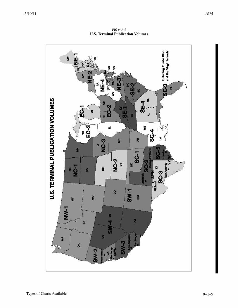
AIM2/11/10
9−1−9Types of Charts Available
FIG 9−1−9
U.S. Terminal Publication Volumes
3/10/11 AIM

AIM 2/11/10
9−1−10 Types of Charts Available
FIG 9−1−10
Airport/Facility Directory Geographic Areas
FIG 9−1−11
Sectional and VFR Terminal Area Charts for Alaska

AIM2/11/10
10−1−5Helicopter IFR Operations
10−1−3. Helicopter Approach Proceduresto VFR Heliports
a. Helicopter approaches may be developed forheliports that do not meet the design standards for anIFR heliport. The majority of IFR approaches to VFRheliports are developed in support of helicopteremergency medical services (HEMS) operators.These approaches can be developed from conven-tional NAVAIDs or a RNAV system (including GPS).They are developed either as a Special Approach(pilot training is required for special procedures dueto their unique characteristics) or a public approach(no special training required). These instrumentprocedures are developed as either an approachdesigned to a specific landing site, or an approachdesigned to a point−in−space.
1. Approach to a specific landing site. Theapproach is aligned to a missed approach point fromwhich a landing can be accomplished with amaximum course change of 30 degrees. The visualsegment from the MAP to the landing site is evaluatedfor obstacle hazards. These procedures are annotated:“PROCEED VISUALLY FROM (NAMED MAP)OR CONDUCT THE SPECIFIED MISSEDAPPROACH.”
(a) This phrase requires the pilot to eitheracquire and maintain visual contact with the landingsite at or prior to the MAP, or execute a missedapproach. The visibility minimum is based on thedistance from the MAP to the landing site, amongother factors.
(b) The pilot is required to maintain thepublished minimum visibility throughout the visualsegment.
(c) Similar to an approach to a runway, themissed approach segment protection is not providedbetween the MAP and the landing site, and obstacleor terrain avoidance from the MAP to the landing siteis the responsibility of the pilot.
(d) Upon reaching the MAP defined on theapproach procedure, or as soon as practicable afterreaching the MAP, the pilot advises ATC whetherproceeding visually and canceling IFR or complyingwith the missed approach instructions. See para-graph 5−1−15, Canceling IFR Flight Plan.
(e) At least one of the following visualreferences must be visible or identifiable before thepilot may proceed visually:
(1) FATO or FATO lights.
(2) TLOF or TLOF lights.
(3) Heliport Instrument Lighting System(HILS).
(4) Heliport Approach Lighting System(HALS) or lead−in lights.
(5) Visual Glideslope Indicator (VGSI).
(6) Windsock or windsock light(s). Seenote below.
(7) Heliport beacon. See note below.
(8) Other facilities or systems approved bythe Flight Technologies and Procedures Division(AFS−400).
NOTE−Windsock lights and heliport beacons should be locatedwithin 500 ft of the TLOF.
2. Approach to a Point−in−Space (PinS). Atlocations where the MAP is located more than 2 SMfrom the landing site, or the path from the MAP to thelanding site is populated with obstructions whichrequire avoidance actions or requires turns greaterthan 30 degrees, a PinS procedure may be developed.These approaches are annotated “PROCEED VFRFROM (NAMED MAP) OR CONDUCT THESPECIFIED MISSED APPROACH.”
(a) These procedures require the pilot, at orprior to the MAP, to determine if the publishedminimum visibility, or the weather minimumsrequired by the operating rule, or operationsspecifications (whichever is higher) is available tosafely transition from IFR to VFR flight. If not, thepilot must execute a missed approach. For Part 135operations, pilots may not begin the instrumentapproach unless the latest weather report indicatesthat the weather conditions are at or above theauthorized IFR minimums or the VFR weatherminimums (as required by the class of airspace,operating rule and/or Operations Specifications)whichever is higher.
(b) Visual contact with the landing site is notrequired; however, the pilot must maintain theappropriate VFR weather minimums throughout thevisual segment. The visibility is limited to no lower
8/26/10 AIM

AIM 2/11/10
10−1−6 Helicopter IFR Operations
than that published in the procedure, until cancelingIFR.
(c) IFR obstruction clearance areas are notapplied to the VFR segment between the MAP andthe landing site. Obstacle or terrain avoidance fromthe MAP to the landing site is the responsibility of thepilot.
(d) Upon reaching the MAP defined on theapproach procedure, or as soon as practicable afterreaching the MAP, the pilot advises ATC whetherproceeding VFR and canceling IFR, or complyingwith the missed approach instructions. See para-graph 5−1−15, Canceling IFR Flight Plan.
(e) If the visual segment penetrates Class B,C, or D airspace, pilots are responsible for obtaininga Special VFR clearance, when required.
10−1−4. The Gulf of Mexico Grid System
a. On October 8, 1998, the Southwest RegionalOffice of the FAA, with assistance from theHelicopter Safety Advisory Conference (HSAC),implemented the world’s first Instrument FlightRules (IFR) Grid System in the Gulf of Mexico. Thisnavigational route structure is completely indepen-dent of ground−based navigation aids (NAVAIDs)and was designed to facilitate helicopter IFRoperations to offshore destinations. The Grid Systemis defined by over 300 offshore waypoints located 20minutes apart (latitude and longitude). Flight planroutes are routinely defined by just 4 segments:departure point (lat/long), first en route gridwaypoint, last en route grid waypoint prior toapproach procedure, and destination point (lat/long).There are over 4,000 possible offshore landing sites.Upon reaching the waypoint prior to the destination,the pilot may execute an Offshore Standard ApproachProcedure (OSAP), a Helicopter En Route DescentAreas (HEDA) approach, or an Airborne RadarApproach (ARA). For more information on thesehelicopter instrument procedures, refer to FAA AC90−80B, Approval of Offshore Standard ApproachProcedures, Airborne Radar Approaches, andHelicopter En Route Descent Areas, on the FAA website http://www.faa.gov under Advisory Circulars.The return flight plan is just the reverse with therequested stand−alone GPS approach contained in theremarks section.
1. The large number (over 300) of waypoints inthe grid system makes it difficult to assignphonetically pronounceable names to the waypointsthat would be meaningful to pilots and controllers. Aunique naming system was adopted that enablespilots and controllers to derive the fix position fromthe name. The five−letter names are derived asfollows:
(a) The waypoints are divided into sets of3 columns each. A three−letter identifier, identifyinga geographical area or a NAVAID to the north,represents each set.
(b) Each column in a set is named after itsposition, i.e., left (L), center (C), and right (R).
(c) The rows of the grid are namedalphabetically from north to south, starting with A forthe northern most row.
EXAMPLE−LCHRC would be pronounced “Lake Charles RomeoCharlie.” The waypoint is in the right−hand column of theLake Charles VOR set, in row C (third south from thenorthern most row).
2. In December 2009, significant improvementsto the Gulf of Mexico grid system were realized withthe introduction of ATC separation services usingADS−B. In cooperation with the oil and gas servicesindustry, HSAC and Helicopter Association Interna-tional (HAI), the FAA installed an infrastructure ofADS−B ground stations, weather stations (AWOS)and VHF remote communication outlets (RCO)throughout a large area of the Gulf of Mexico. Thisinfrastructure allows the FAA’s Houston ARTCC toprovide “domestic−like” air traffic control service inthe offshore area beyond 12nm from the coastline tohundreds of miles offshore to aircraft equipped withADS−B. Properly equipped aircraft can now beauthorized to receive more direct routing, domesticen route separation minima and real time flightfollowing. Operators who do not have authorizationto receive ATC separation services using ADS−B,will continue to use the low altitude grid system andreceive procedural separation from Houston ARTCC.Non−ADS−B equipped aircraft also benefit fromimproved VHF communication and expandedweather information coverage.
3. Three 3 requirements must be met foroperators to file IFR flight plans utilizing the grid:
3/15/077110.65R CHG 2AIM 3/10/11

AIM2/11/10
10−1−7Helicopter IFR Operations
(a) The helicopter must be equipped for IFRoperations and equipped with IFR approved GPSnavigational units.
(b) The operator must obtain prior writtenapproval from the appropriate Flight StandardsDistrict Office through a Letter of Authorization orOperations Specification, as appropriate.
(c) The operator must be a signatory to theHouston ARTCC Letter of Agreement.
4. Operators who wish to benefit from ADS−Bbased ATC separation services must meet thefollowing additional requirements:
(a) The Operator’s installed ADS−B Outequipment must meet the performance requirementsof one of the following FAA Technical StandardOrders (TSO), or later revisions: TSO−C154c,Universal Access Transceiver (UAT) AutomaticDependent Surveillance−Broadcast (ADS−B) Equip-
ment, or TSO−C166b, Extended Squitter AutomaticDependent Surveillance−Broadcast (ADS−B) andTraffic Information.
(b) Flight crews must comply with theprocedures prescribed in the Houston ARTCC Letterof Agreement dated December 17, 2009, or later.
NOTE−The unique ADS−B architecture in the Gulf of Mexicodepends upon reception of an aircraft’s Mode C in additionto the other message elements described in 14 CFR 91.227.Flight crews must be made aware that loss of Mode C alsomeans that ATC will not receive the aircraft’s ADS−Bsignal.
5. FAA/NACO publishes the grid systemwaypoints on the IFR Gulf of Mexico Vertical FlightReference Chart. A commercial equivalent is alsoavailable. The chart is updated annually and isavailable from a FAA chart agent or FAA directly,web site address: http://www.naco.faa.gov.
3/10/11 AIM


AIM2/11/10
Appendix 4−1Abbreviations/Acronyms
Appendix 4. Abbreviations/Acronyms
As used in this manual, the following abbreviations/acronyms have the meanings indicated.
Abbreviation/Acronym
Meaning
AAWU . . . . . Alaskan Aviation Weather Unit
AAS . . . . . . . Airport Advisory Service
AC . . . . . . . . Advisory Circular
ACAR . . . . . Aircraft Communications Addressing andReporting System
ADCUS . . . . Advise Customs
ADDS . . . . . . Aviation Digital Data Service
ADF . . . . . . . Automatic Direction Finder
ADIZ . . . . . . Air Defense Identification Zone
ADS−B . . . . . Automatic DependentSurveillance−Broadcast
AFB . . . . . . . Air Force Base
AFCS . . . . . . Automatic Flight Control System
A/FD . . . . . . Airport/Facility Directory
AFIS . . . . . . . Automatic Flight Information Service
AFM . . . . . . . Aircraft Flight Manual
AFSS . . . . . . Automated Flight Service Station
AGL . . . . . . . Above Ground Level
AHRS . . . . . . Attitude Heading Reference System
AIM . . . . . . . Aeronautical Information Manual
AIRMET . . . Airmen’s Meteorological Information
ALD . . . . . . . Available Landing Distance
ALS . . . . . . . Approach Light Systems
AMSL . . . . . Above Mean Sea Level
ANP . . . . . . . Actual Navigation Performance
AOCC . . . . . Airline Operations Control Center
AP . . . . . . . . Autopilot System
APV . . . . . . . Approach with Vertical Guidance
ARENA . . . . Areas Noted for Attention
ARFF IC . . . . Aircraft Rescue and Fire Fighting IncidentCommander
ARINC . . . . . Aeronautical Radio Incorporated
ARO . . . . . . . Airport Reservations Office
ARSA . . . . . . Airport Radar Service Area
ARSR . . . . . . Air Route Surveillance Radar
ARTCC . . . . . Air Route Traffic Control Center
ARTS . . . . . . Automated Radar Terminal System
ASDE−X . . . Airport Surface Detection Equipment −Model X
ASOS . . . . . . Automated Surface Observing System
ASR . . . . . . . Airport Surveillance Radar
ASRS . . . . . . Aviation Safety Reporting System
ATC . . . . . . . Air Traffic Control
Abbreviation/Acronym
Meaning
ATCRBS . . . . Air Traffic Control Radar Beacon System
ATCSCC . . . . Air Traffic Control System CommandCenter
ATCT . . . . . . Airport Traffic Control Tower
ATD . . . . . . . Along−Track Distance
ATIS . . . . . . . Automatic Terminal Information Service
ATT . . . . . . . Attitude Retention System
AWC . . . . . . . Aviation Weather Center
AWOS . . . . . Automated Weather Observing System
AWSS . . . . . . Automated Weather Sensor System
AWTT . . . . . Aviation Weather Technology Transfer
AWW . . . . . . Severe Weather Forecast Alert
BAASS . . . . . Bigelow Aerospace Advanced SpaceStudies
BBS . . . . . . . Bulletin Board System
BC . . . . . . . . Back Course
BECMG . . . . Becoming group
C/A . . . . . . . . Coarse Acquisition
CARTS . . . . . Common Automated Radar TerminalSystem (ARTS) (to include ARTS IIIE andARTS IIE)
CAT . . . . . . . Clear Air Turbulence
CD . . . . . . . . Controller Display
CDI . . . . . . . . Course Deviation Indicator
CDR . . . . . . . Coded Departure Route
CERAP . . . . . Combined Center/RAPCON
CFA . . . . . . . Controlled Firing Area
CFIT . . . . . . . Controlled Flight into Terrain
CFR . . . . . . . Code of Federal Regulations
COA . . . . . . . Certificate of Waiver or Authorization
CPDLC . . . . . Controller Pilot Data LinkCommunications
CTAF . . . . . . Common Traffic Advisory Frequency
CVFP . . . . . . Charted Visual Flight Procedure
CVRS . . . . . . Computerized Voice Reservation System
CWA . . . . . . . Center Weather Advisory
CWSU . . . . . Center Weather Service Unit
DA . . . . . . . . Decision Altitude
DCA . . . . . . . Ronald Reagan Washington NationalAirport
DCP . . . . . . . Data Collection Package
DER . . . . . . . Departure End of Runway
DF . . . . . . . . Direction Finder
DH . . . . . . . . Decision Height
DME . . . . . . . Distance Measuring Equipment

AIM 2/11/10
Appendix 4−2 Abbreviations/Acronyms
Abbreviation/Acronym
Meaning
DME/N . . . . . Standard DME
DME/P . . . . . Precision DME
DOD . . . . . . . Department of Defense
DP . . . . . . . . Instrument Departure Procedure
DPU . . . . . . . Data Processor Unit
DRT . . . . . . . Diversion Recovery Tool
DRVSM . . . . Domestic Reduced Vertical SeparationMinimum
DUATS . . . . . Direct User Access Terminal System
DVA . . . . . . . Diverse Vector Area
DVFR . . . . . . Defense Visual Flight Rules
DVRSN . . . . Diversion
EDCT . . . . . . Expect Departure Clearance Time
EFAS . . . . . . En Route Flight Advisory Service
EFV . . . . . . . Enhanced Flight Visibility
EFVS . . . . . . Enhanced Flight Vision System
ELT . . . . . . . . Emergency Locator Transmitter
EMAS . . . . . Engineered Materials Arresting System
EPE . . . . . . . Estimate of Position Error
ESV . . . . . . . Expanded Service Volume
ETA . . . . . . . Estimated Time of Arrival
ETD . . . . . . . Estimated Time of Departure
ETE . . . . . . . Estimated Time En Route
EWINS . . . . . Enhanced Weather Information System
EWR . . . . . . . Newark International Airport
FA . . . . . . . . . Area Forecast
FAA . . . . . . . Federal Aviation Administration
FAF . . . . . . . . Final Approach Fix
FAROS . . . . . Final Approach Runway Occupancy Signal
FAWP . . . . . . Final Approach Waypoint
FB . . . . . . . . . Fly−by
FCC . . . . . . . Federal Communications Commission
FD . . . . . . . . Flight Director System
FDC . . . . . . . Flight Data Center
FDE . . . . . . . Fault Detection and Exclusion
FIR . . . . . . . . Flight Information Region
FIS . . . . . . . . Flight Information Service
FISDL . . . . . Flight Information Services Data Link
FLIP . . . . . . . Flight Information Publication
FMS . . . . . . . Flight Management System
FMSP . . . . . . Flight Management System Procedure
FO . . . . . . . . Fly−over
FPA . . . . . . . . Flight Path Angle
FPV . . . . . . . Flight Path Vector
FPNM . . . . . . Feet Per Nautical Mile
FSDO . . . . . . Flight Standards District Office
FSS . . . . . . . . Flight Service Station
Abbreviation/Acronym
Meaning
GBAS . . . . . . Ground Based Augmentation System
GEO . . . . . . . Geostationary Satellite
GLS . . . . . . . GNSS Landing System
GNSS . . . . . . Global Navigation Satellite System
GNSSP . . . . . Global Navigation Satellite System Panel
GPS . . . . . . . Global Positioning System
GRI . . . . . . . . Group Repetition Interval
GSD . . . . . . . Geographical Situation Display
GUS . . . . . . . Ground Uplink Station
HAT . . . . . . . Height Above Touchdown
HDTA . . . . . . High Density Traffic Airports
HEMS . . . . . Helicopter Emergency Medical Services
HIRL . . . . . . High Intensity Runway Lights
HIWAS . . . . . Hazardous Inflight Weather AdvisoryService
HRR . . . . . . . Helicopter Rapid Refueling Procedures
HUD . . . . . . . Head−Up Display
Hz . . . . . . . . . Hertz
IAF . . . . . . . . Initial Approach Fix
IAP . . . . . . . . Instrument Approach Procedure
IAS . . . . . . . . Indicated Air Speed
IAWP . . . . . . Initial Approach Waypoint
ICAO . . . . . . International Civil Aviation Organization
IF . . . . . . . . . Intermediate Fix
IFIM . . . . . . . International Flight Information Manual
IFR . . . . . . . . Instrument Flight Rules
ILS . . . . . . . . Instrument Landing System
ILS/PRM . . . Instrument Landing System/PrecisionRunway Monitor
IM . . . . . . . . . Inner Marker
IMC . . . . . . . Instrument Meteorological Conditions
INS . . . . . . . . Inertial Navigation System
IOC . . . . . . . . Initial Operational Capability
IR . . . . . . . . . IFR Military Training Route
IRU . . . . . . . . Inertial Reference Unit
ITWS . . . . . . Integrated Terminal Weather System
JFK . . . . . . . . John F. Kennedy International Airport
kHz . . . . . . . . Kilohertz
LAA . . . . . . . Local Airport Advisory
LAAS . . . . . . Local Area Augmentation System
LAHSO . . . . Land and Hold Short Operations
LAWRS . . . . Limited Aviation Weather ReportingStation
LDA . . . . . . . Localizer Type Directional Aid
LDA/PRM . . Localizer Type Directional Aid/PrecisionRunway Monitor
LGA . . . . . . . LaGuardia Airport
3/15/077110.65R CHG 2AIM 3/10/11

AIM2/11/10
Appendix 4−3Abbreviations/Acronyms
Abbreviation/Acronym
Meaning
LIRL . . . . . . . Low Intensity Runway Lights
LLWAS . . . . . Low Level Wind Shear Alert System
LLWAS NE . Low Level Wind Shear Alert SystemNetwork Expansion
LLWAS−RS . Low Level Wind Shear Alert SystemRelocation/Sustainment
LNAV . . . . . . Lateral Navigation
LOC . . . . . . . Localizer
LOP . . . . . . . Line−of−position
LORAN . . . . Long Range Navigation System
LP . . . . . . . . . Localizer Performance
LPV . . . . . . . Localizer Performance with VerticalGuidance
LUAW . . . . . Line Up and Wait
LZ . . . . . . . . . Landing Zone
MAHWP . . . Missed Approach Holding Waypoint
MAP . . . . . . . Missed Approach Point
MAWP . . . . . Missed Approach Waypoint
MDA . . . . . . Minimum Descent Altitude
MEA . . . . . . . Minimum En Route AltitudeMEARTS . . . Micro En Route Automated Radar
Tracking SystemMETAR . . . . Aviation Routine Weather ReportMHz . . . . . . . Megahertz
MIRL . . . . . . Medium Intensity Runway Lights
MLS . . . . . . . Microwave Landing System
MM . . . . . . . Middle Marker
MOA . . . . . . Military Operations Area
MOCA . . . . . Minimum Obstruction Clearance Altitude
MRA . . . . . . Minimum Reception Altitude
MRB . . . . . . . Magnetic Reference Bearing
MSA . . . . . . . Minimum Safe Altitude
MSAW . . . . . Minimum Safe Altitude Warning
MSL . . . . . . . Mean Sea Level
MTI . . . . . . . Moving Target Indicator
MTOS . . . . . . Mountain Obscuration
MTR . . . . . . . Military Training Route
MVA . . . . . . . Minimum Vectoring Altitude
MWA . . . . . . Mountain Wave Activity
MWO . . . . . . Meteorological Watch Office
NACO . . . . . National Aeronautical Charting Office
NAS . . . . . . . National Airspace System
NASA . . . . . . National Aeronautics and SpaceAdministration
NAVAID . . . . Navigational Aid
NAVCEN . . . Coast Guard Navigation Center
NCWF . . . . . National Convective Weather Forecast
NDB . . . . . . . Nondirectional Radio Beacon
Abbreviation/Acronym
Meaning
NEXRAD . . . Next Generation Weather Radar
NFDC . . . . . . National Flight Data Center
NGA . . . . . . . National Geospatial−Intelligence Agency
NM . . . . . . . . Nautical Mile
NMAC . . . . . Near Midair Collision
NOAA . . . . . National Oceanic and AtmosphericAdministration
NOPAC . . . . North Pacific
NoPT . . . . . . No Procedure Turn Required
NOTAM . . . . Notice to Airmen
NPA . . . . . . . Nonprecision Approach
NRS . . . . . . . Navigation Reference System
NSA . . . . . . . National Security Area
NSW . . . . . . . No Significant Weather
NTAP . . . . . . Notices to Airmen Publication
NTSB . . . . . . National Transportation Safety Board
NTZ . . . . . . . No Transgression Zone
NWS . . . . . . . National Weather Service
OAT . . . . . . . Outside Air Temperature
OBS . . . . . . . Omni−bearing Selector
ODP . . . . . . . Obstacle Departure Procedure
OIS . . . . . . . . Operational Information System
OIS . . . . . . . . Obstacle Identification Surface
OM . . . . . . . . Outer Marker
ORD . . . . . . . Chicago O’Hare International Airport
PA . . . . . . . . . Precision Approach
PAPI . . . . . . . Precision Approach Path Indicator
PAR . . . . . . . Precision Approach Radar
PAR . . . . . . . Preferred Arrival Route
PC . . . . . . . . . Personal Computer
P/CG . . . . . . . Pilot/Controller Glossary
PDC . . . . . . . Pre−departure Clearance
PFD . . . . . . . Personal Flotation Device
PinS . . . . . . . Point−in−Space
PIREP . . . . . . Pilot Weather Report
POB . . . . . . . Persons on Board
POFZ . . . . . . Precision Obstacle Free Zone
POI . . . . . . . . Principal Operations Inspector
PPS . . . . . . . . Precise Positioning Service
PRM . . . . . . . Precision Runway Monitor
PT . . . . . . . . . Procedure Turn
QICP . . . . . . Qualified Internet CommunicationsProvider
RA . . . . . . . . Resolution Advisory
RAA . . . . . . . Remote Advisory Airport
RAIM . . . . . . Receiver Autonomous Integrity Monitoring
RAIS . . . . . . Remote Airport Information Service
3/10/11 AIM

AIM 2/11/10
Appendix 4−4 Abbreviations/Acronyms
Abbreviation/Acronym
Meaning
RBDT . . . . . . Ribbon Display Terminals
RCAG . . . . . Remote Center Air/Ground
RCC . . . . . . . Rescue Coordination Center
RCLS . . . . . . Runway Centerline Lighting System
RCO . . . . . . . Remote Communications Outlet
RD . . . . . . . . Rotor Diameter
REIL . . . . . . . Runway End Identifier Lights
REL . . . . . . . Runway Entrance Lights
RFM . . . . . . . Rotorcraft Flight Manual
RIL . . . . . . . . Runway Intersection Lights
RLIM . . . . . . Runway Light Intensity Monitor
RMI . . . . . . . Radio Magnetic Indicator
RNAV . . . . . . Area Navigation
RNP . . . . . . . Required Navigation Performance
ROC . . . . . . . Required Obstacle Clearance
RPAT . . . . . . RNP Parallel Approach RunwayTransitions
RVR . . . . . . . Runway Visual Range
RVSM . . . . . . Reduced Vertical Separation Minimum
RWSL . . . . . . Runway Status Light
SAAAR . . . . Special Aircraft and Aircrew AuthorizationRequired
SAM . . . . . . . System Area Monitor
SAR . . . . . . . Search and Rescue
SAS . . . . . . . Stability Augmentation System
SBAS . . . . . . Satellite−based Augmentation System
SCAT−1DGPS . . . . . . Special Category I Differential GPS
SDF . . . . . . . Simplified Directional Facility
SFL . . . . . . . . Sequenced Flashing Lights
SFR . . . . . . . Special Flight Rules
SIAP . . . . . . . Standard Instrument Approach Procedure
SID . . . . . . . . Standard Instrument DepartureSIGMET . . . . Significant Meteorological Information
SM . . . . . . . . Statute Mile
SMGCS . . . . Surface Movement Guidance ControlSystem
SNR . . . . . . . Signal−to−noise Ratio
SOIA . . . . . . Simultaneous Offset InstrumentApproaches
SOP . . . . . . . Standard Operating Procedure
SPC . . . . . . . Storm Prediction Center
SPS . . . . . . . . Standard Positioning Service
STAR . . . . . . Standard Terminal Arrival
STARS . . . . . Standard Terminal AutomationReplacement System
STMP . . . . . . Special Traffic Management Program
SWSL . . . . . . Supplemental Weather Service Locations
Abbreviation/Acronym
Meaning
TA . . . . . . . . . Traffic Advisory
TAA . . . . . . . Terminal Arrival Area
TAC . . . . . . . Terminal Area Chart
TACAN . . . . Tactical Air Navigation
TAF . . . . . . . Aerodrome Forecast
TAS . . . . . . . True Air Speed
TCAS . . . . . . Traffic Alert and Collision AvoidanceSystem
TCH . . . . . . . Threshold Crossing Height
TD . . . . . . . . Time Difference
TDLS . . . . . . Tower Data Link System
TDWR . . . . . Terminal Doppler Weather Radar
TDZ . . . . . . . Touchdown Zone
TDZE . . . . . . Touchdown Zone Elevation
TDZL . . . . . . Touchdown Zone Lights
TEC . . . . . . . Tower En Route Control
THL . . . . . . . Takeoff Hold Lights
TIBS . . . . . . . Telephone Information Briefing Service
TIS . . . . . . . . Traffic Information Service
TIS−B . . . . . . Traffic Information Service−Broadcast
TLS . . . . . . . Transponder Landing System
TPP . . . . . . . . Terminal Procedures Publications
TRSA . . . . . . Terminal Radar Service Area
TSO . . . . . . . Technical Standard Order
TWEB . . . . . Transcribed Weather Broadcast
TWIB . . . . . . Terminal Weather Information for PilotsSystem
UA . . . . . . . . Unmanned Aircraft
UAS . . . . . . . Unmanned Aircraft System
UAV . . . . . . . Unmanned Aerial Vehicle
UFO . . . . . . . Unidentified Flying Object
UHF . . . . . . . Ultrahigh Frequency
U.S. . . . . . . . United States
USCG . . . . . . United States Coast Guard
UTC . . . . . . . Coordinated Universal Time
UWS . . . . . . . Urgent Weather SIGMET
VAR . . . . . . . Volcanic Activity Reporting
VASI . . . . . . . Visual Approach Slope Indicator
VCOA . . . . . Visual Climb Over the Airport
VDA . . . . . . . Vertical Descent Angle
VDP . . . . . . . Visual Descent Point
VFR . . . . . . . Visual Flight Rules
VGSI . . . . . . Visual Glide Slope Indicator
VHF . . . . . . . Very High Frequency
VIP . . . . . . . . Video Integrator Processor
VMC . . . . . . Visual Meteorological Conditions
3/15/077110.65R CHG 2AIM 3/10/11

AIM2/11/10
Appendix 4−5Abbreviations/Acronyms
Abbreviation/Acronym
Meaning
VMINI . . . . . . Instrument flight minimum speed, utilizedin complying with minimum limit speedrequirements for instrument flight
VNAV . . . . . . Vertical Navigation
VNE . . . . . . . Never exceed speed
VNEI . . . . . . . Instrument flight never exceed speed,utilized instead of VNE for compliance withmaximum limit speed requirements forinstrument flight
VOR . . . . . . . Very High Frequency Omni−directionalRange
VORTAC . . . VHF Omni−directional Range/Tactical AirNavigation
VOT . . . . . . . VOR Test Facility
VR . . . . . . . . VFR Military Training Route
VREF . . . . . . . The reference landing approach speed,usually about 1.3 times Vso plus 50 percentof the wind gust speed in excess of themean wind speed.
VSO . . . . . . . . The stalling speed or the minimum steadyflight speed in the landing configuration atmaximum weight.
VTF . . . . . . . Vector to Final
VV . . . . . . . . Vertical Visibility
Abbreviation/Acronym
Meaning
VVI . . . . . . . Vertical Velocity Indicator
VY . . . . . . . . Speed for best rate of climb
VYI . . . . . . . . Instrument climb speed, utilized instead ofVY for compliance with the climbrequirements for instrument flight
WA . . . . . . . . AIRMET
WAAS . . . . . Wide Area Augmentation System
WAC . . . . . . . World Aeronautical Chart
WFO . . . . . . . Weather Forecast Office
WGS−84 . . . . World Geodetic System of 1984
WMO . . . . . . World Meteorological Organization
WMS . . Wide−Area Master Station
WMSC . . . . . Weather Message Switching Center
WMSCR . . . . Weather Message Switching CenterReplacement
WP . . . . . . . . Waypoint
WRS . . . . . . . Wide−Area Ground Reference Station
WS . . . . . . . . SIGMET
WSO . . . . . . Weather Service Office
WSP . . . . . . . Weather System Processor
WST . . . . . . . Convective Significant MeteorologicalInformation
WW . . . . . . . Severe Weather Watch Bulletin
3/10/11 AIM


Pilot/Controller Glossary3/10/11
PCG−1
PILOT/CONTROLLERGLOSSARY
PURPOSE
a. This Glossary was compiled to promote a common understanding of the terms used in the Air TrafficControl system. It includes those terms which are intended for pilot/controller communications. Those termsmost frequently used in pilot/controller communications are printed in bold italics. The definitions are primarilydefined in an operational sense applicable to both users and operators of the National Airspace System. Use ofthe Glossary will preclude any misunderstandings concerning the system’s design, function, and purpose.
b. Because of the international nature of flying, terms used in the Lexicon, published by the InternationalCivil Aviation Organization (ICAO), are included when they differ from FAA definitions. These terms arefollowed by “[ICAO].” For the reader’s convenience, there are also cross references to related terms in other partsof the Glossary and to other documents, such as the Code of Federal Regulations (CFR) and the AeronauticalInformation Manual (AIM).
c. This Glossary will be revised, as necessary, to maintain a common understanding of the system.
EXPLANATION OF CHANGES
a. Terms Added:CONFIDENCE MANEUVERLANDING DISTANCE AVAILABLE (LDA)LINE UP AND WAIT (LUAW)PROMINENT OBSTACLETAKEOFF DISTANCE AVAILABLE (TODA)TAKEOFF RUN AVAILABLE (TORA)TARMAC DELAYTARMAC DELAY AIRCRAFTTARMAC DELAY REQUESTTHREE−HOUR TARMAC RULE
b. Terms Modified:AIRCRAFT CLASSESAREA NAVIGATION (RNAV)CT MESSAGENORDONOTICES TO AIRMEN
TARGET RESOLUTION
c. Terms Deleted:AREA NAVIGATION (RNAV) [ICAO]POSITION AND HOLD
d. Editorial/format changes were made where necessary. Revision bars were not used due to the insignificantnature of the changes.


Pilot/Controller Glossary2/11/10
PCG A−5
AIR TRAFFIC− Aircraft operating in the air or on anairport surface, exclusive of loading ramps andparking areas.
(See ICAO term AIR TRAFFIC.)
AIR TRAFFIC [ICAO]− All aircraft in flight oroperating on the maneuvering area of an aerodrome.
AIR TRAFFIC CLEARANCE− An authorization byair traffic control for the purpose of preventingcollision between known aircraft, for an aircraft toproceed under specified traffic conditions withincontrolled airspace. The pilot-in-command of anaircraft may not deviate from the provisions of avisual flight rules (VFR) or instrument flight rules(IFR) air traffic clearance except in an emergency orunless an amended clearance has been obtained.Additionally, the pilot may request a differentclearance from that which has been issued by airtraffic control (ATC) if information available to thepilot makes another course of action more practicableor if aircraft equipment limitations or companyprocedures forbid compliance with the clearanceissued. Pilots may also request clarification oramendment, as appropriate, any time a clearance isnot fully understood, or considered unacceptablebecause of safety of flight. Controllers should, insuch instances and to the extent of operationalpracticality and safety, honor the pilot’s request.14 CFR Part 91.3(a) states: “The pilot in commandof an aircraft is directly responsible for, and is thefinal authority as to, the operation of that aircraft.”THE PILOT IS RESPONSIBLE TO REQUEST ANAMENDED CLEARANCE if ATC issues aclearance that would cause a pilot to deviate from arule or regulation, or in the pilot’s opinion, wouldplace the aircraft in jeopardy.
(See ATC INSTRUCTIONS.)
(See ICAO term AIR TRAFFIC CONTROLCLEARANCE.)
AIR TRAFFIC CONTROL− A service operated byappropriate authority to promote the safe, orderly andexpeditious flow of air traffic.
(See ICAO term AIR TRAFFIC CONTROLSERVICE.)
AIR TRAFFIC CONTROL CLEARANCE [ICAO]−Authorization for an aircraft to proceed underconditions specified by an air traffic control unit.
Note 1: For convenience, the term air traffic controlclearance is frequently abbreviated to clearancewhen used in appropriate contexts.
Note 2: The abbreviated term clearance may beprefixed by the words taxi, takeoff, departure, enroute, approach or landing to indicate the particularportion of flight to which the air traffic control clear-ance relates.
AIR TRAFFIC CONTROL SERVICE−(See AIR TRAFFIC CONTROL.)
AIR TRAFFIC CONTROL SERVICE [ICAO]− Aservice provided for the purpose of:
a. Preventing collisions:
1. Between aircraft; and
2. On the maneuvering area between aircraftand obstructions.
b. Expediting and maintaining an orderly flow ofair traffic.
AIR TRAFFIC CONTROL SPECIALIST− A personauthorized to provide air traffic control service.
(See AIR TRAFFIC CONTROL.)(See FLIGHT SERVICE STATION.)(See ICAO term CONTROLLER.)
AIR TRAFFIC CONTROL SYSTEM COMMANDCENTER (ATCSCC) − An Air Traffic TacticalOperations facility responsible for monitoring andmanaging the flow of air traffic throughout the NAS,producing a safe, orderly, and expeditious flow oftraffic while minimizing delays. The followingfunctions are located at the ATCSCC:
a. Central Altitude Reservation Function(CARF). Responsible for coordinating, planning,and approving special user requirements under theAltitude Reservation (ALTRV) concept.
(See ALTITUDE RESERVATION.)
b. Airport Reservation Office (ARO).Responsible for approving IFR flights at designatedhigh density traffic airports (John F. Kennedy,LaGuardia, and Ronald Reagan WashingtonNational) during specified hours.
(Refer to 14 CFR Part 93.)(Refer to AIRPORT/FACILITY DIRECTORY.)

Pilot/Controller Glossary 2/11/10
PCG A−6
c. U.S. Notice to Airmen (NOTAM) Office.Responsible for collecting, maintaining, and distrib-uting NOTAMs for the U.S. civilian and military, aswell as international aviation communities.
(See NOTICE TO AIRMEN.)
d. Weather Unit. Monitor all aspects of weatherfor the U.S. that might affect aviation including cloudcover, visibility, winds, precipitation, thunderstorms,icing, turbulence, and more. Provide forecasts basedon observations and on discussions with meteorolo-gists from various National Weather Service offices,FAA facilities, airlines, and private weather services.
AIR TRAFFIC SERVICE− A generic term meaning:
a. Flight Information Service.
b. Alerting Service.
c. Air Traffic Advisory Service.
d. Air Traffic Control Service:
1. Area Control Service,
2. Approach Control Service, or
3. Airport Control Service.
AIR TRAFFIC SERVICE (ATS) ROUTES − Theterm “ATS Route” is a generic term that includes“VOR Federal airways,” “colored Federal airways,”“jet routes,” and “RNAV routes.” The term “ATSroute” does not replace these more familiar routenames, but serves only as an overall title when listingthe types of routes that comprise the United Statesroute structure.
AIRBORNE− An aircraft is considered airbornewhen all parts of the aircraft are off the ground.
AIRBORNE DELAY− Amount of delay to beencountered in airborne holding.
AIRCRAFT− Device(s) that are used or intended tobe used for flight in the air, and when used in air trafficcontrol terminology, may include the flight crew.
(See ICAO term AIRCRAFT.)
AIRCRAFT [ICAO]− Any machine that can derivesupport in the atmosphere from the reactions of the airother than the reactions of the air against the earth’ssurface.
AIRCRAFT APPROACH CATEGORY− Agrouping of aircraft based on a speed of 1.3 times thestall speed in the landing configuration at maximumgross landing weight. An aircraft must fit in only one
category. If it is necessary to maneuver at speeds inexcess of the upper limit of a speed range for acategory, the minimums for the category for thatspeed must be used. For example, an aircraft whichfalls in Category A, but is circling to land at a speedin excess of 91 knots, must use the approachCategory B minimums when circling to land. Thecategories are as follows:
a. Category A− Speed less than 91 knots.
b. Category B− Speed 91 knots or more but lessthan 121 knots.
c. Category C− Speed 121 knots or more but lessthan 141 knots.
d. Category D− Speed 141 knots or more but lessthan 166 knots.
e. Category E− Speed 166 knots or more.(Refer to 14 CFR Part 97.)
AIRCRAFT CLASSES− For the purposes of WakeTurbulence Separation Minima, ATC classifiesaircraft as Heavy, Large, and Small as follows:
a. Heavy− Aircraft capable of takeoff weights of300,000 pounds or more whether or not they areoperating at this weight during a particular phase offlight.
b. Large− Aircraft of more than 41,000 pounds,maximum certificated takeoff weight, up to but notincluding 300,000 pounds.
c. Small− Aircraft of 41,000 pounds or lessmaximum certificated takeoff weight.
(Refer to AIM.)
AIRCRAFT CONFLICT− Predicted conflict, withinURET, of two aircraft, or between aircraft andairspace. A Red alert is used for conflicts when thepredicted minimum separation is 5 nautical miles orless. A Yellow alert is used when the predictedminimum separation is between 5 and approximately12 nautical miles. A Blue alert is used for conflictsbetween an aircraft and predefined airspace.
(See USER REQUEST EVALUATION TOOL.)
AIRCRAFT LIST (ACL)− A view available withURET that lists aircraft currently in or predicted to bein a particular sector’s airspace. The view containstextual flight data information in line format and maybe sorted into various orders based on the specificneeds of the sector team.
(See USER REQUEST EVALUATION TOOL.)
Pilot/Controller Glossary 3/10/11

Pilot/Controller Glossary2/11/10
PCG A−11
AMVER−(See AUTOMATED MUTUAL-ASSISTANCEVESSEL RESCUE SYSTEM.)
APB−(See AUTOMATED PROBLEM DETECTIONBOUNDARY.)
APD−(See AUTOMATED PROBLEM DETECTION.)
APDIA−(See AUTOMATED PROBLEM DETECTIONINHIBITED AREA.)
APPROACH CLEARANCE− Authorization byATC for a pilot to conduct an instrument approach.The type of instrument approach for which aclearance and other pertinent information is providedin the approach clearance when required.
(See CLEARED APPROACH.)(See INSTRUMENT APPROACHPROCEDURE.)
(Refer to AIM.)(Refer to 14 CFR Part 91.)
APPROACH CONTROL FACILITY− A terminalATC facility that provides approach control service ina terminal area.
(See APPROACH CONTROL SERVICE.)(See RADAR APPROACH CONTROLFACILITY.)
APPROACH CONTROL SERVICE− Air trafficcontrol service provided by an approach controlfacility for arriving and departing VFR/IFR aircraftand, on occasion, en route aircraft. At some airportsnot served by an approach control facility, theARTCC provides limited approach control service.
(See ICAO term APPROACH CONTROLSERVICE.)
(Refer to AIM.)
APPROACH CONTROL SERVICE [ICAO]− Airtraffic control service for arriving or departingcontrolled flights.
APPROACH GATE− An imaginary point usedwithin ATC as a basis for vectoring aircraft to thefinal approach course. The gate will be establishedalong the final approach course 1 mile from the finalapproach fix on the side away from the airport andwill be no closer than 5 miles from the landingthreshold.
APPROACH LIGHT SYSTEM−(See AIRPORT LIGHTING.)
APPROACH SEQUENCE− The order in whichaircraft are positioned while on approach or awaitingapproach clearance.
(See LANDING SEQUENCE.)(See ICAO term APPROACH SEQUENCE.)
APPROACH SEQUENCE [ICAO]− The order inwhich two or more aircraft are cleared to approach toland at the aerodrome.
APPROACH SPEED− The recommended speedcontained in aircraft manuals used by pilots whenmaking an approach to landing. This speed will varyfor different segments of an approach as well as foraircraft weight and configuration.
APPROPRIATE ATS AUTHORITY [ICAO]− Therelevant authority designated by the State responsiblefor providing air traffic services in the airspaceconcerned. In the United States, the “appropriate ATSauthority” is the Program Director for Air TrafficPlanning and Procedures, ATP-1.
APPROPRIATE AUTHORITY−
a. Regarding flight over the high seas: the relevantauthority is the State of Registry.
b. Regarding flight over other than the high seas:the relevant authority is the State having sovereigntyover the territory being overflown.
APPROPRIATE OBSTACLE CLEARANCEMINIMUM ALTITUDE− Any of the following:
(See MINIMUM EN ROUTE IFR ALTITUDE.)(See MINIMUM IFR ALTITUDE.)(See MINIMUM OBSTRUCTION CLEARANCEALTITUDE.)
(See MINIMUM VECTORING ALTITUDE.)
APPROPRIATE TERRAIN CLEARANCEMINIMUM ALTITUDE− Any of the following:
(See MINIMUM EN ROUTE IFR ALTITUDE.)(See MINIMUM IFR ALTITUDE.)(See MINIMUM OBSTRUCTION CLEARANCEALTITUDE.)
(See MINIMUM VECTORING ALTITUDE.)
APRON− A defined area on an airport or heliportintended to accommodate aircraft for purposes ofloading or unloading passengers or cargo, refueling,parking, or maintenance. With regard to seaplanes, aramp is used for access to the apron from the water.
(See ICAO term APRON.)

Pilot/Controller Glossary 2/11/10
PCG A−12
APRON [ICAO]− A defined area, on a landaerodrome, intended to accommodate aircraft forpurposes of loading or unloading passengers, mail orcargo, refueling, parking or maintenance.
ARC− The track over the ground of an aircraft flyingat a constant distance from a navigational aid byreference to distance measuring equipment (DME).
AREA CONTROL CENTER [ICAO]− An air trafficcontrol facility primarily responsible for ATCservices being provided IFR aircraft during the enroute phase of flight. The U.S. equivalent facility isan air route traffic control center (ARTCC).
AREA NAVIGATION (RNAV)− A method ofnavigation which permits aircraft operation on anydesired flight path within the coverage of ground− orspace−based navigation aids or within the limits ofthe capability of self-contained aids, or a combinationof these.
Note: Area navigation includes performance−based navigation as well as other operations thatdo not meet the definition of performance−basednavigation.
AREA NAVIGATION (RNAV) APPROACHCONFIGURATION:
a. STANDARD T− An RNAV approach whosedesign allows direct flight to any one of three initialapproach fixes (IAF) and eliminates the need forprocedure turns. The standard design is to align theprocedure on the extended centerline with the missedapproach point (MAP) at the runway threshold, thefinal approach fix (FAF), and the initial approach/intermediate fix (IAF/IF). The other two IAFs will beestablished perpendicular to the IF.
b. MODIFIED T− An RNAV approach design forsingle or multiple runways where terrain oroperational constraints do not allow for the standardT. The “T” may be modified by increasing ordecreasing the angle from the corner IAF(s) to the IFor by eliminating one or both corner IAFs.
c. STANDARD I− An RNAV approach design fora single runway with both corner IAFs eliminated.Course reversal or radar vectoring may be required atbusy terminals with multiple runways.
d. TERMINAL ARRIVAL AREA (TAA)− TheTAA is controlled airspace established in conjunctionwith the Standard or Modified T and I RNAVapproach configurations. In the standard TAA, there
are three areas: straight-in, left base, and right base.The arc boundaries of the three areas of the TAA arepublished portions of the approach and allow aircraftto transition from the en route structure direct to thenearest IAF. TAAs will also eliminate or reducefeeder routes, departure extensions, and procedureturns or course reversal.
1. STRAIGHT-IN AREA− A 30NM arccentered on the IF bounded by a straight lineextending through the IF perpendicular to theintermediate course.
2. LEFT BASE AREA− A 30NM arc centeredon the right corner IAF. The area shares a boundarywith the straight-in area except that it extends out for30NM from the IAF and is bounded on the other sideby a line extending from the IF through the FAF to thearc.
3. RIGHT BASE AREA− A 30NM arc centeredon the left corner IAF. The area shares a boundarywith the straight-in area except that it extends out for30NM from the IAF and is bounded on the other sideby a line extending from the IF through the FAF to thearc.
ARINC− An acronym for Aeronautical Radio, Inc.,a corporation largely owned by a group of airlines.ARINC is licensed by the FCC as an aeronauticalstation and contracted by the FAA to providecommunications support for air traffic control andmeteorological services in portions of internationalairspace.
ARMY AVIATION FLIGHT INFORMATIONBULLETIN− A bulletin that provides air operationdata covering Army, National Guard, and ArmyReserve aviation activities.
ARO−(See AIRPORT RESERVATION OFFICE.)
ARRESTING SYSTEM− A safety device consistingof two major components, namely, engaging orcatching devices and energy absorption devices forthe purpose of arresting both tailhook and/ornontailhook-equipped aircraft. It is used to preventaircraft from overrunning runways when the aircraftcannot be stopped after landing or during abortedtakeoff. Arresting systems have various names; e.g.,arresting gear, hook device, wire barrier cable.
(See ABORT.)(Refer to AIM.)
Pilot/Controller Glossary 3/10/113/10/11 Pilot/Controller Glossary

Pilot/Controller Glossary2/11/10
PCG A−13
ARRIVAL AIRCRAFT INTERVAL− An internallygenerated program in hundredths of minutes basedupon the AAR. AAI is the desired optimum intervalbetween successive arrival aircraft over the vertex.
ARRIVAL CENTER− The ARTCC having jurisdic-tion for the impacted airport.
ARRIVAL DELAY− A parameter which specifies aperiod of time in which no aircraft will be metered forarrival at the specified airport.
ARRIVAL SECTOR− An operational control sectorcontaining one or more meter fixes.
ARRIVAL SECTOR ADVISORY LIST− Anordered list of data on arrivals displayed at thePVD/MDM of the sector which controls the meterfix.
ARRIVAL SEQUENCING PROGRAM− The auto-mated program designed to assist in sequencingaircraft destined for the same airport.
ARRIVAL TIME− The time an aircraft touches downon arrival.
ARSR−(See AIR ROUTE SURVEILLANCE RADAR.)
ARTCC−(See AIR ROUTE TRAFFIC CONTROLCENTER.)
ARTS−(See AUTOMATED RADAR TERMINALSYSTEMS.)
ASDA−(See ACCELERATE-STOP DISTANCEAVAILABLE.)
ASDA [ICAO]−(See ICAO Term ACCELERATE-STOPDISTANCE AVAILABLE.)
ASDE−(See AIRPORT SURFACE DETECTIONEQUIPMENT.)
ASF−(See AIRPORT STREAM FILTER.)
ASLAR−(See AIRCRAFT SURGE LAUNCH ANDRECOVERY.)
ASP−(See ARRIVAL SEQUENCING PROGRAM.)
ASR−(See AIRPORT SURVEILLANCE RADAR.)
ASR APPROACH−(See SURVEILLANCE APPROACH.)
ASSOCIATED− A radar target displaying a datablock with flight identification and altitudeinformation.
(See UNASSOCIATED.)
ATC−(See AIR TRAFFIC CONTROL.)
ATC ADVISES− Used to prefix a message ofnoncontrol information when it is relayed to anaircraft by other than an air traffic controller.
(See ADVISORY.)
ATC ASSIGNED AIRSPACE− Airspace of definedvertical/lateral limits, assigned by ATC, for thepurpose of providing air traffic segregation betweenthe specified activities being conducted within theassigned airspace and other IFR air traffic.
(See SPECIAL USE AIRSPACE.)
ATC CLEARANCE−(See AIR TRAFFIC CLEARANCE.)
ATC CLEARS− Used to prefix an ATC clearancewhen it is relayed to an aircraft by other than an airtraffic controller.
ATC INSTRUCTIONS− Directives issued by airtraffic control for the purpose of requiring a pilot totake specific actions; e.g., “Turn left heading two fivezero,” “Go around,” “Clear the runway.”
(Refer to 14 CFR Part 91.)
ATC PREFERRED ROUTE NOTIFICATION−URET notification to the appropriate controller of theneed to determine if an ATC preferred route needs tobe applied, based on destination airport.
(See ROUTE ACTION NOTIFICATION.)(See USER REQUEST EVALUATION TOOL.)
ATC PREFERRED ROUTES− Preferred routes thatare not automatically applied by Host.
ATC REQUESTS− Used to prefix an ATC requestwhen it is relayed to an aircraft by other than an airtraffic controller.
ATC SECURITY SERVICES − Communicationsand security tracking provided by an ATC facility insupport of the DHS, the DOD, or other Federalsecurity elements in the interest of national security.Such security services are only applicable within
3/10/11 Pilot/Controller Glossary

Pilot/Controller Glossary 2/11/10
PCG A−14
designated areas. ATC security services do notinclude ATC basic radar services or flight following.
ATC SECURITY SERVICES POSITION − Theposition responsible for providing ATC securityservices as defined. This position does not provideATC, IFR separation, or VFR flight followingservices, but is responsible for providing securityservices in an area comprising airspace assigned toone or more ATC operating sectors. This positionmay be combined with control positions.
ATC SECURITY TRACKING − The continuoustracking of aircraft movement by an ATC facility insupport of the DHS, the DOD, or other securityelements for national security using radar (i.e., radartracking) or other means (e.g., manual tracking)without providing basic radar services (includingtraffic advisories) or other ATC services not definedin this section.
ATCAA−(See ATC ASSIGNED AIRSPACE.)
ATCRBS−(See RADAR.)
ATCSCC−(See AIR TRAFFIC CONTROL SYSTEMCOMMAND CENTER.)
ATCT−(See TOWER.)
ATD−(See ALONG−TRACK DISTANCE.)
ATIS−(See AUTOMATIC TERMINAL INFORMATIONSERVICE.)
ATIS [ICAO]−(See ICAO Term AUTOMATIC TERMINALINFORMATION SERVICE.)
ATS ROUTE [ICAO]− A specified route designed forchannelling the flow of traffic as necessary for theprovision of air traffic services.
Note: The term “ATS Route” is used to mean vari-ously, airway, advisory route, controlled oruncontrolled route, arrival or departure, etc.
AUTOLAND APPROACH− An autoland approachis a precision instrument approach to touchdown and,in some cases, through the landing rollout. Anautoland approach is performed by the aircraftautopilot which is receiving position information
and/or steering commands from onboard navigationequipment.
Note: Autoland and coupled approaches are flownin VFR and IFR. It is common for carriers to requiretheir crews to fly coupled approaches and autolandapproaches (if certified) when the weather condi-tions are less than approximately 4,000 RVR.
(See COUPLED APPROACH.)
AUTOMATED INFORMATION TRANSFER− Aprecoordinated process, specifically defined infacility directives, during which a transfer of altitudecontrol and/or radar identification is accomplishedwithout verbal coordination between controllersusing information communicated in a full data block.
AUTOMATED MUTUAL-ASSISTANCE VESSELRESCUE SYSTEM− A facility which can deliver, ina matter of minutes, a surface picture (SURPIC) ofvessels in the area of a potential or actual search andrescue incident, including their predicted positionsand their characteristics.
(See FAAO JO 7110.65, Para 10−6−4, INFLIGHTCONTINGENCIES.)
AUTOMATED PROBLEM DETECTION (APD)−An Automation Processing capability that comparestrajectories in order to predict conflicts.
AUTOMATED PROBLEM DETECTIONBOUNDARY (APB)− The adapted distance beyonda facilities boundary defining the airspace withinwhich URET performs conflict detection.
(See USER REQUEST EVALUATION TOOL.)
AUTOMATED PROBLEM DETECTION IN-HIBITED AREA (APDIA)− Airspace surrounding aterminal area within which APD is inhibited for allflights within that airspace.
AUTOMATED RADAR TERMINAL SYSTEMS(ARTS)− A generic term for several tracking systemsincluded in the Terminal Automation Systems (TAS).ARTS plus a suffix roman numeral denotes a majormodification to that system.
a. ARTS IIIA. The Radar Tracking and BeaconTracking Level (RT&BTL) of the modular,programmable automated radar terminal system.ARTS IIIA detects, tracks, and predicts primary aswell as secondary radar-derived aircraft targets. Thismore sophisticated computer-driven system up-grades the existing ARTS III system by providingimproved tracking, continuous data recording, andfail-soft capabilities.
Pilot/Controller Glossary 3/10/11

Pilot/Controller Glossary2/11/10
PCG A−15
b. Common ARTS. Includes ARTS IIE, ARTSIIIE; and ARTS IIIE with ACD (see DTAS) whichcombines functionalities of the previous ARTSsystems.
c. Programmable Indicator Data Processor(PIDP). The PIDP is a modification to theAN/TPX−42 interrogator system currently installedin fixed RAPCONs. The PIDP detects, tracks, andpredicts secondary radar aircraft targets. These aredisplayed by means of computer−generated symbolsand alphanumeric characters depicting flight identifi-cation, aircraft altitude, ground speed, and flight plandata. Although primary radar targets are not tracked,they are displayed coincident with the secondaryradar targets as well as with the other symbols andalphanumerics. The system has the capability ofinterfacing with ARTCCs.
AUTOMATED WEATHER SYSTEM− Any of theautomated weather sensor platforms that collectweather data at airports and disseminate the weatherinformation via radio and/or landline. The systemscurrently consist of the Automated Surface Observ-ing System (ASOS), Automated Weather SensorSystem (AWSS) and Automated Weather Observa-tion System (AWOS).
AUTOMATED UNICOM− Provides completelyautomated weather, radio check capability and airportadvisory information on an Automated UNICOMsystem. These systems offer a variety of features,typically selectable by microphone clicks, on theUNICOM frequency. Availability will be publishedin the Airport/Facility Directory and approach charts.
AUTOMATIC ALTITUDE REPORT−(See ALTITUDE READOUT.)
AUTOMATIC ALTITUDE REPORTING− Thatfunction of a transponder which responds to Mode Cinterrogations by transmitting the aircraft’s altitudein 100-foot increments.
AUTOMATIC CARRIER LANDING SYSTEM−U.S. Navy final approach equipment consisting ofprecision tracking radar coupled to a computer datalink to provide continuous information to the aircraft,monitoring capability to the pilot, and a backupapproach system.
AUTOMATIC DEPENDENT SURVEILLANCE(ADS) [ICAO]− A surveillance technique in whichaircraft automatically provide, via a data link, dataderived from on−board navigation and position
fixing systems, including aircraft identification, fourdimensional position and additional data asappropriate.
AUTOMATIC DEPENDENT SURVEILLANCE−BROADCAST (ADS-B)− A surveillance system inwhich an aircraft or vehicle to be detected is fittedwith cooperative equipment in the form of a data linktransmitter. The aircraft or vehicle periodicallybroadcasts its GPS−derived position and otherinformation such as velocity over the data link, whichis received by a ground−based transmitter/receiver(transceiver) for processing and display at an airtraffic control facility.
(See GLOBAL POSITIONING SYSTEM.)(See GROUND−BASED TRANSCEIVER.)
AUTOMATIC DEPENDENT SURVEILLANCE−CONTRACT (ADS−C)− A data link positionreporting system, controlled by a ground station, thatestablishes contracts with an aircraft’s avionics thatoccur automatically whenever specific events occur,or specific time intervals are reached.
AUTOMATIC DIRECTION FINDER− An aircraftradio navigation system which senses and indicatesthe direction to a L/MF nondirectional radio beacon(NDB) ground transmitter. Direction is indicated tothe pilot as a magnetic bearing or as a relative bearingto the longitudinal axis of the aircraft depending onthe type of indicator installed in the aircraft. In certainapplications, such as military, ADF operations maybe based on airborne and ground transmitters in theVHF/UHF frequency spectrum.
(See BEARING.)(See NONDIRECTIONAL BEACON.)
AUTOMATIC FLIGHT INFORMATIONSERVICE (AFIS) − ALASKA FSSs ONLY− Thecontinuous broadcast of recorded non−controlinformation at airports in Alaska where a FSSprovides local airport advisory service. The AFISbroadcast automates the repetitive transmission ofessential but routine information such as weather,wind, altimeter, favored runway, breaking action,airport NOTAMs, and other applicable information.The information is continuously broadcast over adiscrete VHF radio frequency (usually the ASOS/AWSS/AWOS frequency.)
AUTOMATIC TERMINAL INFORMATIONSERVICE− The continuous broadcast of recordednoncontrol information in selected terminal areas. Itspurpose is to improve controller effectiveness and to
3/10/11 Pilot/Controller Glossary

Pilot/Controller Glossary 2/11/10
PCG A−16
relieve frequency congestion by automating therepetitive transmission of essential but routineinformation; e.g., “Los Angeles information Alfa.One three zero zero Coordinated Universal Time.Weather, measured ceiling two thousand overcast,visibility three, haze, smoke, temperature seven one,dew point five seven, wind two five zero at five,altimeter two niner niner six. I-L-S Runway Two FiveLeft approach in use, Runway Two Five Right closed,advise you have Alfa.”
(See ICAO term AUTOMATIC TERMINALINFORMATION SERVICE.)
(Refer to AIM.)
AUTOMATIC TERMINAL INFORMATIONSERVICE [ICAO]− The provision of current, routineinformation to arriving and departing aircraft bymeans of continuous and repetitive broadcaststhroughout the day or a specified portion of the day.
AUTOROTATION− A rotorcraft flight condition inwhich the lifting rotor is driven entirely by action ofthe air when the rotorcraft is in motion.
a. Autorotative Landing/Touchdown Autorota-tion. Used by a pilot to indicate that the landing willbe made without applying power to the rotor.
b. Low Level Autorotation. Commences at analtitude well below the traffic pattern, usually below100 feet AGL and is used primarily for tacticalmilitary training.
c. 180 degrees Autorotation. Initiated from adownwind heading and is commenced well inside thenormal traffic pattern. “Go around” may not bepossible during the latter part of this maneuver.
AVAILABLE LANDING DISTANCE (ALD)− Theportion of a runway available for landing and roll-outfor aircraft cleared for LAHSO. This distance ismeasured from the landing threshold to thehold-short point.
AVIATION WEATHER SERVICE− A serviceprovided by the National Weather Service (NWS) andFAA which collects and disseminates pertinentweather information for pilots, aircraft operators, andATC. Available aviation weather reports andforecasts are displayed at each NWS office and FAAFSS.
(See EN ROUTE FLIGHT ADVISORYSERVICE.)
(See TRANSCRIBED WEATHER BROADCAST.)(See WEATHER ADVISORY.)(Refer to AIM.)
AWW−(See SEVERE WEATHER FORECASTALERTS.)
AZIMUTH (MLS)− A magnetic bearing extendingfrom an MLS navigation facility.
Note: Azimuth bearings are described as magneticand are referred to as “azimuth” in radio telephonecommunications.
Pilot/Controller Glossary 3/10/11

Pilot/Controller Glossary2/11/10
PCG C−5
back onto an arrival or departure procedure to complywith all altitude and/or speed restrictions depicted onthe procedure. This term may be used in lieu ofrepeating each remaining restriction that appears onthe procedure.
COMPOSITE FLIGHT PLAN− A flight plan whichspecifies VFR operation for one portion of flight andIFR for another portion. It is used primarily inmilitary operations.
(Refer to AIM.)
COMPOSITE ROUTE SYSTEM− An organizedoceanic route structure, incorporating reduced lateralspacing between routes, in which compositeseparation is authorized.
COMPOSITE SEPARATION− A method of separat-ing aircraft in a composite route system where, bymanagement of route and altitude assignments, acombination of half the lateral minimum specified forthe area concerned and half the vertical minimum isapplied.
COMPULSORY REPORTING POINTS− Reportingpoints which must be reported to ATC. They aredesignated on aeronautical charts by solid triangles orfiled in a flight plan as fixes selected to define directroutes. These points are geographical locationswhich are defined by navigation aids/fixes. Pilotsshould discontinue position reporting over compul-sory reporting points when informed by ATC thattheir aircraft is in “radar contact.”
CONFIDENCE MANEUVER− A confidence man-euver consists of one or more turns, a climb ordescent, or other maneuver to determine if the pilotin command (PIC) is able to receive and comply withATC instructions.
CONFLICT ALERT− A function of certain air trafficcontrol automated systems designed to alert radarcontrollers to existing or pending situations betweentracked targets (known IFR or VFR aircraft) thatrequire his/her immediate attention/action.
(See MODE C INTRUDER ALERT.)
CONFLICT RESOLUTION− The resolution ofpotential conflictions between aircraft that are radaridentified and in communication with ATC byensuring that radar targets do not touch. Pertinent
traffic advisories shall be issued when this procedureis applied.
Note: This procedure shall not be provided utilizingmosaic radar systems.
CONFORMANCE− The condition established whenan aircraft’s actual position is within the conformanceregion constructed around that aircraft at its position,according to the trajectory associated with theaircraft’s Current Plan.
CONFORMANCE REGION− A volume, boundedlaterally, vertically, and longitudinally, within whichan aircraft must be at a given time in order to be inconformance with the Current Plan Trajectory for thataircraft. At a given time, the conformance region isdetermined by the simultaneous application of thelateral, vertical, and longitudinal conformancebounds for the aircraft at the position defined by timeand aircraft’s trajectory.
CONSOLAN− A low frequency, long-distanceNAVAID used principally for transoceanic naviga-tions.
CONTACT−
a. Establish communication with (followed by thename of the facility and, if appropriate, the frequencyto be used).
b. A flight condition wherein the pilot ascertainsthe attitude of his/her aircraft and navigates by visualreference to the surface.
(See CONTACT APPROACH.)(See RADAR CONTACT.)
CONTACT APPROACH− An approach wherein anaircraft on an IFR flight plan, having an air trafficcontrol authorization, operating clear of clouds withat least 1 mile flight visibility and a reasonableexpectation of continuing to the destination airport inthose conditions, may deviate from the instrumentapproach procedure and proceed to the destinationairport by visual reference to the surface. Thisapproach will only be authorized when requested bythe pilot and the reported ground visibility at thedestination airport is at least 1 statute mile.
(Refer to AIM.)
CONTAMINATED RUNWAY− A runway isconsidered contaminated whenever standing water,ice, snow, slush, frost in any form, heavy rubber, orother substances are present. A runway is contami-nated with respect to rubber deposits or otherfriction-degrading substances when the average
3/10/11 Pilot/Controller Glossary

Pilot/Controller Glossary 2/11/10
PCG C−6
friction value for any 500-foot segment of the runwaywithin the ALD fails below the recommendedminimum friction level and the average friction valuein the adjacent 500-foot segments falls below themaintenance planning friction level.
CONTERMINOUS U.S.− The 48 adjoining Statesand the District of Columbia.
CONTINENTAL UNITED STATES− The 49 Stateslocated on the continent of North America and theDistrict of Columbia.
CONTINUE− When used as a control instructionshould be followed by another word or wordsclarifying what is expected of the pilot. Example:“continue taxi,” “continue descent,” “continueinbound,” etc.
CONTROL AREA [ICAO]− A controlled airspaceextending upwards from a specified limit above theearth.
CONTROL SECTOR− An airspace area of definedhorizontal and vertical dimensions for which acontroller or group of controllers has air trafficcontrol responsibility, normally within an air routetraffic control center or an approach control facility.Sectors are established based on predominant trafficflows, altitude strata, and controller workload.Pilot-communications during operations within asector are normally maintained on discrete frequen-cies assigned to the sector.
(See DISCRETE FREQUENCY.)
CONTROL SLASH− A radar beacon slash repre-senting the actual position of the associated aircraft.Normally, the control slash is the one closest to theinterrogating radar beacon site. When ARTCC radaris operating in narrowband (digitized) mode, thecontrol slash is converted to a target symbol.
CONTROLLED AIRSPACE− An airspace ofdefined dimensions within which air traffic controlservice is provided to IFR flights and to VFR flightsin accordance with the airspace classification.
a. Controlled airspace is a generic term that coversClass A, Class B, Class C, Class D, and Class Eairspace.
b. Controlled airspace is also that airspace withinwhich all aircraft operators are subject to certain pilotqualifications, operating rules, and equipmentrequirements in 14 CFR Part 91 (for specificoperating requirements, please refer to 14 CFR
Part 91). For IFR operations in any class of controlledairspace, a pilot must file an IFR flight plan andreceive an appropriate ATC clearance. Each Class B,Class C, and Class D airspace area designated for anairport contains at least one primary airport aroundwhich the airspace is designated (for specificdesignations and descriptions of the airspace classes,please refer to 14 CFR Part 71).
c. Controlled airspace in the United States isdesignated as follows:
1. CLASS A− Generally, that airspace from18,000 feet MSL up to and including FL 600,including the airspace overlying the waters within 12nautical miles of the coast of the 48 contiguous Statesand Alaska. Unless otherwise authorized, all personsmust operate their aircraft under IFR.
2. CLASS B− Generally, that airspace from thesurface to 10,000 feet MSL surrounding the nation’sbusiest airports in terms of airport operations orpassenger enplanements. The configuration of eachClass B airspace area is individually tailored andconsists of a surface area and two or more layers(some Class B airspaces areas resemble upside-downwedding cakes), and is designed to contain allpublished instrument procedures once an aircraftenters the airspace. An ATC clearance is required forall aircraft to operate in the area, and all aircraft thatare so cleared receive separation services within theairspace. The cloud clearance requirement for VFRoperations is “clear of clouds.”
3. CLASS C− Generally, that airspace from thesurface to 4,000 feet above the airport elevation(charted in MSL) surrounding those airports thathave an operational control tower, are serviced by aradar approach control, and that have a certainnumber of IFR operations or passenger enplane-ments. Although the configuration of each Class Carea is individually tailored, the airspace usuallyconsists of a surface area with a 5 nautical mile (NM)radius, a circle with a 10NM radius that extends nolower than 1,200 feet up to 4,000 feet above theairport elevation and an outer area that is not charted.Each person must establish two-way radio commu-nications with the ATC facility providing air trafficservices prior to entering the airspace and thereaftermaintain those communications while within theairspace. VFR aircraft are only separated from IFRaircraft within the airspace.
(See OUTER AREA.)
Pilot/Controller Glossary 3/10/11

Pilot/Controller Glossary2/11/10
PCG C−7
4. CLASS D− Generally, that airspace from thesurface to 2,500 feet above the airport elevation(charted in MSL) surrounding those airports thathave an operational control tower. The configurationof each Class D airspace area is individually tailoredand when instrument procedures are published, theairspace will normally be designed to contain theprocedures. Arrival extensions for instrumentapproach procedures may be Class D or Class Eairspace. Unless otherwise authorized, each personmust establish two-way radio communications withthe ATC facility providing air traffic services prior toentering the airspace and thereafter maintain thosecommunications while in the airspace. No separationservices are provided to VFR aircraft.
5. CLASS E− Generally, if the airspace is notClass A, Class B, Class C, or Class D, and it iscontrolled airspace, it is Class E airspace. Class Eairspace extends upward from either the surface or adesignated altitude to the overlying or adjacentcontrolled airspace. When designated as a surfacearea, the airspace will be configured to contain allinstrument procedures. Also in this class are Federalairways, airspace beginning at either 700 or 1,200feet AGL used to transition to/from the terminal or enroute environment, en route domestic, and offshoreairspace areas designated below 18,000 feet MSL.Unless designated at a lower altitude, Class Eairspace begins at 14,500 MSL over the UnitedStates, including that airspace overlying the waterswithin 12 nautical miles of the coast of the 48contiguous States and Alaska, up to, but notincluding 18,000 feet MSL, and the airspace aboveFL 600.
CONTROLLED AIRSPACE [ICAO]− An airspaceof defined dimensions within which air traffic controlservice is provided to IFR flights and to VFR flightsin accordance with the airspace classification.
Note: Controlled airspace is a generic term whichcovers ATS airspace Classes A, B, C, D, and E.
CONTROLLED TIME OF ARRIVAL− Arrival timeassigned during a Traffic Management Program. Thistime may be modified due to adjustments or useroptions.
CONTROLLER−
(See AIR TRAFFIC CONTROL SPECIALIST.)
CONTROLLER [ICAO]− A person authorized toprovide air traffic control services.
CONTROLLER PILOT DATA LINK COMMU-NICATIONS (CPDLC)− A two−way digital veryhigh frequency (VHF) air/ground communicationssystem that conveys textual air traffic controlmessages between controllers and pilots.
CONVECTIVE SIGMET− A weather advisoryconcerning convective weather significant to thesafety of all aircraft. Convective SIGMETs are issuedfor tornadoes, lines of thunderstorms, embeddedthunderstorms of any intensity level, areas ofthunderstorms greater than or equal to VIP level 4with an area coverage of 4/10 (40%) or more, and hail3/4 inch or greater.
(See AIRMET.)(See AWW.)(See CWA.)(See SIGMET.)(Refer to AIM.)
CONVECTIVE SIGNIFICANT METEOROLOG-ICAL INFORMATION−
(See CONVECTIVE SIGMET.)
COORDINATES− The intersection of lines ofreference, usually expressed in degrees/minutes/seconds of latitude and longitude, used to determineposition or location.
COORDINATION FIX− The fix in relation to whichfacilities will handoff, transfer control of an aircraft,or coordinate flight progress data. For terminalfacilities, it may also serve as a clearance for arrivingaircraft.
COPTER−(See HELICOPTER.)
CORRECTION− An error has been made in thetransmission and the correct version follows.
COUPLED APPROACH− A coupled approach is aninstrument approach performed by the aircraftautopilot which is receiving position informationand/or steering commands from onboard navigationequipment. In general, coupled nonprecision ap-proaches must be discontinued and flown manuallyat altitudes lower than 50 feet below the minimumdescent altitude, and coupled precision approachesmust be flown manually below 50 feet AGL.
Note: Coupled and autoland approaches are flownin VFR and IFR. It is common for carriers to require
3/10/11 Pilot/Controller Glossary

Pilot/Controller Glossary 2/11/10
PCG C−8
their crews to fly coupled approaches and autolandapproaches (if certified) when the weatherconditions are less than approximately 4,000 RVR.
(See AUTOLAND APPROACH.)
COURSE−
a. The intended direction of flight in the horizontalplane measured in degrees from north.
b. The ILS localizer signal pattern usuallyspecified as the front course or the back course.
c. The intended track along a straight, curved, orsegmented MLS path.
(See BEARING.)(See INSTRUMENT LANDING SYSTEM.)(See MICROWAVE LANDING SYSTEM.)(See RADIAL.)
CPDLC−(See CONTROLLER PILOT DATA LINKCOMMUNICATIONS.)
CPL [ICAO]−(See ICAO term CURRENT FLIGHT PLAN.)
CRITICAL ENGINE− The engine which, uponfailure, would most adversely affect the performanceor handling qualities of an aircraft.
CROSS (FIX) AT (ALTITUDE)− Used by ATCwhen a specific altitude restriction at a specified fixis required.
CROSS (FIX) AT OR ABOVE (ALTITUDE)− Usedby ATC when an altitude restriction at a specified fixis required. It does not prohibit the aircraft fromcrossing the fix at a higher altitude than specified;however, the higher altitude may not be one that willviolate a succeeding altitude restriction or altitudeassignment.
(See ALTITUDE RESTRICTION.)(Refer to AIM.)
CROSS (FIX) AT OR BELOW (ALTITUDE)−Used by ATC when a maximum crossing altitude ata specific fix is required. It does not prohibit theaircraft from crossing the fix at a lower altitude;however, it must be at or above the minimum IFRaltitude.
(See ALTITUDE RESTRICTION.)(See MINIMUM IFR ALTITUDES.)(Refer to 14 CFR Part 91.)
CROSSWIND−
a. When used concerning the traffic pattern, theword means “crosswind leg.”
(See TRAFFIC PATTERN.)
b. When used concerning wind conditions, theword means a wind not parallel to the runway or thepath of an aircraft.
(See CROSSWIND COMPONENT.)
CROSSWIND COMPONENT− The wind compo-nent measured in knots at 90 degrees to thelongitudinal axis of the runway.
CRUISE− Used in an ATC clearance to authorize apilot to conduct flight at any altitude from theminimum IFR altitude up to and including thealtitude specified in the clearance. The pilot maylevel off at any intermediate altitude within this blockof airspace. Climb/descent within the block is to bemade at the discretion of the pilot. However, once thepilot starts descent and verbally reports leaving analtitude in the block, he/she may not return to thataltitude without additional ATC clearance. Further, itis approval for the pilot to proceed to and make anapproach at destination airport and can be used inconjunction with:
a. An airport clearance limit at locations with astandard/special instrument approach procedure. TheCFRs require that if an instrument letdown to anairport is necessary, the pilot shall make the letdownin accordance with a standard/special instrumentapproach procedure for that airport, or
b. An airport clearance limit at locations that arewithin/below/outside controlled airspace and with-out a standard/special instrument approachprocedure. Such a clearance is NOT AUTHORIZA-TION for the pilot to descend under IFR conditionsbelow the applicable minimum IFR altitude nor doesit imply that ATC is exercising control over aircraftin Class G airspace; however, it provides a means forthe aircraft to proceed to destination airport, descend,and land in accordance with applicable CFRsgoverning VFR flight operations. Also, this providessearch and rescue protection until such time as theIFR flight plan is closed.
(See INSTRUMENT APPROACHPROCEDURE.)
CRUISE CLIMB− A climb technique employed byaircraft, usually at a constant power setting, resultingin an increase of altitude as the aircraft weightdecreases.
Pilot/Controller Glossary 3/10/11

Pilot/Controller Glossary2/11/10
PCG C−9
CRUISING ALTITUDE− An altitude or flight levelmaintained during en route level flight. This is aconstant altitude and should not be confused with acruise clearance.
(See ALTITUDE.)(See ICAO term CRUISING LEVEL.)
CRUISING LEVEL−(See CRUISING ALTITUDE.)
CRUISING LEVEL [ICAO]− A level maintainedduring a significant portion of a flight.
CT MESSAGE− An EDCT time generated by theATCSCC to regulate traffic at arrival airports.Normally, a CT message is automatically transferredfrom the traffic management system computer to theNAS en route computer and appears as an EDCT. Inthe event of a communication failure between thetraffic management system computer and the NAS,the CT message can be manually entered by the TMCat the en route facility.
CTA−(See CONTROLLED TIME OF ARRIVAL.)(See ICAO term CONTROL AREA.)
CTAF−(See COMMON TRAFFIC ADVISORYFREQUENCY.)
CTAS−(See CENTER TRACON AUTOMATIONSYSTEM.)
CTRD−(See CERTIFIED TOWER RADAR DISPLAY.)
CURRENT FLIGHT PLAN [ICAO]− The flightplan, including changes, if any, brought about bysubsequent clearances.
CURRENT PLAN− The ATC clearance the aircrafthas received and is expected to fly.
CVFP APPROACH−(See CHARTED VISUAL FLIGHT PROCEDUREAPPROACH.)
CWA−(See CENTER WEATHER ADVISORY andWEATHER ADVISORY.)
3/10/11 Pilot/Controller Glossary


Pilot/Controller Glossary2/11/10
PCG L−1
LLAA−
(See LOCAL AIRPORT ADVISORY.)
LAAS−(See LOW ALTITUDE ALERT SYSTEM.)
LAHSO− An acronym for “Land and Hold ShortOperation.” These operations include landing andholding short of an intersecting runway, a taxiway, apredetermined point, or an approach/departureflightpath.
LAHSO-DRY− Land and hold short operations onrunways that are dry.
LAHSO-WET− Land and hold short operations onrunways that are wet (but not contaminated).
LAND AND HOLD SHORT OPERATIONS−Operations which include simultaneous takeoffs andlandings and/or simultaneous landings when alanding aircraft is able and is instructed by thecontroller to hold-short of the intersecting runway/taxiway or designated hold-short point. Pilots areexpected to promptly inform the controller if the holdshort clearance cannot be accepted.
(See PARALLEL RUNWAYS.)(Refer to AIM.)
LANDING AREA− Any locality either on land,water, or structures, including airports/heliports andintermediate landing fields, which is used, orintended to be used, for the landing and takeoff ofaircraft whether or not facilities are provided for theshelter, servicing, or for receiving or dischargingpassengers or cargo.
(See ICAO term LANDING AREA.)
LANDING AREA [ICAO]− That part of a movementarea intended for the landing or take-off of aircraft.
LANDING DIRECTION INDICATOR− A devicewhich visually indicates the direction in whichlandings and takeoffs should be made.
(See TETRAHEDRON.)(Refer to AIM.)
LANDING DISTANCE AVAILABLE (LDA)− Therunway length declared available and suitable for alanding airplane.
(See ICAO term LANDING DISTANCEAVAILABLE.)
LANDING DISTANCE AVAILABLE [ICAO]− Thelength of runway which is declared available andsuitable for the ground run of an aeroplane landing.
LANDING MINIMUMS− The minimum visibilityprescribed for landing a civil aircraft while using aninstrument approach procedure. The minimumapplies with other limitations set forth in 14 CFRPart 91 with respect to the Minimum DescentAltitude (MDA) or Decision Height (DH) prescribedin the instrument approach procedures as follows:
a. Straight-in landing minimums. A statement ofMDA and visibility, or DH and visibility, required fora straight-in landing on a specified runway, or
b. Circling minimums. A statement of MDA andvisibility required for the circle-to-land maneuver.
Note: Descent below the established MDA or DH isnot authorized during an approach unless theaircraft is in a position from which a normalapproach to the runway of intended landing can bemade and adequate visual reference to requiredvisual cues is maintained.
(See CIRCLE-TO-LAND MANEUVER.)(See DECISION HEIGHT.)(See INSTRUMENT APPROACHPROCEDURE.)
(See MINIMUM DESCENT ALTITUDE.)(See STRAIGHT-IN LANDING.)(See VISIBILITY.)(Refer to 14 CFR Part 91.)
LANDING ROLL− The distance from the point oftouchdown to the point where the aircraft can bebrought to a stop or exit the runway.
LANDING SEQUENCE− The order in whichaircraft are positioned for landing.
(See APPROACH SEQUENCE.)
LAST ASSIGNED ALTITUDE− The last altitude/flight level assigned by ATC and acknowledged bythe pilot.
(See MAINTAIN.)(Refer to 14 CFR Part 91.)
LATERAL NAVIGATION (LNAV)– A function ofarea navigation (RNAV) equipment which calculates,displays, and provides lateral guidance to a profile orpath.
3/10/11 Pilot/Controller Glossary

Pilot/Controller Glossary 2/11/10
PCG L−2
LATERAL SEPARATION− The lateral spacing ofaircraft at the same altitude by requiring operation ondifferent routes or in different geographical locations.
(See SEPARATION.)
LDA−(See LOCALIZER TYPE DIRECTIONAL AID.)(See LANDING DISTANCE AVAILABLE.)(See ICAO Term LANDING DISTANCEAVAILABLE.)
LF−(See LOW FREQUENCY.)
LIGHTED AIRPORT− An airport where runway andobstruction lighting is available.
(See AIRPORT LIGHTING.)(Refer to AIM.)
LIGHT GUN− A handheld directional light signalingdevice which emits a brilliant narrow beam of white,green, or red light as selected by the tower controller.The color and type of light transmitted can be used toapprove or disapprove anticipated pilot actions whereradio communication is not available. The light gunis used for controlling traffic operating in the vicinityof the airport and on the airport movement area.
(Refer to AIM.)
LINE UP AND WAIT (LUAW)− Used by ATC toinform a pilot to taxi onto the departure runway to lineup and wait. It is not authorization for takeoff. It isused when takeoff clearance cannot immediately beissued because of traffic or other reasons.
(See CLEARED FOR TAKEOFF.)
LOCAL AIRPORT ADVISORY (LAA)− A serviceprovided by facilities, which are located on thelanding airport, have a discrete ground−to−aircommunication frequency or the tower frequencywhen the tower is closed, automated weatherreporting with voice broadcasting, and a continuousASOS/AWSS/AWOS data display, other continuousdirect reading instruments, or manual observationsavailable to the specialist.
(See AIRPORT ADVISORY AREA.)
LOCAL TRAFFIC− Aircraft operating in the trafficpattern or within sight of the tower, or aircraft knownto be departing or arriving from flight in local practiceareas, or aircraft executing practice instrumentapproaches at the airport.
(See TRAFFIC PATTERN.)
LOCALIZER− The component of an ILS whichprovides course guidance to the runway.
(See INSTRUMENT LANDING SYSTEM.)(See ICAO term LOCALIZER COURSE.)(Refer to AIM.)
LOCALIZER COURSE [ICAO]− The locus ofpoints, in any given horizontal plane, at which theDDM (difference in depth of modulation) is zero.
LOCALIZER OFFSET− An angular offset of thelocalizer from the runway extended centerline in adirection away from the no transgression zone (NTZ)that increases the normal operating zone (NOZ)width. An offset requires a 50 foot increase in DH andis not authorized for CAT II and CAT III approaches.
LOCALIZER TYPE DIRECTIONAL AID− ANAVAID used for nonprecision instrument ap-proaches with utility and accuracy comparable to alocalizer but which is not a part of a complete ILS andis not aligned with the runway.
(Refer to AIM.)
LOCALIZER USABLE DISTANCE− The maxi-mum distance from the localizer transmitter at aspecified altitude, as verified by flight inspection, atwhich reliable course information is continuouslyreceived.
(Refer to AIM.)
LOCATOR [ICAO]− An LM/MF NDB used as an aidto final approach.
Note: A locator usually has an average radius ofrated coverage of between 18.5 and 46.3 km (10and 25 NM).
LONG RANGE NAVIGATION−(See LORAN.)
LONGITUDINAL SEPARATION− The longitudi-nal spacing of aircraft at the same altitude by aminimum distance expressed in units of time ormiles.
(See SEPARATION.)(Refer to AIM.)
LORAN− An electronic navigational system bywhich hyperbolic lines of position are determined bymeasuring the difference in the time of reception ofsynchronized pulse signals from two fixed transmit-ters. Loran A operates in the 1750-1950 kHzfrequency band. Loran C and D operate in the100-110 kHz frequency band.
(Refer to AIM.)
LOST COMMUNICATIONS− Loss of the ability tocommunicate by radio. Aircraft are sometimes
Pilot/Controller Glossary 3/10/11

Pilot/Controller Glossary2/11/10
PCG L−3
referred to as NORDO (No Radio). Standard pilotprocedures are specified in 14 CFR Part 91. Radarcontrollers issue procedures for pilots to follow in theevent of lost communications during a radar approachwhen weather reports indicate that an aircraft willlikely encounter IFR weather conditions during theapproach.
(Refer to 14 CFR Part 91.)(Refer AIM.)
LOW ALTITUDE AIRWAY STRUCTURE− Thenetwork of airways serving aircraft operations up tobut not including 18,000 feet MSL.
(See AIRWAY.)(Refer to AIM.)
LOW ALTITUDE ALERT, CHECK YOUR ALTI-TUDE IMMEDIATELY−
(See SAFETY ALERT.)
LOW ALTITUDE ALERT SYSTEM− An auto-mated function of the TPX-42 that alerts thecontroller when a Mode C transponder equippedaircraft on an IFR flight plan is below a
predetermined minimum safe altitude. If requestedby the pilot, Low Altitude Alert System monitoringis also available to VFR Mode C transponderequipped aircraft.
LOW APPROACH− An approach over an airport orrunway following an instrument approach or a VFRapproach including the go-around maneuver wherethe pilot intentionally does not make contact with therunway.
(Refer to AIM.)
LOW FREQUENCY− The frequency band between30 and 300 kHz.
(Refer to AIM.)
LPV− A type of approach with vertical guidance(APV) based on WAAS, published on RNAV (GPS)approach charts. This procedure takes advantage ofthe precise lateral guidance available from WAAS.The minima is published as a decision altitude (DA).
LUAW−(See LINE UP AND WAIT.)
3/10/11 Pilot/Controller Glossary


Pilot/Controller Glossary2/11/10
PCG N−3
approach is not provided by ground-based precisionor surveillance radar. Radar vectors to the finalapproach course may or may not be provided by ATC.Examples of nonradar approaches are VOR, NDB,TACAN, and ILS/MLS approaches.
(See FINAL APPROACH COURSE.)(See FINAL APPROACH-IFR.)(See INSTRUMENT APPROACHPROCEDURE.)
(See RADAR APPROACH.)
b. Nonradar Approach Control. An ATC facilityproviding approach control service without the use ofradar.
(See APPROACH CONTROL FACILITY.)(See APPROACH CONTROL SERVICE.)
c. Nonradar Arrival. An aircraft arriving at anairport without radar service or at an airport served bya radar facility and radar contact has not beenestablished or has been terminated due to a lack ofradar service to the airport.
(See RADAR ARRIVAL.)(See RADAR SERVICE.)
d. Nonradar Route. A flight path or route overwhich the pilot is performing his/her own navigation.The pilot may be receiving radar separation, radarmonitoring, or other ATC services while on anonradar route.
(See RADAR ROUTE.)
e. Nonradar Separation. The spacing of aircraft inaccordance with established minima without the useof radar; e.g., vertical, lateral, or longitudinalseparation.
(See RADAR SEPARATION.)(See ICAO term NONRADAR SEPARATION.)
NONRADAR SEPARATION [ICAO]− The separa-tion used when aircraft position information isderived from sources other than radar.
NON−RESTRICTIVE ROUTING (NRR)− Portionsof a proposed route of flight where a user can flightplan the most advantageous flight path with norequirement to make reference to ground−basedNAVAIDs.
NOPAC−(See NORTH PACIFIC.)
NORDO (No Radio)− Aircraft that cannot or do notcommunicate by radio when radio communication isrequired are referred to as “NORDO.”
(See LOST COMMUNICATIONS.)
NORMAL OPERATING ZONE (NOZ)− The NOZis the operating zone within which aircraft flightremains during normal independent simultaneousparallel ILS approaches.
NORTH AMERICAN ROUTE− A numericallycoded route preplanned over existing airway androute systems to and from specific coastal fixesserving the North Atlantic. North American Routesconsist of the following:
a. Common Route/Portion. That segment of aNorth American Route between the inland navigationfacility and the coastal fix.
b. Noncommon Route/Portion. That segment of aNorth American Route between the inland navigationfacility and a designated North American terminal.
c. Inland Navigation Facility. A navigation aid ona North American Route at which the common routeand/or the noncommon route begins or ends.
d. Coastal Fix. A navigation aid or intersectionwhere an aircraft transitions between the domesticroute structure and the oceanic route structure.
NORTH AMERICAN ROUTE PROGRAM (NRP)−The NRP is a set of rules and procedures which aredesigned to increase the flexibility of user flightplanning within published guidelines.
NORTH MARK− A beacon data block sent by thehost computer to be displayed by the ARTS on a 360degree bearing at a locally selected radar azimuth anddistance. The North Mark is used to ensure correctrange/azimuth orientation during periods ofCENRAP.
NORTH PACIFIC− An organized route systembetween the Alaskan west coast and Japan.
NOTAM−(See NOTICE TO AIRMEN.)
NOTAM [ICAO]− A notice containing informationconcerning the establishment, condition or change inany aeronautical facility, service, procedure orhazard, the timely knowledge of which is essential topersonnel concerned with flight operations.
a. I Distribution− Distribution by means oftelecommunication.
b. II Distribution− Distribution by means otherthan telecommunications.
NOTICE TO AIRMEN− A notice containinginformation (not known sufficiently in advance topublicize by other means) concerning the
3/10/11 Pilot/Controller Glossary

Pilot/Controller Glossary 2/11/10
PCG N−4
establishment, condition, or change in any compo-nent (facility, service, or procedure of, or hazard inthe National Airspace System) the timely knowledgeof which is essential to personnel concerned withflight operations.
a. NOTAM(D)− A NOTAM given (in addition tolocal dissemination) distant dissemination beyondthe area of responsibility of the Flight ServiceStation. These NOTAMs will be stored and availableuntil canceled.
b. FDC NOTAM− A NOTAM regulatory innature, transmitted by USNOF and given systemwide dissemination.
(See ICAO term NOTAM.)
NOTICES TO AIRMEN PUBLICATION− Apublication issued every 28 days, designed primarilyfor the pilot, which contains current NOTAM
information considered essential to the safety offlight as well as supplemental data to otheraeronautical publications. The contraction NTAP isused in NOTAM text.
(See NOTICE TO AIRMEN.)
NRR−(See NON−RESTRICTIVE ROUTING.)
NRS−(See NAVIGATION REFERENCE SYSTEM.)
NTAP−(See NOTICES TO AIRMEN PUBLICATION.)
NUMEROUS TARGETS VICINITY (LOCA-TION)− A traffic advisory issued by ATC to advisepilots that targets on the radar scope are too numerousto issue individually.
(See TRAFFIC ADVISORIES.)
Pilot/Controller Glossary 3/10/11

Pilot/Controller Glossary2/11/10
PCG P−1
PP TIME−
(See PROPOSED DEPARTURE TIME.)
P-ACP−(See PREARRANGED COORDINATIONPROCEDURES.)
PAN-PAN− The international radio-telephony urgen-cy signal. When repeated three times, indicatesuncertainty or alert followed by the nature of theurgency.
(See MAYDAY.)(Refer to AIM.)
PAR−(See PRECISION APPROACH RADAR.)
PAR [ICAO]−(See ICAO Term PRECISION APPROACHRADAR.)
PARALLEL ILS APPROACHES− Approaches toparallel runways by IFR aircraft which, whenestablished inbound toward the airport on theadjacent final approach courses, are radar-separatedby at least 2 miles.
(See FINAL APPROACH COURSE.)(See SIMULTANEOUS ILS APPROACHES.)
PARALLEL MLS APPROACHES−(See PARALLEL ILS APPROACHES.)
PARALLEL OFFSET ROUTE− A parallel track tothe left or right of the designated or establishedairway/route. Normally associated with Area Navi-gation (RNAV) operations.
(See AREA NAVIGATION.)
PARALLEL RUNWAYS− Two or more runways atthe same airport whose centerlines are parallel. Inaddition to runway number, parallel runways aredesignated as L (left) and R (right) or, if three parallelrunways exist, L (left), C (center), and R (right).
PBCT−(See PROPOSED BOUNDARY CROSSINGTIME.)
PBN(See ICAO Term PERFORMANCE−BASEDNAVIGATION.)
PDC−(See PRE−DEPARTURE CLEARANCE.)
PERFORMANCE−BASED NAVIGATION (PBN)[ICAO]− Area navigation based on performancerequirements for aircraft operating along an ATSroute, on an instrument approach procedure or in adesignated airspace.
Note: Performance requirements are expressed innavigation specifications (RNAV specification,RNP specification) in terms of accuracy, integrity,continuity, availability, and functionality needed forthe proposed operation in the context of aparticular airspace concept.
PERMANENT ECHO− Radar signals reflected fromfixed objects on the earth’s surface; e.g., buildings,towers, terrain. Permanent echoes are distinguishedfrom “ground clutter” by being definable locationsrather than large areas. Under certain conditions theymay be used to check radar alignment.
PHOTO RECONNAISSANCE− Military activitythat requires locating individual photo targets andnavigating to the targets at a preplanned angle andaltitude. The activity normally requires a lateral routewidth of 16 NM and altitude range of 1,500 feet to10,000 feet AGL.
PILOT BRIEFING− A service provided by the FSSto assist pilots in flight planning. Briefing items mayinclude weather information, NOTAMS, militaryactivities, flow control information, and other itemsas requested.
(Refer to AIM.)
PILOT IN COMMAND− The pilot responsible forthe operation and safety of an aircraft during flighttime.
(Refer to 14 CFR Part 91.)
PILOT WEATHER REPORT− A report of meteoro-logical phenomena encountered by aircraft in flight.
(Refer to AIM.)
PILOT’S DISCRETION− When used in conjunc-tion with altitude assignments, means that ATC hasoffered the pilot the option of starting climb ordescent whenever he/she wishes and conducting theclimb or descent at any rate he/she wishes. He/shemay temporarily level off at any intermediate

Pilot/Controller Glossary 2/11/10
PCG P−2
altitude. However, once he/she has vacated analtitude, he/she may not return to that altitude.
PIREP−(See PILOT WEATHER REPORT.)
PITCH POINT− A fix/waypoint that serves as atransition point from a departure procedure or the lowaltitude ground−based navigation structure into thehigh altitude waypoint system.
PLANS DISPLAY− A display available in URETthat provides detailed flight plan and predictedconflict information in textual format for requestedCurrent Plans and all Trial Plans.
(See USER REQUEST EVALUATION TOOL.)
POFZ−(See PRECISION OBSTACLE FREE ZONE.)
POINT OUT−(See RADAR POINT OUT.)
POINT−TO−POINT (PTP)− A level of NRR servicefor aircraft that is based on traditional waypoints intheir FMSs or RNAV equipage.
POLAR TRACK STRUCTURE− A system oforganized routes between Iceland and Alaska whichoverlie Canadian MNPS Airspace.
POSITION REPORT− A report over a knownlocation as transmitted by an aircraft to ATC.
(Refer to AIM.)
POSITION SYMBOL− A computer-generatedindication shown on a radar display to indicate themode of tracking.
POSITIVE CONTROL− The separation of all airtraffic within designated airspace by air trafficcontrol.
PRACTICE INSTRUMENT APPROACH− Aninstrument approach procedure conducted by a VFRor an IFR aircraft for the purpose of pilot training orproficiency demonstrations.
PRE−DEPARTURE CLEARANCE− An applicationwith the Terminal Data Link System (TDLS) thatprovides clearance information to subscribers,through a service provider, in text to the cockpit orgate printer.
PREARRANGED COORDINATION− A standard-ized procedure which permits an air traffic controllerto enter the airspace assigned to another air trafficcontroller without verbal coordination. The proce-dures are defined in a facility directive which ensuresstandard separation between aircraft.
PREARRANGED COORDINATION PROCE-DURES− A facility’s standardized procedure thatdescribes the process by which one controller shallallow an aircraft to penetrate or transit anothercontroller’s airspace in a manner that assures standardseparation without individual coordination for eachaircraft.
PRECIPITATION− Any or all forms of waterparticles (rain, sleet, hail, or snow) that fall from theatmosphere and reach the surface.
PRECIPITATION RADAR WEATHER DE-SCRIPTIONS − Existing radar systems cannot detectturbulence. However, there is a direct correlationbetween the degree of turbulence and other weatherfeatures associated with thunderstorms and theweather radar precipitation intensity. Controllers willissue (where capable) precipitation intensity asobserved by radar when using weather and radarprocessor (WARP) or NAS ground based digitalradars with weather capabilities. When precipitationintensity information is not available, the intensitywill be described as UNKNOWN. When intensitylevels can be determined, they shall be described as:
a. LIGHT (< 30 dBZ)
b. MODERATE (30 to 40 dBZ)
c. HEAVY (> 40 to 50 dBZ)
d. EXTREME (> 50 dBZ)(Refer to AC 00−45, Aviation Weather Services.)
PRECISION APPROACH−(See PRECISION APPROACH PROCEDURE.)
PRECISION APPROACH PROCEDURE− A stan-dard instrument approach procedure in which anelectronic glideslope/glidepath is provided; e.g., ILS,MLS, and PAR.
(See INSTRUMENT LANDING SYSTEM.)(See MICROWAVE LANDING SYSTEM.)(See PRECISION APPROACH RADAR.)
Pilot/Controller Glossary 3/10/11

Pilot/Controller Glossary2/11/10
PCG P−3
PRECISION APPROACH RADAR− Radar equip-ment in some ATC facilities operated by the FAAand/or the military services at joint-use civil/militarylocations and separate military installations to detectand display azimuth, elevation, and range of aircrafton the final approach course to a runway. Thisequipment may be used to monitor certain nonradarapproaches, but is primarily used to conduct aprecision instrument approach (PAR) wherein thecontroller issues guidance instructions to the pilotbased on the aircraft’s position in relation to the finalapproach course (azimuth), the glidepath (elevation),and the distance (range) from the touchdown point onthe runway as displayed on the radar scope.
Note: The abbreviation “PAR” is also used todenote preferential arrival routes in ARTCCcomputers.
(See GLIDEPATH.)(See PAR.)(See PREFERENTIAL ROUTES.)(See ICAO term PRECISION APPROACHRADAR.)
(Refer to AIM.)
PRECISION APPROACH RADAR [ICAO]− Pri-mary radar equipment used to determine the positionof an aircraft during final approach, in terms of lateraland vertical deviations relative to a nominal approachpath, and in range relative to touchdown.
Note: Precision approach radars are designed toenable pilots of aircraft to be given guidance byradio communication during the final stages of theapproach to land.
PRECISION OBSTACLE FREE ZONE (POFZ)−An 800 foot wide by 200 foot long area centered onthe runway centerline adjacent to the thresholddesigned to protect aircraft flying precisionapproaches from ground vehicles and other aircraftwhen ceiling is less than 250 feet or visibility is lessthan 3/4 statute mile (or runway visual range below4,000 feet.)
PRECISION RUNWAY MONITOR (PRM)− Pro-vides air traffic controllers with high precisionsecondary surveillance data for aircraft on finalapproach to parallel runways that have extendedcenterlines separated by less than 4,300 feet. Highresolution color monitoring displays (FMA) arerequired to present surveillance track data tocontrollers along with detailed maps depictingapproaches and no transgression zone.
PREDICTIVE WIND SHEAR ALERT SYSTEM(PWS)− A self−contained system used onboard someaircraft to alert the flight crew to the presence of apotential wind shear. PWS systems typically monitor3 miles ahead and 25 degrees left and right of theaircraft’s heading at or below 1200’ AGL. Departingflights may receive a wind shear alert after they startthe takeoff roll and may elect to abort the takeoff.Aircraft on approach receiving an alert may elect togo around or perform a wind shear escape maneuver.
PREFERENTIAL ROUTES− Preferential routes(PDRs, PARs, and PDARs) are adapted in ARTCCcomputers to accomplish inter/intrafacility controllercoordination and to assure that flight data is posted atthe proper control positions. Locations having a needfor these specific inbound and outbound routesnormally publish such routes in local facilitybulletins, and their use by pilots minimizes flightplan route amendments. When the workload or trafficsituation permits, controllers normally provide radarvectors or assign requested routes to minimizecircuitous routing. Preferential routes are usuallyconfined to one ARTCC’s area and are referred to bythe following names or acronyms:
a. Preferential Departure Route (PDR). A specificdeparture route from an airport or terminal area to anen route point where there is no further need for flowcontrol. It may be included in an InstrumentDeparture Procedure (DP) or a Preferred IFR Route.
b. Preferential Arrival Route (PAR). A specificarrival route from an appropriate en route point to anairport or terminal area. It may be included in aStandard Terminal Arrival (STAR) or a Preferred IFRRoute. The abbreviation “PAR” is used primarilywithin the ARTCC and should not be confused withthe abbreviation for Precision Approach Radar.
c. Preferential Departure and Arrival Route(PDAR). A route between two terminals which arewithin or immediately adjacent to one ARTCC’s area.PDARs are not synonymous with Preferred IFRRoutes but may be listed as such as they doaccomplish essentially the same purpose.
(See PREFERRED IFR ROUTES.)
PREFERRED IFR ROUTES− Routes establishedbetween busier airports to increase system efficiencyand capacity. They normally extend through one ormore ARTCC areas and are designed to achievebalanced traffic flows among high density terminals.IFR clearances are issued on the basis of these routesexcept when severe weather avoidance procedures or
8/26/10 Pilot/Controller Glossary

Pilot/Controller Glossary 2/11/10
PCG P−4
other factors dictate otherwise. Preferred IFR Routesare listed in the Airport/Facility Directory. If a flightis planned to or from an area having such routes butthe departure or arrival point is not listed in theAirport/Facility Directory, pilots may use that part ofa Preferred IFR Route which is appropriate for thedeparture or arrival point that is listed. Preferred IFRRoutes are correlated with DPs and STARs and maybe defined by airways, jet routes, direct routesbetween NAVAIDs, Waypoints, NAVAID radials/DME, or any combinations thereof.
(See CENTER’S AREA.)(See INSTRUMENT DEPARTUREPROCEDURE.)
(See PREFERENTIAL ROUTES.)(See STANDARD TERMINAL ARRIVAL.)(Refer to AIRPORT/FACILITY DIRECTORY.)(Refer to NOTICES TO AIRMEN PUBLICATION.)
PRE-FLIGHT PILOT BRIEFING−(See PILOT BRIEFING.)
PREVAILING VISIBILITY−(See VISIBILITY.)
PRIMARY RADAR TARGET− An analog or digitaltarget, exclusive of a secondary radar target,presented on a radar display.
PRM−(See ILS PRM APPROACH and PRECISIONRUNWAY MONITOR.)
PROCEDURE TURN− The maneuver prescribedwhen it is necessary to reverse direction to establishan aircraft on the intermediate approach segment orfinal approach course. The outbound course,direction of turn, distance within which the turn mustbe completed, and minimum altitude are specified inthe procedure. However, unless otherwise restricted,the point at which the turn may be commenced andthe type and rate of turn are left to the discretion of thepilot.
(See ICAO term PROCEDURE TURN.)
PROCEDURE TURN [ICAO]− A maneuver inwhich a turn is made away from a designated trackfollowed by a turn in the opposite direction to permitthe aircraft to intercept and proceed along thereciprocal of the designated track.
Note 1: Procedure turns are designated “left” or“right” according to the direction of the initial turn.
Note 2: Procedure turns may be designated asbeing made either in level flight or while
descending, according to the circumstances ofeach individual approach procedure.
PROCEDURE TURN INBOUND− That point of aprocedure turn maneuver where course reversal hasbeen completed and an aircraft is established inboundon the intermediate approach segment or finalapproach course. A report of “procedure turninbound” is normally used by ATC as a positionreport for separation purposes.
(See FINAL APPROACH COURSE.)(See PROCEDURE TURN.)(See SEGMENTS OF AN INSTRUMENTAPPROACH PROCEDURE.)
PROFILE DESCENT− An uninterrupted descent(except where level flight is required for speedadjustment; e.g., 250 knots at 10,000 feet MSL) fromcruising altitude/level to interception of a glideslopeor to a minimum altitude specified for the initial orintermediate approach segment of a nonprecisioninstrument approach. The profile descent normallyterminates at the approach gate or where theglideslope or other appropriate minimum altitude isintercepted.
PROGRESS REPORT−(See POSITION REPORT.)
PROGRESSIVE TAXI− Precise taxi instructionsgiven to a pilot unfamiliar with the airport or issuedin stages as the aircraft proceeds along the taxi route.
PROHIBITED AREA−(See SPECIAL USE AIRSPACE.)(See ICAO term PROHIBITED AREA.)
PROHIBITED AREA [ICAO]− An airspace ofdefined dimensions, above the land areas or territorialwaters of a State, within which the flight of aircraftis prohibited.
PROMINENT OBSTACLE– An obstacle that meetsone or more of the following conditions:
a. An obstacle which stands out beyond theadjacent surface of surrounding terrain and immedi-ately projects a noticeable hazard to aircraft in flight.
b. An obstacle, not characterized as low and closein, whose height is no less than 300 feet above thedeparture end of takeoff runway (DER) elevation, iswithin 10NM from the DER, and that penetrates thatairport/heliport’s diverse departure obstacle clear-ance surface (OCS).
Pilot/Controller Glossary 3/10/11

Pilot/Controller Glossary2/11/10
PCG P−5
c. An obstacle beyond 10NM from an airport/heli-port that requires an obstacle departure procedure(ODP) to ensure obstacle avoidance.
(See OBSTACLE.)(See OBSTRUCTION.)
PROPOSED BOUNDARY CROSSING TIME−Each center has a PBCT parameter for each internalairport. Proposed internal flight plans are transmittedto the adjacent center if the flight time along theproposed route from the departure airport to thecenter boundary is less than or equal to the value ofPBCT or if airport adaptation specifies transmissionregardless of PBCT.
PROPOSED DEPARTURE TIME− The time that theaircraft expects to become airborne.
PROTECTED AIRSPACE− The airspace on eitherside of an oceanic route/track that is equal to one-halfthe lateral separation minimum except wherereduction of protected airspace has been authorized.
PT−(See PROCEDURE TURN.)
PTP−(See POINT−TO−POINT.)
PTS−(See POLAR TRACK STRUCTURE.)
PUBLISHED INSTRUMENT APPROACHPROCEDURE VISUAL SEGMENT− A segment onan IAP chart annotated as “Fly Visual to Airport” or“Fly Visual.” A dashed arrow will indicate the visualflight path on the profile and plan view with anassociated note on the approximate heading anddistance. The visual segment should be flown as adead reckoning course while maintaining visualconditions.
PUBLISHED ROUTE− A route for which an IFRaltitude has been established and published; e.g.,Federal Airways, Jet Routes, Area NavigationRoutes, Specified Direct Routes.
PWS−(See PREDICTIVE WIND SHEAR ALERTSYSTEM.)
3/10/11 Pilot/Controller Glossary


Pilot/Controller Glossary2/11/10
PCG R−5
REPORT− Used to instruct pilots to advise ATC ofspecified information; e.g., “Report passing Hamil-ton VOR.”
REPORTING POINT− A geographical location inrelation to which the position of an aircraft isreported.
(See COMPULSORY REPORTING POINTS.)(See ICAO term REPORTING POINT.)(Refer to AIM.)
REPORTING POINT [ICAO]− A specified geo-graphical location in relation to which the position ofan aircraft can be reported.
REQUEST FULL ROUTE CLEARANCE− Usedby pilots to request that the entire route of flight beread verbatim in an ATC clearance. Such requestshould be made to preclude receiving an ATCclearance based on the original filed flight plan whena filed IFR flight plan has been revised by the pilot,company, or operations prior to departure.
REQUIRED NAVIGATION PERFORMANCE(RNP)– A statement of the navigational performancenecessary for operation within a defined airspace.The following terms are commonly associated withRNP:
a. Required Navigation Performance Level orType (RNP-X). A value, in nautical miles (NM), fromthe intended horizontal position within which anaircraft would be at least 95-percent of the total flyingtime.
b. Required Navigation Performance (RNP)Airspace. A generic term designating airspace, route(s), leg (s), operation (s), or procedure (s) whereminimum required navigational performance (RNP)have been established.
c. Actual Navigation Performance (ANP). Ameasure of the current estimated navigationalperformance. Also referred to as Estimated PositionError (EPE).
d. Estimated Position Error (EPE). A measure ofthe current estimated navigational performance. Alsoreferred to as Actual Navigation Performance (ANP).
e. Lateral Navigation (LNAV). A function of areanavigation (RNAV) equipment which calculates,displays, and provides lateral guidance to a profile orpath.
f. Vertical Navigation (VNAV). A function of areanavigation (RNAV) equipment which calculates,displays, and provides vertical guidance to a profileor path.
RESCUE COORDINATION CENTER− A searchand rescue (SAR) facility equipped and manned tocoordinate and control SAR operations in an areadesignated by the SAR plan. The U.S. Coast Guardand the U.S. Air Force have responsibility for theoperation of RCCs.
(See ICAO term RESCUE CO-ORDINATIONCENTRE.)
RESCUE CO-ORDINATION CENTRE [ICAO]− Aunit responsible for promoting efficient organizationof search and rescue service and for coordinating theconduct of search and rescue operations within asearch and rescue region.
RESOLUTION ADVISORY−A display indicationgiven to the pilot by the traffic alert and collisionavoidance systems (TCAS II) recommending amaneuver to increase vertical separation relative to anintruding aircraft. Positive, negative, and verticalspeed limit (VSL) advisories constitute the resolutionadvisories. A resolution advisory is also classified ascorrective or preventive
RESTRICTED AREA−(See SPECIAL USE AIRSPACE.)(See ICAO term RESTRICTED AREA.)
RESTRICTED AREA [ICAO]− An airspace ofdefined dimensions, above the land areas or territorialwaters of a State, within which the flight of aircraftis restricted in accordance with certain specifiedconditions.
RESUME NORMAL SPEED− Used by ATC toadvise a pilot that previously issued speed controlrestrictions are deleted. An instruction to “resumenormal speed” does not delete speed restrictions thatare applicable to published procedures of upcomingsegments of flight, unless specifically stated by ATC.This does not relieve the pilot of those speedrestrictions which are applicable to 14 CFRSection 91.117.
RESUME OWN NAVIGATION− Used by ATC toadvise a pilot to resume his/her own navigationalresponsibility. It is issued after completion of a radar

Pilot/Controller Glossary 2/11/10
PCG R−6
vector or when radar contact is lost while the aircraftis being radar vectored.
(See RADAR CONTACT LOST.)(See RADAR SERVICE TERMINATED.)
RMI−(See RADIO MAGNETIC INDICATOR.)
RNAV−(See AREA NAVIGATION (RNAV).)
RNAV APPROACH− An instrument approachprocedure which relies on aircraft area navigationequipment for navigational guidance.
(See AREA NAVIGATION (RNAV).)(See INSTRUMENT APPROACHPROCEDURE.)
ROAD RECONNAISSANCE− Military activityrequiring navigation along roads, railroads, andrivers. Reconnaissance route/route segments areseldom along a straight line and normally require alateral route width of 10 NM to 30 NM and an altituderange of 500 feet to 10,000 feet AGL.
ROGER− I have received all of your lasttransmission. It should not be used to answer aquestion requiring a yes or a no answer.
(See AFFIRMATIVE.)(See NEGATIVE.)
ROLLOUT RVR−(See VISIBILITY.)
ROUTE− A defined path, consisting of one or morecourses in a horizontal plane, which aircraft traverseover the surface of the earth.
(See AIRWAY.)(See JET ROUTE.)(See PUBLISHED ROUTE.)(See UNPUBLISHED ROUTE.)
ROUTE ACTION NOTIFICATION− URET notifi-cation that a PAR/PDR/PDAR has been applied to theflight plan.
(See ATC PREFERRED ROUTENOTIFICATION.)
(See USER REQUEST EVALUATION TOOL.)
ROUTE SEGMENT− As used in Air Traffic Control,a part of a route that can be defined by two
navigational fixes, two NAVAIDs, or a fix and aNAVAID.
(See FIX.)(See ROUTE.)(See ICAO term ROUTE SEGMENT.)
ROUTE SEGMENT [ICAO]− A portion of a route tobe flown, as defined by two consecutive significantpoints specified in a flight plan.
RSA−(See RUNWAY SAFETY AREA.)
RTR−(See REMOTE TRANSMITTER/RECEIVER.)
RUNWAY− A defined rectangular area on a landairport prepared for the landing and takeoff run ofaircraft along its length. Runways are normallynumbered in relation to their magnetic directionrounded off to the nearest 10 degrees; e.g., Runway1, Runway 25.
(See PARALLEL RUNWAYS.)(See ICAO term RUNWAY.)
RUNWAY [ICAO]− A defined rectangular area on aland aerodrome prepared for the landing and take-offof aircraft.
RUNWAY CENTERLINE LIGHTING−(See AIRPORT LIGHTING.)
RUNWAY CONDITION READING− Numericaldecelerometer readings relayed by air trafficcontrollers at USAF and certain civil bases for use bythe pilot in determining runway braking action.These readings are routinely relayed only to USAFand Air National Guard Aircraft.
(See BRAKING ACTION.)
RUNWAY END IDENTIFIER LIGHTS−(See AIRPORT LIGHTING.)
RUNWAY GRADIENT− The average slope, mea-sured in percent, between two ends or points on arunway. Runway gradient is depicted on Governmentaerodrome sketches when total runway gradientexceeds 0.3%.
RUNWAY HEADING− The magnetic direction thatcorresponds with the runway centerline extended, notthe painted runway number. When cleared to “fly ormaintain runway heading,” pilots are expected to flyor maintain the heading that corresponds with theextended centerline of the departure runway. Driftcorrection shall not be applied; e.g., Runway 4, actualmagnetic heading of the runway centerline 044, fly044.
Pilot/Controller Glossary 3/10/11

Pilot/Controller Glossary2/11/10
PCG R−7
RUNWAY IN USE/ACTIVE RUNWAY/DUTYRUNWAY− Any runway or runways currently beingused for takeoff or landing. When multiple runwaysare used, they are all considered active runways. Inthe metering sense, a selectable adapted item whichspecifies the landing runway configuration ordirection of traffic flow. The adapted optimum flightplan from each transition fix to the vertex isdetermined by the runway configuration for arrivalmetering processing purposes.
RUNWAY LIGHTS−(See AIRPORT LIGHTING.)
RUNWAY MARKINGS−(See AIRPORT MARKING AIDS.)
RUNWAY OVERRUN− In military aviation exclu-sively, a stabilized or paved area beyond the end of arunway, of the same width as the runway plusshoulders, centered on the extended runwaycenterline.
RUNWAY PROFILE DESCENT− An instrumentflight rules (IFR) air traffic control arrival procedureto a runway published for pilot use in graphic and/ortextual form and may be associated with a STAR.Runway Profile Descents provide routing and maydepict crossing altitudes, speed restrictions, andheadings to be flown from the en route structure to thepoint where the pilot will receive clearance for andexecute an instrument approach procedure. ARunway Profile Descent may apply to more than onerunway if so stated on the chart.
(Refer to AIM.)
RUNWAY SAFETY AREA− A defined surfacesurrounding the runway prepared, or suitable, forreducing the risk of damage to airplanes in the eventof an undershoot, overshoot, or excursion from therunway. The dimensions of the RSA vary and can bedetermined by using the criteria contained withinAC 150/5300-13, Airport Design, Chapter 3.Figure 3−1 in AC 150/5300-13 depicts the RSA. Thedesign standards dictate that the RSA shall be:
a. Cleared, graded, and have no potentiallyhazardous ruts, humps, depressions, or other surfacevariations;
b. Drained by grading or storm sewers to preventwater accumulation;
c. Capable, under dry conditions, of supportingsnow removal equipment, aircraft rescue andfirefighting equipment, and the occasional passage ofaircraft without causing structural damage to theaircraft; and,
d. Free of objects, except for objects that need tobe located in the runway safety area because of theirfunction. These objects shall be constructed on lowimpact resistant supports (frangible mounted struc-tures) to the lowest practical height with the frangiblepoint no higher than 3 inches above grade.
(Refer to AC 150/5300-13, Airport Design,Chapter 3.)
RUNWAY TRANSITION−
a. Conventional STARs/SIDs. The portion of aSTAR/SID that serves a particular runway orrunways at an airport.
b. RNAV STARs/SIDs. Defines a path(s) fromthe common route to the final point(s) on a STAR. Fora SID, the common route that serves a particularrunway or runways at an airport.
RUNWAY USE PROGRAM− A noise abatementrunway selection plan designed to enhance noiseabatement efforts with regard to airport communitiesfor arriving and departing aircraft. These plans aredeveloped into runway use programs and apply to allturbojet aircraft 12,500 pounds or heavier; turbojetaircraft less than 12,500 pounds are included only ifthe airport proprietor determines that the aircraftcreates a noise problem. Runway use programs arecoordinated with FAA offices, and safety criteriaused in these programs are developed by the Office ofFlight Operations. Runway use programs areadministered by the Air Traffic Service as “Formal”or “Informal” programs.
a. Formal Runway Use Program− An approvednoise abatement program which is defined andacknowledged in a Letter of Understanding betweenFlight Operations, Air Traffic Service, the airportproprietor, and the users. Once established, participa-tion in the program is mandatory for aircraft operatorsand pilots as provided for in 14 CFR Section 91.129.
b. Informal Runway Use Program− An approvednoise abatement program which does not require aLetter of Understanding, and participation in theprogram is voluntary for aircraft operators/pilots.
3/10/11 Pilot/Controller Glossary

Pilot/Controller Glossary 2/11/10
PCG R−8
RUNWAY VISIBILITY VALUE−(See VISIBILITY.)
RUNWAY VISUAL RANGE−(See VISIBILITY.)

Pilot/Controller Glossary2/11/10
PCG T−1
TTACAN−
(See TACTICAL AIR NAVIGATION.)
TACAN-ONLY AIRCRAFT− An aircraft, normallymilitary, possessing TACAN with DME but no VORnavigational system capability. Clearances mustspecify TACAN or VORTAC fixes and approaches.
TACTICAL AIR NAVIGATION− An ultra-highfrequency electronic rho-theta air navigation aidwhich provides suitably equipped aircraft acontinuous indication of bearing and distance to theTACAN station.
(See VORTAC.)
(Refer to AIM.)
TAILWIND− Any wind more than 90 degrees to thelongitudinal axis of the runway. The magneticdirection of the runway shall be used as the basis fordetermining the longitudinal axis.
TAKEOFF AREA−
(See LANDING AREA.)
TAKEOFF DISTANCE AVAILABLE (TODA)– Thetakeoff run available plus the length of any remainingrunway or clearway beyond the far end of the takeoffrun available.
(See ICAO term TAKEOFF DISTANCEAVAILABLE.)
TAKEOFF DISTANCE AVAILABLE [ICAO]− Thelength of the takeoff run available plus the length ofthe clearway, if provided.
TAKEOFF RUN AVAILABLE (TORA) – Therunway length declared available and suitable for theground run of an airplane taking off.
(See ICAO term TAKEOFF RUN AVAILABLE.)
TAKEOFF RUN AVAILABLE [ICAO]− The lengthof runway declared available and suitable for theground run of an aeroplane take-off.
TARGET− The indication shown on an analogdisplay resulting from a primary radar return or aradar beacon reply.
(See ASSOCIATED.)(See DIGITAL TARGET.)(See DIGITIZED RADAR TARGET.)(See PRIMARY RADAR TARGET.)(See RADAR.)(See SECONDARY RADAR TARGET.)(See TARGET SYMBOL.)(See ICAO term TARGET.)(See UNASSOCIATED.)
TARGET [ICAO]− In radar:a. Generally, any discrete object which reflects or
retransmits energy back to the radar equipment.b. Specifically, an object of radar search or
surveillance.
TARGET RESOLUTION− A process to ensure thatcorrelated radar targets do not touch. Targetresolution must be applied as follows:
a. Between the edges of two primary targets or theedges of the ASR-9/11 primary target symbol.
b. Between the end of the beacon control slash andthe edge of a primary target.
c. Between the ends of two beacon control slashes.Note 1: Mandatory traffic advisories and safetyalerts must be issued when this procedure is used.
Note 2: This procedure must not be used whenutilizing mosaic radar systems or multi−sensormode.
TARGET SYMBOL− A computer-generated indica-tion shown on a radar display resulting from aprimary radar return or a radar beacon reply.
TARMAC DELAY− The holding of an aircraft on theground either before departure or after landing withno opportunity for its passengers to deplane.
TARMAC DELAY AIRCRAFT− An aircraft whosepilot−in−command has requested to taxi to the ramp,gate, or alternate deplaning area to comply with theThree−hour Tarmac Rule.
TARMAC DELAY REQUEST− A request by thepilot−in−command to taxi to the ramp, gate, oralternate deplaning location to comply with theThree−hour Tarmac Rule.
3/10/11 Pilot/Controller Glossary

Pilot/Controller Glossary 2/11/10
PCG T−2
TAS−(See TERMINAL AUTOMATION SYSTEMS.)
TAWS−(See TERRAIN AWARENESS WARNINGSYSTEM.)
TAXI− The movement of an airplane under its ownpower on the surface of an airport (14 CFRSection 135.100 [Note]). Also, it describes thesurface movement of helicopters equipped withwheels.
(See AIR TAXI.)(See HOVER TAXI.)(Refer to 14 CFR Section 135.100.)(Refer to AIM.)
TAXI PATTERNS− Patterns established to illustratethe desired flow of ground traffic for the differentrunways or airport areas available for use.
TCAS−(See TRAFFIC ALERT AND COLLISIONAVOIDANCE SYSTEM.)
TCH−(See THRESHOLD CROSSING HEIGHT.)
TCLT−(See TENTATIVE CALCULATED LANDINGTIME.)
TDLS−(See TERMINAL DATA LINK SYSTEM.)
TDZE−(See TOUCHDOWN ZONE ELEVATION.)
TELEPHONE INFORMATION BRIEFING SER-VICE− A continuous telephone recording ofmeteorological and/or aeronautical information.
(Refer to AIM.)
TENTATIVE CALCULATED LANDING TIME− Aprojected time calculated for adapted vertex for eacharrival aircraft based upon runway configuration,airport acceptance rate, airport arrival delay period,and other metered arrival aircraft. This time is eitherthe VTA of the aircraft or the TCLT/ACLT of theprevious aircraft plus the AAI, whichever is later.This time will be updated in response to an aircraft’sprogress and its current relationship to other arrivals.
TERMINAL AREA− A general term used to describeairspace in which approach control service or airporttraffic control service is provided.
TERMINAL AREA FACILITY− A facility provid-ing air traffic control service for arriving anddeparting IFR, VFR, Special VFR, and on occasionen route aircraft.
(See APPROACH CONTROL FACILITY.)(See TOWER.)
TERMINAL AUTOMATION SYSTEMS (TAS)−TAS is used to identify the numerous automatedtracking systems including ARTS IIE, ARTS IIIA,ARTS IIIE, STARS, and MEARTS.
TERMINAL DATA LINK SYSTEM (TDLS)− Asystem that provides Digital Automatic TerminalInformation Service (D−ATIS) both on a specifiedradio frequency and also, for subscribers, in a textmessage via data link to the cockpit or to a gateprinter. TDLS also provides Pre−departure Clear-ances (PDC), at selected airports, to subscribers,through a service provider, in text to the cockpit or toa gate printer. In addition, TDLS will emulate theFlight Data Input/Output (FDIO) information withinthe control tower.
TERMINAL RADAR SERVICE AREA− Airspacesurrounding designated airports wherein ATCprovides radar vectoring, sequencing, and separationon a full-time basis for all IFR and participating VFRaircraft. The AIM contains an explanation of TRSA.TRSAs are depicted on VFR aeronautical charts.Pilot participation is urged but is not mandatory.
TERMINAL VFR RADAR SERVICE− A nationalprogram instituted to extend the terminal radarservices provided instrument flight rules (IFR)aircraft to visual flight rules (VFR) aircraft. Theprogram is divided into four types service referred toas basic radar service, terminal radar service area(TRSA) service, Class B service and Class C service.The type of service provided at a particular locationis contained in the Airport/Facility Directory.
a. Basic Radar Service− These services areprovided for VFR aircraft by all commissionedterminal radar facilities. Basic radar service includessafety alerts, traffic advisories, limited radarvectoring when requested by the pilot, andsequencing at locations where procedures have beenestablished for this purpose and/or when covered bya letter of agreement. The purpose of this service is toadjust the flow of arriving IFR and VFR aircraft intothe traffic pattern in a safe and orderly manner and toprovide traffic advisories to departing VFR aircraft.
Pilot/Controller Glossary 3/10/11

Pilot/Controller Glossary2/11/10
PCG T−3
b. TRSA Service− This service provides, inaddition to basic radar service, sequencing of all IFRand participating VFR aircraft to the primary airportand separation between all participating VFRaircraft. The purpose of this service is to provideseparation between all participating VFR aircraft andall IFR aircraft operating within the area defined as aTRSA.
c. Class C Service− This service provides, inaddition to basic radar service, approved separationbetween IFR and VFR aircraft, and sequencing ofVFR aircraft, and sequencing of VFR arrivals to theprimary airport.
d. Class B Service− This service provides, inaddition to basic radar service, approved separationof aircraft based on IFR, VFR, and/or weight, andsequencing of VFR arrivals to the primary airport(s).
(See CONTROLLED AIRSPACE.)(See TERMINAL RADAR SERVICE AREA.)(Refer to AIM.)(Refer to AIRPORT/FACILITY DIRECTORY.)
TERMINAL-VERY HIGH FREQUENCY OMNI-DIRECTIONAL RANGE STATION− A very highfrequency terminal omnirange station located on ornear an airport and used as an approach aid.
(See NAVIGATIONAL AID.)(See VOR.)
TERRAIN AWARENESS WARNING SYSTEM(TAWS)− An on−board, terrain proximity alertingsystem providing the aircrew ‘Low Altitudewarnings’ to allow immediate pilot action.
TERRAIN FOLLOWING− The flight of a militaryaircraft maintaining a constant AGL altitude abovethe terrain or the highest obstruction. The altitude ofthe aircraft will constantly change with the varyingterrain and/or obstruction.
TETRAHEDRON− A device normally located onuncontrolled airports and used as a landing directionindicator. The small end of a tetrahedron points in thedirection of landing. At controlled airports, thetetrahedron, if installed, should be disregardedbecause tower instructions supersede the indicator.
(See SEGMENTED CIRCLE.)(Refer to AIM.)
TF−(See TERRAIN FOLLOWING.)
THAT IS CORRECT− The understanding you haveis right.
THREE−HOUR TARMAC RULE– Rule that relatesto Department of Transportation (DOT) requirementsplaced on airlines when tarmac delays are anticipatedto reach 3 hours.
360 OVERHEAD−(See OVERHEAD MANEUVER.)
THRESHOLD− The beginning of that portion of therunway usable for landing.
(See AIRPORT LIGHTING.)(See DISPLACED THRESHOLD.)
THRESHOLD CROSSING HEIGHT− The theoreti-cal height above the runway threshold at which theaircraft’s glideslope antenna would be if the aircraftmaintains the trajectory established by the mean ILSglideslope or MLS glidepath.
(See GLIDESLOPE.)(See THRESHOLD.)
THRESHOLD LIGHTS−(See AIRPORT LIGHTING.)
TIBS−(See TELEPHONE INFORMATION BRIEFINGSERVICE.)
TIME GROUP− Four digits representing the hourand minutes from the Coordinated Universal Time(UTC) clock. FAA uses UTC for all operations. Theterm “ZULU” may be used to denote UTC. The word“local” or the time zone equivalent shall be used todenote local when local time is given during radio andtelephone communications. When written, a timezone designator is used to indicate local time; e.g.“0205M” (Mountain). The local time may be basedon the 24-hour clock system. The day begins at 0000and ends at 2359.
TIS−B−(See TRAFFIC INFORMATIONSERVICE−BROADCAST.)
TMA−(See TRAFFIC MANAGEMENT ADVISOR.)
TMPA−(See TRAFFIC MANAGEMENT PROGRAMALERT.)
TMU−(See TRAFFIC MANAGEMENT UNIT.)
3/10/11 Pilot/Controller Glossary

Pilot/Controller Glossary 2/11/10
PCG T−4
TODA−(See TAKEOFF DISTANCE AVAILABLE.)(See ICAO term TAKEOFF DISTANCEAVAILABLE.)
TOI−(See TRACK OF INTEREST.)
TORA−(See TAKEOFF RUN AVAILABLE.)(See ICAO term TAKEOFF RUN AVAILABLE.)
TORCHING− The burning of fuel at the end of anexhaust pipe or stack of a reciprocating aircraftengine, the result of an excessive richness in the fuelair mixture.
TOTAL ESTIMATED ELAPSED TIME [ICAO]−For IFR flights, the estimated time required fromtake-off to arrive over that designated point, definedby reference to navigation aids, from which it isintended that an instrument approach procedure willbe commenced, or, if no navigation aid is associatedwith the destination aerodrome, to arrive over thedestination aerodrome. For VFR flights, theestimated time required from take-off to arrive overthe destination aerodrome.
(See ICAO term ESTIMATED ELAPSED TIME.)
TOUCH-AND-GO− An operation by an aircraft thatlands and departs on a runway without stopping orexiting the runway.
TOUCH-AND-GO LANDING−(See TOUCH-AND-GO.)
TOUCHDOWN−
a. The point at which an aircraft first makescontact with the landing surface.
b. Concerning a precision radar approach (PAR),it is the point where the glide path intercepts thelanding surface.
(See ICAO term TOUCHDOWN.)
TOUCHDOWN [ICAO]− The point where thenominal glide path intercepts the runway.
Note: Touchdown as defined above is only a datumand is not necessarily the actual point at which theaircraft will touch the runway.
TOUCHDOWN RVR−(See VISIBILITY.)
TOUCHDOWN ZONE− The first 3,000 feet of therunway beginning at the threshold. The area is usedfor determination of Touchdown Zone Elevation inthe development of straight-in landing minimums forinstrument approaches.
(See ICAO term TOUCHDOWN ZONE.)
TOUCHDOWN ZONE [ICAO]− The portion of arunway, beyond the threshold, where it is intendedlanding aircraft first contact the runway.
TOUCHDOWN ZONE ELEVATION− The highestelevation in the first 3,000 feet of the landing surface.TDZE is indicated on the instrument approachprocedure chart when straight-in landing minimumsare authorized.
(See TOUCHDOWN ZONE.)
TOUCHDOWN ZONE LIGHTING−(See AIRPORT LIGHTING.)
TOWER− A terminal facility that uses air/groundcommunications, visual signaling, and other devicesto provide ATC services to aircraft operating in thevicinity of an airport or on the movement area.Authorizes aircraft to land or takeoff at the airportcontrolled by the tower or to transit the Class Dairspace area regardless of flight plan or weatherconditions (IFR or VFR). A tower may also provideapproach control services (radar or nonradar).
(See AIRPORT TRAFFIC CONTROL SERVICE.)(See APPROACH CONTROL FACILITY.)(See APPROACH CONTROL SERVICE.)(See MOVEMENT AREA.)(See TOWER EN ROUTE CONTROLSERVICE.)
(See ICAO term AERODROME CONTROLTOWER.)
(Refer to AIM.)
TOWER EN ROUTE CONTROL SERVICE− Thecontrol of IFR en route traffic within delegatedairspace between two or more adjacent approachcontrol facilities. This service is designed to expeditetraffic and reduce control and pilot communicationrequirements.
TOWER TO TOWER−(See TOWER EN ROUTE CONTROLSERVICE.)
TPX-42− A numeric beacon decoder equipment/system. It is designed to be added to terminal radar
Pilot/Controller Glossary 3/10/11

Pilot/Controller Glossary2/11/10
PCG T−5
systems for beacon decoding. It provides rapid targetidentification, reinforcement of the primary radartarget, and altitude information from Mode C.
(See AUTOMATED RADAR TERMINALSYSTEMS.)
(See TRANSPONDER.)
TRACEABLE PRESSURE STANDARD− Thefacility station pressure instrument, with certifica-tion/calibration traceable to the National Institute ofStandards and Technology. Traceable pressurestandards may be mercurial barometers, commis-sioned ASOS/AWSS or dual transducer AWOS, orportable pressure standards or DASI.
TRACK− The actual flight path of an aircraft over thesurface of the earth.
(See COURSE.)(See FLIGHT PATH.)(See ROUTE.)(See ICAO term TRACK.)
TRACK [ICAO]− The projection on the earth’ssurface of the path of an aircraft, the direction ofwhich path at any point is usually expressed indegrees from North (True, Magnetic, or Grid).
TRACK OF INTEREST (TOI)− Displayed datarepresenting an airborne object that threatens or hasthe potential to threaten North America or NationalSecurity. Indicators may include, but are not limitedto: noncompliance with air traffic control instructionsor aviation regulations; extended loss of communica-tions; unusual transmissions or unusual flightbehavior; unauthorized intrusion into controlledairspace or an ADIZ; noncompliance with issuedflight restrictions/security procedures; or unlawfulinterference with airborne flight crews, up to andincluding hijack. In certain circumstances, an objectmay become a TOI based on specific and credibleintelligence pertaining to that particular aircraft/object, its passengers, or its cargo.
TRACK OF INTEREST RESOLUTION− A TOIwill normally be considered resolved when: theaircraft/object is no longer airborne; the aircraftcomplies with air traffic control instructions, aviationregulations, and/or issued flight restrictions/securityprocedures; radio contact is re−established andauthorized control of the aircraft is verified; theaircraft is intercepted and intent is verified to benonthreatening/nonhostile; TOI was identified basedon specific and credible intelligence that was later
determined to be invalid or unreliable; or displayeddata is identified and characterized as invalid.
TRAFFIC−a. A term used by a controller to transfer radar
identification of an aircraft to another controller forthe purpose of coordinating separation action. Trafficis normally issued:
1. In response to a handoff or point out,2. In anticipation of a handoff or point out, or3. In conjunction with a request for control of an
aircraft.b. A term used by ATC to refer to one or more
aircraft.
TRAFFIC ADVISORIES− Advisories issued to alertpilots to other known or observed air traffic whichmay be in such proximity to the position or intendedroute of flight of their aircraft to warrant theirattention. Such advisories may be based on:
a. Visual observation.b. Observation of radar identified and nonidenti-
fied aircraft targets on an ATC radar display, orc. Verbal reports from pilots or other facilities.Note 1: The word “traffic” followed by additionalinformation, if known, is used to provide suchadvisories; e.g., “Traffic, 2 o’clock, one zero miles,southbound, eight thousand.”
Note 2: Traffic advisory service will be provided tothe extent possible depending on higher priorityduties of the controller or other limitations; e.g.,radar limitations, volume of traffic, frequencycongestion, or controller workload. Radar/nonradar traffic advisories do not relieve the pilotof his/her responsibility to see and avoid otheraircraft. Pilots are cautioned that there are manytimes when the controller is not able to give trafficadvisories concerning all traffic in the aircraft’sproximity; in other words, when a pilot requests oris receiving traffic advisories, he/she should notassume that all traffic will be issued.
(Refer to AIM.)
TRAFFIC ALERT (aircraft call sign), TURN(left/right) IMMEDIATELY, (climb/descend) ANDMAINTAIN (altitude).
(See SAFETY ALERT.)
TRAFFIC ALERT AND COLLISION AVOID-ANCE SYSTEM− An airborne collision avoidancesystem based on radar beacon signals which operatesindependent of ground-based equipment. TCAS-Igenerates traffic advisories only. TCAS-II generates
3/10/11 Pilot/Controller Glossary

Pilot/Controller Glossary 2/11/10
PCG T−6
traffic advisories, and resolution (collision avoid-ance) advisories in the vertical plane.
TRAFFIC INFORMATION−(See TRAFFIC ADVISORIES.)
TRAFFIC INFORMATION SERVICE−BROADCAST (TIS−B)− The broadcast of ATCderived traffic information to ADS−B equipped(1090ES or UAT) aircraft. The source of this trafficinformation is derived from ground−based air trafficsurveillance sensors, typically from radar targets.TIS−B service will be available throughout the NASwhere there are both adequate surveillance coverage(radar) and adequate broadcast coverage fromADS−B ground stations. Loss of TIS−B will occurwhen an aircraft enters an area not covered by theGBT network. If this occurs in an area with adequatesurveillance coverage (radar), nearby aircraft thatremain within the adequate broadcast coverage(ADS−B) area will view the first aircraft. TIS−B maycontinue when an aircraft enters an area withinadequate surveillance coverage (radar); nearbyaircraft that remain within the adequate broadcastcoverage (ADS−B) area will not view the firstaircraft.
TRAFFIC IN SIGHT− Used by pilots to inform acontroller that previously issued traffic is in sight.
(See NEGATIVE CONTACT.)(See TRAFFIC ADVISORIES.)
TRAFFIC MANAGEMENT ADVISOR (TMA)− Acomputerized tool which assists Traffic ManagementCoordinators to efficiently schedule arrival traffic toa metered airport, by calculating meter fix times anddelays then sending that information to the sectorcontrollers.
TRAFFIC MANAGEMENT PROGRAM ALERT−A term used in a Notice to Airmen (NOTAM) issuedin conjunction with a special traffic managementprogram to alert pilots to the existence of the programand to refer them to either the Notices to Airmenpublication or a special traffic management programadvisory message for program details. The contrac-tion TMPA is used in NOTAM text.
TRAFFIC MANAGEMENT UNIT− The entity inARTCCs and designated terminals directly involvedin the active management of facility traffic. Usuallyunder the direct supervision of an assistant managerfor traffic management.
TRAFFIC NO FACTOR− Indicates that the trafficdescribed in a previously issued traffic advisory is nofactor.
TRAFFIC NO LONGER OBSERVED− Indicatesthat the traffic described in a previously issued trafficadvisory is no longer depicted on radar, but may stillbe a factor.
TRAFFIC PATTERN− The traffic flow that isprescribed for aircraft landing at, taxiing on, or takingoff from an airport. The components of a typicaltraffic pattern are upwind leg, crosswind leg,downwind leg, base leg, and final approach.
a. Upwind Leg− A flight path parallel to thelanding runway in the direction of landing.
b. Crosswind Leg− A flight path at right angles tothe landing runway off its upwind end.
c. Downwind Leg− A flight path parallel to thelanding runway in the direction opposite to landing.The downwind leg normally extends between thecrosswind leg and the base leg.
d. Base Leg− A flight path at right angles to thelanding runway off its approach end. The base legnormally extends from the downwind leg to theintersection of the extended runway centerline.
e. Final Approach. A flight path in the direction oflanding along the extended runway centerline. Thefinal approach normally extends from the base leg tothe runway. An aircraft making a straight-in approachVFR is also considered to be on final approach.
(See STRAIGHT-IN APPROACH VFR.)(See TAXI PATTERNS.)(See ICAO term AERODROME TRAFFICCIRCUIT.)
(Refer to 14 CFR Part 91.)(Refer to AIM.)
TRAFFIC SITUATION DISPLAY (TSD)− TSD is acomputer system that receives radar track data fromall 20 CONUS ARTCCs, organizes this data into amosaic display, and presents it on a computer screen.The display allows the traffic management coordina-tor multiple methods of selection and highlighting ofindividual aircraft or groups of aircraft. The user hasthe option of superimposing these aircraft positionsover any number of background displays. Thesebackground options include ARTCC boundaries, anystratum of en route sector boundaries, fixes, airways,military and other special use airspace, airports, andgeopolitical boundaries. By using the TSD, a
Pilot/Controller Glossary 3/10/11

Pilot/Controller Glossary2/11/10
PCG T−7
coordinator can monitor any number of trafficsituations or the entire systemwide traffic flows.
TRAJECTORY− A URET representation of the pathan aircraft is predicted to fly based upon a CurrentPlan or Trial Plan.
(See USER REQUEST EVALUATION TOOL.)
TRAJECTORY MODELING− The automated pro-cess of calculating a trajectory.
TRANSCRIBED WEATHER BROADCAST− Acontinuous recording of meteorological and aeronau-tical information that is broadcast on L/MF and VORfacilities for pilots. (Provided only in Alaska.)
(Refer to AIM.)
TRANSFER OF CONTROL− That action wherebythe responsibility for the separation of an aircraft istransferred from one controller to another.
(See ICAO term TRANSFER OF CONTROL.)
TRANSFER OF CONTROL [ICAO]− Transfer ofresponsibility for providing air traffic control service.
TRANSFERRING CONTROLLER− A controller/facility transferring control of an aircraft to anothercontroller/facility.
(See ICAO term TRANSFERRINGUNIT/CONTROLLER.)
TRANSFERRING FACILITY−(See TRANSFERRING CONTROLLER.)
TRANSFERRING UNIT/CONTROLLER [ICAO]−Air traffic control unit/air traffic controller in theprocess of transferring the responsibility forproviding air traffic control service to an aircraft tothe next air traffic control unit/air traffic controlleralong the route of flight.
Note: See definition of accepting unit/controller.
TRANSITION−
a. The general term that describes the change fromone phase of flight or flight condition to another; e.g.,transition from en route flight to the approach ortransition from instrument flight to visual flight.
b. A published procedure (DP Transition) used toconnect the basic DP to one of several en routeairways/jet routes, or a published procedure (STARTransition) used to connect one of several en routeairways/jet routes to the basic STAR.
(Refer to DP/STAR Charts.)
TRANSITION POINT− A point at an adaptednumber of miles from the vertex at which an arrivalaircraft would normally commence descent from itsen route altitude. This is the first fix adapted on thearrival speed segments.
TRANSITION WAYPOINT− The waypoint thatdefines the beginning of a runway or en routetransition on an RNAV SID or STAR.
TRANSITIONAL AIRSPACE− That portion ofcontrolled airspace wherein aircraft change from onephase of flight or flight condition to another.
TRANSMISSOMETER− An apparatus used todetermine visibility by measuring the transmission oflight through the atmosphere. It is the measurementsource for determining runway visual range (RVR)and runway visibility value (RVV).
(See VISIBILITY.)
TRANSMITTING IN THE BLIND− A transmis-sion from one station to other stations incircumstances where two-way communicationcannot be established, but where it is believed that thecalled stations may be able to receive thetransmission.
TRANSPONDER− The airborne radar beaconreceiver/transmitter portion of the Air Traffic ControlRadar Beacon System (ATCRBS) which automati-cally receives radio signals from interrogators on theground, and selectively replies with a specific replypulse or pulse group only to those interrogationsbeing received on the mode to which it is set torespond.
(See INTERROGATOR.)(See ICAO term TRANSPONDER.)(Refer to AIM.)
TRANSPONDER [ICAO]− A receiver/transmitterwhich will generate a reply signal upon properinterrogation; the interrogation and reply being ondifferent frequencies.
TRANSPONDER CODES−(See CODES.)
TRANSPONDER OBSERVED − Phraseology usedto inform a VFR pilot the aircraft’s assigned beaconcode and position have been observed. Specifically,this term conveys to a VFR pilot the transponderreply has been observed and its position correlated fortransit through the designated area.
TRIAL PLAN− A proposed amendment whichutilizes automation to analyze and display potential
3/10/11 Pilot/Controller Glossary

Pilot/Controller Glossary 2/11/10
PCG T−8
conflicts along the predicted trajectory of the selectedaircraft.
TRSA−
(See TERMINAL RADAR SERVICE AREA.)
TSD−
(See TRAFFIC SITUATION DISPLAY.)
TURBOJET AIRCRAFT− An aircraft having a jetengine in which the energy of the jet operates aturbine which in turn operates the air compressor.
TURBOPROP AIRCRAFT− An aircraft having a jetengine in which the energy of the jet operates aturbine which drives the propeller.
TURN ANTICIPATION− (maneuver anticipation).
TVOR−(See TERMINAL-VERY HIGH FREQUENCYOMNIDIRECTIONAL RANGE STATION.)
TWEB−(See TRANSCRIBED WEATHER BROADCAST.)
TWO-WAY RADIO COMMUNICATIONS FAIL-URE−
(See LOST COMMUNICATIONS.)
Pilot/Controller Glossary 3/10/11

3/10/11 AIM
Index I−1
INDEX[References are to page numbers]
AAccident, Aircraft, Reporting, 7−6−1
Accident Cause Factors, 7−5−1
Adherence to Clearance, 4−4−5
ADIZ. See Air Defense Identification Zones
ADS−B. See Automatic Dependent Broadcast Services
ADS−R. See Automatic DependentSurveillance−Rebroadcast
AdvisoriesBraking Action, 4−3−11Inflight Aviation Weather, 7−1−9Minimum Fuel, 5−5−6Runway Friction, 4−3−11Traffic, 5−5−4
Aerobatic Flight, 8−1−7
Aerodrome Forecast (TAF), 7−1−69, 7−1−70
AeronauticalCharts, 9−1−1Publications, 9−1−1
Aeronautical Light Beacons, 2−2−1
AFIS. See Automatic Flight Information Service
AHRS. See Attitude Heading Reference System
Air Ambulance Flights, 4−2−4
Air Defense Identification Zone, Land−Based, 5−6−1
Air Defense Identification Zones, 5−6−1, 5−6−7
Air Route Surveillance Radar, 4−5−7
Air Route Traffic Control Centers, 4−1−1
Air Traffic ControlAircraft Separation, 4−4−1Clearances, 4−4−1Pilot Services, 4−1−1
Air Route Traffic Control Centers, 4−1−1Airport Reservations, 4−1−21Approach Control Service, Arriving VFR Aircraft,
4−1−2Automatic Terminal Information Service, 4−1−7Communications, Release of IFR Aircraft, Airports
without Operating Control Tower, 4−1−1Control Towers, 4−1−1Flight Service Stations, 4−1−1Ground Vehicle Operations, 4−1−6Hazardous Area Reporting Service, 4−1−18IFR Approaches, 4−1−6
Operation Raincheck, 4−1−2Operation Take−off, 4−1−2Radar Assistance to VFR Aircraft, 4−1−11Radar Traffic Information Service, 4−1−8Recording and Monitoring, 4−1−1Safety Alert, 4−1−10Terminal Radar Services for VFR Aircraft, 4−1−12Tower En Route Control, 4−1−14Traffic Advisory Practices, Airports Without
Operating Control Towers, 4−1−2Transponder Operation, 4−1−15Unicom, Use for ATC Purposes, 4−1−7Unicom/Multicom, 4−1−6
Air Traffic Control Radar Beacon System, 4−1−15,4−5−2
AircraftArresting Devices, 2−3−30Call Signs, 4−2−3Lights, Use in Airport Operations, 4−3−23Unmanned, 7−5−2VFR, Emergency Radar Service, 6−2−1
Aircraft Conflict Alert, 4−1−11
AirportAids, Marking, 2−3−1
Holding Position, 2−3−12Pavement, 2−3−1
Holding Position, 2−3−1Other, 2−3−1Runway, 2−3−1Taxiway, 2−3−1
Airport Advisory/Information Services, 3−5−1Lighting Aids, 2−1−1Local Airport Advisory (LAA), 4−1−3Operations, 4−3−1
Communications, 4−3−16Exiting the Runway, After Landing, 4−3−21Flight Check Aircraft, In Terminal Areas, 4−3−24Flight Inspection, 4−3−24Gate Holding, Departure Delays, 4−3−17Intersection Takeoffs, 4−3−12Low Approach, 4−3−15Low Level Wind Shear/Microburst Detection
Systems, 4−3−11Option Approach, 4−3−23Signals, Hand, 4−3−24Taxi During Low Visibility, 4−3−20Traffic Control Light Signals, 4−3−15Traffic Patterns, 4−3−1, 4−3−2Use of Aircraft Lights, 4−3−23

3/10/11AIM
IndexI−2
[References are to page numbers]
Use of Runways, 4−3−6VFR Flights in Terminal Areas, 4−3−17VFR Helicopter at Controlled Airports, 4−3−17With Operating Control Tower, 4−3−1Without Operating Control Tower, 4−3−5
Remote Airport Advisory (RAA), 3−5−1, 4−1−4Remote Airport Information Service (RAIS), 3−5−1,
4−1−4Signs, 2−3−1, 2−3−19
Destination, 2−3−28Direction, 2−3−25Information, 2−3−29Location, 2−3−23Mandatory Instruction, 2−3−20Runway Distance Remaining, 2−3−29
Airport Reservations, 4−1−21
Airport Surface Detection Equipment − Model X,4−5−7
Airport Surveillance Radar, 4−5−7
Airspace, 3−1−1Basic VFR Weather Minimums, 3−1−1Class D, 3−2−8Class E, 3−2−9Class G, 3−3−1Controlled, 3−2−1
Advisories, Traffic, 3−2−1Alerts, Safety, 3−2−1Class A, 3−2−2Class B, 3−2−2Class C, 3−2−4IFR Requirements, 3−2−1IFR Separation, 3−2−1Parachute Jumps, 3−2−2Ultralight Vehicles, 3−2−2Unmanned Free Balloons, 3−2−2VFR Requirements, 3−2−1
Flight Levels, 3−1−2General Dimensions, Segments, 3−1−1Military Training Routes, 3−5−1Other Areas, 3−5−1Parachute Jumping, 3−5−5Special Use, 3−4−1Temporary Flight Restrictions, 3−5−2Terminal Radar Service Areas, 3−5−9VFR Cruising Altitudes, 3−1−2VFR Routes, Published, 3−5−5
Class B Airspace, VFR Transition Routes, 3−5−7VFR Corridors, 3−5−7VFR Flyways, 3−5−5
Airway, 5−3−5
Airways, Course Changes, 5−3−7
Alcohol, 8−1−1
Alert, Safety, 4−1−10, 5−5−3
Alert Areas, 3−4−2
Alignment of Elements Approach Slope Indicator,2−1−5
Alphabet, Phonetic, 4−2−5
ALS. See Approach Light Systems
AltimeterDensity Altitude, 7−5−4Errors, 7−2−3Setting, 7−2−1
High Barometric Pressure, 7−2−4Low Barometric Pressure, 7−2−4
AltitudeAutomatic Reporting, 4−1−15Effects, 8−1−3
Hypoxia, 8−1−3High Altitude Destinations, 5−1−25Mandatory, 5−4−6Maximum, 5−4−6Minimum, 5−4−6
Ambulance, Air, 4−2−4
Amended Clearances, 4−4−2
ApproachAdvance Information, Instrument Approach, 5−4−3Approach Control, 5−4−2Clearance, 5−4−25Contact, 5−4−59, 5−5−2Direction Finding, Emergency, 6−2−1Instrument, 5−5−2Instrument Approach Procedure, Charts, 5−4−4Instrument Approach Procedures, 5−4−26Low, 4−3−15Minimums, 5−4−49Missed, 5−4−52, 5−5−2No−Gyro, 5−4−35Option, 4−3−23Overhead Approach Maneuver, 5−4−59Precision, 5−4−34Surveillance, 5−4−34Visual, 5−4−57, 5−5−5
Approach Control Service, VFR Arriving Aircraft,4−1−2
Approach Light Systems, 2−1−1

3/10/11 AIM
Index I−3
[References are to page numbers]
ApproachesIFR, 4−1−6Parallel Runways, ILS/MLS, 5−4−36Radar, 5−4−34Timed, 5−4−31
Area Navigation (RNAV), 1−2−1, 5−1−14, 5−3−6,5−5−7
Area Navigation (RNAV) Routes, 5−3−6
Area Navigation (RNAV) Standard Terminal Arrival(STAR), 5−4−1
ARFF (Aircraft Rescue and Fire Fighting) EmergencyHand Signals, 6−5−1
ARFF (Aircraft Rescue and Fire Fighting) Radio CallSign, 6−5−1
Arresting Devices, Aircraft, 2−3−30
ARSR. See Air Route Surveillance Radar
ARTCC. See Air Route Traffic Control Centers
ASDE−X. See Airport Surface DetectionEquipment−Model X
Ash, Volcanic, 7−5−7
ASOS. See Automated Surface Observing System
ASR. See Airport Surveillance Radar; SurveillanceApproach
ATCRBS. See Air Traffic Control Radar BeaconSystem
ATCT. See Control Towers
ATIS. See Automatic Terminal Information Service
Attitude Heading Reference System (AHRS), 1−1−25
Authority, Statutory, 1−1−1
Automated Surface Observing System (ASOS), 4−3−28,7−1−29
Automated Weather Observing System (AWOS),4−3−28, 7−1−27
Automated Weather Sensor System (AWSS), 4−3−28
Automated Weather Sensor System (AWSS), 7−1−29
Automatic Altitude Reporting, 4−1−15
Automatic Dependent Surveillance−Broadcast Services,4−5−14
Automatic Dependent Surveillance−Rebroadcast,4−5−20
Automatic Flight Information Service (AFIS) − AlaskaFSSs Only, 4−1−8
Automatic Terminal Information Service, 4−1−7
AWOS. See Automated Weather Observing System
BBalloons, Unmanned, 7−5−2
Free, 3−2−2
BeaconAeronautical Light, 2−2−1Code, 2−2−1Marker, 1−1−9Nondirectional Radio, 1−1−1
Beacons, Airport/Heliport, 2−1−13
BirdBird Strike
Reduction, 7−4−1Reporting, 7−4−1
Hazards, 7−4−1Migratory, 7−4−1
Bird/Other Wildlife Strike Reporting, Form. SeeAppendix 1
Block Island Reporting Service, 4−1−19
Braking Action Advisories, 4−3−11
Braking Action Reports, 4−3−11
Briefing, Preflight, 7−1−6
CCall Signs
Aircraft, 4−2−3Ground Station, 4−2−4
Cape Code Radar Overwater Flight Following, 4−1−19
Carbon Monoxide Poisoning, 8−1−5
CAT. See Clear Air Turbulence
CDR. See Coded Depature Route
Changeover Points, 5−3−8
Charted Visual Flight Procedures, 5−4−58
Charts, Aeronautical, 9−1−1
Class A Airspace, 3−2−2Definition, 3−2−2Operating Rules, 3−2−2Pilot/Equipment Requirements, 3−2−2

3/10/11AIM
IndexI−4
[References are to page numbers]
Class B Airspace, 3−2−2ATC Clearances, 3−2−3Definition, 3−2−2Flight Procedures, 3−2−3Mode C Veil, 3−2−3Operating Rules, 3−2−2Pilot/Equipment Requirements, VFR Operations,
3−2−2Proximity Operations, 3−2−4Separation, 3−2−3VFR Transition Routes, 3−5−7
Class C Airspace, 3−2−4Air Traffic Services, 3−2−5Aircraft Separation, 3−2−5Definition, 3−2−4Operating Rules, 3−2−4Outer Area, 3−2−5Pilot/Equipment Requirements, 3−2−4Secondary Airports, 3−2−6
Class D Airspace, 3−2−8Definition, 3−2−8Operating Rules, 3−2−8Pilot/Equipment Requirements, 3−2−8Separation for VFR Aircraft, 3−2−8
Class E Airspace, 3−2−9Definition, 3−2−9Operating Rules, 3−2−9Pilot/Equipment Requirements, 3−2−9Separation for VFR Aircraft, 3−2−9Types, 3−2−9Vertical Limits, 3−2−9
Class G Airspace, 3−3−1IFR Requirements, 3−3−1VFR Requirements, 3−3−1
Clear Air Turbulence, 7−1−48
ClearanceAbbreviated IFR Departure, 5−2−2Adherence, 4−4−5Air Traffic, 5−5−1Air Traffic Control, 4−4−1Amended, 4−4−2Approach, 5−4−25IFR, VFR−on−Top, 4−4−4IFR Flights, 4−4−5Issuance, Pilot Responsibility, 4−4−4Items, 4−4−1
Altitude Data, 4−4−2Clearance Limit, 4−4−1Departure Procedure, 4−4−1Holding Instructions, 4−4−2
Route of Flight, 4−4−1Pre−Taxi, 5−2−1Prefix, 4−4−1Taxi, 5−2−1VFR Flights, 4−4−5Void Times, 5−2−4
Clearances, Special VFR Clearances, 4−4−3
Clearing Procedures, Visual, 4−4−10
CNF. See Computer Navigation Fix
Coded Depature Route, 4−4−3
Collision, Avoidance, Judgment, 8−1−8
Communication, RadioContact, Reestablishing, 6−4−2Two−way Failure, 6−4−1
IFR Conditions, 6−4−1Transponder Usage, 6−4−2VFR Conditions, 6−4−1
CommunicationsARTCC, 5−3−1
Additional Reports, 5−3−4Position Reporting, 5−3−3
Distress, 6−3−1Radio, 4−2−1
Phonetic Alphabet, 4−2−5Release, 4−1−1Urgency, 6−3−1
Computer Navigation Fix (CNF), 1−1−34
Conflict Alert, Aircraft, 4−1−11
Contact Approach, 5−4−59
Contact Procedures, 4−2−1Initial Contact, 4−2−1
Control of Lighting Systems, 2−1−10
Control Towers, 4−1−1
Controlled Firing Areas, 3−4−2
Controller, Responsibility, 5−3−8, 5−4−58, 5−5−1
COP. See Changeover Points
CORONA, 7−5−9
Course Lights, 2−2−1
CVFP. See Charted Visual Flight Procedures
DDecompression Sickness, 8−1−4
Density Altitude, Effects, 7−5−4

3/10/11 AIM
Index I−5
[References are to page numbers]
Departure, Restrictions, 5−2−4
Departure Control, 5−2−5
Departures, Instrument, 5−5−6
DF. See Direction Finder
Direct User Access Terminal System, 7−1−3
Direction Finder, VHF, 1−1−25
Discrete Emergency Frequency, 6−5−1
Distance Measuring Equipment, 1−1−3, 1−1−9, 5−3−12
Distress, 6−3−1
Ditching Procedures, 6−3−3
DME. See Distance Measuring Equipment
Doppler Radar, 1−1−25
DUATS. See Direct User Access System
EEar Block, 8−1−3
EFAS. See En Route Flight Advisory Service
EFVS. See Enhanced Flight Vision Systems
ELT. See Emergency Locator Transmitters
Emergency, 6−1−1Air Piracy, 6−3−6Airborne Aircraft Inspection, 7−5−8Aircraft, Overdue, 6−2−5Body Signals, 6−2−6Direction Finding Instrument Approach, 6−2−1Ditching Procedures, 6−3−3Explosives Detection, FAA K−9 Team Program,
6−2−4Fuel Dumping, 6−3−7Inflight Monitoring and Reporting, 6−2−4Intercept and Escort, 6−2−2Locator Transmitters, 6−2−2Obtaining Assistance, 6−3−2Pilot Authority, 6−1−1Pilot Responsibility, 6−1−1Request Assistance Immediately, 6−1−1Search and Rescue, 6−2−5Services, 6−2−1
Radar Service for VFR Aircraft in Difficulty,6−2−1
Survival Equipment, 6−2−6Transponder Operation, 6−2−1VFR Search and Rescue Protection, 6−2−6
Emergency Locator Transmitter, 6−2−2
En Route Flight Advisory Service, 7−1−8
Enhanced Flight Vision Systems, 5−4−55
Escort, 6−2−2
Explosives, FAA K−9 Detection Team Program, 6−2−4
FFinal Guard, 3−5−1
FIS−B. See Flight Information Service−Broadcast
Fitness, FlightAlcohol, 8−1−1Emotion, 8−1−2Fatigue, 8−1−2Hypoxia, 8−1−3Stress, 8−1−2
FlightAerobatic, 8−1−7Fitness, 8−1−1Illusions, 8−1−5Over National Forests, 7−4−1Over National Parks, 7−4−1Over National Refuges, 7−4−1Safety, Meteorology, 7−1−1Vision, 8−1−6
Flight Check Aircraft, 4−3−24
Flight Information Service−Broadcast, 4−5−18
Flight Information Services, 7−1−23
Flight Inspections Aircraft, 4−3−24
Flight Management System, 1−2−3, 5−1−12
Flight Management System Procedures, 5−4−1
Flight PlanChange, 5−1−27
Proposed Departure Time, 5−1−28Closing
DVFR, 5−1−28VFR, 5−1−28
Composite, VFR/IFR, 5−1−10DVFR Flights, 5−1−10Explanation of IFR, 5−1−15Explanation of VFR, 5−1−9Form 7233−1, 5−1−9, 5−1−16IFR, Canceling, 5−1−28IFR Flights, Domestic, 5−1−11VFR Flights, 5−1−8
Flight Restrictions, Temporary, 3−5−2

3/10/11AIM
IndexI−6
[References are to page numbers]
Flight Service Stations, 4−1−1
Flights, Outside the United States, 5−1−26
Fly Visual to Airport, 5−4−19
Flying, Mountain, 7−5−3
FMS. See Flight Management System
FMSP. See Flight Management System Procedures
FormsBird Strike Incident/Ingestion Report, Appendix 1−1Volcanic Activity Reporting Form, Appendix 2−1
Frequency, Instrument Landing System, 1−1−10
FSS. See Flight Service Stations
Fuel Dumping, 6−3−7
GGate Holding, 4−3−17
GBAS. See Ground Based Augmentation System
Glideslope, Visual Indicators, 2−1−1
Global Navigation Satellite System, 1−1−41, 5−1−12
Global Positioning System, 1−1−25Database, 1−1−32Equipment, 1−1−32GPS Approach Procedures, 1−1−32
GNSS. See Global Navigation Satellite System
GPS. See Global Positioning System
GPS Approach Procedures, 1−1−32
Ground Based Augmentation System (GBAS), 1−1−42
Ground Based Augmentation System (GBAS) LandingSystem (GLS), 1−1−41
Ground Station, Call Signs, 4−2−4
Ground Vehicle Operations, 4−1−6
Gulf of Mexico Grid System, 10−1−6
HHalf−Way Signs, 7−5−5
Hand Signals, 4−3−24
HazardAntenna Tower, 7−5−1Bird, 7−4−1Flight
Obstructions to Flight, 7−5−1
Potential, 7−5−1VFR in Congested Areas, 7−5−1
Ground Icing Conditions, 7−5−12Mountain Flying, 7−5−3Overhead Wires, 7−5−2Thermal Plumes, 7−5−13Unmanned Balloons, 7−5−2Volcanic Ash, 7−5−7
Hazardous Area Reporting Service, 4−1−18
HDTA. See High Density Traffic Airports
HelicopterIFR Operations, 10−1−1Landing Area Markings, 2−3−19VFR Operations at Controlled Airports, 4−3−17Special Operations, 10−2−1Wake Turbulence, 7−3−6
High Density Traffic Airports, 4−1−21
Hold, For Release, 5−2−4
Holding, 5−3−8
Holding Position Markings, 2−3−1, 2−3−12for Instrument Landing Systems, 2−3−12for Taxiway/Taxiway Intersections, 2−3−12
Holding Position Signs, Surface Painted, 2−3−12
Hypoxia, 8−1−3
IIcing Terms, 7−1−45
IFR, 4−4−4Operations, To High Altitude Destinations, 5−1−25Procedures, Use When Operating VFR, 5−1−2
IFRApproaches, 4−1−6Military Training Routes, 3−5−2Separation Standards, 4−4−7
ILS. See Instrument Landing System
In−Runway Lighting, 2−1−6Taxiway Centerline Lead−off Lights, 2−1−6Taxiway Centerline Lead−On Lights, 2−1−6Touchdown Zone Lighting, 2−1−6
Incident, Aircraft, Reporting, 7−6−1
Inertial Navigation System, 1−1−25
Inertial Reference Unit (IRU), 1−1−25, 5−1−12
Initial Contact, 4−2−1

3/10/11 AIM
Index I−7
[References are to page numbers]
INS. See Internal Navigation System
Instrument Departure Procedures (DP), 5−2−5
Instrument Landing System, 1−1−7Category, 1−1−10Compass Locator, 1−1−10Course, Distortion, 1−1−11Distance Measuring Equipment, 1−1−9Frequency, 1−1−10Glide Path, 1−1−8Glide Slope, 1−1−8
Critical Area, 1−1−11Holding Position Markings, 2−3−12Inoperative Components, 1−1−11Localizer, 1−1−7
Critical Area, 1−1−11Locators, Compass, 1−1−7Marker Beacon, 1−1−9Minimums, 1−1−10
Instrument Meteorological Conditions (IMC), 5−2−5
Integrated Terminal Weather System, 4−3−11
Intercept, 6−2−2
InterceptionProcedures, 5−6−2Signals, 5−6−5
Interchange Aircraft, 4−2−4
International Flight Plan, IFR, Domestic, International,5−1−17
International Flight Plan (FAA Form 7233−4)− IFRFlights (For Domestic or International Flights),5−1−17
Intersection Takeoffs, 4−3−12
IR. See IFR Military Training Routes
IRU. See Inertial Reference Unit
ITWS. See Integrated Terminal Weather System
KK−9 Explosives Detection Team, 6−2−4
LLAHSO. See Land and Hold Short Operations
Land and Hold Short Lights, 2−1−6
Land and Hold Short Operations (LAHSO), 4−3−13
LandingMinimums, 5−4−49Priority, 5−4−59
Laser Beam Exposure Questionnaire, Appendix 3−1
Laser Operations, 7−5−10
Law Enforcement OperationsCivil, 5−6−4Military, 5−6−4
LDA. See Localizer−Type Directional Aid
Leased Aircraft, 4−2−4
Lifeguard, 4−2−4
Light Signals, Traffic Control, 4−3−15
LightingAeronautical Light Beacons, 2−2−1Aids
Airport, 2−1−1Approach Light Systems, 2−1−1Control of Lighting Systems, 2−1−10In−Runway Lighting, 2−1−6Pilot Control of Airport Lighting, 2−1−10Runway End Identifier Lights, 2−1−6Taxiway Lights, 2−1−13
Airport/Heliport Beacons, 2−1−13Airport, Radio Control, 4−1−6Code Beacon, 2−2−1Course, 2−2−1Navigation, 2−2−1Obstruction, 2−2−1
Line Up and Wait , 5−2−1
LLWAS. See Low Level Wind Shear Alert System
Local Airport Advisory (LAA), 3−5−1, 4−1−3
Local Flow Traffic Management Program, 5−4−2
Localizer Performance with Vertical Guidance, 1−1−38
Localizer−Type Directional Aid, 1−1−8
Locator, Compass, 1−1−10
Long Island Sound Reporting Service, 4−1−18
Long Range Navigation, 1−1−17Chain, 1−1−18Receiver, 1−1−23
LORAN. See Long Range Navigation
Low Approach, 4−3−15
Low Level Wind Shear Alert System (LLWAS),4−3−11, 7−1−52
Low Level Wind Shear/Microburst Detection Systems,4−3−11

3/10/11AIM
IndexI−8
[References are to page numbers]
LPV. See Localizer Perfomance with Vertical Guidance
LUAW. See Line Up and Wait
MMAYDAY, 6−3−1
MedicalCarbon Monoxide Poisoning, 8−1−5Decompression Sickness, 8−1−4Facts, Pilots, 8−1−1Flight, Ear Block, 8−1−3Illness, 8−1−1Medication, 8−1−1Sinus Block, 8−1−4
Meteorology, 7−1−1ATC InFlight Weather Avoidance, 7−1−38Automated Surface Observing System, 7−1−29Categorical Outlooks, 7−1−19Clear Air Turbulence, 7−1−48Cloud Heights, Reporting, 7−1−42Direct User Access Terminal System, 7−1−3Drizzle, Intensity, 7−1−43En Route Flight Advisory Service, 7−1−8FAA Weather Services, 7−1−1ICAO, Weather Formats, 7−1−63Icing, Airframe, 7−1−44Inflight Aviation Weather Advisories, 7−1−9Inflight Weather Broadcasts, 7−1−20Microbursts, 7−1−48National Weather Service, Aviation Products, 7−1−1Pilot Weather Reports, 7−1−43Precipitation, Intensity, 7−1−42Preflight Briefing, 7−1−6Runway Visual Range, 7−1−40Telephone Information Briefing Service, 7−1−20Thunderstorms, 7−1−58
Flying, 7−1−59Transcribed Weather Broadcast, 7−1−20Turbulence, 7−1−47Visibility, Reporting, 7−1−42Weather, Radar Services, 7−1−34Weather Observing Programs, 7−1−27Wind Shear, 7−1−48
Microwave Landing System, 1−1−14Approach Azimuth Guidance, 1−1−14Data Communications, 1−1−15Elevation Guidance, 1−1−15Operational Flexibility, 1−1−16Range Guidance, 1−1−15
Military NOTAMs, 5−1−4
Military Operations Areas, 3−4−2
Military Training Routes, 3−5−1IFR, 3−5−2VFR, 3−5−2
Minimum, Fuel Advisory, 5−5−6
Minimum Safe Altitudes, 5−4−7
Minimum Vectoring Altitudes, 5−4−18
MinimumsApproach, 5−4−49Instrument Landing Systems, 1−1−10Landing, 5−4−49
Missed Approach, 5−4−52
MLS. See Microwave Landing System
MOA. See Military Operations Areas
Mode C, 4−1−15
Mountain Flying, 7−5−3
Mountain Wave, 7−5−4
Mountainous Areas, 5−6−7
MSA. See Minimum Safe Altitudes
Multicom, 4−1−6
MVA. See Minimum Vectoring Altitudes
NNational Forests, 7−4−1
National Geospatial−Intelligence Agency (NGA),5−4−6
National Parks, 7−4−1
National Refuges, 7−4−1
National Security Areas, 3−5−9
National Weather Service, Aviation Products, 7−1−1
NAVAIDIdentifier Removal During Maintenance, 1−1−16Maintenance, 1−1−16Performance, User Report, 1−1−17Service Volumes, 1−1−4with Voice, 1−1−17
Navigation, Aids, 1−1−1Nondirectional Radio Beacon, 1−1−1Radio, VHF Omni−directional Range, 1−1−1
Navigation Reference System (NRS), 5−1−15
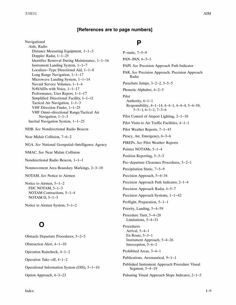
3/10/11 AIM
Index I−9
[References are to page numbers]
NavigationalAids, Radio
Distance Measuring Equipment, 1−1−3Doppler Radar, 1−1−25Identifier Removal During Maintenance, 1−1−16Instrument Landing System, 1−1−7Localizer−Type Directional Aid, 1−1−8Long Range Navigation, 1−1−17Microwave Landing System, 1−1−14Navaid Service Volumes, 1−1−4NAVAIDs with Voice, 1−1−17Performance, User Report, 1−1−17Simplified Directional Facility, 1−1−11Tactical Air Navigation, 1−1−3VHF Direction Finder, 1−1−25VHF Omni−directional Range/Tactical Air
Navigation, 1−1−3Inertial Navigation System, 1−1−25
NDB. See Nondirectional Radio Beacon
Near Midair Collision, 7−6−2
NGA. See National Geospatial−Intelligence Agency
NMAC. See Near Midair Collision
Nondirectional Radio Beacon, 1−1−1
Nonmovement Area Boundary Markings, 2−3−18
NOTAM. See Notice to Airmen
Notice to Airmen, 5−1−2FDC NOTAM, 5−1−3NOTAM Contractions, 5−1−4NOTAM D, 5−1−3
Notice to Airmen System, 5−1−2
O
Obstacle Departure Procedures, 5−2−5
Obstruction Alert, 4−1−10
Operation Raincheck, 4−1−2
Operation Take−off, 4−1−2
Operational Information System (OIS), 5−1−10
Option Approach, 4−3−23
PP−static, 7−5−9
PAN−PAN, 6−3−1
PAPI. See Precision Approach Path Indicator
PAR. See Precision Approach; Precision ApproachRadar
Parachute Jumps, 3−2−2, 3−5−5
Phonetic Alphabet, 4−2−5
PilotAuthority, 6−1−1Responsibility, 4−1−14, 4−4−1, 4−4−4, 5−4−58,
5−5−1, 6−1−1, 7−3−6
Pilot Control of Airport Lighting, 2−1−10
Pilot Visits to Air Traffic Facilities, 4−1−1
Pilot Weather Reports, 7−1−43
Piracy, Air, Emergency, 6−3−6
PIREPs. See Pilot Weather Reports
Pointer NOTAMs, 5−1−4
Position Reporting, 5−3−3
Pre−departure Clearance Procedures, 5−2−1
Precipitation Static, 7−5−9
Precision Approach, 5−4−34
Precision Approach Path Indicator, 2−1−4
Precision Approach Radar, 4−5−7
Precision Approach Systems, 1−1−42
Preflight, Preparation, 5−1−1
Priority, Landing, 5−4−59
Procedure Turn, 5−4−28Limitations, 5−4−31
ProceduresArrival, 5−4−1En Route, 5−3−1Instrument Approach, 5−4−26Interception, 5−6−2
Prohibited Areas, 3−4−1
Publications, Aeronautical, 9−1−1
Published Instrument Approach Procedure VisualSegment, 5−4−19
Pulsating Visual Approach Slope Indicator, 2−1−5

3/10/11AIM
IndexI−10
[References are to page numbers]
RRadar
Air Traffic Control Radar Beacon System, 4−5−2Airport Route Surveillance Radar, 4−5−7Airport Surveillance Radar, 4−5−7Approach Control, 5−4−3Approaches, 5−4−34Capabilities, 4−5−1Doppler, 1−1−25Limitations, 4−5−1Monitoring of Instrument Approaches, 5−4−35Precision Approach, 4−5−7Precision Approach Radar, 4−5−7Surveillance, 4−5−7Vector, 5−5−3
Radar Assistance to VFR Aircraft, 4−1−11
Radar Beacon, Phraseology, 4−1−17
Radar Sequencing and Separation, VFR Aircraft,TRSA, 4−1−13
Radar Traffic Information Service, 4−1−8
Radio, Communications, 4−2−1Altitudes, 4−2−6Contact Procedures, 4−2−1Directions, 4−2−6Inoperative Transmitter, 4−2−7Phonetic Alphabet, 4−2−5Receiver Inoperative, 4−2−7Speeds, 4−2−6Student Pilots, 4−2−4Technique, 4−2−1Time, 4−2−6Transmitter and Receiver Inoperative, 4−2−7VFR Flights, 4−2−8
RCLS. See Runway Centerline Lighting
Receiver, VOR, Check, 1−1−2
REIL. See Runway End Identifier Lights
REL. See Runway Entrance Lights
Release Time, 5−2−4
Remote Airport Advisory (RAA), 3−5−1, 4−1−4
Remote Airport Information Service (RAIS), 3−5−1,4−1−4
Required Navigation Performance (RNP), 1−2−1,5−4−23
Required Navigation Performance (RNP) Operations,5−1−28, 5−5−7
Rescue Coordination CenterAir Force, 6−2−5
Alaska, 6−2−5Coast Guard, 6−2−5Joint Rescue, Hawaii, 6−2−5
Reservations, Airport, 4−1−21
ResponsibilityController, 5−3−8, 5−4−58, 5−5−1Pilot, 4−1−14, 4−4−1, 4−4−4, 5−4−58, 5−5−1, 6−1−1,
7−3−6
Restricted Areas, 3−4−1
RestrictionsDeparture, 5−2−4Flight, Temporary, 3−5−2
RNAV. See Area Navigation
RNP. See Required Navigation Performance
RouteCoded Departure Route, 4−4−3Course Changes, 5−3−7
Route System, 5−3−5
Runway Friction Reports, 4−3−11Aiming Point Markings, 2−3−2Centerline Markings, 2−3−2Closed
Lighting, 2−3−18Marking, 2−3−18
Demarcation Bar, 2−3−4Designators, 2−3−2Friction Advisories, 4−3−11Holding Position Markings, 2−3−12Markings, 2−3−1Separation, 4−4−9Shoulder Markings, 2−3−3Side Stripe Markings, 2−3−3Signs, Distance Remaining, 2−3−29Threshold Bar, 2−3−4Threshold Markings, 2−3−3Touchdown Zone Markers, 2−3−2
Runway Edge Light Systems, 2−1−6End Identifier Lights, 2−1−6Entrance Lights, 2−1−7, 2−1−8Centerline Lighting System, 2−1−6Status Light (RWSL) System, 2−1−7, 2−1−8
Runway Intersection Lights (RIL), 2−1−9
RWSL System, Runway Status Light (RWSL) System.See Runway Status Light (RWSL) System

3/10/11 AIM
Index I−11
[References are to page numbers]
Runway, Visual Range, 7−1−40
Runways, Use, 4−3−6
RVR. See Runway Visual Range
SSafety
Alert, 5−5−3Alerts, 3−2−1
Aircraft Conflict, 3−2−1Mode C Intruder, 3−2−1Terrain/Obstruction, 3−2−1
Aviation, Reporting, 7−6−1Seaplane, 7−5−6
Safety Alert, 4−1−10Aircraft Conflict Alert, 4−1−11Obstruction Alert, 4−1−10Terrain Alert, 4−1−10
SAR. See Search and Rescue
SCAT−I DGPS. See Special Category I DifferentialGPS
Scuba Diving, Decompression Sickness, 8−1−4
SDF. See Simplified Directional Facility
Seaplane, Safety, 7−5−6
Search and Rescue, 6−2−2, 6−2−5
Security, National, 5−6−1
Security Identification Display Area, 2−3−31
See and Avoid, 5−5−4
SeparationIFR, Standards, 4−4−7Runway, 4−4−9Visual, 4−4−9, 5−5−5Wake Turbulence, 7−3−7
Sequenced flashing lights (SFL), 2−1−10
SFL. See Sequenced flashing lights
SIDA. See Security Identifications Display Area
Side−Step Maneuver, 5−4−49
SignsAirport, 2−3−1Half−Way, 7−5−5
Simplified Directional Facility, 1−1−11
Sinus Block, 8−1−4
Special Category I Differential GPS (SCAT−I DGPS),1−1−42
Special Instrument Approach Procedures, 1−1−42,5−4−27
Special Traffic Management Programs, 4−1−21
Special Use Airspace, 3−4−1Alert Areas, 3−4−2Controlled Firing Areas, 3−4−2Military Operations Areas, 3−4−2Prohibited Areas, 3−4−1Restricted Areas, 3−4−1Warning Areas, 3−4−1
Special Use Airspace (SUA) NOTAMs, 5−1−4
Special VFR Clearances, 4−4−3
Speed, Adjustments, 4−4−7, 5−5−4
Standard Instrument Departures, 5−2−5
Standard Terminal Arrival, 5−4−1
STAR. See Standard Terminal Arrival
Surface Painted Holding Position Signs, 2−3−12
Surveillance Approach, 5−4−34
Surveillance Radar, 4−5−7
Surveillance Systems, 4−5−1
TTACAN. See Tactical Air Navigation
Tactical Air Navigation, 1−1−3
TAF. See Aerodrome Forecast
Takeoff Hold Lights (THL), 2−1−8
Takeoffs, Intersection, 4−3−12
TaxiClearance, 5−2−1During Low Visibility, 4−3−20
TaxiwayCenterline Markings, 2−3−7Closed
Lighting, 2−3−18Marking, 2−3−18
Edge Markings, 2−3−7Geographic Position Markings, 2−3−10Holding Position Markings, 2−3−12Markings, 2−3−1, 2−3−7Shoulder Markings, 2−3−7Surface Painted Direction Signs, 2−3−10Surface Painted Location Signs, 2−3−10

3/10/11AIM
IndexI−12
[References are to page numbers]
Taxiway Centerline Lead−Off Lights, 2−1−6
Taxiway Lights, 2−1−13Centerline, 2−1−13Clearance Bar, 2−1−14Edge, 2−1−13Runway Guard, 2−1−14Stop Bar, 2−1−14
TCAS. See Traffic Alert and Collision AvoidanceSystem
TDWR. See Terminal Doppler Weather Radar
TDZL. See Touchdown Zone Lights
TEC. See Tower En Route Control
Telephone Information Briefing Service, 7−1−20
Temporary Flight Restrictions, 3−5−2
Terminal Arrival Area (TAA), 5−4−7
Terminal Doppler Weather Radar (TDWR), 4−3−11,7−1−53
Terminal Radar Service Areas, 3−5−9
Terminal Radar Services for VFR Aircraft, 4−1−12
Terminal Weather Information For Pilots System(TWIP), 7−1−58
Terrain Alert, 4−1−10
THL. See Takeoff Hold Lights
TIBS. See Telephone Information Briefing Service
TimeClearance Void, 5−2−4Release, 5−2−4
TIS. See Traffic Information Service
TIS−B. See Traffic Information Service−Broadcast
TLS. See Transponder Landing System
Touchdown Zone Lights (TDZL), 2−1−6
Tower, Antenna, 7−5−1
Tower En Route Control, 4−1−14
TrafficAdvisories, 5−5−4Local Flow Traffic Management Program, 5−4−2
Traffic Advisory Practices, Airports Without OperatingControl Towers, 4−1−2
Traffic Alert and Collision Avoidance System, 4−4−10
Traffic Control Light Signals, 4−3−15
Traffic Information Service, 4−5−8
Traffic Information Service (TIS), 4−4−11
Traffic Information Service−Broadcast , 4−5−17
Traffic Patterns, 4−3−2
Transcribed Weather Broadcast, 7−1−20
Transponder Landing System (TLS), 1−1−42
Transponder Operation, 4−1−15Automatic Altitude Reporting, 4−1−15Code Changes, 4−1−16Emergency, 6−2−1Ident Feature, 4−1−16Mode C, 4−1−15Under Visual Flight Rules, 4−1−17VFR, 4−1−17
Tri−Color Visual Approach Slope Indicator, 2−1−4
TRSA. See Terminal Radar Service Areas
Turbulence, Wake, 7−3−1Air Traffic Separation, 7−3−7Helicopters, 7−3−6Pilot Responsibility, 7−3−6Vortex Behavior, 7−3−2Vortex Generation, 7−3−1Vortex Strength, 7−3−1
TWEB. See Transcribed Weather Broadcast
TWIP. See Terminal Weather Information For PilotsSystem
UUltralight Vehicles, 3−2−2
Unicom, 4−1−6
Unidentified Flying Object (UFO) Reports, 7−6−3
Unmanned Aircraft, 7−5−2
Urgency, 6−3−1
VVASI. See Visual Approach Slope Indicator
VCOA. See Visual Climb Over the Airport
VDP. See Visual Descent Points
Vector, Radar, 5−5−3
Vehicle Roadway Markings, 2−3−16
Vertical Navigation, 5−1−12
VFR Corridors, 3−5−7

3/10/11 AIM
Index I−13
[References are to page numbers]
VFR Flights in Terminal Areas, 4−3−17
VFR Flyways, 3−5−5
VFR Military Training Routes, 3−5−2
VFR Transition Routes, 3−5−7
VFR−on−Top, 5−5−6
VHF, Direction Finder, 1−1−25
VHF Omni−directional Range, 1−1−1
VHF Omni−directional Range/Tactical Air Navigation,1−1−3
VisualApproach, 5−4−57, 5−5−5Clearing Procedures, 4−4−10Glideslope Indicators, 2−1−1Separation, 4−4−9, 5−5−5
Visual Approach Slope Indicator, 2−1−1
Visual Climb Over the Airport (VCOA), 5−2−8
Visual Descent Points, 5−4−18
Visual Meteorological Conditions (VMC), 5−2−5
Visual Segment, 5−4−19
VNAV. See Vertical Navigation
Void Times, Clearance, 5−2−4
Volcanic, Ash, 7−5−7
Volcanic Activity Reporting, Forms. See Appendix 2
VORSee also VHF Omni−directional RangeReceiver Check, 1−1−2
VOR Receiver Checkpoint Markings, 2−3−16
VORTAC. See VHF Omni−directional Range/TacticalAir Navigation
VR. See VFR Military Training Routes
WWaivers, 4−1−23
Wake, Turbulence, 7−3−1
Warning Areas, 3−4−1
WeatherDeviations in Oceanic Controlled Airspace, 7−1−39ICAO, Weather Formats, 7−1−63
Weather System Processor (WSP), 4−1−23, 4−3−11,7−1−54
WSP. See Weather System Processor