Review of Aeronautical Fatigue and Structural Integrity Work ...
100
Aerospace Review of Aeronautical Fatigue and Structural Integrity Work in Canada (2017 - 2019) Authors: Min Liao Report No.: LTR-SMM-2019-0063 RDIMS No.: N/A Date: April 2019
-
Upload
khangminh22 -
Category
Documents
-
view
4 -
download
0
Transcript of Review of Aeronautical Fatigue and Structural Integrity Work ...

Aerospace
Review of Aeronautical Fatigue
and Structural Integrity Work
in Canada (2017 - 2019)
Authors: Min Liao
Report No.: LTR-SMM-2019-0063
RDIMS No.: N/A
Date: April 2019


LTR-SMM-2019-0063
Review of Aeronautical Fatigue and Structural Integrity Work in Canada (2017 - 2019)
N A T I O N A L R E S E A R C H C O U N C I L C A N A D A ( N R C )
A E R O S P A C E
Review of Aeronautical Fatigue and
Structural Integrity Work in Canada
(2017 - 2019)
Volume 1 of 1
Report No.: LTR-SMM-2019-0063
RDIMS No.: N/A
Date: April 2019
Authors: Min Liao
Classification: Unclassified Distribution: Unlimited
For: International Committee on Aeronautical Fatigue and Structural Integrity (ICAF)
Reference: -
Submitted by: R. Kearsey, Director/A, Structures and Materials Performance Laboratory
Approved by: I. Yimer, Director in General, Aerospace Research Center
Pages : 100 Copy No.: N/A
Figures: 67 Tables: 8
This Report May Not Be Published Wholly Or In Part Without The Written Consent Of The National Research
Council Canada


LTR-SMM-2019-0063
Review of Aeronautical Fatigue and Structural Integrity Work in Canada (2017 - 2019)
CLASSIFICATION: UNCLASSIFIED NRC-CNRC i
EXECUTIVE SUMMARY
This report provides a review of aeronautical fatigue and structural integrity work in Canada during
the period April 2017 to April 2019. The review is a collection of multiple work summaries that
are provided by Canadian industries, universities, and government organizations. All aspects of
structural integrity, especially fatigue related work, are covered including:
full-scale testing, life assessment and enhancement, load and usage monitoring, structural health
monitoring, non-destructive inspection, environmental effects, and new material and
manufacturing. This national review will be presented at the 36th International Committee on
Aeronautical Fatigue and Structural Integrity (ICAF) Conference, which will be held in Krakow,
Poland, from June 2nd to 7th, 2019.

LTR-SMM-2019-0063
Review of Aeronautical Fatigue and Structural Integrity Work in Canada (2017 - 2019)
ii NRC-CNRC DISTRIBUTION: UNLIMITED

LTR-SMM-2019-0063
Review of Aeronautical Fatigue and Structural Integrity Work in Canada (2017 - 2019)
CLASSIFICATION: UNCLASSIFIED NRC-CNRC iii
TABLE OF CONTENTS
EXECUTIVE SUMMARY ......................................................................................................................................... I
TABLE OF CONTENTS ......................................................................................................................................... III
1.0 INTRODUCTION .............................................................................................................................................. 1
2.0 FULL-SCALE STRUCTURAL AND COMPONENT TESTING................................................................. 2
2.1 GLOBAL 7500 DURABILITY AND DAMAGE TOLERANCE TESTS ........................................................................ 2 2.2 BOMBARDIER GLOBAL 7500 FATIGUE TEST CYCLE RATE COMMISSIONING TO ¼ LIFE* ................................. 8
2.2.1 References ............................................................................................................................................ 10 2.3 F/A-18 FTS2 ARMASUISSE HORIZONTAL STABILATOR FATIGUE TEST (NRC/ARMASUSISSE/RUAG) ........... 10 2.4 F/A-18 AILERON FATIGUE TEST (NRC/RCAF/L-3 MAS) ............................................................................. 13 2.5 CF-188 HORIZONTAL STABILATOR TEAR-DOWN ANALYSIS POST LIFE EXTENSION FATIGUE TEST .............. 15 2.6 FATIGUE STRUCTURAL TESTING ENHANCEMENT RESEARCH (FASTER)....................................................... 18
2.6.1 References ............................................................................................................................................ 19 2.7 STRUCTURAL ANALYSIS FOR CH-146 AIR TRANSPORTATION KIT PALLET ASSEMBLY ................................. 19
3.0 FATIGUE LIFE ASSESSMENT AND MANAGEMENT ........................................................................... 22
3.1 CP-140 (P-3) 7249 DAMAGE TOLERANCE ANALYSIS (DTA) UPDATES ......................................................... 22 3.2 CF-188 AIRCRAFT STRUCTURAL INTEGRITY PROGRAM (ASIP) AND AIRCRAFT LIFE EXTENSION (ALEX)
PROGRAM ................................................................................................................................................................ 23 3.2.1 ELE Extension and New BOS Initiative ............................................................................................... 24 3.2.2 Flight Control Surfaces (FCS) Life Extension ..................................................................................... 25
3.3 F-18 AIRCRAFT INTERNATIONAL SUPPORT .................................................................................................... 27 3.3.1 Fastener Life Improvement Techniques – Coupon Testing .................................................................. 27
3.4 CT-114 (TUTOR) AIRCRAFT STRUCTURAL INTEGRITY PROGRAM (ASIP) ...................................................... 30 3.5 CC-150 POLARIS FLEET IN-SERVICE SUPPORT AND FLEET MANAGEMENT ................................................... 31
3.5.1 Obsolescence and ageing aircraft management .................................................................................. 31 3.5.2 CC-150T MRTT Mission Mix Study ..................................................................................................... 31 3.5.3 CC-150 Estimated Life Expectancy (ELE) Study ................................................................................. 32
3.6 CH-148 MARITIME HELICOPTER AIRCRAFT STRUCTURAL INTEGRITY PROGRAM (ASIP) ............................. 32 3.7 DEMONSTRATION OF AN AIRFRAME DIGITAL TWIN FRAMEWORK USING A CF-188 COMPONENT TEST * ...... 34
3.7.1 References ............................................................................................................................................ 35
4.0 FATIGUE LIFE ENHANCEMENT TECHNOLOGIES ............................................................................. 36
4.1 SHOT PEENING TO EXTEND FATIGUE LIFE OF MILITARY AIRCRAFT ................................................................. 36 4.2 LIFE IMPROVEMENT QUANTIFICATION OF FASTENER MODIFICATIONS .......................................................... 37
4.2.1 References ............................................................................................................................................ 37 4.3 HOLE COLD EXPANSION PROCESS PLASTICITY MODELLING .......................................................................... 38 4.4 MEASUREMENT OF RESIDUAL STRESSES RESULTING FROM COLD EXPANSION .............................................. 39 4.5 FATIGUE LIFE PREDICTION AT COLD EXPANDED FASTENER HOLES WITH FORCEMATE BUSHINGS* ............. 42
4.5.1 Reference ............................................................................................................................................. 43 4.6 FATIGUE PERFORMANCE EVALUATION OF BLIND FASTENERS FOR CP-140 VERTICAL STABILIZER REPAIRS 43
5.0 LOAD, USAGE, AND STRUCTURAL HEALTH MONITORING ........................................................... 46
5.1 HELICOPTER LOAD AND USAGE MONITORING RESEARCH IN 2017-2019 ....................................................... 46 5.1.1 A machine learning approach to load tracking and usage monitoring for legacy fleets [7]* ............. 46

LTR-SMM-2019-0063
Review of Aeronautical Fatigue and Structural Integrity Work in Canada (2017 - 2019)
iv NRC-CNRC DISTRIBUTION: UNLIMITED
5.1.2 Data analytics and predictive maintenance [8] ................................................................................... 47 5.1.3 Usage monitoring using MEMS-IMU sensor system and FDR input data .......................................... 48 5.1.4 Analysis of sensor network data for failure modelling and prediction [9][10][11][12] ..................... 49 5.1.5 References ............................................................................................................................................ 50
5.2 STRUCTURAL HEALTH MONITORING (SHM) ................................................................................................. 51 5.3 POTENTIAL DAMAGE LOCATION INDICATION DETERMINED USING ACOUSTIC EMISSION DURING CF-188
AILERON FATIGUE TEST .......................................................................................................................................... 52 5.4 REPEATABILITY STUDY OF STRUCTURAL HEALTH MONITORING (SHM) SENSORS AT ROOM TEMPERATURE53 5.5 DAMAGE DETECTION METHODOLOGY BASED ON MULTI-FREQUENCY GUIDED WAVES FOR SHM
APPLICATIONS WITH EXPERIMENTAL AND NUMERICAL VERIFICATION ................................................................... 55 5.5.1 References ............................................................................................................................................ 57
6.0 NON-DESTRUCTIVE EVALUATION ......................................................................................................... 58
6.1 DETECTION OF LOW-VELOCITY IMPACT DAMAGE IN CARBON FIBER SANDWICH PANELS USING INFRARED
THERMOGRAPHY* ................................................................................................................................................... 58 6.2 INDUCTION THERMOGRAPHY OF STEEL COUPONS WITH CRACKS .................................................................. 60
6.2.1 References ............................................................................................................................................ 60 6.3 RELIABILITY ASSESSMENT OF PULSED THERMOGRAPHY AND ULTRASONIC TESTING FOR IMPACT DAMAGE
OF CFRP PANELS .................................................................................................................................................... 61 6.3.1 References ............................................................................................................................................ 61
6.4 AUTOMATED DYNAMIC INSPECTION USING ACTIVE INFRARED THERMOGRAPHY ......................................... 62 6.4.1 References ............................................................................................................................................ 62
6.5 EMBEDDED ELECTROMAGNETIC SENSORS FOR NDE AND SHM .................................................................... 62 6.5.1 References ............................................................................................................................................ 64
6.6 TECHNICAL JUSTIFICATION OF ULTRASONIC INSPECTION PROCEDURE FOR HELICOPTER COMPONENTS* ..... 64 6.6.1 References ............................................................................................................................................ 67
6.7 EQUIVALENT PENETRAMETER SENSITIVITY (EPS) FOR PERFORMANCE EVALUATION OF COMPUTED
RADIOGRAPHY (CR) SYSTEMS ................................................................................................................................ 67 6.7.1 References ............................................................................................................................................ 69
7.0 ENVIRONMENTAL EFFECTS ON FATIGUE AND STRUCTURAL INTEGRITY ............................. 70
7.1 CORROSION DAMAGE ATLAS FOR AIRCRAFT CORROSION MANAGEMENT AND STRUCTURAL INTEGRITY
ASSESSMENT ........................................................................................................................................................... 70 7.1.1 References ............................................................................................................................................ 73
7.2 EFFECT OF ALTERNATIVE PAINT STRIPPING PROCESSES ON THE FATIGUE PERFORMANCE OF ALUMINIUM
ALLOYS* ................................................................................................................................................................. 73 7.2.1 References ............................................................................................................................................ 75
8.0 FATIGUE AND STRUCTURAL INTEGRITY OF COMPOSITES .......................................................... 76
8.1 SURFACE DAMAGE EVALUATION OF TEXTURED ALUMINIUM HONEYCOMB SANDWICH PANELS .................. 76 8.1.1 References ............................................................................................................................................ 78
8.2 NUMERICAL MODELLING OF COMPOSITE MATERIAL AND STRUCTURAL FAILURE BEHAVIOURS ................... 78 8.2.1 Cohesive Zone Modeling of a Unidirectional CFRP DCB Test on Progressive Failure [27] ............. 78 8.2.2 Progressive failure of a bonded 3D composite section [28] ................................................................ 79 8.2.3 References ............................................................................................................................................ 80
9.0 FATIGUE AND STRUCTURAL INTEGRITY OF NEW MATERIAL AND MANUFACTURING ..... 81
9.1 MEASUREMENT OF THE RESISTANCE TO FRACTURE OF 7249-T76511 ALUMINIUM EXTRUSION .................... 81

LTR-SMM-2019-0063
Review of Aeronautical Fatigue and Structural Integrity Work in Canada (2017 - 2019)
CLASSIFICATION: UNCLASSIFIED NRC-CNRC v
9.1.1 References ............................................................................................................................................ 82 9.2 APPLICATION OF MULTIFUNCTIONAL MECHANICAL METAMATERIALS ......................................................... 82
9.2.1 References ............................................................................................................................................ 83 9.3 DURABILITY AND DAMAGE TOLERANCE OF ADDITIVE MANUFACTURING POLYMER PARTS FOR AEROSPACE
APPLICATION* ......................................................................................................................................................... 84 9.3.1 References ............................................................................................................................................ 86
9.4 CASE STUDY: IN-SERVICE USE OF ADDITIVELY MANUFACTURED AIRCRAFT STRUCTURAL COMPONENTS FOR
REPAIR PURPOSES ................................................................................................................................................... 86 9.5 DEFORMATION AND EVOLUTION OF LIFE IN CRYSTALLINE MATERIALS – AN INTEGRATED CREEP FATIGUE
THEORY ................................................................................................................................................................... 87 9.5.1 Reference ............................................................................................................................................. 89
10.0 ACKNOWLEDGEMENTS ........................................................................................................................ 90

LTR-SMM-2019-0063
Review of Aeronautical Fatigue and Structural Integrity Work in Canada (2017 - 2019)
vi NRC-CNRC DISTRIBUTION: UNLIMITED

LTR-SMM-2019-0063
Review of Aeronautical Fatigue and Structural Integrity Work in Canada (2017 - 2019)
CLASSIFICATION: UNCLASSIFIED NRC-CNRC 1
1.0 INTRODUCTION
Canadian industries, universities and government agencies were solicited for information
describing their fatigue technology and structural integrity related activities over the period
April 2017 to April 2019. This review covers work performed or being performed by the following
organizations (including some collaborative organizations):
Bombardier Aerospace (BA)
o Bombardier Aerospace Experimental Department (BAEX)
IMP Aerospace (IMP)
L-3 Communications (Canada) Military Aircraft Services (MAS)
Rolls-Royce Deutschland
Siemens AG
Siemens Canada
Carleton University
Concordia University
McGill University
Université Laval
Department of Mechanical & Aeronautical Engineering, Clarkson University
Engineering, Harvard University
Department of National Defence (DND)
o Defence Research and Development Canada (DRDC)
o Director of Technical Airworthiness and Engineering Support (DTAES)
o Quality Engineering Test Establishment (QETE)
o Royal Canadian Air Force (RCAF)
o Royal Military College of Canada (RMC)
Royal Australian Air Force (RAAF)
United States Navy (USN)
National Research Council Canada, Aerospace Research Center (NRC Aerospace)
Names of contributors (where available) and their organizations are included in the text of this
review. Full addresses of the contributors are available through the ICAF Canadian National
Delegate at:
Min Liao, Ph.D., Principal Research Officer
Group Leader - Structural Integrity
Aerospace, National Research Council Canada
1200 Montreal Road, Building M14
Ottawa, ON, K1A 0R6, Canada
Tel: 1-613-990-9812;
Email: [email protected]

LTR-SMM-2019-0063
Review of Aeronautical Fatigue and Structural Integrity Work in Canada (2017 - 2019)
2 NRC-CNRC DISTRIBUTION: UNLIMITED
2.0 FULL-SCALE STRUCTURAL AND COMPONENT TESTING
2.1 Global 7500 Durability and Damage Tolerance Tests
Arkady Alperovitch, Product Development Engineering, Bombardier Aerospace
The Global 7500 Complete Aircraft Durability and Damage Tolerance (DADT) Test started in
November 2017 at BAEX (Bombardier Aerospace Experimental Department) in Montreal,
Canada, shown in Figure 1.
Figure 1 Global 7500 durability and damage tolerance tests in Montreal, Canada
(Note: Bombardier Aerospace has changed the name of the Global 7000 ultra-long range
aircraft to the Global 7500 thanks to performance improvements that continue to surpass
expectations)
The main objective of the test is to demonstrate the damage tolerance and fatigue characteristics
of the metallic components of the Global 7500 airframe as well as to demonstrate no Widespread

LTR-SMM-2019-0063
Review of Aeronautical Fatigue and Structural Integrity Work in Canada (2017 - 2019)
CLASSIFICATION: UNCLASSIFIED NRC-CNRC 3
Fatigue Damage (WFD) over the Design Service Goal of 17,000 flights. Other objectives include
validation of:
1. Crack growth models for primary metal structure,
2. Inspection techniques and intervals, and
3. Typical repairs and allowable damage limits.
The main components covered by the Complete Aircraft DADT Test: complete fuselage, wing,
engine mounts, vertical stabilizer and metallic parts of the horizontal stabilizer. It also covers all
doors, landing gear interfaces, as well as the control surface and high lift device attachments and
backup structures within the wing box and empennage boxes, as shown in Figure 2.
Figure 2 Overall setup of the Global 7500 complete aircraft DADT test
The aircraft structure will be subjected to a total of 51,000 flight cycles, which represent three
times the Design Service Goal (DSG) of the aircraft. The test program is divided into 3 phases of
testing and a final phase for teardown inspection:

LTR-SMM-2019-0063
Review of Aeronautical Fatigue and Structural Integrity Work in Canada (2017 - 2019)
4 NRC-CNRC DISTRIBUTION: UNLIMITED
1. Phase 1 – Durability testing: Two DSG of flight cycles (34,000 total flights) will be applied
to the test article which includes typical manufacturing and in-service damage and repairs
(completed).
2. Phase 2 – Damage Tolerance Testing: One DSG of flight cycles (17,000 flights for a total
accumulated count of 51,000 flights) will be applied to the test article with the presence of
artificial damage at specific primary structural element (PSE) locations.
3. Phase 3 – Residual Strength Testing: A series of residual strength tests will be applied to
the test article to demonstrate the structural integrity of standard repairs, confirm the critical
crack lengths of the Damage Tolerance Analysis and demonstrate freedom from
Widespread Fatigue Damage (WFD).
4. Phase 4 – Teardown inspection.
Close-ups of the wing and fuselage tests are shown in Figure 3 and Figure 4 respectively.
Figure 3 Close-up of wing test setup

LTR-SMM-2019-0063
Review of Aeronautical Fatigue and Structural Integrity Work in Canada (2017 - 2019)
CLASSIFICATION: UNCLASSIFIED NRC-CNRC 5
Figure 4 Close-up of fuselage test setup
Three missions with four flight types are applied to the test article. These missions were reduced
and truncated to an equivalent of 199 end points, on average, per flight. Number of cycles required
for Entry-Into-Service (EIS) was reached at end of Dec 2017. It completed two (2) lifetimes
(34,000 flights) of cycling in February 2019.
In addition, there are multiple Durability and Damage Tolerance (DADT) Bench Tests for
components not covered on the Complete Aircraft DADT Test. Table 1 contains a list of the main
rigs. These bench tests had been currently tested for 51,000 flight cycles and follow the same
testing program as the Complete Aircraft DADT Test.
Both Inboard and Outboard flap Durability and Damage Tolerance Tests are performed at BAEX
in Montreal, Canada, shown in Figure 5 and Figure 6. Both flaps are moving to various deployment
angles during flight-by-flight spectrum to more accurately match interface loads.

LTR-SMM-2019-0063
Review of Aeronautical Fatigue and Structural Integrity Work in Canada (2017 - 2019)
6 NRC-CNRC DISTRIBUTION: UNLIMITED
Table 1 List of subsequent metallic test rigs
TEST RIG (Metallic)
ENGINE MOUNTS (FWD AND AFT) AND THRUST FITTING DADT TESTS
SECONDARY HSTA FITTING DT TEST
ELEVATOR METALLIC COMPONENTS AND REAR SPAR FITTINGS DADT TEST
RUDDER METALLIC DADT TEST
INBOARD FLAP DADT TEST
OUTBOARD FLAP DADT TEST
SLAT DADT TEST
AILERON METALLIC PARTS DADT TEST
SPOILER DADT TEST
WINGLET ROOT JOINT DADT TEST
Figure 5 Inboard flap test rig

LTR-SMM-2019-0063
Review of Aeronautical Fatigue and Structural Integrity Work in Canada (2017 - 2019)
CLASSIFICATION: UNCLASSIFIED NRC-CNRC 7
Figure 6 Outboard flap test rig
As the Global 7500 structure is fabricated utilizing various metal alloys as well as Carbon Fiber
Reinforced Plastic (CFRP) for its primary structure, other test rigs are being used to evaluate the
durability and damage tolerance characteristics of the composite structures. These rigs are
following a different testing program. A list of the main test rigs is provided in Table 2.
Table 2 List of composite test rigs
TEST RIG (Composite)
AILERON STATIC AND COMPOSITE DADT TEST
ELEVATOR STATIC AND COMPOSITE DADT TEST
RUDDER STATIC AND COMPOSITE DADT TEST
HORIZONTAL STABILIZER AND HSTA ATTACHMENTS STATIC AND
COMPOSITE DADT TEST

LTR-SMM-2019-0063
Review of Aeronautical Fatigue and Structural Integrity Work in Canada (2017 - 2019)
8 NRC-CNRC DISTRIBUTION: UNLIMITED
In conclusion, multiple Global 7500 DADT tests are either running or have been completed. Three
aircraft design lives (51,000 flight cycles) will be simulated to ensure the metallic structure meets
the Damage Tolerance certification requirements, the requirements for Entry-Into-Service, as well
as customer expectations.
2.2 Bombardier Global 7500 Fatigue Test Cycle Rate Commissioning to ¼
Life*
C.A. Beltempo, NRC Aerospace
A. Beaudoin, R. Pothier, Bombardier Aerospace
* Paper being presented at ICAF2019
Bombardier Aerospace began a durability and damage tolerance (DADT) fatigue certification test
of the Bombardier Global 7500 business jet in 2017, with cycling continuing through 2019. NRC
was involved in a support role during test design and commissioning. At the time of writing, the
G7500 is the largest dedicated business jet in the world, and was certified in 2018. As is customary
for aircraft certification, the fatigue test (DADT) was one of the final tests to be commissioned,
due to the requirement to receive a production-equivalent test article. An aggressive certification
testing milestone was required to meet the certification window. A schematic of the loading vectors
and restraints on the test article is shown in Figure 7.
Figure 7 Global 7500 DADT test loading actuators and restraints schematic

LTR-SMM-2019-0063
Review of Aeronautical Fatigue and Structural Integrity Work in Canada (2017 - 2019)
CLASSIFICATION: UNCLASSIFIED NRC-CNRC 9
In anticipation of this aggressive testing milestone, the Bombardier test team employed several
new techniques to the full scale test that had not been applied in previous Bombardier fatigue tests.
The intent of these extensive preparations was to reduce the amount of ‘on-rig’ learning curve time
that was required to reach the optimum performance of the DADT test hardware, such that the
schedule risk during commissioning could be minimized. A technical liaison from the National
Research Council Canada (NRC) was also on-site prior to and during commissioning activities to
support Bombardier’s efforts.
These techniques included: judicious data-informed hydraulic and pneumatic hardware selections;
informed design choices to minimize mass and actuator count; hydraulic and load controller
training and procedure generation on a dedicated independent test platform; extensive hardware-
in-the-loop tuning to maximize performance; and using the global finite element model (GFEM)
of the test article, coupled with a simple pneumatic model to better estimate test load transition
times. An image of the test setup is shown in Figure 8.
Figure 8 Global 7500 DADTT test setup (view AFT on LHS)
These techniques were successfully employed to meet the required certification target schedule,
and surpassed the original estimate, as shown in Figure 9. A more fulsome explanation of these
techniques is included in a paper in the ICAF2019 conference proceedings [1].

LTR-SMM-2019-0063
Review of Aeronautical Fatigue and Structural Integrity Work in Canada (2017 - 2019)
10 NRC-CNRC DISTRIBUTION: UNLIMITED
Figure 9 Global 7500 test schedule to certification milestone
2.2.1 REFERENCES
[1] C. A. Beltempo, A. Beaudoin, R. Pothier, “Bombardier Global 7500 Fatigue Test Cycle Rate
Commissioning to ¼ Life”, The 30th International Committee on Aeronautical Fatigue and
Structural Integrity (ICAF) Symposium, June 2-7, Krakow, Poland, 2019.
2.3 F/A-18 FTS2 Armasuisse Horizontal Stabilator Fatigue Test
(NRC/armasusisse/RUAG)
R.S. Rutledge, NRC Aerospace
The National Research Council Canada (NRC) completed a fatigue test for the Swiss Air Force
(SAF) to evaluate an F/A-18 horizontal stabilator under Swiss Air Force usage. The test was a
fatigue durability test of a United States Navy (USN) horizontal stabilator (H-stab), serial number
(S/N) A20 2970P test article, using an in-service SAF fatigue test spectrum. To be consistent with
previous armasuisse F/A-18 structural test designations, the test article is referred to as the Fatigue
Test Swiss 2 (FTS2) H-stab. The FTS2 H-stab test article was manufactured with a 3.1 PCF
(pounds per cubic foot) aluminium core and is consistent with the armasuisse fleet configuration.
The NRC Aerospace Research Centre used the same test rig that was used to test the Royal
Canadian Air Force (RCAF) H-stab, designated FT905, to fatigue test the armasuisse test article
to extend its original certified life. The test setup is shown in Figure 10.
0
0.05
0.1
0.15
0.2
0.25
0.3
0 3 6 9 12 15 18 21 24 27 30 33 36 39 42 45 48 51 54 57 60 63 66 69 72 75 78 81 84 87
% o
f D
esi
gn S
erv
ice
Go
al (
Life
)
Actual Test Progression Estimated Test Progression
0.25 DSG for Certification - Day 82
Commissioning Period

LTR-SMM-2019-0063
Review of Aeronautical Fatigue and Structural Integrity Work in Canada (2017 - 2019)
CLASSIFICATION: UNCLASSIFIED NRC-CNRC 11
Figure 10 FTS2 test article with optical marker tracking at actuator locations
The original plan was to test to 120% of the original certification life, i.e., a life extension of 20%
additional usage. However, by the end of testing NRC had applied 144% of the original
certification life. Since the Swiss loading spectrum was three times more severe than the RCAF
spectrum, depending on which critical location is being evaluated, the Swiss test had a Service
Goal (SG) that was much more severe than the RCAF H-stab test completed previously. To
illustrate the increased severity between the two spectra, the sum of actuator distance travelled by
each actuator during each block is shown in Figure 11.
For the FTS2 test, the loading was introduced using 14 hydraulic actuators, all attached at the
bottom surface of a left hand side (LHS) H-stab, as shown in Figure 12. All actuators were at the
same locations and whiffle tree configurations as the RCAF test. The test involved a strain survey
pre-test and the application of a total of six lifetimes of armasuisse fatigue/durability cycling on
the H-stab. All loads were applied on the in-service component to prove that existing component
damages and armasuisse magnitude loads will not compromise the required H-stab performance
during its desired service life.

LTR-SMM-2019-0063
Review of Aeronautical Fatigue and Structural Integrity Work in Canada (2017 - 2019)
12 NRC-CNRC DISTRIBUTION: UNLIMITED
Figure 11 Fatigue testing actuator travel displacement, a comparison between FT905
(RCAF) and FTS2 (SAF)
Figure 12 Fatigue testing FTS2 test configuration
Testing was carried out at the NRC Structural Integrity Laboratory, building M-14, located at the
NRC Montreal Road Campus in Ottawa, Ontario and was completed in November 2018.
Estimated Actuator
Displacement per Block

LTR-SMM-2019-0063
Review of Aeronautical Fatigue and Structural Integrity Work in Canada (2017 - 2019)
CLASSIFICATION: UNCLASSIFIED NRC-CNRC 13
2.4 F/A-18 Aileron Fatigue Test (NRC/RCAF/L-3 MAS)
R.S. Rutledge, NRC Aerospace
The NRC Aerospace Research Centre completed fatigue durability, damage tolerance and residual
strength testing for the Royal Canadian Air Force (RCAF) in 2018. The test was designated FT370
based on the aileron serial number (S/N) A18 0370 test article. The FT370 aileron test article
contains aluminium core with pushed fasteners due to hinge modifications carried out during its
usage. The intent was to test the durability and damage tolerance of the current configuration
RCAF CF-188 aileron in order to extend its life to 133% of its original certification. The test article
was made available to NRC by the RCAF and by the end of testing NRC had applied
approximately 157% of its original certification on the component and 143% on the hinges that
were modified.
NRC had an existing F/A-18 wing test rig that contained a test article that was used to evaluate
structural health monitoring techniques. Since this test article had existing damages the wing was
replaced and the rig was modified to accommodate the installation of an aileron with additional
actuators. This specifically designed and built test rig was used to apply loads normal to the aileron
and outer wing using 11 hydraulic actuators, all attached to the bottom surface of a right hand side
(RHS) aileron, wing, outboard leading edge flap and dummy wing tip missile through a missile
launcher. A picture of the test article in the test rig is shown in Figure 13.
Figure 13 Aileron test (FT370) article and test rig

LTR-SMM-2019-0063
Review of Aeronautical Fatigue and Structural Integrity Work in Canada (2017 - 2019)
14 NRC-CNRC DISTRIBUTION: UNLIMITED
The testing work included: a strain survey pre-test; and the application of five (5) lifetimes of
fatigue cycling on the aileron. Note that the test article had 90% of its original fatigue life expended
prior to test start. Testing on the in-service component was intended to prove that existing
component configuration and damages will not develop to failure and that these damages can be
found with the current maintenance procedures. During testing, NRC monitored the entire
structure and carried out inspections. Periodic X-ray inspections were carried out at the pushed
fastener locations that were created when the hinges were modified. An example of an X-ray
inspection is shown in Figure 14.
Figure 14 Aileron test (FT370) X-ray inspection showing pushed fastener locations

LTR-SMM-2019-0063
Review of Aeronautical Fatigue and Structural Integrity Work in Canada (2017 - 2019)
CLASSIFICATION: UNCLASSIFIED NRC-CNRC 15
Following test load cycling, proof residual strength test (RST) loads were applied. Simulated
original equipment manufacturing cases were applied to 120% design limit load (DLL). These
load cases were re-applied to 133% DLL. Then an additional eight spectrum envelope load cases
were applied with the highest load case applying an environmentally factored load case equivalent
to 165% DLL. The proof load tests to 120% DLL provided experimental evidence that permanent
detrimental deformations of the aileron should not occur during average normal operation, and the
RST cases at the higher loads with the environmental factor proved that catastrophic component
failure will not occur. NRC is now completing a teardown inspection of the aileron.
All testing was carried out at the Structural Integrity Laboratory, Building M-14, NRC Aerospace
Research Centre, Montreal Road Campus in Ottawa, Ontario, Canada.
2.5 CF-188 Horizontal Stabilator Tear-Down Analysis Post Life Extension
Fatigue Test
C.A. Beltempo, R.S. Rutledge, NRC Aerospace
In 2015, the Royal Canadian Air Force (RCAF) contracted the National Research Council Canada
(NRC) to conduct a life extension test of the CF-188 horizontal stabilator (H-stab) to support the
extension of the Canadian CF-188 Estimated Life Expectancy (ELE). This test, referred to as
FT905, was conducted in order to avoid costly and time consuming procurement of additional
parts. The F/A-18 horizontal stabilator is composed of graphite / epoxy composite skins enclosing
an aluminium honeycomb core. Test objectives included determining the durability of the
aluminium core in the presence of substantial damage, investigating suitable inspection techniques
for this type of damage, and determining suitable inspection intervals if required. The test consisted
of five (5) lifetimes of durability cycling, followed by damage introduction, five lifetimes of
damage tolerance testing, and then residual strength testing (RST), with the residual strength loads
incorporating an environmental load factor to account for the service environment (for more details
please refer to ICAF 2017 Proceedings, F-18 Flight Control Surface Life Extension Testing - CF-
188 Horizontal Stabilator, C.A. Beltempo et al). Pulse flash thermography was found to be
effective in characterizing honeycomb core damage, as shown in Figure 15, where induced
damages in three (3) critical areas are presented.

LTR-SMM-2019-0063
Review of Aeronautical Fatigue and Structural Integrity Work in Canada (2017 - 2019)
16 NRC-CNRC DISTRIBUTION: UNLIMITED
Figure 15 CF-188 FT905 H-Stab Induced Damages taken by Pulse Flash Thermography
During the test, periodic X-ray, through transmission ultrasonic C-scan, and pulse flash
thermography inspections were carried out, but revealed no damage growth. The test was
completed successfully in 2017, and the test article was sectioned in 2018 for post-test non-
destructive inspection (NDI). The post-test NDI also did not reveal any damage growth of the
induced damages, nor any indications that were not caused by loading system failures or were not
already present in the test article. As a result of the NDI null findings during the test, the tear-down
sectioning was primarily focused on the three (3) induced damage areas and a fourth area of
concern near the tip, to determine whether the induced damages had grown via fatigue cycling.
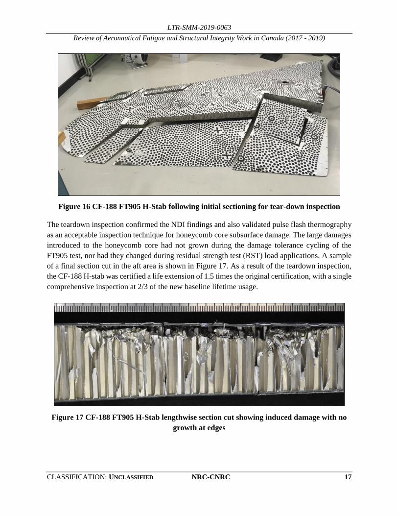
The initial sectioning of the part is shown in Figure 16.
LTR-SMM-2019-0063
Review of Aeronautical Fatigue and Structural Integrity Work in Canada (2017 - 2019)
CLASSIFICATION: UNCLASSIFIED NRC-CNRC 17
Figure 16 CF-188 FT905 H-Stab following initial sectioning for tear-down inspection
The teardown inspection confirmed the NDI findings and also validated pulse flash thermography
as an acceptable inspection technique for honeycomb core subsurface damage. The large damages
introduced to the honeycomb core had not grown during the damage tolerance cycling of the
FT905 test, nor had they changed during residual strength test (RST) load applications. A sample
of a final section cut in the aft area is shown in Figure 17. As a result of the teardown inspection,
the CF-188 H-stab was certified a life extension of 1.5 times the original certification, with a single
comprehensive inspection at 2/3 of the new baseline lifetime usage.
Figure 17 CF-188 FT905 H-Stab lengthwise section cut showing induced damage with no
growth at edges

LTR-SMM-2019-0063
Review of Aeronautical Fatigue and Structural Integrity Work in Canada (2017 - 2019)
18 NRC-CNRC DISTRIBUTION: UNLIMITED
2.6 Fatigue Structural Testing Enhancement Research (FASTER)
C. A Beltempo, NRC Aerospace
R. Fortune, J.R. Forbes, McGill University
NRC has a long and rich history of carrying out full-scale structural tests on fixed- and rotary-wing
aircraft. These tests can be extremely complex from a control systems viewpoint, due to the large
number of actuators and the many factors affecting the response of each actuator. In the past
decades, the Structures and Materials Performance Laboratory (SMPL) at NRC has undertaken
several efforts to improve the manner in which full-scale tests are conducted for our clients. This
work ranges from developing reduced structural mass test loading systems to the development of
cross-coupled compensation (CCC, or C3 used by MTS as a utility of MTS AeroPro™ Control
and Data Acquisition Software
(http://www.mts.com/en/forceandmotion/aerospacetesting/MTS_4026296?article=1) technology
to obtain higher performance and faster test speeds. Further efforts are on-going to continue to
develop the NRC advanced control technologies to improve how full-scale structural tests are run.
The Structural Integrity group at NRC-SMPL had a test rig setup for experimental purposes, shown
in Figure 18. This test set up was based on a need to apply bending and torsion loading to a
structure for previous Structural Health Monitoring (SHM) sensor and algorithm development.
The set up consisted of two (2) identical cantilevered beams on which two (2) actuators were
mounted at each end, in order to apply bending and torsion loads to the testing structure in the
middle (Figure 18). NRC has recently engaged in a research project in collaboration with McGill
University to conduct a variety of control system trials in order to better understand the control
problem. The project centered around various activities, including methods for proportional-
integral (PI) gain estimation, investigating System Identification approaches to accurately predict
plant (complete system) dynamics, developing both single-input single-output (SISO) and
multiple-input multiple-output (MIMO) dynamic feedforward (DFF) controllers based on
identified plant models, and finally implementing H-infinity controller synthesis methods to assess
their performance for force-controlled fatigue test. Although these methods require substantial
additional knowledge, preliminary results indicate the application of DFF or H-infinity methods,
or a combination of the two, yield lower errors and potential increases in test cycling rate. The
preliminary results were also submitted to the proceedings of the 21st International Federation of
Automatic Control (IFAC) Symposium on Automatic Control in Aerospace, (ACA 2019) [2]

LTR-SMM-2019-0063
Review of Aeronautical Fatigue and Structural Integrity Work in Canada (2017 - 2019)
CLASSIFICATION: UNCLASSIFIED NRC-CNRC 19
Figure 18 Test rig setup for FASTER structural fatigue testing research
2.6.1 REFERENCES
[2] R. Fortune, C. A. Beltempo, James Richard Forbes, System Identification and Feedforward
Control of a Fatigue Structural Testing Rig: The Single Actuator Case, submitted to 21st
International Federation of Automatic Control (IFAC) Symposium on Automatic Control in
Aerospace, Submitted for Review, March 2019.
2.7 Structural Analysis for CH-146 Air Transportation Kit Pallet Assembly
G. Qi, G. Li, G. Renaud, J. Rogers, and R. Amos, NRC Aerospace
As a utility tactical transport helicopter, the versatile CH-146 Griffon is used by the Royal
Canadian Air Force (RCAF) in a wide variety of missions, such as troop transport, search and
rescue, casualty evacuation, and humanitarian relief operations both at home and abroad. In
practice, the CH-146s sometimes have to be loaded on a large CC-177 Globemaster III to meet the
mission requirements. However, the current CH-146 design is not supportive to this operation,
because:
(1) In order to be loaded into a CC-177, the main rotor of the helicopter must be removed and a
flight test is required after it is re-installed, which delays the time the CH-146 becomes
available;

LTR-SMM-2019-0063
Review of Aeronautical Fatigue and Structural Integrity Work in Canada (2017 - 2019)
20 NRC-CNRC DISTRIBUTION: UNLIMITED
(2) The CC-177 must stay on the ground for a long period of time, waiting for the CH-146 to be
loaded and tied down to it. This process is very labour intensive and prone to damage the
aircraft by overloading one of the many attachment lugs; and
(3) Each time only three CH-146s can be loaded into a CC-177.
To improve this operation, the National Research Council Canada (NRC) is currently developing
a Palletized Griffon-Air Transportation Kit (PG-ATK). The proposed PG-ATK will be used to
load a CH-146 with the main rotor attached into a CC-177. This kit allows transportation of the
helicopter without rotor removal, rotor re-installation and a follow-up flight test. The current
tedious tie-down process in the CC-177 will be eliminated by pre-mounting the helicopters to a
PG-ATK pallet assembly. Thus a CH-146 can be quickly loaded in a CC-177, allowing a rapid
turnaround. Furthermore, the PG-ATK will also enable the RCAF to load four helicopters into a
CC-177. Therefore, the PG-ATK system can significantly improve the operational efficiency and
reliability, and thus have great impact on the future CH-146 Griffon mission capabilities.
As the key component of the PG-ATK system, the pallet support structure assembly must meet all
the strength, stiffness and weight requirements, while ensuring the structural integrity of the entire
aircraft system. Therefore, a detailed structural analysis is mandatory. Based on the NASTRAN
linear elastic finite element (FE) analyses of two preliminary designs, the current analysis is being
conducted using ABAQUS/Standard to continually support the on-going design improvement (a
prototype of the design is shown in Figure 19). The latest analysis includes elastic-plastic material
properties and comprehensive part interactions (see Table 3) to present precisely the load paths
and achieve sufficiently accurate stress solutions at all critical locations. A finite element mesh of
the pallet support structure assembly is shown in Figure 20. In addition, the fastener related
strengths were examined, which are the crucial considerations for the design configuration. Based
on the analysis results, a refined design is being carried out.
Figure 19 A prototype of the PG-ATK system

LTR-SMM-2019-0063
Review of Aeronautical Fatigue and Structural Integrity Work in Canada (2017 - 2019)
CLASSIFICATION: UNCLASSIFIED NRC-CNRC 21
Table 3 Pallet FE model assembly interactions
Figure 20 A finite element mesh of the pallet support structure assembly, right hand side
(RHS)
Category Subtotal In total
53
2
2
1
1
1
1
1
1
1
1
1
13
1
1
Contact
Tie
Constraint
Connector
Plate to Fwd-Block
Plate to Left-Block
7
2
15
Loads point with Fasteners (Beam Connector)
Aft-Block with Aft-Lug (Hinge Connector)
Plate to Support Assembly
Support Assembly to Left-Block
Support Assembly to Aft-Block
Support Assembly to Fwd-Block
Support Assembly tie to Aft-Lug
Support Assembly tie to Fwd-Lug
Plate to Aft-Block
Fwd-Block with Fwd-Lug (Hinge Connector)
57Fastener points (25+13) with fastener holes
Aft-Block hole, Fwd-Block hole
Aft-Lug hole, Fwd Lug hole
Coupling
FE model Assembly Interactions

LTR-SMM-2019-0063
Review of Aeronautical Fatigue and Structural Integrity Work in Canada (2017 - 2019)
22 NRC-CNRC DISTRIBUTION: UNLIMITED
3.0 FATIGUE LIFE ASSESSMENT AND MANAGEMENT
3.1 CP-140 (P-3) 7249 Damage Tolerance Analysis (DTA) Updates
A.M. Brown, IMP Aerospace
The Canadian CP-140 Aurora (Figure 21), a variant of the P-3 Orion, is completing a fleet mid-
life upgrade in the form of the Aurora Structural Life Extension Program (ASLEP). The ASLEP
replaces the wings and horizontal stabilizers (H-Stab) on the aircraft and includes design changes
intended to address fatigue-prone areas, as identified through previous service experience. In
addition to the design changes, the former stress corrosion cracking (SCC)-susceptible 7075-T651
wing and H-Stab material has been replaced by the SCC resistant 7249-T76511. This material
change should greatly reduce the occurrences of SCC on the wing and H-Stab and addresses a
significant issue with the previous material (7075).
With the material and design changes, it was necessary to update the DTA for all of the tracked
structurally significant items (SSI) on the aircraft. This DTA is conducted in combination with
individual aircraft tracking (IAT) to support structural usage monitoring and maintenance on the
fleet. Aircraft usage is recorded via strain gauges installed on the wings and H-Stab.
FASTRAN is the tool used to perform SSI crack growth predictions on the CP-140 fleet and
requires calibration to the applied spectrum. For this it was necessary to perform a series of 7249
coupon tests with representative spectra. Some of the tests were completed at the National
Research Council Canada (NRC). The FASTRAN re-calibration efforts showed that 7249-T76511
was much less sensitive to retardation than 7075-T651. This characteristic was not observed until
the spectrum coupon testing for the CP-140 was performed, since prior to this, all data were from
constant amplitude tests. The sensitivity to retardation resulted in a reduction in inspection
intervals for some critical SSI by approximately 50%.
To help counteract the reduced 7249 SSI inspection intervals, additional crack growth paths were
added where possible, and beta factors were refined through the use of finite element modelling
(FEM).
Further characterization of the material was performed by NRC through fracture toughness testing.
Testing results from NRC correlated with earlier fracture toughness results produced by
Netherlands Aerospace Laboratory (NLR) that were considered strange. It was found that, for the
limited number of thicknesses tested, the fracture toughness of 7249 increased with thickness. This
is counter to the behaviour of 7075. However, with correlation of the results from the two
independent organizations (NRC and NLR), the 7249 fracture toughness results were incorporated
into the updated CP-140 SSI DTA.

LTR-SMM-2019-0063
Review of Aeronautical Fatigue and Structural Integrity Work in Canada (2017 - 2019)
CLASSIFICATION: UNCLASSIFIED NRC-CNRC 23
While corrosion is much less of a concern on the new wings and H-Stab, efforts are ongoing to
mitigate the reduced SSI inspection intervals as a result of the switch from 7075-T651 to 7249-
T76511. These include the incorporation of cold-working residual stresses in the DTA as well as
the development of non-invasive NDI techniques that could be used on a more frequent basis (e.g.
non-invasive inspection every depot versus invasive inspection every 2nd or 3rd depot).
Figure 21 CP-140 Aurora (http://www.rcaf-arc.forces.gc.ca/en/aircraft-current/cp-
140.page)
3.2 CF-188 Aircraft Structural Integrity Program (ASIP) and Aircraft Life
Extension (ALEX) Program
L-3 Communications (Canada) Military Aircraft Services (L3 MAS)
L3 MAS, a wholly owned subsidiary of L3 Technologies, is among Canada's leading In-Service
Support (ISS) integrator, offering military and commercial customers a full range of modifications
and sustainment solutions, in support of their aircraft and ship fleets. L3 MAS employs over 900
people in its main facility in Mirabel, Quebec and in other operating centers throughout Canada
(Bagotville, Cold Lake, Halifax, Shearwater, Comox, Pat Bay, Greenwood, Gatineau, Ottawa,
Toronto, Trenton and Petawawa).

LTR-SMM-2019-0063
Review of Aeronautical Fatigue and Structural Integrity Work in Canada (2017 - 2019)
24 NRC-CNRC DISTRIBUTION: UNLIMITED
Since 1986, L3 MAS performs the in-service support of the Royal Canadian Air Forces (RCAF)
CF-188 (Boeing F/A-18) fleet as part of System Engineering Support Contract (SESC). This
contract includes the conduct of all aspects of the Aircraft Structural Integrity Program (ASIP) and
of related depot level structural maintenance. L3 MAS also fulfils similar roles in support of the
CT-114 (Canadair CL-41) Tutor aircraft, a fleet that the RCAF currently employ for their
Snowbirds aerobatic team and the CC-150 Polaris aircraft (Airbus A310). As a key partner to
Lockheed Martin in the Maritime Helicopter Program (MHP), L3 MAS also performs ASIP
functions on the CH-148 (Sikorsky S-92) helicopter. L3 MAS also provides engineering services
to international F/A-18 operators such as the US Navy, armasuisse and Finnish Air Force.
L3 MAS conducts a full-fledged ASIP program on the CF-188 fleet on behalf of the RCAF.
Above and beyond usage and structural condition monitoring activities mandated by MIL-STD-
1530, the program has effectively extended the life of the aircraft by approximately 50% via the
life extension program (ALEX). ALEX is comprised of over 250 items total, approximately 60%
of which has been executed at depot (third line) level of maintenance in Mirabel, in three major
phases. The last phase, control point phase 3 (CP3), is in production since 2012. The rest of the
ALEX program is synchronized with the periodic maintenance, which occurs at every 600 airframe
hours and is executed primarily at the base, as far as inspections and modifications are concerned.
Some of the corrective maintenance, primarily on wing components and flight control surfaces,
entails re-induction at depot, on a case-by-case basis and, exceptionally, mobile repair parties or
fly-in into third line (depot) when the fuselage is affected.
The fatigue life of the airframe is managed primarily via the Fatigue Life Expended Index (FLEI)
(computed at the wing root) as part of the Individual Aircraft Tracking (IAT) program. Other areas
on the airframe are certified with higher scatter factors to account for other load influences that are
not tracked by the wing root index and/or dynamic loading. The so-called Tracking Factor is
embedded in the lifing in order to obtain a similar level of safety for all areas of the aircraft.
Landing gear components are managed via manoeuvre counts (essentially landings and retraction
cycles) and flight control surfaces are managed by component cumulative flight hours (CFH).
3.2.1 ELE EXTENSION AND NEW BOS INITIATIVE
In 2017, the RCAF has expressed the need to extend the Baseline life of the CF-188 to support an
Estimated Life Expectancy (ELE) up to the 2030-2032 timeline. This has induced an increase of
8% in the wing root FLEI limit to accommodate fleet leaders and similar increases in the required
number of airframe hours and landings, compared to previous ELE scenario which was 2025-2030.
In parallel, the RCAF is also acquiring 18 aircraft from the Royal Australian Air Force (RAAF) in
order to reduce the yearly flying rates (YFR) on the current fleet and to meet increasing operational
requirement inside the country and to fulfil its obligations with NATO and NORAD. L3 MAS is

LTR-SMM-2019-0063
Review of Aeronautical Fatigue and Structural Integrity Work in Canada (2017 - 2019)
CLASSIFICATION: UNCLASSIFIED NRC-CNRC 25
currently assisting the RCAF to assess and increase the fatigue life of these aircraft which were
initially planned for an early retirement as part of the RAAF fleet.
In the effort to re-assess all critical areas (over 1,000 locations with potential fatigue issues at the
onset) in support of the 8% FLEI increase and to cover the usage characterization of selected
critical locations by L-3 MAS, an automated, but also more refined, lifing and failure rate
calculation methodology, based on the New Baseline Operational Spectrum (BOS), was
developed. The New BOS is a multi-phase spectrum derived from actual fleet usage, developed in
the late 2000s, and it differs significantly from the original BOS that was developed and used
during the follow-on testing efforts in the 1990s. This new approach uses the New BOS multiple
phases, representative of distinct usage periods, to properly characterize the cumulated fatigue
damage at specific locations and to obtain projected trends. Given the current life extension
scenario, the New BOS showed that while for some locations, the loading seems to be less severe
than anticipated, other locations seem to accumulate fatigue damage faster than expected with the
original BOS, locations affected by Negative Nz (i.e. up to -3g) for example. The latter would
affect the fatigue lives of locations such as wing spar upper flanges, fuselage lower longerons, etc.
The impact of this finding on the life of the critical locations of the aircraft is currently under
assessment.
3.2.2 FLIGHT CONTROL SURFACES (FCS) LIFE EXTENSION
Up until the late 2000s, the Flight Control Surfaces (FCS) of the CF-188 had not been considered
systematically and holistically as part of the Aircraft Structural Integrity Program (ASIP) effort.
One of the key reasons is that FCS are easily swapped from one aircraft to another and that, as a
result, preventive modifications or refurbishment are not tied directly to the ALEX CP1-CP2-CP3
framework.
The RCAF had previously adopted an interim position to use the OEM-recommended inspections
at 6000 CFH, which provides an extension to 7000 CFH; however, even this effort is not adequate
to meet RCAF fleet requirements. Supporting the fleet until an ELE of 2028-2032, with due
consideration for non-repairable damages (primarily due to environmental induced damages on
honeycomb core and/or bonded joints) and limited additional provisions for further extensions
ELE, has led to a need to certify FCS for up to 9000 CFH.
Previously, a somewhat conservative assumption had been made that the FCS had to be certified
to the original BOS. In reality, the New BOS, is less critical than the original BOS at the wing
root and aircraft will be allowed to operate for up to 9000 to 10000 hours. Hence, the current plan
is to certify FCS to the New BOS instead, for consistency.
The certification strategy is primarily based on full scale component testing of the horizontal
stabilator (H-stab), the aileron, the inboard leading edge flap (ILEF) and the trailing edge flap

LTR-SMM-2019-0063
Review of Aeronautical Fatigue and Structural Integrity Work in Canada (2017 - 2019)
26 NRC-CNRC DISTRIBUTION: UNLIMITED
(TEF). L3 MAS and the National Research Council Canada (NRC), the test agency, are working
in close collaboration on these programs. Further details are provided below:
Horizontal Stabilator (H-stab) test
This quasi-static test had the objectives of evaluating the life of the honeycomb core (3.1 PCF
(pounds per cubic foot) configuration) under repeated loading for 9000 CFH and also to
demonstrate the damage tolerance capability with either fatigue damage or induced damage. The
test started in March 2015 and cycled for 50,000 SFH (simulated flight hours) of fatigue cycling
(including a 10,000 SFH of damage tolerance). Using a total scatter factor of 5, the test has shown
a Safe Life Limit (SLL) of 10,000 CFH (50,000 SFH/5).
At the end of the fatigue cycling, the test article went successfully through a residual strength test
(RST) during which it was submitted to a total RST factor of 120% Design Limit Load (DLL) with
Environmental Factor (EF). Data gathered following the teardown of the test was used to certify
the critical locations on the H-stab.
Aileron test
Similar to the H-stab, the quasi-static aileron test has the objectives of evaluating the life of both
aileron attachment hinges and the surrounding honeycomb core under repeated loading for 9,000
CFH and also to demonstrate the damage tolerance capability with core induced damage during
maintenance. The test has successfully completed fatigue cycling (41,728 SFH), residual strength
test (RST) and ultimate static test. Data gathered following the teardown of the test was used to
certify the critical locations on the aileron. More test setup and details can be found in Section 2.4
in this National Review.
Trailing edge flap test
Similar to the aileron, the Trailing Edge Flap (TEF) attachment hinges do not meet the ELE target
of 9000 CFH. Due to the urgency of certifying these hinges, two separate tests will be carried out
in two different phases. Phase 1 is near test start and is aiming at certifying the life extension
modifications of the outboard hinge (oversize, coldwork of lug hole, blend and shot peen surface
area), while Phase 2 (a separate test) is aiming at certifying the OEM inboard hinge. Data gathered
following the teardown of these tests will be used to certify the critical locations on both hinges.
ILEF component fatigue test.
The ILEF fatigue life is assumed to be 7,000 CFH until a demonstration of a life extension to 9,000
CFH is done through a component test. The main objective of the test is to certify the life extension
modifications (blend and shot peen) of the ILEF attachment transmission lugs to the wing. It is a
quasi-static test, and both the test life target and test set-up are currently under evaluation. Once
completed, the ILEF would be able to reach its required ELE.

LTR-SMM-2019-0063
Review of Aeronautical Fatigue and Structural Integrity Work in Canada (2017 - 2019)
CLASSIFICATION: UNCLASSIFIED NRC-CNRC 27
3.3 F-18 Aircraft International Support
L-3 Communications (Canada) Military Aircraft Services (L3 MAS)
Over the years, L3 MAS has performed several fatigue life assessments and/or development of
modifications (and inspections) for other F/A-18 operators, namely the Royal Australian Air Force
(RAAF), United Sates Navy (USN), armasuisse and the Finnish Air Force. The locations
addressed via these efforts are often the same or similar in terms of configuration to those covered
in the CF-188 Aircraft Life Extension Program (ALEX) program. The other key reason why these
operators have come to L3 MAS for assistance is because of the unique capability that the company
has developed for in-situ robotic applications, namely machining and shot peening. In 2017, L3
MAS reported herein on the comprehensive experimental program that it conducted on behalf of
the USN on these types of robotic applications. In a similar fashion, coupon testing was also
conducted recently at NRC, in support of fastener life improvement techniques.
3.3.1 FASTENER LIFE IMPROVEMENT TECHNIQUES – COUPON TESTING
The fatigue performance resulting from the use of blind interference fit ground shank fasteners
(I/F GS) were compared with that of legacy clearance fit blind fasteners with ring pad coining
(RPC), that needed to be replaced, and with interference fit Hi-Lok fasteners (I/F HL) that can be
used for locations that are accessible from both sides. These comparisons were required to assess
retrofit modifications for which several fasteners had to be replaced and/or fastener holes had to
be reworked, either for life improvement or for access purposes. However, the life improvement
factor (LIF) of the I/F GS fasteners to be installed was limited by the fleet operator to 2.0. This
suggested that the analytical crack initiation (CI) life benefit that could be claimed from the use of
these fasteners was lower than that of the RPC or I/F HL, which had an approved LIF of 3.0.
In cases where the local peak stress at the hole is more than 150% of the yield strength (1.5Fty),
the fleet operator was attributing a LIF of 1.0. However, this sudden shift from a LIF of 3.0 (or
2.0) to 1.0 when crossing the stress limitation was seen as arbitrary and not representative of the
actual performance of these fastener systems. Further, assuming the same LIF before and after the
modification appeared potentially un-conservative if the I/F GS fastener holes truly have a shorter
life than that of the I/F HL or the RPC fasteners. For these reasons, a coupon test program was
developed to evaluate the relative difference in LIF between the three fastener systems. The
characteristics considered in this program are summarized in Table 4.

LTR-SMM-2019-0063
Review of Aeronautical Fatigue and Structural Integrity Work in Canada (2017 - 2019)
28 NRC-CNRC DISTRIBUTION: UNLIMITED
Table 4 Parameters considered in fastener tests
Characteristics Test Values Considered
Material Aluminium plate, 6-in thick
Stress level 1.5Fty (93 ksi) and 2.0Fty (124 ksi)
Hole diameter (in) 0.25
Surface finish Etched
Targeted C/F 0.0015-0.0020”
Targeted I/F 0.0020-0.0025”
Pitch and e/D 6D and 1.5D
Stress state Through and bearing loads:
no- and high- load transfer
Grain direction LT
Marker bands Added in spectrum (bar code type)
Spectrum Military Wing Root bending Moment spectrum
Spectrum truncation 30%
Twelve mandatory and two conditional series of seven coupons were defined to cover baseline
cases (open holes) and fastener configurations with and without load transfer. Moreover, each
coupon allowed life determination from two identical holes. The geometry of the fastener test
coupons is illustrated in Figure 22.
Figure 22 Geometry of fastener test coupons (with doublers).
The results are shown in Table 5 (unfactored) and Table 6 (factored) below. The series with HL
and load transfer was not conducted as being optional (to save test cost and duration). The results
confirmed that the LIF associated with I/F GS is effectively lower than RPC and I/F HL. A very
high scatter was observed for the I/F GS with no load transfer series, which generated a LIF as low
as 2.06. However, as part of an on-going follow-on coupon test on fatigue damage removal, the
same hole assembly was tested, but with an e/D (hole edge distance/hole diameter) of 1.77 (instead
of 1.5) and showed a much smaller scatter (Log 10 std. dev.= 0.091) and a LIF of 4.37. This
suggests that with e/D closer to blue print values, the GS LIF would perform much better.
Note: coupons were tested
with or without doublers

LTR-SMM-2019-0063
Review of Aeronautical Fatigue and Structural Integrity Work in Canada (2017 - 2019)
CLASSIFICATION: UNCLASSIFIED NRC-CNRC 29
This test program identified two interesting collateral findings. First, the LIF is not reduced when
the stress level exceeds 1.5Fty. In fact, it increases in all cases except for the RPC holes with load
transfer. Secondly, the LIF on crack growth (CG) life is significant, and even higher than on CI
life for the I/F GS and more or less than that of the CI life for other Life Improvement Techniques
(LIT). Note that these coupons have an e/D of 1.5 only, so the CG being relatively short, is more
affected by the LIT than if the plate would have been wider. Further testing/evaluation of these
collateral findings is yet to be conducted.
Table 5 Unfactored results
Table 6 Factored results
Unfactored Lives (Log-Average / Median of lognormal fit)
Group Fastener Load Transfer Peak Stress CI Total CG LIF CI LIF Tot LIF CG
1A 93 5033 9162 4028
1B 124 1255 2570 1302
2A 93 54547 81108 26109 10.84 8.85 6.48
2B 124 8606 21076 12345 6.86 8.20 9.48
2C 93 35741 52498 16489 7.10 5.73 4.09
2D 124 13574 22222 8073 10.81 8.65 6.20
3A 93
3B 124
3C 93 69147 122770 48874 13.74 13.40 12.13
3D 124 23238 37926 12313 18.51 14.75 9.46
4A 93 47179 114543 65728 9.37 12.50 16.32
4B 124 20284 44736 24287 16.16 17.40 18.65
4C 93 33632 61952 31321 6.68 6.76 7.77
4D 124 12856 25242 11720 10.24 9.82 9.00
No
I/F blind
Yes
No
Open hole N/A
C/F blind + RPC
Yes
No
Unfactored
Hi-Loks
Yes

LTR-SMM-2019-0063
Review of Aeronautical Fatigue and Structural Integrity Work in Canada (2017 - 2019)
30 NRC-CNRC DISTRIBUTION: UNLIMITED
3.4 CT-114 (Tutor) Aircraft Structural Integrity Program (ASIP)
L-3 Communications (Canada) Military Aircraft Services (L3 MAS)
L3 MAS conducts a full-fledged ASIP program on the CT-114 fleet on behalf of the RCAF.
Aircraft usage monitoring is achieved by collecting, evaluating and processing the Operational
Loads Monitoring (OLM) system data. Periodically, collected aircraft usage data is validated and
accumulated fatigue damage is calculated for major aircraft components. In addition, remaining
life for every major aircraft component is calculated based on predicted aircraft usage by using the
software tool GIFTS. The monitoring program findings and L3 MAS recommendations are
reported to DND on a monthly basis.
L3 MAS was mandated to extend the service life of the Tutor fleet to 2030. This resulted in the
review of teardown inspection results, identification of additional SSI requiring inspection/rework,
electrical / mechanical systems obsolescence and the development of a fleet strategy to manage
the rotation of service aircraft with those in storage in order to meet the new planned retirement
date.
In addition, airworthiness risk assessments and damage tolerance analyses were performed on
some locations identified from the review of teardown inspection results. L3 MAS
recommendations resulted in new inspections, modification and repair development. Work is
in-progress on the modification and repair development. DND is in-progress of reviewing its
maintenance manual to incorporate the new inspections.
Figure 23 CT-114 Tutor (Snowbird, http://www.rcaf-arc.forces.gc.ca/en/aircraft-
current/ct-114.page)

LTR-SMM-2019-0063
Review of Aeronautical Fatigue and Structural Integrity Work in Canada (2017 - 2019)
CLASSIFICATION: UNCLASSIFIED NRC-CNRC 31
3.5 CC-150 Polaris Fleet In-Service Support and Fleet Management
L-3 Communications (Canada) Military Aircraft Services (L3 MAS)
As part of the Polaris Program, L3 MAS is mandated to provide in-service support for the
operations of the five CC-150 Polaris aircraft (Figure 24) (Airbus A310-304) of DND. L3 MAS
develops and maintains an A310 maintenance schedule to satisfy 180 minutes Extended range
Twin-engine Operations (ETOPS) and CC-150 specific modifications. L3 MAS also provides
engineering support to satisfy Canadian Forces operational requirements and the configuration
control of the CC-150 Polaris (A310 Airbus) fleet.
3.5.1 OBSOLESCENCE AND AGEING AIRCRAFT MANAGEMENT
L3 MAS provides assistance for the management and resolution of technical challenges associated
with maintaining ageing aircraft with diminishing manufacturing sources. L3 MAS is responsible
to develop plans, forecast maintenance and engineering activities, and to provide advice on
upcoming changes to Airworthiness regulatory framework that could affect the fleet, and
medium/long term obsolescence issues affecting aircraft components and missions systems on
both MRTT (Multiple Role Transport Tanker) and non-MRTT aircraft. Maintenance Monitoring
Program - L3 MAS performs Reliability Monitoring based on Airworthiness Manual Advisory
AMA 571.101/1 to monitor the effectiveness of the CC-150 maintenance program.
3.5.2 CC-150T MRTT MISSION MIX STUDY
L3 MAS was mandated to perform an engineering study on CC-150 MRTT Mission Mix. Two
out of five CC-150 aircraft were modified as Multi Role Transport Tanker by Airbus. As the
structure and mission type of the A310 MRTT is different than the basic A310 aircraft, Airbus
published a Supplemental Airworthiness Limitation Item (S-ALI) for all MRTT variances
regarding this modification. Amongst documented differences, the S-ALI introduces an updated
Limit of Validity (LOV) for the structural maintenance program and a specific flight profile
limiting the expected mission mix distribution. Several actions were then required to allow
continued operation of the fleet up to the current ELE of 2025/2026, they are:
Confirmation of mission roles versus aircraft configuration;
Review of CC-150T utilization to evaluate the impact of mission type on life expectancy;
Mechanism set-up to track future utilization of MRTT (role and flight profile);
Airbus assignation to obtain adjustment factors to evaluate the margins of operational MRTT
aircraft life (life expended values per aircraft zone);
MRTT maintenance program adjustment (mainly flight controls and engine mounts), and
Structural components replacement to meet current fleet life expectancy.

LTR-SMM-2019-0063
Review of Aeronautical Fatigue and Structural Integrity Work in Canada (2017 - 2019)
32 NRC-CNRC DISTRIBUTION: UNLIMITED
3.5.3 CC-150 ESTIMATED LIFE EXPECTANCY (ELE) STUDY
The main purpose of this tasking was to help DND identify all technical activities required to
maintain the CC-150 fleet up to the Estimated Life Expectancy (ELE). The scope was also to
outline the technical impacts to be managed for various ELE scenarios (FY 25/26, FY 26/27 and
FY 27/28) on the CC-150 platform (tanker and non-tanker).
Figure 24 CC-150 Polaris in tanker configuration (http://www.rcaf-
arc.forces.gc.ca/en/aircraft-current/cc-150.page)
3.6 CH-148 Maritime Helicopter Aircraft Structural Integrity Program
(ASIP)
L-3 Communications (Canada) Military Aircraft Services (L3 MAS)
As part of the Maritime Helicopter Program (MHP), L3 MAS is mandated to conduct an ASIP
program on the S-92, designated as CH-148 by the RCAF. Usage monitoring is enabled via the
S-92 Health and Usage Monitoring System (HUMS). The HUMS has the capability to recognize
regimes/manoeuvres via recorded flight parameters and sensor data. This data is processed by the
Usage Comparison and Reporting Tool (UCART) that computes fatigue damage rates at selected
locations for each individual aircraft and compares them to the design spectrum according to the
requirements of MIL-STD-1530.
LTR-SMM-2019-0063
Review of Aeronautical Fatigue and Structural Integrity Work in Canada (2017 - 2019)
CLASSIFICATION: UNCLASSIFIED NRC-CNRC 33
In 2018, algorithms for fatigue damage rate derivation in UCART from the HUMS regime and
event data were completed. Filtering of the captured regime data was implemented in order to
provide realistic usage data and avoid multiple triggering of the regime recognition when aircraft
is operating close to the defined thresholds. These filtering algorithms are currently validated and
improved through flight testing.
The other major component of the CH-148 ASIP Program is the Structurally Significant Item (SSI)
database. The SSI database records all the relevant information about each SSI, also known as
Primary Structural Element (PSE), from the design phase and into the in-service phase in order to
enable ASIP analysts to monitor structural damages and, when needed, recommend changes to the
maintenance program or modifications to the helicopter.
Usage monitoring and structural condition monitoring are now well implemented and periodic
reporting is now available. The captured usage data is compared with the design spectrum to
identify any potential discrepancies.
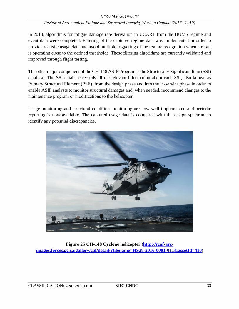
Figure 25 CH-148 Cyclone helicopter (http://rcaf-arc-
images.forces.gc.ca/gallery/caf/detail/?filename=HS28-2016-0001-011&assetId=410)

LTR-SMM-2019-0063
Review of Aeronautical Fatigue and Structural Integrity Work in Canada (2017 - 2019)
34 NRC-CNRC DISTRIBUTION: UNLIMITED
3.7 Demonstration of an Airframe Digital Twin Framework using a CF-188
Component Test *
G. Renaud, M. Liao, and Y. Bombardier, NRC Aerospace
* Paper being presented at ICAF2019
The airframe digital twin (ADT) framework is a potential game-changing fleet management
concept recently proposed by the United States Air Force (USAF) to allow proactive and cost-
effective decisions on an individual aircraft basis. The National Research Council Canada (NRC)
is currently demonstrating the ADT framework using a CF-188 full-scale component test to assess
the adaptability of this approach for the Royal Canadian Air Force (RCAF) fleets [3].
The major advantage of the ADT approach is that it provides a probabilistic representation of
individual aircraft tracking (IAT) and inspection data. However, the fact that some inputs, such as
crack findings, are initially very scarce makes the determination of a probability of failure (POF)
very challenging. The Bayesian inference method is therefore employed to address this
shortcoming by updating prior modelling assumptions to increase the reliability of the predictions
as new information becomes available, throughout the service life of the aircraft. An in-house
analysis tool is being developed to perform quantitative risk assessment (QRA) based on the
Bayesian inference method using individual aircraft tracking and non-destructive inspection data.
The modular components of the ADT tool include load and crack size distribution updating,
material initial discontinuity state, residual stress effects, load transfer functions, crack tip stress
intensity factor calculations, and crack growth predictions. Development and validation of the
modular components of the ADT analysis tool have already highlighted the benefits of Bayesian
updating for realistic test cases that combined uncertain material initial states with scarce
inspection results.
In parallel, NRC has developed a demonstration case, illustrated in Figure 26 that utilizes an
ongoing CF-188 inboard leading edge (ILEF) full-scale life extension test to simulate a flying
aircraft. The tested ILEF is a retired component from the RCAF with a repair history representative
of the current fleet and the loading test spectrum is representative of current and future CF-188
fleet usage. The ILEF transmission lugs, the actual RCAF life limiting items, are the main focus
of this full-scale component test and of the ADT demonstration. The objectives of the
demonstration are to compare the ADT framework with the current lifing and fleet management
practices, and to provide recommendations for the RCAF aircraft fleets.
Short-term benefits are expected from this demonstration for the improvement of existing RCAF
fleet management. First, it allows for improving IAT system and data, with quantification of
variability and correlation of IAT accuracy with risk. Second, it can improve fatigue life estimation

LTR-SMM-2019-0063
Review of Aeronautical Fatigue and Structural Integrity Work in Canada (2017 - 2019)
CLASSIFICATION: UNCLASSIFIED NRC-CNRC 35
for more efficient structural life management. In a longer term, a higher return on investment could
be possible, with benefits that include better decision-making, increased fleet availability, and
reduced total ownership costs.
Figure 26 ADT framework demonstration using the CF-188 ILEF component test
3.7.1 REFERENCES
[3] M. Liao, G. Renaud, and Y. Bombardier, “Airframe Digital Twin (ADT) Technology
Adaptability Assessment and Technology Development Roadmap”, NRC Laboratory Technical
Report, LTR-SMM-2018-0063, March 2018.
[4] G. Renaud, M. Liao, and Y. Bombardier, “Demonstration of an Airframe Digital Twin
Framework using a CF-188 Component Test”, Proceedings of the International Committee on
Aeronautical Fatigue and Structural Integrity (ICAF 2019), Krakow, Poland, Jun 2019.

LTR-SMM-2019-0063
Review of Aeronautical Fatigue and Structural Integrity Work in Canada (2017 - 2019)
36 NRC-CNRC DISTRIBUTION: UNLIMITED
4.0 FATIGUE LIFE ENHANCEMENT TECHNOLOGIES
4.1 Shot peening to extend fatigue life of military aircraft
L-3 Communications (Canada) Military Aircraft Services (L3 MAS)
The shot peening of aluminium parts as a retrofit to extend fatigue life of military aircraft has
already been used for about two decades in the Canadian aircraft industry. For the applications
performed at L3 MAS, the required Life Improvement Factor (LIF) was generally not higher than
1.5. Based on limited coupon testing performed in the late 1990s, engineers were satisfied that
manual application of shot peening with a 200% coverage would provide this level of LIF. More
recently, robotic systems were developed to perform shot peening in-situ as a Life Improvement
Technique (retrofit) to extend the aircraft service life (also see Section 3.3.1). For the more recent
applications, the LIF requested from shot peening went up to 3.0.
In that context, a new coupon test program was required to certify that higher LIF target using the
robotic system. The application involves Al 7050-T7451 plate, 6” thick with a variable amplitude
spectrum (maximum R-ratio of approximately -0.3). The geometries are generally radii at the
bottom of machined pockets with stress concentration Kts varying between 1.4 and 1.5 and stresses
in vicinity of the yield point. Prior to the shot peening being applied at up to 80% of the baseline
unfactored life of the critical hot spot, a light blend of 0.003” to 0.006” was carried out to remove
some of the accumulated surface damage. Several test series were defined to address all bulkhead
hot spot parameters that could affect the shot peening behaviour (ex. stress level, grain direction,
geometry of the critical hot spot, etc.). The effect of performing this retrofit over a 0.015” deep
crack was also verified. Besides this latter series, all test series showed LIF significantly above the
requirement/expectations, as shown below in Figure 27.
Figure 27 Recent test program at NRC on shot peening

LTR-SMM-2019-0063
Review of Aeronautical Fatigue and Structural Integrity Work in Canada (2017 - 2019)
CLASSIFICATION: UNCLASSIFIED NRC-CNRC 37
4.2 Life Improvement Quantification of Fastener Modifications
G. Renaud and M. Liao, NRC Aerospace
P. Martin, L-3 Communications (Canada) Military Aircraft Services (L3 MAS)
A coupon test program is currently being carried out at NRC to certify fastener modifications that
aim at extending the lives of military aircraft components that are short of revised usage goals [5].
The objective of this program is to determine if a life extension penalty should be considered when
blind interference fit ground shank fasteners (I/F GS) were to be used instead of clearance fit blind
fasteners with ring pad coining (RPC), or interference fit Hi-Lok (I/F HL) fasteners. Further, the
life extension performance of these three fastener types are to be evaluated for highly loaded
situations. The results obtained from 85 coupons, summarized in [5], suggest that, in general, the
I/F GS fasteners do not provide as much life extension as the other two fastener types. Furthermore,
contrary to current assumption from the fleet operator, the factored LIF is not reduced when the
stress goes from 1.5×Fty up to 2.0×Fty. In this context, the crack initiation (CI) life is defined at
the time to reach a 0.254 mm (0.01 inch) deep crack. A factored life improvement factor (LIF) is
defined at the life ratio between the tested case and the equivalent open hole configuration, at a
1/1000 cumulative probability of crack initiation.
Table 7 Fastener life improvement factor comparison
Fastener Type Load Transfer Local Stress (Fty) Factored CI LIF Scatter Factor
RPC
Yes 1.5 9.83 1.70
2.0 5.46 1.79
No 1.5 7.94 1.38
2.0 8.82 1.74
I/F HL No 1.5 5.36 3.95
2.0 8.26 3.19
I/F GS
Yes 1.5 3.27 4.42
2.0 12.77 1.80
No 1.5 2.06 4.99
2.0 5.32 2.74
Additional coupons (58) are currently being tested to quantify the effect of fatigue damage
removal, for a nominal to next size fastener typical for these locations, and the effect of an I/F
bushing modification. Results obtained to date suggest that hole oversizing resets the fatigue life.
4.2.1 REFERENCES
[5] G. Renaud, P. P. Martin, and M. Liao, “Experimental Life Improvement Quantification of Shot
Peening and Fastener Modifications”, 12th International Fatigue Congress, May 27 – June 1 2018,
Poitiers, France.

LTR-SMM-2019-0063
Review of Aeronautical Fatigue and Structural Integrity Work in Canada (2017 - 2019)
38 NRC-CNRC DISTRIBUTION: UNLIMITED
4.3 Hole Cold Expansion Process Plasticity Modelling
G. Renaud, G. Li, M. Liao, NRC Aerospace
Cold expansion (Cx) of fastener holes has been used for decades to enhance the fatigue lives of
critical airframe structures. Although the benefits of this technology are undeniable, current
requirements for structural life extension and inspection scheduling remain very stringent.
Research at the National Research Council Canada (NRC) aims at developing physics-based
analytical methodologies and tools to calculate life improvement factors from Cx residual stresses.
As part of the international Engineered Residual Stress Implementation (ERSI) workgroup
sponsored by the USAF, NRC is actively working for improving hole Cx process simulation to
generate reliable residual stress distributions that can be used for accurate crack growth analysis.
One of the recent focuses of the NRC effort was to characterize material properties of 2024-T351
plate material for Cx residual stress distributions measured experimentally by the contour method.
The objective was to determine characteristics that are typically not included in Cx process models
and assess their impacts on the predicted residual stresses. These characteristics include tension-
compression behaviours, anisotropic hardening, and reverse yielding. Then, a thorough calibration
was carried out to identify best practices for Cx process modelling using von Mises, Chaboche and
Barlat plasticity models. For example, the stress-strain curves obtained in different directions for
a ±1.5% compression-tension strain cycle are presented in Figure 28 a), and a comparison of mid-
thickness residual stress curves is presented in Figure 28 b). Overall, the best results were obtained
when anisotropic properties were considered. Additional tests and calibration exercises, focusing
on additional parameters, were proposed.
a) Cyclic Compression-Tension L vs. LT vs. 45° b) Plasticity model calibration examples
Figure 28 Hole cold expansion process modelling from material characterization

LTR-SMM-2019-0063
Review of Aeronautical Fatigue and Structural Integrity Work in Canada (2017 - 2019)
CLASSIFICATION: UNCLASSIFIED NRC-CNRC 39
4.4 Measurement of Residual Stresses Resulting from Cold Expansion
D. Backman, G. Renaud, NRC Aerospace
In support of a research program focussed on incorporating residual stresses into finite element
simulations of the cold expansion process, accurate experimental measurements of the residual
stress field around cold expanded holes using X-ray diffraction (XRD) analysis was performed.
The following two tasks were addressed in more detail:
Determining X-ray elastic constant for 7075-T6 aluminium
Residual stress measurements of cold expanded holes
To obtain the most accurate residual stress measurements possible, an initial investigation was
undertaken to determine the correct X-ray elastic constant (XEC) for the material. The XEC is
related to the elastic modulus, and is used to convert changes in the crystallographic lattice spacing
(i.e., strain changes) into residual stress results. The changes in lattice spacing are analogous to the
changes in displacement one measures using conventional strain measurement techniques, such as
strain gauges.
For this test, a thin strip of 7075-T6 aluminium was instrumented with a conventional strain gauge
on one face and centered in a four-point bend fixture. The four-point bend fixture was used to
apply known displacements on the thin strip, for which strain was measured by strain gauges on
one face and residual stress was measured by XRD on the other. The strain gauge reading was then
converted into applied stress which is plotted against the XRD residual stress in Figure 29.
Figure 29 X-ray elastic constant determination
[MPa]
[MP
a]

LTR-SMM-2019-0063
Review of Aeronautical Fatigue and Structural Integrity Work in Canada (2017 - 2019)
40 NRC-CNRC DISTRIBUTION: UNLIMITED
By determining the relationship between the mechanical Elastic Modulus and the estimated XEC,
an XEC correction factor can be determined. From the initial XEC estimate for generic aluminium
alloy of 18.89x10⁻⁶ MPa-1, a more refined determination of the XEC specifically for 7075-T6 was
calculated as 17.99 x10⁻⁶ MPa-1.
Two coupons were provided for XRD analysis, with each coupon having a central hole which had
been cold expanded using standard FTI (Fatigue Technology Incorporated) tooling (16-1-N). The
residual stress was measured on both the left and right sides of each hole (see Figure 30 and Figure
31) and on both the entry and exit faces. The dark line on Figure 30 denotes the region where XRD
measurements were made.
(a)
(b)
Figure 30 (a) Coupon H1 Entry face (b) Coupon L1 Exit face

LTR-SMM-2019-0063
Review of Aeronautical Fatigue and Structural Integrity Work in Canada (2017 - 2019)
CLASSIFICATION: UNCLASSIFIED NRC-CNRC 41
(a)
(b)
Figure 31 (a) Overall view of XRD machine (b) Detail view of XRD aperture, left and right
detector and coupon
All XRD measurements were made using a 2 mm diameter aperture, with a measurement spacing
of 0.25 mm. The results from the left and right side of each coupon face were averaged together,
with the overall line profile of the residual stresses provided in Figure 32 and Figure 33 below.
Figure 32 Entry and exit face residual stress results for coupon L1
[MP
a]

LTR-SMM-2019-0063
Review of Aeronautical Fatigue and Structural Integrity Work in Canada (2017 - 2019)
42 NRC-CNRC DISTRIBUTION: UNLIMITED
Figure 33 Entry and exit face residual stress results for coupon H1
The results for both coupons show that in the region next to the hole edge, the residual stresses
were higher on the exit face than on the entry face. This result appears to be consistent with data
from the open literature.
4.5 Fatigue Life Prediction at Cold Expanded Fastener Holes with ForceMate
Bushings*
Y. Bombardier, G. Li, and G. Renaud, NRC Aerospace
* Paper being presented at ICAF2019
ForceMate high interference fit expanded bushings, made by Fatigue Technology Inc. (FTI), are
used by aircraft designers and maintainers to improve the fatigue and wear resistance of holes.
While the fatigue life improvement factor (LIF) resulting from the installation of ForceMate
bushings has been demonstrated experimentally, no analytical methods have been approved to
benefit from this technology. To address this gap, a methodology was developed to analytically
determine the LIF resulting from the installation of ForceMate bushings by taking into account the
residual stresses and the effect of high interference fit bushings. To achieve this, a three-
dimensional residual stress field is obtained from finite element analysis of the ForceMate
installation; fatigue crack nucleation lives are calculated; crack propagation analyses are conducted
to calculate the resulting crack shapes and stress intensity factors, and the crack growth predictions
are performed. This methodology was demonstrated on a CF-188 bulkhead at the holes attaching
the main landing gear uplock mechanism. Based on this analytical study, a predicted LIF of 6.6
was obtained for crack nucleation and 4.9 for crack growth from a 0.254 mm quarter-circular crack
to a through-thickness crack. While there are several aspects of this analytical study that need to
[MP
a]

LTR-SMM-2019-0063
Review of Aeronautical Fatigue and Structural Integrity Work in Canada (2017 - 2019)
CLASSIFICATION: UNCLASSIFIED NRC-CNRC 43
be validated experimentally, the calculated LIF correlates with the LIF typically obtained with the
ForceMate system.
Figure 34 Calculation of the residual stresses resulting from the finite element simulation of
the installation of a ForceMate bushing
4.5.1 REFERENCE
[6] Y. Bombardier, G. Li, and G. Renaud, Fatigue Life Prediction at Cold Expanded Fastener Holes
with ForceMate Bushings, Proceedings of the International Committee on Aeronautical Fatigue
and Structural Integrity (ICAF 2019), Krakow, Poland, Jun 2019.
4.6 Fatigue Performance Evaluation of Blind Fasteners for CP-140 Vertical
Stabilizer Repairs
Y. Bombardier, NRC Aerospace
The original equipment manufacturer (OEM) of the CP-140 aircraft does not typically endorse the
use of blind fasteners for vertical stabilizer skin repairs, as these types of fasteners could reduce
the life of the structures by as much as 56%. Due to limited access to the internal structure of the
CP-140 vertical stabilizer, these recommendations cannot always be followed by the maintenance,
repair, and overhaul (MRO) organizations and blind fasteners sometimes have to be used to
execute repairs.
The main objective of this project was to determine the fatigue life reduction factor resulting from
the use of blind fasteners in-lieu of solid rivets. To achieve this objective, the National Research
Council Canada (NRC) designed a test coupon representative of typical vertical stabilizer skin
panel repairs. The specimens were manufactured by IMP Aerospace and Defence to replicate the
installation procedures and to be representative of the CP-140 aircraft.
Stress scale: ksi

LTR-SMM-2019-0063
Review of Aeronautical Fatigue and Structural Integrity Work in Canada (2017 - 2019)
44 NRC-CNRC DISTRIBUTION: UNLIMITED
Static and fatigue tests were conducted by NRC on specimens, illustrated in Figure 35 and Figure
36, with three types of fasteners: MS20426AD6 flush-head solid rivets, MS20470AD6 protruding-
head solid rivets, and NAS1670-3L blind bolts. The fasteners were tested in a double lap shear
configuration to mimic the presence of the stringers that reduce the occurrence of out-of-plane
bending. The fatigue lives obtained with MS20470 and NAS1670 fasteners were equivalent and
the fatigue failures typically originated from fretting damage around the fastener holes. The fatigue
lives obtained for MS20426 flush-head solid rivets were significantly shorter and all fatigue
failures originated from the rivet. Further investigation is therefore required to identify the poor
performance of the specimens with MS20426 fasteners compared to the two other types of
fasteners.
Figure 35 Double lap shear specimen design
Figure 36 Typical failure at a NAS1670 blind bolt
6.35 mm

LTR-SMM-2019-0063
Review of Aeronautical Fatigue and Structural Integrity Work in Canada (2017 - 2019)
CLASSIFICATION: UNCLASSIFIED NRC-CNRC 45
While the preliminary results indicate that the fatigue performance of the tested blind bolt was
equivalent to the protruding-head solid rivets, four additional effects need to be investigated to
fully quantify the fatigue performance of blind bolts: 1) the effect of secondary bending moments,
2) the effect of a multi-row fastener layout, 3) the effect of clamping force upon installation, and
4) the effect of vibrations. Although all four effects likely play a major role in the fatigue
performance of the joints, the clamping load effect is particularly important, as all failures observed
for MS20470 and NAS1670 fasteners originated from fretting damage between the layers, whereas
the failures observed by the OEM had resulted from fatigue cracks nucleating at the fastener hole.

LTR-SMM-2019-0063
Review of Aeronautical Fatigue and Structural Integrity Work in Canada (2017 - 2019)
46 NRC-CNRC DISTRIBUTION: UNLIMITED
5.0 LOAD, USAGE, AND STRUCTURAL HEALTH
MONITORING
5.1 Helicopter Load and Usage Monitoring Research in 2017-2019
C. Cheung, NRC Aerospace
5.1.1 A MACHINE LEARNING APPROACH TO LOAD TRACKING AND USAGE MONITORING FOR
LEGACY FLEETS [7]*
* Paper being presented at ICAF2019
Indirect methods of estimating component loads based on existing aircraft sensor data have been
in development using flight data from an Australian Black Hawk (S-70-A-9) helicopter and
CH-146 (Bell 412) Griffon helicopter, illustrated in Figure 37. The load and fatigue life results
obtained thus far have shown tremendous potential for accurate and consistent estimates using the
same methodology on both platforms. Significant upgrades to the computational approach have
been undertaken towards improving the efficiency and robustness of the algorithm and code. As a
result of these improvements, larger data sets from the two helicopter platforms could be processed
to provide a more complete picture of the effect of more accurate load monitoring.
Figure 37 Illustration of load estimation approach
Refinements to the machine learning models are ongoing as we continue to explore different types
of model architectures and model settings. These models and their results could all be combined
in the load estimation framework to provide an ensemble of models, averaging their results.

LTR-SMM-2019-0063
Review of Aeronautical Fatigue and Structural Integrity Work in Canada (2017 - 2019)
CLASSIFICATION: UNCLASSIFIED NRC-CNRC 47
Accurate load signal prediction enables ongoing load monitoring, allowing for comparisons of
load histograms and load exceedance distributions between individual aircraft, time periods,
aircraft flying certain missions, regions, squadrons, etc. Mean, maximum and minimum loads can
also be compared. These types of comparisons do not rely on any material properties that the OEM
may have used in the design process. With access to material data, more accurate fatigue damage
accumulation can be monitored based on actual usage. Incorporating ground-air-ground analysis
will be addressed in future work.
5.1.2 DATA ANALYTICS AND PREDICTIVE MAINTENANCE [8]
The application of predictive analytics to aerospace operational and maintenance data has the
potential to further enhance overall aircraft safety and realize significant cost savings for aircraft
Original Equipment Manufacturers (OEMs), Maintenance Repair and Overhaul (MRO)
organizations and aircraft operators; be they civilian or military. Potential cost savings include,
but will not necessarily be limited to, improved operational availability, avoidance of Aircraft-on-
Ground (AOG) incidents, avoidance of unscheduled maintenance through timely and proactive
intervention and spares provisioning optimization.
Aerospace predictive analytics are such that significant quantities of data are accumulated from
each flight. Therefore, the implementation of such a capability requires the application of Big
Data Techniques and Technologies. However, although several organizations have tried to apply
Big Data Techniques to this data, few, if any, organizations have been able to demonstrate tangible
Return On Investment (ROI). This lack of success can be attributed to factors such as lack of
appropriate domain expertise integration with the big data techniques, poorly defined
requirements, a lack of understanding of the parameters that need to be monitored and the
development of appropriate models and analysis techniques for data processing. As part of this
effort, NRC has partnered with Celeris Aerospace Canada Inc. to evaluate how large quantities of
operational and maintenance data acquired from in-service aircraft can be effectively analyzed and
synthesized to provide a truly predictive capability that provides tangible operational and
maintenance benefits.
The first part of this process involves obtaining clarity as to the benefits (requirements) aircraft
operators, maintainers, OEMs and other stakeholders are seeking to obtain through the collection
of this data. To that end an online survey focused on determining the predictive operational and
maintenance requirements of the different stakeholders was developed and distributed.
Ongoing advances in technology coupled with the trend to “capture all available data” based on
the assumption that one day it may prove valuable, suggests that the number of parameters captured
(and the corresponding data file sizes) will continue to increase at almost exponential rates for the
foreseeable future. Organizations wishing to derive tangible operational and maintenance benefits
from this data-tsunami need to address three main issues. First, they should implement effective

LTR-SMM-2019-0063
Review of Aeronautical Fatigue and Structural Integrity Work in Canada (2017 - 2019)
48 NRC-CNRC DISTRIBUTION: UNLIMITED
data management and processing strategies to avoid becoming overwhelmed with data, which they
cannot process, validate, understand and interpret. Second, they should counter the widely held
belief that the more data that is collected, the greater the insight that can be obtained, regardless of
whether the rationale for collecting the data is understood or not. Finally, they should evaluate the
actual cost-benefit of adding additional parameters and the associated impact on overall system
design, implementation and cost. Effective solutions to these issues can only be obtained through
a multi-disciplinary approach that evaluates and optimizes the relative merits and implications of
proposed solutions from an overall system design perspective, as opposed to an individual
constituent “discipline-silo” perspective. Consequently, the successful implementation of an
Aircraft Health Monitoring Program that produces tangible operational, maintenance ROI requires
a disciplined approach to overall system integration.
5.1.3 USAGE MONITORING USING MEMS-IMU SENSOR SYSTEM AND FDR INPUT DATA
To support life extension and usage monitoring efforts in various helicopter fleets with limited to
no on-board data logging capability, the National Research Council (NRC) developed a stand-
alone sensor system based on micro-electromechanical systems and inertial measurement unit
(MEMS-IMU) technology, shown in Figure 38. This work was initiated as a temporary usage
monitoring option for an older aircraft fleet, where a standalone system was preferable. This
system recorded relevant flight data to be processed by manoeuvre recognition algorithms.
Figure 38 MEMS-IMU system for helicopter usage monitoring
An initial flight test of the sensor system was performed on a Bell 206 helicopter. The initial
manoeuvre recognition results based on the sensor system measurements were very promising,
though limited to only 7 general manoeuvres. More comprehensive in flight testing of the sensor
system has recently been carried out on a Bell 412 CH-146 Griffon helicopter. A much broader
range of 60 maneouvres and regimes from the CH-146 usage spectrum were flown. Data was
collected for several scripted flights from the MEMS-IMU sensor system as well as the from the

LTR-SMM-2019-0063
Review of Aeronautical Fatigue and Structural Integrity Work in Canada (2017 - 2019)
CLASSIFICATION: UNCLASSIFIED NRC-CNRC 49
flight data recorder (FDR). Data-driven manoeuvre recognition models based on the recorded data
from both data sources were developed and compared.
Continued analysis of the flight test data has included exploring different approaches to training a
classification model that performs well when trained and tested on data from a separate flight. The
data labels were relabelled to reduce the number of targets from 60 specific flight conditions to 7
general flight conditions.
The data was highly unbalanced as certain manoeuvres were performed many more times than
others or were of longer duration than others, thus providing more samples. Thus, to balance the
data set, the majority classes were under-sampled randomly so that the manoeuvres had about the
same number of occurrences or samples. After training with this under-sampled but more balanced
training set, the classification model improved considerably. The testing results indicated that
considerable improvements can be obtained by balancing the data using a random under-sampling
method. Furthermore, using fewer classes improves the predictive performance of the models. In
the future, different data balancing techniques could be explored, such as techniques that generate
data of the minority classes. Acquiring more data would also reduce the variance in the model, as
the training set would have a more diverse set of manoeuvres. However, without more data the
results will only improve through the exploration of new balancing methods.
5.1.4 ANALYSIS OF SENSOR NETWORK DATA FOR FAILURE MODELLING AND PREDICTION
[9][10][11][12]
Rapid developments in sensor technology, data processing tools and data storage capability have
helped fuel an increased appetite for equipment health monitoring in mechanical systems. As a
result, the number of sensors and amount of data collected for health monitoring has grown
tremendously. Developing strategies and capabilities to extract useful information from the
tremendous amounts of data collected is a well-known challenge. This information can be used to
establish system health indicators and contribute to the implementation of condition-based
maintenance. It is hoped that by collecting large quantities of operational data, predictive tools can
be developed that will provide operational, maintenance and safety benefits.
Data mining and machine learning techniques are important tools in addressing the ensuing
challenge of extracting useful results from the data collected. However, incorporating as much
physical domain knowledge to the analysis as possible is also necessary to ensure the results are
relevant and practical for the operator and end-user.
This work relates to continued efforts to analyze sensor data for the turbocharger subsystem of a
diesel engine system. The engine has hundreds of sensors monitoring both the inputs of the engine
operator and the resulting equipment outputs. A turbocharger seizure was recorded by the diesel
engine sensor system. While the sudden nature of the turbocharger incident was not a typical

LTR-SMM-2019-0063
Review of Aeronautical Fatigue and Structural Integrity Work in Canada (2017 - 2019)
50 NRC-CNRC DISTRIBUTION: UNLIMITED
example of a slowly deteriorating mechanical system, the opportunity to build models with a
known outcome was still valuable. Therefore, data analysis of this incident including the lead up
to the event allows for monitoring and identification of changes in equipment condition indicators
with a known outcome.
The objective of the data analysis was to characterize and distinguish the healthy and failed states
of the turbocharger seizure as recorded by the diesel engine sensor system. The analysis approach
included the mapping of high-dimensional sensor data to a low-dimensional space using a variety
of linear and nonlinear techniques in order to highlight and visualize the underlying structure of
the information. Figure 39 shows an example of the 3-D visualization of a mapping of the
turbocharger data using the Isomap technique. This mapping is overlaid with the Turbo A speed
sensor values during the period of data analysis. In addition, data analysis tools were used to
characterize the healthy and deteriorated states of the turbocharger system, including various
classification and anomaly detection techniques.
Future efforts are aimed at expanding this analysis to data from other diesel engines and other
failures in the engine system. Further work to generalize the analysis to a diesel engine system
model instead of a turbocharger-specific model is in progress. The development and
implementation of these tools should help enable advance indication of a change in behaviour that
could be investigated before a major incident.
Figure 39 Turbo A speed sensor value [kRPM] overlay onto Isomap transformation
5.1.5 REFERENCES
[7] C. Cheung, S. Sehgal, J.J. Valdés, “A machine learning approach to load tracking and usage
monitoring for legacy fleets”, Proceedings of the International Committee on Aeronautical
Fatigue and Structural Integrity (ICAF 2019), Krakow, Poland, Jun 2019.

LTR-SMM-2019-0063
Review of Aeronautical Fatigue and Structural Integrity Work in Canada (2017 - 2019)
CLASSIFICATION: UNCLASSIFIED NRC-CNRC 51
[8] Stephen R. Hall, Catherine Cheung, and John W.R. Miner, “Considerations for Obtaining
Tangible Operational and Maintenance Benefits from Aircraft Health Monitoring Systems in a
Big Data Environment”, Proceedings of the 11th DST International Conference on Health and
Usage Monitoring Systems (HUMS2019), Melbourne, Australia, Feb 2019.
[9] C. Cheung, N. Kilfoyle, J.J. Valdés, S. Sehgal, R. Salas Chavez, “Low-dimensional spaces for
relating sensor signals with internal data structure in a propulsion system”, Advances in Science,
Technology and Engineering Systems Journal, Special Issue on Multidisciplinary Sciences and
Engineering, Vol. 3. No. 6, pp. 23-32, 2018.
[10] C. Cheung, J.J. Valdés, R. Salas Chavez, S. Sehgal, “Failure modelling of a propulsion
subsystem: unsupervised and semi-supervised approaches to anomaly detection”, International
Journal of Pattern Recognition and Artificial Intelligence, accepted Jan 2019.
[11] C. Cheung, J.J. Valdés, R. Salas Chavez, A. Lehman Rubio, “Failure modelling and anomaly
detection of a propulsion subsystem”, Proceedings of International Conference on Pattern
Recognition and Artificial Intelligence (ICPRAI 2018), Montreal, QC, May 2018.
[12] C. Cheung, J.J. Valdés, A. Lehman Rubio, R. Salas Chavez, C. Bayley, “Low-dimensional spaces
for the analysis of sensor network data: Identifying behavioural changes in a propulsion system”,
Proceedings of IEEE International Symposium on Robotics and Intelligent Sensors (IEEE
IRIS2017), Ottawa, ON, Oct 2017.
5.2 Structural Health Monitoring (SHM)
L-3 Communications (Canada) Military Aircraft Services (L3 MAS)
L3 MAS is an active member of three on-going collaborative R&D initiatives with universities,
colleges and industrial partners: CRIAQ (Quebec Aeronautical Industrial Research Consortium),
CARIC (Consortium for Aerospace Research and Innovation in Canada) and MICA (Metrology
and Inspection of Composites in Aerospace). Internal and collaborative projects that have been
completed recently were in the areas of Structural Health Monitoring (SHM), shot peening,
robotics and composite materials, as well as software tools in support of fatigue life assessments
and in-service monitoring/management, including Artificial Intelligence (AI) initiatives.
In 2018, L3 MAS and Paradigm Shift Technology (PST) have completed a technology
demonstration project funded under the Build-in-Canada Innovation Program (BCIP). The sensor
developed by PST, coined Chameleon Skin Gauge (CSG), is a passive, thin, isotropic film, which
may be cut and formed in any shape. Once interrogated by the reader and processed though
proprietary software, the sensor data provide direct information on the cumulative effect of host
structure exposure to stress/strain loads and cracking. The project has evaluated the ability of the
Prognostica™ technology to detect structural defects in four different applications deemed

LTR-SMM-2019-0063
Review of Aeronautical Fatigue and Structural Integrity Work in Canada (2017 - 2019)
52 NRC-CNRC DISTRIBUTION: UNLIMITED
representative of the critical CF-188 locations: fatigue cracks in fastener holes and in fillet radii,
disbonds and cracking in underlying structures (detected from the overlaying graphite epoxy skin).
5.3 Potential Damage Location Indication Determined using Acoustic
Emission during CF-188 Aileron Fatigue Test
S. Pant, R. Rutledge, NRC Aerospace
A full-scale test of the aileron was conducted at NRC as a part of life extension efforts for all CF-
188 flight control surfaces. This testing involved fatigue durability and damage tolerance cycling
with static residual strength tests completed at the end of the two cycling test phases. The aileron
test article contains aluminium core with pushed fasteners, due to modifications carried out during
its usage. The intent is to test the durability and damage tolerance of the current configuration of
CF-188 aileron in order to extend its life by an additional one third of a lifetime. During the cyclic
testing, loud noises were emanating from the test article. To locate the noise source, the test had
to be stopped and the entire area had to be manually searched using a Non-Destructive Evaluation
(NDE) technique, such as ultrasonic inspection. These inspections are time consuming and labour
intensive, as the entire area had to be inspected. Inspecting the entire test article meant that the test
had to be stopped for that duration plus the additional labour hours required for the inspection
itself. In order to minimize downtime and determine the location of the noise source, an Acoustic
Emission (AE) technique was implemented. The AE system was developed in-house using
commercial off-the-shelf (COTS) components and custom post-processing and source location
algorithms. The goal was to locate the area of interest to find out if the source creating the noise
was also creating significant damage to the test article. For this purpose, six piezoelectric sensors
were placed at strategic locations, which were moved throughout the test. Sensors’ signal
amplitudes, frequencies along with their arrival times were analyzed to narrow down the location
of area of interest. This area of interest was found to be the transmission connecting the outer wing
to the inner wing, as shown in Figure 40.

LTR-SMM-2019-0063
Review of Aeronautical Fatigue and Structural Integrity Work in Canada (2017 - 2019)
CLASSIFICATION: UNCLASSIFIED NRC-CNRC 53
Figure 40 Area of interest of the noise source determined using Acoustic Emission
5.4 Repeatability Study of Structural Health Monitoring (SHM) Sensors at
Room Temperature
S. Pant, D.Backman, P. Keum, and M. Yanishevsky, NRC Aerospace
This work is focused on exploring the repeatability of Structural Health Monitoring (SHM) sensors
to detect fatigue cracks emanating from crack-starter notches in 0.063 inches thick, aluminium
7075-T6 panels, measuring 12 by 24 inches in a room temperature environment. Three (n=3)
panels were tested in total, where each panel had three (n=3) 0.25 inches diameter holes, drilled at
3 inches apart along the vertical centre of the plates. Two outer holes had Electrical Discharge
Machining (EDM) notches for starting fatigue cracks. Four (n=4) different Structural Health
Monitoring (SHM) technologies: Acoustic Ultrasonic (AU), National Research Council (NRC)
developed Crack Foil Sensor (CFS), resistance wire Strain Gauges (SG), and Thermoelastic Stress
Analysis (TSA), were all evaluated for their ability to repeatedly and reliably detect growing
fatigue cracks. Repeatability in the context of this work is defined as the ability of a particular
sensor technology to successfully detect cracks in multiple holes or on multiple test panels. The
repeatability score is simply defined as the number of positive results divided by the total number
of trials.
A strain survey was initially performed using Digital Image Correlation (DIC) technique and was
corroborated with the numerical model developed in ABAQUS. The panels were cycled in tension-
tension fatigue at 5 Hz with a maximum constant sinusoidal load of 8000 lbf at a load ratio of R =

LTR-SMM-2019-0063
Review of Aeronautical Fatigue and Structural Integrity Work in Canada (2017 - 2019)
54 NRC-CNRC DISTRIBUTION: UNLIMITED
0.1. The experimental setup is shown in Figure 41. Each panel consisted of four AU, eight CFS,
and four SG sensors installed at different locations to detect crack growth, as well as a single TSA
camera capturing thermal images of the specimen. The test ran until the cracks emanating from
the EDM notches propagated through all the installed CFS. Marker band loadings were applied to
each specimen during testing to allow for crack growth information to be extracted using
quantitative fractography (QF).
Figure 41 Experimental setup for a repeatability study of SHM sensors
The results showed that despite all three panels being similar and undergoing the same fatigue
loading sequence, cracks grew at a faster rate in some panels versus others, which highlighted the
fact that cracks emanating from holes in identical components fabricated from the same material
and experiencing the same loading can still behave somewhat differently in fatigue. This
emphasised the potential usage of SHM systems to detect and track damages / cracks in individual
components to reduce / eliminate unnecessary inspection as a part of aircraft maintenance. As for
the different SHM systems that were tested, the repeatability of the AU technique was evaluated
for two excitation frequencies of 300 kHz and 350 kHz for a total of 72 paths. Correlation
Coefficient (CC), Energy Ratio (ER) and Amplitude Ratio (AR) were compared between the wave
signal taken at zero cycles and at different cycles for detecting growing cracks. Overall, there were
12 false calls out of 72 paths, which could be attributed to faulty sensors for an aggregate

LTR-SMM-2019-0063
Review of Aeronautical Fatigue and Structural Integrity Work in Canada (2017 - 2019)
CLASSIFICATION: UNCLASSIFIED NRC-CNRC 55
repeatability rating of 83% (60/72). Out of twenty-four (n=24) NRC developed Crack Foil Sensors
(CFS) that were tested, only one (n=1) was found to be defective. All the functioning CFS tripped
when cracks propagated through the sensors, corresponding to a repeatability of 96% (23/24).
Twelve (n=12) resistance wire Strain Gauges (SG) were used to monitor crack growth trends, and
as expected, increases in strain readings were witnessed by all the twelve SG sensors, when the
crack propagated close to the SG, for a repeatability score of 100% (12/12). The Thermoelastic
Stress Analysis (TSA) were used to monitor cracks at the two outer holes with the EDM notches
for a total of six (n=6) repeats. The TSA was not only able to detect crack formation, but was able
to track crack growth in all six cases giving this technology a repeatability score of 100% (6/6).
5.5 Damage Detection Methodology based on Multi-frequency Guided Waves
for SHM Applications with Experimental and Numerical Verification
S. Pant, M. Yanishevsky, D. Backman, NRC Aerospace
M. Martinez, Clarkson University
Even with increasingly sophisticated sensors and damage detection algorithms, Structural Health
Monitoring (SHM) systems have not yet achieved widespread acceptance by aircraft operators.
One of the challenges includes the ability of SHM systems to provide robust damage detection
algorithms to minimize/eliminate false-calls, which can prompt for unnecessary maintenance
actions. Therefore, the primary objective of this study is to aid in reducing the false-call rates by
using a newly developed Damage Response Factor (DRF) method. This method is based on the
use of multi-frequency guided wave excitation for assessing the presence of damage along an
actuator - sensor path. In this study, the corresponding change in the cross-correlation (CC),
amplitude ratio (AR) and energy ratio (ER) of the wave signal were analysed to detect a growing
fatigue crack in a C-Channel type structure made from aluminium alloy 7075-T651 (Figure 42).
A 0.25 mm thick jeweller’s saw blade was used to introduce a saw-cut approximately 0.4 mm in
length to act as a fatigue crack starter notch at the edge of the 3.2 mm diameter hole. To grow the
crack, the C-Channel was loaded in tension-tension fatigue using a sinusoidal waveform at a
frequency of 5 Hz with a maximum load of 2500 lbf [11120 N] and a load ratio of R = 0.1. In
addition to the commonly used threshold value, the DRF approach uses the upper and lower bounds
of the average DRF value along with the separation of the DRF based on excitation frequency. A
combination of all of these criteria, provided an improved means to identify damage rather than
the classical sole-threshold method.
It is also well known that increasing the load will enhance crack detection by opening up the crack
surfaces. Therefore, instead of using the fatigue cycling data, the load data is used at any given
fatigue cycle, i.e. the baseline is taken at the lowest tensile load as a “cycle-free baseline”

LTR-SMM-2019-0063
Review of Aeronautical Fatigue and Structural Integrity Work in Canada (2017 - 2019)
56 NRC-CNRC DISTRIBUTION: UNLIMITED
technique. The idea behind the “cycle-free baseline” technique is to interrogate the structure during
the same cycle, but at different loading conditions. The advantage of using this technique is to
minimize the false calls due to sensor degradation caused by fatigue and environmental cycling.
The “cycle-free baseline” technique may be beneficial in reducing the false calls associated with
sensor degradation as the structure is interrogated using the same sensor state for determining the
baseline and the change. This technique also eliminates the requirement to store and process all
the data associated with each cycle. However, the downside to this technique is the requirement
for applying discrete loads to the structure. For aircraft applications this can be done before and
after fueling or before and after loading the aircraft with cargo and/or passengers. Unfortunately,
this approach may not be able to detect the damage if it is located on the compressive side of the
structure, an issue which will be addressed in future.
The method was verified numerically using ABAQUS. For running ABAQUS, a Windows 7
computer with two Intel Xeon CPU 2650V3 (a total of 20 physical CPUs) running at 2.30 GHz
with 128 Gigabytes of RAM was used. Despite the simplistic crack model (extension of a notch),
the Finite Element Model (FEM) results displayed that the waves excited at a higher frequency
corresponding to smaller wavelength are in fact more reactive to the presence of the damage in
their path, as compared to the waves generated at a lower frequency corresponding to a longer
wavelength; thereby, verifying the DRF approach [13].
One major issue using ABAQUS was, despite the high computational resource, many of the
simulations took over a week to converge for a total time window of only 350 microseconds.
Therefore, to improve upon the simulation time, new wave propagation software called Onscale
was evaluated and compared against ABAQUS and experiment data. Onscale results were in
excellent agreement with the ABAQUS results, while reducing the simulation time from 10 days
to less than 3 hours on the same machine. This opens the possibility of generating Model Assisted
Probability of Detection (MAPoD) curves. Onscale is currently being used to simulate wave
propagation in order to compare the DRF method with the experimental and ABAQUS results
[14].

LTR-SMM-2019-0063
Review of Aeronautical Fatigue and Structural Integrity Work in Canada (2017 - 2019)
CLASSIFICATION: UNCLASSIFIED NRC-CNRC 57
Figure 42 Experimental setup to grow fatigue crack in C-Channel structure
5.5.1 REFERENCES
[13] S. Pant, M. Martinez, M. Yanishevsky, and D. Backman, “Damage Detection Methodology for
Structural Health Monitoring (SHM) Applications based on Multi-frequency Anti-symmetric
Guided Waves”, 9th European Workshop on Structural Health Monitoring, Manchester, UK,
2018.
[14] F. Falcetelli, M. B. Romero, S. Pant, M. Martinez, “Time Reversal Technique to model Pencil-
Lead Break Acoustic Emission Sources”, 18th International Workshop on Holistic Structural
Integrity Process (HOLSIP), Utah, USA, 2019.

LTR-SMM-2019-0063
Review of Aeronautical Fatigue and Structural Integrity Work in Canada (2017 - 2019)
58 NRC-CNRC DISTRIBUTION: UNLIMITED
6.0 NON-DESTRUCTIVE EVALUATION
6.1 Detection of Low-Velocity Impact Damage in Carbon Fiber Sandwich
Panels Using Infrared Thermography*
T. Rellinger, D. Wowk and T. Krause – Royal Military College of Canada, C. Marsden - Concordia University
*Masters thesis. Tanner Rellinger, Royal Military College of Canada, January 2019.
Sandwich panels with honeycomb core and composite facesheets are commonly used for
aerospace applications, but are susceptible to low-velocity impact events which may result in
damage that is difficult to detect. Some of the damage modes that may occur are plasticity of the
facesheet, crushing of the core, delamination in the facesheet and disbonding of the adhesive
between the facesheet and core. While any form of disbond or delamination is unacceptable,
plasticity in the facesheet and crushing of the core may be acceptable, if within allowable limits.
It is therefore important to be able to differentiate between the different types of damage. An
apparatus using active infrared thermography was designed and used to identify disbonds and
measure their diameter.
The apparatus was designed and constructed around a FLIR T620 infrared camera and consisted
of two 50 Watt halogen bulbs as a heat source, parabolic reflectors for uniform heating, an Arduino
computer and relay board for controlling the heating, and a MATLAB code for post-processing
the thermal images. Figure 43 shows some of the key features of the apparatus.
Figure 43 Infrared thermography apparatus for heating the sample and recording a
sequence of images of the surface temperature
Sandwich panel coupons and laminate facesheets were manufactured in-house using a table-top
autoclave. Two different types of impact damage were created in the panels using a drop tower
apparatus. The first was a disbond between the facesheet and the core. Following springback of
the facesheet, no dent was visible on the surface of the panel although core crushing existed
beneath. The second was a dent, where the facesheet stayed depressed and adhered to the core.

LTR-SMM-2019-0063
Review of Aeronautical Fatigue and Structural Integrity Work in Canada (2017 - 2019)
CLASSIFICATION: UNCLASSIFIED NRC-CNRC 59
This damage mode was created by wet sanding the surface of the laminate facesheet prior to
adhering the core.
Thermographic images of the coupon showed higher temperatures in regions where a disbond
occurred, because the air gap does not transmit the thermal energy into the core as readily as the
intact portion of the panel. Figure 44 a) shows a cross-section of a disbond between the facesheet
and the core with the corresponding thermographic image shown in Figure 44 b). The presence of
the disbond is identified by the local increase in temperature, and the width of the disbond was
measured to within 25% for 9 coupons subject to different impact energies.
Figure 44 a) Cross-section of an impact location with an adhesive disbond, b) thermographic
image of the surface of the impact region
Figure 45 a) shows a cross-section of a dent with no disbond and Figure 45 b) shows the
corresponding thermographic image. The uniform temperature of the panel indicates that no
disbond is present. Even though core crushing and facesheet plasticity exist, they are acceptable
damage modes and can be quantified based on the surface dent.
Figure 45 a) Cross-section of an impact location with an intact adhesive bond, b)
thermographic image of the surface of the impact region

LTR-SMM-2019-0063
Review of Aeronautical Fatigue and Structural Integrity Work in Canada (2017 - 2019)
60 NRC-CNRC DISTRIBUTION: UNLIMITED
This work has shown that thermography has the potential to identify disbonds in sandwich panels
with composite facesheets in regions damaged by low-velocity impacts. The main benefits of this
method are that it does not require any specialized training to implement or interpret the results,
and it is relatively cost effective and efficient.
6.2 Induction Thermography of Steel Coupons with Cracks
M. Genest, G. Li, NRC Aerospace
Induction thermography techniques were assessed experimentally and numerically on notched
steel coupons using two coil configurations: straight line and loop conditions. The coupons had
different fatigue crack lengths varying from 0.1mm to 3 mm, shown in Figure 46. The numerical
predictions showed that the peak temperature was always located at the crack tip or the notch tip
position. The loop coil resulted in higher temperatures than that of the straight line coil. Results
showed that the numerical methods effectively supported the application assessment of this non-
destructive evaluation (NDE) technique for the steel material, but crack geometry remains a
challenge as the exact shape of a natural crack is typically unknown. It is shown that induction
thermography can detect cracks as small as 1 mm in the notched steel coupons [15][16].
Figure 46 Temperature difference from the reference sample with the 50A current at time
100 ms heating time
6.2.1 REFERENCES
[15] M. Genest, G. Li, “Induction Thermography for Detection of Cracks in Steel Publication Number,
Advanced Infrared Technology and Application (AITA 2017)”, Quebec City, QC, 27 -29
September 2017.
[16] M. Genest, G. Li, “Induction thermography of steel coupons with crack, Applied Optics”, Vol.
57, No 18, June 20, 2018 | Advanced Infrared Technology and Applications 2018, pp. D40-48.

LTR-SMM-2019-0063
Review of Aeronautical Fatigue and Structural Integrity Work in Canada (2017 - 2019)
CLASSIFICATION: UNCLASSIFIED NRC-CNRC 61
6.3 Reliability Assessment of Pulsed Thermography and Ultrasonic Testing
for Impact Damage of CFRP Panels
Université Laval and NRC Aerospace
In order to quantitatively compare the reliability of pulsed thermography (PT) and ultrasonic
testing (UT) techniques, a set of thirty-five carbon fiber reinforced plastic (CFRP) composite
panels with impact damages from some aerospace engine nacelles are inspected by PT and UT.
Comparative experimental results and Probability of Detection (PoD) analysis results are
presented. The quantitative comparison shows that PT has smaller defect size at 90% PoD with
95% confidence level, i.e. a90/95 values than UT for the parameters and setup used in the
inspections of these thirty-five CFRP composite panels. PoD curves from PT and UT indicate that
PT has a higher inspection reliability than UT for the parameters and setup used in these
inspections. The intent of this research was to increase the acceptance of infrared thermography
NDT & E techniques beyond the laboratory, especially in the aerospace industry. While, currently,
PT is used as a complement or alternative to UT inspection technology in some practical
applications, it is shown that it could become the inspection method of choice depending on the
critical flaw size.
Figure 47 Log-normal PoD curve and the corresponding 95% lower confidence bound for
UT (left) and pulsed thermography (right) [17]
6.3.1 REFERENCES
[17] Y. Duan, H. Zhang, X. Maldague, C. Ibarra-Castanedo, P. Servais, M. Genest, S. Sfarra, and J.
Meng, “Reliability Assessment of Pulsed Thermography and Ultrasonic Testing for Impact
Damage of CFRP Panels”, NDT & E International, Volume 102, Pages 77-83, March 2019.

LTR-SMM-2019-0063
Review of Aeronautical Fatigue and Structural Integrity Work in Canada (2017 - 2019)
62 NRC-CNRC DISTRIBUTION: UNLIMITED
6.4 Automated Dynamic Inspection Using Active Infrared Thermography
Université Laval and NRC Aerospace
Active thermography is a proven technology used in a wide variety of applications. In the most
common approach using a static configuration, the elements involved in the inspection do not
move. This presents serious drawbacks when it is applied to the inspection of large products and
machines. An alternative approach is dynamic inspection, which enables the inspection of large
and complex products with better resolution, but it is also extremely challenging as data
reconstruction is necessary. This work analyzes two methods for dynamic inspection using active
infrared thermography: the thermal photocopier and the line scan. Automatic robust methods are
proposed to calculate the temperature–time history, producing a pseudostatic sequence that can be
further processed using advanced data processing algorithms to improve defect detection. Results
demonstrate the robustness of the proposed methods and the ability to inspect large products with
excellent results [18].
6.4.1 REFERENCES
[18] R. Usamentiaga, M. Y. Mokhtari, C. Ibarra Castanedo, M. Genest, and X. Maldague, “Automated
dynamic inspection using active infrared thermography”, IEEE Transactions on Industrial
Informatics, Volume 14 , Issue 12 , 5648 – 5657, 2018.
6.5 Embedded Electromagnetic Sensors for NDE and SHM
C. Mandache, NRC Aerospace
Under a project supported by Defence and Research Development Canada (DRDC), thin, surface-
conformable copper coils are proposed as in-situ eddy current sensors for detection of fatigue
cracking developed from fastener holes in aircraft metallic structures. In this technique, eddy
currents are induced into metallic structures via a time-changing magnetic field created by the coil.
Their flow is disturbed by the presence of a crack. The same coil, or a separate, sensing device,
detects the change in the magnetic flux due to the presence of a discontinuity. The development
and potential broad use of these coils are motivated by a few consistent arguments: (i) inspection
of structures of complicated geometries and hard to access areas, that often require disassembly;
(ii) alternative to regular inspection actions that are known to introduce inadvertent damage; (iii)
inspection of structures that have short inspection intervals; and (iv) inspection of repaired
structures where fastener holes contain bushings and prevent further bolt-hole inspections. The
specimen used for demonstration purposes is shown in Figure 48, where the fatigue cracks are
imitated by through-wall electrical discharge machining (EDM) notches of various lengths.

LTR-SMM-2019-0063
Review of Aeronautical Fatigue and Structural Integrity Work in Canada (2017 - 2019)
CLASSIFICATION: UNCLASSIFIED NRC-CNRC 63
Figure 48 Spiral coil centred around a fastener hole, on the back side of a mock-up
specimen
In this study, thin copper circuits, printed on polyimide film substrates are used as surface
conformable eddy current transducers that could be permanently mounted on or between the layers
of metallic aircraft structures. High and low frequency applications in absolute and transmit-
receive modes, respectively, are shown in the next figures (Figure 49 and Figure 50).
Figure 49 High frequency application: voltage variation with respect to the notch length
when the coil is used in absolute mode

LTR-SMM-2019-0063
Review of Aeronautical Fatigue and Structural Integrity Work in Canada (2017 - 2019)
64 NRC-CNRC DISTRIBUTION: UNLIMITED
Figure 50 Low frequency application: area scan with a Hall sensor, when the coil is used as
a driver in a transmit/receive mode
The work is still at an early stage of in-situ NDT development, but the simplicity of the approach
and the preliminary results are showing great promise. The introduction of capable and durable
eddy current coils adjacent to faying surfaces in multi-layer metallic structures can detect fatigue
cracks. Printed conductive traces or coils, of silver or copper, on flexible polyimide film substrates
are suitable for permanent attachment and integration into the part/structure to be monitored.
Issues with sensor durability and degradation, as well as coil-structure bonding need to be included
in future work. The environmental temperature is another parameter that needs to be investigated
before these types of sensors are moved towards applications in a simulated operational
environment.
6.5.1 REFERENCES
[19] Mandache C., Pant S., Khan M., Genest M., “Structure conformable eddy current coils for in-situ
crack detection”, NATO AVT-305 Research Specialists’ Meeting on Sensing Systems for
Integrated Vehicle Health Management for Military Vehicles, Athens, Greece, December 10-14,
2018.
[20] Mandache, C., “Characterization and optimization of spiral eddy current coils for in-situ crack
detection”, Proc. SPIE 10599, SPIE Smart Structures and Materials + Nondestructive Evaluation
and Health Monitoring, Denver, Colorado, 4-8 March, 2018.
6.6 Technical Justification of Ultrasonic Inspection Procedure for Helicopter
Components*
M. Khan, NRC Aerospace
* Paper being presented at ICAF2019
For many Non-Destructive Evaluation (NDE) applications, traditional Probability of Detection
(POD) assessments are impractical because of the cost, time, and complexity associated with

LTR-SMM-2019-0063
Review of Aeronautical Fatigue and Structural Integrity Work in Canada (2017 - 2019)
CLASSIFICATION: UNCLASSIFIED NRC-CNRC 65
manufacturing and preparing the required specimens representative of in-service conditions.
Various alternative methods have been developed to reduce the number of test specimens required
for the reliability estimation.
Technical justification (TJ) is a process that includes analytical and experimental evidence,
physical reasoning, summary and recommendation. Those are gathered and compiled in a
structured format to verify that the targeted inspection technique, equipment and written procedure
conform to the requirements and can meet its stated objective. Inspection qualification through
technical justification minimizes the reliance on the manufacturing of test pieces and their time
consuming inspection trials. In this paper, this promising approach in accordance with the
European Network for Inspection and Qualification (ENIQ) guideline is applied to demonstrate
the reliability of an ultrasonic NDE procedure for the inspection of a helicopter upper tail-cone
assembly. It is intended to provide comprehensive evidence for determining whether the minimum
detectable discontinuity size by an ultrasonic inspection procedure for a helicopter upper tail-cone
assembly can be reduced from 1.27 mm (0.050 inches) to 0.64 mm (0.025 inches), without
compromising the current level of confidence [21].
The main elements of TJ are relevant input information (component, defects, and required
inspection objectives), identification and analysis of influential parameters, physical reasoning
(qualitative evaluation), experimental evidence, recommendation and conclusion summary. The
input information data is all related information regarding the area or component to inspect, type
and features of expected defects, and qualification objectives. Input information (including
essential parameters describing the component, material, discontinuities etc.) has to be available
prior to the start of the process of inspection qualification.
For ENIQ based inspection qualification, all parameters suspected of influencing the capability
and reliability of the NDE procedure are termed as influential parameters. Influential parameters
need to be identified and documented. The natural variability and the ranges of each parameter are
also required. Essential parameters are a subset of influential parameters, whose change in value
would actually affect reliability of a particular inspection in such a way that the inspection can no
longer meet its defined objectives. The calibration requirements of the inspection procedure need
to ensure that such parameters are verified at appropriate intervals, to ensure that they remain
within the specified tolerance.
The input group contains the parameters that define the particular inspection problem, including
test objects, discontinuities and environments. The list of input group (material and discontinuities)
parameters identified for the selected ultrasonic inspection procedure are: pylon lug material
(steel 4340), stress (if residual stress exists), pylon lug geometry, thickness of pylon lug (essential
parameter), surface roughness, surface coatings, couplant condition, temperature, material
homogeneity, etc. Discontinuity group influential parameters include: damage types (fatigue or

LTR-SMM-2019-0063
Review of Aeronautical Fatigue and Structural Integrity Work in Canada (2017 - 2019)
66 NRC-CNRC DISTRIBUTION: UNLIMITED
stress corrosion cracks), sizes and orientations of the discontinuity, crack closure/tip radius,
opening or orientation, surface roughness of reflecting surface, tilting/skewing angle of
discontinuity. Many of the above parameters (material, homogeneity, etc.) are assumed to remain
unchanged during the product life-cycle. Influential parameters from procedure group include:
ultrasonic transducer, transducer frequency, sound wave speed, wave length/mode, reference
calibration discontinuity notch, beam angle (37°), surface distance, scanning direction etc. The
equipment influential parameters contain: ultrasonic testing instrument, analog/digital resolution,
dynamic range, sampling rate, cables, transducer type (essential parameters), crystal size of
transducer (essential parameter) frequency range, resolution, etc.
The physical reasoning section describes the rationale for selecting the procedure for this
inspection. Of the available ultrasonic techniques, the pulse-echo ultrasonic technique in angle
beam is most suitable for ensuring full volumetric coverage for discontinuity detection. The
selection of a 37° angle was determined by a combination of Snell’s Law, bench trials and the
critical location as the most probable angle for the required inspection. The generally accepted
lower limit of detection (rule of thumb approximation) is that a discontinuity (biggest dimension)
must be larger than one-half the wavelength for a reasonable chance of being detected. Following
this equation, using a 5 MHz shear wave angle beam ultrasonic technique, the estimated detectable
discontinuity length would be 0.33 mm (0.013 inches), which is almost half of the target detectable
length of 0.64 mm (0.025 inches).
The CIVA ultrasonic simulation software was used to model the sound beam pressure, beam
propagation and its interaction with discontinuities using the geometry of the specimen coupled
with the as-built probe and wedge (Figure 51 (a)). Parametric studies were performed using CIVA
modelling tools to help evaluate the signal response from a crack-like indication. CIVA modelling
demonstrated that tilt of the indication was found to be an influential parameter, but not considered
to be an essential parameter. Sample thickness variations and variations in probe positioning were
found to be essential parameters. Both the LogLog and Logit PoD models produced an a90/95 area
value of 0.16 mm2. This would correlate approximately to a 0.4 mm (0.016 inches) by 0.4 mm
(0.016 inches) simulated EDM notch.
The technical issues surrounding the reduction of the minimum detectable crack size were
investigated. The CIVA simulation results yielded an a90/95 value lower than 0.64 mm (0.025
inches targeted value) (Figure 51 (b)). Despite the simulation and physical reasoning suggesting a
little improvement in the detection capability, there is a lack of supportive experimental evidence
to confidently support lowering the detectable flaw size of the current inspection procedure. Also
there are a number of influencing factors that have not been assessed yet, and these factors can
have detrimental effects on the inspection results.

LTR-SMM-2019-0063
Review of Aeronautical Fatigue and Structural Integrity Work in Canada (2017 - 2019)
CLASSIFICATION: UNCLASSIFIED NRC-CNRC 67
(a) Inspection geometry influential parameters (b) CIVA generated Logit POD
Figure 51 Inspection geometry and simulation
6.6.1 REFERENCES
[21] M. Khan, “Technical Justification for an Ultrasonic Inspection Procedure Applied to a Helicopter
Component”, Proceedings of the International Committee on Aeronautical Fatigue and Structural
Integrity (ICAF 2019), Krakow, Poland, Jun 2019.
6.7 Equivalent Penetrameter Sensitivity (EPS) for Performance Evaluation of
Computed Radiography (CR) Systems
M. Khan, M. Brothers, NRC Aerospace
To obtain radiographic images which are adequate for non-destructive inspection requirements,
methods are required to evaluate the performance of the imaging technique. Although visual
observation of radiographs can meet part of the quality assessment of radiographic technique, this
method is neither a sufficient nor a reliable way for quantitative assessment of image quality.
Image quality indicators (IQI) are used in film-based industrial radiography as means to determine
if the quality of the radiographic technique is satisfactory. Visualization of a specific IQI in a
production radiograph measures the sensitivity or effectiveness of a radiographic technique in
detecting small density changes in the evaluated specimen. The sensitivity of radiographic
technique is usually represented by its ability to visualize a percentage change of some parameters
with respect to the test piece thickness, where a smaller percentage means better radiographic
sensitivity.
For computed radiography (CR), the primary metrics for establishing the performance are signal-
to-noise ratio (SNR), contrast-to-noise ratio (CNR), and basic spatial resolution (SRb). However,
SNR, CNR or SRb do not provide enough information for a quick quantitative performance
evaluation of the CR technique. Moreover, in CR, often the required IQI hole can be seen in the
radiograph even when the computed radiography system’s performance, in terms of SNR or CNR,
a
α θ
T
L

LTR-SMM-2019-0063
Review of Aeronautical Fatigue and Structural Integrity Work in Canada (2017 - 2019)
68 NRC-CNRC DISTRIBUTION: UNLIMITED
is inadequate for the application. To address these limitations, the concept of equivalent
penetrameter sensitivity (EPS) is being used in CR. The EPS is a measure of the intrinsic (inherent)
contrast sensitivity of an imaging system and gives an indication of how well small density changes
in objects can be detected at a given exposure level. Instead of a single IQI hole, an EPS test
requires a plate with a series of holes and evaluates the number of holes visible using the CR
technique. Although the EPS test is subjective, it is considered to be a reliable means to establish
and monitor a critical performance metric of CR systems. A case study was performed during the
qualification of a CR system, using the EPS concept to demonstrate the concept as a way of reliable
means to establish and monitor a critical performance metric of computed radiography systems
[22].
The EPS value is defined for hole type IQIs in ASTM E1025-11 as:
𝐸𝑃𝑆 (%) = 100
𝑡𝑚𝑎𝑡𝑒𝑟𝑖𝑎𝑙√
𝑇𝐼𝑄𝐼𝑑ℎ𝑜𝑙𝑒
2 (1)
Where, EPS - Equivalent penetrameter sensitivity in % of material thickness
tmaterial - Thickness of penetrated material
TIQI - Thickness of IQI,
dhole - Diameter of IQI hole
The purpose of the EPS testing is to determine the exposure levels (exposure charts for CR in
analogy to film radiography) necessary to ensure an adequate SNR. The EPS process control tests
check the present plateau and compare it with the baseline plateau to ensure that it is stable over
time and to determine if a system is getting “noisier” with age. Therefore, it is not only the contrast,
but also noise and EPS could be considered as an alternative way to measure SNR.
Although the EPS test standard contains holes similar to a standard hole-type penetrameter, by
incorporating multiple holes over an area, the effect of image noise is more robustly assessed. For
systems with a linear relationship between pixel value and exposure received, improved visibility
corresponds to a low EPS: so in essence a low EPS is analogous to a high SNR and CNR. Although
the identification of the number of visible holes is subjective to the judgement of the viewer, this
practice is generally accepted in industrial radiography and has been demonstrated to be a reliable
means to establish and monitor a critical performance metric of computed radiography systems.
The primary purpose of the EPS test is to find the start of its plateau and the acceptable gray value
working range of the CR system and imaging plate combination and was found in this study. EPS
plaques are used because they allow the radiographer to discern subtle differences in image quality

LTR-SMM-2019-0063
Review of Aeronautical Fatigue and Structural Integrity Work in Canada (2017 - 2019)
CLASSIFICATION: UNCLASSIFIED NRC-CNRC 69
as radiographic parameters are changed, and also because they provide an acceptable exposure
range for CR imaging plates (Figure 52).
(a) EPS vs Exposure (b) EPS vs pixel value
Figure 52 EPS and aluminium (Al) absorber plate setup and EPS curve
6.7.1 REFERENCES
[22] M. Khan, M. Brothers, “Equivalent Penetrameter Sensitivity for Performance Evaluation of
Computed Radiographic Systems”, 12th European Conference on Non-Destructive Testing,
Gothenburg, Sweden, November, 2018.
0.00%
0.20%
0.40%
0.60%
0.80%
1.00%
1.20%
1.40%
1.60%
0 1000 2000 3000 4000 5000 6000 7000
EPS
%
Exposure mA-S
Equivalent Penetrameter Sensitivity (EPS)
EPS @15 Hole
EPS @20 Hole
Plateau
0.00%
0.20%
0.40%
0.60%
0.80%
1.00%
1.20%
1.40%
1.60%
0 10000 20000 30000 40000 50000
EP
S %
Pixel Value (PV)
Equivalent Penetrameter Sensitivity (EPS)
EPS @15 Hole
EPS @20 Hole
Plateau

LTR-SMM-2019-0063
Review of Aeronautical Fatigue and Structural Integrity Work in Canada (2017 - 2019)
70 NRC-CNRC DISTRIBUTION: UNLIMITED
7.0 ENVIRONMENTAL EFFECTS ON FATIGUE AND
STRUCTURAL INTEGRITY
7.1 Corrosion Damage Atlas for Aircraft Corrosion Management and
Structural Integrity Assessment
M. Liao, NRC Aerospace
As military aircraft fleets continue to age, most often beyond their original design life, they become
more susceptible to the time-dependent effects of corrosion. Corrosion has significant impacts on
maintenance cost and fleet availability. For example, the corrosion costs for all aviation and
missiles of the United States Department of Defense are $8.97B in FY17 and $10.18B in FY18
(LMI annual report on Estimated Impact of Corrosion on Cost and Availability of DoD Weapon
Systems), which includes the Air Force costs of $5.325B (FY17) and $5.669B (FY18, i.e., 23.6%
of total maintenance cost). In addition, corrosion can affect structural integrity by accelerating the
time to fatigue crack development and stress corrosion cracking for those safety-of-flight structural
locations. Therefore a corrosion assessment is required under the Task II of the United States Air
Force (USAF) Aircraft Structural Integrity Program (MIL-STD-1530).
To improve the Royal Canadian Air Force (RCAF) CPCP (corrosion prevention and control plan)
program, NRC was tasked by RCAF to carry out CPCP review and assessment for all the RCAF
air fleets in 2009-2011. The activities included reviewing the CPCP documents for all fleets to
identify common issues/concerns and revising the Canadian Forces Technical Order (CFTO) C-
12-010-040-TR-021 that is governing fleet wide corrosion prevention plan.
A team of NRC researchers first reviewed various CFTOs for four fixed wing aircraft (CC-130,
CP-140, CF-188, CC-177), two fixed wing lighter aircraft (CC-115, CT-142/Dash-6/7/8) and one
rotary wing aircraft (CH124). Then a focused review was conducted on a general document C-12-
010-040-TR-021, i.e., Aircraft Cleaning and Corrosion Control Exterior and Interior, 1997-04-
30, Ch/Mod 5-2008-01-16 (referred as TR021-97/08 in this paper), which aims at all RCAF fleets,
especially a few fleets which do not have specific corrosion documents. The C-12-010-040-TR-
021 is equivalent to the USAF Technical Manual, TO-1-1-691, i.e., Cleaning and Corrosion
Prevention and Control Aerospace and Non-Aerospace Equipment. Based on the review and
extensive discussion with the RCAF fleet ASIP manager, NRC summarized a number of findings
and recommendations including:
revise/add corrosion definitions in TR021-97/08; provide more realistic corrosion
examples/photos (corrosion damage atlas) for the CFTOs, especially TR021-97/08;
update the outdated (1990s) list for corrosion prevention compounds (CPCs)/corrosion
inhibiting compounds (CICs) in the CFTOs following the common MIL standards;

LTR-SMM-2019-0063
Review of Aeronautical Fatigue and Structural Integrity Work in Canada (2017 - 2019)
CLASSIFICATION: UNCLASSIFIED NRC-CNRC 71
reassess three levels of corrosion (light, moderate, severe) associated with the non-destructive
inspection (NDI) capability and their impacts on structural integrity and fleet management;
and
develop research projects to study topics such as corrosion growth rate for corrosion
prognostics and effect of CPC/CIC on new materials used in the new aircraft structures (ex.
aluminium alloy 7249 in the new CP-140 wings).
Among the above items, it was strongly recommended that a corrosion damage atlas be developed,
which would include images of different types of corrosion and their severity levels. In 2015,
NRC developed an aircraft corrosion damage atlas, including additional inputs from The Technical
Cooperation Program (TTCP) nations. In 2016, DND issued an updated C-12-010-040-TR-021
(herein referred as TR021-2016), which incorporated some of results and recommendations from
the NRC CPCP assessment project.
At the NATO AVT-303 Corrosion Management workshop, NRC presented a paper [23] which
summarized some results of the NRC developed corrosion damage atlas with “real-world”
examples of various types of corrosion that have been found in military aircraft fleets. Eight forms
of corrosion are documented, i.e. 1) Pitting corrosion; 2) Intergranular corrosion (IGC); 3)
Exfoliation corrosion; 4) Crevice corrosion; 5) Filiform corrosion; 6) Galvanic corrosion; 7) Stress
corrosion cracking; and 8) Fretting corrosion. The damage atlas includes images from destructive
and non-destructive inspections (NDI) of corrosion-damaged areas. For comparison, this paper
also presents some corrosion sketches updated in TR021 (Figure 53) and explains why and how to
use the damage atlas example (Figure 54) together with TR021 for more accurate damage
characterization, and for further analyses of corrosion effects on structural integrity.
In particular, the NRC paper [23] highlighted some examples (pitting, IGC, exfoliation) from the
damage atlas, and demonstrated that the NRC corrosion damage atlas can be used in conjunction
with the RCAF corrosion control manuals (ex. C-12-010-040/TR-021) to improve corrosion
level/severity evaluation. The presented corrosion examples were used for assessing their effects
on structural integrity in order to assure aircraft safety and continued airworthiness. One of the
case studies is presented in Figure 55. In the end, this paper discussed a major gap/need on
corrosion growth rate material model and data. This paper suggests to continue updating the NRC
corrosion damage atlas by collecting more real-world examples from service and including new
materials (ex. 7249 versus 7075, as shown in Figure 56). As a result, it is expected that operators
can continue improving military aircraft corrosion management with reduced cost and improved
availability.

LTR-SMM-2019-0063
Review of Aeronautical Fatigue and Structural Integrity Work in Canada (2017 - 2019)
72 NRC-CNRC DISTRIBUTION: UNLIMITED
a) Pitting corrosion (TR-021-97/08)
b) Mechanism of pitting Corrosion (TR-021-2016)
c) Morphology of pitting (TR-021-2016)
Figure 53 Pitting corrosion sketch and updates in DND C-12-010-040-TR-021
Figure 54 Optical micrographs showing additional damage at base of pits found on the
faying surface of a 2024-T3 fuselage lap joint
a) F-5E wing exfoliation corrosion and modelling
b) Analytical and test life comparison
Figure 55 Modelling of exfoliation corrosion effect on F-5E upper wing (7075) structural
integrity

LTR-SMM-2019-0063
Review of Aeronautical Fatigue and Structural Integrity Work in Canada (2017 - 2019)
CLASSIFICATION: UNCLASSIFIED NRC-CNRC 73
Figure 56 Accelerated corrosion tests for aluminum alloys, 7075-T7351, 7249-T76511, and
7075-T6
7.1.1 REFERENCES
[23] M. Liao, “Corrosion Damage Atlas for Aircraft Corrosion Management and Structural Integrity
Assessment”, Proceedings of the NATO AVT-303 Corrosion Management Workshop (STO-MP-
AVT-303), Athens, Greece, December 2018. ISBN: 978-92-837-2208-3, DOI: 0.14339/STO-MP-
AVT-303-07-PDF
(https://www.sto.nato.int/publications/STO%20Meeting%20Proceedings/STO-MP-AVT-
303/MP-AVT-303-07.pdf)
7.2 Effect of Alternative Paint Stripping Processes on the Fatigue
Performance of Aluminium Alloys*
A. Merati, M. Yanishevsky, and Y. Bombardier, NRC Aerospace
* Paper being presented at ICAF2019
As reported in the last ICAF symposium, NRC has been tasked to investigate the potential of the
novel de-painting technologies; Atmospheric Plasma (AP) and Laser Ablation (LA). Typically,
aircraft paint schemes lose their effectiveness for corrosion protection as well as cosmetic

LTR-SMM-2019-0063
Review of Aeronautical Fatigue and Structural Integrity Work in Canada (2017 - 2019)
74 NRC-CNRC DISTRIBUTION: UNLIMITED
appearance every three to five years. As such, an aircraft will usually undergo at least five paint /
de-paint cycles in their lifetime. The conventional methods for removing paint employed
throughout the Canadian Forces mainly include environmentally unfriendly chemical stripping and
abrasive media blasting. These processes yield high amounts of volatile organic compounds and
generate large quantities of waste which requires proper disposal / treatment. Concern over
environment, safety and worker health with current paint removal processes has resulted in the
enactment of new alternative removal processes during the past several years.
In this study, the effectiveness of the novel AP and LA systems are compared to a chemical
solution and Type VII starch-acrylic media blasting stripping processes. The fatigue behaviour on
both the paint-stripped and unstripped sample/region were measured and compared. The graphs
in Figure 57 compare each crack on the stripped region to its mirrored crack in the unstripped
region, seen in Figure 58.
So far fatigue testing and crack length measurements revealed that the novel paint stripping
processes, similar to the traditional processes, were neither detrimental nor beneficial to the fatigue
properties of the aluminium substrates. In all cases, regardless of paint colour, substrate thickness
or aluminium alloy, the averages of the crack lengths in the paint stripped regions were
approximately equivalent to the lengths in the unstripped regions.
Figure 57 Al-7075-T6 TP3 full crack length results and comparison between all lines on the
test panel

LTR-SMM-2019-0063
Review of Aeronautical Fatigue and Structural Integrity Work in Canada (2017 - 2019)
CLASSIFICATION: UNCLASSIFIED NRC-CNRC 75
Figure 58 Panel layout showing stripped and non-stripped lines in Figure 57.
7.2.1 REFERENCES
[24] A. Merati, M. Yanishevsky, T. Despinic, P. Lo, V. Pankov, “Alternate Environmentally Friendly
De-Painting Process for Aircraft Structures - Atmospheric Plasma”, JA-SMM-2017-0038, Journal
of Minerals and Materials Characterization and Engineering (JMMCE), Vol. 5, July 2017, pp.
223-235.
[25] M. Yanishevsky, A. Merati, Y. Bombardier, “Fatigue Testing of Baseline and Atmospheric
Plasma Treated 2024-T3 Aluminium Alloy Sheet”, NRC, Laboratory Technical Report, LTR-
SMM-2017-0130, November 2017.

LTR-SMM-2019-0063
Review of Aeronautical Fatigue and Structural Integrity Work in Canada (2017 - 2019)
76 NRC-CNRC DISTRIBUTION: UNLIMITED
8.0 FATIGUE AND STRUCTURAL INTEGRITY OF
COMPOSITES
8.1 Surface Damage Evaluation of Textured Aluminium Honeycomb
Sandwich Panels
J. Sun and D. Wowk - Royal Military College of Canada, C. Marsden – Concordia University
3D laser scanning has been proposed as an efficient tool for evaluating surface damage in
aerospace sandwich panels. This method has been proven to provide accurate and repeatable
measurements for dents in flat and moderately curved panels, but has not yet been applied to
textured floor panels [26]. The current study examines the use of laser scanning for quantifying
the depth, area and diameter of dents in flat honeycomb sandwich panels with a raised textured
pattern. This pattern is typical of the non-slip surface for exposed floor panels (Figure 59 a)), but
creates challenges with the identification and measurement of dents. In the proposed method, the
textured pattern is removed from the fits of the damaged and undamaged surfaces to allow for a
deviation analysis to be performed.
The entire floor panel is scanned using a FARO® ScanArm apparatus mounted to a lab workstation
to generate a point cloud of 3D scan data. A preliminary analysis is performed on the entire floor
panel in order to identify the locations and approximate sizes of the dents. A deviation analysis
was used to measure the distance between the raw point cloud data that includes the textured
pattern and an idealized flat undamaged surface. Figure 59 b) shows approximations of the dented
regions in the panel identified in yellow. The red circles are the tie downs.
Figure 59 a) Close-up of the textured tread pattern on the floor panel, b) preliminary
deviation analysis of the entire floor panel with the dented regions shown in yellow
A more detailed analysis is then performed for each identified dent individually on a smaller 110
mm by 135 mm area of the panel. A mesh fit of the undamaged surface was created by defining
a) b)

LTR-SMM-2019-0063
Review of Aeronautical Fatigue and Structural Integrity Work in Canada (2017 - 2019)
CLASSIFICATION: UNCLASSIFIED NRC-CNRC 77
control regions in between the protrusions. The control regions were only defined in the region
surrounding the dent (Figure 60 a)), as identified from the preliminary analysis. Being able to
accurately recreate the undamaged panel surface is a key step in the process, as the original
geometry of the panel is typically not available to the inspection personnel. A mesh fit of the
damaged surface was created by defining control regions between every protrusion, including
within the dent region (Figure 60 b)). Surfaces are fit through these control regions, and defining
the control regions between the protrusions has the effect of removing the texture from the surface
fits.
Figure 60 a) Control regions defined for the undamaged surface fit surrounding an
individual dent, b) control regions defined for the damaged surface fit surrounding an
individual dent
A deviation analysis is then performed within Geomagic Design X, where the perpendicular
distance between the damaged and undamaged surface fits is extracted in order to provide the dent
depth. The dent depth is shown as a contour plot in Figure 61 a), where green represents the
undamaged panel, and yellow and orange represent different dent depths. The area and diameter
of the dent was automatically extracted using the image processing software ImageJ by creating a
black and white image, as shown in Figure 61 b).
a) b)

LTR-SMM-2019-0063
Review of Aeronautical Fatigue and Structural Integrity Work in Canada (2017 - 2019)
78 NRC-CNRC DISTRIBUTION: UNLIMITED
Figure 61 a) Deviation analysis results showing the deepest part of the dent in orange, b)
black and white image used for extracting the dent area and diameter
The accuracy of the 3D laser scanning method was evaluated by comparing the dent depth and
area to measurements obtained with the manual procedure currently used in the field. The
difference was 0.22 mm in the dent depth and 6.3% in the dent area. Laser scanning has the
potential to provide an efficient, accurate and repeatable method for determining dent depth and
area in the field. Work is presently underway to automate this method.
8.1.1 REFERENCES
[26] Reyno T., Marsden C., Wowk D., “Surface damage evaluation of honeycomb sandwich aircraft
panels using 3D scanning technology”, NDT&E International, 97 (2018), pp. 11-19.
8.2 Numerical Modelling of Composite Material and Structural Failure
Behaviours
Gang Li, NRC Aerospace
8.2.1 COHESIVE ZONE MODELING OF A UNIDIRECTIONAL CFRP DCB TEST ON PROGRESSIVE
FAILURE [27]
A parametric study was conducted using 2D FE models combined with cohesive elements to
simulate progressive failure behaviour of a composite double cantilever beam (DCB) specimen in
Mode I static loading. The bilinear traction-separation law was used to govern the cohesive
elements. Effects of selected key factors: increment step size, cohesive element length, cohesive
strength, and stiffness, were investigated. Acceptable numerical results were successfully sorted
by the peak load convergence and then a tight fracture toughness, 𝐺𝐼𝐶, agreement degree specified
between the input and the output values. The NRC method would give closer 𝐺𝐼𝐶 values than the
a) b)

LTR-SMM-2019-0063
Review of Aeronautical Fatigue and Structural Integrity Work in Canada (2017 - 2019)
CLASSIFICATION: UNCLASSIFIED NRC-CNRC 79
relevant ASTM method using the numerical results, as compared with the input value. With a
small difference, say 5% in 𝐺𝐼𝐶 , almost identical load-displacement variation profiles were
obtained, by the models using different mesh conditions and different cohesive parameters.
Discussion was also provided regarding the minimum number of the cohesive elements within the
cohesive zone length, and modelling robustness using the cohesive elements in this study [27].
Figure 62 A quasi-static CFRP DCB test and cohesive zone modeling of progressive failure
8.2.2 PROGRESSIVE FAILURE OF A BONDED 3D COMPOSITE SECTION [28]
A 3D finite element model combined with cohesive surface behaviour was created via ABAQUS
CAE code, version 6.14r2, to simulate progressive failure behaviour of a bonded composite section
structure. Only the cohesive failure at the adhesive surfaces was considered in this modelling
analysis. The effect of the adhesive layer was represented by the cohesive behaviour at the
interfaces between the panel and the 3D stiffener. Three-dimensional continuum shell elements
were used to mesh the composite parts and 3D stress elements were used to mesh the steel fixtures.
The predicted peak failure load was employed to guide the experimental rig design, test coupon
preparation, and to ensure that the testing was successfully conducted. Excellent agreement in the
peak failure load within 3% difference was obtained between the numerical and the experimental
result.

LTR-SMM-2019-0063
Review of Aeronautical Fatigue and Structural Integrity Work in Canada (2017 - 2019)
80 NRC-CNRC DISTRIBUTION: UNLIMITED
Figure 63 Failure strength prediction of a bonded composite structure
8.2.3 REFERENCES
[27] G. Li, G. Renaud, M. Liao, “Assessment of cohesive elements on simulating progressive failure
behavior of a unidirectional laminated DCB Specimen Configuration”, NRC, Laboratory
Technical Report, LTR-SMM-2019-0032, 2019.
[28] G. Li, C. Li, “Numerical assessment of the effects of dimension and layup on a bonded composite
section joint design”, The CASI ASTRO 18 Conference, 15-17 May 2018, Quebec City, Canada.

LTR-SMM-2019-0063
Review of Aeronautical Fatigue and Structural Integrity Work in Canada (2017 - 2019)
CLASSIFICATION: UNCLASSIFIED NRC-CNRC 81
9.0 FATIGUE AND STRUCTURAL INTEGRITY OF NEW
MATERIAL AND MANUFACTURING
9.1 Measurement of the Resistance to Fracture of 7249-T76511 Aluminium
Extrusion
Y. Bombardier, NRC Aerospace
During the course of the P-3C/CP-140 Service Life Assessment Program (SLAP), Lockheed
Martin Aeronautics (LMA) and the United States Navy (USN) undertook a program to identify a
newer aluminium (Al) alloy capable of reducing the susceptibility of the P-3C fleet to corrosion
and stress corrosion cracking. This development program led to the selection of Al 7249-T76511
extrusion (Al 7249) as the material of choice to replace the original Al 7075-T6511 (Al 7075) for
all new wings. The initial Al 7249 test results showed that the material properties of Al 7249 were
equal to or superior to Al 7075 in every instance that was tested. To reduce material testing costs,
it was assumed that the overall fatigue performance of Al 7249 was similar to Al 7075, enabling
P-3C operators to employ the extensive data set previously generated for Al 7075. Subsequent
testing has shown that this assumption was optimistic and that further material evaluation was
required. The current test results indicate that the fatigue crack growth threshold of Al 7249 is
significantly lower than that of Al 7075, allowing cracks to develop and grow more rapidly at very
low stress intensity factor ranges. It was also found that Al 7249 does not exhibit the same level
of crack growth retardation as Al 7075 for structures subjected to loading spectra with loads
producing high stresses, resulting in shorter crack growth lives and reduced inspection intervals.
In an attempt to extend the current inspection intervals, the National Research Council Canada
(NRC) was tasked to measure the crack growth resistance (𝐾𝑅) of Al 7249 as a function of material
thickness to accurately establish the residual strength capability of the CP-140 structures instead
of relying on the unsubstantiated assumption that Al 7249-T76511 has equivalent or better crack
growth resistance than the original material, Al 7075-T6511.
The fracture toughness of 7249-T76511 aluminium (Al 7249) was tested according to the
ASTM E561 standard method using middle-cracked tension specimens. Four specimen
thicknesses were tested: 0.090, 0.110, 0.270, and 0.400 inch. For the tested thicknesses, it was
observed that the fracture toughness of Al 7249 unexpectedly increased as a function of thickness.
This unexpected trend can be explained by the fact that the fracture toughness can gradually
decrease as thickness decreases when plane stress conditions prevail, because the volume of
material available for plastic deformation energy absorption decreases. Despite this unexpected
trend, where there was a reduction in fracture toughness for thinner specimens, the results show
that Al 7249 has higher fracture toughness than the original alloy used for the P-3C/CP-140 wing

LTR-SMM-2019-0063
Review of Aeronautical Fatigue and Structural Integrity Work in Canada (2017 - 2019)
82 NRC-CNRC DISTRIBUTION: UNLIMITED
(7075-T6511) along the L-T direction. By comparison, the fracture toughness of Al 7249
aluminium extrusion is equal to or better than 7075-T76511 aluminium extrusion.
9.1.1 REFERENCES
[29] Y. Bombardier, “Measurement of the resistance to fracture of 7249-T76511 aluminium
extrusion”, NRC, Laboratory Technical Report, LTR-SMM-2017-0056, Ottawa, 2017.
9.2 Application of Multifunctional Mechanical Metamaterials
Ali Shanian1, Francois-Xavier Jette1, Mahtab Salehii1, Minh Quan Pham1, Megan Schaenzer1, Genevieve Bourgeois1,
Katia Bertoldi2, Andrew Gross2, Farhad Javid2, David Backman3, Scott Yandt3, Miklos Gerendas4, Tobias Meis5,
Karsten Knobloch6, Friedrich Bake6, and Dieter Peitsch7
1Siemens Canada, 2Harvard University, 3NRC Aerospace, 4Rolls-Royce Deutschland, 5Siemens AG, 6German
Aerospace Center (DLR), 7TU Berlin
Mechanical metamaterials have attracted great interest due their ability to attain material properties
outside the bounds of those found in natural materials. Many promising mechanical metamaterials
have been designed, fabricated, and tested; however, these metamaterials have not been subjected
to the rigorous requirements needed to certify their use in demanding industrial applications that
require multifunctional behaviour. This multidisciplinary research program details an auxetic
multifunctional metamaterial that has been optimized to outperform conventional designs for
cooling systems commonly used in space, transportation, energy and nuclear industries.
Experimental testing performed to certify this material for use in gas turbines have shown that in
comparison to conventional designs, the metamaterial increases structural life by orders of
magnitude, while also providing more efficient cooling and maintaining acoustic damping
characteristics (Figure 64). This auxetic multifunctional metamaterial offers an agile and
economical solution for the realization of next generation components.

LTR-SMM-2019-0063
Review of Aeronautical Fatigue and Structural Integrity Work in Canada (2017 - 2019)
CLASSIFICATION: UNCLASSIFIED NRC-CNRC 83
Figure 64 (a) The six geometric parameters that define the S-slot metamaterial. During
optimization, the parameter b is held constant. (b) One of the mechanical simulations from
the optimization of S-slot geometry compared to the conventional design of circular holes.
Both are subjected to the same level of equibiaxial strain with periodic boundary
conditions. Contours of von Mises stress are normalized by the value of stress present in an
unperforated plate loaded in the same manner. (c) One of the fluid flow simulations from
the optimization of the S-slot geometry compared to the conventional design. Contours
correspond to the near wall gas temperatures. (d) Pareto fronts from the multi-objective
optimization at three values of porosities, and the values of the S-slot geometric parameters
for each solution on the Pareto front.
9.2.1 REFERENCES
[30] F. Javid, J. Liu, A. Rafsanjani, M. Schaenzer, M.Q. Pham, D. Backman, S. Yandt, M.C. Innes, C.
Booth-Morrison, A. Shanian and K. Bertoldi, “Architected porous materials with enhanced
fatigue life”, Advanced Materials , 2017-05-05.

LTR-SMM-2019-0063
Review of Aeronautical Fatigue and Structural Integrity Work in Canada (2017 - 2019)
84 NRC-CNRC DISTRIBUTION: UNLIMITED
9.3 Durability and Damage Tolerance of Additive Manufacturing Polymer
Parts for Aerospace Application*
H. El Fazani, J. Coil, J. Laliberté, Carleton University
* Paper being presented at ICAF2019
Additive manufacturing (AM) technology has great advantages due to its ability to create
lightweight structure with complex geometries that can suite most industries including aerospace.
AM has been receiving a lot of attention from industry, research, as well as academia [31].
However, there is a current need to better understand the material behaviour of AM printed parts.
The lack of research publications on fatigue analysis for AM polymer parts manufactured was
discussed in [32] and [33]. For this reason, more fatigue testing must be carried out to gain a better
understanding of the material behaviour. The fatigue crack propagation behaviour for AM
polymers continues to be an active area of study in the aerospace industry.
The objective of this research is to study the application of damage tolerance and fatigue evaluation
to polymer parts made by AM technology. Therefore, the fatigue characteristics of polymer parts
made by the Stratasys BST 1200es fused deposition machine (FDM) were tested experimentally,
including the influence of building orientation on the fatigue life of the AM parts. The crack growth
in AM polymer specimens was also monitored, as well as the effect of stress intensity factor on
the crack growth.
The material used to manufacture the AM parts was a commercial polymer crylonitrile-butadiene-
styrene (ABS) P430. The fatigue coupon design and dimensions followed the ASTM standard.
The layout for flat and on-edge samples are illustrated in Figure 65. In this study, the flat specimens
were manufactured at different angles of orientation (0°, 22.5°, 45°, 67.5°, and 90°), and the on-
edge parts were built with (0°, 45° and 90°) orientations. The proposed test matrix and number of
test coupons is presented in Table 8.
Figure 65 Fatigue coupon: 1. Flat specimen, 2. On-edge specimen
1 2

LTR-SMM-2019-0063
Review of Aeronautical Fatigue and Structural Integrity Work in Canada (2017 - 2019)
CLASSIFICATION: UNCLASSIFIED NRC-CNRC 85
Table 8 Material test matrix
AM process and orientations
Minimum number of acceptable
fatigue test Total
0◦ 22.5◦ 45◦ 67.5◦ 90◦
Stratasys BST 1200es
(FDM)
Flat 4 3 4 3 7 21
On edge 3 - 3 - 3 9
Total 7 3 7 3 10 30
Figure 66 Fatigue Testing: 1. Specimen mounted at 25 kN MTS load frame, 2. Close-up of
specimen in fatigue testing, 3. Light source 4. Travelling microscope, 5. Multiple crack
sites, 6. Single crack length measurements, 7. Specimen at failure.
Fatigue analysis was conducted and both fatigue crack formation and crack propagation were
investigated. However, the focus of this study was on crack formation. The fatigue test was based
on measuring the crack length of AM specimens caused by low cyclic fatigue loading. As shown
in Figure 66 an optical microscope was used to track the crack formation. Also, multiple cracks
were measured within the same AM specimen. The relation between crack length, for individual
1
2
4
5
6
7
3
LTR-SMM-2019-0063
Review of Aeronautical Fatigue and Structural Integrity Work in Canada (2017 - 2019)
86 NRC-CNRC DISTRIBUTION: UNLIMITED
crack and multiple cracks, versus the number of fatigue cycles was obtained. The variation of
fatigue lives with specimen build orientations was discussed including the influence of building
sides on fatigue life. This research will also help identify which fatigue test methods are suitable
for polymer AM components.
9.3.1 REFERENCES
[31] C. Lindemann, T. Reiher, U. Jahnke, and R. Koch, “Towards a sustainable and economic
selection of part candidates for additive manufacturing,” Rapid Prototyp. J., vol. 21, no. January,
pp. 216–227, 2015.
[32] C. W. Ziemian, R. D. Ziemian, and K. V. Haile, “Characterization of stiffness degradation caused
by fatigue damage of additive manufactured parts,” Mater. Des., vol. 109, pp. 209–218, 2016.
[33] S. Ziemian, M. Okwara, and C. W. Ziemian, “Tensile and fatigue behaviour of layered
acrylonitrile butadiene styrene,” Rapid Prototyp. J., vol. 21, no. 3, pp. 270–278, 2015.
[34] H. Fazani, J. Laliberté, “Durability and Damage Tolerance of Additive Manufacturing Polymer
Parts for Aerospace Application”, Proceedings of the International Committee on Aeronautical
Fatigue and Structural Integrity (ICAF 2019), Krakow, Poland, Jun 2019.
9.4 Case Study: In-Service use of Additively Manufactured Aircraft
Structural Components
R. Amos, D. Backman, F. Kirby, NRC Aerospace
The ability to additively manufacture aircraft structural components on demand is of great interest,
especially to maintenance and repair organizations who struggle with repair and replacement of
legacy structures. To better understand how to produce a certified part that could be used in an
aircraft, a candidate aircraft structural component was selected and a building block approach to
building and testing the part was employed. This case study details the implementation of many
of the key steps required for eventual certification, including: extensive characterisation of the
manufacturing process, non-destructive inspection of the candidate parts, and structural testing of
the candidate structure to ultimate load. For the structural test, the digital image correlation method
was used to determine full field strain in over a significant portion of the structure, while marker
tracking was used to measure the displacement of fasteners under loading. The results of the testing
showed that the candidate part was able to withstand both design limit and ultimate loads with
strains remaining in the elastic range.

LTR-SMM-2019-0063
Review of Aeronautical Fatigue and Structural Integrity Work in Canada (2017 - 2019)
CLASSIFICATION: UNCLASSIFIED NRC-CNRC 87
Figure 67 Static test of an additively manufactured aircraft structural corner fitting, using
digital image correlation technique
9.5 Deformation and Evolution of Life in Crystalline Materials – An
Integrated Creep Fatigue Theory
X. Wu, NRC Aerospace
An integrated creep-fatigue theory (ICFT) was developed starting with the understanding of the
physical nature of basic materials – crystalline structures and imperfections (dislocations and
vacancies), and the kinetics of their movements in a microstructure strengthened by mechanisms
involving the interactions of dislocations with various point defects (solute atoms), line defects
(dislocations themselves), planar defects (grain boundaries and interfacial discontinuities) and
volume defects (precipitates and inclusions), as described in Chapters 1-4 [35]. The ICFT deals
with deformation and crack growth processes involving creep, low-cycle fatigue (LCF), high-cycle
fatigue (HCF), and thermomechanical fatigue (TMF) and their life prediction for various
engineering materials, described in the remaining Chapters of [35].
Regarding creep (Chapter 5), a deformation-mechanism based true-stress (DMTS) creep model is
first developed with consideration of the oxidation effect. The DMTS model describes the entire
creep curve behaviour including the primary, secondary and tertiary stages, and predicts the creep
life with specified failure mode, i.e. transgranular or intergranular fracture. Furthermore, with
consideration of oxidation, which is missing in other creep life prediction methods, it is shown that
the DMTS model can truly predict long-term creep life (> 104 hours) based on short-term creep
tests (< 104 hours), as warranted by the physical mechanisms.

LTR-SMM-2019-0063
Review of Aeronautical Fatigue and Structural Integrity Work in Canada (2017 - 2019)
88 NRC-CNRC DISTRIBUTION: UNLIMITED
Regarding LCF (Chapter 6), first, the Tanaka-Mura model is modified with the corrected
dislocation dipole pileup strain formulation and thus the fatigue crack nucleation life is predicted
just based on the material’s Burgers vector, Poisson’s ratio, elastic modulus and surface energy,
without resorting to experiments, for the first time in the 150-year history of fatigue study. For
high temperature LCF, the ICFT model evaluates the life evolution by considering internally
distributed damage via creep and intergranular embrittlement, as well as oxidation. Thus, the ICFT
model describes the many-faceted phenomena of LCF including the crossover-behaviour, the
temperature, and frequency dependence of LCF life. Demonstrations are shown for ductile cast
iron, austenitic cast steel, and Co/Ni base superalloys.
Regarding TMF (Chapter 7), it is shown that the TMF behaviours and life under various TMF
conditions including in-phase (IP), out-of-phase (OP) and constrained TMF can be sufficiently
described using the LCF-calibrated ICFT model. This further proves that complicated TMF
behaviours are merely manifestation of the underlying physical deformation and damage
mechanisms under the given loading profiles (or boundary conditions). This approach can save a
lot of testing efforts in characterization of TMF for components.
Regarding HCF (Chapter 8), particular emphasises are given to HCF problems with imposed cold
dwell and prior creep history. The cold dwell damage is related to accumulation of Zener-Stroh-
Koehler (ZSK) dislocation pile-ups, and prior creep history effect is related to grain boundary
voids/crack formations, even during steady-state creep. Both phenomena are governed by the same
ICFT damage equation, where a linear damage accumulation rule does not work in these cases.
The microscopic crack nucleation and growth are treated as either Zener-Stroh-Koehler (ZSK) or
Bilby-Cottrell-Swinden (BCS) dislocation pile-ups in anisotropic materials (Chapter 9). Hence,
short crack behaviour can be described by the extended slip band (ESB), the blocked slip band
(BSB) and the propagated slip band (PSB) models, composing the corresponding dislocation pile-
up solutions for anisotropic materials, especially for the initial stage of crack growth.
The macroscopic or long crack growth behaviour has been well known in terms of linear elastic
fracture mechanics (LEFM), for which a restricted slip reversal (RSR) model has been developed
to describe transgranular fatigue crack growth rate (Chapter 10). The applicability of LEFM lies
in the K-similitude with fatigue crack growth rate data generated from standard coupons containing
long cracks. However, load-shedding tests could cause crack closure, which violates the K-
similitude and affects the “fatigue threshold”. An energy approach is developed to derive a new
definition of the “effective stress intensity factor range”, conforming to the Irwin-Kies approach.
Furthermore, creep crack growth is considered as a grain boundary slip dominated process driven
by stress-relaxation by multi-deformation mechanisms in the crack-tip zones.

LTR-SMM-2019-0063
Review of Aeronautical Fatigue and Structural Integrity Work in Canada (2017 - 2019)
CLASSIFICATION: UNCLASSIFIED NRC-CNRC 89
Special topics on advanced gas turbine materials such as single crystal Ni-base superalloys,
thermal barrier coatings and ceramic matrix composites are also discussed (Chapters 11-13).
Finally, component-level life cycle management approaches for gas turbine engine components
against common component damage modes are discussed (Chapter 14). Both the safe-life and
damage-tolerance approaches are reviewed, and the holistic structural integrity process (HOLSIP)
approach is discussed from the ICFT point of view. A case study of nozzle guide vane using the
ICFT approach is described. A new 3D weight function is introduced, which allows fracture
mechanics analyses without meshing for the crack growth. Fracture analyses of gas turbine blade
and spacer are then performed using this weight function method. There is still more work
regarding the four stages of HOLSIP: i) crack nucleation, ii) short crack, iii) long crack, and iv)
unstable fracture, which are also described in [35].
9.5.1 REFERENCE
[35] X. Wu, Deformation and Evolution of Life in Crystalline Materials: An Integrated Creep-Fatigue
Theory, 1st Edition, CRC Press Published April 15, 2019; ISBN 9781138296732 - CAT#
K35630.

LTR-SMM-2019-0063
Review of Aeronautical Fatigue and Structural Integrity Work in Canada (2017 - 2019)
90 NRC-CNRC DISTRIBUTION: UNLIMITED
10.0 ACKNOWLEDGEMENTS
The NRC programs, Defence Technologies and Sustainment (DTS) and Aeronautical Product
Development and Certification (APDC) provided support for the NRC’s effort to prepare this
ICAF National Review.
Special thanks to all the organizations and authors who have contributed the various inputs to the
Canadian National Review for ICAF2019.
Special thanks to Marko Yanishevsky for closely reviewing this report.