aircraft - structures – sa unit 1-fundamentals of aeronautical ...
274
SCHOOL OF MECHANICAL ENGINEERING DEPARTMENT OF AERONAUTICAL ENGINEERING UNIT – I- AIRCRAFT STRUCTURES – SA UNIT 1-FUNDAMENTALS OF AERONAUTICAL ENGINEERING-SAEA1202
-
Upload
khangminh22 -
Category
Documents
-
view
3 -
download
0
Transcript of aircraft - structures – sa unit 1-fundamentals of aeronautical ...

SCHOOL OF MECHANICAL ENGINEERING
DEPARTMENT OF AERONAUTICAL ENGINEERING
UNIT – I- AIRCRAFT
STRUCTURES – SA
UNIT 1-FUNDAMENTALS OF AERONAUTICAL
ENGINEERING-SAEA1202
UNIT 1
1. History of flight in General and in India
2. The Principles of flight
3. Recognize with in 20 seconds display of silhouettes of latest six
military and six civil aircrafts in service in our country.
4. Make three model aeroplanes (uses of kit permissible) for
identification purpose and practices. These models need not fly.
5. Know national markings, both of service and civil aeroplanes of
India and two foreign countries.
6. From observation record over a period of three months the passing
number of aeroplanes stating where possible date, time and place
seen, direction in which flying, whether civil or service, number,
state of weather and country of origin or demonstrate ability to
identify actual aircraft in flight.
The story of man’s endeavour to fly like a bird
Looking up at the birds man always envied them for the ease with which they
fly .
400 Bc ARCHYTAS greek philosopher and inventor made a mechanical bird which is alleged to have flown for a about 200 meters at the end of tether. Chinese harbinger to hot air ballons- (Kongming Lantern paper bags filled with hot air produced by a lamp below the paper bag) used by military to scare invaders and by one general to measure the length of tunnel needed to be dug to go under enemy lines. Tying feather s and trying to jump off cliffs and even gliding for some distance, but many forefeited their lives Chinese seems to have been the first glider makers as well- Monk Elmer of Malmesbury glided for 200 meters so also the Berber Ibn Firnas in the 9-11 century. The great Leonardo da-Vinci (18th Century)seems to made many designs for a flying machines including a Flying Screw helicopter. The speculation about a heavier than air flying machine taking to air was rife all through the ensuing centuries and in 1783 The Montgolfier Brothers flew their hot air ballon at Annonay, France and made the first manned flight on 19th October 1783 and ballooning became a major rage in Europe of 18th century. Soon Armies made use of hot air balloons as observation posts for artillery bombardment. Steerable Ballon called Dirigibles made their entry in the 19 the century and the name of
Ferdinand Von Zeppelin is connected with dirigible development.
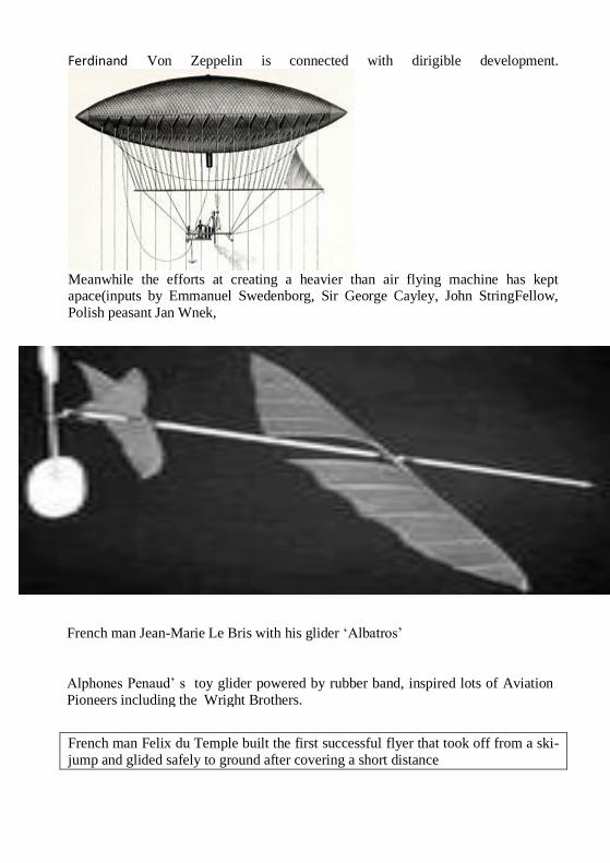
Meanwhile the efforts at creating a heavier than air flying machine has kept apace(inputs by Emmanuel Swedenborg, Sir George Cayley, John StringFellow,
Polish peasant Jan Wnek,
French man Jean-Marie Le Bris with his glider ‘Albatros’
Alphones Penaud’ s toy glider powered by rubber band, inspired lots of Aviation
Pioneers including the Wright Brothers.
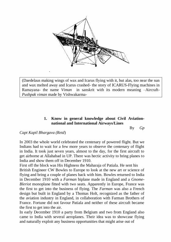
French man Felix du Temple built the first successful flyer that took off from a ski-
jump and glided safely to ground after covering a short distance
.
(Daedelaus making wings of wax and Icarus flying with it, but alas, too near the sun
and wax melted away and Icarus crashed- the story of ICARUS-Flying machines in
Ramayana- the name Viman in sanskrit with its modern meaning –Aircraft-
Pushpak viman made by Vishwakarma-
1. Know in general knowledge about Civil Aviation-
national and International Airways/Lines
By Gp
Capt Kapil Bhargava (Retd)
In 2003 the whole world celebrated the centenary of powered flight. But we Indians had to wait for a few more years to observe the centenary of flight
in India. It took just seven years, almost to the day, for the first aircraft to
get airborne at Allahabad in UP. There was hectic activity to bring planes to
India and show them off in December 1910.
First off the block was His Highness the Maharaja of Patiala. He sent his
British Engineer CW Bowles to Europe to look at the new art or science of
flying and bring a couple of planes back with him. Bowles returned to India
in December 1910 with a Farman biplane made in England and a Gnome-
Bleriot monoplane fitted with two seats. Apparently in Europe, France was
the first to get into the business of flying. The Farman was also a French
design but built in England by a Thomas Holt, recognized as the father of the aviation industry in England, in collaboration with Farman Brothers of
France. Fortune did not favour Patiala and neither of these aircraft became
the first to get into the air.
In early December 1910 a party from Belgium and two from England also
came to India with several aeroplanes. Their idea was to showcase flying
and naturally exploit any business opportunities that might arise out of

the demonstrations. The first of these to land in India was from Coventry’s
Humber Motor Company, famous for its cars especially used by the police
in UK. It included a leader, Capt WG Windham, two pilots - one French and
one English, and two mechanics also one French and one English. The
Humber Company asked the team to proceed to Allahabad immediately after it landed in Bombay by a merchant ship. This group with all its
packing cases set off for Allahabad with the intention of demonstrating the
aircraft at the Industrial & Agricultural Exhibition due to be held there
shortly. It arrived on December 5 and assembled the planes in five days at a
polo ground right next to the Exhibition Grounds. A local newspaper
reported the first flight in India as follows:
“The first actual flight was successfully attained by Mr. Davies in a
‘Bleriot’. On the 10th of December Mr.Davies had the machine ready and
early in the morning circled the polo ground at a height of twenty five or
thirty feet”
The paper added, “ Thus Allahabad has had the distinction of giving the
lead not only in India, but also to the whole of Asian Continent in
connection with the latest of scientific wonders”.
The aircraft ready to fly weighed five hundred pounds without the pilot and
cost £ 550/=, just under Rs 7,500/= at the rate existing then. Surely this
amount was affordable by many people at the time.
The second aircraft flew the next day, December 11, 1910, under the
control of the French pilot Henri Pequet and carried the first air passenger in
India. He was one of the sons of the Maharaja of Benares, obviously an
intrepid young man. But The Statesman of Calcutta, a newspaper still very well respected, published a different version of the flights in Allahabad. Its
issue of December 18 reported that Henri Pequet made the first flight in
India on December 17. According to the paper, Pequet flew the biplane over
the confluence of the Ganges and the Yamuna (Sangam) and also over
Allahabad Fort. The newspaper expected regular display flights to begin on
December 20 over the Exhibition Grounds and continue displays till January
6, 1911. The possibility of joyrides being given was also mentioned. By
then it was estimated that a total of five hours of flying had been
accumulated covering almost 50 miles. Henri Pequet was paid £.50/= per
hour of flying, provided each flight lasted longer than two minutes.
He is today recognised, especially by knowledgeable stamp collectors, as
the pilot to carry world’s first airmail from Allahabad to Naini just across the Yamuna river, and back to Allahabad. He carried 6,000 odd letters and
postcards, many of which were addressed to celebrities worldwide,
including King George V in England. If you can find one of these
postmarked covers or stamps with the words “First Aerial Post”, you can
sell it today for the price of a flat or a house.
Calcutta, the capital of British India before it was shifted to Delhi, was not
far behind in making aviation history. But perhaps news at the time did not
travel between cities fast enough. The Statesman of December 21, 1910 said
that the second flight in India was at Tollygunj, a suburb of Calcutta on
December 20. Baron de Caters flew the Bleriot monoplane over Tollygunj Club for fifteen minutes. The same day the Baron flew with a lady
passenger, Mrs NC Sen, who thus became the first woman in India to get
airborne. The paper had also claimed that Mrs Sen was the first woman in
the world to fly in a plane. But this claim was quite wrong, as by then in the
West it had become fashionable for society ladies to casually drop their
news of having dared a ride in a flying machine.
For December 28, Baron de Caters organised a flying display at Tollygunj.
This attracted almost all the able population of Calcutta willing to forego
work or other pleasures for a day. The Baron did the first few flights in the
Farman, gave rides to two ladies and several gentlemen. While this was
exciting enough, the next day, December 29, Jules Tyck set two national
records in his Bleriot. He became the first to fly over the city, including directly over the Government House. The second record was set when he
climbed to all of 700 feet above ground level. But Calcutta was in for more
excitement.
On January 6, 1911, a huge crowd gathered at the Maidan to witness Henri
Jullerot display his Boxkite developed by the British & Colonial Aeroplane
Company of Bristol, England. The crowds were reported the next day to
have been in excess of 100,000, perhaps even more than seen now-a-days at
Eden Garden for one day international cricket matches. Seats at the Race
Course’s Grand Stand of the Maidan were exorbitantly priced at Rs 5/=
each! The flight was cheered with gusto. But the show concluded fast
enough as the Boxkite had to be dismantled and taken to Aurangabad by train to demonstrate it to the Indian Army. Obviously, just like the armed
forces the world over, Indian Army was quick to realise the military
importance of new technology such as flying machines. The Boxkite was
assembled in open ground next to the Aurangabad railway station. Perhaps
world’s first reconnaissance flights took place in it on January 15 and 16 to
report on the forces opposing a Cavalry Brigade in the ongoing exercise.
The pilot, Henri Jullerot sat on the spar of the leading edge of the lower
wing with his feet on a rudder bar. The observer, Sefton Branckner sat close
behind, a bit higher and with his feet around the pilot. The reconnaissance
sorties were highly successful. But except for a few generals, including the
Commander-in-Chief of the Indian Army and the Chief of Staff, most army
officers did no think that the aeroplane had much use for them except perhaps for limited reconnaissance of enemy positions. This attitude persists
till today, only slightly moderated due to introduction of aviation within the
army itself. Meanwhile Baron de Caters and Jules Tyck took their aircraft
around the country and gave displays at many
towns. The show in Bangalore was on February 3, 1911 and in Madras on
February 18. The First World War soon interrupted any progress of aviation
in India for a while. Two Indians distinguished themselves in this war. Inder
Lal Roy joined the Royal Flying Corps in April 1917 at the tender age of
just over eighteen years. After receiving his training and the King’s Commission, he joined No. 56 Squadron in France but was shot down in
December. He was given up for dead but gained consciousness surrounded
by dead bodies. After recovery he returned to flying and shot down nine
German planes before losing his life in his last air combat. He was
posthumously awarded the Distinguished Flying Cross (DFC), the first
Indian to receive the honour. The other famous Indian pilot was Sardar
Hardit Singh Malik, who had also joined in April 1917. He was wounded in
November but returned to flying in time for the defence of London. He was
demobilised after the war and had a really distinguished career as a
diplomat. He was, not long ago, the senior-most citizen playing golf at the
Delhi Golf Club.
The Royal Air Force inaugurated its first station in India at Ambala. But the Indian Air Force (IAF) was launched by an act of the Governor General on
October 8, 1932. The A Flight of No. 1 Squadron came into existence on
April 1, 1933 under the command of an RAF officer on deputation. Its
senior-most Indian officer was Pilot Officer Subroto Mukherjee who later
became IAF’s first Indian Commander-in-Chief as an Air Vice Marshal and
then took over as the Chief of Air Staff as an Air Marshal. His successor
was Air Marshal AM (Aspy) Engineer.
Aspy Engineer had started his flying career rather early. He and RN Chawla
were the first Indians to fly a De Havilland Moth from India to England.
They left on March 3 and arrived on March 20,1930. Aspy’s return flight
from England was to contest for the Aga Khan Prize of £ 500 for flying between the two countries in either direction.
JRD Tata took off in a Gypsy Moth on May 3 from Karachi for England.
Theycrossed each other at Aboukir in Egypt where Aspy was in some
trouble due to problems with some spark plugs. JRD helped him out. Aspy
arrived in India when JRD had just reached Paris. Presumably because he
took longer, JRD Tata came second to Aspy who won the Prize. But JRD
was never a loser. After protracted negotiations with the Government of
India, he started his airmail service under the name of Tata Aviation, later to
become Air India. He piloted the first carriage of mail from Karachi to
Bombay on October 15, 1932. The initial efforts at passenger carriage
in India were limited to British owned or funded airlines, such as the Indian
Trans-Continental Airways and Indian National Airways. But as the need for more air travel facilities became paramount, permission was given to
almost anyone wanting to start an airline. This resulted in a profusion of
quick start airlines, which competed with each other perhaps by cutting
fares and downtime for maintenance. Soon enough the situation became
untenable. Eventually the Air Corporation Act of 1953 was passed

nationalising all airlines. Air India International took over the international
traffic and Indian Airlines Corporation the domestic. While the two national
airlines still operate, the domestic scene changed recently once again as a
result of economic reforms. The prospects of passenger and cargo traffic in
India can only be described now as rosy. Meanwhile in December 1940, Seth Hirachand Walchand launched
Hindustan Aircraft Limited (HAL) with the help of an American and the
State of Mysore. Dr VM Ghatage, India’s first aircraft designer soon joined
the company and designed the G-1 Glider, the first such venture in India.
However, due to World War II, the G-1 did not get used and Dr Ghatage
became the first to start teaching aeronautical engineering at the Indian
Institute of Science. He rejoined HAL after independence and designed
India’s first powered aircraft the HT-2. In time, HAL became a Corporation
with several Divisions in the country. The first fighter aircraft designed in
the country was the HF-24, though a German team led by Prof KW Tank
largely managed it. Many aircraft types have been produced under licence
and in large numbers. Lately the country has come into its own in designing aircraft, engines, avionics and accessories. The success story of indigenous
designs restarted with the ALH, now named Dhruv, a helicopter for all the
defence services and also meant for civilian use. This has been followed by
the Light Combat Aircraft and the Intermediate Jet Trainer.
India has so far produced transport aircraft only under licence from foreign
sources. These include the Avro- 748, Dornier Do-228 and the Partinavia.
But recently National Aerospace Laboratories developed the Saras, a twin
turbo-prop commuter aircraft. It is expected to obtain its certification in the
next two or three years. HAL is also likely to embark on the development of
a Light Armed helicopter and a100-seater aircraft with capabilities for other
roles, perhaps in collaboration with Russia. The prospects of aviation in India are on the right path and should gladden
the heart of any aviation enthusiast.
2. Know the theory of flight
Basic Principles of Flight
4 forces of flight:
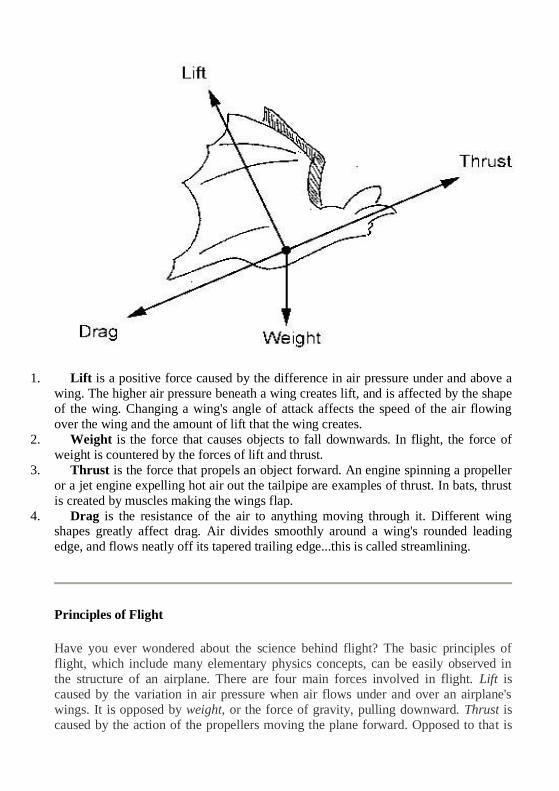
1. Lift is a positive force caused by the difference in air pressure under and above a
wing. The higher air pressure beneath a wing creates lift, and is affected by the shape
of the wing. Changing a wing's angle of attack affects the speed of the air flowing
over the wing and the amount of lift that the wing creates.
2. Weight is the force that causes objects to fall downwards. In flight, the force of
weight is countered by the forces of lift and thrust.
3. Thrust is the force that propels an object forward. An engine spinning a propeller
or a jet engine expelling hot air out the tailpipe are examples of thrust. In bats, thrust
is created by muscles making the wings flap.
4. Drag is the resistance of the air to anything moving through it. Different wing shapes greatly affect drag. Air divides smoothly around a wing's rounded leading
edge, and flows neatly off its tapered trailing edge...this is called streamlining.
Principles of Flight
Have you ever wondered about the science behind flight? The basic principles of
flight, which include many elementary physics concepts, can be easily observed in
the structure of an airplane. There are four main forces involved in flight. Lift is
caused by the variation in air pressure when air flows under and over an airplane's
wings. It is opposed by weight, or the force of gravity, pulling downward. Thrust is
caused by the action of the propellers moving the plane forward. Opposed to that is
drag, caused by air resistance. If lift is more than weight, the plane will rise. If thrust
is more than drag, the plane will slowly accelerate.
Airplane wings are designed to take advantage of lift. They are shaped so that air has
to travel farther over the top of the wing than underneath it. The reason for this is
explained in Bernoulli's Principle, which states that an increase in the velocity
(speed) of air or any fluid results in a decrease in pressure. When the air has to travel
farther over the top of the airplane wing, it must also travel faster, which results in
lower pressure. The shorter distance under the wings results in higher pressure,
causing the airplane to move upward.
You can demonstrate Bernoulli's Principle with a piece of notebook paper. Fold the
paper in half the short way, so that you have a tent shape. Now, set the tent on a table
and blow very carefully (slow and firm) through one of the open ends. The sides of
the tent will stick together but the tent won't collapse. This occurs because the velocity of your breath is more than that of the air outside of the tent, causing lower
pressure. The air outside the tent has higher pressure and pushes the sides of the tent
inward.
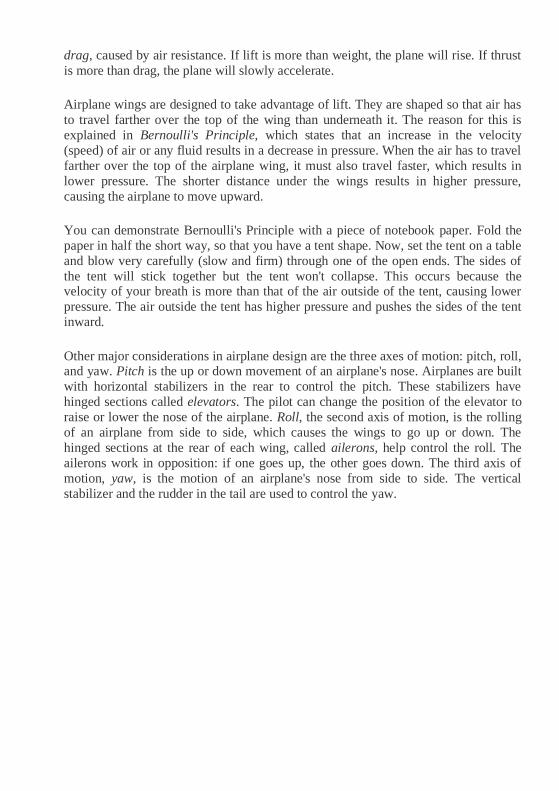
Other major considerations in airplane design are the three axes of motion: pitch, roll, and yaw. Pitch is the up or down movement of an airplane's nose. Airplanes are built
with horizontal stabilizers in the rear to control the pitch. These stabilizers have
hinged sections called elevators. The pilot can change the position of the elevator to
raise or lower the nose of the airplane. Roll, the second axis of motion, is the rolling
of an airplane from side to side, which causes the wings to go up or down. The
hinged sections at the rear of each wing, called ailerons, help control the roll. The
ailerons work in opposition: if one goes up, the other goes down. The third axis of
motion, yaw, is the motion of an airplane's nose from side to side. The vertical
stabilizer and the rudder in the tail are used to control the yaw.
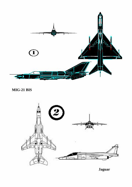
MIG-21 BIS
Jaguar
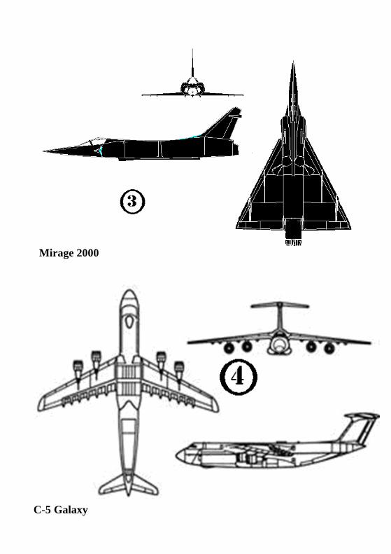
Mirage 2000
C-5 Galaxy
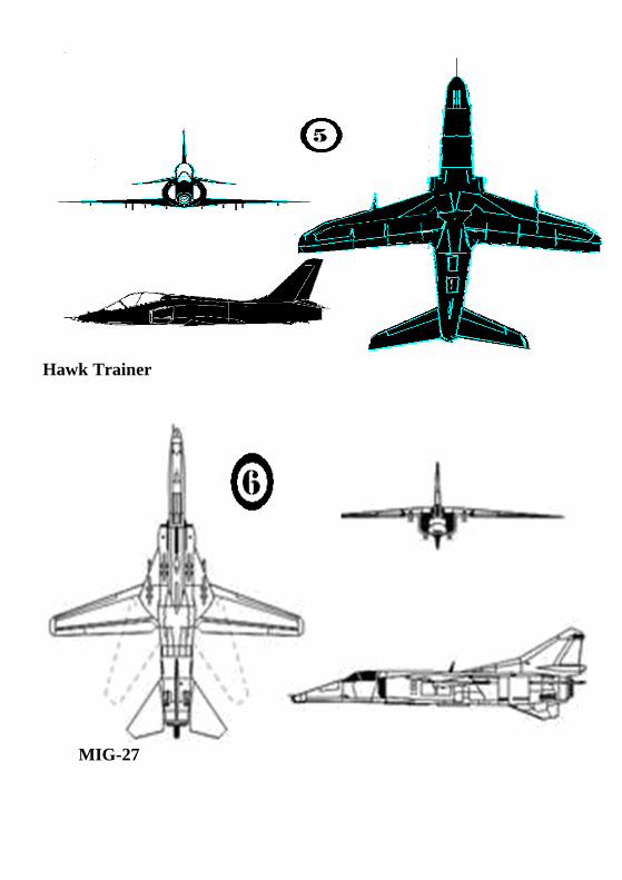
Hawk Trainer
MIG-27

C-130 HERCULES
ANTONOV AN-32
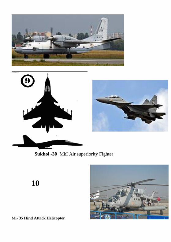
Sukhoi -30 MkI Air superiority Fighter
10
Mi- 35 Hind Attack Helicopter
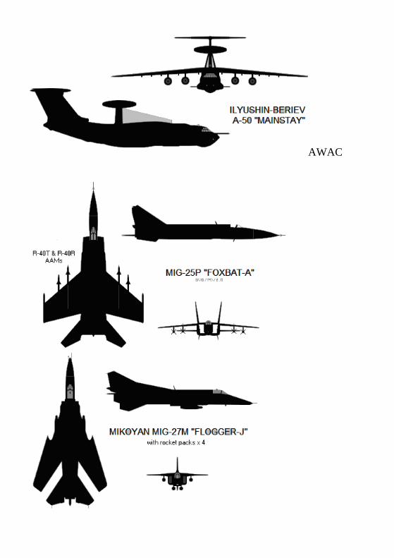
AWAC
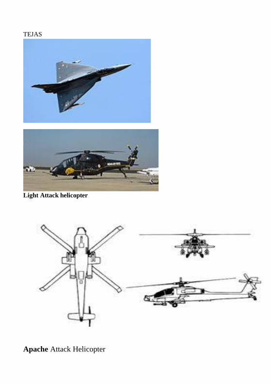
TEJAS
Light Attack helicopter
Apache Attack Helicopter
•
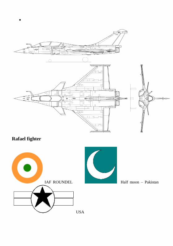
Rafael fighter
IAF ROUNDEL Half moon – Pakistan
USA

RAF -UK
VT- civilian symbol for Indian civilian Aircraft
N- USA
F- FRANCE
Civil Aircrafts operated by Indian carriers
Air Bus 300 series (319-320-321)
AIRBUS 320
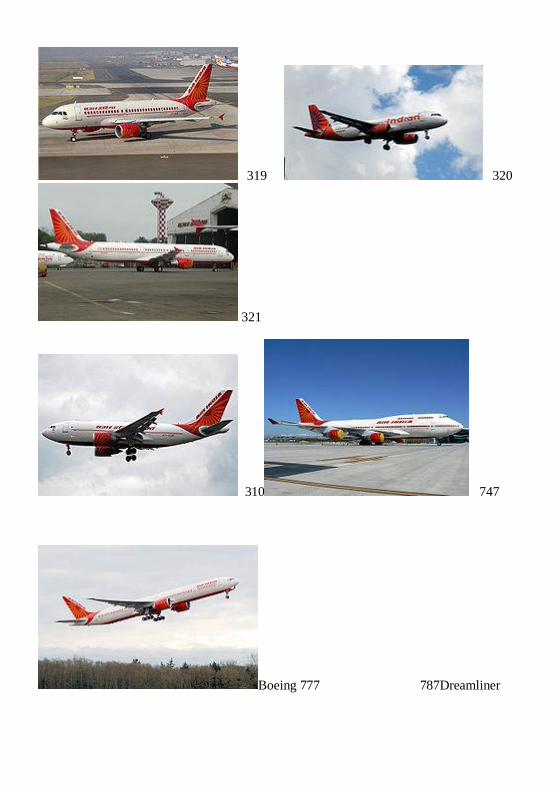
319 320
321
310 747
Boeing 777 787Dreamliner
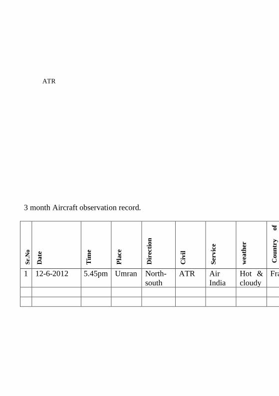
ATR
3 month Aircraft observation record.
Sr.
No
Date
Tim
e
Pla
ce
Dir
ecti
on
Civ
il
Servic
e
weath
er
C
ou
ntr
y
of
o orig
in
1 12-6-2012 5.45pm Umran North-
south
ATR Air
India
Hot &
cloudy
France

SCHOOL OF MECHANICAL ENGINEERING
DEPARTMENT OF AERONAUTICAL ENGINEERING
UNIT – I- AIRCRAFT
STRUCTURES – SA
UNIT 2-FUNDAMENTALS OF AERONAUTICAL
ENGINEERING-SAEA1202
7
NOTES
Lecture 1.
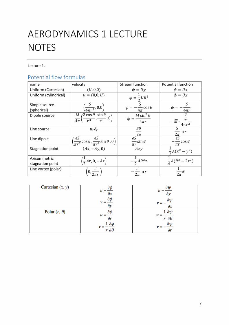
Potential flow formulas name velocity Stream function Potential function
Uniform (Cartesian) (𝑈, 0,0) 𝜓 = 𝑈𝑦 𝜙 = 𝑈𝑥
Uniform (cylindrical) 𝑢 = (0,0, 𝑈) 𝜓 =
1
2𝑈𝑅2
𝜙 = 𝑈𝑥
Simple source (spherical)
(𝑆
4𝜋𝑟2, 0,0) 𝜓 = −
𝑆
4𝜋cos 𝜃 𝜙 = −
𝑆
4𝜋𝑟
Dipole souirce 𝑀
4𝜋(2 cos𝜃
𝑟3,sin𝜃
𝑟3, 0) 𝜓 =
𝑀 sin2 𝜃
4𝜋𝑟
−�⃗⃗� ∙
𝑟 𝑟
4𝜋𝑟2
Line source 𝑢𝑟𝑒 𝑟 𝑆𝜃
2𝜋
𝑆
2𝜋ln 𝑟
Line dipole (
𝜖𝑆
𝜋𝑟2cos 𝜃 ,
𝜖𝑆
𝜋𝑟2sin𝜃 , 0)
𝜖𝑆
𝜋𝑟sin 𝜃 −
𝜖𝑆
𝜋𝑟cos 𝜃
Stagnation point (𝐴𝑥,−𝐴𝑦, 0) 𝐴𝑥𝑦 1
2𝐴(𝑥2 − 𝑦2)
Axisummetric stagnation point
(1
2𝐴𝑟, 0, −𝐴𝑧) −
1
2𝐴𝑅2𝑧
1
4𝐴(𝑅2 − 2𝑧2)
Line vortex (polar) (0,
Γ
2𝜋𝑟 ) −
Γ
2𝜋ln 𝑟
Γ
2𝜋𝜃
AERODYNAMICS 1 LECTURE

8
Introduction - Viscocity
o Stall
o Dynaic stall
o Separation
o Laminar/turbulent flow
o Pressure gradients
What will we study? - Potential flow theory (incompressible)
o 2D building blocks; learng to analyse aerofoil properties
o Its extension to 3D
- Wind tunnel theory
- Boundary layer theory
o Estimate viscous drag
- Aerofoil behaviour
o Geometric properties
- Compressibility effects
- Intro to CFD
o Terminology. Solutions. Pit falls, advantages
Challenges: - incompressible aerodynamics is lots of maths
- What we see mathematically is very simplified; and lost physical reality.
Assignments : 3 assignments (5,10,10) released weeks 1,5,10 (last is group)
3 labs (5,`10 ,5)
- Week 2/3 cylinder flow
- Week 5/6 2D aerofoil flow
- Week 10/11 3D flow
o Reports due one week after lab session
Weekly submission of exercise (5)
Exam (50%) (need 40% in exam)
Resources: - Anderson; fundementals of aerodynamics
- Abbott: theory of wing sections
- Kuethe; foundations of aerodyanamics
- Bertin; aerodynamics for engineers
- Doug’s aerodynamics for students
9
Current assignment: - Page limit
- 2 parts
o Part A: requies you to solve a problem (which aerofoil to use)
- Part B
o Research and literature survey
- Submission 2PM Thursday week 4
- Intermediate submission with penalty applied (week 2 and 3)
Lecture 2. Thursday, 28 July 2016
Assignment: just assume unitary span; only have lift and weight forces 𝐿
𝑢𝑛𝑖𝑡 𝑠𝑝𝑎𝑛=
1
2𝜌𝑈2(𝑐ℎ𝑜𝑟𝑑)𝐶𝐿
Aerofoil features
Air mach numbers Subsonic 𝑀 < 1
Supersonic 𝑀 > 1
Sonic 𝑀 = 1
Hypersonic 𝑀 > 5
Transonic 0.75 < 𝑀 < 1.2
Introduction: - Most important phenomenon in a wind tunnel studied is flow around wing
- Several major improvements in aircraft aerodynamics have resulted from the study of new
forms of wing sections
o (make sure you know temp and pressure for wind tunnel experiments)
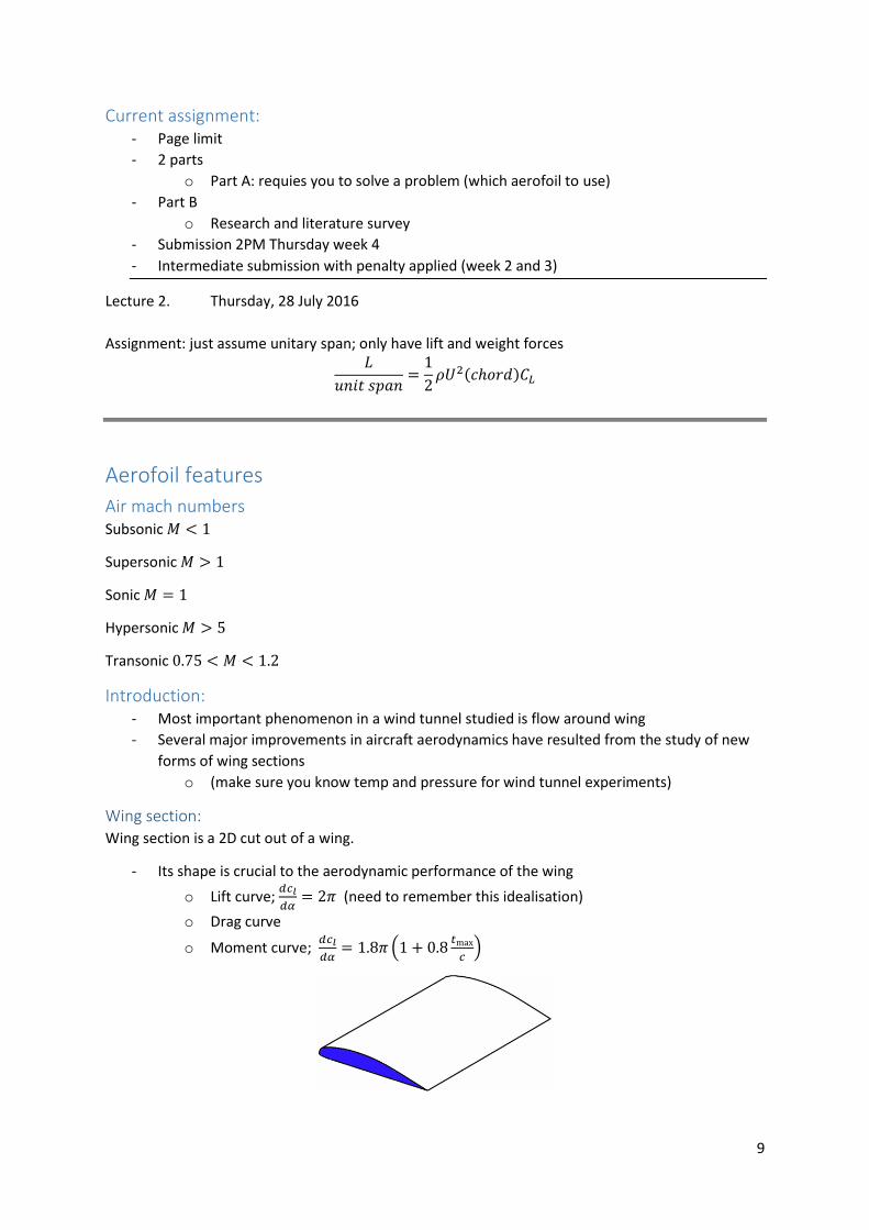
Wing section: Wing section is a 2D cut out of a wing.
- Its shape is crucial to the aerodynamic performance of the wing
o Lift curve; 𝑑𝑐𝑙
𝑑𝛼= 2𝜋 (need to remember this idealisation)
o Drag curve
o Moment curve; 𝑑𝑐𝑙
𝑑𝛼= 1.8𝜋 (1 + 0.8
𝑡max
𝑐)
10
𝛼 is the angle of attack
2D flow uses lower case 𝑐𝑙 , 𝑐𝑑; 3D flow upper case 𝐶𝐿; 𝐶𝐷
Why Aerofoils work Bernoulli: longer travel time on top surface (incorrect)
Newton: air hitting lower surface of wing and reaction force ; assuming that 𝛼 is important to
Newton:
1. In order for the aerofoil to go up, air must go down (true)
2. So angle of attack is important (top plays no part) (half true)
Bernoulli:
1. Air is redirected up on top of wing (true)
2. Air travels further on top (true; not relevant)
3. Air must come back to meet bottom surface at same time (FALSE)
4. Therefore air on top is faster (true, not for given reason)
5. By Bernoulli’s equation, faster air on top exerts less pressure (true, not for given reason)
Reality:
Need both to explain
Air is forced down (downwasg) due to a speeding up of air on the top of the wing; (Bernoulli effect
phenomenon)
The effect is so pronounced that air passing over the wing passes around wing faster that those on
bottom.
- Calculation shows that positive pressure on the bottom of wing is insufficient for the entire
explanation
- It is negative pressure on top of the wing which accounts for most lift
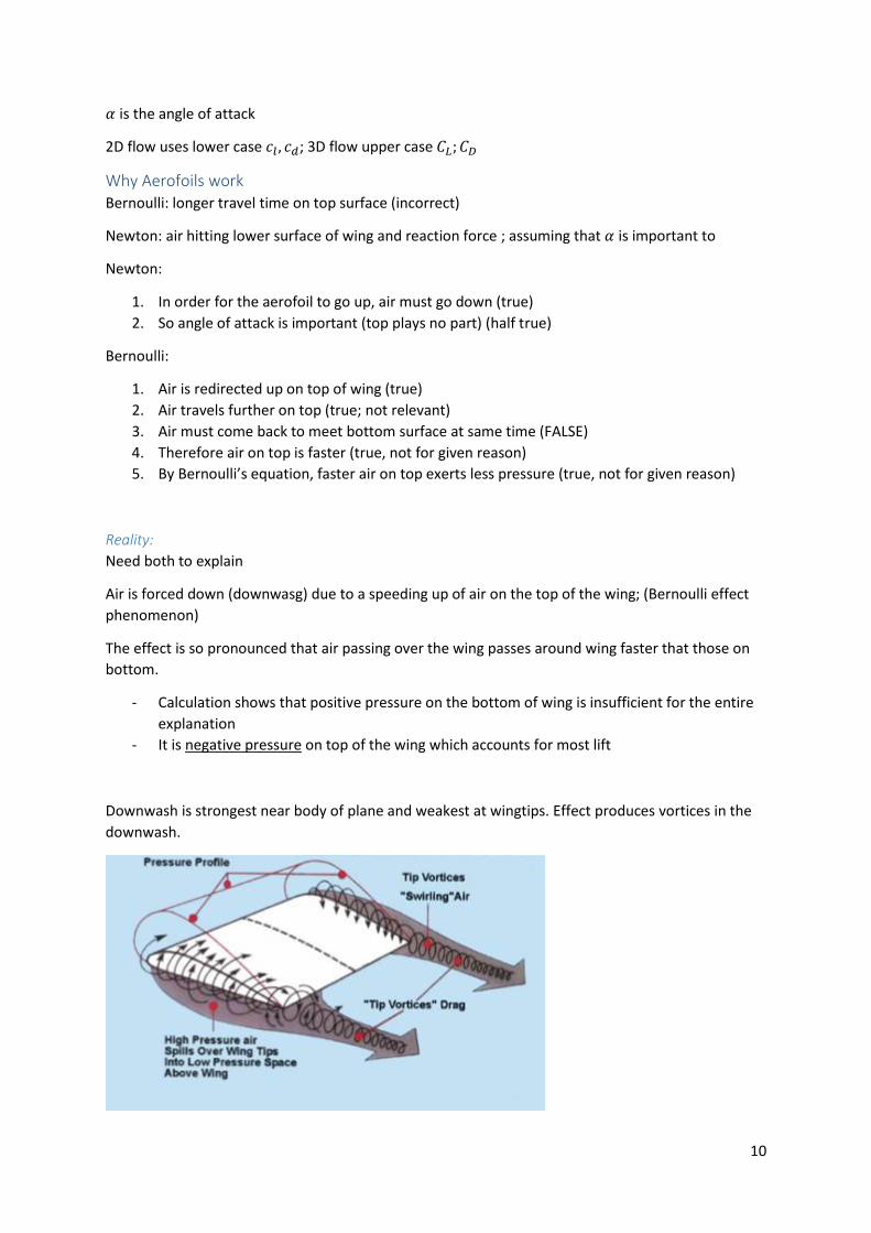
Downwash is strongest near body of plane and weakest at wingtips. Effect produces vortices in the
downwash.

11
Boundary layer
Most of flow field does not be effected by wing;
Only thin boundary layer; if we assume boundary layer is not there we can get a reasonable
approximation of lift, but drag is non existent (as no viscosity)
𝐶𝐷 = 𝐶𝐷0+ 𝑘𝐶𝐿
2
Wing section types: Different section types fro different applications; the correct type must be chosen, and is then used
to create wing’s geometry
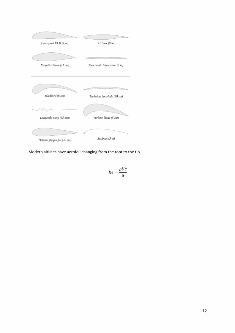
12
Modern airlines have aerofoil changing from the root to the tip.
𝑅𝑒 =𝜌𝑈𝑐
𝜇
13
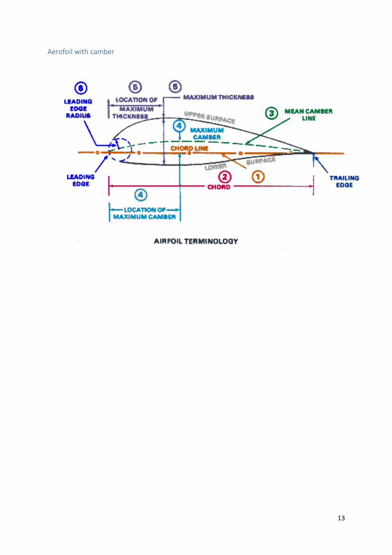
Aerofoil with camber
14
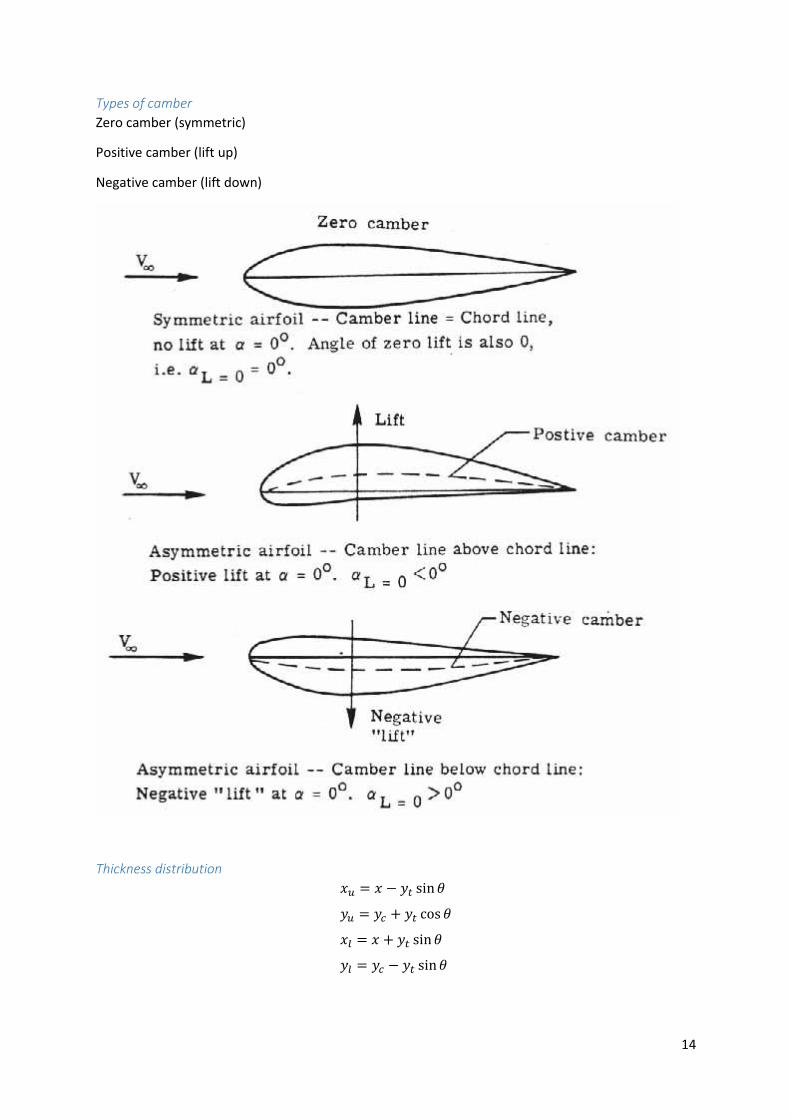
Types of camber
Zero camber (symmetric)
Positive camber (lift up)
Negative camber (lift down)
Thickness distribution
𝑥𝑢 = 𝑥 − 𝑦𝑡 sin𝜃
𝑦𝑢 = 𝑦𝑐 + 𝑦𝑡 cos 𝜃
𝑥𝑙 = 𝑥 + 𝑦𝑡 sin𝜃
𝑦𝑙 = 𝑦𝑐 − 𝑦𝑡 sin𝜃
15
General aerofoil specifications:
Low speed
Hobby aircraft, UAV
Less than 500000𝑅𝑒
Selif, Lissaman famous
Subsonic:
Large leading edge nose radius
Performance invariant to small AoA change
No major drag sacrifice
Max mach 0.75/0.8
Transonic
Maximisation of drag divergence mach number 𝑑𝐶𝑑
𝑑𝑀= 0.1
Supersonic
1 < 𝑀 < 5 mach number
Reduce wave drag
Small thickness (3.36% for F104)
Natural laminar aerofoil: (First used in P51)
- Lower skin drag
- Minimum pressure point as far downstream as possible
- Manage pressure gradient
- External disturbances (Tollmien-Schlichting waves (instability))
Multi element
- High lift→ increased weight→ increased cost
- Single, double and triple element (each increasing in weight and cost)
- But about 0.1 increase in 𝑐𝑙 is roughly 1° less in angle in approach, so we don’t need as big a
landing gear
Morphing
- Change shape
- Alternative to multi element
NACA Aerofoil
NACA 4 series:
- Ground breaking as it parametrised the aerofoil
The geometry equation is:
𝑦𝑡 = 𝑎0√𝑥 − 𝑎1𝑥 − 𝑎2𝑥2 + 𝑎3𝑥
3 − 𝑎4𝑥4
- The square root helps with the leading edge nose radius:
16
𝑅𝐿𝐸 =
[1 + (𝑑𝑡𝑑𝑥
)2
]
32
𝑑2𝑡𝑑𝑥2
≈ 1.1019𝑡max2
NACA2412; max camber = 2%; location from leading edge=4
10; maximum thickness 𝑡 = 12%
- Issues with camber line, extreme values of camber, extreme forward camber locations
NACA 5 series:
NACA 23012 last 2 digits are thichness as a percentage of the chord. The others are parametrised as
coefficients
𝑦𝐶 =Ⓒ((
𝑘1
6(𝑥3 − 3𝑚𝑥2 + 𝑚2(3 − 𝑚)𝑥)
𝑘1𝑚3
6(1 − 𝑥)
)
NACA 6 series:
NACA 662-215
- 1st digit indicated 6 series
- 2nd is the chordwise position of the minimum pressure in 1/10 of the chord for symmetrical
aerofoil at 𝑐𝑙 = 0
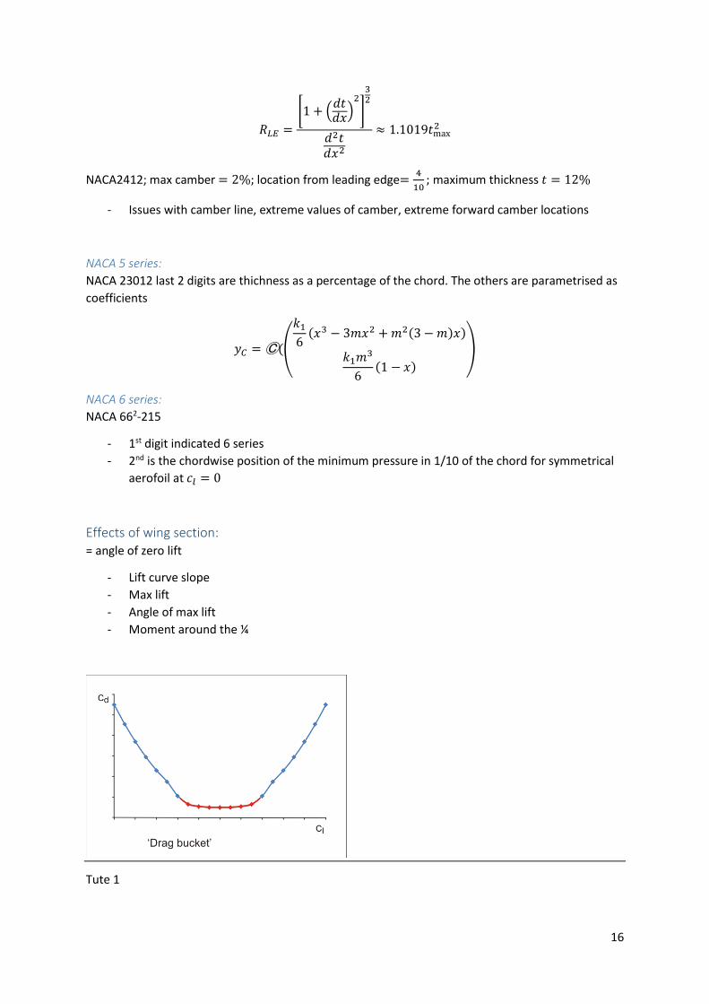
Effects of wing section: = angle of zero lift
- Lift curve slope
- Max lift
- Angle of max lift
- Moment around the ¼
Tute 1
17
Writing reports - Simplicity and clarity
- Write a few drafts
Lab report Components: - Abstract
- Introduction
- Methods
- Results
- Discussion
- Conclusion
Structure Title page
Abstract/summary
Intro
Methodology
Findings/results
Analysis
Summary/conclusion
References
Appendices
- Write shorthand to sound scientific/objective
- Facts and details rather than analysis
- Imply analysis and reasoning without making argument explicit
- Assume reader will read meaning into text
- Good usage, spelling, grammar and punctuation
Components: Intro: background/objectives, scope and limits, previous work/research; important background
information, research aims, (how does lab fit in with body of work)
Method: procedure/material
Results: data, tables, figures, calculations
Discussion: link to intro, interpretation, alternative explanations
Conclusion: summary main point
References: sources
18
Where to start:
Start with data, not intro
How to display the data to be meaningful and concise
Trends in figures
Connect results analysis to theory
Theory:
- Which research question did you set out to answer
- Expected answer or assumptions
o Hypothesis
o Designed to prove
Methods:
- Accurate and complete account of method
Results
- Present data
- State in verbal as well as visual
- Draw attention to key points
- Number/title tables/graphs
- Appendix for raw data or complex calculations
Conclusion:
- Short and to the point
- State what you know
- No new information should be disclosed
- Tie into the introduction
Cover page:
- Neat and clean
- Typed
- Make a good impression
- Include
o Title of lab
o Name, SID; lab parternes
o Date
Technical writing language:
- Impersonal; avoid first person
19
Common mistakes
- Don’t rewrite lab sheet
o There are many plotters which do a better job
o If using matlab, don’t put a grey background
- Don’t use default excel style plots (find better ones)
- Write meaningful figure captions
- Computer spell checks can’t recognise gibberish
- Don’t print table and graph. Graph has information, put table in the appendix
- Negative drag is not a thing‼!
- Incorrect referencing: reference has to appear in the text otherwise it’s a bibliography
- Error analysis (should contain error analysis)
o Sources of errors not listed (realistic errors)
o Error bars in results (X and Y)
- Plots
o Include units, labels
o Make possible to read
o Discrete points
o How to connect the points
- No referencing of figures/tables in text
- Don’t see “as seen in figure below”, say “in figure 3”
- Reference figures/data from external sights (or it’s plagiarism)
- Comparison to literature
o Not evident
o Severely lacking
o Not mentioning who comparing with
- Work on english
Lecture 3. Tuesday, 2 August 2016
𝐿 =1
2𝜌𝑈2𝑆𝐶𝑙 = 𝜌𝑈Γ
Aerofoils (again)
Leading edge nose radius
- Small leading edge radius has sharp stall break
- Large leading edge radius has gentle stall break
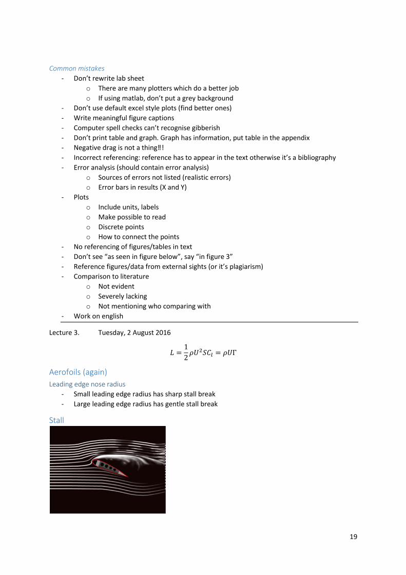
Stall
20
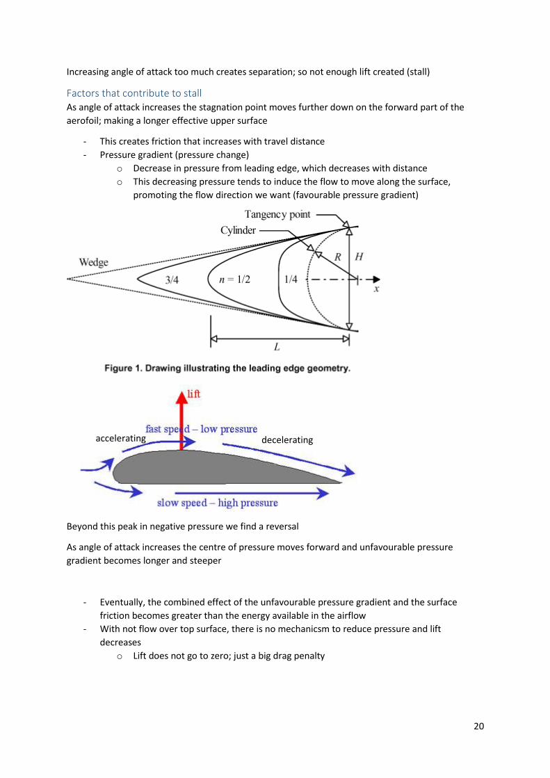
Increasing angle of attack too much creates separation; so not enough lift created (stall)
Factors that contribute to stall As angle of attack increases the stagnation point moves further down on the forward part of the
aerofoil; making a longer effective upper surface
- This creates friction that increases with travel distance
- Pressure gradient (pressure change)
o Decrease in pressure from leading edge, which decreases with distance
o This decreasing pressure tends to induce the flow to move along the surface,
promoting the flow direction we want (favourable pressure gradient)
Beyond this peak in negative pressure we find a reversal
As angle of attack increases the centre of pressure moves forward and unfavourable pressure
gradient becomes longer and steeper
- Eventually, the combined effect of the unfavourable pressure gradient and the surface
friction becomes greater than the energy available in the airflow
- With not flow over top surface, there is no mechanicsm to reduce pressure and lift
decreases
o Lift does not go to zero; just a big drag penalty
accelerating decelerating
21
Reducing stall abruptness: - Roundess of leading edge acts as a barrier to flow at high angle of attack
- Stall stripes
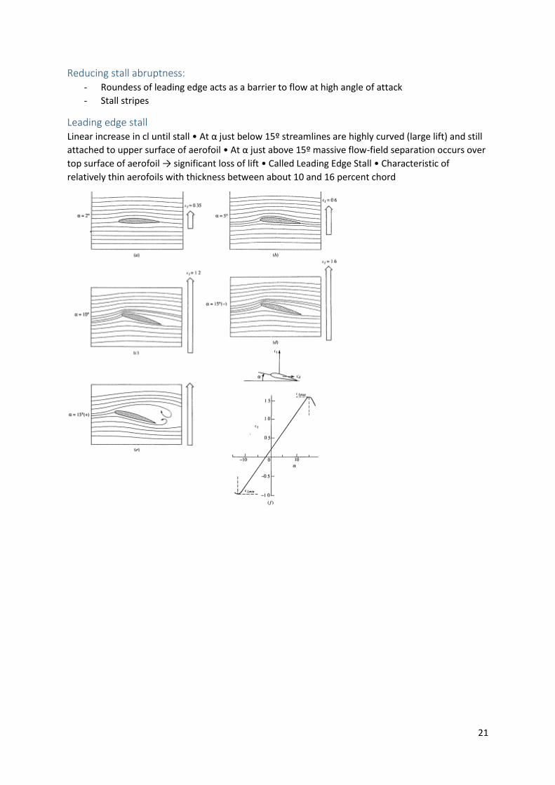
Leading edge stall Linear increase in cl until stall • At α just below 15º streamlines are highly curved (large lift) and still
attached to upper surface of aerofoil • At α just above 15º massive flow-field separation occurs over
top surface of aerofoil → significant loss of lift • Called Leading Edge Stall • Characteristic of
relatively thin aerofoils with thickness between about 10 and 16 percent chord
22
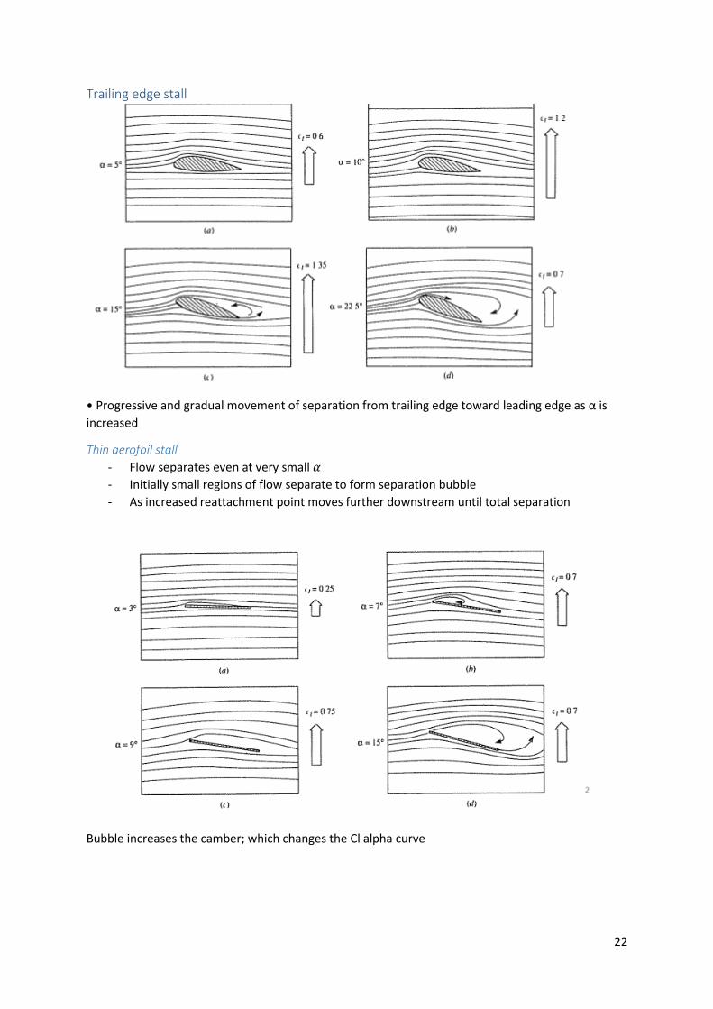
Trailing edge stall
• Progressive and gradual movement of separation from trailing edge toward leading edge as α is
increased
Thin aerofoil stall
- Flow separates even at very small 𝛼
- Initially small regions of flow separate to form separation bubble
- As increased reattachment point moves further downstream until total separation
Bubble increases the camber; which changes the Cl alpha curve
23
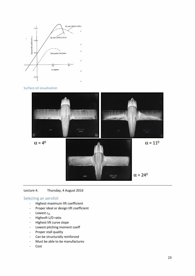
Surface oil visualisation
Lecture 4. Thursday, 4 August 2016
Selecting an aerofoil - Highest maximum lift coefficient
- Proper ideal or design lift coefficient
- Lowest 𝑐𝑑
- Highesft L/D ratio
- Highest lift curve slope
- Lowest pitching moment coeff
- Proper stall quality
- Can be structurally reinforced
- Must be able to be manufactures
- Cost
24
- Other design requirements
- Integration of aerofoils along span
Maximising lift - 2 parameters critical and both dictated by pressure distribution
o Boundary layer separation
o Onset of supersonic flow
- Upper surface is most critical
- Try and achieve constant pressure across top surface
- Reduce shock strength and wave drag
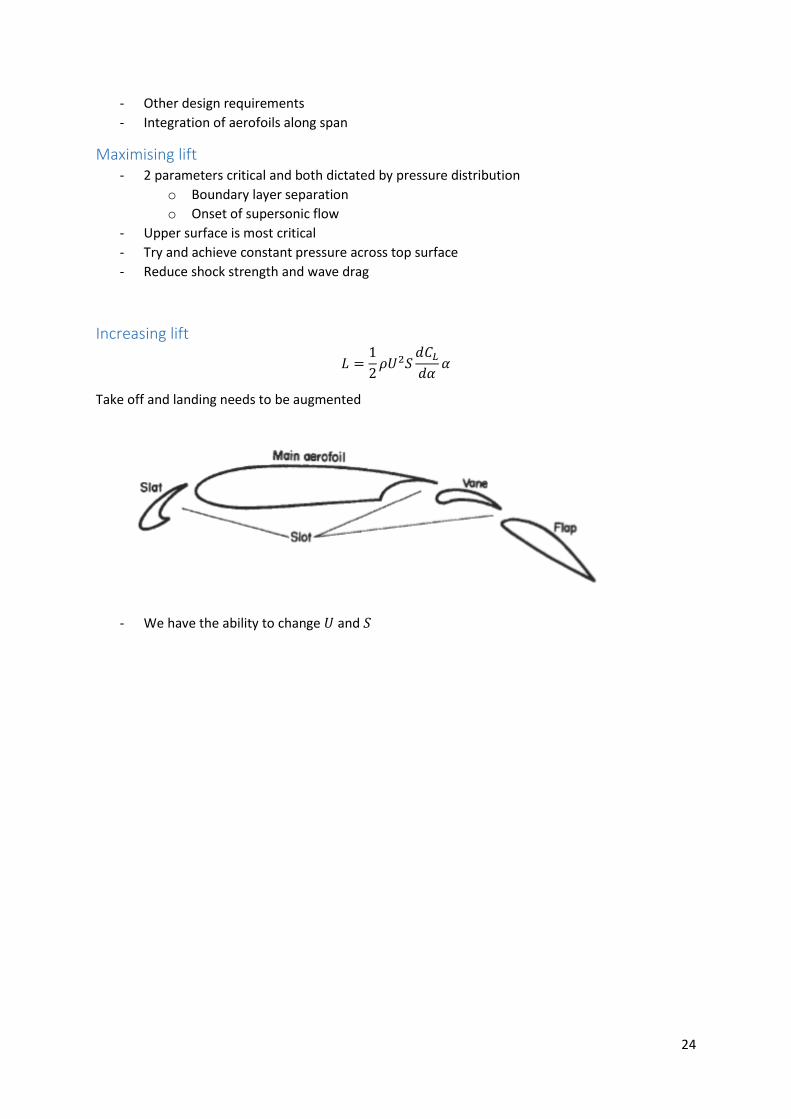
Increasing lift
𝐿 =1
2𝜌𝑈2𝑆
𝑑𝐶𝐿
𝑑𝛼𝛼
Take off and landing needs to be augmented
- We have the ability to change 𝑈 and 𝑆
25
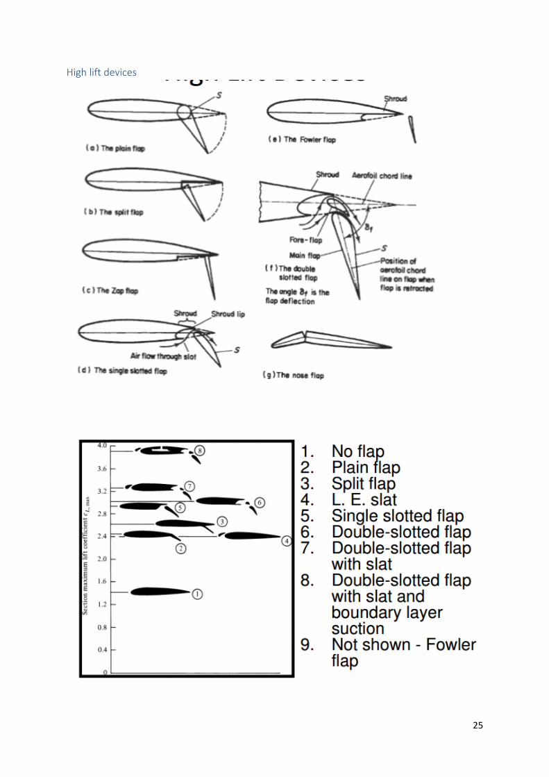
High lift devices
26
Common ones are
- Simple flap
o Increase camber and angle
- Fowler flap
o Increase camber, angle of incidence and wing area
- Nose flap
o Increase camber
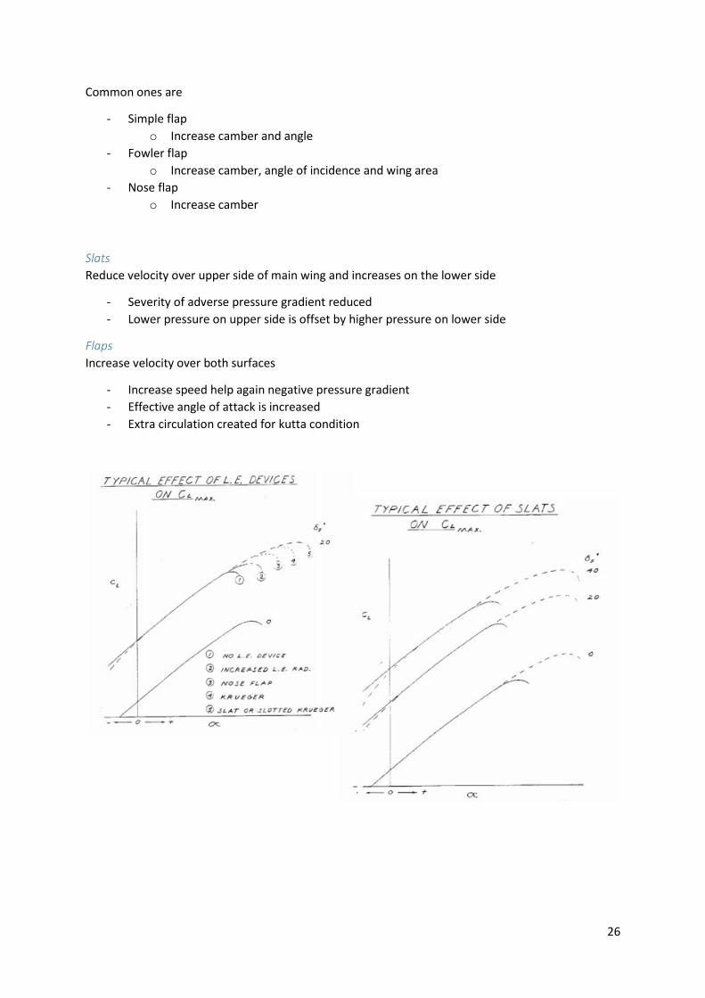
Slats
Reduce velocity over upper side of main wing and increases on the lower side
- Severity of adverse pressure gradient reduced
- Lower pressure on upper side is offset by higher pressure on lower side
Flaps
Increase velocity over both surfaces
- Increase speed help again negative pressure gradient
- Effective angle of attack is increased
- Extra circulation created for kutta condition
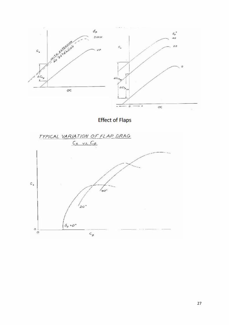
27
28
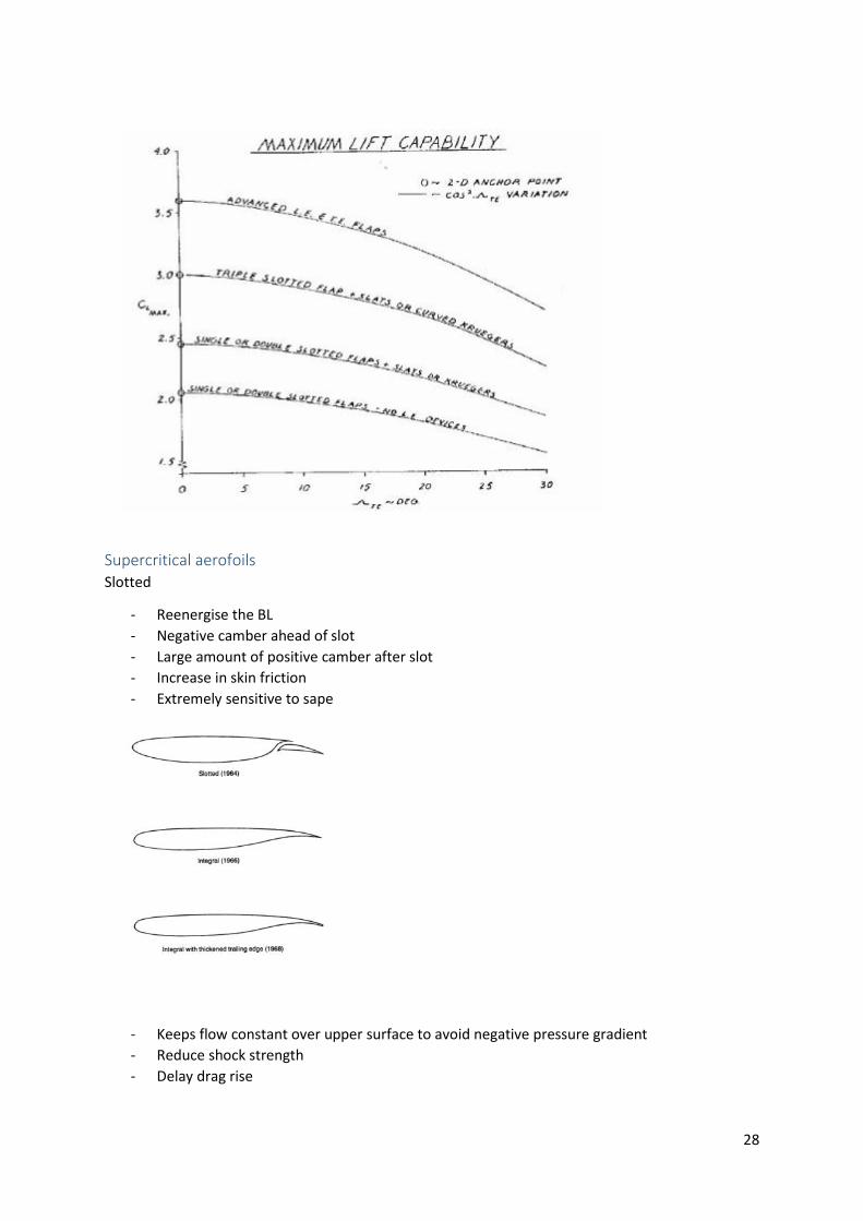
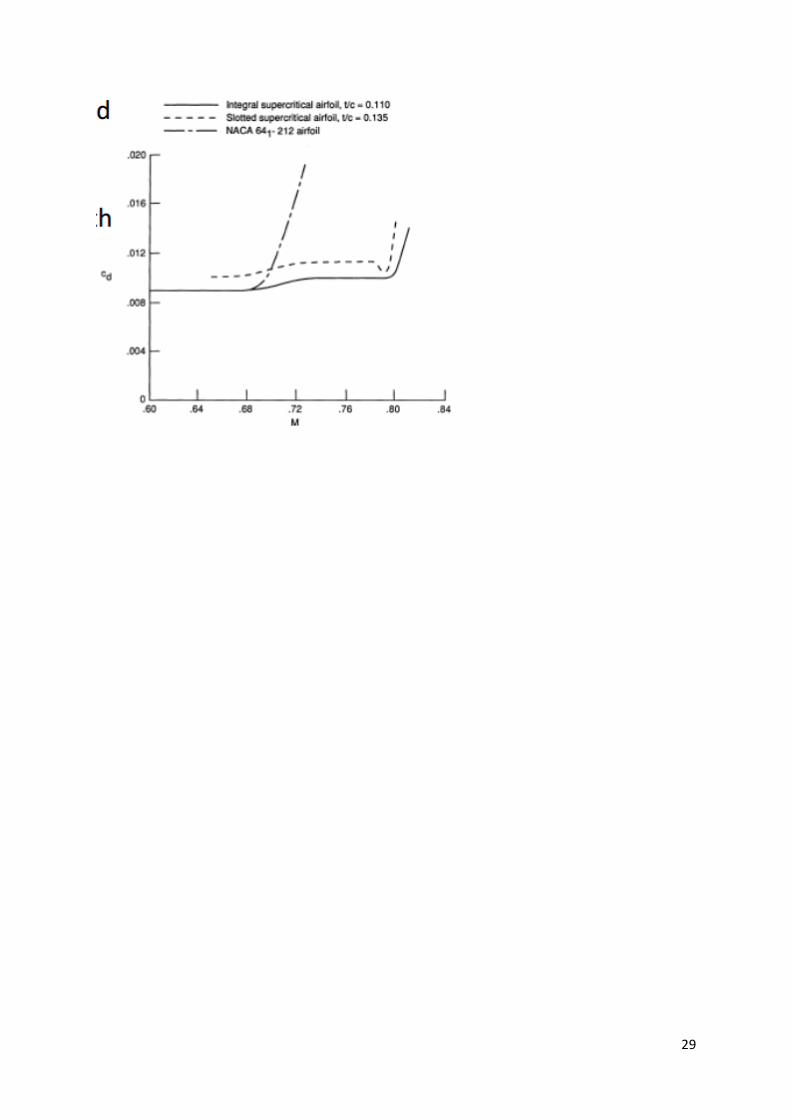
Supercritical aerofoils Slotted
- Reenergise the BL
- Negative camber ahead of slot
- Large amount of positive camber after slot
- Increase in skin friction
- Extremely sensitive to sape
- Keeps flow constant over upper surface to avoid negative pressure gradient
- Reduce shock strength
- Delay drag rise
29

30
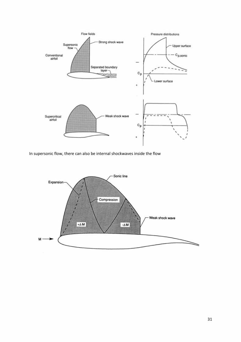
Standard vs supercritical aerofoil
31
In supersonic flow, there can also be internal shockwaves inside the flow
32
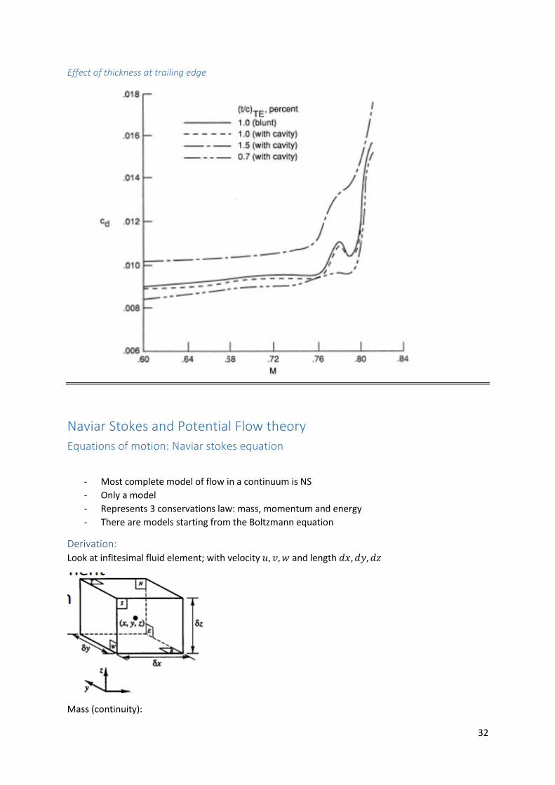
Effect of thickness at trailing edge
Naviar Stokes and Potential Flow theory
Equations of motion: Naviar stokes equation
- Most complete model of flow in a continuum is NS
- Only a model
- Represents 3 conservations law: mass, momentum and energy
- There are models starting from the Boltzmann equation
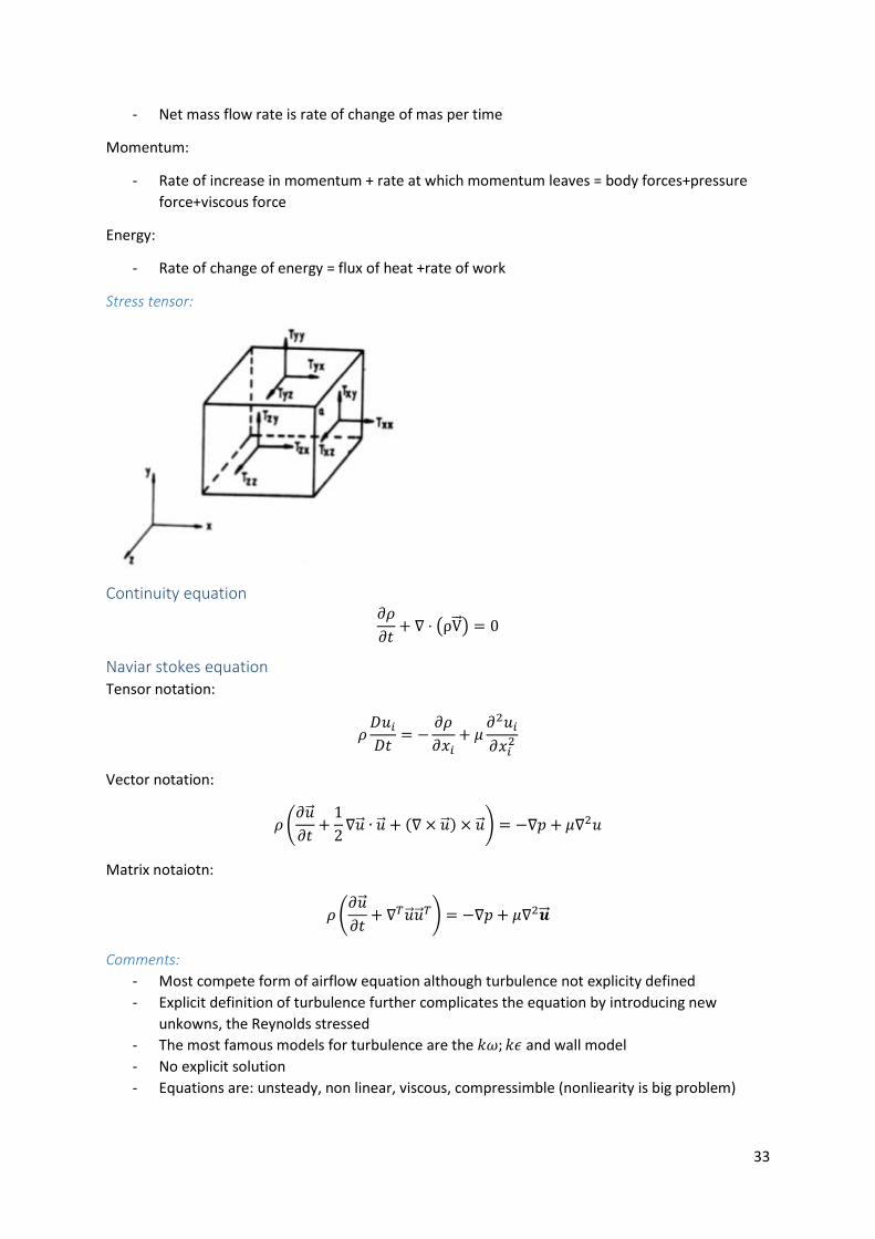
Derivation: Look at infitesimal fluid element; with velocity 𝑢, 𝑣, 𝑤 and length 𝑑𝑥, 𝑑𝑦, 𝑑𝑧
Mass (continuity):
33
- Net mass flow rate is rate of change of mas per time
Momentum:
- Rate of increase in momentum + rate at which momentum leaves = body forces+pressure
force+viscous force
Energy:
- Rate of change of energy = flux of heat +rate of work
Stress tensor:
Continuity equation 𝜕𝜌
𝜕𝑡+ ∇ ⋅ (ρV⃗⃗ ) = 0
Naviar stokes equation Tensor notation:
𝜌𝐷𝑢𝑖
𝐷𝑡= −
𝜕𝜌
𝜕𝑥𝑖+ 𝜇
𝜕2𝑢𝑖
𝜕𝑥𝑖2
Vector notation:
𝜌 (𝜕�⃗�
𝜕𝑡+
1
2∇�⃗� ∙ �⃗� + (∇ × �⃗� ) × �⃗� ) = −∇𝑝 + 𝜇∇2𝑢
Matrix notaiotn:
𝜌 (𝜕�⃗�
𝜕𝑡+ ∇𝑇�⃗� �⃗� 𝑇) = −∇𝑝 + 𝜇∇2�⃗⃗�
Comments:
- Most compete form of airflow equation although turbulence not explicity defined
- Explicit definition of turbulence further complicates the equation by introducing new
unkowns, the Reynolds stressed
- The most famous models for turbulence are the 𝑘𝜔; 𝑘𝜖 and wall model
- No explicit solution
- Equations are: unsteady, non linear, viscous, compressimble (nonliearity is big problem)
34
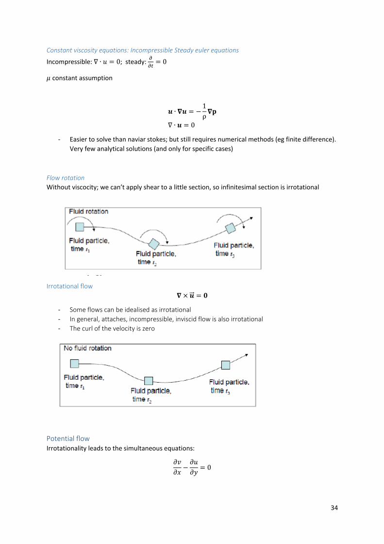
Constant viscosity equations: Incompressible Steady euler equations
Incompressible: ∇ ∙ 𝑢 = 0; steady: 𝜕
𝜕𝑡= 0
𝜇 constant assumption
𝒖 ∙ 𝛁𝒖 = −1
ρ𝛁𝐩
∇ ∙ 𝒖 = 0
- Easier to solve than naviar stokes; but still requires numerical methods (eg finite difference).
Very few analytical solutions (and only for specific cases)
Flow rotation
Without viscocity; we can’t apply shear to a little section, so infinitesimal section is irrotational
Irrotational flow
𝛁 × �⃗⃗� = 𝟎
- Some flows can be idealised as irrotational
- In general, attaches, incompressible, inviscid flow is also irrotational
- The curl of the velocity is zero
Potential flow Irrotationality leads to the simultaneous equations:
𝜕𝑣
𝜕𝑥−
𝜕𝑢
𝜕𝑦= 0

SCHOOL OF MECHANICAL ENGINEERING
DEPARTMENT OF AERONAUTICAL ENGINEERING
UNIT – I- AIRCRAFT
STRUCTURES – SA
UNIT 3-FUNDAMENTALS OF AERONAUTICAL
ENGINEERING-SAEA1202

BASIC AIRCRAFT STRUCTURE
3
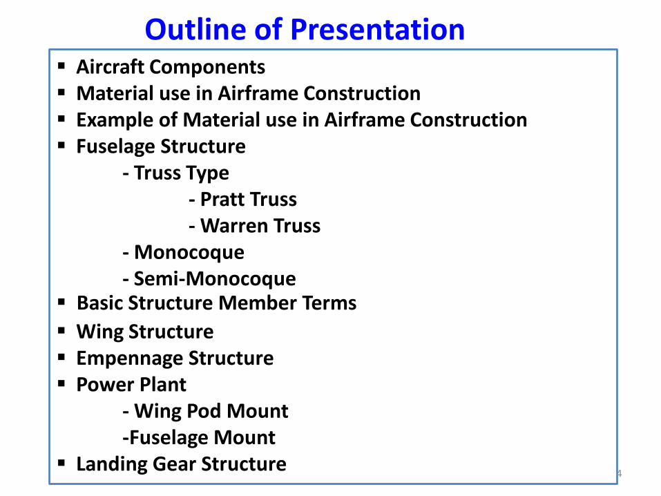
Outline of Presentation Aircraft Components Material use in Airframe Construction Example of Material use in Airframe Construction Fuselage Structure
- Truss Type- Pratt Truss- Warren Truss
- Monocoque- Semi-Monocoque
Basic Structure Member Terms
Wing Structure Empennage Structure Power Plant
- Wing Pod Mount-Fuselage Mount
Landing Gear Structure4

5
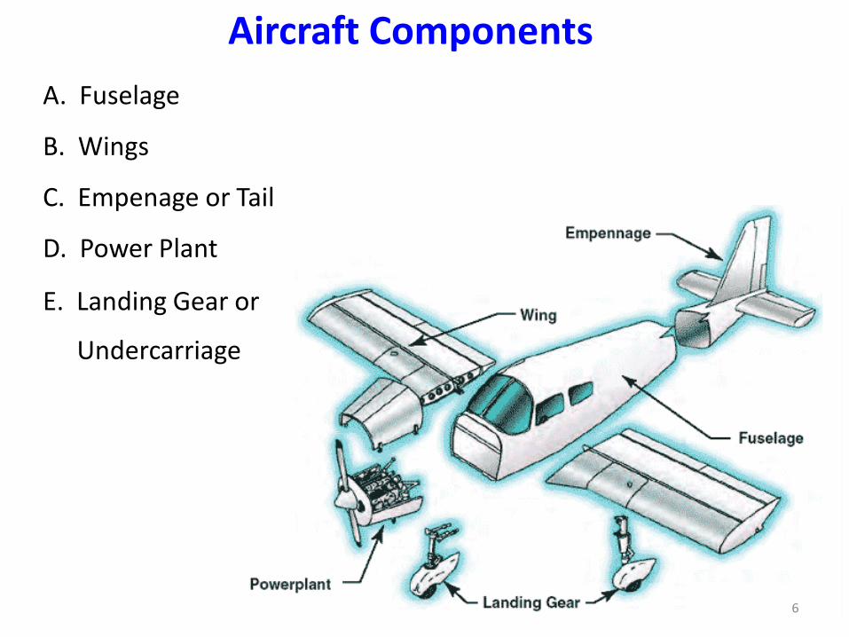
A. Fuselage
B. Wings
C. Empenage or Tail
D. Power Plant
E. Landing Gear or
Undercarriage
Aircraft Components
6
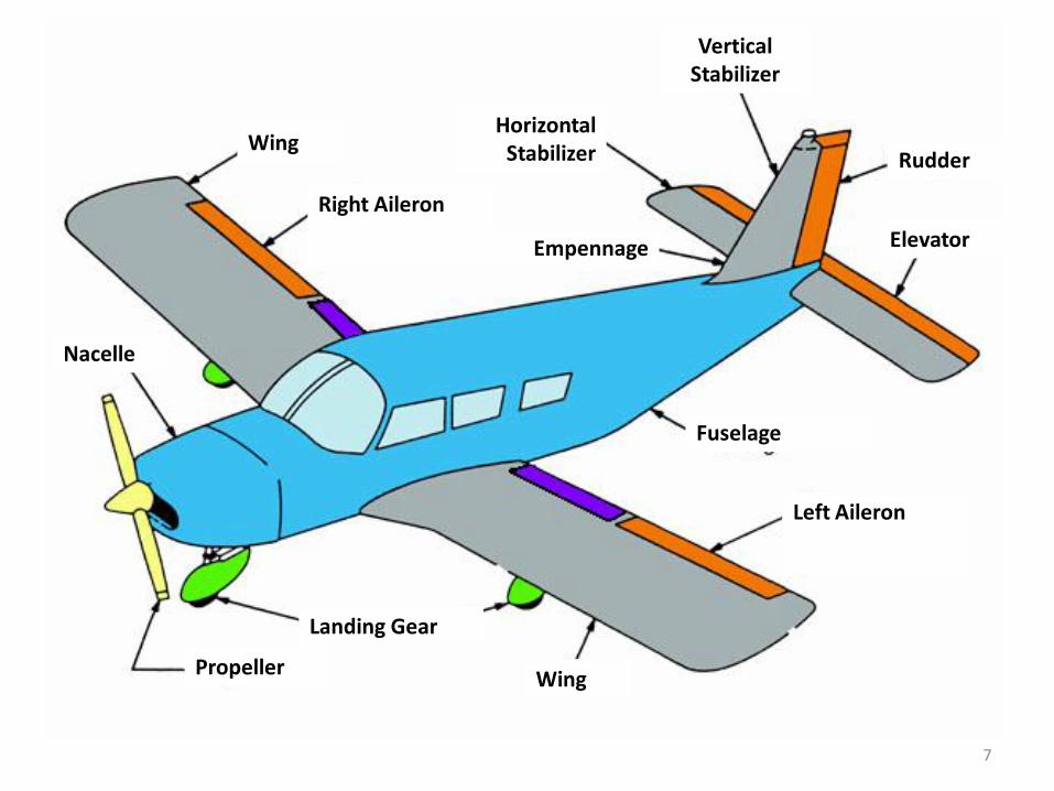
Propeller
Landing Gear
Wing
Left Aileron
Fuselage
Empennage
Nacelle
Right Aileron
WingHorizontal
Stabilizer
Vertical Stabilizer
Rudder
Elevator
7
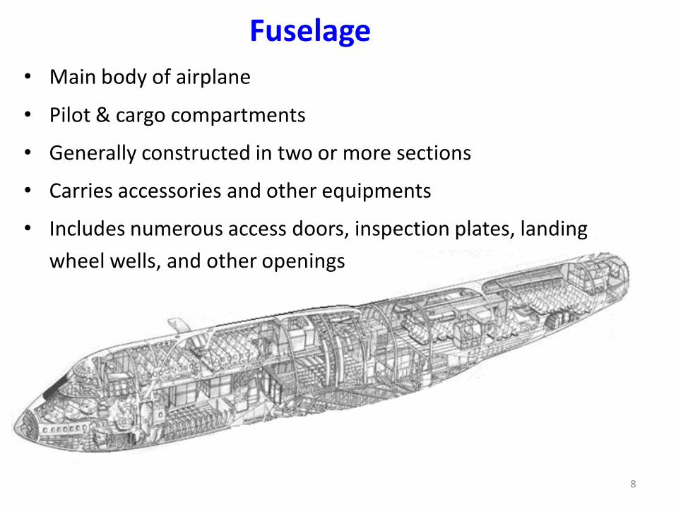
• Main body of airplane
• Pilot & cargo compartments
• Generally constructed in two or more sections
• Carries accessories and other equipments
• Includes numerous access doors, inspection plates, landing
wheel wells, and other openings
Fuselage
8

• Airfoils attached to each side of the fuselage
• Main lifting surfaces
• Various design size and shape
• May be attached at the top, middle, or lower portion of the
fuselage
High-wing
mid-wing
low-wing
• The number of wings can also vary
Monoplanes
biplanes
WING
9
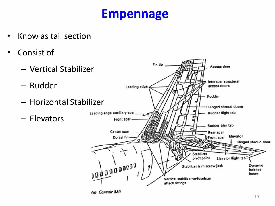
• Know as tail section
• Consist of
– Vertical Stabilizer
– Rudder
– Horizontal Stabilizer
– Elevators
Empennage
10
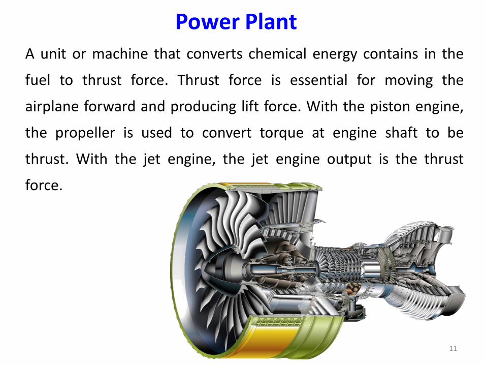
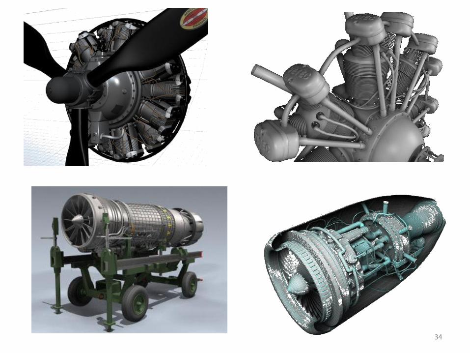
Power PlantA unit or machine that converts chemical energy contains in the
fuel to thrust force. Thrust force is essential for moving the
airplane forward and producing lift force. With the piston engine,
the propeller is used to convert torque at engine shaft to be
thrust. With the jet engine, the jet engine output is the thrust
force.
11
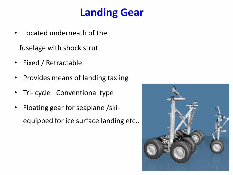
• Located underneath of the
fuselage with shock strut
• Fixed / Retractable
• Provides means of landing taxiing
• Tri- cycle –Conventional type
• Floating gear for seaplane /ski-
equipped for ice surface landing etc..
Landing Gear
12
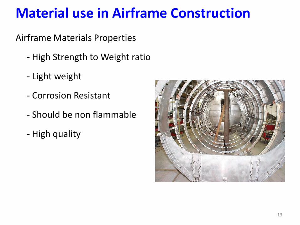
Material use in Airframe Construction
Airframe Materials Properties
- High Strength to Weight ratio
- Light weight
- Corrosion Resistant
- Should be non flammable
- High quality
13

• WOOD (Spruce)
• STEEL & ITS ALLOYS (Strong )
• ALUMINIUM & ITS ALLOY (Commonly use)
• TITANIUM ALLOYS (Heat Barriers)
• MAGNESIUM ALLOYS (3 times lighter than AL)
• PLASTICS & COMPOSITE MATERIAL
Example of Material use in Airframe Construction
14
Fuselage Structure
BASIC STRUCTURE TYPES
TRUSS TYPE
- PRATT TRUSS
- WARREN TRUSS
MONOCOQUE
SEMI-MONOCOQUE
15
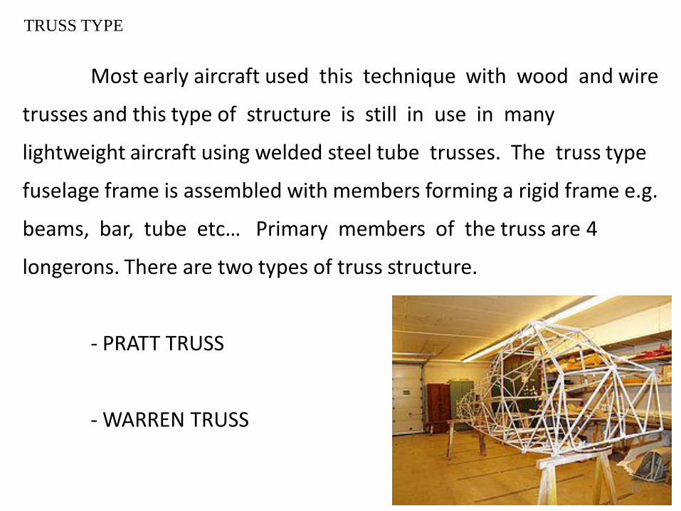
TRUSS TYPE
Most early aircraft used this technique with wood and wire
trusses and this type of structure is still in use in many
lightweight aircraft using welded steel tube trusses. The truss type
fuselage frame is assembled with members forming a rigid frame e.g.
beams, bar, tube etc… Primary members of the truss are 4
longerons. There are two types of truss structure.
- PRATT TRUSS
- WARREN TRUSS
16

PRATT TRUSS
• Early days
• Wooden or metal structure
• Great weight
• Difficult to streamline
• Box with tubular longerons +
vertical members
Diagonal members of tubing or solid rods
17
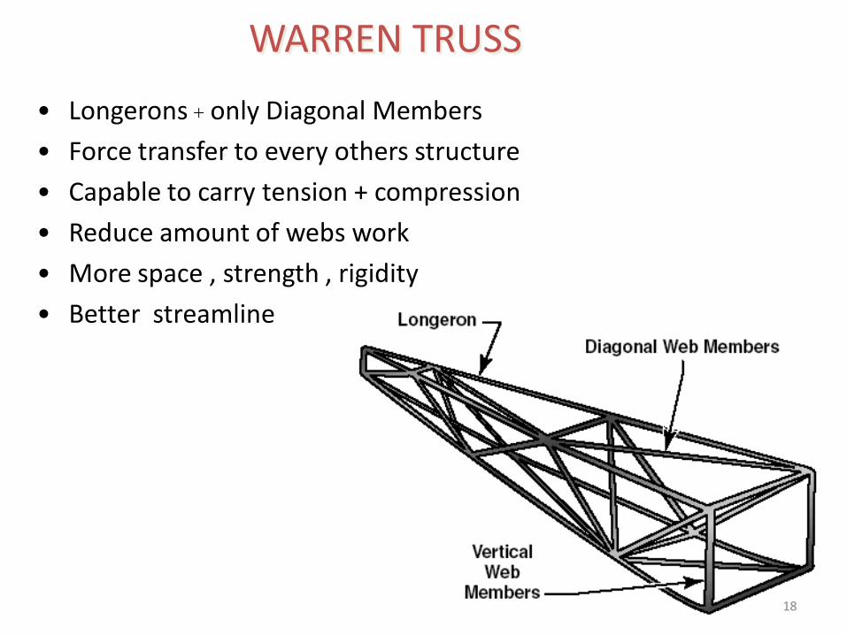
• Longerons + only Diagonal Members
• Force transfer to every others structure
• Capable to carry tension + compression
• Reduce amount of webs work
• More space , strength , rigidity
• Better streamline
WARREN TRUSS
18
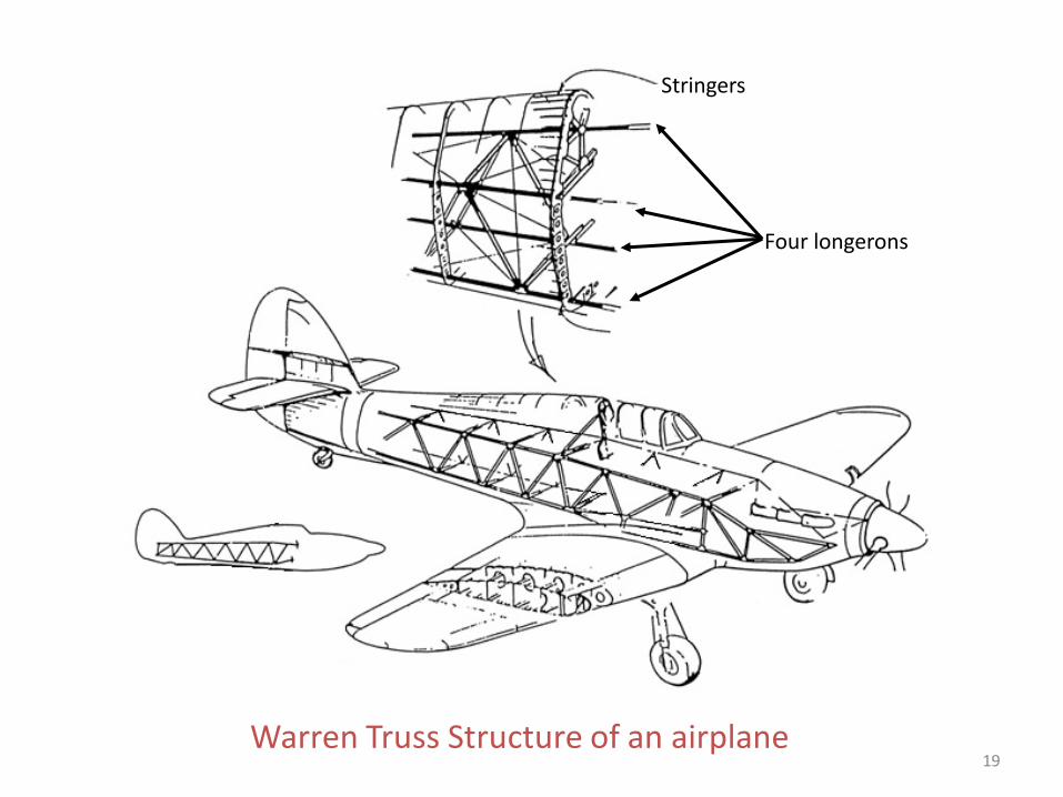
Warren Truss Structure of an airplane
Four longerons
Stringers
19

MONOCOQUE
In this method, the exterior surface of the fuselage is also the
primary structure. A typical early form of this was built using
molded plywood.
A later form of this
structure uses fiberglass
cloth impregnated with
polyester or epoxy resin,
instead of plywood, as
the skin.
20
SEMI-MONOCOQUE
This is the preferred method of constructing an all-
aluminum fuselage. First, a series of frames in the shape of the
fuselage cross sections are held in position on a rigid fixture, or
jig. These frames are then joined with lightweight longitudinal
elements called stringers. These are in turn covered with a skin
of sheet aluminum, attached by riveting or by bonding with special
adhesives. Most modern large aircraft are built using this
technique, but use several large sections constructed in this
fashion which are then joined with fasteners to form the
complete fuselage.21

Semi-monocoque Structure of an airplane22
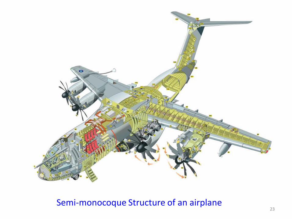
Semi-monocoque Structure of an airplane23
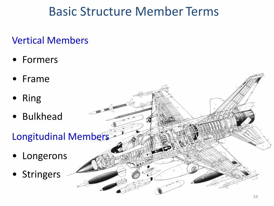
Basic Structure Member Terms
Vertical Members
• Formers
• Frame
• Ring
• Bulkhead
Longitudinal Members
• Longerons
• Stringers
24

Wing Structure
Many high-wing airplanes have external braces, or wing struts,
which transmit the flight and landing loads through the struts to the
main fuselage structure. Since the wing struts are usually attached
approximately halfway out on the wing, this type of wing structure
is called semi-cantilever. A few high-wing and most low-wing
airplanes have a full cantilever wing designed to carry the loads
without external struts. The principal structural parts of the wing
are spars, ribs, and stringers. These are reinforced by trusses, I-
beams, tubing, or other devices, including the skin. The wing
ribs determine the shape and thickness of the wing (airfoil).
25
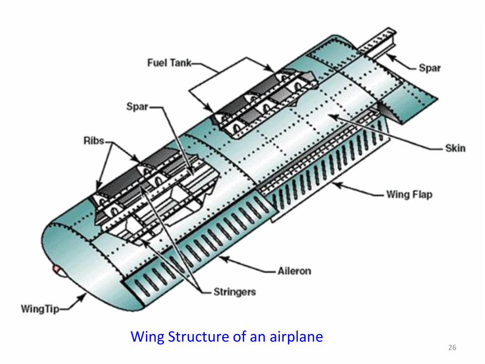
Wing Structure of an airplane26
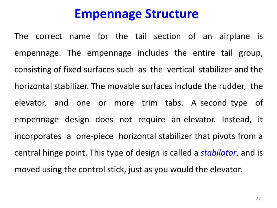
Empennage Structure
The correct name for the tail section of an airplane is
empennage. The empennage includes the entire tail group,
consisting of fixed surfaces such as the vertical stabilizer and the
horizontal stabilizer. The movable surfaces include the rudder, the
elevator, and one or more trim tabs. A second type of
empennage design does not require an elevator. Instead, it
incorporates a one-piece horizontal stabilizer that pivots from a
central hinge point. This type of design is called a stabilator, and is
moved using the control stick, just as you would the elevator.
27
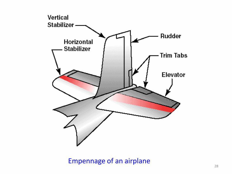
Empennage of an airplane28
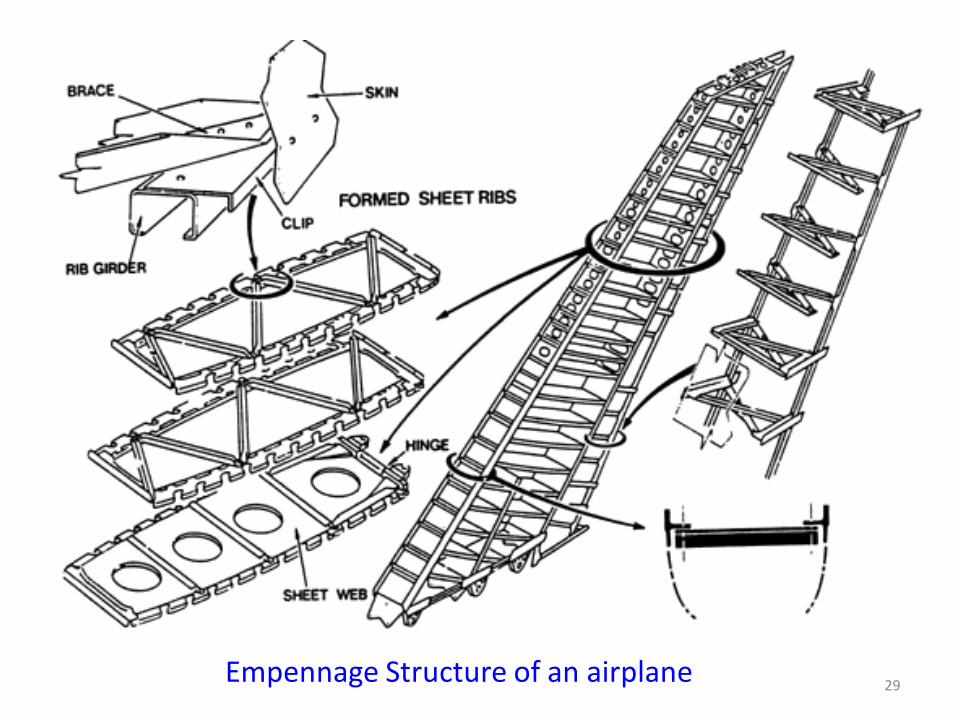
Empennage Structure of an airplane29
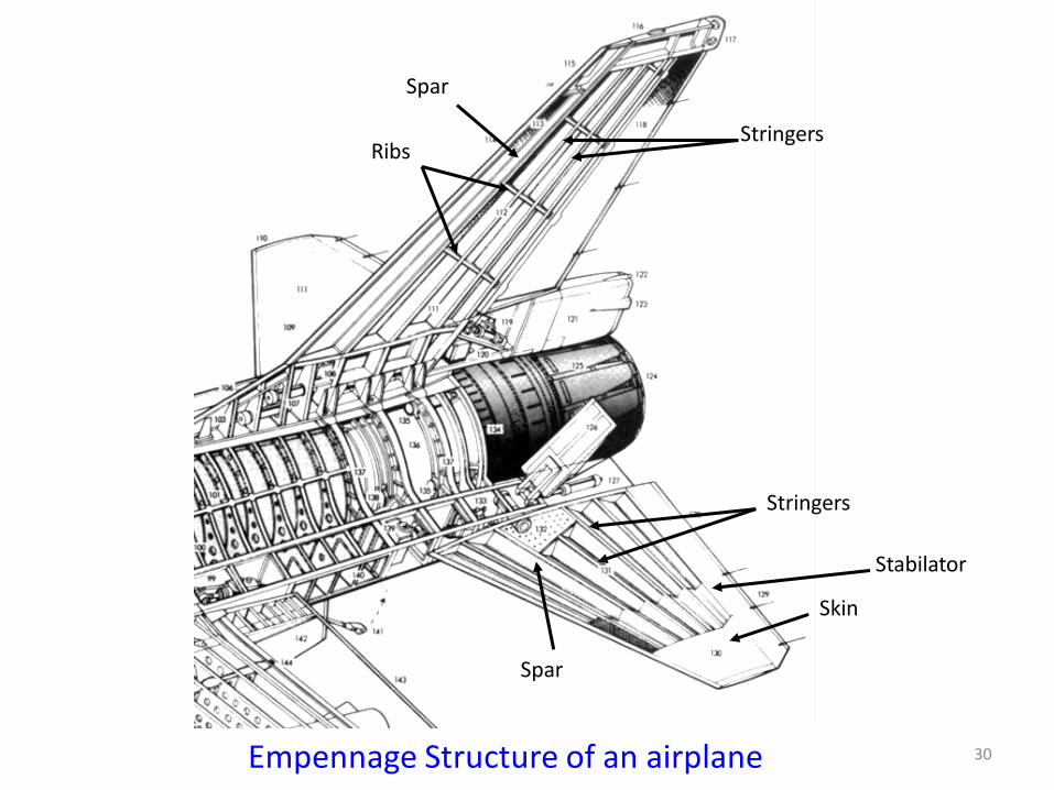
Empennage Structure of an airplane
Spar
RibsStringers
Skin
Spar
Stringers
Stabilator
30
The landing gear is the principle support of the airplane when
parked, taxiing, taking off, or when landing. The most common type
of landing gear consists of wheels, but airplanes can also be
equipped with floats for water operations, or skis for landing on
snow. The landing gear consists of three wheels — two main
wheels and a third wheel positioned either at the front or rear of the
airplane. Landing gear employing a rearmounted wheel is called
conventional landing gear.
Landing Gear Structure
31
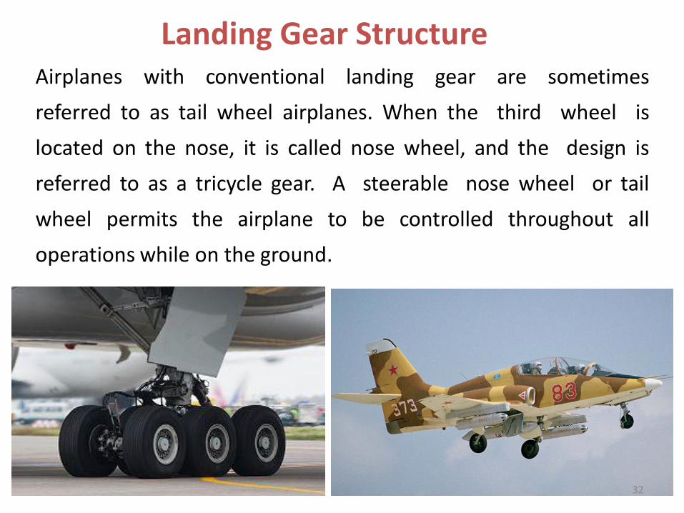
Airplanes with conventional landing gear are sometimes
referred to as tail wheel airplanes. When the third wheel is
located on the nose, it is called nose wheel, and the design is
referred to as a tricycle gear. A steerable nose wheel or tail
wheel permits the airplane to be controlled throughout all
operations while on the ground.
Landing Gear Structure
32
•The power plant usually includes both the engine and the
propeller. The primary function of the engine is to provide the
power to turn the propeller.
• It also generates electrical power, provides a vacuum source for
some flight instruments, and in most single-engine airplanes,
provides a source of heat for the pilot and passengers. The
engine is covered by a cowling, or in the case of some airplanes,
surrounded by a nacelle.
•The purpose of the cowling or nacelle is to streamline the flow of
air around the engine and to help cool the engine by ducting
air around the cylinders.
Power Plant
33
34
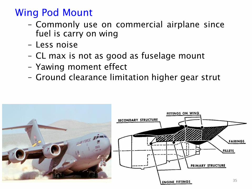
Wing Pod Mount
– Commonly use on commercial airplane since
fuel is carry on wing
– Less noise
– CL max is not as good as fuselage mount
– Yawing moment effect
– Ground clearance limitation higher gear strut
35

• Clean wing ,high CL Max , shorter take off.
• No ground clearance limitation
• Less yawing effect
• Weight penalty Aft Cg. and load distribution
• Cabin Noise and Vibration
Fuselage Mount
36

Historical progress of aircraft structures. Structural layout and
design models
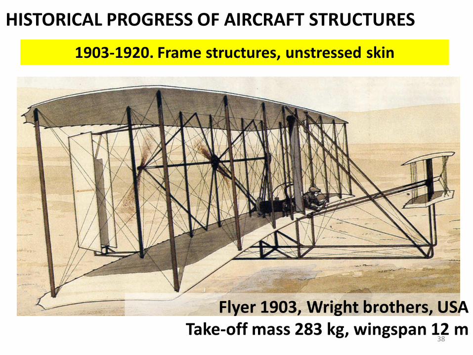
HISTORICAL PROGRESS OF AIRCRAFT STRUCTURES
Flyer 1903, Wright brothers, USATake-off mass 283 kg, wingspan 12 m
1903-1920. Frame structures, unstressed skin
38

HISTORICAL PROGRESS OF AIRCRAFT STRUCTURES
Ilya Muromets, Russian Empire, 1913Take-off mass 7 000 kg, wingspan 31.1 m
1903-1920. Frame structures, unstressed skin
39
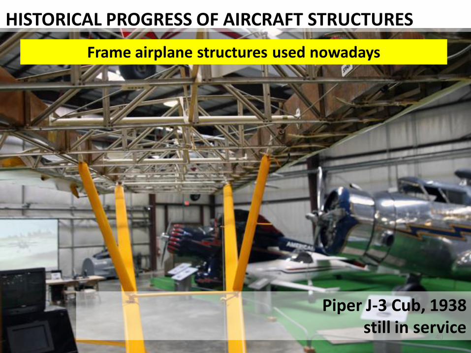
HISTORICAL PROGRESS OF AIRCRAFT STRUCTURES
Piper J-3 Cub, 1938still in service
Frame airplane structures used nowadays
40
HISTORICAL PROGRESS OF AIRCRAFT STRUCTURES
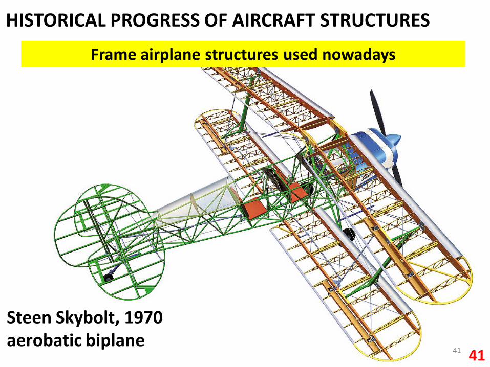
41
Steen Skybolt, 1970aerobatic biplane
Frame airplane structures used nowadays
41

HISTORICAL PROGRESS OF AIRCRAFT STRUCTURES
1920-1930. Monoplanes and corrugated skin introduced
Tupolev TB-3, Soviet Union, 1932Take-off mass 19 500 kg, wingspan 39.5 m
4242
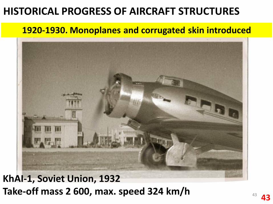
HISTORICAL PROGRESS OF AIRCRAFT STRUCTURES
KhAI-1, Soviet Union, 1932Take-off mass 2 600, max. speed 324 km/h
1920-1930. Monoplanes and corrugated skin introduced
4343
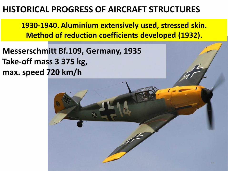
HISTORICAL PROGRESS OF AIRCRAFT STRUCTURES
1930-1940. Aluminium extensively used, stressed skin.Method of reduction coefficients developed (1932).
Messerschmitt Bf.109, Germany, 1935Take-off mass 3 375 kg,max. speed 720 km/h
44
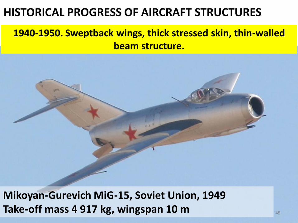
HISTORICAL PROGRESS OF AIRCRAFT STRUCTURES
1940-1950. Sweptback wings, thick stressed skin, thin-walled beam structure.
Mikoyan-Gurevich MiG-15, Soviet Union, 1949Take-off mass 4 917 kg, wingspan 10 m 45
HISTORICAL PROGRESS OF AIRCRAFT STRUCTURES
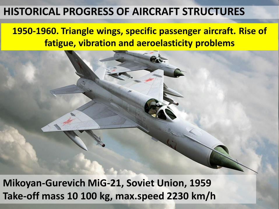
Mikoyan-Gurevich MiG-21, Soviet Union, 1959Take-off mass 10 100 kg, max.speed 2230 km/h
1950-1960. Triangle wings, specific passenger aircraft. Rise of fatigue, vibration and aeroelasticity problems
46
HISTORICAL PROGRESS OF AIRCRAFT STRUCTURES
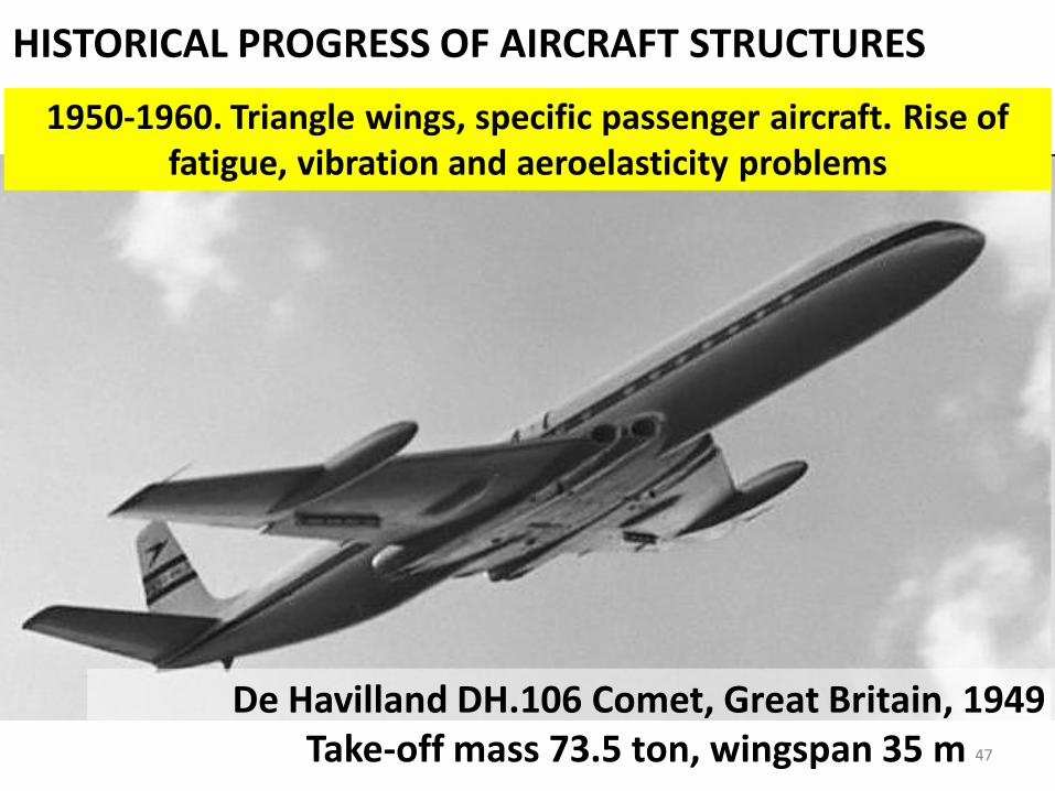
1950-1960. Triangle wings, specific passenger aircraft. Rise of fatigue, vibration and aeroelasticity problems
De Havilland DH.106 Comet, Great Britain, 1949Take-off mass 73.5 ton, wingspan 35 m 47
HISTORICAL PROGRESS OF AIRCRAFT STRUCTURES
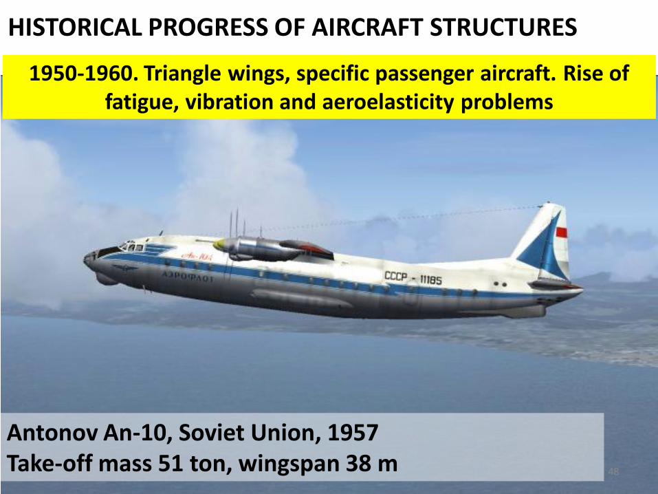
Antonov An-10, Soviet Union, 1957Take-off mass 51 ton, wingspan 38 m
1950-1960. Triangle wings, specific passenger aircraft. Rise of fatigue, vibration and aeroelasticity problems
48
HISTORICAL PROGRESS OF AIRCRAFT STRUCTURES
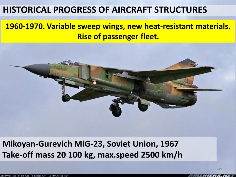
1960-1970. Variable sweep wings, new heat-resistant materials. Rise of passenger fleet.
Mikoyan-Gurevich MiG-23, Soviet Union, 1967Take-off mass 20 100 kg, max.speed 2500 km/h
49

HISTORICAL PROGRESS OF AIRCRAFT STRUCTURES
1970-1980. Wide-body passenger aircraft
Boeing 747, USA, 1969Take-off mass 340.2 ton, wingspan 59.6 m
50

HISTORICAL PROGRESS OF AIRCRAFT STRUCTURES
1980-1990. Extra-large cargo aircraft
Antonov 124, USSR, 1982Take-off mass 402 ton, payload 150 ton, wingspan 73.3 m
51

HISTORICAL PROGRESS OF AIRCRAFT STRUCTURES
1990-nowadays. Wide use of new materials (composite materials, titanium alloys)
Boeing 787 Dreamliner, USA, 2009Take-off mass 245 ton, wingspan 60 m
52

GOALS AND OBJECTIVES
The goal of structural analysis is to get the efficientstructure and verify its fitness for use.
Structural analysis is the determination of the effects ofloads on physical structures and their components.
As a science, structural analysis covers principles andmethods of strength, rigidity and stability calculations.
53
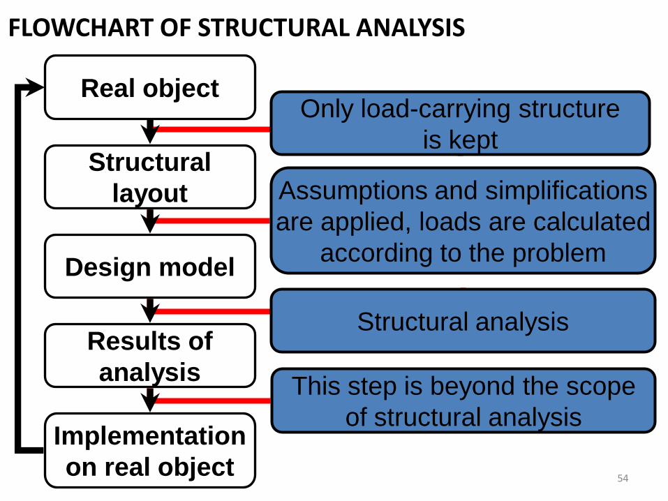
FLOWCHART OF STRUCTURAL ANALYSIS
Real object
Structural
layout
Design model
Only load-carrying structure
is kept
Assumptions and simplifications
are applied, loads are calculated
according to the problem
Results of
analysis
Implementation
on real object
This step is beyond the scope
of structural analysis
Structural analysis
54
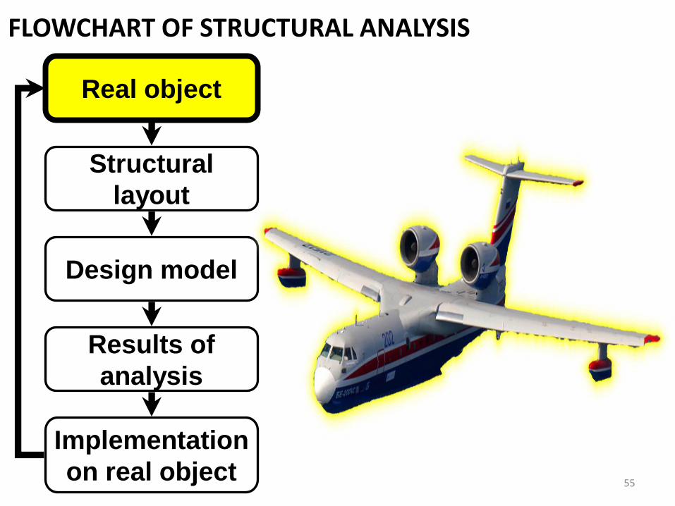
FLOWCHART OF STRUCTURAL ANALYSIS
Real object
Structural
layout
Design model
Results of
analysis
Implementation
on real object55

FLOWCHART OF STRUCTURAL ANALYSIS
Real object
Structural
layout
Design model
Results of
analysis
Implementation
on real object56
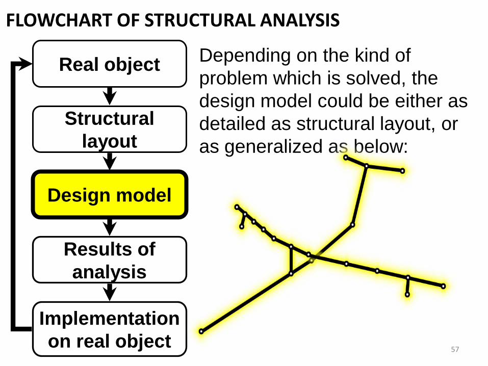
FLOWCHART OF STRUCTURAL ANALYSIS
Real object
Structural
layout
Design model
Results of
analysis
Implementation
on real object
Depending on the kind of
problem which is solved, the
design model could be either as
detailed as structural layout, or
as generalized as below:
57
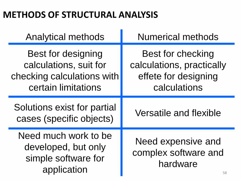
METHODS OF STRUCTURAL ANALYSIS
Analytical methods Numerical methods
Best for designing
calculations, suit for
checking calculations with
certain limitations
Best for checking
calculations, practically
effete for designing
calculations
Solutions exist for partial
cases (specific objects) Versatile and flexible
Need much work to be
developed, but only
simple software for
application
Need expensive and
complex software and
hardware58

METHODS OF STRUCTURAL ANALYSIS
Analytical methods Numerical methods
Methods of Mechanics of
Materials, methods for
statically indeterminate
structures (method of
forces, method of
displacements), beam
theory, method of
reduction coefficients etc.
Finite Element Method
(FEM, best for solid
mechanics),
Finite Difference Method
(FDM),
Movable cellular
automaton (MCA, best for
fracture, crack
propagation) etc.59
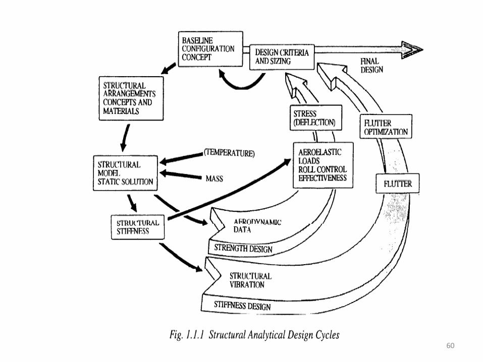
60
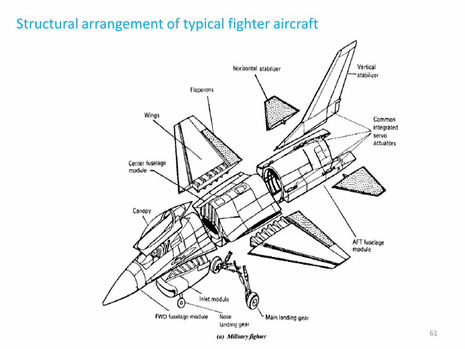
Structural arrangement of typical fighter aircraft
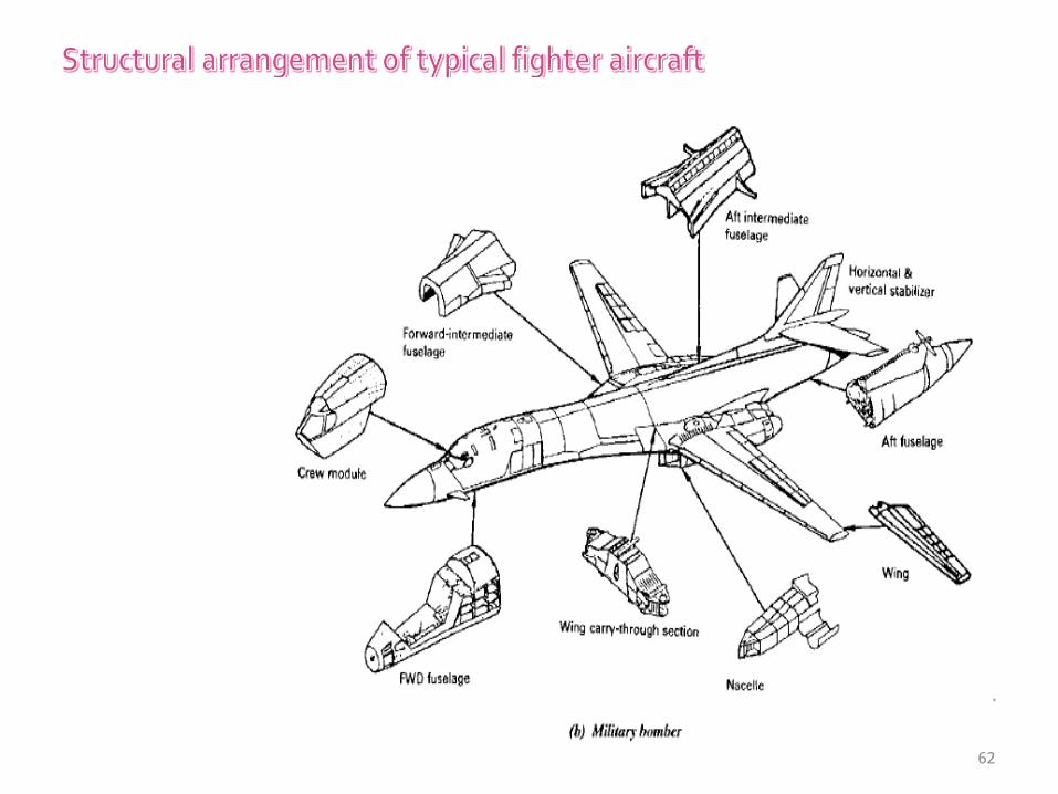
61
62
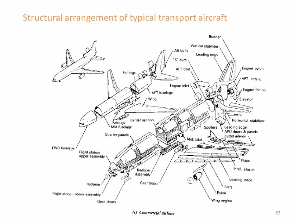
Structural arrangement of typical transport aircraft
63
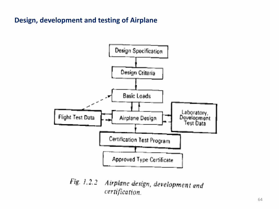
Design, development and testing of Airplane
64

65

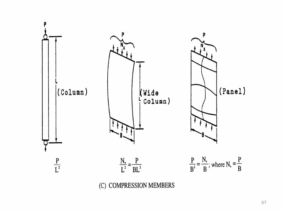
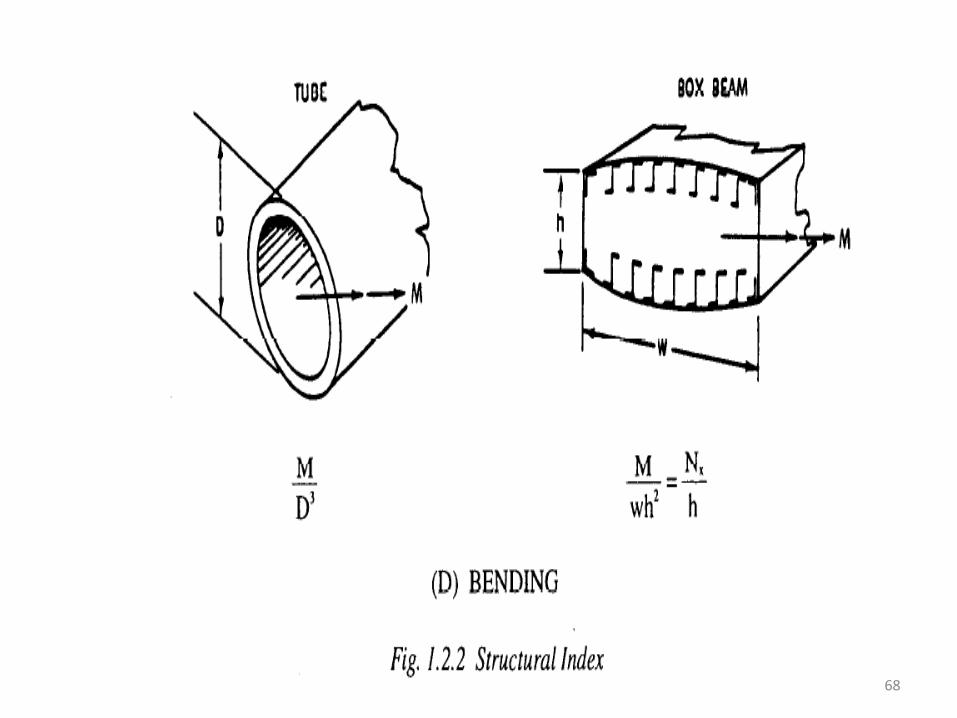
Structural Indexes
66
67
68

SCHOOL OF MECHANICAL ENGINEERING
DEPARTMENT OF AERONAUTICAL ENGINEERING
UNIT – I- AIRCRAFT
STRUCTURES – SA
UNIT 4-FUNDAMENTALS OF AERONAUTICAL
ENGINEERING-SAEA1202

Dpt. Materials Sci. and Eng. and Chem. Eng. UC3M
Topic 8. Composite materials (I)
2
“Mix of two or more constituent materials with significantly different physical or chemical properties which remain separate and distinct on a macroscopic level within the finished structure”
Reinforcement: Particles (dispersion strengthened
or large particles) Fibers (discontinuous - short or
continuous - aligned ) Structural (laminates and sandwich
structures)
Matrix: Metal matrix composites (MMC) Ceramic matrix composites (CMC) Polymer matrix composites (PMC)
When is a material considered to be a composite?
Microstructural level (< 0,01 cm) to macrostructural (> 0,01 cm)
Wood Concrete
Hypoeutectoid steel Reinforce concrete
Austenitic stainless steel Cement
Cellophane Reinforced plastic
Paper
1. CLASSIFICATION
DEFINITION AND TYPES
? Sophia A. Tsipas / Berna Serrano

Dpt. Materials Sci. and Eng. and Chem. Eng. UC3M
Topic 8. Composite materials (I)
3
Wood (lignin + celullose)
Concrete (gravel + cement)
Hypoeutectoid steel (ferrite + pearlite)
Reinforced concrete (gravel + cement + steel)
Austenitic stainless steel (grains =)
Cement
Cellophane (Multiple polymeric layers)
Reinforced plastic (it doesn’t improve its properties)
Paper (only cellulose fibers)
- Composite material - Limit of composite material - Not a composite material
DEFINITION AND TYPES
Sophia A. Tsipas / Berna Serrano

Dpt. Materials Sci. and Eng. and Chem. Eng. UC3M
Topic 8. Composite materials (I)
Wood cellulose-filaments in a matrix of lignin and hemicellulose
growth rings form a layered composite
perpendicular to the growth rings are radially oriented ribbon-like structures : rays which provide a redial stiffening and reinforcement
COMPOSITES IN NATURE
Abalone shell: CaCO3 + 3% organic material >3000* stronger than calcite
Oak wood
pine wood
Sea shells
http://commons.wikimedia.org/wiki/File:Wood_structure_numbers.svg http://commons.wikimedia.org/wiki/File:Hard_Soft_Wood.jpg
Sophia A. Tsipas / Berna Serrano
Dpt. Materials Sci. and Eng. and Chem. Eng. UC3M
Topic 8. Composite materials (I)
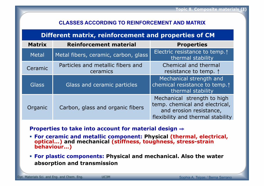
Properties to take into account for material design ⇒
For ceramic and metallic component: Physical (thermal, electrical, optical…) and mechanical (stiffness, toughness, stress-strain behaviour…)
For plastic components: Physical and mechanical. Also the water absorption and transmission
Different matrix, reinforcement and properties of CM
Matrix Reinforcement material Properties
Metal Metal fibers, ceramic, carbon, glass Electric resistance to temp.↑ thermal stability
Ceramic Particles and metallic fibers and ceramics
Chemical and thermal resistance to temp. ↑
Glass Glass and ceramic particles Mechanical strength and
chemical resistance to temp.↑ thermal stability
Organic Carbon, glass and organic fibers
Mechanical strength to high temp. chemical and electrical,
and erosion resistance, flexibility and thermal stability
CLASSES ACCORDING TO REINFORCEMENT AND MATRIX
Sophia A. Tsipas / Berna Serrano

Dpt. Materials Sci. and Eng. and Chem. Eng. UC3M
Topic 8. Composite materials (I)
Structures, reinforcements, types and properties of composite materials
6
COMPOSITE MATERIALS
Particle-reinforced Fiber-reinforced Structural
Large- particle
Dispersion strengthen
Continuous (aligned)
Discontinuous (short)
Laminates Sandwich panels
TYPE OF CONSTITUENTS
aligned Randomly oriented
Structure
Reinforcement Composite material Properties
Particles Particle-reinforced Isotropic
Short fibres Random
Aligned
Isotripic
Anisotropic
Continious fibers Aligned continous fibres Anisotropic
Laminates or layers
laminates Anistotropic
Sophia A. Tsipas / Berna Serrano
Dpt. Materials Sci. and Eng. and Chem. Eng. UC3M
Topic 8. Composite materials (I)
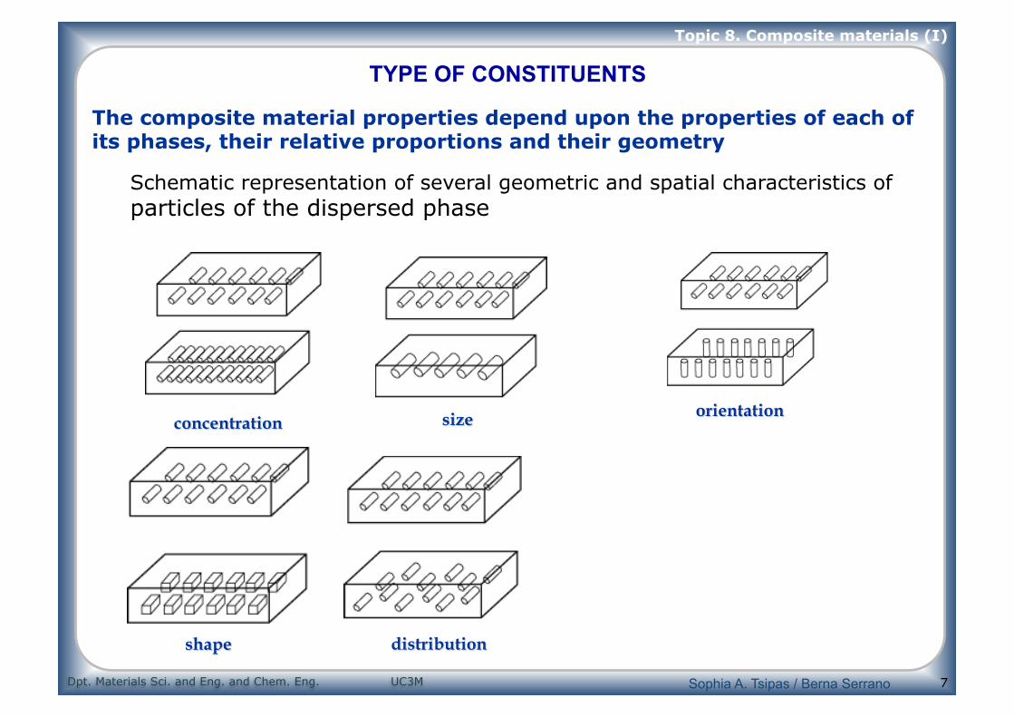
7
Schematic representation of several geometric and spatial characteristics of particles of the dispersed phase
The composite material properties depend upon the properties of each of its phases, their relative proportions and their geometry
TYPE OF CONSTITUENTS
Sophia A. Tsipas / Berna Serrano

Dpt. Materials Sci. and Eng. and Chem. Eng. UC3M
Topic 8. Composite materials (I)
8
3. PARTICLE-REINFORCED COMPOSITE MATERIALS
Particles: geometrical variety Factors that have an influence in physical an mechanical properties: size, distribution and particle content
Advantages of particle reinforced composite materials
Low cost
High stiffness and strength (inorganic particles)
Wear resistance
Simpler manufacturing process
Mechanical properties depend on the reinforcement, manufacturing
and subsequent treatments
Most used metallic matrixes are Al, Mg, Ti y Ni
Polymeric matrixes are reinforced to improve their mechanical
strength and abrasion resistance
General aspects of particle reinforce composites:
Sophia A. Tsipas / Berna Serrano
Dpt. Materials Sci. and Eng. and Chem. Eng. UC3M
Topic 8. Composite materials (I)
9
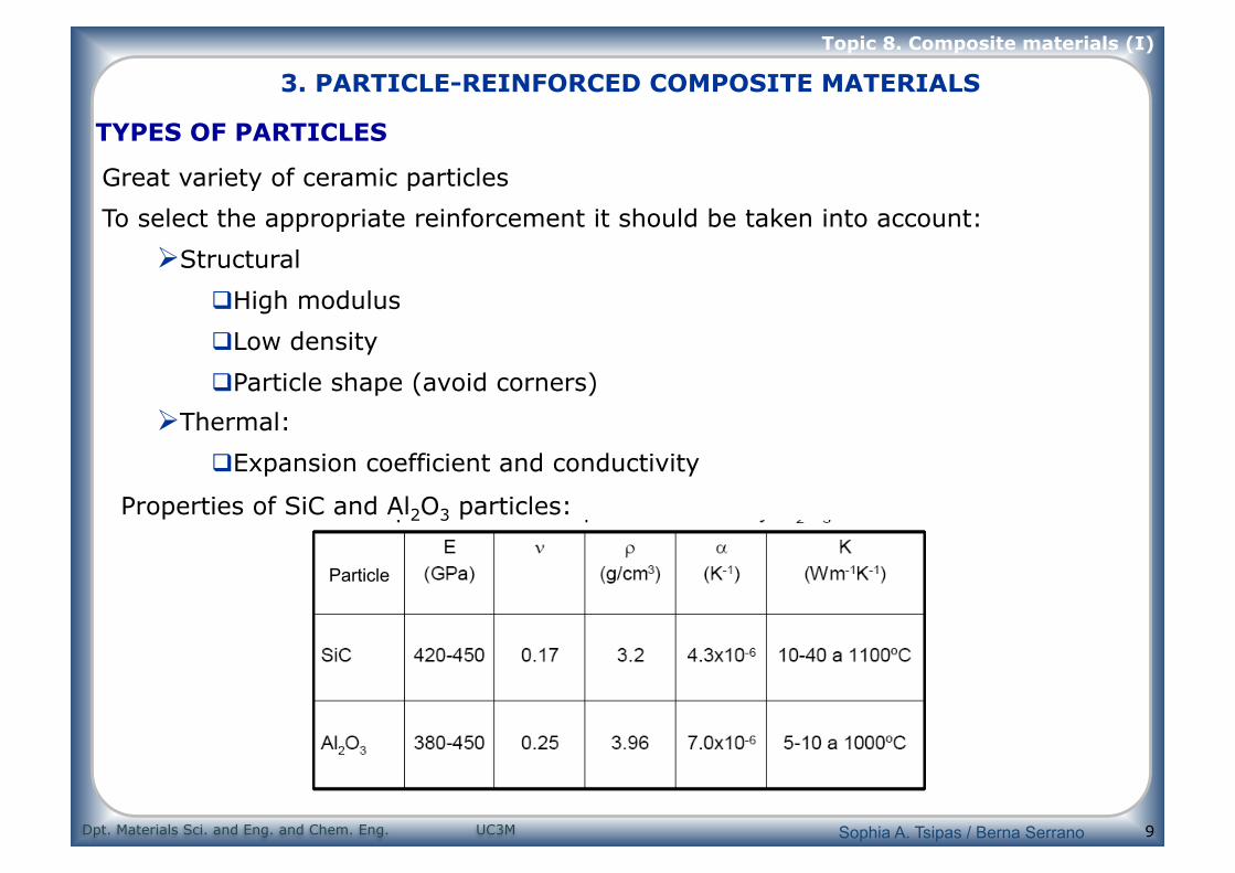
TYPES OF PARTICLES
Great variety of ceramic particles
To select the appropriate reinforcement it should be taken into account:
Structural
High modulus
Low density
Particle shape (avoid corners)
Thermal:
Expansion coefficient and conductivity
Properties of SiC and Al2O3 particles:
Particle
3. PARTICLE-REINFORCED COMPOSITE MATERIALS
Sophia A. Tsipas / Berna Serrano
Dpt. Materials Sci. and Eng. and Chem. Eng. UC3M
Topic 8. Composite materials (I)
10
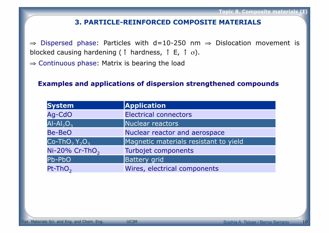
⇒ Dispersed phase: Particles with d=10-250 nm ⇒ Dislocation movement is blocked causing hardening (↑ hardness, ↑ E, ↑ σ).
⇒ Continuous phase: Matrix is bearing the load
System Application Ag-CdO Electrical connectors Al-Al2O3 Nuclear reactors Be-BeO Nuclear reactor and aerospace Co-ThO2,Y2O3 Magnetic materials resistant to yield Ni-20% Cr-ThO2 Turbojet components Pb-PbO Battery grid Pt-ThO2 Wires, electrical components
Examples and applications of dispersion strengthened compounds
3. PARTICLE-REINFORCED COMPOSITE MATERIALS
Sophia A. Tsipas / Berna Serrano

Dpt. Materials Sci. and Eng. and Chem. Eng. UC3M
Topic 8. Composite materials (I)
11
3.2 Composite materials reinforced with large particles
3. PARTICLE-REINFORCED COMPOSITE MATERIALS
Sophia A. Tsipas / Berna Serrano

Dpt. Materials Sci. and Eng. and Chem. Eng. UC3M
Topic 8. Composite materials (I)
12
CERMETS (cemented carbides) Hard ceramic particles scattered in a metallic matrix
Tungsten carbide particles, WC (hard, stiff, and ↑Tm) scattered in metallic matrixes are used as cutting tools
These composites are brittle ⇒ toughness improvement: it is combined with Co powder that when sintered acts as an adhesive for WC particles.
ABRASIVE cutting and forming discs from alumina Al2O3, silicon carbide, SiC cubic boron nitride, BN. This particles are cemented in vitreous or polymeric matrixes
CAST PARTICLE REINFORCED COMPOSITES Al casting with SiC particles for applications in the car industry (pistons and connecting rods)
3. PARTICLE-REINFORCED COMPOSITE MATERIALS
Sophia A. Tsipas / Berna Serrano

Dpt. Materials Sci. and Eng. and Chem. Eng. UC3M
Topic 8. Composite materials (I)
13
CONCRETE It is a matrix of cement together with gravel or sand particles
“It is a composite of particles held together by cement”
There are two kinds of cement: Asphalt cement (for paving) and Portland cement (for building construction)
PORTLAND CEMENT CONCRETE
Ingredients: Fine aggregate Portland cement (sand), coarse aggregate (gravel) and water ⇒ fine sand particles occupy the empty spaces between gravel particles. These aggregates are 60-80% of the total volume. ⇒ The cement-water mixture must cover the sand and gravel particles. The final bonding cement-particles depends upon the quantity of water (insufficient water: incomplete bonding; excess water: porosity)
PROBLEMS: low strength and extremely brittle; it dilates and contracts with temperature; cracks appear when it undergoes freezing-defreezing cycles.
SOLUTION: Reinforcements REINFORCED CONCRETE (STEEL tubes, bars, wires or meshes in cement before curing)
3. PARTICLE-REINFORCED COMPOSITE MATERIALS
Sophia A. Tsipas / Berna Serrano
Dpt. Materials Sci. and Eng. and Chem. Eng. UC3M
Topic 8. Composite materials (I)
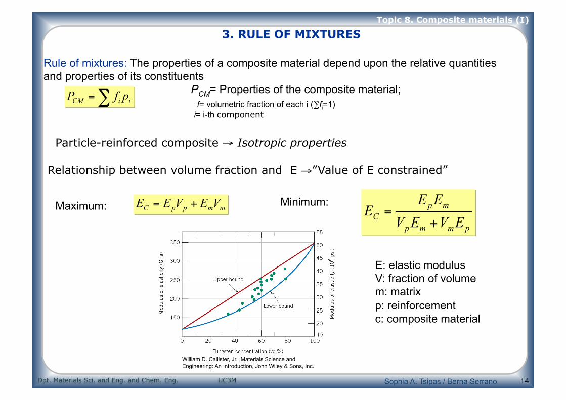
14
Maximum: Minimum:
Relationship between volume fraction and E ⇒”Value of E constrained”
Rule of mixtures: The properties of a composite material depend upon the relative quantities and properties of its constituents PCM= Properties of the composite material; f= volumetric fraction of each i (∑fi=1) i= i-th component
Particle-reinforced composite → Isotropic properties
E: elastic modulus V: fraction of volume m: matrix p: reinforcement c: composite material
3. RULE OF MIXTURES
William D. Callister, Jr. ,Materials Science and Engineering: An Introduction, John Wiley & Sons, Inc.
Sophia A. Tsipas / Berna Serrano

Dpt. Materials Sci. and Eng. and Chem. Eng. UC3M
Topic 8. Composite materials (I)
Examples: Particle Reinforced composite
1 µm
Carbon Black particle reinforcement in Styrene-Butadiene synthetic rubber for car tire application.
WC–Co cemented carbide. Light areas are the cobalt matrix; dark regions, the particles of tungsten carbide x100.
William D. Callister, Jr. ,Materials Science and Engineering: An Introduction, John Wiley & Sons, Inc.
Sophia A. Tsipas / Berna Serrano

Dpt. Materials Sci. and Eng. and Chem. Eng. UC3M
Topic 8. Composite materials (I)
16
5. FIBER-REINFORCED COMPOSITE MATERIALS
Sophia A. Tsipas / Berna Serrano
Dpt. Materials Sci. and Eng. and Chem. Eng. UC3M
Topic 8. Composite materials (I)
17
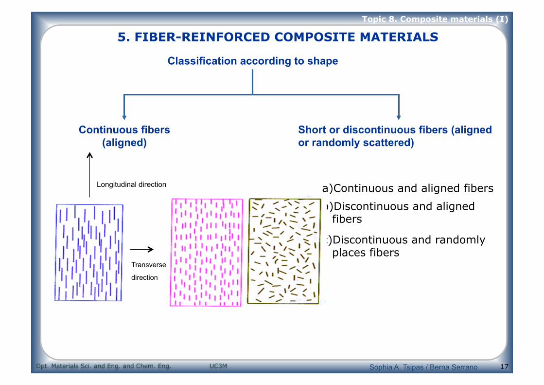
Continuous fibers (aligned)
Short or discontinuous fibers (aligned or randomly scattered)
Classification according to shape
a) Continuous and aligned fibers
b) Discontinuous and aligned fibers
c) Discontinuous and randomly places fibers
Longitudinal direction
Transverse
direction
5. FIBER-REINFORCED COMPOSITE MATERIALS
Sophia A. Tsipas / Berna Serrano

Dpt. Materials Sci. and Eng. and Chem. Eng. UC3M
Topic 8. Composite materials (I)
18
Glass Fibers
5. FIBER-REINFORCED COMPOSITE MATERIALS
http://commons.wikimedia.org/wiki/File:Glass_reinforced_plastic_SEM_Stereo_200x.JPG
Composite material fiberglass reinforced polymeric matrix (stereoscopic SEM image of the fracture surface)
Sophia A. Tsipas / Berna Serrano

Dpt. Materials Sci. and Eng. and Chem. Eng. UC3M
Topic 8. Composite materials (I)
19
5.1 TYPES OF FIBERS: Glass Fibers
Used to reinforce plastic matrixes
Composition: Base of SiO2 (50-70%) + Oxides Ca, Al, B, Na, Mg and K
Properties: non combustible, good chemical, biological and thermal
resistance (Tm↑,α↓), thermal insulator (K↓), electric insulator (σ↓),
low expansion coefficient and low cost
Types and composition of different fiberglass:
Material, % in weight Type of glass Silica Alumina Ca Oxide Magnesium B Oxide Na2CO3 Ca Fluoride Secondary
Oxides E (1) 54 14 20,5 0,5 8 1 1 1
A (2) 72 1 8 4 - 14 - 1
ECR 61 11 22 3 - 0,6 - 2,4
S (3) 64 25 - 10 - 0,3 - 0,7
(1) Ca Aluminoborosilicate (2) Rich in alkali (3) Mg Aluminosilicate without B
Sophia A. Tsipas / Berna Serrano

Dpt. Materials Sci. and Eng. and Chem. Eng. UC3M
Topic 8. Composite materials (I)
20
Fiberglass properties Type
of glass
ρrelative
σtensile (MPa) E (GPa) α × 10-6
(K)
ε (a 20 ºC y 1
MHz) Tm (ºC) For applications that require
E 2,58 3450 72,5 5,0 6,3 1065 Good electrical properties and dimensional stability (circuit boards)
A 2,50 3040 69,0 8,6 6,9 996 Chemical resistance
ECR 2,62 3625 72,5 5,0 6,5 1204 Good electrical properties and chemical resistance
S 2,48 4590 86,0 5,6 5,1 1454 Tensile strength and thermal stability (aerospace and aeronautic industries)
• The strength of these fibers is high but not extreme: there are limits in their application • E glass is the cheapest and has the highest moisture resistance (polymeric matrixes) • All the fibers are good insulators
Common polymeric matrixes:
Thermoplastics: Nylon 66, Polycarbonate y Polystyrene
Thermoplastics: Epoxy, polyesters, phenolic, silicon
5.1 TYPES OF FIBERS: Glass Fibers
Sophia A. Tsipas / Berna Serrano

Dpt. Materials Sci. and Eng. and Chem. Eng. UC3M
Topic 8. Composite materials (I)
21
a) Continuous fibers b) Discontinuous c) Woven fiber (for laminated structures)
There are three possible configurations for fiberglass reinforced composite materials:
5.1 TYPES OF FIBERS: Glass Fibers
a.
b.
c.
Sophia A. Tsipas / Berna Serrano

Dpt. Materials Sci. and Eng. and Chem. Eng. UC3M
Topic 8. Composite materials (I)
22
Advanced composites for aerospace and aeronautic fibers
⇒ Very good thermal and physical properties (High electrical conductivity and high thermal conductivity).
⇒ Carbon fibers in composites with plastic resins (i.e.: epoxy) good combination of high mechanical strength, stiffness and low weight →aerospace applications
- Low cost: sport equipment manufacturing, industrial and commercial products (70’s ≈ 220 $/kg and 80’s ≈ 9$/kg)
⇒ Manufactured from organic precursors: Rayon and isotropic tars (fibers E↓ , ≤ 50 GPa) Polyacrylonitrile (PAN) and liquid crystal tar (E↑) (easier to orientate)
1. STABILIZATION Stretching (200-300ºC): fibrillar network 2. CARBONIZATION 1000-1500ºC inert atmosphere ⇒ Removal O,H,N HT-CF 3. GRAPHITIZATION T>1800ºC. Degree of orientation increased: ↑E and strength: HM-CF
5.1 TYPES OF FIBERS: Carbon fiber
PAN fiber Stabilization at 200-220oC
Carbonization at 1000-1500oC
Grafitization at 1800oC
High-strength carbon fiber
High-modulus carbon fiber
Sophia A. Tsipas / Berna Serrano

Dpt. Materials Sci. and Eng. and Chem. Eng. UC3M
Topic 8. Composite materials (I)
23
⇒ Kevlar polyamide (poly(paraphenylene terephthalamide )) ⇒ The aromatic ring provides thermal stability
⇒ E ↑↑ due to its configuration: rigid molecules are arrayed in ordered domains (liquid crystal polymer)→ during extrusion they are oriented in the direction of the flow ⇒ Thermal and electrical insulator, ↓α, high impact strength and ↓E (compared to carbon)
Properties of the three types of Kevlar Material ρ (g/cm3) Dwire (µm) σtensile(GPa) E (GPa) ε (%)
Kevlar 29 1,44 12 3,6 83 4,0 Kevlar 49 1,44 12 3,6-4,1 131 2,8
Kevlar 149 1,47 12 3,4 186 2,0
5.1 TYPES OF FIBERS: Aramid fiber
http://commons.wikimedia.org/wiki/File:Kevlar_chemical_structure_H-bonds.png
Sophia A. Tsipas / Berna Serrano

Dpt. Materials Sci. and Eng. and Chem. Eng. UC3M
Topic 8. Composite materials (I)
24
Boron fibers
Ceramic fibers: Mainly quartz (Al2O3, Si3N4,…)
Manufactured through a vapor deposition of B over a core of W
5.1 TYPES OF FIBERS: Boron and ceramics
Sophia A. Tsipas / Berna Serrano

Dpt. Materials Sci. and Eng. and Chem. Eng. UC3M
Topic 8. Composite materials (I)
25
5.1 TYPES OF FIBERS
Mechanical properties of the different fibers
William F. Smith, Foundations of Materials Science and Engineering, 3/e, McGraw-Hill 2004
Sophia A. Tsipas / Berna Serrano

Dpt. Materials Sci. and Eng. and Chem. Eng. UC3M
Topic 8. Composite materials (I)
26
6. STRUCTURAL COMPOSITE MATERIALS
Formed by composite materials and homogeneous materials Properties depend on the geometry of the structural elements
Types → laminated composites → sandwich structures
Piling of layers or lamina of unidirectional composite material
Laminar composite example: continuous and aligned fiber reinforced plastics with matrixes such as epoxy, polyester, PE, PA, PET…
In order to get different mechanical properties ⇒ layers of materials with different properties are piled, or a different way of piling layers on top of each other.
Sophia A. Tsipas / Berna Serrano

Dpt. Materials Sci. and Eng. and Chem. Eng. UC3M
Topic 8. Composite materials (I)
27
⇒ Orientation of fibers with respect to the lamina: Usual fiber orientations: 0, 90, +/-45. By combining these orientations, the desired strength
and stiffness is achieved. Plane isotropy can be achieved. Fiber layers arranged in a way so that strength is maximized and weight is minimized.
Laminated composites must always be symmetric with respect to their middle plane, and the must also be balanced to avoid anomalous distortions in the structure
The strength and stiffness varies greatly with the orientation.
A piling of woven materials without any bonding does not have any structural use. Therefore a matrix is needed.
Exclusively unidirectional composites are never used. Piled lamina. The orientation of the direction with
↑R changes in each of the layers
Unidirectional Crossplied
Quasi-isotropic
Sophia A. Tsipas / Berna Serrano

Dpt. Materials Sci. and Eng. and Chem. Eng. UC3M
Topic 8. Composite materials (I)
28
2 external strong layers (face sheets) attached to a layer of less dense material (core) with low stiffness and low strength
Role of the face sheets they withstand most of the plane loads and transversal bending stresses
Face sheet material Al alloys, fiber-reinforced plastics, Ti, steel and plywood. Core material separates both face sheets and resists deformations perpendicular to the
face plane. Provide resistance to shear stress along the planes perpendicular to the face sheets
Core materials may have different and have different structures: polymer foams, synthetic rubber, inorganic cement and balsa wood
Typical core with honeycomb structure→ thin layers arranged in hexagonal cells.
honeycomb panel used in aircraft http://commons.wikimedia.org/wiki/File:CompositeSandwich.png
Sophia A. Tsipas / Berna Serrano

Dpt. Materials Sci. and Eng. and Chem. Eng. UC3M
Topic 8. Composite materials (I)
Applications of composites
GLARE
"GLAss-REinforced" Fibre Metal Laminate (FML),
http://commons.wikimedia.org/wiki/File:LCA_Composites.jpg
honeycomb panel used in aircraft
Sophia A. Tsipas / Berna Serrano

Dpt. Materials Sci. and Eng. and Chem. Eng. UC3M
Topic 8. Composite materials (I)
30
Applications of composites
Sophia A. Tsipas / Berna Serrano

SCHOOL OF MECHANICAL ENGINEERING
DEPARTMENT OF AERONAUTICAL ENGINEERING
UNIT – I- AIRCRAFT
STRUCTURES – SA
UNIT 5-FUNDAMENTALS OF AERONAUTICAL
ENGINEERING-SAEA1202
1Aircraft and Engines.(Aero Engines)
CHAPTER: 1PISTON ENGINE
PRINCIPLES OF OPERATIONA piston (or reciprocating) engine is a device for converting the heat energy of a fuel into mechanical energy, by internalcombustion. The principles which govern the relationship between pressure, temperature. and volume. in a gas arestated in the laws of boyles' and Charles', and these principles are applicable to the operation of a piston engine.
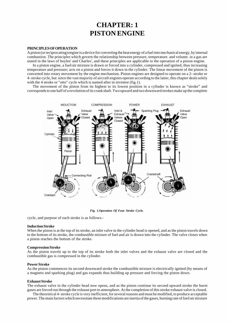
In a piston engine, a fuel/air mixture is drawn or forced into a cylinder, compressed and ignited, thus increasingtemperature and pressure; acts on a piston and forces it down in the cylinder. The linear movement of the piston isconverted into rotary movement by the engine mechanism. Piston engines are designed to operate on a 2- stroke or4- stroke cycle, but since the vast majority of aircraft engines operate according to the latter, this chapter deals solelywith the 4 stroke or "otto" cycle which is named after in inventor (fig.1).
The movement of the piston from its highest to its lowest position in a cylinder is known as “stroke” andcorresponds to one half of a revolution of its crank shaft. Two upward and two downward strokes make up the complete
cycle, and purpose of each stroke is as follows:-
Induction StrokeWhen the piston is at the top of its stroke, an inlet valve in the cylinder head is opened, and as the piston travels downto the bottom of its stroke, the combustible mixture of fuel and air is drawn into the cylinder. The valve closes whena piston reaches the bottom of the stroke.
Compression StrokeAs the piston travels up to the top of its stroke both the inlet valves and the exhaust valve are closed and thecombustible gas is compressed in the cylinder.
Power StrokeAs the piston commences its second downward stroke the combustible mixture is electrically ignited (by means ofa magneto and sparking plug) and gas expands thus building up pressure and forcing the piston down.
Exhaust StrokeThe exhaust valve in the cylinder head now opens, and as the piston continue its second upward stroke the burntgases are forced out through the exhaust port to atmosphere. At the completion of this stroke exhaust valve is closed.
The theoretical 4- stroke cycle is very inefficient, for several reasons and must be modified, to produce acceptablepower. The main factors which necessitate these modifications are inertia of the gases, burning rate of fuel/air mixture
Fig. 1.Operation Of Four Stroke Cycle.
2 L.N.V.M. Society Group of Institutes, Palam Extn., Part-1, Sec-7, Dwarka, New Delhi-45.
and the ineffective crank angle, the last being de-fined as angular position of the crank shaft when, forlarge angular movement of the crankshaft at bothends of the stroke; the linear movement of the pistonis small. Ideally best power will be produced byvarying the valve timing (i.e. the times at which thevalves open and close in relation to the crankshaftposition) according to the rotational speed of theengine, but the mechanism necessary would resultin such increased weight and complication that thevalves of an a/c engine are usually timed to providethe greatest efficiency at cruising speed. The actualtiming of the valves on a particular engine is oftenillustrated in the form of a dig known as valve timingDig. shown in fig 2. The terms Top Dead Centre(T.D.C.) and Bottom Dead Centre (B.D.C.) are usedto define the positions of the crankshaft whenpiston is exactly at the top or bottom of its strokerespectively.
For the induction stroke, the opening of the inletvalve is initiated before T.D.C. to ensure that it ispartially open when the piston commences its down-ward stroke, so reducing the lag between the pistonand the gases.
The inlet valve closes after B.D.C. to take advan-tage of the inertia of the incoming, gases and fill the cylinder as completely as possible. Movement of the piston fora short period after B.D.C. is in sufficient to oppose the incoming gases before the valve closes.
Although the fuel/air mixture burns quickly, combustion is not instantaneous. The ignition is therefore arrangedto occur before T.D.C. at the end of the compression stroke, so that maximum pressure is achieved shortly after T.D.C.on the power stroke.
The exhaust valve opens before B.D.C. on the power stroke when most of the expansion due to combustion hastaken place, and further useful work is limited by the ineffective crank angle residual gas pressure initiates scavengingof the burnt gases through the exhaust port.
The exhaust valve closes after T.D.C. to make use of the inertia of the outgoing gases to completely scavenge thecylinder and to assist in over coming the inertia of the incoming gases.
The number of degrees of crankshaft movement by which valve opening precedes B.D.C. or T.D.C. is known as“valve lead”, and the number of degrees of crankshaft movement by which valve opening follows BDC or TDC is knownas “Valve lag”. The period when both inlet and outlet valve are open together is known as Valve Over Lap.
ENGINE LAYOUTThere are different arrangement of cylinders according to the requirements. Air cooled in line horizontally opposedand radial engines, are all widely used on civil a/c because of their general reliability and economy. Liquid cooled, Vee-engines were widely used on military a/c because of their high power output and low frontal area but are rarely foundon civil a/c.
Radial EngineA radial engine has an odd no of cylinders usually not more than nine arranged radially around the crank case. If greaterpower is required, two banks of cylinders are used, each cylinder in the rear row being located midway between twofront row cylinders to ensure adequate cooling. The crankshaft of the radial engine has only one throw for each bankof cylinders, and all the connecting rods are attached to the single crankpin via a master rod. This fact also dictates
the firing order of the engine. On a seven cylinder engine a firing stroke is required every (360 x 2/7)0 = 0)
7
6102(
7
351
of crankshaft movement, and since the angle between cylinders is
0
7
351
the firing order can only be alternate
cylinders in the direction of rotation i.e. 1,3,5,7,2,4,6. To balance the heavy mass of the master rod assembly, counterweight and fitted to the crankshaft, and it is also usual to fit vibration dampers to minimize the effects of any residualvibration. On engine with two banks of cylinders, the crankshaft throws are arranged at 1800 to each other.
(a) Except for sleeve valve engines, the valves are operated by a cam drum which is concentric with and drivenby the crankshaft. The cam drum has two rows of cams, one for the inlet valves and one for the exhaust valves. Onseven cylinder and nine cylinder engines , there are four equally spaced cams in each row, and the drum rotates at1/8 engine speed ; on three cylinders and five cylinder engines, two equally spaced cams on each row, with the drumrotating at 1/4 engine speed would be suitable.
Fig. 2.Valve Timing Diagram.
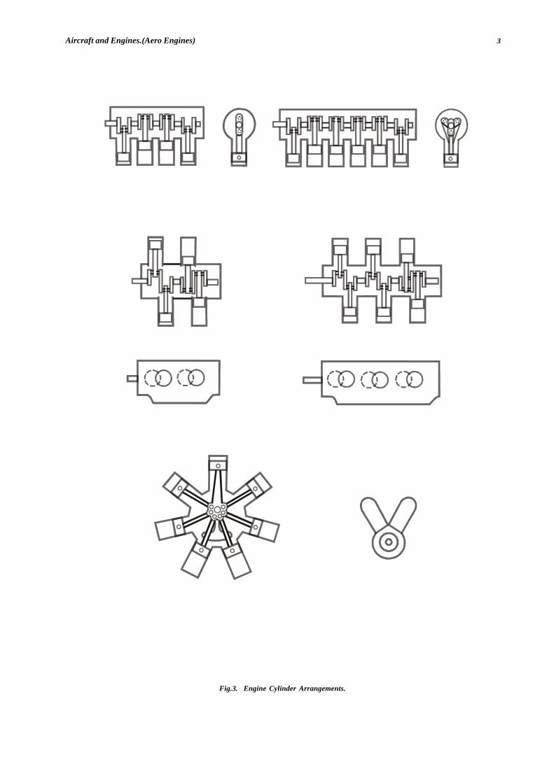
3Aircraft and Engines.(Aero Engines)
Fig.3. Engine Cylinder Arrangements.
(A ) F O U R C Y L IN D E R IN V E R T E D IN - L IN E (B ) S IX C YL IN D E R IN V E R T E D IN -L IN E
(C ) F O U R C Y L IN D E R H O R IZ O N TA L LY -O P P O S E D (D ) S IX C YL IN D E R H O R IZ O N TA L LY -O P P O S E D
(E ) S E V E N C Y L IN D E R R A D IA L (F ) V - T Y PE E N G IN E

4 L.N.V.M. Society Group of Institutes, Palam Extn., Part-1, Sec-7, Dwarka, New Delhi-45.
(b) Taking a seven cylinder radial engine as example, when the inlet valve on No.1 cylinder is open, the next inletvalve to open is on No 3 cylinder ( Since this is the next cylinder in the firing order ).The cams are 900 apart and thedrum must therefore rotate through an angle of (12 x 6/7)0 [the angle between No1 & No.3 cylinder is (102 6/7)0] inthe direction of rotation to open the required value on No.3 cylinder speed of rotation of the cam drum must be
8
1
7
6102
7
612 =÷ engine speed ( operation of cam drum on seven cylinder engine is shown in fig.4) On nine cylinder
engine the spacing of the cylinders is at 400 and successive valves open at every 800 of crankshaft movement. Sincethe cams are 900 apart, the cam drum must rotate in the opposite direction of rotation to the crankshaft, but still at 1/8 engine speed [(90-80]/80] =1/8
In-Line EngineIn line engines usually have four or six cylinders arranged in an upright or inverted row along the crankcase it is notusual to have more than six cylinders, because of the difficulty of cooling the rear cylinders and the length of thecrankshaft which would be required. In a four cylinder engine, four power strokes occur every two revolutions of thecrankshaft, and must be evenly spaced to provide smooth running with the firing order of 1,3,4,2 or 1,2,4,3. The camshaftwhich is a shaft having a cam for each valve in the engine, would be driven from the crankshaft at half engine speedand would operate the valves by means of push rods, and rockers. Each of the eight cams (two to each cylinders) wouldbe located on the cam shaft to open and close an inlet or exhaust valve in relation to the particular firing order andvalve timing prescribed for that engine. If the engine had six cylinders, there would be six power strokes every tworevolutions of the crankshaft and a cylinder would have to fire every 1200 of the crankshaft movement. This wouldnecessitate a crankshaft with throws (i.e. the offset portions of the crankshaft containing the crankpins) arrangedaccordingly. Suitably arranged cams would be provided. On the camshaft, which would still be driven at half the enginespeed. The firing orders of six cylinder engine is generally 1,4,2,6,3,5 but a different order could be used and thecrankshaft would be arranged differently.
Horizontally Opposed EnginesThe cylinders of a horizontally opposed engine (usually four or six) are arranged in horizontal banks on opposite sidesof crankcase. Most engines have individual connecting rods operating on separate crankpins, thus the cylinders arestaggered as shown in fig.3(c). A single camshaft is located either above or below the crankshaft, and is driven at halfengine speed to operate the valves in both banks of cylinders. On some engines the inlet valve cams are shared byopposite cylinders, so that the camshaft of six cylinder engine may have a total of 9 cams, six separate exhaust camsand three shared inlet cams. To minimize the length of the engine, a four cylinder engine may have three main(crankshaft) bearing and a six cylinder engine may have four. Because six firing strokes occur every two revolutionsof crankshaft of a six cylinder engine, the throws of the crankshaft must be arranged at 1200 to each other. In the sixcylinder engine shown in fig.3(d) the firing order would normally be 1,4,5,2,3,6, but different firing orders would bepossible on engines with different crankshaft and cam arrangements.
V-TypeThe V-type engine has the cylinders arranged on the crankcase in two rows or banks forming the letter V with an anglebetween the banks of 90, 60 or 45 degrees. There is always an even number of cylinders in each row.
Since the two banks of cylinders are opposite each other, two sets of connecting rods can operate on same crankpin,thereby reducing the weight as compared with the in-line engine. The frontal area is only slightly greater that of thein-line type, here the engine cowling can be streamlined to reduce drag. If the cylinders are above the crankshaft theengine is known as upright V-type, but if the cylinders are below the crankshaft, it is known as inverted V-type. Betterpilot visibility and a short 1/a are possible if the engine is inverted.
ENGINE CYCLEOtto CycleOtto cycle is the standard cycle for internal combustion engine (spark ignition (SI)). The sequence of process in theelementary operation of the S.I. engines is given below. With reference to fig. below where, the sketches of the engineand indicator diagram are given :-Process 1-2 : IntakeThe inlet valve is open, the piston moves to right admitting fuel-air mixture into the cylinder at constant pressure.Process 2-3 : CompressionBoth the valves are closed, the piston compresses the combustion to the minimum volume.Process 3-4 : CombustionThe mixture is then ignited by means of a spark, combustion takes place and there is an increase in temperature andpressure.Process 4-5 : ExpansionThe products of combustion do work on the piston which moves to the right and the pressure and temperature of gasesdecrease.Process 5-6 : Blow downThe exhaust valve opens and the pressure drops to the initial pressure.
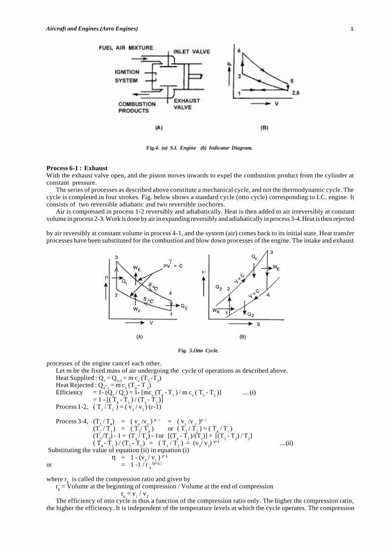
5Aircraft and Engines.(Aero Engines)
Process 6-1 : ExhaustWith the exhaust valve open, and the piston moves inwards to expel the combustion product from the cylinder atconstant pressure.
The series of processes as described above constitute a mechanical cycle, and not the thermodynamic cycle. Thecycle is completed in four strokes. Fig. below shows a standard cycle (otto cycle) corresponding to I.C. engine. Itconsists of two reversible adiabatic and two reversible isochores.
Air is compressed in process 1-2 reversibly and adiabatically. Heat is then added to air irreversibly at constantvolume in process 2-3. Work is done by air in expanding reversibly and adiabatically in process 3-4. Heat is then rejected
by air reversibly at constant volume in process 4-1, and the system (air) comes back to its initial state. Heat transferprocesses have been substituted for the combustion and blow down processes of the engine. The intake and exhaust
processes of the engine cancel each other.Let m be the fixed mass of air undergoing the cycle of operations as described above.Heat Supplied : Q
1 = Q
2-3 = m c
v (T
3 -T
2)
Heat Rejected : Q4-
1 = m c
v (T
4 - T
1)
Efficiency = 1- (Q2 / Q
1) = 1- [mc
v (T
4 - T
1 ) / m c
v ( T
3 - T
2 )] .... (i)
= 1 - [( T4 - T
1 ) / (T
3 - T
2 )]
Process 1-2, ( T2 / T
1 ) = ( v
1 / v
2 ) (r-1)
Process 3-4, (T3 / T
4) = ( v
4 /v
3 ) γ-1 = ( v
1 /v
2 )γ-1
(T2 / T
1 ) = ( T
3/ T
4 ) or ( T
3 / T
2 ) = ( T
4 / T
1 )
(T3 /T
2) - 1 = (T
4 / T
1) - 1or [(T
4 - T
1 )/(T
1)] = [(T
3 - T
2) / T
2]
( T4 - T
1 ) / (T
3 - T
2 ) = ( T
1 / T
2 ) = (v
2/ v
1) γ−1 ....(ii)
Substituting the value of equation (ii) in equation (i)η = 1 - (v
2 / v
1 ) γ−1
or = 1 -1 / r k
(γ−1)
where rk is called the compression ratio and given by
rk = Volume at the beginning of compression / Volume at the end of compression
rk = v
1 / v
2The efficiency of otto cycle is thus a function of the compression ratio only. The higher the compression ratio,
the higher the efficiency. It is independent of the temperature levels at which the cycle operates. The compression
Fig.4. (a) S.I. Engine (b) Indicator Diagram.
Fig. 5.Otto Cycle.
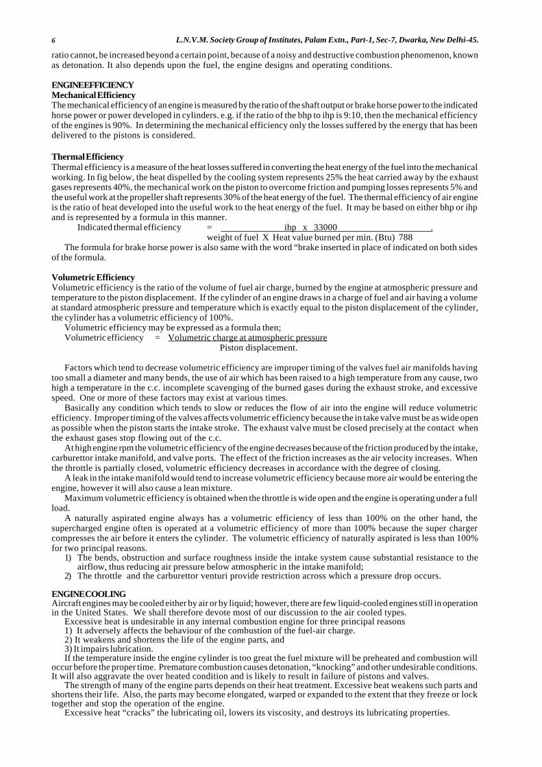
6 L.N.V.M. Society Group of Institutes, Palam Extn., Part-1, Sec-7, Dwarka, New Delhi-45.
ratio cannot, be increased beyond a certain point, because of a noisy and destructive combustion phenomenon, knownas detonation. It also depends upon the fuel, the engine designs and operating conditions.
ENGINE EFFICIENCYMechanical EfficiencyThe mechanical efficiency of an engine is measured by the ratio of the shaft output or brake horse power to the indicatedhorse power or power developed in cylinders. e.g. if the ratio of the bhp to ihp is 9:10, then the mechanical efficiencyof the engines is 90%. In determining the mechanical efficiency only the losses suffered by the energy that has beendelivered to the pistons is considered.
Thermal EfficiencyThermal efficiency is a measure of the heat losses suffered in converting the heat energy of the fuel into the mechanicalworking. In fig below, the heat dispelled by the cooling system represents 25% the heat carried away by the exhaustgases represents 40%, the mechanical work on the piston to overcome friction and pumping losses represents 5% andthe useful work at the propeller shaft represents 30% of the heat energy of the fuel. The thermal efficiency of air engineis the ratio of heat developed into the useful work to the heat energy of the fuel. It may be based on either bhp or ihpand is represented by a formula in this manner.
Indicated thermal efficiency = ihp x 33000 .weight of fuel X Heat value burned per min. (Btu) 788
The formula for brake horse power is also same with the word “brake inserted in place of indicated on both sidesof the formula.
Volumetric EfficiencyVolumetric efficiency is the ratio of the volume of fuel air charge, burned by the engine at atmospheric pressure andtemperature to the piston displacement. If the cylinder of an engine draws in a charge of fuel and air having a volumeat standard atmospheric pressure and temperature which is exactly equal to the piston displacement of the cylinder,the cylinder has a volumetric efficiency of 100%.
Volumetric efficiency may be expressed as a formula then;Volumetric efficiency = Volumetric charge at atmospheric pressure
Piston displacement.
Factors which tend to decrease volumetric efficiency are improper timing of the valves fuel air manifolds havingtoo small a diameter and many bends, the use of air which has been raised to a high temperature from any cause, twohigh a temperature in the c.c. incomplete scavenging of the burned gases during the exhaust stroke, and excessivespeed. One or more of these factors may exist at various times.
Basically any condition which tends to slow or reduces the flow of air into the engine will reduce volumetricefficiency. Improper timing of the valves affects volumetric efficiency because the in take valve must be as wide openas possible when the piston starts the intake stroke. The exhaust valve must be closed precisely at the contact whenthe exhaust gases stop flowing out of the c.c.
At high engine rpm the volumetric efficiency of the engine decreases because of the friction produced by the intake,carburettor intake manifold, and valve ports. The effect of the friction increases as the air velocity increases. Whenthe throttle is partially closed, volumetric efficiency decreases in accordance with the degree of closing.
A leak in the intake manifold would tend to increase volumetric efficiency because more air would be entering theengine, however it will also cause a lean mixture.
Maximum volumetric efficiency is obtained when the throttle is wide open and the engine is operating under a fullload.
A naturally aspirated engine always has a volumetric efficiency of less than 100% on the other hand, thesupercharged engine often is operated at a volumetric efficiency of more than 100% because the super chargercompresses the air before it enters the cylinder. The volumetric efficiency of naturally aspirated is less than 100%for two principal reasons.
1) The bends, obstruction and surface roughness inside the intake system cause substantial resistance to theairflow, thus reducing air pressure below atmospheric in the intake manifold;
2) The throttle and the carburettor venturi provide restriction across which a pressure drop occurs.
ENGINE COOLINGAircraft engines may be cooled either by air or by liquid; however, there are few liquid-cooled engines still in operationin the United States. We shall therefore devote most of our discussion to the air cooled types.
Excessive heat is undesirable in any internal combustion engine for three principal reasons1) It adversely affects the behaviour of the combustion of the fuel-air charge.2) It weakens and shortens the life of the engine parts, and3) It impairs lubrication.If the temperature inside the engine cylinder is too great the fuel mixture will be preheated and combustion will
occur before the proper time. Premature combustion causes detonation, “knocking” and other undesirable conditions.It will also aggravate the over heated condition and is likely to result in failure of pistons and valves.
The strength of many of the engine parts depends on their heat treatment. Excessive heat weakens such parts andshortens their life. Also, the parts may become elongated, warped or expanded to the extent that they freeze or locktogether and stop the operation of the engine.
Excessive heat “cracks” the lubricating oil, lowers its viscosity, and destroys its lubricating properties.
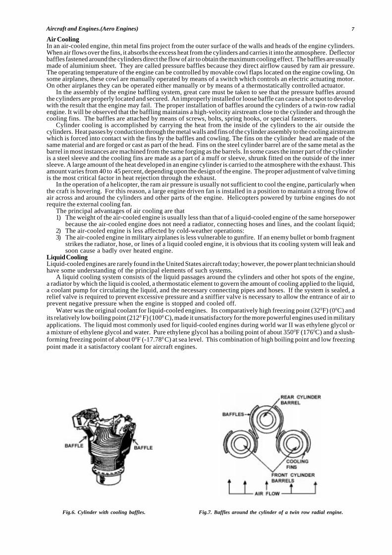
7Aircraft and Engines.(Aero Engines)
Air CoolingIn an air-cooled engine, thin metal fins project from the outer surface of the walls and heads of the engine cylinders.When air flows over the fins, it absorbs the excess heat from the cylinders and carries it into the atmosphere. Deflectorbaffles fastened around the cylinders direct the flow of air to obtain the maximum cooling effect. The baffles are usuallymade of aluminium sheet. They are called pressure baffles because they direct airflow caused by ram air pressure.The operating temperature of the engine can be controlled by movable cowl flaps located on the engine cowling. Onsome airplanes, these cowl are manually operated by means of a switch which controls an electric actuating motor.On other airplanes they can be operated either manually or by means of a thermostatically controlled actuator.
In the assembly of the engine baffling system, great care must be taken to see that the pressure baffles aroundthe cylinders are properly located and secured. An improperly installed or loose baffle can cause a hot spot to developwith the result that the engine may fail. The proper installation of baffles around the cylinders of a twin-row radialengine. It will be observed that the baffling maintains a high-velocity airstream close to the cylinder and through thecooling fins. The baffles are attached by means of screws, bolts, spring hooks, or special fasteners.
Cylinder cooling is accomplished by carrying the heat from the inside of the cylinders to the air outside thecylinders. Heat passes by conduction through the metal walls and fins of the cylinder assembly to the cooling airstreamwhich is forced into contact with the fins by the baffles and cowling. The fins on the cylinder head are made of thesame material and are forged or cast as part of the head. Fins on the steel cylinder barrel are of the same metal as thebarrel in most instances are machined from the same forging as the barrels. In some cases the inner part of the cylinderis a steel sleeve and the cooling fins are made as a part of a muff or sleeve, shrunk fitted on the outside of the innersleeve. A large amount of the heat developed in an engine cylinder is carried to the atmosphere with the exhaust. Thisamount varies from 40 to 45 percent, depending upon the design of the engine. The proper adjustment of valve timingis the most critical factor in heat rejection through the exhaust.
In the operation of a helicopter, the ram air pressure is usually not sufficient to cool the engine, particularly whenthe craft is hovering. For this reason, a large engine driven fan is installed in a position to maintain a strong flow ofair across and around the cylinders and other parts of the engine. Helicopters powered by turbine engines do notrequire the external cooling fan.
The principal advantages of air cooling are that1) The weight of the air-cooled engine is usually less than that of a liquid-cooled engine of the same horsepower
because the air-cooled engine does not need a radiator, connecting hoses and lines, and the coolant liquid;2) The air-cooled engine is less affected by cold-weather operations:3) The air-cooled engine in military airplanes is less vulnerable to gunfire. If an enemy bullet or bomb fragment
strikes the radiator, hose, or lines of a liquid cooled engine, it is obvious that its cooling system will leak andsoon cause a badly over heated engine.
Liquid CoolingLiquid-cooled engines are rarely found in the United States aircraft today; however, the power plant technician shouldhave some understanding of the principal elements of such systems.
A liquid cooling system consists of the liquid passages around the cylinders and other hot spots of the engine,a radiator by which the liquid is cooled, a thermostatic element to govern the amount of cooling applied to the liquid,a coolant pump for circulating the liquid, and the necessary connecting pipes and hoses. If the system is sealed, arelief valve is required to prevent excessive pressure and a sniffier valve is necessary to allow the entrance of air toprevent negative pressure when the engine is stopped and cooled off.
Water was the original coolant for liquid-cooled engines. Its comparatively high freezing point (320F) (00C) andits relatively low boiling point (2120 F) (1000 C), made it unsatisfactory for the more powerful engines used in militaryapplications. The liquid most commonly used for liquid-cooled engines during world war II was ethylene glycol ora mixture of ethylene glycol and water. Pure ethylene glycol has a boiling point of about 3500F (1760C) and a slush-forming freezing point of about 00F (-17.780 C) at sea level. This combination of high boiling point and low freezingpoint made it a satisfactory coolant for aircraft engines.
Fig.6. Cylinder with cooling baffles. Fig.7. Baffles around the cylinder of a twin row radial engine.
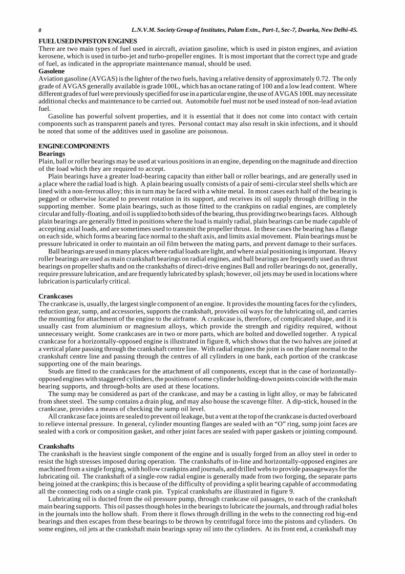
8 L.N.V.M. Society Group of Institutes, Palam Extn., Part-1, Sec-7, Dwarka, New Delhi-45.
FUEL USED IN PISTON ENGINESThere are two main types of fuel used in aircraft, aviation gasoline, which is used in piston engines, and aviationkerosene, which is used in turbo-jet and turbo-propeller engines. It is most important that the correct type and gradeof fuel, as indicated in the appropriate maintenance manual, should be used.GasoleneAviation gasoline (AVGAS) is the lighter of the two fuels, having a relative density of approximately 0.72. The onlygrade of AVGAS generally available is grade 100L, which has an octane rating of 100 and a low lead content. Wheredifferent grades of fuel were previously specified for use in a particular engine, the use of AVGAS 100L may necessitateadditional checks and maintenance to be carried out. Automobile fuel must not be used instead of non-lead aviationfuel.
Gasoline has powerful solvent properties, and it is essential that it does not come into contact with certaincomponents such as transparent panels and tyres. Personal contact may also result in skin infections, and it shouldbe noted that some of the additives used in gasoline are poisonous.
ENGINE COMPONENTSBearingsPlain, ball or roller bearings may be used at various positions in an engine, depending on the magnitude and directionof the load which they are required to accept.
Plain bearings have a greater load-bearing capacity than either ball or roller bearings, and are generally used ina place where the radial load is high. A plain bearing usually consists of a pair of semi-circular steel shells which arelined with a non-ferrous alloy; this in turn may be faced with a white metal. In most cases each half of the bearing ispegged or otherwise located to prevent rotation in its support, and receives its oil supply through drilling in thesupporting member. Some plain bearings, such as those fitted to the crankpins on radial engines, are completelycircular and fully-floating, and oil is supplied to both sides of the bearing, thus providing two bearings faces. Althoughplain bearings are generally fitted in positions where the load is mainly radial, plain bearings can be made capable ofaccepting axial loads, and are sometimes used to transmit the propeller thrust. In these cases the bearing has a flangeon each side, which forms a bearing face normal to the shaft axis, and limits axial movement. Plain bearings must bepressure lubricated in order to maintain an oil film between the mating parts, and prevent damage to their surfaces.
Ball bearings are used in many places where radial loads are light, and where axial positioning is important. Heavyroller bearings are used as main crankshaft bearings on radial engines, and ball bearings are frequently used as thrustbearings on propeller shafts and on the crankshafts of direct-drive engines Ball and roller bearings do not, generally,require pressure lubrication, and are frequently lubricated by splash; however, oil jets may be used in locations wherelubrication is particularly critical.
CrankcasesThe crankcase is, usually, the largest single component of an engine. It provides the mounting faces for the cylinders,reduction gear, sump, and accessories, supports the crankshaft, provides oil ways for the lubricating oil, and carriesthe mounting for attachment of the engine to the airframe. A crankcase is, therefore, of complicated shape, and it isusually cast from aluminium or magnesium alloys, which provide the strength and rigidity required, withoutunnecessary weight. Some crankcases are in two or more parts, which are bolted and dowelled together. A typicalcrankcase for a horizontally-opposed engine is illustrated in figure 8, which shows that the two halves are joined ata vertical plane passing through the crankshaft centre line. With radial engines the joint is on the plane normal to thecrankshaft centre line and passing through the centres of all cylinders in one bank, each portion of the crankcasesupporting one of the main bearings.
Studs are fitted to the crankcases for the attachment of all components, except that in the case of horizontally-opposed engines with staggered cylinders, the positions of some cylinder holding-down points coincide with the mainbearing supports, and through-bolts are used at these locations.
The sump may be considered as part of the crankcase, and may be a casting in light alloy, or may be fabricatedfrom sheet steel. The sump contains a drain plug, and may also house the scavenge filter. A dip-stick, housed in thecrankcase, provides a means of checking the sump oil level.
All crankcase face joints are sealed to prevent oil leakage, but a vent at the top of the crankcase is ducted overboardto relieve internal pressure. In general, cylinder mounting flanges are sealed with an “O” ring, sump joint faces aresealed with a cork or composition gasket, and other joint faces are sealed with paper gaskets or jointing compound.
CrankshaftsThe crankshaft is the heaviest single component of the engine and is usually forged from an alloy steel in order toresist the high stresses imposed during operation. The crankshafts of in-line and horizontally-opposed engines aremachined from a single forging, with hollow crankpins and journals, and drilled webs to provide passageways for thelubricating oil. The crankshaft of a single-row radial engine is generally made from two forging, the separate partsbeing joined at the crankpins; this is because of the difficulty of providing a split bearing capable of accommodatingall the connecting rods on a single crank pin. Typical crankshafts are illustrated in figure 9.
Lubricating oil is ducted from the oil pressure pump, through crankcase oil passages, to each of the crankshaftmain bearing supports. This oil passes though holes in the bearings to lubricate the journals, and through radial holesin the journals into the hollow shaft. From there it flows through drilling in the webs to the connecting rod big-endbearings and then escapes from these bearings to be thrown by centrifugal force into the pistons and cylinders. Onsome engines, oil jets at the crankshaft main bearings spray oil into the cylinders. At its front end, a crankshaft may
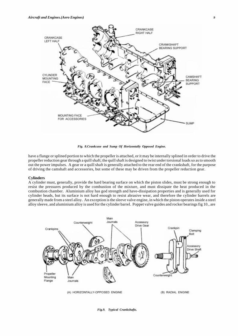
9Aircraft and Engines.(Aero Engines)
have a flange or splined portion to which the propeller is attached, or it may be internally splined in order to drive thepropeller reduction gear through a quill shaft; the quill shaft is designed to twist under torsional loads so as to smoothout the power impulses. A gear or a quill shaft is generally attached to the rear end of the crankshaft, for the purposeof driving the camshaft and accessories, but some of these may be driven from the propeller reduction gear.
CylindersA cylinder must, generally, provide the hard bearing surface on which the piston slides, must be strong enough toresist the pressures produced by the combustion of the mixture, and must dissipate the heat produced in thecombustion chamber. Aluminium alloy has god strength and have-dissipation properties and is generally used forcylinder heads, but its surface is not hard enough to resist abrasive wear, and therefore the cylinder barrels aregenerally made from a steel alloy. An exception is the sleeve valve engine, in which the piston operates inside a steelalloy sleeve, and aluminium alloy is used for the cylinder barrel. Poppet valve guides and rocker bearings fig 10., are
Fig. 8.Crankcase and Sump Of Horizontally Opposed Engine.
Fig.9. Typical Crankshafts.
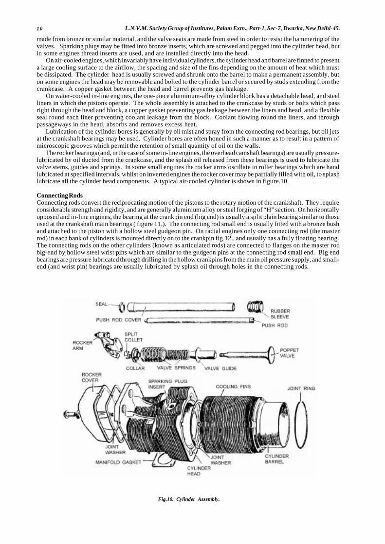
10 L.N.V.M. Society Group of Institutes, Palam Extn., Part-1, Sec-7, Dwarka, New Delhi-45.
made from bronze or similar material, and the valve seats are made from steel in order to resist the hammering of thevalves. Sparking plugs may be fitted into bronze inserts, which are screwed and pegged into the cylinder head, butin some engines thread inserts are used, and are installed directly into the head.
On air-cooled engines, which invariably have individual cylinders, the cylinder head and barrel are finned to presenta large cooling surface to the airflow, the spacing and size of the fins depending on the amount of heat which mustbe dissipated. The cylinder head is usually screwed and shrunk onto the barrel to make a permanent assembly, buton some engines the head may be removable and bolted to the cylinder barrel or secured by studs extending from thecrankcase. A copper gasket between the head and barrel prevents gas leakage.
On water-cooled in-line engines, the one-piece aluminium-alloy cylinder block has a detachable head, and steelliners in which the pistons operate. The whole assembly is attached to the crankcase by studs or bolts which passright through the head and block, a copper gasket preventing gas leakage between the liners and head, and a flexibleseal round each liner preventing coolant leakage from the block. Coolant flowing round the liners, and throughpassageways in the head, absorbs and removes excess heat.
Lubrication of the cylinder bores is generally by oil mist and spray from the connecting rod bearings, but oil jetsat the crankshaft bearings may be used. Cylinder bores are often honed in such a manner as to result in a pattern ofmicroscopic grooves which permit the retention of small quantity of oil on the walls.
The rocker bearings (and, in the case of some in-line engines, the overhead camshaft bearings) are usually pressure-lubricated by oil ducted from the crankcase, and the splash oil released from these bearings is used to lubricate thevalve stems, guides and springs. In some small engines the rocker arms oscillate in roller bearings which are handlubricated at specified intervals, whilst on inverted engines the rocker cover may be partially filled with oil, to splashlubricate all the cylinder head components. A typical air-cooled cylinder is shown in figure.10.
Connecting RodsConnecting rods convert the reciprocating motion of the pistons to the rotary motion of the crankshaft. They requireconsiderable strength and rigidity, and are generally aluminium alloy or steel forging of “H” section. On horizontallyopposed and in-line engines, the bearing at the crankpin end (big end) is usually a split plain bearing similar to thoseused at the crankshaft main bearings ( figure 11.). The connecting rod small end is usually fitted with a bronze bushand attached to the piston with a hollow steel gudgeon pin. On radial engines only one connecting rod (the masterrod) in each bank of cylinders is mounted directly on to the crankpin fig.12., and usually has a fully floating bearing.The connecting rods on the other cylinders (known as articulated rods) are connected to flanges on the master rodbig-end by hollow steel wrist pins which are similar to the gudgeon pins at the connecting rod small end. Big endbearings are pressure lubricated through drilling in the hollow crankpins from the main oil pressure supply, and small-end (and wrist pin) bearings are usually lubricated by splash oil through holes in the connecting rods.
Fig.10. Cylinder Assembly.
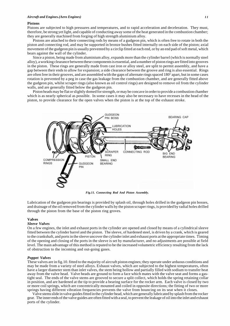
11Aircraft and Engines.(Aero Engines)
PistonsPistons are subjected to high pressures and temperatures, and to rapid acceleration and deceleration. They must,therefore, be strong yet light, and capable of conducting away some of the heat generated in the combustion chamber;they are generally machined from forging of high strength aluminium alloy.
Pistons are attached to their connecting rods by means of a gudgeon pin, which is often free to rotate in both thepiston and connecting rod, and may be supported in bronze bushes fitted internally on each side of the piston; axialmovement of the gudgeon pin is usually prevented by a circlip fitted at each end, or by an end pad of soft metal, whichbears against the wall of the cylinder.
Since a piston, being made from aluminium alloy, expands more than the cylinder barrel (which is normally steelalloy), a working clearance between these components is essential, and a number of piston rings are fitted into groovesin the piston. These rings are generally made from cast iron or alloy steel, are split to permit assembly, and have agap between their ends to allow for expansion; a side clearance between the groove and ring is also essential. Ringsare often free in their grooves, and are assembled with the gaps of alternate rings spaced 180o apart, but in some casesrotation is prevented by a peg in case the gas leakage from the combustion chamber, and are generally fitted abovethe gudgeon pin, whilst scraper rings (also known as oil control rings) are designed to remove oil from the cylinderwalls, and are generally fitted below the gudgeon pin.
Piston heads may be flat or slightly domed for strength, or may be concave in order to provide a combustion chamberwhich is as nearly spherical as possible. In some cases it may also be necessary to have recesses in the head of thepiston, to provide clearance for the open valves when the piston is at the top of the exhaust stroke.
Lubrication of the gudgeon pin bearings is provided by splash oil, through holes drilled in the gudgeon pin bosses,and drainage of the oil removed from the cylinder walls by the piston scraper rings, is provided by radial holes drilledthrough the piston from the base of the piston ring groves.
ValvesSleeve ValvesOn a few engines, the inlet and exhaust ports in the cylinder are opened and closed by means of a cylindrical sleevefitted between the cylinder barrel and the piston. The sleeve, of hardened steel, is driven by a crank, which is gearedto the crankshaft, and ports in the sleeve uncover the cylinder inlet and exhaust ports at the appropriate times. Timingof the opening and closing of the ports in the sleeve is set by manufacturer, and no adjustments are possible at fieldlevel. The main advantage of this method is reputed to be the increased volumetric efficiency resulting from the lackof obstruction to the incoming and out-going gases.
Poppet ValvesThese valves are in fig.10. fitted to the majority of aircraft piston engines; they operate under arduous conditions andmay be made from a variety of steel alloys. Exhaust valves, which are subjected to the highest temperatures, oftenhave a larger diameter stem than inlet valves, the stem being hollow and partially filled with sodium to transfer heataway from the valve head. Valve heads are ground to form a face which mates with the valve seat and forms a gas-tight seal. The ends of the valve stems are grooved to secure a split collect, which holds the spring retaining collarin position, and are hardened at the tip to provide a bearing surface for the rocker arm. Each valve is closed by twoor more coil springs, which are concentrically mounted and coiled in opposite directions; the fitting of two or moresprings having different vibration frequencies prevents the valve from bouncing on its seat when it closes.
Valve stems slide in valve guides fitted in the cylinder head, which are generally lubricated by splash from the rockergear. The inner ends of the valve guides are often fitted with a seal, to prevent the leakage of oil into the inlet and exhaustports of the cylinder.
Fig.11. Connecting Rod And Piston Assembly.
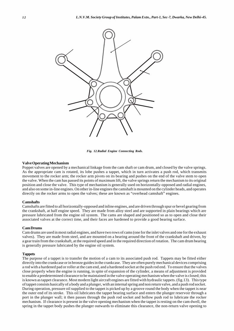
12 L.N.V.M. Society Group of Institutes, Palam Extn., Part-1, Sec-7, Dwarka, New Delhi-45.
Valve Operating MechanismPoppet valves are opened by a mechanical linkage from the cam shaft or cam drum, and closed by the valve springs.As the appropriate cam is rotated, its lobe pushes a tappet, which in turn activates a push rod, which transmitsmovement to the rocker arm; the rocker arm pivots on its bearing and pushes on the end of the valve stem to openthe valve. When the cam has passed its points of maximum lift, the valve springs return the mechanism to its originalposition and close the valve. This type of mechanism is generally used on horizontally-opposed and radial engines,and also on some in-line engines. On other in-line engines the camshaft is mounted on the cylinder heads, and operatesdirectly on the rocker arms to open the valves; these are known as “overhead camshaft” engines.
CamshaftsCamshafts are fitted to all horizontally-opposed and inline engines, and are driven through spur or bevel gearing fromthe crankshaft, at half engine speed. They are made from alloy steel and are supported in plain bearings which arepressure lubricated from the engine oil system. The cams are shaped and positioned so as to open and close theirassociated valves at the correct time, and their faces are hardened to provide a good bearing surface.
Cam DrumsCam drums are used in most radial engines, and have two rows of cams (one for the inlet valves and one for the exhaustvalves). They are made from steel, and are mounted on a bearing around the front of the crankshaft and driven, bya gear train from the crankshaft, at the required speed and in the required direction of rotation. The cam drum bearingis generally pressure lubricated by the engine oil system.
TappetsThe purpose of a tappet is to transfer the motion of a cam to its associated push rod. Tappets may be fitted eitherdirectly into the crankcase or in bronze guides in the crankcase. They are often purely mechanical devices comprisinga rod with a hardened pad or roller at the cam end, and a hardened socket at the push rod end. To ensure that the valvesclose properly when the engine is running, in spite of expansion of the cylinder, a means of adjustment is providedto enable a predetermined clearance to be maintained in the valve operating mechanism when the valve is closed; thisis known as tappet clearance. Most modern light aircraft engines are fitted with hydraulic tappets. (fig.13). This typeof tappet consists basically of a body and a plunger, with an internal spring and non return valve, and a push rod socket.During operation, pressure oil supplied to the tappet is picked up by a groove round the body when the tappet is nearthe outer end of its stroke. This oil lubricates the tappet bearing surface and enters the plunger reservoir through aport in the plunger wall; it then passes through the push rod socket and hollow push rod to lubricate the rockermechanism. If clearance is present in the valve opening mechanism when the tappet is resting on the cam dwell, thespring in the tappet body pushes the plunger outwards to eliminate this clearance, the non-return valve opening to
Fig. 12.Radial Engine Connecting Rods.
M A S T E R R O D
G U D G E O N P INB E A R IN G
A R T IC U L AT E DR O D
W R IS T P INB E A R IN G
W R IS T P INM A S T E R R O DB E A R IN G
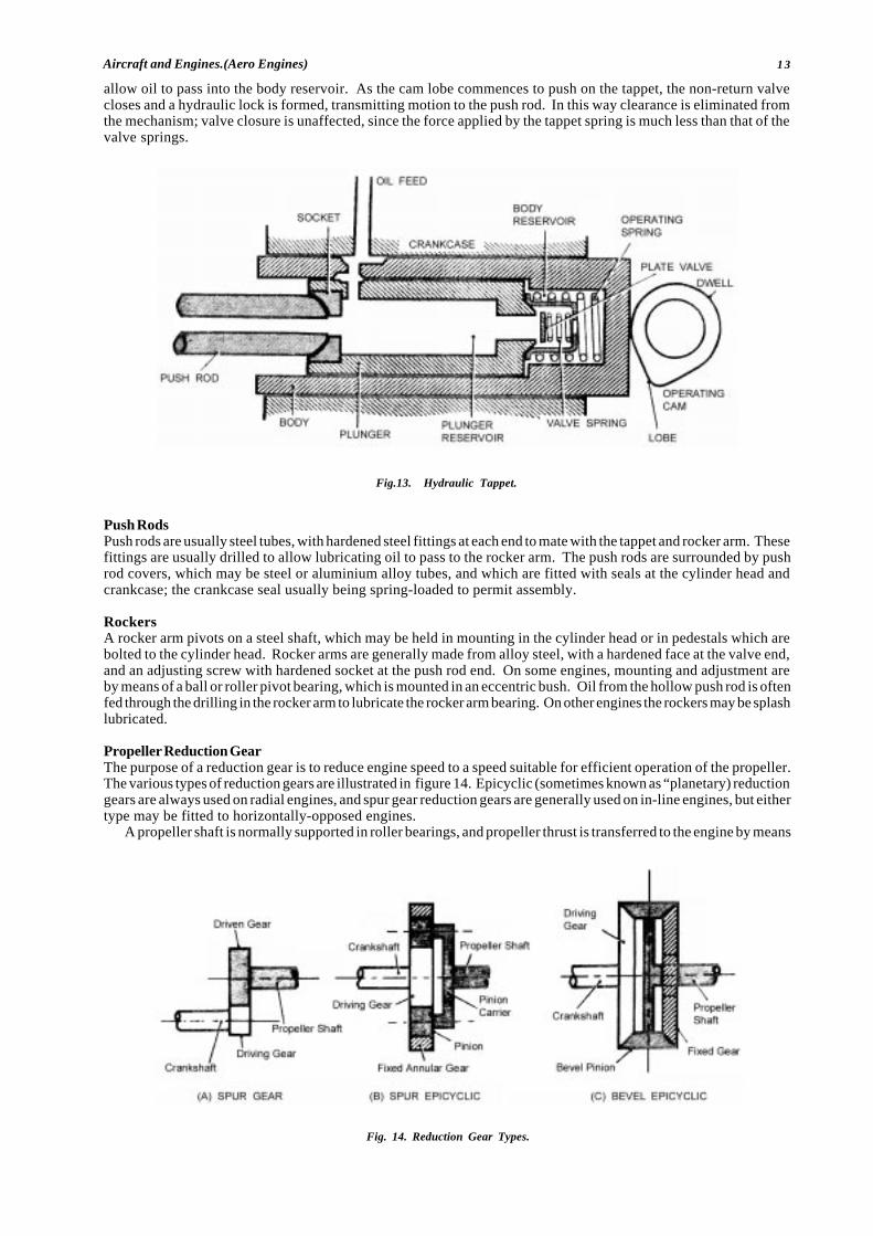
13Aircraft and Engines.(Aero Engines)
allow oil to pass into the body reservoir. As the cam lobe commences to push on the tappet, the non-return valvecloses and a hydraulic lock is formed, transmitting motion to the push rod. In this way clearance is eliminated fromthe mechanism; valve closure is unaffected, since the force applied by the tappet spring is much less than that of thevalve springs.
Push RodsPush rods are usually steel tubes, with hardened steel fittings at each end to mate with the tappet and rocker arm. Thesefittings are usually drilled to allow lubricating oil to pass to the rocker arm. The push rods are surrounded by pushrod covers, which may be steel or aluminium alloy tubes, and which are fitted with seals at the cylinder head andcrankcase; the crankcase seal usually being spring-loaded to permit assembly.
RockersA rocker arm pivots on a steel shaft, which may be held in mounting in the cylinder head or in pedestals which arebolted to the cylinder head. Rocker arms are generally made from alloy steel, with a hardened face at the valve end,and an adjusting screw with hardened socket at the push rod end. On some engines, mounting and adjustment areby means of a ball or roller pivot bearing, which is mounted in an eccentric bush. Oil from the hollow push rod is oftenfed through the drilling in the rocker arm to lubricate the rocker arm bearing. On other engines the rockers may be splashlubricated.
Propeller Reduction GearThe purpose of a reduction gear is to reduce engine speed to a speed suitable for efficient operation of the propeller.The various types of reduction gears are illustrated in figure 14. Epicyclic (sometimes known as “planetary) reductiongears are always used on radial engines, and spur gear reduction gears are generally used on in-line engines, but eithertype may be fitted to horizontally-opposed engines.
A propeller shaft is normally supported in roller bearings, and propeller thrust is transferred to the engine by means
Fig.13. Hydraulic Tappet.
Fig. 14. Reduction Gear Types.
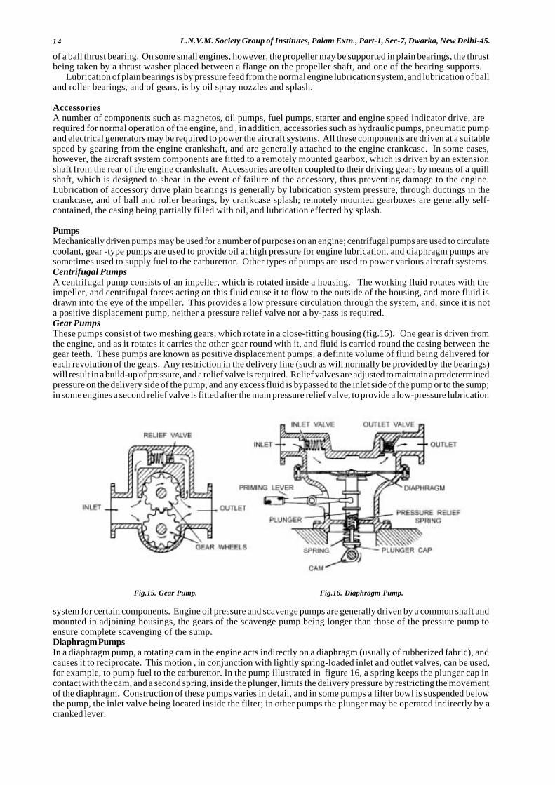
14 L.N.V.M. Society Group of Institutes, Palam Extn., Part-1, Sec-7, Dwarka, New Delhi-45.
of a ball thrust bearing. On some small engines, however, the propeller may be supported in plain bearings, the thrustbeing taken by a thrust washer placed between a flange on the propeller shaft, and one of the bearing supports.
Lubrication of plain bearings is by pressure feed from the normal engine lubrication system, and lubrication of balland roller bearings, and of gears, is by oil spray nozzles and splash.
AccessoriesA number of components such as magnetos, oil pumps, fuel pumps, starter and engine speed indicator drive, arerequired for normal operation of the engine, and , in addition, accessories such as hydraulic pumps, pneumatic pumpand electrical generators may be required to power the aircraft systems. All these components are driven at a suitablespeed by gearing from the engine crankshaft, and are generally attached to the engine crankcase. In some cases,however, the aircraft system components are fitted to a remotely mounted gearbox, which is driven by an extensionshaft from the rear of the engine crankshaft. Accessories are often coupled to their driving gears by means of a quillshaft, which is designed to shear in the event of failure of the accessory, thus preventing damage to the engine.Lubrication of accessory drive plain bearings is generally by lubrication system pressure, through ductings in thecrankcase, and of ball and roller bearings, by crankcase splash; remotely mounted gearboxes are generally self-contained, the casing being partially filled with oil, and lubrication effected by splash.
PumpsMechanically driven pumps may be used for a number of purposes on an engine; centrifugal pumps are used to circulatecoolant, gear -type pumps are used to provide oil at high pressure for engine lubrication, and diaphragm pumps aresometimes used to supply fuel to the carburettor. Other types of pumps are used to power various aircraft systems.Centrifugal PumpsA centrifugal pump consists of an impeller, which is rotated inside a housing. The working fluid rotates with theimpeller, and centrifugal forces acting on this fluid cause it to flow to the outside of the housing, and more fluid isdrawn into the eye of the impeller. This provides a low pressure circulation through the system, and, since it is nota positive displacement pump, neither a pressure relief valve nor a by-pass is required.Gear PumpsThese pumps consist of two meshing gears, which rotate in a close-fitting housing (fig.15). One gear is driven fromthe engine, and as it rotates it carries the other gear round with it, and fluid is carried round the casing between thegear teeth. These pumps are known as positive displacement pumps, a definite volume of fluid being delivered foreach revolution of the gears. Any restriction in the delivery line (such as will normally be provided by the bearings)will result in a build-up of pressure, and a relief valve is required. Relief valves are adjusted to maintain a predeterminedpressure on the delivery side of the pump, and any excess fluid is bypassed to the inlet side of the pump or to the sump;in some engines a second relief valve is fitted after the main pressure relief valve, to provide a low-pressure lubrication
Fig.15. Gear Pump. Fig.16. Diaphragm Pump.
system for certain components. Engine oil pressure and scavenge pumps are generally driven by a common shaft andmounted in adjoining housings, the gears of the scavenge pump being longer than those of the pressure pump toensure complete scavenging of the sump.Diaphragm PumpsIn a diaphragm pump, a rotating cam in the engine acts indirectly on a diaphragm (usually of rubberized fabric), andcauses it to reciprocate. This motion , in conjunction with lightly spring-loaded inlet and outlet valves, can be used,for example, to pump fuel to the carburettor. In the pump illustrated in figure 16, a spring keeps the plunger cap incontact with the cam, and a second spring, inside the plunger, limits the delivery pressure by restricting the movementof the diaphragm. Construction of these pumps varies in detail, and in some pumps a filter bowl is suspended belowthe pump, the inlet valve being located inside the filter; in other pumps the plunger may be operated indirectly by acranked lever.
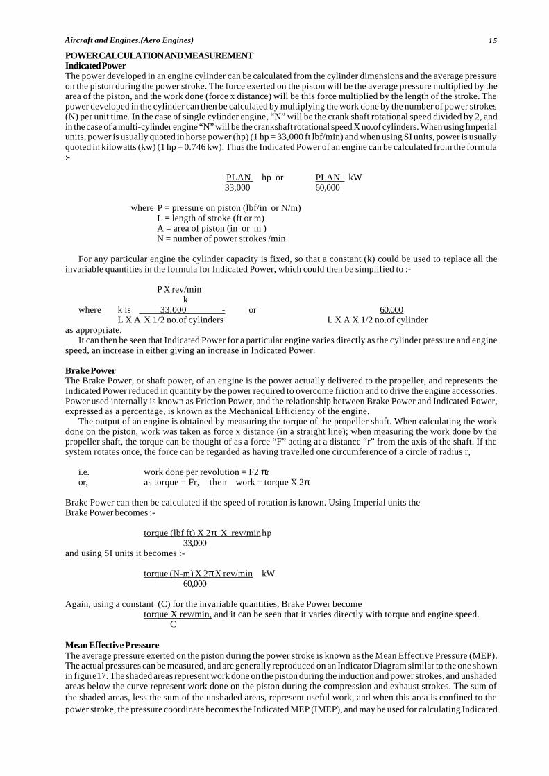
15Aircraft and Engines.(Aero Engines)
POWER CALCULATION AND MEASUREMENTIndicated PowerThe power developed in an engine cylinder can be calculated from the cylinder dimensions and the average pressureon the piston during the power stroke. The force exerted on the piston will be the average pressure multiplied by thearea of the piston, and the work done (force x distance) will be this force multiplied by the length of the stroke. Thepower developed in the cylinder can then be calculated by multiplying the work done by the number of power strokes(N) per unit time. In the case of single cylinder engine, “N” will be the crank shaft rotational speed divided by 2, andin the case of a multi-cylinder engine “N” will be the crankshaft rotational speed X no.of cylinders. When using Imperialunits, power is usually quoted in horse power (hp) (1 hp = 33,000 ft lbf/min) and when using SI units, power is usuallyquoted in kilowatts (kw) (1 hp = 0.746 kw). Thus the Indicated Power of an engine can be calculated from the formula:-
PLAN hp or PLAN kW 33,000 60,000
where P = pressure on piston (lbf/in or N/m)L = length of stroke (ft or m)A = area of piston (in or m )N = number of power strokes /min.
For any particular engine the cylinder capacity is fixed, so that a constant (k) could be used to replace all theinvariable quantities in the formula for Indicated Power, which could then be simplified to :-
P X rev/mink
where k is 33,000 - or 60,000L X A X 1/2 no.of cylinders L X A X 1/2 no.of cylinder
as appropriate.It can then be seen that Indicated Power for a particular engine varies directly as the cylinder pressure and engine
speed, an increase in either giving an increase in Indicated Power.
Brake PowerThe Brake Power, or shaft power, of an engine is the power actually delivered to the propeller, and represents theIndicated Power reduced in quantity by the power required to overcome friction and to drive the engine accessories.Power used internally is known as Friction Power, and the relationship between Brake Power and Indicated Power,expressed as a percentage, is known as the Mechanical Efficiency of the engine.
The output of an engine is obtained by measuring the torque of the propeller shaft. When calculating the workdone on the piston, work was taken as force x distance (in a straight line); when measuring the work done by thepropeller shaft, the torque can be thought of as a force “F” acting at a distance “r” from the axis of the shaft. If thesystem rotates once, the force can be regarded as having travelled one circumference of a circle of radius r,
i.e. work done per revolution = F2 πror, as torque = Fr, then work = torque X 2π
Brake Power can then be calculated if the speed of rotation is known. Using Imperial units theBrake Power becomes :-
torque (lbf ft) X 2π X rev/minhp33,000
and using SI units it becomes :-
torque (N-m) X 2π X rev/min kW60,000
Again, using a constant (C) for the invariable quantities, Brake Power becometorque X rev/min, and it can be seen that it varies directly with torque and engine speed.
C
Mean Effective PressureThe average pressure exerted on the piston during the power stroke is known as the Mean Effective Pressure (MEP).The actual pressures can be measured, and are generally reproduced on an Indicator Diagram similar to the one shownin figure17. The shaded areas represent work done on the piston during the induction and power strokes, and unshadedareas below the curve represent work done on the piston during the compression and exhaust strokes. The sum ofthe shaded areas, less the sum of the unshaded areas, represent useful work, and when this area is confined to thepower stroke, the pressure coordinate becomes the Indicated MEP (IMEP), and may be used for calculating Indicated
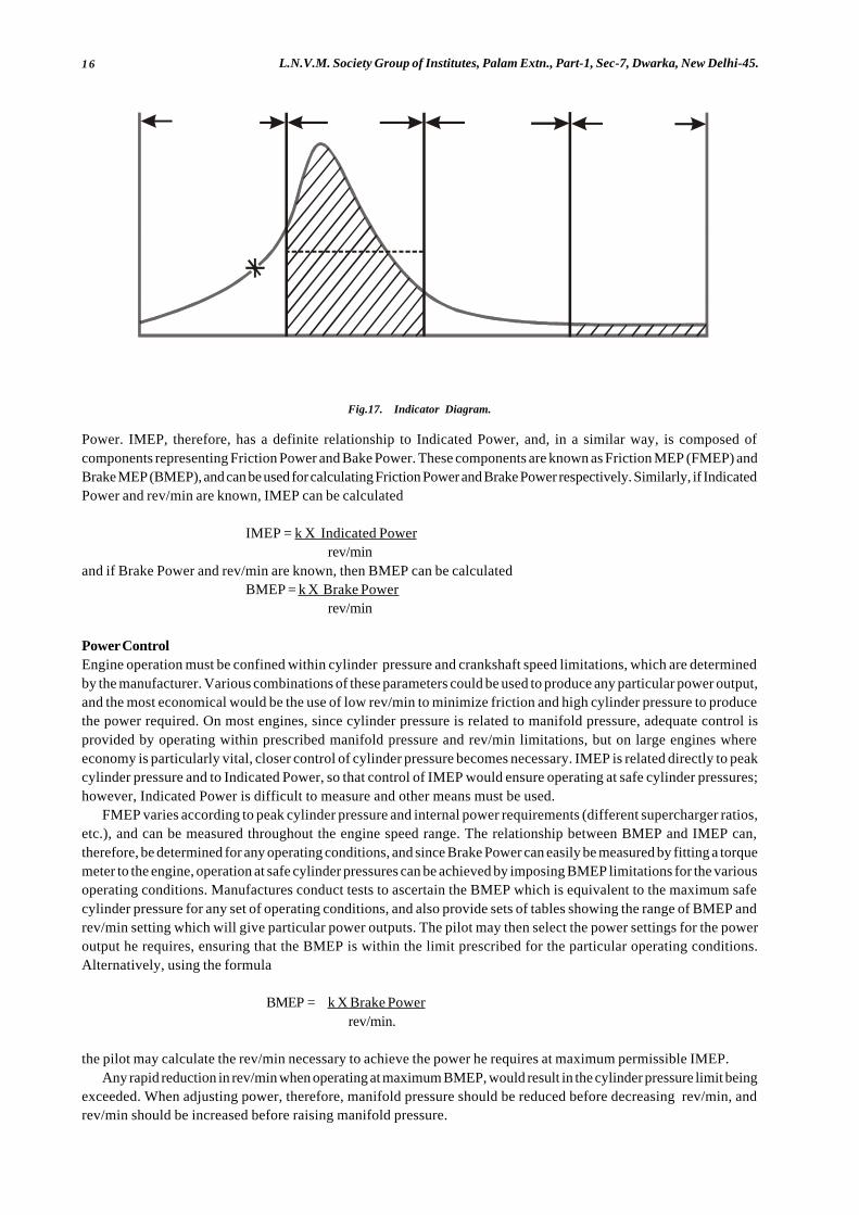
16 L.N.V.M. Society Group of Institutes, Palam Extn., Part-1, Sec-7, Dwarka, New Delhi-45.
C O M P R E S S IO NS T R O K E
P O W E RS T R O K E
E X H A U S TS T R O K E
IN D U C T IO NS T R O K E
IM E P
T D C B D CB D CT D CB D C
IG N I T IO N
PRES
SURE
C R A N K S H A F T A N G L E
Fig.17. Indicator Diagram.
Power. IMEP, therefore, has a definite relationship to Indicated Power, and, in a similar way, is composed ofcomponents representing Friction Power and Bake Power. These components are known as Friction MEP (FMEP) andBrake MEP (BMEP), and can be used for calculating Friction Power and Brake Power respectively. Similarly, if IndicatedPower and rev/min are known, IMEP can be calculated
IMEP = k X Indicated Powerrev/min
and if Brake Power and rev/min are known, then BMEP can be calculatedBMEP = k X Brake Power
rev/min
Power ControlEngine operation must be confined within cylinder pressure and crankshaft speed limitations, which are determinedby the manufacturer. Various combinations of these parameters could be used to produce any particular power output,and the most economical would be the use of low rev/min to minimize friction and high cylinder pressure to producethe power required. On most engines, since cylinder pressure is related to manifold pressure, adequate control isprovided by operating within prescribed manifold pressure and rev/min limitations, but on large engines whereeconomy is particularly vital, closer control of cylinder pressure becomes necessary. IMEP is related directly to peakcylinder pressure and to Indicated Power, so that control of IMEP would ensure operating at safe cylinder pressures;however, Indicated Power is difficult to measure and other means must be used.
FMEP varies according to peak cylinder pressure and internal power requirements (different supercharger ratios,etc.), and can be measured throughout the engine speed range. The relationship between BMEP and IMEP can,therefore, be determined for any operating conditions, and since Brake Power can easily be measured by fitting a torquemeter to the engine, operation at safe cylinder pressures can be achieved by imposing BMEP limitations for the variousoperating conditions. Manufactures conduct tests to ascertain the BMEP which is equivalent to the maximum safecylinder pressure for any set of operating conditions, and also provide sets of tables showing the range of BMEP andrev/min setting which will give particular power outputs. The pilot may then select the power settings for the poweroutput he requires, ensuring that the BMEP is within the limit prescribed for the particular operating conditions.Alternatively, using the formula
BMEP = k X Brake Powerrev/min.
the pilot may calculate the rev/min necessary to achieve the power he requires at maximum permissible IMEP.Any rapid reduction in rev/min when operating at maximum BMEP, would result in the cylinder pressure limit being
exceeded. When adjusting power, therefore, manifold pressure should be reduced before decreasing rev/min, andrev/min should be increased before raising manifold pressure.

17Aircraft and Engines.(Aero Engines)
TORQUE METERSPropeller shaft torque is generally measured at the reduction gear. As the crankshaft gear rotates, it drives the propellerpinions, and these exert a thrust on the fixed gear teeth, tending to rotate the fixed gear in the opposite direction tothe crankshaft gear; this thrust is directly proportional to power output. To measure the thrust applied to the fixedgear, the gear is allowed to float, and is attached to the structure through pistons and oil-filled cylinders, as shownin figure. Engine oil pressure to these cylinders is boosted by a torque meter pump, and each cylinder is fitted witha bleed back to the engine oil system.
OperationAt low engine power, thrust on the “fixed” gear is at a minimum and the bleed port is fully open, resulting in a low oilpressure in the system and a low reading on the torque meter pressure gauge. As power is increased the thrust onthe “fixed” gear increases, and the pistons are forced further into their cylinders. The bleed ports are reduced in sizeby movements of the pistons, and the oil pressure in the system increases to balance the thrust on the fixed gear.The torque meter gauge may be calibrated directly in BMEP, or in units of oil pressure.
Fig. 18. Torquemeter System.
� � �
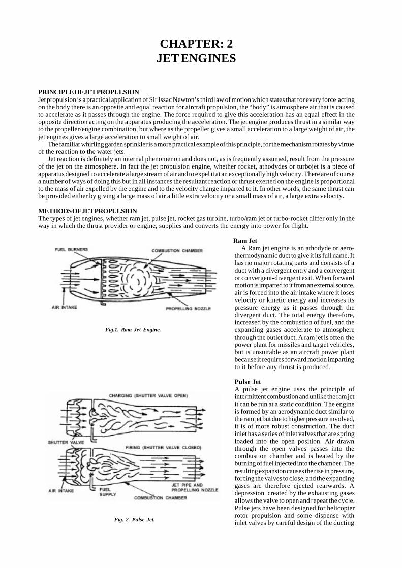
18 L.N.V.M. Society Group of Institutes, Palam Extn., Part-1, Sec-7, Dwarka, New Delhi-45.
CHAPTER: 2JET ENGINES
PRINCIPLE OF JET PROPULSIONJet propulsion is a practical application of Sir Issac Newton’s third law of motion which states that for every force actingon the body there is an opposite and equal reaction for aircraft propulsion, the “body” is atmosphere air that is causedto accelerate as it passes through the engine. The force required to give this acceleration has an equal effect in theopposite direction acting on the apparatus producing the acceleration. The jet engine produces thrust in a similar wayto the propeller/engine combination, but where as the propeller gives a small acceleration to a large weight of air, thejet engines gives a large acceleration to small weight of air.
The familiar whirling garden sprinkler is a more practical example of this principle, for the mechanism rotates by virtueof the reaction to the water jets.
Jet reaction is definitely an internal phenomenon and does not, as is frequently assumed, result from the pressureof the jet on the atmosphere. In fact the jet propulsion engine, whether rocket, athodydes or turbojet is a piece ofapparatus designed to accelerate a large stream of air and to expel it at an exceptionally high velocity. There are of coursea number of ways of doing this but in all instances the resultant reaction or thrust exerted on the engine is proportionalto the mass of air expelled by the engine and to the velocity change imparted to it. In other words, the same thrust canbe provided either by giving a large mass of air a little extra velocity or a small mass of air, a large extra velocity.
METHODS OF JET PROPULSIONThe types of jet engines, whether ram jet, pulse jet, rocket gas turbine, turbo/ram jet or turbo-rocket differ only in theway in which the thrust provider or engine, supplies and converts the energy into power for flight.
Ram Jet A Ram jet engine is an athodyde or aero-thermodynamic duct to give it its full name. Ithas no major rotating parts and consists of aduct with a divergent entry and a convergentor convergent-divergent exit. When forwardmotion is imparted to it from an external source,air is forced into the air intake where it losesvelocity or kinetic energy and increases itspressure energy as it passes through thedivergent duct. The total energy therefore,increased by the combustion of fuel, and theexpanding gases accelerate to atmospherethrough the outlet duct. A ram jet is often thepower plant for missiles and target vehicles,but is unsuitable as an aircraft power plantbecause it requires forward motion impartingto it before any thrust is produced.
Pulse JetA pulse jet engine uses the principle ofintermittent combustion and unlike the ram jetit can be run at a static condition. The engineis formed by an aerodynamic duct similar tothe ram jet but due to higher pressure involved,it is of more robust construction. The ductinlet has a series of inlet valves that are springloaded into the open position. Air drawnthrough the open valves passes into thecombustion chamber and is heated by theburning of fuel injected into the chamber. Theresulting expansion causes the rise in pressure,forcing the valves to close, and the expandinggases are therefore ejected rearwards. Adepression created by the exhausting gasesallows the valve to open and repeat the cycle.Pulse jets have been designed for helicopterrotor propulsion and some dispense withinlet valves by careful design of the ducting
Fig.1. Ram Jet Engine.
Fig. 2. Pulse Jet.
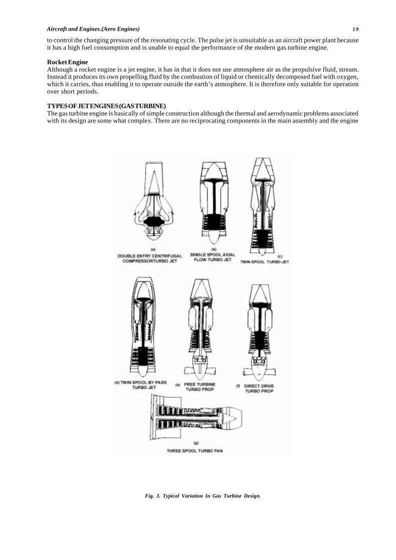
19Aircraft and Engines.(Aero Engines)
to control the changing pressure of the resonating cycle. The pulse jet is unsuitable as an aircraft power plant becauseit has a high fuel consumption and is unable to equal the performance of the modern gas turbine engine.
Rocket EngineAlthough a rocket engine is a jet engine, it has in that it does not use atmosphere air as the propulsive fluid, stream.Instead it produces its own propelling fluid by the combustion of liquid or chemically decomposed fuel with oxygen,which it carries, thus enabling it to operate outside the earth’s atmosphere. It is therefore only suitable for operationover short periods.
TYPES OF JET ENGINES (GAS TURBINE)The gas turbine engine is basically of simple construction although the thermal and aerodynamic problems associatedwith its design are some what complex. There are no reciprocating components in the main assembly and the engine
Fig. 3. Typical Variation In Gas Turbine Design.
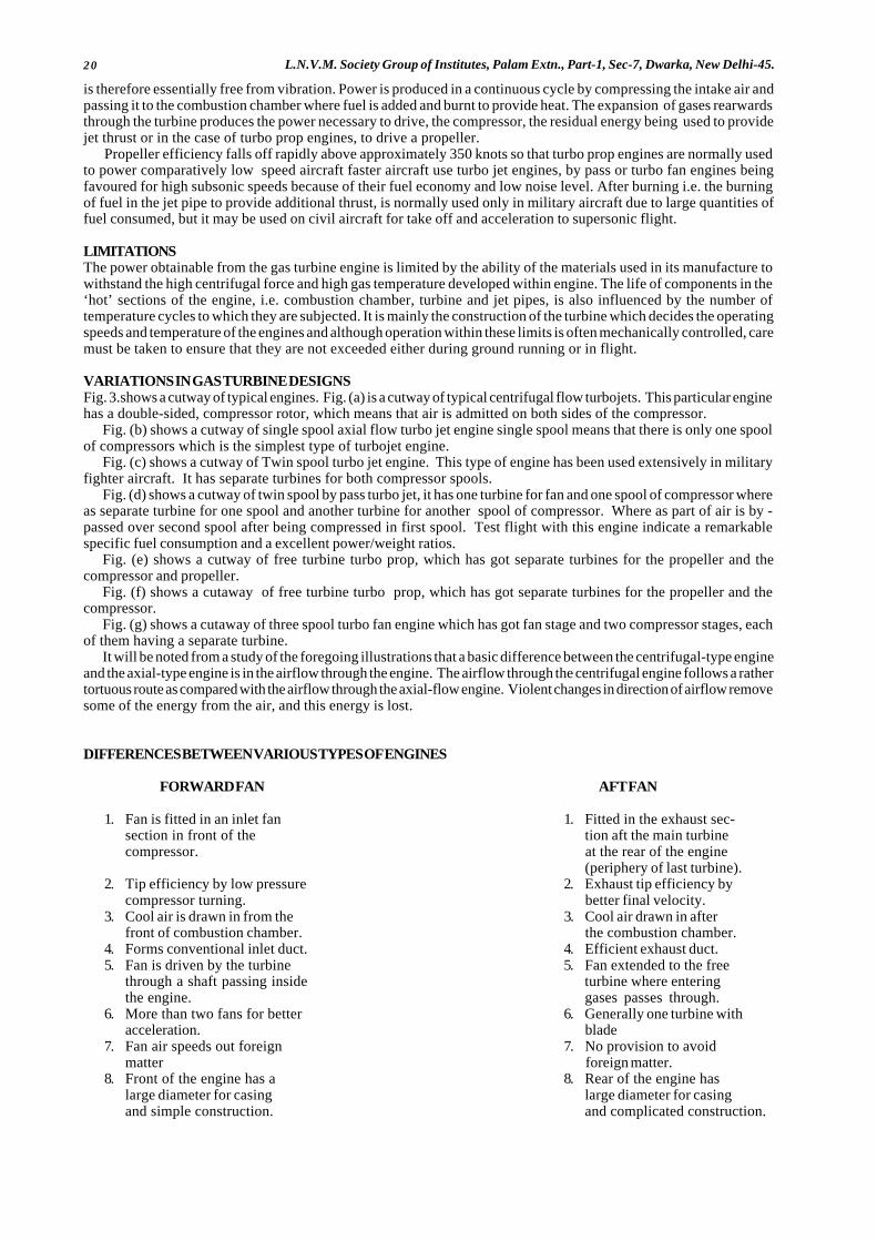
20 L.N.V.M. Society Group of Institutes, Palam Extn., Part-1, Sec-7, Dwarka, New Delhi-45.
is therefore essentially free from vibration. Power is produced in a continuous cycle by compressing the intake air andpassing it to the combustion chamber where fuel is added and burnt to provide heat. The expansion of gases rearwardsthrough the turbine produces the power necessary to drive, the compressor, the residual energy being used to providejet thrust or in the case of turbo prop engines, to drive a propeller.
Propeller efficiency falls off rapidly above approximately 350 knots so that turbo prop engines are normally usedto power comparatively low speed aircraft faster aircraft use turbo jet engines, by pass or turbo fan engines beingfavoured for high subsonic speeds because of their fuel economy and low noise level. After burning i.e. the burningof fuel in the jet pipe to provide additional thrust, is normally used only in military aircraft due to large quantities offuel consumed, but it may be used on civil aircraft for take off and acceleration to supersonic flight.
LIMITATIONSThe power obtainable from the gas turbine engine is limited by the ability of the materials used in its manufacture towithstand the high centrifugal force and high gas temperature developed within engine. The life of components in the‘hot’ sections of the engine, i.e. combustion chamber, turbine and jet pipes, is also influenced by the number oftemperature cycles to which they are subjected. It is mainly the construction of the turbine which decides the operatingspeeds and temperature of the engines and although operation within these limits is often mechanically controlled, caremust be taken to ensure that they are not exceeded either during ground running or in flight.
VARIATIONS IN GAS TURBINE DESIGNSFig. 3.shows a cutway of typical engines. Fig. (a) is a cutway of typical centrifugal flow turbojets. This particular enginehas a double-sided, compressor rotor, which means that air is admitted on both sides of the compressor.
Fig. (b) shows a cutway of single spool axial flow turbo jet engine single spool means that there is only one spoolof compressors which is the simplest type of turbojet engine.
Fig. (c) shows a cutway of Twin spool turbo jet engine. This type of engine has been used extensively in militaryfighter aircraft. It has separate turbines for both compressor spools.
Fig. (d) shows a cutway of twin spool by pass turbo jet, it has one turbine for fan and one spool of compressor whereas separate turbine for one spool and another turbine for another spool of compressor. Where as part of air is by -passed over second spool after being compressed in first spool. Test flight with this engine indicate a remarkablespecific fuel consumption and a excellent power/weight ratios.
Fig. (e) shows a cutway of free turbine turbo prop, which has got separate turbines for the propeller and thecompressor and propeller.
Fig. (f) shows a cutaway of free turbine turbo prop, which has got separate turbines for the propeller and thecompressor.
Fig. (g) shows a cutaway of three spool turbo fan engine which has got fan stage and two compressor stages, eachof them having a separate turbine.
It will be noted from a study of the foregoing illustrations that a basic difference between the centrifugal-type engineand the axial-type engine is in the airflow through the engine. The airflow through the centrifugal engine follows a rathertortuous route as compared with the airflow through the axial-flow engine. Violent changes in direction of airflow removesome of the energy from the air, and this energy is lost.
DIFFERENCES BETWEEN VARIOUS TYPES OF ENGINES
FORWARD FAN AFT FAN
1. Fan is fitted in an inlet fan 1. Fitted in the exhaust sec-section in front of the tion aft the main turbinecompressor. at the rear of the engine
(periphery of last turbine).2. Tip efficiency by low pressure 2. Exhaust tip efficiency by
compressor turning. better final velocity.3. Cool air is drawn in from the 3. Cool air drawn in after
front of combustion chamber. the combustion chamber.4. Forms conventional inlet duct. 4. Efficient exhaust duct.5. Fan is driven by the turbine 5. Fan extended to the free
through a shaft passing inside turbine where enteringthe engine. gases passes through.
6. More than two fans for better 6. Generally one turbine withacceleration. blade
7. Fan air speeds out foreign 7. No provision to avoidmatter foreign matter.
8. Front of the engine has a 8. Rear of the engine haslarge diameter for casing large diameter for casingand simple construction. and complicated construction.
21Aircraft and Engines.(Aero Engines)
DIFFERENCE BETWEEN TURBO JET AND TURBO PROP
TURBO JET TURBO PROP
1. No propeller in front . 1. Propeller in front.2. Thrust is due to the engine press- 2. Thrust is due to the
ure variation and final velocity. displacement of air.3. Simple air intake. 3. Complicated air intake.4. More noise to single or two 4. Less noise due to large
turbine. diameter turbine.5. Less air handled. 5. More air handled.6. More weight. 6. Less weight.7. No reduction gear. 7. Has reduction gear. 8. Turbine
drives compressor 8. Turbine drives propellerdirect drive. through, splined shaft.
9. Efficient at high altitude. 9. Efficient at low altitude.10. Ice formation at inlet 10. No ice formation, aircraft
position at high altitude. flies at low altitude.
DIFFERENCE BETWEEN TURBO PROP AND TURBO SHAFT
TURBO PROP TURBO SHAFT
1. Prop is fitted infront of the 1. Shaft is fitted at theturbine section. rear of the turbine section.
2. Prop shaft is separated from 2. Shaft is bolted to theconnecting torque shaft. turbine.
3. Drives propeller in same 3. Drives the rotor shaftengine axis or off set. 900 to the engine axis.
4. Is driven through spur or 4. The turbine speed is re-bevel planetary gear. duced through having bevel
planetary.5. Propeller throws the air 5. Rotor throws air towards
towards the rear. top, bottom or at angle.6. Speed of prop is more. 6. Speed of rotor shaft is less
CONSTRUCTIONAL DETAILS OF GAS TURBINE
MAJOR COMPONENTS OF GAS TURBINE ENGINESIn many types of turbine engines, it is not possible to list all the major components and have the list apply to all engines.There are several components and common to most turbine engines, however, and a knowledge of these will be helpfulin developing a further understanding of aviation gas-turbine engines.
The operation of any gas-turbine engine requires that provision be made for three principal functions:i) The compression of airii) The expansion of the air by burning fuel andiii) The extraction of power from the jet stream of the engine for driving the compressor and accessories. Thus, we
may say that gas-turbine engine comprises three main sections the compressor section, the combustion sectionand the turbine section.
In addition to these three main section, there are also component which serve to provide transition from one mainfunctional section to another. The following is a list of all the major components, arranged as they would appear fromthe front of the turbine to the rear.
i) Inlet duct and guide vanes.ii) The compressor.iii) The diffuser, with or without air adaptor.iv) The combustion chamber.v) The nozzle diaphragm.vi) The turbine.vii) The exhaust cone.viii) The after burners (if the engine is so equipped).ix) The accessory section (which may be located at the front of the engine or further to the rear).
The Inlet Duct And Guide VanesTurbine engine inlet duct must furnish a relatively distortion free and high energy supply of air on the required quantityto the compressor, the uniform and steady air flow is necessary to avoid compressor stall and excessively high enginetemperature at the turbines. The high energy enables the engine to produce an optimum amount of thrust. The air inlet
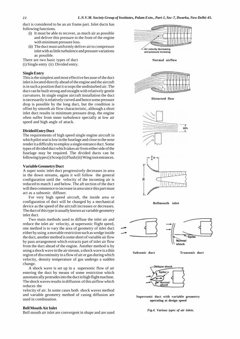
22 L.N.V.M. Society Group of Institutes, Palam Extn., Part-1, Sec-7, Dwarka, New Delhi-45.
duct is considered to be an air frame part. Inlet ducts hasfollowing functions.
(i) It must be able to recover, as much air as possibleand deliver this pressure to the front of the enginewith minimum pressure loss.
(ii) The duct must uniformly deliver air to compressorinlet with as little turbulence and pressure variationsas possible.
There are two basic types of duct(i) Single entry (ii) Divided entry.
Single EntryThis is the simplest and most effective because of the ductinlet is located directly ahead of the engine and the aircraftis in such a position that it scoops the undisturbed air. Theduct can be built strong and straight with relatively gentlecurvatures. In single engine aircraft installation the ductis necessarily is relatively curved and hence some pressuredrop is possible by the long duct, but the condition isoffset by smooth air flow characteristic, although a shortinlet duct results in minimum pressure drop, the engineoften suffer from inner turbulence specially at low airspeed and high angle of attack.
Divided Entry DuctThe requirements of high speed single engine aircraft inwhich pilot seat is low in the fuselage and close to the noserender it a difficulty to employ a single entrance duct. Sometypes of divided duct which takes air from either side of thefuselage may be required. The divided ducts can befollowing types (i) Scoop (ii) Flush (iii) Wing root entrances.
Variable Geometry DuctA super sonic inlet duct progressively decreases in areain the down streams, again it will follow the generalconfiguration until the velocity of the incoming air isreduced to match 1 and below. The aft section of the ductwill then commence to increase in area since this part mustact as a subsonic diffuser.
For very high speed aircraft, the inside area orconfiguration of duct will be changed by a mechanicaldevice as the speed of the aircraft increases or decreases.The duct of this type is usually known as variable geometryinlet duct.
Two main methods used to diffuse the inlet air andreduce the inlet air velocity, at supersonic flight speed,one method is to vary the area of geometry of inlet ducteither by using a movable restriction such as wedge insidethe duct, another method is some short of variable air flowby pass arrangement which extracts part of inlet air flowfrom the duct ahead of the engine. Another method is byusing a shock wave in the air stream, a shock wave is a thinregion of discontinuity in a flow of air or gas during whichvelocity, density temperature of gas undergo a suddenchange.
A shock wave is set up in a supersonic flow of airentering the duct by means of some restriction whichautomatically protrudes into the duct in high flight machine.The shock waves results in diffusion of this airflow whichreduces thevelocity of air. In some cases both shock waves methodand variable geometry method of casing diffusion areused in combination.
Bell Mouth Air InletBell mouth air inlet are convergent in shape and are used
Fig.4. Various types of air inlets.
Supersonic duct with variable geometry operating at design speed
Transonic ductSubsonic duct
Bellmouth inlet
Normal airflow
Distorted flow
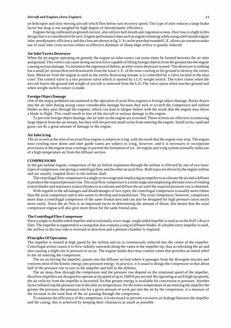
23Aircraft and Engines.(Aero Engines)
on helicopter and slow moving aircraft which flies below ram recovery speed. This type of inlet reduces a large brakefactor but drag is out weighed by high degree of Aerodynamic efficiency.
Engines being calibrated on ground run test, also utilizes bell mouth anti ingestion screen. Duct loss is slight in thisdesign that it is considered to be zero. Engine performance data such as engine trimming while using a bell mouth engineinlet, aerodynamic efficiency and duct loss are shown in fig.3. It can be seen that rounded L.E. allows air stream to makeuse of total inlet cross section where as effective diameter of sharp edge orifice is greatly reduced.
Air Inlet Vortex DestroyerWhen the jet engine operating on ground, the engine air inlet vortex can some times be formed between the air inletand ground. This vortex can cause strong suction force capable of lifting foreign objects from the ground into the enginecausing serious damage. To minimize the ingestion of debris, an inlet vortex destroyer is used. This destroyer is nothingbut a small jet stream directed downwards from the lower L.E. of the nose cowling to the ground to destroy the vortexbase. Bleed air from the engine is used as the vortex destroying stream, it is controlled by a valve located in the nosecowl. The control valve is a two position valve which is opened by a L/G weight switch. The valve closes when theaircraft leaves the ground and weight of aircraft is removed from the L/G.The valve opens when touches ground andwhen weight switch contact is made.
Foreign Object DamageOne of the major problems encountered in the operation of axial flow engines is foreign object damage. Rocks drawninto the air inlet during taxing cause considerable damage because they nick or scratch the compressor and turbineblades as they pass through the engines, which can lead to fatigue failure with the result that the engine may throwa blade in flight. This could result in loss of the aircraft or serious damage to the engine.
To prevent foreign object damage, the air inlet on the engine are screened. These screens are effective in removinglarge objects from the air stream, but they will not prevent small rocks from entering the engine. Small rocks, sand andgrass can do a great amount of damage to the engine.
Air Inlet IcingThe air screen at the inlet of an axial flow engine is subject to icing, with the result that the engine may stop. The enginenose cowling nose dome and inlet guide vanes are subject to icing, however, and it is necessary to incorporateprovisions in the engine nose cowlings to prevent the formation of ice. Jet engine anti icing system normally make useof a high temperature air from the diffuser section.
COMPRESSORSIn the gas turbine engine, compressor of the air before expansion through the turbine is effected by one of two basictypes of compressor, one giving a centrifugal flow and the other an axial flow. Both types are driven by the engine turbineand are usually coupled direct to the turbine shaft.
The centrifugal flow compressor is a single or two stage unit employing an impeller to accelerate the air and a diffuserto produce the required pressure rise. The axial flow compressor is a multi stage unit employing alternate rows of rotating(rotor) blades and stationary (stator) blades to accelerate and diffuse the air until the required pressure rise is obtained.
With regards to the advantages and disadvantages of two types, the centrifugal compressor is usually more robustthan the axial compressor and is also easier to develop and manufacture. The axial compressor, however, compressesmore than a centrifugal compressor of the same frontal area and can also be designed for high pressure ratios muchmore easily. Since the air flow is an important factor in determining the amount of thrust, this means that the axialcompressor engine will also give more thrust for the same frontal area.
The Centrifugal Flow CompressorHave a single or double sided impeller and occasionally a two-stage, single sided impeller is used as on the Roll’s RoyceDart. The impeller is supported in a casing that also contains a ring of diffuser blades. If a double entry impeller is used,the airflow to the rear side is reversed in direction and a plenum chamber is required.
Principles Of OperationThe impeller is rotated at high speed by the turbine and air is continuously induced into the centre of the impeller.Centrifugal action causes it to flow radially outwards along the vanes to the impeller tip, thus accelerating the air andalso causing a slight rise in pressure to occur. The engine intake duct may contain vanes that provides an initial whirlto the air entering the compressor.
The air on having the impeller, passes into the diffuser section where it passages from the divergent nozzles andconverts most of the kinetic energy into pressure energy. In practice, it is usual to design the compressor so that abouthalf of the pressure rise occurs in the impeller and half in the diffuser.
The air mass flow through the compressor and the pressure rise depend on the rotational speed of the impeller,therefore impellers are designed to operate at tip speed of up to 1600 ft per second. By operating at such high tip speeds,the air velocity from the impeller is increased. So that greater energy is available for conversion to pressure. Anotherfactor influencing the pressure rise is the inlet air temperature, for the lower temperature of air entering the impeller thegreater the pressure, the pressure rise for a given amount of work put into the air by the compressor, is a measure ofthe increase in the total heat of the air passing through the compressor.
To maintain the efficiency of the compressor, it is necessary to prevent excessive air leakage between the impellerand the casing, this is achieved by keeping their clearances as small as possible.
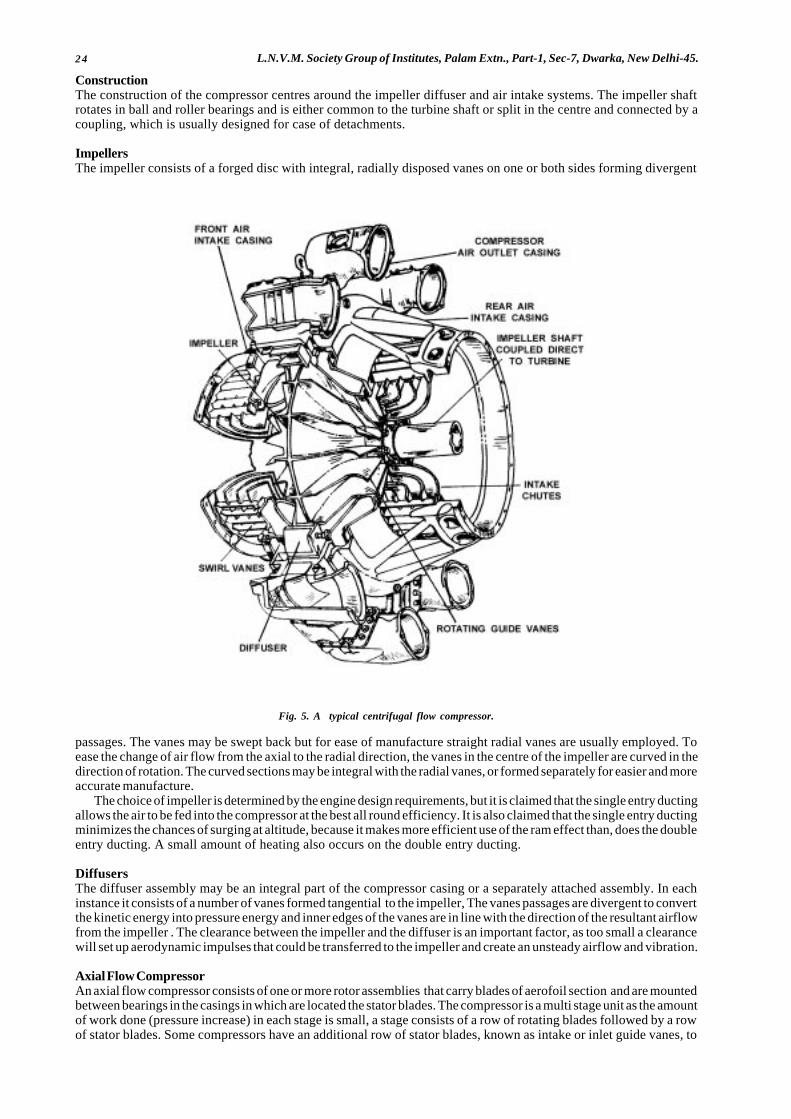
24 L.N.V.M. Society Group of Institutes, Palam Extn., Part-1, Sec-7, Dwarka, New Delhi-45.
ConstructionThe construction of the compressor centres around the impeller diffuser and air intake systems. The impeller shaftrotates in ball and roller bearings and is either common to the turbine shaft or split in the centre and connected by acoupling, which is usually designed for case of detachments.
ImpellersThe impeller consists of a forged disc with integral, radially disposed vanes on one or both sides forming divergent
Fig. 5. A typical centrifugal flow compressor.
passages. The vanes may be swept back but for ease of manufacture straight radial vanes are usually employed. Toease the change of air flow from the axial to the radial direction, the vanes in the centre of the impeller are curved in thedirection of rotation. The curved sections may be integral with the radial vanes, or formed separately for easier and moreaccurate manufacture.
The choice of impeller is determined by the engine design requirements, but it is claimed that the single entry ductingallows the air to be fed into the compressor at the best all round efficiency. It is also claimed that the single entry ductingminimizes the chances of surging at altitude, because it makes more efficient use of the ram effect than, does the doubleentry ducting. A small amount of heating also occurs on the double entry ducting.
DiffusersThe diffuser assembly may be an integral part of the compressor casing or a separately attached assembly. In eachinstance it consists of a number of vanes formed tangential to the impeller, The vanes passages are divergent to convertthe kinetic energy into pressure energy and inner edges of the vanes are in line with the direction of the resultant airflowfrom the impeller . The clearance between the impeller and the diffuser is an important factor, as too small a clearancewill set up aerodynamic impulses that could be transferred to the impeller and create an unsteady airflow and vibration.
Axial Flow CompressorAn axial flow compressor consists of one or more rotor assemblies that carry blades of aerofoil section and are mountedbetween bearings in the casings in which are located the stator blades. The compressor is a multi stage unit as the amountof work done (pressure increase) in each stage is small, a stage consists of a row of rotating blades followed by a rowof stator blades. Some compressors have an additional row of stator blades, known as intake or inlet guide vanes, to
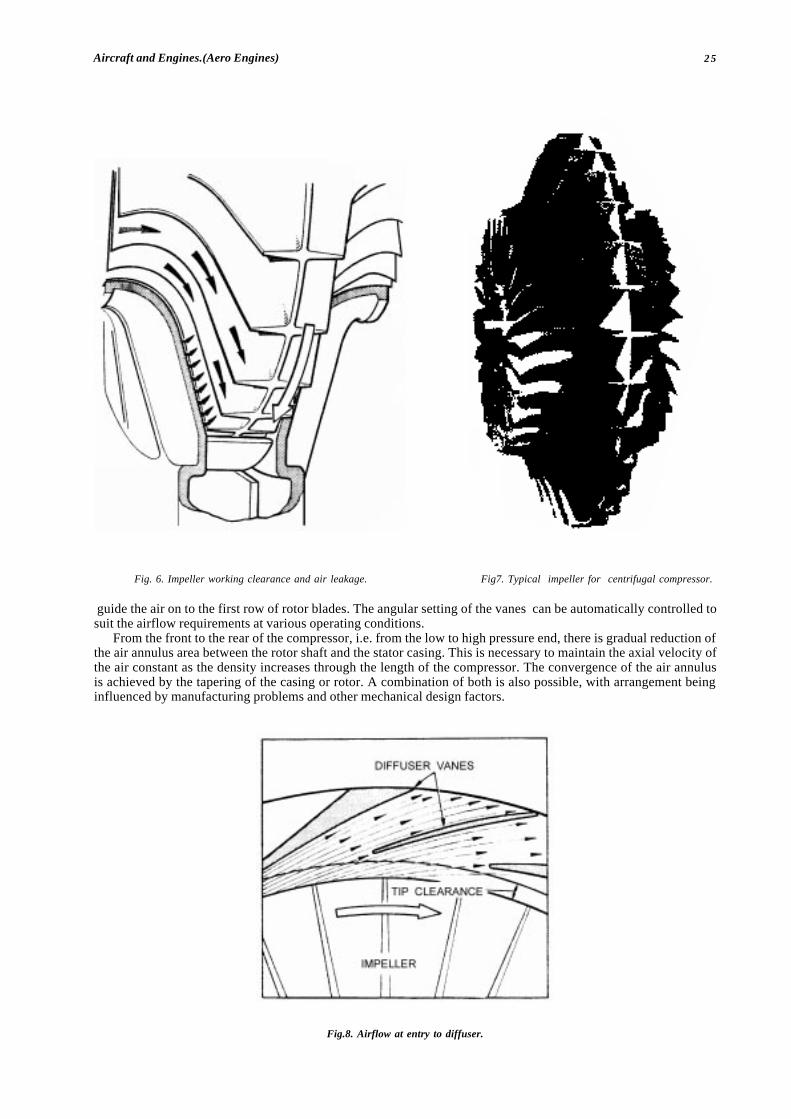
25Aircraft and Engines.(Aero Engines)
Fig. 6. Impeller working clearance and air leakage. Fig7. Typical impeller for centrifugal compressor.
guide the air on to the first row of rotor blades. The angular setting of the vanes can be automatically controlled tosuit the airflow requirements at various operating conditions.
From the front to the rear of the compressor, i.e. from the low to high pressure end, there is gradual reduction ofthe air annulus area between the rotor shaft and the stator casing. This is necessary to maintain the axial velocity ofthe air constant as the density increases through the length of the compressor. The convergence of the air annulusis achieved by the tapering of the casing or rotor. A combination of both is also possible, with arrangement beinginfluenced by manufacturing problems and other mechanical design factors.
Fig.8. Airflow at entry to diffuser.

26 L.N.V.M. Society Group of Institutes, Palam Extn., Part-1, Sec-7, Dwarka, New Delhi-45.
Fig. 9. Typical Axial Flow Compressors.
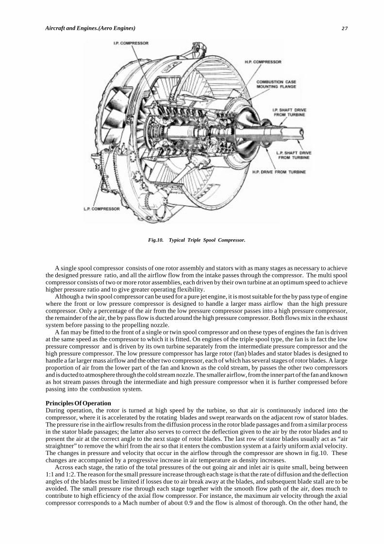
27Aircraft and Engines.(Aero Engines)
A single spool compressor consists of one rotor assembly and stators with as many stages as necessary to achievethe designed pressure ratio, and all the airflow flow from the intake passes through the compressor. The multi spoolcompressor consists of two or more rotor assemblies, each driven by their own turbine at an optimum speed to achievehigher pressure ratio and to give greater operating flexibility.
Although a twin spool compressor can be used for a pure jet engine, it is most suitable for the by pass type of enginewhere the front or low pressure compressor is designed to handle a larger mass airflow than the high pressurecompressor. Only a percentage of the air from the low pressure compressor passes into a high pressure compressor,the remainder of the air, the by pass flow is ducted around the high pressure compressor. Both flows mix in the exhaustsystem before passing to the propelling nozzle.
A fan may be fitted to the front of a single or twin spool compressor and on these types of engines the fan is drivenat the same speed as the compressor to which it is fitted. On engines of the triple spool type, the fan is in fact the lowpressure compressor and is driven by its own turbine separately from the intermediate pressure compressor and thehigh pressure compressor. The low pressure compressor has large rotor (fan) blades and stator blades is designed tohandle a far larger mass airflow and the other two compressor, each of which has several stages of rotor blades. A largeproportion of air from the lower part of the fan and known as the cold stream, by passes the other two compressorsand is ducted to atmosphere through the cold stream nozzle. The smaller airflow, from the inner part of the fan and knownas hot stream passes through the intermediate and high pressure compressor when it is further compressed beforepassing into the combustion system.
Principles Of OperationDuring operation, the rotor is turned at high speed by the turbine, so that air is continuously induced into thecompressor, where it is accelerated by the rotating blades and swept rearwards on the adjacent row of stator blades.The pressure rise in the airflow results from the diffusion process in the rotor blade passages and from a similar processin the stator blade passages; the latter also serves to correct the deflection given to the air by the rotor blades and topresent the air at the correct angle to the next stage of rotor blades. The last row of stator blades usually act as “airstraightner” to remove the whirl from the air so that it enters the combustion system at a fairly uniform axial velocity.The changes in pressure and velocity that occur in the airflow through the compressor are shown in fig.10. Thesechanges are accompanied by a progressive increase in air temperature as density increases.
Across each stage, the ratio of the total pressures of the out going air and inlet air is quite small, being between1:1 and 1:2. The reason for the small pressure increase through each stage is that the rate of diffusion and the deflectionangles of the blades must be limited if losses due to air break away at the blades, and subsequent blade stall are to beavoided. The small pressure rise through each stage together with the smooth flow path of the air, does much tocontribute to high efficiency of the axial flow compressor. For instance, the maximum air velocity through the axialcompressor corresponds to a Mach number of about 0.9 and the flow is almost of thorough. On the other hand, the
Fig.10. Typical Triple Spool Compressor.
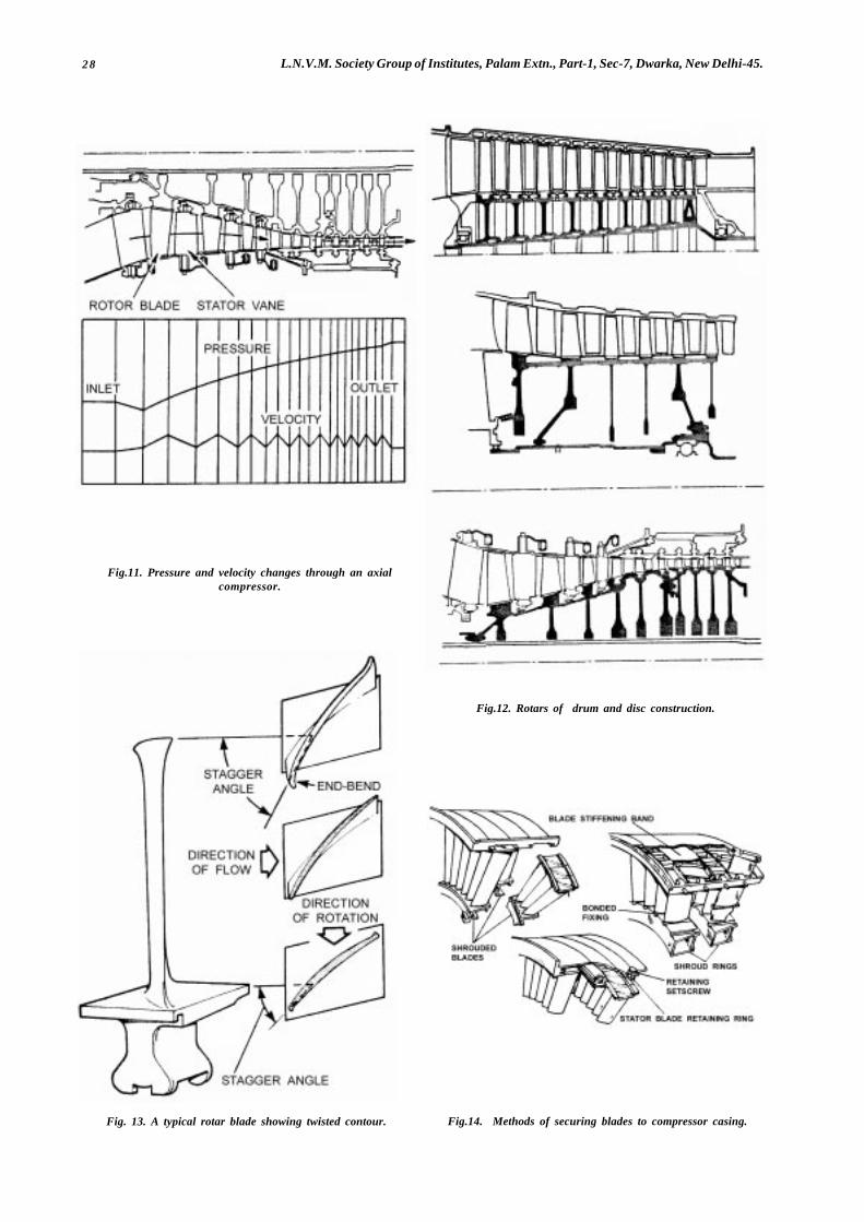
28 L.N.V.M. Society Group of Institutes, Palam Extn., Part-1, Sec-7, Dwarka, New Delhi-45.
Fig.11. Pressure and velocity changes through an axialcompressor.
Fig.12. Rotars of drum and disc construction.
Fig. 13. A typical rotar blade showing twisted contour. Fig.14. Methods of securing blades to compressor casing.

29Aircraft and Engines.(Aero Engines)
velocity through a centrifugal compressor is super sonic in places, reaching a Mach number of 1.2; the flow in thisinstance is tortuous culminating in a right angle bend at the outlet to the combustion chamber.
Because an axial flow compressor requires a large number of stages to produce a high compressor ratio, as the numberof stages increases it becomes more difficult to ensure that each stage will operate efficiently over a engine speed range.An automatic system of airflow control is sometimes necessary to maintain compressor efficiency, but a more flexiblyoperated engine can be achieved by having more than one compressor with each compressor being an independentsystem, driven by separate turbine assemblies through coaxial shafts. The compressor, therefore be designed to operatemore efficiently and with greater flexibility over a wide speed range.
A by pass engine invariably has a spool compressor with the low pressure compressor supplying sufficient air forboth the by pass system and the high pressure compressor. Still greater flexibility can be obtained and higher maximumcompression ratios reached by using an automatic airflow control system for high pressure compressor, this methodis used on the Rolls Royce spey series of engines. Although an engine may have a front or an aft fan, the front fanis favoured by most manufactures as giving greater reliability, due to the fan operating in the cold section of the engine.The fan can have one or more stages of large blades, both rotor and stator. The rotor blades can be fitted to the frontof a compressor or be part of a complete compressor driven by its own turbine. The air accelerated by the outer portionof the blades forms a by pass or secondary airflow that is ducted to atmosphere, the main airflow from the inner portionof blade passes through the remainder of the compressor and into the combustion systems. Only one stage of bladesis used on the fan of triple spool engines, because the blades are designed to operate at transonic tip speeds. This permitsthe desired compression ratio to be achieved and not only reduces the weight of engine but also its noise level.
ConstructionThe construction of the compressor centres around the rotor assembly and casings. The rotor shaft is supported inball and roller bearings and is coupled to the turbine shaft. The casing assembly consists of a number of cylindricalcasings some of which are in two halves to facilitate engine assembly and inspection, these are bolted together tocompletely house the rotor.
RotorsThe rotor assembly may be of a disc construction (in fig) or of drum, or a combination of both types may be used. Thedrum type rotor consists of a one or two piece forging on to which are secured the rotor blades. The disc type rotorhas the rotor blades attached to separate discs, which are then splined to the rotor shaft and separated by integral orindividual spacer rings. In the former type axial thrust and radial load both are taken by the drums where as in disc typeradial load is taken by the disc and axial thrust by the black platform and spacer rings. The accumulated end thrust istaken by the end of the or the end discs.
Rotor BladesThe rotor blades are of aerofoil section (in fig) and are usually designed to give a pressure gradient their length to ensurethat the air maintains a fairly uniform axial velocity. The higher pressure towards the tip balances out the centrifugalaction of the rotor on the airstream. To obtain thrust condition, it is necessary to twist the blade from root to tip to givethe correct angle of incidence at each point. The length of the blades varies from front to rear, the front or low pressureblades being the longest.
Stator BladesThe stator blades are again of aerofoil section and are secured into the compressor casing or into stator blade retainingring, which are themselves secured to the casings. The blades are often mounted in packs in the front stages and maybe shrouded at their tips to minimize the vibrational effect of flow variation on the longer blades. It is also necessaryto lock the stator blades in such a manner that they will not rotate around the casings.
Operating ConditionsEach stage of a multi-stage compressor processes certain airflow characteristics that are dissimilar from those of itsneighbour: thus, to design a workable and efficient compressor, the characteristics of each stage must be carefullymatched. This is a relatively simple process to carry out for one set of conditions ( design mass flow, pressure ratioand rotational speed), but is much more difficult if reasonable matching is to be retained when the compressor isoperating over a wide range of conditions such as an aircraft engine encounters.
Outside the design conditions, the flow around the blade tends to degenerate into violent turbulence when thesmooth flow of air through the compressor is disturbed. Although the two terms ‘stall ‘ and ‘ surge ‘ are often usedsynonymously, there is a difference which is mainly a matter of degree. A stall may affect only one stage or even a groupof stages, but a compressor surge generally refers to a complete flow breakdown through the compressor.
Compressor blades are designed to produce a given pressure rise and velocity increase over the engine speed range.If something should disturb the pressure, velocity, rotational speed relationship the airflow across the blade profilewill break away and create eddies until eventually the blade ‘ stalls ‘. This could occur if the airflow was reduced dueto icing or a flight manoeuvre, or if the fuel system scheduled too high a fuel flow; damage due to ingestion could, ofcourse, create a similar condition.
If the stall condition of a stage or group of stages continues until all stages are stalled, then the compressor willsurge . The transition from a stall to a surge could be so rapid as to be unnoticed; on the other hand, a stall may beso weak as to produce only a slight vibration or poor acceleration or deceleration characteristics.
At low engine speeds or 'off design' speeds, a slight degree of blade stalling invariably occurs in the front stages
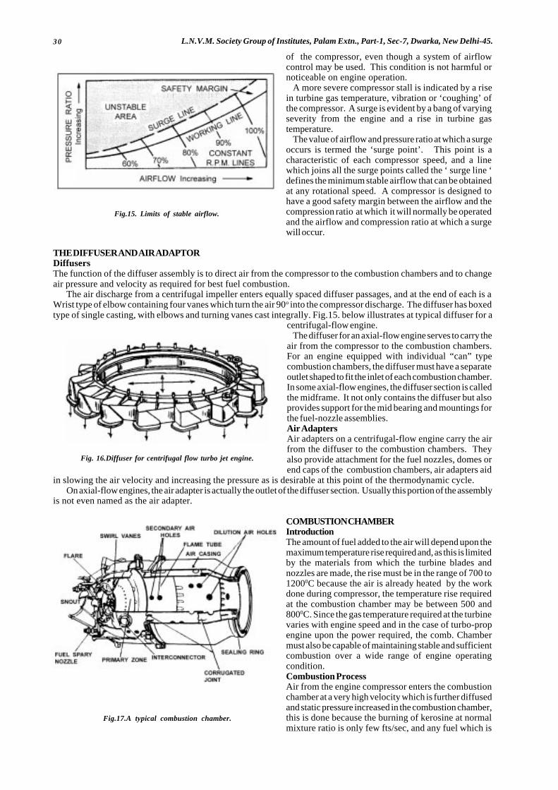
30 L.N.V.M. Society Group of Institutes, Palam Extn., Part-1, Sec-7, Dwarka, New Delhi-45.
of the compressor, even though a system of airflowcontrol may be used. This condition is not harmful ornoticeable on engine operation.
A more severe compressor stall is indicated by a risein turbine gas temperature, vibration or ‘coughing’ ofthe compressor. A surge is evident by a bang of varyingseverity from the engine and a rise in turbine gastemperature.
The value of airflow and pressure ratio at which a surgeoccurs is termed the ‘surge point’. This point is acharacteristic of each compressor speed, and a linewhich joins all the surge points called the ‘ surge line ‘defines the minimum stable airflow that can be obtainedat any rotational speed. A compressor is designed tohave a good safety margin between the airflow and thecompression ratio at which it will normally be operatedand the airflow and compression ratio at which a surgewill occur.
THE DIFFUSER AND AIR ADAPTORDiffusersThe function of the diffuser assembly is to direct air from the compressor to the combustion chambers and to changeair pressure and velocity as required for best fuel combustion.
The air discharge from a centrifugal impeller enters equally spaced diffuser passages, and at the end of each is aWrist type of elbow containing four vanes which turn the air 90o into the compressor discharge. The diffuser has boxedtype of single casting, with elbows and turning vanes cast integrally. Fig.15. below illustrates at typical diffuser for a
centrifugal-flow engine.The diffuser for an axial-flow engine serves to carry the
air from the compressor to the combustion chambers.For an engine equipped with individual “can” typecombustion chambers, the diffuser must have a separateoutlet shaped to fit the inlet of each combustion chamber.In some axial-flow engines, the diffuser section is calledthe midframe. It not only contains the diffuser but alsoprovides support for the mid bearing and mountings forthe fuel-nozzle assemblies.Air AdaptersAir adapters on a centrifugal-flow engine carry the airfrom the diffuser to the combustion chambers. Theyalso provide attachment for the fuel nozzles, domes orend caps of the combustion chambers, air adapters aid
in slowing the air velocity and increasing the pressure as is desirable at this point of the thermodynamic cycle.On axial-flow engines, the air adapter is actually the outlet of the diffuser section. Usually this portion of the assembly
is not even named as the air adapter.
COMBUSTION CHAMBERIntroductionThe amount of fuel added to the air will depend upon themaximum temperature rise required and, as this is limitedby the materials from which the turbine blades andnozzles are made, the rise must be in the range of 700 to12000C because the air is already heated by the workdone during compressor, the temperature rise requiredat the combustion chamber may be between 500 and8000C. Since the gas temperature required at the turbinevaries with engine speed and in the case of turbo-propengine upon the power required, the comb. Chambermust also be capable of maintaining stable and sufficientcombustion over a wide range of engine operatingcondition.Combustion ProcessAir from the engine compressor enters the combustionchamber at a very high velocity which is further diffusedand static pressure increased in the combustion chamber,this is done because the burning of kerosine at normalmixture ratio is only few fts/sec, and any fuel which is
Fig.15. Limits of stable airflow.
Fig. 16.Diffuser for centrifugal flow turbo jet engine.
Fig.17.A typical combustion chamber.
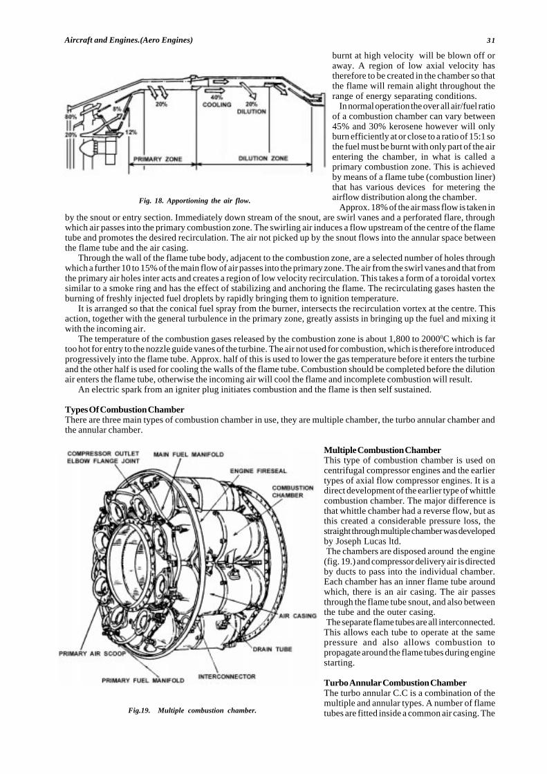
31Aircraft and Engines.(Aero Engines)
burnt at high velocity will be blown off oraway. A region of low axial velocity hastherefore to be created in the chamber so thatthe flame will remain alight throughout therange of energy separating conditions.
In normal operation the over all air/fuel ratioof a combustion chamber can vary between45% and 30% kerosene however will onlyburn efficiently at or close to a ratio of 15:1 sothe fuel must be burnt with only part of the airentering the chamber, in what is called aprimary combustion zone. This is achievedby means of a flame tube (combustion liner)that has various devices for metering theairflow distribution along the chamber.
Approx. 18% of the air mass flow is taken inby the snout or entry section. Immediately down stream of the snout, are swirl vanes and a perforated flare, throughwhich air passes into the primary combustion zone. The swirling air induces a flow upstream of the centre of the flametube and promotes the desired recirculation. The air not picked up by the snout flows into the annular space betweenthe flame tube and the air casing.
Through the wall of the flame tube body, adjacent to the combustion zone, are a selected number of holes throughwhich a further 10 to 15% of the main flow of air passes into the primary zone. The air from the swirl vanes and that fromthe primary air holes inter acts and creates a region of low velocity recirculation. This takes a form of a toroidal vortexsimilar to a smoke ring and has the effect of stabilizing and anchoring the flame. The recirculating gases hasten theburning of freshly injected fuel droplets by rapidly bringing them to ignition temperature.
It is arranged so that the conical fuel spray from the burner, intersects the recirculation vortex at the centre. Thisaction, together with the general turbulence in the primary zone, greatly assists in bringing up the fuel and mixing itwith the incoming air.
The temperature of the combustion gases released by the combustion zone is about 1,800 to 20000C which is fartoo hot for entry to the nozzle guide vanes of the turbine. The air not used for combustion, which is therefore introducedprogressively into the flame tube. Approx. half of this is used to lower the gas temperature before it enters the turbineand the other half is used for cooling the walls of the flame tube. Combustion should be completed before the dilutionair enters the flame tube, otherwise the incoming air will cool the flame and incomplete combustion will result.
An electric spark from an igniter plug initiates combustion and the flame is then self sustained.
Types Of Combustion ChamberThere are three main types of combustion chamber in use, they are multiple chamber, the turbo annular chamber andthe annular chamber.
Multiple Combustion ChamberThis type of combustion chamber is used oncentrifugal compressor engines and the earliertypes of axial flow compressor engines. It is adirect development of the earlier type of whittlecombustion chamber. The major difference isthat whittle chamber had a reverse flow, but asthis created a considerable pressure loss, thestraight through multiple chamber was developedby Joseph Lucas ltd.The chambers are disposed around the engine(fig. 19.) and compressor delivery air is directedby ducts to pass into the individual chamber.Each chamber has an inner flame tube aroundwhich, there is an air casing. The air passesthrough the flame tube snout, and also betweenthe tube and the outer casing.The separate flame tubes are all interconnected.This allows each tube to operate at the samepressure and also allows combustion topropagate around the flame tubes during enginestarting.
Turbo Annular Combustion ChamberThe turbo annular C.C is a combination of themultiple and annular types. A number of flametubes are fitted inside a common air casing. The
Fig. 18. Apportioning the air flow.
Fig.19. Multiple combustion chamber.

32 L.N.V.M. Society Group of Institutes, Palam Extn., Part-1, Sec-7, Dwarka, New Delhi-45.
airflow is similar to that already describedand this arrangement, embodies the caseof overhaul and testing of the multiplesystem with the compactness of annularsystem. (fig. 20).
Annular Combustion ChamberThis type of combustion chamberconsists of a single flame tube, completelyannular in form, which is contained in aninner and outer casing (fig 21). The airflow through the flame tube is similar tothat previously, described, the chamberbeing open at the front to the compressorand at the rear to the turbine nozzles.The main advantage of annular chamber
is that, for the same power output, thelength of the chamber is only 75% of thatof a turbo annular system for an engineof the same diameter, resulting inconsiderable saving of weight andproduction cost. Another advantage isthat because inter connection are notrequired the propagation of combustionis improved.In comparison with a turbo annular
combustion system, the wall area of acomparable annular chamber is much less;consequently the amount of cooling airrequired to prevent the burning of theflame tube wall is less, by approx. 15%.This reduction in cooling air raises thecombustion efficiently to virtuallyeliminate unburnt fuel, and oxidizes thecarbon monoxides to non toxic carbon di-oxide, thus reducing air pollution.A high by pass ratio engine will also
reduce air pollution since for a giventhrust the engine burns less fuel.
Turbine Nozzle And Nozzle DiaphragmThis diaphragm consists of a group ofnozzle vanes welded, between two shroudrings. In the typical nozzle diaphragm,the inner and outer bands containspunched holes to receive the ends ofnozzle vanes. The nozzle vanes are usuallyconstructed of high temperature alloy,and they must be highly heat resistant.In many engines the nozzle vanes are
hollow and are formed from stainlesssteel sheet. They are then welded andground smooth before being installedbetween the shroud rings. When there ismore than one turbine wheel, additionalnozzle diaphragms are installed to directthe hot gases from one wheel to the next.Second third and fourth stage nozzlevanes are often constructed of solid steelalloy. These may be either forged orprecision cast.
PurposeThe purpose of nozzle diaphragm is twofold : (i) it increases the velocity of the hotgases flowing past this point and (ii) it
Fig.20. Turbo-annular combustion chamber.
Fig.21. Annular combustion chamber.
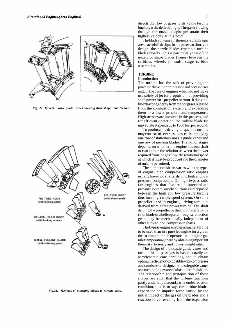
33Aircraft and Engines.(Aero Engines)
directs the flow of gases to strike the turbinebuckets at the desired angle. The gases flowingthrough the nozzle diaphragm attain theirhighest velocity at this point.
The blades or vanes in the nozzle diaphragmare of aerofoil design. In the pure reaction typedesign, the nozzle blades resemble turbineblades closely. This is particularly true of thenozzle or stator blades (vanes) between theturbines wheels in multi stage turbineassemblies.
TURBINEIntroductionThe turbine has the task of providing thepower to drive the compressor and accessoriesand, in the case of engines which do not makeuse solely of jet for propulsion, of providingshaft power for a propeller or rotor. It does thisby extracting energy from the hot gases releasedfrom the combustion system and expandingthem to a lower pressure and temperature.High stresses are involved in this process, andfor efficient operation, the turbine blade tipmay rotate at speeds up to 1300 feet per second.
To produce the driving torque, the turbinemay consists of several stages, each employingone row of stationary nozzle guide vanes andone row of moving blades. The no. of stagesdepends on whether the engine has one shaftor two and on the relation between the powerrequired from the gas flow, the rotational speedat which it must be produced and the diameterof turbine permitted.
The number of shafts varies with the typesof engine, high compression ratio enginesusually have two shafts, driving high and lowpressure compressors. On high bypass ratiofan engines that feature an intermediatepressure system, another turbine is inter posedbetween the high and low pressure turbinethus forming a triple spool system. On somepropeller or shaft engines, driving torque isderived from a free power turbine. The shaftdriving the propeller or the output shaft to therotor blade of a helicopter, through a reductiongear, may be mechanically independent ofother turbine and compressor shafts.
The bypass engine enables a smaller turbineto be used than in a pure jet engine for a giventhrust output and it operates at a higher gasinlet temperature, there by obtaining importantthermal efficiency and power/weight ratio.
The design of the nozzle guide vanes andturbine blade passages is based broadly onaerodynamic considerations, and to obtainoptimum efficiency compatible with compressorand combustion design, the nozzle guide vanesand turbine blades are of a basic aerofoil shape.The relationship and juxtaposition of theseshapes are such that the turbine functionspartly under impulse and partly under reactioncondition, that is to say, the turbine bladesexperience an impulse force caused by theinitial impact of the gas on the blades and areaction force resulting from the expansion
Fig. 22. Typical nozzle guide vanes showing their shape and location.
Fig.23. Methods of attaching blades to turbine discs.
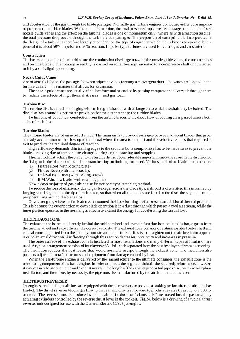
34 L.N.V.M. Society Group of Institutes, Palam Extn., Part-1, Sec-7, Dwarka, New Delhi-45.
and acceleration of the gas through the blade passages. Normally gas turbine engines do not use either pure impulseor pure reaction turbine blades. With an impulse turbine, the total pressure drop across each stage occurs in the fixednozzle guide vanes and the effect on the turbine, blades is one of momentum only ; where as with a reaction turbine,the total pressure drop occurs through the turbine blade passages. The proportion of each principle incorporated inthe design of a turbine is therefore largely dependant on the type of engine in which the turbine is to operate, but ingeneral it is about 50% impulse and 50% reaction. Impulse type turbines are used for cartridges and air starters.
ConstructionThe basic components of the turbine are the combustion discharge nozzles, the nozzle guide vanes, the turbine discsand turbine blades. The rotating assembly is carried on roller bearings mounted to a compressor shaft or connectedto it by a self aligning coupling.
Nozzle Guide VanesAre of aero foil shape, the passages between adjacent vanes forming a convergent duct. The vanes are located in theturbine casing in a manner that allows for expansion.
The nozzle guide vanes are usually of hollow form and be cooled by passing compressor delivery air through themto reduce the effects of high thermal stresses and gas load.
Turbine DiscThe turbine disc is a machine forging with an integral shaft or with a flange on to which the shaft may be bolted. Thedisc also has around its perimeter provision for the attachment to the turbine blades.
To limit the effect of heat conduction from the turbine blades to the disc a flow of cooling air is passed across bothsides of each disc.
Turbine BladesThe turbine blades are of an aerofoil shape. The main air is to provide passages between adjacent blades that givesa steady acceleration of the flow up to the throat where the area is smallest and the velocity reaches that required atexit to produce the required degree of reaction.
High efficiency demands thin trailing edges to the sections but a compromise has to be made so as to prevent theblades cracking due to temperature changes during engine starting and stopping.
The method of attaching the blades to the turbine disc is of considerable important, since the stress in the disc aroundthe fixing or in the blade root has an important bearing on limiting rim speed. Various methods of blade attachment are
(1) Fir tree Root (with locking plate)(2) Fir tree Root (with shank seals).(3) De laval By it Root (with locking screw).(4) B.M.W.hollow blade (with retaining pins).Now a days majority of gas turbine use fir tree root type attaching method.To reduce the loss of efficiency due to gas leakage, across the blade tips, a shroud is often fitted this is formed by
forging small segment at the tip of each blade, so that when all the blades are fitted to the disc, the segment form aperipheral ring around the blade tips.
On a fan engine, where the fan is aft (rear) mounted the blade forming the fan present an additional thermal problem.This is because the outer portion of each blade operation is in a duct through which passes a cool air stream, while theinner portion operates in the normal gas stream to extract the energy for accelerating the fan airflow.
THE EXHAUST CONEThe exhaust cone is located directly behind the turbine wheel and its main function is to collect discharge gases fromthe turbine wheel and expel then at the correct velocity. The exhaust cone consists of a stainless steel outer shell andcentral cone supported from the shell by four stream lined struts or fins is to straighten out the airflow from approx.45% to an axial direction. Air flowing through this section decreases in velocity and increases in pressure.
The outer surface of the exhaust cone is insulated in most installations and many different types of insulation areused. A typical arrangement consists of four layers of A1 foil, each separated from the next by a layer of bronze screening.The insulation reduces the heat losses that would normally escape through the exhaust cone. The insulation alsoprotects adjacent aircraft structures and equipment from damage caused by heat.
When the gas-turbine engine is delivered by the manufacturer to the ultimate consumer, the exhaust cone is theterminating component of the basic engine. In order to operate the engine and obtain the required performance, however,it is necessary to use a tail pipe and exhaust nozzle. The length of the exhaust pipe or tail pipe varies with each airplaneinstallation, and therefore, by necessity, the pipe must be manufactured by the air-frame manufacturer.
THE THRUST REVERSERJet engines installed in jet airlines are equipped with thrust reversers to provide a braking action after the airplane haslanded. The thrust reverser blocks gas flow to the rear and directs it forward to produce reverse thrust up to 5,000 lb.or more. The reverse thrust is produced when the air baffle doors or " clamshells " are moved into the gas stream byactuating cylinders controlled by the reverse thrust lever in the cockpit. Fig.24. below is a drawing of a typical thrustreverser unit designed for use with the General Electric CJ805 jet engine.
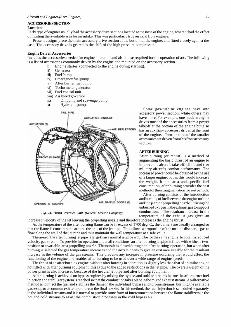
35Aircraft and Engines.(Aero Engines)
ACCESSORIES SECTIONLocationsEarly type of engines usually had the accessory drive sections located at the nose of the engine, where it had the effectof limiting the available area for air intake. This was particularly true on axial flow engines.
Present designs place the main accessory drive section at the bottom of the engine, and fitted closely against thecase. The accessory drive is geared to the shift of the high pressure compressor.
Engine Driven AccessoriesIncludes the accessories needed for engine operation and also those required for the operation of a/c. The followingis a list of accessories commonly driven by the engine and mounted on the accessory section.
i) Engine starter (connected to the engine during starting).ii) Generatoriii) Fuel Pumpiv) Emergency fuel pumpv) After burner fuel pumpvi) Techo meter generatorvii) Fuel control unitviii) Air bleed governorix) Oil pump and scavenge pumpx) Hydraulic pump.
Some gas-turbine engines have oneaccessory power section, while others mayhave more. For example, one modern enginedrives most of the accessories from a powertakeoff at the bottom of the engine but alsohas an auxiliary accessory driven at the frontof the engine. Two or threeof the smalleraccessories are driven from this front accessorysection.
AFTER BURNINGAfter burning (or reheat) is a method ofaugmenting the basic thrust of an engine toimprove the aircraft-take off, climb and (formilitary aircraft) combat performance. Theincreased power could be obtained by the useof a larger engine, but as this would increasethe weight, frontal area and specific fuelconsumption, after burning provides the bestmethod of thrust augmentation for sort periods.
After burning consists of the introductionand burning of fuel between the engine turbineand the jet pipe propelling nozzle utilizing theunburned oxygen in the exhaust gas to supportcombustion. The resultant increase in thetemperature of the exhaust gas gives an
increased velocity of the jet leaving the propelling nozzle and therefore increases the engine thrust.As the temperature of the after burning flame can be in excess of 1700 deg. C., the burners are usually arranged so
that the flame is concentrated around the axis of the jet pipe. This allows a proportion of the turbine discharge gas toflow along the wall of the jet pipe and thus maintain the wall temperature at a safe value.
The area of the after burning jet pipe is large than a normal jet pipe would be for the same engine, to obtain a reducedvelocity gas stream. To provide for operation under all conditions, an after burning jet pipe is fitted with wither a two-position or a variable-area propelling nozzle. The nozzle is closed during non-after burning operation, but when afterburning is selected the gas temperature increases and the nozzle opens to give an exit area suitable for the resultantincrease in the volume of the gas stream. This prevents any increase in pressure occurring that would affect thefunctioning of the engine and enables after burning to be used over a wide range of engine speeds.
The thrust of an after burning engine, without after burning in operation, is slightly less than that of a similar enginenot fitted with after burning equipment; this is due to the added restrictions in the jet pipe. The overall weight of thepower plant is also increased because of the heavier jet pipe and after burning equipment.
After burning is achieved on bypass engines by mixing the bypass and turbine streams before the afterburner fuelinjection and stabilizer system is reached so that the combustion takes place in the mixed exhaust stream. An alternativemethod is to inject the fuel and stabilize the flame in the individual bypass and turbine streams, burning the availablegasses up to a common exit temperature at the final nozzle. In this method, the fuel injection is scheduled separatelyto the individual streams and it is normal to provide some form of interconnection between the flame stabilizers in thehot and cold streams to assist the combustion processes in the cold bypass air.
Fig. 24. Thrust reverser unit. (General Electric Company)
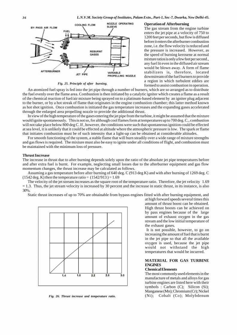
36 L.N.V.M. Society Group of Institutes, Palam Extn., Part-1, Sec-7, Dwarka, New Delhi-45.
Operation of AfterburningThe gas stream from the engine turbineenters the jet pipe at a velocity of 750 to1200 feet per seconds, but flow is diffusedbefore it enters the afterburner combustionzone, i.e. the flow velocity is reduced andthe pressure is increased. However, asthe speed of burning kerosene at normalmixture ratios is only a few feet per second.,any fuel lit even in the diffused air streamwould be blown away. A form of flamestabilizers is, therefore, locateddownstream of the fuel burners to providea region in which turbulent eddies areformed to assist combustion in operation.
An atomized fuel spray is fed into the jet pipe through a number of burners, which are so arranged as to distributethe fuel evenly over the flame area. Combustion is then initiated by a catalytic igniter which creates a flame as a resultof the chemical reaction of fuel/air mixture being sprayed on to a platinum-based element by an igniter plug adjacentto the burner, or by a hot streak of flame that originates in the engine combustion chamber; this latter method knownas hot shot ignition. Once combustion is initiated the gas temperature increases and the expanding gases acceleratedthrough the enlarged area propelling nozzle to provide the additional thrust.
In view of the high temperature of the gases entering the jet pipe from the turbine, it might be assumed that the mixturewould ignite spontaneously. This is not so, for although cool flames form at temperatures up to 700 deg. C., combustionwill not take place below 800 deg C. If , however, the conditions were such that spontaneous ignition could be effectedat sea level, it is unlikely that it could be effected at altitude where the atmospheric pressure is low. The spark or flamethat initiates combustion must be of such intensity that a light-up can be obtained at considerable altitudes.
For smooth functioning of the system, a stable flame that will burn steadily over a wide range of mixture strengthsand gas flows is required. The mixture must also be easy to ignite under all conditions of flight, and combustion mustbe maintained with the minimum loss of pressure.
Thrust IncreaseThe increase in thrust due to after burning depends solely upon the ratio of the absolute jet pipe temperatures beforeand after extra fuel is burnt. For example, neglecting small losses due to the afterburner equipment and gas flowmomentum changes, the thrust increase may be calculated as follows.
Assuming a gas temperature before after burning of 640 deg. C (913 deg K) and with after burning of 1269 deg. C(1542 deg. K) then the temperature ratio = (1542/913 ) = 1.69
The velocity of the jet stream increases as the square root of the temperature ratio. Therefore, the jet velocity 1.69= 1.3. Thus, the jet stream velocity is increased by 30 percent and the increase in static thrust, in its instance, is also30%.
Static thrust increases of up to 70% are obtainable from bypass engines fitted with after burning equipment, andat high forward speeds several times thisamount of thrust boost can be obtained.High thrust boosts can be achieved onby pass engines because of the largeamount of exhaust oxygen in the gasstream and the low initial temperature ofthe exhaust gases.It is not possible, however, to go on
increasing the amount of fuel that is burntin the jet pipe so that all the availableoxygen is used, because the jet pipewould not withstand the hightemperatures that would be incurred.
MATERIAL FOR GAS TURBINEENGINESChemical ElementsThe most commonly used elements in themanufacture of metals and alloys for gasturbine engines are listed here with theirsymbols : Carbon (C); Silicon (Si);Manganese (Mn); Chromium (Cr); Nickel(Ni); Cobalt (Co); Molybdenum
Fig. 25. Principle of after burning.
Fig. 26. Thrust increase and temperature ratio.
T E M P E R AT U R E R AT IO
THRU
STINC
REAS
E
0
2 0
4 0
6 0
8 0
Per
cent

37Aircraft and Engines.(Aero Engines)
(M)Tungsten (W); Colombian (Cb); Titanium (Ti); Nitrogen (N); Copper (Cu); Iron (Fe); Aluminium (Al).This list is not meant to include all possible elements used in high-temperature alloys, but it indicates the types of
elements required.The three characteristics that metallurgists search for in the metals for high-temperature applications are Oxidation
resistance, high-temperature strength, and corrosion resistance. Probably the most vital of these three characteristicsis the capacity to resist oxidation, because structural strength is useless if a metal rapidly burns away. At jet-engineoperating temperature, ordinary steel burns like paper; and tungsten, molybdenum ; and Colombian oxidize quickly,as do most high-melting-point metals.
For years manufacturers have worked closely with the steel mills in developing research data that would serve asa guide to the evolution of new alloys. Today, at least 20% high-temperature alloys are used in the fabrication ofcomponents for power plants. These metals may be classified into four groups;
(1) Chrome-nickel steels,(2) Chrome steels,(3) Nickel-base alloys and(4) Cobalt-base alloys.
Chrome-Nickel SteelsThe chrome-nickel steels contain these elements in approximately 18:8 ratios and are commonly referred to as “austeniticsteels”. This description refers to their crystalline structure, in which the ingredients are said to be in solid solutionso that each crystal is composed of an intimate mixture of the constituents.
This group of steels is most widely used for high-temperature applications because of its good characteristics ofoxidation and corrosion resistance and of high strength at elevated temperatures. These steels have about six timesthe electrical resistance of ordinary steels and respond readily to welding techniques. However, since they expand 50percent faster than plain steels and conduct heat only half as fast, they require special care during welding to preventdistortion. They do not need heat-treatment after welding to develop maximum physical strength.
These steels are nonmagnetic and cannot be hardened by heat-treatment. They may be hardened by cold-working,and then they become slightly magnetic. Cold-working enhances their structural strength at the cost of ductility. Theyare difficult to machine unless they contain added amounts of sulphur or selenium.
When subjected to temperatures above 8000 F, they tend to precipitate carbides in their grain boundaries, thuslowering their resistance to corrosion. The corrosion resistance may be restored by heating them to 1850 to 19000 F andcooling them quickly, or they may be protected against the formation of harmful carbide precipitation by the additionof Colombian or titanium to their formulas.
Chrome Nickel steels are suitable for parts such as high-pressure compressor casings, combustion casings, turbinecasings, and similar parts where extreme temperatures are not encountered. High-temperature stainless steels are alsoemployed for compressor blading, compressor disks, turbine disks, exhaust cones, thrust reversals afterburner casings,and miscellaneous sheet metal parts. The principal disadvantage of chrome-nickel stainless steels is the weight. Forthis reason, titanium alloys are often used where the temperature is not excessive for the material.
Chromium SteelsThe straight alloys, containing no nickel, are either martenstic or ferritic in crystalline structure, depending upon theirhardening characteristics. Those containing upto 14% chromium harden intensely if they are allowed to cool rapidlyfrom high temperatures, forming a hard, relatively brittle substance called martensite. Because these alloys respondto heat-treatment, they are capable of being given a wide range of mechanical properties such as tensile strength andhardness.
Those chromium steels containing from 17 to 30 percent chromium do not respond to heat-treatment or cooling andremain essentially ferritic at all times. The intermediate types, containing between 14 and 17 percent chromium, behavein a manner that depends upon their exact chromium and carbon contents.
Chromium contents up to 4 percent do not increase corrosion resistance. Amounts from 4 to 10 percent improveresistance to corrosion appreciably. Chromium percentages from 10 to 30 percent are designated when oxidationresistance at high temperatures is required.
The steels with chromium contents of 5 to 30 percent are magnetic in all conditions. They exhibit distinctly inferiorcreep resistance compared with the chrome-nickel stainless steels. The 17 percent chromium steels have excellentoxidation and corrosion resistance and may be used at temperatures up to 15000F. The 25% chromium content steel isdesignated for severe heat and corrosion applications and is good for applications where temperatures reach 20000 F.
All the straight chrome steels are more difficult to weld than the chrome-nickel types because the welding heat leavesthem in a brittle condition. They have about the same coefficients of expansion as ordinary steel, with several timesthe electrical resistance and slightly lower melting points. They tend to become brittle from welding heat in two ways: by slow cooling from around the 12000 F range, and by grain growth produced by holding them over 16500 F. The firsttype of embrittlement may be eliminated by quick cooling from above 12000F. The second type cannot be remedied butmay be avoided by careful welding techniques.
From straight chrome steel, jet- engine case weldments and bearing-housing assemblies are built for Pratt & Whitneyturbojet engine. These are fabricated from welded alloys of Type 410. Additional jet-engine detail fittings andcomponents are built from Type-415 and used in applications where temperature is not a critical factor.

38 L.N.V.M. Society Group of Institutes, Palam Extn., Part-1, Sec-7, Dwarka, New Delhi-45.
Nickel Base AlloysThe nickel-base alloy contain between 70 and 80 percent nickel and cannot properly be called “steels” because of theirsmall quantities of iron. In this group of alloys, many of which are called “super alloys”, are the Nimonics, M-252, GMR-235, the Hastelloys, Nichrome, Rex 400, K42 B the Inconels, Waspalloy, Rene 41, Multi-alloy, Refract alloy 26, theUdimets, and Unitemp 1735. These alloys have been tailored for high-temperature and some offer excellent oxidationand corrosion resistance at temperatures of over 21000F.
InconelThese alloys can be cold-worked, hot-worked, or forged without difficulty and can also be welded and machined. Varioustypes of the Inconel alloys are used for combustion chambers, transition liners, turbine nozzle parts, and turbine buckets.The NimonicThe nimonic alloys, numbered 75, 80, 80A and 90, are of British manufacture and contain a major percentage of nickel,with chromium as the next most important element. Nimonic 90 utilizes a large percentage of cobalt as an alloying element.The Nimonic alloys are largely used for the hot parts of gas-turbine engines, such as combustion chambers and turbinenozzles.
GMR-235GMR-235 contains about 55 percent nickel, 15.5% chromium and 10 percent iron with smaller portions of molybdenumaluminium, and titanium. It is of low strategic-alloy content, that is, it contains neither cobalt nor Colombium; henceit can be manufactured even though these metals are not available. GMR-235 was developed by the General MotorsCorporation primarily for gas turbine wheels, buckets, and nozzle vanes operating at temperatures in excess of 14000
F. An improvement of this alloy, GMR-235, contains increased amounts of aluminium and titanium, and less iron.
The HastelloysDesignated A, B, C, R-235. W, and X, are nickel-base alloys developed and manufactured by the Haynes StelliteCompany, a Division of the Union Carbide Company. These alloys contains large % of molybdenum. These alloys areused in various applications where high temperature and corrosion resistance are desirable.
WaspalloyWaspalloy was originally developed by the Pratt & Whitney Aircraft Division of United Aircraft Corporation for usein the manufacture of turbine buckets. It is traditional super alloy suitable for use in the 1200 to 1600°F range althoughit retains good strength at higher temperatures. This alloy is also used for turbine disks and other heavy forging in jetengines.
The UdimetAlloy, manufactured by special metals, Incorporated are super alloys of high strength, corrosion resistance, and hightemperature resistance. Udimet 500 is used for turbine buckets and small integral gas turbines. Udimet 700 is suitablefor the 1400 to 1800°F range and can be used for a short time upto 2000°F. It is used for turbine buckets and for turbinedisks in advanced jet engines. Udimet N-115 is one of the strongest wrought super alloys and is used for turbine bucketsin applications requiring extended service upto 18500F.
Cobalt Base AlloysCobalt-base alloys, also called super alloys, are designated for use where high-temperature strength and corrosionresistance are important. These alloys usually contain substantial amounts of tungsten, nickel, chromium, andmolybdenum in addition to cobalt. Some of the alloys contain either tungsten or molybdenum but not both.
Haynes Stellite No.25 (HS-25) is used to build the eyelid assemblies for afterburners and afterburner flame holders.It has excellent strength and resistance to oxidation at high temperatures. It also exhibits good ductility and can beworked both hot and cold. It has oxidation and carburization resistance for service upto 19000 F.
Haynes Stellite Alloy no.21 (HS-25) is resistant to oxidizing and reducing atmospheres upto 21000F. It has excellentstrength which is maintained through a wide range of temperatures and thermal shock conditions. Haynes Stellite No.31(HS-31) is a casting alloy, and has good creep, endurance, and stress-rupture properties.
Another cobalt-base alloy manufactured by the Haynes Stellite Company is Alloy No.151. This alloy has excellentproperties at high temperatures and is suitable for turbine blade applications upto 18000F.
Variations In Alloy PropertiesIt must be emphasized that the properties of high-temperature alloys are not imparted merely by the mixing of variousmetallic elements. The elements are most important ; however, the type of heat treatment and working applied to thealloy is also essential.
Among some of the treatments employed for developing desired characteristics in the super alloys are solution heattreating, precipitation hardening, strain hardening, cold-working and hot-working. Some of these processes are time-consuming and complicated, hence they add to the cost of the material. It is important to note, however, that withoutthe required treatment a particular alloy will not give the specified service.
Sintered Mesh Porous MediaA rather new material in its applications to jet engines is a sintered mesh sheet constructed of two or more layers of
39Aircraft and Engines.(Aero Engines)
mesh manufactured from high-temperature alloys N-155 or L-605 and sinter bonded. This material is used primarily fortranspiration cooling in high temperature zones.
Transpiration cooling, as the name implies, is the cooling which results from passing a fluid, either liquid of gas,through a porous media to remove heat from the porous surface. The porous media must have a large internal surfacearea for heat transfer to permit an efficient heat removal with a minimum of coolant.
The major application in the aircraft field are found in turbojet engines. Afterburner liners as well as the liners ofcombustion chambers have been fabricated media.
Another important application in turbojet engines is the fabrication of transpiration-cooled turbine blades fromporous media.
COMPARATIVE ADVANTAGES AND DISADVANTAGES OF GAS TURBINE ENGINESIn its present forms, the gas turbine, either propeller-drive or pure jet, has numerous attractive features that have beenmentioned frequently. These may be reviewed briefly as follows.AdvantagesFreedom From VibrationThis permits lighter propeller sections and mounting structure. Vibration is reduced by the elimination of reciprocatingparts such as connecting rods and pistons.Simplicity Of ControlOnly one lever is required for controlling the speed and power of the unit.No Spark Plugs Required Except For StartingSuch surfaces add weight and drag. Very small coolers for lubricating oil are used on large jet engines and turbopropengines.Negligible Cooling Air RequiredConventional engines require from five to eight times as much air for cooling as is required for power production. Theacceleration of this air to airplane speed represents an appreciable loss of power, particularly in climb, even though muchof this may be recovered later by the use of carefully designed radiators.No Spark Plugs Required Except For StartingAfter combustion is once established, it is self supporting.No CarburettorsHence there is no carburettor icing and no mixture controls. There is some question as to this advantage, since largegas turbines do require very complex fuel-control units. The automatic features of these units compensate for theircomplexity, however.Available Supply Of Compressed AirThis air is used for driving cabin superchargers and small turbines and for anti-icing purposes.Decreased Fire HazardFuels used for gas turbines are usually less volatile than the high-octain fuels used in reciprocating engines.Lower Specific WeightA gas turbine may develop several times as much power as a reciprocating engine of the same weight.Lower Oil Consumption
DISADVANTAGESHIGH SPECIFIC FUEL CONSUMPTION AT LOW AIRSPEEDSThis applies chiefly to pure jet engines. Turboprop engines have performance comparable to reciprocating engines insome instances, since they have attained specific fuel consumption as low as 0.40 lb per hp per hr.Inefficient Operation At Low Power LevelsSlow Acceleration From Minimum SpeedThis condition applies chiefly to turbojet engines. Turboprop and turbofan engines are able to accelerate quite rapidly.High Starting Power RequirementsStarting large gas-turbine engines has been a problem in the past; however, starters have been developed within thepast few years which make it relatively simple.High Cost Of ManufactureAlthough the gas turbine is much simpler in operation than the piston engine, the special materials and manufacturingprocesses needed make the cost of the gas turbine much higher.Susceptibility To Damage By Foreign MaterialSuch material is rapidly drawn into the air inlet.
BASIC DIFFERENCES - GAS TURBINE V/S RECIPROCATING ENGINEThe basic differences between the gas-turbine engine and the reciprocating engine may be classified into five maingroups.
Aerodynamic (Advantages)Smaller nacelles possible; negligible cooling power required; highspeed jet is a more efficient propulsive means thanpropeller at high flight speeds.
DisadvantagesA high speed jet is a less efficient propulsive means than a propeller at lower flight speeds and during takeoff. The
40 L.N.V.M. Society Group of Institutes, Palam Extn., Part-1, Sec-7, Dwarka, New Delhi-45.
development of turboprop and turbofan engines has made it possible to combine the advantages of the turbine engineswith the efficiency of the propeller for lower speeds and for takeoff.
Weight (Advantages)Turbine engines are considerably lighter than reciprocating engines for the same power output. Turbojet engines havebeen developed with a weight/power ratio of less than 0.13 lb. per lb. of thrust. Turboprop engines have attained 0.39lb. per equivalent shaft horsepower (eshp) in comparison with reciprocating engines which usually have a weight/powerratio of approximately 1.0 lb. per hp or more.
Fuel Consumption (Neutral Characteristics)Best specific fuel consumption occurs near maximum output. (Best specific fuel consumption reciprocating enginesoccurs at about one-half maximum power.) At a given flight speed, specific fuel consumption of the turbojet enginetends to decrease with altitude. The specific fuel consumption for turboprop engines is comparable to that of the bestreciprocating engines. It is likely that continued development will produce a turboprop engine with much better specificfuel consumption than any reciprocating engine. Turbojet engines have been developed to a point where specific fuelconsumption is excellent, at operating speeds and altitudes, they are more efficient than of 1:2:1 and have brought aboutspecific fuel-consumption figures of less than 0.70 lb. per pound of static thrust.
DisadvantagesBest fuel consumption is in general is poorer for the turbojet engine; however this disadvantage appears to bedecreasing rapidly.
OutputOperation of the gas turbine engine at varying altitudes is somewhere between that of an unsupercharged andsupercharged reciprocating engine. That is, the turbine engine is more adaptable to varying altitudes than theunsupercharged engine and perhaps a little less adaptable than the supercharged reciprocating engine.
General (Advantages)Low power plant vibration, relatively constant speed over a wide range of output.
DisadvantagesHigh engine speed (advantageous for generator drive)
PERFORMANCE COMPARISONA comparison of the performance of aircraft powered by reciprocating turboprop, and turbojet engines indicates thatfor a cruising altitude of 35,000 ft :
1) Aircraft with top speeds below 335 mph achieve their maximum range when powered by reciprocating engines.2) Aircraft with top speeds above 610 mph achieve their maximum range when powered by turbojet engines.3) Aircraft with speeds between those specified in the foregoing statements in general achieve their maximum range
when powered by turboprop or turbofan engines.
Axial Flow V/S Centrifugal FlowWithin the classification of turbojet engines, some engines have advantages over other. At the present stage ofdevelopment of these engines, the axial-flow type has the following advantages over the centrifugal-flow type:
Lower Specific Fuel ConsumptionThis advantage is quite important, since turbine powered aircraft are now designed to fly vast distances withoutrefuelling. The lower fuel consumption is accomplished with the axial-flow engine because the axial compressor makespossible higher pressure ratio. This is particularly true of the turbofan engines.
Smaller Diameter Or Frontal AreaThis characteristic makes the axial-flow engine more suitable for wing installation.
The following are some of the advantages of the centrifugal flow engine over the axial-flow type :
Simple Manufacture And Fewer PartsThis reduces initial cost and maintenance.
Lower Specific WeightA centrifugal engine with an equivalent compression ratio may be lower in weight for the amount of thrust.
Faster Installation And RemovalNo close fitting ducts to engine are necessary.
More Effective Water InjectionOn this type of engine the water can be injected directly into the compressor, where as in an axial flow engine, wateris injected into the C.C.
41Aircraft and Engines.(Aero Engines)
Faster Acceleration Of The Rotor SectionThe advantages of higher compressor ratios possible with the axial flow engines will make this type of engine moredesirable, especially for high performance a/c.
Turbofan or by pass engines increase air mass flow by feeding additional air into the jet stream directly to the rearof the turbine. This results in thrust augmentation because a greater mass of air is accelerated than would be the casewith the simple jet engine.
PERFORMANCE OF GAS TURBINE ENGINESThe performance of the turbojet engine is measured in thrust produced at the propelling nozzle or nozzles, and that ofthe turbo-propeller engine is measured in shaft horsepower (s.h.p.) produced at the propeller shaft. However, both typesare in the main assessed on the amount of thrust or s.h.p. they develop for a given weight, fuel consumption, and frontalarea.
Since the thrust or s.h.p. developed is dependent on the mass of air entering the engine and the acceleration impartedto it during the engine cycle, it is obviously influenced, as subsequently described, by such variables as the forwardspeed of the aircraft, altitude, and climatic conditions. These variables influence the efficiency of the air intake, thecompressor, the turbine, and the jet pipe; consequently, the gas energy available for the production of thrust or s.h.p.also varies.
In the interest of fuel economy and aircraft range, the thrust or s.h.p. per unit weight should be at its maximum withthe fuel consumption as low as possible. This factor, known as the specific fuel consumption (s.f.c.), is expressed inpounds of fuel per hour per pound of net thrust of s.h.p and is determined by the thermal and propulsive efficiencyof the engine.
Whereas the thermal efficiency is often referred to as the internal efficiency of the engine, the propulsion efficiencyis referred to as the external efficiency.
The thermal and propulsive efficiency also influence, to a large extent, the size of the compressor and turbine thusdetermining the weight and diameter of the engine for a given output.
ENGINE THRUST ON THE TEST BENCHThe thrust of the turbojet engine on the test bench differs somewhat from that during flight. On the test bench the thrustis mainly the product of the mass of air passing through the engine and the jet velocity at the propelling nozzle; whereasin flight it is mainly the product of the mass of air passing through the engine, and the jet velocity less the forward speedof the aircraft. Algebraically, the thrust of the stationary engine is expressed as wvj/g
whereW = mass of air (lb.per.sec.)v
j= jet velocity at propelling nozzle (ft.per.sec.)
g = gravitational constant 32.2.Engine running under choked nozzle condition drive additional thrust from the excess pressure acting over the
propelling nozzle and this is expressed as (p - Po) A, wherep = static pressure at propelling nozzle (lb.per.sq.in)Po = atmospheric pressure (lb.per.sq.in.)A = area of propelling nozzle (sq.in.)
Thus, the total thrust F = (p-Po) A+ Wvj/g
From the formula it will be seen that the thrust of the engine can be increased either by increasing the mass of airpassing through the engine or by increasing the jet velocity. Increase in mass airflow may be obtained by using waterinjection and increase in jet velocity by using after burning.
As the air density changes, mass of air entering the engine for a given engine speed changes. Thus, when comparingthe performance of similar engines, a correction to the observed readings is required for any variation from the I.S.A.conditions.
The correction for a turbojet engine is :Thrust (lb.) (corrected) = thrust (lb.) (observed) X 29.99
powhere Po = atmospheric pressure in Hg (observed).The observed performance of the turbo-propeller engine is also corrected to I.S.A. conditions, but due to the rating
being different. For example, s.h.p. (corrected) = s.h.p. (observed) X29.99 X 273+15 Po 273+To
where Po = atmospheric pressure in Hg (observed).To = atmospheric temperature deg C. (observed).
In practice there is always a certain amount of jet thrust in the total output of the turbo-propeller engine and thismust be added to the s.h.p.
The total equivalent horsepower is denoted by t.e.h.p. and is the s.h.p. plus the s.h.p equivalent to the net jet thrust.t.e.h.p. = s.h.p. + jet thrust lb.
2.6
COMPARISON BETWEEN THRUST AND HORSEPOWERBecause the turbojet engine is rated in thrust and the turbo-propeller engine in s.h.p. no direct comparison between
42 L.N.V.M. Society Group of Institutes, Palam Extn., Part-1, Sec-7, Dwarka, New Delhi-45.
the two can be made without a power conversion factor. However, since the turbo-propeller engine receives its thrustmainly from the propeller, a comparison can be made by converting the horsepower developed by the engine to thrustor the thrust developed by the turbojet engine to t.h.p., that is, by converting work to force or force to work. For thispurpose, it is necessary to take into account the speed of the aircraft.
The t.h.p. is expressed is FV/ 550 ft.per.sec.where F = lb.of thrust.
V = aircraft speed (ft.per.sec.)
Since one horsepower is equal to 550 ft.lb.per.sec. and 550 ft.per.sec. is equivalent to 375 miles per hour, it can beseen from the above formula that one lb.of thrust equals one t.h.p. at 375 m.p.h. It is also common to quote the speedin knots (nautical miles); one knot is equal to 1.1515 m.h.p. or one pound of thrust is equal to one t.h.p. at 325 knots.
Thus if a turbojet engine produces 5,000 lb. of net thrust at an aircraft speed of 600 m.p.h. the t.h.p. would be
5,000 X 600 = 8,000375
However, if the same thrust was being produced by a turbo-propeller engine with a propeller efficiency of 55 percent at the same flight speed of 600 m.p.h., then the t.h.p. would be
8,000 X 100 = 14,54555
ENGINE THRUST IN FLIGHTSince reference will be made to gross thrust, momentum drag, and net thrust it may be helpful at this stage to definethese terms.
The gross or total thrust is the reaction to the momentum of the jet velocity, expressed as (p -Po) A + Wvj. Themomentum or intake drag is the drag due to the momentum of the air passing into the engine relative to aircraft velocity,expressed as WV/g .
The net thrust or resultant force acting on the aircraft in flight is the difference between the gross thrust and themomentum drag.
It was stated that the thrust of a stationary engine is mainly the product of the mass of air passing through the engineand the jet velocity at the propelling nozzle. This is expressed algebraically as (p - Po) A +Wvj/g i.e. gross or total thrust.Under flight conditions, momentum drag must be taken into account and subtracted from gross thrust. Therefore,simplifying, net thrust can be expressed as (p - Po) A + W (vj -V)/g.
EFFECT OF AFTER BURNING ON ENGINE THRUSTAt take-of conditions, the momentum drag of the air flowing through the engine is negligible, so that the gross thrustcan be considered to be equal to the net thrust. If after burning is selected, an increase in takeoff thrust in the orderof 30 per cent is possible with the pure jet engine and considerably more with the bypass engine. This augmentationof basic thrust is of greater advantage for certain specific operating requirements.
Under flight conditions, however, this advantage is even greater, since the momentum drag is the same with orwithout after burning and, due to the ram effect, better utilization is done of every pound of air pumped through theengine.
Assuming an aircraft speed of600 m.p.h.(880ft.per sec.,then,momentum drag 880= 27.5 lb. (approximately).
32.2
This means that very pound of air per second pumped through the engine and accelerated up to the speed of theaircraft caused a drag of about 27.5 lb.
Suppose each pound of air pumped through the engine gives a gross thrust of 77.5 lb. Then the net thrust givenby the engine per lb. of air per second is 77.5 - 27.5 =50 lb.
When after burning is selected, the gross thrust will be 1.3 X 77.5 = 107.5 lb. Thus, under this condition, the net thrustper pound of air per second swill be 107.5 - 27.5 = 80 lb. Therefore the ratio of net thrust due to after burning is 80 = 1.60.In other words, a 30 percent increase in thrust under static conditions becomes a 60 percent increase in thrust at 600m.p.h.
This larger increase in thrust is invaluable for obtaining higher speeds and higher altitude performance. The totaland specific fuel consumption are high, but not unduly as for such as increase in performance.
The limit to the obtainable thrust is determined by the after burning temperature and the oxygen in the exhaust gasstream. Because no previous combustion heating takes place in the duct of a bypass engine, these engines with theirlarge residual oxygen surplus are particularly suited to after burning and static thrust increases, of upto 70 percent areobtainable. At high forward speeds several times this amount is achieved.
EFFECT OF FORWARD SPEEDRam RatioRam ratio is the ratio of the total air pressure at the engine compressor entry to the static air pressure at the air intakeentry.
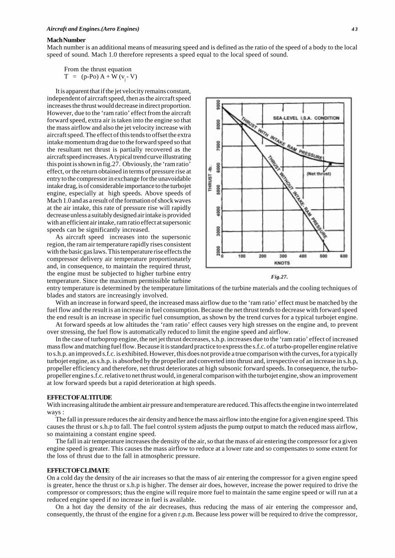
43Aircraft and Engines.(Aero Engines)
Mach NumberMach number is an additional means of measuring speed and is defined as the ratio of the speed of a body to the localspeed of sound. Mach 1.0 therefore represents a speed equal to the local speed of sound.
From the thrust equationT = (p-Po) A + W (v
j - V)
It is apparent that if the jet velocity remains constant,independent of aircraft speed, then as the aircraft speedincreases the thrust would decrease in direct proportion.However, due to the ‘ram ratio’ effect from the aircraftforward speed, extra air is taken into the engine so thatthe mass airflow and also the jet velocity increase withaircraft speed. The effect of this tends to offset the extraintake momentum drag due to the forward speed so thatthe resultant net thrust is partially recovered as theaircraft speed increases. A typical trend curve illustratingthis point is shown in fig.27. Obviously, the ‘ram ratio’effect, or the return obtained in terms of pressure rise atentry to the compressor in exchange for the unavoidableintake drag, is of considerable importance to the turbojetengine, especially at high speeds. Above speeds ofMach 1.0 and as a result of the formation of shock wavesat the air intake, this rate of pressure rise will rapidlydecrease unless a suitably designed air intake is providedwith an efficient air intake, ram ratio effect at supersonicspeeds can be significantly increased.
As aircraft speed increases into the supersonicregion, the ram air temperature rapidly rises consistentwith the basic gas laws. This temperature rise effects thecompressor delivery air temperature proportionatelyand, in consequence, to maintain the required thrust,the engine must be subjected to higher turbine entrytemperature. Since the maximum permissible turbineentry temperature is determined by the temperature limitations of the turbine materials and the cooling techniques ofblades and stators are increasingly involved.
With an increase in forward speed, the increased mass airflow due to the ‘ram ratio’ effect must be matched by thefuel flow and the result is an increase in fuel consumption. Because the net thrust tends to decrease with forward speedthe end result is an increase in specific fuel consumption, as shown by the trend curves for a typical turbojet engine.
At forward speeds at low altitudes the ‘ram ratio’ effect causes very high stresses on the engine and, to preventover stressing, the fuel flow is automatically reduced to limit the engine speed and airflow.
In the case of turboprop engine, the net jet thrust decreases, s.h.p. increases due to the ‘ram ratio’ effect of increasedmass flow and matching fuel flow. Because it is standard practice to express the s.f.c. of a turbo-propeller engine relativeto s.h.p. an improved s.f.c. is exhibited. However, this does not provide a true comparison with the curves, for a typicallyturbojet engine, as s.h.p. is absorbed by the propeller and converted into thrust and, irrespective of an increase in s.h.p,propeller efficiency and therefore, net thrust deteriorates at high subsonic forward speeds. In consequence, the turbo-propeller engine s.f.c. relative to net thrust would, in general comparison with the turbojet engine, show an improvementat low forward speeds but a rapid deterioration at high speeds.
EFFECT OF ALTITUDEWith increasing altitude the ambient air pressure and temperature are reduced. This affects the engine in two interrelatedways :
The fall in pressure reduces the air density and hence the mass airflow into the engine for a given engine speed. Thiscauses the thrust or s.h.p to fall. The fuel control system adjusts the pump output to match the reduced mass airflow,so maintaining a constant engine speed.
The fall in air temperature increases the density of the air, so that the mass of air entering the compressor for a givenengine speed is greater. This causes the mass airflow to reduce at a lower rate and so compensates to some extent forthe loss of thrust due to the fall in atmospheric pressure.
EFFECT OF CLIMATEOn a cold day the density of the air increases so that the mass of air entering the compressor for a given engine speedis greater, hence the thrust or s.h.p is higher. The denser air does, however, increase the power required to drive thecompressor or compressors; thus the engine will require more fuel to maintain the same engine speed or will run at areduced engine speed if no increase in fuel is available.
On a hot day the density of the air decreases, thus reducing the mass of air entering the compressor and,consequently, the thrust of the engine for a given r.p.m. Because less power will be required to drive the compressor,
Fig.27.
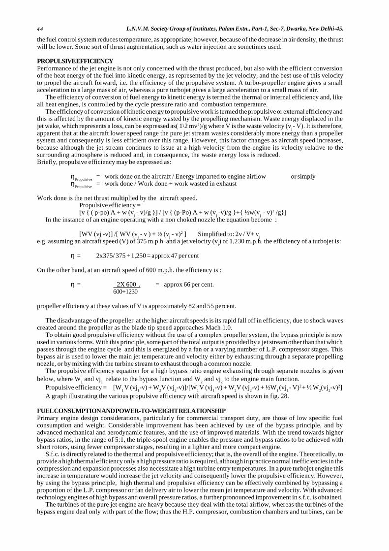
44 L.N.V.M. Society Group of Institutes, Palam Extn., Part-1, Sec-7, Dwarka, New Delhi-45.
the fuel control system reduces temperature, as appropriate; however, because of the decrease in air density, the thrustwill be lower. Some sort of thrust augmentation, such as water injection are sometimes used.
PROPULSIVE EFFICIENCYPerformance of the jet engine is not only concerned with the thrust produced, but also with the efficient conversionof the heat energy of the fuel into kinetic energy, as represented by the jet velocity, and the best use of this velocityto propel the aircraft forward, i.e. the efficiency of the propulsive system. A turbo-propeller engine gives a smallacceleration to a large mass of air, whereas a pure turbojet gives a large acceleration to a small mass of air.
The efficiency of conversion of fuel energy to kinetic energy is termed the thermal or internal efficiency and, likeall heat engines, is controlled by the cycle pressure ratio and combustion temperature.
The efficiency of conversion of kinetic energy to propulsive work is termed the propulsive or external efficiency andthis is affected by the amount of kinetic energy wasted by the propelling mechanism. Waste energy displaced in thejet wake, which represents a loss, can be expressed as( 1\2 mv2)/g where V is the waste velocity (v
j - V). It is therefore,
apparent that at the aircraft lower speed range the pure jet stream wastes considerably more energy than a propellersystem and consequently is less efficient over this range. However, this factor changes as aircraft speed increases,because although the jet stream continues to issue at a high velocity from the engine its velocity relative to thesurrounding atmosphere is reduced and, in consequence, the waste energy loss is reduced.Briefly, propulsive efficiency may be expressed as:
ηPropulsive
= work done on the aircraft / Energy imparted to engine airflow or simplyη
Propulsive= work done / Work done + work wasted in exhaust
Work done is the net thrust multiplied by the aircraft speed.Propulsive efficiency =[v { ( p-po) A + w (v
j - v)/g }] / [v { (p-Po) A + w (v
j -v)/g }+{ ½w(v
j - v)2 /g}]
In the instance of an engine operating with a non choked nozzle the equation become :
[WV (vj -v)] /[ WV (vj - v ) + ½ (v
j - v)2 ] Simplified to: 2v / V+ v
je.g. assuming an aircraft speed (V) of 375 m.p.h. and a jet velocity (v
j) of 1,230 m.p.h. the efficiency of a turbojet is:
η = 2x375/ 375 + 1,250 = approx 47 per cent
On the other hand, at an aircraft speed of 600 m.p.h. the efficiency is :
η = 2X 600 . = approx 66 per cent.600+1230
propeller efficiency at these values of V is approximately 82 and 55 percent.
The disadvantage of the propeller at the higher aircraft speeds is its rapid fall off in efficiency, due to shock wavescreated around the propeller as the blade tip speed approaches Mach 1.0.
To obtain good propulsive efficiency without the use of a complex propeller system, the bypass principle is nowused in various forms. With this principle, some part of the total output is provided by a jet stream other than that whichpasses through the engine cycle and this is energized by a fan or a varying number of L.P. compressor stages. Thisbypass air is used to lower the main jet temperature and velocity either by exhausting through a separate propellingnozzle, or by mixing with the turbine stream to exhaust through a common nozzle.
The propulsive efficiency equation for a high bypass ratio engine exhausting through separate nozzles is givenbelow, where W
1 and vj
1 relate to the bypass function and W
2 and vj
2 to the engine main function.
Propulsive efficiency = [W1 V (vj
1-v) + W
2V (vj
2-v)]/[W
1 V (vj
1-v) + W
2V (vj
2-v) + ½W
1 (vj
1 - V)2 + ½ W
2(vj
2-v)2]
A graph illustrating the various propulsive efficiency with aircraft speed is shown in fig. 28.
FUEL CONSUMPTION AND POWER-TO-WEIGHT RELATIONSHIPPrimary engine design considerations, particularly for commercial transport duty, are those of low specific fuelconsumption and weight. Considerable improvement has been achieved by use of the bypass principle, and byadvanced mechanical and aerodynamic features, and the use of improved materials. With the trend towards higherbypass ratios, in the range of 5:1, the triple-spool engine enables the pressure and bypass ratios to be achieved withshort rotors, using fewer compressor stages, resulting in a lighter and more compact engine.
S.f.c. is directly related to the thermal and propulsive efficiency; that is, the overall of the engine. Theoretically, toprovide a high thermal efficiency only a high pressure ratio is required, although in practice normal inefficiencies in thecompression and expansion processes also necessitate a high turbine entry temperatures. In a pure turbojet engine thisincrease in temperature would increase the jet velocity and consequently lower the propulsive efficiency. However,by using the bypass principle, high thermal and propulsive efficiency can be effectively combined by bypassing aproportion of the L.P. compressor or fan delivery air to lower the mean jet temperature and velocity. With advancedtechnology engines of high bypass and overall pressure ratios, a further pronounced improvement in s.f.c. is obtained.
The turbines of the pure jet engine are heavy because they deal with the total airflow, whereas the turbines of thebypass engine deal only with part of the flow; thus the H.P. compressor, combustion chambers and turbines, can be

45Aircraft and Engines.(Aero Engines)
scaled down. The increased power per lb. of air at theturbines, to take advantage of their full capacity, isobtained by the increase in pressure ratio and turbineentry temperature. It is clear that the bypass engineis lighter, because not only has the diameter of thepressure rotating assemblies been reduced but theengine is shorter for a given power output. With alow bypass ratio engine, the weight reductioncompared with a pure jet engine is in the order of 20per cent for the same air mass Flow.
With a high bypass ratio engine of the triple spoolconfiguration, a further significant improvement inspecific weight is obtained. This is derived mainlyfrom advanced mechanical and aerodynamic design,which, in addition to permitting a significant reductionin the total number of parts, enables rotatingassemblies to be more effectively matched and towork closer to optimum conditions, thus minimizingthe number of compressor and turbine stages for agiven duty. The use of higher strength lightweightmaterials is also a contributory factor.
For a given mass flow, however, less thrust isproduced by the bypass engine due to the lower exitvelocity. Thus, to obtain the same thrust, the bypassengine must be scaled to pass a larger total massairflow than the pure turbojet engine. The weight ofthe engine, however, is still less because of the
reduced size of the H.P. section of the engine. There, in addition to the reduced specific fuel consumption, animprovement in the power-to-weight ratio is obtained.
BRAYTON CYCLEA simple gas turbine power plant is shown in fig.29. Air is first compressed adiabatically in process a-b, it then entersthe combustion chamber where fuel is injected and burned essentially at constant pressure in process b-c, and thenthe products of combustion expand in the turbine to the ambient pressure in process c-d and are thrown out to thesurroundings. The cycle is open. The state diagram on the p-v coordinates is shown in fig.
The Brayton cycle is the air standard cycle for the gas turbine power plant. Here air is first compressed reversiblyand adiabatically, heat is added to it reversibly at constant pressure, air expands in the turbine reversibly andadiabatically and heat is then rejected from the air reversibly at constant pressure to bring it to the initial state. TheBrayton cycle, therefore, consists of
Two reversible isobars and two reversible adiabatics.
The flow, p-v, and T-s diagrams are shown in fig below for m kg of air.
Q1
= heat supplied = mcp(T
3-T
2)
Q2
= heat rejected = mcp(T
4-T
1)
Therefore Cycle efficiency = 1 - Q2/ Q
1= [ 1 -{(T
4 - T
1)/(T
3 - T
2)}]
Now T2
/T1 = (p
2 / p
1) (γ- 1)/ γ =T
3 /T
4(Since p
2 = p
3 and p
4 = p
1)
[ (T4/T
1 ) -1] = [(T
3 /T
2 ) -1]
or [(T4 -T
1 ) / (T
3 -T
2)] = [T
1 /T
2 ] = (p
1 /p
2 )γ-1/ γ = (v
2 / v
1 ) γ-1
if rk = compression ratio =v
1 /v
2, the efficiency becomes
η = 1 - (v2 /v
1 ) γ-1
or η brayton
= 1- 1/rk
γ-1
if rp = pressure ratio = p
2 /p
1 the efficiency may be expressed in the following form also
h = 1- (p1 /p
2 )( γ-1)/ γ
or η brayton
= 1- 1/ (rp)( γ-1)/ γ
The efficiency of the Brayton cycle, therefore, depends upon either the compression ratio or the pressure ratio. Forthe same compression ratio, the Brayton cycle efficiency is equal to the Otto cycle efficiency.
COMPARISON BETWEEN BRAYTON CYCLE AND OTTO CYCLEBrayton and Otto cycles are shown superimposed on the p-v and T-s diagrams. For the same r
k and work capacity, the
Brayton cycle (1-2-5-6) handles a larger range of volume and a similar range of pressure and temperature than does theOtto cycle (1-2-3-4).
Fig. 28.Propulsive efficiencies and aircraft speeds.
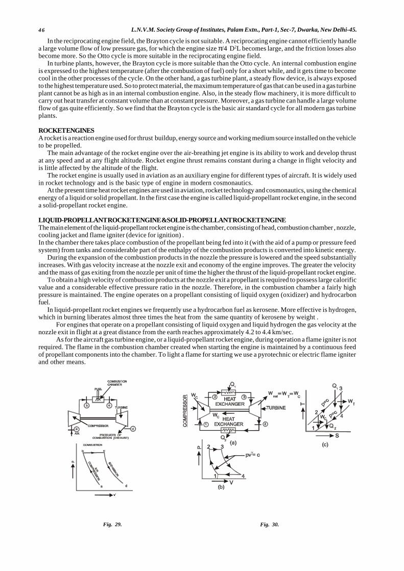
46 L.N.V.M. Society Group of Institutes, Palam Extn., Part-1, Sec-7, Dwarka, New Delhi-45.
In the reciprocating engine field, the Brayton cycle is not suitable. A reciprocating engine cannot efficiently handlea large volume flow of low pressure gas, for which the engine size π/4 D2L becomes large, and the friction losses alsobecome more. So the Otto cycle is more suitable in the reciprocating engine field.
In turbine plants, however, the Brayton cycle is more suitable than the Otto cycle. An internal combustion engineis expressed to the highest temperature (after the combustion of fuel) only for a short while, and it gets time to becomecool in the other processes of the cycle. On the other hand, a gas turbine plant, a steady flow device, is always exposedto the highest temperature used. So to protect material, the maximum temperature of gas that can be used in a gas turbineplant cannot be as high as in an internal combustion engine. Also, in the steady flow machinery, it is more difficult tocarry out heat transfer at constant volume than at constant pressure. Moreover, a gas turbine can handle a large volumeflow of gas quite efficiently. So we find that the Brayton cycle is the basic air standard cycle for all modern gas turbineplants.
ROCKET ENGINESA rocket is a reaction engine used for thrust buildup, energy source and working medium source installed on the vehicleto be propelled.
The main advantage of the rocket engine over the air-breathing jet engine is its ability to work and develop thrustat any speed and at any flight altitude. Rocket engine thrust remains constant during a change in flight velocity andis little affected by the altitude of the flight.
The rocket engine is usually used in aviation as an auxiliary engine for different types of aircraft. It is widely usedin rocket technology and is the basic type of engine in modern cosmonautics.
At the present time heat rocket engines are used in aviation, rocket technology and cosmonautics, using the chemicalenergy of a liquid or solid propellant. In the first case the engine is called liquid-propellant rocket engine, in the seconda solid-propellant rocket engine.
LIQUID-PROPELLANT ROCKET ENGINE &SOLID-PROPELLANT ROCKET ENGINEThe main element of the liquid-propellant rocket engine is the chamber, consisting of head, combustion chamber , nozzle,cooling jacket and flame igniter (device for ignition) .In the chamber there takes place combustion of the propellant being fed into it (with the aid of a pump or pressure feedsystem) from tanks and considerable part of the enthalpy of the combustion products is converted into kinetic energy.
During the expansion of the combustion products in the nozzle the pressure is lowered and the speed substantiallyincreases. With gas velocity increase at the nozzle exit and economy of the engine improves. The greater the velocityand the mass of gas exiting from the nozzle per unit of time the higher the thrust of the liquid-propellant rocket engine.
To obtain a high velocity of combustion products at the nozzle exit a propellant is required to possess large calorificvalue and a considerable effective pressure ratio in the nozzle. Therefore, in the combustion chamber a fairly highpressure is maintained. The engine operates on a propellant consisting of liquid oxygen (oxidizer) and hydrocarbonfuel.
In liquid-propellant rocket engines we frequently use a hydrocarbon fuel as kerosene. More effective is hydrogen,which in burning liberates almost three times the heat from the same quantity of kerosene by weight .
For engines that operate on a propellant consisting of liquid oxygen and liquid hydrogen the gas velocity at thenozzle exit in flight at a great distance from the earth reaches approximately 4.2 to 4.4 km/sec.
As for the aircraft gas turbine engine, or a liquid-propellant rocket engine, during operation a flame igniter is notrequired. The flame in the combustion chamber created when starting the engine is maintained by a continuous feedof propellant components into the chamber. To light a flame for starting we use a pyrotechnic or electric flame igniterand other means.
Fig. 29. Fig. 30.
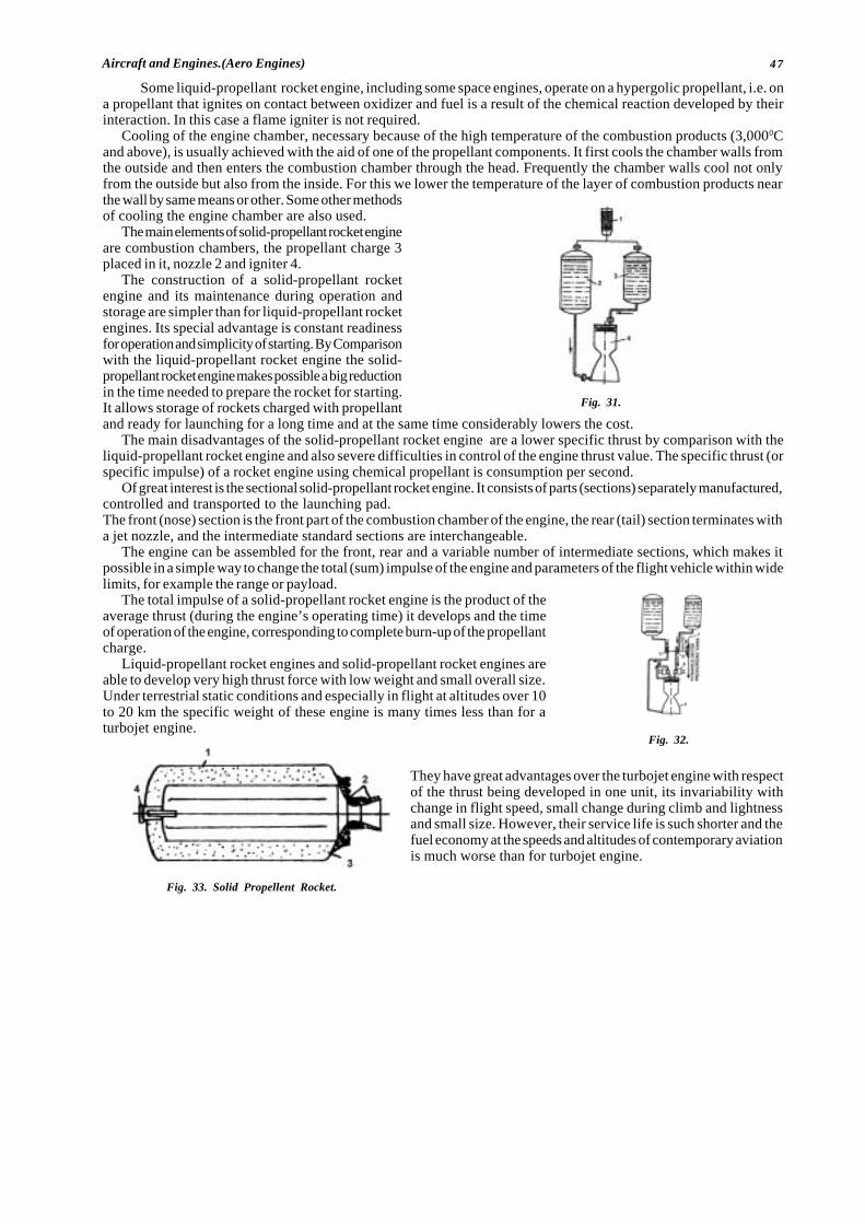
47Aircraft and Engines.(Aero Engines)
Some liquid-propellant rocket engine, including some space engines, operate on a hypergolic propellant, i.e. ona propellant that ignites on contact between oxidizer and fuel is a result of the chemical reaction developed by theirinteraction. In this case a flame igniter is not required.
Cooling of the engine chamber, necessary because of the high temperature of the combustion products (3,0000Cand above), is usually achieved with the aid of one of the propellant components. It first cools the chamber walls fromthe outside and then enters the combustion chamber through the head. Frequently the chamber walls cool not onlyfrom the outside but also from the inside. For this we lower the temperature of the layer of combustion products nearthe wall by same means or other. Some other methodsof cooling the engine chamber are also used.
The main elements of solid-propellant rocket engineare combustion chambers, the propellant charge 3placed in it, nozzle 2 and igniter 4.
The construction of a solid-propellant rocketengine and its maintenance during operation andstorage are simpler than for liquid-propellant rocketengines. Its special advantage is constant readinessfor operation and simplicity of starting. By Comparisonwith the liquid-propellant rocket engine the solid-propellant rocket engine makes possible a big reductionin the time needed to prepare the rocket for starting.It allows storage of rockets charged with propellantand ready for launching for a long time and at the same time considerably lowers the cost.
The main disadvantages of the solid-propellant rocket engine are a lower specific thrust by comparison with theliquid-propellant rocket engine and also severe difficulties in control of the engine thrust value. The specific thrust (orspecific impulse) of a rocket engine using chemical propellant is consumption per second.
Of great interest is the sectional solid-propellant rocket engine. It consists of parts (sections) separately manufactured,controlled and transported to the launching pad.The front (nose) section is the front part of the combustion chamber of the engine, the rear (tail) section terminates witha jet nozzle, and the intermediate standard sections are interchangeable.
The engine can be assembled for the front, rear and a variable number of intermediate sections, which makes itpossible in a simple way to change the total (sum) impulse of the engine and parameters of the flight vehicle within widelimits, for example the range or payload.
The total impulse of a solid-propellant rocket engine is the product of theaverage thrust (during the engine’s operating time) it develops and the timeof operation of the engine, corresponding to complete burn-up of the propellantcharge.
Liquid-propellant rocket engines and solid-propellant rocket engines areable to develop very high thrust force with low weight and small overall size.Under terrestrial static conditions and especially in flight at altitudes over 10to 20 km the specific weight of these engine is many times less than for aturbojet engine.
They have great advantages over the turbojet engine with respectof the thrust being developed in one unit, its invariability withchange in flight speed, small change during climb and lightnessand small size. However, their service life is such shorter and thefuel economy at the speeds and altitudes of contemporary aviationis much worse than for turbojet engine.
� � �
Fig. 31.
Fig. 32.
Fig. 33. Solid Propellent Rocket.

48 L.N.V.M. Society Group of Institutes, Palam Extn., Part-1, Sec-7, Dwarka, New Delhi-45.
CHAPTER: 3STARTING AND IGNITION SYSTEMS
(TURBINE ENGINES)
INTRODUCTIONTwo separate systems are required to start a turbine engine, a means to rotate the compressor turbine assembly anda method of igniting the air/fuel mixture in combustion chamber. Ideally the process is automatic after the fuel supplyis turned on and the starting circuit brought into operation.
METHODS OF STARTINGThe starting procedure for all jet engines is basically the same, but can be achieved by various methods. The type andpower source for the starter varies in accordance with engine and aircraft requirements. Some use electrical power, othersuse gas, air, or hydraulic pressure, and each has its own merits. For example, a military aircraft requires the engine tobe started in the minimum time and, when possible to be completely independent of external equipment. A commercialaircraft, however, requires the engine to be started with the minimum disturbance to the passengers and by the mosteconomical means.
The starter motor must produce a high torque and transmit it to the engine rotating assembly in a manner that providessmooth acceleration from rest upto a speed at which the gas flow through the engine provides sufficient power for theengine turbine to take over.
ElectricElectric starting is used on some turboprop and turbojet engines. The starter is usually a direct current (D.C.) electricmotor coupled to the engine through a reduction gear and ratchet mechanism or clutch, which automatically disengagesafter the engine has reached a self-sustaining speed.
The electrical supply may be of a low or high voltage, and it is passed through a system of relays and resistanceto allow the full voltage to be progressively built up as the starter gains speed. It also provides the power for operationof the ignition system. The electrical supply is automatically cancelled when the starter load is reduced after the enginehas satisfactorily started or when the time cycle is completed.
CartridgeCartridge starting is sometimes used on military engines and provides a quick independent method of starting. Thestarter motor is basically a small impulse-type turbine that is driven by high velocity gases from a burning cartridge.The power output of the turbine is passed through a reduction gear, and an automatic disconnect mechanism to rotatethe engine. An electrically fired detonator initiates the burning of the cartridge charge. As a cartridge charge providesthe power supply for this type of starter, the size of the charge required may well limit the use of cartridge starters.
Iso-Propyl NitrateIso-propyl-nitrate starting provides a high power output and gives rapid starting characteristics, but is dependent uponsupplies of iso-propyl-nitrate.
This starter motor also has a turbine that transmits power through a reduction gear to the engine. In this instance,the turbine is rotated by high pressure gasses resulting from the combustion of iso-propyl-nitrate. This fuel is mono-fuel i.e., it requires no air to sustain combustion. The fuel is sprayed into a combustion chamber which forms part ofthe starter, where it is electrically ignited by a high-energy ignition system. A pump supplies the fuel to the combustionchamber from a storage tank, and an air pump scavenges the combustion chamber of fumes before each start Operationof the fuel and air pumps, ignition systems, and cycle cancellation, is electrically controlled by relays and time switches.
Air StarterAir starting is used on most modern commercial and some military jet engines. It has many advantages over other startingsystems, as it is comparatively light, simple and economical to operate.
An air starter motor has a turbine rotor that transmits power through a reduction gear and clutch to the starter outputshaft that is connected to the engine.
The starter turbine is rotated by air pressure taken from an external ground supply, from an auxiliary power unit(A.P.U.) carried in the aircraft, or from an engine that is running. The air supply to the starter is controlled by an electricallyoperated control and pressure reducing valve that is opened when an engine start is selected and is automatically closedat a predetermined starter speed. The clutch also automatically disengages as the engine accelerates upto idling r.p.m.and the rotation of the starter ceases.
A combustion starter is sometimes fitted to an engine incorporating an air starter, and is used to supply power tothe starter when an external supply of air is not available. The starter unit has a small combustion chamber into whichhigh pressure air, from an aircraft-mounted storage bottle, and fuel, from the engine fuel system, are introduced. Controlvalves regulate the air supply, which pressurizes a fuel accumulator, to give sufficient fuel pressure for atomization,and also activates the continuous ignition system. The fuel/air mixture is ignited in the combustion chamber, and theresultant gas is directed on to the turbine of the air starter. An electrical circuit is provided to shut off the air supply,which in turn terminates the fuel and ignition systems on completion of the starting cycle.
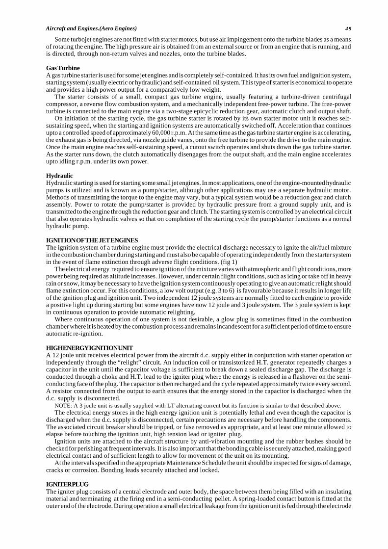
49Aircraft and Engines.(Aero Engines)
Some turbojet engines are not fitted with starter motors, but use air impingement onto the turbine blades as a meansof rotating the engine. The high pressure air is obtained from an external source or from an engine that is running, andis directed, through non-return valves and nozzles, onto the turbine blades.
Gas TurbineA gas turbine starter is used for some jet engines and is completely self-contained. It has its own fuel and ignition system,starting system (usually electric or hydraulic) and self-contained oil system. This type of starter is economical to operateand provides a high power output for a comparatively low weight.
The starter consists of a small, compact gas turbine engine, usually featuring a turbine-driven centrifugalcompressor, a reverse flow combustion system, and a mechanically independent free-power turbine. The free-powerturbine is connected to the main engine via a two-stage epicyclic reduction gear, automatic clutch and output shaft.
On initiation of the starting cycle, the gas turbine starter is rotated by its own starter motor unit it reaches self-sustaining speed, when the starting and ignition systems are automatically switched off. Acceleration than continuesupto a controlled speed of approximately 60,000 r.p.m. At the same time as the gas turbine starter engine is accelerating,the exhaust gas is being directed, via nozzle guide vanes, onto the free turbine to provide the drive to the main engine.Once the main engine reaches self-sustaining speed, a cutout switch operates and shuts down the gas turbine starter.As the starter runs down, the clutch automatically disengages from the output shaft, and the main engine acceleratesupto idling r.p.m. under its own power.
HydraulicHydraulic starting is used for starting some small jet engines. In most applications, one of the engine-mounted hydraulicpumps is utilized and is known as a pump/starter, although other applications may use a separate hydraulic motor.Methods of transmitting the torque to the engine may vary, but a typical system would be a reduction gear and clutchassembly. Power to rotate the pump/starter is provided by hydraulic pressure from a ground supply unit, and istransmitted to the engine through the reduction gear and clutch. The starting system is controlled by an electrical circuitthat also operates hydraulic valves so that on completion of the starting cycle the pump/starter functions as a normalhydraulic pump.
IGNITION OF THE JET ENGINESThe ignition system of a turbine engine must provide the electrical discharge necessary to ignite the air/fuel mixturein the combustion chamber during starting and must also be capable of operating independently from the starter systemin the event of flame extinction through adverse flight conditions. (fig 1)
The electrical energy required to ensure ignition of the mixture varies with atmospheric and flight conditions, morepower being required as altitude increases. However, under certain flight conditions, such as icing or take off in heavyrain or snow, it may be necessary to have the ignition system continuously operating to give an automatic relight shouldflame extinction occur. For this conditions, a low volt output (e.g. 3 to 6) is favourable because it results in longer lifeof the ignition plug and ignition unit. Two independent 12 joule systems are normally fitted to each engine to providea positive light up during starting but some engines have now 12 joule and 3 joule system. The 3 joule system is keptin continuous operation to provide automatic relighting.
Where continuous operation of one system is not desirable, a glow plug is sometimes fitted in the combustionchamber where it is heated by the combustion process and remains incandescent for a sufficient period of time to ensureautomatic re-ignition.
HIGH ENERGY IGNITION UNITA 12 joule unit receives electrical power from the aircraft d.c. supply either in conjunction with starter operation orindependently through the “relight” circuit. An induction coil or transistorized H.T. generator repeatedly charges acapacitor in the unit until the capacitor voltage is sufficient to break down a sealed discharge gap. The discharge isconducted through a choke and H.T. lead to the igniter plug where the energy is released in a flashover on the semi-conducting face of the plug. The capacitor is then recharged and the cycle repeated approximately twice every second.A resistor connected from the output to earth ensures that the energy stored in the capacitor is discharged when thed.c. supply is disconnected.
NOTE: A 3 joule unit is usually supplied with LT alternating current but its function is similar to that described above.The electrical energy stores in the high energy ignition unit is potentially lethal and even though the capacitor is
discharged when the d.c. supply is disconnected, certain precautions are necessary before handling the components.The associated circuit breaker should be tripped, or fuse removed as appropriate, and at least one minute allowed toelapse before touching the ignition unit, high tension lead or igniter plug.
Ignition units are attached to the aircraft structure by anti-vibration mounting and the rubber bushes should bechecked for perishing at frequent intervals. It is also important that the bonding cable is securely attached, making goodelectrical contact and of sufficient length to allow for movement of the unit on its mounting.
At the intervals specified in the appropriate Maintenance Schedule the unit should be inspected for signs of damage,cracks or corrosion. Bonding leads securely attached and locked.
IGNITER PLUGThe igniter plug consists of a central electrode and outer body, the space between them being filled with an insulatingmaterial and terminating at the firing end in a semi-conducting pellet. A spring-loaded contact button is fitted at theouter end of the electrode. During operation a small electrical leakage from the ignition unit is fed through the electrode
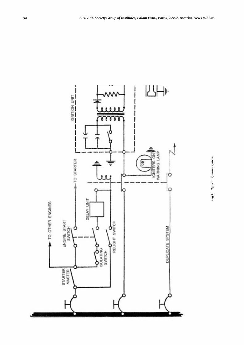
50 L.N.V.M. Society Group of Institutes, Palam Extn., Part-1, Sec-7, Dwarka, New Delhi-45.
Fig
.1.
Typ
ical
ign
ition
sys
tem
.
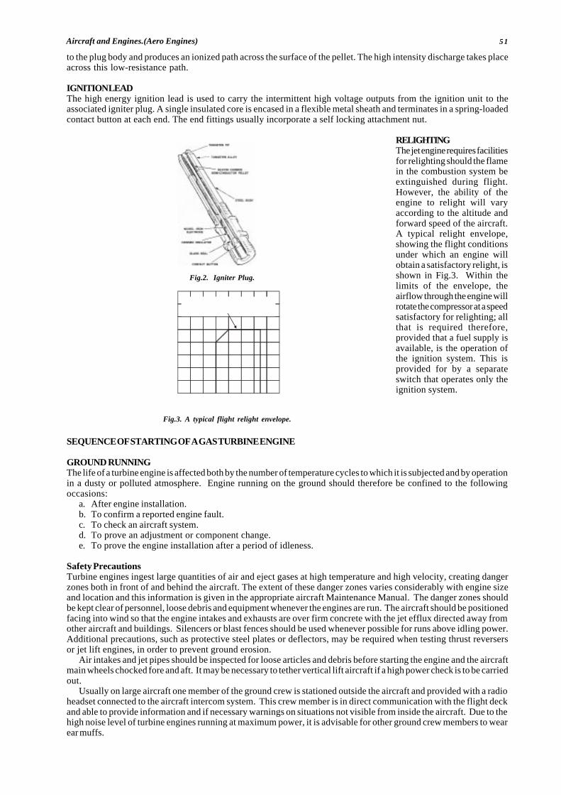
51Aircraft and Engines.(Aero Engines)
to the plug body and produces an ionized path across the surface of the pellet. The high intensity discharge takes placeacross this low-resistance path.
IGNITION LEADThe high energy ignition lead is used to carry the intermittent high voltage outputs from the ignition unit to theassociated igniter plug. A single insulated core is encased in a flexible metal sheath and terminates in a spring-loadedcontact button at each end. The end fittings usually incorporate a self locking attachment nut.
RELIGHTINGThe jet engine requires facilitiesfor relighting should the flamein the combustion system beextinguished during flight.However, the ability of theengine to relight will varyaccording to the altitude andforward speed of the aircraft.A typical relight envelope,showing the flight conditionsunder which an engine willobtain a satisfactory relight, isshown in Fig.3. Within thelimits of the envelope, theairflow through the engine willrotate the compressor at a speedsatisfactory for relighting; allthat is required therefore,provided that a fuel supply isavailable, is the operation ofthe ignition system. This isprovided for by a separateswitch that operates only theignition system.
SEQUENCE OF STARTING OF A GAS TURBINE ENGINE
GROUND RUNNINGThe life of a turbine engine is affected both by the number of temperature cycles to which it is subjected and by operationin a dusty or polluted atmosphere. Engine running on the ground should therefore be confined to the followingoccasions:
a. After engine installation.b. To confirm a reported engine fault.c. To check an aircraft system.d. To prove an adjustment or component change.e. To prove the engine installation after a period of idleness.
Safety PrecautionsTurbine engines ingest large quantities of air and eject gases at high temperature and high velocity, creating dangerzones both in front of and behind the aircraft. The extent of these danger zones varies considerably with engine sizeand location and this information is given in the appropriate aircraft Maintenance Manual. The danger zones shouldbe kept clear of personnel, loose debris and equipment whenever the engines are run. The aircraft should be positionedfacing into wind so that the engine intakes and exhausts are over firm concrete with the jet efflux directed away fromother aircraft and buildings. Silencers or blast fences should be used whenever possible for runs above idling power.Additional precautions, such as protective steel plates or deflectors, may be required when testing thrust reversersor jet lift engines, in order to prevent ground erosion.
Air intakes and jet pipes should be inspected for loose articles and debris before starting the engine and the aircraftmain wheels chocked fore and aft. It may be necessary to tether vertical lift aircraft if a high power check is to be carriedout.
Usually on large aircraft one member of the ground crew is stationed outside the aircraft and provided with a radioheadset connected to the aircraft intercom system. This crew member is in direct communication with the flight deckand able to provide information and if necessary warnings on situations not visible from inside the aircraft. Due to thehigh noise level of turbine engines running at maximum power, it is advisable for other ground crew members to wearear muffs.
Fig.2. Igniter Plug.
Fig.3. A typical flight relight envelope.
4 0
3 0
2 0
1 0
0 1 0 0 2 0 0 3 0 0 4 0 0A IR S P E E D - kn o ts
ALTITU
DE-f
eetx1
,000
S H O W S A LT IT U D E A ND A IR S P E ED U PTO W H IC H A N E N G IN E C A N O B TA IN
A S AT IS FA C TO RY R E L IG H T
52 L.N.V.M. Society Group of Institutes, Palam Extn., Part-1, Sec-7, Dwarka, New Delhi-45.
A suitable CO2 or foam fire extinguisher must be located adjacent to the engine during all ground runs. The aircraft
fire extinguishing system should only be used in the event of a fire in an engine which is fully cowled.
StartingThere are many different types of turbine engine starters and starting systems, therefore it is not possible to give asequence of operations exactly suited to all aircraft. The main requirements for starting are detailed in the followingparagraphs.
An external electrical power supply is often required and should be connected before starting. Where a ground/flight switch is provided this must be set to ‘ground’ and all warning lights checked for correct operation.
Where an air supply is required for starting this should be connected and the pressure checked as being sufficientto ensure a start.
NOTE: If the electrical and air supplies are not adequate for starting purposes it is possible for a light-up to occur at insufficient speedfor the engine to accelerate under its own power. This could result in excessive turbine temperatures and damage to the engine.
The controls and switches should be set for engine starting, a check made to ensure that the area both in front ofand behind the engine is clear and the starter engaged. When turbine rotation becomes apparent the HP cock shouldbe opened and the engine instruments monitored to ensure that the starting cycle is normal. When light-up occurs andthe engine begins to accelerate under its own power, switch off the starter. If it appears from the rate of increase in exhaustor turbine gas temperature that starting limits will be exceeded the HP cock should be closed immediately and the causeinvestigated (see under ‘Trouble Shooting’ in the appropriate Maintenance Manual).
Once engine speed has stabilised at idling, a check should be made that all warning lights are out, the external powersupplies disconnected and the ground/flight switch moved to ‘flight’.
TestingWhen a new engine has been installed a full ground test is necessary, but on other occasions only those parts of thetest necessary to satisfy the purpose of the run need be carried out. The test should be as brief as possible and forthis reason the aircraft Maintenance Manual specifies a sequence of operations which should always be observed.Records of the instrument readings obtained during each test should be kept to provide a basis for comparison whenfuture engine runs become necessary.
Each aircraft system associated with engine operation should be operated and any warning devices or indicatorsin the cockpit checked against physical functioning. It may be necessary in certain atmospheric conditions to selectengine anti-icing throughout the run and this should be ascertained from the minimum conditions quoted in theMaintenance Manual.
The particular tests related to engine operation are idling speed, maximum speed, acceleration, and function of anycompressor airflow controls which may be fitted. Adjustments to correct slight errors in engine operation are providedon the engine fuel pump, flow control unit, and airflow control units. Observed results of the tests must be correctedfor ambient pressure and temperature, tables or graphs being provided for this purpose in the aircraft MaintenanceManual. Adjustments may usually be carried out with the engine idling unless it is necessary to disconnect a control.In this case the engine must be stopped and a duplicate inspection of the control carried out before starting it again.An entry must be made in the engine log book quoting any adjustments made and the ambient conditions at the time.
StoppingAfter completion of the engine run the engine should be idled until temperatures stabilise and then the HP cock closed.The time taken for the engine to stop should be noted and compared with previous times, due allowance being madefor wind velocity (e.g. a strong head wind will appreciably increase the run-down time). During the run-down fuel shouldbe discharged from certain fuel component drains and this should be confirmed. A blocked drain pipe must be rectified.When the engine has stopped, all controls and switches used for the run must be turned off and the engine inspectedfor fuel, oil, fluid and gas leaks.
After a new engine has been tested the oil filters should be removed and inspected and after refitting these itemsthe system should be replenished as necessary.
� � � � � � � �
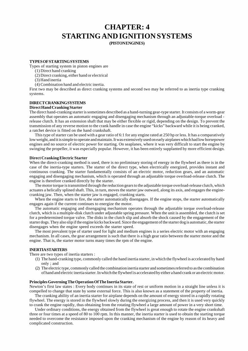
53Aircraft and Engines.(Aero Engines)
CHAPTER: 4STARTING AND IGNITION SYSTEMS
(PISTON ENGINES)
TYPES OF STARTING SYSTEMSTypes of starting system in piston engines are
(1) Direct hand cranking(2) Direct cranking, either hand or electrical(3) Hand inertia(4) Combination hand and electric inertia.
First two may be described as direct cranking systems and second two may be referred to as inertia type crankingsystems.
DIRECT CRANKING SYSTEMSDirect Hand Cranking StarterThe direct hand-cranking starter is sometimes described as a hand-turning gear-type starter. It consists of a worm-gearassembly that operates an automatic engaging and disengaging mechanism through an adjustable-torque overload -release clutch. It has an extension shaft that may be either flexible or rigid, depending on the design. To prevent thetransmission of any reverse motion to the crank handle in case the engine “kicks” backward while it is being cranked,a ratchet device is fitted on the hand crankshaft.
This type of starter can be used with a gear ratio of 6:1 for any engine rated at 250 hp or less. It has a comparativelylow weight, and it is simple to operate and maintain. It was extensively used on early airplanes which had low horsepowerengines and no source of electric power for starting. On seaplanes, where it was very difficult to start the engine byswinging the propeller, it was especially popular. However, it has been entirely supplanted by more efficient design.
Direct Cranking Electric StarterWhen the direct-cranking method is used, there is no preliminary storing of energy in the flywheel as there is in thecase of the inertia-type starters. The starter of the direct type, when electrically energized, provides instant andcontinuous cranking. The starter fundamentally consists of an electric motor, reduction gears, and an automaticengaging and disengaging mechanism, which is operated through an adjustable torque overload-release clutch. Theengine is therefore cranked directly by the starter.
The motor torque is transmitted through the reduction gears to the adjustable torque overload-release clutch, whichactuates a helically splined shaft. This, in turn, moves the starter jaw outward, along its axis, and engages the engine-cranking jaw. Then, when the starter jaw is engaged, cranking starts.
When the engine starts to fire, the starter automatically disengages. If the engine stops, the starter automaticallyengages again if the current continues to energize the motor.
The automatic engaging and disengaging mechanism operates through the adjustable torque overload-releaseclutch, which is a multiple-disk clutch under adjustable spring pressure. When the unit is assembled, the clutch is setfor a predetermined torque valve. The disks in the clutch slip and absorb the shock caused by the engagement of thestarter dogs. They also slip if the engine kicks backward. Since the engagement of the starter dog is automatic, the starterdisengages when the engine speed exceeds the starter speed.
The most prevalent type of starter used for light and medium engines is a series electric motor with an engagingmechanism. In all cases, the gear arrangement is such that there is a high gear ratio between the starter motor and theengine. That is, the starter motor turns many times the rpm of the engine.
INERTIA STARTERSThere are two types of inertia starters :
(1) The hand-cranking type, commonly called the hand inertia starter, in which the flywheel is accelerated by handonly ; and
(2) The electric type, commonly called the combination inertia starter and sometimes referred to as the combinationof hand and electric inertia starter. In which the flywheel is accelerated by either a hand crank or an electric motor.
Principles Governing The Operation Of The Inertia Starter.Newton’s first law states : Every body continues in its state of rest or uniform motion in a straight line unless it iscompelled to change that state by some external force. This is also known as a statement of the property of inertia.
The cranking ability of an inertia starter for airplane depends on the amount of energy stored in a rapidly rotatingflywheel. The energy is stored in the flywheel slowly during the energizing process, and then it is used very quicklyto crank the engine rapidly, thus obtaining from the rotating flywheel a large amount of power in a very short time.
Under ordinary conditions, the energy obtained from the flywheel is great enough to rotate the engine crankshaftthree or four times at a speed of 80 to 100 rpm. In this manner, the inertia starter is used to obtain the starting torqueneeded to overcome the resistance imposed upon the cranking mechanism of the engine by reason of its heavy andcomplicated construction.
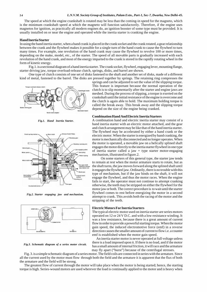
54 L.N.V.M. Society Group of Institutes, Palam Extn., Part-1, Sec-7, Dwarka, New Delhi-45.
Fig.1. Hand Inertia Starter.
Fig.2. Starter engaging jaw and mechanism.
Fig.3. Schematic diagram of a series motor circuit.
The speed at which the engine crankshaft is rotated may be less than the coming-in speed for the magneto, whichis the minimum crankshaft speed at which the magneto will function satisfactorily. Therefore, if the engine usesmagnetos for ignition, as practically all modern engines do, an ignition booster of some type must be provided. It isusually installed on or near the engine and operated while the inertia starter is cranking the engine.
Hand Inertia StarterIn using the hand inertia starter, when a hand crank is placed in the crank socket and the crank rotated, a gear relationshipbetween the crank and the flywheel makes it possible for a single turn of the hand crank to cause the flywheel to turnmany times. For example, one revolution of the hand crank may cause the flywheel to revolve 100 or more times,depending on the make, model, etc., of the starter. The speed of all movable parts is gradually increased with eachrevolution of the hand crank, and most of the energy imparted to the crank is stored in the rapidly rotating wheel in theform of kinetic energy.
Fig.1. is a sectional diagram of a hand inertia starter. The crank socket, flywheel, engaging lever, mounting flange,starter driving jaw, torque overload-release clutch, springs, disks, and barrel are shown.
One type of clutch consists of one set of disks fastened to the shaft and another set of disks, made of a differentkind of metal, fastened to the barrel. The disks are pressed together by springs. The retaining ring compresses the
springs and can be adjusted to set the value of the slipping torque.This feature is important because the normal operation of theclutch is to slip momentarily after the starter and engine jaws aremeshed. During the process of slipping, a torque is exerted on thecrankshaft until the initial resistance of the engine is overcome andthe clutch is again able to hold. The maximum holding torque iscalled the break away. This break away and the slipping torquedepend on the size of the engine being cranked.
Combination Hand And Electric Inertia StartersA combination hand and electric inertia starter may consist of ahand inertia starter with an electric motor attached, and the gearand clutch arrangement may be like that of the hand inertia starter.The flywheel may be accelerated by either a hand crank or theelectric motor. When the starter is energized by hand cranking, themotor is mechanically disconnected and no longer operates. Whenthe motor is operated, a movable jaw on a helically splined shaftengages the motor directly to the inertia starter flywheel in one typeof inertia starter called a jaw = type starter motor-engagingmechanism, illustrated in figure.2.
On some starters of this general type, the starter jaw tendsto remain at rest when the motor armature starts to rotate, but asthe shaft turns, the jaw moves forward along the splined shaft untilit engages the flywheel jaw. Ordinarily, there is no trouble with thistype of mechanism, but if the jaw binds on the shaft, it will notengage the flywheel, and thus the motor races. When the enginefails to start, the operator must not continue to attempt crankingotherwise, the teeth may be stripped on either the flywheel for themotor jaw or both. The correct procedure is to wait until the starterflywheel comes to rest before energizing the motor in a secondattempt to crank. This avoids both the racing of the motor and thestripping of the teeth.
Electric Motors For Inertia StartersThe typical electric motor used on inertia starter are series motorsoperated on 12 or 24 V D.C. and with a low resistance winding. Itwas a low resistance, because there is a great amount of currentflow in order to provide a powerful starting torque. When the motorgain speed, the induced electromotive force (emf) in a reversedirection causes the smaller amount of current to flow i.e. a counteremf is established when the motor gain speed.
An inertia starter motor is never operated at full voltage unlessthere is a load imposed upon it. If there is no load, and if the motorhas a small amount of internal friction, it will race and the armaturemay fly apart (“burst”) because of the centrifugal stresses.
Fig. 3. is a simple schematic diagram of a series motor. The field coils are connected in series with the armature. Sinceall the current used by the motor must flow through both the field and the armature it is apparent that the flux of boththe armature and the field will be strong.
The greatest flow of current through the motor will take place when the motor is being started; hence, the startingtorque is high. Series-wound motors are used wherever the load is continually applied to the motor and is heavy when
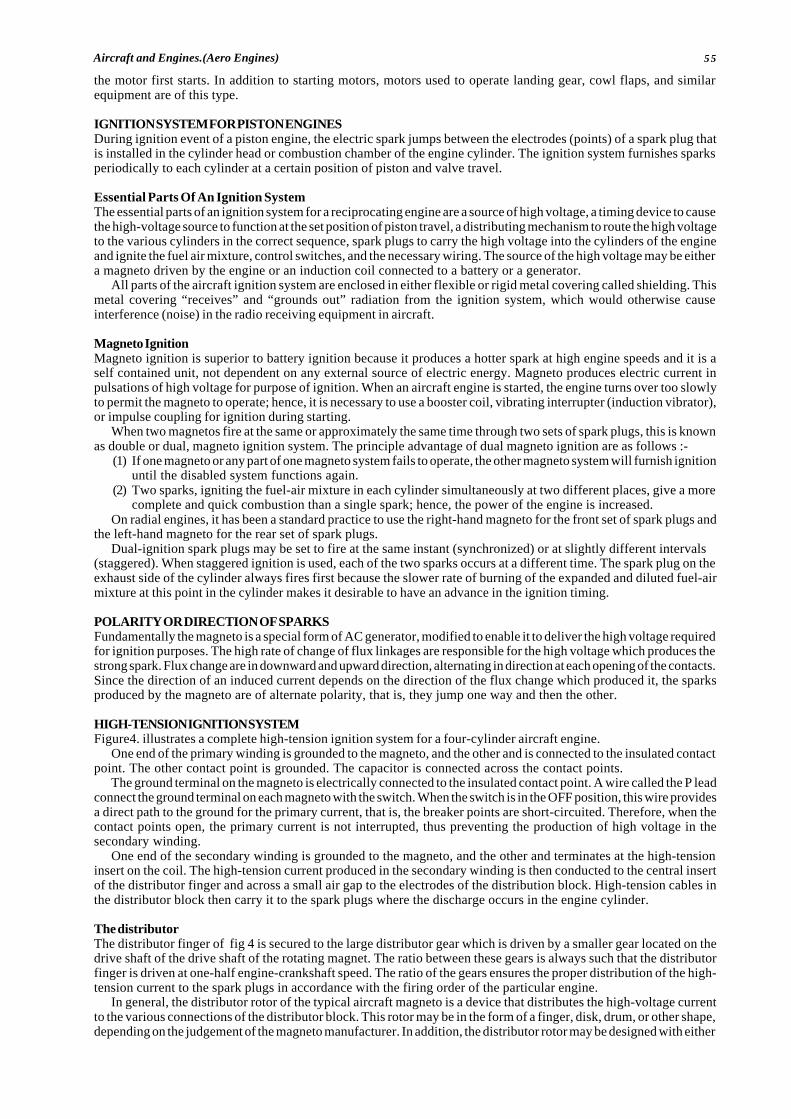
55Aircraft and Engines.(Aero Engines)
the motor first starts. In addition to starting motors, motors used to operate landing gear, cowl flaps, and similarequipment are of this type.
IGNITION SYSTEM FOR PISTON ENGINESDuring ignition event of a piston engine, the electric spark jumps between the electrodes (points) of a spark plug thatis installed in the cylinder head or combustion chamber of the engine cylinder. The ignition system furnishes sparksperiodically to each cylinder at a certain position of piston and valve travel.
Essential Parts Of An Ignition SystemThe essential parts of an ignition system for a reciprocating engine are a source of high voltage, a timing device to causethe high-voltage source to function at the set position of piston travel, a distributing mechanism to route the high voltageto the various cylinders in the correct sequence, spark plugs to carry the high voltage into the cylinders of the engineand ignite the fuel air mixture, control switches, and the necessary wiring. The source of the high voltage may be eithera magneto driven by the engine or an induction coil connected to a battery or a generator.
All parts of the aircraft ignition system are enclosed in either flexible or rigid metal covering called shielding. Thismetal covering “receives” and “grounds out” radiation from the ignition system, which would otherwise causeinterference (noise) in the radio receiving equipment in aircraft.
Magneto IgnitionMagneto ignition is superior to battery ignition because it produces a hotter spark at high engine speeds and it is aself contained unit, not dependent on any external source of electric energy. Magneto produces electric current inpulsations of high voltage for purpose of ignition. When an aircraft engine is started, the engine turns over too slowlyto permit the magneto to operate; hence, it is necessary to use a booster coil, vibrating interrupter (induction vibrator),or impulse coupling for ignition during starting.
When two magnetos fire at the same or approximately the same time through two sets of spark plugs, this is knownas double or dual, magneto ignition system. The principle advantage of dual magneto ignition are as follows :-
(1) If one magneto or any part of one magneto system fails to operate, the other magneto system will furnish ignitionuntil the disabled system functions again.
(2) Two sparks, igniting the fuel-air mixture in each cylinder simultaneously at two different places, give a morecomplete and quick combustion than a single spark; hence, the power of the engine is increased.
On radial engines, it has been a standard practice to use the right-hand magneto for the front set of spark plugs andthe left-hand magneto for the rear set of spark plugs.
Dual-ignition spark plugs may be set to fire at the same instant (synchronized) or at slightly different intervals(staggered). When staggered ignition is used, each of the two sparks occurs at a different time. The spark plug on theexhaust side of the cylinder always fires first because the slower rate of burning of the expanded and diluted fuel-airmixture at this point in the cylinder makes it desirable to have an advance in the ignition timing.
POLARITY OR DIRECTION OF SPARKSFundamentally the magneto is a special form of AC generator, modified to enable it to deliver the high voltage requiredfor ignition purposes. The high rate of change of flux linkages are responsible for the high voltage which produces thestrong spark. Flux change are in downward and upward direction, alternating in direction at each opening of the contacts.Since the direction of an induced current depends on the direction of the flux change which produced it, the sparksproduced by the magneto are of alternate polarity, that is, they jump one way and then the other.
HIGH-TENSION IGNITION SYSTEMFigure4. illustrates a complete high-tension ignition system for a four-cylinder aircraft engine.
One end of the primary winding is grounded to the magneto, and the other and is connected to the insulated contactpoint. The other contact point is grounded. The capacitor is connected across the contact points.
The ground terminal on the magneto is electrically connected to the insulated contact point. A wire called the P leadconnect the ground terminal on each magneto with the switch. When the switch is in the OFF position, this wire providesa direct path to the ground for the primary current, that is, the breaker points are short-circuited. Therefore, when thecontact points open, the primary current is not interrupted, thus preventing the production of high voltage in thesecondary winding.
One end of the secondary winding is grounded to the magneto, and the other and terminates at the high-tensioninsert on the coil. The high-tension current produced in the secondary winding is then conducted to the central insertof the distributor finger and across a small air gap to the electrodes of the distribution block. High-tension cables inthe distributor block then carry it to the spark plugs where the discharge occurs in the engine cylinder.
The distributorThe distributor finger of fig 4 is secured to the large distributor gear which is driven by a smaller gear located on thedrive shaft of the drive shaft of the rotating magnet. The ratio between these gears is always such that the distributorfinger is driven at one-half engine-crankshaft speed. The ratio of the gears ensures the proper distribution of the high-tension current to the spark plugs in accordance with the firing order of the particular engine.
In general, the distributor rotor of the typical aircraft magneto is a device that distributes the high-voltage currentto the various connections of the distributor block. This rotor may be in the form of a finger, disk, drum, or other shape,depending on the judgement of the magneto manufacturer. In addition, the distributor rotor may be designed with either
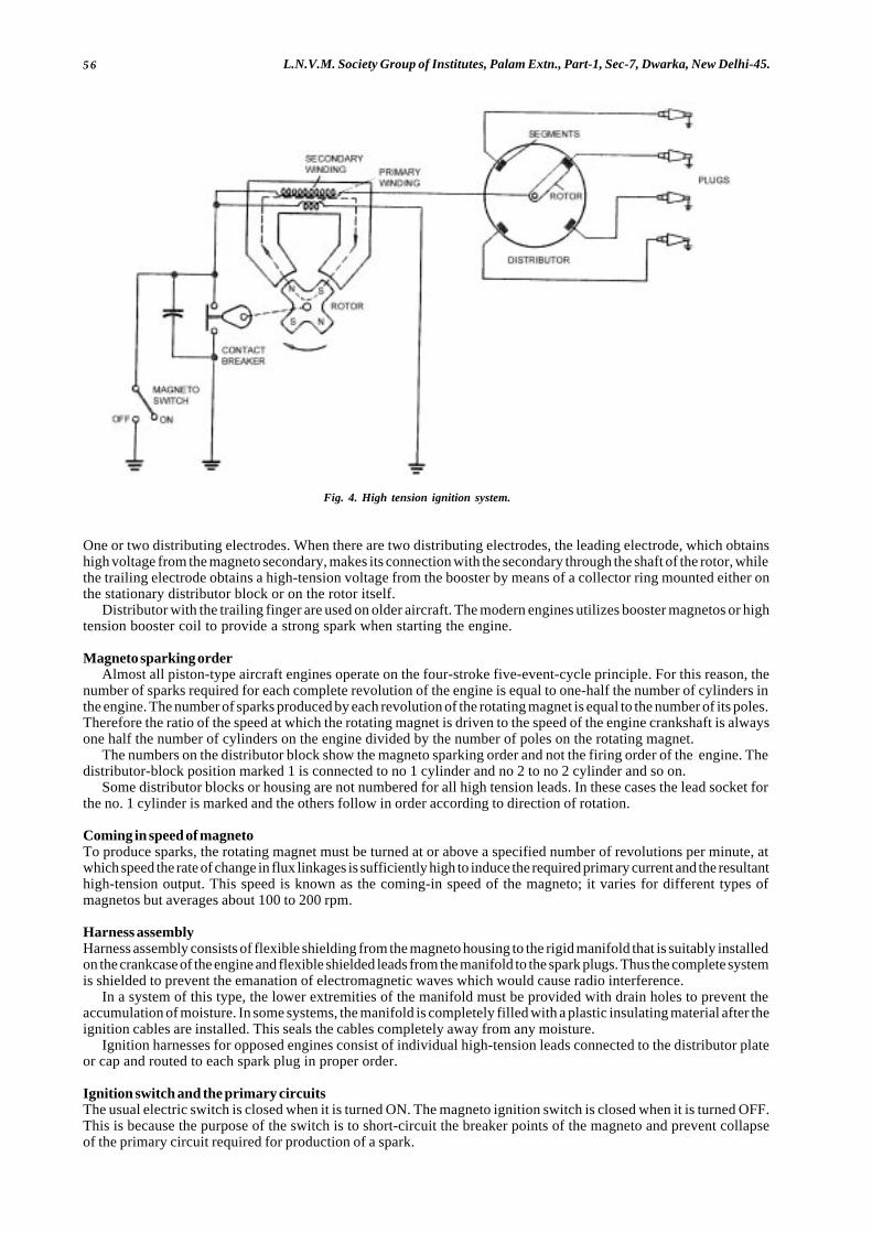
56 L.N.V.M. Society Group of Institutes, Palam Extn., Part-1, Sec-7, Dwarka, New Delhi-45.
Fig. 4. High tension ignition system.
One or two distributing electrodes. When there are two distributing electrodes, the leading electrode, which obtainshigh voltage from the magneto secondary, makes its connection with the secondary through the shaft of the rotor, whilethe trailing electrode obtains a high-tension voltage from the booster by means of a collector ring mounted either onthe stationary distributor block or on the rotor itself.
Distributor with the trailing finger are used on older aircraft. The modern engines utilizes booster magnetos or hightension booster coil to provide a strong spark when starting the engine.
Magneto sparking orderAlmost all piston-type aircraft engines operate on the four-stroke five-event-cycle principle. For this reason, the
number of sparks required for each complete revolution of the engine is equal to one-half the number of cylinders inthe engine. The number of sparks produced by each revolution of the rotating magnet is equal to the number of its poles.Therefore the ratio of the speed at which the rotating magnet is driven to the speed of the engine crankshaft is alwaysone half the number of cylinders on the engine divided by the number of poles on the rotating magnet.
The numbers on the distributor block show the magneto sparking order and not the firing order of the engine. Thedistributor-block position marked 1 is connected to no 1 cylinder and no 2 to no 2 cylinder and so on.
Some distributor blocks or housing are not numbered for all high tension leads. In these cases the lead socket forthe no. 1 cylinder is marked and the others follow in order according to direction of rotation.
Coming in speed of magnetoTo produce sparks, the rotating magnet must be turned at or above a specified number of revolutions per minute, atwhich speed the rate of change in flux linkages is sufficiently high to induce the required primary current and the resultanthigh-tension output. This speed is known as the coming-in speed of the magneto; it varies for different types ofmagnetos but averages about 100 to 200 rpm.
Harness assemblyHarness assembly consists of flexible shielding from the magneto housing to the rigid manifold that is suitably installedon the crankcase of the engine and flexible shielded leads from the manifold to the spark plugs. Thus the complete systemis shielded to prevent the emanation of electromagnetic waves which would cause radio interference.
In a system of this type, the lower extremities of the manifold must be provided with drain holes to prevent theaccumulation of moisture. In some systems, the manifold is completely filled with a plastic insulating material after theignition cables are installed. This seals the cables completely away from any moisture.
Ignition harnesses for opposed engines consist of individual high-tension leads connected to the distributor plateor cap and routed to each spark plug in proper order.
Ignition switch and the primary circuitsThe usual electric switch is closed when it is turned ON. The magneto ignition switch is closed when it is turned OFF.This is because the purpose of the switch is to short-circuit the breaker points of the magneto and prevent collapseof the primary circuit required for production of a spark.
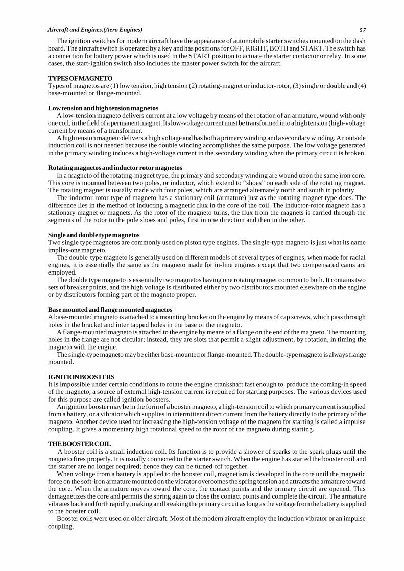
57Aircraft and Engines.(Aero Engines)
The ignition switches for modern aircraft have the appearance of automobile starter switches mounted on the dashboard. The aircraft switch is operated by a key and has positions for OFF, RIGHT, BOTH and START. The switch hasa connection for battery power which is used in the START position to actuate the starter contactor or relay. In somecases, the start-ignition switch also includes the master power switch for the aircraft.
TYPES OF MAGNETOTypes of magnetos are (1) low tension, high tension (2) rotating-magnet or inductor-rotor, (3) single or double and (4)base-mounted or flange-mounted.
Low tension and high tension magnetosA low-tension magneto delivers current at a low voltage by means of the rotation of an armature, wound with only
one coil, in the field of a permanent magnet. Its low-voltage current must be transformed into a high tension (high-voltagecurrent by means of a transformer.
A high tension magneto delivers a high voltage and has both a primary winding and a secondary winding. An outsideinduction coil is not needed because the double winding accomplishes the same purpose. The low voltage generatedin the primary winding induces a high-voltage current in the secondary winding when the primary circuit is broken.
Rotating magnetos and inductor rotor magnetosIn a magneto of the rotating-magnet type, the primary and secondary winding are wound upon the same iron core.
This core is mounted between two poles, or inductor, which extend to “shoes” on each side of the rotating magnet.The rotating magnet is usually made with four poles, which are arranged alternately north and south in polarity.
The inductor-rotor type of magneto has a stationary coil (armature) just as the rotating-magnet type does. Thedifference lies in the method of inducting a magnetic flux in the core of the coil. The inductor-rotor magneto has astationary magnet or magnets. As the rotor of the magneto turns, the flux from the magnets is carried through thesegments of the rotor to the pole shoes and poles, first in one direction and then in the other.
Single and double type magnetosTwo single type magnetos are commonly used on piston type engines. The single-type magneto is just what its nameimplies-one magneto.
The double-type magneto is generally used on different models of several types of engines, when made for radialengines, it is essentially the same as the magneto made for in-line engines except that two compensated cams areemployed.
The double type magneto is essentially two magnetos having one rotating magnet common to both. It contains twosets of breaker points, and the high voltage is distributed either by two distributors mounted elsewhere on the engineor by distributors forming part of the magneto proper.
Base mounted and flange mounted magnetosA base-mounted magneto is attached to a mounting bracket on the engine by means of cap screws, which pass throughholes in the bracket and inter tapped holes in the base of the magneto.
A flange-mounted magneto is attached to the engine by means of a flange on the end of the magneto. The mountingholes in the flange are not circular; instead, they are slots that permit a slight adjustment, by rotation, in timing themagneto with the engine.
The single-type magneto may be either base-mounted or flange-mounted. The double-type magneto is always flangemounted.
IGNITION BOOSTERSIt is impossible under certain conditions to rotate the engine crankshaft fast enough to produce the coming-in speedof the magneto, a source of external high-tension current is required for starting purposes. The various devices usedfor this purpose are called ignition boosters.
An ignition booster may be in the form of a booster magneto, a high-tension coil to which primary current is suppliedfrom a battery, or a vibrator which supplies in intermittent direct current from the battery directly to the primary of themagneto. Another device used for increasing the high-tension voltage of the magneto for starting is called a impulsecoupling. It gives a momentary high rotational speed to the rotor of the magneto during starting.
THE BOOSTER COILA booster coil is a small induction coil. Its function is to provide a shower of sparks to the spark plugs until the
magneto fires properly. It is usually connected to the starter switch. When the engine has started the booster coil andthe starter are no longer required; hence they can be turned off together.
When voltage from a battery is applied to the booster coil, magnetism is developed in the core until the magneticforce on the soft-iron armature mounted on the vibrator overcomes the spring tension and attracts the armature towardthe core. When the armature moves toward the core, the contact points and the primary circuit are opened. Thisdemagnetizes the core and permits the spring again to close the contact points and complete the circuit. The armaturevibrates back and forth rapidly, making and breaking the primary circuit as long as the voltage from the battery is appliedto the booster coil.
Booster coils were used on older aircraft. Most of the modern aircraft employ the induction vibrator or an impulsecoupling.

58 L.N.V.M. Society Group of Institutes, Palam Extn., Part-1, Sec-7, Dwarka, New Delhi-45.
THE INDUCTION VIBRATORA circuit for an induction vibrator is used with a high tension magneto is shown in figure5. This circuit applies to oneengine only, but it is obvious that a similar circuit would be used with each engine of a multi engine airplane. Theinduction vibrator is energized from the same circuit which energizes the starting solenoid. It is thus energized onlyduring the time that the engines are being started.
One advantage of the induction vibrator is that it reduces the tendency of the magneto to “flash over” at highaltitudes, since the booster finger can be eliminated. The function of this induction vibrator is to supply interruptedlow voltage for the magneto primary coil, which induces a sufficiently high voltage in the secondary for starting.
The vibrator sends an interrupted battery current through the primary winding of the regular magneto coil. Themagneto coil then acts like a battery ignition coil and produces high tension impulses, which are distributed throughthe distributor rotor and distributor block, and cables to the spark plugs. These high-tension impulses are producedduring the engine time that the magneto contact points are open. When the contact points are closed, sparks cannotbe generated, although the vibrator continues to sand interrupted current impulses through the magneto contact pointswithout harm to the vibrator or any part of the circuit.
When the ignition switch is in the ON position and the engine starter is engaged, the current from the battery is sentthrough the coil of a relay which is normally open. The battery current causes the relay points to close, thus completingthe circuit to the vibrator coil and causing the vibrator to produce a rapidly interrupted current.
The rapidly interrupted current produced by the vibrator is sent through the primary winding of the magneto coil.By induction, high voltage is created in the secondary winding of the magneto coil, and this high voltage produceshigh-tension sparks which are delivered to the spark plugs through the magneto distributor-block electrodes duringthe time that the magneto contact points are open.
The process is repeated each time that the magneto contact points are separated, because the interrupted currentonce more flows through the primary of the magneto coil. The action continues until the engine is firing because ofthe regular magneto sparks, and the engine starter is released. It should be understood that the vibrator starts to operateautomatically when the engine-ignition switch is turned to the ON position and the starter is engaged. The vibratorstops when the starter is disengaged.
LOW-TENSION IGNITION
Reasons for development of low tension ignitionThere are several very serious problems encountered in the production and distribution of the high-voltage electricityused to fire the spark plugs of an aircraft engine. High voltage electricity causes corrosion of metals and deteriorationof insulating materials. It also has a marked tendency to escape from the routes provided for it by the designer of theengine.
There are four principal causes for the troubles experienced in the use of high-voltage ignition systems: (1) Flashover,(2) Capacitance, (3) Moisture, and (4) High-voltage corona.
Flashover:Is a term to describe the jumping of the high voltage inside a distributor when an airplane ascends to a high altitude.The reason for this is that the air is less dense at high altitudes and hence has less dielectric, or insulating, strength.
CapacitanceIs the ability of a conductor to store electrons. In the high-tension ignition system, the capacitance of the high-tensionleads from the magneto to the spark plugs causes the leads to store a portion of the electric charge until the voltageis built sufficiently to cause the spark to jump the gap of a spark plug. When the spark has jumped and establisheda path across the gap, the energy stored in the leads during the rise of voltage is dissipated in heat at the spark-plugelectrodes since this discharge of energy is in the form of a relatively low voltage and high current, it causes burningof the electrodes and shortens the life of the spark plug.
MoistureWhenever it exists, increases conductivity. Thus it may provide new and unforeseen routes for the escape of high-voltage electricity.High voltage coronaIs a phrase often used to describe a condition of stress which exists across any insulator (dielectric) exposed to highvoltage. When the high voltage is impressed between the conductor of an insulated lead and any metallic mass nearthe lead, and electrical stress is set up in the insulation. Repeated application of this stress to the insulation willeventually cause failure.
Operation of low tension ignition systemThe low tension ignition system consists of (1) a low tension magneto (11) a carbon brush distributor and (111) atransformer for each spark plug.
During the operation of the low-tension system, surges of electricity are generated in the magneto generator coil.The peak surge voltage is never in excess of 350V and probably is nearer 200 V on most installations. This comparativelylow voltage is fed through the distributor to the primary of the spark-plug transformer.
At the instant of opening of the breaker contacts which are connected across the magneto generator coil, a rapidflux change takes place in the generator coil core, causing a rapid rise of voltage in this coil. As has already been
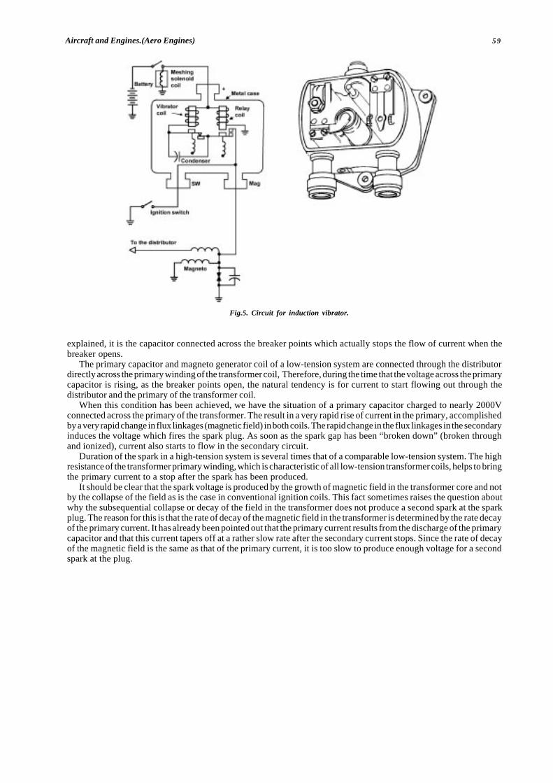
59Aircraft and Engines.(Aero Engines)
explained, it is the capacitor connected across the breaker points which actually stops the flow of current when thebreaker opens.
The primary capacitor and magneto generator coil of a low-tension system are connected through the distributordirectly across the primary winding of the transformer coil, Therefore, during the time that the voltage across the primarycapacitor is rising, as the breaker points open, the natural tendency is for current to start flowing out through thedistributor and the primary of the transformer coil.
When this condition has been achieved, we have the situation of a primary capacitor charged to nearly 2000Vconnected across the primary of the transformer. The result in a very rapid rise of current in the primary, accomplishedby a very rapid change in flux linkages (magnetic field) in both coils. The rapid change in the flux linkages in the secondaryinduces the voltage which fires the spark plug. As soon as the spark gap has been “broken down” (broken throughand ionized), current also starts to flow in the secondary circuit.
Duration of the spark in a high-tension system is several times that of a comparable low-tension system. The highresistance of the transformer primary winding, which is characteristic of all low-tension transformer coils, helps to bringthe primary current to a stop after the spark has been produced.
It should be clear that the spark voltage is produced by the growth of magnetic field in the transformer core and notby the collapse of the field as is the case in conventional ignition coils. This fact sometimes raises the question aboutwhy the subsequential collapse or decay of the field in the transformer does not produce a second spark at the sparkplug. The reason for this is that the rate of decay of the magnetic field in the transformer is determined by the rate decayof the primary current. It has already been pointed out that the primary current results from the discharge of the primarycapacitor and that this current tapers off at a rather slow rate after the secondary current stops. Since the rate of decayof the magnetic field is the same as that of the primary current, it is too slow to produce enough voltage for a secondspark at the plug.
� � �
Fig.5. Circuit for induction vibrator.
60 L.N.V.M. Society Group of Institutes, Palam Extn., Part-1, Sec-7, Dwarka, New Delhi-45.
CHAPTER: 5LUBRICATION SYSTEM : GAS TURBINE ENGINE
INTRODUCTIONThe lubrication requirements of an aircraft gas turbine engine are generally not too difficult to meet, because the oildoes not lubricate any parts of the engine that are directly heated by combustion. Because of this, the loss of oil fromthe system is small compared with that from a piston engine.
The requirements of a turbo-propeller engine are a little more-severe than those of a turbojet engine, because of theheavily loaded propeller reduction gears and the need for a high pressure oil supply to operate the propeller pitch controlmechanism.
Most gas turbine engines use a self-contained recirculatory oil system, in which the oil is distributed and returnedto the oil tank by pumps. Some turbojet engines, however, use another system known as the total loss or expendablesystem in which the oil is spilled overboard after the engine has been lubricated. Recirculatory are divided into twotypes they are (i) Pressure Relief Valve (ii) Full flow systems, the major difference between them being in the controlof the oil flow to the bearings.
LUBRICATION SYSTEMS
Recirculatory systemPressure relief valve systemIn pressure relief valve system the oil flow to the bearings of the rotating assemblies is controlled by limiting the maximumpressure in the feed line. This is achieved by a system relief valve in which feed oil pressure is opposed by a springpressure plus atmospheric pressure via the oil tank. On some installations bearing housing pressure or an equivalentof this is used in place of atmospheric pressure. Above a specific engine speed, feed oil pressure overcomes theopposing pressure and the excess oil spills back to the tank, thus maintaining the pressure and flow to the bearingsconstant at higher engine speeds.
OperationThe pressure pump draws the oil from the tank through strainer which protects the pump gears from any debris whichmay have entered the tank. Oil is then delivered through a pressure filter to a relief valve (system relief valve) that controlsthe maximum pressure of the oil flow to the rotating assemblies. On some engines an additional relief valve (pump reliefvalve) is fitted at the pressure pump out let. This valve is set to open at a much higher pressure than the system reliefvalve and opens only to return the oil to the inlet side of the pump should the system become blocked. To prevent oilstarvation when the oil is very cold or the pressure filter is partially blocked, a bypass valve that operates at a presetpressure difference is fitted across the inlet and outlet of the pressure filter.
On the turbojet system the pressure oil from the relief valve is delivered, through transfer tubes and passages, tolubricate the bearings and gears. Twin-spool engines are provided with a separate metering pump that supplies acontrolled amount of oil to the front bearing of the low pressure compressor. This prevents flooding during the initialstage of the starting cycle when only the high pressure compressor is rotating. As the low pressure compressor startsto rotate, oil is supplied to the front bearing, the flow being centred in relationship to compressor speed.
On the turbo-propeller system, the pressure oil is divided after leaving the relief valve, to feed the rotating assemblybearings, propeller pitch control supply system, reduction gear and torque-meter system.The rotating assembly bearings and some of the heavier loaded gears in the gearboxes are lubricated by oil jets andthese are often protected by thread-type filters. The remaining bearings and gears are splash lubricated. Bearings at‘hot’ end of the engine receive the maximum oil flow because, in addition to lubricating the bearings, the oil assists inheat dissipation.
On some engines, to minimize the effect of the dynamic loads transmitted from the rotating assemblies to the bearinghousing, ‘squeeze film’ type bearings are used. These have a small clearance between the outer track of the bearingand the housing, the space being filled with feed oil. The film modifies the radial motion of the rotating assembly andthe dynamic loads transmitted to the bearing housing, thus reducing the vibration level of the engine and the possibilityof damage by fatigue.
To prevent the flooding of the bearing housing, it is necessary to use more than one pump to return or scavengeit to the oil tank. This is achieved by using a pack of pumps, each of which returns the oil from a particular section ofthe engine. To protect the pump gears, each return pipe is provided with a strainer that, during inspection, can revealthe failure or impending failure of a component.
Centrifugal breatherTo separate the air from the oil returning to the tank, a de-aerating device and a centrifugal breather are incorporated.The return air/oil mixture is fed on to the de-aerator where partial separation occurs, the remaining air/oil mist then passesinto the centrifugal breather for final separation. The rotating vanes of the breather centrifuge the oil from the mist andthe air is vented overboard through the hollow drive shaft.
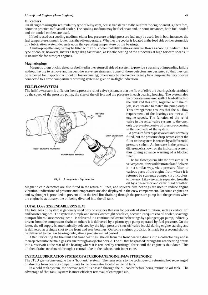
61Aircraft and Engines.(Aero Engines)
Oil coolersOn all engines using the recirculatory type of oil system, heat is transferred to the oil from the engine and it is, therefore,common practice to fit an oil cooler. The cooling medium may be fuel or air and, in some instances, both fuel-cooledand air-cooled coolers are used.
If fuel is used as a cooling medium, either low pressure or high pressure fuel may be used, for in both instances thefuel temperature is much lower than the oil temperature. Whether the cooler is located in the feed side or the return sideof a lubrication system depends upon the operating temperature of the bearings.
A turbo-propeller engine may be fitted with an oil cooler that utilizes the external airflow as a cooling medium. Thistype of cooler, however, incurs a large drag factor and, as kinetic heating of the air occurs at high forward speeds, itis unsuitable for turbojet engines.
Magnetic plugsMagnetic plugs or chip detectors be fitted in the return oil side of a system to provide a warning of impending failure
without having to remove and inspect the scavenge strainers. Some of these detectors are designed so that they canbe removed for inspection without oil loss occurring; others may be checked externally by a lamp and battery or evenconnected to a crew compartment warning system to give an in-flight indication.
FULL FLOW SYSTEMThe full flow system is different from a pressure relief valve system, in that the flow of oil to the bearings is determinedby the speed of the pressure pump, the size of the oil jets and the pressure in each bearing housing. The system also
incorporates a metered spill of feed oil back tothe tank and this spill, together with the oiljets, is calibrated to match the pump output.This arrangement ensures that the oil flowrequirements of the bearings are met at allengine speeds. The function of the reliefvalve in the relief valve system to the openonly to prevent excessive oil pressure occurringin the feed side of the system.
A pressure filter bypass valve is not normallyfitted, but the pressure drop across either thefilter or the system is sensed by a differentialpressure switch. An increase in the pressuredifference is shown on the indicating system,thus giving advance warning of a blockedfilter.
The full flow system, like the pressure reliefvalve system, draws oil from a tank and deliversit in a similar way, via a pressure filter, tovarious parts of the engine from where it isreturned by scavenge pumps, via oil coolers,to the tank. Likewise, air is separated from theoil by a de-aerator and centrifugal breather.
Magnetic chip detectors are also fitted in the return oil lines, and squeeze film bearings are used to reduce enginevibration; indications of pressure and temperature are also displayed in the crew compartment. On some engines ananti-syphon jet is provided to prevent oil in the feed line draining through the pressure pump into the gearbox whenthe engine is stationary, the oil being diverted into the oil tank.
TOTAL LOSS (EXPENDABLE) SYSTEMThe total loss oil system is generally used only on engines that run for periods of short duration, such as vertical liftand booster engines. The system is simple and incurs low weight penalties, because it requires no oil cooler, scavengepump or filters. On some engines oil is delivered in a continuous flow to the bearings by a plunger type pump, indirectlydriven from the compressor shaft; on others it is delivered by a piston-type pump operated by fuel pressure. On thelatter, the oil supply is automatically selected by the high pressure shut-off valve (cock) during engine starting andis delivered as a single shot to the front and rear bearings. On some engines provision is made for a second shot tobe delivered to the rear bearing only, after a predetermined period.
After lubricating the fuel unit and front bearings., the oil from the front bearing drains into a collector tray and isthen ejected into the main gas stream through an ejector nozzle. The oil that has passed through the rear bearing drainsinto a reservoir at the rear of the bearing where it is retained by centrifugal force until the engine is shut down. Thisoil then drains overboard through a central tube in the exhaust unit inner cone.
TYPICAL LUBRICATION SYSTEM OF A TURBO FAN ENGINE: P&W JT 8D ENGINEThe JT8D gas turbine engine has a ‘hot tank’ system. The term refers to the technique of returning hot secavangedoil directly from bearing compartments to the de-areator located in the oil tank.
In a cold tank system, the secavanged oil is passed through the oil cooler before being returns to oil tank. Theadvantage of ‘hot tank’ system is more efficient removal of entrapped air.
Fig.1. A magnetic chip detector.

62 L.N.V.M. Society Group of Institutes, Palam Extn., Part-1, Sec-7, Dwarka, New Delhi-45.
Pressure systemThe oil is gravity fed from the tank to the main oil pump by a transfer tube and cored passage in the accessories gearbox. Pump discharge pressure is then directed to main oil filter. A by pass valve provided in filter provides oil if mainfilter becomes obstructed.
External pressure taps are provided to sense before and after filter. This permits in-flight monitoring of main oil filtervia a differential pressure switch and annunciator light on flight deek.
Oil from filter, regulated to provide operating pressure after the fuel oil cooler, directed to oil cooler and furtherdelivered to engine bearings, components and accessories gear box at desired pressure and temperature.
Pressure regulated valve is located in a cored passage and regulate oil pressure. The surface area of oil cooler isadequate to provide sufficient cooling when flow is the mid to high range, thus, the thermostat control is eliminated.The higher oil temperature at prolonged idling can be controlled by moving the power lever to higher speed periodically.Secavange SystemAfter the oil has lubricated the engine and accessories box bearings, it is returned to oil tank by the secavange system.
The main collection points for secavanging oil located in the Numbers. 1,4,5,and 6 bearings compartment andaccessories gear box. A gear type of pump is located in each compartment. Secavange oil from No.1 bearing is returneddirectly to gear box, number 2 and 3 secavange to gear box by gravity and breather flow throw tower shaft housing.Gear box lube oil along with the oil secavanged from 1,2 and 3 supports is returned to oil tank by gear box secavangepump.
Secavange oil from No.6 bearing area is pumped to no 4(1/2) bearing area through transfer tubes located in lowpressure turbine shaft. Centrifugal force causes the oil to be ejected from the no 4(1/2) bearing out through the highpressure turbine shaft secavanging holes to No 4 and 5 bearing compartments. The secavange pump located in No.4and 5 bearing compartment directly return the oil to the oil tank.Breather SystemTo ensure proper oil flow and to maintain satisfactory secavange pump performance, the pressure in the bearing cavitiesis controlled by the breather system. The breather air from all the main bearings is vented to the accessory gear boxas follows:-
a The No.1 bearing breather air is vented to the accessories box via external tubing.b. The No.2 and 3 bearings are vented internally to the accessory gear box through tower shaft housing.c. The No. 4(1/2) and 6 bearing breath through the secavange system into No. 4 and 5 collection point.d. The combined breather air from No. 4, 4(1/2), 5 and 6 bearings is vented to the accessory gear box through an
external line. A de-oiler located in the accessory gear box serves to remove oil particles from in the breathingair before it is discharged into airframe waste tube.
Magnetic plugs and chip detectors are located in oil system to indicate the presence of metallic chips in lubricatingoil in subsequence of any internal failure of bearings.
TYPICAL LUBRICATION SYSTEM OF A TURBO PROPELLER ENGINE: ALLISON 501-D13For this engine, oil storage and cooling provisions are made in aircraft and provides independent oil supply for powersection and reduction gear assembly.Power Section Lubrication SystemIt contain an independent lubrication system with the exception of airframe furnished parts common to power sectionand reduction gear.Main Oil PumpIt includes the pressure pump, a secavange pump and the pressure regulating valveOil FilterIt houses a check valve, filter element and the by pass valve for the filter is located in gear box housing.Three Secavange PumpsLocated in diffusor, turbine inlet casing and turbine rear bearing supportSecavange Relief ValveLocated in the accessory drive housing assemblyBreatherLocated on top of the air inlet housing.
Oil is supplied from the aircraft tank to the inlet of the pressure pump, after pressurisation flows through the filter,the system pressure is regulated to 50 to 70 psi by the pressure regulating valve. A by pass valve provide oil supplyin the event of blockage of filter and a check valve prevents oil flow when engine is stoped.
The secavange pump which is incorporated in the main oil pump and the three independent secavange pumps areso located that they will secavange oil from the power section in any normal attitude of aircraft flight.
The secavange pump located in the main oil pump, secavange oil from the accessory gear box, the other threesecavanges oil from diffuser and front and rear side of turbine. The out put of diffuser and front turbine secavangepump join that of the main secavange pump.
The out put of the rear turbine secavange pump is delivered to the interior of the turbine to compressor tie boltsand compressor rotor tie bolt. This oil is directed to the splines of turbine coupling shaft assembly and to the splinesfor extension shaft of compressor. Thus the out put of rear turbine secavange pump must be resecavanged by the otherthree secavange pumps.
A secavange relief valve is located, so that it will prevent excessive pressure build up in the power section secavangesystem. The combined flows of secavanged oil from the power section and reduction gear secavange system must becooled and returned to supply tank.
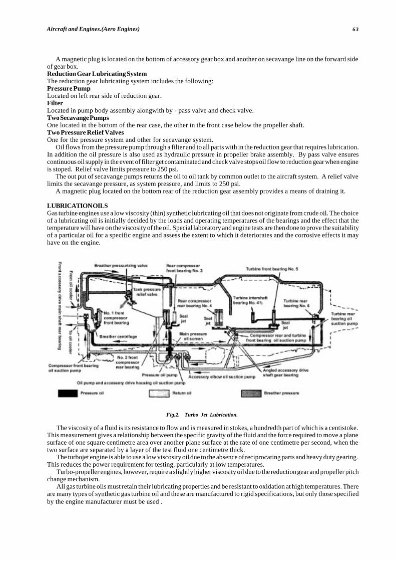
63Aircraft and Engines.(Aero Engines)
A magnetic plug is located on the bottom of accessory gear box and another on secavange line on the forward sideof gear box.Reduction Gear Lubricating SystemThe reduction gear lubricating system includes the following:Pressure PumpLocated on left rear side of reduction gear.FilterLocated in pump body assembly alongwith by - pass valve and check valve.Two Secavange PumpsOne located in the bottom of the rear case, the other in the front case below the propeller shaft.Two Pressure Relief ValvesOne for the pressure system and other for secavange system.
Oil flows from the pressure pump through a filter and to all parts with in the reduction gear that requires lubrication.In addition the oil pressure is also used as hydraulic pressure in propeller brake assembly. By pass valve ensurescontinuous oil supply in the event of filter get contaminated and check valve stops oil flow to reduction gear when engineis stoped. Relief valve limits pressure to 250 psi.
The out put of secavange pumps returns the oil to oil tank by common outlet to the aircraft system. A relief valvelimits the secavange pressure, as system pressure, and limits to 250 psi.
A magnetic plug located on the bottom rear of the reduction gear assembly provides a means of draining it.
LUBRICATION OILSGas turbine engines use a low viscosity (thin) synthetic lubricating oil that does not originate from crude oil. The choiceof a lubricating oil is initially decided by the loads and operating temperatures of the bearings and the effect that thetemperature will have on the viscosity of the oil. Special laboratory and engine tests are then done to prove the suitabilityof a particular oil for a specific engine and assess the extent to which it deteriorates and the corrosive effects it mayhave on the engine.
The viscosity of a fluid is its resistance to flow and is measured in stokes, a hundredth part of which is a centistoke.This measurement gives a relationship between the specific gravity of the fluid and the force required to move a planesurface of one square centimetre area over another plane surface at the rate of one centimetre per second, when thetwo surface are separated by a layer of the test fluid one centimetre thick.
The turbojet engine is able to use a low viscosity oil due to the absence of reciprocating parts and heavy duty gearing.This reduces the power requirement for testing, particularly at low temperatures.
Turbo-propeller engines, however, require a slightly higher viscosity oil due to the reduction gear and propeller pitchchange mechanism.
All gas turbine oils must retain their lubricating properties and be resistant to oxidation at high temperatures. Thereare many types of synthetic gas turbine oil and these are manufactured to rigid specifications, but only those specifiedby the engine manufacturer must be used .
� � � � � �
Fig.2. Turbo Jet Lubrication.
64 L.N.V.M. Society Group of Institutes, Palam Extn., Part-1, Sec-7, Dwarka, New Delhi-45.
CHAPTER: 6PISTON ENGINE LUBRICATION SYSTEM
CLASSIFICATION OF LUBRICANTSDefinitionA lubricant is any natural or artificial substance having greasy or oily properties which can be used to reduce frictionbetween moving parts or to prevent rust and corrosion on metallic surfaces, lubricants may be classified according totheir origins as animals, vegetable, minerals or synthetic.
Animal lubricantsExamples of Animal lubricant oil are tallow oil, lard oil, spermoil and porpoise jaw oil. These are highly stable at normaltemperature, so that they can be used to lubricate fire arms, and other light machinery and devices. Animal lubricantcannot be used for internal combustion engines because they produce fatty acids at high temperature.
Mineral lubricantsMineral lubricants are used to a large extent in the lubrication of aircraft internal combustion engines they may beclassified as solids, semisolids and fluids.
Solid lubricants, such as mica, soapstone and graphite are fairly satisfactory in a finely powered form on slow speedmachines, but they do not dissipate heat rapidly enough for high speed machines. They fill the low spots in the metalon atypical bearing surface to form a perfect smooth surface, and at the same time they provide a slippery film that reducesfriction. When a solid lubricant is finely powdered and is not too hard it may be used as a mild abrasive to smooth thesurface previously roughened by excessive wear or by machine operation in a factory. Some solid lubricants can carryheavy loads, and hence they are mixed with certain fluid lubricants to reduce the wear between adjacent surfacessubjected to high unit pressures.
Synthetic lubricantsBecause of high temperature required in the operation of gas turbine engines, it becomes necessary for the industryto develop lubricants which would retain their characteristics at temperature that will cause petroleum lubricants toevaporate and break down into heavy hydro carbons. These new lubricants are called synthetic because they are notmade from natural crude oil. Typical synthetic lubricants are Type I, alkly diester oils (MIL-L-7808) and Type II poly-ester oil (MIL-L-23699).
Semisolid lubricantsExtremely heavy oils and greases are examples of semi solid lubricants. Grease is a mixture of oil and soap. It gives goodservice when applied periodically to certain units, but its consistency is such that it is not suitable for circulating orcontinuous-operating lubrication systems.
Fluid lubricantsFluid lubricants (oil) are used as the principal lubricant in all types of internal combustion engines because they canbe pumped easily and sprayed readily and because they absorb and dissipated heat quickly and provides a goodcushioning effect.
LUBRICANT REQUIREMENTS AND FUNCTIONSCharacteristic of aircraft lubricating oil
1. It should have the proper body (viscosity) at the engine operating temperature usually encountered by theairplane in which it is used; It should be distributed readily to the lubricated parts and it must resist the pressurebetween the various lubricated surfaces.
2. It should have high anti friction characteristics to reduce the frictional resistance of the moving parts whenseparated only by boundary films. An ideal fluid lubricant provides a strong oil film to prevent metallic frictionand to create a minimum amount of oil friction or oil drag.
3. It should have maximum fluidity at low temperature to ensure a ready flow and distribution when starting atlow temperature. Some grades of oil become practically solid in cold weather, causing high oil drag and impairedcirculation.
4. It should have minimum changes in viscosity with changes in temperature to provide uniform protection whereatmosphere temperature very widely. The viscosity of oils is greatly affected by temperature changes. e.g.at high operating temperature, the oil may be so thin that the oil film is broken and the moving parts wear rapidly.
5. It should have high anti wear properties to resist the wiping action that occurs wherever microscopic boundaryfilm are used to prevent metallic contact. The theory of fluid lubrication by an oil film, is as long as oil film isnot broken, the external friction (fluid friction) of the lubricants takes place of the metallic sliding friction whichother wise would exists.
6. It should have maximum cooling ability to absorb as much heat as possible from all lubricated surfaces andespecially from the piston head and skirt. One of the reasons for long using liquid lubricants is that they are
65Aircraft and Engines.(Aero Engines)
effective in absorbing and dissipating heat. Another reason is that liquid lubricant can be readily pumped orsprayed. Many engine parts, especially those carrying heavy load with high rubbing velocities are lubricatedby oil under direct pressure. Where direct-pressure lubrication is not practical a spray or mist of oil providesthe required protection. Regardless of the method of application, the oil absorbs the heat and later dissipatesit through the coolers.
7. It should offer maximum resistance to oxidation thus minimizing harmful deposits on the metal parts.8. It should be non corrosive to the metals in the lubricated parts.
Functions1. It lubricates, thus reducing the friction between moving parts.2. It cools the various parts of the engine.3. It tends to seal the combustion chamber by filling the walls, thus preventing the loss of compression past the
piston rings.4. It tends to clean the engine by carrying sludge and residue away from the moving engine parts and depositing
them in the oil filter.
COMPONENTS AND CHARACTERISTICS OF LUBRICATING SYSTEMSThe lubrication oil is distributed to the various moving parts of a typical internal combustion engine by one of threemethods:- (1) Pressure (2) Splash (3) A combination of pressure and splash.
Pressure lubricationIn a typical lubrication system, a mechanical pump supplies oil under pressure to the bearings. The oil flows into theinlet or suction side of the pump, usually located higher than the bottom of the oil sump so that sediment which fallsinto the sump will not be drawn into the pump. The pump may by either the eccentric vane type or the gear type, butthe gear type is most commonly used. It forces oil into an oil manifold, which distributes the oil to the crankshaft bearings.A pressure relief valve is usually located near the outlet side of the pump.
Oil flows into the main bearings through holes drilled in crankshaft to the lower connecting rod bearings. Each ofthese holes through which the oil is fed is located so that the bearing pressure at that point will be as low as possible.
Oil reaches a hollow camshaft through a connection with the end bearings or the main oil manifold and then flowsout of the hollow camshaft to the various camshaft bearings and cams.
The engine cylinder surfaces receive oil sprayed from the crankshaft and also from the crankpin bearings. Since oilseeps slowly through the small crankpin clearances before it is sprayed on the cylinder walls, considerable time isrequired for enough oil to reach the cylinder walls, especially on a cold day when oil flow is more sluggish. This situationis one of the chief reasons for diluting the engine oil with engine fuel for starting in very cold weather.
SPLASH LUBRICATION AND COMBINATION SYSTEMPressure lubrication is the principle method of lubrication used on all aircraft engines. Splash lubrication may be usedin addition to pressure lubrication on aircraft engines, but it is never used by itself. Hence aircraft engine lubricationsystem are always of either the pressure type or the combination pressure-and-splash type.
Principle components of a lubrication systemAn aircraft engine lubrication system includes pressure oil pump, an pressure relief valve, an reservoir/either as partof the engine or separate from the engine) an oil pressure gauge, and oil temperature gage, oil filters, and the necessarypiping and connections. In addition many lubrication system include oil coolers and/or temperature regulating devices.Oil dilution system are included when they are deemed necessary for cold weather starting.
Typical lubrication systemIn this system, oil is contained in a separate tank and is forced under pressure from a pressure pump through a hollowcrankshaft to lubricate the engine, the oil is then drained into the sump from which it is pumped by a scavenge pump,which has a 20% greater capacity then a pressure pump, to ensure that the oil does not accumulate in the engine andit passes through an oil cooler and is returned to the tank.
The by pass around the filter is provided to prevent damage in case of failure to clean the filter. In this event dirtyoil is considered definitely a lesser evil than no oil at all. The by pass is also a safety device allowing the oil to returnto the tank without damaging the parts such as the filter in case the pressure should become excessive. The pressurerelief valve provides a means of regulating the oil pressure, the oil pressure is monitored by the means of an oil pressuregage on the instrument panel of the aircraft.
� � �

66 L.N.V.M. Society Group of Institutes, Palam Extn., Part-1, Sec-7, Dwarka, New Delhi-45.
CHAPTER: 7VENTILATION AND COOLING SYSTEM
PISTON ENGINEAircraft engines may be cooled either by air or by liquid, Excessive heat is undesirable in any internal-combustion enginefor three principal reasons: (1) It adversely affects the behaviour of the combustion of the fuel-air charge, (2) it weakensand shortens the life of the engine parts, (3) it impairs lubrication.
If the temperature inside the engine cylinder is too great, the fuel mixture will be preheated and combustion will occurbefore the proper time. Premature combustion causes detonation “knocking,” and other undesirable conditions. It willalso aggravate the overheated condition and is likely to result in failure of pistons and valves.
The strength of many of the engine parts depends on their heat treatment. Excessive heat weakness such parts andshortens their life. Also, the parts may become elongated, warped, or expanded to the extent that they sieze or locktogether and stop the operation of the engine.
Excessive heat “cracks” the lubricating oil, lowers its viscosity, and destroys its lubricating properties.
COOLINGApproximately one third of the energy produced by burning fuel in the engine cylinders manifests itself as heat whichis not converted to power. If this heat were not dissipated failure of some of the engine components indirect contactwith the combustion process would take place, and the engine would fail. Some of the heat is rejected with the exhaustgases but the remainder must be dissipated so as to maintain the working parts of the engine at a temperature whichwill ensure that the materials are not adversely affected. However a minimum temperature must be maintained to assistproper lubrication and to provided good fuel evaporation. There are two main methods of cooling, by liquid or by air,but some internal parts are also cooled by heat transfer through the medium of the lubricating oil.
Liquid coolingIn liquid cooled engines the cylinders are surrounded by a water jacket, through which liquid (normally a mixture ofethylene glycol and water) is passed to absorb and remove excess heat. The jackets are parts of a closed system, whichalso includes an engine driven pump and a radiator which projects into the airstream. Some systems are provided withthermostatically controlled radiator shutter, by means of which a suitable coolant temperature is maintained duringflight. Liquid cooling has been used mainly on military aircraft engines, but a few examples may still be for on civil aircraft.
Air coolingWith air cooled engines, all those parts of the engine which needs to be cooled (mainly the cylinders) are provided withfins, the purpose of which is to present a larger cooling surface to the air flowing round them. The size of the fins isrelated directly to the quantity of heat to be dissipated, thus the fins on the cylinder head gave a greater area than thoseon the cylinder barrel. Baffles and deflecters are fitted round the cylinders to ensure that all surfaces are adequatelycooled and the whole engine is cowled to direct airflow past the cylinder to reduce drag. The exit path from the cowlingis generally provided with gills or flaps, by means of which the mass air flow may be adjusted to control cylindertemperature. Because air cooling is simple and little maintenance is required, air cooled engines are used in the majorityof piston engine aircraft.
AIR-COOLING OF TURBINE ENGINESIntroductionAn important feature in the design of a gas turbine engine is the need to ensure that certain parts of the engine, andin some instances certain accessories, do not absorb heat from the gas stream to an extent that is detrimental to theirsafe operation. This is achieved by allowing a controlled amount of air from the compressors to flow around thesecomponents. The internal cooling airflow is also used to cool the oil, and to pressurize the main bearing housing andvarious drive shaft seals to maintain the efficiency of the lubrication system by preventing oil leakage. External coolingof the engine power plant is also essential to prevent the transfer of heat to the aircraft structure.
Internal coolingThe heat transferred by the turbine blades from the main gas stream to the turbine discs, the bearings of the rotatingassemblies, and the engine main casings, is absorbed and dispersed by directing a flow of comparatively cool air overthese components. High and low pressure airflows are provided by taking air from both compressors; on completionof its function, the air is either vented overboard or joins the exhaust gas flow.
On the type of engine shown in figure, low pressure (L.P.) air is directed forward to cool the L.P. compressor shaft,and rearward to cool the high pressure (H.P.) compressor shaft L.P. air is also taken from the by-pass duct and fed tothe rear of the engine to cool the turbine shafts; the separate L.P. airflows then mix and are ducted overboard after coolingthe outer surface of the H.P. turbine shaft. An intermediate H.P. compressor flow is used to cool the rear half of the H.P.compressor shaft and the rear face of the final compressor disc before passing through tubes into the bypass duct.
The H.P. compressor outlet air is directed rearwards onto the turbine discs and, because the flow moves outwardsacross the discs into the exhaust gas flow, the hot exhaust gases, being of a lower pressure, are prevented from the
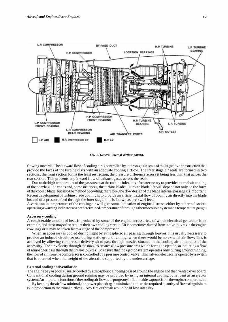
67Aircraft and Engines.(Aero Engines)
Fig. 1. General internal airflow pattern.
flowing inwards. The outward flow of cooling air is controlled by inter stage air seals of multi-groove construction thatprovide the faces of the turbine discs with an adequate cooling airflow. The inter stage air seals are formed in twosections; the front section forms the least restriction, the pressure difference across it being less than that across therear section. This prevents any inward flow of exhaust gases across the seals.
Due to the high temperature of the gas stream at the turbine inlet, it is often necessary to provide internal air coolingof the nozzle guide vanes and, some instances, the turbine blades. Turbine blade life will depend not only on the formof the cooled blade, but also the method of cooling; therefore, the flow design of the blade internal passages is important.Recent development of turbine blade cooling is to provide an efficient axial flow of cooling air directly into the bladeinstead of a pressure feed through the inter stage; this is known as pre-swirl feed.A variation in temperature of the cooling air will give some indication of engine distress, either by a thermal switchoperating a warning indicator at a predetermined temperature of through a thermocouple system to a temperature gauge.
Accessory coolingA considerable amount of heat is produced by some of the engine accessories, of which electrical generator is anexample, and these may often require their own cooling circuit. Air is sometimes ducted from intake louvres in the enginecowlings or it may be taken from a stage of the compressor.
When an accessory is cooled during flight by atmospheric air passing through louvres, it is usually necessary toprovide an induced circuit for use during static ground running, when there would be no external air flow. This isachieved by allowing compressor delivery air to pass through nozzles situated in the cooling air outlet duct of theaccessory. The air velocity through the nozzles creates a low pressure area which forms an ejector, so inducting a flowof atmospheric air through the intake louvres. To ensure that the ejector system operates only during ground running,the flow of air from the compressor is controlled by a pressure control valve. This valve is electrically opened by a switchthat is operated when the weight of the aircraft is supported by the undercarriage.
External cooling and ventilationThe engine bay or pod is usually cooled by atmospheric air being passed around the engine and then vented over board.Conventional cooling during ground running may be provided by using an internal cooling outlet vent as an ejectorsystem. An important function of the cooling air flow is to purge any inflammable vapours from the engine compartment.
By keeping the airflow minimal, the power plant drag is minimized and, as the required quantity of fire extinguishantis in proportion to the zonal airflow . Any fire outbreak would be of low intensity.
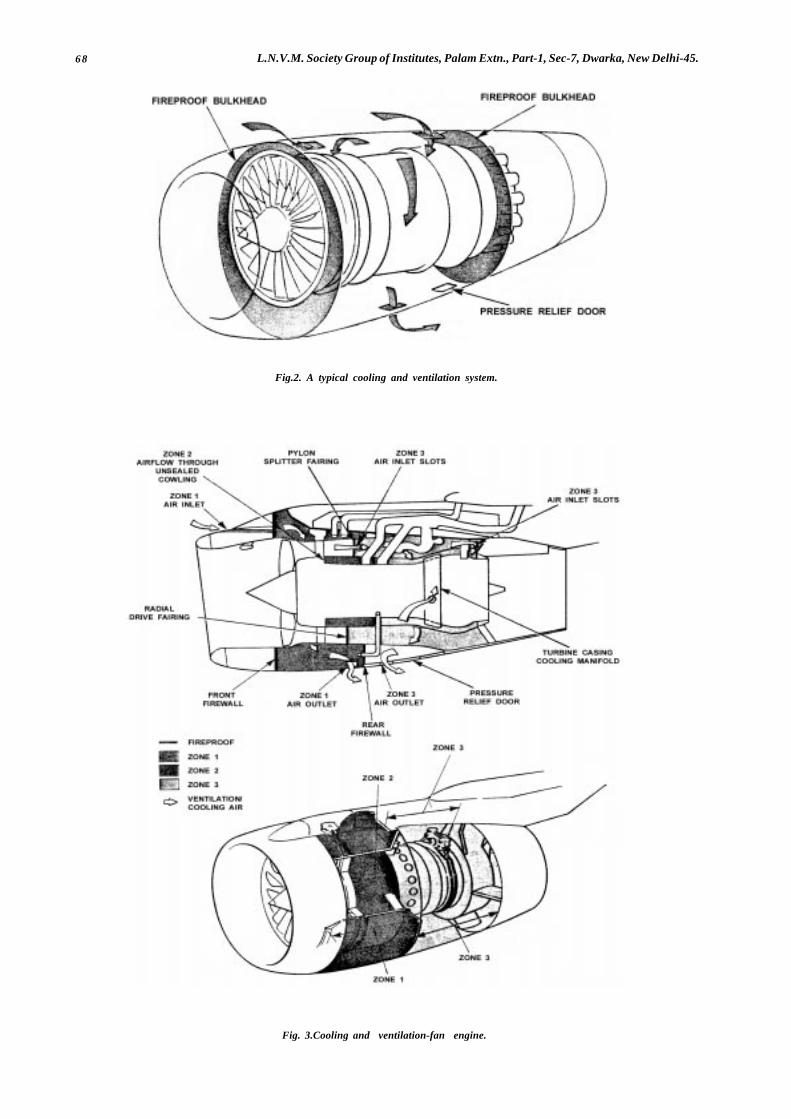
68 L.N.V.M. Society Group of Institutes, Palam Extn., Part-1, Sec-7, Dwarka, New Delhi-45.
Fig.2. A typical cooling and ventilation system.
Fig. 3.Cooling and ventilation-fan engine.

69Aircraft and Engines.(Aero Engines)
A fireproof bulkhead is also provided to separate the ‘cool’ area or zone of the engine, which contains the fuel, oil,hydraulic and electrical systems, from the ‘hot’ area surrounding, the combustion, turbine and exhaust sections of theengine. Differential pressures can be created in the two zones by calibration of the inlet and outlet apertures to preventthe spread of fire from the hot zone.
� � �

70 L.N.V.M. Society Group of Institutes, Palam Extn., Part-1, Sec-7, Dwarka, New Delhi-45.
CHAPTER: 8PISTON ENGINE CARBURATION SYSTEM
INTRODUCTIONThis Chapter deals with piston-engine fuel requirements, and the methods used to provide a satisfactory supply ofcombustible mixture to the cylinders under all operating conditions.
FUELThe fuel used in piston engines is a hydrocarbon fuel, with a composition of approximately 85% carbon and 14%hydrogen by weight. When the fuel is mixed in suitable proportions with air, and ignited, the carbon and hydrogencombine with the oxygen in the air and form carbon dioxide and water vapour; the nitrogen in the air, being an inert gas,is chemically unchanged, but performs the useful function of slowing down the combustion process and maintainingacceptable combustion temperatures.
The most important qualities required in a fuel are outlined in paragraphs to below.
Anti-Knock RatingThis is an indication of the resistance afforded by the fuel to the onset of detonation. It is explained earlier, that anincrease in power can be obtained by increasing cylinder pressure, but that can cause detonation. It is important,therefore, that the fuel has good resistance to detonation in order to enable satisfactory engine power to be developed.Calorific ValueThis is a measure of the amount of heat which can be obtained from a given weight of fuel. This is important in an aircraft,since the weight of fuel carried will limit the payload. The calorific value of a given volume of fuel is also of significance,as in some cases the fuel tank capacity may be a limiting factor.VolatilityThis is the tendency of a fuel to evaporate. Volatility should be high enough to permit easy starting under coldatmospheric conditions, but not so high that vapour will form in the pipelines and pumps at high temperatures and/or low pressures, and interrupt fuel flow or upset the metering system.Corrosive EffectsA fuel must not be corrosive to any components in the engine or fuel system.
Although fuels of various grades have been available in the past, and have been specified for use in particularengines, there is a tendency for fuel companies to reduce the number of grades available, to standardize on Grade 100L(dyed green) or Grade 100LL (dyed blue), which both contain a small quantity of tetraethyl lead to assist in preventingdetonation and are covered by Specifications D Eng RD 2485 and 2475 respectively. The problems associated with theuse of these fuels in engines which were designed for use with non-leaded fuel, or fuel with a lower lead content, areoutlined in CAA Airworthiness Notice No. 70.
MIXTURE REQUIREMENTSAir and fuel vapour will burn if mixed in the ratios of between approximately 8:1 and 20:1 by weight. However, completecombustion will only occur at a ratio of approximately 15:1 (i.e. all the hydrogen and carbon in the fuel, and all the oxygenin the air will be used up), and this is known as the chemically-correct, or stoichiometric, mixture, which produces thehighest combustion temperatures. With weaker mixtures (i.e. those containing less fuel), and richer mixtures (i.e. thosecontaining more fuel), the excess air or fuel will absorb some of the heat of combustion and lower the temperature ofthe burning gases.
Although the chemically-correct mixture strength would theoretically produce the highest temperature, andtherefore power, in practice mixing and distribution are less than perfect and this results in some regions being richerand others being weaker than the optimum strength; this variation may exist between one cylinder and another. A slightexcess of fuel does not have much effect on power since all the oxygen is still consumed and the excess of fuel simplyserves to reduce slightly the effective volumetric efficiency; in fact its cooling effect can be to some extent beneficial.Weak mixtures, however, rapidly reduce power since some of the inspired oxygen is not being utilized, and this powerreduction is much greater than that resulting from slight richness. It is, therefore, quite common to run engines (whenmaximum power rather than best fuel economy is the objective) at somewhat richer than chemically-correct mixtures(i.e. about 1205:1) to ensure than no cylinder is left running at severely reduced power from being unduly weak.
A mixture which is weaker than the chemically-correct mixture, besides burning at lower temperatures, also burnsat a slower rate (because of the greater proportion of inert gas in the cylinder). Power output thus decreases as themixture is weakened, but, because of the increase in efficiency resulting from cooler burning, the fall in power is relativelyless than the decrease in fuel consumption. Thus the specific fuel consumption (i.e. the weight of fuel used perhorsepower per hour) decreases as mixture strength is weakened below 15:1. For economical cruising at moderate power,air/fuel ratios of 18:1 may be used, an advance ignition timing being necessary to allow for the slower rate of combustion.

71Aircraft and Engines.(Aero Engines)
Fig.1. Typical Mixture Requirements.
At high power settings, the increase in engine speed and cylinder pressure results in an increase in mixturetemperature, and this could lead to detonation. Cooling may be provided by using excess fuel, an air/fuel ratio as lowas 10:1 often being used at maximum power. The excess fuel, other than acting as a coolant, is otherwise wasted, becausethere is no oxygen available to burn it.
Fig.2. Fuel Consumption and Power.
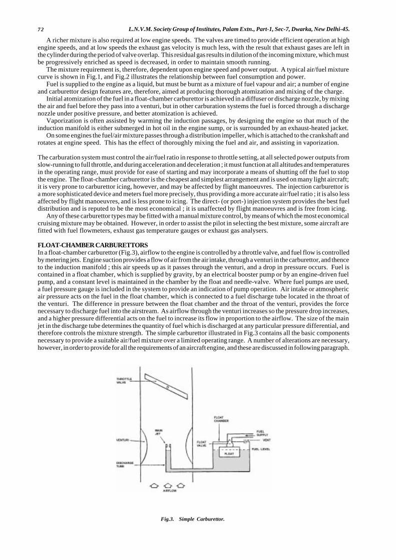
72 L.N.V.M. Society Group of Institutes, Palam Extn., Part-1, Sec-7, Dwarka, New Delhi-45.
A richer mixture is also required at low engine speeds. The valves are timed to provide efficient operation at highengine speeds, and at low speeds the exhaust gas velocity is much less, with the result that exhaust gases are left inthe cylinder during the period of valve overlap. This residual gas results in dilution of the incoming mixture, which mustbe progressively enriched as speed is decreased, in order to maintain smooth running.
The mixture requirement is, therefore, dependent upon engine speed and power output. A typical air/fuel mixturecurve is shown in Fig.1, and Fig.2 illustrates the relationship between fuel consumption and power.
Fuel is supplied to the engine as a liquid, but must be burnt as a mixture of fuel vapour and air; a number of engineand carburettor design features are, therefore, aimed at producing thorough atomization and mixing of the charge.
Initial atomization of the fuel in a float-chamber carburettor is achieved in a diffuser or discharge nozzle, by mixingthe air and fuel before they pass into a venturi, but in other carburation systems the fuel is forced through a dischargenozzle under positive pressure, and better atomization is achieved.
Vaporization is often assisted by warming the induction passages, by designing the engine so that much of theinduction manifold is either submerged in hot oil in the engine sump, or is surrounded by an exhaust-heated jacket.
On some engines the fuel/air mixture passes through a distribution impeller, which is attached to the crankshaft androtates at engine speed. This has the effect of thoroughly mixing the fuel and air, and assisting in vaporization.
The carburation system must control the air/fuel ratio in response to throttle setting, at all selected power outputs fromslow-running to full throttle, and during acceleration and deceleration ; it must function at all altitudes and temperaturesin the operating range, must provide for ease of starting and may incorporate a means of shutting off the fuel to stopthe engine. The float-chamber carburettor is the cheapest and simplest arrangement and is used on many light aircraft;it is very prone to carburettor icing, however, and may be affected by flight manoeuvres. The injection carburettor isa more sophisticated device and meters fuel more precisely, thus providing a more accurate air/fuel ratio ; it is also lessaffected by flight manoeuvres, and is less prone to icing. The direct- (or port-) injection system provides the best fueldistribution and is reputed to be the most economical ; it is unaffected by flight manoeuvres and is free from icing.
Any of these carburettor types may be fitted with a manual mixture control, by means of which the most economicalcruising mixture may be obtained. However, in order to assist the pilot in selecting the best mixture, some aircraft arefitted with fuel flowmeters, exhaust gas temperature gauges or exhaust gas analysers.
FLOAT-CHAMBER CARBURETTORSIn a float-chamber carburettor (Fig.3), airflow to the engine is controlled by a throttle valve, and fuel flow is controlledby metering jets. Engine suction provides a flow of air from the air intake, through a venturi in the carburettor, and thenceto the induction manifold ; this air speeds up as it passes through the venturi, and a drop in pressure occurs. Fuel iscontained in a float chamber, which is supplied by gravity, by an electrical booster pump or by an engine-driven fuelpump, and a constant level is maintained in the chamber by the float and needle-valve. Where fuel pumps are used,a fuel pressure gauge is included in the system to provide an indication of pump operation. Air intake or atmosphericair pressure acts on the fuel in the float chamber, which is connected to a fuel discharge tube located in the throat ofthe venturi. The difference in pressure between the float chamber and the throat of the venturi, provides the forcenecessary to discharge fuel into the airstream. As airflow through the venturi increases so the pressure drop increases,and a higher pressure differential acts on the fuel to increase its flow in proportion to the airflow. The size of the mainjet in the discharge tube determines the quantity of fuel which is discharged at any particular pressure differential, andtherefore controls the mixture strength. The simple carburettor illustrated in Fig.3 contains all the basic componentsnecessary to provide a suitable air/fuel mixture over a limited operating range. A number of alterations are necessary,however, in order to provide for all the requirements of an aircraft engine, and these are discussed in following paragraph.
Fig.3. Simple Carburettor.
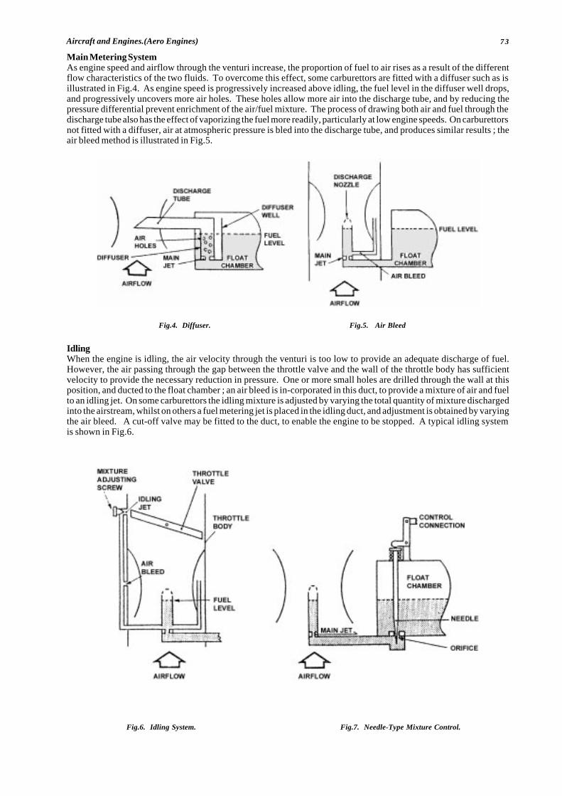
73Aircraft and Engines.(Aero Engines)
Main Metering SystemAs engine speed and airflow through the venturi increase, the proportion of fuel to air rises as a result of the differentflow characteristics of the two fluids. To overcome this effect, some carburettors are fitted with a diffuser such as isillustrated in Fig.4. As engine speed is progressively increased above idling, the fuel level in the diffuser well drops,and progressively uncovers more air holes. These holes allow more air into the discharge tube, and by reducing thepressure differential prevent enrichment of the air/fuel mixture. The process of drawing both air and fuel through thedischarge tube also has the effect of vaporizing the fuel more readily, particularly at low engine speeds. On carburettorsnot fitted with a diffuser, air at atmospheric pressure is bled into the discharge tube, and produces similar results ; theair bleed method is illustrated in Fig.5.
IdlingWhen the engine is idling, the air velocity through the venturi is too low to provide an adequate discharge of fuel.However, the air passing through the gap between the throttle valve and the wall of the throttle body has sufficientvelocity to provide the necessary reduction in pressure. One or more small holes are drilled through the wall at thisposition, and ducted to the float chamber ; an air bleed is in-corporated in this duct, to provide a mixture of air and fuelto an idling jet. On some carburettors the idling mixture is adjusted by varying the total quantity of mixture dischargedinto the airstream, whilst on others a fuel metering jet is placed in the idling duct, and adjustment is obtained by varyingthe air bleed. A cut-off valve may be fitted to the duct, to enable the engine to be stopped. A typical idling systemis shown in Fig.6.
Fig.4. Diffuser. Fig.5. Air Bleed
Fig.6. Idling System. Fig.7. Needle-Type Mixture Control.
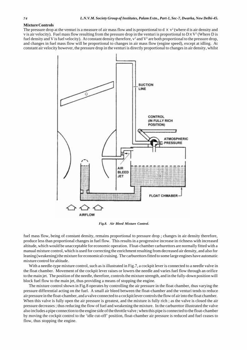
74 L.N.V.M. Society Group of Institutes, Palam Extn., Part-1, Sec-7, Dwarka, New Delhi-45.
Mixture ControlsThe pressure drop at the venturi is a measure of air mass flow and is proportional to d X v2 (where d is air density andv is air velocity). Fuel mass flow resulting from the pressure drop in the venturi is proportional to D X V2 (Where D isfuel density and V is fuel velocity). At constant density therefore, v2 and V2 are both proportional to the pressure drop,and changes in fuel mass flow will be proportional to changes in air mass flow (engine speed), except at idling. Atconstant air velocity however, the pressure drop in the venturi is directly proportional to changes in air density, whilst
fuel mass flow, being of constant density, remains proportional to pressure drop ; changes in air density therefore,produce less than proportional changes in fuel flow. This results in a progressive increase in richness with increasedaltitude, which would be unacceptable for economic operation. Float-chamber carburettors are normally fitted with amanual mixture control, which is used for correcting the enrichment resulting from decreased air density, and also forleaning (weakening) the mixture for economical cruising. The carburettors fitted to some large engines have automaticmixture control for altitude.
With a needle-type mixture control, such as is illustrated in Fig.7, a cockpit lever is connected to a needle valve inthe float chamber. Movement of the cockpit lever raises or lowers the needle and varies fuel flow through an orificeto the main jet. The position of the needle, therefore, controls the mixture strength, and in the fully-down position willblock fuel flow to the main jet, thus providing a means of stopping the engine.
The mixture control shown in Fig.8 operates by controlling the air pressure in the float chamber, thus varying thepressure differential acting on the fuel. A small air bleed between the float-chamber and the venturi tends to reduceair pressure in the float-chamber, and a valve connected to a cockpit lever controls the flow of air into the float chamber.When this valve is fully open the air pressure is greatest, and the mixture is fully rich ; as the valve is closed the airpressure decreases ; thus reducing the flow of fuel and weakening the mixture. In the carburettor illustrated the valvealso includes a pipe connection to the engine side of the throttle valve ; when this pipe is connected to the float-chamberby moving the cockpit control to the ‘idle cut-off’ position, float-chamber air pressure is reduced and fuel ceases toflow, thus stopping the engine.
Fig.8. Air Bleed Mixture Control.
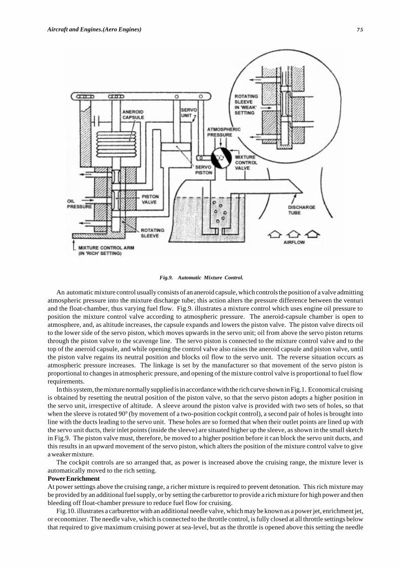
75Aircraft and Engines.(Aero Engines)
An automatic mixture control usually consists of an aneroid capsule, which controls the position of a valve admittingatmospheric pressure into the mixture discharge tube; this action alters the pressure difference between the venturiand the float-chamber, thus varying fuel flow. Fig.9. illustrates a mixture control which uses engine oil pressure toposition the mixture control valve according to atmospheric pressure. The aneroid-capsule chamber is open toatmosphere, and, as altitude increases, the capsule expands and lowers the piston valve. The piston valve directs oilto the lower side of the servo piston, which moves upwards in the servo unit; oil from above the servo piston returnsthrough the piston valve to the scavenge line. The servo piston is connected to the mixture control valve and to thetop of the aneroid capsule, and while opening the control valve also raises the aneroid capsule and piston valve, untilthe piston valve regains its neutral position and blocks oil flow to the servo unit. The reverse situation occurs asatmospheric pressure increases. The linkage is set by the manufacturer so that movement of the servo piston isproportional to changes in atmospheric pressure, and opening of the mixture control valve is proportional to fuel flowrequirements.
In this system, the mixture normally supplied is in accordance with the rich curve shown in Fig.1. Economical cruisingis obtained by resetting the neutral position of the piston valve, so that the servo piston adopts a higher position inthe servo unit, irrespective of altitude. A sleeve around the piston valve is provided with two sets of holes, so thatwhen the sleeve is rotated 900 (by movement of a two-position cockpit control), a second pair of holes is brought intoline with the ducts leading to the servo unit. These holes are so formed that when their outlet points are lined up withthe servo unit ducts, their inlet points (inside the sleeve) are situated higher up the sleeve, as shown in the small sketchin Fig.9. The piston valve must, therefore, be moved to a higher position before it can block the servo unit ducts, andthis results in an upward movement of the servo piston, which alters the position of the mixture control valve to givea weaker mixture.
The cockpit controls are so arranged that, as power is increased above the cruising range, the mixture lever isautomatically moved to the rich setting.Power EnrichmentAt power settings above the cruising range, a richer mixture is required to prevent detonation. This rich mixture maybe provided by an additional fuel supply, or by setting the carburettor to provide a rich mixture for high power and thenbleeding off float-chamber pressure to reduce fuel flow for cruising.
Fig.10. illustrates a carburettor with an additional needle valve, which may be known as a power jet, enrichment jet,or economizer. The needle valve, which is connected to the throttle control, is fully closed at all throttle settings belowthat required to give maximum cruising power at sea-level, but as the throttle is opened above this setting the needle
Fig.9. Automatic Mixture Control.
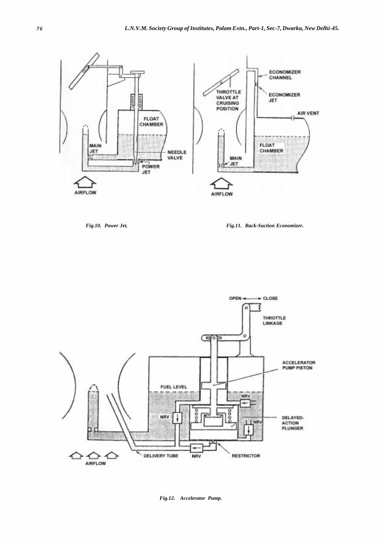
76 L.N.V.M. Society Group of Institutes, Palam Extn., Part-1, Sec-7, Dwarka, New Delhi-45.
Fig.12. Accelerator Pump.
Fig.10. Power Jet. Fig.11. Back-Suction Economizer.
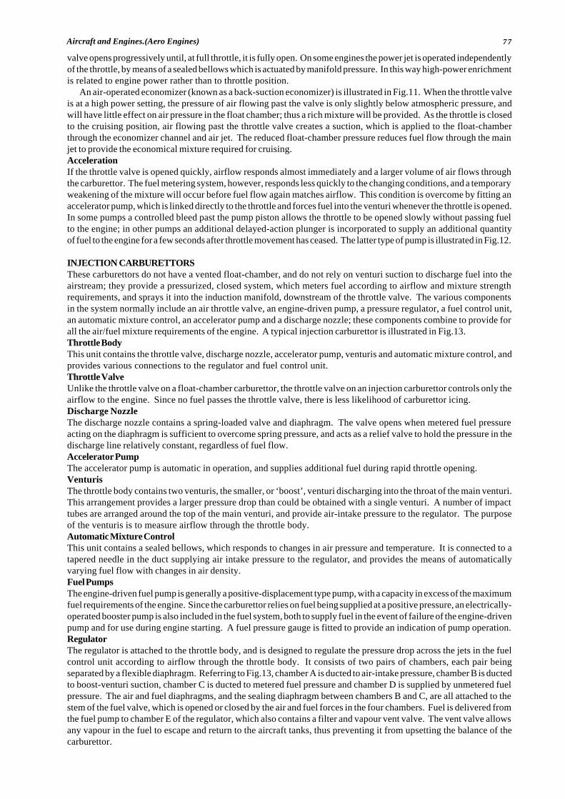
77Aircraft and Engines.(Aero Engines)
valve opens progressively until, at full throttle, it is fully open. On some engines the power jet is operated independentlyof the throttle, by means of a sealed bellows which is actuated by manifold pressure. In this way high-power enrichmentis related to engine power rather than to throttle position.
An air-operated economizer (known as a back-suction economizer) is illustrated in Fig.11. When the throttle valveis at a high power setting, the pressure of air flowing past the valve is only slightly below atmospheric pressure, andwill have little effect on air pressure in the float chamber; thus a rich mixture will be provided. As the throttle is closedto the cruising position, air flowing past the throttle valve creates a suction, which is applied to the float-chamberthrough the economizer channel and air jet. The reduced float-chamber pressure reduces fuel flow through the mainjet to provide the economical mixture required for cruising.AccelerationIf the throttle valve is opened quickly, airflow responds almost immediately and a larger volume of air flows throughthe carburettor. The fuel metering system, however, responds less quickly to the changing conditions, and a temporaryweakening of the mixture will occur before fuel flow again matches airflow. This condition is overcome by fitting anaccelerator pump, which is linked directly to the throttle and forces fuel into the venturi whenever the throttle is opened.In some pumps a controlled bleed past the pump piston allows the throttle to be opened slowly without passing fuelto the engine; in other pumps an additional delayed-action plunger is incorporated to supply an additional quantityof fuel to the engine for a few seconds after throttle movement has ceased. The latter type of pump is illustrated in Fig.12.
INJECTION CARBURETTORSThese carburettors do not have a vented float-chamber, and do not rely on venturi suction to discharge fuel into theairstream; they provide a pressurized, closed system, which meters fuel according to airflow and mixture strengthrequirements, and sprays it into the induction manifold, downstream of the throttle valve. The various componentsin the system normally include an air throttle valve, an engine-driven pump, a pressure regulator, a fuel control unit,an automatic mixture control, an accelerator pump and a discharge nozzle; these components combine to provide forall the air/fuel mixture requirements of the engine. A typical injection carburettor is illustrated in Fig.13.Throttle BodyThis unit contains the throttle valve, discharge nozzle, accelerator pump, venturis and automatic mixture control, andprovides various connections to the regulator and fuel control unit.Throttle ValveUnlike the throttle valve on a float-chamber carburettor, the throttle valve on an injection carburettor controls only theairflow to the engine. Since no fuel passes the throttle valve, there is less likelihood of carburettor icing.Discharge NozzleThe discharge nozzle contains a spring-loaded valve and diaphragm. The valve opens when metered fuel pressureacting on the diaphragm is sufficient to overcome spring pressure, and acts as a relief valve to hold the pressure in thedischarge line relatively constant, regardless of fuel flow.Accelerator PumpThe accelerator pump is automatic in operation, and supplies additional fuel during rapid throttle opening.VenturisThe throttle body contains two venturis, the smaller, or ‘boost’, venturi discharging into the throat of the main venturi.This arrangement provides a larger pressure drop than could be obtained with a single venturi. A number of impacttubes are arranged around the top of the main venturi, and provide air-intake pressure to the regulator. The purposeof the venturis is to measure airflow through the throttle body.Automatic Mixture ControlThis unit contains a sealed bellows, which responds to changes in air pressure and temperature. It is connected to atapered needle in the duct supplying air intake pressure to the regulator, and provides the means of automaticallyvarying fuel flow with changes in air density.Fuel PumpsThe engine-driven fuel pump is generally a positive-displacement type pump, with a capacity in excess of the maximumfuel requirements of the engine. Since the carburettor relies on fuel being supplied at a positive pressure, an electrically-operated booster pump is also included in the fuel system, both to supply fuel in the event of failure of the engine-drivenpump and for use during engine starting. A fuel pressure gauge is fitted to provide an indication of pump operation.RegulatorThe regulator is attached to the throttle body, and is designed to regulate the pressure drop across the jets in the fuelcontrol unit according to airflow through the throttle body. It consists of two pairs of chambers, each pair beingseparated by a flexible diaphragm. Referring to Fig.13, chamber A is ducted to air-intake pressure, chamber B is ductedto boost-venturi suction, chamber C is ducted to metered fuel pressure and chamber D is supplied by unmetered fuelpressure. The air and fuel diaphragms, and the sealing diaphragm between chambers B and C, are all attached to thestem of the fuel valve, which is opened or closed by the air and fuel forces in the four chambers. Fuel is delivered fromthe fuel pump to chamber E of the regulator, which also contains a filter and vapour vent valve. The vent valve allowsany vapour in the fuel to escape and return to the aircraft tanks, thus preventing it from upsetting the balance of thecarburettor.
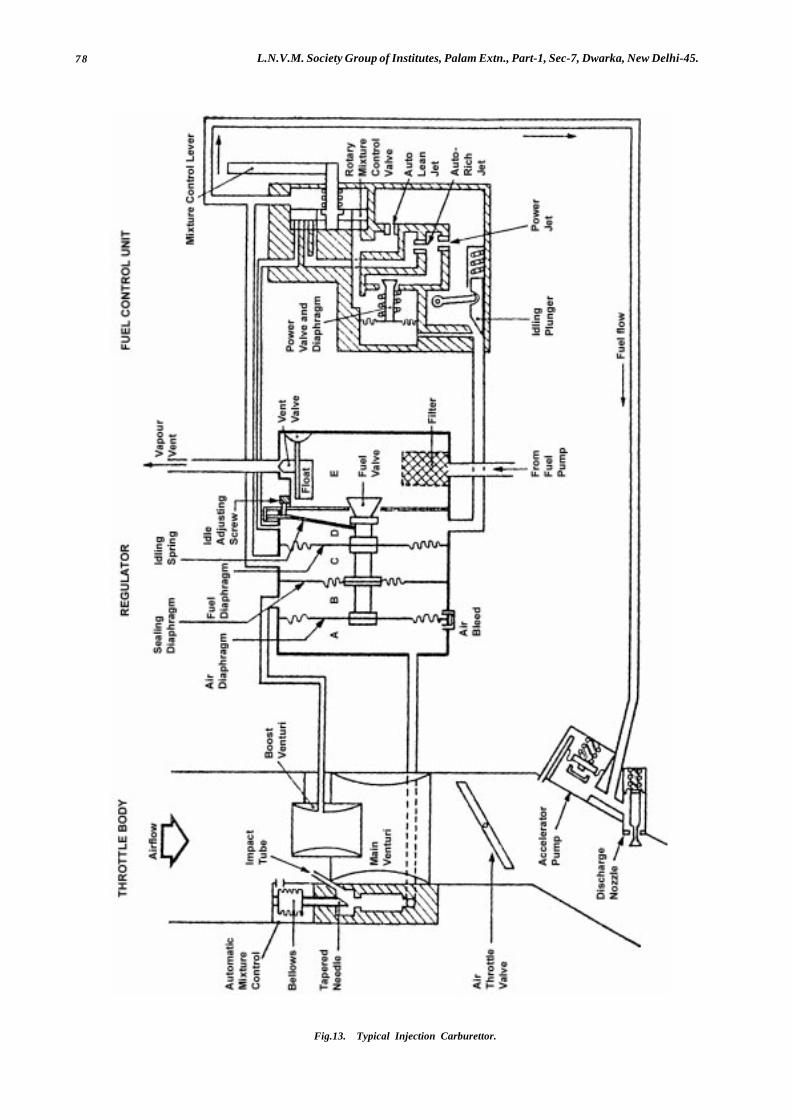
78 L.N.V.M. Society Group of Institutes, Palam Extn., Part-1, Sec-7, Dwarka, New Delhi-45.
Fig.13. Typical Injection Carburettor.
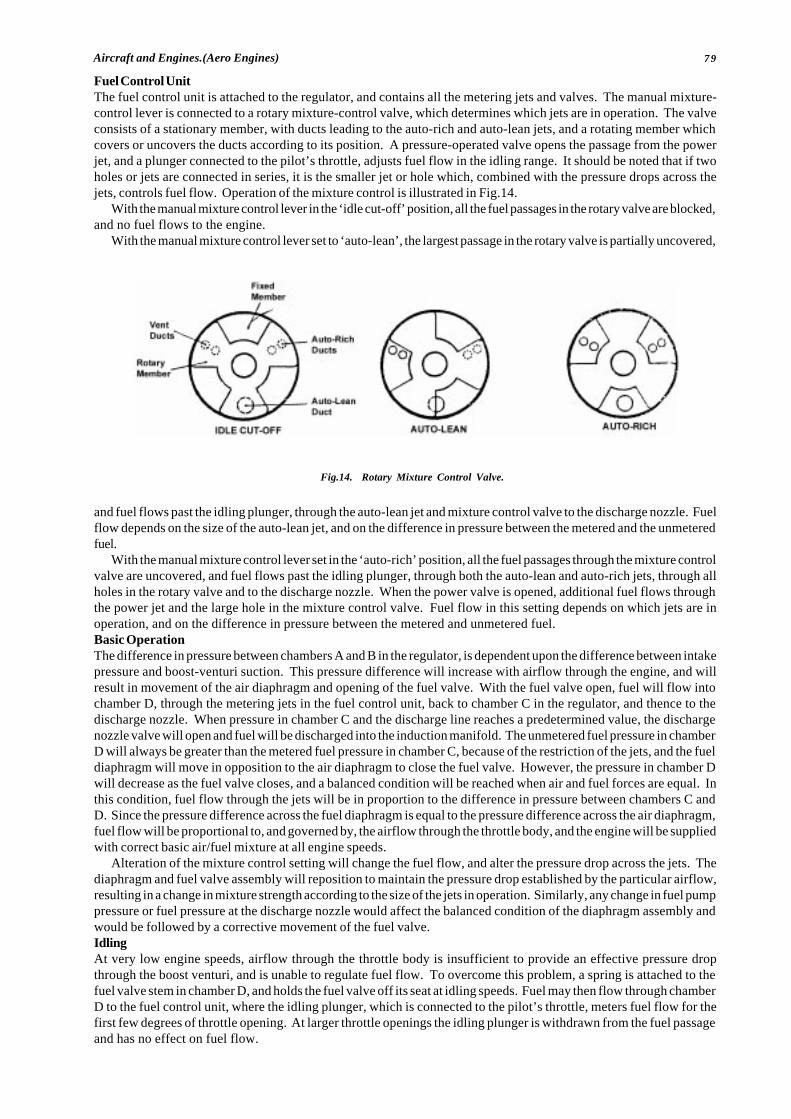
79Aircraft and Engines.(Aero Engines)
Fuel Control UnitThe fuel control unit is attached to the regulator, and contains all the metering jets and valves. The manual mixture-control lever is connected to a rotary mixture-control valve, which determines which jets are in operation. The valveconsists of a stationary member, with ducts leading to the auto-rich and auto-lean jets, and a rotating member whichcovers or uncovers the ducts according to its position. A pressure-operated valve opens the passage from the powerjet, and a plunger connected to the pilot’s throttle, adjusts fuel flow in the idling range. It should be noted that if twoholes or jets are connected in series, it is the smaller jet or hole which, combined with the pressure drops across thejets, controls fuel flow. Operation of the mixture control is illustrated in Fig.14.
With the manual mixture control lever in the ‘idle cut-off’ position, all the fuel passages in the rotary valve are blocked,and no fuel flows to the engine.
With the manual mixture control lever set to ‘auto-lean’, the largest passage in the rotary valve is partially uncovered,
and fuel flows past the idling plunger, through the auto-lean jet and mixture control valve to the discharge nozzle. Fuelflow depends on the size of the auto-lean jet, and on the difference in pressure between the metered and the unmeteredfuel.
With the manual mixture control lever set in the ‘auto-rich’ position, all the fuel passages through the mixture controlvalve are uncovered, and fuel flows past the idling plunger, through both the auto-lean and auto-rich jets, through allholes in the rotary valve and to the discharge nozzle. When the power valve is opened, additional fuel flows throughthe power jet and the large hole in the mixture control valve. Fuel flow in this setting depends on which jets are inoperation, and on the difference in pressure between the metered and unmetered fuel.Basic OperationThe difference in pressure between chambers A and B in the regulator, is dependent upon the difference between intakepressure and boost-venturi suction. This pressure difference will increase with airflow through the engine, and willresult in movement of the air diaphragm and opening of the fuel valve. With the fuel valve open, fuel will flow intochamber D, through the metering jets in the fuel control unit, back to chamber C in the regulator, and thence to thedischarge nozzle. When pressure in chamber C and the discharge line reaches a predetermined value, the dischargenozzle valve will open and fuel will be discharged into the induction manifold. The unmetered fuel pressure in chamberD will always be greater than the metered fuel pressure in chamber C, because of the restriction of the jets, and the fueldiaphragm will move in opposition to the air diaphragm to close the fuel valve. However, the pressure in chamber Dwill decrease as the fuel valve closes, and a balanced condition will be reached when air and fuel forces are equal. Inthis condition, fuel flow through the jets will be in proportion to the difference in pressure between chambers C andD. Since the pressure difference across the fuel diaphragm is equal to the pressure difference across the air diaphragm,fuel flow will be proportional to, and governed by, the airflow through the throttle body, and the engine will be suppliedwith correct basic air/fuel mixture at all engine speeds.
Alteration of the mixture control setting will change the fuel flow, and alter the pressure drop across the jets. Thediaphragm and fuel valve assembly will reposition to maintain the pressure drop established by the particular airflow,resulting in a change in mixture strength according to the size of the jets in operation. Similarly, any change in fuel pumppressure or fuel pressure at the discharge nozzle would affect the balanced condition of the diaphragm assembly andwould be followed by a corrective movement of the fuel valve.IdlingAt very low engine speeds, airflow through the throttle body is insufficient to provide an effective pressure dropthrough the boost venturi, and is unable to regulate fuel flow. To overcome this problem, a spring is attached to thefuel valve stem in chamber D, and holds the fuel valve off its seat at idling speeds. Fuel may then flow through chamberD to the fuel control unit, where the idling plunger, which is connected to the pilot’s throttle, meters fuel flow for thefirst few degrees of throttle opening. At larger throttle openings the idling plunger is withdrawn from the fuel passageand has no effect on fuel flow.
Fig.14. Rotary Mixture Control Valve.

80 L.N.V.M. Society Group of Institutes, Palam Extn., Part-1, Sec-7, Dwarka, New Delhi-45.
Fig.15. Fuel Injection System.

81Aircraft and Engines.(Aero Engines)
Mixture ControlThe manually-operated mixture control varies fuel flow according to engine operating conditions and was describedearlier. Automatic correction of fuel flow for changes in air density (temperature and pressure) is provided by theautomatic mixture control. A small air bleed between chambers A and B in the regulator causes a slight but continuousflow of air from the impact tubes to the boost venturi, thus providing the means of controlling the pressure in chamberA, and thereby regulating fuel flow. At sea level the bellows is fully compressed and the tapered needle is withdrawnfrom the air passage leading to chamber A ; full intake pressure acts on the air diaphragm, so that fuel valve openingand fuel flow are at the maximum for the particular airflow condition. As the aircraft climbs and atmospheric pressuredecreases, the bellows expands and inserts the tapered needle into the air passage, thus restricting the flow of air intochamber A, and reducing the differential pressure across the air diaphragm. As a result the fuel valve closes slightlyand fuel pressure is adjusted to match air pressure, thus reducing fuel flow through the jets to maintain the requiredmixture strength.AccelerationA number of different fully-automatic accelerator pumps may be used with injectors; a single-diaphragm pump isillustrated in Fig.13, and operation of this type is explained below.
Air pressure on the engine side of the throttle valve varies according to throttle position, being lowest when thethrottle is at the idling position and progressively increasing as the throttle is opened. This air pressure is ducted tothe rear of the accelerator-pump diaphragm. At small throttle openings air pressure and fuel discharge-nozzle pressureare sufficient to overcome the force of the spring and withdraw the diaphragm, allowing the pump fuel chamber to fill.When the throttle is opened, the air pressure increases and the spring is able to force the diaphragm forward, dischargingfuel to the nozzle. This fuel, added to the normal metered fuel flow, is sufficient to overcome any temporary weakeningof the mixture.
DIRECT FUEL INJECTIONDirect fuel injection is often employed on aircraft piston engines, but is of the low-pressure, continuous-flow type ratherthan the intermittent-flow type commonly used on diesel engines, in which calibrated quantities of fuel are injected intothe cylinders at a particular time in the operating cycle. In the low-pressure, continuous-flow method, fuel is sprayedcontinuously into the inlet port of each cylinder; the advantages claimed for the method are low operating pressure,good fuel distribution, freedom from icing problems and the ability to use a pump which does not have to be timed tothe operating cycle. Some fuel injectors operate on similar principles to the injection carburettor described earlier, witha distribution system replacing the discharge nozzle, but a different method of operation is used on some engines, andthis latter method is described in paragraphs below.
In this system, the size of a variable orifice is controlled according to the position of the air throttle valve, and thepressure of fuel passing through this orifice is controlled according to engine speed. Mixture strength is varied by amanually-operated control, which adjusts the fuel pressure for altitude or operating conditions, as necessary. Becauseof the method of operation of the injector, no special idling arrangements are required and a separate priming systemfor engine starting is unnecessary. The main components in the system are a fuel pump, a fuel/air control unit, a fuelmanifold (distribution) valve, and discharge nozzles for each cylinder. In addition, a normal throttle valve controlsairflow to the engine, and a fuel pressure gauge is fitted to enable mixture adjustments to be made. The system isillustrated in Fig.15.Fuel PumpThe fuel pump is a positive-displacement, vane-type pump, which is driven by gearing from the engine crankshaft; totalpump output is, therefore, proportional to engine speed. The pump supplies more fuel than is required by the engine,and a recirculation path is provided; a calibrated orifice and relief valve in this path ensure that the pump deliverypressure is also proportional to engine speed. Fuel enters the pump through a swirl chamber in which vapour is separatedfrom liquid fuel; the vapour is ejected from the pump by a jet of pressurized fuel, and returned to the fuel tank. Whenthe pump is not operating, a spring-loaded valve in the base of the swirl chamber allows fuel under positive pressureto by-pass the pump, so allowing an electrically-operated booster pump to be used for engine starting and in anemergency. The booster pump is often a two-speed pump, providing a low pressure for normal back-up use, and a highpressure for use in the event of main fuel pump failure.Fuel/Air Control UnitThis unit is mounted on the intake manifold and contains three control elements.
The air throttle assembly contains the air throttle valve, which is connected to the pilot’s throttle lever and controlsairflow to the engine. The intake manifold has no venturi or other restriction to airflow.
The fuel control unit is attached to the air throttle assembly, and controls fuel flow to the engine by means of tworotary valves. One valve, the metering valve (Fig.16), is connected to the air throttle, and by means of a cam-shapedend face controls fuel flow to the fuel manifold valve according to the position of the air throttle; thus fuel flow isproportioned to air flow and provides the correct air/fuel ratio. The second valve, the mixture valve (Fig.17), is connectedto the pilot’s mixture control lever, and by means of a contoured end face, bleeds off fuel pressure applied to the meteringvalve. Thus the air/fuel ratio can be varied from the basic setting of the metering valve, as required by operatingconditions. A fuel pressure gauge in the system indicates metered fuel pressure, and, by suitable calibration, enables
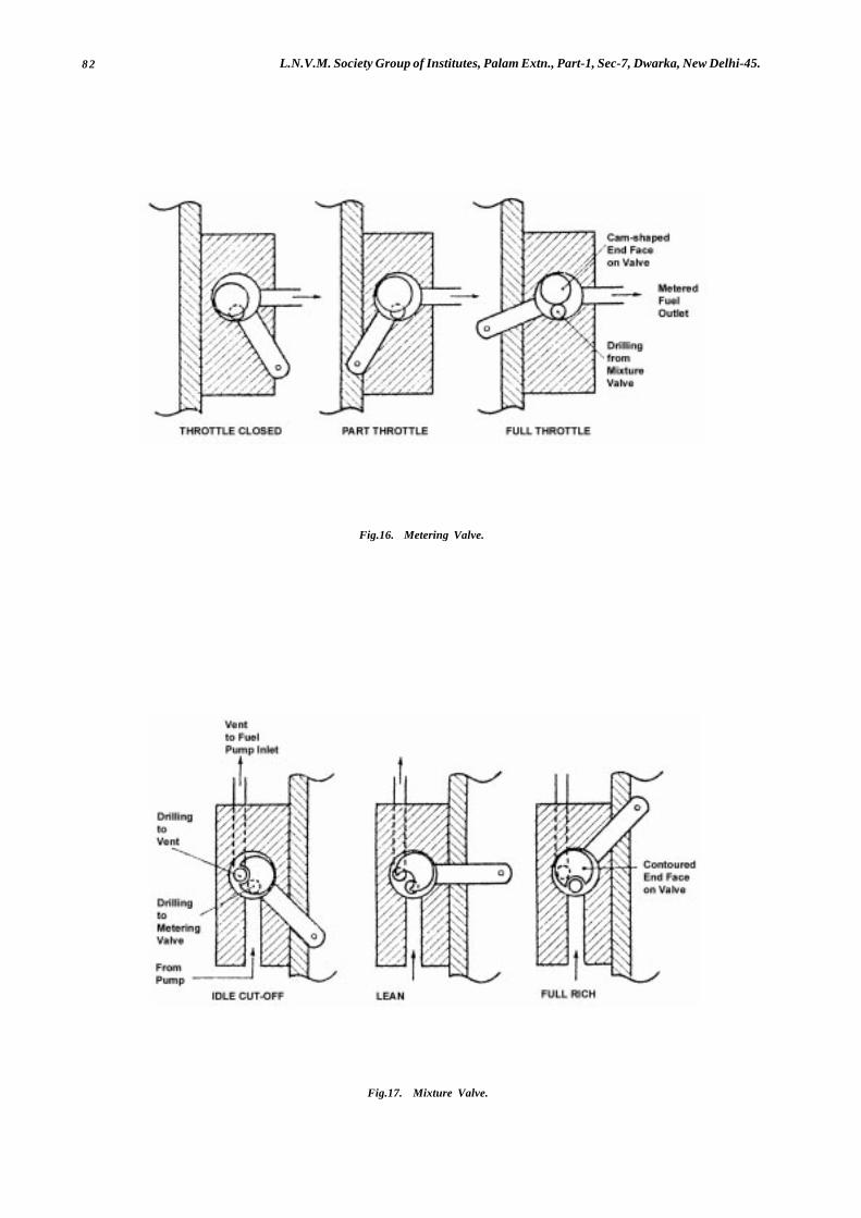
82 L.N.V.M. Society Group of Institutes, Palam Extn., Part-1, Sec-7, Dwarka, New Delhi-45.
Fig.17. Mixture Valve.
Fig.16. Metering Valve.
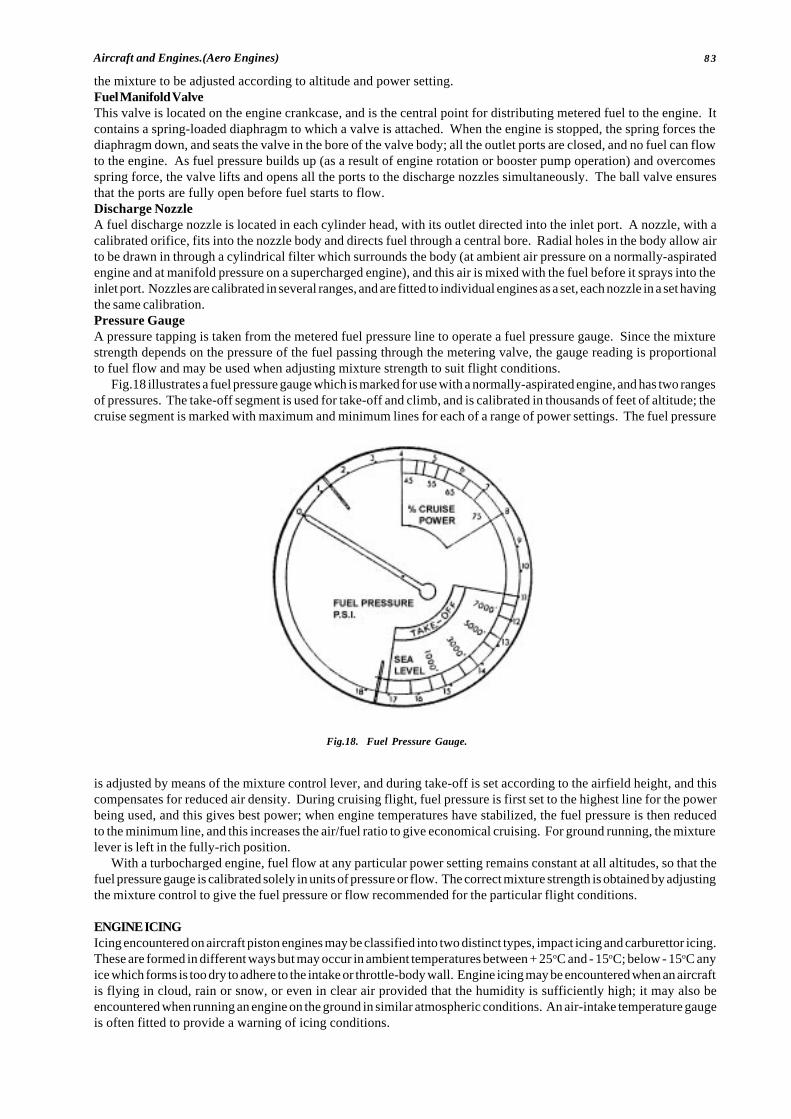
83Aircraft and Engines.(Aero Engines)
the mixture to be adjusted according to altitude and power setting.Fuel Manifold ValveThis valve is located on the engine crankcase, and is the central point for distributing metered fuel to the engine. Itcontains a spring-loaded diaphragm to which a valve is attached. When the engine is stopped, the spring forces thediaphragm down, and seats the valve in the bore of the valve body; all the outlet ports are closed, and no fuel can flowto the engine. As fuel pressure builds up (as a result of engine rotation or booster pump operation) and overcomesspring force, the valve lifts and opens all the ports to the discharge nozzles simultaneously. The ball valve ensuresthat the ports are fully open before fuel starts to flow.Discharge NozzleA fuel discharge nozzle is located in each cylinder head, with its outlet directed into the inlet port. A nozzle, with acalibrated orifice, fits into the nozzle body and directs fuel through a central bore. Radial holes in the body allow airto be drawn in through a cylindrical filter which surrounds the body (at ambient air pressure on a normally-aspiratedengine and at manifold pressure on a supercharged engine), and this air is mixed with the fuel before it sprays into theinlet port. Nozzles are calibrated in several ranges, and are fitted to individual engines as a set, each nozzle in a set havingthe same calibration.Pressure GaugeA pressure tapping is taken from the metered fuel pressure line to operate a fuel pressure gauge. Since the mixturestrength depends on the pressure of the fuel passing through the metering valve, the gauge reading is proportionalto fuel flow and may be used when adjusting mixture strength to suit flight conditions.
Fig.18 illustrates a fuel pressure gauge which is marked for use with a normally-aspirated engine, and has two rangesof pressures. The take-off segment is used for take-off and climb, and is calibrated in thousands of feet of altitude; thecruise segment is marked with maximum and minimum lines for each of a range of power settings. The fuel pressure
is adjusted by means of the mixture control lever, and during take-off is set according to the airfield height, and thiscompensates for reduced air density. During cruising flight, fuel pressure is first set to the highest line for the powerbeing used, and this gives best power; when engine temperatures have stabilized, the fuel pressure is then reducedto the minimum line, and this increases the air/fuel ratio to give economical cruising. For ground running, the mixturelever is left in the fully-rich position.
With a turbocharged engine, fuel flow at any particular power setting remains constant at all altitudes, so that thefuel pressure gauge is calibrated solely in units of pressure or flow. The correct mixture strength is obtained by adjustingthe mixture control to give the fuel pressure or flow recommended for the particular flight conditions.
ENGINE ICINGIcing encountered on aircraft piston engines may be classified into two distinct types, impact icing and carburettor icing.These are formed in different ways but may occur in ambient temperatures between + 25oC and - 15oC; below - 15oC anyice which forms is too dry to adhere to the intake or throttle-body wall. Engine icing may be encountered when an aircraftis flying in cloud, rain or snow, or even in clear air provided that the humidity is sufficiently high; it may also beencountered when running an engine on the ground in similar atmospheric conditions. An air-intake temperature gaugeis often fitted to provide a warning of icing conditions.
Fig.18. Fuel Pressure Gauge.
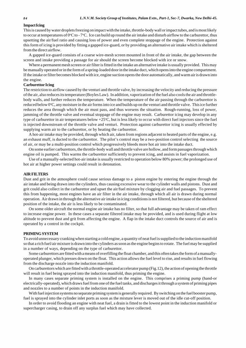
84 L.N.V.M. Society Group of Institutes, Palam Extn., Part-1, Sec-7, Dwarka, New Delhi-45.
Impact IcingThis is caused by water droplets freezing on impact with the intake, throttle-body wall or impact tubes, and is most likelyto occur at temperatures of 0oC to - 7oC. Ice can build up round the air intake and disturb airflow to the carburettor, thusupsetting the air/fuel ratio and causing loss of power and even complete stoppage of the engine. Protection againstthis form of icing is provided by fitting a gapped ice-guard, or by providing an alternative air intake which is shelteredfrom the direct airflow.
A gapped ice-guard consists of a coarse wire-mesh screen mounted in front of the air intake, the gap between thescreen and intake providing a passage for air should the screen become blocked with ice or snow.
Where a permanent mesh screen or air filter is fitted in the intake an alternative intake is usually provided. This maybe manually operated or in the form of a spring-loaded door in the intake duct, which opens into the engine compartment.If the intake or filter becomes blocked with ice, engine suction opens the door automatically, and warm air is drawn intothe engine.Carburettor IcingThe restriction to airflow caused by the venturi and throttle valve, by increasing the velocity and reducing the pressureof the air, also reduces its temperature (Boyles Law). In addition, vaporization of the fuel also cools the air and throttle-body walls, and further reduces the temperature. When the temperature of the air passing through the carburettor isreduced below 0oC, any moisture in the air forms into ice and builds up on the venturi and throttle valve. This ice furtherreduces the area through which the air must pass, and thus worsens the situation. Rough-running, loss of power,jamming of the throttle valve and eventual stoppage of the engine may result. Carburettor icing may develop in anytype of carburettor in air temperatures below +25oC, but is less likely to occur with direct fuel injectors since the fuelis injected downstream of the throttle valve and venturi. Protection against carburettor icing is usually effected bysupplying warm air to the carburettor, or by heating the carburettor.
A hot-air intake may be provided, through which air, taken from regions adjacent to heated parts of the engine, e.g.an exhaust muff, is ducted to the carburettor. The pilot’s control may be a two-position control selecting the sourceof air, or may be a multi-position control which progressively bleeds more hot air into the intake duct.
On some earlier carburettors, the throttle-body wall and throttle valve are hollow, and form passages through whichengine oil is pumped. This warms the carburettor sufficiently to prevent icing, and assists in fuel vaporization.
Use of a manually-selected hot-air intake is usually restricted to operation below 80% power; the prolonged use ofhot air at higher power settings could result in detonation.
AIR FILTERSDust and grit in the atmosphere could cause serious damage to a piston engine by entering the engine through theair intake and being drawn into the cylinders, thus causing excessive wear to the cylinder walls and pistons. Dust andgrit could also collect in the carburettor and upset the air/fuel mixture by clogging air and fuel passages. To preventthis from happening, most engines have an air filter in the air intake, through which all air is drawn during normaloperation. Air drawn in through the alternative air intake in icing conditions is not filtered, but because of the shelteredposition of the intake, the air is less likely to be contaminated.
On some older aircraft the normal engine air intake has no filter, so that full advantage may be taken of ram effectto increase engine power. In these cases a separate filtered intake may be provided, and is used during flight at lowaltitude to prevent dust and grit from affecting the engine. A flap in the intake duct controls the source of air and isoperated by a control in the cockpit.
PRIMING SYSTEMTo avoid unnecessary cranking when starting a cold engine, a quantity of neat fuel is supplied to the induction manifoldso that a rich fuel/air mixture is drawn into the cylinders as soon as the engine begins to rotate. The fuel may be suppliedin a number of ways, depending on the type of carburettor.
Some carburettors are fitted with a means of overfilling the float chamber, and this often takes the form of a manually-operated plunger, which presses down on the float. This action allows the fuel level to rise, and results in fuel flowingfrom the discharge nozzle into the induction manifold.
On carburettors which are fitted with a throttle-operated accelerator pump (Fig.12), the action of opening the throttlewill result in fuel being sprayed into the induction manifold, thus priming the engine.
In many cases separate priming system is installed on the engine. This comprises a priming pump (hand-orelectrically-operated), which draws fuel from one of the fuel tanks, and discharges it through a system of priming pipesand nozzles to a number of points in the induction manifold.
With fuel injection systems no separate priming system is generally required. By switching on the fuel booster pump,fuel is sprayed into the cylinder inlet ports as soon as the mixture lever is moved out of the idle cut-off position.
In order to avoid flooding an engine with neat fuel, a drain is fitted to the lowest point in the induction manifold orsupercharger casing, to drain off any surplus fuel which may have collected.
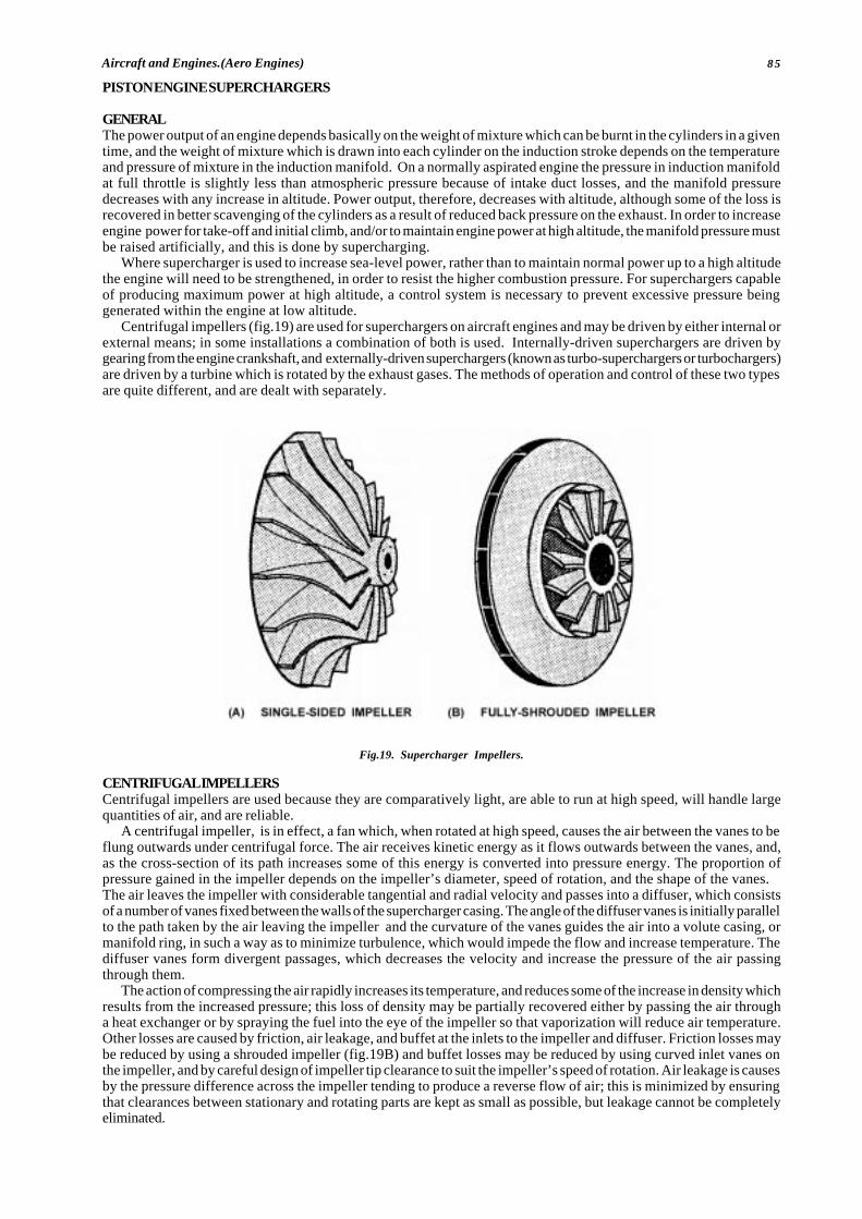
85Aircraft and Engines.(Aero Engines)
PISTON ENGINE SUPERCHARGERS
GENERALThe power output of an engine depends basically on the weight of mixture which can be burnt in the cylinders in a giventime, and the weight of mixture which is drawn into each cylinder on the induction stroke depends on the temperatureand pressure of mixture in the induction manifold. On a normally aspirated engine the pressure in induction manifoldat full throttle is slightly less than atmospheric pressure because of intake duct losses, and the manifold pressuredecreases with any increase in altitude. Power output, therefore, decreases with altitude, although some of the loss isrecovered in better scavenging of the cylinders as a result of reduced back pressure on the exhaust. In order to increaseengine power for take-off and initial climb, and/or to maintain engine power at high altitude, the manifold pressure mustbe raised artificially, and this is done by supercharging.
Where supercharger is used to increase sea-level power, rather than to maintain normal power up to a high altitudethe engine will need to be strengthened, in order to resist the higher combustion pressure. For superchargers capableof producing maximum power at high altitude, a control system is necessary to prevent excessive pressure beinggenerated within the engine at low altitude.
Centrifugal impellers (fig.19) are used for superchargers on aircraft engines and may be driven by either internal orexternal means; in some installations a combination of both is used. Internally-driven superchargers are driven bygearing from the engine crankshaft, and externally-driven superchargers (known as turbo-superchargers or turbochargers)are driven by a turbine which is rotated by the exhaust gases. The methods of operation and control of these two typesare quite different, and are dealt with separately.
Fig.19. Supercharger Impellers.
CENTRIFUGAL IMPELLERSCentrifugal impellers are used because they are comparatively light, are able to run at high speed, will handle largequantities of air, and are reliable.
A centrifugal impeller, is in effect, a fan which, when rotated at high speed, causes the air between the vanes to beflung outwards under centrifugal force. The air receives kinetic energy as it flows outwards between the vanes, and,as the cross-section of its path increases some of this energy is converted into pressure energy. The proportion ofpressure gained in the impeller depends on the impeller’s diameter, speed of rotation, and the shape of the vanes.The air leaves the impeller with considerable tangential and radial velocity and passes into a diffuser, which consistsof a number of vanes fixed between the walls of the supercharger casing. The angle of the diffuser vanes is initially parallelto the path taken by the air leaving the impeller and the curvature of the vanes guides the air into a volute casing, ormanifold ring, in such a way as to minimize turbulence, which would impede the flow and increase temperature. Thediffuser vanes form divergent passages, which decreases the velocity and increase the pressure of the air passingthrough them.
The action of compressing the air rapidly increases its temperature, and reduces some of the increase in density whichresults from the increased pressure; this loss of density may be partially recovered either by passing the air througha heat exchanger or by spraying the fuel into the eye of the impeller so that vaporization will reduce air temperature.Other losses are caused by friction, air leakage, and buffet at the inlets to the impeller and diffuser. Friction losses maybe reduced by using a shrouded impeller (fig.19B) and buffet losses may be reduced by using curved inlet vanes onthe impeller, and by careful design of impeller tip clearance to suit the impeller’s speed of rotation. Air leakage is causesby the pressure difference across the impeller tending to produce a reverse flow of air; this is minimized by ensuringthat clearances between stationary and rotating parts are kept as small as possible, but leakage cannot be completelyeliminated.
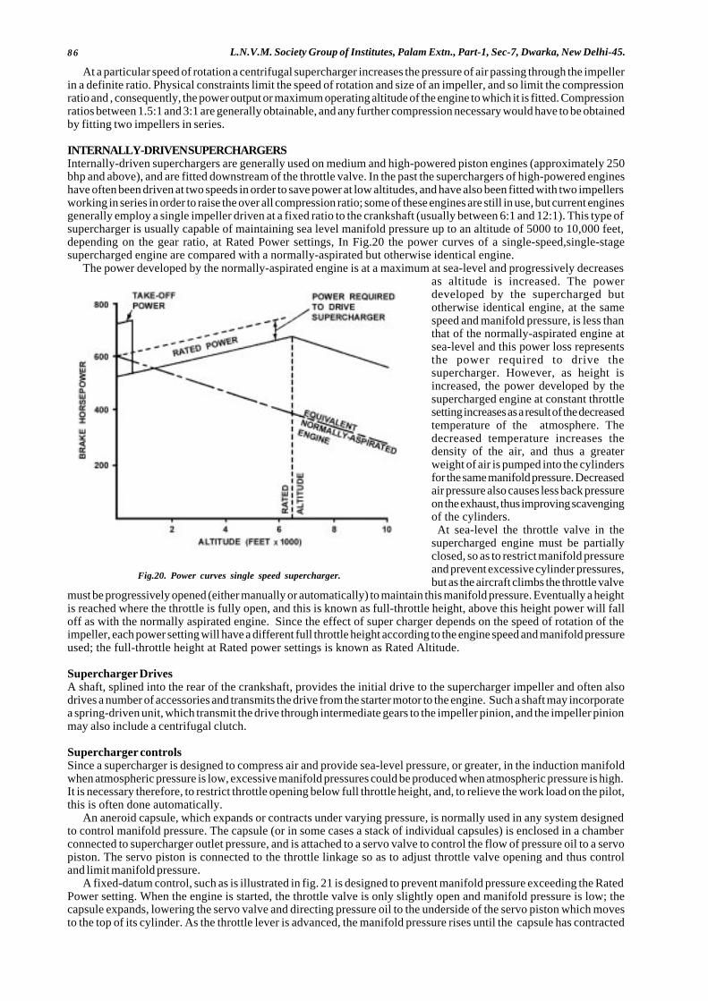
86 L.N.V.M. Society Group of Institutes, Palam Extn., Part-1, Sec-7, Dwarka, New Delhi-45.
At a particular speed of rotation a centrifugal supercharger increases the pressure of air passing through the impellerin a definite ratio. Physical constraints limit the speed of rotation and size of an impeller, and so limit the compressionratio and , consequently, the power output or maximum operating altitude of the engine to which it is fitted. Compressionratios between 1.5:1 and 3:1 are generally obtainable, and any further compression necessary would have to be obtainedby fitting two impellers in series.
INTERNALLY-DRIVEN SUPERCHARGERSInternally-driven superchargers are generally used on medium and high-powered piston engines (approximately 250bhp and above), and are fitted downstream of the throttle valve. In the past the superchargers of high-powered engineshave often been driven at two speeds in order to save power at low altitudes, and have also been fitted with two impellersworking in series in order to raise the over all compression ratio; some of these engines are still in use, but current enginesgenerally employ a single impeller driven at a fixed ratio to the crankshaft (usually between 6:1 and 12:1). This type ofsupercharger is usually capable of maintaining sea level manifold pressure up to an altitude of 5000 to 10,000 feet,depending on the gear ratio, at Rated Power settings, In Fig.20 the power curves of a single-speed,single-stagesupercharged engine are compared with a normally-aspirated but otherwise identical engine.
The power developed by the normally-aspirated engine is at a maximum at sea-level and progressively decreasesas altitude is increased. The powerdeveloped by the supercharged butotherwise identical engine, at the samespeed and manifold pressure, is less thanthat of the normally-aspirated engine atsea-level and this power loss representsthe power required to drive thesupercharger. However, as height isincreased, the power developed by thesupercharged engine at constant throttlesetting increases as a result of the decreasedtemperature of the atmosphere. Thedecreased temperature increases thedensity of the air, and thus a greaterweight of air is pumped into the cylindersfor the same manifold pressure. Decreasedair pressure also causes less back pressureon the exhaust, thus improving scavengingof the cylinders.At sea-level the throttle valve in the
supercharged engine must be partiallyclosed, so as to restrict manifold pressureand prevent excessive cylinder pressures,but as the aircraft climbs the throttle valve
must be progressively opened (either manually or automatically) to maintain this manifold pressure. Eventually a heightis reached where the throttle is fully open, and this is known as full-throttle height, above this height power will falloff as with the normally aspirated engine. Since the effect of super charger depends on the speed of rotation of theimpeller, each power setting will have a different full throttle height according to the engine speed and manifold pressureused; the full-throttle height at Rated power settings is known as Rated Altitude.
Supercharger DrivesA shaft, splined into the rear of the crankshaft, provides the initial drive to the supercharger impeller and often alsodrives a number of accessories and transmits the drive from the starter motor to the engine. Such a shaft may incorporatea spring-driven unit, which transmit the drive through intermediate gears to the impeller pinion, and the impeller pinionmay also include a centrifugal clutch.
Supercharger controlsSince a supercharger is designed to compress air and provide sea-level pressure, or greater, in the induction manifoldwhen atmospheric pressure is low, excessive manifold pressures could be produced when atmospheric pressure is high.It is necessary therefore, to restrict throttle opening below full throttle height, and, to relieve the work load on the pilot,this is often done automatically.
An aneroid capsule, which expands or contracts under varying pressure, is normally used in any system designedto control manifold pressure. The capsule (or in some cases a stack of individual capsules) is enclosed in a chamberconnected to supercharger outlet pressure, and is attached to a servo valve to control the flow of pressure oil to a servopiston. The servo piston is connected to the throttle linkage so as to adjust throttle valve opening and thus controland limit manifold pressure.
A fixed-datum control, such as is illustrated in fig. 21 is designed to prevent manifold pressure exceeding the RatedPower setting. When the engine is started, the throttle valve is only slightly open and manifold pressure is low; thecapsule expands, lowering the servo valve and directing pressure oil to the underside of the servo piston which movesto the top of its cylinder. As the throttle lever is advanced, the manifold pressure rises until the capsule has contracted
Fig.20. Power curves single speed supercharger.

87Aircraft and Engines.(Aero Engines)
sufficiently to lift the servo valve and coincides with Rated Power. If the throttle lever is advanced, the manifold pressurerises until the capsule has contracted sufficiently to lift the servo valve and block the flow to the servo piston; this isthe neutral position of the valve and coincides with Rated Power . If the throttle lever is advanced further, the manifoldpressure will increase and the capsule will contract, lifting the servo valve and directing pressure oil to the top of theservo piston. This action moves the servo piston downwards, closing the throttle valve until manifold pressure hasreturned to the Rated Power settings, the decreasing atmospheric pressure results in a lower supercharger outlet,pressure and the capsule gradually expands, progressively opening the throttle valve until full-throttle height isreached. In order to enable maximum power to be obtained during take-off, a means of overriding the control unit isrequired; this is often in the form of a calibrated leakage from the capsule chamber which is activated by linkage to thethrottle lever. The main disadvantages of the fixed-datum system is that it has no effect on the throttle valve at powersettings below Rated Power, and the throttle lever must be continually adjusted when climbing or descending at a lowerpower. There is also some “lost motion” of the throttle lever, which is greatest at sea level and decreases with altitude,and this means that the mixture enrichment required at high-power settings must be obtained by pressure controlleddevices rather than by the use of jets which are controlled by throttle movement.
Fig. 21. Manifold pressure control.

88 L.N.V.M. Society Group of Institutes, Palam Extn., Part-1, Sec-7, Dwarka, New Delhi-45.
Fig. 22. Variable Datum Control.
A method used to overcome the deficiencies of the system described in the fixed datum control, is the variable datumcontrol which is illustrated in Fig.22, A cam connected to the throttle lever controls the datum setting of the aneroidcapsule; as the throttle lever is closed from the fully-open position, the cam rotates and allows the capsule to rise underspring pressure. Thus the neutral position of the servo valve varies according to throttle lever position, and enablesthe capsule to exercise control at whatever manifold pressure is selected by the throttle lever. There is no lost motionin the throttle lever, and adjustment on the throttle valve to compensate for changes in atmospheric pressure, is carriedout automatically at any selected by the throttle lever.
When an engine is operating in the idling range the induction pressure is very low, and a reversal of flow may occurin which air or exhaust gases are drawn into the induction manifold during the period of valve overlap. This wouldproduce an increase in pressure in the manifold, which would be communicated to the capsule chamber and, on enginesfitted with a variable-datum control, would have the effect of closing the throttle valve. This would effectively preventany acceleration, and with this type of control the cam is so contoured and adjusted that the throttle lever is the solemeans of controlling the throttle valve in the idling range.
EXTERNALLY-DRIVEN SUPERCHARGERSThe main differences between the an internally-driven and an externally-driven supercharger are in the method of drivingthe impeller and, in fact that the latter delivers compressed air to the throttle and carburettor. Externally-drivensuperchargers are powered by the energy of the engine exhaust gases and do not directly lower the power output ofthe engine they are generally known as turbo-superchargers or turbochargers. Some turbochargers are designed tomaintain approximately sea-level air pressure in the engine air intake up to a high altitude, and are known as altitudeturbo charger others are designed to provide an intake pressure which is higher than sea-level pressure, and thusproduce a higher power output at all altitudes than would be available from an unsupercharged engine, and these areknown as Ground Boosted Turbochargers. The former type may be fitted without significant engine design changesto normally-aspirated engines in order to maintain sea level power up to a high altitude but the latter may only be fittedto engines which are designed to withstand the higher stresses imposed by the higher combustion pressure.
A few large engines with internally-driven superchargers are also fitted with a turbocharger, which is used to increasethe altitude at which a given power can be developed; because of the increased air temperature arising from the twostages of compression; it may be necessary to fit an inter cooler between the turbocharger and the carburettor.
A turbocharger consists of a turbine wheel and an impeller fitted on a common rotor shaft, the bearings for whichare contained within a bearing housing and are lubricated by oil from the engine. The turbine and compressor casingsare attached to the bearing housing and are connected to the exhaust and intake systems respectively; the compressoris shielded from the heat of the turbine, and intake or external air is ducted between the two casings to remove excessheat. The turbocharger is not necessarily an integral part of engine, but may be mounted on the engine or on the fireproofbulkhead, and shielded from combustible fluid lines in the engine bay. A typical turbocharger is illustrated in Fig. 23and a turbo charged engine installation is illustrated in Fig.24 below.
Exhaust gases are ducted to the turbine casing, where they pass through nozzles and impinge on vanes on the turbinewheel, causing it to rotate; the gases then pass between the vanes are exhausted overboard. Since the impeller is
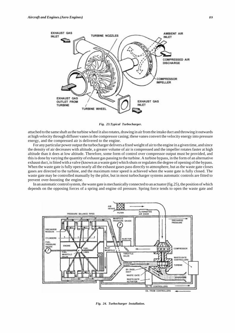
89Aircraft and Engines.(Aero Engines)
Fig. 23.Typical Turbocharger.
attached to the same shaft as the turbine wheel it also rotates, drawing in air from the intake duct and throwing it outwardsat high velocity through diffuser vanes in the compressor casing; these vanes convert the velocity energy into pressureenergy, and the compressed air is delivered to the engine.
For any particular power output the turbocharger delivers a fixed weight of air to the engine in a given time, and sincethe density of air decreases with altitude, a greater volume of air is compressed and the impeller rotates faster at highaltitude than it does at low altitude. Therefore, some form of control over compressor output must be provided, andthis is done by varying the quantity of exhaust gas passing to the turbine. A turbine bypass, in the form of an alternativeexhaust duct, is fitted with a valve (known as a waste gate) which shuts or regulates the degree of opening of the bypass.When the waste gate is fully open nearly all the exhaust gases pass directly to atmosphere, but as the waste gate closesgases are directed to the turbine, and the maximum rotor speed is achieved when the waste gate is fully closed. Thewaste gate may be controlled manually by the pilot, but in most turbocharger systems automatic controls are fitted toprevent over-boosting the engine.
In an automatic control system, the waste gate is mechanically connected to an actuator (fig.25), the position of whichdepends on the opposing forces of a spring and engine oil pressure. Spring force tends to open the waste gate and
Fig. 24. Turbocharger Installation.
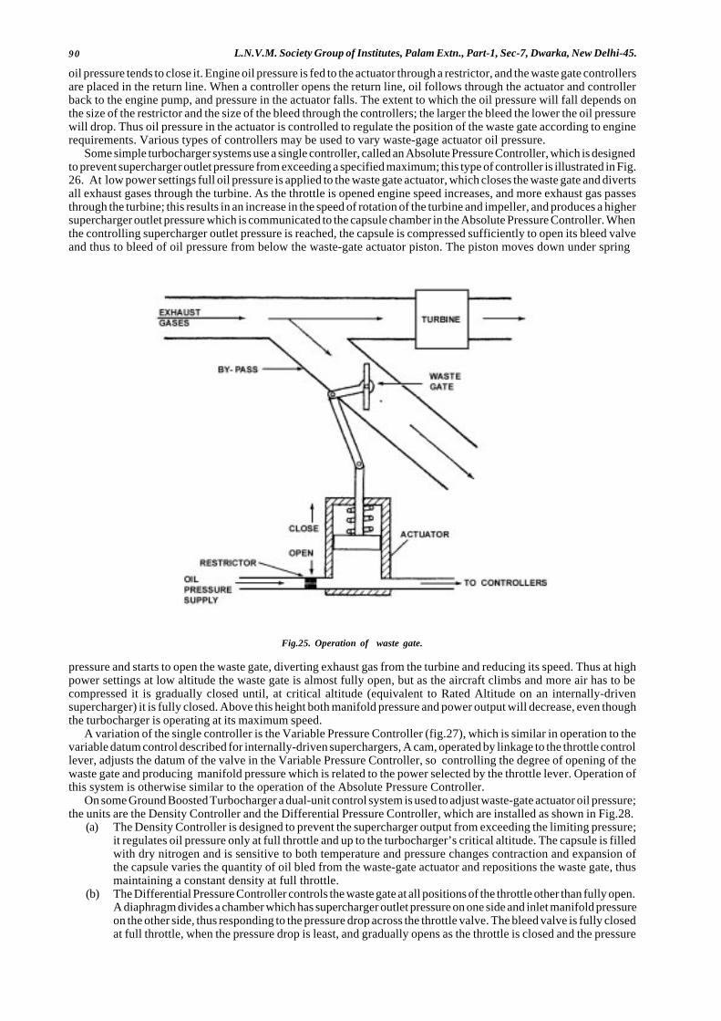
90 L.N.V.M. Society Group of Institutes, Palam Extn., Part-1, Sec-7, Dwarka, New Delhi-45.
oil pressure tends to close it. Engine oil pressure is fed to the actuator through a restrictor, and the waste gate controllersare placed in the return line. When a controller opens the return line, oil follows through the actuator and controllerback to the engine pump, and pressure in the actuator falls. The extent to which the oil pressure will fall depends onthe size of the restrictor and the size of the bleed through the controllers; the larger the bleed the lower the oil pressurewill drop. Thus oil pressure in the actuator is controlled to regulate the position of the waste gate according to enginerequirements. Various types of controllers may be used to vary waste-gage actuator oil pressure.
Some simple turbocharger systems use a single controller, called an Absolute Pressure Controller, which is designedto prevent supercharger outlet pressure from exceeding a specified maximum; this type of controller is illustrated in Fig.26. At low power settings full oil pressure is applied to the waste gate actuator, which closes the waste gate and divertsall exhaust gases through the turbine. As the throttle is opened engine speed increases, and more exhaust gas passesthrough the turbine; this results in an increase in the speed of rotation of the turbine and impeller, and produces a highersupercharger outlet pressure which is communicated to the capsule chamber in the Absolute Pressure Controller. Whenthe controlling supercharger outlet pressure is reached, the capsule is compressed sufficiently to open its bleed valveand thus to bleed of oil pressure from below the waste-gate actuator piston. The piston moves down under spring
Fig.25. Operation of waste gate.
pressure and starts to open the waste gate, diverting exhaust gas from the turbine and reducing its speed. Thus at highpower settings at low altitude the waste gate is almost fully open, but as the aircraft climbs and more air has to becompressed it is gradually closed until, at critical altitude (equivalent to Rated Altitude on an internally-drivensupercharger) it is fully closed. Above this height both manifold pressure and power output will decrease, even thoughthe turbocharger is operating at its maximum speed.
A variation of the single controller is the Variable Pressure Controller (fig.27), which is similar in operation to thevariable datum control described for internally-driven superchargers, A cam, operated by linkage to the throttle controllever, adjusts the datum of the valve in the Variable Pressure Controller, so controlling the degree of opening of thewaste gate and producing manifold pressure which is related to the power selected by the throttle lever. Operation ofthis system is otherwise similar to the operation of the Absolute Pressure Controller.
On some Ground Boosted Turbocharger a dual-unit control system is used to adjust waste-gate actuator oil pressure;the units are the Density Controller and the Differential Pressure Controller, which are installed as shown in Fig.28.
(a) The Density Controller is designed to prevent the supercharger output from exceeding the limiting pressure;it regulates oil pressure only at full throttle and up to the turbocharger’s critical altitude. The capsule is filledwith dry nitrogen and is sensitive to both temperature and pressure changes contraction and expansion ofthe capsule varies the quantity of oil bled from the waste-gate actuator and repositions the waste gate, thusmaintaining a constant density at full throttle.
(b) The Differential Pressure Controller controls the waste gate at all positions of the throttle other than fully open.A diaphragm divides a chamber which has supercharger outlet pressure on one side and inlet manifold pressureon the other side, thus responding to the pressure drop across the throttle valve. The bleed valve is fully closedat full throttle, when the pressure drop is least, and gradually opens as the throttle is closed and the pressure
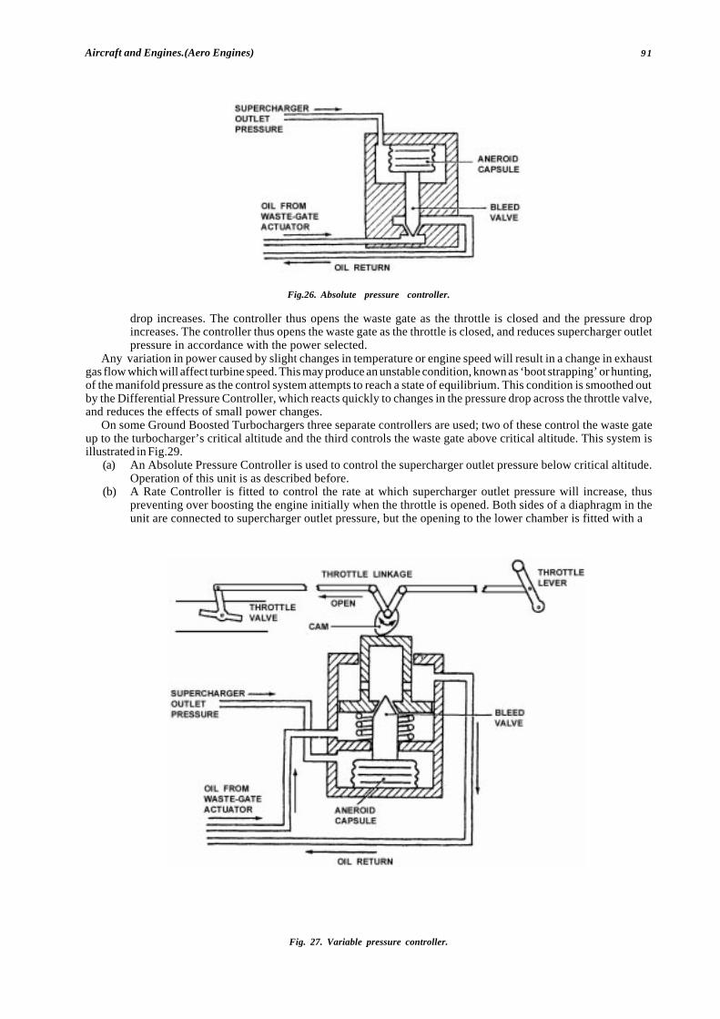
91Aircraft and Engines.(Aero Engines)
Fig.26. Absolute pressure controller.
drop increases. The controller thus opens the waste gate as the throttle is closed and the pressure dropincreases. The controller thus opens the waste gate as the throttle is closed, and reduces supercharger outletpressure in accordance with the power selected.
Any variation in power caused by slight changes in temperature or engine speed will result in a change in exhaustgas flow which will affect turbine speed. This may produce an unstable condition, known as ‘boot strapping’ or hunting,of the manifold pressure as the control system attempts to reach a state of equilibrium. This condition is smoothed outby the Differential Pressure Controller, which reacts quickly to changes in the pressure drop across the throttle valve,and reduces the effects of small power changes.
On some Ground Boosted Turbochargers three separate controllers are used; two of these control the waste gateup to the turbocharger’s critical altitude and the third controls the waste gate above critical altitude. This system isillustrated in Fig.29.
(a) An Absolute Pressure Controller is used to control the supercharger outlet pressure below critical altitude.Operation of this unit is as described before.
(b) A Rate Controller is fitted to control the rate at which supercharger outlet pressure will increase, thuspreventing over boosting the engine initially when the throttle is opened. Both sides of a diaphragm in theunit are connected to supercharger outlet pressure, but the opening to the lower chamber is fitted with a
Fig. 27. Variable pressure controller.
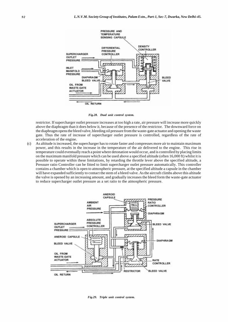
92 L.N.V.M. Society Group of Institutes, Palam Extn., Part-1, Sec-7, Dwarka, New Delhi-45.
Fig.28. Dual unit control system.
restrictor. If supercharger outlet pressure increases at too high a rate, air pressure will increase more quicklyabove the diaphragm than it does below it, because of the presence of the restrictor. The downward force onthe diaphragm opens the bleed valve, bleeding oil pressure from the waste-gate actuator and opening the wastegate. Thus the rate of increase of supercharger outlet pressure is controlled, regardless of the rate ofacceleration of the engine.
(c) As altitude is increased, the supercharger has to rotate faster and compresses more air to maintain maximumpower, and this results in the increase in the temperature of the air delivered to the engine. This rise intemperature could eventually reach a point where detonation would occur, and is controlled by placing limitson the maximum manifold pressure which can be used above a specified altitude (often 16,000 ft) whilst it ispossible to operate within these limitations, by retarding the throttle lever above the specified altitude, aPressure ratio Controller can be fitted to limit supercharger outlet pressure automatically. This controllercontains a chamber which is open to atmospheric pressure, at the specified altitude a capsule in the chamberwill have expanded sufficiently to contact the stem of a bleed valve. As the aircraft climbs above this altitudethe valve is opened by an increasing amount, and gradually increases the bleed form the waste-gate actuatorto reduce supercharger outlet pressure as a set ratio to the atmospheric pressure.
Fig.29. Triple unit control system.

93Aircraft and Engines.(Aero Engines)
On some aircraft a manifold pressure relief valve is fitted in the compressor discharge duct, to prevent over boostingof the engine during rapid acceleration, and in the event of failure of the controllers or sticking of the waste gate. Thevalve is usually a simple poppet type valve, which is adjusted to relieve the supercharger discharge pressure toatmosphere whenever the controlled maximum pressure is exceeded. A manifold pressure relief valve is usually fittedin conjunction with an Absolute Pressure Controller or a Variable Pressure Controller.
Turbocharger systems are very sensitive to changes in exhaust gas flow and automatic controls take time to reacha state of equilibrium. It is important, therefore, that the throttle and propeller controls are operated slowly and that timeis allowed for the control system to settle down.
� � �
94 L.N.V.M. Society Group of Institutes, Palam Extn., Part-1, Sec-7, Dwarka, New Delhi-45.
CHAPTER: 9FUEL SYSTEM TURBINE ENGINES
INTRODUCTIONThe functions of the fuel system are to provide the engine with fuel in a form suitable for combustion and to controlthe flow to the required quantity necessary for easy starting acceleration and stable running, at all engine operatingconditions, to do this, one or more fuel pumps are used to deliver the fuel to the fuel spray nozzles, which inject it intothe combustion system in the form of an atomized spray because the flow rate must vary according to the amount ofair passing through the engine to maintain a constant selected engine speed or pressure ratio, the controlling devicesare fully automatic with the exception of engine power selection, which is achieved by a manual throttle or power lever.A fuel shut-off valve (cock) control lever is also used to stop engine, although in some instances these two manualcontrols are combined for single-lever operation.
It is also necessary to have automatic safety controls that prevent the engine gas temperature, compressor deliverypressure, and the rotating assembly speed, from exceeding their maximum limitations.
With the turbo-propeller engine, changes in propeller speed and pitch have to be taken into account due to theireffect on the power output of the engine. Thus, it is usual to interconnect the throttle lever and propeller controller unit,for by so doing the correct relationship between fuel flow and airflow is maintained at all engine speeds and the pilotis given single-lever control of the engine. Although the maximum speed of the engine is normally determined by thepropeller speed controller, over speeding is ultimately prevented by a governor in the fuel system.
Fuel system also provides oil cooling for lubricating system of various engine parts.There are two types of fuel control i.e. Automatic and Manual. Automatic control system is divided into 3 parts they
are : (i) Pressure Control System (ii) Flow control system (iii) Acceleration and speed control.Some engines are fitted with an electronic system of control and this generally involves the use of electronic circuits
to measure and translate changing engine condition to automatically adjust the fuel pump output. On helicopterspowered by gas turbine engines using the free power turbine principle, additional manual and automatic controls onthe engine govern the free power turbine and consequently aircraft rotor speed.
FUEL CONTROL SYSTEMSTypical high pressure (H.P.) fuel control systems for a turbo-propeller engine and a turbojet engine are shown insimplified form in figure 1, each basically consisting of an H.P. pump, a throttle control and a number of fuel spray nozzles,In addition, certain sensing devices are incorporated to provide automatic control of the fuel flow in response to enginerequirements. On the turbo-propeller engine, the fuel and propeller systems are coordinated to produce the appropriatefuel/r.p.m. combination.
The usual method of varying the fuel flow to the spray nozzles is by adjusting the output of the H.P. fuel pump. Thisis effected through a servo system in response to some or all of the following :
(1) Throttle Movement.(2) Air, temperature and pressure.(3) Rapid acceleration and deceleration.(4) Signals of engine speed, engine gas temperature and compressor delivery pressure.
FUEL PUMPOn some early turbine engines a constant displacement pump was used, the design of which ensured that pump deliverywas always in excess of engine requirements. Excess fuel was bled back to the fuel tanks by means of unit called a Barostatwhich was sensitive to changes in air intake pressure. Most modern British systems employ a pump of the variable stroke(swash-plate) type, a dual pump often being fitted on large engines to obtain high delivery rates.
The variable stroke pump is driven directly from the engine and consists of rotating cylinder block in which a numberof cylinders are arranged around the rotational axis. A spring-loaded piston in each cylinder is held against a non-rotating cam plate so that rotation of the cylinder block results in the pistons moving up and down in their respectivecylinders. Conveniently placed ports in the pump body allow fuel to be drawn into the cylinders and discharged to theengine. The angle of the cam plate determines the length of stroke of the piston and, by connecting it to a servomechanism, delivery may be varied from the nil to maximum pump capacity for a given pump speed.
The servo piston operates in a cylinder and is subjected to pump delivery pressure on one side and the combinedforces of reduced delivery (servo) pressure and a spring on the other. A calibrated restrictor supplies pump deliveryfuel to the spring side of the piston and this is bled off by the control system to adjust the piston position and hencethe angle of the cam plate.
FUEL PUMP CONTROL SYSTEMSSome engines are fitted with a control system which uses electronic circuits to sense changing fuel requirements andadjust pump stroke. Most engines however, use hydro-mechanical systems, with an electromechanical element tocontrol maximum gas temperature and these are discussed in the following paragraphs.

95Aircraft and Engines.(Aero Engines)
Fig. 1. Simplified fuel system for turbo propeller and turbo jet engines.
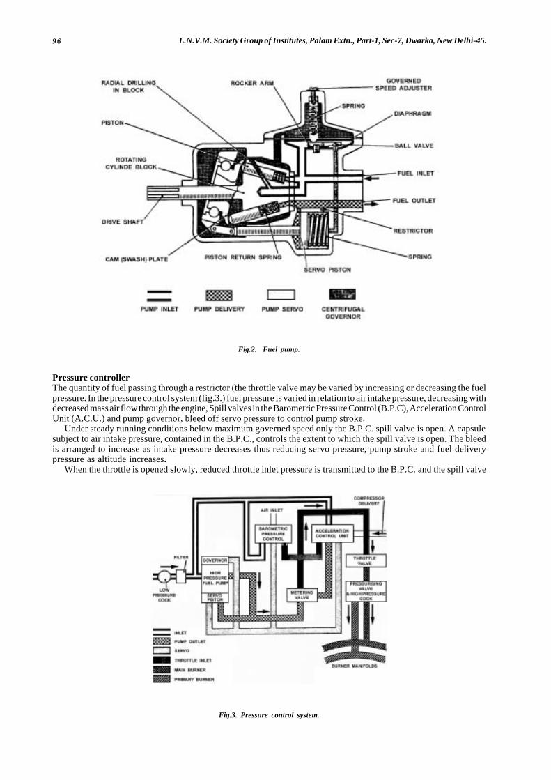
96 L.N.V.M. Society Group of Institutes, Palam Extn., Part-1, Sec-7, Dwarka, New Delhi-45.
Fig.2. Fuel pump.
Pressure controllerThe quantity of fuel passing through a restrictor (the throttle valve may be varied by increasing or decreasing the fuelpressure. In the pressure control system (fig.3.) fuel pressure is varied in relation to air intake pressure, decreasing withdecreased mass air flow through the engine, Spill valves in the Barometric Pressure Control (B.P.C), Acceleration ControlUnit (A.C.U.) and pump governor, bleed off servo pressure to control pump stroke.
Under steady running conditions below maximum governed speed only the B.P.C. spill valve is open. A capsulesubject to air intake pressure, contained in the B.P.C., controls the extent to which the spill valve is open. The bleedis arranged to increase as intake pressure decreases thus reducing servo pressure, pump stroke and fuel deliverypressure as altitude increases.
When the throttle is opened slowly, reduced throttle inlet pressure is transmitted to the B.P.C. and the spill valve
Fig.3. Pressure control system.
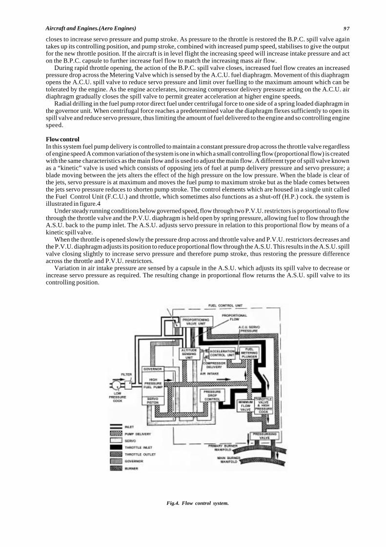
97Aircraft and Engines.(Aero Engines)
closes to increase servo pressure and pump stroke. As pressure to the throttle is restored the B.P.C. spill valve againtakes up its controlling position, and pump stroke, combined with increased pump speed, stabilises to give the outputfor the new throttle position. If the aircraft is in level flight the increasing speed will increase intake pressure and acton the B.P.C. capsule to further increase fuel flow to match the increasing mass air flow.
During rapid throttle opening, the action of the B.P.C. spill valve closes, increased fuel flow creates an increasedpressure drop across the Metering Valve which is sensed by the A.C.U. fuel diaphragm. Movement of this diaphragmopens the A.C.U. spill valve to reduce servo pressure and limit over fuelling to the maximum amount which can betolerated by the engine. As the engine accelerates, increasing compressor delivery pressure acting on the A.C.U. airdiaphragm gradually closes the spill valve to permit greater acceleration at higher engine speeds.
Radial drilling in the fuel pump rotor direct fuel under centrifugal force to one side of a spring loaded diaphragm inthe governor unit. When centrifugal force reaches a predetermined value the diaphragm flexes sufficiently to open itsspill valve and reduce servo pressure, thus limiting the amount of fuel delivered to the engine and so controlling enginespeed.
Flow controlIn this system fuel pump delivery is controlled to maintain a constant pressure drop across the throttle valve regardlessof engine speed A common variation of the system is one in which a small controlling flow (proportional flow) is createdwith the same characteristics as the main flow and is used to adjust the main flow. A different type of spill valve knownas a “kinetic” valve is used which consists of opposing jets of fuel at pump delivery pressure and servo pressure; ablade moving between the jets alters the effect of the high pressure on the low pressure. When the blade is clear ofthe jets, servo pressure is at maximum and moves the fuel pump to maximum stroke but as the blade comes betweenthe jets servo pressure reduces to shorten pump stroke. The control elements which are housed in a single unit calledthe Fuel Control Unit (F.C.U.) and throttle, which sometimes also functions as a shut-off (H.P.) cock. the system isillustrated in figure.4
Under steady running conditions below governed speed, flow through two P.V.U. restrictors is proportional to flowthrough the throttle valve and the P.V.U. diaphragm is held open by spring pressure, allowing fuel to flow through theA.S.U. back to the pump inlet. The A.S.U. adjusts servo pressure in relation to this proportional flow by means of akinetic spill valve.
When the throttle is opened slowly the pressure drop across and throttle valve and P.V.U. restrictors decreases andthe P.V.U. diaphragm adjusts its position to reduce proportional flow through the A.S.U. This results in the A.S.U. spillvalve closing slightly to increase servo pressure and therefore pump stroke, thus restoring the pressure differenceacross the throttle and P.V.U. restrictors.
Variation in air intake pressure are sensed by a capsule in the A.S.U. which adjusts its spill valve to decrease orincrease servo pressure as required. The resulting change in proportional flow returns the A.S.U. spill valve to itscontrolling position.
Fig.4. Flow control system.
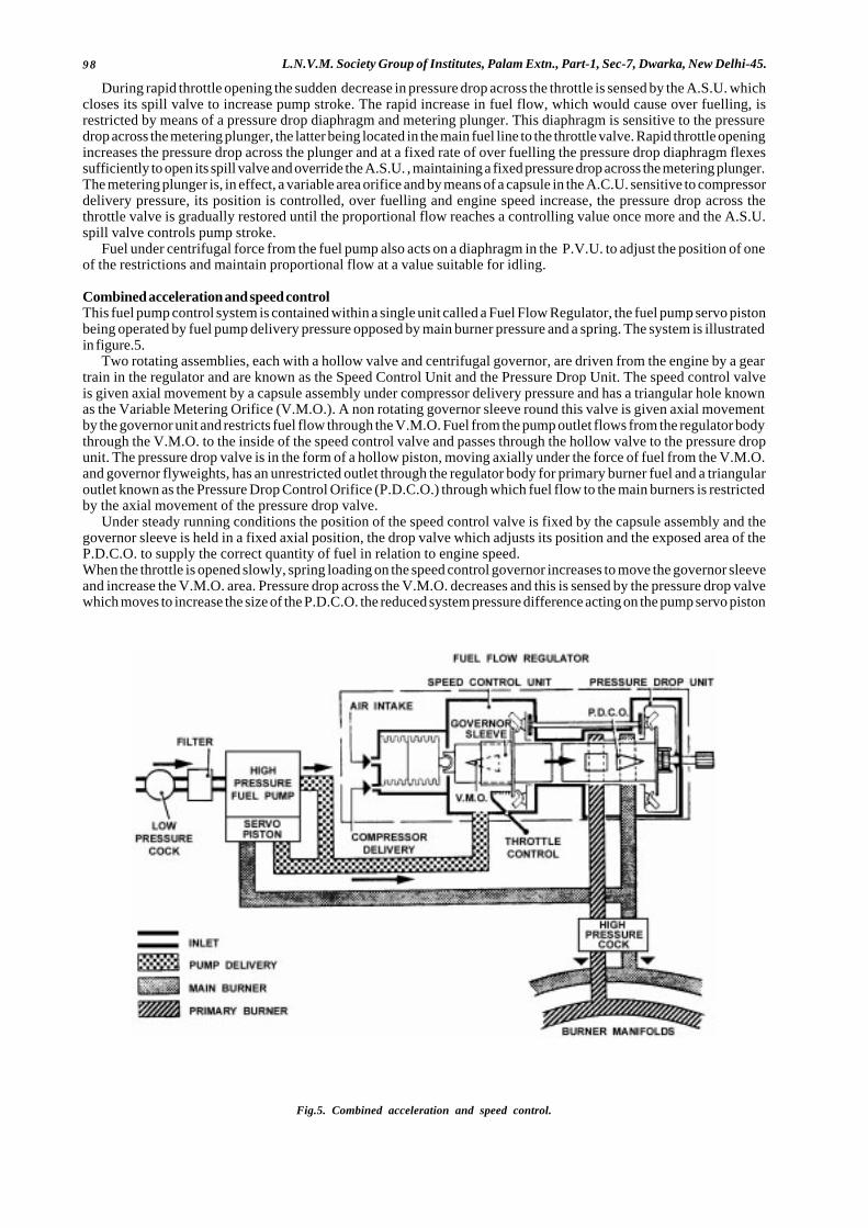
98 L.N.V.M. Society Group of Institutes, Palam Extn., Part-1, Sec-7, Dwarka, New Delhi-45.
During rapid throttle opening the sudden decrease in pressure drop across the throttle is sensed by the A.S.U. whichcloses its spill valve to increase pump stroke. The rapid increase in fuel flow, which would cause over fuelling, isrestricted by means of a pressure drop diaphragm and metering plunger. This diaphragm is sensitive to the pressuredrop across the metering plunger, the latter being located in the main fuel line to the throttle valve. Rapid throttle openingincreases the pressure drop across the plunger and at a fixed rate of over fuelling the pressure drop diaphragm flexessufficiently to open its spill valve and override the A.S.U. , maintaining a fixed pressure drop across the metering plunger.The metering plunger is, in effect, a variable area orifice and by means of a capsule in the A.C.U. sensitive to compressordelivery pressure, its position is controlled, over fuelling and engine speed increase, the pressure drop across thethrottle valve is gradually restored until the proportional flow reaches a controlling value once more and the A.S.U.spill valve controls pump stroke.
Fuel under centrifugal force from the fuel pump also acts on a diaphragm in the P.V.U. to adjust the position of oneof the restrictions and maintain proportional flow at a value suitable for idling.
Combined acceleration and speed controlThis fuel pump control system is contained within a single unit called a Fuel Flow Regulator, the fuel pump servo pistonbeing operated by fuel pump delivery pressure opposed by main burner pressure and a spring. The system is illustratedin figure.5.
Two rotating assemblies, each with a hollow valve and centrifugal governor, are driven from the engine by a geartrain in the regulator and are known as the Speed Control Unit and the Pressure Drop Unit. The speed control valveis given axial movement by a capsule assembly under compressor delivery pressure and has a triangular hole knownas the Variable Metering Orifice (V.M.O.). A non rotating governor sleeve round this valve is given axial movementby the governor unit and restricts fuel flow through the V.M.O. Fuel from the pump outlet flows from the regulator bodythrough the V.M.O. to the inside of the speed control valve and passes through the hollow valve to the pressure dropunit. The pressure drop valve is in the form of a hollow piston, moving axially under the force of fuel from the V.M.O.and governor flyweights, has an unrestricted outlet through the regulator body for primary burner fuel and a triangularoutlet known as the Pressure Drop Control Orifice (P.D.C.O.) through which fuel flow to the main burners is restrictedby the axial movement of the pressure drop valve.
Under steady running conditions the position of the speed control valve is fixed by the capsule assembly and thegovernor sleeve is held in a fixed axial position, the drop valve which adjusts its position and the exposed area of theP.D.C.O. to supply the correct quantity of fuel in relation to engine speed.When the throttle is opened slowly, spring loading on the speed control governor increases to move the governor sleeveand increase the V.M.O. area. Pressure drop across the V.M.O. decreases and this is sensed by the pressure drop valvewhich moves to increase the size of the P.D.C.O. the reduced system pressure difference acting on the pump servo piston
Fig.5. Combined acceleration and speed control.

99Aircraft and Engines.(Aero Engines)
to increase fuel flow to the engine. As the engine accelerates, the capsule in the speed control unit is compressed dueto compressor delivery pressure and moves the speed control valve to further increase the size of the V.M.O. Balanceis restored when centrifugal force acting on the speed control governor moves the governor sleeve to restore the systempressure difference.
The effect to rapid throttle movements is restricted by mechanical stops acting on the governor sleeve.Changes in altitude or forward speed affect the capsule of the speed control unit which adjusts the position of the speedcontrol valve to correct fuel flow.
BURNERSThe purpose of the burners is to provide fuel to the engine in a suitable form for combustion. A burner with a singlespray nozzle, although used on some early engines, is not suitable for large modern engines due to the widely varyingfuel flow requirements for different flight conditions.
If the orifice were of the size suitable for atomising fuel at low rates of flow the pressure required at take-off wouldbe tremendously high, flow through an orifice being proportional to the square of the pressure drop across it.
One of the methods used to overcome this problem is the provision of a dual spray burner. The central orifice providesthe fuel for low flow rates and a second annular orifice is used in addition for high flow rates. Distribution between theprimary (low flow) manifold and the main (high flow) manifold is normally controlled by a pressure operated valve. Inthe case of the Fuel flow Regulator, fuel flowing through the rectangular outlet from the pressure drop valve is alwaysat a higher pressure than fuel flowing through the outlet from the P.D.C.O. and is used to supply the primary burnermanifold.
Another method used on some engines is known as the Vaporising Burner. Fuel is injected at low pressure into oneend of a hollow “U” shaped tube located in the combustion chamber. It mixes with the primary air flow, is vaporisedby the heat in the chamber and ejected upstream into the combustion zone. In this system a separate burner is necessaryfor engine starting.
ADDITIONAL CONTROLSIn addition to, the system usually is provided to prevent the engine from exceeding operating limitations.
Turbine gas temperature controlControl of the maximum permitted turbine gas temperature is often exercised electrically. Signals from the T.G.T.thermocouples are amplified to either actuate a solenoid operated valve in the fuel system or reset the throttle linkageto reduce fuel flow to the burners. On engines which have different T.G.T. limitations for climb and take-off, a switchon the flight deck pre-sets the T.G.T. signal reference datum.
Compressor controlIn certain circumstances such as high forward speed and low ambient temperature it is possible to produce maximumpower/thrust at less than maximum engine speed. Under these conditions the engine could sustain damage due to highcompressor delivery pressures and fuel flow is restricted by providing a bleed from the A.C.U. capsule, chamber toatmosphere when compressor delivery pressure exceeds a predetermined value.
To prevent the low pressure compressor from exceeding its design speed a centrifugal governor driven from the lowpressure shaft is often included in the fuel system. If design speed is exceeded the low pressure governor restricts thefuel flow in the main burner line and reduces both high and low pressure compressor speeds.
� � �

100 L.N.V.M. Society Group of Institutes, Palam Extn., Part-1, Sec-7, Dwarka, New Delhi-45.
CHAPTER: 10CONSTRUCTION AND OPERATION OF PROPELLERS
GENERALA propeller is a means of converting engine power into propulsive force. A rotating propeller imparts rearward motionto a mass of air, and the reaction to this is a forward force on the propeller blades.
Each propeller blade is of aerofoil cross-section. As the blade moves through the air, forces are produced, whichare known as thrust and torque, and which may be regarded as roughly equivalent to the forces of lift and drag producedby an aircraft wing. Thrust is the propulsive force, and torque the resistance to rotation, or propeller load. The magnitudeof the thrust and torque forces produced will depend on the size, shape and number of blades, the blade angle, the speedof rotation, the air density and the forward speed.
Since each blade is of aerofoil cross-section, thrust will be produced most efficiently at a particular angle of attack,that is the angle between the chord line at a particularblade section and the relative airflow. This angle variesboth with operating conditions and with the designcamber of the blade sections, but for a given blade andgiven in flight condition, it will be found to be relativelyconstant along the length of the blade. The rotationalspeed of particular cross-section of a blade will increasewith its distance from the axis of rotation, and, since theforward speed of all parts of the blade is the same, therelative airflow will vary along the blade, and it is,therefore, necessary to provide a decreasing bladeangle from root to tip. The various terms relating topropeller operation are illustrated in fig 1. This is asimplified diagram omitting inflow angles for clarity,but in practical designs these angles can not be ignored.
The geometric pitch of a propeller is the distance which it should move forward in one revolution without slip; itis equal to 2πr tanθ where r is the radius of the particular cross section and θ is the blade angle at that point. Fixedpitch propellers are usually classified by their diameter and pitch, the pitch being related to the blade angle at 3/4 radius,or other nominated station.
Centrifugal, bending, and twisting forces act on a propeller during flight, and can be very severe at high rotationalspeeds. Propellers must be both strong enough to resist these forces, and rigid enough to prevent flutter. The mainforces experienced are as follows :-
a) Centrifugal forces which induce radial stress in the blades and hub, and, when acting on material which is noton the blade axis, also induce a twisting moment. Centrifugal force can be resolved into two components, inthe plane of rotation one is a radial force parallel to the blade axis, and the other a force at 90o to the blade axis;the former produces radial stress, and the latter tends to turn the blade to a finer pitch. The turning effect isreferred to as centrifugal twisting moment, and is illustrated in figure.2; the wider the blade, the greater willbe the twisting moment.
b) Thrust forces which tend to bend the blades forward in the direction of flight.c) Torque forces which tend to bend the blades against the direction of rotation.
d) Air loads which normally tend to oppose thecentrifugal twisting moment and coarsen blade pitch.
The diameter of a propeller, and the number andshape of its blades, depend on the power it isrequired to absorb, on the take-off thrust it is necessaryto produce, and on the noise-level limits which haveto be met. High tip speeds absorb greater power thanlow tip speeds, but if the tip speed approaches thespeed of sound, efficiency will fall, and thisconsideration limits practical diameter/ rotationalspeed combinations. High tip speed is also the mainsource of propeller noise. Large diameters normallyresult in better performance than small diameters,and blade area is chosen to ensure that blade liftcoefficients are kept in the range where the bladesections are efficient. Wide chord blades and/orlarge diameters lead to heavy propellers; increase innumber of blades increases cost but reduces noise.The design of any propeller is, therefore, a compromisebetween conflicting requirements, and the features
Fig. 1. Showing propeller terms.
Fig.2. Centrifugal twisting moment.
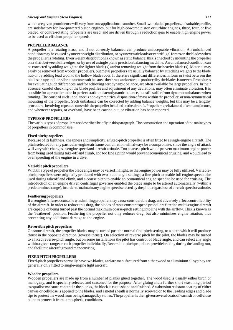
101Aircraft and Engines.(Aero Engines)
which are given prominence will vary from one application to another. Small two-bladed propellers, of suitable profile,are satisfactory for low-powered piston engines, but for high-powered piston or turbine engines, three, four, or fivebladed, or contra-rotating, propellers are used, and are driven through a reduction gear to enable high engine powerto be used at efficient propeller speeds.
PROPELLER BALANCEA propeller is a rotating mass, and if not correctly balanced can produce unacceptable vibration. An unbalancedcondition may be caused by uneven weight distribution, or by uneven air loads or centrifugal forces on the blades whenthe propeller is rotating. Even weight distribution is known as static balance; this is checked by mounting the propelleron a shaft between knife edges; or by use of a single plane precision balancing machine. An unbalanced condition canbe corrected by adding weight to the lighter blade (s) and/or removing weight from the heavier blade (s). Material mayeasily be removed from wooden propellers, but metal propellers are usually balanced by attaching weights to the bladehub or by adding lead wool to the hollow blade roots. If there are significant differences in form or twist between theblades on a propeller, vibration can result because the thrust and or torque produced by the blades is uneven. Proceduresfor evaluating such differences, and for achieving aerodynamic balance, are often available for large propellers. In theirabsence, careful checking of the blade profiles and adjustment of any deviations, may often eliminate vibration. It ispossible for a propeller to be in perfect static and aerodynamic balance, but still suffer from dynamic unbalance whenrotating. The cause of such unbalance is non-symmetrical disposition of mass within the propeller, or non-symmetricalmounting of the propeller. Such unbalance can be corrected by adding balance weights, but this may be a lengthyprocedure, involving repeated runs with the propeller installed on the aircraft. Propellers are balanced after manufacture,and whenever repairs, or overhaul, have been carried out, or vibration has been reported.
TYPES OF PROPELLERSThe various types of propellers are described briefly in this paragraph. The construction and operation of the main typesof propellers in common use.
Fixed pitch propellersBecause of its lightness, cheapness and simplicity, a fixed-pitch propeller is often fitted to a single engine aircraft. Thepitch selected for any particular engine/airframe combination will always be a compromise, since the angle of attackwill vary with changes in engine speed and aircraft attitude. Too coarse a pitch would prevent maximum engine powerfrom being used during take-off and climb, and too fine a pitch would prevent economical cruising, and would lead toover speeding of the engine in a dive.
Variable pitch propellersWith this type of propeller the blade angle may be varied in flight, so that engine power may be fully utilized. Variable-pitch propellers were originally produced with two blade-angle settings; a fine pitch to enable full engine speed to beused during takeoff and climb, and a coarse pitch to enable an economical engine speed to be used for cruising. Theintroduction of an engine driven centrifugal governor enabled the blade angle to be altered automatically (within apredetermined range), in order to maintain any engine speed selected by the pilot, regardless of aircraft speed or attitude.
Feathering propellersIf an engine failure occurs, the wind milling propeller may cause considerable drag, and adversely affect controllabilityof the aircraft. In order to reduce this drag, the blades of most constant speed propellers fitted to multi-engine aircraftare capable of being turned past the normal maximum coarse-pitch setting into line with the airflow. This is known asthe ‘feathered’ position. Feathering the propeller not only reduces drag, but also minimizes engine rotation, thuspreventing any additional damage to the engine.
Reversible pitch propellersOn some aircraft, the propeller blades may be turned past the normal fine-pitch setting, to a pitch which will producethrust in the opposite direction (reverse thrust). On selection of reverse pitch by the pilot, the blades may be turnedto a fixed reverse-pitch angle, but on some installations the pilot has control of blade angle, and can select any anglewithin a given range on each propeller individually, Reversible-pitch propellers provide braking during the landing run,and facilitate aircraft ground manoeuvring.
FIXED PITCH PROPELLERSFixed-pitch propellers normally have two blades, and are manufactured from either wood or aluminium alloy; they aregenerally only fitted to single-engine light aircraft.
Wooden propellersWooden propellers are made up from a number of planks glued together. The wood used is usually either birch ormahogany, and is specially selected and seasoned for the purpose. After gluing and a further short seasoning periodto equalise moisture content in the planks, the block is cut to shape and finished. An abrasion resistant coating of eithercanvas or cellulose is applied to the blades, and a metal sheath is normally screwed on to the leading edges and bladetips to protect the wood from being damaged by stones. The propeller is then given several coats of varnish or cellulosepaint to protect it from atmospheric conditions.
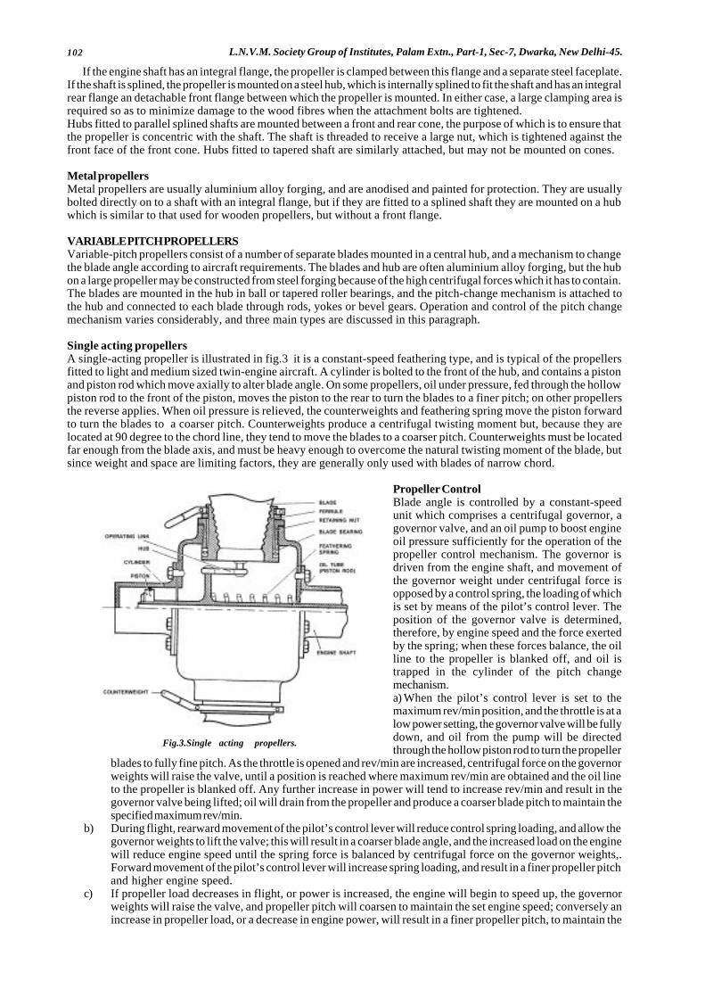
102 L.N.V.M. Society Group of Institutes, Palam Extn., Part-1, Sec-7, Dwarka, New Delhi-45.
If the engine shaft has an integral flange, the propeller is clamped between this flange and a separate steel faceplate.If the shaft is splined, the propeller is mounted on a steel hub, which is internally splined to fit the shaft and has an integralrear flange an detachable front flange between which the propeller is mounted. In either case, a large clamping area isrequired so as to minimize damage to the wood fibres when the attachment bolts are tightened.Hubs fitted to parallel splined shafts are mounted between a front and rear cone, the purpose of which is to ensure thatthe propeller is concentric with the shaft. The shaft is threaded to receive a large nut, which is tightened against thefront face of the front cone. Hubs fitted to tapered shaft are similarly attached, but may not be mounted on cones.
Metal propellersMetal propellers are usually aluminium alloy forging, and are anodised and painted for protection. They are usuallybolted directly on to a shaft with an integral flange, but if they are fitted to a splined shaft they are mounted on a hubwhich is similar to that used for wooden propellers, but without a front flange.
VARIABLE PITCH PROPELLERSVariable-pitch propellers consist of a number of separate blades mounted in a central hub, and a mechanism to changethe blade angle according to aircraft requirements. The blades and hub are often aluminium alloy forging, but the hubon a large propeller may be constructed from steel forging because of the high centrifugal forces which it has to contain.The blades are mounted in the hub in ball or tapered roller bearings, and the pitch-change mechanism is attached tothe hub and connected to each blade through rods, yokes or bevel gears. Operation and control of the pitch changemechanism varies considerably, and three main types are discussed in this paragraph.
Single acting propellersA single-acting propeller is illustrated in fig.3 it is a constant-speed feathering type, and is typical of the propellersfitted to light and medium sized twin-engine aircraft. A cylinder is bolted to the front of the hub, and contains a pistonand piston rod which move axially to alter blade angle. On some propellers, oil under pressure, fed through the hollowpiston rod to the front of the piston, moves the piston to the rear to turn the blades to a finer pitch; on other propellersthe reverse applies. When oil pressure is relieved, the counterweights and feathering spring move the piston forwardto turn the blades to a coarser pitch. Counterweights produce a centrifugal twisting moment but, because they arelocated at 90 degree to the chord line, they tend to move the blades to a coarser pitch. Counterweights must be locatedfar enough from the blade axis, and must be heavy enough to overcome the natural twisting moment of the blade, butsince weight and space are limiting factors, they are generally only used with blades of narrow chord.
Propeller ControlBlade angle is controlled by a constant-speedunit which comprises a centrifugal governor, agovernor valve, and an oil pump to boost engineoil pressure sufficiently for the operation of thepropeller control mechanism. The governor isdriven from the engine shaft, and movement ofthe governor weight under centrifugal force isopposed by a control spring, the loading of whichis set by means of the pilot’s control lever. Theposition of the governor valve is determined,therefore, by engine speed and the force exertedby the spring; when these forces balance, the oilline to the propeller is blanked off, and oil istrapped in the cylinder of the pitch changemechanism.a) When the pilot’s control lever is set to themaximum rev/min position, and the throttle is at alow power setting, the governor valve will be fullydown, and oil from the pump will be directedthrough the hollow piston rod to turn the propeller
blades to fully fine pitch. As the throttle is opened and rev/min are increased, centrifugal force on the governorweights will raise the valve, until a position is reached where maximum rev/min are obtained and the oil lineto the propeller is blanked off. Any further increase in power will tend to increase rev/min and result in thegovernor valve being lifted; oil will drain from the propeller and produce a coarser blade pitch to maintain thespecified maximum rev/min.
b) During flight, rearward movement of the pilot’s control lever will reduce control spring loading, and allow thegovernor weights to lift the valve; this will result in a coarser blade angle, and the increased load on the enginewill reduce engine speed until the spring force is balanced by centrifugal force on the governor weights,.Forward movement of the pilot’s control lever will increase spring loading, and result in a finer propeller pitchand higher engine speed.
c) If propeller load decreases in flight, or power is increased, the engine will begin to speed up, the governorweights will raise the valve, and propeller pitch will coarsen to maintain the set engine speed; conversely anincrease in propeller load, or a decrease in engine power, will result in a finer propeller pitch, to maintain the
Fig.3.Single acting propellers.
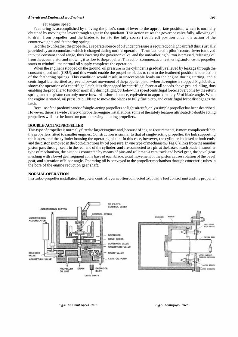
103Aircraft and Engines.(Aero Engines)
set engine speed.Feathering is accomplished by moving the pilot’s control lever to the appropriate position, which is normally
obtained by moving the lever through a gate in the quadrant. This action raises the governor valve fully, allowing oilto drain from propeller, and the blades to turn to the fully coarse (feathered) position under the action of thecounterweights and feathering spring.
In order to unfeather the propeller, a separate source of oil under pressure is required; on light aircraft this is usuallyprovided by an accumulator which is charged during normal operation. To unfeather, the pilot’s control lever is movedinto the constant speed range, thus lowering the governor valve, and the unfeathering button is pressed, releasing oilfrom the accumulator and allowing it to flow to the propeller. This action commences unfeathering, and once the propellerstarts to windmill the normal oil supply completes the operation.
When the engine is stopped on the ground, oil pressure in the cylinder is gradually relieved by leakage through theconstant speed unit (CSU), and this would enable the propeller blades to turn to the feathered position under actionof the feathering springs. This condition would result in unacceptable loads on the engine during starting, and acentrifugal latch is fitted to prevent forward movement of the propeller piston when the engine is stopped. Fig.5. belowshows the operation of a centrifugal latch; it is disengaged by centrifugal force at all speeds above ground idling, thusenabling the propeller to function normally during flight, but below this speed centrifugal force is overcome by the returnspring, and the piston can only move forward a short distance, equivalent to approximately 5o of blade angle. Whenthe engine is started, oil pressure builds up to move the blades to fully fine pitch, and centrifugal force disengages thelatch.
Because of the predominance of single-acting propellers on light aircraft, only a simple propeller has been described.However, there is a wide variety of propeller/engine installations, some of the safety features attributed to double actingpropellers will also be found on particular single-acting propellers.
DOUBLE-ACTING PROPELLERThis type of propeller is normally fitted to larger engines and, because of engine requirements, is more complicated thenthe propellers fitted to smaller engines, Construction is similar to that of single-acting propeller, the hub supportingthe blades, and the cylinder housing the operating piston. In this case, however, the cylinder is closed at both ends,and the piston is moved in the both directions by oil pressure. In one type of mechanism, (Fig.6.) links from the annularpiston pass through seals in the rear end of the cylinder, and are connected to a pin at the base of each blade. In anothertype of mechanism, the piston is connected by means of pins and rollers to a cam track and bevel gear, the bevel gearmeshing with a bevel gear segment at the base of each blade; axial movement of the piston causes rotation of the bevelgear, and alteration of blade angle. Operating oil is conveyed to the propeller mechanism through concentric tubes inthe bore of the engine reduction gear shaft.
NORMAL OPERATIONIn a turbo-propeller installation the power control lever is often connected to both the fuel control unit and the propeller
Fig.4. Constant Speed Unit. Fig.5. Centrifugal latch.
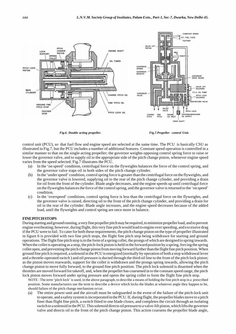
104 L.N.V.M. Society Group of Institutes, Palam Extn., Part-1, Sec-7, Dwarka, New Delhi-45.
Fig.6. Double acting propeller. Fig.7.Propeller control Unit.
control unit (PCU), so that fuel flow and engine speed are selected at the same time. The PCU is basically CSU asillustrated in Fig.7, but the PCU includes a number of additional features. Constant speed operation is controlled in asimilar manner to that on the single-acting propeller; the governor weights opposing control spring force to raise orlower the governor valve, and to supply oil to the appropriate side of the pitch change piston, whenever engine speedvaries from the speed selected. Fig.7 illustrates the PCU.
(a) In the ‘on speed’ condition, centrifugal force on the flyweights balances the force of the control spring, andthe governor valve traps oil in both sides of the pitch change cylinder.
(b) In the ‘under speed’ condition, control spring force is greater than the centrifugal force on the flyweights, andthe governor valve is lowered, supplying oil to the rear of the pitch change cylinder, and providing a drainfor oil from the front of the cylinder. Blade angle decreases, and the engine speeds up until centrifugal forceon the flyweights balances the force of the control spring, and the governor valve is returned to the ‘on speed’condition.
(c) In the ‘overspeed’ conditions, control spring force is less than the centrifugal force on the flyweights, andthe governor valve is raised, directing oil to the front of the pitch change cylinder, and providing a drain foroil in the rear of the cylinder. Blade angle increases, and the engine speed decreases because of the addedload, until the flyweights and control spring are once more in balance.
FINE PITCH STOPSDuring starting and ground running, a very fine propeller pitch may be required, to minimize propeller load, and to preventengine overheating; however, during flight, this very fine pitch would lead to engine over speeding, and excessive dragif the PCU were to fail. To cater for both these requirements, the pitch change piston on the type of propeller illustratedin figure 6 is provided with two fine pitch stops, the flight fine pitch stop being withdrawn for starting and groundoperations. The flight fine pitch stop is in the form of a spring collet, the prongs of which are designed to spring inwards.When the collet is operating as a stop, the pitch-lock piston is held in the forward position by a spring, forcing the springcollet open, and preventing the pitch change piston from moving forward further than the flight fine pitch position. Whenground fine pitch is required, a solenoid in the PCU is energized (normally by operation of both a stop withdrawal leverand a throttle-operated switch ) and oil pressure is ducted through the third oil line to the front of the pitch lock piston;as the piston moves rearwards, support for the collet is withdrawn and the prongs spring inwards, allowing the pitchchange piston to move fully forward, to the ground fine pitch position. The pitch lock solenoid is disarmed when thethrottles are moved forward for takeoff, and, when the propeller has coarsened in to the constant speed range, the pitchlock piston moves forward under spring pressure and opens the spring collet to form the flight fine pitch stop.
NOTE : The term ‘pitch lock’ is used, in the above paragraph, to describe a means of holding the fine pitch stop in a prescribedposition. Some manufacturers use the term to describe a device which locks the blades at whatever angle they happen to be,should failure of the pitch change mechanism occur.(a) The entire power-unit and the aircraft must be safeguarded in the event of the failure of the pitch-lock unit
to operate, and a safety system is incorporated in the PCU. If, during flight, the propeller blades move to a pitchfiner than flight fine pitch, a switch fitted to one blade closes, and completes the circuit through an isolatingswitch to a solenoid in the PCU. This solenoid directs oil pressure to a valve-lift piston, which lifts the governorvalve and directs oil to the front of the pitch change piston. This action coarsens the propeller blade angle,

105Aircraft and Engines.(Aero Engines)
and breaks the circuit to the valve-lift solenoid. If the pitch-change piston does not latch over the spring colletas it moves rearwards, the sequence will be repeated as the blades fine-off past flight fine pitch again. Anisolation switch prevents operation of this safety system when ground-fine pitch is purposely selected.
FEATHERINGFacilities for the manual feathering of the propeller are provided on all large piston and turbo-propeller engines. Withsome turbo-propeller installations, however, the drag from a wind milling propeller in the fine pitch could be verydangerous, particularly with a twin engine aircraft, and for these aircraft automatic feathering is also provided.
(a). Manual feathering of the propeller on a piston engine is normally carried out by movement of the propellercontrol lever to the ‘feather’ position, and operation of the feathering pump. These actions raise the governorvalve, and supply oil under pressure to the appropriate side of the pitch-change piston. On a turbo-propellerinstallation, manual feathering is carried out by an interconnection between the PCU and the high pressurefuel cook. When the fuel cook is moved to the ‘feather’ position, linkage to the PCU lifts the governor valveindependently of governor control, and oil is directed to the front of the pitch change piston to turn the bladesfully coarse. Since the oil pump in the PCU is driven by the engine, the oil supply may be insufficient to featherthe propeller completely, and the operation of the electrically-driven feathering pump may be necessary.
(b). Automatic feathering is initiated by means of a torque switch. Whenever the power levers are positioned abovethe idling range, and the engine torque falls below a specified amount, the torque switch closes and completesa circuit to the feathering pump and the valve-lift solenoid in PCU. The solenoid direct oil to the valve lift pistonwhich raises the governor valve, and opens the oil ports from the feathering pump to the front of the pitchchange piston, thus feathering the propeller.
UNFEATHERINGOn turbo-propeller engines, when the high pressure fuel cock is open and the power levers closed, the governor valveis in a suitable position to direct oil from the feathering pump to the rear of the pitch change piston. Selection of featheringpump switch (which is often incorporated in the fire control handle), supplies oil to the PCU and thence to the propeller,and activates the engine ignition system. When the propeller blades have turned from the feathered position, theairstream commences to wind will the propeller and rotate the engine, and normal oil pressure builds up to completethe unfeathering operation.
REVERSINGIn a reversing propeller, the propeller mechanism includes a removable ground fine pitch stop, which enables thepropeller to fine-off to a negative pitch when certain actions have been taken and certain condition are fulfilled. Varioussafeguards are incorporated to prevent selection during flight. The means of achieving negative pitch vary considerably,but operation of a typical hydraulically operated propeller is described in the following paragraphs.
(a) Electrical control is exercised by throttle-mounted switches, weight contact switches on the landing gear, anda master switch or lever to arm the circuit. With the throttle levers closed beyond normal idling to a datumposition, ‘reverse’ selected, and the weight of the aircraft on its wheels, electrical power is supplied to a pitch-stop withdrawal solenoid, and oil pressure is directed to withdraw the fine-pitch stop and move and pitch-change piston forward to the reverse stop, where it is held by hydraulic pressure. Operation of the ‘reverse’lever also changes the sense of operation of the throttle levers., which are pulled further back to increase powerin reverse pitch.
(b) Indication of stop withdrawal, and movement of the blades to negative pitch, is provided by hub-mountedswitches, which illuminate appropriate warning lamps on the flight deck.
(c) Re-selection of positive blade angle is achieved by moving the throttle into the normal idling range, and bymoving the master lever out of the reverse position. Oil is ducted to the front of the pitch change piston, andthe blades move to a positive angle; the stop returns to normal operation once the blades have moved pastthe ground fine pitch angel.
‘BETA’ CONTROLOn some gas turbine engines, a form of control known as ‘beta’, or blade angle control, is used or ground operations,and may be applied to either, single-acting or double-acting propellers. With this system, the throttle (usually knownas power lever) operate in a gated quadrant. During flight these levers cannot be closed below the ‘flight idle’ gate,and the CSU operates normally to maintain any pre-selected propeller speed, In the ground idling and reversing range,the power lever control propeller speed, and the governor mechanism is overridden. An overspeed sensor, andmechanical pitch stop, prevent operation in the ground (fine pitch) range during flight. In the beta range, the pitch stopis withdrawn, and movement of a power lever rotates a setting cam in the associated CSU, which raises or lowers thegovernor valve according to whether a coarser or finer pitch is required. A mechanical feedback mechanism, operatedby linkage from the propeller blades, resets the governor valve via a follow-up cam, and pitch change ceases when theangle scheduled by the power lever is achieved.
ELECTRICALLY OPERATED PROPELLERSAs with other types of variable-pitch propellers, a hub is mounted on the engine reduction gear shaft, the individualblades are fitted into the hub, and the pitch change mechanism is fitted to the front of the hub. In this type, however,the pitch change mechanism consists of a reversible electric motor, driving a bevel gear through a gear train with a veryhigh reduction ratio. The bevel gear meshes with a bevel gear segment attached to the root of each blade, and, when

106 L.N.V.M. Society Group of Institutes, Palam Extn., Part-1, Sec-7, Dwarka, New Delhi-45.
rotates, turns the blades to alter propeller pitch. Electric power to the motor is provided through a brush and slip-ringarrangement at the rear of the hub. A motor brake is provided to prevent overrun, and normally consists of two frictiondiscs, one fixed to the rotating motor shaft, and the other keyed to the stationary motor casing. The brake is applied(discs held together) by spring pressure, and released by means of a solenoid whenever a pitch change in initiated.
Some electrically operated propellers are controlled by an engine-driven CSU, and switches are also provided whichenable propeller pitch to be controlled manually. The CSU is similar to those fitted to hydraulically operated propellers,but the governor valve supplies oil to the appropriate side of a piston contained in the CSU, which is connected to thecentral contact of a switch unit. Movement of this piston in either direction completes a circuit to the pitch change motor,and alters blade angle as required.
On some multi-engines aircraft an electrical control system is used. A single propeller pitch level controls the speedof a master electric motor, which is used as a reference for engine speed, and which drives the stator of a contactor unitfor each engine. Each engine drives an alternator, which supplies three-phase alternating current to the stator windingof the appropriate contactor, the frequency being proportional to engine speed. During operation , a magnetic field isbuilt up round the stator with a phase rotation opposite to a that of the stator. If the stator speed and alternator speedare the same, the magnetic field will, therefore, be stationary; any variation in alternator speed will result in rotation ofmagnetic field, the direction of rotation depending on whether the alternator is rotating faster or slower than the stator.Rotation of the magnetic, field influences a concentric rotor, which rotates with it, and closes a pair of contacts tocomplete the circuit to the appropriate winding in the propeller pitch change motor. Switches are normally providedto enable pitch changes and feathering to be carried out manually.
� � �
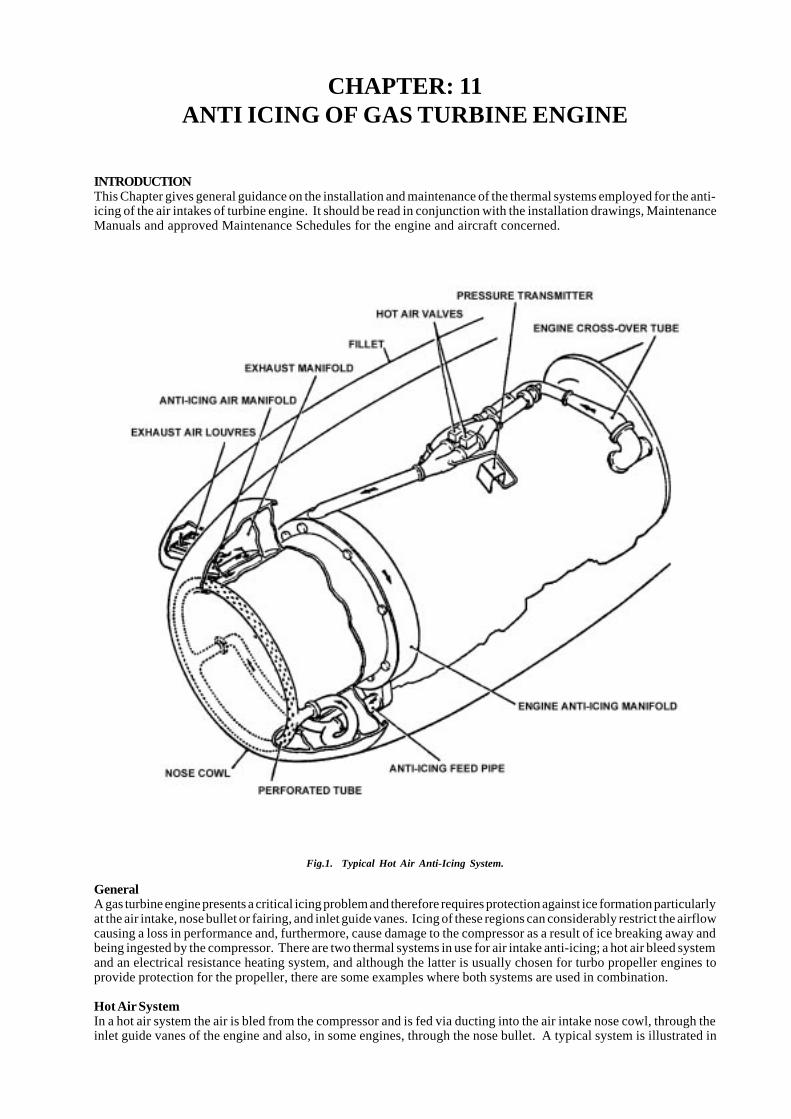
107Aircraft and Engines.(Aero Engines)
CHAPTER: 11ANTI ICING OF GAS TURBINE ENGINE
INTRODUCTIONThis Chapter gives general guidance on the installation and maintenance of the thermal systems employed for the anti-icing of the air intakes of turbine engine. It should be read in conjunction with the installation drawings, MaintenanceManuals and approved Maintenance Schedules for the engine and aircraft concerned.
Fig.1. Typical Hot Air Anti-Icing System.
GeneralA gas turbine engine presents a critical icing problem and therefore requires protection against ice formation particularlyat the air intake, nose bullet or fairing, and inlet guide vanes. Icing of these regions can considerably restrict the airflowcausing a loss in performance and, furthermore, cause damage to the compressor as a result of ice breaking away andbeing ingested by the compressor. There are two thermal systems in use for air intake anti-icing; a hot air bleed systemand an electrical resistance heating system, and although the latter is usually chosen for turbo propeller engines toprovide protection for the propeller, there are some examples where both systems are used in combination.
Hot Air SystemIn a hot air system the air is bled from the compressor and is fed via ducting into the air intake nose cowl, through theinlet guide vanes of the engine and also, in some engines, through the nose bullet. A typical system is illustrated in
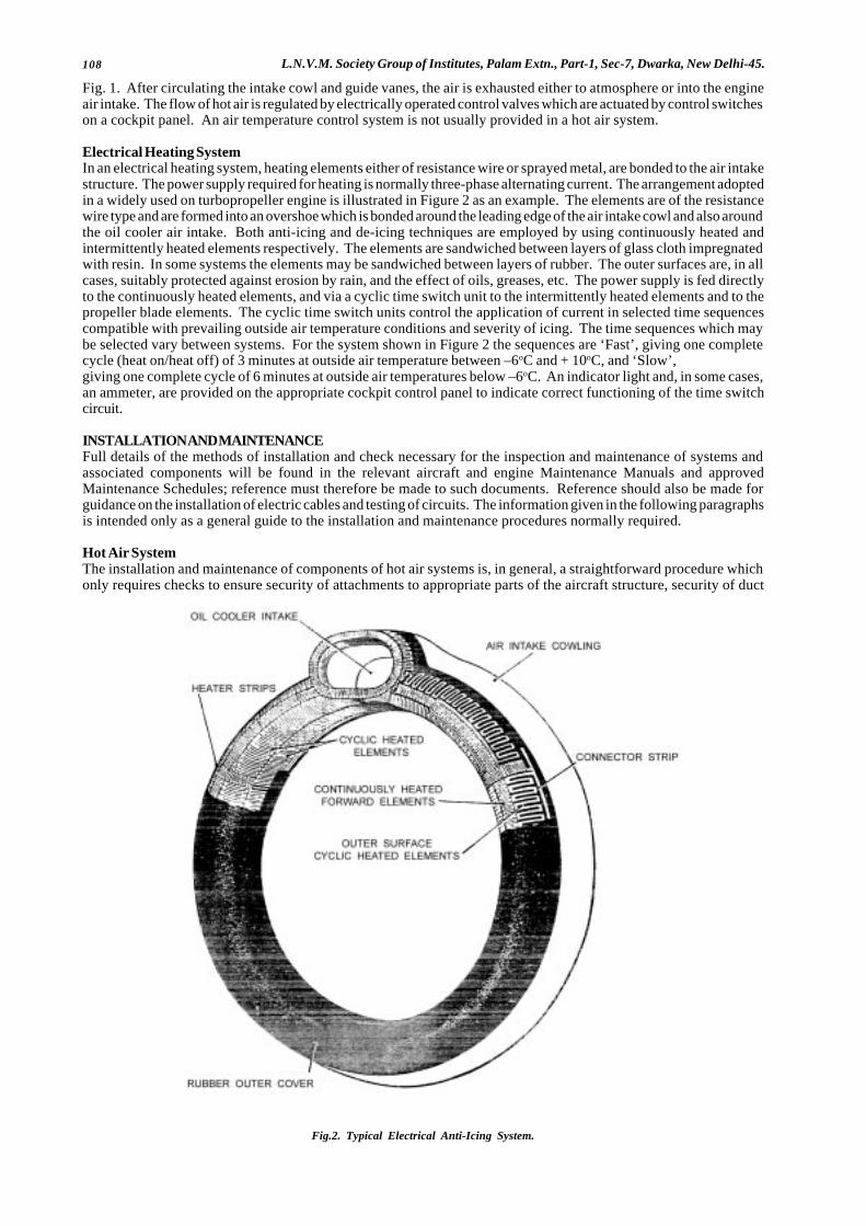
108 L.N.V.M. Society Group of Institutes, Palam Extn., Part-1, Sec-7, Dwarka, New Delhi-45.
Fig. 1. After circulating the intake cowl and guide vanes, the air is exhausted either to atmosphere or into the engineair intake. The flow of hot air is regulated by electrically operated control valves which are actuated by control switcheson a cockpit panel. An air temperature control system is not usually provided in a hot air system.
Electrical Heating SystemIn an electrical heating system, heating elements either of resistance wire or sprayed metal, are bonded to the air intakestructure. The power supply required for heating is normally three-phase alternating current. The arrangement adoptedin a widely used on turbopropeller engine is illustrated in Figure 2 as an example. The elements are of the resistancewire type and are formed into an overshoe which is bonded around the leading edge of the air intake cowl and also aroundthe oil cooler air intake. Both anti-icing and de-icing techniques are employed by using continuously heated andintermittently heated elements respectively. The elements are sandwiched between layers of glass cloth impregnatedwith resin. In some systems the elements may be sandwiched between layers of rubber. The outer surfaces are, in allcases, suitably protected against erosion by rain, and the effect of oils, greases, etc. The power supply is fed directlyto the continuously heated elements, and via a cyclic time switch unit to the intermittently heated elements and to thepropeller blade elements. The cyclic time switch units control the application of current in selected time sequencescompatible with prevailing outside air temperature conditions and severity of icing. The time sequences which maybe selected vary between systems. For the system shown in Figure 2 the sequences are ‘Fast’, giving one completecycle (heat on/heat off) of 3 minutes at outside air temperature between –6oC and + 10oC, and ‘Slow’,giving one complete cycle of 6 minutes at outside air temperatures below –6oC. An indicator light and, in some cases,an ammeter, are provided on the appropriate cockpit control panel to indicate correct functioning of the time switchcircuit.
INSTALLATION AND MAINTENANCEFull details of the methods of installation and check necessary for the inspection and maintenance of systems andassociated components will be found in the relevant aircraft and engine Maintenance Manuals and approvedMaintenance Schedules; reference must therefore be made to such documents. Reference should also be made forguidance on the installation of electric cables and testing of circuits. The information given in the following paragraphsis intended only as a general guide to the installation and maintenance procedures normally required.
Hot Air SystemThe installation and maintenance of components of hot air systems is, in general, a straightforward procedure whichonly requires checks to ensure security of attachments to appropriate parts of the aircraft structure, security of duct
Fig.2. Typical Electrical Anti-Icing System.
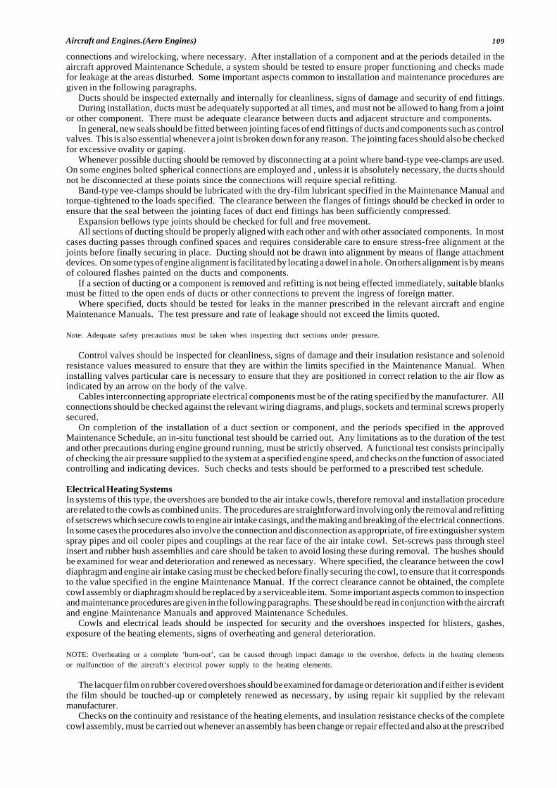
109Aircraft and Engines.(Aero Engines)
connections and wirelocking, where necessary. After installation of a component and at the periods detailed in theaircraft approved Maintenance Schedule, a system should be tested to ensure proper functioning and checks madefor leakage at the areas disturbed. Some important aspects common to installation and maintenance procedures aregiven in the following paragraphs.
Ducts should be inspected externally and internally for cleanliness, signs of damage and security of end fittings.During installation, ducts must be adequately supported at all times, and must not be allowed to hang from a joint
or other component. There must be adequate clearance between ducts and adjacent structure and components.In general, new seals should be fitted between jointing faces of end fittings of ducts and components such as control
valves. This is also essential whenever a joint is broken down for any reason. The jointing faces should also be checkedfor excessive ovality or gaping.
Whenever possible ducting should be removed by disconnecting at a point where band-type vee-clamps are used.On some engines bolted spherical connections are employed and , unless it is absolutely necessary, the ducts shouldnot be disconnected at these points since the connections will require special refitting.
Band-type vee-clamps should be lubricated with the dry-film lubricant specified in the Maintenance Manual andtorque-tightened to the loads specified. The clearance between the flanges of fittings should be checked in order toensure that the seal between the jointing faces of duct end fittings has been sufficiently compressed.
Expansion bellows type joints should be checked for full and free movement.All sections of ducting should be properly aligned with each other and with other associated components. In most
cases ducting passes through confined spaces and requires considerable care to ensure stress-free alignment at thejoints before finally securing in place. Ducting should not be drawn into alignment by means of flange attachmentdevices. On some types of engine alignment is facilitated by locating a dowel in a hole. On others alignment is by meansof coloured flashes painted on the ducts and components.
If a section of ducting or a component is removed and refitting is not being effected immediately, suitable blanksmust be fitted to the open ends of ducts or other connections to prevent the ingress of foreign matter.
Where specified, ducts should be tested for leaks in the manner prescribed in the relevant aircraft and engineMaintenance Manuals. The test pressure and rate of leakage should not exceed the limits quoted.
Note: Adequate safety precautions must be taken when inspecting duct sections under pressure.
Control valves should be inspected for cleanliness, signs of damage and their insulation resistance and solenoidresistance values measured to ensure that they are within the limits specified in the Maintenance Manual. Wheninstalling valves particular care is necessary to ensure that they are positioned in correct relation to the air flow asindicated by an arrow on the body of the valve.
Cables interconnecting appropriate electrical components must be of the rating specified by the manufacturer. Allconnections should be checked against the relevant wiring diagrams, and plugs, sockets and terminal screws properlysecured.
On completion of the installation of a duct section or component, and the periods specified in the approvedMaintenance Schedule, an in-situ functional test should be carried out. Any limitations as to the duration of the testand other precautions during engine ground running, must be strictly observed. A functional test consists principallyof checking the air pressure supplied to the system at a specified engine speed, and checks on the function of associatedcontrolling and indicating devices. Such checks and tests should be performed to a prescribed test schedule.
Electrical Heating SystemsIn systems of this type, the overshoes are bonded to the air intake cowls, therefore removal and installation procedureare related to the cowls as combined units. The procedures are straightforward involving only the removal and refittingof setscrews which secure cowls to engine air intake casings, and the making and breaking of the electrical connections.In some cases the procedures also involve the connection and disconnection as appropriate, of fire extinguisher systemspray pipes and oil cooler pipes and couplings at the rear face of the air intake cowl. Set-screws pass through steelinsert and rubber bush assemblies and care should be taken to avoid losing these during removal. The bushes shouldbe examined for wear and deterioration and renewed as necessary. Where specified, the clearance between the cowldiaphragm and engine air intake casing must be checked before finally securing the cowl, to ensure that it correspondsto the value specified in the engine Maintenance Manual. If the correct clearance cannot be obtained, the completecowl assembly or diaphragm should be replaced by a serviceable item. Some important aspects common to inspectionand maintenance procedures are given in the following paragraphs. These should be read in conjunction with the aircraftand engine Maintenance Manuals and approved Maintenance Schedules.
Cowls and electrical leads should be inspected for security and the overshoes inspected for blisters, gashes,exposure of the heating elements, signs of overheating and general deterioration.
NOTE: Overheating or a complete ‘burn-out’, can be caused through impact damage to the overshoe, defects in the heating elementsor malfunction of the aircraft’s electrical power supply to the heating elements.
The lacquer film on rubber covered overshoes should be examined for damage or deterioration and if either is evidentthe film should be touched-up or completely renewed as necessary, by using repair kit supplied by the relevantmanufacturer.
Checks on the continuity and resistance of the heating elements, and insulation resistance checks of the completecowl assembly, must be carried out whenever an assembly has been change or repair effected and also at the prescribed

110 L.N.V.M. Society Group of Institutes, Palam Extn., Part-1, Sec-7, Dwarka, New Delhi-45.
inspection periods.
NOTE: The metal or air cowls is normally anodised and it is necessary to bare a small area to effect the ‘earth’ connection. On completionof the electrical checks, this area must be reprotected against corrosion.
Functional testing of a complete system must be carried out at the check periods specified in the approvedMaintenance Schedule, when a system malfunction occurs, after replacement of an intake cowl or a system componentsuch as a cyclic time switch, and also after any repairs to an overshoe. A functional test consists principally of checkingthat heating current is applied to the heater elements at the periods governed by the operation of the cyclic time switchand, as indicated by the system indicator light, and ammeter where applicable, to the systems. Tests and checks mustbe performed to a prescribed test schedule paying particular attention to any limitations on system operation and enginespeeds during ground running.
NOTE: The power supply control circuit is usually routed through landing gear shock-strut micro switches so that on the ground the poweris automatically reduced to prevent overheating. Therefore, whenever the aircraft is on jacks, or the micro switches are otherwise renderedinoperative, power should not be applied to the heating elements.
If blisters, gashes, exposure of the heating elements, general deterioration and lack of adhesion of either rubber orglass cloth covering is evident, the covering should be carefully cut open to permit examination of the heating elements.If the elements are not fractured or cracked and the rubber or glass cloth below the elements has not deteriorated, theareas may be repaired as a minor repair.
The heating element system is made up of a number of sections or pads and if any one of the sections has beenfractured due to a localised burn-out or mechanical damage, a repair can be made by welding a portion of element inthe appropriate section.
NOTE: The number or repairs in a section or pad is normally limited to one since the weld causes an increase in element resistance.
The repair methods to be adopted, and the nature of the work involved, depends largely on the extent of damageand also on the type of overshoe construction, i.e. glass cloth or rubber laminate. Repair schemes are therefore devisedfor each type and are usually classified according to the level of the repairs required, i.e. minor repairs which can becarried out in the normal overhaul workshops, or major repairs to be carried out by the manufacturer. Full details ofthese schemes are given in the Maintenance Manuals and Overhaul Manuals for the relevant type of engine andreference must always be made to these documents.
An air intake cowl assembly which has been damaged or has deteriorated to an extent outside repair standardsspecified in the Maintenance Manuals and Overhaul Manuals should be removed and replaced by a serviceableassembly.
� � � � �
111Aircraft and Engines.(Aero Engines)
CHAPTER: 12ROUTINE AND NON-ROUTINE
MAINTENANCE OF PISTON ENGINE
Engine TestingBefore starting an engine the cowlings should be fitted, the aircraft should be faced into wind and securely chocked,the brakes should be applied, and suitable fire extinguishers should be made available. When starting a new engineit is advisable to use an external power supply rather than the aircraft batteries, and this should be connected to theaircraft. The method of starting will vary according to the type of carburettor and the engine installation, and theprocedure recommended by the aircraft manufacturer should be followed. Engine speed should be kept as low aspossible until the oil pressure has built up to a prescribed value in a given time. If the minimum oil pressure is not achievedwithin the specified time the engine must be stopped and the cause determined. The engine should then be warmedup until the recommended minimum cylinder and oil temperatures are reached. At this power setting the magnetosshould be checked for a dead cut (by momentarily switching off both magnetos), then the engine should be stoppedand inspected for fuel and oil leaks. The engine cowlings should then be refitted, the engine started, and the followingchecks carried out as appropriate and in accordance with the manufacturer’s instructions.
a. Exercise the propeller several times by operation of the pitch control lever, to ensure that it is filled with oil andis operating properly.
b. Check the operation of the magnetos at the recommended power settings.c. Carry out an engine power check.d. Open up to full power and check the maximum engine speed. Correct by means of the constant speed unit
adjustment as necessary.e. Check the carburation over the full power range.f. Check operation of the supercharger.g. Check operation of all engine-operated systems. This may include checking battery-charging rate, hydraulic
pressure and system operation, pneumatic pressure and system operation, vacuum pressure, and operation ofthe instruments and de-icing boots. The maintenance of the correct fuel pressure over the full power rangeshould also be checked, to ensure correct operation of the engine-driven pump.
h. Close the throttle and check the idling speed and mixture strength.i. Cool the engine by running it at approximately 1000 rev/min for a short period, or until the cylinder head
temperature is within limits, then close it down.
NOTE: Prolonged ground running at high power settings must be avoided, since the cylinders are not adequately cooled when the aircraftis stationary.
After the ground run, the engine should be inspected for gas, fuel or oil leaks, and any adjustments found necessaryduring the run should be carried out. It will usually also be found necessary to replenish the oil system, since someof the oil from the tank will now occupy the sump and pipelines.
The results of the engine run, including the manifold pressure and engine speed obtained during the power check,and the drop in engine speed obtained during the magneto checks, together with any adjustments carried out, shouldbe recorded in the engine log book.
ROUTINE MAINTENANCEIn order to guard against malfunction or failure of an engine and its associated equipment, a programme of inspectionand maintenance is carried out in accordance with a approved schedule. The engine and component manufacturersstipulate the work which should be carried out to maintain their particular products in a satisfactory condition, and thecombined inspection and maintenance requirements for the complete engine installation are included in the MaintenanceSchedule for the particular aircraft. The bulk of the items will normally be repeated at intervals of 100 flying hours, butsome items may be carried out more frequently and some less frequently. The following paragraphs indicate the workrequired for a typical light-aircraft engine installation.
Lifed ItemsThe engine itself must be removed for overhaul after a specified number of flying hour (see Airworthiness Notice No.35), the time depending on its proven reliability; a new type of engine normally has an initial overhaul life which is capableof being extended as experience is gained during its operation. Some components (such as the alternator) may alsohave to be removed for overhaul after a specified time, but these “lives” are usually arranged to coincide with the enginelife. Other components may have to be replaced at more frequent intervals, depending on their condition.
General Condition of EngineThe general condition of an engine should be checked after each routine inspection, by carrying out an engine run as
112 L.N.V.M. Society Group of Institutes, Palam Extn., Part-1, Sec-7, Dwarka, New Delhi-45.
outlined in earlier Chapter. At less frequent intervals a compression check should be carried out on all cylinders, todetermine the condition of the cylinders, pistons and valves. Various methods of carrying out this check are outlinedbut the particular manufacturer’s recommendations should be followed. If any particular cylinder shows excessive lossof compression, that cylinder should be replaced with a serviceable component; it is not normally necessary to changethe engine because of cylinder unserviceability.
Basic EngineThe crankcase, sump and reduction gear casing, should be inspected for damage, cracks, corrosion and oil leaks, andthe security and locking of attaching parts. The cylinders should be checked for damaged fins, corrosion, cracks,security and locking of attaching parts, oil leaks at the cylinder base, rocker covers, and push-rod covers, and gas leaksat the barrel/head joint and at the inlet and exhaust pipe flanges. Any apparent gas/oil leaks at the barrel/head jointsshould be checked carefully, to ensure that they result from oil seepage and are not the beginning of barrel/headseparation. Any damaged paintwork should be repaired according to the manufacturer’s instructions, and oil leaksshould be rectified as appropriate.
Cowlings and BafflesCowlings should be cleaned and checked for cracks, distortion, condition of any rubbing strips attached to them, andloose or unserviceable fasteners. The interior of the cowlings should be inspected for evidence of chafing againstengine structure, accessories or baffles; the cowlings should be repaired as necessary, and adjustments should be madeto the chafing parts, to provide clearance. Baffles should be checked for cracks, security, and condition of any sealingstrips attached to them. Cracks may normally be repaired by welding or patching, but temporary repairs may be effectedby drilling the ends of the cracks. Fasteners which are not fully effective should be renewed. Paintwork should be madegood in accordance with the manufacturer’s instructions and the particular paint scheme.
Engine MountingsThe engine mounting framework should be carefully inspected for cracks, corrosion, distortion, and security ofattachment to the airframe. The flexible mountings should be inspected for condition and security; some sag may occurduring service, and if this reduces the clearance between engine parts and the structure below the minimum figurespecified, it is usually permitted to add spacers to restore the clearance. Damage to the mounting frame and paintworkmust be repaired.
Intake DuctThe ducting to the carburettor or injector air intake should be inspected for cracks, corrosion and security, and thecondition of the seals at the air filter, carburettor, and, where fitted, the hot-air flap. Any controls provided for filteredair or hot air should be checked for correct operation and for full and free movement, and the connections in the controlrun should be checked for wear and correct locking. Alternative air flaps which are operated by differential air pressureand are held in position by magnetic catches, should be inspected carefully, as they are more prone to wear and failure,particularly when the magnetic catches lose their effectiveness. The air filter should be cleaned regularly.
Exhaust SystemBecause of its operating environment, cracking and wear of parts of the exhaust system are inevitable, and frequentinspections are usually specified in the relevant Maintenance Schedule. All parts of the exhaust system should beinspected for security, warping, cracks, dents, and evidence of gas leakage, particularly at slip joints, V-clamps, bellowsand heater muffs. Damage may often be repairable by welding, but when carrying out such repairs, extreme cautionis necessary to maintain the original contour, since any disruption to the smooth flow of exhaust gas will result in ahot spot, and lead to early failure at that point. Renewal of damaged parts is preferable to repair, and new gaskets orseals should always be fitted.
Attention is drawn, in Airworthiness Notice No. 40, to the dangers inherent in the use of heating systems whichemploy an exhaust heat-exchanger to heat the air entering the cabin. A thorough inspection of these systems shouldbe carried out at the specified intervals, whenever carbon monoxide contamination is suspected. In some cases theheating jacket on the muffler is detachable, and can be completely removed to enable a thorough inspection to be madefor signs of leakage from the exhaust section of the muffler. In other cases a pressure test may be recommended, andthis is carried out by blanking the outlet from the heater jacket and applying air pressure through the inlet; with the airsupply shut off, there should be no leakage from the heater jacket.
Oil SystemInternal lubrication of the engine is of vital importance, and the oil quantity should be checked daily or prior to eachflight. Oil should be changed regularly (usually at 50 or 100 hour intervals) by draining the sump and tank (preferablywhen the oil is hot) and refilling the system with new oil to the correct specification. Oil screens (wire-mesh filters) shouldbe cleaned and filter elements changed at the specified intervals, but on removal, should be inspected for the presenceof metal particles, which would indicate internal failure in the engine. The oil-cooler air passages should be checkedfor blockage and cleaned as necessary, and all parts of the oil system should be checked for cracks, security, chafing,leaks and damage during the routine inspection.
Engine Fuel SystemThe fuel system in the engine bay, including flexible pipes, injector distribution pipes, carburettor, pump, and filter,
113Aircraft and Engines.(Aero Engines)
should be checked for leakage under pressure, and should be inspected for security, chafing and damage; some enginefuel components also have tell-tale drains from shafts, seals and diaphragms which facilitate checks for internal failure.
The main fuel filter should be drained before flight, daily, or after refuelling, as specified in the relevant MaintenanceSchedule, in order to remove sediment and to drain off any water which may have accumulated. A small amount of waterwill often be removed from the filter or tank drains, but if the amount is excessive the fuel system should be checkedaccording to prescribed method.
All filters associated with the fuel system should be removed and cleaned at the specified intervals, and whenrequired by unsatisfactory engine operation. Fuel filters should be cleaned by washing in solvent and blowing drywith compressed air, but the air filters fitted to injector nozzles may not be detachable and are often cleaned with thenozzle, by ultrasonic methods.
Throttle and mixture controls should be checked for full and free movement, for correct locking, and for signs of playor lost motion resulting from excessive wear.
Operation of the engine fuel system should be checked during engine runs. Any adjustments found to be necessaryshould be carried out.
Electrical SystemAll major components in the electrical system should be checked for condition and security. The generator and starterbrushes should be checked for wear, their bearings for play, and their connections for security and locking asappropriate; the alternator drive belt, where fitted, should be checked for condition and tension. The magneto timingand contact breaker gap should be checked and the cam pad should be lubricated. Ignition switch leads should bechecked for condition and security, and the sparking plugs should be removed, cleaned and tested. All wiring harnessesand conduits should be checked for security and condition.
PipesRigid pipes should be inspected for security of attachment to the airframe or engine, for cracks, dents, corrosion andchafing, and for signs of leakage. Bonding strips fitted across hose joining rigid pipes should be checked for conditionand security. All flexible hoses should be inspected for deterioration, kinks, chafing, security and correct installation,without twists or unnecessary bends. The life of flexible hoses should also be checked, and they must be rejected atthe end of this time regardless of their apparent condition. Firesleeves such as are fitted to flexible fuel and oil hoses,should be checked for deterioration, and should be renewed if they are cut, chafed or frayed, or have become impregnatedwith fuel or oil.
LubricationA diagram is provided in most light-aircraft Maintenance Manuals, indicating the method and frequency of lubricationof various parts of the aircraft, and the types of lubricant to be used. As far as the engine installation is concerned,lubrication is generally confined to the application of oil or grease to the various working parts. These include the leverpivots, rod ends and bearings in the throttle, mixture, air filter, and cabin-heat control linkages, and the links and hingeson filter doors, hot-air intake doors, and cooling-air exit flaps. In addition, the rocker covers of some inverted enginesmay need filling with engine oil, whilst the rocker bearings of some radial engines may require lubrication by means ofa grease gun. Dirt, grit and old lubricant should be wiped off before applying the new oil or grease, and any excessshould be removed.
Fireproof BulkheadDamage to a fireproof bulkhead, or ineffective sealing of pipes, mounting structure or controls passing through thebulkhead, could result in exhaust fumes passing into the wing or fuselage, and in the case of an engine fire, in thespreading of the fire to the airframe structure, with possible catastrophic results. The fireproof bulkhead should beexamined very carefully for cracks and other damage, and for signs of ineffectiveness of the seals or sealing compoundused; any faults should be corrected in accordance with the relevant Maintenance Manual.
NON-ROUTINE INSPECTIONSOperating limitations on the rotational speed and manifold pressure of an engine are imposed to ensure that the engineis operated within design parameters. There are times, however, when these limitations may be exceeded, through eithera mechanical fault or mishandling, and the engine must be inspected to determine whether it is still satisfactory forcontinued operation. The inspections necessary following overspeeding or overboosting of the engine, and also aftera shock-loading of the engine. The inspections which are required following a lighting strike or static discharge damageare carried out as specified.
OverspeedingOperation at engine speeds higher than the rated speed (or take-off engine speed when this is specified), can causerapid wear of highly-stressed parts, and, if the speed is high enough, serious damage or failure can occur. Theinspections required by the engine manufacturer are normally contained in the Maintenance Manual or in ServiceBulletins, but the inspections outlined in paragraphs below are typical of those required on light-aircraft engines.Momentary Overspeed up to 2%No special inspections are normally required for a momentary overspeed of 2% of the rated engine speed, but the causeshould be determined and corrected, and an entry should be made in the engine log book.
114 L.N.V.M. Society Group of Institutes, Palam Extn., Part-1, Sec-7, Dwarka, New Delhi-45.
Overspeeding Up to 5%The following inspections should be carried out following an overspeed of up to 5% of rated speed, and if satisfactorythe engine may be returned to service.a. Drain all oil from the engine lubrication system, remove all filters and inspect for metal particles.b. Carry out a cylinder compression check.c. Using a suitable inspection instrument (e.g. a boroscope), examine the cylinder walls for scoring, which may have
been caused by broken piston rings.Overspeeding between 5% and 10%Repeated momentary overspeeds or short periods of operation at 5% to 10% higher than rated speed may produceexcessive wear in the valve train. A routine 100 hour inspection should be carried out, and the following checks shouldalso be made. Any parts which are found to be unserviceable must be renewed before the engine is returned to service.a. Check all filters for metal particles.b. Using a suitable inspection instrument, examine the cylinder walls for scoring, and the valves and seats for distortion
or damage.c. Examine the rockers, valves, valve guides and springs for condition.d. Rotate the engine by hand to check the full and free movement of all parts in the valve train.e. On a turbocharged engine, inspect the turbine wheel and compressor for damage, and the bearings for excessive
wear.Overspeed higher than 10%Any overspeed in excess of 10% above rated speed will require removal of the engine for overhaul in accordance withthe manufacturer’s instructions.
OverboostingOn a supercharged engine, overboosting is possible through a mechanical fault (in the control system) or throughmishandling, and may result in excessive pressures in the cylinders and overstressing of the working parts of the engine.The inspections which are generally required by engine manufacturers, following over-boosting, are outlined as below.Overboosting not exceeding 2 inHg (1 lbf/in2)A momentary overboost which does not exceed 2 inHg does not require any special inspections, but the cause shouldbe determined and corrected, and the relevant details should be entered in the engine log book.Overboosting not exceeding 5 inHg [2(1/2) lbf/in2]An overboost not exceeding 5 inHg which is of short duration (i.e. less than 10 seconds) will require a routine 50 hourinspection to be carried out, and the following checks to be made. Provided that no damage is found, the engine maybe returned to service.a. Inspect cylinders for cracks around base flange, the sparking plug holes and in the head.b. Examine oil filters for metal particles.c. Inspect sparking plugs for cracks, and for loose or damaged electrodes.Overboosting exceeding 5 inHg [2(1/2) lbf/in2]If the overboosting exceeds 5 inHg, or is of long duration, the engine must be removed from the aircraft, and overhauledin accordance with the manufacturer’s instructions.
Shock-loadingWhen sudden stoppage of an engine occurs, through, for example, the propeller striking the ground, damage to theengine is likely to occur. The extent of the damage is very difficult to assess, however, and may bear no relationshipto engine speed or to the forward speed of the aircraft; damage is most likely to be incurred by the propeller shaft, theengine bearers, the crankshaft counterweights and the crankcase bearing webs. The propeller shaft and engine bearerscan be examined for damage, and a limited inspection of the internal parts of an engine can be made by removing oneor more cylinders, but satisfactory crack detection is not possible with the engine assembled. Most manufacturers,therefore, recommend that any incident of sudden engine stoppage is sufficient to warrant removal of the engine forcomplete disassembly and inspection.
� � � � � � � � �
115Aircraft and Engines.(Aero Engines)
CHAPTER: 13STORAGE OF PISTON AND
GAS TURBINE AERO ENGINE
INTRODUCTIONUnder normal operating conditions the interior parts of an engine are protected against corrosion by the continuousapplication of lubricating oil, and operating temperatures are sufficient to dispel any moisture which may tend to form;after shutdown the residual film of oil gives protection for a short period. When not in regular service, however, partswhich have been exposed to the products of combustion, and internal parts in contact with acidic oil, are prone tocorrosion. If engines are expected to be out of use for an extended period they should be ground run periodically orsome form of anti-corrosive treatment applied internally and externally to prevent deterioration.
The type of protection applied to an engine depends on how long it is expected to be out of service, if it is installedin an aircraft, and if it can be turned.
This Chapter gives guidance on the procedures which are generally adopted to prevent corrosion in engines but,if different procedures are specified in the approved Maintenance Manual for the particular engine, the manufacturer’srecommendations should be followed.
The maximum storage times quoted in this Chapter are generally applicable to storage under cover in temperateclimates, and vary considerably for different storage conditions. Times may also vary between different engines, andreference must be made to the appropriate Maintenance Manual for details.
INSTALLED PISTON ENGINESIf it is possible to run a piston engine which is installed in an aircraft and expected to be out of service for a period ofup to one month, sufficient protection will be provided by running the engine every seven days, but if the period ofinactivity is subsequently extended, continued periodic ground running would result in excessive wear and the engineshould be placed in long term storage. The run should be carried out at low engine speed (1000 to 1200 rev/min),exercising the engine and propeller controls as necessary to ensure complete circulation of oil, until normal workingtemperatures are obtained. If the engine cannot be run for any reason, the manufacturer may recommend that it shouldbe turned by hand or motored by means of an external power supply, but generally it will be necessary to inhibit theengine as described below.Long Term StorageWhen a piston engine is likely to be out of service for a period in excess of one month it must be treated internally andexternally with a corrosion inhibitor. The treatments described below are normally considered satisfactory for sixmonths but this may be extended to twelve months in ideal storage conditions. At the end of this period the engineshould be prepared for service, given a thorough ground run and re-protected or, alternatively, removed from the aircraftand stored as described in following paragraphs.
Internal Protection
(I) American Methoda. Drain the oil sump and tank and refill with storage oil as prescribed by the manufacturer.b. Run the engine at low speed (1000 to 1200 rev/min) until normal operating temperatures are obtained.c. Spray cylinder protective into the induction system until white smoke issues from the exhaust, then switch off
the engine but continue spraying until rotation has ceased.d. Drain the oil sump and remove the filters.e. Remove the sparking plugs and spray a fixed quantity of cylinder protective into each cylinder while the engine
is turned by hand. A further quantity should then be sprayed into the cylinders with the engine stationary.f. Fit dehydrator plugs in each cylinder and replace oil filters.g. Place a quantity of desiccant in the intake and exhaust and blank off all openings.
(II) British Methoda. Drain the oil sump and tank and refill with the storage oil recommended by the manufacturer.b. Run the engine at low speed (1000 to 1200 rev/min) until normal operating temperatures are obtained.c. Drain all oil from the system and remove filters.d. Remove sparking plugs and spray the specified quantity of cylinder protective into each cylinder while the piston
is at the bottom of its stroke, at the same time spraying the valve springs and stems with the valves closed, andthe valve heads and ports with the valves open. Also spray the valve rocker gear.
e. Turn the engine at least six revolutions by hand, then spray half the previously used quantity of cylinderprotective into each cylinder with the engine stationary.
f. Replace oil filters and fit dehydrator plugs.g. Blank off all openings into the engine (intake, exhaust, breathers, etc.).h. Replenish oil tank to normal level with storage oil as specified.
116 L.N.V.M. Society Group of Institutes, Palam Extn., Part-1, Sec-7, Dwarka, New Delhi-45.
(III) Special Requirementsa. Coolant systems should be drained and thoroughly flushed unless an inhibited coolant is used.b. Fuel system components such as fuel pumps, injectors, carburettors or boost control units also require inhibiting.
This is done by draining all fuel and oil as appropriate, and refilling with storage or mineral oil as recommendedby the manufacturer. Blanking caps and plugs should then be fitted to retain the oil.
c. Auxiliary gearboxes should also be inhibited. The normal lubricating oil should be drained and the gearbox refilledwith storage oil.
d. If the propeller is removed the propeller shaft should be sprayed internally and externally with cylinder protectiveand correct blanks fitted.
External ProtectionExterior surfaces of the engine should be thoroughly cleaned with an approved solvent such as white spirit, by brushingor spraying, and dried with compressed air. Any corrosion should be removed, the area re-treated in accordance withthe manufacturer’s instructions and chipped or damaged paintwork renewed. The following actions should then betaken :-
I All control rods should be liberally coated with a general purpose grease.II Magneto vents should be covered.III Sparking plug lead ends should be fitted with approved transport blanks, exposed electrical connections masked
and rubber components covered with waxed paper or mouldable wrap.IV Spray holes in fire extinguisher pipes should, if possible, be blanked off, using polythene sleeving or waxed paper
suitably secured.V An approved preservating (normally lanolin or external air drying varnish) should be sprayed over the whole
engine, in a thin even film.
INSTALLED TURBINE ENGINESInstalled turbine engines which are to be out of use for a period of up to seven days require no protection apart fromfitting covers or blanks to the intake, exhaust and any other apertures, to prevent the ingress of dust, rain, snow, etc.A turbine engine should not normally be ground run solely for the purpose of preservation, since the number oftemperature cycle to which it is subjected is a factor in limiting its life. For storage periods in excess of seven daysadditional precautions may be necessary to prevent corrosion.
Short-term StorageThe following procedure will normally be satisfactory for a storage period of up to one month.
Fuel System InhibitingThe fuel used in turbine engines usually contains a small quantity of water which, if left in the system, could causecorrosion. All the fuel should therefore be removed and replaced with an approved inhibiting oil by one of the followingmethods:
Motoring MethodThis should be used on all installed engines where it is convenient to turn the engine using the normal starting system.A header tank is used to supply inhibiting oil through a suitable pipe to the engine. A filter and an on/off cock areincorporated in the supply pipe, which should be connected to the low pressure inlet to the engine fuel system andthe aircraft LP cock closed. After draining the engine fuel filter a motoring run should be carried out bleeding the highpressure pump and fuel control unit, and operating the HP cock several times while the engine is turning. Neat inhibitingoil will eventually be discharged through the fuel system and combustion chamber drains. When the motoring run iscomplete the bleeds should be locked, the oil supply pipe disconnected and all apertures sealed or blanked off.
Pressure Rig MethodThis may be used on an engine which is installed either in the aircraft or in an engine stand. A special rig is used whichcirculates inhibiting oil through the engine fuel system at high pressure. The fuel filter should be drained and, whereappropriate, the aircraft LP cock closed. The inlet and outlet pipes from the rig should be connected to the high pressurefuel pump pressure tapping and the system low pressure inlet respectively, and the rig pump turned on. While oil isflowing through the system the components should be bled and the HP cock operated several times. When neatinhibiting oil flows from the combustion chamber drains the rig should be switched off and disconnected, the bleedvalves locked and all apertures sealed or blanked off.
Gravity MethodThis is used when the engine cannot be turned. A header tank similar to the one used in the motoring method is requiredbut in this case the feed pipe is provided with the fittings necessary for connection at several positions in the enginefuel system. The fuel filter should first be drained then the oil supply pipe connected to each of the following positionsin turn, inhibiting oil being allowed to flow through the adjacent pipes and components until all fuel is expelled:a. High pressure fuel pump pressure tapping.b. Fuel control unit pressure tapping.c. Burner Manifold.d. Low pressure inlet pipe.
117Aircraft and Engines.(Aero Engines)
Components should be bled at the appropriate time and the HP cock operated several times when inhibiting the fuelcontrol unit. All bleeds and apertures should be secured when the system is full of inhibiting oil.
Lubrication SystemsSome manufacturers recommend that all lubrication systems (engine oil, gearbox oil, starter oil, etc.) of an installedengine should be drained, and any filters removed and cleaned, while others recommend that the systems should befilled to the normal level with clean system oil or storage oil. The method recommended for a particular engine shouldbe ascertained from the appropriate Maintenance Manual.
External TreatmentExterior surfaces should be cleaned as necessary to detect corrosion, then dried with compressed air. Any corrosionshould be removed, affected areas re-treated, and any damaged paintwork made good in accordance with themanufacturer’s instructions. Desiccant or vapour phase inhibitor should be inserted in the intake and exhaust, andall apertures should be fitted with approved covers or blanks.
Long-term StorageFor the protection of turbine engines which may be in storage for up to six months, the short-term preservation shouldbe applied and, in addition, the following actions taken :-I Grease all control rods and fittings.II Blank-off all vents and apertures on the engine, wrap greaseproof paper round all rubber parts which may be affected
by the preservative and spray a thin coat of external protective over the whole engine forward of the exhaust unit.
At the end of each successive six months storage period an installed engine should be re-preserved for a furtherperiod of storage. Alternatively, the engine may be removed from the aircraft and preserved in a moisture vapour proofenvelope.
UNINSTALLED ENGINES (PISTON AND TURBINE)Engines which have been removed from aircraft for storage, or uninstalled engines which are being returned for repairor overhaul, should be protected internally, and sealed in moisture vapour proof (MVP) envelopes. This is the mostsatisfactory method of preventing corrosion, and is essential when engines are to be transported overseas.
A piston engine should be drained of all oil, the cylinders inhibited as described in above paragraphs, drives andinside of crankcase sprayed with cylinder protective, and all openings sealed.
A turbine engine should be drained of all oil, fuel system inhibited, oil system treated as recommended by themanufacturer, and blanks fitted to all openings.
Particular care should be taken to ensure that no fluids are leaking from the engine, and that all sharp projections,such as locking wire ends, are suitably padded to prevent damage to the envelope.
The MVP envelope should be inspected to ensure that it is undamaged, and placed in position in the engine standor around the engine, as appropriate. The engine should then be placed in the stand, care being taken not to damagethe envelope at the points where the material is trapped between the engine attachment points and the stand bearers.
Vapour phase inhibitor or desiccant should be installed in the quantities and at the positions specified in the relevantMaintenance Manual, and a humidity indicator should be located in an easily visible position in the envelope. Theenvelope should then be sealed (usually by adhesive) as soon as possible after exposure of the desiccant or vapourphase inhibitor.
The humidity indicator should be inspected after 24 hours to ensure that the humidity is within limits (i.e. the indicatorhas not turned pink). An unsafe reading would necessitate replacement of the desiccant and an examination of the MVPenvelope for damage or deterioration.
After a period of three years storage in an envelope the engine should be inspected for corrosion and re-preserved.
INSPECTIONEngines in storage should be inspected periodically to ensure that no deterioration has taken place.
Engines which are not preserved in a sealed envelope should be inspected at approximately two-weekly intervals.Any corrosion patches should be removed and the protective treatment re-applied, but if external corrosion is extensivea thorough inspection may be necessary.
Envelopes on sealed engines should be inspected at approximately monthly intervals to ensure that humidity withinthe envelope is satisfactory. If the indicator has turned pink the envelope should be unsealed, the desiccant renewedand the envelope resealed.
� � � � � �

118 L.N.V.M. Society Group of Institutes, Palam Extn., Part-1, Sec-7, Dwarka, New Delhi-45.
INDEX
A
Acceleration 77, 81Accelerator Pump 77Accessories 14Accessories Section 35Accessory cooling 67
Additional Controls 99Advantages 39Aerodynamic (Advantages) 39After burning 35
Air Filters 84Air Adapters 30Air Cooling 7Air cooling 66Air Inlet Icing 23Air Inlet Vortex Destroyer 23Air Starter 48
Air-cooling of Turbine Engines 66American Method 115
Animal lubricants 64Annular Combustion Chamber 32Anti-Knock Rating 70Automatic Mixture Control 77Available Supply Of Compressed Air 39Axial Flow Compressor 24Axial Flow V/S Centrifugal Flow 40
B
Base Mounted And Flange Mounted Magnetos 57Basic Differences - Gas Turbine V/S Reciprocating 39
Basic Engine 112Basic Operation 79Bell Mouth Air Inlet 22
‘Beta’ Control 105Brake Power 15
Brayton Cycle 45Breather 62
Breather System 62British Method 115Burners 99
C
Calorific Value 70Cam Drums 12Camshafts 12Capacitance 58Carburettor Icing 84carburettor.Fuel Control Unit 77Cartridge 48Centrifugal breather 60
Centrifugal Impellers 85Centrifugal Pumps 14Characteristic of aircraft lubricating oil 64Chemical Elements 36Chrome-Nickel Steels 37Chromium Steels 37
Classification of Lubricants 64Cobalt Base Alloys 38Combination Hand And Electric Inertia Starters 54Combined acceleration and speed control 98

119Aircraft and Engines.(Aero Engines)
Combustion Chamber 30Combustion Process 30Coming in speed of magneto 56
Comparative Advantages and Disadvantages of Gas Tu 39Comparison Between Brayton Cycle and Otto Cycle 45Comparison Between Thrust and Horsepower 41Components and Characteristics of Lubricating Syst 65
Compression Stroke 1Compressor control 99Compressors 23Connecting Rods 10Construction 24, 29, 34
Constructional Details of Gas Turbine 21Cooling 66
Corrosive Effects 70Cowlings and Baffles 112Crankcases 8Crankshafts 8Cylinders 9
D
Decreased Fire Hazard 39Definition 64Diaphragm Pumps 14
Difference Between Turbo Jet and Turbo Prop 21Difference Between Turbo Prop and Turbo Shaft 21
Differences Between Various types of engines 20Diffusers 24, 30
Direct Fuel Injection 81Direct Cranking Electric Starter 53
Direct Cranking Systems 53Direct Hand Cranking Starter 53
Disadvantages 39Disadvantages 39, 40Discharge Nozzle 77, 83Divided Entry Duct 22
Double-acting Propeller 103
E
Effect of After Burning on Engine Thrust 42Effect of Altitude 43Effect of Climate 43Effect of Forward Speed 42
Electric 48Electric Motors For Inertia Starters 54Electrical Heating System 108Electrical Heating Systems 109Electrical System 113
Electrically Operated Propellers 105Engine Icing 83
Engine Components 8Engine Cooling 6Engine Cycle 4Engine Driven Accessories 35Engine Efficiency 6Engine Fuel System 112
Engine Layout 2Engine Mountings 112Engine Testing 111
Engine Thrust in Flight 42Engine Thrust on the Test Bench 41
Essential Parts of an Ignition System 55Exhaust Stroke 1Exhaust System 112External cooling and ventilation 67External Protection 116

120 L.N.V.M. Society Group of Institutes, Palam Extn., Part-1, Sec-7, Dwarka, New Delhi-45.
External Treatment 117Externally-driven Superchargers 88
F
Faster Acceleration of the Rotor Section 41Faster Installation and Removal 40
Feathering 105Feathering propellers 101Filter 63
Fine Pitch Stops 104Fireproof Bulkhead 113Fixed pitch propellers 101Flashover: 58
Float-chamber Carburettors 72Flow control 97Fluid lubricants 64Foreign Object Damage 23Freedom From Vibration 39
Fuel 70Fuel Consumption (Neutral Characteristics) 40
Fuel Consumption and Power-to-weight Relationship 44Fuel Control Systems 94
Fuel Manifold Valve 83Fuel Pump 94
Fuel Pump 81Fuel pump control systems 94Fuel Pumps 77Fuel System Inhibiting 116Fuel used in piston engines 8Fuel/Air Control Unit 81
Full Flow System 61Functions 65
G
Gas Turbine 49Gasolene 8Gear Pumps 14
General 85, 100General 107General (Advantages) 40General Condition of Engine 111
Gmr-235 38Gravity Method 116
Ground Running 51
H
Hand Inertia Starter 54Harness assembly 56High Cost of Manufacture 39
High Energy Ignition Unit 49High Specific Fuel Consumption At Low Airspeeds 39High Starting Power Requirements 39High voltage corona 58
High-tension Ignition System 55Horizontally Opposed Engines: 4Hot Air System 107, 108Hydraulic 49
I
Idling 73, 79Igniter Plug 49Ignition Boosters 57Ignition Lead 51Ignition of the Jet Engines 49
Ignition switch and the primary circuits 56Ignition System For Piston Engines 55

121Aircraft and Engines.(Aero Engines)
Impact Icing 84Impellers 24In-Line Engine 4Inconel 38Indicated Power 15Induction Stroke 1Inefficient Operation At Low Power Levels 39
Inertia Starters 53Injection Carburettors 77Inspection 117
Installation and maintenance 108Installed Turbine Engines 116Installed Piston Engines 115
Intake Duct 112Internal cooling 66Internal Protection 115
Internally-driven Superchargers 86Introduction 48, 60, 70, 94, 107, 115
Introduction 30, 33, 66Iso-Propyl Nitrate 48
L
Lifed Items 111Limitations 20
Liquid Cooling 7Liquid cooling 66
Liquid-propellant Rocket Engine &Solid-propellant 46Locations 35Long Term Storage 115Long-term Storage 117Low tension and high tension magnetos 57
Low-tension Ignition 58Lower Oil Consumption 39Lower Specific Fuel Consumption 40Lower Specific Weight 39, 40
Lubricant Requirements And Functions 64Lubrication 113
Lubrication Oils 63Lubrication Systems 60
Lubrication Systems 117
M
Mach Number 43Magnetic plugs 61Magneto Ignition 55Magneto sparking order 56Main Metering System 73Main Oil Pump 62
Major Components Of Gas Turbine Engines 21Material For Gas Turbine Engines 36Mean Effective Pressure 15Mechanical Efficiency 6Metal propellers 102
Methods of Jet Propulsion 18Methods of Starting 48
Mineral lubricants 64Mixture Requirements 70
Mixture Control 81Mixture Controls 74Moisture 58Momentary Overspeed up to 2% 113More Effective Water Injection 40Motoring Method 116Multiple Combustion Chamber 31

122 L.N.V.M. Society Group of Institutes, Palam Extn., Part-1, Sec-7, Dwarka, New Delhi-45.
N
Negligible Cooling Air Required 39Nickel Base Alloys 38No Carburettors 39No Spark Plugs Required Except For Starting 39
Non-routine Inspections 113Normal Operation 103
Nozzle Guide Vanes 34
O
Oil coolers 61Oil Filter 62Oil System 112Operating Conditions 29Operation 17, 60Operation of Afterburning 36Operation of low tension ignition system 58Otto Cycle 4Output 40Overboosting 114Overboosting exceeding 5 inHg [2(1/2) lbf/in2] 114Overboosting not exceeding 2 inHg (1 lbf/in2) 114Overboosting not exceeding 5 inHg [2(1/2) lbf/in2] 114Overspeed higher than 10% 114Overspeeding 113Overspeeding between 5% and 10% 114Overspeeding Up to 5% 114
P
Performance Comparison 40Performance of Gas Turbine Engines 41Pipes 113Piston engine 66piston engine superchargers 85Pistons 11
Polarity Or Direction Of Sparks 55Poppet Valves 11Power Calculation and Measurement 15Power Control 16Power Enrichment 75Power Section Lubrication System 62Power Stroke 1Pressure controller 96Pressure Gauge 83Pressure lubrication 65Pressure Pump 63Pressure relief valve system 60Pressure Rig Method 116Pressure system 62
Priming System 84Principle components of a lubrication system 65
Principle of Jet Propulsion 18Principles Governing The Operation of the Inertia 53
Principles of Operation 1Principles of Operation 23, 27Process 1-2 : Intake 4Process 2-3 : Compression 4Process 3-4 : Combustion 4Process 4-5 : Expansion 4Process 5-6 : Blow down 4Process 6-1 : Exhaust 5
Propeller Balance 101Propeller Control 102Propeller Reduction Gear 13
Propulsive Efficiency 44Pulse Jet 18

123Aircraft and Engines.(Aero Engines)
Pumps 14Purpose 32Push Rods 13
R
Radial Engine 2Ram Jet 18Ram Ratio 42Reasons for development of low tension ignition 58Recirculatory system 60Reduction Gear Lubricating System 63Regulator 77
Relighting 51Reversible pitch propellers 101
Reversing 105Rockers 13Rocket Engine 19
Rocket Engines 46Rotating magnetos and inductor rotor magnetos 57Rotor Blades 29Rotors 29
Routine Maintenance 111
S
Safety Precautions 51Secavange Relief Valve 62Secavange System 62Semisolid lubricants 64Sequence of starting of a gas turbine engine 51Shock-loading 114Short-term Storage 116Simple Manufacture And Fewer Parts 40Simplicity of Control 39Single acting propellers 102Single and double type magnetos 57Single Entry 22Sintered Mesh Porous Media 38Sleeve Valves 11Slow Acceleration From Minimum Speed 39Smaller Diameter Or Frontal Area. 40
Special Requirements 116Splash Lubrication And Combination System 65
Starting 52Stator Blades 29Stopping 52Supercharger controls 86Supercharger Drives 86Susceptibility To Damage By Foreign Material 39Synthetic lubricants 64
T
Tappets 12Testing 52
The Booster Coil 57The Centrifugal Flow Compressor 23
The Diffuser and Air Adaptor 30The distributor 55The Exhaust Cone 34The Hastelloys 38
The Induction Vibrator 58The Inlet Duct And Guide Vanes 21The Nimonic 38The thrust reverser 34The Udimet 38Thermal Efficiency 6Three Secavange Pumps 62

124 L.N.V.M. Society Group of Institutes, Palam Extn., Part-1, Sec-7, Dwarka, New Delhi-45.
Throttle Body 77Throttle Valve 77Thrust Increase 36Torque Meters 17
Total Loss (Expendable) System 61Turbine 33
Turbine Blades 34Turbine Disc 34Turbine gas temperature control 99Turbine Nozzle and Nozzle Diaphragm 32Turbo Annular Combustion Chamber 31Two Pressure Relief Valves 63Two Secavange Pumps 63Types af Combustion Chamber 31
Types of Jet Engines (Gas Turbine) 19Types of Magneto 57Types of Propellers 101Types of Starting Systems 53Typical Lubrication System of a Turbo Propeller 62
Typical lubrication system 65Typical Lubrication System af a Turbo Fan Engine: 61
U
Unfeathering 105Uninstalled Engines (Piston and Turbine) 117
V
V-Type 4Valve Operating Mechanism 12Valves 11Variable Geometry Duct 22Variable pitch propellers 101, 102Variations In Alloy Properties 38Variations In Gas Turbine Designs 20Venturis 77Volatility 70Volumetric Efficiency 6
W
Waspalloy 38Weight (Advantages) 40Wooden propellers 101

125Aircraft and Engines.(Aero Engines)