a review of aeronautical fatigue and structural integrity in israel
Upload
khangminh22Category
view
4download
0
REVIEW OF AERONAUTICAL FATIGUE
INVESTIGATIONS IN JAPAN
DURING THE PERIOD JUNE 2017 TO MAY 2019
Edited by
Shigeru Machida
Takao Okada
Japan Aerospace Exploration Agency
For Presentation at the 36th Conference of
the International Committee on Aeronautical Fatigue and Structural Integrity
Krakow, Poland, 3-4 June, 2019

CONTENTS
page
1. INTRODUCTION 4
2. FATIGUE AND FAILURE IN METALLIC MATERIALS AND COMPONENTS
2.1 Fatigue Characteristic of Linear Friction Welded Ti-6Al-4V Joints 6
2.2 Interaction between High- and Low-cycle Thermo-mechanical Fatigue Loadings in Small
Crack Growth around Cooling Hole in A Ni-based Superalloy 8
2.3 Fatigue Life and Fatigue Crack Growth Behavior of Non-through Cracks in Friction Stir-Welded
2024-T3 Aluminum Alloy 9
3. FATIGUE AND FAILURE IN COMPOSITE MATERIALS AND COMPONENTS
3.1 Ply Curving Termination to Suppress Delamination in Composite Ply Drop-Off 11
3.2 Very High-Cycle Fatigue Characteristics of Cross-Ply CFRP Laminates in Transverse Crack
Initiation 13
3.3 Damage mechanisms and mechanical properties of directly bonded CFRTP and aluminum with
nano-structured surface 14
3.4 Tensile Test of Ti/CFRP Scarf Joint with One Stringer 15
4. STRUCTURAL HEALTH MONITORING
4.1 Flight testing of an ultrasonic based SHM system 16
4.2 Real-time Stress Concentration Monitoring of Aircraft Structure during Flights using Optical Fiber

Distributed Sensor with High Spatial Resolution 17
4.3 Optical Fiber Sensor based Impact Detection System for Aircraft Structures 19
4.4 Reconstruction of Local Stress Field using Strain Monitoring Data 21
5. FULL SCALE TESTING
5.1 Full Scale Fatigue Testing for Mitsubishi Regional Jet 23
5.2 Research on Lightweight Airframe Structure 25
6. MISCELLANEOUS
6.1 Lightning Strike Damage of CF/epoxy Composite Laminates with Conductive Polymer Layers 26
6.2 Effect of Plate Thickness and Paint on Lightning Strike Damage of Aluminum Alloy Sheet 27
ACKNOWLEDGEMENTS 28

4
1. INTRODUCTION Shigeru Machida, Japan Aerospace Exploration Agency
This review summarizes the papers on the study of aeronautical fatigue, structural integrity and related
themes conducted in Japan during June 2017 to May 2019.
The papers were contributed by following organizations:
Acquisition, Technology & Logistics Agency (ATLA)
Japan Aerospace Exploration Agency (JAXA)
R&D Institute of Metals and Composites for Future Industries (RIMCOF)
Mitsubishi Heavy Industries, Ltd. (MHI)
Mitsubishi Aircraft Corporation
Kawasaki Heavy Industries, Ltd. (KHI) SUBARU CORPORATION
IHI Corporations
ShinMaywa Industries, Ltd.
Toray Industries, Inc.
The University of Tokyo
Nagaoka University of Technology
Shizuoka University
Tokyo Metropolitan University
Waseda University
Kanagawa Institute of Industrial Science and Technology
The general activities on aircraft development program in Japan during 2017 to 2019 is summarized as
follows:
• The development of MRJ (Mitsubishi Regional Jet, 70-to 90-seat regional jets) aircraft is in the
final stage and various steps for the certification is being made. The first flight was successfully
completed in November 2015. The production is underway at Mitsubishi Aircraft Corporation in
Nagoya. In January 2018, high altitude testing was conducted in Arizona in U.S.A. and MRJ
performed flight demonstration at Farnborough in July of the same year. Certification flight
testing started in January 2019 at Moses Lake in U.S.A.
• Japanese companies are playing an important role in the global joint development of the
Trent1000, GEnx and other engines for Boeing787 and are taking part as the manufacturer of the
low pressure turbine components of GE9X engines for Boeing777X. In March 2018, the engine
was tested under the wing of GE Aviation’s 747 flying testbed. Also, Japanese companies are
participating in global joint development of the PW1100G-JM engine for the Airbus A320neo to
achieve fuel-efficiency, low-pollution, and noise-reduction, with P&W taking the lead.
• XP-1 Maritime Patrol Aircraft succeeded in the first flight in September 2007 and started
delivering to the base from March 2013. XP-1 as P-1 made demonstration flights at Berlin
Airshow in July 2017. XC-2 Transport Aircraft successfully completed its first flight in January
2010 and first delivery to the base as C-2 was in March 2017.
• R&D Institute of Metals and Composites for Future Industries (RIMCOF) was established in July
2016 to promote R&D efficiency in materials and structures development for new aircraft in
collaboration with industries, universities and national laboratories. RIMCOF is responsible to
operate “Civil Aviation Fundamental Technology Program -Advanced Materials & Process
Development for Next-Generation Aircraft Structures” supported by NEDO (New Energy and
Industrial Technology Development Agency). The program includes three projects on (1)
Practical Use of Structural Health Monitoring (SHM) for Composite Aircraft, (2) High Rate
Manufacturing of CFRP Parts, and (3) Material Development and Processing of Next-Generation
Magnesium Alloys.
• “Structural Materials for Innovation” (SM4I) Project started in 2014 as a part of SIP

5
(Cross-ministerial Strategic Innovation Promotion Program) supported by the Council for Science,
Technology and Innovation (CSTI) of the Cabinet Office, Japan. New material development is
underway in the following areas; (1) High Rate Production CFRP Materials, (2) High Temperature
Alloys and Intermetallic Compounds, (3) Ceramic Coatings and Ceramic Matric Composites
(CMC), and (4) Materials Integration. The CFRP materials in development covers, OoA
(Out-of-autoclave) prepregs, Advanced Resin Transfer Molding (RTM) materials, Advanced
Thermoplastic prepregs, High Temperature Polyimide CFRP prepregs. Process and life cycle
monitoring technologies are utilized to establish the manufacturing modeling codes for cost
effective material certification. The first phase of SIP ended in 2018 being followed by the second
phase. From the material development point of view, its purpose is to develop a next-generation
Materials Integration (MI) system for the inverse design creating desired performance, materials
and process, leading the world utilizing the technical foundation of MI being developed so far.
Following three domains construct the research project: A: Establishment of Inverse Design MI
Basis for Advanced Structural Materials and Processes, B: Application of the Inverse Design MI
to Actual Structural Materials (CFRP), and C: Application of the Inverse Design MI to Actual
Structural Materials (3D Powder Processing). The developed material and process plan to use
the aircraft structure and the engine.
• The Weather (Weather Endurance Aircraft Technology to Hold, Evade and Recover) -Eye
consortium was established in 2016, in order to improve the operational safety and efficiency
under the severe weather condition. A slippery short runway in winter, severe lightning, crystal
ice drop and volcanic ash were selected for research topic. From the material point of view,
development of the CFRP with high conductivity through the thickness direction using
conductive polymer have been conducted to reduce the lightning damage. Hight conductive
polymer was developed and the reduction of the lightning damage using the polymer was
demonstrated. The modification of the polymer was underway.
• From 5th to 6th of June, ICAF2017 36th conference was held in Nagoya, Japan followed by
ICAF2017 29th symposium, from 7th to 9th, which featured some new efforts to promote more
participation. Several organized sessions were prepared including Structural Health Monitoring
(SHM) and Material Innovation. The total number of participants was more than 200 from 22
nations.

6
2. FATIGUE AND FAILURE IN METALLIC MATERIALS AND COMPONENTS
2.1 Fatigue Characteristic of Linear Friction Welded Ti-6Al-4V Joints
Hiroshi KUROKI 1, Yukihiro Kondo 1, Tsukasa Wakabayashi 1, Kenji Nakamura 1,
Kikuo Takamatsu 1, Koji Nezaki 1, Mitsuyoshi Tsunori 1
1IHI Corporation, Tokyo, Japan
A blisk is the integrated part of rotating blades and a disk, which is recently being adopted for fan
and compressor modules of jet engines for the purpose of the weight reduction and the performance
improvement. The blisk is generally manufactured by milling from the large forged material.
Therefore large amount of material is wasted as cutting chips. Linear friction welding (LFW) is
expected to save the wasted material, which is a kind of the solid state joining. (see Figure 2.1-1)
The purpose of this study was to investigate the reduction of the fatigue strength due to LFW
process.
Figure 2.1-1. Schematic View of Blisk Fabrication using LFW
The fatigue test specimens of LFW joints and the base material were made from the same forged
material to minimize the effect of scatter. Fatigue tests and analysis of covariance were conducted,
and it was made clear that the fatigue strength of as-welded joint was slightly lower than that of base
material, and that that of post weld heat treated (PWHTed) LFW joint was the same as that of base
material.(see Figure 2.1-2) Since it was thought that the fatigue strength reduction of as-welded
LFW joint was due to the effect of residual stress, the residual stress was measured before and after
PWHT by Center Hole Drilling method. It was confirmed that the residual stress of as-welded LFW
joint remained approximately 3mm from the weld line (see Figure 2.1-3) where the fracture occurred
in the fatigue tests, and that the residual stress of PWHTed LFW joint was reduced drastically. As a
conclusion, it was made clear that the fatigue strength of PWHTed LFW joint was equivalent to that
of base material with the statistical data.
Disk Part + Blade Part
Blisk
LFW
Forge Pressure
Reciprocation

7
Figure 2.1-2. Results of Fatigue Tests
Figure 2.1-3. Result of Residual Stress Measurement
100
1000
1.E+04 1.E+05 1.E+06 1.E+07
Alt
ern
ati
ve
Str
erss
Fracture Life
Base Material
LFW without Stress Relief
LFW with Stress Relief
-200
-100
0
100
200
300
400
500
600
0 0.5 1 1.5 2 2.5 3 3.5
Res
idu
al
Str
ess
[MP
a]
Distance from Weld Line [mm]
Oscillation Direction / As Welded (Specimen A)
Forge Direction / As Welded (Specimen A)
Oscillation Direction / As Welded (Specimen B)
Forge Direction / As Welded (Specimen B)
Oscillation Direction / PWHT (Specimen B)
Forge Direction / PWHT (Specimen B)

8
2.2 Interaction between High- and Low-cycle Thermo-mechanical Fatigue Loadings in
Small Crack Growth around Cooling Hole in A Ni-based Superalloy.
Masakazu OKAZAKI 1, Yuuki YONAGUNI 1
1Nagaoka University of Technology, Niigata, Japan
Cooling hole area introduced in gas turbine blades may be one of susceptible areas to fatigue
failures, when gas turbine systems are subjected to frequent load change. Here an interaction
between high- and low-cycle thermo-mechanical fatigue failure is an key issue to be concerned.
In order to get basic understandings on the structural reliability under such a condition, a new
testing system has been developed in this work (Figure 2.2-1(a)). By means of the test system the
propagation behavior of the small crack nucleated from a simulated cooling hole in a directionally
solidified Ni-base superalloy was studied under the artificial condition in which the high-cycle
thermo-mechanical fatigue (TMF) loading was superimposed on the stationary low-cycle TMF
loading (Figure 2.2-1 (b)). The experimental works demonstrated that the role of the high-cycle
thermal stress cycle resulting from non-stationary response of the structure significantly
interacted with the stationary low cycle TMF loading (Figure 2.2-2).
Figure 2.2-1. A new test system developed and the test program performed.
Figure 2.2-2. Low cycle TMF crack propagation rates significantly affected
by the superimposed high-cycle thermal fatigue loadings.

9
2.3 Fatigue Life and Fatigue Crack Growth Behavior of Non-through Cracks in Friction
Stir-Welded 2024-T3 Aluminum Alloy
Takao Okada 1, Shigeru Machida 1, Naoyuki Watanabe 2 1Japan Aerospace Exploration Agency, Tokyo, Japan 2Tokyo Metropolitan University, Tokyo, Japan
Friction stir welding was invented in 1991, and it has been intended to be applied to primary aircraft
structures, and then wide range of research have been conducted in order to evaluate its properties,
such as elastic, plastic, fatigue, fatigue crack growth and corrosion resistance and so on. Friction
stir-welded (FSW) joints were evaluated under two welding conditions to investigate hardness and
fatigue property and presented in the ICAF2011 Japanese national review. Here, static and fatigue
test were additionally conducted and fatigue crack growth behavior were also evaluated based on the
fracture surfacec observation. Fatigute test of the riveted joint using same skin thickness were also
conducted.
Static test, fracture surface observation and hardness evaluation showed that the kissing bond
became the fracure origin in welding condition A, while the HAZ which was about 1.2 mm away
from the weld center did the fracture origin in welding condition B. The average yield strength of a
specimen for welding condition A is 339.4 MPa, 6% higher than that of the base material, and its
ultimate strength is 435.2 MPa, 10% lower than that of the base material. The elongation at failure is
8.0% and is 40% of that of the base material. For welding condition B, the average yield strength is
333.4 MPa, 4% higher than that of the base material, and the ultimate strength is 6% lower than that
for the base material. The elongation at failure is 12.0% and 60% of that of the base material.
Fatgiue test result of the FSW joint and base material in as-received surface conditions were shown
in Figure 2.3-1. For welding condition A, the slope of the S–N curve when the kissing bond is the
origin of the fracture is indicated by a thick solid line, and the curve when the tool mark near the
burr is the origin of the fracture is indicated by a thick dashed line. For welding condition A, a tool
mark near a burr can be the origin of a fracture at stresses above the fatigue limit because the stress
concentration around it is a source of fatigue failure. On the other hand, the kissing bond is not an
origin of fractures at lower stress levels because it does transfer stress at such stress levels. When the
kissing bond is the origin of a fracture, the fatigue life of the joint is much shorter than that when a
tool mark near the burr is the origin of fracture. The higher fatigue life was obtained for welding
condtion B comparing to that for welding condition A. Because the size of the tool mark and
reduction of thickness for welding condition B were smaller than those for welding condtion A, their
effects on the origin of the fracture and fatigue life become less detrimental. The fatigue test result of
the riveted joints were also shown in Figure 2.3-1. A countersunk rivet made of a 2117-T4 aluminum
alloy was used to fasten the joint. The single lap joint specimen was manufacturered by three rows of
three fasteners. Its fatigue life was much lower than that for FSW joint. Figure 2.3-2 showed the
relationship between the fatigue life and the ratio of stress range to the tensile stress of the joint,
because the tensile stress of the joint were defferent from the type of the joint. The fatigue life was
run-out for FSW joint where the stress range/tensile strength was below 0.3, while the riveted joint
fractured less than a million cycles.
Fatgiue crack growth behavior based on the fracture surface observation were shown in Figure 2.3-3.
The stress intensity factor range for welding condition A was obtained for the edge crack with equal
crack length along the width direction of the specimen. On the other hand, the stress intensity factor
for the corner crack in welding conditon B was calculated using the equations proposed by Newman
et al. The crack growth rate when a kissing bond is the origin of the fracture is close to that of the
base material obtained from the middle tension specimen. The crack growth rate when a tool mark
near a burr is the origin of the fracture is different from that of the base material; overestimating the
stress intensity factor range based on assuming the crack geometry contributes to the difference. The
crack growth rates for welding condition B relatively coincides with that of the base material.

10
Figure 2.3-1. Fatigue test results for FSW and rivete joint.
Figure 2.3-2. Relationship between stress range/tensile strength and fatigue life.
Figure 2.3-3. Fatigue crack growth rate of the FSW specimen.

11
3. FATIGUE AND FAILURE IN COMPOSITE MATERIALS AND COMPONENTS
3.1 Ply Curving Termination to Suppress Delamination in Composite Ply Drop-Off
Shu Minakuchi 1, Nobuo Takeda 1 1The University of Tokyo, Chiba, Japan
In a lightweight aircraft composite structure, it is desirable to decrease the plate thickness in
low-load areas by terminating unnecessary plies (i.e., ply drop-off). It is possible to significantly
save the structural weight by steeply changing the thickness in response to the local load distribution.
However, tapered sections with steep taper angles act as initiation points of delamination. It is
known that stress concentrates at the edge of the terminated 0° plies that have the fiber direction in
parallel to the loading direction. As a result, current aircraft composite structures use quite gradual
taper angles and have unnecessary thick parts in the low-load areas. Structural modification that can
suppress the stress concentration at the edge of the terminated 0° plies is necessary to realize
further-optimized lightweight structures with steeper taper angles.
This study proposes a new approach called “ply curving termination (PCT)” that locally changes the
fiber orientation at the edge of the termination 0° plies. Figure 3.1-1 shows the most basic form of
ply drop-off where one 0° ply is laminated on the base laminate. In the conventional part in Figure
3.1-1 (a), in-plane tensile loading induces stress concentration at the edge of the terminated 0° ply
and secondary bending due to the eccentric load path along the ply drop-off, which leads to
delamination initiation. In contrast, the PCT structure in Figure 3.1-1 (b) has the curved edge that
has significantly low stiffness in the loading direction (e.g., when the curved angle is 45° with
standard carbon/epoxy, the elastic modulus decreases to about 10%). This modification suppresses
the stress concentration and secondary bending at the edge of the terminated ply, so stress is
gradually transferred from the base laminate to the terminated ply. In addition, even if delamination
occurs from the edge, its propagation is suppressed in the curved area because the stiffness of the
delaminated edge is low. Meanwhile, the terminated ply far away from the edge can fulfill the
original purpose of strengthening the base laminate because the fiber direction is along the loading
direction.
This study validated the effectiveness of the proposed concept through numerical analysis and
experiments. Finite element analysis was first conducted (Figure. 3.1-2). It was confirmed that
secondary bending due to the eccentric load path along the ply drop-off is suppressed by PCT (45°
specimen), and the out-of-plane stress at the edge of the terminated ply is significantly reduced.
Validation tests were then performed under static and fatigue loading conditions (Figure. 3.1-3). It
was successfully demonstrated that the proposed structure significantly delays delamination
initiation and propagation.
(a) Conventional structure. (b) Proposed structure with PCT.
Figure 3.1-1. Stress concentration at edge of terminated 0° ply.

12
Figure 3.1-2. Finite element analysis.
(Left) Finite element models. 45° specimen includes PCT.
(Right) Deformation and out-of-plane shear stress 13 at edge of terminated ply. Displacement
magnification factor is 20.
Figure 3.1-3. Validation test results using specimens with taper ratio of 1:5.
(Left) Cross-section of tapered specimens. Fiber direction of base laminate and terminated plies were
0°. 45° specimen had 5 mm long PCT section at edge of terminated plies.
(Right) Static and fatigue test results. White markers indicate that specimens did not fail.
100 mm
20 mm
1 mm
2 mm
5 mm
45
0
0 Fiber
direction
1 mm
0° specimen
45° specimen
45° specimen
0° specimen
45
3
1

13
3.2 Very High-Cycle Fatigue Characteristics of Cross-Ply CFRP Laminates in Transverse
Crack Initiation
Atsushi Hosoi 1, Takuro Suzuki 1, Kensuke Kosugi 1, Takeru Atsumi 1,
Yoshinobu Shimamura 2, Terumasa Tsuda 3, Hiroyuki Kawada 1 1Waseda University, Tokyo, Japan 2Shizuoka University, Shizuoka, Japan 3Toray Industries, Inc., Ehime, Japan
Carbon fiber reinforced plastic (CFRP) laminates are lightweight and have excellent mechanical
properties. Thus, they have been used not only for aircraft fuselages and wings but also for engine
parts. Especially, fan blades are subjected to very high cyclic loadings during the design life, so it is
essential to evaluate the giga-cycle fatigue characteristics of CFRP laminates. In this study, the
transverse crack initiation of the cross-ply CFRP laminates in very high-cycle fatigue region was
evaluated using an ultrasonic fatigue testing machine. The cross-ply [0/904]s CFRP laminates were
formed from interlaminar toughened type prepreg, T800S/3900-2B, with fiber volume fraction of Vf
= 56% and cured at 453 K in an autoclave. The fatigue tests were conducted at the frequency of f =
20 kHz and the stress ratio of R = −1. In order to suppress temperature rise of the specimen, the
intermittent operation with the loading time of 200 msec and the pausing time of 2000 msec was
adopted. The fatigue life data to transverse crack initiation in very high-cycle fatigue region was
compared with the data of the fatigue test which was conducted at the frequency of f = 5 Hz and the
stress ratio of R = 0.1 using a hydraulic control fatigue test machine. Figure 3.2-1 shows the
transverse crack observed on the specimen edge surface at the N = 4.3 × 10⁸ cycles and under the
test condition of initial maximum strain of εmax = 0.15 %. The transverse crack passed through the
thickness and width directions of the specimen perpendicular to the loading axis. Figure 3.2-2 shows
the fatigue life diagram to the transverse crack initiation. It was evaluated considering the influences
of the stress ratio and the thermal residual stress by using the modified Walker model [1]. The
vertical axis of the graph was expressed with the product of the normalized maximum stress and
stress amplitude applied in 90° layers of the cross-ply laminates. From this results, the fatigue life to
the transverse crack initiation of the cross-ply CFRP laminates in the very high-cycle region
exceeding 108 cycles was on the extension of the test data in the low cycle region.
References
[1] Atsushi Hosoi, Hiroyuki Kawada, Fatigue life prediction for transverse crack initiation of CFRP
cross-ply and quasi-isotropic laminates, Materials, 2018, 11(7), 1182.
Figure 3.2-2. Fatigue life diagram to transverse
crack initiation.
Figure 3.2-1. Transverse crack observed
on the specimen edge surface.
(εmax = 0.15 %, N = 4.3 × 10⁸ cycles)
250
μm 100 101 102 103 104 105 106 107 108 109 1010
0.0
0.2
0.4
0.6
0.8
1.0
Number of cycles to transverse crack initiation Ni
Norm
aliz
ed s
tres
s (
max
a )
0.5
/ti
(90
)(9
0)
(90
)
f=5Hz R=0.1 f=20kHz R=-1

14
3.3 Damage mechanisms and mechanical properties of directly bonded CFRTP and aluminium
with nano-structured surface
Kristine Munk Jespersen 1,2, Hikaru Abe2, Hiroki Ota2, Kei Saito2, Keita Wada2, Atsushi
Hosoi 2 , Hiroyuki Kawada 2,3 1Kanagawa Institute of Industrial Science and Technology (KISTEC), Kanagawa, Japan 2Waseda University, Tokyo, Japan 3Kagami Memorial Research Institute for Material Science and Technology, Waseda
University, Tokyo, Japan
In recent years, the aerospace and automobile industries are increasingly focusing on decreasing the
weight of the structures to improve the fuel efficiency and thereby reduce the global CO2 emissions.
As a result, lightweight, stiff and strong carbon fibre reinforced plastics are increasingly replacing
metals in the design. Particularly, carbon reinforced thermoplastics (CFRTPs) are of recent interest
due to their high impact performance along with their great formability and possibility for recycling.
In addition, initiatives for moving away from heavy mechanical joints such as “a fully bonded
aircraft” are arising. However, it is rarely feasible to replace an entire structure with CFRTPs, and
thus dissimilar material bonding, will be necessary to achieve such goals. However, adhesively
joining CFRTP to commonly used metals such as aluminium generally results in low bonding
strength, and thus alternative bonding methods are of interest. Thus, the current study investigates
the mechanical properties and damage mechanisms of a recently proposed method to directly bond
CFRTP and aluminium by altering the aluminium surface. This is achieved by a combination of
anodizing and etching treatments followed by a silane coupling treatment, resulting in a
nano-structure on the aluminium surface (e.g. Figure. 3.3-1). After the treatment, the CFRTP and
aluminium are bonded by hot-pressing. High static bonding strength is confirmed by single-lap
tensile tests. In addition, double cantilever beam (DCB) and end notched flexure (ENF) are carried
out both under static and fatigue loading, where the nano-structure is observed to significantly
improve the strength and fatigue lifetime of the bonded joint. In order to investigate the interface
properties and damage mechanisms in more detail, the tests are monitored by a digital image
correlation (DIC). DIC is used to track the local deformation of the specimen edge by applying a
random pattern paint, making it possible to measure the local crack opening and shear displacements.
Figure. 3.3-2 shows an example of the crack and points tracked by DIC. This allows for the
determination of the cohesive law, which can be directly used in finite element simulations.
Figure 3.3-1. Example of one type of
nano-structure manufactured on the aluminium
surface.
Figure 3.3-2. Example of the DCB specimen
during crack growth with random pattern paint

15
3.4 Tensile Test of Ti/CFRP Scarf Joint with One Stringer
Hikaru Hoshi 1, Sunao Sugimoto 1, Yutaka Iwahori 1, Toshiya Nakamura 1
1Japan Aerospace Exploration Agency, Tokyo, Japan
JAXA aims to reduce weight of single aisle aircraft by usage of composite material and widely use
of adhesive joint. In this study, we have a plan to apply adhesively scarf joint to the wing-body joint
structure, and we are considering adopting of the CFRP/Ti6Al4V scarf joint.
A tensile test was conducted to confirm the load capability of the Ti/CFRP scarf joint which
simulated wing cover root joint. The test article was endured the ultimate load condition without
significant damage at joint region. After that, we estimated simply how much weight can be reduced
by adhesive joint compared with the conventional bolted joints. As a result of estimation, it is
thought that adhesive joint able to reduce 28% against the weight of the conventional bolted joint.
Figure 3.4-1. Test article of Ti/CFRP Scarf Joint with One Stringer
Figure 3.4-2. Wing cover root joint weight comparison between bolted joint and adhesive joint.

16
4. STRUCTURAL HEALTH MONITORING
4.1 Flight testing of an ultrasonic based SHM system
Hideki Soejima 1, Takuya Nakano 1, Makoto Yokozuka 1, Yoji Okabe 2, Nobuo Takeda 3, 4, Noriyuki Sawai 3 1 SUBARU CORPORATION, Tochigi Japan 2 The University of Tokyo, Tokyo Japan 3R&D Institute of Metals and Composites for Future Industries, Tokyo Japan 4Japan Aerospace Exploration Agency, Tokyo Japan
We have been developing an Ultrasonic based structural health monitoring (SHM) system which can
provide essential information on structural integrity of airframes. The SHM system can be used in
whole aircraft lifecycle from design phase to disposal / recycle phase. In order to achieve
implementation of the SHM system, we have conducted various types of tests, in which we assessed
damage detection capability, accuracy and probability of damage detection, environmental durability,
and applicability to aircraft system, and so on, based on the building block approach. In the SHM
system, ultrasonic waves are generated and measured with micro actuators and optical fiber sensors
which are installed in aircraft structures directly. When damages initiate and grow in the structures,
ultrasonic waves which propagate thorough the structures are influenced and changed by the damages.
The changes of the ultrasonic waves are analyzed in the SHM system; consequently, the damages can
be detected. Overview of the SHM system is shown in Figure 4.1-1.
In order to evaluate compatibility to an actual aircraft and detection capability in actual aircraft
operating conditions, which influence to measurement of ultrasonic waves, flight testing for the
SHM system was conducted. Micro actuators and optical fiber sensors were installed to airframes
directly and to a test specimen which was installed to an airframe as well. An interrogation unit and
control PC were also installed in the cabin with a rack. The flight testing was conducted with a
flying test bed (FTB), which was modified by Japan aerospace exploration agency (JAXA) from a
biz-jet class aircraft, Sitation Sovereign, manufactured by Cessna. Some flight maneuvers were
carried out in a series of the flight testing and ultrasonic waves were measured not only on ground
but also in-flight conditions. From the result of the flight testing, it was confirmed that ultrasonic
waves could be measured in-flight conditions just like those measured on ground and damages
introduced to the test specimen could be detected by analyzing the changes in waveforms of the
ultrasonic waves even in the actual operating aircraft.
Figure 4.1-1. Overview of the ultrasonic based SHM system.
Figure 4.1-2. ultrasonic waves before and after damage measured in the test specimen.

17
4.2 Real-time Stress Concentration Monitoring of Aircraft Structure during Flights using
Optical Fiber Distributed Sensor with High Spatial Resolution
Daichi Wada 1, Hirotaka Igawa 1, MasatoTamayama 1, Tokio Kasai 1, Hitoshi Arizono 1,
Hideaki Murayama 2 1Japan Aerospace Exploration Agency, Tokyo, Japan 2The University of Tokyo, Chiba, Japan
For efficient and reliable design and operation of aircraft, monitoring of deformation and strain
during flights is beneficial. Optical fiber sensors are highly applicable for this purpose. They are
light-weighted and flexible, which allows less invasive installation to aircraft structures. In addition,
they are capable of distributed monitoring, which enables efficient measurements by collecting strain
distributions along a single fiber. By using optical fiber distributed sensors with a high spatial
resolution such as mm order, it is even possible to monitor local strain distribution profiles at stress
concentration areas. The stress concentration is critical for structural integrity, whereas difficult
phenomenon to predict and accurately observe without such a distributed sensing technique.
We have developed an optical fiber distributed sensing technique using long-length fiber Bragg
gratings (FBGs) and optical frequency domain reflectometry (OFDR). The OFDR-FBG technique
allows us to monitor real-time strain distributions during flights along the FBGs with a 1.6 mm
spatial resolution and a 151 Hz sampling rate [1, 2]. We applied this monitoring technique to a
middle-sized business jet (Cessna Citation Soverign), and conducted flight tests. In this study, we
report time histories of strain distribution profiles during various maneuvers especially focusing on
stress concentration areas.
Figure 4.2-1 shows the sensing configuration for the flight tests. We conducted two campaigns of the
flight tests. For the first campaign (in 2016), we monitored a stringer of the fuselage and the
aft-bulkhead. We bonded a 5 m-long FBG along the stringer and a 50 cm-long FBG to the surface of
the aft-bulkhead diametrically. For the second campaign (in 2017), we monitored a main wing. We
bonded a 10 m-long FBG to the bottom surface of the wing along the spar.
Figure 4.2-2-4 show examples of monitoring results. Strain values are the variations from the state at
which the aircraft was on the ground. Figure 4.2-2 shows a strain distribution along the main wing
when the aircraft banked-turned. The position indicated the location from the wing root (= 0 m) to
the wing tip (= 8 m). The deflection of the wing with the upward wing tip induced a tensile strain
distribution on the bottom side, having larger amplitudes at the root. We added the rib locations with
dotted lines in the graph. As clearly seen especially at the wing root, the abrupt strain distribution
variations due to the stress concentration existed at the rib locations. Some of them showed larger
values, which illustrated the importance of the actual data monitoring. Figure 4.2-3 shows a strain
distribution along the fuselage stringer when the aircraft banked-turned. The position indicated the
location from close to the main wing (= 0 m) and in the traveling direction. We observed tensile
strains having larger values for locations closer to the main wing. At the banked-turn, the fuselage
was under bending load, and deflected downwards at the aircraft nose. Therefore, the tensile strains
were induced on the top side of the fuselage. We added the locations of the fuselage frames with
dotted lines. We saw the agreement between the locations of the frames and the stress concentrations
with lower strain amplitudes. This was considered to reflect the stiffening effect. Figure 4 shows a
strain distribution of the aft-bulkhead after takeoff. We saw tensile strains, which represented that
the bulkhead “inflated” due the lower air pressure outside of the fuselage. On the back side of the
aft-bulkhead, there were stiffeners. Among the monitoring area, a part of the stiffener was located at
200 mm. We saw larger tensile strains at the stiffened area. We surmised that the overall
deformation of the fuselage due to the air pressure and temperature variations induced bending to the
aft-bulkhead, which caused tensile strains at the thicker area with the stiffener.
We could successfully observe overall strain distributions and local stress concentrations, which
were insightful. Some of them were the data that was difficult to predict purely by theoretical
analysis. This highlighted the importance and the effectiveness of the sensing technique with the
high spatial resolution. We will further examine the monitoring data through comparison with
structural analysis of the aircraft.

18
Figure 4.2-1. Sensing configurations for flight
tests..
Figure 4.2-2. Strain distribution of main wing
during banked turn..
Figure 4.2-3. Strain distribution of fuselage
stringer during banked turn..
Figure 4.2-4. Strain distribution of aft-bulkhead
after takeoff.
References
[1] D. Wada, H. Igawa, M. Tamayama, T. Kasai, H. Arizono, H. Murayama, and K. Shiotsubo, "Flight
demonstration of aircraft fuselage and bulkhead monitoring using optical fiber distributed sensing
system," Smart Materials and Structures 27(2018).
[2] D. Wada, H. Igawa, M. Tamayama, T. Kasai, H. Arizono, and H. Murayama, "Flight demonstration of
aircraft wing monitoring using optical fiber distributed sensing system," Smart Materials and Structures
(2018) (accepted).
Long-length FBGs
• Aft bulkhead
• Fuselage stringer
• Along wing spar
Feedthrough
10 m

19
4.3 Optical Fiber Sensor based Impact Detection System for Aircraft Structures
Noriyoshi Hirano1, Keisuke Saito1, Toru Itoh1, Toshizo Wakayama1,
Nobuo Takeda2, Noriyuki Sawai2, Shu Minakuchi3
1 Kawasaki Heavy Industries, Ltd., Gifu, Japan 2 R&D Institute of Metals and Composites for Future Industries (RIMCOF), Tokyo, Japan 3 The University of Tokyo, Chiba, Japan
The application of composite materials to primary aircraft structure is contributing to the structural
weight reduction while composite structures are more susceptible to impact damages that can only
be detected through detailed non-destructive inspection (NDI).
Kawasaki Heavy Industries, ltd. (KHI) has developed a structural health monitoring (SHM) system
capable of detecting impact damages using the optical fiber sensors namely Fiber Bragg Grating
(FBG) sensors. FBG sensors are ideal for constructing a light-weight sensor network over a wide
area of aircraft structures. The SHM system setup is shown in Figure 4.3-1. The FBG measurement
unit is airworthy interrogator with 100 kHz sampling rate. The objective of this development is to
predict the best maintenance timing to minimize unexpected delays and lost opportunities of aircraft
operations due to impact damage.
KHI demonstrated impact detection tests utilized four different impactor materials, namely steel, ice,
concrete and rubber. Figure 4.3-2 shows the test setup and the impactors. All these objects created
sufficient impact responses for the SHM system to detect the impact. The impact detection method
of measuring strains with FBG sensors was established and verified for the aforementioned impact
objects.
KHI also performed blunt object impact (BOI) detection test for fuselage skin panel as shown in
Figure 4.3-3. BOI damage should be cared for composite fuselage structure because the event is
prone to be a catastrophic damage for composite structures with little or no external indication.
Other application demonstrated by KHI was life cycle monitoring with embedded small diameter
optical fiber sensor network. The network can monitor the composite part during the fabrication
phase, as well as the operation phase.
This work was conducted as a part of the project, "Advanced Materials & Process Development for
Next-Generation Aircraft Structures" under the contract from the New Energy and Industrial
Technology Development Organization (NEDO), founded by the Ministry of Economy, Trade and
Industry (METI) of Japan.
Figure 4.3-1. Impact Damage Detection system
Measurement unit Data analyzer Damage detection
software Structure with
bonded or embedded optical fiber sensors

20
Figure 4.3-2. Impact detection tests using impactors made of various materials
Figure 4.3-3. Blunt object impact tests configuration

21
4.4 Reconstruction of Local Stress Field using Strain Monitoring Data
Toshiya Nakamura1 1Japan Aerospace Exploration Agency, Tokyo, Japan
Structural health monitoring includes two concepts. One is the monitoring of strains from which
operational loads and/or operational stresses are identified. Another is the detection of structural
damage (e.g., cracks and delamination). The former concept can be used to improve the structural
design and the optimization of maintenance schedules, based on actual loads or stresses.
The operational stress distribution or the actual stress concentration data can provide an important
index for structural fatigue. This is quite useful not only in optimizing the maintenance schedule but
also when improving structural design for new aircraft. These are the representative outcomes of the
structural health monitoring. It is possible to calculate the stress concentration if both the operational
load and the structural model are established. However, there are difficulties with identifying
operational loads from strain monitoring data by inverse analysis. Another difficulty is the modeling
of the corresponding structure for inverse analysis. Because we encounter a restriction in the area of
strain measurement, we cannot obtain the comprehensive strain distribution of the entire structure.
Thus, it is inevitable that we focus on the localized area where stress concentration takes place. To
do this, however, a question arises about the definition of the boundary of the focused area.
The present study proposes a method to reconstruct the stress distribution and the stress
concentration from strain monitoring data. The local area around the strain sensor is scrutinized. The
method uses only the strain data obtained inside the area of consideration but does not use the outer
boundary conditions (e.g., operational loads). Thus, we expect that the present method will provide
an easy method of revealing the actual stress concentration around the hot spot where the fatigue
should be assessed.
The method is based on the complex stress functions for plane elasticity problems. The advantage of
employing stress functions is that the fundamental conditions of elasticity (i.e., stress equilibrium
and strain compatibility) are automatically satisfied.

22
Example
A plate with two holes and loading condition
Reconstructed stress field
FEM result Inverse analysis result
Figure 4.4-1. Reconstruction of stress concentration at the right hole
(stress values are normalized by the elastic modulus)

23
5. FULL SCALE TESTING
5.1 Full Scale Fatigue Testing for Mitsubishi Regional Jet
Koji Setta 1, Toshiyasu Fukuoka 1, Kasumi Nagao 1, Keisuke Kumagai 1 1Mitsubishi Aircraft Corporation
Mitsubishi Aircraft Corporation is performing the full-scale fatigue testing (FSFT) for Mitsubishi
Reginal Jet (MRJ) type certification (Figure 5.1-1). Main objective of this test is to show freedom
from wide spread fatigue damage (WFD) during the life of aircraft and establish Limit of Validity
(LOV). Prior to the test, WFD susceptible structures are defined based on the stress distributions and
structure configurations, and they are fully covered by this test. Test duration of FSFT is 240,000
flights (3 x DSG of 80,000 flights). The flight-by- flight loading spectrum (Figure 5.1-2) is newly
designed for MRJ and its loads occurrence data was verified by flight test data. Furthermore, to reduce
the test duration, low loads omission was applied based on the results of some spectrum verification
tests (Figure 5.1-3). During fatigue test, scheduled inspection consistent with MRJ maintenance
program is planned. In addition to external and internal visual inspections, some kinds of NDT are
applied to the specific area.
Consideration of the specific loads other than major operational loads other than flight, ground,
pressurization and control loads is important. For example, thermal stress generated at the hybrid
structural joint of composite and metallic structure due to the difference of CTE (Coefficient of
Thermal Expansion) may affect fatigue characteristics of airframe. It is not feasible to demonstrate it
during FSFT, therefore separated component testing was conducted to validate thermal stress analysis
methodology. Full scale composite horizontal stabilizer was installed in the environmental chamber
and strain behaviour during thermal cycle was investigated. Through this process, thermal stress
spectrum generation process was established.
Since the main objective of FSFT is no WFD substantiation, no artificial crack is introduced during
FSFT. Therefore, damage tolerance evaluation (i.e. crack growth analysis validation) is separately
conducted by sub-component level testing. For example, damage tolerance substantiation for fuselage
structure was performed by using curved panel test facility [1]. This facility can simulate the
pressurization load with axial load and their loading sequence can be customized for each test. Major
detail design points of fuselage structure such as the lap/butt-joint, cut-out structure and repaired
structure are individually evaluated by this type of tests [2]. Based on the test results, potential fatigue
critical locations and crack growth behaviors are efficiently investigated, and they significantly
contribute to the crack growth analysis validation necessary for CFR/CS 25.571 compliance.
References
[1] Tsukigase, K., Fukuoka, T., Kumagai, K., Nakamura, T., Taba, S. In: Curved Panel Fatigue
Test for MRJ-200 Pressurized Cabin Structure, Proceedings of the 28th ICAF Symposium,
Helsinki, 3–5 June 2015, pp. 276–286.
[2] Setta, K., Fukuoka, T., Kumagai, K., Nakamura, T., Taba, S. In: Strucrual Damage and
Repair Assessment for MRJ Aircraft, Proceedings of the 29th ICAF Symposium, Nagoya,
7–9 June 2017, pp. 1286–1292.

24
Figure 5.1-1. MRJ90 full scale fatigue test setup
Figure 5.1-2. Flight profile considered in spectrum loading
Figure 5.1-3. S-N curve investigations and test spectrum verifications

25
5.2 Research on Lightweight Airframe Structure
Yasuhiro Kanno 1, Daishi Hijikuro 1, Keisuke Umezawa 1 and Toshimitsu Hayashi 1 1 Acquisition Technology and Logistics Agency (ATLA), Tokyo, Japan The research on lightweight airframe structure is being carried out to reduce structural weight of
future fighters, since stealth capability, including internal weapon bays, tends to increase the
structural weight of fuselage significantly. In order to reduce the weight of the fuselage we’re
focusing on three features, the integrated bonded structure, the heat shield and the efficient and
accurate structural analysis techniques.
The integrated bonded structure is made of CFRP (Carbon Fiber Reinforced Plastics) parts with
secondary bonding process. Bonding of CFRP parts can reduce the structural weight by reducing the
number of fasteners and decreasing CFRP’s thickness which has been needed for fastener joints.
Bonded structures also make the fuselage parts simpler than conventional ones, which can also
reduce the weight.
The aft-fuselage experiences too much high temperature to apply light materials, which has
prevented to decrease the weight of the aft-fuselage. The heat shield is a cover surrounding a
jet-engine which can shield heat from the jet-engine and allow the use of lighter materials to outer
parts of the heat shield.
The efficient and accurate structural analysis techniques establish rules for FEM (Finite Element
Method) modeling, automatically convert CAD data to the detailed FEM models and obtain criteria
to evaluate integrity directly from the FEM estimation. Using the detailed FEM models, both weight
reduction and risk reduction will be anticipated.
This project has three phases. In phase 1, the sub-component of the mid-fuselage was fabricated and
tested to validate the bonding technology and the analytical estimation. The results of phase 1 was
used in the design of phase 2 full scale mid-fuselage including a part of the aft-fuselage. The strength
tests of the fuselage are being conducted and will end in 2019. In the last phase, the fatigue tests of
bonded structures under severe environments are planned. After coupon specimens are tested, the
specimens cut out from newly-made full scale mid-fuselage will be tested.
Figure 5.2-1.

26
6. MISCELLANEOUS
6.1 Lightning Strike Damage of CF/epoxy Composite Laminates with Conductive Polymer
Layers
Tomohiro Yokozeki1
1The University of Tokyo, Japan
Carbon fiber reinforced plastics (CFRPs) are prone to severe damages by lightning strikes due to
their low electrical conductivity. Current lightning strike protection (LSP) technology generally
consists of metal foils/films on the surface of composite airframe structures. The present work aims
to introduce all polymeric conductive layer for LSP of CFRP structures. Intrinsic conductive
polymer i.e. Polyaniline (PANI) is used to make a thermosetting polymer mixture. CFRPs coated
with this electrically conductive, all polymeric layer was tested against simulated lighting strike. It
has been shown that PANI-LSP specimens dissipated the lightning current effectively and provided
enough residual mechanical properties of CFRPs.
Figure 6.1-1.
27
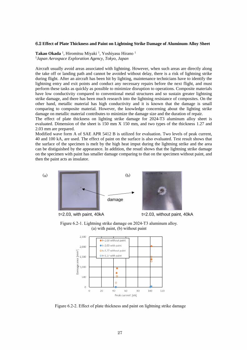
6.2 Effect of Plate Thickness and Paint on Lightning Strike Damage of Aluminum Alloy Sheet
Takao Okada 1, Hiromitsu Miyaki 1, Yoshiyasu Hirano 1 1Japan Aerospace Exploration Agency, Tokyo, Japan
Aircraft usually avoid areas associated with lightning. However, when such areas are directly along
the take off or landing path and cannot be avoided without delay, there is a risk of lightning strike
during flight. After an aircraft has been hit by lighting, maintenance technicians have to identify the
lightning entry and exit points and conduct any necessary repairs before the next flight, and must
perform these tasks as quickly as possible to minimize disruption to operations. Composite materials
have low conductivity compared to conventional metal structures and so sustain greater lightning
strike damage, and there has been much research into the lightning resistance of composites. On the
other hand, metallic material has high conductivity and it is known that the damage is small
comparing to composite material. However, the knowledge concerning about the lighting strike
damage on metallic material contributes to minimize the damage size and the duration of repair.
The effect of plate thickness on lighting strike damage for 2024-T3 aluminum alloy sheet is
evaluated. Dimension of the sheet is 150 mm X 150 mm, and two types of the thickness 1.27 and
2.03 mm are prepared.
Modified wave form A of SAE APR 5412 B is utilized for evaluation. Two levels of peak current,
40 and 100 kA, are used. The effect of paint on the surface is also evaluated. Test result shows that
the surface of the specimen is melt by the high heat imput during the lightning strike and the area
can be distiguished by the appearance. In addition, the resutl shows that the lightning strike damage
on the specimen with paint has smaller damage comparing to that on the specimen without paint, and
then the paint acts as insulator.
Figure 6.2-1. Lightning strike damage on 2024-T3 aluminum alloy.
(a) with paint, (b) without paint
t=2.03, with paint, 40kA
damage
t=2.03, without paint, 40kA
(a) (b)
Figure 6.2-2. Effect of plate thickness and paint on lightning strike damage

28
ACKNOWLEDGEMENTS
The editors appreciated the members of the ICAF national committee of Japan Society
for Aeronautical and Space Sciences and other participants in the committee, for their
contribution in preparation of this national review and contributing discussion in the
committee.
Copyright © 2022 FDOKUMEN