Aerodynamic Enhancement Of Formula Sae Car Using Split ...
6
INTERNATIONAL JOURNAL OF SCIENTIFIC & TECHNOLOGY RESEARCH VOLUME 8, ISSUE 11, NOVEMBER 2019 ISSN 2277-8616 694 IJSTR©2019 www.ijstr.org Aerodynamic Enhancement Of Formula Sae Car Using Split Rear Wings Seralathan S, Baji Babavali S K, Guru Venkat I, Hariram V, Micha Premkumar T Abstract :Formula SAE car with single type wing on the front and the rear wing generates downforce and high drag. Aerodynamic loads acting on high speed Formula SAE car play an important role on its dynamic behavior which results with decreased fuel efficiency and a lesser downforce. In order to improve the aerodynamics Formula SAE car, split type rear wings are used to which produce a lesser drag and more downforce comparatively with respect to single type rear wing. Therefore, the focus of this study is to simulate Formula SAE car with split rear wings to improve its aerodynamic behavior. Simulations are carried out using STAR CCM + . The numerical results obtained showed that split rear wings reduced the drag by 12% and increased the downforce by 38%. This would benefit the car to increase its cornering speed and improve the overall fuel efficiency. Index Terms : Formula SAE car, split wing, aerodynamics, downforce, CFD —————————— —————————— 1. INTRODUCTION Formula One is the motorsports event currently referred to as FIA Formula One World Championship. Ever increasing competition, changes in regulation and need to cut cost by reduced track testing together necessitate the dependence on computer simulations for various aspects of performance enhancement. Aerodynamics play a prominent role to success in Formula One motorsport and huge amount of funds are spent annually on the research and development. The aerodynamic design involves two primary concerns. Firstly, creating negative lift or downforce to facilitate to push the car‟s tyre onto the road and enhance the cornering force. It is known that downforce is the load that pushes upper body structure of car to make added grip on the ground thereby decreasing the slip between the ground and wheels. Secondly, minimizing the drag caused by turbulence which act to slow down the car. Formula SAE contest involves undergraduate students whom are likely to design and build high performance Formula SAE car. Again, aerodynamic factor is very crucial and the important parameters involved in the aerodynamics are lift, downforce, drag force and coefficient of drag as shown in Fig. 1. Higher downforce lead to an improved aerodynamic performance of Formula SAE car. Lift is a load that lifts the car up as air flow from in front of the car at high speeds. Generally, the lift for a Formula SAE car occur from underneath of the car which lifts the vehicle and cause slip between ground and wheels (refer Fig, 1). Further, this affects the aerodynamic performance of the car. Drag force is a load that acts in the direction opposite to car velocity and reduces the car velocity (refer Fig. 1). In order to achieve high performance, Formula SAE car is loaded with aerodynamic components like diffuser, rear wing and front wing. These will decrease the drag force and lift. But, lift and drag force are relative to each other. Therefore, an optimum design is required to derive the best of the lift and drag force. Rear wing helps to achieve good handling in fast corners besides good acceleration. A typical rear wing is shown in Fig. 2. But, rear wing of the car creates the most drag and it contributes nearly a third of the car‟s total downforce. As flow happens over the rear wing, its profile disturbs the flow causing drag force. Even though drag force is typically less than downforce, it impairs the top speed limit and cause vehicle to utilize more fuel to get the car through the air. Based on the literature review, it is understood that rear wing is designed in a way to enhance the motoring performance and to improve stability during cornering by generating large downforce. Recently, to assist in the development of aerodynamically enabled Formula SAE car, almost all teams use some CFD software packages. Aerodynamic study involving Formula SAE car was numerically investigated by Sneh Hetawal et al. [1] to minimize the drag and improve the stability of SAE car by using wings or spoilers. Similar work was also carried out by Vivek Muralidharan et al. [2] by optimizing the design of rear and front wings and reported an improved performance. Lee Wen Yew et al. [3] analyzed the effects of aerodynamic package comprising two element front wing, single element front wing, and diffuser model, on improving the performance of Taylor‟s Formula SAE Car using k-ε realizable turbulence model. Both, the diffuser and front wing and configurations produced higher lift to drag ratio, and higher down force proving the efficacy of the aerodynamic design modifications in improving the race car performance. Earlier, aerodynamic optimization of the Zakspeed Formula One racing car involving the rear end, centre part, and front end of the car body was investigated by Gerhardt and Kramer [4]. Similar study was also performed by Mohammad Arief Dharmawan et al. [5]. Several studies were performed by researchers involving multi-element wing [6], and three stage rear wing [7] with the intention of improving the aerodynamic performance. Based on the literature review [1-13], it is understood that rear wings enhance the motoring performance and improve stability during cornering by generating large downforce. Therefore, the focus of this study is to simulate a Formula SAE car with split wings to improve its aerodynamic behavior. Simulations are carried out using ——————————————— Seralathan S, Associate Professor, Department of Mechanical Engineering, Hindustan Institute of Technology and Science, Chennai 603 103, India. E- mail: [email protected] Baji Babavali S K, Department of Mechanical Engineering,Hindustan Institute of Technology and Science, Chennai, India. Guru Venkat I, Department of Mechanical Engineering, Hindustan Institute of Technology and Science, Chennai, India. Hariram V, Professor, Department of Mechanical Engineering , Hindustan Institute of Technology and Science, Chennai, India. Micha Premkumar T, Associate Professor, Department of Mechanical Engineering , Hindustan Institute of Technology and Science, India
-
Upload
khangminh22 -
Category
Documents
-
view
0 -
download
0
Transcript of Aerodynamic Enhancement Of Formula Sae Car Using Split ...
INTERNATIONAL JOURNAL OF SCIENTIFIC & TECHNOLOGY RESEARCH VOLUME 8, ISSUE 11, NOVEMBER 2019 ISSN 2277-8616
694 IJSTR©2019 www.ijstr.org
Aerodynamic Enhancement Of Formula Sae Car Using Split Rear Wings
Seralathan S, Baji Babavali S K, Guru Venkat I, Hariram V, Micha Premkumar T
Abstract :Formula SAE car with single type wing on the front and the rear wing generates downforce and high drag. Aerodynamic loads acting on high speed Formula SAE car play an important role on its dynamic behavior which results with decreased fuel efficiency and a lesser downforce. In order to improve the aerodynamics Formula SAE car, split type rear wings are used to which produce a lesser drag and more downforce comparatively with respect to single type rear wing. Therefore, the focus of this study is to simulate Formula SAE car with split rear wings to improve its aerodynamic behavior. Simulations are carried out using STAR CCM
+. The numerical results obtained showed that split rear wings reduced the drag by 12% and
increased the downforce by 38%. This would benefit the car to increase its cornering speed and improve the overall fuel efficiency. Index Terms : Formula SAE car, split wing, aerodynamics, downforce, CFD
—————————— ——————————
1. INTRODUCTION Formula One is the motorsports event currently referred to as FIA Formula One World Championship. Ever increasing competition, changes in regulation and need to cut cost by reduced track testing together necessitate the dependence on computer simulations for various aspects of performance enhancement. Aerodynamics play a prominent role to success in Formula One motorsport and huge amount of funds are spent annually on the research and development. The aerodynamic design involves two primary concerns. Firstly, creating negative lift or downforce to facilitate to push the car‟s tyre onto the road and enhance the cornering force. It is known that downforce is the load that pushes upper body structure of car to make added grip on the ground thereby
decreasing the slip between the ground and wheels. Secondly, minimizing the drag caused by turbulence which act to slow down the car. Formula SAE contest involves undergraduate students whom are likely to design and build high performance Formula SAE car. Again, aerodynamic factor is very crucial and the important parameters involved in the aerodynamics are lift, downforce, drag force and coefficient of drag as shown in Fig. 1. Higher downforce lead to an improved aerodynamic performance of Formula SAE car. Lift is a load that lifts the car up as air flow from in front of the car at high speeds. Generally, the lift for a Formula SAE car occur from underneath of the car which lifts the vehicle and cause slip
between ground and wheels (refer Fig, 1). Further, this affects the aerodynamic performance of the car. Drag force is a load that acts in the direction opposite to car velocity and reduces the car velocity (refer Fig. 1). In order to achieve high performance, Formula SAE car is loaded with aerodynamic components like diffuser, rear wing and front wing. These will decrease the drag force and lift. But, lift and drag force are relative to each other. Therefore, an optimum design is required to derive the best of the lift and drag force. Rear wing helps to achieve good handling in fast corners besides good acceleration. A typical rear wing is shown in Fig. 2. But, rear wing of the car creates the most drag and it contributes nearly a third of the car‟s total downforce. As flow happens over the rear wing, its profile disturbs the flow causing drag force. Even though drag force is typically less than downforce, it impairs the top speed limit and cause vehicle to utilize more fuel to get the car through the air. Based on the literature review, it is understood that rear wing is designed in a way to enhance the
motoring performance and to improve stability during cornering by generating large downforce. Recently, to assist in the development of aerodynamically enabled Formula SAE car, almost all teams use some CFD software packages. Aerodynamic study involving Formula SAE car was numerically investigated by Sneh Hetawal et al. [1] to minimize the drag and improve the stability of SAE car by using wings or spoilers. Similar work was also carried out by Vivek Muralidharan et al. [2] by optimizing the design of rear and front wings and reported an improved performance. Lee Wen Yew et al. [3] analyzed the effects of aerodynamic package comprising two element front wing, single element front wing, and diffuser model, on improving the performance of Taylor‟s Formula SAE Car using k-ε realizable turbulence model. Both, the diffuser and front wing and configurations produced higher lift to drag ratio, and higher down force proving the efficacy of the aerodynamic design modifications in improving the race car performance. Earlier, aerodynamic optimization of the Zakspeed Formula One racing car involving the rear end, centre part, and front end of the car body was investigated by Gerhardt and Kramer [4]. Similar study was also performed by Mohammad Arief Dharmawan et al. [5]. Several studies were performed by researchers involving multi-element wing [6], and three stage rear wing [7] with the intention of improving the aerodynamic performance. Based on the literature review [1-13], it is understood that rear wings enhance the motoring performance and improve stability during cornering by generating large downforce. Therefore, the focus of this study is to simulate a Formula SAE car with split wings to improve its aerodynamic behavior. Simulations are carried out using
———————————————
Seralathan S, Associate Professor, Department of Mechanical Engineering, Hindustan Institute of Technology and Science, Chennai 603 103, India. E- mail: [email protected]
Baji Babavali S K, Department of Mechanical Engineering,Hindustan Institute of Technology and Science, Chennai, India.
Guru Venkat I, Department of Mechanical Engineering, Hindustan Institute of Technology and Science, Chennai, India.
Hariram V, Professor, Department of Mechanical Engineering , Hindustan Institute of Technology and Science, Chennai, India.
Micha Premkumar T, Associate Professor, Department of Mechanical Engineering , Hindustan Institute of Technology and Science, India

INTERNATIONAL JOURNAL OF SCIENTIFIC & TECHNOLOGY RESEARCH VOLUME 8, ISSUE 11, NOVEMBER 2019 ISSN 2277-8616
695 IJSTR©2019 www.ijstr.org
STAR CCM+ and the comparison is made with a model having
single type wing.
Fig 1. Aerodynamics parameters
Fig 2. Typical split rear wing
2 NUMERICAL METHODOLOGY Rear wing in Formula SAE car comprises a transverse board shaped like an aero plane wing turned upside down with wing end plates fixed to its end as shown in Fig. 3. As can be seen in Fig. 3, the rear wing is fixed on the rear part of Formula SAE car generates downforce to keep the moving car against the ground thereby the grip force of the rear tyres enhances. This results in improvement of cornering performance, stability at high speeds and acceleration performance. On the other hand, corresponding to square of speed, drag occurs in direction opposite to Formula SAE car‟s running direction. However, by optimizing the shape of rear wing, it is possible to achieve both reduced drag and improved downforce in Formula SAE car. The Formula SAE car model, as shown in Fig. 3, is made according to the FIA 2009 rules and regulations using Solidworks
®. The software used for CFD
simulations of all models is Star CCM+. After ensuing design
changes in the rear wing, the model is imported into Star CCM
+ as IGES file. These importing processes generate
automatically the surfaces or regions on the car model. The Formula SAE car model is kept in rectangular block (i.e., computational domain) that sectioned the car into half, making a plane of symmetry. As the Formula SAE car profile is symmetrical, only the forces acting on half of the car is to be studied. All dimension described in the computational domain as illustrated in Fig. 4 are expressed as a function of length of car (L). The inlet boundary of computational domain is placed two car lengths (i.e., 2L) ahead from nose of the car and outlet boundary is kept at five car lengths (5L) from back of the car to
capture flow physics. About 2.5L each is maintained at lateral side from the symmetry plane. Also, 2L is maintained in the upper side from ground level. These details of the computational domain are illustrated in Fig. 4. The volume mesh in the computational domain is made with polyhedral cells. Star CCM
+ suggest users in deploying polyhedral cells to
ensure a balanced solutions involving multipart mesh generation. The volume mesh also includes prism boundary layers near the wall regions as these layers are necessary to accurately capture the flow physics around boundaries of the Formula SAE car. Figure 5 shows the closer view of mesh generated. As can be seen in Fig. 5, four prism layers are generated in the near wall regions. Non dimensional distance, i.e., y
+ less than 200 is maintained as it is good enough for the
simulation using automatic wall treatment [14-19]. Hence, the polyhedral mesh in tandem with prism layers generated, create a well refined volume mesh that accurately simulate to calculate the aerodynamic forces acting on Formula SAE car. Figure 6 shows the closer view of the split rear wing. Grid independent test is carried out to ensure that results are not mesh dependent. Table 1 lists the outcome of the grid independence test. It can be seen that the drag force at 1.7 million is deviating from the values obtained with 2.1 million cells. However, the deviation between these values is very less (≤ 1%). Therefore, 1.7 million cells are considered for further analysis for Formula SAE car. The continuity equation is expressed as
( ) ... (1)
The momentum equation is expressed as
( )
( )
(
)
... (2)
where
(
)
...
(3)
(
)
... (4)
TABLE 1 GRID INDEPENDENCE TEST
No of Cells (millions)`
Drag force (N) Deviation (%)
1.7 1095 ---
2.1 1084 1
2.4 1081 1.28
2.8 1079 1.46

INTERNATIONAL JOURNAL OF SCIENTIFIC & TECHNOLOGY RESEARCH VOLUME 8, ISSUE 11, NOVEMBER 2019 ISSN 2277-8616
696 IJSTR©2019 www.ijstr.org
Fig 3. Formula SAE car model
Fig 4. Computational domain
Fig 5. Closer view of mesh
Fig 6. Rear wings with split wings
3D steady state numerical investigations are carried out and the flow is considered as turbulent flow. k-ω turbulence model, a two equations based model is deployed to achieve closure for the Reynolds Averaged Navier Stokes (RANS) equations which is used to model the turbulent flow. Air is the fluid chosen to simulate the track conditions. The density of air is 1.18 kg/m
3. The initial velocity is set as 250 kmph (i.e., 69.4
m/s) and assigned to be uniform. Initial pressure is set to 0 Pascal as the reference pressure is kept as 101325 Pascal. The static temperature is 27
oC. The details of boundary
conditions enforced in this study are listed in Table 2. The boundary conditions are assigned at outlet, inlet, symmetry and wall regions so as to simulate real time condition to closer as possible. The surface of Formula SAE car is imposed with wall and no-slip condition and rest is assumed as fluid walls with slip condition under free stream velocity. The simulation is initially carried out under first order upwind scheme with
relaxation factor 0.10 for pressure and 0.30 for velocity. This is done to avoid divergence of the solution. Subsequently, after 150 iterations, second order upwind scheme is evoked with relaxation factor 0.50 for velocity and for pressure it is kept 0.30. This procedure is adopted to accelerate convergence and ensure high accuracy. This procedure is carried out for all simulations till the convergence criteria which is set as 10
-4 is
met.

INTERNATIONAL JOURNAL OF SCIENTIFIC & TECHNOLOGY RESEARCH VOLUME 8, ISSUE 11, NOVEMBER 2019 ISSN 2277-8616
697 IJSTR©2019 www.ijstr.org
Fig 7. Pressure contours of Car ‘A’
Fig 8. Pressure contours of Car ‘B’
Fig 9. Stagnation pressure contours for Car ‘A’
Fig 10. Stagnation pressure contours for Car ‘B’
Fig 11. Velocity contours of Car ‘B’
TABLE 2
BOUNDARY CONDITION Type of flow 3D steady state flow
Turbulence model k-ω
Turbulence intensity 1%
Wall treatment Automatic wall treatment
Wall No-slip i.e., on surface of car
Fluid Air
Dynamic viscosity 1.84e-5
Pa s
Density 1.18 kg/m3
Specific heat 1003.62 J/kgK
Thermal conductivity 0.026 W/mK
Turbulence Prandtl number 0.90
Minimum wall distance 1e-5
m
Minimum temperature 0oC
Maximum temperature 100oC
Reference pressure 101325 Pa
Convergence criteria `1e-4
3 RESULTS AND DISCUSSION The simulations are carried out under steady state condition at a velocity 250 kmph (i.e., 69.4 m/s) for both Car „A‟ and Car „B‟. Car „A‟ denotes Formula SAE car with non-split i.e., single
INTERNATIONAL JOURNAL OF SCIENTIFIC & TECHNOLOGY RESEARCH VOLUME 8, ISSUE 11, NOVEMBER 2019 ISSN 2277-8616
698 IJSTR©2019 www.ijstr.org
rear wing. Car „B‟ denotes Formula SAE car with split rear wings. Identical conditions are maintained for both these cases and the results obtained are interpreted below .As can be seen in Figs. 7 and 8, a high pressure region is generated on top of the wings which cause the negative lift or downforce. The maximum value of downforce exerted on the wing for Car „A‟ is observed to be 2890 N/m
2. Similarly, for Car „B‟ with Split
rear wings, the maximum value of downforce on the wing is 5277.9 N/m
2. Therefore, on comparing the pressure exerted
on the wings in Car „A‟ and Car „B‟, as can be seen in Figs. 7 and 8 respectively, the downforce generated by the split rear wing as seen in Fig. 8 is more than the normal single rear wing. Figures 9 and 10 show the distributions of stagnation pressure for Car „A‟ and Car „B‟ respectively. The total pressure beneath the wings is low as compared to the upper surface of the wings. Due to high pressure above the wings, the downforce is generated. On comparing Figs. 9 and 10, it is understood that maximum total pressure is exerted on the wings and the lowest static pressure is observed below the wings as well as at the intake main fold in both the models. The flow on and below the wings is observed to be more turbulent resulting in causing more drag in Car „A‟ model. But, in the Car „B‟, the flow is visualized to be comparatively less turbulent resulting in relatively low drag (refer Table 3 which is discussed later). With the rear split wing, the static pressure generated is more and negative pressure also dropped from 2970 N/m
2 to 8660 N/m
2 beneath the wing and pressure on
the wing from 2996 N/m2 to 6400 N/m
2 resulting in generating
a high downforce. Figure 11 shows the velocity magnitude regions of Car „B‟. High velocity region are observed beneath the wings, which mean high velocity causes a low pressure region resulting in generating more downforce.
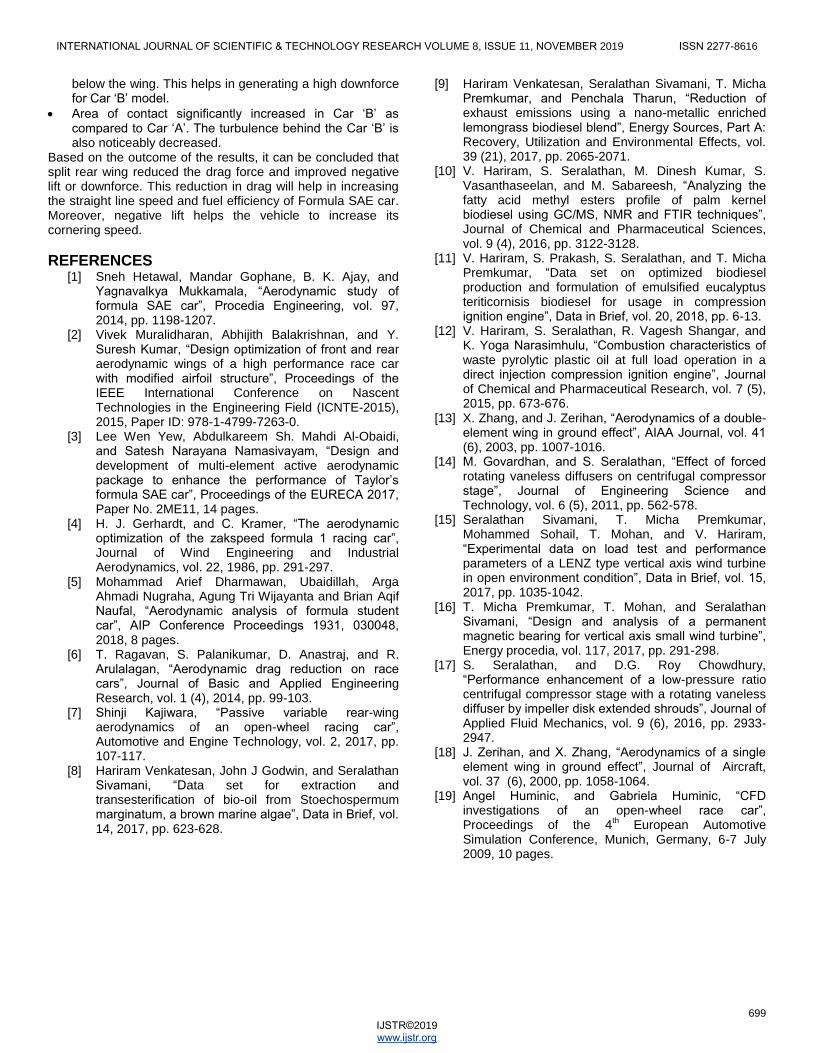
Fig 12. Velocity Vector Car ‘A’
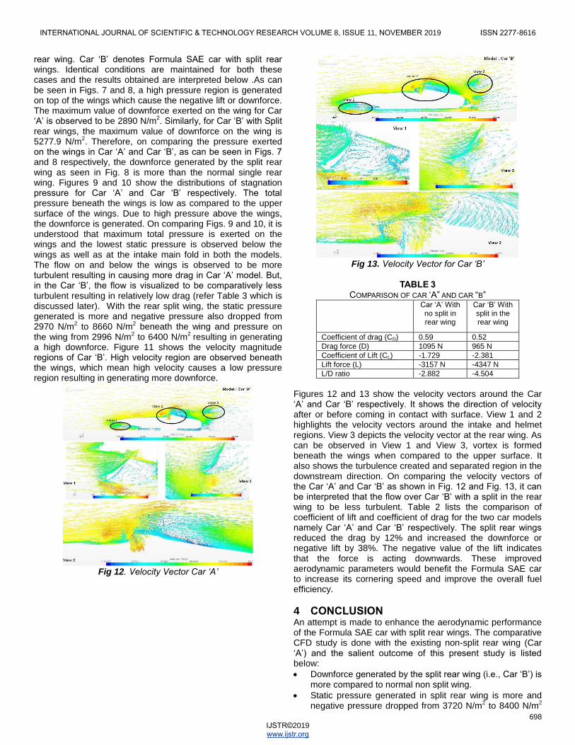
Fig 13. Velocity Vector for Car ‘B’
TABLE 3
COMPARISON OF CAR „A” AND CAR “B” Car „A‟ With
no split in rear wing
Car „B‟ With split in the rear wing
Coefficient of drag (CD) 0.59 0.52
Drag force (D) 1095 N 965 N
Coefficient of Lift (CL) -1.729 -2.381
Lift force (L) -3157 N -4347 N
L/D ratio -2.882 -4.504
Figures 12 and 13 show the velocity vectors around the Car „A‟ and Car „B‟ respectively. It shows the direction of velocity after or before coming in contact with surface. View 1 and 2 highlights the velocity vectors around the intake and helmet regions. View 3 depicts the velocity vector at the rear wing. As can be observed in View 1 and View 3, vortex is formed beneath the wings when compared to the upper surface. It also shows the turbulence created and separated region in the downstream direction. On comparing the velocity vectors of the Car „A‟ and Car „B‟ as shown in Fig. 12 and Fig. 13, it can be interpreted that the flow over Car „B‟ with a split in the rear wing to be less turbulent. Table 2 lists the comparison of coefficient of lift and coefficient of drag for the two car models namely Car „A‟ and Car „B‟ respectively. The split rear wings reduced the drag by 12% and increased the downforce or negative lift by 38%. The negative value of the lift indicates that the force is acting downwards. These improved aerodynamic parameters would benefit the Formula SAE car to increase its cornering speed and improve the overall fuel efficiency.
4 CONCLUSION An attempt is made to enhance the aerodynamic performance of the Formula SAE car with split rear wings. The comparative CFD study is done with the existing non-split rear wing (Car „A‟) and the salient outcome of this present study is listed below:
Downforce generated by the split rear wing (i.e., Car „B‟) is more compared to normal non split wing.
Static pressure generated in split rear wing is more and negative pressure dropped from 3720 N/m
2 to 8400 N/m
2
INTERNATIONAL JOURNAL OF SCIENTIFIC & TECHNOLOGY RESEARCH VOLUME 8, ISSUE 11, NOVEMBER 2019 ISSN 2277-8616
699 IJSTR©2019 www.ijstr.org
below the wing. This helps in generating a high downforce for Car „B‟ model.
Area of contact significantly increased in Car „B‟ as compared to Car „A‟. The turbulence behind the Car „B‟ is also noticeably decreased.
Based on the outcome of the results, it can be concluded that split rear wing reduced the drag force and improved negative lift or downforce. This reduction in drag will help in increasing the straight line speed and fuel efficiency of Formula SAE car. Moreover, negative lift helps the vehicle to increase its cornering speed.
REFERENCES [1] Sneh Hetawal, Mandar Gophane, B. K. Ajay, and
Yagnavalkya Mukkamala, “Aerodynamic study of formula SAE car”, Procedia Engineering, vol. 97, 2014, pp. 1198-1207.
[2] Vivek Muralidharan, Abhijith Balakrishnan, and Y. Suresh Kumar, “Design optimization of front and rear aerodynamic wings of a high performance race car with modified airfoil structure”, Proceedings of the IEEE International Conference on Nascent Technologies in the Engineering Field (ICNTE-2015), 2015, Paper ID: 978-1-4799-7263-0.
[3] Lee Wen Yew, Abdulkareem Sh. Mahdi Al-Obaidi, and Satesh Narayana Namasivayam, “Design and development of multi-element active aerodynamic package to enhance the performance of Taylor‟s formula SAE car”, Proceedings of the EURECA 2017, Paper No. 2ME11, 14 pages.
[4] H. J. Gerhardt, and C. Kramer, “The aerodynamic optimization of the zakspeed formula 1 racing car”, Journal of Wind Engineering and Industrial Aerodynamics, vol. 22, 1986, pp. 291-297.
[5] Mohammad Arief Dharmawan, Ubaidillah, Arga Ahmadi Nugraha, Agung Tri Wijayanta and Brian Aqif Naufal, “Aerodynamic analysis of formula student car”, AIP Conference Proceedings 1931, 030048, 2018, 8 pages.
[6] T. Ragavan, S. Palanikumar, D. Anastraj, and R. Arulalagan, “Aerodynamic drag reduction on race cars”, Journal of Basic and Applied Engineering Research, vol. 1 (4), 2014, pp. 99-103.
[7] Shinji Kajiwara, “Passive variable rear-wing aerodynamics of an open-wheel racing car”, Automotive and Engine Technology, vol. 2, 2017, pp. 107-117.
[8] Hariram Venkatesan, John J Godwin, and Seralathan Sivamani, “Data set for extraction and transesterification of bio-oil from Stoechospermum marginatum, a brown marine algae”, Data in Brief, vol. 14, 2017, pp. 623-628.
[9] Hariram Venkatesan, Seralathan Sivamani, T. Micha Premkumar, and Penchala Tharun, “Reduction of exhaust emissions using a nano-metallic enriched lemongrass biodiesel blend”, Energy Sources, Part A: Recovery, Utilization and Environmental Effects, vol. 39 (21), 2017, pp. 2065-2071.
[10] V. Hariram, S. Seralathan, M. Dinesh Kumar, S. Vasanthaseelan, and M. Sabareesh, “Analyzing the fatty acid methyl esters profile of palm kernel biodiesel using GC/MS, NMR and FTIR techniques”, Journal of Chemical and Pharmaceutical Sciences, vol. 9 (4), 2016, pp. 3122-3128.
[11] V. Hariram, S. Prakash, S. Seralathan, and T. Micha Premkumar, “Data set on optimized biodiesel production and formulation of emulsified eucalyptus teriticornisis biodiesel for usage in compression ignition engine”, Data in Brief, vol. 20, 2018, pp. 6-13.
[12] V. Hariram, S. Seralathan, R. Vagesh Shangar, and K. Yoga Narasimhulu, “Combustion characteristics of waste pyrolytic plastic oil at full load operation in a direct injection compression ignition engine”, Journal of Chemical and Pharmaceutical Research, vol. 7 (5), 2015, pp. 673-676.
[13] X. Zhang, and J. Zerihan, “Aerodynamics of a double-element wing in ground effect”, AIAA Journal, vol. 41 (6), 2003, pp. 1007-1016.
[14] M. Govardhan, and S. Seralathan, “Effect of forced rotating vaneless diffusers on centrifugal compressor stage”, Journal of Engineering Science and Technology, vol. 6 (5), 2011, pp. 562-578.
[15] Seralathan Sivamani, T. Micha Premkumar, Mohammed Sohail, T. Mohan, and V. Hariram, “Experimental data on load test and performance parameters of a LENZ type vertical axis wind turbine in open environment condition”, Data in Brief, vol. 15, 2017, pp. 1035-1042.
[16] T. Micha Premkumar, T. Mohan, and Seralathan Sivamani, “Design and analysis of a permanent magnetic bearing for vertical axis small wind turbine”, Energy procedia, vol. 117, 2017, pp. 291-298.
[17] S. Seralathan, and D.G. Roy Chowdhury, “Performance enhancement of a low-pressure ratio centrifugal compressor stage with a rotating vaneless diffuser by impeller disk extended shrouds”, Journal of Applied Fluid Mechanics, vol. 9 (6), 2016, pp. 2933-2947.
[18] J. Zerihan, and X. Zhang, “Aerodynamics of a single element wing in ground effect”, Journal of Aircraft, vol. 37 (6), 2000, pp. 1058-1064.
[19] Angel Huminic, and Gabriela Huminic, “CFD investigations of an open-wheel race car”, Proceedings of the 4
th European Automotive
Simulation Conference, Munich, Germany, 6-7 July 2009, 10 pages.