Aerodynamic Characteristics of a 1/24-Scale F-111 Aircraft ...
133
I i • i - ." i M ,1 I • ,, , " ' AEBO-TII-iS-N AFATL-TII-7$-§§ ARCHIVE COPY DO NOT LOAN AEIIOi)YNAMIO OIIAIIAOTEIlISTIOS OF A 1/24-SOALE F-111 AIIIOIIAFT WITH VARIOUS EXTERNAL STORESAT IIAm NUMBERS FROM 0.6 TO 1.3 C. F. Ande'rson ARO, Inc., a Sverdrup Corporation Company PROPULSION WIND TUNNEL FACILITY ARNOLD ENGINEERrNG ~DEVE1.OPMENT CENTER AIR FORCE SYSTEMS COMMAND ARNOLD AIR FORCE STATION, TENNESSEE 37389 July 1978 Final Report for Period 23 December 1977 - 9 January .1978 I i I Approved for public release; distribution unlimited. I Prepared for PrOperly ef L; S Air • r. ,, " Force ~,.D,., L~R4~y FJo~bO- "/ /.O,.~jO~ ,3 AIR FORCE ARMAMENT LABORATORY/DLJCA EGLIN AIR FORCE BASE, FLORIDA 82542
-
Upload
khangminh22 -
Category
Documents
-
view
2 -
download
0
Transcript of Aerodynamic Characteristics of a 1/24-Scale F-111 Aircraft ...
I
i
• i
- . " i
M
,1 I
• ,, , " '
AEBO-TII-iS-N AFATL-TII-7$-§§
ARCHIVE COPY DO NOT LOAN
AEIIOi)YNAMIO OIIAIIAOTEIlISTIOS OF A 1/24-SOALE F-111 AIIIOIIAFT WITH VARIOUS EXTERNAL
STORES AT IIAm NUMBERS FROM 0.6 TO 1.3
C. F. Ande'rson ARO, Inc., a Sverdrup Corporation Company
PROPULSION WIND TUNNEL FACILITY ARNOLD ENGINEERrNG ~DEVE1.OPMENT CENTER
AIR FORCE SYSTEMS COMMAND ARNOLD AIR FORCE STATION, TENNESSEE 37389
July 1978
Final Report for Period 23 December 1977 - 9 January .1978 I
i
I Approved for public release; distribution unlimited. I
Prepared for
PrOperly ef L; S Air • r . , , " Force ~,.D,., L~R4~y
FJ o~bO- "/ /.O,.~jO~ ,3
AIR FORCE ARMAMENT LABORATORY/DLJCA EGLIN AIR FORCE BASE, FLORIDA 82542
NOTICES
When U. S. Government drawings, specifications, or other data are used for any purpose other than a definitely related Government procurement operation, the Government thereby incurs no responsibility nor any obligation whatsoever, and the fact that the Government may have formulated, furnished, or in any way supplied the said drawings, specifications, or other data, is not to be regarded by implication or otherwise, or in any manner licensing the holder or any other person or corporation, or conveying any fights or permission to manufacture, use, or sell any patented invention that may in any way be related thereto,
Qualified users may obtain copies of this report from the Defense Documentation Center.
References to named commerical products in this report are not to be considered in any sense as an indorsement of the product by the United States Air Force or the Government.
This report has been reviewed by the Information Office (Of) and is releasable to the National Technical Information Service (NTIS). At .NTIS, it will be available to the general public, including foreign nations.
APPROVAL STATEMENT
This report has been reviewed and approved.
Project Manager, Research Division Directorate of Test Engineering
Approved for publication:
FOR THE COMMANDER
Director of Test Operatio CHAUNCEY D. SMITH, Jn R, Lt Colonel, ~/SAF
Deputy for Operations

UNCLASSIFIED R E P O R T D O C U M E N T A T I O N P A G E
, REPORT NUMBER AEDC-TR-78-35 "!2 GOVT ACCESS,ON NO.
AFATL-TR-78- 55 1 4 T I T L E ( ~ d Subrmete)
AERODYNAMIC CHARACTERISTICS OF A 1 / 2 4 - SCALE F - i l l AIRCRAFT WITH VARIOUS EXTERNAL STORES AT MACH NUMBERS FROM 0 . 5 TO 1 . 3
? AU T H O R f s )
C. F. Anderson, ARO, Inc.
9 P E R F O R M I N G O R G A N I Z A T I O N N A M E A N D ADDRESS
A r n o l d E n g i n e e r i n g Deve lopment C e n t e r Air Force Systems Command Arnold Air Force Station, TN 37389
11 C O N T R O L L I N G O F F I C E N A M E A N D A D D R E S S
A i r Fo rce Armament Laboratory/DLJCA E g l i n A i r F o r c e B a s e , F l o r i d a 32542
t4 M O N I T O R I q G A G E N C Y N A M E 8 ADDRESS.* I ! d l f fe ren f fJ'om Conr ro | i i n l l O f f i c e )
READ [NSTRUCTZONS BEFORE COMPLETING FORM
't R E C I P I E N T ' S C A T A L O G N U M B E R
S TYPE OF REPORT 6 PERIOD COVERED F i n a l R e p o r t , 23 Dec 1977 - 9 J a n 1978
6 P E R F O R M I N G ORG. R E P O R T N U M B E R
0. C O N T R A C T OR G R A N T N U M B E R f s )
10. P R O G R A M E L E M E N T . P R O J E C T . T A S K A R E A & WORK U N I T N U M B E R S
P r o g r a m E l e m e n t 65807F S y s t e m 06ZA, T a s k 01
12. R E P O R T D A T E
J u l y 1978 13 N U M B E R OF P A G E S
129 IS S E C U R I T Y CLASS. (o f ~h#a repor t )
UNCLASSIFIED
ISe D E C L ASSI F IC A T I O N ' D O W N G R A D I N G SC.EDULE N/A
16 D I S T R I B U T I O N S T A T E M E N T (o f t h i l RepotJ)
A p p r o v e d f o r p u b l i c r e l e a s e ; d i s t r i b u t i o n u n l i m i t e d .
17 D I S T R I B U T I O N S T A T E M E N T (e l the ebmtrect entered in Brock 30, I t d i l l e ten l Item Report )
18 S U P P L E M E N T A R Y N O T E S
A v a i l a b l e i n DDC.
19 K E Y WORDS "Cont inue ~ reve rse a;de i f n e c e ~ J a ~ ~ d I d e n r t ~ by block number)
F - 1 Z 1 a i r c r a f t e x t e r n a l s t o r e s a e r o d y n a m i c c h a r a c t e r i s t i c s w i n d t u n n e l t e s t s t r a n s o n i c f l o w
20 A B S T R A C T "ConJtnue ~ r eve rse sJde t f necesnRty end | den t l f y by b lock numbe~
T h i s r e p o r t p r e s e n t s a n d d i s c u s s e s t h e r e s u l t s o f t r a n s o n i c w i n d t u n n e l t e s t s c o n d u c t e d t o e v a l u a t e t h e e f f e c t s o f e x t e r n a l s t o r e s on t h e a e r o d y n a m i c c h a r a c t e r i s t i c s o f t h e F - 1 1 1 a i r c r a f t a t w i n g sweep a n g l e s o f 26 , 45 , a n d 54 d e g . The a n a l y s i s i n c l u d e s e v a l u a t i o n o f t h e i n c r e m e n t a l c h a n g e s i n t h e d r a g , s t a t i c m a r g i n , a n d l a t e r a l - d i r e c t i o n a l d e r i v a t i v e s a s s o c i a t e d w i t h t h e v a r i o u s s t o r e c o n f i g u r a t i o n s . Wind t u n n e l c o e f f i c i e n t d a t a f o r a c l e a n
D D FORM ' JAN ?, 1 4 7 3 ED,T,ON OF ' NOV SS ,S OBSOLETE
UNCLASSIFIED
UNCLASSIFIED
20. ABSTRACT ( C o n t i n u e d )
b a s e l i n e c o n f i g u r a t i o n a r e a l s o p r e s e n t e d . Da ta a r e p r e s e n t e d w i t h p y l o n s a l o n e , GBU-Z0, GBU-15CCW, GBU-15CCW w i t h e x t e n d e d Pave Tack pod , AGM-65, R o c k e y e , SUU-30H/B, and ~K-82SE s t o r e s . Da ta a r e p r e s e n t e d f o r Mach numbers r a n g i n g f rom 0 . 5 t o 1 . 3 a t a n g l e s o f a t t a c k f rom -2 t o 16 deg a t z e r o s i d e s l i p a n g l e , and f o r s i d e s l i p a n g l e s f r o m -10 t o 10 deg a t a n g l e s o f a t t a c k o f 5, 10, and 15 deg .
AF|C Arnold AFS Tenn
UNCLASSIFIED

AEDC-TR-78-35
PREFACE
The work reported herein was conducted by the Arnold Engineering Development Center (AEDC), Air Force Systems Command (AFSC), at the request of the Air Force Armament Laboratory (AFATL/DLJCA) under Program Element 65807F. The Armament
Development and Test Center (ADTC) project monitor was Lt. Thomas Speer. The results of the test were obtained by ARO, Inc., AEDC Division (a Sverdrup Corporation Company), operating contractor for the AEDC, AFSC, Arnold Air Force Station, Tennessee, under ARO Project Number P41C-O4A. Data reduction was completed on February 3, 1978,
and the manuscript was submitted for publication on May 16, 1978.

A EDC-TR-78-35
CONTENTS
Page
1.0 INTRODUCTION ................................ 5
2.0 APPARATUS ................................... 5
2.1 Test Facility and Model Support System . . . . . . . . . . . . . . . . . . 5
2.2 Test Articles ................................ 5
2.3 Instrumentat ion ............................... 6
3.0 TEST DESCRIPTION ............................... 6
3.1 Test Conditions, Procedures, and Test Program . . . . . . . . . . . . . . . 6
3.2 Data Reduction and Corrections . . . . . . . . . . . . . . . . . . . . . . . 7
3.3 Data Uncertainty ............................... 8
4.0 TEST RESULTS .................................. 8
5.0
4.1
4.2
4.3
4.4
SUMMARY OF RESULTS
Aerodynamic Characteristics of the Baseline Configuration . . . . . . . . . 8
Effects of Reynolds Number, Transition Grit, and Afterbody
Modifications ................................. 9
Aerodynamic Hysteresis Effects . . . . . . . . . . . . . . . . . . . . . . . 10
Effects of External Store Loadings . . . . . . . . . . . . . . . . . . . . 10
. . . . . . . ' . . . . . . . . . . . . . . . . . . . . . 12
ILLUSTRATIONS
1. Tunnel Installation ............................... 13
2. F-111 Model ................................... 14
3. External Store Suspension Equipment . . . . . . . . . . . . . . . . . . . . . 20
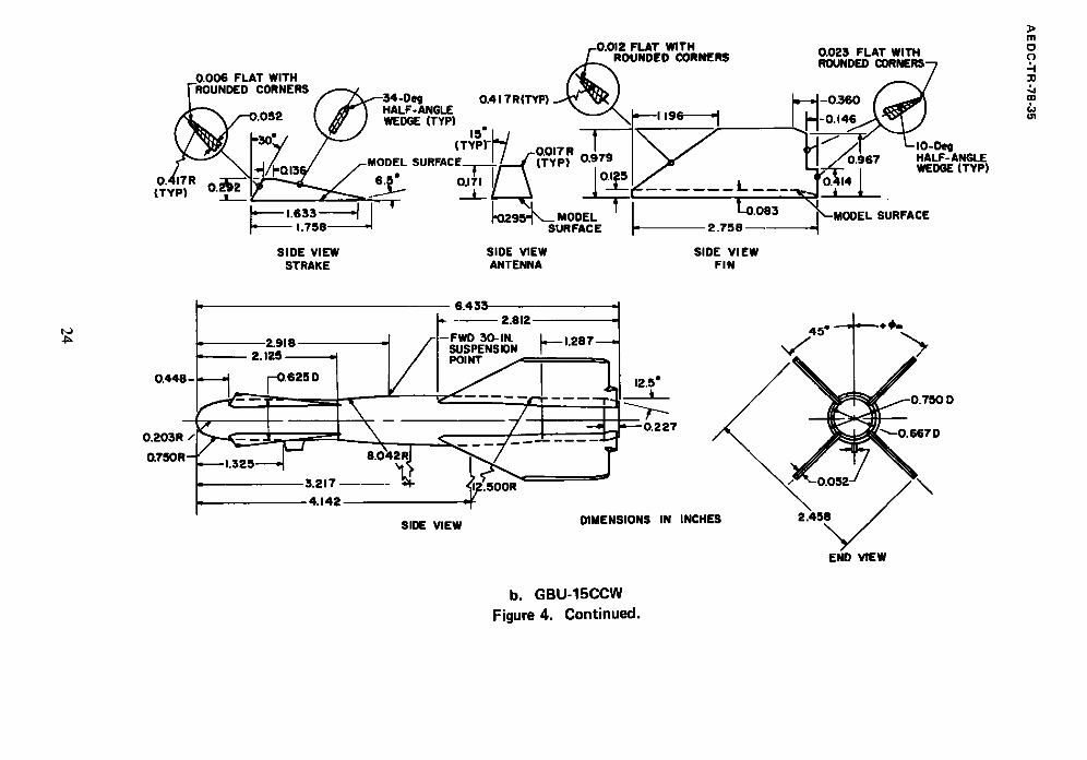
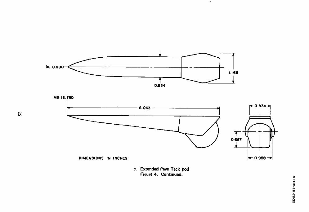
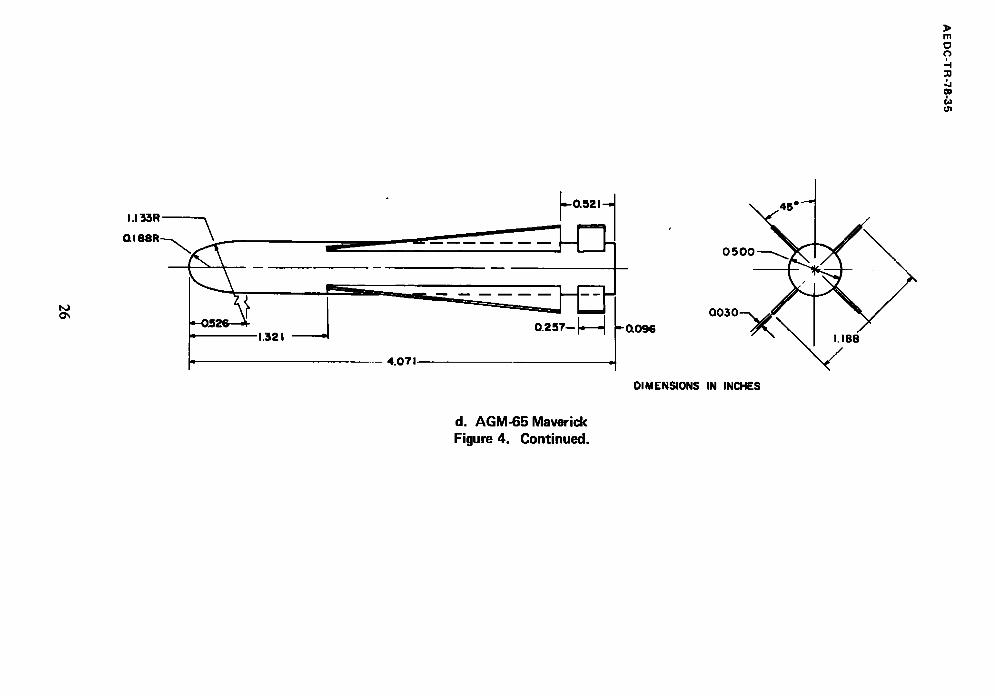
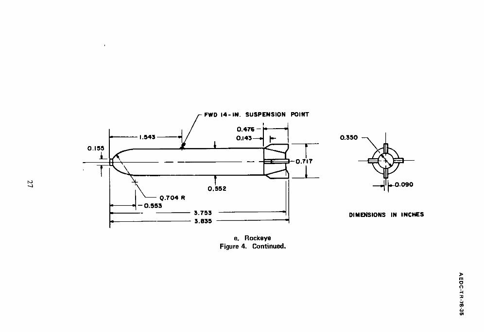
4. External Stores ................................. 23
5. Boundary-Layer Transition Grit Pattern . . . . . . . . . . . . . . . . . . . . 30
6. Pylon/Store Configuration Identification . . . . . . . . . . . . . . . . . . . . 31
7. Tunnel Flow Angularity . . . . . . . . . . . . . . . . . . . . . . . . . . . . . 32
8. Aerodynamic Characteristics o f the F-111 Aircraft,
Clean Configuration ............................... 33
9. Static Stability Derivatives and Drag Coefficients o f the
F-111 Aircraft, Clean Configuration . . . . . . . . . . . . . . . . . . . . . . 51
10. Reynolds Number Effects . . . . . . . . . . . . . . . . . . . . . . . . . . . . 56
11. Transition Grit Effects, A = 26 deg . . . . . . . . . . . . . . . . . . . . . . . 62
12. Sting Fairing Effects, A = 26 deg . . . . . . . . . . . . . . . . . . . . . . . . 65
3
AE DC-TR-78-35
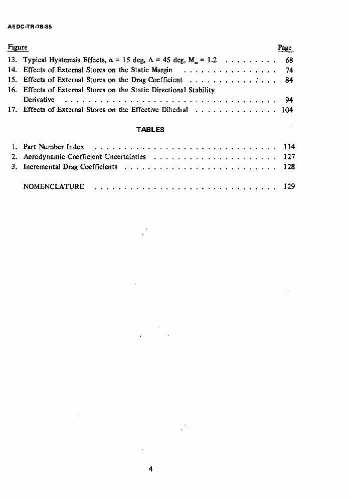
13. Typical Hysteresis Effects, a = 15 deg, A = 45 deg, M.. = 1.2 . . . . . . . . .
14. Effects o f External Stores on the Static Margin . . . . . . . . . . . . . . . .
15. Effects o f External Stores on the Drag Coeff ic ient . . . . . . . . . . . : . . .
16. Effects o f External Stores on the Static Directional Stabil i ty
Derivative ....................................
17.
68 74
84
94
Effects o f External Stores on the Effective Dihedral . . . . . . . . . . . . . . 104
TABLES
1. Part Number Index . . . . . . . . • . . . . . . . . . . . . . . . . . . . . . . . 114
2. A e r o d y n a m i c Coefficient Uncertain,ties . . . . . . . . . . . . . . . . . . . . . 127
3. Incrementa l Drag Coefficients . . . . . . . . . . . . . . . . . . . . . . . . . . 128
N O M E N C L A T U R E ............................... 129
4
A E D C-TR-78-35
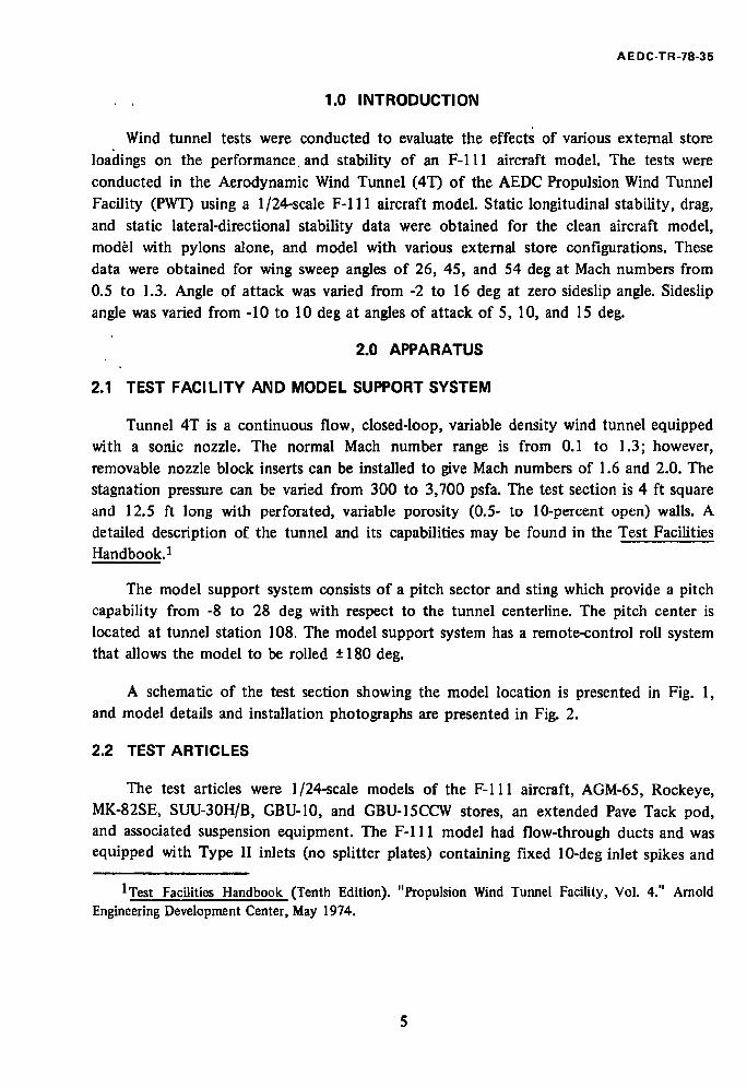
1.0 INTRODUCTION
Wind tunnel tests were conducted to evaluate the effects of various external store loa(lings on the performance and stability of an F-111 aircraft model. The tests were
conducted in the Aerodynamic Wind Tunnel (4T) of the AEDC Propulsion Wind Tunnel
Facility (PWT) using a 1/24-scale F - I l l aircraft model. Static longitudinal stability, drag,
and static lateral-directional stability data were obtained for the clean aircraft model, mod~l with pylons alone, and model with various external store configurations. These data were obtained for wing sweep angles of 26, 45, and 54 deg at Mach numbers from 0.5 to 1.3. Angle of attack was varied from -2 to 16 deg at zero sideslip angle. Sideslip
angle was varied from -10 to 10 deg at angles of attack of 5, 10, and 15 deg.
2.0 APPARATUS
2.1 TEST FACILITY AND MODEL SUPPORT SYSTEM
Tunnel 4T is a continuous flow, closed-loop, variable density wind tunnel equipped with a sonic nozzle. The normal Math number range is from 0.1 to 1.3; however, removable nozzle block inserts can be installed to give Math numbers of 1.6 and 2.0. The stagnation pressure can be varied from 300 to 3,700 psfa. The test section is 4 ft square and 12.5 ft long with perforated, variable porosity (0.5- to 10-percent open) walls. A detailed description of the tunnel and its capabilities may be found in the Test Facilities Handbook. 1
The model support system consists of a pitch sector and sting which provide a pitch capability from -8 to 28 deg with respect to the tunnel centerline. The pitch center is located at tunnel station 108. The model support system has a remote-control roll system that allows the model to be rolled -+ 180 deg.
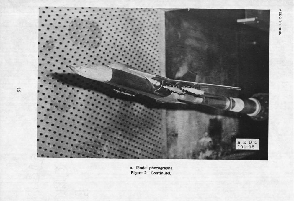
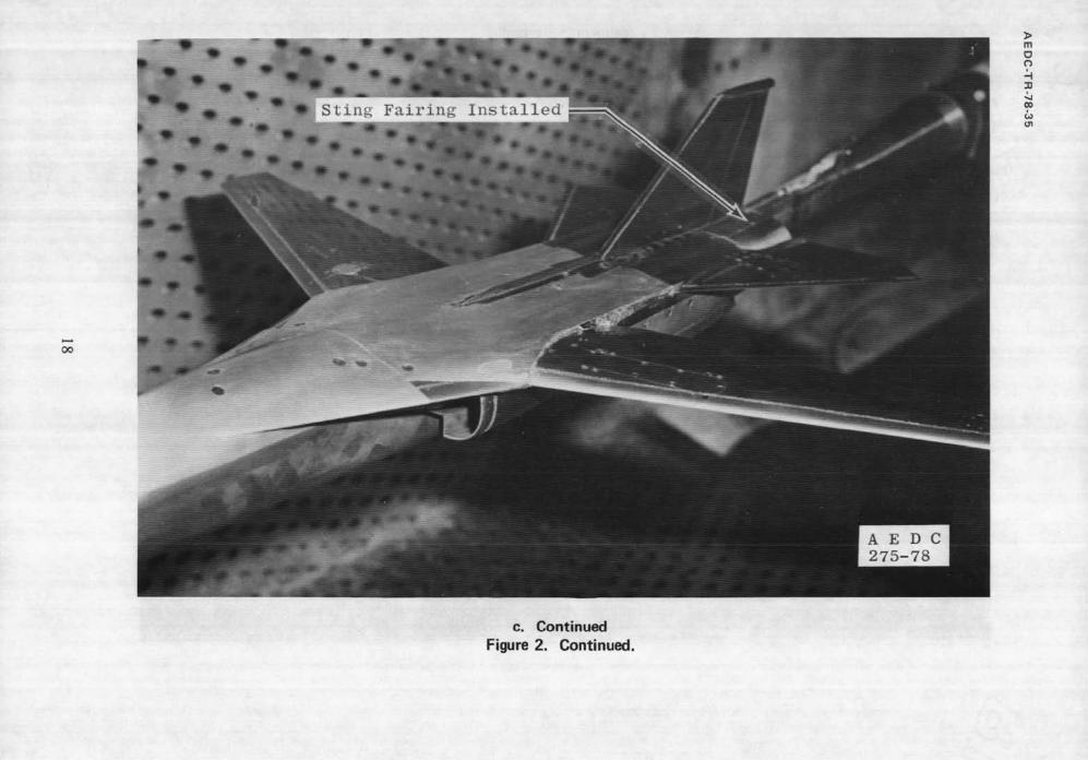
A schematic of the test section showing the model location is presented in Fig. 1, and model details and installation photographs are presented in Fig. 2.
2.2 TEST ARTICLES
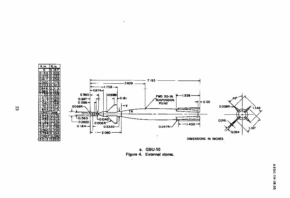
The test articles were 1/24-scale models of the F-111 aircraft, AGM-65, Rockeye, MK-82SE, SUU-30H/B, GBU-10, and GBU-15CCW stores, an extended Pave Tack pod, and associated suspension equipment. The F-I 11 model had flow-through ducts and was equipped with Type II inlets (no splitter plates) containing fixed 10-deg inlet spikes and
lTest Facilities Handbook (Tenth Edition). "Propulsion Wind Tunnel Facility, Vol. 4." Arnold Engineering Development Center, May 1974.

AEDC-TR-78-35
nozzle plugs. The aft fuselage and exhaust nozzles were modifed to allow insertion of the
balance and sting. The model had a fairing above and below the sting between the
exhaust nozzles; however, it was removed to avoid fouling the sting. Limited data were obtained with steel shimstock faMngs installed between the exhaust nozzles to evaluate
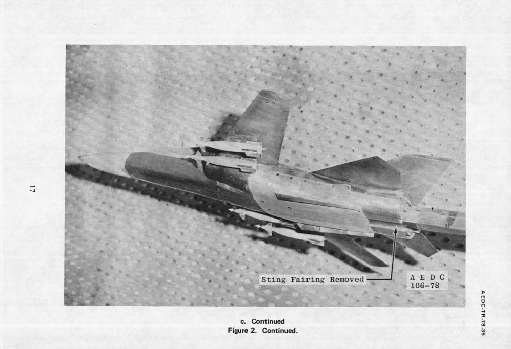
the effects of removing the sting fairing on the aerodynamic coefficients. The model is shown with and without the fairing in Fig. 2. The model stabilator was held constant at
zero deg with respect to a waterline throughout the test.
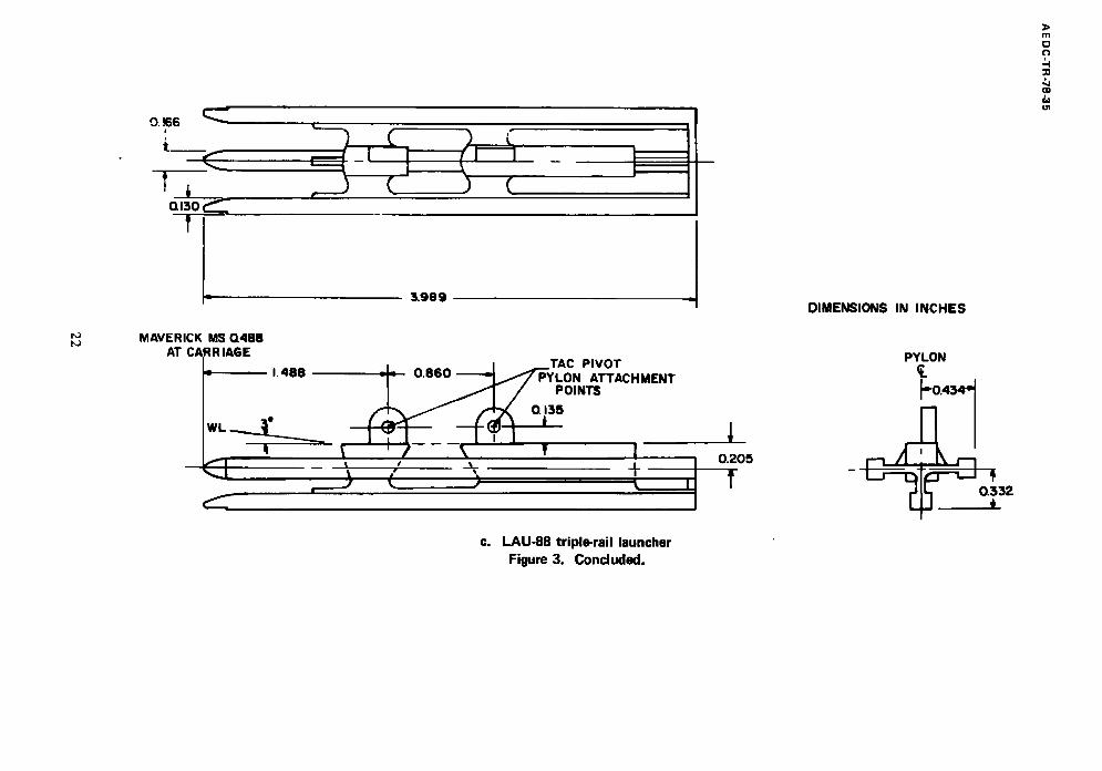
The LAU-88 triple rail launchers used with the AGM-65 stores were modified by deleting the stop normally installed at the aft end of each rail to allow for the installation of store balance sting mounts; however, the AGM-65 stores were bolted directly to the launchers for the current test. Basic details and dimensions of the models
are presented in Figs. 2 through 4. The transition grit pattern used in evaluating possible
boundary-layer transition effects is shown in Fig. 5. Only limited testing was conducted
with transition grit installed on the model.
Pylons were installed at the pivot stations (3 through 6) for all testing except for
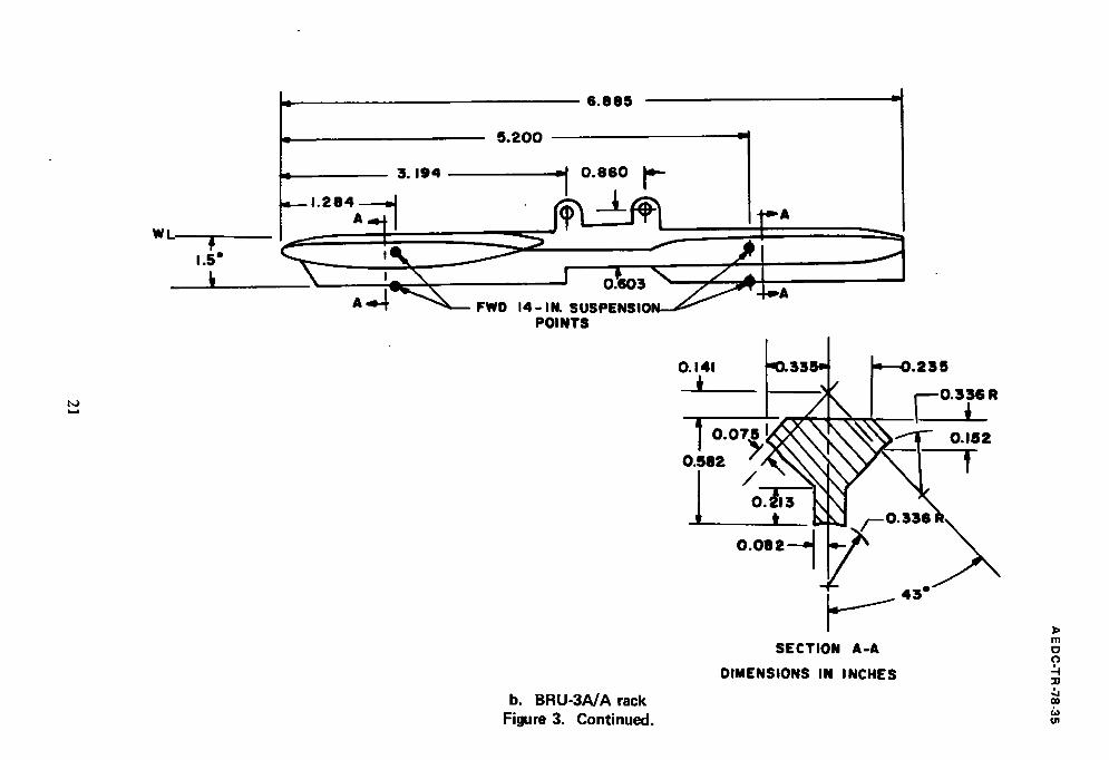
data obtained for the clean configurations. BRU-3AA racks were installed only on those
pylons carrying MK-82SE, SUU-30H/B, or Rockeye stores. The pylon loadings for all
configurations tested are presented in Fig. 6.
The Pave Tack pod is semisubmerged in the weapons bay when extended. A model representing the exposed portion of the extended Pave Tack pod was attached to the
centerline of the weapons bay at MS 12.78 when required.
2.3 INSTRUMENTATION
A six-component, internal strain-gage balance was used to measure the forces and
moments on the F - I l l model. Two base pressure measurements were made using
transducers and orifice tubes which extended just aft of the base of the nozzle plugs.
3.0 TEST DESCRIPTION
3.1 TEST CONDITIONS, PROCEDURES, AND TEST PROGRAM
Static stability data were obtained for all configurations at Maeh numbers from 0.5
to 1.3 at a constant total pressure of 1,200 psfa. Limited data were also obtained at
2,000 psfa for M.. = 0.5, 0.9, and 1.3 with A = 26 and 54 deg with the clean model in order to evaluate possible Reynolds number effects. Transition grit effects were evaluated with the clean model at Pt = 1,200 psfa for Mach .numbers from 0.6 to 0.95 with A = 26
deg. The nominal test conditions were:
6
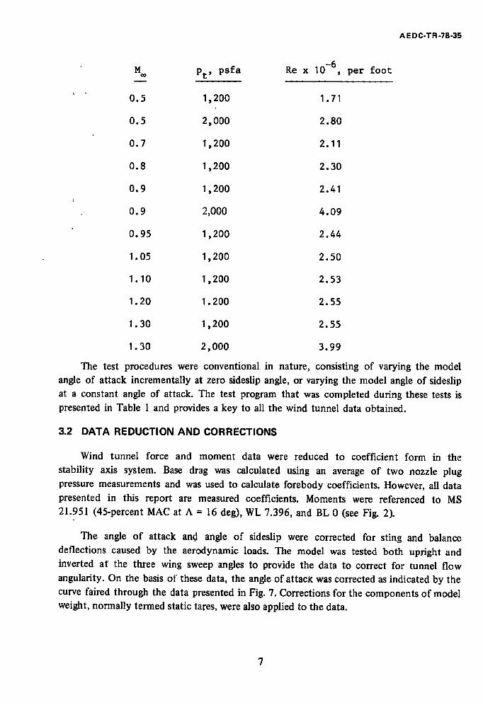
M= Pt' psfa Re x 10 -6
0.5 1,200 1.71
0.5 2,000 2.80
0.7 1,200 2.11
0.8 1,200 2.30
0.9 1,200 2.41
0.9 2,000 4.09
0.95 1,200 2.44
1.05 1,200 2.50
1.10 1,200 2.53
1.20 1.200 2.55
1.30 1,200 2.55
1.30 2,000 3.99
, pe r foot
A E DC-TR-78-35
The test procedures were conventional in nature, consisting of varying the model
angle of attack incrementally at zero sideslip angle, or varying the model angle of sideslip
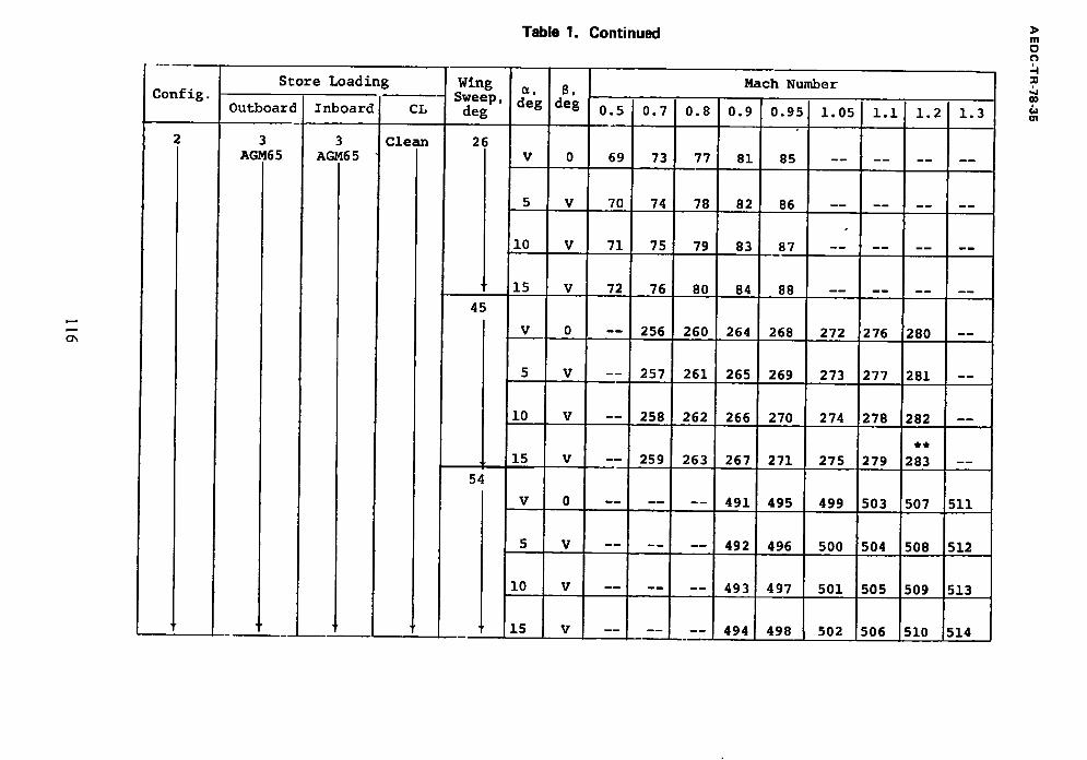
at a constant angle of attack. The test program that was completed during these tests is presented in Table 1 and provides a key to all the wind tunnel data obtained.
3.2 D A T A R E D U C T I O N A N D C O R R E C T I O N S
Wind tunnel force and moment data were reduced to coefficient form in the
stability axis system. Base drag was calculated using an average of two nozzle plug
pressure measurements and was used to calculate forebody coefficients. However, all data
presented in this report are measured coefficients. Moments were referenced to MS 21.951 (45-percent MAC at A = 16 deg), WL 7.396, and BL 0 (see Fig. 2).
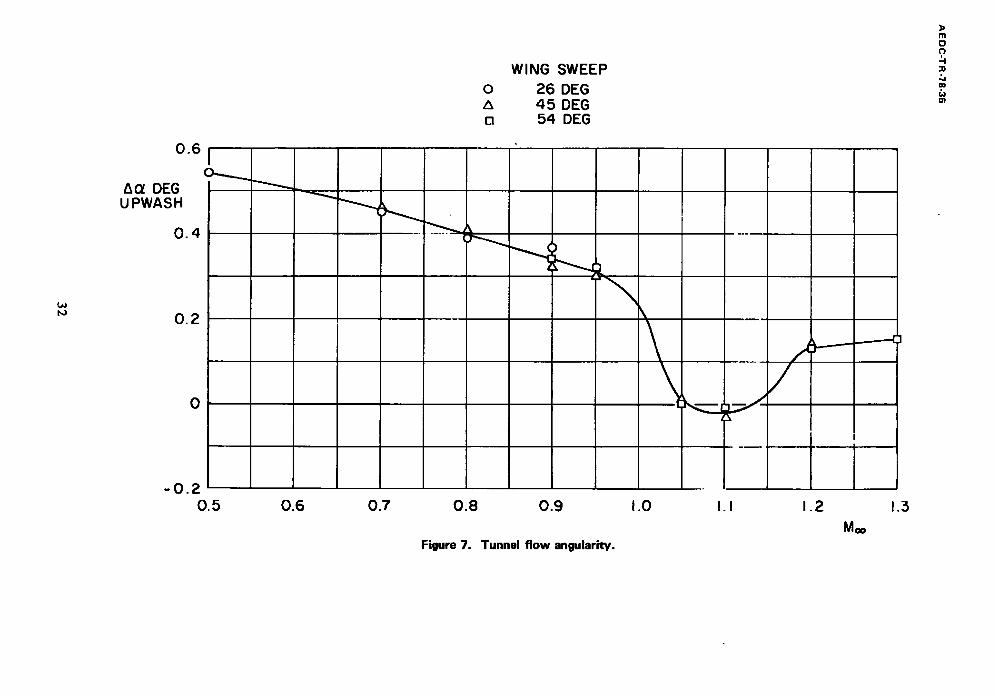
The angle of attack an.d angle of sideslip were corrected for sting and balance deflections caused by the aerodynamic loads. The model was tested both upright and
inverted at' the three wing sweep angles to provide the data to correct for tunnel flow
angularity. On the basis of these data, the angle of attack was corrected as indicated by the curve faired through the data presented in Fig. 7. Corrections for the components of model weight, normally termed static tares, were also applied to the data.
7

AE DC-TR-78-35
3.3 DATA UNCERTAINTY
The data uncertainties determined for a confidence level of 95 percent are presented in Table 2. The aerodynamic coefficient uncertainties include the uncertainties of Math
number and dynamic pressure together with the uncertainty contribution associated with
the balance and instrumentation system. Model angle-of-attack uncertainty has been estimated to be -0.1 deg and model roll angle +0.4 deg.
4.0 TEST RESULTS
The static stability and drag characteristics of the clean F-111 aircraft model are presented together with data showing the incremental effects of various external stores on
the drag and on the static longitudinal and lateral-directional stability derivatives. All aerodynamic coefficients are presented for the baseline (clean) configuration; however,
only incremental data are presented to show the effects of external stores. The incremental data were obtained by subtracting coefficients and derivatives of the baseline configuration from the coefficients and derivatives of the configurations with stores.
Drag increments were calculated at specific lift coefficients from nonlinear curve fits
of the lift and drag coefficients. The static margins were evaluated by taking the slope of a linear least-squares curve fit of Cm versus CL for nominal angles of attack from -2 to 6 deg. Lateral-directional derivatives were also evaluated from linear least-squares curve fits of the data for nominal sideslip angles from -4 to 4 deg.
All moment coefficients and stability derivatives are referenced to a standard moment reference center located at 45 percent of the MAC with the wing at 16 deg sweep angle (see Fig. 2).
4.1 AERODYNAMIC CHARACTERISTICS OF THE BASELINE CONFIGURATION
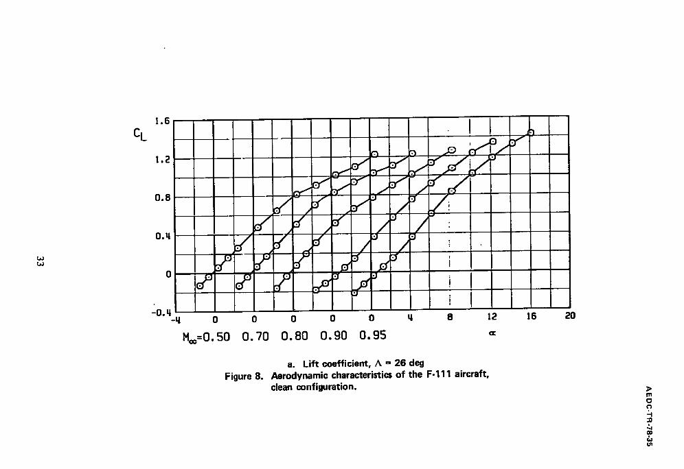
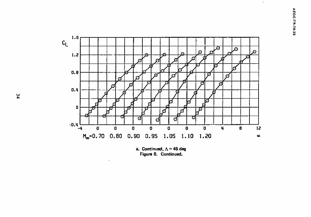
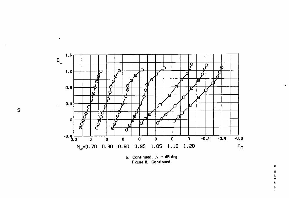
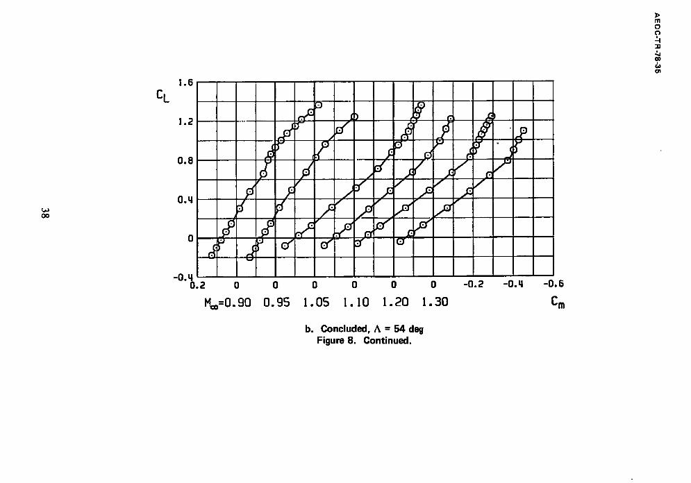
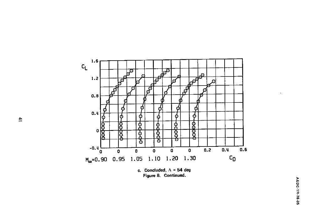
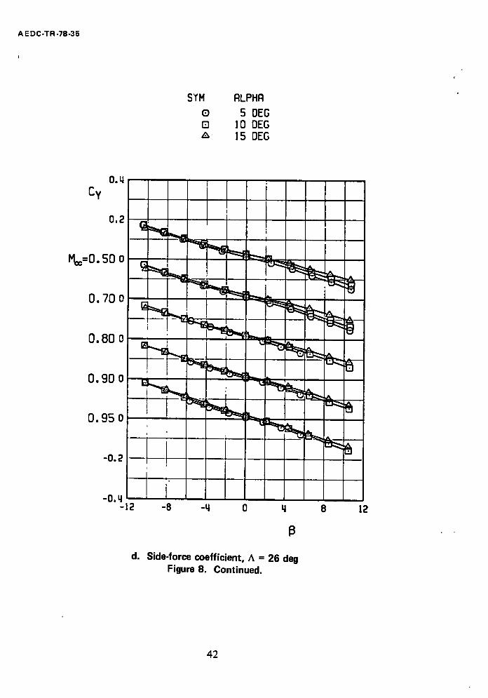
The static aerodynamic characteristics of the clean F-1 I1 model are presented in
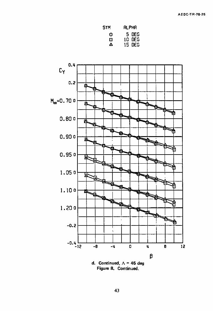
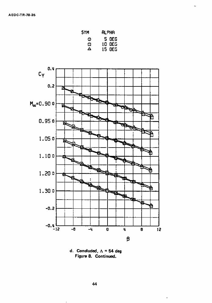
Fig. 8. Although the characteristics are generally well behaved, the lift coefficient variation with angle of attack exhibited unusual changes in slope at M= = 0.9 and 0.95
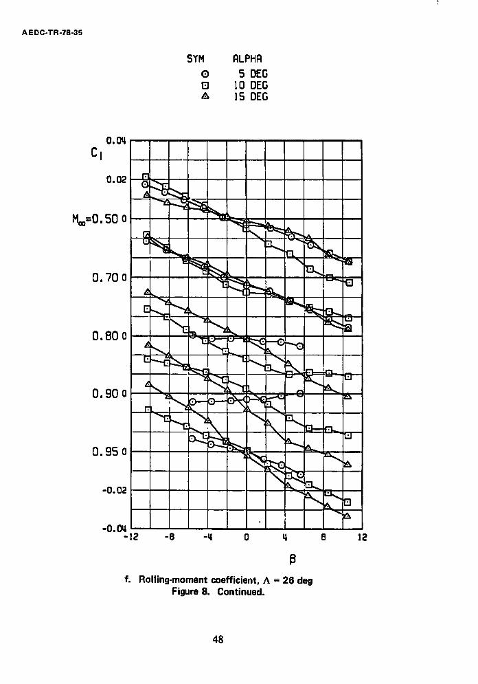
with A = 26 deg. Also, the rolling-moment coefficient was less well behaved at M** i> 0.8
for A = 26 deg. The reason for the rolling-moment coefficient behavior is not known; however, hysteresis checks made at a = 15 deg indicate that the data repeated within the
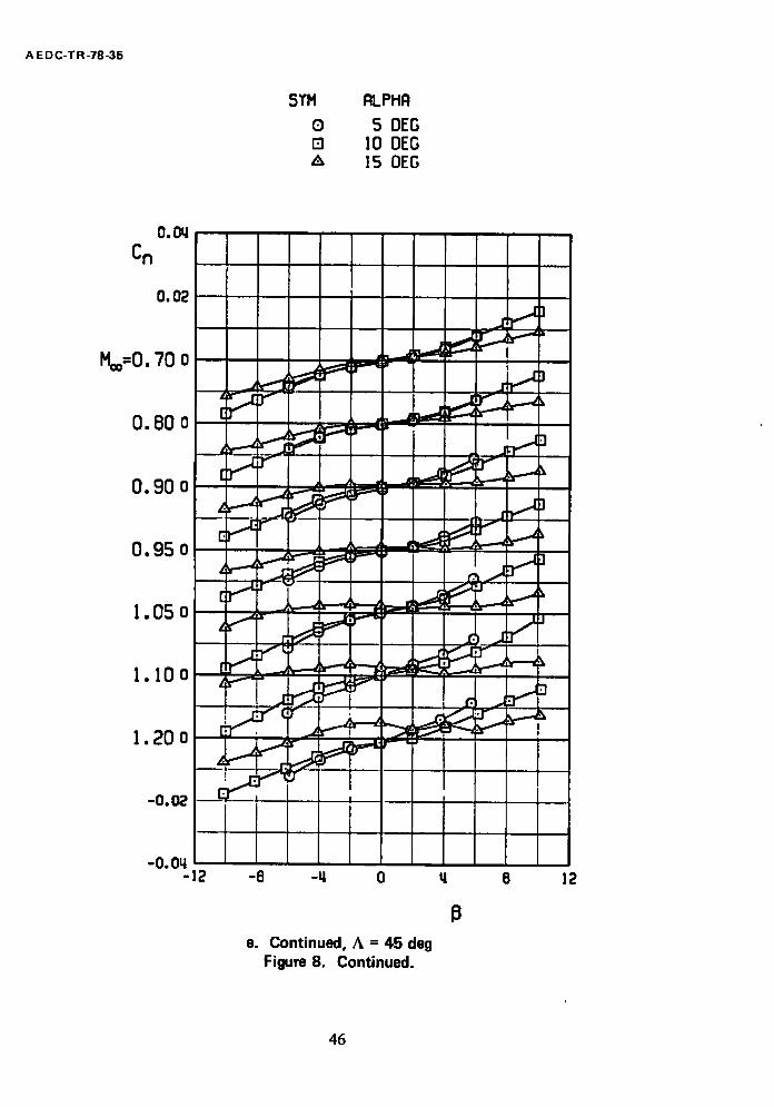
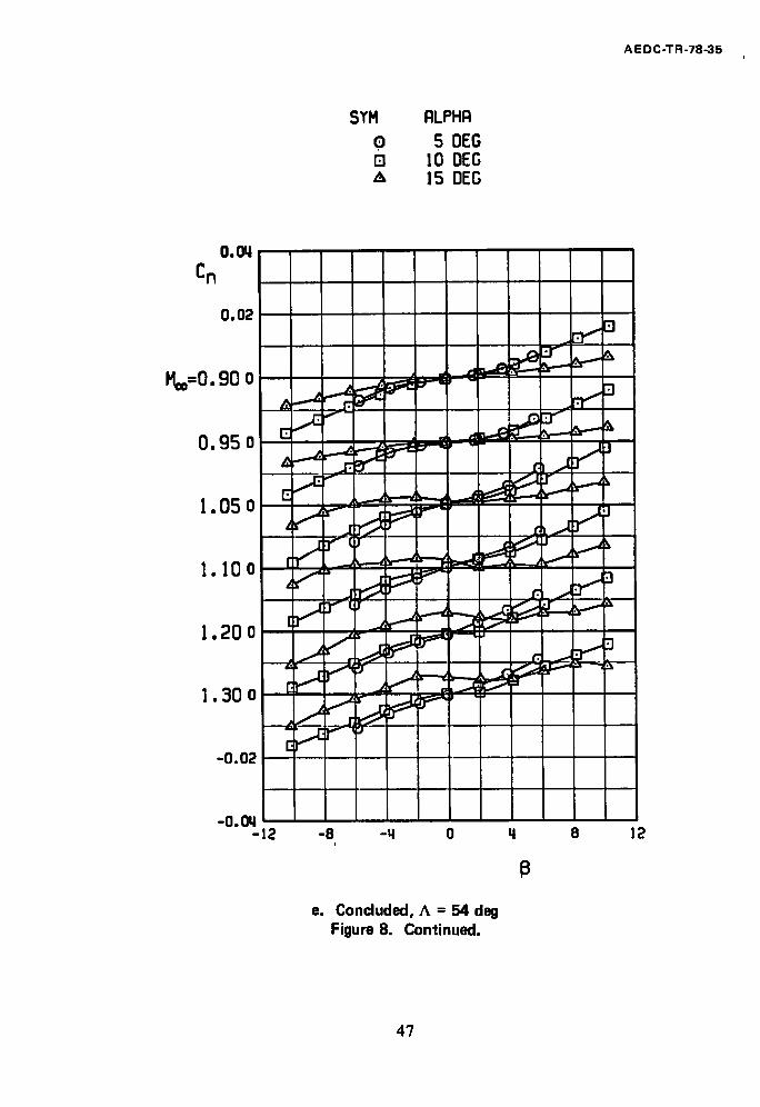
data uncertainty when the model was yawed in both directions. Hysteresis is responsible for the shift in the Cn curves at a =15 deg at supersonic Math numbers (Fig. 8e) and is discussed further in Section 4.3.
8
A EDC-TR-78-35
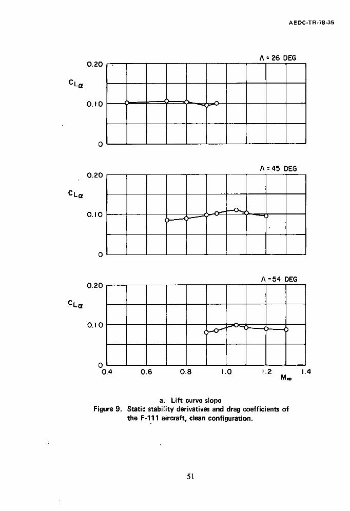
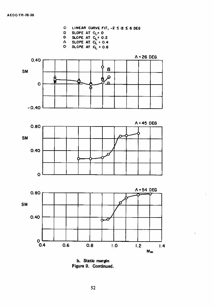
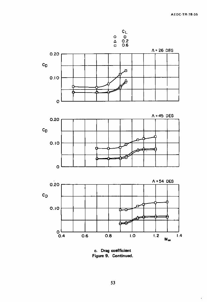
The data presented in Fig. 8 are summarized in Fig. 9 in terms of static longitudinal and lateral-directional stability parameters and drag coefficients at specific values of the
lift coefficient. These data show that the F - I l l model has essentially"neutral static
longitudinal stability at A = 26 deg. Static longitudinal stability increases with increasing
wirig sweep angle and with increasing Math number for M** > 0.9.
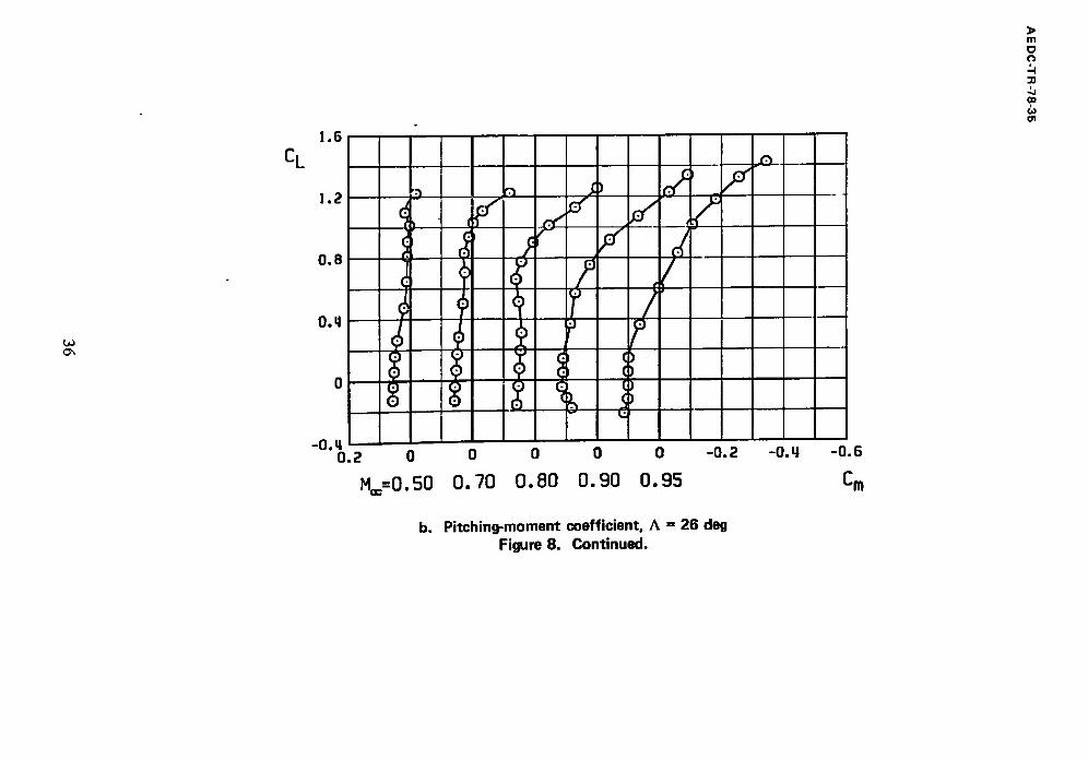
The static margin was calculated by a linear fit of the CL versus Cm curves in order to provide a single figure representative of the static longitudinal stability over a
moderate angle-of-attack range. This procedure provides a reasonable approximation for A =
45 and 54 deg; however, both CL and Cm have significant nonlinearities at low angles of
attack at A = 26 deg. Therefore, static margins for A = 26 deg were also calculated by
determining the slope of a nonlinear curve fit of CL versus Cm at specific values of CL to
show the effects of nonlinearities on the static margin (Fig. 9b). The linear curve fit
rel~resents a reasonable approxinaation of the static margin in the angle-of-attack range of
interest for Mach numbers through 0.8. At M = 0.9 and 0.95, at A = 26 deg, SM and ASM should be used with caution because of the nonlinearities in CL and Cm.
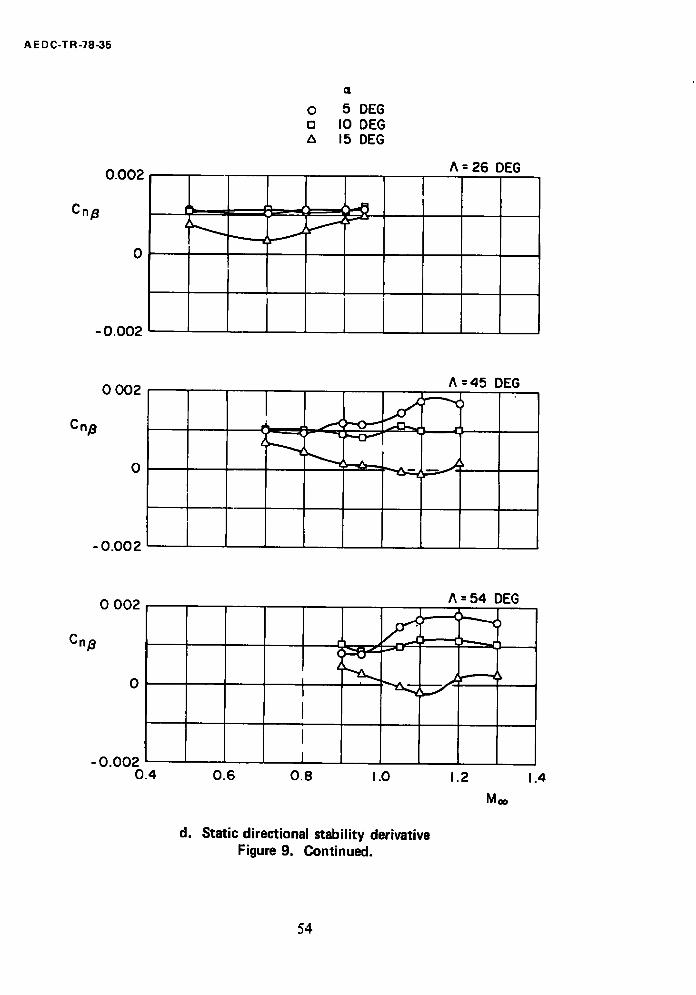
As shown in Fig. 9, the F-111 model was directionally stable at all conditions tested
except at a = 15 deg at M,, = 1.05 and 1.1, where the model became directionally unstable. The F-I 11 model also had favorable effective dihedral except at a = 5 deg for
Maeh numbers near 0.8 and 0.9 at A = 26 deg.
4.2 EFFECTS OF REYNOLDS NUMBER, TRANSITION GRIT, AND AFTERBODY MODIFICATIONS
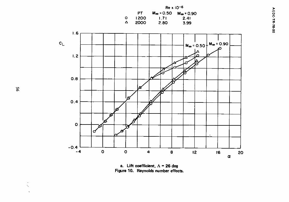
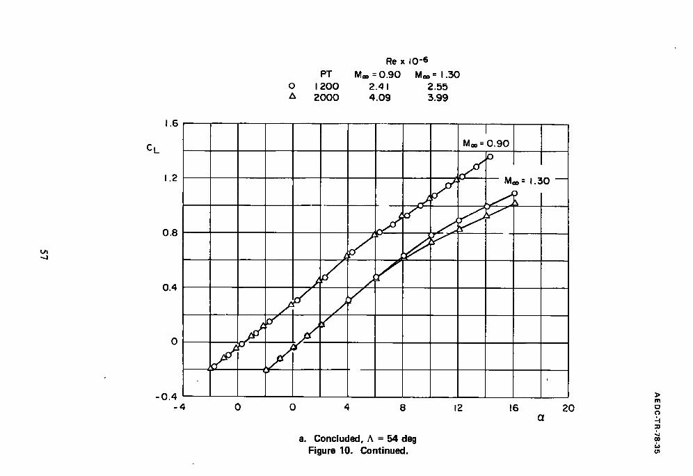
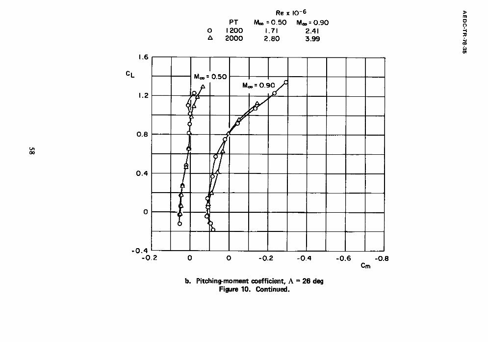
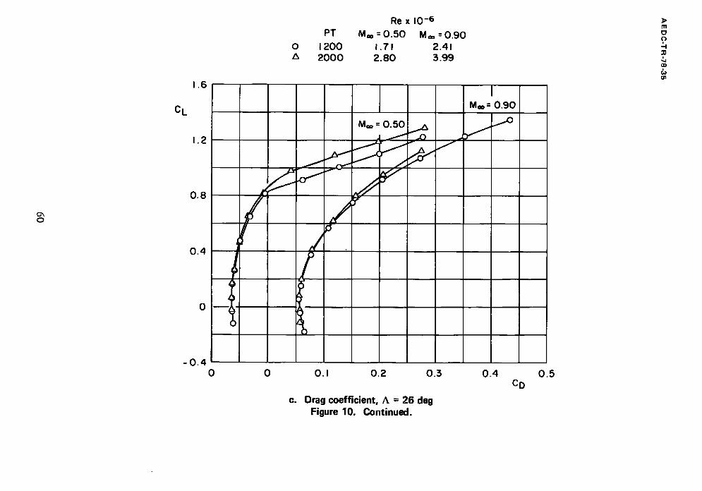
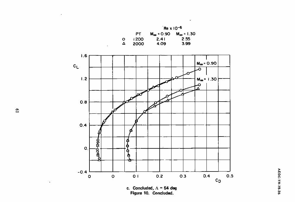
The effects of Reynolds number were investigated by testing the clean model at Pt = 2,000 psfa at M**= 0.5, 0.9, and 1.3 for A = 26 and 54 deg (Fig. 10). A~ qrent Reynolds
number effects are evident for angles of attack above 8 deg at M® = 0.5 and at all angles
of attack at M** = 0.9 for A = 26 deg. At A = 54 deg, increasing Reynolds number had
no effect at M** = 0.9; at M** = 1.3, increasing Reynolds number decreased CL, increased
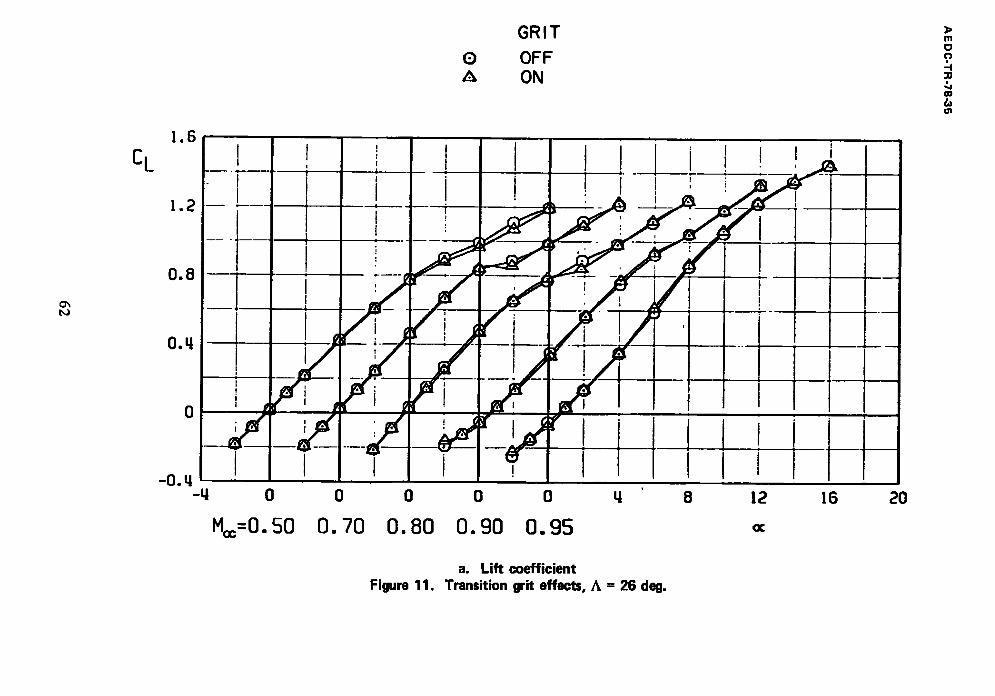
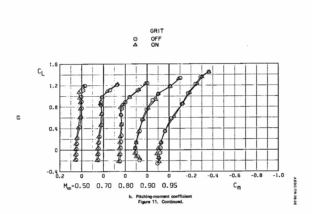
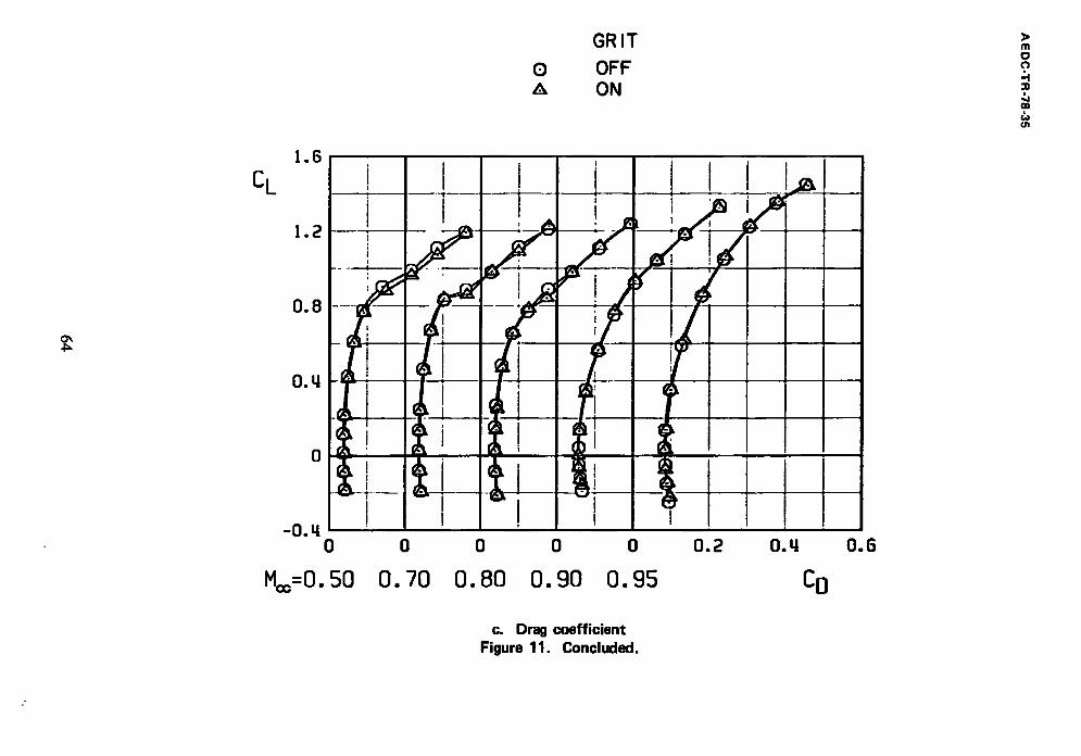
Cm, and had little effect on CD for angles of attack above 8 deg. The addition of transition grit (Fig. 11) had no significant effect on the aerodynamic coefficients of the
clean model at A = 26 deg, indicating that the changes produced by increasing total pressure are not necessarily boundary-layer transition effects.
High balance dynamic loads limited the testing that could be accomplished at Pt =
2,000 psfa. Since the primary purpose of the test was to evaluate the incremental changes in aerodynamic coefficients by adding external stores to the F-111 aircraft, and the
effects produced by increasing total pressure are not believed to affect the incremental
data, all store effect data were obtained at Pt = 1,200 psfa and without transition grit.
9
AE DC-TR-78-35
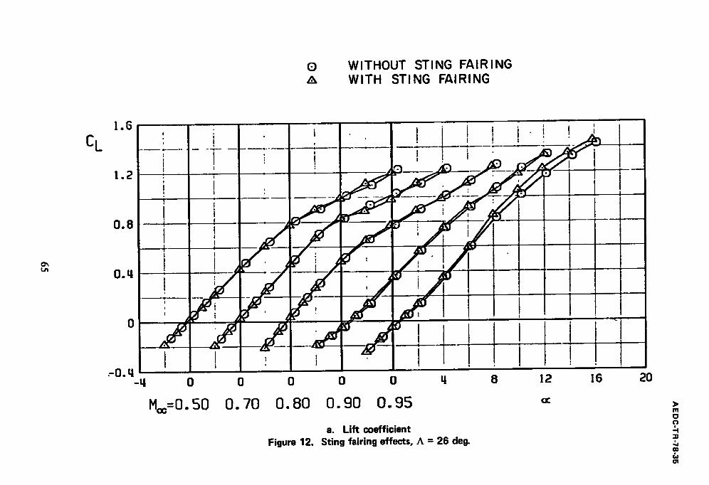
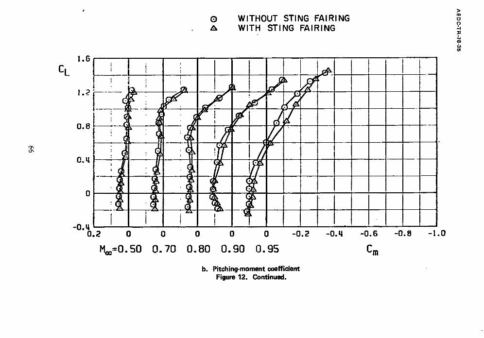
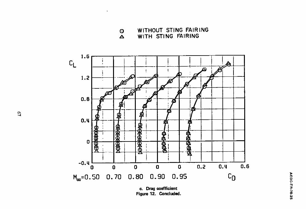
The model was designed with fairings above and below the sting between the nozzle ducts. These fairings were deleted to prevent the sting from fouling the model (Fig. 2c). The effects of removing the fairings were investigated at A = 26 deg by welding steel shimstock between the nozfle ducts as shown in Fig. 2c. The effects of the sting fairings
on CL, Cm, and Co are shown in Fig. 12. As expected, the principal effect of the sting falrings was to increase the nose-down pitching moment at all Mach numbers. There was
also a slight increase in CL at angles of attack above 6 deg at M. = 0.95. All data
presented in this report were obtained with the sting fairing removed except for the data presented in Fig. 12.
4.3 AERODYNAMIC HYSTERESIS EFFECTS
Aerodynamic hysteresis occurs when the value of an aerodynamic coefficient depends on the past history of the model motion, and this phenomenon makes analysis and application of the data difficult. Aerodynamic hysteresis had been observed in pitch and yaw polars at angles of attack below 20 deg during recent transonic wind tunnel tests of a fighter configuration. Therefore, a brief survey was conducted to determine whether aerodynamic hysteresis occurred within the angle-of-attack and sideslip range of the current test.
Hysteresis effects were investigated by pitching and yawing the model in both directions. No significant hysteresis effects were observed for pitch polars; however,
significant hysteresis effects were observed in yaw polars with the clean configuration for
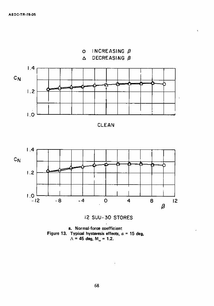
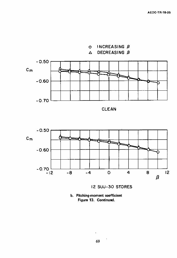
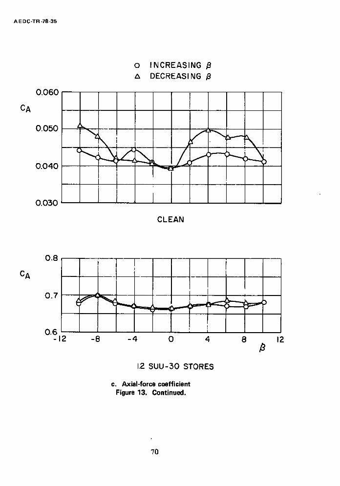
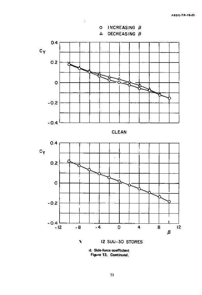
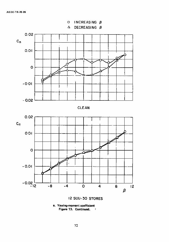
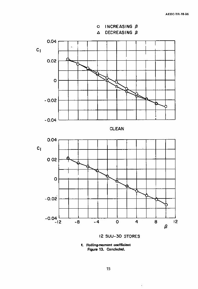
a = 15 deg at supersonic Mach numbers. Typical hysteresis effects obtained while yawing the model from -10 to 10 to -10 deg for the clean aircraft and with 12 SUU-30H/B
stores, at M = 1.2 and a = 15 dec, are presented in Fig. 13. At these test conditions, all aerodynamic coefficients except CN exhibited some hysteresis for the clean configuration, with yawing moment showing the most pronounced effect. Only limited hysteresis data were taken with external stores; however, the data suggest that the addition of pylons, with or without external stores, significantly reduced hysteresis effects during yaw polars. Because test time was limited, all yaw polars could not be run in both directions. Therefore, most of the yaw polars were run with increasing ~3, and all yaw data presented in the remainder of this report were obtained while increasing/$ from -10 to 10 dec.
4.4 EFFECTS OF EXTERNAL STORE LOADINGS
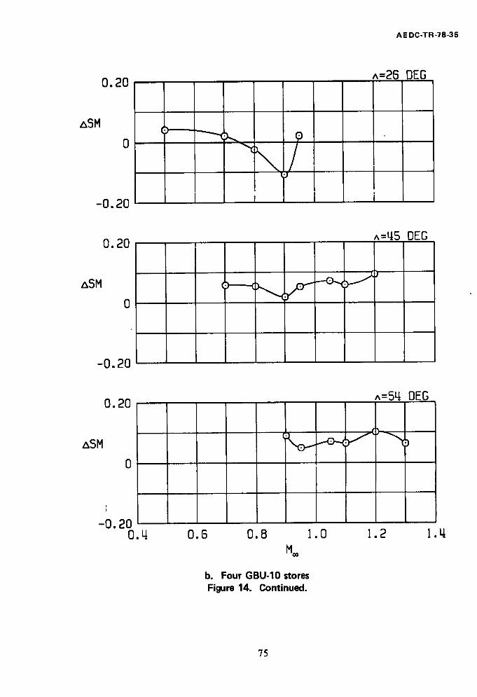
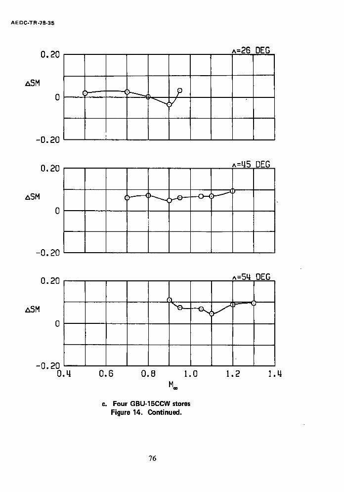
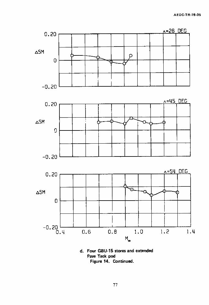
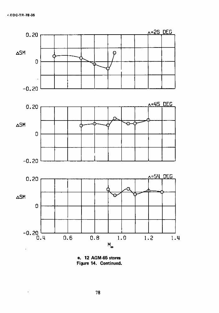
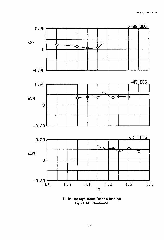
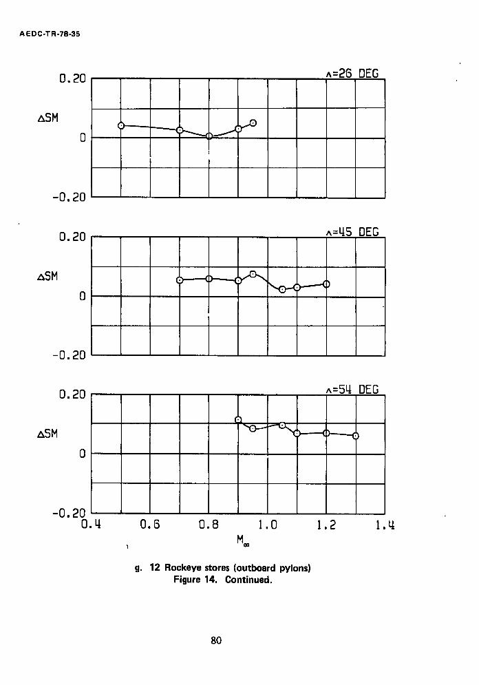
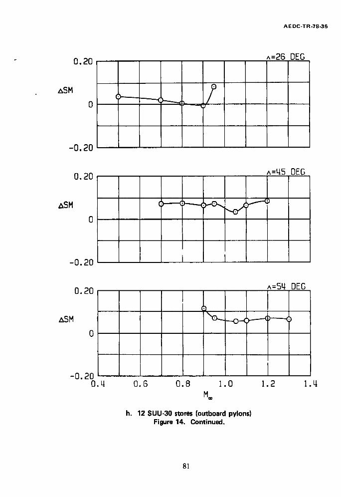
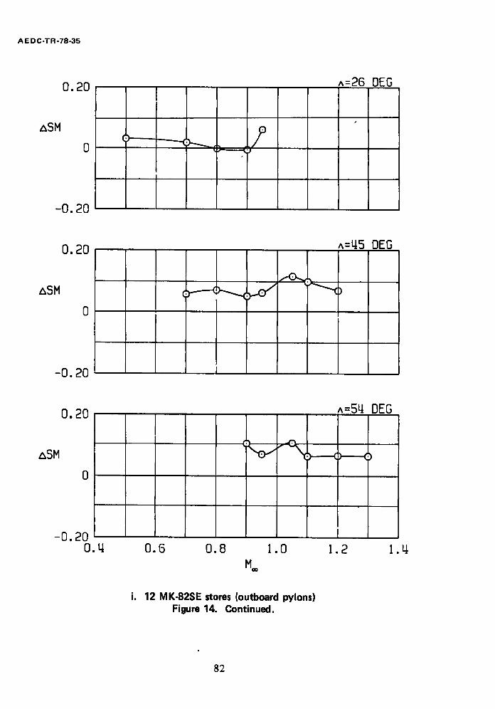
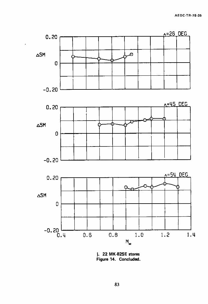
The effects of pylons and various loadings of external stores on the static margin are presented in Fig. 14. Pylons-alone and single-carriage store effects are shown in Figs. 14a through d, and multiple-carriage store effects are shown in Figs. 14e through j. All
10
AE DC-TR-78-35
external store loadings were generally destabilizing, except at M** = 0.8 and 0.9 with A =
26 deg. Single-carriage loads were generally less destabilizing than multiple-carriage loads. Adding the extended Pave Tack pod to the model with four GBU-15CCW stores had little
effect on the static longitudinal stability at subsonic Math numbers and produced a slight
increase in static longitudinal:stability at supersonic Mach numbers.
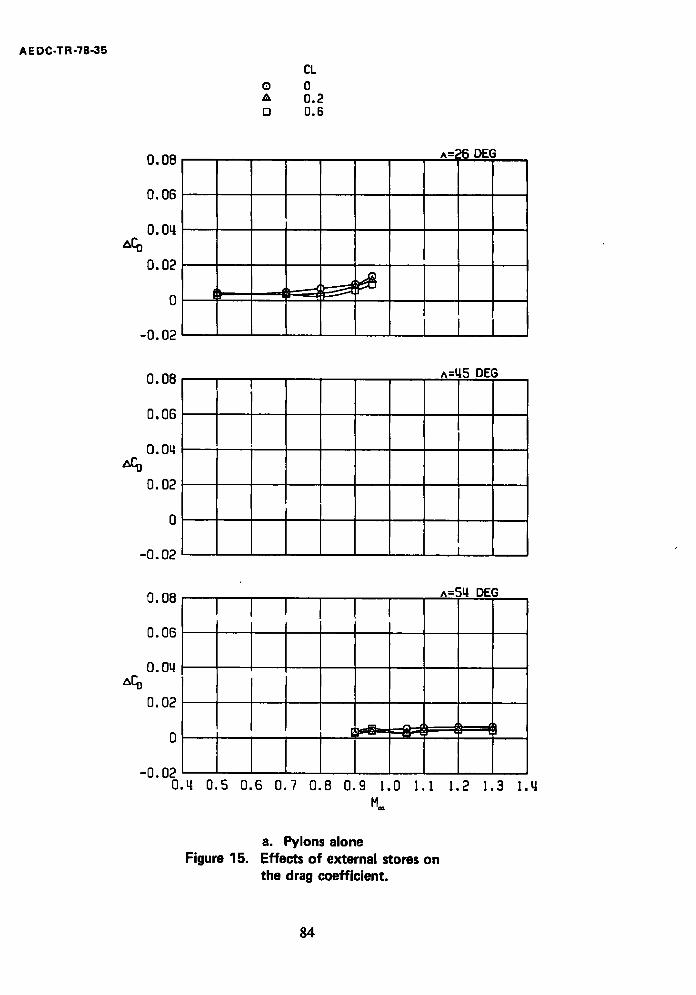
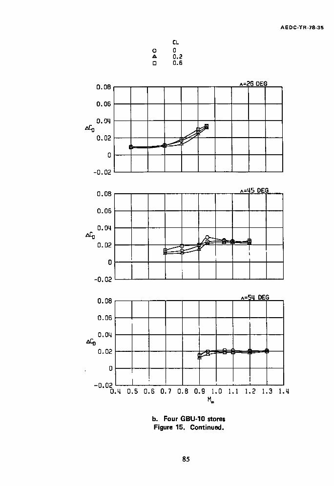
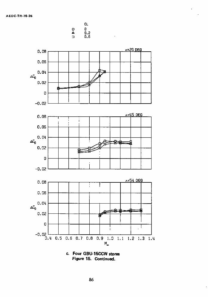
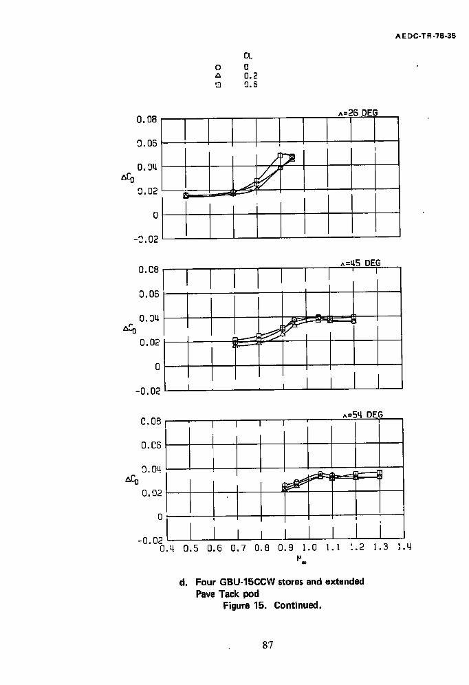
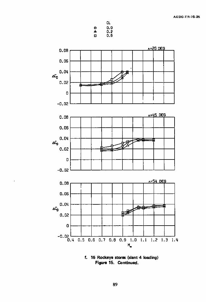
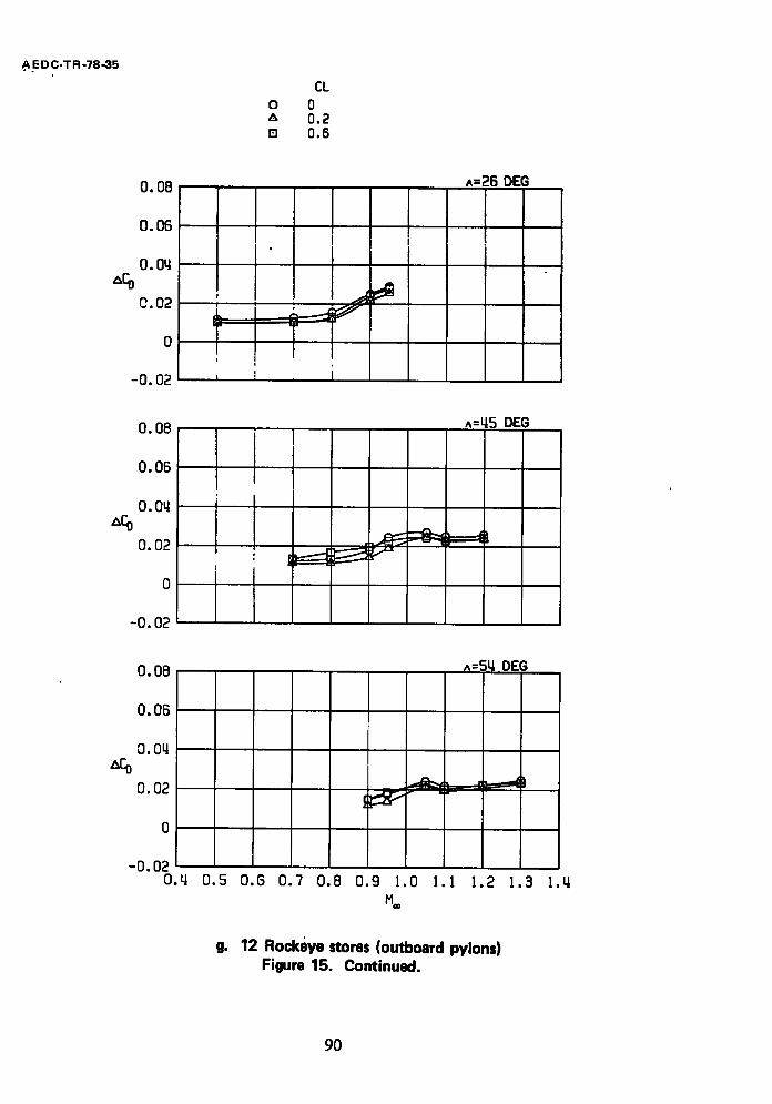
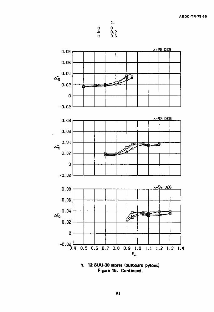
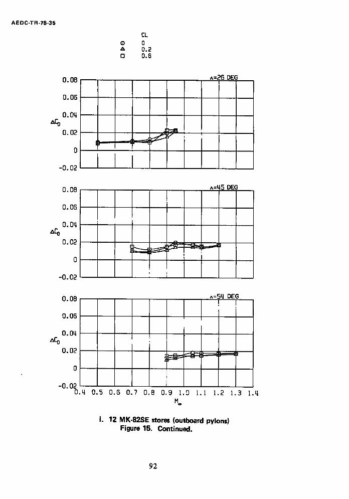
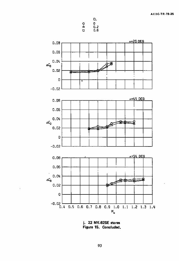
Incremental drag data showing the effects of pylons and various external store loadings on the drag of the clean F-111 model are presented in Fig. 15. The variations of the incremental drag coefficients exhibit the normal transonic drag rise. The incremental drag coefficients also decrease with increasing wing sweep angle. Drag increments produced by the various external stores at representative level flight values of CL are also
presented in tabulated format in Table 3.
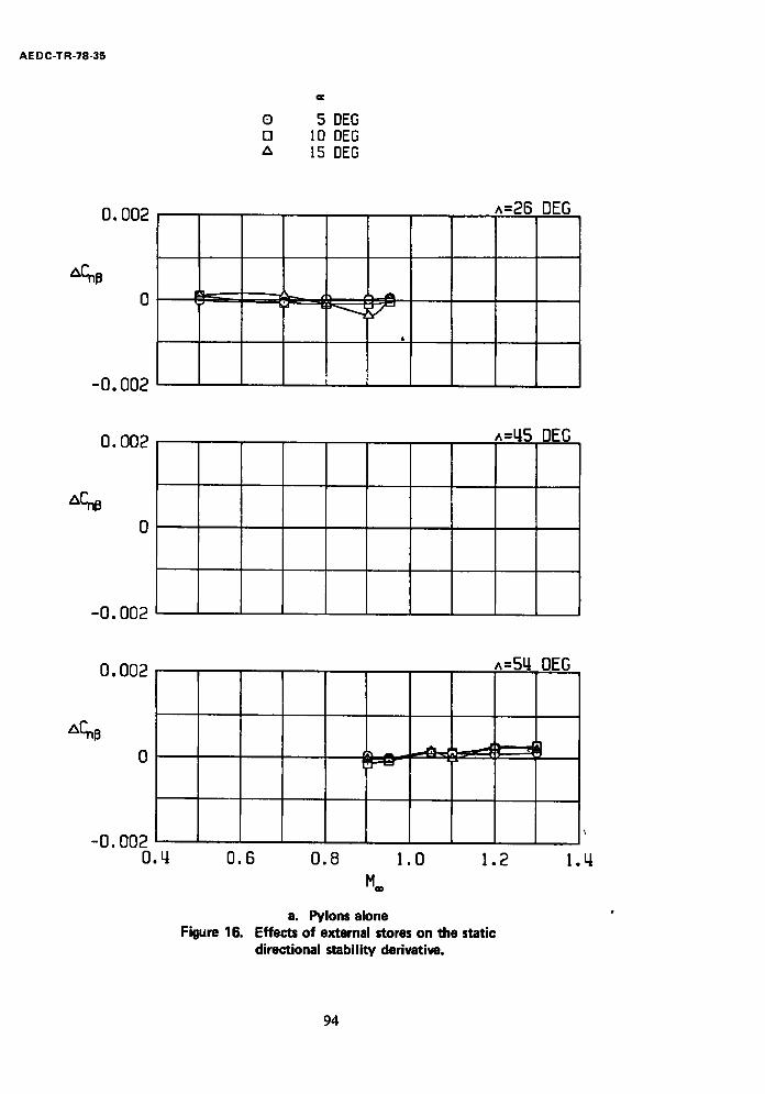
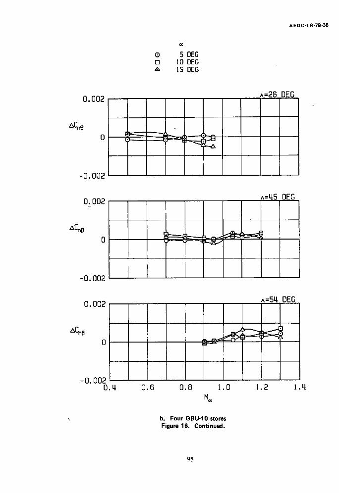
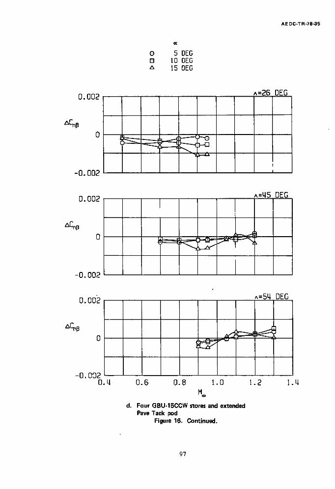
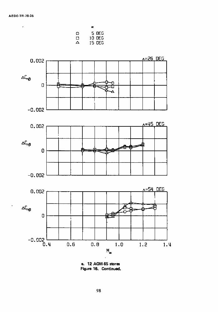
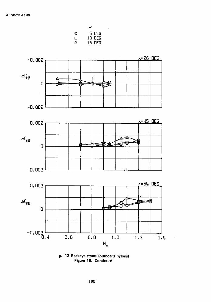
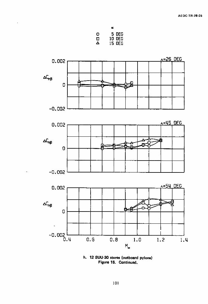
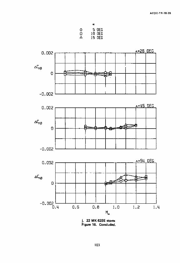
The effects of various external store loadings on the static directional stability derivative are presented in Fig. 16 in the form of incremental changes in the static
directional stability derivative. Most pylon store configurations had little effect on static directional stability except at M** = 0.9 and 0.95 where the GBU-i0, GBU-15CCW, and
AGM-65 stores generally degraded the static directional stability at a = 15 deg. At supersonic Math numbers, pylon store configurations generally increased the static
directional stability (positive ACnl3). The static directional stability contribution of all
pylon store configurations increased with increasing Math number and wing sweep angle at supersonic Math numbers. Adding the extended Pave Tack pod to the fuselage
centerline degraded the static directional stability at all wing sweep angles, angles of attack, and Math numbers.
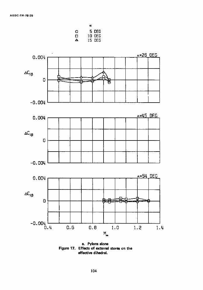
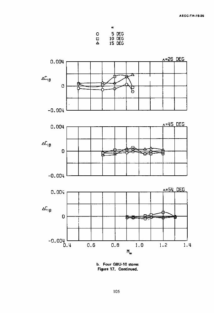
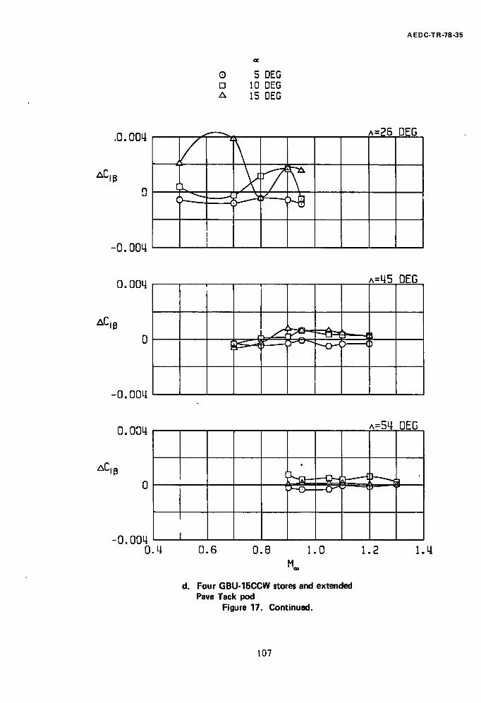
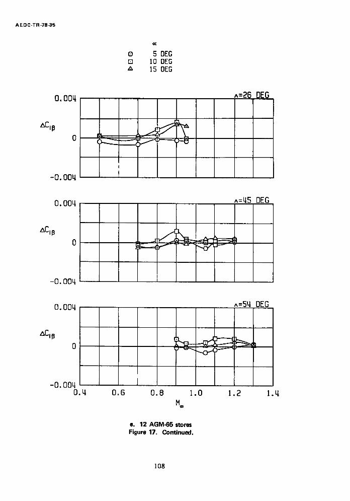
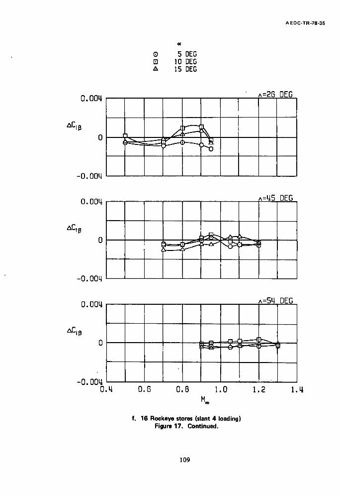
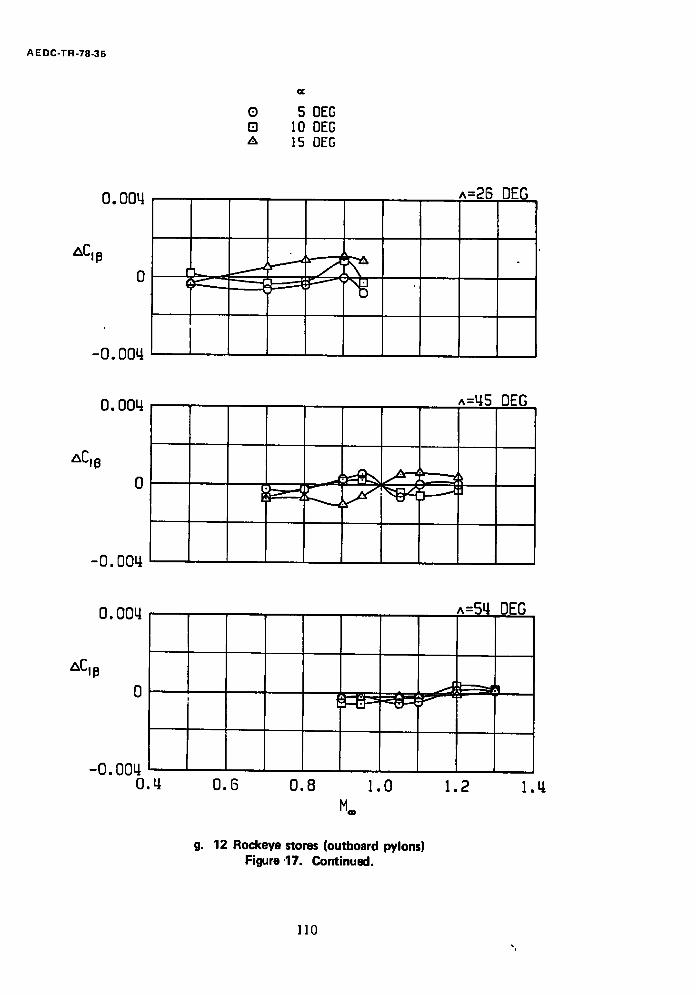
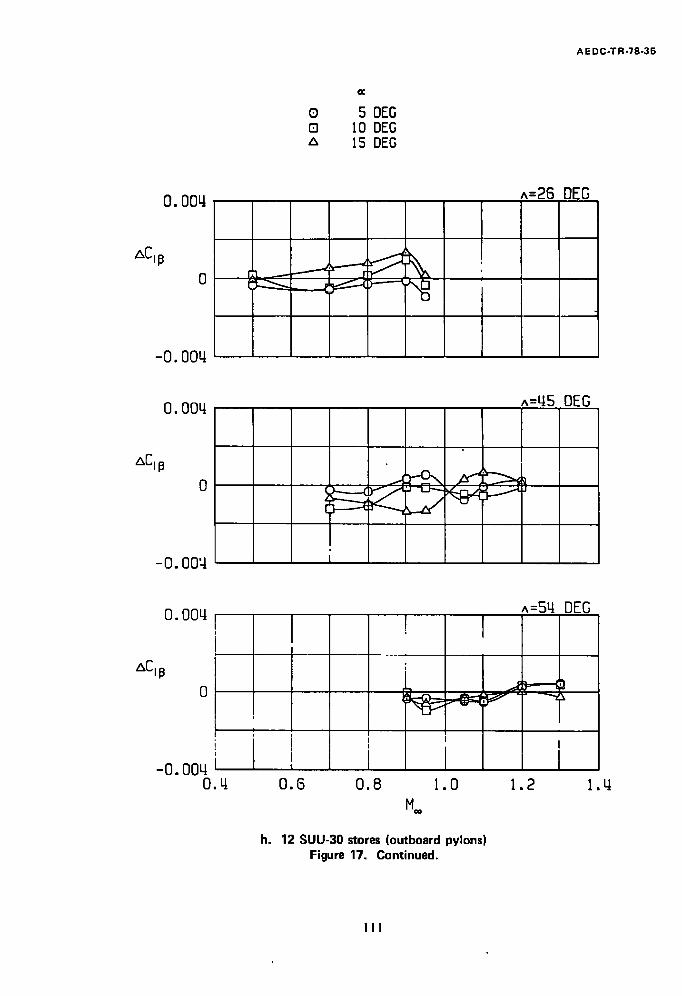
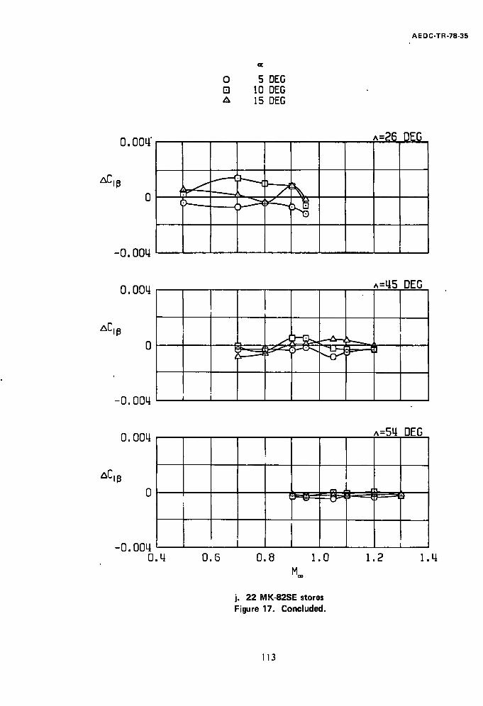
The effects of external store configurations on the effective dihedral are presented in Fig. 17. At A = 26 deg, pylon stores generally increased the effective dihedral (negative AC£/3) at a = 5 deg. At higher angles of attack, most pylon store configurations decreased the effective dihedral. In .particular, the incremental data in Figs. 17c and d, when compared to the clean configuration data in Fig. 9e, show that the GBU-15CCW with and without the extended Pave Tack pod degraded C~l 3 sufficiently to change the effective dihedral from favorable to unfavorable at a = 15 deg at M-- 0.7.
Increasing the wing sweep angle decreased the effect of pylon stores on the effective dihedral. However, at A = 45 deg, the low effective dihedral of the clean aircraft at a = 5
and 10 deg for M= > 0.9 allowed all pylon store configurations to reduce the effective
dihedral to near zero. Adding the extended Pave Tack pod to the aircraft with four GBU-15CCW stores had no significant effect on the effective dihedral.
11
AE DC-TR-78-35
5.0 SUMMARY OF RESULTS
Transonic wind tunnel tests were conducted to determine the effects of external stores on the aerodynamic characteristics of the F-I ! 1 aircraft. The results obtained are summarized as follows:
. For the moment reference point chosen, the clean aircraft model exhibited
near-neutral longitudinal stability for a 26-deg wing sweep angle and was
directionally unstable at high angles of attack at Math numbers 1.05 and 1.10.
. The clean aircraft model exhibited hysteresis effects during yaw polars for
all coefficients except the normal-force coefficient. The yawing-moment coefficient exhibited the most hysteresis effects. Addition of pylons, or
pylons and stores, significantly reduced hysteresis effects.
.
.
Generally, all pylon store and pylon configurations tested decreased the static longitudinal stability, except for Math numbers 0.8 and 0.9 at wing sweep angles of 26 deg, where pylons, single carriage, and AGM-65 store configuations increased the sta'tic longitudinal stability.
Adding pylon stores generally had little effect on the static directional stability at subsonic Math numbers except at M** = 0.9 and 0.95, where
the GBU-10, GBU-15CCW, and AGM-65 were destabilizing at high angles
of attack. All external stores increased the static directional stability at supersonic Math numbers.
.
.
Most pylon store configurations produced a favorable dihedral effect at an angle of attack of 5 deg and an unfavorable dihedral effect at higher
angles of attack at a wing sweep angle of 26 deg. Increasing wing sweep
angle decreased the effect of pylon stores on the effective dihedral.
Adding the extended Pave Tack pod increased the static longitudinal stability at Mach numbers above 1.0, increased the drag coefficient, decreased the static directional stability, and had no significant effect on the effective dihedral.
12

600"~ ~ . ~ / ~ 0.500 DIA. ~-AIRSTREAM SURFACE
o,~_ p'/////////////////z/~'-~.~ L~ ~ " ~'~'//'/ TYPICAL PERFORATED WALL CROSS SECTION
TUNNEL STATIONS AND DIMENSIONS ARE IN INCHES
uJ
~_ FLOW [ EXPANSION --~1
REGION l STA. STA. 0 . 0 36 .0
"OLID AREAS
7 PERFORATED WALLS ( I0 To MAXIMUM OPEN AREA)
5 . 8 5 °
,L•• ,., __- ~ ~~ _
84 .2 108.0 120.0 150.0 PITCH
- CENTER
Figure 1. Tunnel installation.
m o c) 11 O0
01
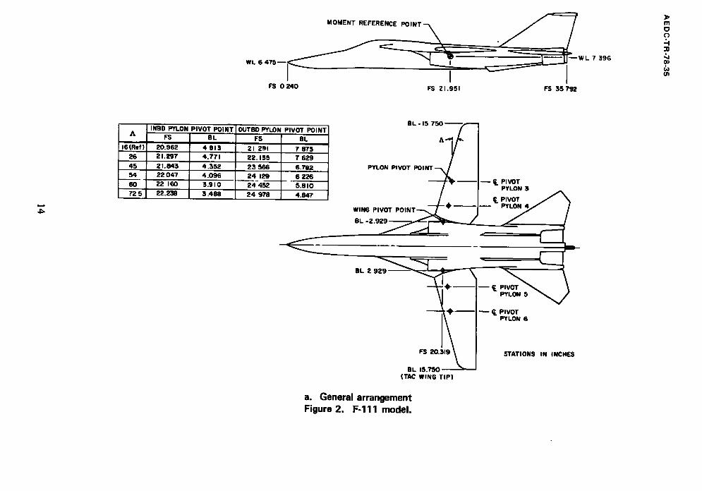
WL 6 4 7 5 - - I - - W L
I I FS 0 2 4 0 FS 21,951 FS 35792
7 396
3> m 0 C)
Co
ol
A
/6(Ref) 26 45 54 60 72 5
INBD PYLON PIVOT POINT FS BL
20.962 4 913 21.297 4.771
2 I, 843 4.352 22 047 4.096 22 160 3,910 22.238 3.488
OUTBO PYLON PIVOT POINT F-~ aC
21 291 7 873 22.135 7 629 23566 6.782 24 129 6 226 24-452 5.8 I0 24 978 4.847
EL -15
PYLON PIVOT
WING PIVOT
BL 2 929
, u ~. PIVOT PYLON 3
PIVOT PYLON 4
§L 2
m f p
~. PIVOT PYLON 6
FS 20.319 \ J STATIONS IN INCHES
BL 15.750 ~ (TAC WING TIP)
a. General arrangement Figure 2. F-111 model.
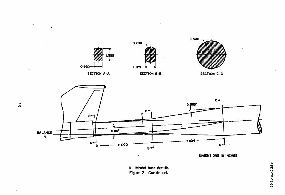
1.358
0 . 9 2 0 - - ~ - - ~
SECTION A-A
0.784 - - ~
1.129-~ SECTION B - B SECT,ON C-C
I ° 5 . 3 8 3 °
BALANCE
I_
5.85 °
- - 6 .000
b. iVIodel base details Figure 2. Cont inued.
-7 .594 - cJ DIMENSIONS IN INCHES
~> I11 o (3
-n
¢o
01
) O v IP LP D O LD D D D •
D o D o e ...... " o !
D e- o~~ 0
0 e O ° 0 ~ •
o e
'-"2-'.'.." ~O O • _ ° o ° o ~ W 0
O t 0
° I P o D e D O O O O O
c. Model photographs Figure 2. Continued.
AE DC 104-78
~> m c~ c)
:D
O0
01
-4
i!~ ~,, i'i ~ i~
~.i. ii/¸III ! iili iiiill i̧ i̧!i̧ i~i̧ i̧i̧ ~̧
• ,
• iiiii~!~ ~ iii.ii,i!i~ii
. ~ . ~ . ~ i .~ ~ . ~ : ~ ~" . ~ \ ~ ~ . - . . . . . . •
~ . "~i ~ ° ~ ~ . . ~
~;"~ • ~:i
~F
~i~ ̧
.......... i ~ ~
S t i n g F a i r i n g R e m o v e d m A E D C
c. Continued Figure 2. Continued.
m
.q -n
w
9 9 e ' O t i ~ ~ O
Q t O g S t i n ~ ' F a i t ' i n ~ I n s t a l l e d
9 ~ O e ~ O
t t :
ID
Q
O
Q
c. Continued Figure 2. Continued.
A E DC 275-78
I l l
c~
-I1
O0
¢JI

',,o
c. Concluded Figure 2. Concluded.
m
o
::0
0o
oi

0
O. 2 2 8 0 . 8 5 9 R - - 3 . 0 9 8 R
3 . 4 5 8 r ]
SECTION A - A
WL LOCATION POINT
WING CHORO'--T
i • WL ~
3* 0.325l 2 6 . 3 *
AXIS OF ROTATION
0 .750 o.l~, ;o~-\ 1, t"
1.718
A
ISrael)
-WL INSD PIVOT PY LON
8 . 0 2 2 26 8 . 0 1 6 45 a.ooe 54 8 . 0 0 3 6 0 8.0 0 I
72.5 8 . 0 0 0
OUTBD PIVOT PYLON 8.061 8 . 0 4 6 0.021 8 . 0 1 2 s. oo6 7 . 9 9 7
BRU-3A/A AND LAU-88 ATTACHMENT POINT
FWD 14-IN. SUSPENSION POINT
FWD 30* IN . SUSPENSION POINT
~> m 0 C)
oo
ol
Figure 3.
DIMENSIONS IN INCHES
a. Pylon External store suspension equipment.
WL
I . i °
L 6.885 -"
5.200
E 3.194 ~ 0.860 I~- ] I_
POINTS
0.141 ~ 0 . 3 3 5 J 14~0.235
I o N o2 o
p p / 3e
SECTION A-A OIMENSIONS IN INCHES
b. BRU-3A/A rack Figure 3. Continued.
}> I l l c~ -I :o CO
01
O. 166 - a
i . , _ _
m C) C~
0o
o l
-f" i
I - 3 . 9 8 9 1 DIMENSIONS IN INCHES
b J MAVERICK MS Q 4 8 8 AT CARRIAGE
1 . 4 8 8
, * " - I m I
, r " - -
_1_ / TAC PIVOT 7- 0.860 ~ ~ Y L O N ATTACHMENT
I
C -~ ÷ ' t ,I I
I 0.205
f
PYLON
~0.434~
c. LAU-88 triple-rail launcher Figure 3. Concluded.
0 560- 0387"" 0 286- ."
0 0 6 8 R - - \ _L. , \
I_}_o~56~- N o 2 . a o I I
0 1 8 4 ~
7 193
- - - 3609 ~ - - ~ POINT
-,.~3,-] _ .
_ I 0.6 FWO 3 0 - I N .
/ / -SUSPENS,ON ,S, , . - 0.,~,
-~'X
_ - - - - T ~ _ _ ~_
F-'I: o . . . . ,j 4~ ~--~,oo:~ o o , ~ . ~
DIMENSIONS IN INCHES
a. GBU-IO Figure 4. External stores,
~> m 0
o0 oi
i-0.012 FLAT WITH ,f]L.~.,,,~,ROU NDE 0 CORNERS
0.006 FLAT WITH /'J~ "~ FROUNDED CORNERS ~ [ ~
t / / ' ~ S 4 - O e 9 0.41TR(TYP) ~ ' ~ J ,., [ ~ " ~ HALF-ANGLE ~ L " - - - - 1 1 9 " - '
/ ~ "~ / - -O .uS2 ~ ~ ' J WEDGE (TYP) - ~ F ,- 7
(TYP)" O017R T 13 DEL SURFACE (~:yp) 0.979
o o , ; , 1 / \ _ L (TYF) v"~l"" ~" ~ ~ - - - - ' ~ " - ~ ~ t . - - - - . ,
- - / i t I "~,1 ; T - - S 3 I'--- '-Gs3 R----'~__J ~,,-~,_: MODEL '-"-" r ' ~ .~so s u R . c E 2 7 s o
SIDE v.sw S.DE V.EW S.DE V.EW STRAKE ANTENNA FIN
0.023 FLAT WiTH ROUNDED
~ - 0 . " 0 (
I H-o,4 ~~.~ f / r L,o-o,~
"~ ~ .
"~--MODEL SURFACE
)> rn 0 c)
-n
Do u1
t~
0 ,448 -
0.203R /
2.918 2.125 - -
_ [--0.625 D
6.433 • ~ - - - 2.612 -- FWD 30- IN.
SUSPENSION POINT ~ =
3.217 - - - - - 4.142
SIDE VIEW
,500N
" - - -0 .227
DIMENSIONS IN INCHES 2 . 4 5 ~
END VIEW
b. GBU-15CCW Figure 4. Continued.
BL 0.000 ~ m
t 0.834
I . i 6 8
MS 12.780
DIMENSIONS IN INCHES
c. Extended Pave Tack pod Figure 4. Continued.
0.667
83, ~ ° I _
" - 0 . 9 5 8 "-~
)> m
o ?
GO
01
1) m
w
b~
I.133R ~--~
1.321
4,O71 0.257-- ~ GOreS
L
DIMENSIONS IN INCHES
0 5 0 0 ~ . ~
oo,o_y~.\ y " ~" ~ 1 8 8
d. AGM-65 Maverick Figure 4. Continued.
~J
0 .155
l -
-FWD 1 4 - I N . SUSPENSION POINT
0 . 4 7 6 --
- - , . 5 4 3 ~ ° - '43- '1 I'- I
~ - 0. 7
. 7 0 4 R
: 3 . 7 5 3 L.. F 3 . 8 3 5 i
e. Rockeye Figure 4. Continued.
0 . 3 5 0 - - ~
. -0.090
DIMENSIONS IN INCHES
m o
::0 00
O1
3> m o c)
-n
O0
U1
t,,) OO
L
f 2.218 ,- 1.425 Ln ,moJ FIM) 14-IN. I I- " " " 1 susl~mmN I
-~ 0.3ff ~-I P O I N T ~
o.~-,~/~ O.I04D 0.147R ---/ /
/ 0.333R
3.833 ~. " I - - - o.7~s--
0.178 --- 0.149
_ 0.215
J T--0.031
0.181
45"
~ 0.!33 o~~ F--~ 0.100
O o . 2 2 _ ~ ~ o,~
OEMENSlONS IN INCHES
f. S U U - 3 O H / B Figure 4. Cont inued.
t,,.) %0
X,ifl. I R°IR
0.2 221 0.096 0.297 J 0.117 0.357 I O. 130 0.485 I O. 154 0.656 I 0.177 o.6z61 o.199 0.997 I 0.209 I . I 66 I 0.220 1.338 [ 0 =)24 CONST ImAM 1.893 I 0.224 2.o6 3 1 o.zzz 2.234 I 0 .2~" 2 .40410.206 2.479 i 0 201 2.47910 209 CONST. SLOPE 2.675 J 0.210 CONS~ SLOPE
3.440J O.088 CONST OIAM
3.74 210.088
0.222.--
O. 125D-~
T
~ 1 . 3 4 6
- - - ~ X
- 3.785
l f wo , , . , ,
SPENSION INT
g. M K-82SE Figure 4. Concluded.
J-'~--- I. 185
1
SLOT~IS " 0 0.073 DEEP
)43 45*
0.019 R " , ~ , ~ ~ 0.-
DIMENSIONS IN INCHES
m C~ c')
2)
co ol
A E DC-TR -78-35
0.05 (TYP)
- ~ - - 0.40
NOTE : TRANSITION GRIT USED ONLY FOR LIMITED TESTING TO EVALUATE TRANSITION GRIT EFFECTS
DIMENSIONS IN INCHES -1~ 150 TRANSITION GRIT
Figure 5. Boundary-layer transition grit pattern.
30
A E DC-TR -78-35
STORES
CLEAN
PYLONS ALONE
4 GBU- IO
4 GBU-15CCW
4 GBU-15CCW AND CENTERLINE PAVE TACK POD
12 AGM-65 ON LAU-88 RACKS
16 ROCKEYE (Slon! 4 Looding)
12 ROCKEYE
12 SUU-50 H/B
12 MK-82SE
22 MK- 82SE
BRU-3AIA RACK
N/A
N/A
N/A
N/A
N/A
FORWARD AFT
FORWARD AFT
FORWARD AFT
FORWARD AFT
FORWARD AFT
± LEFT
OUTBOARD
8
6 6
? ?
LEFT INBOARD
8
6 6
RIGHT INBOARD
8
6 6
RIGHT OUTBOARD
6 6
¢ ?
Figure 6. Pylon/store configuration identification.
31
t,J
0.6
A(2 DEG U PWAS H
0 . 4
0 ,2
0
WING SWEEP o 26 DEG z~ 45 DEG o 54 DEG
/ ~ . . . . . _ - . - - - . - ~
m 0 ¢3 :4 -n
00
01
- 0 . 2 0.5 0.6 0.7 0 .8 0.9 1.0 I.I 1.2 1.3
Figure 7. Tunnel flow angularity. Me=
CL 1.6
1.2
0.8
O.q
0
-O.q -I 0
~=o.5o
• d " ,, • d " . d l
.¢ i ),,,1¢
/ j , . ,j
,~.d / / .
/
- i
0 0 0 0 q 8 12 16 ~0
0.70 0.80 0.90 0.95 ( ] [
a. Li f t coefficient, A = 26 deg Figure 8. Aerodynamic characteristics of the F-111 aircraft,
clean configuration. ~> m O C)
-11
oo
¢n
CL 1.6
1.2
0 .8
O.q
0
-O.q -zl
..m==iimmm,~.=.,,'~ mum o i m l m m H K i P G i ~ I / K i I ~ limm)m olm
IN [Rimtimln/ / /ol i~_d F H / H / H B J / F J / ~ J / m l i imm/Bn Himm H~Jmm Hl~lm .HEIB mm~mm m
J~
F
_n
0 0 0 0 0 0 0 q 8
H==0.70 0.80 0.90 0.95 1.05 1.10 I. 20
L2
G[
]> m
¢o
O1
a. Continued, A = 45 deg Figure 8. Continued.

CI_ 1.6
1.2
0.8
0.tl
-0.~ -tl
( i i i
0 0
H~=0.90 o.95
w
C
mmmlmmmmEMllmm_mm mmEmm mmm um)mE
am! a m . ul Im.,, m u)m,.:,mmam)mu )m m)mmmmmmmm )k mm. m mm.mm
mNmmmmmNmmmmmm !. !I!!lllllll
0 0 0 0 q 8 12 16
1.05 I.I0 1.20 1.30
a. Concluded, A = 54 deg Figure 8. Continued.
if> m
o
::0 .b (DO
tin
CL 1.6
1.2 ~'~
0,8
° $
-O.q 0.2 0
Ho==O. 50
$
(~.
d Y , /
()
)
0 0 0 0
0.70 0.80 0.90 0.95
/
b. Pitching-moment coefficient, A = 26 deg Figure 8. Continued.
-0.2 -o.q -0.6
Cm
m 0
-n
¢0
01
taJ
CL ! .6
1.2
0.8 l~
0,4
i -0,4
0.2 0
H==o. 70
i ;/
f
2
? f
c/
n
- d J
? /
/ /
~ o ~
,4 f
/
d
X f
J
mr
J .j
/
P /
EY
/ P
/
0 0 0 0 0 0
0.80 0.90 0.95 1.05 1 . ]0 1.20
J /
d
-0.2 -0 .4 -0.6
Cm
b. Continued, A = 45 deg Figure 8. Continued.
~> m o c~
30
(%)
oi
CL
1.6
! . 2
0 .8
O.tt
-0 .~
/ ~r p,
I
/
r i
I
I 0
1.05
0.2 0 0
~=0.90 0.95
,I , /~/o
• :i" o
0 0 0
1.10 1.20 1.30
-0 .2
b. Concluded, A = 54 deg Figure 8. Continued.
A P
~o
-0.~ -0.6
Cm
m 0 c~
~o
O0 & 01

CL 1.6
1.2 r t: ~ )
'.~ ~ g J <i' ~ J° f °." ~ ~ '~ 2 ~'
0~ ~: ~; ~
-o.q 0 0 0 0 0
1~:0.50 0.70 O.BO 0.90 0.95
c. Drag coefficient, A = 26 deg Figure 8. Continued.
/ P .o . _
0.2 O.q 0.6
CD
m
? "-I
Co
Ol

0
CL 1.6
] .2
0.8
O.Ll
/
-O.q~ 0 0 0
!'4o==0.70 O. 80 O. 90
t ' : l
Y
;i
Y
t "
T ? ? ? ? ?
.o
J,
0 0 0 0 0.2 O.q 0.6
0.95 1.05 I.I0 1.20
c. Continued, A = 45 deg Figure 8. Continued.
CD
3) m o o
-n
G0
O l
J
1.6
CL
1.2
0 .8 ¢
O.tt (~
o8
-O.q 0
M.=0.90
1 4
f:.
¢
¢:. :F f , ~ ,m
4
0 0 0 0
0.95 1.05 1 . !0 ].20 0 0.2
I. 30
0.~ 0.6
CD
C. Concluded, A = 54 deg Figure 8. Continued.
~> I l l
,o -4 "n
O0
01
A EDC-TR-78-35
5YM ALPHA
O 5 OEG D 10 DEG ~ ' 15 DEG
0.95 o
0. q
' [ 0.2 ~ ~ ,
• ~ ~ , ~=0.50 o
0.70 o
0.80 0 . ~--
o.9oo ~ , ~-
-0.2 ! i f
i J I -12 -8 -q 0 q 8 12
B
d. Side-force coefficient. A = 26 deg Figure 8. Continued.
42
AE DC-TR-78-35
5YM ALPHA
0 5 DEG [] 10 OEG A 15 OEG
O.tl Cy
0.2
M==0.70 o
0.80 o
0.90 o
0.95 o
1.05 0
1.10o
1.20 o
-0.2
l
|
-O.q -12 -8 -q 0 q 8 12
d. Continued, A = 45 deg Figure 8. Continued.
B
43
A E D C - T R - 7 8 - 3 5
5YM RLPHR
® 5 DEG [] IO DEG
15 DEG
O.q Cy
0.2 1
H==O. 90 o
0.95 o
1.05 o
I,I0O
1.20 o
1.30 o
-0.2
-o.q -12
-"~s.. h I I I
I -8
r
I -q 0 q, 8 12
B
d. Concluded, A = 54 deg Figure 8. Continued.
44

AE DC-TR-78-35
SYH RLPHR
® 5 OEG Q lO OEG
I5 DEG
0.0q
Cn 1 o o
M==o.soo ~ ~ ~ ~ ,
0 . 7 0 o ~ ~ ~ - ~ - ~
o~oo ~ ~ ; ~ ~ ~ ~,~¢~~
0.900 , ~ ~ ~ ~,~ ~,, ~ .~=~~-~-
0.95 o
-o.o2 ' - ~ ~ ~ ~ "
-o.oq -12 -8 -q 0 q 8 12
B
e. Yawing-moment coefficient, A = 26 deg Figure 8. Continued.
45
A EDC-TR-78-35
5YH RLPHR
0 5 DEG [] 10 DEG A 15 DEG
0.04 co [
O. 02 [
H~=O. 70 o - ,
o.~oo '~ "i .~ ~ _
1.05 o ~-'~ ~="~
1.1oo ~ ~ - ~ ~ ~
1.20 0 . ~ ~ ~ -0.02
-0.04 -12 -8 -q 0 q 8 12
e. Continued, A = 45 deg Figure 8. Continued.
B
46
A E D C - T R -78 -35 =
5TH RLPHR
O 5 OEG B 10 DEG z, 15 DEG
O.Oq
Cn
0.02
.==0.900 ~ ~ . . . ~
0 .95 o
1.05 o
I.I0O
1.20 o
1.30 o
-0.02
. . m l °
E .,..~ f -
-0. Oq -12 -8 -q 0 q 8 12
i
e. Concluded, A = 54 deg Figure 8. Continued.
8
4?
AEDC-TR-78~5 5YM RLPHR
¢ 5 DEG D 10 DEG A 15 DEG
0.0q CI
0.02 i ~ 1 ~ ~
,~:o.5oo -~N~..~ _N..~~
o.~oo , ~ ,. - - , ~ ~ ~ - ~
_3_ ~L. G.._ o.8oo , -.~~,~~..~
o.ooo
O. 95 o ~--~,,~
-0.02 ~ , ~ , , ~
-0.0~ 1 ] ' :1 " - ]2 -8 -4 0 ~ 8 12
B
f. Rolling-moment coefficient, A = 26 deg Figure 8. Continued.
48
A E DC-TR-78-35
5TM RLPHR
O 5 BEG O I0 OEG A 15 DEG
0 . ~
CI
0.02
~ ~:~
~ " ~ • ~ ~ 0.95 o. ",~.~, , ~ ! ~ -
1.05 0 ,~ -;.--~ " " - -
1 . 2 0 o ~ i ~ ,- :
-0 .02 - - : " ~ , ~
-12 -8 -Li 12
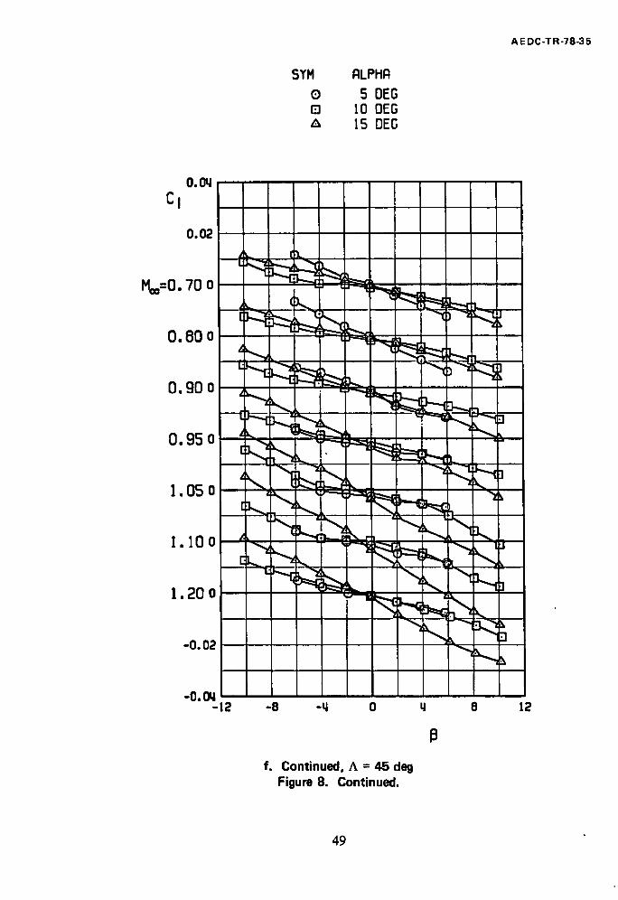
f. Continued, A = 45 deg Figure 8. Continued.
13
49
AEDC-TR-78~5
$YH RLPHR
O 5 OEG [] I0 OEG A 15 DEG
o.oq CI
o
~=o.,oo ~~ ,,~:~. 0 .95 o [ ~
. ~ - - -
N~ t 1.20 o
1.3oo ~ ~ ~
-o.o~ I ~
-0. Oq I -12 -8 -q 0 I& 8 12
13
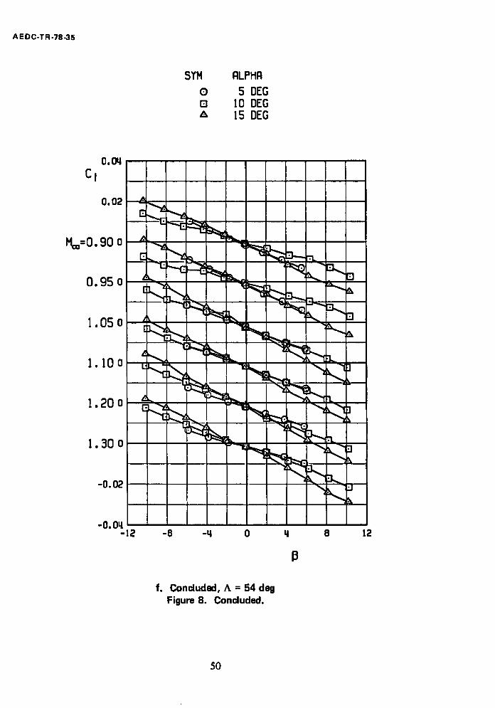
f. Concluded, A = 54 deg Figure 8. Concluded.
50
A E D C - T R - 7 8 - 3 5
CL(~
0.20
O. I 0 ? ~ - - ~"---~...(~.-o
A = 26 DEG
0
CLa
0.20
0.10
0
A = 45 DEG
CL a
0.20 A = 54 DEG
0.10
0 0.4 0.6 0.8 1.0 1.2 1.4
M=
Figure 9. a. Li f t curve slope
Static stability derivatives and drag coefficients of the F-111 aircraft, clean configuration.
5]
A E D C -T R -78 -35
SM
0.40
0
0 LINEAR CURVE FIT, -2 < ~ <_ 6 DEG [] SLOPE AT CL= 0 0 SLOPE AT CL= 0 .2 Z~ SLOPE AT, C L - 0 .4 0 SLOPE AT C L = 0.6
A = 26 DEG
- 0 . 4 0
SM
0.80
0.40 / Y
A=45 DEG
SM
0.80
0 . 4 0 . J
A=54 DEG
0 0.4 0.6 0.8 1.0 1.2 1.4
b. Static margin Figure 9. Continued.
Me=
52
AEDC-TR-78-35
CD
0.20
O,IO
0
CL o 0 z~ 0.2 n 0.6
4~
A = 26 DEG
CD
0.20
0 .10
0
A = 45 DEG
CD
0.20
0.10
0 0.4
A = 54 DEG
0.6 0.8 I.O 1.2 M=
1.4
c. Drag coefficient Figure 9. Continued.
53
A E D C-TR-78-35
0.002
Cn/~
0
- 0 .002
¢1
o 5 DEG o I0 DEG A 15 DEG
A = 26 DEG
0 002
Cn8
0
- 0 . 0 0 2
A = 4 5 DEG
0 002
Cn/~
0
- 0 . 0 0 2 0.4
d.
A = 54 DEG
0.6 0.8 1.0 1.2 1.4
Me=
Static directional stability derivative Figure 9. Continued.
54

J
AEDC-TR-78-35
0 .004
C ~
0
- 0 . 004
G
0 5 DEG n I0 DEG A 15 DEG
A = 26 DEG
c l .e
0 .004 A =45 DEG
0
- 0 . 0 0 4
0 .004 A = 54 DEG
0
- 0 . 0 0 4 0.4 0 .6 0 .8 I .0 1.2
e. Effective dihedral Figure 9. Concluded.
1.4
M =
55
1 , 6
Re x 10 -6
PT M= = 0 .50 M= = 0.90 O 1200 1.71 2.41 zl 2000 2.80 3.99
~> .m 0 0 H "11
u1
U'I O~
CL
1.2
0 . 8
0 , 4
0
J
Mea = 0 .50 Me= = 0 . 9 0 _ _ D
J
- 0 . 4 - 4 0 0 4 8 12 16 20
(2
a. L i f t coefficient, A -- 26 deg Figure 10. Reynolds number effects.
Re x I0 -6
PT Me= = 0.90 Me= = 1.30 0 1200 2.4 I 2.55
2000 4.09 3.99
CL
1.6
1.2
0.8
0.4
0
- 0 . 4 - 4
S
I M~ = 0 .90
D
S, f S ,o_
/
0 0 4 8 12 16
a. Concluded, A = 54 deg Figure 10. Continued.
1.30 - -
20 O(
]> m o o
O0
1.6
CL
1.2
0.8
0 .4
0
Re x 10 -6 PT M,.. : 0 .50 M=o = 0.90
0 1200 1.71 2.41 "~ 2000 2 .80 :3.99
Moo = 0.50
U Moo = 0 .90 /C
f
m 0 ¢3
3J
(]0
01
- 0 . 4 - 0 . 2 0 0 -0 .2 -0 .4 - 0 .6
b. Pitching-moment coefficient, A = 26 deg Figure 10. Continued.
-0 .8 Cm

O A
Re x 10 -6
PT Me= = 0.90 Me= = I.:50 1200 2.41 2.55 2000 4.09 :5.99
CL
1.6
1.2
0.8 /
/ 0.4
S 0
/
/
I Me= = 0.90
/
M.,~=
¢ /
/
I . 3 0
/
- 0 . 4 0.2 0 0 -0.2 -0 .4 -0 .6 -0.8
b. Continued, A = 54 deg Figure 10. Continued.
Cm
~> I11
¢3
;0
00
O1
O
1.6
CL
1.2
0.8
0.4
(
o-I (
- 0 . 4 0
Re x 10 -6 PT M== = 0 .50 M== = 0.90
O 1200 1.71 2.41 Z~ 2000 2.80 3.99
r j t
w r
# J
u
IJ
o
v
0
M= = O. 5 0 j . . ~
J /
0 0.1 0.2 0.3
I M== = 0.90
. i o J
c. Drag coefficient, A = 26 deg Figure 10. Continued.
f
0.4 CD
0.5
m
o :4
00
O1
o zl
Re x I0 -6
PT Me= = 0 .90 M=o = 1.30 1200 2.41 2.55 2 0 0 0 4 .09 3.99
CL
1.6
1.2
0 .8
0 .4
O.
- 0 . 4
1, __I I ------4'
/ :
M= = 0 . 9 0
,..O
M= = I .30
/ /
O 0 0 I 0 .2 0,5 0 .4 O,5
C. Concluded, A = 54 deg Figure 10. Concluded.
CD
~> ITI
(1
-n
00
O1
O~ t ' J
GRIT OFF
1.6 ON
c L 1 i ~ I i i I i , I . I I ! • , J ~
i~ .(i, ./!/F,, I i-t I o . , j ' ~ " i ~ ' I " , III
J I e I I - o . q '
-q 0 0 0 0 0 q ' 8 12 16
M~=0.50 O. 70 0.80 0.90 0.95
a. Lift coefficient Figure 11. Transition grit effects, A = 26 dell.
20
3> m
9 =0
co
Ol
( ~
GRIT
0 OFF A ON
C L ; ! f . . . . . . . . . . . . . i " . . . . . tZ i . . . . . . . . ~ . . . . . . . .
- - - T ~ f ~- i 3 ~ o,, - [ -~,-~ - - ~ - - " ' ~ .... ! -~ ! - - - r
o,, -FI~ -!-r ~ q ! . - - ' - 4 5 . . . . .:-':~ . . . . - ~
i ' ~ , Z
o ..... ~ . . . . . ~.~ . . . . . ._:~ %
I ! ! , i -o.q
0.2 0 0 0 0 0 -0 .2 -0.4 -0 .6
L
-0 .8 -! .0
M ~ = 0 . 5 0 O. 70 0 . 8 0 0 . 9 0 0 . 9 5 Cm
b. Pitching-moment coefficient Figure 11. Continued.
m o
.h
4j
O~
GRIT
-O.q 0 0 0
OFF
"° ,I ! ! i., J c L i -i , • ' - .
0 .8
o.~ ~ I
!, i 1 0 0 0.2 0.q 0.6
H~=0.50 O. 70 0 .80 0 .90 0 .95 CO
m O (3
:0
0o
ol
c. Drag coefficient Figure 11. Concluded,
O WITHOUT STING FAIRING WITH STING FAIRING
O~ u ' l
CL 1.6
1.2
0 . 8
O.q
0
-o .q ' -q
m
4 i , !
= ! I i ; i
, i i l i
, !
i i I I
i I
I L 0
M==O. 50 0
O. 70
0
O. 8 0
Figure 12,
I ! l I
i !
i
I i i ! =
0 0
0.90 0.95
a. L i f t coef f ic ient
,tL 1 ~-,-q I
q 8 12 16
OC
Sting fair ing effects, A = 26 deg.
I
20
> I l l
O o q -n 4j
f,,11
CL 1.6
] . 2
0.8
0.q
0
-0 .q
O A
WITHOUT STING FAIRING WITH STING FAIRING
, I = I ' i
P p . . . . ~ . . . .
.{ , J !
; I
i
i
' i
!
{
0.2 0
M==O. 50
}
i I I ! = 0 0 0 0
0 . 7 0 0 . 8 0 0 . 9 0 0 . 9 5
b.
I } I }
Pitching-moment coefficient Figure 12. Continued.
-0 .2 -o.q -0 .6 -0 .8 -1 .0
Cm
m [3
3] 4j O0
01
0~ -..I
WITHOUT STING FAIRING WITH STING FAIRING
l . B ; . I , , I i
c, ~ 1 ~ . . . . L_J_~ k_v ._/.~_ ; , 1 ) "~-- " ~-~," - - -
. I
! -O.q
0 0 0 0 0 0 . 2 o.q 0.6
C ) ! . ~ . ~_
Mco=0.50 0.70 0.80 0.90 0.95 C O
c. Drag coefficient Figure 12. Concluded.
m
c) 11 ,b w
01
A E D C - T R - 7 8 - 3 5
CN
1.4
1.2
I.O
_ J J i
o INCREASING /3 A DECREASING /3
CLEAN
' t
!
I I
CN
1 . 4 ,
12
1.0 w
I 2
I - 8 -~ 0
I
I 4
Figure 13.
12 SUU- 30 STORES
a. Normal-force coefficient Typical hysteresis effects, ~ = 15 deg, A = 45 deg, M= = 1.2.
8
- j
12
68
AEDC-TR-78-35
Cm
- 0 . 5 0
- 0 . 6 0
- 0 . 7 0
0 INCREASING B A DECREASING B
CLEAN
Cm
- 0 . 5 0
- 0 . 6 0
- 0 . 7 0 - 1 2 -8 -4 0 4 8
b.
12 SUU-30 STORES
Pitching-moment coefficient Figure 13. Continued.
12
P
69
A E D C - T R - 7 8 - 3 5
CA
0.060
0.050
0.040
0.030
0 INCREASING /3 /x DECREASING /3
I
c ~ t ' i
I I
i
I t !
i I i
CLEAN
CA
0.8
0.7
0.6 -12 - 8 - 4
I i
J ! I
0 4 8
1.2 SUU-30 STORES
c. Axial-force coefficient Figure 13. Continued.
12
70
A E D C - T R - 7 8 - 3 5
Cy
0,4
0,2
0
-0.2
-0.4
o INCREASING ,8 A DECREASING ,8
CLEAN
Cy
0.4
0,2
0
-0.2
- 0,4 -12
I I I
I I - 8 - 4 0 4
12 SUU-30 STORES
d. Side-force coefficient Figure 13. Continued.
I
I
8 12
7l
A E D C - T R - 7 8 - 3 5
Cn
0 . 0 2
0.01
0
- 0 0 1
- 0.02
o INCREASING ,8
"~ DECREASING
i i
, / I
I
I
CLEAN
I
Cn
0 .02
0 0 1
0
-0 .01
- 0 .02 -12
I , I - 8 - 4 0 4
I
I
J
12 SUU- 30 STORES
e. Yawing-moment coefficient Figure 13. Continued.
I
8 #
12
72
AE DC-TR-78-35
Cl
0.04
0 .02
0
- 0 .02
- 0 .04
O INCREASING ,8 z~ DECREASING ,8
i !
I I I
CLEAN
Cl
0 .04
0 02
0
-o.o2
-0.04 -12 -8 - 4 0 4 8
12 SUU-$O STORES
f. Rolling-moment coefficient Figure 13. Concluded.
12
73

AE D C - T R - 7 8 - 3 5
O. 20 ^=26 DEG
ASM 0
~,.-------.....~
1
-0.20
O. 20 ^=q5 0E0
ASM
0
-0.20
0.20 ^=5q DEG
ASM
0
-0.20 0.q 0.6 0.B 1.0 1.2 I.~
M®
Figure 14. a. Pylons alone Effects of external stores on the static margin.
74
A E DC-TR-78-35
0.20 ^=26 DEG
z~SM 0
-0.20 I
\/
0.20 ^:L15 0EG
~SM
0
-0.20
O. 20
ASH
0
-0.20 0.u,
A=5~ DEG
0.6 0.B 1.0 1.2 1.4 M®
b. Four GBU-10 stores Figure 14. Continued.
75
AEDC-TR-78-35
O. 20 ^=2B DEG
ASM
0
-0.20
O. 20
zxSM
0
I
r(p-
^=45 OEG
-0.20
0.20
z~$M
0
=̂5u, DEG
-0.20 0.Ll 0.6 0.8 1.0 1.2 1.4
M®
c. Four GBU-15CCW stores Figure 14. Continued.
76
A E D C - T R - 7 8 - 3 5
0.20 ^=26 DEO
ASM
0 C ~-----
-0.20
0.20
z~SM
O
-0.20
A=45 DEG
0.20
ASM
0
-0.20 0.L~
I |
0.6
d.
L_
0.8 H®
^:54 DEG
1.0
|
I I
1.2 1,L~
Four GBU-15 stores and extended Pave Tack pod
Figure 14. Continued.
77
~-. E D C - T R - 7 8 - 3 5
O. 20 ^=26 DEG
~SM
0
-0.20
0.20
zxSM
0
-0.20
I I i
^=45 DEG
0.20
ZXSH
0
-0.20 O.LI 0.6 0,8
V
I
1.0 M®
^=54 OEG
1.2 1.Lt
e. 12 AGM-65 stores Figure 14. Continued.
?8
AE DC-TR-78-35
0.20 ^=26 OEG
ASM
0
-0.20
0.20
z~SM
0
",,(i)...-(~>~ )
^=q5 OEG
-0.20
z~SM
0.20
0
^=5LI OEG
~ J ( " " ' - ~ " D
- 0 . 2 0 O.q 0.5 0.8 1.0
M O0
f. 16 Rockeye stores (slant 4 loading) Figure 14. Continued.
I I
1.2 1.u,
?9
A EDC-TR-78-35
0.20 ^=2B OEG
z~SM
0
. _ _ _ _
!
-0.20
O. 20 ^=45 DEG
aSM
0
-0.20
~5M
0.20
0
^:5LI DEG
-0.20 O.LI 0.6 0.8 1.0 1.2 I.~
M®
g. 12 Rockeye stores (outboard pylons) Figure 14. Continued.
80
A E DC-TR-78-35
0.20 A=2B OEG
z~SM
0
-0.20
(i)------
0.20 A=q5 OEG
z~SM
0
-0.20
0.20
z~SM 0
A=5q
..._--<
OEG
- 0 . 2 0 O.q
h.
0.6 0.8 1.0 M=
12 SUU-30 stores (outboard pylons) Figure 14. Continued.
1.2 l . q
81
A E D C-TR-78-35
O, 20 ^=26 DEG
ASM
0 C)----.
-0, 20
O. 20 ^=LI5 DEG
z~SM
0
-0.20
0.20 ^=5Li OEG
z~SM
0
-0.20 o.q 0 .6 0 .8 1.0
M®
I I
1.2 1.Ll
i. 12 MK-82SE stores (outboard pylons) Figure 14. Continued.
82
AE DC-TR-78-35
O. 20 ^=26 OEG
z~SM 0-----
0
-0.20
O. 20
ASH
0
^:~5 OEG
-0.20
0.20
ASH
0
- 0 . 20 O.U,
^=5~ DEG
0.6 0.8 1.0 1.2 1.q H®
j. 22 MK-82SE stores Figure 14. Concluded.
83
A E D C - T R - 7 8 - 3 5
O A
o
CL 0 0.2 0.6
0.08
O. 06
O.Oq
0.02
0
-0.02
^=26 DEG
I I I I l
0.06
O.Oq
0.02
0
-0.02
0.08 I I
I ^=U,5 DEG
O. 08
0.06
^=SLI DEG
O. Oq
O. 02
0
-0.02 I T 0.~ 0.5 0.6 0.7 0.8 0.9 1.0 I.I 1.2 1.3 I.~
M®
a. Pylons alone Figure 15. Effects of external stores on
the drag coefficient.
84
0 A []
CL 0 0.2 0.6
AE DC-TR-78-35
0.08
0.06
O. Oq ,'Co
0.02
0
-0.02
¢ m , - , ~
^=26 DEG
0.08
0.06
O.Oq
O. 02
0
-0 .02
I i
, I
^=q5 DEG
t
0.08 ^=5u, DEG
0.06
O.Oq
~co O. 02
0
-0 .02 I i
I !
!
I a
O.q 0.5 0.6 0.7 0.8 0.9 1.0 1.1 M®
I •
I !
1 . 2 1 . 3 1 . ~
b. Four GBU-IO stores Figure 15. Continued.
85
A E D C - T R - 7 8 - 3 5
o t .
' 7
CL 0 0.2 0.6
O. 08
O. 06
0.0~
0.02
0
-0.02
i==.===
I !
^=26 DEG
0.08
0.06
O. Oq ",Co
0.02
0
-0 .02
I I : ' i
[ ; , i
^=L~5 DEG
I
I
0.08
0.06
O. OLt
O. 02
0
-0.02 0.Lt
A=5U, DEG
0.50.60.70.8
I I I
0.9 1.0 1.1 1.2 1.3 H®
c. Four GBU-15CCW stores Figure 15. Continued.
].u,
86
O A
CL 0 0.2 0.6
A EDC-TR-78-35
0,08
0,06
0,0~
0,02
0
-.",02
O, C8
F
^=26 DEG
I I
^=~5 DEG
0,06
O, Oq
0,02
0
-0, 02
0,08
0,C6
O.OU.
O, 02
0
-0, 02 O.q 0.5
^:5tL DEG
I I i ~ ' l
i I!111 I i ~ I I I I I
0.6 0.7 0.8 0.9 1.0 1.1 '..2 1.3 P®
d. Four GBU-15CCW stores and extended Pave Tack pod
Figure 15. Continued.
87

A E D C - T R - 7 8 - 3 5
CL o 0.0 ~- 0.2 [] 0.6
0.08
0 .06
0.0'4
0.02
0
-0.02
J
^=26 DEG
0.08
O. 06
O. Oq
O. 02
0
-0.02
^='45 DEG I i , I I t
I I '
I
1 I I
O. 08
0.06
0.0'4 i ~co r
0.02 I 1
i
a i -0° 02 1
I I , I ! I ' ' I !
I I
^=5'4 DEG
0.4 0 .5 0 .6 0 .7 0 . 8 0 .9 1,0 1.1 1.2 1,3 1,'4 H®
e. 12 AGM-65 stores Figure 15. Continued.
88
0 A [ ]
CL 0.0 0.2 0.6
A E D C - T R - 7 8 - 3 5
O. 08
0.06
0.04
O. 02
0
-0.02
A=26 DEG
= t
I I
-,co
0.08
0.06
0.04
0.02
0
-0.02
A=45 DEG
i===d
0.08
0.06
O. 04 "co
0.02
0
-0.02 0.4 0.5 0 . 6 0 . 7 0 . 8 0 . 9
A=54 DEG
!
1 . 0 1 . I 1 . 2 M®
1.3 1,q
f. 16 Rockeye stores (slant'4 loading) Figure 15. Continued.
89
A E D C-TR-78-35
0
[ ]
CL 0 0.2 0.6
0.08
0.06
0.0q ~ro
0.02
0
-0.02
T i
^=26 DEG
0.08
0.06
0.0q ,,r. o
0.02
0
-0.02
^=u,5 DEG
,%
0.08
0.06
0.0q
0.02
0
-0.02
^=5Lt DEG
~ r
O.q O.S 0.6 0.7 0.8 0.9 1.0 1.1 1.2 1.3 1.q M®
g. 12 Rock~,e stores (outboard pylons) Figure 15. Continued.
90
0.08
O. 06
0.04 ,,co
0.02
0
-0.02
0.08
0.06
O. 04
0.02
0
-0.02
0.08
0.06
O.Oq
O. 02
0
-0.02 0.4
CL ® 0 ~" 0.2 0 0.6
^=26 DEG
~======== ~=- - - - - - . . . , I = , - = ' ~ - -
^=45 DEG
,=,=~!
^=54 DEG
0.5 0.8 0.7 0.8 0.9 ] . 0 I. 1 1.2 M=
h. 12 SUU-30 stores (outboard pylons) Figure 15. Continued.
=
AE DC-TR-78-35
1.3 l .q
91
A E D C - T R - 7 8 - 3 5
CL o o A 0.2 o 0.6
O. 08
0.06
O. OLI
O. 02
0
-0.02
^=26 DEG !
f
0.08
O. 06
0.0~
0.02
0
-0.02
^=q5 DEG
I
I i I
I
0.08
O. 06
O. OLI
0.02
0
-0 .02
^=5q DEG = I
i
I
O.q 0.5 0.6 0.7 0.8 Om9 1.0 1.1 1.2 1.3 1.q
i. 12 MK-82SE stores (outboard pylons) Figure 15. Continued.
92
CL
o o A 0.2 [] 0.6
A E D C-TR-78-35
0.08
0.06
O.Oq I ",co
0.02
-0.02
, P
i
^=28 OEG
O. 08
O.OB
O.OLt
0.02
0
-0.02
^=q5 DEG
^co
0.08
0.05
O. 0q
0.02
0
-0.02
, ^=5L1 DEG
I
0.~ 0.5 0.6 0.7 0.8 0.9 1.0 1.! 1.2 1.3 1.4 M®
j. 22 MK~2SE stores Figure 15. Concluded.
93
AEDC-TR-78-35
0 5 OEG o I0 DEG
15 DEG
0.002 ^=26 OEG
0
-0.002
7" , . i t
• A
&
!
0.002 ^=LI5 OEG
0
-0 .002
0.002 ^=5~ OEG
A% 0
-0. 002 0.4 0.6 0.8 1.0 1.2
M®
a. Pylons alone Figure 16. Effects of external stores on the static
directional stability derivative.
1.q
94
A EDC-TR-78-35
0 5 DEG [] I0 DEG A 15 DEG
O. 002 ^=26 DEG
0
-0. 002
O. 002
'%B 0
-0. 002
^=q5 OEG
O. 002
,,% 0
-0. 002 O.q
^=5q DEG
0.6 0 .8 1.0 1.2 1.~ M®
b. Four GBU-10 stores Figure 16. Continued.
95

AE DC-TR-78-35
Q 5 OEG [] I0 DEG
!5 DEG
O. 002 ^:26 DEG
0
-0. 002 [
O. 002
0
-0. 002
^=LI5
I I
OEG
O. 002
0
-0. 002 0.~
^=5~ DEG
0.6 0.8 1.0 1.2 1.~ M®
c. Four GBU-15CCW stores Figure 16. Continued.
96
AE DC-TR-78-35
o 5 DEG [] 1o DEG
]5 OEG
0.002 ^=26 OEG
~CnB 0
-0.002 nmmiml 0.002
^=45 DEG
~r~B 0
-0,002
, , ~ _ M
! o. 0o2 !
,,c~ B 0
-0. 002 O.L~
^=5~ DEG
d.
0.6 0.8 1.0 M®
Four GBU-15CCW stores and extended Pave Tack pod
Figure 16. Continued.
1.2 1.Ll
97
A E DC-TR-78-35
C) [] A
5 DEG 10 DEG 15 DEG
0.002 ^=26 DEG
~c~B 0
-0.002
t
n L i
0.002
0
-0.002
^=~5 DEG
0.002
~c~ 0
-0. 002 O.LI 0.6 0 .8
^=5g DEG
±
1.0 M®
1.2
e. 12 AGM-65 stores Figure 16. Continued,
98

A EDC-TR-T8-35
0 5 DEG 0 lO DEG
15 DEG
0.002 ^=26 OEG
~CnB 0
-0.002 I I
0.002
~c~ 0
-0.002
I f
A=~5 OEG
0.002 ^=54 DEG
~CnB
-0. 002 O.LI 0.6 0.8
I
i I 1.0
M®
i 1.2
f. 16 Rockeye stores (slant 4 loading) Figure 16. Continued.
1.L;
99
A E D C - T R - 7 8 - 3 5
0 5 DEG [] I0 DEG
15 DEG
O. 002 ^:26 OEG
~c~ B
-0. 002
°
I
i
O. 002 A=U,5 DEG
~c~ 0
-0. 002
O. 002
,,c~ B 0
-0.002 0.~ 0.6 0.8
M®
^=5~ DEG
I i
1.0 1.2 1.L1
g. 12 Rockeye stores (outboard pylons) Figure 16. Continued.
100
AE DC-TR-78-35
0 5 DEG 0 IO DEG
15 DEG
O. 002 ^=26 OEG
0
-0. 002
O. 002 ^=~5 DEG
c.B 0
-0. 002 I
O. 002 ^=5g DEG
0
-0.002 O.g 0.6 0.8
I 1.0
M®
h. 12 SUU~O stores (outboard pylons) Figure 16. Continued.
I 1.2
101

AEDC-TR-78-35
0 5 DEG [] I0 DEG
15 DEG
O. 002
0
-0. 002
8 a
I I
^=2B DEG
O. 002 ^=LI5 DEG
~r~B
0
-0. 002
O. 002 ^=5LI DEG
~c~ B
-0. 002 O.L~ O.B 0.8 1.0 1.2 I.~
M®
i. 12 MK-82SE stores (outboard pylons) Figure 16. Continued.
102
A E D C - T R - 7 8 - 3 5
0 5 DEG o 10 OEG z~ 15 DEG
0.002 ^=26 OEG
0
-0.002
{ {
O. 002
~c~ B 0
-0.002
T "
^:q5 DEG !
0.002 ^=5q DEG
At-. B
0
-0. 002 o.q 0.6 0.8 1.0
M®
j. 22 MK-82SE stores Figure 16. Concluded.
I
1.2 l . q
103
AE DC-TR-78-35
0 5 DEG 0 I0 DEG A 15 DEG
O. OOLI ^=26 DEG
~CI~
-0. OOq
O. OOL~ =̂L15 DEG
AC~ B
0
-0. ooq
O. OOU, ^=5q DEG
ACre B
0
- 0 . OOL~ O.q 0.B 0.8 1.0 1.2 l.U,
M®
Figure 17. a. Pylons alone
Effects of external stores on the effective dihedral.
104
AE DC-TR-78-35
0 5 DEG [] I0 OEG
15 DEG
O. OOLI ^=26 DEG
z~C~ B
-0. OOL~
O. OOq ^=q5 DEG
z~Cii3
0
-0. OOLI
O. OOC. ^=5L~ DEG
0
-0. OOL~ 0.~ 0.6 0 .8 1.0 1.2 I .~
M®
b. Four GBU-10 stores Figure 17. Continued.
105

AEDC-TR-78-35
0 5 DEG [] lO DEG
15 DEG
O. OOg
AC~ B 0
-0. OOq 1 L
t
^=2B DEG
O. OOq
AC~ B 0
^=q5 DEG
-0. 004
O. OOLI ^=5LI DEG
AC~I~
0
-0. OOg O.Lt 0.6 0 .8 1.0 1.2 1.q
M®
c. Four GBU-15CCW stores Figure 17. Continued.
106
A E D C - T R - 7 8 - 3 5
o 5 BEG o I0 OEG
15 DEG
,0. OOq
z~Cii3
0
-0 . ooq
I I I I
^=26 OEG
O. ooq
AC~ B
0
-0. OOq
i i
[ i
^=q5
! I J
OEG
O. OOq ^=54 OEG
z~C~ 8
0
-0 . OOq I o .q 0 .6 0 .8 1.0 1.2 1.q
H®
d. Four GBU-15CCW stores and extended Pave Tack pod
Figure 17. Continued.
107
A E D C-T R -78-35
0 5 DEG D I0 DEG
15 DEG
O. OOLI ^=26 DEG
ACII3
0
-O.OOq
O. OOq ^=LI5 OEG
z~C~is
0
-0.00~
.. ~J
0. 004 ^=5q OEG
z~Cl B
0 L..F ~ ~ , , , 0 , ~ - ~ - ~ a
-0 . OOq o .q 0.6 0.8 1.0
M
t J
1.2 1.LL
e. 12 A G M - 6 5 stores Figure 17. Continued.
108
A EDC-TR-78-35
o 5 DEG [] 10 DEG A 15 DEG
O.OOg ^=26 OEG
ACI B
0
-O.OOq
0.00~ ^=g5 OEG
z~Crl3
0
-0. OOg
O. OOg ^=5q OE6
ACII3
-0. OOg o.q
r-"l
I J 0.6 0.8 1.0
H®
16 Rockeye stores (slant 4 loading) Figure 17. Continued.
1.2
b....
1.tl
109
A EDC-TR-78-35
O 5 DEG Q 10 DEG A 15 DEG
O. OOq ^:2B DEG
z~C1B
0
-0.00~
O. 004 ^=~5 DEG
z~C~is 0
-0. OOtl
O. 004 ^=5q DEG
AC~IB 0
-0. OOLi O.LI 0.6 0.8 1.0
M®
g. 12 Rockeye stores (outboard pylons) Figure .17. Continued.
!
1.2 1.Lt
110
AE DC-TR-78-35
o 5 DEG B lO DEG
15 DEG
O. OOLl ^=26 DEG
AC,IB
-0. OOq
O. OOq ^=t15 DEG
z~C~B
0
-0. OOLI
O. ooq
z~C~
0
-O.OOq O.q
h.
, I i I I
1 i I I
0.6 0.8
i
1.0 M®
12 SUU-30 stores (outboard pylons) Figure 17. Continued.
^=5q DEG
p----(~ -q, i
I 1.2 1.u,
I I1

AEDC-TR-78-35
0 5 DEG [] I0 DEG
15 DEG
O. OOLI ^=26 DEG
z~CIp
0
-0.00~
O. OOll =̂L15 DEG
ACip
0
-0. OOLI
O. 00Ll ^=Sq DEG
AC~ B
0
-0. OOtl O.tl
-.- ~------t
0.6 0.8 1.0 1.2 1.q M®
i. 12 MK-82SE stores (outboard pylons) Figure 17. Continued.
112
AE DC-TR-78-35
0 5 DEG 0 I0 DEG
15 DEG
O. 00'.t ^:26 DEG
z:C~is 0
-0 . OOq
O. 00~ ^:q5 DEG
z~Ci B
0
-0. OOq J i
O. OOq ^=5LI DEG
z~C~ e
0
-0. OOq O.q
I 0.6 0.8 1.0 1.2 1.q
M®
j. 22 MK-82SE stores Figure 17. Concluded.
113
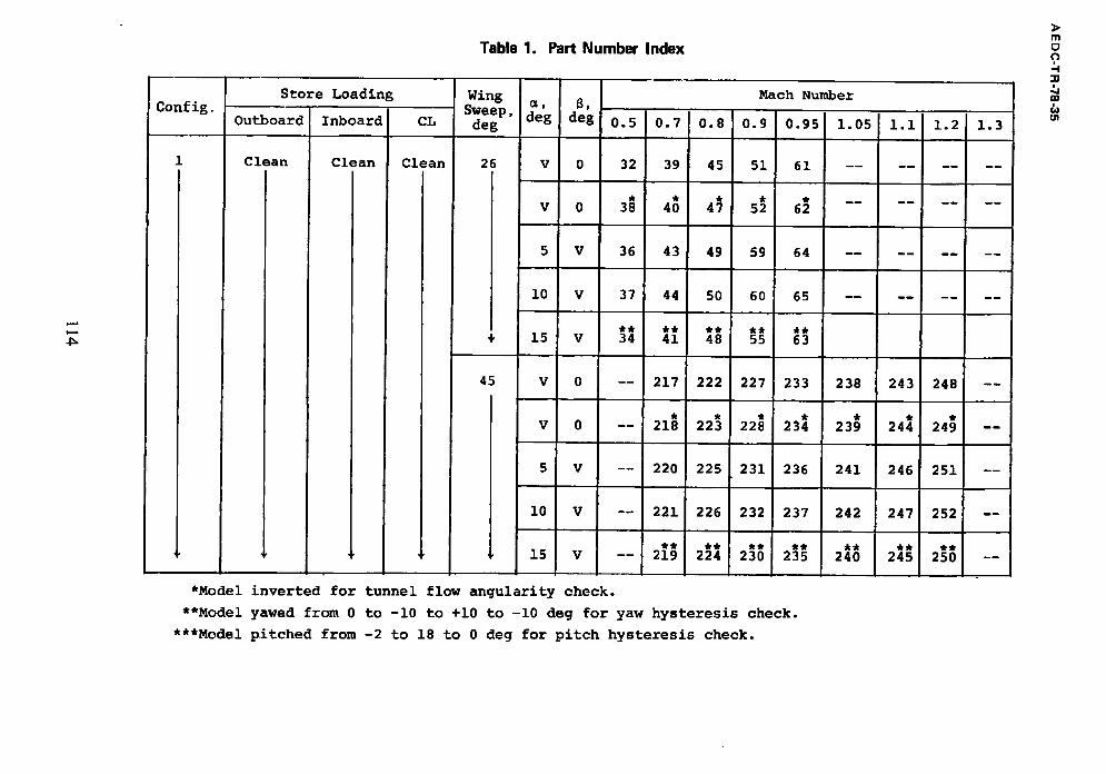
Table 1. Part Number Index
Config. Store Loading
Outboard
Clean
Inboard
Clean
CL
Clean
Wing a , 8, Sweep, deg deg deg
26 V 0
V 0
5 V
I0 V
15 V
45 V 0
V 0
5 V
10 V
15 V
Mach Number
0.5 0.7 0.8 0.9 0.95 1.05 1.1 1.2 1.3
32 39 45 51 61 . . . . . . . .
* * * * * . . . . . . . .
38 40 47 52 62
36 43 49 59 64 . . . . . . . .
37 44 50 60 65
** ** ** ** **
34 41 48 55 63
-- 217 222 227 233
-- 218 223 228 234
-- 220 225 231 236
238 243 248
239 244 249
241 246 251
-- 221 226 232 237
** ** ** **
-- 219 224 230 235
242 247 252
* * * * * *
240 245 250
*Model inverted for tunnel flow angularity check.
**Model yawed from 0 to -i0 to +i0 to -i0 deg for yaw hysteresis check.
***Model pitched from -2 to 18 to 0 deg for pitch hysteresis check.
m o o
00
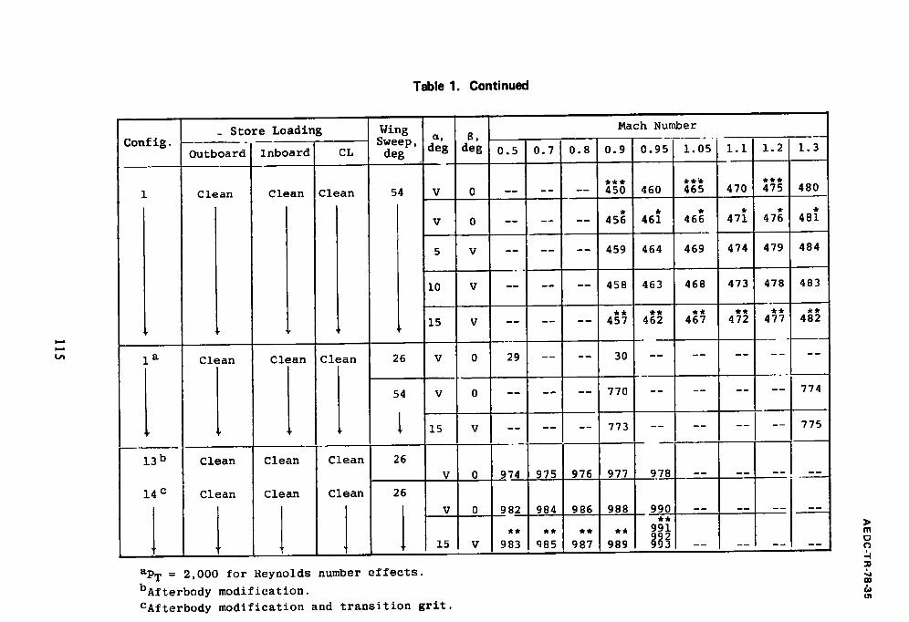
Table 1. Continued
t~
Config.
1
1 a
13 b
14 c
L
_ Store Loading
Outboard
Clean
Clean
1 nboa rd
Clean
Clean i
Clean
Clean
L
CL
Clean
Clean
Clean
Clean
deg
Wing Mach Number up ""
Sweep, dee dee 0.5 0.7 0.8 0.9 0.95 1.05 i.i 1.2 1.3
54 V 0
V 0
5 V
26
I0 V
15 V
. . . . . . 450 460 465 470 475 480
. . . . . . 456 461 466 471 476 481
. . . . . . 459 464 469 474 479 484
Clean
Clean
. . . . . . 458 463 468 473 478 483
. . . . . . 457 462 467 472 477 482
V 0 29 .... 30 . . . .
54 0
15 V
26
2 6
. . . . . . 770 . . . .
. . . . . . 773 --
.... 774
-- 775
V 974 975 976 977 978 -- m m ) m m
V 982 984 986 988 990 --
m
aP T = 2 , 0 0 0 f o r R e y n o l d s n u m b e r e f f e c t s .
b A f t e r b o d y m o d i f i c a t i o n .
C A f t e r b o d y m o d i f i c a t i o n a n d t r a n s i t i o n g r i t .
m
o
0%
Config. Store Loading
Outboard
3 AGM65
Inboard
3 AGM65
CL
Clean
Table 1. Cont inued
Wing Sweep ~g 8,
deg ' deg
26
45
54
0.5
V 0 69
5 V 70
I0 V 71
15 1 V 72
V_y__[ 0 --
5 V
I0 V
15 V --
V 0
5 V
i.0 V
L5 V
0.7
73
74
75
76
256
257
258
259
Mach Number
0.8 0.9 0.9. c
77 81 85
78 82 86
79 83 87
80 84 88
260 264 268
261 265 269
262 266 270
263 267 271
-- 491 495
-- 492 496
-- 493 497
-- 494 498
1.05 i.I 1.2
272 276 280
273 277 281
274 278 282
275 279 283
499 503 507
500 304 508
501 305 509
502 ~06 510
1.3
311
312
;13
~14
m o f)
:0
CO & O1
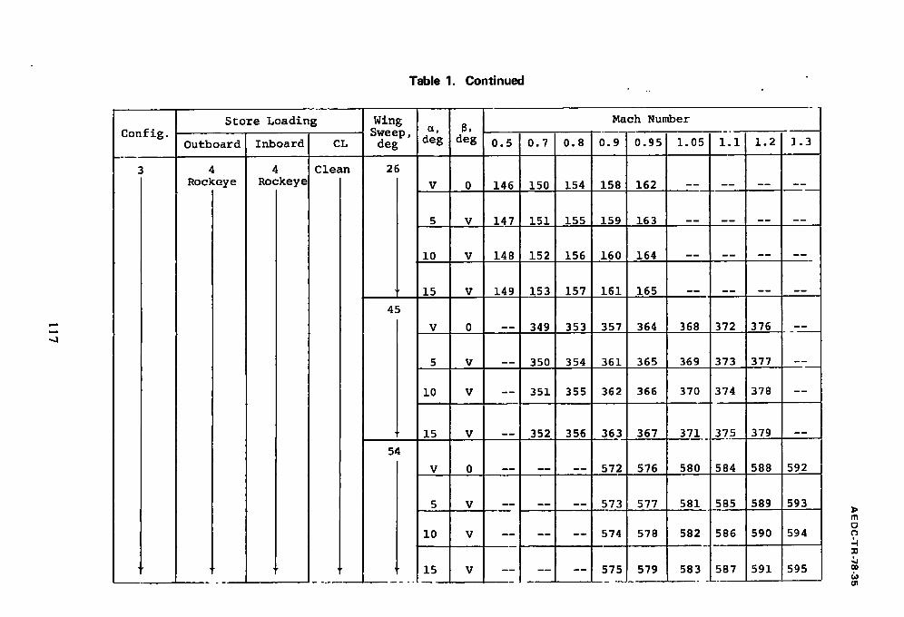
Table 1. Continued
Config.
_ - m
3
Store Loading
Outboard
4 Rockeye
I I i I ! I
Inboard
4 Rockeye
CL
Clean
Wing Mach Number Sweep, a' 8, _. deg deg deg 0.5 0.7 0.8 0.9 0.95 1.05 i.i 1.2 ].3
26
V 0 146 150 154 158 162 . . . . . . . .
5 V 147 151 155 159 163
i0 V 148 152 156 160 164 . . . . . . . .
" 15
45
V
V 149 153 157 161 165 . . . . . . . .
0 -- 349 353 357 364 368 372 376 --
5 V
i0 V
-- 350 354 361 365 369 373 377 --
-- 351 355 362 366 370 374 378 --
54
15
V
V -- .352 356 363 367 371...3.__7..5 379 --
. . . . . . 572 576 580 584 588 592
5
i0
15
V . . . . . . 573 577 581 585 589 593
V
V
. . . . . . 574 578 582 586 590 594
)> m
o
=0
0D
O1
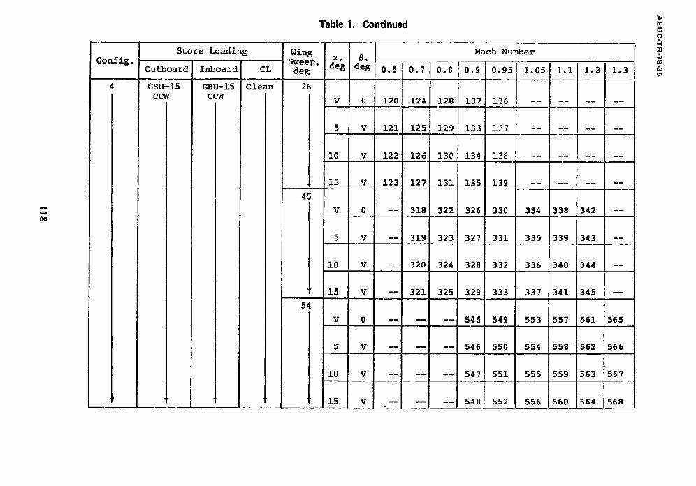
Config.
oo
Store Loading
Outboard
GBU-15 CCW
Inboard
GBU-15 CCW
CL
Clean
Table 1. Continued
Wing Sweep, deg
26
45
54
B. d e g
v
5 V
10 V
15 V
V 0
5 V
10 V
15 V
V 0
5 V
io v
15 V
0.5 0.7 0.8
120 124 128
121 125 129
122 126 130
123 127 131
-- 318 322
-- 319 323
-- 320 324
--i 321 325
iI--
Mach Number
0,9
132
133
134
135
326
327
328
329
545
546
547
548
0.95
136
137
138
139
330
331
332
333
549
550
551
552
] .05
334
335
336
337
553
554
555
556
1 .1
338 1
339
340
341
557
558
559
560
1.2
342
343
344
345
561
562
563
564
1.3
m - -
. - - h
565
566
567
568
m o o
nl
00
~n
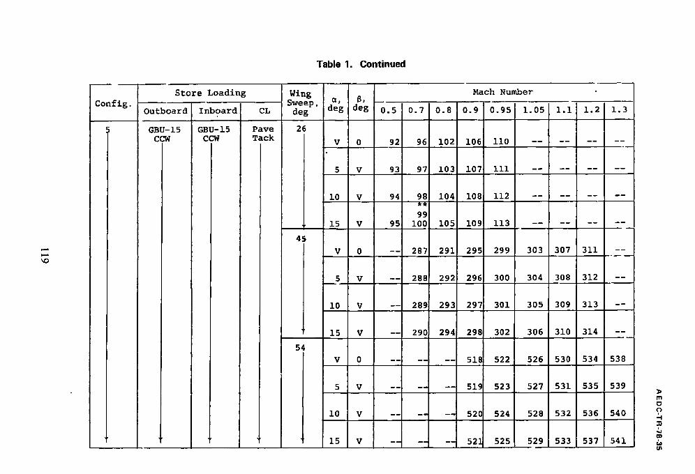
Table 1. Continued
Con fig.
Store Loading
Outboard
GBU-15 CCW
Inboard
GBU-15 CCW
CL
Pave Tack
Wing Mach Number Sweep, e, 8 . . . . deg deg deg 0.5 0.7 0.8 0.9 0.95 1.05 I.I 1.2 1.3
26
v 0 92 96 102 106 ii0 . . . . . . . .
i
45
5 V 93 97 103 107 iii
i0 V 94 98 104 108 112
99 15 V 95 i00 105 109 113
V 0 -- 287 291 295 299 303 307 311 --
5 V
I0 V
-- 288 292 296 300 304 308 312 --
-- 289 293 297 301 305 309 313 --
" 15 V
54
V 0
5 V
i0 V
15 V
-- 290 294 298 302 306 310 314 --
. . . . . . 518 522 526 530 534 538
....... 519 523 527 531 535 539
....... 520 524 528 532 536 540
. . . . . . 52~ 525 529 533 537 541
m
o

o
Confi8. Store Loadin E
Outboard
6 MK-82SE
Inboard
Pylon
CL
Clean
Table 1. Continued
Wing u, 8,
Sweep, de E de E de8
26
v 0
5 v
i0 V
15 v
45
V 0
5 v
10 v
15 v
54
V 0
5 v
i0 V
15 V
0.5 0.7 0.8
169 17" 177
170 174 178
171 17. ~ 179
172 17E 180
-- 38~ 387
- - 384 3 8 8
-- 38. = 3891
- - 38(5 39C
Mach Number
D.9 0.95
181 185
182 186
183 187
184 188
391 395
392 396
393 397
394 398
708 712
709 713
71o 714i
711 715
1.05
399
400
401
4 0 2
719
720
721
722 I
i.i 1.2
~Q
403 408
404 409
405 410
406 411
723 727 i
724 728
725 729
726 730
].3
731
732
733
734
m
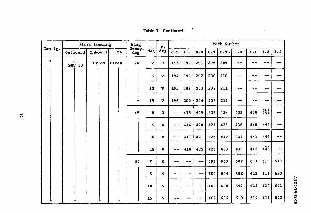
Table 1. Continued
Config. Store Loading
Outboard
6 SUU 30
Inboard
Pylon
CL
Clean
Wing Mach Number Sweep, ~ ' 8, deg deg deg 0.5 0.7 0.8 0.9 0.95 1.05 I.i 1.2 1.3
26 V 0 193 197 201 205 209 . . . . . . . .
5 V 194 198 202 206 210 . . . . . . . .
10 V 195 199 203 207 211 . . . . . . . .
15 V 196 200 204 208 212 --
45 V 0 -- 415 419 423 427 435
5 V -- 416 420 424 428 436
439 443 --
440 444 --
10 V
15 V
-- 417 421 425 429 437 441 445 --
-- 418 422 426 430 438 442 446 --
54
I
V
V
. . . . . . 599 603 607 611 615 619
. . . . . . 600 604 608 612 616 620
10
15
V
V
. . . . . . 601 605 609 613 617 621
. . . . . . 602 606 610 614 618 622
m o o
O0
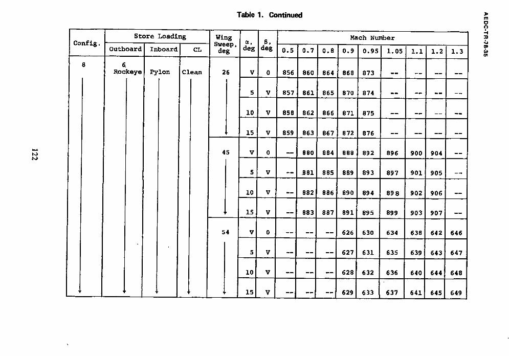
k.d
b~
Conflg. Store Loading
Outboard
6,
Rockeye
Inboard
Pylon
CL
Clean
Table 1. Continued
Wing Mach Number Sweep, I d~eg I B ,
deg ueg 0 .5 0 .7 0 .8 0 .9 0 .95 1 .05 1 .1 1 .2 1 .3 ! I . . . .
26 V 0 856 860 864 868 873
5 V 857 861 865 870 874
I0 V 858 862 866 871 875
,, 15! V 859 863 867 872 876
45 V 0 -- 880 884 888 892 896 900 904 --
5 V ,
i0 V
15 V
--I .881 885 889 893 897 901 905 --
-- 882 886 890 894 898 902 906 --
-- 883 887 891 895 899 903 907 --
54 V 0 . . . . . . 626 630 634 638 642 646
5 V . . . . . . 627 631 635 639 643 647
i0 V . . . . . . 628 632 636 640 644 648
15 V --~ .... 629 633 637 641 645 649
m
o
00
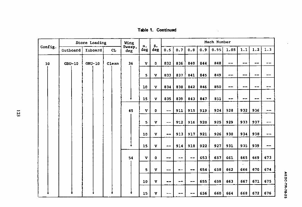
T a b l e 1. C o n t i n u e d
b.d
Confl 8 .
I0
Store Loadin 8
Outboard
GBU-10
Inboard
GBU-10
CL
Clean
Wing Mach Number Sweep, a, B, deg deg dee 0.5 0.7 0.8 0.9 0.95 1.05 1.1 1.2 1.3
36 V 0 832 836 840 844 848 . . . . . . . . • . ....
5 V 833 837 841 845 849 - -
45
i0 V 834 838 842 846 850 . . . . . . . .
~ 1 mL*Jmll:Kf-'ll I I :K~:I l IE:[Kl l E : ] ~ I ~:]IL-")II m ~ -
Y 0 - - 9 1 1 9 1 5 9 1 9 9 2 4 9 2 8 9 3 2 9 3 6 - -
5 V - - 9"12 9 1 6 9 2 0 9 2 5 9 2 9 9 3 3 9 3 7 - -
1 0 V
15 V
- - 9 1 3 9 1 7 9 2 1 9 2 6 9 3 0 9 3 4 9 3 8 - -
- - 9 1 4 9 1 8 9 2 2 9 2 7 9 3 1 9 3 5 9 3 9 - -
5 4 V 0 . . . . . . 6 5 3 6 5 7 6 6 1 6 6 5 669 6 7 3
5 V . . . . . . 6 5 4 6 5 8 6 6 2 6 6 6 6 7 0 6 7 4
10 V - - - ~ - - 6 5 5 6 5 9 6 6 3 6 6 7 6 7 1 6 7 5
1 5 V . . . . . . 6 5 6 6 6 0 6 6 4 6 6 8 6 7 2 6 7 6
m
cJ
"n
.%
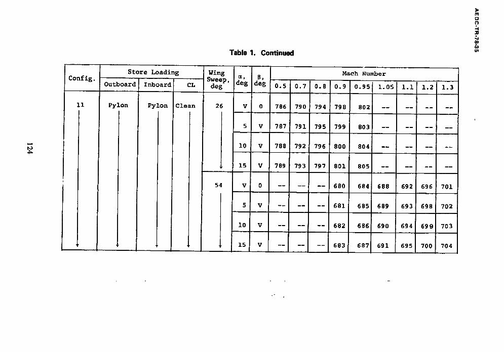
Table 1. Continued
m [2 O
? O1
Config.
11
Jl
Store Loadin 8
Outboard
Pylon
Inboard
Pylon
CL
Clean
Wing Sweep, deg
26
J,
54
U, B, Mach Number
dee Ideg 0.5 0.7 0.8 0.9 0.95 1.05 I.i 1.2 1.3
V 0 786 790 794 798 802 --
5 V 7 8 7 7 9 1 7 9 5 7 9 9 8 0 3 - -
l O V 7 8 8 7 9 2 7 9 6 8 0 0 8 0 4 - -
15 V 789 793 797 801 805 --
N M m
V 0
5 V
i0 V
. . . . . . 680 684 688 692 696 701
. . . . . . 681 685 689 693 698 702
. . . . . . 682 686 690 694 699 703
15 V . . . . . . 683 687 691 695 700 704
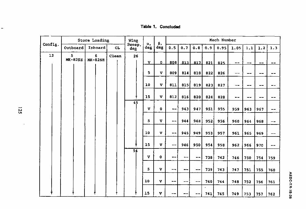
Table 1. Concluded
Config.
1 2
Store Loading
Outboard Inboard
5 6 MK-82SE MK-82SE
I
I
CL
Clean
Wing Mach Number Sweep, ~, 8, deg deg deg 0.5 0.7 0.8 0.9 0.95 1.05 I.i 1.2 1.3
26
v 0 808 813 817 821 825 . . . . . . . .
V 809 814 818 822 826
4~
i0
15
V 811 815 819 823 827
V 812 816 820 824 828
V 0 -- 943 947 951 955 959 963 967 --
5
i
i0
" 15
54
V
i0
' 15
V
V
V
0
-- 944 948 952 956 960 964 968 --
-- 946 950 954 958 962 966 970 --
. . . . . . 738 742 746 750 754 759
V . . . . . . 739 743
V
V
747 751 755 760
. . . . . . 740 744 748 752 756 761
. . . . . . 741 745 749 753 757 762
m
o

AE DC-TR-78-35
Table 2. Aerodynamic Coefficient Uncertainties
M q=, psf ±6C L ±~C m
0.50 180
0.70 295
0.80 350
0.90 400
0.95 425
1.05 460
1.10 475
1,20 500
1.30 515
±6C D ±6C£ ±6C n ±6C£
0.0350 0.0136 0.0124 0.0101 0.0016 0.0010
0.0188 0.0084 0.0071 0.0060 0.0010 0.0006
0.0144 0.0071 0.0057 0.0050 0.0008 0.0005
0.0122 0.0064 0.0050 0.0043 0.0007 0.0005
0.0117 0.0062 0.0048 0.0041 0.0007 0.0005
0.0100 0.0063 0.0043 0.0037 0.0006 0.0004
0.0093 0.0059 0.0041 0.0036 0.0006 0,0004
0.0082 0.0055 0.0038 0.0034 0.0006 0.0004
0.0073 0.0051 0.0035 0.0033 0.0006 0.0004
126

AE DC-TR-78-35
Table 3. Incremental Drag Coefficients
Stores
Pylons alone
4 GBU-10
4 GBU-15CCW
4 GBU-15CCW Pave Tack Pod
12 AGM-65
16 Rockeye
12 Rockeye
12 SUU-30H/B
12 MK-82SE
22 MK-82SE
Pylon Loading
B
Single
Single
Single
Multiple
Multiple Slant 4
Multiple Outboard
Multiple Outboard
Multiple Outboard
Multiple
Rack
LAU-88
BRU-3A/A
BRU-3A/~
BRU- 3A/~
BRU- 3A/A
B RU- 3A/A
AC D
A = 26 ° M~= o.7 C L = 0,6
0.004
0.011
0.013
0.018
0.022
0.017
0.010
0.018
O. 010
0.016
A = 45 °
I~= 0.9
C L = 0.4
0.014
0.017
0.023
0.031
0.019
0.012
0.021
0.011
0.019
A = 54o M = 1.2
C L = 0.2
0.005
0.019
0.025
0.031
0.035
0.023
0.021
0.0-3-2
0.016
0 . 0 2 8
127
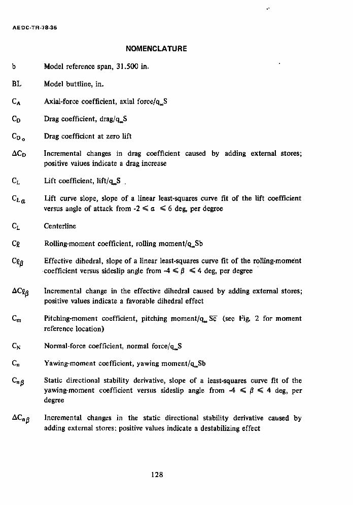
AE DC-TR-78-35
b
BL
CA
CD
CD o
ACD
CL
CLo.
CL
C£
C~fl
Cm
CN
Cn
AC.~
NOMENCLATURE
Model reference span, 31.500 in.
Model buttline, in.
Axial-force coefficient, axial force/q**S
Drag coefficient, drag]q**S
Drag coefficient at zero lift
Incremental changes in drag coefficient caused by adding external stores; positive values indicate a drag increase
Lift coefficient, lift/q**S .
Lift curve slope, slope of a linear least-squares curve fit of the lift coefficient versus angle of attack from -2 < a < 6 deg, per degree
Centerline
Rolling-moment coefficient, rolling moment/q**Sb
Effective dihedral, slope of a linear least-squares curve fit of the rolling-moment • coefficient versus sideslip angle from -4 ~</3 < 4 deg, per degree
Incremental change in the effective dihedral caused by adding external stores; positive values indicate a favorable dihedral effect
Pitching-moment coefficient, pitching moment/q** SE (see Fig. 2 for moment reference location)
Normal-force coefficient, normal force/q. S
Yawing-moment coefficient, yawing moment/q**Sb
Static directional stability derivative, slope of a least-squares curve fit of the yawing-moment coefficient versus sideslip angle from -4 < /t < 4 deg, per degree
Incremental changes in the static directional stability derivative caused by adding external stores: positive values indicate a destabilizing effect
128
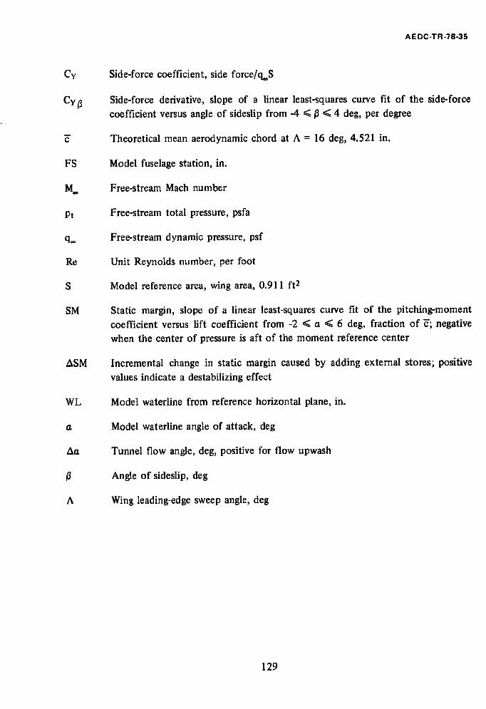
AE DC-TR-78-35
Cy
Cy~
FS
M.
Pt
q..
Re
S
SM
ASM
WL
t~
At~
A
Side-force coefficient, side force/q**S
Side-force derivative, slope of a linear least-squares curve fit of the side-force
coefficient versus angle of sideslip from -4 ~</3 ~< 4 deg, per degree
Theoretical mean aerodynamic chord at A = 16 deg, 4.521 in.
Model fuselage station, in.
Free-stream Mach number
Free-stream total pressure, psfa
Free-stream dynamic pressure, psf
Unit Reynolds number, per foot
Model reference area, wing area, 0.911 ft z
Static margin, slope of a linear least-squares curve fit of the pitching-moment
coefficient versus lift coefficient from -2 ~< a ~< 6 deg, fraction of ~; negative when the center of pressure is aft of the moment reference center
Incremental change in static margin caused by adding external stores; positive
values indicate a destabilizing effect
Model waterline from reference horizontal plane, in.
Model waterline angle of attack, deg
Tunnel flow angle, deg, positive for flow upwash
Angle of sideslip, deg
Wing leading-edge sweep angle, deg
129

ERRATA
AEDC-TR-78-35, July 1978 (UNCLASSIFIED REPORT)
AERODYNAMIC CHARACTERISTICS OF A 1/24-SCALE F-111 AIRCRAFT WITH VARIOUS EXTERNAL
STORES AT MACH NUMBERS FROM 0.5 TO 1.3
C. F. Anderson, ARO, Inc.
A r n o l d E n g i n e e r i n g D e v e l o p m e n t C e n t e r A i r F o r c e S y s t e m s Command
A r n o l d A i r F o r c e S t a t i o n , T e n n e s s e e 37389
R e c e n t t e s t s w i t h t h e 1 / 2 4 - s c a l e F - 1 1 1 m o d e l u s e d t o o b t a i n t h e d a t a p r e s e n t e d i n AEDC-TR-78-35 r e v e a l e d t h a t t h e m o d e l c a n f o u l t h e s t i n g i n t e r n a l l y a h e a d o f t h e f o u l i n g s t r i p i n s t a l l e d f o r t h a t t e s t . T h e r e f o r e , a l l d a t a o b t a i n e d w i t h t h e 1 / 2 4 - s c a l e F - I l l m o d e l w e r e e x a m i n e d f o r p o s s i b l e f o u l i n g . The d a t a i n d i c a t e t h a t f o u l i n g may h a v e b e e n p r e s e n t f o r m o s t c o n f i g u r a t i o n s a t h i g h a n g l e s o f a t t a c k a t Mach n u m b e r s a b o v e 1 . 0 . The maximum a n g l e o f a t t a c k f o r w_hich_~o_indication_of_fouling~was o b s e r v e d i s p r e s e n t e d i n t h e t a b l e b e l o w f o r e a c h t e s t c o n f i g u r a t i o n . A l l d a t a a t a n g l e s o f a t t a c k a b o v e t h o s e l i s t e d s h o u l d be u s e d w i t h c a u t i o n .
~ximum Angle of Attack without Possible Fouling
A = 45 d e g /', = 54 d e g Con f i g
M = I . i M = 1 . 2 M = 1 . 0 5 M = 1 . 3
I
2
3
4
5
6
7
8
i 0
I I
12
M = 1 . 0 5
12
14
14
14
14
14
10
14
14
14
14
14
10
14
14
14
14
14
14
14
12
14
14
12
M = 1 . 1 M = 1 . 2
lO 10
14
14
14 14
14 14
14 14
12 12
10
14
14
14
14
12
14
14
12
10
14
N o t e : N o e v i d e n c e o f f o u l i n g was o b s e r v e d i n t h e d a t a w h e r e a n g l e s a r e n o t s h o w n . ( S y m b o l - - i n d i c a t e s no d a t a t a k e n . )