A189 652 DAMGE MDELS FOR DELAMINATION AMD ... - DTIC
86
A189 652 DAMGE MDELS FOR DELAMINATION AMD TRANSVERSE FRACTURE 1/1 (U) TEXAS A AND M UNIV COLLEGE STATION MECHANICS AND MATERIALS CE R A SCHAPERY ET AL AUG 87 7UNCLASSIFIED MM- 3-87-11 AFOSR-TR-88-8i?9 F/G 11/4 U
-
Upload
khangminh22 -
Category
Documents
-
view
1 -
download
0
Transcript of A189 652 DAMGE MDELS FOR DELAMINATION AMD ... - DTIC

A189 652 DAMGE MDELS FOR DELAMINATION AMD TRANSVERSE FRACTURE 1/1(U) TEXAS A AND M UNIV COLLEGE STATION MECHANICS ANDMATERIALS CE R A SCHAPERY ET AL AUG 87
7UNCLASSIFIED MM- 3-87-11 AFOSR-TR-88-8i?9 F/G 11/4 U

L 36 -
MICROCOPY RESOLUTION TEST CHARTNATIONAL BUREAU OF STANDARDS 1963-A
St 0 0 0 0 0 0 0 2S V V V

UTi FILL Mechanics and Materials Center
TEXAS A&M UNIVERSITYCollege Station, TexasSin" W "
AFOSR.Tih. 8 8 - 0 12 9
w! DAMAGE MODELS FOR DELAr'INATIPN
IAND TRANSVERSE FRACTURE
0[ FINAL TECPNICAL REPORT
R.[A, SCHAPERY
D.P. GOETZ DTICMJ LAMBORN ELECTEf
FEB 2 9 1988
AIR FORCE OFFICE (F SCIENTIFIC RESEARCH
OFFICE OF AEROSPACE RESEARCH
UNITED STATES AIR FORCE
GRANT No, AFCR-84-WJ68
MM 534-87-11 AUGUST 1987
§6] "AIT fln5T Tf ,r !*- 88 2 .26 118

unclassified AN1988 1SECURITY CLASSIFICATION OF THIS PAGE
* REPORT DOCUMENTATION PAGEIs,* REPORT SECURITY CLASSIFICATION III. RESTRICTIVE MARKINGS
unclassified2.. SECURITY CLASSIFICATION AUTHORITY 3. DIST AlBUT ION/AVAI LABILITY OF REPORT
26. OECI..ASSIF ICATION/00WNGRAOING SCHEDULE~1i ___ ___ ___ ___ ___ ___ ___ ___ ___ ___ ___ ___ __ unlimited
4. PERFORMING ORGANIZATION REPORT NUMBEISI15 B. MONITORING ORGANIZATI &NFEORT NUMBeRItsI
AFOSR -TR - 88U 12 9
MM-5034-87-11________ __________________________
Go. NAME OF PERFORMING ORGANIZATION OBb. OFFICE SYMBOL 7a. NAME OF MONITORING ORGANIZATION
Mechanics and Materials Center Itapli, le AFOSR/NATexas A&M University I_______
S.. ADDRESS giiy. State and ZIP Code) 70. ADORES& Icily. SlteW and ZIP Code)
Building 410Boiling AFB, DC 20332-6448
Colleae Station, TX 77843 ________________________________
B.. NAME OF FUNDING/SPONSORING go. OFFICE SYMBOL 9. PROCUREMENT INSTRUMENT IDENTIFICATION NUMBERORGANIZATION (i a, ppI4cabiaJ
AFQSR I. NA Grant No. AFOSR-84-0068\ Be. ADDRESS (city. Staff and ZIP Code) 10. SOURCE OFPFUNDING NO$. _____________
Building 410 PROGRAM PROJECT TASK WORK UNIT
* Bolling AFB, DC 20332-6448 ELEMENT NO. NO. NO. NO.
* 11. TITLE Ilu'd Security clasIfcationi Damo V odels f r .>p tion and Transverse ac. ure 2302 B2
- 12. PERSONAL AUTHOR(I)R.A. Schapery, M..I. Lamborn, D.P. Goetz
13. TYPE OF REPORT 13. TIME COVERE *0 . DATE OF REPORT (Y.. Mo.. Day) 1S. PAS4 COUN4TFinal ~FRbOM 2/15/84 To 6 4/871 August 1987 79\
* S.SUPPLEMENTARY NOTATION \
COAT CODE
FIELD R POUP I SuB. GR. Composites) F r ac tur e> c-Gempoealk-sDamage) Fiber/Reinforced Plastic lf
IS. A&STRAtf(Condinue on neverse if neteararnd Identify by black numbalriThgoretical and experimental work on the deformation and fracture of fibrous composites'
with distributed damage is described. Emphasis is on establishing the existence of poten- (tials analogouS to strain energy and on using these socalled work potentials in deformationand fracture studies. The difference between changing damage and constant damage process es
Jis accounetd for by using rnultivalued work potentials. Discussed first are investigationsoffa etnua a pcmn ndti5wle ueudrxa
* offla retanula ba spcimns nd hinwaled ube uner xia a9d torsional loading.S The limited amount of experimental data presently available on angle-'ply laminates confirms>.. the existence of a potential even when there are large increases in microcracking. Next,"'path independence of the J integral is discussed. A study is then described in which the J
integral is used to determine fracture energy for delamination in double-cantilevered beamspecimens, some of which have a large percentage of off-axis fibers; the results are compare.with fracture energies found by standard methods (which do not account for effects of distri.,
'buted damage). The Appendix contains reprints of papers published during the final project-~year .and the a\tracts of two Ph.D. dissertationsS20 OST RI BUT ION/AVAILA LiTY OF ABSTRACT 21. ABSTRACT SECURITY CLASSIFICATION
UNCUASSIVISOUN"IMIS SAME AS RAPT. 0 OTIC USERS 0
S22gL N4AME OF RESPONSIBLE WOIVIDUAL 220. TELEPHONE NUMBER336 OfFIC4 SYMBOLMao erg aIo fii.ude Are Codgi)2S
Mao gereHa1o (202) 767-0463 1 H ieD0 FORM 1473,.83 APR * ~ IT ION OF 'IJAN 73 IS OBSOLETE. unclassifie* 6 SECURIITY CLASSIPICATIO14 OF THIS P"'j
. . . . . . . . . ..

TABLE OF CONTENTS
1. RESEARCH OBJECTIVES......................................... 1
11. RESEARCH SUMMARY ............................................. 1
1. Overview............................................... 1
2. Studies of Laminates under Axial and TorsionalDeformation ............................................ 3
3. Analysis of Crack Growth in Damaged Media Using aGeneralized J Integral.................................. 23
4. Determination of the Mode I Delamination Toughness ofMultidirectional Laminates.............................. 24
111. PUBLICATIONS AND SPOKEN PAPERS................................ 45
IV. PROFESSIONAL PERSONNEL INFORMATION ............................. 48
1. List of Professional Personnel ........................... 48
2. Degrees Awarded ........................................ 48
V. APPENDIX .................................................. .49
4;.
Aacessiol For
DTIC TAB 0
By
Av i~ I It
o de
By-

I. RESEARCH OBJECTIVES
The overall objective of the research is to develop and verify
mathematical models of aelamination and transverse fracture which account for
local (crack tip) and global damage distributions. One specific objective is
to demonstrate theoretically and experimentally that "work potentials" (which
are analogous to strain energy) exist for composites with constant and
changing damage and with viscoelastic behavior; validity of the very useful J
integral theory of fracture analysis depends on the existence of work
potentials. The second specific objective is to develop and verify methods of
analysis for predicting crack growth in elastic and viscoelastic composites
with distributed damage using, when applicable, the J integral.
II. RESEARCH SUMMARY
A 1. Overview
Methods of deformation and fracture characterization and prediction are
simplified when strain energy-like potentials based on mechanical work can be
0 used, is described in the first paper in the Appendix, "Deformation and
Fracture Characterization of Inelastic Composite Materials Using
Potentials". With these so-called work potentials, important theoretical and
experimental methods using the J integral and energy release rate (originally
,% developed for fracture of elastic media and fracture initiation in metals with
plastic deformations) may be extended to fracture initiation and crack
propagation in monolithic and composite materials.
Section 2 is concerned primarily with a study of rectangular angle-ply
bars under combined axial and torsional deformation. This investigation is by
Mark Lamborn, a Ph.D. student, and it deals with (i) the existence and then
1determination of a work potential for specimens with significant amounts of
distributed damage and (ii) characterization and prediction of delamination

2
when distributed damage and the mode III (antiplane) component of energy
release rate are relatively large. Experimental studies to-date on a
composite with brittle resin (Hercules AS4/3502), as reported in the first
paper in the Appendix, and on a composite with rubber-toughened resin (Hexcel
T2CT145/F155), as reported in Section 2, show that a work potential exists
with proportional axial and torsional deformation. On the basis of the
theory, we expect a work potential to exist over many sets of non-proportional
deformation histories; some experimental work planned for the near term on a
new AFOSR grant will be concerned with non-proportional deformation.
Also summarized in Section 2 is work on cyclic axial-torsional loading of
tubes by another Ph.D. student, Richard Tonda. Here, the objective is to
develop a method for removing from experimental data effects of visco-
elasticity on hysteresis and stiffness so that effects of distributed damage
growth may be more readily studied.
A numerical investigation of crack growth initiation and continuing crack
growth in inelastic media is summarized in Section 3; this work was done by
Randall Weatherby, a Ph.D. student. A multivalued work potential is used to
characterize material behavior. Path independence of the J integral is then
studied and shown to be consistent with theory developed on an earlier AFOSR
grant.
Finally, in Section 4 a delamination study by Douglas Goetz, a Ph.D.
student, is described. Mode I delamination of laminates with multiple fiber
orientations is investigated, and the usefulness of the J integral as a
fracture characterizing parameter is demonstrated.
Most of the work described in Sections 2 and 4 has not yet been
published, and therefore detailed summaries are given.
igV.

3
2. Studies of Laminates Under Axial and Torsional Deformation
The research effort last year was directed toward selection of
rectangular bar specimens, development of experimental procedures, and1 41 development of data reduction schemes. The objective in specimen selection
was to determine which specimens which would exhibit a significant coupling
effect of rotation and axial deformation on loads in order to be able to
critically evaluate the work-potential theory. Laminates of various layups
and "-ometries were tested. Test specimens of Hercules AS4/3502
graphite/epoxy were 24 plies thick and either balanced angle-ply or other
balanced symmetric laminates. Tests were run under conditions of proportional
and non-proportional straining; instrumentation difficulties voided the
results for non-proportional straining and, in fact, resulted in a delay of
testing for several months. All layups and geometries were found to exhibit
only a small effect of rotation on axial load, while the effect of axial
displacement on torque was significant. Test data from proportional straining
tests (i.e. the twist was proportional to the axial extension) were evaluated
for the existence of a work potential as discussed in 12.1]; references for
section 2 start on page 22. The results of some of these tests appear in
Figures 3 and 4 of [2.11, which is in the Appendix. These results provided at
least a limited check of the existence of a work potential for conditions of
proportional straining.
Experimental work was continued in the current reporting year to verify
the existence of a work potential for fiber-reinforced plastic laminates
rsubjected to combined axial and torsional loadings. Hexcel T2CT145/F155, ai. material system consisting of a rubber toughened epoxy matrix with graphite
fibers, was used to fabricate _350 6s flat bar specimens. These were tested
under the conditions of proportional straining. Typical test results'.
I
V° d. . .
4
expressed in terms of "nominal" stresses and strains appear as the dotted
lines in Figures 2.1 and 2.2. The nominal stresses and strains are defined by
Equation (39) in [2.11. The test data was evaluated for the existence of a
work potential by the method outlined in [2.11. The "nominal" axial stress-
strain responses for cases of combined axial and torsional loadings, were
predicted from the experimentally determined work potential. The predicted
responses are shown as the solid lines appearing in Figure 2.2. The
predictions shown in this Figure represent tests run at intermediate values
of E/y, the ratio of nominal axial strain to shear strain. These tests span
the levels of c and y where sufficient data were available for calculation
purposes. Tests were run at E/y = .25, 2, and 4 but could not be predicted
since they represent limit cases and a lack of data exists at the strain
levels reached in these tests. As seen in Figure 2.2 the predicted responses
agree well with experiment. It is tentatively concluded that a work potential
exists for conditions of proportional straining and increasing material
damage.
Data from the proportional straining tests on laminates constructed of
the Hexcel material system were analyzed to determine an analytical
representation of the work potential. The theory in 12.11 was used to
characterize the material and make predictions of material response for
conditions of combined axial and torsional loadings. The relationship used to
characterize the test data is that corresponding to Equation (28) of [2.11.
The form used in this work is
.. WT W + WD (2.1)
where WT = the total mechanical work, W = the strain energy density function,
and WD = the work of damage. All quantities appearing in Equation (2.1) are
*1.
PF

a)Y
r. -4 =
.1.4. -n
00
0\0
-4 0.Co -
C \ \ -'4nF4' xto
cm 0
L s\ SSJ4 I'GA I u IWO
I,~ f
LM \ i) 11-1111:

6
coo
.H >-
L8 L 41
S1-ua o~
.4.--- U
IA
s.4j
x4)
0. a,
a1) 4-)
W A
C C CS C
id - sS2~. s a L tpi [UtWON

7
expressed on a per unit initial volume basis.
SThe total mechanical work input is defined by
2W =.Qidqi (2.2)
where qi = the generalized displacements and Qi= the generalized forces
(i=1,2). The integral is taker from generalized displacement state 1 to
generalized displacement state 2. For stable microcracking and some other
damaging mechanisms, it has been shown that the integral appearing in Equation
(2.2) is independent of path [2.11. WT will be referred to as the work
potential. From Equation (2.2)
Q W T/aq j (2.3)
A basic assumption of this theory is that the strain energy density
function W = W(qi,Dk) exists and is defined by
Qj = aW/aqj (2.4)
where Dk (k=1,2 ..... ,K) are damage parameters. The set Dk includes all the
parameters needed to account for any structural changes occurring in the
material during loading. Such structural changes could include microcracking,
delamination, and fiber breakage. For the purposes of obtaining an initial
analytical representation of the experimental data it is assumed that one
damage parameter accounts for all the structural changes. This damage
parameter is taken to be WO. The damage WD will change with the applied
displacements qi; thus WD = WD(qi). From Equations (2.1), (2.3), and (2.4)
the equation for predicting the current value of WD becomes
aW/aW D : - (2.5)
-%,

8
provided this equation predicts dWD/dt > 0. For cases when dWD/dt < 0 it can
be shown from thermodynamics that WD must be constant.
For the test data under examination the generalized forces and
displacements are taken as ql =, q2 = yQ = a, Q2 = T/3 where E, y, a, and
T are the nominal strains and stresses defined in Equation (39) of [2.11. In
terms of these variables Equation (2.2) is rewritten as
WT = a dE' + I dy' (2.6)0 0
where the initial values of the generalized displacements are taken as zero
(unstrained state). For the purposes of analyzing the experimental data the
strain energy density function is taken to be
W 2 (2.7)
where C and C are functions of WD. The strain energy density function, W,
as given by Equation (2.7) is that of a linear elastic material when WO is
constant. Substitution of Equations (2.6) and (2.7) into Equation (2.1)
yields
E Y , i 2 1 2S= j de' + ]" dy' - 1 C 2 1 C 2 (2.8)
D 6 0 3 ~ 2
%from which WD is seen to be the sum of the shaded areas under the
o versus E and T/3 versus y curves as shown in Figures 2.3 and 2.4. From
,.Eu Equation (2.4)
T o(2.9)*
*1
1§ 111 p ",m

C144
1.4
0
w
C~CN

10
'4.40
0
0
.41
IC\-
~ I 0u
41
to
V.
:%U
(42
A0I loll
LS$96z.

Equation (2.8) shows that when W is evaluated on the loading curve, C and C0 T
correspond to the secant moduli of the a versus E and T/3 versus y curves,
respect i vely.
Equations (2.8) and (2.9) were used to obtain values of C and C as
functions of WD for proportional straining tests run at c/y = 0, .5, .75, 1,
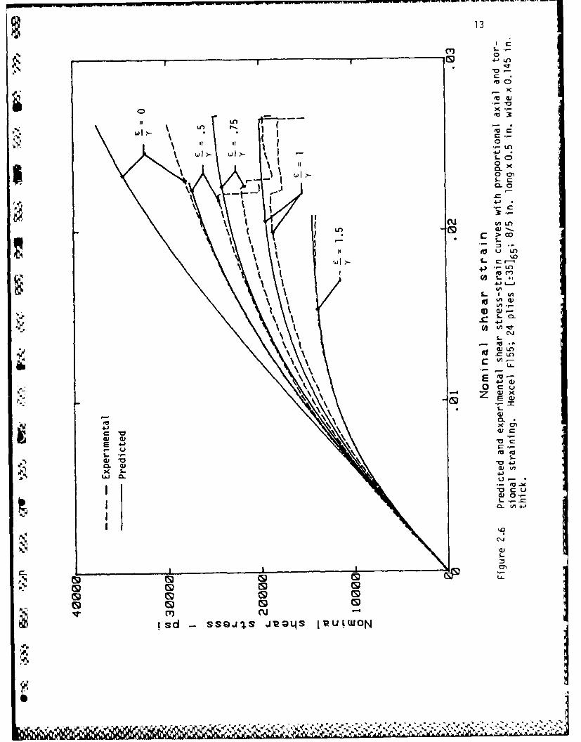
1.5, 2, 4, and -. The results of these calculations appear in Figure 2.5. It
was found that the test ran at E/y = 1.5 experienced the greatest amount of
damage as defined by the maximum value of WD. Analytical expressions were
then obtained for C and C as functions of WD for this one test. These area t
r shown as the solid lines in Figure 2.5. The analytical expressions for these
curves were used with Equations (2.5) and (2.9) to predict the material
response for tests run at the same values of E/y as those appearing in Figures
2.1 and 2.2. The results of these predictions are shown in Figures 2.6 and
2.7. These figures show that the predicted responses for c/y > 1 agree
reasonably well with experiment while those for e/y < 1 do not. The reason
for this appears to be that a second damage mechanism becomes significant at
the larger levels of twist. This would require that a second damage parameter
be incorporated into the model. The additional damage mechanism is apparent
for the data shown in Figure 2.8. Appearing in Figure 2.8 are the secant
moduli plotted against each other for E/y = .5, .75, 1, 1.5, 2, and 4. These
data show that the curves for the different tests are essentially the same
except for c/y = .5 and .75; the two tests correspond to the greatest levels
of twist reached for conditions of combined axial and torsional loadings.
Characterization of the second damage mechanism is presently under study.
Physically, the second damage mechanism may be delamination. For the
angle-ply layup, delamination would have a large affect on the torsional
stiffness but only a small affect on the axial stiffness.

12
--0
G >
in u
S.- S.
wx
U'
CD CD D to t
Ld~~I LL L. L
Ls LUpWlu:a
c 13
0
-CD0~ x
0 .- -c
cu LA LLO 0 - .
* 1 0
4- LAj
uI>- LCL
U-LAC-,
0 a'.-
Z Ix
E ~
X S-
WC 01
C C
L. *-0.) 3
0.0.)isd ssa-I ie4s11U)

14
C'U
0
LAn
"~ 0C
4.1
LC).
41h
4NCo
x r
S--
Cu V
0
91.-
L r.-
L&.
GD ('J
Lsd -i s s 9J s t 121X1 uutwON

15
Ln
<U
fj
uQ
4n
ft0 u
$.W
a a)
> '
A4

16
New Test Methods and Equipment: During the course of these tests,
experimental procedures were refined. Deficiencies in measurement procedures
were recognized and corrected. A computer program was developed to check data
from a series of proportional straining tests for the existence of a work
potential. The program was tested using data from a series of tests on
aluminum under combined axial and torsional loads. The program verified the
existence of a work potential for the aluminum well into the yielded state, as
expected.
New equipment has been purchased to aid in the experimental work. A load
cell which is more sensitive to low torque levels than the one used last year
has been acquired and is currently in use. The fiber-reinforced plastic
' laminates that have been tested in combined axial and torsional loading
typically experience maximum torque levels of 350 in-lbs. The new load cell
fig has torque range settings of 400 in-lbs. and 200 in-lbs, while the previous
load cell had a minimum torque range setting of 1000 in-lbs. The axial
capacity of both old and new load cells is the same.
A new computer system was purchased to aid in data acquisition and
reduction. The new system provides increased data acquisition speed as well
as increased data handling capabilities. This system is currently being used
in the experimental work.
Problems were experienced with the computer controller for the MTS axial-
torsion testing machine. The problem involved the unplanned loading of test
specimens when control switched from manual to the computer. In some
instances this damaged or failed the test specimens. Computer control is
beneficial when complicated displacement and rotation histories are used as
input. Work is currently underway by MTS to resolve the problem.
Related Studies: A literature survey was performed to review prior work

17
concerned with mode III fracture of metals and composite materials. It was
found that little data were available on mode III fracture characterization of
materials. The majority of the available data were from studies on metals.
An investigation of the experimental methods used to characterize metals
subjected to mode III deformation indicates that these methods would be
unsuitable for mode III delamination studies of fiber-reinforced plastic
laminates.
Studies concerned with the mode III fracture characterization of fiber-
reinforced composite materials are few. Experimentally determined values for
the critical energy release rate, GIIIc, have been obtained for a randomly
oriented short fiber composite 12.21 and a fiber-reinforced plastic laminate
[2.31. In both cases the measured value of Giiic was found to be greater than
measured values of GIc and GIIc for the same materials. For the case of the
fiber-reinforced plastic laminate the critical energy release rate in mode III
was determined for three different layups. The value of GIIIc was found to be
greater than GIc and GlIc for all layups. A recent finite element study
adetermined energy release rates for laminates subjected to pure torsional
loading 12.41. For the three layups studied, the energy release rate in mode
III was found to be greater than that in modes I and II, and pure mode III was
achieved in a IO°1ss laminate.
Analytical Studies Related to Torsion and Torsion-induced Delamination:
To gain a better understanding of the torsion problem of a laminate, a closed
form solution to the linear elastic torsion problem for a cross-ply laminate
was obtained. The solution satisfies the field equations on a ply-by-ply
basis. Displacement and stress continuity conditions are required at the
interfaces between 0' and 90' plies. The result is a Fourier series solution
for the stress function of each ply. Convergence of the solution at the
is.

18
interfaces between plies is not necessarily guaranteed and is currently under
investigation. This type of solution may provide reasonable predictions of
material response for angle-ply laminates with a large number of plies and may
be used in test specimen design.
The torsion problem of cracked isotropic plates was also studied
theoretically and experimentally. An isotropic plate with a through-the-
thickness crack was analyzed (Figures 2.9 and 2.10). Shown in Figure 2.9 is
such a plate subjected to torsional loading. As indicated in Figure 2.9, the
separated sides of the plate will bend as beams under torsional loads. It was
an important aspect of this study to examine the effect of grip restraint on
bending and thereby determine the increase in torsional rigidity of the
separated plate. The torsional rigidity in the presence of the crack (Figure
2.10) was predicted using standard torsion theory and a strength of materials
approach which accounts for the bending of the separated sides. Figure 2.10
shows the results of a test made on an aluminum plate and the predictions made
by the two theories. It is apparent from these results that resistance to
bending has a significant affect on the torsional response of separated
plates. These results suggest that bending resistance of the grips may also
have a significant effect on the torsional response of fiber-reinforced
plastic laminates with edge delaminations.
Additional Studies of Rectangular Bars: Research on a new grant will
concentrate on two areas needing further investigation. One topic area deals
with the question of the existence of a work potential. The experimental work
to-date has verified the existence of a work potential under conditions of
proportional deformation when the deformations increase in time. The
existence of a potential for these conditions does not guarantee its existence
for all deformation histories. Future work will investigate the existence of
.Z4
A
SI
4 V 4 ,. * ' . ' , - :." +- -. +- - + .

19
£
Figure 2.9 Bending due to rotation about a point other thanthe center of the cross section.
z
44

20
I IA
v0V . C
10
".4 a
'4 A
U 0
0.
CD 0
L L
* 4 J
.W .C
C9 0 I..
.sql-ui , an io

21
a work potential for non-proportional deformation histories, including
histories where the deformations decrease in time. These input deformation
histories should include processes where some damage mechanisms would remain
inactive while others would be active. These would correspond to different
branches of the multivalued potential. The existence of a potential along
these different branches needs verification. The question of the existence of
a work potential when viscoelastic effects are significant also needs
investigation. For such cases as these, the theory outlined in 12.11 and
. 12.51 will be used to check for the existence of a work potential. For
processes where it is verified that a work potential exists, the generalized J
integral theory given in [2.51 will be used in mode III and mixed mode
fracture studies.
Mode III fracture characterization of fiber-reinforced plastic laminate
is an area requiring further investigation. As previously mentioned, studies
of this type are few. The tentative test specimen which will be used for mode
III characterization studies is a rectangular plate laminate with pre-
fabricated edge and through-width delaminations. It is the intent of future
research to use this test specimen to study mixed-mode and mode III
delamination of fiber-reinforced plastics laminates. At present a 100124
plate of the Hexcel composite has been fabricated with teflon release paper
used to form pre-existing edge delaminations.
A X-ray machine is being purchased so that X-ray fractography may be used
to monitor delamination and other damage growth. This equipment should also
be useful in identifying other damage mechanisms.
Studies of Thin-Walled Tubes: A Ph.D. dissertation involving experimental
work on tubular specimens was completed by Richard Tonda during the grant
period. A significant part of the study was concerned with development of a
.1k
a.

22
technique for modifying stress-strain data on fibrous composites so that the
effects of changing damage may be observed without the complicating effects of
matrix viscoelasticity. The method, which is based on micromechanical
considerations and is not limited to tubular specimens, reduces the behavior
to that of an equivalent elastic composite with damage. The fibers are
assumed to be continuous and linearly elastic. The theoretical basis is
developed and then the method is illustrated using results from cyclic axial-I.:
torsional loading of tubular specimens of graphite/epoxy laminates. This work
is reported in 12.61.
References for Section 2
2.1 Schapery, R. A. "Deformation and Fracture Characterization of InelasticComposite Materials Using Potentials," Polymer Engineering and Science,Vol. 27, No. 1, pp.63-76
2.2 Agarwal, B. D., and Giare, G. S. "Fracture Toughness of Short FibreComposites in Modes II and III," Engineering Fracture Mechanics, Vol. 15,No. 1-2, 1981, pp.219-230
2.3 Donaldson, S. L. "Interlaminar Fracture Due to Tearing (Mode 11)," ICCMSixth International Conference on Composite Materials," Edited by F. L.Matthews, N. C. R. Buskell, J. M. Hodgkinson, and J. Morton, Vol. 3, 19(7,pp. 3.274-3.283
2.4 Chan, W. S., and Ochoa, 0. 0. "An Integrated Finite Element Model of Edge-A Delamination Analysis for Laminates Due to Tension, Bending, and Torsion
Loads," presented at the AIAA/ASME/ASCE/AHS Twenty Eighth Structures,Structural Dynamics, and Materials Conference, Monterey CA., April 6-8,1987
2.5 Schapery, R. A. "Correspondence Principles and a Generalized J Integralfor Large Deformation and Fracture Analysis of Viscoelastic Media,"International Journal of Fracture, 25, 1984, pp. 195-223
2.6 Tonda, R. 0. and Schapery, R. A., "A Method for Studying Composites withChanging Damage by Correcting for the Effects of Matrix Viscoelasticity,"To appear in Damage Mechanics in Anisotropic Composite Materials, Proc.Winter Annual Meeting, Dec. 1987
I6

23
3. Analysis of Crack Growth in Damaged Media Using a Generalized J Integral
A Ph.D. dissertation on analysis of crack growth was completed by Randall
Weatherby during the grant period. The work is summarized here.
In most materials, macrocrack extension is accompanied by inelastic
phenomena (such as microcracking or plastic deformation) throughout a region
surrounding the crack tip. Immediately ahead of that crack tip, strain
localization occurs in a small volume of heavily damaged material referred to
as the failure zone or fracture process zone. In this study, the failure zone
and the surrounding zone of inelastic material are treated as two distinct
regions. The failure zone is assumed to be thin relative to its length and is
represented in a two-dimensional finite element model as tractions which act
across the crack faces near the tip. An opening mode of crack tip deformation
is assumed. The normal traction at any point on the crack surface in the
failure zone is specified as a decreasing function of the crack opening
displacement which vanishes after a critical value of displacement is
6J, reached. Two different rate-independent, inelastic continuum characteri-
zations based on multivalued work-potentials are used; one models metal
plasticity and another represents microcracking in brittle materials. Both
constitutive models allow for the definition of a generalized J integral
developed by Schapery, which has the same value for most paths around the
crack tip for realistic distributions of plasticity or damage in the material
surrounding a stationary or propagating crack. This path independence and the
equivalence between J and the work input to the last ligament of material in
the failure zone are verified numerically in a transient crack growth problem;
both initiation and propagation are studied under conditions of small-scale
inelasticity. In addition, steady-state crack growth is studied in two
different specimen geometries. Simplified J integral analyses are used to
estimate the work input to the failure zone for these steady-state problems.
The J-integral estimations are compared with finite element results to
determine the accuracy of the simplifed analyses.
Flo.
*~~~ ~ orL Wk~ LA ,LWI~i -C I

24
qW.
4. Determination of the Mode I Delamination Toughness of MultidirectionalLaminates
The objective of this study is to develop a procedure for determining the
mode I delamination fracture toughness of multidirectional composite
laminates. To date, the focus of the work has been on application of the J
integral to double cantilever beam (DCB) tests in order to investigate the
- importance of geometry, layup, rate effects, and fracture morphology. The
general goal is to synthesize principles which can guide the prediction of
delamination performance using limited material data. The following
discussion highlights the method used and results obtained.
The material used in this study is T2CT145/FI55, manufactured by-wU
Hexcel. It uses a rubber-toughened epoxy matrix with about 6 % rubber by
weight. The nominal fiber volume fraction for all the material tested was
57%. This material system was chosen in order to accentuate possible
b nonlinear and viscoelastic responses for a commercially available toughened
- composite. It is also currently being used for other work on this contract
and other contracts at Texas A&M, allowing sharing of material data. Three
layups were used. Hereafter, they will be referred to using the following
designations:
Designation Layup No. Pliesunidirectional [0241 24
:V fiber-dominated [+-45/08/-+45]antisym. 24
angle-ply [+-45/(-+45)2/(+- 45 )2/-+ 45]antisym. 24
These designations will also be used in the captions of the figures to be
discussed below. The unidirectional layup is the one which has been most
commonly used in the literature to characterize delamination. In this study
it was used not only to examine delamination between zero degree plies where
ply interpenetration could occur, but to give a baseline for evaluating data
I.-
St, ' -. L . " . - ,... '. - / .: .. < ' - .. ' '-.' '.,. -. . . .. .-. '."-... "...:" -

25
for multidirectional layups. The fiber-dominated layup was used to study
delamination at a +-45 degree interface. Each leg of the DCB specimen was
made balanced and symmetric in order to eliminate stretching-shearing and
stretching-bending coupling. Antisymmetry about the midplane of the laminate
was designated in order to put the delamination plane at a +-45 degree
interface. The stacking sequence for the angle-ply was chosen to minimize
bending-twisting coupling as well.
All data shown in the following figures were generated using DCB
specimens. The fracture toughness was calculated using the J integral method
N; of 14.1], which allows for nonlinear elastic or inelastic behavior. In this
formulation the J integral is calculated using the moment at the crack tip
during crack extension and the moment-curvature relationship for one leg of
the specimen. The J integral is twice the area to the left of the moment-
- curvature curve divided by the specimen width, as shown in Fig. 4.1. In the
following discussion, J will correspond to this integral definition. The
energy release rate was also calculated for comparison. The symbol G will
signify the energy release rate calculated by the area method 14.2], which
allows for nonlinear elastic behavior. The area method comes from the
derivative definition of energy release rate, and provides an average value
for an increment of crack growth. The symbol G1 will refer to the energy
release rate calculated using the equation for a linear elastic beam,
3PG =Pc
6c (11 2ba
where PC is the load at crack extension, 6C is the load line displacement at
crack extension, b is the specimen width, and a is the crack length.
Motivation for using a J integral analysis came from the need for an
.I I
.0

26
CONTOUR C
M M
Jc Mf Ka(M)dM
0 B = width
kM a = crack-tip moment.'4
Figure 4.1 Double cantilever beam specimen, integration path, and moment-curvature diagram for calculation of J [after i
N,

27
analysis which would allow for continuum damage such as might be generated
throughout the legs of a DCB specimen during testing; the value of J is only
the work input to the crack tip during self-similar crack growth. The area
method of calculating the energy release rate allows for geometric and
material nonlinearity, as does J, but does not differentiate between energy
which goes into driving the delamination and that which causes general damage
away from the crack tip, leading to overestimation of toughness. The
difference is illustrated in Fig. 4.2, where G and J are plotted versus crack
length for three angle-ply DCB specimens. Note that for each specimen G is
significantly higher than J. The presence of damage (and a small amount of
viscoelastic behavior) is illustrated by the moment-curvature relationship for
the angle-ply layup, as shown in Fig. 4.3. Note that the unloading portion of
the moment-curvature plot does not retrace the loading portion.
For layups containing a high percentage of 0 degree fibers, one would
expect that G and J would give better agreement, since the effect of continuum
damage on beam deformations would be small. The moment-curvature
relationships for the unidirectional and fiber-dominated layups were linear,
and the unloading portions of the curves retraced the loading portions. When
this is the case and linear beam theory applies, it can be shown that J is
equal to G, calculated using equation 1. This formulation is helpful when
comparing energy release rate and J because G is calculated for a particular
crack length (as J is for the linear and nonlinear cases), avoiding averaging
over crack lengths as in the area method. Figure 4.4 is the load-displacement
record from a fiber-dominated specimen which displayed the development and
breakdown of a tie zone, causing the delamination resistance to increase and
then suddenly drop with crack growth. The corresponding G, and J are plotted
in Fig. 4.5. Both initiation and arrest values are shown. The two methods
,°'

28
z xIL N44f)n(
) (D (0(0 (0 to
(1)* Unc
EAu
* -
4%
4 * e.z CL
00 I
<(1 ) Z' LL t
X Ii
4%4
440 > 0
0 (0 (0'3'e
(Ni/81) r GNV 0
~ ' %N

29
(N
0
C)
z 0
C5C
00
00 CN N J
(E~lNI) N3NE
OI raP

30
cvo
InW. C-
-C E
u0.
c ~0
u -co 0oCC
2 +f
CC
03LE>
- Ic
(S)S
Cki c) LD
(SqL) PIQCo

31
Li
LiJ
c t
CCL
4O 06 -
_I Z - .'-
4-J W
a co
o4-,,
.C0)
4-0 4-'
+
4- L
(U > CA
4-)
S3#- to
LO
(Ni/e-1) r CJNV 'D
90

are in reasonably close agreement, supporting the interpretation of the
difference between energy release rate and J for the angle-ply layup as being
caused b) damage. Even when damage is not present, the simple expression in
equation 1 does not always hold; when geometric nonlinearity is present due to
large rotations of the legs, the energy release rate must be calculated using
either the area method (possibly losing information due to averaging) or using
nonlinear beam theory 14.31.
The usefulness of J as a characterizing parameter depends on its
independence of geometry, such as specimen width. To investigate the effect
of specimen width, angle-ply specimens 1/2, 1, and 2 inches wide were
tested. Representative results are given in Fig. 4.6. The high values for
the I inch wide specimen for shorter crack lengths were found to be associated
with the complex fracture morphology which developed near the starter crack.
For more nearly self-similar crack advance, it appears that width does not
have much effect on the fracture toughness measured over the range of widths
and crack lengths studied. Recent work at Texas A&M [4.4] indicates that the
state of stress in the legs of the DCB specimen is in the transition range
between plane strain and plane stress over the practical range of crack length
to width aspect ratios. However, the effects of the transition on J were not
seen for the aspect ratios in our tests. There is another type of specimen
behavior which does show a marked width effect. Unlike unidirectional
composites, multidirectional composites exhibit significantly curved crack
fronts in DCB tests. The curvature depends on the width of the specimen.
Figure 4.7 compares the normalized crack front profile for 1/2 inch, 1 inch,
and 2 inch wide specimens for several crack lengths. The thickness of one leg
is 0.062 inch. Apparently the crack front curvature has two sources: the
anticlastic curvature of the DCB leg and free edge effects. The general trend

33
I _
ON N 9 Of
S CL
ca
JQ.
D.1
4,1-*-
-J L
00
(N/ep r~

341/2 INCH WIDE SPECIMEN
0.4- pi
0.3
0 %
S01CRACK LENGTH/WIDTH- 4.26
-5.20w 7.26
•0 - 9.28
0.0 -0.0 0.1 0.2 0.3 0.4 0.5 0.6 0.7 0.8 0.9 1.0
DISTANCE FROM EDGE/WIDTH
1 INCH WIDE SPECIMEN
0.4
CRACK LENGTH/WIDTH
- 2.99mm, 3.15"-" 0.3
0" gas 3.90
-'" 4.77
o"0.2
41*
0.1
. 0.0 0.1 0.2 0.3 0.4 0.5 0.6 0.7 0.8 0.9 1.0
DISTANCE FROM EDGE/WIDTH
S Figure 4.7 Normalized crack front profiles for three angle-ply DCBspecimens of different widths. The profiles for various crack
lengths have been superimposed.
NI0-J

35
2 INCH WIDE SPECIMEN
0.4
CRACK LENGTH/WIDTH
-1.665
0,3- 1.860m.2.445
-m2.640
0 -- 2.770
o0.2-
0.0 0.1 0.2 0.3 0.4 0.5 0.6 0.7 0.8 0.9 1.0
DISTANCE FROM EDGE/WIDTH
Figure 4.7 (continued)

37
000
0
I z 0-0+') 4-
IlL w
S.-
LO CN
(Ni/eia)

38
5.-,
S I SPECIMENJ
I-4- 6D24 - 46D 3
2- +
Fiur 4. orlto.o.rcuesrfc opooy ihmaue2eain o frctr togns f,.' tw nlepyspcmn

.39
measured. Note that once a more or less uniform fracture morphology was
established, the toughness values settled into better agreement. The two
angle-ply specimens shown were next to each other in the plate of material
" before cutting. Dark and light bands were formed when the crack tip jumped
forward, then arrested. Dark regions were formed during rapid crack advance;
light regions correspond to slow crack growth. These studies of the effect of
layup illustrate a major difference between unidirectional and
multidirectional laminate delamination behavior. The opportunity for more
mechanisms of fracture leads to a greater complexity of behavior. It is
therefore essential that attention be paid to the fracture morphology when
interpreting the data.
Tests were done to investigate the dependence of J on crack speed. The
results for a unidirectional layup and a fiber-dominated layup are given in
Fig. 4.10. In both cases there is a slight decreasing trend in J with
increasing crack speed. This trend agrees with the observation that when
sudden crack jumping occurred, a low value of toughness was usually
. measured. It is significant to note that no strong trend can be established
for the range of crack speeds experienced by one specimen. Thus rate effects
are not important in interpreting data for individual specimens.
The importance of considering the fracture morphology when interpreting
the delamination toughness data has already been mentioned. Macro- and
microfractography were done to document the fracture mechanisms which were
observed. Two items are of particular interest. First, when off-axis plies
were present at the fracture plane, toughness values were sometimes elevated
even in the absence of complex fracture mechanisms. Apparently this was due
to increased su-face roughness caused when bundles of fibers were pulled away
from the fracture surface. This feature was only observed for layups with
1. 4

000
00
S 0E 0
* -0o 0 0 0 0Q) 0000000
E
(U.
0M
C
00
0 0
+ 0~
00
ooS-
U
0
LCC)
(u/q)9
'7...

W -%M""W~WKW Ww W V w
.-" 41
pop0
0
C.,"OO OO'
0 a.
.C
0" (,-
I .'.'
41
CM'
0 O - .D 0", 0, "
0. C Lo
0~ 00
00 S- C)
+ +
,II
00
Q a
~ 0.0
0 ~ 0) 00 r- 0.L
(u~l/qi) r

-- -- - -- .. .
42
off-axis plies at the delamination plane. For a more brittle system the
phenomenon was found to give differences of a factor of two in toughness
between unidirectional and off-axis specimens [4.71. Figure 4.11 is a cross-
section of a specimen (normal to the direction of crack propagation) at the
fracture surface. A bundle of fibers is separated from the surface at this
plane, but is attached to it at another point.
A second phenomenon which is of significance is that in almost all
specimens tested delamination was found to occur within a ply rather than
between two plies. Figure 4.12 shows a typical situation on a polished cross
section at a fracture surface. Note that the fracture plane does not pass
through the interply region, but stays a few fiber diameters away from it.
*Practically, the presence of resin-rich regions and ply interfaces has only an
indirect impact on the mode I delamination toughness when such steady-state
morphology is present.
Additional Studies: Future work under the follow-on grant will expand on
the investigations of the effect of geometry, layup, rate effects, and
fracture morphology. Further experiments will be performed to explore the
effect of specimen width, especially as it relates to crack front curvature.
The effect of the number of plies and the bending stiffness of the legs of the
DCB specimen need to be addressed. Also, tests will be conducted with various
fiber angles at the delamination plane. The dependence of delamination
toughness on crack speed for matrix-dominated layups will be investigated. An
attempt will be made to systematize the correlation between fracture
morphology and delamination toughness. In addition to these continuing
activities, new study will be begun to understand the effect of continuum
damage on the apparent toughness. This will probably include delamination
tests which simulate mechanical states in real structures, such as tests using
-4 - , % % % . , , , . ,. , . - .. -. -4 ",,. "..". '¢, . .

43
.11
Figure 4.11 Micrograph of a polished section of a failed DCB specimenshowing the fracture surface. A bundle of fibers has beenpulled away from the surface. (150X)
.9..
.q
Figure 4.12 Micrograph of a polished section of a failed DCB specimenshowing the fracture surface. The large circles at the top arethe material used to mount the specimen for polishing. (OOX)
J
J

44
a modified DCB specimen with bending and stretching inputs. Some testing of
specimens with fatigue predamage is planned. In these studies of damage,
emphasis will be on exploring the general applicability of the J integral.
References for Section 4
4.1. Schapery, R.A., "Deformation and Fracture Characterization ofInelastic Composite Materials Using Potentials," Polymer Engineering andScience, v. 27, 1987, pp. 63-76
4.2. Whitney, J.M., Browning, C.E., and Hoogsteden, W., "A DoubleCantilever Beam Test for Characterizing Mode I Delamination of CompositeMaterials," Journal of Reinforced Plastics and Composites, v. 1, Oct.1982, pp. 297-313
4.3. Devitt, D.F., Schapery, R.A., and Bradley, W.L., "A Method for* Determining the Mode I Delamination Toughness of Elastic and
Viscoelastic Composite Materials," Journal of Composite Materials, v.14, Oct., 1980, pp. 270-285
4.4. Davidson, B.D., and Schapery, R.A., "Effect of Finite Width and CrackTip Constraint on Deflection and Energy Release Rate of a Double-Cantilever Specimen," to appear in Journal of Composite Materials
4.5. Chai, H., "The Characterization of Mode I Delamination Failure in Non-woven, Multidirectional Laminates," Composites, v. 15, Oct. 1984, pp.277-290
4.6. Nicholls, D.J., and Gillagher, J.P., "Determination of G - in AnglePly Composites Using a Cantilever Beam Test Method," 5ournal ofReinforced Plastics and Composites, v. 2, Jan. 1983, pp. 2-17
4.7. Schapery, R.A., Jordan, W.M., and Goetz, D.P., "Delamination Analysisof Composites with Distributed Damage Using a J Integral," Proc. of theInt. Symp. on Composite Materials and Structures, Beijing, China, June10-13, 1986
.4-
*1,-1[
b1:

45
I1. PUBLICATIONS AND SPOKEN PAPERS
Publications:
I 1. Schapery, R.A., "Correspondence Principles and a Generalized J Integral
for Large Deformation and Fracture Analysis of Viscoelastic Media," Int.
J. Fracture, Vol. 25, 1984, pp. 195-223.
2. Schapery, R.A., "Time-Dependent Fracture: Continuum Aspects of Crack
". Growth," Encyclopedia of Materials Science and Engineering, Pergamon
Press (1986), pp. 5043-5053.
3. Schapery, R.A., Jordan, W.M., and Goetz, D.P., "Delamination Analysis of
Composites with Distributed Damage Using a J Integral," Proc. Int. Symp.
on Composite Materials and Structures, Beijing, Technomic Pub. Co., 1986,
pp. 543-548.
4. Schapery, R.A., "Deformation and Fracture Characterization of Inelastic
l Composite Materials Using Potentials," Polymer Eng. Sci., Vol. 27, 1987,
pp. 63-76.
5. Fang, G.P., Schapery, R.A., Weitsman, Y., "Thermally Induced Fracture in
Composites," Proc. ASME Symposium on Composites, Anaheim, CA. (Dec.
1986).
" 6. Davidson, B.D., and Schapery, R.A., "Effect of Finite Width on
Deflection and Energy Release Rate of an Orthotropic Double Cantilever
Specimen." To be published in J. Composite Materials.
. 7. Tonda, R.D. and Schapery, R.A., "A Method for Studying Composites with
Changing Damage by Correcting for the Effects of Matrix Visco-
elasticity." To appear in Damage Mechanisms in Anisotropic Composite
Materials, Proc. ASME Winter Annual Meeting, Dec. 1987.
8. Schapery, R.A., "A Constitutive Theory for Composite Materials with
Damage Growth Based on Multivalued Work Potentials. To be submitted to
Mechanics of Materials.
/ -

46
Spoken Papers (Principal Investigator's Activities)
1. "A J Integral for Viscoelastic Fracture Analysis." ASME/AMD Conference,
San Antonio, June 1984.
2. "Research Directions for the Mechanics of Composites." ASME/AMD
Conference, San Antonio, June 1984.
3. "Deformation Properties of Composites." Progress in Paper Physics: A
Seminar, Stockholm, June 1984. Also chairman of workshop on deformation
properties.
4. "Behavior of Composites with Distributed Damage." Owens-Corning
Fiberglas Corp., Granville OH, Oct. 1984.
5. "Matrix Controlled Deformation and Fracture Analysis of Fibrous
Composites." Tenth Annual Mechanics of Composites Review, Dayton OH,
Oct. 1984.
6. "Mechanics of Deformation and Fracture of Polymeric Materials." ThreeU
lectures, National Taiwan Univ., Taipei, Jan. 1985.
7. "Fracture Analysis of Nonlinear Viscoelastic Materials." Mechanics
Seminar, Tel-Aviv Univ., Tel-Aviv, Feb. 1985.
8. "Fracture Analysis of Composite Materials." Composites Group at Israel
Aircraft Industries, Tel-Aviv, Feb. 1985.
9. "Recent Developments on Damage Growth and Fracture of Composite
Materials." Plenary lecture at Israel Aeronautics Conference, Haifa,
March 1985.
* 10. "Deformation and Fracture Characterization of Inelastic Nonlinear
Materials Using Potentials." Mechanics Seminar, Univ. of Texas, Austin,
April 1985.
11. "A Micromechanical Model for Nonlinear Viscoelastic Behavior of Particle-
Reinforced Rubber with Distributed Damage." Int. Union of Theoretical
and Applied Mechanics Conf. on Fatigue and Damage, Technion, Haifa, July
1985.
N *,; N

, U . , fl - . - , w *W WV - rw WVr r, r-.7 z vn : r r rYWWWW W W W WWWU - WV UW
47
12. Deformation and Fracture Characterization of Inelastic Composite
Materials Using Potentials." International Symposium on Nonliner
Deformation, Fracture and Fatigue of Polymeric Materials, National
Meeting of the American Chemical Society, Chicago, Sept. 1985.
13. "Delamination Analysis of Composite Materials With Distributed Damage
Using a J Integral." Int. Conf. on Composites, Beijing, China, June
1986.
14. "Crack Tip Deformation and Work in Viscoelastic Materials with Growing
Cracks." Workshop on Fracture of Polymers and Metals, Cornell Univ.,
Aug. 1986.
15. "Deformation and Fracture of Composite Materials with Distributed
Damage." Seminar, Texas A&M Univ., Sept. 1986.
16. "Some Micromechanical Models for Predicting Deformation and Fracture of r
Viscoelastic Composite Materials." Alcoa Centennial Seminar, Hilton
Head, June 1987.
1.f
%

48
IV. PROFESSIONAL PERSONNEL INFORMATION
1. List of Professional Personnel
Richard Schapery, Principal Investigator
Douglas Goetz, Graduate Research Assistant
Mark Lamborn, Graduate Research Assistant
Richard Tonda, Graduate Research Assistant
Randall Weatherby, Graduate Research Assistant
Bob Harbert, Assistant Research Engineer, (Laboratory Staff Member)
Carl Fredericksen, Electronics Technician, (Laboratory Staff Member)
2. Degrees Awarded
Randall Weatherby, Ph.D. in Mechanical Engineering, May 1986.
Richard Tonda, Ph.D. In Interdisciplinary Engineering, August, 1987.
w
-,-
*1

49
V. APPENDIX
- 1. Reprint of paper "Deformation and Fracture Characterization of Inelastic
"." Composite Materials Using Potentials" by R.A. Schapery.
2. Reprint of paper "Time-Dependent Fracture: Continuum Aspects of Crack
Growth" by R.A. Schapery.
3. Abstract of dissertation "Finite Element Analysis of Crack Growth in
Inelastic Media" by J.R. Weatherby.
4. Abstract of dissertation "Techniques for Characterizing Damage Zones in
Composite Materials" by R.D. Tonda.
-.
.- °
S

]
Deformation and Fracture Characterization of InelasticComposite Materials Using Potentials
R. A. SCHAPERY
Mechanics and Materials CenterDepartment of Civil Engineering
Texas A&M UniversityCollege Station. Texas 77843
An approach using strain energv-like potentials to char-acterize deformation and fracture of inelastic. nonlinearcomposite materials is described. The inelasticity may bedue to various causes. including microcracking. microslip-ping. and rate processes responsible for fading memory(viscoelasticity). The concept of work potentials is intro-duced first. and then arguments are given for their exist-ence for inelastic materials. Emphasis in the paper is onelastic composite materials with changing or constantstates of distributed damage. Experimental results on poly-meric composites are subsequently presented to illustratethis approach to deformation and fracture characteriza-tion. Finally. extension to viscoelastic behavior Is dis-cussed.
INTRODUCTION linear viscous and viscoelastic cases one ma"
Many Important results on the deformation use irreversible thermodynamics (5) or speciall and fracture of linear and nonlinear elastic types of material symmetry. i.e., cubic and iso-materials have been obtained by using strain tropic (6). to argue for the existence of strainenergy functions or potentials to characterize energy-like constitutive potentials in terms ofmaterial response. The thermodynamics of re- physical or Laplace-transformed variables (7).versible processes provides theoretical support While experimental data on multiaxial nonlin-for the existence of these potentials and iden- ear viscous behavior of metals (correspondingtifies them as free energy and Internal energy to the secondary creep stage) may be character-for isothermal and adiabatic processes. respec- ized analytically through a potential, a general
Stively (e.g.. Fung (1)). Besides serving as the theoretical basis for this constitutive potentialbasis for powerful methods of exact and p- does not appear to exist in either irreversibleproximate structural analysis. strain energy thermodynamics or in models of micromechan-functions have been used in the prediction of isms. Rice (8) concluded that there is no suffi-effective or average constitutive properties (or ciently general physical model of slip that istheir upper and lower bounds) of linear multi- capable of providing a firm basis for the exist-phase media in terms of properties and geome- ence of a creep potential Duva and Hutchinsontry of the phases. as reviewed by Hashin (2). (9) give a good illustration on the use of poten-Included in the many publications in this area tials to construct approximate effective consti-are studies of the influence of small distributed tutive equations of nonlinear viscous compos-cracks on the effective stress-straln behavior of ites. In this analysis the composite is a homo-monolithic and composite materials, like those geneous. isotropic. incompressible, power-lawdescribed by Hashin (2) and Kachanov (3). nonlinear material with a given dilute concen-
Methods of characterization and analysis us- tration and size of spherical voids or penny-Ing local and global strain energy-like potentials shaped cracks.for certain inelastic materials, namely viscous, In using a potential to characterize constitu-plastic. and elementary types of viscoelastic tlive equations. it is often sufficient to accountbodies, have been discussed in an early work explicitly for only a dependence of the potentialby Hill (4). Constitutive equations normally em- on the stress or strain (or strain rate) tensor. Ifployed for linear and nonlinear viscous bodies the effect of different temperatures or other
-e are fully analogous to those for elastic media. parameters, such as microvoid or microcrackin which strain rate replaces strain (4). For the fractions and sizes, are of interest, then one
'e, POLYMER EGIPEERE AD SCENCE, ID-JANUARY, 1N7, Vol. 27, No. 1 63
0'

R. A. Schapery
would of course have to consider how these Strain energy potentials have been used
quantities affect the constitutive potential. An widely in fracture mechanics (e V. Broek (161"example of such a potential for an elastic ma- For fully elastic matenals. the mechanical work,."-terlal with damage is the volume-averaged available at a crack tip for producing an incre-strain energy density of a material specimen, ment of crack growth is equal to the decreaseW(e.. Dk). where e. are components of a suita- in potential energy (consisting of global strainbly defined volume-averaged strain tensor, and energy and the boundary-work potential). UseD, represents a set of damage- parameters that of this relationship has resulted in remarkablydefine the current damage state (e.g.. micro- successful investigations of fracture of rubbercrack sizes). The stresses for this material are in its nonlinear range of behavior, which arethen obtained by differentiating W with Dk reviewed by Lake (17). as well as fracture offixed, linear elastic materials (16). Andrews (18) as-
sumed a strain energy-like potential exists fors- 8W/8e u (I) rubber with hysteresis, and suggested how the
In Refs. 2, 3. and 9. the effects due to specified hysteresis would affect crack growth. When asizes and concentrations. D. of microcracks potential exists it is often possible to use Rice's
are considered. If it is further desired to char- J integral theory (19] to simplify fracture anal-acterize the effective constitutive behavior ysis. Schapery (20) recently extended the poten-when the Dk change with time as a result of tial energy and J integral theories to elastic andstraining, then relationships governing these viscoelastic materials with damage.changes must be determined. For discussion Concepts from fracture mechanics are usedpurposes suppose that these relationships are in the section on Multidimensional Theory toknown and that one may solve the equations so obtain the equations needed to predict micro-as to express the damage parameters Do in crack growth, and thus help provide the basisterms of the instantaneous strains ev. For some for potentials, such as 01(e.) in Eq 2. Also.cases, it may then be possible to find a strain potentials are used in the section on Delami-energy-like potential W(e.). say. from which the nation In Double Cantilevered Beam to accounteffective constitutive equations can be derived for the effect of inelastic material behaviorby differentiation. (which may be due to microcracking) on the
growth of a macrocrack in the form of a delam-s u = a8W/8e u (2) ination.
This consitutive potential would depend on only In most of this paper it is assumed the mate-t the instantaneous strains but yet account for rials are elastic when the damage is constant.
changing damage. If such a potential could be In the Viscoelastic Behavior section. a specialfound, it would be like that used to characterize representation of viscoelastic behavior pro-elasto-plastic behavior of metals by the Hencky posed by Schapery (15. 20) is used to extend thedeformation theory (10). Similarly, it would be elastic theory with damage to linear and nonlin-analogous to the potential for metals discussed ear viscoelasticity; viscous behavior appears asby Rice (8) for stationary creep. In his case the a special case.'damage" is an Idealized set of internal slips Finally. it should be mentioned that for lackthat contribute to the average strain rate but do of a better term we are using "damage" whennot appear explicitly in the effective stress- referring to characteristics of the microstruc-strain rate equations for the metal. ture or fabric of a material which affect consti-
The present paper deals in large part with the tutive behavior but are not accounted for inquestion of whether potentials analogous to elastic or fading-memory viscoelastic charac-W(e,,) exist for elastic, viscous, and viscoelastic terizations of continua. Furthermore. a damag-composites with changing damage (or. more ing process, such as considered here. could begenerally. changing microstructure); emphasis associated with crack growth, crack healing.is on elastic behavior with damage. Theory and dislocation creation and motion, breaking orrelated experimental work using data on a par- reforming entanglement points along polymertice-filled rubber and fiber-reinforced plastics chains in rubber. etc.. and therefore may beare discussed. structurally detrimental or beneficial.
We should add that there are already many ONE-DMNSIONAL THEORYpublications on the thermodynamic and micro-
r. mechanistic bases for constitutive potentials The definition of a potential for elastic mate-for different types of inelastic materials, e.g.. rials with damage may be explicitly introducedRice (8, 11). Coleman and Gurtin (12). and through the uniaxial stress-strain curve in Fig.Schapery (13 to 15). However, these potentials 1. Let us suppose that a previously unloadeddepend explicitly on "Internal- parameters specimen is strained monotonically until thewhich reflect the microstructure state, and are strain is e,. (By definition, the initial state isthus like W(ey. D,) in Eq 1. They do not neces- undamaged.') The strain is then reduced, asiisartly lead to the simplified form lil(eo) of par- shown in Fig. 1. Assuming that the bar is elast'
ticular interest here. and has constant damage during the unloading
64 POL rlYMER EJINEERI AND SCMACL NIDJANUARY, IN?, Vol. 27, No.
r V. r

Deformation and Fractue CharacteLzar ion of Ine[asric Compost i MfaIerIals
The strain energy-like quantitN IA is actu -;I,the net work to the material at any st.,c rf
SL, loading or unloading, and thus it will tx- ba!-da work potential It becomes the usual strain
S energy density when the loading and unload:nccurves are identical. Obviously. a work poten-
W U tial W can always be constructed, given theuniaxial stress-strain behavior. Eqs 3 and 4.
Derivatives of multidimensional equationsare needed In the next section. The one-dimen-sional model. Eqs 3 and 4. is useful for clarify-ing some of the analysis ahead of time. In par-ticular, observe that the slope of the unloadingcurve is.
em as _ a f = %,2 VS. U (9)SU ae ae (e9
The loading curve s' is a function of only e.
e However. when using the upper end of the un-loading curve to define st, both arguments InFig 1. Unaxal stress-strain curve for material with in- f(e. e) must be considered in computing the
creasing damage during loading and constant damage devative.during unloading. derivative.
ds= (10period, with instantaneous stress s1' and using de 8e de, be be aem
the same idealization as Gurtin and Francis (21) where we have used the fact that e, = e onin which the maximum strain e, serves to de- the ld cuve (the at tm In E e'-" inetheamont nd efec ofdamgethe loading curve. (The last term in Eq 10 is thef ea f ddifference in slopes of the two curves at e,= e).
s =f(e. em) (3) We may rewrite Eq 10 using Eq 3 and thesecond expression in Eq 7 to obtain
On the loading curve, the maximum strain isthe current strain. Hence. viewing the loading ds- b" a 1W1stress as a point at the upper end of an unload- de 8e-e2 + e(1)ing cure, we may write
where the derivatives of W'I are to be evaluatedsL =f(e, e) (4) at e, = e after differentiation.
The mechanical work (per unit initial volume) MULTIDIMENSIONAL THEORYduring loading to an arbitrary strain isa oFor characterization of multiaxial stress-14 = IL(e = s de' = fe'. e')de' (5) strain behavior, or for other responses that de-
pend on more than one independent input, awork potential does not necessarily exist. How-
whertthe.prie dentes r dumm vhaale ever, it can be expected to exist for some real-integration. The net work input to the sample istic situations, which will be discussed here.at any time during unloading is the shaded area For the sake of generality, let us use as inde-in Fig. 1. pendent inputs the generalized displacements
e f' qj (j = 1. 2.... J). The responses are the gen-"" = W4'(e. e.) = Wfl(el) + sude ' eralized forces Q, which are defined in the
Z (6) usual way by the condition that, for eachj.
=- W(e.) + file'. e,)de' where =WQ) is (12)where 6(Wk) is the virtual work input associ-
i. Observe that during loading and unloading. re- ated with the virtual displacement 6q. Suppose.spectively. for example. that we let each q, represent a
"=. /egradient. aum/ax, (m, n = 1, 2, 3) of a three-sL =-dWC'/de. s" = cWru/e (7) dimensional displacement field, urn, and let
It Is convenient to let W denote a continu- 6(Wk) be virtual work per unit initial volume.
ous quantity which equals W during loading Then J = 9. and Eq 12 implies the Q, are the
(e, = e) and equals W during unloading components of a stress tensor sm. say (for large
(e s em). Then. we may write for both loading or small strains, Fung (1)). In order to charac-
and unloading processes. terize the behavior of laminates using classicalplate theory (22). one may want to associate the
s - 8W/ae (8) set q, with the middle surface curvatures and
POLYMER ENGINEERING AND SCINCE, MID-JANUARY, IN?, Vol. 27, No. 1 6S
I,%

R. A. Schapery
strains In this case. the Q, would correspond to _Q'- a2 Wo + [-w, &aF
moments and in-plane forces per unit length, Oq, - qjq, n-i 0Fn 6qq,(and 6(,'k) would be virtual work per unit area. q
As in the uniaxial example. we assume that +r, (tWn+ "- aF- aFAjwhen the damage is constant, the body (mate- + \OF + aFOFC,, 9q, aq, rial element. test specimen, or complete struc-ture) is elastic in the usual sense; namely, a Clearly. the right-hand side of Eq 18 is the same
'Z work potential W exists with the property that when I and j are interchanged, and thereforeEq 16 is satisfied.
Qj - aWlqa. (13)~Generalizations
(Rather than using the terms 'loading- and "un-
loading- we shall instead now refer to 'damag- Extensions of W for which W D exists areing processes" and 'constant damage proc- discussed in Ref. 20. and lU,0 itself is given. For
. esses." since we do not want to imply that the example, at any given time some of the terms.-. damage is always constant when the magnitude W, in Eq 15 may be for constant damage proc-
of one or more loads or displacements decreases esses while others are for damaging processes.with time.) The effect of damage on Qj is &.-- Also, the potentials may depend explicitly onsumed to be fully represented by a set of "dam- time, and thus provide for effects of aging orage parameters" Ft, (n - 1. 2. ... N) in the next changing physical environments. The theory insubsection. Ref. 20. which allows for large deformations.
uses displacement gradients and Piola stressesA Special Case instead of generalized displacements and
Following Schapery's (201 arguments. it will forces. However. he earlier formulation. in-be shown that for a suitably chosen W a work cluding its extension to viscoelastic behavior.potential W exists during damaging processes carries over fully in terms of the generalizedsuch that variables used here. Thus, as in Eq 8. we may
Introduce a continuous work potential W forQj = aW'D/aqj (14) which
where WD'0 Is a function of only the current Qj = 8W/qj (19)values of qj. One special W discussed in Ref. even if the damage parameters in some compo-20 is. nents W, are constant while others vary in
time.W = W.qj) + W,(F,. F,) (15) Regardless of the process.
where W'o is a work potential without damage aQ/aq, - aQ,/q, =0 (20effects It is assumed that all of the functions (.j = 1.(2. ... J)F, = Fq, are such that the N conditions Fe, = except at the points of change from one processF, are satisfied simultaneously during all dam- to another, considering all W,. The derivativesaging processes. (The uniaxial case. Eqs 3 and in Eq 20 are. in general. discontinuous at these4. is recovered when we set N = I and take transition points (cf. Fig. I at e = e,) and thus14'. = 0. F1 = q1 - e. F. = e,.) To prove that WI Eq 20 does not apply there. Evidence of transi-exists, it is necessary and sufficient to show tion points may appear in experimental data asthat the generalized forces during damaging significant but somewhat random non-zero val-processes satisfy ues of this difference of derivatives (for I 0 j)
(j- 1. 2. .J) (16) over short-time intervals. This experimental be-Q/qj (,J ,havior would indicate that a process has
in Eq 16 are continu- changed from one type to another, damaging toassuming the derivatives nEq6aecotu- constant damage or vice versa.
ous (e.g.. Greenberg (23)). The forces during a It is not the goal here to develop specific phs-
damaging process are taken equal to those int Is not thal here to heo fic phys-
Eq 13 when F, - F, (which is analogous to ical models that give rise to the form for W4 in
saying a stress on the loading curve in Fig. I is Eq 15. We only mention that one based on a
at the upper end of an unloading curve). Con- simple microcracking model is given by Schap-
sequently, we may evauate the derivatives in cry (20). Also, for characterizing laminates us-equentby. werst mayvute nt 1ing classical plate theory, each F,, might beEq ] 6 by first substituting Eq 15 into 13. proportional to a ply or ply-pair failure surface
N, + W, dF, (such as represented by the Tsai-Wu theory (2).Q j + (17) expressed in terms of the local ply strains) or
,qj a F,, 9qj other local invariant. Since the local strains are(linear) functions of the mid-plane strains and
and then setting F~,- F, and differentiating Eq curvatures, one obtains F,, - F,(q,) if the latter' 17 (cf Eq 11). strains and curvatures are included in the set
N ;. ell POL VMER ENGNERING AND SCIENCE, MID44MARY, 17, Vof. 27. No. I
t._7
• .#, , ,-. , ... ,.,e ., ................................................................................................... "..... .-

Deforrnatlon and Fracture CharacterLzat ion of Inelast ic Comrposit MaterILI i
, q,. the summation in Eq 15 would extend over 20. to be valid with crack growth in tx)diec- wi!all plies, other distributed damave.
It is not necessary for the constant-damage In order to predict this growth we al- need i,,potential to have the form in Eq 15 for the work specify the work required G_ sav. for a uni ofpotential in Eq 19 to exist. For example. a dif- new area of the k" crack area. this quanutrt isferent form for W was given in Ref. 20 which the so-called critical energy release rate It iscontains the Henky deformation theory of plas- not necessary to assume G,_ is constant or isticitv (with elastic unloading). Another example the same for all cracks. However. we do assumeis given in the next subsection. it can be derived from a fracture work potential
Micro- and Macrocracking '14Ak. where
The work potential W In Eq 19 may be a G,, Bh/BAk (22)
constitutive potential In the sense that this For example if the critical energy release rateequation could be a stress-strain equation for a for all cracks is constant, but not necessarilycomposite or monolithic material. Alternatively, the same.W may be the total work input to a structure OK
under a general set of boundary displacements W = X G kAk (23)q, whose constitutive response is defined by a k'
work potential density. In either case. the con- Stable (quasJ-static) growth of any one of thestitutive potential may account for some effects K cracks is specified by the condition that re-of microcracking. microvolding. slipping. etc., quired work equals available work. G, = Gk:through the damage parameters F, However. thus.the form of the underlying potential W for con- aW/BA = -- W/laAk (24)stant damage. which has been discussed so far.is not completely general. Also. effects of mac- ifrocracking (such as large-scale delamination)have not yet been explicitly introduced. Thus. algi/aAk < -w/aAk (25)it is of interest to know if a work potential exists unstable growth occurs, whereas ifwhen there is macrocracking and a relativelygeneral distribution of growing microcracks. awj/aAk > -aw/aA (26)This question will now be examined by embed- there Is not growth.ding additional cracks in the body characterized Returning now to the question of whether a
* by W; the Index k will be used to indentify each work potential exists with crack growth. weof these cracks, assumed to be K in number, shall see that it does for the model defined aboveThe cracks may have a wide range of sizes, but if the growth is stable. The potential is denotedIt Is assumed that the scale of the crack tip as WT. and It will be shown that It is simply thefailure process zone, which determines the work of fracture plus the work of deformationwork ;-equired for increments of growth, is such of the elastic or inelastic continuum W namely,that the local material surrounding the failurezone can be approximated as a continuum, and Qj = w3'T/aqj (27)that the effect of the failure zone on the contin- whereuum can be represented by tractions actingalong the local crack plane. Then. the virtual WT = Wf + W (28)work equation with crack growth (see Eq 13 inRef. 20}. which applies with or without chang- The proof is made by first evaluating the deriv-
ing damage in the continuum and regardless of atives of W- while allowing for the stable growthwhether or not growth is self-similar. gives the of an arbitrary number of the cracks; henceavailable crack Up work per unit of new surface BWT _area as -6W/bAk: 6W is the change in the work - A + I + (29)potential for the total body due to the Increase 8cq k (49Ak BAk I 13 j
in area bAk of the kth crack with all q, fixed. For those cracks that do not grow. aAk /aq, = 0.Denoting the available work as Gk. we may thus In view of Eq 19 as well as Eq 24 for the growingwrite cracks. Eq 29 reduces to Eq 27, which was to
GI = -aW/aAk (21) be shown.Equation 24 is a set of K'(0 _< K' <_ K) equa-
where k = 1. 2. -- - K: also, W Is considered to tions whose solution gives the areas Ak(qj of K'be a function of generalized displacements q, growing cracks in terms of the generalized dis-and oriented crack areas Ak. The quantity Gk is placements. If we assume a unique solutioncommonly called the energy release rate. The exists (at least for small changes in q,), then thework potential may also depend on damage pa- areas (or their changes) could be substitutedrameters F,, in that It is the Win Eq 19 except into Wfand W in Eq 28. In this form T,. wouldfor the fact that the body now has K additional be a function of qj and only those Ak that arecracks: the virtual work (Eq 13 In Ref. 20) from constant.which Eqs 19 and 21 follow, is shown in Ref. Pursuing this representation further. let us
PIOLMER ENWNEE AND S CNC MU1IDAMARY, 1367, Vol. 27. No. 1 67.

R. A. &hapery
suppose for simplicity that all areas A, simul- In metals and vet a potential exists for sometaneously either constant or vary; denote the histories, as modeled by the deformation theon.constant values by Ak. Then for a constant of plasticity.damage process (apart from possible effects of One could think of the parameters A, as "In-F, and F.). ternal variables." such as used in irreversible
thermodynamic formulations; they need not be= WT(qJ. A ) (30) areas as longas they fit the above mathematical
and for a damaging process. Ack -* Ak(qj). model. Although it is not necessary here. wemay write the equations that govern their
W r = Wr(qj. Ak(qj)) (31) growth. Eq 24 or equivalently Ge, - Gk. in a rate
Equation 30 does not necessarily have the spe- form similar to that used in thermodynamiccial form of Eq 15. but yet a work potential models. First differentiate G,.- Gk with respectexists for constant and changing damage. the to time.limitation is instead In the form of the relation- BG,, dA, OGk d.A- 8GG,ship governing A(q,). viz. Eq 24. (32)
SAm dt BAm dt j B% dtUnstable Crack Growth where, for simplicity, explicit time-dependence
Unstable crack growth occurs when Gk > Gk. (e.g., aging) in Gck and Gk is omitted.The excess work predicted from quasi-static Solve for dAm/dt.analysis is then modified by dynamic effects, d T - (33and the quantity WT in Eq 28 is not equal to the d H k dtwork input to the body. This does not necessar- dt k aqj dtIly mean a work potential does nto exist. In fact. where H, is the inverse of the matrix Gkm.the assumption of quasi-static crack growthwas not used to arrive at Eq 19. The functions GkM - 9GCklaAm - GOk/Am (34)F,(qj) may reflect, at least in part. an average Complementary Work Potentialeffect of unstable rapid steps of microcrackgrowth. In many problems it is desirable to use the Q.
instead of qj as the independent variables. AllSignificance of the Areas Ak of the preceding theory could have been for-
- Through principles of fracture mechanics we mulated in this way. in which a complementaryobtained a work potential WT, and furthermore work potential W,. say. would be used. whererelated It to physically identifiable parameters qj - a we/Qj (35)Ak and material-related functions W and W.Conceptually. all cracks are considered to pre- For the one-dimensional case in Fig. 1. W, isexist with given initial sizes and orientations: the area to the left of the curves.but many or all may be so small initially thatthey have no real effect on the work potential. WC -o eds' (36)In principle, as many A are to be used as areneeded to fully define the instantaneous loca- where e =f(s'. s,) or e -f(s'. s'). depending ontion and orientation of all crack surfaces and the curve to be used, and s,, is the maximumtheir growth. For example. a crack edge that stress. The relationship between WTand W, is
. advances nonunlformiy along its length mayrequire the use of many small areas or param- (eters Ak to define the changing geometry. With Wr + W - J Qj (37)
* complex arrays of cracks, this formulation Isnot practical unless idealizations, such as peri- Observe that we may start with Eq 27 andodicity and regular shapes. or statistical repre- then define W, by Eq 37 differentiation of thesentations are Introduced. Non-unique solu- latter equation yields Eq 35. Alternatively. wetions A(q,) would further complicate the prob- could reverse the process. Thus. if WT exists solem. giving rise to effects of the history q,(t). In does W,. and vice-versa. It should be noted thatsuch a case. one may have to solve for changes these potentials are multivalued. and thereforeIn A, using small changes in q,. Of course, our one has to interpret their interrelationships onpurpose was simply to argue that a work poten- a process-by-process basis. For instance, in
1%, tial exists: nevertheless. it should be recognized Identifying a particular (s. e) pair for the ex-that even with a work potential. there could be ample in Fig. 1. it is obviously necessary toeffects of the displacement history. Additional specify whether the loading or unloading curvecomplications could arise with friction between is to be used.adjacent crack faces, In that a work potential ANGLE-PLY COMPOSITE BARS UNDERdoes not always exist if there is appreciable AN ORSIONA LO Denergy dissipation through sliding processes: AXIAL AND TORSIONAL LOADINGhowever. it should be recalled that significant The multidimensional theory provides sup-plastic deformation (slip) processes may occur port for using work potentials to characterize
U POE~. MER ENGNEERWG AND SC/ENCE, WND-JAMARY, I?, Vol. 27, NO IS' ,

Deformation and Fracture CharacterizatLon of Inelastic Composite Materials
the behavior of materials and structures with for linear isotropic materials for orhwr!roi(damage In this and in the next two Sections we materials whose planes of symmetr\ art, p[rL- ,describe studies of polymeric composite mate- lei to the specimen surfaces. It can be sh-,,Anrials that give preliminary experimental confir- that the same formulas apply except the widthmation of this characterization for damaging is modified by a ratio of moduli The shearprocesses. strain magnitude is zero at the mid-plane and
Work using laminates of graphite fiber-rein- increases linearly to the specimen faces [L x b)forced epoxy under axial and torsional loading in Fig. 2. Whether the stated conditions apply.is described in this Section. The tests specimens the variables in Eq 39 are useful for normaliz-are flat bars. as illustrated in Fig. 2. which ing data. Equation 38 becomesconsist of several plies or layers, each being a as/-y = a(r/31/ae (40relatively brittle, elastic composite with contin-uous, unidirectional fibers having an angle 8 This equation has been used to analyze thewith respect to the bar's axis, 0 = +300 are used data in Figs. 3 and 4 by first writingin the specimens discussed here. The unidirec-tional material was supplied in pre-preg form i/3 = 7 /3 + g (41)by Hercules. Inc.. and is designated as AS4/ where , = -r'i4 y) is the shear stress for e = 0:3502. It should be emphasized that even though also g = g(e. -y) in which g(o. -y) = 0. Next,there are strain gradients and consequent non- integration of Eq 40 with respect to " yieldsuniform damage (primarily in the form of dis-tributed microcracks and. at high load., edge s a g ')d'r' + so (42)delaminations) the multidimensional theory de ge.may be used. (Basic stress-strain behavior using where so = s (e) is the axial stress when -y =0
thin-walled tubes will be studied in the nearfuture after acquiring additional laboratory Thus. the quantity
equipment.)The generalized variables of the Section on 30000
Multidimensional Theory will be identified withthe specific mechanical variables for the bar asfollows: axial elongation, u = q i: rotation angle oo0,.between ends. 2 = q 2 -: axial load. F = Qi: and .. 0torque. T = Q2. The total work potential W. Eq A, .04528. is the work input to the entire bar throughthe relatively rigid grips.
The necessary and sufficient conditions for _ 1-:92
existence of a potential. Eq 16. for the presentproblem reduce to the single equation,
dF/al = aT/au (38)
Before using Eq 38 with experimental data, it -,ooD , , ,is helpful to replace the variables by measures .. ..of stress and strain. This normalization process Fig. 3. Representative shear stress-strain curves with
eliminates first-order effects of specimen-to- proportional axial and torsional straining Hercules AS4'specimen dimension differences. Specifically. 3502 graphite/epoxy 24 plies 1301w. 2.5 In. long x 0.25
we shall use 'nominal" stresses and strains de- in. u'tdexO.13 in. thick.fined as
s - F/bc T - 3T/bc (39)
e - u/L - - cQ/L
where b = width. c = thickness, and L = length(between grips). For the special case of long.thin homogeneous specimens (L mo b :*, c) s and "e are the uniform axial stress and strain re- E ___0
spectively. and T and -y are the in-plane shearstress and strain respectively at the surface.This is shown by Timoshenko and Goodier (24)
0
-Q48(XW0.32 06
C0 00 0.02 0.D3 0.0
. Fig. 4. Representative axial stress-strain curies with
F"s proportional axial and torsional strainingjrom the sameFig. 2. Lamfrnate specimen used in axtal-torstonial tests. tests used for Fig, 3.
POLYMER ENGINEERING AND SCIENCE, MID-JANUARY, IN?, Vol. 27, No. 1
.~~~* .I . . . .. .

0.2]I
R. A. Schapery
- change from damaging to constant damageAs - g(e. "r')dir' (43) processes and .Ice versa (cf. discussion of Eq
20). or an inabilit' to use a potential in a high.lv
is the change in axial stress due to the twist damaged state. Future studies using propor-induced shear strain. This integrated form is to tional and nonproportional straining shouldbe preferred over the original Eq 40 because of help to explain this behavior.the inaccuracy resulting from differentiation of For some layups with sufficient twist, modeexperimental data. especially considering the III edge delamination occurs prior to significantsmall amount of data available, material fracture near the grips. As a result.The procedure used to check for the existence properly designed bar specimens with and with-of a work potential was to cross-plot the data in out initial delaminations may be useful for stud-Fig. 3 so as to obtain g (which is proportional ies of this type of delamination. When a workto the change in shear stress due to axial strain) potential exists, one often can use the J integralas a function of -y. for fixed values of e. and theory or energy release rates to account for thethen predict the modification to axial stress. F_q effect of distributed damage on the delamina-43. Considering the limited amount of data tion growth.
" available, it is desirable to curve fit analyticalexpressions to the data to aid the needed inter- A HIGHLY-FILLED ELASTOMER UNDERpolations and extrapolations. It was found for a AXIAL LOADING AND PRESSUREwide range of strains that Several years ago Farris (25) described large
deformation studies of crosslinked rubber con-I g(e. -"')dy' = A _t
2 S5 e(B 4 ) (44) taning 65 volume percent of relatively hard.-'" particles. Specimens in the shape of slender
"*':,_. where A. B, and C are constants. Using this rectangular bars were subjected to confiningexpression in Eq 43 yields the change in axial pressure and uniaxial loading. He used revers-stress due to twist. Only for elf - 0.92 is there tble thermodynamics as a basis for predicting
stres duethe effect of pressure on the axial stress-straina significant effect of twist prior to fracture; the bhavio Thesreon we in te goodprediction is drawn in Fig. 4. The agreement behavior. These predictions were in quite goodbetween theory and experiment is relatively agreement with the measurements, in spite ofgood strong effects from the irreversible processesIn the series of tests shown in Figs. 3 and 4 of microcracking and void growth. Here we re-there is only one specimen for each deformation examine the behavior and use the present workhistory, and thus the small differences between potential theory as a basis for making similarmost curves in Fig. 4 could be as large as spec- predictions.imen-to-specimen differences. Nevertheless, It The specimen and relatively rigid grips are". shown schematically In Fig. 6. This assemblyis encouraging that all of the predictions from soncemacaynF. 6.eThis asembltEq 43 turned out to be of the same order as the was placed in a chamber, where it was firstobserved differences in axial stress. Axial stress pressurized to a constant value p and theni or-y,=0 is not shown, but it was essentially stretched axially at a constant crosshead rate:he same as for e/- = 1.78 in Fig. 4 until the axial force acting on the grips is F. Repre-
the ameas fr e-y 1.7 inFig.4 util sentative stress-strain and dilatation -strainpremature failure occurred the latter results data are in Fig. 7.were used in the theoretical predictions. Al-though not needed to check for the existence of In order to select the generalized variables ina potential. it is of interest to observe that when Eq 12. we use for 6( Wk) a virtual work per unitthere Is little or no coupling effect of twist and initial specimen volume.
axial deformation, the stress-strain curves obeypower laws over a wide range of strains this isshown in Fig. 5 where
s-e'" and ?,--y" (45)We have conducted additional exploratory
tests using proportional straining of laminateswith various widths. thicknesses, and fiber an-gles. all of the angle-ply design (±6) with bal- E 0oo"
, anced. symmetric layups. The behavior is sim- tilar to that already discussed, with comparable |verification of Eq 43. Close to the end point ofthe curves, where large scale delamination orfailure at the grips occurs, theoretical and ex-perimental curves tend to separate. as seen in M.
Fig. 4. This difference may be due to inaccuracyin the extrapolations needed for Eq 43 (consid- Fig. 5. Logarithmic plots of stress-strain datafrom Figs.ering the small number of specimens used), a 3 and 4 showing power law behavior.
T0 POLYMER ENGtEEWNO AND SCCE, MID.JAMA.AA, 197, Va. 27, No. I
I .

Deformation and Fracture CharacterLzat ion of Inelastit Compostte Mattruius
P where bu and V are the virtual axia! el n .tion and volume change of the specimen re-
Ft F spectivelv Let us no~k choose for gcnerah,t-d,1 t I I t f displacements the nominal axial strain. c and
dilatation. v. defined in the usual way.Fig.6 Particle filled eLastomer under pressure ard axialloading. q1 I e w u/Lr, q 2 = v "V/V 0 (52)
where u, and V are the increases In specimen'3 length and volume from the initial unstrained
state (in which the length is Lo and volume isVo). Companng Eqs 12 and 51 we see that thegeneralized forces are
0.10 o0o~ Q1 = S. 92 = -p (53)
where s - F i /Ao. the "nominal stress.'-, -As In the previous Section. we shall use Eq
65ps, 16 (with I = 2. j = 1) In integrated form to- - p a determine if a potential exists. Namely. substi-
_5 t, tute the variables from Eqs 52 and 53 and00 -o 1/5 ps, o.05 integrate with respect to v.
165~ psi (Ie v)Pdv) + s(e. vo) (54)
where v 0 is a constant reference value of dila-0 0.2 0.4 0.6 tation. This result is equivalent to that used by
• STU., . Farris except for an additional term a.,sing
Fig. 7. Stress-strain and dilatation-strain behavior of a from surface or fracture energy. which he at-highly filled elastomer (65 volume percent) at a series of tributed to the formation of vacuoles. However.hydrostatic pressures cf. Farrts (25). he subsequently neglected this term and then
used the theory and crossplots constructed from
f T data in Fig. 7 to make the predictions in Fig. 8." 0 ooJ T.IdA (46) For s(e, vo) the curve for p = 500 psi was used:although the dilatation is not constant in this
where T and 6&, are the surface traction and case. it is very nearly so (cf. Fig. 7).virtual surface displacement vectors. respec- It should be noted that Eq 54 is correct as ittively. and Vo is the initial specimen volume: stands. in that surface or fracture energythe integration is over the instantaneous area changes are taken into account implicitly whenA of the specimen and rigid grips. On all sur- one uses data for damaging processes. The un-faces except on the grip ends where F is applied, derlying potential Is Wr. Eq 28, which consists
(47) of the work of fracture U plus the deformationwork W. Furthermore. no restriction has been
where vi is the outer unit normal to the surface. Imposed on the magnitude of the strain or itsIt is helpful to write the normal traction on the uniformity; the strains are in fa. t quite large.grip ends in the form and are nonuniform at least close to the grips.
T. = T,-p (48)
where T1 is defined by this equation. Integrating 200
TdA over the grip ends with area A., regardless soo ,. s, ,of whether or not Tn is uniformly distributed. '6, 5 o,gives the axial force as 65
F =F - pA9 (49) -
where E ,00 e
F, - j TdA (50)
is the axial force above that due to the pressure.Equations 47. 48. and 50, along with the as- 0
, -" sumption of purely axial movement of the grips. 0 02 0.4 0.6
reduce Eq 46 to -,.. .
F, aV Fig 8. Comparison of calculated (points. Eq 54) and mea-6{WK) 6u, - p(51) suredlitnesi stress-strain behaviorfrom data in Fig 7 c~fV, V0 Farris (25).
POL. VlER ENOI NG AND SCIENCE. MAJ4MJARY, IN7, Val. 27, No. I 71
'p
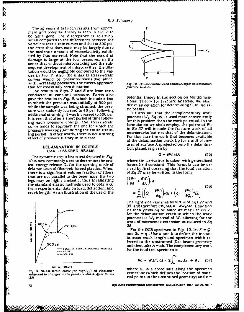
R. A. Schapery
The agreement between results from experi- Fment and potential theory is seen in Fig. 8 tobe quite good. The discrepancy Is relatively~small compared to the differences between the
various stress-strain curves and that at 500 psi;the error that does exist may be largely due to U
the moderate amount of viscoelasticity exhib- -- x,r ited by this material. Note that the extent of
damage is large at the low pressures. in thesense that without microcracking and the sub-sequent development of microcavities. the dila-tation would be negligible compared to the val- aues in Fig. 7. Also. the uniaxial stress-straincurves would be pressure-insensitive since. Fwith increasing pressures. the curves approach Fig. 10. Double cantilevered beam (DCB)Jor delarnnat Ionthat for essentially zero dilatation. fracture studies.
The results in Figs. 7 and 8 are from testsconducted at constant pressure. Fa-rls alsogave the results in Fig. 9. which include a test potential theory in the section on Multidimen-
in which the pressure was initially at 500 psi: sional Theory for fracture analysis. we shall
while the sample was being strained, the pres- derive an equation for determining Gc in inelas-
sure was suddenly lowered to 40 psi; following tic beams.
additional straining. it was increased to 500 psi. It turns out that the complementary work
It is seen that after a short period of time follow- potential Wc. Eq 35, is used more conveniently
ing each pressure change, the stress-strain for this problem than the work potential. In the
curve tends to approach the one for which the formulation we shall employ, the potential WT
pressure was constant during the entire strain- In Eq 37 will include the fracture work of allnpreure microcracks but not that of the delamination.
Ing period. In other words, there is not a strong For this case the work that becomes availableeffect of pressure history in this case.
at the delamination crack tip for a unit of newarea of surface A (projected onto the delamina-
DELAMINATION IN DOUBLE tion plane). is given byCANTILEVERED BEAMS
The symmetric split beam test depicted in Fig. G = aWc/8A (55)
10 is now commonly used to determine the crit- where th, derivative is taken with generalizedical energy release Gc for the opening mode of forces held constant. This formula can be de-delamination of fiber-reinforced plastics. When rived by first observing that the total variationthere is a significant volume fraction of fibers of Eq 37 may be written in the formthat are not parallel to the beam axis. the two rlegs may be highly inelastic, thus invalidating L-.. + a .6Athe standard elastic methods used to obtain Gc dA - A 5from experimental data on load. deflection, and Jcrack length. As an illustration of the use of the - [Qj - "-i- qj + (u - -W- ]6Q e-
aqOQJThe right side vanishes by virtue of Eqs 27 and35, and therefore 8WISA - -WT/aA. Equation21 then yields Eq 55 since we may use Eq 21for the delamination crack in which the work
O .potential is WT instead of W. allowing for the
4Opst work of microcrack extension introduced in Eq/ 00 psi 28.
-. For the DCB specimen in Fig. 10, let F - Q,
z --.. and 2u -qI. Use a and b to define the instan-" 0 "taneous crack length and specimen width re-50ferred to the unstrained (flat beam) geometry
and then take A - ab. The complementary work- EHAVIOR VIN r INTEM7TrEPRSSURE for the total test specimen is
--- 40 PSI_. S0 PSI
W - WC4F. a) = 2 wdx + We' (57)
Fig . Stress in cfor highly-filled elastorer where x, is a coordinate along the specimen
*so subjected to changes in the pressure levels. After Farris centerline (which defines the location of mate-125). rial points in the unstrained geometry) and x =
72 POLYMER ENGINEERING AND SCIENCE, MID-IANUARY 1917, Vol. 27, No. I

Deformation and Fracture Characterization of Inelastic Composite Materials
0 is at the initial line of load application The were used to develop the moment-curvaturt dw-quantity w, is defined as the complementary gram of beams with the lavup of one-hal' o th,work density (based on unit length) for each leg DCB specimen, I e.. for one leg Knowing the
.P from classical beam theory: namelh. the theory moment for crack growth from the DCH test,based on the assumption that matenal planes and the moment-curvature diagram from thethat are initially normal to the beam axis re- four-point bend tests made it possible to denvemain plane and normal when the beam is de- the critical energy release rate from Eq 61. theformed. The correction to beam theory is de- average moment at which crack jumpng oc-noted by W,'. The energy' release rate becomes curred for each DCB specimen was used for M.
This calculation, which is illustrated in Fig 12.2 wl4a) + 2 ,(8 gave values for G, that were practically the
b aa b b ao - )a same for all layups of each of the two graphite/epoxy systems. Indeed, the G. for unidirectional
after neglecting BW i/Ba. For long beams Wea is (8 = 00) laminates was close to that for the lavupately to the right of the delaminatmon crack tip. with multiple fiber orientations. In contrast,
standard data analysis based on beam deflec-and ac)W'/aa can be shown to vanish if the beama n eW an bshon to craish if eetiamly tion and load gave Gc values that differed con-is long enough that the crack tip is essentially siderably for the several layups: some multiple-isolated from the ends. fiber angle layups had apparent Gc values over
Equation 58 is not restricted to small strains twice that for 6 = 0.and rotations. As such. the horizontal distance These findings not only help to support thea' in Fig. 10 may be significantly less than theactual length of the crack surface a. However. underlying potential theory. but also reveal sur-
we shall simplify the analysis by assumingsmall strains and rotations and further assumeboth legs are symmetric and balanced lami-nates in the undamaged and damaged states. LA-D!MACDOn VALES O
With these conditions there is no mid-plane 36 -, C..k--LP AIO.,T ,o,stretching or twisting, and beam theory gives TIP MoP,. 15 ,?,CMAr.,
the simple result
whee = wC kdM' (59)
w'here k = k(M'l is the curvature as a functionof the moment. A moment -curvature diagram8for inelastic material would be similar to thestress-strain diagram in Fig. I: the complemen-tary work. Eq 59, is thus to be evaluated takinginto account the multivalued relationship, asdiscussed in the One-Dimensional Theory Sec-tion. The local beam moment is o
0 1.6 3.2M - Fxj (60) oZPNG DISPCI .. 2 (III.)
and therefore the integral in Eq 58 vanishes as Fig. 11. A typical load-d tsplacement record for openingmode loading of a double cantileuered beam with off-axis
Wv, is independent of a. Thus. we obtain plies at the center interface. Hercules AS4/3502 graph.
S 2 k." (Uelepoxy. After Jordan (26).
G = wAa) (61)b bJ
where M. = Fa is the crack tip moment. G 2 x SHADED A.-'B, This result has been used by Jordan (26) to
analyze delamination of two different graphite/ M - 2
epoxy material systems with plies having var-lous fiber orientations; one system had a rub-ber-toughened resin and the other a brittle resinsystem. Figure I I gives a typical load-displace-ment diagram for the latter one. The short in-clined lines represent periods of no crackgrowth following sudden Jumping at loads alongthe dashed line. Measurement of crack length 0and corresponding loads indicated that thecrack tip moment at the beginning of each jump kin crack length was approximately constant for Fig. 12. Moment-curvature diagram for loading, showingall tests in the series. Four-point bend tests energy release rate. G.
,A. E WWi MJE ENOENG AND SCNCE. MID-.JAMJARY, 1N. Voi. 27, No. I 73*

R. A. Schapery
prisingly simple behavior, considering espe- same result derived by Rice (19] for a split beamcially how much microcracking develops in the under end moments M. It is seen that the resul:specimens whose bending is not fiber-domi- is independent of the location of the left inte-nated. The Jayup Insensitivity of G, seems to gration segment and. in fact. is that in Eq 63indicate that the local normal interface stress, when the segment is located at the crack tiprather than local layup-induced shear stress. is (where du 2/dx = 0). It should be mentioned.the primary factor in delamination. Of course, however, to obtain this path independence (i.e..the findings are from a limited set of tests on derive Eq 64 from 63) it was necessary to as-only two composite systems, and therefore one sume If k(M) is multivalued (cf. Fig. I I that theshould be cautious about extrapolating the find- unloading curve is the same for all left verticalIngs to other laminates. segments used. This latter condition will be met
Finally. it is of interest to consider the rela- for all material (to the left of the current tip)tionship of the above results to Rice's J integral that had experienced the same maximum mo-(19). as extended to crack growth in inelastic ment when the crack tip passed by. Inasmuchmedia with large deformations by Schapery as the experimental results discussed above in-(20). The quantity J is defined by a contour dicate the maximum moment is constant (andintegral, which becomes for the beam problem recognizing that the moment decays with dis-in Fig. 13, tance from the tip). this condition is met all of
112 the way to the location of the initial crack tip., W81TU2 (62) To the left of the initial tip. the maximum mo-
x , x,- ment is less than M. and one finds J depends
where wo is the work potential density. T, and on the location of the left segment. This path
T 2 are tractions along C. and u, and u 2 are dependence in beam theory is fully consistentI a o ewith that predicted from the exact J integral fordisplacements: the indices Indicatea continuum with variable damage in the re-in the x, and x 2 directions. This equation is acotnu wtharbeda genter-
valid for large strains and rotations as long as gions of unloading (20). Some unloading mayvai orlrestanadrttin-soga occur In the continuum very close to the crackwe interpret x, and x 2 to be coordinates of the ouilh continu vepnce o thrundeformed geometry. The integration is coun- tip. possibly causing path dependence and thusterclockwise along the curve C in Fig. 13. which affecting Eq 64. Weatherby (27) used a finite
includes top and bottom beam surfaces and element analysis to study this dependence for avertical segments. The right vertical segment is strongly nonlinear isotropic beam and foundtaken far enough from the crack tip that the that the effect on J is negligible: his analysismaterial Is unstressed, and thus gives no con- predicted a J value very close to that in Eq 64.mteritiunsoresso and ttom sgets. o cFora crack propagating at a constant momenttribution. For the top and bottom segm ents dx2 i o gl m n t h ti ntal o o e e u
'-'C T = T2 = 0. and thus the only contribution in a long laminate that is initially homogeneous-comes from the left segment. Assuming small in the x, direction, the state of stress and strainstrains and that the left segment is close enough in the neighborhood of the tip Is constant in
to the crack tip that we can use small rotation time. This is a type of self-similar growth andbeam theory. yields, therefore (19. 20)
2G =J (65)
Sf k(M'dM' - 2 F du2 (63) Equations 61 and 64 agree with this generalb.-bxresult. Equally important. Eq 64 was derived
where M and du 2/dxl are the moment and slope, without assuming small rotations (except forrespectively, at the left vertical segment. Inte- the neighborhood of the tip). Therefore. in viewgrate k . d 2u 2/dx 1
2 to obtain the slope, and Eq of Eq 65. we may conclude that the formula for63 reduces to work available at the crack tip. Eq 61. is valid
2 C even when the DCB legs undergo large rotationsJ k(M)dM (64) and possibly high axial tensile strains from the
b Joaxial component of F. When this geometric non -where Mo is the crack Uip moment. This is the linearity exists one should use a' (cf. Fig. 10)e M. iinstead of a to determine the crack tip moment.
VISCOELASTIC BEHAVIOR
M/ I CONTOUR C For some types of linear and nonlinear vis-", coelastic materials the Multidimensional The-
ory may be used by simply replacing the gen-eralized displacements with 'pseudo general-ized displacements.' . where
.- mEi- f E(t - t) dr (66)
% Fig. 13. Contour used to evaluate J integral. Here qj Is the physical generalized displacement
74 pVYuEpi ENGINEERMNG AND SCMM5 MID-4ANUARY, 1N7, Vol. 27. . I*4
.d'~ . ~N.,. ,%

Del'or-arion and Frac(ure CharacerLazorfon of )nClasr1v Cornpsut Mtrrls
in terms of the dumm. time vanable of integra- q is sufficientlh larpte L, and its 4ener,,', 1:. .:, Ttion T and other relevant quantities such as to multidmensiona! problemrs ma\ ofi -:, l.ad "coordinates A The quantity E = E(r - r. t) is a to constitutive equations that are andl .L ,;- t( rrelaxation modulus, which imparts hereditary those discussed in Sections on On-Dcharacteristics to the deformation behavior. sional Theory and Multidimensional Thcor-,The second t argument in E allows for aging but there ma'" be explicit dependence of theand other kinds of time-dependence. such as potentials WA, Wi,. and W, on time. and thus the.%may be due to transient temperature. The coef- would be like those for aging elastic materialsficient ER is a -reference modulus." which is an with damage. For example, e" -a 0 and q = 6 5arbitrarilh selected constant that is introduced in Ref. 29. and in this case.so that q,,R and qj have the same units. The ">basis for using Eq 66 to extend deformation and L" eri when deR/dr >0 (69"crack growth theory to viscoelastic behavior has andbeen given by Schapery (15. 20). Here we men-
r.. tion only that it is an exact approach for linear Lq - when deR/dt = 0 (70)isotropic viscoelastic materials with a Poisson's If e R reaches a maximum at t = t,, and thenratio that is constant in the undamaged state decreases,and for nonlinear viscous materials. The lattercase is easily deduced by noting that if the LQ e Rt,, Iq (71)relaxation modulus is proportional to a Dirac Behavior like that in Eqs 69 and 70 reflects thedelta function. i.e.. E = ERtR 6(t - r). where tr IS growth of microcracks until the 'driving force'a time constant, then Eq 66 reduces to e' falls below its maximum value.
R. tRdqljdt (67) CONCLUSIONS
The pseudo displacement is proportional to ve- An approach using work potentials to char-locity with this modulus choice. Replacement of acterize deformation and fracture behavior ofqj by this q," in Eqs 19, 27. and 35 converts inelastic materials has been described. Somethem to equations for viscous media. experimental results on polymeric composites
Elastic-viscoelastic correspondence princi- were presented to illustrate it and give a prelim-pies were developed (I5.20]. which then lead to inary verification of the theory. If the use of
. the development of the theories for effective work potentials to account for the effect of dam-properties of composites (15) and crack and age and other types of inelasticity is furtherdamage growth (20). To date only limited, but substantiated in future studies, one may takeencouraging. experimental work on nonlinear advantage of the simplifications that come fromviscoelastic materials has been done to verify this approach in the mathematical modelling ofthis approach based on pseudo displacements both deformation and fracture behavior. When(28. 29]. In a study (29). a highly-filled elastomer pseudo displacements, Eq 66, can be used towas subjected to complex uniaxial loading his- extend the time-independent characterizationtories. The experimentally measured axial dis- to nonlinear vscoelastic behavior, additionalplacement u of tensile coupons was converted experimental requirements and mathematicalto nominal strain e and then to pseudo strain model complexity are not much more than whate using Eq 66. and the axial stress was plotted is needed for linear viscoelastic behavior.against e' for constant damage states. It wasfound that this method of plotting data essen- ACKNOWLEDGMENTtiallv eliminated viscoelastic effects. thus con- This author is grateful to the U.S. Air Forcefirming the approach. For damaging processes. of Scientific Research. Office of Aerospace Re-the material behaved as a nonlinear elastic ma-terial with history-dependent damage when search, for sponsoring this work, and to Mr.represented in terms of e'v. Guided by simple Mark Lamborn. graduate research assistant.moelforetdamag an som te st Gudat. the for doing the axial-torsional testing of laminates• models for damage and some test data. the non-
linear viscoelastic stress-strain equation was and data analysis.
developed and then verified experimentally us- NOMENCLATUREing loading histories not included in the char-
v acterization process. a = crack length.Besides employing the maximum value em to A. A, = crack areas.
account for damage, as e, is used in Eq 3. a so- b = beam width.called Lebesque norm was used in (29). e = nominal strain (axial extension/
Initial length).[0' el, = strain tensor.Lq -, eR)Qdtj (68) E(t - r. t) = relaxation modulus.
F = force.
where I. I denotes absolute value and q is a Fn = damage function.positive constant: the damage parameter Lq Fcn = damage parameter.arises from viscoelastic crack growth theory. If G. Gk = energy release rates.
VIlER ENGJNEERING AND SCIENCE, MID-JAMJARY, 197, Voi. 27, No. i
N % 1S

R. A. Schaperyj
G,. G", critical energy release rates. 10 L E Malvern. -Introduction to the Mrchani'% o aintegral.Continuous Medium. Prentice-Hali Inc . Engiecd_
j = intgralCllf Is. New JerseN (1969)k -curvature. 1, J, R Rice. J M6ech Phys. Solids. 19. 433 (197 I1L -beam length. 12 B D Coleman and M E. Guritin. J Chem Phys 47.Lq -Lebesque norm. 597(1967)M -moment. 13, R A Schapery. 'Further Development of a Thermod%
p- pressure. flamic Constitutive Theory Stress Formulation 'AA &genealied isplcemnt.14.ES Report No 69-2. Purdue Univ (19691
q) gneraizeddislaceent.14.R. A. Schapery. in B A, Boley. ed -Thermoineiasticit%91 - generalized force. Sprtnger-Verlag. New York. 259 ()970)
s = nominal stress (axial stress/Initial 15. R. A. Schapery. In S. S Wang and W. J Renton. edscross sectional area). *1981 Advances in Aerospace Structures and Mate-
SI, - stress tensor. nals.' The American Society of Mechanical Engineers,t - time. New York. 5 (198 1).
T - torque. 1S. D. Brock. *Eemnentary Engineering Fracture Mechan-u - dsplacment.Ica.' 3rd ed.. Maitnus NIjhoff Publishers. BostonU = dsplacment.(1982).
v - dilatation. 17. G. J. Lake. In'Progreaa of Rubber Technoloiv.' AppliedV - increase In volume. Science Publishers Ltd.. London. 89 (1983)
V, -Initial volume. 18. E. H. Andrews. J. Mater. Sci.. 9. 887 (1974).LV oplmnaywork density. 19. J. R. Rice. J. Appl. Mech.. 35. 379 (1968).
we omlemntiy20. R. A. Schapery. Int. J. Fracture. 25. 195 (1984).W, - complementary work potential. 21. M. E. Gurtin and E. C. Francis. J. Spacecraft and
W4. W,. - work potentials. Rockets. 18. 285 (1981 ).%14j fracture work potential. 22. R. M. Jones. -Mechanics of Composite Materias,-X, - Cartesian coordinates. Scripta Book Co.. Washington. DC. 11975).7 nominal shear strain. 23. M. D. Greenberg. 'Foundations of Applied Mathemnat-
7=nominal shear stress. ics." Prentice-Hall. Inc.. Englewood Cliffs. New Jersey.V 170(1978).
= angle of twist. 24. S. P. Tirnoshenko and J. N. Goodier. -Theory of Elastic-lty.' 3rd ed., McGraw-Hill. New York (I1970).
25. R. J. Farris. Trans. Soc. Rheol. 122. 303 (1968).REFERENCES 26. W. M. Jordan. 'The Effect of Resin Toughness on the
I. Y C. Fung. -oundationisof Solid Mechanics.'Prentice- Delamnination Fracture Behavior of Graphite/EpoxyHall. Inc.. Englewood Cliffs. New Jersey (1965). Composites.' PhD Dissertation. interdisciplinary Engi-
2. Z. Hashin. J. Appi. Mech.. 50. 481 (1983). 2.neering, Texas A&M Univ. (Dec. 19851.3.M acanv.J.En.Mech. Div. ASCE. 106. 1039 2.J. R. Weatherby. 'Finite Element Analysis of Crack
3.(19 ch80). . ng Growth in Inelastic Media.' PhD Dissertation. Mechan-4(R9Hil. J.Mc.Py.Sld.5 6(96.Ical Engineering. Texas A&M Univ. (May 1986).
5. R. Hil. Blo. M Phys. Sv..d9 .46(195). 28. R. A. Schapery and M. Riggins. In R. Dungar. G. N.6. M. AG lP. R evrsan .C. 97k. 463( 15.34(93.Pande. and J. A. Studer. eds 'Numerical Models in6. T. A. Roaer. anJ. C pkl. Mr. 1. 33 (196). Geomechanics.'A. A. Balkema. Rotterdam. 172 (1982).
8 J. R. Rice. J. Appi. Mech.. 37. 728 (1970). 29. R. A. Schapery. 'Proc. Ninth U.S, Nat. Cong. AppI.9. J. M. Duva and J. W. Hutchinson. Mechaznics of Ma- Mech.." Book No. H00228. ASME. New York. 237
Aterials. 3. 41)(1984). (1982).
76 POLYMER ENGINEERMN AND SCIENCE. MID.-JAMRV. IN?. Vok 27, #111. I
22

Reprinted fromn
ENCYCLOPEDIAOF
MATERIALS SCIENCEAND
ENGINEERING
Editor-m- h i c 1"
Michael B Bc\er.- , , .f. U ,, 'i,' t, I,f, ' Zr ' ' ,, ,g:
. i.
tAt
6%PERGAMION PRESS
O lord Ne' ', rk loronto S~dnc\ Frinklur:
'.,0""
0o
6

Time-I)cpendent Fracture: (ontinuum .4 spccI
dianieter of I m or more. The sapwood is pale reddish Time-Dependent Fracture: Continuumsellos and clcarl demarcated from the heartwood, Aspects of Crack Growths, lchinarie, from dull reddish bron to deep red.Gros th rings are distinct and relatiel% wide. but the The gro.th of microcracks and macrocracks is affec-5summners, od bands are narro%% The grain is straight ted b time-dependent material behav ior. regardlessand the texture coarse and esen The wood is %erv of whether it is limited to the crack tip neighborhoodlicht and soft and fairl, eaq% to work with hand and or exists throughout the body This article is con-machine tools. It dries well isithout degradation but cerned with specific ways in shich rheological pro-is eas to cleave. The heartwood weathers well. The perties of continua affect both initiation andwood has a pleasant scent because it contains about continuation of crack growth under quasi-static con-2% of h~drox,,sugiresinol, and is permeable to pre- ditions (i.e., when inertial effects due to strainingseratise The timber is used in building construc- can be neglected). The highly damaged and failingtion. panelling, ceiling boards, joinery. furniture, material at the tip of growing cracks is not explicitlspoles. piles, .ats and boxes Species with similar modelled; rather, emphasis ison the use of mechanicsproperties and uses are taiwania (Taiwania c-p- and properties of the surrounding continuum to pre-tomerioides). Chinese fir or sh5 mfj (Cuninghamia dict local crack tip deformation, stresses and thesipicntii or C. lanceolata) and Formosa fir (C. mechanical work available for extending crackskotislttt These species are important plantation Deformation fields based on bounded rather thintrees in China and Taiman. infinite strains at crack tips are used in order to retain
)"FZ' R, F(E (Picea jezoensis), also known as important local strain rate effects. The anal' ss i,
veddo spruce. %ezomatsu (Japan). gamunbi namu or simplified by using small strain theor% for theka-munpi (Korea) and vulin-s6ng (China). grows in continuum. while allowing for large strains in thenortheast Asia. northern Japan, Korea and Sakhalin. failing material at crack tips.It is one of the most important plantation trees in
- -. Japan. and is a conifer that reaches a height of 30 mand a diameter o! I m The sapwood and heartwood 1. Constitutive Equations
are not demarcated, both being pale beige or pale Outside of the highly damaged and failing material%ell(,s Fine pitch streaks are found frequently. The at crack tips. the deformation behasior is assumedgrain i- Iright and the texture fine and esen. Planed to be characterized by a nonlinear .iscoelaslic consti-surfaces are lustrous The wood is very light, soft and tutte equation in the form of a single heredttar\resilient It machines. seasons and finishes %;ell. The integral for the strain tensor:,nod s lits easils but has excellent weathering -pr,,pcri, 'ses are in house construction, interior , =E R D ot- r. ) -drtrim . sjd o joiner . musical instruments. poles. .,, vr
ship- and halbuildin . ,ehicle bodies and airplanesand for pulp and fiberboard Species with similar The quantity r is a second-order tensor sshichprpertles and uses are Hokkaido spruce or akay- depends on material properties and. in general. is aezoma-u, P :ehmt). Siberian spruce (P obovata), function of the stress tensor ar,,. material point x.Japanese hr or todomatsu (Abies schalinensts). Tai- and time i:san fir (A kaiiakaiot. Taiwan spruce (P. mor- '= F "(xkl. x1) (2)" t~O ",t .euan sun (P asperata) and others inChna P iastilurica, P punRianensL.s, P. tonai- in sshich or . = ET,(x,. t). \kith all indices taking the.ee . I' 1i~ra~ittaca and P. retroflex) alues 1. 2. 3 The coefficient Er is a free constant
which will be termed the reference modulus, it is aSe," at,, l' imer, of Southeast Asia. Timber Resources of useful parameter in discussing special materialthe \\orld. \\,x)d An Oer,.e, behavior and introducing dimensionless variables.
When E,, is used in Eqn. H11. the time argument isspecified as the variable of integration: that is. rshould be replaced by r where explicitl\ shossn in
S-" Btbhorarlht Eqn 12) and in the argument of the stress To simplif\Br,,n \% H TR Timber of the World. Vols 3-5: Timbers notation, the arguments of stress and strain svill not
o0 Stori,'i .4.'fa, Timbers o'f South East Asia. Tiniber. be written out unless required for clarit . For allof ihr Pr'ihrn,,ei and lapan Timber Research and cases it ,oll be assumed that r , = e,, = c-, = O\shenDeselpipment Association, High \'ycombe t < 0 and D(U -- r, t) = 0 \hen t < r. To allow% for the
Hirai S led ) 1980 Enciclopedia of Woods, Vols 1-17. possibilit, of a discontinuous change in E ; with timeKanae Shob6. Tokyo [in Japanese]
Rendle B J ted ) 1970 I 4orld Timbers. Vol 3: Asia and at r = 0. the loser integration limit in Eqn (1) and4ts,a',, ad .\e, Zealand Benn. London succeeding hereditax integral,, should be interpreted
as ( - unless indicated other iseA. Takahashi The quantit E, w.ill be called pseudo strain Its,
5043
% ..

o.
"L 47 ,T1 W.T T17V-T1
I iIme-IlimcndcIti Iracture: Continuum .4 %pects
IcI, dcpendencc on x,, in Eqn (2)accounts when to be used for D and E (eg 1) = Dit r. iir arc."'- irs ,r material nonhomoeneit%, t is intro- not limited to chemical proces,,e For einp ,. thi,-..cd to alloss for aviii and time-dependent residual form accounts for the effect of transient icnrpcr:AIif,.si.iTi, ('rih is th,'c due to thermal expansion on the creep compliance and relasation modtilu,."",r l "c r I \ 1 )) I lie function /)(I - rt) is a creep and includes the familiar therm ,rhcogic ll siirpc
LOMti-,Mce It prosides creep under constant stress behasior of pol.\mers as a special case It sIoulJ bci,, , cll as other hcrcdrtar effects under tiine-sar\ing noted that the expression D(r. r) is sometimes us,dstrts in both acing and nonaging materials. The instead of D(r - r, t) in characterizinv viscoclasticsivmthrcance of c. and D "ill be show n b\ considering behasior of an aging material. Although both form,.oMie .pecial cases are equall general, the latter is used here as it i' a
First. hos eer. it %\ill be useful to res.ri'e Eqns more convenient notation in equations v'hich go\crn(I and h\ expressing stress in terms of strain crack growkth.hisiors Supp,'-g that the merses exist. Eqn. (2) Allowking nos, for nonlinear. anisotropic and non-becomres homogeneous media, it can be seen that for the
)special case of a constant relaxation modulus. E =% = o',,(rx.x.t) 3 ER. Eqn. (4) reduces to c'= f-,, Thus. Eqn (3)
-'rc F- i, reced to the physical strain through the becomes the constitutic e equation for an elastici., ci'c o Fqi ( I material (in that the current stress depend, on the
_. current strain, not past ,.alues of strain) A A ',ir ui.-F I= Et - r) dr (4) alent result is found b% using D = ER in Ln Fyi I
- -r r Viscous behas ior results b\ usin, E =r, ERr - r)in Eqn. (4) (where b(t - r) is the Dirac delta func-
rr ss,:h Ii i. a relaxation modulus, its relationship tion and t, is a time constant). or b% scttine D =• . , 1)en bs (tER)- - r) in Eqn (1) In this casc the pseudo
strain is found to be proportional to the strait rate,Ii'- r - "At) ir- r .rWr=/(t- rT ) (5) that is. r,, = t, ar,k/at. and thus the current stres
v T becomes a function of the current strain rate. EqnIl ) takes this form after integrating it bs part,., then
1,','rc r i rind 11(t - r) is the Hea side step differentiating and insertitg the result '. e MI . t =0and I fort< r, andfor Hereditar integrals Ail) be used throiuehom thi'
A " incirep t i ) cr article, and consequentl, it is desirable 10, intlduccA'-\ rice r n'~c ,.'elastic material ,ithrout residual abbreviated notation for them Speciticalls . for an
',, h ,J i. isotropic. homooeneous and has a function fof time.''' , rl ',,],sons ratio I is characterized b% Eqn
ijc D'e {DDdf}- Er D r -
• hcr i r5 thc K-nccker delta and the standard ' r ,ri r. ,l ,i, on %. c nt li is follo,,ed in \x hich repeated RLdf} =E T
rIrt c.' r i "k ,uninatilon os.er their range. For a ' .L.funim ,.d stress state. ., 0 and all other o, . Thus. Eqns. (I) and (4) becomeF qn I for F . becomes D (
= Dt T- dr (1
or
I fo. 1 H(r t,). %here t,- 0 and o, is constant. 2. Correspondence Principletn f ireduces to j, Dit - r,. rio Since er a The close relationship betseen mechanncAl stale' of
i, cr151 'maril, termed the creep compliance, this nonlinear elast,c and %iscoelastc medida %ith statioi-nrnmc ,.hAll be used for D throughout this article. ar, or grossing cracks is gien in this section It isS tnlmi rl% . if F,, = Fl.tr - ir,) for a uniaxial stress stated in the form of a so-called correspondcmesinc. v, here v is constant, one finds from Eqn principle, and senses a, the basis for the deelopmen,,'i t 'a the relaxation modulus. 7_ f_ is equal to of crack gros th theor,,. First, let us r ,,oduce aI fi.r t . t'hen the second argument in D and E reference elastic solution 0 , u,'..u corre-pondinpin Fqni.n Il! and (4) is dropped. so that D(t - r) and to the case in sshich D - = E = I R ' his solution i"sL.t r) appear in Eqns (I) and (4), respectively, defined to satisfy the field equations.'.' r ' . ,elastic behasor for a nonaging material "I de,. rfit cd A v -"a g
,. ~I hre n.,.hanrsms s* hich may require the aging form b,,
S 44
6!

a - ,. - r flV r r ,-Drlict-w-wt-f r acttc ow n i I* yi. ii... - -- 'Y .'
"Ui4 u, iS el,,, mI)~a te ~i I, i,e hc , ( at i t i -ull li= 'U ' I ( II ) lati prohleti h inpl n t pth indLte)':rJ, 11he
R.. O ) (12 the J intcrd laalloss in patt fromn tli-e tiier-r F'(TAR..X_ 1)(12) dsnamcalls based result that a puaenhl 11 aI 111
I h, I I 'ale ifarrespaadence rriitciple Aill be 'At liepropcri% that (r, = iH"t 1Iil hj t nalih le itatntaneous eeometr,,Ocld deformiation ilicors (if plasticils foar tie loallilic. ua
I~i: r , ~iIhe am for both elastic and %iscoelastic metal,,s %h x rse n ten o 'l,111'K :' [ci srfae trctin T.= an whre is a nalogous to the strain ciierg% densit It . and there -
the r ri-l % ecti'r be a specified function of time and fore the J integral is often useful elsen if lkirPe-cili:p. ~ut. a hih aanahessshenr () o al sufacsS plastic deformation exist, as lonc a,, there I, nt,
H ier h,. nonlinear %iscoelastic solution based on significant unloading from the plastic state "s ithautEI ,excluding unloading, equations for crack gros th Ili
nonlinear %iscoelastic media ma be des eloped anday = 01 i. =jD dr). u,={D dUR (13) expressed in terms of a I integral in mans cases, it oa
\s here,, It'.- 3itables %k oh superscript R zre defined to in Eqn. (3 1can be %%ritten as71,\s Lqr loi-I 121 and the traction boundar% a,= aid) af, 5)
7 = ar n on) all surfaces., . It has been sh-mi-n that the potential (1' c\i't for!\ hlfrst ob,-ers e that the %iscoelastic stress maeilu d rg n als anhst isitIi \ v l
1I ! ',Ieiets the condition , = cr n on S measteias under genen strainhintreg i ie 81'a '.a;ludcs the instantaneous crack faces) lesalsinndrsdedtanigS .r\H
:j.Uilihriujm E 0)Tepudstaind For linear iscous media one ma\ ins okc Otn',.tcrf L411 1 compat bilit a condition). and principle to establish Eqn (15) Alt houch therm -
he. ilscoelastic strain in Eqn. (13) satisfies nrcagmnsaoeapaetciia eueI!I . CeUMntion ss ithout the superscript R (since t o justif\ Eqn. (151 for nonlinear h an ehas ir
Li Ci ndnt f xan th heediarsinthe standard ecquations used for second-irs creepj of1) - i~l r, rientofx ad te ereita itegral is metals mas be Aritten in this form (Leek ic and lls.\en tm 'r [ hus . except for consideration of hurst 19-f4 .I In analop. as th elasicits t her . i
-idue to, crack gross th. the proposed called the pseudo strain eneres dt.nsit\a alitin mets he ompaibiity Before des eloping a fracture thca r% %\h' ,ji.
T~~~~V ith or \Asthout crack growth, relative En W.cransmifctol k )enn!!"_:, :! " !,_ lbtl"C r rak fce,.Au . te if crack tip must be made The Idealized cr~jik k ;
T, " oL, iwtseiaein in Ecbn 11 .' I csduaidi geometr and a local orthogonal set ot1 Cartesian a se'Lea~s(x.) are sholsn in Fit: I in the un,,trainied state the
Au D dAu5 114) crack surfaces, in the neig-horhood of thle Ilp irl
%Pi' is 1hc dlisplacement difference in the assumed to he planar and ito coincide \\ iih thela~.i* .. -- . .u~problem Since the instantaneous x .x plane. a" here _k is perpendicular to thle pl. inc a
Ill dc racks, in the reference problem is the page. and the A, axis is embedded Ii the con;-
helie: si me as, in the actual \vcoelastIic tinuunn at an\ cons enient horizontail la a:itia a I lie
icatretla predicted to a anish until the crack tip or edee is a straight or cursc litec ~ ,71 crick tip reaches, an\ gi\ en ph\ sical ashose intersection askith the plaiie oft lie, pica
-tlassfrom the fact that Au R 0 atin:r as hen Ie I assuniing prior crack- ---
.. L inin c of crack faces has not occurred)..,[ iniplies, the hereditarx integral in Eqn. Wak of do-g
II itij~hc, \AhentI be 1, -2C CkI ha.eaarespolndence principle may begeneralized -
Ill' lls fill specification of displace ment U, on some Ll tl (utiesISchaper\ 198-). In this case, the F~~~
sp. ldau;-!,cc displacement in the elastic problem .,C
is I Al' and, as in Eqn ( 13). elastic and CC ,.. -'i;.: .stresses throughout the continuum are ..
lsiin sItfionar% and grovsing cracks.,C. closed co"'aaoa'
3 (,aaorali_-edl lmegralatd the Crack Tip Model Figure I
I he .1 intcc'ral . as idela used for fracture analyis of Cros cing Ca,frack - ue in i nlinc I';ur . m lilali
rn-ta. f'aereide nt materials., "ill be generalized in opening maadc aaf disIlacennfent 1s drT,aasn l~ thelltin' scii. 'n for subsequent use with the nonlinear basic formulatian almS; [ or shearing drlamniaiaa
% Z
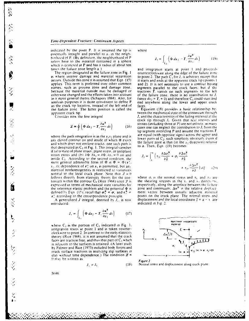
-'W~~W W'. YW -4'Pi'
e*
* " Time-I)cpendent Fracture: Continuum Aspects
indicated by the point P. It is assumed the tip is whereessentiall\ straight and parallel to x, in the neigh- du/b,,rhood of P. (B\ definition, the neighborhood of P J,f HPd . -T, -- d.,) (19)refers here to the material contained in a sphere"
thich is centered at P and has a radius of about tentimes the failure zone length a.) and integration starts at point I and procecdN
The region designated as the failure zone in Fig. I counterclockwise along the edge of the failure zoneis %%here intense damage and material separation to point 2. The path C, for J, is arbitrarN except thatoccurs. Outside this zone it is assumed that Eqn. (15) it starts and ends at the apparent crack tip (points Iapplies. This term is preferred over other common and 2). It is not necessary to use a contour haingnames, such as process zone and damage zone, segments parallel to the crack faces; but if the
r because the material outside may be damaged or tractions T, vanish on such segments to the leftother",ise changed and the effects taken into account of the failure zone, there is no contribution to J,in a more general theor, (Schapery 1984). Also, for (since dx, = T, = 0) and therefore C, could start andanal\sis purposes it is more convenient to define P end anywhere along the lower and upper crackas the crack tip location, instead of the left end of faces.the failure zone. The latter position is called the Equation (18) provides a basic relationship be-arparent crack tip. tween the mechanical state of the continuum throuph
Consider nos, the line integral J, and the characteristics of the failing material it thecrack tip through J. Given that real stre,,es and
d, 8u, ,strains (including those at P) are not infinite. in manY (-3 dx, - T, - ds) (16) cases one can neglect the contribution to J, from the
ax, tip segment encircling P and assume the tractions T,
S where the path integration is in the . 2 plane and is are equal (with opposite signs) across the upper and
an\ closed contour on and inside of which 4 exists lower parts of C2; such simplicity obsiouslh exisl ifand which does not enclose cracks, one such path is the failure zone is thin (in the ., direction) relati\ethat desinated as CT in Fig. I. This integral vanishes to a. Then. Eqn. (19) becomesif (a) a state of plane strain, plane stress, or antiplane aAuF 0A 0strain exists and (b) aq ax, = ad. Ax, =) on and = rU- + --in'ide CT According to the second condition, the ., .most general admissible form of P is (P = (1)(F.
t... 1): dependence of -, on x, is permitted. but an, . r ,t 2)
material nonhomogeneit, is restricted to %ariationsnormal to the local crack plane Note that J = 0folloss directly from elasticitN theor for the con- where c, is the normal stress and r, and r, aretinuum ithin the contour CT (Rice 1968) since J is the shearing stresses in the .t and .x, direct,,n,.expressed in terms of mechanical state variables for respecti.ely. along the interface between the failurethe reference elastic problem and the potential 4) is zone and continuum; Au' is the relarse di plice-defined h\ Eqn (15); recall that oR = o, and r,, ment vector between initiall\ adjacent materialr'< accordrng to the correspondence principle, points on the crack plane. The normal stress and
A generalized J integral. denoted b J,. is nov. displacement and the local coordinate = a - .x, areintroduced: indicated in Fig 2.
f(d --- )1NoJ ineo, v,$coeia,Ic T
\%here C, is the portion of CT indicated in Fig 1; moie,,o
integration starts at point 1 and is taken counter-clockwsise to point 2. In contrast to the early elasticit,theor) (Rice 1968). it is not assumed that the crack Pfaces are traction free, and thus that part of C1 , whichis adjacent to the surfaces is retained. (A later stud\b% Palmer and Rice (1973) included body forces andcrack surface tractions in anal~zing slip surfaces in a .2 i, > 0, 4, o)cla' without time dependence.) The condition Y = 1 _ /(1 mas be s.ritten as Figure 2
J Jr (18) Normal stress and displacement along crack plane
50146
I,
" -.", , ,. ,-., " .. " : v'. . , ..," .. r .. .". ' ''-,',.,' i l .,.. '.:.-._,.'.-. ,".' ' ' . -' - ' ". " '. -',' . . - " ' ': ' ' , ' ' % % r :

Titne-Dependent f'racture: Conhguuom A i,cti
4 Crack Growth %iscous material. D=(tE) 1(t - r) .%here t, r. atime constant, as noted pre% iousl. After interatint
Essential features of equations for predicting the Eqn. (24) b parts. it becomestime : at Ahich crack growth initiates and subsequentcrack propagation speed a %ill be illustrated by (l/,'Jdt=F 125)assumig a slender failure zone (compare with Eqn.(211) aid the opening mode of crack tip displace-ment In this case, sliding displacements along the It may be obsersed that the failure zone length a hascrack plane are zero in the neighborhood of the tip. not been assumed small in Eqns. (21-25) Also, ageneralization of Eqn. (21) is easily obtained if of =
4 1 Inaton of Growth ol(Au.t); one finds that a function of J, and t
In order to asoid excessive mathematical complexity replaces J./o.in illustrating the prediction of t,. the failure stressdjtribution a7 will be assumed independent of , 4.2 Crack Propagation Speedand denoted by c,, Equation (20) becomes Jf = The failure criterion based on mechanical Aork ma,o,,.ii,, where AuR. is the elastic opening dis- be written in the formplacement at the fixed location !: = a: the tip P, Au, Prather than the apparent tip, may move when t -_ 1, in ot df : = 2E (2t))our crack tip model UsingJ, = J,. the displacement is Il ac
.. A.,, =J, o_, and the correspondence principle,E , 3, I *. aneds the coesdpndence ricplaeen, where the fracture energy F. just as F,. is the ssork
Eqr.i 13). yields the time-dependent displacement. required per unit area to rupture a column of materialAu,. = {D d(J,,/o,,)} (21) with cross-sectional area dA in the failure zone In
- o here a,. is not necessarily constant in time. If the contrast to the initiation problem. this column is notcriterion for initiation is based on a critical value of initially at the apparent (free surface) crack tip.openin displacement. Au,. it is possible to determine instead, the column is initialls within or ahead of thethe time at \,hich Au>, in Eqn. (21) is equal to Au,. current failure zone. and its rupture is coincident
An ahlernati\e. commonly used criterion is based Aith the arrival of the apparent tip The left side ofon. mechanicals'ork In this case. sork input from the Eqn. (26) times dA is the total ssork input to the
continuum is equated to work required for failure: column. starting with the time the tip P (see Fig Ifirst armes For con enience in anal. z,0g Lontinuot-
f. Au = 2Pro\%th. the variable of integration h:;s been chanced,.isthe, 0
i t d2,(22 from ( (see Eqn (22)) to Z. .here z = a - .r,. andthe differentiation and integration in Eqn (26) are
%A he-rer-isthe mechanical \sork per unit surface area made \%ith x, held constant The time-dependent'required to break a material column. with cross- opening displacement at an% point in the failure zonesCtional area dA. at the left end of the failure zone, is Au= {D dAub}, which is to be substituted intodesgnated b\ the subscript a on the stress and dis- Eqn (26). The result for predicting a is ratherplacement. a factor of 2 is used to account for the complex. een if Au: is used in a critical displacementt,,, unit, of surface formed for each unit of cross- criterion, because of may depend on Z or directl\ onsectional area of the column The so-called fracture Au, or A0 . and of affects the displacementinitiation energy F, may be affected b% the history of The problem can be greatl, simplified if a) o, andAl,._ depending on the characteristics of the failure Au, for fixed Z. a and a are essentially constantzone For the case in A hich of = c,,,, Eqn. (22) during the time interval a1 b when the crack propa-becomes gates a distance a and (b) aging changes in the creep
Icompliance during this same interval are negligitle. o a,,d[dD d(J,/o,))}/ct] dt = 2F, (23) With these conditions and the observation that the
relation between Au: and Au! is the same as for a
If a,,. is independent of time and the explicit rep- linear viscoelastic material, an approximate exalu-reentation for the hereditar) integral is used (com- ation of the hereditary integral ma, be used (Schap--reenttin. or theheed n tery 1975 pp. 369-88) to findpare \Aith Eqn. (81) then dA. ,~- )O(7,,di/ Au. = ERD(U. t)Au (27)
Fr E,an D(t, - rt,) - dr = 2r, (24) where -k/a and k is a factor which is a veryv eak,r function of the slope n - a log D a log t; this factorFor an elastic continuum, where D = ER' , this is practically 1/3 for the entire range of slopesequation reduces to J, = 2F,* the failure zone may (0 - n -_ I) encountered in practice For a linearbe sztcoelastic. and therefore 2[-, is not necessarily viscous body (n = I). k = 1/3 exactly if = a andconstant. If the continuum is a linear or nonlinear of = on Equation (27) stems from the smooth cusp-50-4
• " N?
%
%-%

1 tinc-Ih'pendcnf Fracture: Continuum .4spects
shaped opening displacement predicted for linear on the state of the nital crack tip In an\ enti!matcrials and the t.picall. weak dependence of n on should not be assunmed that thee energie, arc eqallh. te Assuming the strains are continuous at the tip without adequate support from experimentil data
-- 1 '. tile bhha, lr (if the local displacement in nonlinear
mcdii is expected to be close to that for linear pre- 4.3 Energy Release Rawstresced media (IBrockv.a, and Schaper% 1978) and The J, integral is equal to the energ relca,,e ramtheielore cusp-shaped. Thus. although more careful for self-similar crack growth (A0: =Ai i) osrstud\ of thi, behavior is needed for highly nonlinear 0 ' a) in the reference elastic problem. v, hich i,. amaterials, the cusp shape is expected to exist in many well-known and useful relationship for experimentalcases, permitting the use of Eqn. (27) and a constant and theoretical determination of J, Namlel\,value for k Substituting Eqn. (27) into Eqn. (26)and uing the same type of approximation as in the J = -aP,,'aA (311linear theor\ (Schaper% 1975 pp 369-88. which does where dP, is the change in potential energ. of thenot require oi to be spacewise uniform, there results reference elastic continuum and applied forces. a,-I
aAu is the increase in crack-plane area This relationshipEl D(k a"&, t)) Of dZ = 2F (28) is easil, derived by considering the work done hs a
-* general three-dimensional elastic continuum oin afailure zone which is advanced an amount dr alonc
l T,. i i h replaced b J , to e integral in Eqn a segment of the crack edge (Schaper\ ] .," -rcsuht for predicting a:
ED(ka 6. t)J, = 2r (29) 5. Poier Law Nonlnearitv
7- 1he interation and differentiation in Eqn. (28) Here. the specific effects of nonlinearii\ on the open-fre for fiveds while those in Eqn (210) are for fixed ing mode of crack grovth are illustrated using a
" ti e . fixed crack tip location) howkever. for the posser law, nonlinear material By definition, the,ci::j\ -stlate propagatton assumed during the time pseudo strain energe density in this case for i,,otropicSt. se integrals are equal. Also. t in the second or anisotropic materials is a homogeneou, function
a! itorcilt of I) accounts for aging in the creep corn- of degree N + 1.id phanc, and the aging is assumed small during the qi(c(l, = ,c - '"'W ( 132)
tkm inker 31t 0 6 in spite of the assumed constanc\of , and aging during a a. the\ ma\ ,ar\ appreciabl. where .\ and c are constants and I denotes a!,tedurit, the total time of crack propagation. Like%% ise ,alue. For notational simplicit,. the uper,cript, cthe size a is not necessaril\ constant, as it is related and R ",ill be omitted in succeeding equat n, iin!ilt,) other variables such as J, its prediction is illus- specific results are applied to %.iscoelastc cracktralcd in Sect 5 for a nonlinear power lay material growth analsis \kith the definitionsAl.o. it has not been necessar, to assume a is small E,',-r,. '--l c.. sgnlclCEsignof (1ill derising Eqns. (27) and (29l) it is sufficient to ' "
atsurm: the change in or and An4 is small due to the it folloyss from Eqns l15t and (32) and applicationchance in distance betwseen the crack tip and nearb% of the chain rule to ,(,¢' of,, thatLt ,metric features (such as another crack tip) during a V (1the pcieric period a d = sgnlc)lc'" - o' = sgn(u Itu (341
The similarity of the formulas for initiation. Eqn. Or,'
(24). and continuous grossth. Eqn. (29), is note- For a uniaxial strain state the second relation implie,\xortlh', As a special case. suppose J, is constant for a - sgnl )c1-V!": the same form is predicted for
.t I hen Eqn. (24) reduces to uniaxial stress (Schaper\ 1981 Equation 1321 con-= 2F, (30) tains as a special case the power lak strain eneres
ED(,. =F0 function commonly used for isotropic materials ( RiceThis result and Eqn. (2Q) yield t, = kalb if r = r, and Rosengren 19681and aging is negligible Thus. with k = 1/3. the time Let us introduce a set of dimensionless coordinatc,required for initiation is onlN one-third of that and mechanical state ,ariables.required for subsequent growth of ait amount a Onthi- KisiN. it can he expected in some problems that .- . (7 (7. o,.t, %kill he negligible compared with the total time t,. sgnlo,,,) ,, o7, ,required for failure of a structure.
\hether or not F equals F, depends on the he- U, sgn(o).o., ,, iu 1351reditar, and multiaxial stress characteristics of the The quantities ,., and a, are parameters Aith dimen-failure zone, the ph~sical environment (since the left sions of stress Ihe\ are independent of x . and areedge. a, is at the surface during 0 < <t,) and introduced for the purpose of defining a dimen-
,, 'Ie '.01 ..r % .

Time-Dcpendent I- racture: Coninnumn A Wpc it
s,onless failure stress distribution f and strain energ, similar to that in Rice and Rosengren (1968) for andensit% 4,,. isotropic pos er lass material \%ith a pola coordinate
ssstem (r. H) centered at P (compare with Fig 2) it-'.f -= o, . ) o,, (36) is found that for r , a,
The parameter 7,, is assumed to depend at most on fi, = 11) , h,()acing ine When these definitions are substitutedinto Eqns (10). ( I I) and ( 15). and Eqn. (34) is used, (1, = lI4/-)' " . U)
* the field equations become d= (11 ' "''g,(0) (41)
=0. , + - 0 ,, (37) =(here= r The integral is related toJ, through' ,+ a, Eqn (39a). and the functions of 6 are determinedfrom the solution of Eqn. (37) and the condition of"shere 4, t Allo%%ance is made for negative 1traction-free crack surfaces for ;>0. The failure
value, of (, throuch the factor o,,_ for unloadine ofasscoela,,tic m~trdthis stress coldb naie zone traction on the crack plane is neglected in sols-a, muted p eri f ti ss crack fe cntat. ing this boundary value problem: its effect enters the!nliited period,, of time " ithout crack face contact. solution in the form of 1, after path independence ofLocating the origin of the coordinates at the crack 1, is taken into account through Eqn. (39a) tsshich itip P (a = tin Fig 2). and assuming the crack faces JitaeinocouthrghE . 3a(%hc s
based on Eqns (18) and (21)) The dependence ofare traction free outside of the failure zone, then. Eqn W-I solutions on r is the same as fouit b\ Rice%kith the additional definition i = ( 1 1) =- .f, the an Rosenrens o) b ihc s alond i' nt% -,th and Rosentvrern ' NOS), but the H dependcmxc I, n(,I,olutin to Eqn (37 must satisf- the traction bound- necessarill the same because the strain encre,ar condtion =f(% c)HI- ) for >i as iell as densit, used here is more general. Such detailedmeet the ,smmetrs conditions, associated with the information is not needed III this tud\. ralhict. it i.
"- opening mode. These solutions \kill depend at most sufficient to knos that the entire influence of csternalon the dimensionless coordinates ._ apart from pa- loads and other far-field parameters and geomelrsrameter, in q),, and f and those arising from con- (ucli as other cracks) on the dimiensionlcs, ni,. h-dit in, imposed on the continuum surrounding the ancal state %arahle, in ELn (3;! IL elrlh-failure zone For example. the solution for dimen- bcho o arack In Eq ;Th nt for I, i~swnle ., craick-openne di~placement i, simpl% Atii, =
-With the small-scale failure zone. gisent he shaperm () function f 1)1 for the failure stress distributon and
Au. = ;gn (,)a o(, o.' 'kf11 (3R) not using Eqn (39b). it ma\ be concluded that thepredicted shape function g( i) for the crack-openini
,tiI," 1 an ( - displacement can depend at most on /, N and acig
, J, time i. Equation (39b) is thus an implicit relatiotihip,,, 39a) for predicting L The significance of Eqn. 13UI I ma\be clarified b% imagining an anal\sis in vhich external
sA here loading is increased from zero bx usin incrcasin2
dg ~ %alues of 1, in Eqn (41). but not using Eqn (39hb.I, = f(/l)- (396) until infinite streses and strain, at P are remMoed
-,, " For the linear problem..% = I . it cai [lbe scrifICd that/5- the remos.al occurs when/, is equal to the tnlcitrl inI, From Eq, () and (391. Eqn. (39b):. \ith this \alue for I,. Eqit 13' becomes
Au = (J' o,,.l )g( I)) (4(0 ) identical to a dimensionles, form of the Barenblitt(1962) condition for finite crack tip stress after the"The results in Eqns. (38-40)) are not limited to a f'amiliar relationship
small-scale failure zone and are alid for materials f relationshi2
\ shich age and are physicall, nonhomogeneous v.ith " (42)respect to x,: the dependence of 4, on x. and r and is employed (vshere Kt is the opening-mode stress-related material parameters has been suppressed to intensity factor. ER is Young's modulus and i. issimplif\ the notation. The dimensionless displace- Poisson's ratio) Recall that Eqn (39) comes fromment g. stressf and integral 1, could in general depend Eqns. (18) and ( 19) (through the special case of Eqn.on all dimensionless parameters that influence con- (20)) in which the portion of the contour C, aroundtinuum deformation in the neighborhood of the crack the tip P vanishes on account of the ph% sical require-tip Considerable simplification in this dependency ment of finite stresses and strains Th'us. it appearsresults if the continuum is phvsicall% homogeneous that Eqn. (18). in which Eqn (20) is used for J,. can(at least locall.) and if a is small relative to the be interpreted as a generalization of Barenblatt'4distance to other geometrical features The immedi- condition to nonlinear. amsotropic, %iscoelasicate continuum surrounding the crack tip neigh- media with an arbitraril% large failure zone Forborhood can then be analszed bN using a method such a general situation, these equations ma% not
5(149
',.

limet-IDcpendent fracture: Continuum Aspects
guarantee that the crack faces do not os erlap. and the failure p csfor rnateri,il I lercnt.iit, ti rithus additional anal% sis minsng contact phenomena plane is unaffected bs srresses, prior iI,, lhr irrixi ,rcould he needed near arris al of the crack ip[, such air ;inils r' tI, 't
It has been ow.s n that /, is a constant %;hen f= small-scale failure zone ssould s eld aiht m P ii
illi. except for possible aging It should be clear a(J, Aisth posstbfc deprcndenice on il PIO.1IrAtitIis- is true even %%hen f depends also on the arrieters anid material conistanrts such as lenIMl' cia r
1.1LIslen"ientI shape function g In this latter case one age and nonlinear exponent % . that theisirrir-must sols e siniultaneousls for f, g and 11 using the J, (but not past %alues) determines, the irrst:irtar iedlinienionless equations, a follov s from the fact that the crack tip rrerifr
5 1 C-akGot borhood is surrounded by, a stress hield ishich is,dehined soleh% h the current salue of J. If e .q LIi
The anal ' sis in this section has so far been limited to (41) but in' terms of the dimensional ph\ssicala stud\ of the reference elastic problem With the variablest, assuming], changes slo%% 1\ enough th~it 0addition of the superscript R to strains and displace- is essential constant during the failure ifme. 0 a2ments,. thes mam be used \16ith the results in Sect. 4. Thus. %khen the dependence of a on bhic, maCtriEquations (231 and (24) for fracture initiation were parameters is not of direct interest. one could charac-dens ed assuming (7, does not %arN \kith 1-.represented terize fracture behas or with the function a = JIlhere h% = I since (7, = o,. In this case the equations found directll froni experimental dlata It theorcti iifr, init tin time :, are S er simple and are not insesticatrons indicate a raiige exists fir ss ich -h,limpst' to, a siriall-scale failure zone If df di) ; (0 it dJ, 6 . urrstable crack grossth ( possrhI% in, sre' ,fi' hzclptul t', u~e the results for a power lass material stop-start belias or I mas result and the intrrn~rctI, pre~di,:i r From Eqns (40r land 141 Ae obtain the j - 1, functioin for slow continuous grossib could
pcJand \s coelastic displacements (wkith 9() not be found expenimetitalls Indecd. fot this ciscan appropriate analsi, mas insols e inrt iation atid
"I 4~ g (7,1. Au,, = (B dAu! ) (43) .~ai arest phenomena-'~~ -tr hc dcii
1 ic ic os i'at a ii siithiut 5 2 Potter La". Vascoelaincitts tie ii~iL 'is f ic~is nechlirh The creep compliance for siscoelatijc materials can
P II F qr (-" r~dUCs to Eqn 123 r often be expressed as a power la\s% in ltne J hus. asc'.,~I - Ji!1cJ h\ the nsmtfactor 1, 1? an important special case. consider nonaaci material
Ifra ' y spec] depends (n the siie behas or for wxhich i(i - r) = 1)-i - rl I i sshere 1)i.Ir, lhis sr/c n 'ss assuriied srrl . and r? are positis e constants)I in order to, predict thre
* - V ~'. ssr aterril is ci en h\ L qn I 3141 form of the equation 6 = dl],) using certain specifiedii ic'lrt. i h is result First, failure zone characteristics A small-scale filure
r1,1%i be in'cr-'cled 'is af sreld tress zone \A it h a shape factor f a o- that depends at*...........i hen % is rmjll usriic (1) = 07 (), most on g and rl = Za is assumed. In geneil 0..
I wi 0'i and one-dlimensional or and F ma\ depend on crack speed and other par-:"1'.1 iri: through a stress (7. then e - ameters If. howxever. a, and Fare constant Iso that
ics- the strain is small w.%hen (7 0 c, and this zone exhibits elastic-like behasior) Eqns (29).~~~i .%- -if\ I AI,(), (1-masbhecon- and (3(4a i ield a ths to 44
is .. ' 5 ~c ssilirespect iio locatlin _ i oif thei t, ic- uig rc grossth Thus. the wxhere pr I 1 -(I n ). If a (instead of o,,) and r are
Ir~ r ' F. I 114a I increases \kith increasing ield constatnt. Eqn (29) predicts p = I if The failurew I r' sirsiie to the ratio of sield stress in zone dimensions are defined bN a and crac:k-openitig
S '' s scnsr isen J In elastoplasic fracture displacement AU: at Z= a. 4tee\A quantitiesfl.rrit' i i common practice to assume o, is are constant, one maN use Eq 39a1 t solse
pr-p;'risnal to the \ield stress and f =l .in this case, for o, and then use Eqn. (21)frAand Eqnli., 1,indard result a *- I, of is recosered since 1I ts (401) for A0~ at ?7 a = I to fidthat r,
-nisl,,w %1oe weneralls. ', nias\ sars with ni land [nrl 1II - r Notice that ottl\ in this last case doesr'hc'r pirrmeersl so that a J, is not necessaril% the nonlinearit% exponent appear in the equatioin for
I'llp.I hc. results so, far have been expressed in terms of ExperimentallN dleterminedt salues of p. when com-
matlerial functiiins for the failure zone. a, and I. pared with the results for these and other cases. ma\/ Ihee quantities ma ,.epend on a and other variables be helpful in determining failure zone characteristics,,suit as temperature and moisture. especiall\ if the and guiding theoretical model deselopment The
7zsne is s sco~elastic One could explicitls incorporate values of p = 3 and ni = 0 5 w;ere obtained fromspecitic phssical models of the failure zone in order experimental data on a globallN linear elasiomer. thistoi complete the formulation of the theory Assuming is consistent wijth the assumption of constant F and
5Ii~uN
'.k5e. i

Time-Dependent lFracnitc: (otfinuum tlpccti
o. (Shapcr. 1I15 pp 549-62) Some studlies of crack presented here. For secondarN creep (i.e .nonlinearVro,.,th in mcia), undergoing secondar, creep i e. viscous behavior). experimental data on crac k speed•pro% = 1% pile .alues of p I I (Landes and Begley have been successfulhN correlated in terms of a ("10Th. Nikbn et i N76), since A < I i.picall,, the parameter b% man investigators (e.g .Landes nddat., ire ,'oni lent ,, tth the last two cases for constant Begle% 1976): the function a = a(C ) t~picalls obc,salucs (t F and a or a d., ada It should be added a power law. This characterization. w4hetlher or notthat the exponent . used here pertain to nonlinear the power law is obe~ed, is obtained from the presentbehas.ior of the continuum in the neighborhood of theory by using the relaxation modulu,, f =the crack tip The relationships are Nalid even if ER(t - r) in Eqn. (8). which reduces the pseudononlinearit% of material far from the tip (relative to variables to strain rates (r, = £,, and velocitiesa) does not obe% a pow.er la,. or is linear (i.e., N= (uR = zi,}: in turn, J, becomes C*. The use here ofI) A, hile it, local behas ior is described using N, 1. nonsingular strains at the crack tip, in contrast to
• " The remote nonlinear behavior does not affect the earlier work on secondar, creep. leads to a simplea - J, equation, but it does affect the functional physical interpretation of J, for viscous media. Spe-dependence of J, on the externally applied loads. cifically. from Eqn. (29) with k = 1/3 and D =
ER(t- r), corresponding to the aforestatedmodulus, we find J, = 3(2Fai 'a) = 3 x (mechamial
S( o( lisioiis poNser input to the failure zone per unit area F-orThrough the u,,e of a nonlinear single-intecral consti- viscoelastic materials J, has a simple physical mein-tuitse e~U:iiiton. g'eneralized I-integral theor and ing if the continuum is essentially elastic except forcertain approximations. relativel\ simple crack a small amount of material around the crack tip Ingrossih equations based on mechanical Aork for time this case J, is approximately the energy release rate.of initiation. Eqns (23) and (24). and speed. Eqn. -aP/A. since u, - u,: also. F ERD in Eqn. (214)(2'4j ,,ere derised Onh% the opening mode of grovth ma\ be properly called an effective fracture energ\has been anal'zed in detail here. but the basic Crack growth in homogeneous linear viscoelaticrelatonships in Sects 1-3 could be used for shearing media has been characterized traditionallh in terniand nixed-mode conditions Rheolorical properties of stress-intensits factors because of the man\ sstua-of the continuum are reflected in the creep com- tions in which \iscoelastic stresses are the same a' inphiance L) and the generalized integral J, The length elastic materials With isotrop% . linearit. . a coriiainto of the zone of failing material at the crack tip Poisson'srauo. homoeneiw. and lcall', pane traMn.app,:.rs in the equation for speed. and it pro% ides a it is found that Eqn (41) (after expressing it in term,'.,,'cr .Isi h deterniine,,. in effect, the nmi nitudc (if of the stress-intensit\ factor) and Eqn (3'4a) seldlocal strain rates resulting from crack grossih In Eqn (42) Substitution of Eqn (42) into Eqn, (2-1ge.nerd n is not constant, instead, it is related to J, and (29) results in the same crack grovs th relationsthriuLli Eqn, (1l and (21)1. which reduce to Eqn. deri\ed earlier (Schapers 1975l) Similar re,,ult in3. ss ith po,, er las nonlinearity terms of stress-intenst\ factors for linear behas or
.All( of these results come from an analssis of the exist without the restrictions of constant Poi,,onscontinuum in the icinmt, of the crack tip Thus. for ratio. isotrop. and homogeneit\ (Brock.,a\ andhimted crack grovth it is not necessar% for the entire Schaper, 1978. Schaper\ 1975. i978) Thi, obcr-bods to be represented b\ Eqn (1) and the local vation includes cracks between dissimilar medi;t 0 c ,creep comphiwice 1) Hosw e, er. if it is, Eqn (31) mav adhesive fracture) if both materials are iiconi-h emplo\ed to predict J, v, ith an arbitrarN amount pressible or one is relativelh rigid and the other i,of cr.ck grok th b\ using theoretical and experimental incompressible: without the incompre,,,,ilcicthods similar to those already des eloped for time- behasior. tensile and shearing stresses act simul-independent materials In this expression P, and J, taneously on the crack plane. and a complex mixed-are detined just as for elastic materials, but dis- mode condition generally exists at the crack tip Theplacements and strains are pseudo quantities, u, = nonlinear theory in Sect. 4 is applicable to adhesioe
dul and r = , = {E d,}, respectiels. Stresses fracture if the mixed-mode state does not exist andand loads are the actual physical quantities For D is the same for both materials (or one is relaielsexample. experimentally measured displacements u, rigid) F, and F in Eqns. (24) and (29) ob\1iou\ ha essould he conserted to pseudo displacements u, to be interpreted as the fracture energies for thethrou-h iqn 18j before esaluating J, from test data. particular material combinations involved1lie coetticient F, is a free constant, and could be Primary creep of metals and ceramics is cus-taken as the modulus or reciprocal of compliance at tomarily represented by using a nonlinear poswer lasssome specified time, model of viscous flow with strain hardenin \\hen
The bibliograph\ includes publications which crack growth exists this beha.ior is not described b\describe .arious models for characterizing and pre- Eqn. (I). and the correspondence principle. Eqndicrtin, crack vro\th in different t~pes of materials (13), does not appl\ However. with proportioti,1Seseril models are special cases of the general theory loading and a stationar\ crack, the strati-hardtcim
% X
-. "

7itne-IDeperidcnt F-racture: Citinuumn Aspects
cotistiutise equation becomes identical to that of a eser. most basic experimental and thuorii.a ime s-nionlinear. aging elastic bodN (e.g , Riedel 1981) tigations has e been for the openiing Mode' '' cihesis eEquaition ( I I take-, the appropriatle form by using fracture in essentialls h ooeiieous nviteriails Ini lhis
/ z)= h~tl) A suitable choice of ht(t) and a powser same time period. use of iber-reinficrccd ni.ilcri.ils.Ilixs potential 4,( F, I. N% here the only. time dependence especialls plastics. in load-beariiig stri 5 tj~t's his,is through r, = y'i ields the desired primary increased dramaticalls Thus, considcring the comn-creep behasior as well as a singular stress field plex interactions Nshich ma% occur at '.ariou Scale'Uparameter (' * (Riedel 1981 ) w&hich is identical to J_. and the importance of interfaces in fibrous larniiFor a small-scale failure zone, the early stages of and laminates and in other multiphase material,crack growth are determined by the stress field sur- there is an especial]\ important need for more basicrounding a stationarN crack tip and therefore bv J_. studies on mixed-mode crack growth. adhesi~e crack-Howeser. a theory does not appear to be available ing and the effect of nonhomogeneous time-depen-for relating crack growth to a single parameter v~hen dent properties on all types of crack grossibthe amount of growth becomes comparable to the See 015o Time-Dependent Fracture: Mechanisms. Nlh-scale of the initial singular stress field. aiso laeil A ~ri%
It should be observed that a different type of ancofairasAnOeiwprimary creep. such as that used to characterizepol\ nsers. is contained in Eqn (I )through the depen- Acktioi lidgcnicitdence of creep compliance 1) on tr - r. Also, through This sAork %sas sponsored bi the tLiS At; c'- (Wlli,,j
th ue f gig im i ~= f. neni~ of Scientific Research, Ollice ofI .AerO-SpJccharacterize different types of nonlinear behavior at Researchshort and long times even though the creep com-pliance itself is not a func tion of stress. Thus, in spiteoif the apparent simplicity of Eqn. (I ) compared %\ ith Bihiogw-phiother available nonlinear viscoelastic constitutiveequations. it is really quite general and yet permits Andre~ks F H 1074 A eenerali--d iheors of frac-iurc niech-
the use of the correspondence principle Ic %ith large anic. J Maiwr S i 1) 81, -14- Barenblait (i I l~ic2 lie inaithenratis,I tli\ of eiqi
amloun ts of crack ProN% th. Ne% ertheless. the accuracy lIbhrium cracks in) britle fraciure Adt .If'' Nteciiof Fqn (I I for man,. materials under %various stress Iss 1 1(histories is not yet e'stablished. Brock\&as G S Scharer% R A IQ79 Some sc((ic Lasi C1JJ
The deformation and fracture anal\ sis has been zross rh relir ems fir orthoiroric and prcsrxined md~formulated assuming small strains and rotation' for Ecic Irar Se lil 5~-~
thie cont inuuin This restriction is needed because the Christensen P \t 1W452 7/ir,i ,, I iscciifi !i .1", 1w,.correspondence principle is not generall\ 'salid wsith diiciimm 2nd cdii .AsdeMK Press. \Ls% 't or Inonlinear strain-displacement relations An approxi- Esans A G 4KThe hirh temperature failure of cerarim,mate theor\ wkith large deformations is described b% In \lshire 13. ()ssen D) RI J eds ) 11452 R cii 4,f
ir Creep and f, t,i, of~iieoe.teii 'd.*:Schaper-, ( 19S-4) Another possible complication not tur-c Pinericice Press. Sssansea, pp 'I-IIIesplicitl\ treated here is crack tip heating. wshich Findles %\ N lY,, (irecp of 2lSalurnituni unde-r sJ-,can be ver\ significant in poly mers because of their steps (if rensicin and torsion and stress res ersal prediciedJt~ picallh loss thermal condluctivitN and high ultimate h% a %iscous-%iscoelastic model Jr Appi Atedi 4S -t--
strains If this heating is sufficiently localized, it could 54be included in the characteristics of the failure zone. Greenssood J A. Johinson K L 1)51 1 he nehiric.oand thus not complicate the continuum analhsis adhesion of %iscoelastic solids Phiio sti M I .t1 4 t,-
The idealization of a slender failure zone is quite 7aisi11 1)/ netgtosintefedo hrealistic for crack tips in many materials, as wsell as Kmecnics of 91Ietiaini the fractur of thceesrcbdisSfor craze tips in plastics In considering the zone Ap lciI~7t5shape and size, it should be recalled that onlN the Kinloch A .1. Youns! R JItQ)/3 Fraecue Belmai-iiir of Poipart of the bodN wshich does not obey Eqn. (151) has mers Applied Science. Barking. UKto be included in the failure zone. In some cases it is Lake G J1 1453 Aspects of fatigue and fracture of riihherhelpful to represent part of the failing material (such I'rotz Rubber Tec/oiol. 45: 89-143as, craze) as a surface loading. consequently account- Landles J D. Begle% J A 11476 A fracturc mnechanics:trig for it in J,. As a further generalization i t is shoswn approach to creep crack groth. In. Rice J R lisi 11
b%\ Schaper ( 19841 that important aspects of the feds 1 19476 Alec/ramicc of Crack Groci i. AS I N51 St IPtheors remain valid even if distributed damage. such 5( mrcnSceyfrTsigadNaeil.Pi~
* delphia. Pennsslsania. pp. l2"-~48das, microcracks. is included in the mathematical Leckie F A. Has urst D R 1974 Creep rupture of sir uc.
model of the continuum tures Proc R Soc London. Sen A 340i 323-47C onsiderable progress has been made in the last McCartnes L N 1992 On the energs balance approa~h to
tssenis sears in understanding effects of time-depen- fracture in creeping material% bIt J flact S /i,m I')dent rheological properties on crack growth. Hoss- 99-113
50152
%
-IX

7II1I-)cj7Cndit1~ I rat ihirc I/(( 11ioiirito
NI,:( tirrick I A, iasni J L 'f98t Prohlems in ensirori stresses that are inl% a small Ira. ton oil tie V
niC1o1lk .I c edCreeCraCrk girossth In sernat Nasser st rentIh. t hi, o'td Iiirn is, rnet at suir ti tr r-. 'I
S 1,icI Il 7hrc-Di' 'i ,m'itrivc Reiaurr'ri leesof the cra ked %%stemr' th rorm.' tI,ar, , r fI,i,' Nrirth 1 10old. Arnsierdani pp cannot plisc a sNIgniticatit rie In sti1ct-Ic
I -1-4;response Heince the oini rile -depe Idenrt1,'rl.iiicl L W, Sprine 1 l'J52 Siue mier al rep- in elastic ssstems at loA tettrprititie, ir t,re'ci1!atiiins ,for nonlinear siscoelasric solids Alech st ress,-cor t, sion crac k ing -it s !j: it. - A IMlat' slo craklgo-h id
Nikhin 1K klI 5ehster G A. lurner C E 19~76 Relesarice slc rc rs hudrshttof nonlinear fracture mechanics to creep cracking In be comes, posoI Ne hs rare priiesse, oI ri~lk ipIsrr cdl'", L. ' iliams NI L feds ) IQh Cra k i arid To'ifl or contarnination Jhcs rsI.h ci5frau',> AS INI STPIPfiI American Sociers for Testing are discuss ed elsess here isec .~i''i'
-and Ntaterials. Philadelphia PennsN Is aa pp 47--e,2 mQ, cuhP' ron ,a ta, I, wlo IPalirier A C. Rice J R Q73 * TIhe grovo th of slip surfaces in The time -dependent ft asojr v ' n d h-t i1
the proi'eeise failure of oi~er-coifl50Idated cla.s Proc those A hic h ins 'Ise time J-I'1 ri'.n "'I.R Sic Li'idei. 5cr A 332, s2'-48 VC1eOiU' dalii ig ds ucilj ' 'I ,! ' I'
U ~~~~~~Passiglia U I JK Relaxation of stresses in crazes at crack noiris'paliini'it cri'i 5'rips Iand raiw of craze extension P'r!i ,n'e' 23 7 hi 'iii ' all% sinh det -'r '01 "'I I A
P'nier A- R S Hashursi D R teds I 1(481 ( reer in Strur- nit!,iiL I.rilii . -
rwSpringer . BerlinRice J R I 51i A pith independent invrral aind the :ipnr su'vri i., ic Ot r'y-.
niic ariliisis ofI 'lin,11 C('t.rccrtii' hx n''tchu, and accunijliti'rr ot clrimn---l'c .
Cracks J Apl Alechn3 ' -Mr-i mre cirientratcd atund st' iiuRice J R. Ri'sengren 6 IF IWlO, Plane strain deformation or at tips of suhb. nt cal Lt JIK I '> r., 11 111
near a crack tip in a piioer-Ia%i hardening material J usualls time dependert cr,~ Ii n. , iI-%fit/i rliii NohIif l , 1-1 takes cimparatiscl, hlil 1nT It-f
RiedelI H 1)il (J Ireep deforoa imn at crick tips in elastic- poesstetm eerrni:Lic-r'sIis.piisolid, J klei ib . :i21 1> ' -frnuawth itt p ri'ee sshr ii -' i ii -
Riclel I IJ" Crack -tip sitress leld1, -A crick ~irs"l ft omi-ipoe, %h ~ ,t i
undlcr crceep-faticue cindrtir- In (Gudis J Sh, F te nti~r'processes that fbuiIkl u;, ici n-i, - ti
lcd, , - iam,-Jiaii: f-raitre ',rd So'i'-i' centtatii'ns. esert in the prc~cneo! iiir ,1siriit
I -iin -/i,iolr ( at 4 An;i%'. A'IT\I 'STP ~ priices that itr t' disipate these same sir 'h
* ~~~Anyie'icart Socrers, for 1 estirre: anrd Material,. Phi;a certlrations ( )nk rarelR die' the Tiimceleirr
Ptrnr'sslsania pp 5i2(1 reside in true proc es' oIf (c--es n'11 Ihe0S'pRk A lk5A thetirs if cric inrriafifin tune e''"nt ecular scale lithe phases of the tirnc-de-p-ole~ i,t-
it 'ocircmedia bit J f'act tli,/rot I 1 1 1- 4 t unIe t h itI n %roIes cra ck g r, ," th in 3 a Vt p er vin '- , Iidealt As ith elsess here (see lim oo'- cjirfri: I' ie,
Shapc's R A ilii A metod for prec!trrr crack griAl rhM17 51~ fCaAGoihin ninhonroenotus %iweotic media -n Jo f ,at I iiiudi4;ct fLrtAGon
Sc h ipe' \H A I Q1, I On s swoe IastI c deforma11tioln and failureheha' 't if Cirtpisrie nrr31e ratI i vith drst'rhuted flasss I Forrrrr of BDamotgeIn \k,-inc S S. Rention lik J let' ) I, Adi amer ir.
A r-pa In crrete onid .5lt,i~'rili American Sriciet I upre UersusDaac
of Mlechaniical Engineers,. Nesi Nol ork p 5-241 A bar in tension, as shossn in Fie. 1. carable itS. n.ipe'r\ R A I o'4 irep;irrcc i-t pes and a cen- undergoing time-dependent deformation in steaid\
.1 iriec i it rc'dc--'tor I t' nd retre state under a constant Stress at h~eh temperature \\ ill
1 s-rupture asaresult of gradually ,' :celeratndeom5 ik IO j- I fi I-1 I rai ture Ateeha'iit i of Plti iirs Vd . ation w~hen under a constant anplied load as, the area
VeS continuouslN decreases. If the stead\ state strain rate'scr ir t is a power function of tensile stre ss o., in the form
R A Schaper%, E = B( T)f co,,, where B( T). on and m are materialparameters, the time to complete rupture is
Time-IDependent Fracture: Mechanism1 11mm (
Fraicture irf solids, is accomplished f's the formation vwhere FA, = B( 7 )(a, c)' is the initial Creep strainand grits th oIf Cracks% under stress In purely elastic rate. As Fig 2 shows for two ty .pical cases of ??r = 5bodies, the impending propagation of a crack is associ- and m = 8 for engineering alloss. the acceleration ofated wsith a "ssstem- instability in wshtch ever larger creep in the final stages is extremels rapidamnounts oif ealasic strain energs are released b\s a In the rnajorit of cases w~here stead,,-state defiirnm-growinv crack than is required to produce the sur- atton is attainable onls after a primar\ creep Itarst-fac:es of the cracks. Under usual conditions of applied ent. the oserall extension of the bar is some\s fti
v15
% %N

PH.D. DISSERTATION
Finite Element Analysis of Crack
Growth in Inelastic Media
by
Joe Randall Weatherby
Mechanical Engineering, May 1986.
Co-Chairmen of Advisory Committee: Dr. R.A. SchaperyDr. W.L. Bradley
NABSTRACT
In most materials, macrocrack extension is accompanied by inelastic
phenomena (such as microcracking or plastic deformation) throughout a region
surrounding the crack tip. Immediately ahead of the crack tip, strain
localization occurs in a small volume of heavily damaged material referred to
as the failure zone or fracture process zone. In this study, the failure zone
. and the surrounding zone of inelastic material are treated as two distinct
regions. The failure zone is assumed to be thin relative to its length and is
0 represented in a two-dimensional finite element model as tractions which act
Sacross the crack faces near the tip. An opening mode of crack tip deformation
is assumed. The normal traction at any point on the crack surface in the
failure zone is specified as a decreasing function of the crack opening
displacement which vanishes after a critical value of displacement is
reached. Two different rate-independent, inelastic continuum characteri-
zations are used; one models metal plasticity and another represents
- microcracking in brittle materials. Both constitutive models allow for the
.* definition of a generalized J-integral developed by Schapery, which has the
same value for most paths around the crack tip for realistic distributions of
plasticity or damage in the material surrounding a stationary or propagating
.

W
Crack. This path independence is verified numericaW, for a crack gro.ing
under conditions of small-scale inelasticity, and the equi alence between J
and the work input to the last ligament of material in the failure zone is
demonstrated. Steady-state crack growth is stuided in two different specimen
geometries. Simplified J integral analyses are used to estimate the work
input to the failure zone for these steady-state problems. The J integral
estimations are compared with finite element results to determine the accuracy
of the simplified analyses.
S.4
'4
'p'
-""~,8
II
I 5,
S- .'

"7,T
PH.D. DISSERTATION
*Techniques for Characterizing Damage Zones in Composite Materials
by
Richard Dale Tonda
Interdisciplinary Engineering, August 1987
ABSTRACT
Experimental methods for determining the existence of a work potential,puseful in characterizing material response even in the presence of significant
damage, are developed and described. The underlying fracture theory and
motivation for the development is briefly discussed. The theory involving the
. work potential and the existence and use of a damage parameter is reviewed, as
is the basic composite laminate theory and underlying constitutive
formulation. An experimental program which addresses these factors through
the biaxial loading of composite tubes is presented. The results are
analyzed, incorporating viscoelasticity theory for power law time dependence
of the matrix material, and it is demonstrated that the theory provides a less
complicated presentation of the data by eliminating the superimposed effects
* of time dependent behavior.
t.
I,

PH.D. DISSERTATION
Finite Element Analysis of Crack
Growth in Inelastic Media
by
Joe Randall Weatherby
Mechanical Engineering, May 1986.
Co-Chairmen of Advisory Committee: Dr. R.A. SchaperyDr. W.L. Bradley
ABSTRACT
In most materials, macrocrack extension is accompanied by inelastic
* phenomena (such as microcracking or plastic deformation) throughout a region
surrounding the crack tip. Immediately ahead of the crack tip, strain
localization occurs in a small volume of heavily damaged material referred to
as the failure zone or fracture process zone. In this study, the failure zone
* and the surrounding zone of inelastic material are treated as two distinct
regions. The failure zone is assumed to be thin relative to its length and is
represented in a two-dimensional finite element model as tractions which act
across the crack faces near the tip. An opening mode of crack tip deformation
is assumed. The normal traction at any point on the crack surface in the
failure zone is specified as a decreasing function of the crack opening
displacement which vanishes after a critical value of displacement is
reached. Two different rate-independent, inelastic continuum characteri-
zations are used; one models metal plasticity and another represents
microcracking in brittle materials. Both constitutive models allow for the
definition of a generalized J-integral developed by Schapery, which has the
same value for most paths around the crack tip for realistic distributions of
• plasticity or damage in the material surrounding a stationary or propagating

crac.. This path independence is verified numerically for a crack growing
under conditions of small-scale inelasticity, and the equivalence between J
and the work input to the last ligament of material in the failure zone is
- demonstrated. Steady-state crack growth is stuided in two different specimen
geometries. Simplified J integral analyses are used to estimate the work
input to the failure zone for these steady-state problems. The J integral
estimations are compared with finite element results to determine the accuracy
of the simplified analyses.
.,
• o
B
". . . . . . . . % 4 . . .-- ,.*- ' . - -

PH.D. DISSERTATION
Techniques for Characterizing Damage Zones in Composite Materials
by
Richard Dale Tonda
Interdisciplinary Engineering, August 1987
ABSTRACT
, Experimental methods for determining the existence of a work potential,
useful in characterizing material response even in the presence of significant
aamage, are developed and described. The underlying fracture theory and
motivation for the development is briefly discussed. The theory involving the
work potential and the existence and use of a damage parameter is reviewed, as
is the basic composite laminate theory and underlying constitutive
d formulation. An experimental program which addresses these factors through
the biaxial loading of composite tubes is presented. The results are
analyzed, incorporating viscoelasticity theory for power law tiie dependence
of the matrix material, and it is demonstrated that the theory provides a less
complicated presentation of the data by eliminating the superimposed effects
of time dependent behavior.
'p.
p.!
-, ", " "]' % ,' 'm:,,-r~~r -, ,/ , -Id' - . ,# : ,- 'r "-

S
£4
'.9.
*4-
4-4-
.4~r.
a
j
-p
.4-
.1'~'.-p.
4~)
*1~* /et 0 0 0 0 0 0 0 0 0 0 0 0 0 0 0 0
- 4-.4- 4- 4- 4-


![nato stanag 4285 ed*]*amd*2 89 - TORFone](https://static.fdokumen.com/doc/165x107/631c6ed2b8a98572c10ce6b9/nato-stanag-4285-edamd2-89-torfone.jpg)